PRACTICAL HAND BOOK of GAS, OIL AND STEAM ENGINES STATIONARY, MARINE, TRACTION GAS BURNERS, OIL BURNERS, ETC. FARM, TRACTION, AUTOMOBILE, LOCOMOTIVE
Transcriber’s Note:
The cover image was created by the transcriber and is placed in the public domain.
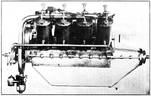
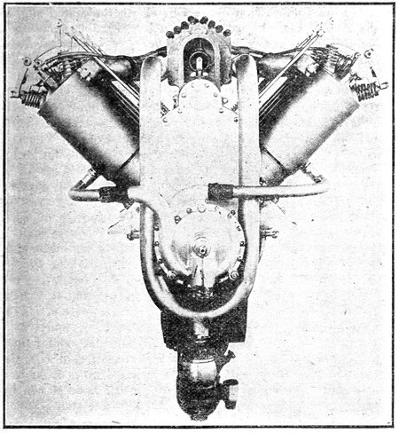
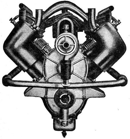
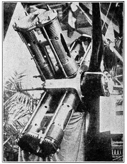
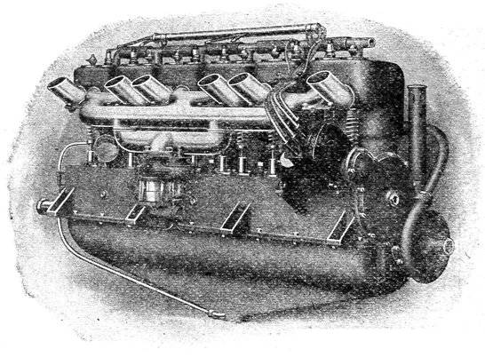
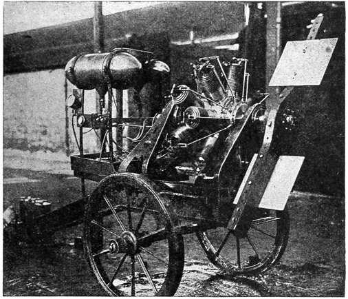
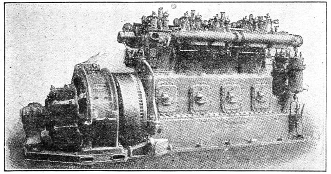
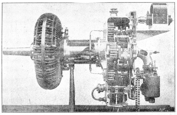
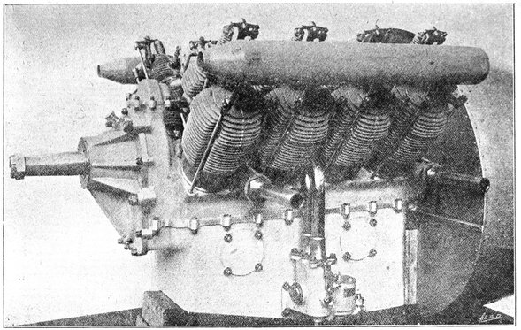
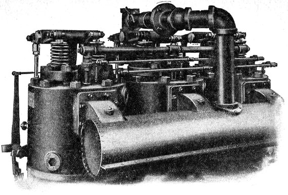
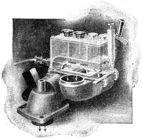
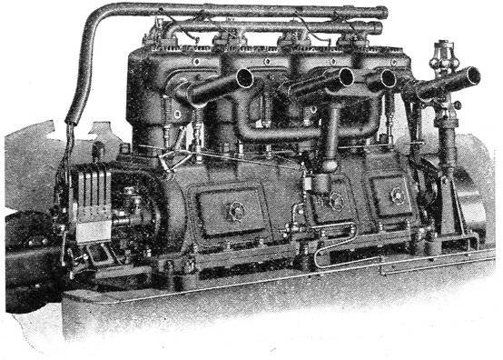
Eight Cylinder “V” Type Curtiss Aero Motor Having Two Rows of Four Cylinders Per Row. The Carburetor is Shown at the Left Hand Lower Corner Below the Motor. For Front Elevation See Fig. F-3 on Page 23.
A simple, practical and comprehensive book on the
construction, operation and repair of all kinds of engines.
Dealing with the various parts in detail and the various
types of engines and also the use of different kinds of fuel.
By
JOHN B. RATHBUN,
Consulting Gas Engineer, Editor “Ignition,” Instructor Chicago
Technical College, Author Gas Engine Troubles and Installation.
Published by
CHARLES C. THOMPSON CO.
CHICAGO, U. S. A.
Copyright 1916
CHARLES C. THOMPSON CO.
Copyright MCMXIII
CHARLES C. THOMPSON CO.
Practical Hand Book Gas, Oil & Steam Engines
Table of Contents
CHAPTER I—HEAT AND POWER
Heat Energy—Mechanical Equivalent of Heat—Expansion Heat Units—Heat Engines—Efficiency—External and Internal Combustion Engines—Compression—Working Medium
Practical Use of the Indicator—Pressure Measurement—Reading the Card—Four Stroke Cycle Card—Defects in Practical Working—Two Stroke Cycle Card—Diesel Card—Effects of Mixture—Effects of Ignition
Hot Tube System—Low Tension System—High Tension System—Details of Make and Break Batteries—Low Tension Magnetos—High Tension Magnetos—Coils—Adjustment—Troubles
CHAPTER I HEAT AND POWER — (1) The Heat Engine. — (3) Combustion In the Cylinder. — (4) Compression. — (5) Efficiency and Heat Losses. — (6) Expansion of the Charge.
5
Heat engines, of which the steam engine and gas engine are
the most prominent examples, are devices by which heat energy
is transformed into mechanical power or motion. In all
heat engines, this transformation of energy is accomplished by
that property of heat known as “expansion,” by which an increase
or decrease of temperature causes a corresponding increase
or decrease in volume of the material subjected to the
varying temperatures. The substance whose expansion and contraction
actuates the heat engine is known as the “working
medium,” and may be either a solid, liquid, or a gas. The extent
to which the working medium is expanded depends not only
upon the change of temperature but also on its composition.
In all practical heat engines, the heat energy is developed
by the process of combustion, which is a chemical combination
of the oxygen of the air with certain substances, such as coal
or gasoline, known as “fuels.” The heat producing elements
of the fuels are generally compounds of carbon and hydrogen,
which when oxydized or burnt by the oxygen form products
that are unlike either of the original components. It is due to
this chemical change that heat energy is evolved, for the heat
represents the energy expended by the sun in building up the
fuel in its original form, and as energy can neither be created
nor destroyed, heat energy is liberated when the fuel is decomposed.
The heat energy thus liberated is applied to the
expansion of the working medium to obtain its equivalent in the
form of mechanical power.
6During the period of expansion, the heat obtained by the
combustion is absorbed by the working medium in proportion
to its increase in volume, and as this increase is proportional
to the mechanical effort exerted by the engine, it will be seen
that the output of the engine in work is a measure of the heat
applied to the medium. The quantity of heat absorbed by the
medium represents the energy required to set the molecules of
the medium into their new positions in the greater volume, or
to increase their paths of travel. In the conversion of heat, each
heat unit applied to the medium results in the production of
778 foot pounds of energy, providing that there are no heat or
frictional losses.
In explanation of these terms or units, we wish to say, that
the unit of heat quantity, called the BRITISH THERMAL
UNIT is the quantity of heat required to raise one pound of
water, one degree Fahrenheit, and the FOOT POUND is the
work required to raise one pound through the vertical distance
of one foot. As the British Thermal Unit = 778 foot pounds
it is equivalent to the work required to raise 778 pounds one
foot or one pound 778 feet, or any other product of feet and
pounds equal to the figure 778.
As liquids expand more than solids with a given temperature,
and gases more than either, the mechanical work returned for
a given amount of thermal energy (the EFFICIENCY) will be
greater with an engine using gas as a working medium than one
using a solid or liquid working medium. The steam engine and
the gas engine are both examples of heat engines using gaseous
working mediums, the medium in the steam engine being water
vapor and in the gas engine, air and the gaseous products of
combustion. For this reason the working medium will be considered
as a gas in the succeeding chapters.
Practically the only way of obtaining mechanical effort from
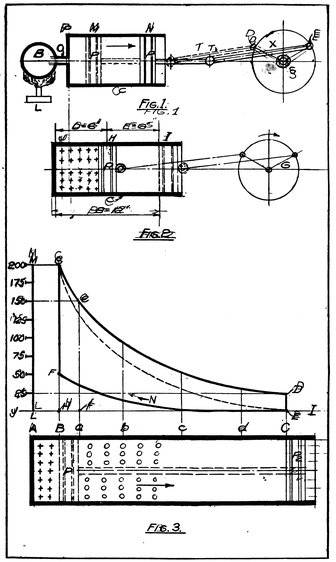
an expanding gas is to enclose it in a cylinder (c) fitted with a
freely sliding plunger or piston (p) as shown in Fig. 1. Two
positions of the piston are shown, one at M indicated by the
dotted lines, and one at N indicated by the full lines. It will be
assumed that the space between the cylinder head P and the
piston at M represents the volume of the gas before it is
heated and expanded, and that the volume between O and N
represents the volume after heating and expansion have occurred.
The vessel B represents a chamber containing air that
is periodically heated by the lamp L, and which is connected
to the working cylinder C by the pipe O.
7
Figs. 1–2–3. Showing Expansion in an External Combustion Engine, the Cycle of Operations in an Internal Combustion Engine, and the Pressure Diagram of the Latter Engine Giving the Pressures at Various Points in the Stroke.
8With the piston at M, the lamp L is lighted and placed under
the retort B which results in the immediate expansion of the
air in B. The expanded air passes through O into the cylinder,
and if sufficient heat is supplied, exerts pressure against the
piston since it occupies much more than its original volume.
Providing that the friction of the device and the load on the
shaft S are low enough the pressure on the piston will, move it
to the position N in the direction of the arrow, thus accomplishing
mechanical work. The motion of the piston revolves
the crank to which it is connected by the rod X from D to E.
During the trip from M to N the volume of gas has greatly
increased being supplied continuously with heat from the lamp.
As a considerable amount of heat has been radiated from the
cylinder during the piston travel, and a considerable portion of
the mechanical work lost through the friction of the piston on
the cylinder walls, and by the crank, not all of the heat units
are represented at the crank as mechanical effort.
Because of the limiting length of the cylinder, and the temperature
limits of the lamp it is not possible to expand the
working medium and increase the temperature indefinitely, therefore
there must be a point where the application of heat must
cease and the temperature be reduced in order to bring the gas
back to its original volume and the piston to its original position
so that the expansion may be repeated. This condition results
in a very considerable loss of heat and power in addition to the
losses previously mentioned, as the heat taken from the medium
to reduce it to its original volume is thrown away as far as the
production of power is concerned. To return the piston to its
former position without expending energy on the engine, the
volume and pressure may be reduced either by allowing the gas
to escape to the atmosphere by means of a valve, or by removing
the lamp and cooling the air by the application of water, but in
any case the heat of the air is lost and the efficiency of the engine
reduced.
To increase the efficiency of the engine and reduce the loss
just mentioned, nearly all heat engines, either steam or gas,
have the working medium at the highest temperature for only
a small portion of the stroke, after which no heat is supplied
to the cylinder. As the pressure forces the piston forward the
volume increases, and as no more heat is supplied, both the
pressure and the temperature continue to decrease until the end
of the stroke is reached, thus utilizing the greater part of the
heat in the expansion. Since the temperature at the end of the
9stroke is comparatively low, very little heat is rejected when the
valve is opened for the return stroke. This loss would be the
least when the temperature of the gas at the end of the stroke
was equal to the temperature of the surrounding air. With
both the internal and external temperatures equal, there would
be no difference between the pressure of the gas in the cylinder
and that of the surrounding air.
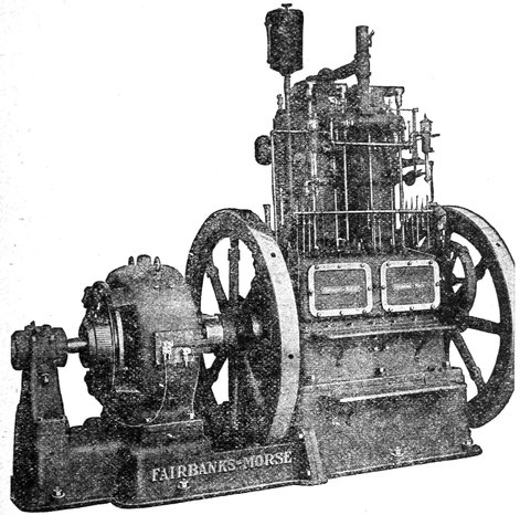
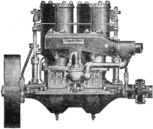
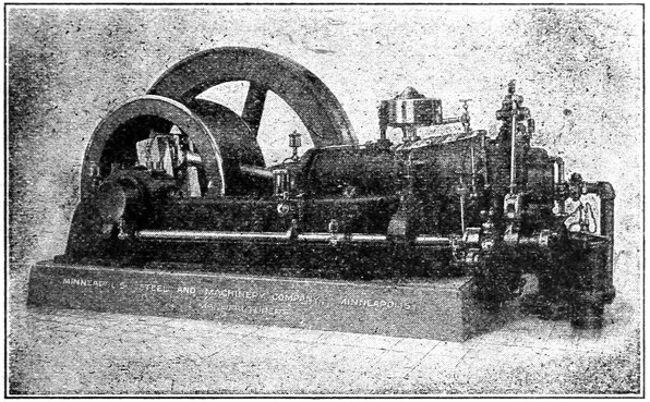
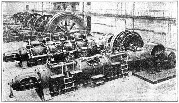
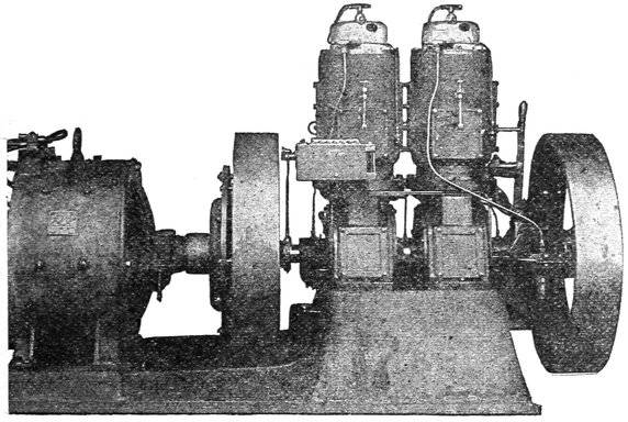
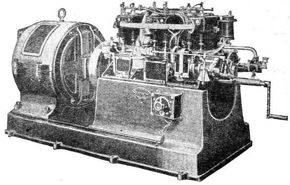
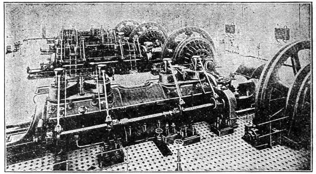
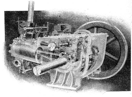
Fig. 1-a. Fairbanks-Morse Two Cylinder, Type “R E” Stationary Engine Direct Connected to a Dynamo.
It will be seen from the example just given that the heat
engine performs mechanical work by dropping the working
medium from a high to a low temperature, as it receives the
medium at a high temperature from the lamp and rejects it at
atmospheric temperature after delivering a small percentage of
useful work. This may be compared to a water wheel which
receives the working medium (water) at a high pressure and
10rejects it at a lower pressure. Carrying this comparison still
further, it is evident that an increase in the range of the working
temperatures (high and low) would increase the output of
the heat engine in the same way that an increase in the range
of pressures would increase the output of the water wheel. The
temperature at which the engine receives the working medium
and the temperature at which it is rejected determines the number
of heat units that are available for conversion into mechanical
energy, and therefore, if the range be increased by either
raising the upper limit of temperature or by reducing the lower
limit, or by the combined increase and decrease of the limits,
the available heat will be increased.
Based on the temperature range, the maximum possible efficiency
of the heat engine may be expressed by the ratio—
Reception Temperature—Rejection Temperature
E =
Reception Temperature
This maximum defined by Carnot establishes a limit that can
be exceeded by no engine, whatever the construction or working
medium.
According to the methods adopted in applying the heat of
combustion to the working medium, heat engines are divided
into two general classes, (1) External combustion engines, (2)
Internal combustion engines. The expressions “Internal” or
“External” refer to the point at which combustion takes place
in regard to the working cylinder, thus an internal combustion
engine is one in which the combustion takes place in the working
cylinder, and an external combustion engine is one in which
the combustion takes place outside of the working cylinder.
The steam engine is an example of an external combustion engine,
the fuel being burned in the furnace of a boiler which
is independent of the engine cylinder proper. As the fuel is
burned directly in the cylinder of a gas engine it is commonly
known as an internal combustion engine.
An external combustion engine, such as the steam engine is
subject to many serious heat losses because of the indirect
method by which the heat is supplied to the working cylinder,
aside from the losses in the cylinder. Much of the heat goes
up the smoke stack and much is radiated from the boiler settings
and the steam pipes that lead to the engine. The greatest
loss however is due to the fact that the range of temperatures
in the working cylinder is very low compared to the temperatures
attained in the boiler furnace, for it is practically impossible
11to have a greater range than 350°F to 100°F with a steam
engine, while the furnace temperatures may run up to 2500°F
and even beyond.
High temperatures with a steam engine result in the development
of enormous pressures, a temperature of 547°F corresponding
to an absolute pressure of 1000 pounds per square
inch. This pressure would require an extremely heavy and inefficient
engine because of the terrific strains set up in the moving
parts. The pressures established by air as a working medium
are very much lower than those produced by air or any
permanent gas at the same temperature, and for this reason it
is possible to exceed a working temperature of over 3000°F
in the cylinder of a gas engine without meeting with excessive
pressures. This high working temperature is one of the reasons
of the extremely high efficiency of the gas engine.
In order to compete with the gas engine from the standpoint
of efficiency, the steam engine builders have resorted to super-heating
the steam after it has left the boiler in order to increase
the temperature range in the cylinder. By applying additional
heat to the steam after it has passed out of contact with
the water it is possible to obtain up to 600°F without material
increase in the pressure, but the practical gains have not been
great enough to approach the gas engine with its 3000°F. After
reaching his maximum temperature at this comparatively low
pressure, the steam engineer has still to eliminate a number of
other losses that do not obtain with the gas engine.
Since the radiation losses of a burning fuel are proportional
to the time required for burning, it is evident that the rate of
combustion has much to do with the efficient development of
the heat contained in it, and it is true that rapid combustion
develops more useful heat from a given fuel than slow. In the
gas engine the combustion is practically instantaneous with a low
radiation loss, but in the steam engine the rate is slow, and with
the excess of air that must necessarily be supplied, a great part
of the value of the fuel is lost before reaching the water in the
boiler. The temperature of the medium determines the efficiency
of the engine and as rapid combustion increases the
temperature it is evident that the gas engine again has the
best of the problem.
In the case of the gas engine where the fuel (in gaseous
form) is drawn directly into the working cylinder in intimate
contact with the working medium (air) and in the correct proportions
for complete combustion, each particle of fuel, when
12ignited, applies its heat to the adjacent particle of air instantly
and increases its volume with a minimum loss by radiation.
A gas engine is practically a steam engine with the furnace
placed directly in the working cylinder with all intervening
working mediums removed, the gases of combustion acting as
the working medium. It derives its power from the instantaneous
combustion of a mixture of fuel and air in the cylinder,
the expansion of which causes pressure on the piston. Under
the influence of the pressure on the piston, the crank is turned
through the connecting rod and delivers power to the belt
wheel where it is available for driving machinery. Whether the
fuel be of solid, liquid, or gaseous origin it is always introduced
into the cylinder in the form of a gas.
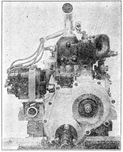
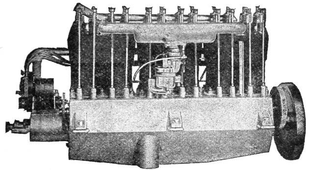
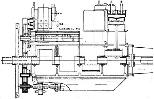
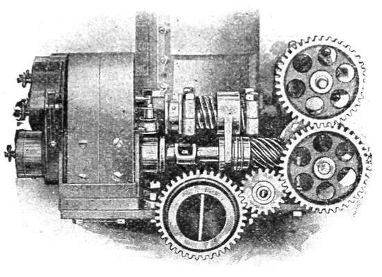
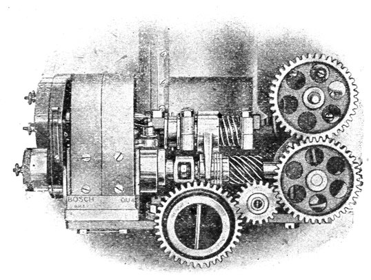
Fig. 1-b. The English Adams Automobile Motor (End View), Showing the Magneto Driven by Spiral Gears at Right Angles to the Crank-Shaft.
As the working medium in an internal combustion engine is
in direct contact with the fuel it must not only be uninflammable
13but it must also be capable of sustaining combustion and must
have a great expansion for a given temperature range. Since
atmospheric air possesses all of these qualifications in addition to
being present in all places in unlimited quantities it is natural
that it should be used exclusively as the working medium for
gas engines. Unlike the vapor working medium in a steam
engine the medium in the gas engine not only acts in an
expansive capacity but also as an oxydizing agent for burning
the fuel, and therefore must bear a definite relation to the
quantity of the fuel in the cylinder to insure complete combustion.
In the gas engine the use of gaseous fuel is imperative since
there must be no solid residue existing in the cylinder after
combustion and also for the reason that the fuel must be in a
very finely subdivided state in order that the combustion shall
proceed with the greatest possible rapidity. In addition to the
above requirements the introduction of a solid fuel into the
cylinder would involve almost unsurmountable mechanical problems
in regard to fuel measurement for the varying loads on the
engine. This limits the fuel to certain hydrocarbon or compounds
of hydrogen and carbon in gaseous form of which the
following are the most common examples:
(a) CARBURETED AIR consisting of a mixture of atmospheric
air and the vapor of some hydrocarbon (liquid) such as
gasoline, kerosene or alcohol.
(b) OIL GAS formed by the distillation of some heavy, nonvolatile
oil, or the distillation of tar or paraffine.
(c) NATURAL GAS obtained from natural accumulations
occurring in subterranean pockets in various parts of the
country.
(d) COAL GAS, made artificially by the distillation of coal,
commonly called “illuminating” gas.
(e) PRODUCER GAS, some times known as “fuel gas,” produced
by the incomplete combustion of coal in a form of furnace
called a “producer.”
(f) BLAST FURNACE GAS, the unconsumed gas from the
furnaces used in smelting iron, somewhat similar to producer
gas but lower in heat value.
It should be noted that there is no essential difference between
engines using a permanent gas or an oil as in either case
the fuel is sent into the cylinder in the form of a vapor. In
the case of oil fuel, the vapor is formed by an appliance external
to the engine proper. In this book, the heat action of an engine
14using one form of fuel applies equally to the engine using
another. The selection of a particular fuel for use with a gas
engine depends not only upon its value in producing heat, but
also upon its cost, the ease with which it meets the peculiar conditions
under which the engine is to work, and its accessibility.
Neglecting for the moment, all of the items that do not affect
the operation of the engine from a power producing standpoint,
the principal requirement of a fuel is the production of a high
temperature in the cylinder since the output is directly proportional
to the temperature range. Since a very considerable
mass of air is to be raised to this high temperature, the heat
value, or CALORIFIC VALUE of the fuel in British Thermal
units is of as much importance as the temperature attained in the
combustion. The calorific value of different fuels vary widely
when based either on the cubic foot or pound, and a considerable
variation exists even among fuels of the same class owing to
the different methods of production or to the natural conditions
existing at the mine or well from which they originated. The
principal elements of gas engine fuels, carbon and hydrogen,
exist in many different combinations and proportions, and require
different quantities of air as oxygen for their combustion
because of this difference in chemical structure.
Since complete combustion is never obtained under practical
working conditions, the actual evolution of heat and the actual
temperatures are always much lower than those indicated by
the CALORIMETER or heat measuring device. Besides the loss
of heat due to imperfect combustion, there are many other losses
such as the loss by radiation, connection, and slow burning, the
latter being the principal cause of low combustion temperatures.
From the statements in the foregoing paragraphs it will be seen
that the theoretical or absolute calorific value of a fuel is not
always a true index to its efficiency in the engine.
Complete combustion results in the carbon of the fuel being
reduced to carbon dioxide (CO2) and the hydrogen to water
(H2O), with the liberation of atmospheric nitrogen that was
previously combined with the fuel, and some oxygen. The reduction
of the fuel to carbon dioxide and water produces every
heat unit available since the latter compounds represent the
lowest state to which the fuel can be burned. Carbon however
may be burned to an intermediate state without the production
of its entire calorific contents when there is not sufficient oxygen
present to thoroughly consume the fuel. Incompletely consumed
carbon produces a gas, carbon monoxide, as a product of
15combustion, and a quantity of solid carbon in a finely subdivided
state known as “soot.” Unlike the products of complete combustion,
both the carbon monoxide and soot may be burned to
a lower state with a production of additional heat when furnished
with sufficient oxygen, both the soot and the monoxide
being reduced to carbon dioxide during the process.
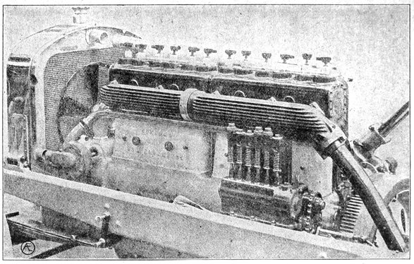
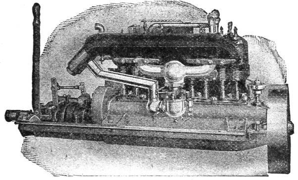
Fig. F-2. Sunbeam Engine with Six Cylinders Cast “En Bloc” (in one piece). At the Right and Under the Exhaust Pipe is the Compressed Air Starting Motor that Starts the Motor Through the Gear Teeth Shown on Flywheel. From “Internal Combustion.”
16As the soot and monoxide have a calorific value it is evident
that much of the heat of the fuel is wasted if they are exhausted
from the cylinder without further burning at the end of the
stroke. To gain every possible heat unit it is necessary to furnish
sufficient oxygen or air to reduce the fuel to its lowest
state. As the free oxygen and nitrogen contained in the fuel
are without fuel value, their rejection from the cylinder occasions
no loss except for that heat which they take from the
cylinder by virtue of their high temperature.
With complete combustion the TEMPERATURE attained increases
with the rate of burning, while the number of heat units
developed remain the same with any rate of combustion. Because
of the conditions under which the fuel is burned in the gas
engine the fuel is burned almost instantaneously with the result
that high temperatures are reached with fuels of comparatively
low calorific value. With a given gas the rate of combustion
is increased with an increase in the temperature of the gas before
ignition and remains constant for all mixtures of this gas
in the same proportion when the initial temperature is the
same. The rate of combustion also varies with the composition
of the gas, hydrogen burning more rapidly than methane. As
a rule it might be stated that the rate of burning decreases with
the specific gravity of the gas, the light gases such as hydrogen
burn with almost explosive rapidity, while the heavier gases
such as carbon dioxide are incombustible or have a zero rate of
combustion. In practice an increased rate of burning is obtained
by heating the charge before ignition by a process that
will be explained later.
Another factor governing the output of an engine with a
given size cylinder is the amount of air required to burn the
fuel. The quantity of air necessary for the combustion of the
fuel determines the amount of fuel that can be drawn into a
given cylinder volume, and as we are dependent upon the fuel
for the expansion it is evident that with two fuels of the same
calorific value, the one requiring the least air will develop the
most power. Since the air required to burn hydrogen gas is
only one fourth of that required to burn the same amount of
17methane it is clear that more hydrogen can be burned in the
cylinder than methane. This great increase in output due to
the hydrogen charge is however, considerably offset by the
greater calorific value of the methane.
Should the air be in excess of that required for complete combustion,
or should a great quantity of incombustible gas, such
as nitrogen be present in the mixture, the fuel will be completely
burned, but the speed of burning will be reduced owing
to the dilution. As the air is increased beyond the proper proportions
the explosions become weaker and weaker as the gas
becomes leaner until the engine stops entirely. Because of the
fact that it is impossible in practice to so thoroughly mix the
gas and air that each particle of gas is in contact with a particle
of air, the volume of air used for the combustion is much greater
than that theoretically required. A SLIGHT excess of air, making
a lean mixture, increases the efficiency of combustion although
it reduces the temperature and pressure attained in the
cylinder. This is due to the fact that while the temperature of
the mixture is lower than with the theoretical mixture the
temperature of the burning gas itself is much higher. A mixture
that is too lean to burn at ordinary temperatures will respond
readily to the ignition spark if the temperature or pressure is
raised.
In the practical gas engine the gas is not ignited at the beginning
of the suction stroke by which it is drawn into the
cylinder, but is compressed in the front end of the cylinder by
the return stroke of the piston, and then ignited. The process
of compression adds greatly to the power output of a given
sized cylinder and increases the efficiency of the fuel and expansion.
In order to understand the relation that the compression
bears to the expansion let us refer to Fig. 2 in which
C is the working cylinder, P the piston and G the crank. While
the piston is moving towards the crank in the direction of the
arrow A it draws the mixture, indicated by the marks x x x x x,
into the cylinder, the quantity being proportional to the position
of the piston. In this particular case let us assume that the
area of the piston is 50 square inches and that the entire stroke
(B) of the piston is 12 inches. To prevent confusion due to
considerations of heat loss we will further assume that the
cylinder is constructed of non-conducting material.
With the piston at the position H, midway between J and I,
18the volume D is filled with the explosive mixture at atmospheric
pressure and a temperature of 500° absolute. Since D = 6 inches
and the area of the piston is 50 square inches, the volume D is
equal to 6 × 50 = 300 cubic inches, and the entire volume is
2 × 300 = 600 cubic inches. On igniting this mixture (at atmospheric
pressure) the temperature will rise immediately, say to
1000°F with the piston at H. According to a law governing the
expansion of gases, known as Gay-Lussac’s Law, the expansion
v × T t = V where v = the initial volume of the gas before
ignition = 300 cubic inches; t = the temperature before ignition
500° absolute; V = the volume of the gas after expansion; and
T = temperature after ignition = 1000° absolute. Inserting the
values in numerical form we have as the final volume:—300 × 1000 500
= 600 cubic inches = the volume after expansion, or
twice the original volume of gas. This means that the expansion
is capable of driving the piston from H to I before the
pressure is reduced again to atmospheric pressure. As the
volume is expanded to twice that of the original volume at
atmospheric pressure (14.7 pounds per square inch), the pressure
against the piston before it starts moving will be 2 × 14.7 =
29.4 pounds per square inch.
Let us now consider the case in which the charge is compressed
before ignition occurs and compare the expansion
and pressure established with that produced by ignition at
atmospheric pressure. To produce the compression the piston
will travel through the entire stroke to the position I on
the suction stroke filling the entire cylinder volumes of 600 cubic
inches with the mixture. On the return stroke the piston stops
at H, reducing the original volume of 600 cubic inches to 300
cubic inches, doubling the pressure of the gas. The initial and
final temperatures will be considered as being the same as those
in the first example, 500° and 1000°. From Gay-Lussac’s Law—v × T t
= V and substituting the numerical values
600 × 1000 500 = 1200 cubic inches, or the expanded volume will be
four times the compressed volume, or four times the initial
19volume of the first case where the gas was ignited at atmospheric
pressure.
It should be noted however, that while the expansion has
been greatly increased by the compression, that this is not all
gain, as equivalent work has been expended in compressing the
charge. With the exception of doubling the fuel taken into the
cylinder, and consequently doubling the output for a certain
cylinder capacity, there has been no increase in fuel efficiency
except that due to conditions other than the mere reduction in
volume. In the second case the volume was increased four
fold which resulted in a piston pressure of 4 × 14.7 = 58.8 pounds
per square inch before the piston increased the volume by moving
from H to I.
The work done by the engine on the charge in compressing
is converted into heat energy causing a rise in the temperature
of the gas. This would not be a loss as it would reappear as
mechanical energy on the return stroke of the piston through
its expanding effect on the gas. This heat would, in effect, be
added to the temperature due to ignition, and the sum would
produce its equivalent expansion. The temperature due to the
combustion may be determined by reversing Gay-Lussac’s Law—
t
I
Pt
=
or T =
p
P
p
Where t = initial temperature; T = temperature combustion;
P = pressure after combustion; p = pressure before combustion.
Because of the fact that the act of compressing the charge in
the cylinder before ignition increases the temperature of the
working medium, the compression will increase the speed of
combustion and efficiency of the fuel as the rate of combustion
increases with the initial temperature. This increased temperature
due to initial compression of course results in a greater
temperature range and output due to the increased rate of burning,
and this rate of combustion may be varied for different
fuels by changing the compression pressure. In a previous
paragraph it was explained that the fuel efficiency was increased
by a slight dilution or excess of air, and that while the temperature
and pressure of the mixture were reduced by the dilution
the temperature of the fuel was increased, provided that the
inflammability was not decreased.
Compression affords a means of using dilute mixtures without
loss of inflammability, as the heat gained by the compression
restores the inflammability lost by the effects of dilution. Increased
20compression pressures increases the possible range of
dilution, so that extremely lean gases and mixtures may be
used with success with appropriately high compression. As an
example of this fact we can refer to the engine using blast furnace
gas, a fuel that is so lean that it cannot be ignited under
atmospheric pressure. By increasing the piston speed, the heat
of the compression can be made more effective as the gas lies
in contact with the cylinder walls for a shorter time which of
course reduces the heat to the jacket water.
Up to the present time we have considered an engine in
which there is no heat loss or loss from friction, but in the
actual engine such losses are large and tend to materially reduce
the values of heat and pressure to be obtained from a
fuel with a given calorific content. Applying the rule for heat
engines given in a previous section where the efficiency is—
T – t
E =
T
We have the theoretical efficiency of a gas engine, neglecting
friction, loss to the cylinder walls, and loss through the rejection
of heat with the exhaust gas, equal to—
1960 – 520
E =
= 73.5 percent.
1960
In substituting the numerical values in the above calculation
it was assumed that the temperature of the burning mixture
would be 1500° F above zero, and that the exhaust temperature
would be as low as 60. Since the calculation is made from
absolute zero, which is 460° below the zero marked on
our thermometers, the temperature of the burning charge,
T = 1500 + 460° = 1960° above absolute zero. Similarly the
absolute temperature of the exhaust would be, t = 60 + 460 =
520° absolute. The application of the absolute temperatures will
be seen from the calculation for efficiency. The value given,
73.5 per cent, it should be understood is the theoretical efficiency
and is at least 20 per cent above the best results obtained in
practice. The best record that we have had to date, is that
established by a Diesel engine which returned 48.2 per cent of
the calorific value of the fuel in the form of mechanical energy.
In order that the reader may have some idea of the losses that
occur in the engine, and their extent we submit the following
21table. These are the results of actual tests obtained from different
sources and represent engines built for different services
and of various capacities:
Losses—Data
Automobile Motor
Stationary Engine
Stationary Engine
Horse-power
30.
200
1000
Heat lost to jacket water
35.8%
31.0%
2970 B.T.U.
Loss at per Horse-power in B.T.U.’s
Heat lost in exhaust
24.6%
30.0%
2835 B.T.U.
Friction loss
8.6%
6.5%
810 B.T.U.
Heat lost by radiation
15.4%
8.2
540 B.T.U.
Heat available as power
2700 B.T.U.
Efficiency (per cent)
15.6%
24.3
Fuel
Gasoline
Producer Gas
The remarkable efficiency of the Diesel engine is due principally
to the extremely high compression pressure, which was
from 500 to 600 pounds per square inch. When this is compared
to the 60 to 70 pounds compression pressure used with
automobile engines it is easy to see where the Diesel gains its
efficiency. It is evident that as much depends on the manner
in which the fuel is used in the engine as on the calorific value
of the fuel.
When an explosive mixture is ignited in the cylinder with
the piston fixed in one position thus making the volume constant,
the increase of temperature is accompanied by an increase
of pressure. If the piston is now allowed to move forward
increasing the volume, the increase of volume decreases the
pressure. Since in the operation of the gas engine the piston
continuously expands the volume on the working stroke it is
evident that there is no point in the stroke where the pressures
are equal, and that the pressure is the least at the end
of the stroke, it being understood of course that no additional
heat is supplied to the medium after the piston begins its stroke.
This distribution of pressure in the cylinder in relation to the
piston position is best represented graphically by means of a
diagram as shown by Fig. 3, in which K is the cylinder and P
the piston. Above the cylinder is shown the diagram HGDE
the length of which (HE) is equal to the stroke of the piston
shown by (BC). Intersecting the line HI are vertical lines, A,
a, b, c, C, which represent certain positions of the piston in its
stroke. The height of the diagram H G represents to scale the
22maximum explosion pressure in pounds per square inch, and
the line HG is drawn immediately above the piston position B
which is at the inner end of the stroke. To the left of the
line HS is drawn a scale of pressures ML divided in pounds per
square inch so that the pressures may be read off of the pressure
curve GD. The line JI represents atmospheric pressure, and
the divisions on ML, of course, begin from this line and increase
as we go up the column. As an example in the use of
the scale we find that the point F is at 50 pounds pressure above
the atmospheric line JI.
We will consider that the clearance space AB is full of mixture
at the point B, and that it is moved toward the left to the
point C filling the space AC full of mixture at atmospheric
pressure. The location of the piston on the diagram is shown
by D and E. The opening through which the gas was
supplied to the cylinder is now closed, and the piston starts
on its compression stroke, moving from C to A. As the
volume is reduced from AC to AB, there is an increase
of pressure which is shown graphically by the rising line EF.
This line rises gradually from the line JI in proportion to the
reduction in volume until the piston reaches the end of the
compression stroke at B, at which point the compression is at
a maximum. The extent of this pressure is shown by the
length of HF which on referring to the scale of pressure at the
left will be found to be 50 pounds per square inch.
Ignition now occurs and the pressure increases instantly from
the compression pressure at F to the maximum pressure at G
which on referring to the scale will be found to equal 200 pounds.
The actual increase of pressure due to ignition above the compression
pressure will be shown by the length of the line
FG which is equal to 150 pounds. As the pressure is now established
against the piston it will begin to move forward with
an increase of volume and a corresponding decrease in pressure,
until it reaches the point C. This point at the end of the
stroke is indicated on the diagram by D which by reference to
the scale will be found equal to 25 pounds above atmosphere.
An exhaust valve is now opened allowing the gas to escape to
the atmosphere which reduces the pressure instantly from D to
E on the atmospheric line. Expansion along the line GD is
not complete as the pressure is not decreased to atmospheric
pressure in the cylinder which means that there is a considerable
loss of heat in the exhaust. In practice the expansion is
23never complete, but ends considerably above atmospheric pressure
as shown.
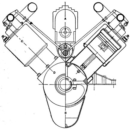
Fig. F-3. Front Elevation of Curtiss “V” Type Aeronautical Motor. This is the Front View of the Motor Shown in the Frontispiece. See Chapter V for Description of this Type of Motor.
Complete expansion is shown by the dotted line GE which
terminates at E on the atmospheric line. By following the
vertical lines up from the points a, b, c, and d, the pressures
corresponding to these piston positions can be found by measuring
the distance of the curve from the atmospheric line, on the
given lines a, b, c or d. To find the pressure at the position a,
for instance, follow upwards along the line a to the point c on
the curve, the length of the line ef from the curve to the atmospheric
represents the pressure, which by reference to the
scale ML will be found equal to 125 pounds. The pressure at
24any other point can be found in a like manner. Compression
pressures may be found at any point by measuring from the
atmospheric line to the compression curve FE along the given
line. It will be noted that the combustion is so quick that the
pressure rises in a straight line along GH, indicating that combustion
was complete before the piston had time to start on
the outward stroke. The expansion curves GE and GD are
similar to the compression curve FE. With the actual engine
the shape of the ideal card as shown by Fig. 3 is sometimes
considerably deformed owing to the effects of defective valves,
leaks, or improperly timed ignition.
Pressure curves of actual engines are of the greatest value as
they show the conditions within the cylinder at a glance and
make it possible to detect losses due to leaks, poor valve settings,
etc. These curves are traced by means of the INDICATOR
which is an instrument consisting of a small cylinder which is
connected to the cylinder of the engine, and an oscillating drum
that is driven to and fro by the engine piston. The piston in
the indicator cylinder is provided with a spring that governs
its movements and communicates its motion to a recording
pencil through a system of levers. The spring is of such
strength that a pressure of so many pounds per square inch in
the cylinder causes the pencil to draw a line of a definite length,
this line being equivalent to the pressure line GH in Fig. 3.
A piece of paper is wrapped about the indicator drum, and the
drum is attached to the piston in such a manner that it turns a
certain amount for every piston position, the complete stroke of
the piston turning the drum through about three-quarters of
a revolution. Rotation of the drum traces the horizontal lines
of the diagram and the movement of the piston draws the
vertical lines, so the combined movements of the drum and
piston records the pressures and piston positions as shown by
Fig. 3.
Since the movement of the indicator piston represents the
pressures in the cylinder to scale it is possible to compute the
power developed in the cylinder as the output in mechanical
units is equal to the product of the average force acting on the
piston multiplied by the speed of the piston in feet per minute.
This product of the force and velocity (known as “foot pounds
per minute”) divided by 33,000 (one horse-power = 33,000 foot
pounds) gives the output of the engine, in horse-power.
As the pressure on the piston fluctuates throughout the
stroke, it would be wrong to consider the force, in the calculation
25for power as being equal to the explosion pressure, and
so the effective pressure is taken as being the average of all the
pressures from the point of explosion to the exhaust. The
average pressure or “mean effective pressure” as it is called is
computed from the indicator diagram by dividing it into a number
of equal parts along the horizontal line, adding the lengths
of the pressure lines such as CH, CF, etc., and dividing the total
length by the number of the lines. After the average height
of the diagram is thus determined, the average length is multiplied
by the scale of the indicator or the pressure that is
shown by it per inch.
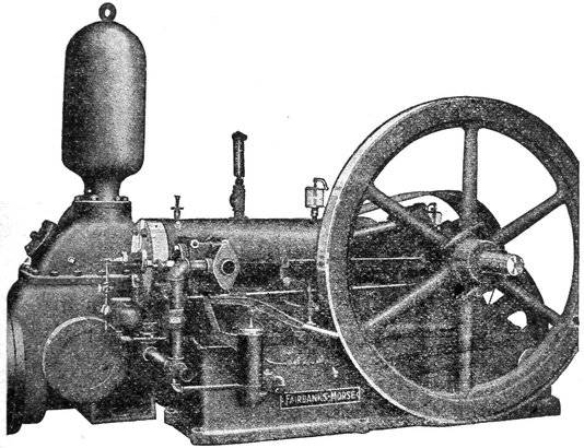
Fairbanks-Morse Gasoline Pumping Engine. Pump is Gear Driven From the Engine Crank-Shaft at Reduced Speed.
Knowing the mean effective pressure, the total pressure on
the piston, or the force is found by multiplying the area of the
piston in square inches by the average pressure per square inch.
This product is multiplied by the piston speed in feet per minute
and is divided by the product of the number of strokes to
the explosion and the quantity 33,000. Should there be more
than one cylinder the result is multiplied by the number of
26cylinders, and this is multiplied by 2 in the case of a double
acting engine. Stated as a formula this rule becomes:
A × P × 2R × L × N × O
H.P. =
33000 × C
When
A =
Area of piston in square inches.
P =
Average or mean effective pressure per square inch. About 75 pounds for Gasoline Engines. See Table on Page 31.
R =
Revolutions per minute.
L =
Stroke of piston in feet.
N =
Number of cylinders.
O =
2 when engine is double acting, that is when explosions occur on both sides of the piston.
C =
Number of strokes per explosion. C = 4 in a four cycle engine, and 2 in a two cycle.
It should be specially noted that the area of the piston is
given in square inches and the stroke of the piston in feet. The
number of revolutions per minute, R, is multiplied by two in
order to obtain the number of strokes, as there are two strokes
per revolution. When the engine governs its speed by dropping
explosions to meet varying loads, the quantity C should be
omitted and the explosions counted.
Due to the fact that the incoming charge of the mixture is
expanded by the heat of the passages, a full charge computed
at atmospheric temperature is never obtained in the cylinder
and for this reason the gas should be kept as cold as possible
before entering the passages in order to obtain the maximum
output. Friction due to restricted passages and valve openings
also reduces the amount of mixture available. Small exhaust
valves and pipes prevent the gases from escaping freely to the
atmosphere and produces a back pressure on the piston which
cuts down the effective pressures. All of these items are recorded
by the indicator and makes it possible to make alterations
that will increase the output of the engine.
Because of the reduced atmospheric pressures at high altitudes
the output and compression are reduced for every foot of elevation
above sea level. As the weight of the atmosphere is
reduced, less mixture is drawn into the cylinder. Taking the
output of the engine as 100 per cent at sea level, it is reduced
to less than 62 per cent at an elevation of 15,000 feet.
CHAPTER II FUELS AND COMBUSTION — (7) Combustion. — (8) Gaseous Fuels. — (9) Gasifying Coal. — (10) Water Gas. — (11) Blast Furnace Gas. — (12) Producer Gas. — (13) Producer Gas From Peat. — (14) Crude Oil Producers. — (15) Operation of Producers. — (16) Coal. — (17) Fuel Oils. — (18) Tar for Fuel. — (19) Residual Oils. — (20) Gasoline. — (21) Benzol. — (22) Alcohol. — (23) Kerosene Oil.
27
The phenomenon called combustion by which we obtain the
heat energy necessary for the operation of the internal combustion
engine is a chemical combination of the air with the fuel.
This process results in heat and some light which is equal in
quantity to the energy required to separate the fuel compound
into its elements or to build it up in its present form from the
original elements. If the process is comparatively slow, the
compound is called a fuel, if it is instantaneous it is called an
explosive. Some substances produce mechanical force through
an instant, without the evolution of much heat, due to the disintegration
of an unstable compound. The effect of the latter
type of which dynamite is an example is static, that is to say,
it is not capable of producing power, but only pressure. For
this reason, compounds having an instantaneous effect without
the ability to produce the pressure through a distance, or an
expansion, are not considered as suitable fuels for a heat engine.
A fuel is essentially a substance which is capable of generating
heat, which is a form of energy, and not static pressure. The
heat engine is an instrument which transforms this energy into
power which is again dissipated into heat through the friction
of the engine itself and by the load that it drives. This is an
illustration of the physical law that “energy can neither be
created nor destroyed,” that is, the heat energy developed by
the fuel is converted into mechanical energy which is again
transformed into heat energy through friction.
It should be understood that fuel belongs to that class of
substances that will not burn nor evolve energy under any
temperature, pressure, or shock, without an outside supply of
oxygen. This is the characteristic property of all fuels used
with the internal combustion engine. Each element, such as
carbon and hydrogen, in a compound fuel, develops a certain
definite amount of heat during their complete combustion, and
at the close of the process certain compounds are formed that
28represent the lowest chemical form of the compound. To restore
the products of combustion to their original form as fuel
would require an expenditure of energy equal to that given out
in the combustion.
While all substances that are capable of oxydization or combustion
can be made to liberate heat energy, it does not follow
that all of them can be successfully used as fuels. A fuel suitable
for the production of power must be cheap, accessible and
of small bulk, and must burn rapidly. Such fuels must also be
products of nature that require no expenditure of energy in
their preparation or completion.
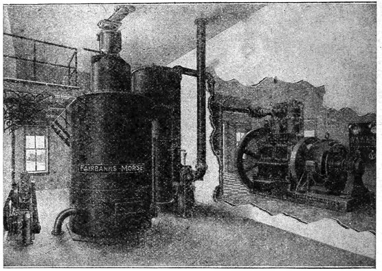
Fig. F-4. Fairbanks-Morse Producer Plant and Engine, Connected for Operation.
In practical work, the natural fuels are coal, mineral oils,
natural gas, and wood, which are compounds of the elements
carbon and hydrogen. When these fuels are burned to their
lowest forms the products of combustion consist of carbon
dioxide and water, the first being the result of the oxydization
of carbon, and the latter a compound of oxygen and hydrogen.
In solid fuels, such as coal, a portion of the compound consists
of free carbon and the remainder of a compound of carbon and
hydrogen known as a HYDROCARBON. In liquid fuels there
is little, if any, free carbon, the greater proportion being in the
29form of a hydrocarbon compound. Natural gas is a hydrocarbon
compound.
It should be noted that a definite amount of oxygen is required
for the complete combustion of the fuel elements, and
that a smaller amount of oxygen than that called for by the
fuel element results in incomplete combustion, which produces
a product of higher form than that produced by the complete
reduction. The product of incomplete combustion represents a
smaller evolution of heat than that of the complete process,
but if reburned in a fresh supply of oxygen the sum of the
second combustion together with that of the first will equal the
heat of the complete oxydization. When pure carbon is incompletely
burned the product is carbon monoxide (CO) instead of
carbon dioxide (CO2).
Carbon completely burned to carbon dioxide produces 14,500
British thermal units per pound of carbon, while the incomplete
combustion to carbon monoxide evolves only 4,452 British
thermal units, or less than one-third of the heat produced
by the complete combustion. Theoretically one pound of carbon
requires 2.66 pounds of oxygen to burn it to carbon dioxide.
On supplying additional oxygen, the carbon monoxide may be
burned to carbon dioxide and the remainder of the heat may
be recovered, or 10,048 British thermal units. When a hydrocarbon,
either solid, liquid or gaseous is burned with insufficient
oxygen, solid carbon is precipitated together with lower hydrocarbons,
and tar. In an internal combustion engine the precipitated
solid carbon is evident in the form of smoke.
Since the carbon and hydrogen elements of a fuel exist in
many different proportions and conditions in coal and oil, different
amounts of oxygen are required for the consumption of different
fuels. It should also be borne in mind that a greater
quantity of air is required for the combustion of a fuel than
oxygen, as the air is greatly diluted by an inert gas, nitrogen,
which will not support combustion. Because of the impossibility
of obtaining perfectly homogenous mixtures of air and
the fuel, a greater quantity of air is used in practice than is
theoretically required.
In a steam engine the fuel can be used in any form, solid,
liquid, or gaseous, but in an internal combustion, it must be
in the form of a gas no matter what may have been the form
of the primary fuel. Fortunately there is no fuel which may
not be transformed into a gas by some process if not already
in a gaseous state. The petroleum products are vaporized by
30either the heat of the atmosphere or by spraying them on a
hot surface. Coal is converted into a gas by distilling it in a
retort or by incomplete combustion. The heat energy developed
by a gas when burning in the open air depends on its chemical
combustion, but its mechanical equivalent in power when
burned in the cylinder of the engine depends not only upon
its composition but upon the conditions under which it is
burned as stated in the chapter devoted to the subject of heat
engines.
While the calorific values of the different gases given in
the accompanying table are approximately correct for gases
burning in the open air at atmospheric pressure they develop
widely different values in the cylinder of an engine because of
the effects of compression and preheating. The table serves,
however, as an index to the relative values of the fuels under
ordinary conditions without compression. While natural gas
has nearly eight times the calorific value of producer gas in
the open air, its actual heat value in the cylinder is only about
45 per cent greater. While acetylene has an exceedingly high
calorific value and explodes five times as fast as gasoline gas,
it develops only 20 per cent more power in the same cylinder.
Another item affecting the value of a gas is the rate at which
it burns, which is in part a characteristic of the fuel and partly
a factor of the conditions under which it is burnt. This subject
is treated of in the chapter devoted to the heat engine.
The calorific value of a gas may either be computed from its
chemical composition or by burning it in an instrument known
as a calorimeter. A gas calorimeter consists of a small boiler
or heating tank which is carefully covered with some non-conducting
material so as to prevent a loss of heat to the atmosphere.
The gas under test is burned in the boiler whose
extended surface catches as much of the heat as possible and
transfers it to the water in the boiler. The weight of the
water heated and its temperature are taken when a certain
amount of the gas has been burned (say 100 cubic feet), and
from this data, the heat units per cubic foot of gas are computed.
31
FUEL GASES.
GAS
B.T.U. per Cubic Foot
Cubic Feet of Air Required to Burn 1 Cubic Foot of Gas
Usual Compression Lbs. per Sq. Inch
Ratio of Gas to Air
Explosion Pressure in Lbs. per Sq. In.
Temperature of Combustion F°
Ignition Temperature F°
Weight per Cubic Foot, Lbs.
Candle Power
Mean Effective Pressure
Actual
Theoretical
Natural Gas
1000.
12.60
9
130
1–12.6
375
1100
.0459
94.00
Natural Gas
1000.
110
1–6
245
1000
72.00
Coal Gas
650.
9.00
5.85
80
1–9
285
1200
.035
18.00
85.00
Producer Anthracite
140.
1.20
1.85
160
1–1.2
360
1450
.065
88.00
Producer Bituminous
160.
3.20
2.20
1350
Water Gas (Uncarb.)
290.
3.60
2.20
.044
Water Gas (Carb.)
500.
8.50
5.15
1.8
22.00
Blast Furnace Gas
94.
1.10
0.70
170
1560
.080
77.5
Acetylene
1500.
20.00
12.60
Gasolene Vapor
520.
See Table of Liquid Fuels
70
1.12
245
1865
1550
79.00
Gasolene Vapor
520.
70
1.8
360
2950
925
82.00
Gasolene Vapor
520.
70
1.6
410
3160
910
84.50
Kerosene Vapor
60
1.8
285
945
85.00
Coke Oven Gas
520.
7.
5.4
.042
Alcohol
180
450
The values given above are approximate, and vary not only with the engine used but also with the method used in producing the gas, and with the character of the fuel used. The figures will give an idea of the relative value of the gases in a rough way.
As a British thermal unit is the amount of heat required
to raise the temperature of one pound of water through one
Fahrenheit degree (at about 39.1° F.), the total heat per cubic
foot of gas as observed by the calorimeter is equal to the weight
32of the water multiplied by its rise in temperature in degrees,
divided by the number of cubic feet of gas burned in the calorimeter.
Since a British thermal unit is equal to 778 foot pounds
in mechanical energy, its mechanical equivalent is equal to the
number of British thermal units multiplied by 778.
Another difference between the actual and theoretical results
obtained is that due the perfect combustion in the calorimeter
and the imperfect combustion in the engine. Since some gases
require more air for their combustion than others, less of the
first gas will be taken into the cylinder on a charge than the
latter, which tends still further to balance the heating effect
of rich and lean gases in the cylinder.
Coal Gas or Illuminating Gas is generated by baking the coal
in a closed retort or chamber out of contact with the air so
that no combustion takes place either complete or incomplete.
The hydrocarbon gases and tars are set free from the coal as
permanent gases and are then piped to a gas holder after going
through various purifying processes to remove the tars, oils,
moisture and dust. The free or solid part of the coal remains
in the retort in the form of coke, which is again burned for
fuel.
Because of its high carbon content, coal gas burns with a
yellowish-white flame and is extensively used for lighting purposes,
hence the name illuminating gas. In many ways coal
gas is an ideal fuel for power purposes as it has a high calorific
value (650–750 B.T.U. per cubic ft.), is supplied by the illuminating
company at practically a constant pressure, and is uniform
in quality. Its only drawback is its comparatively high
cost.
This gas is always obtained from the city service mains as its
preparation is too expensive and complicated for the gas engine
owner. Because of its cost, the use of coal gas is restricted
to small engines.
Water gas is made by blowing air through a thick bed of
some coal that is low in hydrocarbons until the coal becomes
incandescent, the gases that are formed are allowed to escape
to the atmosphere. At this point a jet of steam is blown into
the incandescent bed, which is broken up into its elements, oxygen
and hydrogen, by the heat of the fuel. As there is no
33air present the oxygen combines with the carbon of the fuel
to form carbon monoxide while the hydrogen goes free. Both
of these gases, carbon monoxide and hydrogen, are collected
and supplied to the engine. The production of water gas is
intermittent, as the steam blast cools down the fuel bed, and
requires further blowing before more steam can be passed.
While this gas has a lower heating value than coal gas, it is
much cheaper to make and all of the coal is consumed in the
process.
Water gas is high in hydrogen and is too “snappy” for gas
engines; the hydrogen places a limit on the allowable compression.
For each thousand feet of water gas generated, approximately
24 pounds of water are required.
By the introduction of hydrocarbons or vaporized oil, illuminating
value is given to water gas, this process is called carburetion.
Carbureted gas is not usually used for power, as it
is expensive, and is not proportionately high in heating value.
Many steel companies are utilizing the unconsumed gas of
the blast furnaces for power.
Blast furnace gas is of very low calorific value, rarely if
ever, exceeding 85 B.T.U. per cubic foot. This allows of very
high compression, which greatly increases the actual power
delivered by the engine.
A smelter produces approximately 88,000 cubic feet of gas
per ton of iron smelted.
Blast furnace gas is so lean that it cannot be burned satisfactorily
under a boiler; the high compression of the gas engine
makes its use possible.
Producer gas which is generated by the incomplete combustion
of fuels in a deep bed is the most commonly used gas for
engines having a capacity of 50 horsepower and over, because
of the simplicity and economy of its production. While producer
gas has been obtained from practically every solid fuel,
of which coal, coke, wood, lignite, peat, and charcoal are examples,
the fuel most generally used is either coal or coke.
While producer gas is much lower in calorific value than either
natural or illuminating gas it gives admirable results in the gas
engine and is a much cheaper fuel than coal gas in units above
3450 horse-power capacity. The fuel is completely burned to
ash in the producer without the intermediate coke product that
exists in the manufacture of coke.
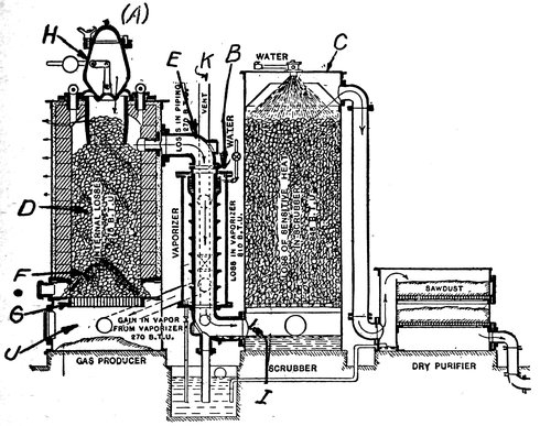
A producer consists of three independent elements as shown
by Fig. F-6; the PRODUCER or generator (A), the steam boiler
(B), and the SCRUBBER or purifier (C). The incandescent fuel
(F) in the form of a cone lies on the grate bars (G) at the
lower end of the producer. Above the burning fuel is a deep
bed of coal (D) which reaches to the top of the producer at
which point it is admitted to the bed through the charging
valve or gate (H). The gas resulting from the combustion
in the producer is drawn out of the tank through the gas outlet
pipe (E) by the suction of the engine. The air for the
combustion is drawn up through an opening in the ash pit
(J) by the engine.
When the oxygen of the air strikes the incandescent fuel
on the grate it combines with a portion of it forming carbon
dioxide (CO2) which is an incombustible gas, but on passing
through the burning fuel above this point, one atom of the
oxygen in the CO2 recombines with the fuel forming the combustible
gas—carbon monoxide (CO). Because of the distilling
effect of the heat in the bed, the volatile hydrocarbons
of the coal are set free and mingle with the CO formed by
the combustion. The producer gas consists, therefore, principally
of CO, with a certain proportion of the volatile hydrocarbons
of the coal such as marsh gas, ethylene, and some oil
vapor.
Since the hydrocarbons are easily condensed on coming into
contact with the coal walls of the piping, to form trouble making
tars and oils, they must either be washed out of the gas
in the purifier or passed again through the high temperature
zone to convert them into permanent gases. In the usual producer,
the hydrocarbons are reheated, as they form a considerable
percentage of the heat of the gas. After the volatile
constituents are reheated, the gases pass through the boiler
(B), which absorbs the heat of the gas in generating steam,
and from this point the gases enter the scrubber where the dust
and the residual tars are removed. The scrubber, which is a
sort of filter, is an important factor in the generating plant,
for if the dust and dirt were allowed to pass into the cylinder
of the engine it would only be a question of a short time until
the valves and cylinder would be ground to pieces.
When the steam from the boiler is allowed to flow into the
35ash pit of the producer and up through the incandescent fuel,
the heat separates the water vapor into its two elements, oxygen
and hydrogen. The oxygen set free combines with the
carbon in the coal forming more carbon monoxide, while the
hydrogen which is unaffected by the combustion adds to the
heat value of the gas. The last additions to the combustion
due to the disassociation of the steam are really what is known
as “water gas.” A limited amount of steam may be admitted
continuously in this manner without lowering the temperature
of the fuel below the gasifying point, and its presence is beneficial
for it not only provides more CO and hydrogen but produces
it without introducing atmospheric nitrogen. The steam
is also a great aid in preventing the formation of clinkers on
the grate bars. Since the air used in burning the fuel in the
first reaction contains about 79 per cent of nitrogen, which is
an inert gas, the producer gas is greatly diluted by this unavoidable
admixture, which accounts for its low calorific value.
Fig. F-6. Diagram of Suction Gas Producer Showing the Generator, Boiler and Washer.
While the air required for the combustion of the fuel is
drawn through the producer by the suction of the engine in
the example shown (SUCTION PRODUCER), there is a type
36in common use called a PRESSURE PRODUCER in which the
air is supplied under pressure to the ash pit by a small blower,
which causes a continuous flow of gas above atmospheric
pressure.
Gas producers are divided into two classes: suction producers
and pressure producers. The suction producer presents the
following advantages:
1. The pipe line is always less than atmospheric pressure,
hence no leaks of gas to the air are possible.
2. The regulation of the gas supply is automatic.
3. No gas storage tank is required.
4. The production of gas begins and stops with the engine.
5. Uniform quality of gas.
The suction producer is limited to power application and
cannot be used where the gas is to be used for heating, as
in furnaces, ovens, etc., or where the engine is at a distance
from the producer, unless pumped to its destination.
The pressure producer does not yield a uniform quality of
gas, hence requires a storage tank where low quality gas will
blend with gas of higher calorific values and produce a gas of
fairly uniform quality.
The pressure producer is adapted to the use of all grades of
fuels, such as bituminous coal and lignite.
Anthracite coal contains little volatile matter and is an ideal
fuel for the manufacture of producer gas, while bituminous coal
with its high percentage of volatile matter and tar, requires
more efficient scrubbing, as these substances must be removed
from the gas.
On starting the producer shown by Fig. 6, the producer is
filled with the proper amount of kindling and coal, and a
blast of air is sent into the ash pit by a small blower, the
products of combustion being sent through the by-pass stack
(K) until the escaping gas becomes of the quality required for
the operation of the engine. The by-pass valve is now closed,
and the gas is forced through the scrubber to the engine until
the entire system is filled with gas. When good gas appears
at the engine test cock the engine is started, and the blower
stopped, the gas now being circulated by the engine piston.
The volume of gas generated by the producer is always equal
to that required by the engine so that no gas receiver or
reservoir is required. Because of the friction of the gas in
passing through the fuel, scrubber and piping, its pressure at
the engine is always considerably below that of the atmosphere,
37which of course reduces the amount of charge taken into the
cylinder. Because of the weak gas and the low pressure in
the piping, it is necessary to carry a much higher compression
with producer gas than with natural or illuminating gas.
The efficiency of a producer is from 75 to 85 per cent, that
is, the producer will furnish gas that has a calorific value of
an average of 80 per cent of the calorific value of the fuel from
which it is made, the remaining 15 to 20 per cent being consumed
in performing the combustion. This is far above the
efficiency of the furnace in a steam boiler, as an almost theoretically
exact amount of air can be supplied in the producer
to effect the combustion, while in the boiler furnace about ten
times the theoretical amount is passed through the fuel bed
to burn it. Heating up this enormous volume of air to the
temperature of the products of combustion consumes a large
amount of fuel and reduces the efficiency of the furnace considerably.
Because of the reduction in the air supply, a gas
fired furnace is always more efficient than one fired with coal.
Producer gas with 300,000 British thermal units per thousand
cubic feet, and oil having 130,000 British thermal units per gallon
will result in 1,000 cubic feet of gas being equal to about
2.30 gallons of fuel oil.
If the gas is to be used for heating ovens or furnaces in connection
with the generation of power, the character of the fuel
will be determined to a great extent by the requirements of the
ovens and by the type of producer used, as each fuel will give
the gas certain properties. Thus gas used for firing crockery
will not be suitable for use in open hearth steel furnaces, as the
impurities in the various fuels may have an injurious effect on
the manufactured product. The cost of the fuel, cost of transportation,
heat value, purity, and ease of handling are all
factors in the selection of a fuel.
The size and condition of a fuel is also of importance. Exceedingly
large lumps and fine dust are both objectionable.
Wet fuel reduces the efficiency of the producer, as the water
must be evaporated, this causing a serious heat loss.
With careful attention a producer gas engine will develop
a horse-power hour on from 1 to 1¼ pounds of anthracite pea
coal, and in many instances the consumption has been less
than this figure. The efficiency in dropping from full load to
half load varies by little, one test showing a consumption of
1.1 pounds of coal per horse-power hour at full load and 1.6
pounds of coal at half load. Producer gas power is nearly as
38cheap as water power, in fact the producer gas engine has displaced
at least two water plants to the writer’s knowledge.
According to an estimate made by a well known authority,
Mr. Bingham, it is possible for a producer gas engine to generate
power for only .1 of one cent more per K.W. hour than
it is generated at Niagara Falls.
According to the United States Bureau of Mines,
“The tests in the gas producer have shown that many fuels
of so low grade as to be practically valueless for steaming purposes,
such as slack coal, bone coal and lignite, may be economically
converted into producer gas and may thus generate sufficient
power to render them of high commercial value.
“It is estimated that on an average each coal tested in the
producer-gas plant developed two and one-half times the
power that it would develop in the ordinary steam-boiler plant.
“It was found that the low-grade lignite of North Dakota
developed as much power when converted into producer gas
as did the best West Virginia bituminous coals burned under
the steam boiler.
“Investigations into the waste of coal in mining have shown
that it probably aggregates 250,000,000 to 300,000,000 tons yearly,
of which at least one-half might be saved. It has been demonstrated
that the low-grade coals, high in sulphur and ash,
now left underground, can be used economically in the gas producer
for the ultimate production of power, heat and light,
and should, therefore, be mined at the same time as the high-grade
coal.
“As a smoke preventer, the gas producer is one of the most
efficient devices on the market, and furthermore, it reduces
the fuel consumption not 10 to 15 per cent, as claimed for the
ordinary smoke preventing device offered for use in steam
plants, but 50 to 60 per cent.”
The production of gas from peat having a low water content
(up to about 20 per cent) for use in suction gas engines has
already met with considerable success in Germany, but for a
number of years efforts have been made to utilize peat with a
water content as high as 50 to 60 per cent and thus eliminate
the costly process of drying the raw material.
Difficulties have been encountered in preventing a loss of
heat through radiation and other causes, and in getting rid
of the dust and tar vapors carried over by the gases to the
39engine; but great strides have been made recently in overcoming
these obstacles. Peat with a water content up to 60
per cent has been found to be a suitable fuel. Owing to its
great porosity and low specific gravity it presents a large combustion
surface in the generator, so that the oxygen in the
air used as a draft can easily unite with the carbon of the
peat.
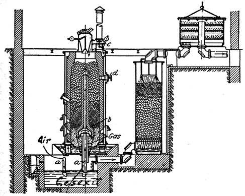
Fig. F-7. German Producer for Generating Producer Gas from Peat.
One of the great difficulties is to eliminate the tar vapors
that clog up many of the working parts of the engine. The
passing of the gas through the wet coke washers and dry sawdust
cleansers does not appear to have thoroughly remedied
the evil. Efforts were therefore made to remove the tar-forming
particles of the gas in the generator itself or to render them
harmless. That of the Aktien-Gesellschaft Gorlitzer Maschinenbau
Ansalt und Eissengiesserei of Gorlitz, was displayed at
the exposition at Posen in 1911. The gas from the generating
plant was employed in a gas suction engine of 300 horse-power
used to drive a dynamo for developing the electric energy for the
exposition. The fuel used was peat with a water content of about
40 per cent. The efficiency and economy results obtained were
very promising.
40The advantages claimed for the Gorlitz engine are that the
sulphurous gases and those containing great quantities of tar
products are drawn down by the suction of the engine through
burning masses of peat and thus rid of their deleterious constituents.
The air for the combustion purposes is well heated
before entering the combustion chamber, thereby producing
economical results. It is claimed also that the gas produced
by its system is so free from impurities that the cleaning and
drying apparatus may be of the simplest kind.
In Stahl und Eisen, an abstract is given of a paper by Carl
Heinz describing a peat gas producer, built by the Goerlitzer
Maschinenbauanstalt. We are indebted to Metallurgical and
Chemical Engineering for the translation of this paper:
Air and fuel enter the producer at the top, and the gas exit
is in the center of the bottom so that the air is forced to pass
through the center of the producer, decomposing the volatile
matter into gases of calorific value. The moisture which is
present in the peat fuel in considerable quantities must be
taken into consideration. For its decomposition which passing
through the hot-fire zone only a certain amount of heat is
available. It is, therefore, important that the heat from the
gasification be fully utilized.
There are two kinds of heat losses in a gas producer, due
to radiation and to the sensible heat of escaping gases. Both
these amounts of heat, however, are utilized according to the
special design of this producer. The air circulates first through
the lower conduit and comes so in contact with the warm
scrubber water. A part of the air which has been preheated
is carried upwards through the pipe A in the center of the
producer where it is thoroughly preheated by the hot gases
and enters then the air superheater B in which the temperature
rises to a still higher degree.
The other part of the air passes through the feet of the
producer into an air jacket which envelops the whole shell of
the producer and enters finally the producer by the reversing
valve C on top of the producer. In this way the outer surface
of the producer is maintained at a temperature hardly higher
than that of the surrounding air. The escaping gases are cooled
down so far that the gas outlet into the scrubber may be
touched by hand. All ordinary heat losses are thus made use
of in the gasification process.
If there is a large excess of moisture in peat, the process is
somewhat modified by regulating both air supplies in such a
41way that the gasification in the upper part of the fuel-bed
takes place in two directions, one downwards and the other
upwards.
It seems that a content of 80 per cent moisture and 20 per
cent dry fuel in the peat is about the limit permitting evaporation
of the water, but it is, of course, impossible to obtain in
this case a gas of calorific value.
The modification of the process for very wet fuel is as
follows:
When the fire on top of the fuel bed appears to disappear,
the heater opens the stack and valve D. Valve C is then closed,
to prevent air from entering on top. The preheated air enters
by D causing a down draft combustion due to the suction
of the gas engine and an upward combustion due to the draft
in the stack. The moisture is evaporated and escapes through
the stack. When the fire has burned through at the top, the
valve is switched over. The bad smelling gases rising from
the scrubber enter the producer together with air and are there
consumed.
In commercial use at the exhibition in Posen the whole plant
worked continuously day and night and cleaning of the gas engines
was necessary only every three months. Slagging of
ashes is done during the operation of the producer, without any
nuisance from dust.
The highest percentage of moisture in peat gasified was 50
per cent. The fuel consumption per horse-power hour is 2.2 lb.
(1 kg.) of peat. Careful tests made by Prof. Baer, of Breslau,
showed that with a cost of peat of $1 per ton the kw-hour at
the switchboard costs 0.15 cent.
The development of the crude oil gas producer, for which
there is great demand, in oil regions remote from the coal
field, has been exceedingly slow but it is believed that definite
progress has recently been made along this line. The most
recent notes on this subject relate to the Grine oil producer.
In this type steam spray is used for atomizing the oil which is
introduced into the upper part of the generator where partial
combustion takes place. The downdraft principle is then applied
and the hydrocarbon broken up and the tar fixed by
passing through a bed of incandescent coke. Mr. Grine reports
that a power plant using one of these producers has been in
operation a year in California. With crude oil as a fuel costing
4295 cents per barrel, or 2.3 cents per gallon, the plant is reported
to develop the same amount of power per gallon of crude as is
ordinarily developed by the standard internal combustion engine
operating on distillates at 7 cents per gallon. Including
the cost of fuel, labor, supplies, interest, depreciation and
taxes, Mr. Grine states the cost per b.h.p. hour to be 0.76 cents
for a plant of 100 h.p. rating.
A good producer operator is simply a good fireman, he must
know how to keep a uniform bed of coal and how to draw the
fire. While there are many thousands of men running producer
plants without previous mechanical training, there are
now but few steam engineers running steam engines of the same
capacity but what have had at least two years’ training and sufficient
mechanical knowledge to pass an examination and obtain a
license. While a considerable amount of skill is necessary
to obtain the best efficiency from a producer, it is a knack that
is easily acquired in a short time by “sticking around” the
plant. Skill in operating a producer consists chiefly in keeping
the right sort of a fire without damage to the lining by poking
down ashes and clinkers. When a new plant is installed, the
manufacturer generally sends an instructor to operate the plant
for a short time so that with a few days running in his hands
any man with ordinary intelligence can overcome the difficulties
which arise from time to time.
While there are many types of producers, the main difference
will be found in the character of the draft, that is whether it
is up, down, or crossways. Down draft producers are generally
used with bituminous coals, as the tars and oils that emanate
from the coal are drawn through the fire which converts them
into a permanent gas, and avoids the difficulty of removing
great quantities of the tar from the producer. An up draft
producer will not do this as the gas is drawn directly into
the mains without coming into contact with the fire. This
would result in considerable expense due to the frequent
cleaning. Anthracite coal which does not contain much tar
can be used successfully in an up draft producer.
A compromise between the up draft and down draft producer
is had in the DOUBLE ZONE producer, which “burns the
candle at both ends” as it were, a fire being at both the top and
bottom of the producer. Nearly any class of fuel may be
used with this type.
43It should be remembered that a hot fire and fuel are required
for the manufacture of gas, and that the ash pit and grate must
be kept clear of the ashes and clinkers that not only reduce
the temperature of the fire, but also reduce the gas available at
the cylinder by increasing the friction. Shaking down and
cleaning out will in nearly every instance start a bucking producer
into operation.
When operating under full load a much hotter fire is required
than when operating under a reduced load, or the producer
will not furnish the necessary gas. According to the
size of the producer, the depth of the incandescent fuel will
run from 30 inches in the large sizes to 15 inches in the
smaller. After being charged up, suction producers will continue
to give gas in sufficient quantities with the bed at half
this depth. This is only possible with a hot producer, and
when no fuel is being fed, as the feeding of a cold charge will
reduce the output. A steady depth of fire should be kept to
maintain a uniform quality of gas.
In suction producers careful watch should be kept for leaks,
as the gas being below atmospheric pressure gives no outward
signs of dilution. If water seals are used in the system they
should be given careful attention. When using coals that are
rich in tar or hydrocarbons, or with fuels that have much
fine dust, considerable trouble is had with some types of producers
due to “caking” or to the adhesion of the coal particles
to the walls of the producers or to their adhesion to one another.
In the latter case the “stickiness” of the fuel prevent the
proper feed. This difficulty may often be overcome by a
change in the rate of feeding or by regulating the depth of
the incandescent bed.
Porosity of the fuel, and the rate at which the air is supplied
to the producer determines the depth of the incandescent
bed. Particular care should be taken that the blast or draft
occurs evenly over the fire surface, and that no holes occur
in the fire which will cause more rapid combustion in one
spot than in another. Neglect of this precaution not only
causes a waste of fuel but often results in the fuel “arching”
and preventing further feed. The producer should be so proportioned
that at full load, the rate of combustion does not
exceed 24 pounds of fuel per square foot of producer area
per hour.
In his researches, Professor Bone (Iron and Steel Institute,
May, 1907) has shown that up to 0.32 lbs. of steam per lb. of
44coal can be completely decomposed in a producer, but that,
from 0.45 lbs. to 0.55 lbs. should be used, approximately 80%
more.
Now, in considering the question of the proper proportion
of steam for the production of gas for power purposes we must
bear in mind that as much heat as possible should be utilized
in the producer itself. Some manufacturers of plant go so
far as to state that as much as 1 lb. of steam per lb. of coal
should be used, but we are safe in saying that 0.5 lb. to 0.7 lb.
should be the figure for a power plant. The common practice
is to use a blast saturation of 55% whenever the clinkering character
of the coal renders it possible. This figure corresponds
to about .57 of steam per lb. of coal gasified.
It is of the utmost importance that the proportion of steam
and air should be constant, and the best figure being determined,
it should not be varied to any degree. It is equally
important that the fuel depth should be left constant. By this
I mean that not only should the coal in the producer be kept
at a specific level, but the position of the fire on the ash bed
should be kept as near as possible a fixed point. Ashes should
be drawn at regular intervals, or, if desired, continuously by
mechanical means.
Further, the supply of air and steam should be regularly
distributed, so that the velocity of the gases through the fuel
shall be as nearly as possible regular across its whole area.
In some cases the by-products of a producer, such as ammonia,
tar, etc., have a commercial value, and if a large amount
of gas is generated it will sometimes pay to select a fuel that is
rich in these particular substances.
Coal which is the basis of producer gas, is composed generally
speaking of the combustible matter, moisture, ash and
sulphur. The combustible element may be subdivided into the
HYDROCARBONS, OR VOLATILES, and the solid fixed carbon.
The exact composition of coal is generally given by what
is known as PROXIMATE analysis, which analysis divides the
constituents of the coal into five groups, viz.: MOISTURE,
VOLATILES, FIXED CARBON, ASH, and SULPHUR.
Ultimate analysis resolves the coal into its ultimate chemical
elements, such as hydrogen, carbon, nitrogen, sulphur, etc., and
being a difficult and tedious process it is not much used.
45The proximate analysis gives all the necessary information
and takes less time to perform.
VALUES OF COAL
Location of Mine
PROXIMATE ANALYSIS
Calorific Value in B.T.U. per Lb. of Coal
Moisture
Volatile Matter
Fixed Carbon
Ash
Sulphur
ANTHRACITE
Northern Pa.
3.39
4.41
83.30
8.17
.73
13,200
Eastern Pa.
3.70
3.07
86.42
6.18
.63
13,440
Western Pa.
3.12
3.76
81.60
10.61
.53
12,875
SEMI-ANTHRACITE
1.25
8.15
83.30
6.27
1.63
13,900
SEMI-BITUMINOUS
Pennsylvania
.80
15.60
77.40
5.35
.85
14,900
Pennsylvania
1.55
16.45
71.50
8.63
1.87
14,200
Pocahontas Va.
1.00
21.00
24.40
3.02
.58
15,100
West Virginia
.90
17.83
77.70
3.30
.27
15,230
BITUMINOUS
Youghiogheny Pa.
1.00
36.50
59.00
2.59
.86
14,400
Sample No. 2
1.20
30.18
59.00
8.84
.78
14,400
Hocking Valley
6.5
35.06
48.80
8.05
1.59
12,100
Kentucky
4.00
34.00
54.70
7.00
.03
12,800
Indiana
8.00
30.20
54.20
7.60
12,500
Illinois
10.50
36.15
37.00
12.90
3.45
10,500
Colorado
6.00
38.01
47.90
8.09
12,200
LIGNITE
9.00
42.26
44.30
3.27
1.18
11,000
The CALORIFIC VALUE of a fuel may be calculated from
its analysis, or may be determined by means of the CALORIMETER46from a sample of the coal; the latter method is the
most reliable. Table gives approximately the calorific values,
and the proximate analysis of several representative coals from
various sections of the country. The values given in the table
are not exact, as the coal from each locality varies considerably
in quality, but the figures will indicate what may be expected
from each type of coal.
Connellsville, Pa., Coke has a calorific value of approximately
13,000 B.T.U.’s per pound, contains no volatile matter, and has
an approximate content of 10% ash. Coke is a valuable fuel
for the gas producer, but is rather expensive. It is clean and
the absence of volatile matter reduces the “scrubbing” problem
to a minimum.
Small coal such as buckwheat and pea contain a much higher
percentage of moisture than given in the table, running from
5% to 10% higher than the given values.
Bituminous coal is high in hydrocarbons or volatiles which
condense easily and form tar. If the tar is not removed or
converted into a permanent gas, it will clog the passages of the
producer and the engine and cause trouble.
The removal of the tar and ash from a gas is called SCRUBBING,
and is performed by a device much resembling a filter.
Anthracite coal and coke are low in volatiles or hydrocarbons,
and therefore do not cause trouble with tar deposits.
A high percentage of volatile matter also causes trouble by
the tar cementing the particles of fuel together. This interferes
with the proper action of the producer.
Fuels having a high percentage of ash call for perfect filtering
or “scrubbing” as such fuels will fill the gas passages with
dust. Dust should be kept out of the engine at all costs, for
the dust even in a quantity will cause wear in the cylinder.
Depending on the quality of the fuel, bituminous coal will
produce about 4½ pounds of ammonia and 12 gallons of tar
with about 5% of sulphur.
Anthracite coal will produce approximately six pounds of
tar, and two pounds of ammonia with traces of sulphur.
Loose Anthracite coal requires approximately 40 cubic feet
of storage space per ton of 2240 pounds and weighs about 56
pounds per cubic foot (market sizes).
Loose Bituminous coal requires approximately 45 cubic feet
of storage space per ton of 2240 pounds, and weighs about 52
pounds per cubic foot in market sizes.
Dry coke requires approximately 85 cubic feet of storage
47space per ton of 2240 pounds, and weighs about 26 pounds per
cubic foot.
Crude oil, a natural product, is the base of the fuels most
commonly used in internal combustion engines, especially in
the smaller sizes. From this compound the following derivatives
are obtained by the process of distillation, a separation
possible because of the different boiling points of the various
oils. As each derivative or DISTILLATE has a different boiling
point, the temperature of the crude oil is maintained at the
boiling point of that product that is desired, and the resulting
vapor is condensed. The following list is not anywhere near
complete for there are several hundred distinctly different distillates,
but it contains those that are of the most interest to
the engine man.
1. Crude Oil.
2. Gasoline.
3. Naphtha.
4. Solar Oil.
5. Kerosene.
The specific gravity of the crude oil as obtained in the field
will range from 12° to 56° Beaumé scale. The crude from
Pennsylvania will average 40° Beaumé while that from Texas
will average 20°. The accompanying table will give the calorific
values and general properties of the principle liquid fuels.
It should be noted that the weight or density of the liquids is
given in terms of specific gravity or Beaumé scale, in which the
SPECIFIC GRAVITY of the fuel is the ratio of its weight per
unit volume to the weight of an equivalent volume of water. The
specific gravity of a liquid is generally determined by an instrument
known as a HYDROMETER which consists of a glass
tube sealed at both ends carrying a graduated scale on the
upper portion of the stem, and a ballast weight of shot or
mercury at the bottom.
The hydrometer is floated in the liquid to be tested, and the
lower the specific gravity, the lower the hydrometer sinks,
and vice versa. The specific gravity of the liquid is read
directly from the graduation on the stem that are on a level
with the surface of the liquid under test. As in the case of
thermometers, hydrometers are all graduated in two different
scales, the specific gravity scale and the Beaumé scale. The specific
48gravity scale reads at 1.00 when floated on distilled water,
and the Beaumé at 10.00 when floated on the same liquid.
A difference in temperature affects the density of a liquid,
hence all hydrometers are graduated for a standard temperature
of 60°F unless otherwise specified. For a difference of 10°F
there is a variation of one degree gravity in the Beaumé scale,
and for a difference of 20°F in temperature there is a change
of one degree on the specific gravity scale. If the temperature
differs from 60°F, the corresponding correction should be made
in the reading.
To convert the Beaumé reading (B) to terms of the specific
gravity scale (S) use the following formula:
140
S =
= specific gravity.
130 + B
140
B =
= Beaumé scale.
S
PROPERTIES OF OILS
Degrees Beaumé
Specific Gravity
Weight per gal.
B.T.U.’S per lb.
B.T.U.’S per gal.
Gasoline
67.2
.7125
5.932
21120
125,284
Heavy naphtha
64.6
.7216
6.011
20527
123,388
Kerosene
48.8
.7848
6.538
20018
130,877
W. Virginia crude
40.0
.8251
6.874
19766
135,871
Penn. fuel oil
31.9
.8660
7.215
19656
141,818
Kansas crude
29.0
.8816
7.345
19435
142,750
Fuel oil
22.7
.9176
7.645
19103
146,042
California crude
22.5
.9248
7.710
18779
144,786
California crude
15.2
.9646
8.036
18589
149,381
Alcohol, 95%
41.9
.816
6.798
10500
71,380
It will be noted that the petroleum products contain an enormous
amount of heat energy, nearly 25% more than that of the
same weight of pure carbon. It will also be noted that the
lighter products such as gasoline, kerosene, etc., have more heat
per pound but less per gallon than the heavier oils. This is rather
confusing at first, but as will be seen after deliberation that
the heavier fuel is the most economical since the least is used
per horse-power, and is bought by the gallon. The calorific
values given in the table are obtained by a calorimeter, and are
burnt in the open air, and consequently have a different heating
value when under compression in the cylinder of the engine.
49In all cases the liquids are vaporized before being introduced
in the cylinder, the more volatile liquids such as gasoline being
converted into vapor at atmospheric temperature, and the
heavier non-volatiles by being sprayed into a heated vessel or
preheated air. The percentage of liquid fuel contained in a cubic
foot of air vapor mixture depends on the temperature, the boiling
point of the liquid and upon the pressure and humidity.
Gasoline consists principally of compounds of the methane
series, the one representative of gasoline being Hexane (C6H14).
It requires 15.5 pounds of air for combustion theoretically and
about 10 per cent. more in practice. The formation of gasoline
vapor produces a drop in temperature of 50°F, and should be
heated 100°F above the atmosphere for the best results. The
volume of air required for the combustion is about 192 cubic
feet. With alcohol at 20 cents per gallon and gasoline at 12½
cents the number of B.T.U.’s for one cent in the case of alcohol
is 3594 and 9265 in the case of gasoline. In the engine the
difference is not so great owing to the difference in compression
pressures.
Because of the increasing interest in the Diesel type engine
and the low grade fuels that it has made possible, we quote
the specifications laid down by Dr. Rudolph Diesel, the inventor,
before the English Institution of Engineers.
(1.) Tar-oils should not contain more than a trace of constituents
insoluble in xylol. The test on this is performed as
follows:—25 grammes (0.88 oz. av.) of oil are mixed with 25
cm.3 (1.525 cub. in.) of xylol, shaken and filtered. The filter-paper
before being used is dried and weighed, and after filtration
has taken place it is thoroughly washed with hot xylol.
After re-drying the weight should not be increased by more
than 0.1 gr.
(2.) The water contents should not exceed 1 per cent. The
testing of the water contents is made by the well-known xylol
method.
(3.) The residue of the coke should not exceed 3 per cent.
(4.) When performing the boiling analysis, at least 60 per
cent. by volume of the oil should be distilled on heating up to
300° C. The boiling and analysis should be carried out according
to the rules laid down by the Trust. (German Tar Production
Trust on Essen-Ruhr.)
(5.) The minimum calorific power must not be less than
508,800 cal. per kg. For oils of less calorific power the purchaser
has the right of deducting 2 per cent of the net price of the
delivered oil, for each 100 cal. below this minimum.
(6.) The flash-point, as determined in an open crucible by
Von Holde’s method for lubricating oils, must not be below
65° C.
(7.) The oil must be quite fluid at 15° C. The purchaser has
not the right to reject oils on the ground that emulsions appear
after five minutes’ stirring when the oil is cooled to 8°.
Purchasers should be urged to fit their oil-storing tanks and
oil-pipes with warming arrangements to redissolve emulsions
by the temperature falling below 15° C.
(8.) If emulsions have been caused by the cooling of the
oils in the tank during transport, the purchaser must redissolve
them by means of this apparatus.
Insoluble residues may be deducted from the weight of oil
supplied.
Coal tar oil is the distillate of the tar obtained from gas
works, from which all valuable commercial materials such as
aniline have been removed. Coal oil tar is also known as
creosote oil and anthracene oil, the heat value of which is not
quite 16,000 B.T.U. per pound.
Residual oil is the residue left after the lighter oils have been
distilled from the petroleum, which before the advent of the
Diesel engine were useless. Residual oil which was hardly
fluid at ordinary temperatures has been successfully used in the
Diesel and semi-Diesel types of engines, by preheating it before
admission to the inlet valves. The enormously increased
demand for gasoline has resulted in a great increase of the
formerly useless residual oil so that it is possible that the demand
for gasoline will make the production of the residual great
enough so that it can be seriously considered as a fuel.
Gasoline is by the far the most widely used fuel for internal
combustion engines because of its great volatility and the ease
with which it forms inflammable mixtures with the air at ordinary
temperatures. Another point in its favor is the fact that
it burns with a minimum of sooty or tarry deposits, without
a disagreeable smell with moderate compression pressures and
without preheating through a wide range of air ratios. Gasoline
51is a product of crude oil from which it is obtained by a process
of distillation, and as it forms but a small percentage of the
crude oil it is rapidly becoming more and more expensive as
the demand increases. Some Pennsylvania crude oils will yield
as much as 20 per cent of their weight in gasoline, while the low
grade Texas and California crudes very seldom contain more
than 3 per cent.
When considered as a term applying to some specific product,
the word “Gasoline” is a very flexible expression as it covers a
wide range of specific gravities, boiling points, and compositions,
the latter items depending on the demand for the fuel
and the taste of the manufacturer. Since the specific gravity
of gasoline is a factor that determines its suitability for the
engine, at least in regard to its evaporating power or volatility,
it is graded according to its density in Beaumé degrees as determined
by the hydrometer. According to this scale gasoline
will range from 85° to 60° Beaumé, and even lower, although
60° is supposed to mark the lowest limit and to form the dividing
line between gasoline and naphtha.
The density of the gasoline in Beaumé degrees is an index
to the volatility, for the higher the degree as indicated on the
hydrometer, the higher is the volatility at a given temperature,
consequently a high degree gasoline will give a better mixture
at a low temperature than one of a low degree. In cold weather
all gasoline should be tested with a hydrometer when purchased
to insure a grade that will be volatile enough for easy
starting when the engine is cold. In cold weather the gasoline
should not be lower than 68°, and for the best results should
be above 72°, at least for starting the engine. Good gasoline
should evaporate rapidly and should produce quite a degree of
cold when a small amount is spread on the palm of the hand,
and it should leave neither a greasy feeling nor a disagreeable
odor after its evaporation.
The high gravity gasoline is of course the most expensive,
as there is less of it in a gallon of the crude oil from which it is
made; gasoline of 76° Beaumé being approximately 15c. per gallon
in carload lots, while naphtha of 58° Beaumé brings 8½c.
per gallon.
The calorific value of gasoline increases as the gravity Beaumé
decreases per gallon; 85° gasoline having approximately 113,000
B.T.U. per gallon while 58° naphtha has an approximate value
of 122,000 B.T.U. per gallon. The calorific value remains nearly
constant per pound for all gravities.
52It should be remembered that heat is absorbed in evaporating
gasoline as well as in evaporating water, and that effects of
cold weather are greatly increased by the amount of heat absorbed,
(or cold produced) by the vaporization of the fuel.
While the heat absorbed by evaporating a given quantity of
gasoline is only .45 per cent of that absorbed by an equal amount
of water, it is a fact that this heat must be supplied from some
source to prevent a reduction in the vapor density. In starting
the engine, the heat of evaporation is supplied by the atmosphere,
and should the temperature of the air be below that required
for a given vapor density, the engine will refuse to start.
By the use of two tanks and a three way valve, it is possible
to use two grades of fuel: one tank containing high gravity
gasoline, and the other low gravity; the high gravity being used
for starting the engine in cold weather, and the cheaper, low
gravity, being used for continuous running after the engine is
warmed up—the change of fuels being made by throwing over
the three way valve.
The VAPOR DENSITY of gasoline vapor is the ratio of the
weight of the vapor compared with the weight of an equal volume
of dry air at the same temperature. If the weight of a cubic
foot of gasoline vapor is divided by the weight of a cubic foot of
air at the same temperature the result will be the vapor density of
the gasoline vapor. Compared to air, the gasoline vapor is
quite heavy so that if a small quantity of gasoline is poured
on the top of a table, the vapor will flow over the edge of the
table and drop to the floor where it will remain until it has
united with the air by the process of diffusion. Experiments
have shown that pure, dry gasoline vapor has a density of
about 3.28, or in other words weighs 3.28 times as much as an
equal volume of dry air. This weight of course is the weight of
pure vapor which is considerably heavier than the mixture of
vapor and air that is used in the cylinder of the engine.
Dampness, or the presence of water vapor in the air reduces
the quantity of gasoline vapor taken up by the air, but only by a
small amount, the maximum difference being only about 2 per
cent. Since it is very likely that the water vapor is broken up
into its original elements, oxygen and hydrogen, by the heat of
the combustion it is likely that there is no heat loss due to the
vapor passing out through the exhaust. The principal trouble
due to dampness is the mixture of water and liquid gasoline
caused by the condensation of the water vapor.
All gasolines and oils contain water to a more or less degree,
53hence provision should be made for the draining of the
water which collects in the bottom of the tank. Water in liquid
fuels is the cause of much trouble.
Water in gasoline may be detected by dropping scrapings
from an indelible pencil into a sample of the suspected fluid. If
water is present in any quantity the gasoline will assume a
violet color.
In filling a supply tank with gasoline, a chamois filter or
chamois lined funnel should always be used, as the chamois
skin allows the gasoline to pass but retains the water and impurities
contained therein. There are many funnels of this type
now on the market.
The rate at which gasoline burns depends on the amount of
surface presented to the air by the fluid, for a given quantity of
gasoline burns faster in a wide shallow vessel than in a deep jar.
Since a spray of minute particles presents an enormously greater
surface than the liquid its burning speed is correspondingly
greater, and as a true vapor has an almost limitless area, its
speed is much greater than that of the spray, the combustion
under the latter condition being almost instantaneous. Besides
the question of subdivision of the liquid, the rate of combustion
also depends on the intimacy of contact of the vapor with the
air and on the pressure applied to the vapor as previously explained
under the head of “COMPRESSION” in another chapter.
CARBURETING AIR, or producing an explosive mixture of
gasoline vapor and air is accomplished by two different methods,
first by passing the air over the surface of the liquid, or by passing
it through the liquid in bubbles; second by spraying the
liquid into the air. The latter is the method most generally in use
at the present time, the spray being formed by the suction of the
intake air upon the open end of the spray nozzle. The vapor
density of the mixture thus formed depends on the suction of
the air and upon the nozzle opening, either of which may be
varied in the modern carburetor to vary the richness of the
mixture.
As a suggestion to the users of gasoline we append the
following remarks.
Gasoline vapor will readily combine with air to form explosive
mixtures, at ordinary temperature. This property at
once makes it the most suitable fuel and the most dangerous
to handle.
Never fill tanks or expose gasoline to the air in the presence
of an open flame, or do not attempt to determine the amount
54of gasoline in a tank with the aid of a match. There are a
number of people who have successfully accomplished this feat,
and a very great number who have not.
Be very sparing in the use of matches around a gasoline
engine; there are such things as leaks.
Always carefully replace the stopper or filler cap in a gasoline
tank after filling. Never use the same funnel for water
and gasoline, and avoid any possibility of water finding its way
into the tank.
If you do succeed in igniting a quantity of free gasoline, do
not attempt to extinguish the fire with water. Pouring water on
burning gasoline spreads the fire. Extinguish it with earth or
sand, or by the use of one of the dry powder extinguishers now
on the market.
Water may be removed from gasoline by placing a few lumps
of desiccated calcium chloride in the tank, the amount depending
on the quantity of water.
Calcium chloride, has a great capacity for absorbing water,
and in a short space of time will absorb all of the moisture
contained in the tank.
The best way to introduce the chloride is to wrap the lumps
in a sheet of wire gauze and lower into tank with a wire, the
wire allowing it to be easily removed when saturated with water.
Benzol has been used to some extent in Europe as a fuel,
its use being due to the rapidly increasing cost of gasoline.
Benzol is a distillate of coal tar, and is a by-product of the
coke industry. In England benzol brings approximately the
same price as gasoline (called petrol), but benzol proves economical
for the reason that it develops more power per gallon.
Benzol is not as volatile as gasoline, but is sufficiently volatile
to allow of easy motor starting.
Benzol is also used for denaturing alcohol.
Alcohol is of vegetable origin, being the result of the destructive
distillation of various kinds of starchy plants or vegetables.
Starch is the base of alcohol.
As a fuel, alcohol has much in its favor, as it causes no carbon
deposit, has smokeless and odorless exhaust, can stand high
compression, and requires less cooling water than gasoline, as
55the heat loss is less through the cylinder walls, and for this
reason it is more efficient fuel than gasoline.
At the present time the price of alcohol prohibits its general
use. In order that alcohol equal gasoline in price per horse-power
hour, it should sell for 10c. per gallon, the price of
gasoline being 15c. per gallon.
Alcohol can be used in any ordinary gasoline engine with
readjustment of carburetor and the compression.
The nozzle in the carburetor has to be of larger bore for alcohol
than for gasoline, and the compression for alcohol
in the neighborhood of 180 pounds per square inch.
The inlet air should be heated to about 280°F for alcohol
fuel; approximately 6% of the heat of the alcohol is required
for its vaporization. Alcohol is much safer to handle than
gasoline owing to its low volatility.
90% alcohol has a calorific value of 10,100 B.T.U. per pound,
its specific gravity being .815.
WOOD, or METHYL alcohol is made by distilling the starch
contained in the fibres of some species of wood (Poisonous).
GRAIN, or ETHYL alcohol is the result of the distillation of
the starch contained in grains, potatoes, molasses, etc. ETHYL,
or GRAIN alcohol rendered unfit for drinking by the addition
of certain substances, is called DENATURED ALCOHOL.
The process of denaturing does not affect the calorific value of
alcohol to any extent.
Kerosene is a fractional distillate of crude oil which has a
considerably higher vaporizing temperature than gasoline. It
does not form an inflammable mixture with the air at ordinary
temperatures, but is vaporized in practice by spraying it into a
chamber heated to above 200°F. Kerosene forms a greater percentage
of crude oil than gasoline and as there has been less
demand for it up to the present time it is much cheaper. Pennsylvania
crude oil produces only 20 per cent of gasoline while
the kerosene contents will average nearly 42 per cent according
to figures at hand.
Kerosene has a very high calorific value per gallon, 8.5 gallons
of kerosene having the same heating effect as 10 gallons
of gasoline. Because of its high calorific value and its low cost
per gallon, many types of engines have been developed for its
use during the last few years, several of which have been very
successful. Before the advent of the modern kerosene engine
56much difficulty was experienced with the fuel because of its
high vaporizing temperature and its tendency to carbonize in
the cylinder, but as the price of gasoline continued to rise, the
inventive genius of the gas engine builder overcame these
troubles so that the kerosene engine is now as reliable as any
form of prime mover.
Kerosene Vaporizer on Fairbanks-Morse Engine. The Engine is Started on Gasoline and When Hot, the Kerosene Feed is Turned on.
Any gasoline engine will run on kerosene, after a manner, if
the engine is thoroughly heated to insure the vaporization of
the kerosene, and if the fuel is heated in the carburetor. Such an
arrangement is make-shift, however, and is not productive of
good results in continuous service. If kerosene is to be used
as a regular fuel, a kerosene engine should be used to avoid
vaporizing and carbonizing difficulties as well as the sooty,
offensive exhaust, and the loss of fuel represented by the soot.
57Many kerosene engines are arranged to start on gasoline,
and, after becoming heated, have the running feed of kerosene
admitted through a three way valve. The gasoline feed is then
stopped.
The above arrangement admits of easy starting in all weathers
and temperatures.
In the Diesel engine there is no evaporating of fuel, and no
deposits of carbon because of the high temperature of the combustion
chamber. With engines that draw the mixture of vapor
and air into the cylinder there are several methods of applying
heat to the liquid, and the combustion of the vapor thus formed
is perfected by the injection of water into the combustion
chamber. It has been found by experiment that a small amount
of water vapor introduced into the cylinder of a kerosene engine
makes the engine run more smoothly and prevents a
smoky exhaust and carbon deposits in the cylinder. The water
is introduced into the cylinder through an atomizer in the form
of a mist or fog, the particles of water being in a very finely
subdivided state.
Kerosene Vaporizer on Fairbanks-Morse Vertical Engine. Started on Kerosene Directly by Heating Vaporizer with Torch.
The deposits of free carbon (soot) caused by the “cracking”
or decomposition of the kerosene vapor before ignition, due to
the high temperature of the cylinder, are burnt to carbon dioxide
by the oxygen of the water which is also set free by the heat of
the cylinder. This produces an odorless gas (CO2) which indicates
complete combustion. Besides the increase of fuel efficiency
due to the water vapor, the cylinder is more thoroughly
cooled and is more efficiently lubricated because of the reduction
in temperature.
CHAPTER III WORKING CYCLES — (24) Requirements of the Engine. — (25) Four Stroke Cycle Engine. — (26) Two Stroke Cycle Engine. — (27) Three Port—Two Stroke Cycle Engine. — (28) Reversing Two Cycle Motors. — (29) Scavenging Engines.
58
In order that an internal combustion engine shall operate
and develop power continuously the following routine of events
must occur in the cylinder in the following order, no matter
what the type of engine.
(1) The cylinder must be filled with a combustible mixture
of air and gaseous fuel at as nearly atmospheric pressure as
possible.
(2) The mixture must be compressed in order to develop
the value of the fuel.
(3) Ignition must take place at the end of the compression
stroke or at the highest point of compression.
(4) Complete combustion of the fuel must follow the ignition
of the charge, with an increase of temperature and pressure
which will act on the piston to the end of the power stroke.
(5) After the piston has completed the working stroke the
products of combustion must be ejected from the cylinder completely
to make way for the admission of the new combustible
mixture.
With the exception of the Diesel engine which (1) fills the
cylinder with pure air without the fuel, and (2) injects the fuel
after compression, all internal combustion engines not only perform
each of these operations but proceed with events in the
order given as well. The accomplishment of the five acts is
called a “cycle of events,” or a “CYCLE,” and the series is performed
in different ways in different types of engines. In the
operation of the engine, the series of events occur over and over
again, always in the same order, 1–2–3–4–5, 1–2–3–4–5, 1–2–3–4–5,
etc. The five events are generally given in terms of the number
of strokes of the piston taken to accomplish the complete
routine, thus a two stroke cycle engine performs the series in
two strokes, and a four stroke cycle engine in four strokes, and
so on.
In order to obtain the benefits of high compression, perfect
59scavenging of the products of combustion from the cylinder and
perfect mixtures, a great variety of engines have been developed
in which the number of strokes taken to accomplish the five
events varies. In some engines the cycle is accomplished in
two strokes, in other engines it is accomplished in six strokes,
but in the great majority of cases the cycle is performed in
either two or four strokes, and as these are by far the most
common routines, we will confine our description to engines of
these types.
The four stroke cycle engine, some times improperly called
the “four cycle” engine is the most widely used type for all
classes of service, except possibly for marine work. Its extended
use is due to its superior scavenging, high efficiency and
reliability, although it is somewhat more complicated than the
two stroke cycle type. Its ability to function properly under a
wide variation of speed has driven the two stroke cycle type
out of the automobile field, and its many admirable characteristics
have cut a wide swath in the marine field, the stronghold
of the two stroke cycle type.
A four stroke cycle engine performs the cycle of events in
four strokes or two revolutions, only one of the strokes being a
power of working stroke. In a single cylinder engine the explosion
in the working strokes supplies enough power to the
fly-wheel to carry the engine and its load through the remaining
three strokes. Thus the energy stored in the fly wheel is
sufficient to carry not only the load during the idle strokes but
to “inhale” and compress the charge as well. Due to the long
interval that exists between explosions, they are corresponding
heavy and are productive of heavy strains in the engine and are
the cause of considerable vibration.
To reduce the ill effects of the heavy intermittent blows, the
majority of automobile and stationary engines are provided
with two or more cylinders, the power being equally divided
among them. In a four cylinder engine, there are four times
as many impulses as in a single cylinder engine and the blow
dealt by the individual cylinder is only one-quarter as great.
While a single cylinder engine has an impulse only once in
every other revolution, the four cylinder has two impulses in
one revolution. Besides the advantages gained by increasing
the impulses, the mechanical balance of a multiple cylinder engine
is always better than that of a single and is also much
60lighter in weight since less material is required to resist shocks
of the explosions.
Fig. 4. Diagrammatic View of Four Stroke Cycle Engine with the Piston in Various Positions Corresponding with the Five Events. Diagram A—Suction. Diagram B—Compression. Diagram C—Ignition. Diagram D—Working Stroke. Diagram E—Release. Diagram F—Scavenging Stroke.
61Engines with more than four cylinders have “overlapping”
impulses, that is some cylinder on the engine is always delivering
power, for before one cylinder reaches the end of the stroke,
another has fired its charge and has started to deliver power.
Thus the impulses “overlap” one another, and the result is an
even and smooth application of power and a minimum of strain
is imposed on the engine.
Aeronautical and speed boat engine builders have carried the
multiple cylinder idea to an extreme because of the nature of
their work. Eight cylinder aeronautical engines are very common
and there are several built having sixteen cylinders. The
latter type of engine gives eight impulses per revolution. To
avoid a great multiplicity of cylinders, and to save on floor
space, the great majority of heavy duty stationary engines are
built double acting, that is an explosion occurs alternately in
either end of the cylinder. In effect, a double acting cylinder
is the same thing as a two cylinder single acting engine, as
it gives twice the number of impulses obtained with a single
acting cylinder.
The order in which the events occur in a four stroke cycle
engine is as follows:
STROKE 1. First outward stroke of the piston causes a partial
vacuum in the combustion chamber thus drawing a charge
of combustible gas into the cylinder through the open inlet valve.
The exhaust valve is closed. See diagram A in Fig. 4. (Suction
Stroke.)
STROKE 2. Inlet valve closes at the end of the suction
stroke and the piston starts on the inward stroke compressing
the charge in the combustion chamber. See diagram B. (Compression
Stroke.) At the end of the compression stroke, or a
little before, the spark “S” occurs causing the ignition of the
charge. See diagram C.
STROKE 3. Working Stroke. As the pressure is now established
in the cylinder, the piston moves down on the working
stroke forcing the crank around against the load and supplying
sufficient energy to the fly wheel to carry the engine through
the three idle strokes. See diagram D. When the piston reaches
the end of the working stroke, or a little before, the exhaust
valve opens to reduce the pressure and to allow the greater part
of the burnt gas to escape. See diagram E.
STROKE 4. Scavenging Stroke. The exhaust valve remains
open and the inwardly moving piston expels the remainder of
62the burnt gas through the exhaust valve, clearing the cylinder
for the next fresh charge of mixture. See diagram F. The
next stroke is the suction stroke explained under “Stroke 1.”
In all of the diagrams the crank is supposed to turn in a
right handed direction as indicated by the arrow, the piston
moving in the direction shown by the arrow under the piston
head. The valves are operated by cams on an intermediate
shaft known as the “cam shaft.” As the valves go through
their series of movements in two revolutions of the crank shaft,
and as the cam shaft must perform all of these operations in one
revolution, it is evident that the cam shaft must run at exactly
one-half the crank-shaft speed. This change of speed is accomplished
by means of gearing between the cam shaft and crank-shaft
from which the cam shaft is driven.
In some engines, notably the Diesel engine, pure air is drawn
into the cylinder on stroke No. 1 instead of the entire mixture.
Fuel is supplied in this type immediately after the end of the
compression stroke.
While an electric spark is shown as the igniting medium in
the diagrams, the ignition is sometimes performed by a hot
tube, or simply by the heat of the compression as in the Diesel
engine.
In the sliding sleeve type of four stroke cycle motor, the
poppet or lifting type of valve as shown in Fig. 4, is replaced
by a peculiar type of slide valve similar in action to the slide
valves used on steam engines, except that it is cylindrical in
form and entirely surrounds the piston. While there is a change
in the form of the valve, and in a number of small details, the
gases are drawn into the cylinder, compressed, ignited, and released
in exactly the same way and in the same rotation, as
in the poppet valve engine just described. A description of the
Knight engine which is the most prominent example of the slide
sleeve motor will be found in a succeeding chapter. Since the
success of the slide valve type has been acknowledged by many
prominent automobile manufacturers, there have been several
similar types placed on the market, some with two sleeves and
some with one, but in all cases the designers have had but two
points in view, that is quiet running and free passages.
Two stroke cycle engines perform the five events of aspiration
(suction), compression, ignition, expansion and release in two
strokes or one revolution. Providing that these events are performed
63as efficiently as in the four stroke cycle engine, it is
evident that with equal cylinder capacity, the two stroke cycle
engine would have twice the output of a four stroke cycle since
it gives twice the number of impulses per revolution. Unfortunately
it is impossible to attain twice the output of the
four stroke cycle type with the small two stroke engines built
at the present time because of their imperfect scavenging and
poor fuel economy. In the larger two stroke engines, the pumps
and blowers used for scavenging the cylinders consume a considerable
percentage of the output.
Fig. 5. Diagram of Two Port—Two Stroke Cycle Engine, Showing the Events in the Crank-Case and Cylinder.
A general classification of the two stroke cycle engine is not
so simple a matter as that of the four stroke because of the
differences in construction of large and small sizes. This difference
between the large stationary engine and the small type
commonly used on boats is due to the efforts of the builders
of the large engine to obtain great fuel economy, while the
chief endeavors of the builders of small engines is to build a
simple and reliable engine for the use of inexperienced persons.
While the smaller type of two stroke engine (less than 25 horse-power)
has not been used in stationary practice to any extent,
owing to the defects just named, or on automobiles, it has been
widely used on motor boats, a service for which it is peculiarly
adapted. Its extended use on boats is due to the fact that in
such service it runs at practically a constant speed and works
64against a steady load, the conditions that are most favorable to
the type. With automobiles where the motor speed is constantly
varying, as well as the load, this type of motor is not flexible
enough to meet the continually varying conditions.
The small two stroke motors are divided into two principal
classes, the two port and three port type, depending on the
method by which the charge is transferred to the cylinder. No
valves are used in the cylinders of either type for the admission
or release of the gases. As the two strokes of the cycle
are the compression stroke and working stroke, it is evident
that the charge must be introduced into the cylinder by means
other than by the suction of the piston and at a time when there
is no pressure in the cylinder. This is accomplished by a preliminary
compression of the charge in the crank case which
places the mixture under sufficient pressure to force it into the
cylinder at the end of the working stroke and at the same time
to displace the burnt gases left from the previous explosion. It
should be noted that the incoming mixture is a substitute for
both the suction and scavenging strokes of the four stroke cycle
engine.
A diagrammatic view of a two port, two stroke cycle engine
is shown by Fig. 5, in which P is the piston, C the crank case,
I the transfer port, V the inlet valve, E the exhaust, and S the
spark plug for igniting the charge. It should be noted that
there are no valves in the cylinder and only three moving parts.
The cycle of events for the two port type is as follows:
STROKE 1. We will consider the piston to be moving up on
the compression stroke as shown in view (A), compressing the
mixture in the combustion chamber D. While moving upwards
in the direction of the arrow, the piston creates a vacuum in
the crank case C drawing fresh mixture into the crank case.
The piston at this time is covering the opening of the transfer
port I and the exhaust port E so that the compressed mixture
in the cylinder cannot escape. On reaching the end of the compression
stroke, a spark occurs at S which drives the piston
down and turns the crank towards the right as shown by the
arrow.
STROKE 2. When the piston uncovers the exhaust port E on
its downward working stroke as shown by view B, the exhaust
gases being under pressure rush out into the atmosphere as
shown by the arrows, and relieve the pressure in the cylinder.
Some of the burnt gas remains in the cylinder at atmospheric
pressure as there is no scavenging action up to this point. While
the piston has moved down on the working stroke it has compressed
65the mixture in the crank case ready for admission to
the cylinder. The valve V prevents the escape of the gas during
the compression.
On reaching the end of the stroke the piston uncovers the
transfer port which allows the compressed mixture in the crank
case to rush into the cylinder through I, as shown by view C.
Owing to the shape of the deflector plate Z on the piston head,
the stream of mixture issuing from I is thrown up toward the
top of the cylinder, as shown by the arrows, and consequently
sweeps the remainder of the burnt gas before it through the
exhaust port E. In this way the fresh mixture from the crank
case scavenges the cylinder and fills it in one operation. Being
filled with gas, the piston now moves up on the compression
stroke for the next explosion as shown by view A.
Unfortunately the scavenging action of the incoming gas is
not complete for the whirling motion of the charge causes it
to mix with the residual gas to a certain extent which, of course,
reduces the heating effect of the fuel and reduces the power
output. Another factor that reduces the output of this type
of engine is the loss of explosive mixture through the exhaust
port at low engine speeds with an open throttle. In
this case, the piston speed being low, part of the mixture has
time to pass over the deflector plate and through the exhaust
opening before the piston closes the exhaust port. At very
high speeds the charge is diluted by a considerable quantity of
burnt gas which has not had time to escape through the port
causing a further loss of power. With the throttle nearly
closed on a light load, the impact of the incoming mixture is
so slight that the percentage of exhaust gas left in the cylinder
is very high. This dilution is so great that with moderately
low speeds (easily within the capacity of the four stroke cycle
engine) it is either impossible to ignite the charge or it is impossible
to ignite two in succession.
In marine service where the loads are constant, and the
speeds fairly uniform, there is but little trouble from the last
mentioned source, and as the fuel is usually a smaller item
than the repair bill, the simplicity of the small two stroke engine
with its freedom from mechanical troubles usually gives
satisfactory results in the hands of the novice.
The principal difference between the three port and two port
types of the two stroke cycle engine is in the manner in which
66the charge is admitted to the crank case for the initial compression.
In the two port motor, as previously described, the check
valve “V” opens to admit the charge, and closes during its compression
in order to prevent its escape through the opening
by which it was admitted to the cylinder. With the three port
type there is no check valve in the crank case, the admission
and the retention of the charge being controlled by the movement
of the piston in practically the same way that the piston
controls the opening and closing of the exhaust and transfer
ports in the cylinder.
Fig. 6.
Fig. 7
Figs. 6–7. Diagram of Three Port—Two Stroke Cycle Engine in Two Positions.
By the piston control of the gases in the crank case, the valve
is eliminated, which makes one less moving part to cause trouble
and expense, and permits the use of the same type of carburetor
that is used on the four stroke cycle engine. As the
check valve opens and closes at a high speed, (twice that of the
valves on a four stroke cycle engine), there is considerable
wear on the valve seats due to the continuous banging, which
results finally in a loss of the initial compression. When the
initial compression is reduced in this way the engine loses
power because of the reduction of the charge in the cylinder.
While the three port type is free from valve leakage troubles,
67it has a steady loss due to the high vacuum that exists in the
crank chamber when the piston is on its upward stroke. This
vacuum drags against the piston and absorbs a considerable
amount of power until the piston reaches the upper end of
the stroke. At this point the inlet port is opened and the
vacuum is broken by the rush of the mixture through the inlet
port. Besides the power loss, the vacuum has a bad effect
on the lubrication of the main crank shaft bearing.
Elevation of Fairbanks-Morse Three-Port Two Stroke Marine Motor Showing Warming Device for Carburetor Air.
Described by strokes, the cycle of events in the three port,
two stroke cycle engine is as follows:
STROKE 1. In Fig. 6, the piston is shown at the end of the
compression stroke with ignition taking place in the combustion
chamber C. The pressure due to the expansion drives the piston
down on the working stroke at the same time causing the initial
compression of the mixture in the crank case as shown by Fig.
7. The gas in the crank case cannot escape during compression
as the inlet port A is covered by the piston.
(a) As the piston descends, its upper edge uncovers the exhaust
port D, allowing the greater portion of the exhaust gases
to escape and reduces the pressure in the cylinder to that of
the atmosphere.
68(b) Descending a little farther, the top of the piston uncovers
the opening of the transfer port B, allowing the compressed
gases in the crank case to enter the cylinder as shown by the
arrows. These gases, guided by the deflector plate on the top
of the piston are thrown upwardly, as shown by the arrows, and
sweep the residual burnt gases before them through the exhaust
port. The cylinder is now filled with the combustible mixture
ready for compression.
STROKE 2. The piston now moves up on the compression
stroke, compressing the charge in the cylinder and at the same
time creates a vacuum in the crank-case. Just before the piston
reaches the end of the exhaust stroke, the lower edge of the
piston uncovers the inlet port A (See Fig. 7), which allows the
mixture from the carburetor to flow into the partial vacuum
and fill the crank case ready for the next initial compression.
When the end of the stroke is reached, the charge in the combustion
chamber C is fired and the cycle is repeated. It should
be noted that the incoming gas and the initial compression are
controlled entirely by the action of the lower edge of the piston
on the inlet port A.
As the admission and exhaust in the two stroke cycle engine
each occur once per revolution, and are controlled directly by
the piston position at opposite ends of the stroke, it is evident
that the direction of rotation is not affected by gas control
or valve timing, as in the case of the four stroke cycle engine.
The factor that does determine the direction of rotation
in the two stroke engine is the time at which ignition occurs
in regard to the angular position of the crank. By changing
the relation between the crank position at the end of the compression
stroke and the time at which the spark occurs, it is
possible to reverse the engine even when it is running.
Should the engine be standing still in the position shown by
Fig. 6, with the crank on the dead center, when ignition occurred,
there would be no more tendency to turn the crank
to the right than to the left, providing of course, that there was
no effect from the momentum of a revolving fly wheel. If ignition
occurred with the crank inclined ever so little toward the
right, the pressure of the piston would force the crank downwards
in a right handed direction. If the crank were inclined
to the left, the tendency would be for left handed rotation.
If the ignition system were arranged so that the spark occurred
69when the crank was inclined towards the right every
time that the piston came up on the compression stroke, we
should have continuous rotation in a right hand direction. By
shifting the sequence of the spark so that it occurred with the
crank on the left we would cause the engine to stop and reverse
to left handed rotation. This is exactly the method used
in reversing two stroke motors in practice, the change in the
ignition being accomplished by advancing or retarding the
mechanism that dispatches the spark (“Timer” or “Commutator”).
Fig. F-9. Cross Section of Fairbanks-Morse Three Port—Two Stroke Cycle Engine, with Parts Named.
This is an advantage not possessed by the four stroke cycle
engine of the ordinary type, as the cams and valve mechanism
require reversal as well as a reversal of the ignition system.
This relation between the valve action and rotation in a four
stroke cycle engine may be illustrated by the following example.
70Consider the piston at the end of the compression stroke in an
engine designed for right hand rotation. After ignition, under
the proper conditions, the piston would descend turning the
crank to the right until it reached the bottom of the stroke, at
which point the exhaust valve would open and relieve the pressure
in the cylinder.
Let us now consider an attempt at reversing the engine by
causing the spark to occur before the piston reached the end
of the compression stroke with the crank still inclined toward
the left. In this case the piston would force the crank down
in a left hand direction until it reached the end of the stroke.
The exhaust valve would not open to relieve the pressure, as the
exhaust cam would be moving away from the valve rod instead
of toward it. Should the crank swing a little past the
dead center, because of its momentum, the inlet valve would be
opened instead of the exhaust, and the contents of the cylinder
would shoot through the intake pipe and carburetor. This
would bring matters to a close as far as rotation was concerned.
The opening of the inlet valve on the reversed working stroke
would occur as the inlet valve closes one stroke, or one-half
revolution, before the end of the compression stroke. As the
engine turned backward one-half revolution, the inlet cam would
again be brought into contact with the inlet valve rod, opening
the valve and allowing the burned gases to pass through the
carburetor. Should the pressure be sufficiently reduced by inlet
valve to allow the piston to reach the end of the second
stroke, it would start on the third stroke by inhaling a “charge”
of burnt gas through the exhaust valve which would now be
open.
As the piston does not sweep out all the cylinder volume because
of the space left at the end of the cylinder for compression,
more or less burned gas remains in the combustion chamber
which dilutes the active mixture taken in on the suction stroke.
Not only are the residual gases useless in generating heat but
they also occupy a considerable space in the cylinder that might
otherwise be filled with a heat producing mixture. Their diluting
effect also prevents the complete combustion of a certain
percent of the fuel actually taken into the cylinder for which
the burnt gas is incapable of supporting combustion.
The amount of burnt gas remaining in the cylinder depends
upon the cycle of the engine and also upon the valve timing
71and size of the exhaust piping. In the four stroke cycle engine
the volume of residual gas is equal to the volume of the
combustion chamber, in the two stroke cycle it varies from
one-tenth to one-third of the entire cylinder volume, depending
on the load and speed. With correct design and free exhaust
passages, the gas held in the clearance space of a four
stroke cycle engine is at a pressure considerably below that
of the atmosphere, and consequently its actual volume is even
less than the volume of the combustion chamber.
Many systems have been devised for the purpose of clearing
the cylinder of burnt gas in order to minimize the loss of
fuel in large engines, but owing to their complication have never
been successfully applied to small engines of the automobile
or marine types. In general, the “scavenging” is accomplished
by pumping out the clearance space at the end of the scavenging
stroke, while fresh air is admitted to the cylinder through
the inlet valves, or by blowing out the clearance space by a
blast of pure air furnished from an air pump attached to the
engine.
There have been several systems proposed by which the gas
in the cylinder is withdrawn by the inertia of the exhaust gas in
specially designed ejectors, and by the compression of fresh air
in the crank case of the engine. The former system known as
“organ pipe ejection,” is by far the simplest method of all as
the ejector is simply a tube without moving parts, and it also
possesses the additional advantage of reducing the back pressure
on the piston. Unfortunately these advantages are obtained
only at certain loads, and with certain velocities of the exhaust
gases, which makes it impossible to obtain even approximately
correct scavenging at other loads and speeds.
When air pumps are used for scavenging, a great percentage
of the economy obtained is offset by the power required to
operate the pumps. In addition to the frictional losses of the
pumps, are the increased maintenance charges and repair bills.
CHAPTER IV INDICATOR DIAGRAMS — (35) General Description. — (36) Diagram of Four Stroke Cycle Engine. — (37) Detecting Faults With the Indicator. — (38) Two Stroke Cycle Diagram. — (39) Diagram of Diesel Engine. — (40) Gas Turbine Development.
72
A brief description of the indicator as a means of recording
the pressures in the cylinder of a simple heat engine in relation
to the piston position was given in paragraph (6), Chapter I,
and as this instrument is so peculiarly adapted to locating the
events taking place in the cylinder we will devote some space
on its application to the practical gas engine cycles described
in the preceding chapter. Since each event in the cycle is accompanied
by a corresponding increase or reduction in pressure,
the beginning or end of an event will be indicated on the diagram
by a change in the vertical height of the curve above
the atmospheric line, at some particular piston position. The
piston position will be in the same relation to the total stroke
as the pencil position will be to the horizontal length of the
card.
If the event, for example, as indicated by a drop in pressure,
be at the center of the card, it will show that the drop in
pressure took place when the piston was in the center of the
cylinder or at mid-stroke. Should the pressure change at a
point one-quarter of the card length from the starting point of
the pencil, it shows that the event took place in the cylinder
when the piston had accomplished the first quarter of its stroke,
and so on. It should be noted that horizontal distances on the
indicator card denote piston positions, and the vertical distances,
pressures.
As explained in a former paragraph the length of the vertical
lines represents certain definite pressures, each inch of length representing
so many pounds as per square inch, the exact amount
per inch depending on the indicator spring strength or adjustment.
To make this point clear, all of the indicator diagrams
shown in this chapter will be provided with a scale of pressures
at the left of the diagram by which the pressure at any point
may be accurately measured off for practice. It should be noted
that points on the curves which are above the atmospheric line
73represent positive pressures above the atmosphere, and that the
points lying below the atmospheric line represent partial vacuums
which may be expressed as being so many pounds per
square inch below the atmosphere. The vacuum pressures indicate
the extent of the “suction” created by the piston when
drawing in a charge of air and gas.
Straight vertical lines show that the increase of pressure along
that line has been practically instantaneous in regard to the piston
velocity, for if the pressure increased at a slow rate this
line would be inclined toward the direction in which the piston
was moving, as the piston would have moved a considerable
distance horizontally while the pencil was moving vertically.
This inclination of the vertical line gives an idea of the rate at
which the pressure increases in relation to the piston speed,
the greater the inclination, the slower is the rate of pressure increase.
Straight horizontal lines that lie parallel to the atmospheric
line denote a constant pressure or vacuum.
The rate at which horizontal lines descend or incline to the
atmospheric line represents the rate at which the pressure increases
or decreases, in respect to the piston position (not piston
velocity). A steep curve represents a rapid expansion or compression
from one piston position to the next. A waving or
rippling line indicates vibration due to valve chattering or
explosion vibrations. A straight inclined line shows that the
pressure is decreasing or increasing in direct proportion to the
piston position.
By referring to paragraph 25, Chapter III, it will be seen
that the five events of suction, compression, ignition, expansion
and exhaust are accomplished in four strokes, in the following
order:
Stroke 1.
Suction—(Mixture drawn into cylinder).
Stroke 2.
Compression—(Mixture compressed).
Stroke 3.
{
Ignition.
Expansion (working stroke).
Stroke 4.
Exhaust—(Scavenging stroke).
These events with the pressures incident to each drawn to
some relative scale are shown graphically in Fig. 10 by four
lines representing the four strokes of the piston. In order to
show the relation between the diagram and the piston, a sketch
of the cylinder with a stroke equal to the length of the diagram
is shown directly beneath the curve. The vertical line IJ
74is the scale of pressures (somewhat exaggerated in order that
the small vacuum and scavenging pressures shall be clearly
shown). The line marked “atmosphere” represents atmospheric
pressure and it is from this line that all measurements of
pressure are taken.
Figs. 10–11–12. Showing Respectively a Typical Four Stroke Diagram, Retarded Combustion and Retarded Spark.
75Consider the piston starting on the suction stroke, the piston
moving from the position L to K, or from left to right. The
movement creates a partial vacuum in the combustion chamber
N which is shown on the diagram as the distance OA, equal to
2 pounds below atmosphere according to the pressure scale.
The suction line remains at this distance below the atmospheric
line until within a short distance of the end of the stroke when
it rises to meet the atmospheric line at B when the piston
reaches the end of the stroke at K. This rise at the end of the
stroke is due to the fact that the piston moves more slowly
when approaching the end of the stroke while the velocity of
the incoming gases remains nearly constant so that the piston
exerts no pull nor suction. On the diagram the entire suction
stroke is represented by AB.
The piston now returns on the compression stroke from K to
J compressing the mixture in the combustion chamber N. On
the diagram this stroke is shown beginning at B, with the pressure
slowly rising until the pressure is a maximum at the point
C at the end of the stroke. During the compression, the pressure
has risen from that of the atmosphere at B to 125 pounds
pressure at C as shown by the scale. At a point slightly before
C is reached, ignition occurs, and the pressure rapidly rises from
C to D, due to the expansion of the heated gas. In this case
the combustion is practically instantaneous as shown by the
straight, vertical combustion line CD.
At D the piston starts on the working stroke from left to
right increasing the volume of the gas and at the same time diminishing
the pressure because of the expansion until the maximum
pressure of 400 pounds per square inch at D is reduced to
30 pounds per square inch at E, the line DE being called the expansion
line. During this time the heated gas has been performing
work on the piston. At E the exhaust valve opens and the
pressure drops from E to T, a point still about 10 pounds above
atmospheric pressure. Theoretically the pressure should drop
instantly from E to atmosphere, or from 30 pounds per square
inch to zero, but practically this is impossible because of the
back pressure due the slow escape of the exhaust gases through
the comparatively small valve openings and exhaust pipes.
76Since considerable pressure is exerted by the piston on the
return stroke in forcing the gases out of the exhaust valve, the
exhaust line TO on the diagram is nearly 10 pounds above the
atmospheric pressure from T to O. At a point near O, the
piston slows up on nearing the end of the stroke so the gases
have more time to escape through the valves, and the pressure
drops to the atmosphere, ready for the succeeding suction
stroke.
It should be noted that the points A, B, E, and F represent
periods of valve action. At A the inlet valve opens; at B
the inlet closes; at E the exhaust opens; at F the exhaust closes,
and at A the inlet again opens at the beginning of the suction
stroke AB. That this is true is apparent from the fact the
inlet must open at the beginning of the suction stroke, and
both valves must be closed from the point B to the point E
in order to prevent the escape of the compressed charge and
expanded gases from the cylinder. At the end of the working
stroke the exhaust valve must liberate the gases and remain
open to the end of the scavenging stroke to eliminate the
residual gas while the closed inlet valve prevents the burnt gases
from being forced through the inlet pipe and carburetor.
As shown on the diagram, the exhaust valve closes at the
same time that the inlet opens, as F, and O both occur on the
same vertical line DL. This is true theoretically, but owing to
the different conditions met in practice, the actual setting of
the valves may vary slightly from that shown on the diagram.
Some makers of high speed engines open the inlet slightly before
the exhaust closes as it is claimed that the inertia of the
exhaust gas passing through the exhaust pipe creates a slight
vacuum that is an aid in filling the cylinder with a fresh charge.
It should be borne in mind that this condition only exists when
the piston has come to rest and exerts no pressure on the
exhaust gas. The vacuum is due to the velocity inertia of the
gas after it has been reduced to atmospheric pressure. Other
makers close the exhaust valve a very little before the inlet
opens, but no matter what the setting, the difference in the time
of opening and closing is very small, and the results obtained
probably differ by an almost negligible amount.
During the suction and scavenging strokes, the fly wheel of
the engine is expending energy on the gas since it is moving
a considerable volume at a fairly high pressure. In the case
of the scavenging stroke, the piston is working against 10
pounds back pressure, which on a 10 inch piston would amount
77to a force of 785 pounds. With the 2 pound vacuum the drag
on the piston would amount to 157 pounds, no small item when
the velocity of the piston is considered. Of course the pressure
of 10 pounds per square inch is rather high, but it is often attained
with long and dirty exhaust pipes. It is items of this
nature that cut into the efficiency of the engine, and increase
the fuel bills, and it is only by the indicator that we can determine
the extent of such “leaks” and remedy them.
Since the area of the indicator card represents the power of
the engine, it is evident that we lose the power represented by
the area included in the rectangle FEBO on the scavenging
stroke plus the area BOA on the suction stroke. The area included
in BCO represents the work taken from the engine in
compressing the charge, but this is returned to us during the
next stroke plus the benefits gained by compressing the mixture.
The arrows show the direction in which the piston is
moving during that event.
An actual engine does not follow the form of the diagram
shown by Fig. 10 exactly because of certain conditions met with
in practice such as imperfect mixtures, faulty valve and ignition
timing, small valve areas or leakage. The combustion in the real
engine is neither instantaneous nor complete but it approximates
the “IDEAL” cycle just described more or less closely with a
high compression and a fairly well proportioned mixture.
For the best results the gas must be completely ignited at the
point of maximum compression, and the pressure must be established
on the dead center, so that the indicator card will show
a straight and vertical combustion line. As all gases require a
certain length of time in which to burn, the ignition should
have LEAD, that is, should be started before the end of the
stroke so that combustion will be complete at dead center. The
amount of ignition lead required depends on the fuel and the
compression. In Fig. 10 the point of ignition (I) is shown as
occurring before the end of the compression at (C), which
insures a straight combustion line CD.
With a lean or slow burning gas, that is, a gas slower than
used on the diagram, combustion would not be complete at the
end of the stroke if the same point of ignition were used. This
effect is shown by Fig. (11), in which the full line diagram BCDE
represents the ideal diagram (Y), and BCFG represents the
slow burning mixture with the same point of ignition (X).
78The compression curves of both diagrams are coincident as
far as C, the ideal diagram shooting straight up at this point
and the weak mixture diagram staying at the same level. When
under the influence of the mixture (X) the piston starts from
left to right and reaches the point F before the slow burning
gas reaches its maximum pressure. During this part of the
stroke there has been very little pressure on the piston and it
will be noticed that the maximum pressure is far below that of
the ideal diagram. This low maximum is due principally to
the reduced compression under which the gas has been burning,
from C to F.
Figs. 13–14. The First Diagram (13) Shows a Two Port Two Stroke Diagram, the Second Shows a Typical Diesel Card.
As the gas has but a small part of the stroke left in which
to expand, the pressure at the point of release is much higher
than the release pressure of the ideal diagram, which means
that a considerable amount of heat and pressure have been
wasted through the exhaust pipe. Besides the heat loss, the
79high temperature of the escaping gas has a bad effect on the
exhaust valve and passage. The great volume of gas passing
through the exhaust valve also increases the back pressure on
the scavenging stroke.
Delayed or retarded ignition will cause a low combustion
pressure and slow combustion with any type of fuel or compression
pressure as will be seen from Fig. 12. In this case the
compression pressures of the ideal diagram Y and the diagram
X showing the retarded spark are of course the same,
the compression line extending from B to C in the direction of
the arrows. At C the ignition occurs for curve Y, and the
pressure immediately rises to D. In the case of curve X, ignition
does not occur until the point I is reached, the compression
falling on the line CI with the forward movement of the
piston as far as the point I. At this point the compression
pressure is very low which results in the slow combustion indicated
by the slant of the combustion line IF. The point of
maximum pressure F is much below D of the ideal curve, and
as there is no opportunity for complete expansion during the
rest of the stroke, the release pressure is high causing a great
heat loss. If running on a LATE or RETARDED spark is
continued for any length of time the excessive heat that passes
out of the exhaust will destroy the valves.
It is apparent that for the best results, the spark should occur
slightly before ignition in order to gain the effects of the compression,
and a high working pressure on the piston. It is also
evident that the point of ignition should be varied for different
mixtures that have different rates of burning. With engines
that govern their speeds by throttling or by changing the
quality of the mixture it is necessary for the best results, to vary
the point of ignition with each quality of fuel that is admitted
by the governor. The retard and advance of the ignition is very
necessary on an automobile engine because of the throttling
control and constant variation of the load and speed. All automobilists
know of the heating troubles caused by running on
a retarded spark.
In the two stroke cycle diagram, the lines showing the suction
and scavenging strokes are missing if the indicator is applied
only to the working cylinder.
Starting at the beginning of the working stroke as at A in
Fig. 13, the gas expands during the working stroke until the
80piston uncovers the exhaust port at B where the pressure drops
to C. A slight travel uncovers the inlet port with the pressure
still above atmosphere due to the pressure in the crank case
filling the cylinder. The crank case pressure continues from
C to D or to the end of the stroke, the pressure dropping
slightly at the latter point.
The compression stroke now takes place with the piston
moving from right to left, the compression pressure reaching
a maximum at F. Ignition occurs slightly before the point of
greatest compression, at I, and the expanded gas increases in
pressure until the point A is reached. From this point the
same cycle of events is repeated. Because of the dilution of
the charge by the burnt gases of the preceding combustion, the
mixture burns slowly as will be seen from the inclined combustion
line FA. Due to this delayed combustion, the piston travels
the distance S on the working stroke before the pressure reaches
a maximum. This diagram is typical of the small marine type
of two stroke cycle engine which has no further scavenging
than that performed by the rush of the entering mixture. The
diagram of the pressures and vacuums in the crank case are
similar to those of suction and compression in the four
stroke cycle type.
A diagram of the Diesel engine is different in many particulars
from that of an ordinary gas engine, as will be seen
from the diagram in Fig. 14. The pressures rise in an even,
gradual line from the end of the compression curve, and instead
of having a sharp peak at the end of the combustion,
as in a gas engine, the top of the curve is broad and greatly
resembles the indicator diagram of a steam engine. The compression
curve constitutes a greater proportion of the pressure
line than that of a steam engine, the rise of pressure due to
the ignition being very slight in comparison to the height of
the compression curve. There is no explosion in the usual
sense of the word, only a slight increase in pressure as distinguished
from the rapid combustion in the gas engine.
Starting at the beginning of the compression stroke at H, the
pressure of the pure air charge increases to about 500 pounds
to the square inch at I, the point at which the fuel is injected.
From I to C is the increase of pressure due to the combustion.
The pressure stays at a constant height from C to D as the fuel
supply is continued between these points, and is cut off when
81the piston reaches the position D. It will be seen that the
admission of the fuel through the distance A covers a considerable
proportion of the working stroke, and that the points of
fuel injection and ignition are coincident.
From the point of fuel cut-off at D expansion begins and is
continued in the usual manner to F, the point of release.
When the load is increased, the period of oil injection is also
increased, the other events remaining constant. Should the
light load require an oil injection period as shown by A, the
greater load would require injection for the period B. In the
latter case, the expansion line would be EG, which would produce
a diagram having a greater area than the line DF, and
there would be a great increase in the release pressure GH as
well.
It will be seen from the diagram that the quantity of air
taken into the cylinder and the compression pressure remain
constant with any load, and that for this reason it is possible
to have a constant point of ignition, or rather point of fuel
injection. As there is no mixture compressed, there are no difficulties
encountered at light loads due to attenuated mixtures.
An excess of air over that required to burn the fuel is also
present at every load within the range of the engine. For the
sake of simplicity, the suction and scavenging lines on the
Diesel engine have been omitted, but they are the same in all
respects as the corresponding lines shown in the diagram,
Fig. 14.
In the attempt to gain mechanical simplicity, small weight,
and diminutive size of the steam turbine, many able experimenters
have endeavored to obtain an internal combustion
motor in which the energy of the expanding gas is converted
into mechanical power by its reaction on a bladed wheel, but
so far the problem is far from being solved. In 1906 two experimental
turbines were built by René Armengand and M.
Lemale, of the constant pressure type, one of which developed
30 Brake horse-power and the other 300 horse-power.
A 25 horse-power De Laval steam turbine was altered by
Armengand says Dugald Clerk so that it operated with compressed
air instead of steam. The compressed air was passed
into a combustion chamber together with measured quantities
of gasoline vapor, and the mixture was ignited by an incandescent
platinum wire as it entered the chamber, thus maintaining
82a constant pressure with continuous combustion. Around
the carborundum lined combustion chamber was imbedded a
coil in which steam was generated by the heat of the burning
gas, the steam being used to reduce the temperature of the gas
from 1800°C to about 400° as it issued from the orifice and came
into contact with the running wheel. The working medium was
therefore composed of two elements, the products of combustion
and the steam at the comparatively low temperature of
400°C.
The constant pressure maintained in the combustion chamber
was about 10 atmospheres, and the hot gases were allowed to
expand through a conical Lava jet in which the expansion produced
a high velocity, and reduced the temperature of the fluid.
At this reduced temperature and high velocity the gases impinged
upon the Laval wheel, and rotated the wheel in the
same way as steam would have done. The experiments showed
that under these conditions the total power obtained from the
turbine separate from the compressor was double that necessary
to drive the compressor.
In the large 300 H. P. turbine the first part of the combustion
chamber was lined with carborundum, backed by sand,
but the second part was surrounded by a coil through which
water was circulated. The water kept the temperature of the
combustion chamber within safe limits, and after absorbing
heat, it passed also around the jet nozzle, and was discharged
into the passage leading to the jet, and there converted into
steam by the hot gases. A mixture of products of combustion
and steam thus impinged upon the turbine wheel. The expanding
jet was arranged to convert the whole of the energy
into motion before the fluid struck the wheel; the temperature
was thus reduced to a minimum before the gases touched the
blades. Notwithstanding this, the wheel itself had passages
through which cooling water flowed, and each blade was supplied
with a hollow into which water found its way. In the
large turbine the compressor was mounted on the turbine
spindle; it was of the Rateau type, and consisted of an inverted
turbine of four stages, which delivered the compressed air finally
to the combustion chamber at a pressure of 112 lb. per sq. in.
absolute. The efficiency of this turbine compressor was found
to be about 65 per cent. The total efficiency of the combined
turbine and compressor was low, as the fuel consumption
amounted to nearly 3.9 lb. of gasoline per B. H. P. hour. An
ordinary gasoline engine with a moderate compression can
83readily give its power at the rate of 0.5 lb. of gasoline per
B. H. P. hour. The combined turbine and compressor was
stated to have run at 4,000 R. P. M. and to have developed 300
H. P. over and above the negative work absorbed by the
compressor.
A gas turbine in which there was no compression was built
in the following year by M. Karovodine which gave 1.6 horsepower
at a speed of about 10,000 revolutions per minute.
It contained four explosion chambers having four jets actuating
a single turbine wheel, which wheel was of the Laval type,
about 6 inches diameter, having a speed of 10,000 R. P. M. The
explosion chambers were vertical, and had a water jacket surrounding
the lower end. The upper portion contained the
igniting plug on one side, and the discharge pipe connecting
with the expanding jet on the other. In the lower water-jacketed
part there was provided a circular cover, held in place
by a screwed cap. This circular plate was perforated with
many holes, and it carried a light steel plate valve of the flap
or hinging type, which pulled down by a spring contained within
the admission passage. This spring could be adjusted, and the
lift of the valve was regulated by means of a set screw passing
diagonally through the water jacket. Air was admitted at
one side by a pipe leading into the valve inlet chamber and a
corresponding passage or pipe admitted gasoline and air or gas
to mix with the air before reaching the thin plate valve. Adjusting
contrivances were supplied in both air and fuel ducts.
To start the apparatus, an air blast was forced through the
valve, carrying with it sufficient gasoline vapor to make the
mixture explosive. The electrical igniter was started, and the
spark kept passing continuously. Whenever the inflammable
mixture reached the upper part of the combustion chamber ignition
took place, and the pressure rose in the ordinary way, due
to gaseous explosion. The gases were then discharged through
the pipe and nozzle on the Laval wheel. The cooling of the
flame after explosion and the momentum of the moving gas
column reduced the pressure within the explosion chamber to
about 2 lb. per sq. in. below atmosphere. Air and gasoline
vapor then flowed in to fill up the chamber, and as soon as the
mixture reached the igniter, explosion again occurred. In this
way a series of explosions was automatically obtained, and a
series of gaseous discharges was made upon the turbine wheel.
Diagrams taken from the explosion chamber showed a fall in
pressure during suction of 2 lb. per sq. in.; ignition occurred
84while the pressure was low, and the pressure rapidly rose to
about 1 1–3 atmospheres absolute. The pressure propelling the
gas column and jet was thus only 5 lb. per sq. in. above atmosphere.
The pressure rapidly fell, and the whole process
was repeated again. According to the diagrams taken, a complete
oscillation required about 0.026 second, so that about 40
explosions per second were obtained.
Fig. 15. Cross-Section of the Combustion Chamber of the Holzwarth Gas Turbine. From the Scientific American.
The most promising type of turbine that has been built to
date is that designed by Hans Holzwarth, an engineer of
some prominence in the steam turbine field. A 1000 horse-power
machine has been built at this writing and as experimental
machines go has made most remarkable performance.
The turbine in general arrangement outwardly resembles the
Curtis steam turbine, in that the turbine wheel rotates in a
horizontal plane, the spindle or shaft is vertical and a dynamo
is mounted on this spindle above the turbine. In the Holzwarth
turbine ten combustion chambers are provided, each of a pear
or bag shape. They are arranged in a circle around the wheel,
85and are cast so as to form the base of the machine. The wheel
is of the Curtis type, with two rows of moving and one row
of stationary blades.
In this turbine the energy of the fuel is liberated intermittently
by successive explosions, instead of by continuous combustion,
and in much the same way that the explosions occur in
a reciprocating engine. Tests made on the new machine have
shown that it is in no way inferior in efficiency to the ordinary
type of motor, and that at full load, the weight per horse-power
is only about one-quarter of that of the reciprocating engine.
The weight factor, as is well known, is of the utmost importance
in marine service and should prove of value to the
marine engineer, if this alone were its only characteristic.
Any of the ordinary power gases may be used with success,
as well as vaporized liquid fuels, and the lower grade oils such
as crude and kerosene have given much better results in the
turbine, than in reciprocating engines, even at this early stage
of its development. As the heat losses are much smaller than
met with in ordinary practice, the temperature is higher, which,
of course, greatly facilitates the vaporization of the lower grade
liquids.
Mr. Holzwarth does not give the dimensions of his turbine
wheel, but from the drawings and some of the velocities given
by him it appears to be about 1 m. in external diameter. The
lower part of each combustion chamber carries gas and air inlet
valves, and the upper part carries a nozzle arranged to cause
the gases to impinge upon the first row of moving blades. This
nozzle is connected to and disconnected from the combustion
chamber by means of an ingeniously operated valve. The explosion
chambers are charged with a mixture of gas and air,
which appears to attain a pressure of about two atmospheres
within the chamber before explosion. The air and gas are
supplied under sufficient pressure from turbine compressors,
actuated by steam raised from the waste heat of the explosion
and the gases of combustion, so that whatever work is done in
compression is obtained by this regenerative action, and does
not put any negative work upon the turbine itself. The combustion
chambers are fired in series, by means of high-tension
jump spark ignition.
Referring to the cut, the explosion chamber A is filled intermittently
with the explosive mixture at a low pressure (about
8 to 12 pounds per square inch). When ignition has occurred,
the pressure of explosion opens the nozzle valve F, allowing
86the compressed gases to flow through the nozzle G to the bladed
turbine H, on which the energy is to be expended. The expansion
of the heated gases in the nozzle reduces the pressure
to that of the exhaust, with the resulting increase in the velocity
of the gas. By means of fresh air, the nozzle valve F is kept
open throughout the expansion and scavenging periods.
After the expansion has been completed, the air that is forced
through the valve D, at a low pressure, thoroughly scavenges or
removes the residual burned gases left in the combustion chamber
and nozzle, forcing it into the exhaust. When the scavenging
has been completed, the nozzle valve and the air valve D
are closed. The combustion chamber A is now filled with
pure cold air, which not only enables a fresh charge of gas to
be introduced into the chamber but which also aids in keeping
the chamber cool.
Pure fuel gas, or atomized oil, is now injected through the
fuel valve E, forming an explosive mixture ready for the ensuing
cycle of events. A number of these chambers are arranged
around the turbine wheel in order to have a uniform
application of power, by having the several chambers working
intermittently. This is in effect, the same proposition as increasing
the number of cylinders on a reciprocating engine.
CHAPTER V TYPICAL FOUR STROKE CYCLE ENGINES — (41) Essential Parts of the Gas Engine. — (42) Application of the Four Stroke Principle. — (43) Horizontal Single Cylinder Engine. — (44) Multiple Cylinder Engines. — (45) Four Cylinder Vertical Auto Motor. — (46) Stationary Four Cylinder Engine. — (47) The “V” Type Motor. — (48) Mesta Gas Engines. — (49) Knight Sliding Sleeve Motor. — (50) Reeves Slide Sleeve Valve. — (51) Argyll Single Sleeve Motor. — (53) Sturtevant Aeronautical Motor. — (54) The Rotating Cylinder Motor. — (55) The Gyro Rotary Motor. — (56) Gnome Rotary Motor.
87
On all gas engines of accepted type are found certain devices
necessary for the performance of the events or cycles outlined
in the preceding section.
For the sake of simplicity these devices are treated as a part
complete in itself. The details of construction, and the refinements
found necessary in the actual construction will be described
in the succeeding chapters.
The names and purpose of these essential components, and
their relation to the operation of the engine as a whole, will be
found in the following outline:
1. The CARBURETOR is a device whose purpose is to
vaporize the liquid fuel, and mix the vapor thoroughly and in
correct proportions with the air required for the combustion,
in the engine cylinder.
The combustible mixture thus formed is drawn into the
cylinder of the four stroke cycle engine or into the crank chamber
of the two stroke cycle engine.
GENERATOR VALVES or MIXING VALVES are similar
to the carburetor in principle but are slightly different in detail.
2. The CYLINDER is the containing vessel in which the
combustion and expansion of the gas takes place.
The cylinder as its name would suggest has a circular opening
or bore extending from end to end, the bore being smoothly
finished to receive the reciprocating piston.
3. The PISTON is a plunger or movable plug fitting the
bore closely enough to prevent the escape of gas, but at the
same time is capable of sliding freely to and fro.
When pressure is established in the cylinder from the combustion,
pressure is also exerted on the end of the piston tending
to force it out of the cylinder. The extent of this force is
governed by the area of the end of the piston and also by the
pressure of the gas.
88Thus the purpose of the piston is to convert the pressure of
the expanding gas into direct mechanical force, and also to
transform the increasing volume of gas into motion. Another,
and no less important function of the piston is to compress the
combustible gas in the upper end of the cylinder for ignition.
Piston and Connecting Rod of the Sturtevant Aero Motor, Showing Three Piston Rings.
4. The CONNECTING ROD (Sometimes called the Pitman)
transmits the pressure on the piston to the crank, the
connecting rod being the means through which the to and fro
motion of the piston is transmitted into the rotary motion of the
crank; its action being similar to that of the human arm turning
the crank of a pump or windlass.
5. The CRANK receives the pressure and motion of the
piston from the connecting rod, changing the reciprocating motion
of the piston into the rotary motion required by the
machinery which the engine drives.
In the majority of cases the crank revolves, while the cylinder
stands still, but in some of the recently developed aeronautic
motors this is reversed, the cylinders revolving with the crank
stationary. The relative motion, however, is the same in both
cases.
(6.) The CRANK SHAFT, of which the crank is an integral
part, transmits the rotary motion of the crank to the driving
pulley.
(7.) The admission and release of the gases to and from the
cylinder are controlled by the INLET VALVE and EXHAUST
VALVE, respectively, in a four stroke cycle engine.
The valves are merely gates, allowing the gas to flow, or
stopping it, at the proper intervals, depending on the event
taking place at that time in the cylinder.
89In the two stroke cycle engine there are no valves, the admission
and release of the gas being controlled by the position
of the piston, and the openings cut in the cylinder walls.
6. IGNITION or the firing of the combustible charge is accomplished
by the IGNITION SYSTEM. In most modern
engines the mixture is ignited when it is under the greatest
pressure or at the end of the stroke.
For maximum efficiency the mixture should be ignited when
it is under the greatest pressure or compression. The time at
which ignition occurs is also controlled by the ignition system.
7. The GOVERNOR regulates the speed of the engine; either
by changing the richness of the mixture, by changing the number
of working strokes in a given time or by altering the
quantity of gas admitted to the cylinder, or sometimes by a
combination of these methods.
8. The BELT WHEELS or PULLEYS are the means of
transmitting the power of the engine to the work to be performed.
The engine is generally connected to the driven machinery
by a belt connecting the engine pulley with the pulley of
the driven machine.
9. The FLY WHEELS by reason of their mass and their
momentum, store up a portion of the energy expended during
the working stroke, and return it to the engine in order to carry
it through the idle strokes of compression, admission and expulsion.
In some engines the fly wheels serve in double the
capacity as pulleys.
10. The BASE or FRAME of the engine acts as a foundation
for the various working parts, holding them in their proper
positions.
While the five events of every commercial four stroke cycle
engine are accomplished in exactly the same order, or routine
as explained in paragraph (8), Chapter 3, the actual design and
method of applying the cycle varies greatly in different makes
of engines. This great difference in the details of construction
often makes it difficult for the novice to identify the cycle of
operations in that particular engine. The different forms of
valve gears that are used to perform the same functions in the
cycle are good examples of the variation in design, some makers
using the poppet or disc type, some the sliding sleeve, and others
the rotary type.
90
Fig. 16. Ball Bearing Crank Shaft, Pistons and Connecting Rods of the “Maximotor,” in Their Relative Positions.
Multiple cylinder engines vary in the cylinder grouping or
arrangement, the arrangement and number of cylinders depending
on the service for which the engine is intended, the amount
of vibration permissible, or the weight. The question of speed
also introduces modifications in the design, but no matter what
valve arrangement is adopted or what grouping of cylinders is
91used, a four stroke cycle engine performs the five events of
suction, compression, ignition, expansion and exhaust in four
strokes, in each and every cylinder. With the exception of fuel
injection (which in reality corresponds to the ignition event)
in the four stroke Diesel engine, the indicator cards of all four
stroke cycle engines passes the same characteristics as the diagram
shown in Fig. 10.
In this chapter, the engine will be described without regard
to the fuel used, or to the means adopted in vaporizing it, for
the vaporizing appliances are considered as being external to
the engine proper, except in some of the heavy oil engines, and
as the fuel is gasified before entering the cylinder the question
of fuel does not affect the general construction of the engine.
The majority of engines are readily converted from gasoline to
gars, or in some cases kerosene, by changes in the vaporizing
device, and with the exception of changing the compression
pressure, little further alteration is needed. Since the vaporization
and admission of the heavier oils, such as crude oil and
kerosene has a more intimate relation to the engine than the
use of gasoline or gas, the heavy oil engines will be described
in a separate chapter in order that the process of oil burning
may be more fully explained. It should not be understood that
the cycle, or principle of the oil engine differs from that of any
other engine, but that the vaporizer forms such a close
connection with the engine proper that they must be described
as one unit.
An example of a modern single cylinder engine operating on
the four stroke cycle principle is the “Muenzel” engine shown
in Section by Fig. 17. It is of the single acting type, that is,
the pressure of the gases acts only on the left end of the piston
which reciprocates in a horizontal direction. Surrounding the
cylinder in which the piston slides, is the water jacket (shown
by the short horizontal dashes) which keeps the cylinder walls
from becoming overheated by the successive explosions of the
mixture. The cooling water is pumped into the jacket through
the pipe shown over the cylinder, and flows out of the jacket
through an outlet near the bottom of the cylinder.
92
Fig. 17. Longitudinal Section Through the Muenzel Horizontal Engine.
Both the inlet and exhaust valves are situated in an extended
portion of the combustion chamber to the left of the
piston, the upper valve being the inlet and the lower valve, the
exhaust. The valves are held on their seats by means of coil
93springs that act on the upper ends of the valve springs. Admission
of the explosive mixture is controlled by the upper valve,
and the release of the burnt gases by the lower. Pipes at the
bottom of the cylinder marked “Gas Supply” and “Exhaust”
convey the gases to and from the inlet and exhaust valves respectively.
Fig. 18. Elevation of Muenzel Engine Showing Lay Shaft and Valve Connections.
The inlet valve, and the inlet valve spring are held in one unit
by a removable metal housing known as a “Valve Cage”, which
is arranged so that the cage, valve, and spring may be removed
as one piece from the cylinder casting when the valves
need attention by removing a few bolts. As the cage is directly
over the exhaust valve, and is considerably larger in diameter,
it is possible to remove the exhaust valve through the opening
left by the removal of the inlet valve cage. Both valves are
surrounded by a water jacket, as are the passages that lead to
them.
Both the inlet and exhaust valves are opened and closed at
the proper moments in the stroke by means of cams mounted
on the horizontal cam shaft shown by Fig. 18 through a system
of levers. The cam shaft is the shaft running parallel to the
engine bed from the crank-shaft to the end of the cylinder and
turns at one-half the speed of the crank-shaft. At a point
directly below the inlet valve in Fig. 18, will be seen an enlargement
on the shaft on which rests the rod running from the
inlet valve to the cam shaft. This is the cam.
A cylindrical casing shown above the cylinder contains the
94governor which maintains a constant speed at all loads by operating
a valve in the intake pipe which varies the quantity of
mixture entering the cylinder in proportion to the load. The
governor is driven from the cam-shaft by spiral gears. The
igniter which furnishes the spark for igniting the gas is located
between the two valves at the extreme left of the combustion
chamber (Fig. 17).
It should be noted that the cylinder head which closes the
left end of the cylinder, and which carries the valves is separate
from the main body of the Cylinder. By unscrewing the bolts
that hold it to the cylinder, the head may be removed when
it becomes necessary to remove dirt and carbonized oil from
the combustion chamber, or when it becomes necessary to remove
the piston. The cylinder barrel in which the piston
works may also be removed through the opening left by the
piston head when it becomes worn, and another barrel or liner
may be substituted, thus practically renewing the engine at a
small fraction of the cost of a new cylinder. The liner is
fastened firmly to the outer cylinder casting at the left but is
free to slide back and forth in the casting at the right hand end,
this end being provided with a packed joint. This play given
to the liner allows it to expand and contract freely with the different
changes of temperature without causing strains either
in the cylinder or in the liner.
Since the power exerted by a single cylinder four stroke
cycle engine is intermittent, the explosive force exerted on each
power stroke is much heavier than would be the case if the
power application were continuous, as the explosions must be
heavier to compensate for the idle periods. To reduce the
strain on the engine and the vibration as well and to obtain an
even turning moment it has been customary to provide more
than one cylinder on engine of over 10 horse-power capacity.
In this way the total power is divided among a number of
cylinders, and as no two cylinders are under ignition at any
one time the turning moment is more even, the vibration is less,
and the strain on the engine is considerably reduced.
Dividing the power in this way makes it possible to reduce
the weight of the engine as less material is required to resist
the strains and a small fly-wheel may be used because of the
even engine torque. In order to gain the full benefit of this
reduction in weight, the builders of aeronautic motors have
95carried the multiplication of cylinders to an extreme, the Antoinette
for example having sixteen cylinders. Engines having
more than six cylinders exert a continuous pull as the impulses
“overlap,” that is, ignition occurs in one cylinder before another
cylinder in the series ends its working stroke. The greater the
number of cylinders, the more continuous will be the torque
or turning moment. The multiple cylinder engine may be
considered as a group of single cylinder engines connected together,
and receiving their fuel from a common source, the only
difference between the single and multiple being in the inlet
and exhaust piping and the ignition system.
Fig. F-12. Six Cylinder Maximotor.
Fig. F-13. Four Cylinder Buffalo Motor for Marine Service.
As a single cylinder four stroke cycle engine has one working
impulse in every two revolutions, a two cylinder engine will
have an impulse for every revolution as there are twice as
many impulses in the same time. It should be remembered
that the number of impulses given per revolution by a four
96stroke cycle engine is equal to the number of cylinders divided
by two. Thus, a six cylinder engine has 6 ÷ 2 = 3 impulses
per revolution, and an eight cylinder, 8 ÷ 2 = 4 impulses, providing
of course, that the engine is single acting.
Arrangement of the cylinders varies with the service for
which the engine is intended and the perfection of balance that
is required, the principal arrangements being the “V,” the
“upright,” the opposed, the “radial,” “tandem,” and “twin.”
The upright engine has the cylinders all on one side of the
crank-shaft in a straight line, as in the four cylinder automobile
engine. In this form, each cylinder has an individual crank
throw the number of throws being equal to the number of
cylinders. This engine is fairly well balanced in the four, six
and eight cylinder types, as one-half of the connecting rods and
throws are up, while the other half are down, but as the connecting
rods do not all make equal angles with the center line
of the cylinder at the same time there is a slight unbalance in
the four and six cylinder types. Because of the ignition sequence,
two cylinder vertical motors are in no better balance
than the single cylinder type since both crank throws and connecting
rods are on the same side of the shaft at the same time.
For this reason the two cylinder engine is most commonly built
in the opposed type which gives perfect balance.
In “V” type arrangement, one-half of the cylinders are set
at an angle of about 90° with the rest of the cylinders, or in
the two cylinder “V” the cylinders are set in the same plane,
perpendicular to the shaft, at angle varying from 57½° to 90°.
The “V” type arrangement is adopted where light weight and
compactness are the principal requirements, as the weight and
length are both reduced by putting the cylinders opposite to
one another by pairs, the “V” being practically one-half the
length of an upright having the same number of cylinders.
This arrangement permits the use of one-half the number of
crank throws used in the vertical type as each crank throw
acts for two cylinders. For the reason that both the cylinders
of a two cylinder “V” act on a common crank throw, the two
cylinder “V” is in no better balance than a single cylinder
engine.
97
Fig. 18-a. G. H. H. Double Acting Tandem Cylinder Engine (German). It will be Noted that an Inlet and Exhaust Valve Are Placed at Both Ends of Each Cylinder. The Exhaust Valves Are Below and the Inlets Above the Cylinders. As this Engine is of the Four Stroke Cycle Type, Each Cylinder Gives One Impulse per Revolution, or Two Impulses per Revolution for Both Cylinders. The Piston and Piston Rod Are Both Cooled by Water, and Are Supported by the Cross Heads so that Their Weight is Taken Off the Cylinder Bore.
An “opposed” type engine is in the most perfect mechanical
balance of any engine as the crank shafts and connecting rods
are not only on opposite sides of the crank-shaft, but make
equal angles with the center line of the cylinders as well, at all
points in the revolution. The explosive impulses occur at equal
98angles in the revolution as in the four and six cylinder vertical
type. An opposed engine may be considered as a “V” having
a cylinder angle of 180°. In the opposed type, one crank throw
is provided for each cylinder, the pistons of the opposite cylinders
traveling in opposite directions at the same time.
A “radial” or “Fan” type motor, as the name would suggest
has the cylinders arranged in one or two rows around the
crank case, each cylinder being on a radial line passing through
the center of the cylinder with one crank throw for each row.
The Gnome engine illustrated elsewhere in the book is an example
of this type, the seven equally spaced cylinders acting
on a common crank throw. When more than seven cylinders
are used on this engine, as in the fourteen cylinder engine, two
cranks are provided, each crank serving seven cylinders. This
arrangement cuts down the weight of a motor enormously because
of the short crank shaft and case. With the ignition
properly timed and the cylinders correctly spaced the firing impulses
occur at equal angles.
“Tandem” cylinders are employed only on stationary engines,
the cylinders being placed on the same center line, one in front
of the other, and when this arrangement is adopted it is the
usual practice to make the cylinders double acting. The two
pistons are connected by a rod known as the “piston rod” which
extends from the rear end of one cylinder into the front of the
following cylinder. Tandem cylinders require too much room
for use on automobiles or motor boats, and for this reason are
seldom seen in this service.
The “twin” engine is a modification of the vertical cylinder
arrangement, both cylinders being on the same side of the
shaft and in line with one another. It is the type most generally
used on very large stationary engines that have more
than one cylinder, and instead of being vertical as in their
prototype are generally laid horizontally. Since the twin engine
is generally double acting, the crank throws are placed on
opposite sides of the shaft.
A common type of four cylinder vertical motor is shown by
Fig. 19, which is of the type commonly used on automobiles. In
order to show the general construction of the cylinder, each
cylinder is cut through at a different point. The cylinder at the
extreme left is shown in elevation, or as we would see it from
the outside. In the second cylinder from the left, the section
99is taken through the valve chamber, which projects from the
side of the cylinder. A section through the center of the cylinder
is shown on the third cylinder, and the fourth cylinder is
in elevation.
On cylinder No. 1, (left) is seen the exhaust pipe (32) and
the inlet pipe (31) entering to valve chamber and connected
to the exhaust valve and inlet valve respectively. The pipes
are held in place by the clamp or “crab” (33). The exhaust
pipe connects with the exhaust valve of each cylinder, and
terminates at the fourth cylinder as shown by (32). Screwed
into the top of the valve chamber on cylinder No. 1 are the
two spark plugs (34) and the relief cock (35).
Referring to cylinder No. 2, the inlet valve (42) is shown at
the left of the chamber and the exhaust valve also shown by
(42) is shown at the right. Above the valves are the spark
plugs (34) which project into the space above the valves. Pressing
against the lower ends of the valve stems and holding the
valves tight on their seats are the springs (44) which fit into the
washers (45) fastened to the stems. The valve stems terminate
in a nut at (48). The valve stem guides (43) form a support
for the valves and at the same time form an air tight connection
for the stems to slide in.
Immediately beneath the stems are the push rods (46) which
are provided with an adjustment (48) at the upper end, and a
roller (49) at the lower end. The rollers (49) rest directly
on the cams mounted on the cam shaft (27), and as the irregular
cams revolve, the push rods are moved up and down which
in turn act on the valve stems and raise the valves at the proper
moment. The cams raise the valves and the springs close them.
The two cams (exhaust and inlet) appear as two rectangular
enlargements on the shaft (27). The bearings (53), support
the cam shaft, one being supplied for each cylinder.
At the extreme left of the crank shaft is shown the half
time gear (20) which meshes with the gear on the crank-shaft
and drives the cams. Next to this gear is the large cam shaft
bearing 26. It should be noted that the section through the
valve chamber taken on cylinder No. 2 is at a point considerably
back from the center line of the cylinders and not in the
same plane as the section shown on cylinder No. 3, which is
taken through the center line of the cylinders.
100
Fig. 19. Cross-Section Through Typical Four Cylinder Automobile Engine. Courtesy of the Chicago Technical College.
In the section of cylinder No. 3, we see the water space surrounding
the upper portion of the cylinder with the opening
(37) connected to the water manifold (36), through which the
101water leaves the cylinder and passes to the radiator. At the
lower end of the stroke is the piston, one-half of which is
shown in section and one-half in elevation so that internal and
external appearance may be readily seen. The piston pin
(60) is located approximately in the center of the piston to
which it is secured by means of the set-screw (61).
By means of the connecting rod (56), the motion of the
piston is transmitted to the crank-shaft throw (54), both ends
of which are provided with bronze bushings (59) and (58),
fitting on the piston pin and crank-pin respectively. Between
each crank throw are the main crank shaft bearings (55) which
are provided with the bronze bushings (54). Below the connecting
rod ends is the small drip trough containing oil into
which the pipes on the rod ends dip when passing around the
lower end of the stroke. When the pipes enter the oil puddle
a small amount of lubricating oil is driven into the crank-pin
bearing because of the force of impact, this force also causing
oil to splash about in the crank case for the lubrication of the
main crank shaft bearings and cam shaft. In order to maintain
a constant level of oil in the puddle so that the bearings
shall receive a constant supply of oil, a small overflow opening
is placed in the center of the puddle which allows an excess of
oil to overflow into the return oil sump below.
This excess of oil drains by gravity back to the oil circulating
pump (73), at the right which again forces the oil to the
various bearings. In this way, the same oil is used over and
over again until it becomes unfit for lubricating purposes because
of dirt or decomposition. The oil pump is driven from
the cam-shaft through the level gears (66) and the vertical
shaft (72). To the right of the oil pump is the fly-wheel (75)
which furnishes the power for the idle strokes of the engine.
At the upper end of the vertical shaft that drives the oil
pump is an extension (68) which passes through the bearing
(70) and drives the ignition timer shown at the top of the
housing (69). The timer controls the period of ignition in the
cylinders in regard to the piston position so that the spark
occurs at the end of the compression stroke. At the extreme
left of the engine is the radiator fan (1) which is driven from
the crank-shaft pulley (16), the belt (10), and the fan pulley
(1122). This fan increases the amount of cold air that is drawn
through the radiator, (mounted to the left of the engine) and
increases its capacity for cooling the jacket water of the engine.
The water circulating pump is located on the opposite
side of the motor.
102
Fig. 19-a. Buda Four Cylinder Automobile Motor. Carburetor Side.
103In this motor both the inlet and exhaust valves are located
on the same side of the cylinder which arrangement classifies
the engine as an “L” type, the extended valve pockets forming an
“L” with the center line of the cylinder. In the motor shown
by Figs. F-14-F-15, the inlet and exhaust valves are on opposite
sides of the cylinder as shown in the cross-section, which classifies
the motor as a “T” type, as the valve chambers together
with the cylinder forms a “T.” The latter type of motor has
several advantages over the “L” type, but as it requires two
cam shafts, one for the inlet and one for the exhaust valves,
it is not adopted by the builders of the cheaper grades of
automobiles. Since the exhaust valves are on the opposite
side of the cylinder, in the “T” type, the inlet air is not expanded
nor the output diminished by the heat of the exhaust
passages. The piping is less complicated which permits of a
more effective arrangement of the carburetor and magneto.
Since the piping in the latter type can be arranged to better
advantage, less back pressure is the result.
Fig. F-14. Cross-Section Through Wisconsin Truck Motor. “T” Type.
104
Fig. F-15. Longitudinal Through Wisconsin Truck Motor.
As in the previous case, the valves are acted on directly by
the cams and push rods, one cam shaft being provided on each
side of the cylinders. In order to reduce the noise made by
the push rods and springs, all of the springs are enclosed by
sheet metal housings or tubes. The circulating pump is shown
at the left nearly on a line with the left hand cam shaft, the
pump outlet being inclined toward the cylinder so that it
enters the water jacket under the exhaust valves. Water
leaves the jacket by the pipe shown on the cylinder tops.
105From the longitudinal section it will be seen that the cylinders
are cast in pairs, two cylinders to the pair, instead of
singly as in the previous case. The large pipe crossing at
about the center of the cylinders is the exhaust pipe (shown
in front of the left pair), and the pipe shown under the
exhaust is the water inlet pipe from the circulating pump. It
will be seen from the longitudinal section that the main
crank-shaft bearings are fastened to the upper half of the
crank case, and are entirely independent of the lower half
which acts simply as an oil shield. This construction allows
the oil shield (lower half) to be removed without disturbing
the adjustment of the bearings, when it becomes necessary
to inspect the internal mechanism.
Six Cylinder Rutenber Automobile Motor, with Cylinders Cast in Pairs.
Large removable plates cover the top of the water jackets
so that it is a simple matter to clean out the water space in case
that it becomes coated with deposits from the water. This
is an important feature as a great many of the heating troubles
may be overcome by having access to the interior of the water
jacket. The water outlet pipes connect with the jacket covers.
Both cam shafts are driven by the gears at the right which
connect with the crank shaft pinion. Fan is belt driven from an
extension to the cam shaft.
All bearings are supplied with oil by a high pressure force
feed pump, the crank pins receiving their supply through
106channels drilled in the crank shaft and pin, which in turn are
connected to the oil supply of the main bearings, no dependence
being placed on a splash system. After leaving the bearings,
the oil drops into the crank case and drains into the sump
shown at the left of the longitudinal section. From the sump,
the oil returns to the oil pump from which point it is returned
to the circulating system under high pressure.
An English stationary engine, the Browett-Lindly, similar
in many respects to the automobile engines just described, is
shown in longitudinal and cross-section by Figs. 20 and 21.
This is of the “L” type of valve arrangement, but instead of
having the valves side by side as in the preceding case, the
inlet valve is placed over the exhaust as will be seen from the
cross-section view.
Fig. 21. Cross-Section Through Browett-Lindly Engine.
The exhaust valve is operated directly from the cam shaft
by the push rod as in the auto engines, but the inlet valve
receives its motion through a long vertical rod and horizontal
lever, the latter being located on the cylinder head as shown
107by the longitudinal section. A supplementary valve is mounted
loosely on the stem of the inlet valve, and this valve is held
against the seat of the gas inlet port by a short spring.
Fig. 20. Section Through Browett-Lindly Four Cylinder Stationary Engine.
A collar on the main valve spindle opens this gas valve, and,
by adjusting the position, a certain amount of lag can be given,
so that air first enters the cylinder and then, by further travel of
the main valve, the gas valve opens and the combined charge
is taken in. This prevents any “back fires” as the gas and
air are entirely separated until they enter the cylinder.
108Starting is effected by means of compressed air, and is entirely
automatic. No compression release is provided, as this
is unnecessary under the system adopted. By opening the
main compressed air valve compressed air is admitted to two
valve boxes placed underneath the cam shaft, and the pressure
of air raises the valves against their levers and cams. Should
the swell on the cam be opposite a lever as it will be in the
correct starting position, the valve cannot close, and the compressed
air then passes to the cylinder through a check valve
on the face of the cylinder, and the engine starts. The automatic
check allows the cylinders to take in a charge of mixture
on the second stroke and firing takes place immediately.
When the explosion pressure is greater than the air pressure
the check remains closed and no more starting air enters the
cylinder.
Fig. 21-a. Section Through Cylinder of Fairbanks-Morse Type “R E” Engine, with Valves in the Head.
Governing is effected by varying both the quantity and quality
of the mixture.
The main valve, plunger, and rod springs, and all springs on
the valves and valve motion, are arranged to be in compression.
The exhaust valves are of cast-iron, and are fitted with renewable
seats in the cylinders. The admission valves are of nickel
steel, and are arranged in boxes, which, when removed from
the cylinders, provide the ports which give access to and space
for the removal of the exhaust valves which are withdrawn
vertically.
109Forced lubrication is fitted throughout all bearings, valves,
plunger guides, governor, cam shaft, etc., the oil under pressure
being supplied by two valveless pumps, either of which is sufficient
to maintain the working pressure of oil.
The normal output of the engine is 400 brake horse-power,
with an allowable overload of 40 horse-power for ½ hour. The
exhaust pipe is water jacketed, each section being supplied from
the small pump shown at the end of the cross section.
Double ignition is provided for an emergency, by two high
tension magnetos, each of which is connected to a separate set
of plugs. When starting the engine, an ordinary spark coil and
storage battery are used until the engine gets up to speed,
when the coil is cut out and the magneto is thrown in.
An example of the “V” type motor is shown by Fig. 22, which
is a front elevation of the Frontier aeronautic motor, a type
that occupies a minimum of space with a minimum of weight.
Fig. 22. End Elevation of Frontier 8 Cylinder “V” Type Motor.
The cylinders are cast separately and are furnished either
with iron or copper water jackets, the copper jackets being
deposited over the cylinder barrels by an electrolytic process
110in much the same way as that of the celebrated French Antoinette.
Bolts passing through flanges on the bottom of the cylinder
fasten them to the base. A special aluminum alloy is
used for the base which is cast in a single piece with webs to
receive the bearings. A unit crank-case insures perfect alignment,
prevents a greater part of the oil leakage, and forms a
much stronger construction than the usual split pattern. A
chamber is provided for the cam shaft at the apex of the case
through which issue the push-rods. Shafts and piston pins are
hollow. All push rods are adjustable for wear and have steel
balls running on the cams which eliminate the possibility of
mis-timing through wear.
Lubrication is by a bronze pump geared from the crank-shaft
and is connected to an oil tank located in the base from which
the oil is forced through the crank-shaft up through the hollow
connecting rods to the piston pins, thence to the cylinder
walls, the surplus returning to the tank in which the strainer is
located.
The circulating pump is driven from the cam shaft as shown
in the cut and supplies the cylinders and radiator with water
through the copper water manifolds which are designed to
give an equal supply to each cylinder. Exhaust manifolds are
of seamless steel tubing.
The cylinders are 4⅛ bore × 4⅜ stroke, and develop 60 to
70 horse-power at 1,100 revolutions per minute, which speed
has been attained with an 8-foot 6-inch propeller having a pitch
of 5 feet. Without radiator or propeller, the iron jacketed motor
weighs 312 pounds, and copper jacketed weighs 290 pounds,
the latter making a difference of 22 pounds in the weight.
A high tension Bosch magneto is used which is mounted on
a pad cast on the top of the crank-case and is driven from a
gear meshing with the cam shaft gear. Connection is made
from the magneto to plugs placed over the inlet valves in the
valve caps.
A 100 horse-power aero engine of the “V” type is shown by
Figs. 23–24–25, which is built by the All British Engine Company
for the aeronautical branch of the English War Department.
It has eight cylinders of 5 inch bore, by 4¼ inch stroke,
and develops its rated horse-power at 1,200 revolutions per
minute. Data from “Aero,” London.
111
Fig. 23. Longitudinal Section Through A. B. C. 100 Horse-Power “V” Motor.
The crankshaft, which is of three per cent nickel chrome steel,
having an ultimate tensile strength of 157,000 lbs. per sq. in.,
is of distinctly large diameter, and is carried in plain bearings
112lined with white metal. It is provided with four throws, each
crank pin being arranged to take the big end bearings of two
connecting rods from cylinders on opposite sides of the crank
case. There is a bearing between each throw, and in order to
reduce the overall length of the engine the cylinders are staggered
on the crank case. The H section connecting rods are
stamped out of steel having a tensile strength of 90,000 lbs. per
sq. in., and for the purpose of lubrication a hole is drilled from
end to end down the center of the web. As mentioned before,
the cylinders are staggered, and there is no overhanging of
the big end bearings at the point of attachment to the connecting
rod. The bearings themselves are lined with white
metal. The small end bearings are provided with phosphor
bronze bushes, and the piston pin is of steel bored out hollow
and hardened.
Fig. 24. Valves and Valve Motion of A. B. C. Motor. (“Aero,” London.)
A very interesting detail of the engine is the combination of
the water outlet pipe from the top of the cylinder with the
bearings for the rocking arms (which are steel stampings)
actuating the valves. This is shown in Fig. 25. A hollow steel
column is bolted to the top of the cylinder and protrudes from
the water jacket, which is fastened to it with the usual shrunk
113ring. To this column is attached a hollow T shaped pipe of
phosphor bronze, the column of the T piece forming the outlet
for the water. On one arm of the T piece the exhaust
rocker takes its bearing and on the other the inlet rocker.
Each T piece arm is connected to its fellow on the next cylinder
by means of rubber pip.
Fig. 25. End Elevation of A. B. C. Motor.
A small bracket projecting from the T piece forms a saddle
on which the valve spring rests. This is a plain semi-elliptical
leaf spring which works both valves. It is slotted at each end
and slightly turned up so as to engage with a cotter pin passed
through a slot in the end of the valve stem.
The crank case is of rather unusual design, being absolutely
circular in section and machined all over. It is practically a
tube with flanged portions bolted on to form the ends. Having
no horizontal joints, it is strong and easily kept oil tight. Three
114radial arms, with slight webs and reinforced with steel columns
down the center, support each bearing. The crank case is carried
by four feet, which are arranged to accommodate three
different widths of engine bearer. To the fore end of the crank
case is bolted a long conical aluminum nose carrying at its extremity
a compound push and pull ball bearing 6 in. in diameter,
which supports an extension shaft bolted to the crankshaft by
means of a flanged coupling.
Fig. 24-a. “Sixteen” Cylinder Favata Radial Type Aero Motor, Consisting of Four Groups of Two Cylinders Per Group. Cylinders are of the Double Acting Type and are Stationary.
At the outer end of this extension is a flange to which the
propeller is bolted, but the arrangement is specially devised to
make quick detachment possible. The boss of the propeller has
a hollow hub and is plate bolted permanently to it by twelve
bolts.
The direct nose is interchangeable with a speed reduction
gear so that the propeller can be driven at a lower speed than
the engine. Fitting this gear nose raises the center line of the
propeller-shaft some 5¼ in. The gears are carried on substantial
115ball bearings, plain bearings being used also in such a
way that they take up the load if the ball bearings through
any cause should fail. The reduction is by means of silent chains.
The arrangement of the gear wheels is plain from the drawing,
and it will be noticed that there is no intermediate wheel between
the crankshaft pinion and the camshaft wheel, which are
of steel and phosphor bronze respectively. A separate gear
wheel is provided on the camshaft for driving the magneto.
The water and oil pumps are carried low down outside the
crank case, and are driven by intermediate wheels at double
the engine speed. The shafts are joined together through
Oldham couplings, so that it is possible to remove the pumps
separately. Both these pumps are of the gear type.
The camshaft is made in one piece with the cams, and is
hardened, being drilled out for lightness. It is enclosed in a
casing of steel tube, which is practically separate from the
crank case, being attached thereto at one end by the timing
gear case and at the other by a saddle. The camshaft is carried
in six bearings. An interesting point is the fact that the
gear wheels are bolted to flanges on the shafts instead of being
attached by keys. Carried in the tube directly above the
camshaft is a second shaft forming the fulcrum of the rocking
arms for the cam rollers. A very interesting point is the provision
of an arrangement for lifting the exhaust valves. The
little rocking arms carrying the rollers which bear upon the
cams are provided with webs, parallel with the camshaft and
between it and the shaft carrying the rockers is a third shaft,
the sides of which normally just clear the webs of the rocking
arms on either side. This shaft is provided with wedge
shape pieces along it, so that by sliding it along the wedges
lift the rocking arms clear of the cams, and thus, through the
tappet rods and rockers, the valves themselves are opened.
116
Fig. 26. Mesta Engines on Test Floor.
Not the least interesting particular of this engine is the
thorough way in which the lubrication is carried out. Four
of the bolts which attach the caps of the main bearings are
prolonged through the bottom of the crank case, and serve to
carry a detachable oil sump which holds sufficient oil for a run of
six hours. As already mentioned, the oil pump is driven at twice
the engine speed, and maintains a pressure of something like 110
pounds per square inch. It delivers directly into a straight steel
tube placed along the bottom of the crank case, and from
this tube a vertical tubular connection is taken to each of the
caps of the main bearings. The crankshaft and crank pins are
117hollow, and, as in the previous engine, in the hollow portions
tubes of a slightly smaller diameter are placed, the tubes being
expanded over at the ends, so that closed annular spaces are
formed which are used as lubrication leads. The lubricating
oil passes through the main bearings into these annular spaces
in the shafts, from them to the annular spaces in the crank
pins, and so to the big-end bearings. From the big-end bearings
it travels up the connecting rods to the gudgeon pins.
It is interesting to note at this point that the connecting rods
work in slots in the crank case which just allow sufficient clearance
for their travel, in order to prevent the flooding of oil
into the cylinders. A steel-lined oil lead is taken up to the
saddle which supports the tubular camshaft casing at the propeller
end of the crank case. The bearings carrying the camshaft
are cut away at their lower edges clear of the tube so
that the oil can flow along the full length of the casing, the
level being sufficient to allow the cams to dip. Precautions are
taken to keep oil from flowing out of the bearings, and the
casing over the gears is specially arranged to prevent the oil
from flooding below.
The Mesta four stroke cycle, double acting gas engine, built
by the Mesta Machine Co., Pittsburgh, is an excellent example
of American big engine practice. Mesta engines are built in
sizes from 400 horse-power up to the largest used, and is built
either in tandem or twin tandem units. While the engine does
not differ widely in either principle or construction from engines
of the same size it has several features worthy of note
that are not found on other engines.
Up to the medium sizes, the cylinders are cast in one piece,
the largest cylinders being made in two parts of cast steel with
air furnace iron bushings. The central part of the cylinder is
open as will be seen from the cuts, and is covered with a
cast iron split band bolted at the center line. The valve chambers
are located directly opposite one another on a vertical
center line, the inlet valve being at the top and the exhaust
valve at the bottom. This arrangement gives a better distribution
of the mixture, increases the output with given size
of cylinder and equalizes the stresses occasioned by the explosions.
As the engine is double acting in all cases there is
one inlet and one exhaust at each end of the cylinder.
Both the inlet valve and the corresponding exhaust valve on
118each end of the cylinder are operated by a single eccentric on
the horizontal lay-shaft shown running below and parallel to
the cylinders. The regulating valves which are controlled by
the action of the governor are perfectly balanced against the
pressure in the cylinder which results in a very small resistance
to the governor action, therefore no oil relay nor similar
complications are required. Any of these valves are easily removed
for clearing, a point of great importance when running
on a gas that is laden with tar or other impurities.
Fig. 27. End View of Mesta Engine.
The chrome-vanadium piston rod carries the pistons floating
free from the cylinder walls reducing the wear on the bore,
while the piston rings maintain a gas tight contact with the
cylinder walls. Each piston rod is made in two halves, the
joint between the sections being made between the cylinders at
which point the rods are supported by an intermediate cross-head
and guide. Both parts of the rod are interchangeable.
The pistons are made in one casting. As will be seen from
119the accompanying cuts the front end of the piston rod is carried
by a cross-head which relieves the pressure on the piston
and packing glands.
Speed regulation is performed by the governor by controlling
both the quantity and the quality of the mixture. Independent
valves in the gas and air passages are actuated by the
governor according to changes in the load. This method of
control combines all of the good features of quantity and
quality regulation.
Make and break ignition is used, with the igniter trip gear
so designed as to allow all of the igniters to be timed from
one lever, or adjusted independently as the case may require.
Each combustion chamber is supplied with two igniters, one
at the top and one at the bottom, which insures regular and
rapid combustion and therefore gives a maximum of efficiency
and reliability.
Compressed air is introduced into the cylinders for starting
at a period corresponding to the power stroke in normal operation.
This is accomplished by cam operated poppet valves
located in the air main and check valves in the cylinders. By
this system the engine can be started and put on full load in
less than one minute.
The Knight motor was the first four stroke cycle automobile
motor to employ an annular slide valve in place of the usual
poppet valve. Its success has led to the development of several
other motors of a similar type which follow the construction
of the original engine more or less closely. Being free
from the slap bang of eight to twelve cam actuated poppet
valves which hammer on their seats at the rate of a thousand
blows per minute, the Knight motor is free from noise and
vibration. Instead of the jumping of a number of small parts,
there is only the slow sliding of the sleeves over well lubricated
surfaces. They make no noise because they strike nothing and
can cause no vibration because they are a perfect sliding fit
in their respective cylinders.
Besides insuring noiseless operation, the valves increase the
output, efficiency and flexibility of the motor for they are positively
driven and are not affected in timing by fluctuations in
the speed. The wear of the reciprocating increases the efficiency
of the sleeve instead of destroying it. With poppet
valves at high speeds, the valves do not seat properly in relation
120to the crank position owing to the inertia of the valves
and to the gradual weakening of the valve springs which delays
the closing of the valves. Carbon also gets on the seats of
the poppet valves and prevents proper closure. These faults
cannot exist with sliding sleeves when they are once set right
as they are positively driven through a crank and connecting
rod.
Fig. 28. Section Through Knight Motor Showing the Sleeves, Eccentrics, and Automatic Adjustment for Lubrication. Inlet is at the Right, Exhaust at the Left.
At high engine speeds the velocity of the exhaust and inlet
gases is very high in the poppet valve type due to the many
restrictions and turns in the passages which causes back pressure
121and a considerable loss of power. With the sliding sleeve
type an ideal form of combustion chamber is possible and the
passages to and from the chamber are short and direct. Very
large port areas with a low gas velocity are also possible. The
sleeves are more effectively cooled than the poppet type, being
in direct contact with the water cooled walls for their entire
length. Because of the large port areas, the cylinders receive
a full charge of mixture, and as a result the engine accelerates
and gets under way with remarkable ease.
Figs. 28–29–30. Showing Sleeve Positions on the Inlet Stroke. (Knight Motor.)
The arrangement of the slide valves, or sleeves, is shown
by Fig. 28, which also gives an idea of the cylinder form, and
122the location of the piston. Fitting the engine cylinder closely,
one within the other, are the two sliding valve sleeves, and
within the inner sleeve slides the power piston.
Figs. 31–32–33. Showing Sleeve Positions on the Exhaust Stroke.
Each sleeve has two slots cut in it, one on each side, which
form an outlet and inlet for the exhaust and inlet gases respectively.
When the slots on the intake side of both the outer and
the inner sleeves register, or come opposite to one another,
and also opposite to the intake pipe, a charge of gas is drawn
into the cylinder. After the explosion has taken place, the
sliding motion of the sleeves brings the other two openings, on
the exhaust side, opposite to one another, and opposite the
123exhaust pipe, which allows the burnt gas to escape to the atmosphere
through the exhaust manifold.
The sleeves are driven from cranks on the half-time shaft
shown at the side of each cut, through the small connecting
rods, which gives them a reciprocating motion. Like the cam
shaft on a poppet valve motor, the lay shaft runs at half the
crank shaft speed, since the engine is of the four-stroke cycle
type. The lower ends of the sleeves, to which the connecting
rods are fastened, are made thicker than the portion within
the cylinder, and are heavily ribbed for strength in the overhang.
The sleeves are of the same composition of cast iron as the
cylinder and are provided with oil grooves cut in their outer
surfaces for gas packing, and the distribution of oil. Leakage
between the inner sleeve, and the cylinder head is prevented
by a packing ring, or “junk” ring that is fastened to the bottom
of the inwardly projecting cylinder head. The junk ring
not only prevents the leakage of gas during the explosion, but
it also serves another purpose.
The exhaust ports or slots in the inner sleeve are above the
junk ring during the explosion, in which position they are protected
from contact with the burning gas. The life of valves
is greatly increased by this protection. It will be noted that
the entire surface of the sleeves is in contact with water jacketed
surfaces, making perfect lubrication and smooth working possible.
The two spark plugs for the dual ignition system are
shown in the depressed cylinder head.
Complete water jacketing encircles the cylinders, cylinder
heads, the circulation area enclosing the plugs and the gas
passages so that a uniform heat is maintained the entire length
of the piston travel.
The half-time shaft, the magneto, and the water pump are
driven by a silent chain from the crank case; this drive being
found superior to the gears commonly used for this class of
work. The cranks on the half-time shaft are made in one integral
piece with the shaft.
Although the piston on the Stoddard-Dayton Knight motor
has a stroke of 5½ inches, it is scarcely as much as this considered
as friction producing travel, because the inner sleeve in
which it rests moves down in the same direction 1⅛ inches.
This distribution of the working stroke to two surfaces
reduces the wear on the side of the sleeve caused by the angularity
or thrust of the main connecting rod. On the compression
124stroke, both outer and inner sleeves go up in the same
direction as the piston, the inner sleeve moving the faster. On
the exhaust stroke and suction stroke the sleeves move in a
direction opposite to the direction of the piston, but on these
strokes there is very little work performed by the piston and
consequently little thrust is produced on the sleeves and walls
of the cylinder.
It is a valuable feature to have the sleeves descend with the
piston on the working stroke because this is the stroke in
which the piston has the greatest amount of side thrust.
The up and down movement of the sleeves is very little compared
with that of the piston. A stroke of 5½ inches gives a
piston speed of 916 feet per minute at a speed of 1,000 revolutions
per minute. The stroke of the sleeves is 1⅛ inches and
its speed is but 93.7 feet per minute, or a little more than
one-tenth that of the piston. This fact makes the problem of
lubrication a feasible one, the slow-movement of the sleeves
distributing the oil thoroughly between them as well as between
the outer sleeves and the cylinder walls.
The action of the valves, and their position at different points
in the cycle, is shown in diagrammatic form by Figs. 28–29–30–31–32–33,
the particular event to which each diagram refers
being marked at the foot of the cuts. The direction of the
sleeve movement is indicated by the arrows at the bottom
of the sleeves. Particular attention should be paid to the position
of the slots in the sleeves.
The first three diagrams show the position of the inlet slots
that govern the admission of the combustible gas from the
carburetor. Fig. 28 shows the slots coming together to form
an opening in the inlet port as the lower edge of the outer
sleeve separates from the upper edge of the inner sleeve. The
outer sleeve is now moving rapidly downward while the inner
sleeve is slowly rising, and as their motion is opposite the
opening is quickly formed. Fig. 29 shows the full opening
with the slots in register.
When closing (Fig. 30) the outer sleeve is nearly stationary
while the inner sleeve is rising rapidly. When the inner sleeve
port is covered by the lower edge of the junk ring, the valve
opening is closed, the slot in the outer sleeve remaining opposite
the inlet opening.
The exhaust port opens (Fig. 31) when the lower edge of
the slot in the inner sleeve leaves the junk ring in the cylinder
head, the sleeve moving rapidly downward at the moment
125of opening. To obtain a rapid opening of the exhaust,
the ports are arranged so that the inner sleeve is just about
to reach its maximum speed at the time of opening.
The outer sleeve closes the port (Fig. 33), closure starting
when the upper edge of the outer sleeve coincides with the
lower edge of the cylinder wall port. At this time the outer
sleeve is traveling downward at maximum speed, so that the
closing of the exhaust is as rapid as the opening.
The lubrication of the Knight motor is accomplished by what
is known as the movable dam system, which overcomes the
tendency of the motor to over-lubricate. A movable trough is
placed under each connecting rod, in the crank case, that is
connected to the carburetor throttle lever in such a way that
the opening and closing of the throttle raises and lowers the
troughs.
When the throttle is opened, raising the troughs, the points
on the ends of the connecting rods dip deeper into the oil which
creates a splashing of oil on the lower ends of the sliding
sleeves. In this way the oil is fed to the engine in direct proportion
to the load and the heat produced in the cylinder. When
the motor is throttled down, the points barely dip into the oil.
An excess of oil is fed to the troughs by an oil pump, which
keeps them constantly overflowing. The overflow is caught in
the pumps located in the crank case, and returned to the circulation
so that it is used over and over again.
Claims of great efficiency are made for this system, there having
been many tests made showing 750 miles per gallon of oil,
while even as high as 1,200 miles per gallon has been made under
favorable conditions.
The oil pump is contained in the crank case, and is of the
gear type, insuring positive action. The pump also acts as a
distributer, a slot being cut in one of the gears which register
successively with each of the six oil leads. In this way it is
possible to obtain the full pump pressure in each lead should
they become obstructed in any way.
In the upper half of the crank case are cored passageways
through which the air passes before reaching the carburetor.
These passages not only eliminate the rushing sound of the
intake air, but also form an efficient method of warming the
air supplied to the carburetor and cooling the crank-case. It
is possible to furnish warm air after the engine has been idle
for several hours, as the oil in the crank case remains warm
longer than any other part of the engine.
126
A simple and compact form of slide sleeve valve gear has
been developed in England that is of more than passing interest.
It permits of a maximum area for both the inlet and exhaust
gases which of course keeps the velocity and back pressure at
a minimum for a given valve lift. The small lift also insures
noiseless operation and a small amount of wear. The sleeve
is balanced at the end of the working stroke. The combustion
chamber is nearly hemispherical in shape which reduces the
heat loss to the walls.
Fig. 34. Reeves Slide Valve Gear.
Referring to the section of the end of cylinder given in the
diagram, (34) A is an open-ended water-jacketed cylinder in
which the piston B works. At the upper end of the cylinder is
attached a ring C forming an extension of the stationary cylindrical
head D carrying the sparking plug. At the lower end
of the head D is provided a seating E for the sliding cylindrical
127inlet valve F, which takes its bearing around the circular head.
This inlet valve is provided with expanding rings G to keep
it gas-tight. Surrounding the inlet valve F is a second cylindrical
exhaust valve H, which is provided with an angular seating
at J. The outer circumference of the cylindrical exhaust valve
H bears against the walls of the cylinder.
Cast in the cylinder is an annular space K communicating
with a passage L for the admission of the inlet gases. These
pass through suitable ports cut in the sides of the exhaust
valve H and the inlet valve F, so that they are free to pass
through the space made when the inlet valve F is lowered from
its seat. A similar type of annular space M is cast in the
cylinder in connection with an opening O for the passage of
the exhaust gas when the cylindrical valve H is raised from its
seating at J.
The cylinder head is not water jacketed as the builder states
that the continual passage of the intake gases keeps it reasonably
cool. The exhaust passages are thoroughly water cooled.
The Argyll sliding sleeve automobile motor is unique in the
fact that only one sleeve is used to control both the inlet and
exhaust gases instead of the two sleeves commonly used on
the Knight motor. This sleeve, instead of having either a
purely vertical or horizontal motion, has a peculiar combination
of the two, that is to say, it moves a certain amount in
rotation within the cylinder, and an equal amount vertically,
the combined motion constituting an ellipse. The external appearance
of the engine is shown by Fig. 35, which will give an
idea of the general arrangement of the cylinders, ports and
piping.
In Fig. 36, is shown the successive movements and events
determined by the sleeve, and the method of opening and closing
the inlet and exhaust ports by the elliptical movement of
the sleeve. The shaded ports are one of the inlet and one
of the outlet ports, respectively, which are cast in the cylinder
wall, and are afterwards machined true. The dotted port, which
changes its position in each diagram, is one of the ports in the
moving sleeve, its position in each of the figures is marked
by the event that is occurring in the cylinder at that time.
In diagram 1, the shaded port to the right is the exhaust
port, and the shaded port to the left, the inlet, this relative
arrangement being true, of course, in each of the succeeding
128diagrams. It will be noted, that in the position shown, in the
exhaust stroke (beginning of stroke), the sleeve port has just
started on its downward stroke, moving also a trifle to the
right as it progresses. Its progress to the right may be more
clearly seen by consulting diagram 2, for the movement.
By consulting the other five figures it will be seen that the
dotted port, in its relation to the shaded ports, first moves out
to the right, and then reverses, moving to the left, and this
combined with the up and down movement constitutes an elliptical
path. In diagram 6 the exhaust is closed, and the inlet
port has just begun to open, the dotted port now starting to
move out to the left, and to rise.
Fig. 35. Elevation of Argyll Single Sleeve Motor from The Motor, London.
In diagram 10, the inlet is nearly closed, the sleeve port passing
away from the cylinder ports to the water jacketed portion
of the cylinder above.
129
Fig. 36. Valve Motion Diagram of Argyll Motor Showing the Valve Positions at Different Parts of the Working Stroke.
This series of diagrams shows the operation of the duplicated
port of the sleeve (which port is the one shown dotted)
in relation with one of the inlet ports and one of the exhaust
ports in the cylinder wall, the latter ports being marked respectively
I and E. The elliptical movement referred to in the
text can be traced by following the different positions of the
dotted port in the sleeve. In the top row of diagrams it is
seen to come downwards and also to move over to the left,
whilst in the lower set it rises—bearing still to the left—until,
after Fig. 10, it goes higher up for the compression and explosion
strokes, during which it bears over to the right and
comes down again ready to commence once more the cycle,
as in Fig. 1. The other ports in the cylinder wall are the same
as those shown, and the other ports in the sleeve are akin in
shape to half of the dotted port, but they are without the little
tongue cut in the base of this double purpose port. This little
tongue in the duplicated port is designed to give as much lead
to the exhaust opening as possible, without interfering with the
correct timing of the inlet port. The way in which it just misses
interfering with the closing of the inlet port is seen in Fig. 10.
We are indebted to “The Motor” for these cuts.
130
The cylinders of the Sturtevant aeronautical motor are of
the “L” type and are cast separately with the cylinder barrel
and water jacket in one integral casting. A special iron is
used for these castings that has an ultimate tensile strength of
40,000 pounds per square inch. The valves which are easily
accessible through valve covers, are operated directly from the
cam shaft without valve rockers. A hollow cam shaft is used
with integral cams to insure a maximum of strength with a
minimum of weight, and bearings are placed between each set
of cams. A bronze gear fitted on the cam shaft meshes with
a gear on the crank shaft without intermediate idlers.
Fig. 41. Six Cylinder Sturtevant Aero Motor.
Like the cam shaft, the crank is bored out from end to end
with a propeller flange applied on a taper at one end of the
shaft. A bearing is provided between each throw with an additional
thrust bearing at the forward end of the shaft which
may be arranged to take either the thrust or the pull of the propeller.
Lubricating oil is applied to all the bearings under a
pressure of twenty pounds per square inch, this pressure being
maintained by a gear pump attached directly to the end of the
cam shaft. The oil is transferred from the pump to the bearings
through passages cast in the base, no piping being used. Oil
enters the hollow crank shaft at the main bearings and is conducted
131through the arms to the connecting rod bearings. The
oil flying from the crank shaft falls into the oil sump at the
bottom of the case where it is cooled before being used again.
A second gear pump in tandem with the first takes the oil from
the sump and forces it through a filter into the tank.
Fig. 43. Crank Shaft of Sturtevant Motor.
Fig. 42. Crank Case of Sturtevant Motor.
This system enables the use of a more efficient filter than
with the suction type and eliminates any danger of its becoming
clogged and stopping the oil supply, since, in the event of such
an occurrence the pump would furnish sufficient pressure to
132burst the filter. However, the filter is particularly accessible
and may be instantly removed for cleaning without disturbing
the oil. The tank regularly fitted to the motor holds sufficient
oil for three hours’ use. If the engine is required to operate for
a longer time without opportunity for replenishing the oil supply,
a larger tank can be used. As no oil is allowed to accumulate
in the base with this system of lubrication, the motor
can be operated continuously at an angle.
Water circulation is maintained by a centrifugal pump of
large capacity, the impeller of which is mounted directly on an
extension of the crank shaft, eliminating the usual bearings and
its grease cup.
The ignition is provided by a high-tension Mea magneto, its
special construction permitting the motor to be started under
a retarded spark avoiding the danger of back kick from the
propeller.
The cylinder and all exposed parts are rendered absolutely
weather-proof by means of a heavy coat of nickel plating.
While it is the common belief that the rotary cylinder gasoline
motor is of French origin it may safely be said that this
type of motor was in actual use in America for several years
before it even reached the experimental stage in Europe. The
Adams-Farwell Company of Dubuque, Iowa, were driving automobiles
successfully with a rotary cylinder motor before Orville
Wright flew at Fort Meyer, Va. Although the original
Farwell motor more than proved its right to existence by faithful
service under the most exacting conditions, the motor never
received the consideration that it deserved, probably because
of its great divergence from what is known as “accepted practice.”
In Europe no such prejudice existed, and consequently the
type made rapid strides, although, to the writer’s belief, the
European model is inferior in many ways to the original American
type. The fact that this type of motor holds practically
all of the world’s aviation records speaks for its practicability
in spite of its unusual construction.
With the rotary motor, the cylinders and crank case revolve
about a stationary crank shaft, the latter part not only serving
as a point of reaction of the cylinders but as a support and
intake pipe as well. Since the crank throw remains stationary,
the cylinders and pistons revolve about two different centers,
133the cylinders revolving about the crank case and the pistons
and connecting rods about the crank pin. Since the pistons,
cylinders, and connecting rods must necessarily revolve together,
as one unit, there is absolutely no reciprocating motion
in regard to the crank shaft except for a very slight movement
due to the difference in angularity of the connecting rods.
The motion of all the parts is strictly rotary in every sense, except
for the relation of the pistons to the cylinders, and the
motion is as continuous as in a turbine. This insures freedom
from vibration. As the cylinders and crank case have considerable
inertia there is no need of the added weight of a fly-wheel.
The movement of the piston in the cylinder bore is brought
about by the difference in the centers about which these parts
revolve. This gives cylinder displacement without the reversal
of stresses or shock or jar.
Because of the revolving cylinders, the mixture is supplied
to the crank case through a hollow shaft, the gas being drawn
into the cylinder on the suction stroke through an inlet valve
placed in the head of the piston. As a rule, the exhaust is direct
to the air through the exhaust valves and without manifolds or
mufflers. The motion of the cylinders through the air multiplies
the efficiency of the radiating Fins.
In the Gyro motor, made by the Gyro Motor Company of
Washington, D. C., are embodied all of the principles of the
typical revolving motor, but with extensive improvements in
the design and in the details. It weighs 3¼ pounds per horse-power,
complete. This light weight is due to the design of the
motor and to the use of alloy steels, and is attained without
sacrificing strength or durability.
Each cylinder is machined out of a heavy 3½ per cent tubular
nickle steel forging that weighs nearly 40 pounds. After the metal
is removed and the cylinder worked down to size, the shell weighs
but 6½ pounds. The radiating ribs on the outside of the cylinder
are machined out of the solid bar, and are arranged in
helicoid or screw-like formation around the cylinder barrel.
This adds to the strength of the cylinder and also aids in the
circulation of the air. The comparative thickness of the cylinder
wall may be seen from Fig. 44. The stiffening effect of
the radiating ribs will also be noted. The crank case to which
the cylinders are fastened is of vanadium steel, and is divided
into two parts. In addition to supporting the cylinders, the
134crank case also serves as a mixing chamber for the gasoline
and air. By removing the bolts seen between each cylinder,
the entire working mechanism can be laid bare for inspection.
The exterior of the case carries the exhaust valve mechanism
and the ignition distributer. The crank shaft is a nickel steel
forging with an elastic limit of 110,000 pounds. It is bored
hollow throughout its length and serves as an intake manifold
by conveying the mixture from the carbureter, attached
to its outer end, to the crank case.
Fig. 45. Section Through Rotary Gyro Motor.
135The intake valves in the heads of the piston are mechanically
operated by a specially patented movement which consists of
two parts, a counter-balancing member, and an operating member.
The counter balance balances the valve against the disturbing
influence of the centrifugal force, while the operating
member, which is fastened to the connecting rod, controls the
opening or closing of the valve by the angular position of the
connecting rod. This valve action insures a full opening of
the valve and a full charge during practically all of the suction
stroke.
There are two separate paths provided for the exhaust gases,
one being through the auxiliary exhaust ports at the end of the
stroke, and the other path through the exhaust valve located in
the cylinder head. The auxiliary ports may be seen in the cross-section
directly below the piston head in cylinders 4 and 5. The
auxiliary ports are uncovered by the piston at the inner end
of the working stroke, and it is at this point that the greater
percentage of the exhaust leaves the cylinder. These ports or
holes are formed on a projecting annular ring in which enough
material is provided to make up for the strength lost by boring
the ports. As these ports are, in the majority of cases, bored
at an acute angle with the center line of the cylinder, it is impossible
for the cylinder oil to escape.
All exhaust valves are operated by levers and push rods connected
to a cam mechanism on the outside of the crank case.
A single cam ring operates all of the valves except where a
step-by-step compression is desired. The exhaust mechanism
is provided with a simple device by which the closing of the
exhaust valve may be delayed through any portion of the exhaust
stroke, thus reducing the compression and adding to the
facility of cranking. The motor is started with the compression
entirely released in which condition it can be spun about its
shaft with ease.
After giving the motor its initial spin, the compression and
136spark are thrown in and the engine begins its normal operation.
The compression release lever may be used for starting
or slow running and in cutting off the power regardless of the
ignition advance or retard.
One connecting rod, called the “master” rod, is an integral
part of the spider that contains the ball bearings of the crank
pin, thus controlling the angular relation between the connecting
rods and cylinders. The remaining six rods are, of course,
articulated on the spider by pins so that the rods may move
in regard to the spider when in different parts of the stroke.
The shell of the pistons is of a fine grade of iron, very thin and
elastic, so that it may conform readily to the outline of the cylinder
bore. The head of the piston consists principally of the
intake valve cage, the cage carrying the piston pin as well as
the valve.
Oil is supplied by a positive pump that measures the lubricant
in exact proportion to the load on the engine. Both the
oil and the gasoline mixture enter the crank case through the
hollow crank shaft and mingle in the form of a vapor. This
oil mist reaches every moving part and results in perfect lubrication.
The pistons are provided with oil shields which carry
the oil directly to the cylinder walls and prevent the loss of
oil through the exhaust valve.
Ignition is performed by a high tension magneto through a
distributer which directs the current to the proper cylinder.
As in all rotary engines, the Gyro has an uneven number of
cylinders (3, 5, and 7) in order that the cylinders receive firing
impulses through equal angles of rotation. An even distribution
of firing is impossible with an even number of cylinders,
as two adjacent cylinders out of six alternately fire together
and then 180° apart. This produces a very jerky turning movement,
and is productive of much vibration. In the seven cylinder
motor the magneto is driven by gears having a ratio of
4 to 7, and the high tension current is distributed to the cylinders
by 7 brushes, the leads from the brushes being taken
direct to the spark plugs.
The Gnome was the first rotary aviation motor built in
Europe and is still one of the most capable flight motors abroad
as its many victories and records prove. It is built in four
sizes, 50, 70, 100, and 140 horse-power, the 50 and 70 horse-power
motors having 7 cylinders, and the 100 and 140 horsepower,
137having 14 cylinders, which consist of two rows of 7
cylinders per row. The cylinders of all sizes rotate about a
stationary crank shaft while the pistons rotate in a circle, the
center of which is the crank pin. Vibration is practically eliminated
at high speed as the pistons do not reciprocate in the
ordinary sense of the word, but simply revolve in a circle, the
reciprocating relation between the cylinders and pistons being
obtained by the difference in the centers of the two revolving
systems. The cooling effect of the radiating ribs is greatly
increased by the air circulation set up by the rotation of the
cylinders. This method of cooling introduces a great loss of
power due to the blower action of the cooling ribs, this loss
often amounting to 15 per cent of the output of the engine.
Fig. 50. Cross-Section Through the Seven Cylinder Rotary Gnome Motor, Showing the Crank Shaft Arrangement and Valves.
The crank shaft is stationary and acts as a support for the
engine, one end being fastened into a supporting spider which
forms a part of the aeroplane frame. The crank shaft is hollow
and also serves to conduct the mixture from the carburetor
138fastened at its outer end to the crank-case of the motor. Only
one crank throw is provided on the seven cylinder engine as
the cylinders are all arranged in one plane which passes through
the center of the crank throw. In the fourteen cylinder engine
where the cylinders are in two rows, there are two crank throws,
one for each row of cylinders.
The seven cylinders are arranged radially, as will be seen
in Fig. 50, each being spaced at an equal distance from the
crank shaft and at equal angles with one another, the arrangement
in general being similar to that of the “Gyro” motor
shown in the preceding section. All cylinders are turned
out of solid forged steel bars, the cylinder walls being only
1.2 millimeters thick after the machining operation. This
results in the strongest and lightest cylinder possible to build,
as all superfluous material is removed and the chances of
defects in the material are reduced to a minimum as the character
of the metal is revealed by the extended machining operations.
Fig. 51. Firing Diagram of Seven Cylinder Rotary Motor. On Starting at Cylinder No. 1, and Following the Zig-Zag Line in the Direction of the Arrows, it Will be Seen that Ignition Occurs at Every other Cylinder at even Intervals Through Two Revolutions, Ending at Cylinder No. 1.
As the motor operates on the four stroke cycle system, an
odd number of cylinders is chosen in order that the firing may
be carried out through equal angles in the revolution to
obtain a uniform turning movement. Since a four stroke motor
must complete two revolutions before all of the cylinders have
139fired, or completed their routine of events, it is evident that
the number of cylinders must be odd in order to bring the
last cylinder into firing position in the last revolution. When
seven cylinders are used, the cylinder are fired alternately as
they pass a given fixed point, that is, one cylinder is fired, the
next skipped, the third fired, and the fourth skipped, and so
on around the circle, so that the firing order in terms of the
cylinder numbers is 1, 3, 5, 7, 2, 4, 6. The cylinders fired in
the first revolution in order are 1, 3, 5, 7, and in the second
revolution, 7, 2, 4, 6, the cylinder 7 being common to both
revolutions. The cylinders are numbered according to their
position on the engine, and NOT according to the firing sequence.
See Fig. 51.
Fig. 52. Firing Diagram of Six Cylinder Rotary Motor. On Following the Zig-Zag Line it Will be Seen that All of the Cylinders Are Not Fired at Equal Intervals. In Some Cases Two Adjacent Cylinders Fire in Sequence, and in Others Two or Three Spaces are Jumped.
With a six cylinder engine it is possible to fire the cylinders
in two ways, the first being in direct rotation; 1, 2, 3, 4, 5, 6
thus obtaining, six impulses in the first revolution, and none
in the second. The second method is to fire them alternately,
1, 3, 5, 2, 4, 6, in which case the engine will have turned through
equal angles between impulses 1 and 3, and 3 and 5, but through
a greater angle between 5 and 2, and even again between 2
and 4, and 4 and 6. See Fig. 52.
Mixture is drawn into the cylinder by the suction of the
piston through an inlet valve in the piston head, in practically
140the same way as in the “Gyro” motor, but unlike the latter
motor, the valve is lifted by the suction (automatic valve) and
not by the mechanical actuation of the connecting rod. The
inlet valve is balanced against the effects of centrifugal force
by a small counter-weight in the piston head, and the valve is
held normally on its seat by a flat spring acting on the valve
stem. The gases are brought into the crank case from the
carburetor through the hollow crank-shaft as described elsewhere.
See Fig. 53.
Fig. 53. Longitudinal Section Through Gnome Rotary Motor.
All exhaust valves are located in the cylinder head and are
actuated by long push rods that are moved by individual cams
in an extension of the crank case. The exhaust valves are
counter-balanced against centrifugal force and are retained on
their seats by a flat spring. The counter weights do not entirely
overcome the effects of the centrifugal force but allow a slight
excess to exist which will permit the engine to run with a
broken spring. All of the exhaust gases escape directly to
the atmosphere without piping or mufflers.
141Owing to the fact that the advancing or leading face of the
cylinder is cooler than the trailing face, the cylinder bore is
thrown out of line by the difference in expansion between the
two sides. Because of this distortion of the bore, a special
form of piston ring is used, which, by its flexibility, adapts itself
to variations in the bore. These rings are of brass and are
shaped like the pump leathers of a water pump so that the pressure
of the explosion acting on the inside of the ring tends
to force the thin shell against the cylinder. In spite of this
precaution, the compression pressure is very low at the best,
in the most of cases not over 45 pounds per square inch. The
exhaust valve screws into the end of the cylinder and may be
removed, complete with its seat, for the frequent regrinding
necessary to efficient operation. After the cylinders are ground
with the greatest care and accuracy, the finishing is carried
still further by wearing-in the cylinder with an actual piston
carrying an “obturateur” or piston ring.
Fig. 54. Gnome Motor on Testing Stand. From Scientific American.
The bushing into which the spark plug screws is not integral
with the cylinder as in a cast construction, but is welded into
142the side of the cylinder head by means of the autogenous process.
It is also evident that this construction enables the inlet
valves to be easily removed, since these screw into the piston
head. Both inlet and exhaust valves in the Gnome engine are
removed with the greatest ease, special socket wrenches being
supplied for the purpose. The castor oil, which is used as a
lubricant, and the gasoline, are fed by a positive acting piston
pump to the hollow crank shaft. The lubricant and fuel then
pass through the automatic inlet valve in the head of the
cylinder.
Fig. 55. Gnome Motor Running On Test Stand. From Scientific American.
The spark produced by the high tension magneto is led
to the proper cylinder through a brush that presses on a
revolving ring of insulating material in which is imbedded 7
metallic segments, one of the segments being connected to a
corresponding cylinder. As the distributor ring revolves the
segments come into contact with the brush in the proper order.
The magneto is stationary and is supported by a bracket in an
inverted position. A pinion on the magneto shaft meshes with
143a large gear mounted on the revolving crank case so that the
armature of the magneto always bears a positive relation to the
piston position. As the engine requires seven sparks for every
two revolutions, or 3½ sparks per revolution it is evident that
the magneto must turn 1.75 times as fast as the engine, if the
magneto is of the ordinary type that generates two sparks per
revolution. In other words the magneto speed is to the engine
speed as 7 is to 4.
The “Indian” Rotary Aero Motor.
The arrangement of connecting rods is interesting, the big
end of one rod being formed into a cage for the reception of
the crank-pin ball race. The outer circumference of the cage
carries the pins to which the other six connecting rods are
fastened. It is necessary that one rod be integral with the
cage to prevent its rotation in regard to the cylinders. Annular
ball bearings are used on both the main bearings, for
the thrust bearing to take the thrust of the propeller, and on
the large end of the master connecting rod. The large ends
of the auxiliary connecting rods and the small ends of all the
rods have plain bearings.
CHAPTER VI TWO STROKE CYCLE ENGINES — (30) The Junker Two Stroke Cycle Engine. — (34) Koerting Two Stroke Cycle Engine. — (57) Two Stroke Cycle Rail Motor Cars. — (58) Rotating Cylinder Two Stroke Cycle Motor. — (60) Gnome Radial Two Stroke Motor. — (62) Variable Speed Two Stroke Motor.
144
The Junker two stroke cycle engine stands unique among
the large stationary units not only in the principle of its working
cycle but in its construction as well, and while it may be
considered freakish when compared to standard practice it has
proved its value in many European installations. The combustion
occurs in the center of an open ended cylinder between two
pistons that are forced in opposite directions by the expansion
of the gas, and as there is a single acting piston in each end
of the cylinder at the end of the stroke, there is no need of
stuffing boxes, cylinder heads or valves.
It is apparent that by moving the pistons in opposite directions,
the effective piston velocity is twice that of the actual
velocity of either of the pistons, and that it is therefore possible
to gain a high heat efficiency at high piston velocities with
a low rate of rotation. The double pistons increase the scavenging
effects, reduce the losses to the cooling water and increase
the efficiency at light loads. A marked reduction in weight over
the four stroke cycle engine is made possible because of the
absence of valves and valve gear.
This engine is of the injected fuel type that is the fuel is
sprayed into the combustion chamber after the completion of
the compression stroke in a manner similar to the Diesel engine.
By prolonging the injection of fuel after the piston has
started on the outward working stroke it is possible to maintain
the maximum pressure due to the combustion for a considerable
period. This gives an indicator card that is very
similar to that of a steam engine as the flat top of the Junker’s
card due to the continued combustion and pressure corresponds
to the admission line of the steam engine. As ignition is caused
by the high temperature of the compression, almost any low
grade oil may be used even down asphaltum oils and coal tar.
145
Fig. 8. The Junker Two Stroke Cycle Engine.
In Fig. 8 five piston positions corresponding to five events are
shown by the diagrams a, b, c, d, e. From the diagrams one
may also get an idea of the arrangement of the principal parts
of the engine and their relation to one another. P and P2 are
the two pistons, C the open ended cylinder, G the connecting
rod of the inner piston P, H-H the two connecting rods of the
piston P2, I-I the side rods of the piston P2, and V is the three
throw crank shaft which is acted on by the three connecting
rods H-H-G. The piston P2 is connected to the side rods
through the yoke Y. It will be noted that the crank throws
146controlling the piston P2 are 180° from the crank connected to
piston P, which causes the pistons to move in opposite directions.
With the pistons together at the inner dead center, the space
between them is filled with highly compressed air from the previous
combustion stroke. At this point the fuel is injected into
the highly heated air, and the expansion of the charge begins,
the combustion proceeding under constant pressure during the
first part of the stroke, or during that part of the stroke in
which the fuel is admitted to the cylinder. When the supply of
fuel is cut off the working stroke continues by the increase of
volume, or expansion of the gas, the gases being reduced to
nearly atmospheric pressure at the end of the stroke with the
pistons at the position shown by diagram (b). At this point
the piston P is just opening the edge of the exhaust port M,
allowing the products of combustion to escape to the atmosphere
through the annular exhaust passage that surrounds the
port M.
As the pistons continue to move outwards the gases continue
to issue from the exhaust port at practically atmospheric pressure
until the position shown by diagram (c) is reached by piston
P2. At this point P2 is just opening the inlet port N allowing
fresh air to enter the cylinder for the purpose of scavenging the
engine. The passage of the air through the intake port N and
out through the exhaust port M continues until the pistons pass
the outer dead center, shown by diagram (d), and begin to
come back on the return stroke. In diagram (e) the pistons
have traveled far enough to close both ports, and as the space
between them is filled with pure air from that furnished by
the port N, the pistons will continue to move toward one another
on the compression stroke. When they have reached the
end of their travel as shown by diagram A, the fuel is injected
into the cylinder and combustion occurs due to the temperature
of the high compression temperature.
This is the complete cycle of events made in two strokes,
and it will be noted that the cycle has been accomplished without
the use of valves. The compressed air for scavenging the
cylinder is provided by air pumps that are driven from the connecting
rods by a link motion. One low pressure pump for
the scavenging and one high pressure pump for spraying the
fuel into the cylinder against compression are provided. As
the inside of the piston is always exposed to the atmosphere
through the open ends of the cylinder and is never exposed
147to the heat of combustion, perfect cooling is secured, and as a
matter of course, perfect lubrication.
In the two cylinder engine in which four pistons are used,
the cylinders are arranged in tandem with the two adjacent
pistons, and the two outer pistons connected respectively. In
fact the second cylinder pistons are duplicates of those just
shown and are connected to the linkage in such a manner as
to have the corresponding pistons in one cylinder act with
the corresponding pistons in the second.
One of the most prominent of the two stroke cycle scavenging
engines built for heavy stationary service is the Koerting
engine. Because of its peculiar scavenging arrangement, and
as it is of the double acting type, it will serve to illustrate the
cycle of that class of engine equipped with independent air
pumps. Several of these engines are in use in Europe that
have an output of over 4,000 horse-power, the general arrangement
of which is the same as shown in the accompanying diagram
Fig. F-11.
Fig. F-11. Koerting Two Stroke Cycle Engine with Scavenging and Charging Cylinders.
Since the engine is double acting, two similar combustion
chambers are provided at each end of the piston as shown by
C and C1, and as each of the chambers gives one impulse per
revolution because of the two stroke cycle, the single cylinder
shown in the figure delivers two impulses per revolution to the
crank-shaft. In order to have one exhaust port serve for both
combustion chambers, the annular port E is placed in the center
of the cylinder so that it is alternately opened to C and then
C1 as the piston travels to and fro, the port being covered by
148the piston at intermediate points in its travel. As the piston
must cover the port for a considerable portion of the stroke,
it is made very long, nearly as long as the stroke. The piston
rod R that connects the piston with the crank passes through
the cylinder head of chamber C1, surrounded by a gas tight
packing that prevents the leakage of the charge from C1.
Unlike the ordinary type of two stroke cycle engine, the two
combustion chambers are provided with mechanically operated
inlet valves, V-V1-V2-V3 that are opened at definite points in
the stroke by the lay shaft X which is driven from the crank
shaft. As the exhaust port E serves all of the functions of an
exhaust valve, there are no valves provided at this point. Exhaust
pipes connected to E carry the burnt gases to the atmosphere.
Two auxiliary air pumps of the double acting type are provided,
shown at A and A2, one pumping gas and the other air.
They are driven from the crank-shaft through the connecting
rod Y, and are proportioned so that together they force a mixture
of the correct proportion for complete combustion into the
working cylinder at a pressure of about ten pounds per square
inch. Air and gas are compressed on one side of each pump
piston in the spaces B and B2, and the air and gas are drawn
in on the other side as at H and H2. The connections from the
compressor cylinders to the working cylinder are arranged so
that the two crank ends of the compressor cylinders discharge
into the crank end of the working cylinder, and the front ends
of the compressors discharge into the front end of the working
cylinder, the exact moment of discharge being controlled by
the inlet valves V-V1-V2-V3. The pumps are arranged so that
only pure air is admitted at first in order to force the products
of combustion through the exhaust port so that they will not
contaminate the following mixture of air and gas. The inlet
valve opens immediately after the piston of the working cylinder
uncovers the port E and reduces the pressure of the burnt gases
to that of the atmosphere.
By the action of the admission control, the scavenging air
first admitted, is prevented from mixing with the residual gas
from the previous explosion, and in the same way the device
prevents the loss of fuel through the exhaust ports, thus overcoming
the principal objections of the simple two stroke types
described earlier in this chapter. The compressor cylinders provide
only enough air and mixture for one stroke and no reservoir
is provided for a surplus of air or mixture.
149As the piston moves forward, on the compression stroke and
covers the exhaust port, the inlet valves also close, and the
compressor pistons arrive at the end of their stroke so that
no more air or mixture is delivered to the inlet valves. At the
end of the compression stroke ignition occurs and the expansion
or working stroke begins. The piston again moves to
the right on the working stroke until the front edge uncovers
the port E where the exhaust gases escape to the atmosphere.
The valve gear on the gas compressing cylinder is arranged
so that no gas is delivered to the inlet valves of the working
cylinder until the air cylinder has provided sufficient air to insure
perfect scavenging of the products of combustion, this preventing
the fuel from becoming contaminated with the burnt gas.
Speed regulation for varying loads is effected by shifting the
valve gear of the gas pump so that the gas is delivered at an
earlier or later period in the stroke of the working piston, thus
causing a variation in the quantity of gas delivered to the working
cylinder. This is controlled by the governor directly
on the valve gear of the pump or upon a by-pass in the pump
cylinder or both. The by-pass, when open returns all of the
gas in the passage leading to the inlet valve, that is beyond
a certain pressure to the cylinder, so that the gas is delivered
to the cylinder at a constant pressure, and therefore in proportion
to the load and point of cut off.
This method of governing produces a mixture that varies in
richness with the different loads that are carried by the engine,
but as the air enters the cylinder first and is prevented from
mixing to any extent with the gas by the shape of the cylinder
heads, the igniting value of the mixture is not disturbed particularly
as the rich gas remains in the cylinder heads and in
contact with the igniters.
Like all large engines, the Koerting is started by compressed
air taken from a reservoir. A special starting valve is provided
for each end of the cylinder which is operated from the cam
shaft by means of an eccentric. The air valves may be thrown
in or out of gear by a clutch.
A unique application of the two stroke cycle motor will be
seen in Fig. 56 which shows a Fairbanks-Morse two stroke
cycle motor direct connected to the driving wheel of a railway
motor car. The three cylinders are mounted between the
driving wheel with the ends of the axle terminating in the
150crank cases of the motors. Access to the bearings is had
through a cover on the crank-case. The simplicity of this
motor and its freedom from valves, cams, springs, gears, and
other trouble causing parts makes it particularly adapted for
the service that it performs in the hands of unskilled track
laborers. As there is no water to freeze or leak, and as the
lubricant is mixed with gasoline, the car needs very little more
attention than the old type hand car.
The car is started by opening the gasoline supply cock, closing
the ignition switch, and pushing the car along the track
until the first explosion occurs. The speed is controlled in the
usual manner by means of the spark advance and throttle. As
the motor is of the two stroke cycle type, it may be reversed
by simply changing the position of the timer without the use
of the gears. The speed is the same in either direction. By
the use of three cylinders, three impulses are obtained per revolution
which gives a distribution of power equal to that of the
ordinary six cylinder, four stroke cycle automobile motor.
Fig. 56. Two Stroke Cycle Fairbanks Motor for Driving Railway Section Cars.
For larger cars built for carrying large gangs of men, a three
cylinder motor is used which drives through a clutch and gears,
similar to that used on automobiles. It is located near the
center of the axle and is supported on a frame that is independent
of the car proper. This motor unit is easily removed from
the car for inspection with all of the parts intact. A universal
coupling is provided on the motor shaft to prevent strains due
to changes in the alignment from being thrown into the motor.
The motor of this car is started with a crank, and may be left
standing with the motor running. As with the two cylinder
car, the engine is reversible, and is lubricated by mixing the
lubricating oil with the gasoline.
151
An unusual type of two stroke cycle engine is that designed
by M. Farcot for aeronautic work. It is of the rotating cylinder
type in which the cylinders rotate about a stationary
crankshaft, and unlike all previous two stroke motors, whether
of the revolving or stationary cylinder type, no initial compression
is performed either in the crank-case or otherwise.
Fig. 63. Farcot Rotary Two Stroke Motor.
152Undoubtedly the two-cycle rotating multi-cylinder engine has
a future when some of the particularly difficult designing problems
involved in its production have been successfully tackled.
Crank case compression has had its devotees, but so far it has
entailed the use of a low compression, owing largely to the
difficulties involved in lubricating the bearings and maintaining
gas-tight joints, besides other defects. Some of these barriers
appear to have been surmounted in this design.
Fig. 63 of the accompanying drawings is a sectional side elevation
of the engine, which, it will be seen, is similar in general
disposition to the usual arrangement of the rotating cylinder
type. In this particular case, however, the short end A
of the stationary crankshaft is reduced in diameter at B, and
on this part are mounted ball bearings C carrying the circular
casing of a rotating centrifugal blower D. To the inner end
of the hub of this blower is attached a gear wheel E, the teeth
of which mesh with small intermediate pinions carried on a
spider F attached to the crankshaft. These pinions are in
turn driven by an internally toothed ring G attached to the
hub of the crank case H. Thus the blower D is driven in the
opposite direction to the crank-case and at a higher speed. In
the interior of the blower casing radial blades K are provided.
Fig. 64. Farcot Fan Plates.
A hollow annular casing L is bolted to the cylinders, and
communicates with their interiors by means of inlet ports M
covered and uncovered by the pistons.
The blower casing D has on either side circumferentially
flanged rings N, which are a running fit in circular register
slots provided in the annular casing L and its cover plate P,
in order to provide a gas-tight joint between the opposite revolving
casings D and L. Fan blades Q are also provided in
the casing L to accelerate still further the incoming gas. The
arrangement of the two sets of blades is made clear in the
sectional sketch (Fig. 64). It will be realized that by means of
this compound blower device a considerable pressure can be
attained.
The crankshaft is drilled to provide a feed for the gasoline,
153which is atomized by a device R in the large central opening
of the blower casing D by means of pressure fed from the
annular casing L through suitable leads S.
As each piston nears the bottom of its stroke, exhaust ports
T, provided with expansion cones for the purpose of increasing
the velocity of the exhaust gases, are opened. The inlet port
M is then uncovered, and the compressed charge rushes into
the combustion chamber.
The general design of the engine is made plain by Fig. 63,
but there is one other point to which reference should be made,
and that is the provision of rings V, one on either side of the
cylinders, to enhance the strength of the construction.
Although the difficulty of compression appears to have been
cleverly tackled in this invention, the possibility of the compressed
mixture in the inlet casing and blower becoming ignited
at the moment of admission by a residue of exhaust gas in the
combustion chamber still exists. However, the effect of such
a backfire should not prove quite so serious as in some designs.
Apart from other considerations, owing to the large
area of the blower intake, such an occurrence should merely
have a more or less elastic braking effect.
The builders of the famous Gnome four stroke cycle rotary
motor, Sequin Frères, have recently developed a radial two
stroke cycle motor that bids fair to supplant their original type.
Referring to the diagrammatic cross-sections which show only
a single cylinder unit, a very long tubular piston will be seen
that is divided into two independent chambers, A and B. Both
chambers are placed in communication with the outside space,
C and D.
The upper end of the piston is continued above the top division
head of the chamber A, and the extension is provided with
the slot F. Near the center of the piston, the walls of the
piston are run out into a flat circular plate or trunk piston E,
which is the actual piston head that receives the force of the
explosion. The piston E reciprocates in the large cylinder H,
which is reduced at its upper end to the diameter of the main
piston barrel, for which it affords a sliding support, or guide,
and also serves to aid the exhaust port closure. The lower
end of the cylinder H is enlarged in diameter as shown by K
so that a clear annular space is left between the cylinder walls
and the piston head E, when the latter is at the bottom of the
154stroke. The cylinder diameter is then reduced to the diameter
of the main piston barrel.
The motor operates as follows:
Suppose the piston to be ascending (Fig. 1), compressing the
mixture above the piston head in the cylinder E, and at the
same time the volume of the space M, below E, is being increased
until the piston reaches the position shown in Fig. 2.
Fig. 65. Gnome Rotary Two Stroke Motor Diagram. Diagrams 1 and 2.
Referring to Fig. 1; the interior chamber A of the piston is
in direct communication through the holes C with the space
M, consequently as the piston goes up, a partial vacuum will
be formed in these two chambers. When the piston reaches the
top of its stroke as shown in Fig. 2, the holes D in the lower
end B of the piston are uncovered as they rise into the increased
diameter of the cylinder, and therefore the mixture is
sucked in from the crank case until the chambers A and M are
filled to atmospheric pressure.
The spark now occurs at the plug S, and the explosion takes
place, driving the piston downwards as shown by Fig. 3, just
155before the exhaust takes place. The volume of the chamber
M has now been decreased with the result that the mixture will
have been compressed into the chamber A.
In Fig. 4, the piston has now reached the bottom of the
stroke, and the ports F have opened as the slots carry below
the upper end of the cylinder where the bore is increased. At
the same time, as the piston plate E passes the bottom of the
cylinder H into the enlarged diameter K, the compressed mixture
in A and M rushes through the annular space opened
around E into the combustion chamber and drives out the
residual burned gases which still remain after the explosion.
On starting the second revolution the piston rises and the
cycle repeats as shown by Fig. 1.
Gnome Rotary, Diagrams 3 and 4.
This engine may be built with any number of the cylinder
units described, preferably with an uneven number, as in the
case of the Gnome radial four stroke cycle, and with twice the
number of impulses of the four stroke type a very uniform
turning movement should be had.
156
Fig. 64-b. Roberts Two Stroke Aero Motor Using a Rotating Tubular Valve that Controls the Mixture from the Carburetor so that it Enters Only One Crank Case at a Time. This Gives Each Cylinder an Equal Charge of Gas.
Fig. 64-c. Roberts Distributor Valve. The Ports Are Cut in the Valve so that Only One Crank Case is in Communication with the Carburetor at Any One Time. The Central Hole Connects with the Carburetor.
157Since the valves are the parts that give the most trouble
in the four-stroke cycle Gnome, this motor should be better
adapted for aviation than the original type of Gnome.
A variable speed two stroke cycle motor is described by
C. Francis Jenkins in the Scientific American that seems to
solve many of the problems encountered in designing a two
stroke cycle motor for automobile purposes. As is well known,
the present design of the crank-case compression type is wasteful
of fuel, and ignites irregularly at low speeds and light running,
and as nearly all automobiles are well throttled for a
greater portion of the time it means that this type of motor
is working under the greatest disadvantage.
Fig. 66. Jenkins Two Stroke Cycle Motor.
Since the greater part of the trouble is due to the dilution of
charge by the residual gases, and as the spark plug of the
158motor is situated in the most diluted portion of the gas, it
would seem that a change of spark plug location, or a change
in the circulation of the fresh mixture in the cylinder would be
a great aid in remedying the difficulty. With the spark continually
in contact with fresh undiluted mixture it would be
possible to run it as low speeds as with the four stroke motor,
with a corresponding increase in the efficiency, and opportunity
to run with a constant advance of the point of ignition. This
is accomplished by any or all of the following conditions:
(1.) By keeping good gas separate from bad.
(2.) By placing the spark near the intake port.
(3.) By leaving the plug in its present position and deflecting
the fresh gas to meet it.
(4.) By changing the location of the inlet port.
Fig. 58-a. Two Cylinder Marine Engine, of the Two Stroke Type. Built by Fairbanks-Morse and Company.
In the motor invented and described by Mr. Jenkins, the
method given by (4) is adopted as shown by Fig. 66, in which
the spark plug is placed at the point of admission of the gas
and in a confined passage. The operation of the motor is
as follows:
Carbureted gas is drawn into crank-case from the carburetor
(not shown) in the usual manner, i. e., by the upward movement
of the piston; and by its downward movement is forced
through the rectangular port in the wall of the piston into the
combustion passage within the water-jacket when the port in
159the piston wall registers with the lower end of this combustion
passage, and drives ahead of it the bad gas remaining after the
previous explosion. If the throttle is wide open the combustion
space above the piston will be completely filled, and on the
ignition of the charge the maximum pressure will be exerted on
the piston. If, however, the throttle is but slightly open, the
combustion passage only may be filled and none overflow into
the combustion space above the piston. This small charge will
be just as efficient in proportion to its volume as was the large
charge, for it was compressed to practically the same extent and
none was mixed with the bad gas of the previous explosion.
It will, therefore, be obvious that the spark-plug is always swept
by the fresh charge, be it large or small, and the ignition will
be just as certain in one case as in the other, although the
charge and consequent impulse may be only just sufficient to
keep the engine turning over, and without missing a single
explosion.
Fig. 64-d. Roberts Cylinder Showing Cellular Screen in the Intake Port. This Screen Prevents Crank Case Fires by Chilling the Cylinder Flame Before it Enters the Crank Case.
In the motor built to test and demonstrate this design,
provision was made for a second spark-plug to be located in
the top of the cylinder for speed work, if this was found necessary.
No opportunity has yet been had for making track
tests, though without regret, as this two-cycle motor will run
idle without missing or “stuttering,” which was the thing heretofore
impossible.
CHAPTER VII OIL ENGINES — (31) Diesel Oil Engine. — (63) Diesel Engine (Marine Type). — (64) The M.A.N. Diesel Engine. — (65) Mirlees-Diesel Engines. — (66) Willans-Diesel Engines. — (67) Installation and Consumption of Diesel Plant. — DIESEL HORSE-POWER FORMULA — (32) Semi-Diesel Type Engine. — (68) De La Vergne Oil Engines. — Semi-Diesel (Type FH) — The De La Vergne Oil Engine (Type HA) — (69) Operating Costs of the Semi-Diesel Type. — (70) Elyria Semi-Diesel Type. — (71) Remington Oil Engine.
160
The Diesel engine marks the greatest progress in the internal
combustion field made in the last few years. It marks a distinct
advance in both thermal efficiency, and in the character
of the fuel that it has made a commercial possibility. By the
use of cheap fuel heretofore unavailable for any type of prime
mover, such as the asphaltum residual oils, coal tar, etc., it
has lowered the cost of power production to a point where it
is unapproached by any type of heat engine. Besides its thermal
efficiency, the engine is free from the annoyances due to delicacy
of the auxiliary appliances such as the carburetor, and ignition
system which are indispensable with the ordinary type of gasoline
engine.
This engine belongs to that type of engine in which combustion
takes place at constant pressure (Brayton Cycle), that is
the combustion pressure is maintained at a constant value for
a considerable distance on the working stroke of the piston.
This method differs from the Otto cycle in which the combustion
proceeds at a constant volume, or the type in which combustion
is completed before the piston moves forward on the
working stroke.
In the Diesel cycle the first stroke of the piston draws pure
air into the cylinder; the piston then moves forward on the
compression stroke, compressing the air to 500 or 600 pounds per
square inch and raising the temperature of the air to about 1,000
degrees C, the exact temperature and pressure depending on
the character of the fuel used in the engine. The high pressure
is obtained by using a small clearance space in the end of the
cylinder. At the end of the compression stroke a spray of oil
is injected into the cylinder which is instantly ignited by the
high temperature of the compressed air.
The oil continues to burn as long as it is sprayed into the
cylinder, this period being from one-quarter to one-third of
the working stroke. After the oil is cut off, the hot gas is expanded
161to the end of the stroke at which point the pressure is
very considerably reduced due to the mechanical work performed.
It should be noted that the type of engine just described
performs the complete cycle in four strokes, the fourth
stroke being the scavenging stroke as in the ordinary four
stroke cycle engine. While the four stroke cycle type of Diesel
engine is by far the most common type, it is also built as a two
stroke cycle that is similar to the two stroke cycle gas engine
previously described except that pure air is received and compressed
in the air compressor in place of the combustible mixture.
Fig. 9. Cross Section of Four Stroke Cycle Diesel Engine. The Center Valve is the Fuel Admission Valve.
It will be noted, that as there is no fuel in the cylinder during
the compression stroke that there is no danger from preignition
from an over heated charge, nor is there trouble from
decomposed fuels due to a gradually increasing temperature so
often met with in oil engines that compress the entire mixture.
As the clearance space is exceptionally small there is a minimum
of residual gas held in the cylinder after the explosion with the
result that the fuel is completely consumed, and that a full
charge is taken into the cylinder.
The speed and output are regulated by controlling the point
in the working stroke at which the oil spray is cut off, and as
this has no effect on the maximum pressure developed in the
cylinder, as in the case of the ordinary gas engine control, the
pressure charge under varying loads is not so severe. Because
of the high compression, and the continued combustion,
there is a very gradual increase of pressure. Since the amount
of pure air admitted to the cylinder is the same at no load as
at full load there is always sufficient air for the complete combustion
of the fuel, and as there is a constant compression
162pressure there is a constant ignition temperature and constant
quantity of the working medium. Because of the high compression
obtained by the Diesel type, it has an efficiency that
is far beyond that of any other form of internal combustion
motor.
Fuel Nozzle of the Koerting Diesel Engine Showing Operating Cam and Lever, and Compressed Air Connection.
Since the fuel is introduced gradually into the combustion
chamber the combustion pressure rises very slowly so that it
is not an explosive engine in any sense of the word, the combustion
pressure rising steadily from the compression pressure
to the maximum in proportion to the supply of fuel. In the
ordinary type of gas engine with a compression pressure of
from 60 to 70 pounds per square inch the pressure rises abruptly
to about three and one-half times the compression pressure,
163with a correspondingly rapid drop in the pressure on the expansion
stroke. In the Diesel engine the drop of pressure in
expansion is much more gradual, the indicator diagram expansion
curve being nearly horizontal. The uniform pressures thus
obtained result in smooth action and even driving power, obtained
with no other type of engine.
Fuel Pump of Koerting Diesel Engine with Operating Cam.
As the fuels used vary from the lightest hydrocarbons to the
heaviest crude oils, there are many types of oil injection valves
in use, the valves being in general divided into two classes,
those in which the oil is vaporized mechanically by the pressure
of a force pump, and those in which the fuel is vaporized
by the atomizing effect of compressed air. Atomization by compressed
air is however, the most common method since less
trouble is experienced with the air pumps than with the liquid
force pumps. The compressed air is supplied by pumps that
164are either operated by the main engine or by an independent
compressor engine.
The fuel valve is a plug screwed into the cylinder containing
an inwardly opening check valve in the inward end. The hole
in the center of the plug receives the oil charge under a few
pounds pressure from the tanks, during the compression stroke
of the engine, and at the end of the compression stroke, a blast
of air at a pressure of about 250 pounds above the compression
pressure blows it into the cylinder in the form of a
fine spray. Injection valves of the forced feed type consist of
a plug with a small passage and a needle valve for regulating
the spray. Fuel is pumped into the valve at about 250 pounds
above the compression pressure of the engine by a small single
acting pump which is built so that the length of the stroke
may be adjusted to meet the load. In practice the length of
stroke is regulated by the governor, so that the full contents
of the pump are delivered at full load, and a reduced amount
with a short stroke at small loads. On issuing from the fuel
nozzle, the liquid strikes a gauze screen by which it is broken
up into very fine spray.
Fluidity is practically the only factor that governs the quality
of fuel that may be used with the engine, since exceptionally
heavy oils and tars cannot be successfully sprayed. In Fig. 9
is shown a cross-section of a Diesel engine cylinder in which
the center valve in the cylinder head is the fuel valve, and the
valves to the right and left are the air inlet and exhaust valves
respectively. The two latter valves correspond to the inlet and
exhaust valves of the Otto cycle engine.
Compressed air is used in starting the engine, which is admitted
to the cylinder through an auxiliary valve which is operated
by a starting cam on the cam shaft. By this mechanism,
high pressure air is furnished to the cylinder during a portion of
the working stroke, turning it over on the first few revolutions
as a common air engine. As soon as the engine picks up
speed, the starting valves are thrown out of operation, and
the engine proceeds on its regular working cycle with the
oil fuel.
When used for marine purposes in sizes over 100 horse-power,
where it is not possible to use reverse gears, the Diesel engine
whether of the two stroke cycle or four stroke cycle type must
be made reversible. This may be accomplished by either of
two methods, first, by changing the angular position of the
cams in regard to the piston position, and second by using two
165sets of cams, one being for right hand rotation and the other
for left hand. When a single cam is used, the relation of the
cam shaft on which the oil pump cams and oil valve cams are
located, is advanced or retarded in respect to the crank shaft
by means of sliding the two spiral gears that drive the cam
shaft, over one another, in a direction parallel to their axes.
The spiral gears are moved back and forth by a hand controlled
reverse lever. This type is used principally on the two stroke
cycle type of engine as there are not so many factors to contend
with as on the four stroke cycle.
With double cams, the system almost invariably used with the
four stroke cycle engine, the cams may be mounted either on
one shaft, or the ahead cams on one cam shaft and the reverse
cams on another. When two shafts are used they are arranged
so that either set of cams may be swung under the valve lifters
by swinging the shafts in a radial direction by brackets. The
single type of cam shaft is usually moved back and forth in
a direction parallel to its axis, the ahead cams coming under
the valve lifts at one position, and the reverse cams at the
other. In the four stroke cycle Diesel it is evident that not
only the relations of the oil pump and oil valves must be
changed in respect to the piston position but the relations of
the air inlet and exhaust valves must be changed as well. This
necessitates double cams for the inlet and exhaust valves in
order to reverse rotation.
Compressed air for starting and injection is generally supplied
by a three stage air compressor or a compressor in which the
pressure is built up in three different steps, the second cylinder
taking the air from the discharge of the first, and the third
cylinder taking the air from the second, and compressing it
to about 250 pounds above the compression pressure of the engine.
Perfect scavenging is possible with this engine because
of the large excess of air supplied during the suction stroke
and the period of injection. On the marine type the air pumps
and water circulating pumps occupy about the same amount of
space as the condenser and circulating pumps of a steam engine
having the same outputs. In a recent test made with an Atlas-Diesel
engine it was found that 11 per cent of the output was
lost in driving the air pumps or more than 50 per cent of the
total loss by friction and impact.
166
Fig. 67. Cross-Section Through the Working Cylinders of the M. S. Monte Penado Two Stroke Cycle Diesel Engine. From the Motor Ship, London.
Unlike the ordinary gasoline engine in which an increase of
speed increases the output in an almost direct proportion, the
output of the Diesel engine decreases when the speed rises
167beyond a certain limit due to imperfect combustion at speeds
much over 350 revolutions per minute. Because of this fact it
has been practically impossible to apply the type to automobile
service which ordinarily requires a speed of from 400 to 800
revolutions per minute under ordinary conditions. In addition
to the speed limitations, the Diesel engine weighs approximately
70 pounds per horse-power against an average weight of
17 pounds per horse-power with the ordinary type of gasoline
automobile motor. Of course these objections may be overcome
in time, as the engine is only in its infancy, and the two
stroke cycle Diesel has not yet been fully developed, but at
the present time it does not seem probable that this engine will
ever be an active competitor of the gasoline automobile motor,
at least from the standpoint of flexibility.
As the Diesel engine depends entirely upon compression for
its operation, it is necessary that all of the parts such as the
pistons, valves, etc., shall be perfectly fitted and air tight under
extremely high pressures. The careful workmanship required
for such fitting and the adjustments make the Diesel much
more expensive to build than the ordinary type of gas engine,
and for this reason the first cost and overhead charges cut into
the fuel item to a considerable extent. A description of the
Diesel engines will be found in the chapter devoted to oil
engines.
As a practical example of a Diesel engine, which was described
in Chapter III, we will give a brief description of the
two 850 horse-power Diesel engines installed in the cargo
vessel “M. S. Monte Penedo,” which were built by Sulzer
Brothers of Winterthur, Switzerland. We are indebted to the
Motor Ship, London, for the details.
The engines are of the two stroke cycle, single acting type,
with four working cylinders, a double acting scavenging pump
cylinder, and a three stage ignition compressor cylinder. The
bore of the working cylinders is 18.8 inches, and the stroke 27
inches. While the crank case is of the enclosed type, there
are two sets of covers which can be easily removed for inspection
while the engine is running, for as the scavenging
pump performs the work of the crank case of the ordinary two
stroke cycle engine there is no need of a tight case to retain
the compression.
168
Fig. 68. Cross-Section Through the Air Cylinders of the Two Stroke Diesel Motors on the M. S. Monte Penado.
The scavenging pump is mounted on one end of the engine
169and is driven from the crank-shaft, the cross-head of the pump
forming one piece with the piston of the low pressure cylinder
of the injection air cylinder. All of the compressor stages are
water cooled and fitted with automatic valves. The double acting
scavenging pump has a piston valve driven by a link motion
for reversing it when the engine is reversed. The air
enters the pump through the top valve chamber from a pipe
leading into the engine room. The air discharges a pressure
of about 3 pounds per square inch in a header that passes in
front of all four working cylinders. By means of a valve the
air entering the low pressure stage of the compressor can be
taken either from the atmosphere or from the discharge of the
scavenging pump; taking the air from the latter allows of a
greater weight of air taken by the compressor and consequently
a higher compression for use in emergencies.
As in the ordinary type of two stroke cycle engine, two independent
sets of exhaust ports are used, one set being for the
scavenging air and the other for the exhaust gases, both sets
being at the end of the stroke as usual. The air inlet ports are
divided into two groups, however, one group being controlled
by the piston of the working cylinder, and the other group by
an independent piston valve driven from the cam-shaft. Both
sets of ports connect with the main scavenging air header. By
means of the valve controlled ports it is possible to admit
scavenging air even after the other ports are closed by the
piston, which greatly increases the scavenging effect. With
the air at 3 pounds pressure the air from the valve controlled
ports throw the scavenging air to the top of the cylinder even
after the exhaust ports are closed. This valve is provided with
a reverse mechanism. A single cam is used for operating the
fuel inlet valve and the air starting valve, and the reversal of
the engine is obtained by turning the cam shaft through a small
angle relative to the crank-shaft, which of course also reverses
the lead of the fuel valve. Starting is accomplished by compressed
air, with the air valve lever on the cam, and the fuel
valve lever off. After turning through a few revolutions, the
air valve levers are raised, and the fuel levers dropped back on
the cams which results in the engine taking up its regular cycle.
By moving the tappet rod of the fuel valve out of or into
a vertical position, the time of the fuel valve opening is regulated
and the amount of air is controlled. This movement is
normally performed by a compressed air motor, but in an emergency
hand wheels may be used.
170One of these serves to rotate the camshaft through the required
angle in order to set the cams in the positions for astern
or ahead running and also reverses the link motion of the
scavenging pump valve by the rotation of shaft, as mentioned
above. The other auxiliary motor operates the fuel and starting
air valves by moving the small spindle longitudinally to bring
the tappet lever of the air valve about the required cam for
ahead or reverse and also lifts this or the fuel valve tappet rod
off its cam, according as it is desired to run on fuel or air.
The spindle on which the valve levers are pivoted is in two
parts, divided at the center. This is to allow two of the cylinders
to run on air whilst the other two are running on fuel,
and, as can be seen from the dial where the pointer indicates
the position, in starting up, whether astern or ahead, first two
cylinders are put on air, then four on air, next two on air and
two on fuel, and finally all four on fuel. This allows very
rapid attainment of full speed.
The amount of fuel entering each cylinder can be regulated
separately by small hand wheels.
Below the fuel pumps are arranged three auxiliary pumps,
two of these being oil pumps for the oil circulation, whilst the
other is of the piston cooling water. On the left of the engine
and driven in a similar manner from the cross-head by
links are three other pumps, one for the circulating water and
the other for the general water supply of the ship.
Lubrication for the cylinders is furnished by 8 small pumps,
just above the water pumps, two oil pumps being provided for
each cylinder. As the supply pipe is divided into two parts,
the oil reaches the cylinder at four points in its circumference.
Four oil pumps are provided for the air compressor.
Four steel columns are provided for the support of each cylinder
in addition to the cast iron frame of the base, and by
this means the explosion stresses are transmitted directly to
the bed plate. The cast iron columns provide guide surfaces
for the cross-head shoes. The guides are all water cooled.
The Maschinenfabrik Augsburg-Nürnberg, A. G., a German
firm have built some remarkably large Diesel engines both of
the vertical and horizontal types. The peculiar merits of the
horizontal type of Diesel engine of which the M.A.N. company
are pioneers are still open to discussion at present, but there
is no doubt but what this type will be the ultimate form of
171very large engines when certain alterations are made in the
design.
Fig. 69. Horizontal M. A. N. Diesel Engine at the Halle Municipal Plant.
Fig. 70. High Speed Mirlees-Diesel Engine.
In Fig. 69 is shown a 2,000 brake-horse-power horizontal
M.A.N. Diesel engine of the four stroke cycle type which is
installed at the Halle Municipal Electricity Works, Halle, Germany.
It is of the double acting type with twin-tandem cylinders
giving four working impulses per revolution. This engine
was installed in addition to the six producer gas engines
already in place to take the peak load of the station at different
times during the day, the gas engines meeting the normal
steady demand.
172This firm has built many thousands of the vertical type of
Diesel engine of all sizes, and has recently installed 13 engines
of 4,500 brake horse-power for operating the Kreff tramways.
The company is now building cylinders giving outputs of from
1,200 to 1,500 brake horse-power per cylinder, giving outputs of
from 5,000 to 6,000 horse-power in tandem twin type engines.
As will be seen from the cut, the horizontal Diesel engine is
remarkably free from complicated valve gear.
The Mirlees-Diesel engine is built by the English firm, Mirlees,
Bickerton and Day both for stationary and marine service.
A generating plant consisting of two, 200 horse-power Mirlees
engines direct connected to Siemens generators has been installed
in the municipal plant at Dundalk as shown by Fig. 71.
On test these units consumed 0.647 pounds of oil per horse-power
at full load and 0.704 pounds per horse-power at half
load with a regulation of 3.24 per cent from full load to no
load. All of the engines built by this firm are of the four
stroke cycle type.
Fig. 71. Mirlees-Diesels at Dundalk.
The Willans-Diesel engines built by the Willans and Robinson
Company of Rugby, England, are in sizes up to 400 brake horsepower,
173and run at speeds up to 250 revolutions per minute.
They are all of the four stroke cycle type and are applied principally
to the driving of electric generators. The cut shows
one of the four, 280 horse-power units supplied to the Alranza
Company and the Rosario Nitrate Works in South America.
Fig. 72. Willans Vertical Diesel Engine.
Unlike the Mirlees engine, the Willans has an individual
frame for each cylinder as in steam engine practice. Like the
steam engine frame, the bottom is left open for the inspection
of the connecting rod ends and the main bearings which is a
most desirable feature. The air compressor and pumps are
arranged in a most compact form at the left end of the crank-shaft
from which the pipes may be seen issuing to the four cylinders.
The valves and over head gear are of the conventional
type, which, with the exception of a few minor details are the
same as those on the recently developed Sulzer-Diesel. The
individual grouping of the cylinder units has many desirable
features and should, we believe, be more extensively copied.
An English gas-electric station was completed at Egham,
England, that is a good example of the changes that have been
made recently in the electricity supply abroad, with Diesel
power.
174The generating plant comprises two 94 K. W. Diesel engines
built by Mirrlees, Bickerton and Day, direct connected
to single phase alternators generating at 2,000 volts. The
exciters are direct connected to the main shaft, and the
plant is capable of generating an overload of 10 per cent for
two hours. Space has been left for the installation of two
more units of a larger size.
The following fuel consumption was guaranteed for a load
of unity power factor, and the official tests show slightly better
figures than the guarantee.
Full load
0.68 lb. oil per K. W. H.
Three-quarter load
0.72 lb. oil per K. W. H.
Half load
0.79 lb. oil per K. W. H.
Quarter load
1.15 lb. oil per K. W. H.
Cross-Section Through Egham, England Municipal Plant.
Particular attention has been given to the water supply for
the jackets of the engines; the circulation being by two electrically
driven, direct connected centrifugal pumps, one of
which is a spare. A Little Company’s cooler has been installed,
which consists of a horizontal cylindrical chamber, the lower
part of which contains water. In the tank are arranged a
number of concentric metal cylinders spaced about ¼-inch
apart, and in several sections, that are carried on a slowly
revolving shaft, driven from the fan shaft. The cylinders are
all of the same length, and are open at both ends.
The lower half of the cylinders dips into the water in the
casing, and as they revolve, a thin film of water on each side
of the plate is carried into the upper portion of the casing
where it meets a blast of cold air from the fan. The fan is
driven from the circulating pumps, and passes the air through
175the chamber in a direction opposite to that of the water, baffles
being placed so that correct circulation is maintained.
The small loss is made up by connecting the ball cock in
the tanks with another tank charged from the works well by
means of a self-starting rotary pump, electrically driven. Very
little power is required for the pumps and cooler. Fuel oil is
stored in a tank outside the building, the oil being supplied
to the tanks from an oil wagon by means of a small hand pump.
Oil is taken from the tanks and forced into the engine room
by a rotary pump, from which it enters two graduated tanks
located in the roof of the station. The graduations on the
tanks allow the consumption of oil to be carefully recorded
by alternately filling and emptying the two auxiliary fuel tanks.
The entire building is electrically heated, and the kitchen of
the flat above the station is equipped with an electric cooking-stove
for the use of one of the engineers who make it his
residence.
P. A. Holliday, in the Engineer, derives a new formula for
computing the horse-power of the four stroke cycle, single-acting
engine. For each horse-power developed by these engines
about 21,000 cubic inches of displacement is necessary,
per minute.
D =
Cylinder bore in inches.
S =
Stroke in inches.
M.P.S. =
Mean piston speed in feet per minute.
R =
Ratio of stroke to bore.
N =
Revolutions per minute, then
√B.H.P. × 2220
D =
M.P.S.
6 M.P.S.
Knowing the value of D, N =
S
For high speed, low ratio (R), four stroke cycle engines,
approximately 22,000 cubic inches displacement per minute is
required.
√2,330 B.H.P.
D =
M.P.S.
In both formulae, the air compressor for fuel injection is
included.
176
In the “Semi-Diesel” Type Engine the oil is injected into
the cylinder at the point of greatest compression in the same
manner as in the Diesel engine, and like the Diesel it compresses
only pure air. In regard to the compression pressure, however,
it stands midway between the pressure of the Diesel engine and
that of the ordinary “aspirating” type oil engine, as the compression
averages about 150 pounds per square inch. While
this is a much higher pressure than that carried by the ordinary
kerosene engine which compresses a mixture of kerosene vapor
and air, it is not sufficiently high to ignite the oil spray by the
increase in temperature due to the compression, but ignites the
charge by means of a red hot bulb or plate placed in the combustion
chamber.
This type of engine is built both in the two stroke and four
stroke cycle types, the events occurring in the same order as
in the two stroke and four stroke Diesel types, that is, pure air
is drawn into the cylinder on the suction stroke (four stroke
cycle) or is forced in at the beginning of the compression stroke
(two stroke cycle), and is compressed in the combustion chamber.
At the end of the compression stroke, the fuel is injected
against the red hot bulb or plate by which the charge is ignited.
Expansion follows on the working stroke after the fuel is cut
off, and release occurs at the end of the stroke.
Fuel oil is supplied to the spray nozzles by a governor controlled
pump having a variable stroke or by compressed air
as in the Diesel engine, making the supply of fire proportional
to the load. A separate pump is generally supplied for each
cylinder, which is capable of developing a pressure of about
400 pounds per square inch. Several of the Semi-Diesel type
engines have water sprayed into the cylinder for the purpose of
cooling the cylinder and piston, and as an aid in the combustion.
This water spray increases the output of a given size
cylinder by the amount of the steam formed by the heat of the
cylinder and piston walls, and by the increased rate of combustion.
The amount of water supplied to the cylinder is equal,
approximately to the amount of fuel oil. The water connection
is made in the air intake pipe so that the water spray and the
intake air are drawn into the cylinder at the same time.
There is very little difference in the efficiency of the Diesel
and Semi-Diesel in favor of the true Diesel type for both
have accomplished records of a brake horse-power hour on .45
pound of crude oil in units of the same capacity. Neglecting
177the question of efficiency the Semi-Diesel has many advantages
which are due principally to the differences in compression
pressures. Valve and piston perfection in regard to leakage is
not as essential with the semi-type as with the Diesel, as the
former is not dependent on compression for its ignition. This
means that the Semi-Diesel has a lower first cost and a lower
maintenance expense. Its low compression pressure makes
starting possible without the use of compressed air with engines
of a considerable horse-power. As the explosion pressure is
much lower than with the Diesel type there is less strain on
the working parts and lubrication is much more easily performed.
Compared with the ordinary type of kerosene engine the Semi-Diesel
is much more positive in its action as the oil is sure to
ignite when sprayed on the hot surface of the bulb or plate
when under the comparatively high compression. In the engine
where the air is mixed with the vaporized fuel before it is drawn
into the cylinder, it is difficult to obtain perfect combustion because
of the uncertain mixtures obtained on varying loads by
the throttling method of governing. At light loads the only
difficulty encountered with the Semi-Diesel type is that of
keeping the igniting surface hot enough to fire all of the
charges.
In the majority of cases the two stroke cycle type of Semi-Diesel
engines compress the scavenging air in the crank chamber
in the same way that a two stroke cycle gasoline motor
performs the initial compression, although there are several
makes that compress the air in an enlarged portion of the cylinder
bore by what is known as a “trunk” piston. This initial
compression determines the speed of the engine, the pressure
limiting the time in which the air traverses the cylinder bore
and sweeps out the burnt gases of the previous explosion.
Two types of four stroke cycle oil engines are built by the
De La Vergne Machine Company, which differ principally in
the method and period of injecting the fuel into the cylinder.
While both types compress only pure air in the working cylinder,
the oil is injected in a heated vaporizer during the suction
stroke in the smaller engine (type HA), and is injected directly
into the combustion chamber of the larger engine (type FH)
at the point of greatest compression. This fuel timing classifies
178the type FH as a semi-Diesel, while type HA comes under
the head of that class of engines known as aspirators.
76-a. Elevation of De La Vergne Oil Engine, Semi-Diesel Type. Class F H.
179
During the suction stroke, air is drawn into the cylinder
through the inlet valve located on the top of the cylinder head,
and on the return, or compression stroke, the air is compressed
to about 300 pounds per square inch in the combustion chamber.
The compression heats the air to a high temperature
which is still further increased by contact with the hot walls
of a cast iron vaporizer D, shown by Fig. 76-b. At the completion
of the compression, the fuel is injected in a highly
atomized state by compressed air through the spray nozzle F,
the spray being thrown into the vaporizer.
76-b. Cross-Section of Type F H, De La Vergne Oil Engine.
The vapor formed by the contact of the spray with the walls
180of the vaporizer mixes with the compressed air in the combustion
chamber and is ignited at the instant of fuel admission
by the combined temperatures of the vaporizer and compression
pressure.
As the fuel is not injected until the proper instant for ignition,
it is possible to obtain a relatively high compression
without danger of the charge preigniting. The oil is supplied
to the nozzle by a fuel pump under pressure. The atomizing
air takes the oil at pump pressure and performs the actual
injection. Details of the spray valve are shown by Fig. 76,
in which the oil and air are entered at a pressure of about
600 pounds per square inch.
Fig. 76. De La Vergne Spray Nozzle.
The air and oil enter the nozzle at opposite sides of the
cylinder B which fits snugly into the valve body A. As the
air and oil proceed side by side along the outside of B, they
are forced to pass through a series of chambers connected
by a system of fine diagonal channels on the surface of B
which results in a very fine subdivision and intimate mixture.
The charge is admitted to the cylinder by a sort of needle
valve about one-half inch in diameter which is provided with
a spring that holds it closed on its seat as shown by C, in
Fig. 76. The needle is so constructed that it may be readily
removed at any time for inspection. The spray valve is located
on the right hand side of the valve chamber directly opposite
181the vaporizer and is operated by an independent cam on the
camshaft.
Fig. 76-c. De La Vergne Governor and Fuel Pump.
The vaporizer consists of an iron thimble having ribs
on the inside to increase the radiating surface. In starting,
the vaporizer is heated for a few moments until it reaches
the temperature necessary for vaporizing the fuel, but after
the engine is running, the blast lamp is removed and the temperature
is maintained by the heat generated by the combustion
182of the successive charges. Since the fuel is ignited
at the instant that it makes contact with the vaporizer, it is
possible to accurately adjust the point of ignition by adjusting
the position of the fuel cam on the camshaft.
Air for spraying the fuel is supplied by a two stage air
compressor that is driven from the crankshaft by an eccentric.
The air compressed by the first stage is stored in tanks
at about 150 pounds pressure for starting the engine. The
second stage compresses the air to about 600 pounds pressure,
but is correspondingly small in volumetric capacity since it
handles only enough air to spray the oil which amounts to
about 2 per cent of the cylinder volume. A governor controlled
butterfly valve in the air intake pipe regulates the
amount of air taken in on the second stage to suit the varying
charges of oil injected at each load.
In starting by compressed air, a quick opening lever operated
valve on the cylinder head is used to admit air from the
tanks to turn the engine over until the first explosion takes
place. If the vaporizer is sufficiently heated by the torch,
the explosion occurs during the first revolution of the crank
shaft. At a point about 85 per cent of the expansion stroke,
the exhaust valve is opened, and the products of combustion
are expelled into the atmosphere. When starting, the compression
may be relieved by shifting the starting lever from
the exhaust cam to the auxiliary starting cam provided for
that purpose.
Speed regulation is affected by a Hartung governor, driven
from the camshaft, which actuates the oil supply pump
through levers by shifting the point of contact between the
pump levers and its actuating cam. This lengthens or shortens
the stroke of the pump in accordance with the requirements
of the load. The type FH engines are built in both single
and twin cylinders ranging from 90 to 180 horse-power in
the single cylinder type to 360 horse-power in the twin.
Since the fuel injection of the smaller engine type HA differs
from that just described, it will be described separately in
the following section.
In the small four stroke cycle De La Vergne Oil Engine,
the fuel is injected into a heated vaporizer during the suction
stroke in such a way that the vapor and intake air do not form
a mixture in the cylinder proper. On the return stroke of
183the piston, the compression of the pure air takes place which
forces the air into the vaporizer and into intimate contact
with the oil vapor. This forms an explosive mixture which
ignites and forces the piston outwardly on the working stroke.
The release and scavenging are performed in a similar manner
to that of a four stroke cycle gas engine. Both the inlet
and exhaust valves are of the mechanically operated poppet
type, and as both the inlet and exhaust gases pass through
the same passage, the entering air is heated to a comparatively
high temperature.
The injection pump receives the fuel from a constant level
stand pipe or tank, located near the engine and injects the
fuel into the vaporizer through a spray nozzle. The vaporizer
is a bulb shaped vessel that is connected with the cylinder
through a short post and really forms a part of the combustion
chamber. Since no water jacket surrounds the vaporizer,
it remains at a high temperature and vaporizes the oil at the
instant of its injection. Because of the residual gases remaining
in the chamber, ignition does not occur until air is forced
through the passage by the compression. The air inlet valve
and the fuel injection valve are opened at the same instant by
a cam lever that also operates the pump.
On the compression stroke, the air which is at a pressure
of approximately 75 pounds per square inch enters the vaporizer,
and ignition occurs, partly because of the increased heat
due to the compression and partly because of the supply of
additional oxygen. Internal ribs provided in the vaporizer
greatly increase the heat radiating surface and add to the
thoroughness with which the atomized oil is vaporized. Since
no mixture of air and fuel takes place in the cylinder proper,
sudden changes in the load do not affect the ignition of the
charge as the heated surfaces are surrounded with comparatively
rich gas under all conditions.
Before the engine is started, the vaporizing chamber is heated
to a dull red heat by means of a blast torch in order to vaporize
the oil for the first stroke. As soon as the engine is running,
the lamp is cut out and the temperature is maintained by
the heat of the successive explosions. The combustion attained
by this method is very complete even with the heaviest
fuels, and whatever carbon deposit is formed occurs in the
vaporizer from which it is easily removed. The contracted
opening of the vaporizer passage effectually prevents the solid
matter from working in the bore or valves.
184A Porter-type fly ball governor maintains a constant speed
at varying loads by regulating the quantity of fuel supply to
the vaporizer, the air intake remaining constant. A by-pass
valve, controlled by the governor divides the oil supplied by
the pump, into two branches, one of which leads to the
spray nozzle and the other to the supply tank. In the case
where all of the oil is not supplied to the vaporizer because
of a light load, the by-pass valve will return the surplus to
the tank, thus maintaining a constant pressure at the spray
nozzle.
When operating under ordinary loads, the governor opens
only the small inside valve which regulates the amount of oil
injected into the vaporizer. But should the engine speed up,
due to a sudden change in the load, the governor will not
only open the small valve but also the large concentric valve,
in which case all of the oil will return to the tank. The makers
guarantee the following speed variation limits under the
different loads.
Ordinary Variation
2½
per cent.
Full load to one-quarter load
4
per cent.
Full load to no load
5
per cent.
As the semi-Diesel type engine will operate successfully on
the lowest grades of crude oils, with an efficiency that compares
favorably with the true Diesel type, the operating expenses are
very much lower than with the gas or gasoline engine. With
the same fuels, the semi-Diesel will show greater net saving
than the Diesel with a low load factor, as the fuel saving is
not eaten up by the high first cost, and overhead charges of
the true Diesel. Western crude oils with a specific gravity of
.960 (16° Beaumé) are being used daily with this type of engine
while nearly every builder of the semi-Diesel type will
guarantee results with oils up to 18° Beaumé (.948 Specific
Gravity). Fuel of this grade will cost anywhere from 1½ cents
to 3½ cents per gallon in tank car lots, depending on the distance
of the engine from the wells or refinery.
With fuel oil weighing 7½ pounds per gallon, an engine
consuming .65 pounds per horse-power hour (a usual guarantee)
at full load, the cost of a horse-power hour delivered at the
shaft will be .26 cent with fuel at 3 cents per gallon. This
the lowest fuel expense of any prime mover even with steam or
gas units of great power. In a twenty-four hour test of a
185De La Vergne oil engine running on 19° Beaumé oil, the consumption
was considerably below the figure assumed above,
being .508 pounds per horse-power hour. Even the engine
was exceeded in a test made on a 175 horse-power engine
by Dr. Waldo, which gave a consumption of .347 pounds of oil
per horse-power hour with oil of .86 Specific Gravity.
The following is a tabulation of reports received by the
De La Vergne Machine Company from the Snead Iron Works,
giving the cost of power at their plant under actual working
conditions extending over a period of twenty-four months.
The plant consisted of a 17 × 27½ inch De La Vergne semi-Diesel
type engine of 180 horse-power rated capacity, the
load factor being 54.2 per cent. The total power produced
during the record was 552,217 horse-power hours, with a working
period of 588 days. Fuel = 28.8° Beaumé = 7.35 pounds
per gallon.
TABULATION
Items
Total Cost
Cost per K.W. Hour
Cost per H.P. Hour
Fuel Oil, 38,211 gallons
$859.75
$.00232
$.00155
Lubricating Oil
228.72
.00061
.00041
Miscellaneous Stores and Repairs
123.20
.00032
.00022
Labor and Attendance
1361.42
.00368
.00246
Total
$.00693
$.00464
Fuel oil used = .761 pounds per K. W. hour = .508 pounds
per horse-power hour. Computing from the load factor of
54.2 per cent, the cost of power produced under the above
conditions would be $9.30 per horse-power year, or $13.98 per
kilowatt year. This result is obtained by assuming that the
horse-power hours would be increased from 552,217 to 1,077,354,
or in proportion to the actual load factor, the period, of course
being the same in both cases.
A type of semi-Diesel type oil engine has been recently
developed by the Elyria Gas Power Co., Elyria, O., that
presents many features of interest. It operates on the two
stroke cycle principle, and with the exception of the spray
nozzle has no valves in the working cylinder. The principle
of the semi-Diesel type cycle as distinguished from the
true Diesel engine, was described in Chapter III, as having
186the following characteristics. (1) Fuel injection. (2) Medium
compression pressure. (3) Hot plate ignition. (4) An efficiency
approximating that of the true Diesel type.
Fig. 77. Working Cylinder of Elyria Oil Engine.
It is claimed that the change from the ordinary four stroke
cycle Diesel cycle has been accomplished with practically no
loss of thermal efficiency, and that the elimination of the many
moving parts of that type has done away with many of the
operating difficulties. By the introduction of a false piston
end and an unjacketed cylinder head, the loss of efficiency due
to the lower compression is compensated by the reduction of
heat loss to the jacket water. Because of the high temperature
it is possible to burn the heaviest fuels with a maximum
pressure not exceeding 400 pounds per square inch, and without
trouble due to missed ignition at light loads. With a given
cylinder capacity this heating effect has increased the output
about 75 per cent. The loss due to the friction of the scavenging
apparatus causes a fuel consumption of approximately 10
percent more than a standard four stroke Diesel.
Unlike the Diesel, this engine automatically controls the
quantity of injection air admitted to the cylinder at different
loads, the air corresponding with the amount of fuel injected.
This is in marked contrast with the Diesel engine which admits
a constant volume of air at all loads. In place of the usual
187crank-case compression of the scavenging air met with in the
ordinary two stroke cycle engine, the initial compression in
the Elyria engine is performed by a “differential piston” which
acts in an enlarged portion of the cylinder bore. This construction
increases the volumetric efficiency from 70 percent,
in the case of the marine type, to well over 90 percent, and it
also does away with the bad effect of the compression on the
lubrication of the main crank shaft bearings.
Fig. 78. Compressor Cylinder of Elyria Oil Engine.
The working piston and differential piston as shown by Fig.
77 is separate castings fastened together by four studs, and the
piston pin is carried by the differential piston which acts as a
cross-head, taking all of the side thrust from the main piston.
The working piston is easily taken from the cylinder by removing
the cylinder head and the four nuts that fasten it to the
differential piston casting. The displacement of the differential
piston is approximately 1.9 times the displacement of the working
piston which is more than enough for thoroughly scavenging
the cylinder and supplying air for combustion. The air
suction is controlled by a piston valve which eliminates much
of the loss encountered in the marine type of two stroke cycle.
In the figure may be seen the separate or auxiliary piston
head which is bolted to the piston proper, a construction that
greatly increases the working temperature, and allows a symmetrical
form of piston. By removing the cap over the inlet
188port, it is possible to inspect the condition of the six piston
rings with removing the piston from the cylinder. Because of
the clean burning of the fuel lubrication is easily effected by
the force pump which supplies oil at three points around the
cylinder wall.
Three stages of compression are employed for providing the
air for fuel injection, the first stage being accomplished by the
differential piston, and the remaining two stages by a separate
air pump driven by an eccentric from the crankshaft. This
cylinder also supplies the air for starting the engine, the air
being taken from the second stage and piped to the storage
tank. The suction of the second stage pump which receives its
air from the differential pump (first stage) is controlled automatically
so that it is possible to keep the supply tank at any
desired pressure regardless of the pressure or amount of air
used for the fuel injection. Air from the tank (at approximately
200 pounds pressure) is piped to the suction side of the third
stage air pump. In this suction line is a valve, controlled by
the governor, which regulates the amount of air admitted to
the injection nozzle, and also the amount. This pressure at
the nozzle will vary from 500 pounds per square inch to 1000
pounds depending on the load and the nature of the fuel. The
high pressure air travels directly from the pump to the fuel
valve casing, and is equipped with a safety valve and pressure
gauge.
The fuel pump is driven by a Rites Inertia Governor located
in the fly-wheel which varies the stroke of the pump plunger
and gives a correct proportion of fuel to the load. This type
of governor has been extensively used on high speed engines
and is exceeding accurate. The fuel pump may be disconnected
from the governor drive, and operated by hand when it is necessary
to provide fuel for starting. The spray or injection valve
is operated by a cam, which lifts the valve at the proper moment
in a very simple manner. The valve proper is made of
a single piece of steel with openings of ample size, so that
there is no danger of clogging with the heaviest fuels. As the
valve only lifts 1 16 of an inch, the amount of work required
to operate the valve is very small.
Starting is accomplished by spraying cold gasoline into the
cylinder through the fuel valve in the same manner that the
heavier oil is fed during operation, and the ignition is performed
by a high tension coil and batteries. No spark time device is
used, so that a continuous shower of sparks is thrown into
189the mixture during the starting period. Within a minute after
the engine is started, the ignition switch may be opened, the
gasoline cut off, and the heavy oil turned on for continuous
running on full load. Starting by an electric spark avoids the
inconvenience and danger of torch starting with a retort.
Cooling water is admitted around the compressor cylinder
from which point it goes to the working cylinder, and is
there discharged. Less water is required for this type of engine
than for the ordinary gasoline engine, for with the water entering
at 60°F, only 3 gallons per horse-power hour is used.
With fuel oil weighing 7.33 pounds per gallon the makers
claim a fuel consumption of .65 pounds per horse-power at the
rated load. The amount of cylinder oil used does not exceed 1
pint per 100 horse-power hours, while the loss of the bearing
oil is extremely small because of the return system.
The Remington Oil Engine is a vertical oil engine operating
on the three port, two stroke cycle, and is an oil engine in the
strict meaning of the word, the oil consumed being introduced
into the combustion chamber as a liquid and gasified within this
chamber.
The method of gasifying and igniting the charge of oil in
the Remington Oil Engine is unique. Only clean air unmixed
with any charge, is taken into the crankcase. This air
is afterwards passed up into the cylinder and compressed until
its temperature has raised to a point high enough to vaporize
the oil which is injected into it. The charge of oil is then
atomized into this hot compressed air and turns immediately
into a vapor, which finds itself well mixed with the charge of
air, comes in contact with a firing pin recessed in the head,
ignite and burns. This method of having the oil well gasified
and mixed with air before ignition begins, prevents the formation
of carbon which is formed when oil not well gasified and
mixed with air comes suddenly in contact with very hot
surfaces.
This perfect system of gasifying the oil has the effect not
only of preventing the formation of carbon in the cylinder, but
also of increasing the mean effective pressure and therefore decreasing
the amount of fuel necessary for doing a certain
amount of work. The engine passes through its cycle of operations
smoothly, and does not have to be constructed with excessive
weight.
190
Fig. 79. Cross-Section of Remington Oil Engine.
191The Remington Engine is of the valveless type, delivering a
power impulse in each cylinder for each revolution of flywheel.
The gases are moved in and out of the cylinder through ports
uncovered by the movement of the piston, which itself performs
also the function of a pump.
On the up stroke of the piston a partial vacuum is created
in the enclosed crankcase, causing air to rush in when the bottom
of the piston uncovers the inlet port seen directly under
the exhaust port (23), Fig. 79. On the next down stroke this
air is compressed in the crankcase to about four or five pounds
pressure per square inch. Meanwhile the mixture of oil vapor
and air already in the cylinder is burning and expanding.
When the piston approaches the end of its down stroke, it
uncovers the exhaust port (23), permitting the burnt charge
to escape, until its pressure reaches that of the atmosphere.
Directly afterward the transfer port on the opposite side of
the cylinder is uncovered by the piston, thereby allowing a
portion of the air compressed in the crankcase to rush into
the cylinder, where it is deflected upwards by the shape of the
top of the piston and caused to fill the cylinder, thereby expelling
the remainder of the burnt charge. The piston now starts
upward, compressing the fresh charge of air into the hot
cylinder head. Near the end of the stroke, a small oil pump,
mounted on the crankcase and controlled by the governor, injects
the proper amount of oil through the nozzle (13), into
the compressed and heated air.
Fig. 80. Remington Spray Nozzle.
This oil is atomized in a vertical direction through a hole
near the end of the nozzle. It is therefore vaporized and gasified
before there is a possibility of its reaching the cylinder
walls.
The spray of oil is ignited by the nickel steel plug (12),
which is kept red hot by the explosions because the iron walls
surrounding it are protected from radiation by the hood (11).
192By the burning of the oil spray in the air the pressure is gradually
increased and the piston forced downward, this being the
power or impulse stroke. Near the end of the down stroke,
the exhaust port is again uncovered and the burnt gases discharged.
Fig. 81. Fuel Pump and Mechanism of Remington Oil Engine.
The operations above described take place in the cylinder
and crankcase with every revolution. Each upstroke of the
piston draws fresh air into the crankcase and compresses the
air transferred to the cylinder. Each down stroke is a power
stroke, and at the same time compresses the air in the crankcase
preparatory to transferring it to the cylinder by its own
pressure at the end of the stroke.
The same volume of air enters the cylinder under all conditions,
and the power is regulated by modifying the stroke of the
193oil pump, which may be done by hand or automatically by the
governor in the flywheel. A separate fuel pump is provided
for each cylinder when multiple cylinders are used, making it
absolutely certain that each cylinder shall receive the same
amount of fuel for a position of the control lever.
When starting the engine, the hollow cast iron prong rising
from the cylinder head is heated by a kerosene torch, and when
hot, a single charge of oil is admitted to the cylinder by working
the hand pump. The flywheel is now turned backward,
thereby compressing the charge which ignites the fuel before
the piston reaches the highest position. After being started
the engine, the torch may be extinguished.
Fig. 82. Two Cylinder Remington Oil Engine Direct Connected to Dynamo.
The governor is of the centrifugal type. It has an L-shaped
weight, pivoted to the piece attached to the flywheel. As the
engine speed increases, the weight tends to swing outward
toward the flywheel rim, and thereby moves the arm attached to
it so as to shift the cam along the crankshaft toward the left.
This cam turns with the shaft, and operates the kerosene
oil pump. According to the position of the cam on the shaft,
it will impart to the pump plunger a long or a short stroke,
thereby injecting more or less oil into the cylinder. The lever
pivoted on the bracket moves with the cam and is used for
194controlling the engine’s speed by hand. To stop the engine
the handle of the lever is pulled towards the flywheel, thereby
interrupting the pump action altogether.
The handle of the control lever can be fitted with an adjustable
speed regulator when required. This device is for
use on marine engines to enable the operator to slow down
the engine. The speed regulator does not interfere with the
action of the governor but acts in conjunction with it. Whatever
the speed of the engine may be, it is under the control of
the governor. The engine can be controlled from the pilot
house if such an arrangement is desirable.
The fuel pump is made of bronze. The valves are made
of bronze and are designed with very large areas. The plunger
is made of tool steel. A bronze cup strainer is attached to the
lower end of the pump to prevent sediment or foreign matter
from reaching the pump valves. As a result of the care used
in its construction, the fuel pump is not only very sensitive in
measuring the oil required by the governor, but is also very
strong and durable.
The nozzle through which the fuel is atomized into the
cylinder is thoroughly water jacketed to prevent the formation
of carbon within the nozzle. It is so constructed that the
water jacket spaces and fuel spaces can be opened for inspection.
Lubrication of all the important bearing joints is effected by
a mechanical force feed oiler, pressure feed oiler or by gravity
sight feed oilers, depending upon the service for which the engine
is designed. Oil is fed in this manner to the piston, the
main bearings and the crankpin bearings. The oil for the
crankpin is dropped from a tube into an internally flanged ring
attached to the crank by which it is carried by centrifugal force
to a hole drilled diagonally through the crank and crankpin to
the centre of the bearing. This insures that all the oil intended
for the crankpin shall reach it. This feature, as well as the
use of the sight feed oiler itself, is in line with the best modern
high speed engine practice, and is an important factor in the
reliability of the engine.
CHAPTER VIII IGNITION SYSTEMS — (73) Principles of Ignition. — (74) Advance and Retard. — (75) Preignition. — (76) Misfiring. — (77) Hot Tube Ignition. — (78) Electrical Ignition. — (79) Sources of Current. — (80) Primary Batteries. — (81) Dry Batteries. — (82) Series and Multiple Connections. — (83) Multiple-Series Connections. — (84) Operation of Dry Cells. — (85) Storage Batteries. — (86) Care of the Storage Cell. — (87) Make and Break System (Low Tension). — (88) Operation of the Make and Break Igniter. — (89) Jump Spark System (High Tension System). — (90) Vibrator Construction. — (91) Operation of the Jump Spark Coil. — (92) Primary Timer. — (93) Timer Construction. — (94) Operation of Timers. — (95) High Tension Spark Plug. — (96) Care of Spark Plug. — (97) Magnetos. — (98) Low Tension Magneto. — (99) Care of Low Tension Magnetos. — (100) High Tension Magnetos. — (101) Bosch Oscillating High Tension Magneto. — (102) The Mea High Tension Magneto. — (103) The Wico High Tension Igniter. — (104) Starting On Magneto Spark.
195
It is the purpose of the ignition system to raise a small
portion of the mixture to the combustion temperature, or the
temperature at which the air and fuel will start to enter into
chemical combination. When combustion is once started in
a compressed combustible gas it will spread throughout the
mass no matter how small the original portion inflamed. The
rate at which the flame spreads through the combustion chamber
depends upon the compression pressure, the richness of
the mixture, the nature of the fuel and upon the number of
points at which it is ignited.
In practice perfect ignition is seldom realized. This is due
not only to the ignition system itself but to poor mixture
proportions, imperfect vaporizing of the fuel, and low compression;
all of which tend to a slow burning mixture with the
attendant losses.
The best ignition system will be that which will cause the
ignition to occur invariably at the point of highest compression
and which will supply ample heat to start the process of
combustion with a cold cylinder, imperfect mixtures, and low
compressions. An efficient and reliable ignition system is without
a doubt the most important unit in the construction of a
gas engine. As ignition systems have improved and become
more reliable, so has the gas engine become more widely used
and appreciated, and in almost a direct proportion to these improvements.
Many ingenious ignition systems have been proposed, but
only two of these have met with any degree of success in
practice; i. e., electrical ignition and ignition by means of the
hot tube.
Sponge platinum has the peculiar property of igniting jets
of hydrogen gas, or hydrocarbons, without the aid of heat;
this is due to the condensing effect of the platinum on these
gases.
196It was proposed to ignite the gaseous charge of the gas engine
by means of the platinum sponge (catalytic ignition) but
the system proved a failure because of the clogging of the
pores in the sponge by fine particles of soot.
Dr. Otto employed an open flame which was introduced into
the mixture by means of a slide valve. This met with only a
fair measure of success.
Cerium, Lanthum and several other rare metals cause a
considerable spark when brought into contact with iron or
steel. The objection to this method was the expense of the
Cerium plugs which required frequent renewal.
The writer remembers a quaint attempt at firing the charge
by means of a piece of flint and steel; the failure of this is
obvious.
The Diesel Engine, a great success from a thermodynamic
standpoint, is fired by means of the heat produced by the compression
of air, the fuel being sprayed into air which is compressed
to several hundred pounds pressure.
Mr. Victor Lougheed proposes ignition by means of a platinum
wire rendered incandescent by a current of electricity.
The plan sounds feasible, but we are still waiting to be shown.
Electric ignition is applicable to all classes of engines; in
fact this system made the variable speed engine as used on
automobiles, etc., a possibility, as accurate timing with the
electric spark covers the range from the lowest possible speed
to speeds of 4,500 revolutions per minute and over.
While the combustion of the mixture is extremely rapid
under favorable conditions, there is, nevertheless, a perceptible
lapse between the instant of ignition and the final pressure
established by the heat of the combustion. For this reason
it is necessary that ignition should be started a certain
length of time before the pressure is required if we are to expect
a maximum pressure at a definite point in the stroke of
the piston. The amount by which the time of ignition precedes
that of combustion is called the ADVANCE, and is usually
given in terms of angular degrees made by the crank in traveling
from the time of ignition to time of maximum pressure.
Since the pressure is always required at the extreme end of
the compression stroke, the degree of advance is given as
the angle made by the center line of the cylinder with the center
line of the crank at the instant of ignition. Should the advance
197be given as 10°, for example, it is meant that the crank
is still 10° from completing the compression when ignition
occurs.
Owing to variations in the richness of the mixture, and
changes in the compression pressure, due to throttling the
incoming charge, the rate of inflammation varies from time to
time under varying loads. To keep the maximum pressure at
a given point under these conditions it is necessary to vary
the point of ignition to correspond with the increase or decrease
of inflammation. This variation of advance to meet
varying loads is approximated by the governor in some engines,
and manually in others. The advance of an automobile is an
example of manual ignition control. Should the point of ignition
vary from the theoretical point it will result in a loss of
fuel and power, and for this reason the ignition should be
under at least an approximate control. A wide variation in
engine speed has a very considerable effect on the ignition
point as there is less time in which to burn the mixture at
high piston speeds, and consequently the ignition must be
further advanced to insure complete combustion at the end of
the stroke. This fact is evident to those who have driven automobiles.
Should the ignition occur too early, so that combustion is
complete before the piston reaches the end of the stroke, there
will be a loss of power due to the tendency of the pressure to
reverse the rotation of the engine. When starting an engine,
over-advanced ignition will throw the crank over in the
reverse direction from which it is intended to go, and will not
only prevent the engine from coming up to speed but will prove
dangerous to the operator.
Due to the effects of inertia and self induction in several
types of ignition apparatus, a greater advance will be required
than that demanded by the combustion rate of the mixture.
This sluggishness of the apparatus in responding to the piston
position is called ignition LAG. The total advance required
to have the combustion complete at the end of the stroke is
equal to the advance required by the burning speed plus the
ignition lag. Since lag is principally due to inertia effects,
it is much greater at high speeds than at low, and it therefore
causes an additional advance at high speeds. Causing the ignition
to occur before the crank reaches the upper dead center
is called ADVANCED IGNITION, causing it to occur after
the piston has reached the upper dead center, or when on the
outward stroke, is called RETARDED IGNITION.
198Ignition is retarded when starting an engine to prevent it
from taking its initial turn in the wrong direction. As the
combustion takes place after the compression, with the piston
moving on the working stroke, in retard, it is impossible for
the pressure to force the piston in any direction but the right
one. Excessively retarded ignition will cause a power loss and
will also cause overheating of the cylinder and valves as the
combustion is slower.
Preignition which is in effect the same as over-advanced
ignition as due to causes within the cylinder such as incandescent
carbon deposits or thin sharp edges in the cylinder that
have become incandescent through the heat of the successive
explosions. Preignition is very objectionable since it causes
heavy strains on the engine parts and causes a loss of power
in the same way as over-advanced ignition. Any condition
that causes the preigniting of the charge should be removed
immediately.
The failure of the ignition apparatus to ignite every charge
is called MISFIRING. This missing not only causes a waste
of fuel and a loss of power but it also causes an increased strain
on the engine parts because of the violence of the explosion
following the missed stroke. The heavy explosion is due to the
fact that the stroke following the “miss” is more thoroughly
scavenged by the two admissions of the mixture than the ordinary
working stroke, and consequently contains a more active
charge.
A combustible gas may be ignited by bringing it into contact
with surface heated to, or above the ignition temperature. It is
upon this principle that hot tube ignition is based.
In practice this surface is provided by the bore of a tube
which is in communication with the charge in the cylinder, the
outer end of the tube being closed or stopped up. Around this
tube is an asbestos-lined chimney which causes the flame from
the Bunsen burner to come into contact with the tube and also
prevents draughts of air from chilling it.
A Bunsen burner is located near the base of the tube and
maintains it at bright red heat. The gas for the burner is supplied
199from a source external to the engine. When the fuel
used is gasoline, a gasoline burner is used, which is fed from
a small supply tank located five or six feet above the burner.
During the admission stroke, the hot tube is filled with the
non-combustible gases remaining from the previous explosion,
therefore, the fresh entering gases cannot come into contact
with the hot walls of the tube and cause a premature explosion,
before the charge is compressed.
As the compression of the new charge proceeds, the fresh
gas is forced farther and farther into the tube and at the
highest point of compression it has penetrated far enough to
come into contact with the hot portion. At this point the
explosion occurs.
The tube being of small bore, does not allow of the burnt
gases mingling with the fresh within the tube; the waste gases
in the tube acting as a regulating cushion. The distance of
travel of the new mixture is proportional to the compression,
hence the explosion does not occur until a certain degree of
compression is attained.
The length of the tube required for a given engine is a matter
of experiment, as is also the location of the heated portion.
High compression naturally forces the mixture farther into
the tube than low, therefore the flame should come into contact
with the tube at a point nearer the outer end with high
compression than with a low compression.
Shortening the tube causes advanced ignition, as the mixture
reaches the heated portion sooner, or earlier in the stroke,
because of the decreased cushioning effect of the residue gases
in the tube.
The length of tube and location of maximum heat zone
should be so proportioned that combustion will take place at
the highest compression. Moving flame to outer end of the
tube retards ignition. Moving the flame toward the cylinder
advances it.
While the hot tube is the acme of simplicity in construction,
it is not the easiest thing to properly adjust, as the adjustment
depends on compression, temperature of the tube, and the
quality of the mixture. Any of these variables may cause improper
firing.
The hot tube is rather an expensive type of ignition with
high priced fuel, as the burner consumes a considerable amount
of gas, and is burning continuously during the idle strokes as
well as during the time of firing.
200It is practically impossible to obtain satisfactory results from
a hot tube on an engine that regulates its speed by varying the
mixture or compression, as engines running on a light load
will not have sufficient compression to cause the mixture to
come into contact with the hot surface, the engine misfiring
on light loads.
The tubes are made of porcelain, nickel steel alloy, or common
gas pipe, and are of various diameters and lengths.
All of these materials have their faults. Porcelain being
very brittle, is liable to breakage. Gas pipe burns out and
corrodes rapidly. Nickel alloy is not liable to breakage, is not
so susceptible to corrosion as iron, but is far from being a
permanent fixture.
Timing valves are a feature of some systems of hot tube
ignition, which correct to a certain extent the irregularity of
firing of the plain type of tube.
The timing valve is introduced in the passage connecting the
cylinder and tube, and prevents the gas in the cylinder from
coming into contact with the heated surface until ignition is
desired.
The valve is operated by means of mechanism connecting it
with the crank shaft. It is evident that with sufficient compression
in the cylinder, the time of ignition can be obtained
with certainty.
This mechanism is rather complicated, and subject to wear,
and the advantage gained by the fixed point of ignition is offset
by mechanical complication and consequent trouble.
The action of hot tube igniters is erratic and their use is not
advisable unless under unusual conditions. The open flame used
in heating the tube is a constant menace, as it is surrounded
by inflammable vapors. This feature alone condemns it in the
eyes of the insurance underwriters; in many places the use
of the hot tube is prohibited both by the underwriters and
city ordinances.
The above inherent defects of hot tubes are supplemented
by breakage, “blowing,” and clogging of the tube or passage
with soot and products of corrosion, each factor of which will
cause misfiring.
In case of misfiring, after determining that the tube is not
broken or clogged with soot or dirt, see that the engine is
being supplied with the proper mixture; that you are obtaining
the proper compression; and that the Bunsen burner is delivering
a bright blue flame on the tube at the proper point.
201Never allow the burner to develop a yellow sooty flame. A
yellow flame indicates that insufficient air is being admitted
to the burner. Remember that an overheated tube is quickly
destroyed, and will cause misfiring as surely as an underheated
tube. Regulate the gas supply to the burner.
A small leak near the outer end of the tube will destroy the
cushioning effect of the burnt gas, and hence will cause premature
firing of the charge. Procure a new tube.
Many engines are provided with a sliding burner and chimney
which allows of some adjustment of the flame on the tube.
In cases of persistent misfiring, move the chimney one way or
the other. It may improve the ignition.
Ignition by means of an electric spark is by far the most
satisfactory method as it makes accurate timing and prompt
starting possible. It is the most reliable of all systems and
is easily inspected and adjusted by anyone having even a
rudimentary idea of electricity or the gas engine. For this
reason electric ignition is used on practically all modern engines
(with the exception of the Diesel types). The spark is
caused by the current jumping an opening or gap in the conducting
path of the current, and the ignition of the charge
is obtained by placing this cap in the midst of the combustible
mixture to which the spark communicates its heat.
The method of producing the spark gap, and the method
by which the current is forced to jump the gap, divides the
electrical ignition system into two principal classes:
(1) The MAKE AND BREAK, or LOW TENSION system.
(2) The JUMP SPARK or HIGH TENSION system.
In either system the spark is produced by the electrical friction
of the current passing through the high resistance of the
gas in the spark gap. The incandescent vapor in the gap
formed by this increase of temperatures causes the flash that is
known as the spark. The temperature of the gap depends
principally upon the current flowing through it, the amount of
heat developed being proportional to the square of the current.
There is of course a practical limit to the amount of current
used in the ignition apparatus to produce spark heat. The
limit is generally set by considerations of the life of the battery
furnishing the current, expense of generating the current,
and the life of the contact points between which the
spark occurs.
202The heat developed by an electric current is proportional to
the amount of resistance offered to its flow and the strength
of the current employed. The greater the resistance, the more
heat developed.
The resistance of copper wire (the usual conducting path),
being very low causes little rise in temperature, but the air in
the opening or break has a resistance of many thousands of
times the resistance of the copper; hence the current passing
across the opening spark or gap raises the air to an exceedingly
high temperature.
With a comparatively heavy current flowing across the
break, the temperature developed is high enough to boil or
vaporize any metal in contact with the spark or flame, rendering
the metallic vapors incandescent. With sufficient current, the
ends of the wires which constitute the break may be melted away.
For the successful and continuous operation of the engine
it is imperative that ends of the conducting path or terminals
be made of a metal of a high fusing point in order to withstand
the heat of the spark and also that the current be
kept to as low a value as possible.
In actual construction the spark gap terminals are generally
made of platinum or platino-iridium, or an alloy of high fusing
point. Iron is sometimes used, but deteriorates rapidly.
Nickel steel lasts longer than common iron or steel but is not
as durable as platinum or its alloys.
As the temperature of the electric spark or arc is approximately
7,500° F., and the ignition temperature of an ordinary
rich gas at 70 lbs. compression is 1,100° F., it is evident that the
quantity of current for ignition may be kept to an exceedingly
low value. High compression increases the resistance of the
spark gap, and requires higher electrical pressure to force a
given current across a gap of given length.
The electric current that causes the ignition spark is usually
generated or supplied by one of the three following methods:—
1. By the primary battery which converts the chemical energy
of metal, and some corroding fluid, into electrical energy,
by chemical means.
2. By the magneto or dynamo that converts mechanical
work or energy into electrical energy through the method
of magnetic induction.
3. By the storage or secondary battery which acts as a
203reservoir or storage tank for current that has been generated
by either of the two above methods. A storage battery simply
returns electrical energy that has been expended on it by
an external generator. A storage battery does not really generate
electricity but as it is often used as a source of current
for an ignition system, we will consider it as a generator.
Current producers that convert chemical or mechanical energy
into electrical energy are called primary generators, and
are represented by the primary battery and dynamo. The
above methods are used for generating current for either the
high or low tension systems.
Electricity may also be produced by friction, but as such
current is without heat value it is not used for ignition purposes.
Electricity produced by friction is called static electricity.
Primary and storage batteries always deliver a direct or
continuous current of electricity, that is a current which flows
continually in one direction. Dynamos are usually made to
furnish a direct current, but can be built to deliver either
direct or alternating.
Alternating current, unlike the continuous current, changes
the direction of its flow periodically; flowing first in one direction
and then in the other, the flow alternating in equal periods
of time.
Magnetos being a special form of dynamo can furnish either
class of current, but with few exceptions are built for generating
alternating current.
Either current may be used for ignition purposes for either
high or low tension systems.
Alternating current has several advantages not possessed by
the continuous current, when used for ignition purposes. The
principal advantages are:
1. Alternating current does not transfer the electrode metal
of contact points, and consequently causes less trouble with
vibrators and “make” and “break” ignitors.
2. Magnetos generating alternating current are less complicated,
have fewer parts to get out of order, and are cheaper
to keep in repair.
3. Alternating current is not liable to burn out spark coils
or overheat with an excessive voltage.
4. Alternating current generators can be used at any speed
without the use of governors.
204
43-a. The Esselbé Rotary Aero Motor. Four Pistons are Contained in the Ring Shaped Cylinder at the Left Which are so Connected with Cranks and Gears in the Gear Box that the Pistons and the Cylinder Rotate in Opposite Directions. As the Pistons Rotate they also Oscillate Back and Forth in Regard to One Another, so that the Working and Compression Strokes are Performed. From Aero London.
When installing an ignition system give due consideration to
the reliability of the source of current. The gas engine is no
205more reliable than its source of current. Failure of the current
means the failure of the engine.
Current is produced in a primary battery by the chemical
action of a fluid known as an ELECTROLYTE upon two dissimilar
metals or solids known as the electrodes. One of the
electrodes, the negative, is usually made of zinc which is more
readily attacked by the electrolyte than the positive electrode.
As the metal of the negative electrode is dissolved and passes
into the solution during the process of current generation, the
electrolyte is also exhausted. The production of current is
accompanied by the liberation of hydrogen gas from the electrolyte
from which it is displaced by the zinc taken into solution.
When the electrodes are immersed in the electrolyte, and
the outer ends of the electrodes are connected with a wire, a
current will flow from the positive electrode to the negative
through the wire, and from the negative to the positive electrode
through the fluid. It will be seen that to complete the
circuit between the electrodes it is necessary that the current
flows through the electrolyte.
Electrical energy is actually generated in the primary battery
by the chemical combustion of the negative electrode in
the same way that heat energy is developed by the burning
of a fuel.
By connecting the binding posts of the electrodes to the
two wires of the external circuit, a current will flow through
the circuit as long as the electrodes remain undissolved, or
until the positive electrode is covered with hydrogen gas
bubbles.
The bubbles of gas tend to insulate the positive electrode
from the electrolyte or fluid, thus breaking the circuit through
the fluid, and stopping the flow of current. This action is
known as polarization.
When a battery is polarized, the only remedy is to disconnect
it from the circuit and allow it to rest or recuperate. The
greater the current drawn from a battery, the more rapid the
polarization, and it is evident that if the battery is to be used
for long periods, polarization must be eliminated, or the current
must be considerably reduced in volume. A battery that
delivers a small current has a much greater capacity in ampere
hours than a battery that has a higher rate of discharge.
206The greater the discharge rate the longer must be the rest
periods.
A battery that is designed for continuous service, or for delivering
heavy currents of long duration, is called a closed-circuit
battery. Polarization is eliminated in closed circuit
batteries by various methods, the usual methods being to place
some substance in the electrolyte that will destroy the hydrogen
film; or by packing some solid oxidizing material around the
positive electrode that will absorb the hydrogen; or by making
the positive electrode of some material that will destroy the
hydrogen as soon as it is developed.
Batteries that are capable of being operated only for short
periods, on account of polarization, are called open circuit
batteries. Open circuit batteries are cheaper and more simple
than closed circuit batteries. For ignition purposes, a battery
is made that is a compromise between the closed and open
circuit cells, this being a battery in which the polarization is
only partially suppressed. As the demand for current on an
ignition battery is small with comparatively long rests between
contacts, the compromise battery answers the purpose and is
fairly cheap.
All primary batteries are in reality wet batteries, for the
reason that it would be impossible to cause a chemical reaction
and a current with a dry electrolyte. The action of dry
and wet batteries is identical.
There are many types of wet battery in use for various purposes,
but few of them are adapted for gas engine ignition because
of a tendency to polarize or because of the cost of maintenance.
All wet batteries are not suitable for portable or automobile
engines because of the slopping of the liquid electrolyte and the
danger of breaking the containing jars. Their weight and bulk
is also a drawback.
If the electrolyte or the electrodes be made of impure material
local currents will be generated. These currents decrease
the life of the cell without producing any useful current
in the ignition circuit. Due to the deteriorating effects of the
local currents, batteries standing idle for several months will
often be found to be completely discharged and worthless
without having done any useful work. In the better grade of
cells this loss is reduced to a minimum.
A type of wet battery using a solution of caustic soda for
an electrolyte, and having zinc and copper oxide electrodes, is
207extensively used for stationary ignition purposes, and is the
most satisfactory type of wet cell for continuous work with
this class of engine. The caustic soda battery is of the
CLOSED circuit type, and is capable of furnishing a strong
uniform current without danger of polarization.
The hydrogen bubbles which cause polarization are oxidized
or eliminated by the copper oxide electrode as soon as they are
formed. The hydrogen combines with the oxygen of the copper
oxide forming water.
The copper oxide is gradually reduced to metallic copper by
the reaction with the hydrogen, and in the course of time requires
renewal. The copper oxide element is rather expensive
and cannot be obtained as readily as the electrodes used in
other cells.
It will be noted that both electrodes are consumed in the
caustic battery, the consumption of the zinc furnishing the
current, and the reducing of the oxide furnishing the chemical
energy for depolarizing the cell.
Dry batteries are by far, the most convenient and economical
form of primary battery to use, for there is no fluid to slop
and leak, the first cost is low, the output is large for the
weight, and last but not least, the cell can be thrown away
when exhausted without great monetary loss. This does away
with the expense and annoyance of changing wet cells, a factor
that will be appreciated by those that are far from a source
of chemical supplies. Since the advent of the automobile the
use of dry cells has extended so that they may be obtained
in almost any country town or village.
While the cell is not dry, strictly speaking, the solution is
held in such a way that it cannot slop around in the cell nor
leak out of the seal. The only fault of a dry cell is its tendency
to deteriorate with age because of the constant contact
of the electrolyte with the electrodes.
The negative electrode of the dry cell (zinc) is in the form
of a cup which serves as a containing vessel for the electrolyte
and the depolarizer.
The electrolyte is usually composed of a solution of ammonium
chloride, with a small percentage of zinc sulphate, this
fluid being held by some absorbent material such as blotting
paper, or paper pulp.
The electrolyte is applied to the electrodes by means of the
208saturated blotting paper, which is also used to line the zinc
container, thus providing insulation between the electrodes.
A rod of solid carbon which forms the positive electrode is
placed in the center of the container, and the space between
the rod and the zinc is packed solidly with granulated carbon,
the blotting paper lining preventing contact of the zinc with
the carbon.
Pulverized manganese dioxide is mixed with the granulated
carbon for a depolarizer.
Brookes Four Cylinder Gasoline Engine Direct Connected to Dynamo.
After the zinc container is filled with the electrolyte and
pulverized carbon, the top of the container is closed hermetically
by means of sealing wax. Granulated carbon is used for
it presents a large surface to the electrolyte, reduces the
internal resistance of the cell, and therefore increases the current
output of the battery.
As soon as the battery starts generating current, polarization
begins, with the liberation of hydrogen gas. If the cell is
discharged at a high rate, the manganese dioxide will be unable
to absorb all of the gas, and consequently pressure will
be erected within the cell. The greater the rate of discharge,
the greater will be the amount of hydrogen set free, and the
higher the pressure.
If a short circuit exists for any length of time, the pressure
of the excess hydrogen will speedily ruin it, as the cell will
209puff up, or even burst under the pressure. If the rate of discharge
be kept so low that all of the gas will be absorbed by
the manganese, as soon as generated, the cell will furnish a
steady current until the elements of the cell or the electrolyte
are exhausted.
The steady current limit, or non-polarizing limit is about
one-half ampere and if long life of the cell is expected, the current
drain should be less than this amount. A good spark
coil will develop a satisfactory spark on a quarter to one-half
ampere, so that the demand of a good coil is well within the
safe limits of battery capacity. The voltage of the average dry
cell when in good condition is 1.5 volts on open circuit. When
the cell is old or exhausted, the voltage falls rapidly when any
demand for current is made on the cell, and the voltage also
varies with the rate of current flow, the voltage decreasing
with an increase of current.
As there is not much difference in voltage between a new
and old cell when on open circuit, it will be seen that the ammeter
giving the current output will give a more accurate determination
of the condition of the battery. The voltage is independent
of the size of cell.
The battery showing the greatest amperage is not necessarily
the best for general use, as cells having an unusually high
current capacity are generally short lived. The strong electrolyte
used in high ampere batteries causes them to burn out or
deteriorate rapidly when not in use.
Under ordinary conditions, a correctly proportioned No. 6
ignition cell should show a current of from fifteen to twenty
amperes on short circuit when the cell is new, although higher
results may be obtained safely with some makes of cells.
While the voltage is the same for all sizes of batteries, and
depends on the material used in the construction, the amperes
increase with the size of the cell, and the area of the electrodes.
If a cell does not show more than ten amperes on short circuit,
it should be thrown out and another substituted for it, as the cell
is liable to go out of commission at any minute when reaching
this point of exhaustion.
A small battery testing voltmeter or ammeter should be in
the kit of every gas engine operator using a battery for ignition,
as the exact condition of a vital part of the power plant
can be determined quickly and with accuracy. For dry batteries
an ammeter is preferable; for storage batteries a voltmeter
must be used.
210When buying dry batteries insist on having new, fresh cells,
as any battery depreciates in value with age. Never take a cell
without testing it, as it is the practice of dealers to work off
their old stock on unsuspecting customers. Examine the battery
closely for the makers’ dates, and if the battery is several
months old, it is probable that the electrolyte is dried up or
that the electrodes are wasted through long continued local
action. As heat stimulates chemical action in the cell, they
should be stored in a cool place to retard the wasting action
as much as possible. Under all conditions, the cell should be
kept dry, since the moisture that is deposited on the cell forms
a closed circuit for the current which soon exhausts the battery.
Cold retards chemical action in the cell and consequently reduces
the output in zero weather to such an extent that starting
is frequently impossible.
Multiple cylinder engines exhaust a battery quicker than
those with a single cylinder, as there are more current impulses
in a given time and consequently more current is used. A battery
may be compared with a bottle that holds a certain quantity
of fluid. If the water is allowed to drip out slowly it will last
for a long time, but if allowed to flow in a continuous stream
will soon be exhausted.
With badly designed or poorly adjusted spark coil, the demand
on the batteries is greater than with one that is in proper
condition. An engine that runs continuously exhausts a battery
faster than one that is run at long intervals. Always open the
battery switch when the engine is to be idle for any length of
time, as the engine may have stopped with the igniter in contact,
allowing the battery to expend its energy uselessly.
Test batteries immediately after a run, as the batteries will
recover after standing a while, and will show a fictitious value.
A weak, partially exhausted battery will cause a poor spark
that will result in misfiring or a loss of power. It is poor
economy to attempt running an engine on a weak battery. An
engine may run on a weak battery for a short time, and then
gradually decrease in speed until it comes to a full stop. Misfiring
is generally in evidence as the engine dies down. In
case of an emergency, weak batteries may be made to run an
engine of an automobile or boat to its destination, by stopping
the engine frequently and allowing the batteries to recuperate
during the idle periods. A battery that is temporarily weakened
by hard service or by a temporary short circuit will usually
revive or partially recover its strength if allowed to “rest” for
211a short time until the hydrogen is absorbed by the depolarizing
material. The life of a dry cell can be extended for a few
hours by punching a hole in the sealing wax on the top of the
battery, and pouring water, or a solution of water and sal-ammoniac
into the cell. This will reduce the internal resistance
and increase the current. The batteries will run under these
conditions for a short time only, and new cells should be procured
at the earliest possible moment. No old cell can be made
as good as new by any method. Never drop the cells on the
floor nor subject them to hard usage mechanically, for if the
active material is loosened, the current output will be reduced.
A short circuit through a closed switch with the engine stopped
or a loose dangling wire will put the cells beyond repair.
If the binding screw on the carbon electrode does not make
good contact with the carbon, tighten it to decrease the resistance.
Fasten the connecting wires firmly under the binding
screws and keep the connections clean.
In the absence of an ammeter, a rough estimate of the condition
of the cell may be made by fastening a short wire tightly
in the zinc binding post, and touching the carbon surface
lightly and intermittently with the free end of the wire. When
contact is made with the free end of the wire, a small puff of
smoke will arise and a red spark will be seen if the cell is in
good condition.
Sometimes the contact made on the carbon will produce only
a small black ring on the surface of the electrode. This indicates
a battery that is nearly exhausted, and one which is good
for only a few more hours of service.
When a number of cells are connected together in such a
way that they collectively form a single source of current, the
group is called a battery, and the resulting voltage and amperes
of the group depends on the way in which the cells are
interconnected.
It is possible to connect the cells of a battery in such a way
that total voltage of the group or battery is equal to the sum of
the voltages of the individual cells. A battery connected in
this manner is said to be connected in series. While the voltage
of a battery is increased, by series connection, the number
of amperes is the same as that given by a single cell, the same
current flowing through the set.
Fig. 86 shows the cells connected in series, the carbon terminal
of one cell being connected to the zinc terminal of the
212second. The carbon of the second cell is connected to the
zinc of the third, and so on throughout the series, the two
remaining terminals of the battery being connected with the
ignition circuit. The number of watts or power developed by
the group is equal to the sum of the outputs of the separate
cells. If the voltage of each cell shown in diagram is 1.5
volts, the total voltage of the group of five cells will be
1.5 × 5 = 7.5 volts, and if the current of a single cell is 15
amperes, the current output of the group will be 15 amperes,
or the same as that of a single cell. Almost all ignition apparatus
now on the market requires six volts for its operation,
so with cells having a voltage of 1.5 volts such apparatus would
call for four cells in series, as 6 ÷ 1.5 = 4.
Fig. 86. Five Cells in Series.
Owing to the increase of internal resistance caused by series
connections it is usual to add one more cell than is theoretically
required, making a group of five cells to supply the six volts
required. A large number of cells will give a hotter spark than
a smaller, but the excessive current causes the contact points
of the igniter or vibrator to burn off rapidly and also hastens
the destruction of the cells themselves.
Batteries connected in such a way that the total amperes
of the group is increased without increased voltage are said
to be connected in multiple or parallel. When batteries are
connected in multiple, the total current in amperes is equal
to the sum of the amperes delivered by the separate cells;
and, while the current in amperes is increased by multiple
connection, the voltage of the group remains equal to that
of a single cell.
If each cell connected in multiple has an electromotive force
of 1.5 volts, and can deliver 15 amperes, the total current delivered
by this system of connection will be 15 × 5 = 75 amperes
with five cells, and the electromotive force will be 1.5 volts as
in the case of the single cell. By connecting batteries in multiple,
the resistance is reduced, allowing a maximum flow of current.
The demand on the individual cells is reduced by multiple
213connection, as each cell only furnishes a small part of the
total current. The greater the number of cells, the less will
be the current required per cell, with a given total current.
As the life of a battery depends entirely upon the rate at which
it is discharged, it is necessary, for economical reasons, to keep
the current per cell as small as possible, therefore the multiple
system would prove of value as it reduces the load to the smallest
possible limit. Enough cells should be placed in multiple
to reduce the current to less than a quarter of an ampere per
cell. The cells shown will not have sufficient voltage to operate
ordinary ignition apparatus requiring a potential of six
volts, hence the multiple system must be modified in order to
have an increased voltage, and at the same time secure the
advantages of multiple connections.
A compromise is affected by the multiple series system of connections
in which are combined the advantages of both the
series and multiple systems of connection.
This arrangement allows sufficient voltage to operate 6 volt
apparatus and at the same time reduces the rate of discharge
on the individual cells. The series-multiple battery shown in
the diagram 88 consists of four groups of batteries connected in
multiple, each group of which consists of five cells that are
connected in series. The current and voltage in the various
branches is shown in the diagram. The series-multiple system
is adapted for use with multiple cylinder engines, as engines
with more than one cylinder cause a severe drain on the ignition
system. Arranging the series groups in parallel increases
the life and efficiency of the cells. If an efficient coil is used,
the drain of a single cylinder is not too great to be met with
a single set of series cells. If possible the set should be provided
with a duplicate, so that the load could be transferred
from one set to the other at proper intervals by means of a
double throw switch.
With a single set of batteries in series the working life of
the cells will be approximately twenty hours under ordinary
conditions. With four groups of four cells in series, the life
of the cell will be approximately 160 hours, or eight times the
life of the single set under similar conditions.
While the cost of the cells will be only four times that of
the single set, it will be seen that the cost of battery upkeep
is halved by reducing the demand on the cells.
214Sometimes duplicate sets of series multiple connected batteries
are used for heavy duty engines, the engine running on
one set for a while and then on the other, allowing the first set
to thoroughly recuperate before it is again thrown in service,
by means of the double throw switch.
When batteries are multiple or series-multiple connected they
should be of the same size and make and of the same voltage.
If the cells are of different voltages useless local currents will
circulate among the cross-connections, shortening the life of
the battery and reducing the output.
Fig. 88. Cells in Multiple Series.
In connecting a dry cell use a good grade of rubber insulated
wire, preferably wire with a stranded conductor, as it is less
liable to break or loosen at the binding screw of the battery.
Carefully remove the insulation from the end of the wire that
is to be fastened under the binding screw of the battery.
Scrape it until it is bright and perfectly free from dirt before
fastening it in the battery terminal. Never allow a dirty or
corroded connection or a loose wire to exist. An open battery
circuit or loose connection will stop engine suddenly, or will
prevent starting.
The battery connections should be screwed down tight with
the pliers, care being taken that the screws are not broken by
215the tightening process. See that frayed ends of the wire do
not project beyond the binding screw to which they are connected
and make contact with other cells or metal objects. Be
sure that no insulation gets between the contact braces of the
binding screw.
The following hints should be observed to obtain the best
results with dry cells.
(1) Never remove the paper jackets from the cells.
(2) Never lay tools or other metallic objects on top of the
cells for this will cause a “short” that will quickly exhaust them.
(3) Do not connect old and new cells together, especially
with the multiple-series system of connections, for the old cells
will limit the output of the new, or else will cause cross-currents
that will exhaust all of them.
(4) When trouble develops in the battery, test each cell
separately and remove the faulty cells. Do not reject all of
the battery because of one or two dead cells.
(5) Place the cells in a wooden box that will protect them
from dirt or moisture, and if possible divide the box off into
pigeon holes with a cell in each hole. For the best protection
against moisture, the box should be boiled in paraffine.
(6) Provide a battery switch on the box that will cut both
leads from the cells completely out of circuit when the engine
is stopped.
(7) Never place a dry cell in a box that has contained storage
cells unless the box has been thoroughly washed out, for
the residual acid of the battery will destroy the zinc elements.
(8) Make all connections firmly with well insulated wire and
take care that the wire does not make contact with any part
of the battery except that to which it is connected.
(9) Keep the battery dry.
The purpose of the storage battery is to store or accumulate
the current generated by a dynamo until so that the current
will be available when the dynamo is not running. A storage
cell does not “store” current in the same way that water is held
in a tank, but returns the energy expended on it through the
chemical changes caused in the cell by the current.
When the charging current passes through the storage battery
chemical changes are produced in the electrodes and
216electrolyte, and the energy expended on the cell is in the form
of latent chemical energy, in which state it remains until the
electrodes are connected with one another by a wire or some
other conducting medium. When the electrodes are connected
through an external circuit, the electrolyte acts on the electrodes
causing them to assume their original composition. As
they pass into their previous chemical condition the latent chemical
energy is converted into electrical energy. The current
thus produced may be used in the same way as in a primary
cell.
When discharging, the action of a storage battery is similar
to that of a primary battery, the current being produced by the
action of a fluid on two dissimilar electrodes. Instead of supplying
new elements when the battery is discharged, as in the
case of the primary cell, the elements are brought back to their
original state by passing a current through the cell in the opposite
direction to that of the discharge.
There are several combinations of materials which may be
used in the making of storage battery electrodes and electrolytes,
but with the exception of the lead sulphuric battery and
the new Edison battery none have proven a commercial success.
The most common type of storage or secondary cell is the
lead-sulphuric type in which the electrolyte is dilute sulphuric
acid and the electrodes are lead plates, covered with a chemical
composition known as the active material. These plates
usually consist of a lead grid, or lattice frame in the pockets
of which is pasted the active material. The pockets or lattice
bars of the plates are for the purpose of supporting the active
material which is of a weak and spongy nature. The active
material on the positive plate is usually litharge, while that
on the negative plate is red lead.
After charging, the active material on the positive plate is
changed to lead peroxide by the action of the current, and the
active material on the negative plate is changed into spongy
metallic peroxide. The composition of the active material on
the plates determines the direction of flow of the discharge, or
secondary current. The current flows from the positive plate
to the negative through the external circuit.
When fully charged, and in good condition, the positive and
negative plates may be readily distinguished by their colors,
the positive plate being a dark brown or chocolate color, and
the negative a slate or grey color.
217The positive active material is hard, while the negative may
be easily cut into by the finger nail. The density of the material
changes slightly with the charge, as the material expands
during the discharge.
The problem of holding the active material securely to the
plates during expansion and contraction has been a hard one
to solve, each manufacturer having some favorite form of grid
or material plug to which he pins his faith. While great improvements
have been made in this direction, it is certain that
we have not yet reached perfection. Loose active material will
cause short circuits and will reduce the output of the cell; loose
active material frequently ruins a cell.
The current capacity of a storage battery depends on the
area of the plates or electrodes, and in order to increase the
capacity of a battery, and consequently the area, it is usual to
use a number of plates connected in parallel. A number of
small plates of a given area are to be preferred to two large
plates of the same area, as the battery will be of a more convenient
size.
Customarily there is one more negative plate than positive,
so that the extreme end plates in a cell are negative, as the
positive and negative plates alternate with each other when assembled.
An ignition battery usually consists of two negative plates
and one positive. Cells used for power purposes have as high
as sixty plates.
A single cell of storage battery should show about two volts
when fairly well charged. If more than two volts are desired
more cells should be connected in series. The total voltage will
be equal to the number of cells, in series, multiplied by the
voltage per cell. The voltage per cell should never be allowed
to drop below 1.7 volts, as the cell is likely to be destroyed
when operated with a low voltage. Recharge as soon as the
voltage drops to 1.8 volts.
The ordinary six volt ignition battery consists of three separate
cells connected in series, which are encased in one protecting
box.
The plates are prevented from touching each other within the
cell by means of a perforated sheet of hard rubber that is inserted
in the space between the plates. The perforations allow
the liquid to circulate between the plates.
The storage battery is furnished as standard equipment with
several well known gas engine builders, and its use is advocated
by nearly all. When used in connection with a low tension
218direct current magneto two independent sources of current are
at hand, either of which will ignite the engine in an emergency.
With the magneto-storage battery combination, it is possible
to obtain a few small lights at any time, whether the engine is
running or not, and the engine is always ready to start on the
first “over” with the storage battery and a good mixture.
If a magneto is not used, difficulty is sometimes experienced
in obtaining a suitable source of charging current, as many
localities do not possess direct current plants. Batteries may
be charged from the direct current exciter in an alternating
current station, or may be charged by an alternating current
rectifier such as is used by automobile garages.
The principal objections to the storage cell are: inconvenience
of charging; sulphating of cell when standing without a charge;
ease with which the cell is ruined by short circuits; the damage
caused by the spilling of the electrolyte; and the fact that the
cell gives no warning of failing or discharged condition.
Since the composition of the plates depends on the direction
in which the current flows through the cell, it is obvious, that
an alternating current which periodically changes its direction
of flow will first charge the plates and then discharge them alternately.
The result of an attempt at charging with alternating
current would be that the plates would be in the same or a
worse condition in a short space of time than they were at the
beginning. In charging a storage cell care should be taken to
determine the character of the current, especially when the cell
is to be charged from a magneto. When under charge, the cell
is connected to the charging circuit in such a way that the
current flows backwards through the cell or in a direction
opposite to that when the cell is discharging.
The storage battery should never be left in an uncharged
condition with the acid electrolyte in the cell, for the solution
will quickly attack the uncharged plates and combine with them
to form lead sulphate. As lead sulphate has a high electrical
resistance and is insoluble in the electrolyte the sulphate coating
will reduce the output or if present in excess, ruin the cell.
The sulphate appears as a white coating on the surface of the
plates. The only remedy for this condition at the hands of the
average engine operator is a prolonged charge, or over charge,
at a slow rate. There are several chemical processes but they
are too complicated for the average man.
219As sediment collects on the bottom of the battery jars, and
is liable to cause a short circuit, the plates should be held about
half an inch from the bottom of the jar. Care should be taken
that the cells of the stationary type of battery are kept dry and
clean. Do not allow dirt to drop into the solution as it is
liable to destroy the cell.
A volt meter should be used to determine the condition of
the battery, and should be used frequently. An ammeter should
never be used on a storage battery, as it is of very low resistance,
and would probably cause a rush of current that would
destroy both the battery and the instrument.
Never short circuit a storage battery, even for an instant, as
excessive current will cause the plates to buckle, or will loosen
the active material on the plates.
The plates are immersed in the electrolyte, which should cover
the entire plate or active surface. If the solution does not
cover the plate, the capacity of the cell will be reduced. Plates
that are partially covered with solution deteriorate rapidly from
“sulphating.” This is caused by the air and acid acting on the
damp inactive portion of the plate.
Usually the electrolyte consists of a dilute solution of sulphuric
acid and water, but in some ignition cells the solution is
“solidified” by some substance to about the consistency of
table jelly. The object of this thickened solution is to prevent
the solution from slopping and leaking when the battery is being
transported.
The solution used in a storage battery is exceedingly corrosive
in its action, and if spilled on metal or wood will destroy it
immediately. Care should be taken in handling the electrolyte.
A cell should never be discharged below 1.7 volts for below
this point, the plates are likely sulphate. When the solution is
replaced by fresh, or water is added for the purpose of restoring
the electrolyte to its original level, use only distilled water, free
from metallic salts and suspended matter.
Many people “test” their cells by snapping a wire across the
terminals to “see if there is a good spark.” Nothing could be
more injurious to the battery, and as this test indicates nothing,
the practice should be discontinued. Make all your tests either
with a hydrometer or a voltmeter, the latter is preferable in the
average case.
The electrolyte is a solution containing approximately 10%
of chemically pure sulphuric acid and 90% of distilled water.
The specific gravity of the fluid should be from 1,210 to 1,212
220in all cases. A standard battery hydrometer should be used by
all storage battery users to ascertain the exact density of the
solution as the specific gravity is a direct index to the condition
of the cell. A gasoline hydrometer is useless for a storage
battery.
When mixing the electrolyte it should be placed in a glass
or porcelain jar, and the process should never be performed in
the battery jar in the presence of the plates. The solution is
very active chemically and should not be brought into contact
with metallic or organic substances because of the danger of
contaminating the fluid. The acid should always be poured into
the water in a thin stream while the mixture is being stirred
with a glass or porcelain rod. Pouring the water into the acid
is likely to produce an explosion and should therefore be carefully
avoided.
As the acid heats the water during the mixing the hydrometer
reading should not be taken until the heat caused by the first
addition of acid has been reduced to that of the room. Taking
a reading with a hot solution will give inaccurate results, unless,
of course, the reading is reduced to normal by the method
described in a previous chapter. When the reading has been
taken and found to be correct and the solution has been reduced
to the temperature of the room, the electrolyte may be
poured into the cell through the filler openings in the top of
the cell. Pour into each cell sufficient fluid to cover the plates
but avoid filling the cell to the top, or flooding it.
At the end of the charging time given by the maker, withdraw
a sample of the electrolyte by means of a syringe and
test the specific gravity. This should not be over 1,290 for a
fully charged cell, and if the solution exceeds this amount, pure
water should be added until the proper point is reached. Always
correct the specific gravity in this way every time the
battery is charged as evaporation and internal chemical changes
cause the density to change from time to time. The voltage of
a good storage battery will be about 2.1 volts when fully
charged. Overcharging is wasteful and finally destroys the
cell, the effects being similar to those caused by excessive discharges,
that is, buckled plates and loosened active material.
Overcharging a sulphated battery may cure the trouble, a
little overcharging at intervals being better than a long continued
overcharge.
An increase in the specific gravity of the electrolyte of from
22130 to 50 degrees, with a corresponding rise of voltage, shows
that the cell is fully charged.
After the charging is completed remove all of the solution
spilled on the battery, preferably by washing, and wipe bone
dry. If the solution is higher in the air, remove the excess
with the syringe.
When a circuit carrying a current is opened or broken at
any place in its length, an electric spark will occur at the point
at which the wires or contacts are separated. This is due to
what might be termed the “momentum” of the current which
causes it to persist in its course even to the extent of jumping
over a short distance of the highly resistant air in the gap.
The size and heat of the spark may be increased by placing
a coil of copper wire in series with the circuit that has an
iron core in the center of the turns. This coil increases the
tendency of the current to jump the gap, or in other words increases
the momentum of the circuit.
Each separation of the terminals of the circuit causes but a
single spark, so that in order to obtain another the terminals
must be again brought into contact and the current reestablished
in the circuit before the circuit is again opened. Thus the function
of the make and break igniter is to alternately make and
break the circuit in the presence of the combustible mixture.
To obtain the greatest spark and most certain ignition, the contact
points should be opened with the greatest possible speed,
an action that is accomplished in the actual engine by springs
and triggers.
A typical cylindrical make and break coil consisting of an
iron wire core surrounded by a coarse copper wire core is
shown by Fig. 91. At one end of the coil will be seen the
two terminal screws by which it is connected with the circuit.
Another make and break coil is shown by Fig. 92, which has
the same type of winding, but differs in having the core wire
coil extended beyond the winding and heads. By closely examining
the cut, the iron wires will be seen in the projecting core
tube at the left end of the coil. A flat base is also provided for
fastening it to a stationary foundation.
A typical make and break igniter is shown by Fig. 93, together
with the usual circuit consisting of a primary coil and
battery. In this figure, A and C are the two electrodes provided
with platinum contact points N and O respectively. The
222electrode A is stationary and is insulated from the iron casing
K by the insulating washer H, and the insulating bushing
or tube I. The electrode C is oscillated intermittently by
the engine through its shaft E, and the trigger G, the springs
S serving to snap the platinum contact O away from N at
the proper moment. This electrode (C) is in electrical connection
with the shell K, and the engine frame at all times,
and is provided with a brass bushing F for a bearing surface.
The outer containing casing K is bolted to the combustion
chamber of the engine by the bolts LL, so that the electrodes
A and C project into the combustion chamber.
Fig. 91. Kingston Cylindrical Make and Break Coil.
Fig. 92. Kingston Make and Break Coil. Short Type.
Current from the battery R passes through the coil winding
P to the coil terminal U from which it passes from V to the
igniter binding post J. From J it flows along the rod D to
the stationary electrode A. Since the rod D is surrounded by
the insulating washers and tube H, T and I, the current cannot
escape directly to the casing K. With the two platinum
points N and O in contact, the current flows through C to the
shell K from which point it flows back to the battery R through
the conducting path V, completing the circuit. The greater
223portion of the path V consists of the engine frame. When the
electrode is moved in the direction of arrow B, the current is
opened and a spark occurs at the point of separation M, in contact
with the gas in the combustion chamber. The electrode
C being connected with the engine frame is said to be
“grounded.” If the stationary electrode A were not insulated
from the casting K, the current would pass directly from the
terminal J back to the battery R without passing through the
contact points at all, and consequently no spark would be produced
on the separation of the points.
Fig. 93. Diagram of Igniter and Connections.
A push rod which is actuated by a cam on the engine, engages
with the trigger G, and causes the spark to occur when
the piston is on the end of the compression stroke. In nearly
all engines, the relation between the time of the spark and the
piston position can be regulated to suit the requirements for
advance and retard. This adjustment is necessary in order
that the spark may be varied to meet the difference between
the starting and running requirements.
While the ignition should be considerably advanced while
running, it is necessary to retard it when starting, as the engine
is liable to “kick back” with an advanced spark.
This advance and retard device should be accessible while
the engine is running, and the operator should be able to control
224the point of ignition at all times. Many men have been seriously
injured by the lack of this device or by neglecting to use it.
The contact points make contact only for a short time before
the spark is required in order to reduce the amount of current
to the minimum, and therefore increase the life of the
batteries.
The duration of the “make” or contact should be as short
as possible. Prolonged contact weakens the batteries and causes
them to run down rapidly. For the same reason the electrodes
should remain separated until the make is actually required.
A certain period of contact is necessary, however, to allow
the spark coil to “build up,” but with a properly designed coil
the time required is very short.
Some engines provide a device that cuts out the ignition
current altogether during the idle strokes. This adds materially
to the life of the batteries.
The igniter should be located near the inlet valve, as the
cold incoming gases tend to keep it cool and clean, besides
insuring the presence of combustible gas around the igniter
electrodes. Improper placing of the igniter will greatly reduce
the efficiency of the engine. Avoid placing the igniter in a
pocket, or in the path of the exhaust gases.
The make and break ignition system has many good features,
but cannot successfully be applied to engines running over 500
revolutions per minute, nor can it be applied to engines of less
than 3 H. P. as the parts would be too small and delicate to
be durable.
The make and break igniter produces the largest and “hottest”
spark of any type of ignition, and is especially desirable for
large or slow running engines. Being operated at a low voltage,
it is not as easily affected by moisture, poor insulation, or
dirt as the high tension or jump spark system, nor is it liable
to give the operator such a violent “shock.”
Engines governing by the “hit and miss” system have a
device that cuts out the current during the “missed” power
strokes. This effects a considerable saving in battery current,
especially on light loads when the engine misses a great number
of strokes.
While possessing many points of merit, the make and break
system is open to several serious objections:
1. Due to the high combustion temperature there is excessive
wear of the working parts in the cylinder, this wear causes a
change in the ignition timing.
2252. The low voltage used in the make and break system calls
for perfect contact of the electrodes in the cylinder. This contact
is often interfered with or entirely prevented by the accumulation
of carbonized oil and soot deposited on the surfaces.
3. The wear of the operating spindle or shaft, which passes
through the cylinder wall causes leakage, which in turn causes
a loss of compression in the cylinder.
4. The wear of the external operating mechanism produces
a change in the timing. The edge of the fingers, wiper blades,
etc., tend to cause an advance in the ignition as a general rule,
with the attendant danger of broken crank shafts.
5. The system is mechanically complicated, correct operation
calling for constant care as to adjustment.
All ignition apparatus wears in the course of time and changes
the timing of the engine. The electrodes and push-rods wear
and require readjustment. Generally the tendency of worn
parts is to advance the ignition. This change in timing occurs
so gradually that the operator does not notice it until the engine
begins to pound, or until the efficiency has been considerably
reduced.
When the engine is new it is well to mark the ignition
mechanism in such a way that the relative positions of the
crank and igniter will be shown at the time when the igniter
trips. It will then be possible for the operator to refer to the
marks at any time to tell whether his ignition is occurring at
the proper time. Always mark the half-time gears when taking
the engine apart for the difference of one tooth when
reassembling will be sufficient to throw the engine out of time.
The usual method of marking the gears, is to center punch,
or scratch one tooth on the small gear, and then mark the two
teeth of the large gear that lie on either side of it. With these
marks it is possible to replace the gears in their original and
proper positions.
The igniter should trip, causing the electrodes to separate
just before the end of the compression stroke is reached, or
just before the crank reaches the inner dead center. The distance
lacking the exact dead center represents the instant of
time between the time of ignition and the actual pressure established
by the combustion.
As most engines have the ignition considerably retarded when
starting, the igniter will trip later with the lever in the “start”
position than when in the “running” position. Never fail to
retard spark when starting nor forget to advance it when
engine is up to speed.
226The actual advance given to an engine depends on the character
of the fuel and on the speed.
An engine is said to have an advance of 10°, if the crank
lacks 10° of having made the inner dead center at the time
of ignition.
The most economical point of ignition is easily determined
when the engine is running on a steady load, by varying the
point of ignition and noting the position assumed by the governor.
To keep the igniter in order, and to obtain the best results
with the least trouble, the following hints should be observed:
(1) Clean the igniter frequently, and remove all deposits of
oil and carbon. For cleaning, the igniter must be removed
from the cylinder, care being taken to avoid injury to the packing
or gasket. Graphite dusted on the gasket will prevent it
from sticking to either the igniter or cylinder.
(2) If the contact points are rough, pitted, or covered with
a carbon deposit, the scale should be removed, and the points
smoothed down with a fine file, taking care that the two faces
are filed parallel with one another.
(3) Insulating washers and tubes should be removed and
washed in gasoline. The hole through which the igniter rod
passes should be scraped free from any deposit for much trouble
can be caused by a tight working shaft.
(4) Examine the hole or bushing through which operating
spindle passes, for wear. A worn spindle or bushing may cause
a serious loss of compression; replace worn bushing at once.
See that the insulation of the stationary electrode is not
broken. If it is injured in the slightest degree, replace it with
new.
(5) Often the sparking points may be cleaned temporarily
without removing the igniter from the cylinder by pulling upon
the outside finger or trigger until the points come together,
and then pushing in towards the cylinder several times on the
movable electrode, which slides them one on the other, scraping
off the deposit. This method is only a make shift.
(6) After removing igniter, replace all wires, screwing them
firmly into place. The ends of wires and connecting screws
should be perfectly clean when the connection is made; to insure
perfect contact, the surfaces should be scraped or sand-papered
until bright and shining. See that no foreign matter of any
227kind gets between the wires and the metal of the binding screws.
Wherever possible connections should be soldered.
(7) A small coil of the wire should be made at the point of
connection; i. e., the wire should be a trifle longer than necessary
to reach the binding screw, the excess wire being coiled
up on a pencil. This coil allows of removing igniter, allows for
broken wire ends and reduces the tendency to loosen the connection.
(8) Ground wires, or wires connected with the frame of the
engine should receive careful attention. They are generally
fastened under some screw or bolt on the engine which may
become loose or fail to make contact, thus opening the entire
circuit and causing the engine to stop. The ground wires are
generally connected in inaccessible places, and require all the
more attention for this reason.
(9) For the primary of low tension wiring, use only the best
grade of stranded rubber covered wire. A special wire for ignition
purposes is on the market. It is rather expensive but is
just the thing for the service.
Never use cotton covered or waxed wire. This covering affords
absolutely no protection against moisture or abrasion.
(10) As the voltage of a primary circuit, or circuit for make
and break is very low, and the current comparatively high, it
is well to have the copper as large as possible. It should never
be less than number 14 gauge. Don’t use solid wire if you can
obtain stranded conductor. (Stranded wire is made up of a
number of fine wires which are twisted into a cable or rope of
the desired size.)
(11) Oil destroys rubber insulation and should be kept off the
wiring. Try to locate the conductors so that they will be out
of range of oil thrown by the moving parts.
Due to its simplicity and the light weight of its moving parts,
the high tension ignition system is applied to practically all
small, high speed engines running 500 R.P.M. or over. The
high tension system is also desirable from the fact that it has
no moving parts in the cylinder of the engine.
The principal objection to the high tension system is the
ease with which the high voltage current leaks or short circuits,
moisture being fatal to the operation of a jump spark engine.
Instead of producing the spark by breaking the circuit of a
low tension current, the spark is produced by increasing the voltage
228to such a point that the current will jump directly across
a fixed gap. To cause the current to jump through the air
requires an extremely high voltage, and as the battery current
is very low it is necessary to introduce a device known as a
“transformer” to stop the current up to the required tension.
In addition to the voltage required at atmospheric pressure
(about 50,000 volt per inch of spark) we must also furnish sufficient
pressure to overcome the increased resistance due to the
compression in the cylinder.
Unlike the spark coil used on the low tension make and
break system, the induction coil or transformer coil has two
separate and distinct coils, that are thoroughly insulated from
each other. One coil has a few turns of heavy copper wire
which is called the primary. The other consists of many thousands
of turns of very fine copper wire, and is called the secondary.
Both coils are wound around a bundle of soft iron
wire called the core, from which they are carefully insulated.
When a battery or magneto current flows through the primary
coil, the core is magnetized, and throws its magnetic influence
through the turns of the secondary coil.
In Fig. 94 the primary coil and the low tension battery and
magneto circuit are represented by heavy lines. The secondary
coil, and high tension circuit are represented by light lines.
In order to obtain a continuous discharge of sparks it is
necessary to make and break the current in the primary coil
very rapidly. This is done by means of the interrupter or
vibrator, which is indicated in the diagram by V. The interrupter
consists ordinarily of a spring A on which is fastened a
soft iron disc D and a platinum contact point B. When the
core is magnetized it attracts the iron disc D which is pulled
toward the core, bending the spring A and breaking the contact
between the platinum point B and C. When the contact
points are separated, and the current broken, the core loses its
magnetism, and the spring assumes its normal position, which
brings the platinum points B and C into contact once more, and
reestablishes the current through the primary. The core is
again magnetized and the primary current is again broken, and
so on. This make and break of the current is thus accomplished
automatically, the current being broken many thousands
of times per minute, the vibrator moving so fast as to cause
a continuous hum.
As soon as the current starts flowing, the magnetic force
spreads out through the secondary coil and threads through the
229turns of which it is composed. The instant that the current
ceases, the magnetic force decreases and the turns are again
threaded by the magnetic field on its return to the core.
Thus two magnetic waves are sent through the secondary
coil, one when the circuit is “made,” and one when the circuit
is “broken.”
Fig. 94. Diagram of High Tension Coil.
When a magnetic wave threads or spreads through the turns
of a coil of wire, a current of electricity is generated in the coil,
the quantity and pressure or voltage of which is proportional
230to the intensity of the magnetism, and to the number of turns
of wire in the secondary coil.
Thus it will be seen that at every make and break of the low
tension current in the primary coil, a current is generated in
the secondary. As the voltage generated in the secondary is
roughly proportional to the number of turns in the secondary,
and as there are many thousands of turns, it is evident that
the voltage in the secondary will be very high. Thus by the
use of the induction coil, the low tension battery current is
transformed into a high tension current of sufficient voltage to
break down the high resistance of the spark gap.
The condenser is shown at L which has one wire leading to
the vibrator spring A, and one wire to the contact screw M.
The function of the condenser is to absorb the spark produced
at the vibrator points so that the break is made quickly, producing
a maximum spark. The intensity of the spark depends upon
the quickness with which the primary current is broken, and
if it were not for the condenser the length and intensity of the
spark would be greatly reduced. This device consists of alternate
layers of paper and tin foil, every other leaf of foil being
alternately connected to the vibrator spring and to the contact
screw.
A method of using two independent sets of battery is shown
in the diagram, so that either set may be thrown into circuit
by means of the double throw switch O. When handle J is
in contact with E, the current of battery set H flows through
the coil as shown by the arrows. When J is in contact with F,
the battery C is thrown into circuit. The spark gap is shown
by X, which represents the spark plug in the cylinder.
In practice, the portion of the circuit shown by I-U is generally
formed by the frame of the engine, or is grounded. The
terminal P of the high tension circuit is always grounded
through the threaded shell of the spark plug, the grounded
circuit being shown by the dotted lines. Grounding saves wire
and many connections, for with P and U connected to ground
it follows that one binding post will serve the place of one high
tension and one primary post, making three coil connections
instead of four.
In order that the spark will occur in the cylinder of the
engine at the proper time, a switch must be placed in the primary
circuit of the coil, that will open and close the circuit
at proper intervals. Such a switch is called a timer, and is
always driven by the engine. The timer is connected to the
231engine shaft in such a way that contact is made at, or slightly
before, the time at which the explosion is required, and as
soon as possible after spark occurs the current is cut off.
For multiple cylinder engines it is usual to provide one coil
for each cylinder, the primaries of which are controlled by a
single timer and battery. A high tension wire from each coil
runs to the corresponding cylinder. Instead of having a number
of coils with a battery system, there are two or three makes
that operate with one coil in combination with a special device
known as a distributor which controls the high tension
current. The high tension distributor directs the current to the
proper cylinder that is in the order of firing, the timing being
performed by a timer similar to that used with multiple coils
except that a single contact sequent is supplied.
Since the efficiency of the high tension coil depends largely
on the construction and efficiency of the vibrator, the different
coil makers have developed various types of vibrators that differ
greatly from the simple device shown in the coil diagram in
details.
Fig. 95. Kingston Vibrator.
The main objects in view in the construction of a successful
vibrator are:
1. To reduce the weight of the moving part as much as possible
in order to increase the speed of vibration, and to make
the trembler instantly responsive to the timer.
2322. To cause the contact points to separate as rapidly as possible
in order to cause the maximum spark.
3. To have the contacts as hard and infusible as possible
to resist wear and the action of the spark between the contacts.
4. To make any adjustments that may be required, due to
wear, as simple and accessible as possible.
The types of vibrators are legion, and we have not the space
to go into the details of all the prominent makes, but will illustrate
and describe two well known types.
The Kingston vibrator made by the Kokomo Electric Company,
is a good example of a modern vibrator and is shown in
detail by Fig. 95. All adjustments between the contact points
are made by means of the contact screw A which carries a
platinum point at its inner end. The retaining spring D keeps
the contact screw from being jarred out of place by the engine
vibration, without the use of lock nuts. Turning A against the
vibrator, the tension of the spring B is increased, raising the
screw decreases the tension. Increasing the tension screw increases
the length and heat of the spark, and also increases
the current consumption. At N is a separate thin iron plate
which is acted on by the magnetized core, a rivet fastening the
plate to the main vibrator spring is shown at the end of the
spring. The current enters through the lug C, and from this
point the circuit is the same as shown in the coil diagram.
The spark produced by a coil in good condition should be
blue-white with a small pinkish flame surrounding it, when the
gap is ¼ of an inch or less. The sparks should pass in a continuous
stream with this length of gap without irregular stopping
and starting of the vibrator. Coils giving a sputtering,
weak discharge that causes sparks to fly in all directions are
broken down and should be remedied.
The secondary windings of coils are often punctured or
broken down by operating the coil with the high tension circuit
open, or by trying to cause long sparks by increasing the spark
gap over ⅜ of an inch in the open air. Coils are also broken
down by allowing excessive currents to flow in the primary coil.
Never cause a spark to jump over ⅜ of an inch.
High compression in the cylinder shortens the jumping distance
of a high tension spark. Coils that will cause a stream
of sparks to flow across a gap of ½ an inch in the open air
are often unable to cause a single spark to jump a gap of 1 32233of an inch under a compression of 80 pounds per square inch in
the cylinder.
Remember that a hot spark causes rapid combustion, and
will fire a greater range of mixtures and “leaner” charges, than
a straggling, thin, weak spark. Spark coils that give poor
results with a long spark gap under high compression are often
benefited by the shortening of the spark gap. Shortening the
gap will increase the heat of the spark, and will insure the
passing of a spark each time that the timer makes contact. A
good coil should have no difficulty in igniting a piece of paper
inserted between the wires forming the spark gap in the open
air.
Fig. 96. Kingston Dash Coil.
The adjusting screw affords a means of increasing or decreasing
the tension of the vibrator spring, and the amount of
battery or magneto current flowing through the primary coil.
Increasing the tension of the spring requires stronger magnetization
of the core to break the circuit of the contact points. This
in turn calls for more current from the battery; hence in order
to lessen the demand for current on the battery, the tension
should be as little as possible to obtain the necessary spark.
An increased tension produces more spark as the magnetization
of the core is increased, but for the sake of your batteries decrease
the tension as much as possible with a satisfactory spark.
Almost all operators have a tendency to run with too stiff
a vibrator, and hence use too much current. An efficient coil
should develop a satisfactory spark with ¼ to ½ of an ampere
of current in the primary coil. I have often found coils that
would work well with ½ ampere, that were screwed up so tight
that the coils were consuming 4 to 5 amperes or 8 to 10 times
as much as they should.
234A battery ammeter used for testing the current consumed by
coil will save its cost many times over in batteries and burnt
points if used at frequent intervals in the primary circuit.
An automobile or marine engine should be tested for vibrator
adjustment in the following way:
Adjust vibrator so that spring is rather stiff. Start engine
and get it thoroughly warmed up and running at full speed, then
slowly and gradually decrease the tension of the spring until
misfiring starts in; then slowly increase tension until misfiring
stops. Increase the tension no farther; this is the correct adjustment.
Poor vibrator adjustment is the cause of much trouble and
expense as it uses up the batteries and wastes fuel. The principles
of correct adjustment are simple, the adjustment easily
made, and there is no possible excuse for the high current consumption
and rapid battery deterioration met in every day
practice. The usual practice of the average operator is to
tighten the vibrator until the spark (observed in the open air)
is at its maximum. This is commonly known as “adjusting the
coil;” shortly after you hear of him throwing out his batteries as
no good. After once getting the vibrator in proper trim the
ear will give much information as to the adjustment.
A vibrator adjusted too lightly will cause “skipping” or misfiring
with the consequent loss of power.
Never attempt to operate a coil that is damp; the coil will be
ruined beyond repair. Above all, do not place the coil in a
hot oven to dry, as the box is filled with wax, and if this is
melted it will run out and reduce the insulation of the coil. Dry
coil gradually.
If the batteries are new or too strong the vibrator may be
held against the core of the coil so that the vibrator will not
buzz. If this is the case loosen the screw until it works at the
proper speed. If the batteries are weak, the coil may not be
magnetized sufficiently to draw the vibrator and break the circuit.
If this is the case tighten the screw. If the vibrator
refuses to work with the battery and wiring in good condition,
and if you are sure that the current reaches the coil, look for
dirty or pitted contacts on the vibrator.
Should the contact points be dirty, clean them thoroughly
by scraping with a knife or sandpaper. Water on the points
will stop the vibrator, as will oil or grease.
If contact points are of a uniform gray color on their contact
surfaces, and are smooth and flat without holes, pits or
235raised points, they are in good condition. If pits, discolorations
or projections are noted, the contact surfaces should be brought
to a square, even bearing by means of a small, fine file. The
point should not come into contact on an edge, but should
bear on each other over their entire surface. Do not use sand
paper to remove pitting, as it is almost impossible to secure an
even, flat surface by this means.
It is best to remove the contact screw and vibrator blade for
examination and cleaning, as it is much easier to file the points
square and straight when removed from the coil.
Be careful not to bend the vibrator spring when cleaning, as
the adjustment will be impaired. When replacing contact screw
and vibrator blade in coil, be careful that they are in exactly
the same relative position as they were before removing. Also
be sure that the contacts meet and bear uniformly on their
surfaces.
The duty of the primary timer is to close the primary circuit
of the spark coil at, or a little before the time at which the
explosive of the charge is required. The exact time at which
the timer closes the circuit depends on the load, the speed, and
the nature of the fuel. The lapse of time between the instant
that the timer closes the circuit and the instant at which the
piston reaches the end of the compression stroke is called the
“advance” of the timer. When the timer closes the circuit after
the piston reaches the end of the stroke, the timer is said to be
“retarded.” The timer is constructed so that the time of ignition
or the advance and retard can be varied between wide
limits. Advancing the spark too far will cause hammering and
power loss as the piston will work against the pressure of the
explosion.
Retarding the spark will cause a loss of power, as the compression
will be less when the piston starts on the outward
stroke; and also for the reason that more of the heat will be
given up to the cylinder walls as the combustion will be slower.
The pressure in the cylinder is less with retarded ignition.
Greatly retarded ignition often causes overheating of the cylinder
walls, especially with air cooled engines, and also overheats
and destroys the seat and valve stem of the exhaust valve.
Do not expect the engine to develop its rated horse-power or
run efficiently with a late, or retarded spark.
When the engine is installed, and before the timer wears or
236has a chance to get out of adjustment, look it over carefully
and see whether the maker has left any marks relating to the
timing of the spark. If there are no marks, it is well to determine
the relation between the position of the piston and the
timer, as the efficiency of the engine depends to a great degree
upon the firing point.
Timers are advanced and retarded by partially rotating the
housing either in one direction or the other. When the timer
is mounted directly on the cam shaft with the cam shaft traveling in
a direction opposite to that of the crank shaft, the timer will
be retarded by moving it in the same direction as the cam
shaft travels, moving it against cam shaft rotation advances
the spark.
Timers for two stroke cycle engines rotate at crank shaft
speed, and the direction of advance and retard varies with the
methods adopted for driving the timer.
Fig. 97 shows a typical timer and circuit arranged for a four
cylinder engine. The device can be arranged for any number
of cylinders, however, by changing the number of sectors, the
sectors being equal to the number of cylinders. There are
timers on the market that differ from the one shown in the
diagram but the principle of operation is the same with all. The
shaft E is usually connected to the cam shaft and is electrically
grounded to the engine frame at L by means of the bearing in
which the shaft rotates.
The lever F mounted on the shaft E carries the pivoted arm
H which is free to move on the pivot to a limited extent to
allow for wear on the walls W-W-W-W. At one extremity of
H is the roller I which rotates on the pin J, as the roller runs
around W-W-W-W. At the other extremity of H is fastened
the spring S, which forces I into contact with the walls.
A-B-C-D are metallic contact sectors whose connections lead
to the four spark coils.
When the metal roller I comes into contact with one of the
sectors as at B, the sector is grounded to the engine frame by
the roller, the current traveling through the roller and its pin,
through lever H and its pin, through the lever F and shaft E to
ground at L, the course of the current being indicated by the
arrows.
237
Fig. 97. Timer Diagram.
As the shaft E rotates and carries with it roller I, the roller
makes contact with the sectors in order B-C-D-A, if rotated in
the direction shown by arrow, which rotation grounds the primary
coils of the spark coils R3-R4-R1-R2 in succession; the
connection from the timer to the primary being to the primary
binding posts P3-P4-P1-P2. A high tension spark occurs at each
contact of the roller with the sectors, as the contact allows current
to flow through the primary of the coils. The high tension
238binding posts S1-S2-S3-S4 are connected with the spark plugs
or spark gaps U1-U2-U3-U4 by means of high tension cables.
As soon as the timer grounds a coil, the coil produces a high
tension spark in its corresponding spark plug.
It is evident from the foregoing that the timer not only determines
the time at which a spark will take place, but it also
determines the cylinder in which the spark will be produced,
providing of course that a spark coil is provided for each
cylinder.
The contact sectors A-B-C-D are insulated from each other
by the insulating walls W-W-W-W, the inner surface of which
provides a path on which the contact roller I revolves.
The contact sectors and insulating walls are encased by the
protective housing Z, to which they are rigidly fastened.
The housing Z can be moved back and forth on the shaft E
for advance and retard, by means of the lever K.
The current flows from the battery terminal V (with the roller
in the position shown) through the switch M, through coil R3,
post P3 to sector B, from which it passes through the roller I,
levers H and F to ground. From the ground on the engine
frame the current flows back to its source, the battery O, thus
completing the circuit. When the roller makes contact with
sector C, the coil R4 is energized, contact with D energizes R1,
and so on. No two coils can be thrown on simultaneously as
only one coil is grounded at a time. The high tension current
flows from each coil to its plug as soon as the current passes
through the primary of that coil.
In some timers, the current is taken from the revolving arm
through a separate connection to ground instead of grounding
the shaft through the bearings. With these timers, the connection
is not affected by worn bearings or an oil film that tends
to insulate the shaft from the bearings.
Timers frequently cause misfiring which is generally due to
dirt or oil getting between the contacts, or to the wear of the
insulating walls W-W-W-W, or to the wear of the moving parts.
Dirt or gummy oil will prevent the contact coming together
and completing the circuit, or will clog up the rollers or levers
so that they cannot perform their functions properly. This
will of course interfere with production of the spark.
The contacts and moving parts of the timer should be kept as
clean as possible, all dirt and heavy oil being removed by means
239of gasoline at regular periods. Make a practice of cleaning out
the timer at intervals not greater than one month; oftener if
possible.
Parts subject to wear, such as the roller pin J and the bearings
should be well lubricated, none but the lightest oil being
employed for this purpose. Heavy grease will gum the contacts
and cause trouble. There should be no rough places or
shoulders on the contact sectors or on the walls W-W-W-W
as roughness will cause the roller to jump over the high places
which in turn result in misfiring. The remedy is to machine
the surfaces of the sectors and walls by grinding or turning in
the lathe. Care should be taken in this operation to have the
interior perfectly smooth and the sectors perfectly flush with
the walls. Repair black or burnt sectors immediately by grinding
or sand paper.
Burnt spots or blackened surface on the contact sectors prevent
good contact between roller and sector, sectors should
show a bright, shining metallic surface.
Sometimes the insulation warps or swells above the contacts
so that the roller jumps over the contacts without touching
them, or if for any reason that contact is made under these
conditions, it is of a short period and results in a poor spark.
Timers often make good contact when starting, or at low
speed, and misfire badly at high speed. This will be caused
generally by the contact sectors or insulation projecting beyond
one another, the roller has time to make good contact at low
speed but jumps over the sector at high.
The roller I may become rough or develop a flat stop which
will cause it to jump over the contact occasionally, or it may
become loose on its bearing pin J, causing intermittent misfiring.
The wearing or loosening of pins J and X result in poor contact.
Should pin J fall out of the lever H, the roller would drop
out of the fork and cause serious damage. This has happened
in two cases to my knowledge.
Should the spring G weaken or break, contact will be made
intermittently at high speed, and no contact at low. In this
case it would probably be impossible to start the engine. In case
the spring breaks, a rubber band may be used temporarily.
Wire connections to the timer should be examined frequently
as the continual back and forth movement tends to twist and
loosen the wire. Use stranded or flexible wire for these connections,
if possible.
Before removing the timer mark the hub and the shaft so
240that the hub can be properly replaced. If this is not done the
engine will be out of time with the usual results of hammering
or power loss.
Should the gears which drive timer shaft be removed, be sure
and mark the teeth of both gears in such a manner that there
will be no mistake possible in reassembling them. Mark a tooth
on the small gear by scratching or with a center punch (the
tooth selected should be in mesh with the large gear). Then
mark the two teeth of the large gear that lay on either side of
the marked tooth of the small gear. Thus it will be easy to
locate the proper relative position of the two gears at any
time.
The high tension spark plug is a device that introduces the
spark gap and spark into the combustion chamber, and at the
same time insulates the current carrying conductor from the
cylinder walls. Since the voltage of the jump spark current
is very high it is evident that the insulation of the plugs must
be of a very high order and that this insulation must be capable
of withstanding the high temperature of the combustion chamber.
A cross-section of a typical plug is shown by Fig. 98, together
with its connections and the course of the current, the
latter being shown by the arrow heads.
The electrode B through which the current enters the cylinder
is thoroughly insulated from the walls by the porcelain rod C.
The porcelain forms a gas tight joint with the threaded
metal bushing F at the point P, the tension caused by the electrode
B and the nut I holds the porcelain firmly on its seat at P.
The nut is supported by the porcelain shell H which rests
in the top of the metal bushing F. A washer L is inserted between
H and F to insure against the leakage of gas from the
plug should a leak develop at P. L being a soft washer (usually
asbestos) allows the porcelains C and H to expand and contract
without breaking. A packing washer or gasket is also placed
at the point where the electrode B passes through the porcelain
H. This is the washer Q, held in position by the nut I. This
washer is elastic and reduces strain on porcelain caused by the
expansion.
The cylinder wall G has a threaded opening R into which
the plug is screwed, the threads of the opening corresponding
with the threads on the metal sleeve E. The plug may be
removed from the cylinder for examination without disturbing
241the adjustment of the electrode and porcelains by unscrewing
it at R.
Allowing the current to jump from the electrode to the cylinder
wall via the metal sleeve saves one wire and connection,
the cylinder and the frame of the engine serving as a return
path for the current. This simplifies the wiring and minimizes
the danger of high tension short circuits.
Fig. 98. Cross-Section of Typical Spark Plug.
By unscrewing the threaded metal bushing F it is possible
to examine the condition of the porcelain rod C at the point
where it is exposed to the heat of the cylinder. This inspection
can be made without disturbing the packed joints at L or Q.
In the high tension, or jump spark system, the spark gap
D-K is of fixed length, hence there are no moving parts or
contacts within the cylinder to wear, to cause leakage of gas,
or to cause a change in the timing. This advantage is offset
242to some degree by the difficulty experienced in maintaining the
insulation of the high tension current.
The high tension current leaves the spark coil M at the binding
screw N, flows along the wire J, and enters the spark plug
at the binding screw A. From the binding post the current
follows the central electrode B to its terminal at D. At D a
break in the circuit occurs which is called the spark gap. It
is at this point that the spark occurs, the current jumping from
D to point K through the air. Point K is fastened in the
threaded metal sleeve E which is in turn screwed into the cylinder
wall G or ground. From the ground the current returns
to its source through binding post O to the coil. The spark
therefore occurs inside of the cylinder wall and in contact with
the combustible charge, at the point marked “spark” in the cut.
Fig. 99. Bosch Spark Plugs.
If the fuel, lubricating oil, and air are not supplied in proper
proportions, soot will be deposited on the lower surface of the
porcelain, and as soot is an excellent conductor of high tension
current, the current will follow the soot rather than the high
resistance of the spark gap, a condition that will result in misfiring
or a complete stoppage of the motor. Carbonized lubricating
oil or moisture have the same effect.
Preventing the deposits of soot, moisture and carbonized oil
is the chief object of plug manufacturers, many of whom have
brought out designs of merit. In fact the problem of elimination
of soot is the principal cause of the many types of plugs
now on the market.
While many plugs differ in minor refinement of detail from
the typical plug shown, the connections and general construction
243are the same in all types, the spark being produced in a
gap of fixed length which is insulated from the cylinder.
A well known form of plug, the Bosch, is shown by Fig. 99
a-b. In this plug a special material known as Steatite is used
instead of the usual porcelain. The three external electrodes
surrounding the center electrode is a particularly efficient arrangement,
especially for magnetos. A peculiar form of pocket
minimizes the soot problem.
As porcelain is brittle and is easily broken by the effects of
heat or blows, mica insulation is often used in place of the
porcelain. The central core of a mica plug is formed by a
stack of mica washers, which are held in place by the central
electrode and the upper lock nuts.
A poorly constructed mica plug is easily destroyed by a
weak, stretching, electrode, or by an overheated cylinder. The
latter causing the washers to shrink and admit oil between the
layers of mica washers causes a short circuit. As soon as the
mica washers loosen and separate, they should be forced together
by means of the mica lock nuts on the top of the plug.
If by any reason the mica core becomes saturated with oil,
it is best to obtain a new one, as it is almost impossible to
remove the oil by simple means open to the average operator.
The chief value of a mica plug lies in its toughness and mechanical
strength, a good mica plug being practically indestructible.
When heated, porcelain does not expand at the same rate as
the metal sleeves, hence in poorly designed or imperfect plugs,
heavy strains are thrown on the delicate porcelains which causes
them to crack. When a crack develops it provides a lodging
place for soot and carbon which of course causes a short circuit.
Should a compression leak occur through faulty packing between
the porcelain and sleeve, it should be immediately tightened
up for eventually it will leak enough to destroy the plug
or reduce the output of the engine.
When ordering a plug be sure that you know the size and
type required by your engine. Some engines require a longer
plug to reach the combustion chamber than others. Never install
a shorter plug than that originally furnished with the engine.
Be sure that the plug is not too long as it may interfere
with the action of the valves or may be damaged by them.
Plugs are furnished with several threads and taps, i. e.:
½ inch pipe thread (Generally used on stationary engines).
Metric Thread (Generally used on imported autos).
244⅞ inch A. L. A. M. Standard (Used on Domestic automobiles).
Using a plug in a hole tapped with the wrong thread will
destroy the thread in the cylinder casting and cause compression
leaks.
Porcelains are often broken by screwing the plug too tightly
in a cold cylinder, as the cylinder expands when heated and
crushes the frail plug. A plug installed in this manner is difficult
to remove as the expanded walls grip the thread. The
plug should be screwed in just enough to prevent the leakage
of gas. A short thin wrench should be used in screwing the
plug home such as a bicycle wrench. A wrench of this type
is so short that it will be almost impossible to exert too much
force, and will be thin enough to avoid any possible injury
to the packing nut. Bad leaks may be detected by a hissing
sound that is in step with the speed of the engine, small leaks
may be detected by pouring a few drops of water around the
joint. If a leak exists bubbles will pass up through the water
and show its location.
Plugs are more easily removed from a cold cylinder than a
hot. If the plug sticks when the engine is cold and is impossible
to remove with a moderate pressure on the wrench squirt a
few drops of kerosene around the threads. Never exert any
force on the porcelain or insulation. The high tension cables
should be connected to the plugs by means of some type of
“Snap Terminal,” such terminals may be had from automobile
dealers.
These terminals make a firm contact with the plug and do
not jar loose from the plug by the vibration of the engine. They
are easily disconnected when the inspection of the plug becomes
necessary, and are generally a most desirable attachment.
The high tension cable should be firmly connected to the
plug terminal under all circumstances. A loose connection will
cause misfiring or will bring the engine to an abrupt halt. If
snap terminals are not used the plug binding screw should be
screwed down tightly on the wire. When making connections
see that the wire is bright and clean, and that frayed ends of
the wire do not project beyond the plug and make contact with
other parts of the engine.
A large percentage of high tension ignition troubles are due
to short circuits in the spark plug which are generally caused
by deposits on the surface of the plug insulation. Soot or oil
245may be removed from the plug by scrubbing the porcelain and
the interior of the chamber with gasoline applied by a tooth
brush. Examine the plug for cracks, and if any are found, replace
the porcelain or throw the plug away. A cracked porcelain
is always a cause of trouble.
To test a plug for short circuits, remove it from the cylinder,
reconnect the wire, and lay the sleeve of the plug on some
bright metal part of the engine in such a way that only
the threaded portion is in contact with the metal of the
engine. Close the switch and see if sparks pass through
the gap. If no sparks appear, and if the coil is operating properly,
clean the plug. As an additional test for the condition of
the coil, hold the end of the high tension cable about ¼ inch
from the metal of the engine while the coil is operating. If a
heavy discharge of sparks takes place between the end of the
cable and the metal of the engine, the coil is in good condition.
If a partial short circuit exists, the spark at the gap will be
weak and without heat; the result will be intermittent, or misfiring
with a loss of power. Moisture in the cylinder is a common
cause of plug short circuits, the moisture coming from leaks
in the water jacket or from the condensation of gases in a cold
cylinder. A drop of water may bridge the spark gap, allowing
the current to flow from one electrode to the other without
causing a spark.
If a cloud of bluish white smoke has been issuing from the
exhaust pipe before the misfiring started, you will probably
find that the trouble is due to sooted or short circuited plug.
The remedy is to decrease the amount of lubricating oil fed
to the cylinder.
When a magneto is used the intense heat of the spark causes
minute particles of metal to be torn from the electrodes and
deposited on the insulation as a fine metallic dust. This will
of course cause a short circuit and must be removed. Short
circuits are sometimes caused by the magneto current melting
the electrodes and dropping small beads of the metal between
the conductors. All metallic particles should be removed from
the plug.
While a spark plug may show a fair spark in the open air
test, it will not always produce a satisfactory spark in the cylinder
on account of the increased resistance of the spark gap
due to compression.
Compression increases the resistance of the spark gap enormously
and thin, highly resisting carbon films that would cause
246very little leakage in the open air will entirely short circuit the
gap under high pressure, the current taking the easiest path
which in the latter case is the carbon deposit.
In order to produce conditions in the open air test similar
to those in the cylinder we must devise some method of increasing
the resistance of the spark gap in the open air above
any possible resistance that could be offered by the carbon film.
Placing a sheet of mica or hard rubber between the electrodes,
or in the spark gap, will increase the resistance to the required
degree. If the spark plug is in good condition the spark will
jump from the insulated terminal to the shell when the mica
is in the spark gap, but if a short circuit exists the current will
go through it without causing a spark. It is assumed that the
battery and coil are in good condition when making the above
test.
If the electrodes or spark points are dirty they should be
cleaned with fine sand paper, special attention being paid to
the surfaces from which the spark issues. When reassembling
the plug, see that all of the washers and gaskets are replaced
and that the length of the spark gap is unchanged. A little
change in the spark gap may make a great change in the spark.
A good spark is blue white with a faint reddish flame surrounding
it. When the discharge is intermittent or sputters in
all directions, either the coil or the plug are partially short circuited.
Always have a spare plug on hand.
Ordinarily the length of the gap or the distance between the
electrodes should be about 1 32 inch for batteries, and a trifle less
for magnetos. A silver dime is a good gauge for the gap. If
the engine misfires with the coil and batteries in good condition,
try the effects of shortening the gap a trifle, usually this
will remedy the difficulty. Exhausted batteries may be made
operative temporarily by closing up the plug gap to 1 64 inch or
even less. Shortening the gap increases the heat of the spark
and nothing is gained by having it over 1 32 inch.
Almost all high tension magnetos have visible safety spark
gaps that show instantly the presence of an open circuit in the
secondary or high tension circuit. If an open circuit exists,
a stream of sparks will flow across the safety spark gap at low
speed.
To determine the cylinder that is misfiring in a four cylinder
engine proceed as follows:
Remove cover on spark coil, and hold down one vibrator
spring firmly against the core while the engine is running.
247If the engine speed is not decreased by cutting this coil out
of action, it is probable that this is the coil connected to the
misfiring cylinder. Now release this vibrator and proceed to
the next coil, and hold its vibrator down. If this decreases the
speed of the engine you may be sure that the first coil is in the
defective circuit. If the vibrator buzzes on the coil under inspection
the trouble will be found in the plug.
Cutting out a coil connected to an active cylinder decreases
the speed of the engine. Cutting out the coil connected with a
dead cylinder makes no difference.
A magneto is a device that converts the mechanical energy
received from the engine into electrical energy, the electricity
thus produced being used to ignite the charge in the engine.
This appliance does away with all of the troubles incident to
a rapidly deteriorating chemical battery and produces a much
hotter and uniform spark. A magneto is especially desirable
with multiple cylinder engines where the demand for current
is almost continuous, as the amount of current delivered by
the magneto has no effect on its life or upon the quality of the
spark.
The principal parts of the generating system of the magneto
are the magnets, the armature, the armature winding, and the
current collecting device, of which the armature and its windings
are the rotating parts. The production of current in the
magneto is the result of moving or rotating the armature coil
in the magnetic field of force of the magnets. When any
conductor is moved in a space that is under the influence of a
magnet a current is generated in the conductor which flows in a
direction perpendicular to the direction of motion. The value
of the current thus generated depends on the strength of the
magnetic field, the speed with which it is cut, and the number
of conductors cutting it that are connected in series. Roughly,
the voltage is doubled, with an increase of twice the former
speed, and with all other things equal, the voltage is doubled
by doubling the number of conductors connected in series.
By employing powerful magnets, and a large number of conductors
(turns of wire) on the armature it is possible to obtain
sufficient voltage for the ignition system at a comparatively
low speed. The number of amperes delivered depends
principally upon the internal resistance of the armature and the
external circuit, and not on the number of conductors, nor
248directly upon the strength of the field. For this reason, low
voltage machines that are intended to deliver a great amperage
have only a few conductors of large cross section, while high
tension machines have a great number of conductors of small
size. In all cases the magneto, or ignition dynamo must be
considered simply as a generator of current in the same way
that a battery is a source of current since the current generated
by them is utilized in precisely the same way.
The class of ignition system on which the magneto is used
determines the class of the magneto. The low tension magneto
is used principally for the make and break system,
although it is sometimes used in connection with a high tension
spark coil or transformed in the same way that a battery
is used with a vibrator coil. The high tension magneto is
used exclusively with the jump spark system and high tension
spark plug.
These classes are again subdivided into the direct and alternating
current divisions, depending on the character of the current
furnished by the magneto. Briefly a continuous current is
one that flows continually in one direction while an alternating
current periodically reverses its direction of flow. As the alternating
current magneto is the most commonly used type, we
will confine our description to this class of magneto. The
alternating current magneto is much the simplest form of machine
as it has no commutator, complicated armature winding,
nor field magnet coils, and in some types the brushes and
revolving wire are eliminated.
As the magnetic flux of an alternating magneto is changed
in value, that is increased and decreased, twice per revolution,
it follows that the current changes its direction twice for every
revolution of the armature. Each change in the direction of
current flow is called an alternation.
The voltage developed in each alternation or period of flow
is not uniform, the voltage being low at the start of the alternation,
rapidly increasing in voltage until it is a maximum at
the middle, and then rapidly decreasing to zero, from which
point the current reverses in direction. As we have two such
alternations, in a shuttle type magneto, per revolution we have
two points at which the maximum voltage occurs; that is in the
center of each alternation. These high voltage points are called
the peak of the wave and consequently the sparking devices
should operate at the peak of the wave or at the point of highest
voltage. The spark therefore should occur when the shuttle
249or inductors are at a certain fixed point in the revolution at
which point the peak of the wave occurs. The peak of the
wave occurs when the shuttle is being pulled or turned away
from the magnets.
In what is known as the “shuttle type” alternating current
magneto, the generating coil is wound in the opening of an
“H” type armature. This iron armature core is fastened rigidly
to the driving shaft and revolves with it. As the armature
revolves, it is necessary to collect the current that is generated
by means of a brush that slides on a contact button B, the
button being connected to one end of the winding.
The winding of the low tension magneto consists of a few
turns of very heavy wire or copper strip, one end of which
is grounded to the armature shaft and the other passing
through the hollow shaft from which it is insulated. The end
of the insulated wire is connected to the contact button (B)
on which the current collecting brush presses. As one end of
the winding is grounded, one brush, and one connecting wire is
saved as the current returns to the magneto through the frame
of the magneto. As the shuttle revolves between the magnet
poles the magnetism is caused to alternate through the iron of
the armature, thus causing the current to alternate in direction
and fluctuate in value.
Since there are only two points at which the maximum current
can be collected during a revolution with the alternating
current magneto, it is necessary to drive it positively through
gears, or a direct connection to the shaft so that this maximum
point of voltage will always occur at the same point in regard to
the piston position. If it is driven by belt without regard to the
position of the piston, it is likely that there will be many times
that the voltage is zero or too low in value when the spark is
required in the cylinder. Alternating current magnetos must
be positively driven, and the armature must be connected to the
engine so that the peak of the wave occurs at, or a little before
the end of the compression stroke.
With this type of magneto the only point that is likely to
give trouble is the point at which the brush makes contact with
the contact button. If the brush should stick or not make contact,
or if the button is dirty or rusty, the current will not
flow; this point should always be given attention. Outside
250of this the only attention necessary is to keep the bearings oiled.
Fig. 101. Sumter Magneto Advanced.
Fig. 102. Sumter Magneto Retarded.
251
Fig. 103. Sumter Magneto on Horizontal Engine.
Fig. 101 and Fig. 102 show the Sumter low tension magneto as
arranged for make and break ignition. The armature and its
connections are of exactly the same type as that shown in the
previous diagram. The magnets and frame are arranged to
tilt back and forth so that the peak of the wave will occur at
the advanced and retarded positions of the igniter. This arrangement
allows the full voltage of the magneto to be obtained
at any point within the range of the ignitor, an important item
when starting the engine or running at low speed. When
mounted on the engine, as shown by Fig. 103, the magnets are
provided with an operating rod that is marked “start” and
“run.” When the pin on the engine bed is engaged under
“start,” the magneto is retarded, when the pin is under “run”
it is advanced. A number of intermediate points are provided
at which the operating arm is held fast by tooth engagements
as shown in the slotted handle. As shown in the illustration
the magneto is fully advanced. The gears by which the magneto
is driven are clearly shown in the cut, the ratio between
the gear on the crank shaft and that on the magneto shaft being
exactly 2 to 1. One lead is carried to the make and break
igniter in the cylinder head, the current being returned through
the bed of the engine. The same make of magneto is shown
mounted on a vertical engine in Fig. 104. In this case the
magneto is positively driven from the crank shaft of the engine
by a chain. The single conductor running from the magneto
to the cylinder heads is clearly shown. To start the engine,
the igniter is set in the usual manner and the magneto tilted to
starting position, as shown in the illustration. The engine is
then started in the usual manner and, when running, the igniter
is changed to running position, and the magneto is tilted outwardly.
252It is not important which is changed first, the magneto
or the igniter. It is easy to remember the “starting” and running
“position” of the magneto, the running position always being
that in which the magnetos are tilted in the direction
opposite to that in which the engine runs.
(1) Avoid setting a magneto on an iron or steel plate, unless
stated otherwise in the manufacturer’s directions, as in some
makes the magnetism will be short circuit by iron or steel and
will reduce the output.
(2) Do not jar magnets or magneto unnecessarily, for this
tends to weaken the magnets.
(3) Never remove the magnets if it can possibly be avoided.
If this must be done, mark the magnets and gears so that they
may be replaced in exactly the same position. If your magneto
refuses to generate after reassembling it is probable that
they are reversed in position or that the magnetism has been
knocked out of them while off of the magneto.
(4) As soon as the magnets are removed, or better before,
place a plate of iron or steel across both ends of the magnet.
Don’t leave the magnets without this keeper for any length of
time or they will lose their magnetism. The best plan is to
leave the magnets alone.
(5) Remember that the running clearance between the magnets
and armature is very small, only a few thousandths of an
inch, and that any error in replacing the bearings in their proper
position will cause the armature to bind in the tunnel. Handle
armature carefully and do not lay it in a dirty place as a bent
shaft or grit in the armature tunnel will fix it permanently.
(6) Most all magnetos are practically water proof, but don’t
experiment with the hose.
(7) Make all connections firmly and have the wire clean
under the binding posts.
(8) Only a few drops of oil are needed at long intervals,
don’t neglect to oil them, but above all do not drown them with
oil.
(9) Examine the brush occasionally and clean off all oil and
dirt.
(10) When replacing the magneto on the engine after its
removal see that the gears are meshed in the former position.
Best to mark the teeth before removal.
253
The “true” high tension type magneto is complete in itself,
requiring no jump spark coil nor timer, the high tension current
being generated directly in the coils carried by the armature.
This arrangement reduces the wiring problem to a minimum,
as the only wires required are those leading directly to
the spark plugs, and one low tension wire connecting the cutout
switch used for stopping the engine.
Fig. 105. Single Cylinder High Tension Bosch Magneto.
The armature of this type of magneto carries two independent
windings, one of a few turns of coarse wire called the primary
coil, and the other consisting of thousands of turns of
extremely fine wire called the secondary coil. It is in the latter
coil that the high tension current is generated. The timer is
connected directly to the armature shaft, and is an integral part
of the magneto. All primary connections are therefore made
within the magneto.
Belts or friction drives cannot be used with this type of
magneto.
As there are no vibrators or independent coils used, the spark
occurs exactly at the instant that the timer operates or breaks
the primary circuit. It will be noted that the spark is produced
with this magneto when the primary circuit is broken by the
timer, instead of made as is the case with battery coils, or coils
used with low tension magnetos. There is no lag and consequently
the time of ignition is not affected by variations in the
engine speed, which requires an advance and retard of the spark
with batteries and vibrator coils.
254When used with multiple cylinder engines the high tension
magneto is provided with a distributor, which connects the high
tension current with the different cylinders in their proper firing
order. The timer determines the time at which the spark is
to occur and the distributor determines the cylinder in which
the spark is to take place.
Fig. 106. Connecticut High Tension Magneto.
The sparks delivered by the high tension magneto are true
flames or arcs of intense heat, and exist in the spark gap for an
appreciable length of time. It is evident that such flames possess
a much greater igniting value than instantaneous static
spark delivered by the high tension spark coil used with the battery
or operated by the low tension magneto, and are capable
of firing much weaker mixtures.
Like low tension magnetos, the true high tension type may be
of either the inductor or shuttle wound class. All high tension
magnetos are positively connected or geared to the engine in
such a manner that there is a fixed relation between time of the
current impulse produced by the magneto and the firing position
of the engine piston.
The current is generated on the same principle as in the
low tension shuttle type; that is, by a coil of wire revolving
in the magnetic field established by permanent magnets.
255During each revolution of the armature, two sparks are produced
at an angle of 180° from each other.
The advance and retard of the spark is obtained by means
of the timing lever which shifts the timer housing back and
forth which results in the primary current being interrupted
earlier or later in the revolution of the armature.
Fig. 107. Longitudinal Section Through Bosch High Tension Magneto.
The timing lever can turn through an angle of 40° measured
on the armature spindle, and the angle of advance for multiple
engines is as follows:
Advance for 1 cylinder
40°
Advance for 2 cylinders
40°
Advance for 3 cylinders
50°
Advance for 4 cylinders
40°
Advance for 6 cylinders
27°
A timer is used with the magneto on a “jump spark” system
in the same way as with a battery, providing a vibrating coil
is used.
In one type of magneto the Connecticut, the coil is part
of the magneto, and is fastened to the magneto frame. This
type of magneto uses a non-vibrating coil, and produces but
a single spark each time the primary circuit is broken by the
magneto timer. As the timer on this type is driven by the
256magneto shaft, it is evident that the magneto must be “timed”
with the engine, or must have its armature shaft connected
to the shaft of the engine in such a manner that the timer contact
is broken, and the single spark produced at the instant
that ignition is required in the cylinder.
Unlike the dynamo, the alternating current magneto cannot
be used with a storage battery, the alternating current producing
no chemical change in the electrodes of the battery.
Four Cylinder “D4” High Tension Bosch Magneto Showing Distributor.
The Bosch high tension magneto is a typical high tension
magneto having the primary and secondary windings wound
directly on the armature shaft, there being no external secondary
coil. The end of the primary winding is connected
to the plate (1) Fig. 107, which conducts the current to the
platinum screw of the circuit breaker (3). Parts (2) and (3)
are insulated from the breaker disc (4), which is in electrical
contact with the armature core and frame. When the circuit
breaker contacts are together the primary winding is short
circuited, and when they are separated the current is broken
and the spark occurs. The breaker contacts are simply two
platinum pointed levers that are separated and brought together
by the action of a cam as they revolve. A condenser
(8) is provided for the circuit breaker to suppress the spark
and to increase the rapidity of the “break.”
The secondary winding of fine wire is a continuation of the
primary winding, and the secondary is wound directly over the
primary. The outer end of the secondary connects with the
257slip ring (9) on which slides the carbon brush (10), which conducts
the high tension current from the armature. This brush
is insulated from the frame by the insulation (11). From (10)
the current is led through the bridge (12) through the carbon
brush (13) to the distributor brush (15). Metal segments are
imbedded in the distributor (16), the number of which corresponds
to the number of cylinders. As the brush rotates, it
makes consecutive contact with each of the segments in turn
and therefore leads the current to the cylinders in their firing
order. Wires from the cylinders are connected to sockets that
in turn connect with the segments. The disc driving the distributor
brush (15) is geared from the armature shaft in such
a way that the armature turns twice for every revolution of the
distributor, when four cylinders are fired, and three times for
the distributors once when six cylinders are fired.
Fig. 108. Bosch High Tension Circuit.
The voltage of the current generated in the secondary coil
by the rotation of the armature is increased by the interruption
of the primary circuit caused by the opening of the contact
breaker.
At the instant of interruption of the primary circuit the high
tension spark is produced at the spark plug.
As the spark must occur in the cylinder of the engine at a
certain position of the piston, it is necessary that the interrupter
act at a point corresponding to a definite position of the piston,
consequently this type of magneto must be driven positively
258from the motor by means of gears, or directly from the shaft.
These magnetos run in only one direction. This running
direction should be given when magneto is ordered, as being
“clockwise” or “counter-clockwise” when looking at the driving
end of the magneto.
The magneto for the single and double cylinder engines has
no distributor, the high tension current being led directly from
the armature.
The circuit diagram of the Bosch four cylinder magneto is
shown by Fig. 108, the winding and plug connections being
clearly shown. When connecting the magneto care should be
taken to have the distributor and plug connections arranged so
that the cylinders will fire in the proper order.
The oscillating type of magneto is used on slow speed heavy
duty engines that move too slowly for the ordinary type of
magneto. In the oscillating type the armature is given a short
angular swing by the action of a tripping device operated by
the engine which results in an intense spark at the lowest
speeds.
Magneto type “29” is constructed with two powerful steel
magnets, while magneto type “30” is provided with three; an
armature of the shuttle type is arranged to oscillate between
their pole-shoes.
The magneto is actuated by a rotating cam or other suitable
device, which moves the armature 30° from its normal position
whenever ignition is required. To permit this movement, a
trip lever is mounted upon the tapered end of the armature
shaft, this trip lever being held in a definite position by the
tension of the spring or springs 1. The trip lever is only supplied
when specially ordered, but each magneto is provided
with the necessary springs and spring bolts.
When the trip lever is moved from its normal position by
the operating mechanism, the springs are extended, and when
the operating mechanism releases the trip lever, the later returns
the trip lever and armature to their normal position, this
movement resulting in the production of a sparking current in
the armature winding.
The winding of the armature is composed of two parts, one
being the primary winding, which consists of a few turns of
heavy wire, and the other the secondary winding, which consists
of many turns of fine wire.
259The tension of the current produced by the oscillation of
the armature is increased by closing the primary circuit at a
certain position in its movement, and then interrupting it by
means of the breaker. At the moment of the interruption,
an arc-like spark is formed at the spark plug and ignition occurs.
Fig. 109. Elevation of Bosch Oscillating Magneto for Slow Speed Engines. High Tension Type.
On cam shaft (c) two cams are mounted side by side. One
of these cams (a) is to be used for starting the motor, or for
the retarded spark position, while the second (b) is to be used
for operation, or for the full advance position. These cams
are mounted on a sleeve, which may be moved longitudinally
on the shaft, so that the trip lever may be operated by cam
(a) or cam (b) as desired. The sleeve is caused to rotate with
the shaft by a key. Between the cam (b) and a fixed collar (f)
a spiral spring is arranged, which tends to maintain the sleeves
in the position when the cam (b) is in operation. A stop collar
is also provided to limit the movement of the sleeve beyond this
full advance position. Over this collar is fitted a hand wheel,
which, in the position illustrated in the diagram, acts together
with the collar as a stop. Around the collar is a circular key-way,
and a brass bolt is located in the hand wheel to lock into
this key-way when the hand wheel is pushed into the position
indicated by the dotted lines. This movement of the wheel
forces the cam sleeve forward, and brings the retarded cam (a)
into the operating position to permit the engine to be started.
260
Fig. 110. Diagram of Oscillating Magneto, Showing Cam and Trigger Arrangement.
The low tension winding of the ordinary type of magneto is
short-circuited by a breaker which opens at certain points of
each revolution with the result that a high voltage is generated
across the high tension winding at the moment of the break,
and a spark produced across the spark gap in the cylinder to
which it is connected. The quality of this spark, or in other
words the heat value, depends among other factors upon the
particular position of the armature in relation to the magnetic
field at the moment the spark is produced. As the armature in
this type of magneto is in a favorable position for obtaining a
spark twice every revolution, two sparks can be obtained per
revolution. The timing of the spark is accomplished by opening
the breaker earlier or later, by shifting the breaker housing
naturally with the unavoidable result that if the position of the
magnetic field remains stationary, the relative position between
armature and field at the moment of the break must vary. Since,
however, as explained above, the quality of the spark depends
upon this relative position, it is apparent that a good spark,
261can, with a stationary magnetic field, be produced only at one
particular timing.
Fig. 111. Side Elevation of “Mea” Magneto, Showing the Magnets, and Cradle in Which the Magneto Swings When Advanced and Retarded.
Fig. 112. Longitudinal Section of “Mea” High Tension Magneto.
The result of these conditions are known to everybody
familiar with automobiles. They are the difficulty of cranking
a motor on one of the average high tension magnetos, if the
spark is fully retarded, and of operating the motor on the magneto
at very low speed, particularly when it is overloaded, as
for example, in hill climbing. Attempts have therefore been
made to obtain the spark, independent of the timing, always at
the same favorable position of the armature.
262The distinct innovation and improvement incorporated in the
Mea magneto consists in bell shaped magnets (Fig. 111) placed
horizontally and in the same axis with the armature, instead of
the customary horse-shoe magnets placed at right angle to the
armature.
This at once makes possible and practicable the simultaneous
advance and retard of magnets and breaker instead of the advance
and retard of the breaker alone as the magnets may be
moved to and fro with the breaker housing. It will be seen that
as a result of this new departure the relative position of armature
and field at the moment of sparking is absolutely maintained,
and the same quality of spark is therefore produced, no
matter what the timing may be. Furthermore, the range of
timing, which with the horse-shoe type of magneto is limited
to 10° or 15° at low speeds (i. e. at speeds at which a retarded
spark is of value) becomes limited only by the necessity of
supplying a suitable support for the magnets. With the standard
types of Mea magnetos described in the following, this
range varies from about 45° to 70°, but if necessary this range
can be increased to any amount desired.
The bell-shaped magnets are fixed to the casing which is
mounted on a base supplied with the magneto. The timing is
altered by turning the casing and magnets together on the base.
Fig. 112 shows a longitudinal section of a four cylinder Mea
magneto. The armature F with the ball bearings 17–18 rotates
in the bell-shaped magnets 100, the poles of the magnets being
on a horizontal line opposite the armature 1. The armature is of
the ordinary H type iron core wound with a double winding of
heavy primary and fine secondary wire. On the armature are
mounted the condenser 12, the high tension collector ring 4,
and the low tension circuit breaker 26–39.
The circuit breaker consists of a disc 27 on which are mounted
the short platinum 33, the other contact point 34 is movable
and is supported by a spring 30 which is fastened to the insulated
plate 28 mounted on disc 27. Fiber roller 31 in connection
with cam disc 40 which is provided with two cams is
located inside the breaker. Revolving with the armature the
roller presses against the spring supported part of the breaker
whenever it rolls over the two cams which of course is twice
per revolution.
263
Magneto of Roberts Motor in Advanced Position.
112-a. Advance and Retard Mechanism Used in the Roberts Motors. The Magneto is Driven by a Helical Gear from the Small Pinion. By Shifting the Gear Back and Forth on the Pinion, the Armature of the Magneto is Advanced or Retarded in Regard to the Piston Position. The Reason for this Change Will be Seen from the Cuts by Noting the Position of the Lower Helix.
Inspection of the breaker points is made easy by an opening
in the side of the breaker box. The box is closed by a cover
74 supporting at its centre the carbon holder 47 by means of
which the carbon 46 is pressed against screw 24. This latter
screw connects with one end of the low tension winding while
the other end is connected to the core of the armature. It
will, therefore, be seen that the breaker ordinarily short-circuits
the low tension winding and that this short-circuit is broken
only when the breaker opens; it will also be apparent that when
the screw 24 is grounded through terminal 50 and the low-tension
switch to which it is connected, the low-tension winding
264remains permanently short-circuited, so that the magneto will
not spark. The entire breaker can be removed by loosening
screw 24.
The high tension current is collected from collector ring 4 by
means of brush 77 and brush holder 76, which are supported by
a removable cover 91 which also supports the low tension
grounding brush 78 provided to relieve the ball bearings of all
current which might be injurious. Cover 91 also carries the
safety gap 89 which protects the armature from excessive voltages
in case the magneto becomes disconnected from the spark
plugs.
The distributor consists of the stationary part 70 and the
rotating part 60 which is driven from the armature shaft through
steel and bronze gears 7 and 72. The current reaches this distributor
from carbon 77 through bridge 84 and carbon 69. It is
conducted to brushes 68 placed at right angles to each other
and making contact alternately with four contact plates embedded
in part 70. These plates are connected to contact holes
in the top of the distributor, into which the terminals of cables
leading to the different cylinders are placed.
In the front plate of the magneto is provided a small window,
behind which appear numbers engraved on the distributor gear
which correspond to the number of the cylinder the magneto is
firing. This indicator is of great value as it allows a setting or
resetting after taking out, without the necessity of opening up
the magneto to find out where the distributor makes contact.
The magneto proper is mounted in the base 53 which is
bolted to the motor frame and the arrangement is such that the
magneto can be removed from its base by removing the top
parts 60a and 60b of the two bearings. The variation in timing
is affected by turning the magneto proper in the stationary base
which is accomplished by the spark lever connections attached
to one of the side lugs 88. The spark is advanced by turning
the magneto opposite to rotation and is retarded by turning it
with rotation. One cylinder magnetos are similar to the four
cylinder except that the distributor and gears are omitted.
The Wico igniter produces a spark similar to that of the
conventional high tension magneto except that the heat of the
spark is independent of the engine speed. In other respects it
is very different from the types described in the preceding
pages for its motion is reciprocating instead of being rotary, and
265because all of the wire is stationary, the only movement being
that of the iron core that passes through the center of the
fields. The fact that the spark is of the same intensity at all
speeds makes this device particularly desirable in starting the
engine at which time the mixture is always of the poorest
quality.
Fig. 113. Wico Igniter. High Tension Reciprocating Type.
It is very simple, and is without condensers, contact points
or primary windings, and has no parts that require adjustment.
The current is generated by the reciprocating movement of
two soft iron armatures shown as a bar across the bottom of
the two coils, which move alternately into and out of contact
with the ends of the soft iron cores. The movement of these
armatures in the upward direction is produced by the motion of
the engine and the speed of this movement is, of course, proportional
266to the speed of the engine. The downward movement,
which produces the spark, is caused by the action of a
spring, is much more rapid than the upward movement and
entirely independent of the speed of the engine.
The magnets are made of tungsten steel, shown as two bars
across the top of the coils, hardened and magnetized and are
fastened by machine screws to the cast iron pole pieces, which
serve to carry the magnetic lines of force from the poles of
the magnets to the soft iron cores. The cores, which fit into
slots milled in the pole pieces, are laminated or built up of
thin sheets of soft iron, each sheet being a continuous piece,
the full length of the core. Each core, extends from just below
the top armature, down through the pole piece, and coil to just
above the bottom armature.
Each armature consists of a number of laminations or sheets
of soft iron mounted on a spool shaped bushing, which, in turn,
is loosely fitted onto the squared end of the armature bar. The
armature bar is supported with a sliding fit in a box shaped
guide which is fastened in the case.
On the outer ends of the armature bar are spiral springs held
in place by cup shaped washers and retaining pins, the combination
making a self-locking fastening similar to the familiar
valve spring fastening used almost universally on gas engines.
These springs bear against the armatures and tend to force
them against the shoulders of the armature bar.
The coils each have a simple high tension winding of many
turns, thoroughly insulated and protected against mechanical
injury. They are connected together in series by means of a
metal strip, thus making one continuous winding. In the single
cylinder igniter, one end of the winding is grounded to the case
of the igniter, while the other end is connected to the heavily
insulated lead wire. This lead wire passes out through a stuffing
box, packed with wicking and thoroughly water tight, direct
to the spark plug in the cylinder.
In the two cylinder machine no ground connection is used,
but both ends of the winding are connected to lead wires passing
out of the case to the spark plugs.
The action of the igniter is as follows:—As the driving bar,
through its connection with the engine, is moved downward to
its limit of travel, carrying the latch with it, the shoulder on
the side of the latch snaps under the head of the latch block.
As the motion reverses the latch carries the latch block and armature
bar upward. The lower armature, being in contact with
267the stationary cores, cannot rise with the armature bar, but the
lower armature spring is compressed between its retaining
washer and the armature, while the bar rises and carries with it
the upper armature, which bears against the upper shoulders
on the bar.
As the driving bar continues its upward motion the upper end
of the latch meets the lower end of the timing wedge and, as
the wedge is held stationary by the timing quadrant, a further
movement of the latch causes it to be pushed aside until the
shoulder on the latch clears the latch block and releases it.
As the lower armature spring is at this time exerting a pressure
between the armature bar and cores through the medium
of the lower armature, the instant the latch block is released,
the armature bar is quickly pulled downward, carrying the
upper armature with it. Just before the motion of the upper
armature is stopped by its coming in contact with the cores,
the lower shoulders on the armature bar come in contact with
the lower armature, and, as the bar has acquired considerable
velocity, its momentum carries the lower armature away from
the cores against the pressure of the upper armature spring,
which thus acts as a buffer to gradually stop the movement
of the armature bar. The armature bar finally settles in a
central position.
The timing of the spark is accomplished by releasing the armature
bar earlier or later in the stroke. This is done by shifting
the position of the eccentric timing quadrant, which in turn
varies the position of the wedge so that the latch strikes it
earlier or later in the stroke. The timing quadrant is furnished
with several notches into one of which the top of the wedge
rests, thus holding the quadrant in the desired position.
The motion should preferably be taken from an eccentric on
the cam shaft of a single cylinder four cycle engine, or the
crank shaft of a single cylinder two cycle or a two cylinder
four cycle engine. On a two cylinder four cycle engine, it is
sometimes more convenient to drive the igniter from the cam
shaft, using a two throw cam to produce the required number
of sparks. In this case the shape of the cam should be such as
to duplicate the motion of the eccentric. That is, it should start
the driving bar slowly from its lower position, move it most
rapidly at mid stroke and bring it to rest gradually at the upper
end of the stroke, exactly as is done by the eccentric motion.
When an eccentric is already on the engine the motion may
be taken from it to an igniter with a driving bar through a
268properly proportioned lever that will give the required length
of stroke. Where a plunger pump is used on the engine the
motion can usually be taken from the pump rod. Where an
eccentric has to be provided especially for the igniter, the driving
bar is generally used with its roller running on the eccentric.
A four-cylinder engine in good condition will come to rest
with the pistons approximately midway on the stroke and balanced
between the compression of the compressing cylinder and
of the power cylinder. When the cylinders of such an engine are
charged with a proper mixture, the engine will start by the ignition
of the mixture contained in the compressing cylinder, for
the pressure produced by the ignited gas will be sufficient to
rotate the crankshaft.
Fig. 114. Bosch Dual System.
It is essential, for the ignition system to be so arranged that
a spark can be produced at any point in the piston travel, and
in this the Bosch dual, duplex and two independent systems are
successful.
The Bosch dual system, Fig. 114, is part of the equipment of
many of the cars and engines marketed, and is composed of
two separate and distinct ignition systems, one supplying ignition
by direct high-tension magneto, and the other by a battery
and high-tension coil. These two systems consist in reality of
but two main parts; the dual magneto, incorporating a separate
battery timer, and the single unit dual coil with its battery.
The sparking current from either battery or magneto is brought
269to the magneto distributor, so that the only parts used in common
are the distributor and the spark plugs; the common use
of the latter for both magneto and battery systems is cause for
the popularity of the dual system for motors having provision
for only one set of plugs.
In both the magneto and the battery sides the spark is produced
on the breaking of the circuit, and the coil is so arranged
that by pressing a button when the switch is in the battery
position, an intense vibrator spark is produced in the cylinder
during that period when the circuit breaker is open, which will
be the case during the first three-fourths of the power stroke.
The current is transmitted to the distributor and passes through
the spark plug of the cylinder that is on the power stroke.
Fig. 115. Bosch Duplex Breaker.
Should the engine come to a stop in such a position that the
battery timer is closed, it will not be possible to produce a
vibrator spark by the pressing of the button, but the releasing
of the button will produce a single contact spark that will ignite
the mixture and thus start the engine.
Thus if the engine should stop in some odd position, and
the spark is produced when the piston is slightly before top
center, for instance, there will be a slight reverse impulse which
will bring another cylinder on the power stroke and into the
ignition circuit. The engine will thereupon take up its cycle
in the proper direction.
In the Bosch duplex system the coil is in series with the
magneto armature, but the spark is produced under the same
condition, that is, on the breaking of the circuit. In consequence
the Bosch duplex system will permit the production
270of a spark during the first three-quarters of the power stroke
by the pressing of the push button set on the switch plate.
The Herz High Tension Magneto in Which the Magnets are Built up of Thin Steel Plates Without Pole Pieces (Four Cylinder Type).
The Bosch two independent system is composed of a separate
Bosch battery system and a separate Bosch magneto. Although
the operation of the coil is somewhat similar to that of the
dual system, the nature of the battery system is such as to require
arrangements for two separate sets of spark plugs. The
coil is not unlike that supplied with the dual system in that by
pressing a button located on the switch plate a series of intense
sparks may be produced in the cylinder at all advantageous
points of the power stroke.
CHAPTER IX CARBURETORS — (105) Principles of Carburetion. — (106) Schebler Carburetor. — (107) Two Cycle Carburetors. — (108) Kingston Carburetors. — (109) The Feps Carburetor. — (111) Gasoline Strainers. — (112) Installing Gasoline Carburetors. — (113) Installing the Carburetor. — (114) Kerosene Vaporizer for Motorcycles.
271
The carburetor is a device for converting volatile liquid fuels,
such as gasoline, alcohol, kerosene, etc., into an explosive vapor.
Besides vaporizing the liquid, the carburetor also controls the
proportion of the fuel to the air required for its combustion.
The mixture produced by the carburetor must be a uniform gas
and not a simple spray to accomplish the best results for complete
and instantaneous combustion. Proper combustion cannot
be attained with any of the fuel in a liquid state as all
of the fuel contained in a liquid particle cannot come into contact
with the consuming air. It is of the utmost importance
to have the air and fuel in correct proportions so that the fuel
may be completely consumed without danger of interfering
with the ignition by an excess of air.
With few exceptions modern gasoline carburetors are
of the nozzle type in which the liquid is broken up into an
extremely fine subdivided state by the suction of the engine
piston. This fine spray is then fully vaporized or gasified by
the heat drawn from the surrounding intake air that is drawn
through the carburetor and into the cylinder on the suction
stroke. Owing to the low grade fuels now on the market and
to the constantly varying atmospheric conditions it is seldom
possible to obtain a perfect vapor in the correct proportions,
and for this reason much heat is lost that would be available
were the mixture perfect.
Carburetors for automobiles and boats vary in detail from
those used on stationary engines due principally to the difference
in matters of speed. A stationary engine runs at a constant
speed which makes adjustment comparatively easy, while
automobile engines have a wide range of speeds and loads making
it very difficult to maintain the correct mixture at all points
in the range. The difference in the fuel and air adjustments
for varying of speeds marks the principal difference between
stationary and automobile carburetors. There are many types
272of successful carburetors on the market, so many in fact that we
have room for the description of only three or four of the
most prominent, but we will say that the well known carburetors
are based on the same principles and differ only in
matters of detail.
A cross-sectional view of the well known Schebler Type D
carburetor is shown by Fig. 116, and is of the type commonly
used on automobile motors and boats.
MODEL “D”
Fig. 116. Cross-Section Through Type “D” Schebler Carburetor.
The carburetor is connected to the intake of the engine by
pipe screwed into the opening R, the gas passing from the carburetor
to the engine through this opening.
D is the spray nozzle which opens into the float chamber B,
the opening of the nozzle being regulated by needle valve E
which controls the quantity of gasoline flowing into the mixing
chamber C.
On the suction stroke of the engine, air is drawn through the
upper left hand opening, past the partially open auxiliary air
273valve A, past the needle valve D, through the mixing chamber
C, and into the engine through R.
The suction of the engine produces a partial vacuum in the
mixing chamber C which causes the gasoline to issue from the
nozzle D, in the form of a fine spray which is taken up by the
air passing through the passage H, and is taken into the engine
through R, thoroughly mixed. The amount of mixture entering
the engine, and consequently the engine speed is regulated by
the throttle valve K, operated by the lever P.
In order that the amount of spray given by the nozzle D be
constant it is necessary that the level, or height of the gasoline
in the nozzle be constant. The level is maintained by means
of the float F, which opens, or closes the gasoline supply valve
H, opening it and allowing gasoline to enter when the level is
low, and closing the valve when the level is high.
The carburetor is connected to the gasoline supply tank, by
pipe connected to the inlet G, through which the gasoline flows
into the float chamber B. The float chamber carries a small
amount of gasoline on which the float F rests. The richness
of the mixture is controlled by opening or closing the nozzle
needle valve E, which passes through the center of the nozzle D.
The float F surrounds the nozzle in order to keep the level of
the liquid constant when the carburetor is tilted out of the
horizontal by climbing hills, or by the rocking of the boat
when used on a marine engine.
A drain cock T is placed at the bottom of the float chamber
for the purpose of removing any water, or sediment that may
collect in the bottom of the float chamber.
At low speeds, the auxiliary air valve A lies tight on its seat,
allowing a constant opening for the incoming air through the
space shown at the bottom of the valve.
When the speed of the engine is much increased, the vacuum
is increased in the mixing chamber C, which overcomes the
tension of the air valve spring O and allows the valve to open
and admit more air to the mixing chamber. The action of the
auxiliary air valve keeps the mixture uniform at different engine
speeds, as it tends to keep the vacuum constant in the mixing
chamber.
When the engine speed increases, the flow of gasoline is
greater, and consequently more air will be required to burn it;
this additional air is furnished by the automatic action of the
valve, and when once adjusted, compensates accurately for the
different engine speeds.
274The gasoline is generally supplied by a tank elevated at least
six inches above the level of the fluid in the float chamber; although
in some cases the gasoline is supplied by air pressure on
a tank situated below the level of the carburetor.
In some types of Schebler carburetors, the float chamber B
is surrounded by a water jacket that is supplied with hot water
from the cylinder jackets of the engine. This keeps the gasoline
warm so that it evaporates readily under any atmospheric conditions.
The quantity of air admitted to the carburetor is controlled
by an air valve shown in the air intake by the dotted lines.
This is adjusted by hand for a particular engine and is seldom
touched afterward.
When starting the engine it is necessary to have a very rich
mixture for the first few revolutions, this mixture being obtained
by “flooding” the carburetor.
On the Schebler carburetor the mixing chamber is flooded by
depressing the “tickler” or flushing pin V.
Nearly any type of carburetor can be used on a two port, two
stroke, cycle engine providing a check valve is placed between
the crank case and carburetor to prevent the crank-case compression
from forcing its contents back through the inlet passages.
A great many manufacturers make special carburetors
for two stroke motors that have the check valve built into the
carburetor itself. With three port two stroke cycle engines a
check valve is not necessary as the piston in this type of engine
performs this duty.
In that class of vaporizers known as mixing valves, the valve
that controls the flow of gasoline blocks the air passage in such
a way that an additional check valve is not necessary.
The Kingston Carburetor shown by Fig. 117 differs from the
Schebler in many details, the principal difference being in the
construction of the spray nozzle and the construction of the
auxiliary air valve. The throttle valve E controls the exit of
the mixture through the engine connection C which is an extension
of the mixing chamber. The spray nozzle J which is
surrounded by a hood or tube is controlled by the needle valve
A which is threaded into the top of the mixing chamber, this
275latter adjustment being locked into place by a button head
screw and a slot in the casting.
Fig. 117. Cross-Section Through Kingston Carburetor Showing Balls Used for Auxiliary Air Valves.
Surrounding the nozzle tube or hood is a curved restriction
in the air intake passage, is known as a Venturi tube, which
insures a constant relation between the air and fuel supplies.
As the action of the Venturi tube is rather complicated, it will
not be taken up in detail. Air is supplied to the Venturi
passage through the intake (D). An annular float (K) surrounds
the mixing chamber that acts on the gasoline supply
valve (I) through a short lever arm. This valve is accessible
for cleaning on the removal of the cap H that covers the
valve chamber. Gasoline enters the float chamber through
the fuel pipe G, and enters the spray nozzle through the two
ports in the base of the mixing chamber.
The auxiliary air valve is a particularly novel feature of this
carburetor, as no springs nor disc valves are used in its construction.
Five balls (M) of different weights and sizes act
as air valves, the balls covering the inlet ports (L) under normal
operation. As the speed increases, the balls are lifted off
their seats in order of their weight or size by the increase in
276suction. With a slight increase of suction, the lightest ball covering
the smallest hole is lifted first, a further increase in suction
lifts the next largest ball which still further increases the
auxiliary air intake, and so on until at the highest speed all
of the balls are off their seats. Access to the ball valves is had
through the valve caps (N). The constant supply inlet is
circular and may be set at any desired angle, as can the float
chamber and gasoline supply connection. Control and adjustment
are entirely by the needle valve.
The Feps carburetor has the main needle valve surrounded
by a Venturi chamber as in the preceding case, the needle valve
adjustment being made through a lever on the left of the mixing
chamber. An auxiliary nozzle directly under the auxiliary
air valve at the right, connects with the float chamber and
furnishes an additional mixture of gasoline and air for hill
climbing and high speed work when the leather faced auxiliary
air valve lifts from its seat. The adjustment for this auxiliary
jet is shown at the right of the air valve chamber.
For intermediate speeds, the air valve alone is in action. No
controlling springs are used on the air valve which insures positive
action and sensitive control of the air. A float surrounding
the Venturi tube controls the fuel valve through the usual lever
arm. A wire gauze strainer placed in the fuel chamber to the
left prevents dirt and water from being drawn into the nozzle,
and as this strainer easily removed it is a simple matter to clean
and prevent the troubles due to dirty fuel.
By closing the upper valve in the vertical engine connection
the vacuum is increased in the manifold when starting the engine.
This increase of vacuum draws gasoline from the float
chamber and primes the engine making the engine easy to start
in cold weather. The tube through which the gasoline is drawn
for priming is the small crooked tube bending over the float and
terminating above the starting valve. Below this valve is the
throttle valve which controls the mixture in the ordinary manner.
The adjustment for intermediate speeds is made by the
center knurled thumb-screw shown over the air valve chamber
which controls the travel of auxiliary air valve. In effect this is
a double carburetor, one jet for high speed and one for low.
277
Much trouble is caused in carburetors by dirt, water and
sediment, collecting in the small passages and obstructing the
flow of the gasoline.
Fig. 119. The Excelsior Carburetor in Which the Air is Regulated by a Ball which Lies in the Tapering Venturi Tube. An Increase of Suction Lifts the Ball and Allows More Air to Pass.
The purpose of the gasoline strainer is to prevent any water
or foreign matter from being carried into the carburetor, and
this device should be used on every engine if the owner wishes
to be free from carburetor troubles.
(1) Use brass or copper pipe from the tank to carburetor if
possible to avoid trouble from dirt and flakes of rust.
(2) When installing a gasoline tank be sure that the bottom
of the tank is at least six inches above the carburetor to insure
a good flow.
278(3) The tank should be provided with an air vent hole, or
the gasoline will not flow because of the vacuum in the top of
the tank.
(4) All tanks should be provided with a drain cock at the
lowest point so that water and dirt may be easily removed.
(5) Clean out the tank thoroughly before filling with gasoline
to avoid clogged carburetors.
(6) Pipes from the tank to carburetor should never be placed
near exhaust pipes or hot surfaces for the gasoline vapor may
prevent the feeding of gasoline.
(7) Clean out pipes before using.
(8) If common threaded pipe joints are used on the gasoline
piping, use common soap in place of red lead.
The carburetor should be placed as near to the cylinder as
possible, the shorter the pipe, the less the amount of vapor
condensed in the manifold. With multi-cylinder engines the
carburetor should be so situated, that is, an equal distance from
each cylinder, so that each cylinder will inhale an equal amount
of vapor.
The intake opening of the pipe should be placed near one of
the cylinders, or draw warm air off the surface of the exhaust
pipe in order that gasoline will evaporate readily in cold weather,
and form a uniform mixture at varying temperatures.
Great care should be taken to prevent any air leaks in the
carburetor, or intake manifold connections, as a small leak will
greatly reduce the strength of the mixture and cause irregular
running. Always use a gasket between the valves of a flanged
connection and keep the bolts tight. If a brazed sheet brass
manifold is used, look out for cracks in the brazing.
Leaks may be detected in the connections by spurting a little
water on the joints, and turning the engine over on the suction
stroke. If the water is sucked in the leaks should be repaired
at once. Make sure when placing gaskets, that the gasket does
not obstruct the opening in the pipe, and that it is securely
fastened so that it is not drawn in by the suction.
Never allow the carburetor to support any weight, as the shell
is easily sprung which will result in leaking needle valves.
CARBURETOR ADJUSTMENT. When adjusting the carburetor
of multiple cylinder engine, it is advisable to open
the muffler cutout in order that the character of the exhaust
may be seen or heard. With the muffler open, the color of
279the exhaust should be noted. With a PURPLE flame you may
be sure that the adjustment is nearly correct for that load
and speed; a yellow flame indicates too much air; a thin blue
flame too much gasoline, and is not the best for power.
Before starting for the adjustment test, try the compression,
and the spark. If the compression is poor, try the effects of a
little oil on the piston, which may be introduced into the cylinder
through the priming cup. It will be well to dilute the oil
to about one-half with kerosene. After all trouble with all the
parts are clear, you may start the engine.
Turn on the gasoline at the tank, and after standing a moment
see whether there is any dripping at the carburetor, if there is,
the trouble will probably be due to a leaky float, dirt in the
float valve, or to poor float adjustment. Locate the leak and
remedy it before proceeding further. Dirt on the seat of the
needle valve may sometimes be removed by “flooding” the carburetor,
which is done by holding down the “tickler” lever for
a few seconds, causing the gasoline to overflow, and wash out
the dirt.
If the motor has been standing for a time it would be well to
“prime” the motor by admitting a little gasoline into the cylinder
through the priming cup, or by pushing the tickler a
couple of times so as to slightly flood the carburetor.
Now turn on the spark and turn over the engine for the start,
taking care that the throttle is just a little farther open than its
fully closed position. If the engine takes a few explosions and
stops, you will find the nozzle, or that some part of the fuel piping
is clogged which will stop the engine. If the motor gradually
slows down, and stops, with BLACK SMOKE issuing
from the end of the exhaust pipe, or MISFIRES badly, the mixture
is TOO RICH, and should be reduced by cutting down the
gasoline supply by means of the needle valve adjusting screw.
If it stops quickly, with a BACKFIRE, or explosion at the
supply of gasoline should be INCREASED by adjusting the
mouth of the carburetor, the mixture is TOO LEAN, and the
needle valve.
In all cases be sure that the auxiliary valves are closed when
the engine is running slowly, with the throttle closed, as in the
above test. If they are open at low speed, the mixture will be
weakened and the test will be of no avail.
After adjusting the needle valve as above until the engine is
running (with throttle in the same partially closed position),
turn the valve slowly in one direction or the other until the
280motor seems to be running at its best. During the above tests
the spark should be left retarded throughout the adjustment,
and the throttle should not be moved.
The carburetor should now be tested for high speed adjustment,
by opening the throttle wide (spark ¼ advanced), and
observing the action of the motor. If the engine back-fires
through the carburetor at high speed, it indicates that the mixture
is too weak which may be due to the auxiliary air valve
spring tension being too weak and allowing an excess of air to
be admitted. Increase the tension of the spring, and if this does
not remedy matters, admit a little more fuel to strengthen the
mixture by means of the needle valve adjustment. Do not touch
the needle valve if you can possibly avoid it, or the high-speed
adjustment, as the fuel adjustment will be disturbed for low
speed.
If the engine misfires, with loud reports at the exhaust, does
not run smoothly, or emits clouds of black smoke at high speed,
the engine is not receiving enough air in the auxiliary air valve,
consequently the tension of the spring should be reduced.
Back firing through the carburetor denotes a weak mixture.
Trouble in cold weather may be caused either by slow evaporation
of the gasoline, or by water in the fuel that freezes and obstructs
the piping or nozzle. In cold weather a higher gravity
of gasoline should be used than in summer, as it evaporates
more readily, and therefore forms a combustible gas the rate
at lower temperatures.
To increase the rate of evaporation of the gasoline, it should
be placed in a bottle and held in hot water for a time before
pouring it into the carburetor or tank, or the air inlet warmed
with a torch.
The cylinder water jacket should always be filled with hot
water before trying to start the engine, and will prevent the gas
from condensing on the cold walls of the cylinder. Often good
results may be had by wrapping a cloth or towel around the
carburetor, that has been dipped in hot water.
The cylinder of an air-cooled engine may be warmed by gently
applying the heat of a torch to the ribs, or by wrapping hot
cloths about it.
The tank, piping, and carburetor should be drained more
frequently in cold weather than in hot, to prevent any accumulation
of water from freezing, and stopping the fuel supply. A
gasoline strainer should always be supplied on the fuel line, and
should be regularly drained.
The motor may often be made to start in cold weather by
281cutting out the spark, and cranking the engine two or three
revolutions with the throttle wide open. The throttle should
now be closed within ⅛ of its fully closed position, the ignition
current turned on, and the engine cranked for starting. This
system will very seldom fail of success at the first attempt.
Carburetor flooding is shown by the dripping of gasoline
from the carburetor, and which results in too much gasoline in
the mixture. Flooding may be caused by dirt accumulating
under float valve, by a leaking float (Copper Float), by Water
Logged Float (Shellac worn off Cork Float), by float adjustment
causing too high a level of gasoline, by leaking float valve,
by cutting out ignition when engine is running full speed, by
rust or corrosion sticking float valve lever, by float binding in
chamber, by float being out of the horizontal, by float valve
binding in guide, by excessive pressure on gasoline, or by tickler
lever held against float continuously.
Dirt accumulated under float valve may sometimes be flushed
out by depressing tickler lever several times; if this does not
suffice, the cap over the valve must be removed, and the orifice
cleaned by wiping with a cloth.
LEAKING FLOAT VALVES should be reground with
ground glass or very fine sand; never use emery as the particles
will become imbedded in the metal, which will be the
cause of worse leaks.
Should the shellac be worn off of a cork float allowing the
gasoline to penetrate the pores of the cork, a new float should
be installed, as it is a doubtful policy for owner to give the
float an additional coat of shellac.
MISFIRING AT LOW SPEED. If the carburetor cannot
be adjusted to run evenly on low speed after making all possible
adjustments with the needle valve, the trouble is probably
due to air leaks between the carburetor and engine, caused
by broken gaskets, cracked brazing in the intake manifold, or
by leaks around the valve stem diluting the mixture.
INCORRECT VALVE TIMING will cause missing, especially
on multiple cylinder engines, as the carburetor cannot
furnish mixture to several cylinders that have different individual
timing. Look for air leaks around the spark edge openings,
and be sure that all valves seat gas tight. Always be
sure that the auxiliary air valve remains closed at low speeds,
as a valve that opens at too low a speed will surely cause misfiring
as it dilutes the mixture.
MISSING in one cylinder may be caused by an air leak in
that cylinder.
282WATER in gasoline will cause misfiring, especially in freezing
weather, as it obstructs the flow of fuel to the carburetor.
The carburetor and tank should be drained at regular intervals,
and if possible, a strainer should be introduced in the
gasoline line.
CLOGGED NOZZLE. Particles of loose dirt in the nozzle
will occasion an intermittent flow of gasoline that will result
in misfiring. The nozzle should be cleaned with a small wire
run back and forth throughout the opening.
CLOGGED AIR VENT in the float chamber will change the
level of the fuel, and will either “starve” the engine, or flood
the carburetor. The air in the float chamber is a very small
hole, and is likely to clog.
HOT FUEL PIPE. If the fuel pipe that connects the tank
with the carburetor, becomes hot, due to its proximity to the
exhaust pipe of cylinders, vapor will be formed in the pipe
that will interfere with the flow of fuel.
DIRT UNDER AUXILIARY AIR VALVE will prevent
the valve from seating properly, causing the engine to misfire
at low speed.
CRACKS OR LEAKS in intake pipe or gaskets will cause
intermittent leaks of air and spasms of misfiring. Old cracks
that have been brazed will sometimes open and close alternately
causing baffling cases of spasmodic misfiring.
DIRT IN AIR INTAKE will change the air ratio, and the
increased suction will cause a greater flow of gasoline. Do not
place the end of the inlet pipe in a dusty place, nor where oil
can be splashed into it by the engine. Clean out periodically.
“LOADING UP” of the inlet piping in cold weather on
light load is caused by the mixture condensing in the intake
pipe. The only remedy is to keep the piping warm, or to
heat the inlet air.
CLOGGED OVERFLOW PIPE, with engines equipped
with pump supply will cause flooding, as the fuel does not
return rapidly enough to the tank.
An ingenious vaporizing device has been designed for the
use of kerosene as a fuel for motorcycle engines, by the M. G.
and G. Motor Patents Syndicate, Ltd., England, is described in
Motor Cycling. The device consists of a comminuter, or vaporizer,
which screws into the sparkling-plug hole in the cylinder,
the plug being transferred to an aperture in the vaporizer, a
283feeder for regulating the supply of fuel to the vaporizer, and a
throttle and air barrel, or mixing chamber, for the purpose of
proportioning the amount of air and gas supplied to the engine,
and for controlling the speed of the machine as in an
ordinary carburetor.
The feeder receives the fuel—in this case kerosene—although
any heavy oil can be used with almost equally good results.
The feeder answers a purpose similar to the ordinary float
chamber of the carburetor, i. e., to regulate the amount of kerosene
it is required to pass through the vaporizer. It consists
of a small chamber mounted upon the end of a pipe leading to
the vaporizer. Kerosene is fed to this device by a copper pipe
from the tank, and enters at the lowest point through a 3 16-inch
hole or jet. This is covered by a small valve, operated
by engine suction. The lift of this valve can be adjusted by the
insertion of washers to suit any particular size of engine, just
as one would use various size jets to suit either a large or small
engine. One of the greatest advantages of the device lies in
the size of this aperture or jet, inasmuch as it cannot possibly
choke up with grit, and even water will pass through and not
stop the operation of the carburetor. At the top of the feeder
is an air hole, which admits just sufficient air to pass the kerosene
through the vaporizer, the reason for this being that the
heat of the vaporizer shall only act upon the fuel, the mixture
afterwards being balanced by air being admitted through the
mixing chamber.
After the kerosene leaves the feeder it passes through a pipe
to the vaporizer. This consists of a gunmetal body with cooling
ribs cast on the outside, whilst through the center runs a
thin copper tube of ⅝-inch diameter and only 20 gauge, which
would really melt during the heat of combustion were it not
for the fact of the fuel passing through it. The heat derived
from this formation of vaporizer is approximately 1,000 degrees
Fahr. Inside the central tube is a strip-steel spiral, which serves
the double purpose of giving a centrifugal motion to the fuel,
and at the same time forming a supporter for the tube, preventing
it crushing under the force of the explosions. It is, of
course, understood that the inside of the feeding tube is entirely
isolated from the combustion chamber. The sparking
plug is screwed into the wall of the vaporizer, which is now
really an extension of the combustion chamber.
Obviously this slightly reduces the compression of the engine,
which, however, is a necessary feature when kerosene is
284used as a fuel. After passing through this device the kerosene
is thoroughly vaporized, and the vapor is led through a flexible
pipe to the throttle chamber; this taking the place of an ordinary
carburetor and being fitted to the induction pipe.
There are two slides, operated by Bowden levers from the
handle-bar, one being for the main air intake and the other for
the gas.
Fig. 121-a. The English Aster Electric Lighting Unit.
Undoubtedly the greatest claim for this vaporizer is the fact
that practically no carbon deposit forms upon the inside of the
cylinder or on the piston. What little deposit is formed takes
the shape of small, soft flakes, which, instead of adhering to the
cylinder walls, break away before they have attained any size
and are blown through the exhaust valve. Altogether, this device
seems to have finally solved the problem of using kerosene
as a fuel on air-cooled engines, especially if the carbon deposit
difficulty has been finally overcome.
The device was fitted to a 3½ h.p. Matchless with a White
and Poppe engine. In order to start up, a small gasoline tank,
holding about one half-pint of gasoline, is fitted under the
main tank and communicates with the feeder. Half a minute
is all that is necessary running on gasoline, when the kerosene
can be turned on. The machine would fire at a walking pace,
and could also be accelerated up to 55 m.p.h.
CHAPTER X LUBRICATION — (116) General Notes on Lubrication. — (117) Force Feed Lubricating System. — (118) Bosch Force Feed Oiler. — (119) Castor Oil for Aero Engines. — (120) Force Feed Troubles. — (121) Oil Cup Failure. — (122) Hot Bearings. — (123) Cold Weather Lubrication. — (124) Plug Oil Holes When Painting. — (125) Oiling the Magneto.
285
No matter how carefully the surface of a shaft or bearing
may be finished, there always remains a slight roughness or burr
of metal, which although of microscopic proportions is productive
of friction or wear. Each minute projection of metal on a
dry shaft acts exactly as a lathe tool, when the shaft revolves
in cutting a groove in the stationary bearing. Since there are
a multitude of these projections in a journal, the wear would
be very rapid, and would in a short time completely destroy
either the shaft or bearing, no matter how highly finished in
the beginning.
When lubricating oil is introduced into a bearing it immediately
covers the rubbing surface, and as the oil has a considerable
resistance to being deformed, or is “stiff,” it separates
the surface of the shaft from that of the bearing for a distance
equal to the thickness of the oil film. With ordinary lubricants
this distance is more than enough to raise the irregularities of
the shaft out of engagement with those of the bearing. This
property of “stiffness” in the oil is known as “viscosity.” The
value of viscosity varies greatly with different grades of oil,
and also with the temperature with the result that the allowable
pressure on the oil per square inch also varies. With oils of
low viscosity a small pressure per square inch on the bearing
will squeeze it out, and allow the two metallic surfaces to come
against into contact, causing wear and friction, while an oil of
greater viscosity will successfully resist the pressure.
The life and satisfactory operation of the engine depends almost
entirely upon the lubricant and the devices that apply it
to the bearings. Excessive wear and change in the adjustments
are nearly always the result of defective lubricating devices
or a poor lubricant. The principal lubricants are:
(1) Solid lubricants such as graphite, soapstone, or mica.
(2) Semi-solid lubricants such as vaseline, tallow, and soap
286emulsions, or greases compounded of animal fats, vegetable and
mineral oils; and
(3) Liquid lubricants, such as sperm oil, or one of the products
of petroleum, the latter medium being the class of lubricant
most suitable for internal combustion engines, owing to its
combining the qualities of a high flash-point with a comparative
freedom from either acidity or causticity.
Oils of animal or vegetable origin should never be used
with gas engine as the high temperatures encountered will
char and render them useless. Tallow and lard oil are especially
to be avoided, at least in a pure state.
In the cylinder only the best grade of GAS ENGINE cylinder
oil should be used, which according to different makers
has a flash point ranging from 500 to 700 degrees. Using cheap
oil in the cylinder is an expensive luxury. In general, the oils
having the highest flash points have also the objectionable tendency
of causing carbon deposits in the combustion chamber
and rings which is productive of preignition and compression
leakage. The lower flash oils have a tendency to vaporize and
to carry off with the exhaust which will leave the walls insufficiently
lubricated unless an excessive amount is fed to the cylinder.
By starting with samples of well known brands recommended
by the builder of the engine it will be an easy matter
to find which is the cheapest and gives the best results.
In figuring the cost of oil do not take the cost per gallon as a
basis, but the cost for so many hours of running, or better yet
the number of horse-power hours. Unless you are fond of buying
replacements and new parts do not stint on the oil supply.
On the other hand, an excess of oil should be avoided as
this means not only a waste of oil through the exhaust pipe,
but trouble with carbon deposits and ignition troubles as well.
Foul igniters, misfiring, and stuck piston rings are the inevitable
result of a flood of lubricating oil. When a whitish yellow
cloud of smoke appears at the end of the exhaust pipe, cut
down the oil feed. The exhaust should be colorless and practically
odorless.
Too much oil cannot be fed to the main bearings of the crank
shaft if the waste oil is caught, filtered and returned to the
bearings by a circulating system, for the flood of oil not only
insures ample lubrication but removes the heat generated as
well. The bearings require a much lighter oil, of a lower
fire test than the cylinder oil. It is evident that its viscosity
is a most important element, as it determines the allowable
287pressure on the shaft. The viscosity of an oil varies with the
temperature and is greatly reduced at cylinder heat. A comparative
test of the viscosity or load bearing qualities of an oil
may be made by making bubbles with it by means of a clay
pipe; the larger the bubble, the higher the viscosity of the oil.
Different sizes of bearings, and bearing pressures, call for oils
of different viscosities, and consequently an oil that would be
suitable for one engine would not answer for another; heavy
bodied oils being used for heavy bearing pressures, and light
thin oil for small high speed bearings. The best way to determine
the value of an oil for a particular shaft bearing is by
experiment, attention being paid to its adaptability for the
feeding devices used.
The compression attained in a gas engine cylinder depends to
a certain extent upon the body of the cylinder oil, for many
engines that leak compression past the rings with thin oil will
work satisfactorily with a heavy viscous oil that clings tightly
to the surfaces. An engine will often lose compression when
an oil of poor quality is used.
Air cooled engine cylinders require an oil of heavier body
than water cooled because of the higher temperature of the
cylinder walls. Gum and sticky residue are usually formed by
animal oils or adulterants added to the numeral oil base. Oils
containing free acids should be avoided as they not only corrode
and etch the bearing, but also clog the oil pipes or feeds
with the products of the corrosion.
Free acid is left from the refining process, and may be determined
by means of litmus paper inserted into the oil. If the
litmus paper turns red after coming into contact with the oil,
acid is present, and the oil should be rejected.
The following are the characteristics of an oil suitable for
use on an engine:
(a) The oil must be viscous enough to properly support the
bearings or to prevent leakage past the piston rings.
(b) It should be thin enough so that it can be properly
handled by the oil pumps, or drip freely in the oil cups.
(c) It should not form heavy deposits of oil in the cylinder
and cause the formation of “gum.”
(d) It should contain no free acid.
Ordinarily a good grade of fairly heavy machine oil will be
suitable for use on the bearings of the average engine, such as
the cam-shaft and crank-shaft bearings.
Only very light clean oil, or vaseline should be used on ball-bearings,
288as heavy greases and solid lubricants pack in the
races and cause binding or breakages.
Flake graphite is much used as lubricant, and too much cannot
be said in its favor, as it furnishes a smooth, even coat over
the shaft, fills up small scores and depressions, and makes the
use of light oil possible under heavy bearing pressures. With
graphite, less oil is used, as the graphite is practically permanent,
and should the oil fail for a time, the graphite coat will
provide the necessary lubrication until the feed is resumed
without danger of a scoring or cutting. In fact, when graphite
is used, the oil simply acts as medium by which the graphite
is carried to the bearings.
If graphite is injected into the cylinder in small quantities it
greatly improves the compression, as it fills up all small cuts
and abrasions in the cylinder walls.
A good mixture to use for bearings is about 1½ teaspoonsful
of graphite, to a pint of light machine oil, thoroughly mixed.
Graphite can be placed in the crank chamber of a splash feed
engine, by means of an insect powder gun.
Trouble with oil cups is always in evidence during cold
weather, as the oil congeals, and does not drip properly into
the bearings. The fluidity of the oil can be increased in cold
weather by the addition of about ten per cent of kerosene to
the oil.
If too much oil is fed to the cylinders, the piston rings will
be clogged with gum, and a loss of compression, or a tight
piston will be the result. An excess of oil will short-circuit
the igniter or sharp plugs, and will form a thick deposit in the
combustion chamber that will eventually result in preignition
or back-firing. Deposits and gum formed in the cylinder will
cause leaky valves and a loss of compression. Feed enough
oil to insure perfect lubrication, but not enough to cause light
colored smoke at the exhaust.
Lubricating systems may be divided into three principal
classes: Sight-feed, splash system, and the force feed system.
Sight feeding by means of dripping oil cups is too common to
require description, and is used on many stationary engines,
both large and small.
The splash system is in general use on small high speed
engines both stationary, and of the automobile type.
The force feed system in which oil is fed under pressure by
a pump is by far the most desirable as the amount of oil fed
is given in positive quantities proportional to the engine speed,
289and with sufficient pressure to force it past any ordinary obstructions
that may exist in the oil pipe.
Another system that is half splash, and half force feed, is the
pump circulated system much used in automobiles.
THE SPLASH FEED SYSTEM is the simplest of all, as
the bearings are lubricated by the oil spray caused by the connecting
rod end splashing through an oil puddle located in
the bottom of the closed crank case. The piston and cylinder
are lubricated by the spray, as well as the bearings, as the
lower end of the piston projects into the crank chamber at the
moment that the connecting rod end strikes the oil puddle.
To maintain constant lubrication, it is necessary that the oil
in the puddle be kept at a constant height, or as in some cases
be varied in such a way that the surface of the puddle is raised
and lowered in proportion to the load on the engine. In the
average engine the oil level is maintained by overflow pipes
or openings that allow any excess of oil over the fixed level
to flow back to the pump. In the Knight engine the puddles
are formed in movable cups which are connected with the
throttle in such a way that the opening of the throttle raises
the oil level and supplies more oil to the engine at the greater
load, or speed.
Oil in splash systems is supplied by a low pressure pump,
usually of the rotary type, in the base of the engine. Oil from
the pump passes to the bearings, drops into the puddle, overflows
through the overflow opening, and returns to the pump
through a filter, the same oil being used over and over again
until exhausted. This strainer should be removed occasionally
and the dirt removed, for should it be allowed to collect it is
likely to obstruct the oil supply. The oil should be replaced
before it becomes too black or foul, the crank case and bearings
thoroughly cleaned with kerosene, and new oil replaced.
The supply may be interrupted by the failure of the pump,
caused by sheared keys or leakage of air in the suction line due
to cracks. It would be well to run the engine for a few minutes
with the kerosene in the crank case, in order that all of
the oil may be removed. See that the drain cock is closed at
the bottom of the cylinder or all of the oil will be lost. Lock
the valve handle carefully so that it cannot jar open. If light
colored smoke appears in intermittent puffs with a multiple
cylinder engine, it indicates that one cylinder is receiving too
much oil.
290
The force feed system is by far the most reliable of all oiling
systems, as it feeds uniformly and continuously at almost
any temperature, and against the pressure of practically any obstruction
in the pipe.
The oil is supplied by a small pump driven from the engine,
the pump being incased in the oil tank housing. Frequently
a hand pump is used in combination with the power pump when
starting the engine, or at times when the power pump is out
of service. A single pump is used with any number of leads,
each lead, or feed, having an independent regulating valve and
sight feed, or a pump unit may be provided for each lead,
depending on the size of the engine.
The force feed of the Bosch Oiler is so positive in character,
that the flow of oil is not affected by heavy back-pressure due
to elbows and the diameter of the conducting pipes. Springs,
valves and other devices, which would check the flow of oil,
are fundamentally eliminated. The amount of oil fed may be
accurately and permanently regulated. Glands and other packings
and bushings are eliminated. Connecting rods and all
links are eliminated by the direct application of the movements
of the oscillating cam disks to the pump plungers and piston
valves.
Each feed of this oiler is provided with a separate pump element
consisting of a pump body plunger and a piston valve,
the suction and feed ducts connecting directly with the pump
body of their respective elements. With this construction,
pump elements may be replaced or added. The oiler requires
no attention other than to be supplied with oil; and the opening
and closing of the valves, pet cocks, etc., on starting and
stopping the machine is rendered unnecessary. The correct
and regular operation of the elements may be verified by observation
of the reciprocating movements of the regulating
screws.
Each pump plunger is provided with an adjusting screw
through which the feed may be regulated from 0 to 0.2 cubic
centimeters for each stroke.
The Bosch Oiler (Fig. 121) being positively driven by the
machine that it supplies, the oil fed is in all cases proportional
to the engine speed; overloads are thus automatically taken
care of.
291The circular arrangement of the elements of the Bosch
Oiler permits the device to be driven by a single shaft, and
the oil is forced through the feeds from a single reservoir to
the required points of application. A pump element consists
of a pump body 1, a pump plunger 2 and a piston valve 3,
and is supported on the base plate 13. The elements are arranged
concentrically about the drive shaft in such a manner
that the pump plungers form a circle around the circle formed
by the piston valves.
Top View of Bosch Force Feed Oiler.
Fig. 121. Cross-Section Bosch Oiler.
The pump cam disk 20 and the valve cam disk 22 are set on
the drive shaft at other than a right angle with its axis, and
the rims of the disks are gripped by slots formed in the heads
of the pump plungers and piston valves. The relation of these
cam disks is such that the valve cam disk is 90° in advance
of the plunger cam disk. The valve cam disk is solid on the
drive shaft, but the pump cam shaft is loose and driven through
a lug on the valve cam disk. When the drive of the pump is
292reversed, the lug on the valve cam disk frees itself and again
takes up the drive of the pump cam disk, after the drive shaft
has made a half revolution.
Regulating screws 4 are set in the slotted heads of the pump
plunger, and by means of this the back-lash or play of the
cam disk may be regulated. The regulating screws are provided
with lock nuts, and project through the cover of the oil
tank housing, being exposed by the removal of the filler cover
42. The filler opening is provided with a removable strainer
to prevent the entrance of foreign particles into the oil tank.
Pump shaft 14 is driven through worm gear 23 which meshes
with worm 24 on drive shaft 25; drive shaft 25 projects from the
oiler housing, and is coupled with the driving shaft of the
machine to be lubricated.
Base plate 13 is attached to the oiler cover by three stud
bolts, thus permitting the removal of the entire oiler mechanism
from the housing.
The quantity of oil in the oil tank is shown by gauge glass 44.
On the starting of the machine to which the oiler is attached,
the pump shaft and the cam disks that it supports are set in
motion through worm 24 and worm gear 23. A direct reciprocating
motion is given to the pump plunger and to the piston
valve by the rotation of the cam disks which have a movement
similar to that of the “wobble saw.” The relation of the
cam disk is such that the piston valve movements are 90° in
advance of the movements of the pump plungers. The pump
will run in either direction without alteration.
To secure this effect a play of 90° is provided between the
cam disk. When cam 22 is driven clockwise, cam disk 20 is
driven by the lug which meshes with a lug on disk 22. The
cams are then in such a relation that the cam valve disk is 90°
in advance of the pump cam disk. When reversed, cam 20 remains
at rest until cam 22 catches the lug and cam 20, when
the drive continues as before. The cams are then in the same
relation as previously for as the valve disk 22 has traveled
through 180° it is evident that it is 90° in advance of the pump
disk.
Castor oil is used almost exclusively in the Gnome and other
rotary engines of the same type, but has not been particularly
successful on stationary cylinders.
Chemically, castor oil differs from all other vegetable or animal
293oils in containing neither palmitin or olein. It is soluble
in absolute alcohol, but practically insoluble in gasoline. On
the other hand, the castor oil is capable of dissolving small
quantities of mineral oil, the more fluid they are the less
it absorbs of them. But the insolubility of castor oil in mineral
oil disappears completely when it is mixed with even a
very small quantity of another vegetable or animal oil, such as
colza or lard oil. An adulteration may thus result in a serious
reversal of the oil’s best qualities; in fact, in serious seizures,
Castor oil does not attack rubber, but it contains 1 to 2 per
cent of acid fats; sometimes more.
“In my opinion says a writer in ‘Autocar’ castor oil can
only be used in fixed cylinders with impunity for short distances
and then with repeated cleanings between runs, but on rotary
engines of the Gnome type cleaning is almost unnecessary. The
reason is that one cannot consistently use castor oil over and
over again, for the fact is indisputable that it has a far greater
tendency than mineral oils to absorb oxygen, and so gradually
to increase in body and finally to gum. When once it commences
to gum the carbonization becomes more rapid, because
the thickened and pitch-like oil acts as an insulating covering
on the top of the pistons and of the cylinder, and cannot get
away with sufficient rapidity to avoid decomposition and baking
to a coke. Therefore if castor oil is to be used on the
ordinary stationary cylinder type of engine, it is necessary to
wash out the crank chamber and to replace with fresh oil at
frequent intervals. On a rotary engine such as the Gnome this
cleaning is unnecessary, because there is a continuous stream
of fresh castor oil brought into the crank chamber and then
thrown by centrifugal force past the pistons and through the
cylinder into the exhaust. Thus the stream of oil never has
sufficient time to oxidize fully, gum or decompose. This action
of centrifugal force accounts for the large consumption of oil
on the rotary engine, and also for the fact that the pistons and
cylinders keep comparatively clean.
“In thus criticizing the use of castor oil I do not wish it to
be inferred that it is not an excellent lubricant. What I wish
to suggest is that in the case of an internal combustion engine
it must be made with discretion. A point in favor of castor oil
is the fact that it maintains its viscosity in a remarkable manner
at high temperatures, and that at those high temperatures
it has a peculiar creeping or capillary action which enables it
to spread uniformly over the whole of the metallic surfaces,
294whereas under the same conditions a similarly bodied mineral
oil would be unevenly distributed in patches. Another point is
that the specific heat of castor oil is considerably higher than
that of a pure mineral oil. This is in its favor, insomuch that
it shows castor oil to be a better heat remover than a mineral
oil.
“Motorists and aviators have from time to time informed me
that they are using castor oil, but have apparently been under
some misapprehension. I find that they have been using a
brand of prepared oil under the impression that it is a specially
refined castor oil, or that it is a blend of castor oil.”
Producer Gas Engine Plant at Göttingen, Germany, Consisting of Four 3,500 Horse-Power Units.
A simple method for testing the purity of castor oil is at
the disposal of all. It is known as the Finkener test. Ten
cubic centimeters of castor oil is placed in a graduate. Five
times as much alcohol, 90 per cent, is added and stirred in. The
solution should remain clear and brilliant at 15 to 20 degrees
C. An admixture of foreign oils, even if only 5 per cent, riles
the solution at this temperature, though not above it.
The most common trouble with force feed systems is the failure
of the operator to remove the dirt collected by the strainer.
The oil piping should be cleaned out at least once every year
by means of a wire and gasoline, to remove any gum that
may have been deposited. Driving belts should be kept tight
295to prevent slipping, and belts that are soaked with oil should
be cleaned with gasoline and readjusted.
Leaking pump valves generally of the ball type are a common
cause of failure. They may leak because of wear or by
an accumulation of grit and dirt on their seats, which prevents
the valves from seating properly. If the valves leak, the oil
will be forced back into the tank, or will not be drawn into
the pump cylinder at all, depending on whether the inlet or
discharge valve is the offender. Plunger leakage which is rare
will cause oil failure.
If the oil pipes that lead to the bearings rub against any moving
part, or against a sharp edge, a hole will be worn in the
pipe, a leak caused which will prevent the oil from reaching the
bearing. A dented or “squashed” pipe will prevent the flow of
oil.
The set screw or pin holding the pulley to the pump shaft
may loosen and cause it to run idly on the shaft without turning
the pump. This will of course, prevent the circulation of oil.
The worm and worm wheel may wear so that the pump is
no longer driven by the pulley shaft, or a poor pipe connection
may leak all that the pump delivers.
The amount of oil required by each lead or bearing should
be carefully determined by experiment, and kept constantly at
the right number of drops per minute.
The feed adjustments jar loose, and should be inspected frequently.
Oil cups should be cleaned out frequently with gasoline or
kerosene, as any gum or lint will interfere seriously with the
feed. They should be adjusted and filled frequently to prevent
any possible chance of a hot bearing.
Oil cups should be as large as possible in order that they may
be left for considerable periods without danger of a hot box.
Cold weather affects the oil feed to a considerable extent,
especially with small oil cups, and they should be kept as warm
as possible. When heavy oils are used a cold draft will stop
the feed.
Oils may be made more fluid in cold weather by the addition
of about ten per cent of kerosene.
A hot bearing is almost a sure sign of insufficient oil, and
the trouble should be located and remedied immediately. Oil
296pumps stopping, clogged oil pipes or holes, frozen oil, or oil
leaks are common causes of hot bearings.
Never allow an engine to run with a hot bearing for any
length of time, as the bearing or piston may seize tight and
wreck the engine. Inspect the journals frequently to see if they
are above normal temperature. A hot, binding bearing often
causes the effect of an overload on the engine, slowing it down,
and increasing the governor and fuel feed, this is followed in a
short time by the bearing seizing.
It is by no means uncommon trouble in cold weather to find
excessive fluctuations in pressure as the engine speed and temperature
of the oil varies. Thus, if the pressure be set correctly
with the engine running fast, and when just started up, it will
be found, after half-an-hour’s running, that, with the engine turning
slowly, the pressure is far too low, owing to the oil having
become thin. If the pressure be then reset, it may be found
on next starting up from cold that the gauge goes hard over,
and may very easily be burst if the engine is run fast.
The point is one to which many designers of engines pay far
too little attention, though the difficulty may be very easily
gotten over. The secret lies in having the by-pass outlet of
most ample proportions, so that the excess of oil, however
thick, can get away quite easily. If there is any throttling of
the by-pass, back pressure must result with consequent increase
of the pressure at which the by-pass valve comes into operation.
In other words, the pressure of the main supply to the
bearings will be increased.
A writer to “The Motor,” London solved this problem in the
following manner:
“Originally, the by-passage was somewhat small, little larger
than the oil delivery pipe to the engine, which was about 3 16
inch bore, and the result was that the pressure when starting
with the oil cold rose to about 25 pounds per square inch, and
fell to about one pound per square inch with the oil hot and
the engine running slow. It was possible, however, to bore
out the by-pass passage and fit a larger pipe, about three times
the area of the main delivery pipe, with the result that
the oil, when cold, never rose above about 15 pounds per
square inch, however fast the engine run. When thoroughly
heated, the normal running pressure was about 6 pounds
per square inch, falling to 2 pounds per square inch with
297the engine only just turning over, which brings up the question
of the correct working pressure. This will vary very
largely with the design of the engine, but, broadly speaking,
the higher the pressure the better for the bearings. The
limiting figure is determined by the tendency of the engine to
throw out oil at the end of crankshaft bearings, and by the
amount that gets past the piston rings. Obviously, an engine
with new, tight bearings and new piston rings will stand a
higher pressure without undue waste of oil or excess deposit
in the cylinder head than will an old engine with worn bearings
and slack rings. And, again, the question will be affected by
the design of the pistons. For instance, where the trunk of
the piston is bored for lightness, much more oil will get past
the rings than in cases where a ‘solid’ trunk is employed.
Roughly speaking, 8 to 15 pounds per square inch is a good
figure for a new, high-speed engine. An old and worn engine,
particularly if not of a high-speed type, may require no more
than 2 to 6 pounds per square inch.”
Brookes Gasoline-Electric Generating Units for Operating Search Lights. An Independent Unit is Used for Each Light.
The writer recently encountered a rather curious difficulty in
connection with obtaining a free by-pass. The return pipe
from the by-pass led into the case carrying the gearwheels of
the camshaft and magneto drive, and oil continually flooded out
298from the end of the camshaft and other bearings. The waste
and mess were sufficiently serious to warrant investigation, and
the cover plate over the gears was accordingly taken off. It
was then noticed that the oil delivered to the gearwheel case
had only two small holes by which to drain away to the crankcase.
The flow from the by-pass was beyond the proper capacity
of these holes, and so the whole gearwheel case became
filled with oil under considerable pressure, quite possibly 2 or 3
pounds per square inch, and it was not surprising that oil exuded
from the ends of the bearing. A few extra limber-holes, if one
may borrow a nautical expression, were drilled through to
the crankcase, and no further trouble was experienced.
When the chassis of the car is repainted it is well to see
that all exposed oil holes are stuffed with waste to prevent
them from being choked. Failure to observe this precaution
may result in the holes being clogged with paint, which if not
removed before the car is started, will prevent oil reaching the
bearings.
Never oil the circuit breaker or circuit breaker mechanism,
unless for a drop of sperm oil that may be applied to the cam
roller by means of a toothpick. If oil gets on the circuit breaker
contact points, it will cause them to spark badly, resulting in
pitting or destruction of the points. If the oil is occasionally
applied to the cam roller or should oil accumulate on breaker
points, the breaker should be rinsed out with gasoline to remove
the surplus.
Pitted or carbonized contact points are capable of causing
much trouble, and gummy oil or dirt will develop this trouble
quicker than any other cause. Use only the best grade of thin
sperm oil on the ball bearings.
In the course of time the circuit breaker contact points will
wear or burn, causing imperfect contact, and too great a separation
between the points. The contacts should be examined
from time to time, and if rough or pitted, should be dressed
down to a flat even bearing by means of a dead smooth file,
and the distance readjusted. The contacts should not bear on
a corner or edge, but should bear evenly over their entire surface
to insure a maximum primary current and spark.
CHAPTER XI COOLING SYSTEMS — (126) Cooling System Troubles.
299
The object of the cooling system is not to keep the cylinder
cold, but to prevent the heat of the successive explosions from
heating the cylinder walls to a degree that would vaporize the
lubricating oil and prevent satisfactory lubrication of the cylinder
and piston. The hotter the cylinder can be kept without
interfering with the lubricating oil, the higher will be the efficiency
of the engine and the greater the output of power.
To obtain the greatest power from an engine, the heat developed
by the combustion should be confined to the gas in order
that the pressure and expansion be at a maximum, it is evident
that the pressure and power will be reduced by over-cooling
as the heat of the expanding gas will be taken from the cylinder
and transferred to the cooling medium. The temperature
of the cylinder, and therefore the efficiency of the engine is
determined principally by the vaporizing point of the lubricating
oil, and consequently the higher the grade of the oil, the
higher the allowable temperature of the cylinder.
If cold water from a hydrant or well be forced around the
water jacket rapidly, the power will be greatly reduced owing
to the chilling effect on the expanding gas. There is not much
danger in keeping the cylinder of an air cooled engine too cool,
in fact the great difficulty with this type of engine is to keep it
cool enough to prevent an excessive loss of lubricating oil.
The valves, particularly the exhaust valves, should be surrounded
with sufficient water to keep them cool as they are
subjected to more heat than any other part of the engine, and
are liable to wrap or pit. The water leaving the jacket of a
gasoline engine should not exceed 160° F., as temperatures in
excess of this amount cause deposits of lime scale.
When possible, a portion of the cooling water should be run
into the exhaust pipe immediately after it has completed its
flow around the valves and cylinders, as the water cools the
gas so suddenly that the exhaust to atmosphere is rendered
almost noiseless, and the exhaust pipe is kept much cooler and
300less liable to cause fire by coming into contact with combustible
objects.
On some engines the exhaust pipe is water jacketed for
some distance to prevent dirty rusty pipes in the vicinity of the
engine mechanism and also to prevent injury to the operator
should he come into contact with the pipe.
Small engines and medium size vertical engines usually have
the water jacket cast in one piece with the cylinder casting
and others have a separate head that is bolted to the cylinder.
In the latter type the water flows from the cylinder to the
head through ports or slots cut in the end of the cylinder water
jacket that register with similar slots in the jacket of the head.
Thus in this construction we have not only to pack the joint
to prevent leakage of gas from the cylinder, but also to prevent
the leakage of cooling water from the jacket into the cylinder,
or outside. Thus there is always a chance of water leaking
into the cylinder bore and causing trouble unless the packing is
very carefully installed and looked after.
In large horizontal engines the gas and water joints are never
made at the same point, as it would be practically impossible
to prevent leakage into the cylinders of such engines.
When the cylinder and cylinder water jackets are cast in one
piece without a water joint at the junction of the cylinder and
the head, the water connection between the head and the cylinder
being made by pipes external to the castings.
Small, portable, stationary engines are sometimes “HOPPER
COOLED,” or cooled by means of the evaporation of the
water contained in an open water jacket that surrounds the
cylinder.
The hopper is merely an extension of the water jacket such
as used on all water cooled engines, the only difference being
that the top of the hopper is open permitting the free escape
of water vapor or steam to the atmosphere. The water level
should be carried within two inches from the top of the hopper.
Water when converted into vapor or steam absorbs a great
quantity of heat, and of course the steam carries the heat of
evaporization with it when it escapes to the atmosphere.
As the hopper is open to the air, the temperature of the
cylinder cannot exceed 212° F. (temperature of boiling water)
as long as there is sufficient water left to cover the cylinder.
The hoppers contain sufficient water for runs of several hours’
duration, and as the water boils away or evaporates, it may be
replenished by simply pouring more water in the top of the
301hopper. Hopper cooling is used principally for small portable
engines where the weight of a water tank or other cooling
device would be objectionable and also where there is danger
of freezing the pipes and connections of other systems.
The loss of water by evaporization is from .3 to .6 of a gallon
per horsepower hour; that is, for a 5 hp. engine the loss would
be from 1.5 to 3 gals. for every hour that the engine was operated
under full load.
The cylinder and the water jacket are cast in one integral
piece, with no joints of any kind in either the combustion chamber
or in the water jacket.
Fig. 124. Air Cooled “Grey Eagle” Aeronautical Motor. Note the Depth of Cooling Ribs.
A system of cooling by which the heat of the walls is radiated
to the air directly without the medium of water is often used
on small high speed engines, and is known as “AIR COOLING.”
This type of cylinder is surrounded with radiating ribs or
spires which increases the radiating surface of the cylinder to
the extent that the required amount of heat is lost to allow of
economical lubrication. This system is desirable where the
weight of radiators and water would be a drawback, where it
would be inconvenient to obtain water, or where there would
be trouble from freezing. An air cooled motor generally is
provided with a fan that increases the efficiency of the radiating
surface by changing the air between the ribs. With aeronautical
motors such as the Gnome, and Gray Eagle, shown
by Fig. 124, the circulation of the air due to the propeller and
302the rush of the aeroplane is sufficient to thoroughly cool the
machine.
As a rule, the air cooled motor is made more efficient in fuel
consumption than the water cooled type because of the high
temperature of the cylinder walls. In fact all engines are air
cooled eventually, whether the heat is radiated at a high temperature
by the fires, or at a lower temperature through the
circulating water and radiator.
When the engines are of the portable type, and likely to be
used out of convenient reach of water, the hopper or EVAPORATOR
TANK system is used, the tank system being used
for the larger engines. In effect, the tank system is the same
as the hopper cooler, the heat being dissipated principally by
evaporation, although some heat is radiated from the surface
of the tank itself. The difference between the two systems is
merely one of size, the tank offering a greater area for the
emission of heat than the hopper.
A tank-cooled engine has one pipe running from the top of
the cylinder to a point near the top of the tank, the bottoms of
the cylinder and tank being connected together by another pipe.
When the water becomes heated in the cylinder, it expands
and becomes lighter than the cold water in the tank and consequently
rises to the surface of the water in the tank through
the upper pipe. As the warm water flows into the tank, it is
immediately replaced by the heavier cold water that flows into
the cylinder from the bottom of the tank through the lower
pipe. This successive discharge of the heated water from the
cylinder to the tank sets up a continuous flow of water through
the water jacket of the cylinder, which transfers the excess
heat of the cylinder to the tank where it is dissipated to the
atmosphere by evaporation and radiation.
The circulation of the cooling water set up by the action of
heat or the expansion of the water is called Natural or Thermo
Syphon circulation.
Cooling tanks may be used profitably with stationary engines
if the tank can be located so that vapor and steam produced
will not be objectionable. If the tank is used inside of
a building, the vapor should be conveyed to the outside air by
means of a stack or chimney, or by means of a small ventilating
fan driven by the engine.
The water consumption of a cooling tank is from .3 to .6
gallons per hour, the exact quantity varying with the atmospheric
conditions and temperature.
303
Fig. 124-a. De Dion Bonton “V” Type, Air Cooled Aero Motor. The Cooling Air is Furnished by a Blower Mounted on the Crank Shaft at the Rear of the Motor. The Propeller is Driven from the Cam Shaft. Courtesy of Aero.
For engines of from 10 to 50 horsepower a battery of cooling
tanks may be used, the number depending on the size of the
engine. For natural circulation, the tank should be installed
so that bottom of the tank is above the bottom of the cylinder
for maximum results, if placed much lower the engine should
be provided with a circulating pump.
304If water is used from the city mains from 10 to 15 gallons
will be required per horsepower hour, the exact quantity varies
with the temperature of the supply.
The water from very large stationary engines is cooled by
allowing it to trickle down through a cooling tower, which is
built somewhat like the screen cooler only on a larger scale.
The object of the cooling tower is to present the greatest possible
surface of water to the air, this is accomplished by screens
or baffles that turn the water over and over as it falls. The
water, well cooled, finally collects in a cistern at the base of
the tower from which it is pumped back to the engine and thus
is used over and over again. This is an ideal system when
water is expensive and when engines of considerable power are
used.
Overheating caused by deposits of scale or lime in the jacket
is one of the most common causes of an excessively hot cylinder.
When hard water containing much lime is heated, the
lime is deposited as a solid on the walls of the vessel forming
a hard, dense, non-conducting sheet. When scale is deposited
on the outside of the cylinder walls it prevents the transfer of
the heat from the cylinder to the cooling water and consequently
is the cause of the cylinder overheating. Besides acting as an
insulator or heat, the deposit also causes trouble by obstructing
the pipes and water passages, diminishing the water supply and
aggravating the trouble.
Scale interferes with the action of the thermo syphon system
more than with a pump, as the pressure tending to circulate the
water is much lower. Whatever system is used, the scale should
be removed as often as possible, the number of removals depending,
of course, on the “hardness” of the water.
Large horizontal engines are usually provided with hand holes
in the jacket, through which access may be had to the interior
surfaces on which the scale collects. Under these conditions the
scale may be removed by means of a hammer and chisel.
The scale may be softened by emptying half the water from
the jacket and pouring in a quantity of kerosene oil, the inlet
and outlet pipes being stopped to prevent the escape of the oil.
The engine should now be started and run for a few minutes
305with the mixture of kerosene and water in the jacket; no fresh
water being admitted during this time. After the mixture has
become boiling hot, stop the engine and allow it to cool; it
will be found that the scale has softened to the consistency of
mud, and may easily be washed out of the jacket.
The work of removing the scale can be reduced to a minimum
by filling the jacket with a solution of 1 part of Sulphuric Acid
and 10 parts of water, allowing it to stand over night. The scale
will be precipitated to the bottom of the jacket in the form of
a fine powder and may be easily washed out in the morning.
If the jacket water is kept at a temperature above 185° F.
the amount of scale deposited will be nearly doubled over that
deposited at 160° F.
Wash out sand and dirt occasionally, a strainer located in the
pump line will help to keep the jacket clear and free from foreign
matter.
If a solution of carbonate of soda, or lye, and water are allowed
to stand in the cylinder over night, the deposit will be
softened and the work with the chisel will be made much easier.
If a radiator is used (automobile or aero engine) the deposit
can be removed with soda, never use acid, lye, or kerosene in
a radiator or with an engine with a sheet metal water jacket.
Obstructions in Water Pipes. Poor water circulation may be
caused by sand, particles of scale, etc., clogging the water pipes,
or by the deterioration of the inner walls of the rubber hose
connections. Sometimes a layer of the rubber, or fabric of the
hose may loosen from the rest and the ragged end may obstruct
the passage.
A sharp bend in a rubber hose may result in a “kink” and entirely
close the opening.
The packing in a joint may swell, or a washer may not have
the opening cut large enough, either case will result in a poor
circulation.
Sediment is particularly liable to collect or form in a pocket,
pipe elbow, or in the jacket opposite the pipe opening. Oil
should be kept off of rubber hose connections as it will cause
them to deteriorate rapidly, this may finally result in water
circulation troubles. Rubber pipe joints between the engine and
the radiator or tanks are advisable as they do not transmit the
vibration of the engine, and hence reduce the strain on the
piping. A strainer should be provided in order to reduce the
amount of foreign material in the water.
Radiators. A clogged radiator will give the same results
306as a clogged jacket with the exception that steam will issue from
the radiator if the circulation is not perfect.
If the radiator becomes warm over its entire surface it is
evident that the water is circulating, the temperature being a
rough index of the freedom of the water, or the interior condition
of the surfaces. A leaking radiator may be temporarily
repaired with a piece of chewing gum.
Should the radiator be hot and steaming at the top and remain
cold at the bottom for a time, it shows that the water is not
circulating and that the jackets on the cylinders are full of
steam. Such a condition usually is indicative of clogging between
the bottom of the radiator and pump, between the pump
and bottom of cylinders, or of a defective pump.
Natural Gas Plant at Independence, Kansas. Used for Pumping Gas From the Wells to Various Distributing Points.
Thermo-syphon radiators are more susceptible to the effects
of sediment and clogging than those circulated by pumps.
A radiator may fail to cool an engine because of a slipping
or broken belt driving the fan, or on account of a loose pulley
or defective belt tension adjuster. Keep the belt tight. The
fan may stick on account of defective bearings.
Radiator may be AIR BOUND, due to pockets or bends in
the piping holding the air.
Rotary Pump Defects. A defective circulating pump will
cause overheating, as it will supply little if any water to the
jackets.
307Examine the clutch or coupling that drives the pump and see
that the key or pin that fastens it to the shaft is in place.
Next see that the driving pinion and gear are in mesh and
properly keyed to their respective shafts.
In some cases the shaft has been twisted off, or the coupling
pin sheared through by reason of the shaft rusting to the pump
casing. Worn gears or impellers IN THE PUMP reduce the
output and cause heating, as will a sheared driving pin in the
impeller. Wear and bad impeller fits reduce the capacity of
the pump.
Scale or sediment collecting in the pump sometimes strips
the pins or impeller teeth. Note the condition of the gaskets
or whether the pump shaft is receiving the proper amount of
grease. Put a strainer in pump intake. See that no leak occurs
on pump intake pipe.
To avoid the trouble and expense due to cracked water
jackets, never neglect to drain the cylinders and piping from
all water in freezing weather. Drain cocks should be provided
at the lowest points in the water circulating system for this
purpose. It would be well to provide an air cock at the highest
point in the line in order that all of the water can drain out
as soon as the drain cock is opened.
With automobile or portable engines it is not always convenient
or possible to drain the engine every time that it is
stopped and consequently we must resort to a “non-freezing”
mixture or at least a solution that will not solidify under ordinary
winter temperatures. Such a solution should be chosen
with care, as many will cause the corrosion and destruction of
the jackets and piping; NEVER USE COMMON SALT and
water under any conditions.
Wood alcohol and water in equal parts, is often used for
automobiles, but is rather expensive for portable engines having
a comparatively great amount of water in circulation.
Unless the circulating system is absolutely air tight, as it is
when radiators are used, alcohol will be lost by evaporation
and must be replaced frequently.
The most practical solution for the average engine used,
is made up by dissolving about five pounds of CALCIUM
CHLORIDE in one gallon of water. This mixture will stand
a temperature of about 15° F below zero, and if diluted to half
the strength will not freeze above zero.
Use CALCIUM CHLORIDE, not ordinary Salt (Sodium
Chloride).
CHAPTER XII GOVERNORS AND VALVE GEAR — (127) Hit and Miss Governing. — (128) The Throttling System. — (129) The Controlling Governor. — (130) Types of Governors. — (131) Governor Troubles. — (132) Throttling Governor Troubles. — (133) Valve Gear Arrangement. — (134) Cam Shaft Speeds. — (135) Valve Gear Troubles. — (136) Valve Timing. — (137) Valve Setting on Stationary Engines. — (138) High Speed Engine Valve Timing. — (139) Timing Offset Cylinders. — (140) Auxiliary Exhaust Ports. — (141) Valves and Compression Leaks—Misfiring.
308
When the speed of an engine is held constant for varying
loads by missing explosions on the light loads and increasing
the number for heavy loads, the governing system is said to be
of the “hit and miss type.” The mixture remains constant in
quantity and quality in this type of engine. A hit and miss
governor allows only enough charges to be fired to keep the
speed constant.
When the load falls off, with a natural tendency on the part
of the engine to increase its speed, the governor cuts out the
next explosion by holding the exhaust valve open and the inlet
closed, thus preventing fresh mixture from being drawn into
the cylinder. With an increase in load, the governor allows
the valves to follow their regular cycle with the result that a
greater or less number are fired in succession. Hit and miss
governing is very economical for only full charges of the most
perfect mixture are fired, and with short exhaust pipes the
scavenging is much better than with other forms of governing.
The principal difficulty with this system is that the regulation
is not as perfect as with some other types.
Unlike the hit and miss system of governing, the throttling
type of governor allows the engine to take an explosion on
every working stroke, the speed being held constant by either
regulating the quality or quantity of the mixture, or both.
Throttle governor permits of close speed regulation as the impulses
are more frequent and not so violent as with the hit and
miss system.
The governor acts directly on the throttle valve, and at no
time is the operating mechanism disengaged from the driving
cam. The throttle governor engine is particularly well adapted
for driving dynamos, supply electric light, as the uniform speed
309gives a smooth, steady light without the objectionable flickering
so likely with the hit and miss engine. To obtain the best fuel
economy with a throttling engine, it should be run close to its
rated capacity, as the poor and imperfect mixture admitted at
light loads considerably increases the fuel consumption.
Fig. 76-d. De La Vergne Governor.
Practically all motors of the variable speed type such as are
used on automobiles and motor boats are controlled manually
by the throttle; although marine motors are often fitted with
governors to prevent racing when the screw is lifted out of
the water in a heavy sea.
The governor proper depends upon centrifugal force for its
action, and generally consists of two weights which are pivoted
at one end to a rotating shaft driven by the engine. When
these weights are rotated rapidly the bottoms are thrown outwardly
by the centrifugal force and tend to assume a horizontal
position. The faster the weights are rotated, the greater will
be the tendency for the bottoms of the weights to come into
the horizontal, and the greater will be the pressure exerted by
them on the controlling levers connected to the throttle. It is
evident that the centrifugal pull on the weights varies directly
310with the speed of rotation and consequently with the speed of
the engine. The exact relation between the travel of the weights
and the speed of the engine is controlled by a spring that acts
between arms cast on the weights and the spindle. If a heavy
spring is used, greater speed must be attained to move the
weights a given distance than with a weak spring, as the centrifugal
force must be greater.
Fig. 124-d. Governor and Governor Mechanism of Fairbanks-Morse Type “R E” Engine. The Fly-Balls, Springs, and Control Rods Are Shown on the Governor Staff. The Upper End of the Bell Crank Goes to the Throttle.
311The throttle valve of the engine is connected by a rod to the
governor through a sliding collar in such a way that the movement
of the governor weights due to an INCREASE of speed
partially closes the valve until the speed of the engine is reduced.
Should the speed of the engines DECREASE, owing to
a heavy load coming on, the spring will force the balls to occupy
a lower position which will increase the valve opening until the
engine again reaches the normal speed for which the tension
of the spring is adjusted.
Thus the speed of the engine is kept practically constant by
the action of the governor in opening and closing the throttle,
which in turn, varies the QUANTITY of mixture admitted to
the cylinder. The QUALITY of the mixture is varied by hand,
in the engine by means of cocks in both the air and gas pipes.
The GOVERNOR PROPER is of practically the same construction
in the hit and miss engine, the difference of the two
types lying in the method of connecting it to the controlling
system. In one case (hit and miss) the governor controls the
exhaust valve, and in the other (throttling) it controls the quantity
of gas admitted by the throttle valve. The speed of the
engine may be varied within certain limits by a lever connected
to the valve controlling rod.
The types of governors used on the leading makes of engines
will be found described and illustrated in Chapter V which
treats of each engine in detail.
Hit and miss governor troubles may be due to the following
defects:
BINDING GOVERNOR COLLAR, stuck with dirt or gummy
oil, will cause the engine to die under load, and overspeed on
light load.
INLET VALVE LOCK may be worn in such a manner as
to prevent the valve from seating during the idle strokes and
lose fuel, or cause overspeeding.
DETENT LEVER KNIFE EDGE may be worn, or rounded
off, so that the exhaust valve is not held open for the idle
stroke. This defect will cause overspeeding.
SPEED CHANGING LEVER may work loose and cause the
speed to vary erratically.
GOVERNOR WEIGHTS may be stuck on pins with dirt
or gummy oil causing engine to overspeed.
312LOST MOTION IN GOVERNOR GEAR such as loose pins
and bushings, worn rollers, or bearing surfaces will cause the
speed to vary continuously. LOST MOTION on portable engines
will cause the engine to run normally in one position,
and overspeed in another.
WEAK OR BROKEN SPRINGS ON GOVERNOR will
cause engine to lose speed or die down altogether. Springs
may be stiffened by pulling out the coils.
DRY GOVERNOR BEARINGS or joints will cause binding
and cause governor to act sluggishly. Use plenty of lubricant.
WORN ROLLERS may cause a speed variation. Keep the
governor well oiled, clean, and free from gum.
If the knife edges are allowed to slip over one another, much
wear is caused on the cams and if allowed to continue, sooner
or later the engine will run away. Springs will weaken with
age and hard usage. With belt driven governors see that the
belt is tight and that the lacing is in good condition for a slack
belt may allow the engine to overspeed.
I advise that every purchaser of an agricultural motor read
his instruction book with care, that is, locate all oil holes and
note the action and purpose of every part. If in doubt as to
any part of its use write the manufacturer of the motor.
STICKING GOVERNOR VALVE will cause the engine to
overspeed; remove the gum and dirt.
LOOSE PINS OR BUSHINGS, or lost motion in any part
of the governor mechanism will cause irregular motion or running;
be sure that the bearings and joints are well oiled.
STUCK PINS will cause the engine to overspeed on light
loads, and fall down on the normal load, or cause racing.
WEAK OR BROKEN SPRINGS will cause the engine to
lose speed or to lie down altogether even on light loads.
STIFF GOVERNOR SPRINGS cause the engine to speed up.
SLIDING COLLAR stuck will cause racing or a fluctuation
in the speed. Keep the governor well oiled, clean, and free
from gum.
The governing valve should be removed from its care frequently
and thoroughly cleaned with kerosene. Deposits of
carbon and gummed oil at this point are dangerous because of
the likelihood of their causing overspeeding.
The valve operating mechanism lay-out depends upon the cylinder
313and valve arrangement, and consequently varies in detail
with different engines.
Overhead Valve Arrangement of the Fairbanks-Morse “R E” Engine.
Fig. F-14–15 in Chapter V, shows the valve gear of an upright
engine having the inlet and the exhaust valves located in
pockets placed at one side of the cylinder. The inlet valve is
operated by a valve rod that is actuated by the cam. The exhaust
valve stem is raised and lowered, directly, through a cam
on the same shaft. The method of driving the valves in this
314engine is practically standard for all vertical engines having the
valves located in pockets. This system is used in a greater
proportion of automobile engines.
The opposed engine has the cylinders arranged on opposite
side of the crank case, and makes an exceedingly well balanced
and quiet running engine; as there is no point in the revolution
where either the crank throws or connecting rods have an unequal
angularity, or differ in velocity.
While this type of two cylinder engine is common in automobile
practice, it is not often met with in stationary work, the
cam-box and the cam being directly in the center of the crank
case.
The opposed type of engine is particularly well adapted for
aeroplane service as a steady, quiet running engine is an absolute
necessity because of the frail construction of the aeroplane
frame.
The valves of the gas engine are opened and closed by means
of cams or eccentrics, that are geared to the crankshaft, and
which also control the timing.
As a four stroke cycle engine performs all of the events, or
a complete cycle in two revolutions of the crankshaft, it is
evident that the cam must go through the routine in one revolution
or must revolve at ONE-HALF OF THE CRANKSHAFT
SPEED.
Therefore the cam gear ratio must be as one is to two, the
smaller gear being placed on the crankshaft, the gears being
known as the “half time gears.”
As a two stroke cycle engine goes through the routine of
events in every revolution, the cam-shaft must run at crankshaft
speed so that the cam outline makes one revolution in
the same time as the crank. The cam shaft speeds given here
apply to all engines of the corresponding cycle no matter
whether the valves are of the poppet, rotary or slide-sleeve
types.
The valve gear mechanism causes trouble principally through
the wear of the various parts which results in a change in the
valve timing, or in the lift of the valves. Loss of power, MISFIRING,
and overheating are the result of such derangements.
Often trouble is caused in reassembling the valve mechanism
315after the engine has been torn down for repairs, which trouble
may generally be traced to incorrect gear meshing.
The following list will give the principal defects due to the
wear of the valve mechanism.
(a) WORN CAM GEARS change timing because of play, or
“back lash” in the teeth, or cause a howling or grinding noise,
that will cause the owner to believe that the end of the engine
is near. MISFIRING and LOSS of power are probable results
of a change in the timing. If any of the teeth are stripped from
the gear you may be sure that the timing is changed. Replacement
with a new gear is the only cure for a worn or broken
gear.
(b) GEARS NOT IN PROPER MESH due to an error in
assembling the gears, will prevent the engine from being started,
or cause misfiring and loss of power.
The maker of the engine generally marks the teeth that go
together, but if no such marks appear, the owner should center
punch or scratch them before taking down the engine.
(c) A GEAR SLIPPING ON THE SHAFT, due to a missing
key in the gear, or to a loose set-screw will cause all of
the troubles due to a change in the timing. Examine the key
carefully, for dirt often collects in the key-way to such an extent
that it is liable to be mistaken for the key. Keys and pins
have sheared in two, allowing the shaft to slip in the gear.
(d) WORN CAM-SHAFT BEARINGS are the cause of
trouble, as they will change both the timing and the lift of
the valves. If much play exists in the bearing, it will prevent
the valves from lifting at the proper time, and will also reduce
the lift by the amount of the play, which sometimes has a considerable
effect on the free passage of the gases. If the cam-shaft
bearings are of the bushing type they should be replaced
with new paying attention at the same time to the condition of
the shaft. If rough or shouldered the shaft should be machined
to a dead smooth surface. If on a large engine and of the adjustable
type, the shims should be removed as required or the
wedges adjusted.
(e) LOOSE CAMS OR ECCENTRICS will change the timing
because of lost or sheared keys. If your cams are not integral
with the shaft, look them over occasionally and be sure
that the keys are tight. Loose cams will produce thumping and
grinding and may often be located by the sound. See that the
key-way is not worn when fitting keys.
If the cams are fitted with taper pins it would be well to ream
316the hole before placing new pins, as there is a liability of the
hole being worn oval.
(f) A TWISTED OR SPRUNG CAM-SHAFT will change
the positions of the cams relative to one another, and not only
will change the time of all cylinders, but will change their time
relatively causing the engine to run out of balance, or produce
an unusual vibration.
(g) WORN CAMS are causes of a change of timing on all
types of engines, and are the most frequent cause of reduced
valve lift with its consequent trouble of overheating.
If the outline or contour of a cam is changed with wear it
should be replaced, if keyed to the shaft, as it will be a constant
source of trouble. If the cams and cam-shaft are in one integral
piece, it will be necessary to replace the entire shaft.
(h) WORN CAM ROLLERS AND ROLLER PINS will
reduce the lift of the valves, and in the case of a broken or
sheared pin will prevent the valve from lifting at all. Always
replace loose pins or loose rattling roller.
(i) PUSH ROD DEFECTS. Too much clearance between
the push rod and valve stem will reduce the lift of the valves and
change the timing. The clearance for small engines should be
equal to the thickness of a visiting card, and for large engines
is somewhat larger, say 1–16″. The increase of clearance is due
principally to wear.
Too small a clearance should be avoided for the reason that
the valve stems expand with the heat and will lift the valves too
soon, or even permanently until readjusted. Broken valve springs
will cause trouble, or lost keys that retain the valve spring
washers. Loose adjusting screws on the push rods or stripped
threads will delay the valve opening.
(j) TAPPET LEVER DEFECTS are generally caused by
wear or poor adjustment. Loose pins or bushings, too much
clearance between the tappet and valve stem or broken valve
springs, or loose adjusting screws will produce changes in the
timing or valve lift.
(k) BENT VALVE ROD. A bent valve rod will shorten
the travel of the valves, and change the timing.
(l) CAM LEVER OR PIN will cause timing troubles if the
pin or bushing are loose or worn, by reducing the travel of
the valves.
When occasion arises for the removal of valves, the opportunity
should be taken to clean the stems and guides, which
may be more or less gummed with ancient oil. Freedom of
317valve movement is of extreme importance, and for this reason
neither the cleaning nor the lubrication of the stems and guides
should be neglected. The occasional use of a little kerosene
will prevent gummy accumulations, but care should be taken
not to allow the kerosene to wash out all of the oil and thereby
leave the surfaces dry.
A broken valve spring, though not a common occurrence, is
not an unknown possibility. If no spare spring is at hand, a
plan that can be recommended is to turn the broken spring end
for end, thus bringing the finished ends up together; this will
prevent the spring from shortening by overlapping, and winding
itself together.
The exact time at which the valves of a four stroke cycle
engine open and close depends to a great extent upon the speed
of the engine, the fuel used, the compression pressure, and the
relation of the bore to the stroke.
As these items vary in nearly every make of engine there
has appeared in the technical press, a great mass of seemingly
conflicting data. Engine speed is the principal factor in determining
the timing.
Correct valve timing plays a considerable part in the output
and efficiency of an engine, for if the inlet valve, for example,
opens too late, the cylinder will not receive a full charge. If
it opens too early the hot gases in the cylinder will ignite the
gas in the carburetor and cause back-firing. Should the exhaust
open too late, the retention of the hot gas in the cylinder
is likely to cause overheating.
The timing of the valves is usually expressed in degrees of
the circle described by the crank-pin, or the angle formed by
the crank with the center line of the cylinder at the time the
valve is to open or close.
The exhaust should open when the crank lacks 30° of completing
the outer end of the power stroke, that is, the crank
should make an angle of 30° with the center line of the cylinder
when the exhaust valve begins to open, and should be inclined
AWAY from the cylinder. Some makers have the exhaust open
a little later in the stroke, but little is to be gained with a later
opening as the retention of the charge beyond 30° heats the
cylinder and does very little towards developing power. The
318only advantage of the late opening is that the valve opens against
a lower pressure and causes slightly less wear on the parts.
The exhaust valve should close 5° AFTER the crank has
passed the INNER dead center on the exhaust or scavenging
stroke, although some makers close the valve exactly on the
dead center. The 5° should be given to allow the gas all possible
chance of escape. The piston is said to be on the inner dead
center when it is in the cylinder as far as it will go, and on
the outer dead center when it is on the center nearest the crankshaft.
The INTAKE valve should open about 5° AFTER the exhaust
valve closes, or 10° after the crank passes the inner dead center.
The inlet valve should NEVER open before the exhaust valve
closes on a low speed engine. The above timing is for engines
running 150–600 R.P.M. The automatic type of inlet valve, of
course, cannot be timed, but attention should be paid to the
strength and tension of the spring and the condition of the valve
stem guides.
The inlet valve should close 10° AFTER the crank passes the
outer dead center in order that the cylinder be filled to the fullest
possible extent. If the valve closed exactly on the dead
center a partial vacuum will exist and the charge retained in
the cylinder will be comparatively small, but if the valve remains
open past this point the air would have time to completely
fill the cylinder and develop the capacity of the engine. The
longer the inlet pipe, the longer the inlet valve opening.
The faster a motor turns, all other things being equal, the
greater the amount of advance necessary with the valves, as the
higher the speed the less the time required to fill or empty the
cylinder. In a short stroke high speed motor the exhaust should
close and the intake open as early as possible in order to admit
the full charge. The exhaust should open early to allow of the
full escape of the gases, as the time allowed for expulsion is extremely
short when an engine runs 1,000 R.P.M. and the back
pressure is liable to be considerable.
The inlet valve of high speed engines should remain open for
a considerable period after the crank passes the outer dead
center on the suction stroke, owing to the inertia of the gases
which tends to fill the cylinder. Lengthening the period of
opening of the inlet valve in multiple cylinder engines produces
319better carbureting conditions and reduces the variations of pressure
in the manifold.
EXHAUST VALVES. The exhaust valve should begin to
open 40° BEFORE the crank reaches the OUTER dead center
on the working stroke, and should close 10° AFTER the crank
has passed the inner dead center.
INLET VALVES. The inlet valve should open 15° AFTER
the crank passes the inner dead center on the suction stroke,
and should close 35° after the crank passes the outer dead center.
The inlet valve should never open before the exhaust valve
closes, although this is done on several types of high speed
aeronautical engines. The makers of these engines claim that
this practice scavenges the combustion chamber more thoroughly
and makes the mixture more effective owing to the inertia
of the burnt gases forming a partial vacuum in the combustion
chamber. The writer has never been able to get satisfactory
results with this timing and doubts whether it can be
accomplished successfully.
In timing an engine great care should be taken to get the
crank exactly on the dead center.
The only difference in timing engines with offset cylinders
and timing those with the center line of the cylinder in direct
line with the crank shaft, is in the locating of the dead center.
With no offset, the center of the cylinder, the crank pin and
the crank shaft are all in one direct line when the engine is on
the dead center.
With offset cylinders the crank pin lies to one side of the cylinder
center line when on the dead center, on either the inner,
or the outer center. To find the center on an offset engine
proceed as follows:
Turn the engine over slowly until the crank-pin reaches either
the extreme top or bottom point of the crank circle, depending on
which center is to be determined, and then turn very slowly
until the centers of the piston-pin, crank-pin, and crank-shaft
are in line. With the average engine this will be found a difficult
and tedious job, and it will be well to mark the dead center
on the flywheel or other convenient point to prevent a repetition
of the job. The quickest method of accomplishing the
feat is to remove the spark plug or relief cock to gain access
to the piston, and insert a rod or pointer in the opening thus
provided.
320Draw the piston back a short distance from the end of the
stroke with the pointer resting on the head of the piston, and
mark this position of the piston both on the pointer, and on
the flywheel, using some stationary part of the engine as a
reference point.
Now turn the crank over the center line until the piston is
moving in the opposite direction, and is the same distance from
the end of the stroke as shown by the mark on the pointer.
Mark this position on the flywheel using the same reference
mark as before. We now have two marks on the flywheel, and
will bisect the distance between them, using the dividing mark
to obtain the center.
Place the bisection mark even with the reference point used
for obtaining the two previous marks on the flywheel, and the
engine will be on the true dead center, as the flywheel is now
midway between two points of equal stroke.
To decrease the amount of hot gas and flame passing over
the exhaust valve some makers provide their engines with
auxiliary exhaust ports, which are similar to the exhaust ports
used on two stroke cycle engines.
The auxiliary exhaust consists of a series of holes drilled or
cored through a rib on the cylinder wall, the holes being so
situated that they are covered by the piston until it is at the
extreme end of its outward stroke. The holes are not uncovered
until the burning charge has been expanded and cooled
to the greatest extent possible in the cylinder. As soon as the
piston uncovers the ports the greater portion of the dead gas
escapes instantly to the atmosphere, carrying with them the
greater percentage of the heat and flame. The small amount
of residual gas that remains is forced out through the exhaust
valve in the usual manner, thus no flame ever reaches the
exhaust valve.
The use of auxiliary exhaust ports produces a cooler cylinder
as the gas passes over the cylinder wall only once, and consequently
is in contact with the walls only one-half of the time
usual with the ordinary system. The cool cylinder lessens the
liability of PREIGNITION and decreases the consumption of
cooling water and lubricating oil. Auxiliary exhaust ports are
particularly desirable on air cooled engines.
321
Owing to the intense heat in the cylinder, and the action of
the gases on the valves the seating surfaces become ROUGH
and PITTED which causes leakage and loss of compression.
Exhaust valves cause the most trouble in this respect as they
are surrounded by the hot gases during the exhaust stroke
and are much hotter than the inlet valves.
To determine the value of the compression, turn the engine
over slowly by hand.
Leaking inlet valves usually are productive of BACK FIRING
or EXPLOSIONS IN THE CARBURETOR intake passages,
or in the mixing valves, as flame from the cylinder
leaks through the valve and fires the fresh gas in the intake.
MISFIRING OR LOUD EXPLOSIONS at the end of the
EXHAUST PIPE are indicative of leaky exhaust valves, if the
mixture is correct and the ignition system above suspicion.
Misfiring caused by leaky exhaust valves is due to combustible
mixture escaping from the cylinder to the exhaust pipe and
being ignited by the succeeding exhaust of the engine.
If the engine has more than one cylinder, test one cylinder
at a time, opening the relief valves on the other cylinders. Now
take a wrench and ROTATE the inlet valve on its seat, for it
may be that some particles of carbon or dirt have been deposited
on surface of the valve seat which prevents the valve from
closing properly. Rotating the valve will usually dislodge the
deposit.
Try the compression again; if there is no improvement, rotate
the exhaust valve on its seat in the same manner, and repeat
the test for compression. ROTATING THE VALVES IN
THIS MANNER WILL OFTEN MAKE THE REMOVAL
OF THE VALVES UNNECESSARY. When the valves are
closed the end of the valve stem should NOT be in contact with
the PUSH ROD, or cam lever. Suitable CLEARANCE should
be allowed between the end of the valve stem and the operating
mechanism when the valve is closed; this clearance varies
from the thickness of a visiting card on small engines to ⅛ of
an inch on the large. If the valve stem is continually in contact
with the push rod it cannot seat properly and consequently
will leak. Wear on the valve seats and regrinding reduces this
clearance, wear on the ends of valve stems and push rods from
continuous thumping increases it. Keep the clearance constant
and equal to that when the engine was new. On many engines
322this clearance is adjustable to allow for wear by lock nuts on
the ends of the valve stems or push rods.
If the above attempts have proved unsuccessful remove the
exhaust valve from the cylinder, if the valve is in a cage, remove
the entire cage; this may easily be done on most types of engines.
Always remove the exhaust valve first as the inlet valve
rarely requires attention. With small engines, and engines
having the valves mounted directly in the cylinder head it will
be necessary to remove the cylinder head to gain access to the
valves. In such a case use care when opening the packed joint
between the cylinder and head, to avoid damaging the gasket.
The exhaust valves should be lubricated with Gas Engine Cylinder
Oil, never with common machine oil on account of gumming
and sticking, or with gas engine cylinder oil thickened
with FLAKE GRAPHITE. Powdered graphite may be used
with success without the addition of oil, but oil makes the
application of the graphite much easier.
A cracked valve seat, due to expansion strains or to the
hammering of the valve, is a common cause of compression
leakage, and is rather difficult to locate as the leakage only
occurs under comparatively high pressure. Leakage may also
occur between the valve cage and the cylinder casting unless
pains are taken to thoroughly clean the cage and the bore before
fastening into place.
Warped valves are caused by overheating, the head of pallet
of the valve becoming out of square with the stem, or by twisting
on the valve seat. If warped valves are suspected the high
point of the seat may be determined by means of the following
test and should be carefully filed down until it is close to a
bearing after which it may be ground down as described under
pitted valves.
If the stems are now in good condition examine the seating
surfaces of the valve pallets and cage or rings.
The seats should be bright and free from pits, depressions,
or streaky blue discolorations. If the seats are deeply grooved
from long continued leaks it is best to discard them and replace
with new.
Pitted valves, and those slightly grooved or streaked should
be reground by the use of a little emery flour and tripoli which
operation is performed as follows:
Lift the valve from its seat and apply lubricating oil to the
seating surface, then sprinkle a little flour or emery on the oiled
323surface and drop the valve back on the seat. Do not use coarse
emery nor too much of the abrasive, a pinch is enough and
will grind as rapidly as a pound. Take care to drop the emery
only where required, do not sprinkle it over the engine or
working parts as it will cause cutting and the destruction of the
bearings.
Now turn the valve around in one direction for about a half
dozen turns and then in the other direction for the same length
of time, alternately, at the same time applying a moderate pressure
on the valve. Small valves may be rotated with a large
screw driver entered in the slot found on the valve plate, but
the handiest method is with a carpenter’s brace in which is inserted
a screw-driver bit.
Never turn the valve around and around in one direction
continuously as this movement is liable to cause grooving, alternate
the direction of rotation frequently with occasional back
and forth movements made in a semi-circle.
Do not press heavily on the valve, use only enough pressure
to insure contact between the two seating surfaces.
The valve should be lifted occasionally from the seat to prevent
grooving, and to redistribute the abrasive, and then dropped
back, after which the grinding should proceed as before. Remove
the valve after it turns without friction, wipe it clean,
apply fresh oil and emery and grind once more. When the
grinding has removed all pits and ridges, and presents a smooth
even surface, the grinding is complete. To test for accuracy
of grinding place a little Prussian Blue on the seat, if the valve
is ground to a perfect surface the blue will show uniformly
spread over the seat, if the grinding is incomplete bare places
showing high spots will be seen. It is a good plan to finish the
grinding by using a little Tripoli with oil after the emery has
removed the pits and high spots, as Tripoli is finer than emery
and will smooth down scratches made by the emery.
After the grinding has been performed to your satisfaction,
wash the valve, valve stem, and guides thoroughly with gasoline
and kerosene to remove the smaller traces of emery, to
prevent wear and cutting.
When the valves are ground in place on the engine stuff up all
openings or parts of the cylinder to prevent the emery from
gaining access to the bore. After grinding is complete wipe
off surfaces thoroughly and remove waste used for stuffing.
CHAPTER XIII TRACTORS AND FARM POWER — (142) The Gas Tractor. — Oil Injection Engines. — (143) Construction of Gas Tractors. — The Clutch. — Reverse Gears. — The Differential Gear. — The Driving Gear. — (144) Fairbanks-Morse Oil Tractor. — (145) The Rumely “Oil Pull” Tractor. — (146) The “Big Four” Tractor.
324
Because of our increased population, which results in a
greater planted acreage, and the scarcity and increased cost of
farm labor, farming has rapidly developed into an industrial
science. Where formerly the farmer was content to perform
certain parts of his work by hand, he today employs machinery
for the same task, and is far more particular as to the working
of his soil and the cost of production per acre. By the use
of machinery his crop is marketed at less expense, in a shorter
time, and he has more time in which to enjoy life than ever
before.
The modern gasoline and oil engine has been the greatest
factor contributing to the farmer’s ease and prosperity for it
has eliminated the terrors and drudgery of plowing, churning,
watering stock, sawing wood, threshing, and has besides given
him many of the conveniences of city life, such as running water
and electric light. The benefits of power are not only conferred
on the farmer but his wife as well for the small domestic
engines have saved the back of the house wife during the
strenuous period of harvest time.
One of the difficulties of farming is the necessity of doing
certain work in a limited time or else suffering a heavy loss.
The breaking, the plowing, the harvesting, and the threshing
each must be done at a certain time, often within a few days of
each other in order to obtain the benefits of the best weather
conditions. Threshing starts as soon as the grain is ready,
and if rain interferes with the threshing, the farmer can start
plowing immediately if provided with a tractor and thereby gain
the undoubted benefits of fall plowing. Plowing at harvest time
has much to do with eliminating weed seeds for the weeds are
turned under while green, the seeds sprout and commence their
growth and are winter killed before they reach maturity. In
this way the field is practically freed from weeds in the spring.
When the weather again becomes suitable, the threshing may
325be resumed and when completed he can again turn to his
plowing.
Operator’s View of the “Big Four” Tractor, Showing the Four Cylinder Engine in Place.
Gas power is not to be considered merely as a substitute for
animal power for the engine not only performs the work of
the horses but also performs work that no horse can do, and
does it with far less expense. In the hottest weather when
horses are dropping in the broiling sun, the tractor moves tirelessly
326through the fields. Every farmer knows the expense
attached to keeping a horse in the idle winter period for it
must be fed, watered, and cared for, work or no work. When
the engine is idle it costs nothing except for the interest on
the investment, while animals grow old and are subject to disease
whether they work or not.
The time of plowing and harvest is short and requires quick
work, and continuous work. Horses cannot be driven at plow
faster than one mile per hour, and cannot be worked more than
10 hours per day, while the tractor under suitable conditions
can travel 2 to 3 miles per hour, and keep at it twenty-four
hours per day. An ordinary tractor can break from 20 to 40
acres of ordinary loam per day and will plow in cultivated land
from 40 to 50 acres per day.
The same factors govern the fuel consumption of a tractor
that govern the rate of plowing, that is, the character of the
soil and the depth of plowing. On an average, 1½ to 2½ gallons
of gasoline will be used in breaking an acre of sod, and
1 to 1½ gallons of gasoline in plowing stubble. As kerosene
contains about 18 per cent more heat per gallon than gasoline,
the quantity of fuel used by an oil tractor is correspondingly
less. When used for pulling wagons on the road at about 3
miles per hour the fuel consumption will approximate 4 gallons
per hour, this consumption varying of course with grades, etc.
Thirty horse-power, at the speed given above represents a
draw bar pull of about 9,000 pounds, which is equivalent to the
tractive effort of from 30 to 40 horses, were it possible to concentrate
the pull of so many horses at a single point, at one
time. It would of course be impossible for the horses to maintain
this effort for as long a time as the tractor. On a level
road it will take about 100 pounds tractive effort for each 2,000
pounds of weight in the form of road wagons (including the
weight of the wagon). The number of wagons that can be
drawn with a given draw bar pull can be easily figured. When
pulling on a grade, the effective draw bar pull will be reduced
in proportion to the extent of the grade. While no fixed rule
can be given regarding the number of plows that can be handled
by a tractor, the average machine can pull six to eight breaking
plows and from eight to twelve stubble plows, depending on
the character of the soil and the depth of plowing. When the
conditions permit the use of a greater number of plows, than
specified above the amount of work done will of course be
greater.
327A tractor can haul four ten foot seeders and two twenty foot
harrows and cover 7 or 8 acres per hour at a cost of from 12
to 15 cents per acre. At harvest time the tractor will also effect
a great saving in time and expense for the average machine will
handle five or six eight foot binders, making a cut of nearly 50
feet wide, and this can be kept up for 24 hours at a stretch.
A tractor of the average output can handle any separator, and
with a 44″ cylinder machine can turn out from 2,000 to 3,000
bushels of wheat and 5,000 bushels of oats in a ten hour run. It
will also handle any of the largest shredders. For irrigation
work, silo filling, and wood cutting it is equally efficient.
The tractor of the internal combustion type using gasoline
or oil as a fuel is much more successful than the steam machine,
both from the standpoints of convenience and cost of operation.
There is absolutely no danger of fire whatever around a gas
tractor for this reason the engine can be placed in any position
regardless of the direction of the wind, which would be
impracticable with a steam engine. This is a great advantage
for if the wind is allowed to blow directly from the engine to
the separator, it will be of great assistance to the pitchers who
feed the separator.
When threshing or plowing in a remote field considerable
difficulty is always experienced in supplying the steam tractor
with the enormous amount of water that it consumes. To supply
the water requires a team, tank wagon and drivers which
is a considerable item in the running expense. The small
amount of water used for cooling the gas engine is renewed
once, or at the most, twice a day. Steam coal is bulky and
requires the continuous service of a man and team to keep
things moving, and this expense is greatly increased by the
expense of the coal.
A gas tractor can be started in a very few moments while the
engineer of a steam rig has to start in an hour or more before
the crew to get steam up, etc. In addition to this there is the
usual tedious routine of “oiling up,” cleaning the flues, etc.
There is absolutely no danger of explosions with the gas engine
which have proved so disastrous in the past with steam threshing
engines.
With the gasoline, the operator is left free to work on the
separator as he has no firing to do and does not have to concentrate
his attention on keeping the water level at the correct
328point in the gauge glass. The engine is automatically lubricated
in all cases so no attention is demanded on this score for it
will run smoothly hour after hour without the least attention.
This feature eliminates one high priced man from the job. On
heavy loads the problem of keeping up the steam pressure is
often a vexatious one, especially if a poor grade of coal is used.
With a lower priced man as operator tending both the separator
and the gas engine the crew need only consist of two pitchers
to feed the machine, with a man and team for each pitcher.
This small crew is easily accommodated at the farmers house,
and does not require the services of a separate cook and camp
equipment.
With a gasoline rig the expenses will be approximately as
follows:
Engineer, wages and expenses
$ 5.00
Two pitchers, at $3.00
6.00
Four men and teams
20.00
60 gallons of gasoline at 15c
9.00
Lubricating oil
1.00
Cost per day
$41.00
Taking 1,500 bushels (wheat) as a day’s work, the cost of
threshing figures out at 2¾ cents per bushel.
According to data furnished by the M. Rumely Company,
which is based on an actual test, the total cost of plowing,
seeding, cutting and threshing, including ground rental and
depreciation, amounted to $8.65 with horses and $6.55 with their
oil tractor. These figures will of course vary in individual
cases, but are principally of interest in showing the comparative
cost of horse and tractor operation.
With a gasoline or oil tractor equipped with engine plows
one man can tend to both the plows and the engine, although
some operators prefer to have two men, one relieving the other
consequently plowing more acres per day and reducing the cost
per acre. In some cases one man is placed on the plows and
the other on the engine. By running the tractor twenty-four
hours per day, with two shifts of men, a much better showing
is made by the tractor when compared with horse plowing, for
with the latter method it would be necessary to supply twice
the number of horses.
To show the relative merits of various grades of fuel we will
329print the data kindly furnished by Fairbanks Morse for a ten
hour day.
ITEM
Fuel Oil 3c
Kerosene 6½c
Gasoline 15c
60 Gallons Fuel
$1.80
$3.90
$ 9.00
Lubricants
.40
.40
.40
Engineer
3.50
3.50
3.50
Plowman
2.00
2.00
2.00
Repairs
.12
.12
.12
Cost to Plow 24 Acres
7.82
9.92
15.02
Cost per Acre
.32
.41
.63
Plowing at the rate of 20 acres per day, and kerosene at 6⅔
cents per gallon, the Rumely Company obtain the cost of plowing
one acre as $0.66. In the latter figure the interest and depreciation
are included which will increase the figures over
those given by Fairbanks Morse. It should be understood that
these costs are approximate and will vary considerably in different
localities and under various conditions.
Engines using low grade fuels such as kerosene, usually experience
much trouble in obtaining a proper mixture when the
fuel is vaporized in an external carbureter even when the carbureter
is specially designed for the heavy oil. This leads to
fuel waste, starting troubles and cylinder carbonization, to say
nothing of the objections of an odorous, dirty exhaust. To
overcome the objections of carbureting the heavy oils it has
been common practice to inject or aspirate a small amount of
water, the water vapor tending to prevent the fuel from cracking
and to distribute the temperature more uniformly through
the stroke. The injection of water is not a particularly desirable
feature, since its use involves one more adjustment and possible
source of trouble when running on variable loads.
In the semi-Diesel engine the fuel is sprayed directly into
the combustion chamber by mechanical means, thus making the
fuel supply to a certain extent independent of atmospheric and
temperature conditions. After the injection the spray is vaporized
both by the hot walls of the combustion chamber and the
heat of compression, the latter being principally instrumental
in causing the ignition of the gas. In this case no electrical
ignition devices are required, thus at one stroke overcoming one
of the principal objections to a gas engine.
330Until recently the semi-Diesel engines were confined to units
of rather large size, the smallest being much larger than the
engines usually used on the farm. It is now possible, however,
to obtain oil engines of the fuel injection type in very small
sizes, built especially for portable or semi-portable service. Not
only is it possible to use a cheaper grade of fuel with this type
of engine, but the fuel consumption is also less than with the
carbureting type. To this may be added the advantages of an
engine free from the troubles incident to the ignition and carbureting
systems.
Good results may be obtained with small injection engines on
oils running from kerosene (48 gravity) down to 28 gravity, the
combustion in all cases being complete and without excessive
carbon deposits. Little trouble is caused by variable loads as
long as the speed is kept constant. Compared with gasoline,
the heavier fuels are much safer to store and handle, owing to
their high flash points.
The compression of the injection engine is much higher than
the old carbureting kerosene engine as the compression heat
is used in a great part to ignite the oil vapor. Usually the pressure
is in excess of 150 pounds per square inch, the exact value
being determined by the form of the combustion chamber,
whether a hot bulb is used, etc. The high compression assists
in increasing the economy of the engine.
Usually the piston either draws in a complete volume of pure
air or draws in pure air through the greater part of the induction
stroke, the spray either starting near the end of the suction
stroke or during the early part of the compression. When a
hot bulb is used the oil spray strikes the bulb forming vapor,
the increasing compression caused by the advancing piston
furnishing the air for combustion and forces the mixture into
contact with the hot walls. Another type has no hot bulb, the
lighter constituents of the fuel being vaporized and ignited by
the compression alone, their inflammation serving to kindle the
main, heavy body of the oil. In some engines, the combustion
of the light constituents serves to spray the heavy oil through
the valve and into the combustion chamber. Details of several
of the most prominent makes of oil engines are described in an
early chapter of this book.
As a rule, this class of oil engine does not run well when the
speed is varied through any great range, nor when governed by
a throttling type governor, since both of these conditions affect
the compression. They may be either of the two or four stroke
331cycle type, and when of the latter they are much more successful
than a two stroke cycle engine using a carbureter.
On small engines the fuel consumption will run about 0.7 pint
per brake horsepower hour, this consumption decreasing on
large engines to about 0.6 pint per brake horsepower hour or
even less.
Oil Injection Type. Injection pump P driven by eccentric E through rods G-H draws oil from tank K through M-N and sprays it into combustion chamber R through O-Q. Amount of oil sprayed is controlled by fly-wheel governor W-W shifting E on shaft S, thus varying stroke of P. Engine is started by heating R with torch U and injecting first oil with hand lever I. A second pump supplies constant level of oil to K, level being observed in glass L. C-C is the cylinder, and F is the fly-wheel.
332The accompanying diagram shows a diagram of a typical oil
engine of the injection type, a pump P supplying the oil from
auxiliary tank to the hot, extended combustion chamber R, this
chamber being an extension of the cylinder C-C. Oil is kept at
a constant level in K by an overflow pipe, the oil entering from
the supply pump through pipe J, and entering the pump through
M at N. By gauge glass L, the operator can tell whether he has
a sufficient supply of oil.
The injection pump P is driven from the eccentric E (mounted
on the main shaft S) through the eccentric rod G and the rod H.
The governor weights W-W alter the amount of fuel supplied by
changing the stroke of the pump, thus keeping the speed constant
under varying loads. The governor acts by shifting E in
relation to the shaft S, a spring T controlling the throw of the
governor. The entire governor mechanism is contained in the
fly-wheel F.
To start, the combustion chamber R is heated by the torch U,
and after thoroughly heated, the starting fuel is injected by
means of the hand lever I. This engine is of the two cycle type
with scavenging air furnished by crank-case compression.
A gas tractor may be considered as being simply a special
application of the gasoline or oil engine in which the engine
drives the road wheels through a train of gearing instead of
driving its load by a belt from the pulley. Four intermediate
mechanisms must be provided between the engine and the road
wheels in order that the tractor may properly perform its
work. These devices are known as the “clutch,” the driving
gears, reverse gear and the “differential” gear. It should be
understood that these mechanisms do not change the construction
or operation of the engine in the slightest, and that the
principles that apply to the engines described in the previous
chapters apply also to the engine of the tractor. The following
will briefly describe the functions of the intermediate trains
in their proper order, starting at the engine.
A tractor is arranged to pull its load in two different ways,
first by the draw bar, as when pulling plows, and secondly
by a belt from the engine pulley as in driving a threshing
machine or circular saw. In the first case it is necessary to
drive the road wheels through the gear train, and in the second
case it is necessary to disconnect the road wheels while driving
333the thresher or saw. As the engine cannot be started while
under load it is also necessary to disconnect the road wheels
to free the engine while turning it over to get the first explosion.
The device that connects and disconnects the engine from
the road wheels is known as the CLUTCH. This usually consists
of two or more friction surfaces that form a part of
the driving gear, which may be brought into frictional contact
with the engine pulley, when it is necessary to drive the
road wheels. When the two members of the clutch are brought
into contact they revolve together, thus connecting the engine
with the driving gear.
The Reverse Gear of the “Big Four” Tractor.
As it is not practicable to reverse the direction of rotation
of the gas engine, the rotation of the road wheels is reversed
by means of gears contained in the driving train. In some
tractors the reverse gears are similar to those in an automobile,
being located in the transmission. In other tractors two bevel
pinions are provided that fit loosely on the engine shaft and
engage with a large bevel wheel that forms part of the driving
gear. A sliding jaw clutch that revolves on the engine shaft
is arranged so that it can connect with either of the bevel
pinions causing them to rotate with the engine shaft and drive
334the main wheel. As the two pinions are on opposite sides of
the large bevel wheel, they run in opposite directions in regard
to it, so that it is possible to reverse the large wheel by
engaging the clutch with either one or the other of the bevel
pinions.
The differential gear makes it possible to apply the same
amount of power to each of the road wheels, and also allows
one wheel to rotate faster than the other when turning around
a corner. If both road wheels were rigidly fastened to a single
rotating axle it would be practically impossible to turn a corner
for it would be necessary for the engine to slip one or the other
of the wheels because of their difference in speed, as the outer
wheels turn faster than the inner.
Differential Gear of the “Big Four” Tractor.
The driving gear consists of a series of spur gears arranged
for the purpose of reducing the high speed and small “pull” of
the motor into the low speed and heavy pull of the road wheels.
This reduction in speed is generally brought about by a
double system of shafts, the second shaft from the motor carrying
the differential gear and meshes directly with the master
gear on the bull wheel. The first shaft is an idler.
335
Fig. 125. Fairbanks-Morse Oil Tractor, Showing General Layout.
336
Fig. 126. Two Cylinder Engine of Fairbanks-Morse Oil Tractor.
The Fairbanks-Morse 30–60 Horse-power Oil Tractor gives an
effective draw bar pull of 9,000 pounds and develops over 60
horse-power at the belt pulley which is more than sufficient to
drive any farm machinery. It will operate equally well on kerosene,
distillate oils, and gasoline, any of which will develop the
rated horse-power. Two forward speeds and one reverse are
obtained by a gear transmission of the automobile type, the
forward speeds being 1¾ and 2½ miles per hour and the
337reverse 1¾ miles. Combined with the governor variation, it
is possible to get the proper speed for any kind of work.
The fuel is sprayed directly into the cylinder with a spray of
water, the proportion of water to oil being nearly equal at full
load. As explained in Chapter VII, the water spray aids in
the combustion of the heavier oils, eliminates soot and tarry
deposits, and makes the engine run more smoothly because of
the reduction of the explosion pressure. The spray also reduces
the temperature of the cylinder and minimizes the dangers of
preignition. The engine is of the slow speed type running at a
normal speed of 375 revolutions per minute, and the two cylinders
have a bore and stroke of 10½ × 12 inches. The speed
regulator supplied with the engine gives an extreme variation
of 300 to 375 R.P.M.
Fig. 127. Fairbanks-Morse Tractor Transmission with Two Forward Speeds and One Reverse.
The cylinders are cast two in a block which arrangement permits
of the bores being brought close together and gives an
easy circulation of cooling water. The value of this practice
has been proved in automobile work where a simple and rigid
structure is absolutely necessary.
All of the valves are in the heads of the cylinder which eliminates
heat radiating pockets in the combustion chamber. Both
the inlet and exhaust valve are mechanically operated through
substantial push rods and valve rockers, and are completely
338surrounded by water. Large clean out holes are provided in
the separately cast cylinder head making it accessible for the
removal of scale and sediment. A single cylinder head serves
for both cylinders which contributes to easy cooling passages
and a single arrangement of exhaust and inlet piping.
The valves are in cages bolted to the cylinder head in such a
way that they are easily removed for inspection without disturbing
the piping or connections.
The pistons are easily removed without taking the heads out
of the cylinder or taking down any shafting. The valve rocker
arms are provided with easily renewed bushings and grease
cups. As the engine is of the four stroke cycle type with both
cylinders on the same side of the crank-shaft, only a single
throw crank shaft is used, which is without intermediate
bearings.
Dual ignition is used, the high tension magneto and the two
unit spark coils shown in Fig. 126 being independent of one
another so that either the magneto or battery can be used for
starting or for continuous operation. The magneto is mounted
directly on the engine bed and is gear driven from the crank
shaft. The ignition advance and retard lever and ignition switch
are mounted on the engine in an accessible position. As the
coil is mounted on the engine the leads are short and the vibrators
are directly under the supervision of the operator.
Close speed regulation is maintained by a throttling type
governor. The voluntary speed variation used to slow the engine
down to meet certain conditions encountered in plowing
is accomplished by a small lever located at the end of the cylinders.
The cooling water is circulated through the cylinders
by a gear driven centrifugal pump. From the cylinders the
water enters a closed radiator of the automobile type located
at the front of the traction where it is cooled without loss. A
nine feed, forced type oiler is used which supplies oil to the cylinders
and bearings, and also to the transmission gears. External
bearings which are subjected to dust are equipped with
grease cups. The fuel pump which takes its supply from an
80 gallon tank is in an accessible position near the operator
and is provided with a handle by which it is operated when
starting the engine.
The clutch which is located in the flywheel at the right of
the engine is operated by a lever on the footboard. All of the
friction faces and levers are arranged inside of the pulley so
339that they are not only protected from injury but are prevented
from tearing the belt should it slip from the pulley face.
A powerful foot with a drum on the differential gear will hold
the outfit on a grade independent of the engine.
The transmission is of the shifting gear type with hardened
steel gears. The transmission gears are enclosed in a practically
dust proof case, this being connected with enclosed crank case
and better providing for air displacement of the pistons. Power
is transmitted to the truck through the clutch on the left hand
side of the engine, which is operated by combined clutch and
shifting lever on the footboard. This lever has an interlocking
device, arranged so that it is impossible for the operator to shift
the gears before the clutch is disengaged, or to engage the clutch
until the gears are completely in mesh. It is also impossible
to get two sets of gearing in mesh at one time and prevents
any possibility of stripping gears by applying the load on the
corners of the teeth.
The drive wheels are 78″ diameter, 30″ face. These give a
very large bearing on the ground which is particularly desirable
when using the engine for cultivating or seeding on plowed
ground. The front wheels are 48″ in diameter, 14″ face. The
wheel base is long and engine is easy to guide. The drive
wheels are covered by a metal housing which protects the operator
and the working parts of the engine from dust and mud.
This engine gives a drawbar pull on low gear of 9,000 lbs.,
which will haul from 8 to 12–14″ plows, according to the character
of the plowing. The hitch is placed about 18″ above the
ground and consists of a heavy bar extending approximately
to the middle of the bull wheels on each side, thus providing
for hitching the load most satisfactorily.
The Rumely oil-pull tractor is driven by a two cylinder, four
stroke cycle oil engine, having a bore and stroke of 10 × 12
inches giving 30 tractive horse-power and 60 horse-power at
the pulley. The cylinders are cast single and are provided
with independent heads. The pistons are easily removed by
unbolting the cylinder heads and the crank end of the connecting
rod, after which operation they may be pulled out upon
the platform. The exhaust and inlet valves are in easily removable
cages placed on either side of the cylinder. The
stems of the valves are at right angles to the bore of the cylinder
340and open directly into the combustion chamber without
pockets or extensions to the chamber.
A bell crank rocker arm acts on the valve stems which in
turn is actuated through a push rod that extends from the
cam-shaft in the crank chamber. The cam-shaft, rocker arms,
valves, and half time gears are clearly shown by Fig. 128. The
housings of the inlet valves connect directly with the special
kerosene carburetor made by the Rumely Company. The Higgins
carburetor used on these engines is very simple and effective
in vaporizing the heavier fuels and has no springs nor
internal mechanism to get out of order. The carburetor is
controlled directly from the governor which regulates the air,
water and kerosene required for the combustion, and has no
manual adjustments that need attention from the operator. A
constant flow of kerosene and water is maintained through the
carburetor by means of force pumps, the level in the device being
kept constant by overflow pipes through which the excess
returns to the supply tanks.
Fig. 128. Phantom View of the Rumely “Oil Pull” Engine.
As in nearly all types of low compression, or carbureting oil
engines, the Rumely engine receives an injection of water in the
cylinder to aid the combustion and cooling, and to reduce the
341initial pressure of the explosion. While the initial pressure is
reduced by the water vapor, and with it the strain on the
engine, the mean effective pressure is increased because of
the absorption of heat from the walls and the more perfect
combustion. The only moving part in the carburetor is a single
plate controlled by the governor which is produced with one or
more air passages. The governor that operates this valve is
driven by gears and regulates the speed by throttling the
charge. The speed of the engine can be varied from 300 to
400 revolutions per minute while the engine is running.
Fig. 129. Higgins Oil Carburetor.
In this engine it is a very simple matter to remove the
crank-case cover and the cylinder heads and expose the whole
of the working mechanism of the engine.
After removing the cylinder heads and without changing his
position, the operator can examine, clean, and, if necessary,
regrind the valves. Also without changing position the operator
can control his reverse transmission gears, friction clutch
for starting the tractor. He is also in reach of the ignition
apparatus, governor carburetor and oiler.
The crank case is cast in one piece. The bearings are cast
integral with the crank case, and are fitted with interchangeable,
342adjustable, babbitted shells. Binder caps hold the bearings
together and keep the babbitted shells securely in position.
The design permits removal of binder caps for examination of
crank shaft bearings without distributing the adjustment. The
crank case is secured to tractor frame by well fitted bolts,
thereby avoiding annoyance from loose bolts and nuts.
The crank case is covered with a sheet steel lid that shuts
out all dust and dirt. This cover can easily be removed at
any time by simply unscrewing the bolts that hold it in place.
It is constructed with this cover on top instead of on the side
or end, which permits of easy access to any working parts in
the crank case.
Fig. 130. Rumely Oil Pull Tractor.
To further facilitate the accessibility to working parts in the
crank case, a secondary cover is provided which can be removed
in a couple of minutes. This opening is large enough to allow
the operator to reach any point within the crank case.
All cams are key-seated upon the cam shaft with double key-seats,
which absolutely prevent any possibility of slipping or
alteration in the timing of the engine. The exhaust and intake
valves are mechanically operated. The valves are constructed
with steel stem, nickel-steel heads, the whole being highly
finished.
Valve cages are oil cooled, thereby eliminating all possibility
343of the valves overheating or warping. The valves themselves
can be removed by simply unscrewing the connection. The
engine is provided with a set of relief cams by which the compression
can be relieved—this greatly facilitates the starting of
the engine.
The piston is equipped with five self-expanding rings. Connecting
rod is of drop-forged steel construction. Crank-pin
bearings are made in halves and lined with shells of special
metal.
A combination of mechanical force feed and splash lubrication
is employed. Six force feed tubes enter the crank case, on to
each bearing, and two tubes force oil into the cylinder. The
crank case contains two gallons of oil and is arranged so that
any surplus may be drawn off immediately. The lubricator
has a gauge glass that shows the quantity of oil supplied at
all times, and which is always in view of the operator.
A make and break system (low tension) furnishes the ignition
spark, which is supplied with current by a Bosch low tension
magneto under normal running conditions, and a battery
for starting and for use when the magneto fails. The magneto
is of course gear driven so that its armature has a fixed
relation with the piston position. The igniters of either cylinder
may be easily removed for examination by simply unscrewing
two nuts.
Oil is used as a medium for carrying heat from the cylinder
walls to the radiator. In the construction of the cooler the
company have followed new principles, thus accomplishing the
desired result with a minimum amount of metal and liquid.
There is no surplus of liquid, just enough oil being used to fill
the cylinder jackets, radiator and circulation pipes. The oil
is kept in a constant flow from the cylinders to the radiator
and back to the cylinders by a large pump which is driven by
a chain direct from the crank shaft. The radiator is self-contained
and will hold the oil for an indefinite period.
The radiator is composed of a number of sections of pressed
galvanized steel. Oil circulates freely within the sections and
the air is drawn round the outside. There is a constant flow
of oil inside and a constant current of air outside.
The engine is provided with a smooth-working, efficient friction
clutch, which is easily handled by a platform lever and
with little exertion on the part of the operator. The toggle
bolts are adjustable so that any wear in the blocks can be
taken up.
344The clutch and brake are so connected that when the clutch
is thrown out the brake is immediately applied and when thrown
in the brake is released.
The various movements of the valves and the ignition mechanism
on the face of the flywheel, are marked so that one can
check up the timing of the engine. By bringing any one of
these marks to coincide with the stationary pointer attached
to the side of the crank case, one can easily ascertain whether
the adjustments and the timing are exact.
The crank shaft is supported by two end, and one intermediate
bearing, the latter bearing being placed between the two
throws of the crank shaft. As the two cylinders are placed
on the same side of the crank shaft, the two throws are also on
the same side of the shaft and to balance these throws cast iron
counter weights are bolted on the bottom of the crank arms.
The bearings are exceptionally long, the total length of the
three bearings amounting to more than half the length between
the outer ends of the bearings.
The frame of the tractor consists of four twelve inch “I”
beams securely riveted together with intermediate channel stiffeners.
The cast steel bearings are riveted to the frame so
that the whole construction is one unyielding mass. The bearings
are in halves which makes the removal of the shafts an
easy task.
With the exception of the differential and master gears all
of the gears are cut out of semi steel blanks. The fly wheel
has a face of 11 inches, and a diameter of 36 inches.
The Big Four tractor differs from the majority of tractors in
having a four cylinder vertical type motor of 30 tractive and
60 brake horse-power capacity. The cylinders have a bore of
6½ inches and a stroke of 8 inches. The engine runs at the
comparatively high speed of 450 revolutions per minute. Gasoline
is used for fuel, and is vaporized in a conventional type of
jet carburetor.
Both the inlet and the exhaust valves are placed in a pocket
at one side of the cylinder making what is known as an “L”
engine. The cylinders and the heads are cast in one piece,
doing away with points between the cylinders and heads. The
pistons and connecting rods may be removed without disturbing
the cylinders or their connections by pulling them out
through hand holes in the base of the crank case.
345The four throw crank shaft is provided with five bearings,
these intermediate bearings between the throws and two end
bearings in the case. The interior working parts of the motor
are lubricated by the splash system with a positive forced feed
oiler. The splash pools can be adjusted at a minute’s notice
so that any desired oil level can be obtained. Grease cups provide
the lubrication for all bearings outside of the motor.
Water is circulated by a direct driven centrifugal pump, and
as the cooling water is in a closed system the same water is
used over and over again without much loss, a bucketful or so
a day being an ample supply. The tubular radiator situated in
the front of the tractor is provided with a cooling fan that is
driven from the engine in a manner similar to automobile practice.
A high tension magneto is gear driven from the cam
shaft, and is mounted on a rocking bracket so that the armature
is advanced and retarded as well as the circuit breaker.
Fig. 131. Views of the Four Cylinder Motor of the “Big Four” Tractor. Note the Massive Construction Compared with Automobile Practice.
An internal expanding clutch connects the motor with the
driving gear by operating on the inner run of the fly-wheel.
The motion of the engine is transmitted to an intermediate
reversing device through bevel gears, this being necessary for
the reason that the crank-shaft runs “fore and aft,” or parallel
346to the length of the tractor. A double acting jaw clutch engages
with either one or the other of a pair of bevel pinions
that run in opposite directions. Motion from the reverse gear
is transmitted directly to the different shaft, and from there it
is transmitted to the master gears on the bull wheels. The
differential shaft is in one piece.
“Big Four,” Four Cylinder Tractor Motor.
Showing the Position of Engine on “Big Four” Tractor.
The main driving wheels are very large when compared with
the wheels of an ordinary tractor, for they are eight feet in
diameter and are proportionately broad. This no doubt gives
splendid tractive effect in soft and uneven fields and must save
347the machine from “stalling” under adverse conditions. Another
unusual feature is the automatic steering device used in
plowing. This device consists of a long tubular boom that is
fastened to the swiveled front axle of the tractor and a small
wheel fastened to the outer end of the boom. The small
wheel rolls in the next furrow and compels the tractor to plow
in a line parallel to it. This steers the tractor more accurately
than would be possible by hand and at the same time enables
one man to operate both the engine and the plows.
The “Case” Gas Tractor.
348
Cost of Gas Engine Operation (American).
GAS PRODUCER PLANT.
NATURAL-GAS ENGINE.
LOW-PRESSURE OIL ENGINE.
DIESEL ENGINE.
Load.
Three-quarter Load.
Half Load.
Load.
Three-quarter Load.
Half Load.
Load.
Three-quarter Load.
Half Load.
Load.
Three-quarter Load.
Half Load.
1
Fuel per hp-hour
1.25 lb.
1.5
1.8 lb.
10 cu. ft.
12 cu. ft.
15 cu ft.
1 lb.
1.25 lb.
1.60 lb.
0.50 lb.
0.55 lb.
0.60 lb.
2
Fuel per hp-year (4,500 hours)
2.5 tons
3 tons
3.6 tons
45,000 cu. ft.
54,000 cu. ft.
67,500 cu. ft.
643 gals.
803.5 gals.
1028.5 gals.
321.5 gals.
353.5 gals.
386 gals.
3
Cost of fuel
$4.00 per ton
30 cents per 1,000 cu. ft.
3 cents per gallon
3 cents per gallon
4
Cost of fuel per year
$10.00
$12.00
$14.40
$13.50
$16.26
$20.25
$19.30
$24.10
$30.85
$9.65
$10.60
$11.58
5
Cost of attendance per hp-hour
0.40 cent
0.25 cent
0.25 cent
0.30 cent
6
Cost of attendance per year
$18.00
$11.25
$11.25
$13.50
7
Lubricating oil per hp-hour
0.006 pint
0.006 pint
0.006 pint
0.007 pint
8
Cost of oil per year at 25 cents per gal.
$0.84
$0.84
$0.84
$0.98
9
Scrubber and cooling water per hp-hour
8 gals.
5 gals.
5 gals.
4 gals.
10
Cost of water per year at 30 cents per 1,000 cubic feet
$1.44
0.90
0.90
0.72
11
Operating expenses; items, 4, 6, 8 and 10
$30.28
$32.28
$34.68
$26.49
$29.19
$34.24
$32.29
$37.09
$43.84
$24.85
$25.80
$26.78
12
Saving by Diesel engine
5.43
6.47
7.90
1.64
3.39
6.56
7.44
11.29
17.06
...
...
...
13
Interest, depreciation and maintenance respectively in per cent of investment
6 + 7 + 2 = 15%
6 + 7 + 2 = 15%
6 + 7 + 2 = 15%
6 + 10 + 3 = 19%
14
Assuming $80 initial cost per hp. the yearly fixed charges will be
$12.00
$12.00
$12.00
$15.00
From a Paper Read Before the American Institute of Electrical Engineers.
CHAPTER XIV THE STEAM TRACTOR — (147) The Steam Tractor. — (148) The Cylinder and Slide Valve. — (149) Expansion of Steam. — (150) Speed Regulation. — (151) Reverse Gear. — Guides and Cross-Head. — Clutch. — Use of the Exhaust Steam. — (152) Feed Pump. — (153) The Boiler. — (154) Oil-Burning Steam Tractors. — (155) Care of the Steam Tractor.
349
The steam tractor consists of the following elements, which
will take up in detail under separate headings.
(1) Engine proper, consisting of the cylinder, piston, valve
motion, guides, crank, fly wheel, etc.
(2) Boiler—with the grates, burners, etc.
(3) Feed pump or injector.
(4) Feed water heater.
(5) Driving gear, differential, clutch, etc.
As in the case of the gas tractor, the machine consists simply
of a steam engine and its boiler that drive the road wheels of
the tractor through a gear train. With the steam tractor the
gearing is simplified as the reverse is performed by the engine’s
valve motion, and not through gearing. There is no need of
speed changing transmission gears in the steam tractor as the
engine is sufficiently flexible to provide an innumerable number
of speeds by simple throttle control.
While the fuel most commonly used is coal, straw and wood,
crude oil is often used, the fuel being determined principally
by the location of the engine, and by its cost on the job. The
matter of fuel should be taken into consideration when the
engine is purchased as the different grades demand different
fire box and boiler construction. When it is possible to obtain
crude oil at a reasonable figure, it certainly should be used in
preference to all others as liquid fuel is the most compact,
most easily controlled, and efficient of any. The subject of oil
burners is taken up later in this chapter, a number of types of
which are clearly illustrated.
The steam engine cylinder consists essentially of a smoothly
bored iron casting in which a plunger called the “piston” slides
to and fro, the cylinder acting not only as a container for the
steam acting on the piston but as a guide and support as well.
350Needless to say, the contact or fit between the piston and cylinder
walls must be as perfect as possible, tight enough to prevent
steam passing the piston, and free enough to allow the
piston to slide without unnecessary friction. The reciprocating
piston is connected to the crank through a connecting rod by
which the pressure on the piston is communicated to the crank
arm.
The pressure exerted on the crank pin by the piston depends
on the area of the piston (in square inches) and the pressure
of the steam on each square inch of the area. With a given
steam pressure, the greater the area, the greater the force tending
to turn the crank. As power is the rate or distance through
which the force acts in a unit of time it is obvious that the
power developed by the engine is equal (in foot pounds) to the
force in pounds multiplied by the velocity of the piston in feet
per minute. Since there are 33,000 foot pound minutes in a
horse-power, the power developed by such a cylinder is equal
to the force multiplied by the piston velocity, divided by 33,000.
As the cylinder is necessarily limited in length it is evident
that the piston cannot travel in one direction continuously but
must be reversed in direction when it travels the length of the
cylinder bore thereby traveling the next distance in the opposite
direction. This reversal of the piston is accomplished by
admitting the steam in one end of the cylinder and then into
the other, this causing the steam to act on the opposite sides
351of the piston alternately. To establish a difference of pressure
on the two piston forces, the steam pressure is relieved on one
side while the steam acts on the other.
A typical cylinder furnished with the ordinary steam tractor
is shown by Fig. 133, in which T is the cylinder, P the piston
and R is the piston rod. When the steam in the cylinder end
E acts in the direction shown by arrow E, the piston pulls the
rod R in the direction shown by arrow S, the pressure in the
cylinder end D being relieved to atmospheric at this time.
The steam is admitted and relieved by the valve L which slides
back and forth on its seat actuated by the valve rod VR.
In the position shown, the valve L is moving to the left as
shown by arrow O. The edge of the valve N is just opening
the steam port G through which the cylinder end F is placed in
communication with the steam filled valve chest A. Steam at
boiler pressure fills the space A, which flows into E past N
and through G when the valve opens and establishes pressure
against P, which, through the piston and connecting rods turns
the crank.
The steam is exhausted from the cylinder end D, through the
port F, through the exhaust port U, and out of the exhaust pipe
X. As will be seen from the figure, the inside valve edge Y
has moved to the left so that the port F is fully opened. When
the piston reaches the left hand end of the cylinder, the valve
L moves to the right so that the end of the cylinder E is connected
to the exhaust port V through the cylinder port G, thus
allowing the steam in the space E to pass out of the exhaust pipe
X. A further movement of the valve to the right causes the
left edge Z of the valve to uncover the cylinder port F which
allows the steam to flow into the cylinder space D and push
the piston to the right. This motion is carried on continuously,
the valve moving in a fixed relation to the piston, and admits
the steam and releases it first on one side of the piston and
then on the other. The valve shown is known as a “D” valve
and is one of a variety of valves furnished with steam engines,
which, however perform exactly the same functions as the valve
shown.
An “eccentric” which is really a form of crank, drives the
valve to and fro, the eccentric being fastened to the crankshaft.
The full pressure of the steam forces the D valve down
on its seat, and as the valve is of considerable size, this pressure
causes much friction and power loss. In some engines a
“balanced” valve is used in which the pressure on the valve
352is balanced by an equal pressure that acts on the under side of
the valve face. Balanced or unbalanced, the function of the
slide is to alternate the flow of steam in the two ends of the
cylinder.
Steam is prevented from passing the piston into the opposite
end of the cylinder by elastic rings placed in grooves on
the piston which are known as “piston rings.” Being thin and
elastic these rings instantly conform with any irregularity of
the piston bore and effectually stop the flow of steam past them.
At the point where the reciprocating piston rod R passes
through the cylinder, a steam tight joint is made by the “stuffing
box” or gland H. The space between the inner walls of
the stuffing box and the piston rod are either filled with some
description of fibrous packing or a metallic packing that fits
around the rod in the same manner that the piston rings fit in
the bore of the cylinder. The packing is arranged around the
valve rod VR in the same manner.
As the piston, piston rod, and valve slide on their respective
surfaces with considerable pressure it is absolutely necessary
that these parts receive ample lubrication. In practically
all engines the oil is taken into the cylinder with the steam in
the form of drops, the oil being measured out by a sight feed
lubricator that is tapped into the steam supply pipe. In this
device, the oil from the lubricator reservoir is fed through a
regulating needle valve, drop by drop, up through a gauge
glass so that the engineer can tell the amount of oil that he
is feeding. The body of the lubricator is filled with condensed
water up to the level of the outlet through which the oil passes
into the cylinder, and the entire lubricator, reservoir and all is
under boiler pressure at all points. The oil regulating valve
is placed at the bottom of the lubricator, and as oil is lighter
than water, it floats up from the valve to the level of the outlet,
through the gauge glass, and from the outlet level floats
out into the steam pipe and mixes with the steam. By floating
the oil in this manner, the engineer can see every drop that
is fed.
In order to reduce the amount of steam used, the valve does
not allow the steam to follow the piston at full boiler pressure
through the entire stroke, but cuts it off at a certain
point after the piston has started on its travel. As the volume
of the steam is increased by the further travel of the
353piston after the point of cut-off, the steam expands in volume
until the end of the stroke is reached, at which point the
pressure is naturally much below the initial or boiler pressure.
This reduction in temperature and pressure results in a wider
working temperature range than would be the case with the
steam following the piston throughout the stroke, and as the
steam is exhausted to atmosphere at a temperature much lower
than that of the boiler steam, much less heat is carried out
through the exhaust. As a general rule, the most economical
point of cut-off is at ¼ of the stroke. Engines requiring more
steam than is supplied at ¼ cut-off in order to carry the load,
are too highly taxed for efficient results. Since the most efficient
point of cut-off is only ¼ of the possible steam travel it
is evident that an engine can carry a load much greater than
that for which it is rated, but it is also evident that this increased
capacity is gained at the expense operating economy.
Wear and tear on the engine parts are also duly increased.
Fig. 134. Case Steam Tractor.
On steam tractors a constant speed is maintained by “throttling”
the steam, to meet the demands of the load by partially
restricting the flow of steam at light loads and opening the
354inlet at full load. The valve that controls the steam for the
different loads is controlled by a “governor” which depends
on the centrifugal force exerted by two fly-balls. The balls, or
weights are hinged to a revolving spindle, driven by the engine,
in such manner that an increase of speed tends to straighten
out and revolve in a more nearly horizontal plane. The amount
of travel of the balls for a given speed increase, is governed
by a spring, which returns them to a vertical position when
the speed decreases. By means of a simple system of levers,
the valve is closed when the balls fly out, due to an increase
of speed, and is opened when the speed decreases, so that the
engine will receive the steam at a higher pressure and again
build up its speed to normal. As the load fluctuates, the balls
are constantly moving up and down, seeking a valve position
that will keep the engine at a constant speed.
Speed variation is generally accomplished by increasing or
decreasing the tension of the spring that controls the travel
of the governor fly balls, and in the majority of engines this
may be done without stopping the engine.
Another form of governor used extensively on stationary engines
controls the speed by increasing or decreasing the cut-off.
Thus with a heavy load the cut-off may occur at ½ the
stroke while with a very light load it may be at 1 10 stroke.
This is by far the most sensitive and economical form of governor,
but on account of the reverse gear it is difficult to apply
it on a tractor.
As explained under “Cylinders” the travel of the valve bears
a definite relation to the piston position so that the ports may be
opened and closed at the proper times. It may be shown by
a rather complicated diagram that this relation of the valve
together with that of the eccentric that drives it is only correct
for one direction of rotation. For any other direction of rotation
the relation of the valve and piston position must be
changed. This may be done in several ways but the most
common types are the Stevenson Link and the Wolff slotted
yoke.
The Stevenson link motion used on the majority of engines,
consists of two independent eccentrics, one being fixed in
the relation for forward motion and the other for the reverse
direction. The ends of the eccentric rods leading from
these eccentrics are connected by a slotted bar or link, in
355which a block is placed that is connected with the valve rod.
The block is free to slide in the slot of the links, that is, it may
be moved from one end of the slot to the other. When it is
desired to have the engine rotate in a right handed direction,
for example, the link is lowered so that the rod from the forward
eccentric is brought directly in line with the block so
that this eccentric alone acts directly on the valve through the
valve stem. When the reverse is desired the link is raised
until the rod from the reverse eccentric is brought in line with
the block and valve stem, drive being by the reverse eccentric.
When the block is on the link in a position between the two
points mentioned, the valve has less travel and it cuts off
earlier in the stroke than when driven directly by one eccentric,
for the motion at an intermediate point on the link is
much different than at the ends of the slots. This fact is taken
advantage of in operating engines with the idea of economy
in view, and is known commonly as “hooking up” the engine.
The best point at which to “hook up” the engine is best determined
by experiment, and is equivalent in many respects to
the problem of advancing and retarding the spark of a gas engine.
We earnestly advise an engineer of a traction engine to
take up this subject and determine the best point of cut-off
for different loads as he will find that different positions make
a considerable difference in his coal bill. Of course the proper
way is to determine this point with a steam engine indicator,
but as few engineers have such an appliance, the work is generally
of the cut and try order. Wear and varying adjustment
soon change the points marked on the reverse sector, and
for economy’s sake these points should be checked occasionally.
In the Wolff motion, a single eccentric is used for both
directions of rotation, in connection with a slotted link. A
single eccentric is securely keyed to the crank shaft. The eccentric
strap has an extended arm which is pivoted to a block that
slides back and forth in a curved guide. The angle at which
the guide stands with the horizontal determines the direction
of rotation, the angle being changed by the reverse lever. The
degree of the angle made by the block also determines the point
of cut-off. This is a very efficient and simple valve gear.
The outer end of the piston rod is supported by a sliding
block known as the “cross-head” which in turn is supported
356by the guides. An oscillating rod called the “connecting rod”
connects the reciprocating cross-head with the crank pin, this
rod is used in the same way as the connecting rod of the gas
engine except that it is connected to the cross-head instead
of the piston.
The clutch affords a means of connecting and disconnecting
the driving wheels and engine shaft. It is usually of the friction
type described under “Gas Tractors.” By releasing the
clutch the engine is disconnected from the driving gear so
that the tractor remains stationary while the engine is driving
a load through the belt.
The exhaust from the cylinders is used in two ways, first to
create a draft for the fire, and second to heat the feed water
pumped into the boiler. The draft is increased by exhausting
a portion of the steam into a nozzle placed directly under the
stack. The friction of the steam on the surrounding air,
draws the air with it, forming a partial vacuum over the grate
at each puff, and in this way it causes additional air to rush
through the fuel and increases the temperature of the combustion.
As the load increases the “puffs” increase in intensity
due to the greater terminal pressure and the fire is accelerated
in proportion. This is a simple but rather expensive
way of increasing the draft.
A considerable proportion of the heat in the exhaust steam
is saved by using it to heat the feed water supplied to the
boiler. Besides the saving in fuel, affected by heating the
water from steam that would otherwise be thrown away, the
strains on the boiler due to the injection of cold water are
greatly decreased as the difference between the temperatures of
the boiling water in the boiler and the hot feed water are
much less than in the former case.
The feed water heater consists essentially of a series of tubes
in a cylindrical shell. The tubes are surrounded on the outside
by the feed water, and are filled with the exhaust steam which
passes from end to end through the tubes. The hot water is
pumped from the heater into the boiler. An efficient feed water
heater adds greatly to the steaming capacity of the boiler.
357
A small steam pump is furnished for pumping the water into
the boiler. This device consists of a small steam cylinder connected
directly with the pump plunger and is absolutely independent
of the main engine so that it can be used whether the engine
is running or not. The exhaust of the pump should be
turned into the feed water heater when the engine is not running
so as to heat the water, but should be directed to atmosphere
when the main exhaust is passing through the heater.
An injector is usually supplied with the engine for feeding the
boiler in emergencies.
The injector forces water into the boiler by means of a
steam jet which is arranged so that a high velocity is imparted
to the water in the injector nozzle by the condensation of the
steam furnished by the jet. In this way water is pumped into
the boiler against a pressure that is equal to the pressure of
the steam acting on the water. Except for a check valve there
are no moving parts. No feed water heater connection is
made with the injector for this device raises the temperature
of the feed to a considerable temperature. The temperature
is not as high, however, as the temperature of the water from
the feed water heater and pump, and because of the comparatively
low temperature coupled with the fact that live steam
is used in heating the injector water, it is not an economical
method of pumping.
As the boilers of traction engines sustain the pull and vibration
of the engine as well as the stresses due to traveling over
rough roads in addition to the steam pressure strains, they
must be made very substantially and of the best materials. The
service of the boiler on a traction engine is very different from
that met with in stationary or locomotive practice for the
tractor seldom receives the attention that is given to the other
types and as it goes bumping over the fields with the water
whacking at every joint and the engine rushing and surging
at every little grade, it receives an “endurance” test every moment
of its existence.
A boiler should show an inspection pressure considerably in
excess of that which it is intended to carry. It should be well
stayed and braced, and should be suspended from the road wheels
in such a way as to be relieved from as much strain as possible.
No transverse seams should be permitted, and the barrel
358should be well reinforced at the point where the front bolster
is attached as well as at points where pipe connections are
tapped into the shell. No large bolts should be tapped into
the steam or water space. The tubes should be placed so
that they may be easily withdrawn or cleaned. The location
of the hand holes and washout holes is also an important item,
for inaccessible hand-holes are an abomination.
Boiler lagging or covering is intended to reduce the heat
loss by radiation, and for this reason it should be of a good
insulating material and should be thick enough to be effective.
The cost of jacketing is more than covered by the saving in
coal, especially in cold weather.
A straw-burning fire box differs from a coal burner in having
a fire brick arch and a shorter grate, and in having a special
chute on the fire door for feeding the straw into the furnace.
After a short time, the fire brick arch becomes incandescent,
keeping the firebox temperature constant and producing perfect
combustion of the tarry vapors distilled from the straw. A
trap door is provided on the straw chute which automatically
keeps the outside air from chilling the fire.
As with the straw-burning furnace, a brick arch is used in
burning oil for the purpose of preventing fractional distillation
of the oil during the combustion. In some forms of oil furnaces
a brick checker-work is used that provides a much greater surface
to the gases than the ordinary firebrick arch and therefore
keeps a steadier temperature and pressure. Broken firebrick
in the furnace placed in heaps with a rather porous formation
is also an aid to combustion. With very heavy oils a
jet of steam in the firebox is of great assistance in consuming
the free carbon of the fuel (soot).
The oil in practically all cases is atomized or is broken up
into a very finely subdivided state by the action of a jet of
steam. The finer this subdivision the better will be the combustion
for the oil particles will be brought into more intimate
contact with the air. Provision is also made in the burner for
either whirling or stirring the oil vapor with the air so that
a rapidly burning mixture is formed. In other respects the oil
burning engine is the same as the coal or wood burner.
During the idle season, the engine should be well housed, all
359bright parts slushed with grease and the whole engine carefully
covered with tarpaulins. A tractor is an expensive machine
and should be given care, or it will rapidly depreciate
and start giving trouble. When one considers the abuse and
neglect given farm machinery it is remarkable that it will work
at all, let alone give efficient service.
Small Fairbanks-Morse Motor Driving Binder.
Before starting a new engine or one that has been idle for a
considerable time, all of the bearings and lubricating should
be thoroughly cleaned with kerosene oil, removing all grit
or gum. After cleaning, they should be thoroughly oiled with
the proper grade of lubricant and then adjusted for the correct
running fit, taking care that the bearings and wedges are not
taken up too tight, nor too many shims are taken out. Be sure
that the openings in the lubricating cups and oil pipes are not
clogged and that oil holes in the bearing bushings register with
those in the bearing caps. At points where there are sight
feed gauge glasses, the glasses should be cleaned with gasoline
and all of the joints repacked with new packing.
360Careful attention should be paid to the piston rod and valve
rod packing taking care that it is only tight enough to prevent
the leakage of steam and no greater. Excessively tight
packing burns out rapidly, scores and shoulders the piston rod,
making it impossible to keep the joint tight. When rods are
badly scored they should be trued up in the lathe taking care
not to take off too much metal on the finishing cut. When
renewing fibrous packing be sure that all of the old packing
is removed before placing the new packing in the box. Keep
the packing well lubricated at all times to prevent wear, and
in some cases it will be advisable to add an oil cup to the
stuffing box to insure sufficient lubrication.
Go over the valve gear and make sure that there is no looseness
or play in the eccentrics or pins, and that all of the bolts
and keys are tight and in place. Loose connections in the valve
gear are not only productive of knocks and wear but also tend
to increase the fuel consumption of the engine. When possible,
indicator cards should be taken at intervals to make sure
that the valves are correctly set. In a test recently made by
the author, the indicator cards showed a defective setting due
to wear, that when corrected saved the owner of the engine
about 600 pounds of coal per day, and as the coal cost $9.50 per
ton delivered in the field, the saving soon paid for the expense
of the test. Points of adjustment are provided on all valve
gears, and as they differ in detail for each engine we cannot
give explicit directions for settling the valves, but will leave
this point for the direction book of the maker.
The governor and governor belt should now receive attention
making sure that there are no loose points or nuts in the
mechanism and that the governor belt is in good condition.
Defective governor belts are dangerous through the possibility
of over speeding. Slipping or oily belts not only increase the
chances of fly-wheel explosions, but also cause a fluctuation
in the speed which is not desirable especially in threshing,
where good results are obtained only by a constant speed.
Make sure that the safety lever works properly and shuts off
the steam with a loose or broken belt. Test the governor valve
stem for sticking or for rough shots that are likely to cause
uneven running. Keep the governor well lubricated with light
oil, and keep the oil off the belt as much as possible. Governor
valve should be carefully tested for tightness and freedom.
The throttle valve must be absolutely steam tight for a leaking
valve is a dangerous proposition especially in stopping the
361engine. It is generally arranged so that it can be reground
with pumice stone or crocus powder and oil. If the valve is of
bronze or brass do not use emery or carborundum for the particles
will become imbedded in the soft metal and put it in a
worse condition than ever. Pack the valve stem.
A leaking slide valve is the cause of much loss of power, and
waste of coal, and as the leakage mingles directly with the
exhaust, it often remains unknown until it has thrown away
a considerable quantity of fuel. It is best detected by blocking
the engine with the piston at mid-stroke and opening the
throttle valve slightly. If the cylinder drain cocks are now
opened, the leaking steam that escapes into the cylinder will
be seen issuing from the drains. The leakage that passes into
the exhaust will be seen escaping from the stack while it is
practically impossible to have the valves absolutely tight at
all times, the steam should not escape so rapidly that it roars
through the openings. Leakage past the piston is another
source of loss that can be detected by blocking the engine so
that the piston is very near, one end of the stroke, with the
valve opening one of the cylinder ports. Any steam that passes
the piston will pass out of the exhaust. With an old engine it
is likely that the cylinder is worn oval, or that the valve seat
is grooved or uneven, in which case it will be necessary to
rebore the cylinder and fit new piston rings or reface the valve
seat. Broken piston rings are often the source of leakage, and
if not replaced with new at an early date, are likely to destroy
the cylinder bore as well. Broken rings generally make themselves
known by a wheezing click when the engine is running.
The steam feed pump should be well lubricated with a good
grade of cylinder oil and should be well packed around the
piston rod especially at the water end. To guard against pump
troubles a good strainer should be provided on the water suction
line to prevent the entrance of sticks and dirt into the
cylinder. Great care should be exercised in keeping the suction
line air tight, for if any air escapes into this line no water will
be lifted. Dirt under the valves is the cause of much pump
trouble, as a very small particle of dirt will allow the water
to pass in both directions through the valves. Leaking packing
will also destroy the vacuum in one end of the cylinder.
For the best results the pump should be run slowly but continuously,
feeding a small amount of water at one time. This
method of feeding allows the feed water heater to bring the
water up to the highest possible temperature which reduces the
362fuel consumption and reduces the strains on the boiler. It is a
bad policy to let the water get low in the boiler and then “ram”
full of cold water in a couple of minutes. Attention should be
paid to the check valve that is located between the pump and
boiler. It should be kept clean and the valve kept tight and
in good condition.
When the feed water is hard a boiler compound should be
used to reduce the amount of scale in the boiler or soften it
and make its removal easier. Scale of 1 16 inch thickness will
decrease the efficiency of the boiler by 12%, and this loss
increases rapidly with a further increase in the thickness of the
scale because of its insulating effect on the tubes. Soft sludges
such as mud and clay may be removed by-blowing off or by
the filtration of the water before it is pumped into the boiled.
Lime and magnesia which form flint-hard deposits, require
chemical treatment such as the addition of sodium phosphate,
etc. In any case, the deposits waste heat and increase the liability
of burning out tubes or bagging the sheets.
Buffalo Marine Motor.
A solution that has given good results with waters containing
lime, consists of 50 pounds of Sal Soda and 35 pounds of
japonica, dissolved in 50 gallons of boiling water. About 1 40
quart is fed into the boiler for every horse-power in 10 hours,
the solution being mixed with the feed water. Kerosene has
been used a great deal to soften scale, and gives good results
if not fed in quantities to exceed 0.01 quart per horse-power
day of 10 hours. An excess of kerosene is to be guarded against
for it is likely to accumulate in spots and cause bagged sheets
or burn outs.
CHAPTER XV. OIL BURNERS. — (156) Combustion.
363
To obtain the full heat value of a liquid fuel it must be provided
with sufficient air to complete the combustion, it must
be in a very finely subdivided state, or in the form of a vapor
at the time of ignition, and it must be thoroughly mixed with
the air so that every part of the oil is in contact which its
chemical equivalent of oxygen. Failure to comply with any of
these conditions will not only result in a waste of fuel but will
also be the cause of troublesome carbon deposits and soot,
which eventually will interfere with the operation of the burner.
Complete combustion is much more easily attained with the
lighter hydrocarbons such as gasoline or naptha than with
crude oil or the heavier distillates, for they are more readily
vaporized and mix more thoroughly with the oxygen. Only a
slight degree of heat and pressure is required with gasoline
while with crude oil a high atomizing pressure and high temperature
are required to obtain a satisfactory flame. In the
majority of cases where heavy oils are used the fuel is not
even completely vaporized but enters the combustion chamber
in the form of a more or less finely atomized spray. The methods
by which the liquid fuel is broken up divides the burners into
three primary classes.
(1) LOW PRESSURE BURNERS in which the fuel is
atomized by a blast of low pressure air which also supplies a
considerable percentage of the air required for combustion.
(2) HIGH PRESSURE BURNER in which a small jet of
high pressure air or steam is used to atomize the oil, the air
for combustion being supplied from a source external to the
burner.
(3) COMBINED HIGH AND LOW PRESSURE BURNER
in which the fuel is atomized by high pressure air or steam,
and the greater part of the air for combustion is furnished by
a blower at a comparatively low pressure.
In class (1) the oil is supplied to the burner under pressure
364and by means of a specially designed jet is thrown against
hot baffle plates or gauze screens where the partially broken
up liquid is caught by the high velocity air and reduced to a still
finer spray by its impact against other screens or baffles further
on in the burner. This system is applicable only to the
light and intermediate grades of oils, such as gasoline, naptha
or kerosene, unless heat is applied to the external casing to aid
in the vaporization. In some cases the projection of the burner
into the furnace gives satisfactory results, but with such an
arrangement there is a tendency to deposit carbon in the burner
and for the flame to “strike back” should the velocity of
the air fall below a certain critical point. Better results were
had with this type of burner, by the author when the air blast
was preheated by passing several long lengths of the intake
air pipe over a hot part of the furnace, instead of entering the
burner nozzle into the combustion chamber proper.
A well known modification of this type is the gasoline torch
used by electricians and plumbers in which the gasoline is
sprayed into a perforated hot tube by air pressure in the tank.
When the spray formed at the needle valve strikes the surrounding
hot tube it is instantly vaporized and is mixed with
the air passing through the perforations in the tube. While
the air entering the tube is not forced through the openings
by external pressure it attains sufficient velocity to aid in the
vaporization because of the vacuum established by the jet.
This however is only enough for the more volatile fuels—such
as gasoline or benzine.
The high pressure which is by far the most commonly used
with low grade fuels may be divided into five principal types
(a) ATOMIZER burner, (b) The INJECTOR burner, (c)
DRIP feed burner, (d) CHAMBER OR INTERNAL burner,
(e) EXTERNAL BLAST burner. All of these burners break
up the fuel by high pressure air or steam, the types given being
different only in the way that the pressure is applied to
the fuel.
The atomizer acts on the same principle as the medical or
perfumery atomizer, the high pressure jet playing directly across
the open end of the oil passage as shown by Fig. A. As
the vacuum created by the blast is very low, and has little effect
in lifting the fuel to the burner, the oil either is made
to flow by gravity or by a pump. In the figure the oil in the
upper passage is shown pouring down in front of the air or
steam jet issuing from the lower port. Both ports are supplied
365by the pipes shown by the circular openings at the right. The
steam and oil are controlled by independent valves placed in
the two passages.
In practice the oil and steam openings at the end of the
burner may be either single or multiple round openings or long
thin slots, the former style being the most common. Since
only a small amount of air is admitted through the blast
nozzle, far too little to completely consume the oil, the air
for the combustion is admitted through openings in the combustion
chamber proper, this air being supplied by natural draft
or by blower. In some cases the burner is entered into the furnace
through an opening that is much larger than the burner
itself. The atmospheric air enters through baffle plates in this
opening which impart a whirling motion to the air that passes
over the burner. This is of considerable aid in maintaining
complete combustion in the furnace, and also tends to prevent
deposits in the burner.
Fig. 135. Showing the Different Classes of Oil Burners.
366
Fig. F. Mixed Pressure Burner, Using Both Steam and Low Pressure Air.
Fig. G. Burner Used by the Pennsylvania Railroad Under Locomotives.
In the injector type of burner shown by Fig. B the air or
steam nozzle terminates inside of a shell and is completely surrounded
by the oil. A mixture of air and oil issues from main
nozzle shown by (2). When the air or steam blows through
the inner opening, a partial vacuum is formed in the space (1)
which draws the oil into the burner from the supply pipe. On
entering this vacuous space the oil comes into contact with
the jet and is blown out through the opening (2) in the form
of a spray. This vacuum is high enough to lift the fuel for a
considerable distance without the aid of a pump and for this
reason is the type most commonly met with in practice. A
boiler or furnace equipped with this burner will lift the oil
directly to the furnace from the reservoir in the same way that
a feed water injector will lift water into the boiler. With the
commercial injector, the position of the steam jet is made
adjustable in relation to the main jet to meet different feed
conditions. The steam enters the inner port through the end
367of the pipe shown at the right. The oil enters the outer port
at the right through a port not shown.
Fig. H. Lassoe-Lovelsin Burner.
Fig. C shows a drip feed or “dribbling” burner in which the
oil pours out of the upper port and over the lower port through
which the steam or air issues. As would be expected, the
atomization is not as perfect with this burner as with the
atomizer or injector type.
Fig. I. Sheedy Oil Burner, Used for Locomotives.
A burner in which the oil and steam mix before passing out
into the furnace through the final opening is known as a “Chamber
burner,” and is shown by Fig. D. In some respects, at
least in construction, it is similar to the injector burner, but
it does not possess the lifting abilities of the latter because
of the open space in front of the steam nozzle. The atomization
368takes place largely within the burner because of the eddy
currents of air and oil vapor created both by the vapor striking
the walls of the outer tube and by the large space in which
it has to circulate before passing out of the orifice.
An external blast burner as shown by Fig. E, in which the
oil is forced out of the openings (3–3) at the extreme end of
the burner atomizes by blowing the oil off of the tube by jets
of steam directed by a series of annular openings in a disc.
This is really a type of atomizer burner as will be seen by close
inspection. This type must be very carefully constructed and
the steam jets must be kept very clean in order to have good
results for a little variation in the pressure or a small particle
of dirt in the openings will deflect the steam and prevent a
perfect oil spray. It’s one advantage lies in the fact that the
oil and air are always separate and therefore minimize the danger
of carbonization.
It should be noted that the figures just shown in the illustration
of the various classes of burners are diagrammatic only,
and that many modifications in detail are made in the practical
burner such as regulating valves, sliding steam nozzles, etc.
A burner much used in stationary engine practice and with
heating furnaces, where air at two or three ounces pressure
is available, is the mixed pressure burner shown by Fig. F. In
this burned steam or air compressed, to say 80 pounds per
square inch is used for breaking up the fuel oil. A blast of
air at low pressure but with considerable volume is used to
support combustion in the furnace. The steam or compressed
air enters the burner at (5) and meets the oil at the nozzle (8)
where it is sprayed into the chamber (9). The oil enters the
burner by the pipe (4), flows into the annular passage around
369the steam nozzle and meets the steam at (8). It will be noted
that the steam nozzle (5) is free to slide back and forth in its
casing so that the relation between the steam nozzle and spray
nozzle may be adjusted to meet different operating conditions.
This adjustment is affected by the levers (10) at the end of
the burner.
The low pressure air entering through opening (6) from the
blower passes around the chamber (9) and mixes with the oil
spray from (8) in the mixing chamber (7). This causes a
violent swirl in (7) with the result that a comparatively intimate
mixture of oil vapor and air is formed before they issue
into the furnace. In many burners of this type a gauze screen
(11) is placed over the mouth of the final orifice so that back
fires are prevented and a still better mixture is formed. Many
burners of this type have been built by the author with very
satisfactory results, and he knows of only one weak point in
the type. This is due to the fact that if a sufficient volume of
air is not kept flowing through the low pressure pipe (6), the
oil vapor may collect in the piping with the result a back fire
will wreck all of the low pressure connections. To prevent
this trouble a light galvanized iron weighted damper was placed
beneath (6) which closed the pipe when the pressure fell below
a certain amount. Since this check valve was placed there
were no more pipe fires.
In all cases a sliding damper should be placed in the opening
so that the blast can be regulated to suit the amount of oil
injected.
As these burners were used in a closed building continuously
without smoke or smell and with indifferent grade of oil it will
be seen that the combustion was as nearly perfect as could be
expected with any type of oil burner.
Several of these burners were made from ordinary steam pipe
fittings without steam nozzle adjustment.
While the burners shown are arranged to give a flat flame
(with the exception of burner F) they may all be built for a
circular flame by surrounding the injection nozzle with a suitable
nozzle. A ROSE or circular flame is particularly desirable
for a vertical boiler where it can be made to conform
with the circular shell and apply the heat directly to the tube
sheet through suitable fire brick baffles.
A burner of the injector type shown by Fig. G, has been
used by the Pennsylvania Railroad with a considerable degree
of success. The steam enters the steam nozzle at (12) through
370the circular openings from which point it passes through the
nozzle (13) and carries the oil from the air port (14). The
mixture or spray of steam and oil passes out of the nozzle
(15) into the furnace. The steam nozzle is threaded into the
casing at (16), and is keyed to the bevel gear (17). Meshing
with (17) is the bevel mounted on the vertical stem which
terminates in a hand-wheel in the engineer’s cab. By turning
the bevels, the nozzle turns in the casing threads causing
it to move back and forth for the adjustment.
In many types of burners having a nozzle similar to (15) a
twisted form of rifling is placed in the bore that gives the
escaping gas a rotary motion. This is very effective in mixing
the air and oil vapor and spreads the flame very close to the
orifice. In burners of the chamber type a spiral vane is sometimes
used to gain the same effect, and in one make a rotating
fan, is placed near the opening of the outer nozzle which gives
a sudden whirl to the gases. While this latter attachment does
all that is claimed for it while it is in good repair, it is very
likely to stick and put the burner out of commission.
The Lassoe-Lovelsin locomotive burner is shown by Fig. H
in which the gas exits through a series of holes in the end of
the nozzle (22). The steam enters the outside casing, and
unlike the burners just described, entirely surrounds the central
oil nozzle, (20). The steam in passing through the openings
21–22 draws the oil through the central opening (23), this
oil nozzle being controlled by the needle valve (24) which terminates
in the handle (25). Oil enters the oil nozzle through the
inlet pipe (26).
The Sheedy oil burner shown by Fig. I has a rectangular
nozzle for a flat flame, and has no steam nozzle adjustment.
Oil surrounds the steam nozzle and enters the casing through
the upper connection. Air enters the lower port through the
lower opening as shown in the cross-section of the burner. As
the oil flows over the trough formed by the steam nozzle it
meets the jet of steam at (30) and is atomized. The air from
the lower port aids in bringing the combustion near the tip
of the nozzle and therefore prevents carbon deposits from being
formed in the burner as well as spreading the flame at a
wide angle.
UP-TO-DATE PRACTICAL HAND BOOKS
Fine paper, profusely illustrated, silk cloth
stiff covers, leather style limp, all titles in gold,
size 5x8 inches. Cloth styles $1.00, leather $1.50.
Questions and Answers for Automobile Students
and Mechanics. By Thomas H. Russell,
A. M. M. E. 600 Questions and Answers.
Automobile Troubles and How to Remedy
Them. By Charles P. Root, Ex-Editor of Motor
Age. 250 pages.
Practical Hand Book of Gas, Oil and Steam
Engines. By John B. Rathbun, M. E. All styles
engines, all fuels. 370 pages.
Automobile Driving Self Taught. By Thomas
H. Russell, A. M. M. E. 250 pages.
Automobile Motors and Mechanism. By Thomas
H. Russell, A. M. M. E. 280 pages.
Ignition, Timing and Valve Setting. By Thomas
H. Russell, A. M. M. E. 240 pages.
Gas Engine Troubles and Installation. By
John B. Rathbun, M. E. 440 pages.
Flying Machines: Construction and Operation.
By W. J. Jackman, M. E., and Thomas H. Russell,
A. M. M. E. 256 pages.
A B C of the Motorcycle. By W. J. Jackman,
M. E. 256 pages.
Motor Boats: Construction and Operation. By
Thomas H. Russell, A. M. M. E. 288 pages.
Moving Picture Making and Exhibiting. By
John B. Rathbun, M. E.
Construction of Dwelling Houses and Bungalows.
By U. M. Dustman. Estimates and specifications
for modern low priced homes. Cloth
only.
Dustman’s Book of Plans and Building Construction.
By U. M. Dustman, Licensed Architect.
Plans, specifications and estimates complete
of 150 buildings. 240 large 9×13 pages.
Cloth styles only. Price $2.00.
IGNITION, TIMING and VALVE SETTING
By THOMAS H. RUSSELL, A. M. M. E. Revised and extended by JOHN B. RATHBUN, former editor of “Ignition and Accessories.”
Pocket size, 240 pages, fully illustrated. A comprehensive
illustrated Manual of self-instruction
for the use of Automobile Owners, Chauffeurs,
Aviators, Stationary Engine Operators, and Repair
Men. Especially adapted for the use of driving
schools and students.
CONTENTS
Common Battery Systems
describing the battery,
spark coil, and timer. Many
circuit diagrams and systems.
Master Vibrators, etc.
Primary and Storage Cells—Description,
systems of
connection, charging circuits,
care and repair, etc.
Modern Battery Systems—Including
Delco, Remy, Atwater-Kent,
etc. Application
of ignition apparatus to
self-starting circuit.
Low Tension Magnetos—Low tension magnetos
as applied to the make and break system. Fundamental
principles of the magneto and its circuits.
High Tension Magnetos—General circuits of Single,
Duplex, Dual and Two Point. Shuttle and
inductor types. Timing, Mounting, Repair and
operation. Drive speeds for multi-cylinders.
Ignition Timing—Battery spark, magneto, and
the four stroke cycle principle. Firing order of
multiple cylinder engines. Firing order of the
Gnome Rotary Motor. Ford Car Ignition System,
etc.
Valve Setting and Timing—Valve lap. Cause
of variations in the valve setting of different
motors. Table of Valve Setting and Timing
for Prominent Modern Automobiles, also of
leading Aero Motors. Valve repairs and adjustments.
Timing Ford Cars, etc.
Self-Starting and Lighting—Circuit diagrams
and elements of prominent self-starting and
lighting systems. Motor and generator principles,
construction and repair. Common causes
of trouble in the wiring, batteries, and electrical
appliances of the self-starting system. Car wiring
diagrams for modern automobiles.
SILK CLOTH, GOLD STAMPING
$1.00
FLEXIBLE LEATHER, GOLD STAMPING
1.50
AUTOMOBILE TROUBLES
and How to Remedy Them
Including Electric Self-Starting and Lighting Systems with Wiring Diagrams
By CHARLES P. ROOT
Former Editor “Motor Age”
Pocket size, 256 pages,
well illustrated. It not
only tells you how to locate
troubles, and make
repairs, but shows you.
CONTENTS
Trouble Charts of Symptoms
and Causes, followed
by detailed Remedies written
in plain comprehensive
language, with many illustrative diagrams
under the following chapter heads:
Back Firing, Causes and Remedy—Blow
Backs—Carburetion Troubles—Compression
Cylinder Troubles—Ignition Troubles and
Diagrams—Storage Batteries—High Tension
Magneto—Knocks in Cylinder or Gearings—Lubrication—Muffler
Troubles—Piston Troubles—Loss
of Power—Starting Troubles—Tire
Troubles—Valve Troubles—Water Circulation—Non-Freezing
Mixtures—Starting
on the Switch—Noise from Transmission
Gears—Timer Trouble and Remedy—Trouble
with Valve Tappets—Engine Hard to
Start—Electric Starting and Lighting Troubles—Overhaul
and Repair of Car—Self-Starting
and Lighting Systems, etc.
SILK CLOTH, GOLD STAMPING
$1.00
FLEXIBLE LEATHER, GOLD STAMPING
1.50
AUTOMOBILE DRIVING SELF-TAUGHT
By THOMAS H. RUSSELL, M. E., LL. B. Author of “Ignition, Timing and Valve Setting.” “Automobile Motors and Mechanism” “Motor Boats: Construction and Operation.”
An exhaustive treatise on the Management,
Care and Operation of Motor Cars. Pocket
size, 230 pages, liberally illustrated, handsomely
bound in black seal flexible leather,
round corners, red edges.
CONTENTS
Automobile Driving—General
Instructions—Starting the engine—Advancing
the spark—How
to change speeds—Use of the
Clutch—The Control levers—Principles
of gear changing—The engine
as a factor—Use of brakes—Causes
of irregular firing—To
avoid side-slip—The tire bill—Gear
missing in speed changes—Engine
thumping—Driving on the brake—How
to get the best work out of
a motor—Skidding or side-slip.
Self-tuition In driving Continued—The initial trip—Charging
tanks—Starting the engine—Manipulating the
control—Correct mixture—Changing gear—On the top speed—Withdrawing
the clutch—Coasting slopes—Picking up
the Drive—Driving on the reverse—Entering and leaving the
garage—After the drive—Road risks.
Another lesson in driving—Learning the steering and
Control—Preliminary attention to car—Starting—Changing
Speed—Coasting, braking and reversing—Sources of side-slip—To
avoid skidding—Non-slip devices—Choice of Track—Speed
limits—Conduct in emergencies—Driving through city
traffic—Meeting horses, cattle and cyclists.
Difficulty in starting—Symptoms, causes and remedies.
Involuntary stops—Causes and remedies.
Loss of power—Causes and remedies.
Care and maintenance of motor cars—Private
housing—The garage—Cleaning—Lubricating—Care of tires.
Care of a car on a tour—Engine treatment—Overhauling
the ignition apparatus—Accessories and tools for the
tour—Stabling the car.
Laying up a car—Cleaning the engine—The transmission
gear—Connections and chains—The lubricators—Tire treatment—Laying
up for the winter.
Gasolene—Its properties and Economical Use—Production
of Gasolene—Its distillation—Specific gravity—Vaporization
experiments—Proper design and function of the carbureter—The
ton mileage Method of arriving at economy—Quality
of the fuel.
Gasolene hints and tips.
Operating mechanism of a modern car.
Choice of a car, Etc.—Considerations of price and cost
of maintenance—Small and large cars—New and tried types—Second
hand cars.
Change speed gear—Various forms—Selective sliding
gears—The Panhard and Mercedes systems—Gate control
mechanism, etc.
Don’ts for motor car drivers and tire owners.
Price,
FLEXIBLE LEATHER
$1.50
CLOTH BINDING
1.00
Gas Engine Troubles and Installation
By J. B. RATHBUN. B. S. C. E.
Author of “Commercial Vehicles for All Purposes,”
“Oxygen—Acetylene Welding,” etc.
420 Pages, 150 Detailed Line Drawings and Illustrations.
¶ A book that shows you HOW TO INSTALL—HOW
TO OPERATE—HOW TO MAKE IMMEDIATE
REPAIRS and HOW TO KEEP A GASOLENE
ENGINE RUNNING. The language is simple—The
illustrations are clear. The book is
authentic—complete—up-to-the-minute,
written by an expert who is employed daily
as a Consulting and Demonstrating Engineer
and Instructor. Nothing has been omitted—It
contains no useless matter—Just the
cream of daily experience. Two Folding
Trouble Charts.
CONTENTS
Elementary mechanics—Units of heat and mechanics defined—Fuels—Behavior
of gases under the influence of heat and
pressure—Combustion—Work done by the expansion of gases—Composition
of the charge—The elementary gas engine—Functions
of the cylinder, piston connections, rod and crank—Cycle
defined—Four stroke cycle, two stroke cycle, six
Stroke cycle defined—Functions of ports, valves, and cams
as applied to foregoing types—Events in cycles—Periods of
ignition, compression, etc., outlined—Multiple cylinder
engines—Crank relations—Ignition—Flame, catalytic, hot
tube, electric (high and low tension)—Make and break ignition—Batteries—Spark
coils, dynamos—Magnetos—Wiring
systems—Timing—discussion of prominent makes of ignition
apparatus—Valve gears—Practical construction of valves
and valve operating mechanism—Valve timing charts—Location
of ports in two stroke cycle engines—Three port,
two-stroke cycle engines—Mixing valves—Carburetors—Manifolds
for multi-cylinder engines—Mufflers—Exhaust
pots, etc.—Cooling systems—Purpose of cooling systems—The
radiator—Air cooling—Tank, hopper and trays—Circulating
pumps—Thermo—Syphon—Water vs. oil—Anti-freezing
solutions—Lubrication—Splash, force feed, exhaust
feed, properties of lubricating oils, grease, pumps, strainers,
filters, cups, connections, etc.—Details of approved systems—Construction
details—Engines for various purposes—Electric
lighting engines—Dynamos—Storage batteries—Wiring—Switch
Board—Installation—Engine room arrangement—Foundations—Piping—Shafting—Hangers,
etc.—Operation—Trouble
Chart for location of troubles—Remedies for trouble—Shop
rules—Formulas—Automobile, motor boat and aero
motors, Trouble Chart—Accessories—Operation, etc., etc.
Price,
FLEXIBLE LEATHER
$1.50
CLOTH BINDING
1.00
THE PRACTICAL HANDBOOK OF GAS, OIL, AND STEAM ENGINES
BY JOHN B. RATHBUN.
Author of “Gas Engine Troubles and Installation,” Editor “Ignition”—Instructor Chicago Technical College.
370 Pages, 150 Line Drawings and Illustrations.
This book is the most complete
and up-to-the-minute book for the
practical man on the subjects of
gas, gasoline, oil, and steam engines.
Oil burners for use in steam engines
in a useful feature. Special emphasis
is placed on farm tractors and
their operation, both oil and steam
driven. The engines described are
the latest types, and include the
Diesel, Semi-Diesel Gnome, Low
and Turbine types.
CONTENTS
Heat and Power.—Fuels—Calorific Values of Fuels—Solid,
Liquid and Gaseous Fuels—Kerosene—Gasoline—Crude
Oil—Producer Gas—Illuminating Gas—Coal—Benzol.
Working Cycles—Definitions of Cycles
Indicator Diagrams—Practical Use of the Indicator—Typical
Four Stroke Cycle Engines—Single Cylinder—Four
Cylinder—Automobile—Opposed Type—V
Type—Tandem—Twin Tandem—Rotary Cylinder—Radial—Diesel—Knight—Argyle—Rotary
Valve. Typical Two Stroke Cycle Engines—Two Port—Three Port—Marine—Controlled
Port—Aeronautic—Oechehauser—Gnome
Rotary Two Stroke. Oil Engines—Elyria—Marine
Diesel—Installation—Aspiration Types—Fairbanks Morse—Kerosene—Carburetion—Semi-Diesel—Combustion
of Heavy Oils. Ignition Systems—Hot Tube System—Low
Tension System—High Tension System—Details of Make-and-Break
Batteries—Low Tension Magnetos—High Tension
Magnetos—Coils—Adjustment—Troubles. Carburetors—Principles
of Carburetion—Jet Carburetors—Water
Jacketing—Fuel Supply—Different Types of Auto
Carburetors—Adjustment—Carburetor Troubles. Lubrication—Forced
Speed—Splash System—Oil Pumps—Lubrication
Troubles. Cooling Systems—Evaporation
Systems—Radiators—Air Cooling. Speed Governors—Automobiles—Stationary—Adjustment—Mixture—Control
Hit and Miss—Mixed Systems. Tractors and Various
Farm Engines—Gasoline and Oil Tractors—Mechanism
of Various Types—Steam Tractors—Plowing and Threshing
Costs—Plowing Contests Data—Two Speed Mechanisms—Draw
Bar Pole—Oil Carburetors, etc. Oil Burners—Combustion—High
Pressure System—Low Pressure
System—Mixed System—Burners for Furnaces, Locomotives,
Pennsylvania Type, Sheedy Burner, Kirchoff
Burner, etc.
Price,
FLEXIBLE LEATHER
$1.50
SILK CLOTH
1.00
Questions and Answers
For Automobile Students and Mechanics
—By—
Thomas H. Russell, A.M., M.E.
Author of “Automobile Driving
Self-Taught,” “Automobile
Motors and Mechanism.” “Ignition,
Timing and Valve Setting,”
“Motor Boats: Construction
and Operation,” etc., etc.
A book of 600 Questions and
Answers, adapted for teaching
School, the Machine-shop or before
the Board of Examining
Engineers. This is the largest,
the latest and most authentic
book of its kind upon the market. Prepared especially for
Home Study. 150 pages. Bound in Cloth, Stiff Covers—In
fact it is a regular text book.
The Questions and Answers in this book will
be found useful by every Student and Mechanic
of Motor Cars and Motoring, as a handy means of
reviewing systematic study or in daily work.
It has long been recognized that the Question
and Answer method is most effective in fixing
in the memory facts gained by study or problems
that confront the Mechanic in his daily work;
hence it is adapted for the purpose.
The more important subjects connected with
Motor Cars, are treated individually, there being
a separate set of Questions and Answers for
each. For the greater convenience of the reader,
the Questions and the Answers in each set appear
on separate pages; the Questions can thus be
used alone for self-instruction, while the Answers
if needed are close at hand for reference.
Minor subjects are covered in a special Catechism,
which deals with all the factors which go
to make up the power plant of a Modern Motor
Car.
Price,
CLOTH
$1.00
LEATHER
$1.50
AUTOMOBILE MOTORS AND MECHANISM.
By THOMAS H. RUSSELL, M. E., LL. B. Author of
“Automobile Driving Self-Taught.” “Ignition, Timing and
Valve Setting.” “Motor Boats: Construction and Operation,” etc
Pocket size, 265 pages, Blue flexible
leather, round corners, red edges, fully
illustrated
CONTENTS
The Internal Combustion Engine—Principles
and Construction—Production of the fuel
mixture—Function of the
carbureter—The cycle of
operations—Cylinders, piston
and rings—Shafts and
bearings—Ignition apparatus—Single
and multi-cylinder
engines—The two cycle
engine—Valves and their
functions—Silencing the exhaust—Engine hints
and tips—A Typical Modern Motor—Detailed description
of construction—Governing and Governors—The
centrifugal governor—Throttle valves—Governing
and control—The hit-or-miss governor—Carbureters—The
float-feed principle—The
float chamber and jet—Various types of modern
construction—Quality of mixture—Flooding the
carbureter—Carbureter troubles and adjustments,
etc.—Transmission Mechanism—The Clutch—Various
forms in use—Positive and friction
clutches—Plate or disk clutches—The combined
disk and cone type—Expanding clutches—Clutch
troubles, etc.—Gear or Gearing—Belt and chain
gearing—Friction gear—Spur or tooth gearing—Spiral,
helical, worm and bevel gearing—Epicyclic
gear—Infinitely variable gear—Differential
or Balance Gear—Its functions—Shafts and their
Functions—The crankshaft, half-speed shaft,
countershaft, etc.—Lubrication and Lubricators—Pumps
and their Purposes—Motor Misfiring, Causes and
Remedies—Noises in the Motor, Causes and Remedies—Motor
Overheating, Causes and Remedies—Electric Motors—Principles
and operation—Steam Cars—The
engine, generator, reverse gear, etc.
Price,
FLEXIBLE LEATHER
$1.50
CLOTH BINDING
1.00
A B C of the MOTORCYCLE
By W. J. JACKMAN. M. E. Author of
“Facts for Motorist,” “Crushed Stone and
Its Uses,” and Similar Books.
Pocket Size, 250 pages,
fully Illustrated, Leather
and Cloth, Round Corners,
Red Edges. A
“Show How” Book for
Owners and Operators of
Motorcycles.
CONTENTS
Inception and Evolution of
the Motorcycle—Modern
Machines and their Vital
Parts—How to Master the
Mechanism—Production and Application of Motive
Power—Construction and Operation of the
Carbureter—What the Carbureter Does—Ignition
Systems—Batteries and Magnetos—Practical
Methods of Handling—Various Types of Motors—Theory
and Effect of Internal Combustion—Troubles
of all Kinds and How to Avoid or Overcome
Them—Lubrication Methods—Transmission
or Drive Systems—How to Compute Horse
Power—Relation of Power and Speed—Weather
Effects on Gasolene Engines—Cost of Maintenance
on Basis of Mileage—Some Dont’s that will
save Time and Money—Selecting a Motorcycle—Hints
for the Buyer—What an Owner
should do on receiving a New Machine—The
First Ride.
Price,
FLEXIBLE LEATHER
$1.50
CLOTH BINDING
1.00
DUSTMAN’S PLAN BOOK
and
COMPLETE MODERN ESTIMATOR of GENERAL BUILDING CONSTRUCTION
By U. M. Dustman, Licensed Architect,
Editor of “The Progressive Builder.”
250 pages, 9×13 inches, Several Books Combined in One.
Invaluable to the Contractor, Builder or Layman.
Cloth Binding, White Foil Stamping,
Price
$2.00
CONTENTS
Designs and Suggestions—Geometrical Problems Illustrated—Roof
Trusses Illustrated—Rafter Diagrams—Construction
Diagrams—Stair Work Diagrams—Stair
and Handrailing Tables—Window Frame Work and
Diagrams—Store Front Problems Illustrated—Brick
Work Construction and Tables—Window Frames for
Brick Walls—General Construction Problems, Concrete
Work, Arches, Brick Work, Mill Construction, Beams,
Columns and Splices, Framing, Drafting, Properties of
Woods and Metals—Plastering—Painting—Roofs—Tables
of Mensuration—Engineering Tables of Beams, Columns,
Channels, etc.—Tables of Rafters—Building Terms—Builders’
Arithmetic—How to Read Plans—Detailed Estimates
of various mechanical departments—Complete
Detailed Specifications Form—Concrete Mixing, Construction
of Houses, Barns, Garages, Silos, Sidewalks,
etc.—Photographs, Plans and Elevations of Many
Houses, Barns. Public Buildings, Out-buildings, etc.
TRANSCRIBER’S NOTES
“Baumé” was consistently misspelled as “Beaumé”. Did not correct.
The spelling of words such as “distributor/distributer” and “carburetor/carbureter”
was inconsistent.
The section and paragraph numbers are not always sequential.