Within the last few years Electric Telegraphy has received
some developments which seem wonderful even by comparison
with those other wonders which had before been
achieved by this method of communication. In reality, all
the marvels of electric telegraphy are involved, so to speak,
in the great marvel of electricity itself, a phenomenon as yet
utterly beyond the interpretation of physicists, though not
more so than its fellow marvels, light and heat. We may,
indeed, draw a comparison between some of the most
wonderful results which have recently been achieved by the
study of heat and light and those effected in the application
of electricity to telegraphy. It is as startling to those
unfamiliar with the characteristics of light, or rather with
certain peculiarities resulting from these characteristics, to be
told that an astronomer can tell whether there is water in the
air of Mars or Venus, or iron vapour in the atmosphere of
Aldebaran or Betelgeux, as it is to those unfamiliar with the
characteristics of electricity, or with the results obtained in
consequence of these characteristics, to be told that a written
message can be copied by telegraph, a map or diagram
reproduced, or, most wonderful of all, a musical air correctly
repeated, or a verbal message made verbally audible.
Telegraphic marvels such as these bear to the original
marvel of mere telegraphic communication, somewhat the
same relation which the marvels of spectroscopic analysis as
applied to the celestial orbs bear to that older marvel, the
telescopic scrutiny of those bodies. In each case, also,
there lies at the back of all these marvels a greater marvel
yet—electricity in the one case, light in the other.
I propose in this essay to sketch the principles on which
some of the more recent wonders of telegraphic communication
depend. I do not intend to describe at any length the
actual details or construction of the various instruments
employed. Precisely as the principles of spectroscopic
analysis can be made clear to the general reader without the
examination of the peculiarities of spectroscopic instruments,
so can the methods and principles of telegraphic communication
be understood without examining instrumental details.
In fact, it may be questioned whether general
explanations are not in such cases more useful than more
detailed ones, seeing that these must of necessity be insufficient
for a student who requires to know the subject
practically in all its details, while they deter the general
reader by technicalities in which he cannot be expected to
take any interest. If it be asked, whether I myself, who
undertake to explain the principles of certain methods of
telegraphic communication, have examined practically the
actual instrumental working of these methods, I answer
frankly that I have not done so. As some sort of proof,
however, that without such practical familiarity with working
details the principles of the construction of instruments may
be thoroughly understood, I may remind the reader (see p. 96)
that the first spectroscopic battery I ever looked through—one
in which the dispersive power before obtained in such
instruments had been practically doubled—was of my own
invention, constructed (with a slight mechanical modification)
by Mr. Browning, and applied at once successfully to the
study of the sun by Mr. Huggins, in whose observatory I saw
through this instrument the solar spectrum extended to a
length which, could it all have been seen at once, would have
equalled many feet.27 On the other hand, it is possible to
have a considerable practical experience of scientific instruments
without sound knowledge of the principles of their
construction; insomuch that instances have been known in
which men who have effected important discoveries by the
use of some scientific instrument, have afterwards obtained
their first clear conception of the principles of its construction
from a popular description.
It may be well to consider, though briefly, some of the
methods of communication which were employed before
the electric telegraph was invented. Some of the methods
of electric telegraphy have their antitypes, so to speak, in
methods of telegraphy used ages before the application of
electricity. The earliest employment of telegraphy was probably
in signalling the approach of invading armies by
beacon fires. The use of this method must have been well
known in the time of Jeremiah, since he warns the Benjamites
“to set up a sign of fire in Beth-haccerem,” because
“evil appeareth out of the north and great destruction.”
Later, instead of the simple beacon fire, combinations were
used. Thus, by an Act of the Scottish Parliament in 1455,
the blazing of one bale indicated the probable approach
of the English, two bales that they were coming indeed,
and four bales blazing beside each other that they were in
great force. The smoke of beacon fires served as signals
by day, but not so effectively, except under very favourable
atmospheric conditions.
Torches held in the hand, waved, depressed, and so
forth, were anciently used in military signalling at night;
while in the day-time boards of various figures in different
positions indicated either different messages or different
letters, as might be pre-arranged.
Hooke communicated to the Royal Society in 1684 a
paper describing a method of “communicating one’s mind
at great distances.” The letters were represented by various
combinations of straight lines, which might be agreed upon
previously if secrecy were desired, otherwise the same forms
might represent constantly the same letters. With four
straight planks any letter of this alphabet could be formed
as wanted, and being then run out on a framework (resembling
a gallows in Hooke’s picture), could be seen from a
distant station. Two curved beams, combined in various
ways, served for arbitrary signals.
Chappe, in 1793, devised an improvement on this in
what was called the T telegraph. An upright post supported
a cross-bar (the top of the T), at each end of which
were the short dependent beams, making the figure a complete
Roman capital T. The horizontal bar as first used
could be worked by ropes within the telegraph-house, so as
to be inclined either to right or left. It thus had three
positions. Each dependent beam could be worked (also
from within the house) so as to turn upwards, horizontally,
or downwards (regarding the top bar of the T as horizontal),
thus having also three positions. It is easily seen that,
since each position of one short beam could be combined
with each position of the other, the two together would
present three times three arrangements, or nine in all; and
as these nine could be given with the cross-bar in any one
of its three positions, there were in all twenty-seven possible
positions. M. Chappe used an alphabet of only sixteen
letters, so that all messages could readily be communicated
by this telegraph. For shorter distances, indeed, and in all
later uses of Chappe’s telegraph, the short beams could be
used in intermediate positions, by which 256 different signals
could be formed. Such telegraphs were employed on a
line beginning at the Louvre and proceeding by Montmartre
to Lisle, by which communications were conveyed from the
Committee of Public Welfare to the armies in the Low
Countries. Telescopes were used at each station. Barrère
stated, in an address to the Convention on August 17, 1794,
that the news of the recapture of Lisle had been sent by
this line of communication to Paris in one hour after the
French troops had entered that city. Thus the message
was conveyed at the rate of more than 120 miles per hour.
Various other devices were suggested and employed
during the first half of the present century. The semaphores
still used in railway signalling illustrate the general
form which most of these methods assumed. An upright,
with two arms, each capable of assuming six distinct positions
(excluding the upright position), would give forty-eight
different signals; thus each would give six signals alone,
or twelve for the pair, and each of the six signals of one
combined with each of the six signals of the other, would
give thirty-six signals, making forty-eight in all. This number
suffices to express the letters of the alphabet (twenty-five
only are needed), the Arabic numerals, and thirteen
arbitrary signals.
The progress of improvement in such methods of signalling
promised to be rapid, before the invention of the
electric telegraph, or rather, before it was shown how the
principle of the electric telegraph could be put practically
into operation. We have seen that they were capable of
transmitting messages with considerable rapidity, more than
twice as fast as we could now send a written message by
express train. But they were rough and imperfect. They
were all, also, exposed to one serious defect. In thick
weather they became useless. Sometimes, at the very time
when it was most important that messages should be quickly
transmitted, fog interrupted the signalling. Sir J. Barrow
relates that during the Peninsular War grave anxiety was
occasioned for several hours by the interruption of a message
from Plymouth, really intended to convey news of a
victory. The words transmitted were, “Wellington defeated;”
the message of which these words formed the
beginning was: “Wellington defeated the French at,” etc.
As Barrow remarks, if the message had run, “French defeated
at,” etc., the interruption of the message would have
been of less consequence.
Although the employment of electricity as a means of
communicating at a distance was suggested before the end
of the last century, in fact, so far back as 1774, the idea
has only been worked out during the last forty-two years. It
is curious indeed to note that until the middle of the present
century the word “telegraph,” which is now always understood
as equivalent to electric telegraph, unless the contrary
is expressed, was commonly understood to refer to semaphore
signalling,28 unless the word “electric” were added.
The general principle underlying all systems of telegraphic
communication by electricity is very commonly
misunderstood. The idea seems to prevail that electricity
can be sent out along a wire to any place where some suitable
arrangement has been made to receive it. In one sense
this is correct. But the fact that the electricity has to make
a circuit, returning to the place from which it is transmitted,
seems not generally understood. Yet, unless this is understood,
the principle, even the possibility, of electric communication
is not recognized.
Let us, at the outset, clearly understand the nature of
electric communication.
In a variety of ways, a certain property called electricity
can be excited in all bodies, but more readily in some than
in others. This property presents itself in two forms, which
are called positive and negative electricity, words which we
may conveniently use, but which must not be regarded as
representing any real knowledge of the distinction between
these two kinds of electricity. In fact, let it be remembered
throughout, that we do not in the least know what electricity
is; we only know certain of the phenomena which
it produces. Any body which has become charged with
electricity, either positive or negative, will part with its
charge to bodies in a neutral condition, or charged with the
opposite electricity (negative or positive). But the transference
is made much more readily to some substances than
to others—so slowly, indeed, to some, that in ordinary
experiments the transference may be regarded as not taking
place at all. Substances of the former kind are called good
conductors of electricity; those which receive the transfer
of electricity less readily are said to be bad conductors;
and those which scarcely receive it at all are called insulating
substances. The reader must not confound the
quality I am here speaking of with readiness to become
charged with electricity. On the contrary, the bodies which
most freely receive and transmit electricity are least readily
charged with electricity, while insulating substances are
readily electrified. Glass is an insulator, but if glass is
briskly rubbed with silk it becomes charged (or rather, the
part rubbed becomes charged) with positive electricity,
formerly called vitreous electricity for this reason; and
again, if wax or resin, which are both good insulators, be
rubbed with cloth or flannel, the part rubbed becomes
charged with negative, formerly called resinous, electricity.
Electricity, then, positive or negative, however generated,
passes freely along conducting substances, but is stopped
by an insulating body, just as light passes through transparent
substances, but is stopped by an opaque body.
Moreover, electricity may be made to pass to any distance
along conducting bodies suitably insulated. Thus, it might
seem that we have here the problem of distant communication
solved. In fact, the first suggestion of the use of electricity
in telegraphy was based on this property. When a
charge of electricity has been obtained by the use of an
ordinary electrical machine, this charge can be drawn off at
a distant point, if a conducting channel properly insulated
connects that point with the bodies (of whatever nature)
which have been charged with electricity. In 1747, Dr.
Watson exhibited electrical effects from the discharges of
Leyden jars (vessels suitably constructed to receive and
retain electricity) at a distance of two miles from the electrical
machine. In 1774, Le Sage proposed that by means
of wires the electricity developed by an electrical machine
should be transmitted by insulated wires to a point where
an electroscope, or instrument for indicating the presence of
electricity, should, by its movements, mark the letters of the
alphabet, one wire being provided for each letter. In 1798
Béthencourt repeated Watson’s experiment, increasing the distance
to twenty-seven miles, the extremities of his line of communication
being at Madrid and Aranjuez. (Guillemin, by
the way, in his “Applications of the Physical Forces,” passes
over Watson’s experiment; in fact, throughout his chapters
on the electric telegraph, the steam-engine, and other subjects,
he seems desirous of conveying as far as possible the
impression that all the great advances of modern science
had their origin in Paris and its neighbourhood.)
From Watson’s time until 1823 attempts were made in
this country and on the Continent to make the electrical
machine serve as the means of telegraphic communication.
All the familiar phenomena of the lecture-room have been
suggested as signals. The motion of pith balls, the electric
spark, the perforation of paper by the spark, the discharge of
sparks on a fulminating pane (a glass sheet on which pieces
of tinfoil are suitably arranged, so that sparks passing from
one to another form various figures or devices), and other
phenomena, were proposed and employed experimentally.
But practically these methods were not effectual. The
familiar phenomenon of the electric spark explains the cause
of failure. The spark indicates the passage of electricity
across an insulating medium—dry air—when a good conductor
approaches within a certain distance of the charged
body. The greater the charge of electricity, the greater is
the distance over which the electricity will thus make its
escape. Insulation, then, for many miles of wire, and still
more for a complete system of communication such as we
now have, was hopeless, so long as frictional electricity was
employed, or considerable electrical intensity required.
We have now to consider how galvanic electricity, discovered
in 1790, was rendered available for telegraphic
communication. In the first place, let us consider what
galvanic or voltaic electricity is.
I have said that electricity can be generated in many
ways. It may be said, indeed, that every change in the
condition of a substance, whether from mechanical causes,
as, for instance, a blow, a series of small blows, friction, and
so forth, or from change of temperature, moisture, and the
like, or from the action of light, or from chemical processes,
results in the development of more or less electricity.
When a plate of metal is placed in a vessel containing
some acid (diluted) which acts chemically on the metal, this
action generates negative electricity, which passes away as
it is generated. But if a plate of a different metal, either
not chemically affected by the acid or less affected than the
former, be placed in the dilute acid, the two plates being
only partially immersed and not in contact, then, when a
wire is carried from one plate to the other, the excess of
positive electricity in the plate least affected by the acid is
conveyed to the other, or, in effect, discharged; the chemical
action, however, continues, or rather is markedly increased,
fresh electricity is generated, and the excess of positive
electricity in the plate least affected is constantly discharged.
Thus, along the wire connecting the two metals a current of
electricity passes from the metal least affected to the metal
most affected; a current of negative electricity passes in a
contrary direction in the dilute acid.
I have spoken here of currents passing along the wire
and in the acid, and shall have occasion hereafter to speak
of the plate of metal least affected as the positive pole, this
plate being regarded, in this case, as a source whence a
current of positive electricity flows along the wire connection
to the other plate, which is called the negative pole. But I
must remind the reader that this is only a convenient way
of expressing the fact that the wire assumes a certain condition
when it connects two such plates, and is capable of
producing certain effects. Whether in reality any process is
taking place which can be justly compared to the flow of a
current one way or the other, or whether a negative current
flows along the circuit one way, while the positive current
flows the other way, are questions still unanswered. We
need not here enter into them, however. In fact, very little
is known about these points. Nor need we consider here
the various ways in which many pairs of plates such as I
have described can be combined in many vessels of dilute
acid to strengthen the current. Let it simply be noted that
such a combination is called a battery; that when the extreme
plates of opposite kinds are connected by a wire, a
current of electricity passes along the wire from the extreme
plate of that metal which is least affected, forming the positive
pole, to the other extreme plate of that metal which is
most affected and forms the negative pole. The metals
commonly employed are zinc and copper, the former being
the one most affected by the action of the dilute acid, usually
sulphuric acid. But it must here be mentioned that the
chemical process, affecting both metals, but one chiefly,
would soon render a battery of the kind described useless;
wherefore arrangements are made in various ways for maintaining
the efficiency of the dilute acid and of the metallic
plates, especially the copper: for the action of the acid on
the zinc tends, otherwise, to form on the copper a deposit of
zinc. I need not describe the various arrangements for
forming what are called constant batteries, as Daniell’s,
Grove’s, Bunsen’s, and others. Let it be understood that,
instead of a current which would rapidly grow weaker and
weaker, these batteries give a steady current for a considerable
time. Without this, as will presently be seen, telegraphic
communication would be impossible.
We have, then, in a galvanic battery a steady source of
electricity. This electricity is of low intensity, incompetent
to produce the more striking phenomena of frictional electricity.
Let us, however, consider how it would operate at
a distance.
The current will pass along any length of conducting
substance properly insulated. Suppose, then, an insulated
wire passes from the positive pole of a battery at a station
A to a station B, and thence back to the negative pole at
the station A. Then the current passes along it, and this
can be indicated at B by some action such as electricity of
low intensity can produce. If now the continuity of the
wire be interrupted close by the positive pole at A, the current
ceases and the action is no longer produced. The
observer at B knows then that the continuity of the wire has
been interrupted; he has been, in fact, signalled to that
effect.
But, as I have said, the electrical phenomena which can
be produced by the current along a wire connecting the
positive and negative poles of a galvanic battery are not
striking. They do not afford effective signals when the
distance traversed is very great and the battery not exceptionally
strong. Thus, at first, galvanic electricity was not
more successful in practice than frictional electricity.
It was not until the effect of the galvanic current on the
magnetic needle had been discovered that electricity became
practically available in telegraphy.
Oersted discovered in 1820 that a magnetic needle poised
horizontally is deflected when the galvanic current passes
above it (parallel to the needle’s length) or below it. If the
current passes above it, the north end of the needle turns
towards the east when the current travels from north to
south, but towards the west when the current travels from
south to north; on the other hand, if the current passes
below the needle, the north end turns towards the west when
the current travels from south to north, and towards the east
when the current travels from north to south. The deflection
will be greater or less according to the power of the current. It
would be very slight indeed in the case of a needle, however
delicately poised, above or below which passed a wire conveying
a galvanic current from a distant station. But the
effect can be intensified, as follows:—

Fig. 1.
Suppose a b c d e f to be a part of the wire from A to B,
passing above a delicately poised magnetic needle N S, along
a b and then below the needle along c d, and then above
again along e f and so to the station B. Let a current
traverse the wire in the direction shown by the arrows. Then
N, the north end of the needle, is deflected towards the east
by the current passing along a b. But it is also deflected
to the east by the current passing along c d; for this
produces a deflection the reverse of that which would be
produced by a current in the same direction above the
needle—that is, in direction b a, and therefore the same as
that produced by the current along a b. The current along
e f also, of course, produces a deflection of the end N towards
the east. All three parts, then, a b, c d, e f, conspire
to increase the deflection of the end N towards the east.
If the wire were twisted once again round N S, the deflection
would be further increased; and finally, if the wire be coiled
in the way shown in Fig. 1, but with a great number of
coils, the deflection of the north end towards the east,
almost imperceptible without such coils, will become sufficiently
obvious. If the direction of the current be changed,
the end N will be correspondingly deflected towards the
west.
The needle need not be suspended horizontally. If it
hang vertically, that is, turn freely on a horizontal axis, and
the coil be carried round it as above described, the deflection
of the upper end will be to the right or to the left,
according to the direction of the current. The needle
actually seen, moreover, is not the one acted upon by the
current. This needle is inside the coil; the needle seen turns
on the same axis, which projects through the coil.
If, then, the observer at the station B have a magnetic
needle suitably suspended, round which the wire from the
battery at A has been coiled, he can tell by the movement of
the needle whether a current is passing along the wire in
one direction or in the other; while if the needle is at rest he
knows that no current is passing.
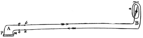
Fig. 2.
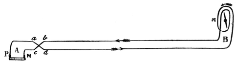
Fig. 3.
Now suppose that P and N, Fig. 2, are the positive and
negative poles of a galvanic battery at A, and that a wire passes
from P to the station B, where it is coiled round a needle
suspended vertically at n, and thence passes to the negative
pole N. Let the wire be interrupted at a b and also at c d.
Then no current passes along the wire, and the needle n
remains at rest in a vertical position. Now suppose the
points a b connected by the wire a b, and at the same moment
the points c d connected by the wire c d, then a current
flows along P a b to B, as shown in Fig. 2, circuiting the coil
round the needle n and returning by d c to N. The upper
end of the needle is deflected to the right while this current
continues to flow; returning to rest when the connection is
broken at a b and c d. Next, let c b and a d be simultaneously
connected as shown by the cross-lines in Fig. 3. (It
will be understood that a d and b c do not touch each other
where they cross.) The current will now flow from P along
a d to B, circuiting round the needle n in a contrary direction
to that in which it flowed in the former case, returning by
b c to N. The upper end of the needle is deflected then to
the left while the current continues to flow along this course.
I need not here describe the mechanical devices by
which the connection at a b and c d can be instantly changed
so that the current may flow either along a b and d c, as in
Fig. 2, circuiting the needle in one direction, or along a d
and b c, as in Fig. 3, circuiting the needle in the other direction.
As I said at the outset, this paper is not intended to
deal with details of construction, only to describe the general
principles of telegraphic communication, and especially those
points which have to be explained in order that recent inventions
may be understood. The reader will see that nothing
can be easier than so to arrange matters that, by turning a
handle, either (1), a b and c d may be connected, or, (2), a d
and c b, or, (3), both lines of communication interrupted.
The mechanism for effecting this is called a commutator.
Two points remain, however, to be explained: First, A
must be a receiving station as well as a transmitting station;
secondly, the wire connecting B with N, in Figs. 2 and 3, can
be dispensed with, for it is found that if at B the wire is
carried down to a large metal plate placed some depth
underground, while the wire at c is carried down to another
plate similarly buried underground, the circuit is completed
even better than along such a return wire as is shown in the
figures. The earth either acts the part of a return wire, or
else, by continually carrying off the electricity, allows the
current to flow continuously along the single wire. We
may compare the current carried along the complete wire
circuit, to water circulating in a pipe extending continuously
from a reservoir to a distance and back again to
the reservoir. Water sucked up continuously at one end
could be carried through the pipe so long as it was continuously
returned to the reservoir at the other; but it could
equally be carried through a pipe extending from that reservoir
to some place where it could communicate with the
open sea—the reservoir itself communicating with the open
sea—an arrangement corresponding to that by which the
return wire is dispensed with, and the current from the wire
received into the earth.
The discovery that the return wire may be dispensed
with was made by Steinheil in 1837.
The actual arrangement, then, is in essentials that represented
in Fig. 4.
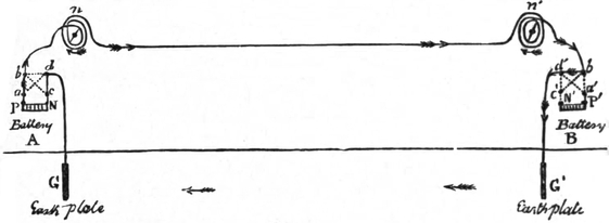
Fig. 4.
A and B are the two stations; P N is the battery at A, P´ N´
the battery at B; P´ P´ are the positive poles, N´ N´, the negative
poles. At n is the needle of station A, at n´ the needle of
station B. When the handle of the commutator is in its
mean position—which is supposed to be the case at station
B—the points b´ d´ are connected with each other, but
neither with a´ nor c´; no current, then, passes from B to A,
but station B is in a condition to receive messages. (If b´
and d´ were not connected, of course no messages could be
received, since the current from A would be stopped at b´—which
does not mean that it would pass round n´ to b´, but
that, the passage being stopped at b´, the current would not
flow at all.) When (the commutator at B being in its mean
position, or d´ b´ connected, and communication with c´ and
a´ interrupted) the handle of the commutator at A is turned
from its mean position in one direction, a and b are connected,
as are c and d—as shown in the figure—while the connection
between b and d is broken. Thus the current passes from P
by a and b, round the needle n; thence to station B, round
needle n´, and by b´ and d´, to the earth plate G´; and so
along the earth to G, and by d c, to the negative pole N.
The upper end of the needle of both stations is deflected to
the right by the passage of the current in this direction.
When the handle of the commutator at A is turned in the
other direction, b and c are connected, as also a and d; the
current from P passes along a d to the ground plate G, thence
to G´, along d´ b´, round the needle n´, back by the wire to
the station A, where, after circuiting the needle n in the same
direction as the needle n´, it travels by b and c to the negative
pole N. The upper end of the needle, at both stations,
is deflected to the left by the passage of the current in this
direction.
It is easily seen that, with two wires and one battery,
two needles can be worked at both stations, either one
moving alone, or the other alone, or both together; but for
the two to move differently, two batteries must be used.
The systems by which either the movements of a single
needle, or of a pair of needles, may be made to indicate the
various letters of the alphabet, numerals, and so on, need
not here be described. They are of course altogether
arbitrary, except only that the more frequent occurrence of
certain letters, as e, t, a, renders it desirable that these
should be represented by the simplest symbols (as by a
single deflection to right or left), while letters which occur
seldom may require several deflections.
One of the inventions to which the title of this paper
relates can now be understood.
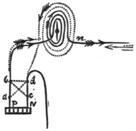
Fig. 5.
In the arrangement described, when a message is transmitted,
the needle of the sender vibrates synchronously with
the needle at the station to which the message is sent.
Therefore, till that message is finished, none can be received
at the transmitting station. In what is called duplex telegraphy,
this state of things is altered, the needle at the
sending station being left unaffected by the transmitted
current, so as to be able to receive messages, and in self-recording
systems to record them. This is done by dividing
the current from the battery into two parts of equal
efficiency, acting on the needle at the transmitting station in
contrary directions, so that this needle remains unaffected,
and ready to indicate signals from
the distant station. The principle
of this arrangement is indicated in
Fig. 5. Here a b n represents the
main wire of communication with
the distant station, coiled round
the needle of the transmitting
station in one direction; the dotted
lines indicate a finer short wire,
coiled round the needle in a contrary
direction. When a message
is transmitted, the current along the main wire tends to
deflect the needle at n in one direction, while the current
along the auxiliary wire tends to deflect it in the other
direction. If the thickness and length of the short wire are
such as to make these two tendencies equal, the needle
remains at rest, while a message is transmitted to the distant
station along the main wire. In this state of things, if a
current is sent from the distant station along the wire in the
direction indicated by the dotted arrow, this current also
circuits the auxiliary wire, but in the direction indicated by
the arrows on the dotted curve, which is the same direction
in which it circuits the main wire. Thus the needle is
deflected, and a signal received. When the direction of the
chief current at the transmitting station is reversed, so also
is the direction of the artificial current, so that again the
needle is balanced. Similarly, if the direction of the current
from the distant station is reversed, so also is the direction
in which this current traverses the auxiliary wire, so that
again both effects conspire to deflect the needle.
There is, however, another way in which an auxiliary wire
may be made to work. It may be so arranged that, when a
message is transmitted, the divided current flowing equally
in opposite directions, the instrument at the sending station
is not affected; but that when the operator at the distant
station sends a current along the main wire, this neutralizes
the current coming towards him, which current had before
balanced the artificial current. The latter, being no longer
counterbalanced, deflects the needle; so that, in point of
fact, by this arrangement, the signal received at a station is
produced by the artificial current at that station, though of
course the real cause of the signal is the transmission of the
neutralizing current from the distant station.
The great value of duplex telegraphy is manifest. Not
only can messages be sent simultaneously in both directions
along the wire—a circumstance which of itself would double
the work which the wire is capable of doing—but all loss
of time in arranging about the order of outward and homeward
messages is prevented. The saving of time is especially
important on long lines, and in submarine telegraphy.
It is also here that the chief difficulties of duplex telegraphy
have been encountered. The chief current and the artificial
current must exactly balance each other. For this purpose
the flow along each must be equal. In passing through
the long wire, the current has to encounter a greater resistance
than in traversing the short wire; to compensate
for this difference, the short wire must be much finer than
the long one. The longer the main wire, the more delicate
is the task of effecting an exact balance. But in the case
of submarine wires, another and a much more serious difficulty
has to be overcome. A land wire is well insulated.
A submarine wire is separated by but a relatively moderate
thickness of gutta-percha from water, an excellent conductor,
communicating directly with the earth, and is, moreover,
surrounded by a protecting sheathing of iron wires,
laid spirally round the core, within which lies the copper
conductor. Such a cable, as Faraday long since showed,
acts precisely as an enormous Leyden jar; or rather, Faraday
showed that such a cable, without the wire sheathing,
would act when submerged as a Leyden jar, the conducting
wire acting as the interior metallic coating of such a jar,
the gutta-percha as the glass of the jar (the insulating
medium), and the water acting as the exterior metallic
coating. Wheatstone showed further that such a cable,
with a wire sheathing, would act as a Leyden jar, even
though not submerged, the metal sheathing taking the part
of the exterior coating of the jar. Now, regarding the cable
thus as a condenser, we see that the transmission of a
current along it may in effect be compared with the passage
of a fluid along a pipe of considerable capacity, into which
and from which it is conveyed by pipes of small capacity.
There will be a retardation of the flow of water corresponding
to the time necessary to fill up the large part of the
pipe; the water may indeed begin to flow through as
quickly as though there were no enlargement of the bore of
the pipe, but the full flow from the further end will be
delayed. Just so it is with a current transmitted through a
submarine cable. The current travels instantly (or with the
velocity of freest electrical transmission) along the entire
line; but it does not attain a sufficient intensity to be
recognized for some time, nor its full intensity till a still
longer interval has elapsed. The more delicate the means
of recognizing its flow, the more quickly is the signal received.
The time intervals in question are not, indeed,
very great. With Thomson’s mirror galvanometer, in which
the slightest motion of the needle is indicated by a beam
of light (reflected from a small mirror moving with the
needle), the Atlantic cable conveys its signal from Valentia
to Newfoundland in about one second, while with the less
sensitive galvanometer before used the time would be rather
more than two seconds.
Now, in duplex telegraphy the artificial current must be
equal to the chief current in intensity all the time; so that,
since in submarine telegraphy the current rises gradually to
its full strength and as gradually subsides, the artificial
current must do the same. Reverting to the illustration
derived from the flow of water, if we had a small pipe the
rapid flow through which was to carry as much water one
way as the slow flow through a large pipe was to carry water
the other way, then if the large pipe had a widening along
one part of its long course the short pipe would require
to have a similar widening along the corresponding part of
its short course. And to make the illustration perfect, the
widenings along the large pipe should be unequal in different
parts of the pipe’s length; for the capacity of a submarine
cable, regarded as a condenser, is different along different
parts of its length. What is wanted, then, for a satisfactory
system of duplex telegraphy in the case of submarine cables,
is an artificial circuit which shall not only correspond as
a whole to the long circuit, but shall reproduce at the
corresponding parts of its own length all the varieties of
capacity existing along various parts of the length of the
submarine cable.
Several attempts have been made by electricians to
accomplish this result. Let it be noticed that two points
have to be considered: the intensity of the current’s action,
which depends on the resistance it has to overcome in
traversing the circuit; and the velocity of transmission, depending
on the capacity of various parts of the circuit to
condense or collect electricity. Varley, Stearn, and others
have endeavoured by various combinations of condensers
with resistance coils to meet these two requisites. But the
action of artificial circuits thus arranged was not sufficiently
uniform. Recently Mr. J. Muirhead, jun., has met the
difficulty in the following way (I follow partially the account
given in the Times of February 3, 1877, which the reader will
now have no difficulty in understanding):—He has formed
his second circuit by sheets of paper prepared with paraffin,
and having upon one side a strip of tinfoil, wound to and
fro to represent resistance. Through this the artificial
current is conducted. On the other side is a sheet of tinfoil
to represent the sheathing,29 and to correspond to the
capacity of the wire. Each sheet of paper thus prepared
may be made to represent precisely a given length of cable,
having enough tinfoil on one side to furnish the resistance,
and on the other to furnish the capacity. A sufficient
number of such sheets would exactly represent the cable,
and thus the artificial or non-signalling part of the current
would be precisely equivalent to the signalling part, so far
as its action on the needle at the transmitting station was
concerned. “The new plan was first tried on a working
scale,” says the Times, “on the line between Marseilles and
Bona; but it has since been brought into operation from
Marseilles to Malta, from Suez to Aden, and lastly, from
Aden to Bombay. On a recent occasion when there was
a break-down upon the Indo-European line, the duplex
system rendered essential service, and maintained telegraphic
communication which would otherwise have been most
seriously interfered with.” The invention, we may well
believe, “cannot fail to be highly profitable to the proprietors
of submarine cables,” or to bring about “before
long a material reduction in the cost of messages from
places beyond the seas.”
* * * * *
The next marvel of telegraphy to be described is the
transmission of actual facsimiles of writings or drawings. So
far as strict sequence of subject-matter is concerned, I ought,
perhaps, at this point, to show how duplex telegraphy has
been surpassed by a recent invention, enabling three or four
or more messages to be simultaneously transmitted telegraphically.
But it will be more convenient to consider this
wonderful advance after I have described the methods by
which facsimiles of handwriting, etc., are transmitted.
Hitherto we have considered the action of the electric
current in deflecting a magnetic needle to right or left, a
method of communication leaving no trace of its transmission.
We have now to consider a method at once simpler in
principle and affording means whereby a permanent record
can be left of each message transmitted.
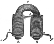
Fig. 6.
If the insulated wire is twisted in the form of a helix or
coil round a bar of soft iron, the
bar becomes magnetized while
the current is passing. If the
bar be bent into the horse-shoe
form, as in Fig. 6, where A C B
represents the bar, a b c d e f
the coil of insulated wire, the
bar acts as a magnet while the
current is passing along the coil,
but ceases to do so as soon as
the current is interrupted.30 If,
then, we have a telegraphic wire from a distant station in
electric connection with the wire a b c, the part e f descending
to an earth-plate, then, according as the operator at that
distant station transmits or stops the current, the iron A C B
is magnetized or demagnetized. The part C is commonly
replaced by a flat piece of iron, as is supposed to be the
case with the temporary magnets shown in Fig. 7, where this
flat piece is below the coils.
So far back as 1838 this property was applied by Morse
in America in the recording instrument which bears his
name, and is now (with slight modifications) in general use
not only in America but on the Continent. The principle
of this instrument is exceedingly simple. Its essential parts
are shown in Fig. 7; H is the handle, H b the lever of the
manipulator at the station A. The manipulator is shown in
the position for receiving a message from the station B along
the wire W. The handle H´ of the manipulator at the station
B is shown depressed, making connection at a´ with the wire
from the battery N´ P´. Thus a current passes through the
handle to c´, along the wire to c and through b to the coil of
the temporary magnet M, after circling which it passes to the
earth at e and so by E´ to the negative pole N´. The passage
of this current magnetizes M, which draws down the armature
m. Thus the lever l, pulled down on this side, presses upwards
the pointed style s against a strip of paper p which is
steadily rolled off from the wheel W so long as a message is
being received. (The mechanism for this purpose is not
indicated in Fig. 7.) Thus, so long as the operator at B
holds down the handle H´, the style s marks the moving
strip of paper, the spring r, under the lever s l, drawing the
style away so soon as the current ceases to flow and the
magnet to act. If he simply depresses the handle for an
instant, a dot is marked; if longer, a dash; and by various
combinations of dots and dashes all the letters, numerals, etc.,
are indicated. When the operator at B has completed his
message, the handle H´ being raised by the spring under it
(to the position in which H is shown), a message can be
received at B.
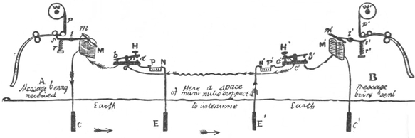
Fig. 7.
I have in the figure and description assumed that the
current from either station acts directly on the magnet
which works the recording style. Usually, in long-distance
telegraphy, the current is too weak for this, and the magnet
on which it acts is used only to complete the circuit of a
local battery, the current from which does the real work of
magnetizing M at A or M´ at B, as the case may be. A local
battery thus employed is called a relay.
The Morse instrument will serve to illustrate the principle
of the methods by which facsimiles are obtained. The
details of construction are altogether different from those
of the Morse instrument; they also vary greatly in different
instruments, and are too complex to be conveniently described
here. But the principle, which is the essential point,
can be readily understood.
In working the Morse instrument, the operator at B
depresses the handle H´. Suppose that this handle is kept
depressed by a spring, and that a long strip of paper passing
uniformly between the two points at a prevents contact.
Then no current can pass. But if there is a hole in this
paper, then when the hole reaches a the two metal points
at a meet and the current passes. We have here the
principle of the Bain telegraph. A long strip of paper is
punched with round and long holes, corresponding to the
dots and marks of a message by the Morse alphabet. As
it passes between a metal wheel and a spring, both forming
part of the circuit, it breaks the circuit until a hole allows
the spring to touch the wheel, either for a short or longer
time-interval, during which the current passes to the other
station, where it sets a relay at work. In Bain’s system
the message is received on a chemically prepared strip of
paper, moving uniformly at the receiving station, and connected
with the negative pole of the relay battery. When
contact is made, the face of the paper is touched by a
steel pointer connected with the positive pole, and the
current which passes from the end of the pointer through
the paper to the negative pole produces a blue mark on the
chemically prepared paper.31
We see that by Bain’s arrangement a paper is marked
with dots and lines, corresponding to round and elongated
holes, in a ribbon of paper. It is only a step from this to
the production of facsimiles of writings or drawings.
Suppose a sheet of paper so prepared as to be a conductor
of electricity, and that a message is written on the
paper with some non-conducting substance for ink. If that
sheet were passed between the knobs at a (the handle H
being pressed down by a spring), whilst simultaneously a
sheet of Bain’s chemically prepared paper were passed
athwart the steel pointer at the receiving station, there
would be traced across the last-named paper a blue line,
which would be broken at parts corresponding to those on
the other paper where the non-conducting ink interrupted
the current. Suppose the process repeated, each paper
being slightly shifted so that the line traced across either
would be parallel and very close to the former, but precisely
corresponding as respects the position of its length. Then
this line, also, on the recording paper will be broken at
parts corresponding to those in which the line across the
transmitting paper meets the writing. If line after line be
drawn in this way till the entire breadth of the transmitting
paper has been crossed by close parallel lines, the
entire breadth of the receiving paper will be covered by
closely marked blue lines except where the writing has
broken the contact. Thus a negative facsimile of the
writing will be found in the manner indicated in Figs. 8
and 9.32 In reality, in processes of this kind, the papers
(unlike the ribbons on Bain’s telegraph) are not carried
across in the way I have imagined, but are swept by
successive strokes of a movable pointer, along which the
current flows; but the principle is the same.
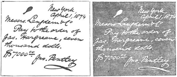
Fig. 8.
Fig. 9.
It is essential, in such a process as I have described,
first, that the recording sheet should be carried athwart the
pointer which conveys the marking current (or the pointer
carried across the recording sheet) in precise accordance
with the motion of the transmitting sheet athwart the wire
or style which conveys the current to the long wire between
the stations (or of this style across the transmitting sheet).
The recording sheet and the transmitting sheet must also
be shifted between each stroke by an equal amount. The
latter point, is easily secured; the former is secured by
causing the mechanism which gives the transmitting style
its successive strokes to make and break circuit, by which
a temporary magnet at the receiving station is magnetized
and demagnetized; by the action of this magnet the recording
pointer is caused to start on its motion athwart the
receiving sheet, and moving uniformly it completes its
thwart stroke at the same instant as the transmitting style.
Caselli’s pantelegraph admirably effects the transmission
of facsimiles. The transmitting style is carried by the
motion of a heavy pendulum in an arc of constant range
over a cylindrical surface on which the paper containing the
message, writing, or picture, is spread. As the swing of the
pendulum begins, a similar pendulum at the receiving station
begins its swing; the same break of circuit which (by demagnetizing
a temporary magnet) releases one, releases the
other also. The latter swings in an arc of precisely the
same range, and carries a precisely similar style over a
similar cylindrical surface on which is placed the prepared
receiving paper. In fact, the same pendulum at either
station is used for transmitting and for receiving facsimiles.
Nay, not only so, but each pendulum, as it swings, serves in
the work both of transmitting and recording facsimiles. As
it swings one way, it travels along a line over each of two
messages or drawings, while the other pendulum in its
synchronous swing traces a corresponding line over each of
two receiving sheets; and as it swings the other way, it
traces a line on each of two receiving sheets, corresponding
to the lines along which the transmitting style of the other
is passing along two messages or drawings. Such, at least,
is the way in which the instrument works in busy times. It
can, of course, send a message, or two messages, without
receiving any.33
In Caselli’s pantelegraph matters are so arranged that
instead of a negative facsimile, like Fig. 9, a true facsimile is
obtained in all respects except that the letters and figures
are made by closely set dark lines instead of being dark
throughout as in the message. The transmitting paper is
conducting and the ink non-conducting, as in Bakewell’s
original arrangement; but instead of the conducting paper
completing the circuit for the distant station, it completes a
short home circuit (so to speak) along which the current
travels without entering on the distant circuit When the
non-conducting ink breaks the short circuit, the current
travels in the long circuit through the recording pointer at
the receiving station; and a mark is thus made corresponding
to the inked part of the transmitting sheet instead of the
blank part, as in the older plan.
The following passage from Guillemin’s “Application
of the Physical Forces” indicates the effectiveness of
Caselli’s pantelegraph not only as respects the character of
the message it conveys, but as to rapidity of transmission.
(I alter the measures from the metric to our usual system of
notation.34) “Nothing is simpler than the writing of the
pantelegraph. The message when written is placed on the
surface of the transmitting cylinder. The clerk makes the
warning signals, and then sets the pendulum going. The
transmission of the message is accomplished automatically,
without the clerk having any work to do, and consequently
without [his] being obliged to acquire any special knowledge.
Since two despatches may be sent at the same time—and
since shorthand may be used—the rapidity of transmission
may be considerable.” “The long pendulum of Caselli’s
telegraph,” says M. Quet, “generally performs about forty
oscillations a minute, and the styles trace forty broken lines,
separated from each other by less than the hundredth part
of an inch. In one minute the lines described by the style
have ranged over a breadth of more than half an inch, and
in twenty minutes of nearly 10½ inches. As we can give the
lines a length of 4¼ inches, it follows that in twenty minutes
Caselli’s apparatus furnishes the facsimile of the writing or
drawing traced on a metallized plate 4¼ inches broad by 10½
inches long. For clearness of reproduction, the original
writing must be very legible and in large characters.”
“Since 1865 the line from Paris to Lyons and Marseilles has
been open to the public for the transmission of messages by
this truly marvellous system.”
It will easily be seen that Caselli’s method is capable of
many important uses besides the transmission of facsimiles
of handwriting. For instance, by means of it a portrait of
some person who is to be identified—whether fraudulent
absconder, or escaped prisoner or lunatic, or wife who has
eloped from her husband, or husband who has deserted his
wife, or missing child, and so on—can be sent in a few
minutes to a distant city where the missing person is likely
to be. All that is necessary is that from a photograph or
other portrait an artist employed for the purpose at the
transmitting station should, in bold and heavy lines, sketch
the lineaments of the missing person on one of the prepared
sheets, as in Fig. 10. The portrait at the receiving station
will appear as in Fig. 11, and if necessary an artist at this
station can darken the lines or in other ways improve the
picture without altering the likeness.
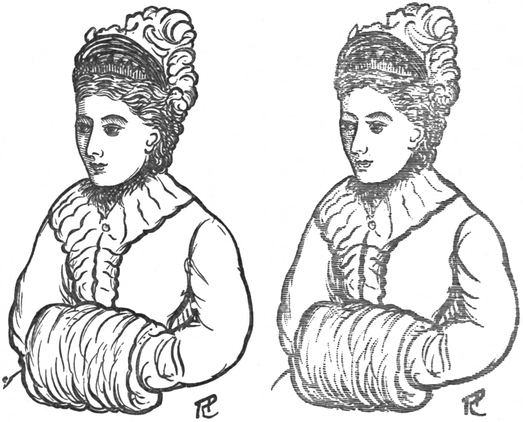
Fig. 10.
Fig. 11.
But now we must turn to the greatest marvel of all—the
transmission of tones, tunes, and words by the electric wire.
The transmission of the rhythm of an air is of course a
very simple matter. I have seen the following passage from
“Lardner’s Museum of Science and Art,” 1859, quoted as
describing an anticipation of the telephone, though in reality
it only shows what every one who has heard a telegraphic
indicator at work must have noticed, that the click of the
instrument may be made to keep time with an air. “We
were in the Hanover Street Office, when there was a pause
in the business operations. Mr. M. Porter, of the office at
Boston—the writer being at New York—asked what tune
we would have? We replied, ‘Yankee Doodle,’ and to our
surprise he immediately complied with our request. The
instrument, a Morse one, commenced drumming the notes
of the tune as perfectly and distinctly as a skilful drummer
could have made them at the head of a regiment, and many
will be astonished to hear that ‘Yankee Doodle’ can travel
by lightning.... So perfectly and distinctly were the
sounds of the tunes transmitted, that good instrumental
performers could have no difficulty in keeping time with the
instruments at this end of the wires.... That a pianist
in London should execute a fantasia at Paris, Brussels,
Berlin, and Vienna, at the same moment, and with the same
spirit, expression, and precision as if the instruments at these
distant places were under his fingers, is not only within the
limits of practicability, but really presents no other difficulty
than may arise from the expense of the performances. From
what has just been stated, it is clear that the time of music
has been already transmitted, and the production of the
sounds does not offer any more difficulty than the printing
of the letters of a despatch.” Unfortunately, Lardner
omitted to describe how this easy task was to be achieved.
Reuss first in 1861 showed how a sound can be transmitted.
At the sending station, according to his method,
there is a box, into which, through a pipe in the side, the
note to be transmitted is sounded. The box is open at the
top, and across it, near the top, is stretched a membrane
which vibrates synchronously with the aerial vibrations corresponding
to the note. At the middle of the membrane,
on its upper surface, is a small disc of metal, connected by
a thin strip of copper with the positive pole of the battery at
the transmitting station. The disc also, when the machine
is about to be put in use, lightly touches a point on a metallic
arm, along which (while this contact continues) the electric
current passes to the wire communicating with the distant
station. At that station the wire is carried in a coil round
a straight rod of soft iron suspended horizontally in such a
way as to be free to vibrate between two sounding-boards.
After forming this coil, the wire which conveys the current
passes to the earth-plate and so home. As already explained,
while the current passes, the rod of iron is magnetized, but
the rod loses its magnetization when the current ceases.
Now, when a note is sounded in the box at the transmitting
station, the membrane vibrates, and at each vibration
the metal disc is separated from the point which it lightly
touches when at rest. Thus contact is broken at regular
intervals, corresponding to the rate of vibration due to the
note. Suppose, for instance, the note C is sounded; then
there are 256 complete vibrations in a second, the electric
current is therefore interrupted and renewed, and the bar of
soft iron magnetized and demagnetized, 256 times in a second.
Now, it had been discovered by Page and Henry that when
a bar of iron is rapidly magnetized and demagnetized, it is
put into vibrations synchronizing with the interruptions of
the current, and therefore emits a note of the same tone as
that which has been sounded into the transmitting box.
Professor Heisler, in his “Lehrbuch der technischen
Physik,” 1866, wrote of Reuss’s telephone: “The instrument
is still in its infancy; however, by the use of batteries of proper
strength, it already transmits not only single musical tones,
but even the most intricate melodies, sung at one end of the
line, to the other, situated at a great distance, and makes
them perceptible there with all desirable distinctness.” Dr.
Van der Weyde, of New York, states that, after reading an
account of Reuss’s telephone, he had two such instruments
constructed, and exhibited them at the meeting of the Polytechnic
Club of the American Institute. “The original
sounds were produced at the furthest extremity of the large
building (the Cooper Institute), totally out of hearing of the
Association; and the receiving instrument, standing on the
table in the lecture-room, produced, with a peculiar and
rather nasal twang, the different tunes sung into the box at
the other end of the line; not powerfully, it is true, but very
distinctly and correctly. In the succeeding summer I
improved the form of the box, so as to produce a more
powerful vibration of the membrane. I also improved the
receiving instrument by introducing several iron wires into
the coil, so as to produce a stronger vibration. I submitted
these, with some other improvements, to the meeting of the
American Association for the Advancement of Science, and
on that occasion (now seven years ago) expressed the opinion
that the instrument contained the germ of a new method of
working the electric telegraph, and would undoubtedly lead
to further improvements in this branch of science.”
The telephonic successes recently achieved by Mr. Gray
were in part anticipated by La Cour, of Copenhagen, whose
method may be thus described: At the transmitting station
a tuning-fork is set in vibration. At each vibration one of
the prongs touches a fine strip of metal completing a circuit.
At the receiving station the wire conveying the electric current
is coiled round the prongs of another tuning-fork of the
same tone, but without touching them. The intermittent
current, corresponding as it does with the rate of vibration
proper to the receiving fork, sets this fork in vibration; and
in La Cour’s instrument the vibrations of the receiving fork
were used to complete the circuit of a local battery. His
object was not so much the production of tones as the use
of the vibrations corresponding to different tones, to act on
different receiving instruments. For only a fork corresponding
to the sending fork could be set in vibration by the
intermittent current resulting from the latter’s vibrations.
So that, if there were several transmitting forks, each could
send its own message at the same time, each receiving fork
responding only to the vibrations of the corresponding transmitting
fork. La Cour proposed, in fact, that his instrument
should be used in combination with other methods of telegraphic
communication. Thus, since the transmitting fork,
whenever put in vibration, sets the local battery of the
receiving station at work, it can be used to work a Morse
instrument, or it could work an ordinary Wheatstone and
Cook instrument, or it could be used for a pantelegraph.
The same wire, when different forks are used, could work
simultaneously several instruments at the receiving station.
One special use indicated by La Cour was the adaptation of
his system to the Caselli pantelegraph, whereby, instead of
one style, a comb of styles might be carried over the transmitting
and recording plates. It would be necessary, in all
such applications of his method (though, strangely enough,
La Cour’s description makes no mention of the point), that
the vibrations of the transmitting fork should admit of being
instantly stopped or “damped.”
Mr. Gray’s system is more directly telephonic, as aiming
rather at the development of sound itself than at the transmission
of messages by the vibrations corresponding to
sound. A series of tuning-forks are used, which are set in
separate vibration by fingering the notes of a key-board.
The vibrations are transmitted to a receiving instrument
consisting of a series of reeds, corresponding in note to the
series of transmitting forks, each reed being enclosed in a
sounding-box. These boxes vary in length from two feet to
six inches, and are connected by two wooden bars, one of
which carries an electro-magnet, round the coils of which
pass the currents from the transmitting instrument. When
a tuning-fork is set in vibration by the performer at the
transmitting key-board, the electro-magnet is magnetized
and demagnetized synchronously with the vibrations of the
fork. Not only are vibrations thus imparted to the reed of
corresponding note, but these are synchronously strengthened
by thuds resulting from the lengthening of the iron when
magnetized.
So far as its musical capabilities are concerned, Gray’s
telephone can hardly be regarded as fulfilling all the hopes
that have been expressed concerning telephonic music.
“Dreaming enthusiasts of a prophetic turn of mind foretold,”
we learn, “that a time would come when future Pattis
would sing on a London stage to audiences in New York,
Berlin, St. Petersburg, Shanghai, San Francisco, and Constantinople
all at once.” But the account of the first concert
given at a distance scarcely realizes these fond expectations.
When “Home, Sweet Home,” played at Philadelphia, came
floating through the air at the Steinway Hall, New York,
“the sound was like that of a distant organ, rather faint, for
a hard storm was in progress, and there was consequently a
great leakage of the electric current, but quite clear and
musical. The lower notes were the best, the higher being
sometimes almost inaudible. ‘The Last Rose of Summer,’
‘Com’ è gentil,’ and other melodies, followed, with more or
less success. There was no attempt to play chords,” though
three or four notes can be sounded together. It must be
confessed that the rosy predictions of M. Strakosch (the
impresario) “as to the future of this instrument seem rather
exalted, and we are not likely as yet to lay on our music
from a central reservoir as we lay on gas and water, though
the experiment was certainly a very curious one.”
The importance of Mr. Gray’s, as of La Cour’s inventions,
depends, however, far more on the way in which they
increase the message-bearing capacity of telegraphy than on
their power of conveying airs to a distance. At the Philadelphia
Exhibition, Sir W. Thomson heard four messages
sounded simultaneously by the Gray telephone. The Morse
alphabet was used. I have mentioned that in that alphabet
various combinations of dots and dashes are used to represent
different letters; it is only necessary to substitute the
short and long duration of a note for dots and dashes to have a
similar sound alphabet. Suppose, now, four tuning-forks at
the transmitting station, whose notes are Do  , Mi,
Sol, and Do
 , or say C, E, G, and C´, then by each
of these forks a separate message may be transmitted, all the
messages being carried simultaneously by the same line to
separate sounding reeds (or forks, if preferred), and received
by different clerks. With a suitable key-board, a single
clerk could send the four messages simultaneously, striking
chords instead of single notes, though considerable practice
would be necessary to transform four verbal messages at
once into the proper telephonic music, and some skill in
fingering to give the proper duration to each note.
Lastly, we come to the greatest achievement of all, Professor
Graham Bell’s vocal telephone. In the autumn of
1875 I had the pleasure of hearing from Professor Bell in the
course of a ride—all too short—from Boston to Salem, Mass.,
an account of his instrument as then devised, and of his
hopes as to future developments. These hopes have since
been in great part fulfilled, but I venture to predict that we
do not yet know all, or nearly all, that the vocal telephone,
in Bell’s hands, is to achieve.
It ought to be mentioned at the outset that Bell claims
to have demonstrated in 1873 (a year before La Cour) the
possibility of transmitting several messages simultaneously
by means of the Morse alphabet.
Bell’s original arrangement for vocal telephony was as
follows:—At one station a drumhead of goldbeaters’ skin,
about 2¾ inches in diameter, was placed in front of an
electro-magnet. To the middle of the drumhead, on the
side towards the magnet, was glued a circular piece of clockspring.
A similar electro-magnet, drumhead, etc., were
placed at the other station. When notes were sung or
words spoken before one drumhead, the vibrations of the
goldbeaters’ skin carried the small piece of clockspring
vibratingly towards and from the electro-magnet, without
producing actual contact. Now, the current which was
passing along the coil round the electro-magnet changed in
strength with each change of position of this small piece of
metal. The more rapid the vibrations, and the greater
their amplitude, the more rapid and the more intense were
the changes in the power of the electric current. Thus, the
electro-magnet at the other station underwent changes of
power which were synchronous with, and proportionate to,
those changes of power in the current which were produced
by the changes of position of the vibrating piece of clockspring.
Accordingly, the piece of clockspring at the receiving
station, and with it the drumhead there, was caused by
the electro-magnet to vibrate with the same rapidity and
energy as the piece at the transmitting station. Therefore,
as the drumhead at one station varied its vibrations in response
to the sounds uttered in its neighbourhood, so the
drumhead at the other station, varying its vibrations, emitted
similar sounds. Later, the receiving drumhead was made
unlike the transmitting one. Instead of a membrane carrying
a small piece of metal, a thin and very flexible disc of
sheet-iron, held in position by a screw, was used. This disc,
set in vibration by the varying action of an electro-magnet,
as in the older arrangement, uttered articulate sounds corresponding
to those which, setting in motion the membrane
at the transmitting station, caused the changes in the power
of the electric current and in the action of the electro-magnet.
At the meeting of the British Association in 1876
Sir W. Thomson gave the following account of the performance
of this instrument at the Philadelphia Exhibition:—“In
the Canadian department” (for Professor Bell was not at
the time an American citizen) “I heard ‘To be or not to be—there’s
the rub,’ through the electric wire; but, scorning
monosyllables, the electric articulation rose to higher flights,
and gave me passages taken at random from the New York
newspapers:—‘S. S. Cox has arrived’ (I failed to make out
the ‘S. S. Cox’), ‘the City of New York,’ ‘Senator Morton,’
‘the Senate has resolved to print a thousand extra copies,’
‘the Americans in London have resolved to celebrate the
coming Fourth of July.’ All this my own ears heard spoken
to me with unmistakable distinctness by the thin circular
disc armature of just such another little electro-magnet as
this which I hold in my hand. The words were shouted
with a clear and loud voice by my colleague judge, Professor
Watson, at the far end of the line, holding his mouth close
to a stretched membrane, carrying a piece of soft iron, which
was thus made to perform in the neighbourhood of an
electro-magnet, in circuit with the line, motions proportional
to the sonorific motions of the air. This, the greatest by
far of all the marvels of the electric telegraph, is due to a
young countryman of our own, Mr. Graham Bell, of Edinburgh,
and Montreal, and Boston, now about to become a
naturalized citizen of the United States. Who can but
admire the hardihood of invention which devised such very
slight means to realize the mathematical conception that, if
electricity is to convey all the delicacies of quality which
distinguish articulate speech, the strength of its current must
vary continuously, and as nearly as may be in simple proportion
to the velocity of a particle of air engaged in constituting
the sound?”
Since these words were spoken by one of the highest
authorities in matters telegraphic, Professor Bell has introduced
some important modifications in his apparatus. He
now employs, not an electro-magnet, but a permanent
magnet. That is to say, instead of using at each station
such a bar of soft iron as is shown in Fig. 6, which becomes
a magnet while the electric current is passing through the
coil surrounding it, he uses at each station a bar of iron
permanently magnetized (or preferably a powerful magnet
made of several horse-shoe bars—that is, a compound
magnet), surrounded similarly by coils of wire. No battery
is needed. Instead of a current through the coils magnetizing
the iron, the iron already magnetized causes a current
to traverse the coils whenever it acts, or rather whenever its
action changes. If an armature were placed across its ends
or poles, at the moment when it drew that armature to the
poles by virtue of its magnetic power, a current would
traverse the coils; but afterwards, so long as the armature
remained there, there would be no current. If an armature
placed near the poles were shifted rapidly in front of the
poles, currents would traverse the coils, or be induced, their
intensity depending on the strength of the magnet, the length
of the coil, and the rapidity and range of the motions. In
front of the poles of the magnet is a diaphragm of very
flexible iron (or else some other flexible material bearing a
small piece of iron on the surface nearest the poles). A
mouthpiece to converge the sound upon this diaphragm
substantially completes the apparatus at each station. Professor
Bell thus describes the operation of the instrument:—“The
motion of steel or iron in front of the poles of a
magnet creates a current of electricity in coils surrounding
the poles of the magnet, and the duration of this current of
electricity coincides with the duration of the motion of the
steel or iron moved or vibrated in the proximity of the
magnet. When the human voice causes the diaphragm to
vibrate, electrical undulations are induced in the coils around
the magnets precisely similar to the undulations of the air
produced by the voice. The coils are connected with the
line wire, and the undulations induced in them travel through
the wire, and, passing through the coils of another instrument
of similar construction at the other end of the line, are
again resolved into air undulations by the diaphragm of this
(other) instrument.”
So perfectly are the sound undulations repeated—though
the instrument has not yet assumed its final form—that not
only has the lightest whisper uttered at one end of a line of
140 miles been distinctly heard at the other, but the speaker
can be distinguished by his voice when he is known to the
listener. So far as can be seen, there is every room to
believe that before long Professor Bell’s grand invention will
be perfected to such a degree that words uttered on the
American side of the Atlantic will be heard distinctly after
traversing 2000 miles under the Atlantic, at the European
end of the submarine cable—so that Sir W. Thomson
at Valentia could tell by the voice whether Graham Bell,
or Cyrus Field, or his late colleague Professor Watson,
were speaking to him from Newfoundland. Yet a single
wave of those which toss in millions on the Atlantic, rolling
in on the Irish strand, would utterly drown the voices
thus made audible after passing beneath two thousand
miles of ocean.
Here surely is the greatest of telegraphic achievements.
Of all the marvels of telegraphy—and they are many—none
are equal to, none seem even comparable with, this one.
Strange truly is the history of the progress of research
which has culminated in this noble triumph, wonderful the
thought that from the study of the convulsive twitchings of
a dead frog by Galvani, and of the quivering of delicately
poised magnetic needles by Ampère, should gradually have
arisen through successive developments a system of communication
so perfect and so wonderful as telegraphy has
already become, and promising yet greater marvels in the
future.
The last paragraph had barely been written when news
arrived of another form of telephone, surpassing Gray’s and
La Cour’s in some respects as a conveyor of musical tones,
but as yet unable to speak like Bell’s. It is the invention
of Mr. Edison, an American electrician. He calls it the
motograph. He discovered about six years ago the curious
property on which the construction of the instrument
depends. If a piece of paper moistened with certain
chemical solutions is laid upon a metallic plate connected
with the positive pole of a galvanic battery, and a platinum
wire connected with the negative pole is dragged over the
moistened paper, the wire slides over the paper like smooth
iron over ice—the usual friction disappearing so long as
the current is passing from the wire to the plate through
the paper. At the receiving station of Mr. Edison’s motograph
there is a resonating box, from one face of which
extends a spring bearing a platinum point, which is pressed
by the spring upon a tape of chemically prepared paper.
This tape is steadily unwound, drawing by its friction the
platinum point, and with it the face of the resonator, outwards.
This slight strain on the face of the resonator
continues so long as no current passes from the platinum
point to the metallic drum over which the moistened tape
is rolling. But so soon as a current passes, the friction
immediately ceases, and the face of the resonator resumes
its normal position. If then at the transmitting station
there is a membrane or a very fine diaphragm (as in
Reuss’s or Bell’s arrangement) which is set vibrating by
a note of any given tone, the current, as in those arrangements,
is transmitted and stopped at intervals corresponding
to the tone, and the face of the resonating box is freed
and pulled at the same intervals. Hence, it speaks the
corresponding tone. The instrument appears to have the
advantage over Gray’s in range. In telegraphic communication
Gray’s telephone is limited to about one octave.
Edison’s extends from the deepest bass notes to the highest
notes of the human voice, which, when magnets are employed,
are almost inaudible. But Edison’s motograph has
yet to learn to speak.
Other telegraphic marvels might well find a place here.
I might speak of the wonders of submarine telegraphy,
and of the marvellous delicacy of the arrangements by
which messages by the Atlantic Cable are read, and not
only read, but made to record themselves. I might dwell,
again, on the ingenious printing telegraph of Mr. Hughes,
which sets up its own types, inks them, and prints them, or
on the still more elaborate plan of the Chevalier Bonelli
“for converting the telegraph stations into so many type-setting
workshops.” But space would altogether fail me
to deal properly with these and kindred marvels. There
is, however, one application of telegraphy, especially interesting
to the astronomer, about which I must say a few words:
I mean, the employment of electricity as a regulator of time.
Here again it is the principle of the system, rather than
details of construction, which I propose to describe. Suppose
we have a clock not only of excellent construction,
but under astronomical surveillance, so that when it is a
second or so in error it is set right again by the stars. Let
the pendulum of this clock beat seconds; and at each beat
let a galvanic current be made and broken. This may be
done in many ways—thus the pendulum may at each swing
tilt up a very light metallic hammer, which forms part of
the circuit when down; or the end of the pendulum may
be covered with some non-conducting substance which
comes at each swing between two metallic springs in very
light contact, separating them and so breaking circuit; or
in many other ways the circuit may be broken. When the
circuit is made, let the current travel along a wire which
passes through a number of stations near or remote, traversing
at each the coils of a temporary magnet. Then, at
each swing of the pendulum of the regulating clock, each
magnet is magnetized and demagnetized. Thus each, once
in a second, draws to itself, and then releases its armature,
which is thereupon pulled back by a spring. Let the armature,
when drawn to the magnet, move a lever by which
one tooth of a wheel is carried forward. Then the wheel
is turned at the rate of one tooth per second. This wheel
communicates motion to others in the usual way. In fact,
we have at each station a clock driven, not by a weight
or spring and with a pendulum which allows one tooth of
an escapement wheel to pass at each swing, but by the
distant regulating clock which turns a driving wheel at the
rate of one tooth per second, that is, one tooth for each
swing of the regulating clock’s pendulum. Each clock,
then, keeps perfect time with the regulating clock. In
astronomy, where it is often of the utmost importance to
secure perfect synchronism of observation, or the power of
noting the exact difference of time between observations
made at distant stations, not only can the same clock thus
keep time for two observers hundreds of miles apart, but
each observer can record by the same arrangement the
moment of the occurrence of some phenomenon. For if
a tape be unwound automatically, as in the Morse instrument,
it is easy so to arrange matters that every second’s
beat of the pendulum records itself by a dot or short line
on the tape, and that the observer can with a touch make
(or break) contact at the instant of observation, and so a
mark be made properly placed between two seconds’ marks—thus
giving the precise time when the observation was
made. Such applications, however, though exceedingly
interesting to astronomers, are not among those in which
the general public take chief interest. There was one
occasion, however, when astronomical time-relations were
connected in the most interesting manner with one of the
greatest of all the marvels of telegraphy: I mean, when
the Great Eastern in mid-ocean was supplied regularly
with Greenwich time, and this so perfectly (and therefore
with such perfect indication of her place in the Atlantic),
that when it was calculated from the time-signals that the
buoy left in open ocean to mark the place of the cut cable
had been reached, and the captain was coming on deck
with several officers to look for it, the buoy announced its
presence by thumping the side of the great ship.