LIGHT
352. A Comparison of Sound and Light.—Light from
the standpoint of physics is considered much as is sound,
as a mode of motion; one affecting the ear, the other producing
the result called vision. There are other differences
also worth considering. (a) While sound travels
as vibrations of some material medium, light travels only
as vibrations of the ether; solids, liquids, and gases act so
as to hinder rather than to assist in its movement. That
is, light travels best in a vacuum or in a space devoid of
ordinary matter. (b) The speed of light is so great that
at ordinary distances on the earth its motion is practically
instantaneous. Experiments have shown that its speed
is about 186,000 miles to 300,000 kilometers a second.
353. Luminous and Illuminated Bodies.—If we consider
the objects within a room, some of them, as books and
furniture, would be invisible if all light from external
sources were excluded. On the other hand, some other
objects, such as a lighted lamp, a burning coal, or a red
hot iron, would be seen if no outside light were present.
Such bodies are said to be luminous. Most luminous
bodies are hot and become non-luminous on cooling.
There are, however, some bodies that are luminous at
ordinary room temperatures, as the firefly and some phosphorescent
paints. When light emitted by a luminous
body strikes an object, a portion of it is always reflected.
It is this reflected light that makes the illuminated object
visible. If the object is a sheet of glass, some of the light
is transmitted. If a substance is so clear that objects can
be seen through it, the substance is transparent, but if objects
cannot be seen through it, the substance is said to be
translucent. Objects transmitting no light are opaque.
Some of the light falling upon a body is neither reflected
nor transmitted, but is absorbed and tends to warm
the body. The light falling upon
a body is therefore either reflected,
transmitted, or absorbed. Thus Fig.
345 represents light coming from
S to a piece of glass GL. A portion
of the light represented by R
is reflected. Another part A is
absorbed and disappears, while
still another part T is transmitted
and passes on.
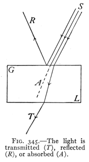 Fig. 345.—The light is
transmitted (T), reflected
(R), or absorbed (A).
Fig. 345.—The light is
transmitted (T), reflected
(R), or absorbed (A).
There is no sharply drawn line
between transparent and opaque
bodies. Very thin sheets of gold
transmit a greenish light, and experiments
have shown that substances
as transparent as clear
water absorb enough light so that at considerable depths
in an ocean or lake little or no light is ever found. All
light whether from luminous bodies or reflected from non-luminous
objects shows certain properties which will now
be considered.
354. The Rectilinear Propagation of Light.—If a beam
of light passes through a hole in a window shade into a
darkened room, it is seen to follow a perfectly straight
course. If a person while coughing holds a book before
the face, the sound passes around the book and is heard
at any point in the room while the face is hidden by the
book. In other words, light ordinarily does not pass
around corners as sound does, but travels in straight lines.
This fact is made use of when one aims a gun or merely
looks at an object. So well established in our minds is the
idea that an object is in the direction from which we see the
light coming to us from it, that we are sometimes deceived
as to the real position of an object, when the course of the
light from it has been changed by a mirror or some other
reflecting surface. Many illusions are produced in this
way, of which the mirage of the desert is one example.
(See Art. 381.)
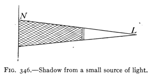 Fig. 346.—Shadow from a small source of light.
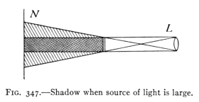 Fig. 347.—Shadow when source of light is large.
355. Shadows.—A shadow is the space from which light
is cut off by an opaque body. Thus if a book (see Fig. 346)
is held between a screen, N, and a small source of light, L,
a shadow is produced which extends from the book to the
screen. Notice that the shadow is a space and not an
area. If a large gas flame (see Fig. 347) is used as the
source of light, the shadow of the book is no longer clear
cut at the edges as before, but has a darker central part
with a lighter fringe of partial shadow at the edges. The
dark portion within the shadow has all the light excluded
from it and is called the umbra. The lighter portion of
the shadow at the edges has only a part of the light from
the flame cut off. This portion is called the penumbra.
when one stands in sunlight his shadow extends from his
body to the ground or object on which the shadow falls.
At night we are in the earth's shadow, which extends out
into space beyond the earth.
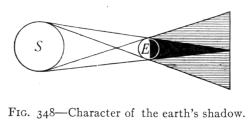 Fig. 348.—Character of the earth's shadow.
356. Eclipses.—Since the sun is a very large object the
shadow cast by the earth contains both umbra and penumbra.
(See Fig. 348.) When the moon passes into the
shadow of the earth, there is said to be an eclipse of the
moon, while if the moon's shadow falls upon the earth,
the portion of the earth cut off from the sun's light has
an eclipse of the sun.
357. Images by Small Apertures.—The straight line
movement of light makes possible the pin-hole camera,
by which satisfactory photographs have been made.
The action of this device may be illustrated by placing
a luminous body, a lighted candle, an incandescent lamp,
or a gas flame, in front of a piece of cardboard, S, which
has a small opening in it. Light from the object (see Fig.
349) falls upon a screen, S2, so as to produce an inverted
image. Other applications of this principle will be given
later.
In Fig. 349 let PQ represent a gas flame, then light from point
P at the top of the flame will pass in a straight line through the opening
or aperture of the cardboard and strike at P2 at the bottom of
the illuminated spot upon the screen. Light from Q passing in
straight lines through the aperture will strike at Q2 at the top of
the lighted space. This spot of light will have the same outlines
as the luminous body PQ and being formed as just described will
be inverted.
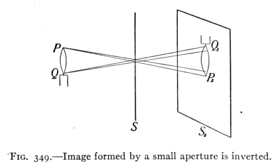 Fig. 349.—Image formed by a small aperture is inverted.
This spot of light, resembling in its outlines the flame,
is called an image. An image is defined as an optical
counterpart of an object. Images are formed in a variety
of devices, such as apertures, mirrors, and lenses. The pin-hole
camera is simply a light-tight box with a small aperture
in one side. Light passing through this aperture
forms an image upon the opposite side of the interior of
the box, of whatever object is in front of the camera.
Light entering a room through a large aperture such as a
window produces a multitude of overlapping images which
blend to form a somewhat evenly illuminated surface.
1. Light contrasted with sound (three differences).
2. Bodies: transparent, translucent, opaque.
3. Light: reflected, transmitted, absorbed.
4. Light travels in straight lines, evidence, shadows, umbra,
penumbra.
5. Formation of images by small apertures.
1. Consider the circumference of the earth as 25,000 miles. How
many times would the speed of light cover this distance in a
second?
2. How soon after any great disturbance takes place on the sun,
93,000,000 miles distant, can it be seen upon the earth?
3. Construct a diagram of the moon's shadow. How much of the
sun can one see when in the moon's umbra? When in its
penumbra? Have you ever been in either? When? Have
you ever been in the earth's umbra? In its penumbra?
4. Explain, using a diagram, the formation of an inverted image by
a small aperture.
5. If the sun is 45 degrees above the horizon, what is the height
of a pole casting a shadow 60 ft. long?
6. If a shadow 6 ft. long is cast by a 10-ft. pole standing vertically
upon a walk, how tall is the tree whose shadow is 42 ft. long,
both measurements being made at the same time?
7. Why are the shadows caused by an electric arc lamp so sharply
defined?
8. Why should schoolroom windows be all on one side and reach
to the ceiling?
9. What is the relation between the size of an image and its distance
from the aperture forming it? Can you prove this by
geometry?
10. What are silhouettes and how are they produced?
358. Photometry.—It is desirable at times to compare
the intensities of illumination produced by light from
different sources. This is done to determine the relative
cost or effectiveness of various illuminants such as candles,
kerosene and gas lamps, and electric lights The process
of determining the relative intensity of lights or lamps is
called photometry. (Photos = light.)
The unit for measuring the power of light is called a
candle power. It is the light produced by a sperm candle
burning 120 grains per hour. An ordinary gas light burns
5 or more cubic feet of gas per hour and yields from 15
to 25 candle power. A Welsbach gas lamp, consuming
3 cu. ft. per hour, produces 50 to 100 candle power.
Instead of using candles, for practical photometry,
incandescent lamps standardized by the Bureau of Standards
are used for testing or calibration purposes.
It is necessary to distinguish between the intensity of a
luminous body, i.e., as a source of light, and the intensity
of illumination upon some surface produced by a light. It
is considered that two sources of light are of equal intensity
if they produce equal illumination at equal distances.
359. Law of Intensity of Light.—A device for measuring
the candle power of a light is called a photometer. Its use
is based upon the law of intensity of light. The intensity of
illumination of a surface is inversely proportional to the
square of its distance from the source of light. This relation
is similar to that existing between the intensity of a sound
and the distance from its source. The following device
illustrates the truth of this law in a simple manner.
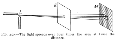 Fig. 350.—The light spreads over four times the area at twice the
distance.
Fig. 350.—The light spreads over four times the area at twice the
distance.
Cut a hole 1 in. square in a large sheet of cardboard (K) and place
the card in an upright position 1 meter from an arc light or other
point source of light (L). Now rule inch squares upon another card
(M) and place it parallel to the first card and 2 meters from it.
(See Fig. 350.) The light that passed through the hole of 1 sq. in.
at a distance of 1 meter is spread over 4 sq. in. at a distance of 2
meters. Therefore, the intensity of illumination on each square inch
of M is one-fourth that upon the surface of K. If M is placed 3
meters from the light, 9 sq. in. are illuminated, or the intensity is
one-ninth that at 1 meter distance.
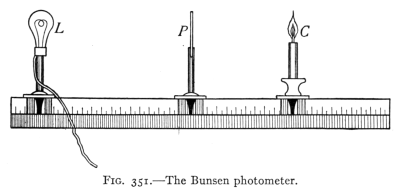 Fig. 351.—The Bunsen photometer.
These relations show that the intensity of illumination
is inversely proportional to the square of the distance from
the source of light. An application of the law of intensity
is made in using a simple (Bunsen) photometer. This
consists of a card containing a spot soaked with oil or
melted wax. (See Fig. 351.) The lights whose intensities
are to be compared are placed upon opposite sides of the
card. The card is then adjusted so that the spot appears
the same on both sides. The illumination is now equal on
both sides of the card and the candle powers of the two lights
are proportional to the squares of their distances from the
card. The simple device just described will give approximate
results only. For accurate results more elaborate
apparatus is required.
360. Measurement of the Intensity of Illumination.—A
standard candle (Art. 358) produces when lighted 1
candle power. The illumination caused by this upon a
surface 1 ft. away and at right angles to the light rays
is called a foot-candle. It is the unit of intensity of
illumination. A 4-candle-power lamp, at a distance of
1 ft., produces 4 foot-candles. A 16-candle-power lamp
at a distance of 2 ft. also produces 4 foot-candles—(16 ÷ 22).
The intensity of illumination required for a good light
for seeing varies with the conditions. Thus, for stage and
store lighting about 4 foot-candles are needed, while homes
and churches may require but 1 foot-candle.
Too great an intensity of illumination is as harmful as
not enough. Exposed lights having an intensity of more
than 5 candle power per square inch are often a cause
of eye trouble. Such lights should be protected by frosted
globes.
A pleasing form of lighting for large halls and public
buildings is the indirect system. In this, the lamps are
hidden by reflectors which throw the light upon the ceiling
from which it is diffused over the room. This form of
lighting is more expensive than other systems since but
a part of the light is reflected. Its cost therefore is an
important factor when considering its use.
361. The Reflection of Light.—The
light reflected from the surfaces
of bodies about us gives us information
concerning our surroundings.
A knowledge of the behavior of
light undergoing reflection is not
usually gained from ordinary observation.
The law of reflection of light
may be shown, however, by an experiment.
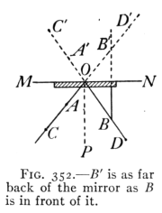 Fig. 352.—B´ is as far
back of the mirror as B
is in front of it.
Fig. 352.—B´ is as far
back of the mirror as B
is in front of it.
 Christian Huygens
(Popular Science Monthly)
Christian Huygens (1629-1695).
Dutch physicist; invented the pendulum
clock (1656); developed the
wave theory of light; discovered
polarization of light (1690).
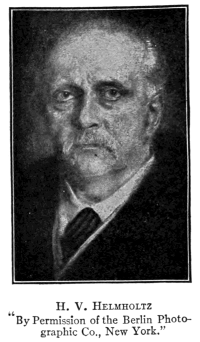 H. V. Helmholtz
"By Permission of the Berlin Photographic
Co., New York."
Hermann von Helmholtz (1821-1894)
Germany. Established the
doctrine of conservation of energy;
made many discoveries in sound;
invented the ophthalmoscope;
established the physical basis of
tone quality.
A plane mirror, M, is held in a vertical position resting upon a
sheet of paper. (See Fig. 352.) Pins are set upright in the paper
at A and B. On placing the eye along the line AC and looking
toward the mirror an image of B may be seen in the mirror due to
the light reflected from its surface. Pins C and D are now set in
the paper so that when one looks along the line BD toward the
mirror one may see all four pins apparently in one line. This
indicates that the light from A and C passing along CA toward
O is reflected back along the light CBD. By means of a ruler,
draw lines through BD and AC till they intersect at O. Also draw
PO perpendicular to the mirror at O.
Then the angles AOP and BOP will be found equal.
These are called the angles of incidence and reflection
respectively. The law of reflection is therefore stated:
The angle of reflection is equal to the angle of incidence.
These angles are in the same plane, that of the paper.
This law applies in all cases of reflection of light. It is
similar to the law of reflection of sound (Art. 326.)
1. Photometry, law of intensity, candle power, foot-candle.
2. Intensity of illumination.
3. Reflected light and law of reflection.
1. Both sides of a card are equally illuminated when two lights are
on opposite sides of it and 10 and 30 cm. respectively from it.
what are their relative intensities?
2. What are the relative intensities of illumination from a gas light
upon a book 6 ft. and 2 ft. respectively from the light?
3. Which is more expensive per candle power? How many times
as expensive? A 50-watt 16-candle-power incandescent lamp
at 10 cents per kilowatt-hour or a 100-candle-power Welsbach
light burning 5 cu. ft. of gas per hour at 80 cents per 1000 cu. ft.
of gas. (Find cost of each per hour, and then the cost of 1
candle power hour for each.)
4. Why are not ordinary shadows perfectly dark?
5. At what distance will a 16-candle-power lamp give the same
illumination as a single candle at 10 in.?
6. If the sun is at an elevation of 30 degrees what is the angle of
incidence at which it strikes the surface of water? What is the
angle between the incident and the reflected rays?
7. What is the difference between the phenomena of reflection of
light from a white sheet of writing paper and from a piece of
clear window glass?
8. A horizontal ray of light, traveling due east, strikes a vertical
mirror so that after reflection it is traveling due north. If the
mirror be now turned 10 degrees about a vertical axis, the north
edge moving east, what will be the direction of the reflected ray?
9. The necessary illumination for reading is about 2 foot-candles.
How far away may an 8-candle-power lamp be placed?
10. What is the illumination in foot-candles upon a surface 20 ft.
from an arc lamp having an intensity of 1000 candle power?
11. How far from a 100-candle-power Welsbach light would the
illumination be 2 foot-candles?
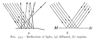 Fig. 353.—Reflection of light, (a) diffused, (b) regular.
362. Mirrors.—The many purposes served by mirrors
in our every-day life has made their use familiar to everyone.
Yet without study and experiment few understand
their properties and action. Any smooth surface may
serve as a mirror, as that of glass, water, polished wood,
or metal. Most objects, unlike mirrors, have irregular
surfaces; these scatter or diffuse the light that falls upon
them. (See Fig. 353a.) This is called diffused or irregular
reflection. The reflection of light from the smooth surface
of a mirror is regular. (See Fig. 353b.) In every case of
reflected light, however, the angle of reflection equals the
angle of incidence, diffusion being due to the irregularity
of the surface. It is by means of the light "diffused"
from the surface of illuminated bodies, such as plants,
animals, food, and manufactured articles, that we "see"
the various objects about us, and it is this light that
enables us to judge of their distance, size, form, color, etc.
The moon is seen by the sunlight reflected from its surface.
Moonlight is therefore sunlight diffused by reflection.
The new moon is that phase or condition of the moon when
only a narrow strip of the moon's illuminated surface
is turned toward the earth. At the time of the full
moon the whole illuminated surface is seen.
363. Images Formed by a Plane Mirror.—The most
common use of mirrors is in the formation of images. The
way in which images are formed
by a plane mirror may be illustrated
by diagrams. Thus in
Fig. 354, let L represent a
luminous body and E and E´
two positions of the observer's
eye. Take any line or ray as
LO along which the light from
L strikes the mirror O-O´. It
will be reflected so that angle
LOP equals angle POE. Similarly
with any other ray, as
LO´, the reflected ray O´E´ has
a direction such as that angle L´O´E´ equals angle P´O´E´.
Any other rays will be reflected in a similar manner,
each of the reflected rays appearing to the eye to come
from a point L´ behind the mirror.
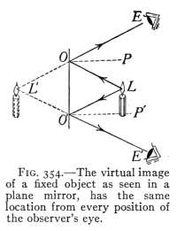 Fig. 354.—The virtual image
of a fixed object as seen in a
plane mirror, has the same
location from every position of
the observer's eye.
Fig. 354.—The virtual image
of a fixed object as seen in a
plane mirror, has the same
location from every position of
the observer's eye.
364. Light Waves and Wave Diagrams.—Just as a
stick continually moved at the surface of a body of water
sets up a series of waves spreading in all directions, so one
may imagine a train of waves sent out by a luminous
body L (as in Fig. 355) to the mirror MN. These waves
will be reflected from the mirror as if the source of light
were at L´. It is much simpler and more convenient to
locate the position of the image of a point by the use of
lines or "rays" (as in Fig. 354) than by the wave diagram
(as in Fig. 355). In all ray diagrams, however, it should be
kept in mind that the so-called ray is a symbol used to
represent the direction taken by a part of a light wave.
Thus in Fig. 354, the light from L moving toward O is
reflected to E along the line OE, the heavy lines representing
rays.
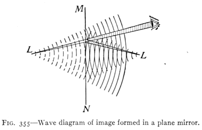 Fig. 355.—Wave diagram of image formed in a plane mirror.
365. To locate the image of an object formed by a
plane mirror requires simply an application of the law
of reflection. Thus in Fig. 356 let AB represent an object
and MN a plane mirror. Let AA´ be a ray from A striking
the mirror perpendicularly. It is therefore reflected back
along the same line toward A. Let AO represent any other
ray from A. It will be reflected along OE so that angle
r equals i. The intersection of AC and OE at A´ behind
the mirror locates the image of the point A, as seen by
reflection from the mirror. The triangles ACO and
A´CO may be proved equal by geometry. Therefore
A´C equals AC. This indicates that the image of a point
formed by a plane mirror is the same distance back of the
mirror as the point itself is in front of it. This principle
may be used in locating the image of point B at B´. Locating
the position of the end points of an image determines
the position of the whole image as A´B´.
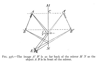 Fig. 356.—The image A´B´ is as far back of the mirror M N as the
object A B is in front of the mirror.
Fig. 356.—The image A´B´ is as far back of the mirror M N as the
object A B is in front of the mirror.
366. How the Image is Seen.—Suppose the eye to be
placed at E. It will receive light from A by reflection
as if it came from A´. Similarly light starting from B
reaches the eye from the direction of B´. There is nothing
back of the mirror in reality that affects our sight, the light
traveling only in the space in front of the mirror. Yet
the action of the reflected light is such that it produces
the same effect as if it came from behind the mirror.
Images such as are seen in plane mirrors are called virtual
to distinguish them from real images, in which light
actually comes to the eye from the various parts of the
visible image, as from the real image formed by a projecting
lantern upon a screen, or by an aperture as in the pin-hole
camera. Real images therefore are those that can
be obtained upon a screen while virtual images cannot.
367. Multiple Reflection.—If the light from an object
is reflected by two or more mirrors various effects may be
produced, as may be illustrated by the kaleidoscope. This
consists of three plane mirrors so arranged that a cross-section
of the three forms an equilateral triangle. The
mirrors are placed in a tube across the end of which is a
compartment with a translucent cover containing pieces
of colored glass. On looking through the tube, the reflections
from the several surfaces produce beautiful hexagonal
designs.
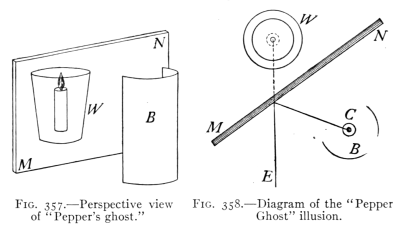 Fig. 357.—Perspective view
of "Pepper's ghost."
Fig. 357.—Perspective view
of "Pepper's ghost."
Fig. 358.—Diagram of the "Pepper
Ghost" illusion.
368. Optical Illusions by a Plane Mirror.—The illusion
called Pepper's Ghost is typical of many illusions produced
by reflection. It may be illustrated by taking a piece of
plate glass, M-N, a tumbler of water, W, and a lighted
candle, C, placed in a box, B, having one side open and
arranged as shown in perspective in Fig. 357, and in
section in Fig. 358. If the effect is produced in a darkened
room, the observer at E sees a virtual image of the
lighted candle as if it were in the glass of water, the water
being seen by transmitted light through the plate glass, the
latter forming a virtual image of the candle by reflection.
Some of the illusions produced by this means are: (a)
the figure suspended in mid air; (b) the bust of a person
without a trunk; (c) the stage ghost; (d) the disappearing
bouquet.
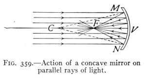 Fig. 359.—Action of a concave mirror on
parallel rays of light.
Fig. 359.—Action of a concave mirror on
parallel rays of light.
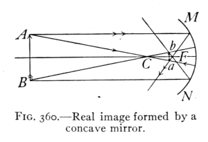 Fig. 360.—Real image formed by a
concave mirror.
Fig. 360.—Real image formed by a
concave mirror.
369. Concave Mirrors.—Another useful piece of physical
apparatus is the
concave spherical mirror.
It is frequently
made from plano-convex
lenses by silvering
the convex surface of
the lens, thus making a
concave reflecting surface from the inner surface of the
silvered part; they are also made by polishing the inner
surfaces of metallic spherical shells. The concave mirror
is represented in section in Fig. 359 by the curve MN;
C is the center of curvature or the center of the surface of
which this mirror MN is a part; the line VC through the
center V of the mirror is
called the principal axis;
while any other line passing
through C is called
a secondary axis. The
point midway between
the vertex V and center
of curvature C is called
the principal focus, F. It is the point through which
parallel incident rays pass after reflection. The angle
MCN which the curve of the mirror subtends at the
center is called the aperture of the mirror. We learned in
Art. 361, the angle of reflection of a ray of light is always
equal to the angle of incidence no matter what the nature
of the reflecting surface may be. If the reflecting surface
is a regular concave surface, like the inner surface of a
sphere, the rays of light coming from a point source may
after reflection come to a focus, forming a real image.
The two extreme points of an object should be selected
for locating its image; Fig. 360 shows the construction.
The real images formed by concave mirrors are always
inverted. The principal focus of a concave mirror may
be observed by holding the mirror in a beam of sunlight
entering a darkened room. The sun's rays after reflection
converge to form a small, round, intense spot of light,
which is a real image of the sun, located at the principal
focus of the mirror. The distance of the principal focus
from the mirror is the least distance that a real image
can be formed in front of a concave mirror.
370. Virtual Images by Concave Mirrors.—When light
comes from a small point situated between a concave mirror
and its principal focus, the
reflected rays are divergent and
hence no real image of the object
can be found in front of the
mirror. But if the rays are extended
behind the mirror they
will meet in a point called the
virtual focus. This is the point
from which they appear to come.
Any image of an object situated
between the principal focus and a concave mirror is
therefore a virtual image, erect and larger than the
object. (See Fig. 361.)
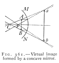 Fig. 361.—Virtual image
formed by a concave mirror.
Fig. 361.—Virtual image
formed by a concave mirror.
371. Construction of Real Images.—There are five
positions at which an object may be situated in front of a
concave mirror, namely: (1) beyond C; (2) at C; (3) between
C and F; (4) at F and (5) between F and V. There
are two ways by means of which the image formed at each
of these positions may be located, namely; (1) experimentally,
by allowing the rays of light from a luminous
body to focus on a screen and (2) diagrammatically. By
the latter method the two rays of light are considered the
course of each of which may easily be determined; first, the
ray which strikes the mirror parallel to its principal axis
and which after reflection passes through the principal
focus; second, the ray which passing through the center
of curvature strikes the mirror at right angles and therefore
after reflection must pass directly back along its
incident path. Where these two reflected rays intersect
is located the real image of the object. Whenever these
two rays of light do actually intersect, as in Fig. 360, a
real image (ab) is formed of the object AB.
The points A and a, B and b and others similarly
situated on an axis extending through the center of curvature
C are called conjugate foci, for they are so related that
an object being at either one, its image will be found at the
other.
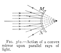 Fig. 362.—Action of a convex
mirror upon parallel rays of
light.
Fig. 362.—Action of a convex
mirror upon parallel rays of
light.
372. The Convex Mirror.—There are few practical
uses to which convex mirrors can be put. They are sometimes
used to give the chauffeur
of an automobile a view
of the road behind him. It is
then attached to the wind
shield by a short rod. The
reflected rays coming from
a Convex mirror are always
divergent (see Fig. 362), hence
the image is always virtual and
located behind the reflecting surface. The method of
construction for images formed by a convex mirror is
similar to that for concave mirrors. (See Fig. 363.)
The center of curvature and principal focus are behind
the mirror and consequently the reflected rays have to
be produced backward until
they meet. The images are
always virtual, erect and smaller
than the object.
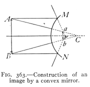 Fig. 363.—Construction of an
image by a convex mirror.
Fig. 363.—Construction of an
image by a convex mirror.
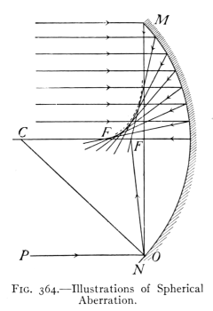 Fig 364.—Illustrations of Spherical
Aberration.
Fig 364.—Illustrations of Spherical
Aberration.
373. Spherical Aberration.
Sometimes in a concave
mirror when the aperture
MCN (Fig. 364) is large the
images are blurred or indistinct.
This is due to the fact
that the incident rays near the outer edge of the mirror
do not focus after reflection at the same point as those
which pass into the mirror near the vertex, but cross
the principal axis at points
between the mirror and
principal focus as is shown
in Fig. 364; this result is
called spherical aberration.
The larger the aperture of
the mirror the more the
image is blurred. Concave
mirrors in practical
use do not have an aperture
much greater than 10
degrees. This non-focusing
of the rays of light by
curved reflecting surfaces
may be noticed in many
places, as when light is
reflected from the inside
of a cup that contains
milk or from the inside of a wide gold ring placed on top
of a piece of white paper. The pupil will note other
instances. This curve of light observed is called the
caustic by reflection.
374. Parabolic Mirrors.—The best possible surface to
give to concave mirrors is parabolic. This is a curve which
may be generated by moving a point
so that its distance from a fixed point
and a fixed line are always equal.
If a source of light is placed at F
the rays after reflection are rendered
parallel. See Fig. 365. This reflector
is used in automobile lamps, headlights
of locomotives, search-lights,
etc. It is also used in large reflecting
astronomical telescopes to collect as
large an amount of light as possible from distant stars
and bring it to a focus. Such mirrors may be made
exceedingly accurate.
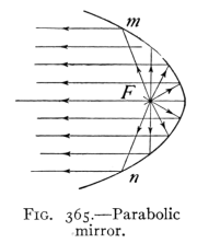 Fig. 365.—Parabolic
mirror.
Fig. 365.—Parabolic
mirror.
1. Reflection: regular, diffused; plane mirrors; laws of reflection.
2. Formation and location of images by plane mirrors. Wave and
ray diagrams.
3. Multiple reflection, illusions.
4. Curved mirrors, uses; concave, convex, parabolic.
1. Distinguish between regular and diffused reflection. By means
of which do we see non-luminous bodies?
2. Could a perfect reflecting surface be seen? Explain.
3. A pencil is stood upright in front of a plane mirror set at an
angle of 45 degrees to the vertical. Shown by a diagram the
location and position of the image.
4. Show by diagrams the position and location of the images of a
pencil (a) when standing erect and in front of a vertical mirror.
(b) when standing upon a horizontal mirror.
5. What is the difference between a real and a virtual image?
6. A standard candle and a lamp give equal illuminations to a
screen that is 1 ft. from the candle and 6 ft. from the lamp.
What is the candle power of the lamp? Explain.
7. Why are walls finished in rough plaster or painted with soft
tones without gloss better for schoolrooms than glossy paints
or smooth white plaster?
8. Try to read a printed page by looking at its image in a mirror.
write your name backward on a sheet of paper, and then look
at the image of the writing in a mirror. What effect is produced
by the mirror in each case?
9. If the point of a pencil is held to the surface of a piece of plate-glass
mirror two or more images may be seen in the mirror.
Explain.
10. Given a small lighted candle, a concave mirror, a meter stick,
and a white screen, how would you prove the statements made
in Arts. 369 and 370 concerning the location of images formed
by concave mirrors? Make the diagram in each case.
11. Why do images seen in a quiet pond of water appear inverted?
Explain by a diagram.
375. Common Examples of Refraction.—Everyone has
noticed the apparent bending of an oar, of a stick, or of a
spoon when placed in water (see
Fig. 366), while many have observed
that the bottom of a pond or stream
looks nearer to the surface than it
really is. These and similar illusions
are due to the refraction or bending
of light rays as they pass from one
medium to another. The principles
of refraction are among the most useful
found in the study of light since application is made of
them in the construction and use of important optical
instruments, such as the camera, microscope, telescope,
and the eye.
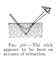 Fig. 366.—The stick
appears to be bent on
account of refraction.
Fig. 366.—The stick
appears to be bent on
account of refraction.
376. Action of Light Undergoing Refraction.—If a
beam of sunlight be admitted to a darkened room and reflected
by a mirror so that it strikes the surface of water
in a glass jar, a part of the beam may be seen to be reflected
while another portion is transmitted through the water
(Fig. 367). The reflected
beam follows
the law of reflection
while the transmitted
beam is seen to be
refracted, or to have
its courses slightly
changed in direction
upon entering the
water. If the mirror
is turned so that the
angle at which the
light strikes the water
is changed, the amount
of refraction or change of course of the light is varied.
When the light strikes the water perpendicularly there
is no refraction. On the other hand, the greater the
angle at which the light strikes
the water the greater the
bending.
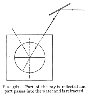 Fig. 367.—Part of the ray is reflected and
part passes into the water and is refracted.
Fig. 367.—Part of the ray is reflected and
part passes into the water and is refracted.
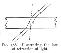 Fig. 368.—Illustrating the laws
of refraction of light.
Fig. 368.—Illustrating the laws
of refraction of light.
377. Laws of Refraction.
The action of light on entering,
passing through, and
leaving a great variety of
substances has been carefully
studied. A summary of
the results of these observations is given in the following
laws of refraction: I. When light enters a transparent body,
perpendicularly, it passes on without changing its direction.
II. When light enters a denser transparent body obliquely, it
is bent toward the perpendicular; when light enters a less dense
body obliquely, it is bent away from the perpendicular.
(See Fig. 368.)
378. The cause of refraction may be illustrated by
considering a line of men moving across a field and occupying
at equal time intervals the
successive positions 1, 2, 3, etc.,
indicated in Fig. 369. Suppose
that the upper and lower
parts of the field have a smooth
hard surface, while at the center
is a strip of newly ploughed
ground. The line will move
more slowly over the ploughed
field than over the hard field.
This will result in a retardation
of the end of the line first striking
the soft ground with a
resulting change of direction of the line, toward the
perpendicular to the edge of the field (on entering the
place of more difficult travel), and away from the perpendicular
on moving into a place where increased speed
results.
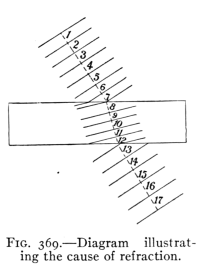 Fig. 369.—Diagram illustrating
the cause of refraction.
Fig. 369.—Diagram illustrating
the cause of refraction.
379. Index of Refraction.—By studying the change of
direction of the marching men as shown in Fig. 369 it is
evident first that it is due to a difference in speed in the
two media. It is not easy to measure the speed of light
in a medium. However, the amount of refraction may be
determined easily and from this the relative speed may be
computed. The number that expresses the ratio of the speed
of light in air to its speed in another medium is called the
index of refraction of that medium. The relative speeds of
light, or the indices of refraction for some substances, are:
water, 1.33, crown glass, 1.51, flint glass, 1.61, diamond,
2.47, carbon bisulphide, 1.64.
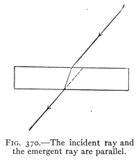 Fig. 370.—The incident ray and
the emergent rays are parallel.
Fig. 370.—The incident ray and
the emergent rays are parallel.
380. Plates, Prisms, Lenses.—The refraction of light
is usually observed when it is passing through a plate, a
prism, or a lens. The important
differences between
the effects of each in refracting
light are illustrated in
Figs. 370, 371 and 372. In
Fig. 370 it is seen that the
refraction of the ray on entering
the glass is counteracted
by the refraction away from
the perpendicular upon leaving
it. So that the entering
and emergent rays are parallel.
In Fig. 371 the refraction at the two surfaces of
the prism results in a change of direction of the ray, the
course being bent toward the thicker part of the prism. In
Fig. 372 it may be noticed that the convex lens resembles
two prisms with their bases together. Since all parts of
the lens refract light toward the thicker part, the center,
the effect of the convex lens is to bring the rays of light to
a focus, at F.
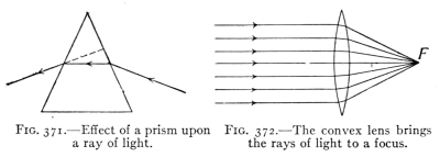 Fig. 371.—Effect of a prism upon
a ray of light.
Fig. 371.—Effect of a prism upon
a ray of light.
Fig. 372.—The convex lens brings
the rays of light to a focus.
381. Total Reflection.—It has been shown that when
light passes from a denser to a lighter medium, as from glass
or water to air, that the beam is refracted away from the
perpendicular. This is illustrated in Fig. 373. The
diagram represents the change in the course of a ray of
light that passes through water to a surface with air above
it. A ray striking perpendicularly passes through without
refraction. Other rays show increasing refraction
with increasing angle of incidence. For one ray the angle
of refraction is so large that the refracted ray is parallel
to the surface. When this condition is reached, the
angle of incidence is called the critical angle. Any increase
in the angle of incidence causes all of the light to be reflected
as is the beam E. This action is called total
reflection, the course of the reflected ray being according
to the law of reflection. A right-angle prism (see Fig. 374)
is often used where a mirror would ordinarily be employed,
the total reflection occurring within the prism giving more
satisfactory results than a mirror. See Art. 398 for a
description of the Zeiss binocular field-glass for an example
of this use of total reflection.
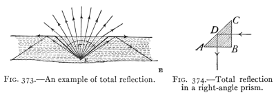 Fig. 373.—An example of total reflection.
Fig. 374.—Total reflection
in a right-angle prism.
The mirage (see Fig. 375) is an optical illusion by which distant
objects, below the horizon, are sometimes plainly seen. This phenomenon
is most frequently observed in hot, desert regions, when
the air conditions are such that the lower strata near the ground are
very much hotter than those above. These lower strata, having expanded
the most, are less dense than the cooler ones above. Hence
a ray of light traveling obliquely downward is refracted more and
more until total reflection takes place. The images seen are inverted
giving a representation of trees or other objects reflected on the surface
of still water. The mirage is also frequently seen at sea, ships
being observed, sometimes erect, sometimes inverted, apparently sailing in
the clouds near the horizon. Over the Great Lakes, trees, boats,
and towns on the opposite shore, sixty or seventy miles away,
can sometimes be plainly seen, apparently but a few miles out. In
this case the images are erect, the total reflection being from warm,
still layers of air over colder layers near the water.
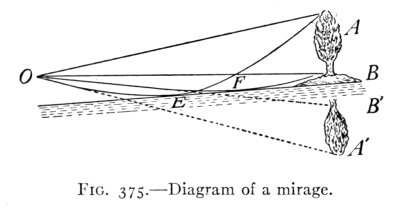 Fig. 375.—Diagram of a mirage.
(A) Refraction: cause, illustration, two principles.
(B) Index of refraction, meaning.
(C) Plates, prisms, lenses, action of each.
(D) Total reflection, uses.
1. Compute the speed of light in water, the index of refraction
being 1.33.
2. If one wished to shoot a fish under water, should he aim at the
apparent location of the fish as viewed from the air? Explain,
using a diagram.
3. Define refraction. Mention two illustrations of this action
that you have observed out of school.
4. Why does the moon look larger near the horizon?
5. Is your reflection seen in a pool of water upside down? Why?
6. Why does it whiten molasses candy to pull it?
7. When looking at a building through the ordinary glass of a
window why do straight lines of the building appear to be so
distorted? What makes them appear to move as you move
your head slightly?
8. Explain the phenomenon which one observes when looking at
an object through the air arising from a hot stove or radiator.
9. Frequently the horizontal diameter of the setting sun appears
to be greater than the vertical. Explain.
10. Explain why one observes several images of a luminous body
like a lighted candle when the reflected light from a thick glass
mirror enters the eye, the angle of reflection being large.
382. Uses of Lenses in Optical Instruments.—The use
of instruments that employ lenses in their operation, such
as spectacles, reading and opera glasses, and the camera,
microscope, and telescope, is familiar to most students of
physics. The part played by the lenses, however, is not
generally understood. Consequently the study of the
formation of images by lenses is of general interest and
importance.
383. Forms of Lenses.—While a lens may be formed
from any transparent solid it is commonly made of glass.
It may have two curved surfaces or
one curved and one plane surface.
Most lenses are spherical lenses, since
their curved surfaces form a part of
the surface of a sphere. Fig. 376
represents a spherical lens with a
curved surface coinciding with that of
a sphere whose center is at C. This
center is called the center of curvature, while the radius of
the sphere R, is the radius of curvature.
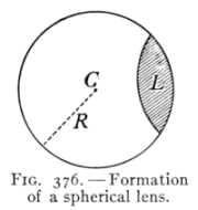 Fig. 376.—Formation
of a spherical lens.
Fig. 376.—Formation
of a spherical lens.
There are two classes of lenses: those thick in the middle
are called convex, while those thick at the edges are concave.
The mode of constructing the six forms of spherical lenses
is shown in Fig. 377. These are named as follows: (1)
double convex, (2) plano convex, (3) concavo-convex,
(4) double concave, (5) plano concave, (6) convexo-concave.
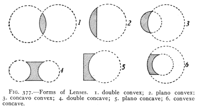 Fig. 377.—Forms of Lenses. 1. double convex; 2. plano convex;
3. concavo convex; 4. double concave; 5. plano concave; 6. convexo
concave.
Fig. 377.—Forms of Lenses. 1. double convex; 2. plano convex;
3. concavo convex; 4. double concave; 5. plano concave; 6. convexo
concave.
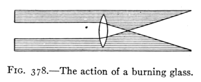 Fig. 378.—The action of a burning glass.
384. Effect of Lenses upon Light.—The most important
characteristic of a lens is its effect upon a beam of light.
Most persons have seen a "burning glass," a double convex
lens, used to bring to a point, or focus, a beam of sunlight.
To show the action of a burning glass send a beam of
light into a darkened room, and place in its path a double
convex lens. (See Fig. 378.) If two blackboard erasers
are struck together near the lens, the chalk particles in the
path of the light are strongly illuminated, showing that the
light after passing through the lens it brought to a focus
and that it spreads out beyond this point. This point
to which the cone of light rays converges after passing
through the convex lens is called the principal focus of
the lens. The distance from the principal focus to the
center of the lens is the focal length or principal focal
distance of the lens. The focal length of double convex lenses of crown glass is about the same as the radius of
curvature of either surface.
The action of a convex or
converging lens upon light may be better understood by
studying Fig. 379 in which light is passing from S to F.
The successive positions and
shape of the advancing light
waves are indicated by lines
drawn across the beam. The
light being retarded more in
the thicker part of the lens,
the light waves on leaving
the lens have a concave front.
Since light waves tend to move at right angles to the front
of the wave, the light is brought to a focus. After passing
the focus the waves have a convex front, forming a
diverging cone.
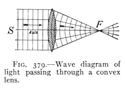 Fig. 379.—Wave diagram of
light passing through a convex
lens.
Fig. 379.—Wave diagram of
light passing through a convex
lens.
385. Concave Lenses.—When sunlight passes through
a concave lens a diverging cone of light is formed. (See
Fig. 380.) This is caused by the edges of the wave being
retarded more than the center, producing a convex wave
front. This diverging cone of light acts as if it had proceeded
from a luminous point at F.
This point is called a virtual focus and is nearly at the
center of the curvature of the nearer surface.
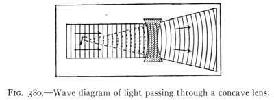 Fig. 380.—Wave diagram of light passing through a concave lens.
386. The Formation of Images by Lenses.—If a beam
composed of parallel rays of light, as sunlight, is sent in
turn through three convex lenses of the same diameter but
of different thickness, it is
found that the thicker the
lens the greater is its converging
power, or the shorter is its
focal length. (See Fig. 381.)
Now if a luminous body,
such as a lighted candle, be
placed near the convex lens
but beyond its focal length,
the light will be brought to a
focus upon the other side of
the lens and an image of the
candle may be clearly seen
upon the screen placed at
this point. (See Fig. 382.)
The two points so situated on
opposite sides of a lens that
an object at one will form an image at the other are called
conjugate foci.
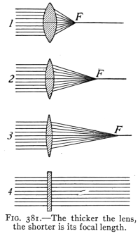 Fig. 381.—The thicker the lens,
the shorter is its focal length.
Fig. 381.—The thicker the lens,
the shorter is its focal length.
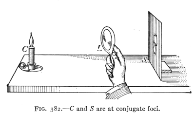 Fig. 382.—C and S are at conjugate foci.
It will be helpful to compare the images formed of a
candle by an aperture and by a convex lens. Rays of
light from each point of the luminous body pass through
the aperture in straight lines and produce upon the screen
a lighted space of the same shape as the candle. This
image is rather hazy in outline. Each cone of rays from
luminous points of the flame is brought by the lens to a
focus on the screen, producing a sharp image. It is the
converging power of convex lenses that enables them to
produce clear images.
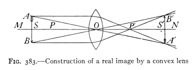 Fig. 383.—Construction of a real image by a convex lens.
387. The Construction of Diagrams to Represent the
Formation of Images by Lenses.—Just as the earth has
an axis at right angles to its equator to which are referred
positions and distances, so a lens has a principal axis at
right angles to its greatest diameter and along this axis
are certain definite positions as shown in Fig. 383. Let
MN be the principal axis of a convex lens, P and P´ are
principal foci on either side of the lens, S and S´ are
secondary foci. These are at points on the principal axis
that are twice as far from O, the center of the lens, as are
the principal foci. In the formation of images by a convex
lens, several distinct cases may be noticed:
(A) If a luminous body is at a great distance at the left,
its light is brought to a focus at P, or its image is formed
at P. (B) As the object approaches the lens the image
gradually recedes until the object and image are at S and
S´, equally distant from O and of equal size (as in Fig. 383).
The object and image are now said to be at the secondary
foci of the lens. (C) As the object moves from S to P the
image recedes, rapidly increasing in size until (D) when
the object is at P the rays become parallel and no image
is formed. (E) When the object is between P and the
lens, the rays appear to proceed from points back of the
object, thus forming an erect, larger, virtual image of the
object. (See Fig. 384.) This last arrangement illustrates
the simple microscope.
With a concave lens but one case is possible, that corresponding
to the one last mentioned with convex lenses;
since the rays from a body are divergent after passing
through a concave lens they appear to proceed from points
nearer the lens than the object and hence a virtual, erect,
smaller image of the object is formed. This virtual image
may be seen by looking through the lens toward the object.
(See Fig. 385.)
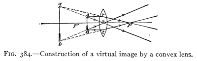 Fig. 384.—Construction of a virtual image by a convex lens.
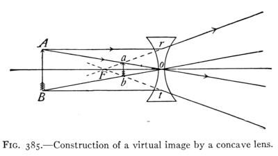 Fig. 385.—Construction of a virtual image by a concave lens.
388. The Lens Equation.—The location of either the
object or of the image upon the principal axis of the lens
may be calculated if the position of one of these and the
focal length are known. This is accomplished by the use
of a formula 1/F = 1/D0 + 1/D1 in which F represents the focal
length and D0 and D1 the distance from the lens of the
object and the image respectively. Thus if an object is
placed 30 cm. from a lens of 10 cm. focal length, where will
the image be formed? Thus: 1/10 = 1/30 + 1/D and 3D1 =
D1 + 30, or 2D1 = 30 D1 = 15. This result indicates
that a real image will be 15 cm. from the lens. A minus
value would indicate a virtual image.
(A) Lenses: convex, concave, six forms, center and radius of
curvature.
(B) Principal focus, focal length, virtual focus, conjugate foci.
(C) Principal axis, images formed when object is in various locations.
(D) Computation of location of images.
1. Why is an image of a candle formed by an aperture, not sharply
defined?
2. When a photographer takes your picture and moves the camera
nearer you, must he move the ground glass screen toward
the lens or away from it? Explain.
3. How can you find the principal focal length of a lens.
4. How can you test a spectacle lens to see whether it is convex
concave?
5. When will a convex lens produce a virtual image? Have you
ever seen one? Where?
6. When a photographer wishes to obtain a full length view of a
person, where does he place the camera?
7. The focal length of the lens is 24 cm. How far from the lens
must an object be placed in order that a real image may be
three times as long as the object?
8. There is a perfect image of an object on the ground glass of a
camera. The center of the lens is 20 cm. in front of the image
and the object 75 cm. from the lens. What is the focal length of
the lens?
9. An object is 60 cm. from the lens, the image 120 cm. from it.
Find the focal length.
10. How can you find experimentally the principal focal length
of a lens?
11. A lens is used to project an enlarged image of a candle upon a
screen. Which is farther from the lens, the candle or the image?
Explain.
389. The Eye.—The most common optical instrument
is the eye. While the structure of the eye is complicated,
the principle of it is simple, involving the formation of an
image by a double convex lens.
(See Fig. 386, in which is shown
a front to back, vertical cross-section
of the eye.) The eye
appears to be made of portions
of two spheres, one of which,
smaller than the other, is
placed in front. This projecting
part is transparent,
but refracts the light which
strikes it obliquely, so as to turn it into the eye. This
enables us to see objects at the side when looking
straight ahead. Test this by looking directly in front of
you and see how far back on each side of the head you can
notice a movement of the forefinger of each hand.
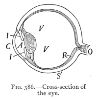 Fig. 386.—Cross-section of
the eye.
Fig. 386.—Cross-section of
the eye.
390. Action of the Eye in Vision.—When we look at an
object, a small, real, inverted image is formed upon the
retina at the back of the interior of the eye. The retina is
an expansion of the optic nerve and covers the inner surface
at the back of the eyeball. Seeing is due to the action
of light in forming images upon the retina. Our eyes are
so constructed that when they are relaxed the lens is adjusted
to form clear images of distant objects upon the
retina. If we look from distant to near objects without
changing the shape of the eye lens, a sharp image of the
latter cannot be formed and we get a blurred impression.
It is difficult, however, to look at objects without automatically
adjusting the eye lens so that it will make a sharp
image. Test this by looking out of a window at a distant
object, then without moving the head or eyes look at the
glass of the window; you will notice a slight change of some
sort in the eye itself as the vision is adjusted. This adjustment
is made by muscles that pull or compress the eye lens
so as to make it thicker for near objects and thinner for
distant ones. The eye ordinarily does not see objects
nearer than 10 in. clearly. This means that the greatest
possible thickening of lens will not form clear images upon
the retina if the object is nearer than 10 in. (25 cm.).
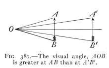 Fig. 387.—The visual angle, AOB
is greater at AB than at A´B´.
Fig. 387.—The visual angle, AOB
is greater at AB than at A´B´.
391. The Visual Angle.—To examine objects carefully
we usually bring them as close to the eye as possible, for
the nearer to the eye the
object is brought, the larger
is the visual angle formed
by it (see Fig. 387), and the
larger is its image upon the
retina. The visual angle of
an object is the angle at the
eye lens between the rays that
have come from the ends of the object. Consequently the more
distant the object, the smaller is its visual angle. Now if we
wish to examine small objects with great care, we frequently
find that it is necessary to bring them close to the eye so
that they have a visual angle of adequate size. If they
must be brought closer than 10 in. a double convex lens
is placed in front of the eye. This assists the eye lens in
converging the light so that a clear image may be formed
when the object is close, say an inch or so from the eye.
This is the principle of the magnifying glass used by watch-makers
and of the simple microscope. The action of the
latter is illustrated by Fig. 388. The convex lens forms
a virtual, enlarged image
"A´-B´" of the object
"A-B" which it
observed instead of the
object itself.
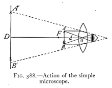 Fig. 388.—Action of the simple
microscope.
Fig. 388.—Action of the simple
microscope.
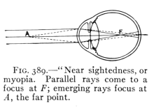 Fig. 389.—"Near sightedness", or
myopia. Parallel rays come to a
focus at F; emerging rays focus at
A, the far point.
Fig. 389.—"Near sightedness", or
myopia. Parallel rays come to a
focus at F; emerging rays focus at
A, the far point.
392. Defects of Vision.—There
are several
defects of vision that
may be corrected by
spectacles or eye-glasses.
One of these is "near-sightedness." It is due
either to an eyeball that is elongated, or to an eye lens that
is too convex, or to both conditions. This condition brings
light from distant objects to a focus too soon (as shown in
Fig. 389). Only light from near objects will focus upon
the retina in such cases. With normal vision light from
distant or near objects may be focused without unusual
effort upon the retina, see
Fig. 390. The remedy for
near-sightedness is to use
concave lenses which will
assist in properly refracting
the light so the focus will be
formed on the retina (Fig.
391). "Far-sightedness" is
the reverse of near-sightedness; the eyeball is either too
short, or the lens too flat, or both conditions obtain, so
that the light entering the eye is brought to a focus behind
the eyeball (Fig. 392). The remedy is convex lenses which
will assist in properly converging the light, see Fig. 393. A
third defect is called astigmatism. This is caused by some
irregularity or lack of symmetry in the eye. It is corrected
by a cylindrical lens that compensates for this defect of
the eye. A diagram similar to Fig. 394 is used as a test
for astigmatism. If the lines
appear with unequal distinctness,
some irregularity of refraction
(astigmatism) is indicated.
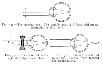 Fig. 390.—The normal eye. The parallel rays A B focus without accommodative
effort at C.
Fig. 390.—The normal eye. The parallel rays A B focus without accommodative
effort at C.
Fig. 391.—Correction of near-sightedness
by concave lens.
Fig. 392.—Far-sightedness or
hyperopia. Parallel rays focused
behind the retina.
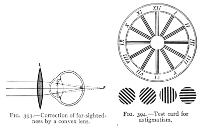 Fig. 393.—Correction of far-sightedness
by a convex lens.
Fig. 393.—Correction of far-sightedness
by a convex lens.
Fig. 394.—Test card for
astigmatism.
393. The Photographic Camera.—This
is a light-tight box, provided with a convex
lens in front, covering an aperture and a ground glass
screen at the back. The distance between the lens and
the screen is adjusted until a sharp image is obtained
upon the latter, which is then replaced by a sensitive
plate or film. The sensitized surface of the plate or film
contains a salt of silver which is changed by the action of
light. After the plate has been "exposed" to the action
of light, it is "developed" by the use of chemicals producing
a negative image. From "negative," by the use
of sensitized paper, "positive" prints may be secured
which resemble the object photographed.
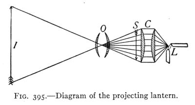 Fig. 395.—Diagram of the projecting lantern.
394. The projecting lantern (see Fig. 395) employs a
strong source of light, as an electric arc lamp L, to strongly
illuminate a transparent picture, or lantern slide, S, a real
image (I) of which is formed upon a large screen. Two
large plano-convex lenses (C), called condensing lenses,
are placed near the lamp to concentrate the light upon the
"slide" S. The convex lens forming the image is called
the "objective" (O).
395. The compound microscope consists of two lenses.
One called the objective is placed near the object to be
viewed. This lens has a short focal length usually less
than a centimeter. It forms a real image of the object.
A´-B´. The other lens, the eyepiece forms a virtual image
of this real image. A´´-B´´. (See Fig. 396.)
396. The telescope consists of two lenses, the eyepiece
and the objective. As in the compound microscope, the
objective of the telescope forms a real image of the distant
object, the eyepiece forming an enlarged virtual image of
the real image. It is the virtual image that is viewed by
the observer. (See Fig. 397.) In order to collect sufficient
light from distant stars the objective is made large, sometimes
50 in. in diameter.
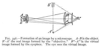 Fig. 396.—Formation of an image by a microscope. A-B is the object.
B´-A´ the real image formed by the "objective." B´´-A´´ is the virtual
image formed by the eyepiece. The eye sees the virtual image.
Fig. 396.—Formation of an image by a microscope. A-B is the object.
B´-A´ the real image formed by the "objective." B´´-A´´ is the virtual
image formed by the eyepiece. The eye sees the virtual image.
The length of the telescope tube depends upon the
focal length of the objective, since the distance between
the two lenses must equal the sum of their focal lengths.
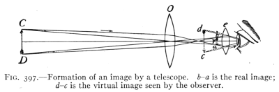 Fig. 397.—Formation of an image by a telescope. b-a is the real image;
d-c is the virtual image seen by the observer.
Fig. 397.—Formation of an image by a telescope. b-a is the real image;
d-c is the virtual image seen by the observer.
397. The opera glass consists of a convex lens as objective
and a concave lens as an eyepiece. The former tends
to form a real image but the latter diverges the rays before
a real image can be formed, the action of the two lenses
producing an enlarged virtual image (as in Fig. 398) which
is viewed by the one using the glass. The compact size
of the opera glass is due to the fact that the distance
between the two lenses is the difference of the focal lengths.
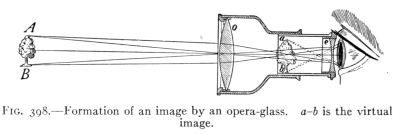 Fig. 398.—Formation of an image by an opera-glass. a-b is the virtual
image.
Fig. 398.—Formation of an image by an opera-glass. a-b is the virtual
image.
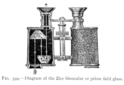 Fig. 399.—Diagram of the Zeiss binocular or prism field glass.
398. The Prism Field Glass or Binocular.—This instrument.
has come into use in recent years. It possesses the
wide field of view of the spy glass but is as compact as the
opera glass. This compact form is secured by causing the
light to pass back and forth between two right-angle
prisms (as shown in Fig. 399). This device permits the
use of an objective lens with a focal length three times
that of the tube, securing much greater magnifying power
than the short instrument would otherwise possess. A
further advantage is secured by the total reflection from
the two prisms, one of which is placed so as to reverse the
image right for left and the other inverts it, so that when
viewed in the eyepiece it is in its proper position.
1. The eye: parts, formation of image, kind, how, where.
2. Eye defects, how remedied. Visual angle.
3. Simple microscope, camera; images, kind, how formed.
4. Compound microscope, telescope and opera glass; images, action
of each lens.
1. Name three instruments in which lenses form virtual images
and three in which real images are formed.
2. In what direction is an oar in water apparently bent? Explain
by a diagram.
3. What optical instruments have you used? Is the visible image
formed by each of these real or virtual?
4. The focal length of a copying camera lens is 14 in. Where must
a drawing be placed so that an image of the same size may be
formed upon the ground glass screen? What must be the distance
of the screen from the lens?
5. What are two methods by which you can determine the focal
lengths of the lens of a photographic camera?
6. The critical angle for water is 48-1/2 degrees. Show by a diagram
how much of the sky can be seen by a diver who looks
upward through the water.
7. How is near-sightedness caused? How is it corrected? Illustrate
by a diagram.
8. How is the eye accommodated (focused) as an object gradually
approaches it?
9. Explain why a simple microscope assists in looking at the parts
of a flower or insect.
10. Why do people who have good eyesight when young require
glasses as they grow old?
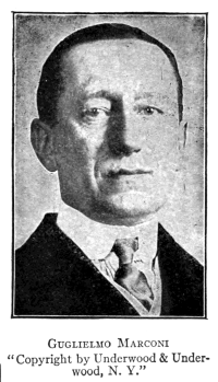 Guglielmo Marconi
"Copyright by Underwood & Underwood,
N. Y."
Guglielmo Marconi (Italy). Inventor
of wireless telegraphy.
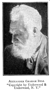 Alexander Graham Bell
"Copyright by Underwood &
Underwood, N. Y."
Alexander Graham Bell, Washington,
D. C. Inventor of the telephone.
399. Color.—Much of the pleasure experienced in gazing
at beautiful objects is due to the color shown by them.
The blue sky, the green grass, and the varied tints of flowers,
and of the rainbow all excite our admiration The study
of color begins naturally with the production of the spectrum,
the many-colored image upon a screen produced by
passing a beam of light through a prism. The spectrum
is best shown when the light enters by a narrow slit (Fig.
400). The spectrum was first produced by Sir Isaac
Newton in 1675 by the means just described. The names
usually given to the more prominent colors of the spectrum
are violet, indigo, blue, green, yellow, orange, and red.
The initials of these names, combined, spell vibgyor, a
word without meaning except to assist in remembering the
order of the colors in a spectrum.
If the light that has
passed through a prism is sent
through a second prism placed
in reverse position (see Fig.
401), the light passing through
both prisms is found to be
white. This experiment
indicates that white light is composed of light of all colors.
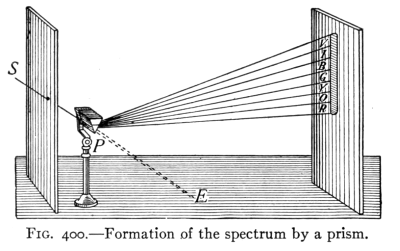 Fig. 400.—Formation of the spectrum by a prism.
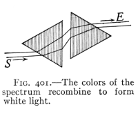 Fig. 401.—The colors of the
spectrum recombine to form
white light.
Fig. 401.—The colors of the
spectrum recombine to form
white light.
400. Dispersion.—The separation of the colors by a
prism is called dispersion. In experimenting to find a
reason for dispersion, it has been learned that lights of
different colors are of different wave lengths. Color in
light is therefore analogous to pitch in sound. We hear
through many octaves, but we see through about one
octave. That is, the shortest visible waves of violet
light are about 0.000038 cm. in length while the longest
visible red rays are 0.000076 cm., or the longest visible
light waves are about twice the length of the shortest
visible ones. It appears from the evidence of experiments
upon dispersion that light
waves of different lengths
are refracted differently.
This causes the images
formed by refraction
through simple glass lenses
to be fringed with color
and to lose some of their
sharpness and definiteness
of outline, since the violet
light is brought to a focus
sooner than the red. (See Fig. 402.) This seriously affects
the value of such lenses for optical purposes. Fortunately
it is found that different kinds of glass have a different rate
of dispersion for the same amount of refraction.
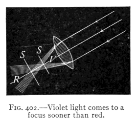 Fig. 402.—Violet light comes to a
focus sooner than red.
Fig. 402.—Violet light comes to a
focus sooner than red.
401. The Achromatic Lens.—The existence of these
different kinds of glass makes possible a combination of
lenses in which dispersion is entirely overcome with the
loss of only about one-half of the refraction. Such a combination
is shown in Fig. 403. It is called an achromatic
lens, since images formed by it are not colored
but white (a = without, chroma = color). The achromatic
lens consists of a double convex lens of crown glass combined
with a plano-concave lens of flint glass. Achromatic lenses
are used in all high-grade optical instruments such as
telescopes and microscopes. The colored images that are
sometimes seen in cheap opera glasses show the result of
not using achromatic lenses.
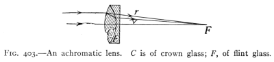 Fig. 403.—An achromatic lens. C is of crown glass; F, of flint glass.
402. The Color of Bodies.—Project the spectrum of
sunlight upon a white surface in a darkened room.
Now place in different parts of the spectrum objects of various
colors. Red objects will show brilliant red when at the red end of
the spectrum but look black at the blue end, while blue objects
appear blue only at the blue end.
These facts indicate that the color of an object depends
upon two things: (a) the light that falls upon it and (b) the
light which it sends to the eye. A black surface absorbs all
color while a white one reflects all wave lengths to the eye
in the same proportion that they come to it. A white
object will appear red in red light, and blue in blue light
since it reflects both of these. A colored object reflects
light of its own color but absorbs all others. The color
then of a body is due to the light which it does not absorb,
but which comes from it to the eye.
403. The color of transparent bodies, such as colored
glass, is due to the presence of a dye or pigment contained in
the body. This pigment absorbs a part of the light, the
part transmitted giving the color. This may be shown by
holding a sheet of colored glass in a beam of light either
before or after it has passed through a prism. Some
colors, as red, may be found to be nearly pure, only the
red passing through, while green glass often transmits in
addition to the green some yellow and some red light.
404. Complementary Colors.—If two prisms are placed
in reversed position near each other (see Fig. 401), a beam
of light dispersed by one is recombined into white light
by the other. If now a card is held between the two prisms
so as to cut off some of the colored light, say the red, the
remaining light will be found to form a greenish blue. If
the card is removed, the light becomes white again. That
is, red and peacock blue light together form white. Any
two colors that together form white light are called complementary.
Other complementary colors are light yellow
and blue, green and crimson, orange and greenish blue,
violet and greenish yellow. We must not confuse the
combining of colors (light) and the combining of pigments,
the latter consisting of bodies that absorb light. Yellow
pigment absorbs all but yellow and some green, while
blue pigment absorbs all but blue and some green. Mixing
these two pigments causes the absorption of all
colors but green. Blue and yellow paint mixed produce
green, while blue and yellow light give white.
405. The solar spectrum, as the spectrum of sunlight
is called, may be observed in the rainbow. The
latter is produced through the dispersion of light by spherical
raindrops. Its formation may be imitated by sending
a small circular beam of light through a screen against a
round glass flask filled with water. (See Fig. 404.) The
light passes through the water and is dispersed when
it enters and when it leaves, producing a color upon the
screen at R-V. The course of the light within the drop
is indicated in Fig. 405. The violet ray comes to the
eye more nearly horizontal and is therefore below red, as
we look at the rainbow.
406. Fraunhofer Lines.—Some of the most important
features of the solar spectrum are not seen in the rainbow
or in the band of light usually observed upon a screen.
By the use of a narrow slit and a convex lens to carefully
focus the slit upon a white screen it is seen that the solar
spectrum is crossed by many dark lines. These are called
Fraunhofer lines, to honor the German scientist who
in 1814 first accurately determined their position. Two
experiments with a spectroscope will help to make clear the
meaning of the Fraunhofer lines.
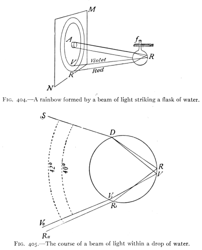 Fig. 404.—A rainbow formed by a beam of light striking a flask of water.
Fig. 405.—The course of a beam of light within a drop of water.
407. The Spectroscope and Its Uses.—The spectroscope
(Fig. 406) is an instrument for observing spectra. It
consists of a prism, a slit, and a convex lens T for focusing
an image of the slit accurately upon a screen (Fig. 407)
where the spectrum is observed through the eyepiece E.
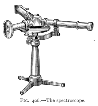 Fig. 406.—The spectroscope.
(A) A Bunsen flame is placed in front of the slit and a
heated platinum wire which has been dipped in common
salt or some sodium compound placed in the Bunsen flame;
the latter becomes yellow and a vivid yellow line is observed
on the screen in the spectroscope. Other substances,
as barium and strontium salts, when heated to
incandescence in the Bunsen flame, give characteristic
bright lines. In fact each element has been found to have
its own characteristic set of colored lines. This fact is
made use of in spectrum analysis, by which the presence
of certain elements in a substance can be definitely proved
upon the appearance of its particular lines in the spectrum.
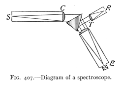 Fig. 407.—Diagram of a spectroscope.
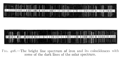 Fig. 408.—The bright line spectrum of iron and its coincidences with
some of the dark lines of the solar spectrum.
Fig. 408.—The bright line spectrum of iron and its coincidences with
some of the dark lines of the solar spectrum.
(B) If light from, for example, an arc light is sent over a
gas flame containing sodium vapor, a dark line appears in
the spectrum—in the exact position in which the yellow
sodium line appeared. It seems that the sodium vapor
removes from white light the same wave lengths that it itself
produces. This absorption is supposed to be due to
sympathetic vibration; just as a tuning fork is set in vibration
by the waves of another fork in unison with it, at
the same time absorbing the wave energy, so in the gas
flame the sodium particles absorb the wave motion of the same
vibration rate as that emitted by them. The fact
that the spectrum of sunlight contains a great many dark
lines is believed to indicate that the sun is surrounded
by clouds formed by the vaporization of the various substances
in the sun itself. By comparing the dark lines of
the solar spectrum with the bright-line spectra of various
substances found in the earth, such an exact correspondence
of the lines is found that the presence of the vapor
of these substances about the sun is considered proved.
(See Fig. 408 which shows the exact correspondence
between the bright-line spectrum of iron vapor and the
dark lines appearing in a portion of the sun's spectrum.)
The spectra of the stars also contain certain dark lines.
Thus the presence of the corresponding substances in distant
stars is considered as determined.
408. Theory of Color Vision.—By combining light of
the three colors red, green and blue-violet in proper proportions,
it has been found possible to produce any color
effect, even white. This leads to the conclusion that in
the retina of the eye are three different kinds or sets of
sensitive nerve endings, sensitive respectively to red, to
green, and to blue light. This idea is given corroboration
by some facts of color blindness. Thus some persons have
no sensation of red, this color not being distinguished
from green. Others are color blind to green or blue. It
is supposed that in color blind persons one of the sets of
nerve endings sensitive to one of these three colors is
lacking.
409. Three-color Printing.—Since all colors may be
produced by mixing the three colors, light red, green, and
blue-violet, these are called the three primary colors. The
so-called primary pigments or paints are simply the complements
of the three primary colors. They are, in order,
peacock blue, crimson, and light yellow. The three
pigments when mixed yield black, since combined they
absorb all kinds of visible light. The process of three-color
printing, now so generally employed in printing
colored pictures for books, calendars, etc., consists in
combining upon white paper three colored impressions,
using successively the three primary pigments (yellow,
crimson and blue) from plates prepared as follows:
Three photographs of a given colored object are taken,
each through a different sheet of gelatine called a filter,
stained the color of one of the primary colors. From these
photographs half-tone blocks are made in the usual way.
The colored picture is made by carefully superposing impressions
from these blocks, using in each case an ink
whose color is the complement of the "filter" through
which the original picture was taken. An illustration of
the process is given upon the plate in the frontispiece of
this book.
1. Color, due to wave length; dispersion by prism, sphere in rainbow,
complementary colors, color of opaque and transparent
bodies.
2. Spectra, solar; formation of rainbow; bright-line spectra, how
formed, how used; dark-line, how formed, used.
3. Theory of color vision. Three color printing.
1. How does a white flower look when viewed through a blue glass?
Through a red glass? Through a red and blue glass at the same
time?
2. Why does a red ribbon appear black when seen by blue light and
red when seen by red light?
3. In what part of the sky must you look to see a rainbow in the
morning? In the afternoon? Explain.
4. How would you arrange two similar prisms so as to produce
double the deviation produced by one?
5. The color of an object depends upon what two things?
6. What kind of a spectrum should moonlight give? Why?
7. A mixture of green and red lights gives a sensation of yellow.
Can you suggest why a mixture of blue and yellow lights gives
the sensation of white?
410. The Corpuscular Theory.—The theory of the
nature of light that was most generally accepted until
about the year 1800, held that light consists of streams of
minute particles, called corpuscles, moving at enormous
velocities. This corpuscular theory was in accord with the
facts of reflection and the rectilinear motion of light, but
was abandoned after the discovery of the interference of
light, as it could not account for the latter phenomenon.
411. The Wave Theory of Light.—The theory that
light is a form of wave motion was first advanced by Huygens,
a Dutch physicist, in the seventeenth century. This
theory was opposed at the start since (A) no medium was
known to exist which would convey wave motion through
space, as from the sun to the earth, and (B) the rectilinear
motion of light was unlike that of any other form of known
wave motions, such as that of water or of sound waves
which are able to bend around corners. In answer to the
first objection, Huygens assumed the presence of a medium
which he named ether, while the second objection has been
completely overcome during the past century by the discovery
that light may deviate from a straight line. It is
now known that the excessive shortness of light waves is
the reason for its straight-line motion. Further, long ether
waves, as those of wireless telegraphy, are found to bend
around obstacles in a manner similar to those of water or
sound.
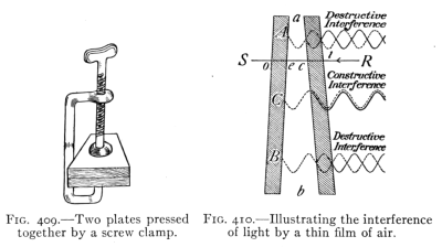 Fig. 409.—Two plates pressed
together by a screw clamp.
Fig. 409.—Two plates pressed
together by a screw clamp.
Fig. 410.—Illustrating the interference
of light by a thin film of air.
412. The interference of light is one of the phenomena
for which the wave theory offers the only satisfactory
explanation. Interference of light may be shown by taking
two pieces of plate glass and forcibly pressing them
together by a screw clamp, as shown in Fig. 409. After a
certain pressure has been reached, colored rings will appear
about the compressed spot when viewed by light reflected
from the upper surface of the glass. If light of one color,
such as that transmitted by red glass, falls upon the apparatus,
the rings are seen to be alternately red and dark
bands. The explanation of this phenomenon according
to the wave theory is as follows: The two sheets of glass,
although tightly pressed together, are separated in most
places by a thin wedge of air (see Fig. 410), which represents
in an exaggerated form the bending of the plates
when pressed by the clamp. Several waves are represented
as coming from the right and entering the glass. Now the
wave moving from R to the plates has some of its light reflected
from each glass surface. Consider the two portions
of the wave reflected at each of the surfaces between the
plates, i.e., from the two surfaces of the wedge of air.
If the portion of the wave reflected from the second surface
of the air wedge combines with that reflected from the
first surface, in the same phase as at C, the two reflected
waves strengthen each other. While if the two reflected
portions of the wave meet in opposite phases as at A and B,
a decrease or a complete extinction of the light results.
This is called interference. If light of one wave length
is used, as red light, the regions of reinforcement and interference
are shown by red and dark rings, while if white
light is used, the ring where red light interferes, yields its
complementary color, greenish blue. Where interference
of greenish blue occurs, red is found, etc. Many phenomena
are due to interference, such as (A) the color of thin
films of oil on water, where the portions of light reflected
from the two surfaces of the oil film interfere resulting in
the production of color; (B) the color of soap bubbles.
When first formed, soap-bubble films are not thin enough
to show interference well, but as the bubbles increase in
size or become thinner on standing, the conditions for
interference are reached and, as the film becomes thinner,
a regular succession of colors is noticed.
413. Differences Between Light and Sound.—Among
the important differences between light and sound that
have been considered are the following: the former are
(a) waves in the ether, (b) of very short wave length, and
(c) their motion is in straight lines. Another difference (d)
is in the mode of vibration.
Sound waves are longitudinal, while light waves are transverse.
Light waves consist of vibrations of the ether at
right angles to the line of motion. To illustrate the reasoning
that has led to this conclusion, suppose a rope to be
passed through two vertical gratings. (See Fig. 411, 1.)
If the rope be set in transverse vibration by a hand, the
waves produced will readily pass through to the gratings
P and Q and continue in the part extending beyond Q.
If, however, Q is at right angles to P, no motion will
be found beyond Q. Now if a stretched coiled spring with
longitudinal vibrations should take the place of the rope,
it is evident that the crossed position of the two gratings
would offer no obstacles to the movement of the vibration.
In other words, crossed gratings offer no obstruction to
longitudinal vibrations, while they may completely stop
transverse vibrations.
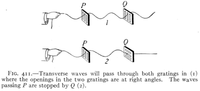 Fig. 411.—Transverse waves will pass through both gratings in (1)
where the openings in the two gratings are at right angles. The waves
passing P are stopped by Q (2).Fig. 411.—Transverse waves will pass through both gratings in (1)
where the openings in the two gratings are at right angles. The waves
passing P are stopped by Q (2).
Fig. 411.—Transverse waves will pass through both gratings in (1)
where the openings in the two gratings are at right angles. The waves
passing P are stopped by Q (2).Fig. 411.—Transverse waves will pass through both gratings in (1)
where the openings in the two gratings are at right angles. The waves
passing P are stopped by Q (2).
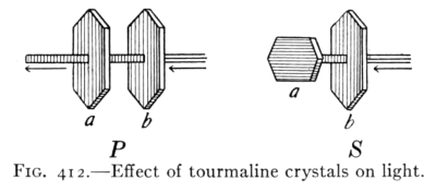 Fig. 412.—Effect of tourmaline crystals on light.
414. Polarization of Light.—It is found that two crystals
of tourmaline behave toward light just as the two gratings
behave with respect to the transverse waves of the rope.
Thus, if a small opening in a screen is covered with a
tourmaline crystal, light comes through but slightly
diminished in intensity. If a second crystal is placed over
the first one so that the two axes are in the same direction
as in Fig. 412P, light is as freely transmitted through the
second crystal as through the first, but if the crystals are
crossed (Fig. 412S) no light passes the second crystal.
This experiment shows that the light which has passed
through one tourmaline crystal will pass through another
only when the latter is held in a certain position, hence it
is believed that a tourmaline crystal is capable of transmitting
light that is vibrating in one particular plane. The
direct conclusion from this is that light waves are transverse
rather than longitudinal. The experiment just described
illustrates what is called polarization of light. The beam
that after passing through a (Fig. 412) is unable to pass
through b, if the two axes are crossed, is called a polarized
beam. The conclusion that light waves are transverse is
therefore based upon the phenomenon of the polarization
of light. This was first discovered by Huygens in
1690.
1. Interference of light: evidence, reasoning involved, illustration.
2. Polarization of light: evidence, reasoning involved.
3. Nature of light, differences between sound and light.
1. Make a list of the differences between sound and light and state
briefly the evidence upon which the knowledge of these differences
is based.
2. Why will a thickness of film that will produce interference of
red light be different from that producing interference for green
or blue?
3. Using the formula n = v/l compute the vibration rate for violet
light if its wave length is considered as 0.00004 cm.
4. Explain how the fact of polarization affects the wave theory of
light.
5. Show how it is possible by comparing the spectrum of the sun
with that of a star to tell whether the star is approaching or
receding from the earth.
Light; speed, source, medium.
Straight Line Motion; shadow, umbra, penumbra, eclipse, image.
Photometry; Law of intensity, candle power, foot-candle.
Mirrors; Law of reflection; image—real, virtual; plane, curved, parabolic,
mirrors.
Refraction; cause and effects; plate, prism, lens; total reflection.
Lenses; six forms, principal focus, center, lens equation, 1/F = 1/Do
+ 1/Di.
Optical instruments; eye, defects and correction, camera, microscope,
etc.
Spectra; 3 kinds, dispersion, production of color effects, spectroscope,
uses.
Nature of Light; wave theory, interference, polarization,
significance.
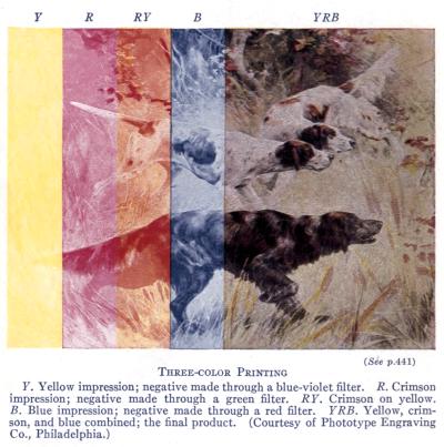 (See p.441)