While attempts at Perpetual Motion are
as old as the human race, not many of the more
ancient devices have been preserved, either by
engraving or by explanation.
Among the very earliest of these attempts
of which we have detailed information is the
device of Wilars de Honecort. He was an
architect, and lived in the thirteenth century.
The information is preserved in "A Sketch
Book" by him which was deposited and remains
in the Ecole des Chartes at Paris. About
the middle of the nineteenth century comments
were published in France on this ancient device.
Some of these were translated into English.
The following account is an extract from a
translation made by Professor Willis, of Cambridge.
"Many a time have skilful workmen tried to
contrive a wheel that shall turn of itself: here is a
way to make such a one, by means of an uneven
number of mallets, or by quicksilver."
Wilars de Honecort presents to us a device
for a perpetual motion; it is not clear
whether he intends to claim the contrivance of
it, or whether he had met with it in the course
of his travels. It differs very little from a well-known
contrivance for this purpose which has
been so often published, and its fallacy so fully
explained in popular books, that it is unnecessary
to dwell at length upon the mechanical
principles which it involves. It is extremely
curious in this place, because it shows the great
antiquity of the problem, the solution of which
has wasted the time, the brains, and the means
of many an unhappy artisan or philosopher.
In the drawing we have now before us, the
two upright posts, which are framed together
and skilfully braced so as to ensure their steadiness,
support between them a long horizontal
axle, to the center of which is fixed a wheel
with four spokes. The absence of perspective
in this drawing makes the wheel appear as if
it were parallel to the frame, instead of being,
as it is, at right angles to it.
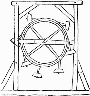
Seven mallets, or arms, each loaded with
a heavy weight at the end, are jointed at equal
distances to the circumference of the wheel, so
that those which happen to have their joints
below the diameter of the wheel will hang
freely down, but if the wheel be turned round by
hand or otherwise, the weights of those which
are on the ascending side will, in succession,
rest on its circumference, and will, in that position,
be carried over the highest part of the
wheel and downwards on the descending side,
until the arms that bear them are brought into
a vertical position and a little beyond it, and
then the weight will fall suddenly over and rest
on the opposite position on the circumference of
the wheel, until its further descent enables it
to dangle freely as before. The effect of this
mechanism upon the position of the weights
is not truly represented, for the upper mallet
has fallen over too soon. In the modern form
of this contrivance a pin, or stop, is introduced,
by which the mallet, when it falls over, is compelled
to rest so that its arm shall point to the
center of the wheel, and thus the descending
weight be held at a greater distance from the
center than when ascending. It is extremely
probable that this difference is a mere error of
the artist, for the drawing has the appearance
of having been made from a model of the wheel
at rest; a condition in which, of course, it would
always be found, unless moved by some external
force. The inventor seems to have
thought that the action above described would
always place four weights on the descending
side, and leave but three on the ascending side,
each weight as it rises to the top being intended
to leap suddenly over to the descending side,
in the manner just explained; or perhaps, as
M. Lassus suggests, the contriver imagined
that the blows given to the wheel in succession
by the falling mallets would help it forward.
It is surprising that although the slightest
model would show the failure of devices of this
class to persons incapable of mathematical reasoning,
yet such machines have been seriously
proposed in books, and are continually recontrived
by ingenious workmen. The allusion
to quicksilver in the manuscript shows that
Wilars was acquainted with the well-known
contrivance described in the books already referred
to, in which portions of that metal inclosed
in channels are used instead of the falling
weights.
This device was brought forth in 1831 in
England, and illustrates what we say in the
Introductory Essay to the effect of inventors
working on the same plan in different parts of
the earth and centuries apart.
We are unable to give the inventor's name.
He was a correspondent to Mechanics' Magazine,
and the description furnished by the inventor
as published in Mechanics' Magazine,
is as follows:
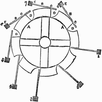
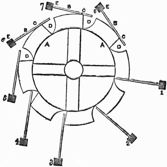
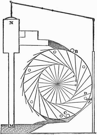
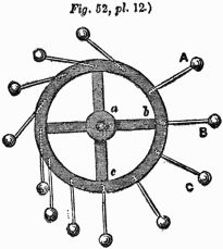
Description.—A A A is a ring of thin wood;
B B B, several spokes, movable round the fixed
points C C C, and only allowed to move one way
by the construction of the openings D D D;
E E E, heavy weights fixed to the ends of the
spokes.
From the position in which the wheel is at
present, it is evident that the weights on the right-hand
side (1 and 2) acting at a greater distance
from the center than those (4 and 5) on the other
side, will cause that side to descend until the spoke
1 reaches the position 3, when it will exert no
moving influence, but by which time the weight 8
will have fallen into the position 1, when a similar
effect will take place, and so on with the rest.
It is with a mingled feeling of sorrow and
exaltation that we note the Perpetual Motion
labors of the great Leonardo da Vinci. Of all
of the men who ever gave the subject more
than a passing notice he is the most famous.
Leonardo da Vinci was an Italian, born in
1452, and died in 1519. He was the illegitimate
son of Florentine, lawyer. His mother has
been variously described as a peasant, and as
of gentle birth. Little about her is known.
The father belonged to a family of lawyers,
and never repudiated the son, but took him,
educated him, and cared for him. It is well
for the world that he did, for Leonardo da Vinci
has perhaps contributed more to art and learning
in the world than any other single individual
that ever lived. He was a painter, a sculptor,
an architect, a musician, a mechanician,
engineer and natural philosopher. Each subject
in art or science that he touched he not
only mastered, but improved and embellished.
He painted the original of the well-known picture
of the Christ and His twelve Apostles,
known as the "Last Supper," or the "Last Supper
of Our Lord." This, and Mona Lisa, are
perhaps the paintings by which he is known to
the greatest number of people, and are considered
by many connoisseurs the highest perfection
in art ever attained by mortal man.
But, as painter and sculptor, he is to be
regarded as among the greatest, if not the very
greatest that ever lived. In art he ranks beside,
if not ahead of Michelangelo and Raffael,
and yet they are known only as artists, while
he was preeminent in both art and science. The
work he did in natural science was entirely
original and emanated from an inherent initiative
and originality, and as a scientist, he is
entitled to rank below only Newton, Gallileo
and Copernicus, and very few others. In all
the history of the world he is the only man of
whom it can be said that he attained the apex
of eminence in both art and science.
The information concerning Leonardo da
Vinci's devices for obtaining Perpetual Motion
is extremely meager. There does not seem to
be extant any detailed explanation of just how
he expected his different designs to work.
All that is known concerning his efforts
is sufficiently illustrated by the following cuts
and language from Dircks:
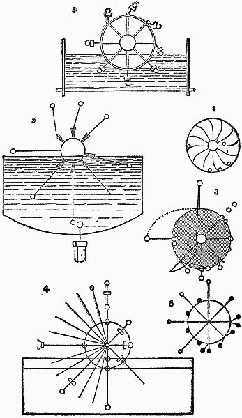
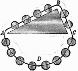
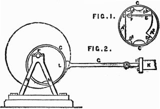
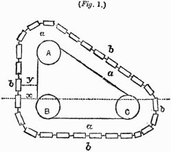
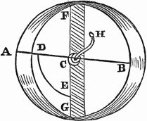
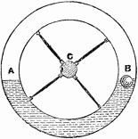
Fig. 1 may be taken as a scheme belonging
to the fifteenth century. It seems to be placed
at the head as a simple or elementary design
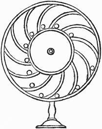
for future improvement. It is a chambered
drum wheel, containing balls or weights, which,
being always farthest from the center on one
side, as compared to the other, are expected to
keep the wheel constantly rotating.
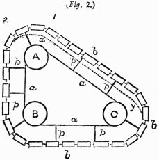
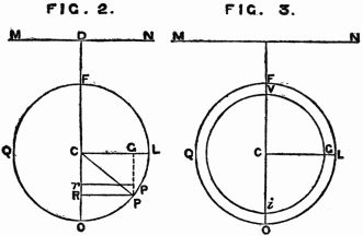
Fig. 2. Failing in this scheme, the inventor
next offers one with weighted levers, which
are to fall outwards on one side, but to fall inwards
on the opposite side, the weight at the
same time sliding up the lever when vertical
at the bottom, so as to be nearer the center
throughout on the ascending side. But how
the weight is to be made to ascend at the bottom
remains to be shown.
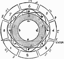
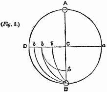
Fig. 3. The difficulty of elevating the
weight would appear to have suggested its immersion
in a trough of water, as here shown.
The weights seem to be attached to some contrivance
to float them upwards; but we are perplexed,
and so no doubt was da Vinci, how to
sink them, or being sunk, how to render them
again buoyant by any self-motive process.
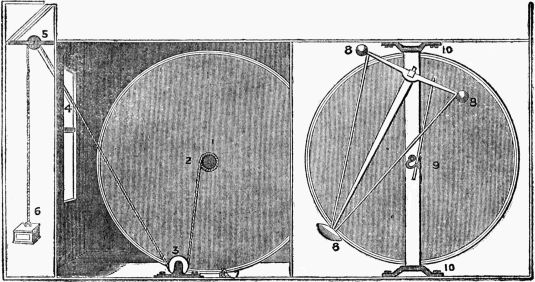
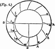
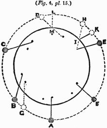
Fig. 4. It would appear as though the difficulties
observable in Fig. 3 were attempted
to be met here, in a plan which evidently combines
several views of the case, yet without
removing the main difficulty; for although the
weight at the end of the long arm may be quite
capable of sinking in the liquid, we still inquire,
How is it ever to be raised again?
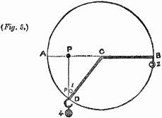
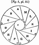
Fig. 5 seems to be an incomplete sketch,
and a mere variation on the preceding designs,
with the addition either of machinery below to
be worked by it, or to give it motion. Possibly
it was proposed to have a magnet at the bottom
of the vessel.
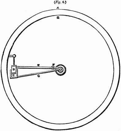
Fig. 6 appears to be two designs in one
sketch. On one side we have long single
levers, with a single weight at their ends, and a
weight between each at the periphery; on the
other end, double or forked levers and double
weights. Its mixed character renders it probable
that it was merely some preliminary
sketch.
The great value of the present exhibition
of these early contrivances of misdirected mechanical
ingenuity consists in the convincing
evidence which they afford, that all young inventors
who occupy themselves in the search
for self-motive machines, do little more than
reproduce the blunders of a past age. After a
lapse of five centuries modern inventors often
become patentees of contrivances which are
only more complicated than the assumed-to-be
overweight wheel of Wilars de Honecort, or
the six similar ones of Leonardo da Vinci.
But such has hitherto been the ignorance of
mechanics on this subject, that Fig. 1 of the
annexed diagrams has frequently been adduced
by writers on the subject, as the veritable wheel
invented by the Marquis of Worcester, in the
seventeenth century!
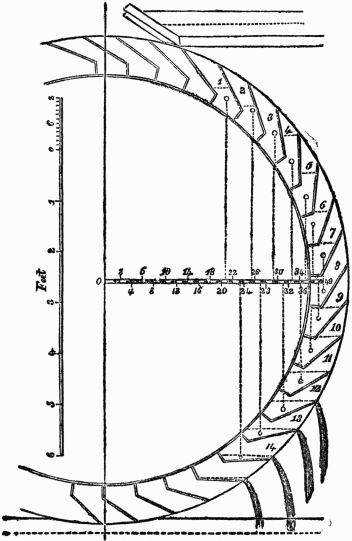
In 1678, A Capra, of Italy, revived the ancient,
but still favorite scheme that dates back
to the 13th century. (See page 22 ante.) He
illustrates his idea with the following figure
and the following comment:
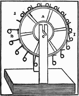
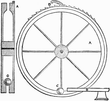
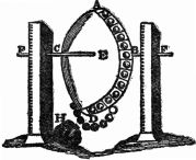
On the wheel A (of the facsimile engraving
opposite), which must be hung well equipoised
between two uprights, are appended
counter-weights, eighteen in number, all precisely
at the same distance from each other,
and all exactly of the same weight. The counter-weights
are provided with a small ring by
which they are hung.
Whilst the counter-weights B are farther
from the center C of the wheel, they weigh
more than the counter-weights I, because these
are low and nearer to the center C of the wheel,
so that the counter-weights B descend and the
weight I drops; and whilst the weight B is alternately
descending and the weight I ascending,
the wheel will revolve continually. But
it must be understood that it is necessary to
make the wheel perfectly true in equilibrium,
so that it do not weigh more on one side than
on the other on account of the counter-weights.
This inventor was certain he had overtaken
and captured the ever-illusive Perpetual
Motion. He gives a description of his happiness
and his machine in the following effusively
joyous language:
The annexed drawing shows how I have
at length taken this enticing jilt (perpetual
motion), though after a long and weary
chase—
Through pleasant and delightful fields,
Through barren tracts and lonely wilds;
'Mongst quagmires, mosses, muirs and marshes,
Where deil or spunkie never scarce is!
By chance I happened on her den,
And took her when she didna ken.
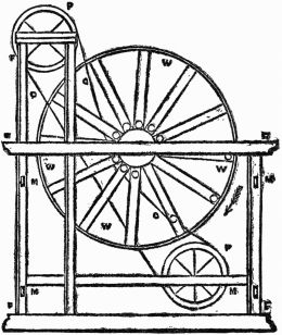
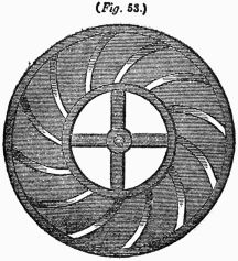
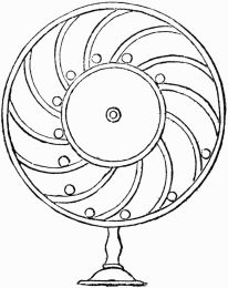
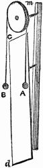
W W W W represents a wheel with
twelve hollow spokes, in each of which there
is a rolling weight or ball. C C C C is a chain
passing over two pulleys P P. There is an opening
round the wheel from the nave to the circumference,
so as to allow the chain to pass
freely and to meet the weights. The weights
are met by the chain as the wheel revolves,
and are raised from the circumference till they
are at last brought close to the nave, where
they remain till, by the revolution of the wheel,
they are allowed to roll out to the circumference.
By this arrangement the weights are,
on one side of the wheel, always at the circumference,
so that that side is more powerful than
the other, which causes the wheel continually
to revolve. F F F F is the frame of the machine;
M M M M the mortices for joining the
two sides of the frame by cross rails. The
arrows point out the direction in which the
wheel turns.—I am, yours, &c., Dixon Vallance.
Liberton, Lanarkshire, Nov. 10, 1825.
Strange as it may seem, the patent office
of the U. S. government as late as 1884 and
1886, received and filed, seriously considered
and granted Letters Patent on Perpetual Motion
Devices as appears from the description of
Furman's Device following, and from Schirrmeister's
"Mechanical Movement," and Enbom
& Anderson's "Improvement in Pumps," appearing
on pages 38 and 76 respectively, supra.
These were not denominated Perpetual
Motion Devices by the inventors, but the specifications
show them to be simply that and
nothing more.
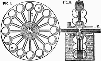
July 15, 1884, George H. Furman, of
Rochester, Ohio, U. S. A., was granted U. S.
Patent No. 301979, on
"A New and Improved Motor."
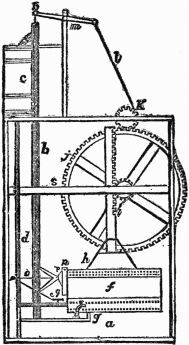
The essentials are sufficiently shown by
the following excerpt from the specifications
and the following figure. We have omitted
Figure 2, mentioned in the specifications:
UNITED STATES PATENT OFFICE.
George H. Furman, of Rochester, Ohio.
MOTOR.
Specification forming part of Letters Patent
No. 301979, dated July 15, 1884.
Application filed March 6, 1884. (No model.)
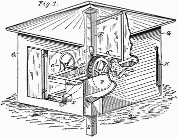
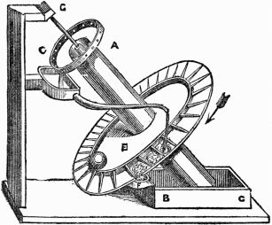
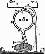
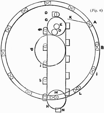
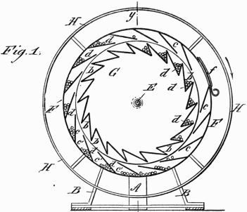
The action of the motor is as follows: A
suitable quantity of the small weights d being
placed in the outer drum, F, through the door
f, the machine being at rest, they will accumulate
at the lower part of the drum F in the
pockets c´ c´. Now, to run the machine a person
will apply his hands to the rim H and revolve
the outer drum, F, in the direction of the
arrow shown in Fig. 1. This movement of the
outer drum will cause the weights d to be carried
in the pockets c´ c´ to the upper side of the
drum, at which point they will roll from the
pockets c´ c´ into the pockets b b of the inner
drum, G, where their weight will cause the drum
G and shaft E to revolve. As the pockets b of
the inner drum pass below the shaft E they empty
the weights into the troughs c´ of the outer wheel,
F, to be again carried above the shaft and dropped
into the pockets b, so that the inner wheel, G, and
shaft E will be revolved continuously.
July 6, 1886, Charles Schirrmeister, of
Brooklyn, Kings County, State of New York,
U. S. A., obtained Letters Patent No. 345077,
on a new and useful
"Mechanical Movement."
The essentials of the patented device appear
from the following excerpts from the specifications,
and the following figures accompanying
the specifications. (Figs. 2, 3 and 4
we do not show.)
The object of my invention is to furnish a
cheap and simple means for imparting mechanical
power; and I accomplish this by means of
a series of radial arms placed at right angles to
and projecting from the axis of motion where
power is first applied, and so arranged that each
arm is in a different vertical plane, said arms
being weighted at each end with a ball of metal.
Some of these arms are also made hollow and
inclose sliding or rolling weights, which move
back and forth as the axis revolves, and the motion
is still further re-enforced by a series of
springs which are attached to the axis by a
lever and eccentric.
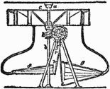
Taking the simplest form of my device, I
illustrate the same by the accompanying drawings,
in which—
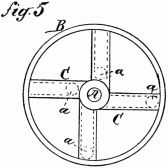
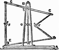
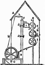
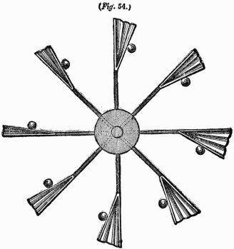
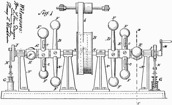
Figure 1 is a side elevation of the entire
apparatus. Fig. 2 is a sectional view showing
the hollow arm with a rolling weight. Fig. 3
is an end view showing the operation of a re-enforcing
spiral spring. Fig. 4 is a detailed
view showing still further the method of re-enforcing
motion by springs. Fig. 5 is a view
of the driving-pulley with its hollow arms.
Similar letters refer to similar parts in the
several views.
A is the axis to which the power first imparting
motion is applied.
N are the bearings supporting the same.
B is the driving-pulley attached to said
axis, and from which motion is imparted by
means of the driving belt b to any point desired.
C are the hollow arms of the driving-pulley
B.
D are the solid arms radiating from the
axis A.
E are the hollow arms radiating from the
axis A.
F are the solid balls or weights secured to
the ends of the arms D and E.
a are the sliding or rolling weights, which
are inclosed within the hollow arms C and E.
c are the slots cut into the hollow arms E,
to relieve the air-pressure formed by the backward
and forward motion of the weights a.
G are springs so arranged as to expend
their force upon the axis A by means of the
connecting rods H, both attached to the springs
and one attached to the axis A by means of the
eccentric I and the other to the wheel J at one
end of the axis.
K is a balanced lever, upon which the
springs G may rest, said lever being supported
at each end upon the springs L.
M is a crank attached to one end of the
axis A, and serves to show the place and manner
in which the power may be applied.
The manner of constructing and operating
my invention is as follows: The entire apparatus
is made of steel or iron, and the shaft,
bearings, arms, springs and connecting-rods
are of ordinary form. The main or driving
pulley is cast with four hollow arms, in which
round weights are inclosed, which move back
and forth within the arms when the wheel is
set in motion. The solid arms, as well as the
hollow arms, which are used in addition to
those forming a part of the driving-pulley, are
arranged by means of set-screws a suitable distance
apart upon the axis and in different perpendicular
planes, so as to give steadiness in
motion. A thread is cut upon each end of these
arms, and the fixed weights are then screwed
on. When the shaft or axis revolves, the
weights which move toward the ends of the
arms above the center accelerate the motion,
and the momentum of the machine aids in overcoming
the resistance caused by the weights,
which are below the center. At the same time
the revolution of the eccentric and crank-pin
upon the axis depresses the connecting-rods,
which in turn depress the springs, which, being
released as soon as the eccentric and crank-pin
have reached their lowest point, contribute a
lifting power to overcome the resistance above
mentioned. As shown in the drawings, these
springs joined to the connecting-rods may be
supported and assisted by other springs.
The power is applied by hand, operating
upon a crank at the end of the axis, or may be
imparted by steam, hot air, electricity, or in
any other known method, and is conducted to
any desired point by means of the belt b.
Having fully described my invention, what
I claim as new, and desire to secure by Letters
Patent, is:
1. The combination, in apparatus for increasing
mechanical power, of an axis, as A,
supported upon bearings N, with a driving-pulley,
as B, having hollow arms, as C, with
movable weights, as a, and radial arms, both
solid and hollow, the latter having movable
weights, together with fixed weights attached
to the end of each arm, all substantially as and
for the purpose described.
James Ferguson was an eminent Scotch
mechanician and astronomer. He was born in
1710, and died in 1776. He was reared in very
humble circumstances, and is known as the
Peasant Boy Philosopher. A most interesting
story of his life was written by Henry Mayhew,
and published in England in 1857, entitled
"The Story of the Peasant Boy Philosopher."
He prepared astronomical tables of great
value and lectured on astronomical and mechanical
subjects. His lectures were edited by
a no less eminent man than Sir David Brewster.
While Perpetual Motion seemed to have received
considerable time and attention from him,
and while his writings show that he examined a
great many mechanical devices, he seems all the
time to have entertained serious doubt of the possibility
of a machine having self-motive power.
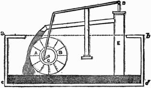
However, in 1770, he devised a machine for the
purpose of producing Perpetual Motion. It
does not appear that he ever offered the machine
to the public, or sought publicity for it.
A description of it is to be found in his Common
Place Book in the University Library, Edinburg.
The description there furnished is as
follows:
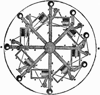
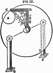
The axle at A is placed horizontally, and
the spokes B, C, D, etc., turn in a vertical position.
They are jointed at s, t, u, etc., as a common
sector is, and to each of them is fixed a
frame as R, S, T, etc., in which the weights
7, 8, 9, 1, 2, etc., have liberty to move. When
any spoke as D is in a horizontal position, the
weight I in it falls down and pulls the part b
of the then vertical spoke B straight out, by
means of a cord going over the pulleys K and
k to the weight I. The spoke C c was pulled
straight out before, when it was vertical, by
means of the weight 2, belonging to the spoke
E e which is in the horizontal position D d; and
so of all the others on the right hand. But
when these spokes come about to the left hand,
their weights 4, 5, 6 fall back, and cease pulling
the parts f, g, h, i; so that the spokes then
bend at their joints X, y, z, and the balls at
their ends come nearer the center A, all on the
left side. Now, as the balls or weights at the
right hand side are farther from the center A
than they are on the left, it might be supposed
that this machine would turn round perpetually.
I have shown it to many who have declared
it would; and yet for all that, whoever
makes it, will find it to be only a mere balance.
I leave them to find out the reason.
This device was incubated in the brain of
an American. His name is unknown. We
have denominated it "B. Belidor's Device," not
because B. Belidor was the inventor, but because
the account of the invention was furnished
by him. This device seems to the author
to have possessed originality, though, of
course, it failed to work for reasons clearly
apparent.
An account of it was given in the Journal
of Franklin's Institute, Philadelphia, in 1828.
The article contributed by B. Belidor is as
follows:
Even the pursuit after perpetual motion,
hopeless as it is, may not be considered entirely
vain, in occasionally leading to useful
modifications of machinery. As an instance of
this, I here submit to you a plan suggested by
an ingenious friend of mine, several years ago,
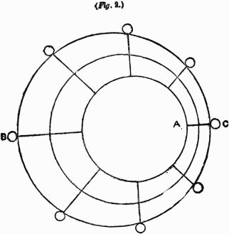
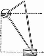
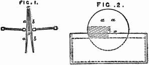
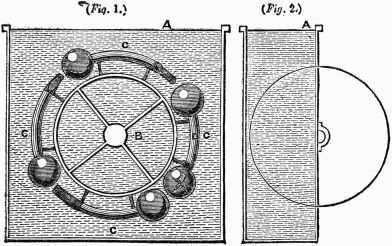
as in the diagrams annexed, Fig. 1, a perpendicular,
and Fig. 2 a horizontal view.
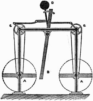
A A, two vertical wheels, placed diagonally,
and revolving on the axes X X. The
levers B B and C C are hinged at the peripheries
of the wheels. By rotation the arms B B are
projected from the center of motion, while the
arms C C are drawn in.
It is plain that a series of arms as shown
in Fig. 2, will produce an eccentric motion,
causing the weights at their ends apparently
to preponderate on the side B.—Belidor.
This so-called problem is of doubtful classification.
The author of the problem did not
claim that the discovery of the problem discloses
any means for attaining Perpetual Motion,
and, yet, it is apparent that if the author
of the problem was correct in his solution of it,
Perpetual Motion was thereby already within
his grasp. The difficulty about it all is that
while the problem is quite interesting, the
author's solution shows that he was not familiar
with even fundamental mechanics. The
name of the author was J. T. Desagulier, LL.D.,
F. R. S. He was a minister of the gospel, but
evidently gave considerable attention to mechanical
questions. He is mentioned in chapter
X of this work.
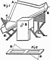
Rev. Desagulier presented two problems
of the balance. One he calls "A Proposition on
the Balance, not taken notice of by Mechanical
Writers, explained and confirmed by an Experiment."
The article under this heading is
as follows:
In the last papers I published in "Philosophical
Transaction" against this perpetual motion,
described in No. 177, I intreated the author to
permit me to say nothing as to what alterations he
might make in his engine, resolving to leave it
to others to show him that upon that principle
all he can do signifies nothing. But I
find since, in the "Nouvelles de la Republique"
for December last, that he still persists to urge
some new contrivances, which being added, he
conceives his engine must succeed. To this I
answer, that I undertook only to shew that his
first device would faile, which yet I should
scarce have done if I had thought a dispute of this
nature could have lasted so long. To come,
therefore, to the point where he saith that this
engine may well succeed without alteration,
because he hath tryed with liquors put into
bellows immersed in water; I again say that I
grant him the truth of the experiments, but
deny the consequences he would draw from
them. I have already given the reasons of my
dissent, which this gentleman is not pleased to
understand. But to end all controversies, he
may please to consult Mr. Perrault, De la Hire,
or any other at Paris well known to be skilled
in hydraulicks, and I doubt not but he will find
them of the same opinion with Mr. Boyle, Mr.
Hook, and other knowing persons here, who all
agree that our author is in this matter under a
mistake.
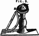
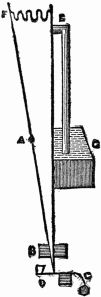
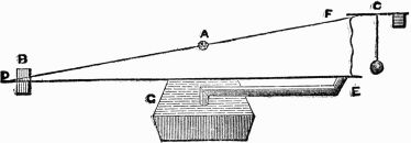
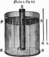
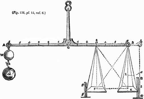
A B is a balance, on which is supposed to
hang at one end, B, the scale E, with a man in
it, who is counterpoised by the weight W hanging
at A, the other end of the balance. I say,
that if such a man, with a cane or any rigid
straight body, pushes upwards against the
beam anywhere between the points C and B
(provided he does not push directly against B),
he will thereby make himself heavier, or overpoise
the weight W, though the stop G G hinders
the scale E from being thrust outwards
from C towards G G. I say likewise, that if
the scale and man should hang from D, the
man, by pushing upwards against B, or anywhere
between B and D (provided he does not
push directly against D), will make himself
lighter, or be overpoised by the weight W,
which before did only counterpoise the weight
of his body and the scale.
If the common center of gravity of the
scale E, and the man supposed to stand in it,
be at k, and the man, by thrusting against any
part of the beam, cause the scale to move outwards
so as to carry the said common center of
gravity to k x, then, instead of B E, L l will
become the line of direction of the compound
weight, whose action will be increased in the
ratio of L C to B C. This is what has been
explained by several writers of mechanics; but
no one, that I know of, has considered the case
when the scale is kept from flying out, as here
by the post G G, which keeps it in its place, as
if the strings of the scale were become inflexible.
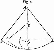
Now, to explain this case, let us suppose
the length B D of half of the brachium
B C to be equal to 3 feet, the line B E to 4 feet,
the line E D of 5 feet to be the direction in
which the man pushes, D F and F E to be respectively
equal and parallel to B E and B D,
and the whole or absolute force with which the
man pushes equal to (or able to rise) 10 stone.
Let the oblique force E D (= 10 stone) be resolved
into the two E F and E B (or its equal
F D) whose directions are at right angles to
each other, and whose respective quantities
(or intensities) are as 6 and 8, because E F and
B E are in that proportion to each other and to
E D. Now, since E F is parallel to B D C A,
the beam, it does no way affect the beam to
move it upwards; and therefore there is only
the force represented by F D, or 8 stone, to
push the beam upwards at D. For the same
reason, and because action and reaction are
equal, the scale will be pushed down at E with
the force of 8 stone also. Now, since the force
at E pulls the beam perpendicularly downwards
from the point B, distant from C the whole
length of the brachium B C, its action downwards
will not be diminished, but may be
expressed by 8 × B C; whereas the action upwards
against D will be half lost, by reason of
the diminished distance from the center, and
is only to be expressed by 8 × B C/2; and when
the action upwards to raise the beam is subtracted
from the action downwards to depress
it, there will still remain 4 stone to push down
the scale; because 8 × B C - 8 × B C/2 = 4 B C.
Consequently, a weight of 4 stone must be
added at the end A to restore the æquilibrium.
Therefore a man, &c., pushing upwards under
the beam between B and D, becomes heavier.
Q. E. D.
On the contrary, if the scale should hang
at F, from the point D, only 3 feet from the
center of motion C, and a post G G hinders the
scale from being pushed inwards towards C,
then, if a man in this scale F pushes obliquely
against B with the oblique force above mentioned,
the whole force, for the reasons before
given (in resolving the oblique force into two
others acting in lines perpendicular to each
other) will be reduced to 8 stone, which pushes
the beam directly upwards at B, while the same
force of 8 stone draws it directly down at D
towards F. But as C D is only equal to half
of C B, the force at D, compared with that at
B, loses half its action, and therefore can only
take off the force of 4 stone from the push upwards
at B; and consequently the weight W
at A will preponderate, unless an additional
weight of 4 stone be hanged at B. Therefore,
a man, &c., pushing upwards under the beam
between B and D, becomes lighter.
The other problem presented by Rev.
Desagulier is denominated by him "An Experiment
explaining a Mechanical Paradox,
that two bodies of equal weight suspended on a
certain sort of balance do not lose their equilibrium
by being removed, one farther from, the
other nearer to, the center."
The article concerning this problem is as
follows:
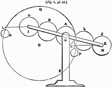
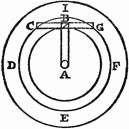
If the two weights P W hangs at the ends
of the balance A B, whose center of motion is
C, those weights will act against each other
(because their directions are contrary) with
forces made up of the quantity of matter in
each multiplied by its velocity; that is, by
the velocity which the motion of the balance
turning about C will give to the body suspended.
Now, the velocity of a heavy body is
its perpendicular ascent or descent, as will appear
by moving the balance into the position
a b, which shews the velocity of P to be the
perpendicular line e a, and the velocity of B
will be the perpendicular line b g; for if the
weights P and W are equal, and also the lines
e a and b g, their momenta, made up of e a
multiplied into W, and b g multiplied into P,
will be equal, as will appear by their destroying
one another in making an equilibrium. But
if the body W was removed to M, and suspended
at the point D, then, its velocity being
only f d, it would be overbalanced by the body
P, because f d multiplied into M would produce
a less momentum than P multiplied into b g.
As the arcs A a, B b, and D d, described by
the ends of the balance or points of suspension,
are proportionable to their sines e a, g b, and
d f, as also the radii or distances C A, C B, and
C D; in the case of this common sort of balance,
the arcs described by the weights, or their
points of suspension, or the distances from the
center, may be taken for velocities of the
weights hanging at A, B, or D, and, therefore,
the acting force of the weights will be reciprocally
as their distances from the center.
Scholium.—The distances from the center
are taken here for the velocities of the bodies,
only because they are proportionable to the
lines e a, b g, and f d, which are the true velocities;
for there are a great many cases wherein the
velocities are neither proportionable to the distances
from the center of motion of a machine,
nor to the arcs described by the weights or
their points of suspension. Therefore, it is not
a general rule that weights act in proportion
to their distances from the center of motion;
but a corollary of the general rule that weights
act in proportion to their velocities, which is
only true in some cases. Therefore, we must
not take this case as a principle, which most
workmen do, and all those people who make
attempts to find the perpetual motion, as I have
more amply shewn in the Phil. Trans., No. 369.
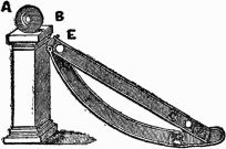
But to make this evident even in the balance,
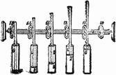
we need only take notice of the following
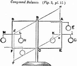
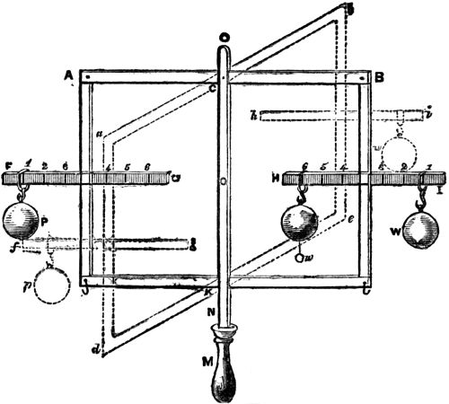
experiment:—A C B E K D is a balance in the
form of a parallelogram passing through a slit
in the upright piece N O standing on the pedestal
M, so as to be moveable upon the center
pins C and K. To the upright pieces A D and
B E of this balance are fixed at right angles the
horizontal pieces F G and H I. That the equal
weights P W must keep each other in æquilibrio,
is evident; but it does not at first appear
so plainly, that if W be removed to V, being
suspended at 6, yet it shall still keep P in
æquilibrio, though the experiment shews it.
Nay, if W be successively moved to any of the
points 1, 2, 3, E, 4, 5, or 6, the æquilibrium will
be continued; or if, W hanging at any of those
points, P be successively moved to D, or any
of the points of suspension on the cross-piece
F G, P will at any of those places make an
æquilibrium with W. Now, when the weights
are at P and V, if the least weight that is
capable to overcome the friction at the points
of suspension C and K be added to V, as u, the
weight V will overpower, and that as much at
V as if it was at W.
From what we have said above, the reason
of this experiment will be very plain.
As the lines A C and K D, C B and K E,
always continue of the same length in any position
of the machine, the pieces A D and B E
will always continue parallel to one another,
and perpendicular to the horizon. However,
the whole machine turns upon the points C and
K, as appears by bringing the balance to any
other position, as a b e d; and therefore, as the
weights applied to any part of the pieces F G
and H I can only bring down the pieces A D
and B E perpendicularly, in the same manner
as if they were applied to the hooks D and E,
or to X and Y, the centers of gravity of A D
and B E, the force of the weights (if their
quantity of matter is equal) will be equal, because
their velocities will be their perpendicular
ascent or descent, which will always be as the
equal lines 4 l and 4 L, whatever part of the
pieces F G and H I the weights are applied to.
But if to the weight at V be added the little
weight u, those two weights will overpower,
because in this case the momentum is made up
of the sum of V and u multiplied by the common
velocity 4 L.
Hence follows, that it is not the distance
C 6 multiplied into the weight V which makes its
momentum, but its perpendicular velocity L 4
multiplied into its mass. Q. E. D.
This is still further evident by taking out
the pin at K; for then the weight P will overbalance
the other weight at V, because then
their perpendicular ascent and descent will not
be equal.
The Rev. Dr. Desagulier was evidently a
man of scientific turn and capacity. It is unusual
to find ministers deeply interested in scientific
matters, and yet, he seems to have been. The net
result of his experiments can be succinctly stated
as follows:
In the first problem there is no change in
the distance of the center of gravity from the
support, and, therefore, there could be no disturbance
of the equilibrium.
In the second problem there is a change in
the distance in the center of gravity from the
support, and there must have been a disturbance
of the equilibrium.
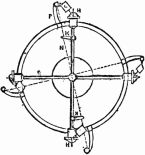
In 1790, John Haywood, of Long Acre,
Middlesex, draftsman and mechanic, obtained
British patent on:
"A machine for working mills and engines
without the aid of fire, water, or wind, or in aid
of all or any of those or any other powers."
The specification describes the device as
follows:
"The machine acts on a rotative principle,
or, in other words, has a revolving circular or
circulating motion round an axis, center, or
centers. It may be made or constructed of any
materials or matter whatsoever, so it be of sufficient
strength to sustain the power of action
when applied to any mill, engine, or machine to
which action or motion can or may be communicated
by a wheel. The size or dimensions
of this machine are by no means confined, but
may be varied or altered as circumstances may
require.
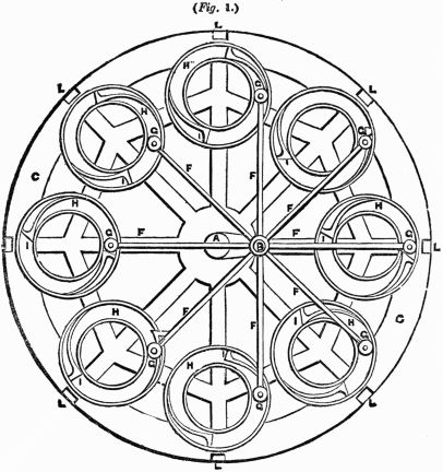
"References to the drawings of the machine
hereunto annexed:—Fig. 1 is the section
of the machine. A, A, B, a cranked or double
center, fixed to the stand or frame D by the
bolts E. C, C, the wheel which turns or revolves
round that part of the cranked center mark
A. F, levers which turn or revolve round the
cranked center B. G, G, rollers or weights
which revolve in the circular guides or grooves
by means of the leavers F. H, H, circular
grooves or guides which are affixed to the inner
sides of the wheel. N. B.—the distance from A
to B is the radius in all cases to determine the
space between the center of the guide or groove
H and the center of the roller or weight G. The
distance of the two concentric circles which
form the guides or grooves H must be equal to
the diameter of the roller or weight G. I, I,
springs which stop the rollers or weights G
from returning when at the horizontal diameter
of the wheel. K, weights, which may be increased
or diminished at pleasure. L, ledges
which connect the sides of the wheel together.
N. B.—By fixing cogs or teeth on the rim of the
wheel, so as to connect it with any mill, machine,
or engine to which motion can be given by a
wheel, the power of this machine may be communicated."
It must not be presumed that the preceding
devices shown in this chapter constitute any considerable
part of the Wheels and Weights Devices
that have been constructed through the hope of
attaining Perpetual Motion. Of all the means
whereby Perpetual Motion has been sought
wheels and weights have been by far the most
prolific. There is scarcely a village or a rural
community in the civilized world that cannot
point out its Perpetual Motion worker, and
he generally starts with wheels and weights,
though often, after long labor and final failure
with wheels and weights, he still exploits other
attractive fields of hopeless endeavor. Of the
devices of that kind, accounts of which have appeared
in scientific journals, or application for
patents upon which have been made, and, indeed,
patents often granted, it would be possible
to write a book of thousands of pages, but to do
so would be to no purpose.
It is believed by the author that the preceding
devices are sufficient to illustrate, and show
the controlling features of all the various mechanical
contrivances for the utilization of wheels
and weights as a means of Self-Motive Power.
Countless others could be shown of more or less
complicated mechanism, but an examination
would disclose the fact that each gets back to
some combination of parts well illustrated in the
preceding. Also, in endeavoring to express why
all wheels and weights devices have failed to
work, each essential point of weakness is disclosed
in the preceding. Now, why have they
failed to work, and wherein are they inherently
wrong and unscientific?
A cursory examination of the preceding devices
shows that each depends ultimately on the
supposition:
1. That a descending weight elevates an
equal weight through a distance equal to the
descent, and at the same time overcomes the frictional
resistance of mechanism, both ascent and
descent being measured on perpendicular lines, or
2. That weights affixed to an axis and
caused to have a longer leverage on the descending
side than on the ascending side, and consequently
the downward pull on the long lever side
is supposed to be greater than the downward pull
or resistance on the short lever side of the axis.
If the fallacy of these supposed principles is
explained and fully understood, it disposes, and
disposes effectually, of the possibility of obtaining
Perpetual Motion by means of wheels,
weights and the force of gravity.
It should be remembered that a wheel is a
lever, or rather it is a continuous series of levers—nothing
more—nothing less.
We first refer to the figure shown in A.
Capra's device, page 33 ante. The left side of
this wheel is, of course, supposed to be the descending
side on which the weights are farthest
from the center of the wheel. It is apparent that
only five weights are having any leverage advantage
whatever, while a much greater number are
being made to ascend. The advantage which a
few of the weights have by virtue of the leverage
pulling downward is always exactly counterbalanced
by an increased number of weights being
drawn upward. It should be borne in mind that
the direction of the force of gravity is toward
the center of the earth, and not in the direction
of the motion of the wheel, except at the extreme
left side of the wheel.
Again, consider the figure appearing on
page 63. It is manifest that the weights on the
right hand are further out, and have a leverage
advantage of the weights on the left hand
side, but it is also manifest that there is, and always
must be, a greater number of weights on
the left hand side. The greater leverage of the
weights on one side is exactly balanced by the
greater number of weights on the other side.
For a further illustration, take the figure
shown on sheet 65, ante. The weight "1" has a
distinct advantage over weight "5." Weight "2"
has a distinct advantage over weight "6." But
here we have only three weights: 1, 2 and 8, tending
to pull the wheel from left to right, whereas
there are five weights, 3, 4, 5, 6 and 7, tending to
prevent its going to the right.
In other words, if weights 1, 2 and 8 were
removed, it is clear that the wheel would turn
back to the left by reason of the action of the
weights 3, 4, 5, 6 and 7. Here again the leverage
advantage which weights have descending is
counterbalanced by the increased number of
weights on the opposite side acted on by the force
of gravity, tending to prevent the descent of those
having the greater leverage.
All the simpler devices failed, of course, to
work. The more complicated devices are simply
efforts to overcome the elementary principles that
prevented the simpler devices from working.
Among these that of Dixon Vallance (see page
34, ante), is best adapted to illustrate the folly
and the fallacy of these various devices to overcome
elementary principles.
We here refer to the figure appearing on
page 35, ante, shown in connection with Dixon
Vallance's Device. The obvious purpose was to
keep all the weights close to the hub, except those
depended upon to produce continuous motion by
their greater leverage.
To the untrained and untechnical person it
would perhaps not be manifest at first just why
the Vallance machine failed to work. Here is
its failure: Weight "c" must be raised toward the
hub of the wheel. To raise that weight requires
the application of force. That force must be
supplied. The belt "cc" would work more freely
if it were not elevating a weight, and the force
required from "w" to turn the wheel so as to
elevate the weight at "c" is counterbalanced by
the resistance the weight "c" offers to being
raised, and consequently to the motion of the belt
and in turn to the progress of the wheel.
It should always be remembered that, omitting
friction, the energy exerted by a descending
body is the perpendicular distance of its descent
multiplied by its weight. For, notwithstanding
what its course may be from an elevated point to
a lower point the energy accumulated in the descent
is still the product of the perpendicular distance
and the mass, or weight.
In all of these devices it is apparent that
every weight is brought back by some force from
the lowest point it reaches to the same elevation
from which it started to descend. It is axiomatic,
therefore, that the perpendicular ascent is
equal to the perpendicular descent. The ascending
weight and the descending weight are, of
course, the same. Therefore, the product of the
weight and the perpendicular distance of ascent
is exactly equal to the product of the weight and
the perpendicular distance of descent. Hence,
there is an exact balancing of energies, and no
motion results. Any motion imparted by wind,
water or steam will, if the moving force be withdrawn,
soon be overcome by unavoidable friction,
and a state of rest follows. There can be no
doubt that any attempt to attain Self-Motive
Power by means of wheels, weights, levers, and
the force of gravity must result in failure. The
thing itself is physically impossible.
In addition to what is above stated, read
carefully Chapter XI, on Conservation of Energy;
also read Chapter XIV, entitled "The
Seeming Probability of Effecting a Continual
Motion by Solid Weights in a Hollow Wheel or
Sphere" at page 290 of this book.