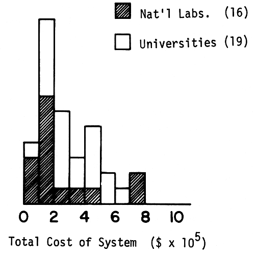
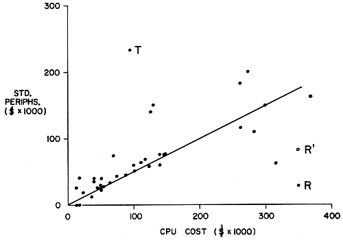
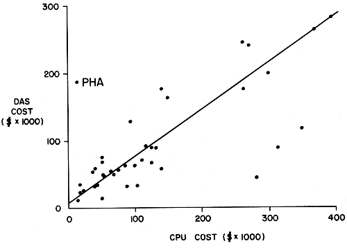
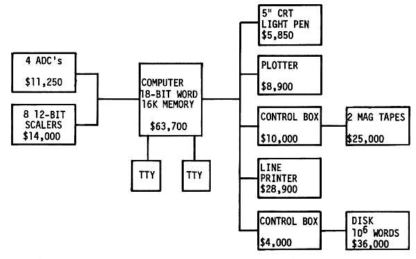
The movement toward computer systems began in earnest about
1962. Much of the early work depended on the use of magnetic
tape for storage of data, either raw or partially digested,
the analysis of data being carried out later, off-line. More
recently, computers have been used increasingly for on-line
processing. The early work is well known and will not be
described here. Some of the more recent systems are basically
very close descendants of one or another of the early
systems. Many varieties are now in service. Most incorporate
small or medium-sized computers, however, extensive new experience
has been gained during the past two or three years
of operation of a few large time-shared systems, in particular
those in the tandem Van de Graaff accelerator laboratories at
Yale and at Rochester, perhaps the first large systems in
operation which were planned systematically for nuclear research.
Both operate with multiprogramming monitor control,
background calculations being possible, on a low-priority
basis, simultaneously with data acquisition.
Simple rules for the design of various types of data-acquisition
systems cannot be stated, but some examples of possible
systems can be given. (See Figure 1.)
a. A simple system for pulse-height analysis work can
be assembled from a small computer, a 5-in. Tektronix CRO,
an ADC unit, and a teletype with paper-tape attachment for a
cost of about $30,000, providing that a competent engineer is
available, not counting programming and engineering costs. A
Calcomp plotter could be added for about $6000. To maintain
and operate the system at least a half-time technician-programmer
would be required.
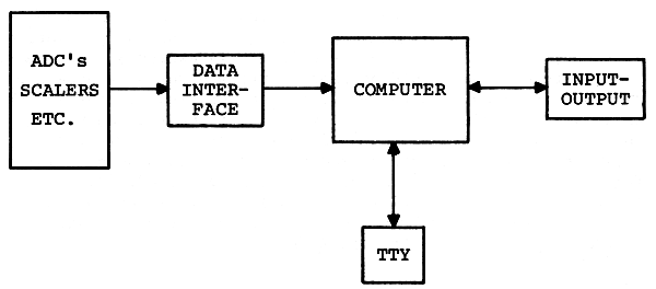
FIGURE 1 Basic data-acquisition system.
b. A general-purpose system for use in an accelerator
laboratory can be assembled from a medium-sized computer,
two typewriters, four 13-bit (0-8192) ADC's, six 18-bit
(0-262,144) counters, a 10 in. x 10 in. CRO display unit
with light pen, two tape drives (for IBM tape), a Calcomp
plotter, and a fast paper-tape reader for about $175,000 plus
the cost of engineering service and programming. At least one
full-time technician-programmer would be needed for maintenance
and programming.
c. A large shared-time system of the smallest configuration
which makes much sense consists of a large computer
with a 16k memory, two typewriters, a fast punched-tape
reader, four DEC tapes (or the equivalent), one IBM-compatible
magnetic tape, one CRO with light pen, one incremental plotter,
input devices for experimental data (ADC's, counters, etc.),
plus an interfacing system to link the external input-output
devices to the computer. The interfacing system may include
a fixed-wired "front end," such as that used at Yale, a small
computer, such as that used at Rochester, or both. The hardware
would probably cost over $400,000 exclusive of engineering,
and to this must be added a large expense for programming,
even if the manufacturer supplies a satisfactory shared-time
monitor plus all the usual software. Three men would be
needed to assemble, maintain, and operate the system: an
engineer, technician-programmer, and a full-time programmer,
or some equivalent combination, assuming use of the system
in a large laboratory with an active and continually developing
research program. Thus the cost of this "stripped-down"
system must be expected to reach $500,000 before it is in full
operation, and the cost of keeping it going, including salaries,
overhead, and replacement parts will likely exceed $50,000 per
year, although this could perhaps be trimmed somewhat once the
system is running. Furthermore, to run efficiently, the system
would need additional components: another 16k (at least) of
core memory, another IBM-compatible magnetic-tape drive, and
a line printer. A rotating memory device would also be helpful.
These would raise the cost by well over $100,000. It
is apparent that large time-shared systems are so expensive
that they can ordinarily be justified only in the largest,
most lively research establishments.
In medium and large systems the use of small computers for
coupling input and output devices to the main computer offers
a number of attractive advantages, especially now that mass
production and competition have brought the prices down so
low that a large amount of hardware nearly ideal for the
purpose is available at a bargain. Some advantages:
(1) The small machine can control data acquisition, accumulating
blocks of data while the large machine is doing
background calculations, interrupting those calculations only
occasionally to transfer raw or partially processed data.
(2) The small machine can continuously control the monitor
CRO. (3) It can control output devices such as a plotter,
line printer, rotating memory, or tape drive. (4) It can
carry out many logic operations on the incoming data. Experience
has shown that such operations are numerous, and
from the economic point of view they should not be allowed
to tie up the larger machine, which, at the same time, can
better be engaged in complicated calculations. In some cases
the use of two small satellite computers can easily be justified.
The chief disadvantage: Programming can be complicated.
However, if the larger machine already has a time-shared
monitor which recognizes the small machine as a typical
input-output device (as is the case with the PDP-6 plus PDP-8
system at Rochester) the programming problem is not bad.
In the following five sections descriptions of a number
of data-acquisition systems of various types and sizes will
be given in order to illustrate concretely some practical
system configurations. In each case a breakdown of costs
and a discussion of the lessons learned in connection with
planning, construction, and operation will be included. The
systems are of the following types: two small, one medium,
one large, two multiple-CPU, and one process control.
In 1966, two identical computer systems based on PDP-7 computers
were set up in two different locations at the Lawrence
Radiation Laboratory (LRL), to be used by several groups of
experimenters (see Figure 2). Assembly of the hardware for
the first system was completed 6 months after delivery of
the computer. Assembly of the second system required only
3 months. Two years after operation commenced, the first
satisfactory time-sharing monitor was completed and put into
service. The basic use of these systems is pulse-height analysis.
In principle many other types of operation are possible.
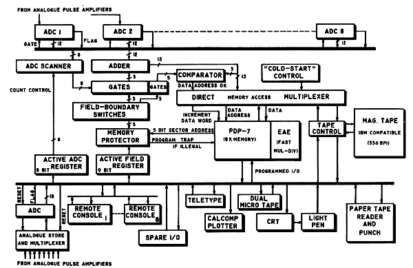
FIGURE 2 PDP-7 data-acquisition system at Lawrence Radiation Laboratory
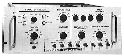
FIGURE 3 A switch panel used for data taking and control of CRT display in conjunction with
the PDP-7 computer. The switch-setting codes can be read into the PDP-7 accumulator
under program control and are used to select branch points in the program. As many as eight
of these units can be connected to the system. The lights are used to indicate program status.
Data-reduction jobs currently possible in the shared-time
operating mode include spectrum stripping, normalization,
smoothing, storage and retrieval of data from magnetic tapes,
graph plotting, printout, energy calibration, background
fitting, peak integration, and transfer of data from a remote
analyzer. Remote control of the computer from up to eight
experimental locations is possible using inexpensive switch
panels (Figure 3). Remote slave CRT display is also provided.
Multiparameter pulse-height acquisition and analysis can be
done on a time-shared basis but often requires all the computer's
time and memory.
The hardware configuration is shown in Figure 2. The PDP-7
computer was supplied by the Digital Equipment Corporation
with an 8k memory (18 bits) extended arithmetic hardware,
microtape (Dectape), paper tape, teletype, and cathode-ray
tube (CRT). The other items were built or interfaced at LRL.
Automatic memory increment and memory-protection hardware,
together with suitable programming, allow a user to carry out
simple data-reduction jobs with a live CRT display while two
other users are independently acquiring separate, 2048-channel,
pulse-height spectra in part of the computer memory, with
computer-controlled-gain stabilization. ADC dead time per
pulse is less that 40 µsec. Up To 6144 words of the memory
can be used for data (one PHA channel per word), while machine
language programs fill the remaining 2048 words of memory.
The system works well for pulse-height analysis, but for new
applications, e.g., nuclear magnetic resonance magnet control,
it needs additional hardware and programs.
Two groups of experimenters, doing chiefly pulse-height
analysis experiments are very satisfied with the system.
Another group, with a wider range of interests, has been
dissatisfied because of the time lag to implement new experiments.
One programmer is now engaged full time preparing more
programs.
Lack of free computer time has become a limitation for
both users and programmers.
Provision for programming at the outset was inadequate.
One full-time systems programmer should have been assigned
to these systems for 18 months.
Experimenters need Fortran or similar language capability.
A disk, or more core memory, would make this
practical.
The memory size is totally inadequate for multiple users
because of the large amount of data space needed for the high-resolution
spectra now obtainable with Ge(Li) detectors. An
external 8k memory is being acquired for data acquisition in
each system so that more of the computer memory can be used
for computing.
Memory CRT's are needed to provide independent displays
for each user. A separate teletype for each user would be
invaluable.
A disk memory is needed for rapid overlay of programs and
for sorting of multiparameter data.
A "czar" should have been appointed for day-to-day assignment
of facilities, consultations with users, and routine
maintenance and upkeep of the hardware and programs. The
"czar" could be a good electronics technician interested
both in programming and in physics.
System costs for the PDP-7 with time-sharing are given in
Table 1. Fabrication time is included as a dollar cost.
Engineering and programming times shown are one half those
charged against two identical systems.
Additional special-purpose experimental equipment commonly
used with the system includes gain stabilizers, analog
pulse derandomizers, amplifiers, pulse pileup rejection,
low-noise preamplifiers, and Ge(Li) detectors.
| TABLE 1 System Costs—PDP-7 with
Time-Sharing[A] |
| Items |
Costs |
Man-Months |
| CPU (8k, EAE) PDP-7, 1966 |
$ 52,000 |
|
| Dual microtape |
10,350 |
|
| Calcomp plotter |
4,825 |
|
| Calcomp interface |
200 |
½ |
| CRT controller |
2,300 |
|
| Large screen CRT |
3,500 |
|
| 3 small CRT's (5 in.) |
1,995 |
½ |
| Mag tape (556 BPI, 30 IPS) (with erase head) |
8,690 |
|
| Mag tape interface |
200 |
4 |
| Memory protection |
2,000 |
3 |
| Direct memory multiplexer |
2,000 |
2 |
| 2 ADC's (4096-channel, 35 µsec per count) |
5,000 |
- |
| ADC multiplex interface (automatic memory increment) |
2,000 |
3 |
| 8-parameter input to ADC (analog multiplexer) |
1,500 |
1 |
| 4 remote memory switch panels |
1,200 |
2 |
| Cabling to experiments |
1,500 |
1 |
| 8k external, 18-bit, 2-µsec memory |
12,000 |
3 |
| |
|
20 |
| Programming |
|
18 |
| |
$113,260 |
38 |
This second example of a small computer system is also taken
from experience at LRL. It was planned in February 1967 and
first put into operation in the summer of 1967. Data were
first taken with the aid of the system in the spring of 1968,
and the system programming was completed in May 1969. The
system is used extensively in experiments with the Bevatron.
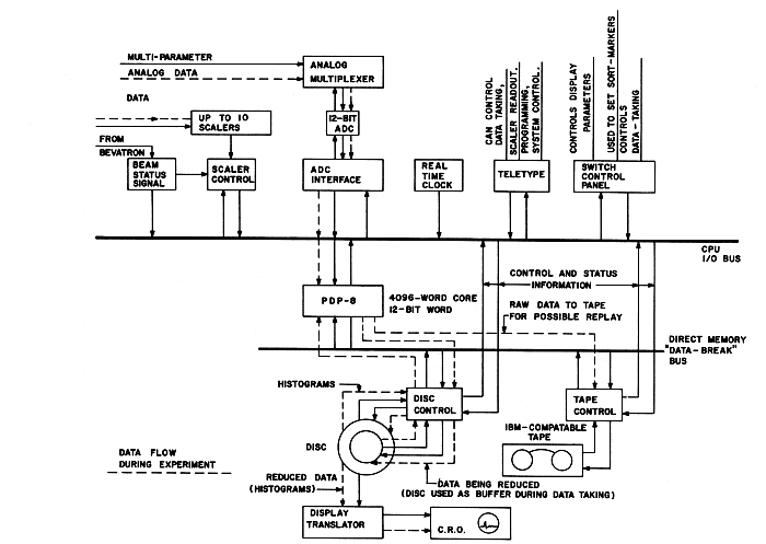
FIGURE 4 PDP-8 data-acquisition system at Lawrence Radiation Laboratory.
The computer-system hardware consists of the items shown
in Figure 4. The PDP-8 has 4k of memory. The disk is a Data
Disc unit with a removable disk (128 tracks and a movable
head) on the same shaft as a smaller disk and three fixed data
heads. Two of the fixed-head tracks are devoted to the display:
they drive a hardware-translator continuously. A single display
track is used when the number of points does not exceed
2000. For larger displays two tracks are used alternately.
The display is controlled from the switch panel. On-line
operating functions may be controlled both from the switch
panel and from the teletype.
Three classes of programming have been completed:
System Programs: Symbolic Text Editor, Assembler, a general-purpose
library system—all disk oriented.
Data-Taking Programs: These cause the ADC to be read, control
elementary sorting, update histograms resident on the disk,
write raw data on tape, and monitor the beam. The Bevatron
has approximately 1 sec of beam every 6 sec. During a beam
pulse the computer is devoted entirely to acquiring data,
saving raw data in core, on the disk, and on tape. After a
beam pulse, the 13-disk histograms are updated, then the
display programs are read into core memory and the display
is updated. The system is designed to be capable of accepting
over 1000 events per beam burst, and it has met this
requirement.
Simple Data-Analysis Programs: These compute displays (linear,
log, isometric, and contour—all double precision), read out
the sealers, monitor the real-time clock, allow resorting of
raw data from tape, and generate tapes for remote plotting.
The system now functions as originally intended and does its
job very satisfactorily.
The experimenter relies heavily on the main computer center
for data processing.
In assembling this system now, one would buy the disk already
interfaced by the computer manufacturer; furthermore
the manufacturer now offers programs that would greatly reduce
the programming costs.
A memory scope would eliminate the need for a disk-to-CRT
display interface.
Less-expensive magnetic tapes are now available. However,
it would be better to buy the tape already interfaced by the
manufacturer of the computer.
The added cost of buying a 16-or 18-bit computer would
have been almost completely offset by savings in the cost of
programming.
The addition of a fast printer (e.g., Inktronic $5600)
would have paid for itself in time saved during programming
but would not be of much use in experiment.
The costs of the PDP-8 are given in Table 2.
| TABLE 2 System Costs PDP-8—1967 |
| |
Costs |
Man-Months |
| CPU, 4k, 12-bit |
$18,000 |
- |
| Data disk |
8,300 |
- |
| Disk interface |
2,500 |
6 |
| CRT display control |
1,000 |
1 |
| CRT |
700 |
- |
| Mag tape (556 BPI, 30 IPS) |
8,800 |
0 |
| Mag tape interface |
2,000 |
6 |
| Misc. interfaces |
2,700 |
12 |
| 8 scalers (on loan) |
- |
- |
| ADC (4096-channel, 35-µsec dead time) |
2,500 |
- |
| 8-parameter input to ADC (analog multiplexer) |
1,500 |
- |
| Remote console (switch panel) |
300 |
- |
| Time-of-day clock |
1,000 |
- |
| |
|
|
|
$49,300 |
|
| Systems programs |
|
12 |
| Data-handling programs |
|
12 |
| Engineering diagnosis, debugging |
|
9 |
| |
|
58 |
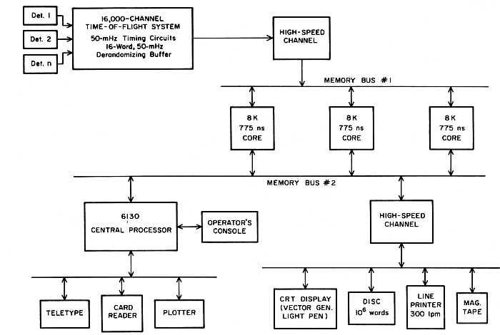
FIGURE 5 Block diagram of EMR 6130 data-acquisition system at Columbia University.
An EMR 6130 computer system has been installed and is being
prepared for use with Columbia University's Neutron Velocity
Spectrometer data-acquisition and analysis system. The
spectrometer is characterized by high data rates and many
events per burst. At present, peak arrival rates are approximately
106 events per second, with 40-60 events per burst
and a burst rate of 70 Hz. The arrival distribution is
random; therefore, 10 percent of the interarrival intervals
are 100 nsec long, and 1 percent are 10 nsec long. In the
future, peak arrival rates of 107 events/sec and 400-600
events per burst are possible, with a burst rate of 300 Hz.
With an appropriate time-of-flight "front end," the 6130 will
be able to handle the anticipated faster rates.
The EMR 6130 is a 16-bit, 775-nsec computer. The memory
has a multibus structure which permits each bus to communicate
simultaneously with a separate memory module. Up to four
memory buses may be purchased. The Columbia system has two
memory buses. If a high-speed buffered data channel is used,
block transfer may occur at memory cycle speeds. With two
buses, data may be stored in two memory modules at rates up
to twice memory speed. Alternatively, one bus, channel, and
one or more memory modules may be dedicated to data acquisition,
while the central processor and standard peripheral
devices, using the second bus, simultaneously operate in the
remaining memory modules.
A block diagram of the Columbia system is given in Figure 5.
The system has three 8k core modules. Memory bus 1 is dedicated
to a high-speed channel serving the time-of-flight
acquisition system. Memory bus 2 serves both the central
processor and a second high-speed channel. Low-speed input-output
devices, such as the operator's console, teletype,
card reader, and plotter communicate directly through the
processor. The high-speed input-output devices, namely, a
magnetic tape unit, line printer, fixed head disk, and interactive
CRT display, communicate through the channel.
The box designated as "time-of-flight system" represents
special-purpose electronics, including a 50-mHz clock, time-quantizing
circuits which "clock" an input event from one of
the detectors to the nearest clock pulse following its arrival,
a 50-mHz counter, and a 16-word derandomizing buffer capable
of storing a new word of data (i.e., arrival time) every
20 nsec. The number of channels, nominally 16,000, is limited
not by the front end but by the amount of core available for
histogram storage in the 6130 system. (For the high data
rates anticipated in the future, the time-of-flight clock
speed and derandomizing buffer data acceptance rate will be
increased to 100 mHz. At the same time, an accumulating
buffer of several hundred words capacity, with a 20-mHz data
acceptance rate, will be added to empty the derandomizing
buffer and store temporarily the time-of-arrival data prior
to its transmission to the 6130 system.)
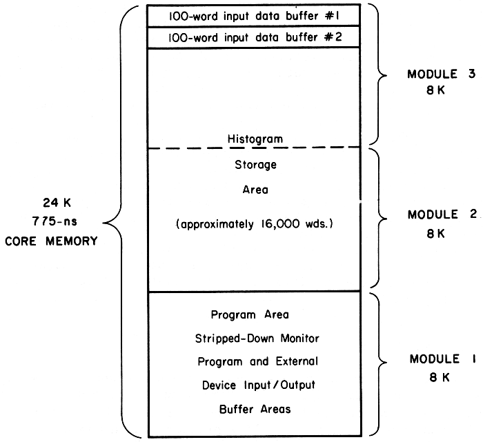
FIGURE 6 Diagram illustrating mode of utilization of
core memory in the Columbia System shown in Figure 5.
During the time-of-flight experiment, memory is utilized as
follows (see Figure 6). The channel dedicated to data acquisition
writes on alternate bursts, into two buffer regions,
of approximately 100 words each, in the top of memory module
3. The remaining parts of memory module 3 and all module 2
will be devoted to histogram storage (i.e., time-of-flight
channels). Module 1 will contain a stripped-down monitor
program and all data-handling programs, including buffer
regions for the external devices other than the time-of-flight
front end. Programs will be capable of referring to all module
1 or 2 in full concurrency with data acquisition. Reference
to module 3 will also overlap data acquisition, except
for a period of high input data rate of 100-to 200-µsec duration
per burst. With the type of memory allocation described,
the system will permit the use of all standard I/O
devices, concurrent with the essential operations of input data
buffering and histogram generation. Thus, new data may be
stored on, or old data retrieved from, the disk or magnetic
tape; either new or old data may be displayed on the CRT; and
the same or other data may be output with the plotter or line
printer. Control information will be input from the teletype,
the operator's console, or from special-purpose switches.
The importance to the physicist is that hard copy output is
immediately available during data acquisition and may be used
to monitor, or modify, the experiment.
Subsequent to the input data increase, a high-speed
memory incrementing channel will be used to input time-of-flight
data directly to the histogram area. With this channel
the buffer area in module 3 will no longer be required.
Histogram data will be stored in all modules 2 and 3, and no
program intervention will be required for histogram generation.
Between data-acquisition runs, the system will be used
for data analysis.
The computer, with two memory modules and one channel and bus,
was delivered in July 1968. The remaining memory module
channel and bus were delivered in the fall of 1968, the CRT
arrived in June 1969, and the line printer (which was not
purchased from EMR) came shortly afterward. The first time-of-flight
run with this system was scheduled for December 1969.
During the period from delivery to the first run, one full-time
programmer and approximately half the time of one physicist
were devoted to the debugging of manufacturer-supplied
programs and the writing of the on-line programs required for
the run.
It has been hoped that the system would be used extensively
for the analysis of previously acquired data, beginning
shortly after delivery; however, very little such use has
proved possible, essentially because of the unreliability of
the 100-cpm card reader supplied by EMR. The lack of a line
printer was also a factor. A more reliable reader has been
purchased. The delivery of a line printer should rectify the
second need.
The development of high-speed, buffered, time-of-flight
front ends has been a continuing interest at Columbia. It is
therefore difficult to estimate the precise costs of the time-of-flight
system developed for use with the 6130. A rough
estimate of the design and development time is approximately
3 engineer man years.
Columbia chose to order the EMR 6130, even though at that
time (1966) it was not in production, because it seemed a
very powerful machine which matched the needs of the system
planners. The alternate possibility open was to order a
larger, much more expensive machine of proven capability. As
it turned out, difficulties in the development of the 6130
caused a delay of over a year in the delivery of the main
frame and of over two years in the delivery of the CRT display.
(When these delays became apparent, EMR loaned Columbia a
24-bit computer and also a small display for use during the
interim period.) The EMR 6130 is perhaps the most powerful
16-bit computer available today, in spite of one or two
changes in the original specifications, but in order to get
it Columbia apparently traded time for money.
The costs of the Columbia University EMR 6130 system are
given in Table 3.
TABLE 3 Cost of Columbia University EMR 6130 System
(Prices from EMR Except where Indicated) |
| 1 |
Central processor with 16k core memory |
$65,500 |
| 1 |
Additional 8k core memory |
17,850 |
| 1 |
Teletype, model 35 |
1,930 |
| 2 |
Word/byte buffered channels |
10,300 |
| 1 |
Additional memory bus and control |
4,300 |
| 1 |
Additional cabinet assembly |
5,000 |
| 1 |
Card reader, 100 cpm |
4,100 |
| 1 |
Magnetic disk and control |
16,800 |
| 1 |
Tape transport and control |
26,000 |
| 1 |
8 levels, priority interrupt |
1,000 |
| 1 |
CRT display, including vector generator and light pen |
27,750 |
| 1 |
300-lpm line
printer[B] |
18,000 |
| |
|
$198,530 |
Since early 1966, Yale and IBM Research have been engaged in
a joint study in the application of computers to nuclear-data
acquisition. The main goal was the production of an integrated
hardware-software system which is fully under the control
of the experimenter in the sense that he can define his
entire data acquisition and analysis process with a Fortran
program.
The joint study may be divided into four areas: (1)
Development of a suitable general and powerful data-acquisition
interface and control unit (front end) with a set of
compatible nuclear instrumentation modules (scalers, ADC's,
and general-purpose input registers). (2) Development of a
suitable display system. (3) Development of a data-acquisition
language (as an extension to Fortran) and the necessary
library routines to support this language. (4) Development
of a general-purpose multiprogramming system for the selected
computer (the IBM System/360, Model 44) into which the data-acquisition
system could be incorporated.
The first three areas became operational in July 1967,
within three months after delivery of the computer, using the
standard batch programming system for the 360/44 as a basis.
Development continues on the multiprogramming system, which
has now reached a state where users inexperienced in using
the system can compile and execute Fortran programs, but the
data-acquisition components are not yet operational.
Nuclear data are input by means of a general-purpose
nuclear-data-acquisition interface and control unit, organized around
the concept of an event, an occurrence in the real world which
causes the outputs of a group of instruments selected by the
user to be read into computer memory. Sixteen independent
events are provided for, with each of which may be associated
any or all of 30 different instruments (scalers, ADC's, or
general-purpose monitor registers) by means of a diode plug
board matrix. The instruments themselves, also designed and
built by IBM, are modular and completely interchangeable and
enable the experimenter to configure his experiment in any
way desired, i.e., to determine not only which instruments
are to be read but also in what order. Exclusion logic is
provided to prevent processing of certain events if and when
other defined events occur simultaneously (Figure 7).
The cathode-ray-tube display unit provides a 1024 x 1024
point plotting oscilloscope with seven levels of intensity,
character-generation hardware, a light pen, and a programmed
function keyboard, by means of which the user can call in
programs by pushing buttons. Such programs can perform any
function from changing displays gains to curve-fitting. They
may be system-supplied or user-written and may be (and usually
are) written Fortran. A parallel, high-resolution photographic
system permits computer assembly of publication quality illustrations.
The data-acquisition and display-programming system is
composed of a group of subroutines which may be called from
Fortran programs for performing the various processes in data
acquisition and display. For this purpose, a considerable
number of additional statements have been added to the Fortran
language. These statements perform such functions as defining
multidimensional pulse-height analyzers in the computer memory,
performing pulse-height analysis using incoming data as channel
numbers, and defining separate programs to process each of
the 16 classes of input events. All the special statements
that make up the new data-acquisition language are implemented
by means of a preprocessor which converts them into Fortran
coding, which the standard 360/44 Fortran compiler then
processes.
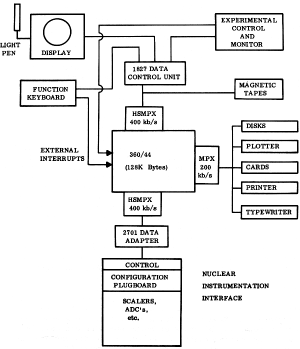
FIGURE 7 Block diagram of the IBM 360/44 system at Yale.
The general-purpose multiprogramming operating system is a
multilevel priority system designed to provide access to the
system simultaneously by an, in principle, unlimited number
of users, each with unique priority. Unlimited means that
there is no arbitrary restriction on the number of users;
the nth user can always get access if the facilities his
particular job requires are not already in use. Two types of
user are recognized by the system: The basic unit of execution
is the logical user, or task. Each logical user has a unique
priority level. Switching between users is carried out as a
response to I/O, timer, or external interrupts, at which time
the highest priority user in a position to execute gains control
of the central processor. The basic unit of memory protection
is the physical user, composed of one or more logical
users engaged in a common cause. Physical users correspond
to real people doing independent work simultaneously. By
dividing his work up among a group of logical users, a person
may take advantage of the parallel processing capabilities of
the system in a natural way. Since logical users within a
physical user are not memory-protected against each other,
they may communicate rapidly, at full machine speed. Communication
between different physical users is also possible,
via real or simulated I/O devices. While this system by no
means guarantees execution time to any but the highest priority
user, it is adequate in a single-experiment environment.
The assumption is that the experimenter, who has actual control
of the computer at all times, loads his logical users
in the order in which he requires their priorities. Following
this, other users load their jobs, getting whatever memory and
I/O facilities remain. The amount of processor time available
to the other users varies inversely with the experimenter's
counting rate and the amount of processing he does on his data.
In most experiments, the experimenter uses significantly less
than 50 percent of the processor time simply because those
experiments requiring the sophistication of the computer also
have rather low counting rates. A priori, it is estimated
that the simple priority algorithm described above is not only
adequate but pays a dividend in terms of reduced system overhead
time as compared to a more elaborate algorithm. It also
guarantees that no data will be lost due to the lower priority
users being in the machine.
In general the new system will provide all the facilities
of 44PS within the multiprogramming framework, including execution
of the Fortran compiler simultaneously with data
acquisition.
| TABLE 4 |
| The Basic System |
CPU:
with 128k-byte memory, 1-µsec registers,
external interrupts, floating point, one
high-speed multiplex channel, one low-speed
multiplex channel, and one single-disk
storage drive |
$291,280.00 |
Standard I/O gear:
with 128k-byte memory, 1-µsec registers,
external interrupts, floating point, one
high-speed multiplex channel, one low-speed
multiplex channel, and one single-disk
storage drive |
164,259.00 |
| Data-acquisition and display
subsystem[C]: |
|
| Display system (RPQ on 1827) with
function keyboard and light pen |
19,000.00 |
| 2972-VII Scientific Interface and Control
Unit (front end) |
40,000.00 |
| 6 LeCroy model 157M general-purpose registers
and ADC interface to 2972, as designed for
Maryland |
5,950.00 |
| 2 LeCroy model 150B scaler banks (each contains
eight 15-bit scalers with separate inhibit,
strobe, and reset, as modified for Maryland) |
3,900.00 |
| 2 LeCroy interfaces to connect model 150B
to 2972 |
2,000.00 |
| 4 Northern Scientific 4096-channel ADC's |
8,800.00 |
| Data-acquisition and display subtotal |
79,650.00 |
| TOTAL |
$535,189.00 |
| TABLE 5 |
| Additional Items Needed to Make a System Identical to the Yale System |
CPU and peripherals:
additional high-speed multiplex channel with
extra subchannel, high-speed (1/4 µsec)
general registers, additional single-disk
storage drive, memory protect, additional
tape drive (240IV),[D]
1627 (Calcomp) plotter
and adapter, keypunch, six additional disk
cartridges |
$114,316.00 |
| Data-acquisition subsystem |
|
| 2 additional Northern Scientific 4k ADC's |
4,400.00 |
| 2 additional LeCroy 157M registers |
1,400.00 |
|
|
| Costs of extras |
120,116.00 |
| Grand total for basic system |
535,189.00 |
| Cost to copy the Yale system | TOTAL |
$655,305.00 |
To the laboratory interested in developing a system of the
magnitude of the Yale system, but not a copy, it must be
reiterated that neither Yale's out-of-pocket costs nor the
cost of copying the system represents the total cost of development.
IBM's development costs are not known, but they
may be assumed to be very large.
From IBM's viewpoint, the ADC and scaler project is the
least successful part of the whole project. Although those
instruments are technically excellent, IBM is either unwilling
or unable to sell them at a price competitive with the costs
of front-end and interface equipment available from the traditional
nuclear instrument manufacturers. However, ADC's
and scalers available from the traditional sources can easily
be interfaced to the front end (whose price is in keeping with
its power and versatility). The University of Maryland has
followed this procedure.
We therefore present the cost of copying the Yale system
by some other laboratory. In Tables 4 and 5 following the
example of Maryland, we have not selected IBM ADC's and scalers
but rather less expensive components from traditional manufacturers,
together with suitable adapters available commercially.
The prices shown are to be considered strictly reference
numbers and in no way constitute price quotations.
Starting by producing an operational data-acquisition software
system running within the standard batch programming system for
the 360/44 enabled the system to become operational within
three months of the delivery of the computer. This not only
enabled it to do useful work almost immediately but also enabled
important experience to be gained which is being applied
to the development of the multiprogrammed version.
One of the main lessons so far is that a batch-oriented
system barely begins to tap the real-time potentials of a
computer such as the 360/44. In a batch system, whatever
analysis is needed during data acquisition must be somehow
tied to the processing of events. If this is not possible,
it is necessary to stop data acquisition in order to do
analysis even though, on a millisecond time scale, plenty of
CPU time is available during acquisition. Multiprogramming
software is necessary in order to utilize this available
time. This means that multiprogramming not only makes the
machine available to several people at a time, but, more
important, it makes large amounts of parallel processing power
available to the experimenter.
It has also been shown quite conclusively that the ability
of the physicist to program his own experiment (in Fortran)
gives him enormous power, power which simply would not be
available on a suitable time scale if he has to queue up for
the services of a system programmer.
While the generalized event structure gives the experimenter
considerable ability to deal with complex experimental
situations, it has an overhead associated with it which limits
it to about 5000 events per second. This is, of course, adequate
for all experiments that demand such an event structure.
For simple pulse-height analysis, it is unnecessary overhead,
but it can be "turned off" in a trivial way, by simply defining
the completion of filling of the buffer as an event
and calling a special pulse-height-analysis program to process
the entire buffer, bypassing the event sorting. This allows
for close to 100,000 pulse-height analyses per second.
There are, however, few situations that justify using a
computer as powerful as the 360/44 in a manner just described
(i.e., doing nothing but simple addition 100,000 times per
second). Therefore, such simple experiments will shortly be
handled by means of a link between an existing multichannel
analyzer and the computer.
The system does not suffer from having the front end
directly connected to the 360/44. The data channel on the
360/44 is sufficiently sophisticated so that it performs all
the functions that one might relegate to a small CPU placed
between the front end and the 360/44, without any interference
with the program currently running in the CPU. The one application
described above, which does warrant a separate processor,
is handled best by attaching the processor to a separate
input port rather than by placing it between the front end
and the computer. This enables it to do its intended job
without acting as a bottleneck in jobs requiring the power
of the front end. It also, incidentally, will function as a
completely separate data input terminal if two simultaneous
terminals should ever be required.
The particular display system employed has worked very
well. Because the display list is in the main memory of the
computer, programming of light-pen and other manipulative
actions is extremely easy, but at the price of large amounts
of memory being tied up. It is clear that the system cannot
support two such terminals if they are to be truly independent
of each other. It is equally clear that the display is as
useful in data analysis as it is in data acquisition. A second
display terminal is therefore being added. The selected
unit (built by Computer Displays, Inc.) is oriented around
the Tektronix 611 storage oscilloscope. It provides both
alphameric and graphic display, as well as an interactive
device (a cursor moved by means of a joystick) for a price
of $8000 to $12,000 plus the cost of interfacing to the computer.
At the Rutgers-Bell (RB) nuclear physics laboratory, work has
been done with two different two-CPU systems. The first of
these represented essentially two duplicate processors (Figure
8), and the second, now in the process of implementation, two
processors of different size and capability (Figure 9). While
full data are not yet available on the actual performance of
the second system, an outline of the experience to date will
be given.
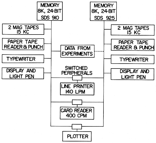
FIGURE 8 The two-central-processor system of Rutgers-Bell.
The initial success of the original RB SDS 910 data-acquisition
system was soon tempered by a result of its popularity: during
most experiments the computer was unavailable for program development
or data analysis. Since most experiments required
the use of displays and light pens in at least one stage of
data analysis, the computer center could not handle the work.
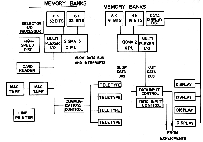
FIGURE 9 The new Rutgers-Bell Sigma 2-Sigma 5 system.
The solution adopted was to acquire another computer with the
same instruction set (an SDS 925) and to provide switches such
that the line printer, card reader, and plotter could be run
from either computer. No provision was made for direct transfer
of data from one computer to the other.
In practice this system worked out quite well. There was
complete interchangeability of programs from the 910 to the
925, which differed only in being five times faster. Normally
the switchable peripherals were run from the 925; when the
group taking data wished to print or plot current spectra,
they consulted with the 925 users, then used the peripherals
with little more difficulty than permanently attached units
would have involved.
A further advantage of the switchable peripherals, in
addition to the cost saving, was that the experiments associated
with the 910 could proceed while the peripherals were
being serviced. The 910 is exceedingly reliable, averaging
less that one main frame failure per year, and the 925 is
nearly as reliable. The vast majority of service calls have
been occasioned by the peripherals and have competed with data
analysis but not with accelerator utilization.
In addition to the switched peripherals, both computers
were equipped with two magnetic tape transports, electric
typewriter, and high-speed paper-tape reader and punch. While
these units were also subject to downtime, the paper-tape
system and the typewriter could be exchanged between the 910
and 925. Only the magnetic-tape transports required the use
of the 910 CPU during servicing, and the presence of two
transports has usually meant that the second one could carry
the load until the weekly accelerator maintenance period.
While the reliability record of the central processors
has been excellent, that of many of the peripherals has not.
Here is an excellent justification for renting computing
equipment: if units do not work well, they can be returned.
For a time, a low-cost card reader (100 cards per minute)
built by NCR for SDS was used. It was unacceptable in reliability
and was replaced by the Univac reader which came with
the 925. Another unit returned was a cartridge magnetic-tape
system built by SDS. The Ampex TM-4 magnetic-tape transports
on both the 910 and 925 have been consistently poor in reliability,
but no other unit has been available to replace them.
A manufacturer's name does not seem to be a guarantee of good
or bad quality—the line printer, also made by NCR, has been
excellent both in reliability and print quality.
While the two-computer system generally rated high in user
satisfaction, considerations of performance have led to the
design of a larger and more powerful system with totally new
components. The 925, without wired multiplication or floating-point
operations, was too slow for theoretical computation or
for many types of data analysis such as those using Monte Carlo
methods. Interactive methods of analysis, using a display and
light pen, have been found very effective in the cases where
the 925 could accommodate them but have not been available
through either the Bell Laboratories or Rutgers computer centers.
A further limitation on the earlier system was that only
one person could use the 925 at a time. The generation of a
display involved the full time of the CPU, and while multiprogramming
might have been able to divert some CPU time, the
8k memory size did not permit it.
Data acquisition on the 910 was limited in array size to
the capacity of the core memory. For multiparameter experiments,
three, six, or even twelve 4096-channel arrays have
been stored in core, but the advantages of live display available
with core storage have discouraged anyone from handling
large arrays by logging raw data on magnetic tape for analysis
later. Memory expansion would have been desirable, but the
necessity of making the expansion on both the 910 and the 925
effectively doubled the cost.
Limited flexibility, then, is a major drawback of this
type of system. As long as only two users needed to be accommodated,
and each could adapt to exactly half of the total core
storage, it was satisfactory and provided redundant facilities
to guard against experiment downtime due to computer failures.
In ordering a new computer powerful enough to handle most of
the nuclear physics laboratory's data analysis and theoretical
computing tasks, cost ruled out the acquisition of a pair of
program-compatible computers. It was recognized that desirable
features of the original system would have to be obtained in
new ways. Accessibility of the system for programming could
be improved by running a simple time-sharing monitor on it.
Reliability could be enhanced by avoiding bargain peripherals
and using only items of demonstrated high quality and by the
capability of running the peripherals on either computer.
The use of a separate CPU for data collection still
seemed particularly desirable, however. A combination of a
large (by present standards) computer with a powerful small
computer as a front end was designed. It includes a display
disk for refreshing displays without CPU attention, as well
as for storing data arrays too large to be kept in core. The
computers selected were a 32k, 32-bit SDS Sigma 5 and a 12k,
16-bit Sigma 2.
The new system, with separate and nonequivalent computers,
will have advantages over the old system in data analysis and
general computation, because these will be done on the larger
computer, either in time sharing or batch mode. Time sharing
should enhance the flexibility of the system by making it
easier to generate and debug new programs, in addition to
improving the accessibility.
For the data-collection computer, RB will lose the advantage
of a separate computer on which complete debugging of
programs may be done. This loss can be tolerated since the
fraction of the load carried by the Sigma 2 will be less than
that carried by the 910 in the old system. In the old system,
very few distinct data input or display programs were written.
A few subroutines and their calling parameters sufficed for
all needs for six years; the logic and I/O operations unique
to each experiment were written in Fortran by the experimenters.
In the new system, the Sigma 2 will be concerned with the
operations used in the data acquisition and formating of displays;
most of the rest can be left in the Sigma 5, with routines
sent over to the Sigma 2 under the time-sharing system.
If the user should prefer, he can operate the Sigma 2 directly
and make use of the Sigma 5 only for data storage.
Until very recently, program development on the Sigma 2
has been slow because it lacked means of getting program listings
quickly. We have now developed an assembler for the
Sigma 2 which runs on the Sigma 5. The availability of card
reader input and line printer output has greatly speeded Sigma
2 software development. The loading of Sigma 2 programs is
also much more convenient, since they can be stored on the
Sigma 5 disk and loaded exactly as Sigma 5 programs. It seems
highly desirable to have an assembler for any small data-acquisition
computer capable of running on another machine; the
means of transporting the object code to the small computer
is of less importance.
The reliability of the new equipment has been excellent.
Only the card reader has had any downtime of consequence, and
modifications seem to have resolved its problems. The Sigma
5 main frame has had no failures in 12 months, and the Sigma
2 has had only one in the past year. If this record continues,
the loss of the redundancy inherent in the old 910/925 system
will not have any serious effects.
One component of the new system is taking on an increasingly
important role, although it had not been a part of the original
planning. That is the computer-independent data bus consisting
of system controller, bin controller, and register
units. Only the system controller is specific to a particular
computer; moreover the same system controller design could be
used on both the Sigma 2 and Sigma 5 by restricting the data
path to 16 bits. The register units are used to interface
external devices to the computer quite cheaply; a typical
register used here to interface an existing Calcomp plotter
to the new computers costs about $300 in parts and labor.
Similar units are used to interface the Sigma 5 to the Sigma
2 and to the 910, to drive a temporary core-resident display
on the Sigma 5, to read pushbutton inputs, and to read ADC's.
The display disk controller now under construction uses these
registers to furnish control information, although the data
go directly to and from the core.
At the present time, the registers are read and written
under program interrupt control, but the design is not limited
to program-controlled operation. By substituting a controller
designed to operate automatically (directly to core or to the
I/O processor) speeds approaching 1 or 2 µsec per word transferred
could be obtained. Such interfaces have been built for
various computers using the European CAMAC bus system, which
is conceptually similar.
The system is highly modular and is built into NIM bins
with modified back connectors. Exchange of modular units has
been very helpful in debugging the system, and presumably it
will also be helpful in case of failures in operation. This
is a much more satisfactory situation than that which was
obtained with the ADC interface on which RB collaborated with
Brookhaven. The latter unit was built with computer-type
construction: commercial logic cards and wire-wrapped back
panel. Debugging of that unit was exceedingly laborious because
of the lack of modularity in its components.
The computer-independent bus system has not been expensive
in manpower. It has required about 9 man-months in
design and debugging and somewhat less time in construction.
The registers cost about $300, as mentioned, and the controllers
$1500 to $2000 depending on the need for cable drivers.
The costs of the RB multiple-computer system are given
in Table 6. The figures are approximate and not the result
of detailed accounting.
| TABLE 6 Systems Costs of Rutgers-Bell Multiple-Computer System |
| a. |
Original 910/925 system |
|
| |
Systems/programming |
1 man-year |
| |
Interface design |
910 |
6 man-months |
| |
|
925 |
3 man-months |
| |
Interface construction |
910 |
$15,000 including display |
| |
|
925 |
$11,000 |
| |
Computer costs |
910 |
$3,500/month; bought with rental allowance for $58,000 |
| |
|
925 |
$ 4,800/month; including line printer and card reader |
| |
Maintenance and updating |
910 |
1 man-year, over 6 years |
| b. |
New system (including some components not yet acquired) |
|
| |
Planning and expediting |
1½ man-years |
| |
Systems programming |
3 man-years to date, 2 more expected |
|
ADC interface |
|
| |
Engineering design |
$20,000 |
| |
Construction and test |
9,000 spent outside |
| |
Parts |
11,000 |
| |
Time spent locally |
9 man-months |
| |
Data bus system |
|
| |
Parts |
$ 5,000 |
| |
Design and debug |
9 man-months |
| |
Construction |
6 man-months |
| |
Display disk system |
|
| |
Disk with 64 heads and amplifiers |
$ 24,000 |
| |
Interface to Sigma 5, Sigma 2, and displays |
$ 10,000 (estimated, since design is not complete) |
| |
4 14-in. displays with analog rotators and light pens |
$ 12,000 |
| |
Three teletypes |
$ 5,000 |
| |
Miscellaneous technical work |
1 man-year |
| |
Computer costs |
|
| |
Sigma 2 |
$ 50,000 |
| |
Sigma 5 |
$440,000 purchase equivalent, but part is leased |
| |
TOTALS FOR NEW SYSTEM |
|
| |
CASH COSTS |
$586,000 |
| |
TIME |
8 man-years professional |
| |
|
3 man-years technician |
In 1965, a system based on an SDS 920 computer was put into
operation at the Brookhaven National Laboratory to control
data-acquisition processes involving eight neutron spectrometers
and one x-ray spectrometer. The neutron spectrometers
are located on the floor surrounding the High Flux
Beam Reactor (HFBR); the x-ray spectrometer was placed in the
same building in order to facilitate linking it to the computer.
The system can control the execution of experiments on all
nine sets of apparatus simultaneously, yet each experimenter
feels that he is working essentially independently of all other
users. The system controls all angular rotations of crystals
and counters, all detector counting, the data displays, the
input and output operations, and automatic error responses.
It can also perform most of the calculations necessary
for real-time guidance of the course of the experiments. For
example, the experimenter can mount a crystal on a goniometer
at approximately the correct angular orientation, then he can
specify to the computer where several peaks should be found,
whereupon the computer will direct the execution of a trial
experiment to find where the peaks do, in fact, occur, executing
least-squares calculations in the process, after which
the error in crystal orientation is known and the angular
scales are automatically corrected. In another example, the
computer is given as input information the crystal constants
(unit cell) and the zone orientation of the crystal on the
goniometer and is asked to produce a scanning of a given part
of reciprocal space. The computer then calculates where to
look, turns to a correct angle to check the intensity of a
central peak, and performs the other necessary steps, making
many decisions as it controls the execution of the entire
experiment.
When it was first assembled, the system included only two
teletypes, both located near the computer. Early in 1969, a
communications network was added to permit the installation
of a local, assigned typewriter at each of the nine spectrometer
stations, as well as three assignable remote teletypes
located in the Chemistry and Physics buildings. This
network incorporates a Varian 620i computer. It permits any
ordinary operation to be carried out from any of the 12 remote
stations, except program loading, which still must be
done via the high-speed paper-tape reader at the computer.
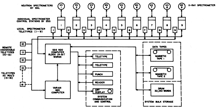
FIGURE 10 The multiple-spectrometer control system at Brookhaven National Laboratory.
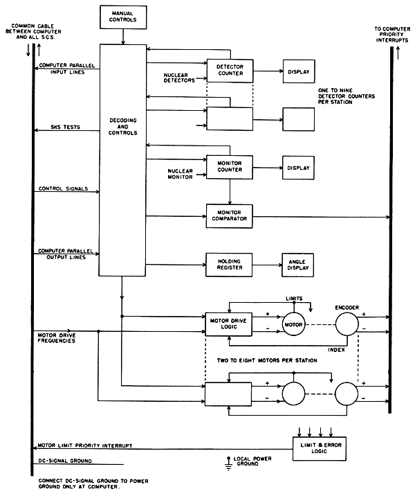
FIGURE 11 Block diagram of a single-spectrometer control
station of the MSCS shown in Figure 10. [From D. R. Beaucage,
M. A. Kelley, D. Ophir, S. Rankowitz, R. J. Spinrad, and
R. Van Norton, Nucl. Instrum. Methods 40, 26 (1966).]
The major parts of the system (Figure 10) are the SDS
920 computer with a 16k, 24-bit memory, a bulk storage memory
section comprising two magnetic tapes units and one 32,010-word
drum, the communication network, and the nine local control
stations (SCS) at the spectrometers. Each SCS (Figure
11) contains the stepping motors required for computer control
of angular rotations of crystals and counters, together with
shaft rotation encoders (optional, incremental type) to feed
information back to the computer. Each SCS also includes
manual controls, the electronic counters associated with the
radiation detectors, counter displays, a decoding and control
section, and other related equipment.
a. The system now does "all things imagined to be
necessary."
b. The computer has proved to be remarkably reliable,
with a record of about 40,000 hours of use without a breakdown.
c. A reasonable amount of preventive maintenance is done,
mostly during the one week of four that the reactor is shut
down.
d. One person serves as operator and programmer (for
simple jobs). He also transports magnetic tapes to the computing
center for off-line data processing and performs smaller
tasks. The average user does not need to do any programming.
e. Fortunately, the people who have written most of the
programs have remained in attendance and have updated the
programs frequently. Machine-language programming has not
proved to be a bad chore because the system is a fixed-hardware
setup.
f. Modes of data collection can easily be changed.
g. The overall performance is excellent. The only problem
is an occasional wiping out of a program due to the fact
that there is no hardware memory-protection feature in the
computer. These accidents are estimated to cost at most a
loss of a few percent of the running time.
The costs in manpower and dollars of the MSCS are given in
Table 7.
| TABLE 7 Cost in Manpower and Dollars of MSCS |
| a. |
Engineering Design and Costs (Professional Only) over 12 Calendar Months |
| |
|
Man-Months |
Cost |
| |
Electronic equipment |
|
|
| |
Development, design, construction, and startup |
15 |
$ 28,000 |
| |
Mechanical development and liaison |
4 |
7,000 |
| |
System coordination, development, design, coding, etc. |
30 |
56,000 |
| |
Parameter generating, data analysis, and programming |
15 |
28,000 |
| |
TOTAL |
64 |
$119,000 |
| b. |
Construction Time and Costs (Technical) over 16 Calendar Months |
| |
|
Man-Months |
Cost |
| |
System construction and interconnection |
15 |
$ 17,000 |
| |
Debugging and startup |
6 |
7,000 |
| |
Documentation and drafting |
12 |
14,000 |
| |
TOTAL |
33 |
$ 38,000 |
| c. |
Major Components |
| |
|
Cost |
| |
Original cost |
|
| |
SDS 920 (16k mem., 96 interrupts) |
$147,000 |
| |
15-kc mag. tape and controller |
20,000 |
| |
1 additional 15-kc tape |
15,000 |
| |
Magnetic drum memory |
36,000 |
| |
9 Spectrometer control stations |
86,000 |
| |
Off-line paper-tape pre. unit |
5,000 |
| |
TOTAL |
$309,000 |
| Replacement: The major components of the MSCS cannot be
replaced by new line units as they are no longer in production. |
| d. |
Operating Costs |
| |
Normal use |
Per Year |
| |
Computer operator/programmer |
$ 11,000 |
| |
Computer maintenance |
12,000 |
| |
Materials |
4,000 |
| |
Misc. (minor system improvements) |
10,000 |
| |
Overhead |
5,700 |
| |
TOTAL |
$ 42,700 |
| |
Manpower required |
|
| |
Computer operator/programmer |
1 |
| |
Systems programmer (as required) |
1 |
| |
Maintenance personnel (part-time) |
2 |
| Note: All manpower with the exception of the on-call systems
programmer has been costed in a above. |
| e. |
MSCS Communications Network |
| The Communications Network adjunct to the MSCS was started
October 1967, and it became operational early in 1969. |
| |
|
|
Cost |
Man-Months |
Calendar
Months |
| |
1. |
Engineering design and programming |
$25,000 |
10 |
12 |
| |
2. |
Components (commercially available) |
50,000 |
— |
— |
| |
3. |
Construction |
6,000 |
4.2 |
7 |
| |
|
TOTALS |
$81,000 |
14.2 |
19 |
Although the use of a small data-acquisition and experiment-control
computer on-line to a remote computing center machine
is not uncommon in high-energy particle physics applications,
we know of few such systems presently operating in low-energy
nuclear physics.
For the purposes of this discussion, we define "general
computing facility" to be a relatively large-scale centralized
installation charged with the responsibility of servicing a
wide range of computing needs. The typical university computing
center is our model for such a facility.
In light of the fact that only a few years back the
remote computer on-line to a general computing facility was
considered to be the wave of the future, with plans for such
systems under vigorous discussion at many low-energy physics
installations, it is at first sight surprising that there is
so little progress to report at this time. The Van de Graaff
accelerator laboratory at the State University of New York at
Stony Brook was one such facility planning to couple a PDP-9
on hand to an IBM System 360/67 available at the university
computing center. It is instructive to examine what happened
there. In 1967, with the completion of the new accelerator
scheduled within a year, it was decided that the best way to
acquire the desired power and flexibility in computing support
was through a coupled system of the kind under discussion.
Plans were formulated for a high-speed transmission line to
a control unit on a selector channel at the computer center.
Since true time-sharing of the System 360/67 was not in the
offing, a 128k-byte partition of high-speed core storage was
to be permanently dedicated to the needs of experimental physics
(including the particle-physics group), and a high-speed
program-swapping drum and at least one tape drive were to be
assigned to the physics users as well.
What actually happened was that as funds became available
to the low-energy physics group to implement its share of the
remote link to the computer center, sentiment shifted to the
point of view that the funds could more usefully be invested
in a second PDP-9 installed at the accelerator, and the second
small-to-intermediate class computer was in fact purchased.
The two PDP-9's are coupled only by a switchable tape drive,
with no plans at present for direct channel-to-channel communication.
Plans for a remote link to the computing center
have been completely dropped; any further funds for computing
will be invested in larger high-speed core stores for the
PDP-9's, at least in the foreseeable future.
Conversations with the principals involved in the operation
of the Stony Brook low-energy physics facility fail to
yield a clear and uniform explanation of the change in computing
outlook. One cannot escape the impression that the
group was not wildly enthusiastic about the proposed remote
linkup in the first place, and that the evident immediate
benefits to the group of a second PDP-9 on hand for program
debugging and experiment setup while the second machine was
running an experiment were irresistible when compared to the
future promise of a remote link to the IBM 360/67. The physicists
were not anxious to undertake what was expected to be
a substantial systems program development task for the coupled
system, being unconvinced that the result would be worth the
effort. While they still wish to increase the computing power
available to them on-site, they have elected to achieve that
end by expanding high-speed core storage on their machines,
at least until true time-sharing becomes available at the
central computing facility.
The coupled system at the University of Manitoba cyclotron
is representative of what was intended at Stony Brook. At that
installation, the PDP-9 is linked to the computing center's IBM
360/65 by a control unit commercially available from DEC for
about $15,000. The unit connects the PDP-9 (or its successor,
the PDP-15) directly to a System 360 selector channel, without
requiring an additional control unit. The maximum data-transfer
rate at Manitoba over a 2000-foot twisted pair cable is
50k bytes/sec. A relatively unsophisticated set of system
programs has been written to control communication and transfer
of data between the two computers.
The only experiment to which the coupled system (as distinct
from the stand-alone use of the PDP-9) has been applied
is a p-p bremsstrahlung measurement, where the data are developed
in wire spark chambers and plastic scintillation
counters. Information from the wire chambers defines proton
trajectories, and pulse heights from the counters determine
their energies. The PDP-9 first tries to reconstruct a vertex
from the proton trajectories. If a point of origin can be
determined for the protons to the required accuracy, the
relevant coordinates for the proton trajectories and the pulse
heights are sent to the IBM 360/65 for full kinematic and
statistical analysis of the individual event; otherwise, the
event is rejected. The large computer also prepares displays
and plots of physical interest that are returned to the PDP-9
for display on the local CRT or output on the local x-y plotter.
The remote computer operates in a multiprogramming rather
than in a time-shared environment, with an assigned partition
of 65k bytes. Because of the well-designed program overlay
feature of the 360/65 operating system, the Manitoba group
does not find itself restricted by this relatively small partition.
Because of other demands on the computing center,
however, they are restricted in the use of this partition to
16 hours/day and 5 days/week. The operation of the coupled
system is controlled almost entirely from the PDP-9 teletype,
with 360/65 operator intervention required only for initial
loading of the partition, off-line printout, and, of course,
mounting magnetic tapes at the computing center.
Users of the Manitoba system are pleased with the cooperation
and service they have received from the computing
center thus far, and they are anticipating no difficulties
developing as their demands on the central computing facility
increase. But while use of the coupled system for experiments
other than that described is clearly possible and desirable,
no information was available on plans for the future.
The Brookhaven on-line remote network (Brooknet), where
a pair of CDC 6600 machines sharing a common one million word
extended core storage unit may be interfaced over a high-speed
channel to as many as 64 remote data-acquisition computers,
can be considered an extreme example of a coupled system.
Although the software for Brooknet is reported to be complete
and debugged, the system has not yet begun routine operation,
and the first remote computer intended for low-energy physics
application (a PDP-15) has not yet been delivered. (The only
Brooknet user at present is the Chemistry Department, which
has a remote batch terminal: teletype, card reader, and
printer.)
Why has linking data-acquisition computers directly to computing
centers not proved as popular as the obvious advantage
of having access to an extremely powerful computer would lead
one to expect? There are a number of contributing factors:
1. Since the remote computer can be used only if it is
in operating condition and if the necessary personnel are
present, the physicist stands to lose some of his independence
and flexibility of operation (often not four-shift operation).
2. Most remote computers operate on a multiprogramming
basis, hence prompt interrupts are not available. The waiting
time for attention might typically be several tenths of a
second, therefore the computer in the physics laboratory should
be fairly powerful in order to handle the preliminary processing
and buffering. With such a computer at work the
necessity for fairly rapid access to the large remote machine
may entirely disappear, or else the experimenter may be able
to store partly processed data on magnetic tape for subsequent
further reduction off-line at the computing center.
3. The total amount of time available to one user of a
shared-time system per day is always limited. The amount of
access time guaranteed by the computing center may not be
sufficient.
4. In some cases there is a question of charges, and
the total expense of involvement with the computing center
may be comparable over a period of several years with the
extra cost of buying a sufficiently large local computer for
the laboratory to be able to handle all the essential on-line
calculations. Even though the calculations may take longer
in terms of machine time, they may not require as much lapsed
real time if there are stringent limitations on computer center
access time.