THE MAKING OF A PHOTOGRAPHIC OBJECTIVE.
Being a Description of a Course in Applied Optics Offered at the
Emerson McMillin Observatory of the Ohio State University.
H. C. Lord.
Photography, in its more serious phase, has taken an important place
in almost every field of human activity while in its lighter mood,
through the development of the “Kodak” and the roll film, is giving us
one of our most delightful pastimes. As a condition for the best work,
a high grade lens is a necessity and especially so for those extremely
short exposures required in the photography of rapidly moving objects.
It often happens that some of the most perfect and at the same time
most difficult specimens of optical design are found on cameras so
small that they can be easily carried in one’s coat pocket. These so
called anastigmats furnish to the optician a difficult and yet at the
same time most fascinating problem for mathematical investigation.
Thousands of photographic objectives are placed on the market every
year, yet though almost every branch of engineering is covered by
our technical schools, I know of no place outside of Germany where a
student can be instructed in the design and construction of a simple
photographic objective. Professor Silvanus P. Thompson in his inaugural
address as President of the British Optical Convention held in London
in 1912, states: “In the Universities and Colleges the only people who
are learning Optics are merely taking it as a part of Physics for the
sake of passing an examination for a degree, and care nothing for the
application of Optics in the industries. They are being taught Optics
by men who are not opticians, who never ground a lens or calculated
even an achromatic doublet, who never worked an opthalmoscope or
measured a cylindrical lens.” Further on he speaks as follows: “What
is wanted is an establishment where the whole atmosphere is one of
optical interest; where theory and practice go hand in hand; where the
mathematician will himself grind lenses and measure their performance
on the test bench; where braincraft will be married to handcraft; where
precision, whether in computation or workmanship, will be the dominating ambition.”
Some four years before the above quotations were written, the author
started to work up a course in Optics which should aim, not only to
give to the student a knowledge of the fundamental theory of lenses,
but should also apply those principles to the methods of optical design
and thus enable him to compute the curves of the component lenses of a
photographic objective. This has now been fairly well worked out and is
given in the Arts college under the official titles “Astronomy, 107,
108, 109 and 110.” The basis of this course is “A System of Applied
Optics,” by H. Dennis Taylor, the inventor of the Cooke lens. This
splendid volume develops, from the standpoint of geometric optics, a
complete discussion of the formation of an image by a combination of
any number of lenses, but does not apply the methods and formulae there
developed to the actual design of a photographic objective. The writer
of this paper was, therefore, compelled to work out this part of the
theory for himself and, as he had always felt that all mathematics
should ultimately end in arithmetic and that all arithmetic should
ultimately end in doing something, he resolved at the outset that
the course should end in laboratory work in the actual computation,
grinding and polishing of lenses. As to how well this has succeeded,
I will let the illustrations which accompany this article speak for
themselves. Suffice it to say that the half tone cuts were made from
five by seven enlargements from negatives, one and three quarters by
two and one-eighth inches, taken with a lens designed and built
at this observatory and working at an aperture of F six. A peculiar
feature of this lens is that it is composed of four lenses all cut
from the same piece of crown glass. This lens beautifully illustrates
the importance of adding to the theoretical side of the course, the
practical work in the laboratory in construction and testing as this
lens, though in the main satisfactory, has one serious defect and a
defect which is very instructive in that it shows that at a certain
point in the design, the theory was weak and needed to be extended and
enlarged. It should be stated that this theoretical investigation is
now completed and ready to be put to the test of practice.
This Observatory possesses a well equipped instrument shop, which was
used for the practical side of this work and it has seemed to me that
a description of how we used the ordinary tools of a machine shop, of
what special appliances we were compelled to make, and how we finally
ground and polished our lenses would be of general interest. These
methods do not pretend to be the best, nor those actually employed by
the manufacturer, but they do illustrate how a lens can be made and how
a little ingenuity will enable one if he has the standard tools of a
machine shop to carry out almost any kind of experimental work.
As a preliminary to this, a brief outline of the problem before the
lens designer may be of interest. A simple lens consists of a piece of
glass bounded by either plane or spherical surfaces as these, except
in large reflecting surfaces, are the only kind that can be made with
sufficient accuracy. Such a lens would have a great many defects or
errors and would be unable to give a sharp image on the photographic
plate unless stopped down to a very small aperture. By changing the
radii of the surfaces, and the thickness of the lens, the designer can
vary these errors, but after all is said and done he can do but little
to improve the single lens. He then combines lenses of different forms
and of different kinds of glass into a single objective, in this way
making the positive errors of some of the lenses balance the negative
errors of the others, until he arrives at a combination which is more
or less perfect according to his skill as a designer. How this is
accomplished is far beyond the limits of this paper, so I will now
proceed to the mechanical side of the problem.
The first consideration is the glass; of course it must be what is
known as optical glass and its selection is really part of the work of
the designer. Optical glass is nothing more than a very perfect kind
of glass which has been exquisitely annealed. You are all familiar
with the intense green of window glass when seen edgewise; a piece of
white paper will hardly be changed in color when seen through twelve
inches of a good optical crown. The best optical glass is not made in
this country, but must be purchased from either Schott & Gen. of Jena
or Mantois of France. The Jena glass has become very celebrated and
most of the lens makers state that their lenses are made out of it and
as a consequence most people think that Jena glass means a certain
kind, while, as a matter of fact, their catalogue for 1909 shows about
seventy different varieties. These differ in optical qualities and
chemical composition, and cost from about a dollar to five dollars a
pound, with a few special varieties costing as much as fifteen dollars.
This glass comes in slabs, but will be cut by the makers with either a
diamond saw or a sand saw, the purchaser paying for the “saw dust.”
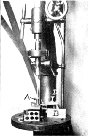
Fig. 1
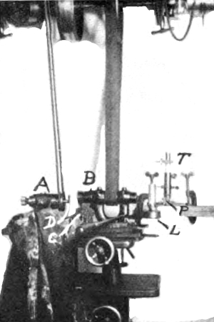
Fig. 2
The slabs that were used here were 2" × 6" × ½" and the first
operation was to cut from these round disks a little larger than the
finished lens. This was accomplished in the following manner and is
illustrated in Fig. 1. In the chuck of a drill
speeder on a Barnes drill press was placed a ¼" steel rod which carried
at its lower end a copper tube, A, which was steadied at the bottom
by a steel washer, bored to a loose fit to the tube, and clamped to
the glass as shown. Number 40 Carborundum was used and lubricated with
plenty of water. The tube must be lifted frequently to allow the
abrasive to flow to the cutting edge. This is done so often that it
seems almost a continuous motion of lifting and pressing down again,
the tool resting on the glass hardly more than two or three seconds
at a time. The cutting may be done at such a speed as to allow of a
slight heating. As soon as the tube has cut itself about a sixteenth
of an inch into the glass, the guiding washer may be removed and the
glass will then act as its own guide. A disk about one inch in diameter
and a half of an inch thick could be cut out in a little over a half of
an hour. At B Fig. 1 is shown one of the uncut
slabs and at C and D two that are about used up. Though working rather
slowly this proved quite satisfactory though wasteful of glass as it
cut a rather wide scarf, copper must be used; brass was tried but the
wear was so great as to render it almost useless while the copper shows
almost none.
As these disks are cut out they are not only cone shaped but the
edges are very rough so that the next operation was to grind these to
smooth and true circular disks. This was done on a Wells tool grinder
shown in Fig. 2, which was slowed way down by
placing a large pulley on the counter shaft. The glass to be ground
was held by cementing it with pitch onto a piece of brass rod which in
turn was held in the drawing collet of the head A. A special wheel B,
made by the Norton people for grinding the rims of spectacle lenses,
was used and the machine slowed until the wheel would keep wet when
running against a sponge, C, resting in water. The glass disk was in
this way kept dripping and heating entirely prevented. The grinding was
then carried out just as with any other material and the edge was made
beautifully smooth and true in a few minutes. The beauty of pitch as a
cement for holding the glass is that a slight heating will soften it so
that the disk can be shifted to any position and then a dash of cold
water clamps it in place and at the same time the pitch will slowly
yield to the slightest pressure so that in a few minutes the glass is
entirely free from strain. In manufacturing this sort of work is done
with a diamond and is of course done much more quickly.
The disks were thick enough to make two lenses each so we sawed them
into two as illustrated in Fig. 3. A is an old
polishing head upon which was mounted a pulley at one end and a copper
disk, B, at the other, the disk being held between large washers. C is
a cast iron box fastened to an arm, D, hinged at E and kept pressed
against the copper disk by a cord passing over two pulleys on the
ceiling. This made a most excellent automatic feed. The glass to be
split was fastened to a block of pine with pitch and the wood held
in the iron box, C, with wedges. Number 40 Carborundum was used with
plenty of water and the glass was cut through faster than a power hack
saw would cut through steel. The glass should be cut half way through
and then reversed so that the final break will come in the middle and
thus prevent the edges from spawling off. The chief defect of this
machine was the way it scattered emery.
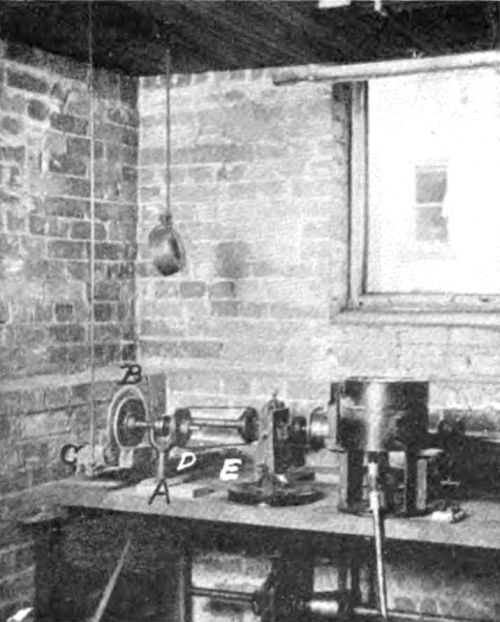
Fig. 3
The disks are now ready for the grinding which is done on the
machine on the right of Fig. 3, which consists
simply of a vertical spindle run by a quarter twist belt from the
counter shaft against the wall. The end of this spindle is tapered at
the upper end to receive the grinding tool or laps, shown on the table
in Fig. 5 which also shows the spindle raised so
that the grinding lap is seen above the tin box, C, which surrounds the
spindle to catch the abrasive that is thrown off in grinding. The glass
is first smoothed down on a flat lap until it is of equal thickness at
all points as measured by a micrometer when it is ready to be ground
to the proper curves. For this purpose the spherical laps, shown
in Fig. 5, are turned in the special machine
illustrated in Fig. 4. The compound rest of an
old Seller’s lathe was removed and in its place, on the cross slide of
the carriage, was mounted the sphere turning rest. This consists of a
base, A, in which the slide, B, is so mounted that it can be rotated
about the center, C, by turning the milled head, D, which carries a
worm at the opposite end. E is the tool post with the cutting tool T
and L the lap to be turned. A hole was drilled at C into which was
fitted a round piece of steel the upper end being pointed and then
half cut away like a center reamer. This was used in finding the zero;
the rod, pointed end up, was placed in the hole at C and the cutting
tool adjusted against the flattened side. The zero position is then
determined by measuring, with an inside micrometer, the distance from
the tool post to a stop placed at the end of the slide B. By adding to
or subtracting from the zero reading of the micrometer the length of
the radius of the grinding lap, the tool post may be set to the proper
position for either a convex or a concave surface. This, however, is
only approximate, for these laps must be made with the highest possible
accuracy. After sufficient cuts have been taken to give a spherical
surface, the radius is carefully measured with a special spherometer
and the error in the radius corrected by changing the position of
the cutting tool by an amount calculated from the readings of the
spherometer. This spherometer we were compelled to build as we could
find none of sufficient accuracy on the market and it is described in a
note at the end of this article.
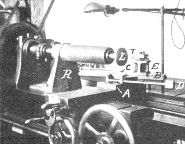
Fig. 4
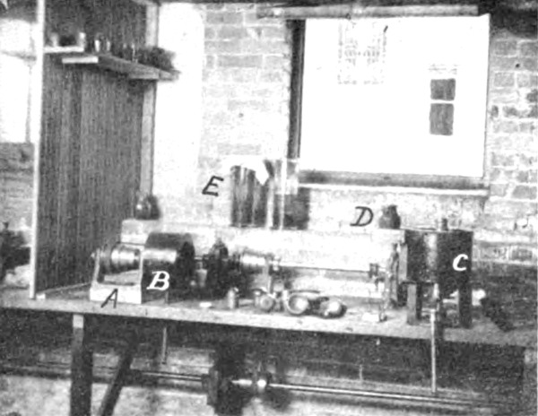
Fig. 5
In Fig. 4, R is simply a steady rest made with
the large overhang to allow the slide B to swing under it in turning
a convex surface. Two master laps, male and female, must be made and
carefully ground together. Every effort should be taken to make these
as accurate as possible since upon these depends the goodness of our
lens. This special tool is easy to make and leaves nothing to be
desired in its operation. Detail drawings and directions for making it
are given in a note at the end.
We now come to the grinding or lapping of the lenses themselves. This
is done in a lap turned as above and carefully fitted to the master
laps and which must be trued from time to time as the work progresses.
This lapping of glass is entirely different from the lapping of metals
in that, while in metals the lap is to be kept almost free from the
abrasive, in glass the lap must be freely supplied with emery and water
or deep scratches will result. The best way to apply the emery is with
a paint brush; the brush, saturated with emery, being held in front of
the lens as it is ground. The lens may be held in the hand or cemented
to a disk of brass having a center hole drilled in the back in which is
placed a pointed piece of steel held in the hand, the lens being free
to rotate about the pointed steel holder. Of course where the lens has
to be ground to a definite thickness it must be held by hand. Flour of
emery was used to rough grind though coarser grades would have worked
faster. The final smooth grinding was done with a special fine emery
made for this purpose by Bausch and Lomb. Great care must be taken in
the grinding to keep the lens as nearly centered as possible. A lens is
said to be centered when the line which joins the centers of curvature
of the surfaces passes through the center of figure. Obviously if a
double convex lens could be ground to a knife edge it would be centered
but if this were done the edge would be almost certain to crumble
in the final polishing and deep scratches result. The centering of
a convex lens can be watched by keeping the edge as nearly uniform
of thickness as possible with a concave lens, if the original blank
is made larger than necessary and care is taken to make the sides
parallel, the centering can be watched by keeping a flat edge of equal
width around the concave portion, the lens being placed back on the
flat tool, from time to time, as the work progresses. If care is used
the lens need be made but little larger than the finished size to allow
for the final accurate centering to be described later.
After being smooth ground the lens is beautifully smooth and velvety
to the touch but is just as much ground glass as ever, that is, it is
absolutely opaque. We now come to the polishing. This is done with
specially prepared rouge and only an excessively small amount of glass
is taken off. Lord Rayleigh in a paper on “Polishing of Glass Surfaces”
read before the British Optical Convention held in 1905, states: “I
started with a finely ground surface, rather more finely ground I think
than is used in practice, and I found that in order to obtain a pretty
good polish it was necessary to remove a weight of glass, corresponding
to a depth of about 6 wavelengths. I do not pretend that such a polish
would satisfy the requirements of commerce; probably the 6 would have
to be raised to 10 or 12 in order to get to the bottom of the deepest
pits.” When it is remembered that a wave length is about the fifty
thousandth part of an inch we realize how very delicate such lapping
must be. For this work the lap is covered with pitch which has been
brought to the proper degree of hardness either by boiling, to harden
it or by adding asfalt varnish to soften it. The proper degree of
hardness is very important and must be adjusted to the temperature of
the room. Obviously if the pitch is too soft it will not hold its shape
and it will be impossible to hold the polishing tool to the proper
radius. I have put three different curves on a lens about an inch in
diameter in a few minutes and it had to go back on the grinding machine
before it could be finished.
The polishing tool is prepared as follows: A disk of pitch, about ¼"
thick, is cast by pouring it in a mold made by a strip of brass bent
to a circle, the ends clamped with a tool maker’s clamp, and rested on
a piece of cold cast iron which has been planed smooth. This should be
of such size that when bent to the proper shape it can be molded over
a tool similar to the grinding tool but with a radius changed by about
the thickness of the pitch. This tool is then heated and painted with
a stick of pitch, the disk is warmed, and the two pressed together,
when cooled the pitch will stick tight to the iron but will be far from
a smooth surface. This and the master tool of the opposite curvature
are placed in warm water and pressed together and at the same time one
slowly rotated, one about the other. When a good fit is secured they
are cooled and a number of small holes, about 1-8" in diameter, are
drilled all over the pitch to distribute the abrasive, which of course
spoils the surface and the tool must be again pressed. This pressing
to shape must be done repeatedly and requires great care and some
practice in order to have the pitch come to the exact opposite of the
pressing tool. The most important thing is to do the pressing slowly
and in fact in the whole process of this work one must never get in a
hurry. Ritchey, in his memoir on the construction of the great 60" at
Mt. Wilson, recommends covering the pitch with beeswax, and for quicker
and poorer work a cloth polisher may be used, the cloth being a special
felt and cemented to the cast iron tool with a thin layer of pitch.
The abrasive is rouge or red oxide of iron and its preparation is
fully described in the above mentioned work by Ritchey. We purchased
the anhydrous red oxide of iron from Merck & Co. This was mixed
with plenty of water in the jars shown at E, Fig. 5.
The rouge will rapidly precipitate, the coarse particles falling to
the bottom, and leaving clear water above the precipitated rouge. The
upper two-thirds of the rouge will be almost perfect and will give a
beautiful polish when carefully siphoned off. This should be kept in
tightly corked bottles, one of the best things is a horse radish jar as
this has a place for the handle of the brush in the glass stopper, and
all dust and grit can be easily washed off before the jar is opened.
For polishing, the lens is cemented to a handle at whose end is a piece
of brass turned to fit the lens in the sphere turning machine already
described. Even in a small lens the polishing tool must be run slowly,
the speeds of our machines run from 170 to 300 revolutions per minute
and the fastest can seldom be used. The reason of this is that the lens
fits the polisher so perfectly that almost a perfect vacuum is formed
and the lens hugs the polished so closely that it is impossible to hold
it in small sizes by hand alone and in the case of a convex surface,
if the cavity is carried clear out to the edge of the glass disk, this
may be broken simply by the friction due to this grip of the glass and
pitch. Fig. 5 shows a horizontal polishing head
at B and a vertical one at C. There is little choice except that for
convex surfaces B seems the best, as it can be run faster, while for
concave C seems better.
The lenses are now ready to be centered, that is, the circumference
so turned that the line which joins the centers of curvature of the
two spherical surfaces shall pass through the center of figure.
In order to accomplish this, the lens is first cleaned from the
pitch used to cement it to the handle used in holding the lens
for polishing. For a long time I could find no way of doing this
satisfactorily when pitch was the cement; finally, I laid my troubles
before Dr. A. M. Bleile, Head of the Department of Physiology, and he
suggested to first soak the lens in lard and then wash it in benzol
(C6H6). This worked like magic though
the first time I tried it I used some lard that had been heated with
some pitch in it which made the lard very soft in fact almost as soft
as it could be and yet not be an oil, and this same lard was used
over and over again. The action is rather peculiar; the lard does not
apparently effect the pitch at all but after a few minutes in the
benzene it all flakes off and leaves the lens perfectly clean. The
actual centering is then carried out on the grinding machine shown in
Fig. 2; A holder, D, whose front face has
been turned in the spherical turning machine to fit one of the surfaces
of the lens, is held in the head A. If the lens be cemented to this
with a thin coat of pitch, it is obvious that the surface of the lens
next to the holder will have its center of curvature coincide with
the axis of rotation of the spindle of the head, A, but the center of
curvature of the other lens surface will probably fall outside of this
axis. A lamp, L, has a tin chimney with a pin hole in it turned towards
the lens, this pin hole forming a brilliant point of light, an image of
which is formed by each surface and reflected by the total reflecting
prism, P, into the telescope, T, where it is seen through the eyepiece.
If the centers of curvature of both surfaces do not accurately coincide
with the axis of rotation of the head, A, the images of the pin hole
will describe circles as this axis is rotated. The back surface will
of course be centered if the layer of the pitch used as cement is of
uniform thickness which will generally be the case if the work has
been carefully done; but in any case the image formed by it should
be examined. If the front surface is out of center, as it generally
will be, the holder should be warmed and the lens shifted, care being
used to keep it tight against the surface of the holder as it is being
shifted. As soon as both images remain stationary as the head, A, is
rotated, the lens is fed against the wheel, B, and ground true and to
size. This worked beautifully and the tests were wonderfully sensitive.
As soon as the component lenses of the objective have all been thus
centered, they are ready to be assembled in the cell or shutter in
which they are to be used; but as this is simply a matter of careful
machine work, I need not describe it further.
I know of no literature on the grinding of small lenses though the
following memoirs on the making of large reflecting telescopes should
be in the hands of any one interested in this work:
- On the Construction of a Five-foot Equatorial Reflecting Telescope.
- By A. A. Common, LL. D., F. R. S.
- Memoirs of the Royal Astronomical Society, Vol. L., 1890-91.
- On the Construction of a Silvered Glass Telescope, Fifteen and a Half Inches in Aperture,
and its Use in Celestial Photography.
- By Henry Draper, M. D.,
- Smithsonian Contributions to Knowledge, Vol. 34.
- On the Modern Reflecting Telescope and the Making and Testing of Optical Mirrors.
- By George W. Ritchey.
- Smithsonian Contributions to Knowledge, Vol. 34.
Note 1—A Spherometer for Short Radii.
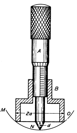
Fig. 6
In Fig. 6, A is a regular Brown & Sharpe
Micrometer Head with the measuring point ground to an angle of 60° and
slightly rounded; B is a round steel base all machined at one setting
in which the micrometer head is clamped by a set screw not shown.
Let r be the radius of the spherical surface, MNO, and we will have at
once r = (a2 + d2) ⁄ 2d. The advantage
of this form of spherometer is that it is very easy to make the point
of the micrometer exactly central with the base and the value of 2a can
be accurately determined by means of an ordinary micrometer calliper.
For a convex surface, 2a should obviously be the inside diameter of the base, B.
In using the instrument, two tables, one for concave and one for
convex surfaces, should be prepared; these tables to give the power in
dioptres for each one thousandth of an inch in the value of d. Using
the American Optical Co.’s Standard Index, namely, μ equal to 1.5000
and one dioptre as being the power of a lens of 40 inches focus, we
have, for a plano lens, p = 40⁄f =
40d ⁄ (a2 + d2) since
f = r ⁄ (μ-1).
The advantage of forming the table in dioptres in place of radii
directly is that the tabular differences are small at all parts of the
table so that interpolation can be readily done and this is not the
case in tables which give the radii directly.
If upon measuring the radius of the tool or lap being turned in the
sphere turning machine, Fig. 4, with this spherometer, the tool is
found to be in error by an amount Δp this may be corrected by changing
the position of the cutting tool by an amount 20 (Δp ⁄ p2).
Note 2—Cross Section
of the Sphere Turning Rest.
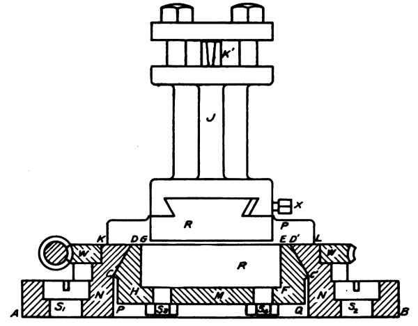
Fig. 7
In Fig. 7 is shown a cross section of the
sphere turning rest further illustrated in Fig. 4.
In machining this the following suggestions should be followed.
The piece M should be cast with a lug projecting from the face PQ to
chuck it by and all the turning done at one chucking. It should be made
a close fit to R and bolted tight against DG and ED´ with the bolts
S3 and S4, clearance being given along the line
HF. To compensate for ware the face DG and ED´ can be releaved from
time to time with a file. The base N, should be planed along AB, where
it fastens to the cross slide of the carriage, then bolted to a face
plate of the lathe and finished, care being used to leave the setting
of the compound rest unchanged between machining the faces CD and C´D´
of the pieces M and N. The dove tail on R should be first planed and
then this bolted to a face plate and the boss GHFE and the faces KG
and EL turned at one setting. If these directions are followed almost
no hand work will be needed. W is a brass worm wheel held by screws
not shown and J is the sliding tool post clamped at X with the tool at K´.
NOTES ON THE ZYGNEMALES. [A] — DEBARYA Wittrock. — Debarya glyptosperma Wittrock. — Debarya americana nov. sp. — Debarya decussata nov. sp. — ZYGNEMA Agardh. — Z. pectinatum (Vauch.) Agardh. — Z. ericetorum (Kütz) Hansgirg. — Z. peliosporum Wittrock. — Z. cruciatum (Vauch) Agardh. — Zygnema stellinum (Müller) Agardh. — Zygnema cylindricum nov. sp. — Zygnema rhynchonema Hansg. — SPIROGYRA Link. — S. Juergensii Kützing. — S. varians (Hass.) Kütz. — S. Borgeana nov. sp. — S. lutetiana Petit. — S. velata Nordstedt var. occidentalis Transeau. — S. Lagerheimii Wittrock. — S. daedalea Lagerheim. — S. Goetzei Schmidle. — S. submarina (Collins) nov. comb. — E. ellipsospora Transeau. — S. propria nov. sp. — Spirogyra braziliensis (Nordstedt) nov. comb. — S. fluviatilis Hilse. — S. nova-angliae nov. sp. — S. diluta Wood. — S. crassa Kützing. — S. submaxima Transeau. — S. micropunctata nov. sp. — S. reflexa nov. sp. — S. hydrodictya nov. sp. — S. protecta Wood. — S. tenuissima (Hass.) Kütz var. rugosa Transeau. — S. Farlowii nov. sp. — S. groenlandica Rosenvinge. — S. fallax (Hansgirg) Wille. — S. floridana nov. sp.
The following notes principally concerning North American Zygnemales
are based on a study of the specimens accumulated in the course
of eight years collecting in central Illinois; a collection made
by Mr. Charles Bullard, of Cambridge, Mass., in Massachusetts
and New Hampshire; the specimens distributed in the Phycotheca
Boreali-Americana by Collins, Holden and Setchell; the specimens
distributed in American Algae, by Miss Josephine E. Tilden; the
specimens in the U. S. National Herbarium; and small collections sent
me by Professor Farlow, Miss Tilden, Professor A. B. Klugh, Professor
D. S. Johnson and Miss Grace Stone. They have been compared with the
species distributed by Wittrock and Nordstedt in their “Algae Aquae
dulcis exsiccatae,” and other valuable European and South American
specimens sent me by Professors O. Borge and O. Nordstedt.
In determining almost any species of the Zygnemales it is absolutely
essential that the specimens show both the vegetative cells and the
mature spores. With the exception of a few species of Mougeotia the
spores are colored either yellow, brown, or blue when they are mature.
The characteristic markings of the median spore wall do not develop
usually until this color appears. Consequently it is useless to attach
names to vegetative specimens based on dimensions and number of chromatophores.
Keys based on such characters are not only useless, but misleading.
Judging from my experience in Illinois it is highly probable that the
list of North American forms will be considerably augmented, when
intensive studies have been made at localities in the Southern United
States. The most satisfactory method of collecting these forms is to
take samples from the various ponds and streams at regular intervals
of ten days, or two weeks, throughout the growing season. Many of the
species show local variations and considerable experience is needed
before many of the forms can be satisfactorily classified. The writer
has in course of preparation an illustrated key to the group, in which
figures for all of the species will be published.
This genus is in many respects the most generalized of all the
Zygnemales. It is distinguished by three important characteristics:
(1) the entire contents of the gametangia enter into the making of the
zygospore; (2) the zygospore is formed in the conjugating tube and
is not cut off from the other parts of the gametangia by partition
walls; (3) as the gametes move toward the tube during conjugation,
their place is taken by a secretion of cellulose, which renders the
gametangia solid and highly refractive. This secretion also occurs when
a vegetative cell forms an aplanospore.
This species has been recorded for America. It is not uncommon in
Massachusetts and has also been found in Minnesota and Florida. In
P. B.-A. No. 808 from Boswell, California is a somewhat smaller
variety with blue spores associated with Zygnema peliosporum Wittr.
The spores are common in the material and the vegetative cells and
filaments occasional. Following is a diagnosis for this variety:
Var. formosa nov. var. Cellulis vegetativis 7.5-9µ latis;
zygosporis 24-30µ × 30-42µ, caeruleis; ceterum ut in typo.
Vegetative cells 7.5-9µ in diameter, zygospores 24-30µ × 30-42µ steel
blue, otherwise like the type.
Cellulis vegetativis 9-12µ × 27-120µ, ad dissepimenta constrictis;
chromatophoris cum pyrenoidibus 2; cellulis fructiferis,
10-14µ × 75-180µ; zygosporis ovoideis vel quadrato-ovoideis,
20-40µ × 30-40µ, angulis rotundatis, productis, vel retusis;
parthenosporis 15-20µ × 20-30µ, oblique ellipticis, cum polis retusis;
mesosporio subtiliter et irregulariter verrucoso, maturitate luteo-brunneo.
Vegetative cells 9-12µ × 27-120µ constricted at the end walls,
chromatophore with two pyrenoids; fertile cells 10-14µ × 75-180µ;
zygospores ovoid or quadrately ovoid, 20-40µ × 30-40µ, with angles
rounded, produced, or retuse; parthenospores 15-20µ-× 20-30µ
unilaterally ellipsoid with retuse ends; median spore wall minutely and
irregularly verrucose, yellow-brown at maturity.
This species was collected by Professor A. B. Klugh, Kingston, Ontario.
It is the material upon which the Ontario record for Mougeotia
calcarea (Cleve) Wittr. is based. Of special interest is the
chromatophore with two pyrenoids, which although an axile plate is
distinctly two-lobed and forms an easy transition to the next species,
in which the chromatophore resembles Zygnema. Type in herb. E. N. T.
Collection No. 2950.
Cellulis vegetativis 16-20µ × 25-50µ cylindraceis; chromatophoris
asteroidiis duobus, singulis cum pyrenoidibus (ut in Zygnemate);
zygosporis vel ovoideis, vel irregularibus, 24-30µ × 30-48µ cum angulis
vel rotundatis, vel retusis, vel productis; aplanosporis uno latere
ovoideis, 17-25µ × 20-40µ; parthenosporis 15-20µ × 20-30µ; membrana
media sporarum scrobiculata, luteo-brunnea; akinetis ad dissepimenta
constrictis, membrana subcrassa et glabra, 18-20µ × 20-36µ.
Vegetative cells 16-20µ × 25-50µ cylindrical; chromatophores two,
stellate, each with a pyrenoid (as in Zygnema); zygospores ovoid,
quadrate-ovoid, or irregular, 24-30µ × 30-48µ, with rounded, retuse,
or produced angles; aplanospores unilaterally ovoid, 17-25µ × 20-40µ;
parthenospores 15-20µ × 20-30µ; median spore walls scrobiculate,
yellow-brown; akinetes with smooth heavy walls, 18-20µ × 20-30µ.
Type in herb, E. N. T. Collections No. 1177, 1939, 1949, 2686 and
2918. I have specimens from several localities in central Illinois;
Williamsport, Pa.; Minnesota; Mackinaw, Mich. and Kingston, Ontario.
This form is of great interest because of its resemblance, in the
vegetative condition, to Zygnema decussatum (Vauch.) Transeau.
Also because it shows not only the zygospores, but aplanospores and
parthenospores. In all cases the secretion of cellulose accompanies
the process of spore formation. The unilaterally placed aplanospores
are strikingly different from those formed by the Zygnemas. In some
of the Illinois ponds it regularly produces only zygospores, in other
ponds from which I have collections covering a period of several
years it fruited only asexually, producing aplanospores and akinetes.
But several of the collections show all the forms of reproduction in
different cells of the same filament.
The characteristics of this species suggest that the peculiar Zygnema
reticulatum, which was described by Hallas in 1895[B],
is in reality a Debarya. The fact that the reproductive cells become
filled with cellulose, that the aplanospores are very irregular in form
and that the vegetative cells contain as high as seven chromatophores,
are all in harmony with this idea. On this basis it is also easy to
understand the most notable peculiarity of the species—that spores
derived from cells with several chromatophores produce two or three sporelings.
With the addition of the two new American species and this Danish
species Debarya reticulata (Hallas) nov. comb. the description
of the genus needs to be modified as follows:
Vegetative cells cylindrical or constricted at the ends, varying
from 1-16 diameters in length; chromatophore varying from an axile
plate with two or more pyrenoids to stellate chromatophores, each
with a central pyrenoid. Reproduction by zygospores formed of the
complete contents of the gametangia; not cut off from the gametangia
by partition walls; but in the process of conjugation, as the gametes
pass into the conjugating tube, their place is taken by a secretion of
cellulose. Aplanospores occupying only part of the sporogenous cell,
the remainder being filled with cellulose. All spores variable in form.
Parthenospores and akinetes occur not infrequently in some of the
species. The walls of the aplanospores and parthenospores resemble the
zygospores of the same species in their markings.
There are now eleven described species
belonging to this genus. D. immersa W. West and D. africana G. S.
West bear a close resemblance to Mongeotia sphaerocarpa Wolle. D.
Hardyi G. S. West has much the same appearance as Mongeotia viridis
(Kutz) Wittrock. D. desmidiodes W. & G. S. West, D. calospora
(Palla) W. & G. S. West, D. reticulata, D. americana, and
D. decussata have characters in common with the Zygnemas. D.
glyptosperma has the vegetative characters common to several of the
species, but its spores are quite unique among the Zygnemales.
This is probably common in the eastern half of the United States at
least. In Illinois along with the type occurs the variety conspicuum
(Hass.) Kirchner, and a variety with large spores. This latter variety
in fact is more common than the type.
var. crassum nov. var. Cellulis vegetativis 30-40µ × 20-80µ;
zygosporis 40-55µ × 50-60µ, ceterum ut in typo.
Vegetative cells 30-40µ × 20-80µ; zygospores 40-55µ × 50-60µ, otherwise
like the type. Type in herb. E. N. T. Collections No. 2350, 2392, 2660, 2685.
Professor G. S. West has studied the reproduction of this species and
finds that it is a true Zygnema and that the description and figure by
De Bary, which shows the cutting off of two special gametangia before
the union of the gametes is at fault, consequently there is no longer
any need of maintaining the genus Zygogonium Kützing.
Specimens of this species have been distributed under the name of Z.
chalybeospernum Hansgirg, in P. B.-A. No. 808 from Boswell, Calif. (N.
L. Gardner); Amer. Alg. No. 156 from Ft. Collins, Colo. (J. H. Cowan);
and Amer. Alg. No. 392 from Vancouver, B. C. (J. E. Tilden). Z.
chalybeospermum has the median wall smooth, but the spores of all of
the above specimens have distinctly scrobiculate median walls. In size
the specimens show a somewhat greater variation in dimensions than has
been recorded for European localities.
Specimens of this species have been found at Fath Pond, north of
Coffeen, Ill., in which both zygospores and aplanospores occurred in
abundance. The aplanospores fill or slightly enlarge the vegetative
cells as in Z. Collinsianum Transeau,[C]
but the ends of the spores are usually more nearly truncate, 34-50µ ×
30-80µ. At Casey, Ill., a variety with the same dimensions but steel
blue spores occurs in the old Ice Plant Pond.
var. caeruleum nov. var. Cellulis vegetativis et sporis ut
in typo, sed membrana media sporarum caerulea.
Vegetative cells and spores as in the type, except that the
median spore wall is steel blue. Type in Collection E. N. T. No. 495.
The specimen distributed under the name Z. insigne (Hass.) Kütz. in
the P. B.-A. No. 457, from Chestnut Hill, Mass. (G. F. Moore), belongs
to this species as shown by the scattered mature spores. This species
is common everywhere in central Illinois. In the U. S. Natl. Herb, is a
specimen from Baltimore Co., Md., (J. D. Smith). In Amer. Alg. No. 157,
a specimen from St. Paul, Minn., (J. E. Tilden) shows both zygospores
and aplanospores. The aplanospores are cylindric ovoid in form,
occupying the entire cell 30-33µ × 40-88µ, median wall scrobiculate.
Cellulis vegetativis 28-33µ × 28-66µ; zygosporis incognitis;
aplanosporis cylindricis vel tumido-cylindricis, 30-33µ × 24-58µ,
sporangia complentibus; membrana media brunnea scrobiculata.
Vegetative cells 28-33µ × 28-66µ; zygospores unknown; aplanospores
cylindric or tumid-cylindric, 30-33µ × 24-58µ, filling the sporangia,
median wall brown, scrobiculate. Type in Herb. E. N. T. No. 1164, 1177.
This species is not uncommon in ponds, and pools throughout central
Illinois. It was at first classified as aplanosporic material of Z.
stellinum (Müller) Agardh. On going over the specimens in all my
collections, however, it was found that in no case were the filaments
containing the aplanospores connected with the filaments containing
zygospores. This must be the final test of the identity of the species,
as it occurs in some collections alone, sometimes associated only with
fruiting Zygnema pectinatum, and sometimes with Z. stellinum.
In a collection of algae made at the Minnesota
Seaside Station, Vancouver Island, B. C., in 1901, by Professor
Tilden, is a form which perhaps belongs here. The vegetative cells
are from 22-28µ in diameter, and 32-52µ in length, while the European
specimens are described as 16-20µ in diameter and 2-6 diameters long.
The Vancouver specimens are producing both aplanospores (globose,
24-26µ in diam.), and zygospores (ovoid 24-28µ × 36-44µ) by the union
of gametes through the partition wall separating the two gametangia.
The specimens show some evidences of being in an abnormal condition.
The specimen in P. B.-A. No. 510 from Knightsville, R. I., distributed
under the name of S. longata (Vauch) Kütz. with cell diameter 27-30µ,
and ellipsoid spores 30-33µ in diameter, fertile cells enlarged,
evidently belongs to this species. The spores of S. longata are
distinctly ovoid with rounded ends. In the Illinois specimens the
spores of S. Juergensii frequently occur with diameters up to 33µ.
The varieties scrobiculata Stockman and minor Teodoresco have
not been reported from America. They both occur rarely in Illinois. The
latter I have also seen in material collected by Mr. Charles Bullard,
at Lynnfield, Mass. The former is characterized by its scrobiculate
spores, the latter by its smaller dimensions throughout. In my
herbarium S. varians scrobiculata is represented in Collections No.
1799, and 1881; and S. varians minor in Collection No. 2951.
Cellulis vegetativis 30-35µ × 50-200µ, dissepimentis planis,
chromatophoris singulis anfractibus arctis 1.5-5; cellulis
fractiferis altero latere inflatis, altero latere (in quo conjugatio
sequitur) rectis; zygosporis ellipticis, 33-40µ × 54-70µ, membrana
media flava, glabra.
Vegetative cells 30-35µ × 50-200µ, end walls plane, 1 chromatophore
making 1.5-5 turns; fertile cells inflated on the outer side, straight
on the conjugating side; zygospores ellipsoid 33-40µ × 54-70µ, median
wall yellow, smooth. Type in herb. E. N. T. Coll. No. 1883, 1890. Charleston, Illinois.
This species bears some resemblance to a form of S. varians figured
by Professor Borge.[D]
It differs from his figure in that the conjugating side of the fertile
cells is not at all swollen, and the dimensions are somewhat larger. If
this form had been found but once it would have been passed over as a
variation intermediate between S. Juergensii and S. varians. But
it has been found several successive years in a small stream south, and at
a small pond west of Charleston, Illinois.
So far as I am aware no specimens of this species have been found in
America. The Illinois record in my list[E]
is an error. The P. B.-A. specimen labelled S. lutetiana is S.
fallax (Hansg.) Wille, as shown by its often replicate cell walls,
verrucose spores and the number of chromotophores.
Specimens of this variety have been distributed in the P. B.-A. No. 96,
under the name of S. dubia Kütz. var. longiarticulata Kütz. from
Oak Bay, Victoria, British Columbia (N. L. Gardner). The spores are for
the most part not mature but they show the characteristic scrobiculate
markings of the median wall.
This species is not uncommon in central Illinois. The
specimen labelled S. communis in P. B.-A. No. 1416, from
Winchester, Mass., has a cell diameter over 30µ, and the
spores are ellipsoid instead of ovoid. The median spore wall
in the mature spores is punctate. Here also belongs the P. B.-A.
specimen No. 365, Falmouth, Mass. Both the vegetative cells
and the spores are considerably below the lower dimensions
for S. porticalis. The P. B.-A. specimen No. 1668, S. porticalis
var. tenuispira Collins establishes this name as a synonym of
S. Lagerheimii. Professor Farlow has recently sent me a
specimen of this species from Chocorua, N. H.
This species has recently been found in a pond south of
Coffeen, Ill. The spores show the characteristic markings
and the dimensions are near those of the original collection.
The spores are slightly more rhomboidal than in the type
material, which I have seen. In herb. E. N. T. Collection No. 2912, 2850.
This species previously known only from the tropics has been found in
the collection of Mr. Charles Bullard, from Wellfleet, Mass. In herb.
E. N. T. Collection No. 2954.
This species was described by Collins as a variety of S. decimina
(Müller) Kütz, which it somewhat resembles in the form of the
vegetative cells. The spores, however, are distinctly ellipsoid, while
those of S. decimina are ovoid. The dimensions are much smaller than
those of S. decimina. It seems better therefore to recognize this as
a distinct species. It has been collected in Massachusetts, Connecticut
and Bermuda.
Described originally from Illinois, I have seen specimens during
the past year from Maine, Massachusetts and Minnesota. Professor G.
S. West[F]
described about the same time a species from Columbia, South America,
which appears to be a form of this same species. The vegetative
cells are considerably larger, the chromatophores are six (or five)
in number, and the spores are at the upper limit of size of the
North American form. As our specimens all show, a wider range of
dimensions and number of chromatophores, the South American form is
best classified as a variety under the name S. ellipsospora var.
splendida (G. S. West) nov. comb.
Cellulis vegetativis 60-68µ × 80-150µ, dissepimentis planis;
chromatophoris 3, anfractibus arctis .5-1; cellulis fructiferis
cylindricis; zygosporis ellipticis 42-60µ × 80-120µ; membrana media
sporarum scrobiculis irregularis ornata, luteo-brunnea.
Vegetative cells 60-68µ × 80-150µ, end walls plane; 3 chromatophores
making .5-1 turn in the cell; fertile cells cylindrical; zygospores
ellipsoid, 42-60µ × 80-120µ, median wall irregularly pitted,
yellow-brown. Type in herb. E. N. T. Coll. No. 2666. Coffeen, Illinois.
This species is very distinct in the form of its spores and their
position in the fertile cells. Lateral conjugation only has been
observed. It is possible that the number of chromatophores is more
variable, but in all the vegetative cells in which they could be
counted there were three.
Owing to the indefinite and imperfect description of S. lineata
Suring., the variety Braziliensis Nordstedt, of which we have a
perfect description and specimens (W. & N. Alg. aq. dulc. exsicc. No.
360), should be given specific rank. Its connection with S. lineata
is very problematical.
In all the published descriptions of this species the spores are
described as smooth, and the number of chromatophores is given as
four. I have seen many specimens from Illinois, and collections from
the upper peninsula of Michigan (T. L. Hankinson), Minnesota (J. E.
Tilden), Hawaii (J. E. Tilden), Massachusetts (P. B.-A. No. 1217),
Pennsylvania (E. N. T.) and Guatemala (W. A. Kellerman). In all cases
the mature spores are brown and scrobiculate, and the number of
chromatophores is three or four.
Cellulis vegetativis 50-60µ × 200-350µ, dissepimentis planis;
chromatophoris 3-5, anfractibus arctis 2.5-4.5; cellulis fructiferis
non inflatis; zygosporis ovoideis 50-65µ × 80-120µ: membrana media
sporarum reticulata et dense punctata, flava.
Vegetative cells 50-60µ × 200-350µ, end walls plane; 3-5 chromatophores
making 2.5-4.5 turns; fertile cells not inflated; zygospores ovoid
50-65µ × 80-120µ: median wall reticulate and densely punctate, yellow
in color.
This species was first found in the collections of Mr. Bullard
from Beaver Dam, Brook Pond, Natick; the pond west of Winter Pond,
Winchester; and the Middlesex Fells, Mass. Recently the same form was
found in a large prairie pond south of Coffeen, Illinois. Its position
in the genus is near S. malmeana Hirn. In herb. E. N. T. Collections
No. 2952, 2953 and 2900.
I first came across this species in Mr. Bullard’s collection from
the pond west of Winter Pond, Winchester, Mass. On going over Wood’s
description, its identity with S. diluta is unmistakable. The
position, color and form of the spore, and the shape of the fertile
cells is perfectly represented in Wood’s figure. The dimensions also
correspond. Wolle is responsible for confusing this species with S.
nitida (Dillw.) Link, but a glance at Wood’s figure is sufficient to
show that it is very different from that species. The P. B. A. specimen
No. 513 (labelled S. nitida) from Bridgeport, Conn., belongs here.
Miss Grace Stone also sent me a collection of this species from near
New York City. In the U. S. National Herbarium is another specimen from
Bois Sabbi, Louisiana, April 7th, 1891, (A. B. Langlois). Recently the
species has been collected at Donnelson, Illinois, by Mr. Frank Harris.
The vegetative cells are usually shorter than in S. nitida, the
spores are ovoid, not ellipsoid, and the spore wall is verrucose, or
reticulate-verrucose, chestnut brown in color. In herb. E. N. T. Coll. No. 2900.
Var. formosa nov. var. Varietas gracilis, cellulis vegetativis
80-95µ × 80-270µ; zygosporis 88-100µ × 120-150µ × 70-90µ; ceterum ut in
typo.
A small variety, vegetative cells 80-95µ × 80-270µ: zygospores
88-100µ × 120-150µ × 70-90µ; otherwise similar to the type. Type in
herb. E. N. T. Coll. No. 1939. This variety occurs in a pond east of Ashmore, Ill.
This species which was described from Illinois has been found with
nearly the same dimensions in the collections from Middlesex Fells, and
South Peabody Station, Mass., sent me by Mr. Chas. Bullard.
Cellulis vegetativis 30-36µ × 120-300µ, dissepimentis planis,
chromatophoris singulis anfractibus arctis 3-7; cellulis fructiferis
modo binis vel quaternis inter cellulas vegetativas distributis,
modo continuis, altero latere (in quo conjugatio sequitur) inflatis,
altero rectis; tubo conjugationis plerumque ex cellula mascula emisso;
zygosporis ellipticis 37-42µ × 57-100µ membrana media micropunctata et lutea.
Vegetative cells 30-36µ × 120-300µ, end walls plane; 1 chromatophore
making 3-7 turns; fertile cells scattered in twos or fours among
vegetative cells, or continuous, inflated on the conjugating side,
outer side straight; conjugating tubes formed almost wholly by the
male cell, zygospores ellipsoid 37-42µ × 57-70µ, median wall minutely
punctate, yellow. Type in herb. E. N. T. Coll. No. 2470, 2953.
This species was first found in the West Big Four Pond, east of
Charleston, Illinois. It has since been found in a collection from
Chocorua, N. H., sent me by Mr. Chas. Bullard. It evidently belongs in
the punctata group of the Spirogyras, but in form and markings of the
spore, and the shape of the fertile cells it is amply distinct from its
nearest allies; S. punctiformis Transeau and the next species to be described.
Cellulis vegetativis 30-40µ × 120-300µ, dissepimentis planis;
chromatophoris singulis anfractibus arctis 3-8 cellulis fructiferis
binis vel quaternis inter cellulas vegetativas distributis, inflatis
et valde reflexis; tubo conjugationis ex cellula mascula emisso;
zygosporis ellipticis, 44-54µ × 90-150µ, membrana media glabra et
luteo-brunnea.
Vegetative cells 30-40µ × 120-300µ, with plane end wall; 1
chromatophore making 3-8 turns; fertile cells in groups of 2 or 4,
inflated or enlarged and strongly reflexed; conjugating tube formed by
the male cells; zygospores ellipsoid, 44-54µ × 90-150µ, median wall
smooth, yellow-brown. Type in herb. E. N. T. Collection No. 2661, 2664, 2912.
This species has been under observation for four years and has been
collected from ponds near Casey, Lerna, Coffeen and Donnellson,
Illinois. The large, smooth spores, the reflexed conjugating cells,
and the tube produced wholly by the male cells are the distinguishing characteristics.
Cellulis vegetativis 75-100µ × 210-360µ, dissepimentis planis,
chromatophoris 7-10, modo subrectis longitudinalibus, modo spiralibus
anfractibus arctis .1-.5; cellulis fructiferis inflatis vel
subinflatis; tubo conjugationis ex cellula mascula emisso; zygosporis
lenticularibus vel globoso-lenticularibus, 80-120µ × 110-195µ, membrana
media scrobiculis obsita, brunnea.
Vegetative cells 75-100µ × 210-360µ, end walls plane, 7-10
chromatophores, either straight, or spiral making .1-.5 turns; fertile
cells inflated or subinflated; conjugating tube formed by the male
cell; zygospores lenticular or globose-lenticular 80-120µ × 110-195µ,
median wall brown, pitted. Type in herb. E. N. T. Coll. No. 2661, 2665.
Coffeen, Illinois.
This is one of the most remarkable forms described in this genus.
It combines large size, the lenticular spore form, and the habit of
forming the conjugating tube entirely by the male cell. The conjugating
tube has walls heavier than those of any known species. Conjugation
is both lateral and scalariform, and occurs between scattered cells,
very rarely continuous for 6-8 cells. In the fruiting condition the
filaments form a mesh-work which suggests the specific name. It has
thus far been found only in the Fath Pond, north of Coffeen, Illinois.
A study of American specimens of this species from Massachusetts,
Connecticut, New Jersey, Michigan and Illinois, shows that like S.
Grevilleana there are always some cells with two chromatophores. I
have twice found this species producing aplanospores.
P. B.-A. specimen No. 456, Easton’s Pt., Newport, R. I., belongs to
this variety rather than the type, as shown by the scrobiculate spore
wall. In Mr. Bullard’s collection there are also specimens of the
variety from Pennannock, N. J., and from Spy Pond, Lake St., Arlington, Mass.
Cellulis vegetativis 24-30µ × 70-180µ, dissepimentis replicatis;
chromatophoris singulis, rarius duobus, anfractibus arctis 2.5-6;
cellulis fructiferis inflatis (ad 39-60µ); zygosporis ellipticis, polis
plus minus acuminatis, 32-45µ × 48-93µ, membrana media glabra, lutea.
Vegetative cells 24-30µ × 70-180µ, end walls replicate; 1 (rarely 2)
chromatophore making 2.5-6 turns; fertile cells inflated to 39-60µ;
zygospores ellipsoid, ends more or less pointed, 32-45µ × 48-93µ,
median wall smooth, yellow. Type in herb. E. N. T. Coll. No. 2955, 2956, 2957.
In Mr. Bullard’s collection there are specimens of this species from
Lexington, Arlington, and Middlesex Fells, Mass. The P. B.-A. specimen
No. 362, labeled S. Grevilleana, from Medford, Mass., belongs here,
rather than to S. Grevilleana, in which the spores are distinctly
ovoid with broad rounded ends.
This interesting form is characterized by quadrately inflated fertile
cells, highly refractive cell walls, and unusually long cells and
spores. In Mr. Bullard’s collection there are specimens from Stony
Brook, South Framingham, Middlesex Fells, Wayside Inn, North Eastham,
and Malden Fells, Massachusetts. The P. B.-A. specimen No. 363 labelled
S. inflata, Orange, Conn., belongs to this species.
This species is one of several forms near S. insignis (Hass.)
Kützing. If Wille’s description is correct and identical with
Hansgirg’s material, then S. inconstans Collins becomes a synonym
of S. fallax. Hansgirg’s figure suggests that the filaments in his
material are homosexual. While Wille’s description and figure suggests
that the filaments are reflexed and that conjugation does not regularly
occur between parallel filaments, with the spores all in one filament.
It is difficult to decide just where these rough-spored forms belong
as the earlier authors did not pay much attention to spore markings.
In this connection the note by Professor Nordstedt in connection with
specimen No. 958 in Wittrock and Nordstedt’s Algae Exsiccatae is of
interest. Until these forms have been clearly separated by a study
of the original collections it seems best to use S. fallax for S.
inconstans, of which the type is P. B.-A. No. 1568. Here also belongs
P. B.-A. No. 1570, Middlesex Fells, Mass., and P. B.-A. No. 1571, Wakefield, Mass.
Cellulis vegetativis 56-66µ × 120-335µ, dissepimentis planis;
chromatophoris 4-5, subrectis vel anfractibus arctis .5; cellulis
conjugatis abbreviatis, inflatis (ad 135µ) et geniculatis; canalis
conjugationis brevis et latis; zygosporis ellipticis, 75-105µ × 95-135µ
membrana media glabra, lutea.
Vegetative cells 56-66µ × 120-335µ, end walls plane; 4-5
chromatophores, nearly straight or making a half turn; conjugating
cells geniculate, shortened; fertile cells inflated up to 135µ;
conjugating tube very short and broad; zygospores ellipsoid, 75-105µ ×
95-135µ median wall smooth, yellow. Type in U. S. National Herbarium,
collected by J. D. Smith, in S. W. Florida, March, 1878.
In its dimensions S. floridana is intermediate between S. stictica
(Eng. Bot.) Wille and S. ceylanica Wittrock. In several publications
the statement is made that S. ceylanica is intermediate between S.
stictica and the common forms of Spirogyra. A study of authentic
material of this species has shown that it has not intermediate
characters, but with its spores having a minutely pitted median
wall, it seems to be intermediate between S. floridana and S.
illinoiensis Transeau, the most specialized form in the Sirogonium
group of the genus.
Throughout the study of these collections the writer has been greatly
assisted by Mr. Hanford Tiffany, now a teacher in the Charleston,
Illinois, High School. It is a pleasure to acknowledge my indebtedness
to the many collectors who have sent me specimens for study.