NON-TECHNICAL CHATS ON IRON AND STEEL AND THEIR APPLICATION TO MODERN INDUSTRY
Transcriber’s Note:
New original cover art included with this eBook is granted to the public domain.
BY
La VERNE W. SPRING, A.B.
CHIEF CHEMIST AND METALLURGIST, CRANE CO., CHICAGO
WITH TWO HUNDRED AND NINETY-FOUR ILLUSTRATIONS AND DIAGRAMS
NEW YORK
FREDERICK A. STOKES COMPANY
PUBLISHERS
Copyright, 1917, by
Frederick A. Stokes Company
All rights reserved, including that of translation
into foreign languages
TO
MY FELLOW WORKERS
IN THE VAST IRON AND STEEL INDUSTRY
THIS BOOK IS
AFFECTIONATELY DEDICATED
FOREWORD — Illustrations are from the following sources:
vii
It has long been a desire of the author to put into non-technical
form the interesting data here given. During
several years spent in the service of one of the great steel
companies of this country, first in the laboratories and
afterward in the rolling mills, he acquired a love for the
industry that is now of fairly long standing. Spending as
much of his spare time then and since in visiting various
parts of that mammoth plant and as many others as he was
able, he has always felt that this extremely interesting subject
could not fail to prove fascinating even to those who
had previously known little of the manufacture of steel
and steel products. Later work with gray and malleable
cast irons and with cast steel enlarged the outlook and further
urged his sharing these interesting things with others
not so fortunately situated.
Such an inspiration, if it may so be called, is the reason
for the appearance of these articles. Practically as here
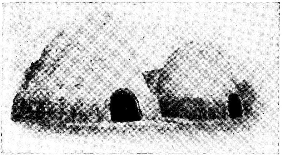
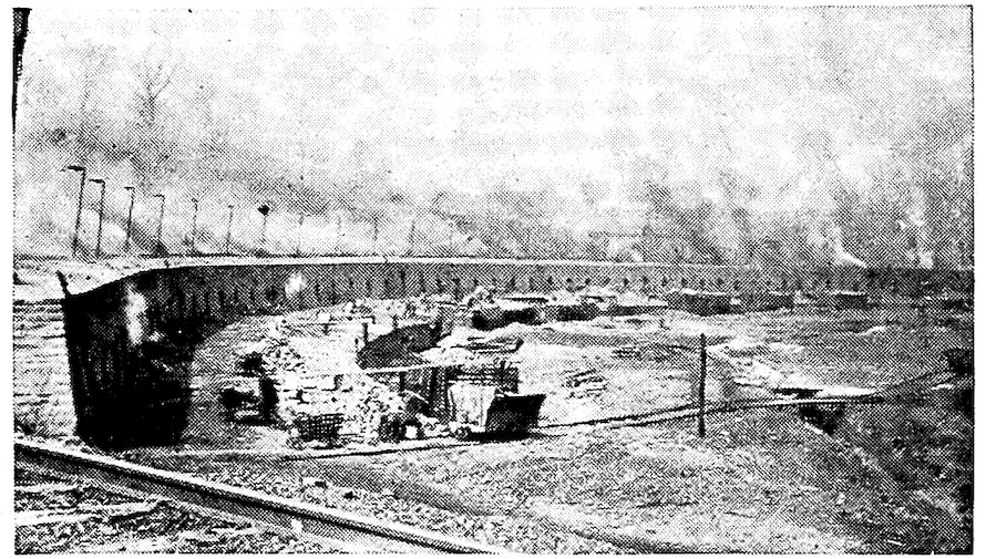
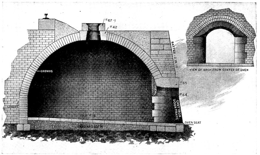
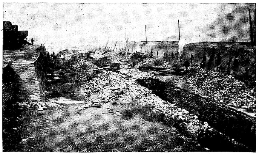
reprinted, the first thirteen of them were published during
1915 and 1916 in serial form in the “Valve World,” the
house organ of Crane Company of Chicago, with which the
writer for some time has been connected. The enthusiasm
with which they were received has been very gratifying,
while the scores of letters bearing favorable comment testify
to the correctness of the judgment that the metallurgy
of our most useful metal, iron, is of very general interest.
It may be remarked by some that certain of the statements
made in the book are not strictly accurate in that
few details have been stated or exceptions made. This is
viiitrue, but it seemed necessary if main facts were to be made
to stand forth with the boldness required to accomplish the
purpose which the author had in mind. The chapters are
in no way intended to be an encyclopedia of the subject.
The idea throughout has been to present only the main
points and to show the derivation of the products from the
raw materials and their relationships to each other. In
other words the book is intended only as a sort of outline.
References are given which will aid in the selection
of works to be consulted by any who are sufficiently interested
to go farther.
Without the encouragement and coöperation of Crane
Company and the kind assistance of friends, some within
and some without the iron and steel industry, this little
book would not have been possible. Special mention must
be made of the aid given by Messrs. I. M. Bregowsky, J. A.
Matthews, C. D. Carpenter, and others whose reading of
and suggestions concerning parts of the manuscript were
of much help. Thanks are due also to many individuals
and firms for their very hearty coöperation in furnishing
information and the photographs which appear in the pages
of the book.
L. W. S.
ix
A. M. Byers Co., Pittsburg.—National Tube Co., Pittsburg.—U. S.
Steel Corporation, New York.—Tennessee Coal, Iron & Railroad Co., Birmingham,
Ala.—Shenango Furnace Co., Pittsburg.—Pickands, Mather & Co.,
Pittsburg.—United States Geological Survey.—Wellman-Seaver-Morgan Co.,
Cleveland, O.—Lackawanna Steel Co., Buffalo.—Cleveland-Cliffs Iron Co., Ishpeming,
Mich.—J. H. Hillman & Sons Co., Pittsburg.—Harbison-Walker Refractories
Co., Pittsburg.—By-Products Coke Corporation, Chicago.—H. Koppers
Co., Pittsburg.—Federal Furnace Co., Chicago.—Crucible Steel Company
of America, Pittsburg.—Crane Co., Chicago.—Interstate Iron & Steel Co.,
Chicago.—LaBelle Iron Works, Steubenville, O.—Morgan Construction Company,
Worcester, Mass.—J. A. Matthews. Syracuse, N. Y.—McLain’s System,
Milwaukee, Wis.—Allis-Chalmers Co., Milwaukee, Wis.—J. H. Williams & Co.,
New York.—Griffin Wheel Co., Chicago.—U. S. Molding Machine Co., Cleveland.—Bradley
Manufacturing Co., Bradley, Ill. (Sears, Roebuck & Co., Chicago).—Snyder
Electric Furnace Co., Chicago.—Commonwealth Steel Co., St.
Louis.—John A. Crowley & Co., Detroit.—Illinois Steel Co., Chicago.—Pickands,
Brown & Co., Chicago.—“Sketches of Creation,” by Alexander Winchell.
Harper & Bros., New York.—“Descriptive Metallurgy of Iron,” by
S. Groves.—“Materials of Engineering,” by R. H. Thurston. John Wiley &
Sons, New York.—“Chambers’ Encyclopedia.” J. B. Lippincott, Philadelphia.—“Cast
Iron in the Light of Recent Research,” by W. H. Hatfield.
Charles Griffin & Co., Ltd., London.—“Handbook of Chemical Technology,”
Wagner-Crookes. D. Appleton & Co., New York.—“The Ore Deposits of the
United States and Canada,” by J. F. Kemp. McGraw-Hill Book Co., New
York.—“The Valve World.” Crane Co., Chicago.—“The Romance of Steel,”
by H. Casson. A. S. Barnes & Co., New York.—“The Metallurgy of Steel,”
by Harbord & Hall. Chas. Griffin & Co., Ltd., London.—“Metallurgy of
Steel,” by H. M. Howe. McGraw-Hill Book Co., New York.—Tomlinson’s
“Encyclopedia of Useful Arts” (1854). G. Virtue & Co., New York.—“Liquid
Steel,” by E. G. Carnegie. Longmans, Green & Co., New York.—“Iron
and Steel in All Ages,” by James Swank. American Iron & Steel
Association, Philadelphia.—“The A.B.C. of Iron and Steel.” Penton Publishing
Co., Cleveland, O.—“The Iron Age.” David Williams, New York.—“The
Iron Trade Review.” Penton Publishing Co., Cleveland, O.—“High
Speed Steel,” by O. Becker. McGraw-Hill Book Co., New York.
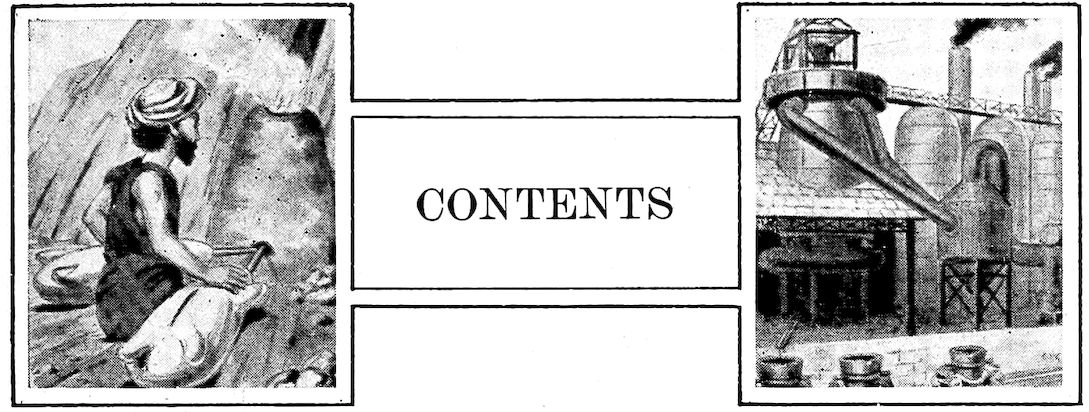
When in imagination we see the iron maker of early
days sitting cross-legged on his platform between two
crude bellows formed from goat skins with slits for
air intakes and nozzles of bamboo, working them alternately
to deliver their pitifully small streams of air
into the hole
in the side of
a bank of clay
which served
as a furnace,
we wonder at
his patience;
and after long
hours of such
effort his reward
was only
a few pounds
of iron!
Contrast with this, if you please, the modern blast furnace
with its towering height of 100 feet, its four huge heating
stoves, the big blowing engines which each minute deliver to
the furnace 50,000 cubic feet of blast, and the whole array
of dust arresters, gas washers, and automatic ore and coke
handling machinery which are essentials of this king of
modern metallurgical devices. How insignificant seems the
2output of the ancient furnace when compared with the
daily yield of 500 tons from this giant of to-day!
How has this come about?
The First Razor
Looking back over the centuries we see a period many
thousands of years ago when primitive man lived in caves
or other rude habitations and was entirely without the
implements which we now consider indispensable. The
weapons with which he defended his wife and babes from
the wild beasts and from his warlike neighbors were
clubs, wooden spears with perhaps a bone or shell tip, and
hatchets of chipped stone tied with thongs of hide into a
split stick. He managed by ingenious snares and his crude
weapons to provide game and fish for
the support of his family.
He did not shave often, for his wife
was not as particular in regard to his
appearance as are modern women, but
when such a thing happened, a piece of
shell was his razor. The good wife had
no steel needles with which to sew together skins for their
crude clothing. If she darned her husband’s socks it is
not recorded, nor did she use steel crochet hooks in making
the “doilies” for their parlor table.
When grain began to supplement the wild game, fruit,
and berry diet, it was broken between flat stones or ground
in stone mortars. Fires were kindled after long and laborious
twirling or rubbing together of two dry pieces of wood.
With his stone hatchets and by liberal burning away of
parts by fire he formed his canoes from trunks of fallen trees.
This was the “Stone Age,” and iron and steel were unknown
and not to be heard of for many thousands of years.
In various parts of the world copper always has occurred
“native”; i.e., in the metallic form and not in
combination with other elements as an earth or ore. As the
3centuries rolled on, man eventually learned that this soft
red metal could be pounded into thin-edged implements and
that it made more useful tools than those of stone, which
his ancestors had taught him to form. Some of these metal
implements were hard and had fairly good cutting edges,
made so by accidental or intentional presence of tin, and
little did he
dream that
the twentieth
century upon
finding his
buried bronze
implements would think his crude alloy so wonderful and
talk reverently of a “lost art of tempering copper.”
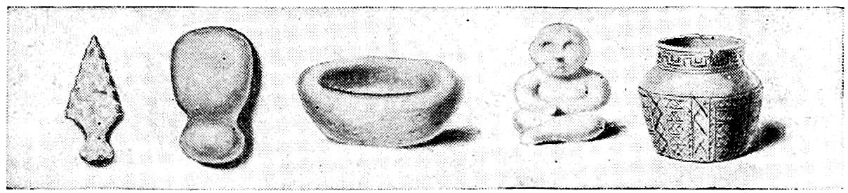
Implements of the Stone Age
Gold, too, became known to him because it also occurs
“native.” Its melting point was low enough that he could
fashion it into ornaments, idols, and other articles for religious
purposes. But during the hundreds of centuries
of the “Stone Age” and during much of this—the
“Bronze Age”—copper, bronze, and gold were the only
metals used.
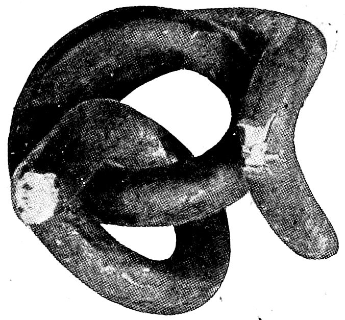
Though the
smiths became
very dextrous
in casting and
modeling
these metals, they yet knew not iron or steel.
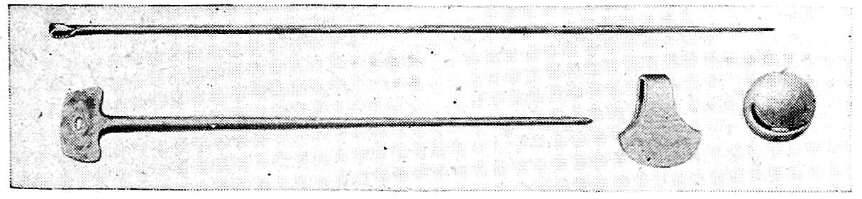
Implements of the Bronze Age
Round about them during these many centuries, as multi-colored
earths or rocks, were the ores of various metals.
They little dreamed that when rightly treated certain of the
heavy red, yellow, or black earths which lay right at their
doors could give up that most useful metal, iron. No one
even had knowledge of such a substance, for, unlike copper
and gold, iron never occurs “free,” having too great a
4tendency to chemically combine with other elements, for example,
oxygen of the air, with which, in moist climates, it
so readily forms “iron rust.” Besides, its melting point
is high and so much heat and carbon are needed for its
“reduction” from the ore that, during the thousands of
years that had gone before, it had never been produced.
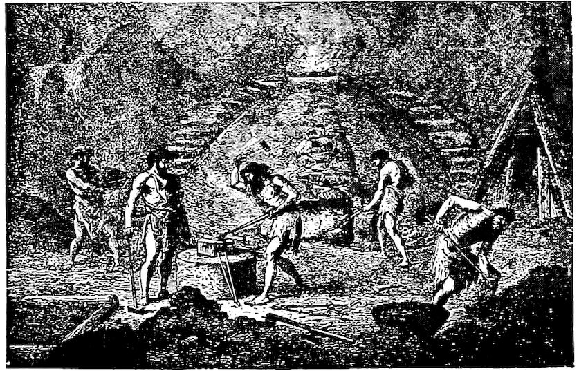
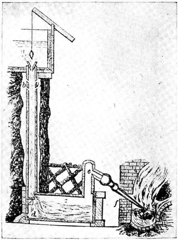
Primitive Furnace for Smelting Iron
But one day by accident and under fortunate coincidence
of rich ore, high heat, and plenty of carbon in the form of
charcoal from the wood, a lump of metallic iron was formed
underneath a pile of logs which had got afire and burned
fiercely because of a high wind. When pounded between
two stones this new
heavy metal, too, was
malleable and could
be formed into a
spearhead superior
to anything yet
known. Every one
was interested and an
observant one soon
“doped out” that
certain earths could
be made to yield this new metal, iron.
The art of extracting it spread slowly, each artisan learning
from his neighbor, and, as rich ores were plentiful in
many districts, iron became more and more generally produced.
Not only in one country was this so but evidence
shows that in many others—in Egypt, Chaldea, Borneo,
India, China, etc.,—roughly similar processes and crude
furnaces came to be used.
Tubal-Cain, supposedly about 4000 years B.C., is mentioned
in the Bible as an “artificer in iron and brass,” and
a wedge of wrought iron was buried in the great pyramid
of Cheops probably as early as 3500 B.C. This wedge was
5recently found and is now the property of the British Museum.
The Chinese made use of iron many centuries before
the Christian era, but the Assyrians are supposed to
have been the first to use the metal on a really extensive
scale.
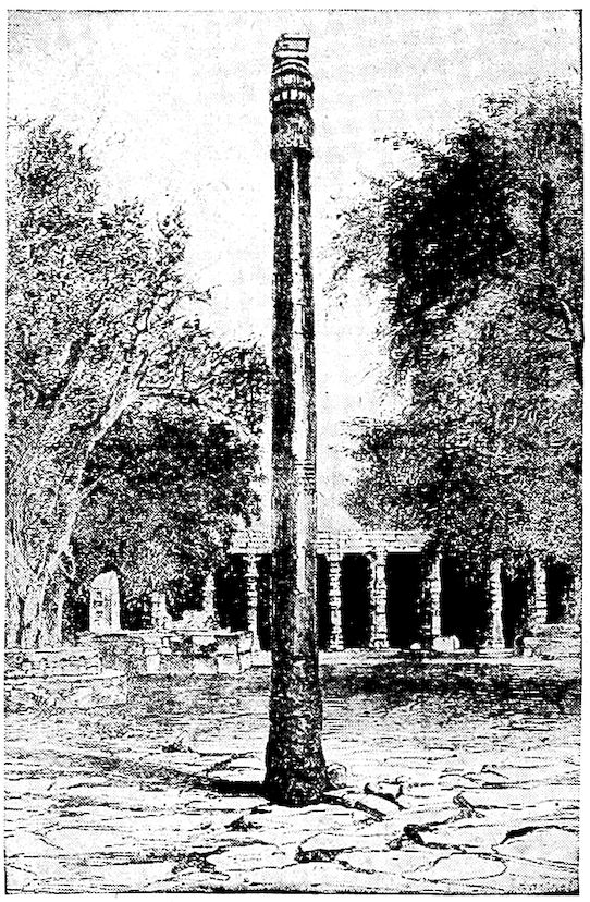
The Pillar at Delhi, India
The much discussed pillar at Delhi, India, which is still
standing in a remarkable state of preservation, is twenty-two
feet high. It is made up
of several wrought iron sections
cleverly welded together.
As the natives regard it
with religious awe, metallurgists
have been unable to
make thorough investigation
and chemical analysis. While
the date of its erection is
somewhat in doubt, it is supposed
to have been about the
4th or 5th century A.D.
But from our modern viewpoint
those early iron furnaces
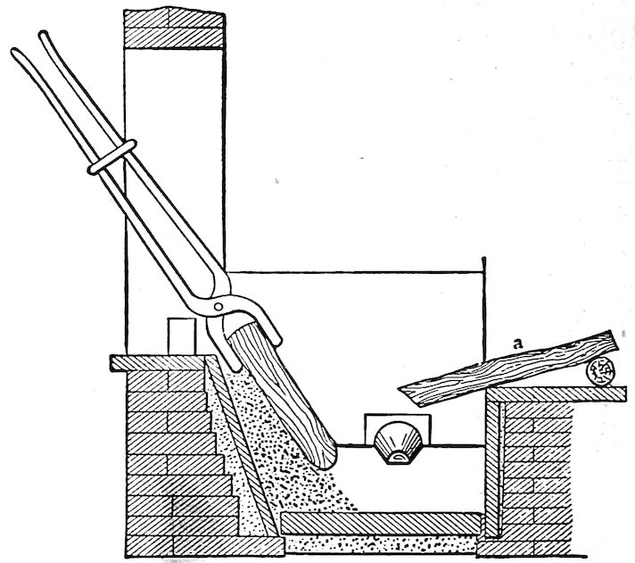
were queer things. The
first were little more than
piles of ore and wood or charcoal
on the tops of hills where
a brisk wind would make a
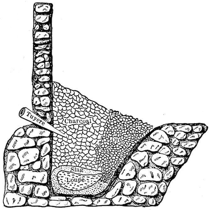
hot fire. Later, with the invention of the crudest of bellows,
the smelting was done in small holes in the side of banks
of clay, charcoal made from the forest trees being used as
fuel. Indeed, some of these types of furnaces still exist
and are so operated to-day in neglected districts in Western
India and elsewhere, producing their little five to 100 pound
balls of iron after several hours of tedious work.
When the Romans invaded Britain (now England), they
6found the Britons making iron in crude furnaces called
bloomaries; and not a great deal of improvement, except
in size, was made up to Queen Elizabeth’s time, when
strict laws had to be
enacted to prevent
destruction of the
forests which were
being denuded for
production of charcoal,
coke, which we
know so well, not yet having been produced for fuel.
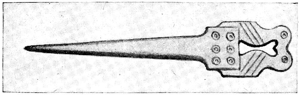
Milady’s Needle
The Catalan Forge
But the real forerunner of our modern blast furnace was
the Catalan forge, developed in and named from Catalonia,
north Spain, where it originated. The Catalan, however,
and all of such crude early furnaces, including those thus
far described, produced a variable kind of what
we now know as “wrought iron,” and our modern
“cast” iron did not appear until about 1350
when, with larger furnaces, an excess of charcoal,
with greater heat and other favorable conditions,
the Germans found that the
pasty, difficultly melting metal
could be made to absorb
carbon enough
to make it easily fusible.
This was the
secret.
To state the matter
in a simple way, iron
ore, which is essentially
a natural “iron
rust,” is the metal, iron, held in the strong chemical grip
of the gas, oxygen, which normally forms one-fifth of the
air we breathe. As you note, the combination forms a substance
7entirely unlike either the iron or the oxygen, but
both of these can be regenerated from it (the ore) by chemical
methods. Under influence of high heat (this is one of
the chemical methods, by the way), this stranglehold can be
broken by carbon, of which lampblack, graphite, charcoal,
and coke, are our most familiar examples. The result, in
the small, crude, and inefficient furnaces of long ago was a
disappointingly small ball
of crude iron, pasty and
scarcely meltable, even at
highest heats, but soft and
malleable when cold. As
mentioned, it was a variety
of what is now commonly
called “wrought iron.”
A Catalan Forge With Italian Trompe, or Water Blower
The ancients got this far.
But this was not “cast
iron.” When, however,
much more charcoal was
present in the highly heated
furnace than was necessary
simply to combine
with the oxygen of the ore,
the liberated iron greedily
absorbed enough of the extra
carbon to change its
own nature. The metal then became very fluid, whereas
before it had been pasty and stiff even at much higher
temperatures, or, indeed, at white heat. This liquid iron
could be “cast,” that is, poured into molds and in that way
made into various useful shapes. It therefore became
known as “cast iron” because of this property.
So the brittle metal (cast iron) in our kitchen ranges,
for instance, is only the early malleable form of the metal
8surcharged with or having a large amount of carbon (3½
per cent to 5 per cent) in its make-up, and it is this supercarbon
content which confers the fluid quality while hot and
the extreme brittleness when cold. True, there are other
important constituents in our modern cast iron, but for our
present purpose they need not be dealt with.
It has been stated that the ancients got only as far as
balls of wrought iron. They really got further as their
very fine sword steels show—the “Wootz” of India, the
“Damascus” of Syria, and later the “Toledo” of Spain.
These they produced by heating rich ore in very small,
closed crucibles with just enough carbon (pieces of wood
or green leaves) to make what we now call “carbon tool
steel.” As carbon steel is simply iron which has absorbed
not over 2 per cent of carbon (cast iron described above
has a supersaturation with its 3½ per cent to 5 per cent
of carbon and therefore is entirely different) they were
able to make it in small quantities. When hardened by
cooling quickly in water, a forged-out blade of this product
would cleave without dulling its edge a piece of iron, it is
said, or cut cleanly a tuft of silk floss tossed into the air.
These steels attained well deserved renown.
While no one can desire to cast the slightest disparagement
on the product of that period, much of which was
excellent, astonishingly so considering the period, a moment’s
consideration will convince one that modern products
not only do not suffer in comparison but in reality are
immensely superior. The ancients had little or no knowledge
of the reason for the proper qualities of their tools
and they made the metal from variable materials in a
crude way in such small quantities that little uniformity
was possible. While some of the product was undoubtedly
excellent, much must have been less desirable.
Modern discoveries and inventions, with the great mechanical
9progress of the last three centuries and the
scarcely half-century-old application of chemical control,
have given during recent years products of great uniformity
and marvelous quality. What can compare with thirty
thousand pound lots of steel turned out from one Bessemer
converter each seventeen minutes during the 24 hours in
the day, that is, a total of 1300 tons or 2,600,000 pounds,
in which not only the main controlling element, carbon, but
also four lesser ones,
silicon, manganese, sulphur,
and phosphorus,
are held within extremely
narrow limits;
or the modern blast furnace
which produces a
million pounds each 24
hours, run with the
same certainty of control?
Modern high-speed
steels which are
every day being made
have such high quality
that tools formed from
them will stand up for
hours working red-hot
under a lathe speed of two or three hundred linear feet per
minute taking a deep cut and “plowing out” chips faster
than a laborer can carry them away.
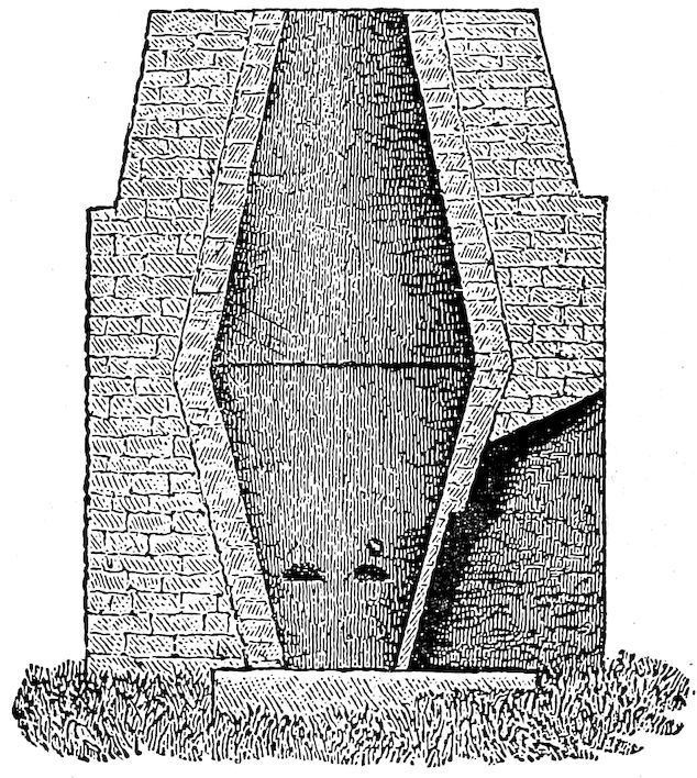
The German Stuckofen
Modern war armament which has recently been so well
advertised is sufficient answer as to whether modern metallurgy
is in advance of that of centuries ago.
The only necessity for such comparisons is that it seems
to be a failing of many to think that our forefathers were
more wise and better in other ways than we. It was but
10a few years ago that the fallacious announcement was
made that during archeological excavations in Egypt there
had been found a fully equipped telephone system. The inference
intended to be conveyed, of course, was that Bell’s
invention of the telephone had been antedated many hundreds
of years.
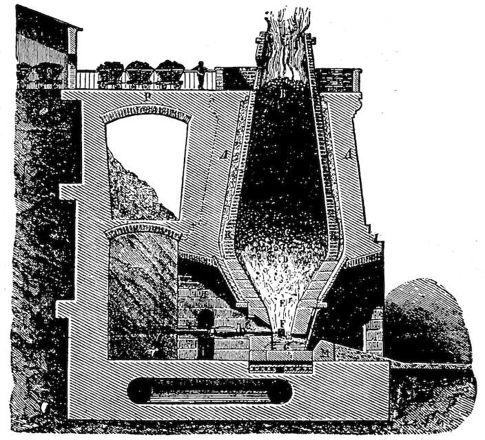
A German Blast Furnace of Fifty Years Ago
The forerunner of the modern steels was crucible steel,
first made by Huntsman
about the middle
of the eighteenth century.
Previous to his
time steel had been
made by the “cementation”
process by
which method hammered-out
bars of
wrought iron
were given a
hard steel
crust by heating
to a red
heat in charcoal
or bone
dust. Huntsman’s
product
began to come so uniform and of such quality that his
competitors were quite outdistanced. It is related that one
of them took advantage of a very severe storm to gain
admittance to the forest forge of Huntsman, who, he knew,
could not refuse shelter at such a time. What he beheld
was a very simple thing—the melting in a clay pot of pieces
of cementation steel.
Even to-day the crucible process is holding its own where
quality is the main consideration. It is the method by
11which practically all of the tool, automobile, and other
special steels of to-day are manufactured and can hardly
be given too high a rating. The newly devised electric
furnace process is the only possible competitor in sight.
Of course for quantity and for lower cost the Bessemer
and the open-hearth processes are the only available ones,
but crucible steel has been the mighty factor in the commercial
development of the world—at least until the latter
half of the last century when the two other processes last
mentioned began to acquire honor of their own without,
however, detracting much from the importance of crucible
steel as the steel of “quality.”
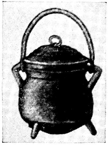
The First Iron Casting Made in America
Though more interesting than any of the
“six best sellers” much of the subsequent
history of iron will have to be passed over
at this time. We can now only mention
those very great and revolutionary discoveries
and inventions which led to and absolutely
are the basis of the quantity and
excellence of modern irons and steels; namely,
the trial for a time of coke made from
pit coal by Dud Dudley of England and its
failure which was turned into a great success a century later
(about 1713) by Abraham Darby; Watt’s invention of the
steam engine in 1770 which made possible application of a
strong continuous blast; invention of the process of “puddling”
of iron and of the rolling mill by Cort about
1784; the introduction by Neilson about 1830 of the hot instead
of the cold blast which increased blast furnace production
fourfold; the regenerative system of furnace
heating invented by Frederick and William Siemens;
and the invention of the Bessemer and Siemens-Martin or
open-hearth processes which provided methods for steel
making on such an immense scale that this invaluable
12material was made available for general purposes.
It should be repeated that the inventions just mentioned
have been of the utmost importance to the iron industry,
and through them only has it acquired its consequence of
to-day. Without them we would not have the wonderful
steel bridges, the skyscrapers, the gigantic steel ships, the
all-steel railway trains, etc., and the hundreds of iron products
that are to-day so plentiful and so constantly about us
that we disregard their presence. It is difficult thus to
pass them by, but as most of them will be referred to in
later chapters we must do so.
Early iron making in America is of interest to us and
must be briefly stated.
The colonists were aware of some of the iron ore deposits
about them and sent samples to England where these
yielded very fine iron. In 1619 a company known as the
“London Colony” was sent out from England to engage in
the manufacture of iron at Falling Creek, near Jamestown,
Virginia, but three years later all were massacred by Indians.
It was many years before attempt was again made
to manufacture iron in Virginia.
About 1637 the General Court of Massachusetts granted
to Abraham Shaw one-half of the benefit of “any coles or
yron stone wch shall bee found in any comon ground wch is
in the countryes disposing.” Apparently little resulted
from this high-sounding grant.
Real iron making in America began six years later with
John Winthrop, Jr., and his “Company of Undertakers
for the Iron Works” which for many years operated in
several localities in the New England States. Heaps of
cinders left from their furnaces may still be seen and testify
to their very extensive operation. One of Winthrop’s men
was Joseph Jenks, who became known as the “Tubal-Cain”
13of New England. What is claimed to have been the first
casting made on the Western Continent was made by him.
It is a small pot, which was acquired and is said to be still
owned by the family of Thomas Hudson, a descendant of
Hendryk Hudson.
Sand molding as used at present was introduced by an
ingenious Englishman, Jeremy Floris, and is vastly superior
to the previously used system of molding in clay. Hollowware
began to be extensively produced about this time.
As the country developed, iron works sprung up here
and there and various kinds of articles came to be regularly
manufactured. Of the early plants we can only mention
the Stirling Iron Works, at Warwick, New York, which
made the great 186–ton chain with links weighing 140
pounds each, which spanned the Hudson River near West
Point, and where in 1816 was cast the first cannon made in
America; the foundry of Sharp & Curtenius, in New York,
where was cast the first steam cylinder; and the Trenton
Rolling Mills, which first rolled iron as fireproof structural
material.
Before the Revolutionary War the colonies exported considerable
bar and pig iron to Europe, and as early as 1791
England began to foresee that this country would eventually
be a serious rival.
Pittsburg’s great advantage as an iron and steel center
has been due to its proximity to an extensive seam of bituminous
coal and ore in adjacent counties, and to its location
so near the Great Lakes, which provided cheap water transportation
for the Lake Superior ores. The first iron works
there was that of Turnbull & Company, which was established
in 1790.
Though Reameur, a Frenchman, is the accredited discoverer
of the process of malleableizing cast iron, Seth Boyden,
in a little shop in Newark, New Jersey, made malleable
iron castings a commercial success.
14
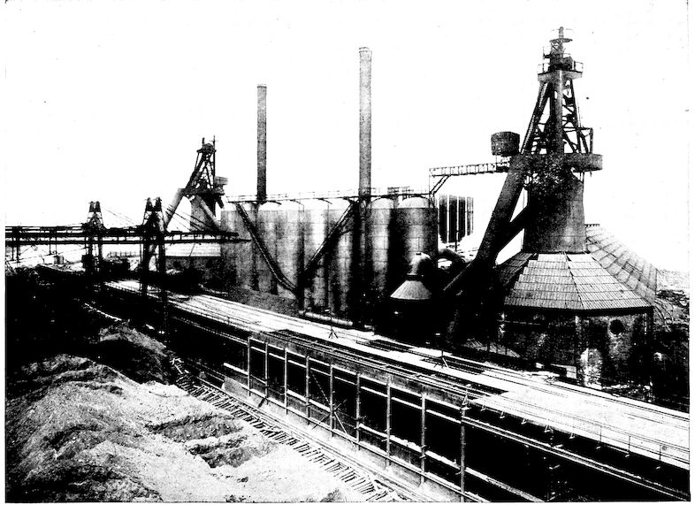
Two Modern Blast Furnaces, Showing Skip-Hoists, Cast Houses, Stoves, and Ore Pile
15The utilization of the great beds of high grade coking
coal of eastern Pennsylvania, well known as the Connellsville
district, and the discovery and development of the
Lake Superior ore deposits have made the United States
the leading producer of iron and steel of the world. The
development of the Birmingham, Alabama, district, also
has been a chapter of great importance but lack of space
forbids description at this time.
We can have only a very slight appreciation of the debt
which civilization owes to iron, for practically everything
we see or with which we daily come in contact contains or
has resulted from application of iron in some way or other.
Our cooking utensils and implements (even the enameled
and tinned ones), the kitchen range, the water and
drain pipes, and the furnace and heating plants of our
houses, are they not largely of iron? Our main building
materials—the steel frames of skyscrapers and bridges,
and are not even wood, brick, stone, and cement either
shaped, molded, or of necessity made by aid of iron machinery?
The conveyances by which we travel—wagons,
automobiles, street cars, steam railways and steamships—how
would they be possible without iron or steel? Consider
the power plants of our factories, of gas and electric
lighting plants, the pumping machinery and distribution
systems of water works, mines, etc. Would the electric
current which supplies so much of our power and light be
known to-day or even be possible but for the magnetic
properties of iron? And how many of the materials and
articles which we wear, use, and have about us constantly
would be in any way possible without the wealth of steel
machinery and tools which are available and absolutely necessary
for their production?
16The iron industry is often spoken of as the barometer
of a people’s civilization. If all iron and iron products
and their influence upon the world should be obliterated, it
seems impossible that we could be even started on the road
to civilization.
No matter how we try, probably none of us ever realizes
the immensity and importance of the iron and steel industry
with approximately 460 huge blast furnaces here, 5000
cast and malleable iron foundries, about 1000 Bessemer and
open-hearth steel and some 3000 puddling furnaces, and the
many thousands of factories which each day are turning
the products of these into rails, plate, wire, pipe, and the
infinitude of finished articles which enter into and are
mighty factors of our civilization. Yet with these furnaces,
forges and factories at our very doors, 99.9 per cent of us
are entirely oblivious to their wonders and to their presence
except to be annoyed by their noise and smoke. Even
the blacksmiths and their service we scarcely note, though
they are daily fashioning for us a material which is vastly
more important and more wonderful than any of the
“Seven Wonders of the World.”
CHAPTER II THE RAW MATERIALS — Iron Ore
17
A story has it that a minister once visited a friend who
was a zoölogist. Upon realizing for the first time how
highly organized a creature was the humble earth-worm
with its three-layer skin covering, alimentary canal,
nephridia or excretory system, reproductory organs, rude
nervous system, and setæ for purposes of locomotion, he
exclaimed: “Wonderful! I had always supposed that
worms were only skin and squash.”
With millions of tons of heavy reddish-brown earth from
northern Michigan and Minnesota going by our doors continuously
during the shipping season, the position of most
of us is very similar to that of the minister relative to the
earth-worm. We know that something is going on but we
are not aware of its importance or the immensity of it.
Almost every one knows that there are extensive copper
deposits along the Lake Superior shore of what is now
northern Michigan. In the 17th century word of these was
several times taken to Europe where in old publications
was mentioned a huge ingot of copper from which the Indians
chopped pieces with their hatchets. At that early
date maps of the region were drawn which are wonderfully
accurate, and, from time to time over a period of a
century and a half, adventurers attempted to gain wealth
in this favored region.
18
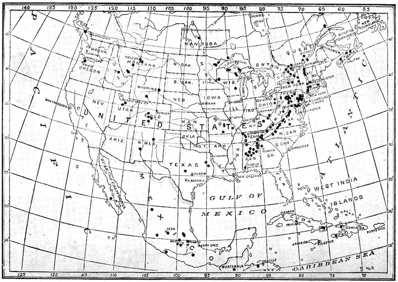
Map Showing Distribution of Iron Ores of America
19However, despite the definite knowledge of considerable
mineral wealth there and rumored claims of much more,
Michigan at the time of her admission to the Union in 1836
bitterly opposed having what is now the northern peninsula
included within her territory in lieu of a ten mile wide
strip of northern Indiana and Ohio, and it has been said
that she nearly went to war to resist it. Even after the
discovery of the iron ore deposits, no one realized the full
importance of the minerals of this region.
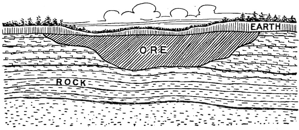
Showing Typical Mesaba Ore Bed Which, after Earth Covering is Removed, Becomes an Open Pit Mine
During the many years of campaigning for Federal help
in the building of a canal at Sault Sainte Marie, the fisheries,
valued at $1,000,000
a year, were
given as the leading
reason why a canal
should be built, and
it was no less a personage
than Henry
Clay, who, in opposing
appropriation for
this purpose, referred
to the project and the district as “beyond the remotest
settlement, if not in the moon.”
Now, within eighty years of that time, the annual tonnage
of shipping passing through the Sault Sainte Marie
canal is as great as the combined tonnage from the ports
of New York, London, Liverpool, Antwerp, and Hamburg,
and, as against the $1,000,000 value of the fisheries, the
value at the mines of the ore alone shipped from this region
amounts to about $100,000,000 yearly.
20
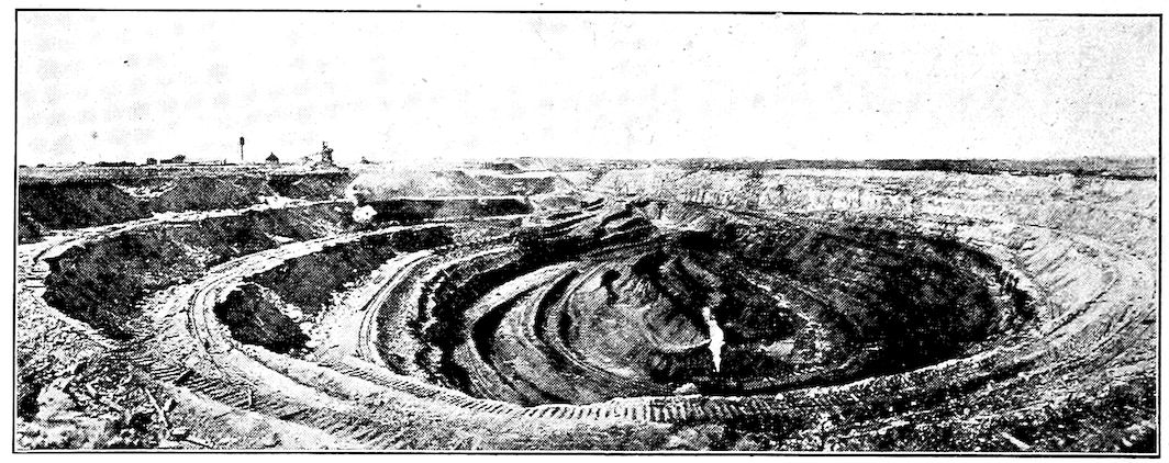
Shenango Open Pit Mine, Chisholm, Minn.
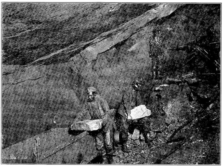
Interior of a Hard or Lump Ore Mine
21As the copper deposits are mostly along the shore of the
lake and the great iron ore beds occur seven or more miles
inland, the latter were not discovered until Sept. 19, 1844,
when William A. Burt, a Deputy United States Surveyor,
noticed that the needle of a solar compass of which he was
the inventor became unreliable. In looking about to discover
the magnetic source which must be the cause of the
variation, members of his party discovered ore just beneath
the sod near what is now Negaunee, Michigan. Inventor-like,
Burt’s only concern was to devise some preventive for
future interference by stray magnetic currents. He simply
noted in his book that there was here a deposit of iron
ore and neither he
nor any of his party
profited or apparently
attempted to
profit from the discovery.
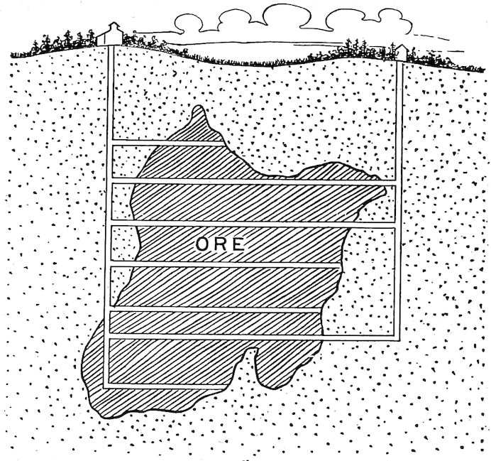
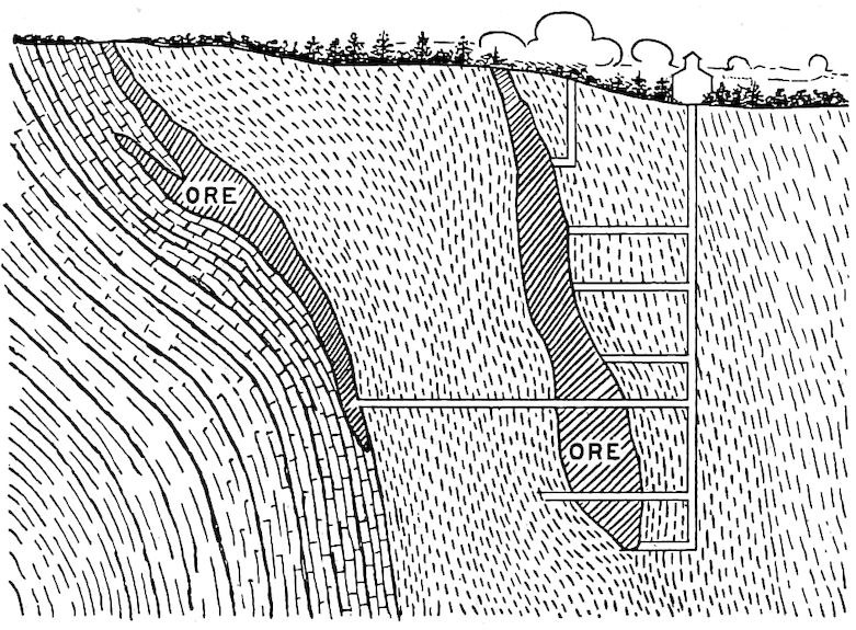
Showing Ore Body and Shaft Method of Mining
The Indians seem
to have had no previous
knowledge of
these ore deposits.
The first shipments
of ore naturally
were samples
taken from what
afterward came to
be known as the
Jackson mine and trials of them in blacksmiths’ forges
were made at Jackson, Michigan (from which town went
the first seriously-minded pioneer, Philo M. Everett), and
at Cucush Prairie. They were soon afterward tried in a
blast furnace at Sharon, Pa.
The first plan was to build forges and manufacture iron
near the mines. So there was established on Carp River
a forge to which the ore was hauled in winter when the
ground was frozen. It turned out, however, that while
very good bar iron was manufactured here, it could not be
22delivered in Pittsburg at a cost less than $200 a ton. As
the market rate for iron then was but $80 a ton the plan
was not financially successful.
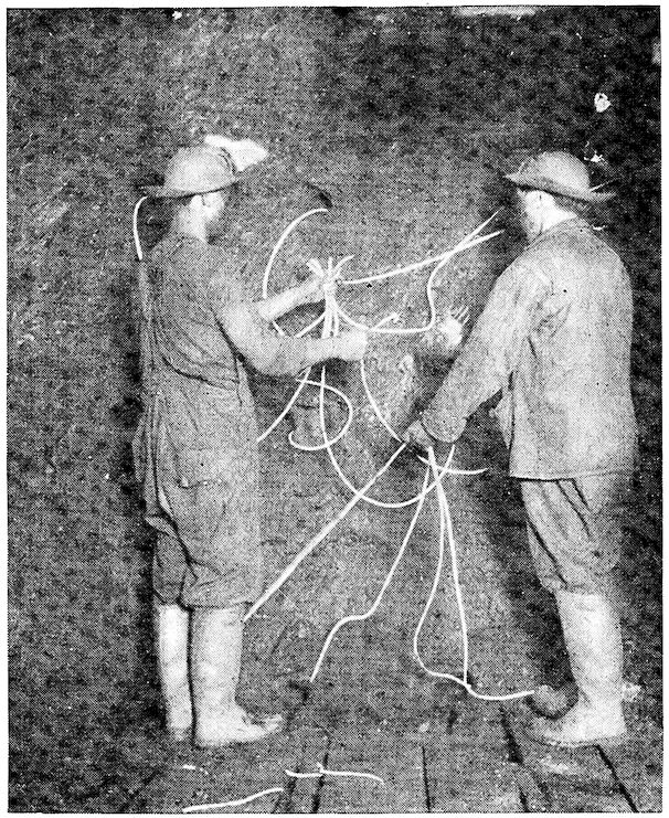
Lighting the Fuses in a Shaft Mine
Attention was turned to the shipping of ore to furnaces
better located as regards coke supply and market. It was
possible to make this a profitable undertaking only through
cheap ore handling
and transportation.
So, to-day, the ore
which is better
adapted than the
other raw materials
for handling by labor-saving
devices
and transporting
without deterioration,
is taken to the
coke and limestone,
and to the market for
the product. While
the weight of coke
used is but half that
of the ore smelted,
its greater bulk, loss
by breakage when
handled in quantities,
and deterioration upon exposure preclude its manipulation
in the way which would be necessary to get it to
the ore.
23
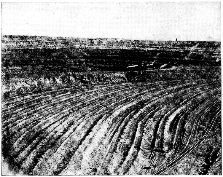
View of Hull-Rust Mine, near Hibbing, Minn.
24The marvelous development of this territory into the
greatest ore producer of the world, including the hauling
of the first small shipment on mule back, the building of
the plank and then the “strap” railroad with grades so
steep that the small trucks often ran over and killed the
mules, the building of the steam railroad, the successive
building and enlarging of canal locks at Sault Sainte Marie
connecting for use of ever larger and larger ore boats the
waters of Lake Superior and Lake Michigan, and the
growth of ore boat fleets to such size that during the shipping
season scarcely ever is one boat out of sight of another
over the entire 800 mile journey from Duluth to the
furnaces along Lake Michigan and Lake Erie, is within the
memory of men still living. Marquette was the shipping
point during
the earlier
days and the
history of this
and adjacent
regions during
the latter
half of last
century vies
in pioneering
flavor with
the tales of
our early
western
frontiers, and with the more recent Yukon mining camps.
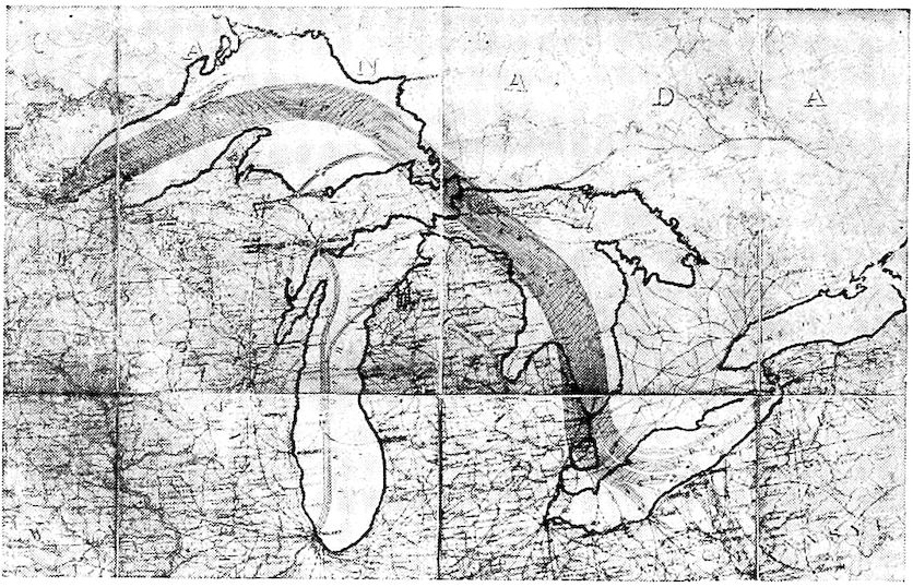
The Routes by Which Lake Superior Ores Go to the Furnaces
The first two mines, the Jackson and the Marquette, have
come to be particularly well known historically. The development
of these and other ranges in northern Michigan
and Minnesota, particularly the Menominee, Gogebic, Vermillion,
etc., and, since 1890, the Mesaba and Cuyuna, have
brought about revolutions in ore digging, handling and
transportation, which followed each other with extreme
rapidity. The ore carrying boats, for instance, may almost
be said to have jumped from a length of three hundred
to six hundred feet, and the Sault Sainte Marie canal
locks were several times almost immediately outgrown,
though rebuilt again and again, each time so much larger
than before that they were deemed impossible to be outgrown.
25
Loading Ore at an Open Pit Mine
26
Showing Other Typical Ore Bodies, Shaft Mined
Practically all of the ore beds, with the exception of the
Mesaba, yield hard or lump ores and most of them are shaft
mines in which mining has to be done underground and the
ore blasted down. Blast furnaces had never used any but
lump ores when along came discovery of the immense soft
ore deposits lying
just beneath the surface
of the ground
over a region one-hundred
miles long
in what is known as
the Mesaba district
of Minnesota.
These soft ores
were so accessible
and so rich that they
drew the attention
of the iron makers
of the whole country.
But, alas! While perfectly good in every other respect,
they were merely dry powder and not adapted to
blast furnace methods. There were great discussion, excitement,
and ridicule among or at those who invested
in these soft ore mines. Eventually, of course, blast furnace
men worked out feasible methods of converting
soft or what are termed “Mesaba Range” ores into
iron in the blast furnace. Those brave spirits, who in
the face of ridicule dared to invest in and develop
Mesaba properties, have long been reaping their financial
reward which still shows no sign of diminishing,
as “Mesaba Range” mines are “the” mines of to-day.
27
A Close View of the Hoover & Mason Unloaders
28While it may be done, it has not been found desirable
to make up the entire “burden” or furnace charge of soft
ores alone as long as lump or hard ores are obtainable to
mix with them, but often more than half is soft ore.
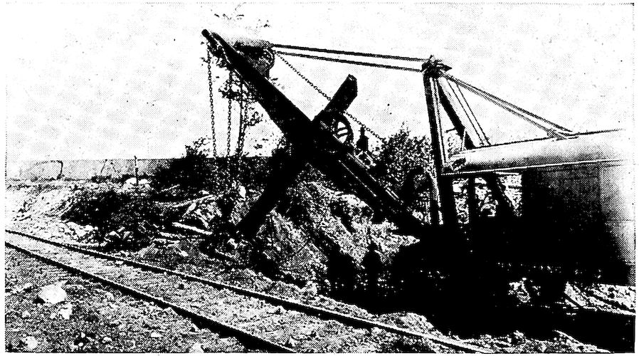
Starting an Open Pit Mine. The Earth Covering is Being Removed
While ores from the shaft mines, called “Old Range”
ores, are won by going down into the earth sometimes as
far as 3,000 feet, drilling holes in the rock, blasting down
the ore, and loading it into buggies which are hoisted to
the surface,
“Mesaba
Range” ores
are made
available by
simply “stripping”
off the
thin earth
covering, then
caving or
loading with
steam shovels
the soft ore
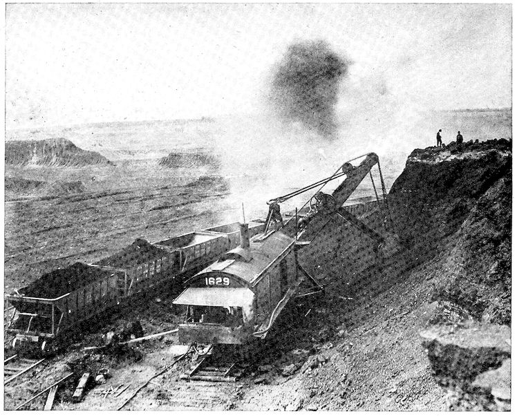
into railway cars. Some of the illustrations presented
show the ore trains and shovels, and the manner in which
the open pits are worked in terraces.
One naturally wonders how it is possible to mine and
carry these ores to the shipping ports of Duluth, Superior,
Two Harbors, Marquette, Ashland, Escanaba, etc., put
them aboard ore carrying boats, transport them by steam
power to Milwaukee, Chicago, Gary, Detroit, Cleveland,
Pittsburg, Buffalo, and the many other iron centers and
convert them into iron and steel at a profit. This, of course,
is only possible because of the inventive genius of man.
For every operation ingenious machinery has been constructed
which has brought the cost of such operations to
its lowest terms.
29
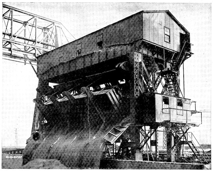
Unloading Cars of Coal or Ore is a Simple Matter with the Modern Car Dumper
30
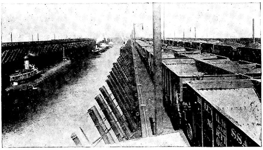
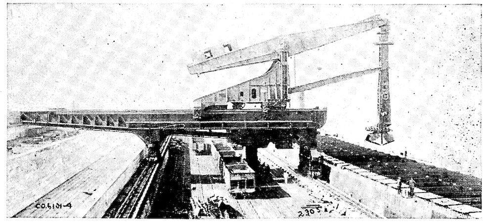
Ore Cars are Unloaded by Gravity at Docks. The Chutes Then Convey the Ore from the Ore Pockets into the Boat’s Hold
By modern methods the cars carrying the ore from the
mines are run up trestle-work into positions above the ore
bins high over the docks. The mammoth ore carrying
boats are merely steel shells with quarters for crew and
machinery at bow and stern, and hatches built with exact
twelve foot centers between. They are tied alongside the
dock, long steel chutes, also spaced twelve feet apart, are
lowered along
most of the
length of the
boat and the
ore slides into
the vessel’s
hold evenly
all along as it
has to do, else
the buoyancy
of lighter
parts of the
boat might
break the frail shell. The entire load of 10,000 tons of ore
is ordinarily taken aboard in less than one hour. Pulling
out immediately the vessel traverses Lake Superior, the
Sault Sainte Marie canal, Lake Michigan or Lakes Huron
and Erie as the case may be, and ties up at the dock at
destination. Years ago it would have been unloaded by
men with buckets or wheel-barrows, requiring some days
at best. Now, however, the hatches are uncovered and several
ore unloaders with huge clam shell buckets taking as
high as fifteen tons of ore at a “bite” descend like vultures
upon it. Within four or five hours the boat is again empty
31with no manual labor having been done upon the ore from
the mine to the furnace pile with the exception of a little
heaping up of the ore in the corners of the boat’s hold,
which the ore unloaders could not reach.
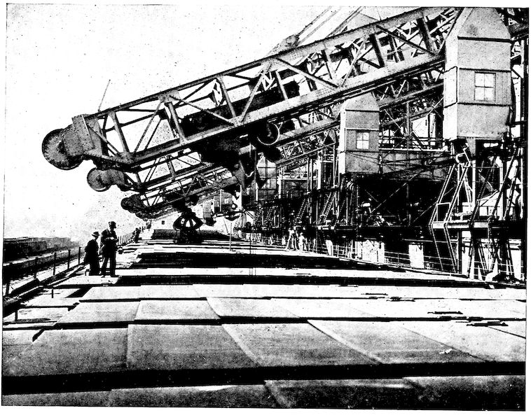
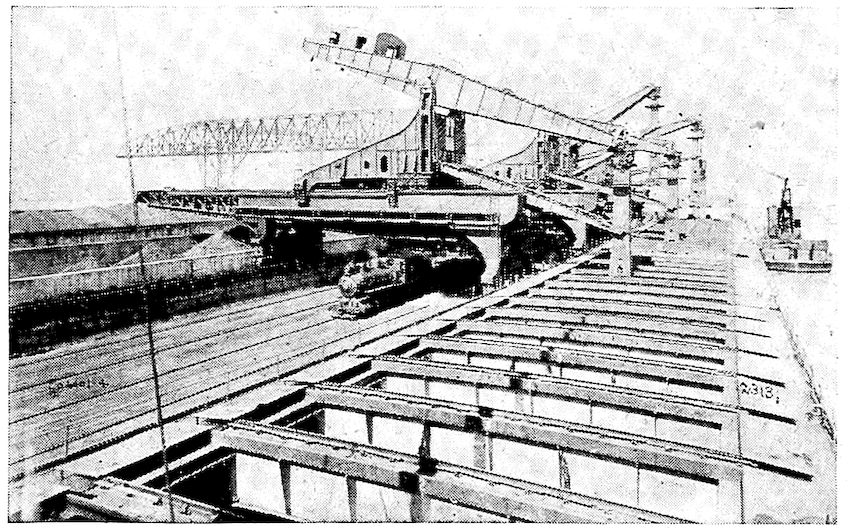
Hoover & Mason Unloaders at the Illinois Steel Co., South Chicago, Ill.
A young
man named
Alexander E.
Brown could
not bear, in
the old days,
to see the ore
so awkwardly
unloaded, and
in 1880 started
the procession of ore unloading devices. There are
now several successful ore unloaders of which the Brown
hoist, the Hoover & Mason, and the Hulett are probably
the best known. With the Hulett unloader the
operator has to be an aviator, as his position is directly
above the
grab bucket.
He descends
into the hold
with the bucket,
comes up
with it and is
with it in its
entire journey
from the
boat’s hold to
the dump and back again. It must be dizzy business.
The Hulett Unloader. Note the Operator’s Head in White Spot Just Above the Grab
Time is too precious to hold the boat at the dock long
enough that each bucketful, large as it is, can go directly
to its final bin. It is dropped just back of the unloading
32machine from which it is again picked up by other buckets
which carry it back toward the furnaces and deposit it in
cement ore troughs awaiting further journey to the ore
house, from which it goes to the furnaces. The empty
ore boat immediately coals with whole car loads of the
fuel dumped into chutes leading to her bunkers by the car
dumper and proceeds on her way back to the mines for
another cargo of ore. The round trip, including loading
and unloading, requires but seven days.
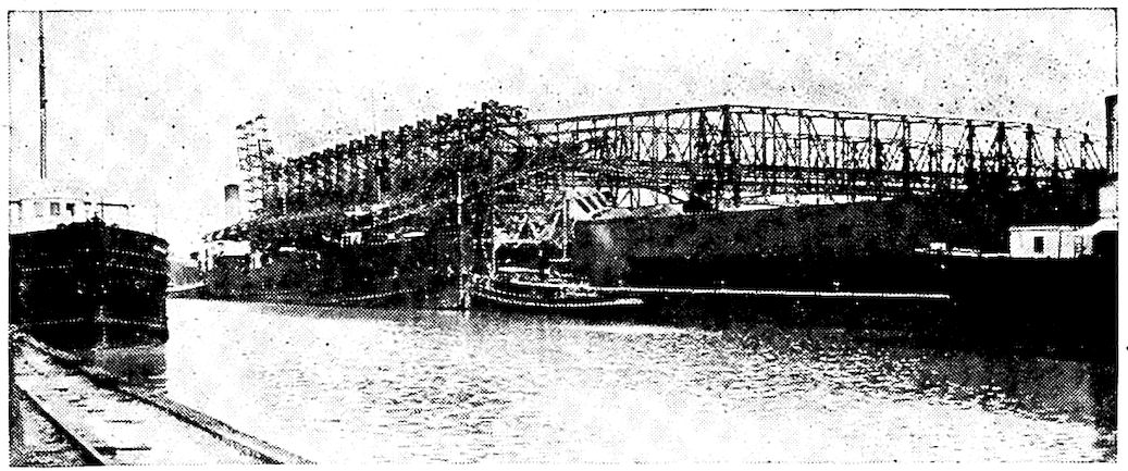
A Good View of the Hatch System of Modern Ore Boats and Four Hulett Unloaders at Work
As in many
other lines of
commercial
endeavor
of to-day,
speed and
large tonnage
have been the
aim and it
would seem
that in ore
handling and
conveying devices
the limit
has about been reached. The big steam shovels, gravity
docks, ore tanks or boats, and unloading and coaling devices,
with the low cost of water transportation have made
our modern iron and steel preëminence possible. To show
the importance to us of this water transportation, we might
mention that the rate for carrying ore from Lake Superior
ore ports to the Lake Erie furnaces has been as low as
$.0007 per ton per mile while the transportation cost by
way of a well operated railway at that particular time was
more than $.005 per ton per mile—more than seven times
as much.
33
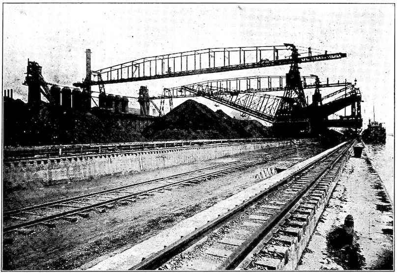
The Rehandling Bridge with Stock Ore Pile and Blast Furnace at Rear
Though for some years past more than three-quarters
of all of the iron ore used in the United States has come
from seven or eight mines in the northern peninsula of
Michigan and the adjacent part of Minnesota, it must not
be understood that the Lake Superior mines are the only
ore deposits in this country. Figures show that such an
inference is far from the truth. It is true, however, that
they have made the United States what it is, the leading
iron producer of the world. There are still immense quantities
to be mined on the Lake Superior ranges. Their
heavy production of cheaply handled high grade ore has,
of course, held back development of other districts, which
also have great natural resources. The Birmingham, Ala.,
region for instance, is a great ore and iron producer, right
now producing the third largest tonnage of any district in
34the country. Some time in the not far off future, Alabama
with her great deposits of iron ore, coal, and other natural
resources is going to announce herself in no small voice.
New York, Pennsylvania, Tennessee, and Virginia rank
next after Minnesota, Michigan, and Alabama as ore producers,
and several other states of the Union are not paupers
in resources of iron ore.
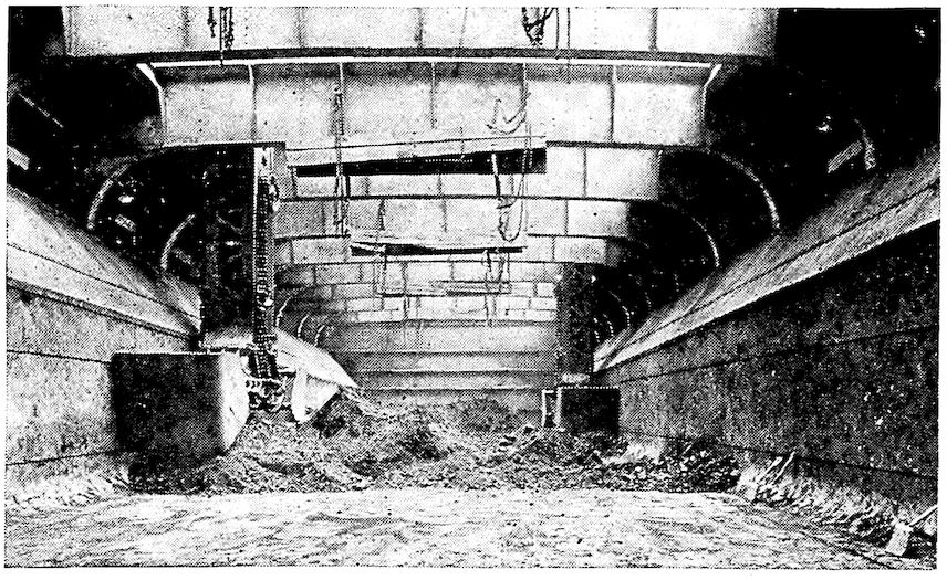
Hulett Grab Buckets in the Hold of an Ore Boat
We should not get so enthusiastic over our ore supply and
iron production as to think that other countries are devoid
of such material. Almost every civilized country has ore
enough that it
does pretty
well. With
many the
trouble is that
the ore has
objectionable
constituents
or that
supply of
cheap fuel is
not available.
Germany has
large deposits of iron ore, but until the invention of the
basic Bessemer process about 1870 she was handicapped
because of the high phosphorus content of her ore. The
basic processes, both Bessemer and open-hearth, allow of
the removal of this phosphorus during the conversion into
steel, and they therefore brought Germany to the front as
an iron producer.
The excellence of Sweden’s iron and steel has long been
known the world over. Sweden produces approximately
one per cent of the world’s total production of iron and
steel, but her ore has been of such high grade that iron made
35from it has maintained its position as a standard for use in
the manufacture of highest grade crucible steels. The very
finest steels for cutlery and tools, and even the softer grades
of steel of northwestern Europe, have been made from
Swedish iron as a base.
Iron ore, of course, is classified by geologists and chemists
into varieties with such names as hematite, magnetite,
siderite, etc., which here little concern us.
To be worked at a profit, the iron content of the ore must
be high with the smallest possible amounts of undesirable
impurities, particularly phosphorus, sulphur, and silica.
There are, however, certain impurities which are not undesirable,
for instance, lime, which will act as a flux and
neutralize the effect of some of the undesirable impurities.
For these reasons the prices for iron ore are based on the
iron content and modified by the relative amounts of undesirable
and desirable impurities. Phosphorus is almost a
domineering factor and at present approximately fifty cents
a ton more is paid for Bessemer ore (that containing less
than .050 per cent phosphorus) than for non-Bessemer ore.
As might be expected the best ores have been the first used
and the grade is constantly falling. Instead of the 66 per
cent iron ores of some years ago those coming nowadays
contain not much more than 59 per cent of iron and the
Bessemer ores described above are getting scarcer, so that
for some years practically all of the furnaces have been
mixing with them as much higher phosphorus ore as could
be used without pushing the phosphorus content of the
mixture over the allowable limit.
We often hear people surmising what is to become of us
when all of the iron ore of this planet has been used. There
is no harm in taking stock of resources and in this case it
does us much good. It happens that each time the count is
taken of iron ore available and that which under future and
36better methods of working can be utilized, we find ourselves
immensely better off than the previous report had
made out and we have less cause to worry about the future.
The last inventory was taken by the extremely ambitious
International Geological Congress held at Stockholm, Sweden,
in 1910. It shows that the world yet has enough rich
ore to make 10,192,000,000 tons of iron, and, a further supply
of ore for 53,136,000,000 tons of iron, which could be
used if necessary.
So we will get along for a while yet.
CHAPTER III THE OTHER RAW MATERIALS — Charcoal — Coke — The Beehive Oven Process — The By-product Process — Coal — Fluxes
37
Old Charcoal Kilns, near Negaunee, Mich.
Since the beginnings of iron manufacture, charcoal has
been a favorite fuel. Though during the past two centuries
coke has grown to be the standard, with anthracite
and some few bituminous coals finding use in certain
favored localities, charcoal may be considered the fuel
which developed the
iron industry, at least
until recent years.
As most of us
know, charcoal is
completely charred
wood, usually hard
wood, though sometimes
resinous or other soft woods are used. Of well-dried
timber more than 50 per cent by weight is moisture. This
and certain other constituents are driven off by heat in the
absence of air, which process is usually called “destructive
distillation.”
By primitive methods a considerable part of the wood
was completely burned and wasted during the production
of charcoal. Stacked in piles or long rows the cut wood
was well covered with earth, except for a small opening
at the top through which the fire was lighted down a center
38cavity left to the bottom of the pile. The air coming in
through the opening at the top was sufficient to keep the
wood smoldering. After a period, which had been shown
by experience to give the best results, the opening was
closed and the fire smothered.
Beehive Coke Ovens
Brick ovens of the beehive shape were built at a later
date where considerable charcoal was to be made. These
were operated on much the same general principle as the
meillers or earth-covered piles, described above. The fire
was lighted at the bottom of the central cavity of the corded
wood, the only air at first coming from the top, though
later in the process
a little was admitted
through holes in the
walls. After about
ten days, when gas
ceased to come off,
the kiln was tightly
closed for a period of
twenty days more for
the fire to die out and
the charcoal to cool.
By both of these processes valuable constituents were
burned or driven off by the heat and lost. These were
mainly methyl alcohol, acetic acid, and wood tar.
Modern industry so emphatically disapproves of any
waste of materials that apparatus has been devised to produce
charcoal which allows of recovery of the by-products
at the same time. In northern Michigan, which is practically
the only district in the United States in which the
charcoal industry as an industry still survives, long steel
tubes or retorts are built with brick fire-boxes under each
end, much as a stationary boiler is set. Into these retorts
are run steel cars loaded with the wood. The retorts being
closed, the heat drives or distills off the moisture and gaseous
compounds through pipes connecting them with condensing
apparatus. After about twenty hours the wood has
been charred, the doors of the kilns are suddenly opened
and the cars are rushed into other and similar retorts for
cooling, while fresh loads of wood replace them in the first.
39
Standard Beehive Coke Oven
40
Beehive Ovens
As may be surmised vast quantities of wood and of
wood-producing land are required for extensive charcoal
manufacture, and this is the most serious problem for the
manufacturer of charcoal. Several square miles of timber
land must be cut over each year and the wood efficiently
transported in order
to operate a large
plant profitably.
Pig iron as a by-product
is a rather
novel idea, but that is
practically what the
charcoal pig iron
produced in our Lake
Superior region is.
Several companies
operate wood distillation plants for the production of
methyl alcohol, acetic acid, acetate of lime, etc., and use
their charcoal in the manufacture of charcoal pig iron from
the ores so close at hand.
The very low sulphur content and the small amount of
ash have been the great advantages possessed by charcoal
over other solid fuels. Resulting characteristics made charcoal
pig iron a former favorite for manufacture of certain
articles such as chilled car wheels, etc., and it, therefore,
brought a higher price than coke pig iron. During recent
years, however, by careful selection of coal and improvements
in the coking process the sulphur and ash of coke
41have been so reduced that charcoal has not so great an advantage
as formerly. Charcoal iron to-day brings only
about $1.50 per ton more than coke iron; whereas, the differential
a few years ago was as great as $5.00 or $6.00
per ton.
Charcoal is quite fragile and structurally weak, so much
so that blast furnaces for its use cannot be built higher
than sixty feet; whereas, the great strength of coke allows
them to be built to exceed one hundred feet in height with
correspondingly increased
output. What
this means may be
realized by every one
conversant with the
demands of modern
industry.
Charging Coal into the Ovens
As charcoal is completely
charred wood,
so coke for analogy’s
sake may be said to
be completely
charred coal, practically always of the bituminous type. By
“baking” bituminous coal at a cherry-red heat, its volatile
constituents are driven off as the well-known “coal-gas”
of almost every small town, and a strong, brittle and porous
material or coke residue is left. If the baking is done
without any admission of air to the retort, practically none
of the coal burns and the “cake” or coke which is left contains
the ash of the original coal and what is known as the
“fixed carbon,” i.e., carbon which cannot be distilled or
driven off by heat alone, though it would burn were air
admitted.
42The gases or volatile constituents which are given off
consist mainly of moisture and a mixture of gaseous chemical
compounds, which are known as “hydro-carbons.”
These contain that part of the carbon of the original coal
which does not remain as “fixed carbon” in the coke.
Quenching after Coal Has Been Coked
Just why some coals will coke while others of apparently
the same composition as shown by the chemist’s analyses,
will not, but instead of the hard brittle mass will leave a
heap of brown or black powder, is not as yet definitely
known. It is easy
enough for chemists
to determine with accuracy
the amounts
of hydrogen, nitrogen,
oxygen, carbon,
sulphur, and other
elements; but it is a
difficult and perhaps
an impossible matter
to determine just how
these elements are
“hitched up” in the
very complex mineral,
coal,—one of the most complex substances which we know.
Various theories have been advanced in the attempt to
explain the coking quality. A bulletin of the United States
Geological Survey claims that the relative percentages of
hydrogen and oxygen in the coal determines it; others have
held that it depends upon the compounds of a tarry or asphaltic
nature present. The fact remains that some coals
coke without trouble, while others do not coke at all. As
yet the only real way to tell whether a new variety of coal
will or will not coke is to try it.
Since 1713, when Abraham Darby in England succeeded
43in introducing it as a substitute for the fast disappearing
charcoal for use in blast furnaces, coke has become the
standard fuel. It is very strong and will bear up under
the great weight of iron ore and limestone with which the
furnace is charged. So furnaces for use with coke may be
built much larger than those in which charcoal is to be
the fuel. The porous nature of coke allows it to burn rapidly
with intense heat, so that the output of an iron works
is greatly increased through its use—a very desirable thing
in these days of big
things. It has its disadvantages,
of
course, mainly high
sulphur, a deleterious
substance for which
molten iron, unfortunately,
has a voracious
appetite, and a
rather high percentage
of ash which
must be fluxed out.
But all in all, it is
a very desirable fuel
for blast furnace and other metallurgical purposes, as is
shown by the fact that it is used in the production of about
ninety-nine per cent of all iron and steel now made.
Drawing the Coke
What is known as the Appalachian coal region produces
coal for more than seventy-five per cent of the coke made
in the United States. This region includes the strip of
territory extending from Western Pennsylvania and Ohio
down to Tennessee, Georgia, and Alabama. The famous
Connellsville district is a part of this region.
Illinois and Indiana have a great deal of coal, which,
however, has rather indifferent coking qualities. Almost
44constant experimentation has been carried on in the attempt
to induce these semi-coking coals to coke. The best that
has so far developed is the use of a considerable percentage
of them in admixture
with coals of good
coking qualities.
Such mixtures yield
quite satisfactory
coke.
Large Pieces of Coke
In the old days
there was no desire
or incentive to avoid
waste of coal resources.
If during
the coking process some air got into the oven and part of
the coal was burned, or if all of the gas given off was
wasted, it did not matter. There was plenty more of coal
and the thing desired
was to get the requisite
coke in the quickest
and cheapest way.
Where Coals Are Pulverized and Mixed for Coking
In Western Pennsylvania,
Ohio, and
Virginia, were great
beds of high grade
coking coal. In this
region and particularly
around Pittsburg,
numerous blast furnaces and steel mills grew up.
The coke for these was made in the most convenient way—in
the wasteful beehive ovens.
45
Battery of By-Product Coke Ovens, Showing Gas-collecting Main
As the name signifies, these ovens or retorts are brick
chambers shaped like beehives. In the larger plants they
are built either in single rows against long hills or in double
rows back to back. Over the tops of the ovens in each
row runs a car called a charging “lorry.” Coal is poured
from the bottom of this through a hole in the top of each
oven while it is still hot from the preceding charge. No air
gets in except that admitted through the hole in the oven
top and a small slit left over the one side door, through
which the coke is drawn when the coking process is finished.
The heat of the oven starts the distillation of the moisture
and the volatile compounds
which escape
through the hole in
the oven top. The
small amount of air
admitted burns a little
of the coal and
gas and raises the
temperature of the
oven to that required
for coking.
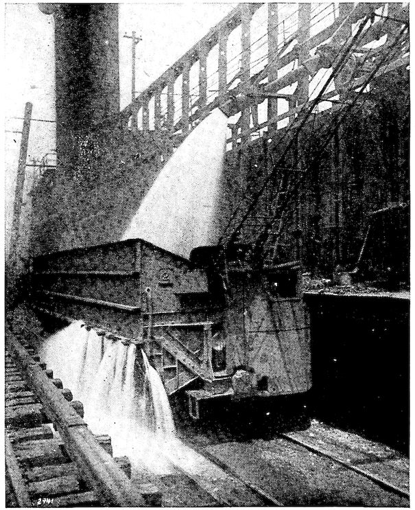
After 48 or 72 hours a spray of water is thrown in over
the glowing coal to quench the fire. The partially cooled
coke is drawn through the open door, sorted and loaded into
cars for shipment.
Though this method of coking is a very wasteful one, it
yet produces the larger quantity of the coke made in the
United States. However, conditions are rapidly changing
and it will not be many years before the much less wasteful
“by-product” process gains the ascendency. By 1914 it
had already come to produce about twenty-five per cent of
the total coke made here, and since that date the percentage
has been rapidly increasing.
46
Top of Ovens with Charging Bin and Lorry at Far End
By this system of coking a greater yield of coke is obtained
and most of the by-products are saved. The value
of the latter depends
largely, of course,
upon local conditions,
such as transportation,
costs of the material,
cost of labor,
and available market
for the coke oven gas.
They are usually figured
as having a
value of $1.50 per ton of coal coked, equivalent to a total
of $71,000,000 per year for the coal coked in the United
States.
Lorry for Charging Coal into Ovens
The ovens and apparatus required are considerably more
expensive, but, since
this industry has developed
in this country
during the last
twenty-two years to
a point where one-quarter
of all of the
coke manufactured is
made by the by-product
process, there can
be no doubt that it is
a profitable proposition and that eventually the wasteful
beehive ovens will be a thing of the past.
Practically all of the types of by-product coke ovens in
use have been developed in Germany or Belgium, where
circumstances forced earlier conservation of resources than
47in this country. The three best known types are the Semet-Solvay,
the Otto Hoffman, and the Koppers—the latter a
recent arrival. They differ mainly in details of construction
and operation.
Machine for Pushing Coke from Ovens
In a general way a “battery” of coke ovens consists of
from 40 to 80 long narrow brick-walled chambers placed
closely side by side with heating flues or “checker-work”
between them. The fire for the baking process is in these
flues, which are interconnected, and the heat developed is
sufficient to drive off the moisture and volatile substances
of the coal in the narrow chambers just on the other side
of the brick walls.
Charging is done by
a “lorry” as in the
beehive process.
After from seventeen
to twenty-four hours
at a red heat, the
coke is “pushed”
from the ovens, one
after another, by an
electric ram which enters at one end. The 30 × 7 × 1½ foot
block of glowing coke emerges from the other end, where,
breaking under its own weight into good-sized pieces, it
falls into a steel car on a track just beneath. A spray of
water quenches it and it is taken to the storage bins to
be sorted.
Rich coal-gas is the main by-product. That which comes
off during the first seven hours is the richest and has the
greatest illuminating or “candle” power. After washing
free from dust, tar, ammonia, etc., the gas is usually run
into holders or tanks from which it is distributed for use
for illuminating or for heating purposes. That which comes
off during the latter part of the coking period has much less
48of those constituents which give illuminating value. It has
good heat value, however, and as fuel is required for keeping
the ovens up to the coking temperature, this poorer gas
from the coking chambers is switched into and burns in the
flues between the coking chambers as mentioned.
Thus the larger part of the gas is sold to customers, usually
in the city near which the ovens have been located,
and the poorer part is utilized in heating the ovens and the
steam boilers which run the plant.
Quenching Car Awaiting Its Load
The coal tar, which
the German chemists
have made so famous
through its manufacture
into the almost
endless variety of
beautiful dyes, is another
of the by-products
which is recovered
by this, but
burned or lost in the
beehive oven process.
From a long main
over the tops of the
ovens which connects the gas pipes, the tar flows along
with the gas to the scrubbing and gas cleaning plant, where
by rather intricate operations it is freed from other substances.
In this country much of the tar is used for building purposes,
etc., and some as fuel, but not much has been made
into the chemical products for which Germany is so
famous. For a long time a few dyes and other chemical
compounds have been made here from coal tar. Since the
early days of the war in Europe and the cessation of
imports of such materials on this account, there has come
49about considerable expansion in their manufacture here;
but it is doubtful if the time is yet ripe for a wholesale
entry into the manufacture of these coal tar “derivatives,”
especially the very extensive variety of dyestuffs.
Naphthalene and benzol from which many other chemical
compounds as well as munitions of war can be made, are
among the by-products.
Quenching the Coke
Most of the ammonia which the corner drug store sells,
comes from the by-product
manufacture
of coke. The largest
part of the ammonia
which is produced in
the process, however,
is manufactured into
sulphate of ammonia,
a well-known fertilizer.
Anthracite or hard
coal has been used
in certain districts
in the United States,
especially in New
Jersey and eastern
Pennsylvania. It is
not an ideal fuel as it
is too solid to burn rapidly, spalls or cracks under heat and
interferes with the blast. Since 1860 when coke became
available here much less coal has been used, though some
is yet used in admixture with coke. Some bituminous coals
which contained little tarry matter also have been used in
this way.
50
Limestone, the rock which is ordinarily used for fluxing
purposes, needs no introduction to any of us. As the
marble of statuary,
the material of which
oyster and other sea
shells and the white
tombstones of our
cemeteries are composed,
it is well
known. Any of these
varieties of the material
may be used
for fluxing purposes,
but usually it is limestone
which is quarried
for the purpose
or obtained as chippings
or spalls from
building blocks.
Coke Going from Quenching Car to Bins
Loading Coke in Box Car
The active agent,
which produces the
chemical or fluxing
action in the blast
furnaces, is carbonate
of calcium (lime)
of which limestone
contains about 98 per
cent. Dolomite is a
mixture of carbonates
of lime and magnesium,
about 53 per cent of the former and 45 per cent
of the latter, and is sometimes used in place of limestone.
51Fluor spar, a rock composed of calcium and fluorine, is
used in small quantities in some of the metallurgical processes.
It is a very powerful flux.
CHAPTER IV THE BLAST FURNACE
52
Up the dark tower shoots the elevator with its “buggy”
of coke. Its speed is not conditioned to the comfort of man,
who is not supposed to be a passenger, except the occasional
laborer whose duty as buggy-pusher requires his presence
on twelve-hour shifts at the top. So we, whose exploratory
proclivities have led us at the office to sign away our lives
for grant of a pass to the blast furnace, find our breath
about taken from us with the first mad dash into the darkness
of the climb. That stone tower had looked much more
innocent from below.
But now the rickety elevator has as suddenly emerged
into the light again and stopped abruptly at the charging
floor which extends across the chasm to the top of the
furnace.
As the smoke-begrimed buggy-pushers rush the buggy
of coke across to the furnace bell, we have opportunity to
notice that we are a full hundred feet above ground. Just
here, seemingly so close that we can put our hands on them,
in a row, are the round steel tops of the four stoves which
are for the purpose of preheating the blast. The huge
pipes, dust arresters, tanks, and buildings, all so necessary
to the plant, look almost like a tangled mass from our high
station, while the charging floor upon which we stand, the
shoulder-high steel fence around it, the furnace top, the
adjacent stoves and in fact everything for a half mile
53around us, is colored yellow-red with iron dust. We understand
the reason for this when the buggies of ore which
have succeeded the coke are dumped into the funnel-shaped
depression around the conical bell at the center. As the
huge bell is lowered and the charge slides in there is considerable
blowing out of the fine ore dust, which, in fact,
continually “oozes” out of all crevices under the heavy
pressure of the blast inside.
Hand-fed Blast Furnace
Day and night, month in and month out, during the life
of the fire-brick lining
of the furnace,
this routine of charging,
first coke, next
the theoretically correct
charge of analyzed
iron ores, then
limestone, in rotation
goes on. From 6 A.M.
to 6 P.M. and from
6 P.M. to 6 A.M. on
twelve-hour shifts,
alternating gangs of
laborers push the
buggies across to the furnace top, dump and return them
to the elevator already up with another load.
The incessant quiver of the iron plates beneath our feet
with the rumbling and groaning from the inside of this
monster are disquieting and the thought constantly recurs:
“What if this powerful creature should just now rebel, as
quite occasionally occurred in the old days when all of its
moods had not been so well understood?” For this king
of metallurgical devices, though gentle and obedient as a
lamb under proper treatment, is a domineering fury when
it has dyspepsia as occurs whenever its attendants are remiss
in their attentions to its diet. “Those explosion doors
just below the furnace top—are they in working order and
would they be adequate?” But whether, as in recorded
instances, the whole furnace top is torn off as evidence of
its wrath, or its displeasure is exhibited in a milder way,
we much prefer to be absent. The thought is disquieting
and we are glad to
leave.
54
Cinder or Slag Flowing into Ladles
55
“Fireworks” at the Cinder-Notch
Unwilling to test
again the elevator for
the downward trip,
we take to the narrow
iron stairway
which leads from the
top of the furnace to
the ground. But this
is worse than the elevator,
for the stair
treads are very narrow
and made only of
three slender iron
rods. To our palpitating
hearts they
seem to give very insecure
foothold and
the gaps show that
there is nothing but earth beneath us, and that a hundred
feet below. To make matters worse, before we
creepingly get half way down some visitors below have
stopped to watch our slow and trembling steps and
our nervous clutch on the low “stingy” hand rail. We
hear them innocently inquire of one another why we
move so slowly. We wish that we could appear brave,
especially before the women in the party, but we could
56not move with greater alacrity if our lives depended
upon it.
Once below again with our breath regained, things are
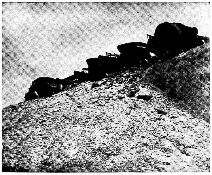
more interesting. The red-hot molten slag which has just
been tapped out is running from the furnace along a long
trough into a ladle six feet high resting upon a car on the
railway track alongside the “cast house,” as the huge
structure which houses the lower part of the furnace is
called. This smoking, molten slag stream gives off a powerful
sulphur smell
and throws a lurid
glare over everything
round about.
The Slag Dump
The furnace superintendent
is just explaining
to the other
party that No. 2 furnace
has been “hanging”
for a couple of
days and is still dangerous.
“If you realize,”
said he, “the
great weight of coke,
ore, and limestone in that furnace, you can see what a
splash it would make if the clogged, bridged part with all
above it should fall suddenly into the molten pool in the
‘hearth’ of the furnace. Two years ago No. 1 broke out
and the molten metal caught and burned to death one of
our men and injured several others. ‘Hanging’ does not
occur when the furnace is working right, but failure of the
charge to come down evenly is very serious sometimes.
A blast furnace is like a coquette; she has to be handled
just so, and even then you cannot always be sure what she
is going to do next.
57“Oh yes,—where does the iron come from? Well, we
often read nowadays of a man and his ‘affinity.’ Now the
chemist has used that word ‘affinity’ for years to describe
the liking or attraction of one chemical ‘element’ for another;
in fact, that is where this recent colloquial use of
the word originated.
Iron ore is nothing
more nor less than
metallic iron, the element,
chemically
combined with oxygen,
another element
which constitutes
one-fifth of the air we
breathe. Under conditions
produced in the
blast furnace, though
for centuries wedded
to iron, oxygen deserts
him for her ‘affinity’
carbon, which
is best known to you
as coke, coal, or charcoal.
The iron, now
free, becomes molten
at the high temperature
encountered
(about 2800° to 3000° F.) and descends into the ‘hearth’ or
bottom of the furnace, while oxygen and her new partner
escape out of the top of the furnace in gaseous form. When
molten iron has accumulated in the hearth to the extent desired
it is tapped out as you will soon see.
Diagrammatic Sketch of Blast Furnace
“The limestone charged has ‘affinity’ for dirt and certain
other impurities of the ore which it removes in molten
58form as the ‘cinder’ or ‘slag’ which is there running into
the ladle. When cold, this cinder is a dark greenish-black,
glassy substance, which of recent years has come to be used
to a certain extent in the manufacture of Portland cement
but is mainly used for filling-in purposes. Some is crushed
and utilized in concrete mixtures and for road building. In
Chicago considerable
land has been ‘made’
by dumping slag into
the lake, and South
Chicago is reported
as standing on a
swamp which has
been filled in with
slag from the steel
works there.
Old-Fashioned Pig Bed
“This immense
furnace is simply a
strong steel shell
lined two or three
feet thick with fire
bricks. At the ‘bosh,’
which is the region
where the greatest
heat is produced, hollow
bronze plates are
inserted among the bricks of the lining through which circulating
cold water keeps the bricks from being fused.
“The hot gases which are led from the upper part of the
furnace through that brick-lined ‘downcomer’ are burning
in three of those ‘stoves’ to heat them, while cold, clean air
from the blowing engines is coming through the other stove,
which, ten minutes ago, when it was put on blast, was the
hottest of the four. It is now giving up part of its accumulated
59heat to the blast on its way to the furnace. Switching
the cold incoming air every little while from a partially
cooled stove through
a hotter one while allowing
the former to
reheat, provides continuous
blast of a
temperature of 800°
to 1400° F. The ‘hot
blast’ idea originated
about 1830 with
James Neilson, a gas
engineer of England,
and its introduction
revolutionized the
blast furnace industry
and made the
highly efficient modern
practice possible.
Furnace and Sand Bed Ready for Iron
“This big pipe
above our heads
which encircles the
furnace is the ‘bustle
pipe.’ It also has to
be lined with fire
bricks. The hot blast
is distributed by this
‘bustle pipe’ to the
tuyères here—these
L-shaped pipes—which
shoot it directly into the furnace. Through the
peep-holes in the tuyères you can get a glimpse of the dazzling
interior of the furnace. The blast of heated air is
causing the coke to burn fiercely there so that it melts the
iron, which farther up in the furnace has been forced to
part from the oxygen, as I explained to you.”
60
Layout of Blast Furnace Plant
61But now six men with a long steel bar are starting to
break through the two or three feet of clay with which the
“tap hole” of the monster furnace is plugged, and our informant
hurries
away.
Skip Hoist at Work. Skip Dumping into Hopper
For ten minutes
with strong sledge
blows the tappers
struggle to break
through the plug of
burned clay. Meanwhile
the monotonous
whistle of the heavy
blast into and
through the bustle
pipe and tuyères goes
on and the discharge
pipes of the water-cooling
plates empty
into the gutter around
the furnace bottom
the water which has
been circulating to
keep the inner bricks
from fusing.
62
SECTION OF BLAST FURNACE SHOWING FILLING ARRANGEMENT, BINS AND ORE BRIDGE
63And now a shout
and the strong red glow throughout the cast house tell us
that the tap hole is open and the iron is running down
the main channel of the sand bed. Past the plugged entrances
to the lateral branches runs the molten iron stream
to the end of the cast house nearly one hundred feet distant
where it divides, filling the laterals on each side and from
them running into many open molds arranged like the teeth
of a comb. Each of these molds is about five feet long.
They form the “pigs,” and the laterals what are known
as “sows.” As each lateral and its molds fill, the lateral
ahead of it is opened and the process repeated, laterals
and pigs filling up simultaneously on opposite sides
of the main channel till the whole cast house floor is
filled nearly up to the furnace with the red smoking metal.
Sand Cast Pig Iron
There are few
sights more glorious
than the cast house
with bed just filling
with metal, and especially
is it so at night.
The strong yellow-red
light of the flaming
metal issuing
from the furnace and
the intense glow of
that already in the
bed illuminates
everything in and
about the building.
But already, before
the furnace is empty,
the workmen are spraying with water the earliest cast pigs.
Covering them with a light layer of sand they venture upon
them with thick-soled shoes and break the “pigs” from
the “sows” with sledge hammers.
This is the old-fashioned “sand cast” pig iron. After
remelting in the cupola furnaces of neighboring towns and
casting into stove parts or other forms it is known as
“cast iron”; through “puddling” in reverberatory or
special furnaces it becomes “wrought iron”; after decarbonizing
64treatment in steel furnaces of various design
it is changed into the wonderful material called
“steel.”
Pig iron is thus the intermediate or semi-raw material
from which practically all of our various iron and steel
products are made
and the transition
product through
which they pass.
Machine Cast Pig Iron
But the romantic
period of the hand-fed
furnace and the
gloriously beautiful
pig beds at casting
time are rapidly
passing; in fact, are
almost past. Modern
“skip-hoists”
carrying automatically
dumped
buckets or cars
charge the furnace
more economically than even low-waged laborers can do it.
The two charging cars alternate, one filling at the bottom
in the stock house while the other is dumping through the
double bell at the top of the furnace. Furnaces are now
tapped by power driven drills which make quick work of a
formerly difficult operation. Instead of running it into the
sand bed, the molten iron from the furnace is nowadays
run into ladles alongside the cast house as is the cinder
which was described above. If the metal is to be made into
pigs it goes to the pig casting machine, where the traveling
iron molds very quickly convert the entire cast into “chilled
cast” pigs. At the top of the incline these pigs which have
been cooling under sprays of water fall from the traveling
molds into railroad cars below which deliver them to the
consumer.
65
How Pig Iron Is Now Cast into Traveling Molds
66
Upper End of Casting Machine Where Pigs Are Dumped from Traveling Molds into Railway Cars
In large steel works the greater part of the molten iron
is not cast into pigs at all but while yet molten is directly
charged into the open-hearth or Bessemer furnaces which
convert it at once into steel of which the greater part is
made into plate, rails, or other shapes before being allowed
to cool. Even the gas
is recovered nowadays.
Its journey
through the “dust arrester”
rids it of
most of its dust, after
which filters and
washers clean it thoroughly.
That not required
for the heating
of the stoves is
used for firing the
steam boilers about
the plant and as fuel
for batteries of huge gas engines which in large plants
have been installed to generate low-priced electric current.
It should be noted that in modern practice iron is mined,
loaded, transported to the furnaces, unloaded, charged and
made into pigs or converted into steel and even into the
finished products with practically no hand labor, all operations
being performed by machinery.
Though a “direct” process for converting the ore into
wrought iron or steel has been long sought, a method has
never been found, except that used in the very small way
followed by the old iron-workers with their crude furnaces.
67It has always proved commercially advantageous to make
pig iron in the blast furnace as an intermediate step and
then by a second step convert it into wrought iron, steel,
etc. So the ore is brought from the mines to the furnace,
the coke and limestone arrive from another region,
and batteries of huge blast furnaces through the country
make from them the pig iron.
1. No advantage has been found in furnaces having a height of over 110 feet.
The chemical laboratory plays a very important rôle in
iron making. Analyses made of each car or boat load of
ore by the furnace chemists representing the buyer must
check very closely the analyses made by the mine chemists
for the seller, as the price of every ton of ore is based on
its iron and its phosphorus contents and the percentages
of certain other constituents present. In calculating the
“burden” or charges for the furnace, each of these constituents
is estimated in pounds actually present per
charge, losses or gains during the journey through the
furnace are allowed for, and by combining the various
ores the charges are so made up that the resulting iron
will be of certain desired composition. The closeness
68of actual composition obtained to calculated results is
startling.
Truly this is an age of efficiency.
Though technical information and statistics are not to
be inflicted upon our readers to any extent in this series
of articles, it may not be amiss to give one table of interesting
figures which show the increase in height and capacity
of furnaces from 1850 to the present time. During this
period the annual production of pig iron in the United
States has risen from 565,000 to 31,000,000 long tons (2240
pounds). It will be noted that since 1887, when we passed
Great Britain, the United States has been the champion
pig iron producer of the world.
The record production of a single blast furnace to date
was that of one of the United States Steel Corporation’s
furnaces at Duquesne, Penn., which produced 900 tons of
pig iron in one day.
CHAPTER V A GENERAL GLIMPSE AHEAD — The Metallographic Method of Classification — Classification by Chemical Analysis and by Physical Tests — Volumetric Analysis of the Iron Alloys
69
We have arrived at the parting of the ways. From the
vast beds of iron ore, the coal fields and coke ovens, and
from the quarries of limestone, all roads have led to the
blast furnace. This we have visited and we now know how
pig iron is made.
From this point the several paths diverge. One by one
we are to follow them to get acquainted with the interesting
country which they traverse and the regions to which they
lead. However, before choosing any one of these paths for
our first trip, it will be to our advantage to pause, to study
for a moment our position and get a general view of the
country ahead of us. We should know the relative locations
and importance of the places we are going to visit,
for only by getting a comprehensive idea of the general
plan of this ferrous (meaning iron) world, can we understand
to the best advantage the position of each of the
main products, wrought iron, steel, cast iron, malleable
iron, etc., and acquire a satisfactory knowledge of them.
In the last chapter pig iron was called the intermediate
stage between the ore and the finished iron product, and
such the sketch given shows it to be. It is only as an intermediate
product that pig iron has value, for nowhere in
the commercial world has it a purpose except as a material
to be chemically and structurally transformed into other
materials which may themselves be used without further
70transformation. It is desirable that we fully realize the
position of this very important semi-raw material, pig
iron, before passing on to the study, one at a time, of the
refined ferrous products which are susceptible of direct
use in our commercial life.
Electric Arc, Microscope, and Camera, Part Of Metallographic Apparatus
From Table A (page 71) it will be seen that from blast
furnace metal
several well-known
products
are formed
by the various
processes
of refinement.
Each of these
methods of
purification
may be
said to result
in a certain
general composition
and
structure
which give to
the material formed its character and properties.
By aid of the microscope it is possible actually to look
into the structure of these materials.
71
TABLE A
IRON AND STEEL PRODUCTION OF THE UNITED STATES FOR 1912
72
Part of a Chemical Laboratory Where 6,000 Samples a Year Are Analyzed
73By cutting in any direction through a piece of metal or
alloy, polishing the surface exposed very clean and smooth
and then etching (corroding) slightly with acid, the exposed
grains of the metal may be seen when sufficiently magnified.
Not only may the grains of metal be seen, but certain of the
other constituents which are present are visible. Photographs,
also, can be taken by attaching a camera to the
microscope. This method of analysis, which is known as
“metallography,” has proved as valuable an aid to the
metallurgist as it proved to the geologist when applied to
the study of rocks and geological specimens.
Machine for Determining Strength of Iron and Steel Bars
The metallography of wrought iron, cast iron, malleable
iron and steel differentiates them to us with considerable
accuracy, as is shown
by a glance at the accompanying
photomicrographs,
as photographs
taken through
the microscope are
called.
For our immediate
purpose of gaining
a general knowledge
of the relative
positions of these
products, this method
of analysis probably
cannot be excelled.
After the processes of manufacture of these materials
have been taken up one by one in later chapters, the photomicrographs
will be even better understood than now, as
will the differences of chemical composition and physical
properties of the alloys, such as strength, hardness, brittleness,
forging quality, etc. The photomicrographs are
given at this time to show that the materials are structurally
very different and to aid in the general classification.
To make them comparative, all have been taken at the
74same magnification of seventy diameters; i.e., the microscope
has made everything shown just seventy times as
large as it actually was in the alloy.
No. 198. Photomicrograph of Sand Cast Pig Iron. The Thick Black Lines Are Graphite Flakes
As stated before, the alloy pig iron normally contains
from 3 to 5½ per cent of carbon. This was absorbed during
the journey through the blast furnace. As long as the
iron was molten all of this carbon was in the “combined”
form; i.e., in chemical combination with the iron itself.
Cold iron, however, cannot retain in the chemically combined
form as much
carbon as does molten
iron, so, during
the solidification and
cooling of the alloy,
more or less of its
carbon was precipitated,
i.e., thrown out
of solution and from
chemical combination
with the iron, the
amount depending
mainly upon the
speed of the cooling.
It appeared then as the “free” carbon (crystalline graphite)
which remained distributed throughout the alloy and
may be seen as the jet black flakes in photomicrograph
No. 198.
Every pure metal is supposed to be composed of crystals
or grains which would have been of the true cubic form if
the severe internal pressure during solidification and cooling
had not distorted them.
Photomicrograph No. 99b represents quite well a pure
metal. It is that of an extremely mild steel made by special
methods in the open-hearth steel furnace. It is so highly
75refined that it can hardly be called steel at all but is often
called “open-hearth iron” or “ingot iron.” It is probably
the purest iron on the
market in commercial
quantities to-day.
While in the chemical
laboratory iron of
considerably greater
purity can be made,
for a commercial
product this is remarkably
pure, seldom
containing more
than ¼ per cent of
elements other than
the metal, iron.
No. 99b. Open-Hearth Iron. Probably the Purest Commercial Iron Product
The boundary lines of the crystals or grains may be
plainly seen. Each grain should show practically white.
The dark parallel
lines, the dots, and
the grayish portions
result from inequalities
in the polishing
and etching.
No. 1d. Section of Wrought Iron Cut Lengthwise of the Bar. Black Patches and Filaments Are “Slag” or “Cinder”
After noting the
appearance of photomicrograph
No. 99b,
which is of a nearly
pure iron, one need
have no difficulty in
realizing that pig iron
and the steels are
alloys and not simple metals. The truth is that of all alloys
some of the well-known iron products which we are
studying are by far the most complicated, much more so
than are the nonferrous alloys, which include the brasses,
bronzes, babbitts, German silver, etc.
76
Physical Test Room Where 15,000 Specimens Are Tested Each Year
77This should not worry us, however, for we shall not attempt
to follow them into their complications.
No. 3b. Steel Containing .10 Per Cent of Carbon. The Carbon is in the Black Patches
The important point just now is to observe the crooked
black flakes of crystalline graphite in this photomicrograph
No. 198. It is largely because of these flakes of brittle, soft
graphite that pig iron and the cast irons are so fragile.
One has no difficulty
in realizing that these
flakes, which cut in
every direction
through the metal,
make it structurally
weak, especially toward
a sudden blow.
No. 1d shows a
typical section of
wrought iron cut
lengthwise of
the rolled bar. It
will be noted that, as
in photomicrograph No. 99b, there are no graphite flakes.
In the process of wrought iron manufacture practically
all of the carbon of the original pig iron is burned out,
leaving little besides the iron itself and some viscous cinder
or slag. In the rolling or hammering out of the resulting
white-hot “bloom,” the slag enclosures which remain
after the squeezing process are extended lengthwise
through the bar. Upon observing with the microscope any
prepared section of wrought iron which has been cut lengthwise
of the bar the filaments of slag may be plainly seen,
all parallel or practically so. When such filaments of slag
78can be discerned in a longitudinal section it is practically
an absolute indication that the material in question is
wrought iron.
No. 22c. Steel with .50 Per Cent of Carbon
No. 36a. Steel with 1.98 Per Cent of Carbon
Photomicrograph
No. 3b is that
of mild steel containing
.10 per cent (⅒
per cent) of carbon.
Here we have neither
the graphite flakes of
No. 198 nor the slag
filaments of No. 1d.
We can plainly see
the boundary lines of
the grains. The irregular
dark patches which are evenly distributed throughout
are the defining features of steel. In what might
be called a chemical-mechanical combination, these dark
patches contain all of
the small percentage
of carbon which gives
to carbon steel its
definite properties.
During the manufacture
of this alloy
all but a small
amount of carbon is
eliminated by burning
it out, as happens
with wrought iron.
But the steel is molten
or fluid when finished
and the slag which has been formed floats on top
and is also eliminated, which does not occur with wrought
79iron, which is thick and pasty at its finishing temperature.
No. 74. Gray Cast Iron. The Crooked Black Lines Are Graphite Flakes
Therefore, steel contains no graphite and no slag but has
only the small percentage
of carbon
which was purposely
put back to give to it
its valuable properties.
No. 92d. Semi-Steel, a Stronger Gray Cast Iron
Photomicrograph
No. 22c is typical
for steel which
contains .50 per cent
(½ per cent) of carbon.
The irregular
patches containing
the carbon are
much larger and more frequent. It will be seen, therefore,
that through metallography the various iron alloys,
to a considerable extent, may be analyzed as well as
classified.
Photomicrographs
Nos. 74 and
92d represent soft
and stronger grades
of ordinary gray cast
iron respectively. It
will be noted at once
that both much resemble
pig iron in
structure, as of
course they should,
for simple remelting
in the cupola does not effect much modification in composition
or structure.
80Occasionally castings are made from molten iron direct
from the blast furnace, but such practice is not very satisfactory
and is little
done. It forms probably
the only exception
to the statement
made above that pig
iron has no useful
purpose in the commercial
world except
as something to
be transformed by
some refining process
into another material.
No. 132. Gray Cast Iron 200 Years Old
No. 109. Malleable Cast Iron Before Annealing
The remelting for
the well-known cast iron is usually of such selected brands
of pig iron and cast scrap as will produce cast iron best
adapted to the purposes
intended. The
resulting alloy still
contains 3 per cent
or 3½ per cent of
carbon.
No. 132 is interesting.
It is a photomicrograph
of a piece
of cast iron which is
approximately 200
years old. From the
standpoint of the
metallurgist it is the
same as other photomicrographs of cast iron, the difference
in appearance resulting probably from casting conditions, etc.
81Malleable cast iron is made much as is gray cast iron except
that it is brought to such a composition that sections
of castings made from the melt show a white fracture when
broken. Castings of gray iron of course show a gray fracture.
The former are extremely hard and are as brittle as
glass until they have gone through a careful long anneal
or heat softening process. By maintaining them at cherry-red
heat away from air for sixty hours or more and cooling
slowly, they become “malleable”; i.e., not brittle at all
but capable of considerable
distortion
without cracking.
No. 35. Malleable Cast Iron Annealed
From the viewpoint
of malleability,
malleable iron may
be considered to occupy
a position between
gray cast iron
and steel.
Photomicrographs
Nos. 109 and
35 are those of malleable
iron before
and after the annealing treatment. The former shows the
typical structure of white cast iron, while the latter plainly
shows the minute lumps of pure carbon and the surrounding
grains of pure iron metal, the two having become divorced
through the annealing process. Note that the large
amount of carbon in this, the “temper carbon” form, does
not make the alloy brittle through cutting of the grains as
does the crystalline graphite form of carbon.
The above gives very briefly the most essential points in
the classification of the irons and steels from the structural
standpoint. True it has not entered into the vast
82complications of the higher carbon or tool steels which are
those which will take a “temper”; i.e., the tool steel’s
quality of hardening by quenching in water from a cherry
red heat. The simpler points of these will be taken up later.
But enough has been given that we now understand something
of the relative positions of the great main products,
some reasons therefor, and their general structures.
No. 8. Bar Rolled from Scrap; Contains Both Wrought Iron and Steel
It has been seen that their micrographs quite definitely
differentiate them and probably no one will have difficulty
in recognizing and
naming such specimens.
As testing this
it may be interesting
to note photomicrograph
No. 8. Two
different iron alloys
made up the material
from which this photomicrograph
was
taken. Apparently
the bar was one
made by heating and
rolling together
scrap metals. Such
material is on the market. The photomicrograph shows
that some of the scrap used was wrought iron and some of
it mild steel of about .08% carbon.
So far not much has been said about composition except
that upon it to a great extent depends the structure and
physical properties of the alloy. Composition and physical
characteristics as well as structures are necessary to a fair
83
Table B—Chemical Composition and Physical Properties
2. In degrees Fahrenheit. For our purposes, the same as the melting points of the alloys.
3. Pounds required to pull apart lengthwise a bar one inch square.
4. Number of inches that a bar eight inches long will stretch before it breaks.
84
Iron and Steel Test Pieces and Instruments Used in Measuring Their Size, Elastic Limit and Elongation
85understanding of the subject. There is given therefore,
a table showing approximate comparative values of chemical
compositions and physical properties of the alloys under
discussion.
It should be distinctly understood that the figures given
in Table B are approximate only and are intended to be
average, or rather, perhaps, typical.
There are all sorts of conditions which in practice modify
the figures given in the table, and criticism may be maintained
justly against some of the too specific statements
which here it was necessary to make. The classification
is given with considerable hesitation and only because, arranged
in this way, it brings out existing relationships
which otherwise would escape notice and which we cannot
afford to overlook.
But please do not gain the impression that these alloys
are divided into distinct classes. There are no dividing
lines at all. One group merges into the next so gradually
that it is impossible to tell where the one ends and the
other begins.
It is to be hoped that no one will make himself miserable
by trying to digest these rather formidable figures of
Table B all at one sitting. They are given mainly for comparison
and for reference. It is suggested that after noting
carefully the similarities and differences to which attention
is called, they be reserved until the processes of
manufacture of the various alloys are taken up one by
one. Reference to these figures on those occasions should
be profitable.
The main points to be noted at this time are:
1. Open-hearth iron is practically pure iron, having no
constituents or slag inclusions which materially affect its
properties.
2. Wrought iron, for all practical purposes, is pure iron
86except for its content of slag. It is the only one of the iron
family which does normally contain slag.
3. Neither open-hearth iron nor wrought iron contains
carbon in appreciable quantities.
4. The distinguishing and active element of the steel
family is carbon. With increase of carbon the hardness of
the alloy increases as does its tensile strength, but the
ductility (elongation or stretch) decreases.
5. Other conditions being equal, the more carbon the
alloy contains the more easily it melts; i.e., at lower temperature.
So the purer irons such as open-hearth iron,
wrought iron, and mild steel (i.e., steel with low carbon,
usually under 0.15 per cent) have relatively high and the
cast irons lower melting points.
Table C—Percentages of the so-called “Metalloids” by Weight and by Volume
5. These alloys contain small amounts of other elements so these percentages of iron are a little
high, though approximately correct. Note the purity (high percentage of iron) of the open-hearth
iron.
6. In the cast irons, the carbon occurs not in one only
but in two different forms; i.e., as graphitic carbon, commonly
called graphite (Gr. C.) and the combined form (C.
C.). The sum of these is usually between 3.00 per cent and
3.50 per cent. It is not so much the total amount of the carbon
that causes the differences in structure and physical
properties which have been noted in 1 and 2 and in 16 and
17 above, as it is the relative proportions in which these
two varieties occur.
87
Exhibition Case Showing Four Well-Known Iron Alloys with Their Metalloids
887. No one knows just when, with increase of carbon,
steel ceases to be steel and becomes white cast iron. There
is no definite dividing line either in chemical or physical
properties. The changes are extremely gradual throughout
the scale. Aided by the microscope, modern physical
chemistry has disclosed the fact that alloys of iron with
carbon “freeze” from molten to solid condition according
to two different laws. The change from one to the
other occurs somewhere between 1.7 per cent and 2.2 per
cent of carbon as is described in Chapter XXII. This is
our only basis for calling alloys with less than 2 per cent
of carbon, steels, and those with greater amounts, cast irons.
8. For our immediate purposes the other “metalloids”
or constituents are of secondary importance and will not
be taken up now. From this it must not be understood that
they can be slighted by the metallurgist and furnace man in
his work. They cannot. Every one of them is of importance
and must be accounted for in the final product or
trouble results.
There is a way in which we may visually get a
very intimate idea of the relative composition of these
alloys.
The cabinet of which a photograph is given is partitioned
into four sections. Each one of these contains a bar and
six specimen jars. As you may or may not be able to read
from the labels, the bars, all of exactly the same size, are
soft cast iron, semi-steel (a stronger cast iron), annealed
malleable iron and cast steel. The six jars above each bar
contain the exact amounts of the various constituents other
than iron which are in the bar beneath.
As none of the constituents except manganese are as
89heavy as iron, their volumes per unit of weight are correspondingly
greater. Putting it into approximate figures
we have the percentages by weight and by volume shown
in Table C.
This means, of course, that of the cast iron plates of your
cook stove or steam or water radiators fully one-quarter
(26 per cent by volume) is not iron at all but brittle substances
of little or no strength. These elements, silicon,
sulphur, phosphorus, and carbon, are commonly called
“metalloids.” While the first three named are not in
“free” form in the alloy and therefore allow of some doubt
as to just the space they require, we have good reason
to suppose that the figures given are not far from
correct.
With such a volume of weakening constituents and particularly
with the graphite flakes cutting through and separating
the iron grains as the photomicrographs show, can
one wonder that cast iron is fragile—more so than steel or
wrought iron?
To sum up, naming only the most familiar alloys and the
two or three qualifying features of each which stand forth
with particular boldness, we have:
Pig Iron—Very High Carbon. Brittle.
Gray Cast Iron—High Carbon. Brittle.
Malleable Cast Iron—High Carbon. Made Malleable by
Annealing.
Wrought Iron—Slag. Little or no Carbon. Very Malleable
without Annealing.
Mild Steel—Very Low Carbon. No Slag. Very Malleable
without Annealing.
Carbon Tool Steel—Medium Carbon. No Slag. Of Medium
Malleability.
So steel which is not called “iron” at all is a very pure
metal in comparison with gray and malleable cast iron and
90usually has a larger percentage of the chemical element,
iron from which all are derived, than has the well-known
wrought iron itself.
CHAPTER VI WROUGHT IRON — Bushelled Iron
91
We of America, and especially of the West, never have
been particularly devoted to the study of our genealogies.
However, it is likely that most of us at one time or other
in our mind’s eye have seen that little country town back
in Massachusetts or New York State, whence came our
forebears. Since those days of long ago, when, with you
upon his knee, grandfather waxed reminiscent and related
tales of his boyhood, haven’t you many times wished that
Father Time could carry you back with him a hundred and
fifty years and allow you for a few hours to walk among
those good people with their quaint dress and customs?
How interested you would be in the relatives and friends
whose queerly transcribed verses, bearing date of a
century and a half ago, adorn the yellow pages of your
great aunt’s autograph album, which is one of your treasures!
To the present rather unsentimental world we admit of
much the same sort of reverent feeling as we traverse the
paths, centuries old, of the wrought iron region. Here is
something which links us with the antiquities and we “take
off our hats and tread lightly” over the lands and the
centuries in and through which this primal material,
wrought iron, has been produced.
92But we come back to a plain statement of the case. Let
not the fact be overlooked that it is wrought iron which in
some form or other has been made during the forty or more
centuries that iron has been known. It undoubtedly was
the pioneer of the iron family and through all of the centuries
it has maintained its importance. From it as a base
during the earlier centuries were made the steels for which
the ancients were so famous, and similar practice has prevailed
from those early times up to the present day.
Wrought Iron Bar Steel has no “fiber” and can not be split in this way.
We say that the iron made by
the ancients was in reality a variety
of what we now term wrought
iron, for it fulfilled three of the
principal requirements for
wrought iron, viz., it was not
necessarily melted during
production, it was a malleable
metal, and it contained cinder
or slag, but practically no
carbon.
Early iron and steel, of
course, were comparatively
rare, so much so as to be
available only for implements
of war and for particular purposes.
Moreover, all of the steel made was of the high carbon,
hard variety, none of it being of the low carbon sort
which we know as the soft or mild steels. The latter have
all come since the invention of the Bessemer process in
1855 and the Siemens-Martin (the open-hearth) process of
a few years later.
As you will remember the next development in the
iron industry was the use of the larger blast furnace and
much more fuel, with higher temperatures and the production
93of cast iron which, by reason of the absorption
of considerable carbon from the fuel, was fluid enough
to run out of the furnace. And, as you also know,
this blast furnace metal has come
to be the great intermediate product
in what has come to be known
as the Indirect Process of making
iron and steel.
Pickling in Weak Acid Exposes the “Fibers” of Wrought Iron
As pig iron contains 3½% or
more of carbon, while wrought iron
has none or comparatively little of
this embrittling element, any process
for converting the pig iron into
wrought iron must eliminate the
carbon.
Following the advent of pig iron
as a commercial product several
furnaces and processes were developed
to turn it into wrought iron.
All of these were based upon the
elimination of the carbon by oxidation,
which means the burning of
the carbon in presence of oxygen
of the air.
The best known ones were the
Walloon or Swedish Lancashire
process, the South Wales process,
the Finery Fire, the Running-Out
Fire and the Charcoal Finery or
Knobbling process. The Walloon
furnace, largely used in Sweden, is shown in the illustration
on page 94.
While by the process generally used to-day wrought iron
is more easily and cheaply produced, it must be said that
94by the processes above named has been made as fine iron
as has ever been produced. The Sheffield manufacturers,
whose high grade steel made by
the crucible process, is so widely
and favorably known for cutlery,
tools, etc., in many cases yet demand
the Walloon process iron
made from high grade Swedish
ores as the starting point for
their product.
Bar Iron Will Stand Severe Bending Even After It Has Been Nicked
Swedish Walloon Furnace
One of several types of furnaces that preceded the Reverberatory. Some of them are still used.
In these furnaces which consisted
mainly of a shallow hearth
filled with glowing charcoal, with
tuyères for blast supply, the pigs
of iron were heated until molten. At high temperatures
the metalloids of pig iron will readily burn in a blast of air.
After the air blown
over and upon the
molten metal has
burned out most of
the carbon, the main
metalloid, the melting
point of the purified
metal becomes so
much higher that the
heat of the furnace is
not sufficient to keep
it molten. It becomes
more and more pasty
and stiff therefore.
This is what the iron
maker calls “coming
to nature.” It is the signal that the carbon is about gone
and that he must be careful or the iron will suffer in quality.
95At this stage he sees to it that the mass of pasty iron
is well protected by glowing charcoal until it is removed
to be hammered or worked into a bar.
This in general is the process which was used from about
the fourteenth century up to 1783 when Cort invented the
reverberatory furnace which has since been the type generally
used.
In the processes just referred to, all very similar, it
should be noted that the iron was in contact with the fuel,
which, therefore, had to be charcoal, the fuel with little or
no sulphur.
Cort’s Reverberatory Furnace
This is the type of furnace generally used to-day.
Charcoal was an expensive fuel, and, moreover,
there was an insufficient supply because
of the great destruction
of forests necessary
for its production.
Naturally the
thing to do was to
substitute coal, which
was plentiful. But
the sulphur of the
coal spoiled the iron.
This proved to be
a great barrier until 1783 when Henry Cort of England
succeeded in making wrought iron in a new type of furnace
wherein the iron was refined in one compartment while the
fuel was made to furnish its heat from another; i. e., the
fuel and the metal were not in contact and the refined metal
did not suffer from the sulphur content of the coal.
The figure illustrating Cort’s furnace plainly shows how
this was accomplished and it represents almost as well the
furnace used to-day. In the one-hundred and thirty-three
years that have elapsed since it was designed, his furnace
has been changed only in certain details, and but two important
96changes have been made in his process—the use
of an iron bottom instead of the sand bed by S. B. Rogers
in 1804 and the introduction of “pig boiling” by Joseph
Hall in 1830.
Cort’s process is known as “dry puddling” and his trouble
was the excessive loss of iron, due to his use of the sand
bottom and the absence of a proper cinder. The loss was
said to have been from 50% to 70% of the iron charged;
i. e., it took about 2 tons of pig iron to make one ton of
wrought iron. Because of the great demand for iron and
the fact that he was
using such a cheap
fuel, coal, his process
at that time was a
success financially.
Early Iron Rolls
While Cort did not originate the idea, it was he who first made the rolling process successful, and, therefore, he is given credit for the invention.
But Cort did not
stop here. He saw
the desirability of a
quicker and more
economical method of
reducing the
“blooms” or balls of iron into bars or other finished shapes
than the hammering process up to that time used. He accomplished
this by the use of power driven rolls, such as
those shown in the cut.
These two inventions of Cort’s were epoch making,
though of the two the more important one was the invention
of the rolls from which has developed the modern rolling
mill.
There remains to be described in a little more detail the
making of wrought iron as practiced to-day. The puddling
furnace used has a grate upon which is built the coal fire.
The long flame passes over the fire wall and is deflected by
the roof down upon the charge of pig iron piled upon the
97“fettling” or lining of iron oxide (iron ore or mill scale)
over the air or water cooled iron plates which form the
bottom and the sides of the hearth.
With a long iron bar the “puddler” (the expert attendant)
turns the pigs until they have melted down into the
bath of slag or cinder charged and continually being
formed by the chemical union of iron from the ore or pig
and some of the sand and other impurities present. This
cinder, which is largely a silicate of iron, is a protection
for the bath of molten iron and its use prevents excessive
oxidation and loss of metal.
During the melting of the charge the heat is kept as
high as possible and the molten iron is “puddled,” i. e.,
stirred, by the “puddler” or his helper with a “rabbler”
or iron bar. In order to take out the phosphorus
and sulphur, which for best results should be removed before
the carbon is eliminated, the heat of the furnace
is lowered somewhat as soon as all of the pig has melted,
and some iron oxide is mixed into the “bath” of molten
iron and cinder. Most of the phosphorus and sulphur
are chemically acted upon and pass into the
cinder which covers the iron. Soon the mass begins to
boil or seethe and small blue flames break through the
cinder covering. This indicates that the carbon is being
oxidized by the oxygen of the iron ore which was
added, the oxygen, as in the blast furnace, having a greater
“affinity” for carbon than it has for the iron.
This “pig boiling” goes on for twenty or thirty minutes,
the “puddler” meanwhile “rabbling” the charge
in order to hurry the reactions and to make sure that all
parts of the bath of molten metal are uniformly exposed
to the oxidizing conditions.
98
The Making of Wrought Iron To-day. Charging the Pig Iron
99Soon the metal begins to “come to nature” and little
lumps of pure iron here and there through the bath stiffen
up into little pasty balls. Some may be seen sticking
out through the cinder covering of the bath and others must
be torn loose from the bottom with the rabbler. This “balling”
period lasts
from fifteen to twenty
minutes, during
which time all of the
iron has “come to
nature.”
The Coal Pile and Fire Box of a Reverberatory Furnace
Turning the Pigs to Insure Even Melting
The puddler quickly
separates into two
or three white-hot
balls the 400 pounds
or so of spongy iron.
These balls, full of
and dripping with
cinder, are seized, one at a time, with long tongs, removed
from the furnace and rushed to the rotary squeezer through
which they are twisted and turned, ever becoming longer
and smaller in diameter
until they emerge
from the other
and narrower side
much compacted and
with but little of the
cinder which they
originally carried.
Without being
given time to cool,
the blooms are seized
and shoved into the
“muck rolls,”
whence after a few passes they emerge as long flat bars,
very rough and imperfect in appearance.
100After shearing into short lengths, many pieces of this
“muck bar,” as it is called, are made into “box
piles” and tied together with wires. These are charged
into the furnace of
the finishing mill.
After coming to a
white heat the box
piles go to the finishing
rolls where they
are rolled into bars,
rods, plates, or other
shapes desired. By
repeated cutting, piling,
heating, and rolling,
double refined
and other high
grades of wrought iron are made, each repiling and rerolling,
of course, producing a more compact and better
product.
Puddling the Melted Charge
Considerable Cinder Overflows During the “Boiling” Stage
Wrought iron has
a “fiber,” as may be
seen from two of the
illustrations presented.
In “coming to
nature” small particles
of iron crystallize
out as they become
purer. These
measure perhaps ¹⁄₃₂″
or ¹⁄₁₆″ in diameter.
As it goes to the
squeezer the ball of “sponge” is made up of such grains
of iron loosely welded together with the interstices filled
with cinder. The squeezer, and later the rolls, elongate
101the particles of iron into threads, which, welded together,
make the bar.
It is thought by some that films of cinder, too thin to be
seen under the microscope,
surround each
fiber of iron and
that these afford protection
from rusting
and give to wrought
iron the excellent
welding quality that
it possesses.
Drawing One of the Balls from the Furnace
On the Way to the “Squeezer”
Steel has no fiber
and for this reason it
cannot be split as
was the wrought iron
bar shown in the illustration of page 92.
It will have been noticed that only small amounts of iron
can be refined at one
time. This, indeed,
has been the unfortunate
part of
wrought iron manufacture,
for it may
readily be seen that
production of any
such material in lots
as small as a quarter
ton results in labor
costs which are almost
prohibitive in
these days of machine-made goods. Not only is the output
of a furnace small but much skill and judgment are necessary
for the production of a high grade product. Very
102sturdy and strong men, too, are required as puddlers, for
the work is heavy and the extremes of heat and cold to
which they are exposed necessitate men of rugged health.
Cross-Section of a “Squeezer”
This material in bar iron, engine
stay bolts, butt and lap-welded pipe
and certain other products has long
held a high place. Though not as
strong as steel, its very excellent
welding properties and comparative
freedom from “crystallization” and
treacherous breakage under long
continued vibration or sudden jar
have fostered its application in such
products as stay bolts, chain-links,
cable hooks and others where failure might have serious
consequences. Too, it is thought by many that pipes,
sheets and other articles of wrought iron resist the corrosive
influences of moist air, soil, etc., particularly well. The
cinder films in
which the fibers
are supposed to
be encased are
given credit for
such protective
influence.
“Box Piles” Ready for the Re-Heating Furnace
Though the
product has always
been a favorite with iron users, the industry has suffered
during the last sixty years by reason of the high cost
of manufacture, which has very largely restricted the application
of wrought iron to certain uses for which first cost
is not a main factor.
The production of wrought iron rails has rapidly
dwindled since the year 1880, when they began generally
to be replaced by rails made from Bessemer steel.
103
The Ball Going Into the “Squeezer”
Shearing the Muck Bar into Short Lengths for “Piling”
The Bloom from the Squeezer Goes to the “Muck” Rolls Which Roll It Down into “Muck Bar”
The Re-Heated “Box Piles” Being Rolled into “Skelp” for Pipe, in the Finishing Mills
104
Cross Piling Gives Cross Fibers in the Finished Bar—a Desirable Quality
Of recent years, mild steel has been the great competitor
of wrought iron. With marvelous energy, skill, and much
capital the manufacturers of Bessemer
and open-hearth steels have
adapted their products very well to
the needs of the iron user, while the
enormous tonnages turned out in
short time by use of ingenious furnaces
and other devices has resulted
in a low cost of production.
Had any of the several mechanical
puddling furnaces devised for
the manufacture of wrought iron proved really successful,
things might be more rosy commercially for this very excellent
material.
According to the 1916 Statistical Report of the American
Iron and Steel Institute, the recent yearly production in
this country of wrought iron and steel merchant bars, plates
and sheets, and skelp for pipe in gross tons has been:
Merchant Bars
Plate and Sheets
Skelp for Pipe
Iron
Steel
Iron
Steel
Iron
Steel
1905
1,322,439
2,271,162
72,156
3,460,074
452,797
983,198
1906
1,481,348
2,510,852
74,373
4,107,783
391,517
1,137,068
1907
1,440,356
2,530,632
74,038
4,174,794
444,536
1,358,091
1908
685,233
1,301,405
54,033
2,595,660
297,049
853,534
1909
952,230
2,311,301
76,202
4,158,144
370,151
1,663,230
1910
1,074,163
2,711,568
91,118
4,864,366
350,578
1,477,616
1911
835,625
2,211,737
89,427
4,398,622
322,397
1,658,276
1912
944,790
2,752,324
75,044
5,800,036
327,012
2,119,804
1913
1,026,632
2,930,977
64,729
5,686,308
312,746
2,189,218
1914
563,171
1,960,460
56,590
4,662,656
264,340
1,718,091
1915
657,107
3,474,135
20,253
6,057,441
262,198
2,037,266
1916
993,948
5,625,598
13,303
7,440,677
355,445
2,572,229
105There is considerable so-called wrought iron on the market
to-day which is not truly wrought iron, by which we
mean iron “puddled” from pig iron.
After heating a mixture of thin sheet or other soft steel
and wrought iron scrap to a welding heat in a reverberatory
furnace, it may be balled and put through the squeezer,
muck rolls, etc., as was the true wrought iron made by
puddling. This manipulation of scrap is known as the
bushelling process and the product as “bushelled iron” or
“scrap bar.” By using scrap bar for the outer layers and
old wrought iron bars cut to length for the interior, box
piles are made, which, heated and rolled, make very good
material, though not as good as puddled iron. Certain
grades on the market, e. g., common bar iron, contain more
or less of this bushelled iron, but the better grades, refined
wrought iron, double refined wrought iron, engine and stay-bolt
iron, are usually the pure puddled product.
As with the latter, repeated shearing, piling, and rolling
improve the quality.
Bushelled iron is largely the result of an endeavor to
reduce the cost of production of wrought iron. The material
has a legitimate place and considerable of it is used.
CHAPTER VII CEMENTATION AND CRUCIBLE STEELS
106
In the early days practically the only steels recognized—certainly
the only ones desired—were of the high carbon
or hardening variety. These were required for the
manufacture of swords and other implements of war, for
tools, etc., most of which had to have hard and sharp cutting
edges.
When softer and less brittle metal was desired, wrought
iron was available, but in all probability high carbon steel
was the material most largely used.
Having but the two iron alloys and these of very different
properties, it was not difficult to distinguish between
them. A piece of metal could be heated to redness and
plunged into cold water. If it became glass hard when
cooled in this way it was thereby proved to be steel; if still
soft, it was iron.
But the problem is not so simple to-day. Medium, mild
and yet softer steels, and other alloys which have steel
characteristics have appeared and are used in immense quantities.
Their advent introduced considerable complication.
It will be well, therefore, before taking up our subject,
“Cementation and Crucible Steel,” and the several steels
which are to follow, to make sure that we all understand,
as well as we may, what is “steel” as defined to-day, what
are the best known varieties, and what are their characteristics?
For a rough classification it is safe for us to divide the
107steel world into four general divisions as follows:
1. The harder, high carbon steels used for tools, dies, etc.
2. The mild and medium steels of which wire, rod,
bar, plate, pipe and structural
shapes for bridges, ships and “sky
scrapers” are made.
Hardening a Piece of Tool Steel. Ready to Quench
3. Alloy steels, to which some
metal such as nickel, manganese or
chromium gives definite properties
and the name.
4. Those other modern materials
which are known as “self-hardening”
and “high-speed steels.”
Bowknot Made from Piece of Steel Pipe
The two classes last named are
not simple iron-carbon alloys and
their properties are less directly derived from and do not
so plainly depend upon carbon. Metallurgically, then, they
are not steels in the exact former sense of the word; but
as they do require carbon—though perhaps in lesser
amount, are made by
regular steel processes,
have most of
the characteristics of
steel and are used for
the same general purposes,
they are undoubtedly
entitled to
the appellation “steel.” However, to distinguish, they are
usually termed “alloy steels.”
We are just now concerned only with the steels of classes
one and two—the carbon steels. As explained in a previous
chapter, these are alloys of iron with not more than 2 per
cent of carbon.
108
High Carbon Tool Steel (1.25 Per Cent C) as Cast
(Magnification 70 diameters)
Low Carbon Tool Steel (.50 Per Cent C) Annealed
(Magnification 70 diameters)
Low Carbon Tool Steel (.50 Per Cent C) as Cast
(Magnification 70 diameters)
Medium Carbon Tool Steel (.86 Per Cent C) as Cast
(Magnification 400 diameters)
109Carbon is the element the presence of which confers
upon iron the ability to harden when cooled suddenly from
a cherry-red heat, as by quenching in water or oil. If the
steel contains less than four-tenths of one per cent of carbon
it has little or no hardening power under this treatment;
but steel with six-tenths of one per cent or more of the
element, has the wonderful property of being slightly malleable
when in the annealed state, but extremely hard and brittle
after this sudden cooling—leads a dual life, so to speak.
Low Carbon Tool Steel (.50 Per Cent C) Hardened
(Magnification 100 diameters)
At any time, hardened
steel may be returned
to its former
condition of softness
by the well known
process of annealing,
wherein it is reheated
to the same cherry-red
heat and slowly
cooled.
At the will of the
blacksmith or metal
worker alternate
hardening and softening
may be repeated
a great many times without apparent deterioration.
Various degrees of hardness also, may be obtained according
to (1), the percentage of carbon in the steel, and
(2), the completeness and suddenness of the cooling.
As considerable brittleness and internal strain in the
metal necessarily follow hardening, the hardness is usually
“tempered” or “let down” by a careful reheating to
a much lower temperature, usually 425 to 550 degrees
Fahrenheit. From this temperature a second quenching
“fastens” the temper at whatever of the original hardness
the steel retains at the temperature chosen by the smith
110for the second quenching. Much of the brittleness is in this
way relieved. The smith calls it “toughening” the steel.
Tools so treated are much less liable to break.
The steels that will harden (we will call them “carbon
tool steels”), range ordinarily from the .60 per cent carbon
variety, used for hammers, cold chisels, etc., to those containing
1.50 per cent of carbon which are selected for razors,
scalpels, and other tools requiring high temper. Each one
of these many grades is susceptible of a wide variety of
temper in the hands
of a capable man,
who must select his
steel and give to it
the most desirable
temper for the work
for which the tool is
designed.
Mild Steel Pipe (.10 Per Cent C)
(Magnification 70 diameters)
Blacksmiths and
other tool makers become
extremely proficient
in judging
steels and the proper
temperature at which
each should be hardened and “drawn” (tempered). They
judge temperatures solely by the color of the steel when
heated. Every five or ten degree change imparts a slightly
different shade as the steel grows hotter in the forge fire or
cooler when about to quench.
Observation of a good blacksmith at work and a few
minutes’ conversation with him about his “art” will give
one greater knowledge and appreciation of the carbon tool
steels than volumes of writings concerning them. Along
with it will come more respect for the skill of these clever
men whose handiwork is never exhibited in salons and
about whom the world hears little, though indebted to them
for a great measure of its civilization and prosperity.
111
High Carbon Tool Steel Is Extremely Brittle When Hardened and Has Very Little Malleability When Annealed
112What and how much would be possible without machines
and proper tools?
Quarter-inch Mild Steel Plate with Double Fold. Folded Cold Without Slightest Crack
About sixty years ago steels of much lower carbon content
appeared. They have been made softer and softer
until we have what we now know as the “mild” steels and
even the almost or practically carbonless material which we
called “open-hearth iron” or “ingot iron” in a former
chapter. These have not the hardening property but they
possess softness, ductility and freedom from brittleness
which the higher carbon steels always
lack. For such real evidences
of our Twentieth Century civilization
as the great bridges, ships,
buildings, etc., they are indispensable,
for they are easily cut, bent
and otherwise worked into shape,
and they combine pliability with
sufficient strength for the service
intended. Such steels are desirable,
for when overloaded they bend before they break,
thus giving warning of the danger.
These mild and medium steels are of immense importance
industrially. Of the 31,000,000 tons of steel made in
the United States during 1912 probably 99 per cent was of
the soft and medium varieties.
It has been said that “the exception proves the rule.”
Cementation steel is the exception to the rule which we
gave in Chapter VI that steel is always melted during its
manufacture.
If a thin piece of bar iron be packed in powdered charcoal
and heated at low red heat for some time, the metal,
113after cooling, will be found to have
acquired the hardening property.
In other words by absorption of
carbon it will have become steel
with all of the characteristics of
that material. Neither the iron nor
the carbon by which it was surrounded
have melted, yet in some
way carbon has penetrated into the
iron and if the heating has been
sufficiently long, carbon will be
found at the center of the bar.
But always there will be more carbon
in the outer layers of the bar
than in those farther inside, i. e.,
it will be found in diminishing
amounts as we approach the center.
Shelby Seamless Steel Tubing Crushed Endwise
Just how and when the cementation
process for making steel, to be
now described, was discovered is
not known. It may have been the
result of the non-uniform working
of the larger blast furnaces which
were developing in Continental Europe
during the Thirteenth century.
From the German “natural
steel” which was probably the
steely product too rich in carbon
for the wrought iron which they intended
to make and much too poor
in carbon to be the fluid cast iron
which with the growing height and
heat of the blast furnace they later did make, may have
come the idea. More likely, a piece of thin wrought iron
was accidentally left imbedded in glowing charcoal until it
had absorbed some carbon.
114
A Crucible Melting Room. “Melting Holes” Are Beneath the Square Covers on the Floor at the Left. Note the New Crucibles Drying on the Shelves, and the Ingot Molds at the Right
115The first mention of cementation steel appears to have
been by an Italian metallurgist, Vannuccio Biringuccio,
who, in 1540, described the making of steel by heating billets
of soft iron for a long time in molten cast iron. The
modern method, the heating of wrought iron in powdered
charcoal, was certainly known in the sixteenth century and
this method of cementation has been practiced in France,
England, Belgium
and Germany since
the seventeenth century.
A Sheffield (England) Cementation Furnace
Reaumur, the
Frenchman, whose
process of making
cast iron soft by annealing
bears his
name and is still used
in Europe, was the
first to study and understand
to any extent
the cementation
process. Publication,
about 1722, of his complete directions for cementing
iron gave great impetus to the manufacture of steel by
this process. Fate, however, was unkind and his own nation,
France, by reason of her small production of suitable
iron for the work, was unable to profit greatly through his
discoveries. Sweden, England and Germany were benefited
to a much greater extent.
During the early years many were the secret and wonderful
mixtures and compounds offered for this work, but of
them all carbon in some form was the only necessary element.
116Finely divided or powdered charcoal or bone dust has
been mostly used.
Huntsman Crucible Furnace—Original Type
One Type of Oil-Fired Crucible Furnace
Sheffield, England, steel makers, have been very successful
in the manufacture
of cementation
steel. Their usual
method is to pack flat
strips of best Swedish
Walloon iron in
charcoal in rectangular
stone boxes about
four feet wide, three
feet high and fourteen
feet long. Alternate
layers of
small-sized charcoal
and thin iron bars
are piled in these
boxes until they are filled, the bars not being allowed to
touch one another. When full, top slabs are luted on to
the boxes to make them airtight.
Fire is kindled in the firebox below
and the heat gradually raised
until furnace and boxes are cherry-red
in color. This heat is maintained
for seven to eleven or more
days, depending upon the hardness
desired, i.e., the amount of carbon
they desire absorbed. The furnace
is closed and allowed to cool slowly,
which requires another seven or
more days.
Upon unpacking the furnace the bars are found to be
brittle and of a steely fracture instead of the soft malleable
117material which was put in. They have become high carbon
steel.
Expert workmen are able to judge very closely the hardness
of the steel by looking at the fracture and they sort the
bars in this way, piling bars of similar hardness
together.
Huntsman Coke-Fired Crucible Furnace—Modern Type
Bars thus made show many blisters on the
surface and the steel became known as “blister
steel” on this account. The reason for
these blisters was not discovered until along
about 1864, when the well-known English metallurgist,
Percy, proved that the blisters were
caused by the chemical action of carbon on
the slag contained in the wrought iron. The
gases formed produced the blistering of the
bar. That this is the explanation is proved by
the fact that bars of mild steel or iron without
slag do not blister.
Blister bars heated to a forging heat and
drawn out under
the hammer
or rolled into
bar steel are
known as
“spring steel”,
or “plated
bars.”
As in wrought
iron manufacture, a cutting to length, repiling, heating,
welding and again drawing down by hammering or rolling
produces much more homogeneous and reliable steel. Piled
and reworked steel of this sort became known as “shear”
steel because blades of shears for cropping woolen cloth
were always made in this way.
118Many of us will recognize in the cementation process
an extended “case hardening.” Case hardening is very
largely resorted to by iron and steel workers, who in a
few hours can give a hardened and long-wearing thin outer
layer of steel to a piece of iron or soft steel after it has
been forged or machined into the desired shape.
Siemen’s Gas-Fired Crucible Furnace—Regenerative System
One pair of Checker-work Chambers, k. h., is being heated by the hot outgoing flame and waste gases while the other pair is heating incoming gas and air. They are worked alternately.
This shear steel was largely made and was quite satisfactory,
until, as described before, Huntsman, a Sheffield
clock maker, conceived the idea of melting together in a pot
or crucible blister
bars or bars of
shear steel. This he
did to equalize the
carbon content and
give uniformity of
product which had
never been attainable
through the cementation
process alone.
From that date
(1740) to this the
crucible process has
undergone only minor
alterations and to-day it produces the highest grades
of steel which we have. Practically all of the high grade
tool steels are produced by this process.
Nor has Huntsman’s form of furnace been greatly
changed, as the illustrations prove. Though gas and oil
as well as coal are, in many cases, used as the fuel, the general
design of the furnace has remained the same.
For a century crucibles were made from clay molded to
form, slowly dried and very carefully burned. Usually
each steel maker made his own crucibles. They could be
used but three times, becoming so thin and tender after
119use for three batches of steel that they were not safe for
a fourth. Graphite crucibles are now very largely used.
They withstand the severe heat much better and can be
used five or six times. The expense item for either clay
or graphite crucibles is a large one.
The Stalwart Melters
After filling with small pieces of blister or shear steel
the crucibles are entirely surrounded by coal or coke in the
furnace pit.
The fire is so
regulated that
the steel is not
too quickly
melted. Fresh
coal or coke
must be put in
around the
crucibles two
or even three
times.
When he
thinks the
steel should
be molten, the
expert attendant
known as
the “melter” quickly removes the tight fitting cover of the
crucible and with an iron rod determines whether any unmelted
pieces remain.
After complete melting the steel must be “killed,” else
it will boil up in the mold upon pouring and leave a spongy
or insufficiently solid “ingot” or block of steel. This “killing”
of steel is a rather peculiar phenomenon. It is accomplished
by allowing the steel to remain quiet in the furnace
for another half hour or so. Undoubtedly the quieting is
120the result of the escape of the gases or impurities
which are contained in the charge, and absorption of
the chemical element, silicon, from the walls of the crucible.
We have met this element, silicon, before in our metallurgical
journey and we will likely meet it several times
again. To the metallurgist it is secondary in importance
only to carbon.
Pulling the Crucible
When the steel has been properly melted and killed it is
ready to pour. An assistant lifts the cover from the melting
hole, the
“puller-out”
seizes
the crucible
just below the
bulge with circular
tongs
and pulls it
from the
coke which
surrounds
it. The slag
is skimmed
off the top
and the steel
poured into iron molds forming small “ingots,” usually
from 2 to 4 inches square and two feet or more long.
Every part of the process, even the pouring, must be
done with extreme skill and care or the product suffers.
After liberation from their molds, the ingots are heated
and either rolled or hammered down to the sizes desired
for tools, etc.
As stated before, crucible steel necessarily is an expensive
material both on account of high labor and crucible
costs. For this reason, many have resorted to the process
121used in the very small way mentioned for the manufacture
of Wootz steel—the melting of wrought iron bar or
soft steel in a crucible with carbon.
In the Wootz process chopped wood and green leaves
were used. Nowadays charcoal is substituted or there is
added the proper amount of cast iron to give the desired
amount of carbon to the wrought iron or soft steel charged.
During the melting the iron takes up the charcoal and alloys
with it.
“Teeming” or Pouring into Ingots. The Ingots Later Are Forged or Rolled into Bars from Which the Tools Are Made
Proper
amounts of
silicon, manganese,
and
other beneficial
materials
are also
charged,
which become
either part of
the alloy itself
or have a
cleaning or
fluxing action
upon it.
Steels made
in this way are practically, though perhaps not quite, as
good as steels made by melting together the properly selected
cementation bars. The method has come to be very
generally used on account of its directness and because it
eliminates the long and expensive preliminary cementation
process.
When Bessemer and open-hearth steels made their appearance
in the market an attempt was made to use them
instead of wrought iron as the base for high grade crucible
122steels. Though seemingly pure enough, apparently purer
even than wrought iron, these metals were not able to compete
with wrought iron for this purpose. For some reason,
not yet satisfactorily explained, these new materials which
are made in 15, 35 and 50–ton batches, when used as
a base, do not give as high quality tool steel as puddled
wrought iron, which is slowly and laboriously made in
500–pound lots. Considerable of these materials are
utilized but it is for a somewhat lower grade of crucible
steel.
For many years mild steels for castings have been quite
largely made by the crucible process. They are among the
best but the crucible and labor costs are usually too great
to allow crucible steel castings to compete in present
markets.
CHAPTER VIII BESSEMER STEEL
123
The “Manufacture of Malleable Iron and Steel without
Fuel” was the startling title of a scientific paper read in
1856 before the British Association for the Advancement of
Science. This was the announcement to the world of Henry
Bessemer’s invention of the process for making iron and
steel which led to the greatest commercial development the
world has seen.
To those of us who have had little or no experience
along manufacturing lines the announcement seems strange
enough, but metallurgists, engineers and manufacturers
who know how serious is the matter of fuel bills realize at
once how revolutionary the claim of Bessemer must have
seemed to men of those days.
As occurs with so many new things the idea was scoffed
at; Bessemer’s scheme was one purporting to give “something
for nothing” and—well, it could not be.
It was ridiculous!
And why should it not have seemed strange when we
consider that up to that time fuel had been required in all
metallurgical processes. In the old Catalan furnace and
the types that preceded it, in the Finery Fire, the Walloon
and the several other refining furnaces fuel had to be provided
without stint. The lowest proportion that seventy
years of experiment and practice had brought about in
Cort’s puddling process was one ton of coal per ton of iron,
124while the blast furnace required at the least four-fifths
of a ton of coke for each ton of pig iron produced.
Kelly’s First Tilting Converter
Whether Bessemer, an Englishman of French descent,
or William Kelly, an American of Irish descent, of Eddyville,
Ky., first conceived the idea of the “pneumatic” process
is a moot question. Considerable evidence substantiates
the claim that the latter first hit upon the scheme and
during the ten years
between 1846 and
1856 had considerable
success with its
development.
Perhaps Bessemer
had heard of
Kelly’s experiments.
There is no proof
that he did. Whether
he did or not, the fact
remains that he quite
independently and
very fully developed
the process in England,
and with great
business sagacity and
energy made it the
success that it is.
As fortune has withheld from Kelly and from this country
credit which was deserved, it is desirable to tell briefly
the part which he had in the development of this process
that with a single furnace converts pig iron into steel at
the rate of a thousand tons in 24 hours and first made mild
steel available as a building material.
In 1846 Kelly, with a brother, bought the Suwanee Iron
Works, near Eddyville, Ky. After about a year they encountered
125the same difficulty that charcoal iron manufacturers
usually have encountered—the failure of the supply of fuel.
This difficulty Kelly, a better inventor
than business man, apparently had not
foreseen. His business was threatened
unless some other way of refining his
iron was found.
Crucible with Which Bessemer’s First Experiments Were Conducted
One day while watching the operation
of his Finery Fire he noticed that the
blast of air from the tuyère made the
molten iron where it impinged very
much whiter and apparently hotter than
the rest. Like other iron makers, he had
always supposed that a blast of cold air
chilled molten iron.
It appears that Kelly was not long in surmising the
truth. In a few days he had rigged up a crude apparatus
and made soft iron from which a horseshoe and a horseshoe
nail were fashioned by a
blacksmith.
Fixed Converter of 1856 with Six Tuyères About the Sides
Being conservatives, Kelly’s
customers were not slow in informing
him that they did not
want iron made by anything other
than the “good old process” and
he was obliged to accede to their
demands or lose their trade.
Like Galileo, however, he had
not really surrendered. In the
woods near by he built and experimented
with seven successive
“converters,” as the furnaces are
called in which Bessemer steel is made.
Upon learning that Bessemer of England had been
126granted a United States patent (1856), Kelly came before
the patent office and proved that he had several years before
used the same process. The priority of his invention
was acknowledged,
and a patent was
granted to him also
(1857).
Bottom Blowing Tilting Converter
Financial troubles
and finally bankruptcy
handicapped
him. However, the
Cambria Steel Co., of
Johnstown, Pa., became
interested and let him experiment with his process
at the company’s plant. Here in 1857 he built his first “tilting”
converter. His first public demonstration resulted in
failure and ridicule,
but a few days later
he was successful.
Steel makers bought
interests in his patent,
which at its expiration
in 1870 was
renewed by the
United States
Patent Office, while
renewal of Bessemer’s
patent was refused.
In 1858 Bessemer Erected His First Converter of the Form Generally Used To-Day
The Kelly Pneumatic
Process Company, which was organized to operate
under Kelly’s patents, built a converter at an iron
works at Wyandotte, Michigan. Here the first pneumatic
process steel ever made in this country in other
127than an experimental way was “blown” in 1864.
Meanwhile Alexander L. Holley, an American engineer,
had obtained for another American company the right to
manufacture steel here under Bessemer’s patents. He
built a plant at Troy, New York, which began making steel
in 1865.
Even the Detachable Bottom—to Facilitate Repairs—Was Thought of and Patented by Bessemer—1863
It was soon decided to merge the interests of the two
companies and in 1866 this was done, the process thereafter
being known as the Bessemer Process.
During the early years of the process
here Holley became very well known.
As consulting engineer he designed
practically all of the Bessemer plants
which were built during the first ten
or fifteen years.
To the majority of the people of the
United States to-day Kelly and his
parallel part in the great invention are
practically unknown, and thus not only
he but the United States is without
credit which should be ours.
Fortunately Kelly did not entirely
fail to profit financially as so many
times is the case with inventors. He
received a total of about $500,000. Bessemer’s
return from his process is said to have approximated
$10,000,000 and he was knighted by the British sovereign.
More intimate details regarding Kelly and his work may
be found in Munsey’s Magazine for April, 1906, where H.
Casson gives information which he received direct from
several of the men who knew and worked with Kelly.
While apparently not the originator of the process, Bessemer
is without any doubt entitled to most of the credit
128he received. There is no proof that he had heard of Kelly’s
experiments when he began his own or that he was aided
by Kelly’s discoveries. He worked out the details of the
process independently, as had Kelly, and it was Bessemer
who put it on a commercial basis.
As has occurred with other new processes Bessemer’s
first licensees were not particularly successful. When those
who had bought the right to use his process had failed in
their efforts to use it, and become discouraged as most of
them did, he quietly bought back their rights and went
ahead with his development of the
process. Perhaps no man ever exhibited
more perseverance in continuing
experiments and development
under very discouraging conditions
than did Henry Bessemer.
He had faith.
Sectional View of a Modern Converter Showing Air Duct and Tuyères
He had a genius for invention
and was thorough in his experimental
work. Practically no
type of converter has since been
brought out that he did not think
of and try, and the process has
been modified in but one or two important particulars in
the years that have passed.
The essential part of the Bessemer process is the blowing
of air through molten cast iron to remove the metalloids
by which cast iron differs from steel and wrought
iron, as has been explained before.
This being the essential point, and at first thought the
lack of fuel seeming so peculiar, we must describe what
happens during the Bessemer “blow.”
129
Pouring Charge of Molten Pig Iron into Converter
130Technically speaking, the metalloids are “oxidized.”
Oxidation is the chemical uniting of oxygen, generally from
the air, which has 21 per cent of this element, with another
element or material such as iron, silicon, carbon, wood, coal,
etc. If the oxidation is slow as in the “rusting” of iron,
the resulting heat dissipates as fast as it is generated and
the change is hardly noticeable. If, however, the reaction
occurs rapidly and with vigor enough, we say that the material
“burns.” The latter sort of oxidation is what we
call “combustion.”
The affinity between the metalloids and oxygen has been
noted by us before, but in those cases most of the oxygen
came from a different source.
In the wrought iron process most of it was furnished by
the iron ore or scale which was stirred into the metal, or by
the slag which covered the “bath.” In the Bessemer, or as
it was first known in America, “Kelly’s air blowing process,”
the oxygen of the air blown through the molten metal
directly oxidizes or burns out the carbon, silicon, and manganese.
The extremely rapid oxidation of these furnishes
the heat.
The iron, then, furnishes its own fuel and no outside combustible
is needed.
How can this be?
In every ton of molten cast iron there are approximately
70 pounds of carbon, 25 pounds of silicon, and 15
pounds of manganese or a total of about 2000 pounds
of these metalloids in the fifteen-ton charge of molten
metal which goes into the ordinary steel plant converter.
We know that if burned in a furnace this ton of high
grade fuel would generate much heat. Burned inside of the
mass of molten metal it generates exactly that same amount
of heat and the heat is applied with such rapidity, directness
and efficiency that the molten iron which had a temperature
of 2300° F., say, when charged, in nine or ten minutes
131has become steel with a temperature of about 3000°
F. simply through this rapid oxidation of its 4 to 6 per
cent of metalloids.
How the blast under 15 to 30 pounds per square inch is
applied through little nozzles in the bottom of the modern
“converter” and the several types of vessels with which
Bessemer experimented in the course of his investigations
are shown in the illustrations.
Nor is it necessary that the air be blown through the
metal. Air blown upon its surface accomplishes practically
the same purpose, and in many of the steel foundries of
to-day smaller converters of this “surface-blown” type are
used for producing steel for castings. The large steel
plants, however, use the larger “bottom-blown” converter.
Two or three of these vessels, working with proper metal
from the “mixer,” produce an immense tonnage of steel
each 24 hours.
The “mixer” is quite necessary. It is a large vessel or
furnace holding and keeping hot from 75 to 300 or more tons
of metal from the blast furnace. It mixes and equalizes
irons of various compositions, so that the converters have
the advantage of uniform and hot metal with which to work.
In addition it is made to perform a “refining” service.
By mixing into the metal a quantity of manganese, considerable
of the sulphur present (a deleterious substance) is
removed.
The fifteen or twenty minute blowing of 15 tons of metal
in the big egg-shaped converters of a steel plant presents
a spectacle which, when once observed, will never be forgotten.
One sees a little “dinky” engine come shooting into the
converter building with its ladle of molten iron from the
“mixer.” With America’s time saving routine not a single
minute is lost while emptying the metal into the converter,
now in a horizontal position. Almost before the ladle is
out of the way, the converter swings to the upright position
with the blast already on, for otherwise the metal would
flow into the tuyère holes at the bottom.
132
Comparison of Ingots
A. From Four Pot Crucible Furnace: Each Heat 400 Pounds in 4 Hours or 100 Pounds an Hour, Each Heat Pours 4 Ingots 3 × 3 × 36″. B. From Fifteen Ton Bessemer Converter: 30,000 Pounds in 20 Minutes or 90,000 Pounds an Hour, Each Heat Pours 6 Ingots 19 × 20 × 62″. C. From Fifty Ton Open-Hearth Furnace, 100,000 Pounds in 8 Hours or 12,500 Pounds an Hour, Each Heat Pours 6 Ingots 24 × 32 × 72″.
133Reddish-brown smoke and a shower of sparks come from
the converter. These gradually develop into a flame.
The blast shows considerable partiality in selecting for
its first attention the metalloids silicon and manganese, in
preference to the iron itself or any other of the metalloids
present. After from three to five minutes half of the silicon
and manganese have been burned out. If the temperature of
the metal and other conditions have become right the carbon
then begins to burn. This gives a change in the nature of
the flame which becomes large and of a dazzling whiteness.
The metal is hot—very hot—so much so that pieces of
cold steel often must be dropped in to cool it somewhat.
This is known as “scrapping” the charge.
An experienced blower can judge through every period
of the operation of the condition of his metal and just how
things are progressing.
After some minutes the flame begins to waver and later
“drops”; i.e., there is scarcely a flame at all. This signal,
which is very definite to an experienced man, cannot be
lightly disregarded. Oxygen has affinity for iron as well
as for the metalloids and it is only because of its greater
love for silicon, manganese and carbon that it has thus
far largely neglected the iron. With the metalloids mentioned
out of the way, as they are when the drop occurs, the
iron will begin to burn. Were the “blowing” continued
we would shortly have no iron left, but in its place a mass
of iron oxide and slag.
Thus we see that during the first minutes of the blow,
more than one-half of the silicon and manganese are burned.
The remainder of these and all of the carbon are removed
in the subsequent five or six minutes. At the end of this
short blowing period we have practically pure iron.
134
Two Converters in Operation and a Third Pouring
135The metal is not yet in condition to pour well, however,
largely because of the dissolved air and gases which it
holds. Something akin to the “killing” of the steel which
we observed in the crucible process must be accomplished
or ingots from it will be spongy. And, having practically
no carbon, it is not yet “steel.”
Bessemer, knowing that the finished steel should contain
carbon, tried to stop the blow long enough before the
drop of the flame to leave exactly the desired amount of
this element. He found this difficult to do and therefore
uncertain. It was found to be far better to blow until the
drop of the flame and then put back sufficient carbon to
give the proper composition.
An English metallurgist named Mushet discovered that
addition of manganese ridded the metal of injurious gases
and oxides and what is known as “red-shortness.” After
a period of difficulty without it Bessemer acknowledged the
necessity of manganese and adopted its use. It had before
this been used in crucible steel.
Upon turning down the converter at the drop of the
flame, the blast is turned off and a smaller ladle is run in
on a track above. This brings a molten mixture of irons,
usually known as “spiegel” or “spiegeleisen” which contains
just enough carbon, manganese and silicon to give to
the whole of the molten metal in the converter the metalloids
needed to make of it steel of the composition desired.
This addition also accomplishes the “deoxidation” of the
metal. By deoxidation we mean that the iron is relieved
of the oxygen and gases which have remained as a result
of the blast. This is necessary in order to give proper
fluidity for pouring and the best physical properties to the
finished steel.
136After “recarburization,” as this addition of manganese-silicon-carbon
metal is called, the steel and slag are quickly
poured out into a ladle waiting below from which the steel
is “teemed” (i.e., poured), through a “nozzle” or hole in
the bottom into ingot molds arranged on trucks on the railroad
track which runs through the building.
Teeming the Finished Steel into the Ingot Molds
When the molds have been filled and a strong crust develops
on the steel the cars are pulled to the “stripper”
where the
molds are removed,
leaving
the white-hot
ingots
standing
on the cars.
The ingots
mentioned in
the chapter on
Cementation
and Crucible
Steel
were usually
small enough
that one pot
of 100 pounds of metal filled the mold. A four pot furnace
therefore produced 400 pounds. Now for the first time,
we are talking in tonnage figures. Instead of a batch of steel
making four 3″ × 3″ × 36″ ingots of 100 pounds each, the ordinary
“heat” of Bessemer steel from the 15–ton converter
gives six or seven ingots about 18″ × 20″ × 60″ in size. Each
of these weighs about two tons. The total is 30,000 pounds.
From the stripper the ingots go to the gas-fired soaking
pits where the molten interiors of the ingots gradually
solidify by cooling while the outer crusts are reheated.
After equalizing the temperatures of exteriors and interiors
in this way, the ingots are white-hot again and ready for
rolling.
137
Molds Being Stripped from Ingots
138The purpose for which the steel is intended, of course,
determines the shapes and sizes into which the ingots are
rolled. For rails they are rolled down directly, each ingot
making about six rails, of thirty-three-foot length. For
most other purposes the ingots are rolled in the slabbing
mill into billets or slabs which are of intermediate shapes
and sizes which are reheated and further rolled down into
axles, bars, shapes, wire or other products.
Meanwhile the converter which we saw emptied has
not been idle. The American steel engineer has genius
for mechanical efficiency and all parts of a great steel
plant are so co-ordinated that enormous quantities of
material can be handled with not a moment lost between
trips. Almost before the ladle of steel had swung away
from the converter’s mouth, any remaining slag was
dumped from the converter by further tipping, the vessel
returned to receiving position and the ladle car, back again
from the mixer, poured in the next charge.
Thus blow after blow is made without loss of time.
Repairs are allowed to take no longer than is absolutely
necessary. When the lining around the tuyères gets too
badly cut by the action of the air and metal the bottom is
removed, another one is quickly substituted and the steel
making goes on.
Blowers, ladlemen, cranemen, pourers, patchers, vesselmen,
sample boys and the other workmen are relieved by
their “partners” at the end of each shift, each man of necessity
working until relieved—twelve, twenty-four, or even
thirty-six hours, for there must be no delay. So day and
night, through the entire week from Monday morning at
six, when they begin, until the next Sunday morning at six,
139when the plant shuts down for a brief spell, the converters
go on turning out three heats per hour or four to five hundred
per week each.
It has been mentioned that most of Bessemer’s first
licensees failed with the new process. The reasons for this
were various, but one in particular was the attempt of
many to use metal of high phosphorus content. Bessemer
soon discovered that no phosphorus was removed during
the “blow” and that, as phosphorus in quantity over one-tenth
of one per cent was detrimental to steel, it was necessary
to use raw material which had little of this element.
This could be done, but it barred many pig irons otherwise
good. Fortunately Swedish and many English irons
had low phosphorus. Germany’s vast beds of high phosphorus
ores, however, were useless for the purpose.
For twenty years this situation existed, during which
time many metallurgists endeavored to make the process
applicable to irons which contained high phosphorus. After
long study and many experiments the problem was solved
by Sidney Thomas, an English metallurgist. With a cousin,
Percy Gilchrist, he made hundreds of blows with a toy converter
holding only eight pounds of iron.
Bessemer’s linings had been of sand, clay and other
earths which are known chemically as “acid” materials.
By using “basic” materials such as limestone, dolomite,
etc., for the converter lining and additions of limestone or
burnt lime to the charge before and during the blow to
make and keep the slag “basic,” Thomas was able to make
the phosphorus burn after the carbon had been removed.
Therefore, a three or four minute “after blow” following
the “drop” of the carbon flame took out the phosphorus,—again,
with generation of heat.
So there are two varieties of the process—the acid Bessemer
and the basic Bessemer, but the former, only, is used
140in this country as we have few high phosphorus ores. The
analogous open-hearth processes, which are next to be described,
are both used in this country with the basic open-hearth
greatly in the lead.
However, the basic Bessemer process of Thomas and Gilchrist
is credited with making Germany’s great industrial
development possible.
The well-known “Thomas Slag” which is in demand as a
fertilizer on account of its phosphorus content is the by-product
of the basic-lined converter.
An idea of what the invention of the Bessemer process
meant to railroad development alone may be gained by
141studying for a moment Table No. 1. Wrought iron was
our first material for rails, but, being very soft, it did not
give long service. But a short time was required for Bessemer
steel to displace it for rails when steel became available.
The greater uniformity, strength and hardness of the
alloy gave such excellent wearing properties that few rails
of iron were laid after the year 1880.
During recent years rails have been made of greater
and greater strength and hardness to keep pace with the
fast increasing weight, speed and frequency of railroad
trains, steel being susceptible to much modification of properties.
Now it appears that Bessemer steel is giving way to
other products which show even superior properties.
What happened in the railroad world to a great extent
has happened elsewhere, as the figures of Table No. 2 show.
They are a barometer which indicates what has been our
industrial development and our advance in civilization.
CHAPTER IX THE OPEN-HEARTH PROCESS
142
Bessemer’s was a wonderful process, but the time seemed
to be ripe for great development along metallurgical lines,
and the method of converting pig iron into steel which he
devised soon had a competitor which was destined eventually
to take the lead in steel production. Many years
passed before the tonnage turned out annually by Bessemer’s
process was equaled by that of the new, but as shown
in the last chapter the Siemens-Martin or open-hearth
process in 1907 produced the greater tonnage. It has since
retained its lead and probably will continue to do so.
As far back as 1845 John Marshall Heath took out a
patent for a process for making steel patterned after the
old puddling process. In a way he may therefore be said
to have devised or forecast the open-hearth process, but
because of the great obstacles that had to be surmounted
in getting a furnace that would fulfill the requirements
he was unable to carry out his scheme. You will remember
that in the puddling furnace the purified metal became
pasty because of its high melting point. Because of the
great heat required it was not until the invention of the
regenerative system by C. W. Siemens in 1860 that the
open-hearth process was possible. Siemen’s furnace was
the first one that could keep the iron molten. It was in
Birmingham, England, that the first successful open-hearth
furnace was used.
143
alt='GAS PRODUCER FURNACE AND REGENERATIVE SYSTEM'
Early Type of Gas Producer, Regenerators, and Open-Hearth Furnace. Course Taken by Air, Gas, and Products of Combustion Are Plainly Shown, as Are the Valves That Reverse Direction of Flow
144While not as speedy nor as prolific a producer as the
Bessemer process and far less spectacular, the open-hearth
has several advantages.
The acid Bessemer was always handicapped because pig
iron with less than 0.1 per cent of phosphorus was necessary.
The majority of ores carry more than this amount.
The basic Bessemer requires pig iron containing not less
than 2 per cent of phosphorus. The vast quantities of
material which contain percentages of phosphorus between
these limits are useless as far as the Bessemer process is
concerned.
To be successfully used the pig iron must be further
limited as to composition. It must have sufficient silicon,
manganese, and carbon to give the heat required for Bessemerizing,
as the burning of these metalloids has to be
depended upon for the conversion to steel and to give
proper fluidity to the finished alloy.
Then, too, the large amount of air forced through to a
certain extent “over-oxidizes” the bath and some of the
gases are mechanically retained by the steel no matter how
complete the deoxidation. There also is loss of metal due
to unavoidable “spitting,” for the rapid streams of air
mechanically carry some metal and slag with the flame out
of the vessel.
On the other hand, for the open-hearth process can be
used pig iron of widely varied character and composition
and, further, large percentages of low-priced steel scrap
can be utilized in the charges; as no air is blown through
the metal and little comes in contact with it, the conversion
takes place quietly and smoothly and with much less
loss by oxidation, the yield of steel usually being from 90
to 97 per cent of the metal charged as against 83 to 87 per
cent which is the yield by the Bessemer process; besides
giving less over-oxidation and gases in the metal, the slowness
145of the conversion is an advantage, as control is very
easy, and, when desired, samples for test may be taken.
From his tests the
melter can be quite
certain when he taps
out the steel that it
is of the composition
desired.
Section Through Typical Stationary Open-Hearth Furnace, Showing Construction of Furnace, Lining, Bath and Air and Gas Ports
The melting in an
open-hearth furnace
is done largely by indirect
or radiated
heat, and it is not intended
that the flame shall impinge too directly upon the
surface of the bath.
Boxes of Steel Scrap and Electric Charging Machine in Front of Charging Doors at Rear of Furnaces
Except during the melting down of the pig iron and other
materials
charged in the
furnace, the
flame and air
take little part
in the actual
elimination
of the
metalloids.
Their main
function is to
furnish the
heat necessary.
Being
used so indirectly—mostly
by radiation from the roof and walls—very great
heat must be used and much would be wasted if special
146precautions were not taken to save it. The bath must be
kept hot enough to remain molten after purification of the
metal, which we were unable to accomplish in the wrought
iron puddling furnace.
Under each end of the rectangular furnace are two chambers
built up with checker-work of fire brick. These sets
are in duplicate and each has one chamber for air and one
for gas.
Charging Machine with Box of Scrap Half Way into Furnace
Thus an open-hearth furnace will be seen to occupy a
sort of hollow square, the furnace proper forming one side,
the regenerative
chambers
two sides,
with the chimney
and flues
the remaining
side. “Reversing”
valves force
the incoming
gas and air to
travel each
through its respective hot regenerating chamber up through
the ports and into the furnace where they unite and burn
with a very hot flame. The hot gases leave through similar
ports in the other end of the furnace and on their way to
the chimney heat the checker-work in the regenerative
chamber. Every fifteen or twenty minutes the valves are
reversed and the direction of flow is changed. In this way
the incoming gas and air are preheated and in the furnace
burn with a very much hotter flame than would cold gas
with cold air. No blast is required, the draft caused by
the chimney being sufficient.
For protection of the roof from the great heat developed
147and the metal of the bath from too great oxidation, the air
ports usually are located above the gas ports. The streams
of air, while protecting the roof from the flame, at the same
time are prevented from directly impinging upon and too
strongly oxidizing the metal of the bath.
The diagrammatic sketches given show roughly a furnace,
regenerative chambers, ports, etc.
Charging “Hot” Metal
The original intention was to melt pig iron and reduce
it; i. e., burn out the silicon, manganese, and carbon by
action of the flame and addition of iron ore. This was
the process worked
out by Siemens in
England. In France,
P. and E. Martin altered
the method by
diluting molten pig
iron in the Siemens
furnace by melting
and dissolving in it
steel scrap. It was
soon found that a
combination of the
two methods was better
than either one alone and the open-hearth process acquired
its name—the Siemens-Martin—in this way.
In the United States about 20,000,000 tons of steel are
made annually by the basic open-hearth process while
only 1,100,000 tons are produced by the acid open-hearth
process.
The two processes are practically the same except
that by the basic process the phosphorus as well as
the silicon, manganese, and carbon are reduced or eliminated.
In order to take out the phosphorus, additions
of lime (i. e., calcium oxide or calcium carbonate)
148are made just as occurred with the basic Bessemer
process.
Should we use lime in a furnace having an acid lining,
much of the lime, which is a “base,” would react with the
“acid” (silica) bricks of the lining, and, becoming neutralized,
would not do its work. So, as in the basic Bessemer
process, we here have to use either “basic” or “neutral”
lining.
The material generally used is burnt magnesium carbonate
which is known as “magnesite.” Dolomite, which is a
combination of the carbonates of calcium and magnesium,
is sometimes used. Chrome bricks, the usual neutral material,
are rather too expensive for extensive use. The best
magnesite comes from Austria and is usually not very
cheap. As acid materials (those of silica or clay) are
cheaper and mechanically stronger, a compromise is ofttimes
effected by using basic materials for the furnace bottom
and acid bricks for the sidewalls and roof. A few rows
of chrome bricks may be put in to form a neutral dividing
line just at and above the edge of the bath where the action
of the slag is the most severe. It also serves to keep the
basic and acid materials apart and from reacting with
each other.
At the commencement of charging, limestone or sometimes
burnt lime is shoveled in upon the bottom or
“hearth” of the white-hot furnace.
When cold metal is charged, the pigs of iron are conveyed
into the furnace by the melter and his helpers by
means of long handled flat iron tools called “peels.” This
is followed by charging some or all of the scrap or iron
which is to be made a part of the charge.
Even in the smaller 15 or 25–ton furnaces hand charging
takes a great deal of time, sometimes as much as six or
eight hours, and the labor cost as well as the heat loss is
149therefore excessive. Modern machine charging which requires
not more than an hour is therefore highly desirable.
Row of Open-Hearth Furnaces Showing Pit or Tapping Side
During the melting down of the pig iron with the scrap
that has been charged, the air and flame burn out about
half of the silicon and manganese of the metal. To remove
the remainder of these and the carbon of the charge,
additions are made from time to time of sufficient ore to
keep the bath “boiling.” This phenomenon results from
the giving off of carbon monoxide gas formed from the
oxygen of the iron
ore and the carbon of
the metal, just as
happened when the
puddler in the manufacture
of wrought
iron used iron ore in
his furnace. The covering
of slag which
forms and protects
the bath from the
flame undoubtedly
transfers oxygen
from the furnace
gases to the bath and this helps to burn out the carbon.
The lime charged unites with the phosphorus of the iron
and takes it into the slag which covers the bath. If necessary,
further additions of lime may be made from time to
time during the melting and the “working down” (elimination
of the metalloids) of the charge. As long as the slag
is kept basic it retains the phosphorus, but should it turn
acid the iron of the bath would take the phosphorus back
again.
These reactions are all chemical, just as much so as are
150the burning of wood and coal and the thousands of reactions
which are brought about in chemical laboratories.
Additions of ore are made from time to time and the bath
rabbled. Samples are taken now and then with a long
handled iron spoon or ladle and these are poured into molds
to form small bars of steel, which, after quenching, are
broken.
Open-Hearth Furnace “Tapping”
The melter has become very proficient in judging the
composition of the metal of the bath from the fracture of
these broken
test pieces.
By means of
the samples
taken he
watches the
elimination
of the
metalloids.
When he
thinks the reactions
have
progressed
far enough
he takes a last
sample which is rushed to the chemist who makes a hurried
“control” analysis for carbon and phosphorus, the
metal being held in the furnace meanwhile. If the results
of this analysis show the bath to have the desired composition
the steel is poured. If the reactions have not
been complete, the chemist’s report shows that the carbon
and perhaps the phosphorus are still too high, in
which case the charge must be still further worked
down.
Some melters are able to make fairly uniform and satisfactory
151steel without a chemist, but for best results a chemical
laboratory is desirable.
When ready to tap, the big ladle is suspended from a
crane under the spout of the furnace. With a tapping bar
the plug of clay is removed from the tap hole and the molten
steel gushes out into the ladle. The slag which has
covered the bath is the last to drain out. Many times this
will overflow the
ladle, making a beautiful
cascade as it
pours over the sides
all around to the
floor beneath. Especially
at night is this
a glorious sight.
Teeming the Steel into Ingot Molds
Recarburization
is not done to the
same extent as it is
in the Bessemer
process. As the
open-hearth elimination
of carbon is
slower and under so
much better control,
the furnace usually is
tapped when the carbon
has been reduced to the percentage desired in the finished
steel. When it is necessary to add carbon it is done
sometimes by adding pig iron to the bath and sometimes
by throwing a weighed amount of coal or coke in the ladle
as the steel is going in. Molten iron and steel have
strong appetites for carbon and dissolve it very readily.
Ferro-manganese is used to prevent red-shortness and
to deoxidize the metal. This also is usually put into
152the ladle as too much loss would occur were it added in the
furnace.
While the furnace is again being charged through the
charging doors at the rear, the steel is teemed through the
nozzle of the big ladle into the waiting ingot molds. These
go to the stripper, to the soaking pits, and then to the rolls
of the blooming mills just as did the Bessemer ingots.
At the “Stripper”
In the acid-lined furnace no attempt is made to reduce
the phosphorus.
It
would be futile.
Therefore
the materials
charged
must be very
low in phosphorus
and
sulphur.
No lime additions
are
made, the
flame simply
melts down
the pig iron
and scrap, the iron oxide later is added from time to time
to keep up the boil until the test bars show that the carbon
as well as the silicon and manganese have been eliminated
as fully as is desired. The metal is then tapped as described
above.
Three or more hours are usually required to melt
down cold charges. The elimination of the remainder
of the silicon, manganese, and the carbon requires about
four or five hours more. So for each heat the open-hearth
furnace requires from eight to twelve hours,
153depending largely upon the speed of charging and melting.
Of late years the difficulties attending the use of molten
metal from the blast furnace in place of cold pig iron have
been largely surmounted. The use of uniform metal from
the “mixer,” which was described in the article on the
Bessemer process, has aided the open-hearth process also.
Of course, when molten metal is added none of its silicon
and manganese is reduced by the flame as occurred with
the cold metals during the melting down, so the molten
metal charged is usually low in these elements to compensate.
By use of “hot” (molten) metal the time necessary
to produce a “heat” of steel is considerably shortened.
The first and perhaps the majority of furnaces yet building
are “stationary.” Some have found it advantageous
to construct furnaces that can be tipped to pour the metal
into the ladle. Such are known as “tilting” furnaces. One
furnace designer has even gone so far in a smaller type
used for steel castings as to make the furnace removable,
thus doing away with a ladle entirely. The big crane simply
lifts the whole furnace out from between the housings which
contain the ports. It is taken bodily to the molds which
are poured directly.
Open-hearth furnaces have been built of larger and larger
capacity. A great many fifty-ton furnaces have been built
and furnaces which produce eighty or more tons at a heat
are now not uncommon.
Furnaces of the Talbot type are built for as much as 200
and even 300 tons of metal, but from these only part of the
finished steel is tapped at a time, the remainder being left
to help work down the additions of new material which is
added to replace the steel tapped out.
The rolling mill industry is so intimately connected with
154and dependent upon the steel-making methods and equipment
that each is designed with reference to the other.
Bessemer steel has been largely used for the manufacture
of rails, rod, wire, pipe, merchant bar, etc., while open-hearth
steel has gone into plate, boiler tubes, structural
shapes, billets for axles, etc. Recently it is being used for
rails and very many of the products which were formerly
made from Bessemer steel.
Lower Half of a “Battery” of Modern Gas Producers
It should
not be inferred
from
this that Bessemer
steel is
no longer in
demand or
that it is not
good steel.
As you will
notice from
the table
given in the
last chapter,
the production
of Bessemer
steel has not declined appreciably, if at all. The fact
is that open-hearth steel production has been increasing
at a great rate, while the production of Bessemer has remained
stationary. With the growing scarcity of ores
suitable for pig iron for Bessemerizing, the open-hearth
process is becoming able to compete with the Bessemer
process in the matter of cost. For some purposes the
steel is considered to be a little more desirable, but, as is
the case with many good things, the pendulum swings too
far and there is no doubt that open-hearth steel is often
155demanded and used for purposes for which Bessemer steel
would be just as good and perhaps better.
For many years it has been said that the Bessemer process
is “doomed.” This, of course, was because of the
scarcity of low phosphorus ores. Just how “doomed” it is,
it is perhaps impossible to say. Certainly it is still a very
live process and the combining of processes, such as “duplexing,”
will probably prolong its life.
By the “duplex” process, molten blast furnace iron from
the mixer is “desiliconized” in the Bessemer converter.
Before too much of the carbon has been burned, the metal
is transferred to a basic open-hearth furnace where the
remainder of the carbon and most of the phosphorus is removed.
By this method the advantages of the open-hearth
and much of the speed of the Bessemer process are combined.
The output of the open-hearth furnace is thus
greatly increased.
To-day all kinds of combinations of Bessemer, open-hearth,
and electric furnace are being projected and it is
difficult and likely impossible for any one to predict the
future of any of the processes.
Lest the metallurgical facts scattered through several
chapters escape, let us summarize a little. Roughly speaking,
the capabilities of and materials required for the processes
are as follows—the chemical symbols for silicon, manganese,
carbon, phosphorus, and sulphur being used for
brevity:
Process
Refining Capability
Material Required
Crucible Process.
Removes no metalloids, but simply remelts.
Very low Si. P. S. and C.
Acid Bessemer Process.
Takes out Si. Mn. and C.
Very low P. and S. (under 0.1%).
Basic Bessemer Process.
Takes out Si. Mn. C. P. and some S.
Very high P. (2% and over).
Acid Open-Hearth Process.
Takes out Si. Mn. C.
Very low P. and S. (under 0.1% of each).
Basic Open-Hearth Process.
Takes out Si. Mn. C. P. and some S.
Wider Variety.
Electric Furnace Process.
Takes out Si. Mn. C. P. and S.
Wider Variety.
156In further explanation of the competition in quality of
Bessemer and of open-hearth steels it should be understood
that in both the acid Bessemer and the acid open-hearth
furnaces we get out in quality just what we put in. While
for some purposes phosphorus and sulphur of 0.1 per cent
is allowable, for other purposes they should not be over
0.025 or 0.03 per cent. To produce steel of the latter high
quality, material containing slightly less than this of sulphur
and phosphorus must be charged, and these are usually
much
higher in
price than are
pig iron and
scrap containing
greater
percentages
of these
metalloids.
Charging Floor of the Battery of Gas Producers Showing Rocking Arms for Gradual Feeding of the Coal
Where materials
of 2.5
to 3 per cent
of phosphorus
are obtainable,
as, generally speaking, they are not in this country,
the basic Bessemer should make as low phosphorus steel
as does the basic open-hearth.
The great advantages of the basic open-hearth process,
then, are that for it can be utilized a much wider variety
of raw materials than is possible with the acid open-hearth
or either of the Bessemer processes, and, particularly
that here, at least, the proper materials are readily
available.
The fuels used vary, of course, according to what is
most available, considering quantity, quality, and price.
157Natural gas has been a favorite fuel, as also has oil. But
in many localities natural gas never was available and in
others which were thus blessed, the supply has been exhausted.
By-product coke oven gas and tar are being experimented
with with some success.
Largely because of the great size of the open-hearth furnace
solid fuel, such as coal which can be used for puddling
furnaces, is not adaptable.
As far back as 1839 attempts were made to gasify coal
by burning it to ash and utilizing the gaseous products for
industrial purposes. These attempts succeeded and the
process has been brought to quite a high state of development.
There are to-day a large number of efficient types
of “gas producers” which furnish gas for general industrial
use and it is with this “producer gas” that a great
deal of the steel nowadays is made.
While endeavoring to leave out of these articles most of
the chemistry and as much of the technical detail as is consistent
with clearness, the chemistry of combustion and the
“gas producer” is so interesting that it will be well to explain
that carbon (coal, coke, wood, etc.) can burn either
in one or two stages. Nearly every one has noticed the
blue flame with which coal burns in the parlor coal heater
or in other furnaces where little draft is used and most of
us remember that the gas which is given off from such a
fire has asphyxiated many who were unfortunate enough
to be sleeping in a closed room, when through insufficient
chimney draft or a leaky stove some of the unburnt gas
filled the room.
This gas, which is carbon monoxide, is labeled CO in
books on chemistry. It is the result of burning the coal
with insufficient air. Chemically it is explained by the second
of the chemical “equations” which follow. The third
equation explains the second stage of the burning which
158would occur were further air or oxygen admitted to the
upper part of the furnace.
The usual one-stage combustion with plenty of air:
1. C (carbon) + 2O (oxygen) burns to CO2 (carbon dioxide).
Non-poisonous.
The two-stage combustion with insufficient air:
2. C + O burns to CO (carbon monoxide). Poisonous.
3. CO + O burns to CO2. Non-poisonous.
Carbon monoxide asphyxiates by forming a chemical
compound with the hæmoglobin of the blood, which therefore
is prevented from supplying the body with the oxygen
that is required for the sustenance of life.
Carbon dioxide is no such poisonous product, as may be
inferred when we remember that it is the gas with which
our carbonated waters are charged and which is so commonly
served with ice cream in ice cream soda.
Now in a gas producer, by maintaining a sufficiently
thick bed of glowing coal and admitting only such amounts
of air as will produce mainly carbon monoxide gas, a product
of high burning value is obtained. A kilogram (2.2
pounds) of carbon in burning from C to CO generates only
2450 calories or heat units, whereas its complete burning to
CO2 would give 8080 calories. So by conducting the carbon
monoxide gas—the product of the first stage of the combustion—through
brick-lined pipes to the furnace, and in
the latter by addition of air allowing it to burn to CO2, the
greater amount of heat (i. e., 8080 minus 2450 or 5630 calories)
is evolved in the furnace. Of course, some of this
theoretical two-thirds which is in this way made available
at the furnace is lost because a little CO2 is formed, and
always the nitrogen of the air used greatly dilutes the gas.
But there are gains, notably the great heat which is carried
over by the hot gas from the glowing bed of coal and
that from the water-gas which is formed from steam used
159in the producer. So, all in all, the gas generated in a “battery”
of gas producers, all of which discharge into one
large main or header to maintain gas of average composition,
is quite a satisfactory fuel.
CHAPTER X CAST IRON
160
From the preceding chapters we now know pretty well
the place which cast iron occupies in the iron family. In
the chapters which have succeeded the one in which we
discussed the blast furnace and pig iron, every one of the
products except crucible steel has been produced through
some “refining” operation which greatly changed the composition,
structure and properties of the product. Cast iron
is not the result of a refining operation in this sense of the
word. It is produced through simple mixing of pig irons
of various compositions, usually with some admixture of
iron castings of similar composition which have outlived
their usefulness in the industrial world and have been returned
as scrap to be remelted.
When we say that cast iron is not produced through a
refining operation, it must not be inferred that no change
in composition occurs during the remelting. There is some
change, notably a loss through oxidation from the air blast
of a little of the silicon and manganese. Aside from this
there usually will be absorption of enough, or sometimes
more than enough, carbon from the coke used in melting
to make up for the carbon which is oxidized. Usually some
sulphur also is taken up from the fuel. There is, however,
no such actual or intended alteration of composition
through burning out of the metalloids as is necessary for
the production of wrought iron and steel.
161But from this we must not assume that the manufacture
of cast iron for chilled rolls, car wheels, machine parts,
valves and fittings, etc., is an easy proposition. As we
will soon see, accurate regulation is required of metal for
proper depths of “chill” for rolls, car wheels and castings
which must have high resistance to wear. Too, the
metal for valves and fittings and other more or less complicated
castings for
high steam, air, ammonia,
water, etc.,
must be uniform, of
close grain, strong,
yet soft enough to
machine easily at the
extremely high
speeds which modern
efficient tools and
methods demand.
The production of
the best metal for
such work requires
the use of properly
selected materials,
judicious mixing,
and clever operation of the cupola furnace, that the
molten metal delivered to the foundry for the pouring of
the molds may be hot and fluid and of the right composition
for the particular work in hand.
Sampling Cars of High Silicon Pig Iron
It is always interesting and instructive to follow the materials
through their course from the “raw” state to finished
products, and, therefore, we are going to take you on
a little trip from the receiving yard of a firm making cast
iron goods where we see the cars of pig iron just in from
the blast furnace and where the materials are sampled and
162held pending analysis, to the laboratory where the samples
are analyzed, then to the storage bins where the materials
are unloaded, and, later, with the weighed charges,
to the cupolas which convert them into molten cast iron of
the proper composition and quality for high grade castings.
Sampling Other Pig Irons
Pig irons of lower silicon content cannot be broken easily with a sledge but usually are thrown from a height across an iron block.
Twenty years ago it looked as if the iron foundry would
be one of the last strongholds of “rule-of-thumb” to give
way to scientific methods. It does not look so to-day,
though there are many foundries which yet buy and use
their pig iron
on the basis of
fracture; i.e.,
the foundryman
guesses
by judging of
the color and
closeness
of grain and
other characteristics
of
fresh fractures
of the
pig irons how
suitable they are for his purpose and in what proportion
to mix them. A skillful man can get fair results in this
way only so long as he uses the small number of brands of
pig iron with which he is perfectly familiar, and even then
there must be but little fluctuation in composition of the
irons used and he must be allowed considerable latitude
in the quality of the iron which he produces.
Success by this method is even more difficult now than
it was ten years ago, for the advent of many new blast furnaces
and their greater variety of products have made this
rule-of-thumb mixing a much more uncertain matter than it
163formerly was. Machine-made pigs, which are so generally
on the market now, give fractures which tell little regarding
their compositions.
Drilling the Samples
No oil or other lubricant is allowable and the drillings are taken up with a magnet that no sand or other impurity may get into the sample for analysis.
While some foundries
still attempt to
accomplish this
difficult and sometimes
impossible feat,
the majority are now
applying more scientific
methods to their
manufacture of cast
iron.
Though the eye
cannot tell surely
from the fracture the
composition or quality
of the iron which
is used in making up
the charges, chemical
analysis does definitely
give this information.
Therefore,
every car of
pig iron purchased
by this firm is sampled
and analyzed,
the composition of all
other materials used
in its mixtures is determined, and, irrespective of fracture,
which may or may not tell the truth regarding their composition,
the raw materials are charged with respect only to
their actual content of the metalloids. The resulting molten
iron each day is analyzed to confirm the correctness of
164the mixture and to furnish analysis of the “sprues” which
next day are to be used as a part of the day’s charge.
Physical test bars, too, are cast each hour or so, and the
tensile, transverse strengths, hardness, shrinkage, etc. are
accurately determined in testing machines and recorded.
In this way absolutely nothing is left to chance or to guess
work, and, as
you may surmise,
any
slight deviation
from
the composition
desired is
shown at once
and the mixture
immediately
changed
to the extent
necessary
to bring the
iron back to
normal. It is
surprising
within
what narrow
limits of variation
compositions and physical properties can be held, with
furnace operations continually under such surveillance.
Weighing Out Portions for Analysis
The finely divided mixed drillings are shaken from a thin-bladed spatula on to the balance pan. Drillings are added or taken off until the long needle attached to the beam of the balance swings over an equal number of divisions on each side of the center mark of the white scale in the middle. Accuracy is 1/453,000 of an avoirdupois pound; this is approximately the weight of the lead of a “pencil mark” one inch long.
As the basis for its cast iron, many thousands of tons of
pig iron are each year used direct from the blast furnaces.
The raw materials come in railroad cars or by boat. The
inspector who represents the metallurgical department enters
each car and inspects the materials, taking from each
a representative sample for analysis. In the case of pig
165iron this will be from four to eight half pigs, it having been
found by experience that these represent very well the contents
of the car. So each car of material is held without
unloading until it has been determined by inspection and
analysis that it is fully up to the specifications upon which
the iron was purchased.
Arriving at the laboratory, the half pigs from each car
are drilled, equal amounts of the drillings being taken and
mixed in an envelope which bears the name of the brand of
iron, the number of the car,
the date, etc. The sample
pigs from each car are
treated in this same way,
each car being treated individually.
The envelopes containing
the drillings then go to the
chemists. Frequently samples
from fifteen or twenty
cars of pig iron, with as
many other samples of various
derivation, are being
analyzed at the same time
for the four or six different constituents which it is necessary
for the metallurgists to know and control in order that
a highly satisfactory product may result. Though a hundred
different determinations may be in progress at the
same time, spelling “chaos” in the mind of one not entirely
familiar with the details of the work, it will be interesting
to single out and explain briefly how the samples are analyzed.
Closer View of the Weighing
In such analytical work everything is based upon weight;
i.e., constituents are determined and reported in percentages
by weight. In chemical laboratory work everywhere
166the metric system is used, the cumbersome English system
of weights and measures being practically impossible.
Thus, the metric system is the international scientific standard.
The unit taken is the gram, which is equivalent to
¹⁄₄₅₃ part of an avoirdupois pound. One gram of pig iron
drillings is such an amount as could be held on an ordinary
ten-cent piece.
Working with such
small amounts of the
sample, exactness
and skill are extremely
necessary. The
balances used are
necessarily very delicate—just
as delicate
as were the scales
upon which the jeweler
weighed your diamonds—you
remember,
of course. On
these balances we can
weigh an inch-long
mark made by an ordinary
lead pencil.
Dissolving in Acids
This is done under a hood that the irritating fumes given off may be kept from the room.
As the results of
the analysis have to
be known inside of
three or four hours that the cars may be quickly unloaded
in order to avoid demurrage, which is the penalty for holding
cars longer than the allowable time, separate portions
of each sample are weighed out for determination of the
silicon, manganese, sulphur, phosphorus, graphitic carbon,
and combined carbon. These are necessary in order to determine
that the iron is up to the quality specified in the
167purchase contract and also to provide for its most efficient
use in the manufacture of iron castings.
The exactly weighed portions are put into clean, numbered
beakers, which are small pieces of high grade glassware
that will stand sudden changes of heat and cold. Some
of these portions are dissolved in nitric acid, some in hydrochloric
acid, others
in combinations
of acids. In each
case the drillings go
into solution in the
acids, and after various
treatments of
boiling, evaporating,
filtering, etc., well
known to those of the
chemical profession,
the desired results
are obtained. In some
cases it is by actually
weighing a constituent
which has been filtered
out and burned
to ash of a constant
known composition,
in others it is by comparison of color with standards of
known composition, and sometimes it is by other means.
Filtering Silicons
After evaporating the excess acid, baking dry, cooling, and redissolving in weaker acid, the silicon compound formed may be filtered out. The iron and other soluble constituents, now in solution, pass through the filter, which is of pure, porous, unglazed paper.
In all of this analytical work the chemist must take care
to lose not one drop of the solution or one grain of the
ash from the burned “precipitate,” as the “filtered out”
constituent is called.
The pig iron is always bought upon guarantee that it
will contain a certain percentage of silicon—the element
which in cast iron is known as a “softener.” But this is
168not the only thing necessary in the iron that is purchased.
It must also show proper specified quantities of manganese,
phosphorus and carbon, which also are very desirable elements
in iron castings, and as little of that undesirable
element, sulphur, as possible. Therefore they pay in proportion
to the content of silicon, manganese, phosphorus,
and carbon—and penalize the seller for sulphur.
“Burning off” the Silicons
The paper and contents, in a little crucible, are placed in a red-hot muffle furnace. The paper is such pure cellulose that it leaves no weighable ash. That which remains after burning is silicon oxide, which is a perfectly white, fine sand. This is very carefully weighed. (Ordinary sand is silicon oxide usually slightly colored with iron.)
The laboratory holds copies of the contracts upon which
these materials were bought. If,
upon comparison, the analysis obtained
complies with the terms of
the contract, an O. K. unloading
slip is made out and the receiving
department is given directions into
what raw-material bin in the receiver
building it shall be unloaded.
If not fully up to the standard
called for in the contract, the purchasing
department is notified and
the car is either rejected or accepted
upon some proper terms of
adjustment if it can be used without
detriment to the product in
which it is to be utilized.
Cars of coke, limestone, fluorspar, etc., are inspected,
analyzed and treated in the same way, so that nothing is
left to guess work. The compositions as determined by the
laboratory serve not only as the basis for acceptance or
rejection, but the analyses of accepted materials are forwarded
at once to the metallurgists, who from them figure
the mixtures to be used in the cupolas.
Having great stocks of analyzed raw materials in the
labeled bins in the receiver building, the metallurgists who
supervise the mixing and melting of the iron determine by
mathematical calculation just what irons and how much of
each must be taken to give molten iron of the best composition
and properties for the castings.
169
Titrating the Sulphur
Sulphur is evolved from the drillings as a gas (hydrogen sulphide). This is absorbed in a solution of chloride of zinc. The amount of sulphur is measured by slowly running in from a burette a solution of iodine of very accurately known strength. The iodine unites with the sulphur compound as long as any of the latter remains, but the first drop added thereafter turns blue the whole solution because of the reaction of the excess of iodine with starch paste that has been added previously as an indicator. Accuracy is about .005 per cent of sulphur.
170The total iron materials charged must have a definite
amount of silicon, of manganese, of phosphorus and of carbon.
For a 4,000–pound charge for soft cast iron, for instance,
the total silicon
in the materials
which make up the
charge must be somewhere
near 118
pounds, the manganese
and the phosphorus
about 30
pounds each. The
usual losses of these
materials through
oxidation are known,
of course, and sufficient
excess has been
allowed that the
desired final composition
will result.
Titrating Phosphorus
A yellow precipitate containing the phosphorus is filtered out on filter paper. It is redissolved in alkali and titrated with a standard solution of nitric acid, similarly to the sulphur. The solution in the flask turns pink with the first drop added after the phosphorus has been measured.
On several scales
which are regularly
inspected and kept
carefully adjusted, the weighers weigh out the prescribed
quantities of the raw materials. “Buggies”
holding nearly one ton each are loaded in turn with coke,
with proper amounts of pig iron, cast iron scrap, sprues
from the foundry castings of the preceding day, and a
proper weight of limestone flux. Each charge of two
tons of iron requires four buggies for its transportation
171from the raw-material bins and scales to the cupolas.
The old-time way was for laborers to dump the charges
into the cupola and spread the materials by hand, but in
modern foundries better ways have been provided. Here
a charging machine operated by compressed air lifts into
the furnace, one by
one, the buggies of
coke, and of the other
materials, whence,
after the dumping of
their contents, the
buggies are returned
to the receiver building
to be filled again.
Thus many charges
per hour pass
through the yawning
charging doors of
the cupolas, being
dumped in fast
enough to maintain
the level approximately
even with the
bottom of the charging
door.
Reading the Carbons
The higher the combined carbon the darker the nitric acid solution of the iron or steel. The solution is diluted with water or weak acid until the color matches that of a “known” sample or standard. Accurately graduated comparison tubes are used.
In starting, a wood
fire has been made on
the sand bottom of
the cupola. This is covered with coke in such a way and in
such amount that, when ready for charging of the metal, a
column of glowing coke extends to a distance of one foot or
two above the tuyères. Upon this “bed” in alternating layers
are piled the weighed amounts of pig iron, sprue, scrap
and limestone as described above. Following each charge is
172a layer of coke sufficient in amount to replace the “bed”
coke which is burned away in melting the iron charge, thus
maintaining the top of the bed of coke throughout the day
at approximately the same height.
Weighing the Graphitic Carbon
The graphite is filtered out on an asbestos pad in a perforated platinum crucible. After drying until all moisture is gone it is weighed, ignited, and weighed again. The loss of weight equals the weight of the graphite of the sample.
Ever since 7 o’clock A.M., when the twelve to sixteen
ounces of blast pressure was put on, the charges have been
descending gradually from the charging door. Encountering
the intense heat in the “melting zone” at the top of the
bed of coke a little above the tuyères, the iron melts and
trickles down through the three to five-foot bed of glowing
coke on to the sand cupola bottom or hearth where it accumulates.
The tapper, with his iron bar and “bod stick”
173with its little ball of moist fire clay, alternately opens and
plugs the tap hole at the bottom of the furnace as occasion
requires, but throughout the day of ten or more hours there
is almost constantly a full stream of iron flowing from the
spout. The big “bull ladle” which receives it, in turn gives
it up to smaller or “shank” ladles, in which it is conveyed
along trolleys to still smaller ladles from which it is poured
into the sand molds to form the castings.
Another Close-up View
As in the blast furnace, limestone is added as flux to
make liquid and dispose of sand, dirt, scale, etc., which
are detrimental. The liquid
slag formed from union of
limestone with these impurities
floats upon the molten
iron in the cupola hearth,
as it is less than half as
heavy as the iron itself. It
flows almost continuously
from a higher hole called
the “slag hole,” in the rear
of the furnace and just beneath
the tuyères. The slag
has little value except as
material for filling purposes,
etc. So-called “slag wool” can be made by blowing
air through it. Sometimes the blast from the cupola blows
it in such a way that this pure white “wool” is formed and
blows out of the slag hole of the cupola. About Christmas
time some of the workmen take quantities of it home for
decoration and for fireproof whiskers for “Santa Claus.”
These operations go on continuously throughout the
day, each cupola making the particular grade of cast iron
or “semi-steel” which is best adapted to the particular
castings to be poured, size, shape and purpose of
174
Determining Carbon by Direct Combustion
In an electric furnace with pure oxygen passing over them, the drillings burn as would splinters of wood. From the gas given off the total carbon is determined with great accuracy.
Weighing Pig Iron for the Cupola
From three to six varieties of pig iron are used in each charge.
175
The Receiver Building
Here pig irons of different compositions are separately kept in numbered and labeled bins. The magnet which is used for unloading and handling the iron may be seen. The grab bucket for sand is at the right.
Weighing the Charge of Coke
Close weighing is necessary, for a variation of ten or fifteen pounds may affect the running of the cupola.
176the castings being the three main determining factors.
Sectional View of a Cupola
When nearing the end of the day, charging ceases, the
charging door is closed and the last charge, gradually descending,
melts and
flows into the bull
ladle about an hour
later. As soon as the
bull ladle is emptied
it is run out of the
way, the cupola is
drained of all iron
and considerable slag
through the tap hole,
and the bottom doors
of the cupola are
dropped by pulling
from under them the
“props” which have
held them in position.
The great mass of
bed coke follows with
a great burst of heat,
light and flame. This
is quickly subdued
with a stream
of water and removed.
When cool,
the slag and accumulations
are chipped from the cupola lining, burned areas are
patched with bricks and stiff, fire-resisting mud, the bottom
doors are raised and fastened in position, and the eight-inch
sand bottom is packed in ready for the next day’s run. After
building a fire and getting a good “bed” of glowing coke,
the cupola is ready again for the charging of iron.
177
A Cupola in Operation
The stream of iron from the cupola spout flows into a “bull ladle” and from that into “shank-ladles.” The bull ladle serves as a reservoir and mixer.
Castings of Cast Iron as They Come from the Molds
The “sprues” have not been removed.
CHAPTER XI CAST IRON ( Continued )
178
Unlike the modern Bessemer, open-hearth, and other steel
products which are reworked, i.e., rolled, forged, etc., cast
iron is a comparatively old alloy dating back over several
centuries. It cannot be rolled, forged, or otherwise reshaped,
so its final form must be given to it at once by
pouring or “casting” the molten metal into a mold. Its
castings serve exceedingly well in the hundreds of places
for which they are adapted. They are comparatively cheap,
can be readily duplicated in small or large quantities, and
those from the softer grades of cast iron may be machined
easily.
These cast iron alloys have only from one-third to one-half
the strength of steel or wrought iron and are, comparatively
speaking, very brittle. Where resistance to
severe shock must be withstood they should not be used.
Also, some varieties have a “habit” of growing larger
upon repeated heating and cooling. This “permanent
growth” is particularly noticeable when the alternate heating
and cooling is at red heat or over. Pieces of cast iron
have been made to gain 15 per cent in linear dimensions,
and it is quite common knowledge among machinists that a
piece of cast iron which is slightly too small can be permanently
expanded by heat.
Nevertheless, the cast irons have large and legitimate
fields in which they are very serviceable. From most of
their important present uses they are not likely soon to be
displaced.
179
Because of Their Large Size Molds for Very Large Castings Have to Be Made on the Floor of the Foundry, or Partly in Pits
180Cast irons in considerable variety of compositions and
physical properties are available, as was indicated by alloys
Nos. 14 to 19 which were given in the table on page 83,
part of which is here reproduced. In alloys 3 to 13 the
carbon exerts the great influence on the physical properties,
and this is true also of the cast irons. But all of the latter
have a total carbon content of more than 2½ per cent,
and, under certain conditions, some of the carbon assumes
a different form from that which we encountered in the
steels. This modified form is “graphite,” well known to
us as a flaky, black, greasy-feeling material, which is soft
and very fragile. Graphite in the iron alloy naturally
weakens it and, as it is itself such a good lubricant, it
makes cast iron machine easily if sufficient amount is
present.
A Few of the Cast Irons
Silicon, Per Cent
Graphite, Per Cent
Combined Carbon, Per Cent
Total Carbon, Per Cent
No. 14. White Cast Iron
.70
.10
2.65
2.75
Very Hard
No. 15. Annealed Malleable Iron
.70
2.70
.05
2.75
Machinable
No. 16. Cast Iron for Chilled Castings
1.00
1.00
2.00
3.00
Very Hard
No. 17. Semi-steel
1.75
2.80
.40
3.20
Machinable
No. 18. Gray Cast Iron
2.00
3.10
.30
3.40
Machinable
No. 19. Soft Gray Cast Iron
2.50
3.30
.15
3.45
Machinable
Now, the above must be understood as being typical compositions
only. There are, of course, irons of all intermediate
compositions, also, and while the total, graphitic
and combined carbons, typically, are about as indicated,
there may be wide variation.
To illustrate what a variety of chemical and physical
181properties may be
produced, let us assume
that the total
carbon in a certain
cast iron is 3.25 per
cent. If this carbon
is all in the chemically
combined form (i.
e., combined with the
iron to form the very
hard compound
which is known to
the metallographist
as “cementite”) the
fracture will be white and the alloy extremely hard. If none
of this carbon is combined, but all is in the form of graphite
flakes throughout the
alloy, the fracture
will be “gray” and
the alloy soft and machinable.
It is possible
to produce
either of these two
conditions or practically
any intermediate
stage; i.e., we can
almost at will split
up the 3.25 per cent
of carbon into varying
percentages of
graphitic and combined
carbon—the total always equaling 3.25 per cent.
No. 30. Very Soft Cast Iron. Note Large Graphite Flakes
No. 31. Medium Hard Cast Iron
The “combined carbon” is in the roundish, dark parts. It is the “combined carbon” that increases the strength of cast iron and steel.
The “precipitation” of graphite which is necessary for
softness is brought about mainly through the influence of
182silicon, which we before
termed the
“softener.” Other
conditions being
equal, the higher the
silicon (if not above 4
per cent), the higher
will be the graphite
and the lower the
combined carbon;
and vice versa, the
lower the silicon the
lower will be the
graphite and the
higher the combined carbon. It is mainly due to the “combined
carbon” which is left after precipitation of the
graphite that the alloy
has greater
strength, hardness,
and closer
grain. So, just as the
steels are stronger
and harder as the
carbon increases (in
steel all the carbon
is combined), so,
other conditions being
equal, the
strengths and hardnesses
of the cast
irons, within usual limits, increase as the combined carbon
increases.
No. 92d. Semi-Steel. A Closer Grained and Yet Stronger Cast Iron
No. 33e. Mottled Cast Iron
So-called because it is a mixture of white and gray iron.
Just here it is interesting to remember that from the
standpoint of metallography cast irons are simply steels in
183which there is what we might call an impurity or an adulterant,
graphite crystals. It will be seen at once that could
these graphite crystals be removed from the cast irons
shown in photomicrographs No. 74, No. 92d, No. 30 and No.
31, we would have alloys quite similar in appearance to the
steels shown in photomicrographs No. 3b and No. 22c which
appeared on pages 77 and 78.[7]
So the softer cast irons which are used for valves and
fittings, machine parts, radiators, hollowware, etc., have
high silicon. Parts
that do not have to
be machined can be
of “harder” iron; i.
e., made of iron having
lower silicon content.
Manipulation
of the silicon content
is not the only method
by which the hardness
of cast iron can
be influenced.
Graphite can “precipitate”
(i.e., separate throughout the casting) only if
sufficient time is given it to do so. That is, the cooling of
the casting after pouring must be sufficiently slow. In a
sand mold the iron remains molten for a time, and after
solidification it cools slowly enough that the greater portion
of the carbon separates as graphite. Therefore, castings
of proper composition made in sand molds are soft
and machinable.
If the iron is poured into a mold the surfaces of which
are made of iron, the molten metal upon entering becomes
184solid almost as soon as it takes the form of the mold, and
it cools with great rapidity. Under such conditions the
carbon of the alloy is denied the time necessary to change
into the graphitic form and the casting
has a white fracture and is so
hard that it cannot be machined.
Section of Chilled Car Wheel
Showing white iron rim.
There are many purposes for
which the alloy should have extreme
hardness and the great resistance
to wear which accompanies
such hardness. The wearing faces
of gears, brake shoes, rolls, and
car wheels, for instance, must be
hard. For such products, white
cast iron, the extremely hard condition
of the alloy, just referred to,
is utilized. Such castings are usually
produced with a white cast iron
face, but with a gray iron interior,
gray iron being less brittle and less
likely to break under shock or strain. A car wheel, for instance,
has approximately an inch in depth of white iron on
the surface which lies next to the rail on which it runs.
Chilled Cast Iron
The white edge resulted from the more rapid cooling against an iron chill, as did the white rim of the wheel shown above.
Such are known
as “chilled castings.”
Molds for
them are usually
made of sand, with
pieces of iron (called
“chills”) imbedded
where white iron is
to be produced. The molten iron next to the sand surfaces
cools in the usual way and is gray and soft, while
that which lies next to the “chill” is white and extremely
185hard. The “depth” of the chilled layer can be increased or
diminished according to the thickness of the iron “chill”
used, its temperature, and by the composition and temperature
of the molten cast iron with which the mold is poured.
The sulphur
and total carbon
of the
molten cast
iron also have
considerable
influence
on the depth
of “chill.”
Two-Part Molding Flasks
There is a
cast iron alloy which is familiarly known as “semi-steel.”
It is simply a high grade and stronger “gray” iron and
must be classed as a cast iron, as our table on page 180
shows. While it could undoubtedly be made from materials
which are commonly used for cast iron, it is practically
always produced by charging
with these a certain amount of
steel scrap to bring about the
lower silicon, phosphorus and
total carbon desired.
A Hollow Cylinder
The casting which we are about to make.
Because steel has a higher
tensile strength than has cast
iron, many have inferred that
it was the steel addition which made semi-steel stronger
than the ordinary soft cast iron alloy. The rather unfortunate
name, “semi-steel,” apparently was given because of
the steel used and the intermediate strength which the resulting
product possessed.
However, during the melting down of the charge the steel
scrap becomes molten and its constituents merge with those
186of the other iron materials charged. We get out of the
cupola, then, a mixture which, disregarding the losses and
gains due to the air of the blast, the fuel, etc., is an average
of the materials charged. We, therefore, no longer
have any steel, but a cast iron which has a somewhat
lower silicon, phosphorus
and carbon than the softer
cast irons. The greater
strength of the alloy is due
to its composition and only
indirectly to the fact that
steel was used in its production.
The physical properties of the steel charged have
been entirely obliterated in the melting process.
Split Pattern of Wood, Surface-Coated with Shellac Varnish
This view that semi-steel only indirectly gets its increase
in strength from the steel charged is confirmed by its structural
appearance under the microscope, as was shown in
numbers 74 and 92d which were given on page 79, and the
photomicrographs given here, and by its extreme brittleness
under hammer blows.
Under such shock it is but
little more resistant than
cast iron.
Core That Makes Hole in Casting
This weakness under
“shock” was shown by
tests from which the table which follows was compiled.
Bars one inch square and thirteen inches long laid on supports
exactly twelve inches apart, were struck at the center
by a twenty-five pound weight. It took seven blows to
break the cast iron bar, the semi-steel bar required eleven,
while cast steel withstood ninety-two blows. Even this does
not adequately express the great resistance of the cast steel
(another alloy not yet discussed), for the height of the
“drop” was being increased one inch with every blow, and
the cast steel bar, on account of its bending, had to be regularly
turned. The total foot-pounds exerted by the blows
are given in the table which follows:
187
Drag, or Bottom Half of Mold, after Pattern Is Withdrawn
Drag with Core in Place and Cope, or Top Half of Mold Ready to Close
Transparent Mold, Showing Relative Positions of Core, Casting, Sprue, Etc.
8. On account of bending, the malleable iron and the steel bars had to be
turned several times.
Semi-steel is a very close-grained alloy of ten or twelve
thousand pounds per square inch greater strength than
cast iron. It is a most satisfactory material for medium
and larger sized castings for which cast iron formerly was
used.
Cast Iron Tee, Cock Plugs, and Return Bends, with Sprues and Gates Attached
Did we say that cast iron was very brittle? So it is,
comparatively speaking.
But just as the
chemist will tell you
that there are no substances
which are
absolutely insoluble,
just so does cast iron
appear to be extremely
brittle only
when compared with
the iron alloys of considerably less brittleness.
The three pictures of the hooped and twisted casting illustrate
how unwise it might be to speak with absoluteness.
A few years ago the casting illustrated on pages 190 and
192 was brought to this country by a visitor to Europe,
with an expression of regret that cast iron produced in this
country did not have such qualities of elasticity as had cast
189iron made abroad.
Whereupon, without
any change whatever
in his iron mixture or
cupola practice, the
superintendent
of a well-known
foundry made castings
which were exact
duplicates of that
submitted. The three
photographs shown
further on (Figs. A, B, C) were of one of these castings.
The ability to bend without breaking is, of course, largely
due to the shape.
Plugs and Wheels as They Come from the Mold
Occasionally as many as 200 castings can be made in one mold.
Type of Molding Machine
As a matter of fact,
such castings were
not at all new in this
country, having been
furnished by American
foundries for
electrical work for
many years. Cast
iron springs, piston
rings, and many
other articles of cast
iron are regularly
made, which show
such elastic quality.
We have said
considerable about
“castings.” In general we know what castings are, but
in the minds of some there may be a little uncertainty
190as to the manner in which they are produced.
Another of the Many Kinds of Molding Machines
There are few lines of human endeavor which require
greater judgment
and skill
than does the
making of
molds for
castings.
Sound judgment
based on
long experience,
knowledge
of conditions
under
which the
work immediately
in hand must be done, observation, and accurate, deductive
reasoning as to the causes of failure are absolutely
necessary for success.
Casting, Which Because of Its Length and Small Cross Sections, Requires Very Fluid Cast Iron. (Fig. A)
In general, molding may be said to be done in “pit” or
on the “floor”
for large
work, on the
“bench” for
smaller work,
or by “machine.”
Pit,
floor, and
bench molding are applicable for production of castings of
all sizes and descriptions and this general type which we
might term “hand molding,” is the form that has been
practiced longest. Molding machines are more or less recent
inventions which have enabled certain standard shapes
191and sizes of castings which are in sufficient demand to be
produced in great numbers by unskilled workmen and
therefore at less cost than is possible by the older hand
method.
Each design for casting may be said to demand individual
treatment, and the molder must select that method out of
the many which alone, perhaps, can be successful. The
subject is such a broad one that little will be here attempted
further than to give by description and illustration the
predominant points of the making of molds and castings.
A simple, typical case of bench molding will be taken, that
the relation of pattern, mold, core and casting may be clear.
The molding sands used are usually natural sands which
contain greater or lesser amounts of clay, which, when
moist, acts as a “binder” of the grains of sand. When
used without drying, the mold is said to be a “green sand”
mold; if dried, a “dry” or “baked” mold, as the case may
be. The majority are “green sand” molds.
For the usual casting of which only a few or several duplicates
are wanted, the “split” pattern is generally the
most convenient.
The two halves of the mold, the “cope” (top) and the
“drag” (bottom), are separately made in the two parts
of the “flask” or molding box by “ramming” properly
selected and “tempered” (moistened, mixed, and sieved)
sand over the halves of the pattern. Of these, the drag is
made first over the lower half of the separable pattern
placed flat side down upon a bottom board. After “ramming,”
i.e., packing the sand, just hard enough but not
too hard, this half mold is reversed and the top half of
the pattern placed upon the lower half, now at the upper
face of the drag and flat side up. A little “parting powder”
or fine, dry sand is sprinkled over the fresh surface
of the half mold so that the upper half, next to be made,
192will not stick to the lower half, but can be lifted off at the
proper time.
It May Be Bent Double Readily Without Breaking. (Fig. B)
The cope half of the two-part “flask” is now put on,
filled and rammed with sand as was the drag. Any extra
sand is scraped off with a straight
edge and at the proper place a hole
is cut with the “sprue cutter”
straight down through the cope to
the “parting.” More commonly,
perhaps, this “sprue” hole is made
by withdrawing a “sprue” stick
(of wood) about which sand had
been packed during the making of
the cope. It is through this hole that the molten metal will
be poured into the mold.
Because of Its Ability to Withstand Bending and 180–Degree Twists It Is Often Jocularly Referred to as the “Rubber Casting.” (Fig. C)
Lifting the cope or top half, it is turned upside down,
and, after cutting in the drag the “runner” or “gate” connecting
the
“sprue” hole
with the casting,
the halves
of the pattern
are carefully
drawn that
the sand may
not be disturbed.
Now
in the cavity
left in the drag, to make the hole in the casting, is hung
the baked “core” of sand, held together by flour or rosin
or a “drying” oil. The cope is carefully replaced upon the
drag, thus “closing” the mold.
As will be noted from the drawings, there is left between
the core and the mold a space all around, which will
193be filled by the metal of the casting when poured. Therefore
the surface of the core shapes the inside, and the mold
itself the outside and ends of the casting.
The molten metal, entering through the vertical “sprue”
hole, flows along the “runner” and into the mold through
the more or less constricted entrance called the “gate.”
The gases formed during pouring and the air with which
the mold was filled are driven out through the porous bodies
of sand of the mold and core. Had the mold been rammed
too hard the gases could not escape through the sand and
an imperfect casting would result.
The poured mold is allowed to stand until the metal has
solidified and cooled sufficiently, when the casting is
“shaken out.” The sand is returned to the molder to be
used again. The sprue and runner are broken from the
casting, which, after cleaning by “tumbling” with others
in a revolving mill, or otherwise, goes to the machining and
assembling shops.
Some form of the above general method is everywhere
used for the production of all kinds of castings, except for
those which can be made by machine at a lower cost for
molds.
This kind of molding, which we have termed “hand
work,” requires expert molders and is too slow and expensive
for the hundreds of standard shapes and sizes of
castings which are in great and constant demand. The
latter are made on cleverly devised molding machines working
with compressed air or by hand power applied through
a lever. The pattern is attached to the machine, set and
very accurately adjusted by a skilled mechanic. Thereafter
the sand is rammed, the runner formed and the pattern
drawn by the machine itself, all of these very critical
movements being therefore rapidly and unerringly duplicatable
any desired number of times by unskilled labor,
194which has but to put on the parts of the “flasks,” feed in
the sand, set the cores, close and remove the mold, and
begin the next.
Sometimes there is but one, but for the smaller sizes
there are often ten or twenty, and, occasionally, as many as
two hundred pieces or castings in a single mold.
CHAPTER XII MALLEABLE CAST IRON
195
It almost goes without saying that the capacity to withstand
distortion without breaking was the meaning of and
the reason for the use of the term “malleable.” But
wrought iron is malleable as also is mild steel, and, in Europe
fifty years ago (though in general not now) by the
term “malleable iron” was meant and understood what we
know as wrought iron. You will remember that Bessemer’s
paper announcing his great process was entitled “The Manufacture
of Malleable Iron and Steel without Fuel.” The
first reference was to wrought iron. Bessemer did not
succeed in making this by his process but his success in the
manufacture of steel was immense. Therefore, while in
ordinary conversation such definiteness is not necessary,
perhaps, and not usual here, to be safe one should say
“malleable cast iron,” and not simply “malleable iron,”
for by the latter, many Europeans still understand wrought
iron.
Like “Topsy” of “Uncle Tom’s Cabin” fame, the various
members of the iron family “just growed.” Therefore
a strictly logical classification and nomenclature is
hardly to be expected.
It was mentioned in a former article that a process for
making malleable the brittle white cast iron was discovered,
or at least described, by Reaumur, a Frenchman, about
1722. It is likely that his discovery or acquaintance with
196it came about through his extended experiments with cementation
steel.
Malleable Cast Iron Bars
Malleable Iron Castings
The publicity which Reaumur voluntarily gave to his researches
forms a notable
exception to the
customs of those days
when it was the usual
thing for manufacturers
jealously
to guard all trade secrets.
These were
handed down from
father to son or to
others of close interest
in the business.
So aside from Reaumur’s
announcements concerning malleable iron, few details
of its manufacture came to light during the eighteenth
century. Even during the hundred years which have just
passed there have
been few lines in
which greater secrecy
has been maintained
both in Europe and
America. During the
last thirty years,
only, has real scientific
work been done
to make known the
reactions which occur during annealing and the real causes
of the malleability.
The father of malleable iron in this country was Seth
Boyden, of Newark, New Jersey, a very ingenious man who
well deserves the monument erected in his honor by the
197citizens of the city, which is pardonably proud of him.
Test Sprues, Showing White, Slightly Mottled, Medium Mottled, and Gray Fractures
Boyden apparently had no knowledge of the existence
in Europe of the malleableizing process, but after noticing
that a piece of formerly brittle cast iron had become rather
malleable, apparently
through the action of
heat, he set about
making experiments
to produce a malleable
material which
could be produced
more cheaply than
wrought iron. By
melting in a forge pieces of pig iron and then annealing in
a small furnace in his kitchen fireplace the bars which he
cast from the melt, he had worked out by 1826 a process
that produced cast iron which was malleable. In 1831 he
started a foundry and made a thousand or more different
articles for which
there was demand,
and, from this beginning,
an immense industry
developed in
this country.
Test Bars with One Edge Cast against a “Chill”
The composition of the mixture is regulated according to the depth of the chill as well as by appearance of test sprues.
We must not forget
that the malleable
cast iron as produced
in this country is an
entirely separate and distinct thing from the European
malleable iron, as will be shown later. So our immense industry
is our own and not a copied one.
It is only certain members of the cast iron family that
can be made malleable by proper heat treatment. Alloys
No. 14 and No. 15 represent one of these alloys before and
198after the annealing process. While No. 14 was given as a
typical analysis for white cast iron for malleableizing it
must be understood that compositions can vary considerably
without detriment from that given.
There is one thing, however, which is absolutely necessary
and that is that all or practically all of the carbon of
the alloy must be in the combined form previous to the
annealing process. This means that the alloy shall be white
cast iron and have no free graphite, for any graphite flakes
will remain through and after the annealing process and
weaken the alloy just
as it weakens gray
cast iron.
Sketch of a Coal-Fired Air Furnace
For producing this
white cast iron two
processes are in general
use—the “cupola”
and the “air
furnace.” The latter
predominates.
Operation of the
cupola for malleable iron requires great skill and very close
attention to detail, for, to malleableize easily and with the
best results, the composition of the alloy must be regulated
within narrow limits, very much narrower than for gray
cast iron. However, this is entirely possible and cupolas
are operated continuously for malleable cast iron for ten or
more hours with very slight fluctuation.
In general, operation is very similar to that described
for cast iron except that the composition of the charge is
necessarily different, much lower silicon being required,
and more coke has to be used for the melting.
Most malleable iron castings are made in sand molds,
and, as stated, the iron poured must be of such composition
199and temperature that the castings so made will be white
of fracture. It is possible to get a quick indication of the condition
of the iron for pouring by making test pieces, every
one in the same way, which, after cooling and breaking, will
show by fracture the approximate composition of the metal.
According to these test pieces, called “sprues,” which, at
times, may be cast as often as every five or ten minutes,
the mixture is regulated to produce a uniform product.
Firing an Air Furnace
To illustrate: The fracture of a round sprue, or test
piece, always
⅞ inch in diameter,
when
poured in the
sand, cooled
there to low
red heat,
quenched
in water and
then broken,
should be
white with
only a few
flecks of dark constituent. A gray iron fracture indicates
too high silicon content and such iron is usually termed
“low” iron. Castings of medium or heavy section, which,
therefore, cool slowly in the sand, if poured of too high
silicon, i.e., “low” iron, might precipitate a little graphite
during cooling, even though thinner-sectioned castings
which cool so much more rapidly would come white from
the same iron.
While iron giving nearly white sprues is necessary
for particularly large castings, to make sure that the
usual run of malleable castings will come white in
the sand requires very slightly mottled test sprues.
200Test blocks also, with one side cast against an iron
“chill” are poured to determine the depth of chilling, and
test bars of various shapes are regularly made, to test
after annealing, for tensile strength, torsion and other
physical properties.
“Air furnaces” are much like longer puddling furnaces.
They vary in capacity from ten to forty-five tons while
occasionally small ones of as little as three or five tons
capacity are
met with.
Taking Off the Slag
The usual
fuel is soft
coal. The long
flame passes
from the grate
at one end
over the
bridge wall
and is deflected
by the roof
down upon
the bath beneath.
A chimney at the outgoing end furnishes draft.
The furnace bed is usually of brick upon which is fritted
(slightly fused) a mixture of sand with a little lime. In
order to facilitate charging of the materials to be melted
the roof is usually removable in parts, called “bungs.”
These have frame work of iron which hold in place the
fire bricks that come in contact with the flame. During
charging these bungs are lifted off one at a time, and the
iron materials are dumped through the openings. Small
doors in the sides just above the bath allow “rabbling” or
mixing of the charge and skimming of the slag which forms,
and one or more spouts lined with fire bricks and clay provide
201for tapping out the metal when it is ready to pour.
Tapping
Unlike puddling furnace and open-hearth no burning
out of the silicon, manganese and carbon is desired, though,
of course, some occurs and has to be allowed for in calculating
the mixture. The intention is simply to melt together
with
the least possible
loss a
mixture of
such materials
as will
give the average
final composition
which
long experience
has
shown to give
the proper
qualities
to the finished
product.
Charges
usually are
of certain percentages of pig iron with not too much phosphorus,
sprues from previous melts, more or less good malleable
iron scrap and small amounts of steel scrap. These
are melted down as quickly as possible. Occasionally the
slag which accumulates is skimmed off and, after rabbling,
test plugs are poured from the fractures of which the composition
of the iron is judged.
When the silicon content is deemed proper or has been
adjusted through longer action of the flame if too high or
addition of more silicon in the form of a high silicon alloy
if too low, the iron is tapped, provided it is hot enough.
202Malleable iron is largely used for very small castings.
These require very hot and fluid metal. So, even if it is
of proper composition, the metal must be held in the furnace
until it is of a high enough temperature to pour properly.
Through prolonged and strong heating the iron may
easily become oxidized or “burnt” and much skill is necessary
for proper operation of the furnace.
After tapping, the iron must be got into the molds with
the least possible delay.
As has been mentioned with former processes the melting
of iron in contact with coke or coal results in more or
less contamination with sulphur. For this reason cupola
malleable has considerably higher sulphur than has malleable
cast iron made in the air furnace. Cupola and air
furnace each has certain advantages and certain disadvantages.
While strength and elongation are somewhat
greater in air furnace than in cupola malleable, both anneal
well and give materials which are satisfactory for
the purposes for which they are intended.
Cupola metal has an advantage in that the temperature
and the composition can be closely maintained the same
throughout the heat, perhaps more so than with the air furnace.
With the latter the metal at the top of the bath is
hotter than that underneath, and, through action of the
flame and air, silicon is somewhat lowered before all of the
heat can be poured, especially with air furnaces of large
size. The metal can easily be “burnt” unless extreme
care is taken. In the cupola we can get very hot iron continuously
so that it is unnecessary to prolong the heat with
the danger of burning that occurs with the air furnace.
Air furnace iron anneals rather more readily than does
the product of the cupola, and the strength and malleability
are usually greater. The former requires a temperature
of about 1350° F., while the latter must have 1500° F.,
203a difference of about 150° F. Whether this results alone
from the somewhat higher sulphur of cupola malleable is
not definitely known, but it is probable that, also, the
slightly higher total carbon gives the iron-carbon chemical
compound a tendency to persist more strongly.
The open-hearth furnace is sometimes used for making
malleable cast iron. It melts much more quickly than does
the air furnace which requires from three and one-half to
nine hours per heat, depending upon the size. The quality
of the product which the open-hearth furnace produces is
of the best, but on account of the continuous operation necessary,
this type of furnace is not largely used. Malleable
iron has also been made in the Bessemer converter, and,
occasionally, in the crucible furnace, but in this country
the practice is not at all common. In Germany a great deal
of malleable iron is made in the crucible furnace.
When dumped from the molds the castings are extremely
brittle. The sprues are knocked off and the castings go to
the “tumbling” mills where they are tumbled, either with
the sprues, with hard iron (white iron) shot or star-shaped
pieces of iron which quickly clean the sand from them and
give smooth, clean surfaces.
At the chipping and sorting benches any remaining pieces
of gates and other excrescences are removed while the castings
are being handpicked and sorted. White iron, because
of its brittleness, breaks easily and small protruding parts
can more readily and cheaply be removed before annealing
than after the castings have been thereby toughened.
204
Annealing Furnaces, Showing Sets of Pots or “Saggers” in Which the Castings Are Annealed
205Having the cleaned castings of white iron of proper composition,
malleability is given to them by the heat treatment
known as “annealing.” Through the influence of a cherry-red
heat continued over a sufficiently long period the iron
and carbon, which in the white iron are chemically combined,
gradually become divorced, and, after complete annealing,
the casting will be found to consist of free iron in
which are imbedded throughout very small particles of
coke-like carbon. Castings that before this heat treatment
were so brittle that they broke into many pieces under a
blow and so hard that they might scratch glass, are now
found to be capable of withstanding considerable distortion
without fracture and so softened that a needle may scratch
them.
Not only is a proper temperature necessary for best annealing,
but, as stated, a sufficient time must be allowed for
the separation of the carbon and iron. The separation requires
many hours and the cooling from the annealing temperature
must be slow in order that the carbon and iron
may not again unite, as they certainly would do were the
castings chilled in water or otherwise cooled too fast.
Most manufacturers produce tonnage enough that castings
have to be annealed in quantity. As iron at red or
higher heat wastes very rapidly on account of scaling (in
fact would take fire in air if hot enough), and the quality
of castings deteriorates somewhat if even a small amount
of air is allowed to come in contact with them during the
annealing process, they are generally protected by enclosing
in iron containers on which tops are luted and cracks
filled with stiff, fire-resisting mud which keeps out the air.
These iron drums are of suitable size and shape that they
can be stacked one upon the other to a height of from four
to six feet. The stacks or “sets” of “saggers” as they
are called, are run into large brick-lined retort chambers
which are heated either with coal from a grate, by powdered
coal, oil, producer gas or other fuel. The larger the
furnace and the greater the tonnage of iron which must be
heated, the longer will be the time necessary for bringing
the furnace and castings up to the cherry-red heat which
is necessary for the annealing. Therefore, the larger furnaces
206require a somewhat longer time than those of smaller
size, though the time required for the annealing of the castings
themselves is no
longer. In this country
with ordinary-sized
furnaces the
usual time for the annealing
operation is
approximately one
week. This includes
the heating of the
furnace and castings
and the cooling to a
black heat again.
No. 109. Photomicrograph of White Cast Iron
Some manufacturers,
however, anneal without pots but they aim to have the
castings protected from the flame and air.
No. 110. Photomicrograph of No. 109 after Several Hours of Annealing
Handling devices
have been designed
which facilitate loading
and unloading
the furnaces. With
these the many sets
of pots or saggers
which the furnace
holds can be very
quickly charged
or removed.
After shaking the
castings out of the
cooled pots, the
dark coating is removed from them by “tumbling”
with iron shot, pieces of leather or other polishing
material in tumbling mills after which they are
207ready for any machining which may be necessary.
Photomicrographs Nos. 109, 110, 113 and 35 which show
the samples at 75
diameters magnification
show the
course of the annealing
process. No. 109
was taken from an
unannealed casting.
No. 110 was of the
same iron after approximately
thirty hours in the
furnace. No. 113
shows that after
about forty-five
hours nearly all of the iron-carbon chemical compound has
been broken down into black patches of free carbon, surrounded
by the white
areas of pure iron.
After about sixty
hours all of the iron
and carbon have been
divorced and the annealing
operation is
complete, as is shown
by photomicrograph
No. 35.
No. 113. Photomicrograph of No. 109 When Nearly Annealed
No. 35. Completely Annealed Malleable Cast Iron
While heat alone
effects the divorcing
of the carbon and
iron, which is the essential
part of the annealing process, in the greater number
of cases aid is given by what may be termed chemical
208means. Reaumur, who about 1722 discovered the annealing
process, used iron oxide for the purpose. The white iron
was packed in iron ore or mill scale. At the high temperatures
employed the oxygen of the ore in some way not yet
definitely known, gradually removed the greater amount of
the carbon from the casting. It has always been a scientific
conundrum how a solid, iron oxide, surrounding another
solid, a piece of
white iron, could remove
from the latter
its carbon when
neither of them melts
nor mingles with the
other. Whether some
of the oxygen from
the ore penetrates
the iron and burns
out its carbon or
whether the carbon
of the casting itself
migrates is not yet
definitely settled.
Certain it is
that the carbon is
gradually removed
from the casting, from the surface first and with
increasing length of time from greater depths.
The photomicrograph also shows that this casting was not fully annealed.
In European practice malleable iron castings are still
malleableized in this way, i. e., by burning out the carbon.
The castings are made as thin as possible and the annealing
in “packing” (iron ore or mill scale) is continued
for from one to two weeks. At the expiration of this time
the castings have a white, steely fracture which is entirely
unlike the fractures of malleable iron castings which are
209made in this country. Photomicrographs of such malleable
iron show few or none of the black spots which No. 35 exhibits,
and analyses of castings annealed in this way give
very low results for
carbon.
Malleable Cast Iron in Which Practically All of the Carbon Has Been Removed by Reaumur Process Annealing
While in this country
the Reaumur
process of annealing
is not followed, a
“packing” of ore or
scale is generally
used. Some use an
inert packing such as
sand, and as first
mentioned, some use
no packing at all.
Really, one of the
main purposes of the
“packing” as now used is the prevention of warping of
the castings in the pots while annealing. The annealing
temperature is not so high as in Europe nor is the annealing
continued so long, but when
packing is used for the shorter
time only, some surface carbon is
removed and the carbon throughout
the center portions of the castings
is precipitated in the coke-like
form which is known as “temper
carbon” to distinguish it from
graphite which is shown in photomicrograph
No. 35. To the eye,
then, fractures of such castings show black centers and white
rims. They are known as “black heart” castings and these
form the bulk of the malleable cast iron made in this country.
Fracture of Black Heart Iron
Note the white rims and black coke-like interiors. The majority of American malleable iron is of this “black heart” variety.
210We may say, then, that there are in general three varieties
of malleable cast iron: the “all black” which is annealed
without “packing,” the “black heart,” annealed in
“packing” and the most common kind in this country, and
in Europe, but very rarely here, the “whiteheart” from
which practically all of the carbon has been burned during
the “anneal.”
Malleable Cast Iron Swivels of Which Parts No. 2 Are Cast Tightly Around No. 1 and Loosened Only upon Annealing.
Comparison of photomicrographs
No. 35 and
No. 30 given on page 181,
will show at once one of
the reasons for the much
greater malleability of
malleable cast iron.
While the total carbon
present is very nearly
the same in the two
irons, the difference in
physical form causes
great difference in the
malleability of the two.
In the gray cast iron,
No. 30, the carbon is
crystalline and in the
form of long brittle
flakes which cut through and separate the grains of iron.
Thus “planes of cleavage” are formed which make the
alloy unable to resist severe shock and cause it to be anything
but malleable. It is not so with annealed malleable
cast iron. Here the carbon is in the form of small pellets
which are imbedded among the grains of pure iron, the
malleability of which is not seriously impaired largely because
of the continuity of the “pure iron” structure. A
second reason for the ability of malleable cast iron to
211withstand shock is that in the burning out of the carbon
of the outer portions of the casting very small cavities are
left. These allow the surface to become considerably deformed
and battered under successive shocks without great
strain on the casting itself.
Nothing has been said so far concerning one trait of all
of the irons and indeed of most metals and alloys which
are used for casting purposes. This is the tendency to
“shrink” during the solidification and cooling of the metal
of the casting. On account of the freezing of the outer
portions of the casting before the metal of the inside, there
must result certain hollow places or cavities after the inside
metal has cooled unless some channel is kept open
through which fluid metal can pass inside to keep cavities
from forming. We will not here go into the matter of
shrinkage with its great worry to the molder nor the ingenuity
and strategy through which he produces castings
without shrinkage cavities. One of the methods taken to
overcome the trouble will be explained in the chapter on
Cast Steel which is to follow.
There is, however, another type of shrinkage—that exhibited
by the contraction of the entire piece of metal as
it gradually cools after solidification. This presents a
rather curious and interesting case.
It is well known among founders and pattern makers,
that gray cast iron shrinks during cooling about ⅛ inch per
foot, white iron ¼ inch per foot and cast steel ⁵⁄₁₆ inch per
foot. That is, a bar cast exactly one foot long will be found
when cold to be ⅛ inch short if of gray cast iron, ¼ inch
short if of white cast iron and ⁵⁄₁₆ inch short if of cast
steel. The patterns have to be made larger than the castings
desired to allow for this shrinkage.
But, during annealing, white cast iron loses one-half of
its ¼ inch per foot shrinkage and the resulting malleable
212cast iron is found to have a net shrinkage of but ⅛ inch
per foot which is the same as that of gray iron.
It appears that the precipitation of the temper carbon expands
the bar throughout to practically the same dimensions
which it would have had if flake graphite had been
allowed to precipitate through slow cooling, as is the case
with gray cast iron.
This is cleverly taken advantage of by manufacturers
of swivels of malleable iron, such as those shown. The
inner portions are separately cast first and thoroughly
cleaned after which they are imbedded in another mold.
The outer portions are then cast around them, shrinking
so tightly upon the inner portions that they cannot be
turned at all. However, upon annealing they loosen enough
that they can readily be turned yet remain tight enough
that they cannot be separated.
Malleable iron from which the carbon has not been removed
can be hardened and given a steely fracture by sudden
cooling from a red heat even if it has previously been
annealed. Decarbonized malleable iron, also, can readily be
recarbonized by the cementation process. These characteristics
are often taken advantage of for the manufacture
of tools from malleable iron. Hammers, wood working
chisels, gears, etc., are quite largely made. Where they
are sold at a cheaper price than the better steel tools and
without misrepresentation, there can be little objection, but
sometimes they pass for steel.
Ofttimes malleable iron castings are made in what are
known as “permanent molds” of iron. They are really
“chilled castings.” Annealing of these is accomplished in
the regular way. Such castings have very smooth and
beautiful surfaces but as the iron molds have high first cost
they can be used only for castings for which the sales warrant
the expense.
213While much less malleable than is wrought iron or mild
steel, annealed malleable cast iron has considerable malleability.
It will resist great shock and can be severely battered
and bent without breaking. It has about 75 per cent
or more of the tensile strength of mild steel and because of
the cheapness of its castings the malleable iron industry
has developed wonderfully. About a million tons of this
product are produced here each year.
Naturally malleable iron castings are used where a material
with properties intermediate between cast iron and
steel will suffice. Such are castings for railroad cars, for
reapers, binders, and other agricultural machines, pipe fittings,
and the cheaper grades of tools.
CHAPTER XIII CAST STEEL
214
We have seen how primitive man hunted and fought with
no implements and weapons better than clubs, bows and
arrows, and stone hatchets, and how his wife cracked and
ground the corn between flat rocks or in mortars of stone.
In the succeeding “Bronze Age” we found ornaments, idols
and tools being made of copper or the copper alloy, bronze.
It was only after the next great advance that we found man
utilizing iron for his purposes of civilization. This metal,
which with us is so common, was in those days very expensive,
so much so that it could be used only for purposes of
war and as the gifts of kings.
But the world was traveling fast and it was not long before
the iron-carbon alloy, steel, was produced. Even so,
many hundreds of years elapsed before the present wonderful
age was ushered in through the great inventions of
Henry Bessemer and the Siemens brothers. And while fine
steels for swords and tools have had an incalculably great
influence upon the development of the human race, it was
the mammoth production of Bessemer and open-hearth
steel which permitted its general use as a material for construction
of ships, bridges, buildings, and for railroads,
that made this the “Age of Steel.”
Speaking in terms of the power house, it is also the
“Age of Cast Steel.” Twenty-five years ago the manufacturer
and power house man were quite content with
215their “saturated” steam temperatures and pressures. With
cast iron valves and fittings their plants were well equipped.
Steel Castings Showing the Risers on the Flanges
Castings for use on steam, ammonia, water lines, etc., must be of very close-grained metal and require much larger risers than castings for less exacting service.
But the world did not stand still. It became known that
by heating the steam out of contact with the water in the
boiler it lost the moisture which it carried and became dry
and then could be charged with as much additional heat as
it was desired to give to it. This “superheated” steam,
of course, would do more work and it had also certain other
advantages
which the old-fashioned
“saturated”
steam had
not.
But while
cast iron fittings
gave
satisfactory
service
up to temperatures,
say,
around 450°
F., they faltered
when
forced to work under the new conditions which meant decidedly
higher temperatures and pressures. And, too, the
repeated heatings and coolings which were often necessary,
disclosed a disadvantage previously unknown—a so-called
“permanent growth” of the cast iron which was attended
by loss of strength, and altogether it was soon found out
that when superheated steam was to be used, higher types
of materials were advisable than those which had been
used under old conditions.
216
Steel Castings in the Annealing Oven
217Superheated steam has rapidly come into general use.
Some of the new locomotives and most of the modern power
plants are now built for as much as 200° superheat, i.e., a
total temperature of approximately 600° Fahrenheit.
Valves and fittings of cast steel not only are the articles
“de luxe” for such service but they have come to be considered
the necessary articles and their advantages have
only fairly begun to be appreciated.
Though our most august scientific societies are proposing
and debating upon systems of classification which shall include
and satisfactorily define all of our ferrous metals, a
satisfactory one has not yet been evolved, and, considering
the intricacy of our ferrous metallurgy and the discoveries
which are being made almost daily, the outlook for a strictly
logical classification is not yet flattering.
With “Cast Steel” our metallurgical nomenclature is
again faulty. Before what we now call the “steel casting”
was known, crucible steel was poured into ingots, “forged”
into tools just as it now is and often went under the name
“Cast Steel” to distinguish it from the contemporaneous
material, wrought iron. So to-day we buy many tools and
implements which bear the name cast steel, which we
know to have been forged in bringing them into their final
shape.
But it is not these which we mean by the term, cast steel,
but rather those steel products which get their final form
by being “cast” from a fluid condition into a mold. These
are what are rapidly coming to be understood when the
term “cast steel” is used.
Satisfactory metal for steel castings may be made in any
of three or four types of furnaces, but, as was suggested
before, the making of molds for castings is a fine art, as is
the preparation of the metal which is to go into them. Further,
the making of that special class of castings which are
to withstand water, steam or air pressure is a very different
218thing from the making of steel castings for other purposes,
and this is too often forgotten.
For the former are necessary particularly close-grained
castings, free from flaws or spongy spots. Under the
great pressures applied such defects would certainly allow
leakage.
Flanges and Fittings of Cast Steel
Whatever the method of production of steel for castings
the metal is poured into molds to receive its final shape.
Because of the
intensely high
heat of the
steel only
sands of great
refractoriness
(resistance
to heat)
can be used as
material for
the mold.
White silica
sand is such a
material and
is generally
used, mixed with enough clay and molasses-water to give
it “bond.” While molds for some steel castings are made
in “green” (i.e., undried or unbaked) sand, baked molds
are preferred for fine finish and surest results. After the
making of the molds in the usual way they are sprayed with
very finely powdered white sand or quartz mixed with a
little molasses-water. They are then thoroughly dried in
an oven.
Cast steel shrinks during cooling even more than malleable
iron and the pattern and mold must be made to allow
for this. Upon the freezing of the surfaces of the casting
219with consequent attainment of rigidity, the interiors, which
freeze last, may have cavities unless means for avoiding
them is provided. For this purpose heavier pieces, which
later can be cut off, are cast upon such parts of the casting
as tend to have “shrink holes.” These may be likened to
receptacles filled with fluid metal, which being larger than
the parts of the castings which they “feed,” hold excess
metal in fluid condition until the casting itself has become
solid throughout. Such are usually called “risers” or, in
Europe, “lost heads,” and the molten metal in them flows
down into the interior of the casting and fills the shrink
holes which are forming. Not only must the risers be large
enough that the metal in them is the last to solidify but
they must be built high enough above the casting that sufficient
pressure is exerted on the steel entering the shrinking
parts to make its entry sure.
Grain of Steel Castings as They Come from the Mold
Grain of Steel Castings after Annealing
(Magnification 60 diameters)
Baked molds, of course, are comparatively rigid. As the
risers which stand on top of the flanges and other high
parts of castings aid in resisting the natural shortening
of long castings during and after “setting” of the metal,
220there is great liability that the still red-hot casting will
crack somewhere along its length. It is therefore necessary
to loosen with bars the sand of the mold as soon as
the metal of the casting has set, particularly between the
risers, and to break out the sand of the core inside, around
which the shrinking metal might crack were the sand left
in its hard packed condition.
After the casting is shaken out from the mold, it is
cleaned and the risers cut off either by sawing or with the
more modern
oxy-acetylene
torch
flame.
Other Typical Steel Castings
Steel castings
should be
annealed
in order to
“refine,” i.e.,
make finer
the grain of
metal and to
equalize
“strains” which are set up in the castings during cooling.
Coarse grain and internal strains tend to make the castings
brittle. No such extended annealing, however, is necessary
as is the case with malleable cast iron, for no divorcing
of carbon from the iron with separation of free carbon
is possible. The castings are carefully heated to a temperature
of about 1600° or 1700° Fahrenheit and allowed
to cool slowly.
After annealing, they are cleaned and excrescences removed
by chipping, after which the castings are tapped,
drilled or otherwise machined according to the purposes
for which they are intended.
221
Cast Steel Valves, Steam Separator, and Direct-return Trap for Use with Superheated Steam
222While more costly in manufacture and installation than
are those of cast iron, valves, fittings and other cast steel
products are, so far
as we now know,
practically permanent.
Their notable
shock resisting quality
is well shown in
the following table
which is reprinted
from page 188.
Pouring Steel into Molds from a Bottom-pour Ladle
It is to be noted
that while malleable
cast iron far surpasses
“semi-steel”
in this property,
though their tensile
strengths are ordinarily
somewhere
near the same, cast steel, in turn, offers more than six times
the resistance of the malleable iron to shock and has nearly
double its tensile strength. It is this great strength and
resistance to shock, heat and pressure, with freedom from
“permanent growth” under alternate heatings and coolings
that make cast steel such a valuable material for the many
purposes for which castings are to-day employed. Millions
of steel castings annually find varied application.
Alloy
Tensile Strength
Number of Blows
Total Foot Pounds
Cast Iron
23,400
7
102
Semi-steel
35,050
11
206
Malleable Cast Iron
37,140
22
1,580
Cast Steel
72,120
92
10,112
223In modern power houses and other commercial steam
and hydraulic installations particularly, steel castings have
come to be the materials usually specified and approximately
the only ones which satisfactorily serve under the
severe conditions of to-day.
Pouring from a Lip-pour Ladle
Undoubtedly the first steel castings were poured from
crucible steel, though we must remember that the crucible is
a melting and
not a refining
furnace. This
was only natural.
In the
crucible the
metal can be
made very hot
and fluid, and
if of proper
composition
and
properly
“killed” crucible
steel
makes very
fine castings.
Crucible
steel castings, however, are not in as fortunate a position as
are other products of this high grade material. Tool steels
ordinarily bring high enough price that there remains a
profit to the manufacturer though his manufacturing cost
is necessarily high. In the steel casting line, however, there
is much keener competition and crucible steel has had considerable
difficulty in maintaining its place. It seems to be
a matter of price alone.
Open-hearth steel is very largely used for steel castings,
224more than two-thirds of all made in this country being of
this material. About one half of these are poured from
basic open-hearth metal, and the other half from acid metal.
It is generally considered that the product of the acid-lined
furnace is a little freer from over-oxidation.
Tapping Side of Two-ton Oil-burning Open-hearth Furnace for Steel Castings
Open-hearth steel cannot generally be as hot and fluid
as are the steels made in other types of furnaces. For
this reason as
well as because
of the
larger size of
the usual
open-hearth
furnace, small
castings are
not generally
poured from
this steel. It
is for steel
castings of
considerable
size and where
there are sufficient
orders to warrant a steady and large output that the
open-hearth has its place. True, smaller open-hearths are
now built, some of them of only two or three tons capacity,
but, in general, the standard open-hearth for steel castings
is of fifteen tons or more capacity and of the style of the
open-hearth furnaces which were described in Chapter IX.
In their proper sphere they are highly satisfactory, but
they are “inelastic” in that they must be run continuously
day and night and should not be allowed to cool until extensive
repairs are imperative.
It was mentioned that in the open-hearth process the
225furnace is always hotter than the metal which it contains
and that the heat which can be put into the steel is limited
by the ability of the refractories of which the roof and side
walls are made to withstand melting. In the Bessemer
process the metal is hotter than the furnace because the
heat is generated by combustion of certain of the metalloids
contained in the metal itself. As metal for castings
must be very hot and fluid the Bessemer process is very
satisfactory for the
making of steel for
castings.
A 30–ton Basic Open-Hearth Furnace Tapping
The overflow from the ladle into the pit is slag.
It has, also, the advantage
of “elasticity.”
The supply of
metal is practically
continuous and one
furnace can make
from one to eighteen
or even more heats
on day turn only and
be shut down for the
night turn or longer
and then started
again without such
loss as would result from the shutting down of an open-hearth
furnace with regenerators.
For the making of metal for steel castings, very small-sized
Bessemer converters are used which make from one
to three tons of metal per blow. Some converters of as
little as one-half ton capacity are being used. While some
are of the “bottom-blown” type already described, the
majority are what are called “surface-blown” or “side-blown.”
In these, from four to eight round tuyères, about
one and one-half inches in diameter each, pierce the brick
226or ganister lining just above the surface of the bath. They
slope downward a little toward the bath so that when the
converter is tipped to its upright or blowing position the
air blast will strike the adjacent edge of the metal and blow
across its surface. This three or four pounds per square
inch of air blast
keeps the metal in
circulation, meanwhile
burning out
its silicon, manganese,
and carbon, just
as it does in the
larger bottom-blown
converters. Surface-blown
give hotter
metal than do bottom-blown
converters
and very fine
steel castings are
made from their
metal. For these converters,
which are
practically all acid-lined
(i.e., with silica
or clay brick or ganister),
metal low in
phosphorus and sulphur
is regularly drawn from a cupola specially run for
the purpose.
Small Side-Blown Converter Making Steel for Castings
The remaining recognized type of furnace for steel for
castings is the comparatively new electric furnace.
Commercial melting of metals by the electric current
has been sought for half a century. In 1879 the first furnaces
of promise were patented by Sir William Siemens,
227one of the Siemens brothers who became so well known
through their great work with the open-hearth furnace, the
gas producer and many other things metallurgical. While
Siemens melted as much as twenty-two pounds of iron per
hour in his furnace, the cost of the electric current at that
time was so high as to be practically prohibitive for the
manufacture of steel in competition with the open-hearth,
Bessemer and crucible
processes.
Drawing of Side-Blown Converter in Blowing Position, Showing Edge of Metal Even with Row of Tuyères
Little of great moment
in the electric
furnace line developed
during the nineteen
years which followed.
Then, in 1898,
Stassano in Rome,
Italy, constructed a
furnace in which
three carbons gave
an electric arc above
the surface of the
bath. About the
same time, Heroult, a
Frenchman, was developing
the electric
furnace which to-day has become so well known in this
country, and which bears his name. Other well known
furnaces of the arc type are the Gronwall-Dixon, the Snyder,
the Girod and the Rennerfelt.
In general, electric furnaces have more or less round
steel shells with shallow brick, magnesite or sand-lined
hearths, and sidewalls and removable roofs of brick. Heat,
of course, is furnished electrically. In most of them long
carbon electrodes are lowered through holes in the roof
228until the lower ends strike an arc with the metal on the
hearth. The number of carbons may be from one to four
or more depending upon the style and size of the furnace
and the manner in
which electrical connections
are made.
All of the furnaces
mentioned have been
used for the production
of steel for castings
and the Heroult
and Girod are in use
in larger sizes for
electric steel for rails
and miscellaneous
products. The steel
is first cast into ingot
molds and is later rolled down into bars, rods, etc.
A Gronwall-Dixon 5–Ton Electric Furnace Tapping
First Experimental Arc Electric Furnaces Patented by Sir William Siemens in 1879
All of the above use carbon electrodes and are known as
“arc” furnaces.
There is a distinctly
different type of furnace
which, also,
is in use in commercial
sizes. This
is the “induction”
furnace. In this,
what is known to
electricians as a secondary
current is “induced” in the bath itself and
heats the metal. Of this type the Kjellin and the
Rochling-Rodenhauser are the best known in this country.
While they are in use in the larger sizes for production
of steel for ingots, these two furnaces do not seem to
229have been used to any extent for metal for steel castings.
The details of construction of the furnaces which are
used for metal for castings are
more or less different, but they are
not of particular interest to us.
The working of all is similar and
a general description should suffice.
Drawing of the Snyder Electric Furnace
Small Snyder Electric Furnace Tapping
Whether starting with furnace
cold or hot, materials in molten or
in the more usual “cold” form are
charged on the shallow hearth of
the furnace. The charging doors
are closed, the current is turned on and the carbon electrodes
are lowered until an arc is struck between the upper
electrodes and the
metal on the hearth,
which in some way is
made to connect with
the negative electrodes.
In one or two
of the types mentioned
the arc plays
between the carbons,
all of which are above
the bath.
At first there are
great fluctuations in
the current intensity
because of the uneven
surface presented by scrap steel on the hearth. In
a short time, however, the current steadies. The intense
heat of the arcs soon brings cold steel to a molten condition.
230Occasional attention from the attendant is necessary to
see that the melting is even and that any outlying pieces
of steel are pushed to the center where they must melt.
Sketch of the Heroult Three-Phase Electric Furnace
There are three electrodes, all of them above the bath. Only two show here.
In the basic-lined furnaces lime is usually charged with
the cold steel. With
the iron oxide which
is added from time to
time this forms a
highly oxidizing slag,
which, after it takes
the phosphorus from
the metal, is skimmed
off.
As you will remember,
the other processes
stop at this
point, little further
refining being possible.
In the electric
furnace, however, the
sulphur, also, can be
reduced to almost
any desired amount
by use of a further
addition of lime, and
greater heat. Not
only can the sulphur
be reduced to very small percentages but the over-oxidized
bath can be brought to neutral condition and the green or
black slag made white with return of its manganese and
iron to the bath. This is accomplished by addition of small
amounts of powdered coke or coal. The whole process is
under very accurate control.
With a practically white slag, which is the signal that
231the deoxidation of the bath is complete, and the sulphur reduced,
the steel is ready to pour provided it is hot enough.
Tests of this are usually made either by pouring a little
of the steel from a small ladle and observing its fluidity
or by observing the quickness with which the end of an iron
bar is melted off when plunged into the metal in the furnace.
The Heroult Electric Furnace
Of all the metallurgical
steel
furnaces, the
electric furnace
is the most susceptible
of accurate
control.
With the heat
applied directly
to the metal
in the cleanest
way possible, i. e.,
without the
admission
of coal ash or
gas or air of
the blast, the
atmosphere in
the tightly
closed electric furnace can be made “oxidizing,” “neutral,”
or “reducing” at will. The metal can be held in the furnace
and additions made, samples taken, and the operations
conducted with regulation and certainty.
This newly devised metallurgical apparatus is coming
to be largely used in the production of tool steels. While
it has not displaced the crucible method for the production
of steels of the very highest qualities, it has proceeded far
enough in this direction in the very limited number of years
232since its introduction, that it is certain that the crucible,
even for tool steels, is to have a keen competitor. Tool
steels in considerable variety are to-day being quite satisfactorily
made in the electric furnace and it is not at all unlikely
that steels of the very highest grade will shortly be
produced by this method.
CHAPTER XIV THE ALLOY STEELS — Manganese Steel — Silicon Steels — Molybdenum Steels — Tungsten Steels — Nickel Steel — Chrome and Nickel-Chrome Steels — Chrome-Vanadium Steels
233
We have learned that steel, fundamentally, is an alloy of
iron with carbon, i.e., carbon is the characteristic element.
We are now to note what often seem to be exceptions to
this rule. While in reality steel is just this iron-carbon
alloy, there are alloys known as steels to which such strong
characteristics are given by elements other than carbon,
that carbon seems not to be the defining constituent at all.
Indeed, in some of these, the carbon content may be small
enough that, judging from our experience with the carbon
steel series, we would not expect any such physical properties
as some of these alloy steels show.
You remember that in olden days they distinguished
between wrought iron and steel by quenching the piece in
water from a cherry-red heat. If the piece was hardened
and made brittle, by this treatment, it was thereby proved
to be “steel.” Also, it is generally known that by annealing
a piece of hardened steel, which usually means holding
at a cherry-red heat for a time and then cooling slowly, it
is made soft.
Then what shall we say concerning a certain one of these
new alloys, Hadfield’s manganese steel, which is made very
much less brittle and a little softer by quenching, but which
refuses absolutely to soften under annealing treatment—in
other words, is almost the opposite of what we know
as steel in these chief defining traits? The nickel steel
234which contains 15 per cent of nickel, also, exhibits just
these characteristics, being softened by quenching but not
by annealing.
Again, while iron, the carbon steels, and even the magnetic
oxide of iron which contains only about 72 per cent
of the metal, are strongly magnetic, manganese steel which
has 85 per cent of iron is so non-magnetic that it is sometimes
used in place of brass or bronze where an entirely
non-magnetic material is required. The nickel steels with
24 per cent or more of nickel are also non-magnetic though
both constituent metals, alone, are strongly attracted by the
magnet.
These are some of the things which make a logical classification
of the iron family so difficult. Though derived
from the steels which we knew and made from the same
materials with the exception that a greater amount of one
constituent, manganese, is added, or perhaps, in other cases,
another element or two, the resulting alloys have markedly
different and often contradictory properties.
However, we must not be led astray. In all probability
carbon is still the necessary constituent, but much less of it
is needed to produce results when the other elements are
present. There is no doubt, however, that in “manganese
steel” or in “nickel,” “chrome,” “tungsten,” “silicon,”
“vanadium,” “titanium,” and other alloy steels, the added
element or elements exert very strong modifying influences,
and sometimes obscure the influence of the carbon.
In the first place, we better at once dispose of certain of
these steels by terming the added element a “scavenger”
only. Such usually are “titanium” and “aluminum”
steels. These are generally ordinary carbon steels in which
a very small amount of titanium or aluminum has been
used to rid the alloy of certain gaseous or other deleterious
elements. Upon analysis, steels so treated often show no
235trace of the element which has been added to do the work,
all of it having passed into the slag, carrying with it the
obnoxious substances, which, had they remained would have
injured the quality of the steel. Manganese and silicon
which were spoken of in the discussion of the Bessemer
process as deoxidizing the metal, also exert just this same
influence, though there is usually added of these enough that
a certain percentage remains in the finished steel. Vanadium
and titanium have a particular affinity for oxygen and
nitrogen, and aluminum for oxygen. By chemically combining
with these gases in the metal, and through possible
other influence, they help to produce sound steel having
very good physical properties. Vanadium, however, is
much more than a “scavenger” as will be seen later on.
Manganese steel was discovered and highly developed by
Robert Hadfield of Sheffield, England, along about 1882.
His 11 per cent to 14 per cent manganese steel with about
1 per cent of carbon has such great hardness that it cannot
be drilled or cut with tools. In forgings and castings it is
used for milling machinery for ore treatment; manganese
steel rails inserted around sharp curves and for “frogs,”
etc., under severe service conditions outlast ordinary steel
rails three or four times; it goes into various rolls and
crusher parts, steam and dredge shovels, grab buckets, sand
pumps, gears, pinions, etc., which have to resist heavy wear.
It is much used, too, as a material for burglar-proof safes.
The alloy is far too hard to drill and too tough and strong
to be broken. It is said that no manganese steel safe has
ever been drilled or forcibly entered.
In forming irregular shapes, manganese steel must be
cast and finished by grinding but for ordinary bars and
rails it can be rolled. In the “raw” condition it is quite
236brittle and extremely hard. Quenching from a cherry-red
heat greatly toughens it and makes it ductile. Though now
it can be dented by a hammer blow and marked with a file,
it always is so tough that it cannot be machined with any
tool. Ordinary annealing treatment has no softening effect
on the alloy.
When alloyed in the steel in certain quantities, silicon
gives desirable properties. Steels with from one to two
per cent of silicon in the tempered condition are very tough.
For this reason the leaves of automobile springs are often
made from it. Steels with from 3 to 5 per cent of silicon
are much used in electrical appliances because of their
improved magnetic properties.
To a certain extent steels containing 3 or 4 per cent of the
metal molybdenum, and 1 or 1½ per cent of carbon are used
in the construction of permanent magnets. It is said that
molybdenum is used in some modern guns, which longer
resist the corrosive effect of the powder-gases because of it.
A certain amount goes into the high-speed steels where it
replaces part or all of the tungsten. Here, however, it has
been a disappointment and the amount so used seems to be
decreasing rather than increasing.
Steels with about ½ per cent of each of carbon and
tungsten are occasionally used for manufacture of springs,
and with greater amounts, e.g., ¾ per cent of carbon and
5 or 7 per cent of tungsten, for permanent magnets for
which they are claimed to be the best material known. The
237use of tungsten in the tool steels (other than the high-speed
steels) is considerable.
Nickel steel is much used on account of its high strength.
The most usual alloy, perhaps, is the one which contains
about 3½ per cent of nickel. This is in addition to the
carbon which may vary between .15 per cent and ½ per cent.
This 3½ per cent of nickel adds several thousand pounds
per square inch in strength to the steel, and when tempered,
both the strength and toughness are greatly improved.
Nickel steels of these compositions can readily be forged
and rolled. They are used for drop forgings, machine
parts, engine and automobile parts, in seamless tubes and
for bridge members of great span.
Nickel will not rust so it does not surprise one that with
22 per cent or more of nickel the steel is almost immune
from ordinary corrosion. Steels containing from 25 to 46
per cent nickel are variously used for resistance wire, for
valve stems, valves for motors, etc. The 36 per cent nickel
steel is the alloy, “Invar,” which has such slight expansion
and contraction with heat and cold that it is used for clock
pendulums, watch parts and for parts of measuring instruments.
Forty-six per cent nickel steel is called “Platinite.” It
has practically the same rates of expansion and contraction
with heat and cold as glass and for this reason it finds
extensive use in incandescent electric lamps. Wires of
the alloy are fused into the glass bases and connect with
the filaments in place of the expensive platinum which formerly
was used.
As remarked above, the 13 per cent to 15 per cent nickel-iron
alloys soften with quenching but not with annealing.
The 15 per cent nickel steel has the highest strength of the
238nickel-iron-carbon series. Though nickel and iron are each
strongly magnetic, alloys of the two which contain 24 per
cent or more of nickel are not magnetic.
While “simple” chrome steel is pretty well known as a
material for products which require great hardness, such as
balls, roller bearings, files, rolls, five-ply safes, stamp shoes,
projectiles, etc., and heat-treated chrome-vanadium steels
are now extensively used in forged frames and shafts of
automobile and other machines, a combination of nickel and
chromium gives steels which have been great favorites.
With 2 to 3½ per cent of nickel, not over 3 per cent of
chromium and ½ per cent of carbon, these steels, when
expertly heat-treated, can give “elastic limits” anywhere
between 40,000 and 250,000 pounds per square inch, with
good freedom from brittleness. They are very largely used
for automobile gears, axles, and other parts, for armor
plate, for projectiles and for many other purposes.
These alloys are also used for castings.
Within a comparatively short time the chrome-vanadium
steels have come to be very largely used, often in place of
the chrome and nickel-chrome steels. As vanadium is a
“deoxidizer,” whereas nickel is not, the chrome-vanadium
steels show fewer imperfections than the nickel-chrome
steels and they also roll, forge and machine better.
They are used for automobile frames, shafts, for miscellaneous
forged and rolled articles and for heat-treated
armor plates. Of this comparatively new material about
90,000 tons were made during 1913, according to a recently
issued bulletin of the Department of the Interior.
It is impossible, of course, to even begin to impart any
239adequate conception of the qualities and great importance
of the alloy steels for purposes of construction. As has
been shown they are special steels for special purposes and
their application is wide. Incorporation of the new element
in the alloy imparts peculiar and valuable properties: for
example, 12 per cent of manganese, great hardness and
toughness; 23 per cent of nickel, non-corrosive properties
and great strength; chromium, nickel with chromium or
chromium with vanadium, strength and high elastic limit
(resistance to distortion) as well as great hardening power
when desired, this, of course, the usual hardening through
quenching from a cherry-red heat.
Very often instead of the single defining element, a combination
of two, three or even four of them is used. Such,
of course, are rather complicated steels having combinations
of properties as might naturally be expected, though
very often these resulting properties are not those which
are expected. In fact no one can tell in advance what
properties any new combination of metals in an alloy will
produce and often new proportions of the same constituent
metals give entirely different and unique results.
The only certain method of ascertaining what characteristics
and properties a new alloy will have is to develop it
and in that way find out.
Description of a special and extremely important class
of these alloys, the “high-speed steels,” will serve to show
how laborious, slow and expensive a process development
of new alloys may be and what unlooked-for results are
sometimes obtained.
CHAPTER XV THE HIGH-SPEED STEELS
240
During early centuries the art of metal cutting made little
progress except in-so-far as the application of greater driving
power and the use of better machines were concerned.
Lathes had been known since the sixth century B. C., at
least, but, of course, little was or could be accomplished,
comparatively speaking, before the invention of the steam
engine by Watt, which was the first contrivance to give
sufficient power for machining purposes. During the century
which followed Huntsman’s time, steel makers and
smiths became very expert in the manufacture and tempering
of carbon steels. Lathe tools were made of these carbon
steels, the only available material, but even with the better
machine shop practice of the 19th century they were capable
only of what we now consider to be inefficient results.
The trouble was that since carbon tool steel gets its hardness
from quenching from a red heat and then “drawing”
the temper by reheating and slowly cooling from 400° or
500° F., tools made from it could not retain their hardness
if their cutting points became much heated, as occurred if
the lathe was run too fast. The usual cutting speed, therefore,
was 20 or 30 linear feet per minute. Speeds in excess
of this took the temper out of the tools and soon made them
useless.
About 1868 Robert F. Mushet, a metallurgist of Sheffield,
England, made a momentous discovery. He found that a
241piece of tool steel which had cooled in the air was as hard
as some of those which he had quenched. Being an investigator
he set about discovering the reason for this experience
which was without precedent. Analysis showed that
beside the usual constituents of tool steel this particular bar
contained tungsten, a comparatively new metal. He experimented
with some hundreds of mixtures and evolved an
alloy, which, in tools, would stand up under machine speeds
double those which could be used with carbon steels. These
new alloys became known as “air-hardening” or self-hardening
tool steels because they required no quenching.
The principal application of these new steels was in the
cutting of harder metal than it had before been possible to
cut, and little attention, apparently, was paid to the getting
of greater outputs by increase of machine speeds.
At this point Frederick W. Taylor of “efficiency” fame
appears upon the scene. While manager of the Bethlehem
Steel Works in the nineties of the last century, he was
working upon the efficiency investigations for which he later
became so famous. During his investigations, with Maunsel
White he experimented with many air-hardening steels to
determine the best grades to use for their shop work. Getting
some inconsistent results they determined upon and
made what was a most extended and systematic investigation,
one so thorough and complete that Taylor and White
have become part of the history of high-speed steels.
They produced new compositions the quenching of which
could be from temperatures greatly in excess of those which
tool makers for centuries had held to be ruinous and which
really are ruinous to carbon tool steels. The best results
were obtained when the new steels were quenched by plunging
in oil from close to their melting points—a dripping
or “sweating” heat as it is called. This was something
entirely new but it developed that after proper drawing,
242steels quenched from these extreme temperatures, would
stand up under lathe speeds as great as 200 or 300 feet
per minute.
Compare these with the miserable speeds of 20 or 30 feet
per minute, which were the average performances of the
best carbon steels.
The secret of Taylor and White’s treatment was not long
in coming out and soon high-speed steel makers in Europe
and America were vying with each other in production of
finer and finer high-speed steels.
The progress which has been made during the last twenty
years and particularly during the past ten has been astounding.
Improvement has followed improvement in composition,
manufacture and heat treatment, so that to-day, instead
of the cut at 30 feet per minute, which was a high
figure with carbon steel tools, the modern lathe or shaper
tool often works at 300 or 400 or more feet per minute, and,
with sufficient power behind it, at somewhat lower speeds
plows out ½ inch deep and ¾ inch wide chips so fast that
their removal to keep the machine clear is no mean problem.
Often 2,000 pounds of the material per hour can be thus
cut away with one tool.
As suggested, the new steels do not suffer such loss of
temper from the heat generated by the friction of the tool
in the metal as occurs with carbon steel tools. In fact, tools
of high-speed steel work best after “warming up” and they
can run for a considerable period of time with the point of
the tool red-hot, though such is not advisable.
As is readily seen the essential property of the high-speed
steels is the so-called “red hardness” which is the
ability to retain hardness at red heat. This is several hundred
degrees in excess of the temperatures at which the
carbon tool steels quickly lose their “temper.”
As forecast by Mushet, the essential constituent of the
243new steels is the metal, tungsten. But tungsten alone cannot
give the desired property. Mushet, it will be remembered,
was the metallurgist whose patents for the use of
manganese in steel Bessemer was obliged to recognize to
make his process a success, though the metal had earlier
been used in crucible steel. The air-hardening property of
Mushet’s steel was contributed by a happenstance combination
of tungsten and this same metal, manganese. It
later developed that tungsten and chromium were the best
hardening elements and these have maintained their place,
though refinements of the past few years have made use of
vanadium, and, more recently, cobalt in addition. Usual
amounts may be said to be tungsten 14 to 25 per cent,
chromium 2 to 7 per cent, with vanadium ½ to 1½ per
cent, and cobalt up to 4 per cent, perhaps. The carbon
content is usually .6 to .8 per cent. Sometimes another
comparatively rare metal, molybdenum, is used in high-speed
steels in place of part of the tungsten, but its use
does not seem to be on the increase.
Manufacturers differ considerably in formulas.
It will be noticed that at best there is left room for only
70 or 80 per cent of iron in the alloy. From certain standpoints,
the high-speed steels might not at first thought be
called “steels” at all since carbon seems to be of so little
importance. They might be considered to be low carbon
alloys somewhat similar to the newer “stellite” (an alloy
from which tools are made), which contains little or no
carbon and no iron but is made up mainly of cobalt and
chromium. They fit in, however, with the general and very
comprehensive scheme of classification of the iron-carbon
alloys which has been developing over a period of twenty
years and there is no doubt among metallurgists and metallographists
that, as is the case with the alloy steels described
above, they are iron-carbon alloys—in other words,
244steels—the properties of which have been greatly modified
through the presence of the other elements. Carbon, therefore,
is an essential, though it is much less in amount than
in the carbon tool steels. The hardening and softening
properties, also, very definitely classify these alloys with
the “tool steels.” Stellite cannot be softened.
As with the carbon tool steels, most of the high-speed
steels are made by the crucible method, though a small but
increasing amount is of late being produced in the electric
furnace. After careful pouring into small ingots and cooling,
the ingots are removed from the iron molds and
“topped” to remove any “pipe” or unsound portion.
Then, if without defect and satisfactory as to analysis, they
are slowly and carefully heated to forging temperature
and are hammered out into bars. By this method they are
taken nearly down to the final size desired. The bars are
finished by rolling to size. After careful annealing they
are ready for shipment to the tool maker.
When taking heavy cuts a tool of to-day may exert as
much as ten tons’ pressure against the metal it is cutting
and the advent of this wonderful material for tools necessitated
the building of immensely heavier and stronger
lathes and other machines, which, alone, were capable of
giving them power to do their work. The high-speed steels,
therefore, have revolutionized metal-cutting practice and
shop methods and have very largely aided efficiency.
CHAPTER XVI THE MECHANICAL TREATMENT OF STEEL — Forging — Drop Forgings — Forging of Large Pieces by Hydraulic Press — Forging vs. Rolling
245
Molten steel is practically always poured into upright
molds of cast iron which shape it into long slightly tapering
blocks of metal of square or rectangular cross-section.
After the ingot mold has been stripped off, the still red-hot
ingot cannot well be taken directly to the rolls, for, while
the exterior parts may have the proper temperature for
rolling, the interior of the ingot may still be liquid. The
ingot, throughout, should be uniform in temperature when
it is rolled. It is therefore put into a closed pit or furnace
of proper temperature where the center of the ingot
can be cooling while the outer portions are kept hot or
are reheated if necessary, until all is ready for the rolling
operation.
It would take a “steel man” a long time to tell you all
of the unfortunate things that can and do happen to such
blocks or ingots of steel which influence their applicability
to the purposes for which they are intended. You must
have learned of the most serious of these—“pipes,”
“cracks,” “segregation,” etc., through reports of investigations
of broken railroad rails and accidents caused
thereby. A word or two regarding these:
In the ingot mold the outside of the steel ingot is, of
course, the first to solidify. It may be hours after the
freezing of the outer crust before the interior is able to
cool sufficiently that it, too, can set. As steel, like most
246other metals and alloys, occupies less space when “frozen”
than it does when molten, there must occur a hollow space
in the interior since the crust is solid and cannot contract
much. This hollow space usually takes the form of a more
or less elongated cavity extending along the axis of the
upper quarter of the ingot. It is called a “pipe.”
Pipe and Blowholes in an Ingot of Steel
Then, too, the metalloids of the steel do not always stay
where they belong. Even if the steel has been of a uniform
chemical composition when poured, the interior portions
of the ingot after cooling will be found to have a
greater amount of sulphur, phosphorus
and carbon than parts which
are nearer the surface. Such gathering
together of constituents of the
steel is known as “segregation.”
With the development of the steel
industry and the demand for greater
and greater tonnages, ingots have
been made larger and larger. Piping,
segregation, etc., are very naturally
accentuated in the large masses
of steel.
Much “gray matter” has been expended
in attempting to overcome
these and other defects to which large steel ingots are liable.
Covering the molten ingot top with charcoal; filling in before
complete solidification with additional molten metal;
and keeping the ingot top molten by application of powerful
gas flames have been, perhaps, the most useful methods.
But, even so, piping and segregation have not been completely
prevented, though great improvement has resulted.
The usual way around the difficulty is to make certain
that only the bottom (or best half) of each ingot is used
for the most important products, such as locomotive and
247car axles, firebox and boiler plates, rails, etc. The next
or third quarter or a little more is utilized for products
which go into less exacting service. These may be plates
for ordinary water tanks, for flooring, for ship plates, etc.
The top part which contains the pipe is cut off and goes
back to the furnace to be remelted. It is termed “discard.”
The big steel makers themselves shape most of their
steel into such finished products as rails, plates, rods, and
wire. Some of it is by them reduced from the ingot into
intermediate “blooms,” “billets,” “bars,” etc., and sold in
this form for the manufacture of axles, drop forgings and
the hundreds of products which we each day see.
It is a very fortunate circumstance that at a cherry-red
or white heat the carbonless irons and most of the steels
can be quite easily fashioned into products. As is well
known to us the most usual methods of mechanically shaping
these metals while hot are by hammering, by rolling
and by forging in a press.
With sufficient power and proper appliances, soft and
medium steel to a considerable extent can be fashioned
cold, but, of course, in this condition its resistance to reshaping
is immensely greater. The cold treatment of these
metals is usually some form of tube or wire drawing.
Certain other methods such as extrusion, spinning, etc.,
are also in use, and, through them, some otherwise difficultly
formed products are made.
In one of the earlier chapters we saw that annealing
refines (make finer) the grain of a steel casting and improves
its physical properties. Annealing for refining purposes
is practiced with other steel products also, and with
just as effective results.
However, the mechanical shaping of steel while at cherry-red
or at a white heat much more materially refines the
grain while helping the strength and greatly increasing the
248ductility of the alloy.
Steel which has been
hot-forged or rolled is
said to have been “hot
worked.” Steel usually
is “hot worked,” for
“cold-working” methods
are not so generally
applicable and the product
is more liable to suffer
under the more
drastic treatment. The
amount of “hot-work,”
at proper temperatures,
that low and medium
carbon steels will stand
with improvement of the grain and physical properties is
considerable.
As we must anyway shape the
metal into useful implements
and other products, it is fortunate
that the quality of the
metal is benefited by the process.
No. 69a. Photomicrograph of Cold-Drawn Steel Wire Showing Distortion of the Crystals from Cold Working
Hot Working does not produce distortion but makes the grain finer. Annealing relieves this distortion to a great extent.
(Magnification 70 Diameters.)
Undoubtedly the earliest
shaping of ferrous (iron) metals
was by hammering the small
balls of metal into bars, spears
or swords. Presumably it was
done with stone hammers which
later had to give way to hammers made of iron. These had
sufficient hardness to serve the purpose well.
249For hundreds of centuries the shaping of iron, steel and
the other metals into tools and weapons must have been
done by such forging methods. It is not difficult for us to
picture the early
smiths at their work,
laboriously and yet
very skillfully hammering
into spear-heads
and sword-blades
the lumps of
iron or Wootz Steel
which they had made
in their crude furnaces.
The Old Oliver Foot-Power Hammer
An Old Forge Hammer
In much the same
way, though on a considerably
larger scale
and with heavier and
better hammers and
tools, was the same
work done up to the
time of the invention
of Cort’s rolling process—about 1783. Various styles of
hammers were used, some with a spring pole attached to
raise them for the next stroke which was delivered by foot
power, others known
as “helve” or
“shingling”
hammers gave periodical
blows as
teeth on a revolving
wheel lifted and allowed the hammer heads to fall. The
heavier ones often gave as many as seventy-five and the
lighter ones which were used for “tilting” (forging) shear
250steel into bars or implements as high as three hundred blows
per minute.
The Squeezer Was Sometimes Used in Place of the Hammer
The Old Tilt Hammer
Though Cort’s rolls very materially aided in the shaping
of balls of iron from the puddling furnace into bars, the
hammering or forging method remained the one by which
finished iron and steel articles were made.
251About 1835 it happened that a very large propeller shaft
for a new ship was desired. Being so large, no one was
found who could forge it until the matter was put before
an English iron-worker named James Nasmyth, who had a
reputation for ingenuity. Nasmyth roughly sketched out
an immense hammer which he proposed to operate by steam.
There was no
opportunity
to build it,
however, for
the propeller
shaft never
was ordered.
But the idea
of the steam
hammer got
to certain
French engineers,
who
constructed
one which
Nasmyth
came upon
during a visit
to a French
iron works.
Nasmyth realized the importance of his invention, which,
luckily, the Frenchmen had not attempted to patent. A
patent was granted to Nasmyth.
A Belt-Driven Power Hammer of To-day
To most of us the steam hammer, still little changed in
essentials, is quite well known and some of us have witnessed
the cracking of an egg without breaking the egg cup
which held it. The adjustment and regulation of these
mammoth hammers is so nice that with almost successive
blows a skillful operator can flatten a piece of iron and
then break the crystal of a watch without otherwise injuring
the timepiece. Needless to say, the steam hammer
has proved to be the only efficient hammering device for
forging large pieces.
252
Two Board Hammers and Trimming Press
253But whether made in the small way of the village blacksmith,
by the larger helve, tilt, Bradley, or by the monster
steam hammer, each forging, unless made in a die, must
be considered to be specially formed and no two pieces,
when finished, are exactly alike. They are always “hand
made” articles.
Many years ago, what are known as duplicate or interchangeable
parts, therefore, were quite unknown and it is
related that parts of the famous English Enfield rifle were
made in various parts of the civilized world, shipped to the
Tower of London and there assembled. But during assembly,
the various pieces had to be filed and carefully adjusted
by hand because no two parts were exactly alike.
But the “Yankee tool makers” of New England solved the
problem by forging the pieces of which many duplicates
were necessary in a “die” or impression in a block of steel.
The forged pieces, of course, took the exact impression of
the “die” and successive pieces thus made were alike in
size and shape. From finished duplicate parts which went
to London from the New England states, the Enfield rifle
was assembled with very little final finishing of the “cut
and try” variety.
Done at first with the die on a blacksmith’s anvil and
with a light hammer, this promising method soon developed
expert “die-sinkers” (die makers), also ingenious men of
whom the term “Yankee Tool Makers” is self-explanatory.
In connection with this work what are known as “drop
254hammers” came to be largely used. Of these an important
type were the “board hammers,” in which the heavy
steel hammer-head was attached at the bottom end of a
vertical board set between pulleys. As the pulleys squeezed
and revolved against the board it was carried up between
them and dropped, when the pulleys loosened it at whatever
height was desired. Rapidly and periodically ascending
and dropping upon the anvil beneath, it quickly
forced the white-hot iron into the “die” upon the
anvil, forming what have since been known as “drop forgings.”
Nasmyth’s Steam Hammer Revolutionized Steel Working
Commonly the hammer face itself carries the impression
of the upper part of the article to be formed, i.e., there is
an upper “die” on the hammer and a lower one on the
anvil.
255
Modern Forging of an Automobile Crank Shaft
256“Fins” were of course, left all around where the excess
metal was squeezed out from between the upper and
lower dies. It shortly developed that a second pair of dies
shaped for trimming could clean the forging of this excess
metal, which is so well known under the appellation,
“flash.”
Nasmyth’s steam hammer, also, has been used very
largely for drop-forging work.
A “cast” metal is not and cannot be as dense, free from
holes, sponginess or other defects or as strong as “worked”
metal. While often not as cheap as castings as far as cost
of production goes, “drop forgings” are usually considerably
superior to them and are to be preferred. However,
it does not pay to make dies unless for many pieces.
One or several “castings” can be made without great
expense.
Of late years much forging has been done, not by the
hammer which gives such a sudden, superficial blow with
shallow working of the piece, but by hydraulic or other
press, which very slowly squeezes the hot piece to smaller
and longer shape. Sir Henry Bessemer was one of the first
to realize the advantages of and make use of the press for
steel working.
Unlike the hammer the press exerts a deep working of
the piece which can be seen to flow throughout under the
stress rather than in surface only as occurs under the hammer.
This is very desirable as the interior, which is known
to have much coarser grain than outer parts, particularly
needs to be “worked.” In plainer terms the press seems
to knead the mass much as the bread-maker kneads dough,
while the hammering method simply batters down the outside.
At a glance an experienced eye can tell from the
appearance of the end of a forging whether it has been
pressed or hammered.
257
A Modern Hydraulic Forging Press
258Pressures as high as 8,000 pounds per square inch are
used in hydraulic presses, though much lower pressures are
more common.
Though we have not yet considered the rolling mill or its
products, we understand that, in general, only products of
regular and uniform cross-section and of considerable
length can conveniently be rolled. Where they can be obtained
of satisfactory shape and size, steel products formed
by the rolling process are highly desirable and are usually
cheaper than those which are produced by the forging
process. Compared with those made by the rolling process,
forged products are usually quite costly in labor and time.
Rolling mills, however, cost immensely more to build
and equip than do plants installing even the steam hammering
outfit, so the rolling process cannot pay except for
such articles as are demanded in great quantities. Articles
of irregular and odd shape must, of course, be forged and
here, especially for very small articles, the drop-forging
process is available and highly satisfactory where enough
pieces of one kind and size are wanted to pay for the requisite
dies.
Forged articles have another advantage which we should
not overlook. The physical properties which are imparted
during forging are somewhat superior to those which the
rolls bestow. The physical properties shown by the latter
are very satisfactory, however.
CHAPTER XVII THE ROLLING PROCESS — The “Two-High” Mill — The “Three-High” Mill — The Reversing Mill — “Breaking-Down” the Ingot — The Rolling of Steel Plates — Sheets — The Rolling of Rails and Structural Shapes — Specifications and Inspection
259
Early Rolls
After invention of the puddling furnace with its rather
large yield from the standpoint of those days, Cort about
1783 found the hammering method unsatisfactory for his
purposes and rolls were devised by him to facilitate working
of the larger balls of iron which his furnace produced.
His rolls were provided with a series of grooves which
systematically reduced the balls of iron to pieces of longer
and longer length and proportionally decreasing diameters.
They were power driven and served very well as long as
iron and steel were made in quantities no larger than those
which were produced in the puddling and crucible furnaces.
Quite naturally there was little or no change in the essentials
of rolling mill design until it was forced by the invention
of the Bessemer steel-making process. With that
260occurrence trouble began. The open-hearth process followed,
and, with the increasingly large steel outputs of
mills using these processes, necessity after necessity developed
which resulted in the highly developed rolling mills
of to-day.
The mill as invented by Cort had but two rolls and these
were actuated by a fly wheel. Turning in one direction
continually, the rolls allowed the piece being rolled to go
through in only one direction, i.e., it had to be returned
from the rear to the front side of the mill after every passage,
usually called “pass.” This was done by the
“catcher,” a brawny man at the rear of the mill, seizing
the piece, lifting one end bodily to the top of the upper
roll over which it was carried back with more or less difficulty
and awkwardness to the “roller,” who, from the
261front, seized and entered it again into the next succeeding
or smaller groove of the rolls.
Two-High Rolls and Effect on the Piece
Action of Three-High Rolls
In 1857 John Fritz
was watching his men
at their slow and fatiguing
work at the
two-high mill of the
Cambria (Pa.) Iron
Works. The thought
struck him that by adding another or third roll at the top,
the piece could also be given a pass on every trip back
to the roller in front. The rolls would of course pull it
through, the work would be less
severe on the men, and, receiving
passes in both directions, the
piece would receive the full number
in approximately one-half of
the time which was then required,
and, more important than all else,
it would not have nearly so long
a time to cool and could be finished
at a more desirable temperature—a
great advantage.
Strange to say the idea was
immediately pronounced impracticable
when he mentioned it and
it was necessary for him to go
through a long fight to obtain
permission to make a trial.
The experiment was from the first successful but the
mill burned one Saturday night, having supposedly been set
262afire by workmen who feared loss of their jobs. Rebuilt
and manned by new workmen it ran with success.
The succeeding ten years saw the “three-high” type of
mill come into extensive use both in America and Europe.
Elevating or tilting tables have since been provided which
mechanically raise the piece to the upper rolls, thereby relieving
the workmen of this duty, which, with the great increase
in size of ingots and pieces rolled soon became very
arduous. To-day the “three-high” mill is just as important
as ever.
Having a fly wheel for the storing-up of power, the rolls
must keep turning continuously in the established direction.
In England, Nasmyth—the same man who invented
the steam hammer—suggested that the fly wheel be dispensed
with and the two-high rolls reversed after each pass.
The piece would go back to the roller’s side receiving work
in a regular pass on the way, just as in the three-high return.
The idea was developed by Mr. Ramsbottom of the
London and Northwestern Railway Company. By the use
of powerful enough engines the desired end was accomplished
and this type is now quite generally used for very
heavy ingots which it is not economical to lift by tilting
tables in the three-high mill process. There are certain
other advantages also.
The above are the three general types of mills.
Whether it is to be sold in intermediate shapes or further
rolled down into a finished product, all ingots have to
be “cogged” or broken down into intermediate-sized slabs,
263blooms or billets, for an ingot contains altogether too much
steel for any single plate, rail, rod, or other finished
product.
The cogging or first rolling is accomplished in one of the
three types of rolls already described but now more generally
in the reversing mill.
Ingot Coming Out of the “Soaking Pit”
When the tongs of the big overhead crane have lifted
the white-hot ingot out of the soaking pit it is run back
and forth
through the
rolls which
are forced
nearer and
nearer together
by the
“screw-down”
man
so that the
piece continually
becomes
thinner and
much longer
with each
pass. Tables
made up of small rollers geared together receive the long
piece as it emerges from the rolls. After each pass they
bring the piece back to the rolls which are now turning in
the opposite direction. The table on the other side repeats
the process, the piece being regularly turned on edge
or slid from one side of the rolls to the other by steel
guides which can be raised up between the rollers of the
tables where desired. The direction of these as well as of
the rolls themselves is controlled through levers by two
or three men standing at one side of the mill.
264Reversing after each pass, with the big ingot apparently
turning and sliding itself into the most advantageous position
for the next entry, the big engine, mill and roll-train
seem almost
human.
Ingot in the Rolls
It is manifestly
impossible
in the
space at disposal
to give
in much detail
the rolling of
many of the
better known
products.
Fortunately it is not necessary, for after description of the
making of plate, pipe and tube, and of rod and wire, the
rolling of other forms such as rails, bars, and the structural
shapes,
I beams, channels,
angles, Z
bars, etc., can
well be imagined.
Steel Billets for Forging or Other Purposes
From the
contract department
to
the mill clerk come the orders for plate, with detailed list
of sizes and thicknesses, and definite specifications of quality
in terms of chemical and physical requirements, etc.
265
Rolling Ingot into Slabs
After studying these, the clerk makes requisition upon
the open-hearth furnace for such tonnages of steel of various
compositions as he estimates will give him sufficient
stock for his purposes. As soon as possible the steel is
made and poured into ingots which are transferred to the
soaking pits of the slabbing mill there to await disposition
as soon as the chemical laboratory has made analysis of
the sample taken and has reported by telephone the result
to the clerk
who ordered
the material.
If close
enough to the
composition
he ordered,
he sends
to the slabbing
mill his
requisition
ordering
them to roll
and cut the
four or six ingots
of the
“heat” into
slabs of definite weights, each one designed for a plate on
a customer’s order.
The clerk at the slabbing mill determines to what width
and thickness each ingot shall be rolled and in what varying
lengths it is to be cut to furnish slabs of the definite
weights ordered in the requisition.
After rolling the ingot down to proper width and thickness,
the “piped” end is cut off and “discarded.” Slabs
are cut and piled in regular order on a little flat steel car
266on which they are pulled, still red-hot, by the shrieking little
dummy engine out from the slabbing mill, through the yard
and to the plate mill furnaces, into which they are charged
in proper order. Here they remain until they are again
white-hot and the plate mill roller is ready for them.
Meanwhile record sheets giving the heat number, the
number of the ingot and the weights of the slabs in the order
in which they were piled come to the plate mill clerk.
From these and the results of analysis of the steel he makes
out the rolling orders for the plates to be manufactured.
Slabs from Which Plates Are Rolled
You have
heard how
difficult it is
to get solid
ingots and
how the top
eighth (or
sometimes
more) of an
ingot is usually
“piped”
and discarded. Now slabs from the balance of the ingot
were piled on the car and have been charged in the plate
mill furnace. Those from the upper part of the ingot (next
to the discarded part) are used for the less exacting qualities
of plate. Only the bottom half of the ingot, which of
course is the solidest and best, goes into the higher grades
of plate, such as “fire box,” the choicest grades of “flange”
steel, etc. The third quarter goes into flange stock, “ship”
and “tank” plate, the latter representing miscellaneous
lower-priced plate which may be used for water tanks, steel
flooring, etc. Steel known as “fire box” of course must
be of very high grade. It is used for parts of locomotives,
etc., which come in contact with and likely will suffer deterioration
267from flame, smoke, etc. The best “flange” goes
into boiler plates and other products which have to stand
considerable bending to shape.
In making out his rolling orders the clerk sees that each
numbered slab is ordered rolled only into a product for
which it is well suited. He has to take into consideration
the chemical composition, the probable strength and other
physical properties which were definitely named in the
specifications of the customer’s order. And, as the physical
properties of such steel are mightily affected by temperature
and speed of rolling and by rapidity of cooling,
he must know mill practice and constantly keep in touch
with the results which the physical testing laboratory is
getting from bars sheared from such of his plates as have
been “pulled” for customers or the inspectors who represent
them.
When hot, the slabs one by one and in regular order
come to the rolls from the furnace. Following his rolling
orders the roller and his helpers put each slab back and
forth through the plate mill rolls, first drawing it out to a
width a few inches greater than the plate to be sheared
from it, and then turning it a quarter around, they draw
it out in the rolls until it has come down to the proper thickness
or “gauge.”
If the clerk’s computations have been correct the plate
will now have the proper length. However, he may have
ordered a slab of insufficient weight to make it, particularly
if the rolls have become much worn.
It will hardly be realized how much the width and thickness
of the plate ordered have to do with the “percentage”
of trimmed plate which the mill will get out of the slab
ordered. There is a “fish tail” on each end of a rolled plate.
On a thin, wide plate this becomes rather serious.
Wherever possible the clerk puts two or three plates end
268to end and perhaps narrow ones side by side, but he must
not exceed the width which the “shears” can “split” nor
give the mill such a long plate that it will become too cold
to roll or too long to be conveniently handled.
An 84–inch Plate Mill
For diversion the mill men take delight in throwing an
extra amount of salt upon the plate to rid it of scale when
nervous visitors have come as close to the rolls as their
conductor through the mill will bring them. The explosion
which comes from the usual amounts is much intensified and
it is not at all
out of the ordinary
to hear
shrieks from
the women
and to see
surprised and
somewhat dismayed
men
among the
visitors.
Plate mills
are usually
three-high
with tables of small rollers on each side which tilt to feed the
plate into the rolls and to receive it on the other side from
which it is fed in again, either above or below as the case
may be. As the plates must be flat, perfectly plain rolls are
used. For plates which are very wide these rolls may be 140
inches or more long and perhaps three feet in diameter.
The rolls, of course, are kept flooded with water to keep
them cool. At first thought one would think that the water
would cool the plates which are being rolled. It does not
materially do so, however, the extreme heat apparently
keeping the water from coming in actual contact with them.
269Thus they are rolled down from the three-inch thick slab
to ³⁄₁₆″, ¼″ or ⅜″, and from 6″, 8″, 10″, or 12″ slabs into
½″, ¾″ or possibly 1″ or 1¼″ plates.
The Rolling of Plates
All plates must be rolled very accurately to gauge, allowance
of variation often being not over one or two hundredths
of an inch. The roller must be a man of experience
and of very good judgment for slabs for almost any
plate may come of any one of several thicknesses and
lengths. He must know his temperatures, speeds of rolling
and the
amount of reduction
given
with each
pass, and,
particularly
in case
of thin, wide
plates, the
condition of
his rolls,
which after
two or three
days’ wear
will produce
plates thicker in the middle than at the edges. As the
“screw-down” man on top screws the rolls together a
little with each successive pass and the “hookers” under
the roller’s direction keep the plate entering the
rolls properly, he must with his very accurate gauge
measure the thickness of the plate as it nears completion.
Especially when plates are ordered and paid
for by average weight per square foot must he judge
accurately the thickness of the center of the plate
where he cannot measure, and pull down the edges enough
270that the finished plate when sheared will average right.
It is fortunate for the steel mill men of this country which
does not know the advantages of the metric system that a
steel plate one inch thick weighs very close to 40.8 pounds
per square foot. This is an easy figure and the clerk, roller,
hot bed foreman, weighers and all concerned “think” in
terms of a plate one foot square and one inch thick. One-half
inch plate, therefore, weighs 20.4 lbs.; ¼″, 10.2 lbs.;
and ³⁄₁₆″, 7.66 lbs. per square foot.
As will be seen when we consider wire drawing and cold-drawn
seamless tubes, the strength and other physical properties
of steel depend first, upon composition, and, secondly,
upon temperature at which they are hammered, rolled, or
otherwise “worked.” Therefore, plates can be much modified
in physical properties by finishing at chosen temperatures.
A steel containing .19% of carbon and .45% of manganese,
for instance, which in one inch plate should give
a tensile strength of around 55,000 pounds per square inch,
58,000 pounds in ½″ or 62,000 pounds in ¼″ when finished
at usual temperatures, by slightly “colder rolling” can be
made to show a considerably greater strength. Of course,
the ductility is somewhat reduced, but, with a moderate
amount of cold rolling, it will not be enough to do harm.
All of these and many other details must be not only
kept in mind but become second nature to the plate worker.
After the final pass the plates go upon the “hot bed”
where they are laid out side by side in the order in which
they have been rolled. They must now have marked out
upon them the boundaries of the smaller plates or pieces
into which they are to be cut. From a duplicate of the
roller’s sheet the hot bed foreman marks upon the end of
each plate what is to be laid out and boys or men wearing
shoes with thick soles of old belting or other cheap non-conducting
material go upon them with chalk and “squares”
271which are somewhat similar to the carpenter’s square but
having “legs” six and twelve or fifteen feet long. Though
the soles of their shoes smoke from contact with the still
hot plate, they very quickly and accurately mark out upon
its surface the design which the hot bed foreman has
signified.
Usually the plates laid out are rectangular and of standard
size but often the boys have to lay out pieces of odd
sizes and shapes, and sometimes, what are known as
“sketches” have to be drawn using arcs, chords, radii, etc.,
as the student in geometry draws his geometrical figures.
Round plates for boiler heads, tank ends, etc., in plate mill
parlance are termed “heads.” These are marked out with
string and a piece of chalk. A boy with a pot of white
paint follows and paints on the surface of each piece laid
out its size, thickness, the customer’s name, the order number
and heat number. That the plate can always be identified,
even after exposure to severe service or weather conditions,
another boy with steel stamps follows and stamps
into the steel the heat number.
Cranes with magnets or hooks convey the long plates to
the “goose necks” over the small rollers of which they are
pulled to the shears where the powerful steam or hydraulically-operated
square-edged knife with ease trims the ends
and irregular edges along the chalk lines into the sizes
marked. Accuracy is everywhere necessary as ¼″ over or
under ordered dimensions or a variation of two hundredths
of an inch in thickness may and probably will cause rejection
of a plate.
After weighing and recording, the plates are conveyed to
the shipping yard, where they are loaded by electro-magnets
into cars for shipping.
In the plate mill process above described plates anywhere
between 30 and 120 inches in width, say, can be rolled.
272And as mentioned, the more or less irregular edges on the
sides are “sheared” off. This extra allowance, which must
be given, of course becomes “scrap.”
For plates which can best be rolled in long narrow
lengths a “universal” plate mill is often used. This has
vertical rolls just back of the two horizontal rolls, which
are adjustable so that the plate can be regulated, not only
as to thickness, but also as to width as well. Such mills
give plates which have to be trimmed on the ends only, the
sides being
quite smooth.
Loading Plate from the Shipping Yard
The rolling
of plate has
been described
thus in detail
that a
slight conception
can be
obtained
of the refinement
and the
minutia which
is a necessary
part of modern
mill practice. American outputs which have grown
to as much as several hundred tons per twelve-hour turn,
require that every operation move along with “clock-like”
precision. But with this immense tonnage and with all of
the handicaps of occasional broken rolls and machine parts,
electric crane delays, and illness of important men, the
work must be and usually is kept up without serious delay.
Modern metallurgical and rolling mill practice is a
marvel.
273
The Rolling of Sheets
Most plates are rolled from slabs which are about 36
inches wide, but “sheets,” which are plates less than ³⁄₁₆″
thick are rolled from much smaller-sized slabs known as
“sheet bars.” After “pulling out” into sheets these may
be folded once or even more times, so that from two to eight
thinner sheets are rolled at once. That they may not weld
or stick together under the
heavy pressure, they must be
rolled colder than are single
plates. They are later trimmed
and pulled apart. Some mills
start sheet bars of smaller size,
for each sheet a separate piece,
which, after drawing out somewhat
are piled, two, three, four
or five high. With coal or charcoal
dust—either dry or mixed
with water—between them, they
are heated and rolled, the charcoal
and coal dust keeping them
from sticking together. After
annealing, pickling, etc., they
may be cold finished in polished rolls or otherwise treated
according to the purpose for which they are intended.
After straightening some are galvanized, others are tinned,
blued or painted. Most of them are sold “black,” i.e., with
no coating at all. Terneplate has a coating of 75% of lead
and 25% of tin.
It will be readily understood after reading the above,
that, instead of using plain rolls, mills for rolling steel rails,
274I beams, channels, angles, Z bars, rods, etc., must have
grooved rolls. For these products the first pass will be
through a groove slightly smaller than the bloom or billet.
Successive passes will be through other grooves in the same
set of rolls which will gradually make smaller and bring
more nearly to the finished shape the piece being rolled.
Rail in the Finishing Rolls
Before our eyes the white-hot bloom enters the three-high
mill, goes backward and forward through the rolls and
very shortly
assumes the
general shape
desired. Each
pass thereafter
brings it
nearer to the
finished
shape. Rails,
for instance,
are rolled out
from the
blooms into
one long rail
perhaps 140
feet in length
which glides along like a huge snake to the swiftly revolving
“hot” saws which are so spaced that four 33–foot rails
are sawed from it at the same time. As the rails pass from
the saws to the cooling bed they are marked by a revolving
stamp. When cool they go to the straightening yard, are
straightened, drilled, inspected and later loaded into cars
for shipment.
The production of all kinds of finished rolled iron and
steel products in the United States during the past twenty-eight
years is given in the following table which shows how
275extensive are our rolling mill industries and the rapidity
of their development.
Year
Iron and Steel Rails
Plates and Sheets
Nail Plate
Wire Rods
Structural Shapes
All Other Finished Rolled Prod.
Total Gross Tons
1887
2,139,640
603,355
308,432
2,184,279
5,235,706
1890
1,885,307
809,981
251,828
457,099
2,618,660
6,022,875
1895
1,306,135
991,459
95,085
791,130
517,920
2,487,845
6,189,574
1899
2,272,700
1,903,505
85,015
1,036,398
850,376
4,146,425
10,294,419
1901
2,874,639
2,254,425
68,850
1,365,934
1,013,150
4,772,329
12,349,327
1903
2,992,477
2,599,665
64,102
1,503,455
1,095,813
4,952,185
13,207,697
1905
3,375,929
3,532,230
64,542
1,808,688
1,660,519
6,398,107
16,840,015
1907
3,633,654
4,248,832
52,027
2,017,583
1,940,352
7,972,374
19,864,822
1909
3,023,845
4,234,346
63,746
2,335,685
2,275,562
7,711,506
19,644,690
1911
2,822,790
4,488,049
48,522
2,450,453
1,912,367
7,316,990
19,039,171
1913
3,502,780
5,751,037
37,503
2,464,807
3,004,972
10,030,144
24,791,243
1915
2,204,203
6,077,694
31,929
3,095,907
2,437,003
10,546,188
24,392,924
Customers, of course, have a right to see that their specifications
are lived up to. Though years ago the mills perhaps
intentionally sold to customers products which did not
fulfill his specifications to the letter, it is not generally so
to-day. Now the mills’ own inspectors are commonly more
severe in their rejections of products than are the representatives
which the customers themselves send. Not only
does the mill laboratory make careful and accurate analysis
of each heat or batch of steel made, but, after its application
to orders, pieces of plate, shapes or rails rolled from
it are examined, gauged, and test bars of the steel are pulled
in the physical testing laboratory.
The mill rightly recognizes that it is for its own
interest that the standard of its product be kept
high.
A trip through one of the large steel plants with its furnaces,
its blooming and slabbing mills, its rail, plate, structural
and rod mills is one of the most interesting that
can be taken. If the visitor is not afraid of smoke or
dust or of what seems to him an uncomfortable heat
276on a warm day he will discover new worlds. No particular
attention is paid to the casual visitor to the
plant, but, for those who show real interest, steel men
have a warm welcome, from manager to the sample
boys.
CHAPTER XVIII THE ROLLING OF RODS — The Belgian Mill — The Bedson Continuous Mill — The Morgan Continuous Mill — The Garrett Mill
277
Steel rods and what we will call large wires are rolled
from billets which are long, and approximately square
blocks of steel. The size and shape of the billets used vary,
depending upon the process and the size of the rod to be
rolled. Much of the finished rod is sold as such for various
purposes for which round steel is desired and an immense
tonnage of one of the smaller sizes is used as the intermediate
raw material from which wire is drawn.
Rod mills have a very interesting history, which, by the
way, is but one of several histories of the development of
the iron and steel processes and products which should
make us proud of the genius of man in the way of metallurgical,
mechanical and business development.
The first bars and rods were rolled in the old two-high
mill, where, after each pass they were pulled back over the
top roll and inserted into the next groove by the roller as is
usual with the two-high mill. Then along came the three-high
mill which probably resulted in greater advantage to rod
rolling than to other lines, important, even, as it was to them.
But long, thin bars or rods are quite pliable when at
white or rolling heat and the “catcher” soon discovered a
way by which he could save time and push up his tonnage.
He skillfully caught the forward end of the bar as it came
278through, and, giving it a quarter twist, he inserted it in the
proper return groove without waiting for the whole bar to
run through to his side before starting it on its return journey.
This, of course, was easily possible with the slow
speeds then used.
Naturally the rod coming through from one side and going
back to the other formed a loop.
The roller, at the front, was not slow in discovering that on
long rods he could do the same thing, so rods were soon regularly
going through three or more passes at the same time.
Wire drawing of 350 Years Ago
It was soon
found out that
it was better
to use a second
set of
rolls placed
end to end
with the first
for the third
and subsequent
passes
as the roller had hardly room or time to loop the rod on
the return and start his next one. This second set of rolls
was connected on the same shaft and therefore made to
run at the same speed as the first. It worked out that by
use of such extra sets of rolls and an additional helper or
two the same long rods could be running through as many
as six or seven passes at once with a great saving in time.
As it came from the final pass the forward end of the
finished rod was seized in a pair of tongs by a boy who
ran with it away from the rolls, stretching it out along the
floor to cool. As the various sets of rolls were connected
on the same driving shaft and revolved at the same speed,
the loops which were formed between passes continually
279grew longer. Here, too, boys with iron hooks were useful
in controlling the loops. Later it was found advisable to
have each succeeding mill speeded enough to take the rod
as the preceding pair of rolls delivered it; then the loops
remained of approximately constant length.
Plan of a Modern Looping Mill (The Garrett Mill)
To push
production
the mill
was run faster
and faster.
As longer
rods were
rolled, a hand-operated
reel
was devised
to which the
boy attached
the forward
end of the rod
while another
turned the
reel. But the
speed of the
mill was limited
mainly because
of the
slow reel and
the awkward method of getting the rod attached to it.
About 1867 George Bedson of England, invented the first
“continuous” mill.
Instead of looping the rod around and back through the
rolls he put several sets of rolls each in front of the other
280with every other pair vertical. This alternate horizontal
and vertical roll arrangement was necessary because the
reduction of the billet or rod in any pass can be only in a
direction perpendicular to the axis of the rolls. The roller
and catcher had given it a quarter-turn twist each time they
started it into the two-high rolls. Bedson’s successive pairs
of rolls were set close together, each pair being speeded
enough that it took the rod exactly as fast as the preceding
pair delivered it. The billet or rod, therefore, traveled
through them in a straight line.
This continuous process was, of course, of great advantage
in that considerable speed could be attained and there
was not the rapid cooling nor the opportunity for loss by
scaling from exposure to the air which occurred with the
long loops of the Belgian Mill. It was a great advance,
but the speed was yet held down by the finishing pass and
the inability of the reel to coil the rod fast enough.
The greatest development came through the inventive
genius of two men, Charles Morgan and George Garrett,
who developed the two separate types of mill which have
made the rod rolling industry what it is to-day. The work
of both was done in this country.
Morgan’s also was a continuous process. The billet was
put in at one end of a new type of heating furnace which
Morgan devised, and was gradually pushed along to the
other end. From this second or outgoing end, the long,
narrow, white-hot billet went through several pairs of two-high
rolls set close together, each successive pair having
smaller grooves than the one preceding it, so that, after
traversing these several pairs of rolls, the rods emerged
from the last pair finished, having traveled in a straight
line through them.
281Hand reeling was much too slow for Morgan who invented
two different types of high-speed automatic reel
which, in the highly speeded mills of to-day, receive and
coil wire coming from the finishing passes at speeds of over
one-half mile per minute. It is stated that the billets and
rods therefrom traverse the rolls so fast and the pressure
is applied so quickly and so hard that the rods emerging
from the finishing passes are hotter than were the billets
when they went into the rolls.
The Billet Traverses the Morgan Continuous Mill at High Speed Emerging from the Last Roll as Finished Rod
As was explained, no reduction in thickness is brought
about by the sides of the grooves in the rolls. Therefore,
a bar or rod must be turned after each pass unless Bedson’s
alternating horizontal and vertical rolls are used.
This turning Morgan did in spiral tubes inserted between
the successive sets of rolls, all of which were horizontal.
These tubes operate as does the “rifling” in a gun barrel, in
turning the rod.
282In Bedson’s mill, with its alternating horizontal and vertical
pairs of rolls, it was possible to roll only one rod at
a time. With Morgan’s system, in which all rolls were
horizontal, several rods could be traversing the mill side
by side.
With the high-speed reels and what are known as “flying
shears” in which billets or rods can be cut to any
length while going at full speed, Morgan’s mill had come to
a high stage of development. It was practically automatic.
While Morgan was developing his continuous mill, William
Garrett was improving the old Belgian mill. Garrett
believed and insisted that with proper working, rods could
be rolled from billets of much larger diameter and greater
weight than the long narrow billets which had been used.
He eventually did away with an intermediate rolling operation
by using larger billets.
You remember that in the Belgian mill the “catchers”
looped the rods back into the rolls. To do this work automatically
Garrett inserted between the sets of rolls looping
troughs which guided the forward ends of the rods around
and into the next groove in the rolls. These troughs are
called “repeaters.” It was found that while they worked
very well for looping the cross-sections known as the
squares, they were less suitable for looping the oval sections
which were produced with every other pass. These
were better and more safely done in the old way, i.e., by
manual labor. They are generally so done to-day. With
the Morgan high-speed reel, sloping floors to better take
care of the loops, and with successive pairs of rolls each
running at higher speed than the preceding pair, the Garrett
mill has apparently kept pace with the Morgan.
Each has its advantages and each is used for certain
283classes of work. For long continued runs on rod of one
size the Morgan mill can produce more cheaply, its product
is more uniform in temper and the loss from scaling is less
as little of the rod is exposed while in the mill. As the first
pair of rolls in the Morgan mill is set close to the furnace,
less than one-quarter of the billet is in the mill at any one
time and the forward end of the billet is on the reel as finished
rod before the last of the billet leaves the furnace.
With any process something occasionally goes wrong so
that the rod does not follow the path intended. In such
cases misshapen or tangled rod results. Such spoiled billets
or rods are called “cobbles.” With what is known
as the “flying shears,” which in the Morgan mill cuts the
billet or rod while it is traveling at high speed, the rear
part of the piece can be cut off and saved in case of cobbling.
On this account the Morgan mill is said to give less
scrap than the Garrett.
The Garrett mill, on the other hand, gives rod which is
more uniform all along in shape and diameter and it has
the considerable advantage that it is quickly adaptable to
change of product; it does not require such complicated
and nice adjustment as does the Morgan mill. So, despite
the greater danger to the rollers from the circling loops
about them, which occasionally become unmanageable, the
Garrett mill is largely used.
CHAPTER XIX WIRE AND WIRE DRAWING
284
It may be rather disconcerting to some enthusiastic ones
who assume that we Moderns have made all the progress
that is worth while to learn that so many of our supposedly
new products were far antedated. In the case of wire,
again, we were antedated as much as 30 centuries. The
wires which were produced by the Ancients, however, were
usually of the noble metals, gold and silver. They were not
drawn through dies as are the wires that we know, but
were hammered into shape from long, thin strips of metal.
The earliest use of our “drawplate” method of which we
find authentic mention was in the 14th century in Germany.
The wire was hand-drawn. Machine-drawn wire was being
produced in England as early as 1565.
In the United States the wire drawing industry had become
pretty well established by the middle of the 17th
century. As Cort had not at this time invented the rolling
process for bars and rods, very uneven strips of metal only
were available from which to draw the wires. But, even
so, with our highly developed rod mills and our present
very satisfactory No. 5 wire rod to begin with, our wire
drawing methods are yet seemingly crude and show small
advance compared with the very great progress which has
been made in other lines of the iron and steel industry.
Unlike the processes of forging, rolling, etc., drawing of
wire is done cold. In this condition steel has its highest
285strength to stand the strain. The rod or wire is pulled
through very hard cast iron or steel dies, the general process
being well likened to pulling a rope through a small
knot hole.
As was seen in the rolling of plates, “cold working”
raises the strength, lowers the ductility and embrittles steel
more than does the regular “hot working” at the cherry-red
or white heats which are usual in the forging and rolling
processes. If the so-called “cold finishing” at very
low red or black temperatures affects the physical properties
of plates, it can be readily understood that cold-drawing
of wire and of seamless tubes at ordinary temperatures
of 70 to 100° F., must considerably accentuate the effects
noted. So much is this so that drawn wires and tubes
have to be frequently annealed, i.e., heated to a good red
heat for a time between successive trips through the dies,
annealing having the effect of off-setting the lowered ductility
and increased brittleness which would cause the wire
to break. In some cases the wire has to be annealed after
each pass or draft, but oftener several passes are possible
before annealing is necessary. This depends largely upon
the quality of the steel used and the amount of “reduction”
attempted in each pass.
The raw material, No. 5 soft wire rod, which is about
one-fifth of an inch in thickness, comes to the wire-drawing
plant from the rod mill. This No. 5 rod is the thinnest
which the mills have found it economical to roll, so further
pulling down in size can best be done by “drawing.”
286
Before Drawing into Wire the Scale Must Be Removed from the Rods by “Pickling” in Acid
As all iron and steel materials which have cooled in air
from a red heat are covered with a hard, brittle scale of
iron oxide, the rod must first be “pickled,” i.e., digested
in hot, weak sulphuric acid, which, in 10 or 15 minutes so
dissolves and loosens the hard surface that it can be readily
jarred loose and washed off. By immersion in a vat of
boiling milk of lime, the pickled rod is given a lime coating
which neutralizes any acid which remains, and, when dry
materially aids in the lubrication of the wire while it is
going through the dies. Thorough drying, called “baking,”
is accomplished in the dry house at 300 or 400° F., from
which the rod with soft, scaleless, lime-coated surface goes
to the “drawing” benches. After rinsing free from the
pickling acid, the wire is often allowed to acquire a soft
film of rust by spraying it with water and keeping it wet in
287the air for a short time before going to the lime vat. This
rust or “sull” coat itself assists in the lubrication. However,
the color
of the product
is not as good
as when the
“sull” coat is
not used, and
such wire usually
goes into
articles for
which darker
color is no
drawback.
Single Wire-Drawing Block
A Wire-Drawing Die
The dies
with more or
less funnel-shaped
holes
of accurate
diameter are set vertically. They are of extremely hard
material in order to stand as long as possible the severe
service without
excessive
wear, which
sooner or
later so enlarges
the
holes that the
dies become
useless. Then
they must be
removed and
either discarded, or, in the case of steel dies, the holes reduced
by hammering and redrilled. Often the holes of
288worn cast iron and steel dies are enlarged to the next
larger size and so used.
The Drawing of Wire
The loose end of each coil of rod of wire is hammered
or otherwise made smaller for a length long enough to be
threaded through the hole in the die and firmly grasped by
tongs or “pliers.” The die being firmly fastened, the draw
head, of which the pliers are a part, is drawn away until a
sufficient length has come through that it can be attached
to a revolving block or drum which thereafter continuously
pulls the rod through the die and winds it into a coil about
the block as it comes, at speeds as high as 400 feet a minute.
As the rod passes through the box in which the die is
fastened, besides its lime or sull coating it is sometimes
provided and takes up other lubricants, such as soap,
grease, or tallow.
289The coil of wire is lifted off the drum and tied, or is redrawn
to wire of a smaller size.
After from one to several drafts, depending upon conditions,
the wire must be annealed for several hours, and
again pickled to remove the scale formed, washed, lime-coated
and dried. For wire which must undergo many
reductions or passes, as must all small wires, several drawings,
annealings and cleanings must be gone through with
before it is down to the desired size.
In order to work properly and not cut the die too fast,
which would rapidly enlarge the hole and cause the rear
end of the wire to be of different thickness than the forward
end, the rod or wire must be of maximum softness.
Either under-cleaning or over-cleaning will make the metal
harsh, as, also, will under-baking in the dry ovens. These
they endeavor to avoid in preparing the rod.
Other lubricants may be used and certain finishes or colors
given to the wires. Such are the various white to red
coatings which come from using tin and copper sulphate
solutions instead of lime coatings. This is more often done
with fine wire than with thicker. Certain “patenting”
processes make use of various methods of tempering wires
by cooling in air after a last annealing.
Not only are wires ordered to size but many times also
of certain temper or grades of hardness and stiffness.
These various tempers are determined largely by the chemical
analysis of the steel and the number of drafts after the
last annealing.
Piano wire is well known to have a very high strength,
sometimes as high as 400,000 pounds per square inch.
Spring wire is rolled and drawn from higher carbon steel
than is ordinary wire, and, through heat treatment, the
best properties are imparted to it.
Besides being in this form used for miscellaneous purposes,
290thousands of tons of wire are annually made into
wire nails, staples, wire fence, barbed wire, etc., all of
which products are of American derivation, with the possible
exception of wire nails. Even this, however, if not
originally ours we have made ours through our great production.
All are very speedily turned out by automatic
machines into which the wire or wires feed. The product
drops out into boxes below or is rolled into coils as is the
case of the wire fence and barbed wire. The speed of the
machines is so great that the eye cannot begin to follow
the operation.
Wire being so well known it is not necessary to speak of
its uses, but it will be interesting to call attention to the
very extensive production of this steel product. Of the
32,000,000 tons of steel produced in 1915, for instance, over
3,000,000 tons were rods and wire, and when we think of the
length of small or even average sized wire that it takes to
make a pound, a hundred weight, or a ton, some slight conception
of the amount of wire produced and used comes to
us. As the material for wire gauze and cloth, wire rope,
cable, piano strings, springs of all sorts, pins, needles, nails,
fence, barbed wire, and the myriad of other things, wire
really is one of our great products.
It was mentioned that piano wire had been made which
had a tensile strength as high as 400,000 pounds per square
inch, which is six or seven times the strength of an equivalent
cross-section of steel rail or plate. Wire is undoubtedly
the strongest product which is made from steel. This
is why wire rope or cable is so strong. It is made by twisting
together many small wires.
Though extremely recent from the standpoint of our
world’s history, the building of the famous Brooklyn
Bridge by the Roeblings was far enough back that we
likely have forgotten that each of the four big 15¾–inch
291cables is made up of 5,296 separate wires tied into a
bundle.
Undoubtedly the best preservative against corrosion for
iron and steel is what is known as “hot galvanizing.” Much
wire is hot galvanized. In this process the wire is “pickled”
in weak acid to remove scale, given a soft red coating by
dipping in weak muriatic acid and drying. The strands of
wire 20 or 30 abreast are run through a kettle of molten
zinc. The wires are wiped smooth and free from excess
zinc by pulling them through asbestos pads. A continuous
coating of zinc is thus permanently left upon the surfaces of
the wires which very effectively keeps them from rusting.
Wires which have to stand severe weather conditions may
not have the excess zinc wiped from them. Telegraph and
telephone wires often have the thicker or unwiped coating.
Very naturally the drawing of wire requires use of much
greater power than the rolling of rod and the speed of drawing
is nowhere near as great. Therefore the cost of wire
is comparatively much greater than the cost of rolled products.
In the case of watch springs it was once computed
that the product had to bring 50,000 times the cost of the
steel from which the wire was drawn.
“Continuous” wire drawing has not been so successful
nor advantageous as was the continuous rolling of rods. It
has been possible in a small way and with certain grades of
the product to apply the continuous process, but, mainly on
account of mechanical difficulties, continuous drawing of
wire seems to be comparatively unimportant.
CHAPTER XX THE MANUFACTURE OF PIPE AND TUBES — The Butt-Weld Process — Lap-Welded Pipes
292
Tubes of some sort have been in use by man since very
early times. Nature provided the first ones in the way of
hollow stems of shrubs, such as alder and bamboo. Some
of these we saw in use by the early smiths conveying the
blast of air from their goat-skin bellows into the crude clay
furnaces built in the hillside.
Tubes made of clay, stone, lead and bored logs were also
used. Much later pipes made of cast iron came into rather
extended use for the conveyance of water. The general
use of gunpowder greatly accelerated the manufacture of
small tubes which the smiths produced for gun barrels by
hammering and welding together long, red-hot strips of
wrought iron about round rods or “mandrels.” About
1815 illuminating gas came to be used in England for house
lighting. This brought a demand for tubes of considerably
greater length, which were first made by screwing or
otherwise fastening together old gun barrels which were
very plentiful at that period.
The first patents for the making of welded pipe as we
know it were taken out in 1824 and 1825, the latter for the
butt-welding method of pulling a narrow iron plate, called
“skelp,” through a bell-shaped orifice which curled it and
welded the edges together very much as is done to-day by
this process.
Our modern pipe of both butt-weld and lap-weld varieties
293is manufactured either from wrought iron or from soft
steel.
alt='BAMBOO RODS WERE USED FOR CONVEYING WATER'
Early Water Pipes
How Butt-weld Pipes Are Made
From the double refined puddled iron, in the case of
wrought iron, or from billets of soft Bessemer or open-hearth
steel, long narrow plates are rolled. The width
and thickness of these plates, which are known as “skelps,”
are exactly such as will give pipe of the desired diameter
and gauge. In order that
the weld may be solid all
along, the skelp as it leaves
the rolls has edges not exactly
square but very slightly
beveled, so that the surface
which is to form the interior
of the pipe is slightly
narrower than the other.
After trimming the pieces of skelp so that each has
one end with a sort of point where the tongs are to
take hold, they are laid side by side in a heating furnace
294and left there until they have become white-hot.
Just in front of the furnace is the “bell,” with a second
and slightly smaller one in front. With strong tongs the
workman reaches into the furnace and fastens onto the
pointed end of a piece of the white-hot skelp. Hooking
the handle of his tongs into the draw chain the skelp is
drawn through the first and second bell, the first bending
it almost into tube shape, the second completing the operation
and pressing together the edges of the plate in the top
of the bell so tightly that they weld.
Plates Called “Skelp” Are First Rolled
The pipe now goes through what are known as cross
rolls, the axes of which are somewhere near parallel
with the axis of the pipe. In these the pipe is rapidly spun
around, surface-cleaned and straightened. Going up a cooling
incline it goes to tables where the ends are cut off and
the product inspected.
A very important part of the inspection is the hydrostatic
295or water test. One at a time the pieces are tightly fitted in
between two water-tight caps, water is turned into the pipe
and gradually brought up to the testing pressure of 600
pounds or more per square inch according to specifications.
Charging Skelp into the Heating Furnace
Drawing Butt-weld Pipe
296Pipes of diameters between ⅛″ and 3″ are usually made
by the butt-weld process.
Pipes larger than 3″, and boiler tubes or other particularly
high grade welded tubes of 2″ and over are usually
“lap-welded.” This process
gives a considerably more
reliable product than does
the butt-welding process, for
reasons which are readily
seen.
How Lap-weld Pipes Are Made
Bent Skelp for Lap-welding Being Charged into Furnace
Skelp for lap-welding is
rolled in just the same way
as is skelp for butt-welding except that the edges are
“scarfed” or decidedly beveled so that the two edges can
make a considerable lap without increase of thickness of
that part of the wall. These pieces of skelp are charged
into the heating furnace just as occurred in the butt-weld
297process and, after coming to a white heat, they are drawn
through a sort of bell or die which curves them so that one
edge considerably overlaps the other. Back they go into
the furnace to regain any heat that has been lost, for, to
weld properly, the skelp must be hot enough that any scale
which had covered it drips off.
The Lap-welding Rolls with Mandrel in Position
The welding rolls are very short rolls, almost “sheaves”
or wheels, with
concave edges of exactly
the outside diameter
of the pipe to
be formed. Between
these two rolls, at the
end of a long straight
bar, is a mandrel or
projectile-shaped ball
of high-speed steel
over which the white-hot
tube must be
pushed.
The reheated,
curved skelp is pulled
from the furnace and
the forward end
forced into the rolls
which shoot it
through and over the mandrel at high speed, forcing together
and welding under heavy pressure the overlapping
edges of what was formerly the plate. Amid the noise and
the shooting sparks an unsuspecting bystander is quite
startled by the suddenness of it all.
While still hot the pipes pass to “sizing” rolls which
correct any variation in inside and outside diameters. The
cross or straightening rolls next smooth and clean their
298surfaces while straightening the pipes or boiler tubes.
After the first trip through the welding rolls, boiler tubes
and certain other high grades of pipe go back into the furnace
where they are reheated. They are again put through
the welding rolls to make absolutely sure of a tight weld.
After cooling, the ends of each pipe are cut off. Because
of the “scarfing” of the edges and the great pressure of
the rolls, it is difficult to tell where the welds occur, the
thickness of the walls being practically uniform all around.
Lap-welded pipe of as great as 36″ diameter has been made
in this way.
Pipes in Sizing and Cross Rolls
The water-pressure test is given to all lap-welded pipe
as are certain tests for tensile and torsional strengths, and
for ability to flatten without breaking. In the case of boiler tubes,
a piece is cut from each end of each tube, which must
stand flanging or spreading “cold” and also must crush
down endwise under the heavy pressure applied in the testing
machine without fracture or opening of the welds.
The pipe may be “threaded” to order or shipped as it
comes from the testing bench.
299
The Finishing End
As remarked, both butt and lap-welded pipe is regularly
manufactured from wrought iron and from steel.
Hydrostatic Test of the Pipes
It was suggested during the discussion of the manufacture
of wrought iron, that, owing mainly to high labor costs,
300wrought iron was with difficulty competing with the soft
steels. Wrought iron is noted for its welding properties
and it has always had its loyal admirers. Aside from its
application as “bar iron” which always has been and still
is in favor with many metal workers for miscellaneous purposes
and its use as Swedish bar iron or low phosphorus
melting bar by makers of crucible steel as a base for their
product, wrought iron probably finds its next most favored
place as a material for pipe as is shown by the table given
in Chapter VI.
While not as strong as steel pipe under hydrostatic test,
many pipe users insist that, presumably on account of its
slag enclosures and cinder films which are supposed by
some to surround and protect the fibers, wrought iron pipe
outlasts steel pipe when used under conditions which induce
corrosion. Others are as strenuous in their denial of this
assertion and this subject of comparative wrought iron pipe
and steel-pipe corrosion is still a very live issue. For many
years this matter has been under investigation. Hundreds
of tests have been made and discussed by learned societies
and their committees. The laboratories and testing departments,
too, of the large pipe manufacturers and their
customers, have made extended investigations.
However, the conditions under which pipe is used are so
varied and the time required for any true and decisive test
is so long that really conclusive results have not been forthcoming.
With other materials, each condition and corrosive
influence is largely a “law unto itself,” and one wonders
if such may not prove to be the case with these materials
also. As suggested, a great quantity of published information
giving comparative service tests is available for those
who are particularly interested in this subject. How much
of the decline in tonnage and in percentage of the total
skelp produced, is due to the approximately 30% greater
301cost of wrought iron pipe and how much to satisfactory
performance of its competitor must be left to you to judge.
Fortunately pipe of both kinds is available, meanwhile,
and one can get whichever he prefers.
The uses of pipe are almost innumerable. Great quantities
are used for conveyance of water, oils and gases, for
ice-making and refrigeration, the heating and draining of
buildings, for dry kilns, hospital beds and apparatus, electric
light, railway and telegraph poles, pipe railings, for
conduit work, etc. For many of these applications, the
seamless variety is now utilized, however.
For many purposes coated pipe is highly desirable. This
may be by hot asphalt, or other liquid dip, by surface electro-galvanizing
or by the hot galvanizing method of dipping
in molten zinc, by which method probably the greater
portion of coated pipe is treated. Certain other protective
coatings are used to a limited extent.
CHAPTER XXI THE MANUFACTURE OF SEAMLESS STEEL TUBES
302
It is more than likely that the popularity of the bicycle,
which created the recent great demand for strong, light
and perfect tubes, was largely instrumental in developing
the seamless tube industry, which may be said to have
“sprung up” within the last twenty-five years. Previously
all of the iron and steel pipes or tubes obtainable were
either of the “butt” or “lap-weld” variety with the exception
of those which were made from long pieces of metal
by boring holes lengthwise through them. Tubes by this
boring method are, of course, quite difficult and expensive
to make.
Shorter and thicker billets of steel can more easily be
bored. When the holes have been enlarged by pushing
larger and larger-nosed rams through them in a hydraulic
press, they can be rolled down to size over a mandrel, just
as lap-welded pipe is rolled, only in this case they are put
through several times and considerably reduced in diameter.
In this way some of the seamless tubes are made.
The important starting point in all processes for seamless
steel tubes is the piercing operation and it is mostly
in the method of getting the first hole through the billet
that they differ, since the hot-rolling and the cold-drawing
processes by which they are finished have long been known.
One of the most important modern processes for seamless
tubes, the Mannesmann, is based upon the principle
303that if a white-hot round steel bar is rapidly rotated between
“cross rolls,” a longitudinal rupture which is almost
a hole forms along its center. We may liken the motion of
the bar in the rolls to the whirling of a lead pencil between
the palms of our hands, except, of course, that the bar is
kept rotating in one direction only. Though something like
this tendency of a steel bar to open along the center through
pressure applied at two opposite points on the outside,
seems to have been known to forgemen, the Brothers Mannesmann
came upon the similar tendency under action of
the rolls, by accident.
They were German tool steel manufacturers. A critical
customer wanted perfectly round and surface-polished bars
of steel. They attempted to give his bars this perfect shape
and smoothness by finishing them between cross rolls which
spun the bars rapidly around while they were slowly passing
along through the machine. The pieces were perfect
outwardly, but, much to the steel makers’ chagrin, the customer
reported that the quality of the steel was not as satisfactory
as that which he previously had been receiving.
Upon investigation it was found that this cross-rolling under
pressure tended to form a small hole along the center
of the bar with slight cracks in the metal all around it.
Upon this happenstance discovery is based the Mannesmann
process for piercing the bar, which consists in pushing
over a piercing head such a center-weakened piece as
it comes through the cross rolls.
One or two modifications of the Mannesmann piercing
method are also in use.
The material generally used for seamless steel tubes is
medium soft open-hearth steel of .15% to .25% carbon. It
is received as billets which are rolled down and cut at the
mill or they are purchased as 3″ to 6″ “rounds” and cut
into such lengths as give proper amounts of steel for the
304tubes which are to be formed. Usually the bars cut for
tubes are from three to five feet in length.
They are heated in a furnace and after the end has been
dented at the
center, they
go into the
rolls.
Piercing a Solid Billet by the Mannesmann Process
Rolling Down the Pierced Tube
The rolls
seize the forward
end of
the bar and
swiftly whirl
it as it is slowly
pulled in.
A piercing head of high-speed steel at the end of a stiff
mandrel extends between the rolls just as we saw it in the
pipe-rolling process. As the forward end of the rapidly
whirling white-hot steel bar pushes against this piercing
head, the piece, weakened along its center line is pierced.
As neither the rolls nor the piercing head can be resisted,
305it is forced through the rolls and grinds its way over the
piercing head with the supporting bar, the walls of the
white-hot tube being thinned down and the piece very materially
lengthened.
It comes out a rough tube with thick and irregular walls.
After its removal from the rolling mill bar upon which
another and colder piercing head is placed in readiness for
the next tube, it goes to other rolls through which it is
passed, first without a mandrel inside, and later, with one,
until it has become somewhere near the desired size and
the walls have been pulled down to the proper thickness.
The mandrel, of course, determines the size of the interior
of the tube, and the rolls, its outside diameter.
Some are sold in this form as hot-finished tubes after
having been straightened and cut to length by removal of
the ends.
A great deal of the seamless tubing made is given the
cold finish, i.e., it is drawn through dies much as rods are
drawn in the making of wire.
For cold-drawing, one end of each tube is reduced in
size over a length of a few inches, by forging or by other
means. This is where the “pliers” are to take hold.
Now we can never heat steel without forming upon it a
brittle oxide or scale which is much harder and harsher
than the metal itself. During its sojourn in the heating
furnace and its journey through the rolls, therefore, each
of the tubes acquired a hard brittle surface which must
be removed before the tube can be “drawn.” The most
practical way of removing this scale is by “pickling” the
tube in some weak acid, usually sulphuric (oil of vitriol).
The acid dissolves some of the scale and loosens the remainder
so that it can be washed off. To neutralize any
excess acid which clings to the tube and to aid lubrication,
it is dipped into lime-water and then dried.
306The tube now goes to the drawing benches which are
long steel frames along which a heavy steel draw chain
is continuously traveling from the center toward one end.
Anchored at the opposite end of the bench is a long bar
upon which is fastened the mandrel or ball which is to determine
the inside diameter of the tube in the drawing as
did the mandrel between the rolls in the rolling.
Tube-drawing Bench
The tube to be drawn is threaded over the long rod
which is anchored in place, and the forged-down small end
is pushed through the “die,” very firmly fastened to the
bench near its center. The pliers take hold of the forged-down
end of the tube with a vise-like grip, and are then
hooked into the draw chain. The tube is thus slowly drawn
through the hole in the die. As these dies are of very hard
material, either hard cast iron or hardened steel with hole
a little smaller than outside of the tube, they compress the
tube upon the mandrel inside and the thickness of wall is
thus regulated, the excess metal being squeezed out so that
the tube is very materially lengthened. Tallow or grease
with the lime-coat lubricate the tube, a little being continually
drawn into and through the somewhat funnel-shaped
die.
As was the case with the “cold finishing” of plate and
307the drawing of wire, this cold working
increases the elastic limit and tensile
strength of the steel. So cold-finished
tubes are stronger than hot-finished.
For many purposes such increase in
strength is highly desirable. The exterior
of the tube is also made very
smooth and uniform in diameter by the
drawing.
How Tubes Are Drawn
The cold-drawing has a disadvantage,
however. It somewhat embrittles the
steel, as may be inferred from the increase
in strength. This is not a serious
matter, however, unless the cold-drawing
has been overdone.
But for smaller sizes of tubing many
drawings have to be resorted to, to reduce
the steel to the size required.
Sometimes ten or even fifteen passes are
required before the tubes reach their
final size. In such case the tubes have to
be annealed and repickled, limed and
dried after each pass or two in order to
restore to the steel its ductility. If this
were not done the tube would eventually
break in the die.
The last pass is through an accurate
“sizing” die which corrects any variation
in inside or outside diameter.
As the pulling strain which the steel
will stand is limited, too much of a reduction
in size in any single pass must
not be attempted.
As annealing, pickling, drying, etc.,
308have to be done after every pass or two, a considerable period
of time elapses between the piercing of the billet and
its final pass as a small tube. For economy in handling,
tubes cannot be considered or handled singly, but must be
treated in quantity, so this period between billet piercing
and the final pass may be as much as two weeks, possibly
more.
The tubes must next be straightened. This is done in
cross rolls as has been mentioned under the manufacture
of lap-welded pipe, or in various other types of machines.
Cupping and Drawing Seamless Tubes from Plates
Much seamless tubing goes into automobile, bicycle, and
various other products for which very high grade and perfect
material is desirable.
One of the many interesting
applications of seamless
tubing is its use in very
fine sizes for hypodermic
needles.
Seamless tubes are easily
bent, swaged, upset, spun or
otherwise changed in form,
as the material is ductile and there are no welds to open.
Very large tubes are not made in the way just described.
They are rather made by “cupping” flat, round steel plates
through a die. A cup is then in several successive drawings
put through smaller dies, under which treatment it grows
longer each time and gets a thinner wall until it has become
a long tube with the one end still closed. For open ended
tubes this and the upper, open end are cut or trimmed off.
Cold-drawing here necessitates annealing to restore ductility
just as it does elsewhere and each annealing operation
is necessarily followed by pickling for removal of the
scale formed.
By rapidly spinning large tubes in lathes or other machines
309and the application of pressure with the proper tools
and lubrication, the walls of the tubes may be deformed. In
this way the ends may be expanded, made smaller, or completely
closed. By such “spinning” operations large tubes
are made into articles of various shapes.
By this same “cupping” or hydraulic drawing of flat,
well lubricated sheets of soft steel, seamless high-pressure
gas cylinders, steel drums, barrels, and the like are made.
CHAPTER XXII TRANSFORMATIONS AND STRUCTURES OF THE STEELS — The “Point of Recalescence” — Loss of Magnetism — Dilatation and Conductivity — Recalescence Indicates the Hardening Point — Steels of Other Composition — The Meaning of the Points — The Structures of Quenched and Unquenched Steel — Tempering or Drawing — How and Why Do the Steels Harden?
310
It was “Ali Baba” who is quoted as saying, “Those who
do not know how to take the Philistine, better hadn’t!” or
words to that effect.
Now through these chapters we have attempted to discuss
in an entirely non-technical manner the subjects presented.
On this account we were compelled to forego discussion of
many things which are highly important and interesting
but which are more or less difficult of explanation without
the use of scientific terms and theories. One such has been
the “mechanism” of the hardening of steel and its opposite,
its softening by annealing. For those who may desire to
get a glimpse into this “wonderland” it is hardly fair to
refrain from brief discussion of the subject just because it
is technical and difficult and so may prove to be tedious to
some who have little reason to be interested.
It seems desirable, therefore, to impose this more technical
chapter or two that the subject of the real metallurgy
of iron and the steels may at least be “hinted at.” We say
“hinted at” advisedly for it is a long, long story, and, even
now, after a great many years of serious study no one has
yet read it to the end. We are not saying this in a discouraging
way, however, for there seems little reason to
doubt that the multitude of facts which have been disclosed
through the tireless experiments and the study of
311hundreds of investigators have put us well on our way to
the solution of this one of Nature’s great problems.
To those, however, who are not interested in the known
details of “how” and “why” hardening and softening of
steel is possible and why hardening of pure iron and mild
steels does not and cannot take place, we must say as would
“Ali Baba”:—“Those who do not care to study it better
hadn’t.” Anyway, the study of this rather intricate subject
is conducive of “headaches,” and perhaps it is not extremely
important when viewed from the non-technical
standpoint of these articles.
We have several times referred to the debt which civilization
owes to iron and steel structural materials, machinery
and tools and particularly to those tools which have hardened
cutting edges. Almost every one knows that hardened
cutting edges are imparted to tools by sudden cooling in
water or oil from a good red heat. Probably most of us,
too, know that the blacksmith can again soften such tools by
reheating to the same red heat and allowing them to cool
slowly. This he calls annealing. In this softened or annealed
condition a piece can readily be sawed or filed, while
in its hardened state a saw or file produces no result
upon it.
Now what are the facts, meaning and the cause of this
dual life of the alloy, steel, without which we would be so
greatly handicapped.
To be better prepared to understand the answer, let us
consider three or four accompanying and closely allied
phenomena which close observation of the habits of steel
has disclosed.
If we drill a hole in a small piece of carbon tool steel
which we are about to put into the heating furnace, and if
312into this hole we insert the bare tip of an electric pyrometer,
this heat-measuring instrument will indicate at all
times the rising temperature of the piece of steel as it
heats in the red-hot muffle or chamber of the furnace.
As we watch the piece grow red, the pyrometer registers
900°, 1000°, 1100°, 1200° F.,—gradually and uniformly indicating
higher and higher temperatures.
Apparatus for Determining the Critical Points of Steel
But lo! Something must be wrong! The pyrometer
needle does not now move forward but is standing still.
Though we know that in that hot furnace the piece must be
absorbing heat at the same rate as before, yet the pyrometer
needle does not budge!
But, as our wonderment grows and we are still undecided
as to the meaning, the needle again begins to advance and
continues again regularly and uniformly to higher and
higher temperatures as though it had never taken the vacation.
313With the piece now at a white heat, we have proceeded
far enough with the heating.
Turning off the electric current from the furnace and allowing
it to cool we again watch the pyrometer needle as
the temperature of the piece in the cooling furnace gradually
falls. Lower, lower, lower swings the needle, always
at a rate approximately uniform.
But again it suddenly stops and remains immovable, or
perhaps even rises slightly, for a period of several seconds,
after which it resumes its uniformly-timed downward
course as though nothing had happened.
Yes, these pauses of the needle occurred at very nearly
the same marking on the pyrometer dial, but not at exactly
the same ones. Going up it was at 1350° F., and on the
downward way it was at 1250° F. And you are correct in
surmising that these two points are closely related. They
are parts of the same, if we may so speak, and, in reality
they represent one point which is located about halfway
between them, the divergence resulting from what is known
as “hysteresis” or “lag,” which means, of course, a “being-behind-hand”
or tardiness.
For the present we may say that all carbon steels have
this “critical” range as shown by such pauses of the pyrometer
needle during heating or cooling of the steel.
Now as the piece is most certainly continuing to absorb
heat in the furnace as it grows hotter and is losing it uniformly
to the air as the furnace cools, we have no alternative
but to judge that the pause of the needle on its upward
way was caused by some internal affair of the piece of steel
itself, for which, at just that stage of its journey, it required
and used for its purpose (which was other than making
itself hotter), the heat furnished it by the furnace; and,
that on the downward journey, at just that same point, it
gave out again that same heat. It must have been the setting
314free of this imprisoned heat, if we may so term it,
which kept the piece for those few moments from cooling
at the usual rate. Indeed, had we conducted our experiment
in a rather dark room and observed the piece closely
we would have noticed that during the pause of the pyrometer
the piece of steel did brighten or glow somewhat,
showing that it had extra heat from some hidden source.
Because of this “self-heating” of the steel as shown by the
pyrometer and the brightening, the temperature at which
the phenomenon occurs has been named the “point of recalescence,”
which means the point at which it spontaneously
becomes hotter.
Now another curious thing took place had we but noticed
it.
We all know that iron and steel are our most magnetic
materials. From childhood we have seen pins, needles,
steel pens, and various other steel or iron objects jump to
a magnet held near them.
What, now, when we find that our piece of steel in the
furnace when at a red or higher heat is entirely unresponsive
or dead to the attraction of a strong magnet?
Strange! Do you suppose that our magnet has lost its
power?
Let us see.
Suppose that every minute or so, while watching the
pyrometer needle go slowly down again after turning off
the heat, we put the magnet to the steel.
Continually lower comes the temperature of the piece—1500°,
1400°, 1375°, 1350°, 1325°, 1300°, 1275° F.,—and lo!
the piece jumps, and from this all the way down to cold it
responds to the attraction of our magnet. Just to make sure
that we are not “seeing things,” we again start our furnace,
315and, as the steel heats, we test it with the magnet.
So far there is no doubt about its being magnetic!
At 900° F., the pieces begins to show dark red, at 1000°,
1100°, 1150°, 1200°, 1250°, stronger and stronger red. At
all of these temperatures the steel is attracted. So it is at
1275° and at 1300° F.
But just as we are thinking that we must have been
mistaken before, we find that again the steel is suddenly
“dead” to the pull of the magnet!
And at what temperature? The pyrometer indicates
1320° F. But was not this the same or very nearly the
same reading at which the pyrometer needle paused on the
way up, and do you not remember that it was only a little
below 1250° F. that it paused on the way down, and the disagreement
of the two temperatures we ascribed to “lag”?
No, we made no mistake. Steel loses all of its magnetic
properties at the “critical range” and has none above it.
Certain other great changes, too, occur here.
We know that most materials expand uniformly upon
heating and contract as they cool. Steel is no exception,
but at the critical range on heating it becomes fickle and
for a short space contracts instead of continuing its uniform
expansion. Conversely, during cooling, it ceases its
uniform contraction and suddenly dilates or expands for a
short period when it reaches the critical range, after which
aberration it again resumes its old habit of uniform contraction
as the temperature falls.
Just so with its electrical conductivity. At the critical
range the electrical conductivity suddenly decreases abnormally
as the piece gets hotter and as abnormally increases
as the steel cools through the critical range on the return
trip.
316There are certain other happenings at or near this particular
temperature but we will not consider them here.
Manifestly all of this has a deep meaning.
You remember that we said the divergence between the
going up and the coming down pauses of the pyrometer
needle was due to
tardiness or lag?
Among humans habitual
tardiness is
not considered a desirable
trait, but it is
undoubtedly through
this very lag or tardiness
that steel becomes
so serviceable
to us.
Heating and Cooling Curves of Steel with .9 Per Cent of Carbon
This lag is peculiar
in that it grows less
the more slowly we
heat or cool the steel,
and, if the heating or
cooling is done slowly
enough, the lag
disappears almost
entirely, i.e., the
pause of the pyrometer needle occurs at the same temperature
on the upward as on the downward way. Conversely,
the disagreement or split grows or widens the faster the
temperature is raised or lowered.
Here is the vital point.
By extremely sudden cooling, such as quenching in water,
the lag becomes so great that it never catches up at all and
317any structure with its consequent properties which was
brought about in the steel by the higher temperature is
thus frozen or fixed and made to “persist” after the steel
has become cold.
It is just at this point, the “point of recalescence,” that
steel changes from its soft and malleable, to its extremely
hard and brittle
condition. If it is
quenched from
temperatures
above this point, it
is extremely hard,
if from temperatures
below it, even
those only a little
below, it is soft
and ductile. It is
from just a little
above this point,
then, usually between
1350° F.,
and 1500° F., that
the blacksmith
hardens his tools
by plunging them
into cold water.
Heating and Cooling Curves of Steel with .46 Per Cent of Carbon
Now it should be noted particularly that the specimen
with which we have been experimenting is a tool steel of
.90% carbon or thereabouts. This is important, for, while
all of the carbon steels show this same critical temperature,
at which occurs the point of recalescence, those containing
from .45% to about .85% carbon have another point
318somewhat higher on the temperature scale, and steels which
contain from .10% to .45% of carbon have two others, or
three points in all. Further, steels having less than .10%
of carbon and iron with no carbon at all have the two upper
points but no point at 1290° F. This lower one has disappeared.
All of this means that if instead of a piece of .90% carbon
steel we had used one having .60% of carbon, say, we
would have found two different critical ranges or points at
which the pyrometer paused, the one at 1290° F., and another
when we got to 1360° F. Had the steel been one
containing .30% carbon we would have discovered pauses
at three different points, viz., at 1290° F., at 1395° F., and
at 1480° F. With very low carbon steel or with wrought
iron, the pyrometer would have registered two pauses, one
at about 1395° F., and the other at 1650° F.
When records are carefully kept of the time which is required
for the temperature to rise or lower over each and
every twenty-five degree period, say, on the upward and
downward way, and these are “plotted,” what are called
“heating” and “cooling” curves can be drawn through the
stars and dots so set down and these form a record of the
behavior of the pyrometer needle at each temperature along
the scale. Two illustrations of such curves are shown.[9]
9. Special apparatus is now obtainable for determination of critical points,
heating and cooling curves.
Now if on properly spaced, dotted, vertical lines, which
we will let represent these various alloys, we mark points
number three, two and one as shown by our “cooling”
curves, calling the topmost point three, it is readily seen
that the points are related. The lines and the alloys which
they represent are,
(a)
The wrought iron,
(b)
.15% carbon steel,
(c)
.30% carbon steel,
(d)
.45% carbon steel,
(e)
.60% carbon steel,
(f)
.75% carbon steel, and
(g)
the steel with .90% carbon.
319
Critical Point Diagram of Pure Iron and the Steels
320Of course many more cooling curves, especially of steels
with other percentages of carbon would be desirable, but we
have enough that we are safe in sketching the horizontal
and oblique lines, Ar1, Ar2, Ar3, Ar3·2 and Ar3·2·1, through
the points which we have arranged.
For convenience, metallurgists everywhere mark these
points Ar1, Ar2 and Ar3, the first being the lower, and Ar3
the upper one. Arcm represents an upper point found in
steels having more than .9% of carbon. The letter “r” is
derived from the French word, “refroidissement,” meaning
“cooling.” The corresponding points disclosed during
heating are marked Ac1, Ac2, Ac3·2·1, etc., from the
word, “chauffage” meaning “heating.” The “A” apparently
“just happened.” Before the upper critical points
were known it had been used by Tschernoff to designate the
temperature at which steels harden.
But it must not be supposed that the skeleton which we
have constructed can be fully accepted as true until it has
been checked and rechecked hundreds and hundreds of
times by other investigators. A great many have worked
upon these critical points and upon the “freezing-point”
curves of the various alloys. It was of course impossible
for all of them to make their determinations in just the
same manner and with exactly the same materials. Examination
of their work and consideration of the results which
they obtained show some discrepancies as might be expected,
largely probably because of difference in purity of
the materials tested, every impurity such as manganese,
nickel, silicon, sulphur, phosphorus, etc., modifying more
321or less the results obtained. As we discovered, speed of
heating and cooling also modify the results. When we consider
the difficulties which attend the making of determinations
on metals and alloys at high temperatures, the wonder
is that there is such close agreement. From these
standpoints the differences which exist in the published results
seem quite small.
It was but twenty years ago that the first outline was
drawn and the whole “fusibility” or “equilibrium diagram”
of the iron-carbon alloys given in the next chapter
has practically been developed within this time. But over
this period of twenty or so years the points upon which these
lines Ar1, Ar2, Ar3, Ar3·2 and Ar3·2·1 are based have been
checked many times and they are now well substantiated.
These lines form but a small part of the complete “iron-carbon
diagram.”
You remember that wrought iron and steels having less
than .10% carbon showed no point Ar1, and that in all other
steels this point becomes stronger as they contain higher
and higher carbon. There is little doubt that the point Ar1
exists or results from and because of the carbon of the
alloy. In wrought iron there is no carbon, hence there is no
point Ar1. If the extremely low carbon steels have an Ar1
it is so weak that it cannot be detected.
Had we tested the .45% carbon steel for magnetic properties
we would have found that it lost magnetism at about
1395° F., instead of at 1290° F., at which temperature the
.90% steel became non-magnetic. The point Ar2, then,
shows the temperature at which loss or gain of magnetism
occurs. The electrical conductivity change comes at neither
of these points, Ar1, nor Ar2, but at Ar3.
However, with increase of carbon the line Ar3, which was
322drawn through the points, Ar3, rapidly descends. At about
.45% or .50% carbon content, this line Ar3, representing
the changes in conductivity, joins line Ar2. Hence in steels
having .45% carbon or more, there is a common point, or
one which in reality is made up of both points. At this
common point the phenomena peculiar to each of the points
occur.
This common line, now called Ar3·2, itself lowers with further
increase of carbon until, in steels of around .90% carbon,
there is but the single point Ar3·2·1, and the phenomena
corresponding to all three of the points occur at this one
point at 1290° F., as we found in our experiments.
As points Ar2 and Ar3 occur in carbonless iron, they cannot
result in any way from carbon but must have to do with
the iron itself. From their experiences with other materials,
chemists and physicists are well acquainted with
such evolutions of heat as occur at Ar2 and at Ar3. These
heat absorptions and evolutions, with the sudden dilatation,
gain in conductivity, etc., indicate that some internal change
or reorganization takes place in the iron itself.
Such changes seem to indicate what are known as “allotropic”
modifications. More familiar examples of allotropic
forms of materials may be mentioned. Phosphorus,
for example, may exist, either as the “yellow” variety
which is poisonous and so inflammable that it must be kept
constantly under water, or as the “red” variety which is
non-poisonous and non-inflammable. Too, there is carbon,
which may exist in any one of several forms such as amorphous
carbon (soot), graphite, and the diamond. It is believed
that iron, itself, exists in three allotropic states.
These have been named “alpha,” “beta” and “gamma”
iron. We do not need to go into this part of the great subject
except to state that at ordinary temperatures and up
to Ar2, we have alpha iron, between Ar2 and Ar3, beta iron,
323and above Ar3, gamma iron. Both beta and gamma iron
are non-magnetic, while alpha iron is strongly magnetic.
In cooling through Ar3, i.e., from gamma to beta iron, some
rearrangement of its molecules produces the dilatation or
expansion and the change in conductivity which was noted
above.
From the fact that by chemical analysis any certain steel
must have the same composition in its hardened that it has
in its unhardened condition, it will readily be seen how
futile it would be to expect chemical analysis to give us
complete information regarding it. Too, tensile strength
and the other usual physical tests can hardly tell us all that
we wish to know. Microscopic analysis or metallography,
however, shows us internal structure of properly prepared
pieces of either the hardened or unhardened alloy that we
may see the actual condition or grouping of the constituents.
The view points given by all three of these methods,
chemical, physical and metallographical, are, of course,
much better than any one or two alone.
We saw that the lag or tardiness is greater the more
rapid the cooling. Along with this very great lag which
is brought about by very rapid cooling comes increasing
slowness, i.e., less ability to catch up, as the temperature
is lowered. Hence quenching produces such a wide lag and
so slows the changes which should take place that they do
not take place at all, i.e., the structure which the piece had
at the higher temperatures cannot change but is set or fastened
by the quickness of the cooling.
Though no degree of suddenness is sufficient to set completely
the structure existing at very high temperatures,
for our present purposes we can say that by quenching in
cold water we can freeze or fix any structure. Then after
324we have quenched a piece of steel, it will have when cold,
the structure which corresponded with or resulted from
the temperature which it had at the moment before the
quenching.
If so, the microscope should give us aid.
Illumination of the Sample under the Microscope
By breaking
off pieces of a
quenched piece and
very carefully and
slowly grinding
and polishing without
heating a surface
which was an
interior part we
find after etching
that we can actually
see the kind of
structure which
corresponded with
the temperature
from which
the piece was
quenched.
Photomicrograph
No. 80
shows the appearance of a piece of hardened carbon steel.
Note the needle-like structure under the microscope at magnification
of 400 diameters. This structure is characteristic.
The constituent, having this needle-like appearance has
been named “martensite” in memory of a distinguished
European metallurgist, A. Martens. It is supposed to be
“beta” iron, much the hardest allotropic variety of iron,
and to hold in solution the carbon of the alloy, either as
325carbon alone or as the extremely hard chemical compound,
iron carbide, Fe3C.
Martensite, then, is the extremely hard structure, necessarily
containing considerable carbon or iron carbide in
solution which gives to our carbon tool steels their hardness
and great usefulness.
Unhardened steels never look like this. Their appearance
is shown in photomicrographs Nos. 3b, 5, 22 and 24a.
No. 80. Martensite, the Constituent of Hardened Steel
(Magnification 400 Diameters)
In unhardened
steels having less than
.90% of carbon we find
two constituents.
“Ferrite” is the
name which has been
given to one, the soft
and ductile constituent,
pure iron. With
ordinary etching the
ferrite usually shows
as light-colored
or white grains
bounded by black
lines, which, if the patch is large enough, give a fish-net
appearance. It is soft and ductile like copper, for pure
iron and pure copper are not so greatly different in malleability
and ductility as one might suppose.
The darker and more or less triangular patches at the
corners of the ferrite grains are “pearlite,” a name originating
because of their “pearly” appearance under the
microscope. How this pearly appearance comes about will
be readily understood from photomicrograph No. 23e which
was taken at a magnification of 400 diameters. It is seen
that it results from alternate black and white layers.
Again we must give up the idea of any finality in the
326things we learn or think we have learned. We just learned,
for instance, that ferrite usually was light or white in color.
Well, in pearlite, as shown in photomicrograph No. 23e,
every other plate is of ferrite but they are not the white
but the black ones.
No. 23e. Pearlite at Magnification of 400 Diameters
You may not have understood before that color as shown
under the metallographic microscope depends not so much
upon actual color of the material itself as upon its ability
to reflect light. For metallographic observations it is necessary
to have very strong illumination. Usually the powerful
beam from an
electric arc is concentrated
by means of
condensing lenses
upon a thin disc of
glass called an oblique
reflector which directs
the beam upon the polished
and etched specimen
beneath the objective
of the microscope.
Often a prism is used.
The rays of light returning
from this highly illuminated “field” under observation
return up through the tube and eye piece of the microscope
and can be focused upon a small screen convenient
for observation or upon the ground glass of the attached
camera by means of which the pictures are taken. Unless
the surface of the specimen being examined is perfectly
plain and level, not all of the vertical rays thrown down
upon it will be reflected back up through the tube and eye
piece. Those portions of the field which are absolutely at
right angles to the vertical rays appear at the eye piece
or upon the screen as white or light-colored portions, while
327those which, during the polishing or etching have been dug
or eaten away reflect the light imperfectly or in directions
other than up the tube of the microscope, wherefore such
portions show as darker or black sections.
The pearlite, then, is made up of little plates of soft ferrite
alternating with others of a very much harder constituent.
The harder plates are much less affected during polishing
and etching than are those of the softer ferrite, hence
they stand out in relief and reflect abundant rays of light,
whereas the “dug-out” ferrite plates reflect the light imperfectly
or not at all and therefore appear as dark lines.
These white, hard plates of the pearlite contain all of the
carbon of the low carbon alloys. They are this other constituent,
“cementite,” so named because it was first discovered
in steel made by the “cementation” process. It
is a very hard and brittle substance, hard enough to scratch
glass. It is the chemical compound (Fe3C), unvarying in
composition as chemical compounds always are. It consists
of just three atoms of iron (93.4% by weight) and one
of carbon (6.6%).
Pearlite, therefore, is a sort of mechanical mixture of
two separate constituents, ferrite or pure iron, and this
chemical compound, carbide of iron, which is called cementite.
Pearlite is common to all unhardened steels whether
of low, medium or high carbon content and may be considered
characteristic.
That we may understand clearly the structures of the
annealed steels, let us start with pure iron and gradually
change it into higher and higher carbon steels by gradual
addition of carbon. Pages 328 and 329 show such a series.
Photomicrograph No. 99b is open-hearth iron which is
entirely made up of free ferrite. In No. 3b there is considerable
pearlite, here appearing black, though the sample
of steel yet contains but .10% of carbon. In No. 5,
328which is of a steel containing .30% of carbon, we have more
pearlite and in No. 22c with .50% carbon we have yet more.
Manifestly at this rate the comparative pearlite areas are
growing so that there will soon be room for no ferrite at
all. In No. 23g this has occurred. This, the photomicrograph
of a steel containing .86% of carbon is one of the
steels in which we found that the point of recalescence, loss
of magnetism, decrease in electrical conductivity and rate
of expansion take place all at the one point.
No. 99b. Carbonless Iron
No. 3b. Steel with .1 Per Cent Carbon
No. 5. Steel with .3 Per Cent Carbon
No. 22c. Steel with .5 Per Cent Carbon
(Magnification 60 Diameters.)
Now as we go still farther on up in percentage of carbon
content, i.e. (beyond .86%, we have a white constituent
329beginning to appear as cell walls around the grains of the
pearlite and this increases with increase of carbon until,
with alloys having carbon around 3%, we have a proportionately
small amount of pearlite while the white areas
have so increased that it appears that the more or less
round patches of pearlite float in a lake of white. This
white which appears first as cell walls, and later in greater
and greater quantity is free cementite.)
No. 23g. Steel with .9 Per Cent Carbon
No. 24a. Steel with 1.25 Per Cent Carbon
No. 36b. Steel with 2 Per Cent Carbon
No. 109. White Cast Iron with 3 Per Cent Carbon
(Magnification 60 Diameters.)
Such are illustrated in photomicrographs Nos. 24a, 36b
and 109 which contain 1.25%, 1.98% and 3.00% of carbon
respectively. While steels with the typical white, free ferrite
330areas are so soft that a needle-point will plow furrows
across them, those with over 1.25% of carbon have such
excess of free cementite that they are very hard to scratch
and too brittle to use except for special purposes.
Austenite (White) and Martensite (Dark) Magnified 1,000 Times Their Actual Size
So during ordinary cooling from the molten alloy or
the slower cooling of the steel during the annealing process,
the martensitic structure breaks down at the recalescent
temperature into
pearlite and ferrite
(soft iron) if the carbon
content of the
steel is lower than
about .90%, or pearlite
and the other and
very hard constituent,
“cementite,” if
the steel has more
than .90% of carbon.
If the carbon content
happens to be just
.90%, or thereabouts,
there is exactly sufficient
pearlite to
make up the total
area of the field shown under the microscope.
Another constituent which is of great interest scientifically,
though not at all commercially, is “austenite.” By
quenching very high carbon steels from a very high temperature
very suddenly and completely, we can fasten the
“austenite” structure, which exists only at temperatures
higher than martensite, i.e., austenite is our gamma iron
with the carbon of the alloy in solid solution, perhaps as
iron carbide, while martensite is thought to be the beta iron
solid solution, perhaps with some gamma iron mixed with it.
331While ordinary quenching fastens structures pretty well,
it is not usually quick enough to prevent the austenite from
sliding along down into martensite. However, carbon discourages
such slipping, so, with high carbon to act as a
brake, we can fasten some of it by chilling very suddenly
and completely from a very high temperature. Steels with
1.5% of carbon and temperatures of 2000° F., or over, are
usually necessary to accomplish it.
However, austenite, after we get it, is not as hard as
martensite and we have little use for it commercially. As
was stated before,
martensite is the useful
and proper structure
for carbon steel
tools.
No. 73. Annealed Steel has Fine Grain
(Magnification 70 Diameters)
“Tempering” is
done to relieve the intense
brittleness of
steel after quenching
to martensite. While
we dislike to sacrifice
any of the hardness, it pays to temper or “toughen” the
steel, as the toolmaker calls it, by reheating it to somewhere
between 400° and 570° F.
The higher the temperature, the freer and quicker is
the change from one structure to another, as, for instance,
the austenite to martensite. At the low drawing temperatures
the changes from martensite to the pearlitic structure
may be said to just creep along. A second quenching
then fastens it at the new structure which gives a trifle
less hard but a tougher steel. As you would guess, the
microscope shows on these what we may term a “transition”
332or “breaking-down” appearance and structures not
at all definite. These, of course, give to the steels the various
degrees of hardness and brittleness and other qualities
which are so desirable from the practical standpoint. The
production of these fine shades of temper by the practical
tool maker or blacksmith may almost be considered a
fine art.
Now, from all of these facts, what, shall we say, is the
cause of the hardening of steel?
The explanation most generally accepted seems to be,
that, of the three allotropic forms of iron the gamma and
beta varieties are very much harder than alpha iron, which
is the one which we have in annealed steel at ordinary temperatures,
and, of the two, the beta is harder than the
gamma variety. It is thought also, that carbon, perhaps
as carbide of iron, is held in solution in gamma or beta
iron after the quenching, and increases the hardness proportionately
with increase of the carbon content of the steel.
While this carbon or iron-carbide solid solution may and
probably does itself confer additional hardness to the steel,
its main function is to retard or slow down the change from
gamma into beta and alpha iron, which change in carbonless
iron and low carbon steels is so insistent and extremely
rapid that not even the most severe quenching, as in ice-water
or liquid air, can prevent or stop it. Not only do
we fail to get austenite, which is gamma iron, until we
get 1% or more of carbon present and quench from very
high to very low temperatures, but we cannot even stop
the transition at beta iron, the next lower allotropic variety
until we have at least .30% of carbon, and, for
serviceable hardening fully .60% of carbon in the steel.
Fortunately for us, this beta form of iron is the one we
333want, for it is harder and more useful than the gamma
form.
Our most serviceable constituent, martensite, then, is a
solid solution of carbon or iron carbide in beta iron. It is
magnetic but this probably results from its containing some
alpha iron through incomplete stoppage of the change by
the quenching.
As has been stated, “tempering,” which means careful
reheating to 400° F., 500° F., or 600° F., allows the slight
“slipping” of enough
of the beta solution,
always eager at temperatures
below the
point of recalescence
to return to alpha condition,
to relieve
the excessive brittleness
of the hardened
steel.
No. 72. The “Sorbite” Grain Is Produced by Cooling in a Blast of Air after Annealing. It Gives Good Wearing Properties
(Magnification 70 Diameters)
Annealing is the
complete release
of beta iron and the
“trapped” carbon
which allows of their return to the normal condition of
pearlite with alpha iron. To accomplish this, the hardened
steel has to be heated above its point of recalescence and
cooled more or less slowly. Different speeds of cooling
give different grain size, structures and physical properties.
This explanation of hardening, which is known as the
“allotropic” theory, is not universally accepted, conclusive
evidence being lacking at more than one point.
It must be stated also that some who hold the “allotropic
theory” of hardening doubt the existence of beta
334iron. These contend that the so-called beta iron and martensite
are only decomposition or transition forms of
gamma iron and austenite.
Two or three other theories have been more or less
strongly advocated but these also suffer from lack of evidence.
The one which perhaps ranks next in number of
advocates is the “carbon theory.” Its supporters contend
that by quenching, alpha iron is made to hold carbon or
iron carbide in solid solution and that it is this solution of
carbon or carbide which gives to the steel hardness in proportion
to its carbon content. Others hold that the great
density or strain under which quenched steel exists accounts
for the hardness.
Like many other great problems of the universe this one
is not yet conclusively or satisfactorily solved, so reluctantly
does Nature yield her secrets. But while it may not
have explained all of the “whys” and “wherefores,” the
work which investigators have done has brought about
great improvement in methods of manufacture and quality
of the alloys which are making our civilization greater and
this Age more wonderful.
CHAPTER XXIII THE EQUILIBRIUM DIAGRAM OF THE IRON-CARBON ALLOYS — The “Eutectic” — Transformations and Decompositions — The Cast Irons
335
It was a great day for metallurgy when it was discovered
that molten mixtures were governed by the same natural
laws which govern our ordinary liquid solutions. Probably
it was because most metallic alloys are solid at ordinary
temperatures and liquid only at very high ones that
for so long a time we failed to suspect their similarity.
If a sensitive pyrometer is inserted into an ordinary solution
or a molten alloy which is being gradually cooled, it
indicates the first instant that solidification (freezing) begins
as well as the termination of the freezing period. Unlike
the freezing of water or a pure metal, complete solidification
ordinarily does not take place at a definite single
temperature but over a greater or lesser range of temperature.
By taking such upper and lower freezing-point measurements
for many different percentage compositions of a
binary (two metal) alloy, for instance, curves can be plotted
which show accurately the habits of any and all of the possible
combinations (i.e., alloys) of those two metals.
Such are called “freezing-point” curves, and, as we shall
see later on, a study of them will give us much valuable
and interesting information.
Such curves have been constructed for a great many alloys
since the discovery of the analogy between their behavior
and that of aqueous solutions led us to study alloys after
336the manner which physical chemists found so satisfactory
for the study of ordinary solutions. Since the study of
binary or two metal alloys is often very difficult, it can be
readily understood why the determination and interpretation
of the curves of alloys which contain three, four or
more metals is a very much more serious matter. Much of
it has to be done by methods which are long and tedious,
such as quenching and microscopic study of innumerable
specimens taken during the freezing and subsequent cooling
of various alloys of each series. The value of the results
depends upon the skill, devotion and clear sightedness
of those who carry out the work.
The Freezing-Point Curves of the Iron-Carbon Alloys
337The “freezing-point” and “decomposition” curves of the
iron-carbon series of alloys have been brought to their present
stage of development after something like twenty years
of labor by investigators in many lands. If we look at the
diagram on page 345, we note at once that the curves are
quite complicated. Even yet they are not complete for all
percentage combinations of iron and carbon, and those who
have given the most time and study to the subject have not
yet been able to interpret with entire satisfaction to all
concerned all of the discoveries so far made.
Without endeavoring to take up in detail the technique
of the manner of their production, which would be unprofitable
for us without a great deal more of preliminary study
than we have time and space to give, we will at once examine
the freezing curves of the iron-carbon alloys as now
developed. The works named on page 354 as references
for Chapters XXII and XXIII may be consulted for the
various types and methods of construction and for explanation
of freezing curves by those who desire to study them.
Referring to the freezing-point diagram on page 336, the
upper or broad V-shaped line, ABC, indicates the temperatures
at which the alloys of various percentages of iron
and carbon begin to freeze, and the lower one, AED, the
temperatures at which the freezing of these alloys ends.
From the diagram it is readily seen that pure iron (100%),
has a very high freezing-point and solidifies at once. Iron
which contains about 2% of carbon begins to freeze at a
much lower temperature and has a long period of solidification,
while iron with 4.3% of carbon has the lowest freezing-point
of the series with an extremely short solidification
period or range.
Since we have been unable to go sufficiently into the
methods and technique of freezing-curve construction to
be able to understand their general classification, we must
338accept the statement that the curve of the iron-carbon series
is really a double one. The part of it that lies to the
left of the dividing line UV of the diagram on page 336, is
of the type exhibited by liquids which freeze from “liquid
solutions” into what are known as “solid solutions,” which
by aid of the microscope are found to be homogeneous mixtures
of crystals. On the other hand, alloys which lie to
the right of UV, are of the type which form “eutectics.”
This will be described later. This dividing line UV, which
occurs at about 1.7% of carbon, divides the iron-carbon
alloys into these two natural divisions. It was the basis
for calling those having 2% of carbon or less, “steels,” and
those with over this amount, “cast irons.”
Molten iron is so greedy for carbon, that, when it can get
it, it readily holds in solution from 7% to 10% of this element.
But solid (frozen) iron cannot retain anything like
this amount. As we learned in the last chapter, gamma
iron is the only variety which can exist above our lines of
loss of conductivity, magnetism and recalescence, i. e., Ar3,
Ar3·2, etc. It is, too, the only variety of solid iron which
is able to retain carbon in solution, and it can retain only
about 1.7% of it.
So when molten steel containing 1.5% of carbon, say,
cools until it reaches the temperature represented by the
line, AB, which, at its intersection with the 1.5% carbon
line would be at about 2582° F., particles or crystals begin
to freeze out and float in the molten alloy. As the temperature
falls, more crystals separate until, when the temperature
determined by intersection of the 1.5% carbon line with
the lower freezing curve, AE, is reached, the last of the
now mushy alloy solidifies.
Alloys of all other compositions below 1.7% of carbon do
just this way except that the temperatures at which freezing
begins and ends are different and distinctive for each
339composition.[10] Upon freezing, every one of them retains in
“solid solution” in the “gamma” iron whatever carbon it
had in the liquid or molten solution. But, as stated above,
it can not be over the 1.7% limit.
10. Temperatures of beginning and end of freezing may always be ascertained
by locating on the freezing-point diagram the points at which the vertical line
representing the desired composition intersects and crosses the lines of the freezing-point
curves—in these cases, AB and AE.
Of the iron-carbon alloys of compositions lying to the
right of the line UV, we find the case to be different, for
each one of them has more than the 1.7% of carbon which
is the maximum amount which “gamma” iron can retain.
Now the lowest temperature at which any iron-carbon alloy
can exist without freezing is slightly above 2066° F.,
and there is but one composition—95.7% of iron and 4.3%
of carbon—which can survive until this low temperature is
reached. A content of 4.3% of carbon then, is the greatest
and also the least concentration which Nature will allow
to remain molten down to this minimum temperature. This
4.3% carbon composition which is the lowest melting, i.e.,
the easiest melted alloy, is called the “eutectic” alloy from
Greek words which mean “well melting.” This eutectic
composition may be said to divide or rather subdivide this
group of alloys into two groups, those containing between
1.7% and 4.3% of carbon, and those which have 4.3% and
over.
As stated before, freezing is not an instantaneous but a
progressive process. During the freezing period of any
of these alloys which have over 1.7% of carbon the still
liquid portion which remains after freezing begins to become
smaller and smaller in quantity as freezing progresses
just as it did in alloys of the “solid solution” group. And
as Nature allows a concentration of 4.3% of carbon as the
highest concentration at the minimum temperature the very
last of the remaining liquid of every alloy eventually gets
340to this eutectic composition just before the alloy freezes.
Those to the left of the eutectic or exact 4.3% composition
do so by the gradual freezing out of iron containing the
maximum or 1.7% of carbon, i.e., iron is taken out faster
than carbon, hence there is gradual concentration of carbon
in the remaining liquid. This goes on until 4.3% is
reached. The compositions to the right of the line WX
throw out the chemical compound, Fe3C, which contains
6.6% of carbon, whereby carbon is eliminated faster than
iron and the desired 4.3% carbon alloy is arrived at from
the other direction.
To illustrate, take, say, the composition represented by
the vertical line at 3% carbon and 97% iron. As the molten
alloy cools it reaches the temperature 2330° F., at which
temperature the vertical line representing the 3% carbon
composition cuts the line AB. Here the alloy begins to
freeze by the separation of small crystals of solidifying iron
containing definite amounts of carbon.[11] But as the carbon
thus taken along by the freezing crystals of iron is always
less than 1.7%, a proportionally greater amount of iron
than carbon is removed from the unfrozen part of the alloy
and the remaining liquid or unfrozen part, therefore,
is left with slightly more than the 3% of carbon with
which it started.
11. The percentages of carbon carried by the particles of iron freezing at any
particular temperature of the solidification range may be determined from the
diagram but the works named in the reference list should be consulted for
method and explanation.
This we must now consider another alloy with a lower
freezing-point, the reason being, of course, its higher carbon
content. At the next lower temperature, more iron
containing carbon is frozen out and the remaining liquid
is again left a little higher in carbon than before. In this
way the continually diminishing amount of remaining liquid
keeps concentrating, forming thereby a continuous succession
341of alloys of higher and higher carbon content as the
temperature continuously drops.
Eventually, of course, the concentration of this remaining
liquor becomes 4.3% of carbon just before completion
of the freezing at 2066° F.
The “Eutectic,” the Part of the Alloy Which Solidifies Last
(Magnification 700 Diameters)
Now with alloys containing more than 4.3% of carbon,
almost the opposite occurs. Let us choose the one having
5% carbon and 95% of iron. This molten alloy cools until
at 2215° F.,
small crystals
begin to freeze
and form in the
molten mass.
But, as the
liquid already
has more than
the favored
4.3% of carbon,
it is not free iron
which freezes
out, but instead,
the chemical
compound, Fe3C,
which contains
6.6% of carbon. This, of course, takes out carbon proportionally
faster than iron, hence, at each very slightly
lower temperature, the liquid which remains unfrozen contains
just a little less of carbon than did its predecessor.
So the constantly decreasing amount of remaining liquid
progresses through a succession of compositions each containing
just a little less of carbon than the previous one,
and eventually, just before freezing we get back to the mixture
which contains 4.3% of carbon. Of course there is
left unfrozen by this time only a very small amount
342of the alloy and it is this which has the composition
stated.
Now, having just the composition which she wants,
whether arrived at from alloys lower or higher than 4.3%
in carbon, Nature lets this composition freeze at once in
thin alternating plates which lie side by side about and
among the earlier frozen crystals of the alloy. The appearance
of this typical eutectic formation under the microscope
is shown on page 341.
Had we chosen the 4.3% alloy itself, neither any of the
solid solution of carbon in iron nor the chemical compound,
Fe3C, would have frozen out, but the whole mass would
have remained liquid down to 2066° F., where the whole
would have solidified at once in the plate-like eutectic formation
just described.
To sum up, iron-carbon alloys which contain less than
1.7% of carbon, in other words, the steels, freeze as solid
solutions of carbon in gamma iron. This, of course, is the
metallographic constituent which is called austenite. It
is not of a definite composition as it contains whatever carbon
is available up to 1.7%. Alloys containing between
1.7% and 4.3% of carbon gradually freeze out this solid
solution, austenite, more and more being formed in the
freezing alloy until, upon arriving at a concentration of
4.3% of carbon for the remaining liquid, the latter, too,
freezes as a eutectic of alternating plates of more of this
same constituent, austenite, and the carbide of iron, Fe3C,
about and among the crystals of the previously formed
austenite. From alloys which contain more than 4.3%
of carbon, iron carbide, Fe3C, gradually freezes out
as the temperature falls, until, at concentration of 4.3%
of carbon, the eutectic of remaining carbide and austenite
343forms about and among the earlier frozen carbide
crystals, always at the same temperature, 2066° F., no
matter what the original composition of the alloy.
Upon reheating, the constituents melt in reverse order,
the eutectic liquifying first at 2066° F., the remainder of
the alloy gradually becoming liquid between this temperature
and the temperature at which the first freezing began
during cooling.
So far we have considered only the freezing of the iron-carbon
alloys from the molten to the solid condition. Now
what happens to them at temperatures below 2066° F.? Do
they remain as we left them above, until and after they
are fully cold?
We must now combine the little sketch which we made on
page 319, by plotting the points, Ar1, Ar2 and Ar3, with
the freezing-point diagram which we have just now been
considering. You remember that we found all sorts of
things happening to our 0% to 1.7% alloys—the steels—at
temperatures around 1290° F., 1395° F., and 1650° F.
Similarly, a great deal happens to these other alloys, as
they cool from their solidifying temperatures downward.
344
The Freezing-Point and Critical-Point Curves Make up the Equilibrium Diagram
But for the moment considering only the steels, i.e., the
third of the diagram to the left of the 1.7% carbon line,
we remember that upon completion of the solidification of
any alloy, we had only a frozen solution of all the carbon in
iron. Now in the bottom part of this left third of our diagram
on page 344, the line GOSE does not look so very
much different than the freezing line, ABC, does it? It
resembles it not only in appearance but also in actual experience.
But in this case it represents not a freezing from
liquid to solid but a decomposition, or better perhaps, a
transformation. The solid solutions or alloys which contain
less than .9% of carbon give up their excess of pure
iron upon getting down to temperatures lying along the
line GOS, by gradual decomposition of the austenite. In
alloys lying to the right of this .9% carbon vertical line
the austenite rids itself of excess carbon by throwing out
of solid solution and freeing the chemical compound, Fe3C,
as the line SE is reached and passed. That is, analogously
to what occurred during freezing, certain concentrations
occur in the solid, lower carbon alloys by gradual rejection
of pure iron crystals until the remainder of the mass has
exactly .9% of carbon, or deconcentrate in the higher
345ones by rejection of Fe3C until they reduce the carbon
to this .9% figure. In all cases, by the time the temperature
1290° F., has been reached this has been accomplished and
the remaining undecomposed austenite, now with just .9%
of carbon, in some way splits into the alternating plate-like
constituent which is shown in the cut on page 341.
The Equilibrium Diagram and Interpretation as Now Tentatively Accepted
This plate-like constituent we can hardly call eutectic
or “well-melting” alloy for it, as well as the rest of the
alloy, has been solid for a long time. But being so similar
346in derivation and appearance to the eutectic which forms
during freezing of a molten alloy, it is proposed that it be
called the next best thing, the “eutectoid.” It is often
called the eutectic, however.
By this time you doubtless have seen that the free iron
which was thrown out of the steel having less than .9%
carbon is the ferrite which we found in the soft steels, and
that the chemical compound, Fe3C, of the higher carbon
steels is the extremely hard constituent, cementite. The
eutectoid or plate-like structure is, of course, pearlite, which
in the last chapter we found to consist of just these alternating
plates of ferrite and cementite.
All of the alloys lying to the right of the line UV contain
more than 1.7% of carbon, and, according to our classification,
therefore, are “cast irons.”
We have seen how they freeze either as eutectic alone,
as crystals of austenite with eutectic or as crystals of cementite
(Fe3C) and eutectic, depending upon the original
composition of the molten alloy. At and just below the
temperatures represented by the line ED, this undoubtedly
represents the situation.
What happens to the alloys from this temperature down
to normal depends upon conditions. Just what occurs and
the mechanism of it is not definitely known except in the
practical way. Certain it is, the “precipitation” of free
carbon is necessary for cast irons which are to be serviceable
for usual purposes. This may occur with consequent
softening during the first cooling or they may be cast as
“hard iron” and softened afterward.
In Chapter XI we said that silicon was a “softener” as
its presence brought about precipitation of the carbon as
graphite throughout the cast iron, thereby softening it both
347by reason of the presence of the soft flakes of graphite and
because it leaves so little of the carbon in the “combined”
or hardening condition. So silicon is a ready means of
bringing about decomposition of the higher temperature
structures as the alloys cool.
The speed of the cooling also exerts a very powerful influence
in determining the amount of graphite which will
separate. Other conditions being equal, the slower the cooling,
the greater the decomposition with resulting graphite.
Swift cooling, even such as results from the dumping of
castings from the molds while at nearly white or high red
heat results in insufficient graphite and otherwise harder
metal. Cooling of very hot castings on a cold floor or in a
current of cool air has considerable hardening effect even
when the composition of the alloy would otherwise give
very soft and machinable metal. In an extreme and very
interesting case a few very hard cast iron flanges were each
day found among the many thousands of habitually soft
castings regularly produced. Each day two or three expensive
“taps” were ruined by attempting the impossible—the
machining of these pieces of hardened iron, which, on
the outside, looked just like all the rest. It was soon discovered
that two or three mold dumpers each noon and
evening were warming water for “wash-up” by dropping
into the pails a flange or two which were still white-hot
after dumping from the molds. The men were innocent of
any intention of harm but their warm water cost several
hundred dollars before their method of producing it was
discovered.
Silicon and rate of cooling are the two most powerful
influences but presence of certain elements other than silicon
also influences to some extent the degree of hardness.
However, while silicon has a strong softening effect, manganese
and sulphur have an opposite or hardening tendency.
348On this account the amounts of these latter elements
which can be used or allowed must be strictly limited.
From the above it is seen that all sorts of cast iron can
be produced ranging from the extremely hard, high cementite,
white irons with low silicon content down to the very
soft gray irons which result mainly because of higher silicon
content and slower cooling.
The white irons are more or less unstable as is shown
by the decomposition through which the hard, white iron
castings become “malleable”
by annealing
as was told in Chapter
XII which discussed
Malleable Cast Iron.
No. 31. Gray Cast Iron with Ferrite, Pearlite and Graphite Flakes
(Magnification 70 Diameters)
The gray cast irons
are much more stable.
They consist of what,
in an early chapter,
we referred to as
“steels with an impurity,
the graphite
flakes.” They consist,
then, of free, soft iron
or ferrite, certain amounts of the characteristic steel constituent,
pearlite, and the soft graphite flakes.
They arrive at this composition, through breaking down
of the austenite and cementite structures during the cooling,—just
how not having been satisfactorily determined.
Consistent study is being put upon this subject and several
unique and long-studied possible explanations of this section
of the full equilibrium diagram have been proposed
and debated, all based upon the data so far available. While
much information on this subject has been gained the matter
is still so much in dispute that it is best for us to venture
349nothing definite in regard to just how the changes occur.
The reference books for this chapter (see page 354) give
quite completely the data, theories and explanations so far
available.
Compared with the steels, the cast irons are vastly complicated.
In them we have elements which occur in practically
negligible amounts in the steels. Commercial cast
irons, for instance, have silicon ranging anywhere from
½% to 3%, phosphorus .10% to 2%, graphite 0% to 3.50%,
and carbon in the combined form (pearlite or cementite)
from 3.50% to .10%. If these represent the majority of
cast irons what about our pig irons which have 2, 5, 8, 10
or even 15% of silicon, others with 1 or 2 and occasionally
very much more of manganese, and still others which vary
widely in phosphorus content?—for from the metallographic
and physical chemistry standpoint pig irons are
cast irons.
As we can never get perfectly pure iron-carbon alloys
to experiment with, their content of other elements, silicon,
nickel, phosphorus, etc., vitiate more or less the results obtained,
but even could such pure alloys be secured we are
not greatly helped since our serviceable alloys are never
such. Each added element brings about greater complication
and one does not wonder that in the short twenty
years which have elapsed since study was seriously undertaken,
metallurgical science has not entirely solved the
big problem.
REFERENCES — GENERAL & VARIOUS — CHAPTER I — CHAPTER II — CHAPTER III — CHAPTER IV — CHAPTER VI — CHAPTER VII — CHAPTER VIII — CHAPTER IX — CHAPTERS X & XI — CHAPTER XII — CHAPTER XIII — CHAPTERS XIV & XV — CHAPTER XVI — CHAPTER XVII — CHAPTERS XVIII & XIX — CHAPTERS XX & XXI — CHAPTERS XXII & XXIII
350
“The A B C of Iron and Steel,” Penton Publishing Co., Cleveland.
“The Steel Foundry,” J. H. Hall, McGraw-Hill Book Co., New
York.
“The Metallurgy of Steel,” H. M. Howe, The Scientific Publishing
Co., New York.
“The Manufacture and Properties of Iron and Steel,” H. H. Campbell,
Hill Publishing Co., New York.
“The Metallurgy of Iron and Steel,” B. Stoughton, McGraw-Hill
Book Co., New York.
“The Metallurgy of Steel,” Harbord and Hall, Charles Griffin &
Co., Ltd., London.
“Liquid Steel,” E. G. Carnegie, Longmans, Green & Co., London.
“Krupp’s Steel Works,” F. C. G. Muller, Wm. Heinemann, London.
“By Bread Alone” (a novel), I. K. Friedman, McClure, Phillips
& Co., New York.
“The History of the Manufacture of Iron in All Ages,” James
Swank, Am. Iron and Steel Assoc., Philadelphia, Pa.
“The Materials of Engineering—Iron and Steel,” Robert Thurston,
John Wiley & Son, New York.
“The Honorable Peter White,” R. D. Williams, Penton Publishing
Co., Cleveland, O.
351“The Iron Ore Resources of the World,” International Geological
Society, Stockholm, 1910.
“The Story of Coal and Iron in Alabama,” Ethel Armes, Chamber
of Commerce, Birmingham, Ala.
“Modern Coking Practice,” T. H. Byrom, C. Lockwood & Son,
London.
“Coal and Coke,” Frederick H. Wagner (1916), McGraw-Hill
Book Co., New York.
“Washing and Coking Tests of Coal,” A. W. Belden, G. R. Delamater,
J. W. Groves, Bulletin 368, U. S. Geological Survey,
1909.
“Washing and Coking Tests of Coal and Cupola Tests of Coke,”
R. Moldenke, A. W. Belden, and G. R. Delamater, U. S. Fuel
Testing Plant, St. Louis, Mo., U. S. Geological Survey, Bulletin
336, 1908.
“Manufacture of Coke and Other Prepared Fuels and the Saving
of By-Products,” John Fulton, 1905, International Text Book
Co., Pittsburg, Pa.
“The Blast Furnace and Manufacture of Pig Iron,” Robert Forsythe,
D. Williams & Co., New York.
“A Study of the Blast Furnace,” Harbison-Walker Refractories
Co., Pittsburg, Pa.
“The Principles of Manufacture of Iron and Steel,” Sir I. L. Bell,
George Routledge & Son, London.
“The Business Message of the Wrought Iron Bar,” Interstate Iron
and Steel Co., Chicago.
“The Control of Quality in Every Process,” A. M. Byers Co.,
Pittsburg, Pa.
“The Cementation of Iron and Steel,” Gioletti, McGraw-Hill Book
Co., New York.
352“The Fine Steel Industry,” J. A. Mathews, The Halcomb Steel
Co., Syracuse, New York.
“Sir Henry Bessemer—An Autobiography,” Offices of Engineering,
London.
“The Romance of Iron and Steel—The Story of a Thousand Millionaires,”
H. N. Casson, Munsey’s Magazine, April, 1906,
and on; In book form, A. S. Barnes & Co., New York.
“The Manufacture of Open-Hearth Steel Castings,” W. M. Carr,
Penton Publishing Co., Cleveland.
“The Basic Open-Hearth Steel Process,” C. Dichmann, Constable
& Co., Ltd., London.
“A Study of the Open-Hearth,” Harbison-Walker Refractories
Co., Pittsburg, Pa.
“Cast Iron in the Light of Recent Research,” W. H. Hatfield,
Charles Griffin & Co., Ltd., London.
“Cast Iron,” W. J. Keep, John Wiley & Sons, New York.
“The Metallurgy of Cast Iron,” T. D. West, Cleveland Printing
& Publishing Co., Cleveland, O.
“American Foundry Practice,” T. D. West, John Wiley & Sons,
New York.
“The Production of Malleable Castings,” Richard Moldenke, The
Penton Publishing Co., Cleveland.
“Malleable Cast Iron,” S. J. Parsons, A. Constable & Co., Ltd.,
London.
“Electric Furnaces in the Iron and Steel Industry,” Rodenhauser
& Schoenawa (Translated by Vom Baur), John Wiley & Sons,
New York.
353“The Electric Furnace,” A. Stansfield, The McGraw-Hill Book
Co., New York.
“Electric Furnaces for Making Iron and Steel,” Lyon and Keeney,
U. S. Bureau of Mines, Bulletin No. 67 (1914).
“The Manufacture and Uses of Alloy Steels,” H. D. Hibbard, U. S.
Bureau of Mines, Bulletin No. 100 (1915).
“High Speed Steel,” O. M. Becker, McGraw-Hill Book Co., New
York.
“Nickel Steel—Its Practical Development in the United States,”
H. F. J. Porter, Cassier’s Magazine, 1902, Page 480.
“Chrome-Vanadium Steel,” W. E. Gibbs, Cassier’s Magazine, June,
1910, Page 174.
“Vanadium Steels,” J. Kent Smith, American Vanadium Co.,
Pittsburgh, Pa.
“Alloy Steels in Motor Car Construction,” J. A. Mathews, Journal
Franklin Institute, May, 1909, Page 379.
“On the Art of Cutting Metals,” F. W. Taylor, Trans. Am. Soc.
Mech. Eng. 1906–28 No. 3.
“High Speed and Carbon Tool Steels,” Machinery Reference Series
No. 117, Industrial Press, New York.
“Alloy Steels,” Machinery Reference Series No. 118.
“Drop Forging, Die Sinking and Machine Forging of Tools of
Steel,” J. V. Woodworth, N. W. Henley Publishing Co., New
York.
“Metal Working,” Hasluck, David McKay, 1907.
“Drop Forging,” Machinery’s Reference Series No. 45.
“Press Working of Metals,” Oberlin Smith, John Wiley & Sons
(1913).
“The Rolling Mill Industry,” F. Kindl, Penton Publishing Co.,
Cleveland, Ohio.
354
“Wire Manufacture and Uses,” J. B. Smith, John Wiley & Sons,
New York.
“Modern Welded Pipe,” National Tube Co., Pittsburg, Pa.
“The Control of Quality in Every Process,” A. M. Byers Co.,
Pittsburg, Pa.
“Seamless Tubing, Bulletin No. 17–A”, National Tube Co., Pittsburg,
Pa.
“The Manufacture of Iron and Steel Tubes,” E. C. R. Marks,
Van Ostrand & Co., New York.
“The Metallography of Steel and Cast Iron,” H. M. Howe, McGraw-Hill
Book Co., New York.
“The Metallography and Heat Treatment of Iron and Steel,”
Albert Sauveur, Sauveur and Boylston, Cambridge, Mass.
“Metallic Alloys: Their Structure and Constitution,” G. H. Gulliver,
Charles Griffin & Co., Ltd., London.