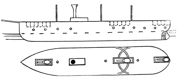
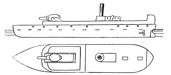
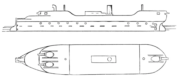
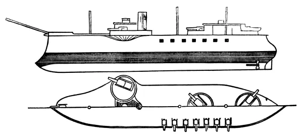
Latest Developments in Ordnance, Torpedoes,
and Naval Architecture,
AND A CONCISE SUMMARY OF THE
PRINCIPAL NAVAL BATTLES OF THE LAST TWENTY YEARS, 1860-1880.
BY Lieut. EDWARD W. VERY, U.S.N.
NEW YORK: JOHN WILEY & SONS, 15 Astor Place. 1880.
Copyrighted, 1880, by
JOHN WILEY & SON.
PREFACE
During the past twenty years the changes in the “matériel” of which
fleets are composed have been so rapid and universal that it has been
impossible at any time to form a true estimate of the strength of the
navy of any maritime power that would be of any value beyond a very
limited time. With displacements advancing from 5000 to 13,000 tons;
weight and power of ordnance developing beyond the most exaggerated
conceptions of twenty years ago; torpedo warfare springing into
existence and developing as a new and special arm; modifications in
engines and boilers by which speed has been developed from 12 to 18
knots, and steaming capacity from 2500 to 6000 miles; the revolution
of naval tactics, and the entire change in the conditions of naval
warfare brought about by the development of armor defence and the ram
attack,—it is only through paying the closest attention and under
exceptionally favorable circumstances that naval officers have been
able to comprehend the magnitude of the general result.
It is only within the past two years that the craze for naval
development has subsided to a slow and steady advance, and the present
time has been seized upon as one favorable for measuring the actual
strength and resources of the navies of the world.
In preparing this work the author has simply aimed at representing in
as detailed a manner as possible all the elements which go to make up
the active naval strength, leaving to those who in their search for
information may have recourse to the data herein presented to estimate
the values of these elements as they are developed and combined in
different navies, and to judge for themselves of the true value of the
results obtained.
In collecting this data the greatest care has been taken to only
give such as is entirely authentic. For the most part it has come
from official sources, and, wherever it has been necessary to make
comparisons or to give opinions, the writer has in no case given his
own independent ideas on the subject. The principal authorities,
aside from official records, whose works have been consulted are:
Reed, White, Dislere, Marchal, and De St. Bon, on Naval Architecture;
Owens, Mayevski, Sebert, Müller, and Cooke, on Ordnance; Schleeman and
Stotherd, on Torpedoes; and Von Billerbeck, on the iron-clads of the
first decade.
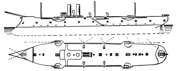
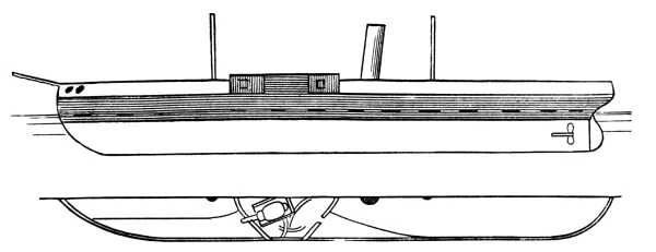
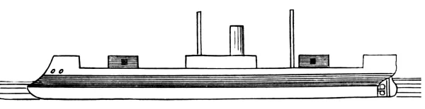
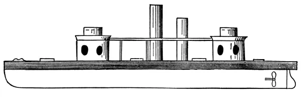
High-sided ram monitors. Armored belt, casemate, and single turrets.
Ram bow and round stern. Twin screws and half sail-power.
(See Buffel, Dutch.)
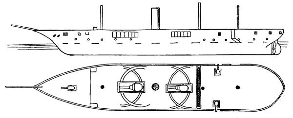
PARANA. URUGUAY.
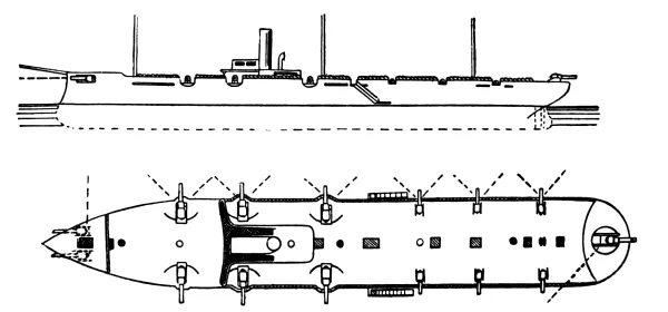
Iron, second-class corvettes, sheathed with wood, carrying two 6½-inch
pivots amidships, two 20-pdrs. in broadside, and a light forecastle
gun. Covered poop and forecastle. Bridge just forward of the main mast.
Single screw, full sail-power.
CONSTITUCION. REPUBLICA. BERMEJO. PILCOMAYO.
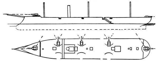
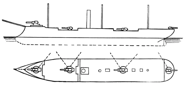
Iron, double-screw, second-class gun-boats, carrying one 12-inch gun
firing through a bow-port. (See Alpha, Chinese.)
A = Length between Perpendiculars.
B = Breadth of Beam.
C = Maximum Draft.
D = Displacement.
E = Construction Material.
F = Greatest thickness of Armor.
Type and Name.
A
B
C
D
E
F
Ft.
Ft.
Ft. in.
Tons.
In.
Redoubt Frigates.
Tegetthoff
287
71
26 7
7,300
Iron
14½
Custoza
302
58
25 10
7,060
”
9
Erzherzog Albrecht
276
54
23 3
5,940
”
8
Casemate Frigates.
Lissa
275
55
28 2
6,080
Wood
6¼
Kaiser
264
59
25 8
5,810
”
6¼
Don Juan
222
44
22 6
3,550
Iron
8
Kaiser Max
222
44
22 6
3,550
”
8
Prinz Eugen
222
44
22 6
3,550
”
8
Broadside Frigates.
Ferdinand Max
253
51
24 10
5,140
Wood
5
Hapsburg
253
51
24 10
5,140
”
5
Salamander
197
44
21 3
3,110
”
4¾
Monitors.
Maros
160
27
3 6
310
Iron
2
Leitha
160
27
3 6
310
”
2
Spalato
Experimental single-turreted citadel ship
G = Backing.
H = Indicated Horse-power.
I = Maximum Speed.
J = Date of Launch.
Type and Name.
G
H
I
J
Battery.
In.
Knots
Year
Redoubt Frigates.
Tegetthoff
10
7,200
14
1878
VI 11-inch Krupp.
Custoza
7
4,650
14
1872
VIII 10-inch ”
Erzherzog Albrecht
8
4,000
13½
1872
VIII 9-inch ”
Casemate Frigates.
Lissa
28
3,700
13½
1869
XII 9-inch ”
Kaiser
29
3,130
12½
1871
X 9-inch Armstrong.
Don Juan
8
2,900
13
1875
VIII 8¼-inch Krupp.
Kaiser Max
8
2,866
13¼
1875
VIII 8¼-inch ”
Prinz Eugen
8
2,900
13
1876
VIII 8¼-inch ”
Broadside Frigates.
Ferdinand Max
26
2,912
12½
1865
XIV 7-inch Armstrong.
Hapsburg
26
3,090
12½
1865
XIV 7-inch ”
Salamander
23½
2,060
11½
1861
X 7-inch ”
Monitors.
Maros
8
320
8½
1871
II 5¾-inch Wahrendorf.
Leitha
8
320
8½
1871
II 5¾-inch ”
Spalato
II 17-inch Armstrong.
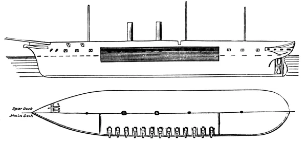
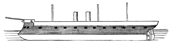
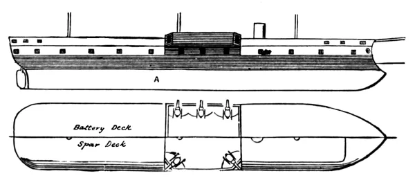
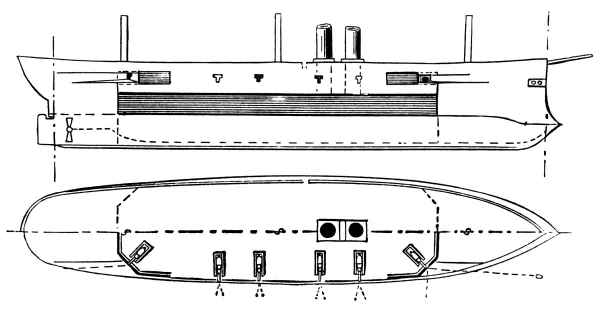
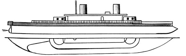
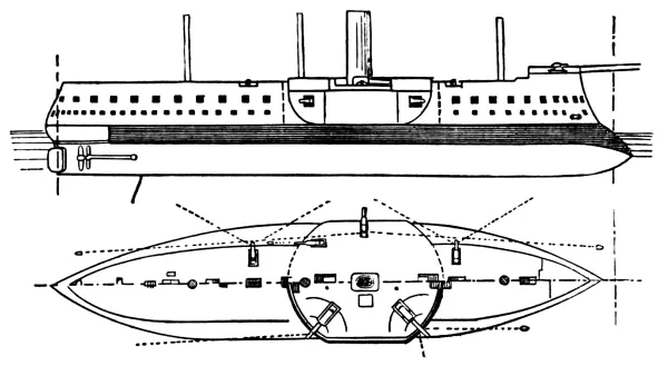
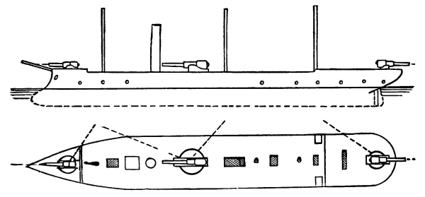
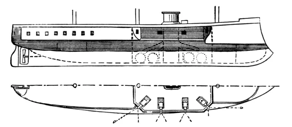
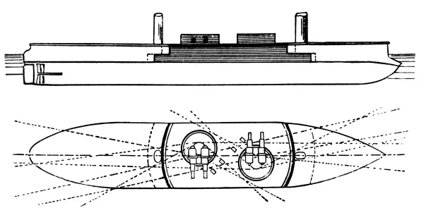
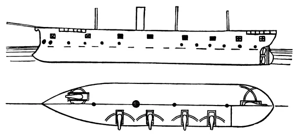
TEGETTHOFF.
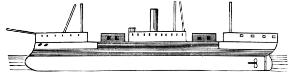
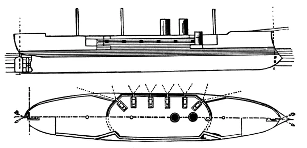
Partial armored belt and long redoubt. Ram bow, straight overhanging
stern. The armored belt encircles the water-line aft and as far forward
as the commencement of the bow-frames, where it ends in an armored
bulkhead, the lower edge being carried forward in a heavy steel deck,
the thickness of the belt being carried out to the bow with cork
filling. The belt rises to the height of the main-deck beams. The
redoubt has an overhang of five feet, being cut back in the wake of the
centre-ports as a protection to the muzzles of the guns. The corners
are cut and hollowed for angular ports, giving bow and beam fire. The
sides are given a rank tumble home forward and abaft the redoubt, to
open the fore-and-aft fire. An armored pilot-house rises well above the
spar-deck rail at the forward end of the redoubt. A heavily armored
athwartship bulkhead crosses the redoubt just abaft the forward guns
as a protection from raking fire. Three-quarter sail-power, barkentine
rig, single screw.
TEGETTHOFF.
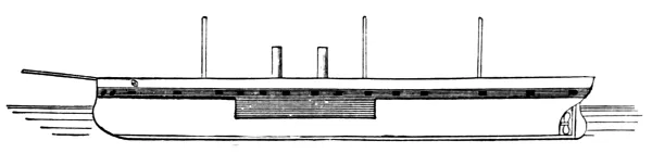
CUSTOZA.ERZHERZOG ALBRECHT.
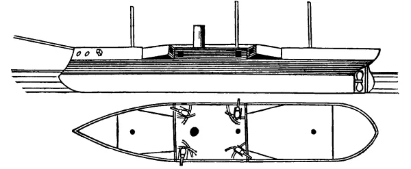
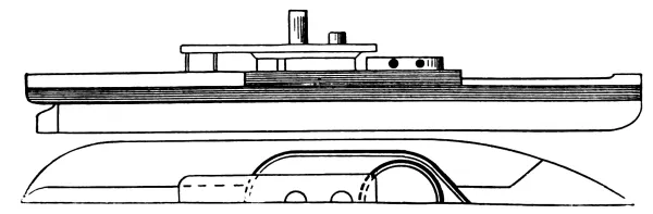
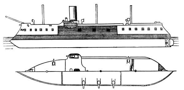
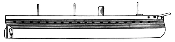
Armored belt and double-decked casemate; ram bow, round
overhanging stern, single screw, full sail-power. The armored belt
encircles the water-line to the height of the main-deck beams, the
casemate rising sheer to the top of the spar-deck rail. Forward, the
side is carried back from the main-deck up, parallel to the keel, to
open bow-fire from the forward guns. Aft, the side is recessed for
the upper deck alone. Stern-fire is secured from a single unprotected
heavy spar-deck rifle working in three ports for stern and beam fire.
The Albrecht has 1200 tons less displacement than the Custoza, with a
lighter battery and a speed one half knot less. The casemate guns each
work in two ports for fore-and-aft and beam fire.
CUSTOZA.
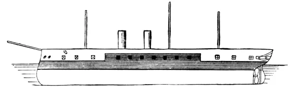
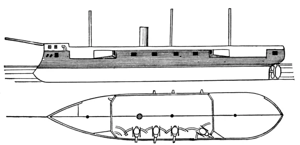
LISSA. KAISER.
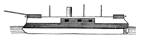
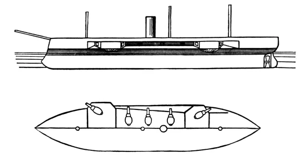
Armored belt, casemate, and spar-deck redoubt. Ram bow, round
overhanging stern, single screw, full sail-power. The belt encircles
the ship to the height of the main-deck beams. There is no fore-and-aft
fire from the casemate, that being secured by an upper-deck redoubt
mounted on the forward end of the casemate and having an overhang
of about five feet. (See Sultan’s spar-deck
redoubt.) Mixed construction, the armored part of the hull being of
wood and the unarmored upper works of iron.
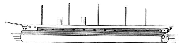
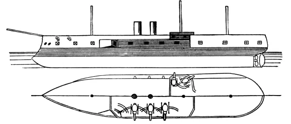
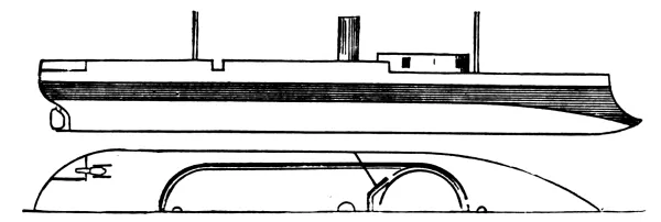
DON JUAN. KAISER MAX. PRINZ EUGEN.
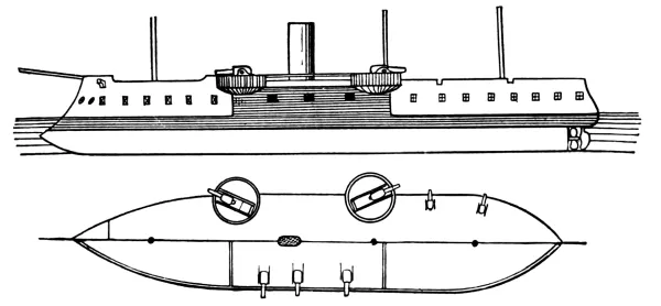
Armored belt and casemate, ram bow, round overhanging stern, single
screw, full sail-power. The belt encircles the water-line to the height
of the main-deck beams, coming down forward in a curve over the point
of the ram. The casemate rises to the spar-deck beams. The side forward
on the main-deck is recessed to open forward fire from the casemate. No
after-fire from the casemate, that being secured by unprotected light
stern-guns. These ships are rebuilt from broadside iron-clads.
DON JUAN.
FERDINAND MAX. HAPSBURG. SALAMANDER.
Broadside frigates; ram bow, round stern, single screw, full
sail-power. The armor is complete from below the water-line to the
spar-deck beams, coming down forward in steps, below the point of the
ram, to give a heavy support and a strong junction between the wooden
hull and the armor. Armored pilot-house just abaft the main-mast. There
is a light armored traverse forward, forming the forward part of the
spar-deck rail and protecting a bow-gun working in two large bow-ports
for fore-and-aft and beam fire. The Ferdinand Max is the frigate that
sank the Re d’Italia by ramming at the battle of Lissa.
FERDINAND MAX.
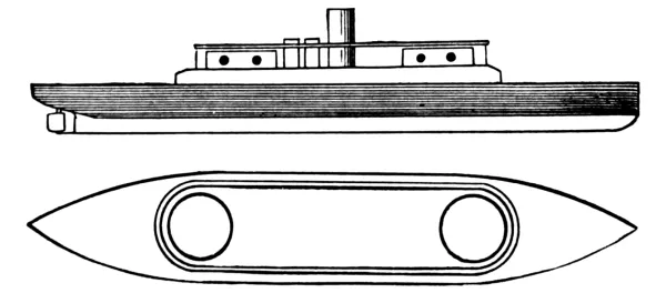
MAROS. LEITHA.
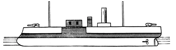
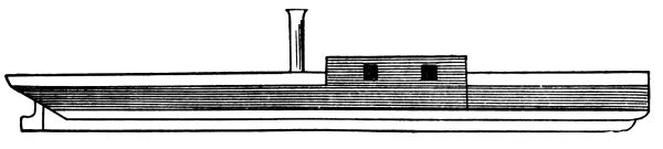
Single-turreted, light-draft river monitors. The freeboard is 38 inches
amidships and 20 inches forward and abaft, the deck being curved fore
and aft. The turret is revolved by hand, having on top of it an armored
pilot-house. The weakness in the hull armor is made up by sinking the
ship when going into action until only the amidship part is out of
water. The bow and stern ends are completely unarmored.
SPALATO (LATE DRACHE).
Originally a sister-ship to the Salamander; now being rebuilt as a
citadel ship on the general plan of the Inflexible, but to carry one
turret armed with two 17-inch rifles.
Type and Name.
Displacement.
Guns.
Tons.
Frigates.
Radetzky
3,380
15
Laudon
3,380
15
Corvettes.
Donau
2,400
11
Saida
2,400
11
Dandolo
1,690
14
Erzherzog Friedrich
1,540
14
Fasana
1,940
4
Helgoland
1,790
5
Zrinyi
1,320
4
Frundsberg
1,320
4
Aurora
1,320
4
Gun-boat.
Dalmat
886
4
Screw Gun-boats.
Hun
886
4
Zara
815
2
Exp. Gun-boat
640
2
Nautilus
560
2
Albatros
560
2
Kerka
530
2
Narenta
530
2
Sansego
344
2
Möve
364
2
Paddle Gun-boats.
Miramar
1,800
2
Elisabeth
1,540
5
Garguano
1,855
2
Triest
885
2
Andreas Hofer
816
3
Taurus
560
3
Triton
177
2
Yachts.
Greif
1,330
2
Fantasie
325
Transports.
Pola
895
2
Cyclop
2,115
2
Tenders.
Grille
354
2
Gemse
354
2
Alnoch
177
Thurn Taxis
118
Gorzkowski
40
School-ships. Guard-ships. Hulks. Store-ships. Thorneycroft
torpedo-boats rigged for Whitehead torpedoes.
A = Backing.
B = Displacement.
C = Construction Material.
Type and Name.
Thickness of Armor.
A
B
Mean Draft.
C
Light.
Heavy.
Inches
Inches
Ft.
Tons.
Ft. In.
Turret Ships.
Sete de Setembro
15 4
Iron
Solimoës
6
12
10
3,660
11 6
”
Javari
6
12
10
3,660
11 6
”
Lima Barros
3
4.5
8
1,330
13 5
”
Silvado
3
4.5
9
1,130
10 6
”
Bahia
2.75
4.5
11
964
8 6
”
Casemate Ships.
Tamandaré
2.5
4
25
964
7 9
Wood
Barrozo
2.5
4.5
25
964
8 5
”
Cabral
2.75
4.5
8
1,016
11 5
Iron
Colombo
2.75
4.5
8
1,016
12 1
”
Herval
2.75
4.5
8.5
787
9 6
”
Mariz é Barros
2.75
4.5
8.5
787
9 6
”
Brazil
2.75
4.5
8.5
1,493
12 5
”
River Monitors.
Alagoas
2
4.5
14.5
334
4 11
Wood
Pará
2
4.5
14.5
334
4 11
”
Rio Grande
2
4.5
14.5
334
4 11
”
Santa Catarina
2
4.5
14.5
334
4 11
”
Ceara
2
4.5
14.5
334
4 11
”
Pianhy
2
4.5
14.5
334
4 11
”
D = Maximum Speed.
E = Date of Launch.
Type and Name.
Horse- power.
D
E
Battery
Knots.
Year.
Turret Ships.
Sete de Setembro
Nominal 300
1876
IV 9¼-inch Whitworth.
Solimoës
Indicated 2,200
11
1875
IV 10¼-inch ”
Javari
Indicated 1,685
11
1875
IV 10-¼-inch ”
Lima Barros
Nominal 300
12
1866
IV 7-inch ”
Silvado
200
11
1866
IV 5.8-inch ”
Bahia
140
10.5
1865
II 7-inch ”
Casemate Ships.
Tamandaré
80
8.5
1865
III 68-pdr. smooth-bore.
I 5.8-inch ”
Barrozo
130
9
1864
III 4.7-inch ”
II 7-inch ”
II 68-pdr. ”
Cabral
240
10.5
1864
II 5.8-inch Whitworth.
IV 68-pdr. smooth-bore.
Colombo
240
10.5
1864
VIII 68-pdr.”
Herval
200
9
1865
IV 7-inch Whitworth.
Mariz é Barros
200
9
1865
II 7-inch”
II 68-pdr. smooth-bore.
Brazil
250
11.5
1865
IV 7-inch Whitworth.
IV 68-pdr. smooth-bore.
River Monitors.
Alagoas
30
7.5
1864
I 5.8-inch Whitworth.
Pará
30
7.5
1864
I 5.8-inch ”
Rio Grande
30
7.5
1864
I 5.8-inch ”
Santa Catarina
30
7.5
1864
I 7-inch”
Ceara
30
7.5
1864
I 7-inch”
Pianhy
30
7.5
1864
I 7-inch”
SOLIMÖES. JAVARI.
SOLIMÖES.
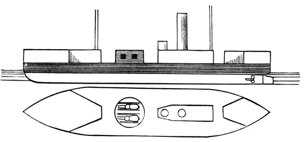
Double-turreted, low-freeboard monitors of the American type. No
overhang. Twin screws. Guns loaded by hydraulic apparatus outside the
turrets. No port stoppers or shutters. Magazines and shell-rooms under
the turrets. Pilot-house just abaft the forward turret. Flying deck
communicating with the lower deck by a musket-proof passage, and armed
with two 9-pdr. Whitworth rifles and two Gatling guns for defence
against torpedo-boats. Armor of decreasing thickness at bow and stern.
Boats stow on the flying deck without davits, being hoisted in and out
by a derrick and the signal-mast. Water-closets and bath-rooms on the
flying deck.
LIMA BARROS. SILVADO. BAHIA.
Double-turreted, high freeboard vessels with a drop rail; three-quarter
sail-power. (See Prinz Hendrik, Dutch.) The Silvado
is unseaworthy.
BRAZIL.
BRAZIL.
Armored belt and casemate; ram bow, round stern. The belt encircles the
water-line to the height of the upper deck. The casemate springs up
sheer from the upper deck with ports in all four faces for all-around
fire. There is no direct communication between the forward and after
parts of the vessel except through the casemate ports. Single screw,
full sail-power.
CABRAL. COLOMBO.
Similar to the Brazil, but smaller. In these vessels the casemate is
divided into two sections by the engine, which projects into it.
TAMANDARE. BARROSO.
Similar to the Brazil, but smaller and having no fore-and-aft fire at all.
THE SIX RIVER MONITORS.
Single-turreted, light-draft river monitors, the turrets being square
and mounted on turn-tables.
Type and Name.
Guns.
Screw Frigate.
Amazonas
14
Corvettes.
Nictheroy
14
Trajano
3
Vital do Oliveira
6
Magé
8
Belmonte
3
Paddle Corvette.
Paraense
4
Screw Gun-boats.
Araguary
3
Pedro Affonso
1
Forte de Coimbra
1
Ypiranga
2
Paddle-wheel Gun-boats.
Henrique Diaz
1
Vidal de Negreiros
1
Greenhalgh
2
Taquary
4
Henrique Martins
2
Felippe Camarão
1
Tenders.
Bonifacio
2
Braconnot
1
Apa
1
Moema
2
Lamego
1
Antonio João
2
Corumba
2
Paddle-wheel Transports.
Madeira
Punes
Leopoldina
Werneck
A = Length between Perpendiculars.
B = Breadth of Beam.
C = Maximum Draft.
D = Displacement.
E = Construction Material.
F = Armor.
Type and Name.
A
B
C
D
E
F
Ft.
Ft.
Ft.
Tons.
Inches.
Armored Frigates.
Almirante Cochrane
179
46
20
3,430
Iron
9
Blanco Encalada
179
46
20
3,430
”
9
Turret Ship.
Huascar
196
35
15½
1,800
”
5½
G = Backing.
H = Indicated Horse-power.
I = Maximum Speed.
J = Date of Launch.
Type and Name.
G
H
I
J
Battery.
Ft.
Knots
Year
Armored Frigates.
Almirante Cochrane
9¼
3,000
13
1874
VI 9-inch,.
II 20-pdr. Armstrong
Blanco Encalada
9¼
3,000
13
1875
VI 9-inch,
II 20-pdr.”
Turret Ship.
Huascar
4½
1,500
11
1864
II 9-inch,
III 4½-inch ”
Type and Name.
Displacement.
Guns.
Tons.
Corvettes.
O’Higgins
1,083
7
Chacabuco
1,083
7
Magellanes
760
4
Paddle Gun-boats.
Abtao
1,034
5
Valdivia
726
3
Ancud
490
1
Independencia
348
2
Tolten
286
2
Tender.
Covadonga
395
2
ALMIRANTE COCHRANE. BLANCO ENCALADA.
Armored belt and redoubt, ram bow, round stern, twin screws,
three-quarter sail-power. The armored belt encloses the water-line
to the height of the main-deck beams. The redoubt is crenelated, the
after-part having an overhang of about five feet, thus giving clear
forward fire to the first two pairs of guns. The ship’s side forward
and abaft the redoubt is given a rank tumble home to open the fire.
Clear, flush upper deck.
ALMIRANTE COCHRANE.
HUASCAR.
HUASCAR.
Sea-going turret vessel. Swan-breasted ram bow, pointed stern, single
screw, three-quarter sail-power. Armored belt encircling the water-line
to the height of the upper-deck beams. Tripod fore-mast with the single
turret just abaft it. No direct bow-fire on account of a topgallant
forecastle, and no direct stern-fire from the turret owing to a
poop-cabin. Light, unprotected poop-guns secure fire in this direction.
Drop-rail in wake of the turret. Armored pilot-house just abaft turret.
(Captured in 1879 from the Peruvians.)
A = Length between Perpendiculars.
B = Breadth of Beam.
C = Maximum Draft.
D = Displacement.
E = Indicated Horse-power.
F = Maximum Speed.
Type and Name.
A
B
C
D
E
F
Battery.
2 Frigates.
13 Light River Gun-boats.
Ft.
Ft.
Ft.
Tons.
Knots
River Gun-boats.
Alpha
118
27
9
325
300
9
I 11-inch Armstrong.
Beta
118
27
9
325
300
9
I 11-inch”
Gamma
120
30
9
400
340
9
I 12½-inch ”
Delta
120
30
9
400
340
9
I 12½-inch ”
Chin Pei
125
29
10½
440
389
10
I 12-inch”
Chin Shan
125
29
10½
440
389
10
I 12-inch Vavasseur.
Fu Shing
125
29
10½
440
389
10
I 12-inch”
Lung Lang
125
29
10½
440
389
10
I 12-inch”
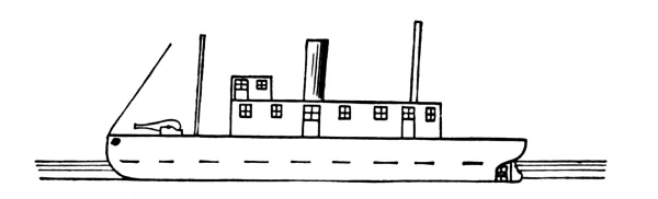
Torpedo-boats. Transports. Junks. Hulks. Guard- and School-Ships.
RIVER GUN-BOATS.
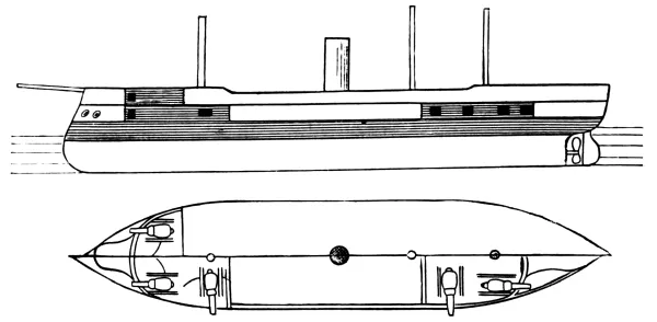
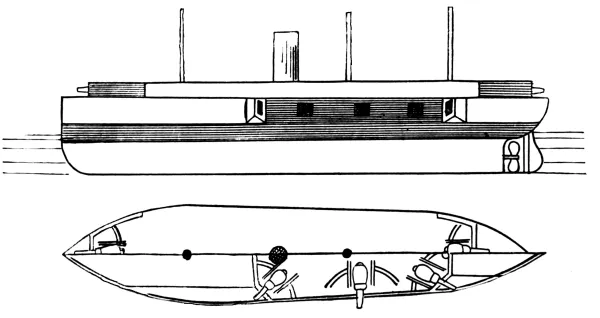
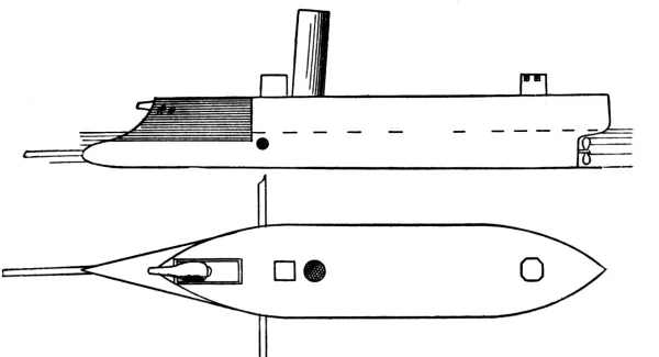
Iron, twin-screw gun-boats, carrying one heavy gun firing through
a musket-proof bow-port. Hydraulic loading apparatus underneath
the covered forecastle. Magazine and shell-rooms under the gun,
with side-hatches and railways for transporting the ammunition to
the muzzle. Bridge across the after-part of the high musket-proof
rail, with steering-wheel just abaft it and so low as only to permit
the helmsman’s head to come above the rail. After-rail low, with a
musket-proof booby-hatch over the engine-room.
ALPHA.
A = Length between Perpendiculars.
B = Breadth of Beam.
C = Maximum Draft.
D = Displacement.
E = Construction Material.
F = Greatest thickness of Armor.
G = Backing.
Type and Name.
A
B
C
D
E
F
G
Ft.
Ft.
Ft.
Tons.
In.
In.
Frigates.
Danmark
269
49
19½
4,665
Iron
5
18
Peder Skram
225
49
22
3,325
Wood
5
26
Monitors.
Rolf Krake
185
38
10½
1,325
Iron
4½
9
Lindormen
216
39
14¾
2,050
”
5½
9¾
Gorm
232
40
15
2,310
”
8
9¾
Casemate Ships.
Helgoland
257
59
19
5,350
”
12½
10
Odin
237
48
16½
3,040
”
8
10
Iron-clad Gun-boats.
Ingolf
150
26
13
850
”
2½
Absalon
135
25
12
520
”
2½
Esbern Snare
135
25
12
520
”
2½
Fylla
140
25½
12
550
”
2½
Diana
140
25½
12
550
”
2½
H = Indicated Horse-power.
I = Maximum Speed.
J = Date of Launch.
Type and Name.
H
I
J
Battery.
Knots
Year
Frigates.
Danmark
1,007
8.1
1864
XII 8-inch Armstrong.
XII 36-pdr. smooth-bore.
Peder Skram
1,680
11.7
1864
VIII 8-inch Armstrong.
VIII 36-pdr. smooth-bore.
Monitors.
Rolf Krake
750
7.8
1863
II 8-inch Armstrong.
Lindormen
1,560
12
1868
II 9-inch ”
Gorm
1,670
12.2
1870
II 10¼-inch ”
Casemate Ships.
Helgoland
3,700
13
1878
I 12-inch Krupp.
IV 10¼-inch ”
V 5¾-inch ”
Odin
2,260
12.4
1872
IV 10¼-inch ”
Iron-clad Gun-boats.
Ingolf
700
13
1867
III 8-inch Armstrong.
Absalon
700
13
1869
III””
Esbern Snare
700
13
1869
III””
Fylla
700
13
1869
III””
Diana
700
13
1869
III””
Type and Name.
Displacement.
Guns.
Tons.
Frigates.
Niels Juel
2,350
26
Själland
2,350
26
Jylland
2,420
26
Corvettes.
Heimdal
1,175
14
Dagmar
1,176
14
St. Thomas
1,546
5
Gun-boats.
Falster
350
1
Möen
350
1
Öresund
240
1
Storebelt
240
1
Lillebelt
240
1
Thure
145
2
Schröedersee
145
2
Willemöes
145
2
Krieger
145
2
Marstrand
145
2
Hauch
95
1
Drogden
50
1
DANMARK. PEDER SKRAM.
Broadside iron-clad frigates (See Ferdinand Max, Austrian), still
capable of forming part of cruising fleet, but of little use beyond
harbor defence.
ROLF KRAKE.
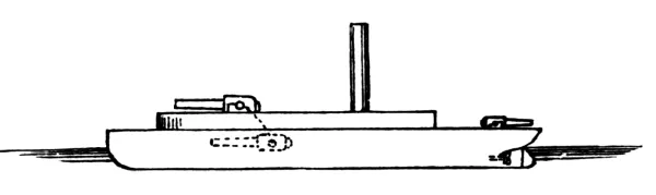
Monitor gun-boat, having a superstructure forming a covered forecastle
forward and officers quarters aft, the upper line of the superstructure
being carried along by a rail in wake of the turrets, which may be
dropped in action. Her turrets are small, containing one gun each and
capable of being turned by hand or by steam (Coles system). The armored
belt comes to the height of the deck-beams, and the deck is convex,
plated with ¾-inch steel. An armored pilot-house is placed well aft.
She has full sail-power.
ROLF KRAKE.
LINDORMEN. GORM.
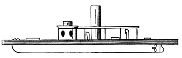
Single-turreted, breastwork, light-draft monitors. (See Buffel,
Dutch.)
HELGOLAND.
Casemated iron-clad frigate with complete armored belt. No bow or stern
fire from the casemate, which carries four 10¼-inch Krupp rifles.
Forward on the upper deck is placed a 12-inch Krupp pivot for bow and
beam fire. Her armor at the water-line is 12 inches, diminishing to 6
at the bow and stern. She is provided with apparatus for discharging
Whitehead torpedoes from each beam above water.
ODIN.
Armored belt with elevated casemate.
(See Brazil, Brazilian.) The
casemate contains four 10¼-inch Armstrong muzzle-loaders, each of which
fires from two ports. She has no spars except signal-masts.
INGOLF. ABSALON. ESBERN SNARE. FYLLA. DIANA.
Armored gun-boats, having fine lines and an armored belt from two feet
below the water-line to the deck-beams. Three unprotected pivot-guns
working amidships on centre-pivot carriages and firing over the rail.
Full sail-power and hoisting screw.
INGOLF.
The wooden fleet is of the ordinary type of old-style
steam corvettes and gun-boats.
A = Length between Perpendiculars.
B = Breadth of Beam.
C = Maximum Draft.
D = Displacement.
E = Construction Material.
F = Greatest thickness of Armor.
Type and Name.
A
B
C
D
E
F
Ft. in.
Ft. in.
Ft. in.
Tons.
In.
Armored Frigates.
Warrior
380
58
26 5
9,681
Iron
4½
Black Prince
380
58
27
9,681
”
4½
Achilles
383
58
27 4
9,681
”
4½
Northumberland
400
59 5
27
10,395
”
5½
Defence
280
54
25 6
6,074
”
4½
Resistance
280
54
26
6,074
”
4½
Hector
280
56 7
25 7
6,960
”
4½
Valiant
280
56 5
26 10
6,420
”
4½
Lord Warden
280
58 9
26
7,675
Wood
7
Repulse
252
59
26 2
6,190
”
5
Casemate Ships.
Agincourt
400
59 5
27
10,395
Iron
5½
Minotaur
400
59 5
27
10,395
”
5½
Bellerophon
300
56
26
7,540
”
7½
Swiftsure
280
55
26 2
6,660
Iron sheathed
9¼
Triumph
280
55
26 2
6,660
”
9¼
Audacious
280
54
28
6,084
”
9¼
Invincible
280
54
23
6,034
”
9¼
Iron Duke
280
54
23
6,034
”
9¼
Hercules
325
59
26 5
8,700
Iron
11
Sultan
325
59
27 6
9,286
”
10½
Alexandra
325
63 8
26 6
9,492
”
13½
Temeraire
285
62 2
27 1
8,412
”
12½
Superb
333
59
25
8,994
”
13½
Armored Water-line.
Shannon
260
54
22 6
5,108
”
10½
Nelson
280
60
24 2
7,323
”
10½
Northampton
280
60
24 2
7,323
”
10½
Turret Ships for Coast Defence.
Prince Albert
240
48 1
19 8
3,900
”
5
Scorpion
224 6
42 4
16 3
2,777
”
5
Wyvern
224 6
42 4
15 8
2,725
”
5
Cyclops
225
45
16 5
3,430
”
9¼
Gorgon
225
45
16 5
3,430
”
9¼
Hecate
225
45
16 5
3,430
”
9¼
Hydra
225
45
16 5
3,430
”
9¼
Glatton
245
54
19
4,912
”
13½
Sea-going Turret Ships.
Monarch
320
57 6
26
8,322
”
8½
Devastation
285
62 3
26 3
9,157
”
13½
Thunderer
285
62 3
26 3
9,157
”
13½
Neptune
300
63
25 2
8,900
Iron sheathed
13½
Dreadnought
320
63 10
27
10,886
Iron
15⅜
Ajax
260
66
24
8,492
”
19½
Agamemnon
260
66
24
8,492
”
19½
Inflexible
320
75
25 4
11,500
”
24
Conqueror
Orion
245
52
19 6
4,700
”
13½
Bellisle
245
52
19 6
4,700
”
13½
Armored Corvettes.
Pallas
225
50
24 3
3,797
Wood
5
Penelope
260
50
17 4
4,394
Iron
6
Research
195
38 6
15 5
1,780
Wood
5
Rams.
Hotspur
235
50
20 8
4,012
Iron
12
Rupert
250
53
23 6
5,358
”
9⅞
Gun-boats.
Viper
160
32
11 7½
1,220
”
5
Vixen
160
32
11 7½
1,220
”
5
Waterwitch
162
32 1
11 9
1,279
”
5
Colonial Turret Ships.
Abyssinia
225
42
14
2,901
”
7
Magdala
225
45
14 8
3,344
”
8
Cerberus
225
45
14 8
3,344
”
8
Floating Battery.
Erebus
1,814
”
4½
Ram.
Polyphemus
240
40
2,660
”
G = Least thickness of Armor
H = Backing.
I = Indicated Horse-power.
J = Maximum Speed.
Type and Name.
G
H
I
J
Battery.
In.
In.
Knots
Armored Frigates.
Warrior
4½
18
5,469
14.3
VIII 8-inch
Woolwich.
XXIV 7-inch
”
Black Prince
4½
18
5,772
13.6
VIII 8-inch
”
XX 7-inch
”
Achilles
3
18
5,722
14.3
XIV 9-inch
”
II 8-inch
”
Northumberland
3
9
6,558
14.1
VII 9-inch
”
XX 8-inch
”
Defence
4½
18
2,437
11.6
II 8-inch
”
XIV 7-inch
”
Resistance
4½
18
2,428
11.6
II 8-inch
”
XIV 7-inch
”
Hector
3
18
3,256
12.5
IV 8-inch
”
XIV 7-inch
”
Valiant
3
18
3,560
12.5
IV 8-inch
”
XIV 7-inch
”
Lord Warden
4
31
6,706
13.5
XVIII 7-inch
”
Repulse
4
30½
3,347
12.2
XII 8-inch
”
Casemate Ships.
Agincourt
3
9
6,867
15.4
XVII 9-inch
”
Minotaur
3
9
6,702
14.4
XVII 9-inch
”
Bellerophon
5
9¾
6,521
14.1
X 9-inch
”
V 7-inch
”
Swiftsure
4
9¾
4,913
13.5
X 9-inch
”
IV 64-pdr.
”
Triumph
4
9¾
4,892
13.5
X 9-inch
”
IV 64-pdr.
”
Audacious
4
9¾
4,021
12.8
X 9-inch
”
IV 64-pdr.
”
Invincible
4
9¾
4,832
14
X 9-inch.
”
IV 64-pdr.
”
Iron Duke
4
9¾
4,268
13.6
X 9-inch
”
IV 64-pdr.
”
Hercules
6
9¾
7,200
13.2
VIII 10-inch
”
II 9-inch
”
Sultan
6
9¾
8,629
14.1
IV 7-inch
”
VIII 10-inch
”
Alexandra
6
9¾
8,615
15
II 12-inch
”
X 10-inch
”
Temeraire
7
9¾
7,700
14.6
IV 12-inch
”
IV 10-inch
”
Superb
7
11.8
7,430
13.8
XII 10-inch
”
IV 7-inch
”
Armored Water-line.
Shannon
6
9¾
3,370
12.6
II 10-inch
”
VII 9-inch
”
Nelson
6
9¾
6,000
14
IV 10-inch
”
VIII 9-inch
”
Northampton
6
9¾
6,000
14
IV 10-inch
”
VIII 9-inch
”
Turret Ships for Coast Defence.
Prince Albert
4½
18
2,128
11.6
IV 9-inch
”
Scorpion
4½
9
1,450
10.2
IV 9-inch
”
Wyvern
4½
9
1,450
10.2
IV 9-inch
”
Cyclops
5
9¾
1,660
11
IV 10-inch
”
Gorgon
5
9¾
1,669
11
IV 10-inch
”
Hecate
5
9¾
1,755
11
IV 10-inch
”
Hydra
5
9¾
1,472
11
IV 10-inch
”
Glatton
9
18
2,868
12.1
II 12-inch
”
Sea-going Turret Ships.
Monarch
5
11¾
7,842
14.9
IV 12-inch
”
II 9-inch
”
I 7-inch
”
Devastation
8½
18
6,652
13.8
IV 12-inch
”
Thunderer
8½
18
6,270
13.4
II 12½ inch
”
II 12-inch
”
Neptune
7
9¾
9,100
14.6
IV 12½-inch
”
II 7-inch
”
Dreadnought
7
18
8,000
14
IV 12½-inch
”
Ajax
11
18
6,000
13
IV 12½-inch
”
Agamemnon
11
18
6,000
13
IV 12½-inch
”
Inflexible
18
18
8,000
14
IV 16-inch
”
Conqueror
IV 17 inch
Armstrong.
Orion
6
9¾
3,900
13
IV 12-inch
”
Bellisle
6
9¾
3,955
13
IV 12-inch
”
Armored Corvettes.
Pallas
3
22
3,581
13.4
IV 8-inch
”
II 64-pdr.
”
II 40-pdr.
”
Penelope
3
9¾
4,703
12.8
III 40-pdr.
”
VIII 8-inch
Woolwich.
Research
3
19¾
1,042
10.3
IV 7-inch
”
Rams.
Hotspur
6
11⅞
3,497
12.6
I 12-inch
”
II 64-pdr.
”
Rupert
6
11⅞
4,635
12.4
II 64-pdr.
”
II 10-inch
”
Gun-boats.
Viper
3
6
696
9
IV 7-inch
”
Vixen
3
6
740
9
IV 7-inch
”
Waterwitch
3
6
777
9.2
IV 7-inch
”
Colonial Turret Ships.
Abyssinia
4½
1,200
9.6
IV 10-inch
”
Magdala
5
9
1,400
9.7
IV 10-inch
”
Cerberus
5
9
1,400
9.7
IV 10-inch
”
Floating Battery.
Erebus
4⅜
24
493
6.0
XVI 64-pdr.
”
Ram.
Polyphemus
5,500
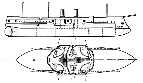
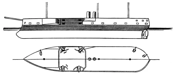
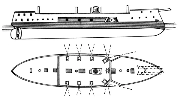
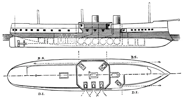
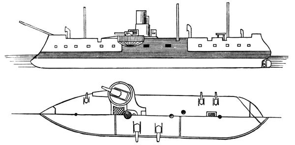
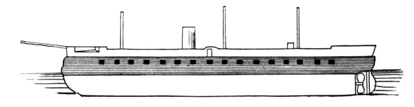
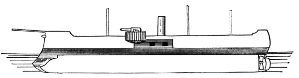
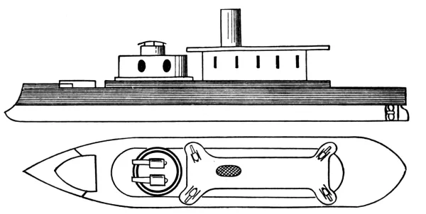
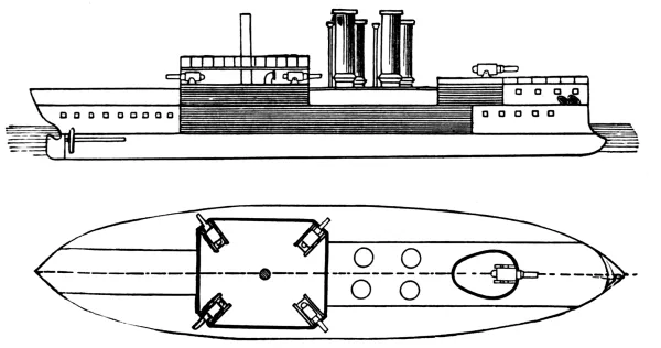
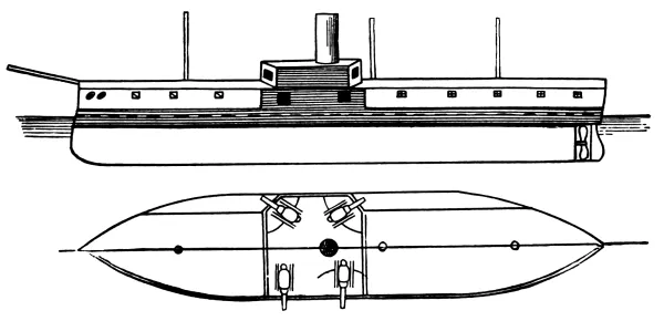
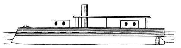
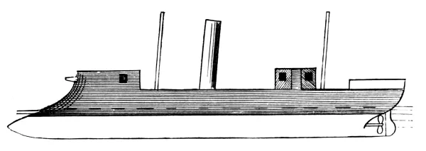
WARRIOR. BLACK PRINCE. DEFENCE. RESISTANCE.
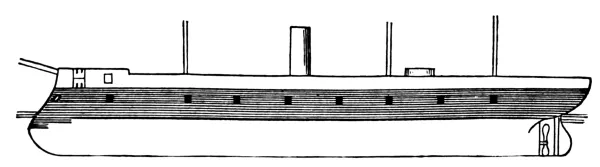
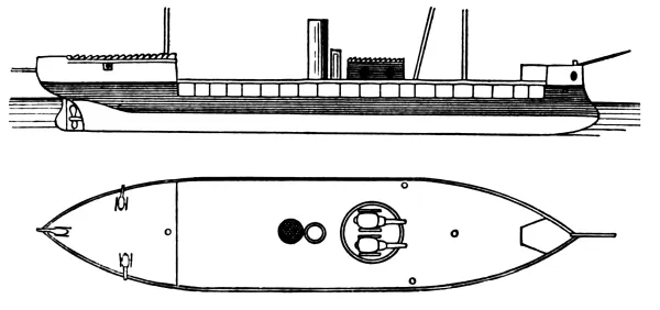
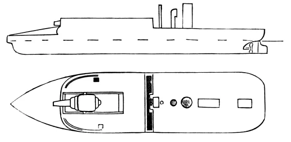
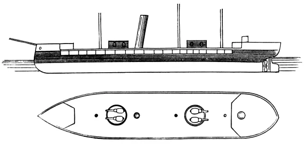
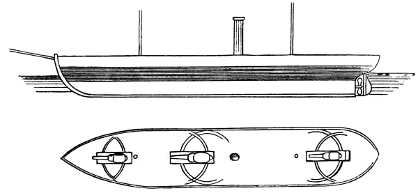
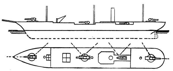
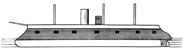
Armored broadside frigates. The armor of these ships consists of a long
casemate covering the battery only, and extending from about two feet
below the water-line to the spar-deck beams. The bow and stern sections
are left completely unprotected, the armor forward and aft ending in
athwartship bulkheads. The hull is divided into a number of very large
water-tight compartments. The extreme forward part of the upper-deck
rail is recessed to permit straight-ahead fire from the forecastle
guns. The bows of these ships, although not built especially for
ramming, are made very heavy to permit of this mode of attack with
safety. Full sail-power.
WARRIOR.
HECTOR. VALIANT.
Armored broadside frigates with swan-breasted ram bows. The armor
of these ships consists of a belt around the main-deck, whilst the
boilers and engines are in a casemate. The water-line forward and abaft
is unprotected. Full sail-power.
VALIANT.
ACHILLES.
Armored broadside frigate with straight bow strengthened for ramming.
The armor of this ship consists of a water-line belt the height of the
gun-deck beams and a casemate for the battery. Full sail-power. No
bow-fire except from an unprotected forecastle gun.
(See Warrior.)
ACHILLES.
NORTHUMBERLAND. MINOTAUR. AGINCOURT.
Armored broadside frigates, swan-breasted bow for ramming. The armor in
these ships may be called complete, forming a belt rising to the height
of the spar-deck beams fore and aft. Full sail-power (5 masts).
MINOTAUR.
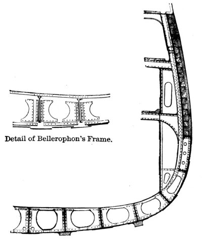
BELLEROPHON. REPULSE. LORD WARDEN.
LORD WARDEN.
Armored broadside frigates with ram bows. The armor in these ships is
complete, rising to the height of the spar-deck beams, and in addition
having a casemated forecastle. The Lord Warden and Repulse have wooden
hulls, having been originally laid down for wooden line-of-battle
ships. The Bellerophon carries heavier armor and more effective backing
atthe water-line than any of the foregoing ships. These ships
have full sail-power. The Bellerophon is a good sailer.
PALLAS. RESEARCH.
Armored belt and redoubt, the side being cut back just forward and
abaft the redoubt to permit the broadside guns to fire well forward and
aft through adjacent ports. These ships have wooden hulls, having been
originally laid down for wooden frigates. The Pallas is a remarkably
fine sailing ship.[1]
PALLAS.
HERCULES. SUPERB. PENELOPE.
Armored belt and long armored redoubt, the sides being
cut back for bow-fire. The Hercules has armored breastworks
at the bow and stern on the battery-deck for heavy bow and
stern-guns. The Superb is the late Memdouhieh (Turkish).
HERCULES.
SULTAN.
Armored belt and long armored redoubt. The side forward of the redoubt
is cut back for forward fire, but instead of the forward and after
breastworks of the Hercules, an upper redoubt is built at the after-end
of the main one, projecting clear of the side, and from which clear bow
and stern fire is available.
SULTAN.
SWIFTSURE. TRIUMPH. AUDACIOUS. INVINCIBLE. IRON DUKE.
IRON DUKE.
A—Wound made in the Vanguard by the Iron Duke.
Armored belt and short casemate, on which is mounted an upper-deck
redoubt. The gun-deck casemate does not permit of bow-fire, as the
lines of the ship are not broken forward or abaft it. The upper redoubt
projects clear of the side over the lower casemate, and has its corners
cut off to permit of angular ports being cut that give fore-and-aft and
beam fire. This redoubt has no athwartship bulkhead. The magazines are
directly under the casemates. The boat-davits are near the amidship
line, so that the boats are kept well inboard. (The Vanguard, sunk by
collision with the Iron Duke, belonged to this type.)
ALEXANDRA.
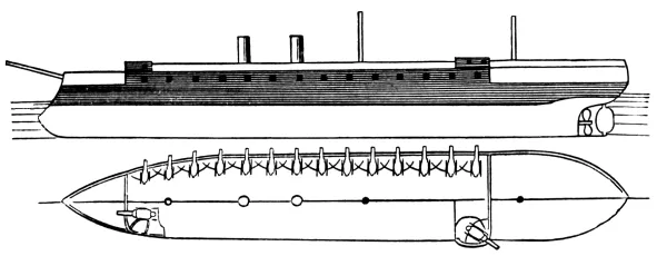
Armored belt and double-decked casemate, ram bow, and overhanging
stern. The forward part of the belt is carried down in a curve over the
ram. The side forward from the gun-deck beams up is carried well back
parallel to the keel to give fore-and-aft fire. There is no stern-fire
from the main-deck casemate. The after bulkhead rises straight from
the belt to the top of the upper casemate. This casemate is, however,
shorter than the lower one, and its forward bulkhead being carried down
separates the main-deck casemate into two chambers, forming a double
protection for the after-guns. The corners of both casemates are cut
off for angular ports to give fore-and-aft and beam fire. The hull is
divided longitudinally by an armored bulkhead rising to the height
of the main-deck beams, one set of engines and boilers being in each
compartment. Twin screws and full sail-power.
ALEXANDRA.
TEMERAIRE.
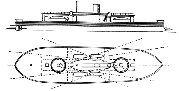
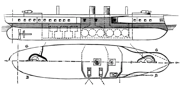
Armored belt, redoubt, and two barbette turrets. Ram bow. The armored
belt is carried down in a curve over the ram. No stern-fire from the
casemate, the forward corners being cut for angular ports, and the
side forward being carried back for bow-fire. The casemate is cut in
two chambers similar to the main-deck casemate of the Alexandra. The
barbette turrets forward and abaft the casemate are oval in shape, and
the guns are mounted on Moncrieff carriages. The armor of the body
of the turrets does not come below the spar-deck beams, but an
armored shaft is carried down to the level of the belt, through which
ammunition is passed and communication given. The hull is divided
longitudinally by an armored bulkhead similar to the Alexandra. Twin
screws and auxiliary sail-power. (Brig rigged.)
TEMERAIRE.
SHANNON.
SHANNON.
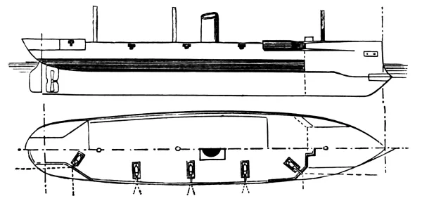
Partial armored belt and partial spar-deck breastwork. The belt is
carried around the stern as a protection to the steering-gear, but ends
just abaft the fore-mast in an armored bulkhead, which rises sheer to
the height of the spar-deck rail. From the foot of this bulkhead an
iron deck is carried forward to the stem, ending as a support to the
ram. A breastwork on the spar-deck forward forms a protection for the
bow-guns, the topgallant forecastle being carried to its after-edge.
The corners of the breastwork are cut for angular ports, and the rail
forward is carried back parallel to the keel. The rail aft is recessed
and cut back for after angular ports, but the guns are not protected
by armor. An armored conning tower is placed at the forward part of
the breastwork. A single gun is used aft, working on a turn-table for
shifting from one port to the other.
NELSON. NORTHAMPTON.
Partial armored belt and partial forward and after spar-deck
breastworks. The armored belt extends for three fifths of the length
of the ship amidships, ending in armored athwartship bulkheads,
which rise to the height of the spar-deck beams. A heavy iron deck
prolongs the lower edge of the belt to the bow and stern, protecting
the steering-gear aft and forming a support for the ram forward. The
guns are all carried on a covered deck, giving a flush spar-deck. The
breastworks on the main-deck at the bulkheads form a side protection
for the forward and after guns, the corners being cut for angular ports
and the side recessed for fore-and-aft fire. These ships have twin
screws and an armored longitudinal bulkhead similar to the Alexandra.
NELSON.
MONARCH. NEPTUNE.
Armored belt and revolving Coles turrets on the spar-deck. The belt
rises to the height of the main-deck beams, and amidships is carried
up to the spar-deck beams to cover the lower part of the turrets and
machinery. An armored bulkhead rises well forward, forming on the
spar-deck a forecastle breastwork for the bow-guns. The spar-deck rail
in wake of the turrets may be dropped to open their fire. The Neptune
has no protected stern-fire. The belt of the Monarch is carried up aft
to the height of the spar-deck beams, forming a breastwork for the stern-guns.
(See Hercules.) The Neptune is the late Independenzia.
MONARCH.
INFLEXIBLE. AJAX. AGAMEMNON. CONQUEROR.
INFLEXIBLE.
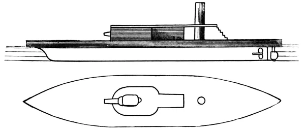
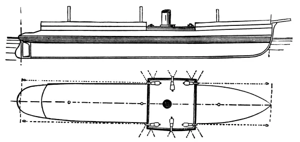
Casemated, double-turreted, mastless, sea-going iron-clads. Ram bows.
The armored casemate is rectangular and encloses the middle third of
the vessel. The lower edge of the casemate is prolonged fore and aft
in a heavy iron deck, which forward curves down below the point of the
ram. Short unarmored forecastle and poop structures, carried along
in line with the keel to the smoke-stacks. The turrets are placed
diagonally to open the full fore-and-aft fire. Forward and abaft the
casemate is a cork belt of the thickness of the armor, to give the ship
floating power in case the unprotected sections are pierced. The ship
is divided in two by a longitudinal bulkhead. Twin screws.
DREADNOUGHT. ORION. BELLEISLE.
Armored belt and breastwork, sea-going monitors. The armor is complete
fore and aft, and is carried down in a curve forward below the point
of the ram. Throughout the middle third a casemate rises to protect
the bottom of the turrets and give them a good elevation above the
water-line. Forward and abaft this casemate, and in line with it,
an unarmored superstructure is carried, stopping short of the bow
and stern. This forms roomy quarters and gives the ship an increased
freeboard and stability. The turrets are amidships and in line with
the keel. Between them is a musket-proof superstructure, expanding
into a flying deck having at its forward end an armored pilot-house.
Longitudinal armored bulkhead, similar to the Alexandra.
DREADNOUGHT.
DEVASTATION. THUNDERER.
DEVASTATION.
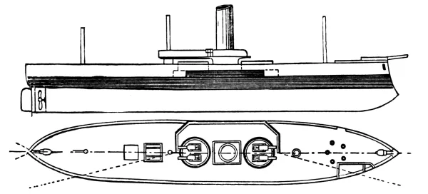
Armored belt and breastwork, double-turreted, sea-going monitors. The
armored belt from forward to the forward turret comes only to the
height of the water-line. The breastwork differs from that of
the Dreadnought in not coming out to the side, but the freeboard
necessary is obtained by carrying around it and well forward and aft a
musket-proof superstructure. A musket-proof superstructure also rises
between the turrets, expanding into a flying deck with an armored
pilot-house at its forward end.
GLATTON.
Armored belt and breastwork, single-turreted, coast-defence monitor.
The armored belt rises to the upper-deck level, and is of the same
thickness from stem to counter. It has an overhang beyond the hull of
2½ feet amidships. The breastwork surrounds the turret and smoke-stack
and does not come out to the side. Forward and abaft a narrow
superstructure carries along the line of the breastwork. Abaft the
turret, which is situated well forward, a musket-proof superstructure
rises, expanding into a flying deck, with an armored pilot-house at its
forward extremity.
Armored belt and breastwork, double-turreted, coast-defence monitors.
The breastwork occupying somewhat more than the middle third of these
vessels surrounds the turrets and smoke-stack, but does not come out to
the side. Musket-proof passages or tubes and ventilators, together with
an armored pilot-house, extend above a light flying deck. The Cerberus
is stationed permanently at Melbourne, having had a temporary rail and
upper deck built on her for her passage out. The Abyssinia and Magdala
are permanently stationed at Bombay.
HOTSPUR. RUPERT.
Armored rams. The armor-belt completely encircles the hull and is
carried down in a curve forward below the point of the ram. Each vessel
is provided with a breastwork and single turret. That of the Hotspur is
fixed and has four ports, the gun being worked on a turn-table. That
of the Rupert is of the Coles type of revolving turret. The breastwork
surrounds the foot of the turret and the smoke-stack. Both vessels have
a high superstructure from abaft the turret to the stern, rising two
thirds the height of the turret, and each carries a stern-gun, the side
being recessed at each counter for stern-fire. The Hotspur carries an
armored pilot-house on top of her turret; the Rupert has two, one on
each side, abaft the turret in the dead-angle. At present the turret of
the Hotspur is being changed to a revolving one like the Rupert’s.
HOTSPUR.
PRINCE ALBERT.
Four-turreted monitor. This ship has a wooden hull, having been cut
down from a line-of-battle ship. Her armor-belt encircles her hull and
she has no breastwork; her Coles turrets being protected about their
lower parts by the armored deck. This vessel is only fit for harbor
defence.
SCORPION. WYVERN.
Armored belt, double-turreted iron-clads with full sail-power. These
vessels are high sided, the high rail between the fore and mizzen masts
dropping to unmask the turrets. The armor-belt encircles them. They
have strengthened ram bows, a long, high forecastle extending to the
fore-mast and making a dead-angle for the forward turret, and a high
poop to the mizzen-mast, making a dead-angle for the after turret. The
fore and main masts are tripod masts. These vessels are bark rigged,
with full sail-power, and when their side rails are up they have the
appearance of ordinary corvettes. They were built for the Confederates
during the war of the American Rebellion.
VIPER. VIXEN. WATERWITCH.
Casemated gun-boats. These vessels have rectangular casemates about
the boilers and engines (see Inflexible), the
forward bulkhead rising above the spar-deck level, and being provided
with two ports for bow-fire. They are only intended for bow-fire and
end-on attack. The Waterwitch is a double-ender, having steering-gear
at each end, and at present, instead of steam boilers and engines, she
has a hydraulic motor.
POLYPHEMUS.
Armored ram The transverse section of this ship is top-shaped, showing
above water a convex upper deck surmounted by a light musket-proof
superstructure. In addition to her heavy ram, she is provided with
apparatus for firing the Whitehead torpedo, ahead and from each beam.
1st Class Gun-boats.
Low-pressure Engines. Twin Screws.
Tons.
Knots.
Curlew
774
Composite
811
10
I 7-inch pivot. II 40-pdrs.
Lapwing
882
Magpie
857
Philomel
961
Plover
977
Ringdove
957
Seagull
702
Swallow
892
Vulture
847
Woodlark
881
1st Class Gun-boats.
High-pressure Engines. Twin Screws.
Avon
584
Composite
528
10
III 64-pdrs. II 20-pdrs.
Beacon
506
Boxer
587
Cracker
528
Dwarf
495
Elk
472
Flirt
582
Fly
489
Growler
696
Hart
608
Hornet
506
Lynx
526
Midge
472
Pert
502
Rocket
632
Teazer
489
Thistle
641
Frolic
592
Composite
896
10
II 64-pdrs. II 20-pdrs.
Kestrel
835
Ready
891
Rifleman
715
Dart
570
Composite
336
10
II 64-pdrs. II 20-pdrs.
Newport
335
Torch
281
2d Class Gun-boats.
Compound Engines. Single Screw.
Firebrand
45
Composite
360
9
II 64-pdrs. II 20-pdrs.
Firefly
Firm
Forester
Forward
Foxhound
Ariel
430 to 455
Composite
540
10.1 to 10.8
II 64-pdrs. II 20-pdrs.
Contest
515
Coquette
406
Cygnet
532
Decoy
459
Express
438
Foam
406
Goshawk
484
Mallard
398
Merlin
428
Moorhen
387
Mosquito
501
Sheldrake
867
Swinger
461
Zephyr
534
2d Class River Gun-boats.
Dee
868
Iron
810
9.5
III 64-pdrs.
Don
Esk
Medina
Medway
Sabrina
Slaney
Spey
Tay
Tees
Trent
Tweed
2d Class Gun-boats.
Britomart
330
Wood
160 to 277
8
II 64-pdrs.
Bruiser
Cherub
Cockatrice
Cromer
Heron
Netley
Orwell
Speedy
Tyrian
Dapper
284
Wood
140 to 272
8
II 64-pdrs.
Earnest
Fervent
Skylark
Thrasher
Whiting
Ant
254
Iron
168 to 268
9
I 10-inch.
Arrow
Badger
Blazer
Bloodhound
Bonita
Bulldog
Bustard
Cornet
Cuckoo
Fidget
Gadfly
Griper
Hyena
Kite
Mastiff
Pickle
Pike
Pincher
254
Iron
168 to 268
8
I 10-inch.
Scourge
Snake
Snap
Tickler
Weazel
Hunter
249
Wood
131
8
II 64-pdrs.
Plucky
196
Iron
224
I 9-inch.
Staunch
180
”
134
I 9-inch.
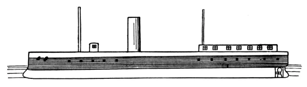
INCONSTANT.
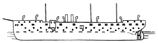
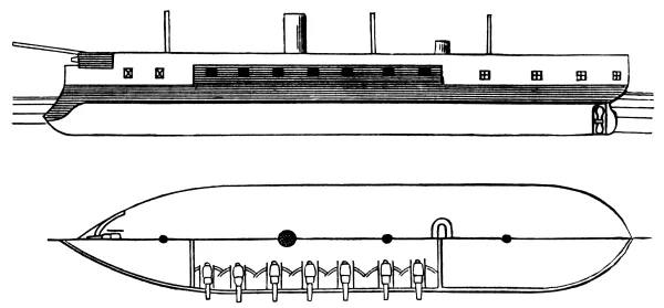
Iron frigate sheathed with wood and coppered. Straight bow, round
stern. Rail cut back on each side of the bow-sprit to permit bow-fire.
Gun-deck battery composed of ten 9-inch rifles in broadside, the ports
being very widely spaced. Long topgallant forecastle and flush aft.
Spar-deck battery composed of six 7-inch rifles. One bow-gun under the
forecastle working in four ports (one each side ahead and one each side
abeam), the gun being transported from one to another by turn-tables.
One stern-gun working on turn-tables in three ports (one astern and
one on each quarter). The remaining four guns are arranged as pivots,
so that all may be used on one side if desirable. They secure in pairs
amidships. The ports for these guns are cut in pairs forward and abaft
the gun-deck ports. The strength of fire of this ship is: ahead,
one 7-inch; abeam, six 7-inch, five 9-inch; astern, one 7-inch. The
stability of this ship being originally deficient, part of her double
bottom was filled with 180 tons of cement, thus reducing her estimated
speed nearly one knot. Her coal supply permits steaming 2160 miles at
a speed of ten knots. Greatest speed attained at sea for twenty-four
consecutive hours, 15½ knots.
SHAH. RALEIGH.
Iron frigates sheathed with wood and coppered. General type similar to
the Inconstant. The gun-deck battery of the Shah is a broadside one of
sixteen 7-inch rifles and two 64-pdrs., the latter being just forward
of the cabin bulkhead (separated from the main battery). The spar-deck
battery consists of one 10-inch rifle under the topgallant forecastle,
working in the same manner as the Inconstant’s; one 10-inch rifle
stern-gun working in two ports, the quarter-rail being recessed for the
purpose, so as to get stern and beam fire; six 64-pdrs. in broadside
(two forward and two abaft the gun-deck battery, and two abreast the
after smoke-stack). The Raleigh’s battery is similar to the Shah’s in
arrangement, but is smaller in number. (Fourteen guns on gun-deck; six
on spar-deck.)
SHAH.
BOADICEA. BACCHANTE. EURYALUS.
Iron-sheathed frigates of the same general type as the above. The
battery is all under cover; the broadside battery being entirely on
the gun-deck, the bow-gun under the topgallant forecastle, and the
stern-gun in the spar-deck cabin. The Boadicea has a straight stem, the
other two ram bows. In order to permit the latter arrangement the wood
sheathing was covered with zinc in place of copper, to allow of direct
connection with the iron ram without danger of galvanic action.
ROVER. ACTIVE. VOLAGE.
First-class corvettes, iron sheathed with wood. Of the same general
type as the Inconstant, except that the battery is all carried on the
spar-deck. Strength of fire: Ahead—Rover and Active, one 7-inch;
Volage, one 64-pdr. Abeam—Rover, two 7-inch, eight 64-pdrs.; Active,
three 7-inch, two 64-pdrs.; Volage, ten 64-pdrs. Astern—Rover and
Active, one 7-inch; Volage, one 64-pdr.
All other corvettes of the new type carry their batteries on the
spar-deck and are of the same general type, differing only in engines
and boilers and the material of the hull.
CLEOPATRA CLASS (nine in number).
First-class steel corvettes, sheathed with wood. Bow and stern-guns,
7-inch rifles; broadside, twelve 64-pdrs.; beam-fire, two 7-inch, six
64-pdrs.
AMETHYST CLASS (eleven in number).
First-class composite corvettes. Six of the number form a subdivision
of the class, being of later build, having about 30 tons more
displacement and carrying but twelve instead of fourteen 64-pdrs. The
noticeable feature with regard to this class is the recession of the
spar-deck rail forward and aft to give clear bow and stern fire. Only
one gun is used at either end, pivoting each side. In the case of the
Amethyst class these guns are 64-pdrs., mounted on ordinary carriages.
In the Cleopatra class and larger ships they are 7-inch guns, mounted
on pivot carriages, which renders the working much heavier. The bow and
stern-guns are both under cover; the broadside guns are on the open
spar-deck.
AMETHYST.
CORMORANT CLASS (twelve in number).
Second-class composite corvettes, carrying 7-inch bow and stern-guns
and 64-pdrs. in broadside.
ALBATROSS CLASS (six in number).
Third-class composite corvettes, carrying 64-pdr. bow and stern-guns
and 7-inch broadside. These vessels are bark rigged, and carry crews of
one hundred and twenty men.
IRIS. MERCURY.
Fast steel despatch and torpedo vessels. Their batteries consist of ten
64-pdrs. The boilers and engines take up the greater part of the space
below. In addition to the battery each vessel carries four 80-feet
Thorneycroft torpedo-boats fitted for launching Whitehead torpedoes.
These launches are carried on a species of gallows-frame amidships, the
frame being carried to the outer edge of the rail, so that the launch
may be slid out over the side and lowered without trouble. In exterior
appearance these vessels are not unlike fast mail packets.
IRIS.
MYRMIDON CLASS (nineteen in number).
MYRMIDON.
First-class composite gun-boats, carrying for bow and stern-guns
64-pdrs., and a single 7-inch centre-pivoting rifle amidships. Twelve
of these gun-boats form a subdivision of the class, having about 70
tons less displacement and carrying 40-pdr. bow and stern-guns. They
are bark rigged, carrying crews of about 90 men, and have a mean draft
of water of about 11 feet.
AVON CLASS (twenty-four in number).
First-class twin-screw gun-boats, carrying 20-pdrs. for bow and stern
guns, and two 64-pdrs. amidships on pivot-carriages.
FIREBRAND CLASS (twenty-one in number).
Second-class single-screw composite gun-boats, carrying the same
battery as the Avon class. Three-masted, square-rigged forward, lifting
screws, crew of 60 men, and mean draft of water 9 feet. At a speed of
six knots they burn about three tons of coal per twenty-four hours.
BRITOMART CLASS (sixteen in number).
Second-class wooden gun-boats of the old-fashioned type, carrying two
64-pdr. pivot-guns.
BLAZER CLASS (twenty-four in number).
Second-class iron gun-boats, carrying one 10-inch rifle. These vessels
are little more than large launches, having a bow decked over with
light plates. The gun is mounted on a platform, which itself is
supported on heavy screws; these screws, being revolved by steam-power,
permit the gun to be lowered down into the hold when going to sea, or
raised for fighting. The in-and-out tackles and ammunition gear are
manipulated by a small capstan aft. These boats have double screws, and
work up to a speed of 7 knots. The Staunch, which is the model from
which these gun-boats were built, is smaller, and has a musket-proof
shelter at the gun. The others have none.
BLAZER.
DEE CLASS (twelve in number).
Second-class iron river gun-boats, of a peculiar design. These vessels
have twin screws, and are provided with a rudder at each end, the
bow-rudder, with its yoke and chains, being entirely unprotected.
The hull proper is very low, the side curving sharply inboard above
the water-line, almost in cigar shape, to such a degree that the
dead-lights slope at an angle upward of about 40°. The deck-rail
springs from the upper part of this curve about two feet inside of the
water-line, being waist high amidships and rising fore and aft into
a curved forecastle and poop musket-proof firing-cover for the guns.
Amidships are a musket-proof pilot-house and engine-room. The battery
consists of two 64-pdrs. at each end under cover, and firing from four
ports each, two fore and aft and two abeam.
DEE.
VESUVIUS.
Torpedo-boat. This craft, built for sudden attacks with torpedoes, is
built very low in the water. The smoke-stack is bent horizontally,
running along the deck. The furnace is intended to burn coke in order
to suppress smoke. The steam-discharge pipes open under water. She is
rigged for projecting Whitehead torpedoes. (See Torpedoes, Part III.)
9 Paddle-steamers. 88 Harbor-tugs. 177 Hulks used as school, depot,
guard, hospital, coal, and store ships.
Iron-clad Hulks Caledonia, Enterprise, Favorite, Lord Clyde, Ocean,
Prince Consort, Royal Alfred, Royal Oak, Royal Sovereign.
The General Service fleet, with the exception of the Transports and
Yachts, belong to the old-fashioned types of steam cruisers. They are,
however, constantly in commission as cruising vessels on home and
foreign stations.
A = Length between Perpendiculars.
B = Breadth of Beam.
C = Maximum Draft.
D = Displacement.
E = Construction Material.
F = Greatest Thickness of Armor.
Type and Name.
A
B
C
D
E
F
Ft. in.
Ft. in.
Ft. in.
Tons.
In.
Masted Turret Ships.
Amiral Duperré
319 5
66 11
26
10,315
Iron
23
Duguesclin
265 7
57 3
24
5,785
”
11
Casemate Ships.
Foudroyant
371 7
66 5
24 8
9,630
”
16.5
Devastation
371 7
66 5
9,630
”
16.5
Redoubtable
330
66 5
24 11
8,658
”
15.3
Colbert
314 1
57 3
27 11
8,167
Wood
8.7
Trident
314 1
57 3
27 11
8,164
”
8.7
Friedland
314 1
57 3
27 11
8,164
”
9.8
Richelieu
314
57 3
27 11
8,269
”
8.7
Ocean
282 10
57 7
29 2
7,360
”
7.8
Marengo
282 10
57 7
29 2
7,360
”
7.8
Suffren
282 10
57 7
29 2
7,360
”
7.8
Armored Frigates.
Gloire
252 3
55 9
27 10
5,530
”
4.7
Couronne
260
54 3
25
5,813
Iron
4.7
Flandre
258 10
55 9
26 10
5,725
Wood
6
Provence
258 10
55 9
26 10
5,700
”
6
Heroine
258 10
55 9
26 10
5,700
Iron
6
Gauloise
258 10
55 9
26 10
5,610
Wood
6
Guyenne
258 10
55 9
26 10
5,610
”
6
Magnanime
258 10
55 9
26 10
5,610
”
6
Savoie
258 10
55 9
26 10
5,610
”
6
Revanche
258 10
55 9
26 10
5,610
”
6
Surveillante
258 10
55 9
26 10
5,610
”
6
Valeureuse
258 10
55 9
26 10
5,610
”
6
Corvettes.
Bayard
230
45 9
21
5,785
Iron
9.85
Turenne
230
45 9
21
5,785
”
9.85
Vauban
230
45 9
21
5,785
”
9.85
La Gallissonniere
230
45 9
21
4,480
Wood
6
Casemated Corvettes.
Victorieuse
230
45 9
21
4,147
”
6
Triomphante
230
45 9
21
4,147
”
6
Alma
230
46 3
23 9
3,665
”
6
Belliqueuese
230
46 3
23 9
3,410
”
6
Jeanne d’Arc
230
46 3
23 9
3,371
”
6
Thetis
230
46 3
23 9
3,371
”
6
Armide
230
46 3
23 9
3,371
”
6
Atalante
230
46 3
23 9
3,371
”
6
Montcalm
230
46 3
23 9
3,371
”
6
Reine Blanche
230
46 3
23 9
3,371
”
6
Coast-defence Ships.
1st Class Rams.
Tonnerre
241 6
57 9
21 4
5,495
Iron
14
Fulminant
241 6
57 9
21 4
5,495
”
14
Furieux
241 6
57 9
21 4
5,495
”
14
Caïman
”
Indomptable
”
Terrible
”
2d Class Rams.
Tempete
241 6
57 9
16 9
4,452
”
13.8
Tonnant
241 6
57 9
16 9
4,452
”
13.8
Vengeur
241 6
57 9
16 9
4,452
”
13.8
1st Class Rams.
Tigre
216 6
53 1
19 7½
3,313
Wood
8.6
Belier
216 6
53 1
19 7½
3,313
”
8.6
Bouledogue
216 6
53 1
19 7½
3,313
”
8.6
Cerbere
216 6
53 1
19 7½
3,313
”
8.6
Taureau
216 6
53 1
19 7½
3,313
”
6
Monitor.
Onondaga
228 7
51 2
12 7½
2,551
Iron
6.7
Armored Batteries.
Embuscade
129 7
51 10
10 10
1,422
”
5.5
Protectrice
129 7
51 10
10 10
1,422
”
5.5
Imprenable
129 7
51 10
10 10
1,422
”
5.5
Refuge
129 7
51 10
10 10
1,422
”
5.5
Implacable
144 4
48 5
8 8
1,338
”
4.7
Opiniatre
144 4
48 5
8 8
1,338
”
4.7
Nos. 8, 9, 10, 11
88 7
29 6
5 7
280
”
3.1
G = Least Thickness of Armor.
H = Backing.
I = Horse-power.
J = Maximum Speed.
Type and Name.
G
H
I
J
Battery.
In.
In.
Knots
Masted Turret Ships.
Amiral Duperré
Armored only at water-line and turrets
14
6,000
IV 13¼-inch,
XIV 5½-inch.
Duguesclin
14
4,100
14
IV 9¼-inch,
I 7½-inch,
VI 5½-inch.
Casemate Ships.
Foudroyant
13.7
12.6
6,000
14
VI 12¼-inch
VIII 5½-inch.
Devastation
13.7
12.6
6,000
14
VI 12¼-inch,
VIII 5½-inch.
Redoubtable
8.7
15
6,000
14.5
VIII 10¾-inch,
VIII 5½-inch.
Colbert
6
34.5
4,800
14
VIII 10¾-inch,
I 9¼-inch,
VI 5½-inch.
Trident
6
34
4,800
14
VIII 10¾-inch,
I 9¼-inch,
VI 5½-inch.
Friedland
6
15
3,800
13.3
VIII 10¾-inch,
VIII 5½-inch.
Richelieu
6
34.5
3,800
13.8
VI 10¾-inch,
V 9¼-inch.
II 5¼-inch,
X 4¾-inch.
Ocean
6
32.3
3,878
13.8
IV 10¾-inch,
Marengo
6
32.3
3,673
13.5
IV 9¼-inch,
Suffren
6
32.3
4,181
14.1
VI 4¾-inch.
Armored Frigates.
Gloire
3
26
2,537
12.8
VI 9¼-inch,
IV 7½-inch.
Couronne
3
15
2,820
12.2
VIII 9¼-inch, IV 7½-inch.
Flandre
4
26
3,540
14.3
Provence
4
26
3,500
13.9
Heroine
4
26
3,143
12.1
Gauloise
4
26
3,500
13.9
Guyenne
4
26
3,500
13.9
Magnanime
4
26
3,500
13.9
Savoie
4
26
3,500
13.9
Revanche
4
26
3,500
13.9
Surveillante
4
26
3,500
13.9
Valeureuse
4
26
3,500
13.9
Corvettes.
Bayard
7
15
3,200
14
VI 9¼-inch, I 7½-inch, VI 5½-inch.
Turenne
7
15
3,200
14
Vauban
7
15
3,200
14
La Gallissonniere
4.7
26
2,376
13
VI 9¼-inch,
I 7¼-inch,
II 4¾-inch.
Casemated Corvettes.
Victorieuse
4.7
26
2,400
13.2
VI 9¼-inch,
I 7½-inch,
VI 5½-inch.
Triomphante
4.7
26
2,400
13.2
VI 9¼-inch,
I 7½-inch,
VI 5½-inch.
Alma
4.7
26
1,897
11.8
VI 7½-inch, IV 4¾-inch.
Belliqueuese
4.7
26
1,233
11.8
Jeanne d’Arc
4.7
26
1,900
12.3
Thetis
4.7
26
1,900
12.3
Armide
4.7
26
1,900
12
Atalante
4.7
26
1,900
12
Montcalm
4.7
26
1,900
12
Reine Blanche
4.7
26
1,900
12
Coast-defence Ships.
1st Class Rams.
Tonnerre
8.6
15.7
3,500
13.5
II 12½-inch.
Fulminant
8.6
15.7
3,500
13.5
Furieux
8.6
15.7
3,500
13.5
Caïman
13.5
VI 12½-inch..
Indomptable
13.5
Terrible
13.5
2d Class Rams.
Tempete
9.85
15.7
1,500
10
II 12½-inch..
Tonnant
9.85
15.7
1,500
10
Vengeur
9.85
15.7
1,500
10
II 9¼-inch..
1st Class Rams.
Tigre
6.3
31.5
1,800
12
II 9¼-inch.
Belier
6.3
31.5
1,800
12
Bouledogue
6.3
31.5
1,800
12
Cerbere
6.3
31.5
1,800
12
Taureau
4.3
26
1,805
11.9
I 12½-inch.
Monitor.
Onondaga
4
11.8
613
7
II 9¼-inch.
Armored Batteries.
Embuscade
4.3
15.7
440
8.5
IV 7½-inch.
Protectrice
4.3
15.7
440
8.5
Imprenable
4.3
15.7
440
8.5
Refuge
4.3
15.7
440
8.5
Implacable
4.3
15.7
490
6.7
III 9¼-inch.
Opiniatre
4.3
15.7
490
6.7
Nos. 8, 9, 10, 11
3.1
13.8
100
5.3
II 5½-inch.
AMIRAL DUPERRÉ. DUGUESCLIN.
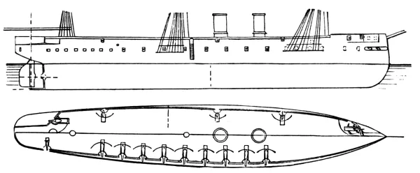
Armored belt and four barbette turrets. Ram bow and overhanging dome
stern. The armor-belt covers the water-line to the height of the
main-deck beams, coming below the point of the ram and covering the
steering-gear. The barbette turrets are arranged one on each side,
abreast the forward smoke-stack, having an overhang of nearly half
its diameter, so as to give clear fore-and-aft fire. The other two
turrets are amidships, before and abaft the mizzen-mast. There are two
armored pilot-houses on the Duperré, one abreast the forward turrets
and one between the after ones; the Duguesclin has but one, forward.
The gun-deck battery is composed of light rifled guns, unprotected.
The deck plating of these ships is three inches in thickness (one inch
steel over two inches of iron). A bow-gun works in a single port under
the topgallant forecastle.
AMIRAL DUPERRÉ.
DEVASTATION. FOUDROYANT. REDOUBTABLE.
Armored belt and redoubt. Ram bow and dome stern. The belt of the
Redoubtable encircles the water-line to the height of the main-deck
beams, curving down forward over the point of the ram; that of the
other two ships stops short of the curve of the counter in an armored
bulkhead, the lower edge being carried on by an armored deck to protect
the steering-gear. The sides forward and abaft the redoubt are given a
rank tumble home, the redoubt rising straight to the spar-deck, thus
giving clear fore-and-aft and beam fire from the main-deck battery.
A heavy gun is mounted in barbette on top of the redoubt, each side,
having a clear firing angle of 180°; the gun-slide alone is protected
by armor, while a musket-proof shield is mounted on the forward part
of the slide, as protection to the crew. On the spar-deck is carried a
battery of light rifles in broadside.
DEVASTATION.
TRIDENT. FRIEDLAND.
TRIDENT.
Armored belt and casemate. Ram bow and dome stern. The belt encircles
the water-line to the height of the main-deck beams. The casemate
rises to the height of the spar-deck beams. At the forward end of the
casemate, on each side, a barbette unarmored half-turret is built,
being simply a projecting shelf for mounting a heavy gun. The sides
from the main-deck up forward are given a sharp tumble home to permit
clear forward fire; while aft the spar-deck rail is placed inboard
about three feet, leaving a clear fire aft, giving the part of the
spar-deck outside the rail the appearance of a continuous
channel-piece. The turret guns are only protected by a light
musket-proof shelter, rising above the slide. There is a light battery
of broadside rifles on the spar-deck, a bow-gun working in one port
under the forecastle, and a similar stern-gun. There is no forward or
after fire from the main-deck battery.
COLBERT.
Of the same type as the Friedland, except that in place of the barbette
half-turrets there are armored breastworks for the protection of a
heavy bow and a heavy stern-gun on the spar-deck.
COLBERT.
RICHELIEU. MARENGO. OCEAN. SUFFREN.
SUFFREN.
Armored belt and casemate, with four armored barbette turrets. Ram bow,
straight stern. The belt encircles the water-line, coming to but not
covering the ram, which is a solid bronze casting. The barbette turrets
are just over the corners of the casemate, projecting nearly half their
diameter clear of the side for fore-and-aft fire. The side is not
broken in or given a tumble home, as the muzzles of the turret guns are
above the spar-deck rail. The Richelieu has twin screws, the others
single ones. There is no fore-and-aft fire from the casemate. Light
spar-deck broadside battery. Armored commander’s lookout.
BAYARD. TURENNE. LA GALLISSONNIERE. TRIOMPHANTE. VICTORIEUSE. VAUBAN.
Second-rate sea-going iron-clads. Armored belt and casemate and two
barbette turrets. The belt encircles the water-line to the height of
the main-deck beams, the casemate carrying the armor to the spar-deck.
The barbette turrets are over the forward corners of the casemate. Ram
bow and dome stern. Light spar-deck broadside battery. Bow-gun working
in a single port under the forecastle.
Broadside iron-clad frigates, completely armored. These vessels belong
to the earliest type, and, with the exception of the Couronne and
Heroine, they have wooden hulls. The armor extends from about three
feet below the water-line to the spar-deck beams. Armored conning
towers are placed abaft the main-mast. Originally built for a large
battery of light smooth-bores, the height of the main-deck presents the
full outfit of a heavy battery.
Second-class cruising iron-clads. Armor belt and casemate, and four
barbette turrets. The belt comes to the main-deck beams all around,
the casemate carrying it up to the spar-deck. The turrets are at the
corners of the casemates. In some of these vessels the after turrets
were left off, it being found that the hull was overweighted when it
was attempted to put heavier guns aboard than the ships were originally
intended to carry.
Single-turreted, casemated monitors for coast defence. These vessels
are heavily armored at the water-line; the single turret is very large,
in order to bring the two guns in it well apart, to gain clear fire aft
on each side of the superstructure. This turret is on the forward third
of the hull, and it, as well as the superstructure aft, is surrounded
by a breastwork that does not come out to the side. On top of the
turret is a barbette commander’s lookout. Forward the deck rises into
a short forecastle, just abaft of which is an armored casemate giving
ingress into the crew’s quarters. The superstructure abaft the turret
is musket-proof, of a width just sufficient to permit the guns to get
stern-fire. The upper part expands into a flying deck, with a low
musket-proof shield, and corner stands for Hotchkiss machine-guns.
TIGRE. BELIER. CERBERE. BOULEDOGUE.
Monitor rams. These vessels have a low freeboard, the single turret
being on the forward third of the hull, surrounded by a casemate, which
also covers the lower part of the smoke-stack. A superstructure rises
forward and aft of the turret and is semi-cylindrical, curving at the
ends in such a manner as to give no foothold on any part. The turret
is surmounted by a barbette lookout. The hulls are of wood and heavily
strengthened at the ram. Double screws.
TAUREAU.
Similar to the above, with the exception that the turret is fixed and
has four ports for bow and beam fire.
TAUREAU.
ONONDAGA.
Double-turreted American monitor; laminated plating, low freeboard, no
casemate.
ROCHAMBEAU.
Casemated iron-clad (late Dunderberg). Ram bow, low freeboard, and
rectangular casemate, with sloping sides giving fore-and-aft and beam
fire.
Armored floating batteries. Low freeboard forward and abaft, with
rectangular casemates having perpendicular sides, and giving
fore-and-aft and beam fire. Light draft.
EMBUSCADE.
CAIMAN. INDOMPTABLE. TERRIBLE.
Coast-defence vessels; type not known, but presumably citadel ships
of a displacement not less than 12,000 tons. The battery of this type is
six 13¼-inch guns. They are evidently intended as more powerful vessels
than either the Inflexible or Duilio.
A = Length between Perpendiculars.
B = Breadth of Beam.
C = Maximum Draft.
D = Displacement.
E = Construction Material.
Type and Name.
A
B
C
D
E
Ft. in.
Ft. in.
Ft. in.
Tons.
1st Class Cruisers.
Duquesne
326 6
50
22 7
5,345
Iron sheathed
Tourville
326 6
50
22 7
5,345
”
2d Class Cruisers.
Duguay Trouin
289 8
42 9
16 1
3,070
”
Villars
249 3
37 11
15 1
2,231
Wood
Forfait
249 3
37 11
15 1
2,231
”
Magon
249 3
37 11
15 1
2,231
”
Roland
249 3
37 11
15 1
2,231
”
La Perouse
262 5
37 5
17
2,200
”
D’Estaing
262 5
37 5
17
2,200
”
Monge
262 5
37 5
17
2,200
”
Nielly
262 5
37 5
17
2,200
”
* * * *
262 5
37 5
17
2,200
”
* * * *
262 5
37 5
17
2,200
”
Infernet
245 8
35 9
12 5
1,865
”
Champlain
245 8
35 9
12 5
1,865
”
Laclocheterie
245 8
35 9
12 5
1,865
”
Du Petit Thouars
245 8
35 9
12 5
1,865
”
Sané
1,900
”
Seignelay
1,900
”
Fabert
1,900
”
3d Class Cruisers.
Eclaireur
236 2
35 5
14 8
1,610
Composite
Rigaut de Genouilly
236 2
35 5
14 8
1,610
”
3d Class Dispatch Vessels.
Bisson
200
28 5
11
833
”
Labourdonnais
200
28 5
11
833
”
Hussard
200
28 5
11
833
”
Lancier
200
28 5
11
833
”
Chasseur
200
28 5
11
833
”
Voltigeur
200
28 5
11
833
”
Bouvet
”
Parseval
850
”
F = Indicated Horse-power.
G = Maximum Speed.
H = Date of Launch.
Type and Name.
F
G
H
Battery.
Knots
Year.
1st Class Cruisers.
Duquesne
6,589
17
1876
VII 7½-inch,
XIV 5½-inch.
Tourville
6,589
17
1877
VII 7½-inch,
XIV 5½-inch.
2d Class Cruisers.
Duguay Trouin
3,740
16
1877
V 7½-inch,
V 5½-inch.
Villars
2,790
15
Building
VI 6½-inch, X 5½-inch.
Forfait
2,790
15
”
Magon
2,790
15
”
Roland
2,790
15
”
La Perouse
2,790
15
”
D’Estaing
2,790
15
”
Monge
2,790
15
”
Nielly
2,790
15
”
* * * *
2,790
15
”
* * * *
2,790
15
”
Infernet
1,784
14.4
1869
I 6½-inch, VIII 5½-inch.
Champlain
1,784
14.4
1872
Laclocheterie
1,784
14.4
1872
Du Petit Thouars
1,784
14.4
1875
Sané
1,967
15
1867
Seignelay
1,900
14.7
1875
Fabert
1,900
14.7
1875
3d Class Cruisers.
Eclaireur
1,900
15
1876
VIII 5½-inch.
Rigaut de Genouilly
1,900
15
1877
3d Class Dispatch Vessels.
Bisson
850
12.2
1877
IV 5½-inch.
Labourdonnais
850
12.2
1876
Hussard
850
12.2
1876
Lancier
850
12.2
1877
Chasseur
850
12.2
Building
Voltigeur
850
12.2
”
Bouvet
850
12
1876
I 6½-inch, II 5½-inch, I 4¾-inch.
Parseval
850
12
1877
Type and Name.
Displacement.
Date of Launch.
Battery.
Tons.
Year.
1st Class Gun-boats.
Crocodile
452
I 7½-inch, II 4-inch.
Lionne
Lutin
Lynx
Milan
Vautour
Diligente
393
II 5½-inch.
2d Class Gun-boats.
Chacal
295
II 5½-inch.
Etendard
Fanfare
Gladiateur
Hyene
Jaguar
Leopard
Oriflamme
Couleuvre
295
II 5½-inch.
Décidée
Frelon
Pique
Surprise
Tactique
Epée
177
I 9¼-inch,
28 Gun-boats
177
I 4¾-inch.
Transports.
Bievre
1,475
II 5½-inch.
Oise
1,770
Caravans
2,868
1875
Ampère
Building
Annamite
5,840
1876
Mytho
5,840
Building
Shamrock
5,840
”
Tonquin
5,840
”
Allier
1,655
”
IV 5½-inch.
Nievre
1,655
”
Drac
1,655
”
Saone
1,655
”
DUQUESNE. TOURVILLE.
Iron frigates, sheathed with wood and coppered. Strengthened bows
for ramming, with heavy bronze rams. Three half-turrets or platforms
on each side of the spar-deck, projecting clear of the side to give
clear fore-and-aft fire. Bow-gun working in a single port under
the forecastle. Pilot-house and chart-room on a bridge forward of
the smoke-stacks. Boats carried on a gallows-frame between the
smoke-stacks. Fine lines, heavy shoulder; the bow-frames are given a
flare out from the main-deck up, to give a full forecastle for working
the bow-gun. Single screw, full sail-power. Gun-deck, broadside
battery, fourteen 5½-inch rifles. Spar-deck battery, seven 7½-inch
rifles. Bow-fire, three 7½-inch; beam-fire, nine 5½-inch (two guns can
be shifted on the gun-deck, so as to give nine for a broadside), three
7½-inch; stern-fire, two 7½-inch. Two sets of engines and boilers,
placed one abaft the other for protection. Between the forward turrets
on the spar-deck are the wash-rooms and water-closets, giving the
appearance of a fourth half-turret. Maximum speed at sea for 24 hours,
16½ knots.
TOURVILLE.
DUGUAY TROUIN.
Iron corvette, sheathed with wood and coppered. Strengthened bow for
ramming, with heavy bronze ram. Four half-turrets, similar to those of
the Tourville. Bow-gun working under the forecastle in a single port.
Single screw, full sail-power. All the battery carried on the
spar-deck, leaving a clear, roomy main-deck. Stern-gun mounted in
barbette on a centre-pivot carriage. Bow-fire, two 7¼-inch, one
5½-inch; beam-fire, two 7¼-inch, three 5½-inch; stern fire, two
7¼-inch, one 5½-inch.
DUGUAY TROUIN.
VILLARS CLASS (seventeen in number).
Second-class wooden corvettes, with strengthened ram bow. Two light
bow-guns firing through recessed ports, giving bow and beam fire. (In
some cases the guns are on the forecastle, in others underneath.)
Stern-gun mounted on a centre-pivot carriage in barbette. Midship guns
of heavy calibre, the deck being carried out slightly, to give them an
extreme firing angle.
VILLARS.
ECLAIREUR CLASS (two in number).
Third-class composite corvettes, with strengthened ram bow. Bow
pivot-gun mounted on the forecastle: stern-pivot in barbette; six guns
in broadside.
ECLAIREUR.
LANCIER CLASS (eight in number).
Avisos, or fourth-class corvettes, composite, with strengthened ram
bows. Four rifled-guns mounted on centre-pivot carriages in the midship
line of the vessel. Drop-rail abreast the main-deck guns.
LANCIER.
LYNX CLASS (seven in number).
First-class composite gun-boats, with strengthened ram bows. Light,
centre-pivoting rifled bow and stern-guns, and one heavy rifled,
centre-pivot gun amidships firing in barbette.
LYNX.
FARCY CLASS (twenty-seven in number).
Second-class iron gun-boats. These vessels are more nearly large
launches, built with ram bows to give them good displacement. One heavy
gun is mounted in the bow, the slope of the bow from the ram up being
carried up to form a musket-proof shield, permitting the gun to fire
through an embrasure.[2]
TROMBLON.
MYTHO CLASS (four in number).
First-class iron troop-ships, similar in general to the English
troopers of the Serapis class. Capacity for berthing 1700 men with all
the camp equipage.
MYTHO.
DRAC CLASS (four in number).
Light cavalry transports. These vessels are composite built and may
serve either as transports or gun-boats, as they carry a battery of
two light and two heavy centre-pivoting rifles. They are used for the
transportation of cavalry horses, artillery, and stores.
DRAC.
BIEVRE CLASS (four in number).
Light, fast iron transports, similar in general to the Drac class.
A = Displacement.
B = Indicated Horse-power.
C = Guns.
D = Construction Material.
E = Date of Launch.
Type and Name.
A
B
C
D
E
Tons.
Year.
Ships of the Line.
Souverain
5,115
25
Wood
1856
Louis XIV
4,820
12
”
1854
Ville de Bourdeaux
5,210
12
”
1860
Ville de Lyon
5,210
12
”
1861
Castiglione
5,500
12
”
1857
Masséna
5,015
12
”
1860
Fontenoy
3,934
12
”
1858
Jean Bart
3,934
22
”
Saint Louis
3,934
12
”
1854
Frigates.
Pallas
3,560
1,330
34
”
1860
Magicienne
3,375
1,310
32
”
1861
Themis
3,375
1,310
18
”
1862
Victoire
3,325
1,310
16
”
1861
Flore
3,100
1,520
18
”
1867
Clorinde
1,740
1,430
12
”
1865
Corvettes.
Amorique
2,800
1,040
22
”
1862
Minerve
2,700
1,530
22
”
1865
Venus
2,700
1,530
22
”
1864
Chateau Renaud
1,830
1,700
5
”
1866
Dupleix
1,780
1,050
10
”
1861
Decrès
1,770
1,480
6
”
1866
Desaix
1,640
1,780
6
”
1866
Laplace
1,590
700
10
”
1852
Cosmos
1,840
1,100
13
”
1861
D’Assas
1,920
740
16
”
1864
Sloops. (Avisos, 1st Class.)
Beautemps
1,270
1,050
6
”
1872
Beaupré
1,270
1,050
6
”
1872
Duchaffaut
1,289
1,050
8
”
1872
Hugon
1,290
1,050
6
”
1872
Kerguelen
1,280
1,050
6
”
1872
Bourayne
1,260
960
6
”
1869
Dayot
1,260
960
6
”
1869
Ducouëdic
1,260
960
6
”
1869
Sloops. (Avisos, 2d Class.)
Kersaint
1,270
960
6
”
1869
Segond
1,260
960
6
”
1869
Vaudreuil
1,280
1,050
6
”
1870
D’Estrées
1,280
1,000
6
”
1867
Volta
1,300
1,000
6
”
1867
Hamelin
1,220
1,000
6
”
1866
Limier
1,220
1,000
6
”
1866
Talisman
1,310
800
6
”
1863
Kleber
1,260
740
2
”
1856
Forbin
1,250
870
4
”
1859
Linois
830
720
6
”
1867
Cassard
850
660
3
”
1859
Hirondelle
1,080
1,780
2
”
1870
Despatch Vessels (Avisos, 2d Class).
Renaud
840
490
4
”
1866
Lamotte Piquet
720
420
4
”
1859
Latouche Treville
720
390
4
”
1860
Curieux
760
560
4
”
1859
Surcouff
700
430
4
”
1858
Bougainville
740
310
6
”
1859
Bruat
700
490
4
”
1866
Adonis
730
490
4
”
1868
Guichen
700
460
2
”
1863
Boursaint
750
610
3
”
1872
Corse
510
220
”
1842
Transports.
Algesiras
5,600
2,100
4
”
1842
Charlemagne
5,600
1,150
12
”
1851
Intrépide
5,600
2,960
4
”
1864
Ville de Paris
5,600
1,350
12
”
1850
Guerrière
3,200
1,350
4
”
1860
Entreprenante
3,200
780
4
”
1858
Dryade
3,200
540
4
”
1856
Ceres
3,200
410
4
”
1857
Danaë
3,250
540
4
”
1888
Renommée
3,200
540
4
”
1847
Européen
2,350
1,200
2
Iron
Japon
2,300
960
2
Wood
Aveyron
3,500
1,520
4
”
1864
Correze
3,500
1,520
4
”
1868
Creuze
3,500
1,520
2
”
1863
Sarthe
3,500
1,520
2
”
1862
Tarne
3,500
1,520
2
”
1863
Orme
3,000
750
4
”
1862
Var
3,000
750
4
”
1863
Calvados
3,000
540
4
”
1856
Finisterre
3,000
650
4
”
1859
Garonne
3,000
650
4
”
1859
Jura
3,000
650
4
”
1855
Dordogne
2,400
370
4
”
1855
Maine
2,400
370
4
”
1855
Meuse
2,400
370
4
”
1855
Rhin
2,400
560
4
”
1855
Yonne
2,400
370
4
”
1856
Seine
2,400
370
4
Iron
Charente
2,000
280
4
”
1856
Adour
1,800
250
2
”
1856
Ariege
1,800
450
2
”
1865
Isère
1,800
450
2
”
1865
Moselle
1,970
390
2
”
Vienne
1,800
370
2
Wood
1858
Cher
1,400
610
6
”
1868
Indre
1,400
610
6
”
1864
Dives
1,682
670
2
”
1870
Rance
1,682
670
6
”
1870
Sendre
1,682
670
6
”
1872
Vire
1,682
670
6
”
1868
Loiret
1,200
210
3
”
1856
Paddle-wheel frigates Albatros, Magellan.
”corvettes Catinat, Coligny, Eumenide.
Four paddle-wheel gun-boats, 1st class, 700 to 800 tons, two to four guns.
Four”” 2d ” 700 tons, four guns.
Thirty screw tenders.
A = Length between Perpendiculars.
B = Breadth of Beam.
C = Maximum Draft.
D = Displacement.
E = Construction Material.
F = Greatest Thickness of Armor.
Type and Name.
A
B
C
D
E
F
Ft.
Ft.
Ft. in.
Tons.
In.
Redoubt Frigates.
Kaiser
280
62
24 8
7,440
Iron
11¾
Deutschland
280
62
24 8
7,560
”
11¾
Turret Frigates.
Friederich der Grosse
298
52
24 8
6,560
”
10½
Preussen
308
54
24 8
6,748
”
10½
Casemate Frigates.
König Wilhelm
353
60
26 6
9,451
”
9¼
Friederich Karl
290
55
24
5,819
”
4¾
Kron Prinz
286
24 6
5,393
”
4¾
Barbette Corvettes.
Sachsen
213
51
19 8
7,135
”
9
Baiërn
213
51
19 8
7,135
”
9
Würtemberg
213
51
19 8
7,135
”
9
Two others
213
51
19 8
7,135
”
9
Redoubt Corvette.
Hansa
285
51
21 7
3,497
Wood
6¼
Monitor.
Arminius
197
36
13 7
1,558
”
4½
Redoubt Ram.
Prinz Adalbert
158
27
21 7
3,863
”
4½
Armored Gun-boats.
Wespe
10 2
985
Iron
8
Viper
10 2
985
”
8
Biene
10 2
985
”
8
Mücke
10 2
985
”
8
Scorpion
10 2
985
”
8
Basilisk
10 2
985
”
8
Four others
10 2
985
”
8
River Monitors.
Rhein
164
25
3 6
1½
Mosel
164
25
3 6
1½
G = Least Thickness of Armor.
H = Backing.
I = Indicated Horse-power.
J = Maximum Speed.
Type and Name.
G
H
I
J
Battery.
In.
In.
Knots
Redoubt Frigates.
Kaiser
6¼
10¼
8,000
14½
VIII 10¼-inch, I 8¼-inch.
Deutschland
Turret Frigates.
Friederich der Grosse
5½
8¼
5,400
14
IV 10¼-inch, II 6¾-inch.
Preussen
Casemate Frigates.
König Wilhelm
5½
9¾
8,000
14¾
XVIII 9¼-inch, V 8¼-inch.
Friederich Karl
3
15
3,500
13½
XVI 8¼-inch.
Kron Prinz
3
16
4,800
14¼
Barbette Corvettes.
Sachsen
9
7¾
5,600
14
I 12-inch, IV 10¼-inch
Baiërn
9
7¾
5,600
14
Würtemberg
9
7¾
5,600
14
Two others
9
7¾
5,600
14
Redoubt Corvette.
Hansa
4
12½
3,000
12
VIII 8¼-inch
Monitor.
Arminius
3
9
1,200
10½
IV 8¼-inch
Redoubt Ram.
Prinz Adalbert
3
12
1,000
9
I 8¼-inch II 6¾-inch.
Armored Gun-boats.
Wespe
4
8
700
9
I 12-inch.
Viper
4
8
700
9
Biene
4
8
700
9
Mücke
4
8
700
9
Scorpion
4
8
700
9
Basilisk
4
8
700
9
Four others
4
8
700
9
River Monitors.
Rhein
1¼
8
80
6
II 4½-inch.
Mosel
1¼
8
80
6
KAISER. DEUTSCHLAND.
Armored belt, redoubt, and stern casemate. Ram bow and straight stern.
The belt encircles the water-line, coming up to the height of the
main-deck beams abaft the redoubt, but forward of it reduced in height
to not over three feet above the water-line, and having a heavy steel
deck at the height of its upper edge. The belt does not cover the
ram. The sides forward and abaft the redoubt are given a rank tumble
home, while the redoubt is carried straight up to the spar-deck beams,
opening fore-and-aft and beam fire from the angular ports, (vide
Devastation, French). The stern casemate prevents raking from aft, and
also protects a stern-gun working in a single port. The engines and
boilers form two distinct sets, one abaft the other, the magazines and
shell-lockers coming between them. The redoubt has an overhang clear of
the side of 3½ feet forward and 1½ feet aft. There is no bow-gun, the
bow-fire coming from the redoubt. The after-redoubt guns only fire to
within 15° of right astern, the stern-gun filling out the dead-angle.
Single screw, full sail-power.
KAISER.
FRIEDRICH DER GROSSE. PREUSSEN.
Armored belt, breastwork, and two revolving turrets. These ships are
built on the lines of the Monarch, although improved in detail. The
belt encircles the water-line, but does not come as low down as the
point of the ram. The breastwork surrounds the boilers and the bottoms
of the turrets, but the engines are outside of and abaft it. The
turrets are closer together than in the Monarch, and have no upper
works to interfere with their fire. The dead-angles of the turret-guns
are filled by a bow and stern-gun working in single unprotected ports.
These ships have single screws and about three-quarter sail-power.
PREUSSEN.
KÖNIG WILHELM.
KÖNIG WILHELM.
Armored belt and long, main-deck casemate, stern casemate, and two
spar-deck redoubts. Ram bow and straight stern. The belt encircles
the water-line, coming to the height of the main-deck beams aft, but
somewhat lower forward of the casemate, that portion being covered by
a steel deck. There is no forward or after fire from the casemate, the
sides rising straight up fore and aft. The ends of the casemate are
protected from raking by armored bulkheads, rising to the spar-deck
beams forward and abaft. The stern casemate protects a single gun
working in one port. At the forward end of the main casemate, and
rising clear of the upper deck, is a redoubt—or rather traverse, for
it is unprotected at the rear—giving protection to two guns working
each in two ports for fore-and-aft and beam fire. At the after-end
of the main casemate is a similar traverse, which has an overhang of
several feet, its two guns working also each in two ports for stern
and beam fire (vide Sultan, English). These traverses encumber the
spar-deck for working the gear of the sails. Single screw and full
sail-power.
FRIEDRICH KARL. KRON PRINZ.
Armored belt and long casemate with bow redoubt. Ram bow and straight
stern. The belt encircles the water-line to the height of the main-deck
beams, coming down in a curve forward well over the ram. There is no
fore-and-aft fire from the casemate, the ship being wall-sided. The bow
redoubt cuts off the point of the bow above the spar-deck beams and
protects a bow-gun working in a single port. There is a high, oval,
armored pilot-house just abaft the main-mast. No stern-fire. Single
screw and full sail-power.
FRIEDRICH KARL.
SACHSEN. BAIERN. WÜRTEMBERG.
(Two others not yet named.)
Partial armored belt and two barbette casemates. Ram bow, round stern.
Half sail-power (brig rigged). Four smoke-stacks. The belt forms a
casemate for the boilers and engines, covering the middle third of the
ship, the lower edge being prolonged in a heavy steel deck, which, aft,
protects the steering-gear. This casemate rises to the spar-deck beams.
At its after-end a high, rectangular barbette casemate rises well up
above the spar-deck rail, giving clear fore-and-aft and beam fir to its
four guns. At the forward end of the casemate is an oval barbette
turret (vide Temeraire, English) amidships, giving clear bow and beam
fire to its single gun. These ships gain a nearly perfect all-around
fire from the heaviest calibre guns, with a maximum thickness of armor.
They combine great armor and battery strength with light draft and
displacement.
SACHSEN.
HANSA.
HANSA.
Armored belt and double-decked redoubt. Swan-breasted bow strengthened
for ramming, pointed stern, single screw, full sail-power. The belt
encircles the water-line to the height of the main-deck. The main-deck
redoubt is short and does not give fore-and-aft fire, the ship being
wall-sided. The upper-deck redoubt, rising a little above the spar-deck
rail, is octagonal, to permit angular ports for fore-and-aft and beam
fire. The spar-deck rail is carried inboard parallel to the keel to
open the angular ports.
ARMINIUS.
ARMINIUS.
Double-turreted monitor, with ram bow and no overhang. Light flying
deck, single screw. (American type modified.)
PRINZ ADALBERT.
Armored belt, double redoubt. Long ram bow, round stern, single screw,
half sail-power. The belt encircles the water-line to the height of the
upper deck. The curve of the ram bow is carried up, forming a spar-deck
redoubt, giving protection to a single heavy bow-gun working in one
port. A second redoubt, well aft, gives protection to two guns, each
working in two ports for fore-and-aft and beam fire. A superstructure
aft cuts off the stern-fire from these guns, and the forward redoubt
cuts off the bow-fire. The shape of both of the redoubts is nearly
circular. The Stonewall (Confederate) belonged to this type. (Sister ships.)
Small, light-draft, armored gun-boats. All except the
Rhein and Mosel have an armored belt and a horseshoe-shaped traverse,
giving protection to the crew of a single barbette gun, which gives
only bow-fire. They are provided with rams. The Rhein and Mosel are
light-draft monitors, similar to the Austrian Danube gun-boats.
(See Austrian Danube monitors.) The Wespe class
belongs to the English Staunch and the French Farcy type.
Completely armored broadside frigate or large corvette; ram bow,
straight stern. Armor-belt enclosing water-line to the height of
spar-deck beams. (See Maria Pia, Italian.)
GEORGIUS.
Armored belt and hexagonal casemate amidships. The rail forward of the
casemate is carried inboard parallel to the keel to open the bow-fire
from the casemate. Abaft, the rail is cut in for some distance from
the casemate, and given a rank tumble home, to open the after-fire. No
stern-fire. Double screws, three-quarter sail-power. The armor has a
backing of ten inches. The guns work on turn-tables, one on each side,
and have a firing-angle of about 110° from each port.
Double-turreted, high-sided, sea-going monitors. Armored belt and
casemate; ram bow, straight stern. The belt encloses the water-line to
the height of the main-deck beams. The casemate encloses the bottoms of
the turrets, engines, and boilers, occupying the middle third of the
vessel. The fore-and-aft fire of the turret guns is completely cut off
by the superstructures forming forecastle and cabin, and which rise to
the height of the top of the turrets.
PRINZ HENDRIK.
These superstructures are cut in at the ends nearest the turrets
to open the fire as much as possible, increasing slightly the firing-angle
and almost completely destroying the necessary freeboard. Between
the turrets is a third superstructure, musket-proof, protecting the
approaches to the boilers and engines. At the forward end of this
superstructure is a musket-proof pilot-house. Double screws, full
sail-power, with tripod fore and main masts. These ships are a medium
between the Wyvern and the ill-fated Captain. Bow and stern fire are
secured by light unprotected guns.
High-sided ram monitors. Armored belt, casemate, and single turret. Ram
bow and round stern. The belt encircles the water-line to the height
of the main-deck beams. The casemate surrounds the foot of the turret
only. The turret has perfect all-around fire, being large enough to
give stern-fire past the smoke-stack. A superstructure gives a full
freeboard all around as high as the top of the casemate, furnishing
quarters. The upper deck carries a light barbette battery of bow,
stern, and broadside guns. Twin screw and half sail-power.
Single-turreted low monitors, with high superstructures forward and
abaft the turret cutting off the fore-and-aft fire. Twin screws,
half-sail power.
BLOEDHOUND.
VAHALIS. ISALA. RHENUS. MOSA. MERVA.
Light-draft, single-turreted monitors. The turret is
elevated and surrounded by a casemate having a tumble home of 35°.
A = Displacement.
B = Indicated Horse-power.
C = Maximum Speed.
D = Date of Launch.
Type and Name.
A
B
C
D
Battery.
Tons.
Knots.
Year
1st-class Cruisers.
Atjeh
3,108
2,900
14
1876
VI 6.8-inch Krupp.
Tromp
3,108
2,900
14
1877
De Ruyter
3,108
2,900
14
1878
3d-class Cruisers.
Suriname
836
350
1876
I 5.8-inch Krupp. III 4.7-inch ”
Bonaire
836
350
1876
I 5.8-inch ” III 4.7-inch ”
St. Eustatius
836
350
1877
I 5.8-inch ” III 4.7-inch ”
Samarang
836
350
1877
Batavia
836
350
1878
Macassar
836
350
1878
Padang
836
350
1878
A = Displacement.
B = Indicated Horse-power.
C = Construction Material.
D = Date of Launch.
Type and Name.
A
B
C
D
Guns.
Tons.
Year
Frigate.
Evertsen
3,300
1,000
Wood
1857
51
Corvettes.
Silverin Kruis
2,160
1,480
”
1869
12
Van Galen
2,160
700
”
1872
12
Leenwarden
2,030
700
”
1861
14
Curaçao
2,030
700
”
1863
14
Watergeus
1,490
770
”
1864
6
Marnix
1,490
770
”
1867
6
Sloops.
Alkmaar
1,010
600
Composite
1874
3
Prinses Maria
760
250
Wood
1862
7
Cornelius Dirks
760
250
”
1859
6
Aruba
730
250
Composite
1873
6
Paddle Steamer.
Valk
1,220
800
Wood
1864
3
A = Displacement.
B = Indicated Horse-power.
C = Construction Material.
D = Date of Launch.
Type and Name.
A
B
C
D
Guns.
Tons.
Year
Paddle Steamers.
Soeribaija
1,450
975
Wood
1867
2
Merapi
1,150
975
Iron sheathed
1874
6
Bromo
1,150
975
”
1874
6
Sumatra
950
550
Iron
1867
4
Borneo
950
550
”
1867
4
Banka
950
550
”
1867
4
Timor
950
550
”
1867
4
Oenarang
650
360
”
1875
3
Soembing
650
360
”
1877
4
Sindoro
650
360
”
1877
4
Onrust
190
290
”
1863
3
Salak
200
290
”
1875
3
Admiral v. Kinsbergen
180
200
”
1854
1
Screw Steamers.
Aart Van Ness
650
280
Wood
1863
2
Schouwen
650
280
”
1863
6
Bommelerward
650
280
”
1862
6
Riouw
730
340
Composite
1872
3
Banda
730
340
”
1872
3
Amböina
730
340
”
1873
3
Deli
730
340
”
1873
3
Sambas
750
350
”
1874
3
Pontianak
750
350
”
1873
3
Bandjermassing
750
350
”
1874
3
Palembang
750
350
”
1874
3
Surveying Steamer.
Hydrograaf
730
340
”
1873
3
ITALY. — ARMORED FLEET. — ITALIAN UNARMORED FLEET. (Rapid Cruisers.) — ITALIAN GENERAL-SERVICE FLEET. (Old-Type Steam Cruisers.)
A = Length between Perpendiculars.
B = Breadth of Beam.
C = Maximum Draft.
D = Displacement.
E = Indicated Horse-power.
F = Maximum Speed.
Type and Name.
A
B
C
D
E
F
Ft.
Ft.
Ft.
Tons.
Knots.
Citadel Ships.
Dandolo
340
65
26
10,650
7,500
14
Duilio
340
65
26
10,650
7,500
14
Italia
400
74
30
13,480
9,000
15
Lepanto
400
74
30
13,480
9,000
15
Casemate and Redoubt Frigates.
Palestro
265
58
25
5,780
3,200
12.2
Principe Amadeo
265
58
25
5,780
3,200
12.9
Venezia
250
57½
25
5,699
4,000
13
Roma
250
57½
25
5,099
3,500
13
Broadside Frigates.
Ancona
256
50
22
4,194
3,000
11½
Castelfidardo
256
50
22
4,149
3,000
11½
Maria Pia
256
50
22
4,194
3,000
11½
San Martino
256
50
22
4,194
3,000
11½
Conte Verde
256
50
22
4,194
3,000
11½
Messina
256
50
22
4,194
3,000
11½
Floating Batteries.
Terribile
198
45
18
2,700
1,800
12
Formidabile
198
45
18
2,700
1,800
12
Varese
198
42
13
2,600
1,000
9
Monitor Ram.
Affondatore
290
40
20
4,070
3,200
13
G = Greatest Thickness of Armor.
H = Least Thickness of Armor.
I = Backing.
J = Date of Launch.
Type and Name.
G
H
I
J
Battery.
In.
In.
In.
Year
Citadel Ships.
Dandolo
21½
13¾
19¾
1876
IV 17-inch, IV 4¾-inch.
Duilio
21½
13¾
19¾
1878
Italia
Building
Lepanto
”
Casemate and Redoubt Frigates.
Palestro
8⅝
6
24¼
1872
I 11-inch, IV 10-inch.
Principe Amadeo
8⅝
6
24¼
1873
Venezia
6
4
26
1871
VIII 10-inch, I 9-inch.
Roma
6
4
26
1869
XI 10-inch.
Broadside Frigates.
Ancona
4⅝
3
13
1863
IX 8-inch, II 9-inch.
Castelfidardo
4⅝
3
13
1863
Maria Pia
4⅝
3
13
1864
San Martino
4⅝
3
13
1864
Conte Verde
4⅝
3
13
1861
VI 9-inch, I 8-inch.
Messina
4⅝
3
13
1861
Floating Batteries.
Terribile
4½
3
9
1862
VIII 8-inch.
Formidabile
4½
3
9
1862
Varese
4½
3
9
1862
IV 8-inch, I 6½-inch.
Monitor Ram.
Affondatore
5
3
9
1865
II 9-inch.
DANDOLO. DUILIO. ITALIA. LEPANTO.
Armored-casemate, double-turreted monitor ships. Ram bow, overhanging
stern. The casemate surrounds the boilers, engines, and turrets,
occupying about one third of the ship. The lower edge of the casemate
is carried forward and aft in a steel deck three inches thick, the deck
curving down forward below the point of the ram. The upper deck is also
plated fore and aft with two-inch steel plates. The turrets are placed
diagonally to open full fore-and-aft and beam fire. The two sets of
boilers and engines are grouped one abaft the other, the boilers being
arranged transversely between the sets of engines. Twin screws, no
sail-power, no superstructure. Designed by Admiral Brin.
DUILIO.
PALESTRO. PRINCIPE AMADEO.
Armored belt and double casemate. Swan breast, ram bow, straight stern.
The belt encloses the water-line to the height of the main-deck beams.
Forward is a double casemate or traverse (the rear being unprotected)
rising to the top of the topgallant forecastle, and giving protection
to two heavy guns on the main-deck, working each in two ports for bow
and beam fire, and one heavy rifle on the upper deck working in two
ports over the forward main-deck ones for bow-fire. The bow-frames are
distorted to open the fire on the main-deck. Aft is a long main-deck
traverse protecting four heavy rifles, giving two guns for stern-fire
and, if desired, three for beam-fire (one gun may be shifted from side
to side). The stern-frames, like those of the bow, are distorted to get
stern-fire. Single screw, full sail-power.
PALESTRO.
VENEZIA. ROMA.
VENEZIA.
Armored belt, long main-deck casemate, and upper-deck bow and stern
traverses. Straight bow, round stern. The belt encircles the water-line
to the height of the main-deck beams. The casemate is long and
trapezoidal in shape, with the corners cut to allow angular ports for
fore-and-aft fire. The side forward and abaft the casemate is given a
rank tumble home to open the fore-and-aft fire. The casemate surrounds
the boilers and engines. On the spar-deck are bow and stern traverses,
each protecting a gun working in a single port. The bow and stern upper
rail is cut off by the traverses sufficient to give them square fronts.
Single screw, full sail-power.
ANCONA. CASTELFIDARDO. MARIA PIA. SAN MARTINO.
CONTE VERDE. MESSINA.
MARIA PIA.
Armored-belt and long-casemate, broadside frigates. Ram bows and round
sterns. The armored belt encloses the water-line to the main-deck
beams, and is carried up in the casemate to the spar-deck beams.
No fore-and-aft fire except from light upper-deck guns. An armored
pilot-house just forward of the mizzen-mast. Single screw, full
sail-power.
TERRIBILE. FORMIDABILE. VARESE.
Old-type floating batteries. The Varese has the corners of her casemate
cut to give fore-and-aft and beam fire. Walls of casemate tumble home
at a sharp angle. Ram bows, twin screws, no sail-power.
AFFONDATORE.
AFFONDATORE.
Double-turreted monitor ram. High-sided, with half sail-power and
superstructures forward and abaft the turrets. Armored belt enclosing
the water-line to the upper-deck beams. Long ram bow, continued up
and forming a topgallant forecastle nearly as high as the top of the
turret. Musket-proof superstructure surrounding the engine-room.
Stern-frames carried up to form a spar-deck cabin. No fore-and-aft
fire. Single screw. This vessel was the Italian flag-ship at the Battle
of Lissa.
Type and Name.
Displacement.
Maximum Speed.
Battery.
Tons.
Knots.
2d Class Corvettes.
Cristoforo Colombo
2,500
16.2
V 4¾-inch.
Staffetta
1,485
12.5
V 3-inch.
Rapido
1,426
11.8
Gun-boats.
Agostin
650
17
II 4¾-inch.
Barbarigo
650
17
Marcantonio
650
17
Colonna
650
17
Torpedo Vessels.
Pietro Micca
512
14.5
Torpedoes.
Seb. Verniero
512
And. Provano
512
Type and Name.
Displacement.
Construction Material.
Guns.
Tons.
Frigates.
Vittorio Emanuele
3,420
Wood
22
Maria Adelaide
3,460
”
24
Corvettes.
Vettor Pisani
1,580
”
14
Carracciolo
1,580
”
6
Garibaldi
1,440
”
8
Dispatch Vessel.
Vedetta
790
Iron
4
1st Class Gun-boats.
Scilla
1,050
Wood
4
Cariddi
1,050
”
4
Guardiano
265
”
1
Sentinella
265
Iron
1
2nd Class Gun-boats.
Veloce
274
Wood
4
Ardita
274
”
4
Conflenza
262
”
4
Paddle-wheel Corvettes.
Governolo
1,700
”
8
Ettore Fieramosca
1,400
”
6
Guiscardo
1,400
”
6
Archimede
1,300
”
6
Dispatch Vessels.
Esploratore
1,080
”
4
Messaggiero
1,080
”
4
Transports.
Citta di Genova
3,730
”
4
Citta di Napoli
3,730
”
8
Europa
2,300
Iron
2
Conte Cavour
1,870
”
2
Washington
1,400
”
2
Doria
1,100
”
2
Depot Vessel.
Vulcano
276
Wood
Hulks. Guard-ships. School-ships. Harbor-tugs.
JAPAN. — ARMORED FLEET — JAPANESE UNARMORED FLEET.
A = Length between Perpendiculars.
B = Breadth of Beam.
C = Draft.
D = Displacement.
E = Indicated Horse-power.
F = Maximum Speed.
Type and Name.
A
B
C
D
E
F
Ft.
Ft. in.
Ft.
Tons.
Knots.
Armored Corvettes.
Foo-Soo
220
48
18
3,718
3,500
13
Kong-Go
231
40 9
18
3,650
2,450
13¾
Hi-Yei
220
48
18½
3,718
2,490
14
Ram.
Ko-tets-een
158
27
13
3,863
1,000
9
Broadside Corvette.
Rio-jio-kan
213
34 6
17½
G = Greatest Thickness of Armor.
H = Least Thickness of Armor.
I = Backing.
J = Date of Launch.
Type and Name.
G
H
I
J
Battery.
In.
In.
In.
Year
Armored Corvettes.
Foo-Soo
9
8
1877
IV 9½-inch, II 6¾-inch Krupp.
Kong-Go
5
5
1877
III 6¾-inch, VI 5¾-inch Krupp.
Hi-Yei
5
5
1878
Ram.
Ko-tets-een
4½
3
12
1864
III 9-inch Armstrong.
Broadside Corvette.
Rio-jio-kan
4
4
1864
II 6-inch, X 5-inch cast-iron rifles.
Type and Name.
Length between Perpendiculars.
Breadth of Beam.
Draft.
Guns.
Ft.
Ft.
Ft.
Corvettes.
Tsu-ku-ba-kan
197
29½
15
10
Nishin-kan
203
29
14
7
Kasuga-kan
242
27
10
7
Gun-boats.
Ho-shio-kan
150
21
7
2
Moshium-kan
150
21
7
4
Dai-itchi-Teibo-kan
131
22
7
4
Dai-ni-Taibo-kan
131
22
7
2
Un-yo-kan
4
Tchiotagata-kan
3
Transports.
Osaka-maru
Two others
FOO-SOO.
Armored belt and redoubt. Ram bow, round stern. Belt encircling the
water-line to the height of the main-deck beams, and covering the ram.
Square central redoubt, having an overhang of about three feet, the
corners being cut off to permit angular ports for fore-and-aft and beam
fire. The sides above the main-deck beams are given a rank tumble home
to open the fore-and-aft fire of the redoubt. On top of the redoubt a
heavy rifle is mounted on each side in barbette, giving a firing-angle
of 180°. Designed by Reed. This ship resembles very closely in type the
French Redoubtable.
KONG-GO. HI-YEI.
Armored-belt, broadside corvettes. The belt comes to the height of the
upper-deck beams, but ends short of the bow and stern in an armored
bulkhead. There is no fore-and-aft fire from the main battery. Two
heavy bow-guns are carried under the forecastle in recessed ports,
giving bow and beam fire. One stern-gun working in two recessed ports
gives stern and beam fire. Single screw, full sail-power. Long yacht
bow and round stern.
KO-TETS-EEN (LATE STONEWALL).
Armored belt and redoubt, long ram bow, round stern, single screw, and
half sail-power. This vessel is almost the exact counterpart of the
Prinz Adalbert (German). Both ships were built at Bordeaux.
RIO-JIO-KAN.
Partial armored belt, from about three feet below the water-line to the
height of the spar-deck beams, ending forward and abaft the battery
in armored bulkheads. There is no fore-and-aft fire from the battery,
and only bow-fire from a light rifle. The disposition of the armor is
similar to that of the Warrior. The hull is divided into several large
water-tight compartments, and the long yacht-bow is strengthened for
ramming. Single screw, full sail-power.
NORWAY AND SWEDEN. — ARMORED FLEET. — NORWEGIAN AND SWEDISH UNARMORED FLEET.
A = Draft.
B = Displacement.
C = Indicated Horse-Power.
D = Maximum Speed.
E = Armor at Water-line.
F = Armor on Turret.
G = Backing.
Norway.
Type and Name.
A
B
C
D
E
F
G
Battery.
Ft. in.
Tons.
Knots
In.
In.
In.
Monitors.
Scorpionen
11 6
1,423
380
7
5
11.8
26
II 11-inch Armstrong.
Mjölner
11 6
1,490
460
7
5
11.8
26
Thrudvang
11 6
1,490
500
8
5
11.8
26
Thor
13 2
1,970
600
9
7
13.7
9
Odin
13 2
1,970
600
9
7
13.7
9
Sweden.
Monitors.
John Ericsson
11 6
1,475
380
7
5
10½
31½
II 15-inch Rodman smooth-bore.
Thordön
11 6
1,475
380
7½
5
10½
26
II 9¼-inch Finsporg Rifle.
Tyrfing
11 6
1,475
380
7½
5
10½
26
Loke
12 2
1,575
430
8
5
17¾
24½
Monitor Gun-boats.
Garmer
6 6
256
90
5½
1½
6
7¾
I 9¼-inch Armstrong.
Fenris
8 3
256
43
6
1½
10½
33¾
Sköld
7 6
236
17
3¾
1½
8½
33¾
Gerda
8 9
453
133
8
2½
14
33¾
Hildur
8 9
453
133
8
2½
14
33¾
Björn
8 9
453
133
8
2½
14
33¾
Berserk
8 9
453
155
8
2½
14
33¾
Folke
8 9
453
155
8
2½
14
33¾
Sölwe
8 9
453
155
8
2½
14
33¾
Ulf
8 9
453
155
8
2½
14
33¾
One other
8 9
453
155
8
2½
14
33¾
SCORPIONEN. MJOLNER. THRUDVANG. THOR.
JOHN ERICSSON. THORDON. TJIFING. LOKE.
Armored belt and casemate. Ram bow, straight stern, low freeboard. The
Odin belongs to the floating-battery type; her casemate rising above
the deck-level with tumble-home sides, and ports in all four faces for
all-around fire.
GARMER.
THE TWELVE SWEDISH MONITOR GUN BOATS.
Armored belt and fixed turret, twin screws, no sail power. The turret
is dome-shaped, with a small dome-shaped armored pilot-house on its
after-end. The sides of the turret curve into a steep glacis, which is
carried out nearly to the side of the ship, the deck in wake of the
turret being merely a narrow platform for passing fore and aft without
difficulty. The single heavy gun is worked on a turn-table in five
ports for all-around fire. The after-part of the turret is carried
on in a superstructure covering the engines, boilers, and hatchways.
A light flying deck or bridge is carried around the upper part of the
turret. The armor of the side and turret is curved in every section,
so as not to present a fair target for striking in any position. The
ellipsoidal bow is very strong, and is heavily strengthened for ramming.
Norway.
Type and Name.
Displacement.
Speed.
Battery.
Tons.
Knots.
Frigates.
Kong Sverre
3,472
11
XLIV 32-pdrs.
Saint Olaf
2,182
10
XXXIV ”
Corvettes.
Nordsgernen
1,609
9
XVI ”
Nornen
958
9
XIV ”
Gun-boats.
Steipner
580
8
I 10¼-inch, I 5¾-inch.
Vale
233
8
I 10¼-inch.
Uller
233
8
Glommen
II 10¼-inch.
Lugen
Sarpen
Rjuken
Two others
233
8
I 10¼-inch.
Fourteen Galleys
I 5¾-inch.
Sweden.
Type and Name.
Displacement.
Speed.
Battery.
Tons.
Knots.
Ships of the line.
Stockholm
2,850
10
LXVI 20-pdrs.
Vanadis
2,130
12
XVI 32-pdrs.
Corvettes.
Balder
1,880
9
VI 5¼-inch Krupp.
Gefle
1,280
9
VIII””
Thor
1,070
9
V””
Saga
1,530
8
VII””
Gun-boats.
Blenda
500
13.2
I 10¾-inch, I 4¾-inch.
Disa
500
13.2
Urd
500
13.2
Verdande
500
13.2
Skagul
536
13.5
Skuld
536
13.5
Sköggald
536
13.5
Rota
536
13.5
Svensksund
180 to 200
8
I 4¾-inch.
Hogland
Motala
Carlsund
Allög
Astrid
Ingegud
Sigrid
Alfhild
Gunhild
Transport.
Valkyrian
I 5¾-inch.
Torpedo Vessel.
Ran
630
18
I 6½-inch.
The Navy is supplied with a number of Thorneycroft torpedo-launches
using Whitehead torpedoes.
INDEPENDENCIA (wrecked in action with the Covadonga).
Armored casemate, ram bow, straight stern, single screw, half
sail-power. The armor covers the water-line and rises to the height of
the spar-deck beams, ending forward and abaft the battery in armored
bulkheads. There is no fore-and-aft fire from the casemate, this fire
being secured by a single bow and a single stern-gun mounted on the
spar-deck, unprotected.
ATAHUALPA. MANCO CAPAC. VICTORIA. LOA.
Low-freeboard, single-turreted monitors of the American type.
The Atahualpa and Manco Capac are the late American monitors
Chickasaw and Winnebago.
Armored belt and casemate. (See Foo Soo, Japanese.)
Ram bow, straight stern. The belt encircles the hull to the height of
the upper deck, coming below the ram. The casemate rises above the
deck, the corners being cut to permit angular ports for fore-and-aft
and beam fire. The rail is carried back slightly and the casemate
has an overhang of three feet, giving the vessel, at a distance, the
appearance of a paddle steamer. Single screw, full sail-power.
Type and Name.
Displacement.
Guns.
Nominal Horse-power.
Date of Launch.
Tons.
Year.
Corvettes.
Estephania
1,476
19
400
1859
Bartholomeu Diaz
1,243
17
400
1858
Rainha de Portugal
1,020
8
150
1876
Mindello
1,020
8
150
1876
Duque de Terceira
848
5
220
1864
Sagres
814
4
300
1858
Infante Don Henrique
848
10
200
1862
Sa de Bandeira
848
13
200
1862
Gun-boats.
Rio Lima
539
5
80
1875
Tamega
589
5
80
1875
Screw Gun-boats.
Sado
589
5
80
1875
Tejo
589
2
100
1869
Douro
369
2
100
1873
Quanza
369
8
100
1877
Paddle Gun-boats.
Quelimane
286
1
40
1868
Tete
111
1
85
1871
Sena
111
1
85
1871
Transports.
India
1,201
2
160
1871
Africa
1,400
2
1875
A = Length between Perpendiculars.
B = Breadth of Beam.
C = Maximum Draft.
D = Displacement.
E = Indicated Horse-power.
F = Maximum Speed.
G = Greatest Thickness of Armor.
Type and Name.
A
B
C
D
E
F
G
Ft. in.
Ft. in.
Ft. in.
Tons.
Knots.
In.
Frigates.
Sevastopol
300
50 10
25 11
6,200
3,088
12
4½
Petropaulowski
300
56
25 3
6,200
2,460
11
4½
Knjaz Pozarski
280
49
21
4,500
2,835
10.6
4½
General Admiral
285
48
23
4,500
6,300
13
6
Herzog von Edinburgh
285
48
23
4,500
6,300
13
6
Minin
289
49
23 8
5,800
6,300
12
9.2
Battery Ships.
Perwenec
220
53
17
3,300
800
9
4½
Netronz-menya
220
53
17
3,300
1,140
8
4½
Kreml
218 6
53
17
3,300
913
8.5
6
Turret Ships.
Peter der Grosse
330
64
22 9
9,510
8,700
13.2
17
Admiral Lazareff
260
43 6
19
3,700
2,020
10.8
5½
Admiral Greigh
260
43 6
19
3,700
2,020
10.2
5½
Admiral Cicagoff
260
43 6
19 2
3,700
2,080
10.8
6
Admiral Spiridoff
260
43 6
19 2
3,700
2,080
10.8
6
Popoffkas.
Vice-Admiral Popoff
121
121
14
3,550
8.3
16
Novgorod
101
101
13 2
2,490
6.5
9
Double-turret Monitors
Carodjezka
210
42
11 9
1,835
750
8.7
4½
Russalka
210
42
11 9
1,835
750
8.7
4½
Smertch
172 10
38
1,380
700
8.3
4½
Single-turret Monitors
Stryeletch
200
46
11 6
1,558
340 to 490
7
12
Jedinrog
Latnik
Bronenosec
Uragan
Tifon
Larva
Perun
Wjestchun
Koldun
Sistov
5
512
290
8
3
Nikopolis
5
512
290
8
3
H = Least Thickness of Armor.
I = Backing.
J = Date of Launch.
Type and Name.
H
I
J
Battery.
In.
In.
Year
Frigates.
Sevastopol
3
2.6
1863
XVIII 8¼-inch Aboukoff.
Petropaulowski
3
2.4
1865
XXI ” 5.8-inch Aboukoff.
Knjaz Pozarski
3
1.8
1867
X ””
General Admiral
4
1
1873
IV ” II ””
Herzog von Edinburgh
4
1
1875
IV ” II ””
Minin
6
24
1878
IV ” VIII ””
Battery Ships.
Perwenec
4
10
1863
XIV ””
Netronz-menya
4
12
1864
XVI ” I 60-pdr. smooth.
Kreml
4
18
1864
XII 5.8-inch. V 5.8-inch Aboukoff
Turret Ships.
Peter der Grosse
9
10
1872
IV 12-inch Aboukoff.
Admiral Lazareff
3
18
1867
VI 9-inch”
Admiral Greigh
3
18
1868
III 11-inch”
Admiral Cicagoff
4
18
1868
II ””
Admiral Spiridoff
4
18
1868
II ””
Popoffkas.
Vice-Admiral Popoff
16
15¾
1875
II 12-inch”
Novgorod
8¼
9
1873
II 11-inch”
Double-turret Monitors
Carodjezka
3¼
18
1867
IV 9-inch”
Russalka
3¼
18
1867
IV ””
Smertch
4
7.8
1864
II ””
Single-turret Monitors
Stryeletch
12
39
1864
II 9-inch Aboukoff.
Jedinrog
Latnik
Bronenosec
Uragan
Tifon
Larva
Perun
Wjestchun
Koldun
Sistov
2
10
1864
II 4¾-inch, I 3¼-inch Aboukoff.
Nikopolis
2
10
1864
SEVASTOPOL. PETROPAULOWSKI.
Armored belt and casemate, swan-breasted ram bow, round stern, single
screw, full sail-power. The belt encircles the water-line to the height
of the main-deck beams. The casemate rises to the spar-deck beams, with
armored bulkheads forward and abaft. No fore-and-aft fire from the
casemate, the ships being wall-sided. (See Achilles, English.)
KNJAZ POZARSKI.
Armored belt and casemate; ram bow, round stern, single screw, full
sail-power. Corners of casemate cut to permit angular fire.
(See Hercules, English.) Double iron hull, very
flat-bottomed, and having two bilge-keels in place of a main-keel. Bow
and stern fire from light spar-deck guns, unprotected.
PERWENEC. NETRONZ-MENYA. KREML.
PERWENEC.
Completely armored broadside frigates, ram bow, overhang stern, single
screw, full sail-power. (See Numancia, Spanish.)
The Kreml has her bow and stern spar-deck rails recessed for
fore-and-aft fire. (See Amethyst, English.)
The sides of these ships tumble home from the water-line at an angle of 15°.
LAZAREFF. GREIGH. CICAGOFF. SPIRIDOFF.
American type of low-freeboard, revolving-turreted monitors, with
strengthened bows for ramming. The Lazareff and Greigh have three
turrets, the others two.
SISTOV. NIKOPOLIS.
Floating batteries. Armored belt and casemate built on upper deck, with
ports in all four faces for all-around fire. (See Embuscade, French.)
GENERAL ADMIRAL. HERZOG VON EDINBURGH.
Armored belt and armored barbette casemate. Straight bow, long,
peculiarly-shaped dome stern, single screw, full sail-power. The belt
encircles the water-line to the height of the main-deck beams, and
the main-deck is protected by steel plates two inches in thickness.
The barbette casemate is square, low-browed, and has considerable
overhang, rising clear of the spar-deck to a height of about four feet,
and protecting the carriages of six heavy pivot-rifles giving clear
fore-and-aft and beam fire. The symmetry of the hull is preserved
throughout. These ships carry a very great coal supply, sufficient to
carry them a distance of 6000 miles at a speed of ten knots.
GENERAL ADMIRAL.
MININ.
MININ.
Originally laid down for a casemated monitor, but subsequently
transformed into an armored-belt corvette. Straight bow and stern, the
bow being heavily strengthened for ramming,single screw, full
sail-power (double topsail-yards). The belt encloses the water-line to
the height of the upper deck. The battery is all on the upper deck and
entirely unprotected. The upper-deck rail is so fashioned as to give
four guns for bow and four for stern fire. Forward it is recessed on
each bow, and similarly astern for the forward and after guns to get
bow and beam fire. (See Amethyst, English.)
The platform for the next pair of guns (forward and aft) has an
overhang of about three feet (see Tourville, French),
in order to give them clear fore-and-aft and beam fire also. The
remainder of the battery is broadside. Her spar-deck rail is very high
(about eight feet); she has a topgallant forecastle and poop-cabin.
Amidships there is a bridge for discharging Whitehead torpedoes.
PETER THE GREAT.
Armored, belt, breastwork, and double-turreted sea-going monitor,
straight bow strengthened for ramming, double screws, no sail-power.
Musket-proof superstructure between the turrets expanding into a flying
deck. The belt has an overhang similar to the American monitors.
General type similar to the Dreadnaught.
PETER THE GREAT.
ADMIRAL POPOFF. NOVGOROD.
Armored belt and barbette casemate, circular iron-clads. Six screws,
no sail-power. The belt of these ships encloses the water-line to the
height of the low freeboard. The deck has more than the ordinary
spring, forming a sort of light glacis. In the centre of the vessel
rises a circular barbette casemate, covering the carriages of two heavy
guns mounted on a turn-table within it. Forward and aft the top of the
casemate is continued in a musket-proof superstructure, having aft a
musket-proof pilot-house. The forward section of the vessel is heavily
strengthened for ramming. The two smoke-stacks are placed one either
side of the casemate.
Stern View
DOUBLE AND SINGLE TURRETED MONITORS.
These vessels are of the general type of the American monitors, with
slight freeboard, great overhang, and double screws. The turret is
raised somewhat higher than in the American monitors, and the foot is
protected by a glacis. The turret is also somewhat larger, giving clear
fire past the smoke-stacks. Pilot-house on top of the turret.
Fully armored broadside frigates, ram bow, round stern, single screw,
full sail-power. Two armored pilot-houses. The Zaragosa was laid down
for a wooden frigate, her design being changed when she was nearly finished.
NUMANCIA.
SAGUNTO.
Armored belt and casemate. Ram bow, round stern, single screw, full
sail-power. (See Maria Pia, Italian.)
PUIGCERDA.
Double-turreted, light-draft river monitor. American type.
Type and Name.
Displacement.
Guns.
Tons.
Screw Frigates.
Villa de Madrid
48
Almansa
48
Navas de Tolosa
48
Gerona
48
Asturias
51
Carmen
41
Lealtad
33
Concepcion
32
Blanca
38
Screw Corvettes.
Maria de Molina
18
Jorge Juan
3
Sanchez Barcaiztegui
3
Tornado
6
Consuelo
2
Vencedora
3
Narvaëz
3
Santa Lucia
3
Diana
5
Africa
3
Paddle-wheel Corvettes.
Ciudad de Cadiz
16
Isabel la Catolica
16
Colon
6
Blasco de Garay
6
Pizarro
6
Hernan Cortez
6
Churruca
2
Leon
2
Vulcano
6
Lepanto
2
Fernando el Catolico
3
Marquis del Douro
3
Liniers
2
Vigilante
2
Alerta
2
Conte del Venadito
2
Don Juan de Austria
1
Guadalquiver
1
Bazan
2
Maria
1
Transports.
San Quentin
1,300
San Francisco de Borja
1,300
Marquis de la Vitoria
1,200
Patino
1,200
Ferrol
800
San Antonio
600
Screw Gun-boats.
Telegrama
1
Criollo
1
Ardid
1
Indis
1
Caribe
1
Alarma
1
Descubridor
1
Yumuri
1
Pelicano
1
Cocodrillo
1
Salamandra
1
Fradera
1
Martin Alvarez
1
Somorrostro
2
Ebro
2
Bidassoa
2
Teruel
2
Nervion
2
Toledo
2
Tajo
2
Arianza
2
Turia
2
Segura
2
Altrevido
2
Mindanao
2
Calamianes
1
Paragua
1
Mindoro
1
Prueba
1
Guadiana
3
Sirena
3
Ligera
3
Favorita
3
Santa Filomena
2
Constancia
2
Valiente
2
Animosa
2
Prosperidad
2
Buenaventura
2
Caridad
2
Concordia
2
Edetna
2
Ceres
2
Activo
1
Cuba
1
Española
1
Argos
1
Lince
1
Centinela
1
Guardian
1
Vigia
1
Astuto
1
Almendares
1
Eco
1
Destello
1
Contramaestro
1
Marinero
1
Ericsson
1
Cazador
1
Canto
1
Gacela
1
Panay
1
Samar
1
Filipino
1
Bulusar
1
Jolo
1
Maribeles
1
Arayak
1
Pampanza
1
Bojeador
1
Albay
1
Manileno
1
Caviteno
1
Callao
1
JORGE JUAN.
Second-class corvette, single screw, full sail-power. Complete
all-around fire obtained by means of overhang in half-ports. Forecastle
gun sunk in a well so as to cover the slide, carriage, and crew.
Armored belt and casemate, ram bow, round stern, single screw, full
sail-power. Sister-ships to the Superb (English). The armored belt
rises to the height of the main-deck beams, but does not cover the
point of the ram. The casemate is of the same type as that of the
Hercules, but longer, the sides being recessed forward and abaft for
angular ports. Fore-and-aft fire is obtained from unprotected bow and
stern-guns on the spar-deck, working in single ports.
MESS OUDIEH.
AZIZIE. MAHMUDIE. ORCHANIE. OSMANIE.
Completely armored broadside frigates, with a low redoubt or traverse
on the forecastle. Swan-breasted ram bow, round stern, single screw,
full sail-power. The bow traverse protects two forward guns, each
working in two ports, for bow and beam fire. This traverse rounds off
the spar-deck rail some distance abaft the stern, which is carried up
as a support for the bow-sprit. Armored pilot-house at the rear of the traverse.
AZIZIE.
ASSAR I TEFVIK.
Armored belt, casemate, and two barbette turrets. (See Victorieuse.)
Ram bow, dome stern, single screw, full sail-power. Built in France.
IDSCHLALIE. ASSAR I SCHEFKET. NEDSCHIN I SCHEFKET.
Armored belt, casemate, and single barbette turret amidships, at
after-end of casemate. Ram bow, round stern, full sail-power.
AVNI ILLAH. MUIN I ZAFFIR.
Armored belt; two octagonal redoubts having an overhang and connected
by an armored curtain in such a manner as to give the plan the
appearance of a violin. Ram bow, no deck armor. Built at Constantinople.
AVNI ILLAH.
HUFZ I RAHMAN.
Double-turreted monitor, the forward turret being larger than the after
one. Tripod masts. Traverse at the bow. The turrets are revolved by hand-power.
HEZBER.
Single-turreted, light-draft monitor. American type.
FETH I ISLAM. BEURTLEN. SEMENDIRE.
BEURTLEN.
Light-draft, armored belt and casemate vessel; casemate
rising above deck with ports on all sides.
Type and Name.
Tonnage.
Date of Launch.
Guns.
Tons.
Year.
Ship of the Line.
Fethie
3,380
1855
67
Frigates.
Ertogrul
3,344
1863
41
Hudavendighai
2,897
1860
41
Selimie
4,717
1865
55
Muhbiri Surur.
1,477
1851
22
X (not yet named)
1,621
Building
9
Corvettes.
Sinope
800
1859
12
Brussa
800
1859
12
Mensuré
800
1863
12
Muzafer
800
1863
12
Libnan
800
1864
12
Edirné
800
1859
12
Ismid
800
1859
12
Transports.
Schaar i Nusret
3,029
1869
2
Mevret i Nusreb
3,029
1869
2
Sultanie
2,902
1861
4
Babel
1,733
1868
Taif
1,609
1871
4
Assyr
1,609
1875
4
Mukademie Nusret
2,132
1875
Mukademie Scheref
2,132
1875
Peiki Mesret
2,132
1877
Rechbir i Zevfik
2,132
1878
Feiz i Bahri
1,490
1848
4
Essir i Djedid
1,108
1841
6
Peiki Schfhet
465
1853
4
Essei i Hair
313
1839
4
Sloops.
Izzedin
1,075
1865
4
Ismail
1,075
1865
4
Zhalia
1,075
1865
4
Fuad
1,075
1865
4
Candia
955
1863
6
Chania
829
1863
3
Pertefi Prale
909
1868
Rethmo
777
1869
3
Arkadi
767
1867
6
Mudai i Zafir
1,385
1869
4
Essir i Nazret
1,385
1869
4
Schooners.
Iskenderje
609
1862
9
Zohaf
609
1862
9
Mehrih
609
1863
9
Uthraret
609
1863
8
Beirut
609
1859
12
Seddul Bahr
609
1859
12
Steamers.
Sijar
220
1865
4
Mossul
220
1865
4
Istankieni
203
1874
Jali Kioschk
195
1869
1
Ninali Kavak
195
1869
2
Intibah
258
1866
4
Liver i Deyeh
258
1866
4
Muschdi i Ressan
258
1866
4
Schaheddin
258
1866
4
Syrat
184
1863
2
Suda
184
1864
2
Bojana
80
2
Bai
2
Eurgen
2
Sultan’s Yacht,
Surreja
500
1865
4
Dispatch, Transport, and Service Steamers.
Sulhie
180
1868
Esser i Nezhet
193
1847
2
Peik i Tjdscheret
193
1845
4
Mermere
153
1873
Eregli
137
1873
Rustschuk
112
1873
Jeni Kapu
112
1873
Dschebali
112
1873
Kabatsch
112
1873
Tophané
112
1873
Rassim Pasha
77
1873
Dschitana
78
1858
Funduklu
77
1873
Oltenitscha
78
1858
Rechber
40
1863
DANUBE FLOTILLA.
Gun-boats.
Schefket Nuna
200
1864
4
Varna
200
1869
4
Akka
200
1869
4
Steamers.
Chaireddin
474
2
Rodos
203
1874
Isalahat
120
1873
UNITED STATES. — IRON-CLAD FLEET. — UNITED STATES GENERAL-SERVICE FLEET.
Double-turreted, low-freeboard monitor vessels. No overhang. Turrets
suspended on a central spindle on the Ericsson system. Resting normally
on their bases, but elevated for revolving by means of hydraulic
presses. Conning tower on top of each turret. Light flying deck
between the turrets, with a ventilating shaft rising just abaft the
smoke-stack. Twin screws.
MIANTONOMOH.
THE FIFTEEN SINGLE-TURRETED MONITORS.
Old-type, single-turreted, low-freeboard monitors. All except the
Dictator have an overhang. In some the turrets are raised by driving
wedges under the spindle; in others by hydraulic presses. Conning tower
on top of the turret. Laminated plating.
PASSAIC.
INTREPID.
Armored torpedo vessel. Ram bow, round stern, twin screws, partial
sail-power. The armored belt, made up of five inches of laminated
plating, encircles the water-line to the height of the upper-deck
beams. The lower part of the smoke-stack is protected by a belt of nine
inches of laminated plating. The deck is made up of two ¾-inch
thicknesses of plate covered by a wooden deck. The pilot-house forward
is musket-proof. The hull is of iron, with a wood backing to the
armor of eleven inches. Aft is a light wooden superstructure, forming
quarters for officers. The vessel carries no guns and is provided with
torpedo-spars (one forward and four broadside).
INTREPID.
ALARM.
Partially armored torpedo gun-boat. Ram bow, pointed stern. Mallory
steering-screw; no sail-power. The bow of the vessel is provided with
an armored traverse of four inches thickness, the remainder of the hull
being unprotected. One 15-inch smooth-bore is carried forward, firing
only straight ahead. It is the intention to replace this by a 10-inch
rifle. The hull is of iron and double, with cellular compartments
and water-tight compartments in addition. Three torpedo-spars are
projected. One from the snout of the ram a distance of 30 feet, and
one from each beam 17 feet. Musket-proof pilot-house aft. Steel ⅜-inch
deck-plate under a wooden deck.
ALARM.
A = Length between Perpendiculars.
B = Breadth of Beam.
C = Maximum Draft.
D = Displacement.
E = Indicated Horse-power.
F = Maximum Speed.
G = Date of Launch.
Type and Name.
A
B
C
D
E
F
G
Ft.
Ft.
Ft.
Tons.
Knots.
Year
Frigates.
Colorado
264
53
23¼
4,772
997
9
1855
Franklin
270
54
25½
5,162
2,000
10
1865
Minnesota
265
51
24
4,833
993
9
1855
Wabash
262
51
23½
4,774
1,039
10
1855
Tennessee
335
45
22½
4,105
2,500
10
1865
Corvettes.
Lancaster
236
46
19
3,291
2,000
9
1858
Brooklyn
233
43
19
2,686
705
9
1858
Pensacola
231
45
20
2,852
2,000
10
1858
Hartford
225
44
18
2,826
696
8
1858
Richmond
225
43
17
2,604
2,000
9
1858
Trenton
253
48
21¾
3,900
3,500
13
1876
Powhatan
18¾
3,980
1,500
10
1850
Alaska
251
38
17½
2,394
1,150
12½
1868
Benicia
251
38
17½
2,394
1,150
9
1868
Omaha
251
38
17½
2,394
1,150
12½
1868
Plymouth
251
38
17½
2,394
1,150
12½
1868
Lackawanna
234
38
17½
2,526
1,304
9½
1862
Ticonderoga
234
38
17½
2,526
1,304
12
1862
Canandaigua
225
38
15
2,128
1,304
8¾
1862
Monongahela
225
38
17½
2,078
1,304
8½
1863
Shenandoah
225
38
17½
2,070
1,304
8½
1863
Juniata
205
38
16
1,934
1,304
8
1861
Ossipee
205
38
17½
1,934
1,304
8
1862
Quinnebaug
216
30
11¾
1,113
1,132
11½
1875
Swatara
216
30
18
1,113
1,132
11½
1873
Galena
216
32
18
1,900
1,132
12½
1877
Vandalia
220
38
17½
2,080
1,132
12½
1874
Marion
220
38
18
1,900
1,132
12½
1873
Mohican
216
30
18
1,900
1,132
12½
Building
Iroquois
199
34
11¾
1,488
813
11½
1858
Wachusetts
199
34
12½
1,488
717
10
1861
Wyoming
199
33
11
1,475
717
9¾
1858
Tuscarora
199
33
12¾
1,457
717
9
1862
Kearsarge
199
34
12¼
1,461
822
9¾
1862
Adams
185
35
16½
1,375
800
11½
1874
Alliance
185
35
16
1,375
800
11½
1875
Essex
185
35
16¼
1,375
800
10½
1874
Enterprise
185
35
16
1,375
800
11½
1874
Nipsic
185
35
12½
1,375
800
11½
1878
Narragansett
1,235
1,000
9½
1858
2d Class Corvettes.
Alert
175
28
13¾
1,020
560
9½
1874
Ranger
175
28
13½
1,020
560
9½
1874
Kansas
180
30
13½
900
670
9½
1864
Saco
180
30
13½
900
670
9½
1865
Shawmut
180
30
13½
900
670
9
1865
Yantic
180
30
13¾
900
670
9½
1878
Paddle Steamers.
Ashuelot
1,370
1,468
8
1864
Monocacy
1,370
1,468
8
1864
Michigan
685
750
9
1844
Rio Bravo
6
Purchased
Torpedo Vessels.
Alarm
173
28
11
720
800
11
1873
Intrepid
170
35
12
1,123
800
9
1874
Type and Name.
Battery.
Frigates.
Colorado
I 11-inch, XLII 9-inch, II 100-pdrs., II 20-pdrs.
Franklin
I 11-inch, XXXVIII 9-inch, IV 100-pdrs.
Minnesota
I 11-inch, XLII 9-inch, II 100-pdrs.
Wabash
Tennessee
Corvettes.
Lancaster
II 11-inch, XX 9-inch.
Brooklyn
II 11-inch, XVIII 9-inch, II 60-pdrs.
Pensacola
Hartford
II 11-inch, XVI 9-inch, II 20-pdrs.
Richmond
XII 9-inch, II 100-pdrs., I 20-pdrs.
Trenton
XI 8-inch, II 20-pdrs. Rifles.
Powhatan
I 11-inch, XIV 9-inch, II 100-pdrs.
Alaska
I 11-inch, X 9-inch, I 60-pdr., II 20-pdrs.
Benicia
Omaha
Plymouth
Lackawanna
II 11-inch, VIII 9-inch, II 20-pdrs.
Ticonderoga
II” VIII”
I 60-pdr., II 20-pdrs.
Canandaigua
II” VIII”
II 20-pdrs.
Monongahela
II” VIII”
I 60-pdr.
Shenandoah
II” VIII”
I ”II 20-pdrs.
Juniata
I 11-inch, VI 9-inch, I 60-pdr.
Ossipee
Quinnebaug
I 8-inch, I 60-pdr. (rifles), VI 9-inch.
Swatara
I 11-inch, VI 9-inch, I 60-pdr.
Galena
Vandalia
I 11-inch, VI 9-inch, I 60-pdr.
Marion
Mohican
Iroquois
II 11-inch, IV 9-inch, III 20-pdrs.
Wachusetts
II 11-inch, IV 9-inch, I 60-pdr.
Wyoming
II” IV” I 20-pdr.
Tuscarora
II 11-inch, IV 9-inch, II 20-pdr.
Kearsarge
Adams
I 11-inch, IV 9-inch, I 60-pdr.
Alliance
Essex
Enterprise
Nipsic
2d Class Corvettes.
Alert
I 11-inch, II 9-inch, I 60-pdr.
Ranger
Kansas
Saco
Shawmut
Yantic
Paddle Steamers.
Ashuelot
IV 8-inch, II 60-pdrs., II 20-pdrs.
Monocacy
Michigan
VIII 20-pdrs.
Rio Bravo
Howitzers.
Torpedo Vessels.
Alarm
I 15-inch.
Intrepid
No guns.
Type and Name.
Displacement.
Tons.
Gun-boats.
Palos
306
Dispatch
730
Fortune
306
Mayflower
306
Leyden
306
Nina
306
Pinta
306
Speedwell
306
Triana
306
Standish
306
Catalpa
191
Pilgrim
168
These Gun-boats are at present unarmed, and, with the exception of the
Palos and Dispatch, are used as Tenders at dock-yards. The Palos is in
service in China; the Dispatch is in service as a cruising gun-boat.
TENNESSEE.
Iron-braced, wooden, rapid steam frigate. Straight bow, strengthened
and provided with a bronze ram; round stern, single screw, full
sail-power. No heavy bow-fire.
TRENTON.
Iron-braced, wooden, first-class corvette (second-rate frigate).
Ram bow, round stern, single screw, full sail-power. Bow-fire fully
developed from four 8-inch rifles. Bower and sheet chains coming in
on the berth-deck, leaving the forward part of the gun-deck clear for
working the forward guns. Gun-deck battery of eight 8-inch rifles in
broadside; spar-deck battery, two 8-inch pivot-guns forward giving bow
and beam fire, and one 8-inch pivot-gun aft giving stern and beam fire.
TRENTON.
POWHATAN.
Old-fashioned wooden paddle-wheel frigate.
ASHUELOT. MONOCACY.
Iron, paddle-wheel, double-ender corvettes. These vessels were
originally provided with a rudder at each end, but the forward one
is removed. They can carry in addition to their present armament
one 11-inch pivot forward and one 11-inch pivot aft. Musket-proof
pilot-house on the hurricane-deck.
ASHUELOT.
MICHIGAN.
Old-fashioned iron, paddle-wheel gun-boat carrying a battery of
boat-guns.
RIO BRAVO.
Light-draft river steamer carrying a battery of boat-guns. (Purchased.)
DISPATCH
Rapid dispatch vessel carrying a battery of boat-guns. (Purchased.)
The remainder of the fleet is made up of the ordinary general-service
type of corvettes and gun-boats.
ALASKA.
ESSEX.
PINTA.
THE PRINCIPAL NAVAL BATTLES OF TWENTY YEARS. 1860-1880.
I.
BOMBARDMENTS OF EARTHWORKS.
II.
BOMBARDMENTS OF MASONRY FORTS.
III.
PASSAGES OF FORTS.
IV.
DASHES.
V.
ASSAULTS.
VI.
DELIBERATE GENERAL ACTIONS.
VII.
IRON-CLADS AGAINST WOODEN VESSELS.
VIII.
DUELS.
BOMBARDMENTS OF EARTHWORKS.
Earthworks at Hatteras Inlet,
August 28 and 29, 1861.
FEDERAL. WOODEN SQUADRON.
Guns.
Minnesota
46
Wabash
45
Susquehanna
17
Sailing Corvette Cumberland
24
Pawnee
15
Monticello
6
Harriet Lane
5
CONFEDERATE.
Fort Clark.—Water-battery mounting 5 guns.
Fort Hatteras.—Earthwork mounting 20 guns.
Early on the morning of the 28th, the Wabash, with the Cumberland in
tow, led in to attack Fort Clark, followed by the Minnesota and later
by the Susquehanna. This battery was bombarded for three hours, the
ships passing and repassing, when it was deserted and not reoccupied.
The remainder of the squadron were employed during the forenoon landing
troops, but owing to the rough surf only landed 300 men, who occupied
and raised a flag on Fort Clark, but took no part in the action at
any time. Late in the afternoon fire from the whole fleet was opened
on Fort Hatteras and continued for two hours, when the ships drew
out of action for the night. At 8 a.m. next day, the frigates led
in and opened the engagement, continuing it for three hours, when
Fort Hatteras surrendered. Six hundred and seventy prisoners were
taken in addition to the forts with their armaments. The gun-boats
were slightly injured, and four or five men wounded. Loss of the
Confederates unknown beyond 18 wounded prisoners.
Earthworks at Hilton Head, November 7, 1861.
FEDERAL. MAIN SQUADRON.
Guns.
Wabash
45
Susquehanna
17
Mohican
7
Seminole
6
Pawnee
15
Unadilla
6
Ottawa
5
Pembina
4
Vandalia
22
(In tow of a light gun-boat.)
FLANKING SQUADRON.
Bienville
11
Seneca
4
Curlew
6
Penguin
9
Augusta
10
CONFEDERATE.
Fort Walker.—II 6-inch rifles, XII
32-pdrs., I 10-inch, II 8-inch, III 7-inch, I 42-pdr., II 12-pdrs.,
smooth-bores = 23 guns.
Fort Beauregard.—VIII 32-pdrs., I 6-inch
rifle, V 42-pdrs., I 10-inch, I 8-inch, II 24-pdrs., II 6-pdrs. = 20
guns.
At 8.30 a.m. the main squadron formed in line ahead, and passing
in between the forts turned towards Fort Walker, delivering their
broadsides as they passed within 600 yards. Turning, they passed
Fort Beauregard (across the channel and two miles from Fort Walker),
delivering broadsides. On the third time passing Fort Walker, it was
deserted and taken possession of. Fort Beauregard had been silenced
sooner and was taken possession of in the afternoon. The flanking
squadron had been sent to attack a flotilla of Confederate gun-boats,
which retreated up the river; they then took part in the general
engagement. Federal loss, 8 killed, 23 wounded. Duration of action,
five hours.
Earthworks on the Mississippi, February 6, 1862.
FEDERAL. VAN DIVISION—IRON-CLAD GUN-BOATS.
Guns.
Cincinnati
13
Essex
7
Carondelet
13
St. Louis
13
REAR DIVISION—WOODEN GUN-BOATS.
Guns.
Conestoga
7
Taylor
7
Lexington
7
CONFEDERATE.
Fort Henry.—Twenty guns, mostly of heavy calibre.
The squadron advanced in two divisions, line abreast, the iron-clads
leading, and opened fire at 1700 yards, slowing down and approaching
to 600 yards. Stopping at this position, the action continued for an
hour and a quarter, when the fort surrendered. During this engagement
the Cincinnati was struck 31 times, Essex 15 times, St. Louis 7 times,
Carondelet once. Casualties, 2 killed, 37 wounded, of whom 28 were
scalded by the steam from the boiler of the Essex, which was pierced.
Earthworks at Roanoke Island, February 7, 1862.
FEDERAL. GUN-BOAT FLEET.
Guns.
Stars and Stripes
5
Louisiana
5
Hetzel
2
Underwriter
4
Delaware
3
Valley City
5
Southfield
4
Hunchback
4
Morse
2
Whitehead
1
Seymour
2
Shawsheen
2
Lockwood
3
Ceres
2
Putnam
1
Brincker
1
Granite
1
CONFEDERATE.
Fort
Bartow
8
”
Blanchard
4
”
Huger
12
”
Ellis
4
”
Forrest
9
Park
Point water-battery
3
Eight light gun-boats mounting 17 guns.
The Federal fleet had convoyed a squadron of army transports carrying
17,000 men, for the purpose of landing them and then silencing the
batteries so that they could be captured by the troops. The fleet,
having taken up an irregular position owing to the shallow water,
opened fire at 11 a.m. At 3 p.m. the landing of troops was commenced
and was completed before dark, when the fleet ceased firing. At
daylight on the 8th firing was recommenced. At 1 p.m. a row of
obstructions across the channel was broken through and the Confederate
gun-boats were driven up the river. By 3 p.m. the works were all
silenced and in the hands of the troops.
Loss, 6 killed, 17 wounded, eight of the latter by the explosion of a
rifled 80-pdr.
Earthworks on the Mississippi, February 14, 1862.
FEDERAL. IRON-CLAD GUN BOATS.
Guns.
St. Louis
13
Carondelet
13
Louisville
13
Pittsburg
13
WOODEN.
Taylor
7
Conestoga
7
CONFEDERATE.
Fort Donelson.—A triple row of
earthworks, one behind and above the other, mounting in all 20 guns.
The gun-boats advanced in two divisions, line abreast, at 3 p.m., and
opened fire at 600 yards, holding their position for an hour and a
half, when they drifted out of action disabled, having only silenced
the water-battery: 10 killed, 44 wounded. The steering-gear of the St.
Louis and the Louisville was shot away, and the other vessels were
forced out of action on account of shots between wind and water.
Earthworks on the James River, May 15, 1862.
FEDERAL. IRON-CLADS.
Guns.
Galena
6
Monitor
2
WOODEN.
Aroostook
6
Port Royal
6
Naugatuck
6
CONFEDERATE.
Fort Darling.—A strong earthwork,
built on a perpendicular bluff about 200 feet above the river, mounting
14 heavy guns.
CARONDELET.
United States Iron-clad River Gun-boat,
used with great success during the Civil War.
The iron-clads moved up to within 600 yards, which was as close as they
could come and reach the fort with their guns. The wooden vessels came
to within about 1400 yards and the squadron anchored, and, springing
their broadsides on the fort, opened fire. The action continued four
hours, when the ammunition of the Galena giving out and no impression
having been made on the fort, the squadron drew out of action: 13
killed, 14 wounded. All the casualties except two wounded happened on
board the Galena, an experimental iron-clad. She was so much cut up
that her armor was removed and she was made a wooden gun-boat. The
Monitor was uninjured.
Earthworks at Fort Hindman, January 10 and 11, 1863.
FEDERAL. IRON-CLAD GUN BOATS.
Guns.
Louisville
13
Baron de Kalb
13
Cincinnati
13
Lexington
7
Black Hawk
6
Rattler
6
CONFEDERATE.
Fort Hindman, Arkansas River.—A
quadrangular earthwork, mounting 10 guns, two of the heaviest being in
armored casemates.
At 5 p.m. of the 10th, the Louisville, De Kalb, and Cincinnati moved
up in line abreast to within 400 yards and opened fire. As soon as the
fire of the forts slackened the Lexington and Black Hawk moved up and
opened with shrapnel, while the Rattler passed up the river and took
the fort in enfilade. Ceased firing and drew out of action at dark. In
the morning the attack was renewed in the same manner, and the fort
surrendered in four hours. Casualties, 5 killed, 23 wounded. The two
casemates were completely shattered and every gun dismounted.
Earthworks at Grand Gulf, April 29, 1863.
FEDERAL. IRON-CLAD GUN-BOATS.
Guns.
Louisville
13
Carondelet
13
Mound City
13
Pittsburg
13
Tuscumbia
5
Benton
16
Lafayette
6
CONFEDERATE.
Grand Gulf Batteries,
Mississippi.—Consisting of one fort 75 feet high, mounting four heavy
rifles, and one fort farther down the river mounting four heavy rifles.
The Louisville, Carondelet, Mound City, and Pittsburg moved down in
line ahead and attacked the lower battery, silencing it an hour, and
then moved up to the support of other vessels against the upper one.
The action continued five hours and a half, and the batteries being
silenced the flotilla drew out of action, expecting the army to assault
and take possession. This was not done, and the next day the flotilla
was ordered to attack again. The batteries were both found deserted
and the guns spiked, except three which had been dismounted by the
firing. Casualties: Lafayette, 1 wounded; Benton, 7 killed, 12 wounded;
Louisville, none; Tuscumbia, 5 killed, 24 wounded; Mound City, none;
Carondelet, none; Pittsburg, 6 killed, 12 wounded. The Benton was
hit 47 times; 12 shots pierced the ⅝-inch armor, 4 shots pierced the
2½-inch casemate armor, and 1 shot pierced the 1½-inch armor of the
pilot-house. Louisville hit 7 times, Tuscumbia 81 times, Pittsburg 35
times.
Earthworks at Simonoseki, July 11, 16, and 20,
1863, and September 5, 1864.
These attacks were made by vessels of different nationalities on a
series of earthworks lining the narrow straits of Simonoseki, Japan.
July 11, the Dutch corvette Medusa entered the straits, and being fired
at opened fire on the batteries at a distance of 1200 yards. The action
continued one hour, when the Medusa drew out without having silenced
the batteries. Casualties, 4 killed, 5 wounded.
On the 10th, the United States corvette Wyoming entered the straits,
and on being fired at opened a return fire. Passing between two sailing
gun-boats on one side and a steam gun-boat on the other at pistol-shot
distance, she gave them both broadsides, sinking the sailing vessels
and blowing up the boiler of the steamer. Action continued an hour and
a half, when the Wyoming drew out without silencing the batteries.
Casualties, 4 killed, 7 wounded.
On the 20th, the French frigate Semiramis and corvette Tancrède
entered the strait, and on being fired at returned the fire. The first
broadside blew one of the earthworks to pieces. In two hours the forts
were silenced, and a landing party spiked the guns and blew up the
magazine.
On the 5th of September, 1864, an allied squadron of English, French,
Dutch, and American vessels, 16 in number, mounting 200 guns, and
carrying 3500 men, anchored in the straits and opened fire on the
batteries. The batteries were silenced and deserted in about two hours.
The next day a force of 2600 men was landed, the guns were spiked and
the fortifications were dismantled. Casualties, 12 killed, 60 wounded.
Earthworks at Kagosima, August 15, 1863.
ENGLISH.
Guns.
Euryalus
35
Pearl
24
Perseus
17
Argus
6
Race-horse
4
Havoc
2
Coquette
2
JAPANESE. KAGOSIMA DEFENCE.
One fort containing four guns.
One fort containing twenty guns.
The corvettes advanced in line ahead on the four-gun battery,
delivering their broadsides as they passed, silencing the fort and
leaving it to the care of the gun-boats. Passing on to within 1200
yards of the twenty-gun battery they bombarded it for six hours, having
to contend with a typhoon at the same time. During the action the city
of Kagosima was accidentally set on fire and nearly half of it was
burned. The fort was not silenced at dusk, when the squadron hauled out
of action, but the next morning the Japanese came to terms before the
attack was renewed.
Earthworks off Charleston Harbor, July 18 and August 17, 1863.
FEDERAL. INNER LINE—IRON-CLADS.
Guns.
Montauk
2
New Ironsides
20
Catskill
2
Nantucket
2
Weehawken
2
Patapsco
2
OUTER LINE—WOODEN GUN-BOATS.
Paul Jones
9
Ottawa
5
Seneca
4
Chippewa
6
Wissahicken
4
CONFEDERATE.
Fort Wagner.—A strong
earthwork, containing 10 heavy guns, and supported by three 4-gun
water-batteries.
On the 18th of July the iron-clads moved in line, taking up a position
abreast the fort and within 1200 yards, the gun-boats firing at
long
range. At 4 p.m., the tide serving, the iron-clads moved in to 400
yards and completely silenced the fort. Drew out of action at dark, the
object of silencing the battery being accomplished. On August 17th the
iron-clads moved in abreast the fort to within 450 yards, and silenced
the fort in two hours. Drew out of action at noon, the object having
been accomplished.
Earthworks at Fort McAllister, March 3, 1863.
FEDERAL. MONITORS.
Guns.
Passaic
2
Patapsco
2
Nahant
2
CONFEDERATE.
Fort McAllister.—A strong earthwork
containing seven heavy guns and one 11-inch mortar.
This attack was intended as a test of the strength of monitors to
resist a heavy fire. The monitors moved up in line ahead and opened
fire, continuing the action for eight hours at a distance of 1200
yards. The forts were not silenced. The Passaic was hit 9 times on the
side-armor, no damage; 13 hits on the deck-plating, the deck being
crushed through in three places; 5 hits on the turret, no damage; 2 on
the pilot-house, no damage; 1 on the roof of the turret, breaking a
beam; 4 through smoke-stack—34 hits in all; none killed or wounded.
Patapsco one hit on deck; no injury. Nahant no hits.
Earthworks at Fort Fisher, December 24 and 25, 1864,
and January 13 and 14, 1865.
FEDERAL.
FIRST LINE—IRON-CLADS.
Guns.
New Ironsides
20
Canonicus
2
Monadnock
4
Saugus
2
Mahopac
2
WOODEN GUN-BOATS.
Guns.
Nyack
8
Unadilla
6
Huron
4
Pequot
8
Pontoosuc
6
Nereus
2
Kansas
8
SECOND LINE—FRIGATES.
Guns.
Wabash
45
Powhatan
19
Susquehanna
18
Colorado
45
Minnesota
46
CORVETTES.
Guns.
Juniata
11
Shenandoah
10
Brooklyn
26
Ticonderoga
10
Tuscarora
10
Mohican
7
Vanderbilt
15
GUN-BOATS.
Guns.
Seneca
4
Pawtuxet
4
Mackinaw
12
Maumee
4
Yantic
5
ADVANCED SQUADRON OF SECOND LINE—GUN-BOATS.
Guns.
Monticello
7
Rhode Island
11
Sassacus
6
Chippewa
6
Osceola
8
Tacony
6
St. Jago de Cuba
10
Fort Jackson
6
RESERVE LINE—GUN-BOATS.
Guns.
Aries
Howquah
Wilderness
Cherokee
Vance
Anemone
Moccasin
Eolus
Gettysburg
Keystone State
13
Banshee
Emma
Lilian
Nansemond
Tristram Shandy
Britannia
Bignonia
Governor Buckingham
CONFEDERATE.
Fort Fisher and a range of isolated
batteries containing 36 guns, about one half being rifles.
At daylight the fleet steamed in in lines ahead, the first line
anchoring abreast the sea-face of the fort within 1300 yards, the
second line abreast the salient of the works at 1700 yards, the
advanced second line abreast the land-face attacking the outworks;
the reserve, out of fire, outside of the second line. The fort was
completely silenced in an hour and a quarter. Fire was kept up all day,
and 3000 troops were disembarked, but returned without attempting an
assault. The enemy’s fire was silenced so quickly that not a person
was injured in the fleet. Six 100-pdr. rifles exploded in the fleet,
killing 16 and wounding 23. Three gun-boats were partially disabled by
the fire from the fort, but went into action next day. On the 25th the
same positions were taken by the lines and the fort was silenced in
one hour. On January 13th the same positions were taken and the fort
was silenced in three hours. Fire was kept up all day, and 8000 troops
were landed in three hours. January 15th the same positions were taken,
and the fort was silenced in one hour. (For remainder of action of
15th, see Assaults.) During these
bombardments, every gun on the sea-face (19) was dismounted or
disabled.
Earthworks on the Danube, May 6, 1877.
The Turkish double-turreted monitor Luft-i-Dyelil attacked a
water-battery on the Danube at a distance of 1800 yards. The Russians
replied with rifled field artillery. After an action of one hour the
monitor received a shot through her boiler, which blew up and sank the
ship. All but one man lost.
Earthworks at Callao, May 2, 1866.
SPANISH. ONE IRON-CLAD FRIGATE,
FIVE WOODEN FRIGATES, ONE WOODEN GUN-BOAT.
Guns.
Numancia
33
Blanca
25
Resolucion
25
Berenguela
16
Villa de Madrid
52
Almansa
38
Vencedora
3
PERUVIAN.
Defences of Callao.—Range of
earthworks containing XV 32-pdrs., VI 60-pdrs., IV 9-inch rifles, II
iron revolving turrets, IV 9-inch, II light-draft monitors, II 6-inch
rifles.
The fleet divided into three divisions for the attack of different
parts of the line of fortifications, and went into action in line ahead
at noon, taking positions at about 1600 yards’ distance and maintaining
an action of four hours, when the squadron drew out of action, not
having silenced the forts. One battery only silenced through the
bursting of a gun. Casualties in the fleet, 38 killed, 150 wounded.
The. Villa de Madrid was disabled early in the action by a shot
through her boiler. The Resolucion was disabled by a shot through the
water-line. Admiral Nuñez wounded.
RÉSUMÉ.
Total number of earthwork attacks noted, 21.
Complete Success—8. Hatteras Inlet, Hilton Head, Fort Henry,
Roanoke Island, Fort Hindman, Grand Gulf, French at Simonoseki, Allies
at Simonoseki.
Partial Success—6. Kagosima, Fort Wagner, three attacks on
Fort Fisher, second attack on Fort Wagner.
Failures—7. Fort Donelson, Fort Darling, Dutch at Simonoseki,
Americans at Simonoseki, Fort McAllister, Danube forts, Callao.
Of the partial successes, all six accomplished the objects of the
bombardment. In that of Kagosima the Japanese were brought to terms,
and the other five had for their object to silence the forts, which
they accomplished.
Of the failures, the two attacks on Simonoseki were retaliatory
measures, and would probably have succeeded had they been kept up
longer. Fort Darling and Fort McAllister were experimental tests,
although there are no grounds to believe that the forts would have been
silenced had the action been kept up longer. At Fort Donelson, the
Danube forts, and Callao the ships were beaten.
BOMBARDMENTS OF MASONRY FORTS.
Attack on Fort Sumter, April 7, 1863.
FEDERAL. IRON-CLAD SQUADRON.
Guns.
Weehawken
2
Passaic
2
Montauk
2
Patapsco
2
New Ironsides
16
Catskill
2
Nantucket
2
Nahant
2
Keokuk
2
CONFEDERATE.
Fort Sumter, 10 guns, supported by
Fort Moultrie, 16 guns, and earthworks adjacent mounting 43
guns.
The squadron went into action at 2 p.m. in line ahead, approaching Fort
Sumter as close as the obstructions would permit (from 500 to 1000
yards), and opened fire. The action lasted two hours, when the fleet
withdrew, not having silenced the fort. The Weehawken was hit 53 times,
the side-armor being completely shattered in places, the deck broken
through once, 36 turret-bolts broken, and at one time the turret was
jammed. The Passaic was hit 35 times; her turret was disabled for a
time, and one turret-gun was completely disabled; the pilot-house was
knocked almost over. Montauk hit 14 times; no injury. Patapsco hit
47 times; gun disabled. New Ironsides hit about 50 times; one
port-shutter knocked off, otherwise uninjured. Catskill hit 20 times;
deck broken through. Nantucket hit 51 times; port-stopper jammed,
disabling one gun. Nahant hit 36 times; turret jammed, side-armor badly
shattered. Keokuk (casemated gun-boat) pierced at and below the
water-line 19 times; turrets pierced and port-shutters knocked away;
vessel sank the next day. Casualties: Keokuk, 16 wounded; Nahant, 1 killed,
6 wounded; all by broken bolts flying in the turret or pilot-house.
Attack on Fort Sumter, August 22 and September 1, 1863.
FEDERAL. IRON-CLAD SQUADRON.
Guns.
Weehawken
2
Montauk
2
Nahant
2
Passaic
2
Patapsco
2
CONFEDERATE.
Fort Sumter, supported by Fort Moultrie.
Squadron went into action at 3 a.m. within 800 yards of Sumter, keeping
up a steady fire for three hours. Only six shots fired from Sumter in
return, but a heavy fire kept up from Moultrie. Fleet drew out, not
having drawn the fire of Sumter. On the night of September 1st the
squadron moved in again and bombarded Sumter for five hours. The fort
was almost dismantled, but still kept its garrison. Fort Moultrie
responded to the fire. The fleet withdrew, not having driven the
garrison from the fort.
Bombardment of Mississippi Forts, April 18 to April 28, 1862.
FEDERAL.
Twenty mortar-schooners, each armed with a single mortar. For about one
hour and a half the forts were under the fire of Admiral Farragut’s
fleet of 17 vessels, mounting 188 guns.
CONFEDERATE.
Fort Jackson.—A masonry fort on
the right bank of the Mississippi, mounting 75 guns. Fort St.
Philip.—A masonry fort on the left bank of the river, nearly
opposite Fort Jackson, mounting 30 guns.
On the morning of April 18th the mortar-schooners were towed into
position in three divisions. The first and third (14 vessels) were
moored near the right bank of the river at a bend below Fort Jackson,
within 2800 yards of it, and protected by a thick wood, the mast-heads
of the schooners being trimmed with branches to conceal their exact
position. The second division was moored near the left bank of the
river, more exposed and 3700 yards from Fort Jackson. About 1 p.m. fire
was opened from all the mortars on Fort Jackson, and continued without
interruption until sunset. One mortar only was directed against Fort
St. Philip. At the end of the first day’s bombardment two guns had been
dismounted and a third heavy rifle broken in two in Fort St. Philip.
The citadel of Fort Jackson was set on fire. On the evening of the
18th the second division was transferred to the right bank, the left
one being too much exposed. On the 19th, 20th, 21st, 22d, and 23d the
bombardment was continued each day, one mortar-vessel being sunk by
a rifled shot from Fort Jackson on the 19th. On the night of the 23d
and early morning of the 24th an incessant fire was kept up whilst
Admiral Farragut’s fleet was passing the forts. On the 25th, 26th, and
part of the 27th the bombardment continued, and on the 28th both forts
capitulated. Fort Jackson was reduced almost to a ruin, over 800 bombs
having fallen in it. Several guns were dismounted and the casemates
were cracked through in all directions. Fort St. Philip was not much
injured, its fall being a necessary consequence of that of Fort Jackson.
RÉSUMÉ.
Total number of masonry attacks noted, 4. Successful, 1. Failures, 3.
Fort Sumter was, by repeated bombardments for two years, reduced nearly
to a total ruin, but was not abandoned until Charleston was captured
by General Sherman. Fort Moultrie never was silenced until it was
abandoned. Fort Jackson refused to surrender after six days’ constant
bombardment by a mortar fleet and an hour’s bombardment from a passing
fleet at from 60 to 300 yards, only capitulating at a second summons,
when the capture of New Orleans destroyed the last chance of relief.
PASSAGES OF FORTS.
Passage of Fortifications below New Orleans, April 24, 1862.
FEDERAL.
WOODEN FLEETS.—FIRST DIVISION.
Guns.
Hartford
28
Brooklyn
26
Richmond
25
Sciota
3
Iroquois
7
Kennebec
4
Pinola
4
Itasca
4
Winona
4
SECOND DIVISION.
Pensacola
26
Mississippi
19
Cayuga
6
Oneida
10
Varuna
6
Katahdin
6
Kineo
6
Wissahickon
4
CONFEDERATE.
Fort Jackson, 75 guns. Fort St.
Philip, 30 guns. Above the forts, two iron-clad rams and eighteen
gun-boats. Below the forts, a heavy boom of logs and chain across the
river. The river current to be stemmed runs at a speed of about six to
seven knots.
On the night of the 22d, two gun-boats were sent up to break the
obstructions. The end of the chain was reached and successfully cut
under a heavy fire, making an opening wide enough to allow vessels
to pass. At 2 a.m. of the 24th the fleet got under way, forming two
lines, the first division to take Fort Jackson, and the second Fort
St. Philip. The chains were stopped up and down the sides in wake of
the boilers; decks were whitewashed and boarding-nettings triced up.
Coming under the fire of the forts, the fines were broken owing to the
strength of the current and the necessity for feeling the way up in the
channel, there being no pilots. The Hartford grounded abreast Fort St.
Philip, and whilst in this position a fire-raft was pushed against her,
setting her on fire aft. The raft was pushed clear, fire extinguished,
and the ship was worked off the shoal. She was hit 32 times; 3 killed,
10 wounded. The Brooklyn fouled the obstructions, and was held for a
short time under the fire of Fort St. Philip. Clearing these, she was
rammed by the ram Manassas, but the blow was a glancing one.
Immediately afterward a gun-boat was seen coming at her full speed.
The Brooklyn gave her the port broadside, and disabled her: killed,
9; wounded, 26. Richmond, killed, 2; wounded, 4. Sciota, wounded, 2.
Iroquois, killed, 8; wounded, 24. Kennebec fouled the obstructions,
and did not get clear until the fleet had passed up; returned to the
lower anchorage. Pinola, killed, 3; wounded, 8. Itasca received a shot
through her boiler abreast the forts, and drifted down helpless out
of action; wounded, 3. The Winona was fouled by the Itasca in getting
under way, and did not make the attempt until the fleet had passed,
when she was obliged to turn back: killed, 6; wounded, 4. Pensacola,
killed, 4; wounded, 33. Mississippi, just after passing the forts, was
rammed on the quarter by the Manassas, injured, but not cut through:
killed, 2; wounded, 6. Cayuga—the leading vessel in the fight—after
passing the forts was attacked by three gun-boats at once: one on the
starboard beam she disabled by a broadside; one on the port-bow was
driven off by the bow-pivot; one on the port-quarter was taken in hand
by the Varuna before she could do harm: wounded, 6. Oneida, just after
passing the forts, discovered a gun-boat trying to cross her bow; ran
her down and sank her at once: wounded, 3. Varuna, after passing the
forts, disabled two gun-boats; was then rammed twice by one gun-boat,
and once by another; finding her sinking, her commander ran her ashore,
disabling completely both the gun-boats that had rammed him: killed,
3; wounded, 9. Katahdin, uninjured. Kineo, wounded, 8. Wissahickon,
uninjured. Total: killed, 37; wounded, 147. The Mississippi, after
clearing the fight, was ordered to ram the Manassas, which was seen
coming up the river. Running down towards her, the Manassas sheered
broad off and ran ashore, receiving two broadsides, which disabled
her and set her on fire. She drifted down the river and blew up.
Fourteen vessels out of seventeen passed the forts. Of those failing
to pass, one was disabled. Of those that passed, one was sunk. Of the
Confederate flotilla eleven were captured, and eight—including the ram
Manassas—were destroyed. The second ram (Louisiana) did not engage for
some reason. Two days afterward, while the flag of truce was flying at
the capitulation of the forts, she was set on fire and turned adrift to
explode amongst the mortar squadron. She blew up before reaching it.
The fleet that passed the forts went into action on the next
day (25th), silenced a line of earthworks, and passing up to
New Orleans received its surrender.
Passage of Forts, Mississippi River, June 28, 1862.
FEDERAL.
Guns.
Richmond
25
Hartford
28
Brooklyn
26
Iroquois
7
Oneida
10
Wissahickon
4
Sciota
3
Winona
4
Pinola
4
Katahdin
6
Kennebec
4
CONFEDERATE.
Triple line of earthworks at Vicksburg, mounting about 30 guns.
At 4 a.m. the squadron, steaming up the river in double line ahead
(large ships inside with the smaller ones abreast the intervals),
came under the fire of the enemy at a distance of 600 yards. The rate
of steaming was about three miles per hour. Three ships (Brooklyn,
Kennebec, and Katahdin) failed to pass. The Brooklyn, getting fouled
with the mortar flotilla, was detained, and under a misapprehension of
orders stopped to silence the battery, and dropped down after daylight.
The Kennebec held her position astern of the Brooklyn. The Katahdin,
having no orders at all, followed the motions of the Brooklyn.
Casualties in the part of the squadron which passed: killed, 15;
wounded, 30. Duration, two hours; distance gone while under fire, three
miles.
Passage of Forts, Mississippi River, March 14, 1863.
FEDERAL. WOODEN SQUADRON.
Guns.
Hartford
28
Richmond
25
Monongahela
14
Mississippi
19
Albatross
7
Genesee
8
Kineo
6
CONFEDERATE.
Earthworks at Port Hudson.—A line of earthworks extending at
intervals a distance of about three miles, and mounting 70 guns, most
all of heavy calibre.
At 9 p.m. of the 24th, signal was made to weigh anchor and pass the
forts up-stream. The vessels except the Mississippi were lashed in
pairs (Hartford and Albatross, Richmond and Genesee, Monongahela and
Kineo). The mortar fleet below the forts opened a heavy fire on the
works, and two light gun-boats took up an enfilading position and
shelled the water-batteries. The Hartford passed up without trouble.
The Richmond (slowest vessel in the squadron) reached a bend of the
river where she was directly within the cross-fire of the batteries,
but could not stem the current even with the help of her tow, so she
was obliged to turn and go back. The Monongahela reached the bend
and the current forced her ashore for about half an hour; getting
off finally she started ahead, but was obliged to stop her engine on
account of the heating of the journals; drifted down again out of
range. The Mississippi ran aground at the bend, but could not be gotten
off. After working for half an hour, her guns were spiked, the ship was
fired and deserted, and she blew up. Casualties: killed, 12; wounded,
35; missing, 63. One steam frigate lost.
Passage of Fort Morgan, August 5, 1864.
FEDERAL.
MONITORS.
Guns.
Tecumseh
2
Manhattan
2
Winnebago
4
Chickasaw
4
CORVETTES.
Brooklyn
26
Hartford
28
Richmond
25
Lackawanna
14
Monongahela
14
Ossipee
12
Oneida
10
GUN-BOATS.
Octarora
10
Metacomet
10
Port Royal
6
Seminole
6
Kennebec
4
Itasca
4
Galena
6
CONFEDERATE.
Fort Morgan.—A masonry fort containing 30 guns.
Iron-clad ram Tennessee (six 7-inch rifles). Gun-boats Selma, Morgan,
and Gaines. A line of torpedoes and pile obstructions across the channel.
Before the Action.
After the Action.
Section through Pilot-House.
CONFEDERATE RAM TENNESSEE.
At 5.30 a.m. the fleet got under way and steamed in in two lines ahead,
the four monitors in the starboard line slightly leading and nearest
the fort. The port line of wooden ships showed the corvettes towards
the fort, with each one having a gun-boat lasted along the port side.
The fort opened fire at 7.30, the leading ship (Tecumseh) being within
1400 yards. Just abreast the fort the Tecumseh fouled a torpedo and
was sunk. The Brooklyn (leading the second line) stopped her engines
and threw the line into disorder, but the Hartford pushing on ahead
restored the line and led the way in, all the ships passing the fort.
On clearing the narrow channel, the gun-boats were cast off and gave
chase to the Confederate gun-boats, the Metacomet capturing the Selma,
the other two vessels escaping under the fort. At 8.45 the fleet was
all in the bay beyond the fort. The Tennessee then made a rush at the
Hartford, and Admiral Farragut made the signal to attack with guns and
rams. The Monongahela struck the ram first, a square blow, making no
impression, but breaking off its own ram. The Lackawanna then struck
a fair blow with no impression, but staving its own bow. The Hartford
then rammed, striking a glancing blow and swinging alongside, giving a
full broadside without effect. The Lackawanna and Hartford then bore
down together but collided, the Hartford’s side being cut down almost
to the water’s edge by the Lackawanna. The Lackawanna, Monongahela, and
Ossipee then bore down at full speed, but sheered off at seeing a white
flag hoisted. During the ramming, the monitors got under the stern of
the ram and bombarded her casemate with effect. Casualties: killed, 52;
wounded, 170. Monitor Tecumseh sunk with all hands except 11. Corvette
Oneida disabled abreast the fort by a shot through the boiler, but
dragged through the action by her consort. The injuries to the bows of
the ramming ships and to the Hartford’s side were not so severe as to
at all disable them. Captured, armored ram Tennessee, wooden gun-boat
Selma, 280 prisoners. The steering-gear and smoke-stack of the ram were
shot away, the port-shutters were jammed so as to disable the guns, and
the ship’s frame was racked so as to make her leak, but not badly. The
ramming vessels left no marks.
Passage of the Vicksburg Batteries, April 16, 1863.
FEDERAL. IRON-CLAD GUN-BOATS.
Guns.
Benton
16
Lafayette
6
Louisville
13
Mound City
13
Pittsburg
13
Carondelet
13
Tuscumbia
5
General Price
2
Three army transports.
CONFEDERATE.
Vicksburg Batteries.—47 heavy guns.
The vessels started from up the river in line ahead, with the
transports in rear, the Tuscumbia acting as rear-guard to prevent the
transports turning back when once under fire. Leaving the anchorage at
10.30 p.m., they steamed slowly down until coming within sight of the
batteries, when they stopped their engines and drifted. The leading
vessel was discovered abreast the first battery and fire was opened.
The fleet then started ahead fast returning the fire. Two transports
turned and started back, but were driven down again by the Tuscumbia,
the three vessels suffering severely in the manœuvring, but passing
down successfully. Casualties, 12 wounded. Each gun-boat carried a
barge-loaded with coal, on the off side. Two barges were sunk, the
remainder were carried through safely. One of the transports was
disabled, but was taken in tow under fire and brought safely through.
Time under fire, one hour.
RÉSUMÉ.
Total number of battles passing fortifications, 5. Successful, 3.
Partially successful, 2. Of the latter, one failed on account of a
misunderstanding of orders, and one on account of the strength of
current rendering the ships unmanageable. In all cases the ships passed
the main line of fortifications at a distance of less than 600 yards,
and all were subjected to a severe well-aimed fire.
ASSAULTS.
Assault on Fort Sumter, September 8, 1863.
At 10 p.m., September 8th, a landing party of 300 sailors and 100
marines was put in boats, taken in tow by a tug-boat, and towed to
within 1000 yards of the breach at Fort Sumter. One division of 20 men
was sent to the north-east face to make a feint, while the main body
landed at the breach. Through a general misunderstanding the boats
went in irregularly, but a few boats’ crews landed, and, no support
being given, they were captured. The expedition was a total failure, no
assault being made. Casualties: 3 killed, 27 wounded, 130 prisoners, 11
missing.
Assault on Fort Fisher, January 15, 1865.
The assaulting column, composed of 1600 sailors and 400 marines, formed
about a mile from the face of the fort (the fire of the fort being
kept under by a heavy bombardment from the fleet) in four lines. The,
marines forming the first line, were deployed as skirmishers, and
advanced along the beach to a line of rifle-pits and occupied them
within 600 yards of the sea-face of the fort. The other three lines
advanced by the left flank (parallel to each other) along the beach,
reaching the marines, and the column lay down while the fleet shelled
the works, the marine line coming abreast the second line of sailors.
At the word “Charge,” the column rose and charged by the flank to the
stockade, extending from the salient of the fort to the water’s edge.
Instead of keeping on past the stockade and then charging by the
right flank up to the ditch, which would have brought the lines in
proper position, the heads of the column turned up at the stockade
and became mixed together. The charge was continued to the parapet,
but the confusion of the wrong movement caused a break, ending in a
panic, and the whole column retreated under a heavy fire from the fort,
leaving about 60 men under the protection of the head of the stockade,
who entrenched themselves there and stayed until the fort was taken
by the troops entering at the other end of the fort. The assault was
a failure in everything except as far as deceiving the besieged, who
mistook it for the main assault, and thus permitted the 8000 troops at
another point to gain a foothold. Casualties: killed, 80; wounded, 228;
missing, 22.
Assault on the Corean Forts, June 11, 1871.
The Monocacy (10 guns) and Palos (4 guns) steamed up the Salée River
and disembarked a landing party of 546 sailors and 105 marines,
taking with them a battery of seven boat-guns. Five forts were to be
captured, situated at distances of from half a mile to three miles.
The Monocacy, taking position abreast the first fort, shelled it
vigorously, protecting the landing party and driving the Coreans from
the earthworks and stone fort in about one hour. The landing party
entered without resistance, capturing and destroying two 32-pdrs.,
six 18-pdrs., and twenty smaller pieces, 2 and 4 pdrs. The advance
stopped for the night, the landing party going into camp outside
of the fort. At daylight of the 11th the advance recommenced, the
Monocacy keeping abreast and shelling the Coreans out of the second
fort, which was occupied and dismantled. The citadel about three miles
farther up the river was the next point to be captured, and had to be
taken by assault. Marching to the crest of a hill within 150 yards of
the citadel, the storming party were ordered to lie down for a rest,
the skirmishing line of marines keeping up a fire on the parapet. A
detachment of men and guns was sent to occupy a commanding position and
hold a large body of Coreans in check that was forming in rear, while
another detachment was sent to cut off the retreat from the citadel. A
deep ravine lay between the storming line and the fort, and the walls
of the citadel were twelve feet high, the only entrance being through a
small breach made by the fire of the Monocacy. The citadel was stormed,
and a foothold gained without a halt, and after a hard hand-to-hand
fight, was captured. With the fall of the citadel the other forts were
abandoned, whilst the detachment commanding the road of retreat of
the Coreans put them under a severe fire. The assault was a complete
success. Loss of the Coreans: killed, 243; wounded, unknown; prisoners,
22; five stone forts and 481 pieces of ordnance, comprising eleven
32-pdrs., fourteen 24-pdrs., two 20-pdrs., and the remainder 2 and 4
pdrs.; fifty flags, including the standard of the Generalissimo. Loss
of United States: killed, 3; wounded, 10.
RÉSUMÉ.
Number of assaults noted, 3. Failures, 2. Success, 1. Of the failures,
the first was too hastily planned to even make a commencement.
Everything was confusion from the time that the boats were cast off
from their tows. The second was primarily due to confusion of the
assaulting columns at the most critical moment, followed by a panic.
DELIBERATE GENERAL ACTIONS.
Gun-boat Flotillas in the Mississippi, June 5, 1862.
FEDERAL.
IRON-CLAD GUN-BOATS.
Guns.
Benton
13
Louisville
13
Carondelet
13
Cairo
13
St. Louis
13
RAMS.
Queen of the West
2
Monarch
2
CONFEDERATE.
IRON-CLAD GUN-BOATS.
Guns.
Lovell
Beauregard
Price
Thompson
Little Rebel
Sumter
Bragg
Van Dorn
On the morning of June 5th, the Federal flotilla descending the river
discovered the Confederate flotilla moored at the city of Memphis. The
latter formed in double line abreast below the city, and received the
attack. The Queen of the West, dashing from the Federal line, rammed
the Lovell and sank her at once. In getting clear she was rammed by the
Beauregard and seriously injured, though not disabled. The Beauregard
was rammed by the Monarch, and at the same time received a shot through
her boilers which disabled her; she drifted near the bank of the
river and sank. The Price was accidentally rammed and sunk by one of
her own flotilla. The Little Rebel was disabled by shot, run ashore
and abandoned. The Thompson was set on fire by shells and blown up.
The Sumter was captured. The Bragg was rammed and sunk. The Van Dorn
escaped down the river. Result: one Federal ram partially disabled; no
killed, no wounded. Four Confederate gun-boats sunk, one captured, one
blown up, one deserted, and one escaped. Killed and wounded unknown,
but many lost by drowning and scalding. Duration of action, twenty minutes.
In this fight the Federal fleet had the advantage of fighting down
stream, being the ones to make the onset, and having the heavier
vessels and batteries. The Confederates took no advantage of the weak
steaming powers of the Federal gun-boats. Had they passed up stream,
re-formed, and forced the Federals to act on the defensive and fight up
stream, the result might have been different. Decisive action.
Battle of Helgoland, May 9, 1864.
DANISH SQUADRON.
Guns.
Niels Juel
42
Jylland
44
Heimdal
16
AUSTRIAN SQUADRON.
Guns.
Schwartzenburg
48
Radetzky
31
Three Prussian gun-boats.
The two squadrons advanced in line ahead, the Danes coming up on
the beam of the Austrians. The Niels Juel joined action with the
Schwartzenburg, and the Jylland with the Radetzky, the Heimdal
attempting to reach the gun-boats, which steamed up on the unengaged
side of the frigates, causing the latter to steam in a circle. The
action was fought in this manner, steaming in a circle of which
the gun-boats were the centre and the Danes 600 yards outside the
Austrians, the Heimdal joining in the attack on the Radetzky. After
three hours, the Schwartzenburg was set on fire and the Austrians ran
for Helgoland, the Danes hauling off at the neutral-ground limit.
Indecisive action.
Battle of Lissa, July 20, 1866.
AUSTRIAN FLEET.
IRON-CLAD FRIGATES.
Ferdinand Max.
Hapsburg.
Don Juan d’Austria.
Kaiser Max.
Prinz Eugen.
Salamander.
Drache.
WOODEN SQUADRON.
Five frigates.
One corvette.
Fourteen gun-boats.
ITALIAN IRON-CLAD FLEET.
Re d’Italia.
Re di Portugalo.
Principe di Carignano.
Ancona.
Castelfidardo.
Maria Pia.
San Martino.
Affondatore.
Palestro.
Varese, Terribile, and
Formidabile not in action.
Wooden fleet did not come up.
The Austrians advanced in three echelonned lines ahead, the Ferdinand
Max (flag-ship) leading the right and advanced iron-clad line. The
wooden frigates formed the centre line, and the gun-boats the left
and rear. All in close order. The Italians on sighting the Austrian
fleet formed in single line ahead, open order, covering a distance of
over five miles. The head of the Italian line opened fire on coming
within gunshot. The Austrians, turning together eight points to port,
sent a broadside into the head of the Italian line and, resuming the
former course, immediately pierced the Italian line astern of the
third ship (between the Ancona and the Re d’Italia), half of his
iron-clads passing through this interval and the other half between the
Re d’Italia and the Palestro. The leading Italian division turned to
starboard to attack the Austrian wooden fleet, and Tegethoff to foil
this manœuvre turned and passed back through the same intervals. The
rest of the Italian fleet closing up on the broken Austrian line, and
the smoke concealing signals, the action became a mêlée. The Ferdinand
Max made two attempts to ram two different vessels, both being avoided
by the helm. A third attempt on the Re d’Italia was successful,
striking her under the counter and sinking her. At the time, the Re
was engaged with three Austrians on his bow and beam. The Italians state
that his steering-gear was shot away; the Austrians, that he was backing.
Three Austrians (two iron-clads and one wooden frigate) concentrated
on the Palestro and set her on fire; she drew out of action and
blew up in about an hour. The San Martino, fighting in company with
the Re d’Italia, hauled out of action when the latter was sunk. The
Affondatore (flag-ship) made two ineffectual attempts to ram, but her
clumsy steering-gear and slow speed made the attempts abortive. The
Re di Portugalo made a fine attempt to ram the Kaiser Max, which the
latter avoided by turning towards the Portugalo and going full
speed, the ships rubbing sides, bringing down the Kaiser’s fore-mast,
which fell on the smoke-stack and caught fire but was extinguished.
The Portugalo then ran the gauntlet of the two iron-clad divisions,
reaching her own line, and the Italian fleet hauled out of action, the
Austrians not chasing. The Italian loss was two iron-clads; killed,
650; wounded, 40. Austrians, 136 killed and wounded, of whom three
quarters belonged to the Kaiser Max. Partial success.
DASHES.
Passes of the Mississippi, October 12, 1861.
At 4 a.m. the Confederate ram Manassas steamed suddenly into the
Federal squadron at anchor in the Passes below New Orleans—
Guns.
Richmond
25
Water Witch
3
Union
4
SAILING CORVETTES.
Vincennes
10
Preble
11
striking the Richmond a glancing blow. Chains were
slipped at once, and the Richmond avoided a second blow by sheering.
The ram passed back up the river. On the Confederate side the dash was
a failure. On the Federal side the Vincennes was run ashore, deserted,
and accident only saved the vessel, a train having been laid to her
magazine and fired by Commander Handy. The train is said to have been
put out by one of the crew before leaving, and the ship was hauled off
after daylight.
Mississippi River, above Vicksburg, July 15, 1862.
At about 7 a.m. the Confederate ram Arkansas made a dash down the river
through the Federal squadron lying at anchor.
Guns.
Hartford
28
Richmond
25
Oneida
10
Iroquois
7
Wissahickon
4
Winona
4
Sciota
4
As she passed through without attempting to ram, broadsides were
exchanged. The Arkansas was disabled, but not caught. Federal loss:
killed, 5; wounded, 16.
Charleston Blockading Fleet, February 2, 1863.
At about 4 a.m. a Confederate iron-clad ram made a dash from the harbor
into the blockading squadron.
Guns.
Keystone State
13
Housatonic
13
Quaker City
9
Augusta
10
Mercedita
9
Memphis
7
Running at the Mercedita, she rammed her on the starboard beam, and
at the same time put a shot through her boiler, completely disabling
her. The ram then passed under her stern, demanded and received her
surrender, but did not take possession, the crew being paroled. The
Keystone State was then attacked, but avoided being rammed, although
she received a shot through her boilers, completely disabling her. The
ram then retired. Attack successful. Federal loss: killed, 24; wounded,
23; one crew paroled, two vessels disabled. Duration of attack, one hour.
IRON-CLADS AGAINST WOODEN VESSELS.
Hampton Roads, March 8, 1862.
On the morning of March 8th the Confederate ram Merrimac entered
Hampton Roads, where were lying at anchor the
STEAM FRIGATES.
Guns.
Minnesota
50
Roanoke
50
SAILING FRIGATES.
Congress
50
Cumberland
24
St. Lawrence
12
Running directly at the Cumberland, the ram struck her under the
counter, sinking her in fifteen minutes. Turning to the Congress, which
had slipped her cable and run ashore, the ram took a position under her
stern at 50 yards distance, and forced her to surrender after a fight
of an hour. Possession was not taken of her, and the ship was fired
and deserted, blowing up in a few hours. The Minnesota having grounded
where the Merrimac could not get at her, these two engaged at long
range, the Roanoke and St. Lawrence taking part for about four hours,
when the Merrimac drew out of action leaking badly from the effects of
ramming the Cumberland. Federal loss: 2 sailing frigates; killed, 247;
wounded, 90.
Roanoke River, April 18, 1864.
At 11 p.m. of the 18th the Confederate ram Albemarle was discovered
coming down the Roanoke River. In obedience to previous instructions
from the Admiral, the two gun-boats present (Miami, 12 guns, and
Southfield, 4 guns) were lashed alongside each other to receive the
attack, the intention being to put the ram between the two vessels, and
while held by lashings fight her at point-blank on both sides. After
lashing, the gun-boats were headed for the Albemarle, going full speed.
The arrangement was perfect for a test of the plan. The ram
scraping the port side of the Miami with her prow, struck the starboard
bow of the Southfield, staving her in forward; the forward lashings
were broken, and the gun-boats swung out of the angle of fire after
giving but one broadside. The ram backed clear to get room for a blow
at the Miami, but the latter, having swung head down stream, escaped.
The Southfield sank in about fifteen minutes. Federal loss: killed, 1;
wounded, 11; missing, 67; 1 gun-boat sunk.
Albemarle Sound, May 5, 1864.
The squadron blockading Albemarle Sound had received orders that in
case the ram Albemarle appeared, the vessels were to form in double
line ahead.
Guns.
Miami
12
Ceres
4
Commodore Hull
6
Seymour
4
Mattabesset
6
Sassacus
6
Wyalusing
4
Whitehead
4
At 4.45 p.m. the Albemarle was sighted coming into the sound
accompanied by two small gun-boats. The squadron formed and steamed
to meet her, the Mattabesset and Sassacus delivering a broadside in
passing at 100 yards. The ram attempted to run the Sassacus down, but
the latter avoided her, being thrown out of the line in the manœuvre.
Being in the vicinity of one of the Confederate gun-boats, the Sassacus
gave her a broadside, received her surrender, and sent her out of
action to an anchorage. Turning to resume her place in line, the
Sassacus found herself in position to ram the Albemarle, and went at
her full speed, striking her fairly amidships, and heeling her over
considerably. The two vessels were in close contact for about ten
minutes, when the Sassacus swung alongside and received a shot through
her boilers, partially disabling her. The ram getting clear drew out
of action and steamed up the river, chased for some distance by the
squadron. Casualties on the Federal side: killed, 4; wounded, 25; 1
gun-boat disabled. Confederates: 1 gun-boat captured; 1 gun on the ram
disabled. The bow of the Sassacus was somewhat broken and twisted, but
not sufficient to leak.
Black Sea, July 23, 1877.
On the morning of the 23d the Russian gun-boat Vesta (6 guns), cruising
in the sea, made out black smoke on the horizon at early daylight, and
steamed towards it. When within less than two miles she discovered
it to be the Turkish iron-clad frigate Assav-i-Tefvik (14 guns), and
turned to escape; a running fight ensued, lasting for two hours, the
Turk slowly overhauling the Vesta. When within about half a mile, a
shell from the Vesta exploded in the barbette turret of the Turk,
disabling its gun, killing and wounding most of the crew. The latter
then hauled on and the Vesta escaped. Action indecisive. Killed and
wounded about equal on both sides.
Off Ylo, Peru, May 29, 1877.
The Peruvian iron-clad Huascar, having been taken possession of by a
party of insurgents, and having committed depredations against British
commercial vessels, was attacked off Iquique by the British frigate
Shah and the corvette Amethyst. The Huascar running into shoal water
prevented the close approach of the enemy, and the action was continued
for about three hours, during which time neither of the British vessels
was struck and no notable damage had been done to the Huascar. Just
before dark the Huascar cleared the shoals and ran down the coast
followed by the British until dark. One Whitehead torpedo was sent at
her, but ineffectually.
After dark a launch was sent into the bay of Ylo with Whitehead
torpedoes for the purpose of sinking the vessel, but she had escaped.
Action indecisive. Casualties: Peruvian, killed, 1; wounded, 1.
British, none. Neither vessel injured sufficiently to affect her
fighting power. The Huascar was manned by a raw crew, causing her fire
to be entirely ineffective.
Iquique Harbor, May 21, 1879.
The Peruvian iron-clads Independencia and Huascar appeared off Iquique
Harbor on the morning of May 21st, finding there the Chilian gun-boats
Esmeralda and Covadonga. The latter on discovering the enemy ran into
shoal water, the iron-clads taking a position about 2000 yards away.
After a short action, the Covadonga (apparently with the intention of
dividing the fire and possibly escaping) attempted to run down the
coast, the Independencia giving chase. The Huascar continued to engage
the Esmeralda, and notwithstanding the short range, failed to hit her.
At length a shore battery drove the Esmeralda into deep water, and
before she could commence to manœuvre a shot from the Huascar disabled
her engines. The Huascar then rammed her three times, the first two
blows being total failures on account of stopping the ship too quick.
The third was a success, sinking the Esmeralda with her colors flying.
The Covadonga, keeping in shoal water as much as possible, ran for two
hours, the Independencia making three attempts to ram her and failing.
At the fourth attempt the ship was missed, and the Independencia
struck a rock and hung fast. The Covadonga at once turned, and taking
a position under the Peruvian’s stern, opened fire on him and forced
him to surrender. The Huascar appearing at this time, possession could
not be taken, and the Covadonga escaped. Attempts to haul the Peruvian
off the rocks proving unavailing, she was fired and burned. In this
action the Chilians lost the greatest number of men owing to the
sinking of the Esmeralda, but the loss of the Independencia more than
counterbalanced it.
DUELS.
Monitor and Merrimac, March 9, 1862.
On the morning of the 9th the Merrimac steamed into Hampton Roads to
finish the destruction of the wooden squadron which she had attacked
the day previous (see page 166). The Monitor
having arrived during the night steamed out to meet her after she had
approached within gunshot of the Minnesota. After a short engagement
at a distance of 200 yards, the Merrimac attempted to ram or force a
surrender of the Minnesota, in doing which she ran ashore, and was
for a short time exposed to the full broadside fire of the frigate.
Getting clear, she again turned to the Monitor, and attempted to ram
her, striking a slight ineffectual blow. The Merrimac kept on down
the channel, the Monitor chasing for some distance, but hauling out
of action when she found her speed and artillery power not sufficient
to bring the Merrimac to terms. Casualties on the Monitor, 1 wounded,
2 temporarily disabled by the shock of the projectiles striking the
turret against which they happened to be leaning. Action indecisive.
Alabama and Hatteras, January 11, 1863.
The Hatteras (6 guns) proceeding to blockade duty off Galveston went in
chase of a sail on the morning of the 11th, and running close to her,
stopped and hailed. The answer returned was “Her Majesty’s Steamer
Vixen.” The Hatteras then lowered a boat and sent it alongside. Before
the boat was fairly started the hail came, “We are the Confederate
steamer Alabama,” accompanied by a broadside. The fire was returned at
once, and the Hatteras attempted to close and board, but could not.
In about five minutes she had been set on fire by one shell and her
boiler was pierced by another. The Alabama then took a position under
her stern, and in a few minutes forced her to surrender, the crew being
transferred to the Alabama, and the Hatteras left to burn and blow up.
Casualties: on the Hatteras, killed, 2; wounded, 5. Action decisive.
(For fighting power of ships, see page 172.)
Weehawken and Atlanta, June 17, 1863.
At early daylight the Confederate ram Atlanta was seen coming down
the Wilmington River, and the Federal monitors Weehawken and Nahant
steamed in to meet her. The Atlanta opened fire at 1500 yards, and
a few moments afterwards grounded. The Weehawken approaching within
300 yards opened fire, and forced the surrender of the ram in fifteen
minutes. Five shots were fired by the Weehawken, all striking and three
penetrating the ram, killing and wounding many people at the guns. The
ram was taken possession of and sent in as a prize. Action decisive.
Kearsarge and Alabama, June 19, 1864.
The Alabama steamed out of Cherbourg Harbor on the morning of the
19th to meet the Kearsarge in accordance with a challenge sent out
two days before. The Kearsarge, steaming out clear of neutral water,
turned when at a good distance and headed for the Alabama. The action
commenced at 1200 yards, the Alabama sending the first broadside, which
was immediately returned by the Kearsarge. The action continued for 65
minutes at a distance of 900 yards, the two ships steaming in a circle.
At the end of this time the Alabama surrendered, and in about twenty
minutes after sunk. Action decisive.
Fighting Powers of the Hatteras, Alabama, and Kearsarge.
Hatteras.
Alabama
Kearsarge.
Battery.
Battery.
Battery.
I 20-pdr. rifle.
I 100-pdr. rifle.
I 30-pdr. rifle.
I 30-pdr. ”
I 68-pdr. ”
II 11-inch smooth-bores.
IV 32-pdr. smooth-bores.
IV 32-pdr. smooth-bores.
IV 32-pdr.”
Battery Fought.
Battery Fought.
Battery Fought.
II rifles, II 32-pdrs.
II rifles, III smooth-bores.
I rifle, II 11-inch, II 32-pdrs.
Crew, 125 men.
Crew, about 170 men.
Crew, 163 men.
Meteor and Bouvet, November 9, 1870.
On the morning of November 8th the French gun-boat Bouvet (5 guns)
steamed out of Havana and beyond the neutral limit to wait for the
Prussian gun-boat Meteor (3 guns) to come out in answer to a challenge.
The Meteor, after waiting in port twenty-four hours as prescribed by
law for the sailing of belligerent vessels, steamed out, and the action
commenced about two miles outside of the neutral limit, the Bouvet
firing the first gun. After a few manœuvres the Bouvet closed with the
intention of ramming, and was partially avoided, striking a glancing
blow abeam and slipping along, carrying away the Prussian’s main and
mizzen masts, the rigging fouling the Meteor’s screw. In return, the
Meteor put a shot through the Bouvet’s steam-chest, partially disabling
her. The latter made sail at once and escaped into neutral water, the
Meteor keeping up a fire but unable for a time to chase owing to the
fouled screw. Action indecisive on account of the proximity of neutral
water. Casualties: Bouvet, 3 wounded. Meteor, 3 killed; 1 wounded.
Duration of action, less than one hour.
RÉSUMÉ.
Number of duels noted, 5. Decisive, 3. Indecisive, 2. Of the indecisive
fights, one was due to lack of speed for overhauling the opponent
and continuing the action; the other to the temporary disability of
fouling the screw and the proximity of neutral water. In the decisive
actions, two were decided by sinking, although in both cases the ship
surrendered first.
Action off Point Tetas, October 8, 1879.
At daylight on the 8th the Chilian iron-clad corvette Blanco Encalada
sighted the Peruvian iron-clad turret-ship Huascar, and gave chase. The
Huascar, running to the northward, and slowly distancing the Blanco,
was headed by the Chilian iron-clad corvette Almirante Cochrane. These
two ships then engaged, and in about half an hour the Blanco closed
and opened on the Huascar, placing her between two fires. After an
action of one hour and a half the Huascar surrendered, having been much
cut up, and having lost her three senior officers. Casualties: Blanco
Encalada, none. Almirante Cochrane, 2 killed, 10 wounded.
Note.—After careful research
it has been found that in every case cited in which boilers were
penetrated by projectiles, the part of the boiler hit was above the
water-line.
PART II. NAVAL ORDNANCE. — Austria. — English Ordnance. — Guns. — BREECH-LOADING GUNS (ORIGINAL). — MUZZLE-LOADERS (ORIGINAL). — CARRIAGES. — GUNPOWDER. — CARTRIDGES. — PROJECTILES. — FUSES. — PRIMERS. — SIGHTS. — DISTINGUISHING MARKS OF PROJECTILES. — PALLISER CONSTRUCTION. — WHITWORTH CONSTRUCTION. — THE VAVASSEUR CONSTRUCTION. — French Ordnance. — GUNS. — CARRIAGES. — GUNPOWDER. — CARTRIDGES. — PROJECTILES. — FUSES. — PRIMERS. — SIGHTS. — ACCESSORIES. — German Ordnance. — GUNS. — CARRIAGES — GUNPOWDER. — PROJECTILES. — FUSES. — PRIMERS. — SIGHTS. — Italian Ordnance. — Swedish Ordnance. — Russian Ordnance. — United States Ordnance. — GUNS. — CARRIAGES. — GUNPOWDER. — PROJECTILES. — FUSES. — PRIMERS. — LOCKS. — SIGHTS. — MACHINE-GUNS. — Small-Arms. — CONVERTED BREECH-LOADERS. — NEW SYSTEMS.
A = Calibre.
B = Over all.
C = Rifled Bore.
D = Powder Chamber.
E = Number of Grooves.
F = Twist of Rifling.
G = Gun, including Breech-block.
H = Breech-block.
I = Preponderance.
Name, Nature, and
A
Length.
E
F
Weight.
I
Classification.
B
C
D
G
H
In.
In.
In.
In.
Calib.
Lbs.
Lbs.
Lbs.
Krupp Pattern Steel Breech-loaders.
28 cm
11
240
170.7
36.41
64
45
60,500
2,266
26 ”
10.24
225
148.4
46.06
32
70
48,400
1,947
24 ”
9.27
206
136
41.7
32
70
34,100
1,408
24 ”
9.27
185
115.3
41.7
32
64.7
32,450
1,419
21 ”
8.24
165
105
37
30
59
19,400
1,078
Wahrendorff Breech-loader.
15 ”
5.87
152
112.4
22.6
36
45
8,800
321
248
Armstrong Muzzle-loaders.
23 ”
9
156
104
20.9
6
45
27,900
255
18 ”
7
130
85.5
18.7
3
35
14,500
394
Cast-Iron Breech-loaders.
15 ”
5.87
121
89.8
16.9
30
63
6,300
178
299
12 ”
4.74
109
84.4
12.4
24
52
3,300
106
273
Bronze Breech-loaders.
9 ”
3.43
81
57.5
16.5
24
45
1,070
55
103
7 ”
2.6
39
23.8
11
18
30
196
49
48.4
Austrian Ordnance—(continued)
A = Carriage.
B = Slide.
C = Height of Axis of Bore above Deck.
D = Steel.
E = Chilled.
F = Common.
Name, Nature, and Classification.
Carriages.
Projectiles.
A
B
C
Full Weight.
Bursting Charge.
D
E
F
D
E
F
Lbs.
Lbs.
In.
Lbs.
Lbs.
Lbs.
Lbs.
Lbs.
Lbs.
Krupp Pattern Steel Breech-loaders.
28 cm
29,260
29,260
53
559
574
473
14.3
7.7
25.3
26 ”
6,140
12,617
46
395
354
8.8
20.2
24 ”
4,900
9,845
46
292
263
6.6
3.7
14.9
24 ”
5,814
7,528
45
292
308
263
6.6
3.7
14.9
21 ”
6,194
10,412
45
206
196
172
4.4
3.1
14.9
Wahrendorff Breech-loader.
15 ”
1,878
3,740
39
84.7
69
2.1
5.1
Armstrong Muzzle-loaders.
23 ”
4,188
6,917
44
249
257
5.9
18.5
18 ”
2,956
3,757
45
114
118
1.1
7.9
Cast-iron Breech-loaders.
15 ”
1,047
1,207
39
61
1.9
12 ”
715
32
32
1.1
Bronze Breech-loaders.
9 ”
836
38
14
.4
7 ”
294
21
6.4
.16
G = For Steel and Chilled Shot.
H = For Common Shell.
Name, Nature, and Classification.
Powder Charge.
G
H
Lbs.
Lbs.
Krupp Pattern Steel Breech-loaders.
28 cm
121
121
26 ”
70.4
59.4
24 ”
52.8
44
24 ”
52.8
44
21 ”
37.4
30.8
Wahrendorff Breech-loader.
15 ”
17.6
14.3
Armstrong Muzzle-loaders.
23 ”
50.6
30.8
18 ”
28.6
13.2
Cast-iron Breech-loaders.
15 ”
4.7
12 ”
2.4
Bronze Breech-loaders.
9 ”
.9
7 ”
.35
Austrian Ordnance—(continued)
A = Ordinary.
B = Saluting.
C = Steel.
D = Chilled.
E = Common.
Name, Nature, and Classification.
Powder Charge.
Initial Velocity.
A
B
C
D
E
Lbs.
Lbs.
Ft.
Ft.
Ft.
Krupp Pattern Steel Breech-loaders.
28 cm
1,542
1,673
26 ”
59.4
19.8
1,404
1,378
24 ”
44
15.4
1,420
1,378
24 ”
44
15.4
1,378
1,345
1,329
21 ”
30.8
8.8
1,394
1,253
1,345
Wahrendorff Breech-loader.
15 ”
14.3
4.7
1,608
1,509
Armstrong Muzzle-loaders.
23 ”
30.8
15.4
1,411
1,000
18 ”
13.2
8.8
1,493
1,066
Cast-iron Breech-loaders.
15 ”
4.7
4.7
1,017
12 ”
2.4
2.4
1,000
Bronze Breech-loaders.
9 ”
.9
.9
1,469
7 ”
.35
.35
977
C = Steel.
D = Chilled.
E = Common.
F = Penetrating Power.
Name, Nature, and Classification.
Working Effect.
F
C
D
E
Foot Tons.
Foot Tons.
Foot Tons.
In.
Krupp Pattern Steel Breech-loaders.
28 cm
9,473
14.8
26 ”
5,404
4,666
11.6
24 ”
4,087
3,464
10.6
24 ”
3,838
3,223
3,867
10.25
21 ”
2,781
2,198
2,153
9.3
Wahrendorff Breech-loader.
15 ”
1,379
1,060
7.8
Armstrong Muzzle-loaders.
23 ”
3,429
1,788
9.9
18 ”
1,766
928
8.1
Cast-iron Breech-loaders.
15 ”
438
12 ”
222
Bronze Breech-loaders.
9 ”
209
7 ”
42
The first type of rifled ordnance regularly introduced into the
Austrian naval service was the old-type Armstrong muzzle-loader. In
addition there are still found a few guns of present obsolete types
which never passed the experimental stage. Within the past five years
(1876) the Krupp breech-loader has been adopted as the standard
pattern, and all guns of a higher calibre than 15-cm. are now of
this type, although many complete Armstrong batteries are now found
on board ship in the wooden fleet. The boat-guns are of the Krupp
type breech-loaders, but are all manufactured of bronze, or what is
generally known as Uchatius metal from its method of manufacture.
The Uchatius Construction.
The peculiarity of the Uchatius construction is the method of
manipulating the bronze of which the gun is made, by which the metal
is given all the advantageous qualities of steel. The body of the gun
is cast in a chill mould, by which the cooling is so rapid that the
mechanical mixture of tin and copper has no opportunity of separating
and forming tin spots as is the case with ordinary bronze castings.
After boring the gun, a succession of steel mandrels is driven through
the bore, putting the whole casing in a condition of extreme tension
on the exterior and compression on the interior, so that the different
strata of metal are in proper condition for resisting tangential strains.
Argentine Ordnance.
In the Argentine navy the heavy calibres (used on gun-boats of the
Andes class) are Armstrong muzzle-loaders of the modified pattern
(see page 195), the medium calibres are divided
between old-type Armstrong muzzle-loaders and Krupp breech-loaders.
The machine-guns used are Gatlings (see page 308).
There is no regular gun factory in the country, the armament being
entirely purchased abroad.
Brazilian Ordnance.
The standard ordnance adopted in the Brazilian navy is the Whitworth
(see page 218), both muzzle and breech-loaders.
Machine-guns are of the Gatling type (see page 308).
Chilian Ordnance.
There is no standard ordnance in the Chilian navy, although the
iron-clads are provided with Krupp guns, whilst the wooden fleet is
armed with Armstrong muzzle-loaders. It is probable that the Krupp
breech-loader will gradually supersede other types. The machine-guns
are of the Gatling type.
Chinese Ordnance.
The greater part of the rifled ordnance used in China is of the
Armstrong muzzle-loading pattern. Some of their wooden vessels carry
batteries of Krupp guns, and others Vavasseurs (see page 219).
The Gatling machine-gun has been introduced into this service.
Danish Ordnance.
There are three separate patterns of rifled ordnance found in the
Danish navy. The favorite appears to be the Krupp breech-loader, whilst
there are many guns of the Finspong pattern (see page 276, “Swedish
Ordnance”). The Armstrong muzzle-loader has apparently the numerical superiority.
A = Over all.
B = Rifled Bore.
C = Powder Chamber.
D = Number of Grooves.
Name, Nature, and Classification.
Length.
D
A
B
C
In.
In.
In.
17-inch, 100-ton
392
308
55
27
Muzzle-loading, built-up Guns. Woolwich pattern.
Armor-piercing.
16-inch, 80-ton
321
231.5
56.5
12.5-in., 38-ton
230
170.5
27.5
9
12-inch, 35-ton
195
135
27.5
9
12-inch, 25-ton
182.5
127
18
9
11-inch, 25-ton
180
119
26
9
10-inch, 18-ton
180
119
26.5
7
9-inch, 12-ton
156
104
21
6
8-inch, 9-ton
144
99.5
18.5
4
7-inch, 90-cwt
131
95.5
15.5
3
7-inch, 6½-ton
133
95.5
15.5
3
64-pdr., 64-cwt., shell
118
90
7.5
3
Boat.
9-pdr., 8-cwt
72
59.8
3.7
3
9-pdr., 6-cwt
61
49.3
3.7
3
7 pdr., 200-lb., steel
41
34
2
3
64-pdr., 71-cwt., converted
122.7
96.27
7
3
Breech-loaders. Armstrong pattern.
Shell.
7-inch, 82 cwt.
126
83.5
16
76
40-pdr., 32-cwt.
126
92.87
13.5
56
40-pdr., 35-cwt.
127
92.87
13.5
56
20-pdr., 15-cwt
72
43.12
11
44
20-pdr., 18-cwt
72
43.12
11
44
Boat.
9-pdr., 6-cwt.
68
45.5
7
38
6-pdr., 8-cwt.
66
46
7
32
12-pdr., 8-cwt.
78
52.87
8.5
38
E = Twist of Rifling.
F = Weight of Guns.
G = Preponderance.
Name, Nature, and Classification.
E
F
G
Calib.
Lbs.
Lbs.
17-inch, 100-ton
0/40
229,000
8,960
Muzzle-loading, built-up Guns. Woolwich pattern.
Armor-piercing.
16-inch, 80-ton
179,200
12.5-in., 38-ton
0/35
85,120
12-inch, 35-ton
0/35
78,400
120
12-inch, 25-ton
100/50
56,000
616
11-inch, 25-ton
0/35
56,000
168
10-inch, 18-ton
100/40
40,300
952
9-inch, 12-ton
0/45
26,900
560
8-inch, 9-ton
0/40
20,100
448
7-inch, 90-cwt
35
10,100
560
7-inch, 6½-ton
35
14,500
336
64-pdr., 64-cwt., shell
40
7,160
336
Boat.
9-pdr., 8-cwt
30
896
7
9-pdr., 6-cwt
30
672
29.5
7 pdr., 200-lb., steel
20
200
5
64-pdr., 71-cwt., converted
40
7,950
714
Breech-loaders. Armstrong pattern.
Shell.
7-inch, 82 cwt.
37
9,184
776
40-pdr., 32-cwt.
36.5
3,584
607
40-pdr., 35-cwt.
36.5
3,920
532
20-pdr., 15-cwt.
38
1,680
108
20-pdr., 18-cwt.
38
1,456
164
Boat.
9-pdr., 6-cwt.
38
672
82
6-pdr., 8-cwt.
30
886
55
12-pdr., 8-cwt.
38
896
199
A = Carriages.
B = Slide.
C = Height of Axis of Bore above Deck.
Name, Nature, and Classification.
Carriages.
Weight.
C
A
B
Lbs.
Lbs.
In.
17-inch, 100-ton
Turret
Muzzle-loading, built-up Guns. Woolwich pattern.
Armor-piercing.
16-inch, 80-ton
Turret
12.5-in., 38-ton
Turret
12-inch, 35-ton
25,000
Turret
45
12-inch, 25-ton
11,800
19,712
60
23,100
Turret
11-inch, 25-ton
21,120
Turret
49
10,700
18,500
10-inch, 18-ton
21,000
Turret
49
8,940
8,680
9-inch, 12-ton
4,800
7,400
44
8-inch, 9-ton
4,780
6,710
44
7-inch, 90-cwt
2,700
3,900
41
7-inch, 6½-ton
3,500
4,700
41
64-pdr., 64-cwt., shell
1,430
2,600
41.5
Boat.
9-pdr., 8-cwt.
532
356
41.5
9-pdr., 6-cwt.
532
336
7-pdr., 200-lb., steel
112
252
64-pdr., 71-cwt., converted
1,600
2,700
Breech-loaders. Armstrong pattern.
Shell.
7-inch, 82-cwt.
1,760
2,796
42.5
40-pdr., 32-cwt.
1,595
1,425
42
40-pdr., 35-cwt.
1,595
1,425
42
20-pdr., 15-cwt.
616
977
29
20-pdr., 13-cwt.
616
977
29
Boat.
9-pdr., 6-cwt.
298
504
6-pdr., 3-cwt.
560
12-pdr., 8-cwt.
364
336
D = Chilled.
E = Common.
F = Shrapnel.
G = Burster for Chilled.
H = Burster for Common.
Name, Nature, and Classification.
Projectiles.
Entire Weight.
Weight.
D
E
F
G
H
Lbs.
Lbs.
Lbs.
Lbs.
Lbs.
17-inch, 100-ton
2,000
11.25
Muzzle-loading, built-up Guns. Woolwich pattern.
Armor-piercing.
16-inch, 80-ton
1,700
9.9
12.5-in., 38-ton
800
843
14
43
12-inch, 35-ton
700
615
612
6.5
40
12-inch, 25-ton
600
497
497
6.9
37.7
11-inch, 25-ton
535
536
5.5
29.7
10-inch, 18-ton
400
398
404
4.5
20.25
9-inch, 12-ton
250
250
255
2.5
19
8-inch, 9-ton
180
182
180
2.5
14.5
7-inch, 90-cwt.
115
117
116
8.75
7-inch, 6½-ton
115
117
116
8.75
64-pdr., 64-cwt., shell
64
66
7.2
Boat.
9-pdr., 8-cwt.
9
9.75
.5
9-pdr., 6-cwt.
9
9.75
.5
7-pdr., 200-lb., steel
7
7.5
.4
64-pdr., 71-cwt., converted
64
66 Segment shell.
7.2
Breech-loaders. Armstrong pattern.
Shell.
7-inch, 82-cwt.
90
102
7.6
40-pdr., 32-cwt.
38
40
.25
40-pdr., 35-cwt.
38
40
.25
20-pdr., 15-cwt.
20.5
20
1.2
20-pdr., 13-cwt.
20.5
20
1.2
Boat.
9-pdr., 6-cwt.
9.5
8.5
.4
6-pdr., 3-cwt.
6
5.5
12-pdr., 8-cwt.
11.25
11
.5
A = For Steel and Chilled Shot.
B = For Common Shell.
C = Ordinary Firing.
D = Saluting.
E = Chilled Shot.
F = Common Shell.
Name, Nature, and Classification.
Powder Charge.
Initial Velocity.
A
B
C
D
E
F
Lbs.
Lbs.
Lbs.
Lbs.
Ft.
Ft.
17-inch, 100-ton
440
1,590
Muzzle-loading, built-up Guns. Woolwich pattern.
Armor-piercing.
16-inch, 80-ton
370
1,520
12.5-in., 83-ton
130
1,451
12-inch, 35-ton
110
1,300
12-inch, 25-ton
85
67
55
1,180
11-inch, 25-ton
85
70
60
1,315
10-inch, 18-ton
70
60
44
1,364
9-inch, 12-ton
50
43
30
15
1,420
8-inch, 9-ton
35
30
20
12
1,413
7-inch, 90-cwt
30
22
14
10
1,525
7-inch, 6½-ton
30
22
14
10
1,250
64-pdr., 64-cwt
10
10
6
1,383
Boat.
9-pdr., 8-cwt.
1.75
1.75
1.5
1,380
9-pdr., 6-cwt.
1.5
1.5
1
1,390
7-pdr., 200-lb., steel
.75
.75
.25
968
64-pdr., 71-cwt., converted
8
8
6
1,230
Breech-loaders. Armstrong pattern.
Shell.
7-inch, 82 cwt.
11
11
7
1,165
40-pdr., 32-cwt.
5
5
3
1,180
40-pdr., 35-cwt.
5
5
3
1,180
20-pdr., 15-cwt.
2.5
2.5
1.5
1,000
20-pdr., 13-cwt.
2.5
2.5
1.5
1,000
Boat.
9-pdr., 6-cwt.
1.1
1.1
1
1,035
6-pdr., 3-cwt.
.75
.75
.7
1,046
12-pdr., 8-cwt.
1.5
1.5
1
1,239
Name, Nature, and Classification.
Muzzle Energy.
Penetration. (Iron.)
Remarks.
Chilled Shot.
Common Shell.
At 500 Yards.
At 1000 Yards.
Foot Tons.
Foot Tons.
In.
In.
17-inch, 100-ton
37,700
Muzzle-loading, built-up Guns. Woolwich pattern.
Armor-piercing.
16-inch, 80-ton
27,213
27.5
26.4
12.5-in., 38-ton
11,676
18.7
17.7
Woolwich groove. Increasing twist.
12-inch, 35-ton
8,200
15.4
14.6
12-inch, 25-ton
7,030
13.9
13.1
11 inch, 25-ton
6,415
13.8
13.1
10-inch, 18-ton
5,160
12.7
12
9-inch, 12-ton
3,496
10.4
9.6
8-inch, 9-ton
2,492
9.8
9.5
7-inch, 90-cwt.
1,855
8.8
8.6
Woolwich groove.
7-inch, 6½-ton
1,246
7.7
7.1
Uniform twist
64-pdr., 64-cwt shell
848
Shunt groove. Uniform twist.
Boat.
9-pdr., 8-cwt.
528
Modern French groove.
9-pdr., 6-cwt.
120
Uniform twist.
7-pdr., 200-lb., steel
45.5
French groove. Uniform twist.
64-pdr., 71-cwt., converted
670
Plain groove. Uniform twist.
Breech-loaders. Armstrong pattern.
Steel.
7-inch, 82-cwt.
847
40-pdr., 32-cwt.
378
Armstrong multigroove.
Uniform twist.
40-pdr., 35-cwt.
378
20-pdr., 15-cwt.
142
20-pdr., 13-cwt.
142
Steel.
9-pdr., 6-cwt.
64
6-pdr., 3-cwt.
45.6
12-pdr., 8-cwt.
117
The old cast and wrought iron smooth-bore guns are now obsolete, and
only found in service at dock-yards for saluting and experiment, and
forming the broadside batteries of some of the training ships.
The rifled ordnance consists of the Woolwich muzzle-loader, the
Palliser converted muzzle-loader, the Armstrong breech-loader, and the
Gatling machine-gun.
7-inch Mark III.
The Woolwich type is subdivided into marks or patterns of each calibre
corresponding to the gradual improvements in manufacture. Mark I. is
in most cases the original Armstrong pattern, in which the jacket is
composed of a large number of small coils or bands. In the other marks
the number of the coils is decreased, whilst each one is increased in size.
10-inch Mark I.
The Palliser converted type is confined to the 64-pdr. calibre.
The Armstrong breech-loader is no longer manufactured, but there are
many guns of this type in service. These breech-loaders were originally
of two types, known as the screw and the wedge gun. The latter was
designed especially for naval use, but it has been entirely withdrawn
from service, leaving only the screw type. It is not improbable that
another type of breech-loaders will eventually find its way into
service, having a breech-closing arrangement similar to the French type
in principle.
64-pdr.
SECTION OF GROOVE FULL SIZE.
French Groove.
French Modified Groove.
Woolwich Groove.
Plain Groove.
Various systems of grooves will be found in these guns, corresponding
to different stages of development. In the 7-pdr. the French groove is
used, having sharp angles, the loading side being at a sharper pitch
than the driving. In the 9-pdrs. appears the modified French groove,
in which the angles are rounded off and the loading side is at right
angles to the driving side. In the 64-pdr. converted gun the plain
groove is used. This groove is almost rectangular, the driving side
being canted but little. In the 64-pdr. of 64 cwt. the shunt groove is
used. This is a double groove, one half being deeper than the other,
the rear end of the groove having a shunt by which the studs are turned
into the shallow half. The 7-inch muzzle-loaders have the Woolwich
groove with a uniform twist. This groove is the final modification
of the original French groove. The higher calibres up to the 16-inch
gun have the Woolwich groove with an increasing twist. The 16-inch
calibre will have the plain multigroove, or the groove ordinarily
used for expanding projectiles. The breech-loaders have the Armstrong
multigroove, a groove which in section is not unlike a saw-tooth.
7-pdr. Steel R. M. L. 200 lbs.
Introduced into service in 1873. Made of a single block of steel,
having no swell at the muzzle, but a small dispart patch into which the
fore sight screws. Copper vent bouch. The sight is a plain, centre hind
sight set at a permanent angle of deflection of 3°. It seats in a hole
bored in the metal of the gun, having a simple clamp-screw to hold it
in position. Two sight-bars are used with the gun, one graduated to 6°
and the other to 12°, the graduations on both being for intervals of
3´. This gun may be distinguished from the 9-pdr. by the slope at the
junction of the reinforce and chase, which is gradual.
9-pdr. Wrought Iron R. M. L. 6 and 8 cwt.
Introduced into service in 1871 and 1873. It consists of two parts—a
toughened steel tube, and a jacket composed of two single coils and a
trunnion-ring welded together. The cascabel is cut out of the solid end
of the steel tube, and is recessed to receive the head of the elevating
screw, which is fastened to it by a bolt and keep-pin. The 6 cwt. and 8
cwt. guns differ only in length and weight, the latter being 10½ inches
longer. The 7-pdr. and the 9-pdr. are of the same calibre, but the same
projectiles cannot be used in both, as the twist is different and the
studs on the 7-pdr. projectile are much wider than those of the 9-pdr.
The arrangement of the sights is the same for both guns. It is easily
distinguished by the abrupt step at the forward end of the jacket.
9-pdr.
64-pdr. Wrought Iron R. M. L. 64 cwt.
There are three marks or patterns of this gun. Mark I. was adopted in
1864 to replace the Armstrong wedge breech-loaders. It belongs to the
Armstrong type of construction, and consists of a wrought-iron coiled
A tube, a forged breech-piece, a trunnion-ring, several outer coiled
tubes, and a muzzle-ring. The A tube being bored all the way through,
the joints at the bottom of the bore were closed by means of a heavy
copper gas-check. The calibre is 6.3 inches, in order to permit firing
32-pdr. round shot from it. The greater part of these guns have been
retubed with a steel A tube. In these, the plain groove is found,
whilst the iron-tubed ones have the shunt groove. This gun is easily
recognizable by its raised trunnion-ring and also by the combination
of the stepped breech with the muzzle-ring. Mark II. was adopted in
1866. It is made up of a coiled wrought-iron A tube, double at the
chase, a forged breech-piece, a breech-coil composed of a double coil
and trunnion-hoop welded together, a coil in front of the trunnions,
and a cascabel block. The end of the bore of the A tube is reduced
and forms a gomer chamber. These guns may be recognized either by the
shunt rifling combined with the Woolwich form of gun or by the letter
B marked on the left trunnion. Mark III. is made up of a solid-ended
steel A tube, a breech-coil made up of a triple coil, trunnion-ring and
coil in front of the trunnions welded together, and a forged cascabel
block. These guns are similar in appearance to the 7-inch, but the
sea-service guns of this mark have iron A tubes, and may be recognized
by the shunt rifling.
64-pdr. R. M. L. 71 cwt. (Converted.)
64-pdr. Converted.
Adopted in 1864. This gun is the old cast-iron 8-inch gun, which is
bored out and tubed on the Palliser plan. The tube is coiled and double
at the rear, and, being through bored, the bottom joints are closed by
a screw cup. After insertion the tube is held in place by a muzzle
screw-collar and a pin tapped through the casing just forward of the
trunnions. The gun is easily recognized from its old-fashioned shape.
7-inch R. M. L. 6½ tons and 90 cwt.
Adopted in 1865. There are three patterns of the 6½-ton guns, the first
being of the old Armstrong construction, recognizable by its soda-water
bottle shape. The other two marks are of the improved construction. The
90-cwt. gun was adopted in 1874 for use in the armament of unarmored
vessels. It is similar to the Mark III. 6½-ton gun, except that it is
lighter, the outside being turned down to get the required lightness.
These guns are very similar in build and exterior appearance to the 64-pdr.
8-inch R. M. L. 9 Tons.
Introduced in 1866. There are three marks of this gun, similar to the
7-inch patterns. The only way in which the 8-inch can be distinguished
from the 7-inch without measuring the diameter of the bore is by the
fact of its having four grooves in place of three.
9-inch R. M. L. 12 Tons.
Introduced in 1865. There are five marks of this gun, the first one
being of the old Armstrong construction, and the others of the Woolwich
developments. The distinctive mark of this calibre is the grooving,
there being six grooves.
10-inch R. M. L. 18 Tons.
Introduced in 1868. There are two patterns of this gun, both of the
Woolwich design. The distinguishing marks are the nine grooves.
11-inch R. M. L. 25 Tons.
Introduced in 1867. There are two patterns of this calibre, both
Woolwich. But few of them are used in the navy. This calibre cannot be
distinguished from the 12-inch, except by measurement.
12-inch R. M. L. 25 Tons and 35 Tons.
The 25-ton gun was introduced in 1864. There are two patterns, the
first built on the old Armstrong pattern, there being but four in
service. The second mark is Woolwich. The 35-ton gun was introduced in
1871. There is but one mark of this gun corresponding to the Woolwich.
12-inch Mark I.
12½-inch R. M. L. 38 Tons.
Introduced in 1875. There is but one mark of this calibre, and it
exactly resembles the 35-ton 12-inch.
16-inch R. M. L. 80 Tons.
Introduced in 1878. There is but one mark of this calibre. These guns
have a chamber one inch greater in diameter than the bore, and the form
of rifling is that used with expanding projectiles, being multigroove
with shallow grooves. The construction corresponds to the latest
development of the Woolwich pattern.
16-inch.
Armstrong Construction.
The first type of rifled guns introduced into the English naval service
was the Armstrong, for both breech and muzzle loaders. Fabrication of
original breech-loader ceased in 1864, but many of this type still
remain in service. The original construction of the muzzle-loader
was modified in 1864, but the general type and principles were
preserved and are still used. The present type of modified Armstrong
construction is used by many foreign services, and the 100-ton gun
has been introduced in the English service. The modified Armstrong
breech-loading system for the 100-ton gun has been adopted in Italy.
The grooves of the breech-loader (original) are saw-toothed in shape,
vanishing at the shot-chamber for use with a lead-coated projectile.
Armstrong Groove for Breech-Loader.
Armstrong Shunt Groove for Muzzle-Loaders.
Armstrong 100-ton Gun (Improved Construction).
The grooves of the muzzle-loader (original) are of the shunt or double
type, being cut to the full depth for the entire length and one
half the width of the groove. The other half of the width is cut
on an incline from the muzzle towards the chamber, this half being the
driving side. The loading edge of the groove near the bottom is cut at
a sharp angle so as to throw the studs of the projectile against the
driving edges of the groove, and give it a close bearing. In coming out
the studs ride up the incline of the driving side and are pinched,
centring the projectile. This groove is now obsolete. The groove of the
improved muzzle and breech-loaders is the plain groove.
7-inch B. L. R. 82 cwt.
This calibre has been totally withdrawn from service, and has been
replaced by the muzzle-loader. The body of the gun consists of an A
tube, a breech-piece and B tube, a trunnion-ring and six coils. A
vertical slot pierces the gun at the base of the chamber, into which
fits a block called the vent-piece. This block is quite light and is
easily lifted out or replaced by means of handles. The forward face
of the block fits the rear of the chamber, and the escape of gas is
prevented by means of a tin-cup gas-check. This vent-piece is held in
position when in the gun by a block termed a breech-screw. This block
is provided with a full screw-thread, and works longitudinally, the
forward end of the block seating against the back of the vent-piece.
This breech-screw is provided with a handle for turning, the handle
being weighted at the end, and having a lost-motion movement by which
the block may be driven close home when screwed up. The vent is bored
in the vent-piece, piercing it vertically to the centre, and then
turning at right angles. The breech-screw is hollow, the hole being of
slightly less diameter than the powder-chamber. When the vent-piece is
out, the gun is cleaned and loaded through the breech-screw.
Armstrong Breech-Loader.
Vent-Piece.
Breech-Screw.
40-pdr. B. L. R. 32 and 35 cwt.
The same general type as the larger calibre. In this and smaller
calibres there is no separate gas-check, the joint consisting of two
bevelled copper facings, one on the vent-piece and the other in the
powder-chamber, which form a close contact and seal the joint by
expansion.
20-pdr. B. L. R., 15 and 13 cwt.;
12-pdr. B. L. R., 8 cwt.; 9-pdr. B. L. R., 6 cwt.;
6-pdr. B. L. R., 3 cwt.
Same construction as the 40-pdr., except that the coils are fewer.
Modified Breech-Loaders.
Although these guns are not yet introduced into service, they probably
will be. The construction is the same in principle for the body of the
gun as in the old breech-loaders, with slight modifications. The breech
mechanism is almost identical with the French, the modifications being
in the gas-check, which is of the general Broadwell type.
These guns consist of a steel solid-ended tube, reinforced by a number
of coils connected by hook-joints. The coils are of wrought-iron
bars, rolled into hollow cylinders and the turns welded in order to
give a circumferential direction to the grain. Over the breech and
powder-chamber a forged breech-piece fits, the grain of the iron
running longitudinally. The base of the A tube is supported by a solid
wrought-iron piece screwing into the forged breech-piece. A narrow
spiral gutter is cut around the A tube throughout its length, and
carried out at the cascabel screw-thread. By means of this, in case
that the steel tube gets cracked through, the leakage of gas gives
warning by blowing out at the breech. Some of these guns (7-inch) have
the shunt groove, and the later ones the Woolwich groove.
Modified.
The modified construction consists in abolishing the forged
breech-piece, giving the steel tube a greater thickness over the
powder-chamber, and decreasing the number of coils, whilst their
thickness is increased individually. The guns are also given a greatly
increased length of bore, and the powder-chamber is enlarged in
diameter to permit the insertion of a heavier charge. Plain grooves.
At present the Elswick Company is engaged in supplying the Italian
Government with breech-loading 100-ton guns. The breech-block is of the
French type, and arrangements are made for moving the block as well as
loading by hydraulic or steam power. The 100-ton gun has no carriage
proper, its trunnions resting in heavy blocks on the fixed slide, being
connected in rear with hydraulic recoil pistons which are themselves
connected in such a manner as to equalize the strain of recoil. The
movements of running out and in and loading are all performed by
hydraulic power. The vent of the 100-ton gun is axial both in the
breech and muzzle loader.
The points of peculiarity of the Armstrong breech mechanism are: 1st.
The face of the breech-block is made slightly convex so that the
gas-check springs back when the pressure comes on it, throwing the edge
outwards, and making a wedged joint. This comes free again the moment
that the block is started. 2d. The rear of the shaft holding the
gas-check in place is held by a spiral spring, so that in turning the
block to lock it the gas-check is not revolved in its seat.
Naval gun carriages and slides, as a rule, are built of plate-iron,
although many of the wooden ones are still retained in service for
the lighter calibres. The lighter carriages are worked by tackles,
and the heavy ones by gearing. Breechings are no longer used with
slide carriages, the recoil being checked by friction compressors or
hydraulic recoil cylinders and buffers.
Wooden carriages are furnished for all smooth-bores and breech-loading
rifles, and for 64-pdr. muzzle-loaders. Iron carriages may be furnished
for these guns, but wooden ones are never furnished for others.
The wooden standing carriage is the old-fashioned four-truck one. The
wooden rear-chock carriage is similar to what is known elsewhere as
the Marsilly. Breechings are rove through holes in these carriages,
and are not attached to the guns. The wooden slide-carriages and their
slides are of the ordinary old-fashioned type. The compressor for these
carriages consists on each bracket of the carriage of two iron plates
with hinged pieces on their lower ends. They are suspended on iron
bolts passing through the bracket so that their lower ends hang down
and overlap the side of the slide. Through the upper ends of the plates
and the bracket an iron screw and lever passes, whose motion separates
or approaches the pieces, allowing them to release or grip the slide.
Some slide-carriages are provided with hydraulic recoil cylinders.
Iron Field-Carriage.
This carriage consists of two ¼-inch plate-iron brackets recessed to
receive the axle-tree. These plates are strengthened by angle-irons
riveted along the upper edge on the outer side from the trunnion-holes
to the point. The brackets are lightened as much as possible by
having pieces cut out of them. A front transom of plate-iron, having
angle-irons riveted to it each side to connect it with the brackets; a
similar transom about half way down the brackets; an iron trail-plate
and axle-tree, and wooden wheels. The carriage makes a load for a mule,
and the wheels another load. The elevating-gear consists of an iron
stool-bed formed in front to hook loosely over a cross-bar, while the
rear end, provided with two small studs, rests in racks riveted to the
brackets. This is for getting rapid elevations. For fine sighting a
sliding quoin is fitted to the stool-bed by clips, and is worked by a
hand-wheel. Check-ropes are applied to the trail-eye and lashed to the
wheels in firing. The Gatling gun is provided with a curved ratchet
projecting down from the bottom of the gun-case, giving elevations by
means of a hand-wheel and pinion.
7-pdr. Field-Carriage.
Iron Boat-Carriage.
9-pdr. Boat-Carriage.
The boat-carriage is made up of two ⅝-inch plate brackets, having
narrow stiffening pieces along the front and upper edges. The brackets
are riveted to a bottom plate by angle-irons on the outer sides, and
are connected in front by a transom of plate riveted to angle-irons,
and in rear by another transom. It has two outside holding-down clips
on each side. The elevating-screw admits of 10° elevation and 2°
depression. The slide consists of two sides of girder-iron, 6½ inches
deep, and are joined by a connecting plate, three bottom plates, and a
rear transom. These bottom plates have metal friction-plates attached
beneath them. The centre as well as the front is fitted with a
pivot-bolt. The transporting axle bolts beneath the slide. The
hydraulic buffer lies upon the centre and rear transoms, to each of
which it is secured by a band. This buffer is nothing more than the
ordinary type of long cylinder and piston.[3]
The cylinder is nearly filled with oil through a hole in the upper rear
part. In case it is desired to empty the cylinder, there is a hole for
the purpose in the lower forward end. Holes of a certain diameter are
bored through the piston, and the recoil is checked in proportion to
the resistance of the oil in passing through these holes. The cylinder
not being quite full leaves an air-cushion to ease the strain. The
piston-rod is secured to the carriage, and a slight vertical play is
allowed in its fastenings to prevent the jump of the gun from bending it.
Carriage for Light Upper-Deck Guns.
Slide for Light Upper-Deck Guns.
The carriage consists of two ½-inch plate brackets connected by a
bottom plate and transom. This carriage has no rollers. It is fitted
with the elevating hand-wheel, pinion, and ratchet in use with the
heavier calibre.[4]
The toothed ratchet bolts to the side of the breech of the gun. The
toothed edge of the ratchet gears to a pinion, while the back is
supported by a friction-roller attached to the bracket. The pinion
being inside the bracket connects with a hand-wheel on the outside,
which is held by a friction-brake. The peculiarity of the slide is
that it slopes to the front at an angle of 10°. It is provided with
a hydraulic recoil buffer (see Boat-Carriage),
and also with plate compressors. There are two rubber buffers at the
front of the slide to catch the gun in running out, and an in-tackle is
fitted underneath the slide. A pivot-flap projects from the front of
the slide, the pivot-bolt being close to the gun-port.
Carriage and Slide for 7-inch M. L. R.
7-inch Carriage.
The carriage is a single-plate one, having two brackets, two
transoms, and a bottom plate assembled by angle-irons. The bottom
plate is slotted for the Elswick compressor.[5]
This compressor is a modification of the American 15-inch one. It
is made up of six bars of plate-iron, all of which are movable and
which are placed lengthwise in the slide like the wooden balks in the
American type. Seven plates hang through the slot in the bottom plate
of the carriage, being loosely secured to it. The plates and bars are
pressed together by rocking levers worked by screw-shafts, the shafts
being worked by levers. The screws on the shafts are of different
pitch. That on the right is called the compressing, having a quick
pitch; when it is moved it presses the plates against the other lever,
which, having a finer-pitched screw, is called the adjusting. The lower
end of the adjusting lever is prolonged to form a trip-stop so that the
recoil of the gun will throw the lever down automatically.
7-inch Slide.
The front rollers of the carriage are permanently in action, whilst
the rear ones are on eccentrics. The elevating-gear is the wheel and
ratchet. The slide has a slope to the front of 3°. The slide-rollers
are on eccentric axles. Attached to the rear of the slide is a simple
system of winch-gear for running in and training. This is nothing more
than a spur-wheel and windlass revolved by a pinion and crank. In using
it, the fall of the in-tackle or training-tackle is caught over the
windlass which is turned by the crank. In revolving slides, or slides
which shift from one port to another, there is a separate attachment
under the forward end, which is nothing more than a centre roller which
when thrown into action raises the forward rollers clear of the deck;
the after-end of the slide being held by a pivot-bolt, the forward
one is swung to a new pivot-centre. This centre roller is thrown into
action by gearing. Two ordinary bollard-heads are attached to the rear
of the slide, so that the carriage may be held back or veered out in a
seaway by turns of the in-tackle falls about them.
Carriage and Slide for 8-inch M. L. R.
8-inch Slide.
The carriage is similar to the 7-inch, except that instead of being
fitted for tackles it is provided with Scott’s nipping-gear and endless
chain.[6]
The chain is a slide attachment. The nipping-gear consists of
a heavy iron stirrup, movable in a vertical direction by means of an
eccentric and lever. The chain passes freely through this stirrup when
it is down, but on throwing it up the links of the chain are caught
in the teeth of a sprocket-plate fastened to the bed-plate of the
carriage, so that the movement of the chain carries the carriage with
it. The slide is similar to the 7-inch, except that the Scott chain and
gearing is used, which also traverses the slide. There are two chains,
one at each side of the slide, which are revolved by pinions at either
end. At the rear end the pinions are on a heavy axle, which is revolved
by a crank and gearing. For training, this gearing is connected to a
short shaft, having a pinion at its forward end, which gears in a metal
rack on the deck; this shaft may be revolved or fixed at will by means
of a pawl-wheel and screw-break, so that in training the slide can be
traversed or fixed as desired. When the slide is a shifting one, the
same gearing is used to swing the forward end of it around, by means of
another pinion which is shipped just in front of the forward end of the
slide. The compressor is the Elswick pattern.
Elswick Compressor.
Carriage and Slide for 9-inch M. L. R.
The broadside 9-inch carriage is the same as the 8-inch; that for
ships of the Sultan class differs in several particulars. The carriage
is very low, its bottom plate coming well down inside of the slide.
It is a double-plate carriage built on a cast-iron frame, the outer
plate coming to the top of the slide, whilst the inner one is carried
down inside. The rollers are completely hidden in their recesses, the
forward ones being permanently in action, whilst the rear ones are on
eccentrics. The rear axle between the rollers is bent down so as to
give room for the breech of the gun in elevating.
9-inch Elevating-Gear.
The compressor fitted to this carriage is called the bow-compressor.
It consists, on each side, of a bow or cramp pivoted at the centre,
so that one arm projects inside the carriage through the bracket. A
hinged plate is secured to the inner end, while the outer one holds an
adjusting-screw which is worked by a hand-wheel, the latter having a
pawl to hold it in any desired position. A brass arc near the face of
this wheel graduated up to 17° shows the amount of compression. Two
projecting pieces are attached to the side of the carriage to support
the compressor-plates which hang upon them. These plates are three
in number, the two inner ones being tapered, whilst the outer one is
square-faced and much heavier. When the carriage is mounted on the
slide, these tapering plates lie between the outer side of the slide
(the T of which is filled out with wood) and two compressor-bars, which
are tapered to correspond with the plates. The adjusting-screw takes
against the outer plate, and by turning it the plates and bars are
jammed together. The advantage of this compressor is that when once
set it is self-acting, going out of action when the carriage is raised
on its rear rollers, and coming into action by the weight of gun and
carriage when the rollers are down.
Bow-Compressor.
Scott Nipping-Gear.
The Scott nipping-gear is used, but it is single, the chain traversing
the middle of the slide. The slide has no peculiarities except its
height, which is greater than that of the 8-inch.
Carriage and Slide for 10-inch M. L. R.
The carriages for ships of the Sultan class are the same as those
for the 9-inch, except that the rear rollers are thrown in action by
means of a hydraulic jack attached to the left bracket, there being a
capstan-head arrangement at the other end of the axle for use in case
the jack should break down. (For turret-carriage,
see turret-carriage of 11-inch.) The slide is similar to that of
the 9-inch, except that instead of the bow-compressor two hydraulic
recoil cylinders are used, one at each side of the slide.
Hydraulic Recoil Compressor.
Carriage and Slide for 11-inch M. L. R.
11-inch Small-Port Carriage.
The carriages for ships of the Temeraire or Hotspur class are the same
as the 9-inch ones. The turret-carriage is of the muzzle-pivoting type.
This carriage presents the peculiarity of having one bracket larger
than the other, in order to allow for the circular shape of the turret.
The general frame of the carriage is similar in shape to the ordinary
type, being double plate on a cast-iron frame, with an interior
wrought-iron frame which serves as a guide for the saddle. The gun is
supported by the trunnions in a saddle which is nothing more than a
massive fork, the leg of which is a hydraulic piston-rod. The arms,
containing the trunnion-holes, are supported in the framework of the
brackets. The hydraulic cylinder projects through and is secured to
the bottom plate of the carriage, and the double-acting pump-brake is
attached to a spindle passing through the bracket.
The gun does not rest permanently on the hydraulic, but when at the
middle or top of its elevation the saddle-arms are supported by iron
blocks, which are put in place through slits in the brackets. When the
gun is down the saddle rests on the bottom of its slots. At the low
level the gun gets 13° elevation, and at the high level 6° depression.
The rear rollers are thrown in action by means of a double-acting
hydraulic. The elevating-gear for this gun is different from that of
the smaller calibres. Instead of having a curved ratchet attached to
the gun, the ratchet in this case is pivoted to the carriage, and a
gearing and traveller being clamped to the cascabel of the gun, the
breech elevates or depresses up and down the stationary ratchet. This
carriage is provided with Scott’s nipping-gear and the bow-compressor,
the latter being heavier and double, working on both sides of the
slide-plates. These carriages are provided with breechings which pass
around a fitting bolted to the inside of the front transom. Additional
hydraulic jacks are placed underneath the arms of the saddle for use in
case the central one gives out. The slide is similar to the 10-inch,
where traversing slides are used. In turrets the slide is a fixture.
(See 12-inch slide.)
Carriage and Slide for 12-inch and 12½-inch M. L. R.
The carriage for turrets of the Devastation class is similar in general
to that of the 11-inch. The hydraulic lift for the saddle is not a part
of the carriage, however, but a part of the ship, there being two rams,
one for raising the gun when run out, and one for raising it when run
in. The elevating-gear is also different, in having an arrangement for
altering the height of the stationary ratchet to correspond with the
different levels of the trunnions. The slide is provided with hydraulic
recoil cylinders, which also act as the running in and out power. The
piston-head has no holes bored in it, but when the gun recoils the oil
is driven out of the cylinder, the flow being regulated by a balanced
valve. The pump to move the hydraulic is worked by steam, the direction
of the movement being controlled by a lever in the turret.
Carriage and Slide for 16-inch M. L. R.
There is no carriage proper for the 16-inch gun, the trunnions resting
in saddles on beams fixed in the turret. Hydraulic piston-rods are
attached to each saddle, the two cylinders being connected by a pipe to
equalize the strain. The breech of the gun rests on a third block which
travels in guides. These guides are hinged at the rear, the forward
ends resting by means of a cross-head on the piston of a vertical
hydraulic cylinder. By means of this the gun is elevated or depressed.
The gun is run in or out, elevated, and loaded by hydraulic power.
Loading Arrangements.
81-ton Gun-Slide and Trunnion Saddles—
Hydraulic Loading Arrangements.
With the lighter calibres and broadside guns the usual loading methods
are used, the heavy charges and projectiles being transported by means
of railways either on deck or under the beams (the projectile in the
latter case being slung to a traveller), and raised to the muzzle of
the gun by a small davit shipped at the proper point on the slide. With
the heavy turret-guns, automatic loading is resorted to. To accomplish
this, a hole the size of the bore of the gun is worked in the turret
underneath the port. Athwartship openings are left in the turret casing
of the main-deck, in front of which are placed a hydraulic lift and the
hydraulic extension rammer. The gun being run in, the turret is revoved
until the port comes over the station of the rammer. The muzzle is then
depressed, and the gun started out until it rests at the loading-hole.
The rammer, which is also the sponge, being fixed permanently at
the proper angle, is started ahead by a lever and is pushed to the
bottom of the bore. On bringing up, a small spring at one side of the
rammer-head is pressed, which opens a valve and turns on a stream of
water. The rammer being withdrawn, the charge is run up in a hand-car
on to the hydraulic lift, by which it is raised to the muzzle. A wad
is shipped on the head of the rammer, and the latter, being started
ahead, pushes the charge home. Owing to the shape of the rammer-head,
the valve-spring cannot be pressed in pushing the charge down, so there
is no danger of turning on the water. The position of the rammer-head
in the bore is denoted by a simple pointer worked by a string, the
other end being attached to the rammer-head. This crude arrangement is
frequently out of order, and but little attention was paid to it until
its importance was brought forcibly into notice by the double loading
and consequent explosion of one of the Thunderer’s guns. One drawback
to this system of loading is the care necessary to put the projectile
on its car in one exact position, in order that the studs may come
opposite their grooves. The car itself must be built at a certain fixed
angle to bring the charge exactly in line for loading.
Hydraulic Recoil Press.
Gunpowder is graduated, according to size of grain and type, into seven
distinct classes.
Service Pistol Powder is used for Colts’ and Adams’ pistols and
for the bursting charges of shrapnel. It passes through a 44 and rests
on a 72 mesh sieve.
Service R. F. G. Powder is used for rifled small-arms, except
the Martini-Henry, Gatling guns, and pistols. It passes through a 12
and rests on a 20 mesh sieve. Density, 1.6.
Service R. F. G.² Powder is used for Martini-Henry rifles and
Gatling guns. It is of the same size as the R. F. G., but greater
density—1.72.
L. G. Powder is used in smooth-bores, and in rifled guns below 7
inches. This powder is being withdrawn as of inferior quality.
R. L. G. Powder is used for full charges in guns of 7 inches
and upward where the weight of charge does not exceed forty pounds. It
passes through the 4 and rests on the 8 mesh sieve.
P. Powder is used for battering-charges of all rifled guns of
7 inches and above, up to 12½ inches, and for all service charges of
forty pounds and upward. The grain is cubical, ⅝ of an inch on a side.
P.² Powder is used with the 12½-inch and upward. This powder is
cubical, 1½ inches on a side.
Gunpowder is graduated according to its fitness for use into six
classes:
Class I. Service.—All new powder. All returned powder found to
be uninjured.
Class II. Blank.—Powder from broken-up cannon-charges too dusty
for Class I. Powder from broken-up small-arm ammunition. Service powder
found too dusty for use in cartridges.
Class III. Shell.—Powder found too dusty for Class II.
Class IV. Doubtful.—All powder returned into store and waiting
examination.
Class V. Condemned for Sale.—Powder too much deteriorated for
the higher classes.
Class VI. Condemned for Extraction.—Powder obtained from
shells, and powder found to have been too much damaged for any use
except for the extraction of the saltpetre.
Cartridge-bags are made either of serge or of silk cloth.
Serge is used in all smooth-bores and breech-loading rifles, except for
the blank cartridges of smooth-bores, which are of silk.
Silk is used for all muzzle-loading rifles.
Cartridges are always filled by weight and not by measure.
All cartridges are both choked and hooped, the number of hoops
depending on the length of the cartridge. These hoops are either of
twine or braid, according to the size and weight of cartridge and the
stiffness required.
All cartridges are marked in black with the nature of the gun for
which they are intended, the weight of powder, and the monogram of the
station where they were filled.
Cartridges are packed in magazines, in corrugated brass tanks which are
either rectangular or pentagonal.
Cartridges for calibres above 8 inches are not transported about the
ship’s decks in passing-boxes, but in zinc cylinders with a lock cover.
The projectiles used are shot, shell, shrapnel, and case-shot.
Woolwich Shrapnel.
Woolwich Common Shell.
Woolwich Case-Shot.
Woolwich Double Shell.
The Palliser chilled shot is used with the muzzle-loading guns of
7 inches and upward. It is of cast-iron, the head as far as the
shoulder being cast in a chill, while the rest is in a sand-mould.
This shot is never solid, but a space is left large enough to contain
a bursting-charge if desirable. By this means a better casting is
obtained. With the larger calibres, the cylindrical part of the shot
is reduced slightly in diameter to allow for setting up when the
projectile first starts. There are four kinds of shells: the segment,
common, double, and Palliser. The segment shells are only used with
breech-loaders. This shell consists of a thin cast-iron
cylindro-conoidal case lined with cast-iron segments built up in layers
and leaving a cylindrical powder-chamber in the centre. The base is
closed by a cast-iron disc. It is provided with a thin jacket of alloy,
which takes in the rifling and gives the twist to the projectile.
The common shell is the ordinary cast-iron projectile. In addition
to its fuse-hole it is provided with a loading-hole opening on the
shoulder.
The double shell is similar to the common shell, except that it is
nearly four calibres long and its chamber is provided with longitudinal
strengthening ribs. It is only used in the 7-inch gun.
Zinc Passing-Box.
Armstrong Segment Shell.
Armstrong Shrapnel.
Woolwich Cartridge.
The Palliser shell is similar to the Palliser shot, except that it is
slightly longer and has a larger chamber. Fuses are never used with the
Palliser shot or shell.
The shrapnel consists of two main parts—the cast-iron body and the
wooden head. The body is nearly as thick as that of the common shell,
and is scored longitudinally in order to permit it to break up easily.
The wooden head is covered with a light sheet-iron case which rivets
to the body. The bottom of the chamber is the powder-chamber proper,
over the mouth of which rests a wrought-iron disc having a hole in the
centre, tapped to take a wrought-iron tube. The upper chamber is filled
with lead bullets which are set fast with resin. The fuse screws into a
hole in the head, and projects into the wrought-iron tube communicating
with the powder-chamber. Both the chamber and the tube are filled with powder.
Case-shot are of the ordinary form. Up to the 7-inch calibre the body
is made of tin, beyond that it is of tinned sheet-iron. For the smaller
calibres the bottom is of tin, for the larger it is a wrought-iron
disc. The top is in all cases tinned iron. The contents of the case are
packed in clay and sand, and there is an interior lining made up of
three loose-fitting wrought-iron segments.
Shot and shell used with muzzle-loading rifles are now provided with
a copper disc attached to the base, called a gas-check. This disc is
slightly convex to the rear to enable it to spread and stop the windage
on firing. It is attached to the projectile by means of a screw-plug
and nut. On firing, it is expanded into the rifling and completely
stops the windage. It gains a grip on the base of the shell by means
of an undercut rim, whilst radial scores on the base prevent it from
gaining an independent rotary motion, and enable it to assist in
rotating the projectile.
Palliser Shot.
Papier-maché Wad.
Brass Gas-Check for Projectiles.
All muzzle-loading projectiles are provided with studs for rotation.
They are of gun-metal, swedged into countersunk holes, in two rows. The
loading side of all grooves is cut back so as to double the width of
the groove at the muzzle, in order to facilitate the insertion of the
projectile.
Papier-maché wads are used in front of the heavier projectiles to keep
them from slipping forward out of place. These wads are very slightly
less than the calibre of the gun, and about an inch in thickness. A hole
is bored through the centre, large enough to leave a clear space for
the fuse. A short papier-maché tube projects from the forward side of
the wad, which serves to attach it to the rammer when loading, and hold
it vertical while the charge is going home.
Shell-charges for Palliser projectiles are introduced in serge bags to
prevent premature explosions.
Both time and percussion fuses are used in the navy. The time-fuses are
the Boxer and the Armstrong; the latter used only with breech-loading
segment shell. The percussion fuse is the Pettman.
The Boxer time-fuse has a beech-wood body and is conical in shape. The
fuse composition is a vertical column in a centre channel which is not
bored entirely through the bottom, a base being left to receive the
set-back of the column on firing. Two side channels are bored from the
bottom nearly to the top, and are filled with mealed powder. Holes are
bored from the outside into these channels one tenth of an inch apart,
and the composition burns at the rate of one inch in five seconds, so
that each hole represents a half-second. The head of the fuse is closed
by a safety-cap, which is removed before loading. The time of burning
is set by boring through the desired hole into the composition. The
bottom hole is always bored through.
Boxer Time-Fuse.
Armstrong Time-Fuse.
Armstrong Percussion Fuse.
The Armstrong time-fuse is made of gun-metal. A ring of fuse
composition similar to that of the old Bormann fuse is pressed in a
channel whose outer wall is marked in inches and tenths. This fuse
composition is covered by a movable collar which is kept in place by
a nut. Attached to this movable collar is a small chamber containing
a detonator. When the gun is fired, this detonator ignites the
composition at the point at which it is set, and the flame travels
around until it meets the magazine, or blowing-chamber, which
communicates the flame to the shell-charge.
The Pettman percussion fuse is made up of seven principal parts—the
body, top plug, steady plug, detonating ball, cone plug, lead cap,
and bottom plug. The top and bottom plugs are set fast; the shock of
firing sets back all the other parts, crushing the lead cap over the
cone and bottom plugs, which by their shape are all held fast when
jammed together. The detonating ball, whose surface is covered with a
detonating composition, is carried straight back and prevented from
coming in contact with the sides of the chamber by the steady plug.
When the projectile strikes, however, the steady plug starts forward
and releases the ball, which, coming in contact with the sides of the
fuse, explodes the detonating powder and the flame is carried by holes
through the lower plugs to the charge.
Pettman Percussion Fuse.
Laboratory Percussion Fuse.
Electrical Primer.
Quill Friction Primer.
Gun-locks are no longer used in the navy. Guns are fired by means of
either the friction or the electric tube. The quill friction-tube is
used exclusively for the navy. This tube is of two sizes, the short and
the long, the latter being used with the heavy calibres. The quill is
driven with mealed powder, and a hole is pierced through the centre.
The top and bottom are stopped with shellac putty. In the upper part of
the tube an iron-wire friction-bar is inserted, having a sprinkling of
detonating composition and mealed powder on one side. The top of the
tube is strengthened by a thread woolding and a leather loop, which
slip over a pin placed forward of the vent.
The naval electric tube consists of a quill body and a xylonite
bottom, the quill being of a diameter to slip completely into the
vent. Within this quill are insulated terminals of wire connected
by a platinum-silver wire bridge surrounded by priming composition.
The whole tube goes into the vent, a stop on the insulating wires
preventing it from going too far.
Centre Hind-Sight—Muzzle-Loaders.
Wood Scale.
Sliding Leaf Tangent Sight—Muzzle-Loaders.
All muzzle-loading guns, except turret-guns and boat-guns, have six
sights—three hind-sights (two tangent and one centre) and three
trunnion-sights. Boat-guns have one centre hind and one fore sight, and
turret-guns have turret-sights. All guns except boat-guns have wood
scales, and all guns in covered batteries, except turret-guns, have
graduated arcs on the pivot-circles.
Barrel-Head Tangent-Sight—Breech-Loaders.
(Screw.)
(Drop.)
Fore-Sight.
Sliding-Leaf Tangent-Sight—Breech-Loaders.
The tangent-sight is a rectangular steel bar rounded off on two sides,
and having a gun-metal head in which slides a gun-metal leaf. The
gun-metal leaf slides in a socket, and is provided with a simple
clamp-screw. These sights are graduated on the four sides. In general,
the forward side is graduated to 10´ from 0 up to 12°. The right side
is marked from 100 up to 4000 yards, and for seconds of fuse from 1
to 30—both graduations for common shell with the full charge; the
rear side from 100 to 4800 yards for Palliser shot or shell with the
battering-charge; the left side from 100 to 4800 yards, and from 1
second to 34 seconds, for common shell with battering-charge.
The centre hind-sight is a hexagonal gun-metal bar with the sliding
leaf marked like the tangent-sights, but shorter.
All hind-sights are set at a permanent angle of deflection.
The fore or trunnion sights consist of a pillar and collar of
gun-metal, a small steel leaf, and a screw for fixing the leaf. A
gun-metal socket is fixed in the gun, and the sight secured in this
socket by a double bayonet-joint, so that it may be readily removed or
replaced without requiring a special adjustment.
With turret-guns the sights are placed on top of the turret. Each
turret is provided with a number of man-holes large enough to admit the
head and shoulders. For each man-hole a pair of sights is adjusted, the
line of sight being parallel to the axis of the gun. In some turrets,
in order to prevent exposure, mirrors are arranged so that these sights
may be used by persons in the turret.
The wood scale is a wooden bar used in connection with marks on the
rear face of the cascabel. This face is marked from 0 to 3½° for both
elevation and depression. The wood scale is a square bar having its
four sides marked to yards for different charges. When the gun is
placed in position aboard ship, this scale is cut so that its zero and
the cascabel zero shall coincide with the guns at level, on an even
keel.
The sights for breech-loaders are similar to those of muzzle-loaders,
except that what is known as the barrel-headed sliding leaf is used,
and there are no centre-sights.
The common shell is known from its carrying a fuse in the point which
is cut off for that purpose.
The double shell is known by its disproportion of length to diameter.
The Palliser projectile is known from its sharp point.
The shrapnel is known from the joint which connects the head to the body.
Fragments of a copper disc would denote that Palliser projectiles were
used, and a fragment of the head of a Palliser projectile is easily
recognizable by the grain of the iron.
Palliser Converted Gun.
(10-inch Rodman Smooth-Bore converted to an 8-inch Rifle.)
The Palliser construction is entirely applied to the conversion of old
cast-iron smooth-bore guns into efficient rifles. In this system the
bore of the gun is reamed out to a sufficient diameter to permit the
insertion of a coiled wrought-iron tube. This tube is made up of a
number of short coiled sections end-welded together. The rear of the
tube is planed down, and a jacket (coiled with the spirals opposite
in direction to the tube) is shrunk on. The breech end of the tube is
closed by a wrought-iron disc screwed into place. The surface of the
tube is then turned to a snug but not tight fit in the casing or gun,
and is inserted, being held in place by a muzzle screw-collar. A screw
is tapped through the chase into the tube to keep it from turning.
The old vent is bored through and the gun is submitted to a course of
proof-firing with full charges, to expand the tube against the wall of
the casing, making a snug fit. A spiral slot is cut around the tube
from front to rear, and carried through the cascabel as a tell-tale
for the escape of gas in case the tube is split or cracked through
at a weld. These guns are extraordinarily long-lived, and have been
extensively used by the governments of Great Britain and the United States.
Whitworth ordnance is used almost exclusively in the Brazilian Navy,
and is the regulation type. The Whitworth construction belongs to
the all-steel type, and differs in almost every particular from the
other types. The guns are both muzzle and breech-loaders. The body of
the gun consists of a steel tube reinforced by steel hoops. The tube
is cast solid and submitted to a heavy hydraulic pressure while in a
molten state, giving the metal as it solidifies a perfectly homogeneous
crystallization throughout. This tube is bored completely through, and
in the muzzle-loaders the breech end is closed by a steel screw-plug.
The hoops are hollow cast and forged on a mandrel, the lengths in the
different layers being accurately turned and screwed together; the
layers are then put on the gun cold and forced home (from the
muzzle end) by hydraulic pressure, the forcing being carefully gauged
so as not to crush the metal of the tube.
Whitworth Breech-Loader.
The breech-loaders are slotted across the rear face in such a manner
that the rear face of the block is entirely exposed, thus saving in
length of breech of gun. The breech-block is cubical, and is traversed
along the upper and lower surfaces by heavy threads set at an angle
with the face of the block. These threads travel in heavy male threads
in the slot, the system forming the support for the thrust on the
block. Attached to the rear face of the block is a weighted crank which
revolves a cogged wheel housed in the block and travelling in a rack in
the rear of the lower side of the block-seat. In guns of heavy calibre
the system is reversed, the crank and wheel housing in the rear of the
gun and the rack in the block. By means of this gearing the block is
moved transversely, masking and unmasking the bore, the left end of the
block being cut for a loading-hole. A stop on the face of the breech
locks the block when home and catches it at the proper point when open.
The Whitworth groove is of a peculiar nature, being almost a perfect
hexagon, and having an extremely sharp twist of from one turn in 2 feet
in the 2-pdr. to one turn in 13 feet in the 9-inch.
The projectiles are cut to fit the grooves, the armor-punching ones
being of compressed steel.
Whitworth Projectiles.
Vavasseur ordnance is used considerably in China, and has found some
use in other quarters of the world. The gun belongs to the steel type.
It consists of a mild-steel oil-tempered tube, reinforced by steel
hoops, the hoops being narrow and numerous and shrunk on. The
trunnion-hoop is of wrought iron. The gun has, properly speaking, ribs
instead of grooves, the grooves being cut in the projectiles. The twist
is a constant one.
Vavasseur Gun and Carriage.
The gun-carriage possesses a peculiar recoil arrangement, consisting
of a heavy screw-shaft traversing the middle of the slide and carrying
at its forward end a wrought-iron friction-wheel with a metal strap
worked by a lever, by which any desired amount of friction may be
applied. Attached to the carriage is a sleeve or clutch grasping the
screw-shaft. When the gun recoils, the motion of the sleeve along the
shaft causes the latter to revolve, the friction being regulated by
the friction-band. For running in and out a large cog-wheel is fixed
to the inside of each carriage-bracket, the cogs taking in racks along
the sides of the slide. In starting the gun out, the motion of starting
slacks the friction-band on the screw-shaft, allowing the gun to run
freely; for controlling the motion in a seaway, a small friction-brake
on the rear of the slide is used. The carriage is mounted on eccentric
rollers, and the movement of throwing them out of or into action
ungears or gears the running-out cranks outside of the brackets, so
that in recoiling the cranks are not thrown around. The chamber of the
Vavasseur gun, as originally constructed, is smaller than the bore,
being in this a reversal of the present accepted true principle, and
limiting the guns to small charges and low velocities.
A = Over all.
B = Bore.
C = Number of Grooves.
Name, Nature, and Classification.
Calibre.
Length.
C
A
B
In.
In.
In.
French pattern, cast-iron, steel-lined Breech-loaders.
Model of 1870.
32 cm.
12.6
264
244
32
27 ”
10.8
212
194
28
24 ”
9.46
195
179
24
19 ”
7.64
164
151
20
16 ”
6.49
146
135
16
14 ”
5.46
123
115
14
Model of 1864-67.
27 ”
10.8
184
167
5
24 ”
9.46
180
165
5
19 ”
7.64
150
138
5
16 ”
6.49
133
124
3
14 ”
5.46
81
73.6
3
Bronze Muzzle-loaders
12 cm
4.78
81.4
71.5
6
4 ”
3.41
37.8
31.7
6
Hotchkiss Machine-gun.
1.46
51.2
29.1
Model of 1858-60 Muzzle-loaders
22 cm
16 ”
14 ”
D = Twist of Rifling.
E = Gun, including Breech-block.
F = Breech-block.
G = Preponderance.
Name, Nature, and Classification.
D
Weight.
G
E
F
Cal.
Lbs.
Lbs.
Lbs.
French pattern, cast-iron, steel-lined Breech-loaders.
Model of 1870.
32 cm.
0/45
85,800
1,540
396
27 ”
0/45
51,040
1,100
88
24 ”
0/45
34,400
726
88
19 ”
0/45
17,500
352
88
16 ”
0/30
12,000
103
14 ”
0/30
5,900
176
103
Model of 1864-67.
27 ”
0/30
45,100
704
24 ”
0/30
31,900
567
19 ”
0/30
17,610
295
16 ”
0/30
11,000
191
330
14 ”
0/30
4,100
103
165
Bronze Muzzle-loaders.
12 cm.
1,360
176
4 ”
220
33
Hotchkiss Machine-gun.
440
Model of 1858-60 Muzzle-loaders.
16 ”
14 ”
A = Carriage.
B = Slide.
C = Steel.
D = Chilled.
E = Common.
F = Canister.
G = Bursting Charge Common Shell.
Name, Nature, and Classification.
Carriage.
Projectiles.
Weight.
Complete Weight.
Weight.
A
B
C
D
E
F
G
Lbs.
Lbs.
Lbs.
Lbs.
Lbs.
Lbs.
Lbs.
French pattern, cast-iron, steel-lined Breech-loaders.
Model of 1870.
32 cm.
770
770
630
37.4
27 ”
10,230
12,960
475
475
396
317
24
24 ”
7,304
8,140
317
317
264
220
17
5,720
19 ”
4,664
11,550
165
165
137.5
114
7
4,400
3,410
16 ”
3,520
9,460
99
99
84
69
14 ”
2,085>
1,287
46
41
2.4
Model of 1864-67.
27 ”
10,230
12,980
475
317
321
14.6
24 ”
5,720
8,140
817
220
211
10.3
220
19 ”
4,400
3,410
165
115
105
4.8
16 ”
3,520
9,460
99
69
66
3
2,639
1,260
14 ”
1,540
1,100
41
27
2.1
39.6
Bronze Muzzle-loaders.
12 cm.
1,023
25
24.6
1.1
385
4 ”
352
231
10
10
.17
319
Hotchkiss Machine-gun.
Model of 1858-60 Muzzle-loaders.
22 cm.
16 ”
14 ”
A = Steel and Chilled Shot.
B = Common Shell.
C = Ordinary.
D = Saluting.
E = Steel.
F = Chilled.
G = Common.
Name, Nature, and Classification.
Powder Charge.
Initial Velocity.
A
B
C
D
E
F
G
Lbs.
Lbs.
Lbs.
Lbs.
Feet.
Feet.
Feet.
French pattern, cast-iron, steel-lined Breech-loaders.
Model of 1870.
32 cm.
132
132
1,394
1,394
1,496
27 ”
92.4
92.4
52.8
19.8
1,417
1,417
1,542
24 ”
61.6
61.6
35.2
13.2
1,443
1,443
1,555
19 ”
33
33
17.6
7.7
1,456
1,456
1,726
16 ”
20.9
20.9
1,575
1,575
1,660
14 ”
9
9
3.3
1,493
Model of 1864-67.
27 ”
79.2
52.8
52.8
19.8
1,086
1,188
24 ”
52.8
35.2
35.2
13.2
1,115
1,188
19 ”
27.5
17.6
17.6
7.7
1,128
1,168
16 ”
16.5
11
11
5.5
1,132
1,197
14 ”
4.4
4.4
4.4
1,053
Bronze Muzzle-loaders.
12 cm.
2.2
2.2
2.2
1,007
4 ”
.66
.66
.66
738
Hotchkiss Machine-gun.
.18
1,318
Model of 1858-60 Muzzle-loaders.
22 cm.
16 ”
14 ”
Name, Nature, and Classification.
Muzzle Energy
Penetration.
Steel.
Chilled.
Common.
Steel.
Chilled.
Ft. Tons.
Ft. Tons.
Ft. Tons.
In.
In.
French pattern, cast-iron, steel-lined Breech-loaders.
Model of 1870.
32 cm.
10,390
10,390
9,730
14.5
14.5
27 ”
6,596
6,596
6,506
12.5
12.5
24 ”
4,561
4,561
4,414
11.1
11.1
19 ”
2,330
2,330
1,828
9
9
16 ”
1,698
1,698
1,598
8.2
8.2
14 ”
712
Model of 1864-67.
27 ”
3,871
3,088
9.6
24 ”
2,821
2,144
8.75
19 ”
1,451
1,081
7.0
16 ”
876
687
5.87
14 ”
314
Bronze Muzzle-loaders.
12 cm.
176
4 ”
39
.94
Hotchkiss Machine-gun.
.94
Model of 1858-60 Muzzle-loaders.
22 cm.
16 ”
14 ”
Smooth-bore guns are entirely obsolete, except for saluting purposes at
dock-yards.
The rifled ordnance consists of the cast-iron breech-loader, model
1870, the cast-iron breech-loader, model 1864-67, the cast-iron
muzzle-loader, model 1858-60, the bronze muzzle-loader, the
mitrailleuse, and the Hotchkiss machine-gun. A new all-steel pattern is
being introduced into the service, whose attachments are quite similar
to the model of 1870.
The two models of breech-loaders differ radically in the style of
rifling, and although the breech mechanism is the same in principle in
both types, it is quite different in detail.
Breech-Loader, Model 1870.
Guns of this type consist of a cast-iron body strengthened by a steel
tube and steel hoops. The steel tube, which is about one quarter of
a calibre in thickness, is inserted into the bore from the rear, and
is set fast by a heavy male screw-thread worked at its rear end. It
extends a short distance forward of the trunnions. The steel hoops are
shrunk on over the cast-iron body, and cover all that part occupied by
the tube. For the 14-cm. calibre there is but one row of hoops; for the
higher calibres two rows breaking joints. The trunnions form a part of
the hoop next to the forward one. In all calibres above 16-cm. this
trunnion-hoop is thicker than the others, and forms a salient on the
surface of the gun.
27-cm. French Gun, Model 1870.
The bore is rifled on the multigroove system, with an increasing
twist of from 0° at the breech to 4° at the muzzle, the direction of
the twist being from right to left (contrary to the invariable rule
in other countries). The chamber proper is divided into four parts:
the shot-chamber, the powder-chamber, the gas-check seat, and the
breech-block seat.
The shot-chamber is conical in shape, small end forward, the rifling
vanishing at this point in an easy slope. The diameter of this end is
the same as that of the bore measured across the grooves. The rear end
is joined to the powder-chamber by a second small cone, against which
the rear ring of the projectile takes when home.
The powder-chamber is cylindrical, and of a diameter slightly greater
than that of the bore.
The gas-check seat is of considerably greater diameter than the
powder-chamber. It is conical in shape, small end forward.
Breech-Block (Gun open).
Breech-Block (Gun closed).
The breech-block seat is cylindrical, having a heavy screw-thread
around its wall, which is cut into three equal sectors, leaving three
blanks of the same width. One of these blanks comes at the bottom of
the seat, in order to allow the breech-block to slide back and forth.
The breech mechanism consists of two main parts, the block and the
console or bracket, which is hinged to the face of the breech and holds
the block when it is withdrawn from its seat.
Gas-Check (1871).
The breech-block is a steel cylinder having heavy screw-sectors about
its surface to correspond with those in the seat. The last turn of
screw-thread is left entire in order to relieve the shock of closing
the breech. The forward face is made movable in order that when it
becomes worn and scored by the action of the powder-gas it may be
changed. This face is a steel disc which sets flat against the face
of the block, and is of the same diameter. It seats in the face of
the block by means of a smaller cylinder or trunnion, and projecting
from the rear of this trunnion is a steel rod, which passes completely
through the axis of the block and carries the vent. In order to prevent
the disc from having any independent motion, a small tenon on its rear
face enters a socket in the face of the block. The disc is keyed fast
by a small pin which is screwed radially through the block near the
middle, the end of the pin taking in a score cut in the vent-rod. A
small catch, projecting from the rear lower side of the block, holds
the console in place when the breech is closed. The rear face of the
block is provided with two parallel handles screwed to it, to assist
in moving it, and a long crank-handle between them for revolving the
block. At the end of this crank-handle there is a slight projection
made to receive the blows of any instrument that may be used to drive
the block around when it works stiffly. Along the two lower blanks
of the block slots are cut, in which traverse small projections of
the console to hold the block steady. About the middle of the lower
screw-sector a small hole is cut into which a small stop springs
when the block is withdrawn to its limit on the console. The vent is
provided with a copper bush at its forward end and a steel one at its rear.
The console is semi-cylindrical, and is hinged to the face of the
breech so that when the breech-block is withdrawn it may be swung to
the right and unmask the bore. It is provided with a spring stop and
two small projections taking in the block, which limit the movement of
the latter and hold it steady when resting on the console.
Two small pins, screwed into the face of the breech, limit the arc of
movement of the crank-handle, one at the vertical point and the other
60° to the right.
A small stop attached to the face of the breech holds the crank-handle
fast when the breech is closed. This stop allows the handle to pass in
closing, but must be raised by hand in opening.
The gas-check is of copper, and is a fixture in its seat. It is a ring
in reality, the centre being cut out to permit the passage of the
charge through it in loading; the edge is turned up, forming a cup, the
outer part being conical to fit the seat. The bend of the rim is quite
thick, and a gutter is cut around it in order to make the powder-gas
seal the joint properly. The bottom of this ring is provided with
three concentric grooves to break the force of the gas that may escape
through the joints. When the breech is closed the face of the block
presses directly on the gas-check, and a copper ring is countersunk in
the face of the block which forms the contact with the check. This ring
has grooves to correspond with the grooves on the back of the gas-check.
The vent is horizontal, and is situated in the axis of the
breech-block. Its outer end is formed in double-cone shape (throughout
the steel bush), the small ends of the cone being joined. Percussion
primers are used in connection with a spring gun-lock. (See Primers.)
Breech-Loader, Model 1864-67.
These guns are hooped like the model of 1870, but are not tubed.
14-cm. French Gun.
The vent is pierced vertically near the bottom of the powder-chamber,
instead of being in the breech-block.
The grooves are of the pattern known as the “basket-handle,” for
mechanical fit projectiles (see French Groove, English Ordnance),
having an increasing twist of from 0° to 6°. The 14-cm. and 16-cm.
guns have three grooves, the others five. The width of the grooves
is the same throughout the length of the bore, being cut back on
the loading side near the powder-chamber to facilitate loading. The
depth of the groove, however, diminishes towards the muzzle in order
to pinch the studs and steady the projectile. At the powder-chamber
and running forward for a short distance in the centre of each band
is a supplementary groove, in which travel the rear studs of the
projectiles, which are made so small as to easily sheer off. These
secondary grooves prevent the projectile from being pushed too far
into the bore. With the 19-cm. gun, the supplementary groove is made
by cutting back the loading side of the regular groove. There is no
shot-chamber proper.
Groove (1864).
Groove (1871).
Rear end of Groove (1864), showing Stop for Projectile.
The powder-chamber is cylindrical, of the same diameter as that of the
bore across the grooves. The bottom groove is produced through the
powder-chamber, to serve as a directing groove for the projectile in loading.
In rear of the powder-chamber there are two gas-check seats, conical in
shape, with the small diameter forward. The rear and larger one is
intended for service in case of accident to the other.
Gas-Check (1864).
Breech-Block (Section).
The breech-plug seat is similar to the model 1870.
The breech-closing mechanism consists of two main parts like that of
the model 1870, the breech-plug and the console or bracket.
The breech-plug differs from the model 1870 in being lighter, by having
the interior cut away as much as possible consistent with strength. It
has two movable faces or discs to correspond with the two gas-check
seats. These discs are secured to the face of the plug in a similar
manner to the model 1870, except that the disc in this case is allowed
to revolve freely. The gas-check is carried on the face of the disc
instead of being a fixture of the gun.
It is quite similar to the model 1870, except that the hole in the
centre is smaller and serves to secure it to the face of the disc.
The centre of the disc being slightly raised carries two ears which
receive the inner edge of the gas-check and centre it. Over these a
solid-headed nut screws, which fixes the gas-check and makes a tight
joint. The gas-check is made of steel.
The console is similar to the model 1870.
Muzzle-Loader, Model 1858-60.
These guns are hooped, but have no tubes. The trunnions are cast with
the body of the gun, the hoops not coming so far forward. The vent is
vertical near the bottom of the powder-chamber, like the model 1864.
The grooves are of the “basket-handle” type, three in number, with an
increasing twist of from 0° to 6°. These grooves, near the chamber, are
cut back and prolonged to form seats for the rear studs.
All guns of this model are converted from old smooth-bores.
Bronze Muzzle-Loader.
These guns are of the ordinary bronze type. The 23-pdr. (canon de 12)
has six common grooves having a regular twist from left
to right. The bottom groove is narrowed on the loading side
near the powder-chamber in order to force the studs into close contact
with the driving side. The 8-pdr. (canon de 4) has six grooves with a
regular twist similar to the 23-pdr.
The vent is pierced vertically near the bottom of the powder-chamber.
The Mitrailleuse.
The exterior of the mitrailleuse has the appearance of a bronze
cannon. This case encloses 25 rifled tubes brazed together. The rear
part of the cannon presents a vertical cavity, very large and nearly
rectangular in shape. This cavity is called the cage, and is intended
to receive the breech-block and firing mechanism. The breech-block is
a cubical block containing prolongations of the 25 barrels which serve
as chambers for the cartridges. When loaded, this block drops into the
forward part of the cage. The lock mechanism is a box containing 25
firing-pins, arranged with guides and springs on the ordinary system.
This box is movable longitudinally by the motion of a breech-screw,
which also sets up the breech-block when in place. The motion forward
of this box retracts the firing-pins, which are then held until
released in rapid succession by a turn of the crank. After firing, the
breech-screw is backed, the block taken out and a loaded one is put in
its place, the screw is set up retracting the locks, and the piece is
ready for firing again.
Hotchkiss Machine-Gun.
(See United States Ordnance.) This gun is an
American invention, but was first introduced into the French Navy.
Gun-carriages in the French Navy are classified as follows:
Slide-carriages for heavy broadside-guns.
Turret-carriages and revolving-slide carriages for heavy guns.
Directing-bar carriages for broadside-guns.
Four-truck and rear-chock carriages for broadside-guns.
Gun-boat carriages for bronze guns.
Boat-carriages for bronze guns.
Mountain carriages for bronze guns.
Mitrailleuse saddle or fork for machine-guns.
Slide-Carriage for 27-cm. and 24-cm. Guns.
Elevating-Gear and Compressor, 24-cm. Gun.
The rails of the slide are of heavy double T iron, connected
by T and plate iron transoms. The slide rests on a pair of
conical rollers, with concentric axles forward and a double pair of
rear rollers (concentric) at the rear. The forward pair of the rear
rollers and the front rollers travel on smooth tracks, while the rear
pair of rollers are pinions working in a rack on deck. The slide is
traversed by tackles, except in fine pointing, when levers are shipped
on the rear rollers and the fine traversing is done by heaving on them.
A pawl working on the rear rollers secures the slide in any desired
position. The recoil is checked by friction compressors. There are
eight iron compressor-bars on each side of the slide, just inside of
the rails, resting on the front and rear transoms. On top of the front
transom is a heavy iron dumb-sheave, which receives the bight of a
rope breeching. The carriage is of the ordinary form of double plate,
mounted on rollers, the forward pair being in permanent action and the
rear pair on eccentric axles. Tackles are used for running out and in.
The compressor-plates are nine in number on each side, suspended on an
axle. The outer plates are heavier than the others. The ones next to
the brackets are backed by steel disc-springs. Rocking levers working
in screw-threads on the axle press against the inner plates. The
levers are worked by a ratchet-lever on the exterior right side, this
lever being provided with a trip for throwing it down automatically in
firing. Railway buffers are placed at the rear of the slide to act in
case of over-recoil. The elevating-gear consists of a flat-linked chain
passing underneath and supporting the breech of the gun. The ends of
the chain wind about axles in the carriage-brackets, the axles being
revolved by endless-screw gearing. Levers for turning this gearing
ship outside the brackets. In elevating or depressing, it is necessary
to turn the gearing alike on both sides in order to keep the centre
link, which is marked, in its place under the breech. In elevating, the
gearing must be worked slowly in order to allow the breech to follow
down by its preponderance. With the 24-cm. gun, the compressor-plates,
12 in number, are all in the centre instead of being at the sides.
Slide-Truck for 19-cm. Gun.
Slide-Carriage for 19-cm. Gun.
The fixtures for the slide and carriage differ in several particulars
from the heavier ones. The slide travels on four pairs of
rollers, the rear rollers of the rear pairs being cogged for fine
pointing as in the heavier ones. The slide rests on iron pillars
with screw-threads at the upper extremities, the lower ones resting
on the axles between the rollers, forming a pair. The threaded top
has a capstan-head, so that, by turning, the front or rear of the
slide may be elevated or depressed. These rollers are also arranged
for transporting the slide from port to port. For this they may be
turned to run in the desired direction, similar to the principle of
chair-rollers (casters). Clamps are provided to hold them in the
desired position.
The carriage has only one in-tackle. The rocking-lever compressor
is changed to the ordinary bow-compressor. (See English Ordnance,
Compressor for wooden-slide carriages.)
Additional Gearing for Elevating-Gear of
Turret-Carriage.
The turret-slide, instead of being provided with rollers for
traversing, is mounted on a centre-pivoting turn-table. The turret
itself is fixed, the gun firing over it “en barbette.” The turn-table
is mounted on sixteen conical rollers, and is revolved by means of a
fixed rack, to which gears a pinion worked by a crank attachment on
the slide. This attachment consists of a horizontal axle revolving in
bearings through the rear of the slide-plates, having a crank at each
end and a chain-wheel in the middle. An endless chain transmits the
motion to gearing at the forward end of the slide, which connects with
the rack on the floor of the turret. A locking arrangement holds the
turn-table in the desired direction. The slide resting on its supports
rises to a much greater height than with broadside-carriages, and is
provided with a short stairway from the turn-table to the slide-top.
The carriage is similar to the ones heretofore described, except
that extra gearing is applied to the elevating apparatus to enable
it to be reached by the men standing on the turn-table. Chain-gear
similar to Scott’s in and out gear is used with the carriage. Instead
of a movable stirrup used to catch the chain, the upper part passes
through a slit in the rear transom of the carriage, so that when the
rear trucks are thrown in action teeth in it catch the chain. The
same style of compressor is used as is found with the 24-cm. carriage
previously described, except for the 19 cm. gun, which has the ordinary
cramp-compressor.
Barbette Turret-Carriage.
Revolving-Slide Carriage.
The slide is a centre-pivot resting on a circular track and on four
rollers. It is traversed by a crank revolving gearing which works in a
circular rack around the outside of the roller-circle. The carriage is
similar to the ordinary type, except that it is much higher, in order
to allow a greater angle of depression to the gun. Instead of in and
out tackles, a runner is used which passes over a windlass fixed on the
rear slide-transom. This runner throws the rear trucks in action, and
then, according to its lead, runs the gun in or out. The elevating-gear
for the 16-cm. gun consists of a heavy cross-bar underneath the
breech, having sleeves at the extremities which clasp heavy upright
screws. By revolving these screws, the bar is carried up or down. The
elevating-gear for the 14-cm. gun is the old-fashioned telescopic
elevating-screw.
Training-Gear for Centre-Pivot.
Elevating-Gear for Centre-Pivot Carriage.
Directing-Bar Carriage.
The carriage proper is of the ordinary rear-chock or Marsilly
type, which when run out for firing is lifted from the deck on a
slide or chariot, so that it may be easily and quickly trained.
The chariot consists of a broad, short front-piece, mounted on two
rollers; projecting forward from it is a pivot-flap which secures
by a pivot-bolt just underneath the port, the rollers being canted
for traversing about the pivot. Projecting to the rear from this
front-piece is a tongue made of T iron, which is supported at
its rear end on two trucks which are canted like the forward ones for
traversing. When the carriage is run in, its rear end comes flush with
the end of this tongue, and the forward trucks rest on the deck. In
running out, however, two small rollers on the axle, inside of the
brackets, catch on and mount two inclined planes which slope back from
the top rear of the chariot, thus lifting the carriage completely from
the deck. A breeching is used with this carriage, its bight going
around a B block on the front of the chariot. There is also a
friction compressor at the rear of the brackets, the compressor plates
taking against the sides of the T iron, which are filled out
with wood for that purpose. The forward edge of the B block
serves as a hurter in running out. In all other respects the carriage
is similar to the ordinary broadside rear-chock carriage. It is used on
upper decks of large ships for light guns.
Four-Truck Carriage and Rear-Chock Carriage.
These are of the general type of old-fashioned wooden carriages.
Gun-Boat Carriages and Boat-Carriages.
These carriages are of the old-fashioned type. The former is the slide
pattern, its only peculiarity being that its forward and rear rollers
can be revolved for transportation on a vertical pivot. The carriage
has no rear trucks.
Directing-Bar Carriage.
Boat-Carriage.
The carriage is provided with holding-down clips, and the recoil is
checked by a breeching whose ends are made fast to the brackets, the
bight passing around a bollard on the forward transom of the slide.
Mountain-Carriage.
The mountain-carriage is similar to the English field-carriage except
the elevating-gear, which consists of a plain elevating-screw to which
a hand-wheel and pinion gear.
Mitrailleuse Saddle.
This consists of a pillar whose lower end ships in a socket in the
ship’s rail, and whose upper end branches into a fork to support the
trunnions. A longitudinal support projects from the pillar, which
holds a pivoted arm by means of a clamp. This gives a quick motion for
elevating or depressing. The end of the pivoted arm holds an ordinary
elevating-screw for slow motion.
The gunpowder used in the French service is classified according to the
size of grain.
Wetteren powder, named from the place of manufacture in Belgium,
is a large-grained cubical powder used in guns of the model 1870.
Ripault powder, named from its place of manufacture in France,
is an ordinary-sized cannon powder used in all guns, except the above.
Hunting powder is a small-grained, highly-glazed powder used in
revolver cartridges.
B powder, of a slightly larger grain than the hunting, is used
in Chassepot rifle cartridges.
Musket powder is used in the manufacture of primers, fuses, and
signals.
Cartridge-bags are made either of parchment or serge. For the smaller
calibres they are of parchment.
Each cartridge is marked in black with the calibre of the gun for which
it is intended, the weight of charge, monogram of the place where it
was filled, and date of filling.
Cartridges are kept aboard ship in brass or copper tanks of various
forms having water-tight covers.
The projectiles used in the French Navy are shot, shell and case-shot.
There are two kinds of shot, cylindrical and ogivo-cylindrical,
corresponding to the shape of the head; the cylindrical being used only
in the calibres above 19 cm. They are all steel. The ogivo-cylindrical
shot are used in all calibres above 14 cm., and are either of steel or
chilled cast-iron. Shell are of cast-iron, and are similar in shape to
the ogival shot.
Projectiles, Model 1864.
Armor-Shot.
Shell.
Solid Shot.
Projectiles, Model 1870.
Armor-Shot.
Shell.
Solid Shot.
These projectiles are differently mounted for the different models.
For the model 1870 the mounting consists of a forward ring of zinc or
cast-iron just back of the shoulder of the shell, slightly smaller than
the diameter of the bore across the lands. Its object is simply to keep
the forward end of the projectile centred. A rear ring of copper, of
a diameter slightly greater than that of the bore across the grooves.
This ring brings up in its seat in the shot-chamber, and on firing the
bands are scored and rotate the projectile. Around the surface of this
ring are two or three grooves, cut to receive the metal displaced by
the lands on firing. These projectiles carry at their base a light wire
grommet to facilitate handling them.
For the model 1864-67 the projectiles are provided with studs, there
being two rows. The forward studs take in the grooves and give the
twist to the projectile; the rear ones hold the base of the projectile
centred, and according to the calibre of the piece they travel in the
grooves or on the lands. For the heavy projectiles, where the rear
studs travel on the lands, there are provided three small intermediate
studs which bring up in false grooves provided for the purpose, keeping
the projectile from going too far forward in the bore when loading.
These studs are sheared off on firing. The studs are made either of
zinc or bronze. Projectiles for the bronze muzzle-loaders are similar
to the model 1864.
Case-shot are of the ordinary type, and have neither studs nor belts.
Sea-weed wads are used with all projectiles except those of the model
1870. These are used in order that the powder-charge may act with a
more gradual effect on the projectile at the start. Placed between the
charge and the projectile, their rapid compression gives room for the
powder to expand and burn more slowly at the first instant.
Percussion fuses are used in all shell except the 25-pdr. and 8-pdr.
boat-guns, which use time-fuses.
The percussion fuse consists of a hollow cylindrical bronze body having
a solid conical head. At the bottom of the cylinder is screwed a copper
firing-pin. The centre of the cylinder is occupied by a brass plunger
carrying a charge of hunting powder. The forward end of this plunger
carries a wooden plug which is hollow and filled with detonating
composition. The plunger is held in position by two iron pins upon
which the base rests, and two leaden stops through the wall of the fuse
entering the shell of the plunger. These stops are not broken by the
start of the projectile, but by its shock on striking an object. The
bottom of the fuse, being covered by shellac-paper, is blown away by
the charge of powder in the plunger, and the flame is communicated to
the charge.
Percussion Fuse.
Time-Fuse.
The time-fuse for boat-guns consists of a brass body having two
longitudinal chambers for fuse-composition columns of different times
of burning. For the 23-pdr. the times correspond to 1500 and 3000
metres; for the 8-pdr. they correspond to 1100 and 2200 metres. The
longer column is always uncapped on loading. The different times are
distinguishable by the difference in the caps. That for the long time
is of wire; for the short time it is of leather covered with a red wafer.
The primers are of two kinds, percussion and friction. The former seal
the vent entirely on firing, and are only used in guns having vents
through the breech-block (Model 1870). Friction primers are used in all
guns having vertical vents.
The percussion primer consists of a body of brass or copper, slightly
conical and having a solid head. Into this body screws a small steel
anvil carrying an ordinary percussion-cap, which, when the anvil is
screwed home, bears against the primer-head. The remainder of the body
is filled with fine hunting powder, and the bottom is closed by a
shellacked wafer.
Quill Primer.
Percussion Primer.
The friction primer consists of two quill tubes, the lower and larger
one being filled with fine musket powder, the bottom being sealed with
wax. The upper is filled with fulminating composition, and has passing
through its centre a brass friction-wire corrugated along its length.
The exterior of the wire is formed in a loop for hooking on the firing
laniard. The upper part of the primer is closed by a block of wood
forming a fairleader for the friction-wire. A small independent loop is
attached to the head of the primer, by which it may be withdrawn from
the vent without touching the friction-wire.
The sights used in the French Navy are all side-sights, and for the
most part the tangent-sights are inclined at a permanent angle.
The front-sights are conical in shape, and are screwed into the
rim-bases.
The tangent-sights are square in section, working in boxes screwed
to the face of the breech. They are graduated to full and half
cable-lengths (200 and 100 metres). As a rule, guns are sighted on the
left side, although provision is made for a right tangent and front
sight. Sights are graduated on the left side for shell and on the right
for shot, the graduations being all carried across the rear face. In
general there is a short and a long sight, the long one being used for
distances greater than 30 cables (6000 metres).
The loading-plate is a plate which attaches to the breech of the gun
when the breech-block is open; along the bottom of this plate is a
groove which forms a prolongation of the bottom groove of the gun (not
applicable to model 1870); the projectile being hoisted to the level of
the bore is landed on this plate, and is then in position to be rammed
home. For small projectiles this plate serves as a shell-bearer for
transporting projectiles, being provided with side handles.
The shell is brought to the loading-plate on covered decks by means of
a tackle appended to a roller working on a traveller. The projectile
being hoisted from the deck is pushed along on the traveller to the
plate. In turrets the projectile is hoisted and swung by means of a davit.
The passing-box for the cartridge is made of leather with an ordinary
close leather cover.
The rammer and sponge are of the old-fashioned type.
In calibres of a nature above 16-cm. a leather guard is always used
in loading, to cover the gas-check and prevent injury from shocks in
loading.
A system of guards against firing the gun before the breech-block is
entirely closed is attached to the breech or the breech-block. In guns
of the model 1864 the guard consists of a small hollow cylinder with
funnel-shaped ends, acting as a sort of fairleader for the firing
laniard. On the laniard itself are worked three turk’s-heads which,
when the laniard is rove through the fairleader and hooked to the
primer, come forward of the forward edge. A small spring is attached
to the closing-stop of the handle, which projects into the funnel and
will not permit the laniard to pass. When the breech is closed, the
crank pressing against the closing-stop pushes back the spring and
allows a free passage to the laniard. In guns of the model 1870 the
guard consists of a small disc which slides over the vent when the
breech-block is opened, and remains there so that a primer cannot be
inserted until the block is closed and locked.
A = Over all.
B = Rifled Bore.
C = Powder Chamber.
Name, Nature, and Classification.
Calibre.
Length.
A
B
C
In.
In.
In.
In.
Krupp’s pattern steel Breech-loaders.
30½ cm.
hooped
12
264
172
54.7
28 cm.,
hooped and tubed
11.15
240
171
46.1
28 ”
hooped
10.34
240
171
46.1
26 ”
long hooped
10.24
225
138.5
55.3
26 ”
short ”
10.24
205
128
42.1
24 ”
long ”
9.27
206
136
38.4
24 ”
short ”
9.27
185
115.4
38.4
21 ”
long ”
8.24
185
124.6
33.7
21 ”
short ”
8.24
154
96.8
31.4
17 ”
long ”
6.8
167
107.5
40.8
17 ”
short ”
6.8
134
92.0
24.7
17 ”
short, light hooped
6.8
136
92.7
25.7
15 ”
long hooped
5.87
152
105.8
27
15 ”
short ”
5.87
129
86.8
28.5
15 ”
tubed
5.87
128
86.8
23.5
12 ”
hooped
4.74
115
85.7
14.7
8 ”
heavy
3.19
76
57.6
8.4
8 ”
light
3.19
76
57.6
8.4
8 ”
2.20
62
45.9
7.7
4 ”
1.54
69
54.7
9
D = Number of Grooves.
E = Twist of Rifling.
F = Gun, including Breech-block.
G = Breech-block.
Name, Nature, and Classification.
D
E
Weight.
F
G
Calib.
Lbs.
Lbs.
Krupp’s pattern steel Breech-loaders.
30½ cm.
hooped
72
45
78,980
2,970
28 cm.,
hooped and tubed
36
70
60,500
2,244
28 ”
hooped
36
70
60,500
2,244
26 ”
long hooped
36
50
48,400
1,980
26 ”
short ”
36
50
39,600
1,980
24 ”
long ”
32
70
34,100
1,375
24 ”
short ”
32
65
31,900
1,375
21 ”
long ”
30
68
21,450
858
21 ”
short ”
30
59
19,800
858
17 ”
long ”
30
45
12,320
495
17 ”
short ”
30
59
11,000
484
17 ”
short, light hooped
30
45
7,590
411
15 ”
long hooped
24
45
8,800
319
15 ”
short ”
24
68
7,700
319
15 ”
tubed
24
65
7,040
391
12 ”
hooped
18
60
3,014
178
8 ”
heavy
12
46
714
64
8 ”
light
12
46
650
64
8 ”
12
46
500
55
4 ”
12
70
156
9
A = Preponderance.
B = Carriage.
C = Slide.
D = Height of Axis of Bore above Deck.
E = Chilled.
F = Common.
Name, Nature, and Classification.
A
Carriages.
Projectiles.
B
C
D
Full Weight.
Bursting Charge.
E
F
E
F
Lbs.
Lbs.
Lbs.
In.
Lbs.
Lbs.
Lbs.
Lbs.
Krupp’s pattern steel Breech-loaders.
30½ cm.
hooped
51,040
102
715
609.5
8
22
28 cm.,
hooped and tubed
24,200
102
561
477
7.7
25.3
28 ”
hooped
24,200
102
561
477
7.7
25.3
26 ”
long hooped
16,500
18,075
67
411
367
5.28
17.27
26 ”
short ”
8,849
13,831
48
411
367
5.28
17.27
24 ”
long ”
8,349
13,831
48
308
261
3.19
15.4
24 ”
short ”
5,082
8,756
39
308
261
3.19
15.4
21 ”
long ”
4,290
6,556
40
216
175
2.75
10.45
21 ”
short ”
4,114
6,402
42
216
175
2.75
10.45
17 ”
long ”
2,772
4,576
41
123
112
1.21
9.24
17 ”
short ”
2,321
3,400
33
121
99
1.21
6.6
17 ”
short, light hooped
2,156
2,068
34
117
112
1.32
5.94
15 ”
long hooped
16.5
2,057
3,806
38
78
78
7.7
6.5
15 ”
short ”
48.4
1,947
2,530
34
78
61
7.7
4.4
15 ”
tubed
62.7
1,908
2,640
35
78
61
7.7
4.4
12 ”
hooped
22.2
1,595
2,750
47
38
33
2.48
8 ”
heavy
15.4
1,100
33
9.5
.6
8 ”
light
14.7
880
35
9.5
.6
8 ”
14
246
246
35
6.7
.6
4 ”
Turntable.
125
.28
A = For Steel and Chilled Shot.
B = For Common Shell.
C = Saluting.
D = Penetrating Power.
Name, Nature, and Classification.
Powder Charge.
D
A
B
C
Lbs.
Lbs.
Lbs.
In.
Krupp’s pattern steel Breech-loaders.
30½ cm.
hooped
158.4
158.4
16.4
28 cm.,
hooped and tubed
132
132
14.4
28 ”
hooped
132
132
13.3
26 ”
long hooped
107.8
107.8
17.6
13
26 ”
short ”
107.8
107.8
17.6
11.5
24 ”
long ”
59.4
44
17.6
11.27
24 ”
short ”
59.4
44
17.6
10.05
21 ”
long ”
41.8
30.8
13.2
8.9
21 ”
short ”
35.2
26.4
13.2
8.55
17 ”
long ”
26.4
22
6.6
7.25
17 ”
short ”
17.6
14.3
6.6
7.33
17 ”
short, light hooped
16.5
16.5
6.6
7.88
15 ”
long hooped
18.7
15.4
4.4
6.7
15 ”
short ”
13.2
12.1
4.4
6.58
15 ”
tubed
13.2
12.1
4.4
5.6
12 ”
hooped
7.7
4.62
2.31
5.6
8 ”
heavy
1.1
1.1
8 ”
light
1.1
1.1
8 ”
.98
1.1
4 ”
.41
E = Chilled.
F = Common.
Name, Nature, and Classification.
Initial Velocity.
Working Effect.
E
F
E
F
Ft.
Ft.
Foot Tons.
Foot Tons.
Krupp’s pattern steel Breech-loaders.
30½ cm.
hooped
1,591
1,623
12,584
11,176
28 cm.,
hooped and tubed
1,515
1,640
8,960
8,931
28 ”
hooped
1,515
1,640
7,210
8,931
26 ”
long hooped
1,587
1,640
6,802
6,876
26 ”
short ”
1,430
1,387
4,835
6,466
24 ”
long ”
1,502
1,391
4,625
3,511
24 ”
short ”
1,469
1,355
4,625
3,327
21 ”
long ”
1,476
1,394
3,275
2,348
21 ”
short ”
1,312
1,394
2,587
1,970
17 ”
long ”
1,548
1,525
1,944
1,809
17 ”
short ”
1,279
1,279
1,399
1,127
17 ”
short, light hooped
1,325
1,341
1,437
1,411
15 ”
long hooped
1,623
1,615
1,431
1,172
15 ”
short ”
1,477
1,591
1,030
1,072
15 ”
tubed
1,358
1,446
1,001
888
12 ”
hooped
1,476
1,230
584
345
8 ”
heavy
1,118
84
8 ”
light
1,118
84
8 ”
1,135
66.5
4 ”
1,837
Smooth-bore guns are now entirely obsolete. The rifled ordnance is
constructed entirely on the Krupp system of steel breech-loaders.
Although the Krupp system taken as a whole is represented by three
distinct types of guns corresponding to different developments of the
breech-closing mechanism, but one, the latest development, appears in
the armament of war vessels. There are also two types corresponding to
the building of the body of the guns, but these are quite similar, the
difference being simply in the use of a number of thin hoops in the
later guns to replace a few thick hoops in the earlier construction.
All guns except the 9-pdr. bronze breech-loader are built entirely
of steel. The broadside-guns of medium calibre are divided into two
classes, the long and the short gun, the latter being intended for
vessels whose beam or displacement will not permit the use of the
longer and heavier gun. The short gun of one calibre is, however, in
all cases a more powerful gun than the long one of the next lower
calibre.
All naval guns except the converted 15-cm. calibre have a steel body
strengthened by hoops. The converted gun has no hoops, it having been
strengthened by boring the body up to form a casing, which was shrank
over a steel tube. This tube extends from the breech-block to about one
calibre beyond the muzzle.
The 30½-cm. gun has three tiers of hoops, the 26-cm. and 24-cm. guns
have two tiers, and the remainder one tier. The trunnions in all cases
are in one with one of the hoops. The hoops are prolonged forward of
the trunnions, diminishing rapidly in thickness.
The bore is rifled on the multigroove plan, the rifling differing
slightly according to the projectile which the gun was intended
to fire. Formerly all projectiles were provided with a zinc
rifling-jacket, and for such, a smooth shot-chamber was necessary, the
rifling stopping at its forward end. The French style of copper bands
being now used, the rifling is continued through the shot-chamber to
the opening of the powder-chamber. With the zinc jackets, the grooves
decreased in width from the breech towards the muzzle in order to keep
a firm grip on the easily yielding metal throughout the bore. With the
copper rotating belt the grooves are of the same width throughout.
The powder-chamber is cylindrical, and about the depth of a groove
wider than the diameter of the bore across the grooves. It is
connected with the shot-chamber by a short cone which brings up
the rear rifling-belt of the projectile in loading. In general the
powder-chamber is concentric, but there are two calibres (26 cm. and 15
cm.) in which it is eccentric, its axis being slightly above that of
the bore. The powder-chamber ends in a gas-check seat, which is coned
and slightly countersunk forward to receive the Broadwell gas-check.
Just behind the gas-check seat is the transverse breech-block seat,
three of its sides being flat, and the rear or bearing side being
hollowed out to a semicircular wall.
The bore of the gun is continued straight through the breech, forming a
loading-hole in rear of the breech-block.
Broadwell Gas-Check, Seat, and Face-Plate.
The breech-blocks of all guns traverse the breech transversely, and
they are all single blocks. There are two patterns, differing only in
the shape of the rear portion, one being cylindrical and the other
flat. The latter type is found only in guns where formerly a double
wedge (the Kreiner system) was used, so that in changing to the single
wedge there was not metal enough left in rear to permit hollowing out
that face.
The breech mechanism consists of the breech-block, the covering-plate,
the transporting-screw, the locking-screw, the curb-chain, the
gas-check, the face-plate, and the vent.
The breech-block is a heavy solid steel block, generally
cylindro-prismatic, sometimes square in section. The rear of this block
is not parallel to the front, but inclined in wedge shape at an angle
of 1° 55´. The prismatic part of the block is slightly wider than the
diameter of the cylindrical part, forming at the junction an edge at
the top and bottom, which serves as a guide for the block in sliding in
and out. The block is much shorter than the width of its seat, so that
it is not necessary to entirely withdraw it in order to unmask the bore.
Except for special guns, the breech-block always draws out to the left,
and its left end has bolted to it a steel plate of the same size,
called the covering-plate.
This plate merely serves as a holder for the locking and moving
mechanism. With light breech-blocks a shackle-handle bolts to the
centre of this plate for withdrawing the block. With the heavier
calibre, where the block cannot be moved by hand it is worked in and
out by a screw.
This transporting-screw lies along the top of the block from end to
end, revolving in journals; one half of the circumference only lies in
the block, the other half, projecting, takes in a half-female thread
in the upper wall of the gun. The end of the screw projecting beyond
the covering-plate is squared so as to permit a crank to be shipped. In
this manner, by revolving the screw, the block is worked out or in.
Breech-Block (front).
Breech-Block (rear).
The locking-screw, as its name implies, serves to lock the block. It
is on the rear part of the block, placed like the transporting-screw
only half in the block, so that its thread will take in the gun-wall.
Besides locking the breech, it forces the block close home and
releases it, taking the strain from the transporting-screw, which
might otherwise be bent by the shock of firing. The threads of the
locking-screw, except the first or outer turn, are cut away for
one third of the circumference, so that the action of locking and
unlocking is similar to that of the French mechanism. The outer thread
is left full to cover the joint when the breech is closed. A stop on
this thread limits the revolution of this screw by catching on the
covering-plate, so that when brought up at one point it shows the
breech to be locked, and at the other that it is unlocked. The same
crank is used to work the transporting-screw and the locking-screw.
The curb-chain is a short chain which limits the withdrawal of the
block and prevents it from being pulled all the way out. One end is
fast to the lower end of the covering-plate, and the other to the gun
just underneath.
The Broadwell gas-check is a steel ring, fixed in the gun
semi-permanently; that is, it does not move with the breech-block,
although it may easily be knocked out. This ring is coned around
its outer edge, which is turned up cup-shaped. The inner side of
this cup-rim is shaped in gutter form, in order to make the best
distribution of the gas pressure. The whole middle is cut away, of
the same size as the powder-chamber, so that the charge can be passed
through it. Three concentric scores are cut around the back of the
check, the idea being to break the force of any gas that may escape by
making it suddenly expand and contract as it forces its way by them.
The rear of the gas-check projects slightly beyond the rear of its seat.
The face-plate is a steel disc attached to the forward face of the
block, and forming the bearing surface for the gas-check. This plate
has a slightly greater diameter than the height of the block. It fits
into a seat cut for it, and is prevented from turning or falling out
by a little dowel and a spring-catch on the upper part of the block.
As this plate wears, thin washers of brass or copper are fitted behind
it. The rear face of this plate is fitted with grooves, which, from
the shock of firing, attach and hold fast these washers. Each gun is
provided with a spare face-plate and gas-check, and aboard ship a
reserve gas-check is supplied in addition for each pair of guns.
Vent-Bush and Vent Gas-Check.
Vent-Piece, showing Hook for Head of Primer.
The vent is pierced in a steel vent-bush, which traverses the
breech-block in the axis of the bore. The forward part of the vent
is provided with a simple arrangement for preventing the escape of
gas. A small vertical chamber contains a steel ball, which in its
normal position covers the vent completely. When the primer is fired,
the flame drives the ball up and passes on to the cartridge, but the
back-flame also striking the ball drives it down over the mouth of the
vent again and seals it. The rear end of the vent-bush is provided with
a hook for holding the primer in place for firing. The hook itself
completely covers the mouth of the vent, having a slit for the
friction-bar of the primer. It is so shaped on the rear side that the
back-flame through the vent throws it back. A small knob is fixed to
it for convenience in hooking and unhooking. This hook is so screwed
on the end of the vent-bush that it may be easily removed, and after
removing the vent-bush itself may be easily backed out of the block.
Aboard ship each gun is provided with two reserve vent-bushes.
The vent of the 8-cm. boat-gun is a right-angled one, pierced from the
face of the block to its centre, and then, turning at right angles,
passes up through the block and the wall of the gun. The joint at the
top of the block is made tight by copper bearing surfaces. This vent
has neither the ball for checking back-fire nor the primer-hook.
All guns except boat-guns are provided with a loading-box. This is a
hollow steel cylinder fitting in the loading-hole. When in place, its
forward end rests against the back of the gas-check, while the rear
end comes to the end of the cascabel, being provided with steadying
hooks that hook into the cascabel. The charge being entered in this
loading-box is pushed directly home. The boat-guns have no loading-box,
but instead the right end of the breech-block is prolonged and a
loading-hole is cut through it.
The transporting-screw removes the block by about one and three quarter
turns, as it has a very sharp pitch. Below the calibre of seventeen
centimetres there is no transporting-screw, the locking-screw serving
both purposes.
Broadside-Carriage for the Heavy and Light 8-cm. Guns.
This carriage is of the simplest construction. It consists of two
plate-iron brackets connected and braced by through-bolts. It is
mounted on two trucks forward, and a single broad wooden rear chock.
For the light gun, breeching-holes are made in the forward part of the
carriage, the ends of the breeching shackling to bolts in the ship’s
side; for the heavy gun, the ends of the breeching shackle to the
brackets, the bight being shackled under the centre of the port. These
carriages are provided with breast-pieces for training, a training
handspike, and tackles for running out and in. The light gun is
provided with the ordinary elevating-screw, but the heavy one has a
rack, pinion, and hand-wheel for rapid and extreme elevating. The
pinion is held by a compressing lever. The trucks are of cast-iron with
brass journals.
Broadside-Carriage for 8-cm. Boat-Gun.
Broadside-Carriage for 12-cm. and 15-cm. Guns.
This carriage consists of two plate-iron brackets, a forward transom,
and two bottom plates. The trunnion-holes, as in all other carriages,
are broadened by brass journal-plates. It rests on two cast-iron trucks
forward, and in rear on a rear chock. A swivel roller is fixed in
the middle of this chock with a forked attachment, by which a trail
handspike may be shipped at an angle of about 45°. Heaving down on
this handspike lifts the rear of the carriage on the roller, and the
lateral movement permitted to the handspike enables the carriage to be
steered out. Bolted to the forward transom is a fork which, projecting
forwards, forms a pivoting point. In running out it is necessary to run
the end of this fork (which has jaws for the purpose) against the bolt
provided for it to pivot about. The rear chock is of plate-iron with a
brass shoe.
The recoil is governed by what is called the Brookwell apparatus. This
consists of a drum with a friction-band controlled by a lever at the
left side. Turns of a breeching are wrapped around the drum, the ends
being fast to it, and the bight shackling to the pivot-bolt in the
centre of the port. In running out, cranks ship on the ends of the
axle, and the breeching is in this manner wound on the drum by heaving
down the brake, the friction-band is tightened on the periphery of the
drum, thus easing the recoil. The power of the cranks is not sufficient
to enable the gun to be run out by this arrangement, and side tackles
have to be used. A reserve breeching is also kept rove, through
breeching-holes in the forward part of the brackets.
Brookwell Broadside-Carriage.
The ordinary elevating-screw is used, working in a screw-box through
the rear transom.
Slide-Carriages.
Slide-carriages are used with all guns of seventeen centimetres and
upwards. These carriages are classified as either carriages with fixed
or with movable slides; and each of these is subdivided into slides for
firing from ports or over the rail. As the necessities have arisen for
modifications, changes have been made in the details of these carriages
and slides, although the general form has remained the same. As a rule,
the pivot centre of the slides is either in the middle of the gun-port
or close to the spirketing, always forward of the body of the slide.
Slide and Carriage for Short 24-cm. and 21-cm. Guns,
Pattern 1868.
The carriage-brackets are of the double-plate pattern, having a
wrought-iron frame, and, connected by a bottom plate, forward and rear
transoms secured by angle-irons. The carriage rests on rollers, both
front and rear being on eccentric axles. The rear rollers are thrown
into action by means of levers, and the act of lifting the rear of the
carriage on the axle throws the front rollers into action. The bottoms
of the brackets are shod with brass friction-plates for travelling on
the slide. The elevating-gear consists of a metal rack and pinion. The
front edge of the rack is kept against the pinion by a smooth roller
against the rear edge. The pinion is worked by means of a lever and
capstan-head outside of the bracket. A screw-brake holds the gear fast,
it being worked by a lever. When this lever is thrown up the brake is
off, when down it is set fast. The carriage is run out and in by means
of tackles, but one tackle being used on each side. The carriage-block
for this tackle is a double block working on a hinge midway on the
forward end of the bracket. The compressing arrangement is the Elswick
pattern (see English Ordnance) of iron bars
and plates worked by rocking levers, and having a compressing lever
outside of one bracket and a regulating lever outside of the other,
the former being provided with a trip for automatic compression. The
carriage has also front and rear holding-down clips bolted to the
bottom plate.
Carriage and Slide for 21-cm. Gun.
Slide Tackle-Block.
Hinged Carriage Tackle-Block.
Buffer.
The slide consists of two heavy double T-iron rails bent in front. They
are connected by three bottom plates, and an angle-iron joining the
front ends. Seven compressor-bars are laid in the centre of the slide,
and from the middle to the rear bottom plate a wooden platform is laid.
Two railway buffers are provided at either end for taking up the shock
in violent running in or out. The fighting pivot-flap is a stout bar
hinged to the front end of the slide so as to have vertical motion; a
single eye in the end enters the jaws of the pivot-shackle in the
centre of the port. The slide rests on front and rear rollers, the
front ones being permanently in action and the rear ones, on eccentric
axles, being thrown into action by levers. The 24-cm.-gun slide is
provided with a windlass for running in and out and training. This
consists on each side of the slide of a pinion turned by crank and
gearing in a spur-wheel which carries the bollard. The out and in
tackles are carried directly to the windlass. For training, the fall
of the tackle is rove through a leading-block hooked just forward of
the windlass to give a fair lead. Housing pivot-flaps are hinged at
each end of the slide, which drop and key over bolts projecting from
the deck. Bow and stern pivot-slides are provided with transporting
rollers, which ship just inside the traversing rollers and work on
eccentric axles. There are three traversing circles on the deck: the
front and rear are for the front and rear rollers, the centre one holds
the slide when it buckles from the position of the gun on it.
Centre Pivot-Bolt.
Centre-port Pivot-Bolt.
Eccentric Axle and Handspike Socket.
Windlass for Training and In Tackles.
Front Housing-Bolt.
Carriage and Slide for the Long 21-cm. Gun, Pattern 1869.
This pattern only differs from the former in being heavier braced. The
fighting pivot-flap is not hinged, but is three-armed and secures to
the slide by shackle-bolts. Shifting slides are provided with a third
pair of rollers just forward of the centre of the slide, which are
thrown in action when pivoting around the rear pivot-bolt; from their
position, they lift the forward rollers clear of the deck when in action.
Cabin-Carriage for the Long 21-cm. Gun.
Training-Gear for Cabin-Carriage.
Owing to the cramped space for training bow and stern-guns, and the
necessity for rapid training, geared train-wheels are used in this
slide in place of the regular training-tackle. A sunken rack in the
deck, midway of the slide, forms the track for a heave mitre-wheel, the
axle of which cants up to the rear and is held by a journal in the rear
transom. On its outer end a large spur-wheel gears in an endless
screw which is revolved by cranks. The axle of this endless screw
also carries the windlass-drum for aiding the in and out tackle; it
is therefore necessary that the screw and spur-wheel can ungear.
For this purpose the main axle is in two parts, the rear one
carrying a heavy sleeve which is free to revolve, and has a female
screw-thread worked in it and handles outside for turning. A male
screw-thread is worked on the forward axle, and the end is also
slotted to allow a tenon on the after axle to fit it. By revolving
the sleeve, then, the rear axle is pushed to the rear through the
rear journal, thus releasing the spur-wheel from the screw. In this
carriage there is also a slight modification of the arrangement for
jamming the elevating-gear. There is also but one compressor-lever
working as a ratchet-lever in a ratchet-wheel on the compressor-axle.
The slide-rollers of this type are on concentric axles in action
permanently.
Slide Rear Roller, showing Manner of
Pinning the Roller in Action.
Slide-Carriage for the Long 21-cm. Gun,
Pattern 1873.
(Plan.)
(Section.)
Stirrup on Carriage for Endless Chain.
Rear of Slide, showing Training-Gear, Chain-Roller,
Crank, and Recessed Rear Roller for taking Recoil.
Axle-Grip for Putting Training-Gear in and out of Action.
Training-Axle and Rear Chain-Axle with Gearing.
Front Chain-Roller.
Recoil-Hook and Countersunk Traverse.
This pattern differs from the 1868 one in having a higher slide and
lower carriage, gearing for training the gun, and the Scott endless
chain for running out and in. The forward rollers work automatically
as in the former pattern. The levers for the rear rollers ship inside
the brackets, and heave down instead of up for putting in action. The
chain-clamp consists of a stirrup moving vertically, which carries the
chain freely when down, but when hove up by a lever jams the links in a
toothed rack. A stop on the outside of the brackets holds the stirrup
when lifted by the lever. An endless chain travels on each side,
but only one is used, the other one being kept as a reserve. The
slide-rollers are constantly in action, and are arranged to divide with
the pivot-bolt the strain of the recoil. To accomplish this the circle,
or racer, is made quite narrow, and the middle part of the roller
is hollowed out so as to grip both sides of it. The training-gear
is similar to the one for the cabin-carriage, except with regard to
connecting the screw and spur-wheel. The screw is worked on a loose
sleeve, which at its left end is toothed. A movable toothed gripe
revolving with the axle, but free to move along it, is brought to the
sleeve or retracted from it, as desired, thus revolving the screw
or leaving it free on the axle. The gripe is moved by a lever. The
screw-shaft is revolved by means of pinions at each end, which gear
in large spur-wheels. The axle of these spur-wheels carries, also,
inside the slide, the rear rollers of the endless chain. Outside of the
spur-wheels are the cranks. By this arrangement, the same gearing runs
the carriage in or out and trains the slide. If the gripe be backed
clear of the screw-sleeve, the training-gear is thrown out of action,
and by heaving up the stirrup the carriage is clamped to the chain and
run in or out. Reversing these processes, the carriage is thrown out of
action and the slide is trained to the right or left.
Slide-Carriage for the Short 26-cm. Gun, Pattern 1875.
Gearing for Short 24-cm. Slide.
This pattern is similar in general to the one just described. The
forward carriage-rollers are automatic eccentric ones, the rear work
by levers, the Scott chain-gear is used for running in and out, and
similar training-gear is used. The pivot-bolt does not bear any of the
shock of the recoil, it being taken up partially by the slide-rollers
and partially by a cramp fixed to the forward end of the slide and
travelling in an undercut circle on the deck. The slide inclines to the
rear to facilitate running out.
Hydraulic Recoil Cylinder and Piston.
The main difference between this carriage and the others is the use
of a hydraulic recoil cylinder working in a manner quite different
from the English style. The cylinder itself is of steel, and is hung
on trunnions to the carriage. The piston-rod runs completely
through it, and is secured at each end of the slide. Both ends of
the cylinder are closed by cast-iron heads with stuffing-glands.
The forward head, being the one which receives the violence of the
recoil, is secured by a heavy iron brace which fastens to the cylinder
trunnions. The cylinder is filled with glycerine, the filling and drip
holes being both at the rear end. It rests and slides on a bed fixed
along the middle of the slide. The arrangement for checking recoil,
and also for governing violent movements of the carriage, is contained
in the piston-head. This head is made up of two discs which are bolted
together, the interior face of each being hollowed out so as to form
a chamber in the piston-head. Four holes are bored through each disc
into the chamber, but they are not in line, the hole in one disc coming
opposite a blank in the other. Four small valves close the inner ends
of the forward holes, and these valves are secured to a plate which is
free to move back and forth in the little chamber, and thus open or
close the holes. A rod from the back of this plate passes through the
hollow rear end of the piston-rod, and seats against a carriage-spring
on the rear transom of the slide. This spring holds the valves forward,
closing the forward piston-holes. A small hand-lever on the valve-rod
enables it to be drawn back, thus opening the valves at will. The
action of the compressor is as follows: The recoil of the gun carries
the cylinder to the rear and violently contracts the space forward of
the piston-head; the oil is forced with violence through the forward
holes, pressing back the small valves and escaping by the other holes
to the rear of the cylinder. As the recoil ceases, the force of the
spring carries the valve-stem and its valves forward again, closing the
holes. The gun is held thus in position, as it cannot run out unless
the valves permit the oil to pass into the forward end of the cylinder
again. The pressure, however, comes against the back of the valves and
keeps them closed. A slight turn of the hand-lever opens the valves,
and the oil gaining free passage permits the gun to run out. The moment
that the gun starts, however, to run out violently, a single movement
closes the valves and the gun is held fast.
Piston-Head.
Rear End of Piston-Rod and Connections.
Slide-Carriage for the Short 24-cm. Gun, Pattern 1876.
This carriage differs in no important point from the last mentioned,
except in the training-gear, which is more compactly arranged. The
training-shaft carries on its rear end, instead of a large spur-wheel,
a small mitre-wheel. Instead of the endless screw on the shaft, there
is a mitre-pinion worked on a loose sleeve and having the same locking
apparatus as the one before mentioned. The outer gearing for revolving
the train-work is similar to what has been described; the axle carrying
the endless-chain rollers, however, is not continued across the slide, but
each wheel is independent, its axle seating in a journal inside the slide.
Slide-Carriage for 17-cm., 15-cm., and 12-cm. Guns.
These carriages are of the ordinary pattern and simple in detail. The
carriage-rollers are like the others, automatic forward and worked by
levers in rear. The elevating-gear is rack and pinion style for the
17-cm., and simple screw for the others. In the carriages previous to
1875, breechings are used. Where the gun is not a shifting one, the
bight is rove through holes in the forward ends of the brackets; where
it is shifting, the ends of the breeching shackle to the brackets. The
forward slide-rollers are permanently in action, the rear ones are
worked by levers. Where the slide is a shifting one, a third pair of
eccentric rollers is midway of the slide and canted for rear-pivoting.
The carriage is held on the slide by front and rear clips. Carriages
later than 1875, unless they are of the newest type, have Elswick
compressors; the latest have the before-mentioned hydraulic recoil
cylinder in some instances, and in others the English style. These
slides all have rear housing-bolts as above described. Where the
fighting pivot-arm is long, a front housing-bolt and lip are used; if
it is short, there is none. Tackles are used entirely for running in
and out.
Half-Slide Carriage for the 17-cm. Gun,
Pattern 1875.
(Side View.)
(End View.)
Half-Slide Carriage for 17-cm. Gun.
The general plan of slide and carriage is similar to the foregoing. The
slide is, however, very low and short, its rollers being permanently in
action. The carriage has two front rollers on eccentric axles worked
by levers. The rear of the carriage is somewhat longer than ordinary,
and under it is hung a single long roller, which, when the gun is
run out, does not touch the deck. In recoiling it drops to the deck
and supports the rear of the carriage. The recoil is checked by the
Elswick compressor, and in addition a breeching is provided, whose
bight runs through holes in the front of the bracket. Rack and pinion
elevating-gear is used. In slides intended for shifting ports, the
rollers can be turned around a vertical axis and be locked so as to
move the slide sideways.
Slide-Carriages for Light Guns Firing over the Rail.
The only difference between these and the others is that the slide is
much higher and is centre-pivoting. In order to take off the shock of
recoil from the pivot-bolt, the slide-rollers overlap the circles on
both sides.
Slide-Carriage for the 30½-cm. Gun for Armored Gun-boats.
The general principle of the carriage is the same as the ordinary
one. Its front and rear rollers are the same, and the elevating-gear
is the rack and pinion type, the power being increased in accordance
with the greater weight to be moved. The carriage is heavier braced,
having three transoms in place of two. There are no out-tackles or
chain-gearing, the slope of the slide (6°) being sufficient to run
the gun out by its own weight. When it is necessary to run it in,
in-tackles are used, the falls being taken over windlass-heads on the
rear hurter of the slide. The slide is centre-pivoting, and traverses
on four heavy rollers which overlap the edges of the circles to take
the force of the recoil. A cramp under the forward end of the slide
moving in an undercut circle on deck also takes the recoil shock.
The gun is traversed by gearing. Just inside the roller-circles is
a circular rack into which a pinion gears; the inner end of the
pinion-axle carries a mitre-wheel whose upper and lower cogs gear in
mitre-pinions which are worked on loose sleeves on a vertical axle.
Between these pinions, revolving with the axle, but free to move
vertically, is an iron grip which catches in the upper or lower pinion,
according as it is desired to sweep the gun to the right or left. The
vertical axle passes down to the lower deck, where is a train-work with
crank-handles to be revolved by six men. By means of the single grip
arrangement between the mitre-pinions, the gun may be traversed to the
right or left or stopped without reversing the motion of the
crank-handles below. The hydraulic recoil cylinder above described
is used to check the recoil and control the running out of the gun.
A sheet-iron musket-proof shelter is raised on the slide for the
protection of the gun’s crew. For lifting the projectile to the gun
a derrick is fixed at the rear of the slide. The fall of the whip is
taken around a windlass-head, and the davit is swung around by means of
an endless screw and pinion.
Front Half of Slide for Centre-Pivoting Gun-boat Carriage.
The turret-slide is fixed, and forms a part of the turret. The rails
incline forward at an angle of 6°, so that out-tackles are unnecessary.
The carriage-rollers are of the ordinary type. But one lever is used
in throwing the rear trucks in action, as there is not room to work on
the inside of the carriage. For running in, two chains shackle to the
turret in rear of the gun and pass over a drum in the centre of the
carriage. The drum is revolved by gearing. The recoil is controlled by
the Elswick compressor. The elevating-gear is the single-screw type.
Turret-Carriage for the 24-cm. Gun, Pattern 1874.
This carriage, intended for a small port, differs in height and shape
from the previous ones in order to permit a vertical elevation and
depression of the gun-trunnions. It is built on the double-plate plan,
with heavy transoms and bottom plates. The four carriage-rollers are
arranged in the usual manner, the levers for throwing the rear trucks
in action being moved by a tackle. The elevating-gear is fixed to the
chase of the gun forward of the trunnions. It is of the ordinary rack
and pinion type, but does not connect with the carriage, being hung in
a frame which projects from the trunnions. The gun is run in and out by
means of the endless-chain gear, the gearing being connected to a long
shaft outside of the turret, to which three hand-wheels are attached.
These hand-wheels are of course underneath the upper deck, coming out
directly under the port. The recoil is governed by a hydraulic recoil
piston, the arrangement in this case being identical with the English
system. (See English Ordnance.) The
trunnions have three positions, the lower, middle, and upper. They
are supported in a saddle whose arms travel in a framework in the
brackets, being supported by iron blocks inserted through holes in
the sides of the brackets. The saddle is raised by a hydraulic press,
which is so fixed in the turret that the piston takes against the
bottom of the saddle when the gun is run out. The details of this
arrangement are precisely similar to those of the corresponding
English turret-carriage. The slide-rails are fixed in the turret with
a slope to the front of 5°. In addition to the chain nipping-gear
and the hydraulic recoil piston, the gun-carriage is provided with
bow-compressors on each side. (See English Ordnance.)
Boat-Carriages.
The boat-carriage complete consists of a wooden slide bound together
in front and rear by iron plates, and a composite carriage made up of
a wooden bed surmounted by an iron bed-plate and bracket-frames for
the trunnions. Two buffers are put at the rear of the slide to take an
over-recoil. The elevating-gear is the simple screw and hand-wheel. The
compressor is a brass-faced block whose upper side takes in undercut
spaces in the slide. The block is held up and tightened by a screw and
hand-clamp. For transporting the boat-carriage and gun together a small
block-cart is used, which is nothing more than a heavy, flat, wooden
body provided with an axle and two gun-trucks.
Boat-Carriage.
Field-Carriages.
The field-carriage is of the ordinary type, consisting of two straight
iron brackets, strengthened along the upper edge by angle-irons, and
curved to form a sole at the bottom. To this a trunnion socket-frame
is bolted. The brackets are braced by transoms and by two side rods.
An iron axle bolts to the under side of the brackets just in rear of
the trunnion-holes. The wheels are wooden with brass hub-boxes and
iron tires. The elevating-gear is of the plain screw and hand-wheel
pattern. A limber is provided with this carriage which carries two
ammunition-boxes, each of which holds six rounds of shell and the
corresponding cartridges (not fixed to the projectile). The carriage
itself also carries two ammunition-boxes of the same size.
Field-Carriage.
The gunpowder used for the majority of naval guns is of the kind known
as prismatic powder. Of this there are two classes. The first, for
use with the heaviest calibres, is solid; that for medium calibres
is pierced with holes longitudinally—for the high calibres with
one central hole, and for the medium with seven. Large-grained
cannon-powder is used in shell-guns, whilst the usual classes of
small-grained powder is used with small-arms and for shell-charges.
Prismatic powder is invariably used for battering-charges in all
calibres, the gradation with regard to time of burning being obtained
by the holes pierced through the grains: slow powder, solid; medium,
one hole; quick, seven holes.
The projectiles used in the German Navy are shot, shell, case-shot, and
shrapnel. Shot are either solid or hollow for the lighter calibres,
and hollow for the heavy ones. They are of ordinary cast-iron, chilled
cast-iron, and steel, the solid shot being invariably made of ordinary
cast-iron. They are of two different types, according to the style of
rifling arrangement. In the earlier patterns, all projectiles were
provided with a lead belt extending from the shoulder to within about
two inches of the base. To receive and hold this jacket, broad shallow
grooves were cut around the circumference of the projectile, the ridges
left having slots cut through them at intervals to resist the tendency
of the jacket to slew around. The jacket was moulded around the
projectile and zinc-soldered. Corresponding with the grooves in the
projectile, there were grooves in the jacket to receive the overflow of
metal forced back when the projectile took the rifling.
Chilled Shot.
Common Shell.
27-cm. Gun.
Chilled Shot.
Common Shell.
Long Shell.
15-cm. Gun.
Segment Shell. 17-cm. Gun.
Common Shell. 8-cm. Gun.
In the late patterns, instead of a jacket, two rings are used; the
forward one being for centring or holding steady the head of the
projectile, and the rear and larger one for rifling. This rear one is
provided with grooves to receive the overflow of metal. Both rings are
copper. The steel and chilled shot are very similar in appearance.
Shell are similar in exterior shape and appointment to shot, and are
all made of ordinary cast-iron. Double shell (see English Ordnance)
are used with the 17-cm. and 15-cm. calibres.
Case-shot are of the ordinary pattern.
Shrapnel are only used with boat-guns, and are similar in construction
to the English. (See English Ordnance.)
Solid shot are used only with the 17-cm. and 15-cm. guns.
Case-shot are not used with boat-guns.
Hollow-shot, shell, and case-shot are used with all the higher calibres.
Fuses are not used with hollow-shot, the bases of which are closed by a
gun-metal screw-plug.
German Percussion Fuse.
Both percussion and time fuses are used in the shells of all calibres.
The percussion fuse consists of a plunger having a fire-hole through
the centre and surmounted by a pointed anvil. This is dropped into the
fuse-hole of the shell, and hangs on a shoulder in the wall of the
fuse-hole. Even with the point of the anvil a hole is bored through
the wall of the shell horizontally, into which a pin is inserted whose
inner end covers the anvil and keeps it from going forward. A gun-metal
case screws into the end of the fuze-hole, and into this screws a small
cap carrying the fulminating composition. When the gun is fired the
centrifugal force throws the pin out, and when the projectile strikes
the plunger rides forward against the fulminate and explodes it. The
fulminate-cap and the pin are not inserted until the projectile is
brought to the gun, the mouth of the fuse-hole being kept sealed by a
wafer. The Krupp time-fuse consists of a gun-metal body which screws
into the fuse-hole and has two chambers. The lower one, containing
the blowing-charge, opens into the shell. It is solid to the rear,
except a diagonal channel on one side which is pierced up and opens on
a small table which carries the fuse-composition disc. The latter is
circular and on the principle of the Bormann fuse, its exterior wall
being marked for seconds and fractions. The upper chamber of the fuse
is open at its upper extremity and closed at the lower, except several
side channels leading to the composition disc. In the bottom of this
chamber is a pointed anvil. The fuse-cap is ogival and screws over the
tipper chamber, fitting tightly down on the composition disc. In this
cap is a plunger loaded with fulminating composition at its lower end,
and suspended by five small tenons. The composition is ignited by the
percussion part of the fuse on firing. A safety-pin passes through the
fuse-cap and plunger, and is withdrawn when the shell is brought to the gun.
German Time-Fuse.
Friction primers are used altogether. These are of the same type as
those used with English guns. (See English Ordnance.)
Sight-Bush and Clamp.
Rear-Sight.
Front-Sight.
Rear-Sight for Light Guns.
The sights used with naval guns are all of the tangent pattern, and
all except the boat-guns are provided with sights on both sides. The
socket for the tangent-sight is bored through the breech-piece, the
upper part having steel or bronze bushing and a clamp-screw passing
through at right angles. The sight is cylindrical, with a flat rear
surface on which is marked elevations to sixteenths of degrees. On the
left cylindrical side, elevations for every 100 metres are marked for
common shell, and on the right for chilled or steel shot. The head of
the sight consists of a rectangular cross-head fastened to the top of
the bar, in whose upper surface a swallow-tailed groove is cut in which
travels the sight-notch. On the face of the cross-head, gradations of
sixteenths of a degree corresponding to elevations are marked, and the
sight-notch carries a small pointer. The gradations are marked each
way so as to account for drift and deviation to the right or left. The
forward sight is cylindrical, with a conical point, and screws into
the trunnion-hoop. Sights for boat-guns differ in having gradations
only on the rear face, and the sliding leaf works by an endless screw.
These sights are all vertical. With some boat-guns, however, the
tangent-sight is placed at a permanent angle of deflection, in which
case there is no sliding leaf.
A = Calibre.
B = Over all.
C = Rifled Bore.
D = Powder Chamber.
Name, Nature, and Classification.
A
Length.
B
C
D
In.
In.
In.
In.
Armstrong pattern Muzzle-loaders.
43 cm.
17
392
311.3
52
28 ”
New Model
11
173
120.5
24.4
28 ”
Old ”
11
173
119
26
25 ”
No. 1 Long
10.1
173.2
119.1
26
25 ”
” Short
10.1
167.6
113.9
26
25 ”
No. 2
10.1
156.1
111.1
14
22 ”
9
156.1
105.6
19.7
20 ”
8
130
88.6
15.8
Cast-iron Muzzle-loaders.
16 ”
Wrought-iron Tube
6.5
142.1
104
13.8
16 ”
6.5
126.7
94.1
13.9
Armstrong Breech-loader.
12 ”
4.7
70.4
19.7
Bronze Breech-loader.
7.5 ”
2.95
70.1
52.4
10.2
Bronze Muzzle-loaders.
8 ”
3.4
45.3
9.8
8 ”
3.4
31.9
3.5
Cast-Iron Muzzle-loader.
12 ”
4.77
73.3
6.3
E = Number of Grooves.
F = Twist of Rifling.
G = Gun entire, including Breech-block.
H = Preponderance.
Name, Nature, and Classification.
E
F
Weight.
H
G
Calib.
Lbs.
Lbs.
Armstrong pattern Muzzle-loaders.
43 cm.
27
0/45
222,300
9,980
28 ”
New Model
9
0/35
55,800
28 ”
Old ”
8
0/45
55,800
25 ”
No. 1 Long
7
0/40
40,100
25 ”
” Short
7
0/40
40,400
25 ”
No. 2
8
55
27,000
620
22 ”
6
0/43
28,260
20 ”
6
45
15,680
805
Cast-iron Muzzle-loaders.
16 ”
Wrought-iron Tube
6
42.5
11,440
1,065
16 ”
6
42.5
7,920
924
Armstrong Breech-loader.
12 ”
27
2,640
59.4
Bronze Breech-loader.
7.5 ”
12
48.6
596
79.2
Bronze Muzzle-loaders.
8 ”
6
25
726
8 ”
6
25
240
Cast-Iron Muzzle-loader.
12 ”
6
27
2,948
A = Weight of Carriages.
B = Height of Axis of Trunnions above Deck-level.
C = Steel.
D = Chilled.
E = Common.
F = Ordinary.
G = Saluting.
Name, Nature, and Classification.
A
B
Projectiles.
Weight Complete.
Bursting Charge.
C
D
E
D
E
Lbs.
In.
Lbs.
Lbs.
Lbs.
Lbs.
Lbs.
Armstrong pattern Muzzle-loaders.
43 cm.
2,000
37
28 ”
New Model
17,820
52
528
528
200
5.7
26
28 ”
Old ”
17,820
52
528
530
200
5.7
26
25 ”
No. 1 Long
15,750
44
294
300
188
5
24
25 ”
” Short
15,590
46
294
300
188
5
24
25 ”
No. 2
12,620
42
288
284
135
3.3
18
22 ”
12,620
42
248
252
99
2.2
19
20 ”
7,480
34
156
150
79
1.3
9.7
Cast-iron Muzzle-loaders.
16 ”
Wrought-iron Tube
4,540
65
33
2.3
16 ”
1,287
66
33
3.3
Armstrong Breech-loader.
12 ”
35
2.6
Bronze Breech-loader.
7.5 ”
477.4
8
9
.5
Bronze Muzzle-loaders.
8 ”
587.4
9
9.25
.7
8 ”
176
9
4.4
.7
Cast-iron Muzzle-loader.
12 ”
550
26
22.6
3.1
D = Chilled.
E = Common.
F = Ordinary.
G = Saluting.
Name, Nature, and Classification.
Powder Charge.
D
E
D
E
Lbs.
Lbs.
Lbs.
Lbs.
Armstrong pattern Muzzle-loaders.
43 cm.
471
28 ”
New Model
95
95
66
28 ”
Old ”
95
95
66
25 ”
No. 1 Long
77
77
53
25 ”
” Short
77
77
53
25 ”
No. 2
64
64
42
22 ”
60
60
37
20 ”
44
44
24
Cast-iron Muzzle-loaders.
16 ”
Wrought-iron Tube
20
20
7
8
16 ”
7.7
8
Armstrong Breech-loader.
12 ”
5.5
2.2
Bronze Breech-loader.
7.5 ”
1.5
1.4
Bronze Muzzle-loaders.
8 ”
1.2
1.2
8 ”
.7
1
Cast-iron Muzzle-loader.
12 ”
3.3
2.2
A = Chilled.
B = Common.
C = Penetration.
Name, Nature, and Classification.
Initial Velocity.
Working Effect.
C
A
B
A
B
Ft.
Ft.
Ft.Tons.
Ft.Tons.
In.
Armstrong pattern Muzzle-loaders.
43 cm.
1,584
34,550
22.8
28 ”
New Model
1,312
1,312
6,300
6,300
12.1
28 ”
Old ”
1,312
1,312
6,262
6,330
12.1
25 ”
No. 1 Long
1,410
1,399
5,369
5,390
11.7
25 ”
” Short
1,410
1,399
5,369
5,390
11.7
25 ”
No. 2
1,410
1,420
3,952
3,970
10
22 ”
1,476
1,476
3,731
3,790
10.3
20 ”
1,476
1,509
2,345
2,345
8.7
Cast-iron Muzzle-loaders.
16 ”
Wrought-iron Tube
1,525
1,066
16 ”
1,026
483
Armstrong Breech-loader.
12 ”
1,368
457
Bronze Breech-loader.
7.5 ”
1,312
97.5
Bronze Muzzle-loaders.
8 ”
1,040
63.4
8 ”
764
33.8
Cast-iron Muzzle-loader.
12 ”
1,095
12
The standard Italian naval ordnance is the Armstrong muzzle-loader.
There are some batteries of breech-loaders of the French type, and
now that the Armstrong 100-ton gun has become a part of the standard
ordnance, the government have ordered them made breech-loading
with the Armstrong breech mechanism. The guns are to be provided
with arrangements for both breech and muzzle loading. With the
breech-loading, as the block is turned to unlock it, a grip on the end
of a hydraulic piston in rear takes in a slot in the block, and when
the latter is unlocked, a movement of the piston to the rear withdraws
it from the gun to a small car having a transverse motion by which the
block is carried sideways so as to unmask the bore. An iron cylinder
is then inserted and pushed up to the rear of the powder-chamber as
a loading-plate, guarding the screw-threads from injury. The charge,
being raised by a hydraulic press in the usual manner, is forced home
by a hydraulic rammer, and the breech-block is closed by its car
and piston. The Gatling gun is used, and there has been an attempt
to introduce the Albertini machine-gun, which is used in the army.
Although of native manufacture, it has not as yet been received with
much favor, being still too complicated in its mechanism, although the
instrument is not as yet perfected.
Greek Ordnance.
The armament of the Greek Navy is exclusively of Armstrong
muzzle-loaders.
Dutch Ordnance.
The standard naval ordnance of Holland is at present the Krupp type.
Many of their vessels have batteries of Armstrong muzzle-loaders, and
there are a few Finspong guns. The Hotchkiss machine-gun has been
adopted for torpedo defence. (See page 305.)
Japanese Ordnance.
The standard Japanese naval ordnance is the Krupp. There
are a few batteries of Armstrong muzzle-loaders, but none are now purchased.
A = Calibre.
B = Over all.
C = Rifled Bore.
D = Powder Chamber.
E = Number of Grooves.
F = Twist of Rifling.
G = Gun complete, including Breech-block.
H = Breech-block.
Name, Nature, and
A
Length.
E
F
Weight.
Classification.
B
C
D
G
H
In.
In.
In.
In.
Cal.
Lbs.
Lbs.
Rifled Breech-loaders, cast-iron with steel hoops.
27 cm
10.8
210
162
30.3
5
29.2
52,088
770
24 ”
9.4
179
133
26.6
5
29.3
31,800
528
16 ”
6.6
135
89.5
16.8
5
29.8
12,000
170
Cast-iron Muzzle-loader, Rifle.
12 ”
4.6
102
97
13.6
4
40
4,200
Cast-iron Smooth-bores.
15 in
15
146
43,000
9 ”
9
158
38,000
Norwegian Ordnance.
Armstrong Muzzle-loaders.
27 cm
10.5
162
110.6
20.5
8
55
40,500
27 ”
10.5
176
120
25
8
55
43,400
27 ”
10.5
206
47,700
20 ”
8
130
85.7
18.8
6
50
16,700
Palliser Muzzle-loaders.
16 ”
6.6
139
85.7
18.5
3
34.1
11,000
15 ”
Krupp Breech-loaders.
26 ”
10.2
225
160.5
34
60
45
48,400
1,960
15 ”
5.9
152
112
22.6
36
45
8,800
304
A = Preponderance.
B = Upper Carriage.
C = Slide.
D = Height of Axis of Gun above Deck-level.
E = Chilled.
F = Common.
Swedish Ordnance.
Name, Nature, and Classification.
A
Carriage.
Projectiles.
B
C
D
Complete Weight.
Bursting Charge.
E
F
E
F
Lbs.
Lbs.
Lbs.
In.
Lbs.
Lbs.
Lbs.
Lbs.
Rifled Breech-loaders, cast-iron with steel hoops.
27 cm
127
23,076
23,076
49
475
396
23.2
24 ”
220
5,370
45
317
220
9.3
16 ”
403
2,105
2,200
40
107
76.5
3.7
Cast-iron Muzzle-loader, Rifle.
12 ”
85
2,105
900
41
34
2.2
Cast-iron Smooth-bores.
15 ”
253
31
430
340
14
9 ”
53
31
150
112
5.8
Norwegian Ordnance.
Armstrong Muzzle-loaders.
27 cm
1,340
6,720
28
385
308
6
21
27 ”
440
7,600
8,000
38
385
308
6
21
27 ”
403
20 ”
761
7,000
7,000
39
149
149
1.76
10.1
Palliser Muzzle-loaders.
16 ”
246
1,880
2,150
43
82.5
3.3
15 ”
246
1,000
2,300
43
58
3
Krupp Breech-loaders.
26 ”
756
20,608
20,608
52
462
380
59.4
21
15 ”
160
5,600
5,600
41
86
70
1.1
5
A = Chilled.
B = Common.
C = Penetration.
Swedish Ordnance.
Name, Nature, and Classification.
Powder Charge
Initial Velocity
Working Effect
C
Remarks.
A
B
A
B
A
B
Lbs.
Lbs.
Feet.
Feet.
Ft. Tons
Ft. Tons
In.
Rifled Breech-loaders, cast-iron with steel hoops.
27 cm
98
66
1,364
6,153
12
Finspong Rifles.
24 ”
59.4
37.4
1,322
1,476
3,763
3,333
10
16 ”
23.3
17.6
1,377
1,591
1,414
1,347
7.36
Cast-iron Muzzle-loader, Rifle.
12 ”
6.5
4.4
1,456
509
Cast-iron Smooth-bores.
15 in.
50.1
35
1,213
9 ”
24.8
17.6
Norwegian Ordnance.
Armstrong Muzzle-loaders.
27 cm.
66
38.5
1,302
1,148
4,541
3,156
10.5
27 ”
71.5
38.5
1,371
1,148
5,032
3,156
11
27 ”
20 ”
29.7
19.8
1,364
1,148
1,938
1,360
7.9
Palliser Muzzle-loaders.
16 ”
22
11
1,138
742
7.1
15 ”
Krupp Breech-loaders.
26 ”
99
81.4
1,584
1,584
7,933
6,644
14
15 ”
18.7
18.7
1,590
1,640
1,528
8
The Norwegian ordnance is both smooth-bore and rifled, the smooth-bore
guns being of the Rodman (see page 283) and
the rifles of the Krupp style. The Swedes manufacture their own
breech-loaders, having chosen for their standard the French type
of cast-iron body reinforced by steel hoops. These guns, known as
the Finspong breech-loaders, have proved very satisfactory, the
Swedish cast-iron being second only to American in excellence. The
breech-blocks and steel hoops for these guns are all made in France.
Two types of machine-guns, which have found general favor in Europe,
are of Swedish invention.
The Nordenfeldt Machine-Gun.
This gun, which has been experimented with in the English Navy, is
intended as a defence against torpedo-boats. It has four barrels placed
in line, having a calibre of one inch, to fire a half-pound steel
projectile. The projectiles are placed in guides behind the rear of
the barrels, and by the movement of a lever are sent into the chamber,
fired, and the empty shell extracted. Gearing worked by hand-wheels
gives elevation and direction. The fire is rapid from this gun, and
the results have been excellent for penetration. Weight of the gun
complete, about 1000 pounds.
The Palmcrantz Machine-Gun.
The Palmcrantz mitrailleuse is a machine-gun for firing small-arm
ammunition. It has ten barrels placed side by side and secured in
a frame, the rear ends of the barrels being screwed into a single
bar-transom, behind which the lock mechanism is placed in a flat
rectangular box. The system is mounted on a swivel in such a manner as
to give it free motion for elevating and depressing or sweeping. An
eccentric cam attached to the crank-axle can be thrown into gear, by
means of which the barrels are given an automatic sweep through a small
arc. The whole gun is compact and light. Each barrel has a separate
feeder, so that the velocity of discharge is very great, the barrels
being fired in succession.
A = Calibre.
B = Length over all.
C = Number of Grooves.
D = Twist of Rifling.
E = Weight of Gun, including Breech-block.
F = Preponderance.
Name, Nature, and Classification.
A
B
C
D
E
F
In.
In.
Cal.
Lbs.
Lbs.
Krupp Russian pattern steel Breech-loaders.
Finished.
12 in.
12
240.8
36
89,173
1,958
11 ”
11
219
36
70
57,280
0
9 ”
9
180
32
60
33,150
440
9 ”
9
156
32
60
29,920
748
8 ”
8
175
30
60
19,820
440
Unfinished.
6 ”
6
140
24
45
9,370
352
8 ”
8
175
30
60
17,570
792
6 ”
6
146
24
45
10,090
1,078
9 pdr.
4.2
16
1,738
4 ”
3.4
70
12
40
792
88
Bronze Rifled Muzzle-loaders.
8 pdr.
4
1,650
4 ”
3.4
809
4 ”
3.4
865
American pattern cast-iron Smooth-bore Muzzle-loaders.
20 in.
20
96,360
15 ” new
15
180
72,160
0
15 ” old
15
170
43,340
1,078
10¾ ”
10.75
168
26,180
1,333
60 pdr. No. 1
7.6
135
10,780
792
60 ” ” 2
7.6
7,040
36 ” ” 1
6.8
7,040
36 ” ” 2
6.8
5,610
36 ” ” 3
6.8
4,590
36 ” ” 4
6.8
4,240
30 ” ” 1
6.4
6,864
30 ” ” 2
6.4
5,214
30 ” ” 3
6.4
4,330
30 ” ” 4
6.4
1,770
G = Weight of Upper Carriage.
H = Steel.
I = Chilled.
J = Common.
Name, Nature, and Classification.
G
Projectiles.
Complete Weight.
H
I
J
Lbs.
Lbs.
Lbs.
Lbs.
Krupp Russian pattern steel Breech-loaders.
Finished.
12 in.
649
644
11 ”
10,604
495
462
439
9 ”
270
264
267
9 ”
270
264
267
8 ”
4,686
180
191
172
Unfinished.
6 ”
3,508
96
85.4
84
8 ”
4,868
180
191
182
6 ”
3,322
96
85.4
84
9 pdr.
693
24
4 ”
739
14
Bronze Rifled Muzzle-loaders.
8 pdr.
666
26
4 ”
603
11.5
4 ”
603
Cast-iron Round Shot.
13.5
American pattern cast-iron Smooth-bore Muzzle-loaders.
20 in.
1,000
1,000
15 ” new
440
440
373
15 ” old
6,270
440
440
373
10¾ ”
160
160
60 pdr. No. 1
2,220
57.7
57.7
43
60 ” ” 2
1,518
57.7
57.7
43
36 ” ” 1
1,518
40
40
29
36 ” ” 2
1,210
40
40
29
36 ” ” 3
990
40
40
29
36 ” ” 4
790
40
40
29
30 ” ” 1
1,408
32
32
26
30 ” ” 2
1,188
32
32
26
30 ” ” 3
1,528
32
32
26
30 ” ” 4
32
32
26
A = Steel.
B = Chilled.
C = Common.
D = For Steel and Chilled Shot.
E = Common Shells.
F = Ordinary.
G = Saluting.
Name, Nature, and Classification.
Projectiles.
Powder Charge.
Bursting Charge.
D
E
F
G
A
B
C
Lbs.
Lbs.
Lbs.
Lbs.
Lbs.
Lbs.
Lbs.
Krupp Russian pattern steel Breech-loaders.
Finished.
12 in.
16
121
58.5
11 ”
12
7
13.5
82.5
41.2
9
9 ”
7
4.5
9.5
47
23.4
7.2
9 ”
7
4.5
9.5
43
23.4
7.2
8 ”
5
2
6.2
28.5
14.2
7.2
Unfinished.
6 ”
1.8
3
18
10.8
4.5
8 ”
5
2
6
22.5
14.2
7.2
6 ”
1.8
3
14.4
10.8
4.5
9 pdr.
1
2.7
2.5
2.7
4 ”
.5
1.5
1.5
Bronze Rifled Muzzle-loaders.
8 pdr.
1.5
3.6
3.6
3.6
4 ”
.8
1.5
1.5
1.5
4 ”
1
Cast-iron Round Shot.
2
1.8
1.8
American pattern cast-iron Smooth-bore Muzzle-loaders.
20 in.
117
15 ” new
10.75
67.5
45
27
9
15 ” old
10.75
67.5
45
27
9
10¾ ”
36
9
60 pdr. No. 1
1.8
14.5
10
4.5
60 ” ” 2
1.8
10.8
2.6
4.5
36 ” ” 1
1
8
2
3.6
36 ” ” 2
1
8
2
3.6
36 ” ” 3
1
6.2
1.6
8.6
36 ” ” 4
1
5.5
1.4
8.6
30 ” ” 1
.8
9
2.3
2.7
30 ” ” 2
.8
6.7
1.7
2.7
30 ” ” 3
.8
5
1.2
2.7
30 ” ” 4
.8
3.5
.9
2.7
A = Steel.
H = Working Effect.
I = Penetration.
Name, Nature, and Classification.
Initial Velocity.
H
I
A
Feet.
Ft. Tons.
In.
Krupp Russian pattern steel Breech-loaders.
Finished.
12 in.
1,446
9,408
14.1
11 ”
1,205
5,844
11.6
9 ”
1,341
3,365
9.8
9 ”
1,276
3,043
9.3
8 ”
1,404
2,463
9.0
Unfinished.
6 ”
1,335
1,188
7.1
8 ”
1,246
1,938
7.8
6 ”
1,207
972
6.4
9 pdr.
Common 1,049
183
4 ”
Common 1,003
96
Bronze Rifled Muzzle-loaders.
8 pdr.
4 ”
Common 1,000
77
4 ”
American pattern cast-iron Smooth-bore Muzzle-loaders.
20 in.
1,118
8,581
15 ” new
1,184
4,263
15 ” old
971
2,872
10¾ ”
60 pdr. No. 1
60 ” ” 2
36 ” ” 1
36 ” ” 2
36 ” ” 3
36 ” ” 4
30 ” ” 1
30 ” ” 2
30 ” ” 3
30 ” ” 4
The standard type of Russian ordnance is the Krupp breech-loader,
manufactured in their own workshops, and slightly modified in some
few details of guns and carriages. Some of their monitors are armed
with the Rodman type of 15-inch smooth-bore. During the first period
of the development of rifled guns the Russians adopted the Armstrong
muzzle-loader, and shortly afterward they passed to the French
breech-loader, there being still several armaments of these types in
the wooden fleet; but all types have been superseded by the Krupp. The
circular iron-clads having their guns firing en barbette, are
worked on depressing carriages of Russian invention.
The Razkazoff Depression-Carriage.
This carriage consists of a heavy bed-plate, at the forward end of
which is a heavy solid axle forming a turning-point for two solid cast
arms, the upper ends of which form seats for the trunnions. Connected
to these arms are the piston-rods of hydraulic recoil cylinders. The
breech of the gun is supported by auxiliary arms, the bottom rests of
which are mounted on screws in such a manner that they may be traversed
through short lengths, thus elevating or depressing the gun. When the
gun is down in its loading position these arms may be freely traversed,
and the desired elevation be thus attained before raising the gun for
firing. Both the Palmcrantz and the Hotchkiss machine-guns are used.
Peruvian Ordnance.
The naval ordnance of Peru consists of a few smooth-bores of the Rodman
type and some Armstrong muzzle-loaders of the original type. They
also have two or three Whitworth muzzle-loaders. The machine-guns are
Gatlings.
Portuguese Ordnance.
The Portuguese Navy has a few Krupp breech-loaders, but the wooden
fleet is for the greater part armed with Armstrong muzzle-loaders.
Spanish Ordnance.
The greater part of the Spanish fleet is armed with Armstrong
muzzle-loaders, but medium-calibred steel guns of the French type are
now manufactured in their own government workshops, some of which have
been introduced into the navy, and it is supposed that at least for
medium calibres this type will be the standard. There are some Krupp
armaments, but these are exceptional. The Gatling machine-gun is used.
Turkish Ordnance.
The greater part of the ordnance of the Turkish fleet is of the
Armstrong muzzle-loading pattern, although there is a preference
for Krupp armaments, which are used to replace the original type of
Armstrong guns. The Gatling machine-gun is used.
European Systems.
Of the breech-loading systems of Europe there are at present but two
distinct types in use—the French and the Krupp—the latter being the
one at present most fully represented, it being the standard ordnance
of Germany, Russia, Austria, Denmark, and Holland.
The French type is the standard of France, Spain, Sweden, and, as may
now be claimed, Italy. Armstrong, whose artillery is almost as fully
represented as Krupp’s, has adopted the French type, and this will in
all probability make this type the standard in those countries who
purchase guns instead of manufacturing them.
The muzzle-loading types were abolished by all the manufacturing
nations of Europe except England by 1864, although the prestige of
Armstrong’s ordnance has kept up the supply to the smaller nations
to the present time. This ordnance has been steadily growing in
disfavor, and the latest development in rifled ordnance (enlarging the
powder-chamber) will probably lead to its disuse.
A = Length of Bore.
B = Calibre.
C = Number of Grooves.
D = Twist of Rifling.
E = Weight.
Name, Nature, and Classification.
Gun.
F
G
A
B
C
D
E
In.
In.
Feet.
Lbs.
Lbs.
Lbs.
Muzzle-loading Rifles.
8 inch converted
136
8
15
40
17,350
3,790
3,710
100-pdr. Parrott
130
6.4
9
0/19
9,700
1,300
Directing Bar
60-pdr. ”
105
5.3
7
0/15
5,400
1,970
”
30-pdr. ”
4.2
5
0/12
3,550
1,970
”
20-pdr. ”
3.7
5
0/10
1,750
802
”
20-pdr. Dahlgren
65.6
4
3
12½
1,350
802
”
12-pdr. bronze
55
3.4
3
10
880
482
Boat Carriage
Breech-loading Rifles.
80-pdr. converted
6.4
9
0/19
10,166
1,300
Directing Bar
60-pdr. ”
5.3
7
0/15
5,270
1,970
”
30-pdr. ”
4.2
5
0/12
3,428
1,970
”
20-pdr. bronze, converted
4
6
12½
1,340
832
Boat Carriage
20-pdr. converted
3.7
5
0/10
1,740
826
”
7-pdr. bronze, heavy
3
16
7½
535
500
”
7-pdr. ” light
3
16
7½
350
450
”
Smooth-bores.
Weight of Shot. Lbs.
15-inch
146
15
450
43,000
18,000
Turret Carriage
11-inch
131
11
166
16,000
3,790
3,710
9-inch
107
9
90
9,000
1,300
Marsilly
8-inch
96
8
65
6,500
860
”
32-pdr.
92
6.4
32.5
4,500
735
”
24-pdr. bronze
58
5.8
Shell Guns.
1,310
730
”
12-pdr. ” heavy
55
4.6
760
Boat 482
Field 487
12-pdr. ” light
50
4.6
430
233
381
A = Weight of Shell.
B = Charge of Powder in Shell.
C = Powder Charge.
D = Initial Velocity.
E = Muzzle Energy.
Name, Nature, and Classification.
A
B
C
D
E
Lbs.
Lbs.
Ozs.
Lbs.
Feet.
Foot Tons.
Muzzle-loading Rifles.
8-inch converted
180
10
0
35
1,450
2,627
100-pdr. Parrott
100
3
11
15
1,080
810
60-pdr. ”
48
2
2
6
1,320
30-pdr. ”
29
1
8
3¼
20-pdr. ”
18
0
13
2
20-pdr. Dahlgren
18
1
0
2
12-pdr. bronze
12
0
8
1
Breech-loading Rifles.
80-pdr. converted
80
3
11
15
1,250
60-pdr. ”
50
6
30-pdr. ”
30
3½
20-pdr. bronze, converted
18
0
8
2
20-pdr. converted
20
2
1,070
7-pdr. bronze, heavy
7
1
1,087
63
7-pdr. bronze, light
7
¾
1,087
63
Smoth-bores.
15-inch
352
13
0
100
1,600
7,997
11-inch
136
6
0
30
1,062
1,300
9-inch
74
3
0
18
1,820
847
8-inch
58
1
11
7
32-pdr.
27
0
14
6
24-pdr. bronze
23
1
0
2
12-pdr. ” heavy
12
1
0
1
12-pdr. ” light
12
1
0
½
In the United States Navy both smooth-bores and rifles are used, and of
the latter both muzzle and breech-loaders.
Smooth-Bores.
15-inch Rodman Gun (Smooth-Bore).
9-inch Dahlgren (Smooth-Bore).
The smooth-bore guns used form a complete range of calibres from the
15-inch to the 6½-inch. The turret-guns, which are exclusively of the
15-inch pattern, are of the Rodman type of construction, of cast-iron,
being cast on a core and cooled from the interior. The exterior surface
shows no sharp angles and no muzzle-ring, the general shape being that
of a bottle with a rounded base. The chamber of the gun is of two
types, cylindrical and conical, in accordance with different dates of
fabrication. The 11-inch guns are used exclusively for pivot-guns of
first and second class corvettes, and it is this calibre that is being
converted into 8-inch rifles, the intention being to so transform all
of this type. These guns are of the Dahlgren type of construction,
being similar in shape to the 15-inch (with the exception of having
a swell at the muzzle), but solid cast. These guns all have
conical chambers. The 9 and 8 inch and 32-pdr. are broadside-guns, and
are similar in construction to the 11-inch. The 24-pdr. and two classes
of 12-pdrs. are of bronze, having a conical exterior surface. These
guns are used as light upper-deck guns and boat-guns.
12-pdr. Bronze (Smooth-Bore).
100-pdr. Parrott M. L. R.
20-pdr. Bronze M. L. R.
12-pdr. Bronze M. L. R.
Rifled Guns.
The muzzle-loading rifled guns are of three patterns.
1st. The 8-inch converted. These guns are all converted from the
11-inch smooth-bore on the Palliser system (see page 217),
the length of bore being slightly increased by cutting back at the breech.
2d. The Parrott type, a compound gun consisting of a cast-iron body
with a coiled wrought-iron hoop over the powder-chamber. These guns
were introduced into the service in 1860, contemporaneously with the
first development of rifled guns in Europe.
As early as 1862, guns of this type with a calibre of eight inches
were in active service, being at that time as powerful as any guns in
the world. The 8-inch calibre has never been extensively used in the
service, and is at present obsolete.
3d. The Dahlgren type of bronze muzzle-loaders. The 20-pdr. gun of this
type is similar in shape to the general smooth-bore type, slightly
modified. The light calibres are similar to their corresponding
smooth-bores.
8-inch Converted M. L. R.
Breech-Loaders.
3-inch Boat-Gun (R. B. L.).
The breech-loaders with the exception of the bronze and steel boat-guns
are as yet entirely converted from the muzzle-loaders of the Parrott
type. In this conversion, the coiled hoop is removed, the cascabel is
cut off to the powder-chamber, and the rear end of the bore as far
forward as the trunnion is reamed out for the insertion of a steel
tube, having a heavy screw-thread at its rear end by which it is
secured in the casing. The old rifling is then carried through this
tube, leaving the calibre unchanged. The coiled hoop is replaced by
another of similar type, but covering a longer space. The breech
mechanism is of the French type, with Broadwell steel gas-check fixed
in its seat in the gun. The breech-block is provided with a steel
nose-plate of the diameter of the face of the block, and having a
copper ring countersunk in its forward face to form a bearing surface
against the rear of the gas-check. The nose-plate is secured to the
block by a long tenon which passes through the axis of the block and
is secured by a nut at the rear. The vent is bored axially through
this tenon, and is of two types, corresponding to date of fabrication,
for preventing back-fire. In the first, a small steel plate covers the
forward end of the vent, being loosely secured, so that on firing the
flame escapes past the edges of the plate, but the back pressure holds
the plate close over the vent; the action being precisely similar to
that of an ordinary valve. In the other type, the forward part of the
vent is reduced in size until just large enough to give free passage to
the flame, giving it a needle-point, which causes the flame to pierce
well into the cartridge. The back pressure is neutralized in this
manner, as it reacts before the forward flame pressure is relieved. It
is intended to so modify the firing arrangement as to use percussion
primers, the gun-lock forming the mask to the vent. The crank is
double, there being a vertical arm having at its upper extremity a
crank and a pinion working in a rack on the face of the breech. The
swinging tray for the breech-block is hinged at the right side of
the breech, while at the left side is hinged a loading-tray having a
sliding guard on it. The projectile being placed on this guard and the
tray swung around to face the bore, on pushing forward the projectile
the guard also enters the breech-block seat, bringing up against the
gas-check, and thus guarding both the check and the screw-threads. In
the boat-guns there is no loading-tray, the remainder of the breech
mechanism being of the same type. Boat-guns are both of steel and
bronze, being in both cases made of a single block.
Grooves.
The grooves are of two types. Those for the Parrott and converted guns
are of the plain rectangular type, the rule for their number and size
being that they shall be uneven in number to bring a land opposite a
groove; lands and grooves shall be equal in width, and grooves for all
calibres shall be the same depth—¹/₁₀₀ of an inch. Increasing twist.
The Dahlgren type of groove is similar to the modified French groove
(see plate, page 187), there being three
only of a regular twist. These grooves are found only in the Dahlgren
muzzle-loading bronze boat-guns.
Parrott Groove.
Dahlgren Groove.
Naval gun-carriages are built of plate-iron, although there are still
a few wooden carriages and slides for pivot-guns. Breechings are used
with broadside-carriages, except in the directing-bar type.
Boat-Carriages.
As yet the designs for an iron boat-carriage for the breech-loading
gun are not finished. The wooden carriage in use consists of a double
wooden slide, the bed, or lower slide, having pivot-centres in front
and rear and being slotted through the centre for the compressor.
The upper slide traverses freely on the lower one, having a piece
projecting from its lower face into the slot in the lower slide to act
as a guide. A second heavy piece, used as a compressor, travels along
the lower face of the slot, and is held in position by screw-handles
working on threaded shafts which are tightened or loosened readily by
hand. The upper slide holds the trunnion-rests, which are made in a
single casting with a bottom plate to bolt on the slide.
Wooden Boat-Carriage.
Field-Carriages.
The field-carriages are of two types, both of iron. That for the
muzzle-loader consists of a single bar to which the axle is bolted and
stayed. To its lower end is bolted an iron box for a trail-wheel and a
socket for a directing handspike. A small seat for the elevating-screw
is bolted at its middle on top, and at the forward end is a light
iron frame for holding two ammunition-boxes. The field-carriage for
the breech-loader consists of two plate-iron brackets connected by
the axle and three transoms. The lower part expands into a box for
the trail-wheel, and the end is finished in a loop for a drag-rope.
At the forward end is a lug for attaching a caisson, and a frame on
the axle outside of the brackets on each side for ammunition-boxes.
The elevating-screw works in a pivoting screw-box. It will be noticed
that the breech-loader has trunnions, while the muzzle-loader has
only a lug, making the forward ends of the two carriages different in
construction.
Iron Field-Carriage for Muzzle-Loaders.
Broadside Marsilly Carriage.
The Marsilly or rear-chock carriage is the type used with the broadside
smooth-bore guns. It consists of two plate-iron brackets with a transom
across the front ends and a bed-plate in the rear, giving a support for
the elevating-screw, and being provided with two brass friction-shoes
resting directly on deck. Holes are cut in the brackets to lighten
them. A wooden breast-sweep is bolted to the transom, and there are
four bolts for hooking tackles, one at each end and one at the rear of
each bracket. This carriage differs from European ones in the point of
not having the breeching attached to it; the latter is secured to the gun.
Broadside Directing-Bar Carriage.
Broadside Marsilly Carriage. (Elevation.)
Broadside Marsilly Carriage. (Plan.)
DIRECTING BAR CARRIAGE FOR 60 Pdr.
(With Circular Brake Compressor.)
The directing-bar carriage is a broadside-carriage which combines the
compactness of broadside types with the advantages of pivoting and
checking recoil by friction instead of breechings. The top carriage is
similar in type to the Marsilly, differing only in its attachments.
Instead of using an elevating-screw (which with breech-loaders of
medium calibre is unsafe), elevation is secured by geared racks. A rack
is secured to each side of the gun and travels in guides in a similar
manner on both sides; whilst, however, there is a clamp to each rack,
there is but one hand-wheel for elevating, on the right side of the
carriage. Just in rear of the truck-axle, a heavy axle is secured in
the brackets, carrying on its centre a large cogged wheel, and just
inside the left bracket a friction-drum with a gun-metal friction-band
worked by a lever outside the bracket. The lever is held in any desired
position by a rack, thus regulating compression. A stationary double
block is secured to the transom, and a single bolt to the rear of the
bed-plate, for convenience in hooking a tackle. The directing-bar
consists of a long I iron having a pivot-centre near each
extremity and eye-bolts at each end for hooking training-tackles. A
treble block fixed at its forward end serves with the double block
on the carriage for reeving an out-tackle. Along the centre of the
bar a metal rack is bolted, in which the cogged wheel of the carriage
travels. About three quarters of the distance to the rear are secured
two railroad buffers, which may be shifted or removed at will. The
carriage rests with its trucks and chocks on deck; when running in and
out the chocks may be lifted from the deck on a roller handspike, and
in shifting from one port or pivot to another the carriage may be run
over one of the pivot-centres and then lifted with the bar entirely
clear of the deck.
Iron Pivot-Carriage and Slide
for 11-inch Smooth-Bore.
The carriage consists of two plate-iron brackets with one transom
and two bottom plates connected by angle-irons to the brackets. The
forward trucks are permanently in action, the rear ones being mounted
on eccentric axles. At the rear of the brackets are loops for the in
and out tackles, and secured to the rear bed-plate are loops for a
preventer-breeching. Two projecting lips protrude from the forward
bed-plate beyond the brackets, forming seats for a screw-compressor.
The slide is made up of two heavy double T bars connected
by bottom plates and rods. It is mounted on eccentric rollers, and
both the forward and rear pivot-centres are in the bed-plates. The
compressors (one on each side) are of the ordinary screw-press form,
composed of a wrought-iron frame having a lip on its inner lower side
which takes under the slide-bars, whilst a screw in the top of the
frame seats on the projections of the carriage. This type of slide and
carriage is going out of use.
Iron Pivot-Carriage with
Central Recoil Check.
This carriage is the same in general principle as the ordinary
pivot-carriage, the main modification being in the arrangement for
checking recoil. A worm-shaft, attached to the transom of the carriage
and worked by a hand-wheel outside the left bracket, gears in a large
cogged wheel just outside the transom. This wheel has at the lower
end of its axle a screw-sleeve operating a friction-plate which seats
against two heavy bars secured to the slide. Railroad buffers are also
fixed at each end of the slide.
Central Recoil-Check Carriage.
Geared Broadside-Carriage and Slide
with Hydraulic Recoil Check.
The carriage is very low, its bottom plates coming down inside the
slide-rails, which are given a slope to the front. The slide is
centre-port pivoting. The carriage is run out and in either by tackles
or gearing. For the latter, long screw-shafts are fixed outside of
the slide-rails on each side, geared by mitre-gearing to large cogged
driving-wheels on the rear of the slide. A long lever is pivoted
in wake of the trunnion-sockets, carrying at its lower end a half
screw-sleeve. By heaving out on the lever, the sleeve engages in the
screw-shaft and the gun is drawn in or out. The recoil cylinder is of
the ordinary type, but provided with a circulating pipe and balanced
valve by which the oil passes from one end to the other. The valve may
be regulated for any desired amount of recoil. The training-gear is of
the ordinary type, working a longitudinal shaft having on its outer
end a cogged wheel to gear in a metal rack just inside of the rear
slide-rollers.
Ericsson’s Broadside-Carriage and
Slide with Friction Recoil.[8]
The recoil arrangement of this carriage is made up of two plates
operated by a lever, and jamming between them a flat plate attached
to the carriage. The carriage is run in and out by gearing, the
driving-wheel engaging in racks inside the slide-rails. The
training-gear is of the ordinary type, but gears directly into the
slide-rollers, whose middle sections are cogged, the middle section of
the circle or races being cut in a rack.
Geared Carriage and Slide with Hydraulic Recoil.
Ericsson’s Turret-Carriage.
The slide of the turret-carriage consists of two bars built into the
turret. The carriage is made of double plate-iron worked on a frame.
The compressor is the original of the Elswick compressor (see page 201),
working on the same principle. The gun is run in and out by means
of a large cogged driving-wheel gearing in a rack underneath the slide.
Ericsson’s Turret-Carriage. (Top.)
Ericsson’s Turret-Carriage. (Bottom.)
Friction-Drum Recoil-Check Carriage.
The carriage and slide are similar to those of the 11-inch iron
pivot-carriage, except with regard to the recoil check, which is
exactly the same in principle as that of the directing-bar carriage.
Ericsson’s Friction Recoil Carriage.
Cubical Powder.
Hexagonal Powder.
Gunpowder is classed in accordance with its size of grain as follows:
Hexagonal Cubical
not
less than
70
nor
more than
75
grains
to the pound.
Mammoth
”
”
0.5
”
”
1
inch
measurement.
Rifle
”
”
0.3
”
”
0.5
”
”
Cannon
”
”
0.1
”
”
0.3
”
”
Torpedo
”
”
0.1
”
”
.15
”
”
Small-arm
”
”
0.05
”
”
.06
”
”
Shell
”
”
.02
”
”
.06
”
”
The projectiles used with both smooth-bores and rifles are shot, shell,
shrapnel, and case-shot.
All smooth-bore projectiles are of cast-iron.
All rifle projectiles except the 8-inch shot are common cast-iron;
the shot are chilled-headed.
100-pdr. Parrott-Shell.
8-inch Shell.
8-inch Shot.
8-inch B. L. Shell.
Rifled projectiles for the boat-guns (B. L.) are provided with rotating
grooved belts cast on them. They also have a rear centring ring. The
rotating-rings for the larger calibres are brass rings screwing on
the base of the projectile, and having an expansion groove or cup
on the rear end. In the Parrott projectiles the ring is cast on the
base around a heavy dovetailed score, having jogs to prevent the ring
turning on the base of the shell.
The shrapnel for the boat-guns is of the simplest description, having a
thin shell and a central powder-chamber throughout its length. Shrapnel
for the heavy calibres is similar to the English type. Case-shot is of
the ordinary construction.
12-pdr. Smooth-Bore Shrapnel.
3-inch B. L. Shrapnel.
Fixed Charge for Boat-Gun. (Shell and Cartridge.)
Navy Time-Fuse.
The fuses used in the navy are both time and percussion. There are
three types of time fuses. The navy time-fuse, used in rifled and
smooth-bore projectiles, consists of a brass fuse-case pierced by a
centre hole, the bottom of which is closed by a small leaden plug
simply jammed into place, called a safety-plug. On the top of this
is the column of fuse composition driven in a paper case. Over this
screws a small metal plug, called a water-cap, having angular passages
cut through it to prevent the passage of water to the flame. These
holes are filled with igniting composition. Over the water-cap is
secured a leaden patch, sealing the fuse. This patch is torn off when
the projectile is put in the gun; the flame of discharge ignites the
composition, and the projectile starting from its seat drives the
safety-plug out of its place into the shell, leaving the passage clear
for the flame.
The Bormann fuse is used with the smooth-bore shrapnel. In this, the
composition is driven in a horizontal cavity opening into a centre
magazine. The top of the fuse is sealed, and its periphery marked to
fractions of seconds. When inserting the projectile this fuse is cut,
laying the composition bare at the desired time.
Bormann Fuse.
Boxer Time-Fuse.
Schenkl Percussion Fuse.
The Boxer fuse is a wooden-cased fuse similar to its English original.
There is but one type of percussion fuse used in the service. It
consists of a brass case containing a small iron hollow cylinder filled
with composition, and having at its head a small anvil on which an
ordinary percussion-cap is fitted. This cylinder is suspended midway
of the case by a small brass screw through the wall of the case. The
top of the fuse is closed by a small screw-cap, one side of which is
hollowed in a small cavity. Ordinarily this cap is screwed in place
with the cavity turned downward, so that in case the cylinder breaks
from its fastening the cap cannot be struck as it enters the cavity,
while the shoulders bring it up before striking. To prepare it for
firing, the cap is unscrewed and reversed, putting its flat side down.
When the time-fuse is used in rifled shells, the safety-plug is removed
before inserting the fuse.
Both percussion and friction primers are used. The percussion primer
consists of a quill tube, the upper end of which is split and spread
out to form a wafer. The body is filled with fine powder, the lower
end being sealed with shellac, and the wafer is filled with detonating
composition, covered and sealed with shellac.
The friction primer is a quill tube filled with fine powder, and having
in its head a wire igniter in contact with detonating composition.
The end of the wire is twisted into a loop for the purpose of hooking
a firing laniard. A small preventer-loop is attached to the primer,
hooking over a small pin just forward of the vent.
Percussion Primer.
Friction Primer.
Percussion-locks are used with all smooth-bores. They are of the
ordinary type of heavy brass gun-locks, the pivot-hole being slotted so
that in firing, after the lock strikes the primer it is drawn clear of
the vent.
The smooth-bore broadside-guns are provided with centre-breech and
reinforce sights, pivot-guns with centre and tangent sights, and the
rifled guns with tangent-sights. The smooth-bore breech-sights are
rectangular bars shipped with an angle to the rear so that two sides
may be seen. These sights are marked on one side for ordinary and on
the other for heavy charges, corresponding to shot and shell. The
reinforce sights are of the ordinary pattern. The Parrott tangent-sight
does not slide in a sight-box, but has a stem which seats in a casing.
It is cylindrical, and the sight-notch, fixed to a ring, slides up and
down the sight-bar. The sight-notch itself is a small capstan-head
having four radial notches, and working on a screw perpendicularly to
the sight-bar to allow for drift. The tangent-sight for the 8-inch
M. L. R. is set at a permanent angle of deflection of 1° 50´, and is
provided with a sliding leaf. The graduation on all sights except
the Parrott rifles and the boat-guns is in hundreds of yards. In the
remainder it is in fractions of degrees.
The Hotchkiss Revolving Cannon.
The Hotchkiss Revolving Cannon.
This gun is introduced into naval services with the especial objects
of, first, repelling torpedo and boarding attacks; second, for use
against light merchant vessels where a light, long-range artillery fire
is most effective. The gun has five barrels, and can be fired at a rate
of from 60 to 80 shots per minute without forcing. Its ammunition is
shell and case-shot, the weight of projectile ranging from one and a
half pounds in the light calibre to four pounds in the heavy one. The
extreme range is about 4500 yards. The barrels are assembled about
and revolve around a central axis, the cartridges being fed through a
chamber in the left upper side of the breech-casing. There is but one
lock, and each barrel fires once during a revolution. The cartridge on
falling into the chamber is carried forward by a cam into its barrel,
being pushed close home and receiving good support when passing in
front of the firing-pin. The latter is retracted by a cam, plunging
forward as the centre of each cartridge comes in front of it. The rim
of the cartridge-case is then seized by an independent extractor,
withdrawn, and dropped to the ground. Although the crank is turned
steadily, there is a certain amount of lost motion in the revolution
of the barrels. This takes place as the cartridge reaches the
firing-point, and during this short time of rest one cartridge is fired
and another empty case is ejected. No elevating-screw is used with this
gun. It is mounted on trunnions in a saddle, and projecting from the
rear of the breech-case is a wooden shoulder-piece, while underneath
is a handle to allow a support with the left hand. The cartridges are
permanently attached to the rear of the projectiles. The shells are
of steel with a percussion fuse. The barrels of the gun are made of
Whitworth compressed steel of the finest quality. This gun has up to
the present time proved the most effective torpedo-gun in existence.
Its only rival at present is the Nordenfeldt gun, which is not yet
thoroughly developed.
Chamber. (Longitudinal Section.)
Chamber. (Vertical Section.)
The Gatling Gun.
Long Pattern.
Short Pattern.
This gun, which has as yet been unequalled as a mitrailleuse, finds a
place in the armament of nearly all the navies of the world. Hitherto
the object of the gun in naval use has been simply to aid the small-arm
fire whenever the latter was made necessary, but at present it is the
design to increase the calibre of the gun so as to enable it to fire
projectiles of two or more pounds. What modifications will be required
in the present type of gun are not as yet known; but although the
Gatling and Hotchkiss guns are both American inventions, they must
not in their present stages of development be considered as rivals.
The Gatling is as a rule confined to the use of small-arm ammunition;
on the other hand, the Hotchkiss is to be in reality classed with boat-guns.
Lock, Extractor, and Breech-Cover.
Breech Mechanism.
Chamber.
The Gatling has ten barrels grouped about a central axis. Each barrel
is provided with its own separate lock and extractor, retracted by
a cam, the barrels being each fired as it comes to a certain point.
The speed of firing can be carried as high as between 400 and 500
cartridges a minute without much forcing. There are two patterns of
this gun, known respectively as the long and the short gun, the latter
being designed especially for use in ships’ tops, while the former is
used in landing and long-range firing. The cartridges are fed to the
gun in tin cases holding 40 each, and which are rapidly put in position
and changed so that there is no especial time lost in removing one case
and shipping another. In case that one barrel should become fouled or
a lock be broken, the lock can be extracted very quickly and so no
hindrance is offered to the working of the mechanism, as cartridges
dropping into the faulty chamber are carried around and dropped out
without being fired. Notwithstanding the great rapidity of the fire
there is no danger of the barrels becoming too much over-heated, and
the great difficulty experienced in most guns of the mitrailleuse
pattern of sticking and refusing to work, through the expansion of the
barrels and mechanism due to the heat of rapid firing, is either fully
avoided or compensated in the Gatling.
Barrels, Chamber, and Revolving-Gear.
Frame and Covered Breech.
Breech-loading small-arms are used in all the navies of the world,
and, as with great-guns and machine-guns, although the greater nations
strive to develop patterns of their own, many use the same pattern;
small-arms of American manufacture being used by the majority. In many
navies these arms are of two patterns, generally one of them being some
system of conversion from old smooth-bores, whilst the other is a gun
of a new pattern.
Types of Small-Arms in Use in the Different Navies.
COUNTRY.
TYPE.
Argentine
Remington.
Austria
Werndl.
Brazil
Remington.
Chili
Remington.
China
Peabody-Martini.
Denmark
Remington.
England
Snider (converted),
Peabody-Martini.
France
Tabatière (converted)
Chassepot.
Germany
Mauser.
Holland
Beaumont.
Greece
Chassepot.
Italy
Vetterlin.
Japan
Remington.
Norway and Sweden
Remington.
Peru
Remington.
Portugal
Peabody-Martini.
Russia
Krnka (converted),
Berdan.
Spain
Remington.
Turkey
Snider (converted),
Peabody-Martini.
United States
Remington,
Hotchkiss (Magazine),
Springfield (Marine Corps).
The United States Navy is the only one in which the magazine rifle has
been introduced. The Springfield, used in this country by its Marine
Corps, is a converted rifle. The Beaumont rifle, used in Holland, the
Peabody-Martini and Snider, used in England, and the Berdan, used in
Russia, are all modifications of original American types.
Snider.Tabatière.
Snider.
Tabatière.
These two systems of conversion are almost identical, differing only
in one or two of the minor points. The breech-block is hinged to open
transversely, the lug of the hinge being somewhat shorter than the
axle, the intermediate space being filled by a spiral spring which
holds the block forward. By drawing back the block against the spring
after opening, the extractor which is attached to the forward part
withdraws the empty cartridge-case. There is no lock on the block, the
pressure of the hammer on the firing-pin holding it down.
Krnka.
Krnka.
Breech-Block.
This system is a Russian invention, and is exceedingly simple and
compact. The breech-block revolves transversely, and the movement
of opening causes the extractor, which is a simple lever, to throw
the cartridge-case out of the chamber. Two lugs rise in rear of the
breech-block, leaving a cavity between them for the insertion and
ejection of cartridges. The breech-block when closed is held down by
the hammer on the firing-pin.
Springfield.
Springfield.
In the Springfield system the breech-block hinges at the upper forward
end and is turned up. The extractor is operated by a small spring which
ejects the cartridge-case forcibly on throwing open the breech-block.
The firing-pin passes diagonally through the breech-block to the axis
of the bore. A catch holds the rear of the block down when closed, and
the bottom of the block is hollowed out to lighten it.
Peabody-Martini.
Martini-Henry.
In this system the breech-block is hinged at its upper rear end and
drops down in opening. It is opened and closed by a bent lever in
rear of the trigger-guard. The extractor is a bent lever, the lower
front of the breech-block striking it in opening and causing it to
violently eject the cartridge-case. The firing-pin is in the axis of
the breech-block, and is retracted and cocked by the motion of opening
the breech. By means of a small slide just in front of the trigger the
firing-pin can be secured at full cock. A small pointer on the left
outer face of the receiver serves as a tell-tale to show when the piece
is at full cock.
Werndl.
Werndl.
The breech-block of this piece revolves about an axis just below the
barrel, and by its revolution works the extractor and throws the empty
cartridge-case out. The firing-pin is of the ordinary type, held back
by a spring and operated by the blow of a hammer. The head of the bolt
in which the breech-block revolves has for its section a segmental
shape, and a flat spring presses upwards against it. One of its
flat sides presses on the spring at each extreme position of the
breech-block, and by this means the block is held secure when open or
shut, whilst the movement of opening is made with a snap, assisting in
the ejection of the empty case.
Mauser.
The breech-block of this piece is a cylindrical block travelling
lengthwise, and turned and moved by a projecting thumb-piece. A part
of the right side of the slot-way in which it travels is cut away, so
that in pushing forward the block to close the breech it may be turned
also; projections on the thumb-piece cut with a slant, taking against
the sides of the cut so as to force the block, close up wedge-fashion
and hold it secure. The extractor is secured to the nose-piece of
the block. The firing-pin travels in the axis of the block and is
retracted, or rather the spring is pressed forward, as the block is
drawn back, being held cocked by the sear when the block is pushed
forward again. This gun is a modification of the old Chassepot.
Mauser.
Chassepot.
Le Gras (modified Chassepot).
This gun is the same in principle as the one just described, it being
in reality a system of conversion from the old needle-gun used in
connection with a paper cartridge, to the new one using brass
cartridge-cases. The principal differences between the Mauser and the
Le Gras are in the details of the trigger and in the use of a rubber
gas-check.
Berdan.
The breech-block of this system is pivoted at the upper forward end,
and is opened by drawing back the locking-bolt to its full extent
and then throwing the breech-block up. In drawing the bolt back the
firing-pin is cocked, as in the Mauser pattern, and throwing the
breech-block up operates the extractor.
Berdan.
Remington.
The breech-block of this system is pivoted at its lower extremity, and
is held fast by a hammer-block. Cocking the latter, the breech-block
may be thrown back, working the extractor.
Remington.
Hotchkiss Magazine.
The breech-block of this system is on the principle of the Chassepot,
being turned by a thumb-piece to unlock it and then retracted, the
operation of retracting, cocking the firing-pin, withdrawing and
ejecting the old cartridge-case, and opening the magazine, from whence
a fresh cartridge is pushed in front of the block by a spiral spring.
The magazine runs along the axis of the butt-stock, and is provided
with a feed-stop by which the supply may at any time be shut off.
Hotchkiss Magazine.
Recapitulation of Naval Ordnance.
Nation.
Type of Ordnance.
Calibres.
Inches.
Austria
Krupp steel breech-loaders
11, 10¼, 9¼, 8¼, 5⅞
Armstrong muzzle-loaders
9, 7
Austrian bronze breech-loaders
3½, 2½
Werndl (small-arms)
0.42
Hotchkiss revolving cannon
1½
Gatling machine-guns
½
Brazil
Whitworth muzzle-loaders
10¼, 9½, 7, 6, 4½
Brazilian cast-iron smooth-bores
8, 6
Gatling machine-guns
½
Remington (small-arms)
0.45
Chili
Krupp breech-loaders
9¼, 8¼
Armstrong muzzle-loaders
9, 4½
Gatling machine-guns
½
Remington (small-arms)
0.50
China
Armstrong muzzle-loaders
12½, 12, 10, 7
Vavasseur muzzle-loaders
12
Gatling machine-guns
½
Peabody-Martini (small-arms)
.45
Denmark
Krupp breech-loaders
12, 10¼, 6½
Armstrong muzzle-loaders
10¼, 9, 7¾
Nordenfeldt machine-guns
1¾
Palmcrantz machine-guns
½
Beaumont-Remington (small-arms)
0.45
England
Woolwich muzzle-loaders
16, 12½, 12, 10, 9, 8, 7, 6¼, 3
Armstrong muzzle-loaders
17, 7
Palisser converted muzzle-loaders
6¼
Armstrong breech-loaders
7, 4¾, 3¾, 3, 2½
Gatling machine-guns
1½
Snider converted (small-arms)
0.57
Peabody-Martini (small-arms)
0.45
France
French breech-loaders
13¼, 12½. 10¾. 9½. 7½, 6½, 5½
French bronze muzzle-loaders
4¾, 3½
Hotchkiss machine-guns
1¾, 2
Chassepot (small-arms)
0.42
Tabatière (converted small-arms)
0.50
Germany
Krupp breech-loaders
12, 11, 10⅜, 10¼, 9¼, 8¼, 6¾, 5⅞, 4¾, 3¼
Palmcrantz machine-guns
0.50
Mauser (small-arms)
0.42
Greece
Armstrong muzzle-loaders
9, 7
Chassepot (small-arms)
0.42
Hotchkiss machine-guns
1¾
Holland
Krupp breech-loaders
11, 6½, 7, 4¾
Armstrong muzzle-loaders
11, 9
Hotchkiss machine-guns
1¾
Gatling machine-guns
0.50
Remington-Beaumont (small-arms)
0.45
Italy
Armstrong muzzle-loaders
17, 11, 10, 9, 8
Italian breech-loaders
4¾, 3½, 3
Hotchkiss machine-guns
1¾
Albertini machine-guns
0.50
Vetterlin (small-arms)
0.42
Japan
Krupp breech-loaders
9½, 6¾
Armstrong muzzle-loaders
9, 7
Gatling machine-guns
0.50
Remington (small-arms)
0.50
Norway and Sweden
Krupp breech-loaders
10¼, 6
Finspong, breech-loaders
10⅞, 9½, 6½
Cast-iron muzzle-loaders
6½, 4½
Nordenfeldt machine-guns
1¾
Palmcrantz machine-guns
0.50
Remington (small-arms)
0.45
Peru
Whitworth muzzle-loaders
8½, 7, 6
Armstrong muzzle-loaders
9, 7
Gatling machine-guns
0.50
Remington (small-arms)
0.50
Portugal
Krupp breech-loaders
10¼, 6
Armstrong muzzle-loaders
6, 4¾
Gatling machine-guns
0.50
Peabody-Martini (small-arms)
0.45
Russia
Krupp breech-loaders
12, 11, 9, 8, 6, 4, 3½
Russian bronze muzzle-loaders
4, 3½
Rodman cast-iron smooth-bores
20, 15, 10¾, 7½, 7, 6½
Gatling machine-guns
0.50
Hotchkiss machine-guns
1¾
Krnka (converted small-arms)
0.50
Russian Berdan (small-arms)
0.40
Spain
Armstrong muzzle-loaders
9⅞, 9, 7⅞
French breech-loaders
9, 7, 6¼, 4¾
Gatling machine-guns
0.50
Remington (small-arms)
0.45
Turkey
Armstrong muzzle-loaders
10, 9, 8, 7, 4¾
Krupp breech-loaders
10⅜, 9¼, 6¾, 5⅞, 3¼
Gatling machine-guns
0.50
Peabody-Martini (small-arms)
0.45
United States
French breech-loaders
7½, 5¼, 4¼, 4, 3½, 3
Dahlgren smooth-bores
15, 11, 9, 8, 6½, 3
Parrott muzzle-loaders
8, 6½, 5¼, 4¼, 4, 3
Hotchkiss machine-guns
1¾
Gatling machine-guns
0.50
Hotchkiss magazine (small-arms)
0.45
Remington (small-arms)
0.45
Springfield (converted small-arms)
0.45
PENETRATING POWER OF ENGLISH PROJECTILES
Showing the Penetrating power of Projectiles fired
from English Guns against Iron-clad Ships of war.
Each target represents a certain class of vessel at a
distance of 70 yards except where the range at which
projectiles would penetrate is stated.
NOTE.—Where the target is shown pentrates but no
range given it includes all distances up to 2000 yards.
Diagram Showing the
Perforating Powers of Projectiles Fired at Various Ranges from
German and French Breech-Loading Rifled Guns.
Note.—The upper
scale is for guns ³/₁₄ of an inch to 1 foot. The lower scale
is for targets ¼ of an inch to 1 foot.
SHOWING THE PENETRATING ENERGY, IN FOOT-TONS PER INCH
OF SHOTS CIRCUMFERENCE, OF FOREIGN ORDNANCE. AT RANGES
FROM 70 YARDS FROM THE MUZZLE OF THE GUN TO 2000 YARDS.
PART III. TORPEDOES. — LOCOMOTIVE TORPEDOES. — THE LAY TORPEDO. — TOWING TORPEDOES. — SPAR-TORPEDOES. — TORPEDO VESSELS. — TORPEDO-BOATS. — SHIPS’ BOATS. — SUBMARINE BOATS. — DRIFTING TORPEDOES. — DEFENCES AGAINST OFFENSIVE TORPEDOES. — DEFENSIVE TORPEDOES. — TORPEDO-FUSES. — CLEARING CHANNELS OF TORPEDOES. — EXAMPLES OF THE USE OF TORPEDOES DURING THE PAST TWENTY YEARS.
The torpedoes used by and against the different navies of the world may
be classed under two general heads, viz., offensive and defensive.
Offensive torpedoes may be classified in accordance with the manner in
which they are used, as Locomotive, Towing, Spar, and Drifting.
The Whitehead Torpedo.
The Whitehead torpedo consists of a projectile, or more properly
speaking a boat, containing a heavy explosive charge, an engine driven
by compressed air, screw propellers, and mechanism for regulating the
speed, depth of flotation, distance of run, and security of firing
arrangements. The general exterior appearance of the torpedo is that of
a spindle of revolution, its greatest diameter being in the middle and
the lines being so curved as to present a surface of minimum resistance
to the water. The dimensions of the torpedo range from fourteen feet
in length by sixteen inches in diameter to nineteen feet by seventeen
inches. The speed ranges from seven knots for a distance of eight
hundred yards up to twenty-five and a quarter knots for two hundred
yards, the most powerful combination being fifteen and a half knots for
one thousand yards.
Whitehead Torpedo and Firing-Tube.
This torpedo, if adjusted to run at any desired depth of water of
from five to fifteen feet, and if it be projected from either above
water, at the water-line, or below the surface, will rapidly attain the
desired depth and maintain it throughout the run. If fired in still
water, it will make a straight run in the line of projection, allowance
being made for the sweep of currents. It can be adjusted to stop after
having run any distance up to its extreme range, and after stopping, it
will sink, float, or explode as desired.
The gun-cotton charge is placed in what is termed a cartridge-case,
which is a wooden case similar in shape to the forward section of the
torpedo, somewhat smaller, and held in place in its compartment by
wooden wedges. This charge is ignited mechanically, the arrangement
being as follows: Extending from the nose of the torpedo to the
cartridge-case is a tube terminating in a copper case, in which is
placed the priming charge and the detonating composition; within the
tube is a steel rod, two feet long, fitted with a needle-point at its
inner end and having its outer end screwed into a frame; this frame is
capable of moving in and out, and is connected with a spiral spring
which tends to force it, and consequently the steel rod, inwards,
the action being similar to that of the firing-pin of breech-loading
small-arms. By compressing this spiral spring, the inner end of the
frame is brought forward to a catch and held retracted. If now this
catch is disengaged in any manner, the rod flies back, acting like an
ordinary firing-pin on the detonating composition. The extreme forward
point of the torpedo, called the nose-piece, is so fitted that it is
capable of being forced inwards, but in a position of rest its inner
edge is just clear of the catch. This nose-piece is provided with short
horizontal and vertical arms, so as to insure good contact with the
body struck. The collision of the nose-piece against any resisting
body forces it back and releases the firing-pin. In order to secure
against accident, the nose-piece is provided with a safety-wedge and
key. Before discharging the torpedo the key is removed, and after the
discharge the wedge is withdrawn by the action of mechanism, and is
so arranged that it may be replaced automatically and thus disarm the
torpedo after its run, in case it is desired to recover it.
The arrangement for adjusting the length of range and for drawing and
replacing the wedge is as follows: Two cog-wheels, a large one and a
small one, are fixed on the upper part of the after-end of the torpedo,
just in front of the propellers. The small wheel has thirty teeth,
gearing in an endless screw attached to the propeller-shaft, and of
such a pitch that one revolution of the propeller moves the wheel one
tooth. The big cog-wheel is so arranged as to move one tooth for each
revolution of the small wheel. In front of this gearing is a small
stud that works fore and aft in a slot, being provided with a spring
which tends to force it towards the after-end of the slot. This stud
is connected by a rod to the valve which admits the compressed air to
the cylinders of the engine. When the stud is in the forward part of
the slot the valve is open, in the after part it is closed. By means
of a lever the spring of the stud is compressed, and the stud is moved
to the fore part of its slot; the big wheel is then moved around until
a stud on its face is the desired number of teeth above the lever. Now
for every thirty revolutions of the propeller, or one tooth of the big
wheel, a certain known distance is travelled, varying according to the
pattern of the torpedo, slip, etc. When the propeller has made the
number of revolutions corresponding to the desired length of range,
the stud on the big wheel presses against the lever of the spring
and releases the latter, forcing the valve-rod back and closing the
valve. Attached to the axle of the big wheel is a small brass arm which
is connected by means of a brass rod to the safety-wedge, and is so
arranged that after any required number of revolutions of the propeller
the safety-wedge will be drawn out; or it may be drawn out at the
instant of discharge. By means of an additional lever at the fore port
of the torpedo, which is connected by means of a rod to the valve of
the engine, and by arranging the attachment of the safety-wedge to the
brass rod from the big wheel so that on the wedge being withdrawn it
is released from the brass rod, the action of the closing of the valve
after the run of the torpedo is completed, forces the wedge into its
securing position again.
Naturally the torpedo would float at the end of its run from its
difference of buoyancy, owing to the compressed air used in working the
engines.
To sink the torpedo at the end of its run, a spiral-spring valve is
placed in the after wall of the adjustment chamber, which can be
attached to the brass rod working the engine-valve in such a way that
when the latter valve is closed the spring-valve is opened, admitting
water to the chamber and thus sinking the torpedo. If it is desired to
explode the torpedo at the end of the run, the nose-piece is connected
to the engine-valve, which, on closing, draws it violently back and
releases the firing-pin. To adjust the depth of flotation, a small
wheel, the face of which is marked in feet, is placed in the adjustment
chamber, and is turned by means of a key until the number of feet
desired comes under a pointer.
The secret of the Whitehead is in the mechanism by which the torpedo
maintains a desired depth. The adjustment chamber, which is next abaft
the explosion chamber, is connected by screw to the forward and after
chambers in such a manner that by means of a number of small holes
bored around the circumference the faces of the chamber are exposed
to the pressure of the outside water, which varies with the depth to
which the torpedo descends. Within the adjustment chamber is an endless
strong spiral spring, attached to the after face of the chamber,
and so arranged that after being set to a certain tension, capable
of resisting an equivalent pressure on the outside of the face, any
increase or decrease in this pressure will cause this spring to work
a rod by which the horizontal rudders of the torpedo are regulated.
Within this adjustment chamber is also placed an automatic balance,
which assists in maintaining the torpedo at the desired depth by
swinging forward on the torpedo’s descending or aft on ascending, and
thus assisting the rudders.
The Whitehead may be discharged through a submerged tube in the stern
or in broadside, from a carriage above the water-line, or from the
surface.
For discharging under water a tube is fitted to an orifice in the stern
or broadside, closed by a water-tight valve; the inner end is closed by
a water-tight door. The torpedo, being prepared, is placed in the tube,
the door is shut, water is admitted to the interior, and the valve is
opened. The torpedo is then shot out and started by means of a piston
bearing against its rear end and worked by compressed air. To prevent
it from slipping out before the time, a stop is provided at the forward
end of the tube, which is removed automatically at the same time that
the compressed air is admitted to the piston. In the case of broadside
discharge, the tube works inside an iron casing, through a stuffing-box
at the inner end and in a shield at the outer end. The shield, placed
on the forward side of the orifice, is of such a length as to protect
the torpedo from the pressure of the water passing the vessel.
In projecting from above water, an iron carriage is used, which is
fitted with a frame in which the torpedo rests. The outer end of this
frame is provided with a lip a few feet long, by means of which the
rear end of the torpedo is slightly canted up on leaving the frame,
preventing undue strain on the extreme end. The frame is mounted in
the carriage in such a way that it can be elevated or depressed by
means of a screw, like a gun. The torpedo is ejected by means of a
piston as before, the carriage being provided with a small reservoir of
compressed air so that it may be moved to any point aboard ship.
To project from the surface, no tube is necessary; all that is required
is to set it for the depth, point it, and turn back the lever by hand,
when it starts off of its own accord.
For discharging from boats, the torpedo is either mounted on its
carriage forward or carried in iron slings suspended from davits. In
the latter case the davits are pivoted, so that normally the torpedo
rests in a cradle on deck; but the cradle being removed, the davits are
swung over, lowering it to about two feet below water, where it is held
securely until discharged.
The propeller is worked by means of a pair of Brotherhood engines,
working to 60 indicated horse-power and giving 1000 revolutions a
minute. Weight of charge, 33 lbs. gun-cotton; weight of torpedo, 500 lbs.
The shape of the Lay torpedo is quite similar to that of the Whitehead,
although it is considerably larger. As in the Whitehead, the forward
section forms the explosion chamber. Next abaft this is a chamber for
holding the gas reservoirs, carbonic-acid gas being the motive power.
Next aft is the compartment for holding an electrical cable, which
forms a constant connection between the torpedo and the operator. In
rear of this is the compartment for the engines and steering apparatus.
These sections are separated from each other by water-tight bulkheads.
The torpedo is propelled by double screws, the propellers working in
opposite directions and being placed one abaft the other, the shaft of
the forward one being hollow and that of the after one passing through
it. The torpedo has four horizontal fins or wings, two forward and two
aft; these wings are mounted on shafts or spindles passing transversely
through the boat. A guide-rod or short staff is provided at each end
of the torpedo to enable the operator to regulate the course. At night
lanterns are hung on these rods. The electrical cable, made up of two
insulated wires, is wound on a reel, and pays out through a hole in
the bottom of the compartment as the boat advances. By means of one of
these wires the boat is started, stopped, and steered, and by the other
it is fired.
Lay Torpedo.
A double steering-rudder is used, one half being above and the other
below the line of the propellers; these rudders are worked by means of
a small auxiliary, engine, which is started, stopped, and reversed by
means of the electrical current. The current passing in one direction
starts the engine ahead, putting the helm to starboard. If the current
is broken, the engine stops and the rudder swings amidships. The
current passing in the opposite direction reverses the engine and puts
the helm to port.
In the firing circuit there are two resistance-coils, one in the boat
and one by the operator; the charge may be fired through either one of
the coils, but not through both. When the nose of the torpedo strikes
a resisting object the coil in the boat is cut out of circuit and the
charge is exploded. If the operator desires to fire before striking, he
can at any moment cut the coil near him out of the circuit and thus fire.
The propelling engines have a throttle-valve which controls the
admission of gas from the reservoirs to the cylinders, the valve being
in connection with a balanced lever. The current passing one way draws
down one end of the lever, opening the valve, and passing the other
draws the other end down, closing it.
In one modification of this torpedo the forward compartment or magazine
is made detachable, so that on striking an object it breaks adrift
and sinks a short distance before exploding, thus gaining the best
depth of water. In launching these torpedoes from a vessel, a tube
is provided opening below the water-line and being provided with a
forward water-gate and a rear loading-door. The torpedo being put in
place, the rear door is closed, the gate raised, admitting the water,
and the torpedo launches itself after the engine is started. In order
to sink or raise the boat, a water-chamber is supplied having a valve
for admitting outside water and another for the admission of gas. By
sending a current one way, the water-valve is opened and water is
admitted until the torpedo is sunk to the required depth. By sending
the current the other way, the gas-valve is opened and the pressure of
the gas forces the water out and the torpedo rises.
The Lay torpedo may be used for clearing river obstructions, by laying
out small charges in any position or by dragging a grapnel. In the
latter case, an exploding charge is attached to the upper end of the
grapnel-chain. When the grapnel holds fast to any obstruction the
operator is notified, and by means of an electrical current he detaches
the charge, which slides down the grapnel-chain and explodes at the
obstruction, blowing it away.
The Harvey Torpedo.
Harvey Torpedo.
Towing-Reel.
Levers.
Firing-Bolt.
The general form of the Harvey torpedo is that of a box of a
rectangular vertical and trapezoidal horizontal section, intended to
float on end and tow at an angle from the ship’s keel. The case is
generally made of copper or Muntz’s metal sheathed with wood; the upper
inner edges being provided with shackles for attaching a towing-span.
The body of the torpedo is also the magazine, large enough to hold from
33 to 58 lbs. of gun-cotton. The firing-bolt with its fuse attachment
enters the magazine from the middle of the top or deck of the torpedo.
This bolt is acted upon by a series of levers so arranged that if
the torpedo strikes in any position, one of the levers will drive
the bolt down and explode the fuse. In the later patterns of Harvey
torpedoes there is also a small rudder attached, by which the course
of the torpedo is regulated when the tow-rope is suddenly slacked.
The sling is made with four legs going to the corners of the torpedo
and of a length to bring the centre of effort in the right position
for towing the torpedo at a good angle of divergence. The firing-bolt
is so arranged that the torpedo may be fired in three different ways:
electrically on contact, mechanically on contact, or electrically at
will. The mechanical arrangement is an ordinary chemical fuse placed in
the firing-bolt in connection with a small vial of sulphuric acid. When
the firing-bolt is forced down by the contact of the levers with any
resisting substance, the vial is broken by coming in contact with a
stout needle and the acid ignites the fuse. For firing electrically at
will, a platinum-wire fuse is used; one terminal going to earth at the
torpedo, and the other passing through the firing-bolt and attaching to
the insulated wire core of the tow-rope leading aboard ship. To fire on
contact electrically, a resistance-coil is introduced in the circuit
at the fuse in such a manner that by forcing the firing-bolt down the
resistance-coil is cut out of the circuit and the fuse is fired by the
short circuit.
The firing-bolt is fitted to act with a pressure of from 30 to 40 lbs.
on its head, and under ordinary circumstances is secured by a key in
the ordinary manner of keying bolts. If these torpedoes are left to
sink of themselves, they will explode at a depth of about 60 fathoms
from the pressure of the water on the head of the bolt.
In order to hold the torpedo steady when towing, it is provided with
cork buoys which tow astern of it. The buoy-rope is rove through a ring
at the after-end of the torpedo, and has an eye spliced in its end to
which the tow-rope knots after reeving through the eye of the sling.
The firing-bolt key has a small line attached to it by which it is
withdrawn whenever desired after the torpedo has been launched. The
tow-rope coming from the torpedo reeves through a leading-block on a
spar lashed about 25 feet above the deck, and, coming inboard through
another leader, passes to a reel secured on deck and controlled by
friction-brakes.
To launch this torpedo, it is hoisted by its tow-rope clear of the
side, and the rope then being rapidly veered until the torpedo strikes
the water and then gradually checked, it diverges at once. Veering
then slowly, the torpedo takes its position at an angle of about 45°
from the ship’s side. In attacking a vessel, when the torpedo has been
towed to within a short distance of the desired point, the tow-rope
is rapidly veered and the torpedo dives; checking the rope, it rises
almost immediately, and at a very sharp angle bringing up against the
vessel’s bilge. In case it becomes necessary to get rid of the torpedo,
the tow-rope is cut at the reel and unreeves and the torpedo sinks.
There are two rings for reeving the buoy-rope through, a large one and
a small one. If the rope is rove through the large ring, the torpedo is
lost when the tow-rope is cut; if rove through the small ring, the knot
connecting the buoy-rope and the tow-rope brings up against it, and the
torpedo is held up and buoyed the length of the buoy-rope below water.
In securing the torpedo after the key has been withdrawn from the
firing-bolt, a pair of tongs is used to grasp the bolt and keep it from
being forced down.
The Menzing Towing Torpedo.
This is a modification of the Harvey, used in the German service,
intended to overcome objections to the original in regard to facility
of use. The general shape is slightly different, the forward end being
wedge-shaped so that the torpedo may be towed on either side. This
torpedo has two tow-ropes, each rove in a similar manner. The ends
of the ropes are provided with two legs which are made fast to the
after-end of the torpedo, where is a small rudder, the ropes coming
to it and acting on it in such a manner that when a strain is brought
on one it turns the rudder in the opposite direction. Secured to the
bow of the torpedo is a crane, having at its end an eye through which
the main part of both tow-ropes reeves. If it is desired to tow on
the starboard side, the starboard tow-rope is slackened, bringing the
entire strain on the port one; the crane at the bow of the torpedo
swings around by the strain until it brings up against a knot at the
splice of the legs, thus forming with the legs a complete bridle; the
divergence of the torpedo is at the same time assisted by the action
of the rudder. Levers for firing mechanically are applied in much the
same manner as in the Harvey. A circuit-wire for electrical firing and
buoys for steadying the torpedo are also used. By these arrangements
the torpedo may be towed astern until required for use, and then by
slacking the necessary tow-rope it may be swung out on either quarter
desired.
Menzing Torpedo.
The French Towing Torpedo.
This torpedo is in the shape of a long box tapered at the forward end.
It is made of wood, with a cork bow, the powder-chamber being hung
between the cork and the main body in such a manner that it may be
detached automatically. This is secured by a bolt projecting from the
top of the powder-case, whose head is held by a movable plate. The slot
in the plate through which the bolt-head passes is larger than the
bolt-head, so that when the plate is knocked back the bolt slips
through and the magazine is detached. Two curved whiskers project
forward from the plate as contact-points. In order that the torpedo may
be exploded at the proper depth, two shafts are pivoted to the bottom
of the float and attached to the magazine. When the latter is detached
it drops down the full length of the shafts (9 feet below the surface),
and on reaching that position the electrical circuit is closed and
the charge is fired automatically. To fire the torpedo at will, a
miniature gun is mounted on the after-part of the plate, which is fired
by electricity; the recoil draws the plate back and thus releases the
chamber. The magazine of this torpedo holds 33 lbs. of dynamite.
French Torpedo.
The American Torpedo.
American Spar-Torpedo.
American spar-torpedoes are of two general forms. The first,
for gunpowder charges, is in the shape of a long cylinder with
hemispherical ends. The second, for dynamite charges, is in the shape
of a large double convex lens. The powder torpedoes have a capacity for
a charge of from 75 to 100 lbs. of small-grain powder; the dynamite
ones have a capacity of from 15 to 30 lbs. In the gunpowder torpedo a
large hollow spindle passes through the axis, closed and secured at one
end by a large nut. This spindle is pierced with flame-holes at short
distances, so as to permit the flame from the fuse to penetrate and
ignite all parts of the powder-charge at once. Around this spindle is
a guard of wire gauze to prevent the powder from the charge sifting
into and choking the flame-passages. This spindle projects some little
distance beyond the inner end of the torpedo-case, forming a handle
or support by which the case is attached to a spar. At the inner end
on each side of the spindle is a loading-hole secured by nuts and
washers. There are also four handles, two on each side of the case,
for convenience in transporting. The 100-pdr. torpedo loaded and fused
weighs about 360 lbs. The torpedo-fuse, which is an electric one,
finds a place by itself inside the spindle, the terminal wires passing
through a simple water-tight gland.
Socket for American Spar-Torpedo.
Wood and Lay’s Spar-Torpedo.
Boat-Fittings for American Spar-Torpedo.
On the end of the torpedo-spar is lashed a cast-iron sleeve into which
the end of the spindle is keyed. The torpedo-spar for use on the bows
or broadsides of vessels varies in length from 20 to 50 feet, and is
supported and pointed by guys and lifts in the same manner as is common
with swinging spars generally. The wires from the fuse are brought in
along the spar to the electrical machine and firing-keys arranged in
suitable positions.
The spars used in boats are generally arranged on a different principle
from those attached to the bows or beams of high-sided vessels.
Arranged to work in a swivelled sleeve with a martingale at the rear
end to regulate the depth to which they shall sink, the spar is either
launched or dropped over and is permitted to swing without guys, the
operator watching and exploding it as it is brought abeam and into the
desired position by the driving ahead of the boat.
Fitting for Heel of Spar Ship-Torpedo.
Chafing-Plate for Heel of Spar-Torpedo.
The spar used with the dynamite torpedo is an iron or steel bar of
diminished cross-section in order to offer a minimum resistance to the
water, with a hinged piece at its rear end bolting to the keelson of
the boat and acting as a martingale.
In several of the navies of the world gun-boats have been designed for
the purpose of using torpedoes, either locomotive or spar, to the total
exclusion of battery—or, in some cases, with a limited artillery—fire.
Pietro Micca (Italian).
This vessel, having a displacement of about 530 tons, is built very low
in the water, with a curved deck or cover, and is not armored except as
regards a deck under the curved cover and over the engines, intended
to resist the penetration of plunging projectiles, and which is of
laminated steel 2¼ inches thick. Her estimated speed is 18 knots, and
she is provided with tubes for discharging Whitehead torpedoes ahead,
abeam, and astern.
Rau (Swedish).Ziethen (German).
Vesuvius (English).Uzreef (Russian).
Whitehead torpedo gun-boats of from 400 to 700 tons displacement and an
estimated speed of from 13 to 16 knots. The peculiarity of the Vesuvius
is in having an elbowed smoke-stack carried along the deck. The Rau
carries a light rifled gun. All carry machine-guns.
The Alarm (American).
The Alarm is an iron ram gun-boat, built on the transverse bracket
system, with a double bottom and water-tight bulkheads every 25
feet. Her dimensions are: length, 173 feet; beam, 28 feet; draft, 11
feet—which may be increased by sinking the vessel to the level of the
upper-deck beams, arrangements having been made for the admission and
ejection of water in the compartments formed by the double hull. The
torpedo system of this vessel consists of three hollow steel tubes,
one projected from the end of the ram a distance of 30 feet, and one
from each broadside, 17 feet. These tubes slide in and out on frames,
and are worked by small auxiliary engines and winches; the torpedo
is fitted to the end of the spar and is fired by electricity. The
port from which the spar is projected, being below the water-line, is
provided with a water-box and double doors and heavy rubber washers,
which grip the spar water-tight as it is run out.
In addition to the torpedo system, this vessel is arranged to carry
a 10-inch rifle forward. Her ram is strengthened, and her bow is
protected for some distance by a plating of 4½ inches. On her rail
she carries machine-guns to resist the attack of torpedo-boats.
Her propeller is of a novel pattern, serving as steering-gear and
propelling power. This vessel was originally fitted with a propelling
apparatus known as the Fowler steering-wheel, a novel propeller which
both gave the vessel headway and steered her. The blades of the
propeller were worked by means of a simple steam-valve arrangement
manipulated by the helmsman. The steering qualities with this apparatus
were little short of marvellous, as she could be driven and steered
with as great facility astern as ahead, and could even be worked
sideways. Her speed, however, was deficient, never reaching ten knots.
At present the vessel has been fitted with the Mallory steering
propeller, a form of screw with a jointed shaft so that it may be
revolved about a vertical axis. This screw promises to give a speed
more nearly warranted by the fine lines of the vessel.
The Intrepid (American).
This vessel is a gun-boat of about the dimensions of the Alarm, having
a short, heavy ram bow and an armored belt at the water-line of five
inches thickness all around. Her load draft brings her upper deck to
within three feet of the water-line. This vessel carries no armament
except a few Gatling guns on the rail, and her torpedo system consists
of four ordinary swinging-spar torpedoes, two on each beam. Ordinarily
these spars lie in crutches alongside, and they are manipulated by
topping-lifts and guys in the ordinary way. The torpedoes are exploded
by electricity.
The Destroyer (American).
Ericsson’s Torpedo Vessel (Destroyer).
This vessel is 130 feet long by 12 feet beam and 10 feet draft, built
with a straight bow, bow and stern lines being the same and very sharp.
She has no upper-deck rail, this deck being very low, with a long
superstructure rising amidships. There are no openings in the sides of
this superstructure, so that if desirable the vessel may be run with
her upper deck completely under water. Thirty-two feet from the bow
a heavy armored bulkhead crosses the vessel, inclined at a vertical
angle of 45°, and intended as a thorough protection to the engines and
boilers, enabling the vessel to approach bows on with impunity. Her
armament consists of a bow-torpedo, which is projected from a tube in a
manner not unlike the firing of a projectile from a gun. This torpedo
consists of a solid block of light wood having inserted in its forward
end a heavy bursting-charge in a steel case. The transverse section of
this torpedo is square; longitudinally it is a rectangle with sharpened
ends. Ignition of the charge is obtained by means of a percussion fuse.
To project this torpedo, it is inserted in a tube provided with
water-gates, fixed in the bow of the boat just above the keel. A steam
piston-rod fits against the after-end and pushes the torpedo out with
a velocity sufficient to send it at least 100 feet. The weight of the
torpedo is about 1400 lbs. This vessel has been tried, but the system
is not yet perfected.
The Uhlan (German).
This vessel is of a novel type, consisting of two separate hulls, one
within and abaft the other, the intervening space being filled with
cork. She carries affixed to a ram which projects ten feet forward
from the stem a dynamite contact torpedo. Arranged to travel at a high
speed, the idea is to carry her at full speed against the enemy, the
crew finding refuge on a small raft which she carries and which is
detached just before her striking. It is not expected that the main
hull, in which are the engines and steering-gear, will be injured by
the explosion. The raft, it is understood, is not completely detached
from the vessel, but a long tow-line is paid out rapidly, and after
the explosion of the torpedo the crew haul alongside and take the boat
clear ready for another attack.
The Thornycroft Torpedo-Launch.
This boat is built to combine great speed with a moderate seaworthiness
and resisting power. The dimensions range as follows: length, 57 to 85
feet; beam, 7½ to 10 feet; draft, 3 to 4 feet. They are built of steel
of an average thickness of ³/₁₆ an inch, being completely decked over.
Generally they are divided into six separate water-tight compartments.
The forward and after ones are store-rooms; the second one is arranged
for the accommodation of the crew; the third is the pilot-house;
fourth, engine and fire room; and fifth, for the accommodation of
officers. The single-screw shaft projects some distance beyond the
stern-post to allow the double rudder to work forward of it. The screw
itself is of a peculiar construction, so built as to project the water
straight aft instead of radially. These launches are fitted for either
spar or Whitehead torpedoes. In the former case the swivelled sleeve in
which the spar works pivots abreast the pilot-house. In the latter case
two methods are in use. By one, a Whitehead is carried on deck on each
side mounted on a carriage running on rails, by which they may be run
up to a firing-case on the forward part of the deck. This firing-case
is mounted on a pivot-carriage and has depressing-gear, so that the
torpedo may be pointed in any desired direction. A pointing apparatus
is provided in the pilot-house by means of which allowance of angle may
be made for the movements of the boat or of the attacked vessel. The
pivot-circle is graduated so that the torpedo may be correctly aimed
with but little difficulty. By the other arrangement, a Whitehead is
carried on each side on pivoted davits in a sling, so that it may be
lowered into the water; the machinery is then started by hand, and the
torpedo moves off without being projected. In this case the torpedo can
only be fired right ahead.
H. M. Steam Torpedo Launch "Lightning".
Thornycroft Torpedo-Launch.
Length (extreme)
84
6
Beam
10
10
Draught
5
0
Speed
18 Knots
The Yarrow Torpedo-Boat
Yarrow Torpedo-Launch.
This is a launch of the same general construction as the Thornycroft,
although a higher rate of speed is attained by this type, and there
are several important modifications. The fire-room, or stoke-hole, is
completely separated or bulkheaded off from the boiler, except the
front part, so that in case the boiler collapses or is pierced by a
shot there is no danger of scalding the crew. The pilot-house is placed
aft in the compartment occupied by the officers. There is no visible
smoke-stack. Two ports are cut in the sides of the launch, one on each
side, and the products of combustion may be carried through either or
both. The ports are provided with valves, which are held open by the
force of the blast, but which close immediately if struck by a wave.
The helmsman can direct the smoke through either port, so that in
approaching a vessel the one on the side next to her is closed and the
smoke through the other port is partially masked by the side of the
boat. When running in a seaway both these ports may be closed, and a
temporary smoke-pipe is shipped in the usual place.
These boats are provided with a rudder at each end, both rudders being
operated by the wheel at the same time. The forward rudder may be
drawn up into a well, if desired, or in case that it gets fouled it
can easily be dropped overboard. These boats have attained in smooth
water a speed of 22 knots an hour. The torpedo arrangements are similar
to those of the Thornycroft. Above 18 knots there is no noticeable
vibration of the frame.
The Herreshoff Torpedo-Boat.
Herreshoff Torpedo-Launch.
The general type of hull is the same as that of the Yarrow and
Thornycroft, except that it is of composite construction, having
a steel frame with wood planking below water and steel above. The
propeller is a single two-bladed screw, placed under the keel just
abaft the middle of the boat, the hollow steel screw-shaft being put
in on a curve. The rudder is of the balanced type, and is suspended
underneath the after-part of the keel. The pilot-house is abaft the
smoke-pipe. The boiler of this boat is of a novel character. It
consists of a cylindrical combustion chamber about 4 feet in diameter,
within which is a spiral coil of about 300 feet of two-inch pipe. This
coil is continued at the top so as to form a kind of dome under the
cover of the combustion chamber. By the side of the boiler is a
separator into which the steam passes before it goes to the engine. The
water from the feed-pump is admitted at the top of the coil, and during
its course to the bottom the greater part of it becomes converted into
steam. Having passed through the entire length of the coil, the steam
and water are discharged together into the separator, in such a manner
that the water is entirely separated from the steam and can be blown
off as required. The steam is taken from the top of the separator and
returns through a short coil placed inside the combustion chamber,
where it becomes superheated and is led thence to the engines. By means
of this boiler a good working pressure can be obtained in about five
minutes from the time of lighting the fires. This boat may be rigged to
carry either the Whitehead or the spar torpedoes. Its speed is about 18
knots, equal to that of the Thornycroft.
Herreshoff Boiler.
Steam-launches are at present, as a rule, fitted with spar or Whitehead
torpedo-gear of a general and simple type. It is not intended that
these boats should be classed as fighting torpedo-boats, as they
lack the requisite speed and protection, and, as a rule, are too
noisy to be of use except in a general or concentrated attack. Such
boats find their greatest sphere of usefulness in clearing channels
of obstructions and countermining. For the former work many are now
provided with electrical valve-gear and steering apparatus, by which
they may be controlled from a boat towed some distance astern, as in
the manipulation of the Lay torpedo.
At different times during the development of torpedo warfare there
have been many attempts to construct and perfect submarine boats
of different types, but in no case has an attempt to use one been
successful. The United States corvette Housatonic was sunk off
Charleston Harbor in 1864 by a submarine torpedo-boat, but there are
excellent reasons for believing that she was at the time of the attack
used as an ordinary surface-boat with a bow-torpedo on a spar. In
most cases the boats used, or rather designed, have been propelled by
hand-power, their rate of speed being very low. Attempts are being made
in all countries to perfect some form of submarine boat, and, judging
from the experimental success attained heretofore, it is fair to
suppose that some type will finally prove successful, although in any
case its use would be extremely limited.
Torpedoes of this description have been used in great numbers in time
of war, but only with indifferent success. The especial function of
the drifting torpedo is the destruction of vessels lying at anchor,
the torpedo being sent adrift at a convenient point and allowed to
float either at the surface or by means of a buoy at some distance
below, and by the action of the current to be carried into contact with
the vessel, being exploded by a contact-fuse. There is no especial
shape considered superior for this type, and generally the torpedoes
are extemporized from the most convenient materials at hand. Of the
many types that have been tried there are two which may be considered
especially dangerous.
The first of these is a torpedo intended to be dropped by a vessel
being chased, to be caught by the one in her wake. This type may be
described in general as two torpedoes of a size sufficient to contain
20 or 30 lbs. of dynamite, connected by a rope or light chain bridle,
and floated by flat water-colored buoys. Dropped from the stern of
a vessel, the bridle is caught by the bow of the chaser, and the
torpedoes being swept alongside explode against the bilges.
Lewis’s Drifting Torpedo.
Lewis’s Beam Torpedo.
This torpedo, intended to reach a vessel at anchor and surrounded by a
boom of logs, consists of a case of powder or dynamite resting loosely
on a small shelf attached to one extremity of a heavy pine beam,
ballasting it in such a manner that it will float on end with the top
just above water. The torpedo is attached to the beam by a loose chain
bridle, the ends of which are stapled respectively to the lower end
and just above the centre of gravity of the beam. The shelf itself
is hinged, and is held in position by a catch operated by a small
bell-crank lever on top of the beam. This beam on coming in contact
with a boom is canted slightly, and the lever being tripped the shelf
drops from under the torpedo, which, hanging by its bridle, cants the
beam almost horizontally, thus allowing it to slip under the boom and
float on against the ship’s side, where the torpedo explodes on coming
in contact.
Vessels at anchor in protecting themselves against torpedoes
establish three separate lines of defence. The outer line consists
of guard-boats; the boats of the ship, either carrying machine and
boat guns or having their crews armed with rifles, patrolling the
approaches to the ship at such a radius as may be well guarded by the
number of boats employed. The second line consists of a boom of logs or
spars arranged around the ship at a distance of from twenty to fifty
feet, having in addition, wherever practicable, heavy nets which hang
down below the level of the keel. The third and inner line consists
of the machine-guns and small-arms of the crew, the double hull and
compartment construction of the vessel itself, and powerful electric
lights which at intervals sweep the water in the vicinity of the
vessel, lighting up every approaching object.
Torpedoes of this class may be described generally as being either
heavy cases of explosive material resting on the bottom of shallow
channels and fairways, and usually exploded at will by electrical
fuses, or smaller torpedoes anchored and either buoyed or supported
at from three to twelve feet below the surface. The first class of
torpedoes is of crude and varied construction, being simply heavy cases
of boiler-iron of a capacity for from 100 to 200 lbs. of dynamite or
1000 to 2000 lbs. of powder, caulked water-tight and sunk generally
within easy range of a heavy battery, in a position where a vessel
would probably stop or anchor to open fire, or else in a shallow
channel where a ship must pass directly over it.
The buoyant torpedoes are of different form; the most successful types
being
The Frame-Torpedo.
This consists of a row of heavy beams planted across a channel similar
to a “chevaux de frise.” The inner ends of the beams are securely
anchored to the bottom, the latter giving them a support when they are
ran into. The outer ends carry each a single torpedo shaped like a
large rifled shell and holding from 60 to 100 lbs. of powder; bolted to
it so that the tops of the torpedoes are about eight or ten feet below
water. These ends are moored so as not to swing about too much in the
current. Just under the outer ends a frame is constructed to support
the beams in case they get waterlogged. Contact-fuses are used with
these torpedoes, and the whole arrangement serves the double purpose of
acting as a torpedo and as a construction defence. These beams are also
used singly in many cases.
Frame-Torpedoes.
Brooks’s Torpedo.
This form of torpedo is intended to baffle attempts at removal by
sweeping with drags and grapnels. The beam used in this case is of a
length sufficient to allow the top of the torpedo to be at the proper
distance below water when it is vertical. The heel of the spar is shod
with a pointed iron casing having a ring in the end connected to an
anchor-shackle, the anchor being completely buried. In this manner the
beam is free to oscillate. The torpedo, which is conical with a dome
cover, ships on the upper end of the beam, all sharp corners and
edges where a rope or grapnel might catch being avoided. In the top
of the torpedo are placed five contact-fuses. In order to make this
torpedo still more difficult of removal, it is placed in connection
with a heavy ground-torpedo called a turtle-back in such a manner that
any attempt to remove it from its berth causes the explosion of the
turtle-back.
Singer’s Torpedo.
This torpedo contains an air-chamber in the upper part, whilst all the
lower portion is devoted to the charge, varying in weight from 50 to
100 lbs. of powder. On top of the case is a heavy conical iron cover
loosely secured, so that if the torpedo is struck a violent blow or is
canted well over it will fall off. This cover is secured by a wire to a
mechanical fuse (there are several different types) in such a way that
the jerk given to the wire when the cover falls off will explode it.
Brooks’s Torpedo.
Singer’s Torpedo.
Barrel Torpedoes.
Barrel Torpedo.
Barrels are frequently used as torpedoes, being thoroughly caulked and
pitched and strengthened as much as possible. They are slung with rope
or chain slings, moored in position, and exploded either by contact or
electrical fuses. In the majority of cases with defensive torpedoes at
present, they are so arranged as to be fired either by contact or at will.
Torpedo-fuses may be classified under four different heads; viz.,
Percussion, Friction, Chemical, and Electric.
A percussion fuse is one in which the flame is produced by a blow on
some fulminating compound. Of such a type is the fuse of the Whitehead
torpedo, which in principle is precisely that of the firing arrangement
of breech-loading small-arms. The shock on the nose of the torpedo
starts it back, releasing the firing-pin spring, which driving against
a cap or fuse of fulminate, explodes it. The fuse of Singer’s torpedo
cannot depend directly on the shock of collision to explode it, as the
shock might be very light. As an intermediary, therefore, the heavy
cover of the torpedo is used, which falls off when the torpedo is
tilted, and by its descending weight releases the lock mechanism. This
consists of a firing-pin and spring secured vertically underneath the
torpedo and held retracted by a small pin. This pin is withdrawn by the
falling cover, permitting the firing-pin to drive forward against the
bottom of the torpedo. Just over the spot where it strikes is a short
rod travelling in guides, the upper end being in contact with a small
capsule of fulminate, which is exploded by the shock of the outside pin.
The Torpedo Time-Fuse
is in principle a lock mechanism in which the firing-pin catch is in
connection with a train of clockwork. This clockwork being set to
run for a certain length of time, the torpedo is set adrift to float
against the vessel or obstruction, and the torpedo explodes at the end
of the time for which it is set. The original and most crude form of
this type of fuse is a candle cut to a certain length, the bottom being
connected to a quick-match. It is not in this case a percussion fuse,
as the quick-match communicates directly with the charge.
Clockwork Fuse.
McEvoy’s Fuse
consists of a percussion system in connection with a small propeller.
As long as the torpedo drifts with the current the propeller does not
revolve, but if it is brought up in any way the force of the current starts
the propellers, which after a few turns release the firing-pin spring.
The torpedo by means of which the Albemarle was sunk
(see cut, page 335) was exploded by a
percussion fuse of still a different nature. The torpedo itself was
attached to the end of a spar, but just before explosion it was
intended to detach and capsize. A hollow tube passed through the axis
of the torpedo, having at the nose-end an ordinary percussion-cap
arrangement. The rear half of the torpedo formed an air-chamber, and
at the rear end of the tube an iron ball, free to move along the tube,
was held in place by a small pin to which a laniard was attached
to be pulled by hand. The torpedo being thrust by the spar under a
vessel was detached, and the air-chamber caused it to tumble bottom
up immediately. The pin then being withdrawn by the laniard, the ball
dropped on the percussion-cap and fired it.
McEvoy’s Propeller-Fuse.
English Dynamo-Electric Fuse.
Hill’s Fuse
consists of a brass body having a percussion anvil screwed into its
lower end. A spiral spring surrounds this anvil, projecting slightly
above it and forming a seat for a light case holding the fulminate,
which is of a very sensitive composition. Covering the top of the
fuse-case, and just clear of the fulminate-case, is a light copper
dome. A slight blow on this dome presses it in and drives the fulminate
down on the anvil.
McEvoy’s Improved Percussion-Fuse
consists of a fuse-case containing an ordinary spring gun-lock, nipple,
and percussion-cap. The hammer of the lock is held back by a vertical
rod free to travel in a guide. On top of the rod is a ball held in
place lightly by the upward pressure of a spring. In case that the
torpedo is struck and tilted over the ball falls from its seat on the
rod, the latter is forced up by the spring, releasing the hammer and
exploding the percussion-cap.
Friction-Fuses.
Friction-fuses as a rule consist of some arrangement by which an
ordinary friction cannon-primer is exploded. This is done by attaching a
firing laniard to the friction-bar of the primer and either leaving
it free, so as to fire at the will of the operator, or attaching it
in such a way that the momentum of a vessel catching it will pull it.
McEvoy’s improvement on Singer’s percussion-fuse consists in attaching
the laniard of a friction primer to the heavy cover.
Barrel Torpedoes with Friction-Fuses.
Chemical Fuses
Chemical Fuse.
are those in which substances separated until
required for action are then brought into contact and unite chemically
with an explosive effect.
Sulphuric-acid Fuse.
This fuse consists of a brass fuse-case containing the magazine and
crowned by a thin lead cylinder containing the chemicals, which consist
of a small closely sealed glass phial of sulphuric acid placed in the
tube and packed with a mixture of potassium chlorate and loaf-sugar. A
slight blow on the lead cylinder breaks the bottle, thus permitting a
contact between the explosive mixtures.
Harvey’s Torpedo-Fuse.
The principle of this fuse is precisely similar. The bottom of the
firing-rod is in this case hollowed and partially packed with the
potassic chlorate and loaf-sugar mixture. Over it a small bulb
containing a few drops of sulphuric acid is placed and packed carefully
with raw cotton. The mouth of the hole is then sealed with a lead
capsule. The firing-rod is itself suspended over a firing-pin against
which it is driven by the levers on the top of the torpedo.
Electrical Fuses
depend upon the heating powers of an electrical current to ignite
certain explosive substances, preferably gun-cotton. Although there
are many modifications of the electrical fuse, they almost without
exception agree entirely in general make. Two current wires are
necessary, called terminals, and having their inner ends separated, in
order that some substance offering a high resistance to the passage
of the current may be inserted between them. The terminals are of
copper wire; the resistance material or bridge is generally of fine
platinum wire, although other substances are used in different types.
The terminals are as a rule separated by a small block of hard wood
which forms an insulator and a support. Around the bridge a wisp of
gun-cotton is generally wrapped, although here again other explosives
are used in modified forms. This combination is called an exploder,
and it is inserted in a fuse-case or magazine containing powder or
gun-cotton. The exploder and magazine together form the fuse. One of
the terminals is generally attached to the exterior of the torpedo,
which forms an earth; the other one is connected with an insulated wire
or cable leading to the electrical battery. These fuses are made to
explode either at will or on contact. If they are to explode at will,
the firing circuit as a rule is not completed until the moment desired
for explosion. If they are to explode by contact, the general manner
of use is to insert in the circuit at some part a resistance-coil
of sufficient force to weaken the current below the firing point.
At the moment of contact, the resistance coil is automatically cut
out and the torpedo is fired. Another way is to use what is called a
circuit-closer, which normally leaves the circuit broken, but on being
touched the circuit is closed and the torpedo is fired.
American Dynamo- Electric Fuse.
English Dynamo- Electric Fuse.
One advantage of the electrical fuse is the facility with which the
whole circuit may be examined at any time to test its condition. It is
simply necessary to send a very weak current through the circuit, and,
the resistance being known, the length of the circuit can be measured
electrically and the position of flaws may at any time be located. The
modifications of the different fuses depend in a great manner upon the
type of generator of the current, as voltaic batteries, dynamo- and
magneto-electric machines are used according to the position of the torpedo.
The greatest skill and care is necessary in attempting to clear a
channel of mines and torpedoes. Light-draught boats, launches,
gun-boats, drag-nets, grapnels, and materials for handling torpedoes
at a distance of thirty or forty feet are indispensable. Torpedoes of
the Brooks class may be dragged over many times and escape notice. The
frame-torpedo requires the aid of counter-mines or large torpedoes
extemporized and sunk on them to blow them to pieces. The shallow water
both sides of the channel must be carefully and thoroughly dragged for
leading wires. Boats on search must proceed with frames rigged from
their bows to catch and explode torpedoes in advance. Deep-draught
frames of timber must be dragged up or floated down a channel. Muddy
bottoms must be thoroughly sounded, and after the search is complete
deep-draught vessels cannot pass through suspected channels without
torpedo-catchers rigged from their bows. Too close an examination of a
torpedo after it is picked up must be avoided. It may almost invariably
be easily and safely exploded, and no better disposition can be made of it.
Whitehead.
Sent from the British frigate Shah against the Peruvian iron-clad
Huascar, May 29th, 1877. During the running fight between these
vessels, the Shah discharged a Whitehead from a bow tube under water,
which failed to reach the Huascar, the reason given being that at the
moment of firing the latter changed her course. It is to be presumed
that the torpedo in this case was carefully aimed, as there was no
cause for great hurry. The Huascar could not be aware of the moment of
firing, and the failure appears to demonstrate the great difficulty of
using this type of torpedo between rapidly moving vessels at distances
of eight hundred yards or over.
Sent from Russian steam-launches against Turkish iron-clads off Batoum,
December 28th, 1877. The Turkish vessels in this instance were lying
at anchor, surrounded by booms of logs and vertical timbers, and
having guard-boats out. The Russian launches succeeded in passing the
guard-boats and approaching to within less than a hundred yards of the
Turks before they were discovered. Two Whiteheads were then launched at
one iron-clad, missing their mark completely, both being found on the
beach, unexploded, next morning. The attributed causes of the failure
were non-familiarity with the complications of the torpedo itself,
darkness, and a slight swell.
Sent from Russian torpedo-launches against a Turkish revenue vessel,
January 26th, 1878. In this instance the torpedo-launches were entering
Batoum harbor with the intention of attacking the iron-clad fleet,
when they were met by a revenue steamer coming out. Whiteheads were
discharged at a distance of less than one hundred yards, and the
steamer was struck and sunk.
The Lay torpedo has never been used in war.
Towing-torpedoes were used on several occasions by the Russians against
the Turks, but never successfully.
Spar-Torpedoes.
Attack by a steam-launch armed with a spar-torpedo on the Confederate
iron-clad Albemarle, October 27th, 1864. The Albemarle in this instance
was secured to a wharf and surrounded by a boom of logs at a distance
of about thirty feet. The Federal steam-launch approached within one
hundred yards of the boom without being discovered. Fire then being
opened on her, she started ahead full speed, passed the ram, and
made a complete turn in order to get speed and direction for striking
the boom a fair blow. Hitting the boom, the launch breasted it in
several feet and mounted it, evidently coming to a stand-still. At this
moment, and whilst under a close fire, the torpedo-spar was pushed
under the ram and the torpedo was exploded fairly, thus sinking her. In
this case success was due entirely to a cool and deliberate execution
of a thoroughly developed plan.
Attack by Russian launches armed with spar-torpedoes on the Turkish
monitor Duba Saife, on the Danube, May 26th, 1877. In this attack the
launches passed the guard-boats without being seen. The monitor was
not protected by booms, and two launches, making a dash at her from
opposite sides, planted their torpedoes fairly, exploded them, sank the
monitor and escaped.
Attack by Russian spar-torpedo boats on the Turkish fleet at Sulina,
June 10th, 1877. There were six torpedo-boats arranged in two divisions
in this attack, the two fastest boats leading. These leaders reached to
within thirty yards of the Turks before being discovered.
Fire was then opened on them. The first boat, coming down on the bow of
one of the monitors, fouled her cable and swung alongside; her torpedo
was exploded, but not being put in proper position no damage was done.
The boat succeeded in getting clear, but was sunk by the Turks and the
crew captured. The other boat succeeded in exploding her torpedo, but
also failed to get it in position. The other division of boats did not
follow up the attack.
Attack on a Turkish monitor off Rustchuk by a Russian Thornycroft
boat. In this attack the Russians approached very closely before being
discovered. Fire was opened on the boat and the circuit-wires of the
torpedo were cut, rendering it harmless; the boat escaped.
Attack on Turkish monitors at Soukum Kaleh, August 24th, 1877. Four
torpedo-boats, taking advantage of an eclipse of the moon, dashed into
the Turkish fleet. They were discovered at a distance and a heavy fire
was opened on them, driving them off. One boat exploded her torpedo,
but it was not properly placed and did no harm.
Attack by a spar-torpedo boat on the United States frigate Minnesota,
April 9th, 1864. In this attack the Minnesota was unprotected; the
torpedo-boat was discovered about fifty yards away and fire was opened
on her. Her torpedo was properly planted and exploded, damaging the
frigate considerably, but the charge was not heavy enough to sink her.
Attack by a spar-torpedo boat on the United States corvette Housatonic,
February 17th, 1864. The boat used in this attack was in reality a
submarine boat, but there are good reasons for believing that on this
occasion she was used as a spar-torpedo boat. She was discovered about
fifty yards away, but there was no time to open fire on her. She
planted her torpedo fairly and exploded it, sinking the vessel and
herself at the same time.
Besides these attacks there were several during the American civil war,
in which the boats were discovered at a distance and driven off.
PART IV. ARCHITECTURE AND CONSTRUCTION. — Unarmored Fleets. — ARCHITECTURAL DEVELOPMENTS. — CONSTRUCTIONAL DEVELOPMENT. — Armored Vessels. — ARCHITECTURAL DEVELOPMENT.
American Revolving Turret (Ericsson’s System).
English Revolving Turret (Coles’ System).
French Revolving Turret.
French Barbette Fixed Turret and Revolving Gun Carriage.
Ever since the introduction of steam propulsion in ships of war,
England, France, and the United States have taken the lead in the
development of types of naval vessels, and in examining the various
methods followed it is necessary to at first fully understand the
conditions under which each nation acted and the obstacles against
which each had to contend.
In Great Britain the navy has always been considered the main defence.
Its support and development have for over two hundred years been
considered of the first importance, and, in legislating for its
maintenance, expense has seldom been spared. Since the Crimean war, no
sudden strain has been imposed upon its administration tending to limit
development to certain especial types. Experiments have been carried
on with equal profusion in all types, from the line-of-battle ship to
the gun-boat, and as each experiment resulted in the addition of a
vessel to the fleet whose lifetime could be estimated safely at fifteen
years, we find in this immense navy a most heterogeneous collection of
ships, which it would be impossible to classify distinctly. Although
this heterogeneousness is a certain sign of extravagance, it by no
means follows that it is a sign of weakness in the fleet itself. In all
this range of liberal experiment there has been but one point where
Great Britain has been really hampered, and the true advantage of a
certain amount of restraint is well exemplified in the superiority of
development brought about by it in this instance. In order to keep the
fleet constantly up to the standard in number of vessels, a greater
expenditure of timber was required than could be supplied by home
production. It was easily foreseen that in case of a foreign war no
dependence could be placed upon a constant supply from abroad, and to
remedy this evil we find Great Britain the first to utilize iron in
ship-construction, and battling against the first and apparently
insurmountable obstacles to carry iron ship-building to perfection,
making it immeasurably superior to wood, and through its use extending
the range of architectural development far beyond the old limits.
In France there has always been a generous system of legislation for
the support of the marine, but in this country the navy has never been
considered of the vital importance to the safety of the nation that it
has in England; consequently naval controllers have always been obliged
to exercise a much greater economy in development, and the rigidly
mathematical system of the French in the exercise of all control is
nowhere better exemplified than in the development of their fleet. The
ships of the fleet will be found most rigidly classified, each type
being clearly distinct. Reconstruction and development is carried on
as it were en masse in accordance with the prescriptions of
fleet programmes carefully studied out to meet the exigencies of the
time, and once settled upon being rigidly followed to the end. It
is on this account that the French are found as a rule backward in
introducing radical changes of detail. Whilst keeping to their systems
of classification, the French have kept close to the English in the
matter of fleet strength. There has been one period in which France
fell so far to the rear as almost to take third place in strength of
fleet, whilst development ceased entirely. This was caused by the
disastrous Franco-Prussian war, from whose effects the navy still
suffers, although it has fully regained its former position close to
that of Great Britain.
In the United States, naval development has been constantly hampered
not only by parsimonious legislation but by a constant legislative
meddling, imposing a restraint far more injurious than lack of funds
or the distractions of war itself. At no time has the strength of the
fleet been sufficient to bear a comparison with that of either England
or France, but in the matter of architectural development the United
States has repeatedly passed to the front at a single stride. In spite,
however, of the advantages gained, parsimoniousness and political
meddling have invariably interfered to hold the navy fast at its single
stage of advance until its first developments sank into insignificance
beside the modifications and perfections applied in Europe. During the
Crimean war American architects laid down a programme for an efficient
steam fleet and led the world in the development of the steam frigate
and corvette. Notwithstanding this start, the outbreak of the civil war
in 1861 found the navy with but the nucleus of a steam fleet. Whilst
sailing war-vessels had almost disappeared from European navies, giving
place to steam types founded mainly upon the principles which had given
American architects the lead, the bulk of the United States Navy was
still composed of the old sailing frigates and sloops. The turreted
iron-clad, the river gun-boat, and the rapid cruiser again showed the
way to the world; but the close of the war brought demoralization to
all systems of development.
In 1865 the United States possessed a fleet fully able to protect the
whole line of its immense sea-coast against foreign aggression; in 1870
the fleet was reduced to a handful of vessels that, whilst showing
heterogeneousness equal to the English fleet, did not possess a single
element of strength.
At the date of the outbreak of the Crimean war, the building of sailing
war-vessels may be said to have ceased throughout the world. Steam
corvettes and frigates formed the bulk of the effective fighting
fleets, whilst steam line-of-battle ships were being slowly introduced,
as yet scarcely beyond the experimental stage. The introduction
of steam propulsion and the advancement in the science of naval
architecture had given rise not only to improvements in design,
strength, and seaworthiness of men-of-war, but also to a gradual
increase in dimensions of the different classes. The extent of this
advancement is well shown in comparing the English line-of-battle ship
Victory, Nelson’s flag-ship at Trafalgar, having a displacement of
less than 2900 tons, with the average displacement of English
first-class frigates in 1854, which was not less than 2800 tons; the
battery power of the frigates being more than twice as effective,
steam-power being added, and handiness and speed under sail alone
being much superior. Progress in this direction had been made to the
extent that in 1854 the French had laid the keel of the Imperatrice
Eugènie, a frigate of 3600 tons displacement, designed for a speed of
12 knots and a battery of 56 guns (five and six inch smooth-bores). At
the declaration of war with Russia neither the English nor the French
navy was in a condition to meet the suddenly created exigencies; both
fleets were in a transition state from sail to steam. The necessity
for steam-power on all ships was suddenly made forcibly apparent,
and architectural development ceased almost entirely in the work of
converting all the available line-ships and frigates of the old sailing
fleet into steamers.
This total extinction of sailing vessels as fighting war-ships made its
effects felt across the ocean, and an attempt was made in the United
States to create an efficient steam navy. With but a limited supply of
funds for its creation, American architects were forced to study fully
the necessities of the fleet before embarking on the new work. Since
the foundation of the navy it had been always one of the principles
of American construction to build ships whose measurement exceeded
those of similar types in Europe. Carrying out this principle in
the development of the new fleet, there appeared in 1855 four steam
frigates superior in every way to any European vessels of their
class that had yet appeared. The importance of these vessels did not
lie simply in their excess of measurements over European frigates,
but in the combination of all those parts which go to make up the
efficient lighting vessel. The Imperatrice Eugènie with her 3600
tons displacement had surpassed previous frigate developments, but
had made no impression on other types of vessels. On the contrary,
the appearance of the Minnesota, Wabash, Colorado, and Merrimac was
the signal for the disappearance of the line-of-battle ship. The
displacement of these ships was about 4700 tons, or 1100 tons in excess
of the Eugènie. The battery was of the same number of guns as
in the French ship, but exceeded by an inch in calibre that of any
broadside afloat, the combination of numbers and weight giving these
ships superiority even over three-deckers. Whilst the design of the
Eugènie called for a speed of 12 knots, her coal supply was sufficient
for but 1500 miles. The Americans, with a speed of 9½ knots, carried
coal for 2500 miles. The sail-surface of these ships was enormous,
ranging as high as thirty times the area of the immersed midship
section. In 1858 a fifth vessel was added to this type (Niagara), the
displacement in this instance being carried to 5500 tons, speed 12
knots, with a coal capacity for steaming 2500 miles, full sail-power,
and a battery in which calibre had been carried to the extreme limit of
broadside fire (11 inches).
Whilst the French were engaged on their Eugènie type the English had
laid down a type of 3000-ton frigates (Emerald class) which reached a
speed of 13 knots. On the appearance of the Wabash in European waters,
the English at once designed a type to surpass her, and completely
overshot the mark in the Mersey and Orlando, in which displacement
was carried to 5600 tons; but in the attempt to realize a speed of 13
knots, they gave the vessels proportions that were unfit for wooden
construction. With their profusion of experiments, however, we find
between 1857 and 1860 a succession of types ranging from 2500 to 4600
tons, the majority averaging about 3800 tons. In these ships may be
seen the constant search to find the one combination that shall possess
all the excellences. All of these vessels were thorough cruisers,
and in no case except in the Mersey type do we find the experiment
resulting in worthlessness; still, an examination of the frigates will
show the impossibility of giving a distinct classification to them.
Beyond the Crimean war it has been already stated that the development
of the line-of-battle ship had scarcely passed the experimental stage,
and after 1857 the sudden increase in power of the frigate, combined
with the introduction of the sea-going iron-clad, stopped almost
entirely the development of this type, although their construction was
carried on until 1860.
In France a new fleet programme was laid down in 1857, in which the
heavy American and English frigates were entirely ignored, and whilst
new frigates of the Eugènie type were built almost without change,
the increase in vessels of this class was confined almost exclusively
to lengthening and converting the old frigates of 2500 tons into
steamers of 3000. Development of wooden ships was found only in the
corvette class. The reason for this independent departure was, in
all probability, due to the original start made by France in the
development of the iron-clad frigate in this same year, combined with
a dissatisfaction on the part of the French with the speed realized in
the Wabash and Orlando.
In 1858 the United States Navy put forth a type of vessel new in every
particular, and one whose value, although not immediately recognized,
has by its development become the true standard for effective medium
unarmored cruisers. The Hartford, Brooklyn, Richmond, and Pensacola
combined all the advantages of both the second-class frigate and the
sloop-of-war. With a displacement of 3000 tons, which placed them in a
line with light frigates, their steam-power was fully developed, whilst
steaming capacity and sail-power were kept at a maximum, and strength
of battery combined, in the best manner, calibre and number of guns. In
the civil war, which soon followed, no class of vessels proved itself
of so much fighting value as this. These vessels formed a distinct
class in the navy, and contemporaneously with them appeared a third and
lighter class (Iroquois, Wyoming, Mohican, and Narragansett), with a
displacement ranging from 1600 to 1900 tons.
In France this latter type had appeared in the navy at the same time,
the Cosmao and Dupleix, with a displacement of 1800 tons, realizing a
speed of nearly two knots greater (12 knots), whilst steaming capacity
and sail-power were the same, and the battery was inferior in about the
same proportion as the speed was superior.
In England the development of this class was an extension of the
old steam-sloop, realizing in the Challenger and Barossa type a
displacement of 2350 tons, with the disadvantages of excessive draught
of water, lack of development of speed and steaming capacity. No better
evidence of the complete demoralization of architectural development
in the United States can be found than in the movement made in 1872,
in which the Hartford class, after having established thoroughly its
great utility, was by the addition of a spar-deck reduced to the plane
of the Challenger, with increased draught, reduced speed and steaming
capacity, and in fact a reduction of all the qualities which had
rendered it superior, notwithstanding the total disappearance of the
type not only in the English but in all foreign navies.
During the Crimean war a great number of gun-boats, ranging between 500
and 800 tons displacement, had been hastily but well constructed, and
the type was continued after the war until 1860 almost without change.
The same types with but slight modifications were contemporaneously
introduced in France, those of the French Navy, as a rule, possessing a
superiority in speed of about one knot.
With the Immortalité frigate, the Challenger sloop, and the Britomart
gun-boat, the development of wooden war-vessels ceased in England in
1859, giving place to composite and iron construction.
In 1860 a new range of types appeared in the French Navy, the prominent
feature throughout being the extreme development of speed and steaming
capacity, combined with medium sail-power and a minimum battery-power,
although here the French introduced the rifled gun as an offset to the
heavier calibres of American smooth-bores, the primitive type of the
rifle leaving it inferior to the latter in power. In the first rate
appears a development of the English Challenger class.
Rate.
Name.
Displacement.
Speed.
Battery.
Tons.
Knots.
First
Venus
2,700
12.7
XIV 6½-inch rifles, VIII 6-inch smooth.
Second
Decrès
1,770
12
II 6½-inch rifles, IV 5¾-inch rifles.
Third
Talisman
1,300
12.4
II 6½-inch rifles, IV 4¾-inch rifles.
Gun-boat
Adonis
730
9.3
IV 4¾-inch rifles
The corresponding new types of the United States Navy as they appeared
in 1862, excluding the frigates, although the Franklin appeared after
this date as the last of this type, were:
Rate.
Name.
Displacement.
Speed.
Battery.
Tons.
Knots.
Second
Hartford
2,900
10.5
II 11-inch, XVIII 9-inch smooth, I 5¼-inch rifle
Shenandoah
2,100
12
II 11-inch, VIII 9-inch smooth, I 5¼-inch rifle.
Third
Iroquois
1,575
10
II 11-inch, IV 9-inch smooth, I 4½-inch rifle.
Gun-boat
Saco
900
9.5
IV 6½-inch smooth.
From these lists the aims of the constructors in France and the
United States may be seen. In the former, displacement was kept at
a medium whilst speed was developed to the extreme, the balance in
battery-power being sought in the introduction of rifles. With the
latter, displacement and battery-power were carried to the extreme,
speed being sacrificed, although in this respect great attention was
paid to retaining fine under-water lines and a maximum of sail-power.
From 1860 to 1873 an interregnum in the development of French wooden
types occurs corresponding to the length of time intervening between
the fleet programmes.
At the outbreak of the civil war, the Hartford, Shenandoah, and
Iroquois types were being built upon slowly, with every prospect
of completing a small but compact and efficient cruising fleet.
Whilst, however, this fleet had been designed especially for ocean
cruising, the unforeseen exigencies of this war demanded the immediate
introduction of a type of light-draught gun-boats for river service, as
well as an immediate increase in the numbers of vessels for blockade
duty. During the first two years blockading and river vessels were
extemporized from whatever material could be found in the merchant
service. It was this war, however, which gave birth to the Saco type of
gun-boats, these vessels being of a greater tonnage and better fitted
for blockade duty on the open coast than the gun-boats of foreign
types. Although the vessels of this type, hastily constructed and of
poor material, were completely worn out in five or six years’ service,
the type was renewed and has remained in the service. Two types of
river gun-boats, both of which passed out of existence with the war,
demand attention from their great usefulness. The first of these was
the ordinary river ferry-boat. These vessels, having a displacement
of less than 300 tons and a draught of water of seven feet, possessed
two valuable qualifications for river fighting. They were built to run
either end foremost with equal facility, their speed being moderate and
manœuvring qualities excellent. Their decks, intended to carry heavy
moving weights, needed no especial bracing to prepare them for heavy
batteries. These ferry-boats, without undergoing any transformations
except those made necessary for the proper accommodation of the crew
and the manœuvring of the guns, carried successfully throughout the war
heavier proportional batteries than any vessels afloat before or since.
The type itself, enlarged and modified so as to permit the vessel to
do cruising duty as well as river service, appeared in 1863 in what
was known as the double-ender, a vessel standing between the gun-boat
and the second rate, but not to be classed with the regular third-rate
cruiser.
The total ruin of American commerce, brought about by the depredations
of half a dozen Confederate cruisers, led to the introduction of four
new types of ships, and in these types American constructors sought in
general to realize the maximum of speed without reducing any of the
other qualities.
The first of these (in point of rate) was designed entirely with a
view to securing the highest possible speed and steaming capacity, all
other qualities being made subordinate. The displacement of this type
was between 4800 and 5000 tons, ranging about 300 tons higher than
the frigates of 1855, and they were designed for a speed of 17 knots,
with a steaming capacity of 5600 miles at 10 knots. The speed alone
was realized. The ships themselves being built of white oak rotted
almost before they could be launched; the frame was not of sufficient
strength to resist the powerful working of the engines or the wear and
tear of cruising, failing in this particular as the English frigates
Mersey and Orlando had in 1858. The consumption of fuel was beyond the
calculations, reducing the steaming power to less than 3500 miles.
The second type was that of a fast frigate, or more properly first-rate
(Piscataqua), in which strength of battery and sail-power were
raised to their old proportions with regard to the displacement.
The displacement of this type was 4000 tons, battery 25 nine-inch
smooth-bores, and speed 12 knots, with a steaming capacity of 3000
miles at 10 knots. These ships were also built of white oak and soon
rotted, and their general unhandiness combined, with the great expense
of keeping them in commission, caused the type to drop out of existence.
The third type (Congress), having a displacement of 3000 tons, came
nearer to the requirements of a large fast ocean cruiser than either
of the others, proving fast under steam or sail, handy, and carrying a
well-proportioned battery. This type died out with the others in the
general demoralization following the reduction of the fleet after the war.
The fourth type (Plymouth), having a displacement of 2400 tons,
with a battery of 12 guns and a speed of 12 knots, was in reality a
development of the Shenandoah class, having for an increase of 300
tons a gain in battery proportional, and a maximum of speed both under
steam and sail without any increase of draught. Of the four types, this
one alone, which was a development of the Shenandoah class, the latter
being modified from the Hartford, was the only real step in advance;
but even this type has passed from the active list at present.
Between 1865 and 1873 England was the only country in which real
development was carried on. The French, keeping closely within the
limits of their programme, were engaged in developing speed and testing
subordinate modifications in the lower rates of their vessels. By this
is meant such modifications as testing the value of the topgallant
forecastle, leading to its adoption in all rates; the suppression of
the poop-cabin, the test of the long ram bow for furnishing additional
buoyancy forward, the merits of double and single screw propulsion,
etc.—particulars which were subordinate to the main architectural
development. The United States Navy from 1865 to 1873 passed through a
period of uninterrupted decadence. Millions were spent in the futile
effort to patch up the fast-rotting fleet of white-oak ships that had
been hastily constructed during the war, while not a single attempt was
made to benefit by the rapid development of the English.
Between 1860 and 1866 English attention had been almost exclusively
turned to the development of the iron-clad fleet; that of the unarmored
fleet consisted almost entirely of experiments in composite and iron
construction, bringing out no new types, but perfecting constructional
development. In the latter year, however, directly following the
appearance of the Wampanoag, the same course was followed as with
the Wabash ten years before. Before the world had had time to form
any judgment with regard to the real value of the type, the lines
of the Inconstant were laid down and the ship was pushed rapidly to
completion. In this case the development of iron construction saved
England from the blunder committed in 1858 with the Orlando. It was
the American vessel that had overshot the mark in measurements for
wooden construction. The English turned out a seaworthy ship, but her
real utility is questionable owing to her unhandiness and the expense
of keeping her in service. The displacement of the Inconstant is
5800 tons, battery ten 9-inch and six 7-inch rifles, speed 16 knots,
and steaming capacity 2160 miles at 10 knots. The Americans attained
superior speed and steaming capacity by a sacrifice of battery-power.
The English attempted to realize all the qualities.
At the same time two other fast cruisers approaching the rate of the
Congress were built (Volage and Active). Between 1870 and 1873 is seen
the same search amongst dimensions to find the ones which will best
satisfy the demands of speed, steaming capacity, and battery-power. The
Shah, Raleigh, Boadicea, Bacchante, Euryalus, and Rover, ranging in
displacement from 3500 to 6000 tons, overshooting the mark at first,
and apparently best satisfied with dimensions falling between the
Piscataqua and Congress types. All of these ships belong more properly
to the Piscataqua than to the Wampanoag type; the latter appearing
fully developed in the Iris and Mercury, in which, as in the Wampanoag,
all is sacrificed to speed. The modifications in this case consist,
first, in the steel construction, giving a strength of frame sufficient
to withstand the engine-power; second, the reduction of dimensions,
giving a displacement of 3700 tons; third, the increase in speed to 18
knots.
In France is found, on the programme of 1873, provision for first-rate
fast cruisers; accepting the necessity for this development of the
general frigate type, this country deliberates and studies the birth of
the type in 1865 in the United States, its development for six years in
England, and finally crowns the English modifications with what to-day
must be regarded as the most perfect development of the Piscataqua and
Shah type. The Duquesne and Tourville have a displacement of 5400 tons,
speed of 17 knots, and steaming capacity of 5000 miles at 10 knots. In
these ships France borrows the English constructional development of
iron sheathed with wood, while by an excellent arrangement she secures
a full battery-power with an almost perfect command.
Next in order of rate in England, but last in development, is what is
known as the C class of corvettes. Built of steel, with a displacement
of 2380 tons, they truly represent the last development of the type
whose foundation was the Hartford, and this type is apparently as great
a favorite in the English Navy as the Hartford in her day was in that
of the United States. In France the second-rate of the programme of
1873 is a distinctly new type. The Duguay-Trouin in one respect is
a departure from French custom, her dimensions being carried to the
maximum for this rate, giving her a displacement of 3200 tons, which
is an increase over her own immediate predecessors of 1200 tons. Her
battery-power is if anything lighter than the proportional French
average and below that of the English and American vessels of lighter
displacement. She is designed for a speed of 16 knots and a steaming
capacity of 3500 miles at 10 knots. The main architectural peculiarity
of this vessel is the arrangement for securing great command of fire.
Her battery is all carried on the upper deck, whilst she has a clear
flush main-deck; the opening of fore-and-aft fire by carrying the
gun-platforms beyond the upper-deck rail is also a modification.
Contemporaneously with the Duguay-Trouin the Americans introduced a new
type which comes nearer a modification of the Raleigh than any other
class, although it springs directly from the attempted modification of
the Hartford class referred to above by which spar-decks were added
to them. The present Hartford, with her spar and main decks, and the
development of the type in the Trenton show two ships wherein is
well exemplified the absurdity of, as it were, putting new wine into
old bottles. The Trenton has a displacement of 3900 tons, a battery
of eleven 8-inch rifles, and a speed of 13 knots, with a steaming
capacity of 3500 miles at 10 knots. In this ship, as in the Trouin,
the dimensions of the second rate are carried to an extreme, although
in this case the Americans hold fast to the idea of combining moderate
speed with a maximum of battery-power and general cruising qualities.
The Hartford, however, having proved herself possessed of all the
excellences of her day, and these excellences having been secured by
a wise distribution of architectural elements, was sacrificed to the
crude development of a new type by the addition of a new deck. Although
these two ships belong to the same type and rate, no comparison can
be instituted between them, and at the very time that the English
perfect the Hartford type in the C class of corvettes a blunder of the
Americans disrates the original.
Below the C class in England appeared the Opal class of 1900 tons,
a modification of the earlier Blanche type corresponding and
following close after the American Plymouth type. At the same time a
corresponding type appeared in France and the United States. In the
former the Rigault de Genouilly has a displacement of 1640 tons, an
increase of 400 tons over her immediate predecessors, a battery of
eight 5½-inch guns, and a speed of 15 knots, with a steaming capacity
of 4000 miles at 10 knots. In America the Marion has a displacement of
1900 tons, a battery of one 8-inch and seven 5½-inch guns, and a speed
of 12 knots, with a steaming capacity of 2500 miles at 10 knots. The
French in this class show the same difference in qualities from the
English and American types that appeared twenty years before.
The English development closes with the gun-boats whose types come more
directly from those commenced during the Crimean war. The displacement
of these vessels ranges from 400 to 900 tons, with a diversity that
scarcely admits of a distinct classification. The American gun-boats
are reductions of the Iroquois class of corvettes, exceeding the
English in average displacement, or rather showing no types below 500
tons. The French gun-boats are more closely allied to English than to
American types, although there is but little difference between the
three, the English showing greater diversity, the Americans greater
measurements, and the French greater precision of rating.
Chart of Architectural Development.—
Unarmored Vessels.
Previous to 1857 wood construction was universal in the building of
war-vessels. About this date England introduced iron frames in her
first armored vessels, passing rapidly to the full development of iron
construction in armored ships, composite construction in the medium and
light classes of unarmored vessels, and iron or steel sheathed with
wood in the first and second unarmored rates. By 1867 the old wood
construction had been entirely discarded.
French Corvette La Clocheterie. (Wooden System.)
United States Corvette Plymouth. (Wooden System.)
In France the wooden construction was almost exclusively used until the
development of the programme of 1873. Iron was then introduced in the
armored hulls, iron sheathed with wood in the first and second rate
unarmored ships, and composite construction in the gun-boats of less
than 700 tons, leaving the light second-rates and the third-rates to
the old wood construction.
In the United States the wood construction is still invariably
followed. There are no composite vessels in the navy, nor has any
attempt been made to build one. There are two or three iron vessels
of 1000 tons displacement, built during the period of greatest
demoralization, and on account of political pressure brought to bear in
the interest of iron merchant-ship building. These vessels can scarcely
be pointed at with pride, since, throughout the naval world, pure iron
construction is found only in transports and troop-ships. In England,
where iron ship-building had its birth and development, constructors
have never proposed this very excellent type of merchant-ship
construction for war-vessels.
Wooden Construction.
The keel in the wooden construction is sided to a certain proportion
to the beam of the vessel, the pieces composing it being generally
connected by a plain scarf, the stem carrying the form up forward
being hook-scarfed to the forward end of the keel and supported by
the timbers of the deadwood and apron, forming a solid mass at the
fore-foot. The stern boundary is carried up in the main stern-post,
which seats with two tenons on the after-end of the keel, being
supplemented in some vessels by a rudder-post, but generally in the
larger classes of vessels the latter gives way to the equipoise rudder.
The angle of the stern-post and keel is made up into a solid supporting
mass by the after-deadwood. The junction of stern-post and keel is
further strengthened by bronze castings bolted on each side. The keel
is rabbeted each side to receive the garboard strake of planking, and
the stern-post and apron prolong the rabbet at either end for the
hooding-ends of the outside planking. The floor-timbers cross the keel,
giving an alternate long and short arm on either side, the frames
being carried up by futtocks and top-timbers shifting butts. Over the
floor-timbers in the plane of the keel a heavy keelson is laid with,
generally, sister-keelsons on each side, the system of keel and keelson
forming the rigid back-bone of the ship.
The longitudinal supports of the ship are the boiler-keelsons, parallel
to the main-keelson and forming the supports to the boilers; the
diagonal bracing, composed of iron ribbons of about three fourths of an
inch in thickness, crossing each other at an angle of 45°, and forming
a complete lattice-work for the ship extending from the spar-deck to
the turn of the bilge. These braces are generally worked on the inner
side of the frames, but in certain cases they have been worked on the
outside or on both sides. The inner planking, formed of the thick
strakes, bilge-strakes, and ceiling; the deck-clamps, ranges of heavy
plank for the support of the ends of the beams; water-ways, covering
the beam-ends and corresponding to the deck-clamps underneath; and the
outside planking.
Diagonal Braces.
The transverse supports are the beams with their connecting systems
of knees and carlings, the breast-hooks and transoms, and finally
the decks themselves, which furnish both longitudinal and transverse
support. Of late years it has been the custom to make the beams,
knees, breast-hooks, and transoms of iron, and it is a very general
idea amongst those who have not paid especial attention to the subject
that this modification, taken in conjunction with the introduction of
diagonal braces, constitutes composite construction, which is by no
means the case. In the wooden construction the American and the English
systems are very closely allied, whilst the French differs from both
in many details. These differences are, however, in the detail work,
a description of which would be scarcely warranted in the general
summarizing of a system.
The outside planking is made up of a series of strakes differing in
thickness of plank in accordance with the points at which the greatest
strains are brought by the motions of the vessel. Next the keel on each
side, and tending to give it thorough support, are ranges of plank
firmly secured in the rabbet of the keel and thicker than the planking
in general, called the garboard strakes. Outside of the gun-deck
beams is another range of heavy planking called the main wales, and
in two and three decked vessels other strakes called middle wales are
worked abreast the other beams. In the same way a great longitudinal
strengthening is gained in the deck-planking by the outer range of
planks next to the water-ways, called the thick strakes.
It is considered that all these points are generally understood, and
they are simply referred to on account of the necessity of bearing them
in mind in following the developments.
Diagonal Construction.
This system of construction is found only in the English royal yachts
and in their heavy wooden steam and sailing launches, but it is the
opinion of an eminent English naval architect that had it not been
for the very general introduction of iron in ship-building it would
probably have taken precedence over the ordinary wooden construction.
Its only objectionable feature is its expensiveness, while it is much
superior in point of lightness and structural strength. Whilst in the
ordinary wooden construction the weight of hull ranges between 46 and
54 per cent of the displacement, it is reduced in the diagonal system
to between 32 and 40 per cent.
Diagonal Construction.
In this system the keel, keelsons, stern and stern posts, and
floor-timbers are similar to the ordinary construction. The heavy
frames, however, stop with the floor-timbers, and there is no diagonal
iron framework. The outer and inner planking of the ship are the same
as in the old construction except that the thick strakes of outer
planking forming the wales are done away with, retaining only the heavy
garboard-strakes. In place of the futtocks and top-timbers of the old
construction a double course of diagonal planking is introduced. That
part of the inner planking which covers the floor-timbers is of the
ordinary thickness, whilst beyond the timber-heads the planking is
increased in thickness to give a smooth turn to the bilge ceiling.
These four or five strakes are rabbeted into each other and into
the timber-heads. The clamps and water-ways are as in the old type.
In order to give transverse strength to this system, the knees are
constructed in a peculiar manner. The lower leg of the orlop-deck
hanging knee is carried down beyond the head of the floor-timber.
Every other knee is forked, giving a housing to the beam-end, the two
legs following the curve of the clamps and water-ways and rising with
a spread of half the height between decks and beyond the foot of the
hanging knee over it.
This system of construction has found great favor in England in the
construction of yachts, and it has been very successfully applied to
sailing merchant-ships and steamers.
Composite Construction.
Jordan’s Composite Construction.
The object of this construction is to combine, as far as possible,
all the advantages of the wooden and the iron ship. There are three
main systems of English types ranging from a close approximation to
the wooden construction to that of the iron sheathed with wood, which
latter forms the connection between composite and iron construction.
In McLain’s system, which is the closest approximation to the wood
construction, the keel, stem and stern posts, frame, and outer planking
are of wood. The ceiling or inner planking, however, is of iron,
forming a complete iron inner skin; the beams, knees, stringers,
keelsons, transoms, and breast-hooks being also of iron. The wooden
frames are of a smaller scantling than in the wooden system, being
supplemented by angle-iron frames, by means of which the iron skin is
secured to them. The outer planking bolts directly to the wooden
frames, being kept entirely clear of the iron inner hull. In Jordan’s
system the frames are entirely of iron, inner and outer skins being
of wood, whilst the keelsons, stringers, and transverse supports are
of iron. In Scott’s system the frames are made of T-iron instead of
angle-iron as in Jordan’s system, and a modification is introduced by
which the frames are spaced much farther apart. Between the frames oak
or teak chocks are fitted, bolted to the frames and calked throughout,
thus forming a complete water-tight course. These are the main types
as represented in England. In Russia is found another system which,
doing away with diagonal braces, which it must be remembered are
used with all the systems just described, makes use of the McLain
system in connection with Mr. Scott Russell’s method of longitudinal
strengthening. In this, the keel, stem and stern posts, and outer
planking are of wood, whilst the frame is of iron with an iron skin
outside of it, which in general terms would class the type with that of
iron ships sheathed with wood. To the outside of this iron skin Z-iron
stringers are bolted, the space between them being filled up by chocks
to form a complete wooden sheathing. These chocks are made shorter than
the spaces, and are wedged in their seats. Outside of this sheathing is
run the wooden outer planking in the ordinary way. It will be seen by
the descriptions following that this system can scarcely be classed as
a true composite.
Scott’s Composite Construction.
McLain’s Composite Construction.
Russian System.
French Gun-boat Crocodile. (Composite.)
French Transport Annamite. (Composite.)
The French system as applied in their light gun-boats has the same
wooden outer skin, with the ordinary iron frame. The outer planking is
double, gaining great longitudinal strength by breaking seams. There
is no diagonal bracing. This system of outer planking is the one used
in the English Navy. In the French transports of the Annamite class a
system of alternate framing is followed, with wooden ceiling and double
outside planking. In these vessels additional longitudinal strength is
gained by the use of heavy iron box-stringers in place of the ordinary
water-ways.
Iron Construction.
In tracing the development of iron construction it is necessary to
pass from the consideration of unarmored vessels to the armored types,
as the pure iron construction is limited almost exclusively to these
vessels. The advantages of iron over wood may be summed up as being,
1st, lightness combined with strength; 2d, durability when properly
treated; 3d, ease and cheapness of construction and repair; 4th, safety
when properly constructed and subdivided. Its disadvantages are: (1)
easy penetration of the bottom by rocks or by other pointed substances;
(2) fouling of the bottom and consequent loss of speed; (3) the immense
holes made, not only by taking out solid pieces, but, what is worse,
the long rents or tears made by a penetrating shot through the thin
side-plates and frames. Fast cruisers cannot be built of iron alone
on account of the fouling, and the smaller the ship the greater the
harm from this cause. War-vessels of any kind are excluded from this
construction on account of the vulnerability of the sides, combined
with the impossibility to stop a shot-hole which is starred with long
rents. In the heavy iron-clad, however, the third disadvantage is done
away with by the application of armor. The second is partially overcome
by the surplus engine-power, and the first is neutralized by the double
bottom, wing passages and compartments which the large roomy hull
allows to be introduced.
The Brazilian iron-clad corvette Brazil, although built as late as
1866, is a good example of the primitive iron construction as applied
to vessels of war. The keel of this vessel is what is known as the
solid-bar type, the plates forming the garboard-strakes turning down
on each side of it. The frames, made of upper and lower angle-irons
strengthened from the amidship line to the turn of the bilge by a deep
web, abut against an interior keel formed of a single plate surmounted
by a flat plate-keelson, the frames, keels, and keelson being thoroughly
bound together by angle-iron. The stem is scarfed into the keel, rising
as a continuation of it and being rabbeted for the reception of the
bow-plates. The main longitudinal strengthening consists in an iron
bulkhead rising from the bilge to the under side of the main-deck and
running fore and aft, forming water-tight wing passages. Just outside
of the edges of the plate-keelson is what is called an intercostal
longitudinal frame, consisting of short plates between the webs of the
frames and secured to them by angle-irons; these frames run fore and
aft. In addition to these longitudinal supports, a wide stringer-plate
is carried along underneath the water-ways of both decks. In the
formation of the armor-shelf, the exterior angle-irons of the frames,
turned back along the edge of the web, form the shelf, while the
interior angle-irons are carried up unbroken to the plank-sheer. The
plating is the system generally applied of every other plate lapping on
both edges.
Brazil.
Warrior.
In the Warrior the solid-bar keel gives way to the plate-keel, which in
this case is double, the garboard-strakes butting against the edges of
the internal plate, while the external one laps well over the joint.
The continuous internal keel is found in this ship similar to the
Brazil, secured by angle-irons to the inner keel-plate and the broad
plate-keelson. The lower angle-irons in this case are continuous, while
the upper ones are in short lengths, permitting the upper angle-irons
of the frame to pass across and form a continuous length
from plank-sheer to plank-sheer. The web of the frame is here
shown increased in depth to a maximum, being lightened as far as
possible by circular sections cut out. The assemblage of a frame
consists of the continuous inner angle-irons, one on each side of a
narrow strip to which the deep web-pieces are bolted, and the lower
angle-irons bounding the webs. In the Warrior will be noticed six
longitudinal frames similar to the continuous inner keel, and it will
be noticed that the third of these frames, forming the seat of the
wing-passage bulkhead, and the sixth, running along the outer edge of
the floor-plates, project beyond the angle-irons of the transverse
frame, being slotted to permit these angle-irons to pass them. The
wing-passage bulkhead forms another longitudinal support, extending
fore and aft from the turn of the bilge to the lower side of the
main-deck. The armor shelf-plate in this instance consists simply of a
broad plate bent at right angles and secured by angle-irons to the inner
plating. This is a noticeable feature, as the extreme strain on the
plate in the sharp bend is a plane of weakness.
Bellerophon.
The Bellerophon shows the same arrangement of keel and keelson with the
addition of wooden bilge-keels secured lightly to the bottom plates by
angle-irons. The framing of this ship, however, is of the type known as
the bracket-plate system. The features of this system are the adoption
of a double bottom and of angle-irons connected by bracket-plates
instead of by solid forged iron-work. The web of the frame in this
instance is much deeper, giving a large space between the outer plating
and the bottom formed by plating the floor edge of the transverse
frames. In the Warrior it will be noticed this plating only extended
to the third longitudinal on each side, while in the Bellerophon it
reaches to the wing-passage bulkhead. The transverse inner angle-iron
is continuous from bulwark to bulwark, the outer one being in short
lengths to allow continuous longitudinals. The upper angle-irons of
the longitudinal frames notch down over the transverse frames, while
the lower ones are continuous. The spaces between the bracket-frames
lighten the assemblage a great deal, while the longitudinals, being of
continuous plate like the inner keel, are lightened by having holes cut
in them. In this manner large water-tight compartments are secured; for
the inner keel, the third longitudinal, and the wing-passage bulkhead
longitudinal are solid. The web just underneath the armor-shelf is of
the old-style solid plate, to give better support than would be gained
by bracket-plates. The double-bottom arrangement continues throughout
two thirds of the length of the ship, the frames outside of this
being reduced in dimensions. The armor-shelf of the Warrior proving
a weak construction, that of the Bellerophon was better worked. The
outer angle was formed by an angle-iron bolted to the vertical outside
plating, and to a flat plate forming the armor-seat, the iron being on
the inside of each plate. This left an open joint between the lower
edge of the plating and the upper edge of the side-plate, but the joint
is one easily calked.
Filled Wing-Passage of Hercules.
Floor of Hercules.
In the Hercules the bracket-plate system is quite similar, and
additional strengthening was put in by partially filling the
wing-spaces with a strake of heavy teak backing. Two box-keelsons
were also run on each side of the main keelson, and the main keelson
itself was strengthened by being carried up above the floor and braced
by brackets on each side. The armor-shelf in this instance was also
slightly modified.
In the Invincible the wing-passage and its bulkhead is done away
with, and in place of it the web of the transverse frame is deepened
considerably, carrying the double-bottom arrangement up to the
armor-shelf; and whilst retaining a good depth as security against the
outer skin being broken by ramming, much space is gained in the hold.
These ships, being constructed for ramming, require a firmly braced
stem. The stem itself is a solid forging, and attaches to the flat keel
by a plain scarf, the outer keel-plate being carried some distance
farther along the turn of the fore-foot than the inner one. The whole
length of the stem is deeply rabbeted to receive the forward ends of
the side-plates and armor, which all house in it. For a distance of
forty or forty-five feet from the bow the bottom plates are doubled to
give additional stiffness, each plate housing in a separate rabbet. The
rear side of the stem is cut square, the breast-hooks seating fairly on
it.
Stern-posts are now invariably made in single solid forgings, and are
plain scarfed to the keel as with the stem. Compartment bulkheads
form an element of great transverse strength. There is no fixed rule
for their application in war-vessels, but the usual number is seven.
Of these, one is placed well forward, called the collision bulkhead,
another is far enough aft to just enclose the screw-shaft stuffing-box,
two others are respectively forward of the boilers and abaft the
engines, and the others divide the remaining space as is best suited.
Above the water-line, doors of a sufficient size to render free passage
are worked in the bulkheads and are on hinges having clamps by which
they may be screwed up water-tight. Below the water-line the doors
slide either horizontally or vertically, being worked by gearing on
the main-deck. The wing-passages are provided with small sliding doors
generally kept closed. The compartments of the double bottom are
connected by sluice-valves worked from the main-deck.
These points constitute the main peculiarities of iron ship-building
as it is at present carried on. There are constant modifications
made in details, many of which are of the greatest importance, but a
description of them would be out of place except in a work on iron
ship-construction.
Iron Sheathed with Wood.
It has been stated that in no navy (except that of the United States)
are there to be found iron ships of the pure construction. When iron
ship-building was first introduced in England, two iron sloops were
laid down and experiments were carried on with targets representing
their sides, to find out the effect of shot upon them. The frames of
these vessels were spaced only one foot apart, and it was found that a
very serious amount of splintering took place when a shot penetrated.
It was also found that for thicknesses beyond half an inch the
projectile was broken to pieces on contact. This advantage for iron
was, however, soon counterbalanced by the rapid increase of calibre,
change to rifled guns and high velocities, and the introduction of
steel and chilled projectiles. The great advantages offered by iron
construction, however, rendered its introduction an absolute necessity
when it became a question of speed. The rapid fouling of bottoms, with
its consequent loss of speed, could only be overcome by coppering, and
this necessity introduced another and far more serious difficulty, that
of galvanic action. The introduction of the system of sheathing iron
with wood is due directly to Mr. Grantham, an English builder. The
main principles laid down by him were to have widely spaced transverse
frames, and on the exterior of the iron skin to work a system of
angle-irons which should in themselves bring up the strength of the
hull to the standard, making up for the loss by wide spacing. The iron
skin having been covered with pitch, a wooden filling was introduced
between the angle-irons, wedged solid so as to form a complete wooden
casing. Over this was placed a layer of tarred paper, and then the
sheathing proper of the ship was fastened by brass screw-bolts to the
wooden filling, completely insulating the iron hull. This sheathing
could then be coppered. These exterior angle-iron frames, being worked
as a support to the inner ones, take, as a rule, an opposite direction.
Thus if the main inner frames are transverse, the exterior ones are
longitudinal, and vice versa. Grantham’s method is in reality the one
shown in the description of the Russian composite system.
The English Admiralty method is somewhat different. Here the sheathing
is in two thicknesses, the inner course being tap-bolted to the iron
skin, the bolt-heads being sunk well into the planks and covered with
pitch. The outer course shifts seams and butts with the inner one and
is secured with brass screw-bolts. Over this course comes the copper.
The Admiralty system is the one followed in France in the construction
of the first and second rate fast cruisers. The difficulties of
insulation are not yet solved by any means. Could the sheathing be
absolutely excluded from moisture the system would be perfect, but as
yet no means have been devised by which the wood can be prevented from
becoming wet and thus serving the part of the porous jar in a voltaic cell.
In examining and discussing different systems of construction it
is necessary to always keep in mind the great distinctions between
composite, iron, and iron sheathed with wood. Those who cry down the
wooden construction, in view of the rapid deterioration of the American
unarmored fleet, must bear in mind that this fleet was constructed
of the worst possible material. In discussing the advantages of the
composite system, those of the diagonal system must not be lost sight
of. Above all, it must be remembered that the disadvantages of the
pure iron construction, as evidenced by English and French target
experiments, have never been overcome. The iron and steel sheathed with
wood is an amelioration, but as yet it is by no means a satisfactory
one. Although England has totally discarded the wood construction,
it must be remembered that France holds her own with but a partial
introduction of iron and composite in her highest and lowest rates.
The subject of constructional development is still in its experimental
stage, and to those nations who, unlike Great Britain, cannot depend
upon legislative support and sympathy, nothing is more dangerous to
the healthy development of an efficient unarmored fleet than a hasty
adoption of a new constructional type.
It would be useless to attempt to assemble in chronological order the
many propositions that have been submitted to or even entertained by
different maritime governments looking towards the building of armored
vessels. The first serious attempt made and effectually carried out
was by France in 1855, when there were built five floating batteries
carrying an armor of five inches, which, although almost totally
unmanageable from their bad lines and realizing a speed of but four
knots, went into action on the 17th of October in that year and
silenced the batteries of Kinburn.
These vessels taught nothing with regard to architectural development,
but at the instance of France the English Government built nearly at
the same time some vessels quite similar, and the attention which this
movement caused led to a consideration of the suggestions of Captain
Coles, who, in the same year, sent into action the little cupola vessel
Lady Nancy.
Had it not been for the dire necessity for an armored vessel to hold
the Merrimac in check, Ericsson would not have won for the United
States the credit of introducing the monitor type of vessel. Whilst
he was designing the lines and arrangements of the Monitor, Coles was
engaged in almost precisely the same work for the Danish Government,
designing the Rolf Krake.
From the successful work of the French floating batteries that
government passed at a stride to the Gloire, laid down in 1858.
Scarcely was this vessel’s frame up before the keel of the Warrior
was laid in England. In designing these two ships the honors of
development are divided between the countries. England introduced iron
ship-construction, France combined thickness and disposition of armor
as well as dimensions of vessels which required the least change as
development progressed. Before the end of 1862 all Europe had been
aroused to the new marine development. France and England already
possessed iron-clad fleets, whilst Spain, Italy, Austria, Denmark,
Russia, Holland, and Sweden were ordering ships wherever they could be
obtained. In the United States a powerful fleet of monitors and armored
river gun-boats was being rapidly formed, whilst to this country the
eyes of the world were turned for the actual warfare tests of the new
idea.
In England the development of the broadside sea-going iron-clad extends
from 1858 to 1867. Commencing with the Warrior, there is a gradual
increase in dimensions until the maximum of unwieldiness is reached in
the Minotaur, the false development ceasing at her and falling back in
the Bellerophon and Lord Warden, the last of the pure broadside type,
to nearly the dimensions laid down by the French at the commencement
of their work. In disposition of armor the English departed in the
same manner from true development. Commencing with simply an armored
battery in the Warrior, altering to a fully armored main-deck in the
Valiant, changing again in the Achilles to an armored water-line and
battery, and ending with a full water-line and main-deck armor in the
Minotaur and Bellerophon—the system adopted by France at the start.
During this period Coles’s turret-ship development commenced with two
different types of ships—a harbor-defence type, represented by the old
line-of-battle ship Royal Sovereign, which was cut down, armored, and
provided with revolving turrets mounted on a low flush deck, and the
Rolf Krake, Scorpion, and Wyvern, constructed for foreign governments,
and intended as low-freeboard sea-going vessels.
In France the lifetime of the pure broadside type was about the same
as in England. Commencing with the Gloire, a tentative development of
iron construction was made in the Couronne, but was not followed up.
Remaining satisfied with the Gloire type as it was perfected in the
Flandre, the French built up a homogeneous and effective fleet, making
but one false step in the development. This was in the attempt to carry
height and weight of battery to a maximum by introducing a two-decked
frigate. In the Magenta and Solferino the armor of the upper gun-deck
was confined to the battery, leaving the ends exposed as in the
Warrior, but with far more injurious consequences; for the upper works
in these ships being of wood were open to the ravages of fire caused by
shell and hot shot, which would have inevitably put these ships hors
de combat. The turret-ship development was also commenced at this
period with the ram Taureau, an amplification of Coles’ Lady Nancy;
passing from thence to the Cerbere type, which was closely allied to
the American monitors. In the private ship-yards of France, Germany had
commenced an independent type with the Prinz Adalbert, a false design
which was repeated but once, in the Confederate ram Stonewall. In
comparing the developments of France and England, there is one novel
feature worthy of remark. France, ignoring iron construction, made
no attempt to convert her wooden line-of-battle ships into armored
vessels. England, throwing wood construction out entirely as unfit for
application, converted a number of her wooden vessels into armored ones.
In the United States, attention was turned almost entirely to the
development of the monitor type, passing from the single to the double
turreted class, and overstepping the limit in the three-turreted
converted ship Roanoke. The Confederates having designed an independent
armored battery-ship (Merrimac type), the Federals developed it in the
New Ironsides, carrying it to the end in the Dunderberg.
Spain, Austria, and Italy adopted the French development of the
broadside ship, the latter country making a false step in the
Affondatore, which belonged to the Rolf Krake type. The northern
nations introduced the American development almost unchanged.
In 1867 England struck the death-blow to the pure broadside ship by the
design of the belt and box ship Enterprise, passing rapidly and in a
true line to the Pallas, Penelope, Hercules, Sultan, and ending with
the Audacious. During this period the faulty development of Coles’s
low-freeboard sea-going turret system culminated in the Captain, with
whose loss the inventor perished. His work was not lost, however, for
in the Monarch appears the true development of his system. During this
period also the English, taking the American monitor type in connection
with Coles’s turret, advanced the combination in the Rupert, Cerberus,
Glatton, and Fury (Devastation).
In France the broadside type was modified by introducing the short
main-deck battery, supplemented by the spar-deck barbette turrets in
the Belliqueuse, carried forward in the Alma and culminating in the
Ocean and Richelieu.
In the United States, iron-clad development had entirely ceased. In
Germany the König Wilhelm represented the full development of the
English Enterprise, and the Friedrich Carl entered her fleet as the
model of the second-rate armored cruiser belonging to the Alma type.
Russia failed in an attempt to advance the New Ironsides type in the
cruising iron-clad Perwenec. Holland, with the Buffel, introduced a new
type of high-freeboard monitor, and Turkey appeared developing a fleet
of the Hercules type.
Since 1871 the English have in their sea-going frigates mainly
developed individual ships of different types—the Alexandria,
Temeraire, Nelson, and Shannon. Their turreted ships have advanced from
the Devastation to the Dreadnought and Inflexible, and with these ships
the English have for a time rested.
In France development was stopped for a time by the war, but
recommenced in 1875, when the Alma type was perfected in the
Victorieuse, and the Redoubtable and Duperré commenced a new departure.
Their coast-defence vessels were also remodelled, following closely the
ideas expressed in the Glatton, improving on her in the Tonnerre type.
In Italy independent action appears in the new cruising types Venezia
and Palestro, and her architects rightly claim half the honor of the
last development of turreted vessels. Whether to Italy or to England
belongs exclusively the Duilio and Inflexible type is a question that
probably will never be satisfactorily answered.
Austria develops independently the Custoza and the Tegetthoff.
Russia makes a false development in the Popoffkas, and a true one in
the Duke of Edinburgh.
Germany carries the Monarch development to its highest point in the
Preussen, and the Redoubtable development in the Kaiser.
Chili, with the help of England, produces a new and true type in
the Almirante Cochrane, and Japan and Portugal each appear with a
well-designed reduction of the Redoubtable in the Foo Soo and the Vasco
da Gama.
In this rush of development of twenty years it is true that all fleets
have been immeasurably strengthened, but it has been at a cost far
beyond what the result would warrant. It is only within the past five
years that the development of iron-clad architecture can be said to
have taken any steady course. As yet the full effects of this forced
and feverish course can scarcely be realized; but as fleets grow
now slowly and steadily, those nations who have waited a little and
profited by the true developments of the more hasty ones will be in a
far better position to meet the sudden exigencies of war than those
who have counted on numbers of vessels and gross tonnage displacement
as a true criterion of naval strength. From the number of cautious
nations the United States must be excluded, since in this country the
blow given to the development of private ship-building by the civil war
and to the development of naval architecture by political intrigue and
interference has resulted in the nearly complete destruction of the
science itself.
Nothing is more common amongst naval people than speculations and
arguments with regard to the true methods of developing a fleet, and it
is generally taken for granted amongst those who give the subject but
a superficial study that, since the designs that have been created are
almost countless in their variety, and that amongst those nations that
have attempted an independent development there is not one that does
not count as many failures as successes, the matter of design is one of
pure guess-work, not stopping to think that, as a rule, the designers
themselves are men of the highest abilities, and that with a ship, as
with everything else, there are certain limiting circumstances that the
nature of the vessel itself forbids violating.
In this respect a comparison of the proportions of the different
elements of vessels of varying types affords a useful lesson.
RATIOS OF THE PRINCIPAL ELEMENTS OF IRON-CLAD VESSELS TO
THEIR DISPLACEMENT.
First-rate, Sea-going, Full-rigged Frigates.
Displacement ranging from 10,500 to 5400 Tons.
Names.
Hull.
Armor.
Hull and Armor.
Ordnance.
Engines and Boilers.
Coal.
Spars, Crew, and Supplies.
French.
Gloire
.472
.144
.616
.066
.114
.116
.088
Magenta
.474
.161
.635
.073
.107
.107
.078
Provence
.441
.163
.604
.065
.134
.107
.090
Marengo
.463
.180
.643
.063
.111
.078
.085
Richelieu
.476
.195
.671
.067
.095
.085
.082
Devastation
.389
.294
.683
.061
.118
.064
.074
Austrian.
Kaiser
.481
.147
.628
.055
.113
.083
.121
Tegetthoff
.342
.289
.631
.051
.145
.087
.086
German.
König Wilhelm
.401
216
.617
.066
.121
.111
.085
English.
Warrior
.518
.149
.667
.059
.101
.098
.075
Achilles
.504
.183
.687
.048
.107
.072
.086
Minotaur
.493
.194
.687
.047
.101
.072
.093
Bellerophon
.483
.171
.654
.054
.118
.085
.089
Sultan
.428
.209
.637
.062
.133
.080
.088
Hercules
.431
.199
.630
.065
.138
.090
.077
Audacious
.437
.221
.658
.055
.117
.085
.085
Alexandra
.405
.246
.651
.072
.141
.053
.083
Temeraire
.404
.226
.630
.058
.158
.060
.096
Second-rate, Sea-going, Full-rigged Frigates.
Displacement ranging between 5150 and 2950 Tons.
Names.
Hull.
Armor.
Hull and Armor.
Ordnance.
Engines and Boilers.
Coal.
Spars, Crew, and Supplies.
French.
Alma
.519
.234
.753
.043
.107
.062
.035
Victorieuse
.475
.172
.647
.075
.096
.068
.114
English.
Pallas
.488
.153
.641
.038
.162
.074
.085
Shannon
.655
.071
German.
Hansa
.416
.194
.610
.069
.157
.067
.097
Russian.
Duke of Edinburgh
.379
.112
.491
.033
.197
.215
.064
Chilian.
Almirante Cochrane
.073
.073
Austrian.
Drache
.526
.133
.659
041
.086
.089
.125
Turreted Sea-going Iron-clads.
Displacement ranging between 11,550 and 8400 Tons.
Devastation
.301
.341
.642
.054
.117
.146
.041
Dreadnought
.342
.301
.643
.048
.131
.137
.041
Inflexible
.327
.362
.689
.070
.117
.103
.021
Duilio
.341
.315
.656
.053
.117
.108
.066
Peter the Great
.366
.051
.145
.092
Monarch
.433
.217
.650
.041
.133
.072
.104
Turreted Coast-defence Iron-clads.
Displacement ranging between 5550 and 2550 Tons.
Cerberus
.428
.369
.797
.059
.077
.036
.031
Hotspur
.430
.309
.739
.030
.133
.069
.029
Glatton
.320
.352
.672
.068
.114
.112
.034
Cyclops
.411
.331
.742
.068
.076
.082
.032
Javary
.288
.373
.661
.068
.106
.051
.114
Popoff
.291
.384
.675
.078
.150
.047
.050
Onondaga
.624
.117
.741
.059
.102
.068
.130
Tonnerre
.359
.371
.730
.036
.118
.052
.064
Although these tables are too limited to permit of a just appreciation
of the development of iron-clad architecture, much profit may be
derived from them. For example: it is known that the French have been
slow in adopting iron hulls, and at the first glance many are inclined
to sneer at their backwardness, but an inspection of the table will
show that their caution was well founded. In weight of hull they never
passed 48 per cent, while the English with their iron construction
did not reach that point as a minimum until the Hercules was
designed. Whilst, however, the French had reached the lowest possible
limits with wood (between 44 and 48 per cent), the English by constant
improvement steadily reduced the weight of their iron hulls from 52
per cent in the Warrior to 44 in the Audacious. The gradual perfection
of steel manufacture coming to their assistance permitted the English
by partially introducing it to reduce the weight to 40 per cent. At
this point the French take up the iron hull and with the Devastation
reach 39 per cent. The Austrians, appreciating the value of the
saving in weight of hull, build an all-steel hull in the Tegetthoff,
bringing the weight to its present minimum of 34 per cent. Since iron
manufacture has never been in so advanced a state in France as in
England, it is safe to state that had the Gloire’s hull been of iron,
it would have absorbed at least 52 per cent of the displacement, a very
serious matter in the first stages of iron-clad building. The wisdom
of choosing a wooden hull is then sufficiently shown in this one point
of saving 6 per cent in weight, and as the French had commenced with a
complete armored side, they could not build in iron until the weight
of that system was reduced to that of wood. This necessity was all the
more urgent as the percentage of armor increased more rapidly than
that of hull diminished. From the Gloire to the Richelieu and from the
Warrior to the Hercules the regularity of increase is remarkable, being
about the same in both countries, and yet an examination of the weight
of hull and armor together shows the French to have the advantage.
A strictly true comparison of percentages of armor, however, would
necessitate a closer examination of the system of application than is
permissible in a general summary.
The advantages of a light hull, however, are well shown in the
respective percentages of the Devastation and Tegetthoff. The 39 per
cent of the Devastation is far beyond the English limit, but it also
brings the hull and armor together about the same amount in advance,
which is a clear disadvantage to other factors. By saving on the hull,
however, the Tegetthoff gets the same high per cent of armor, while
weight of hull and armor together are at the very lowest limit.
Passing to the second-rates we find the weight of hull averaging higher
and that of armor lower, bringing the total weight about the same. The
Duke of Edinburgh is of a special type which can hardly be compared
with the others. Her hull of 38 per cent is evidently of iron and steel
in the best combination, whilst her very low percentage of armor shows
at once that it is extremely limited, bringing the total at least 12
per cent below the average, the reason for which is shown at once by
referring to weight of engines and coal, which are carried far beyond
the average. This vessel is intended to steam 16 knots, with a coal
capacity for 6000 miles at 10 knots.
Turreted vessels having a low freeboard should naturally have a smaller
percentage of weight of hull, which is found in the heavier types to
range between 30 and 34 per cent (excluding the Peter the Great, which
is of a comparatively early construction). As an offset to this, armor
is applied until the difference is made up, bringing the total weight
about the same. The Onondaga deserves especial examination, as showing
the attention (?) paid by Americans to this point. Her weight of hull
is 15 per cent more than that of the heaviest wooden hull amongst the
French frigates, and 33 per cent more than that of the Javary, a vessel
of an exactly similar type. Her armor, turrets included, is 3 per cent
less than that of the Gloire, instead of being, as it should,
15 per cent more, and 25 per cent less than that of the Javary. Hull
and armor together are at least 10 per cent above the average. By a
bad construction of hull a clear 30 per cent of weight was completely
wasted.
The very low percentage of ordnance seems no doubt strange to many who
talk loosely of heavy guns and projectiles without thinking that this
element is one of solid dead weight occupying an immense space. From 5
to 7 per cent includes the entire range, from the vessel sacrificing
ordnance to speed to the one with a maximum of ordnance and moderate
speed, the Duke of Edinburgh being again an exception. The limits of
weights of engines and boilers may be placed at from 11 to 13 per cent,
and those of the coal supply from 8 to 11 per cent. Great diversity
should be expected in the percentages of ordnance, engines, and coal
in the second-rates, depending upon their special objects, yet as is
seen there is scarcely 4 per cent difference between the extremes. The
remaining percentage should be about the same throughout, with a slight
variation for the proportion of sail-power, the total allowance for
this latter being from 1 to 3 per cent.
By means of these tables the beginner may get an adequate idea of the
limiting proportions of the main elements of a vessel. It is seen that
the factor absorbing the greatest proportion of the displacement is
the one that calls for a reduction, all others requiring extension.
Weight of hull is an obstacle. In armor, by an increase of percentage
an increase of defensive power is gained; with ordnance, an increase
of offensive power; with boilers and engines, an increase of general
effectiveness; with coal, an increase in endurance; while the
percentage of spars, crew, and stores is a necessary constant. Thus
the development of naval construction is seen to be a matter of vital
importance. Had the Onondaga been properly constructed there would have
been a useful percentage of fully 20 per cent to have been distributed
in making her a sea-going vessel. This fact is plainly brought out
in the breastwork modifications of the monitor type, in which the
breastwork is a clear addition of dead weight on a similarly formed
and proportioned body without being of any assistance as additional
freeboard. From the results attained in the Tegetthoff the lowest
limit of weight of hull attainable with present perfections of steel
construction may be placed at 34 per cent for first-rate frigates and
about the same for second-rates. For turreted vessels it may fall to 28
or 27 per cent.
Although weight of armor is in a manner a direct measure of defensive
power, it is an objectionable feature and one whose difficulty of
counteraction has been almost insurmountable owing to the excessive
cost of steel, whose superiority in the end was extremely doubtful.
Within the past few years, however, a happy combination of iron and
steel has been made which will go far towards saving percentage in
weight, although apparently it will for some time to come make a
saving in this direction of only the percentage between iron and steel
framing. With iron framing and compound armor the same results of
weight of hull and armor together may be attained that now hold with
steel framing and iron armor, with the advantages of an increase in
defensive power at about the same cost.
Wherever it is a question of rearmoring vessels, the compound armor is
a great gain to the fighting power of the vessel, although in general
the expense of the change is more than the result would warrant.
The highest advantages of this armor are reaped by the second-rate
cruisers, who retain their speed and coal capacity with an increase
of defensive power that brings them within the fighting lines of first-rates.
Capacity for fuel is a matter of the greatest importance in time of
war. England alone of all the maritime nations can afford to neglect
this point. A man-of-war without steaming-power in war-time is
helpless, and yet by the precepts of international law she is debarred
from getting this material in foreign ports. Russia, having a
peculiarly vulnerable home coast, easily closed and hard to reach, has
with great wisdom sacrificed all qualities in her fast cruisers to the
two of speed and coal capacity. Keeping her sail-power as the constant
factor, the two important ratios of ordnance and armor are reduced to
the lowest point, their gain being entirely transferred to the coal
capacity.
In considering the most advantageous method of placing and distributing
armor, problems without end arise whose consideration requires the
most careful weighing of all the different circumstances of its use,
and yet it is in this particular that are generally found the most
positive assertions and criticisms from those who have given but little
or no attention to the subject. For the protection of the battery and
above-water sections of a vessel the extremes of position of armor are
the vertical, giving the greatest possible extent of protection, and
the horizontal, giving none.
Arguments without end are found in favor of this or that type, varying
between the two limits. The truth is, however, that there is scarcely
any choice between these extremes. Experiment has fully proved that
inclining armor at any angle less than 50° is of itself no advantage as
regards preventing penetration. Beyond this angle the great increase of
weight necessary to make up the vertical space required necessitates a
curtailment in extent of armor entirely neutralizing all the benefits
of the inclination. There is left then no choice between the vertical
complete protection and the horizontal or armored-deck system giving
none whatever. In the vertical protection the question of distribution
presents itself anew, varying between the long rectangle and the
circular turret. The minimum turret diameter may be safely taken at
20 feet inside. Here the greatest economy of room is attained, but
this economy involves a reduction in the number of guns, a limitation
in the position, and, unless the French barbette turret be used, the
possibility of disabling at one blow the greater part of the offensive
power of the ship by jamming the turret. With the same amount of armor
that is used in a turret of 20 feet, the broadside may be well covered
for a length of from 15 to 18 feet, giving protection to double the
number of guns. This advantage, however, is purchased at the expense
of a more unfavorable disposition of weight and a complication of
upper-work framing. These points bear directly upon the service for
which the vessel is intended, and are so intimately connected with the
whole general type of the vessel that it becomes the most complete
absurdity to assert that turrets alone or armored broadsides alone
shall be used. As weight of armor increases, the extent of its
protection becomes one of the most serious of questions. In ten years
from the date of its introduction it became impossible to completely
protect the hull of the frigate, and in fifteen years we find it
necessary to commence to strip the turreted vessel with her minimum
of freeboard. If the greatest architects of the world find themselves
almost at a loss to retain the effectiveness of the armor carried
whilst keeping within proper bounds in weight, it is certainly idle
for those who barely appreciate the necessity for covering battery and
steering-gear to assert that armor should be carried thus and so.
The application of horizontal armor presents problems equally abstruse;
more so in fact to the designer who does not fully appreciate all
the obstacles to be surmounted and the real advantages which are to
be obtained. A vessel having a heavy steel deck that shall fully
protect her under-water sections and yet permit of such a division of
above-water spaces as to permit her to be pierced with impunity whilst
that space is left available for the many necessities of circulation
and storage, is a consummation of architectural skill the most
difficult of attainment.
The matter of properly proportioning the vital factors of a man-of-war,
be she iron-clad or unarmored, is one of the highest consideration.
To speak of designing ships to carry 40-ton guns and have a speed of
16 knots, and at the same time not to consider what are the absolute
limitations in their construction, is as senseless as to attempt to
rebuild a monitor without first finding out whether she will float or
not after she is built. The Onondaga is an example of the first method
of construction, the Puritan of the second. These two vessels represent
the condition of naval architecture and construction in the United
States for a period of ten years during which the naval architects of
all the rest of the world have been advancing at giant strides.
Whilst then we may leave out of consideration those types of vessels
which have clearly proved failures, there is not a single one that
has been in any way successful that is not deserving of the closest
attention and study. Whilst amongst English types we find the greatest
diversity of application combined with the very highest architectural
skill and development, it must not be forgotten that France, Italy, and
Austria have architects second to none in the world, men whose national
jealousies and ambitions lead them to totally independent lines of
thought and action and whose works are worthy of the highest praise.
PART V. PERSONNEL. — ORGANIZATION—FLEET DIVISION—BUDGETS. — Argentine Republic. — Austria. — Brazil. — Chili. — China. — England. — France. — Germany. — Holland. — Italy. — Japan. — Norway and Sweden. — Russia. — Spain. — Turkey. — United States.
The navy of this country is as yet not fully or independently
developed, its administration and budget being incorporated with that
of the army. All vessels of a larger size than gun-boats have been
purchased from foreign governments, and until lately there have been no
facilities for the repair of ships; at present, however, a dock-yard is
in course of construction at Zarate, which when completed will furnish
docking and repairing facilities for first-rate vessels. This yard is,
however, hardly to be considered a building yard. Engines, boilers, and
ordnance will be purchased from foreign markets for some time to come,
as the mechanical industries are not yet sufficiently developed to
permit the establishment in the country of the necessary machine-shops.
A naval school has been established and measures have been taken to
introduce apprentice instruction.
The personnel of the Argentine fleet is divided into three corps or
divisions:
NAVAL DIVISION.
2
Fleet Commandants.
22
Cadets.
5
Colonels.
43
Midshipmen.
8
Lieutenant-Colonels.
7
Paymasters.
6
Majors.
26
Machinists.
7
Captains.
748
Men.
26
Lieutenants.
—
Apprentices.
Total
900
MARINE INFANTRY AND ARTILLERY DIVISION.
2000 Men (National Guard).
TORPEDO DIVISION.
3 Chiefs. 8 Officers. 80 Men.
The yearly budget of the navy is about $700,000, or a little less than
one twenty-fourth of the entire national expense.
There are no cruising squadrons as yet, although more than half of the
fleet is kept constantly in commission, policing the coast of Patagonia
and the home coast.
The Imperial Council being composed of three Ministers only, holding
respectively the portfolios of foreign affairs, war, and finance, the
navy although a branch of imperial control (as distinguished from the
separate cabinets of Austria and of Hungary) is not distinctively
recognized in the Council. The head of the Marine Section of the
Ministry of War is a Vice-Admiral, who is Commander-in-Chief of the
fleet and under whose direct control is placed the superintendence of
all the departments of the navy, the Admiralty of the war station of
Pola, and the command of the maritime district of Trieste.
The personnel of the navy has a double “cadre,” one for war and
another, somewhat reduced, for peace, there being during time of
peace a reserve division of officers composed of those whose services
can best be spared. The corps and grade divisions of the personnel
correspond with those of other navies, the names and cadres being as follows:
SEA OFFICERS.
WAR.
PEACE.
1
1
Admiral (Complimentary Grade.)
3
2
Vice-Admiral.
7
6
Contre-Admiral.
22
16
Linienschiffs Capitän.
21
19
Fregatten Capitän.
25
22
Corvetten Capitän.
146
100
Linienschiffs Lieutenant, 1 Klasse.
73
50
Linienschiffs Lieutenant, 2 Klasse.
216
155
Linienschiffs Fähnrich.
244
163
See Cadet and Aspirant.
MARINE INFANTRY.
1
1
Contre-Admiral.
1
1
Linienschiffs Capitän.
4
4
Fregaten Capitän.
3
3
Corvetten Capitän.
19
19
Linienschiffs Lieutenant, 1 Klasse.
9
9
Linienschiffs Lieutenant, 2 Klasse.
10
10
Linienschiffs Fähnrich.
MARINE PRIESTHOOD.
1
Marine Pfarrer.
2
Marine Curat.
6
Marine Kaplan.
(The Pastor and the Curates
have permanent duty on shore.)
MEDICAL CORPS.
1
1
Oberster Marine-Arzt.
2
2
Marine-Ober-Stabsarzt.
4
4
Marine-Stabsarzt.
23
18
Linienschiffs-Arzt.
25
18
Fregatten-Arzt.
29
19
Corvetten-Arzt.
TECHNICAL DEPARTMENT.
Ship Building.
1
Oberster Ingenieur.
1
Oberingenieur, 1 Klasse.
2
Oberingenieur, 2 Klasse.
2
Oberingenieur, 3 Klasse.
8
Ingenieur, 1 Klasse.
8
Ingenieur, 2 Klasse.
8
Ingenieur, 3 Klasse.
4
Élève.
Engine Building.
1
Oberster Ingenieur.
1
Oberingenieur, 1 Klasse.
1
Oberingenieur, 2 Klasse.
2
Oberingenieur, 3 Klasse.
3
Ingenieur, 1 Klasse.
3
Ingenieur, 2 Klasse.
4
Ingenieur, 3 Klasse.
Marine Artillery.
1
Oberster Ingenieur.
1
Oberingenieur, 1 Klasse.
2
Oberingenieur, 2 Klasse.
2
Oberingenieur, 3 Klasse.
3
Ingenieur, 1 Klasse.
6
Ingenieur, 2 Klasse.
6
Ingenieur, 3 Klasse.
6
Élève.
Building and Dock Construction.
1
Oberster Ingenieur.
1
Oberingenieur, 1 Klasse.
1
Oberingenieur, 2 Klasse.
1
Oberingenieur, 3 Klasse.
1
Ingenieur, 1 Klasse.
1
Ingenieur, 2 Klasse.
2
Ingenieur, 3 Klasse.
Machinists.
2
Ober Maschinist.
20
Maschinist, 1 Klasse.
35
Maschinist, 2 Klasse.
55
Maschinist, 3 Klasse.
COMMISSARIAT DEPARTMENT.
1
Marine-Generalcommissär.
4
Marine-Obercommissär, 1 Klasse.
4
Marine-Obercommissär, 2 Klasse.
12
Marinecommissär.
14
Marinecommissär-Adjunct, 1 Kl.
41
Marinecommissär-Adjunct, 2 Kl.
41
Marinecommissär-Adjunct, 3 Kl.
14
Marinecommissär-Élève.
The number of enlisted men in time of peace is 5836, increased for a
war footing to 11,532. These men are all drawn for service from the
coast provinces, their length of service being three years in the fleet
and seven in the reserve. From the time that men are drafted into the
service until they pass into the reserve a thorough system of education
is followed out. The depot for their reception is at Pola, where the
recruits (received first in shore barracks) are divided into twelve
companies, the arrangement being as nearly as possible in conformity
with the intelligence of the individual. Company No. 6 is made up
entirely of firemen and coal-heavers; Company No. 12, workmen employed
in the gun-foundries and dock-yards. The remaining ten companies are
the sailors of the fleet. Whilst in the company, the recruit is taught
the elements of the drills and discipline, and a certain time is
devoted each day to teaching reading, writing, and more especially the
German language, as a great number of the recruits are totally ignorant
of any tongue except that of their native province.
RELATIVE RANK.
Rear-Admiral
Line-Ship Captain
Frigate Captain
Corvette Captain
Lieutenant,
1st
class
”
2d
class
Ensign
Midshipman
Cadet
Commissary-General
Chief Commissary,
1st
class
””
2d
class
Commissary
Asst. Commissary,
1st
class
””
2d
class
””
3d
class
Commissary Cadet
Medical Commandant
Medical Chief of Staff
Staff Surgeon
Line-Ship Surgeon
Frigate Surgeon
Corvette Surgeon
Engineer Commandant
Chief-Engineer,
1st
class
””
2d
class
””
3d
class
Engineer Cadet
Chief Machinist
Machinist,
1st
class
2d
class
3d
class
Naval
Pastor
”
Curate
”
Chaplain
As the recruits advance in instruction, they are picked out for the
formation of classes for instruction aboard ship, and at certain
intervals a class is transferred to the guard-ship Bellona, where their
instruction is extended somewhat, and during the course on this ship
selections are made of those who are best qualified to become helmsmen
and gunners. The course of instruction on this ship lasts for from
six weeks to two months. From the Bellona the classes are transferred
to the different school-ships in accordance with the especial line
of instruction that is to be followed. The seamen go to the corvette
Minerva, to which vessel also recruits who are already sailors are sent
direct from the depot without passing through the Bellona, and men who
have passed either the helmsman’s or gunner’s course come here for
their final course of seamanship. The Minerva is kept cruising
almost constantly for exercise in seamen’s duties, and the course
of a class is about six months. At the end of this course those who
show sufficient aptitude are transferred to the other ships for the
complete course; the remainder, as well as all men who have passed the
entire course, return to the depot, forming one or more of the twelve
companies in readiness for transfer to any ship going into commission.
Those who are found too stupid or vicious to learn within a reasonable
time are transferred from the ships to the depot, where they do the
police work and are drafted as landsmen into cruising ships. The sloop
Saida is the instruction vessel for helmsmen and quartermasters, the
course being about three months. Men passing from the Bellona to the
Saida are transferred to the Minerva for the final seamanship course,
whilst the best of those from the Minerva pass to the Saida and
thence to the gunnery-ship for complete instruction. The Adria is the
gunnery-ship, the term of service being of the same length as that
of the Saida. On board of this ship there is the ordinary gunner’s
course, a superior course for those seamen who are selected for
non-commissioned officers of marine infantry, and an officer’s course,
the higher petty officers who are intended for instructors aboard ship
being admitted to the latter.
There is attached to the depot a school for machinist petty officers,
having for its object the perfection of the theoretical and practical
knowledge of the workmen chosen from amongst the most capable of the
12th company. The length of the course is fixed at one year, at the end
of which time an examination is held, and those who pass successfully
are appointed machinists and embarked in cruisers at once; the
remainder are returned to the depot for subordinate duties. For certain
of those who in depot give promise of final success without having the
knowledge requisite for an immediate entry into the machinist school, a
preliminary six months’ course is provided.
This system is a temporary one to furnish machinists until the thorough
establishment of a new machinists’ apprentice school, the duration of
instruction in the latter being three years. This school is intended
exclusively for the children of persons who have served in the navy.
The entrance age is between fourteen and seventeen, and the children
must already have served a partial apprenticeship in a machine-shop.
They are obliged to serve for ten years in the navy after completing
the course, and in case of failure for any cause except incapacity they
are obliged to render one year of general service for each year or part
of year passed at the school. The number of apprentices is limited to
50, and whilst at the school they receive in addition to their clothing
and sustenance eight cents a day.
There are in general about 2000 men in depot. The Bellona’s complement
is 300, the Minerva’s 100, the Saida’s 50, and the Adria’s 500. The
remainder of the cadre are embarked or on duty at the dock-yards. In
addition to these and not counted in the general draft are the seaman
apprentices, quartered on board the Schwartzenberg and numbering about
300. This school is open to all boys between the ages of fifteen and
seventeen. The course is three years, with obligation to serve ten more
after finally passing.
On leaving the apprenticeship at the end of the three years, the
boys pass to the Minerva, Saida, and Adria, receiving certificates
and advancement in grade in proportion to their aptitude. In case of
failure to pass through the apprentice course they are transferred to
depot to go through the recruit’s course and serve out their time.
The Naval Academy is established at Fiume. The curriculum of the
school is of the same grade as that of the municipal superior schools.
Candidates are appointed by competitive examination, and must be
between the ages of 13 and 15. The course is four years, at the
expiration of which the student passes into service with the grade of
cadet.
Aspirants are students passing into the service without having gone
through the academy course. They must be between the ages of 15 and 17
and have successfully passed through the course of one of the municipal
superior schools. Upon entering they take the regular course on board
the school-ships, taking the grade of cadet at the final successful
examination.
One-Year Volunteers.
This institution is a favor accorded to young men who, having prepared
themselves by a course of study for a certain profession, do not wish
to serve full time under their draft. During one year they receive
naval instruction sufficient to fit them as sailors or petty officers
in time of war. Particular attention is paid to as far as possible
follow a course in consonance with their previous studies. At the end
of the course they pass into the reserve. Professional mariners may
enjoy this privilege upon presenting certificates stating that they
have successfully passed examinations before any native or foreign
marine school. They must in addition thoroughly understand German and
one other of the languages spoken generally throughout the empire.
During their year of service they receive the pay of third-class
seamen and their clothing. After passing the different school-ships
they enter the reserve as officers if there are vacancies, otherwise
as cadets. Students who are preparing themselves for engineers follow
the courses of machinists or constructors in the same way. Students
whose professions are in no way in accordance with that of the naval
officer are sent to the Adria for a thorough course of gunnery. They
enter the reserve at the end of a year as petty officers or seaman
gunners, according to the rate of their examinations. Medical students
have their year of service confined strictly to hospital duty, passing
into the reserve as medical cadets, to serve as such in hospitals only,
during war-time. Doctors having diplomas practise for a year in the
hospitals and pass to the reserve with the grade of lieutenant. They
are liable for sea service in time of war.
The depot, school-ships, machinists’ school and apprentice school are
all at Pola, and at the same place there is a school for the children
of both sexes of people in the naval service in indigent circumstances.
In addition to these departments of the navy, there is a Hydrographic
Department, charged with the care of the Observatory, correction
of charts, and preparation of almanacs; the Permanent Artillery
Commission, charged with all ordnance experiments; the Permanent
Commission of Naval Constructions, charged with the examination of
all modifications and improvements in the construction and outfit of
war-vessels; the dock-yard at Trieste; and the arsenal at Pola. The
iron-clads and large wooden vessels of the Austrian Navy are built in
the private ship-yards of San Marco and San Rocco at Trieste, under the
superintendence of constructing engineers. These yards are fully equal
to building iron-clads of the largest type.
Austria has no foreign squadrons in time of peace. Her foreign cruisers
are wooden corvettes which make cruises of from one to two years’
duration. Her iron-clads are commissioned singly to cruise for short
periods in the Adriatic. In time of war her whole iron-clad fleet is
put in commission, the fleet being divided into squadrons of nine
vessels each.
Almirante
Vice-Almirante
Chefe de Esquadra
Chefe de Divisão
Capitão de mar é guerra
Cirurgião-mór
Commissario de numero de não
Capitão de fragata
Cirurgião de esquadran
Capitão tenente
Cirurgião de divisão
Commissario de primeira classe
Primeiro tenente
Primeiro cirurgião
Segundo tenente
Segundo cirurgião
Commissario de segunda classe
Machinista de primeira classe
Guarda marinha
Pharmaceutico
Commissario de terceira classe
Machinista de segunda classe
Aspirante
Machinista de terceira classe
The Emperor of Brazil is Commander-in-Chief of the land and naval
forces of the empire and President of the Supreme Council of War. The
navy has a separate representative in the Cabinet, the Minister of
Marine being always a civilian. In the Supreme Council of War the navy
is represented by four members, naval officers of the highest grades.
The organization of the naval ministry consists of a civil and a naval
department. The head of both departments is the Minister, assisted in
the civil one by a Director-General, four Directors of sections and
the under-officers of the sections. The naval department consists of
a Naval Council having a vice-president, members, and a secretary. In
addition to the Naval Council there is an Adjutant-General’s Bureau
with a vice-Admiral at the head who is the immediate executive, a
Controller’s Bureau and a Finance Bureau, all within the limits of the
Navy Department proper. There are five naval arsenals, situated at Rio
Janeiro, Bahia, Pernambuco, Pará, and Matto Grosso. At the ports of Rio
Janeiro, Espiritu Santo, Bahia, Sergipe, Alagoas, Pernambuco, Parahyba,
Ceara, Rio Grande do Norte, Pianhy, Maranhão, Pará, Matto Grosso, Rio
Grande do Sul, Porto Alegre, Santa Catarina, Parana, and San Paulo are
established offices of naval control under the superintendence of a
Captain of the Port, these places being recruiting depots. In addition
to these departments there is a Naval School, Observatory, and Library
at Rio Janeiro.
The naval personnel is divided into two main classes, the active and
the reserve, the latter forming a very small minority. The grade
divisions of rank are as follows:
There is a corps of pilots having no relative rank, and chaplains are
assigned from the different sees without rank.
Warrant officers have the grade of second lieutenant. Machinists are
graded into first, second, and third class, the first class having the
grade of second lieutenant and the others no official grade.
Candidates for entrance into the Naval Academy are required to be
between the ages of 14 and 17. The duration of the course is three
years, during which time the exercises are pursued almost exclusively
on shore. At the date of graduation the cadet takes rank at once as
midshipman. The average complement at the Academy is 100. The cadre of
the personnel of the navy is 821 officers, 100 cadets, 2993 men, 842
men of the marine battalion, and 1528 apprentices; total, 6184.
The Brazilians have no foreign squadrons, their practice being to send
occasional cruisers to different parts of the world. Their own waters
are, however, divided into squadron cruising grounds as follows: Sea
coast, three districts, each employing a squadron of from three to
seven vessels; river stations, five, as follows: Rio Grande do Sul,
Uruguay, Amazon, Paraguay, Rio Plata, each one having a flotilla of
from six to twelve gun-boats and iron-clads.
There is no distinct Navy Department in Chili, that administration
forming one of the sections of the War Department, having one of the
senior naval officers at its head. The central administration is at
Valparaiso, and is in reality controlled by the civil governor of
that district, who has on his staff a naval officer with the title of
Major-General, for the superintendence of maritime affairs. Attached
to the naval section are a Hydrographic Office, Observatory, and Naval
School, and an Apprentice School. The navy is manned in time of peace
entirely from voluntary enlistment. The war cadre is not known. That
for peace is 148 officers and 5400 men, in addition to which there is a
battalion of marine infantry and a battalion of marine artillery of the
Civil Guard, amounting in all to 1200 men, making a grand total of 6800.
The grades of Chilian naval officers correspond to those of other
services, except that there is no grade of Admiral. The Chilians
have neither foreign cruising squadrons nor single cruisers, except
an occasional single ship visiting the northern Pacific ports and
the Brazil coast. There is but one dock-yard for general repairs at
Valparaiso. The vessels composing the fleet with the exception of small
gun-boats are purchased in foreign markets. The navy, although small,
is in excellent discipline, and is rapidly developing in strength and
general efficiency.
The control of naval affairs forms one of the sections of the Ministry
of War, the central administration being at Pekin, whilst the general
administration is divided amongst three coast districts, at each of
which is a dock-yard for construction and repair. To these districts
correspond three distinct fleet divisions; 1st, Canton squadron; 2d,
Foo Chow squadron; 3d, Shanghai squadron. At Foo Chow are the principal
machine-shops and building-yard; at Shanghai the powder factory and
arsenal; at Canton the naval school-ships. The fleet is manned by a
coast conscription, the length of service being indefinite; cadre unknown.
The government of the navy is vested in a board known as the Board of
Admiralty. This board consists of five members, namely: the First Lord,
who is always chosen from civil life and is a member of the Cabinet;
the Senior Naval Lord (naval officer); the Third Lord (naval officer);
the Junior Naval Lord (naval officer), and the Civil Lord (civilian).
Under the board is a Parliamentary Secretary, changing, like the
five lords, with the government in power. The fixed administration,
independent of political parties, consists of one permanent Secretary
(naval), a Controller of the Navy (Vice-Admiral), Accountant General
(naval), Director-General of the Medical Department (naval), Director
of Engineering and Architectural Works (army), Director of Transports
(naval), Director of Contracts (naval), Director of Naval Construction
(naval), Director of Naval Ordnance (naval), and a Superintendent of
Victualling and Stores. The First Lord has supreme authority and all
questions are settled by his decision. The Senior Naval Lord directs
the movements of the fleet and is responsible for its discipline. The
Third Lord has the management of the dock-yards and superintendence of
ship-building. The Junior Naval Lord deals with the victualling of the
fleet and with the transport department. The Civil Lord has control of
the accounts, and the Financial Secretary has charge of the purchase
of all stores. The immediate chiefs under the board are the heads of
bureaus or departments. In addition to those above named there are
others not directly connected with the Admiralty Administration: the
Chief of the Hydrographic Bureau, the Adjutant-General of Marines, the
Astronomer Royal, and the President of the Naval College.
In the central administration the financial secretary assisted by the
Civil Lord exercises a rigorous control over all the expenses, guarding
against extravagance by means of a system of inspection. For this
duty there are two bureaus, the agents of which carry on a rigorous
and personal inspection of all coming within their provinces in the
different dock-yards. The inspectors of the first bureau are: 1
inspector of machinery, 1 inspector of works in progress, 1 inspector
of timber, 2 examiners of completed works, 2 examiners of store
accounts. In the second bureau are: 1 inspector of coal, 3 inspectors
of dock-yard accounts, 1 examiner of shop accounts, and 1 inspector of
buildings and coast-guard posts.
For the general administration there are four naval establishments
of the first class, Portsmouth, Devonport, Chatham, and Sheerness,
and four of the second class, Deptford, Woolwich, Pembroke, and
Haulbowline. In addition to these there are 15 colonial depots:
Gibraltar, Malta, Halifax, Bermuda, Antigua, Jamaica, Ascension, Sierra
Leone, Cape of Good Hope, Trincomalee, Singapore, Hong Kong, Esquimalt,
Sydney, and Queenstown.
The four first-class home stations are each under the immediate
command of a commander-in-chief of the station. The Admiral exercises
a military command over all the personnel of the reserve, the depots,
school-ships, and vessels in commission. The discipline, instruction,
and inspection are under his immediate direction. He has charge also
of the police of the coasts and harbors of his district in time of
peace and their defence and protection in time of war. With regard to
the administration of the dock-yard he is only charged with a general
surveillance, and under ordinary circumstances he never interferes with
its affairs. He has the power to interfere in cases of necessity, but
is obliged under such circumstances to render an immediate account of
his actions to the Admiralty.
The immediate command of the dock-yard is entrusted to a Rear Admiral
superintendent, whose assistants are the heads of the different
departments of works.
The navy is manned entirely by voluntary enlistment. There are two
main cadres of personnel, the active force and the reserve. The latter
force is kept up by voluntary enlistment for periods of five years,
with obligation to serve twenty-eight days in each year. This service
carries with it certain marine privileges, pay, and after twenty years
of service a life pension. Its advantages correspond quite closely to
those of a life insurance. The apprentice system is also a permanent
source of supply to the active personnel.
The period of enlistment in the active service is for five years, with
increase of pay and allowances for continuous service.
GRADES AND RELATIVE RANK IN THE BRITISH NAVY.
Executive Corps
Medical Corps
Secretary’s Corps
Pay Corps
Engineer’s Corps
Admiral of the Fleet
Honorary
Admiral
Vice-Admiral
Rear-Admiral
Inspector-Gen’l of Hospitals
Captain of the Fleet
Brevet
Inspector-Gen’l under 3 yrs
Commodore
Captain
Secretary to Admiral of the Fleet
Paymaster-in-Chief
Chief Inspector of Machinery
Deputy Inspector-Gen’l of Hospitals
Inspector of Machinery afloat after 3 years
Captain under 3 years
Deputy Inspector-Gen’ under 3 years
Secretary to Commander-in-Chief
Inspector of Machinery under 3 years
Commander
Fleet Surgeon
Sec’y to Com.-in-Chief under 5 years
Paymaster at 15 years’ seniority
Chief-Engineer at 15 years’ seniority
Lieutenant after 8 years
Staff ”
Secretary to Flag Officer
Paymaster of 8 years
Chief-Engineer of 8 years
Lieutenant
Surgeon
Secretary to Commodore
Paymaster under 8 years
Chief-Engineer under 8 years
Sub-Lieutenant
Assistant Paymaster
Engineer
Chief Gunner
Chief Boatswain
Chief Carpenter
Midshipman
Clerk
Assistant Engineer
The coast-guard service, although not strictly naval, forms an
auxiliary naval force, and is drawn entirely from the personnel of the
navy. No person is eligible for the coast-guard who has not served
eight years in the Navy and who has not qualified as a trained man or a
seaman gunner.
The effective cadre of the British Navy is as follows:
OFFICERS.
Executive Corps
2,252
Engineer Corps
870
Pay Corps
526
Chaplains
164
Medical Corps
415
Coast Guard
346
Naval Reserve
405
4,978
MEN.
Petty Officers
16,500
Blue Jackets, Firemen, etc.
18,600
Boys
6,300
Coast Guard
3,954
Naval Reserve
18,000
Total
63,354
Officers
4,978
Grand total
68,332
In addition to this cadre there are two corps of marine troops.
The marine infantry, intended exclusively for service aboard ship,
consists of three divisions of sixteen companies each, comprising in
all 300 officers and 11,092 non-commissioned officers and privates;
the marine artillery, intended for garrison duty and to a limited
extent as gunnery servants on board ship (in the proportion of 32 to a
first-rate), 16 companies, comprising a cadre of 100 officers and 2800
non-commissioned officers and privates.
The number of civil employés in the dock-yards amounts to about 20,600.
Officers of the executive corps are drawn exclusively from the naval
school established on board the school-ship Britannia. Those of the
engineer corps are drawn from the engineer school-ship Marlborough. The
other corps are drawn from civil life.
The Royal Naval College at Greenwich is an institute at which officers
of the executive, construction, and engineer corps take an advanced
course of instruction, for the purpose of raising the standard of
naval education and efficiency. All officers between the grades of
captain and sub-lieutenant are eligible after passing a preliminary
examination. This institution, organized first in Great Britain, is
rapidly being developed in all the other European navies.
At the Portsmouth dock-yard there is a special gunnery and torpedo
school for the purpose of advanced instruction.
The highest grade of officers in the naval reserve is that of
lieutenant. This grade is opened to masters of the merchant service
under 45 years of age. The grade of sub-lieutenant is open to the
chief mates of the merchant service. The grade of midshipman is open
to young gentlemen who have served not less than two years in one of
the mercantile training-ships, and who are not over 18 years of age.
There is an honorary reserve corps in which the grade of commander is
reached, officers of this corps having served in the active reserve.
The course of instruction at the naval school-ship (Britannia) is two
years, and the required entering age is between 12 and 13½.
All cadets, midshipmen, and acting sub-lieutenants in active service
are required to pass a written examination every year on board the
ship where they may be serving. The results of these examinations are
forwarded to the Admiralty, and it is by means of them that these
officers take their rank in the grade of sub-lieutenant. Those officers
who make a specialty of gunnery or navigation and pilotage receive
extra pay while doing duties in these specialties. A premium of extra
pay is also offered to those officers who acquire fluency in some one
of the generally used modern foreign languages.
The squadron divisions for foreign service exclusive of colonial-port
stations are:
Channel Squadron.
Mediterranean Squadron.
North American Squadron.
Pacific Squadron.
China Squadron.
East India Squadron.
Australian Squadron.
Cape of Good Hope Squadron.
East Coast of Africa Squadron.
South American Squadron (Brazil).
The average strength of a squadron during time of peace is eight
vessels, the great majority being light corvettes and gun-boats.
An independent naval establishment has been organized for the
protection of the interests of the Indian Empire, called the Indian
Navy. There are also independent Australian and Canadian services at
the support of the colonies, and regarded as auxiliary forces for
colonial coast-defence.
The French Navy is represented in the Cabinet by a Minister of Marine,
who is invariably chosen from the active list of Admirals. The Minister
has as his immediate assistant and Chief of Staff a Vice or Rear
Admiral. The central administration of naval affairs is the Naval
Ministry at Paris, composed of a Ministers’ Cabinet and five Sections
or Directions, which are subdivided into Bureaus.
FIRST DIRECTION.
Personnel.—First Bureau: The Staff of the Fleet, controlling
all affairs of the Admiralty Council, prefectures, officers, naval
schools. Second Bureau: Technical Corps and General Agents, having
charge of construction and engine corps, hydrographic office,
commissariat clerks, chaplains, hydraulic engineers, watchmen, etc.
Third Bureau: Sailors of the Fleet and Maritime Justice. Fourth Bureau:
Marine Infantry and Artillery.
SECOND DIRECTION.
Matériel.—First Bureau: Naval construction and hydraulic works.
Second Bureau: Ordnance. Third Bureau: Equipment.
THIRD DIRECTION.
Administrative Service.—First Bureau: Naval inscription and
navigational police (control of merchant service). Second Bureau:
Fisheries and maritime control. Third Bureau: Pay and clothing. Fourth
Bureau: Subsistence and hospitals.
FOURTH DIRECTION.
Colonies.—The administration of colonial affairs is entirely
under the direction of the Minister of Marine.
FIFTH DIRECTION.
General Accounts.—First Bureau: Funds and regulations for their
expenditure. Second Bureau: Expenses abroad. Third Bureau: Examination
of accounts. Fourth Bureau: Examination of receipts and expenditures.
Fifth Bureau: Interior service, archives, and libraries.
These being the main divisions of control, there are certain
commissions intimately connected with the regulation of affairs, most
of the committees being permanent in character.
The Council of Naval Works examines the technical points connected with
the introduction or manufacture of naval material.
The Superior Council of Health superintends sanitary matters.
The Council of Captures and Losses regulates prizes and reimbursements.
The Lighthouse Committee controls all lighthouse affairs.
The Forestry Committee has charge of all standing timber and timber
lands.
The Committee of Inspection of Fuel has charge of the purchase,
storage, and issue of fuel.
The Permanent Commission of Control and Revision of the Regulations,
Armament, and Clothing attends to all matters of change of regulation.
The Consulting Commission for the Arrangement of Disputes has general
consultation superintendence.
The Superior Commission of Submarine Defences has control of torpedoes.
The Central Commission for the Examination of Works of Officers is
a committee through whose hands pass all the naval reports made by
officers for the benefit of the service.
The Permanent Commission of Libraries has charge of libraries for naval
stations, ships, and prisons.
The Direction for the Regulation of the Affairs of Pensioners and
retired people of the service forms a separate department of the
Ministry. The Hydrographic Office, Bureau of Longitudes, Museum, Naval
and Apprentice Schools and the Artillery experimental firing-ground of
Gavre form separate departments.
The general administration of affairs is carried on at the naval ports.
The maritime territory of France is divided into five grand districts,
each under the control of a Préfet Maritime, who is a Vice-Admiral,
Commander-in-Chief of the station; the districts are subdivided,
each subdivision being under the control of a Chief and a Captain of
the Port. The First District extends from the Belgian frontier to
Cherbourg; headquarters, Cherbourg; sub-districts, Dunquerque, Havre,
and Cherbourg. The Second District extends from Cherbourg to Quimper,
including adjacent islands; headquarters, Brest; sub-districts, Saint
Servan and Brest. The Third District extends from Quimper to the Loire,
including adjacent islands; headquarters, L’Orient; sub-districts,
Nantes and L’Orient. The Fourth District extends from the Loire to the
Spanish frontier; headquarters, Rochefort; sub-districts, Bordeaux,
Rochefort, and Bayonne. The Fifth District comprises the whole
Mediterranean coast and Corsica; headquarters, Toulon; sub-districts,
Marseilles, Bastia, and Toulon.
The Préfet Maritime, being at the head of maritime affairs in his
district, is assisted by—1st. Major-General of Marine, who has
immediate command of all the personnel in the district, the instruction
of officers and men, details for dock-yard duty, library, observatory,
hydrographic establishment, inspection of vessels fitting out, and
the receipt and transmission of reports. This office is as a rule
filled by a Rear-Admiral. 2d. A Commissary-General, who has control of
the receipt and distribution of funds, enlistment of civil employés,
the direction of the marine inscription, administration of police,
detail of officers of the commissary department, and general charge
of all accounts kept in the district, receiving, arranging, and
forwarding them. 3d. A Director of Port Movements (Captain of the
Port), who has charge of all vessels either in or out of commission,
superintending their movement, anchorages, ballasting, careening,
entrance into basins, etc., charge of fire apparatus, clearing of
channels, placing of buoys, lights, and signals. 4th. A Director of
Naval Constructions. 5th. A Director of Artillery. 6th. A Director
of Hydraulic Works and Buildings. 7th. A Council of Health, composed
of the surgeons stationed in the district. All of these officers are
found at the headquarters port; at the ports of the sub-districts there
are always two naval representatives: 1st. The “Chef de Service,” who
is a Commissary-General and whose principal charge is in relation to
the inscription. 2d. The Captain of the Port, who in general is a
Lieutenant.
The French Navy is manned by voluntary enlistment and by inscription.
Every seafaring person is placed upon the inscription list upon
reaching the age of eighteen, and between that and twenty he is bound
to present himself at the headquarters of the district within which
he lives. Here he passes through a preliminary course of instruction
on board the school-ships lasting for a few months, at the expiration
of which time if his services are not required in the fleet he is
granted a leave of absence, without pay, which may be extended from
time to time. During this period he may make foreign voyages, the only
restriction being that he shall not change his calling. At the end of
five years he passes into the first reserve, where for a period of two
years he cannot leave the country. At the end of this time he passes
into the second reserve and is practically free, being only liable to
service under especial circumstances. Special inducements are held out
for seafaring people. None but those who are or have been inscribed are
allowed to fish in French waters or to be employed on French coasting
vessels. While they are serving their time, troops cannot be billeted
on them; they travel at military rates, and have the benefits of naval
hospitals and naval insurance.
In drafting for active service great care is taken to only draft those
who can be best spared from their homes, leaving the others at almost
entire freedom.
NAMES AND ASSIMILATED GRADES OF THE DIFFERENT NAVAL CORPS.
Corps de la Marine
Art. et Inf. de Marine
Corps du Génie
Amiral
Vice-Amiral
Général de Division
Contre-Amiral
Général de Brigade
Inspecteur Général
Directeur
Capitaine de Vaisseau
Colonel
Ingenieur de 1ʳᵉ clss.
Capitaine de Frégate
Lieuten’t-Colonel Chef de Bataillon
Ingenieur de 2ⁿᵈᵉ clss.
Lieutenant de Vaisseau
Capitaine 1ʳᵉ cl. 2ⁿᵈᵉ ”
Sous-Ingé’r 1ʳᵉ cl. 2ⁿᵈᵉ ”
Enseigne de Vaisseau
Lieutenant 1ʳᵉ cl. 2ⁿᵈᵉ ”
Sous-Ingénieur de 3ᵐᵉ classe
Aspirant 1ʳᵉ classe 2ⁿᵈᵉ ”
Sous-Lieutenant
Élève
Corps du Commissariat
Corps de Santé
Mécaniciens
Inspecteur Général
Commissaire Général
Directeur de Santé
Commissaire de Marine
Médecin en Chef
Commissaire Adjoint
Médecin Principal
Mécanicien en Chef
Sous-Commissaire
Médecin de 1ʳᵉ classe
Mécanicien Principal, 1ʳᵉ classe
Aide Commissaire
Médecin de 2ⁿᵈᵉ classe
Mécanicien Principal, 2ⁿᵈᵉ classe
Aide Médecin
At Brest there is a special school of instruction for apprentices,
who are received under ordinary restrictions with regard to age and
character, and who are obliged to serve for ten years after finishing
their apprenticeship. The apprentice school and the schools of
instruction for the “inscrits” are amongst the best of their kind in
the world, complete records being kept of every man under instruction
and the system of rewards being such as to render the inscription a
benefit to the seafaring population instead of being a draft on them.
All officers, without distinction of corps, below the grade of
Capitaine de Frégate, are obliged once in two years to submit to
the Minister of Marine an essay on any subject that they may choose
that is of interest to the profession. These essays are examined and
reported upon by a special committee. Those that are unsatisfactory
are returned, and the writer is required to furnish a satisfactory one
within three months. Those that are satisfactory are recorded or
disposed of by being published at government expense in the Revue
Maritime or Journal Officiel. Rewards for satisfactory essays
range from an honorable mention to promotion and the gift of the
“Légion d’Honneur.” Officers showing an especial aptitude are placed
on a list for special duty. In this way all departments requiring
specialists are filled by the best talent of the service.
Promotions are by seniority except in the highest grades. Retirement
takes place forcibly after 65 years of age or 45 years of active
service. The officers of every corps are graduates of separate naval
schools, except in the medical corps, where the naval tutelage consists
of a course of naval-hospital practice combined with an advanced
course of medical lectures. In time of peace the grade of Admiral is
honorary, bringing no especial command except that of appointment by
chance to Minister. The marine artillery and infantry do no service
in the fleet. The former have charge of the manufacture of ordnance
and the garrisoning of naval fortifications; the latter do garrison
duty at dock-yards, arsenals, and in the colonies. The Génie Maritime
superintend the construction of ships and engines, hydraulic works,
buildings, hydrographic work, and civil-engineering duty. They have no
duty in the fleet. Machinists have duty almost exclusively in the fleet
or in the schools of instruction of firemen. The effective force of the
fleet is 1783 officers and 46,500 men; in addition to this force there
are 155 officers of Génie Maritime, 825 officers of commissariat, 557
medical officers, 61 chaplains, 63 machinists, 1769 persons connected
with the administration; four regiments of marine infantry, 16,000 men;
4500 men of the marine artillery, and 5 companies of gendarmerie with
a complement of 660, making a grand total of 71,104 exclusive of the
civil employés of the administration. Properly the marine artillery and
infantry should be excluded, as their service is principally colonial
and carried on by the army in other nations.
The French have six foreign-squadron cruising grounds, in which are
included the colonial stations. The squadrons are divided as follows:
MEDITERRANEAN.
1st. Squadron of evolutions; consisting of from nine to twelve
iron-clads and several despatch vessels, having headquarters at Toulon
and cruising throughout the sea. 2d. Station of Algiers. 3d. Levant
division, consisting of one or two vessels stationed permanently on the
Egyptian and Greek coasts, and generally one cruising division of the
squadron of evolutions. 4th. Constantinople station; one or two vessels
stationed permanently at Constantinople and the mouth of the Danube.
NORTH ATLANTIC.
1st. Subdivision of Newfoundland and station of St. Pièrre and
Miquelon, a small squadron cruising on the fishing grounds. 2d.
Division of the Antilles, a small squadron cruising on the United
States, Mexican, and Central American coasts. 3d. Three stations of
Martinique, Guadaloupe, and Guiana.
SOUTH ATLANTIC.
1st. South Atlantic division, cruising on the Brazilian coast. 2d.
Senegal station, on the west coast of Africa.
CHINA SEAS.
1st. China seas division, cruising on the coast of China and Japan. 2d.
Station of Cochin China, with cruisers on that coast, Siam, and the
Dutch East Indies.
INDIAN SEAS.
Indian station, with cruisers at each of the French possessions.
PACIFIC OCEAN.
1st. Pacific division, cruising on the west coast of South America. 2d.
Tahiti station. 3d. New Caledonia station.
These stations require during peace a total of about 75 vessels and
11,000 men.
The navies of the different states of the empire are consolidated into
a single one under the chief command of Prussia, controlled by an
Imperial Ministry. The cabinet representative of the navy is chosen
from amongst the General officers of the army, bearing, whilst Minister
of Marine, the honorary title of Admiral, and having naval officers
for his immediate staff. The Imperial Admiralty is divided into three
grand sections: 1st. The Military Section, composed of the Bureaus of
Mobilization, Naval and Military Affairs, General Military Affairs,
Instruction, Exploration and Coast Defence, Justice, Sanitary and
Medical Affairs. 2d. The Technical Section, composed of the Bureaus of
Equipment, Docks, Construction of Vessels, Construction of Engines,
Construction of Ordnance, Construction of Torpedoes and Torpedo
Defence. 3d. The General Section, composed of Bureaus of Constructional
Affairs, Budget and Pay, Administration of Garrisons, Indemnities,
Judiciary, Hydrography, and Observatory. In addition to these
sections there are connected with the Admiralty: 1st. A Commission
for the Examination of Officers of Marine Superintendence. 2d. The
Administration of the Naval Stations of Kiel, Wilhelmshaven, Dantzic,
and Friedrichsort, and the Naval Academy.
The navy is manned by inscription from the maritime districts, the
obligation of service commencing on the 1st of January of the year in
which the age of 20 is reached. Active service continues for three
years, at the end of which time men pass into the First Reserve for a
further period of seven years, during which time they are called for
exercise twice in four years in time of peace, and on the breaking
out of war they are called into active service. At the end of the
seventh year in the first reserve they pass into the second reserve
for a further period of five years (seewehr). The Second Reserve also
includes those who have been subject to service but who have not been
called on: these latter are exercised twice in twelve years. Sailors
of the merchant marine are authorized to present themselves between
the ages of 20 and 24 years. Mariners who have followed the sea for
five years have only to serve for one year; those who have been to sea
four years serve two years. For tradespeople and mechanics the term
of active service may be reduced to one year. The maritime population
of Germany is estimated at 45,000 men, of which number 12,000 may be
called into service at any time, not counting sailors of the merchant
service absent from home.
The cadre of the executive corps of officers is as follows:
1 Admiral (Honorary).
1 Vice-Admiral.
4 Contre-Admiral.
23 Capitän zur See.
45 Corvetten Capitän.
75 Capitän-Lieutenant.
148 Lieutenant zur See.
128 Unter-Lieutenant zur See.
100 See Cadet.
The sailors of the fleet, divided into two divisions, one being
stationed at Kiel and the other at Wilhelmshaven, number 821 petty
officers and 5621 men. There is also one division of apprentices,
numbering 12 petty officers and 400 boys.
Apprentices are entered between the ages of 14 and 16, and engage to
serve for twelve years. The first two years they are placed aboard
cruising school-ships, and for another year they are under general
harbor instruction. At the end of the third year they pass into the
fleet, and if successful in their examinations they are promoted at
once to seamen.
Officers of the Second Reserve are recruited from five different
sources: 1st. From officers who have retired from active service and
who are less than 31 years old. 2d. From masters of the merchant
marine. 3d. From one-year volunteers who are seafaring people.
4th. From certain auxiliary officers. 5th. From young men who have
successfully passed a master’s examination. Persons from the last three
categories must serve for one year at least in the fleet, at the end
of which time they receive the brevet of Sub-Lieutenant of Reserve.
Officers of the Reserve may be promoted after a certain length of
service to the grades of Lieutenant and Lieutenant-Captain, and if they
are under 24 years of age they may pass into the active roster.
Machinists are recruited from volunteers and also from tradespeople
of the inscription, and before entering the fleet they pass through a
course of dock-yard instruction. In the permanent fleet there are 24
Machinist-Engineers, divided into 3 Superior Engineer-Machinists, 9
Engineer-Machinists, and 12 Sub-Engineer-Machinists. The total cadre
of the dock-yard division, which includes machinists, petty officers,
mechanics, firemen, and coal-heavers, numbers 1475 men.
In the Pay Department there are 26 Commissaries and 29 Sub-Commissaries.
The Medical Corps comprises 1 Surgeon-General, 5 Surgeon-Majors, 17
Surgeon-Majors (subs), and 22 Assistant Surgeons divided into three
classes.
The Marine Infantry consists of a single battalion of six companies,
organized in a similar manner to the line of the army, and comprising
in its cadre 47 officers and 984 men, there being a Colonel in command.
The officers are all recruited from regiments of the line.
The detachment of Marine Artillery is composed of three companies
organized similarly to the Fortress Artillery of the army; 112 officers
and 346 men. This detachment mans the batteries and coast-works under
the control of the navy. In time of peace it is employed principally in
the fabrication of munitions. The officers are all recruited from army
artillery regiments.
Attached to the infantry battalion is a small body called the
staff-guard, consisting of 52 Sergeant-Majors and Sergeants, who have
charge of the police duties aboard ship and at the dock-yards.
The Technical Corps of Officers forms two divisions, one of Naval
Constructions and the other of Engine Constructions, having grades not
assimilated with those of officers of the fleet. There are 62 officers
in the corps.
CONSTRUCTION.
ENGINES.
Directors
3
3
Superior Engineers
4
3
Engineers
11
11
Sub-Engineers
13
9
At Kiel a Naval Institute has been established on the same principles
as the Greenwich Royal Naval College, for the benefit of officers
of higher rank than cadet. Officers as high as the grade of Captain
are admitted for a course of two years. By this means the standard
of general efficiency is raised. Officers receive instruction in all
branches of their profession.
The men of the fleet are divided into two divisions, one being
stationed at Kiel and the other at Wilhelmshaven. Each division is
subdivided into two classes. To pass from the second to the first
class, good conduct, a service at sea of 48 months, and a certificate
of complete instruction is required. The men of the first class receive
a higher pay and form the body of the petty officers of the fleet.
Firemen and coal-heavers may, by proper application, pass through the
grades of Machinist to the Corps of Engineer Machinists. In general the
Machinists are all drawn from apprentices of that class.
The Germans are just commencing the introduction of permanent foreign
squadrons.
The King of Holland is Commander-in-Chief of the Dutch Navy, the Crown
Prince being Rear-Admiral and Chief of Staff. The navy is represented
in the Cabinet by a civilian Minister of Marine, the central control
being divided into sections and bureaus in a similar manner to that of
other European nations. The general administration is centralized at
four dock-yard stations—Amsterdam, Willemsoord, Hellevoetsluis, and
Fijenoord—Amsterdam being the principal building-yard, and Fijenoord
being the boiler and engine factory.
The grades of the Dutch Navy correspond with those of other services,
the names of those of the executive corps being:
Luitenant-Admiraal.
Vice-Admiraal.
Schout-bij-Nacht.
Kapitein ter Zee.
Kapitein Luitenant ter Zee.
Luitenant ter Zee 1ᵉ klasse.
Luitenant ter Zee 2ᵉ klasse.
Adelborst
1ᵉ klasse.
2ᵉ klasse.
3ᵉ klasse.
In addition to the dock-yard at Amsterdam there is a Naval School
and school-ships for the instruction of seamen and apprentices. At
Hellevoetsluis there is a school for machinists. Great attention is
paid in Holland to the development of torpedo instruction, a special
corps of officers being drawn from the executive corps.
The cadre of the navy is filled from both volunteer and inscription
methods, the latter resembling the French. This cadre amounts to 788
officers and 6426 men, not including 1000 native sailors and 600
marines in the East Indian local service.
In addition to this force there is a corps of Marine Infantry amounting
to 52 officers and 2100 men.
There are two main divisions of the Dutch fleet, the first for home
service and the second for East India service. The foreign squadrons
are: 1. The Curaçao station. 2d. The Surinam station. 3d. The East
India fleet, which is divided into three main squadrons and four
subordinate flotilla stations for the purpose of patrolling the coasts
of Borneo, Sumatra, Java, and the Celebes Islands. Single cruisers are
sent out at short periods to make cruises around the world, whilst a
large division is kept ready for service in the shallow home waters.
The Italian Navy is represented in the Cabinet by a Minister of Marine.
The central administration is divided into four main departments:
1st. The Personnel, under the control of a Secretary-General. 2d. The
Matériel. 3d. Artillery and Torpedoes. 4th. Merchant Marine. There is
an Admiralty Council for the general consideration of naval affairs,
and a Scientific Bureau for the regulation of hydrographic affairs. The
general arrangement of bureaus and superintendencies is similar to that
of France, the whole central department being classed under the head of
the General Staff.
For the general administration of affairs, there are two dock-yard
stations, Spezzia and Venice, with a third in process of formation at
Tarenta.
The grades of the executive corps of the service are as follows:
Ammiragle.
Vice-Ammiragle.
Contro-Ammiragle.
Capitano di Vascello.
Kapitein Luitenant ter Zee.
Capitano di Vascello.
Capitano di Fregato
1ᵃ classe.
2ᵃ classe.
Luogotenento di Vascello.
Sottotenento di Vascello.
Guardia Marina di 1ᵃ classe.
All of the officers of this corps are drawn from the cadets of the
Naval School, the course being four years of instruction. At present
the cadets pass two years at Naples and two at Genoa, but it is the
intention to establish a single Academy at Spezzia. There are three
divisions of this corps: the active, the reserve or retired, and the
officers at stationary residence, the latter being those who have
waived promotion in consideration of having fixed duties at a seaport.
The Medical Corps is divided in the same manner as in other countries,
the grades being:
Medico Ispettore.
Medico Direttore.
Medico di Vascello.
Medico di Fregata, 1ᵃ classe.
Medico di Fregata, 2ᵃ classe.
Medico di Corvetta
1ᵃ classe.
2ᵃ classe.
The Technical Corps or Corps du Génie and the Commissary Corps are
called the naval auxiliary corps.
GÉNIE.
Ispettore Generale.
Direttore delle Costruzioni Navali.
Ingegnere di 1ᵃ classe.
Ingegnere di 2ᵃ classe.
Sotto Ingegnere di 1ᵃ classe.
Sotto Ingegnere di 2ᵃ classe.
Allieve Ingegnere (Cadet).
COMMISSARIAT.
Commissario Generale di 1ᵃ classe.
Commissario Generale di 2ᵃ classe.
Commissario di 1ᵃ classe.
Commissario di 2ᵃ classe.
Sotto Commissario di 1ᵃ classe.
Sotto Commissario di 2ᵃ classe.
Sotto Commissario di 3ᵃ classe.
Sotto Commissario Aggiunto di 1ᵃ classe.
Sotto Commissario Aggiunto di 2ᵃ classe.
Scrivano (Clerk).
These corps at present have relative military rank, but measures
have been taken to give both a strictly civil organization, as it
is considered that their duties are not compatible with military
subordination.
The Machinists’ Corps comprises but three grades—
Machinists.
First Chief Machinists.
Second Chief Machinists.
These grades are entirely recruited from the master-machinists or
petty-officers grade of firemen. The grade of Chief Machinist, which
was the highest until of late years, has been abolished, the duties
being performed by officers of the Corps du Génie.
For the purpose of naval inscription the coast of Italy is divided into
three departments, Spezzia, Naples, and Venice, subdivided into 22
districts, under controls similar to those of France. All persons
interested in a trade bearing upon navigation are liable for service on
reaching the age of 20. They are then drawn into one of two divisions
according to lot. The first is under obligations to render service
for four years either at sea or in the dock-yards, at the end of
which time they are granted a leave for six years, which, though not
confining them to the country, may be rescinded at any time. At the
end of the tenth year they pass into the Second Reserve, and are not
liable except for extraordinary service. The second division receive
at once a leave for ten years, at the end of which time they pass to
the Second Reserve. There is also a system of voluntary enlistment and
apprenticeship.
The Corps of Marine Infantry is recruited from the inscription in the
same manner as the army. The headquarters are at Naples. This corps is
made up of three battalions (one for each department), and the service
is divided between the fleet and the dock-yards. There is no marine
artillery in the Italian Navy.
The effective cadre of the Italian Navy is 1084 officers and 14,200
men, 90 officers of Marine Infantry and 3000 men. In comparison with
the number of petty officers and men, there are fewer officers in this
navy than in any in the world. The Italians have no cruising squadrons;
single vessels do the foreign service, while the home service is
confined to a single large squadron of evolutions.
The navy is represented in the Council of State by a Minister and
two Vice-Ministers, the central administration being carried on by a
department constructed much in the same manner as in most European
countries. The general administration is at present also almost
entirely directed by the Navy Department. There is but one dock-yard
at present completed and in operation, that of Yokoska in the Bay of
Yeddo, in connection with which there is quite an extensive foundry at
Yokohama.
At Nagasaki, although there is no especial dock-yard, there are
repair-shops, a marine railway, and a partially completed dry-dock. At
Kobi there are repair-shops, and an attempt has been made to establish
a dock-yard at Tokio, but the shallow approaches render it of but
little importance. Connected with the central administration there
is a Hydrographic Office, Observatory, Naval School, and schools of
instruction for Marine Infantry and Artillery. At present the navy is
manned entirely from volunteer enlistment, but a system of inscription
is being perfected by which every person following a maritime trade
will be liable for service between the ages of 18 and 45. The officers
heretofore have for the greater part been educated in foreign naval
schools, but at present the Naval Academy at Tokio is fully equal to
the task of keeping the cadre full. This Naval School is modelled after
the general European plan, the course being four years. Officers, as
a rule, are appointed from the Noble class. The cadre of the navy at
present is 300 officers, 5138 men, and 113 cadets. The grades and
corps correspond closely with those of foreign powers. But very few
foreign officers are now employed in the naval service, none at all
in the fleet, their duties being confined to instructional and yard
superintendence.
As yet the Japanese have not instituted any squadron service whatever,
keeping nearly every vessel of their fleet in constant commission for
instructional service. It is the intention, however, to establish both
home and foreign squadron service as soon as the naval development will
permit it to be done. The cadre of the Japanese Navy is 1180 officers
and 4270 men.
The navies of Norway and Sweden are distinct services, each having
its own complete organization and administration. The Norwegian Navy
is represented in the Cabinet by a Rear-Admiral, Chief of the Marine
Department, who is assisted by a second Rear-Admiral, Chief of Staff.
The central control at Stockholm is divided into three main sections,
with Controllers at their heads, and subdivided into bureaus. The
general administration is divided in control between two dock-yards,
Christiania and Stockholm. There is also a Naval Academy, Hydrographic
Office, and Observatory.
The Swedish Navy is represented in the Cabinet by a Minister of
Marine, the central control having two main divisions, Chancellery and
Command. There is in addition a Commander-in-Chief of Personnel, a
Military Department, Construction Department, Commissariat Department,
Pilotage Department, Naval School, and Hydrographic Office. The general
administration is divided between the two naval stations of Carlskrona
and Stockholm.
The personnel of both navies is recruited by voluntary enlistment,
there being a special arrangement for conscription, in case of war in
the maritime districts, of all persons between the ages of 22 and 35 years.
The grades of officers of the different corps are similar to those of
other services, there being no grade of Admiral. The cadre of the two
navies is:
SWEDEN.
Officers
518
Men
5,051
NORWAY.
Officers
104
Men
550
Total
6,223
The Norwegian fleet is entirely confined to coast-defence vessels, no
cruisers being now sent out. The Swedish fleet is well provided with
cruisers, but there are no foreign squadrons, the foreign cruising
being confined to single ships.
The Russian Navy is represented in the Council of State by the
Admiral-General, a prince of the blood, who is Commander-in-Chief of
the naval force. The head of the central administration is a Minister
chosen from the list of Vice-Admirals. There are six sections or
departments of control: 1st. The Chancellery, having charge of the
expenditure of the Budget. 2d. The Department of the Personnel. 3d. The
Hydrographic Department. 4th. The Technical Committee, divided into
three sections—Construction of Vessels, Construction of Machinery, and
Construction of Ordnance. 5th. The Supreme Naval Tribunal. 6th. The
Direction of the Health Service. The general administration is divided
between the naval stations of St. Petersburg, Sebastopol, Odessa, and
the naval stations of the Caspian and Aral seas and Petropaulovsk on
the Amoor River.
The personnel of the Russian Navy is recruited by inscription
throughout the maritime districts, the inscription carrying with it
certain benefits to the seafaring population, as in other countries.
There are two divisions, active and reserve, the time of service being
seven years in the active division and three in the reserve. The grades
correspond with those of other navies. The effective strength is 4219
officers and 26,683 men.
The fleet is divided into five divisions with squadron sub-divisions:
1st. The Baltic Fleet, divided into the Squadron of Evolutions,
Division of School-ships, Lighthouse and Survey Squadrons, and
Cruisers, the latter being engaged in long foreign cruises
independently. 2d. Black Sea Fleet, Division of School-ships,
Coast Guard-ships, Lighthouse Service, Hydrographic Service, Port
Guard-ships, and Cruisers confined to the Black and Mediterranean
seas.
3d. The Caspian Flotilla. 4th. The Siberian Flotilla. 5th. All
vessels in course of construction at St. Petersburg or Odessa.
The Minister of Marine is invariably chosen from the grades of Vice
or Rear Admiral, having an officer of one of these grades as an
Assistant Secretary and Chief of Staff. The affairs of the Ministry
are controlled by bureaus and sections, with special committees
for the regulation of certain special affairs. For the immediate
superintendence of the naval administration the Spanish coast is
divided into three departments, each commanded by an officer of high
rank. The headquarters of the Department of the East are at Cartagena,
those of the South at Cadiz, and those of the North at Ferrol; the
Eastern Department including the Balearic Isles, and the Southern
the Canaries. Cuba and Porto Rico form a fourth department, with
headquarters at Havana; and the Philippine Islands a fifth, with
headquarters at Manila. The Commander-in-Chief of the department is
also in command of the fleet at the station.
For the purposes of naval inscription the departments are subdivided
into provinces and districts, there being in all 110 districts, each
of which is in charge of a naval officer so far as marine inscription
is concerned. The corps and grade divisions of the active personnel
correspond with those of other nations, the grades of the executive
corps being as follows:
Almirante.
Vice-Almirante.
Gefe de Escuadra.
Capitän de Navio.
Capitän de Fregata.
Teniente de Navio
1ᵃ cl.
2ᵃ cl.
Alfarece de Navio.
Guardia Marina.
The grades of the Medical Corps are:
Medical Inspector.
Medical Sub-Inspector.
Surgeon-Major.
First Surgeon.
Second Surgeon.
The grades of the Commissary Corps are:
Superintendent.
Purveyor
(1st class).
(2d class).
Commissary
(1st class).
(2d class).
First Asst. Commissary.
Second Asst. Commissary.
Third Asst. Commissary.
Supernumeraries.
Chaplains have their ecclesiastical rank, and also a naval grade:
Sub Vicar-General.
First Chaplain.
Second Chaplain.
Sacristan (lay official).
Chorister (lay official).
The Technical Corps embraces in one body the ship and engine
constructors, called Engineers of the Fleet, and having the grades of—
General Officer.
Brigadier.
Ship-of-the-Line Captain.
Frigate Captain.
Lieutenant.
Ensign.
For service in working engines aboard ship there is a corps of
machinists:
First Machinists
1st class.
2d class.
Second Machinists.
Third Machinists.
Fourth Machinists.
Assistant Machinists.
The total active personnel of the fleet is 1792 officers (exclusive of
Midshipmen, Chaplains, and the Technical Corps) and 14,000 men.
In addition to this cadre, there is a corps of Marine Artillery
(Technical).
1
General Officer.
3
Colonels.
7
Lieutenant-Colonels.
16
Captains.
20
Lieutenants.
And a corps of Marine Infantry which is divided into two half brigades
of two battalions each, besides two companies of native infantry at the
Philippines. The strength of this corps is 170 officers and 6256 men,
making a grand total of 1962 officers and 20,256 men.
For the administration of justice each department has a district court,
the maritime superior court being at Madrid.
The Naval Academy, situated at Ferrol, furnishes all the officers of
the executive corps of the service. The age of entrance to the Academy
is between 12 and 14 years, the length of the course at the school
being two years and a half. At the expiration of this time they pass
to a school-ship as second-class midshipmen, where they remain one
or two years according to the needs of the cadre, when they pass to
active service as midshipmen of the first-class, and after one year are
commissioned Ensigns (Alfarece).
There are special schools under naval control for the education of
pilots of the merchant service, another school for machinists, and an
academy for the Artillery and Technical Corps.
At Madrid there is a Hydrographic Bureau and a Naval Museum, and at San
Fernando a Naval Observatory.
The Spanish have five squadron cruising-grounds: the Mediterranean,
South American, West Indian, Asiatic, and Atlantic, and a small African
station limited to the Spanish possessions in the Gulf of Guinea.
At each of the prominent ports both of the home and colonial coasts
there is a naval control under the superintendence of a Captain of the
Port.
Promotion in all grades of the service except to that of Rear-Admiral
is by seniority. Rear-Admirals are appointed by choice from the list
of Line-Ship Captains. All persons in the maritime districts who
follow a calling connected in any way with the sea are subject to the
inscription, and none but those who are inscribed can engage in fishery
or work upon the wharves or piers. The term of service is four years
in the active and four in the reserve division. Each department has a
separate school-ship and divisional formation, so that those persons
who are inscribed are seldom removed from their immediate homes except
for short cruises. There is a system of voluntary enlistment by which
the main part of the active cadre is kept constantly full. In Spain
as in Italy the merchant service is entirely under the control of the
navy. In the headquarter ports of Spain, unlike those of other nations,
the Commander-in-Chief has no flag-ship and does not display a broad
pennant. Flag-ships represent strictly the commands afloat. This is a
point of importance, as all ports visited by foreign men-of-war have a
commanding naval authority of high rank, although there is no visible
sign of such command.
The navy is represented in the Cabinet by a Minister of Marine and in
the Divan or Chancellery by an Assistant Secretary. For the central
administration there is an Admiralty Council composed of Admirals and
General Officers. The service is divided into four sections: 1st.
Personnel. 2d. Matériel. 3d. Naval Constructions. 4th. Health. Each
control has an Admiral at its head with the title of Director. The
Minister has the supreme control of all naval affairs.
The fleet is recruited by inscription from the maritime districts,
there being no reserve proper. The length of service is eight years.
The personnel of the navy consists of 1868 officers and 30,000 men,
in addition to which there is a corps of marine infantry numbering 91
officers and 4500 men. The grades correspond with those of other
countries except that there is no grade of Admiral, and the grade of
Ensign corresponds closely with that of Midshipman in other services,
there being no Naval Academy and no grade of Cadet.
The navy is represented in the Cabinet by a Secretary of the Navy, who
is invariably a civilian; the President of the United States being the
Commander-in-Chief, but without any immediate naval executive. The
central control is divided into eight bureaus under the superintendence
of naval officers of the different corps having the grade of Commodore:
1st. Bureau of Navigation, subdivided into the Office of Detail, having
charge of the personnel of the fleet; Hydrographic Office, Naval
Observatory, and Signal Office. 2d. Bureau of Ordnance, having charge
of all artillery matters, including the torpedo station at Newport.
3d. Bureau of Equipment and Recruiting, having charge of outfits,
recruiting, and the apprentice service. 4th. Bureau of Yards and Docks,
having charge of all naval grounds and buildings. 5th. Bureau of
Medicine and Surgery. 6th. Bureau of Provisions and Clothing, having
charge of supplies and accounts. 7th. Bureau of Steam Engineering,
having charge of the design and care of engines and boilers. 8th.
Bureau of Construction and Repair. The Naval Academy is under an
independent control attached directly to the superintendence of the
Secretary of the Navy.
The general administration is divided into departments at the different
dock-yards, each department corresponding with a bureau of the central
control, and all under the superintendence of a commandant who is an
officer of the executive corps having the grade of Commodore. There
are no naval maritime districts in the United States, naval authority
being limited strictly to the dock-yard government. There are seven
dock-yards: Portsmouth (New Hampshire), Charlestown (Massachusetts),
Brooklyn (New York), League Island (Pennsylvania), Norfolk (Virginia),
Pensacola (Florida), and Mare Island (California). In addition to these
there are three subordinate stations for coaling, recruiting, and
repairing: New London (Connecticut), Port Royal (South Carolina), and
Key West (Florida). The Coast Survey and Lighthouse establishments,
although not under the control of the Navy Department, employ naval
officers almost exclusively.
ASSIMILATED GRADES OF THE CORPS OF THE UNITED STATES NAVY.
Executive Corps.
Medical Corps.
Pay Corps.
Engineer Corps.
Constructors’ Corps.
Admiral
Honorary
Vice-Admiral
Rear-Admiral
Commodore
Surgeon-General
Paymaster-General
Engineer-in-Chief
Chief Constructor
Captain
Medical Director
Pay Director
Chief Engineer
Commander
Medical Inspector
Pay Inspector
Naval Constructor
Lieutenant-Commander
Surgeon
Paymaster
Lieutenant
Passed Asst. Surgeon
Passed Asst. Paymaster
Passed Asst. Engineer
Assistant Naval Constructor
Master
”””
”””
”””
Ensign
Assistant Surgeon
Assistant Paymaster
Assistant Engineer
Midshipman
Cadet Midshipman
Cadet Engineer
Cadet
Engineer Cadet
Corps of Chaplains and Professors.
Officers of these corps bear the names of Chaplain and
Professor, the grades being from Captain to Lieutenant, except
that there is no grade to correspond with Lieut.-Commander.
Officers of the Executive and Engineer Corps are drawn exclusively from
graduates of the Naval Academy. The other corps are drawn from civil
life. Promotion is strictly by seniority in all grades. All officers
except those in the Constructors’ and Professors’ Corps are obliged to
pass a rigid examination in being promoted from one grade to another.
The course of study at the Naval Academy is four years for both
executive and engineer officers; the cadet then passes into the fleet
for a period of two years for active service, at the end of which time
he is eligible for promotion to the next grade. On reaching the age of
62 years or after 45 years of service, officers are retired from the
active list. Officers failing twice in examination for promotion may be
retired as mentally unqualified for active service.
In addition to these grades, in the regular line of promotion there are
five subordinate; grades of what are called Warrant Officers namely,
Boatswain, Gunner, Carpenter, Sailmaker, and Mate.
The cadre of the active list of the navy is 1678 officers, 7500 men,
and 700 apprentices.
There is also a corps of Marine Infantry numbering 75 officers and 2500
men.
The method of enlistment is entirely voluntary, for periods of three
years, with special inducements for re-enlistment. There is no reserve
division of the service, the active cadre representing the entire
disposable force. Apprentices are enlisted between the ages of 14
and 18, with obligatory service until they reach the age of 21. They
are first put in training-ships, where they remain between two and
three years, entering the fleet as soon as they are considered fully
instructed. After entering the fleet they are eligible to advancement
as seamen and petty officers.
The cruising fleet is divided into five squadrons—the North Atlantic,
South Atlantic, European, Asiatic, and Pacific—with one vessel in
constant commission cruising in the chain of great lakes on the
northern boundary, and one in the Rio Grande on the Mexican boundary.
Four ships (one steam frigate and three sailing corvettes) are also
kept constantly in commission as cruisers with apprentices for
instruction. The iron-clad fleet is kept in partial commission ready
for service, but in fresh water, in order to prevent the fouling and
corrosion of the bottoms.
Denmark.
The navy is represented in the Cabinet by a Minister of Marine, the
central administration having an officer of high rank at its head,
bearing the title of Director-General. The control is divided into
three sections: 1st. The Admiralty. 2d. The Commissariat. 3d. The
Judiciary. The Admiralty is subdivided into departments of Personnel,
Matériel, and Health. Grades of personnel are similar to those of other
navies. The cadre of the navy is 120 officers and 2761 men. There are
no foreign cruisers.
Greece.
The navy is represented in the Cabinet by a Minister of Marine, and the
central control is superintended by an Admiral bearing the title of
Inspector-General of the Fleet. The grades of officers correspond to
those of other navies. The cadre of the personnel of the fleet is 71
officers and 581 men.
Peru.
The navy is not a separate organization, being represented in the
Cabinet by a Minister of War, and having at its head an Admiral
Commander-in-Chief. The control is confined to the port of Callao,
where in time of peace the fleet is kept almost permanently at anchor.
Administration and cadre unknown.
Portugal.
The navy of Portugal is represented in the Cabinet by a Minister of
Marine, who has also the Colonial Service under his jurisdiction, as
with the French. The King of Portugal is Commander-in-Chief of the
navy (taking the rank of Admiral amongst his titles), the immediate
executive control of the naval personnel being superintended by a
Vice-Admiral Commander-in-Chief, assisted by a Board of Admiralty. Both
the central and general controls are at Lisbon, where is situated the
only dock-yard. The grades of the personnel of the Portuguese Navy are
similar to those of other nations. The cadre is 393 officers and 3200 men.
The Portuguese fleet is distributed in squadrons at the different
colonial stations, although they do but little cruising. A squadron is
kept in commission at Lisbon, cruising to Madeira and the African coast
in the fall of the year. In addition to the dock-yard there is a Naval
School and Observatory, and a small repair-yard at Oporto. The navy is
recruited by voluntary enlistment.
Naval Budgets.
TOGETHER WITH THE PROPORTION WHICH THEY BEAR
TO THE ENTIRE EXPENSES OF THE GOVERNMENT FOR THE CORRESPONDING YEAR.
(IN DOLLARS OF AMERICAN COIN.)
AUSTRIA.
BRAZIL.
DENMARK.
ENGLAND.
1875
$5,038,980
¹/₁₁
$10,737,267
¹/₇
$1,258,180
¹/₁₀
$53,447,020
¹/₇
1876
4,705,090
¹/₁₂
11,992,977
¹/₆
1,193,700
¹/₁₂
55,317,245
¹/₇
1877
4,705,090
¹/₁₂
5,467,730
¹/₁₁
1,193,700
¹/₁₂
56,821,915
¹/₇
1878
4,805,480
¹/₁₂
5,467,730
¹/₁₁
1,323,308
¹/₉
54,892,960
¹/₁₁
1879
4,354,900
¹/₁₆
6,138,301
¹/₇
1,589,418
¹/₈
59,811,580
¹/₁₀
FRANCE.
GERMANY.
GREECE.
HOLLAND.
1875
$27,277,496
¹/₁₉
$4,511,955
¹/₂₂
$360,070
¹/₂₂
$2,617,994
¹/₈
1876
27,277,496
¹/₁₉
5,267,120
¹/₁₉
391,978
¹/₂₀
2,726,517
¹/₉
1877
73,253,303
¹/₈
7,144,250
¹/₁₉
422,941
¹/₂₀
2,781,076
¹/₉
1878
32,592,387
¹/₁₇
14,672,671
¹/₉
426,941
¹/₂₀
2,753,677
¹/₉
1879
32,183,416
¹/₁₇
11,434,197
¹/₁₂
749,731
¹/₁₉
2,627,732
¹/₉
ITALY.
JAPAN.
NORWAY AND SWEDEN.
PORTUGAL.
1875
$7,468,184
¹/₃₉
$1,800,000
¹/₂₆
$1,526,275
¹/₁₈
$1,468,800
¹/₂₀
1876
7,543,390
¹/₃₅
2,700,000
¹/₂₅
1,725,350
¹/₁₇
1,554,406
¹/₁₉
1877
8,326,156
¹/₃₄
3,549,700
¹/₂₀
2,204,040
¹/₁₆
1,878,665
¹/₁₇
1878
8,870,282
¹/₃₂
3,217,500
¹/₁₇
1,944,875
¹/₁₆
1,876,264
¹/₁₇
1879
8,864,877
¹/₃₂
2,636,300
¹/₂₇
1,896,750
¹/₁₇
1,952,837
¹/₁₆
RUSSIA.
SPAIN.
TURKEY.;
UNITED STATES.
1875
$20,084,813
¹/₂₂
$6,560,355
¹/₁₈
$2,600,000
¹/₃₈
$23,000,000
¹/₁₄
1876
20,030,705
¹/₂₃
6,536,235
¹/₁₈
3,200,000
¹/₃₆
21,497,626
¹/₁₄
1877
19,895,028
¹/₂₃
5,739,806
¹/₂₃
3,200,000
¹/₃₆
18,963,310
¹/₁₆
1878
18,839,706
¹/₂₅
5,196,955
¹/₂₈
2,560,000
¹/₂₂
14,959,935
¹/₁₇
1879
20,956,465
¹/₂₄
5,196,955
¹/₂₈
2,560,000
¹/₂₂
17,365,301
¹/₁₄
Krupp’s Cast-Steel Coast and Naval Guns
of 30 and 35 Calibres Length.
12 cm.
15 cm.
17 cm.
Of 30 calib. length.
Of 35 calib. length.
Of 30 calib. length.
Of 35 calib. length.
Of 30 calib. length.
Of 35 calib. length.
Calibre
mm
120
120
149.1
149.1
172.6
172.6
Total length
”
3600
4200
4470
5220
5180
6040
Length of bore
”
3275
3875
4050
4800
4695
5555
Weight of gun
kg
2015
2260
4200
4750
6700
7500
Weight of steel shell
”
20
20
38.5
38.5
60
60
Battering charge
”
9
9
17
17
26
26
Muzzle-velocity
m
575
605
575
605
575
605
Energy
total
mt
337.03
373.12
649
718
1011.1
1119.4
per cm. of circumference
”
8.94
9.90
13.85
15.34
18.18
20.13
per cm². of cross section
”
2.98
3.30
3.71
4.1
4.32
4.78
per 1000 kg of weight of gun
”
167.2
165
155
151
151
149
Remaining velocity of steel shell
of 500 m
m
516.5
543
526.7
554
533.3
560.5
” 1000 ”
”
464.5
487.5
482
506.7
494.5
520
” 1500 ”
”
418.5
438.5
442
464
458.6
482
” 2000 ”
”
380
397
406.7
426.3
425.5
447
” 2500 ”
”
348.5
362
375
393
397
415.8
Energy
total
” 500 ”
mt
271.9
300.5
544.4
602.3
869.7
960.8
” 1000 ”
”
219.9
242.2
455.9
503.8
747.8
826.9
” 1500 ”
”
178.5
196
383.4
422.5
643.1
710.5
” 2000 ”
”
147.1
160.7
324.59
356.6
553.7
611.04
” 2500 ”
”
123.8
133.6
276
303.1
482
528.7
per cm. of circumference
” 500 ”
”
7.21
7.97
11.62
12.86
15.65
17.28
” 1000 ”
”
5.83
6.43
9.73
10.75
13.45
14.87
” 1500 ”
”
4.74
5.20
8.18
9.02
11.57
12.78
” 2000 ”
”
3.90
4.26
6.93
7.61
9.96
10.99
” 2500 ”
”
3.28
3.54
5.89
6.47
8.67
9.51
per cm² of cross section
” 500 ”
”
2.40
2.66
3.12
3.45
3.72
4.11
” 1000 ”
”
1.94
2.14
2.61
2.89
3.20
3.53
” 1500 ”
”
1.58
1.73
2.20
2.42
2.75
3.04
” 2000 ”
”
1.30
1.42
1.86
2.04
2.36
2.61
” 2500 ”
”
1.09
1.18
1.58
1.74
2.06
2.26
When striking
at the muzzle at a
at right angles
distance
cm
23.5
25.5
29.5
31.5
34
37
the steel shell
of 500 m ”
”
20
22
26
28
30.5
33
penetrates a
” 1000 ” ”
”
17
18.5
22.5
24.5
27
29.5
wrought Iron-Plate
” 1500 ” ”
”
15
16
20
21.5
24
26
of the following
” 2000 ” ”
”
13
14
17.5
18.5
21.5
23.5
thickness
” 2500 ” ”
”
11
12
15.5
16.5
19.5
21
at the muzzle at a
distance
cm
10 + 18
10 + 20
15 + 20
15 + 22.5
18 + 22
18 + 25.5
Or two plates of
of 500 m ”
”
10 + 14
10 + 16
15 + 16
15 + 18
18 + 18
18 + 21
the following
” 1000 ” ”
”
10 + 11
10 +12.5
15 + 12
15 + 14
18 +14.5
18 + 17
thickness
” 1500 ” ”
”
10 + 8
10 + 9
15 + 8
15 + 10
18 +11
18 + 13
” 2000 ” ”
”
10 + 5
10 + 6.5
15 + 5
15 + 7
18 + 7
18 + 9.5
” 2500 ” ”
”
10 + 3
10 + 4
15 + 1
15 + 4
18 + 3.5
18 + 6
Krupp’s Cast-Steel Coast and Naval Guns
of 30 and 35 Calibres Length.—(Continued.)
20 cm.
21 cm.
24 cm.
Of 30 calib. length.
Of 35 calib. length.
Of 30 calib. length.
Of 35 calib. length.
Of 30 calib. length.
Of 35 calib. length.
Calibre
mm
200
200
209.3
209.3
240
240
Total length
”
6000
7000
6280
7330
7200
8400
Length of bore
”
5425
6425
5670
6720
6480
7680
Weight of gun
kg
11000
12500
12500
14000
19000
21500
Weight of steel shell
”
95
95
108
108
160
160
Battering charge
”
40
40
45
45
65
65
Muzzle-velocity
m
575
605
575
605
575
605
Energy
total
mt
1600
1773
1820
2014.8
2700
2985
per cm. of circumference
”
25.5
28.25
27.68
30.64
35.8
39.6
per cm². of cross section
”
5.1
5.65
5.29
5.86
5.96
6.6
per 1000 kg of weight of gun
”
145.5
142
145.6
144
142
139
Remaining velocity of steel shell
of 500 m
m
539.5
567.5
541
568.8
544
572.5
” 1000 ”
”
505
532
509
535.2
514.7
541.5
” 1500 ”
”
474.5
498.7
479
503.3
487
512.6
” 2000 ”
”
445.5
468
451.5
473.8
461
485
” 2500 ”
”
419
439.7
426.4
447
437.5
459.3
Energy
total
” 500 ”
mt
1409.4
1559.5
1611.1
1780.9
2415
2673
” 1000 ”
”
1237.4
1370.5
1426.1
1576.7
2165
2391.4
” 1500 ”
”
1090.3
1204.3
1263
1394.4
1934.2
2143
” 2000 ”
”
961.1
1060.6
1122.2
1235.7
1732
1918.4
” 2500 ”
”
850.1
936.2
1000.8
1099.8
1561
1720.5
per cm. of circumference
” 500 ”
”
22.43
24.82
24.50
27.09
32.01
35.45
” 1000 ”
”
19.69
21.81
21.69
23.98
28.65
31.72
” 1500 ”
”
17.35
19.17
19.21
21.26
25.65
28.42
” 2000 ”
”
15.30
16.88
17.07
18.79
22.99
25.44
” 2500 ”
”
13.53
14.90
15.22
16.73
20.71
22.82
per cm² of cross section
” 500 ”
”
4.49
4.96
4.68
5.18
5.34
5.91
” 1000 ”
”
3.94
4.36
4.15
4.58
4.78
5.29
” 1500 ”
”
3.47
3.83
3.67
4.05
4.28
4.74
” 2000 ”
”
3.06
3.38
3.26
3.59
3.83
4.24
” 2500 ”
”
2.71
2.98
2.91
3.20
3.45
3.80
When striking
at the muzzle at a
at right angles
distance
cm
40.5
43.5
42
45
47.5
51
the steel shell
of 500 m ”
”
36.5
39.5
38
41
43.5
47
penetrates a
” 1000 ” ”
”
33
36
35
37.5
40
43.5
wrought Iron-Plate
” 1500 ” ”
”
30
32.5
31.5
34
37
40
of the following
” 2000 ” ”
”
27.5
29.5
29
31
34
36.5
thickness
” 2500 ” ”
”
25
27
26.5
28.5
31.5
34
at the muzzle at a
distance
cm
25 + 23
25 +26.5
25 +24.5
25 +28.5
30 +26.5
30 + 31
Or two plates of
of 500 m ”
”
25 +18.5
25 + 22
25 + 20
25 +23.5
30 +21.5
30 + 26
the following
” 1000 ” ”
”
25 + 14
25 + 18
25 + 16
25 +19.5
30 +17.5
30 + 21.5
thickness
” 1500 ” ”
”
25 + 10
25 + 13
25 + 12
25 + 15
30 + 13
30 + 17
” 2000 ” ”
”
25 + 5.5
25 + 9
25 + 8
25 + 11
30 + 8.5
30 + 12.5
” 2500 ” ”
”
25 + 0
25 + 4.5
25 + 4
25 + 4
30 + 3.5
30 + 8
Krupp’s Cast-Steel Coast and Naval Guns
of 30 and 35 Calibres Length.—(Continued.)
26 cm.
28 cm.
30½ cm.
Of 30 calib. length.
Of 35 calib. length.
Of 30 calib. length.
Of 35 calib. length.
Of 30 calib. length.
Of 35 calib. length.
Calibre
mm
260
260
280
280
305
305
Total length
”
7800
9100
8400
9800
9150
10700
Length of bore
”
7020
8320
7560
8960
8220
9770
Weight of gun
kg
25000
28100
33200
37300
42900
48400
Weight of steel shell
”
205
205
255
255
329
329
Battering charge
”
83
83
103
103
132
132
Muzzle-velocity
m
575
605
575
605
575
605
Energy
total
mt
3454.5
3824.4
4297
4757.3
5544.2
6137.9
per cm. of circumference
”
42.29
46.82
48.85
54.08
57.86
64.05
per cm². of cross section
”
6.51
7.20
6.98
7.73
7.59
8.40
per 1000 kg of weight of gun
”
138
136
129.5
127.5
129
127
Remaining velocity of steel shell
of 500 m
m
546.8
575.3
548.6
577.3
550.7
579.4
” 1000 ”
”
519.9
547
523.5
550.8
527.4
554.9
” 1500 ”
”
494.4
520.1
499.4
525.5
505.1
531.5
” 2000 ”
”
470.1
494.6
476.5
501.4
483.8
509
” 2500 ”
”
447
470.3
454.7
478.4
463.3
487.5
Energy
total
” 500 ”
mt
3123.5
3458
3912
4330.8
5085.3
5629.9
” 1000 ”
”
2824.1
3126.5
3561.2
3942.5
4664.5
5164
” 1500 ”
”
2553.5
2826.8
3242
3589.1
4278.5
4736.7
” 2000 ”
”
2308.7
2556
2951.3
3267.3
3924.4
4334.7
” 2500 ”
”
2087.5
2311.3
2686.7
2974.4
3599.6
3083
per cm. of circumference
” 500 ”
”
38.24
42.33
44.47
49.23
49.23
58.75
” 1000 ”
”
34.57
38.28
40.48
44.82
48.68
53.89
” 1500 ”
”
31.26
34.61
36.85
40.80
44.65
49.43
” 2000 ”
”
28.26
31.29
33.55
37.14
40.96
45.34
” 2500 ”
”
25.56
28.29
30.62
33.81
37.57
41.59
per cm² of cross section
” 500 ”
”
5.88
6.51
6.35
7.03
6.96
7.71
” 1000 ”
”
5.32
5.89
5.78
6.40
6.38
7.07
” 1500 ”
”
4.81
5.32
5.27
5.83
5.86
6.48
” 2000 ”
”
4.35
4.81
4.79
5.31
5.37
5.95
” 2500 ”
”
3.93
4.35
4.37
4.83
4.82
5.45
When striking
at the muzzle at a
at right angles
distance
cm
51.5
56
55.5
60
60.5
65
the steel shell
of 500 m ”
”
48
51.5
51.5
56
56.5
61
penetrates a
” 1000 ” ”
”
44.5
48
48
52
53
56.5
wrought Iron-Plate
” 1500 ” ”
”
41.5
44.5
44.5
48.5
49.5
53.5
of the following
” 2000 ” ”
”
38
41.5
41.5
45
46.5
50
thickness
” 2500 ” ”
”
35.5
38
38.5
42
43
47
at the muzzle at a
distance
cm
35 + 26.5
35 +31.5
38 +26.5
38 +32.5
40 + 34
40 + 37
Or two plates of
of 500 m ”
”
35 + 21.5
35 +26.5
38 + 23
38 + 27
40 +26.5
40 + 32.5
the following
” 1000 ” ”
”
35 + 17
35 +21.5
38 + 18
38 +23.5
40 +21.5
40 + 27.5
thickness
” 1500 ” ”
”
35 + 12.5
35 +17
38 + 13
38 +18.5
40 + 17
40 + 23
” 2000 ” ”
”
35 + 7.5
35 +12.5
38 + 8
38 +13.5
40 + 13
40 + 18
” 2500 ” ”
”
35 + 2
35 + 7.5
38 + 2.5
38 + 8.5
40 + 7
40 + 13.5
Krupp’s Cast-Steel Coast and Naval Guns
of 30 and 35 Calibres Length.—(Continued.)
[1]
The Pallas and Research were sold out of service in 1880.
[2]
By increasing the displacement of this type thirty tons, an increase of
speed of two knots has been obtained, a 4-inch stern-gun mounted, and
the boats made perfectly seaworthy.