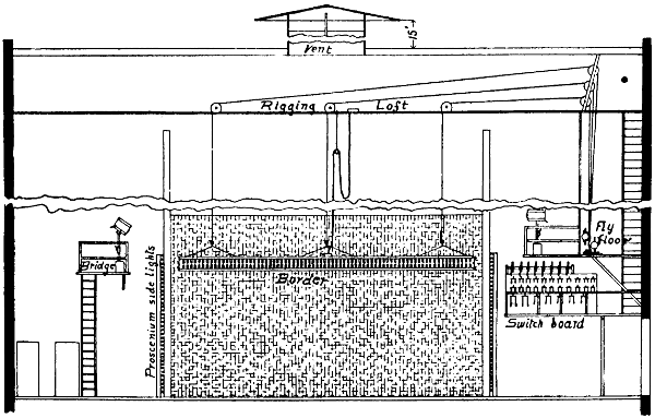
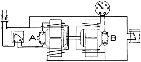
The wireman should not fail to consult local rules
or inspection departments as to whether any rules
conflict with those given below. He must be warned
to consult local authorities or rules, too, because safety
rules are liable to change.
The purpose of this chapter is to furnish a ready
reference work concerning questions of electrical construction
in theaters which come up daily in all progressive
play houses. To this end the subjects have
been arranged in alphabetical order and the practical
considerations, as well as extracts from the National
Electrical Code governing construction, have
been given together. The aim has been to enable the
workman to find all information concerning construction
work grouped together, so as to obviate the
necessity of looking through various parts of the book
for the information sought. This order of things will
probably avoid the troubles now often caused by overlooking
certain points that should be considered.
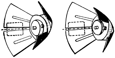
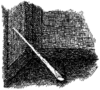
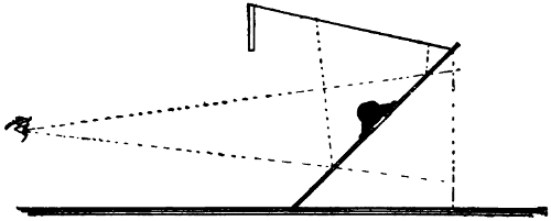
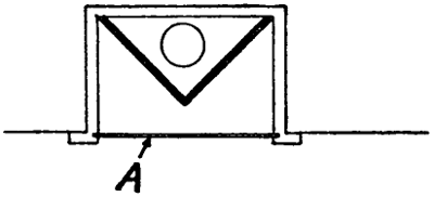
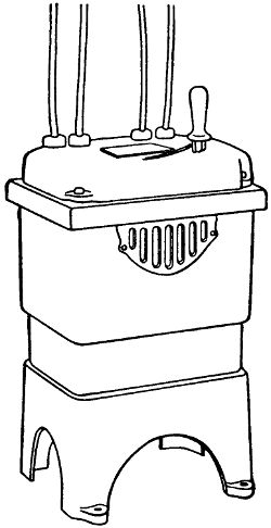
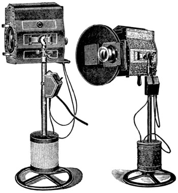
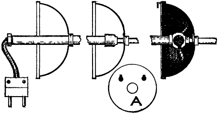
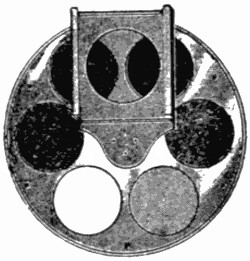
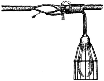
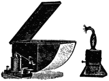
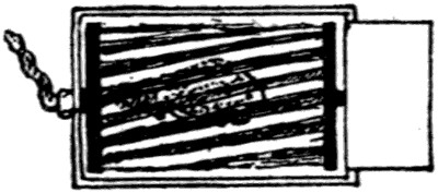
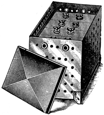
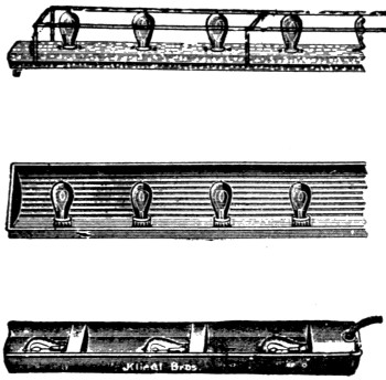
Aisle Light.—Figure 151 is an illustration of an
aisle light. Such lights are often placed along steps
and aisles. The light illuminates only the floor.
Aisle lights should be arranged on a separate circuit
and controlled by a switch at the door.
Alternating Current.—All wires of any circuit or
mains or sub-mains of any system must be run in the
same conduit. Failure to do this will cause an unnecessary
drop in voltage and heating of the conduit.
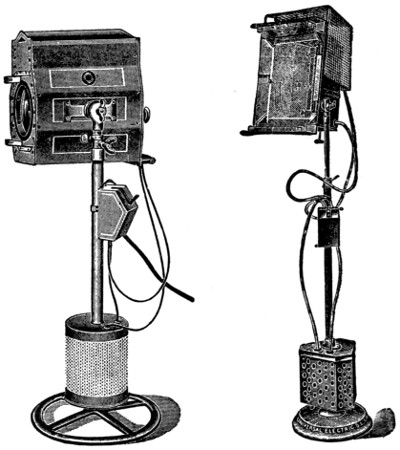
Arc Lamps.—For treatment and construction of
portable arc lamps, see the chapter on “Portable Stage
Equipment”.
Permanently located arc lamps are used about
theaters mostly for out-door lighting. Very often,
two or more lamps are arranged in front of the house.
Such lamps are mostly of the flaming arc lamp type
and are hung up high.
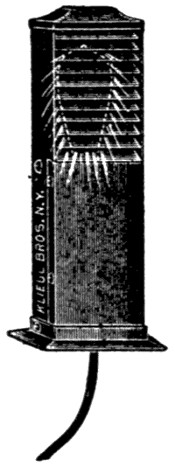
FIGURE 151.
In some of the cheaper theaters a pair of arc lamps
is used on the stage, but they do not give satisfaction.
The light is not even and steady enough and cannot
be properly “dimmed”. Where arc lamps are to be
arranged for stage illumination they must be suspended
amid the scenery and enclosed with wire
guards. In some cities the use of arc lamps suspended
above the stage is prohibited.
In the auditorium, arc lamps are sometimes installed,
but this practice can not be recommended
and, with the present high efficiency incandescent
lamps, there is but little excuse for it. The only advantage
in using arc lamps lies in the first cost of
wiring, and this is more than balanced by the difficulties
of trimming lamps located in such places.
Wherever arc lamps are used it is essential that they
be hung high and those that do not naturally throw
the light downward must be equipped with suitable
reflectors. The question of drop in voltage need not
be considered with arc lamps unless runs are very
long.
Arc Lamps in General.
Must be provided with reliable stops to prevent
carbons from falling out in case the clamps become
loose.
All exposed parts must be carefully insulated from
the circuit.
Must, for constant-current systems, be provided
with an approved hand switch, and an automatic
switch that will shunt the current around the carbons,
should they fail to feed properly.
The hand switch to be approved, if placed anywhere
except on the lamps itself, must comply with
requirements for switches on hanger-boards.
Terminals must be designed to secure a thoroughly
good and permanent contact with the supply wires,
which contact must not become loosened by motion
of the lamp during trimming.
Spark arresters must so close the upper orifice
of the globe that it will be impossible for any sparks,
thrown off by the carbons, to escape.
Series Arc Lamps.
Must be carefully isolated from inflammable material.
Must be provided at all times with a glass globe
surrounding the arc, and securely fastened upon a
closed base. Broken or cracked globes must not be
used.
Must be provided with a wire netting (having a
mesh not exceeding one and one-fourth inches)
around the globe and an approved spark arrester,
when readily inflammable material is in the vicinity
of the lamps, to prevent escape of sparks of carbon
or melted copper.
Outside arc lamps must be suspended at least eight
feet above sidewalks. Inside arc lamps must be placed
out of reach or suitably protected.
Arc lamps, when used in places where they are exposed
to flyings of easily inflammable material, must
have the electrodes enclosed completely in a tight
globe in such manner as to avoid the necessity for
spark arresters.
“Enclosed arc” lamps, having tight inner globes
may be used, and the requirements of b and c above
would, of course, not apply to them.
Where hanger-boards are not used, lamps must
be hung from insulating supports other than their
conductors.
Lamps when arranged to be raised and lowered
either for carboning or other purposes, shall be connected
up with stranded conductors from the last
point of support to the lamp, when such conductor is
larger than No. 14 B. & S. gauge.
Arc Lamps on Constant-Potential Circuits.
Must have a cut-out for each lamp or each series
of lamps.
The branch conductors must have a carrying capacity
about fifty per cent in excess of the normal
current required by the lamp.
Must only be furnished with such resistances or
regulators as are enclosed in non-combustible material,
such resistances being treated as sources of
heat. Incandescent lamps must not be used for this
purpose.
Arc Lamps Used as a Part of a Moving-Picture Machine.
Must be constructed, so far as practicable, similar
to arc lamps of theaters, and wiring to same must
not be of less capacity than No. 6 B. & S. gauge. See
“Portable Stage Equipment”.
Stage and Gallery Pockets.
Must be of approved type, insulated from ground
and controlled from switchboard, each receptacle to
be of not less than 35 ampere rating for arc lamps
nor 15 amperes for incandescent lamps, and each receptacle
to be wired to its full capacity. Arc pockets
to be wired with wire not smaller than No. 6 B. & S.
gauge and incandescent pockets with not less than No.
12 B. & S. gauge.
Plugs for arcs and incandescent pockets must not
be interchangeable.
Armored Cable.—All wires in the stage part of
theaters must be enclosed in conduit or armored cable.
Armored cable is thus the only flexible conductor
allowed for permanent work. This cable is very convenient
where wires must be “fished”, or run around
beams or other obstacles making many bends necessary.
It should, however, be used only where the
rigid conduit cannot well be installed and it is advisable
to use the latter, even where the additional
expense is considerable. Wires run in rigid conduit
can be taken out and replaced by new ones at any
time, while this is not the case with armored cable.
Should a wire incased in armored cable develop a
serious fault, the old cable would have to be abandoned
and a new circuit run, which in many cases would
mean the tearing up of parts of the building.
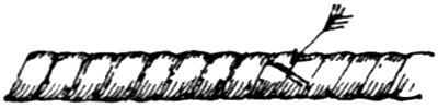
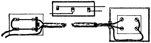
FIGURE 152.
Where armored cable is to be used great care should
be exercised to see that bends are not made too short,
and that each length of cable is tested for grounds,
short circuits, and open circuits. Special attention
must be given to the wires at the place where the
armor has been cut. Careless workmen can do great
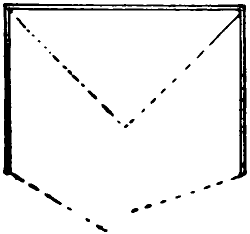
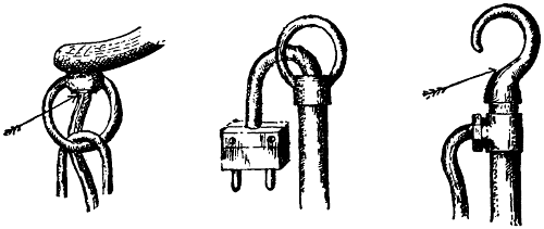
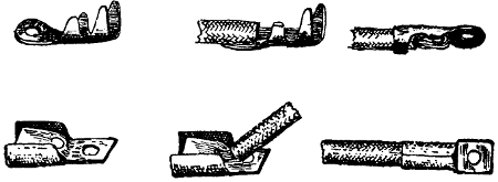
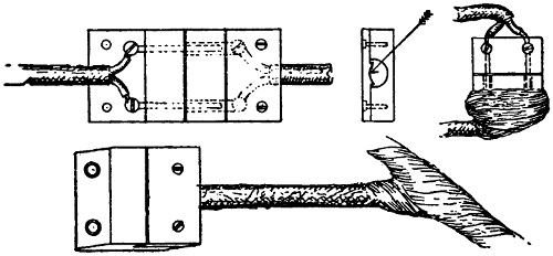
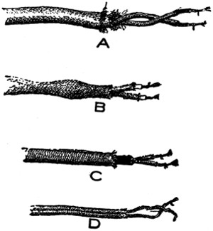
damage at this point. The manner of cutting the
armor is shown in Figure 152. Each strand of the
armor is partly cut with a saw and may then be
broken off, taking care that no sharp edge is left
in position to pierce the wire.
Installation rules are given below. Before installing
any armored cable, be sure that it is of approved
make and guaranteed to pass inspection.
Must be continuous from outlet to outlet or to
junction boxes or cabinets, and the armor of the cable
must properly enter and be secured to all fittings,
and the entire system must be mechanically secured
in position.
In case of service connections and main runs, this
involves running such armored cable continuously
into a main cut-out cabinet or gutter surrounding the
panel board, as the case may be.
Must be equipped at every outlet with an approved
outlet box or plate, as required in conduit
work.
Outlet plates must not be used where it is practicable
to install outlet boxes.
For concealed work in walls and ceilings composed
of plaster on wooden joist or stud construction, outlet
boxes or plates and also cut-out cabinets must be
so installed that the front edge will not be more than
one-fourth inch back of the finished surface of the
plaster, and if this surface is broken or incomplete it
shall be repaired so that it will not show any gaps or
open spaces around the edges of the outlet box or
plate or of the cut-out cabinet. On wooden walls or
ceilings, outlet boxes or plates and cut-out cabinets
must be so installed that the front edge will either be
flush with the finished surface or project therefrom.
This will not apply to concealed work in walls or ceilings
composed of concrete, tile or other non-combustible
material.
In buildings already constructed where the conditions
are such that neither outlet box nor plate can
be installed, these appliances may be omitted by special
permission, provided the armored cable is firmly
and rigidly secured in place.
Must have the metal armor of cables permanently
and effectually grounded to water piping, gas
piping, or other suitable grounds, provided that when
connections are made to gas piping, they must be on
the street side of the meter. If the armored cable
system consists of several separate sections, the sections
must be bonded to each other, and the system
grounded, or each section may be separately
grounded, as required above.
The armor of cables and gas pipes must be securely
fastened in outlet boxes, junction boxes, and cabinets,
so as to secure good electrical connection.
If armor of cables and metal of couplings, outlet
boxes, junction boxes, cabinets, or fittings having protective
coating of non-conducting material, such as
enamel, are used, such coating must be thoroughly
removed from threads of both couplings and the
armor of cables, and from surfaces of the boxes, cabinets,
and fittings where the armor of cables or ground
clamp is secured in order to obtain the requisite good
connection. Grounded pipes must be cleaned of rust,
scale, etc., at place of attachment of ground clamp.
Connections to grounded pipes and to armor of cables
must be exposed to view or readily accessible, and
must be made by means of approved ground clamps,
to which the ground wires must be soldered.
Ground wires must be of copper, at least No. 10 B.
& S. gauge (where largest wire contained in cable is
not greater than No. 0 B. & S. gauge), and need not
be greater than No. 4 B. & S. gauge (where largest
wire contained in cable is greater than No. 0 B. & S.
gauge). They must be protected from mechanical
injury. The ground for the armored cable system is
not to be considered as a ground for a secondary
system.
When installed in so-called fireproof buildings
in course of construction, or afterwards if exposed to
moisture, or where it is exposed to the weather, or
in damp places, such as breweries, stables, etc., the
cable must have a lead covering placed between the
outer braid of the conductors and the steel armor.
The lead covering is not to be required when the
cable is run against brick walls, or laid in ordinary
plaster walls unless same are continuously damp.
Where entering junction boxes, and at all other
outlets, etc., must be provided with approved terminal
fittings which will protect the insulation of the conductors
from abrasion, unless such junction or outlet
boxes are specially designed and approved for use
with the cable.
Junction boxes must always be installed in such a
manner as to be accessible.
For alternating-current systems must have the two
or more conductors of the circuit enclosed in one
metal armor.
All bends must be so made that the armor of
the cable will not be injured. The radius of the
curve of the inner edge of any bend not to be less
than 11⁄2 inches.
Asbestos.—As all wiring in theaters is required to
be run in conduit, and metal cabinets are compulsory
in this connection, there is but little opportunity to
use asbestos. Wherever the use of asbestos is advisable
it must conform to the general requirements
as given for wooden cutout cabinets, viz.: “for lining
wooden cabinets, one-eighth inch rigid asbestos
board may be used when firmly secured in place by
screws or tacks”.
Attachment Plugs.—Attachment plugs should be
used to connect all portable apparatus. All plugs
should be of approved type and constructed so as to
pull out in case strain is put on them. On the stage,
pin-plug connectors should be used in place of attachment
plugs, as none of the latter are sufficiently
rugged to withstand the hard usage.
Link fuse attachment plugs of the types now on the
market are considered unsafe, as under entirely possible
conditions an arc may be produced when the
fuses blow, damaging the plug and perhaps causing
fire. Attachment plugs are not approved for more
than six hundred and sixty watts or two hundred and
fifty volts.
Auditorium.—Two separate systems of lighting are
required: See emergency or exit lighting. Metal
moulding, as well as armored cable or conduit, is permissible
in wiring the auditorium part of the theater.
Auto-Starters.—Auto-starters perform the same
service with alternating-current motors that resistances
do with direct-current motors. They are
used with motors from two or three horse power upward,
and not generally with the smaller motors.
The following are extracts from the “National
Electrical Code” concerning their use:
In all wet, dusty, or linty places, auto-starters, unless
equipped with tight casings enclosing all current-carrying
parts, must be enclosed in dust-tight fireproof
cabinets. Where there is any liability of short
circuits, caused by accidental contacts, across their
exposed live parts a railing must be erected around
them.
The switch on the auto-starter must provide an off
position, a running position, and at least one starting
position. It must be so arranged that it will be held
in off and running position, but not in starting position
or without the proper running overload-protection
devices in the circuit.
For currents above 30 amperes, lugs, into which
the connecting wires may be soldered, or approved
solderless connectors must be used. Clamps or lugs
will not be required when leads are provided as a
part of the device.
The following rules are drawn for rheostats but
may also apply to auto-starters:
Where the circuit-breaking device on the motor-starting
rheostat disconnects all of the wires of the
circuit, the switch called for in this section (to disconnect
all apparatus) may be omitted.
Overload-release devices on motor-starting rheostats
will not be considered to take the place of the
cutout required to protect the motor and the rheostat.
Balconies.—The illumination of balconies is a difficult
matter. The ceilings under galleries above are
always low, and to obtain even illumination requires
the use of many small candle-power lamps. These
should be set well back so as not to be visible too
much to the audience.
Stage-pocket capacity for one or more arc lamps
should always be provided. Where there are galleries
above, the arc lamps used for stage illumination
are generally placed there, but it often happens
that a moving-picture machine must be installed and
it is very disadvantageous if this must be located in
the galleries. Balconies require the same exit and
emergency light service as is required in the auditorium.
Batteries.—See Portable Stage Equipment.
Bells.—Systems of call bells are generally arranged
between the box office or the manager’s office and the
stage switch board; also from the stage switch board
to the fly floor by which signals for raising and
lowering the curtain may be given; also to the orchestra
leader. In some cities all of this wiring is
required to be in conduit. These signaling circuits
should be carefully installed, for they are as important
as any part of the wiring. Only the very best
bells and push buttons should be used, and it is advisable
to avoid the use of the ordinary annunciator
wire so often seen in connection with bell work.
Numerous diagrams and much information concerning
bell wiring is given in “Modern Wiring Diagrams
and Descriptions”, which should be consulted
in case some complicated annunciator system is to
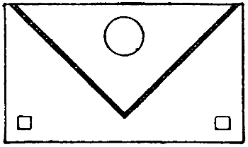
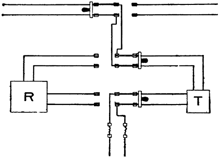
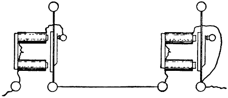
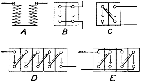
be installed. Figure 153 is a diagram of a simple
call-and-return-call system.
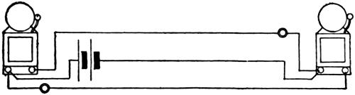
FIGURE 153.
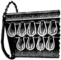
FIGURE 154.
Borders.—The number of borders used in theaters
varies from one to six, the latter number being sufficient
for almost any stage. They are generally made
of a length about equal to the proscenium opening.
The borders placed in the rear are of less importance
than those in front and consequently are made shorter
and are not provided with so many lights. Each
border should have at least three circuits, one for each
color; each circuit being taken through a separate
dimmer so that any color may be used alone and
dimmed as desired.
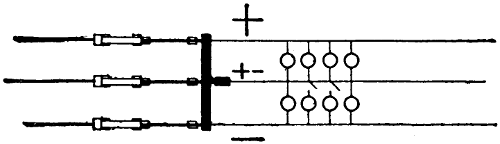
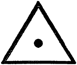
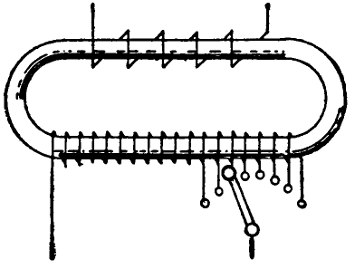
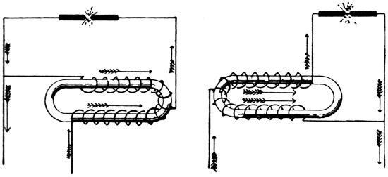
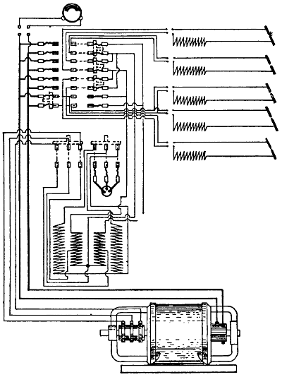
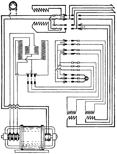
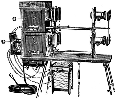
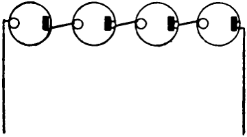
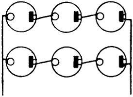
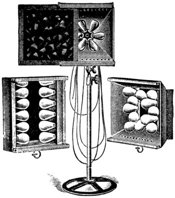
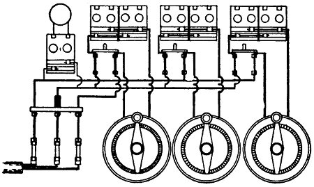
Figures 154 and 155 show types of borders, and
the method of wiring is shown in Figure 156.
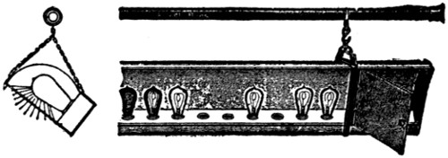
FIGURE 155.
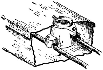
FIGURE 156.
Large borders are very heavy and are usually suspended
by wire rope and provided with counterweights
to make handling easy. The wire rope should
be kept well protected by oiling; the moisture given
off by fireproofed scenery is liable to rust them very
fast, and as the ropes are made up of very fine
strands the rust soon cuts entirely through them.
The suspending ropes and also cables supplying lights
must be long enough to admit of bringing the border
within five or six feet of the stage floor for lamp renewals
and cleaning. The cleaning is very important
as the dust which accumulates may absorb a large
part of the light.
Must be constructed of steel of a thickness not
less than No. 20 U. S. sheet metal gauge; treated to
prevent oxidation; be suitably stayed and supported;
and so designed that flanges of reflectors will protect
lamps.
Must be so wired that no set of lamps requiring
more than 1,320 watts nor more than 26 receptacles
shall be dependent upon one cut-out.
Must be wired in approved conduit or armored
cable, each lamp receptacle to be enclosed within an
approved outlet box, or the lamp receptacles may be
mounted in an iron or steel box, metal to be of a
thickness not less than No. 20 U. S. sheet metal gauge
treated to prevent oxidation, so constructed as to enclose
all wires. Wires to be soldered to lugs of receptacles.
Must be provided with suitable guards to prevent
scenery or other combustible material coming in contact
with lamps.
Cable for borders must be of approved type and
suitably supported; conduit construction must be
used from switchboard to point where cables must
be flexible to permit of the raising and lowering of
border.
For the wiring of the border proper, wire with
approved slow-burning insulation must be used.
Borders must be suitably suspended, and if a wire
rope is used same must be insulated by at least one
strain insulator inserted at the border.
Box Office.—The box office is often a very stuffy
place in summer and very cold in winter. There
should be an outlet for a fan motor, and also one for
a heater. Very many box offices depend upon electric
heating for comfort in winter. Plenty of light
should be provided and the light should be at the ceiling,
out of the way, and directly over the ticket
window.
Brackets.—Any brackets used in theaters should
be at least seven feet above the floor. Brackets used
for emergency or exit lights must be fitted with keyless
sockets. See “Fixtures”.
Branch Circuits.—The term, “branch circuit”, as
here used refers to the wires leaving the last cut-outs
and connecting directly to the lamps or other
devices. Mains are often run from the switchboard
to various parts of the building to feed cut-out centers,
and the branch circuits are then run from
these centers. This is often the cheapest method, but
it is by no means the best. In a well designed theater
all branch circuits lead out from the vicinity of the
switchboard so that, in case of any trouble with fuses,
they may be replaced without interfering with any
part of the audience and in the shortest possible time.
This method of wiring involves some long runs of
branch circuit wires and Table V, which shows the
drop in voltage, was prepared for the convenience of
wiremen. If possible the circuits should be so arranged
that the lamps fed are closely together so all
may receive nearly the same voltage. The drop
should not much exceed two per cent.
Table showing drop in voltage due to 6 amperes,
with sizes of wire and distances given:
| Distance in feet |
50 |
75 |
100 |
125 |
150 |
175 |
200 |
225 |
250 |
300 |
| Size of Wire No. 14 |
1.58 |
2.37 |
3.16 |
3.95 |
4.74 |
5.53 |
6.32 |
7.11 |
7.90 |
9.48 |
| Size of Wire No. 12 |
0.99 |
1.48 |
1.98 |
2.47 |
2.97 |
3.45 |
3.96 |
4.45 |
4.95 |
5.94 |
| Size of Wire No. 10 |
0.63 |
0.94 |
1.25 |
1.56 |
1.87 |
2.19 |
2.50 |
2.81 |
3.12 |
3.75 |
| Size of Wire No. 8 |
0.39 |
0.59 |
0.78 |
0.97 |
1.17 |
1.36 |
1.56 |
1.75 |
1.95 |
2.34 |
No wire smaller than No. 14 B. & S. gauge must
be used.
Each branch circuit must be protected by fuses,
which must be so placed that no set of small motors,
small heating devices, or incandescent lamps, whether
grouped on one fixture or on several fixtures or pendants
(nor more than 16 sockets or receptacles) requiring
more than 660 watts, will be dependent upon
one cut-out.
By special permission, in cases where wiring equal
in size and insulation to No. 14 B. & S. gauge approved
rubber-covered wire is carried direct into keyless
sockets or receptacles, and where the location of
sockets and receptacles is such as to render unlikely
the attachment of flexible cords thereto, the circuits
may be so arranged that not more than 1,320 watts
(or thirty-two sockets or receptacles) will be dependent
upon the final cut-out.
Except for signs and outline lighting, sockets and
receptacles will be considered as requiring not less
than 40 watts each.
All branches or taps, from any three-wire system,
which are directly connected to lamp sockets or other
translating devices, must be run as two-wire circuits
if the fuses are omitted in the neutral, or if the difference
of potential between the two outside wires
is over 250 volts, and both wires of such branch or
tap circuits must be protected by proper fuses.
The above shall also apply to motors, except that
small motors may be grouped under the protection
of a single set of fuses, provided the rated capacity
of the fuses does not exceed 10 amperes.
When 1,320 watts are dependent upon one fusible
cut-out, as is allowed in theater wiring, outline lighting
and large chandeliers, the fuses may be in accordance
with the following:
| 125 volts or less |
20 amperes |
| 125 to 250 volts |
10 amperes |
Bus-Bars.—Bus-bars may be made of bare metal.
They must, however, be protected against accidental
contact. The metal should be ample so that it will
not heat more than 50 degrees Fahrenheit above the
surrounding air.
It is customary to calculate the metal needed, on
the basis of 1,000 amperes per square-inch cross section.
On this basis bars of the sizes given below
would have the carrying capacities in amperes given
in the body of the table.
| Thickness |
2⁄32 |
3⁄32 |
4⁄32 |
5⁄32 |
6⁄32 |
7⁄32 |
8⁄32 |
9⁄32 |
10⁄32 |
12⁄32 |
16⁄32 |
Width
in
In-
ches |
|
1⁄2 |
30 |
45 |
60 |
75 |
90 |
105 |
120 |
135 |
150 |
165 |
180 |
| |
5⁄8 |
37 |
57 |
75 |
94 |
108 |
132 |
150 |
168 |
188 |
206 |
225 |
| |
6⁄8 |
45 |
68 |
90 |
112 |
135 |
158 |
180 |
202 |
225 |
248 |
270 |
| |
7⁄8 |
53 |
79 |
105 |
130 |
158 |
184 |
210 |
236 |
263 |
289 |
315 |
| 1 |
.0 |
60 |
90 |
120 |
150 |
180 |
210 |
240 |
270 |
300 |
330 |
360 |
| 1 |
1⁄4 |
75 |
112 |
150 |
188 |
225 |
263 |
300 |
338 |
375 |
412 |
450 |
| 1 |
1⁄2 |
90 |
135 |
180 |
225 |
270 |
315 |
360 |
405 |
450 |
495 |
540 |
| 1 |
3⁄4 |
105 |
157 |
210 |
263 |
315 |
367 |
420 |
473 |
525 |
577 |
630 |
| 2 |
.00 |
120 |
180 |
240 |
300 |
360 |
420 |
480 |
540 |
600 |
660 |
720 |
| 3 |
.00 |
180 |
270 |
360 |
450 |
540 |
630 |
720 |
810 |
900 |
990 |
1080 |
Cabinets.—Cabinets are required to enclose all
fuses. It is advised that they be arranged so that it
will not be necessary to open the fuse compartment
to operate switches.
Care should be exercised in locating cut-out cabinets.
They should be in a dry place, easily accessible
to authorized persons, and not accessible to the general
public or miscellaneous employes. If too accessible
they are likely to be made receptacles for
all sorts of rubbish. Wooden or composition cabinets
must not be used in theaters. Use only approved
cabinets.
In some cities special rules, governing the construction
of cabinets for theaters, exist and these should
be looked up.
Cables.—For construction rules, see “Stage
Cables” in the chapter on “Portable Stage Equipment”.
Cables are required to connect border lights.
The cable is usually run from an outlet on the grid
floor above the center of the border. It must be long
enough to allow the border to be lowered for the cleaning
and renewal of lamps. The slack cable must be
taken up when the border is raised and some provision
must be made to support the cable without injury
to the insulation. Wire ropes or cables are generally
used to support the borders, but the lower end,
which is handled by the stage crew, is of ordinary
manilla rope. Wire cables must be insulated from
the border by strain insulators.
Canopies.—Very many theaters are provided with
canopies which extend over the street. Sometimes
these are fitted out with glass signs behind which incandescent
lamps are installed. Often, also, a row
of lights is arranged around the bottom of the canopy
ceiling. The number of lights to be used depends
upon the design of the canopy, but the effect is best
if a large number of small candle-power lamps are
used. These lamps should be of low intrinsic brilliancy.
If possible, the lamps and sockets should be
arranged to be out of the weather. In addition to
the small outline lamps, other lights are often placed
under canopy to provide bright illumination. Each
circuit may carry 1,320 watts.
Where insulating joints are required, fixture
canopies of metal must be thoroughly and permanently
insulated from metal walls or ceilings, or from
plaster walls or ceilings on metal lathing, and from
outlet boxes.
Canopy insulators must be securely fastened in
place, so as to separate the canopies thoroughly and
permanently from the surfaces and outlet boxes from
which they are designed to be insulated.
Carriage Call.—See “Program Board”.
Carrying Capacity of Wires.—Table VII is designed
to help the wiremen select the proper size of
wire to use in supplying a certain number of lights.
The first column at the left gives the B. & S. gauge
number. The second column gives the number of
amperes allowed on each wire according to the National
Electrical Code. The third column gives the
distance in feet which will cause a loss of 2 volts
with the current given; thus a current of 70 amperes
in a No. 4 B. & S. gauge wire will lose 2 volts
over a distance of 56 feet. The proper size of wire
to be used can easily be determined from the table.
The loss will always be in proportion to the product
of distance and current. The balance of the table is
devoted to showing the number of watts and lamps
of various sizes the wires will be allowed to supply.
Ceiling Fans.—Must be hung from insulated hooks,
or else there must be an insulator interposed between
the motor and its support. Not more than 660 watts
may be on one circuit.
Chandeliers.—Large and elaborate chandeliers are
sometimes used in the center of the auditorium ceiling
for purposes of illumination. Such chandeliers
should be suspended in a manner which will admit
of readily raising or lowering them for lamping up
or repairs. For rules governing wiring, see “Fixtures”.
B. & S.
Gage |
Rub-
ber
Insu-
lation |
Dis-
tance
in
Feet
Caus-
ing
a Loss
of
2 Volts |
Total
Capacity
in Watts |
Total Number of Lamps of Different Voltages and Wattages that may be supplied |
| 25-Watt |
40-Watt |
60-Watt |
100-Watt |
150-Watt |
250-Watt |
Am-
peres |
110 V. |
220 V. |
110 V. |
220 V. |
110 V. |
220 V. |
110 V. |
220 V. |
110 V. |
220 V. |
110 V. |
220 V. |
110 V. |
220 V. |
| 14 |
15 |
26 |
1650 |
3300 |
66 |
132 |
41 |
82 |
27 |
54 |
16 |
33 |
11 |
22 |
6 |
13 |
| 12 |
20 |
30 |
2200 |
4400 |
88 |
176 |
55 |
110 |
36 |
73 |
22 |
44 |
14 |
29 |
8 |
17 |
| 10 |
25 |
38 |
2750 |
5500 |
110 |
220 |
68 |
137 |
46 |
91 |
27 |
55 |
18 |
36 |
11 |
22 |
| 8 |
35 |
43 |
3850 |
7700 |
154 |
308 |
96 |
192 |
64 |
128 |
38 |
77 |
25 |
61 |
15 |
30 |
| 6 |
50 |
50 |
5500 |
11000 |
220 |
440 |
137 |
275 |
91 |
183 |
55 |
110 |
36 |
73 |
22 |
44 |
| 5 |
55 |
56 |
6050 |
12100 |
242 |
484 |
151 |
302 |
100 |
201 |
60 |
121 |
40 |
80 |
24 |
48 |
| 4 |
70 |
56 |
7700 |
15400 |
308 |
616 |
192 |
385 |
128 |
256 |
77 |
154 |
49 |
99 |
30 |
61 |
| 3 |
80 |
61 |
8800 |
17600 |
352 |
704 |
220 |
440 |
146 |
292 |
88 |
176 |
58 |
117 |
35 |
70 |
| 2 |
90 |
68 |
9900 |
19800 |
396 |
792 |
247 |
494 |
165 |
330 |
99 |
198 |
66 |
132 |
39 |
78 |
| 1 |
100 |
67 |
11000 |
22000 |
440 |
880 |
275 |
550 |
183 |
366 |
110 |
220 |
73 |
146 |
44 |
88 |
| 0 |
125 |
78 |
13750 |
27500 |
550 |
1100 |
343 |
686 |
229 |
458 |
137 |
274 |
91 |
182 |
55 |
110 |
| 00 |
150 |
82 |
16500 |
33000 |
660 |
1320 |
412 |
824 |
275 |
550 |
165 |
330 |
110 |
220 |
66 |
132 |
| 000 |
175 |
89 |
19250 |
38500 |
770 |
1540 |
481 |
962 |
320 |
640 |
192 |
384 |
128 |
256 |
77 |
154 |
| 0000 |
225 |
87 |
24750 |
49500 |
990 |
1980 |
618 |
1236 |
412 |
824 |
247 |
404 |
165 |
330 |
99 |
198 |
| 200000 |
200 |
92 |
22000 |
44000 |
880 |
1760 |
550 |
1100 |
367 |
734 |
220 |
440 |
146 |
292 |
88 |
176 |
| 300000 |
275 |
101 |
30250 |
60500 |
1210 |
2420 |
756 |
1512 |
504 |
1008 |
302 |
604 |
201 |
402 |
121 |
242 |
| 400000 |
325 |
114 |
35750 |
71500 |
1430 |
2860 |
893 |
1786 |
596 |
1192 |
357 |
714 |
238 |
476 |
143 |
286 |
| 500000 |
400 |
117 |
44000 |
88000 |
1760 |
3520 |
1100 |
2200 |
733 |
1455 |
440 |
880 |
293 |
586 |
176 |
352 |
| 600000 |
450 |
123 |
49500 |
99000 |
1980 |
3960 |
1237 |
2474 |
825 |
1650 |
495 |
990 |
330 |
660 |
198 |
396 |
| 700000 |
500 |
130 |
55000 |
110000 |
2200 |
4400 |
1375 |
2750 |
916 |
1832 |
550 |
1100 |
366 |
732 |
220 |
440 |
| 800000 |
550 |
135 |
60500 |
121000 |
2420 |
4840 |
1512 |
3024 |
1008 |
2016 |
605 |
1210 |
403 |
806 |
242 |
484 |
| 900000 |
600 |
139 |
66000 |
132000 |
2640 |
5280 |
1650 |
3300 |
1100 |
2200 |
660 |
1320 |
440 |
880 |
264 |
528 |
| 1000000 |
650 |
143 |
71500 |
143000 |
2860 |
5720 |
1787 |
3574 |
1191 |
2382 |
715 |
1430 |
476 |
952 |
286 |
572 |
| 1100000 |
690 |
147 |
75900 |
151800 |
3036 |
6072 |
1897 |
3794 |
1264 |
2528 |
759 |
1518 |
506 |
1012 |
303 |
606 |
| 1200000 |
730 |
151 |
80300 |
160600 |
3212 |
6424 |
2007 |
4014 |
1338 |
2676 |
803 |
1606 |
535 |
1070 |
321 |
642 |
| 1300000 |
770 |
155 |
84700 |
169400 |
3388 |
6776 |
2117 |
4234 |
1412 |
2824 |
847 |
1694 |
564 |
1128 |
338 |
676 |
| 1400000 |
810 |
161 |
89100 |
178200 |
3564 |
7128 |
2227 |
4454 |
1485 |
2970 |
891 |
1782 |
594 |
1188 |
356 |
712 |
| 1500000 |
850 |
164 |
93500 |
187000 |
3740 |
7480 |
2337 |
4674 |
1558 |
3116 |
935 |
1870 |
623 |
1246 |
374 |
748 |
B. & S.
Gage |
Rub-
ber
Insu-
lation |
Dis-
tance
in
Feet
Caus-
ing
a Loss
of
2 Volts |
Total
Capacity
in Watts |
Total Number of Lamps of Different Voltages
and Wattages that may be supplied |
| 25-Watt |
40-Watt |
60-Watt |
Am-
peres |
110 V. |
220 V. |
110 V. |
220 V. |
110 V. |
220 V. |
110 V. |
220 V. |
| 14 |
15 |
26 |
1650 |
3300 |
66 |
132 |
41 |
82 |
27 |
54 |
| 12 |
20 |
30 |
2200 |
4400 |
88 |
176 |
55 |
110 |
36 |
73 |
| 10 |
25 |
38 |
2750 |
5500 |
110 |
220 |
68 |
137 |
46 |
91 |
| 8 |
35 |
43 |
3850 |
7700 |
154 |
308 |
96 |
192 |
64 |
128 |
| 6 |
50 |
50 |
5500 |
11000 |
220 |
440 |
137 |
275 |
91 |
183 |
| 5 |
55 |
56 |
6050 |
12100 |
242 |
484 |
151 |
302 |
100 |
201 |
| 4 |
70 |
56 |
7700 |
15400 |
308 |
616 |
192 |
385 |
128 |
256 |
| 3 |
80 |
61 |
8800 |
17600 |
352 |
704 |
220 |
440 |
146 |
292 |
| 2 |
90 |
68 |
9900 |
19800 |
396 |
792 |
247 |
494 |
165 |
330 |
| 1 |
100 |
67 |
11000 |
22000 |
440 |
880 |
275 |
550 |
183 |
366 |
| 0 |
125 |
78 |
13750 |
27500 |
550 |
1100 |
343 |
686 |
229 |
458 |
| 00 |
150 |
82 |
16500 |
33000 |
660 |
1320 |
412 |
824 |
275 |
550 |
| 000 |
175 |
89 |
19250 |
38500 |
770 |
1540 |
481 |
962 |
320 |
640 |
| 0000 |
225 |
87 |
24750 |
49500 |
990 |
1980 |
618 |
1236 |
412 |
824 |
| 200000 |
200 |
92 |
22000 |
44000 |
880 |
1760 |
550 |
1100 |
367 |
734 |
| 300000 |
275 |
101 |
30250 |
60500 |
1210 |
2420 |
756 |
1512 |
504 |
1008 |
| 400000 |
325 |
114 |
35750 |
71500 |
1430 |
2860 |
893 |
1786 |
596 |
1192 |
| 500000 |
400 |
117 |
44000 |
88000 |
1760 |
3520 |
1100 |
2200 |
733 |
1455 |
| 600000 |
450 |
123 |
49500 |
99000 |
1980 |
3960 |
1237 |
2474 |
825 |
1650 |
| 700000 |
500 |
130 |
55000 |
110000 |
2200 |
4400 |
1375 |
2750 |
916 |
1832 |
| 800000 |
550 |
135 |
60500 |
121000 |
2420 |
4840 |
1512 |
3024 |
1008 |
2016 |
| 900000 |
600 |
139 |
66000 |
132000 |
2640 |
5280 |
1650 |
3300 |
1100 |
2200 |
| 1000000 |
650 |
143 |
71500 |
143000 |
2860 |
5720 |
1787 |
3574 |
1191 |
2382 |
| 1100000 |
690 |
147 |
75900 |
151800 |
3036 |
6072 |
1897 |
3794 |
1264 |
2528 |
| 1200000 |
730 |
151 |
80300 |
160600 |
3212 |
6424 |
2007 |
4014 |
1338 |
2676 |
| 1300000 |
770 |
155 |
84700 |
169400 |
3388 |
6776 |
2117 |
4234 |
1412 |
2824 |
| 1400000 |
810 |
161 |
89100 |
178200 |
3564 |
7128 |
2227 |
4454 |
1485 |
2970 |
| 1500000 |
850 |
164 |
93500 |
187000 |
3740 |
7480 |
2337 |
4674 |
1558 |
3116 |
B. & S.
Gage |
Rub-
ber
Insu-
lation |
Dis-
tance
in
Feet
Caus-
ing
a Loss
of
2 Volts |
Total
Capacity
in Watts |
Total Number of Lamps of Different Voltages
and Wattages that may be supplied |
| 100-Watt |
150-Watt |
250-Watt |
Am-
peres |
110 V. |
220 V. |
110 V. |
220 V. |
110 V. |
220 V. |
110 V. |
220 V. |
| 14 |
15 |
26 |
1650 |
3300 |
16 |
33 |
11 |
22 |
6 |
13 |
| 12 |
20 |
30 |
2200 |
4400 |
22 |
44 |
14 |
29 |
8 |
17 |
| 10 |
25 |
38 |
2750 |
5500 |
27 |
55 |
18 |
36 |
11 |
22 |
| 8 |
35 |
43 |
3850 |
7700 |
38 |
77 |
25 |
61 |
15 |
30 |
| 6 |
50 |
50 |
5500 |
11000 |
55 |
110 |
36 |
73 |
22 |
44 |
| 5 |
55 |
56 |
6050 |
12100 |
60 |
121 |
40 |
80 |
24 |
48 |
| 4 |
70 |
56 |
7700 |
15400 |
77 |
154 |
49 |
99 |
30 |
61 |
| 3 |
80 |
61 |
8800 |
17600 |
88 |
176 |
58 |
117 |
35 |
70 |
| 2 |
90 |
68 |
9900 |
19800 |
99 |
198 |
66 |
132 |
39 |
78 |
| 1 |
100 |
67 |
11000 |
22000 |
110 |
220 |
73 |
146 |
44 |
88 |
| 0 |
125 |
78 |
13750 |
27500 |
137 |
274 |
91 |
182 |
55 |
110 |
| 00 |
150 |
82 |
16500 |
33000 |
165 |
330 |
110 |
220 |
66 |
132 |
| 000 |
175 |
89 |
19250 |
38500 |
192 |
384 |
128 |
256 |
77 |
154 |
| 0000 |
225 |
87 |
24750 |
49500 |
247 |
404 |
165 |
330 |
99 |
198 |
| 200000 |
200 |
92 |
22000 |
44000 |
220 |
440 |
146 |
292 |
88 |
176 |
| 300000 |
275 |
101 |
30250 |
60500 |
302 |
604 |
201 |
402 |
121 |
242 |
| 400000 |
325 |
114 |
35750 |
71500 |
357 |
714 |
238 |
476 |
143 |
286 |
| 500000 |
400 |
117 |
44000 |
88000 |
440 |
880 |
293 |
586 |
176 |
352 |
| 600000 |
450 |
123 |
49500 |
99000 |
495 |
990 |
330 |
660 |
198 |
396 |
| 700000 |
500 |
130 |
55000 |
110000 |
550 |
1100 |
366 |
732 |
220 |
440 |
| 800000 |
550 |
135 |
60500 |
121000 |
605 |
1210 |
403 |
806 |
242 |
484 |
| 900000 |
600 |
139 |
66000 |
132000 |
660 |
1320 |
440 |
880 |
264 |
528 |
| 1000000 |
650 |
143 |
71500 |
143000 |
715 |
1430 |
476 |
952 |
286 |
572 |
| 1100000 |
690 |
147 |
75900 |
151800 |
759 |
1518 |
506 |
1012 |
303 |
606 |
| 1200000 |
730 |
151 |
80300 |
160600 |
803 |
1606 |
535 |
1070 |
321 |
642 |
| 1300000 |
770 |
155 |
84700 |
169400 |
847 |
1694 |
564 |
1128 |
338 |
676 |
| 1400000 |
810 |
161 |
89100 |
178200 |
891 |
1782 |
594 |
1188 |
356 |
712 |
| 1500000 |
850 |
164 |
93500 |
187000 |
935 |
1870 |
623 |
1246 |
374 |
748 |
When 1,320 watts are dependent upon one cut-out,
as is allowed in theater wiring, outline lighting, and
large chandeliers, the fuse may be in accordance with
the following:
| 125 volts or less |
20 amperes |
| 125 to 250 volts |
10 amperes |
Circuit Breakers.—Circuit breakers are not used
much about theaters. They are used mostly in connection
with motors and on switchboards of isolated
plants. They are more sensitive and quicker to act
than fuses and, in case of a blow-out, can be more
easily replaced. Where circuit breakers are used it
is good practice to set them for a higher amperage
than the fuses so that, in case of a heavy short circuit,
the breaker may act while the fuse will take
care of an overload which comes on more gradually.
With motors an automatic circuit breaker, disconnecting
all wires of the circuit, may serve as both
switch and cut-out.
Where the circuit-breaking device on the motor-starting
rheostat disconnects all wires of the circuit,
the switch may be omitted.
Circuit breakers must not be set more than thirty
per cent above the allowable carrying capacity of
the wires, unless a fusible cut-out is also installed on
the circuit.
When installed without other automatic overload
protective devices, automatic overload circuit
breakers must have the poles and trip coils so arranged
as to afford complete protection against overloads
and short circuits and, if also used in place of
the switch, must be so arranged that no one pole can
be opened manually without disconnecting all the
wires.
Concealed Work.—All concealed work must be in
conduit or armored cable. Wherever possible, rigid
conduit should be used. Armored cable should be
used only where the whole cable may at any time be
withdrawn, or where it is impracticable to use rigid
conduit.
Conduit Work.—This is now considered the
standard method of construction. It is, however,
somewhat over-rated and, especially in wet places, has
led to much disappointment. It is generally recognized
that wires, placed in conduit, will cause more
trouble than those placed in any other standard manner.
The trouble is, however, confined to the interior
of the conduit and, if the conduit system be kept in
good order, and fuses at their proper limit, there is
no chance of fire from the wire confined within the
conduit.
There are three points which, if carefully observed,
will avoid most, if not all, of the conduit troubles:
Avoid as far as possible locating conduit in wet or
damp places.
Run all conduits so that they will drain.
Give particular attention to joints in outlet or
junction boxes; tape them heavily; and arrange them
so they are not pressed against metal more than is
necessary; use large boxes.
Wires used in conduits must have approved rubber
insulation and double braid.
Wires for Conduit Work.
Must have an approved rubber insulated covering
(Type Letter R. D.), and must within the conduit
tubing be without splices or taps.
Must not be drawn in until all mechanical work
on the building has been, as far as possible, completed.
Conductors in vertical conduit risers must be supported
within the conduit system in accordance with
the following:
- No. 14 to 0 every 100 feet
- No. 00 to 0000 every 80 feet
- No. 0000 to 350,000 C. M. every 60 feet
- 350,000 C. M. to 500,000 C. M. every 50 feet
- 500,000 C. M. to 750,000 C. M. every 40 feet
- 750,000 C. M. every 35 feet
The following methods of supporting cables are
recommended:
(1) A turn of 90 degrees in the conduit system will
constitute a satisfactory support.
(2) Junction boxes may be inserted in the conduit
system at the required intervals, in which insulating
supports of approved type must be installed and secured
in a satisfactory manner so as to withstand the
weight of the conductors attached thereto, the boxes
to be provided with proper covers.
(3) Cables may be supported in approved junction
boxes on two or more insulating supports so placed
that the conductors will be deflected at an angle of
not less than 90 degrees, and carried a distance of
not less than twice the diameter of the cable from
its vertical position. Cables so suspended may be
additionally secured to these insulators by tie wires.
Other methods may be used if specially approved.
Must, for alternating-current systems, have two
or more wires of a circuit drawn in the same conduit.
It is suggested that this be done for direct-current
systems, also, so that they may be changed to alternating
systems at any time, induction troubles preventing
such a change if the wires are in separate
conduits.
Except in the case of stage pocket and border circuits
the same conduit must not contain more than
four two-wire, or three three-wire circuits of the same
system, except by special permission, and must never
contain circuits of different systems.
Interior Conduits.
No conduit smaller than one-half inch electrical-trade
size shall be used.
Must be continuous from outlet to outlet or to
junction boxes or cabinets, and the conduit must
properly enter, and be secured to all fittings and the
entire system must be mechanically secured in position.
In case of service connections and main runs,
this involves running each conduit continuously into
a main cut-out cabinet or gutter surrounding the
panel board, as the case may be. Departure from
this rule may be authorized in case of underground
services by special permission.
Must be first installed as a complete conduit system,
without the conductors.
Must be equipped at every outlet with an approved
outlet box or plate. At exposed ends of conduit
(but not at fixture outlets), where wires pass
from the conduit system without splice, joint, or tap,
an approved fitting, having separately bushed holes
for each conductor, must be used. Departure from
this rule may be authorized by special permission.
Outlet plates must not be used where it is practicable
to install outlet boxes.
For concealed work in walls and ceilings composed
of plaster on wooden joist or stud construction, outlet
boxes or plates, and also cut-out cabinets must be
so installed that the front edge will not be more than
one-fourth inch back of the finished surface of the
plaster; and if this surface is broken or incomplete
it shall be repaired so that it will not show any gaps
or open spaces around the edges of the outlet box or
plate or of the cut-out cabinet. On wooden walls or
ceilings, outlet boxes or plates and cut-out cabinets
must be so installed that the front edge will either
be flush with the finished surface or project therefrom.
This will not apply to concealed work in walls
or ceilings composed of concrete, tile or other non-combustible
material.
In buildings already constructed where the conditions
are such that neither outlet box or plate can
be installed, these appliances may be omitted, providing
the conduit ends are bushed and secured.
It is suggested that outlet boxes and fittings, having
conductive coatings, be used in order to secure
better electrical contact at all points through the
conduit system.
Metal conduits, where they enter junction boxes
and at all other outlets, etc., must be provided
with approved bushings or fastening plates fitted so
as to protect wire from abrasion, except when such
protection is obtained by the use of approved nipples,
properly fitted in boxes or devices.
Must have the metal of the conduit permanently
and effectually grounded to water piping, gas
piping, or other suitable grounds, provided that when
connections are made to gas piping, they must be
on the street side of the meter. If the conduit system
consists of several separate sections, the sections
must be bonded to each other, and the system
grounded; or each section may be separately
grounded, as required above. Where short sections of
conduit (or pipe of equivalent strength) are used
for the protection of exposed wiring on side walls,
and such conduit or pipe and wiring is installed as
required by the Code Rules, the conduit or pipe need
not be grounded.
Conduits and gas pipes must be securely fastened
in outlet boxes, junction boxes, and cabinets, so as
to secure good electrical connections.
If conduits, couplings, outlet boxes, junction
boxes, cabinets or fittings, having protective coating
of non-conducting material such as enamel, are used,
such coating must be thoroughly removed from
threads of both couplings and conduit, and such surfaces
of boxes, cabinets, and fittings, where the conduit
or group clamp is secured, in order to obtain the
requisite good connection. Grounded pipes must be
cleaned of rust, scale, etc., at place of attachment of
ground clamp.
Connections to grounded pipes and to conduits
must be exposed to view or readily accessible, and
must be made by means of approved ground clamps
to which the ground wires must be soldered.
Ground wires must be of copper, at least No. 10 B.
& S. gauge (where largest wire contained in conduit
is not greater than No. 0 B. & S. gauge), and need
not be greater than No. 4 B. & S. gauge (where
largest wire contained in conduit is greater than No.
0 B. & S. gauge). They shall be protected from
mechanical injury. The ground on the conduit system
is not to be considered as a ground for a secondary
system.
Junction boxes must always be installed in such
a manner as to be accessible.
All elbows or hands must be so made that the
conduit will not be injured. The radius of the curve
of the inner edge of any elbow must not be less than
three and one-half inches, and must have not more
than the equivalent of four quarter bends from outlet
to outlet, the bends at the outlets not being
counted.
Contacts.—Must be mounted on non-combustible
non-absorption insulated bases. Other materials than
slate, marble, or porcelain must be submitted for special
examination before being used.
Cord.—The use of flexible cord should be reduced
to a minimum. Wherever drop lights are necessary
they should be wired with reinforced cord or stage
cable.
Current Taps.—Must be of approved construction
and may be used if properly installed.
Where, in addition to sockets or receptacles already
installed, connections are desired to lighting circuits
for portable lamps, for motors, or other special appliances
requiring only small amounts of current,
multiple-current taps may be used, provided the entire
circuit does not require more than 660 watts, and
provided their use will not, under any conditions, involve
a departure from the requirements of Rule 23-d
of the National Electrical Code. Current taps must
not be used in key or pull sockets if the device, controlled
through such sockets, requires more than 250
watts.
Cut-Outs.—All cut-outs should be on the stage
switchboard. This requires considerable extra wire,
but it will be profitable in the end. Fuses should be
inspected occasionally to see that contacts are bright
and screws kept tight. There is everywhere a very
strong tendency to over-fuse, and the principal reason
for it is the failure to keep screws tightly fastened.
There is no fuse better than the plug fuse but it
is not permitted with voltages higher than 125 or
with more than 30 amperes. Refillable fuses must
not be used. Cartridge fuses, especially, require to
be kept clean. The spring contacts on these often
grow weak and cause heating which helps to blow the
fuse. The neutral fuse in three-wire installations
should be larger than the outside fuses. Link fuses
should be avoided on account of the delay that may
be caused through difficulty of installing.
It is advisable not to place switches in the same
cabinet with fuses.
Constant-Potential Systems.
Must be placed on all service wires, either overhead
or underground, in the nearest accessible place
to the point where they enter the building, inside the
walls, and arranged to cut off the entire current from
the building. Departure from this rule may be
authorized only under special permission in writing.
Where the service switch is inside the building, the
cut-out required by this section must be placed so as
to protect it.
For three-wire (not three-phase) systems the fuse
in the neutral wire may be omitted, provided the
neutral wire is of equal carrying capacity to the larger
of the outside wires and is grounded.
Must be placed at every point where a change is
made in the size of wire (unless the cut-out in the
larger wire will protect the smaller). For three-wire
direct current or single-phase systems the fuse in the
neutral wire, except that called for under Section d,
may be omitted, provided the neutral wire is
grounded.
Must be in plain sight, or enclosed in an approved
cabinet, and readily accessible. They must not be
placed in the canopies or shells of fixtures. Link
fuses may be used only when mounted on approved
bases and must be enclosed in dust-tight, fireproofed
cabinets, except on switchboards.
Must be so placed that no set of small motors,
small heating devices, or incandescent lamps, whether
grouped on one fixture or on several fixtures or pendants
(nor more than 16 sockets or receptacles) requiring
more than 660 watts, will be dependent upon
one cut-out.
By special permission, in cases where wiring equal
in size and insulation to No. 14 B. & S. gauge approved
rubber-covered wire is carried direct into keyless
sockets or receptacles, and where the location of
sockets and receptacles is such as to render unlikely
the attachment of flexible cords thereto, the circuits
may be so arranged that not more than 1,320 watts
(or thirty-two sockets or receptacles) will be dependent
upon the final cut-out. Except for signs
and outline lighting, sockets and receptacles will be
considered as requiring not less than 40 watts each.
All branches or taps from any three-wire system
which are directly connected to lamp sockets or other
translating devices, must be run as two-wire circuits
if the fuses are omitted in the neutral or if the difference
of potential between the two outside wires
is over 250 volts, and both wires of such branch or
tap circuits must be protected by proper fuses.
The above shall also apply to motors, except that
small motors may be grouped under the protection
of a single set of fuses, provided the rated capacity
of the fuses does not exceed 10 amperes. When 1,320
watts are dependent upon one fusible cut-out, as is
allowed in theater wiring, outline lighting, and large
chandeliers, the fuses may be in accordance with the
following:
| 125 volts or less |
20 amperes |
| 125 to 250 volts |
10 amperes |
The rated capacity of fuses must not exceed
the allowable carrying capacity of the wire. Circuit
breakers must not be set more than 30 per cent above
allowable carrying capacity of the wire, unless a
fusible cut-out is also installed on the circuit. Fixture
wire or flexible cord of No. 18 B. & S. gauge,
will be considered as properly protected by 10-ampere
fuses.
Each wire of motor circuits, except on main
switchboard or when otherwise subject to competent
supervision, must be protected by an approved fuse
whether automatic overload circuit breakers are installed
or not. Single-phase motors may have one
side protected by an approved automatic overload
circuit breaker only if the other side is protected by
an approved fuse.
For circuits having a maximum capacity greater
than that for which enclosed fuses are approved, circuit
breakers alone will be approved. The ordinary
porcelain link fuse cut-out will not be approved.
Link fuses may be used only when mounted on slate
or marble bases conforming to the rules, and must be
enclosed in dust-tight, fire-proofed cabinets, except
on switchboards located well away from combustible
material, as in the ordinary engine and dynamo room,
and where these conditions will be maintained.
Damp Places.—It is best to avoid wiring in damp
places if possible. If wires must be run in such
places, they should be lead covered. If armored
cable is used, the wires in cable must be incased in
lead. Weatherproof sockets must be used and the
use of cords should be avoided. Where cords must
be used they should be of the brewery or packing-house
type. If outside of the theater, proper open
work may be used. Conduit work is permissible but
not advisable, except where wires are subject to
mechanical injury.
Decorative Lighting Systems.—The commercial
decorative lighting systems are not suitable for use
inside of theaters and should be used only outside.
Special permission may be given in writing
for the temporary installation of approved systems
of decorative lighting, provided the difference of
potential between the wires of any circuit shall not
be over 150 volts and also provided that no group
of lamps requiring more than 1,320 watts shall be
dependent on one cut-out.
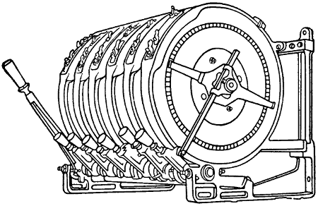
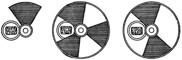
FIGURE 157.
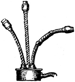
Dimmers.—“Dimmer” is the name given to the
resistances which are used to dim the electric lights
on the stage. They are usually mounted at the top
or bottom of the switchboard with the operating
handles in easy reach of the operator. A dimmer
should be provided for each color in every border
light and also for the foot lights. In some cases the
proscenium side lights are also arranged for several
colors. The dimmers should be mounted so that
each one is directly above the switch which controls
the circuit to which it belongs. They should be protected
by wire guards against rubbish, which is likely
to accumulate among them if they are not enclosed.
Good ventilation must be provided. A certain dimmer
can be used only while the amperage remains
within the proper limitations. If carbon lamps, for
instance, are changed for tungsten, the amperage
will be much reduced and the dimmer may not work
properly.
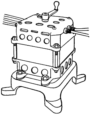
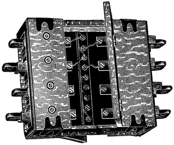
Modern dimmers are all of the interlocking type so
that the whole bank may be worked together or any
one singly. Figure 157 is an illustration of a small
bank of dimmers.
Door Switches.—Door switches are used mostly in
connection with dressing rooms. When the light in
the room is burning, opening and closing the door
will turn it out.
Dressing Rooms.—Many dressing rooms are wired
with lights on pendant cords, but this method is not
to be recommended. It is better to arrange the
lights in sockets fitted into the outlet boxes. It will
be well if each dressing room is provided with a circuit
for flatirons. If this is considered too expensive,
the fuses on circuits leading into dressing rooms
must be kept small enough to blow in case a flatiron
is connected. Many actors are in the habit of carrying
flatirons and will use them on incandescent-light circuits
if no other circuit is provided. If metal
guards are fastened on securely, much of the trouble
from flatirons will be avoided, but they must be fastened
so that an ordinary screwdriver will not loosen
the screws.
Dressing room illumination, if properly carried
out, will save the proprietor much annoyance. Actors
have ways of obtaining the light they want by
fair means or foul, and it is much better to arrange
the lighting so that it will be satisfactory to those
using it, than to have it continually tampered with.
A bright illumination is essential for making up
and both sides of the face should be fully illuminated.
To accomplish this it is necessary to provide
at least two lights for each mirror. Every lamp
should be provided with a substantial guard which
may be securely fastened to the outlet box. This is
especially necessary if small candle power lamps are
furnished. For, if the light furnished is insufficient,
there will be strong efforts made to replace the small
lamps by larger ones. Guards are also necessary as
a protection against fire. Actors are in the habit of
drying small articles of clothing on the lamps, and
fires have been known to start from this cause. The
guards on the lamps throw shadows on the faces of
the actors, and for this reason are not liked. In
order to avoid the shadows, frosted lamps may be
used, or two lamps on each side of the mirror. One
lamp will then illuminate the shadows caused by
the other. Where there are long dressing tables, as
in rooms occupied by the chorus, mirrors may be
placed between each two lamps on each side of the
table and the lamps staggered vertically. In this
way each party will receive the benefit of at least
four lamps and the shadows will be less noticeable.
The color value of the lamps used in dressing
rooms should match that of the lamps used on the
stage. Some stages, for instance, are illuminated by
flaming arcs which may give an altogether different
effect to a “make up” than the tungsten lamps, for
instance.
Where there are a large number of sockets without
lamps in them, it is advisable to close the socket
by a fuse plug from which the fuse has been removed,
or in some similar manner in order to avoid the
chance of short circuits from hat pins or similar objects
used in dressing rooms.
Drop Lights.—Drop lights should be avoided as
much as possible. Where they must be installed reinforced
cord, armored cable, or flexible steel armored
cord should be used.
Emergency Lighting.—Every theater must have
an emergency lighting system as outlined in the rules
below. The object of this is to provide a double system
of illumination so as to reduce the likelihood of
the theater being left in total darkness. This is a
frequent occurrence where the theater is supplied
by an isolated plant, and may also occur where the
supply is obtained from a large outside lighting system
although the latter is usually more reliable.
Every unnecessary light that is added to an emergency
system increases the likelihood of trouble. A
sufficient number of lights added to it to illuminate
the space used by the audience in getting out is,
therefore, necessary but more than this is a detriment
rather than a help. The practice of connecting
all of the hall and lobby lights to the emergency
system is to be condemned, since it defeats the purpose
of the rule which provides a double illumination
system for every part of the theater used by the
audience. The two systems should be carried into
the auditorium, all stairways, exits, and lobby clear
to the street. They should, furthermore, be kept
entirely separate, in separate conduits and using
separate meters.
The rule does not specify the number of exit and
emergency lights required. Good practice requires a
light for every 400 square feet or so. If each of these
outlets be fitted with a 50 watt lamp the illumination
will interfere with many of the acts and so, smaller
lamps are generally used. One emergency light for
each 60 seats will fill the bill nicely.

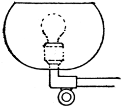
FIGURE 158.
Over each exit, an exit light must be provided, but
as these exit lights are usually incased in ruby glass
such as shown in Figure 158 they cannot be counted
as giving any illumination. In many theaters gas
is used for emergency and exit lighting and in many
respects this seems to be a good practice. In some
quarters, however, it is believed that a fire in the
scenery of a theater might create such an air pressure
in the building as to overcome the low gas pressure
and thus put out the gas at the very time when
it is most needed. The very best suggestion that
can be made is that of a storage battery to supply the
emergency system. Where alternating current is
used this, however, introduces some complications and
becomes quite expensive. Avoid the use of key
sockets, fan motors, or any unnecessary device on
emergency or exit light circuits.
Where supply may be obtained from two separate
street mains, two separate and distinct services
must be installed, one service to be of sufficient
capacity to supply current for the entire equipment
of theater, while the other service must be at least
of sufficient capacity to supply current for all emergency
lights. Where supply cannot be obtained from
two separate sources, the feed for emergency lights
must be taken from a point on the street side of
main service fuses. By “emergency lights” are
meant exit lights and all lights in lobbies, stairways,
corridors, and other portions of theater to which the
public have access, which are normally kept lighted
during the performance. Where the source of supply
is an isolated plant within the same building,
an auxiliary service of at least sufficient capacity to
supply all emergency lights must be installed from
some outside source, or a suitable storage battery
within the premises may be considered the equivalent
of such service.
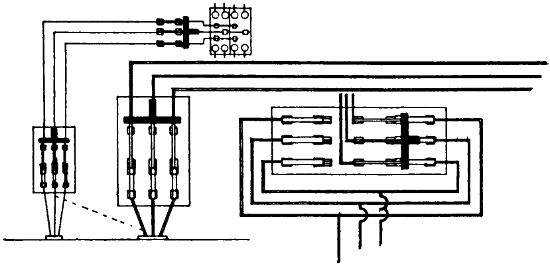
FIGURE 159.
Exit lights must not have more than one set of
fuses between same and service fuses. Exit lights
and all lights in halls, corridors, or any other
part of the building used by audience, except the
general auditorium lighting, must be fed independently
of the stage lighting, and must be controlled
only from the lobby or other convenient place in
front of the house. All fuses must be enclosed in
approved cabinets.
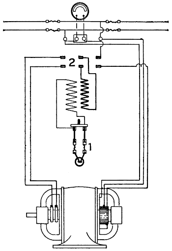
Figure 159 shows a diagram of an emergency lighting
system together with that of the house lighting
system. The main house switch is sometimes arranged
with two sets of fuses, so that it need only
be thrown over when a fuse blows. See Figure 159
at the right.
Exit Lights.—Exit lights are usually required over
all doors leading from any part of the auditorium
to the lobby or outside of the theater. They are
usually incased in ruby glass on which the word
EXIT has been etched in large letters. See also
Emergency Lighting.
Fan Motors.—In large theaters, sometimes as many
as ten or twelve fan motors are arranged along the
walls of the auditorium, to blow air toward the
audience. In small theaters there is a strong temptation
to connect these to the emergency circuit, but
this should never be done. The motors are too noisy
to be allowed to run during an act and must be
wired so that they can all be thrown on or off together
from the stage switchboard. Not more than
660 watts should be connected to any one circuit and
the connection should be by means of attachment
plugs and reinforced cord, a bracket for the motor
being placed as near as possible to the outlet, so as
to reduce the amount of cord required to a minimum.
Fire Alarm.—In some of the cities a special signal
system between stage and box office is required and
it is necessary to consult authorities about this.
Ordinarily a bell circuit, such as shown under
“Bells,” will answer.
Fish Work.—The fishing of wires incased in loom,
as is permitted in other places, is not permissible in
theaters. If wires are to be “fished” they must be
incased in metal armor.
Fixtures.—Fixtures require careful inspection before
installing. It is seldom that the piping is properly
reamed out as required by the rule. Chain fixtures
especially, must be closely watched. There is
little if any trouble to be expected from the wires
laced among the chain links, but there is much trouble
to be looked for from the wires at the points where
they leave the chain support and where they enter
the socket. The openings for the wires at these
points are seldom large enough to admit of the proper
wire being used, and they are not well reamed either.
The result of these conditions is that the wire is
very quickly abraded and short circuits are common.
Fixtures may be tested for short circuit by connecting
a magneto at the feed end of the wires and
turning it briskly. If a ring is obtained it is an
indication that something in wrong. The test for
open circuit may be made with the same connection.
Insert a screw driver or a plug into each socket; if
it is not possible to obtain a ring there must be an
open circuit. The test for “ground” may be made
by connecting both feed wires to one pole of the
magneto, and the other pole to the metal of the fixture
taking care that there is no lacquer on that
part of the fixture. If a ring is obtained it is an
indication that some bare spot on the wire is in
contact with the fixture. Fixtures used for emergency
lighting must carry no key sockets and must
not feed fan motors.
Wires for Fixture Work.
Must not be smaller than No. 18 B. & S. gauge,
and must have an approved rubber insulating
covering. In wiring certain designs of show-case fixtures,
ceiling bull-eyes, and similar appliances in
which the wiring is exposed to temperature in excess
of 120 degrees Fahrenheit (49 degrees centigrade),
from the heat of the lamps, approved slow-burning
wire must be used. All such forms of fixtures must
be submitted for examination, test and approval before
being introduced for use.
Supply conductors, and especially the splices to
fixture wires, must be kept clear of the grounded
part of gas pipes, and, where shells or outlet boxes
are used, they must be made sufficiently large to
allow the fulfillment of this requirement.
Must, when fixtures are wired outside, be so secured
as not to be cut or abraded by the pressure
of the fastenings or motion of the fixture.
Wires of different systems must never be contained
in or attached to the same fixture, and under no
circumstances must there be a difference of potential
of more than 300 volts between wires contained in
or attached to the same fixtures.
On chains of similar parts where conductors are
not completely enclosed in metal, wires must be
stranded and must have rubber insulation not less
than one thirty-second of an inch in thickness; or
approved pendant or portable cord may be used.
Fixtures.
When supported at outlets in metal conduit,
armored cable, or metal-molding systems, or from gas
piping or any grounded metal work, or when installed
on metal walls or ceilings, or on plaster walls
or ceilings containing metal lath, or on walls or
ceilings in fireproof buildings, fixtures must be insulated
from such supports by approved insulating
joints placed as close as possible to the ceilings or
walls. The insulating joint may be omitted in conduit,
armored cable, or metal-molding systems with
straight electric fixtures in which the insulation of
conductors is the equivalent of insulation in other
parts of the system, and provided that approved
sockets, receptacles, or wireless clusters are used of
a type having porcelain or equivalent insulation between
live metal parts and outer metal shells, if any.
Where insulating joints are required, fixture
canopies of metal must be thoroughly and permanently
insulated from metal walls or ceilings, or from
plaster walls or ceilings on metal lathing, and from
outlet boxes.
Canopy insulators must be securely fastened in
place so as to separate the canopies thoroughly
and permanently from the surfaces and outlet boxes
from which they are designed to be insulated.
Fixtures having so-called flat canopies, tops, or
backs, will not be approved for installation, except
where outlet boxes are used.
In non-metallic fixtures wireways must be metal-lined
unless approved armored conductors with suitable
fittings are used.
Flashers.—Flashers are used to economize electrical
energy in sign illumination. An electric sign
is often just as effective if only one side or one letter
is in use at a time and in such a case there is considerable
saving by the use of a flasher.
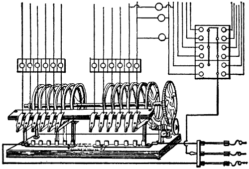
FIGURE 160.
Flashers are made up in a variety of forms, one
of them being shown in Figure 160. The manner
of wiring to the sign will be readily understood by
reference to the figure. The neutral wire is carried
direct to the sign and fuses for that wire are often
installed up in the sign, while those for the other
side of the circuits must be close to the flasher to
comply with the rule which requires fuse protection
where a small wire is tapped off from a larger one,
unless the fuse in the larger wire is below the carrying
capacity of the smaller.
Time switches, sign flashers, and similar appliances
must be of approved design and enclosed in
approved cabinets.
Flat Irons.—See Heaters.
Flexible Cord.—The ordinary flexible cord should
not be used in any part of a theater. It is recommended
that only those cords described below be
used, each of course in its proper place. Approved
reinforced cord for pendants. Approved asbestos-covered
cord for portable heaters. Approved Stage
and Border Cables on Stage.
See “Stage Cables.”
Flexible Tubing.—Flexible tubing is not permissible
in theaters.
Floor Pockets.—These are always a source of
trouble and their use should be avoided as much as
possible. If it is necessary to use any they must
be of a type approved by the inspection department
having jurisdiction.
Fly Floor.—This is the name given to that part of
the gallery above the stage upon which those employes,
whose duty it is to raise and lower curtains
and scenery, work. No great illumination is required,
but the lights should be arranged so as to be convenient
to the men for reading during long waits.
If this is not done there will always be considerable
objectionable cord wiring found in this place. Fly-floor
and rigging-loft lights should be provided with
three way switches so that lights may be turned on
or off either at the stage switchboard or on the fly
floor.
Footlights.—These form the most important and
effective part of the permanently located stage
lights. To locate them properly requires careful consideration.
If they are brought too high they will
obstruct the view of the audience; if located too low
they will not illuminate the lower part of the stage.
Opinion is somewhat divided as to whether they
ought to be arranged in circular form or be laid out
straight across the stage. In large theaters there
is a circular space between the front seats and
the front of the stage. A circular stage will utilize
this space and this form of stage with footlights arranged
in a similar manner will also allow the actors
to approach more closely to the audience and will
procure for them some illumination from the side.
The difficulty of making up a circular strip of footlights
is somewhat greater than that of making them
up in a straight line.
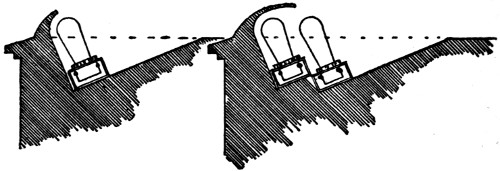
FIGURE 161. FIGURE 162.
The footlights are generally made to extend nearly
the full opening of the stage and the lights should
be crowded into them as closely as possible. The
lighting should be divided into three groups suitable
for three colors. It is customary to have about half
of the lights white and the remaining half divided
into two equal parts for different colors. A small part
of the white lights should be arranged upon a separate
circuit so that they may be used for rehearsals
or other purposes, when not very much light is needed.
No very definite recommendations concerning the
type of lamp to be used can be given. In some theaters
the stage is very solid and tungsten lamps are
used to advantage; in others the jarring prevents
their use. The white lights should be arranged so
that their light need not pass through the colored
lamps. In vaudeville houses some protection in the
form of chains or guards is often provided to prevent
objects from being rolled or thrown against the lights.
Figures 161 and 162 show types of footlights and
the manner of installing the sockets.
Must be wired in approved conduit or armored
cable, each lamp receptacle being enclosed within an
approved outlet box, or the lamp receptacles may
be mounted in an iron or steel box, metal to be of a
thickness not less than No. 20 U. S. sheet metal
gauge treated to prevent oxidation and so constructed
as to enclose all the wires. Wires to be soldered to
lugs of receptacles. Must be so wired that no set
of lamps requiring more than 1,320 watts nor more
than 26 receptacles shall be dependent upon one
cut-out.
Fuses.—See “Cut-outs.”
Gallery Lighting.—The proper lighting of galleries
is a difficult matter where there is another gallery
above. In such a case the ceiling is always very
low. An even distribution of light requires the use
of many small incandescent lamps evenly distributed.
This will make the wiring expensive. The light should
be taken pretty well from the rear so as to avoid
placing lights in the range of visions of the audience.
Emergency lights should be provided here as well
as in the main auditorium.
Gallery Pockets.—Pockets for arc lamps are often
provided, as it often happens that a moving-picture
machine must be placed in the gallery. The stage
pockets should be wired with number 6 B. & S. gauge
wire, this being the smallest wire allowed to feed
a moving-picture arc. The stage pocket should be
controlled by a switch on the switchboard. It often
happens that the operator at the lamp has a wrong
cue and his light can then be controlled by the stage
manager at the stage switchboard.
Gas Lighting.—Electric gas lighting is very little
used at the present time, but in many theaters the
emergency lighting is by gas and, in order to save
the time necessary to light these by hand before
every performance, an automatic gas lighting system
has been installed in some theaters. A diagram
of such a system is shown in Figure 163. A battery
of considerable capacity is necessary and also a
spark coil S. At each gas jet a magnet M is installed
which, when energized, is capable of turning the gas
on and at the same time producing a spark. This
magnet is also capable of turning the gas off. Two
buttons are provided, one to turn the gas on and
the other to turn it off.
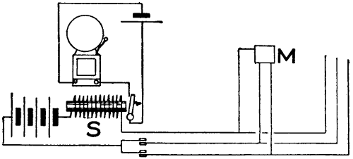
FIGURE 163.
As the wiring is always used in connection with
gas piping, grounds are of frequent occurrence, and
in order to indicate a ground as soon as it comes
on, the bell and battery shown are provided. If a
ground causes a continuous current, the spark coil
will attract the armature, thus causing the bell to
ring continuously.
Electric gas lighting, unless it is the frictional
system, must not be used on the same fixtures with
the electric light.
Grid Floor.—This is the term given to the framework
which supports the pulleys over which the cables
for handling curtains and scenery run. It is usually
made up of parallel iron slats or bars; hence the
name. A fairly good illumination should be provided
here and all of the lights should be arranged on
three-way switches. One light for every 400 square
feet will be sufficient.
Connections to grounded pipes and to conduit must
be exposed to view or be readily accessible, and
must be made by means of approved ground clamps
to which the ground wire must be soldered.
The metal of conduit, armored cable, or metal
molding must be permanently and effectually
grounded to water piping, gas piping, or other suitable
grounds, provided that, when connections are
made to gas piping, they must be on the street side
of the meter. If the conduit system consists of several
separate sections, the sections must be bonded
to each other, and the system grounded; or each
section may be separately grounded, as required
above.
Conduits and gas pipes must be securely fastened
in outlet boxes, junction boxes, and cabinets, so as
to secure good electrical connections.
If conduit, couplings, outlet boxes, junction boxes,
cabinets, or fittings, having protective coating of non-conducting
material such as enamel, are used, such
coating must be thoroughly removed from threads of
both couplings and conduit and such surfaces of
boxes, cabinets and fittings where the conduit or
ground clamp is secured in order to obtain the requisite
good connection. Grounded pipes must be
cleaned of rust, scale, etc., at place of attachment
of ground clamp.
Connections to grounded pipes and to conduit must
be exposed to view or readily accessible, and must be
made by means of approved ground clamps to which
the ground wires must be soldered.
Ground wires must be of copper, at least No. 10
B. & S. gauge (where largest wire contained in conduit
is not greater than No. 0 B. & S. gauge), and
need not be greater than No. 4 B. & S. gauge (where
largest wire contained in conduit is greater than
No. 0 B. & S. gauge). They shall be protected from
mechanical injury.
The ground on the conduit system is not to be considered
as a ground for a secondary system.
Guards.—A guard rail should be provided around
the stage switchboard to prevent actors from coming
in contact with any live part of the switchboard.
All incandescent lamps about the stage, dressing
rooms, fly-floor, grid-floor, etc., should be provided
with guards.
Hanger-Boards.—Hanger-boards are not compulsory
but where not used, arc lamps must be hung
from insulating supports other than their conductors.
Hanger-boards must be so constructed that all
wires and current-carrying devices thereon will be
exposed to view and thoroughly insulated by being
mounted on a non-combustible, non-absorptive, insulating
substance. All switches attached to the same
must be so constructed that they shall be automatic
in their action, cutting off both poles to the lamps,
not stopping between points when started, and preventing
an arc between points under all circumstances.
Heaters.—Heaters are used sometimes in cold dressing
rooms, in box offices and in other small spaces
where other adequate heating arrangements have not
been made. The fire hazard incident to the use of
electric heaters is considerable and they should be
carefully installed according to the rules given below.
From one-half to three watts per cubic foot will be
required to heat a room. The quantity of heat necessary
to be supplied depends largely upon the ventilation.
It will be small in closed dressing rooms and
large, for instance, in the box office. Always place
a heater where the air enters a room; never where
it leaves.
Each heater of more than 6 amperes or 660
watts capacity must be protected by a cut-out, and
controlled by a switch or plug connector plainly indicating
whether “on” or “off” and located within
sight of the heater. Heaters of 6 amperes or 660
watts capacity, or less, may be grouped under the
protection of a single set of fuses, provided the rated
capacity of the fuses does not exceed 10 amperes;
or may be connected individually to lighting circuits.
Flexible conductors for smoothing irons and sad
irons, and for all devices requiring over 250 watts,
must have an approved insulation and covering.
With portable heating devices, approved plug connectors
must be used so arranged that the plug
may be pulled out to open the circuit without leaving
any live parts so exposed as to render likely accidental
contact therewith. The connector may be located at
either end of the flexible conductor or inserted in
the conductor itself.
Smoothing irons, sad irons, and other heating devices
that are intended to be applied to combustible
articles, must be provided with approved stands.
Stationary heaters such as radiators, ranges, plate
warmers, etc., must be so located as to furnish ample
protection between the device and surrounding combustible
material.
Must each be provided with a name-plate, giving
the maker’s name and the normal capacity in volts
and amperes.
High Potential.—The National Electrical Code
classifies all voltages below 550 as low. Nevertheless
voltages above 220 should not be considered in the
auditorium, stage, or dressing rooms of any theater.
And this voltage only in connection with a three-wire
system where the high voltage exists only between
the outside wires, and 110 volts are used for
lamps and other devices. High potential systems
should be used only on the outside.
Illumination.—Illumination is more an art than a
science and the rules that can be given have only a
very general application. The best practice, where
really good illumination is desired, is to install a
large number of circuits in proportion to the number
of lights, so that lamps of large candle power may
be used wherever desirable. The quantity of light
needed in theaters varies greatly with the color of
decorations and with their condition. Dust accumulates
rapidly in theaters and may absorb half of the
light. If there is plenty of capacity the candle power
of lamps may be changed to suit conditions and obtain
any result desired.
The number of sockets installed in the auditorium
varies widely. In some of the cheaper theaters one
light for each twenty seats is considered sufficient;
while in elaborately lighted houses, there are cases
where the number of sockets is equal to about half
the number of seats. Good illumination requires
that the light come from the back, but very often the
purpose is to obtain a brilliant effect by placing lights
in front of the audience. In such cases, however, the
lamps are always of low candle power and should be
frosted.
Incandescent Lamps.—Practically all incandescent
lamps are now rated in watts. They can be obtained
in voltages ranging from 2 to 250 and may be operated
in series or in multiple. All but the tantalum
lamp operates equally well on alternating or direct
current. The tantalum cannot be recommended for
alternating-current circuits. No incandescent lamps
will operate well on frequencies lower than forty
cycles. The natural distribution of light is mostly
in the horizontal plane and for good illumination
reflectors should be provided.
The color value is in the following order: Tungsten,
tantalum, graphitized filament, carbon filament. None
are equal for color-matching purposes to the intensified
arc or the Moore tube.
The life of all incandescent lamps varies inversely
with the voltage. An increase in voltage will produce
an increase in the efficiency of the lamp but
shorten its life. The efficiency decreases with continued
use, and it is generally considered that the
useful life of a lamp is over when its efficiency
has fallen to 80 per cent of its original value. Frosting
or coloring shortens the life of lamps from 30
to 50 per cent and reduces the candle power from
3 to 10 per cent, but the lamp yields a more pleasing
light. Frosting is ordinarily used only where lamps
are placed so as to come in the line of vision. Bowl
frosting does not materially reduce the life of a lamp.
With incandescent lamps the term “efficiency” has
a meaning quite different from that usually given,
it being the number of watts per candle power. The
lower the efficiency of an incandescent lamp, the
better it is and the more light it yields per watt
consumed.
Mazda Lamp.
The Mazda lamp has an efficiency of about 1.25 and
is the most efficient of all. It may be recommended in
all places where lamps may be suspended vertically;
where there is not too much jarring; where there is
ordinary care in handling; and where the lamps are
burning a large part of the time. The operating
expense of this lamp is low, but the initial cost is
high and the breakage is likely to be considerable.
If lamps are much handled and not burned much,
the cost of broken lamps may exceed the saving in
energy. It is best not to clean Mazda lamps when
cold. Shock absorbers should be used where there
is much jarring. The illumination should be laid
out for the use of lamps not smaller than 60 watts.
The lamps should not be used for temporary work
or for coloring. Arrange lamps as far as possible to
be controlled by switches. Broken filaments can
often be united again by shaking the lamps gently
until the broken ends come together. The current
will then weld them. When a bank of Mazda lamps is
turned on there is an excessive current for an instant.
Tantalum Lamp.
The efficiency of this lamp is from 1.8 to 2 watts
per candle power. This lamp is much used for
street-car and similar illumination because it stands
jarring very well. It should not be used on alternating-current
circuits. The filament can often be
united in the same manner as the Mazda.
Graphitized Filament Lamp.
This lamp has an efficiency of 2.5 watts per candle
power.
Carbon Filament Lamp.
This lamp used on 110-volt circuits has an efficiency
of from 3 to 3.2 watts per candle power. The efficiency
of the smaller sizes is from 4 to 5 watts per
candle power. The carbon filament lamp is the most
expensive of all to operate, but on account of the
strength and cheapness of the lamp it can be recommended
in places where the breakage is liable to be
great or where the light is used for comparatively
brief periods.
Must be provided with guards when liable to come
in contact with inflammable material or subject to
rough usage. Must be protected by vapor-proof
globes where inflammable gases exist.
When supported at outlets in metal conduit,
armored cable, or metal molding systems, or from gas
piping or any grounded metal work; or when installed
on metal walls or ceilings, or on plaster walls
or ceilings containing metal lath, or on walls or ceilings
in fireproof buildings, fixtures must be insulated
from such supports by approved insulating joints
placed as close as possible to the ceilings or walls.
The insulating joint may be omitted in conduit, armored
cable, or metal molding systems with straight
electric fixtures in which the insulation of conductors
is the equivalent to insulation in other parts of the
system, and provided that approved sockets, receptacles,
or wireless clusters are used of a type having
porcelain or equivalent insulation between live metal
parts and outer metal shells, if any.
Where insulating joints are required, fixture canopies
of metal must be thoroughly and permanently
insulated from metal walls or ceilings, or from plaster
walls or ceilings on metal lathing, and from outlet
boxes.
Canopy insulators must be securely fastened in
place, so as to separate the canopies thoroughly and
permanently from the surfaces and outlet boxes from
which they are designed to be insulated.
Inverted Lighting.—In this method of lighting the
light is first thrown upward against the ceiling and
then reflected back. This method can be used to
advantage with light colored ceilings only. It is
especially suited for low ceilings and with high
ceilings the advantage disappears. The light obtained
in this manner is very even and almost shadowless.
Much light is lost through absorption but, owing to
the fact that the light is of such an even quality,
the eye readily accommodates itself to a lower quantity
and the net increase in energy required to illuminate
suitable spaces is not so very great. Those
who wish to go into the subject of illumination thoroughly
will find it treated fully in “Modern Illumination
Theory and Practice”.
Joints.—Methods of making joints are illustrated
in Figure 164. Be careful not to overheat, especially
at points where there is a strain on the wire.
Wires must be so spliced or joined as to be both
mechanically and electrically secure without solder.
The joints must then be soldered unless made with
some form of approved splicing device, and covered
with an insulation equal to that on the conductors.
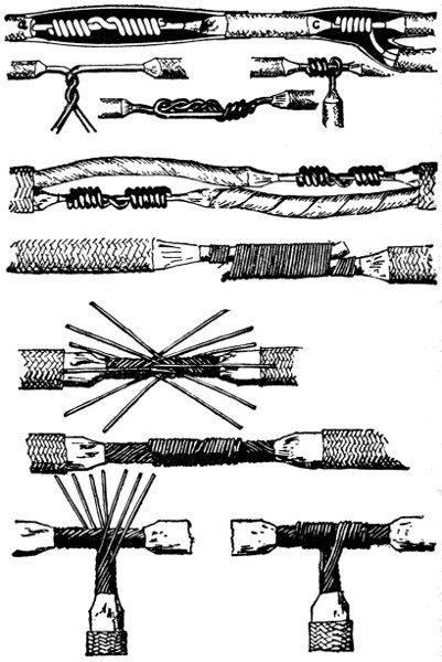
FIGURE 164.
Stranded wires (except in flexible cords) must be
soldered before being fastened under clamps or binding
screws; and, whether stranded or solid, when they
have a conductivity greater than that of No. 8 B. &
S. gauge they must be soldered into lugs for all
terminal connections, except where an approved solderless
terminal connector is used.
Junction Boxes.—Junction boxes are installed in
conduit systems for the purpose of facilitating the
drawing in of the wire or of branching off from a
main run. See “Conduit Work.”
Lamps.—See “Incandescent Lamps.”
Lobby.—The lobby generally requires a number of
lights and the aim often is to create a lavish display.
Very often a cut-out center is arranged at some
convenient place. The exit and emergency lights
must be controlled from the lobby. Sometimes outlets
are provided for electric bulletin boards or small
signs.
Lugs.—For solderless lugs, such as are used on
rheostats or for arc lamps, see “Portable Stage Equipment.”
For fuses rated over 30 amperes lugs, firmly
screwed or bolted to the terminals and into which
the conducting wires are soldered, must be used.
On rheostats, resistances, etc., lugs will not be required
when leads are provided as a part of the
device.
Switches for current of over 30 amperes must be
equipped with lugs, firmly screwed or bolted to the
switch, and into which the conducting wires shall be
soldered. For the smaller sized switches simple
clamps can be employed, provided they are heavy
enough to stand considerable hard usage.
Where lugs are not provided, a rugged double-V
groove clamp is advised. A set screw gives a contact
at only one point, is more likely to become loosened,
and is almost sure to cut into the wire. For the
smaller sizes, a screw and washer connection with
up-turned lugs on the switch terminal gives a satisfactory
contact.
Must not be used on stage side of proscenium wall.
Must not be used for circuits carrying more than
1,320 watts.
Wire used must be standard rubber covered, but
may be single braid.
Must never be concealed or run in damp places.
Must not be used where the difference of potential
exceeds 300 volts.
Must be continuous from outlet to outlet, to junction
boxes, or approved fittings designed especially
for use with metal moldings, and must at all outlets
be provided with approved terminal fittings which
will protect the insulation of conductors from abrasion,
unless such protection is afforded by the construction
of the boxes or fittings.
Such molding where passing through a floor must
be carried through an iron pipe extending from
the ceiling below to a point five feet above the floor,
which will serve as an additional mechanical protection
and exclude the presence of moisture often prevalent
in such locations.
Where the mechanical strength of the molding itself
is adequate, this ruling may be modified to require
the protecting piping from the ceiling below to
a point at least three inches above the flooring.
Where such moldings pass through a partition the
iron pipe, required for passing through floors, may
be omitted and the molding passed directly through,
providing the partition is dry and the molding is in
a continuous length with no joint or coupling within
the partition.
Backing must be secured in position by screws or
bolts, the heads of which must be flush with the
metal.
Must have the metal of molding permanently
and effectually grounded to water piping, gas piping,
or other suitable grounds, provided that when connections
are made to gas piping, they must be on
the street side of the meter. If the metal molding
system consists of several separate sections, the sections
must be bonded to each other and the system
grounded, or each section may be separately grounded,
as required above.
Metal moldings and gas pipes must be securely fastened
to outlet boxes, junction boxes, and cabinets,
so as to secure a good electrical connection. Molding
must be so installed that adjacent lengths of molding
will be mechanically and electrically secured at all
points.
If metal molding, couplings, outlet boxes, junction
boxes, cabinets, or fittings having protective coating
of non-conducting material such as enamel are used,
such coating must be thoroughly removed from
threads of couplings and metal moldings, and from
the surfaces of boxes, cabinets, and fittings, where
the metal molding or ground clamp is secured in
order to obtain the requisite good connection.
Grounded pipes must be cleaned of rust, scale, etc.,
at the place of attachment of the ground clamp.
Connection to grounded pipes and to metal moldings
must be exposed to view, or readily accessible,
and must be made by means of approved ground
clamps, to which the wires must be soldered.
Ground wires must be of copper, at least No. 10
B. & S. gauge. They shall be protected from mechanical
injury.
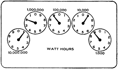
FIGURE 165.
Must be installed so that for alternating-current
systems the two or more wires of a circuit will be in
the same metal molding. It is suggested that this be
done for direct-current systems also so that they may be
changed to the alternating-current system at any time,
induction troubles preventing such change if the wires
are in separate moldings.
Meters.—A good job of meter setting requires that
the meter fittings which are now on the market be
used. Two separate meters will be required in each
theater; one for the general lighting and one for
the emergency system.
Meter Reading.—Meter readings are indicated by
pointers, arranged to move over dials as shown in
Figure 165. The various pointers are connected together
by gearing in such a manner, that alternate
pointers move in opposite directions, as indicated by
the figures on the dials. The gearing moving the
pointers in Figure 165 is of such proportions that
a total revolution of any pointer represents one-tenth
of a revolution of the pointer to the left of it. Thus
ten revolutions of one pointer causes one revolution
of the one at the left.
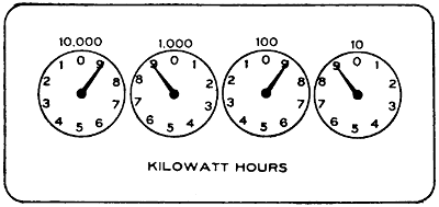
FIGURE 166.
FIGURE 167.
At the top of each dial the value of the reading
of that dial is shown. Where the figures given are
followed by the letter “s”, as in Figures 167 and
168, it signifies that each division of the dial represents
the amount of energy indicated by the figures
at the top. For instance, in Figure 168 each division
of the dial at the right represents one-tenth of one
kilowatt hour and a total revolution of the pointer
ten-tenths, or one kilowatt hour.
If the figures given at the top of the dial are not
followed by the letter “s”, or as shown in Figure
166, each division of the dial represents one-tenth
of the amount shown at the top of the dial, the dial
at the right of Figure 166 indicating nine-tenths of
ten kilowatts or nine kilowatts.

FIGURE 168.
The meter must always be read from right to left,
the lowest indicating dial being the one at the extreme
right, and the lower reading ones always
being used to check the higher ones just at the left.
The following example will illustrate the manner of
reading meters:
In Figure 165 the right-hand pointer registers
nine-tenths of 1000, or 900 watt hours; the pointer
next to it registers eight, since it cannot be considered
as fully up to any number unless the pointer at the
right of it has just arrived at or passed 0. By the
same token the middle pointer also registers 8 and
as the middle pointer has not reached 0 the one at
the left of it must be read as one, the last dial also
indicates one and the total reading is 1,188,900. On
some types of meters a multiplier is used. This
is generally given on the meter dial and the readings
given by the pointers must be multiplied by this
number to obtain the correct reading of the meter.
Motors.—Motors are used in theaters for ventilation,
for raising and lowering the steel curtain in
cities where such are required, and also in some
cases for operating drop curtains, but for this last
purpose they have not found much favor. In some
localities motors are required to keep up a certain
water pressure to be used in case of fire. Voltages
higher than 550 are not considered in theater work.
Motors operating at a potential of 550 volts or
less must be thoroughly insulated from the ground
wherever feasible. Wooden base frames used for
this purpose, and wooden floors, which are depended
upon for insulation where, for any reason, it is necessary
to omit the base frames, must be kept filled to
prevent absorption of moisture, and must be kept
clean and dry. Where frame insulation is impracticable
special permission in writing may be given
for its omission, in which case the frame must be
permanently and effectively grounded.
The motor leads or branch circuits must be designed
to carry a current at least 25 per cent
greater than that for which the motor is rated. Where
the wires under this rule would be over-fused in order
to provide for the starting current, as in the case of
many of the alternating-current motors, the wires
must be of such size as to be properly protected by
these larger fuses.
Each motor and resistance box must be protected
by a cut-out and controlled by a switch; said switch
plainly indicating whether “on” or “off”.
Small motors may be grouped under the protection
of a single set of fuses, provided the rated capacity
of the fuses does not exceed 6 amperes. With
motors of one-fourth horse power or less, on circuits
where the voltage does not exceed 300, single-pole
switches may be used. The switch and rheostat
must be located within sight of the motor, except in
cases where special permission to locate them elsewhere
is given, in writing.
Where the circuit-breaking device on the motor-starting
rheostat disconnects all wires of the circuit,
the switch called for in this section may be omitted.
Overload-release devices on motor-starting rheostats
will not be considered to take the place of the cut-out
required by this section. An automatic circuit-breaker
disconnecting all wires of the circuit may
serve as both switch and cut-out.
Auto starters, unless equipped with tight casings
enclosing all current-carrying parts, in all wet, dusty,
or linty places, must be enclosed in dust-tight, fireproof
cabinets. Where there is any liability of short
circuits across their exposed live parts being caused
by accidental contacts, a railing must be erected
around them.
Must not be run in series-multiple or multiple-series,
except on constant-potential systems, and then
only by special permission.
Must, when combined with ceiling fans, be hung
from insulated hooks, or else there must be an insulator
interposed between the motor and its support.
Must each be provided with a name-plate, giving
the maker’s name, the capacity in volts and amperes,
and the normal speed in revolutions per minute.
All varying (or variable) speed alternating-current
motors except those used for railway service must
be marked with the maximum current which they can
safely carry for 30 minutes, starting cold.
Terminal blocks when used on motors must be
made of approved non-combustible, non-absorptive,
insulating material such as slate, marble, or porcelain.
Adjustable-speed motors, unless of special and appropriate
design, if controlled by means of field
regulation, must be so arranged and connected that
they cannot be started under weakened field.
The use of soft rubber bushings to protect the
lead wires coming through the frames of motors is
permitted, except when installed where oils, grease,
oily vapors, or other substances known to have rapid
deleterious effect on rubber are present in such quantities
and in such proximity to motors as may cause
such bushings to be liable to rapid destruction. In
such cases hardwood properly filled, or preferably
porcelain or micanite bushings must be used.
The following table shows the sizes of wire recommended
to be used with motors of the horsepower
given. This table is an extract from the rules of the
Department of Gas and Electricity of the City of
Chicago. The column headed “Mains” may be used
when there are a number of motors fed by a single
line. For all lines which supply a single motor only,
the column headed “Branches” must be used.
The difference between the two is due to the fact
that it is not believed that several motors fed by a
single line will all be started at the same time; hence
it is not necessary to provide the overload capacity
for all of the motors as it is where but a single motor
is installed.
| DIRECT CURRENT |
| |
110 Volts |
220 Volts |
| H. P. |
Full-
load
Current |
Size
of
Wire
Mains |
Size
of
Wire
Branches |
Full-
load
Current |
Size
of
Wire
Mains |
Size
of
Wire
Branches |
| 1 |
|
8 |
14 |
14 |
4 |
14 |
14 |
| 2 |
|
15 |
14 |
12 |
8 |
14 |
14 |
| 3 |
|
23 |
10 |
8 |
12 |
14 |
14 |
| 4 |
|
30 |
8 |
6 |
15 |
14 |
12 |
| 5 |
|
38 |
6 |
6 |
19 |
12 |
10 |
| 7 |
.5 |
56 |
5 |
4 |
28 |
8 |
8 |
| 10 |
|
75 |
3 |
1 |
38 |
6 |
6 |
| SINGLE-PHASE |
| 1 |
|
12 |
... |
12 |
6 |
... |
14 |
| 2 |
|
23 |
... |
8 |
11 |
... |
12 |
| 3 |
|
33 |
... |
6 |
16 |
... |
10 |
| 4 |
|
44 |
... |
4 |
22 |
... |
8 |
| 5 |
|
53 |
... |
3 |
26 |
... |
6 |
| THREE-PHASE |
| 1 |
|
... |
... |
... |
3 |
14 |
14 |
| 2 |
|
... |
... |
... |
5 |
14 |
14 |
| 3 |
|
... |
... |
... |
8 |
14 |
14 |
| 4 |
|
... |
... |
... |
10 |
14 |
14 |
| 5 |
|
... |
... |
... |
13 |
14 |
12 |
| 7 |
.5 |
... |
... |
... |
19 |
12 |
8 |
| 10 |
|
... |
... |
... |
26 |
8 |
6 |
Music Stands.—Music stands are used by the
musicians and are generally placed between the first
row of seats and the stage. Each musician should
be provided with an individual stand, although if
necessary, two or three can get along with one stand.
No first-class theater should be fitted up with less
than twenty outlets for musicians’ lights. In the
Metropolitan Opera House of New York there are
one hundred. Houses used exclusively for vaudeville
do not, however, need that many. In houses devoted
to grand opera, often as many as one hundred or
more musicians are employed at the same time. To
take care of such a number, the music stands should
be wired with pin-plug connectors so that connections
may be made from one to the other. Long
flexible connections are necessary for most music
stands.
Sometimes it is necessary to crowd the orchestra
under the stage and at other times, with musical
comedies, for instance, they must be brought out
where they can see the movements of the actors.
The more the circuits are subdivided, and the different
lights made independent of each other, the
better it will be and the less the annoyance in case
a fuse blows. The fuses should always be arranged
at the switchboard so that it will not be necessary for
the electrician to work in front of the audience in
cases of trouble. For this reason extra stands should
also be kept on hand.
A main switch controlling the lights should be
placed where one of the musicians can handle it. In
dark scenes these lights must often be turned out.
If these lights are left under the control of the stage
electrician they will be more likely to be forgotten
at the critical moment than if under the control of
the men who need them.
An eight candle-power lamp for each stand will be
sufficient and this is usually placed inside a special
reflector which allows the light to fall upon the music
sheet only. Stage cable of good quality should be
used for the connections; there is too much rough
handling for reinforced cord. The use of the ordinary
attachment plug should be avoided; use approved
pin-plug connectors.
Open Work.—Open work is not allowed in theaters.
Operating Room.—See special chapter on “Operating
Room.”
Panel Boards.—Panel boards are really small
switchboards, the switches and cut-outs being mounted
usually upon slate. The slate must be free of metal
seams; these, if present, often manifest themselves
by heating. Panel boards, unless located in the
immediate vicinity of the main switchboard, and
where they are enclosed in a compartment, must
always be placed in standard metal cabinets.
The following specifications are intended to apply
to all panel and distributing boards used for the
control of light and power circuits, but not to such
switchboards in central stations, sub-stations, or isolated
plants as directly control energy derived from
generators or transforming devices.
Design.
The specifications for construction of switches and
cut-outs given in the following pages must be followed
as far as they apply.
In the relative arrangement of fuses and switches,
the fuses may be placed between the bus-bars and the
switches, or between the switches and the circuits,
except in the case of service switches. When the
branch switches are between the fuses and the bus-bars,
the connections must be so arranged that the
blades will be dead when the switches are open.
When there are exposed live-metal parts on the
back of a board, a space of at least one-half inch
must be provided between such live metal parts and
the cabinet in which the board is mounted.
Spacings.
| |
Between Parts of
Opposite Polarity,
Except at
Switches and
Link Fuses |
Between Parts of
Same Polarity
at Link Fuses |
When Mounted
on the Same
Surface |
When Held
Free in Air |
| Not over 125 volts |
|
3⁄4 inch |
|
1⁄2 inch |
|
1⁄2 inch |
| Not over 250 volts |
1 |
1⁄4 inch |
|
3⁄4 inch |
|
3⁄4 inch |
| Not over 600 volts |
2 |
3⁄4 inch |
1 |
3⁄4 inch |
|
At switches or enclosed fuses, parts of the same
polarity may be placed as close together as convenience
in handling will allow. It should be noted
that the above distances are the minimum allowable,
and it is urged that greater distances be adopted
wherever the conditions will permit.
The spacings given in the first column apply to the
branch conductors where enclosed fuses are used.
Where link fuses or knife switches are used, the
spacings must be at least as great as those given in
the following section on fuse spacing. The spacings
given in the second column above apply to the distance
between the raised main bars and between these
bars and the branch bars over which they pass. The
spacings given in the third column are intended to
prevent the melting of a link fuse by the blowing of
an adjacent fuse of the same polarity.
Panel boards of special design, in which the insulation
and separation between the bus-bars, and between
the other current-carrying parts is secured by
means of barriers or insulating materials instead of
by the spacings given above, must be submitted for
special examination and approved before being used.
Spacings must be at least as great as those given in
Table X, which applies only to plain, open link
fuses. The spaces given are correct for fuse blocks
to be used on direct-current systems, and can therefore
be safely followed in devices designed for alternating
currents. If the copper fuse tips overhang
the edges of the fuse block terminals, the spacings
should be measured between the nearest edges of
the tips.
A space must be maintained between fuse terminals
of the same polarity of at least one-half of an inch for
voltages up to 125 and of at least three-quarters of an
inch for voltages from 125 to 250. This is the minimum
distance allowable, and greater separation should
be provided when practicable.
For 250 volts, boards, or blocks with the ordinary
front-connected terminals, except where these have
a mass of compact form equivalent to the back-connected
terminals usually found in switchboard work,
a substantial barrier of insulating material, not less
than one-eighth of an inch in thickness, must be
placed in the “break” gap—this barrier to extend
out from the base at least one-eighth of an inch farther
than any bare live part of the fuse-block terminal,
including binding screws, nuts and the like.
For three-wire systems cut-outs must have the
break-distance required for circuits of the potential
of the outside wires.
| Not over 125 volts: |
Minimum Separation
of Nearest Metal
Parts of Opposite
Polarity |
Minimum
Break
Distance |
| 10 amperes or less |
|
3⁄4 inch |
|
3⁄4 inch |
| 11-100 amperes |
1 |
3⁄4 inch |
|
3⁄4 inch |
| 101-300 amperes |
1 |
3⁄4 inch |
1 |
3⁄4 inch |
| 301-1,000 amperes |
1 |
1⁄4 inches |
1 |
1⁄4 inches |
| Not over 250 volts: |
Minimum Separation
of Nearest Metal
Parts of Opposite
Polarity |
Minimum
Break
Distance |
| 10 amperes or less |
1 |
1⁄2 inches |
1 |
1⁄4 inches |
| 11-100 amperes |
1 |
3⁄4 inches |
1 |
1⁄4 inches |
| 101-300 amperes |
2 |
3⁄4 inches |
1 |
1⁄2 inches |
| 301-1,000 amperes |
2 |
1⁄2 inches |
2 |
3⁄4 inches |
When designed with 250-volt spacings between adjacent
blades, triple-pole switches must be marked
250 volts and may be used on 3-wire D. C. or single-phase
systems having not more than 250 volts between
adjacent wires and not more than 500 volts
between the two outside wires.
Spacings and dimensions must be at least as great
as those given below:
| Not Over 125 Volts D. C. and A. C. |
| Current |
Width and Thickness |
Minimum Separation
of Nearest Metal
parts of Opposite
Polarity |
Minimum
Break
Distance |
| |
Blades |
Clips and
Hinges |
| 30 amp. |
1⁄2 inch by
5⁄64 inch |
1⁄2 inch by
3⁄64 inch |
1 |
1⁄4 inch |
|
3⁄4 inch |
| 60 amp. |
1 |
1⁄4 inch |
1 |
3⁄4 inch |
| Not Over 125 Volts D. C. and A. C. |
| |
|
|
|
Inch |
Inch |
Inch |
Inch |
| 30 |
|
amperes |
1⁄2 by 5⁄64 |
1⁄2 by 3⁄64 |
1 |
1⁄4 |
1 |
|
| 60 |
and |
100 |
amperes |
|
1 |
1⁄2 |
1 |
1⁄4 |
| 200 |
|
amperes |
|
2 |
1⁄4 |
2 |
|
| 400 |
and |
600 |
amperes |
|
2 |
3⁄4 |
2 |
1⁄2 |
| 800 |
and |
1000 |
amperes |
|
3 |
|
2 |
3⁄4 |
A 300-ampere switch with the spacings of the 200-ampere
switch above may be used on switchboards.
| 250 Volts Only D. C. and A. C. |
| |
|
|
|
Inch |
Inch |
Inch |
Inch |
| 30 amperes |
1⁄2 by 5⁄64 |
1⁄2 by 3⁄64 |
1 |
3⁄4 |
1 |
1⁄2 |
| Not Over 250 Volts D. C. nor Over 500 Volts A. C. |
| |
|
|
|
Inch |
Inch |
Inch |
Inch |
| 30 |
|
amperes |
5⁄8 by 1⁄8 |
5⁄8 by 1⁄16 |
2 |
1⁄4 |
2 |
|
| 60 |
and |
100 |
amperes |
|
2 |
1⁄4 |
2 |
|
| 200 |
|
amperes |
|
2 |
1⁄2 |
2 |
1⁄4 |
| 400 |
and |
600 |
amperes |
|
2 |
3⁄4 |
2 |
1⁄2 |
| 800 |
and |
1000 |
amperes |
|
3 |
|
2 |
3⁄4 |
A 300-ampere switch with the spacings of the 200-ampere
switch above may be used on switchboards.
Cut-out terminals on switches for over 250 volts
must be designed and spaced for 600-volt fuses.
| Not Over 600 Volts D. C. and A. C. |
| |
|
|
|
Inch |
Inch |
Inch |
Inch |
| 30 |
|
amperes |
5⁄8 by 1⁄8 |
5⁄8 by 1⁄16 |
4 |
|
3 |
1⁄2 |
| 60 |
|
amperes |
|
4 |
|
3 |
1⁄2 |
| 100 |
|
amperes |
|
4 |
1⁄2 |
4 |
|
Paint Bridge.—The paint bridge is usually a scaffold
which can be raised and lowered, and which
serves the purpose of carrying scene painters at work
on the curtains. A long strip is the best means of illumination
and it must be connected with long stage
cable so as to be portable.
Paint Room.—Rooms in which paints are stored
should not contain switches or cut-outs. Lamps
should be incased in vapor-tight globes.
Program Board.—A simple form of program board
is shown in Figure 169. Except at the top and the
bottom, where three lamps are shown together in
one compartment, each lamp is incased by itself. In
front of the lamps is usually colored glass, bearing
numbers or letters. The lamp behind any number
being turned on, that number becomes visible. The
top and bottom are usually labeled, “Special”, or
“Extra”.
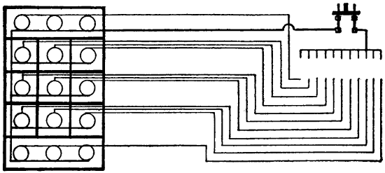
FIGURE 169.
Another form of program board is shown in Figure
170. This requires much more wiring. Each lamp
on the board is connected to a plug or switch at the
operator’s station. Whichever switch is closed on the
small board at the right causes a corresponding light
on the large board to appear.
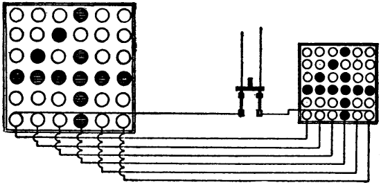
FIGURE 170.
Two program boards are usually installed, one at
each side of the stage, facing the audience at angles,
so that one can be seen from the extreme right, the
other from the extreme left.
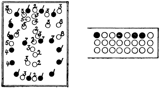
FIGURE 171.
A system that is often used for carriage call is
shown in Figure 171. The lights are arranged on
circuits as indicated by numbers. All lamps bearing
the same number being connected to one wire leading
to the controlling station. Thus there are eight controlling
or switch wires and there is one wire common
to all. A special switch is provided which has
a contact point for each wire. Paper cards, perforated
specially for the numbers they represent, are used.
If a card bearing a certain number is inserted in the
proper place and the switch closed, the number
printed on the card will appear on the sign. If, for
instance, the shaded circles in the card at the left of
the figure allow contact to be made, the lights indicated
by black circles will light up and make the
figure “6”.
Another form of program or call board is shown
in Figure 172. This requires more wires than the
one just described, one wire being carried to the controlling
board from each lamp. The connections may
be made in various ways. Sometimes they are made
with knife switches. If it is desired to make the
figure 1, for instance, only the three lights in a
vertical row in the center need be lighted, and to do
this the three wires from those lamps must be connected
to one switch. To make the figure 2, seven
lamps would have to be lit by another switch. It is
capable of making any letter or number and when
used as a program board only may be somewhat
simplified.

FIGURE 172.
In connection with these signs a large number of
wires may be required and attention should be given
to the following rule:
Except in the case of stage pockets the same conduit
must never contain more than four two-wire,
or three three-wire circuits of the same system except
by special permission, and must never contain circuits
of different systems.
Proscenium Side Lights.—These lights are located
on each side of the stage, as near as possible to the
edge of the proscenium opening and often in front
of the steel curtain. They are of more use in musical
productions, where choruses spread over the whole
stage, than in dramatic productions where the interest
is more in the center of the stage. In some theaters
the proscenium side lights extend the full height
of the opening and are arranged for three colors in
the same manner as footlights and borders. Very
often, however, only ten or twelve lights are arranged
on each side of the stage.
The construction rules are the same as those governing
foot-lights.
Lamps must be protected by strong wire mesh.
This is essential as in many cases actors are very
likely to back into them while passing off the stage.
Portable strips are sometimes used as proscenium side
lights.
Receptacles.—See “Stage Pockets”.
Retiring Rooms.—In these places a quiet subdued
illumination is usually desired. There are also often
quaint objects and effects to be illuminated. A large
number of outlets conveniently located for the use of
table lamps, fire places, and illumination of pictures,
should be provided.
Rheostats.
Location.
Must be placed on a switchboard, or at a distance
of at least one foot from combustible material, or
separated therefrom by a slab or panel of non-combustible,
non-absorptive, insulating material such as
slate, soapstone, or marble, somewhat larger than the
rheostat, which must be secured in position independently
of the rheostat supports. Bolts for supporting
the rheostat shall be countersunk at least one-eighth
inch below the surface at the back of the slab
and the bolt heads shall be covered with insulating
material. For proper mechanical strength, slab should
be of a thickness consistent with the size and weight
of the rheostat, and in no case to be less than one-half
inch.
If resistance devices are installed in rooms where
dust or combustible flyings would be liable to accumulate
on them, they must be equipped with dust-proof
face plates.
Materials.
Must be made entirely of non-combustible materials,
except such minor parts as handles, magnet insulation,
etc. All segments, lever arms, etc., must be
mounted on non-combustible, non-absorptive, insulating
material.
Connections.
Clamps for connecting wires to the terminals must
be so designed as to insure a thoroughly good connection
and must be sufficiently strong and heavy to
withstand hard usage. For currents above 30 amperes,
lugs into which the connecting wires may be soldered,
or approved solderless connectors must be used.
Clamps or lugs will not be required when leads are
provided as a part of the device.
No-Voltage Release.
Motor-starting rheostats must be so designed that
the contact arm cannot be left on intermediate segments,
and for direct-current circuits must be provided
with an automatic device which will interrupt
the supply circuit before the speed of the motor falls
to less than one-third of its normal value. In motor-starting
rheostats for alternating-current circuits the
automatic interrupting device may be omitted.
Overload Release.
Overload-release devices which are inoperative during
the process of starting a motor will not be approved,
unless other circuit-breakers or fuses are installed
in connection with them.
Signals.—Signals are necessary between the manager’s
office and the stage electrician’s station; for
this purpose telephones are generally used. In many
cities a fire-alarm signal system is also required and
it is specified to what part of the house it shall lead.
In addition to the above, a means of signalling the
fly floor and the orchestra leader must be provided.
Buzzers are used for these signals. It is best to use
batteries for all these signals instead of attempting
to run them from lighting circuits. Means of signalling
the arc-lamp station in the gallery or the balcony
should also be provided for use in connection with
lantern slides, etc. Telephone connection to this point
will also be very useful in order to give instructions
to the lamp operator. Return-call systems are advisable
in all places so that the electrician can be
called from any point.
In some cities the local laws require these wires to
be in conduit so as to preclude any possibility of
their communicating fire to anything. At any rate
the wires should be very carefully installed.
Signs.—In nearly all electric signs used about
theaters the letters are outlined by incandescent
lamps. Small candle-power lamps are always used.
They are not only economical but much more attractive
because the glare from too much light is very
annoying. Many signs are equipped with low candle-power
tungsten lamps wired in series. In order that
the letters should show to full advantage they should
be glossy white and be kept clean. Such letters will
show as bright as the lamps. It is best to wire the
sign so that either side can be used independent of
the other. In many cases, also, signs are wired so
that each letter is independent of the others for use
with flashers.
Attraction signs are used to advertise the attractions
which appear from time to time. Independent
portable letters are used and changed as often as the
attractions change. Each letter must be fitted with
cable and attachment plug of some kind and should
have a separate circuit. Cut-outs are generally located
on the frame and must be protected from the
weather.
Sockets.—Sockets must be of approved construction.
Key sockets must not be used for emergency
or exit lighting. Sockets with fiber linings must not
be used unless protected by insulating joints. In
damp places weatherproof sockets must be used.
Where inflammable gases exist, lamps must be incased
in vapor-proof globes. Porcelain sockets should not
be used in theaters. Weatherproof sockets are generally
used for portable purposes because they have
no screws, etc., to work loose.
Stage Cable.—Stage cables are allowed in theaters
only where flexible conductors are absolutely necessary.
All wiring that can possibly be installed in
conduit or strip construction should be so arranged.
By the use of plugging boxes the quantity of stage
cable necessary can be much reduced. Plugs for arc
and incandescent lights must not be interchangeable.
Stage Flues.—In most cities stage flues, as described
in the chapter on “Theater Buildings”, are
required. The requirement is also, often, that they
be released by electrical means. The rule below contemplates
a circuit containing an electro-magnet and
at least two switches in series. The magnet must be
energized to hold the ventilator closed. If the current
fails or a switch is opened the dampers must fly
open at once. Where direct current is available the
magnet is usually wound for 110 volts and connected
to a circuit that is always alive. In case of an isolated
plant which is shut down at night some arrangement
for tying the dampers down should be made, but
it is not always advisable, as once tied they are likely
to remain so and sure to fail when needed. Magnets
do not work well on alternating currents and in such
cases the magnet should be wound for a small current
to be obtained from a gravity battery which may be
allowed to be always working. Locate the battery
where it will not freeze.
In cases where dampers are released by an electric
device, the electric circuit operating same must be
normally closed. Magnet operating dampers must be
wound to take full voltage of circuit by which it is
supplied, using no resistance device, and must not
heat more than normal for apparatus of similar construction.
It must be located in loft above scenery,
and be installed in a suitable iron box with a tight,
self-closing door.
Such dampers must be controlled by at least two
standard single-pole switches mounted within approved
iron boxes provided with self-closing doors
without lock or latch, and located, one at the electrician’s
station and the others as designated.
Stage and Gallery Pockets.—Stage pockets are usually
located on each side of the stage just far enough
from the center to be safely back of the scenery. The
more pockets there are the better it will be. Each
pocket usually contains four circuits, and one of these
at least should be for incandescent lights. It will be
convenient if the stage pockets are divided into four
groups, each group under control of a separate switch
and the whole again under control of a main switch.
This will enable the operator to throw off all of the
pockets at once, if necessary, or to make any combination
desired.
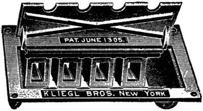
FIGURE 173.
Sometimes lights fed through stage pockets require
to be dimmed; but it is hardly practicable to arrange
dimmers for apparatus carried by traveling companies,
since a dimmer must be selected with respect
to the amperage it is to control.
In addition to the rules given below, some cities
require the bottom of stage pockets to be open, so as
to avoid an accumulation of dust. This is a very essential
precaution, as otherwise the pockets soon fill
up or require very frequent cleaning. The covers
must be substantial as heavy trucks are sometimes run
over them. Two illustrations of stage pockets are
given in Figures 173 and 174. The plugs used with
these boxes are shown in Figure 175.
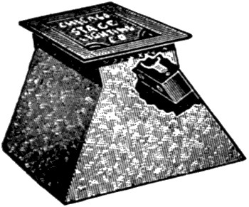
FIGURE 174.
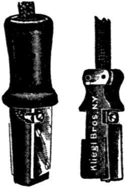
FIGURE 175.
Gallery pockets are not usually laid in the floor
but along the railing. The gallery pockets should
be under separate control from the stage switchboard.
Must be of approved type, insulated from ground
and controlled from switchboard, each receptacle to
be of not less than 35-ampere rating for arc lamps
nor 15-ampere for incandescent lamps, and each receptacle
to be wired to its full capacity. Arc pockets
to be wired with wire not smaller than No. 6 B. & S.
gauge and incandescent pockets with not less than
No. 12 B. & S. gauge. Plugs for arcs and incandescent
pockets must not be interchangeable.
Switches.—All knife switches should be enclosed in
cabinets unless they are located on a switchboard. In
exposed places, flush switches should be used. The
usual height at which scattered switches are located
is about four and one-half feet above floor. Door
switches are of use principally in dressing rooms.
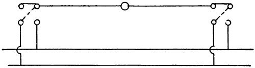
FIGURE 176.
Diagrams of three-way switches are given in Figures
176 and 177. In Figure 177, the wiring by
which a light can be controlled from three different
points is shown. The middle switch must be a pole-changing
switch. In this case a throw-over knife
switch is wired to perform this function. Omitting
the knife switch we have two three-way switches controlling
the light. When both switches (indicated
by broken lines) connect to the same wire the light
burns.
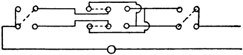
FIGURE 177.
In Figure 176, when both switches connect to the
same polarity the light is out; when one of them is
connected to the other pole the light burns. Under
certain conditions this arrangement is more economical
in wire but has the disadvantage which the other
method avoids, of bringing both poles to each switch.
This method cannot be used with direct-current arc
lamps. Three-way switches are useful on stairways,
enabling one to turn on a light at the bottom of the
stairway and turn it off when at the top or vice
versa.
Switches.
Must be placed on all service wires, either overhead
or underground, in the nearest readily accessible
place to the point where the wires enter the building,
and arranged to cut off the entire current. Departure
from this rule may be authorized only under special
permission in writing. Switches controlling emergency
lighting must be located only in the lobby.
Must when used for service switches, indicate, on
inspection, whether the current be “on” or “off”.
Switch cabinets must be deep enough to allow the
door to be closed when 30 ampere branch-circuit
switches are in any position, and when larger single-throw
switches are thrown open as far as their construction
and installation will permit.
Must, for constant-current systems, close the main
circuit and disconnect the branch wires when
turned “off”; must be so constructed that they shall
be automatic in action, not stopping between points
when started, and must prevent an arc between the
points under all circumstances. They must indicate
whether the current be “on” or “off”. Service cut-out
and switch must be arranged to cut off current
from all devices including meters.
Must always be placed in dry, accessible places,
and be grouped as far as possible. Single-throw knife
switches must be so placed that gravity will not tend
to close them. Double-throw knife switches may be
mounted so that the throw will be either vertical or
horizontal as preferred, but if the throw be vertical
a locking device must be provided, so constructed as
to insure the blades remaining in the open position
when so set.
When practicable switches must be so wired that
blades will be “dead” when the switch is open.
When switches are used in rooms where combustible
flyings would be likely to accumulate around them,
they must be enclosed in dust-tight cabinets.
Up to 250 volts and thirty amperes, approved indicating
snap switches are suggested in preference
to knife switches on lighting circuits.
Single-pole switches must never be used as service
switches nor for the control of outdoor signs
or circuits located in damp places, nor placed in the
neutral wire of a three-wire system, except in the two-wire
branch or tap circuit supplying not more than
660 watts.
Where flush switches or receptacles are used,
whether with conduit systems or not, they must be
enclosed in an approved box constructed of iron or
steel, in addition to the porcelain enclosure of the
switch or receptacle.
Hinges of knife switches must not be used to carry
current unless they are equipped with spring washers,
held by lock-nuts or pins, or their equivalent, so arranged
that a firm and secure connection will be
maintained at all positions of the switch blades.
Spring washers must be of sufficient strength to
take up any wear in the hinge and maintain a good
contact at all times.
Connections.
Switches for currents of over thirty amperes must
be equipped with lugs, firmly screwed or bolted
to the switch, and into which the conducting wire
shall be soldered. For the smaller sized switches
simple clamps can be employed, provided they are
heavy enough to stand considerable hard usage.
Where lugs are not provided, a rugged double-V
groove clamp is advised. A set screw gives a contact
at only one point, is more likely to become loosened,
and is almost sure to cut into the wire. For the
smaller sizes, a screw and washer connection with up-turned
lugs on the switch terminal gives a satisfactory
contact.
Spacings.
See “Panel Boards”.
Switchboards.—The stage switchboard is usually
located on the right-hand side of the stage. This position
enables the operator to watch cues easily and
handle his switches with the right hand. This side
is also the one from which the stage manager prefers
to work. It is preferable to have the board raised
high enough above stage level to allow all space on
the stage to be used by actors. If the switchboard is
located on stage level it takes up much room that is
valuable and makes stage exits for actors difficult.
The wiring of a good switchboard should be divided
into three parts, each part independent of the
others, so that any one part can be entirely cut off
without interfering with the other. All of the house
lights should be fed through one main switch, and all
of the stage light connected to another set of bus-bars,
but it is best not to have the stage side of the
board as a whole controlled by a main switch. If the
stage side of the board is controlled by a single switch
there exists the possibility that this switch may be
used to cut off everything for a dark scene and when
light is again wanted a part of the lighting of the
previous setting may be left on and possibly interfere
with the new scene.
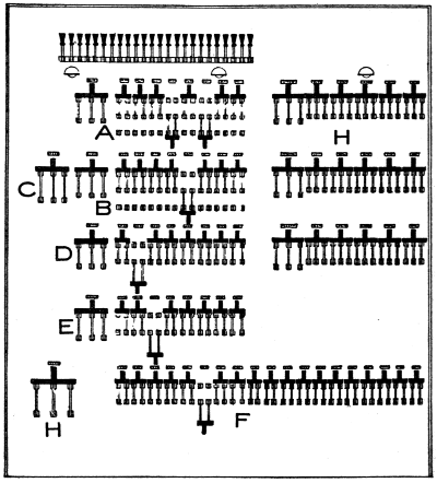
FIGURE 178.
The stage lighting is usually divided into four
groups, viz.: three color groups and a group of stage
pockets. The number of white lights is usually equal
to that of all of the colors.
Figure 178 shows a well laid out switchboard. All
of the lights in the auditorium are controlled by
switches shown in the upper right-hand corner and
all of these are under the control of the main switch.
The house lights are usually thrown on or off as a
whole and this main switch must be convenient for
the operator.
The stage pockets are controlled by the bank of
switches shown at E. Lights burning off the stage
pockets generally are controlled by special operators
on the stage or by actors, and need not be so very
convenient to the switchboard operator. They must,
however, be under his control when necessary; but
here also a main switch is not advisable.
In addition to the three groups of lights spoken of
above, there are a number of lights which should be
controlled from the switchboard but must be so connected
that they will be left on, no matter what is
done with either house or stage light.
In this group belong a few lights mounted at the
top of the switchboard which enable the operator to
see his switches when all else is dark. These lights
are generally shielded so as to throw no light in the
direction of the stage opening. The orchestra lights
also belong in this group, but a special switch may,
with advantage, be arranged on this circuit to bring
it under the control of one of the musicians. In some
dark scenes these lights are turned out for a short
time, but it is very important that they be turned on
again at the proper moment, and this is more certainly
assured, by giving the musicians control, than by
leaving it to an electrician on the stage who may be
very busy with other matters at the time.
The lights on the fly floor and in the rigging loft,
as well as those in dressing rooms and basement, must
also be independent. Fan motor circuits should also
be independent of the house circuit. They are often
needed when the house lights are thrown off.
With the switchboard illustrated in Figure 178 we
have shown only the switches governing the house and
stage proper. The switches governing the other lights
are usually worked into the vacant spaces between
the two groups. Each switch should be labeled in
such a manner that a new operator can learn the
board easily.
The most important part of the board is that part
governing the stage lighting, and this should always
be placed as conveniently as possible to the operator.
A stage switchboard is like a house in that no one is
wholly satisfied with the one he has, but thinks he
could improve it a little if he could build it over
again. The arrangement shown in Figure 178 is,
however, quite satisfactory for general purposes. The
white lights predominate in the ratio of two to one
and are laid out in two groups A and B. Both groups
are controlled by the switch C. The switches A and
B do not control the lights at all if the smaller throw-over
switches at the right are thrown downward. A
diagram of these switch connections is given in Figure
179 where the switches B and C are indicated.
The object of the switches A and B is to help in quickly
increasing or decreasing the illumination on the stage.
If in the beginning of a certain scene, for instance,
only a small quantity of light is wanted, while a little
later full illumination is desired, the low illumination
may be obtained by throwing the proper switches
down; the additional illumination which will be
needed a few minutes later may be prepared for by
setting the other switches needed to the upward position
and at the proper moment closing switch B; this
will instantly produce the effect which otherwise
would be possible only by operating a number of
switches in succession. In the same way, by a reversal
of this process, the illumination may be reduced
in any amount. This feature is very valuable
in many stage settings.
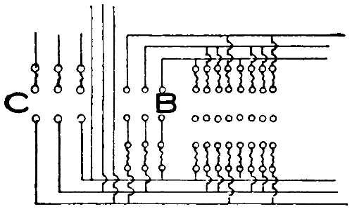
FIGURE 179.
To throw off all of the white lights the switch C
must be opened. The switches D and F are main
switches controlling colored lamps. All lamps of one
color should be connected to one or the other of these
groups unless some special color effect is desired.
From the three groups of switches, circuits extend
into the foot lights, into every border, and into the
proscenium side-light strips so that the color scheme
may be carried out in any of these.
The handles of all switches in a row should be of
the same height so that the operator may more readily
accustom himself to catch them quickly. It is better
to have switches of some excess capacity, as the heavy
metal stands the arcing much better.
A main switch by which the whole board may be
cut off should be installed but this need not be on the
front of the board.