(264) The last process in the production of yarn is that in which the
rovings, obtained in the manner described, are elongated and twisted
into a thread. To many persons this is known as “spinning,” although
strictly speaking, that phrase is applicable to the whole range of
treatment by which cotton is converted into yarn. Using the term,
however, in its narrower sense, spinning may be either an intermittent
or continuous operation, that is, the rovings can be twisted for a
portion of the time only during which the machine is working, or for
the whole of that period. Although the latter system is the most
ancient, for the last century the former has been more generally
pursued. It is, therefore, advisable to describe first the machine by
which it is carried out.
(265) This is known as the “mule,” and owing to the practical
automaticity of its mechanism, as the “self-acting” mule or “self
actor.” It is without exception the most interesting of the whole
series of machines used in cotton manufacture, combining an intricate
sequence of mechanical movements with great ingenuity. As a further
consideration will show, one piece or part of the mechanism used
performs work widely diverse in its character at different periods,
and it is this fact which renders the mule so difficult a machine to
understand. The time occupied in completing the cycle of operations
which constitute mule spinning is so small that the action of the
various parts must be very rapid and certain. In order to understand
the description which follows, it will be advisable to define the
stages or periods which succeed each other and form the entire process.
(266) In order to facilitate the grasp of the subject by the reader, it
will be better to describe first and briefly the essential or primary
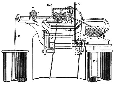
parts of the machine. These are shown in Fig. 148, which is a purely
diagrammatic representation. The roving bobbins A are fitted on
a skewer and placed in the frame or creel arranged at the back of the
machine, being held in an almost vertical position. The roving R
is guided as shown to the nip of triple lines of drawing rollers B
B B. From the rollers the roving passes to the tip or point of
a steel spindle H, sustained by an upper bearing or bolster
O, and a footstep N. These are fixed in wooden rails
which form part of a box or frame I, known as the “carriage.”
The carriage is fitted at convenient distances along its length, with
cross brackets, in each end of which bearings are formed for the axes
of the pulleys or runners P. These rest upon the edges of oblong
iron bars or “slips” Q, which are securely fastened to the floor
of the room. The spindle receives a rapid rotary motion, being driven
by a band M, carried tightly round a small V grooved
pulley or “warve” fixed on the spindle, and a light roller K
extending longitudinally of the carriage, and fastened on a shaft
T. The roller—or more correctly the “tin roller”—K is
suitably driven, and, it will be easily understood that the direction
and velocity of H will depend upon those of K. In
its passage to the spindle the roving is taken under a small guide
wire D—known as the “faller wire” or shortly the winding
“faller”—fastened on the outer end of a curved arm or “sickle” secured
on the shaft F—known as the “faller shaft.” The roving also
passes over a second wire C—called the “counter faller”—which is
fixed in a similarly shaped arm fastened on the “counter faller shaft”
E. By the oscillation of the shafts E F, the winding
faller and counter faller are elevated or depressed, thus enabling the
finished yarn to be wound into the spool or “cop” G, which is
made of the shape shown. The above form the essential portions of a
mule and their respective functions can now be explained.
(267) The rollers B perform the same office as those used in the
drawing and roving machines, namely, the attenuation and delivery of
the roving. Each of the three lines revolve at different velocities,
that of the front line being the superior one, with the result that
roving which, as was shown, has been already considerably reduced in
diameter is still further attenuated prior to being twisted.
(268) The roving is wrapped round the spindle two or three times in
commencing operations, being sometimes rendered adhesive by paste, and
sometimes wrapped on a paper tube placed on the spindle. Being thus
held at one end by the spindle, and at the other by the nip of the
front rollers, the rotation of the former will necessarily further
twist the partially twisted roving. On the degree of twist—that is the
number of turns per inch—depends the amount of roving delivered by the
rollers in a given time, as explained in paragraph 234.
(269) In the roving machines the relative positions of the spindle
and front rollers are fixed, but in the mule an important variation
in this practice occurs. The carriage I receives by suitably arranged
mechanism an alternate movement from and towards the roller B.
During the period they are delivering roving it is drawn away from them
until it has travelled about 63 inches, when its motion ceases. While
this traverse is taking place the spindles are revolving, and twist is
therefore being introduced into the roving. The cessation of the motion
of the carriage is accompanied by a similar stoppage of the rollers
and spindles, and there is then a number of lengths of yarn—each 63
inches—held in tension by them. This traverse of the carriage is called
its “stretch” or “draw.”
(270) The yarn, as thus spun, requires winding upon the spindle, so as
to form the cop, but before doing this it is necessary to free two or
three turns which are wrapped on the spindle between its point and the
point or “nose” of the cop. This operation is called “backing off.”
In order to effect it the roller K has its motion reversed
for a short time, so as to give the necessary backward rotation to
the spindles. The slack yarn thus produced is taken up, first, by
the ascent of the counter faller, and, second, by the descent of the
winding faller. The former rises sufficiently to preserve the tension
of the yarn as it is freed, and the latter is drawn down so as to
assume a proper position to commence winding when the operation of
backing off is completed.
(271) As soon as this stage is finished the inward traverse of the
carriage I commences, an operation which is accompanied by
the forward revolution of the spindles, which thus wrap or “wind” on
to the cop the 63 inches of twisted yarn. The rollers during winding
are, of course, stationary. By the time the carriage has again reached
its innermost point the full length of yarn is wound, and during that
period the faller has risen from the base of the upper cone of the cop
to its nose. This ascent is a gradual one, and causes the yarn to be
wound in finely pitched spiral coils upon the cop. With the termination
of the inward traverse or “run” of the carriage winding ceases, the
winding faller and counter faller wires are released, and the whole of
the operations begin anew.
(272) It is now possible to define the various stages in the whole
process of mule spinning. These are as follows:—
First. The period during which roving is being delivered and twisted.
During it, the rollers are revolving at a defined speed; the carriage
is being drawn outwards at a constant rate; the spindles are revolving
rapidly at a velocity definitely relative to that of the front roller.
During this period the faller and counter faller are held in the
position shown in Fig. 148, being quite clear of the yarn.
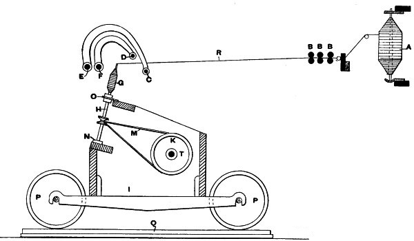
Fig. 148.J.N.
Second. The period during which the movements just named are stopped.
The roller driving gear is detached; the mechanism by which the
carriage is drawn out is stopped; the spindles are stopped because
of the transfer of the driving strap to the loose pulley and the
consequent cessation of the motion of the driving band; and preparation
for the engagement of the faller and counter-faller with the yarn takes
place.
Third. This is the period of “backing-off.” During it the driving band
is driven in the contrary direction to its normal one, and the spindles
are reversed. The faller wire is drawn down, depressing the yarn; the
yarn between the nose of the cop and spindle point is uncoiled; the
counter faller rises and takes up the slack yarn; and the faller is
“locked.”
Fourth. During this period “winding” takes place. The rollers are
stationary; the carriage is “running in” at a variable speed; the
spindles are revolving in the same direction as when twisting; and the
winding faller is operated so as to guide the yarn on the cop.
Fifth. The carriage comes to rest; the faller and counter faller are
released; the roller driving gear is re-engaged; the strap is moved on
to the fast pulley and the driving band put in motion; and the drawing
out gear is again engaged.
With this the cycle of movements is completed, and the whole of the
operations begin anew.
(273) There are thus five periods, viz., 1st, twisting; 2nd,
arrestation; 3rd, backing-off; 4th, winding; and 5th, re-engagement. In
addition to these, when fine yarns are spun, there is sometimes a sixth
period, which takes place immediately after the termination of the
first as at present defined. This is a period of supplementary twisting
after the rollers have stopped. This operation is sometimes known as
“twisting at the head,” and will be dealt with at a later stage.
(274) It is thus indicated that at various times one part of the
mechanism performs different functions. The rollers revolve for the
whole or part of the first period and remain stationary afterwards. The
spindles revolve at a constant and maximum velocity in their normal
direction during the first period, at a slower but constant velocity
in the reverse direction during the third period, and at a variable
speed in their normal direction during the fourth stage. The carriage
makes its outward run at a regular speed during the first period, is at
rest during the second and third, and makes its inward traverse at a
variable speed during the fourth. The winding faller remains stationary
and free from contact with the yarn until the third period, when it
makes a rapid descent to the winding point, after which it first
descends quickly to its lowest point, and then ascends slowly to the
nose of the cop during the fourth. The counter faller remains below and
out of contact with the thread during the first and second periods, and
ascends during the third, remaining in contact with and sustaining the
yarn until the termination of the fourth.
(275) This preliminary explanation will enable the detailed description
following to be more easily understood and appreciated. As there are
many variations in the construction of the mule it is desirable to
select one of the most widely used, and for this reason the machine
constructed by Messrs. Platt Brothers and Co. has been chosen for
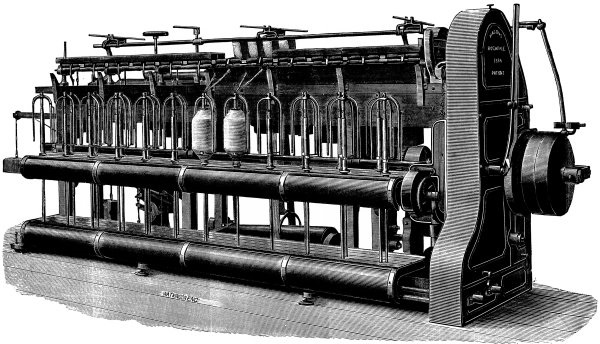
description. Front and back perspective views of the machine are given
in Figs. 149 and 150. The Parr-Curtis mule is also largely employed,
and many modifications of it exist. All the root principles which are
contained in the machine are, however, found in the Platt machine. That
is to say, it contains mechanism founded upon certain rules which are
essential to all mules, so that, although the details may be, and are,
varied, the main features are identical. A detailed description of its
mechanism, therefore, will enable the subject to be fully understood,
but, at the close of the chapter, particulars will be given of special
features in other makers’ machines. To enable the construction of the
machine to be more fully grasped, a series of diagrammatic views are
given of each motion separately, and the reference letters are arranged
so that each part is marked with the same letter in all the views in
which it occurs, although the same letter, in some cases, refers to
various parts in different diagrams.
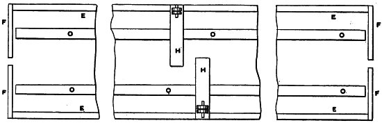
Fig. 151.J.N.
(276) It may be first explained that the greater number of the parts
by means of which the required motion is given to the various portions
of the mechanism are contained in a longitudinal framing placed in
the centre of the machine, this part of the mule being called the
“headstock.” At right angles to the headstock, and at each side of it,
the rollers and carriages extend for the entire length of the machine.
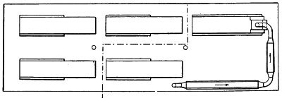
The arrangement of a “pair” of mules is clearly shown in Fig. 151, the
machines being usually placed with their headstocks zig-zag to one
another. The carriage of one mule is coming out while that of the one
opposite to it is at the roller beam, this arrangement permitting the
free movement of the workman attending to the machines, and preventing
the broken threads in each machine requiring piecing at the same time.
It might, perhaps, be explained that “piecing” is always effected when
the carriage is making the first part of the outward run, so that some
inconvenience would arise if both carriages were in that position at
the same time. A special motion is sometimes fitted by which each
carriage is released alternately by the movement of the carriage
opposite to it. Referring now to Fig. 151, H represents the
headstocks of the two mules, E the lines of rollers, F
the end frames, and O the carriages. It will be noticed that the
headstock divides the machine into two portions of unequal length, each
of which contains its own rollers and spindles. The special object of
this is to enable the mules to be placed in closer proximity than could
be done if both sides were of the same length, and the headstocks were
placed quite opposite to each other.
(277) The rollers are in three lines, and are borne in brackets or
stands fastened to longitudinal iron “roller beams,” sustained at
intervals by light frames or “spring pieces.” The lower lines of
rollers are finely fluted, and are made of the same superior quality
of iron as those used in the roving frames. Their diameter is usually
an inch, but this varies with the staple to be spun. The front line of
top rollers are generally of Leigh’s loose boss type, cloth and leather
covered, and are weighted by a saddle, stirrup, and lever weight. The
middle and back lines are “common rollers,” also covered in the same
manner. The front lines of the right and left-hand set in each mule are
coupled by a short shaft, and the second and third are driven from the
first.
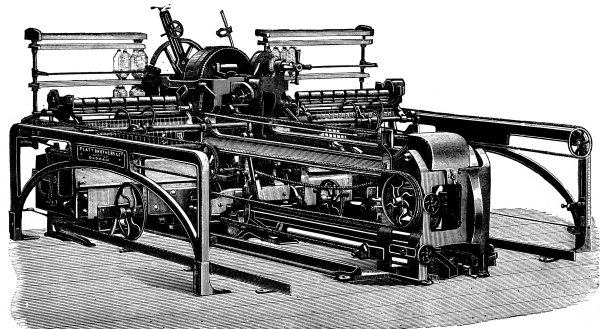
Fig. 149.
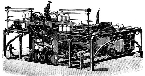
Fig. 150.
(278) The carriage has a rectangular frame, being built with strong
longitudinal timbers, securely tied together by cross pieces. These
carry, as was shown, the bolster and footstep rails. On the cross
cast-iron “muntins” the bearings for the tinroller shafts are fastened.
The carriages at each side of the headstock are coupled by a strong
iron frame, to which they are securely fastened. This is known as the
“square,” and carries some of the mechanism for giving motion to the
spindles and building the cop.
(279) The tin roller is generally six inches in diameter, and consists
of a series of cylinders made from sheets of tinned iron, securely
soldered together. In each end of the rollers so formed an iron disc
is fastened, and the lengths are coupled by means of short shafts. The
whole of the lengths are thus connected, and a bearing is placed at
each junction, so that the tin roller is well sustained throughout.
The rollers in each of the two carriages are coupled by a short shaft,
extending across the square, and carried by means of pedestals, fixed
to the latter. On this short length of shaft the driven tin roller
pulley is secured, as will be hereafter fully described.
(280) The spindle is made of steel, and is from 131⁄2 to 18 inches
long, according to the class of material being dealt with. For coarse
counts and for “twist” yarn a larger cop is made, and the spindle is of
necessity longer. For 32’s twist yarn a spindle about 17 inches long
is used, and its diameter varies from 3⁄8ths inch to less than 1⁄8th
inch. The part between the two bearings is called the “haft,” and that
above the bolster—on which the cop is wound—the “blade.” The spindle
is thickest in the haft, terminating in a small foot, but the blade is
tapered throughout. Great care is taken with the spindles to ensure
their accuracy, and they can, therefore, be run at velocities as high
as 11,000 revolutions per minute without vibration. The extra diameter
of the haft ensures the necessary resistance to flexure caused by the
pull of the driving band. The latter is a thin cotton cord-made of the
best grades of cotton—passed tightly over the spindle warve and the
tin roller. It is highly important that the bands should not be either
too tight or too slack. In the one case the friction generated would
be excessive and detrimental, and in the other the twist would not be
fully put into the roving, which would be said to be “slack twisted.”
Varying atmospheric conditions materially alter the tension of the
bands, and their proper piecing is only to be mastered after long
practice. The spindle is disposed in the carriage at a varying angle,
to suit the material being spun.
(281) The description of the general construction of the machine thus
given clears the ground for the detailed explanation which follows.
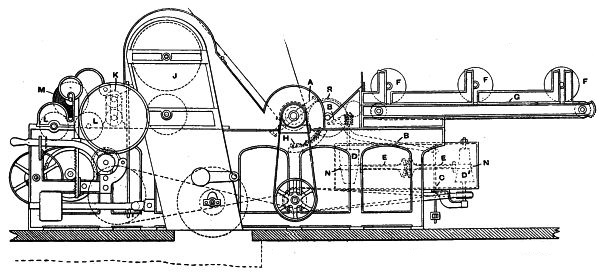
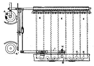
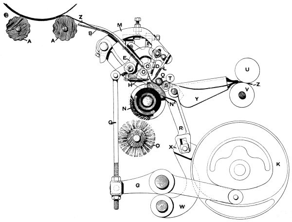
For convenience it will be as well to begin by describing the mode of
obtaining the motion of the spindles. This is illustrated in Fig. 152,
which is a diagrammatic representation of the course of the bands and
driving pulleys. The mule is driven from the line shaft, or a counter
shaft by means of a strap passing over the pulley A fastened
upon the shaft C. The latter is termed the “rim shaft,” and
upon it the loose pulley B is also placed. Free to revolve and
slide upon the same shaft is the spur wheel A1, formed with
a large internal cone, the exact object of which will be hereafter
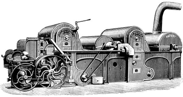
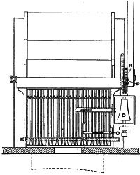
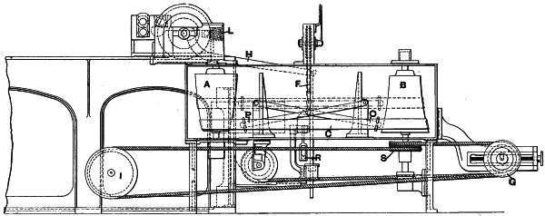
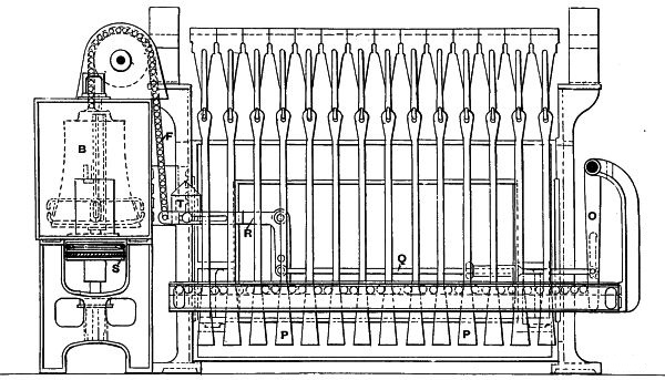
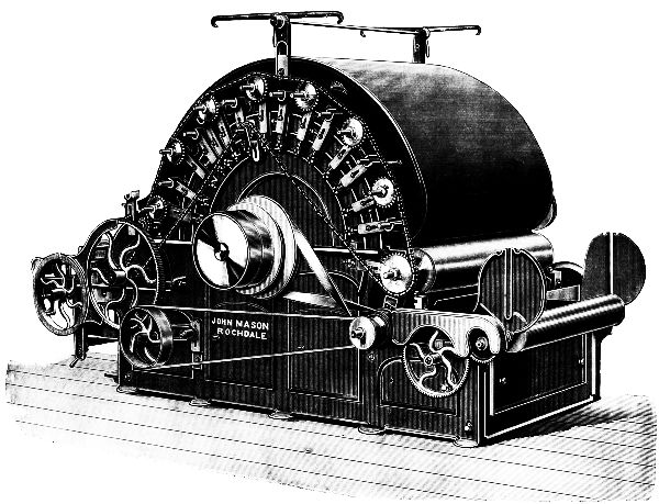
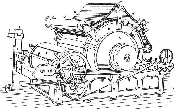
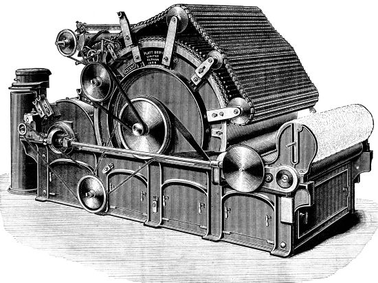
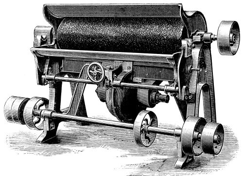
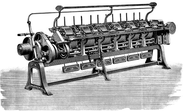
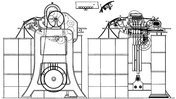
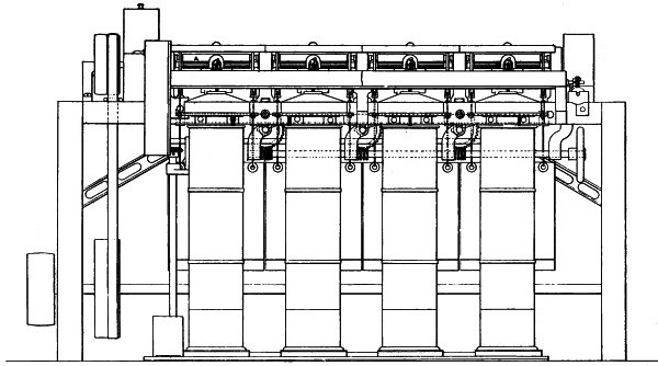
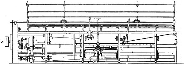
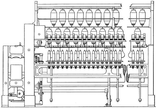
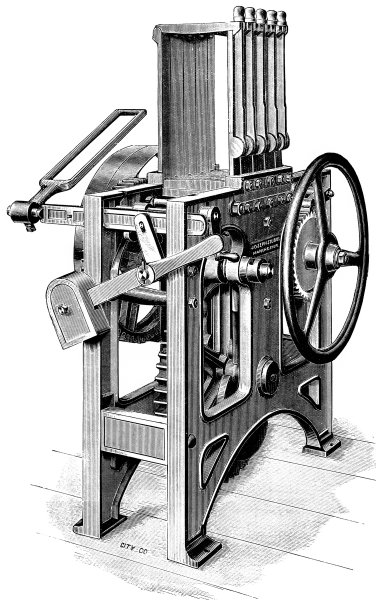
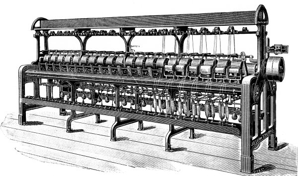
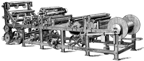
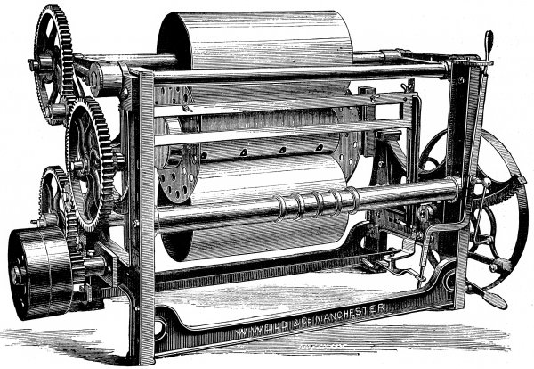
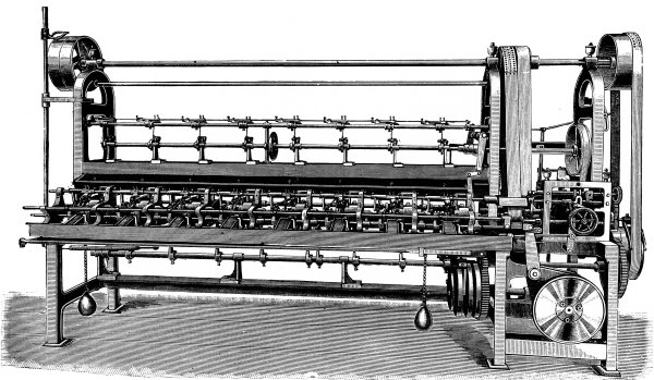
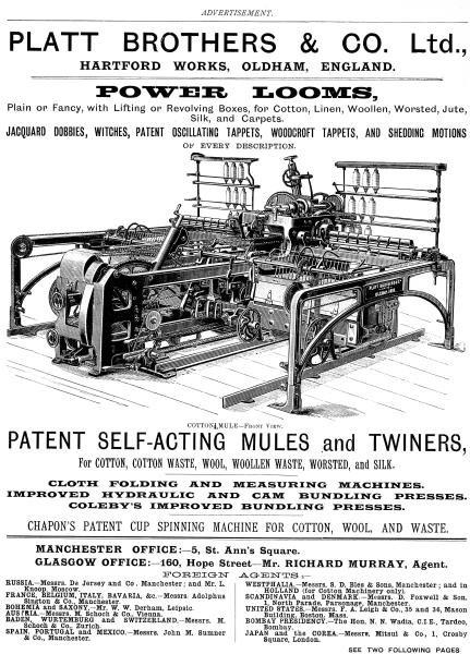
described. The fast pulley is about 5 inches wide, and the loose pulley
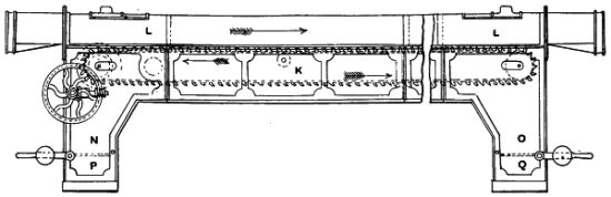
51⁄4 inches, the diameter being about 15 inches. Thus, when the
strap is on the fast pulley it is also partially on the loose pulley,
which is always revolving. At the other extremity of the rim shaft
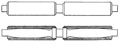
a double, treble, or quadruple grooved pulley C1 is fixed,
which is called the “rim.” Over this the endless cord or band driving
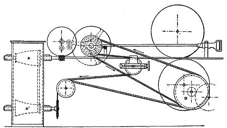
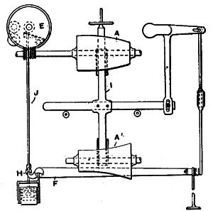
the spindles is passed—being known as the “rim band”—its course being
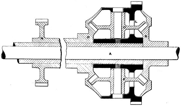
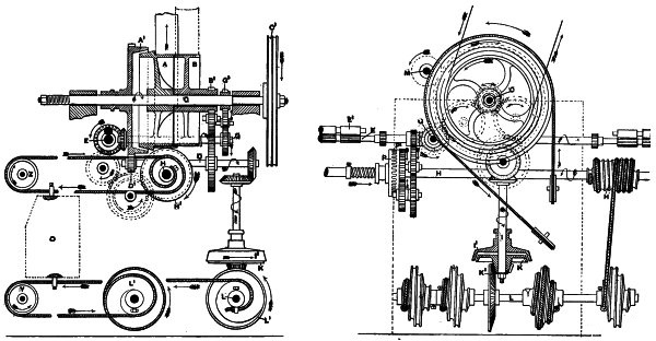
clearly shown by means of the arrows. It will be noticed that it is
first passed round a carrier pulley on the carriage square, and then
round the tin roller pulley on the tin roller shaft T, being
then taken round the carrier pulley Y fixed at the end of the
headstock frame, afterwards returning to the rim pulley. It will, of
course, be understood that the explanation just given relates to the
course of the rim band, considered as a single rope. When the rim is
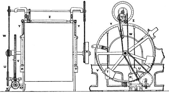
double or treble grooved, corresponding arrangements must necessarily
be made in the rim band course. The rollers E are driven from
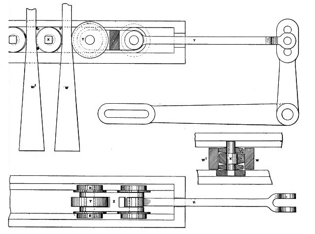
the rim shaft by the train of wheels and the side shaft G shown,
and the drawing out of the carriage is effected by the band passing
round the scrolls at H and round the pulley Z. This will
be more particularly described presently.
(282) Particular reference will now be made to Figs. 153 and 154, which
are respectively longitudinal sections of the driving gear and back
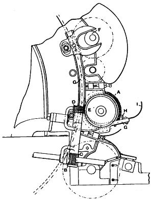
view of the same. The loose pulley B has formed upon its boss
a spur pinion B1, from which, by means of a carrier wheel,
the side shaft D is driven. On the other end of this shaft a
pinion D1 is fixed, which gears with and constantly drives
the spur wheel A1, this being the object of the overlapping
of the driving strap previously referred to. The wheel A1 is
formed, as shown, on its inner side with a large internal conical
surface, which, at the proper moment, engages with a corresponding
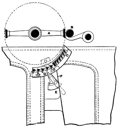
leather-covered surface formed on the pulley A. This engagement
takes place for the purpose of backing-off, and the cone A1 is
therefore known as the “backing-off cone” or “friction.” The engagement
of the friction cone with the fast pulley causes it first to act as a
brake, and the strap having been moved upon the loose pulley it then
exerts sufficient force to revolve the backing-off cone in the contrary
direction. To enable this contact to take place a ring groove is formed
in the boss of the backing-off wheel, in which a claw engages, which is
oscillated as afterwards described. The effect of this arrangement is
that the rotation from the loose pulley B of the friction wheel
A1, whilst it is engaged with the fast pulley A, causes
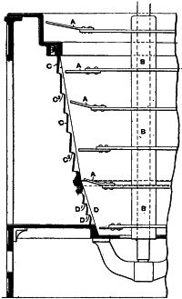
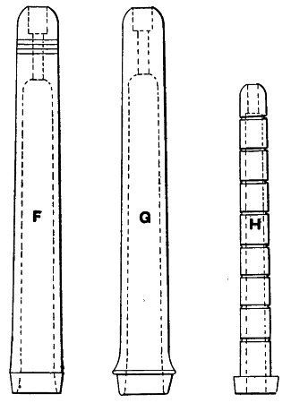
the rim shaft to be rotated in the opposite direction to that normal
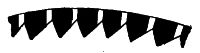
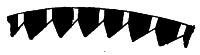
to it. The direction in which the various parts revolve normally is
clearly shown by the arrows. The extent of the backward movement of the
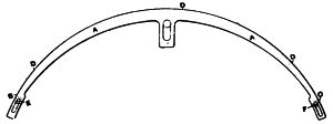
rim shaft depends, of course, entirely upon the length of time during
which the friction cone A1 is allowed to engage with that on
the pulley A, this being regulated by the amount of yarn to be
unwound.
(283) The rollers E are driven from a pinion G1 fastened
on the rim shaft, by means of which the shaft G is revolved,
and motion is thus given to a bevel wheel loose upon the short shaft
coupling the two front lines of rollers. One half of a toothed or claw
clutch is formed on the boss of the wheel, the other half of which is
secured to but slides upon the coupling shaft, being formed with a ring
groove on its boss into which the two arms of a claw are fitted so as
to engage and disengage the clutch.
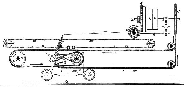
Fig. 152.J.N.
Figs. 153 and 154.J.N.
(284) On the boss of the bevel wheel is a spur wheel which, by means
of the train of wheels shown, communicates the forward movement to
the “back” shaft H on which are fixed the scrolls H1.
On these the ropes or bands shown are wound, being attached to the
carriage as shown in Fig. 152. As the carriage extends to the right
and left of the headstock, as explained, the back shaft H
is similarly extended, and has placed upon it a number of scrolls
at suitable distances apart, on which other bands are wound. This
enables the carriage to be evenly drawn out throughout its entire
length. The method of attaching the bands to the end frames of the
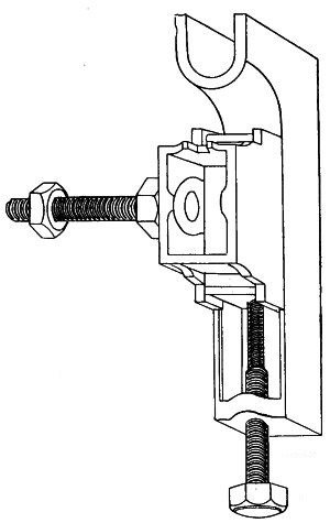
carriage is shown in Fig. 155, and it will be seen that there is power
of adjustment given, which enables the carriage to be “squared” or
kept parallel with the roller beam. The last of the train of wheels
P1, by which the back shaft is driven, is loose upon it, and
forms one half of a clutch, the teeth of which are peculiarly shaped.
The other half P slides upon the boss of a disc which is keyed
upon the shaft, and has a ring groove in its boss, being ordinarily
pushed up to its position by a spiral spring surrounding the back shaft
and kept in compression by a stop hoop or collar which can be set up as
desired. This, combined with the peculiar construction of the teeth,
enables the clutch to open and its teeth to glide over one another in
the event of any obstruction being offered to the free outward run of
the carriage. The forked end of an L lever fits in the groove in
the clutch, being oscillated as afterwards described.
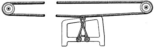
Fig. 155.
(285) The bevel wheel on the outer end of the taking-in side shaft
D gears with a similar one fixed on the upper end of the
vertical shaft I, on the lower end of which is loosely placed
the friction cone K. With the latter the hollow cone I1
engages, this being able to slide in a vertical direction on a disc
keyed to the shaft. It is usually kept out of gear by means of a
hinged forked lever, the fork of which fits in the groove shown in
I1, and which is sustained at its free end so that it can be
readily released to allow the sudden engagement of the friction cone.
On the half cone K, at its underside, is cast a small bevel
pinion; which engages with a bevel wheel K1 fixed on the shaft
L, extending transversely of the headstock at the back. Spirally
grooved or “scroll” pulleys L1 are fixed on the shaft L,
on which ropes are wound, these being attached to the carriage square
as shown in Fig. 168, page 212. An additional scroll is fitted on the
shaft L, and is set at such an angle that when the rope is fully
drawn off the other scrolls it is wound on the additional one. When the
friction cone is in gear the ropes are wound on to the scrolls, and the
carriage is drawn in. From the fact that these scrolls are employed,
and that their object is to draw in the carriage, the shaft L
is called the “scroll” or “taking-in” shaft, and the friction cone
is commonly styled the “taking-in friction,” or, more shortly, the
“friction.”
(286) The means just described are those which are in use on a large
number of mules constructed by Messrs. Platt, and worked satisfactorily
until the speed of the rim shaft was largely increased. Up to about
750 revolutions the train of gearing driving the taking-in side shaft
could be used, but as the rim is now run at speeds as high as 900
revolutions it is the practice to drive the taking-in side shaft by
means of a grooved pulley fastened upon it, and driven by a separate
band from the counter shaft. In this way much of the strain is taken
from the rim shaft, and the use of gearing obviated for the taking-in
and backing-off. When this method is adopted—as is now almost generally
done—there are many advantages gained, and it is the most modern
practice.
(287) Another method of driving, also largely employed by Messrs.
Platt, is a patented system of duplex driving. This is shown in plan
in Fig. 157. Instead of using one belt only, by means of which the
power is transmitted, two narrower ones are employed, each of which is
23⁄4 inches wide. The fast pulleys A are also 23⁄4 inches on
their face, while the loose pulleys B are 3 inches wide. The
strap guide is made, as shown, double, and the distance which it has
to traverse is only half that which is usual. The advantages of this
arrangement are derived both from the smaller width of the belts, and
the shorter distance they need moving. The diminished width causes
the belt to be more pliable and less rigid, and in consequence the
pressure applied is more readily responded to. The shortened traverse
enables the change of the belts to be made more easily and in less
time, and, in consequence of the latter fact, the time the edges of
the belts are pressed upon by the guider is reduced. This reduction
involves considerably less wear of the strap edges, which, alike on
this account and because of their easier and less strained motion,
are found to have a much longer life. The smooth action of the belts
produces another effect. It enables the full speed of the rim shaft to
be more readily reached, and so tends to increase the production of the
machine. The makers have now constructed a large number of mules with
this arrangement, and its use is steadily extending.
(288) The mechanism just described is that on which depends the driving
of the whole of the parts, and its mode of action can now be easily
explained. Beginning with the commencement of the outward run, when the
rim band is traversing in its normal direction, the rollers commencing
to deliver yarn, and the spindles revolving, the position of the parts
is as follows. The strap is on the fast pulley, and the rim shaft is
revolving. The backing-off friction is out of gear, the necessary
motion is given to the roller shaft, and as the claw clutch is engaged
the front line of rollers is revolved, roving being delivered. At the
same time the back shaft is driven, the clutch on it being in gear, and
the carriage is drawn out. The scrolls on the back shaft are shaped
so as to allow the carriage to move at a constant velocity. While the
carriage is running out the rim band is giving the required revolution
to the tin roller shaft, and the spindles rotate in consequence at
their normal velocity. The carrier pulley on the square shown in Fig.
152 is arranged at such an angle that the rim band passes freely on
to and from the pulley on the tin roller shaft. A similarly accurate
setting is given to the guide pulleys at the back of the headstock,
the wear of the bands being much reduced in consequence. The velocity
given to the carriage is slightly in excess of that of the surface
speed of the rollers, so that the roving is a little stretched. The
excess of the carriage traverse is from 1 to 3 inches, and is known as
its “gain.”
(289) When the carriage reaches the termination of its outward run,
or, as is commonly said, the end of its stretch, it becomes necessary,
first to arrest and then to reverse its movement, these operations
necessitating a complete change in the positions of the various parts.
The chief agent in making these changes is the shaft M, placed
parallel to but a little higher than the rim shaft. It is known as
the “cam shaft,” and plays an important part in the operation of the
machine. It is entirely distinct both by position and function from the
rest of the mechanism, and a separate view of it and its connections is
given in Fig. 156, which is a detached sectional elevation.
(290) Hinged to one side of the headstock framing is the lever
T—known as the “long lever”—at each end of which pins are
fastened, which carry the bowls R R1. Fastened to the carriage
by bolts are two horn brackets S S1, to which power of
adjustment is given. The underside of the brackets is curved, and they
are fixed at such a height, that, as the carriage approaches either end
of its run, one of them will engage with the bowl or runner carried on
a stud fixed in the end of the long lever, as shown very clearly by the
dotted lines. At the outer end of the long lever, the bell crank lever
Q is pivoted, and is ordinarily drawn towards the end of the
long lever by a spiral spring O. In this way, when the latter
has assumed a position in consequence of the pressure of the horn
brackets S S1, the pressure of Q upon it prevents it
from moving until a similar force is again applied. In short, the long
lever is locked.
(291) On the cam shaft three cam or eccentric surfaces are placed,
marked respectively W Y and Z. These are shown with their
connections in detached views. The cam W is compounded with the
male half of the friction clutch X, and can slide along with
the half clutch upon a feather key fixed in the shaft. The other half
of the clutch is loose upon the shaft, and has formed upon its boss
a spur pinion which, as shown in Fig. 153, engages with the teeth of
the backing-off wheel A1. Thus the continuous rotation of the
latter leads to a similar movement of X, and, as a consequence,
the latter is always in a state of readiness to rotate the cam shaft. A
spiral spring surrounds the cam shaft, being sunk into a recess in the
bearing and continually pressing upon a flange formed on the sliding
half of the friction clutch, thus tending to force the latter into
gear. On the inner side of the flange two cam surfaces are formed, as
shown at V, with which the nose of the rocking or escape lever
engages. The latter is connected by a short rod to the end of the
long lever, the whole attachment being very clearly indicated in the
illustration. Suppose the end of the lever to be in the position shown
in the left hand view of V, the friction clutch would then be
engaged, and the cam shaft would revolve until the outer cam surface on
V came into contact with the end of the lever, when the sliding
half clutch would be disengaged and arrested, and the motion of the
cam shaft would cease. In this position the parts remain until the
long lever is again moved, this time having its inner end depressed by
reason of the contact of the bracket S1, and bowl R1.
The nose of the escape lever is then moved off the outer cam surface
into the flat or level portion of the inner cam course. This permits
the re-engagement of the friction clutch, and the cam shaft makes the
second half turn, causing the inner cam course to engage with the nose
of the lever and again disengaging the friction clutch. The raised cam
surfaces on V are directly opposite one another, so that the
cam shaft can only make a half turn before it is disengaged. The next
movement of the long lever, which takes place at the end of the next
outward run, is caused by the engagement of S and R,
and the escape lever nose is then moved on to the level surface of
the outer cam course. This alternate movement of the long lever takes
place, as will be readily understood, when the carriage reaches the
termination of its inward and outward runs.
(292) If it be assumed that the carriage has reached the end of its
outward run, and the cam shaft has made a half revolution, three things
take place. The back shaft clutch is disengaged, and the shaft ceases
to revolve; the roller clutch is detached, stopping the delivery of
roving; and the cam Y is moved into such a position that the
strap lever can traverse so as to allow the strap to pass on to the
loose pulley.
(293) The back shaft clutch is controlled by the internal cam Z,
in which a bowl on a pin fixed in the bell crank lever Z1,
Fig. 162, page 201, to which reference will be made for this part of
the subject, works. In the groove of the sliding half P of the
clutch, the forked end of the lever T fits, this lever being
hinged at its lower end and having a horizontal arm, the end or nose of
which rests upon the horizontal limb of the rocking lever Z1.
Thus, when the latter is rocked so as to make an upward movement, the
lever T is raised, and causes a disengagement of the clutch P
P1. The back shaft is thus freed, and all motion of the carriage
ceases.
(294) The rollers are disengaged by the cam W, which acts upon
the cranked lever shown, the vertical arm of which is forked and fits
in the groove in the loose half of the roller clutch I. When the
cam is in the position shown in Fig. 156, the rollers are engaged, but
when the cam shaft makes its half revolution the lever is oscillated
and the clutch is detached. As previously noted, the cam course is
formed in the loose half of the friction clutch X, which thus
serves a double purpose.
(295) The compound strap guide lever is placed almost vertically, as
shown in Fig. 158, being hinged upon a pin in the headstock frame. The
part G carries a short pin on which a small runner or bowl can
freely revolve. While the carriage is running out, the bowl is at the
point of the cam Y, but when the half revolution of the cam
shaft is made it assumes a position at the base of the cam. These two
positions are very clearly shown in the right hand bottom corner of
Fig. 156. This allows the strap to move, in a manner more particularly
described afterwards, on to the loose pulley, so that the backing off
friction can be engaged.
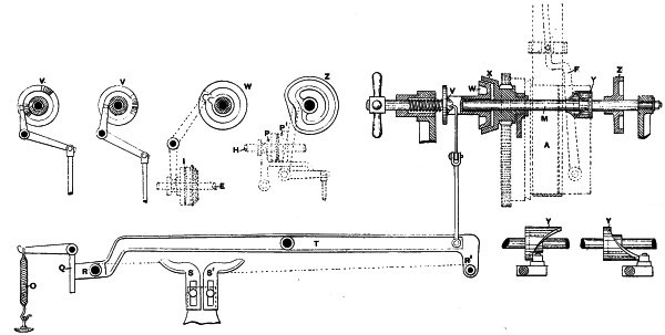
Fig. 156.J.N.
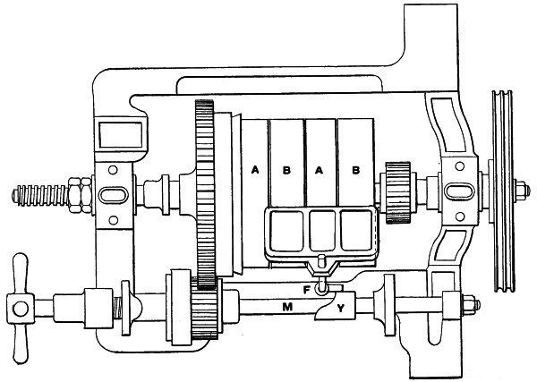
Fig. 157.J.N.
(296) It has thus been shown that the half revolution of the cam
shaft causes the stoppage of the motion of the carriage, rollers,
and spindles. This is the second stage or period, and it is at once
followed by the third. Before passing on it is worth while reiterating
that there is a decided advantage in the constant rotation of the loose
half of the clutches X and A1, their engagement being
made more rapidly and with less strain. The power derived from the
portion of the strap upon the loose pulley is sufficient to rotate
the cam shaft, and cause it to make the changes. It is also capable
of maintaining the steady rotation of the backing-off and taking-in
friction clutches, so long as these are not in gear, or communicating
motion to the spindles or carriages.
(297) The strap guide arrangement is shown in detail in Fig. 158.
The guider is fixed at the upper end of a lever F, which is
hinged, as shown, at its lower end to the heel of the lever G.
F has also an arm F1, which is coupled to a horizontal
limb of the lever G by the spring S. The two or compound
levers are therefore constantly drawn towards each other. The lever
G is secured on a short shaft, and has a second spring Q
attached, which pulls it in the direction of the arrow, when it is
freed by the rotation of the cam Y. A short stud bowl is fixed
in G, and the pull of the spring presses it constantly against
the cam. Coupled to a short arm, fixed on the shaft to which G
is secured, but at the other side of the headstock, is the horizontal
lever H, the outer end of which is drawn upwards by the spring
P, fastened to the framing. A shoulder or recess is formed in
H, which ordinarily engages with the fixed catch L, by
which the strap guide lever is locked in position when the strap is on
the fast pulley. On the inner end of the rim shaft a worm K is
formed, which gears with a worm wheel compounded with a spur pinion,
which, in turn, gears with the spur wheel shown. On the spindle of the
last-named wheel a small crank O is keyed, the outer end of
which has a pin, carrying a bowl, fixed in it.
(298) The action of this mechanism is as follows: The revolution of
the rim shaft causes the crank O, which is, at the commencement
of the outward run, just clear of the nose of the lever H, to
revolve. By the time the outward run is completed, the crank will have
made almost a complete revolution. When the necessary twist has been
put in the yarn, the crank O comes in contact with the front end
of the lever H and releases the catch L. Immediately this
happens the spring Q acts, and the strap guide lever oscillates,
causing the strap to glide upon the loose pulley.
(299) This step having been accomplished, the next operation is to
engage the backing-off friction. As shown in Fig. 158, the boss of
the wheel A1 is formed with a ring groove, into which a claw
fastened on a short stud fits. The lever D is also fixed on the
same stud, so that any movement given to it is communicated to the claw
and backing-off friction. The lower end of the lever is forked and
passes over a rod X extending along the side of the headstock.
This rod is guided by a bracket fixed to the side of the frame, and
has the two stop hoops X1 X2 fastened on it. Between the
stop hoops a spiral spring, always in compression, is threaded upon
the shaft, one end pressing against the lever D, and the other
against the hoop X2. It will be readily understood that the
compression of the spring will tend to push the lever D in the
direction of the arrow, until its motion is stopped by a link connected
with the slide in the arm, to which is fastened the lever H. It
is essential that the engagement of the backing-off clutch should be
practically simultaneous with the transferring of the strap from the
fast to the loose pulley, and it is therefore desirable that the spring
on X should be put in compression a little before the actual
traverse of the strap.
(300) This is accomplished by means of the swinging lever V
shown in Fig. 162. This is hinged upon the square, and is formed, as
shown, with an open mouth, at the upper part of which is an angular
projection or lip. Pivoted on the framing is the lever L, the
horizontal arm of which carries a small runner, which engages with
the incline of V as the carriage runs out. The lever V
cannot, until the termination of the stretch, be swung upon its pivot
by reason of its connection with the faller locking lever A.
When, therefore, the bowl in the lever L engages with the
incline of V, the lever L is oscillated, so that the
spring on X is further compressed. The spring is, therefore, in
a position to push the backing-off lever forward, as soon as the latter
is freed. The engagement of the lever L with the lever V
takes place a few inches before the carriage arrives at the end of its
outward run.
(301) When the outward run is completed, and the cam shaft begins to
revolve, the lever D has sufficient pressure on it to push
it over if it were free to move. Reverting again to Fig. 158, the
horizontal lever H and the arm previously referred to are
coupled by a small pin in the latter, which takes into a slot in the
former. When, therefore, the lever H is locked, the vertical
lever D cannot move, but when the unlocking of the lever
H by the crank O occurs, the oscillation of the strap
lever draws, by means of the arm, the lever H in the direction
of the arrow. This permits the spring X to extend and push the
lever D forward and so engage the backing-off friction. This
movement is rapid and nearly simultaneous with the transferal of the
driving strap. The mechanism is set to permit the backing-off friction
to come gradually into gear for the purpose of acting as a brake, as
was explained in paragraph 282.
(302) The friction cones being engaged and the strap placed on the
loose pulley, the rim shaft is driven in the contrary direction, thus
reversing the spindles. It therefore becomes necessary to take up the
yarn as it is delivered from the spindles. This is effected by means of
the faller and counter faller, as indicated in paragraph 270, and the
precise mode of action of these can now be described.
(303) The faller arms M and U, as shown in Fig. 161 (page
205), are sickle or crescent shaped, so that they can readily pass
down between the cops without touching them. The arms are keyed on
the winding faller and counter faller rods B B1 at convenient
intervals, and the wires are threaded through them. The latter are thus
well sustained, and do not deflect to any appreciable extent, this
being fatal to the effective building of the complete set of cops.
The rods or shafts B B1 are borne by brackets fastened to the
carriage, so that their axes are quite parallel to the centre line
of the carriage. The winding faller shaft is oscillated by suitable
mechanism, by which at the proper moment it is drawn downwards, while
the upward movement of the counter faller is regulated from the winding
faller. There is an important difference in the action of these parts.
As the winding faller is to act as a guide to the yarn during winding,
it is essential that it is, at the beginning of each inward run, in
the correct initial position for that purpose, and that, when it has
reached that position, it shall be locked. On the other hand, the
function of the counter faller being merely to maintain the tension of
the yarn during winding and backing-off, it is necessary that it should
be free, so as to bear constantly against the underside of the threads
without exercising an undue strain. The pressure thus exerted should
be a little in excess of the downward pull of the whole of the threads
which are being spun in the machine, but not so much in excess as to
prevent the counter faller yielding a little if from any cause an extra
pull is put upon the threads. In other words, the action of the winding
faller is positive, while the counter faller acts as a regulator of
the yarn tension. In order to maintain this relation it is desirable to
establish a connection between the descent of the faller and the ascent
of the counter faller. This is done by making the latter dependent on
the former, and by leaving it free after it has been released.
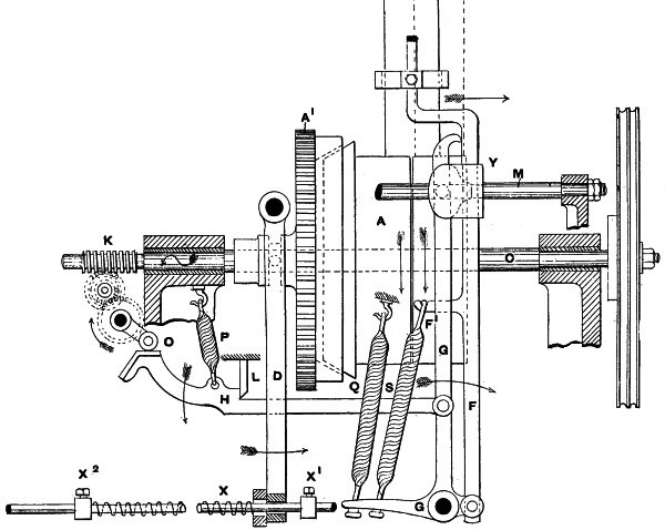
Fig. 158.J.N.
(304) The controlling mechanism is shown in Fig. 159, which is a
representation of the parts affecting the counter faller. Hinged,
as shown, to a bracket on the underside of the carriage is a lever
J, to which are attached two chains E1 I. The former
is coupled to a sector E, which is secured on the counter
faller shaft or rod B1. If it is assumed that the latter is
free to rotate, as it is, the pull exercised by the lever J
would be sufficient to cause it to do so. But until the winding faller
makes its descent so as to assume the winding position, as afterwards
described, the weight of the lever J is taken by the chain
I, which at its upper end is fixed to the hook shown. The
latter is hinged to the bracket or lever S, the other arm. of
which rests upon the counter faller rod B1, and thus limits
the upward movement of the winding faller. A steady torsional pull is
exercised upon the bracket S, so as to draw the chain I
upwards, by the spring V, attached as shown. The unwinding of
the two or three coils of yarn during backing-off takes place during
the time the winding faller is descending. Immediately backing-off is
completed, the carriage begins to run in, and the yarn is wound. It
is therefore necessary for the counter faller to rise, so as to take
up any slack yarn. Unless this is done, the yarn—owing to its tightly
twisted condition—runs into small loops or kinks, technically known as
“snarls.” The oscillation of the winding faller rod B has caused
a similar movement in S, and, as a result, the chain I
becomes slackened and ceases to sustain the lever J. As,
therefore, the carriage O begins to run in the lever J
descends, and the whole of its weight is borne by the chain E1,
which is caused to pull upon the sector E. In this way the
counter faller rod B1 is oscillated, and the counter faller
wire M is raised. The extent of its upward movement is regulated
solely by the tension of the threads, which is sufficient to act as a
counterbalance to the lever J. In order that this equilibrium
shall be sufficient to preserve the necessary tightness of the threads,
without any danger existing of either slack threads or of the counter
faller being unyielding when an extra strain is put upon the yarn,
balance weights can be added at the end of the lever J, as
shown. In this way the necessary sustainment of the yarn threads is
obtained without any likelihood of straining or breakage. When the
carriage has completed its inward run the weight of the lever J
is relieved by the roller W, so that the faller, when released,
as afterwards described, can easily assume its proper position during
spinning or twisting.
(305) While the counter faller is being freed in the manner described
the downward movement of the faller is also proceeding. Referring now
to Fig. 160, which is a detailed view of the faller arrangement, the
faller shaft has fixed on it an arm or backing-off finger D,
to which is fastened one end of a chain E. One end of E
passes round the small bowl F, and its other end is fastened
to a snail or scroll G mounted on the tin roller shaft. The
snail is geared by a ratchet clutch which engages only when the tin
roller is revolving during backing-off, being disengaged during the
whole period of spinning. The size of the snail is arranged so as to
draw down the faller finger D during the period of backing off
to such an extent that the faller is brought into the proper position
for the commencement of winding. In dealing with the latter operation
it will be shown that the faller is a little below the cop nose when
winding begins, and then rapidly descends until the base of the upper
cone is reached. At present it is only necessary to note this fact, as
it has a somewhat important bearing on the mechanism being described.
During the period of the faller descent a pull is exercised on the rod
F1, by which the bowl or runner F is carried. The other
end of F is hinged to the “locking” lever A, to which
the curved arm or sector C is hinged at its upper end. This arm
is fixed on the faller shaft, so that the oscillation of the latter,
which is caused by the pull of the chain E, gradually raises the
“locking” lever A. This elevation goes on until the shoulder
or bracket K is high enough for its under side to slip over
the small bowl fixed in the lever or slide L. The latter is at
the end of a lever hinged at one end to the carriage and carrying the
runner or bowl L1. This is drawn along with the carriage, and
the lever is consequently called the “trail” lever. As soon as K
slips on to the bowl in L the “locking” lever and faller are
said to be “locked,” and are then in a position to begin winding. This
action is practically simultaneous with the termination of backing-off.
This method of locking the faller is now general, having quite
superseded the older method of locking at the top.
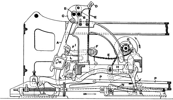
Fig. 160.J.N.
(306) In order to render the action of backing-off more perfect, and
to ensure that the slack of the yarn, as it is unwound, shall be taken
up by the faller, Messrs. Platt Brothers and Company have adopted
the mechanism also shown in Fig. 160. The reversal of the direction
of rotation of the spindles takes place a little in advance of the
downward movement of the faller, and it is therefore found that a short
length of yarn is unwound before the faller presses upon it. The actual
extent of the unwinding is relatively greatest when the cop is almost
built. It therefore becomes necessary to expedite the action of the
backing-off chain as the cops are built, so that the faller is drawn
into contact with the yarn at the earliest moment. A little reflection
will show that at the period when the cops are beginning to be built
the faller wire has a much longer distance to travel than when they are
almost finished. As will be afterwards shown, the period at which the
faller is locked is gradually made earlier as building proceeds, so
that a much shorter traverse of the faller prior to locking takes place
correspondingly. Thus, for instance, if it has to be depressed one
inch before it touches the yarn at the commencement of a set of cops,
the relative proportion of that distance to the whole traverse prior
to locking is less than when the traverse is so much diminished at the
end of a set. Thus it follows that a degree of lagging permissible at
one stage is absolutely detrimental at the other. From this it may
be deduced that an earlier and accelerated motion of the faller is
necessary in order to take up the slack yarn during backing off.
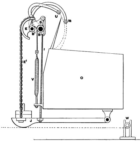
Fig. 159.J.N.
(307) It is hardly practicable to fit a motion of absolute accuracy to
effect this purpose, but an approximation to it can be obtained. It
is, therefore, arranged that at the beginning of a set the backing-off
chain shall be slack, and during building shall be gradually tightened
until at the end of it is nearly in a state of tension. The snail is
proportioned so as to give a quick downward movement to the faller,
and in combination with the arrangement about to be described gives
very good results. Referring again to Fig. 160, attached to the snail
G is a second chain, the other end of which is fastened to a
lever H, hinged on the bracket shown. The other end of H
rests on an inclined plate N, which slides on a bedplate
fastened to the floor. The plate N is fastened to the copping
plate connecting rod—afterwards referred to—which passes through a
horn fastened on N. As the copping plate is moved in, H
is also caused to assume the position indicated by the dotted lines,
N having also moved in. The effect is that a pull is put upon
the snail which gradually rotates it, and causes it to wind on the
slack of the chain E, so that, when backing-off occurs, the
faller is drawn downwards at an earlier moment. The restoration of
N to its original position accompanies that of the copping
plate, and is made at the beginning of a new set of cops.
(308) The various movements in connection with backing-off having
thus been described, it is necessary to show how the traverse of the
faller is obtained during the inward traverse of the carriage. This is
shown in Fig. 161, page 205, which is a separate view of the copping
or building mechanism. The faller “locking” lever A is, as has
been described, raised until the shoulder R slips on to the
slide L, in which position it remains until it is released
at the termination of the inward run. On the underside of L
a small bowl or runner L1 is carried, which rests upon the
upper surface of a longitudinal, or “copping” rail P, made of
a strong section. If the latter was placed in such a position that
its upper surface was horizontal, it is plain that the slide L
would receive no vertical motion during the period that the runner
L1 was traversing it. In consequence the sickle U would
remain in one position during the same time. But if the rail P
is raised at one end so that its upper edge is inclined, the slide
L will, during the run in of the carriage, receive a vertical
traverse corresponding to the difference in the altitude of the two
ends of the copping rail. That is to say, if one end of the rail
was six inches from the floor line, while the other end was seven,
L would ascend or descend to the extent of one inch while it
was travelling from one end to the other of the rail P. The
question as to whether it would ascend or descend depends entirely upon
which end of the rail was highest. From this it may be inferred that
by varying the angularity or profile of the copping rail any desired
traverse, either regular or intermittent, could be given to the slide
L. Now it was shown that the winding faller sickles are keyed
on the shaft B, which is oscillated by the backing-off finger
D fastened upon it. The latter being jointed to the “locking”
lever A, it follows, that, as the latter is raised, the winding
faller moves in an arc, which corresponds in length and direction to
the length and inclination of the copping rail.
(309) It is necessary when the carriage arrives at the end of its
stretch to lock it in that position during the time that backing-off
is taking place, and the motions of releasing the counter faller and
locking the winding faller are in operation. A reference to Fig. 162 is
necessary to understand this part of the mechanism. That illustration
is a diagrammatic representation of the mechanism relating to locking
the carriage, and the engagement and disengagement of the taking-in
gear. The parts are not in their working position, but are projected
so that their operation may be better understood. The actual relative
position of the various motions is shown by the diagrammatic sketch
in the right hand top corner of Fig. 162. Upon the carriage O
a bracket O1 is fixed, which carries at its outer end a pin
or catch, with which the hook at the end of the horizontal arm of the
L lever S can engage. The hook readily falls over the
pin in O1, as the carriage is pushed up to it near the end of
its traverse. The lever S is coupled in the manner shown to
the horizontal rod R, which, at its other end, is jointed to
a bell crank lever U1. The rod R, on account of its
function, is termed the “holding-out catch rod.” The lever U1
is in turn connected with the rod U, jointed at its upper end
to the lever W, which is coupled to the horizontal arm of the
lever Z1 by the connecting rod M. A connection is
thus established between the cam Z on the cam shaft and the
“holding-out” catch lever S. During the run out of the carriage
the friction clutch I1 K is disengaged by means of the lever
W. The rod R is also locked by the small vertical slide
S1, which engages with the catch notch formed in it. The
movement of the backing-off rod X, which is hinged to the lever
L, causes the projecting arm in the lever Y to be pushed
under the end of the lever W, thus sustaining the latter and
preventing the engagement of the upper half I1 of the taking-in
friction with the lower half K. This action occurs just before
the termination of the outward run, being a little in advance of
backing-off, but simultaneous with the compression of the backing-off
spring on X. Whatever movement of W may take place after
the arm on Y is thus projected into the path of the end of the
lever W, the friction cannot fall into gear until the support
of the arm is withdrawn. The whole of these parts are thus locked
together, and fall into gear simultaneously. It will be noticed that
the connection between the lever S and the rod R is such
that the latter can make a certain movement forward before the lever
falls. Further, the carriage can be arrested during its outward run by
the pedal lever fixed to the floor.
(310) The action of the mechanism is as follows: When the carriage
arrives at its outermost point the connecting rod R is unlocked,
and is free to move. In this way the catch lever S can be
easily raised by the bracket on the carriage O, over which it
falls, and securely holds it, the slot in the rod R permitting
this movement. In this position it remains during the whole period
of backing-off, when in a way which is afterwards described, it is
released simultaneously with the taking-in friction with which, as
shown, it is connected. The locking of the carriage is the last
operation requiring explanation before proceeding to deal with the
movements, which, together, make up the fourth stage or period. This is
the one in which the nicest problems require solution, and in which the
mechanism used is the most ingenious.
(311) The first step in commencing to wind is, of course, to release
the carriage and draw it in. Before proceeding to show how this is
effected, it will be as well to recapitulate and describe the position
of the various parts. The strap is entirely upon the loose pulley; the
backing-off friction clutch is in gear; the spindles are revolving in
the opposite direction to that normal to them; the winding faller is
drawn down and locked in a position a little below the nose of the cop;
the counter faller is held just out of contact with the threads, but
free to rise as soon as an inward movement of the carriage occurs; the
roller and back shaft clutches are disengaged; and the upper half of
the taking-in friction is out of gear with the lower, but revolving
with the vertical shaft on which it slides.
(312) When the chain E (Fig. 160) has sufficiently raised the
faller locking lever A to permit it to lock, the swinging lever
V is suddenly drawn back. An examination of the drawings,
either Fig. 160 or Fig. 161, will show that so long as the face of
the locking lever presses against the face of the slide no lateral
movement of the former is possible. Further, the connection established
between the locking lever A and the lever V, by means
of the lever F1, ensures that as soon as the inward movement
of the lever takes place when locking occurs, the lever V must
necessarily oscillate on its pivot. This movement of the lever V
causes its lower jaw to exercise a pressure upon the lever L
in the contrary direction to that previously noted, and so draws the
stop X1 in contact with the bottom of the backing-off lever
D. This action is aided by the spring on the backing-off rod,
which is free to extend, and its whole force can be exerted on the
lever D. In this way D is drawn back, and the backing-off
clutch is disengaged.
(313) The same movement draws away the supporting piece on the vertical
lever Y, and allows the upper half of the taking-in friction
to fall into gear with the lower half, this action being aided by the
spring Q. The slot in the end of the connecting rod M
permits the upward movement of the left hand end of the lever W
to be made rapidly and freely. In this way the engagement of the
friction clutch is a very quick one. This upward movement of the lever
W is communicated, in a manner described, to the holding out
catch, which is also raised nearly simultaneously, and the carriage
released.
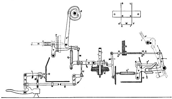
Fig. 162.J.N.
(314) It is, of course, highly essential that all the three releasing
motions shall be accurately “timed,” so as not to take place either
before or after the proper moment. Accordingly, ample means of
adjustment are provided, both on the rod X by the regulation of
the stops X1 and X2; on the connecting rod M
coupling the levers Z and T; and also on the holding-out
rod. In this way it is possible to secure that simultaneous movement
of the three parts, which is so essential for effective working. It is
obvious that the backing-off friction and holding-out catch must be
released before the taking-in friction gears, but the interval between
these is so slight that they occur practically simultaneously.
(315) The taking-in friction being in gear, the rotation of the
loose pulley is, by the train of wheels shown, communicated to the
“scroll” shaft, on which the taking-in scrolls are fixed. These have
bands attached to and wrapped round them when the carriage is at the
roller beam. As the carriage runs out, the bands, which are fastened
to it, are drawn off the scrolls, the scroll shaft being then free
to revolve. The engagement of the taking-in friction reverses this
process and winds on the bands, thus drawing up the carriage. It will
be observed that the scrolls vary in diameter, being about 9 inches
in the largest part, and about 3 inches in the smallest. The reason
of this construction is to give a varying traverse to the carriage,
so as to start it easily, and bring it up to the back stops gently.
The scrolls are designed so that, so long as they are revolving, they
exercise a pull upon the carriage which is steady and constant. In this
way, over-running is avoided, but to prevent any possibility of it a
scroll L1, shown in a detached position in Fig. 153, is fixed
on L at an angle of 180 degrees to the others, the point of
attachment of its rope being diametrically opposite that on the other
scrolls. Thus when the bands on the drawing out scrolls are unwound,
that on the “check scroll” is wound and vice versa. The purpose of
this scroll is, as its name indicates, to check any tendency to
over-running, which it effectually does. In all mules above a certain
length, it is desirable to provide some means whereby the carriage
shall be drawn in evenly throughout its length, and shall not be in
danger of twisting or warping. The scroll shaft, it will be noticed,
only extends across the headstock, so that the bands can only exercise
any pull on the square, and if no other points of attachment were
made, the carriage would at its extremities lag behind the centre. A
considerable amount of friction would be thus caused, and the spindles
at the end of the carriage would not take up the full length of yarn.
It was shown that the back shaft is, during winding, disengaged, so
that it is only necessary to establish a connection between it and the
scroll shaft, to enable the carriage to be drawn in at several points
throughout its length, instead of at one only. Accordingly, the scroll
shaft is extended, and an extra scroll shown in Fig. 154 at the right
hand side is fitted, from which a band is taken to a drum upon the back
shaft. Thus the back shaft is converted into a taking-in shaft, and
during that operation revolves of necessity at a variable speed given
to it by the scrolls. In this way the carriage is kept parallel to the
roller beam throughout its course, and comes up to the back stops along
its entire length at one time.
(316) The arrangements for taking-in having thus been described, it
now becomes necessary to describe the operation of winding. Before
doing so, it will be better to deal with the problem to be solved,
and it will aid in understanding it if the construction and method of
building the cop be described. For this purpose a reference to the
diagrams given in Figs. 163 and 164, page 207, is necessary. The cop
is built, as before explained, upon the blade or taper part of the
spindle, and, when finished, is of the shape shown in Fig. 163, viz.,
a cylinder with conical ends. The central part of the cop, E G K
F, is cylindrical, and at the top and bottom of this part are two
cones. The lower cone, A E B C F D, forms what is known as the
“cop bottom,” and the upper one, G H I K, the “nose,” although
the latter term is more often and strictly applied to the extreme apex
at the points H I. As previously stated, the yarn may be wound
either upon the bare spindle, upon a short paper tube, as indicated
by the thick line inside the cop bottom, or upon a similar tube the
whole length of the cop. The use of paper tubes of this character is
preferable, especially in cases where the cop is likely to be much
handled, as it prevents it from being crushed in, and enables the
introduction of a skewer for subsequent winding without there being any
danger of the cop being pierced or “stabbed,” this being a fruitful
source of waste.
(317) In commencing to wind, the yarn is wrapped on the lower part of
the spindle in close coils or spirals for a length of a little more
than an inch. The whole of one stretch is wrapped upon this space, and
when the next stretch requires winding, it is laid upon the previous
layer, and so on until the double cone A E B C F D is produced.
The length of the traverse of the winding faller wire, or the length
of each layer vertically, is called the “chase” of the cop or faller.
From this point the yarn is wound in successive layers, beginning
always at a higher point, until the final traverse is obtained by which
the winding is conducted upon the surface or nose represented by the
letters G H I K. It was stated in paragraph 311 that the winding
faller wire, when the winding faller is locked, is in a position a
little below the point H I. As soon as the carriage begins to
run in, the vertical movement of the winding faller locking lever
begins, and is so arranged that the first movement of the wire is a
rapid downward one. The effect is that the yarn is laid on the nose of
the cop in coarsely-pitched descending spirals, as shown in Fig. 164,
these extending downwards until the winding faller wire reaches a point
opposite the base of the upper cone, in this case shown in Fig. 163 at
K. From this point a slower ascent of the winding faller wire
is made, so that the yarn is laid in the more finely pitched spirals
shown, until the nose of the cop is reached. By this time the carriage
has arrived at the roller beam, and the whole of the 63 inches of yarn
has been wound.
(318) When the first layer of yarn is wound, and the winding faller is
assuming its position to wrap on the second, the initial point of its
traverse is a little raised. In this way the yarn is gradually wound
in layers, which are represented by the angular lines springing from
the lines A E and D F towards the spindles. During this
period the enlargement of the diameter of the cop bottom is proceeding
until at the points E F the full diameter of the cop is reached.
As soon as this occurs the initial point of each layer is gradually
raised, and the length of the traverse is slowly diminished as the
completion of building is approached, until at the termination of a
cop the angle of the layers is shown by the lines G H and I
K. There are thus two adjustments shown to be necessary—first,
the starting point of each traverse of the winding faller requires
altering; and second, its extent also needs regulation.
(319) These two objects are attained by the regulation of the copping
rail P, as shown in Fig. 161. The ends of this rail rest upon
inclined “copping” plates Y X, which are fastened together by
the rod W, and which receive, as will afterwards be described,
an inward movement during the building of the cop. It was shown that
the locking of the faller lever and its vertical movement leads to a
corresponding movement of the faller. If, for instance, the faller
locking lever fell an inch, the winding faller sector would be
oscillated and the faller wire drawn upwards. The rate of the ascent
of the latter is absolutely relative to the period of the descent
of the locking lever. Referring now to Fig. 165, which is a small
diagrammatic sketch of the copping rail and its supports, suppose the
line G H to represent the top of former, O P the latter,
and L the bowl at the foot of the locking lever, if L,
starting from the left hand position, be supposed to travel in the
direction of the arrow V, it will be seen that it will fall to
the extent indicated by the space Y Z. If, on the other hand,
the slides O P are moved into the position shown by the dotted
lines, the rail G H will also fall into that indicated in a
similar manner. The result is that if L now makes the same
traverse as before it will rise a little as indicated by the space W
X. The effect on the winding faller would be that in the first
case it would be raised, and in the second it would be depressed to an
extent corresponding to the depression of the locking lever. The extent
to which this elevation or depression is made depends upon the vertical
traverse of the locking lever, and the ratio of the distance of the
point of junction of the sector C with the faller shaft and that
of the faller wire from the same rod. If, for instance, this proportion
was 1:2, an elevation of the locking lever half an inch would result in
a depression of the faller an inch. It is therefore necessary, during
the inward run of the carriage, to provide for the inclination of the
carriage to such an extent as to secure the requisite traverse of the
faller wire. As the amount of such traverse varies during the building
of the cop, it follows that the inclination of the copping rail must be
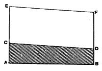
varied correspondingly.

Fig. 165.J.N.
(320) Referring again to Fig. 161, the ends of the copping rails have
pins fixed in them, on which are anti-friction bowls, which run upon
the edges of the copping plates. The latter are duplicated, so as to
sustain the rail at each side, and thus maintain its vertical position.
At one side of one of the plates Y is an ear S1, which
is threaded to correspond with a square threaded screw S passing
through a fixed bracket fastened to the floor. In this way the screw
S is free to revolve, but cannot make any longitudinal movement.
On the end of the screw S a ratchet wheel is fixed with which a
pawl S2 engages, which is oscillated so as to move the wheel
one tooth at convenient times. The speed of the revolution of the
screw varies according to the counts being spun, the elevation of the
point of locking being more quickly effected when coarse yarns are
being made than when the finer varieties are produced. Whatever may
be the velocity at which this elevation is accelerated, the profile
of the copping plates is such that the inner end of the copping rail
P is lowered at a more rapid rate during the formation of the
cop bottom than at a subsequent stage. The reason of this will be
easily comprehended, if the description of the mode of building the
latter be borne in mind. It was then shown that the traverse of the
winding faller rapidly increased in extent until the full length of the
cop bottom was built. It, therefore, follows that the descent of the
locking lever must be largely increased at this period at a quick rate,
in order to produce the result indicated. When the outer end of the
copping rail begins to descend at a rate which more nearly corresponds
to that of the inner end, it gradually approaches to the horizontal,
and the vertical motion of the slide, locking lever, and faller is
proportionately limited.
(321) The regulation of the winding faller as just described was the
one which was usual until recent years. It has been found necessary,
however, to obtain a more accurate regulation, so as to ensure that
the faller wire shall be in its correct position when locking occurs,
especially during the period between the beginning of a cop and the
attainment of its full diameter. It is now customary to attach to the
front end of the copping rail a loose plate Q, which is hinged
at one end to the rail, and which carries at its outer extremity a pin
and bowl resting upon a third inclined plate Z. By varying the
profile of the plate Z, the regulation of the faller during
the early part of its traverse can be accurately made and the proper
position of the wire ensured. As a glance at the illustration will
show, the upper edge of the copping rail is not straight, but is shaped
so as to give a variable speed to the slide L in its vertical
movement. The proper shaping of the copping rail gave rise to some
difficulty, and it will be seen that the loose copping rail Q is
shaped so as to produce the proper effect, while being much more easily
adjusted.
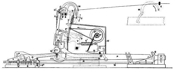
Fig. 161.J.N.
(322) The actual operation of this mechanism is as follows: When the
carriage is at its outermost point, and the winding faller is locked,
the wire is, as previously mentioned, a little below the nose of the
cop. As the inward run proceeds, the bowl first runs up the loose
incline, thus raising the locking lever and depressing the winding
faller wire. The distance, from the extreme outward point reached by
the bowl L1 and that where the loose rail Q is hinged
and the downward inclination of the copping rail begins, is so short
that the initial depression of the winding faller is very rapid. This
produces the coarsely pitched coils referred to in paragraph 317, and
illustrated in Fig. 164. By the time the bowl L1 is at its
highest point the winding faller wire is opposite the base of the upper
cone. The subsequent downward inclination of the copping rail is much
less acute, and the consequent descent of the faller locking lever
less rapid. As a result the upward traverse of the winding faller
wire is made more slowly, and the yarn is wound in more finely pitched
spirals. It only remains to be said, in connection with this part
of the subject, that owing to the shape of the copping plates their
inward movement is accompanied by a gradual fall of the copping rail,
and, consequently, the locking point of the faller lever is relatively
elevated. In other words, the traverse of the locking lever prior to
locking is gradually lessened as the trail lever slide L is
lowered, and this is equivalent to an elevation of the winding faller
lever and its locking point or shoulder K. This causes the
depression of the winding faller wire prior to locking to be gradually
diminished, so that there is an elevation of its initial point.
(323) The method of obtaining the traverse of the winding faller having
been described, the equally important points relating to the mode of
rotating the spindle during winding require to be dealt with. A little
thought will show that so long as the surface upon which the yarn is
wound remains small the spindles must revolve at a more rapid rate
than when the surface is enlarged. As the extreme diameter of the cop
bottom is enlarged the conditions of successful winding are continually
changing. At the commencement of the cop the yarn is wound upon what
is practically a parallel surface with a diameter of 5⁄16 inch and a
circumference of ·98 inch. This implies that to wind the 63 inches
of yarn 64·3 revolutions are required, these being made during the
run up of the carriage. But as the diameter of the cop is enlarged
the circumference of the conical surface becomes a variable one, and
owing to its enlargement the number of revolutions required to wind
the same length of yarn is fewer. This is quite clear and needs no
demonstration. Thus when the cop bottom is formed the extreme range
of variation is reached, and it follows that in the interval between
the commencement of winding and the formation of the cop bottom each
stretch must be accompanied by a diminution of the velocity of the
spindle proportionate to the increase of diameter. In addition to this
it is necessary to take into consideration the varying diameter of the
conical surface on which winding takes place, which necessitates a
greater terminal than initial velocity of the spindle.
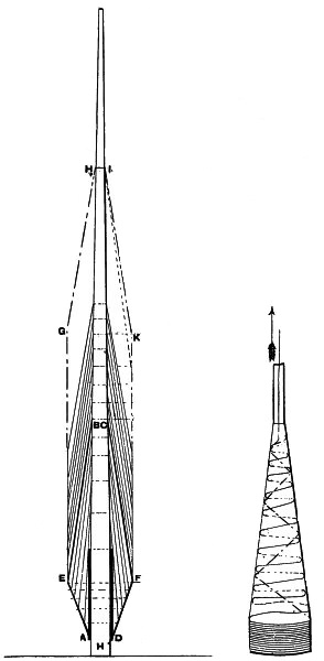
Figs. 163 and 164.J.N.
(324) A further point requires elucidation. If the spindle blade were
parallel, the number of revolutions necessary to wind the 63 inches of
yarn properly, when the cop bottom is formed, being fixed, no further
alteration would be necessary. But these conditions do not exist, and
the nose of the cop is wound upon a continually diminishing diameter.
It is of the utmost importance that the yarn is wound tightly at the
nose during the whole of the building of the cop. The rate of the
vertical traverse being practically uniform, unless an acceleration of
the spindle velocity occurred, there would be slack winding during the
latter part of the building of the cop. This would produce a sponginess
of the nose, which, when the yarn was drawn off in the subsequent
process of winding, as shown by the arrow in Fig. 164, would result in
several rings or coils being pulled out in an entangled condition, thus
producing waste. Technically the cop would be said to be “halched.”
Illustrating this part of the subject by figures, if the diameter of
the spindle at the point B, Fig. 163, be assumed to be 1⁄4
inch, its circumference would be ·7854 inch; while if the diameter
at H be assumed to be 1⁄8 inch, the circumference would be
only ·3927 inch. To wind, say, 10 inches of yarn in each case, would
require about 12 and 25 revolutions of the spindle respectively. It
is therefore clear that, if the same length is to be wound with equal
tension upon the nose of the cop throughout the whole process of
building, there must be a gradual acceleration of the terminal velocity
of the spindle. Although this is only slight at first it is required
at an earlier point as the cop is formed, and becomes of increasing
importance.
Fig. 166.J.N.
(325) It will be shown, a little later, that the rotation of the
spindles during winding is obtained by the pull of the carriage on a
chain, which has its other end attached to an oscillating arm, being
fastened to a drum on the carriage. To get a clear idea of the action
of this part of the mechanism the two diagrams shown in Figs. 166
and 167 are given, a study of which will be profitable. In Fig. 166
the circles B C D represent three positions of the barrel or
drum after it has moved in a horizontal plane in the direction of the
arrow. To the drum a chain is supposed to be attached, which is held
at the point A. It is, of course, understood that the barrel is
mounted upon a shaft or axis so that it can freely revolve. If it be
now assumed that the barrel is in the left hand of the three positions
B, the chain will be wrapped completely round it. As it is
moved horizontally in the direction of the arrow it is revolved, as
indicated by the curved arrows, and, by the time it has reached its
middle position C, has been rotated sufficiently to unwind about
half a turn of the chain. A further horizontal motion to the right hand
position D will complete the unwinding, and, by this time, the
drum will have made one complete revolution. It will be at once seen
that the rate at which the drum will be revolved will depend upon two
factors—its diameter, and the speed of its horizontal traverse. If
the point A at which the chain is held is stationary, and the
horizontal movement uniform, then the rotation of the barrel will be
constant. But if the barrel be traversed at a variable rate then its
rotation will also be variable. In actual practice this uniformity does
not exist, for, as was shown in paragraph 315, the taking-in scrolls
vary considerably in diameter. Assuming this variation to be 1:3:1,
it would follow that the rotation of the barrel would increase and
diminish in the same ratio. In practice this is what happens, and the
speed of the revolution of the barrel is quicker about the middle of
the taking-in than at any other time.
(326) The assumption that the point A is stationary was only
made to illustrate the point at issue, and is not founded upon the
actual facts of the case. If now it be assumed that not only the barrel
but the point at which the chain is held makes a forward movement, a
new set of conditions arises. In this case the unwinding of the chain
during a given time will be diminished by the amount of the advance
of the point A in the same period. Assuming the latter to be
made at a regular rate it would be easy to calculate the extent of
the unwinding. If the effect of the horizontal movement of the barrel
from B to C be to unwind half of one coil of chain—say
a length of 7 inches—and that in the same space of time the point
A moved 3 inches, the amount unwound would be reduced to 4
inches. But this is not the actual condition of things in practice.
The point moves at a variable velocity, its forward motion gradually
diminishing, so that the acceleration of the rotary velocity of the
barrel is greater at the end of its horizontal traverse than at the
beginning. In other words, its terminal velocity is highest.
(327) The point of the attachment of the chain at A is made
in an oscillating arm which, during the inward run of the carriage,
receives a forward movement at a speed which is controlled by the
velocity of the back shaft. As the latter is, in turn, commanded by the
scroll shaft during this period—see paragraph 315—it follows that the
variation in the forward movement of the arm is coincident with that of
the carriage. Thus the advance of the point A will always be in
strict correspondence with the velocity of the carriage traverse.
(328) Referring now to Fig. 167, and, assuming A B to be the
arm to which the chain is fastened, and O J and H C
to represent the arcs through which the point of attachment of the
chain travels at different times, it will be seen that the periods
of movement are well marked. In each case the arcs are of the same
number of degrees, although the chord of one is shorter than that of
the other. Dealing first with the inner arc, which represents the
position of the point of attachment when nearer the centre, the whole
period of movement is divided into equal parts. These are represented
by the letters J K L M N O. Now, if vertical lines are drawn
from these, until they terminate in a straight line drawn parallel
to a horizontal line through the point B, a clear idea can
be formed of the effect of the oscillation of the vertical arm A
B. The lines terminate at J1 K1 L1 M1 N1 O1. It can
be easily seen that the horizontal movement of the point of attachment
of the chain gradually becomes less as the arm is oscillated from its
most backward position B C to its most forward one B H,
this diminution occurring most after the point L is reached. In
the movement from J to K and K to L the
horizontal traverse is about equal. It shows a decrease from L
to M, a greater one from M to N, and a still
greater one from N to O. The same thing happens if the
chain be supposed to be attached at the point D. In this case
also the decrease in the horizontal forward traverse is variable, but
occurs in the same way. The periods here are marked by the letters
C to H, and the extent of the forward motion by those
C1 to H1. It will be noticed that the amount of the
traverse is greater than that previously noted, the total space
covered being respectively J1 to O1 and C1 to
H1. That is to say, the point at which the chain is fastened
moves forward in the same direction as the barrel, but at a different
speed. In other words, when the chain is held at K, the total
forward movement is comparatively small, and if it were held at a
point shown by the small inner circle, it would be still less. On the
other hand, its attachment at B implies a greater total forward
movement. It therefore happens that the retardation of the chain by
the arm is less in the early part of the oscillation of A B—or,
to put it differently, the delivery of the winding chain by the arm is
greater when it is fixed at D than when it is fixed at K.
Therefore the barrel is more slowly rotated during the same period in
the former than in the latter case, but as it completes its lateral
movement it is rapidly and considerably accelerated.
(329) The application of this principle is as follows, and it can now
be stated that the end of the chain is attached to a nut which slides
along the arm, being actuated by the rotation of a screw upon which
it fits. Remembering that an acceleration of the terminal velocity
and a regulation of the revolution of the spindle is required, the
demonstration just given shows that these are obtained by the removal
of the nut further from the centre of oscillation. The influence of
the pull of the chain upon the barrel when the nut is in the position
K is much slighter, and shows less variation than when it is at
D. Every inch which the nut travels outwards has an influence
upon this factor, and the conditions of winding are thus accurately
regulated. When the winding of the cop begins, the nut is in its lowest
position, and the rotation of the barrel is then practically equal. As
the nut moves away from the centre the barrel gradually rotates more
slowly at the beginning of its inward movement. By the time the most
outward position is reached—which, in practice, coincides with the
formation of the cop bottom—the variation in the velocity has reached
its greatest amount. This, it can be easily seen, is what is wanted.
Referring again to Fig. 163, one revolution of the spindle when the
yarn is being wound on A D would practically take up the same
length as would be taken up at the top of the paper tube. But when the
faller is guiding the yarn on the conical surface from E to
B, one revolution of the spindle would wind on a greater length
at E than it would at B. Therefore, the initial velocity
requires to be less than the terminal. But when the point E
has become the initial position, the conditions of winding remain
thereafter constant, except in so far as is affected by the taper of
the blade, and there is no further need for an outward movement of the
nut.
(330) The theory underlying the method of winding having thus been
dealt with, the mechanism employed can be described. This is shown in
Fig. 168, which is a diagram of the whole of the apparatus, and in Fig.
169, which is an enlarged view of a portion of it. The winding arm
M is centered at its lower end, and has formed on it a toothed
quadrant M1. The “quadrant” M oscillates on a short
shaft, securely carried by the headstock framing, and receives its
forward movement by means of a pinion Z, which engages with its
teeth. The extent of the quadrant movement is about a quarter circle.
The pinion Z is mounted on the same centre as a grooved pulley,
over which a cord from the back shaft H is passed. Thus the
rotation of H in either direction produces a similar movement
in the pinion Z; and the effect is, that, while the back shaft
is drawing the carriage out, the pinion is revolving so as to raise
the arm M or cause it to make a backward oscillation. When
the back shaft acts as a taking-in shaft, as described in paragraph
315, the pinion Z is revolved so as to move the arm M
forward. The velocity at which the forward stroke is made is by this
arrangement a variable one, and completely corresponds to that of the
carriage traverse. Inside the winding arm a long slot is formed in
which a screw P is placed, this being free to revolve. It may
be made with a thread of equal pitch throughout, but, as shown, is
provided with a thread of varying pitch, which gradually becomes finer
towards the outward end of the arm. The reason of this is obvious. The
effect of each layer of yarn upon the problem of winding is greater at
the beginning of the formation of the cop bottom than when it is more
nearly finished. That is, the enlargement of its diameter is relatively
greater at the first stage than at any other. For instance, if the
diameter is 3⁄8 inch and it be increased 1⁄16 inch, the ratio is 1⁄6th;
while if the diameter is 3⁄4 inch, and the same increase takes place,
the ratio is 1⁄12th only. The variation required in the speed of
winding as each layer is wrapped is therefore less in the latter than
in the former case. This is the purpose of the helical screw, which
gives a quicker advance to the nut in the earlier stages of winding
than when the cop bottom is nearly formed.
Fig. 167.J.N.
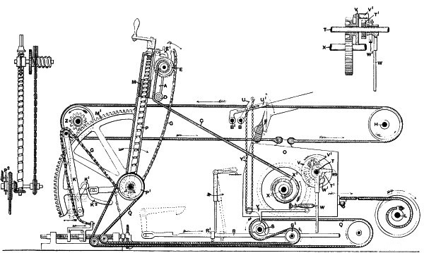
Fig. 168.J.N.
(331) The screw has fixed upon it, at its lower extremity, a small
bevel pinion, gearing with a similar one placed loosely on the short
shaft forming the centre for the arm. During the oscillation of the
arm the pinion moves with it, and it is clear that if both remained in
this position only this alternate action would occur, and no rotation
of the screw would be made. If, however, the pinion on the short shaft
be rotated it communicates its motion to the screw P, and thus
traverses the nut. This is what takes place, and the precise method of
effecting it will be described in detail at a little later period. The
nut engages with the screw and originally had an eye or hook formed
in it, to which the end of the winding chain or band C was
fastened. The attachment is now made in a different manner, a frame
A being fixed to the nut along with which it can slide. At the
upper end of the frame a small drum is carried, round which the winding
chain is wrapped, passing over a small bowl D at the lower end
of the frame. The other end of the chain or band C is fastened
to the drum or scroll X1 which is mounted on a shaft X
carried in suitable bearings in the square. On the same shaft a spur
wheel is geared which engages with a pinion loose upon the tin roller
shaft, which it revolves by special mechanism afterwards described in
detail. The use of a scroll is intended to accelerate the revolutions
of the spindles during the latter part of the fallen traverse. This,
like the winding arm, is a modified application of the fusee, and it
will be easily understood that when the chain is being unwound from
the larger diameter of the scroll, the number of revolutions given to
the scroll will be less than when it is being taken off the smaller
diameter.
(332) It has been previously shown that the diminishing diameter of
the spindle causes it to be necessary that, as the cop is built higher
upon it, a correspondingly higher rotary velocity shall be given to it,
in addition to the increased terminal velocity produced in the manner
described. The most usual method of doing this has been to provide
at the end of the quadrant arm a bracket carrying a pin known as the
“nosing peg.” The object of this device is to shorten the chain by
deflecting it from a straight line about the time when the carriage
nears the end of its inward run. This is equivalent to a sudden
shortening of the chain, and gives a sudden acceleration to the winding
drum. In some cases an automatic arrangement is fitted by which the
peg is brought into contact with the chain at an earlier point every
stretch, so that the acceleration of the spindle takes place sooner,
as the nose of the cop is formed higher up the spindle. It is not
difficult to obtain a clear notion of the action of the nose peg if a
short length of string be held at one end and attached to a sliding
piece at the other. If then the string be pressed down by a rod at the
same point, but a little further every time, it will be seen that the
sliding piece is moved to a greater extent with each depression.
(333) The arrangement used in the Platt mule is shown in detail in Fig.
169. It consists of the sliding bracket A, carrying, as described, at
its upper part, a small drum on which the winding chain C is
fastened. On the spindle of the winding drum a ratchet wheel E
is fixed, with which the detent pawls E1 engage, thus ensuring
that E is held in any position assumed by it. Also fastened on
the spindle of the drum is the curved sector arm F, to which
a chain G is secured. By means of the guide pulleys shown the
chain G is conducted over the arm or lever K, and is
attached to the bracket I. The lever K is hung from its
upper end, and has a projecting short arm K1 attached to it,
which can move upwards in the direction of the arrow. The outer end
of K1 presses against a bracket K2 attached to the
quadrant, so shaped that the backward movement of the quadrant pushes
the lever K back at its lower end. In the bracket I a
finger I1 engaging with the copping nut is fixed. The parts
having been adjusted to their proper position the slide A is
at the bottom end of the quadrant M, as shown, and the curved
arm F is in such a position that it has wound upon it a certain
length of the chain G. The latter is a little slack at first,
but as the nut moves out this is rapidly taken up until the chain
G is in tension. As soon as this happens, each of the forward
oscillations of the arm M leads to the chain being drawn,
and causes the lower end of the lever K to be swung forward.
The return movement of the quadrant leads to the bracket K2
pressing upon the arm K1, so as to push back the end of the
arm or lever K. In this way the chain G is pulled and
the curved arm F is drawn a little forward, thus causing the
drum and ratchet wheel E to revolve. As the winding chain is
wound on the barrel, every rotary movement of the latter in a forward
direction takes up a little more chain and shortens its length. The
amount of this shortening is not great up to the time of the completion
of the cop bottom and the arrival of the slide A at the end of
its traverse along the arm. The position of the parts at this period
is shown in the detached view at the right hand top corner of Fig. 169.
Up to this time only about the same length of chain is taken up which
is needed by the increased distance of the slide A from the
centre, and the greater forward traverse of the quadrant arm, which,
in a sense, releases a certain length of winding chain. When this
point is reached the finger I1 begins to be pressed against
by the nut S1 of the shaper screw, and the bracket I
commences to be drawn inward. To facilitate the correct action of this
mechanism the finger I1 is adjustable, and the exact moment
of its contact with the nut S1 is thus regulated. The forward
movement of the shaper nut which follows gives a similar motion to the
bracket I, and the chain G is thus drawn forward. In this
way the drum and ratchet wheel E are rotated, and the winding
chain gradually shortened. Thus more of it is unwound from the scrolls
at each traverse of the carriage, and as it is drawn from the smaller
diameter of the scroll towards the end of the run in, the velocity of
the spindles is considerably accelerated. The position of the various
parts when the carriage is at the back stops is shown in Figs. 170 and
171.
(334) These represent respectively the places occupied by the different
portions of the mechanism immediately at the completion of the cop
bottom, and at the finish of building a set of cops. The positions of
the various parts connected with the slide A when winding is
complete are shown also in Fig. 169, at the top end of the quadrant
arm. Referring to Fig. 170, it will be noticed that the winding chain
C is unwound from the large part of the scroll only, while Fig.
171 shows it almost entirely unwound from the smaller portion. As was
shown, this implies a high terminal velocity of the winding scroll and
spindles.
(335) It has been previously mentioned that the rotation of the
quadrant screw is obtained by means of the engagement of two bevel
wheels, one on the foot of the screw and the other upon the spindle,
forming the centre of the quadrant. It was also stated that the
last-named wheel was held so as to move round the centre with the
quadrant. This is effected by means of a brake spring P2 which
clips the boss of the wheel and holds it. The resistance thus created
causes the bevel wheel to move with the quadrant, and prevents it from
rotating on its axis. The wheel is compounded with a grooved cord
pulley P1, over which an endless band Q passes. The
band Q fits the groove in the pulley, and is afterwards guided
by the various carrier pulleys shown. Two of these, S S1, are
borne by brackets fixed to the carriage, and S is formed with
teeth so as to allow of the engagement of the vertical detent catch
on the lever Y. If the whole of the pulleys over which the
band Q passes are free to revolve, except that on the quadrant
centre, the inward run of the carriage gives no motion to the cord or
band. No effect is produced beyond the rotation of the carrier pulleys,
and the forward stroke of the quadrant is made without any effect being
produced upon the position of the nut.
(336) It was shown that the gradual accretion of yarn by the cop
results in the necessity for a graduation of the velocity of the
spindle in winding. This takes place during the whole period of
building, and it follows that the traverse of the nut must be governed
during the whole period. After a layer of yarn has been wound the nut
remains in the position occupied by it during the preceding inward
run, until the carriage has made another outward run, and is again
commencing to run in. At the commencement of the run in of the
carriage the spindles revolve at the same speed as that at which they
rotated in the preceding period of winding. If the yarn is a coarse one
this is sure to be too fast, because of the increase in the diameter
of the cop, owing to the yarn wound during the last inward run. The
initial velocity of the spindles is, therefore, such that they take up
the yarn too rapidly, and put an extra amount of tension upon it. As
was shown in paragraph 303, this causes a depression of the counter
faller wire. This is utilised to revolve the quadrant screw and
traverse the nut and slide. In other words, the winding is said to be
“governed,” and the motion is known as the “governing” or “strapping”
motion.
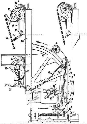
Fig. 169.J.N.
(337) Fixed on the winding faller and counter faller shafts B
B1 (Fig. 168) are two arms U U1, to which the ends of a
light chain Y1 are attached. The chain passes round a runner,
or pulley, placed in the outer end of the hinged lever Y, which
is in this way sustained. It is obvious that the vertical position
of the lever will be strictly regulated by the position of the two
arms U U1. As they follow the oscillations of the winding and
counter faller shafts, the elevated position of these during spinning
ensures the lever Y being raised at its free end. This results
in the tooth, or detent, being taken out of contact with the teeth on
the pulley S. When the counter faller is depressed by reason of
the tension of the yarn upon it a similar movement occurs in the lever
Y.
(338) In the early stages of winding, when the winding faller is
depressed to a comparatively large extent prior to being locked, the
vertical position of the lever Y is naturally lower than when
the winding faller is not pushed down so far. It thus occurs that, when
the cop bottom is being formed, which is the stage during which the
traverse of the nut is required, and the winding faller is locked at
its lowest point, the clearance of the detent catch on Y and the
teeth on the pulley S is least. At this period, therefore, they
are most easily engaged by any depression of the counter faller. When
the higher initial velocity of the spindle, produced as described in
paragraph 336, causes the yarn to be put into tension and the counter
faller wire depressed, an engagement of the catch and pulley teeth
occurs.

Figs. 170 and 171.J.N.
(339) The effect is that the rotation of the toothed pulley is stopped,
and the band Q is practically gripped by S and its fellow
pulley S1, which are borne by the carriage. Instead, therefore,
of slipping over the pulleys as before, the band is drawn along with
the carriage and the remaining pulleys are caused to revolve. The force
so applied is sufficient to rotate the grooved pulley P1 by
overcoming the resistance of the spring clip, and the bevel wheels and
quadrant screw are rotated. The nut is thus moved outwards, and the
winding chain relieved as previously described. This causes a slight
diminution in the speed of winding, sufficient to relieve the pressure
of the threads on the counter faller wire, which rises and breaks the
contact of the detent and the toothed pulley. The further movement of
the nut is thus arrested.
(340) The necessity for a diminution of the initial velocity of the
spindle is strictly relative to the counts of yarn being spun. Some of
the finer counts require a very slow traverse of the nut, and there may
be practically none during several draws of the carriage. As the nut
slowly rises and the locking point of the winding faller is elevated,
the period of the engagement of the detent catch and the wheel S
becomes shorter, and the rotation of the screw is not so prolonged.
When the cop bottom is fully formed, the nut is at its most outward
point, and the “governing” motion is not therefore required. At this
point, the relative positions of the arms U U1 are such,
that the chain Y1 will not permit the lever Y to fall
sufficiently to allow its tooth to engage with the wheel. The motion,
therefore, falls out of use until the commencement of another set of
cops.
(341) The motion of the winding scroll is communicated to the tin
roller by means of a catch or “click” plate shown in detail in Fig.
168. On the spindle of the winding scroll X1 is a spur
wheel—indicated by dotted lines—which engages with a small pinion on
the tin roller shaft T. The whole of this special mechanism is
shown in longitudinal section in the right hand top corner of Fig.
168. The pinion is cast in one piece with the disc V which is
loose upon the shaft T. The latter has a pin fixed in it, on
which the small catch or “click” V1 is hinged. The click catch
is ordinarily held out of position by the bent spring W1,
which surrounds the boss of a ratchet wheel T1—to which the
name of the “click wheel” is given. When the “click spring” W1
is slightly oscillated in the same direction as the rotation of the
ratchet wheel, it allows the click catch to fall into gear with the
click wheel. As the latter is keyed upon the tin roller shaft T,
the engagement with it of the catch causes the tin roller to be
revolved, and thus rotates the spindles.
(342) It was formerly the practice to allow the click catch to fall
into gear when the disc V began to rotate upon the commencement
of the inward run of the carriage. It was, however, found that the
click catch engaged with the wheel earlier at one stretch than at
another, and that, consequently, winding began a little more slowly
than it should. The effect of such an occurrence is that a little slack
yarn was produced as the carriage was running in, although winding was
not taking place. Under these conditions tight winding at the nose
throughout was practically impossible. It will be easily understood
that, when the click catch is released, it may very readily be left
either close to the tooth with which it has to engage or only just over
the point of the preceding tooth. In the first case the engagement
would take place at once, while in the second instance almost the
distance of a tooth would have to be travelled by the click catch
before engagement occurred. In hard twisted yarns this is especially
objectionable, and its prevention is of importance.
(343) To overcome the defect thus explained a hanging lever W
is fitted on the tin roller shaft, and the click spring W1,
instead of fitting on the boss of the disc V, fits on the inner
boss of the lever W, which it clips. A slight oscillation of
the lever is, therefore, at once followed by the movement of the
spring, and the click catch is engaged. The tail end of the lever
W comes in contact with a stop R1 on the holding-out
catch rod R. When R is moved in order to release the
catch it causes the lever W to move into the position shown by
the dotted lines, and so oscillate the spring W1. The tail
of the click spring passes between a fork formed in the click catch,
and thus presses the catch in either direction, according to which
side of the fork it gears with. When, therefore, the click spring is
oscillated by the releasing movement of the holding-out rod acting upon
the lever W, the click catch is forced hard up to the tooth
with which it is engaging. The continued movement of the rod, if made,
has, of course, no further effect upon the click catch, but the parts
are quite ready for winding with the click in gear. Immediately the
carriage begins its inward run winding commences. Thus, whatever may
be the position of the click catch at the end of an outward run, it is
always ready for its work before the inward run commences. The weight
of the rod W is sufficient to keep the click catch disengaged
during the whole period of spinning and backing-off.
(344) The whole of the points relating to winding having been
considered, the motions used in the fifth and last period require
describing. When the carriage is near the completion of its inward run,
the various parts are in the following position: The strap is on the
loose pulley and the backing-off side shaft is being revolved either by
the gearing named, or by its independent band; the back shaft clutch is
disengaged and the back shaft is revolving so as to aid in drawing up
the carriage; the rollers are disengaged and are not delivering roving;
the taking-in friction is engaged, and the scroll bands are drawing
in the carriage; the quadrant arm is completing its forward movement,
and the spindles are revolving in their normal direction; the winding
faller is locked and the wire is approaching the nose of the cop; and
the counter faller is in contact with and sustaining the threads. As
soon as the carriage arrives at the roller beam, the whole of these
motions require changing, so that the different parts shall occupy the
positions indicated in paragraph 286.
(345) This operation is mainly the work of the cam shaft, but in part
is performed by other mechanism. As soon as the carriage arrives
at, or near, the end of its outward run, the horn S1 on the
carriage comes in contact with the anti-friction bowl R1 in
the long lever T and depresses it (see Fig. 156). This removes
the nose of the releasing lever from the raised surface on V
and allows the friction clutch W X to come into gear. The cam
shaft immediately begins to rotate, and the three cams to act upon the
various parts in the reverse way to that previously described. The
rotation of the cam Z (Fig. 156) performs the two functions of
disengaging the taking-in friction clutch and engaging the back shaft
clutch, the motions of these always being closely related. The cam
W during the same period allows the roller clutch to go into
gear, and the delivery of roving again begins. The rotation of the cam
Y causes it to exercise a thrust on the pin fixed in G
(Fig. 158), so forcing the driving strap over on to the fast pulley,
this giving renewed motion to the spindles. The same movement causes
the lever H to be pushed forward until the shoulder formed in
it can again engage with the fixed catch L, the spring P
pulling the end of H upwards as soon as it is sufficiently far
forward. The strap guider is thus again locked when the strap is on the
fast pulley. By the time these engagements and disengagements have been
made, the cam shaft M has made its second half revolution, and
the end of the release lever again presses upon the raised surface on
the cam V and detaches the friction cone W from X.
The cam shaft is thus stopped and remains stationary until the end of
the outward run as described in paragraph 291.
(346) The whole of the parts governed by the cam shaft having thus
resumed their original position, it remains to be shown how the winding
and counter fallers are released, so as to be able to assume their
relative positions out of contact with the yarn. The unlocking of the
winding faller must be made as late as possible in the inward run, but
the exact period at which it is made is affected by the height of the
cop nose on the spindle. The termination of winding requires to be
made throughout the whole period of building a set of cops, at such a
point as to leave sufficient yarn to coil on the spindles between their
points and the cop nose. It will be easily seen that this quantity is
varying throughout the whole of the formation of the cop, and that
the length to be wound on is greatest at the commencement of the cop.
This implies the unlocking of the winding faller at a point which is
made gradually later, and this is well carried out in the Platt mule.
At the lower end of the locking lever is a curved arm or “boot leg,”
which, at the termination of the inward run, comes in contact with
the fixed stop bracket G (Fig. 161). The face of this is so
shaped that the moment of unlocking is regulated in accordance with
the requirements of the case throughout the whole of the formation of
the cop. This is an important point, and requires careful attention.
In a special form of mule, made by Messrs. Platt Brothers and Co., for
finer counts, the stop bracket is a movable one, and is released by the
run of the carriage, so as to slide forward and unlock at the exact
moment required. The finer the yarns the more care is required in this
respect, owing to their greater liability to breakage.
(347) Referring now to the release of the winding and counter fallers,
it is essential that they should leave the yarn free as soon as
spinning begins. For this purpose the lever J is raised by
contact with the small roller W (Fig. 159), and its weight
is removed from the counter faller shaft, and also from the winding
faller. Still further to facilitate the descent of the counter
faller, which is sometimes a little sluggish, a stop is placed in the
headstock, which engages with a tail piece on the counter faller shaft
when the carriage has run in. This arrangement is shown in the dotted
lines at the right hand top corner of Fig. 161. The weight of the
winding faller connections is, of course, sufficient to lift it quickly
out of contact with the yarn.
(348) The operations thus described constitute the fifth period, and at
its termination the mechanism is again engaged in the work of spinning
or twisting, being at the commencement of another cycle of movements.
There is, however, one more piece of mechanism to refer to before the
description of this machine can be brought to a close. It was seen
that during the period of winding the chain was drawn off the winding
scroll during the forward stroke of the quadrant arm. Referring to
Fig. 172, which represents a portion of the mechanism relating to the
quadrant, it will be seen by the arrows that during the outward run of
the carriage, the quadrant M also makes its backward stroke.
During the same period it is necessary to rewind on the winding scroll
the chain C which was previously unwound, and this is effected
by the cord S. S is attached at one end to a hook or
staple T, fixed to the framing, and at its other end to a
weighted lever U, pivoted on a bracket fixed to the floor. The
cord S, in its course, passes over the two pulleys shown fixed
to the carriage, and its tension is sufficient to cause the pulley on
the shaft X to be rotated by the inward run of the carriage,
thus winding the chain C on to the scroll. By the termination
of the outward run this operation is concluded, and the chain is ready
to act again efficiently as soon as winding recommences. When a “set”
of cops—that is, the whole number spun on a mule—is finished, it is
“doffed” or stripped from the spindles. As soon as this is completed
the winding nut is wound back by hand to the bottom of the quadrant,
and the copping plates are also restored manually to their original
position.
(349) The description thus given of the machine as made by Messrs.
Platt will enable an accurate idea to be obtained of the mechanical
movements which are found in the work of a mule. It is true that this
special machine differs in some of its details from many of other
makers, and that there are motions fitted to it which are not found
in other machines. When the latter are used, however, they tend to
increase the automaticity of the machine. The winding chain shortening,
or, as it is more correctly called, the nosing motion, and the
backing-off chain tightening motion, are of this class, both tending to
an increased efficiency. The main principles in a machine of this class
are embodied in the mule described, and the general explanations given
will prove serviceable, whatever may be the make of mule studied.
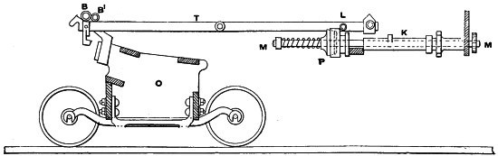
Fig. 173.J.N.
(350) One of the important points of difference between this and mules
of other makes is found in the position of the cam shaft. This, it
was seen, is in the Platt machine placed above the axis of the rim
shaft. In other cases it is placed, as shown diagramatically in Fig.
173, along the headstock of the mule, and below the centre of the long
or “balanced” lever T. In this case the cam shaft K is
a tubular one, and has passed through its centre the shaft M,
which is suitably driven from one end. The cam shaft is fitted with
a friction clutch at P, the fixed half being on the tubular
shaft. The other half slides on the shaft M, being pressed
up to the fixed half by the spiral spring shown. On the long lever
T at the point L a pendant cam plate is hung, which
surrounds the cam shaft as shown in a detached front view and section
in Figs. 174 and 175, and is formed with a slot so as to permit it to
rise and fall freely. The cam plate has two raised cam surfaces or
courses, against which the end of a pin is pressed by the action of
the spiral spring. The pin passes through the half clutch fixed on the
cam shaft, and presses against the sliding half on the shaft M.
Thus when the pin is on the raised part of the cam plate the clutch is
detached, while if it is on the lower part the clutch is in gear. When,
therefore, the inner end of the balanced lever T is depressed,
the fall of the pendant plate causes the pin to come upon the lower
part of the cam course, and permits the engagement of the clutch. The
cam shaft thus makes a half circle turn, and effects the necessary
changes for beginning spinning. This causes the end of the pin to run
on to the second cam course, and by the time the half revolution is
made, it comes on the raised surface and disengages the cam. In this
position it rests until the outer end of the long lever is depressed,
when a similar action occurs, terminating in a similar way.
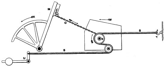
Fig. 172.J.N.
(351) The back shaft is also engaged and detached in a different
manner. It is driven from the roller shaft by a train of wheels, but
the last of the train is a compound one, consisting of a large wheel
with a smaller pinion. The latter gears with the back shaft wheel, and
is put into or out of gear accordingly, as it is desired to revolve
or stop the rotation of the back shaft. For this purpose the compound
wheel is borne on a hinged lever, called commonly the Mendoza lever,
which is weighted in a suitable manner. The exact origin of the word
Mendoza, as applied to this lever, is difficult to define, but it
probably arises from the French phrase, main douce—Anglicè, the soft
hand. However this may be, the function of the lever is to put the
pinion into and out of gear with the backing-off wheel, and to effect
this, its motion is controlled by a cam or eccentric on the cam shaft.
This cam works in a fork in a lever, and the rotation of the cam shaft
raises or lowers the Mendoza. The object of the weight is to ensure the
full engagement of the pinion and back shaft wheel, so as to obviate
any jumping out of gear at the commencement of winding. There is some
tendency towards this unsteadiness of driving in the early part of the
outward run, and it is desirable to lock the Mendoza lever in position.
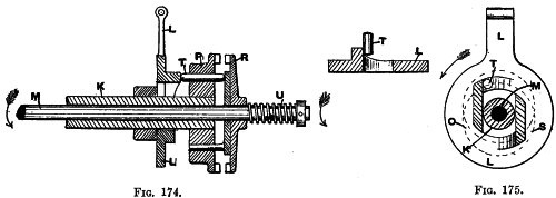
Figs. 174 and 175.J.N.

Fig. 176.
(352) Messrs. John Hetherington and Sons employ a special device
by which this difficulty is overcome. The mule, as made by
them—arranged to be driven with the rim shaft transversely, instead
of longitudinally, placed in the headstock—is illustrated in Fig. 176
in longitudinal elevation, and in Fig. 177 in back view. Both views
show the method of driving quite clearly. On the outward end of the
Mendoza weight a pin is fixed which takes into a fork formed at the
upper end of a vertical lever. The fork is shaped with a shoulder or
recess, below which the pin referred to can slip when desired to lock
the Mendoza in position. A small ear is formed on the vertical lever,
through which a set screw is passed, the point of which comes in
contact with the end of a horizontal lever centred on a pin fixed in
the headstock. The last named lever has a long tail extending outwards
toward the carriage. When the carriage comes up to the back stops and
the Mendoza lever falls, putting the driving pinion into gear with the
back shaft wheel, the long tail of the horizontal lever is raised,
and the effect is that the pin in the Mendoza weight passes under
the shoulder of the fork in the vertical catch lever, and so firmly
holds the Mendoza lever down. As the latter carries the driving wheel,
the pinion is kept firmly in gear, and the effective driving of the
carriage is obtained. As soon as the carriage has run out a little—by
which time it has gained momentum—the horizontal lever is released,
and its long end falls, thus freeing the catch or pin in the Mendoza.
Sometimes the minder, in cleaning, runs out the carriage a little and
then changes the cam, without freeing the horizontal or locking lever.
If afterwards the mule is started the carriage endeavours to run in,
although the back shaft wheel and its driving pinion are in gear. This
leads to breakages, and in order to avoid these, Messrs. Hetherington
have arranged a small relieving lever, coupled to the long lever, so
that any motion of the latter causes the relieving lever to act and
free the Mendoza catch pin, without reference to the position of the
horizontal locking lever. This mule is arranged with the extra band for
driving the taking-in side shaft D referred to in paragraph 286.
The band E is driven from the counter shaft R, and passes
round a double grooved pulley on D. It is kept in tension by the
pulley F, carried by a frame which can be moved inwards by the
quadrant rack G with which a worm gears. The remaining reference
letters indicate the same parts as in the other illustrations.
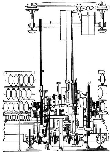
Fig. 177.
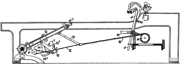
Fig. 178.
(353) It was shown that to perfect the action of winding at the nose
of the cop it is customary to deflect the chain by means of a nose
peg. A motion based upon the principle of the deflection of the chain,
but in which that object is attained in a different fashion, is shown
in Fig. 178 in side elevation, and in Fig. 179 in enlarged detail.
This is Dobson and Hardman’s patent, and is made by Messrs. Dobson and
Barlow. Two main objects have been aimed at. These are the control of
the winding from the faller—so that the relation of the two will be
strictly maintained—and the deflection of the chain by a pull from
below instead of a push from above. On the faller shaft a tappet is
fixed, to which is jointed a lever J with an arm or finger
K secured to it. A bracket H is attached to the quadrant
arm a few inches from its centre, and its outer edge H1 is
formed into a rack with which two catches engage. These are carried
by a lever G, which is hung on a pin in the upper part of the
bracket H. G has a projecting shoulder at its outer end,
to which is fastened one end of the chain E passing over the
pulley F, and having its other end attached to the lower end of
the link C. The winding chain B is also attached to the
link C. The lever G is formed with an arm G1, to
which is jointed a double tumbler I, each part of which is free
to move as required. A projection is cast on I, which causes
it to rest on G when in its normal position. This mechanism
acts in the following manner: When a set of cops is begun the lever
G is at its lowest position relatively to the quadrant rack
H1, and the winding chain B and link C are then
almost straight. At the end of each stretch the finger K comes
into contact with the lower part of I, which is raised to allow
K to pass. When the inward run begins K causes the
projection on I to press upon the lever G and raise it
if the pressure is maintained a sufficient time. Whether this is so or
not is determined solely by the vertical position of J, which,
in turn, is regulated from the winding faller. If the latter is not
substantially raised from stretch to stretch the position of G
in like manner remains unaltered. If this is not the case G is
a little lifted, and the chain E is thus drawn forward a little
over the pulley F. The result is that a pull is exercised on the
link C, which is drawn down so that it and the chain B
no longer represent a straight line. This is equivalent to shortening
the chain B, and the result is that the necessary acceleration
of the winding drum is effected. The chief feature of this motion
is the regulation which is obtained from the faller, the position of
which fixes the amount of extra pull put on the drum. However slowly
the building proceeds the necessary acceleration is made in exact
proportion.
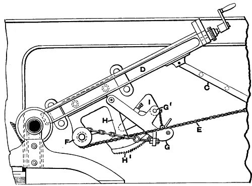
Fig. 179.J.N.
(354) In the description of the governing motion, given in paragraph
339, it was shown that the rotation of the screw in the quadrant arm is
made during the inward run of the carriage. There are some objections
made to this procedure on the ground of the extra tension put on the
yarn in the early part of winding, which is of some moment when fine
or tender yarns are being spun. In Fig. 180 a side view is given of
a motion made by Messrs. Dobson and Barlow, which is designed to
obviate the necessity for altering the screw during the inward run,
and provide means by which it can be made during the outward run. In
lieu of the ordinary grooved pulley on the quadrant axis, a toothed
wheel U is used, with which a toothed rack R can engage
under circumstances presently to be described. The rack R is
carried by a sliding frame S, which is fixed upon a longitudinal
rod T, extending backwards in the headstock, and carried by
brackets fastened to the floor. The rack is fitted at one end with
an inclined foot, and at the other with a spring, which prevents too
deep an engagement of the rack and wheel. The rack passes—during its
outward stroke—over a frame fastened to the headstock, in which is a
screw X on which is threaded the sliding stop W. The
pitch of the screw thread is varied to correspond with the thread
in the quadrant arm Q, and the screw is rotated by a ratchet
wheel, with which a pawl, oscillated by a finger, engages. At the point
I a loose tongue is hinged, which at the end of the stroke of
the frame engages with the nut W. On the winding faller a
sector Y is fixed, in which a stud, formed with two portions of
different diameters, is bolted. On the counter faller a sector Z
is fastened, carrying a screwed staple, to which is secured one end of
a chain, indicated by dotted lines. The chain passes round the bowl
R at the upper end of the pendant lever O, guided in
brackets at the front of the carriage. The loose end of the chain is
formed into a loop, which can be slipped on to either of the surfaces
of the bowl in the sector Y. A hinged finger L is carried
by a bracket on the rod T, and has a little range of movement in
a circular direction.
(355) In beginning a set of cops the stop W is turned back to
its proper position, which is determined by the size of the cop about
to be spun. The frame S is then pushed forward as much as
possible, and the chain is slipped on to the smaller portion of the
bowl in Y. This allows the pendant O to fall a little,
and its height subsequently is regulated strictly by the position
of the fallers. During the outward run the horizontal arm P,
which forms part of the pendant O, engages with the vertical
projection on the frame S and causes it to move forward. The
rack R being raised engages with the wheel U and rotates
it, this movement being consequently communicated to the quadrant nut.
Thus the latter is put into position for action during the next period
of winding and any straining of the yarn is avoided. As the stroke of
the rack is continued, the tongue I engages with the nut and
causes the rack to drop out of gear with the pinion, and any further
movement of the quadrant nut is avoided. It has been shown that the
traverse of the latter is gradually diminished as the cop is built,
and, in like manner, the inward motion of the stop W causes the
engagement of the rack and pinion to be limited. This is a sort of
“trip” motion very familiar to students of steam engine practice, and
is well applied in this case. The slide S is drawn back into
position by the engagement of the lower end of the pendant O
with the finger L. A slight contact at first between these
becomes a firm one by the backward movement of the finger when pressed
upon by the pendant O, but it will be obvious that, if the
latter is too high to move the finger L, the rack will remain
untraversed until a sufficient depression of O takes place. It
only remains to be said that once the nut W has been set at the
beginning of winding, all that is required is for the minder to slip
the loop of the chain on the right portion of the bowl in Y, and
the motion acts automatically until winding is finished.
(356) A somewhat similar attachment has been recently introduced in
France, and is the invention of Mons. Dubs. The author is informed by
a trustworthy mechanician that the motion acts perfectly throughout
winding, and it may, therefore, be well to give a brief description of
it. As in the motion of Messrs. Dobson and Barlow, the regulation of
the nut takes place during the outward run, and it is unnecessary to
again detail the reasons for this course. The chief operating part of
the mechanism is the rack finger A—shown in its position when in
gear—which is hinged on a vertical rod or plunger K, sustained
in a frame or bearing S fastened to the carriage. Referring to
Fig. 181, the whole of the apparatus moves with the carriage and is
self-contained. Attached to the faller is a connecting rod or link
B, which is coupled to a hinged lever O formed at its
outer end with a toothed rack or quadrant finely pitched. With this
rack, which has two sets of stepped teeth, two detent catches H
engage. The lever O is hinged to a plunger L, which
has at its lower end a screwed shank fixed to a plate F also
secured in the same manner to the plunger K. The inner end of
the rack lever A has a hanging piece D which can engage
with a catch E on the plate F, but which in the view is
shown out of gear. The downward motion of the inner end of A is
regulated by the stop screw R, and it is coupled by the chain
C to the counter faller. The spring M constantly presses
the inner end of A down, tending to raise the rack. When the
various parts are adjusted the parts F K and L move
together and simultaneously with the lever O.
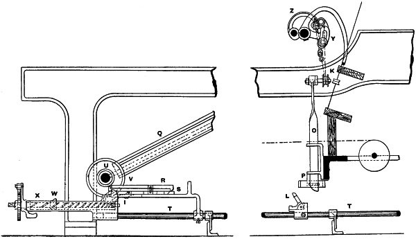
Fig. 180.J.N.
(357) The action of this mechanism is as follows: Assuming that
the inward run of the carriage is nearing completion, the lever
G engages with a stop or bracket fixed to the floor, which
causes D to fall out of gear with the catch E. This
leaves the plate F and all its connections to the control of
the chain C and the counter faller. When the faller locks it
raises the rod B and the lever O, which is then held in
position by the detent catches H. During the first inward run
O is lifted to its highest point, which, of course, affects
all the parts attached to it. Just before the end of each stretch the
catches H are released, so that the whole of the subsequent
regulation depends on the counter faller. As the locking point of the
winding faller wire is gradually raised the elevation of the fork at
the upper end of K—which by reason of the connection of the
plate F with the lever O always takes place—occurs at
a gradually lower point throughout building. The effect is that when
D is released, as described, an elevation of the rack A
takes place if needed. If not, D falls over the catch E
as the carriage begins to run out and thus locks it, preventing the
rack A from rising. If, however, the tension on the yarn at
the end of winding is such that the counter faller is depressed, the
catch D cannot recover its position. The end of the rack lever
consequently falls on to the stop screw R, and the rack is
raised into contact with a wheel on the quadrant axis formed with teeth
of a similar shape. Thus the screw is given a turn while the carriage
is running out, and the nut is in the correct position for winding the
next length.
(358) Quite recently Messrs. Curtis, Sons and Co. have constructed a
mule in which the cam shaft, as an instrument for making the “changes,”
is entirely done away with. A side elevation of the mechanism for
effecting this is shown in Fig. 182, and a plan of the same in Fig.
183. The back shaft clutch F is formed so that its driving
half slides, this being controlled by the action of a lever L,
connected, as shown, at two points to the rods R M. The
taking-in friction is placed horizontally, and is controlled by the
vertical lever H connected with the sliding rod R. The
lever F1, by which the back shaft clutch is disengaged, is
coupled by the link going across the carriage—shown in Fig. 183—to
the roller clutch box, so that the engagement or disengagement of the
roller clutch box is simultaneous with the attachment or detachment
of the roller gear. The mechanism for actuating these parts is based
upon the principle of the push and pull of spiral springs, a partial
application of which was shown in the case of the backing-off rod.
On the axle of the quadrant a short arm S is fixed, which is
coupled with the rocking lever T, connected to the sliding boss
on the rod M. Two springs M1 M2 are threaded on the
shaft, and are placed respectively between the sliding boss and stop
hoops fixed on the shaft. The rod M is coupled at the back to
the lever L, the function of which is, as indicated, to actuate
the back shaft clutch. At the front end of the rod M a catch
lever Q is fixed, which detains it as the carriage is running
out. When this happens, the spring M1 is compressed by the
oscillation of the quadrant axle acting through the crank S
and its connections, the other spring M2 being then out of
compression. As soon as the end of the outward run is reached a boss
on the counter faller shaft B1 comes in contact with the
underside of the catch lever Q and raises it, thus freeing the
rod M. The spring M1 is thus free to extend, and, acting
upon the lever L, disengages the back shaft and roller clutches.
This accounts for one part of the changes; and while it is taking place
a catch lever O, which had previously been raised, is lowered.
When the inward run of the carriage is made by the operation of the
same parts the spring M2 is compressed. On the arrival of the
carriage at the roller beam the lever O is tripped by a boss on
the faller shaft B, allowing the spring M2 to extend and
re-engage the two clutches named.
(359) The taking-in or scroll shaft is operated from the rod R,
which is fitted with one spring only at its back end. This is
compressed by the intervention of a second lever, fastened on the same
shaft on which the rocking lever T oscillates, the compression
taking place during the outward run of the carriage. The spring is held
in compression by a latch P, which engages with a lug on the
rod R. When the carriage runs in, a boss on the faller shaft
releases the latch, and the extension of the spring disengages the
taking-in friction clutch. The latter is put into gear by the locking
of the faller in the ordinary manner, and is held in gear until the
latches O and P are tripped in the manner described. The
spring R presses on a collar carried by the lever H,
and the releasing of the friction is aided by the lever L,
which comes against the head of H when the spring M2 is
extended. The levers H and L are so arranged that they
cannot both act together, so that the two motions of taking-in and
drawing-out cannot be in action at the same time.
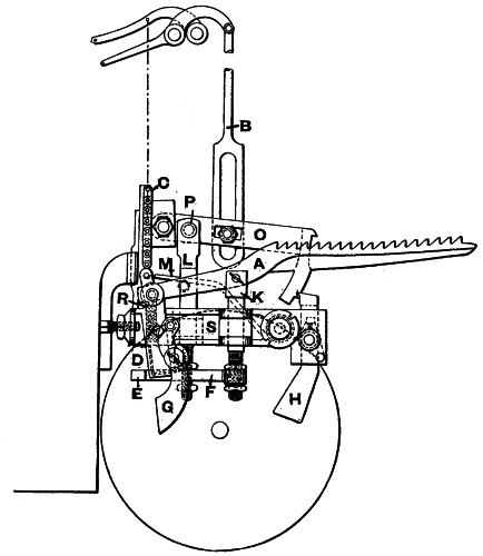
Fig. 181.J.N.
(360) The angle of the spindle relatively to the vertical line is such
as is necessary to suit the material being spun, but there is another
feature which it is necessary to mention. As the point of the spindle
moves in a horizontal plane, it is obvious that the yarn will pass on
to it from the rollers at an angle varying with its distance from them.
That is to say, the angle formed by the yarn, in passing on to the
spindle, will be more acute when the carriage is near to the rollers
than it will be when it is further away. This has a little influence
upon the problem of spinning, and an arrangement exhibited at the
Manchester Jubilee Exhibition, applied to Messrs. Asa Lees and Co.’s
mule, is shown in Fig. 184. In this case there are two carriage slips
instead of only one, and these are inclined so as to compensate for the
difference in angle. On one of the slips A the front carriage
runner D travels, and on the other the back one C. The
result is that the inclination of the spindles is slowly altered, with
the result that the angle formed by the yarn and the spindle in each
case, is nearly the same in all positions. This device worked well, but
the difficulty existing does not appear to be great enough to lead to
any wide adoption of it.
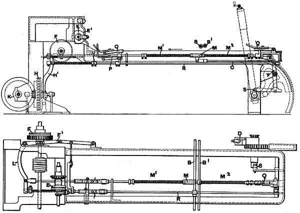
Figs. 182 and 183.J.N.
(361) Having thus described in detail the construction and principles
of the mule, it is only necessary to say a few words on the subject
of its application to the spinning of the finer counts, which require
specially delicate treatment. It is found necessary to fit a few
special attachments which are supplementary to the ordinary mechanism
employed. In dealing with fine yarns the rollers are stopped a little
before the carriage has completed its outward run, and this results in
the yarn being a little stretched. A more important result, however,
is that if there be any unevenness in the diameter of the yarn, the
twist speedily runs into the thin places, which become hardened, and
do not easily elongate or draw. The thicker places remaining untwisted
are, therefore, drawn down until the full twist runs into them also.
This supplementary twisting and drawing is called “jacking,” and
its amount varies, of course, with the staple of the cotton being
spun, the further movement of the carriage being sometimes as much as
five inches. In order to permit the jacking to be effective, it is
the custom to put into the yarn very little twist before the roller
delivery ceases, after which it is rapidly introduced. This tends to
shorten the yarn and puts it in such a state of tension, that unless
relieved, it would break. There are two methods of obviating this
difficulty. The first is to move the carriage in a little during the
period of twisting, and the other to cause the rollers to deliver a
short length of yarn. The latter is now the most usual method, and
by the adoption of a special engaging motion, the amount delivered
can be regulated at will. When long stapled cotton is being spun, it
is the practice to cause the rollers to deliver a little yarn during
the inward run, while winding is going on. The amount varies, but is
about three inches, so that only 60 inches is wound on the spindle
during each inward run. Messrs. Platt Brothers and Co. make a very good
fine spinning mule with a number of well thought out motions of great
ingenuity, a full description of which will be found in the Proceedings
of the Institution of Mechanical Engineers, 1880, pages 516 to 527.
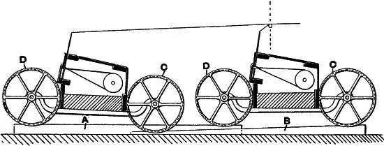
Fig. 184.J.N.
(362) Mr. Richard Threlfall of Bolton has devoted himself to the
construction of fine spinning mules, and has produced a self-acting
machine, which is capable of spinning the highest counts. With a brief
description of it as made by him, the present treatment of this machine
must be closed. In the Threlfall mule the roller delivery after jacking
is effected by a short shaft on which is a catch box, the outer surface
of which constitutes a cam course, which is revolved from the twist
shaft. On this cam shaft is the first of a train of wheels, which
gear up to the roller, and the first wheel has motion given to it by
a ratchet and pawl, the movement of the latter being controlled by
the throw of the cam. The cam can be set so as to give a whole turn
to the rollers, or only one flute, and by means of changes in the
train of wheels further regulation can be made. The copping rail is
specially constructed, so as to enable short cops of any shape to be
easily built. The fallers are arranged so as to be very sensitive in
action. The action of the quadrant is aided by a special contrivance
consisting of a narrow pulley placed alongside the loose backing-off
pulley, but fast on the shaft. Connected to the strap guide is a
lever which is coupled to a rod suitably carried in brackets, and on
which is a regulating screw and nut. This regulation is provided so
that the passage of the strap on to the narrow pulley is effected as
desired. The strap is prevented from traversing from the loose pulley
by a catch, and the release of the latter is effected by a finger on a
bracket fastened to the carriage square. When the latter runs in the
finger pushes over a tumbler holding the catch in position and releases
the latter. The weight of the parts then throws the strap over on to
the fast narrow pulley, and the winding is thus accelerated. By fixing
the finger and setting the adjusting screw, this motion may be brought
into play at any desired moment. On the faller shaft is a bracket, to
the outer edge of which is attached by a bolt or screw a grooved cam
surface. To this is attached a cord actuated by the governor motion. By
suitably setting the cam, winding is effected during each inward run
with equal tension. A brake is applied to the faller shaft, consisting
of a lever fastened to the carriage, one end of which engages with
an inclined plane, and the other end has a cord attached passing
over a pulley on the faller shaft. By tightening the band the faller
is held perfectly steady. The combination of the last three motions
effectually prevents snarls. A roller delivery motion is added, and the
most perfect adjustment of the whole of the movements is provided. The
spindles revolve at two speeds, the final or twisting velocity being
about 8,000 revolutions per minute.
(363) Such is a description of the most intricate machine in the whole
range of textile mechanics, which, although threatened more than once
with extinction, is yet more largely used to-day than at any previous
time. On it yarn of varying qualities can be spun, either soft or hard
twisted. The yarn which is used for warp purposes is more commonly
known as twist, and that employed for weft is known by that name. Weft
yarn, as will be shown at the end of the next chapter, is always more
softly twisted than warp yarn, and the mule spindles revolve in the
opposite direction to that employed when the latter is spun. About
the question of twists and the system of the arrangement of draughts
throughout the whole process of spinning, a few words will be said in
concluding the next chapter.
(364) The mule is used in a modified form to produce “doubled”
warps-that is, two strands of yarn twisted together. When so employed,
the machine is known as a “twiner,” and is constructed with a low
creel. With the necessary alterations to suit the circumstances
peculiar to the case, the machine is largely employed in certain
districts. In its main features, however, it resembles the mule, and
does not require a detailed description. Another modified form is used
for spinning yarns made from waste, being nearly identical with the
machine as employed in spinning fine worsted yarns. The student who is
interested in this subject will find a description of the woollen mule
in “Spinning Woollen and Worsted,” by Mr. W. S. Bright McLaren, M.A.
(365) A table is appended of actual productions from Messrs. John
Hetherington and Sons’ mule. These are given from 74 machines for the
ordinary working week of 561⁄2 hours. A great variety of counts are
included, all of which were being spun at the same time. An additional
table is given of productions from Messrs. Platt Brothers and Co.’s
mule. An explanation of the value of the hank is appended to the next
chapter.
Table 2.
ACTUAL PRODUCTIONS IN A WORKING WEEK OF 561⁄2 HOURS, FROM MESSRS. JOHN
HETHERINGTON AND SON’S MULES.
No. of
Mule. |
Hanks. |
Counts. |
Hanks per
Spindle. |
| 2 |
77,250 |
39 |
31·14 |
| 4 |
70,750 |
43 |
28·52 |
| 6 |
71,000 |
43 |
28·62 |
| 8 |
75,500 |
41 |
30·44 |
| 10 |
65,750 |
32 |
32·42 |
| 12 |
68,750 |
28 |
33·90 |
| 14 |
61,750 |
36 |
30·44 |
| 16 |
71,750 |
45 |
28·73 |
| 18 |
69,750 |
45 |
27·94 |
| 20 |
72,250 |
45 |
28·94 |
| 22 |
71,750 |
45 |
28·73 |
| 24 |
71,000 |
45 |
28·43 |
| 26 |
71,250 |
45 |
28·53 |
| 28 |
71,250 |
45 |
28·53 |
| 30 |
72,250 |
45 |
28·93 |
| 32 |
73,000 |
42 |
29·23 |
| 34 |
72,500 |
42 |
29·03 |
| 36 |
61,500 |
36 |
29·97 |
| 38 |
66,750 |
32 |
32·52 |
| 40 |
62,000 |
38 |
30·21 |
| 42 |
58,500 |
38 |
28·50 |
| 44 |
62,750 |
36 |
30·57 |
| 46 |
62,250 |
38 |
30·33 |
| 48 |
63,250 |
36 |
30·82 |
| 50 |
60,250 |
38}
33} |
29·35 |
| 52 |
64,750 |
34 |
31·55 |
| 54 |
65,750 |
36 |
32·03 |
| 56 |
65,000 |
40 |
30·52 |
| 58 |
61,750 |
40 |
29·91 |
| 60 |
61,000 |
42 |
29·55 |
| 62 |
60,000 |
42 |
29·06 |
| 64 |
63,000 |
40 |
30·52 |
| 66 |
61,500 |
40 |
29·79 |
| 68 |
61,500 |
42 |
29·79 |
| 70 |
61,250 |
42 |
29·67 |
| 72 |
59,750 |
42 |
28·94 |
| 74 |
65,750 |
40 |
31·85 |
Total Weight, 59,9201⁄2 lbs.
Average Counts, 39·53.
Average Hanks per Spindle, 29·88. |
Table 3.
ACTUAL PRODUCTIONS IN A WEEK OF 561⁄2 HOURS OF TWIST AND WEFT YARNS
FROM MESSRS. PLATT BROTHERS AND CO’S. MULES.
| TWIST. |
No. of
Spindles in
each Mule. |
Counts
spun. |
Hanks
per
Spindle. |
| 1044 |
30’s |
32 |
| „ |
32’s |
31·5 |
| „ |
33’s |
30·65 |
| „ |
24’s |
30 |
| „ |
50’s |
28 |
| „ |
54’s |
27 |
| |
| WEFT. |
No. of
Spindles in
each Mule. |
Counts
spun. |
Hanks
per
Spindle. |
| 1280 |
28’s |
33·81 |
| „ |
29’s |
34 |
| „ |
34’s |
31·85 |
| „ |
36’s |
31 |
| „ |
38’s |
30·46 |
| „ |
40’s |
30 |
| „ |
46’s |
29 |
Note.—The production of any mule varies of course with the
class of cotton used, the amount of twist required, and the length of
mules; but the figures given in the tables are, in each case, figures
of actual productions.