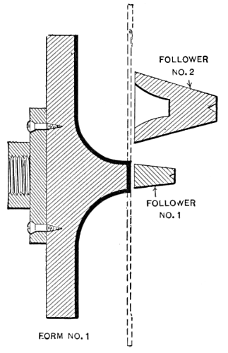
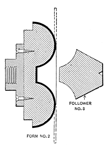
The principal object of this chapter is to describe in detail the various
operations of spinning metal so that a tool-maker or machinist
who has not access to a metal spinner, will be able to make his own
tools, rig up an engine or speed lathe, and make the simple forms
or models that are required in experimental work. To do this intelligently,
it is necessary to follow in detail every step in metal spinning
from the circular blank to annealing, pickling, dipping, burnishing,
etc., and also to know how to make the simpler forms of spinning
tools, what lubricants to use on the different kinds of metals, what
material to make the spinning chuck of, and how far the metal can be
worked before annealing.
Spinning metal into complicated and elaborate shapes, is an art
fully as difficult as any craft, and the man is truly an artist that can
make artistic and graceful outlines in metal, especially when only a
few pieces are required and the cost will not allow of making special
chucks to do the work on and with no outline chucks to govern his
design, the forms being made by skill and manipulation of tools alone.
Such skill is far superior to that of the Russian metal worker, who,
instead of making a vase or ornament of one piece, cuts up several
sections and soft solders them together, after covering them with
crude “gingerbread” work to disguise his poor metal work.
The amateur can imitate the Russian work, but never the work of
the skilled spinner. There are several grades of spinners, most of
them never attaining the skill of the model-maker or the facility for
handling the different metals. A man that has had several years of
experience spinning brass or copper would not be able to spin britannia
or white metal without stretching it to a very uneven thickness.
As brass or copper is harder than the other metals mentioned, they resist
the tool more and require more pressure in forming, and if the
operator used the same pressure on the softer metals, he would stretch
or distort them, so that they would be perhaps one-quarter of the
original thickness at angles and corners where the strain in spinning
would be greatest, which would ruin the articles. The best test for
skill in ordinary spinning, is to take a long difficult shape, after being
finished, and saw it in two lengthwise, and if the variation in thickness
is less than 25 per cent of the original gage, it is good practice.
Some spinners can keep within 10 per cent of the gage on ordinary
work, but they are scarce.
The spinning trade in this country is mostly followed by foreigners,
Germans and Swedes being the best. The American that has intelligence
and skill enough to be a first-class spinner, will generally look
around for something easier about the time that he has the trade
acquired. It is an occupation that cannot be followed up in old age,
as it is too strenuous, the operator being on his feet constantly, and
having to use his head as well as his muscles.
For common plain shapes, a patternmaker’s faceplate, with a tapered
center screw, is sufficient for holding the wood chuck. The hole
in the wood should be the same taper as the screw, thus giving an
even grip on the thread. If a straight hole only is used, and it is not
reamed out before screwing to the plate, it will only have a bearing
on one or two threads, and if the chuck is taken off and replaced on the
faceplate, it will not run true. Care should also be taken to face off
the end of the chuck flat, or to slightly recess it, so that it will screw
up evenly against the faceplate, as a high center will cause it to rock
and run out of true.
In large chucks (over five inches) it is best to have three or four
wood screws, besides the center screw. The holes for these can be
spaced off accurately on a circle in the iron faceplate, and drilled and
countersunk. It is best to have twice as many holes as screws; that
is, if four screws are used there should be eight holes, so that if the
chuck has to be replaced at any time and the wood has shrunk, it
can be turned one-eighth of a revolution further than the original
chucking.
Where a chuck has to be used several times, it is better practice
to cut a thread in the wood and screw the chuck directly to the
spindle of a lathe, not using the faceplate. This thread can be chased
with a regular chasing tool, where the operator has the skill, or
if not, the wood can be bored out and a special wood tap used. Such
a tap has no flutes and it is bored hollow, there being a wall about
³/₁₆ inch thick. One tooth does all the cutting, that is the one at the
end of the thread. The chips go into the hollow part of the tap. The
end of the tap for about ¼ inch should have the same diameter as the
hole before threading to act as guide for the cutting tooth.
It is essential that a chuck should run very true and be balanced
perfectly, as the high speed at which it runs will cause it to vibrate
and run out of true, causing the finished metal to show chatter marks.
The best wood for chucks is hard maple, and it should be selected
for its even grain and absence of checks and cracks. It is best to
paint the ends with paraffine or red lead, or to immerse the chucks
in some vegetable oil after turning. Cottonseed oil is very good for
this purpose, but care should be taken not to soak the chucks too
long.
For a man not skilled in spinning, it is better to use metal chucks
than wood, for if there are many shells of a kind, the operator is
liable to bear too hard on the tool, thus compressing the chuck and
making the last shells smaller than the first. Corners and angles not
well supported might also be knocked off. The writer prefers cold
rolled steel for chucks up to 6 inches in diameter and cast iron for the
larger ones, but where good steel castings can be obtained, a good
chuck can be made by turning roughly to shape a wood pattern, allowing
enough for shrinkage and finishing, and hollowing out the back to
lighten it. When the chuck is finished all over in the lathe, it should
balance much better than a cast iron one, as there are not the chances
of having blow holes in the iron, thus throwing the chuck out of balance.
The distance that metal can be drawn without annealing, can only
be learned by experience. A flat blank rotated in the lathe, being soft,
will offer little resistance and it can be gradually drawn down by a
tool held under the chuck and against the blank. This tool is pushed
from the center outward and forward at the same time, and every
time it passes over the blank or disk the metal becomes harder by
friction, and the change of formation and the resistance at the point
of the tool greater. This can be felt as the tool is under the operator’s
arm. When the spring of the metal is such that the tool does
not gain any, but only hardens the metal, the shell should be taken
off and annealed. If the metal has been under a severe strain, it
should be hammered on the horn of an anvil or any metal piece that
will support the inside. The hammer should be a wood or rawhide
mallet, but never metal, the object being to put dents or flutes in the
metal to relieve the strain when heating for annealing; if this is not
done the shell will crack.
After annealing the shell it should be pickled to clean the oxide or
scale from the surface; otherwise the metal will be pitted. When
the scale is crowded into the metal and when it will not finish smooth
after spinning to shape, the metal can be finished by skimming or
shaving the outer surface which cuts out all tool marks; it can then
be finished with medium emery cloth or the shell can be bright dipped,
and be run over with a burnishing tool before buffing. Burnishing
can be done on the spinning chuck, but the speed should be higher
than for spinning; this requires some skill for a good job, and it can
be done only on metal chucks.
Annealing is best accomplished in a wood or gas oven, where a
forge fire is used. The metal should never touch the coke or other
fuel, but it should be held in the flame above the fire. Where only
part annealing is required, the shell can be immersed in water, the
part to be annealed being exposed above the water, and a blowpipe
used on it. The remainder of the shell will then be hard. This way
of annealing is sometimes necessary on a special shapes.
Brass should be heated to a cherry red, and held at that point for
a few minutes, in a muffle furnace. If an open furnace is used, just
bring the metal to a cherry red and then dip it in water; this method
is better than when waiting for it to cool, the action being just the opposite
to that on steel. Brass such as the common yellow brass is not
suitable for spinning, there being but 55 per cent copper and 45 per
cent zinc. There are two grades of brass suitable for spinning. These
are known as “spinning and drawing,” having 60 per cent copper and
40 per cent zinc, and “extra spinning and drawing” having 67 per
cent copper and 33 per cent zinc. There is also a better grade known
as “low brass” having from 75 to 80 per cent copper; it has the color
of bronze and is only used on very deep and difficult spinning.
The scale, after annealing, should be pickled off in an acid bath
(described further on in this chapter), and the part thoroughly washed
in running water. Brass, German silver and the harder metals should
be hammered before annealing; it is not necessary to hammer zinc,
copper, aluminum, etc.
A pyrometer in an annealing furnace would be an advantage where
quantities of the softer metals such as zinc, aluminum, etc., are being
heated. Copper is annealed the same as brass and is also pickled.
Zinc is coated with oil before being put in the oven, and when the oil
turns brown, which occurs when the temperature is about 350 degrees,
the metal is ready to take out; it should then be plunged in water to
shed the scale, but not pickled. The melting point of zinc is 780 degrees
F. Aluminum can be annealed the same as zinc, as the melting
point is 1,140 degrees F.
Steel should be annealed by heating to a cherry red and then allowing
it to cool slowly; it should be scaled in a special pickle, thoroughly
washed, and then put back in the fire long enough to evaporate every
particle of acid that may have remained from the pickling operation.
Any acid remaining on the steel will neutralize any lubricant that is
applied when spinning. Annealing should be avoided wherever possible.
Open hearth steel only should be used. It should be free from
scale and preferably cold rolled. Bessemer steel is not suitable, except
for very shallow spinnings. Tin plate made from open hearth
steel can be spun about one-half as deep as its diameter where the
shape is not too irregular. German silver is difficult to spin, especially
when it contains over 15 per cent nickel; it has to be hammered
before annealing, the same as brass, to avoid cracks.
Common yellow soap cut up in strips about ½ inch or ¾ inch square
is a good lubricant for spinning most metals. It should be applied
evenly to the disk or blank while it is revolving, by holding the soap
in the hand and drawing it across the surface. Beeswax is the best
for spinning steel, but it is expensive. Lard oil mixed with white
lead is a fair substitute. Either mutton or beef tallow applied with a
cloth swab is very good on most all metals; also vaseline and graphite
mixed to a paste and applied the same as tallow.
The different metals are malleable, ductile and tenacious in the
following order; white metal or britannia, aluminum, zinc, copper,
low brass, high brass, German silver, steel, tin plate. White metal
does not harden in spinning, but it requires special skill in handling,
or the metal will be of very uneven gage. The best metal for an
amateur to start on is copper, as it is both tenacious and ductile, and
will stand much abuse in the fire and on the lathe. One of the peculiar
properties of zinc is that it has a grain or texture, and when
spinning, the two sides that go through the rolls lengthwise will
be longer than the sides that have the cross grain, requiring the shell
to be trimmed off quite a distance to even the edge.
To show the possibilities of working the different metals, and their
relative spinning values, a number of articles made from different
materials are illustrated herewith.
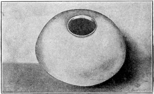
Fig. 16. Zinc Lamp Shade Spun in One Operation without Annealing
A zinc lamp shade is shown in Fig. 16 that is 14¼ inches in diameter
and 4¾ inches deep. This shade was spun in one operation, without
annealing, from a flat circular blank. All zinc should be warmed
before spinning, either over a gas burner at the lathe or in hot soap
water, and the chuck also should be heated, as otherwise the blank
will soon chill, if spun on a cold metal chuck, as the chuck absorbs
the heat long before the operation is finished. Of course this does
not apply to wooden chucks. The chuck may be heated by using the
burner shown in Fig. 17, which is located around the spindle of the
lathe. The size of the burner should, of course, be in proportion to
that of the chuck used. The burner illustrated is 8 inches in diameter.
It has several small holes drilled for the gas on the side facing
the chuck. The heat of the chuck is regulated by varying the supply
of gas to the burner. The blank is heated before it is put on the
chuck and the friction of the spinning tool helps to keep it warm until
it comes in contact with the chuck. The metal retains its heat until
the job is finished, and this sometimes saves an annealing operation.
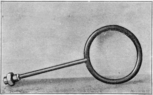
Fig. 17. Gas Burner for Heating Spinning Chuck
In Fig. 18 is shown an example of aluminum spinning. The article
illustrated is a cuspidor having a top 7¾ inches in diameter, a neck
with a 4-inch flare, a diameter at the top of 9½ inches, and a height
of 6½ inches. This shell was spun without annealing, which shows
the extreme ductility of aluminum. The copper shell shown in Fig.
19, has a maximum diameter of 7 inches, and a depth of 8 inches;
it was spun with four annealings. A German silver reflector, which
is 10 inches in diameter at the largest end and 5 inches deep, is shown
in Fig. 20. The spinning of such a reflector, when made from this
material, is quite difficult. An open hearth cold-rolled steel shell with
a maximum diameter of 3 inches and a depth of 4 inches is shown in
Fig. 21. This shell was spun without annealing, which shows that the
grade of steel used is well adapted for this work.
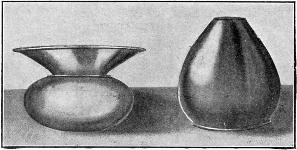
Figs. 18 and 19. Examples of Aluminum and Copper Spinning
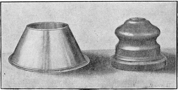
Fig. 20. German Silver Reflector
Fig. 21. Open Hearth Cold-rolled Steel Shell
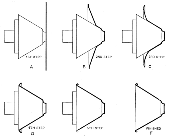
In Fig. 22 two finished brass shells are shown to the right, and also
the number of operations required to change the form of the metal.
The upper shell is 6 inches long and 3½ inches in diameter at the
large end, while the lower one is 7¼ inches long by 3¾ inches in
diameter. It was necessary to anneal these shells between each
operation, the upper shell being annealed four times and the lower
one three times. These pieces were made in quantities sufficient to warrant
the making of chucks for each operation, which enabled them to
be spun with less skill than would be required if a finishing chuck
only were made. When a single finishing chuck is used, the various
operations in spinning a shell of this kind would be left to the judgment
of the spinner, who would decide the limit of the stretch of
metal between the operations before annealing.
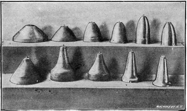
Fig. 22. Various Steps in Spinning the Two Brass Shells at the Right
A brass shell that is made in five operations and with four annealings
is shown in Fig. 23. The finishing chuck used is a split or key
chuck on which it is necessary to cut out the end of the shell in order
to withdraw the key after the shell is spun. This shell, which is
shown finished to the right, is 5½ inches long. It is spun smooth on
a machine steel chuck, and is not skimmed, but gone over with a
planishing tool at the last operation. The two pieces shown in Fig.
22 were also finished in this way.
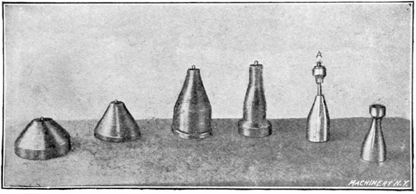
Fig. 23. Another Brass Spinning Operation; the Chuck used is shown at A
Fig. 24 shows a brass shell, which is a good example of “air spinning,”
so called because the finishing or second operation on part of
the shape is done in the air, thus avoiding the use of a sectional or
split chuck. The shell shown is about 5½ inches in diameter. The
first or breaking-down chuck is shown at A. The neck or small part
of the piece, and also a portion of the spherical surface, is formed by
the spinning tool without any support from the chuck. After the shell
is spun or broken down on chuck A, it is annealed and pickled. It is
then put back on chuck A and planished or hardened on the part that
is to retain its present shape. The work is then placed on the chuck
B and the soft part is manipulated by the tool until it conforms to
the shape shown to the right. While this soft part of the metal is
being formed, the part which was previously hardened retains its
shape.
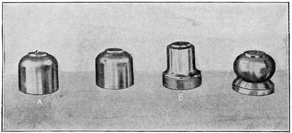
Fig. 24. An Example of “Air Spinning” and the Chucks used
A miscellaneous collection of spinning chucks is shown in Fig. 25.
As will be seen, the larger ones are machined out in the back to
lighten them, and also to give them an even balance. The larger of
those illustrated measure about 9½ inches in diameter, and they are
made of cast iron, while the smaller chucks shown in this view are
of machine steel. The chuck marked A is a key chuck. Another
collection of spinning chucks of various shapes is shown in Fig. 26.
Those in the upper row are all key or split chucks, and the keys
are shown withdrawn from the sockets. All these chucks, up to 6
inches in diameter, are made of machine steel; those seen in the
lower row are shapes which are comparatively easy to spin.
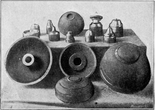
Fig. 25. Miscellaneous Collection of Spinning Chucks
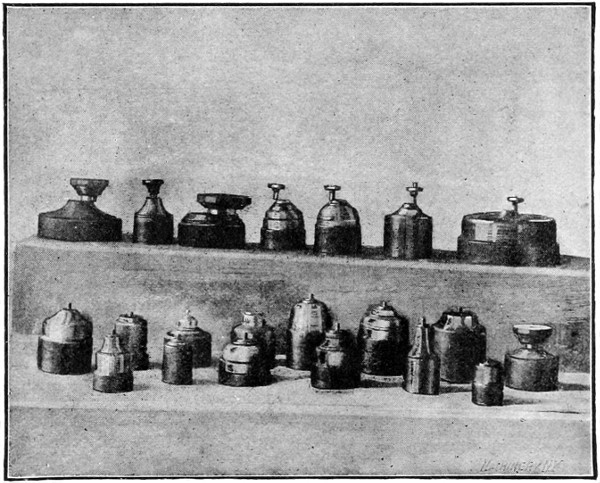
Fig. 26. Another Group of Spinning Chucks. Those in the Upper Row
are of the Split or Key Type
A collection of hard maple chucks is shown in Fig. 27, some of
which represent shapes that are difficult to spin. The chuck A is 15
inches long, and the maximum diameter of B is 12½ inches. These
figures will serve to give an idea of the proportions of the other
chucks. All of the chucks shown have threads cut in them and they
are screwed directly to the spindle of the lathe, the faceplate being
dispensed with. Some of the larger wooden chucks used measure
approximately 5 feet in diameter. A chuck of this size is built up of
sections which are glued together.
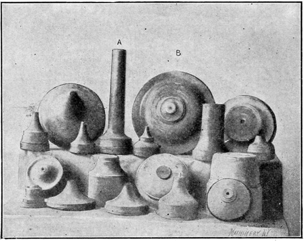
Fig. 27. Various Forms of Spinning Chucks made from Hard Maple
A number of bronze sectional split chucks are shown in Fig. 28.
When spinning over a sectional chuck, it is first necessary to break
down the shell as far as is practicable on a solid chuck. Care should
be taken, however, to leave sufficient clearance so that the work may
be withdrawn. The shell is then annealed, after which it is put on
the sectional chuck and the under cut or small end is spun down to
the chuck surface. When the entire surface of the shell is spun down
to a bearing, the shell is planished or skimmed to a smooth surface;
the open edge is also trimmed even and the shell is polished with
emery cloth.
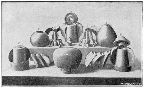
Fig. 28. A Group of Bronze Sectional Chucks
A large bronze chuck of seven sections, one of which is a key section,
is shown at A. The largest diameter of this chuck is 10 inches.
It has a cast iron center hub and a steel cap at the top for holding
the sections in place. This cap, when in place in the retaining groove
shown, is flush with the top of the chuck. Another large chuck having
five sections and one key section is shown at B. The retaining
cap in this case is of a different form. The lower parts of the sections
of all these chucks fit in a groove at the bottom of the hub. A chuck
of five sections that is without a binding cap, is shown at C. This
is not a good design as the hub or center is too straight, and all of
the grip or drive is from the bottom groove, which is not sufficient.
The shape shown at D is more difficult to spin than any of the others,
as it is smaller at the opening in proportion to its size. This chuck
also requires more sections in order that it may be withdrawn from
the shell after the latter is spun. The chuck E is intended for a small
shell that is also difficult to spin. The drive pins which prevent the
segments of the chuck E from turning may be seen projecting from
its base. The centering pins at the outer end of chucks D and E and
the binding caps may also be seen. The chuck A, because of its size,
is hollowed out to reduce the weight. All of these chucks were made
for hard service, and they have been used in spinning thousands of
shells.
Another group of sectional chucks is shown in Fig. 29. They are
mostly made from hard maple. The sections of chuck A are planed
and fitted together and thin pieces of paper are glued to these sections
before they are glued collectively for turning. By using the
paper between the joints, the sections may be easily separated after
they are turned to the proper size and form. If the different sections
were glued without paper between them, the joint formed would be
so good that the separation of the sections could not be controlled,
and parts from opposite sections would be torn away. The use of the
paper, however, between the glued joints, controls the separation of
the sections. The chuck shown at D is also made with the paper between
the sections. Chucks B and E are turned from the solid, care
being taken to have the grain of the wood lengthwise. After they are
turned to the required form, they are split into sections with a sharp
chisel. Before doing this, the key-section should first be laid out.
There should be as few sections as possible, the number being just
sufficient to enable the withdrawing of the chuck from the shell after
the latter is spun to shape. This method of making a chuck, while
quicker than the other, is not good practice, except for small work.
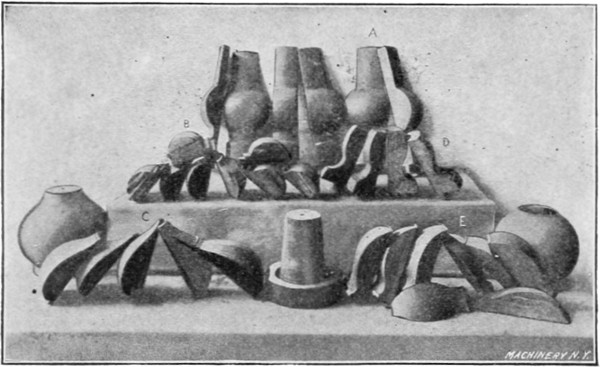
Fig. 29. Sectional Chucks made from Wood
A lignum vitæ chuck is shown at A in Fig. 30; this was made with
paper between the sections. The key-section is shown on top. This
wood, while being more durable than hard maple, costs sixteen cents
a pound in the rough and, counting the waste material, is not any
cheaper than bronze, and is less durable. The hard maple chucks B
and C were turned from the solid, after which the sections were split.
The segments shown in the center of the illustration did not split
evenly, owing to a winding or twisting grain.
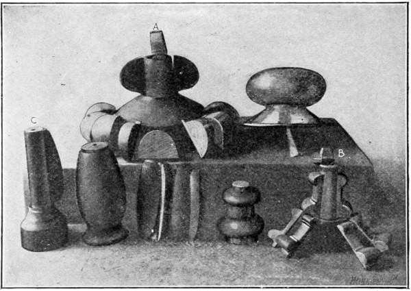
Fig. 30. Other Examples of Wooden Sectional Chucks
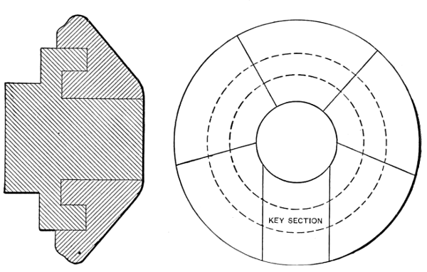
The construction of a sectional spinning chuck is shown in Fig. 31.
This illustration also shows the proper proportion for the central hub
and its taper. This hub should never be straight, but should have
from 5 to 7½ degrees taper on the central part. There should also
be a taper of 1½ degree on the other binding surfaces as indicated.
These parts are made tapering so that the shell can be released from
the lathe after spinning, without hammering or driving; when straight
surfaces are used the work has to be pried off, and it is also harder
to set up the sections for the next shell. Another disadvantage is that
with straight fittings the wear cannot be taken up. An end cap or
binder should be used wherever possible as it steadies the chuck. A
drive pin should also be used and the hole for it drilled in the largest
section; this is important, as it gives the sections a more positive
drive. If they slip they will soon wear themselves loose and leave
openings at the joints.
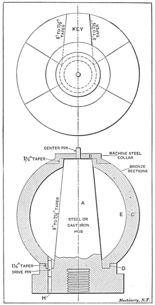
Fig. 31. Elevation and Plan showing Construction
of Sectional Chuck
The plan view shows the method of laying out the various sections.
The key should be laid out first. One key is enough for the particular
form of chuck illustrated, but it is often necessary to use two key
sections when the shell opening is small.
When a sectional chuck is to be made, it is important to decide first
on the size of the central hub A, the number of sections C, and also the
design of the cap or binder B. This cap must not exceed in size the
opening in the finished shell, as it would be impossible to remove it
after the chuck sections
were taken out. After
the size of the hub A has
been decided upon, a
wooden form should be
turned that is a duplicate
of A, except that a spherical
surface E should be
added. This spherical part
should be slightly smaller
than the inner diameter
of the bronze sections in
order to allow for machining
them. In turning this
wooden pattern on which
the plaster patterns for the
sections are to be formed,
the shoulder D should be
omitted, as a removable
metal ring will take its
place.
When the wooden hub is
ready, two metal partitions
or templets of the
same outline as the chuck,
though about one-half inch
larger than its total diameter,
for shrinkage and
finishing, are fastened to
the hub in the correct position
for making a plaster
pattern for the key section.
These patterns should
have extension ends so
that the sections when cast
may be held by them while
they are being turned.
The templets should be banked around with a wad of clay, and they
should also be coated on the inside with sperm oil to keep the plaster
from sticking. There should be two brads driven in the hub for
each section of plaster to hold the sections in place while they are
being turned. After the plaster for the key section has hardened, the
templets should be located one on each side of the key section, so
that the two adjacent sections may be made. In this way all the
sections are finished. After about forty-eight hours the plaster will
be hard enough to turn in the lathe with a hand tool. The form
should be roughly outlined and plenty of stock left for shrinkage, as
bronze shrinks considerably. Before taking the sections off the wooden
frame, the metal band D should be removed to allow the sections to
be separated. This should not be done, however, until they are numbered,
so that they can be again placed in their proper positions.
After the sections are cast, they should be surfaced on a disk grinder,
or finished with a file, care being taken to remove as little metal as
possible. Each section is next tinned on both contact faces, and then
all are assembled and sweated or soldered together by a blow-pipe.
It is sometimes necessary to put a couple of strong metal bands around
the sections to hold them firmly in place when soldering and also
to support them during the turning operation.
The central hub A should be machined first; then the assembled
outside shell should be machined to fit the hub A, both on the taper
part and at the point D. While the segments are being bored and
faced, they are held by the extension ends (not shown) which were
provided for this purpose. This outer shell should also be machined
all over the inside so that it will be in balance. It is then taken out of
the chuck and a hole is drilled in the largest section for drive pin H.
The hub A is then caught in the lathe chuck with the assembled sections
on it, and a seat is turned for the cap B. After this is done
the binder bands can be removed, but not before. The chuck can be
finished with a hand tool and file after the roughing cut is taken.
After the sections are removed from the hub and numbered at the
bottom or inner ends, they can be separated by heating them. If the
joints are properly fitted there will be only a thin film of solder,
which can be wiped off when hot.
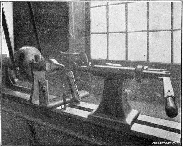
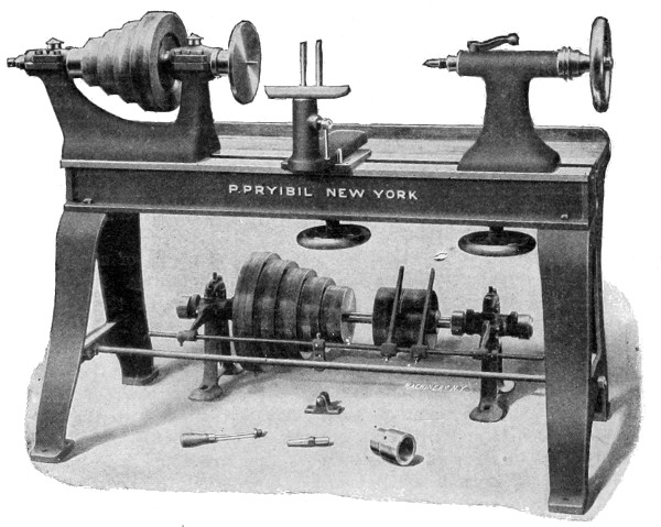
Fig. 32. A Modern Spinning Lathe
A twenty-four-inch metal spinning lathe that is rigged up in a modern
way, is shown in Fig. 32. The hand wheel of the tailstock has
been discarded for the lever A, which is more rapid and can be manipulated
without stopping the lathe. This lathe has a roller bearing
for the center B which is a practical improvement over types previously
used. The pin C, which is used in the rest as a fulcrum for
the spinning tools, is also an improvement, being larger than those
ordinarily used. It is ¾ inch in diameter, 6 inches long, and it has
a reduced end for the holes in the rest, ⅜ inch in diameter by 1 inch
long. This pin is large enough so that the spinner can conveniently
hold it with his left hand when necessary, and it can also be rapidly
changed to different holes. The pins ordinarily used, because of their
small size, do not have these advantages. The speed of a spinning
lathe having a five-step cone should be about 2,250 to 2,300 revolutions
per minute with the belt on the smallest step, and from 600 to
700 revolutions per minute with the belt on the largest step. The
fastest speed given is suitable for all work under 5 inches in diameter,
and the slowest for work within the capacity of the lathe. On
large shells it is sometimes necessary to change from one speed to
another as the work progresses. Figs. 33 and 34 show the spinner at
work, and illustrate how the tool should be held, and also the proper
position of the left hand.
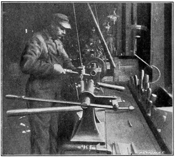
Fig. 33. View showing how the Tool is held when Spinning
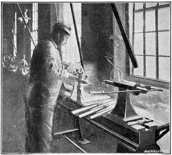
Fig. 34. Another View showing the Position of the Spinner and the
Way the Tool is held when forming the Metal
Fig. 35 shows a spinning-lathe tailstock, which has been changed
from the hand-wheel-and-screw type to one having a lever and a roller
bearing. The spindle A which is withdrawn from the lever and
turned one-quarter of a revolution to give a better view of the rollers,
is made from 1¾-inch cold rolled steel. The rollers against which
the center bears do not project beyond the spindle, so that the latter
can be withdrawn through the tailstock. This eliminates the excessive
overhang caused by ball bearings and other centers. When the center
projects too far, the tailstock cannot be set close to the work
owing to the necessity of withdrawing the center when removing the
spun part. The application of this principle to a spinning lathe is
original and the type of center illustrated was used only after all
other kinds had failed, including all the types of ball bearings and
revolving pins. The best forms of ball bearing centers do not last
over a year, if in constant use, and they will not always revolve on
small work. Two other spindles are shown in this engraving, which
were taken from other lathes in order to show different views of the
parts. The cylindrical pieces B are the hardened friction rollers
which belong in the slot of the spindle F, and C is the hardened pin
upon which they revolve. The hardened center D has a threaded end
on which the back-centers E of different lengths and shapes are
screwed. The friction rollers should always be in a vertical position,
and care should be taken to have them exactly central with the spindle.
[See Transcriber’s Note at the end of this book.]
and also gives the principal dimensions of a roller bearing for a 1¾-inch
spindle. A is a hardened steel bushing, which is driven into
the machine steel spindle. The parts B are the hardened steel rollers
which travel in opposite directions. These rollers have a small amount
of friction, and this is distributed over a large area. A spindle revolving
at 2,300 revolutions per minute will not cause these rollers to
rotate very rapidly, while a ball bearing with balls traveling in a
channel 1½ inch or 2 inches in diameter would be traveling at the
same speed as the driving spindle. They also wear out rapidly as the
end strain is very great, it being necessary to force the center against
the metal with considerable pressure to keep it from slipping. C is the
hardened pin upon which the rollers revolve, and D is the hardened
spindle on which the various back-centers are screwed. The collar E
should either be flattened for a wrench, or a ⁵/₁₆-inch hole, in which a
wire can be inserted, should be drilled through the spindle, so that
it can be kept from rotating when screwing on the back-centers. Some
spinners prefer the spindle loose, so that it can be withdrawn when
changing the centers, while others prefer one with considerable lateral
motion, but not enough to permit of withdrawal. By inserting a
screw-point in the recess F, the center has considerable lateral motion,
but not enough to allow it to be withdrawn. This recess is useful
in that it helps to distribute the oil. All parts should be hardened
and drawn to a light straw color; they should also be ground or
lapped to a true fit after hardening. Back-centers of this construction
have been in use for over three years in one establishment, and it
has not been necessary to replace a single part.
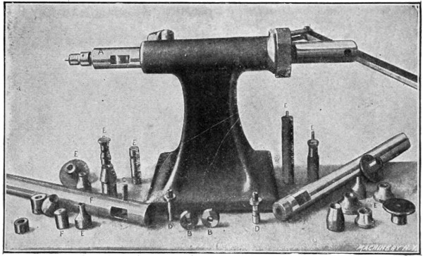
Fig. 35. Detailed View of a Spinning-lathe Tailstock
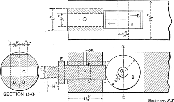
Fig. 36. Sectional View showing the Back-center and its
Double Roller Bearing
Fig. 37 shows an attachment which is used to roll any bead or form.
This tool, when in use, is inserted in the tailstock spindle in place
of the regular center. It is adjustable for any diameter. The roll
illustrated is for making a sharp turn, but rounds and other forms
are used. The shell being spun by this tool should be held on a hollow
chuck. The roll is set at a point where the metal is to be turned
over, and by its use the curve may be governed and made uniform
with less skill than when the work is done by “air spinning.” In
addition, the spinning may be done in less time. This attachment,
for some shapes, makes the use of sectional chucks unnecessary.
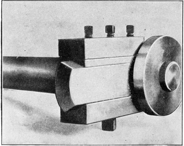
Fig. 37. Attachment used for Rolling Sharp Turns and Beads
Fig. 38 shows several spinning tools, the heads of which were turned
in the lathe instead of being forged. This method of making spinning
tools is believed to be original. The spinners prefer them to
the tools which are forged in one piece, because the heads which
are screwed to the shanks are made of the best quality of steel, such
as the high-speed or self-hardening steel. The shapes are also better
and the surfaces more true. The heads of these tools are all threaded
with standard ¼-inch, ⅜-inch and ½-inch pipe taps, according to the
size. Obviously, a spinner can have as many different shaped heads
as may be required of each of the sizes given, and only one handle.
The tapering threads in these heads insure that they will always
screw on the shanks tightly no matter how often they may be replaced.
The ¼-inch size takes a ½-inch cold rolled holder; the ⅜-inch, a
⅝-inch holder, and the ½-inch, a ¾-inch holder. These will be found
large enough for the heaviest work. The egg-shaped tool A is a good
form for roughing or breaking down, as it has plenty of clearance
on the heel, and a blunt point that will not tear the metal. This tool
is shown in four sizes. The ball or spherical tool B is a good one to
use on curves and large sweeps. The tool C is elliptic, and is
slightly different from A, as it has a blunter point. One of these
heads is shown at D screwed onto a reducer by which it is held in the
lathe chuck while being turned. These heads or points can also be
turned while on the handle by using a steady rest.
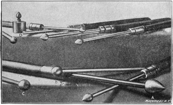
Fig. 38. Metal Spinning Tools with High-speed Steel Removable Heads
A group of trimmers, skimmers and edgers is shown in Fig. 39.
Three skimmers of the built-up type are illustrated, the shanks being
of machine steel and the blades being riveted to the holders. These
blades are made of either high-speed or regular steel. Skimmers
which are forged in the regular way from one piece of steel, are
shown at B. A number of edgers C, which are made of high-speed or
self-hardening steel, are also illustrated. These tools are used without
handles until they are worn down short, after which tangs are
forged on their ends and they are used in handles. Edgers are utilized
on all kinds of work for trimming the ends of the shells. The
skimmer is seldom used on metal chucks, but mostly in connection
with wooden chucks, where the metal cannot be smoothed down with
a planisher. The skimmer is run over the metal lightly, taking a
thin shaving and smoothing the uneven surfaces. It requires considerable
skill to use this tool without wasting the metal. The surface
of the work is finished with emery cloth after skimming.
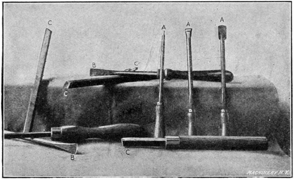
Fig. 39. Tools used for Trimming and Skimming Spun Work
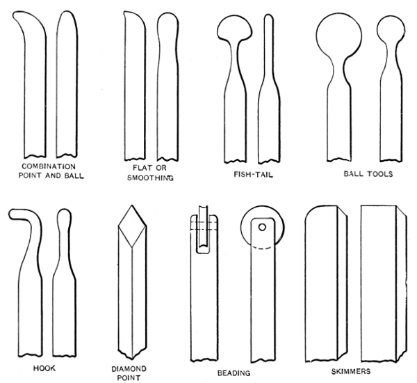
Figs. 40 and 41 show a number of spinning tools of various shapes.
The letters A indicate the breaking-down or round-nosed tools of different
sizes. This type of tool, which is finished smooth and has a blunt
point, is used for forming corners and sharp angles, and it is the tool
most commonly used by spinners. The planishers and burnishers B
are used on all convex surfaces and for finishing on metal chucks
where there is to be no skimming done. The tools C are known as
hook or poker tools, and they are used to turn up beads or curves from
the inside of the shell. The holders having rollers are used for turning
over beads, the metal first being trimmed and turned to a vertical
position. The other shapes shown are irregular tools for special work
and they are not in daily use.
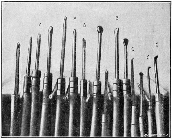
Fig. 40. A Group of Spinning Tools of Various Shapes
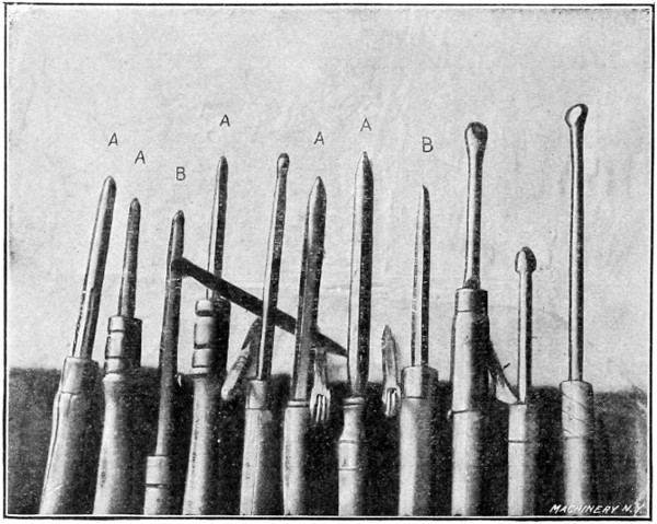
Fig. 41. Another Group of Spinning Tools
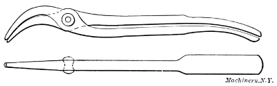
Two pairs of spinners’ pliers for turning over the edge of the metal
when making large curves are shown in Fig. 42. The wedge-shaped
pieces shown in this illustration are used when breaking down or
roughing shells to give a bearing to the metal in order to prevent it
from wrinkling or buckling when changing its formation. These pieces
are made of hard wood with the exception of the one to the right,
which is of steel. When one of these pieces is in use it is held in
the left hand at a point directly opposite the spinning tool, the metal
being between the two. Wood is preferable in most cases, as it does
not harden the metal blank.
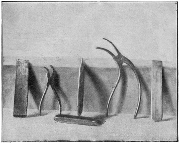
Fig. 42. Spinners’ Pliers which are used for turning the Edge of the
Metal when making a Large Bend
The tools shown in Fig. 43 are used in spinning steel. The round
tools are of drawn brass, and they can be used where the steel tools
cannot, for while a steel tool is perfection on brass, a brass tool is the
only thing on steel. It wears out, however, much more rapidly than
one of steel. The rolls shown in the center are used for breaking
down steel shells. These tools are hardened and have hardened roller
bearings. The handles are made of one-inch iron pipe, which is filled
with lead to give weight and strength.
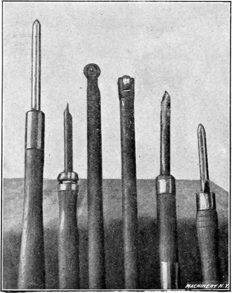
Fig. 43. Some Spinning Tools used in
Working Steel
Hard wood tools that are used for breaking down large thin copper
blanks ranging from 2 to 5 feet in diameter are shown in Fig. 44.
These tools are also used where the surface that the tool will cover
without hardening the metal is important. Blanks which are broken
down with these tools are finished with the regular types.
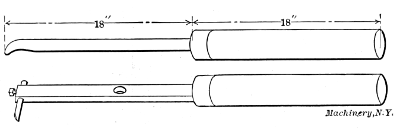
The handles of spinning tools vary in diameter from 1¼ to 1¾
inch, and in length from 16 inches to 20 inches. The tools should
project from the handles from 9 to 18 inches, and the total length of
the tool and handle should average from 30 to 34 inches.
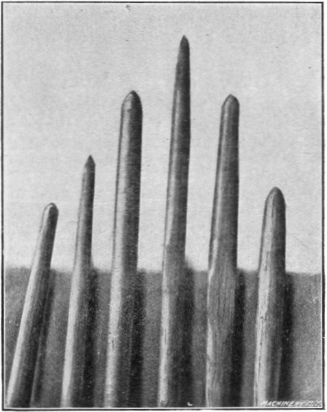
Fig. 44. Wooden Tools which are used on Large
Thin Copper Blanks
A group of wood working tools is shown in Fig. 45. These tools
are of the type commonly used by spinners for turning the various
shapes of wooden spinning chucks. As the tools illustrated are the
kind regularly used for wood turning by patternmakers and other
wood-workers generally, they will need no description.
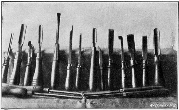
Fig. 45. Wood-turning Tools which are used in turning
Spinning Chucks
Brass, copper, and German silver should be pickled after annealing in
order to get the scale or oxide from the surface. There are furnaces
that anneal without scaling by excluding the air when heating, but
they are not in general use. A pickling bath may be made by using
one part of oil of vitriol (sulphuric acid) and five parts of water. The
shells can be put in hot, or the bath can be heated by a coil of lead
or copper pipe running through it. Steam in no case should enter
the bath, as the iron in the feed pipe will spoil the pickle. Any basket
or box that may be used to hold the shells in the pickle should not
contain any iron. If a box is used it should be held together with
copper nails. The pickle can be used cold, but it will take a little
longer time to remove the scale. As soon as the scale is free, which
will be in about half an hour, the shells should be removed or washed
thoroughly in running water. The shells should be allowed to dry
before the next operation, which is that of spinning. A lead-lined
wooden tank or an earthen jar may be used for holding the pickle.
The pickle which is used for steel should be about half as strong as
that employed for brass. After the work is in this pickle, the latter
should be brought to the boiling point, after which the pieces should
be taken out and washed. They are then replaced in the fire for
a short time to evaporate any acid that may remain after washing.
Finished brass articles may be given different shades by dipping
them in a solution consisting of one part aqua fortis (nitric acid) and
two parts oil of vitriol. This solution should stand seven or eight
hours to cool after mixing, and be kept in a crock immersed in a
water bath.