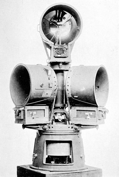
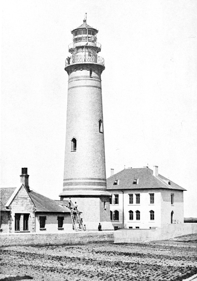
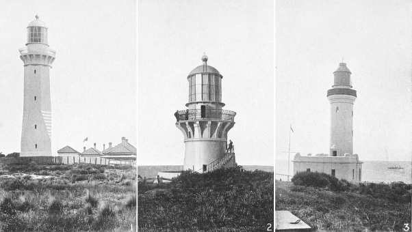
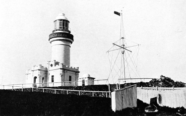
While it is the tower that probably creates the deepest
impression upon the popular mind, owing to the round of
difficulties overcome associated with its erection, yet, after
all, it is the light which is the vital thing to the navigator.
To him symmetry of outline in the tower, the searching
problems that had to be solved before it was planted in a
forbidding spot, the risks that were incurred in its erection—these
are minor details. His one concern is the light thrown
from the topmost height, warning him to keep off a dangerous
spot and by its characteristic enabling him to determine his
position.
I have described the earliest type of light, the open wood
or coal fire blazing on an eminence. In due course the brazier
gave way to tallow candles. This was an advance, certainly,
but the range of the naked light was extremely limited.
Consequently efforts were made to intensify it and to throw
it in the desired direction. The first step was made with a
reflector placed behind the illuminant, similar to that used
with the cheap wall-lamp so common in village workshops.
This, in its improved form, is known as the “catoptric
system,” the reflector being of parabolic shape, with the
light so disposed that all its rays (both horizontal and
vertical) are reflected in one direction by the aid of a highly
polished surface. While the catoptric system is still used
on some light-vessels, its application to important lighthouses
has fallen into desuetude, as it has been superseded
by vastly improved methods. But the reflector, made
either of silvered glass set in a plaster-of-Paris mould or of
brightly polished metallic surfaces, held the field until the
great invention of Augustin Fresnel, which completely
revolutionized the science of lighthouse optics.
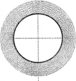
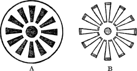
Fig. 2.—Fixed Apparatus of 360 Degrees.
Shows one ray throughout the complete circle.
(By permission of Messrs. Chance Bros. and Co., Ltd.)
Fresnel was appointed a member of the French Lighthouse
Commission in 1811, and he realized the shortcomings of the
existing catoptric method only too well. Everyone knows
that when a lamp is lighted the luminous rays are diffused
on every side, horizontally as well as vertically. In lighthouse
operations the beam has to be thrown in a horizontal
line only, while the light which is shed towards the top and
bottom must be diverted, so that the proportion of waste
luminosity may be reduced to the minimum. While the
parabolic reflector achieved this end partially, it was far
from being satisfactory, and Fresnel set to work to condense
the whole of the rays into a horizontal beam. Buffon, a
contemporary investigator, as well as Sir David Brewster,
had suggested that the end might be met by building up a
lens in separate concentric rings, but neither reduced his
theories to practice.
Fresnel invented a very simple system. He took a central
piece of glass, which may be described as a bull’s-eye, and
around this disposed a number of concentric rings of glass.
But these rings projected beyond one another. Each constituted
the edge of a lens which, while its radius differed
from that of its neighbour, owing to its position, yet was of
the same focus in regard to the source of illumination. The
parts were shaped with extreme care and were united in
position by the aid of fish glue, the whole being mounted in
a metal frame. The advantage of the system was apparent
in the first demonstrations. The lenses being comparatively
thin, only one-tenth of the light passing through was absorbed,
whereas in the old parabolic reflectors one-half of the
light was lost.
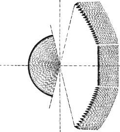
Fig. 3.—Single Flashing Apparatus (One Panel
and Mirror).
(By permission of Messrs. Chance Bros. and Co., Ltd.)
This revolutionary development was perfected in 1822,
and in the following year it was submitted to its first practical
application on the tower of Cordouan in the Gironde. Several
modifications were made by the inventor for the purpose of
adapting his system to varying conditions. One of the most
important was the disposition of lenses and mirrors above
the optical apparatus for the purpose of collecting and driving
back the rays which were sent out vertically from the illuminant,
so that they might be mingled with the horizontal
beam, thereby reinforcing it. At a later date similar
equiangular prisms were placed below the horizontal beam
so as to catch the light thrown downwards from the luminous
source, the result being that finally none, or very little, of
the light emitted by the illuminant was lost, except by
absorption in the process of bending the rays into the desired
direction.
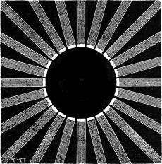
Fig. 4.—A Twenty-Four Panel Light, which was introduced
into Certain French Lighthouses.
In this ingenious manner the circle of light is divided into
sections, called “panels,” each of which comprises its bull’s-eye
and its group of concentric rings and prisms. The
extent of this division varies appreciably, as many as
sixteen panels being utilized in some instances. In this
direction, however, subdivision can be carried too far.
Thus, in some of the French lighthouses no less than twenty-four
panels were introduced. The disadvantage is obvious.
The total volume of light emitted from the luminous source
has to be divided into twenty-four parts, one for each panel.
But the fewer the panels, the more light is thrown through
each, and the correspondingly greater power of the beam.
Thus, in a four-panel light each beam will be six times as
powerful as that thrown from a twenty-four panel apparatus
of the same type.
Fresnel also introduced the system of revolving the
optical apparatus, and by the introduction of suitable devices
was able to give the light a flashing characteristic, so that
it became possible to provide a means of identifying a light
from a distance entirely by the peculiarity of its flash. The
French authorities were so impressed with the wonderful
improvement produced by Fresnel’s epoch-making invention
that it was adopted immediately for all French lights. Great
Britain followed suit a few years later, while other countries
embraced the system subsequently, so that the Fresnel lens
eventually came into universal use.
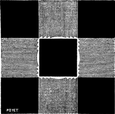
Fig. 5.—A Four-Panel Light.
The ray thrown through each panel is six times as powerful as the
beam thrown through a twenty-four panel apparatus.
But the Frenchman’s ingenious invention has been developed
out of recognition. To-day only the fundamental
basis is retained. Marked improvements were made by Mr.
Alan Stevenson, the famous Scottish lighthouse engineer.
In fact, he carried the idea to a far greater degree than
Fresnel ever contemplated, and in some instances even
anticipated the latter’s subsequent modifications and improvements.
This was demonstrated more particularly in
the holophotal revolving apparatus, the first example of
which he designed for the North Ronaldshay lighthouse in
1850, a similar apparatus being devised some years later by
Fresnel. In 1862 another great improvement was made by
Mr. J. T. Chance, of the well-known lighthouse engineering
firm of Birmingham, which proved so successful that it was
incorporated for first and third order apparatuses in the
New Zealand lights designed by Messrs. Stevenson in the
same year.
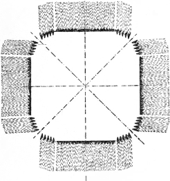
Fig. 6.—Single Apparatus in Four Panels.
(By permission of Messrs. Chance Bros. and Co., Ltd.)
The French and British investigators, however, were not
having things entirely their own way. The United States
played a part in these developments, although they did not
enter very successfully into the problem. The first lighthouse
at Boston Harbour carried candles until superseded
by an ordinary lamp, which was hung in the lantern in much
the same way as it might have been suspended behind the
window of a private dwelling. An inventor, Mr. Winslow
Lewis, who confessed that he knew nothing about lighthouse
optics, patented what he called a “magnifying and reflecting
lantern” for lighthouse work, which he claimed was a lamp,
a reflector, and a magnifier, all in one. It was as crude a
device as has ever emanated from an inventive brain, but
the designer succeeded in impressing the Government so
effectively that they gave him £4,000, or $20,000, for his
invention. The reflector was wrought of thin copper with
a silvered surface, while the magnifier, the essence of the
invention, was what he called a “lens,” but which in reality
comprised only a circular transparent mass, 9 inches in
diameter, and varying from 2½ to 4 inches in thickness,
made of bottle-green glass. The Government considered
that it had acquired a valuable invention, and was somewhat
dismayed by the blunt opinion of one of its inspectors who
held contrary views concerning the magnifier, inasmuch as
he reported cynically that its only merit was that it made
“a bad light worse.”
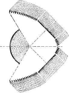
Fig. 7.—Double Flashing Apparatus: Two
Panels and Mirror.
(By permission of Messrs. Chance Bros. and Co., Ltd.)
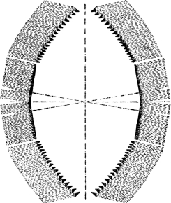
Fig. 8.—Double Flashing Apparatus: Two Groups
each of Two Panels.
(By permission of Messrs. Chance Bros. and Co., Ltd.)
The inventor did not manifest any antagonism to this
criticism, but immediately pointed out the great economy
in the consumption of oil that was arising from the use of
his idea. Indeed, he prosecuted his claims so successfully
that he clinched a profitable bargain to himself with the
Government. His apparatus had been fitted to thirty-four
lights, and he contracted to maintain them on the basis of
receiving one-half of the oil previously consumed by the
lamps which his invention superseded. This arrangement
was in vogue for five years, when it was renewed, with the
difference that on this occasion the Government, concluding
that the inventor was making too much out of the transaction,
reduced the allowance to one-third. Subsequently
the invention received higher commendation from the officials
than that advanced by the critical inspector, although it
must be pointed out that meanwhile the magnifying bull’s-eye
had been abandoned, and a new type of reflector introduced,
so that the sole remaining feature of the wonderful
invention was the lamp. Even that had been modified.
When the Lighthouse Board was established in 1852 it
abolished the much-discussed invention, and introduced the
Fresnel system, bringing the United States into line with the
rest of the world.
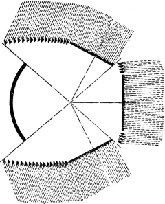
Fig. 9.—Triple Flashing Apparatus: Three
Panels and Mirror.
(By permission of Messrs. Chance Bros. and Co., Ltd.)
One feature of the subject cannot fail to arrest attention.
This is the possibility of producing a variety of combinations
by the aid of the lenses to fulfil different requirements. The
Fresnel, Stevenson, and Chance developments in the science
of lighthouse optics facilitated this work very significantly.
Accordingly, to-day a variety of lights, evolved from the
variations in the mounting of the lenses, is in vogue. For
purposes of identification they have been divided into a
number of classifications, and, for the convenience of the
navigator, are described as lights of the first order, second
order, and so on. Broadly speaking, there are seven main
groups, or orders, the rating only applying to dioptric or
catadioptric lights, indicating the bending of the luminous
rays in the desired direction, either by refraction and reflection
through the medium of prisms, or a combination of
both. Actually there is a distinction between these two,
the true dioptric system referring only to refraction, where
the ray is bent in the desired direction by a glass agent,
known as a “refracting prism.” In the catadioptric system, on
the other hand, both methods are employed, since the prism
performs the dual purpose of reflecting and refracting the
rays. However, in modern lighthouse parlance both are
grouped under the one distinction “dioptric.”
The rating or classification of the lights varies according
to the inside radius or focal distance of the lens—in other
words, the distance from the centre of the light to the inner
surface of the lens. The main groups are as follows:
| Hyperradial, |
1,330 |
millimetres |
(52·3 inches) |
focal distance. |
| 1st order, |
920 |
” |
(36·2 ”) |
” |
| 2nd ” |
700 |
” |
(27·6 ”) |
” |
| 3rd ” |
500 |
” |
(19·7 ”) |
” |
| 3½ ” |
375 |
” |
(14·7 ”) |
” |
| 4th ” |
250 |
” |
( 9·8 ”) |
” |
| 5th ” |
187·5 |
” |
( 7·4 ”) |
” |
| 6th ” |
150 |
” |
( 5·9 ”) |
” |
The most powerful apparatus used to-day, however, is
that known as the “hyperradiant,” and it is the largest
which has yet been devised. For this, lighthouse engineering
is indebted to Messrs. Stevenson, the engineers to the Commissioners
of Northern Lighthouses. It was first suggested
as far back as 1869, and experiments were carried out which
emphasized the fact that such an apparatus was required,
since it was found that when large gas-burners were used
much of the light in revolving apparatuses was out of focus
and escaped condensation. The Scottish engineers thereupon
suggested that an apparatus should be used having
a focal distance of 1,330 millimetres, or 52·3 inches. In
fact, they went farther and suggested even larger apparatuses,
but this idea has not matured. But it was not until
1885 that Messrs. Stevenson had such a system manufactured,
and then it was tested at the South Foreland beside
the powerful lenses which had just been built for the new
Eddystone and the Mew Island lighthouses. The merits
of the theories advanced by Messrs. Stevenson were then
completely proved, for it was found that with a ten-ring
gas-burner the hyperradiant apparatus threw a light nearly
twice as powerful as that given by the rival lenses with the
same burner.
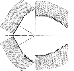
Fig. 10.—Quadruple Flashing Apparatus:
Four Panels.
(By permission of Messrs. Chance Bros. and Co., Ltd.)
At the present moment the hyperradiant is regarded as
the ultima thule of lighthouse optical engineering, and Messrs.
Chance Brothers and Co., of Birmingham, have built some
very magnificent apparatuses of this order. At present there
are not more than a dozen such powerful lights in operation.
Three are on the English coast, at Bishop Rock, Spurn
Point, and Round Island, respectively; two in Scotland, at
Fair Isle and Sule Skerry; two in Ireland, at Bull Rock and
Tory Island; one in France, at Cap d’Antifer; one in China,
at Pei Yu-shan; one in India, at Manora Point, Karachi;
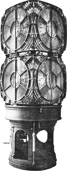
and the Cape Race light in Newfoundland. The hyperradiant
apparatus is a massive cage of glass, standing some
12 feet in height, and, as may be supposed, is extremely
expensive.
There is another point in lighthouse optics which demands
explanation. This is the term “divergence,” which plays an
important part in the duration of the flash. In speaking
about focus, the engineer follows somewhat in Euclid’s footsteps
in regard to the definition of a point; in a way it is
equally imaginary. The focal point does not mean the
whole of the flame, but the centre of the luminous source,
and, as is obvious, it is impossible to secure a flame without
dimensions. It may be an attenuated, round, oval, or fan-shaped
light—the result is the same. The focal point is the
theoretical centre of the luminous source, and the rays,
coming from the top, sides, and bottom of the flame cannot
come from the true focus. If they did, all the light from
one panel would be emitted in absolutely parallel lines, and
therefore in a revolving apparatus the beam would pass any
given point on the horizon in an infinitely short period of
time—to be precise, instantaneously. But the ex-focal rays
of the flame, in passing through the lens, emerge at an angle
to those coming from the absolute centre, so that the whole
beam becomes “diverged,” and throws a cone of light from
the lens. Consequently the beam occupies an appreciable
period of time in passing a given point on the horizon.
As may be supposed, the intricate character of the lenses
constituting the optical apparatus of the modern lighthouse
demands the highest skill and infinite care in their
preparation, while the composition of the glass itself is a
closely guarded secret. There are less than half a dozen
firms in the world engaged in this delicate and highly
specialized work, of which France claims three, Germany one,
and Great Britain one. All the lighthouse authorities of the
various nations have to secure their requirements from one
or other of these organizations. The industry commenced
in France, and for many years the French reigned supreme.
Then it contrived to make its entrance into England, and
was taken up by the family of Chance in Birmingham, who
soon proved themselves equal to their French leaders.
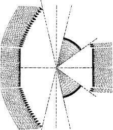
Fig. 11.—Red and White Flashing Apparatus.
(By permission of Messrs. Chance Bros. and Co., Ltd.)
The British firm has established a unique reputation, as
it has been responsible for the majority of the great lights
of the world, some of which are not only of huge dimensions
and weight, but also of novel form. The hyperradial apparatuses
which have been placed recently in the towers of
Manora Point and Cape Race probably rank as the most
powerful and the finest in existence. These are used in
conjunction with the petroleum vapour incandescent burner.
The Cape Race light, for instance, comprises a revolving
optic of four panels, subtending a horizontal angle of
90 degrees, with a vertical angle of 121½ degrees. Each lens
comprises the central disc, or bull’s-eye, around which are
placed nine rings of glass, giving a total refracting angle of
57 degrees. In order to bend the vertical rays into a horizontal
path twenty-two catadioptric reflecting prisms are
disposed above the lens, while below are thirteen similar
prisms. The total amount of glass worked into the four
panels is about 6,720 pounds, and the prisms are mounted
in gun-metal frames, which weigh approximately 4,800
pounds, so that the total weight of the glass portion and its
mounting alone, standing some 12 feet in height, is over
11,500 pounds. The installation completed for the equipment
of the Manora Point lighthouse, Karachi, is very similar.
In some cases the demand for a powerful light has been
met with a system differing from the “hyperradiant.”
The lenses and respective groups of refractors are superimposed,
each tier having its individual burner and flues for
carrying off the products of combustion. In this way we
have the biform, comprising two such panels arranged one
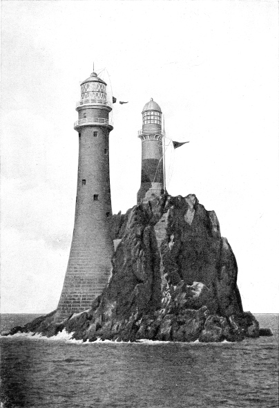
above the other, as in the Fastnet and Eddystone lights;
and the quadriform, wherein four tiers are built one above
the other, as installed at the Mew Island light in Ireland.
The advantage of this arrangement is that a beam of great
intensity is secured with a lantern of comparatively small
diameter.
The French authorities adopted a modification of this
system. Instead of placing two lenses and refractors one
above the other, they ranged them side by side, the effect
being analogous to a couple of squinting eyes, the panels
being parallel and therefore throwing out parallel beams.
But these adaptations have not come into extensive use,
as they have been superseded by more simple means of
achieving similar requirements with an even more powerful
ray. The hyperradiant stands as the finest type of apparatus
yet devised, and therefore is employed when an
extremely powerful light is required.
While the design and arrangement of the optical apparatus
is certainly a most vital and delicate task, the mounting
thereof upon a substantial support in such a way that it may
perform its work with the highest efficiency is equally
imperative, since the finest apparatus might be very adversely
affected by being improperly mounted.
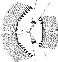
Fig. 12.—Apparatus showing a Double Flash,
followed by a Single Flash.
(By permission of Messrs. Chance Bros. and Co., Ltd.)
Obviously, owing to the great weight of the glass, the
support must be heavy and substantial. A massive cast-iron
pedestal is employed for this purpose. When the light
is of the revolving character, means have to be incorporated
to secure the requisite rotation. In the early days the
turntable upon which the lens is mounted ran upon rollers,
but now a very much better system is universally employed.
This has been brought to a high standard of perfection by
Messrs. Chance of Birmingham, who have carried out unceasing
experiments in this field. The objection to rollers
was the enormous friction that was set up, and the great
effort that was required, not only to set the lenses revolving,
but to keep them rotating at a steady pace. In the modern
apparatus the rollers are superseded by an iron trough filled
with mercury, upon which floats the turntable carrying the
lenses. When the apparatus is properly built and balanced,
the friction is so slight that the turntable can be set in motion
by the little finger, notwithstanding that several tons have
to be moved. Although the optical part of the apparatus
floats upon the bed of quicksilver in the same way as a cork
lifebelt floats upon water, it is provided with rollers which
serve to hold the whole apparatus steady and to overcome
any oscillation.
In the case of an immense apparatus such as a hyperradiant
lens, which, together with the turntable, may have
a total weight of 17,000 pounds, an enormous quantity of
mercury is required. The trough of the Cape Race hyperradiant
light carries 950 pounds of quicksilver, upon which
the lantern is floated. In such an instance, also, the pedestal
is a weighty part of the apparatus, representing in this
case about 26,800 pounds, so that the complete apparatus
utilized to throw the 1,100,000 candle-power beam from
the guardian of the Newfoundland coast aggregates, when
in working order, some 44,000 pounds, or approximately
20 tons.
Within the base of the pedestal is mounted the mechanism
for rotating the optical apparatus. This is of the clockwork
type driven by a weight. The latter moves up and down a
tube which extends vertically to a certain depth through
the centre of the tower. The weight of the driving force
and the depth of its fall naturally vary according to the
character of the light. In the Cape Race light the weight
is of 900 pounds, and it falls 14½ feet per hour. Similarly,
the length of time which the clock will run on one winding
fluctuates. As a rule it requires to be rewound once every
sixty or ninety minutes. A longer run is not recommended,
as it would demand a longer weight-tube, while many
authorities prefer the frequent winding, as the man on duty
is kept on the alert thereby. As the weight approaches the
bottom of its tube it sets an electric bell or gong in action,
which serves to warn the light-keeper that the mechanism
demands rewinding.
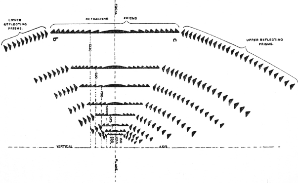
Fig. 13.—The Classification of Lights, showing the Respective Radius or Focal
Distance of Lens from 150 to 1,330 Millimetres.
(By permission of Messrs. Chance Bros. and Co., Ltd.)
The weight and clockwork mechanism perfected by
Messrs. Chance is regarded as one of the best in service. The
rotation is perfect and even, owing to the governing system
incorporated, while the steel wire carrying the weight is
preferable to the chain, which is subject to wear and is noisy
in action. In the Chance clockwork gear the weight is just
sufficient to start the apparatus from a state of rest, the
advantage of such a method being that, should the apparatus
be stopped in its revolution from any untoward incident, it
is able to restart itself.
Of course, the clockwork mechanism is required only in
those cases where the lenticular apparatus has to be revolved.
This introduces the question of avoiding confusion between
lights. When beacons were first brought into service, the
lights were of the fixed type, and the navigator, although
warned by the glare to keep away from the spot so marked,
was given no information as to his position. Accordingly,
lighthouse engineers sought to assist him in this direction
during the blackness of the night by providing a ready visual
means of identification. Owing to the ingenuity which has
been displayed, it has been rendered possible to ring the
changes upon a light very extensively.
These may be subdivided broadly as follows:
| Type of Light. |
Symbol. |
Characteristics. |
| Fixed |
F. |
A steady continuous light. |
| Flashing |
Fl. |
A revolving light showing a single flash at regular intervals, or a fixed light with total eclipses. |
| Fixed and flashing |
F.Fl. |
A fixed light varied at regular intervals by a single flash of greater brilliancy. |
| Group flashing |
Gp.Fl. |
Various combinations of flashes shown at regular intervals. |
| Occulting |
Occ. |
A steady light suddenly and totally eclipsed at regular intervals. |
In the foregoing classifications only a white light is used.
But it may so happen that the lighthouse, owing to its
position and the dangerous character of the spot which it
marks, carries a light which changes colour from white to
red or green, which are shown alternately in various combinations.
These characteristics are indicated as follows:
| Type of Light. |
Symbol. |
Characteristics. |
| Alternating |
Alt. |
White and colour alternating. |
| Alternating flashing |
Alt.Fl. |
Flashing alternations by revolving mechanism. |
| Alternating fixed and flashing |
Alt.F.Fl. |
Fixed and flashing alternating. |
| Alternating group flashing |
Alt.Gp.Fl. |
Group flashing alternating. |
In timing a revolving or flashing light, the cycle is taken
from the beginning of one flash to the beginning of the next.
In these readings the flash is always shorter than the
duration of the eclipse, while an occultation is shorter than,
or equal to, the length of the light interval. Since flashing
and occulting may be carried out with a fixed light suddenly
extinguished or eclipsed, the characterization is determined
solely according to the relative duration of light and darkness,
irrespective of the type of apparatus employed or the
relative brilliancy. There is one peculiarity of the flashing
light which may be remarked. At short distances and in
clear weather a faint continuous light may be shown.
Hand in hand with the development of the optical apparatus
has been the wonderful improvement in regard to
the illuminants and the methods of producing a brilliant
clear flame. The fuel first used upon the introduction of
the oil lamp was sperm or colza oil, the former being obtained
from the whale, and the latter from seeds and a wild-cabbage.
Both were very expensive, so that the maintenance of a light
was costly—so much so that the United States authorities
devoted their efforts to the perfection of a high-class lard-oil.
This proved highly satisfactory, possessing only one
drawback. In winter it congealed so much under the low
temperature that it had to be heated before it could be placed
in the lamp; but once the light was set going, the heat
radiated from the burner served to keep the oil sufficiently
fluid to enable it to mount the wick to the point of combustion
under capillary action.
So far as the American authorities were concerned, the
advantages of lard-oil sufficed to bring a cheaper medium
than colza-oil into vogue. A company, which had been
induced by the Government to install an elaborate and expensive
plant for the production of colza-oil, after prolonged
experiment and efforts to reduce the cost of production,
announced that it could not compete with the lard-oil, and
suggested that the latter should be employed in preference
to the colza. The Government agreed, but, to compensate
the company for its trouble, purchased the plant which the
latter had laid down.
The advances in the processes for refining petroleum, and
the exploitation of the extensive resources of the latter, led
to “earth-oil,” in some form or other, being employed for
lighthouse purposes. The attempt was facilitated by the
invention and improvement of the Argand burner, whereby
a brilliant white annular sheet of flame is produced. Various
lighthouse engineers devoted their attention to the improvement
of this burner in conjunction with paraffin. Their
results were completely successful, and at last paraffin
became universally utilized as the cheapest and most efficient
illuminant known.
The general method of feeding the lamps was to pump the
oil from a low level to the burner, thereby producing practically
a pressure-feed system in preference to the capillary
action which is used in the ordinary household lamp. By
increasing the number of rings the intensity of the flame
was increased, until at last it was thought that with this
development perfection had been attained so far as lamps
were concerned.
Then came another radical revolution. The invention of
the incandescent gas mantle by Dr. von Auer, and the
complete change that it wrought in connection with gas
lighting, induced lighthouse engineers to experiment in this
field. As they could not use coal-gas, they devoted their
investigations to the perfection of a gas from petroleum,
which should be capable of combustion with the incandescent
burner. Many years were devoted to these experiments,
and many petroleum vapour systems were devised. One of
the best known, most successful, and most scientifically
perfect, is the Chance incandescent light. This burner is
used in many of the most powerful lights of the world and
has given complete satisfaction. The mantle varies in size
with the size and type of the light, ranging from 35 to 85
millimetres in diameter, the latter, in conjunction with a
hyperradial apparatus, producing a light exceeding 1,000,000
candle-power.
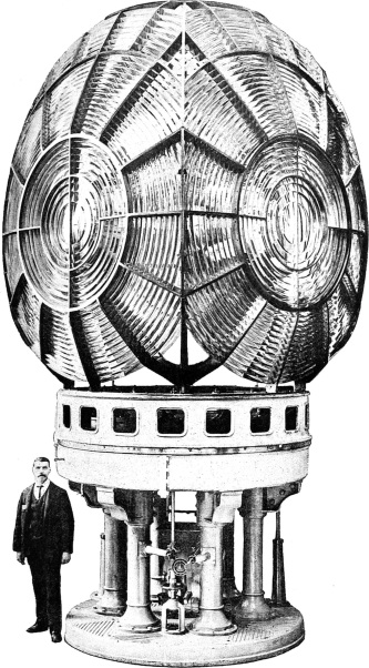
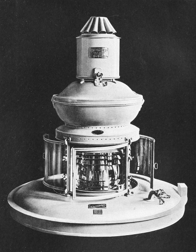
By courtesy of Messrs. Chance Bros. & Co., Ltd.
THE HYPERRADIAL APPARATUS FOR THE MANORA POINT LIGHT,
KARACHI, INDIA.
Of 1,330 millimetres focus, this is the most powerful and largest lighthouse apparatus made.
Not only was a far more powerful light obtained in this
manner with the assistance of the petroleum vapour burner
and incandescent mantle, but the cost of maintaining the
light was reduced, owing to the great economy in oil consumption
that was effected thereby, the largest mantle and
burner—85 millimetres—burning only 2½ pints of oil per
hour. The light thus obtained, while being vastly superior
to that derived from a six-wick oil-burner, enables a saving
of nearly £48, or $240, per annum to be recorded, taking the
cost of the petroleum at 1s., or 25 cents, per gallon delivered
to the lighthouse.
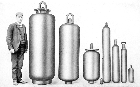
While petroleum is generally used, some countries have
adopted other oil fuels for small permanent lights. Thus,
in Germany compressed oil-gas, water-gas associated with
benzine vapour, and Blau liquid gas, are utilized. The last-named
is coming very extensively into vogue, also, in Holland,
Denmark, and Austria. Blau gas has the advantage that
it can be transported in small steel tanks under extremely
high pressure—up to 100 atmospheres, or approximately
1,400 pounds per square inch. It is an extract of oil-gas
produced at a low pressure in the gas retorts, and then
compressed so severely that it liquefies. The fuel, as it is
drawn from the cylinder in which it is stored, has the pressure
reduced by means of a valve, so that it reaches the burner
in a gaseous form at a pressure equivalent to that of the coal-gas
used in private houses, and is burned in the same way
with an incandescent mantle. The advantage of this
method lies in the facility with which large volumes of gas
may be transported, a steel cylinder containing 7,500 cubic
feet weighing only 132 pounds. It is also inexpensive, a
bottle of the foregoing capacity costing only 12s. 6d., or $3.
In some cases the incandescent mantles, the average life
of which is about a fortnight, are of large diameter, running
up to 100 millimetres, or about 4 inches.
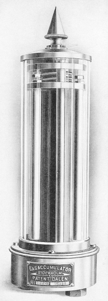
Recently Mr. Gustaf Dalén, of the Gas Accumulator Company
of Stockholm, the inventor of the Dalén flasher and
sun-valve, which are described elsewhere, has introduced a
new illuminant, which is coming into vogue, especially on
the Continent. This is called “Daléngas,” and is a mixture
of 9 per cent. dissolved acetylene and 91 per cent. atmospheric
air. Here the dissolved acetylene gas is conducted
from a storage reservoir or high-pressure gas cylinder, of
special construction, to a governor, where the pressure is
reduced, and then to the mixing apparatus, where the
acetylene gas is associated with the air in the above proportions.
The idea of this combination and method is to
enable an acetylene gas mixture to be used with the ordinary
incandescent mantles.
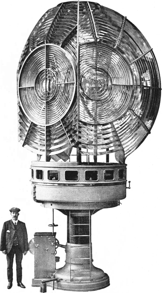
By courtesy of Messrs. Chance Bros. & Co., Ltd.
FIRST ORDER TRIPLE FLASHING LIGHT OF 920 MILLIMETRES
FOCAL DISTANCE FOR CHILANG LIGHTHOUSE, CHINA.
The advantage of the Daléngas, according to present
experience, is the increased candle-power that is obtainable
as compared with other systems, the superiority being about
75 per cent. under ordinary conditions. With the largest
Fresnel lenses a lighting power of 200,000 Hefner candle-power
is secured, while with revolving lenses of the latest type
a beam of 3,000,000 candle-power can be obtained. The flame
is small, and thus becomes concentrated more in the focus of
the lens, so that the divergence of the light may be diminished
if desired. When a light of a certain range is to be
installed, the optical apparatus can be made smaller for
Daléngas than for other illuminants, and the cost is reduced
correspondingly. Similarly, if the system is introduced
into an existing light, the latter can be made appreciably
more powerful, without changing the optical apparatus or
affecting the divergence.
In this system the gas is conducted into the lens apparatus
from above, and the lighting arrangement is quite independent
of, and does not interfere in any way with, the revolving
apparatus, while the time spent in changing the mantle is
less than half a minute.
All combustible gases, mixed with air in certain proportions,
may produce more or less violent detonations when
fired. But the quantity of mixed gas in this instance is
confined in the length of piping between the burner and the
mixing apparatus, and this quantity is so small that an
explosion cannot be dangerous. In fact, all such danger has
been guarded against completely—is, indeed, impossible in
any circumstances.
Electric light has been adopted in one or two cases; but
while the foremost authorities agree that it throws the best,
most brilliant and most powerful beam of light, the system is
generally impracticable on account of its great cost. When
tests with this light were made some years ago in comparison
with the light thrown from oil burners, it was claimed
that the latter, owing to its reddish-yellow tinge, was the
most suitable from the all-round point of view, and that it
could penetrate to a greater distance in foggy weather. I
have been informed by several authorities, who have gone
more deeply into this question since, that this is a fallacy,
and that the advantage rests completely with electric light.
Experience in Germany, which has two magnificent electric
lighthouses, and in Scotland, certainly supports this contention,
and I have been assured that the sole reason why
electric lighting has not been adopted more widely is the
heavy cost, both of installation and of maintenance. When
electric lighting is rendered cheaper and is brought more
to the level of existing lighting arrangements, one may
expect another complete change in lighthouse practice.
In this direction, as explained in another chapter, the
Germans have carried out practical experiments in their
characteristic manner, and have brought the cost of
maintaining a most powerful electric light to the minimum.
One very great advantage of the electric light is the ease
with which the power of the beam may be increased during
thick weather, so as to secure penetration to the greatest
distance, and decreased to suit easier conditions in clear
weather.
This point raises the question, “From how far can a light
be seen out at sea?” This factor is influenced by climatic
conditions, and also by the curvature of the earth. The
higher the light, or the spectator, or both, is elevated above
the water, the greater the distance from which the light can
be seen. The table on p. 52, prepared by Mr. Alan Stevenson,
the eminent Scottish lighthouse engineer, gives the
distances at which objects can be seen at sea, according to
the respective elevations of the object and the eye of the
observer.
For instance, the passenger on a liner the boat-deck of
which is 40 feet above the water, approaching the English
Channel, will sight the Bishop Rock light from a distance
of about 22 miles, because the focal plane—that is, the bull’s-eye
of the lens—is 163 feet above the water, which, according
to the following table, equals about 14½ miles, to which must
be added the height of the boat’s deck, 40 feet representing
7·25 miles. Similarly, the ray of the Belle Ile light will
come into view when the vessel is 32½ miles distant—height
of focal plane of light, 470 feet = 25 miles, + eye of
observer on board the liner, 45 feet = 7·69 miles; while the
Navesink light, being 246 feet above the water, may be
picked up by the captain of a liner from a distance of
28 miles. The range of many lights, however, owing to
the curvature of the earth, is greatly in excess of their
geographical range, and with the most powerful lights the
glare of the luminous beams sweeping the clouds overhead
may be seen for a full hour or more before the ray itself
comes into view.
TABLE OF DISTANCES AT WHICH OBJECTS CAN BE SEEN AT SEA, ACCORDING TO THEIR
RESPECTIVE ELEVATIONS AND THE ELEVATION OF THE EYE OF THE OBSERVER.
Heights in
Feet. | Distances in
Statute or English
Miles. | Distances in
Geographical or
Nautical Miles. |
|---|
| 5 |
2·958 |
2·565 |
| 10 |
4·184 |
3·628 |
| 15 |
5·123 |
4·443 |
| 20 |
5·916 |
5·130 |
| 25 |
6·614 |
5·736 |
| 30 |
7·245 |
6·283 |
| 35 |
7·826 |
6·787 |
| 40 |
8·366 |
7·255 |
| 45 |
8·874 |
7·696 |
| 50 |
9·354 |
8·112 |
| 55 |
9·811 |
8·509 |
| 60 |
10·246 |
8·886 |
| 65 |
10·665 |
9·249 |
| 70 |
11·067 |
9·598 |
| 75 |
11·456 |
9·935 |
| 80 |
11·832 |
10·260 |
| 85 |
12·196 |
10·570 |
| 90 |
12·549 |
10·880 |
| 95 |
12·893 |
11·180 |
| 100 |
13·228 |
11·470 |
| 110 |
13·874 |
12·030 |
| 120 |
14·490 |
12·560 |
| 130 |
15·083 |
13·080 |
| 140 |
15·652 |
13·570 |
| 150 |
16·201 |
14·220 |
| 200 |
18·708 |
16·220 |
| 250 |
20·916 |
18·14 |
| 300 |
22·912 |
19·87 |
| 350 |
24·748 |
21·46 |
| 400 |
26·457 |
22·94 |
| 450 |
28·062 |
24·30 |
| 500 |
29·580 |
25·65 |
| 550 |
31·024 |
26·90 |
| 600 |
32·403 |
28·10 |
| 650 |
33·726 |
29·25 |
| 700 |
35·000 |
30·28 |
| 800 |
37·416 |
32·45 |
| 900 |
39·836 |
34·54 |
| 1,000 |
41·833 |
36·28 |
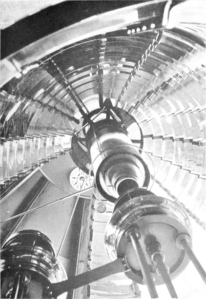
By permission of the “Syren and Shipping.”
LOOKING UP THE LANTERN OF THE NEEDLES LIGHTHOUSE.
So far as the candle-power of any light is concerned, the
method of determining this factor, varying according to the
calculating methods adopted, is somewhat misleading. So
far as Great Britain is concerned, the practice of setting out
the candle-power of any light in the official list has been
abandoned, the authorities merely stating that such and
such a light is of great power. The United States and
Canada, on the other hand, indicate the approximate candle-power.
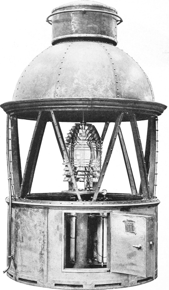
By courtesy of Messrs. Chance Bros. & Co., Ltd.
FIXED APPARATUS OF THE FOURTH ORDER FOR SARAWAK.
The focal distance is 250 millimetres, and the diameter of lantern inside
glazing 6 feet 7¾ inches.
By combining and arranging the integral parts of the
optical apparatus, the lighthouse engineer is able to accomplish
many astonishing results. Thus, while the various
types generally follow accepted broad lines, coinciding with
the order which they represent, here and there some very
striking divergences are made. The Bell Rock light is
perhaps the most interesting example in this direction. It
was designed by Messrs. D. and T. Stevenson, and built
by Messrs. Chance Brothers and Co. The light is alternating,
the colours being white and red. Externally the
optical apparatus appears to be bizarre, yet it is one of the
most perfect which has ever been installed. In its design
and construction almost all the known lighthouse optical
elements are incorporated, including the equiangular refractor,
the reflecting prism, the double-reflecting prism, and
the dioptric mirror. Another noteworthy fact is that, by an
exceedingly ingenious arrangement, the absorption of the
rays by the glass used in producing the red flashes is neutralized
to such a vast degree that the white and red flashes are
of equal intensity.
The subsidiary light is another striking feature which the
lighthouse engineer has introduced. For instance, a light
may be shown from a dangerous reef, and give the mariner
all the warning desired. But some distance away may lurk
another isolated rock, which it is just as imperative to indicate,
and yet on which another tower cannot be erected.
This necessity is met by the subsidiary light. A portion of
the light from the main apparatus is deflected and thrown to
the desired spot by an ingenious arrangement of the prisms.
On the west coast of Scotland, at Stornoway, a stream of
light used to be deflected from the lantern in a vertical
direction down the tower, and there bent at right angles, to
be thrown through a lower window and fall upon a prism
placed on the crest of a rock several hundred feet distant.
From the deck of a vessel, the effect of the light striking the
prism was akin to that produced by a beacon. Similarly in
the case of St. Catherine’s light in the Isle of Wight: a portion
of the light, which would otherwise be wasted over the area
on the landward side, is carried vertically down the tower
by a disposal of lenses and prisms, and is projected horizontally
through a small window, after being coloured into a
red ray by passing through some glass of the desired tint, to
mark a danger spot some distance away. This method,
however, is not favoured now, as the peril can be more
efficiently marked by means of an independent beacon, a
system which has become feasible owing to the vast improvements
that have been made in automatic lights requiring no
attention for several weeks or months at a time.
But in those instances where the latter expedient is not
adopted, the practice is to cover the danger with a ray thrown
from an entirely different light. When the present Eddystone
tower was completed, a “low-light room,” as it is
called, was incorporated, and a low-powered light was thrown
from two Argand burners and reflectors through a window
to mark a dangerous reef some three miles distant. But
perhaps the best example of a subsidiary light is that which
was carried out by Messrs. Chance in connection with the
Cap de Couedie lighthouse. In this instance two dangers
had to be indicated in a subsidiary manner, one being
covered with a red, the other with a green, ray. The red
sector marks a danger spot known as Lipson’s Reef, lying
8¾ miles distant, while the green light indicates Casuarina
Island, 1¾ miles away. This installation, it may be pointed
out, has proved highly successful, and certainly is very
economical.
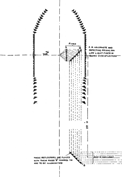
Fig. 14.—The Means whereby the Rays are deflected from
the Main Light to form a Subsidiary Light.
(By permission of Messrs. Chance Bros. and Co., Ltd.)
There is another point which deserves mention—the
duration of the flash in a revolving light. There was considerable
discussion and difference of opinion upon this
question some years ago. It was maintained that the
shorter the duration of the flash, and the more rapidly it
were thrown, the better it would be for the mariner. The
Scottish engineers realized the significance of this problem,
and, despite the hostile criticism of contemporary engineers,
adopted a specific principle which was to give a flash of
two and three-quarter seconds’ duration. Subsequently it
was reduced to one second. The introduction of the mercury
float enabled the optical apparatus to be revolved faster,
and also facilitated the reduction in the number of panels
or faces, so that ultimately the Scottish engineers reduced
the flash to one of four-tenths of a second.
When Mr. Bourdelles devised the mercury float which
enabled rotation to be accelerated, the French authorities
rushed to the opposite extreme. They reduced the faces
to four, and arranged for the apparatus to be revolved at a
high speed, so that the duration of the flash was only one-tenth
of a second at rapidly-recurring intervals. This type
of light was called the feu-éclair, and was adopted as a
result of prolonged laboratory investigation. But this was
an instance where laboratory experiments and scientific
reasoning failed to go hand in glove with practical experience
and navigation, where the mariner has to contend with all
sorts and conditions of weather. The seafarer expressed his
opinion of the one-tenth of a second flash in uncomplimentary
terms, displaying an indifferent appreciation of artificially-produced
sheet-lightning.
Eventually there was a general agreement, among all those
countries which had investigated the problem closely, that a
flash of about three-tenths of a second was the most satisfactory,
and this has since become tacitly standardized.
The French authorities recognized the fallacy of their idea,
and soon came into line with the other countries.