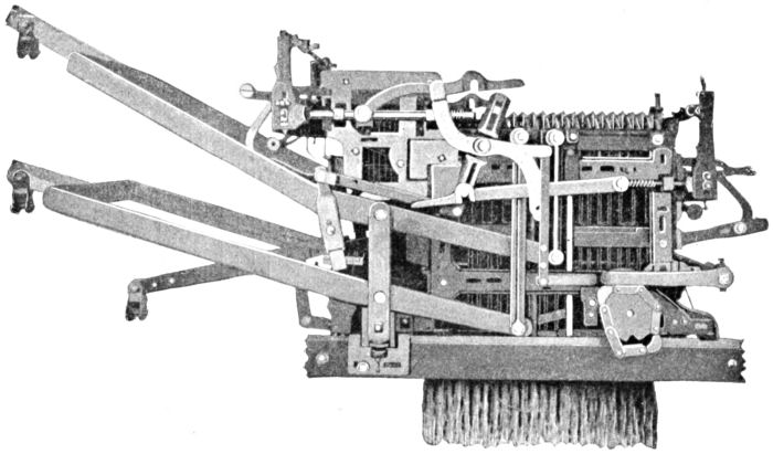
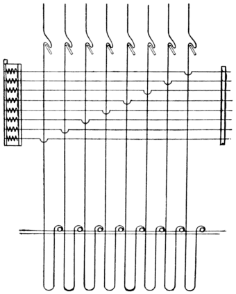
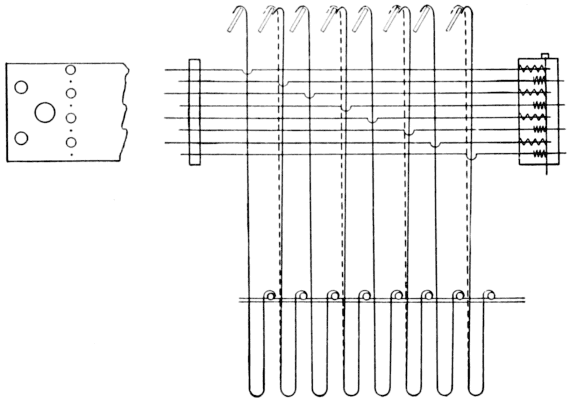
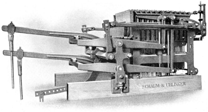
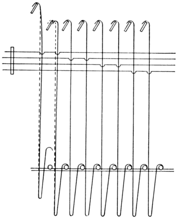
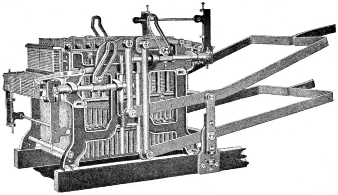
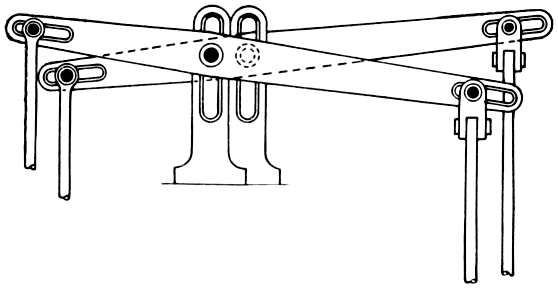
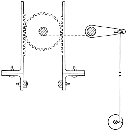
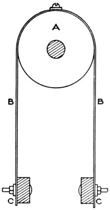
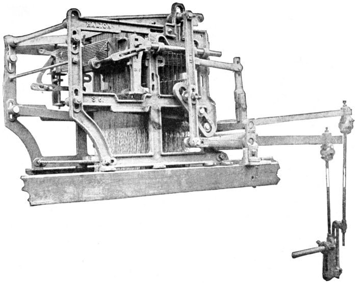
Fig. 9. Single Action Jacquard Machine.
The illustration, Fig. 9, shows a jacquard known as the
Single Action Machine. The chief feature of this machine is
that the same griffe lifts the hooks for every shed, so the
griffe must descend before the next shed can be lifted. This allows
all the yarn to be lifted from the bottom shed. The single
action machine is convenient and well adapted to work when a
8]
high speed is not required; ninety to one hundred thirty picks per
minute being the most suitable speeds.
In the silk industry the single action machine is extensively
used as there is no danger of the cards becoming crossed. This
is a very valuable feature as wrong picks are often placed in the
cloth by a double cylinder machine through the skipping of the
cards.
Construction. The single action is the original idea and is
the simplest machine. Fig. 10 shows a sectional view of a 400-hook
single machine. The meaning of the term 400-hook is as
follows: There are four hundred hooks and four hundred needles
in the machine which are in rows of eight hooks and eight needles.
It also means that there are four hundred harness threads to one
repeat of the maximum pattern that can be woven by the machine.
Nearly all machines have a few extra hooks (from 16 to
26) which are often classed with the regular number of hooks,
but are chiefly used for extra work, such as selvedge, extra harnesses,
etc. A pattern of less than four hundred to a repeat can
be woven, by casting out some of the hooks.
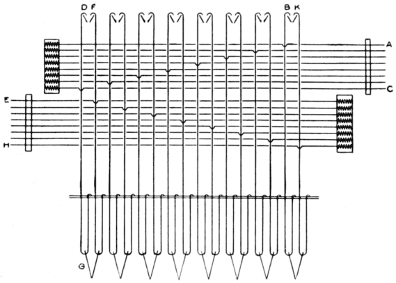
Referring to Fig. 10, B is the needle board or plate, through
which the points of the needles E protrude three-eighths or one-half
inch. C is the griffe which is composed of eight blades; H
is the spring box, containing four hundred brass springs which
are placed against the back or loop ends of the needles, one spring
for each needle. G is the grate through which the hooks F pass.
Needle Plate. In some cases the needle plate is made of
wood and in others it is made of metal, but the former is undoubtedly
the more economical from every standpoint. Particularly
is this shown in the single cylinder machines where the cylinder
travels at a faster rate of speed than a double cylinder machine,
consequently there is more movement and a larger amount
of friction between the needle and needle board or plate, which
results in rapidly wearing out the points of the needles if a metal
plate is used. Worn needle points cause a large amount of
trouble, for in single cylinder machines the cylinder has a tendency
to half-turn when the lay is pushed back by hand, and when the
cylinder returns to the needle points the corner of the cylinder
presses against them and invariably bends a number of the points
9]
down on to the plate. This prevents some of the hooks which
ought to be lifted from being lifted, and causes some hooks to be
lifted which ought to be down.
A composition of powdered black lead and French chalk was
used to prevent the needle points from wearing out, but it was
discarded because the dust was constantly dropping into the harnesses
and yarn, and also was very disagreeable for the weaver.
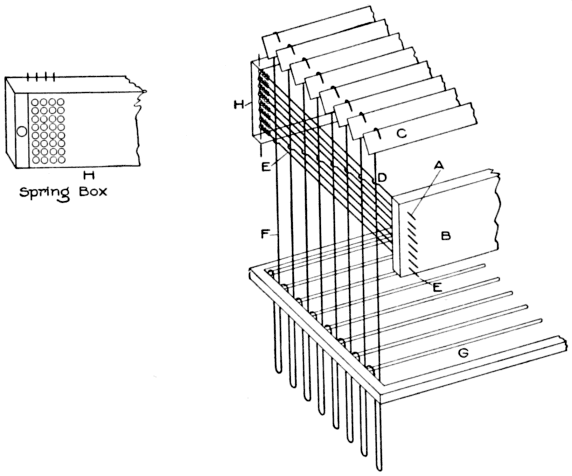
Fig. 10. Showing Arrangement of Hooks, Needles, Etc.
A needle board or plate for a 400-machine, has 416 holes,
arranged in 52 rows with 8 holes in a row. The rows are divided
by a groove into 26 rows on each side. There are also grooves at
each end of the needle board. The grooves are for the lacings
which hold the cards together.
The lacing naturally makes the card occupy more space at
the ends and center, because it passes along the upper and under
sides of the card, and if there were no grooves in the needle board,
the needles would have to be made longer so as to allow the points
to protrude farther out from the needle board; or when the card
10]
was in contact with the needle points, the hooks would not be
pressed back far enough to prevent them from being lifted. The
grooves are also a great saving on the lacing of the cards, for if it
came in close contact with the needle board every time the cylinder
was drawn in, the lacing would soon be cut, and this often
causes the breakage of cards.
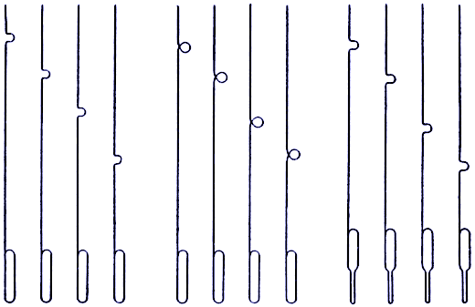
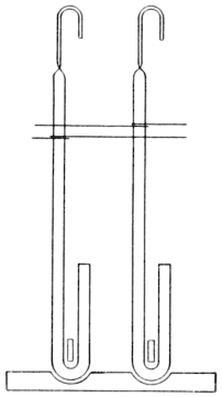
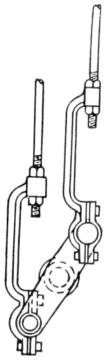
Fig. 11. Showing Loops for Springs.
The reason for the extra rows of needles, is to allow the selvedge
to be worked by that row of hooks; also because a jacquard
sometimes has patterns added that require additional harness at
the front and back of the comber board, and the extra needles
are used for the working of the extra harness.
A spring box is seldom used on American machines to hold
the springs that press back the needles, but where the spring box
is dispensed with, a longer loop is made on the back end of the
needle (see Fig. 11) and the spring is placed on the loop, with the
cotter, which holds the needles. The spring box, however, is
most certainly of value if it is made to fit squarely in the framework
of the machine. The springs are kept cleaner and consequently
will give good results; and if a spring should break, it
can be replaced more readily in a spring box than if it were on
the end of a needle.
11]
There is, however, one disadvantage in using the spring box,
for when the hole, through which the bolt, which holds the box
in position, passes, has become worn, some of the needles will be
pressing against the edge of the spring instead of the center, unless
care is taken in fixing on the box. This causes the needles to
stick in the box, preventing the hooks from working as they
ought to do.
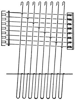
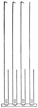
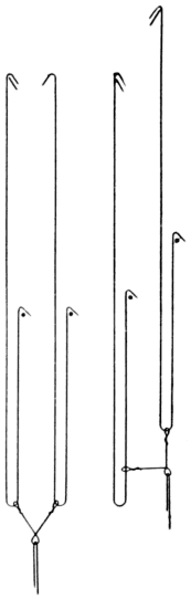
Fig. 12. Hooks Out of Perpendicular with Needles.
When placing hooks and needles in a machine, one row of
eight needles is placed in first; that is, the needles are passed
through the bars that extend across the machine from side to side,
and into the holes in the needle board. On the bars the loop of
the needle rests, the bars keeping each 52 needles separate. The
first needle is the one that has the half circle, through which the
hook passes, nearest the needle board at the top (see Fig. 10), and
the others are graded down until the eighth is placed in. This
will be the bottom needle with the half circle nearest the spring
box H.
When the cotter has been placed through the loop of the
needles, the hooks are placed in among the needles. The first
hook is pressed through the half circle of the needle and passes on
the outside of the others, which keeps the hook in position. The
second is placed through the half circle of the second needle, but
12]
passes on the outside of the first needle and on the outside of the
lower needles. This rule is followed out until the eighth hook is
placed in position.
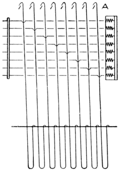
Fig. 13. Hooks Out of Perpendicular with Needles.
The grate through which the hooks pass is sometimes made
with extra rows of holes, and is also made so that it can be moved
around to help in the setting of the hooks. For this reason, it is
best, after placing in one row of hooks, to notice if they are
straight in the grate. If they are not straight, and cannot be
made straight by moving the grate, the next row of holes must be
used. If the hooks are not straight, even though they may work
freely, the needles, hooks and grate will be worn out in a very
short time.
The hook that passes through the first needle is considered
the first thread in the pattern, although when standing in front of
a single action machine, it is the last thread. In a machine that
has the needle board divided into twenty-six rows at one side of
the middle, and twenty-five at the other side, the twenty-six rows
are always at the left-hand side of the machine, looking at the
point of the needles. (So that the number end of the cards will
be at the left hand side of the machine, looking at the top needle
board.)
13]
When all the needles and hooks have been placed in the machine,
the frame, in which the bars that support the top of the
needle are fixed, must be made perfectly straight with the needle
board. If they are not straight with each other, there is endless
trouble with the machine. In the first place, the loop of the
needle presses down the spring when the needle is forced back by
the card, instead of pressing the spring back straight in the box.
This will cause the springs to wear out sooner and they will often
stick, preventing the hooks from being lifted.
In the second place, the needle points will not be straight in
the needle board. This causes the hole in the board to be worn
crooked, also, the dust and oil that get into the back portion of the
board has a greater tendency to bind the needles when they are
not straight. The holes in the needle board at the back are counter
sunk, which allows the needles to be placed in
more readily when the machine is being fixed up, or
when a broken needle has to be replaced.
When the hooks and needles have been fixed, the
grate, needle board and needle frame adjusted, the
spring box is attached and every needle is tested and
made to work freely. After this is done, the griffe
is placed in the machine. It is absolutely necessary
that the griffe be made to lift straight, and each blade
or knife must be in exact position relative to the
hooks, or there will be a number of the hooks either
“crowned” or not lifted when they ought to be. The
griffe is made so that each side can be moved either
forward or backward, but it is sometimes necessary
to bend one or two blades of the griffe so as to have
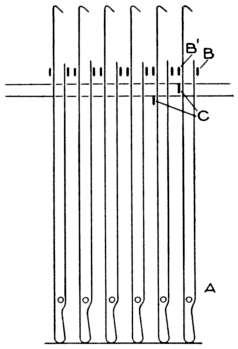
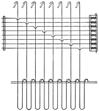
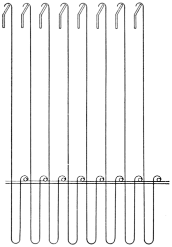
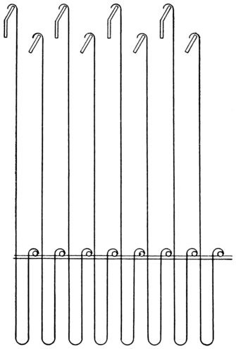
them straight with the hooks. Figs. 12, 13 and 14
show crooked hooks and needles.
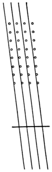
Fig. 14.
When the griffe is set, the top of the blade ought to be just
touching the hook. If the hook is pressing too hard against the
blade, either the needle point must extend farther out from the
needle board, or the cylinder has to press hard against the needle
board when the hooks have to be pressed off the griffe. Either
case is detrimental to the machine. In the first instance, the
cylinder requires to pass farther out from the needle board, to
14]
allow the cards to clear the needle points when the cylinder is being
turned, or there is a possibility of the edge of the card catching
on the needle points, preventing the cylinder from turning,
and causing misspicks. In the second instance, if the cylinder
presses too hard against the needle board, the lacing is often cut,
and the needles have a tendency to pierce the card where it is
blank.
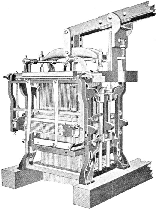
Fig. 15. Showing Overhead Lever Lift and Independent Batten Motion.
15]
Having set all the inner parts of the machine, the next in
order is the tying on of the neck cords. Carelessness in the setting
of the inner parts so far mentioned cannot afterwards be rectified,
and means the loss of years of work from the machine besides
having endless trouble during the time it is working.
The Outer Workings of the Machine. There are five distinct
methods of operating the movable parts of the machine: First, top
or overhead lever lift and independent batten or swing cylinder
motion; second, overhead lever and spindle cylinder motion; third,
overhead lever and independent slide cylinder motion; fourth,
bottom or cradle lever lift, and independent spindle cylinder motion;
and fifth, bottom or cradle lever lift and spindle cylinder
motion.
The first method is illustrated by Fig. 15. It consists of a
lever at the top of the machine, or in some instances suspended
from the beam that supports the ceiling. The inner end of the
lever is connected by a link to the crossbar of the griffe. This
must be fixed exactly in the center of the crossbar so as to give a
straight lift to the griffe. To the outer end of the lever, a long
driving rod is attached. The bottom end of the driving rod is
placed on a stud attached to the hand wheel, which is fixed on the
crank shaft of the boom when the machine is a single lift. The
overhead lever is from thirty-six to forty inches long, according
to the width of the loom. On the thirty-six inch lever the inner
end, which is attached to the crossbar from the link to the supporting
stud, fixed in the bracket attached to the framework of
the machine, is about ten and one-half inches long, and the longer
end, which is attached to the lifting rod, is twenty-four to twenty-five
and two-thirds inches long. The throw from the center of
shaft to the stud fixed to the hand wheel is four inches. This
gives an eight inch stroke on the hand wheel.
Allowing for the fall of the griffe below the bend of the hook
the movement will give about a three-inch shed in the harnesses.
16]
The batten or swing cylinder movement is shown in detail in
Fig. 16. It is composed of five distinct parts as follows:
(a) Two small arms are fixed at the top of the machine, one
at each side. Two pointed set screws with lock nuts are set in the
arms and the batten or swing is supported on these points.
(b) The batten, which is in the form of a square iron frame.
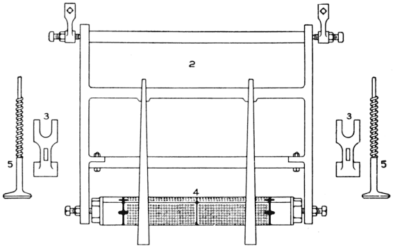
Fig. 16. Details of Batten or Swing Cylinder Motion.
(c) Two cups set in the batten frame, which support the
cylinder. The cups are made of iron or brass and are held in
place by a bolt with thumb screw on the outside of the frame of
the batten. Set into the bottom of the batten frame and pressing
upwards against the cups, are two set screws whose purpose is to
raise or lower the cylinder.
(d) The cylinder. This is a square prism with a number
of holes bored on each side to correspond with the needles in the
machine. On each of the four sides of the cylinder and near each
end there is a small brass peg (shown in Fig. 17) for the purpose
of holding the card in the correct position on the cylinder. (The
perforations in the cards should be over the holes in the cylinder).
The pegs are set so they can be adjusted to the right or left. At
the ends of the cylinder square iron castings with rounded edges
are fixed.
17]
(e) A spring hammer, the flat end of which rests on the
casting on the end of the cylinder. What might be termed the
handle of the hammer passes through the lower cross rail of the
bottom frames and through the top frame.
A spring is placed between the two rails and
around the handle of the hammer. The object
of the hammer is to keep the cylinder
perfectly level so that the cylinder will strike
the board level.
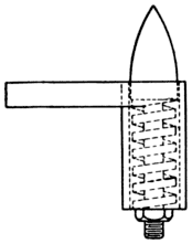
Fig. 17. Spring Peg.
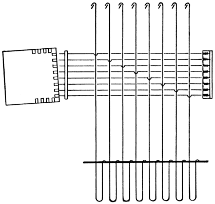
Fig. 18. Cylinder Out of True with Needle Board.
Flat springs also are attached to the inside
of the batten, the lower end of the spring
pressing the card to the cylinder. It is impossible
to overestimate the value of these
springs, especially on single cylinder machines,
for it would be almost impossible to
work without them. Their great value is shown when the cylinder
is leaving the needle board by preventing the card from swinging
on to the points of the needles, and also preventing the cards
from slipping off the pegs as the cylinder is drawn over by the
catch.
18]
The catch is fixed to the framework of the machine, and
rests on the square casting fixed to the end of the cylinder. As
the cylinder moves out, the catch comes in contact with the
rounded edges of the square and in this manner the cylinder is
turned. There is also another catch fixed underneath, but it is
not in contact with the cylinder, and is adjusted so that it can be
raised up in contact and the top catch raised from contact with
the cylinder. This permits the cylinder to be turned back when
a lost pick has to be found.
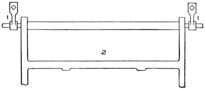
Fig. 19. Iron Bar Supporting Batten Frame.
At each side of the batten frame toward the lower end, an arm
is fixed. To these arms rods that extend downward are attached,
and each rod is fixed to an arm that is set-screwed on a shaft supported
by brackets fixed to the arch of the loom. At the end of
this shaft another arm is fixed and is connected to the eccentric
rod that is attached to the clamp that encircles the cam or eccentric.
The cam is for the purpose of imparting motion to the
batten. The cam generally used to operate the batten is about
three and one-half inches from center of movement to extreme
outside length of cam. The cylinder is moved out from the
needle board from two to three inches.
For the saving of cards, a great deal depends upon the movement
that is imparted to the cylinder. The less movement that
can be given to the cylinder, the better; that is, of course, when
obtaining the results required. The cylinder ought to be about
one-quarter inch from the needle points when commencing to turn.
Sometimes it is necessary to have the cylinder a little farther out,
especially when the cards have been stored in a damp place and
become warped so that they do not lie flat on the cylinder. In
19]
this case, unless the cylinder is a little farther out from the needle
points when commencing to turn, the edge of the card will catch
on the needle points. This will throw the cards off the pegs and
cause a pick-out. If the distance traveled by the cylinder is too
short, it causes too sharp a turning of the cylinder, which has a
tendency to jump the cards from the pegs; and if the cylinder
moves out too far, there is too much friction on the working parts,
as the larger distance has to be traveled in the same space of time
as the shorter distance.
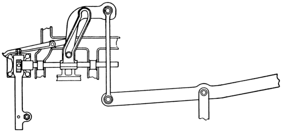
Fig. 20. Spindle Cylinder Motion.
When setting the batten frame by either the set screws or the
arms to which the set screws are attached, the principal point is
that the cylinder must be flat against the needle board, both at the
top and bottom of the board, and have the needle points as near
the center of the holes in the cylinder as possible. It is particularly
desirable that all points be square and straight with the
batten motion, because the batten, moving from a top connection,
performs an arc movement, and if the cylinder does not lie flat
against the needle board, some of the hooks will not be pressed
far enough off the griffe, or the points of the needles will come in
contact with the sides or bottom of the holes in the cylinder and
in that case, hooks will be down when they ought to be lifted.
Fig. 18 shows the cylinder set crooked with the needle board.
The set screw support for the batten frame is a very objectional
feature as will readily be seen, for the frame resting and
working on two points is a great strain and some part of the
20]
screw soon becomes worn. This, of course, lowers the cylinder.
When the cylinder is adjusted by turning the set screw, the frame
is not only raised higher but is moved to the right or left, which
throws the cylinder out of place, thus making double the amount
of work to adjust it.
The method of supporting a batten frame on an iron bar is
by far the best, as by this arrangement, the cylinder can be directly
adjusted. The illustration given in Fig. 19, shows this
method of supporting the cylinder.
In the second method of operating the movable parts (see
Fig. 20) the top motion remains the same as in the first, but the
method of operating the cylinder is different. Fixed to each side
of the square iron frame that supports the cylinder, is an iron
spindle, which passes through two brackets which act as slides for
the spindle and are fixed to the frame of the machine. Attached
to this cylinder spindle is a two-inch cranked slotted arm. Attached
to the spindle of the griffe is a small extension on which an
iron roller is placed. This iron roller sets in the slot of the
cranked arm; the slot arm being about seven inches long. The
seven inches is divided into three parts, the top and lower portions
being perpendicular, to allow a rest for the cylinder when it
is out from the needle board, and also when it is in contact with
the needle board. As the griffe is lifted, the roller passing up
the slot of the cranked arm forces out the cylinder. The distance
the cylinder is moved cannot be changed to any great extent, neither
can the time of the cylinder be changed, so that when a
warped set of cards is being used, there is always the tendency for
the cards to catch on the needle points.
In the third movement (see Fig. 21), the top motion is the
same as the first and second, but the cylinder movement is distinct.
A flat, iron casting which acts as a slide, is placed on each
side of the machine. These slides are supported by small iron
rollers, which are placed in brackets fixed to the frame of the machine.
At the end of the slide, a brass cup for the cylinder and
the spring hammer is fixed. A stud is attached to the slide.
The rod connected to the clamp of the cam (or what is called the
eccentric rod) extends upwards and is attached to an arm that is
set-screwed on a shaft, but extends upwards. This movement is
21]
one of the best. The brackets that support the rollers are adjustable
but seldom in the life of a harness do they require adjusting,
for if the rollers are well oiled they last many years, because the
friction is at the lowest possible point.
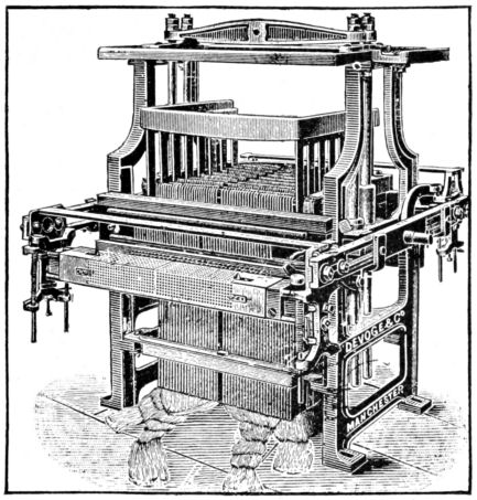
Fig. 21. Showing Overhead Lever Lift and Slide Cylinder Motion.
In the fourth movement a square cradle lever is placed in
brackets near the feet of the machine, and connected to the top of
the griffe spindle by means of an arm attached to the end of the
cradle lever. This is shown in the double-lift machine, Fig. 22.
There is an arm at each side of the machine that is connected to
the cradle lever. To the outer end of the lever the long lifting
rod is attached. The length of the square lever is generally
twenty-eight inches from fulcrum to connection of long lifting
rod, and ten inches on the shorter end. This gives about a four-inch
lift to the griffe. The cylinder is driven by an independent
spindle motion. An iron spindle is attached to the frame that
supports the cylinder. The spindle passes through two slide
brackets fixed to the sides of the machine. Between the two
22]
brackets and set-screwed on the spindle is an extension with a
stud attached to the top of it. On this stud, the connecting arm
from the lever is placed. The lever is supported at the top of the
same bracket that supports the square lifting lever. To the outer
end of the lever the eccentric rod is attached, but instead of using
a cam to give motion to the cylinder, one part of a double crank
is used, the other portion is used for lifting the griffe.
The fifth method is the same as the fourth with the exception
that the cylinder is operated by the slotted crank arm same
as in the second method.