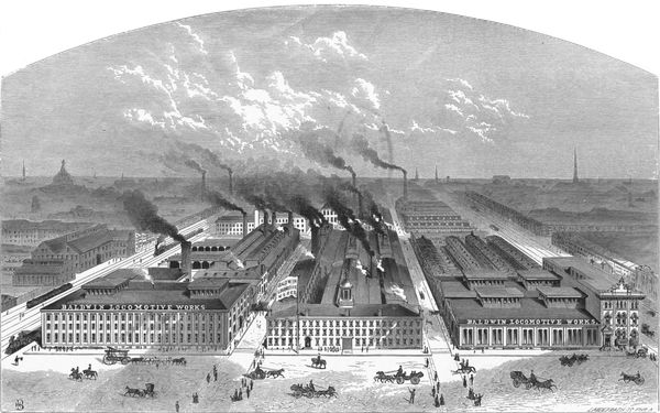
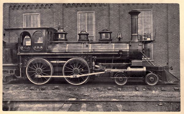
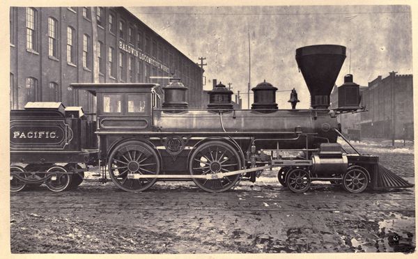
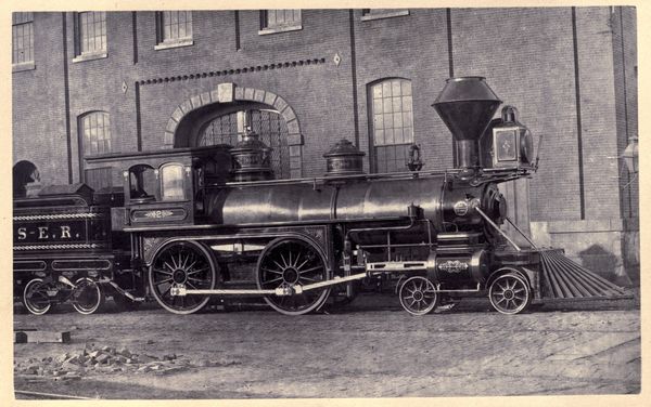
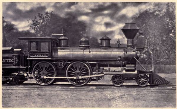
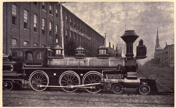
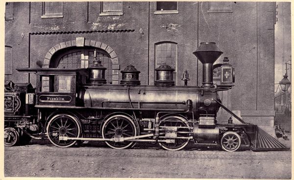
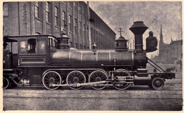
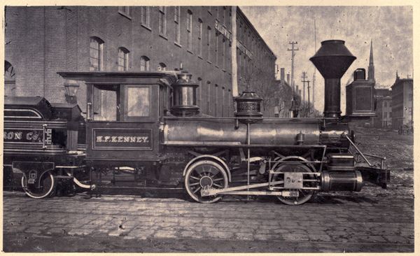
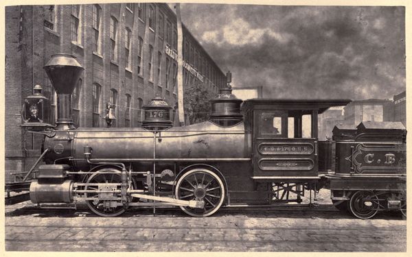
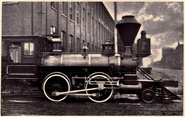
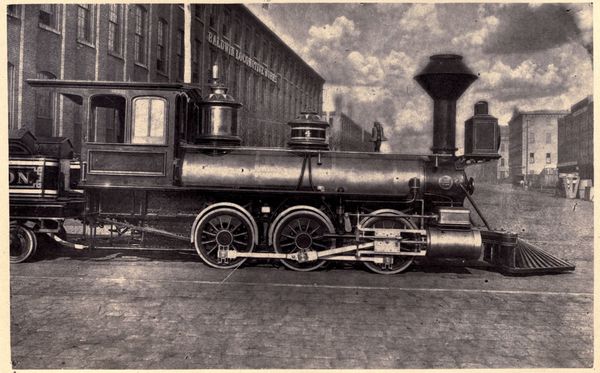
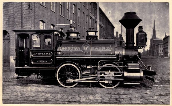
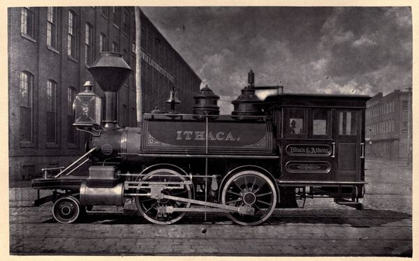
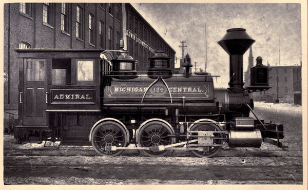
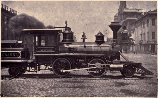
The Baldwin Locomotive Works dates its origin from the inception of
steam railroads in America. Called into existence by the early
requirements of the railroad interests of the country, it has grown
with their growth and kept pace with their progress. It has
reflected in its career the successive stages of American railroad
practice, and has itself contributed largely to the development of
the locomotive as it exists to-day. A history of the Baldwin
Locomotive Works, therefore, is, in a great measure, a record of the
progress of locomotive engineering in this country, and as such
cannot fail to be of interest to all who are concerned in this
important element of our material progress.
Matthias W. Baldwin, the founder of the establishment, learned the
trade of a jeweler, and entered the service of Fletcher & Gardiner,
Jewelers and Silversmiths, Philadelphia, in 1817. Two years later he
opened a small shop, in the same line of business, on his own
account. The demand for articles of this character falling off,
however, he formed a partnership, in 1825, with David Mason, a
machinist, in the manufacture of bookbinders' tools and cylinders
for calico-printing. Their shop was in a small alley which runs
north from Walnut Street, above Fourth. They afterwards removed to
Minor Street, below Sixth. The business was so successful that
steam-power became necessary in carrying on their manufactures, and
an engine was bought for the purpose. This proving unsatisfactory,
Mr. Baldwin decided to design and construct one which should be
specially adapted to the requirements of his shop. One of these
requirements was that it should occupy the least possible space, and
this was met by the construction of an upright engine on a novel and
ingenious plan. On a bed-plate about five feet square an upright
cylinder was placed; the piston-rod connected to a cross-bar having
two legs, turned downward, and sliding in grooves on the sides of
the cylinder, which thus formed the guides. To the sides of these
legs, at their lower ends, was connected by pivots an inverted
U-shaped frame, prolonged at the arch into a single rod, which took
hold of the crank of a fly-wheel carried by upright standards on the
bed-plate. It will be seen that the length of the ordinary separate
guide-bars was thus saved, and the whole engine was brought within
the smallest possible compass. The design of the machine was not
only unique, but its workmanship was so excellent, and its
efficiency so great, as readily to procure for Mr. Baldwin
orders for additional stationary engines. His attention was thus
turned to steam engineering, and the way was prepared for his
grappling with the problem of the locomotive when the time should
arrive.
This original stationary engine, constructed prior to 1830, has been
in almost constant service since its completion, and at this day is
still in use, furnishing all the power required to drive the
machinery in the erecting-shop of the present works. The visitor who
beholds it quietly performing its regular duty in a corner of the
shop, may justly regard it with considerable interest, as in all
probability the indirect foundation of the Baldwin Locomotive Works,
and permitted still to contribute to the operation of the mammoth
industry which it was instrumental in building up.
The manufacture of stationary steam-engines thus took a prominent
place in the establishment, and Mr. Mason shortly afterward withdrew
from the business.
In 1829-30 the use of steam as a motive power on railroads had begun
to engage the attention of American engineers. A few locomotives had
been imported from England, and one (which, however, was not
successful) had been constructed at the West Point Foundry, in New
York City. To gratify the public interest in the new motor, Mr.
Franklin Peale, then proprietor of the Philadelphia Museum, applied
to Mr. Baldwin to construct a miniature locomotive for exhibition in
his establishment. With the aid only of the imperfect published
descriptions and sketches of the locomotives which had taken part in
the Rainhill competition in England, Mr. Baldwin undertook the work,
and on the 25th of April, 1831, the miniature locomotive was put in
motion on a circular track made of pine boards covered with hoop
iron, in the rooms of the Museum. Two small cars, containing seats
for four passengers, were attached to it, and the novel spectacle
attracted crowds of admiring spectators. Both anthracite and
pine-knot coal were used as fuel, and the exhaust steam was
discharged into the chimney, thus utilizing it to increase the
draught.
The success of the model was such that, in the same year, Mr.
Baldwin received an order for a locomotive from the Philadelphia,
Germantown and Norristown Railroad Company, whose short line of six
miles to Germantown was operated by horse-power. The Camden and
Amboy Railroad Company had shortly before imported a locomotive from
England, which was stored in a shed at Bordentown. It had not yet
been put together; but Mr. Baldwin, in company with his friend, Mr.
Peale, visited the spot, inspected the detached parts, and made a
few memoranda of some of its principal dimensions. Guided by these
figures and his experience with the Peale model, Mr. Baldwin
commenced the task. The difficulties to be overcome in filling the
order can hardly be appreciated at this day. There were few
mechanics competent to do any part of the work on a locomotive.
Suitable tools were with difficulty obtainable. Cylinders were bored
by a chisel fixed in a block of wood and turned by hand. Blacksmiths
able to weld a bar of iron exceeding one and one-quarter inches in
thickness, were few, or not to be had. It was necessary for Mr.
Baldwin to do much of the work with his own hands, to educate the
workmen who assisted him, and to improvise tools for the various
processes.
The work was prosecuted, nevertheless, under all these
difficulties, and the locomotive was finally completed, christened
the "Old Ironsides," and tried on the road, November 23, 1832. The
circumstances of the trial are fully preserved, and are given,
further on, in the extracts from the journals of the day. Despite
some imperfections, naturally occurring in a first effort, and which
were afterward, to a great extent, remedied, the engine was, for
that early day, a marked and gratifying success. It was put at once
into service, as appears from the Company's advertisement three days
after the trial, and did duty on the Germantown road and others for
over a score of years.
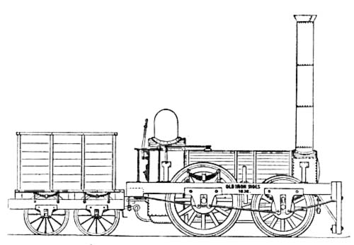
Fig. 1.—The "Old Ironsides," 1832.
The "Ironsides" was a four-wheeled engine, modeled essentially on
the English practice of that day, as shown in the "Planet" class,
and weighed, in running order, something over five tons. The rear or
driving-wheels were fifty-four inches in diameter on a crank-axle
placed in front of the fire-box. The cranks were thirty-nine inches
from centre to centre. The front wheels, which were simply carrying
wheels, were forty-five inches in diameter, on an axle placed just
back of the cylinders. The cylinders were nine and one-half inches
in diameter by eighteen inches stroke, and were attached
horizontally to the outside of the smoke-box, which was D-shaped,
with the sides receding inwardly, so as to bring the centre line of
each cylinder in line with the centre of the crank. The wheels were
made with heavy cast-iron hubs, wooden spokes and rims, and
wrought-iron tires. The frame was of wood, placed outside the
wheels. The boiler was thirty inches in diameter, and contained
seventy-two copper flues, one and one-half inches in diameter and
seven feet long. The tender was a four-wheeled platform, with wooden
sides and back, carrying an iron box for a water-tank, inclosed in a
wooden casing, and with a space for fuel in front. The engine had no
cab. The valve-motion was given by a single loose eccentric for each
cylinder, placed on the axle between the crank and the hub of the
wheel. On the inside of the eccentric was a half-circular slot,
running half-way around. A stop was fastened to the axle at the arm
of the crank, terminating in a pin which projected into the slot.
This pin would thus hold the eccentric at one end or the other of
the half-circular slot, and the engine was reversed by moving the
eccentric about the axle, by means of movable hand-levers set in
sockets in the rock-shafts, until it was arrested and held by the
pin at one end or the other of the slot. The rock-shafts, which were
under the footboard, had arms above and below, and the
eccentric-straps had each a forked rod, with a hook, or an upper and
lower latch or pin, at their extremities, to engage with the
upper or lower arm of the rock-shaft. The eccentric-rods were raised
or lowered by a double treadle, so as to connect with the upper or
lower arm of the rock-shaft, according as forward or backward gear
was desired. A peculiarity in the exhaust of the "Ironsides" was
that there was only a single straight pipe running across from one
cylinder to the other, with an opening in the upper side of the
pipe, midway between the cylinders, to which was attached at right
angles the perpendicular pipe into the chimney. The cylinders,
therefore, exhausted against each other; and it was found, after the
engine had been put in use, that this was a serious objection. This
defect was afterwards remedied by turning each exhaust-pipe upward
into the chimney, substantially as is now done. The steam-joints
were made with canvas and red-lead, as was the practice in English
locomotives, and in consequence much trouble was caused, from time
to time, by leaking.
The price of the engine was to have been $4000, but some difficulty
was found in procuring a settlement. The Company claimed that the
engine did not perform according to contract; and objection was also
made to some of the defects alluded to. After these had been
corrected as far as possible, however, Mr. Baldwin finally succeeded
in effecting a compromise settlement, and received from the Company
$3500 for the machine.
We are indebted for the sketch of the "Ironsides" from which the
accompanying cut is produced, as well as for other valuable
particulars in regard to the engine, to Mr. H. R. Campbell, who was
the Chief Engineer of the Germantown and Norristown Railroad when
the "Ironsides" was placed in service, and who is thoroughly
familiar with all the facts in regard to the engine. Much of the
success of the machine was due to his exertions, as, while the
President of the Company was inclined to reject it as defective, Mr.
Campbell was earnest in his efforts to correct its imperfections,
and his influence contributed largely to retain the engine on the
road.
The results of the trial and the impression produced by it on the
public mind may be gathered from the following extracts from the
newspapers of the day:
The United States Gazette of Nov. 24th, 1832, remarks:
"A most gratifying experiment was made yesterday afternoon on the
Philadelphia, Germantown and Norristown Railroad. The beautiful
locomotive engine and tender, built by Mr. Baldwin, of this city,
whose reputation as an ingenious machinist is well known, were
for the first time placed on the road. The engine traveled about
six miles, working with perfect accuracy and ease in all its
parts, and with great velocity."
The Chronicle of the same date noticed the trial more at length,
as follows:
"It gives us pleasure to state that the locomotive engine built
by our townsman, M. W. Baldwin, has proved highly successful. In
the presence of several gentlemen of science and information on
such subjects, the engine was yesterday placed upon the road for
the first time. All her parts had been previously highly finished
and fitted together in Mr. Baldwin's factory. She was taken apart
on Tuesday and removed to the Company's depot, and yesterday
morning she was completely together, ready for travel. After the
regular passenger cars had arrived from Germantown in the
afternoon, the tracks being clear, preparation was made for her
starting. The placing fire in the furnace and raising steam
occupied twenty minutes. The engine (with her tender) moved from
the depot in beautiful style, working with great ease and
uniformity. She proceeded about half a mile beyond the Union
Tavern, at the township line, and returned immediately, a
distance of six miles, at a speed of about twenty-eight miles to
the hour, her speed having been slackened at all the road
crossings, and it being after dark, but a portion of her power
was used. It is needless to say that the spectators were
delighted. From this experiment there is every reason to believe
this engine will draw thirty tons gross, at an average speed of
forty miles an hour, on a level road. The principal superiority
of the engine over any of the English ones known, consists in the
light weight,—which is but between four and five tons,—her
small bulk, and the simplicity of her working machinery. We
rejoice at the result of this experiment, as it conclusively
shows that Philadelphia, always famous for the skill of her
mechanics, is enabled to produce steam-engines for railroads
combining so many superior qualities as to warrant the belief
that her mechanics will hereafter supply nearly all the public
works of this description in the country."
On subsequent trials, the "Ironsides" attained a speed of thirty
miles per hour, with its usual train attached. So great were the
wonder and curiosity which attached to such a prodigy, that people
flocked to see the marvel, and eagerly bought the privilege of
riding after the strange monster. The officers of the road were not
slow to avail themselves of the public interest to increase their
passenger receipts, and the following advertisement from Poulson's
American Daily Advertiser of Nov. 26, 1832, will show that as yet
they regarded the new machine rather as a curiosity and a bait to
allure travel than as a practical, every-day servant:
"Notice.—The locomotive engine (built by M. W. Baldwin, of this
city) will depart daily, when the weather is fair, with a train
of passenger cars. On rainy days horses will be attached."
This announcement did not mean that in wet weather horses would be
attached to the locomotive to aid if in drawing the train, but that
the usual horse-cars would be employed in making the trips upon the
road without the engine.
Upon making the first trip to Germantown with a passenger train with
the Ironsides, one of the drivers slipped upon the axle, causing the
wheels to track less than the gauge of the road and drop in between
the rails. It was also discovered that the valve arrangement of the
pumps was defective, and they failed to supply the boiler with
water. The shifting of the driving wheel upon the axle fastened the
eccentric, so that it would not operate in backward motion. These
mishaps caused delay, and prevented the engine from reaching its
destination, to the great disappointment of all concerned. They were
corrected in a few days, and the machine was used in experimenting
upon its efficiency, making occasional trips with trains to
Germantown. The road had an ascending grade, nearly uniform, of
thirty-two feet per mile, and for the last half-mile of forty-five
feet per mile, and it was found that the engine was too light for
the business of the road upon these grades.
Such was Mr. Baldwin's first locomotive; and it is related of him
that his discouragement at the difficulties which he had undergone
in building it and in finally procuring a settlement for it was such
that he remarked to one of his friends, with much decision, "That is
our last locomotive."
It was some time before he received an order for another, but
meanwhile the subject had become singularly fascinating to
him, and occupied his mind so fully that he was eager to work out
his new ideas in a tangible form.
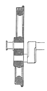
Fig. 2.—Half-Crank.
Shortly after the "Ironsides" had been placed on the Germantown
road, Mr. E. L. Miller, of Charleston, S. C, came to Philadelphia
and made a careful examination of the machine. Mr. Miller had, in
1830, contracted to furnish a locomotive to the Charleston and
Hamburg Railroad Company, and accordingly the engine "Best Friend"
had been built under his direction at the West Point Foundry, New
York. After inspecting the "Ironsides," he suggested to Mr. Baldwin
to visit the Mohawk and Hudson Railroad and examine an English
locomotive which had been placed on that road in July, 1831, by
Messrs. Robert Stephenson & Co., of Newcastle, England. It was
originally a four-wheeled engine of the "Planet" type, with
horizontal cylinders and crank-axle. The front wheels of this engine
were removed about a year after the machine was put at work, and a
four-wheeled swiveling or "bogie" truck substituted. The result of
Mr. Baldwin's investigations was the adoption of this design, but
with some important improvements. Among these was the "half-crank,"
which he devised on his return from this trip, and which he patented
September 10, 1834. In this form of crank, shown in Figure 2, the
outer arm is omitted, and the wrist is fixed in a spoke of the
wheel. In other words, the wheel itself formed one arm of the crank.
The result sought and gained was that the cranks were strengthened,
and, being at the extremities of the axle, the boiler could be made
larger in diameter and placed lower. The driving axle could also be
placed back of the fire-box, the connecting rods passing by the
sides of the fire-box and taking hold inside of the wheels. This
arrangement of the crank also involved the placing of the cylinders
outside the smoke-box, as was done on the "Ironsides."
By the time the order for the second locomotive was received, Mr.
Baldwin had matured this device and was prepared to embody it in
practical form. The order came from Mr. E. L. Miller in behalf of
the Charleston and Hamburg Railroad Company, and the engine bore his
name, and was completed February 18, 1834. It was on six wheels; one
pair being drivers, four and a half feet in diameter, with
half-crank axle placed back of the fire-box as above described, and
the four front wheels combined in a swiveling truck. The
driving-wheels, it should be observed, were cast in solid
bell-metal. The combined wood and iron wheels used on the
"Ironsides" had proved objectionable, and Mr. Baldwin, in his
endeavors to find a satisfactory substitute, had recourse to brass.
June 29, 1833, he took out a patent for a cast-brass wheel, his idea
being that by varying the hardness of the metal the adhesion of the
drivers on the rails could be increased or diminished at will. The
brass wheels on the "Miller," however, soon wore out, and the
experiment with this metal was not repeated. The "E. L. Miller" had
cylinders ten inches in diameter; stroke of piston, sixteen inches;
and weighed, with water in the boiler, seven tons eight
hundredweight. The boiler had a high dome over the
fire-box, as shown in Figure 3; and this form of construction, it
may be noted, was followed, with a few exceptions, for many years.
The valve-motion was given by a single fixed eccentric for each
cylinder. Each eccentric-strap had two arms attached to it, one
above and the other below, and, as the driving-axle was back of the
fire-box, these arms were prolonged backward under the footboard,
with a hook on the inner side of the end of each. The rock-shaft had
arms above and below its axis, and the hooks of the two rods of each
eccentric were moved by hand-levers so as to engage with either arm,
thus producing backward or forward gear. This form of single
eccentric, peculiar to Mr. Baldwin, was in the interest of
simplicity in the working parts, and was adhered to for some years.
It gave rise to an animated controversy among mechanics as to
whether, with its use, it was possible to get a lead on the valve in
both directions. Many maintained that this was impracticable; but
Mr. Baldwin demonstrated by actual experience that the reverse was
the case.
Meanwhile the Commonwealth of Pennsylvania had given Mr. Baldwin an
order for a locomotive for the State Road, as it was then called,
from Philadelphia to Columbia, which, up to that time, had been
worked by horses. This engine, called the "Lancaster," was completed
in June, 1834. It was similar to the "Miller," and weighed seventeen
thousand pounds. After it was placed in service, the records show
that it hauled at one time nineteen loaded burden cars over the
highest grades between Philadelphia and Columbia. This was
characterized at the time by the officers of the road as an
"unprecedented performance." The success of the machine on its trial
trips was such that the Legislature decided to adopt steam-power for
working the road, and Mr. Baldwin received orders for several
additional locomotives. Two others were accordingly delivered to the
State in September and November respectively of that year, and one
was also built and delivered to the Philadelphia and Trenton
Railroad Company during the same season. This latter engine, which
was put in service October 21, 1834, averaged twenty-one thousand
miles per year to September 15, 1840.
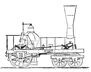
Fig. 3.—Baldwin Engine, 1834.
Five locomotives were thus completed in 1834, and the new business
was fairly under way. The building in Lodge Alley, to which Mr.
Baldwin had removed from Minor Street, and where these engines were
constructed, began to be found too contracted, and another removal
was decided upon. A location on Broad and Hamilton Streets (the
site, in part, of the present works) was selected, and a three-story
L-shaped brick building, fronting on both streets, erected. This was
completed and the business removed to it during the following year
(1835). The original building still stands, forming the office,
drawing-room, and principal machine-shops of the present works.
These early locomotives, built in 1834, were the types of
Mr. Baldwin's practice for some years. Their general design is shown
in Figure 3. All, or nearly all of them, embraced several important
devices, which were the results of his study and experiments up to
that time. The devices referred to were patented September 10, 1834,
and the same patent covered the four following inventions, viz.:
1. The half-crank, and method of attaching it to the driving-wheel.
(This has already been described.)
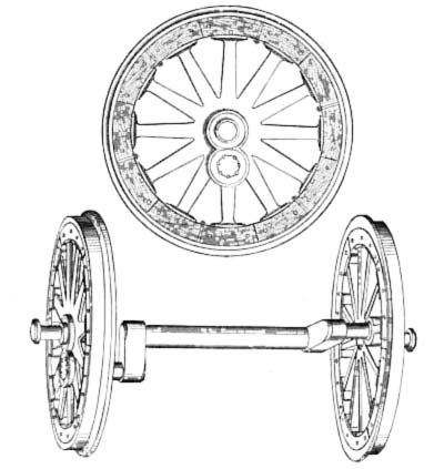
Fig. 4.—Baldwin Compound Wood and Iron Wheels,
1834.
2. A new mode of constructing the wheels of locomotive engines and
cars. In this the hub and spokes were of cast-iron, cast together.
The spokes were cast without a rim, and terminated in segment
flanges, each spoke having a separate flange disconnected from its
neighbors. By this means, it was claimed, the injurious effect of
the unequal expansion of the materials composing the wheels was
lessened or altogether prevented. The flanges bore against wooden
felloes, made in two thicknesses, and put together so as to break
joints. Tenons or pins projected from the flanges into openings made
in the wooden felloes, to keep them in place. Around the whole the
tire was passed and secured by bolts. The above sketch shows the
device.
3. A new mode of forming the joints of steam and other tubes. This
was Mr. Baldwin's invention of ground joints for
steam-pipes, which was a very valuable improvement over previous
methods of making joints with red-lead packing, and which rendered
it possible to carry a much higher pressure of steam.
4. A new mode of forming the joints and other parts of the
supply-pump, and of locating the pump itself. This invention
consisted in making the single guide-bar hollow and using it for the
pump-barrel. The pump-plunger was attached to the piston-rod at a
socket or sleeve formed for the purpose, and the hollow guide-bar
terminated in the vertical pump-chamber. This chamber was made in
two pieces, joined about midway between the induction and
eduction-pipes. This joint was ground steam-tight, as were also the
joints of the induction-pipe with the bottom of the lower chamber,
and the flange of the eduction-pipe with the top of the upper
chamber. All these parts were held together by a stirrup with a
set-screw in its arched top, and the arrangement was such that by
simply unscrewing this set-screw the different sections of the
chamber, with all the valves, could be taken apart for cleaning or
adjusting. The cut below illustrates the device.
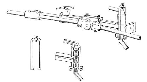
Fig. 5.—Pump and Stirrup.
It is probable that the five engines built during 1834 embodied all,
or nearly all, these devices. They all had the half-crank, the
ground joints for steam-pipes (which was first made by him in 1833),
and the pump formed in the guide-bar, and all had the four-wheeled
truck in front, and a single pair of drivers back of the fire-box.
On this position of the driving-wheels, Mr. Baldwin laid great
stress, as it made a more even distribution of the weight, throwing
about one-half on the drivers and one-half on the four-wheeled
truck. It also extended the wheel-base, making the engine much
steadier and less damaging to the track. Mr. William Norris, who had
established a locomotive works in Philadelphia in 1832, was at this
time building a six-wheeled engine with a truck in front and the
driving-wheels placed in front of the fire-box. Considerable rivalry
naturally existed between the two manufacturers as to the
comparative merits of their respective plans. In Mr.
Norris's engine, the position of the driving-axle in front of the
fire-box threw on it more of the weight of the engine, and thus
increased the adhesion and the tractive power. Mr. Baldwin, however,
maintained the superiority of his plan, as giving a better
distribution of the weight and a longer wheel-base, and consequently
rendering the machine less destructive to the track. As the iron
rails then in use were generally light, and much of the track was of
wood, this feature was of some importance.
To the use of the ground joint for steam-pipes, however, much of the
success of his early engines was due. The English builders were
making locomotives with canvas and red-lead joints, permitting a
steam pressure of only sixty pounds per inch to be carried, while
Mr. Baldwin's machines were worked at one hundred and twenty pounds
with ease. Several locomotives imported from England at about this
period by the Commonwealth of Pennsylvania for the State Road (three
of which were made by Stephenson) had canvas and red-lead joints,
and their efficiency was so much less than that of the Baldwin
engines, on account of this and other features of construction, that
they were soon laid aside or sold.
In June, 1834, a patent was issued to Mr. E. L. Miller, by whom Mr.
Baldwin's second engine was ordered, for a method of increasing the
adhesion of a locomotive by throwing a part of the weight of the
tender on the rear of the engine, thus increasing the weight on the
drivers. Mr. Baldwin adopted this device on an engine built for the
Philadelphia and Trenton Railroad Company, May, 1835, and thereafter
used it largely, paying one hundred dollars royalty for each engine.
Eventually (May 6, 1839) he bought the patent for nine thousand
dollars, evidently considering that the device was especially
valuable, if not indispensable, in order to render his engine as
powerful, when required, as other patterns having the driving-wheels
in front of the fire-box, and therefore utilizing more of the weight
of the engine for adhesion.
In making the truck and tender wheels of these early locomotives,
the hubs were cast in three pieces and afterward banded with
wrought-iron, the interstices being filled with spelter. This method
of construction was adopted on account of the difficulty then found
in casting a chilled wheel in one solid piece.
April 3, 1835, Mr. Baldwin took out a patent for certain
improvements in the wheels and tubes of locomotive engines. That
relating to the wheels provided for casting the hub and spokes
together, and having the spokes terminate in segments of a rim, as
described in his patent of September 10, 1834. Between the ends of
the spokes and the tires wood was interposed, and the tire might be
either of wrought-iron or of chilled cast-iron. The intention was
expressed of making the tire usually of cast-iron chilled. The main
object, however, was declared to be the interposition between the
spokes and the rim of a layer of wood or other substance possessing
some degree of elasticity. This method of making driving-wheels was
followed for several years.
The improvement in locomotive tubes consisted in driving a copper
ferrule or thimble on the outside of the end of the tube, and
soldering it in place, instead of driving a ferrule into
the tube, as had previously been the practice. The object of the
latter method had been to make a tight joint with the tube-sheet;
but, by putting the ferrule on the outside of the tube, not only was
the joint made as tight as before, but the tube was strengthened,
and left unobstructed throughout to the full extent of its diameter.
This method of setting flues has been generally followed in the
works from that date to the present, the only difference being that,
at this time, with iron tubes, the end is swedged down, the copper
ferrule brazed on, and the iron end turned or riveted over against
the copper thimble and the flue-sheet, to make the joint perfect.
Early in 1835, the new shop on Broad Street was completed and
occupied. Mr. Baldwin's attention was thenceforward given to
locomotive building exclusively, except that a stationary engine was
occasionally constructed.
In May, 1835, his eleventh locomotive, the "Black Hawk," was
delivered to the Philadelphia and Trenton Railroad Company. This was
the first outside-connected engine of his build. It was also the
first engine on which the Miller device of attaching part of the
weight of the tender to the engine was employed. On the eighteenth
engine, the "Brandywine," built for the Philadelphia and Columbia
Railroad Company, brass tires were used on the driving-wheels, for
the purpose of obtaining more adhesion; but they wore out rapidly
and were replaced with iron.
Fourteen engines were constructed in 1835; forty in 1836; forty in
1837; twenty-three in 1838; twenty-six in 1839; and nine in 1840.
During all these years the general design continued the same; but,
in compliance with the demand for more power, three sizes were
furnished, as follows:
| First-class. |
Cylinders, |
12½ × 16; |
weight, |
loaded, |
26,000 |
pounds. |
| Second-class. |
" |
12 × 16; |
" |
" |
23,000 |
" |
| Third-class. |
" |
10½ × 16; |
" |
" |
20,000 |
" |
The first-class engine he fully believed, in 1838, was as heavy as
would be called for, and he declared that it was as large as he
intended to make. Most of the engines were built with the
half-crank, but occasionally an outside-connected machine was turned
out. These latter, however, failed to give as complete satisfaction
as the half-crank machine. The drivers were generally four and a
half feet in diameter.
A patent was issued to Mr. Baldwin, August 17, 1835, for his device
of cylindrical pedestals. In this method of construction, the
pedestal was of cast-iron, and was bored in a lathe so as to form
two concave jaws. The boxes were also turned in a lathe so that
their vertical ends were cylindrical, and they were thus fitted in
the pedestals. This method of fitting up pedestals and boxes was
cheap and effective, and was used for some years for the driving and
tender wheels.
As showing the estimation in which these early engines were held, it
may not be out of place to refer to the opinions of some of the
railroad managers of that period.
Mr. L. A. Sykes, engineer of the New Jersey Transportation Company,
under date of June 12, 1838, wrote that he could draw with his
engines twenty four-wheeled cars with twenty-six passengers
each, at a speed of twenty to twenty-five miles per hour, over
grades of twenty-six feet per mile. "As to simplicity of
construction," he adds, "small liability to get out of order,
economy of repairs, and ease to the road, I fully believe Mr.
Baldwin's engines stand unrivalled. I consider the simplicity of the
engine, the arrangement of the working-parts, and the distribution
of the weight, far superior to any engine I have ever seen, either
of American or English manufacture, and I have not the least
hesitation in saying that Mr. Baldwin's engine will do the same
amount of work with much less repairs, either to the engine or the
track, than any other engine in use."
L. G. Cannon, President of the Rensselaer and Saratoga Railroad
Company, writes, "Your engines will, in performance and cost of
repairs, bear comparison with any other engine made in this or any
other country."
Some of Mr. Baldwin's engines on the State Road, in 1837, cost, for
repairs, only from one and two-tenths to one and six-tenths cents
per mile. It is noted that the engine "West Chester," on the same
road, weighing twenty thousand seven hundred and thirty-five pounds
(ten thousand four hundred and seventy-five on drivers), drew
fifty-one cars (four-wheeled), weighing two hundred and eighty-nine
net tons, over the road, some of the track being of wood covered
with strap-rail.
The financial difficulties of 1836 and 1837, which brought ruin upon
so many, did not leave Mr. Baldwin unscathed. His embarrassments
became so great that he was unable to proceed, and was forced to
call his creditors together for a settlement. After offering to
surrender all his property, his shop, tools, house, and everything,
if they so desired,—all of which would realize only about
twenty-five per cent. of their claims,—he proposed to them that
they should permit him to go on with the business, and in three
years he would pay the full amount of all claims, principal and
interest. This was finally acceded to, and the promise was in effect
fulfilled, although not without an extension of two years beyond the
time originally proposed.
In May, 1837, the number of hands employed was three hundred, but
this number was reducing weekly, owing to the falling off in the
demand for engines.
These financial troubles had their effect on the demand for
locomotives, as will be seen in the decrease in the number built in
1838, 1839, and 1840; and this result was furthered by the
establishment of several other locomotive works and the introduction
of other patterns of engines.
The changes and improvements in details made during these years may
be summed up as follows:
The subject of burning coal had engaged much attention. In October,
1836, Mr. Baldwin secured a patent for a grate or fireplace which
could be detached from the engine at pleasure, and a new one with a
fresh coal fire substituted. The intention was to have the grate
with freshly ignited coal all ready for the engine on its arrival at
a station, and placed between the rails over suitable levers, by
which it could be attached quickly to the fire-box. It is needless
to say that this was never practiced. In January, 1838, however, Mr.
Baldwin was experimenting with the consumption of coal on the
Germantown road, and in July of the same year the records
show that he was making a locomotive to burn coal, part of the
arrangement being to blow the fire with a fan.
Up to 1838, Mr. Baldwin had made both driving and truck wheels with
wrought tires, but during that year chilled wheels for engine and
tender trucks were adopted. His tires were furnished by Messrs. S.
Vail & Son, Morristown, N. J., who made the only tires then
obtainable in America. They were very thin, being only one inch to
one and a half inches thick; and Mr. Baldwin, in importing some
tires from England at that time, insisted on their being made double
the ordinary thickness. The manufacturers at first objected and
ridiculed the idea, the practice being to use two tires when extra
thickness was wanted, but finally they consented to meet his
requirements.
All his engines thus far had the single eccentric for each valve,
but at about this period double eccentrics were adopted, each
terminating in a straight hook, and reversed by hand-levers.
At this early period, Mr. Baldwin had begun to feel the necessity of
making all like parts of locomotives of the same class in such
manner as to be absolutely interchangeable. Steps were taken in this
direction, but it was not until many years afterward that the system
of standard gauges was perfected, which has since grown to be a
distinguishing feature in the establishment.
In March, 1839, Mr. Baldwin's records show that he was building a
number of outside-connected engines, and had succeeded in making
them strong and durable. He was also making a new chilled wheel, and
one which he thought would not break.
On the one hundred and thirty-sixth locomotive, completed October
18, 1839, for the Philadelphia, Germantown and Norristown Railroad,
the old pattern of wooden frame was abandoned, and no outside frame
whatever was employed,—the machinery, as well as the truck and the
pedestals of the driving-axles, being attached directly to the naked
boiler. The wooden frame thenceforward disappeared gradually, and an
iron frame took its place. Another innovation was the adoption of
eight-wheeled tenders, the first of which was built at about this
period.
April 8, 1839, Mr. Baldwin associated with himself Messrs. Vail and
Hufty, and the business was conducted under the firm name of
Baldwin, Vail & Hufty until 1841, when Mr. Hufty withdrew, and
Baldwin & Vail continued the copartnership until 1842.
The time had now arrived when the increase of business on railroads
demanded more powerful locomotives. It had for some years been felt
that for freight traffic the engine with one pair of drivers was
insufficient. Mr. Baldwin's engine had the single pair of drivers
placed back of the fire-box; that made by Mr. Norris, one pair in
front of the fire-box. An engine with two pairs of drivers, one pair
in front and one pair behind the fire-box, was the next logical
step, and Mr. Henry R. Campbell, of Philadelphia, was the first to
carry this design into execution. Mr. Campbell, as has been noted,
was the Chief Engineer of the Germantown Railroad when the
"Ironsides" was placed on that line, and had since given much
attention to the subject of locomotive construction. February 5,
1836, Mr. Campbell secured a patent for an eight-wheeled engine
with four drivers connected, and a four-wheeled truck in
front; and subsequently contracted with James Brooks, of
Philadelphia, to build for him such a machine. The work was begun
March 16, 1836, and the engine was completed May 8, 1837. This was
the first eight-wheeled engine of this type, and from it the
standard American locomotive of to-day takes its origin. The engine
lacked, however, one essential feature; there were no equalizing
beams between the drivers, and nothing but the ordinary steel
springs over each journal of the driving-axles to equalize the
weight upon them. It remained for Messrs. Eastwick & Harrison to
supply this deficiency; and in 1837 that firm constructed at their
shop in Philadelphia a locomotive on this plan, but with the
driving-axles running in a separate square frame, connected to the
main frame above it by a single central bearing on each side. This
engine had cylinders twelve by eighteen, four coupled
driving-wheels, forty-four inches in diameter, carrying eight of the
twelve tons constituting the total weight. Subsequently, Mr. Joseph
Harrison, Jr., of the same firm, substituted "equalizing beams" on
engines of this plan afterward constructed by them, substantially in
the same manner as since generally employed.
In the American Railroad Journal of July 30, 1836, a wood-cut
showing Mr. Campbell's engine, together with an elaborate
calculation of the effective power of an engine on this plan, by
William J. Lewis, Esq., Civil Engineer, was published, with a table
showing its performance upon grades ranging from a dead level to a
rise of one hundred feet per mile. Mr. Campbell stated that his
experience at that time (1835-6) convinced him that grades of one
hundred feet rise per mile would, if roads were judiciously located,
carry railroads over any of the mountain passes in America, without
the use of planes with stationary steam power, or, as a general
rule, of costly tunnels,—an opinion very extensively verified by
the experience of the country since that date.
A step had thus been taken toward a plan of locomotive having more
adhesive power. Mr. Baldwin, however, was slow to adopt the new
design. He naturally regarded innovations with distrust. He had done
much to perfect the old pattern of engine, and had built over a
hundred of them, which were in successful operation on various
railroads. Many of the details were the subjects of his several
patents, and had been greatly simplified in his practice. In fact,
simplicity in all the working parts had been so largely his aim,
that it was natural that he should distrust any plan involving
additional machinery, and he regarded the new design as only an
experiment at best. In November, 1838, he wrote to a correspondent
that he did not think there was any advantage in the eight-wheeled
engine. There being three points in contact, it could not turn a
curve, he argued, without slipping one or the other pair of wheels
sideways. Another objection was in the multiplicity of machinery and
the difficulty in maintaining four driving-wheels all of exactly the
same size. Some means, however, of getting more adhesion must be
had, and the result of his reflections upon this subject was the
project of a "geared engine." In August, 1839, he took steps to
secure a patent for such a machine, and December 31, 1840, letters
patent were granted him for the device. In this engine, an
independent shaft or axle was placed between the two axles
of the truck, and connected by cranks and coupling-rods with cranks
on the outside of the driving-wheels. This shaft had a central
cog-wheel engaging on each side with intermediate cog-wheels, which
in turn geared into cog-wheels on each truck-axle. The intermediate
cog-wheels had wide teeth, so that the truck could pivot while the
main shaft remained parallel with the driving-axle. The diameters of
the cog-wheels were, of course, in such proportion to the driving
and truck wheels, that the latter should revolve as much oftener
than the drivers as their smaller size might require. Of the success
of this machine for freight service, Mr. Baldwin was very sanguine.
One was put in hand at once, completed in August, 1841, and
eventually sold to the Sugarloaf Coal Company. It was an
outside-connected engine, weighing thirty thousand pounds, of which
eleven thousand seven hundred and seventy-five pounds were on the
drivers, and eighteen thousand three hundred and thirty-five on the
truck. The driving-wheels were forty-four and the truck-wheels
thirty-three inches in diameter. The cylinders were thirteen inches
in diameter by sixteen inches stroke. On a trial of the engine upon
the Philadelphia and Reading Railroad, it hauled five hundred and
ninety tons from Reading to Philadelphia—a distance of fifty-four
miles—in five hours and twenty-two minutes. The Superintendent of
the road, in writing of the trial, remarked that this train was
unprecedented in length and weight both in America and Europe. The
performance was noticed in favorable terms by the Philadelphia
newspapers, and was made the subject of a report by the Committee on
Science and Arts of the Franklin Institute, who strongly recommended
this plan of engine for freight service. The success of the trial
led Mr. Baldwin at first to believe that the geared engine would be
generally adopted for freight traffic; but in this he was
disappointed. No further demand was made for such machines, and no
more of them were built.
In 1840, Mr. Baldwin received an order, through August Belmont,
Esq., of New York, for a locomotive for Austria, and had nearly
completed one which was calculated to do the work required, when he
learned that only sixty pounds pressure of steam was admissible,
whereas his engine was designed to use steam at one hundred pounds
and over. He accordingly constructed another, meeting this
requirement, and shipped it in the following year. This engine, it
may be noted, had a kind of link-motion, agreeably to the
specification received, and was the first of his make upon which the
link was introduced.
Mr. Baldwin's patent of December 31, 1840, already referred to as
covering his geared engine, embraced several other devices, as
follows:
1. A method of operating a fan, or blowing-wheel, for the purpose of
blowing the fire. The fan was to be placed under the footboard, and
driven by the friction of a grooved pulley in contact with the
flange of the driving-wheel.
2. The substitution of a metallic stuffing, consisting of wire, for
the hemp, wool, or other material which had been employed in
stuffing-boxes.
3. The placing of the springs of the engine truck so as to obviate
the evil of the locking of the wheels when the truck-frame vibrates
from the centre-pin vertically. Spiral as well as semi-elliptic
springs, placed at each end of the truck-frame, were
specified. The spiral spring is described as received in two
cups,—one above and one below. The cups were connected together at
their centres by a pin upon one and a socket in the other, so that
the cups could approach toward or recede from each other and still
preserve their parallelism.
4. An improvement in the manner of constructing the iron frames of
locomotives, by making the pedestals in one piece with, and
constituting part of, the frames.
5. The employment of spiral springs in connection with cylindrical
pedestals and boxes. A single spiral was at first used, but, not
proving sufficiently strong, a combination or nest of spirals
curving alternately in opposite directions was afterward employed.
Each spiral had its bearing in a spiral recess in the pedestal.
In the specification of this patent a change in the method of making
cylindrical pedestals and boxes is noted. Instead of boring and
turning them in a lathe, they were cast to the required shape in
chills. This method of construction was used for a time, but
eventually a return was made to the original plan, as giving a more
accurate job.
In 1842, Mr. Baldwin constructed, under an arrangement with Mr. Ross
Winans, three locomotives for the Western Railroad of Massachusetts,
on a plan which had been designed by that gentleman for freight
traffic. These machines had upright boilers, and horizontal
cylinders which worked cranks on a shaft bearing cog-wheels engaging
with other cog-wheels on an intermediate shaft. This latter shaft
had cranks coupled to four driving-wheels on each side. These
engines were constructed to burn anthracite coal. Their peculiarly
uncouth appearance earned for them the name of "crabs," and they
were but short-lived in service.
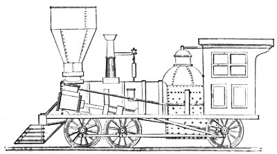
Fig. 6.—Baldwin Six-Wheels-Connected Engine, 1842.
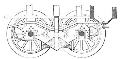
Fig. 7.—Baldwin Flexible-Beam Truck,
1842.—Elevation.
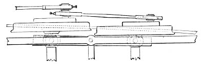
Half Plan.
But, to return to the progress of Mr. Baldwin's locomotive practice.
The geared engine had not proved a success. It was unsatisfactory,
as well to its designer as to the railroad community. The problem of
utilizing more or all of the weight of the engine for adhesion
remained, in Mr. Baldwin's view, yet to be solved. The plan of
coupling four or six wheels had long before been adopted in England,
but on the short curves prevalent on American railroads, he felt
that something more was necessary. The wheels must not only be
coupled, but at the same time must be free to adapt themselves to a
curve. These two conditions were apparently incompatible, and to
reconcile these inconsistencies was the task which Mr. Baldwin set
himself to accomplish. He undertook it, too, at a time when his
business had fallen off greatly and he was involved in the most
serious financial embarrassments. The problem was constantly before
him, and at length, during a sleepless night, its solution flashed
across his mind. The plan so long sought for, and which,
subsequently, more than any other of his improvements or inventions,
contributed to the foundation of his fortune, was his well-known
six-wheels-connected locomotive with the four front drivers combined
in a flexible truck. For this machine Mr. Baldwin secured a patent,
August 25, 1842. Its principal characteristic features are now
matters of history, but they deserve here a brief mention. The
engine was on six wheels, all connected as drivers. The rear wheels
were placed rigidly in the frames, usually behind the
fire-box, with inside bearings. The cylinders were inclined, and
with outside connections. The four remaining wheels had inside
journals running in boxes held by two wide and deep wrought-iron
beams, one on each side. These beams were unconnected, and entirely
independent of each other. The pedestals formed in them were bored
out cylindrically, and into them cylindrical boxes, as patented by
him in 1835, were fitted. The engine-frame on each side was directly
over the beam, and a spherical pin, running down from the frame,
bore in a socket in the beam midway between the two axles. It will
thus be seen that each side-beam independently could turn
horizontally or vertically under the spherical pin, and the
cylindrical boxes could also turn in the pedestals. Hence, in
passing a curve, the middle pair of drivers could move laterally in
one direction—say to the right—while the front pair could move in
the opposite direction, or to the left; the two axles all the while
remaining parallel to each other and to the rear driving-axle. The
operation of these beams was, therefore, like that of the
parallel-ruler. On a straight line the two beams and the two axles
formed a rectangle; on curves, a parallelogram, the angles varying
with the degree of curvature. The coupling-rods were made with
cylindrical brasses, thus forming ball-and-socket joints, to enable
them to accommodate themselves to the lateral movements of the
wheels. Colburn, in his "Locomotive Engineering," remarks of this
arrangement of rods as follows:
"Geometrically, no doubt, this combination of wheels could only
work properly around curves by a lengthening and shortening of
the rods which served to couple the principal pair of
driving-wheels with the hind truck-wheels. But if the
coupling-rods from the principal pair of driving-wheels be five
feet long, and if the beams of the truck-frame be four feet long
(the radius of curve described by the axle-boxes around the
spherical side bearings being two feet), then the total
corresponding lengthening of the coupling-rods, in order to allow
the hind truck-wheels to move one inch to one side, and the front
wheels of the truck one inch to the other side of their
normal position on a straight line, would be
√602+12 - 60 + 24 - √242-12 = 0.0275
inch, or less
than one thirty-second of an inch. And if only one pair of
driving-wheels were thus coupled with a four-wheeled truck, the
total wheel-base being nine feet, the motion permitted by this
slight elongation of the coupling-rods (an elongation provided
for by a trifling slackness in the brasses) would enable three
pairs of wheels to stand without binding in a curve of only one
hundred feet radius."
The first engine of the new plan was finished early in December,
1842, being one of fourteen engines constructed in that year, and
was sent to the Georgia Railroad, on the order of Mr. J. Edgar
Thomson, then Chief Engineer and Superintendent of that line. It
weighed twelve tons, and drew, besides its own weight, two hundred
and fifty tons up a grade of thirty-six feet to the mile.
Other orders soon followed. The new machine was received generally
with great favor. The loads hauled by it exceeded anything so far
known in American railroad practice, and sagacious managers hailed
it as a means of largely reducing operating expenses. On the Central
Railroad of Georgia, one of these twelve-ton engines drew nineteen
eight-wheeled cars, with seven hundred and fifty bales of cotton,
each bale weighing four hundred and fifty pounds, over maximum
grades of thirty feet per mile, and the manager of the road declared
that it could readily take one thousand bales. On the Philadelphia
and Reading Railroad a similar engine of eighteen tons weight drew
one hundred and fifty loaded cars (total weight of cars and lading,
one thousand one hundred and thirty tons) from Schuylkill Haven to
Philadelphia, at a speed of seven miles per hour. The regular load
was one hundred loaded cars, which were hauled at a speed of from
twelve to fifteen miles per hour on a level.
The following extract from a letter, dated August 10, 1844, of Mr.
G. A. Nicolls, then Superintendent of that line, and still connected
with its management, gives the particulars of the performance of
these machines, and shows the estimation in which they were held:
"We have had two of these engines in operation for about four
weeks. Each engine weighs about forty thousand pounds with water
and fuel, equally distributed on six wheels, all of which are
coupled, thus gaining the whole adhesion of the engine's weight.
Their cylinders are fifteen by eighteen inches."
"The daily allotted load of each of these engines is one hundred
coal cars, each loaded with three and six-tenths tons of coal,
and weighing two and fifteen one-hundredths tons each, empty;
making a net weight of three hundred and sixty tons of coal
carried, and a gross weight of train of five hundred and
seventy-five tons, all of two thousand two hundred and forty
pounds."
"This train is hauled over the ninety-four miles of the road,
half of which is level, at the rate of twelve miles per hour; and
with it the engine is able to make fourteen to fifteen miles per
hour on a level."
"Were all the cars on the road of sufficient strength, and making
the trip by daylight, nearly one-half being now performed at
night, I have no doubt of these engines being quite equal to a
load of eight hundred tons gross, as their average daily
performance on any of the levels of our road, some of which are
eight miles long."
"In strength of make, quality of workmanship, finish, and
proportion of parts, I consider them equal to any, and superior
to most, freight engines I have seen. They are remarkably easy on
the rail, either in their vertical or horizontal action, from the
equalization of their weight, and the improved truck
under the forward part of the engine. This latter adapts itself
to all the curves of the road, including some of seven hundred
and sixteen feet radius in the main track, and moves with great
ease around our turning Y curves at Richmond, of about three
hundred feet radius.
"I consider these engines as near perfection, in the arrangement
of their parts, and their general efficiency, as the present
improvements in machinery and the locomotive engine will admit
of. They are saving us thirty per cent, in every trip, on the
former cost of motive or engine power."
But the flexible-beam truck also enabled Mr. Baldwin to meet the
demand for an engine with four drivers connected. Other builders
were making engines with four drivers and a four-wheeled truck, of
the present American standard type. To compete with this design, Mr.
Baldwin modified his six-wheels-connected engine by connecting only
two out of the three pairs of wheels as drivers, making the forward
wheels of smaller diameter as leading wheels, but combining them
with the front drivers in a flexible-beam truck. The first engine on
this plan was sent to the Erie and Kalamazoo Railroad, in October,
1843, and gave great satisfaction. The Superintendent of the road
was enthusiastic in its praise, and wrote to Mr. Baldwin that he
doubted "if anything could be got up which would answer the business
of the road so well." One was also sent to the Utica and Schenectady
Railroad a few weeks later, of which the Superintendent remarked
that "it worked beautifully, and there were not wagons enough to
give it a full load." In this plan the leading wheels were usually
made thirty-six and the drivers fifty-four inches in diameter.
This machine of course came in competition with the eight-wheeled
engine having four drivers, and Mr. Baldwin claimed for his plan a
decided superiority. In each case about two-thirds of the total
weight was carried on the four drivers, and Mr. Baldwin maintained
that his engine, having only six instead of eight wheels, was
simpler and more effective.
At about this period Mr. Baldwin's attention was called by Mr. Levi
Bissell to an "Air Spring" which the latter had devised, and which
it was imagined was destined to be a cheap, effective, and perpetual
spring. The device consisted of a small cylinder placed above the
frame over the axle-box, and having a piston fitted air-tight into
it. The piston-rod was to bear on the axle-box, and the proper
quantity of air was to be pumped into the cylinder above the piston,
and the cylinder then hermetically closed. The piston had a leather
packing which was to be kept moist by some fluid (molasses was
proposed) previously introduced into the cylinder. Mr. Baldwin at
first proposed to equalize the weight between two pairs of drivers
by connecting two air-springs on each side by a pipe, the use of an
equalizing beam being covered by Messrs. Eastwick & Harrison's
patent. The air-springs were found, however, not to work
practically, and were never applied. It may be added that a model of
an equalizing air-spring was exhibited by Mr. Joseph Harrison, Jr.,
at the Franklin Institute, in 1838 or 1839.
With the introduction of the new machine, business began at once to
revive, and the tide of prosperity turned once more in Mr. Baldwin's
favor. Twelve engines were constructed in 1843, all but
four of them of the new pattern; twenty-two engines in 1844, all of
the new pattern; and twenty-seven in 1845. Three of this number were
of the old type, with one pair of drivers, but from that time
forward the old pattern with the single pair of drivers disappeared
from the practice of the establishment, save occasionally for
exceptional purposes.
In 1842, the partnership with Mr. Vail was dissolved, and Mr. Asa
Whitney, who had been Superintendent of the Mohawk and Hudson
Railroad, became a partner with Mr. Baldwin, and the firm continued
as Baldwin & Whitney until 1846, when the latter withdrew to engage
in the manufacture of car-wheels, in which business he is still
concerned as senior member of the firm of A. Whitney & Sons,
Philadelphia.
Mr. Whitney brought to the firm a railroad experience and thorough
business talent. He introduced a system in many details of the
management of the business, which Mr. Baldwin, whose mind was
devoted more exclusively to mechanical subjects, had failed to
establish or wholly ignored. The method at present in use in the
establishment, of giving to each class of locomotives a distinctive
designation, composed of a number and a letter, originated very
shortly after Mr. Whitney's connection with the business. For the
purpose of representing the different designs, sheets with
engravings of locomotives were employed. The sheet showing the
engine with one pair of drivers was marked B; that with two pairs,
C; that with three, D; and that with four, E. Taking its rise from
this circumstance, it became customary to designate as B engines
those with one pair of drivers; as C engines, those with two pairs;
as D engines, those with three pairs; and as E engines, those with
four pairs. Shortly afterwards, a number, indicating the weight in
gross tons, was added. Thus, the 12 D engine was one with three
pairs of drivers, and weighing twelve tons; the 12 C, an engine of
same weight, but with only four wheels connected. Substantially this
system of designating the several sizes and plans has been retained
to the present time. The figures, however, are no longer used to
express the weight, but merely to designate the class.
It will be observed that the classification as thus established
began with the B engines. The letter A was reserved for an engine
intended to run at very high speeds, and so designed that the
driving-wheels should make two revolutions for each reciprocation of
the pistons. This was to be accomplished by means of gearing. The
general plan of the engine was determined in Mr. Baldwin's mind, but
was never carried into execution.
The adoption of the plan of six-wheels-connected engines opened the
way at once to increasing their size. The weight being almost evenly
distributed on six points, heavier machines were admissible, the
weight on any one pair of drivers being little, if any, greater than
had been the practice with the old plan of engine having a single
pair of drivers; Hence engines of eighteen and twenty tons weight
were shortly introduced, and in 1844 three of twenty tons weight,
with cylinders sixteen and one-half inches diameter by eighteen
inches stroke, were constructed for the Western Railroad of
Massachusetts, and six, of eighteen tons weight, with
cylinders fifteen by eighteen, and drivers forty-six inches in
diameter, were built for the Philadelphia and Reading Railroad. It
should be noted that three of these latter engines had iron flues.
This was the first instance in which Mr. Baldwin had employed tubes
of this material. The advantage found to result from the use of iron
tubes, apart from their less cost, was that the tubes and
boiler-shell, being of the same material, expanded and contracted
alike, while in the case of copper tubes the expansion of the metal
by heat varied from that of the boiler-shell, and as a consequence
there was greater liability to leakage at the joints with the
tube-sheets. The opinion prevailed largely at that time that some
advantage resulted in the evaporation of water, owing to the
superiority of copper as a conductor of heat. To determine this
question, an experiment was tried with two of the six engines
referred to above, one of which, the "Ontario," had copper flues,
and another, the "New England," iron flues. In other respects they
were precisely alike. The two engines were run from Richmond to
Mount Carbon, August 27, 1844, each drawing a train of one hundred
and one empty cars, and, returning, from Mount Carbon to Richmond,
on the following day, each with one hundred loaded cars. The
quantity of water evaporated and wood consumed was noted, with the
result shown in the following table:
| |
Up Trip, Aug. 27, 1844. |
Down Trip, Aug. 28, 1844. |
| |
"Ontario." (Copper Flues.) |
"New England." (Iron Flues.) |
"Ontario." (Copper Flues.) |
"New England." (Iron Flues.) |
| Time, |
running |
9h. 7m. |
7h. 41m. |
10h. 44m. |
8h. 19m. |
| " |
standing at stations. |
4h. 2m. |
3h. 7m. |
2h. 12m. |
3h. 8m. |
| Cords of wood burned |
6.68 |
5.50 |
6.94 |
6. |
| Cubic feet of water evaporated |
925.75 |
757.26 |
837.46 |
656.39 |
| Ratio, cubic feet of water to a cord of wood |
138.57 |
137.68 |
120.67 |
109.39 |
The conditions of the experiments not being absolutely the same in
each case, the results could not of course be accepted as entirely
accurate. They seemed to show, however, no considerable difference
in the evaporative efficacy of copper and iron tubes.
The period under consideration was marked also by the introduction
of the French & Baird stack, which proved at once to be one of the
most successful spark-arresters thus far employed, and which was for
years used almost exclusively wherever, as on the cotton-carrying
railroads of the South, a thoroughly effective spark-arrester was
required. This stack was introduced by Mr. Baird, then a foreman in
the Works, who purchased the patent-right of what had been known as
the Grimes stack, and combined with it some of the features of the
stack made by Mr. Richard French, then Master Mechanic of the
Germantown Railroad, together with certain improvements of his own.
The cone over the straight inside pipe was made with volute flanges
on its under side, which gave a rotary motion to the sparks. Around
the cone was a casing about six inches smaller in diameter than the
outside stack. Apertures were cut in the sides of this casing,
through which the sparks in their rotary motion were discharged and
thus fell to the bottom of the space between the straight
inside pipe and the outside stack. The opening in the top of the
stack was fitted with a series of V-shaped iron circles perforated
with numerous holes, thus presenting an enlarged area, through which
the smoke escaped. The patent-right for this stack was subsequently
sold to Messrs. Radley & Hunter, and its essential principle is
still used in the Radley & Hunter stack as at present made.
In 1845, Mr. Baldwin built three locomotives for the Royal Railroad
Committee of Würtemberg. They were of fifteen tons weight, on six
wheels, four of them being sixty inches in diameter and coupled. The
front drivers were combined by the flexible beams into a truck with
the smaller leading wheels. The cylinders were inclined and outside,
and the connecting-rods took hold of a half-crank axle back of the
fire-box. It was specified that these engines should have the
link-motion which had shortly before been introduced in England by
the Stephensons. Mr. Baldwin accordingly applied a link of a
peculiar character to suit his own ideas of the device. The link was
made solid, and of a truncated V-section, and the block was grooved
so as to fit and slide on the outside of the link.
During the year 1845 another important feature in locomotive
construction—the cut-off valve—was added to Mr. Baldwin's
practice. Up to that time the valve-motion had been the two
eccentrics, with the single flat hook for each cylinder. Since 1841
Mr. Baldwin had contemplated the addition of some device allowing
the steam to be used expansively, and he now added the "half-stroke
cut-off." In this device the steam-chest was separated by a
horizontal plate into an upper and a lower compartment. In the upper
compartment, a valve, worked by a separate eccentric, and having a
single opening, admitted steam through a port in this plate to the
lower steam-chamber. The valve-rod of the upper valve terminated in
a notch or hook, which engaged with the upper arm of its rock-shaft.
When thus working, it acted as a cut-off at a fixed part of the
stroke, determined by the setting of the eccentric. This was usually
at half the stroke. When it was desired to dispense with the cut-off
and work steam for the full stroke, the hook of the valve-rod was
lifted from the pin on the upper arm of the rock-shaft by a lever
worked from the footboard, and the valve-rod was held in a notched
rest fastened to the side of the boiler. This left the opening
through the upper valve and the port in the partition plate open for
the free passage of steam throughout the whole stroke. The first
application of the half-stroke cut-off was made on the engine
"Champlain" (20 D), built for the Philadelphia and Reading Railroad
Company, in 1845. It at once became the practice to apply the
cut-off on all passenger engines, while the six- and
eight-wheels-connected freight engines were, with a few exceptions,
built for a time longer with the single valve admitting steam for
the full stroke.
After building, during the years 1843, 1844, and 1845, ten
four-wheels-connected engines on the plan above described, viz., six
wheels in all, the leading wheels and the front drivers being
combined into a truck by the flexible beams, Mr. Baldwin finally
adopted the present design of four drivers and a four-wheeled truck.
Some of his customers who were favorable to the latter plan had
ordered such machines of other builders, and Colonel
Gadsden, President of the South Carolina Railroad Company, called on
him in 1845 to build for that line some passenger engines of this
pattern. He accordingly bought the patent-right for this plan of
engine of Mr. H. R. Campbell, and for the equalizing beams used
between the drivers, of Messrs. Eastwick & Harrison, and delivered
to the South Carolina Railroad Company, in December, 1845, his first
eight-wheeled engine with four drivers and a four-wheeled truck.
This machine had cylinders thirteen and three-quarters by eighteen,
and drivers sixty inches in diameter, with the springs between them
arranged as equalizers. Its weight was fifteen tons. It had the
half-crank axle, the cylinders being inside the frame but outside
the smoke-box. The inside-connected engine, counterweighting being
as yet unknown, was admitted to be steadier in running, and hence
more suitable for passenger service. With the completion of the
first eight-wheeled "C" engine, Mr. Baldwin's feelings underwent a
revulsion in favor of this plan, and his partiality for it became as
great as had been his antipathy before. Commenting on the machine,
he recorded himself as "more pleased with its appearance and action
than any engine he had turned out." In addition to the three engines
of this description for the South Carolina Railroad Company, a
duplicate was sent to the Camden and Amboy Railroad Company, and a
similar but lighter one to the Wilmington and Baltimore Railroad
Company, shortly afterwards. The engine for the Camden and Amboy
Railroad Company, and perhaps the others, had the half-stroke
cut-off.
From that time forward, all of his four-wheels-connected machines
were built on this plan, and the six-wheeled "C" engine was
abandoned, except in the case of one built for the Philadelphia,
Germantown and Norristown Railroad Company in 1846, and this was
afterwards rebuilt into a six-wheels-connected machine. Three
methods of carrying out the general design were, however,
subsequently followed. At first the half-crank was used; then
horizontal cylinders inclosed in the chimney-seat and working a
full-crank-axle, which form of construction had been practiced at
the Lowell Works; and eventually, outside cylinders with outside
connections.
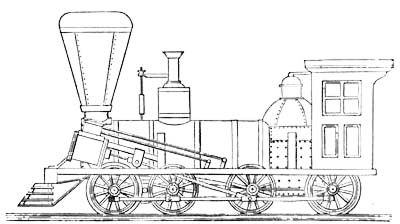
Fig. 8.—Baldwin Eight-Wheels-Connected Engine,
1846.
Meanwhile the flexible truck machine maintained its popularity for
heavy freight service. All the engines thus far built on this plan
had been six-wheeled, some with the rear driving-axle back of the
fire-box, and others with it in front. The next step, following
logically after the adoption of the eight-wheeled "C" engine, was to
increase the size of the freight machine, and distribute the weight
on eight wheels all connected, the two rear pairs being rigid in the
frame, and the two front pairs combined into the flexible-beam
truck. This was first done in 1846, when seventeen engines
on this plan were constructed on one order for the Philadelphia and
Reading Railroad Company. Fifteen of these were of twenty tons
weight, with cylinders fifteen and a half by twenty, and wheels
forty-six inches in diameter; and two of twenty-five tons weight,
with cylinders seventeen and a quarter by eighteen, and drivers
forty-two inches in diameter. These engines were the first ones on
which Mr. Baldwin placed sand-boxes, and they were also the first
built by him with roofs. On all previous engines the footboard had
only been inclosed by a railing. On these engines for the Reading
Railroad, four iron posts were carried up, and a wooden roof
supported by them. The engine-men added curtains at the sides and
front, and Mr. Baldwin on subsequent engines added sides, with sash
and glass. The cab proper, however, was of New England origin, where
the severity of the climate demanded it, and where it had been used
previous to this period.
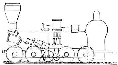
Fig. 9.—Baldwin Engine for Rack-Rail, 1847.
Forty-two engines were completed in 1846, and thirty-nine in 1847.
The only novelty to be noted among them was the engine "M. G.
Bright," built for operating the inclined plane on the Madison and
Indianapolis Railroad. The rise of this incline was one in
seventeen, from the bank of the Ohio River at Madison. The engine
had eight wheels, forty-two inches in diameter, connected, and
worked in the usual manner by outside inclined cylinders, fifteen
and one-half inches diameter by twenty inches stroke. A second pair
of cylinders, seventeen inches in diameter with eighteen inches
stroke of piston, was placed vertically over the boiler, midway
between the furnace and smoke-arch. The connecting-rods worked by
these cylinders connected with cranks on a shaft under the boiler.
This shaft carried a single cog-wheel at its centre, and this
cog-wheel engaged with another of about twice its diameter on a
second shaft adjacent to it and in the same plane. The cog-wheel on
this latter shaft worked in a rack-rail placed in the centre of the
track. The shaft itself had its bearings in the lower ends of two
vertical rods, one on each side of the boiler, and these rods were
united over the boiler by a horizontal bar which was connected by
means of a bent lever and connecting-rod to the piston worked by a
small horizontal cylinder placed on top of the boiler. By means of
this cylinder, the yoke carrying the shaft and cog-wheel could be
depressed and held down so as to engage the cogs with the rack-rail,
or raised out of the way when only the ordinary drivers were
required. This device was designed by Mr. Andrew Cathcart, Master
Mechanic of the Madison and Indianapolis Railroad. A similar
machine, the "John Brough," for the same plane, was built by Mr.
Baldwin in 1850. The incline was worked with a rack-rail and these
engines until it was finally abandoned and a line with easy
gradients substituted.
The use of iron tubes in freight engines grew in favor, and in
October, 1847, Mr. Baldwin noted that he was fitting his
flues with copper ends, "for riveting to the boiler."
The subject of burning coal continued to engage much attention, but
the use of anthracite had not as yet been generally successful. In
October, 1847, the Baltimore and Ohio Railroad Company advertised
for proposals for four engines to burn Cumberland coal, and the
order was taken and filled by Mr. Baldwin with four of his
eight-wheels-connected machines.
The year 1848 showed a falling off in business, and only twenty
engines were turned out. In the following year, however, there was a
rapid recovery, and the production of the works increased to thirty,
followed by thirty-seven in 1850, and fifty in 1851. These engines,
with a few exceptions, were confined to three patterns, the
eight-wheeled four-coupled engine, from twelve to nineteen tons in
weight, for passengers and freight, and the six- and
eight-wheels-connected engine, for freight exclusively, the
six-wheeled machine weighing from twelve to seventeen tons, and the
eight-wheeled, from eighteen to twenty-seven tons. The drivers of
these six- and eight-wheels-connected machines were made generally
forty-two, with occasional variations up to forty-eight, inches in
diameter.
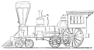
Fig. 10.—Baldwin Fast Passenger Engine, 1848.
The exceptions referred to in the practice of these years were the
fast passenger engines built by Mr. Baldwin during this period.
Early in 1848, the Vermont Central Railroad was approaching
completion, and Governor Paine, the President of the Company,
conceived the idea that the passenger service on the road required
locomotives capable of running at very high velocities. Henry R.
Campbell, Esq., was a contractor in building the line, and was
authorized by Governor Paine to come to Philadelphia and offer Mr.
Baldwin ten thousand dollars for a locomotive which could run with a
passenger train at a speed of sixty miles per hour. Mr. Baldwin at
once undertook to meet these conditions. The work was begun early in
1848, and in March of that year Mr. Baldwin filed a caveat for his
design. The engine was completed in 1849, and was named the
"Governor Paine." It had one pair of driving-wheels six and a half
feet in diameter, placed back of the fire-box. Another pair of
wheels, but smaller and unconnected, was placed directly in front of
the fire-box, and a four-wheeled truck carried the front of the
engine. The cylinders were seventeen and a quarter inches diameter
and twenty inches stroke, and were placed horizontally between the
frames and the boiler, at about the middle of the waist. The
connecting-rods took hold of "half-cranks" inside of the
driving-wheels. The object of placing the cylinders at the middle of
the boiler was to lessen or obviate the lateral motion of the
engine, produced when the cylinders were attached to the
smoke-arch. The bearings on the two rear axles were so contrived
that, by means of a lever, a part of the weight of the engine
usually carried on the wheels in front of the fire-box could be
transferred to the driving-axle. The "Governor Paine" was used for
several years on the Vermont Central Railroad, and then rebuilt into
a four-coupled machine. During its career, it was stated by the
officers of the road that it could be started from a state of rest
and run a mile in forty-three seconds. Three engines on the same
plan, but with cylinders fourteen by twenty, and six-feet
driving-wheels, the "Mifflin," "Blair," and "Indiana," were also
built for the Pennsylvania Railroad Company, in 1849. They weighed
each about forty-seven thousand pounds, distributed as follows:
eighteen thousand on drivers, fourteen thousand on the pair of
wheels in front of the fire-box, and fifteen thousand on the truck.
By applying the lever, the weight on the drivers could be increased
to about twenty-four thousand pounds, the weight on the wheels in
front of the fire-box being correspondingly reduced. A speed of four
miles in three minutes is recorded for them, and upon one occasion
President Taylor was taken in a special train over the road by one
of these machines at a speed of sixty miles an hour. One other
engine of this pattern, the "Susquehanna," was built for the Hudson
River Railroad Company, in 1850. Its cylinders were fifteen inches
diameter by twenty inches stroke, and drivers six feet in diameter.
All these engines, however, were short-lived, and died young, of
insufficient adhesion.
Eight engines with four drivers connected and half-crank-axles, were
built for the New York and Erie Railroad Company in 1849, with
seventeen by twenty inch cylinders; one-half of the number with
six-feet and the rest with five-feet drivers. These machines were
among the last on which the half-crank-axle was used. Thereafter,
outside-connected engines were constructed almost exclusively.
In May, 1848, Mr. Baldwin filed a caveat for a four-cylinder
locomotive, but never carried the design into execution. The first
instance of the use of steel axles in the practice of the
establishment occurred during the same year,—a set being placed as
an experiment under an engine constructed for the Pennsylvania
Railroad Company. In 1850, the old form of dome boiler, which had
characterized the Baldwin engine since 1834, was abandoned, and the
wagon-top form substituted.
The business in 1851 had reached the full capacity of the shop, and
the next year marked the completion of about an equal number of
engines (forty-nine). Contracts for work extended a year ahead, and,
to meet the demand, the facilities in the various departments were
increased, and resulted in the construction of sixty engines in
1853, and sixty-two in 1854.
At the beginning of the latter year, Mr. Matthew Baird, who had been
connected with the works since 1836 as one of its foremen, entered
into partnership with Mr. Baldwin, and the style of the firm was
made M. W. Baldwin & Co.
The only novelty in the general plan of engines during this period
was the addition of the ten-wheeled engine to the patterns of the
establishment. The success of Mr. Baldwin's engines with all six or
eight wheels connected, and the two front pairs combined by
the parallel beams into a flexible truck, had been so marked that it
was natural that he should oppose any other plan for freight
service. The ten-wheeled engine, with six drivers connected, had,
however, now become a competitor. This plan of engine was first
patented by Septimus Norris, of Philadelphia, in 1846, and the
original design was apparently to produce an engine which should
have equal tractive power with the Baldwin six-wheels-connected
machine. This the Norris patent sought to accomplish by proposing an
engine with six drivers connected, and so disposed as to carry
substantially the whole weight, the forward drivers being in advance
of the centre of gravity of the engine, and the truck only serving
as a guide, the front of the engine being connected with it by a
pivot-pin, but without a bearing on the centre-plate. Mr. Norris's
first engine on this plan was tried in April, 1847, and was found
not to pass curves so readily as was expected. As the truck carried
little or no weight, it would not keep the track. The New York and
Erie Railroad Company, of which John Brandt was then Master
Mechanic, shortly afterwards adopted the ten-wheeled engine,
modified in plan so as to carry a part of the weight on the truck.
Mr. Baldwin filled an order for this company, in 1850, of four
eight-wheels-connected engines, and in making the contract he agreed
to substitute a truck for the front pair of wheels if desired after
trial. This, however, he was not called upon to do.
In February, 1852, Mr. J. Edgar Thomson, President of the
Pennsylvania Railroad Company, invited proposals for a number of
freight locomotives of fifty-six thousand pounds weight each. They
were to be adapted to burn bituminous coal, and to have six wheels
connected and a truck in front, which might be either of two or four
wheels. Mr. Baldwin secured the contract, and built twelve engines
of the prescribed dimensions, viz., cylinders eighteen by
twenty-two; drivers forty-four inches diameter, with chilled tires.
Several of these engines were constructed with a single pair of
truck-wheels in front of the drivers, but back of the cylinders. It
was found, however, after the engines were put in service, that the
two truck-wheels carried eighteen thousand or nineteen thousand
pounds, and this was objected to by the company as too great a
weight to be carried on a single pair of wheels. On the rest of the
engines of the order, therefore, a four-wheeled truck in front was
employed.
The ten wheeled engine thereafter assumed a place in the Baldwin
classification. In 1855-56, two of twenty-seven tons weight,
nineteen by twenty-two cylinders, forty-eight inches drivers, were
built for the Portage Railroad, and three for the Pennsylvania
Railroad. In 1855, '56, and '57, fourteen, of the same dimensions,
were built for the Cleveland and Pittsburg Railroad; four for the
Pittsburg, Fort Wayne and Chicago Railroad; and one for the Marietta
and Cincinnati Railroad. In 1858 and '59, one was constructed for
the South Carolina Railroad, of the same size, and six lighter
ten-wheelers, with cylinders fifteen and a half by twenty-two, and
four-feet drivers, and two with cylinders sixteen by twenty-two, and
four-feet drivers, were sent out to railroads in Cuba.
It was some years—not until after 1860, however—before this
pattern of engine wholly superseded in Mr. Baldwin's
practice the old plan of freight engine on six or eight wheels, all
connected.
On three locomotives—the "Clinton," "Athens," and
"Sparta"—completed for the Central Railroad of Georgia in July,
1852, the driving-boxes were made with a slot or cavity in the line
of the vertical bearing on the journal. The object was to produce a
more uniform distribution of the wear over the entire surface of the
bearing. This was the first instance in which this device, which has
since come into general use, was employed in the Works, and the
boxes were so made by direction of Mr. Charles Whiting, then Master
Mechanic of the Central Railroad of Georgia. He subsequently
informed Mr. Baldwin that this method of fitting up driving-boxes
had been in use on the road for several years previous to his
connection with the company. As this device was subsequently made
the subject of a patent by Mr. David Matthew, these facts may not be
without interest.
In 1853, Mr. Charles Ellet, Chief Engineer of the Virginia Central
Railroad, laid a temporary track across the Blue Ridge, at Rock Fish
Gap, for use during the construction of a tunnel through the
mountain. This track was twelve thousand five hundred feet in length
on the eastern slope, ascending in that distance six hundred and ten
feet, or at the average rate of one in twenty and a half feet. The
maximum grade was calculated for two hundred and ninety-six feet per
mile, and prevailed for half a mile. It was found, however, in fact,
that the grade in places exceeded three hundred feet per mile. The
shortest radius of curvature was two hundred and thirty-eight feet.
On the western slope, which was ten thousand six hundred and fifty
feet in length, the maximum grade was two hundred and eighty feet
per mile, and the ruling radius of curvature three hundred feet.
This track was worked by two of the Baldwin six-wheels-connected
flexible-beam truck locomotives constructed in 1853-54. From a
description of this track, and the mode of working it, published by
Mr. Ellet in 1856, the following is extracted:
"The locomotives mainly relied on for this severe duty were
designed and constructed by the firm of M. W. Baldwin & Company,
of Philadelphia. The slight modifications introduced at the
instance of the writer to adapt them better to the particular
service to be performed in crossing the Blue Ridge, did not touch
the working proportions or principle of the engines, the merits
of which are due to the patentee, M. W. Baldwin, Esq.
"These engines are mounted on six wheels, all of which are
drivers, and coupled, and forty-two inches diameter. The wheels
are set very close, so that the distance between the extreme
points of contact of the wheels and the rail, of the front and
rear drivers, is nine feet four inches. This closeness of the
wheels, of course, greatly reduces the difficulty of turning the
short curves of the road. The diameter of the cylinders is
sixteen and a half inches, and the length of the stroke twenty
inches. To increase the adhesion, and at the same time avoid the
resistance of a tender, the engine carries its tank upon the
boiler, and the footboard is lengthened out and provided with
suspended side-boxes, where a supply of fuel may be stored. By
this means the weight of wood and water, instead of abstracting
from the effective power of the engine, contributes to its
adhesion and consequent ability to climb the mountain. The total
weight of these engines is fifty-five thousand pounds, or
twenty-seven and a half tons, when the boiler and tank are
supplied with water, and fuel enough for a trip of eight miles is
on board. The capacity of the tank is sufficient to hold one
hundred cubic feet of water, and it has storage-room on top for
one hundred cubic feet of wood, in addition to what may be
carried in the side-boxes and on the footboard.
"To enable the engines better to adapt themselves to the
flexures of the road, the front and middle pairs of drivers are
held in position by wrought-iron beams, having cylindrical boxes
in each end for the journal-bearings, which beams vibrate on
spherical pins fixed in the frame of the engine on each side, and
resting on the centres of the beams. The object of this
arrangement is to form a truck, somewhat flexible, which enables
the drivers more readily to traverse the curves of the road.
"The writer has never permitted the power of the engines on this
mountain road to be fully tested. The object has been to work the
line regularly, economically, and, above all, safely; and these
conditions are incompatible with experimental loads subjecting
the machinery to severe strains. The regular daily service of
each of the engines is to make four trips, of eight miles, over
the mountain, drawing one eight-wheel baggage car, together with
two eight-wheel passenger cars, in each direction.
"In conveying freight, the regular train on the mountain is three
of the eight-wheel house-cars, fully loaded, or four of them when
empty or partly loaded.
"These three cars, when full, weigh, with their loads, from forty
to forty-three tons. Sometimes, though rarely, when the business
has been unusually heavy, the loads have exceeded fifty tons.
"With such trains the engines are stopped on the track, ascending
or descending, and are started again, on the steepest grades, at
the discretion of the engineer.
"Water, for the supply of the engines, has been found difficult
to obtain on the mountain; and, since the road was constructed, a
tank has been established on the eastern slope, where the
ascending engines stop daily on a grade of two hundred and eighty
feet per mile, and are there held by the brakes while the tank is
being filled, and started again at the signal and without any
difficulty.
"The ordinary speed of the engines, when loaded, is seven and a
half miles an hour on the ascending grades, and from five and a
half to six miles an hour on the descent.
"When the road was first opened, it speedily appeared that the
difference of forty-three feet on the western side, and
fifty-eight feet on the eastern side, between the grades on
curves of three hundred feet radii and those on straight lines,
was not sufficient to compensate for the increased traction due
to such curvature. The velocity, with a constant supply of steam,
was promptly retarded on passing from a straight line to a curve,
and promptly accelerated again on passing from the curve to the
straight line. But, after a little experience in the working of
the road, it was found advisable to supply a small amount of
grease to the flange of the engine by means of a sponge,
saturated with oil, which, when needed, is kept in contact with
the wheel by a spring. Since the use of the oil was introduced,
the difficulty of turning the curves has been so far diminished,
that it is no longer possible to determine whether grades of two
hundred and thirty-seven and six-tenths feet per mile on curves
of three hundred feet radius, or grades of two hundred and
ninety-six feet per mile on straight lines, are traversed most
rapidly by the engine.
"When the track is in good condition, the brakes of only two of
the cars possess sufficient power to control and regulate the
movement of the train,—that is to say, they will hold back the
two cars and the engine. When there are three or more cars in the
train, the brakes on the cars, of course, command the train so
much the more easily.
"But the safety of the train is not dependent on the brakes of
the cars. There is also a valve or air-cock in the steam-chest,
under the control of the engineer. This air-cock forms an
independent brake, exclusively at the command of the engineer,
and which can always be applied when the engine itself is in
working order. The action of this power may be made ever so
gradual, either slightly relieving the duty of the brakes on the
cars, or bringing into play the entire power of the engine. The
train is thus held in complete command."
The Mountain Top Track, it may be added, was worked successfully for
several years, by the engines described in the above extract, until
it was abandoned on the completion of the tunnel. The exceptionally
steep grades and short curves which characterized the line,
afforded a complete and satisfactory test of the adaptation of these
machines to such peculiar service.
But the period now under consideration was marked by another, and a
most important, step in the progress of American locomotive
practice. We refer to the introduction of the link-motion. Although
this device was first employed by William T. James, of New York, in
1832, and eleven years later by the Stephensons, in England, and was
by them applied thenceforward on their engines, it was not until
1849 that it was adopted in this country. In that year Mr. Thomas
Rogers, of the Rogers Locomotive and Machine Company, introduced it
in his practice. Other builders, however, strenuously resisted the
innovation, and none more so than Mr. Baldwin. The theoretical
objections which confessedly apply to the device, but which
practically have been proved to be unimportant, were urged from the
first by Mr. Baldwin as arguments against its use. The strong claim
of the advocates of the link-motion, that it gave a means of cutting
off steam at any point of the stroke, could not be gainsaid, and
this was admitted to be a consideration of the first importance.
This very circumstance undoubtedly turned Mr. Baldwin's attention to
the subject of methods for cutting off steam, and one of the first
results was his "Variable Cut-off," patented April 27, 1852. This
device consisted of two valves, the upper sliding upon the lower,
and worked by an eccentric and rock-shaft in the usual manner. The
lower valve fitted steam-tight to the sides of the steam-chest and
the under surface of the upper valve. When the piston reached each
end of its stroke, the full pressure of steam from the boiler was
admitted around the upper valve, and transferred the lower valve
instantaneously from one end of the steam-chest to the other. The
openings through the two valves were so arranged that steam was
admitted to the cylinder only for a part of the stroke. The effect
was, therefore, to cut off steam at a given point, and to open the
induction and exhaust ports substantially at the same instant and to
their full extent. The exhaust port, in addition, remained fully
open while the induction port was gradually closing, and after it
had entirely closed. Although this device was never put in use, it
may be noted in passing that it contained substantially the
principle of the steam-pump, as since patented and constructed.
Early in 1853, Mr. Baldwin abandoned the half-stroke cut-off,
previously described, and which he had been using since 1845, and
adopted the variable cut-off, which was already employed by other
builders. One of his letters, written in January, 1853, states his
position, as follows:
"I shall put on an improvement in the shape of a variable
cut-off, which can be operated by the engineer while the machine
is running, and which will cut off anywhere from six to twelve
inches, according to the load and amount of steam wanted, and
this without the link-motion, which I could never be entirely
satisfied with. I still have the independent cut-off, and the
additional machinery to make it variable will be simple and not
liable to be deranged."
This form of cut-off was a separate valve, sliding on a partition
plate between it and the main steam-valve, and worked by an
independent eccentric and rock-shaft. The upper arm of the
rock-shaft was curved so as to form a radius-arm, on which
a sliding-block, forming the termination of the upper valve-rod,
could be adjusted and held at varying distances from the axis, thus
producing a variable travel of the upper valve. This device did not
give an absolutely perfect cut-off, as it was not operative in
backward gear, but when running forward it would cut-off with great
accuracy at any point of the stroke, was quick in its movement, and
economical in the consumption of fuel.
After a short experience with this arrangement of the cut-off, the
partition plate was omitted, and the upper valve was made to slide
directly on the lower. This was eventually found objectionable,
however, as the lower valve would soon cut a hollow in the
valve-face. Several unsuccessful attempts were made to remedy this
defect, by making the lower valve of brass, with long bearings, and
making the valve-face of the cylinder of hardened steel; finally,
however, the plan of one valve on the other was abandoned, and
recourse was again had to an interposed partition plate, as in the
original half-stroke cut-off.
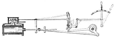
Fig. 11.—Variable Cut-off Adjustment.
Mr. Baldwin did not adopt this form of cut-off without some
modification of his own, and the modification in this instance
consisted of a peculiar device, patented September 13, 1853, for
raising and lowering the block on the radius-arm. A quadrant was
placed so that its circumference bore nearly against a curved arm
projecting down from the sliding-block, and which curved in the
reverse direction from the quadrant. Two steel straps side by side
were interposed between the quadrant and this curved arm. One of the
straps was connected to the lower end of the quadrant and the upper
end of the curved arm; the other, to the upper end of the quadrant
and the lower end of the curved arm. The effect was the same as if
the quadrant and arm geared into each other in any position by
teeth, and theoretically the block was kept steady in whatever
position placed on the radius-arm of the rock-shaft. This was the
object sought to be accomplished, and was stated in the
specification of the patent as follows:
"The principle of varying the cut-off by means of a vibrating arm
and sliding pivot-block has long been known, but the contrivances
for changing the position of the block upon the arm have been
very defective. The radius of motion of the link by which the
sliding-block is changed on the arm, and the radius of motion of
that part of the vibrating arm on which the block is placed,
have, in this kind of valve gear, as heretofore constructed, been
different, which produced a continual rubbing of the
sliding-block upon the arm while the arm is vibrating; and as the
block for the greater part of the time occupies one position on
the arm, and only has to be moved toward either extremity
occasionally, that part of the arm on which the block is most
used soon becomes so worn that the block is loose, and jars."
This method of varying the cut-off was first applied on the engine
"Belle," delivered to the Pennsylvania Railroad Company, December
6, 1854, and thereafter was for some time employed by Mr.
Baldwin. It was found, however, in practice, that the steel straps
would stretch sufficiently to allow them to buckle and break, and
hence they were soon abandoned, and chains substituted between the
quadrant and curved arm of the sliding-block. These chains in turn
proved little better, as they lengthened, allowing lost motion, or
broke altogether, so that eventually the quadrant was wholly
abandoned, and recourse was finally had to the lever and link for
raising and lowering the sliding-block. As thus arranged, the
cut-off was substantially what was known as the "Cuyahoga cut-off,"
as introduced by Mr. Ethan Rogers, of the Cuyahoga Works, Cleveland,
Ohio, except that Mr. Baldwin used a partition plate between the
upper and the lower valve.
But while Mr. Baldwin, in common with many other builders, was thus
resolutely opposing the link-motion, it was nevertheless rapidly
gaining favor with railroad managers. Engineers and master mechanics
were everywhere learning to admire its simplicity, and were
manifesting an enthusiastic preference for engines so constructed.
At length, therefore, he was forced to succumb; and the link was
applied to the "Pennsylvania," one of two engines completed for the
Central Railroad of Georgia, in February, 1854. The other engine of
the order, the "New Hampshire," had the variable cut-off, and Mr.
Baldwin, while yielding to the demand in the former engine, was
undoubtedly sanguine that the working of the latter would
demonstrate the inferiority of the new device. In this, however, he
was disappointed, for in the following year the same company ordered
three more engines, on which they specified the link-motion. In
1856, seventeen engines for nine different companies had this form
of valve gear, and its use was thus incorporated in his practice. It
was not, however, until 1857 that he was induced to adopt it
exclusively. This step was forced upon him, at that time, by the
report of Mr. Parry, then Superintendent of the Works (now a member
of the present firm), who, on returning from an extended tour in the
South, brought back the intelligence that the link-motion was
everywhere preferred, and that the Baldwin engines were losing
ground rapidly, in consequence of their lack of this feature. Mr.
Baldwin's characteristic reply was, "Then they shall have
link-motion hereafter." And thenceforth the independent cut-off
gradually disappeared, and the link reigned in its stead.
February 14, 1854, Mr. Baldwin and Mr. David Clark, Master Mechanic
of the Mine Hill Railroad, took out conjointly a patent for a
feed-water heater, placed at the base of a locomotive chimney, and
consisting of one large vertical flue, surrounded by a number of
smaller ones. The exhaust steam was discharged from the nozzles
through the large central flue, creating a draft of the products of
combustion through the smaller surrounding flues. The pumps forced
the feed-water into the chamber around these flues, whence it passed
to the boiler by a pipe from the back of the stack. This heater was
applied on several engines for the Mine Hill Railroad, and on a few
for other roads; but its use was exceptional, and lasted only for a
year or two.
In December of the same year, Mr. Baldwin filed a caveat for a
variable exhaust, operated automatically, by the pressure of steam,
so as to close when the pressure was lowest in the boiler,
and open with the increase of pressure. The device was never put in
service.
The use of coal, both bituminous and anthracite, as a fuel for
locomotives, had by this time become a practical success. The
economical combustion of bituminous coal, however, engaged
considerable attention. It was felt that much remained to be
accomplished in consuming the smoke and deriving the maximum of
useful effect from the fuel. Mr. Baird, who was now associated with
Mr. Baldwin in the management of the business, made this matter a
subject of careful study and investigation. An experiment was
conducted under his direction, by placing a sheet-iron deflector in
the fire-box of an engine on the Germantown and Norristown Railroad.
The success of the trial was such as to show conclusively that a
more complete combustion resulted. As, however, a deflector formed
by a single plate of iron would soon be destroyed by the action of
the fire, Mr. Baird proposed to use a water-leg projecting upward
and backward from the front of the fire-box under the flues.
Drawings and a model of the device were prepared, with a view of
patenting it, but subsequently the intention was abandoned, Mr.
Baird concluding that a fire-brick arch as a deflector to accomplish
the same object was preferable. This was accordingly tried on two
locomotives built for the Pennsylvania Railroad Company in 1854, and
was found so valuable an appliance that its use was at once
established, and it was put on a number of engines built for
railroads in Cuba and elsewhere. For several years the fire-bricks
were supported on side plugs; but in 1858, in the "Media," built for
the West Chester and Philadelphia Railroad Company, water-pipes
extending from the crown obliquely downward and curving to the sides
of the fire-box at the bottom, were successfully used for the
purpose.
The adoption of the link-motion may be regarded as the dividing line
between the present and the early and transitional stage of
locomotive practice. Changes since that event have been principally
in matters of detail, but it is the gradual perfection of these
details which has made the locomotive the symmetrical, efficient,
and wonderfully complete piece of mechanism it is to-day. In
perfecting these minutiæ, the Baldwin Locomotive Works has borne its
part, and it only remains to state briefly its contributions in this
direction.
The production of the establishment during the six years from 1855
to 1860, inclusive, was as follows: forty-seven engines in 1855;
fifty-nine in 1856; sixty-six in 1857; thirty-three in 1858; seventy
in 1859; and eighty-three in 1860. The greater number of these were
of the ordinary type, four drivers coupled, and a four-wheeled
truck, and varying in weight from fifteen ton engines, with
cylinders twelve by twenty-two, to twenty-seven ton engines, with
cylinders sixteen by twenty-four. A few ten-wheeled engines were
built, as has been previously noted, and the remainder were the
Baldwin flexible-truck six- and eight-wheels-connected engines. The
demand for these, however, was now rapidly falling off, the
ten-wheeled and heavy "C" engines taking their place, and by 1859
they ceased to be built, save in exceptional cases, as for some
foreign roads, from which orders for this pattern were still
occasionally received.
A few novelties characterizing the engines of this period may be
mentioned. Several engines built in 1855 had cross-flues
placed in the fire-box, under the crown, in order to increase the
heating surface. This feature, however, was found impracticable, and
was soon abandoned. The intense heat to which the flues were exposed
converted the water contained in them into highly superheated steam,
which would force its way out through the water around the fire-box
with violent ebullitions. Four engines were built for the
Pennsylvania Railroad Company, in 1856-57, with straight boilers and
two domes. The "Delano" grate, by means of which the coal was forced
into the fire-box from below, was applied on four ten-wheeled
engines for the Cleveland and Pittsburg Railroad, in 1857. In 1859,
several engines were built with the form of boiler introduced on the
Cumberland Valley Railroad in 1851 by Mr. A. F. Smith, and which
consisted of a combustion-chamber in the waist of the boiler, next
the fire-box. This form of boiler was for some years thereafter
largely used in engines for soft coal. It was at first constructed
with the "water-leg," which was a vertical water-space, connecting
the top and bottom sheets of the combustion-chamber, but eventually
this feature was omitted, and an unobstructed combustion-chamber
employed. Several engines were built for the Philadelphia,
Wilmington and Baltimore Railroad Company in 1859, and thereafter,
with the "Dimpfel" boiler, in which the tubes contain water, and,
starting downward from the crown-sheet, are curved to the
horizontal, and terminate in a narrow water-space next the
smoke-box. The whole waist of the boiler, therefore, forms a
combustion-chamber, and the heat and gases, after passing for their
whole length along and around the tubes, emerge into the lower part
of the smoke-box.
In 1860, an engine was built for the Mine Hill Railroad, with boiler
of a peculiar form. The top sheets sloped upward from both ends
toward the centre, thus making a raised part or hump in the centre.
The engine was designed to work on heavy grades, and the object
sought by Mr. Wilder, the Superintendent of the Mine Hill Railroad,
was to have the water always at the same height in the space from
which steam was drawn, whether going up or down grade.
All these experiments are indicative of the interest then prevailing
upon the subject of coal-burning. The result of experience and study
had meantime satisfied Mr. Baldwin that to burn soft coal
successfully required no peculiar devices; that the ordinary form of
boiler, with plain fire-box, was right, with perhaps the addition of
a fire-brick deflector; and that the secret of the economical and
successful use of coal was in the mode of firing, rather than in a
different form of furnace.
The year 1861 witnessed a marked falling off in the production. The
breaking out of the war at first unsettled business, and by many it
was thought that railroad traffic would be so largely reduced that
the demand for locomotives must cease altogether. A large number of
hands were discharged from the works, and only forty locomotives
were turned out during the year. It was even seriously contemplated
to turn the resources of the establishment to the manufacture of
shot and shell, and other munitions of war, the belief being
entertained that the building of locomotives would have to be
altogether suspended. So far, however, was this from being the case,
that, after the first excitement had subsided, it was found
that the demand for transportation by the general government, and by
the branches of trade and production created by the war, was likely
to tax the carrying capacity of the principal Northern railroads to
the fullest extent. The government itself became a large purchaser
of locomotives, and it is noticeable, as indicating the increase of
travel and freight transportation, that heavier machines than had
ever before been built became the rule. Seventy-five engines were
sent from the works in 1862; ninety-six in 1863; one hundred and
thirty in 1864; and one hundred and fifteen in 1865. During two
years of this period, from May, 1862, to June, 1864, thirty-three
engines were built for the United States Military Railroads. The
demand from the various coal-carrying roads in Pennsylvania and
vicinity was particularly active, and large numbers of ten-wheeled
engines, and of the heaviest eight-wheeled four-coupled engines,
were built. Of the latter class, the majority were with fifteen and
sixteen inch cylinders, and of the former, seventeen and eighteen
inch cylinders.
The introduction of several important features in construction marks
this period. Early in 1861, four eighteen inch cylinder freight
locomotives, with six coupled wheels, fifty-two inches in diameter,
and a Bissell pony-truck with radius-bar in front, were sent to the
Louisville and Nashville Railroad Company. This was the first
instance of the use of the Bissell truck in the Baldwin Works. These
engines, however, were not of the regular "Mogul" type, as they were
only modifications of the ten-wheeler, the drivers retaining the
same position, well back, and a pair of pony-wheels on the Bissell
plan taking the place of the ordinary four-wheeled truck. Other
engines of the same pattern, but with eighteen and one-half inch
cylinders, were built in 1862-63, for the same company, and for the
Don Pedro II. Railway of Brazil.
The introduction of steel in locomotive-construction was a
distinguishing feature of the period. Steel tires were first used in
the works in 1863, on some engines for the Don Pedro II. Railway of
South America. Their general adoption on American railroads followed
slowly. No tires of this material were then made in this country,
and it was objected to their use that, as it took from sixty to
ninety days to import them, an engine, in case of a breakage of one
of its tires, might be laid up useless for several months. To
obviate this objection, M. W. Baldwin & Co. imported five hundred
steel tires, most of which were kept in stock, from which to fill
orders.
Steel fire-boxes were first built for some engines for the
Pennsylvania Railroad Company in 1861. English steel, of a high
temper, was used, and at the first attempt the fire-boxes cracked in
fitting them in the boilers, and it became necessary to take them
out and substitute copper. American homogeneous cast-steel was then
tried on engines 231 and 232, completed for the Pennsylvania
Railroad in January, 1862, and it was found to work successfully.
The fire-boxes of nearly all engines thereafter built for that road
were of this material, and in 1866 its use for the purpose became
general. It may be added that while all steel sheets for fire-boxes
or boilers are required to be thoroughly annealed before delivery,
those which are flanged or worked in the process of
boiler-construction are a second time annealed before riveting.
Another feature of construction, gradually adopted, was the
placing of the cylinders horizontally. This was first done in the
case of an outside-connected engine, the "Ocmulgee," which was sent
to the Southwestern Railroad Company of Georgia in January, 1858.
This engine had a square smoke-box, and the cylinders were bolted
horizontally to its sides. The plan of casting the cylinder and
half-saddle in one piece and fitting it to the round smoke-box was
introduced by Mr. Baldwin, and grew naturally out of his original
method of construction. Mr. Baldwin was the first American builder
to use an outside cylinder, and he made it for his early engines
with a circular flange cast to it, by which it could be bolted to
the boiler. The cylinders were gradually brought lower, and at a
less angle, and the flanges prolonged and enlarged. In 1852, three
six-wheels-connected engines, for the Mine Hill Railroad Company,
were built with the cylinder flanges brought around under the
smoke-box until they nearly met, the space between them being filled
with a spark-box. This was practically equivalent to making the
cylinder and half-saddle in one casting. Subsequently, on other
engines on which the spark-box was not used, the half-saddles were
cast so as almost to meet under the smoke-box, and, after the
cylinders were adjusted in position, wedges were fitted in the
interstices and the saddles bolted together. It was finally
discovered that the faces of the two half-saddles might be planed
and finished so that they could be bolted together and bring the
cylinders accurately in position, thus avoiding the troublesome and
tedious job of adjusting them by chipping and fitting to the boiler
and frames. With this method of construction, the cylinders were
placed at a less and less angle, until at length the truck-wheels
were spread sufficiently, on all new or modified classes of
locomotives in the Baldwin list, to admit of the cylinders being
hung horizontally, as is the present almost universal American
practice. By the year 1865, horizontal cylinders were made in all
cases where the patterns would allow it. The advantages of this
arrangement are manifestly in the interest of simplicity and
economy, as the cylinders are thus rights or lefts,
indiscriminately, and a single pattern answers for either side.
A distinguishing feature in the method of construction which
characterizes these Works, is the extensive use of a system of
standard gauges and templets, to which all work admitting of this
process is required to be made. The importance of this arrangement,
in securing absolute uniformity of essential parts in all engines of
the same class, is manifest, and with the increased production since
1861 it became a necessity as well as a decided advantage. It has
already been noted that as early as 1839 Mr. Baldwin felt the
importance of making all like parts of similar engines absolutely
uniform and interchangeable. It was not attempted to accomplish this
object, however, by means of a complete system of standard gauges,
until many years later. In 1861 a beginning was made of organizing
all the departments of manufacture upon this basis, and from it has
since grown an elaborate and perfected system, embracing all the
essential details of construction. An independent department of the
Works, having a separate foreman and an adequate force of skilled
workmen, with special tools adapted to the purpose, is organized as
the Department of Standard Gauges. A system of standard
gauges and templets for every description of work to be done, is
made and kept by this department. The original templets are kept as
"standards," and are never used on the work itself, but from them
exact duplicates are made, which are issued to the foremen of the
various departments, and to which all work is required to conform.
The working gauges are compared with the standards at regular
intervals, and absolute uniformity is thus maintained. The system is
carried into every possible important detail. Frames are planed and
slotted to gauges, and drilled to steel bushed templets. Cylinders
are bored and planed, and steam-ports, with valves and steam-chests,
finished and fitted, to gauges. Tires are bored, centres turned,
axles finished, and crossheads, guides, guide-bearers, pistons,
connecting- and parallel-rods planed, slotted, or finished, by the
same method. Every bolt about the engine is made to a gauge, and
every hole drilled and reamed to a templet. The result of the system
is an absolute uniformity and interchangeableness of parts in
engines of the same class, insuring to the purchaser the minimum
cost of repairs, and rendering possible, by the application of this
method, the large production which these Works have accomplished.
Thus had been developed and perfected the various essential details
of existing locomotive practice, when Mr. Baldwin died, September 7,
1866. He had been permitted, in a life of unusual activity and
energy, to witness the rise and wonderful increase of a material
interest which had become the distinguishing feature of the century.
He had done much, by his own mechanical skill and inventive genius,
to contribute to the development of that interest. His name was as
"familiar as household words" wherever on the American continent the
locomotive had penetrated. An ordinary ambition might well have been
satisfied with this achievement. But Mr. Baldwin's claim to the
remembrance of his fellow-men rests not alone on the results of his
mechanical labors. A merely technical history, such as this, is not
the place to do justice to his memory as a man, as a Christian, and
as a philanthropist; yet the record would be manifestly imperfect,
and would fail properly to reflect the sentiments of his business
associates who so long knew him in all relations of life, were no
reference made to his many virtues and noble traits of character.
Mr. Baldwin was a man of sterling integrity and singular
conscientiousness. To do right, absolutely and unreservedly, in all
his relations with men, was an instinctive rule of his nature. His
heroic struggle to meet every dollar of his liabilities, principal
and interest, after his failure, consequent upon the general
financial crash in 1837, constitutes a chapter of personal
self-denial and determined effort which is seldom paralleled in the
annals of commercial experience. When most men would have felt that
an equitable compromise with creditors was all that could be
demanded in view of the general financial embarrassment, Mr. Baldwin
insisted upon paying all claims in full, and succeeded in doing so
only after nearly five years of unremitting industry, close economy,
and absolute personal sacrifices. As a philanthropist and a sincere
and earnest Christian, zealous in every good work, his memory is
cherished by many to whom his contributions to locomotive
improvement are comparatively unknown. From the earliest years of
his business life the practice of systematic benevolence was
made a duty and a pleasure. His liberality constantly increased with
his means. Indeed, he would unhesitatingly give his notes, in large
sums, for charitable purposes, when money was absolutely wanted to
carry on his business. Apart from the thousands which he expended in
private charities, and of which, of course, little can be known,
Philadelphia contains many monuments of his munificence. Early
taking a deep interest in all Christian effort, his contributions to
missionary enterprise and church extension were on the grandest
scale, and grew with increasing wealth. Numerous church edifices in
this city, of the denomination to which he belonged, owe their
existence largely to his liberality, and two at least were projected
and built by him entirely at his own cost. In his mental character,
Mr. Baldwin was a man of remarkable firmness of purpose. This trait
was strongly shown during his mechanical career, in the persistency
with which he would work at a new improvement or resist an
innovation. If he was led sometimes to assume an attitude of
antagonism to features of locomotive-construction which
after-experience showed to be valuable,—and a desire for historical
accuracy has required the mention, in previous pages, of several
instances of this kind,—it is at least certain that his opposition
was based upon a conscientious belief in the mechanical impolicy of
the proposed changes.
After the death of Mr. Baldwin, the business was reorganized, in
1867, under the title of "The Baldwin Locomotive Works," M. Baird &
Co., Proprietors. Messrs. George Burnham and Charles T. Parry, who
had been connected with the establishment from an early period, the
former in charge of the finances, and the latter as General
Superintendent, were associated with Mr. Baird in the copartnership.
Three years later, Messrs. Edward H. Williams, William P. Henszey,
and Edward Longstreth became members of the firm. Mr. Williams had
been connected with railway management on various lines since 1850.
Mr. Henszey had been Mechanical Engineer, and Mr. Longstreth the
General Superintendent of the Works for several years previously.
The production of the Baldwin Locomotive Works from 1866 to 1871,
both years inclusive, has been as follows:
| 1866, one hundred and eighteen |
locomotives. |
| 1867, one hundred and twenty-seven |
" |
| 1868, one hundred and twenty-four |
" |
| 1869, two hundred and thirty-five |
" |
| 1870, two hundred and eighty |
" |
| 1871, three hundred and thirty-one |
" |
In July, 1866, the engine "Consolidation" was built for the Lehigh
Valley Railroad, on the plan and specification furnished by Mr.
Alexander Mitchell, Master Mechanic of the Mahanoy Division of that
railroad. This engine was intended for working the Mahanoy plane,
which rises at the rate of one hundred and thirty-three feet per
mile. The "Consolidation" had cylinders twenty by twenty-four, four
pairs of drivers connected, forty-eight inches in diameter, and a
Bissell pony-truck in front, equalized with the front drivers. The
weight of the engine, in working order, was ninety thousand pounds,
of which all but about ten thousand pounds was on the
drivers. This engine has constituted the first of a class to which
it has given its name, and over thirty "Consolidation" engines have
since been constructed.
A class of engines known as "Moguls," with three pairs of drivers
connected and a swing pony-truck in front equalized with the front
drivers, took its rise in the practice of this establishment from
the "E. A. Douglas," built for the Thomas Iron Company in 1867.
These engines are fully illustrated in the Catalogue. Several sizes
of "Moguls" have been built, but principally with cylinders sixteen,
seventeen, and eighteen inches in diameter, respectively, and
twenty-two or twenty-four inches stroke, and with drivers from
forty-four to fifty-seven inches in diameter. This plan of engine
has rapidly grown in favor for freight service on heavy grades or
where maximum loads are to be moved, and has been adopted by several
leading lines. Utilizing, as it does, nearly the entire weight of
the engine for adhesion, the main and back pairs of drivers being
equalized together, as also the front drivers and the pony-wheels,
and the construction of the engine with swing-truck and one pair of
drivers without flanges allowing it to pass short curves without
difficulty, the "Mogul" is generally accepted as a type of engine
especially adapted to the economical working of heavy freight
traffic.
In 1867, on a number of eight-wheeled four-coupled engines, for the
Pennsylvania Railroad, the four-wheeled swing-bolster-truck was
first applied, and thereafter nearly all the engines built in the
establishment with a two- or four-wheeled truck in front have been so
constructed. The two-wheeled or "pony" truck has been built both on
the Bissell plan, with double inclined slides, and with the ordinary
swing-bolster, and in both cases with the radius-bar pivoting from a
point about four feet back from the centre of the truck. The
four-wheeled truck has been made with swing-bolster exclusively and
without the radius-bar. Of the engines above referred to as the
first on which the swing-bolster-truck was applied, four were for
express passenger service, with drivers sixty-seven inches in
diameter, and cylinders seventeen by twenty-four. One of them,
placed on the road September 9, 1867, was in constant service until
May 14, 1871, without ever being off its wheels for repairs, making
a total mileage of one hundred and fifty-three thousand two hundred
and eighty miles. All of these engines have their driving-wheels
spread eight and one-half feet between centres, thus increasing the
adhesive weight, and with the use of the swing-truck they have been
found to work readily on the shortest curves on the road.
Steel flues were put in three ten-wheeled freight engines, numbers
211, 338, and 368, completed for the Pennsylvania Railroad in
August, 1868, and up to the present time have been in constant use
without requiring renewal. Flues of the same material have also been
used in a number of engines for South American railroads. Experience
with tubes of this metal, however, has not yet been sufficiently
extended to show whether they give any advantages commensurate with
their increased cost over iron.
Steel boilers have been built, to a considerable extent, for the
Pennsylvania, Lehigh Valley, Central of New Jersey, and some other
railroad companies, since 1868, and with good results thus
far. Where this metal is used for boilers, the plates may be
somewhat thinner than if of iron, but at the same time, as shown by
careful tests, giving a greater tensile strength. The thoroughly
homogeneous character of the steel boiler-plate made in this country
recommends it strongly for the purpose.
In 1854, four engines for the Pennsylvania Railroad Company, the
"Tiger," "Leopard," "Hornet," and "Wasp," were built with straight
boilers and two domes each, and in 1866 this method of construction
was revived. Since that date, the practice of the establishment has
included both the wagon-top boiler with single dome, and the
straight boiler with two domes. When the straight boiler is used,
the waist is made about two inches larger in diameter than that of
the wagon-top form. About equal space for water and steam is thus
given in either case, and, as the number of flues is the same in
both forms, more room for the circulation of water between the flues
is afforded in the straight boiler, on account of its larger
diameter, than in the wagon-top shape. The preference of many
railroad officers for the straight boiler is based on the
consideration of the greater strength which this form confessedly
gives. The top and side lines being of equal length, the expansion
is uniform throughout, and hence there is less liability to leak on
the sides, at the junction of the waist and fire-box. The
throttle-valve is placed in the forward dome, from which point drier
steam can be drawn than from over the crown-sheet, where the most
violent ebullitions in a boiler occur. For these reasons, as well as
on account of its greater symmetry, the straight boiler with two
domes is largely accepted as preferable to the wagon-top form.
Early in 1870, the success of the various narrow-gauge railway
enterprises in Europe aroused a lively interest in the subject, and
numerous similar lines were projected on this side of the Atlantic.
Several classes of engines for working railroads of this character
were designed and built, and are illustrated in full in Division VII
of the Catalogue.
The history of the Baldwin Locomotive Works has thus been traced
from its inception to the present time. Over twenty-six hundred
locomotives have been built in the establishment since the
completion of the "Old Ironsides," in 1832. Its capacity is now
equal to the production of over four hundred locomotives annually,
and it has attained the rank of the largest locomotive works in the
world. It owes this position not only to the character of the work
it has turned out, but largely also to the peculiar facilities for
manufacture which it possesses. Situated close to the great iron and
coal region of the country, the principal materials required for its
work are readily available. It numbers among its managers and
workmen men who have had the training of a lifetime in the various
specialties of locomotive-manufacture, and whose experience has
embraced the successive stages of American locomotive progress. Its
location, in the largest manufacturing city of the country, is an
advantage of no ordinary importance. In 1870, Philadelphia, with a
total population of nearly seven hundred thousand souls, gave
employment in its manufactures to over one hundred and twenty
thousand persons. In other words, more than one-sixth of its
population is concerned in production. The extent of
territory covered by the city, embracing one hundred and
twenty-seven square miles, with unsurpassed facilities for ready
intercommunication by street railways, renders possible separate
comfortable homes for the working population, and thus tends to
elevate their condition and increase their efficiency. Such and so
vast a class of skilled mechanics is therefore available from which
to recruit the forces of the establishment when necessary. Under
their command are special tools, which have been created from time
to time with reference to every detail of locomotive-manufacture;
and an organized system of production, perfected by long years of
experience, governs the operation of all.
With such a record for the past, and such facilities at its command
for the future, the Baldwin Locomotive Works submits the following
Catalogue of the principal classes of locomotives embraced in its
present practice.