There are many toys which one meets with in the scientific
stores, the making of which for themselves would give
great satisfaction to enterprising devotees of the electrical
art. They are for the most part easily constructed, and a
great deal of amusement can be derived from them. I have
my doubts whether the fathers and mothers of the amateur
electrician will thank me for introducing the subject of the
present article, but they must take comfort in the thought
that if it works well it shows real constructive power on the
part of the maker.
For the benefit of those whose capability of working in
metal is limited, I am first going to describe the making of
this remarkable instrument in its simplest form—a form, in
fact, so simple that any one can make it and achieve success
in a few hours.
First of all we want an old tooth-powder box. These are
all made the same size, and consequently it is unnecessary
to give dimensions. The top of the tooth-powder box is to
be taken, and by means of a fretsaw (this invaluable tool
should be in the hands of every boy who likes carpentering;
there are many uses to which it can be put quite different
for what it is intended for) a circular hole is to be cut out
about ⅛ inch less than the inside—that is to say, a rim of
about ⅛ inch is to project all around from the rim of the
lid.
We now want what is known in photography as a “ferrotype”
plate—i. e., a piece of very thin sheet iron. Most
dealers in photographic goods will not sell less than four or
five dozen of them, and this is too many for us. A photographic
friend will let us have one gratis, or a professional
photographer may agree to part with one for five or ten
cents if he is attacked when in a good temper.
The ferrotype plate having been procured by some means
or other, the next thing is to cut from it a circle just small
enough to go inside the rim of the top of the tooth-powder
box. You can mark out the circle before cutting it by painting
the top of the rim of the bottom of the tooth-powder box
with ink and pressing it down on the ferrotype plate, when
enough ink will come off to guide the scissors, and of course
the circle so cut will be the exact size required.
We now have to make the motive power of the machine,
for there is plenty of work done in it, though it only makes
a noise—no one can “make a noise in the world” without
doing plenty of work! And to make this we take a piece of
soft iron rod about 1½ inch long and half an inch in diameter,
and cut two circles out of cardboard 1¾ inch in diameter.
The soft iron rod can be bought from any hardware
store, and it ought to be quite soft enough to work at once
without doing anything to it; if it is not, it must be heated
red-hot in a good fire and left among the coals over-night to
get cool very gradually.
Personally I have always found that the ordinary bars of
soft iron bought from any hardware man are amply soft
enough for any electrical work.
You must get the hardware man to file the ends of your
bar flat; if they are not filed you will have to do it yourself,
and a fine job it is!
Now we go back to the circles of cardboard. A hole is to
be cut in each in the center exactly the size to admit the core
of soft iron, then by slipping the circles over the ends we get
a reel. Now a hole has to be made exactly in the center of
the bottom of the tooth-powder box, and exactly so large
that the core of soft iron will fit tightly into it; you can do
this again with the fretsaw, the wood of which tooth-powder
boxes are made is delightfully easy to cut.
Now comes the adjustment of the reel. You must put the
circles on the core, and putting one end of the latter through
the hole at the bottom of the box you must push the iron
through until the top is exactly flush with the top of the rim
of the side of the box. One of your circles will now be much
further on the core than the other, and the one at the end
that is not pushed through the hole must be adjusted close to
the edge, leaving about 1⁄16 of the core projecting, so that
we have now a reel formed at one end of the core, and held
in position by the bottom of the box. The more stiffly the
core fits the hole the better, and if it has to be hammered
into its place, better still, only take care not to split the
wood of the bottom of the box.
The circles, being now in their right places, must not be
moved again, but the roller has to be wound with wire, for
which purpose the core will have to come out of the box
temporarily. Before beginning to wind the wire, get some
thin paper (French note-paper is best), and wind a piece
round and round the core between the circles, fastening it
and the circles at its ends to the core by means of a small
quantity of mucilage.
We now have to wind the wire on to the roller. The more
wire the stronger the magnet will be, but sufficient will be
about two ounces. You can get the wire at most hardware
stores for fifteen cents an ounce. It is generally cotton-covered,
of light green color; medium thickness should be
used, not too fine, as this offers too much resistance to the
current, and not too coarse, or it will fill the reel too soon.
We begin by making a hole near the core in the circle
which is furthest on it, and push one end of the wire
through a hole from the inside of the reel. About three
inches should be pushed through to allow for future manipulation,
and the wire is now to be wound tightly over the
paper covering the core in even coils, layer on layer, till the
reel is nearly full and we have arrived at within about
three inches of the other end of the wire. This is now to be
passed through another hole in the same circle as before,
which hole will of course be further from the center than
the first. The magnet will be much stronger if two or
three folds of paper are wrapped round it between each
layer of wire.
The coil is now constructed, and can be replaced in the
tooth-powder box, passing the ends of the wire through two
holes in the side or bottom made to receive them. Before
leaving this part of the instrument I may remark that care
must be taken that the covering of wire is quite continuous
throughout, and has not got rubbed off at any points; if it
has, you must wind fine silk over it to cover it up again.
Should there be a break anywhere in the wire you must
carefully scrape the wire off the two ends and twist the
wires firmly together, if possible soldering them together
and then wind fine silk over the join.
It is not necessary in this machine to soak the coil in
melted paraffin, but might improve the insulation if the cover
of the wire is thin. Only if there is a join and you have
twisted, not soldered the wires together, you must not soak
the coil in wax, or the melted wax gets between the ends of
the wires and stops the current (this of course applies to all
electro-magnets and should be remembered as a possible
cause of failure.)
The core having been pushed through the hole again, up
to the circle of cardboard, the ferrotype plate is placed in the
top of the box, and the box is shut up. Now the ferrotype
plate must be exactly free of the end of the core and that is
all. You can test this by tapping it. If it vibrates in and
out, it is all right; if the end of the core is too tightly pressed
against it, there will be no possibility of moving the center
in and out, and the core must be driven further through the
hole till it is just free of the ferrotype plate.
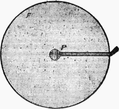
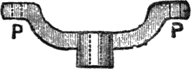
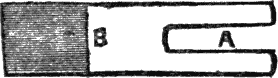
Fig. 1.—Shape of Platinum Foil, p, Fastened to Ferrotype
Plate, f.
Now comes another part of the instrument, viz., the contact-breaker.
The following is as good a way of arranging it
as any: Take a piece of sheet brass the exact length of the
diameter of the top of the tooth-powder box and about half
inch wide, and in the middle of it bore a hole which will admit
a brass screw—with a milled head preferably. The screw
should fit tightly into the hole, so as to screw easily up and
down when turned. To the end of the screw, which is cut
off flat, is soldered a short piece of platinum wire, inserted in
a hole in the end of the screw made to receive it; it can be
fastened by any other means, as long as it will screw up and
down and is in contact with the brass screw. Adjust the
screw so that the platinum point is within a minute distance
of the ferrotype plate when the brass support is screwed
down at the ends to the side of the box lid, and screw it
down with small screws firmly in its position.
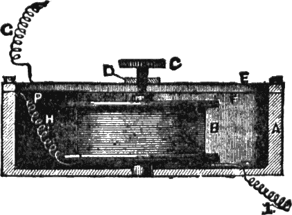
Fig 2.—Section of Simple Electric Trumpet Showing
Details of Various Parts.
A, Tooth-powder box. B, Electro-magnet. C, Brass
Screw. D, Flange for screw. E, Brass support for screw.
F, Ferrotype plate. G, Wire attached to brass strip supporting
screw. H, Wire from end of coil attached to platinum
foil at P. I, Wire from the other end of coil passing
through bottom of box.
Before this is done, however, a thin strip of platinum foil
should be soldered to the upper surface of the ferrotype
plate, or otherwise fastened to it—elastic glue will answer—this
strip terminating in the center, and reaching to the edge
of the plate, leaving a short piece over. A very thin strip
will be enough, of the shape of P in Fig. 1. Now the ferrotype
plate is to be placed in position again (the side of which
the platinum foil is fastened being outwards, and the end of
the foil going down between the edge of the ferrotype plate
and the wood into the inside of the box), and the end of the
wire from the coil which was left inside the box is to be securely
fastened, either by soldering or otherwise, to the end
of the platinum foil which was left loose, so as to be in metallic
connection with it. A wire can now be twisted round
or soldered to the screw with the platinum point, and the instrument
is complete.
It has taken some space to describe, but I made my own
in about half an hour. Fig. 2 gives a general view of the
parts put together.
The lid of the box should be tightly fastened down by four
small screws, two of which may be those which fasten on the
brass strip holding the screw.
Now to consider its action. The wire I in Fig. 2 is connected
to one wire of the battery, and the wire G to the other.
The current then starts from the battery, round the coil B,
converting the core into a magnet, and up the wire H to the
platinum foil P, along the platinum foil, which was fastened
to the upper side of the ferrotype plate F, to the platinum
wire which tips the screw C. It then goes up the screw C,
along the brass piece E, which is fastened to the box by
screws, as shown in the figure, to the wire G, and so back to
the battery by the other wire.
The screw C must be therefore screwed down till the platinum
wire at its tip is just in contact with the foil on the ferrotype
plate. Now of course when the current goes round
the coil, and thus converts the soft iron into an electro-magnet,
the latter instantly attracts the ferrotype plate
which is immediately above it. But the latter moving its
center near the core, the platinum foil which is attached to
it is thereby moved out of contact with the wire on the
screw C, and the current is instantly stopped. Thereupon
the attraction of the magnet ceases, and the ferrotype plate
flies back to its former position and so joins the platinum
wire and foil, and starts the current again, and the former
process is repeated. The ferrotype plate therefore vibrates
with tremendous rapidity between the core and the platinum
screw. Now the vibrating armature of an ordinary coil
makes quite a hum when hard at work, but of course a large
plate such as this makes a much louder noise, consequently
you will hear a ferocious buzzing like an army of millions of
bees let loose from a hive, and on screwing the screw C up
or down till you get to the correct point you will get a shrill
note very like a penny whistle. If screwed up the vibrations
are slower, and a deeper note is produced; if screwed down
the vibrations are more rapid and a higher note is sounded.
Therefore you can amuse yourself by screwing it rapidly up
and down, or adjusting it by pressing the brass piece with
your finger, and a little practice will enable you to bring
out a sort of tune produced by electricity!
When you have become tired of jingling out your tune you
can fix the electric trumpet up in a permanent position, adjusting
the wires from the battery so as to pass through an
ordinary “press” which may be in another room. The
trumpet will then begin buzzing or hooting whenever the
button of the press is pushed in, and stop when the pressure
is released. In this way of course the trumpet will act
as a “call” instead of a bell, and as the double wire can be
easily hidden under the carpet and in dark corners, and
painted to match whatever wood-work it crosses, you can
arrange it from an up-stairs room to a down-stairs one or vice
versa with very little trouble. I give an illustration of the
method of connecting the battery and trumpet with one
switch or “press,” to show how to arrange the series. (See
Fig. 3.)
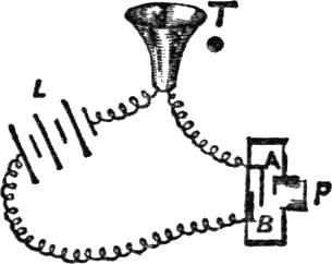
Fig. 3.—Method of Connecting Trumpet to Battery and
One Press.
When the button P is pushed in, the spring A touches
the metal piece B, and completes the circuit. On removing
the finger from P, the spring separates from B, and the
current is stopped. P, Press. L, Battery. T, Trumpet.
The trumpet made in the very simple way I have described
will not produce a very loud noise, but quite loud enough, if
properly put together, to attract a person’s attention who
was in the room when it went off. The sound can be rendered
louder by fixing a cardboard funnel or “cornucopia”
to the front of the tooth-powder box to make a kind of horn.
The trumpets sold in the shops, as a rule, make a very
loud noise indeed—in fact, a little of it goes a very long way
with most people. The increased sound is probably due to
the body of the trumpet being composed of brass, which,
vibrating in unison with the ferrotype plate, increases the
sound. Wood will therefore not give so loud a sound, and
if you can construct the case of metal you should certainly
do so. The vibrations of the plate, and therefore the sound,
may also be increased by using a horseshoe magnet, the two
poles attracting the plate more strongly. In the bought
trumpets the case is shaped like a horn, in which the magnet
is placed, the platinum contact-breaker being behind
(where it is in the one I have described, supposing there was
no bottom to the box and the magnet was supported by a
bar across from side to side, the cornucopia being placed on
that side of the box, instead of the other, with the magnet
inside it). I think it is unnecessary to describe their construction
further, as the principle and details of construction
of the simple one I have described will apply to any, and any
method of structure may be adopted which suits the mind of
the maker.
The trumpet having been made I will now give you a plan
of fitting it up which adds enormously to the effect. We
want to hide the trumpet so that no one shall know where it
is. My own plan of doing this is as follows: I have made a
wooden erection, of which I give a drawing which will explain
itself. It consists of a back with a shelf at the bottom
and a kind of canopy at the top. It can be made almost any
size, small or big, to suit the occupant of the shelf. My own
measurements are about as follows: From the top A to the
bottom B, the length of back piece, including bracket, 1 foot
3 inches. Breadth of back 5¼ inches. Side of canopy (D),
breadth 4½ inches, height 3½ inches, breadth of front
(C to D) 5¼ inches; height of course the same as sides.
The top piece will then be about 5¼ inches by 4½ inches.
The shelf at the bottom is about the same size as the top of
the canopy, and is supported by a bracket of rather thick
wood, which you can carve as elaborately as you like.
Now take the electric trumpet, whether made at home or
purchased, and fasten it to the under side of the canopy
(this is best done before the sides are put on), and fasten a
double wire behind the back (cutting a groove for it to go in)
up to the back of the canopy, where it goes through and divides,
one wire being fastened to one terminal of the trumpet
and the other wire to the other. The double wire goes right
down the back and emerges at B. Obviously if you now join
your press and battery on to the double wire, when you
squeeze the press the trumpet will squeak. But here we are
going to practice a little innocent deception, and to that end
we go to a toy shop and purchase a small and pretty doll of
the male sex, and if you can get one (or dress one up) attired
as a soldier or trumpeter, by all means do so. The doll
is now to be fixed on to the bracket by means of a long
wire—say a hairpin bent out straight, one end being pushed into
the wood, the other passing up one trouser leg of the doll
and into its body; the wire is thus completely hidden and is
much better than glue, as it admits of the doll being placed
in a natural attitude, and being removed if required. In one
of his hands you must make him hold a small trumpet (this
is a very expensive item; it will cost two cents) with the
mouthpiece to his mouth, as represented in the picture.
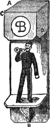
Fig. 4.—Electric Doll.
(Letters as referred to in text.)
The whole thing is now fastened to the wall in a convenient
place, by driving nails through the back, and the
double wire is completely hidden by passing it behind furniture,
books, etc., down to the floor. There is great scope
for ingenuity on the part of the worker in hiding the wire,
and no definite instructions can possibly be given. In my
own case I have no back piece below the shelf the support
being against the wall. The wire descends behind the support
(to B in the picture), and below that I have hung a
“date calendar” over it, it makes a turn to the right and
goes down behind a chiffonier covered with books to the
floor. Under these circumstances no human being could
possibly tell that there was a wire at all, and there being no
back piece under the bracket (so that the paper of the room
can be seen), nothing but the support touching the calendar,
it does not look as if any wires could possibly be hidden
anywhere.
Now, if you press the button, of course the trumpet
squeaks, but the doll being just underneath it, and the trumpet
being in the dark under the canopy, no one thinks it is
a separate instrument, but of course every one jumps to the
conclusion that it is the doll blowing! Hide the battery in
a corner in a black box, the wires coming through the side next
the wall, and the press in a dark corner, or on the
floor under a table so that you can put your foot on it while
your hands are free, writing, etc.
You can of course now tell the doll to blow, at the same
moment putting your foot on the press, when the trumpet
blows accordingly. Of course this is mysterious to the last
degree to the uninitiated friend to whom you are displaying
the doll, as you may be any distance off from the doll with
your hands free, speaking to him across the room.
The wooden erection to hold the doll can be painted any
color; preferable the back should be black, as it shows off
the doll. In front of the canopy you can paint a monogram
or heraldic device. If the doll is one of those extremely
pretty little specimens which can be procured at any good
toy shop for about twenty-five cents, dressed as base ball
players, soldiers, etc, (what our grandmothers would have
thought of them in their young days it is difficult to imagine)
it will really be quite an ornament to the room, independently
of its electrical qualities.
This chapter has outgrown the space I meant to occupy,
and I must wait for the next to tell you how to make the
doll work from various parts of the room as you walk about
and talk to him, and how to make the battery. The best
battery to use is to Leclanche. You can use three or four
cells of No. 2 size according to length of wire through which
the current has to pass.
In my next chapter I will try and explain how to make an
electric drum, so that you can have a kind of drum and fife
band.
In part two on the “Electric Trumpet,” I promised to
explain how to make an electric drum; and this promise I now
propose to redeem.
The system on which it works is precisely analogous to
that of the electric trumpet, and almost identical with that
of the ordinary electric bell, of which I hope to say more in
another chapter.
As before, we have a hammer vibrating backwards and
forwards in response to pulls from a magnet, which is magnetized
and demagnetized by stopping and starting an electric
current. In the case of the induction coil, the hammer
is only a means whereby the current is broken and started
again with great rapidity, and in the case of the trumpet the
vibrator is used to make the noise by its vibration, but in
this instrument we must have a bona fide hammer, which
must be able to beat the drum, and thus cause a stirring and
martial sound.
First, then, we will devote our attention to the construction
of the magnet. In former chapters (as in the case of the
electro-motor for example), I have given you the method of
making the magnets out of one solid piece of soft iron, in the
form of a horseshoe. This time, however, we will make it of
several pieces, for a change; it is far more convenient to
make, and looks much neater when finished.
Take a piece of soft iron 1½ inches long by ⅝ inch
broad and ⅛ inch thick, and in the middle drill a hole about
3⁄16 inch in diameter. On each side of this, on a line with
it at a distance of about ¼ inch, drill two more holes of the
same size. This is to form the back, or, as it is scientifically
termed, the yoke of the magnet. To form the poles we require
two exactly similar pieces of soft iron bar 1½ inch
long and ⅜ inch in diameter. These are to be filed quite
smooth at the ends after cutting, and in the middle of one
end a hole is to be drilled to admit a screw which will just go
through the holes on each side of the center one made in
the flat piece of the soft iron. These holes are cut to receive
the thread of the screw, but if you can’t do this
you can simply leave out the end holes for screws, and solder
the round and flat pieces of iron together. These are to be
soldered or screwed together, so as to form a magnet, the
hole in the middle of the flat piece serving to introduce a
screw, for the purpose of attaching the magnet to a support.
The best plan, if you can do it, is to drill and “tap” this
hole to receive a screw which is inserted in a brass support
made of a piece of brass 1⅛ inch long, ½ inch broad, and
⅛ inch thick, bent at right angles at about ½ inch from
one end, this shortest end being drilled for two screws to
fasten it to the base-board, while the longest end has a hole
in the center about ⅛ inch from the end, to admit the screw
which fits the hole in the center of the yoke. Having done
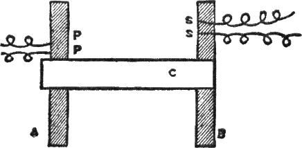
all this, you will have Fig. 1, which represents the magnet
before it is wound.
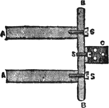
Fig. 1.—Magnet Put Together Ready for Winding.
(Sectional diagram.)
A A, Circular bars of soft Iron. B B, Flat bars of soft iron
forming the “yoke.” C, Brass support for magnet. S S S,
Screws fastening parts of magnet together.
The soft iron cores have now to be converted into magnets
as usual, and here comes in the especial advantages of having
screws to fasten the magnet together, as you can take
the whole thing to bits, wind the wire on the legs in comfort,
and then fasten together again. But if you have soldered
the magnet together, you can achieve the same end in a different
way by making two small bobbins to hold the wire, the
exact size to slip on over the soft iron cores when the wire
is wound on them. It is generally considered proper to wind
the wire on bobbins, which can be removed from the cores
if required. I should think it can seldom be required, but
the bobbins are convenient in this case. I may remark
parenthetically that bobbins wound and unwound, soft iron
cores, and yokes, separately or together, and supports fixed
to the yokes or not, can be obtained from any large electrician
who sells parts of electric bells, etc.; the magnet can
also be got put together complete.
We now have to make bobbins, supposing that we are not
going to buy them. The elaborateness of their manufacture
will depend entirely on the skill of the maker. Some construct
them by sawing off top and bottom of a reel of cotton,
and forming a roller of cardboard to fit the magnets, finally
joining the ends of the reel to this roller, to make an elongated
reel of the right size. Others construct their bobbins
entirely of cardboard, the ends being merely two circles of
card. Others who are versed in the mysteries of wood-turning,
and are lucky enough to possess a lathe with which to
do it, make two bobbins of solid wood, drilled to fit the iron
cores. For these no instructions are needed, as the dimensions
will be as given presently. For those who only want
to use the magnet for this special purpose, and do not care
about the bobbins being removable, the following is the simplest
way to set to work:
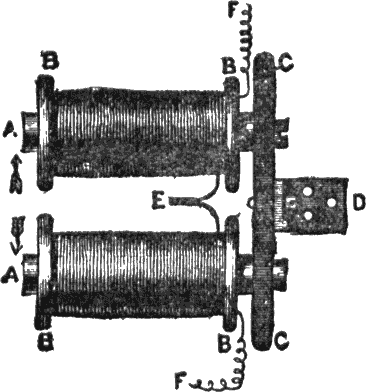
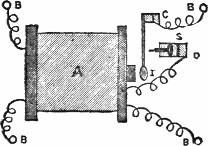
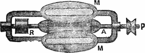
Fig. 2.—Magnet Wound and Put Together.
A A, Soft iron cores. B B B B, Ends of bobbins, on which
wire is wound as shown. C C, Yoke of magnet fastened to
support and held up by D, bottom of brass support, with
holes for screws. E, Joined ends of wires. F F, Exterior
ends of coils. The arrows show relative directions in which
the two coils are wound.
Cut two circles of thick cardboard, each ⅞ inch in diameter,
and in the center cut a hole the exact size to slip over
the soft iron core. Now wrap several thicknesses of thin
tissue paper—or preferably French note paper or tracing
paper—over the magnet, between the circles of cardboard,
cutting the strip about 1⅛ inch broad or ⅜ inch less than
the length of the cores. Now you can fasten the two circles
of cardboard at the ends of the tracing paper, and keep them
in their proper places on the magnet by means of mucilage—beat
the soft iron before applying, and it will then adhere
firmly to it. In this way, of course, you form a roller, on
which we now have to wind the wire. If you have soldered
the magnet’s parts together, you must have movable bobbins,
as it would be simply impossible to wind the wire evenly
on the cores when fixed in position, as the edges of the
bobbins will be so close together that it is not possible to
wind the wire on between them without the coils becoming
displaced.
The method of winding the wire is simple enough. No. 24
wire is a good size to use; it can be cotton-covered or, preferably,
silk-covered, as in the latter case the insulation is
better. Begin by making a hole near the roller in the circle
of cardboard that is next to the end where the hole for the
screw has been made. Pass about three inches of wire
through the hole and then wind it evenly on over the tracing
paper from end to end and back again. You ought to have
five or six layers of it; an ounce, or an ounce and a half,
of wire will probably be enough. When it is all on, make another
hole in the disc and pass out the wire. This is only to
hold it safe while you wind the other bobbin. When that is
finished you can put the magnet together, and ends of the
two wires have now to be joined together. The two ends
that are joined together must be those which come from the
wire that is wound from the right to the left over one core
and left to right over the other, that is to say, taking the wire
when joined as one, it must be so wound on both limbs of
the magnet that if they were bent into one straight bar it
would all be wound in the same direction.

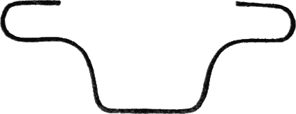
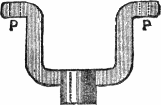
Fig. 3.—Shape of Spring for Armature.
P, Platinum foil. A A, Holes for screws to armature. H H,
Holes for screws to support.
With a composite magnet, however, there is no earthly
difficulty in getting it right, for you have only to connect
the battery to two wires and join the other two, and if they
don’t make the magnet work, join up one to the battery instead
of one of those joined, and connect the other two wires;
whichever gives the best result stick to. You must get all
the silk or cotton off the wire, where you join them, and
twist them over and over tightly together; if you can solder
them, so much the better. Pull the wire tight and wind it
on the reels until the place where it is joined is pulled tightly
and not left in a loop, which would look untidy. Fig. 2 gives an
idea of the magnet completed, and I have endeavored by
means of the arrows to show how the wire is wound, they are
supposed to give the direction of the top layer of wire in each
case; of course either may be wound from the inside, so you
must also consider that in this picture the outside coils are
joined. The magnet having been thus constructed, we must
now turn our attention to the vibrating hammer which is to
beat the drum. To make this we want another piece of soft
iron of about the same size as that forming the yoke of the
magnet, say, 1⅜ inch × ½ inch × ⅛ inch. We shall then
require a piece of brass spring about three inches long and
half an inch broad. This is made of very thin springy brass,
so as to make a spring which will move the armature quickly.
One end of the spring should be tapered off as shown in Fig.
3, and at the point P in the figure a small piece of platinum
foil (the real thing, not tin-foil, which I am sure is often sold
in cheap apparatus instead of it,) should be fastened, by
solder if possible.
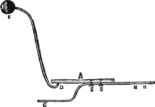
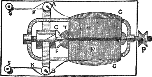
Fig. 4.—Drum Hammer Put Together.
A, A bar of soft iron. B, Brass spring of contact breaker.
C, Portion of brass spring bent outwards, the platinum foil
is soldered on at the point C. S S, Screws holding spring to
soft iron. Holes are made at the points H H to fasten
spring to support. D, Bent wire fastened to soft iron
armature. E, Wooden head of drumstick.
We now want a piece of rather stout brass wire bent into
the shape shown in Fig. 4. It must be about four inches
long, but its length will be determined by the size of the drum
and the length of the magnet when it is all put together. At
the end of this wire you must have a wooden knob (not brass,
which doesn’t produce nearly so much noise). This you will
have provided ready for you if you purchase the drum, as they
will naturally supply drumsticks with it, and the head of one
of these cut off and fastened to the end of the wire, by simply
making a hole and sticking it in, will answer the purpose
beautifully.
This wire has to be fastened to the soft iron armature, a
simple way of doing which is to drill a hole the exact size
and insert the end; it can then be soldered in. Or, if you
cannot drill a hole, you can simply solder it on. The brass
spring has the end bent outwards, as shown in Fig. 4, and is
fastened to the soft iron armature by screws, as shown in the
figure at S S, or simply soldered on. The point C is the end
that is tapered off, and the platinum wire is fixed at that
point; the spring should extend about 1¼ inch beyond the
armature at the other end. Two holes are drilled in the
spring at the points H H, through which screws are passed
into the support. This support may be either a piece of iron
½ inch long, ¾ inch broad and ¾ inch thick, or a piece
of wood will answer very well, and save drilling holes in the
iron. If it is wood it had better be larger, say ¾ inch by
¾ inch by 1¼ inch.
We can now proceed to fasten all the parts together. We
must have a piece of hard wood for the base, about 3½
inches by 3 inches and ⅜ inch thick. On this the magnet
has to be fastened by its support being screwed firmly down.
In front of it the armature has to be fastened at such a
height as to be exactly in front of the poles of the magnet.
The relative positions of the parts are shown in Fig. 5, so I
do not think a detailed account of their exact positions on
the base is at all necessary.
There is, however, one piece of the mechanism in the
figure to which I have introduced you, this is the contact-screw
shown at C. To make this we take a piece of brass
about 1½ inch long, ½ inch broad, and rather less than
⅛ inch thick, and bend it at right angles, so that one leg is
one inch long and the other ½ inch. Now in the part that
is ½ inch have to be drilled three holes to fasten it with
nails or screws to the base. The other part, one inch long,
will then stand erect, but before fastening it in its place we
put it to stand in front of the magnet and mark a point
which is exactly on a level with the piece of platinum foil on
the spring, when the spring and magnet are fixed in position.
A hole has now to be drilled through that point and tapped
to admit a brass screw with a milled head, and fix the piece
in which the screw works to the front hole, so that the screw
will work through it.
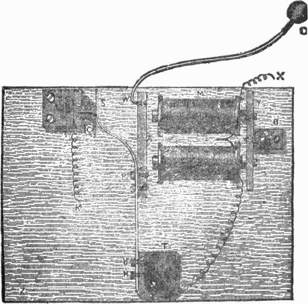
Fig. 5.—Interior Mechanism of Drum Complete.
M, Magnet. Y, Yoke of magnet. B, Brass support of
magnet. A, Armature of soft iron attached to S, spring
fastened to armature by screws at P, and to support by
screws at H H. T, Support of spring. D, Head of drumstick.
W, Wire supporting head of drumstick. C, Contact
screw and support. The wire from one coil is joined
to brass spring at H H. The wire X, coming from the other
coil, and K, the wire from the contact-breaker, are joined
to battery. Positions of screws joining parts together are
shown by dotted lines. The side marked Z is placed at the
bottom when fixing into the drum.
The point of the screw has now to be cut off and a very
small piece of platinum wire fixed at the end. This wire
will now come in contact with the platinum foil on the
spring, when the brass support is fixed in a certain position
on the base, and it is now to be fixed in that position with
screws or nails. It should be so fixed that when the screw
is turned till it is nearly out of its hole the wire is just out of
contact with the platinum foil on the spring. It is now evident
that by turning the screw one way you make the spring
vibrate more rapidly, and by turning it the other way its
efforts are relaxed.
The contact-breaker screw having been fixed in its place,
and the support of the spring also fixed as at T in the diagram
(Fig. 5)—by screws through the base into the iron, if
it is made of iron, or by nails or screws through it into the
base if of wood—all the parts are now together, and all that
remains to be done is to make the necessary connections.
One wire that comes from the magnet is to be joined (soldered,
if possible,) to the spring at H in the picture; the other
wire is left loose. To the brass support of the contact screw
we solder another piece of wire. Now this piece of wire is
connected with the zinc of the battery and the other (coming
from the coil of the magnet) with the carbon of the battery.
What happens?
The electricity passes along the wire X, we will say, and
round the magnet coils, thus turning the cores into magnets.
It then goes down the other wire to H, up the brass spring,
along the screw, and down by the brass support to the other
wire, by which it returns to the battery. That is to say, it
would do all this if the armature stood still, but, of course,
when the cores become magnets they attract the armature,
which instantly moves towards them; this breaks the circuit,
the spring moving off the platinum point of the screw, and
the armature springs back again, which makes the circuit
complete and the magnet attracts it again, and so on. The
object of the spring is to get a good deal of vibration, and
it and the screw should be so adjusted that although the
armature is close enough to the magnet to make it certain
to “go off” directly it is meant to do so, yet there may be
as much scope for the spring to work with elasticity as possible.
We have now completed the electrical part of the business,
but a slightly necessary part of the apparatus has yet
to be obtained—viz., the drum. You can easily make a
drum if you like, by taking a broad piece of tin, twisting it
round to form a hoop, and covering the ends with parchment
strained tightly over them. However, I should certainly
not do so, for there can hardly be any spot, I should
think, which boasts of a toy-shop at all, where drums cannot
be procured! For twenty-five cents you can get a very
superior drum, just about the right size; if you like to get a
bigger one and make the mechanical part bigger, you will,
of course, be rewarded by more noise.
Now, suppose you have got a 25-cent toy-drum, you must
proceed to take off one end. If you look at the construction
of the drum you will find (at least it is the case with my
own, and I have not seen any that are differently made) that
by cutting one of the double strings that fasten the wood
hoops at the top and bottom together, and then loosening
all the other strings with your fingers, the wooden hoop at
one end will come right off, if the nails fastening the ends
together are taken out, and that then the inner hoop on
which the parchment is stretched will also come off and leave
that side of the drum open.
Now, this is simply grand for our purpose, for when we
have arranged our little dodges inside the drum, we can put
on all the hoops again, replace the one double string, and
no one will be an atom the wiser. If you could get off the
side without breaking any strings it would save the trouble
of replacing any, but I am afraid this is hardly possible.
However, off comes the side of our drum, and what is to be
done next? Well, the “beater” must be put bodily inside
the drum, just so close to the parchment side that was taken
off that the wooden head of the drumstick touches it when
attracted by the magnet. You can easily find the right
place in actual practice by setting the beater going and finding
the spot inside the drum where it kicks up the worst
racket when working. It must not be too close or it will
hinder the vibration, and we want the hammer to go off instanter
when required. The beater is fixed to the side of the
drum with its side marked Z in the figure (5) downwards. It
is easily fastened there by making two holes in the wood (in
the thickness of it), and two corresponding holes in the
metal side of the drum, and then screwing it down in its
proper place.
Two holes are to be made in the side of the drum and two
ornamental bits of silk-covered flexible copper conductor let
through. They can be secured by simply tying knots inside
the drum, and the copper ends are now to be fastened, one
to the wire X and the other to the wire K from the contact
screw support. Having done all this and made sure that
the beater works when the ends of the flexible cord outside
the drum are connected with the battery, we seal up our
drum again, and that is then concluded.
Now as to fixing it up, I think I may fairly assume that
you know how to make it work by an ordinary battery and a
“press.” It is only necessary to run a double wire from
battery to press and from press to drum, one wire of the
double conductor being fastened to the carbon end of the
battery and the other to the zinc end, and the other end of
one wire to one of the wires coming from the drum. The
other wire coming from the drum is then joined to the bottom
conductor of the press, and the upper conductor of the
press is joined to the other wire of the double conductor that
goes to the battery. It is all very easy to understand if you
follow the course of the current and consider that it has to
pass through the drum and the press when the latter is
pushed down, and be stopped when it is left to spring up
again.
But the more magical arrangement can be made with the
drum, and I think it is well worth while to do it, if merely
for the fun of mystifying people. The drum is going to be
suspended by the flexible cords; therefore, let them be the
same length, and cutting off all the coverings at the end of
each, fasten a brass “eye” to the copper, twisting the wire
well round the bottom of the eye. Now wind silk of the same
color as the rest all round the join, so that the connection of
wire and eye is completely hidden, and the eye appears
merely fastened to the flexible cord as a means of suspending
the drum. Now we want to construct a hook from which
the drum can be hung.
Take two small pieces of brass wire about an inch long,
and turn up the ends of each into a hook. Now get a minute
piece of ebonite of the same length, and, putting one
hook on one side and one on the other, bind the whole together
with silk. If you cannot get ebonite easily you can
use a small piece of sealing-wax in the same way; by heating
the wires you can sink them into the wax and so make a
neater join. Now the wires must not touch each other anywhere,
but must be completely separated by the ebonite or
sealing-wax. The double wire from the battery and press is
now fastened, one wire to the press hook on one side, and
one wire to that on the other side of the sealing-wax or ebonite.
Wind silk over the whole to cover the joins, and a
neat double hook is the result. The picture (Fig. 6) gives the
method of making the hook, and it also gives a great deal
more, which I now proceed to explain.
Supposing we can rig up a small beam of wood from
which to suspend the drum, we can make matters more mysterious
still. Let the double wire, being hidden by some
means or other all along its course, be conducted on to the
end of the beam. It can then be trained along the top of it
until it comes to the point from which the drum is to hang.
Here there must be a hole drilled, large enough to admit
the hook rather tightly. Pull the double wire through and
fasten the two wires to the hooks as before described.
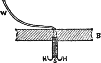
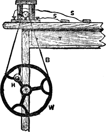
Fig. 6.—Hook From Which to Suspend the Magic
Drum.
W, Double wire from battery and “press.” B, Beam of
wood from which drum is suspended. H H, Brass hooks
at side. S, Ebonite or sealing-wax between the hooks.
The beam is, of course, shown in section.
Now you can pull back the wire and fix the hook firmly in
the hole, hiding the double wire at the top of the beam (of
course if it is high up no one will be able to see over the
top of the beam, so you will be quite safe); the hook being
thus fixed will not attract any one’s notice, and look quite unsuspicious.
The chief glory of the double hook thus constructed
is, of course, that you can remove the drum whenever
you choose, for examination, and whenever you hang it
up you have only to hitch one eye over one side of the hook
and the other over the other side, and the drum will work.
People who are not up in the matter cannot conceive how
the electricity can get to the drum, when it is simply hung
by an (apparently) ordinary cord and ordinary eyes to what
looks like an ordinary hook attached to a beam in a plain
and straightforward manner.
You are now possessed of an electric trumpet and an
electric drum, which you can put one at one end of the room
and the other at the other. By running double wires from
battery and press to the trumpet, and another double wire
from battery and press to the drum, you can arrange matters
so that when you put one press down the trumpet
works, and when the other press is put down the drum
works. If you want to work both together you must either
have a very powerful battery (say 6 or 7 cells, No. 2 Lechlanche)
or two batteries, one for trumpet and one for drum.
If you want to use one battery for both you can make
either work (at different times) from the same battery and
presses, wherever they may be, by having a two-way switch
in a dark corner of the wire.
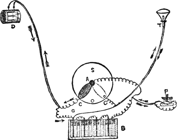
Fig. 7.—Method of Joining Switch Drum and Trumpet to Press
and Battery.
S, Switch. B, Battery. P, Press. D, Drum. T, Trumpet.
The arrows show the course of the current when the switch
is at A C and A G respectively.
It is very confusing business setting up the wires so as to
produce the right effect, which is to change the current from
drum to trumpet and vice versa in a moment by merely
altering the handle of the switch. Readers who are not
accustomed to the work will find it most intricate, and as I
have done it myself several times, they may as well have the
benefit of my trouble. I therefore give an illustration of
how to connect up the wires (Fig. 7), and hope it will make
matters clear to them. An explanation of the picture is
necessary.
Suppose first of all that the switch is at A C, then the current
will travel from the right-hand end of the battery, B, up
one wire of the double conductor to the press, P, as shown
by the lower arrow, through the press and along the wire,
as shown by the top arrow, to the middle of the switch, A,
down the arm of the switch to C, up one wire of the double
conductor to the drum, and down by the other wire to the
other end of the battery.
Now let the handle of the switch be moved to the other
terminal, as shown by the dotted lines. The current will
now go from the right-hand end of the battery to press and
center of switch as before, it then goes down the arm of the
switch up to the trumpet by the wire on the left side, and
down to the other end of the battery by the wire on the right
side, as shown by the arrows. Therefore when the arm of
the switch is at A C the press will work the drum; when it is
at A G the press will work the trumpet.
Suppose we have no press, but instead of it we have only
one wire going straight from the right-hand end of the battery
to the middle of the switch. Now let two incandescent
lamps be substituted for the trumpet and drum. When the
arm of the switch is at A C the current goes straight up
from the right-hand pole of the battery to the center of the
switch, along the arm, up to the lamp on the left-hand side,
and down to the other pole of the battery. Now, suppose
the arm of the switch is moved to A G, the current will go
up as before to the center of the switch, down by the arm,
up the wire to the lamp on the right-hand side, and back to
the battery by the other wire. In the first case, therefore,
the lamp at D lights up, in the second case the lamp at T
lights up. The wires from C to D and G to T may be as long
as you please, you can therefore control the lamps when they
are far apart or in different parts of the house. When the
arm of the switch is central neither lamp lights up, or, if you
are fitting up the trumpet and drum, the press will not work
either when the switch is in this position. This is an advantage,
as when people get too inquisitive you can turn off the
current, and then whatever they do they will not make the
trumpet or drum work till you turn it on again, which you
can do when you want them to work for you!
The construction of the switch is so simple that it is hardly
necessary to explain the method of joining the wires, but
I may say that one is to be joined to the bottom of the brass
pillar in the center which supports the brass arm. The
others are joined to the right and left terminals, generally
by brass screws under the base, but sometimes by screw
terminals at the upper surface; this depends on the make of
switch which is purchased.
Ingenious readers can easily make a switch for themselves;
it only requires a brass arm attached at one end to a central
figure, and long enough to touch two screws, or pieces of
brass, fixed to the base on opposite sides of it, when turned
in their direction. The end of the arm not supported by the
brass pillar is provided with a small wooden handle to turn
it by.
The switch should be arranged to occupy some dark corner
in which you can turn on drum or trumpet to work from
the “presses” at will without any one seeing you alter it.
I will only add one thing in conclusion, and that is, that
you can have the double wire from the battery and center of
switch to the press at the end as long as you like, and it can
turn about behind furniture or under the carpet as much as
you like, and it will still work instantly from the end press.
Now, by scraping the wire clean at any intermediate
point, or as many points as you like, and arranging a simple
spring contact fastened to the wires without breaking
them so that they can be made to touch when required and
spring apart directly the touch is removed (this is easily
done with two springs consisting of two strips of sheet
brass, one fastened to one wire and one to the other, separated
by a piece of wood except at the end when pressed
together), you can make the trumpet squeak or the drum
roll at any part of the room you like. The springs can be
hidden under the carpet so as to be absolutely undiscernible
except to the initiated. The best places are under furniture
with rather long legs; the foot of the operator can then be
placed on the springs, and so make them meet and the
trumpet or drum sound without the least chance of detection.
The wires not being broken in fixing the springs as described,
those springs which are closer to the battery, in no way interfere
with those which are further off, as, when these are
used, the current simply runs round those that intervene between
them and the battery, without being in any way hindered
in its course, and the press at the end of the double
wire will, therefore, work just as if no intermediate springs
existed.