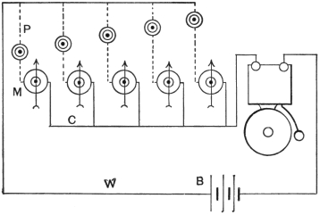
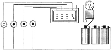
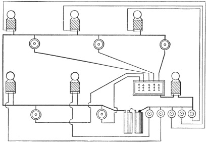
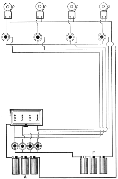
The two main types of house
bells are the iron box and the skeleton.
The iron box has a cast-iron frame, or base, and
a cast- or stamped-iron cover over the mechanism.
The skeleton bell has an iron frame but no
cover, and is generally better finished and more
expensive than the iron box bells.
For fire alarm purposes, mechanical bells or
gongs are made, in which a clockwork mechanism
causes the hammer to strike the gong upon
being released by electromagnetism.
Marine or waterproof bells have an iron cover
fitting tight over a rubber gasket; they are for
marine, or mining, work.
Polarized, or magneto, bells are used in telephone
work, and are rarely operated by a battery,
but have a miniature dynamo generator operated
by hand, or power, to supply the actuating current.
Most bells are classed for size by the diameter
of the gong, a four-inch bell being one with a
gong four inches in diameter; a six-inch bell one
with a six-inch gong, and so on.
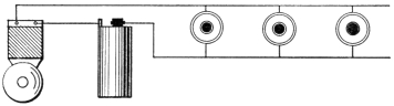
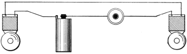
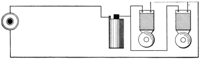
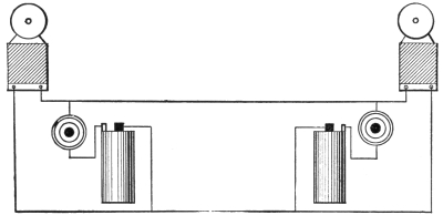
According to the use for which they are intended,
bells may be vibrating, as before described,
single-stroke, shunt or short-circuiting, differential,
continuous-ringing, or adapted for circuits of
high voltage.
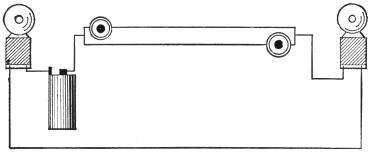
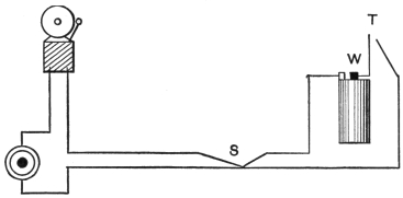
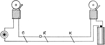
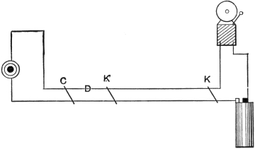
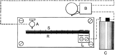
The bell before described,
and again shown in Fig. 5, is a vibrating,
or trembling, bell. It is often desired to have the
hammer give only one stroke for each pressure of
the push, as in signaling with a code of taps; in
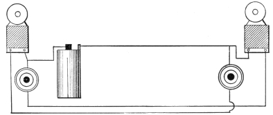
this case a single-stroke bell is used. The circuit
from the binding posts is then directly through
the magnet coils without any break at the contact
screw, as in Fig. 6.
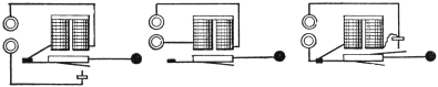
Fig. 5
Fig. 6
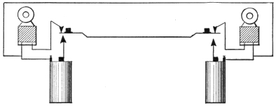
Fig. 7
In adjusting such a bell to give a clear sound,
press the armature up against the iron magnet
cores and then bend back the hammer until it just
clears the gong. The spring of the hammer wire
will carry the hammer sufficiently forward to hit
the gong. The tone will be clearer than if the
hammer dampered the gong by pressing against
it when the armature was nearest the core.
By bringing out a third connection, a vibrating
bell may be made both single stroke and vibrating.
There is a form of bell,
Fig. 7, known as the shunt, or short circuit bell,
which is often used when two or more are to be
connected in series, as will be seen in the description
of circuits. In this bell the circuit through
the magnets is not broken at the contact screw,
but the forward movement of the armature short
circuits the coils.
As the short, or shunt, circuit is very much
lower in resistance than the wire on the magnet
coils, the main current flows around the latter and
they do not become energized. The sparking at
the shunting contact screw is much less than it
would be at the ordinary breaking contact screw,
and the platinum points last longer.
Sparking at the breaking
contacts of an electric bell is detrimental to
the platinum points, and many remedies have been
devised to overcome it.
Sparking is due to the self-induction of one
turn of the wire coil acting on its neighbor, and
this property is utilized in the gas engine, or gas-lighting
spark coil, where a fat spark is needed to
ignite gas.
The differential bell has two windings in opposite
directions. The action of one would be to
produce an N-pole at one end and an S-pole at
the other. But the second coil produces poles just
the opposite, as the polarity of a magnet depends
on the direction in which the current flows around
it.
Where the current flows around the first winding
the armature is attracted and its spring contact
meets the contact screw and allows the current
to divide, part flowing through the first coil,
the other flowing in the reverse direction in the
opposite way. One coil would tend to produce
an N-pole where the other coil produced an S-pole,
and these opposite poles would so neutralize each
other that there would be no magnetism.
The armature would therefore be pulled back
by its spring when both coils were thrown into
circuit. In so doing it would cut out one coil
and the same series of operations would recommence.
As a spark is normally produced where magnetism
is lost by a break of circuit,B no spark appears,
as magnetism is produced by a break of
circuit in this case.
In some classes of bell
work, such as burglar alarms, it is desired that the
bell when once started shall continue to ring until
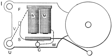
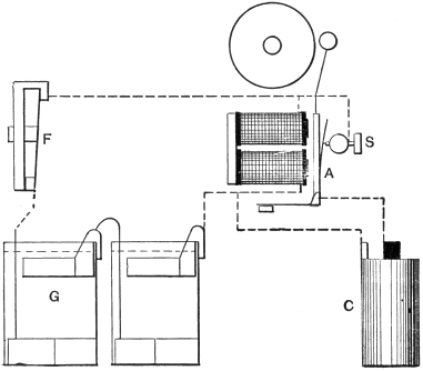
stopped by the person called. In this case a continuous-ringing
bell is needed, such as in Fig. 8.
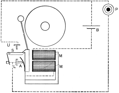
Fig. 8
When the push P is pressed, the current flows
in the usual way through contact screw L, armature
spring A, magnet coils M M, battery B, back
to P, and the bell rings. But on the first forward
movement of the armature it releases the spring
contact S, which flies forward and makes contact
at U. The circuit is now from B, through M M,
to A, thence through L and S, to U and back
to B.
The bell will continue to ring until the spring
contact S is moved back and caught by the projection
on the armature A.
A continuous-ring attachment is also made and
sold in most electrical supply stores, which is complete
in itself and can be applied to any bell.
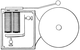
Fig. 9
In Fig. 9 is an example of
a waterproof bell where the mechanism is almost
all entirely encased in a waterproof brass case.
The circuit is made and broken inside the case,
but the magnet cores project through it and act
on a second armature placed outside. This second
armature carries the hammer which strikes
the gong and is governed in speed by the contact-breaking
armature inside.
In order to provide a
variety of sounds, bells are provided with gongs
of various shapes.
Fig. 10 shows the ordinary form of gong.
Fig. 11, a tea gong; Fig. 12, a cow gong; and
Fig. 13, a sleigh bell.

Fig. 10
Fig. 11
Fig. 12
Fig. 13
A coil of steel wire is also used, as in Fig. 14,
which on being struck by the hammer gives a
pleasant but not loud tone.
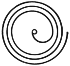
Fig. 14
The buzzer is the mechanism of
a vibrating bell less the hammer and gong. As
the armature vibrates it makes a buzzing noise
which does not carry as far as the sound from
a struck gong. It is used chiefly for a desk call
and in telephone exchange work, or any place
where general attention is not desired to the signal.
When it is
desired to ring a bell situated at a considerable
distance from the push, the resistance of the line
becomes objectionable.
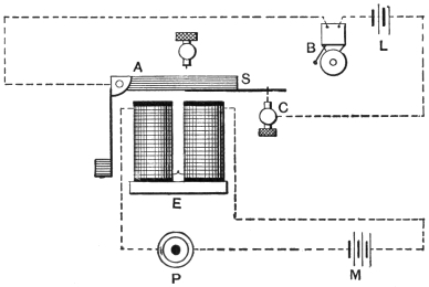
Fig. 15
On lines of 500 feet, No. 18 copper wire and
upwards, the battery necessary would be very
large, two small batteries and a relay would prove
more satisfactory.
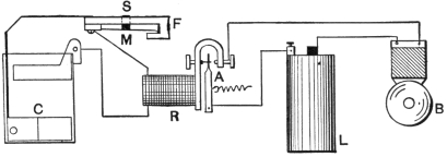
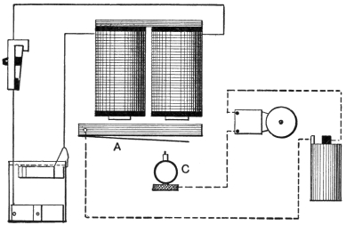
In Fig. 15 the circuit of a simple form of relay
is given. An adjustable contact screw C is placed
where an extension S of the armature A can strike
it. This extension is provided with a platinum
contact. The connections are as in the figure.
When the push P is depressed, the current from
the main battery M energizes the electromagnet E,
and the armature A being attracted, contacts S
and C meet. These contacts close the second circuit
containing the bell B and the local battery L.
The relay resembles a second push near the
bell, but controlled by current from a distance
instead of being depressed by hand. Its advantage
consists in it needing but a very weak current
to move the armature A, which is held back
by a light spring, or by gravity.
The relay may then be set near the bell and
the wires from the push may be of a very great
length. Battery L, which actually rings the bell,
will thus only have to work through a few feet
of wire.
Sometimes
it is desired to reduce the resistance the bell coils
offer to the current, the bell then working over a
very short line with few cells of battery. Or
the bell coils may have been wound with fine
wire for large battery voltage and a long line.
The bell coils may be put in multiple, the current
then dividing and one-half going through
each spool.
Untwist the joint between the spools near the
yoke or iron bar to which the spools are attached.
Join one of these ends to the wire at the armature
end of the other spool and the second untwisted
end to the armature end wire of its neighboring
spool. Use short pieces of insulated wire for
these extra connections.
The current now instead of having to go
through one spool and then the other, can branch
through both at once.
The resistance to the current of one spool is
half the resistance of two, the current through one
spool will therefore be twice that through the
two spools as at first connected. And as there are
two paths for it, each one-half the first resistance,
the total will be only one-fourth the resistance
of the ordinary series arrangement.
The same size battery will therefore send four
times the current through the spools in multiple
than when they are in series.
It is to be noted that the wire on one spool is
wound in the reverse direction to that on the
other. The reason will be apparent if the two
spools and yoke are considered as merely one
spool bent in a U or horseshoe form.
If both spools were wound in the same direction
they would be in opposite directions when the
U were straightened out, and would cause like
poles at the same ends. These poles would neutralize
one another, so that there would be no
magnetic attraction.
This can be readily proved by joining together
the two yoke ends and the two armature ends of
the spool wires. Then pass the current through
these two joined connections.
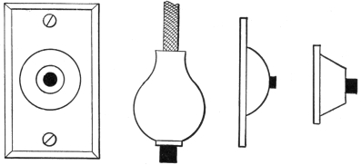
Fig. 16
Fig. 17
Fig. 18
Fig. 19
Push buttons, or pushes,
are made in a variety of forms, with metal, wood,
hard rubber, or porcelain bases.
Fig. 16 has a metal base, and is suitable for
a front door.
Fig. 17 is a wooden pear push, and is attached at
the end of a cord which has the two conductors
braided in it, each, however, having its own insulation.
Fig. 18 is a plate push for an outside door.
Fig. 19 is either of metal, wood, or porcelain,
and is the shape most commonly used.
A three-point push has three contact springs.
One is movable by means of the button, one is
below the movable spring, and the third is above
it.
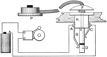
Fig. 20
When the push button is not being depressed,
the movable spring makes contact with the upper
spring. But when the button is depressed, these
two springs part, and the movable spring makes
contact with the lower one.
This style of push is used for special bell and
annunciator work, as will be described later.
The form of combination floor and table push in
Fig. 20 is the most solidly constructed device of
its kind. The lower part is set in a hole bored
in the flooring, the metal flange keeping it in
place and preventing its slipping through.
The floor push attachment works as follows:
The central metal rod is divided into two parts
B D, by an insulating piece of hard rubber. When
depressed against the action of the spiral spring
by the foot, the upper part B connects together the
contact springs A C, closing the circuit of bell
and battery. These contact springs are insulated
from each other by a hard rubber block R.
From the table push a cord containing two insulated
wires leads to the two parts of the rod
at B and D. When the push centre is pressed
down, the push springs come together and practically
short circuit B and D, which completes the
circuit of bell and battery. At any time the centre
rod may be removed, leaving a surface almost
flush with the carpet, or floor, over which furniture
may be moved without injury to the mechanism
of the push.
For a floor push alone a shorter form of the
centre rod is also sometimes furnished which is
not divided by insulation. The spiral spring
keeps it clear of the lower contact A but enables
it to always make connection with the upper contact
B. Pressing this rod down will also short
circuit the bell and battery so that the signal is
given.
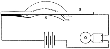
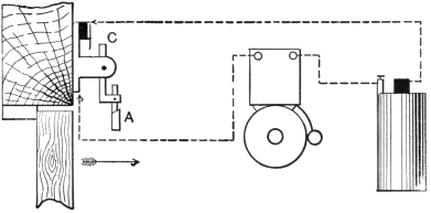
A door pull attachment, like Fig. 21, is made
so that the ordinary form of lever pull bell may
be changed into an electric bell. Being screwed
up near the door pull, a wire is run from the latter
and fastened to lever L. When the pull is
drawn out the lever L turns on a pivot and a
projection presses the insulated spring S against
the metal base B. The circuit of the bell and
battery being thus closed, the bell rings.
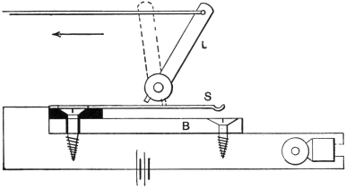
Fig. 21
A push button is
made which contains in the base a small electromagnet
in series with the line. An armature on
a spring is fixed near the magnet poles. When
the push is depressed, the current travels through
this electromagnet, and as the circuit is made
and broken at the distant bell, it is also interrupted
in the electromagnet. The armature vibrates in
unison with the bell and thus gives an audible
indication that the bell is ringing.