HOW TO BUILD A MODEL LOCOMOTIVE.
As a preparatory step toward becoming an engineer, it is
highly desirable for the boy who looks forward to that honorable
calling to familiarize himself with the different parts of
the locomotive engine. This we have stated before.
There is no better way to accomplish it than to build a
model locomotive.
At first glance this may seem to be among the things impossible,
but it is not so, providing the boy has a mechanical
turn, and any boy who has not better not think of becoming
an engineer.
We now propose to give simple and accurate directions
for building a model locomotive, accompanying the same
with a series of illustrations, which we trust will be sufficient
for the purpose intended.
Before beginning we have one word of caution to offer.
Don't do your work in a hurry. Don't calculate on the
length of time it is going to take you to do it. Make up
your mind to understand each detail before you begin, and
to work slowly and carefully.
If you remember this you will probably be able to build
your locomotive. If you forget it you certainly will fail.
How to Begin.
First of all in building a model locomotive, as in every
other class of engineering work, it is necessary to get the
measurements correct in spacing out the different parts to
be joined together; and do not think that because it is only
a model you are making that any off-hand way will do, because
you will find before the engine is half finished that
great accuracy is necessary if you wish your model to work.
A slight mistake in the measurements of a large engine
will cause so much friction as to take half its power to overcome.
The same mistake with your model will stop it entirely.
In soldering be careful to get the metal thoroughly heated.
You will then get a firm joint—otherwise not.
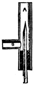
Fig. 1.
|
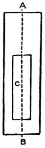
Fig. 3.
|
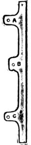
Fig. 4.
|
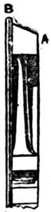
Fig. 6.
|
In giving these directions we assume that the boy who
will undertake to follow them is accustomed to the use of
tools to some extent. If not, he will have to learn as he advances
by repeated experiments.
Try your experiments on something else. In soldering, for
instance, solder pieces of brass together until you learn to
make a joint.
Don't try your experiments on your model, or you will
grow discouraged before you are half through.
A word more about soldering.
Do not touch the metal with the soldering-iron and then
take it away. You might be able to solder in that way but
the joint would not hold, but fall apart at the first pressure
or slight blow.
Soldering on the best work should be used very seldom,
and all the fastenings should be either done by riveting,
screwing or brazing, and it is hardly necessary to remark
that no part of a boiler should be soldered which comes in
contact with the flame of the lamp or furnace.
Brazing had better not be attempted by any boy who has
not been practically taught the art, unless it be on small
joints.
To braze the seams of a model boiler would require a
forge fire, or a very powerful gas blast—too expensive for
the amateur. Small things such as a broken slide valve,
rod, etc., can be brazed by using a gas blowpipe.
This will cost but little to make, and as it will be useful,
we explain. See Fig. 1.
To make a blowpipe such as is pictured in Fig. 1, first get
a small piece of brass tube, A, of about half an inch diameter,
and 5 inches long. Drill a hole at 2 inches from one end, and
insert a piece of gas pipe, B, soldering it in place.
Now take a glass tube a quarter of an inch in diameter and
7 inches long, hold one end in a gas flame, and when red-hot
draw it out to a fine point, then file round and break off
the tip, leaving a small hole.
Now take a sound cork and squeeze it into the tube A as
at C, drill a quarter inch hole through its center, insert the
glass tube D, and the blow pipe is finished.
To use it you connect the pipe B with a gas bracket by
means of a rubber tube, and attach the glass tube D to a
pair of bellows by means of another piece of rubber tubing.
The bellows should have an air-bag attached. Otherwise
you will have a jerky, uncertain flame.
When you want to braze any article, bind the parts together
with some very fine brass wire and cover with a little
powdered borax and water; then lay the article on a piece of
charcoal, and if it is necessary to preserve the temper of the
steel you are about brazing, cut a potato in half and push
each end of the steel rod into the halves, which will keep the
temperature from getting too high.
Then turn on the gas and start your blow pipe, at the same
time working the bellows with your foot, and by either pushing
in the glass tube D, or drawing it slightly out, you can
regulate the shape of the flame as required.
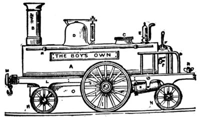
Fig. 2.
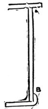
Fig. 11.
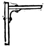
Fig. 5.
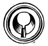
Fig. 7.
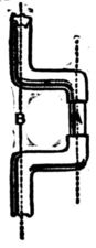
Fig. 8.
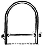
Fig. 12.
Now bring the flame to bear on the joint you wish to
braze, having first supplied plenty of borax. Soon you will
find the brass wire melting and running into the joint like
water. It must then be neatly filled up and the joint will be
scarcely visible.
Here are a few tools which will be useful to you in this
work.
A center punch, or steel spike for mashing metal for drilling,
etc., and a small riveting hammer. Three or four files
of different degrees of fineness, a screw plate and taps, a
small hand-drill with a set of drills to fit and a good firm vise.
A lathe is of course desirable. Curves for bending metal
you can easily make from pieces of bar-iron, holding them
in the vise while working on them.
When you have your tools ready get the material for your
model.
Several sheets of brass and copper, the castings and various
sized screws and bolts are what will be required.
All being thus prepared the time has arrived to take the
First Step.
The first step toward building a model locomotive is to be
posted on the action of steam in the cylinder.
Go to encyclopedia and read up on that point.
If you have no encyclopedia go and look one up in some
library. You can't build your engine until you understand
this.
Next draw an accurate plan of your model.
Figure 2 is the idea. It is a side view of our locomotive.
Let us describe.
A. Boiler.
B. Smoke-stack.
C. Screwhead, to fill boiler with water.
D. Steam chest with safety valve attached on top.
E. Whistle.
F. Steam tap to start the engine with.
H. H. Leading and trailing wheels.
I. Driving wheel.
K. Cylinders.
L. Frame.
M. Buffers.
N. Set thumbscrew to fasten on the tender.
O. The lamp.
P. Tap, used to ascertain the quantity of water in the
boiler.
R. S. Hand rail.
To all locomotives there are three principal parts, the
frame work, or carriage, the engine, or cylinders, and parts
connected with them, and the boiler.
Our model shall be a fifteen inch one.
Laying out Materials
is the next thing in order. First we want a sheet of brass
for the bed plate, 1/16th of an inch thick, cut 4×14 inches,
and be sure to cut the corners square. (See Figure 3.)
Hammer this out flat, file it smooth and dress up, with
emery cloth fastened upon a flat piece of wood.
Next cut a square hole in it as at C, beginning half an
inch from B, and making the opening 11 × 1-1/2 inches. Be
careful to center this hole on the line A B, or your engine
will be lopsided, and you must take the same care in setting
the smoke stack, dome, etc.
Now take Fig. 4. This represents one of the side frames.
Cut these out now, thus:
Drill holes at A B C for the axles to work in. Finish both
sides the same way. Turn the bed plate upside down, fasten
the frames on at a quarter of an inch from either side by
small angle pieces (Fig. 5), or by soldering, which is easier
done. Then solder a piece across each end, about half an
inch deep, and the frame is ready for the wheels.
These you can make if you have a lathe, but it would be
better to buy your wheels ready made if you can, but if you
can't do that, and have the lathe, turn your tires up to the
form shown in Fig. 6.
The small wheels should be about 2-1/2 inches in diameter,
and the driving wheels, 4 inches. The rim, B, should project
a little over 1/16th of an inch, and the rest of the edge
should be beveled off rightly, as at A.
The spokes should then be filed up smooth, drilling out
the center hole for the axle before removing it from the
lathe.
Great care must be taken to turn both the driving wheels
to exactly the same diameter, or one wheel would travel further
in a revolution than the other, and as they ought both
to be fixed rigidly on the crank shaft, the engine would never
travel in a straight line, but would go round and round in a
circle.
Get some steel wire for the axles and fasten them to the
wheels by soldering or by cutting a slot with a fine file in the
center of the wheel, as at A, Fig. 7. Then file a small portion
of the ends of the axle flat and drive in a brass wedge
made by a piece of wire which will hold them together
firmly.
The crank shaft, or axle, must be hammered up to shape,
making it hot occasionally in the gas flame while working
it.
The cranks should be at right angles to each other, and
the throw of the crank half the distance of the cylinder
stroke.
For instance, say the cylinder being a 1-1/2 inch stroke, the
distance between A B (Fig. 8) will be three-quarters of an
inch, you must then ease the size of the crank at A to prevent
the piston knocking the cylinder ends.
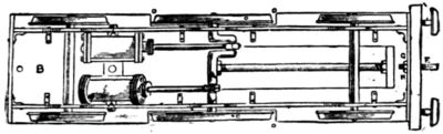
Fig. 9.
The cylinders you had better buy ready made or have them
made for you. Get a pair of oscillating cylinders of three-quarter
inch bore and inch and a half stroke. These will
drive your engines several miles an hour.
Fig. 9 gives an underneath view of the frame work and the
place to put the cylinders in. They must be supported by
two lugs, A A, screwed to the bed plate B, which must have
a piece cut out on either side to allow the driving wheels C,
to work in, as at D; because, being larger than the others,
they project beyond the top of the bed plate, as shown in
Fig. 2.
Next screw on by means of the hook F, the buffer beam,
previously cut from a piece of mahogany, 5 inches long, half
an inch thick and one inch deep, nicely squared and sand
papered. Drill a hole at G, and pass the shank of the hook
through the beam and piece of brass in front of the frame,
screwing up tight with nut H.
For buffers you may take two brass, flat-headed screws,
and attach them to the beam half an inch from either end,
allowing half an inch projection.
Now polish everything smooth and bright. Next warm
the model over the gas—don't let it get hot—and carefully
lacquer it with a small brush taking care not to go over any
part more than once. The spokes of the wheels must be
painted, the buffer beams varnished and the cylinders painted,
leaving the covers and flanges bright. Now put away your
work to dry, covering carefully from dust.
How to Make the Boiler.
In making the boiler you can't be too careful. This is the
part where the greatest chance for failure comes in.
Buy a piece of copper tubing 11 inches long, 3 inches wide
and half an inch in diameter.
If you want to make it yourself bend your copper round a
wooden roller and rivet or solder together—riveting is the
best if you can get it tight. You must then turn two circles
of brass about an eighth of an inch thick for the ends and
polish all. Fig 10 gives you the idea.
Now push the ends into either end of the tube about an
eighth of an inch from the edge, as at A, Fig. 11, and solder
in place. The projecting flange must be hammered down
all around as at B, soldered and finished with a half round
file. When filing solder use only an old worn file as a good
one soon fills up.
Smokestack, Tubes, etc.
Now drill a hole at A (Fig. 10) for the smokestack, which
should be three-quarters of an inch in diameter. Then cut
a slot in the bottom of the boiler 6 inches long by 1-1/2 inches
wide, commencing one-quarter of an inch from the forward
end of the boiler.
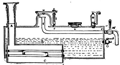
Fig. 10.
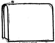
Fig. 13.
|
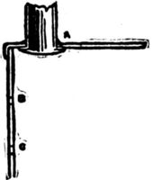
Fig. 14.
|
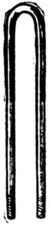
Fig. 15.
|
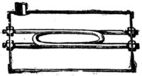
Fig. 16.
|
Next take a sheet of copper and cut a piece about 6-1/4
inches long by 6 inches wide and bend it over a wooden
roller to the shape shown in Fig. 12, keeping it 1-1/2 inches
apart between A and B. Cut also two other pieces of copper
to the shape of your bent sheet (Fig. 12), and make it long
enough to reach to the dotted line. These form the two ends,
and may be placed an eighth of an inch from the edges, as in
Fig. 13, and soldered in place, and the projecting rims turned
over and sweated with solder from the outside, in the same
manner that you did the boiler ends in Fig. 11. Then drill
a three-quarter inch hole at B (Fig. 13) for the bottom of the
smokestack to go into, and cut a piece of three-quarter inch
brass tubing of sufficient length to pass out at top of boiler
about half an inch, as shown at A, Fig. 10. You can then
hammer out a rim or flange on the bottom end of the smokestack
and push it up through the hole in the copper box,
soldering it in place from the top as at A, Fig. 14. Then
drill two small holes at each end of the box, B C, Fig. 14.
These should be a little more than an eighth of an inch in
diameter, to allow an eighth of an inch tube to pass through.
Now get two 12-inch lengths of hard drawn steam pipe,
an eighth of an inch in diameter, and with your screw plate
put a thread on each end, about half an inch in length.
Then make eight nuts to fit the threads on the piping, filing
them up into proper shape.
Now take the piping and bend it very gently, to prevent it
cracking, around a bar of iron or handle of some tool held in
the vise, until it is in the form shown in Fig. 15. Do each
one the same, then mix a little turpentine with white lead,
and smear each end, where you have formed the screws,
taking care not to get any into the tubes, which can be temporarily
plugged up.
Next put a nut at either end, as far as the thread will take
it, then smear a little white lead around the holes drilled in
the ends of the box, B C, Fig. 14.
Push the tubes in from the inside, and screw up firmly
with the remaining nuts, in the position shown at Fig. 16.
The inside nuts can then be tightened up with a wrench, and
if you do all this carefully, you will never be troubled with
any leakage, no matter what pressure you may get in your
boiler.
These tubes are immensely strong, and owing to their
small size, the water in them is raised quickly to a higher
temperature than that contained in the rest of the boiler,
causing a continual circulation to take place, and a constant
supply of steam to be found.
The box can now be placed in the boiler, through the slot
cut in the bottom, taking care that the top of the box is not
more than half way up the boiler, as at B, Fig. 10. This
will leave a portion projecting below the lower edge of boiler
like C. This part protects the flame of the lamp from being
blown away by the draught caused by traveling along, and
which would cause you to lose steam. Solder it firmly in
position from the outside to prevent the flame from touching
any soldered portion. Also solder neatly round A, Fig. 10.
The smoke stack can be made from another piece of
three-quarter inch brass; turn it up in your lathe bright
and put a collar on it at A Fig. 17, to allow it to push on
to the piece of tube left projecting at A Fig. 10.
The top of the smoke stack, B Fig. 17, will also require
turning in the lathe and must be fitted on neatly.
Get advice from some mechanic about the steam chest,
which is a brass casting and will have to be turned up in the
lathe, and after cutting a circular hole in the top of the
boiler of about an inch in diameter it can be either screwed
or soldered on, previously putting the steam pipe E in
position by drilling a hole at F and after bending it as
shown, pass it through at F and solder in place. The top of
pipe E should be about a quarter of an inch from the top of
inside of steam chest.
Before soldering on the steam chest drill two holes as at G
H Fig. 10, one for the small lug G to be screwed into, which
holds one end of the lever of the safety valve, and that at H
should be drilled conical with a rimer, and the valve H can
be turned in the lathe and afterwards ground to fit the hole
with a little emery and water, by means of a slot cut across
the top and worked round with a screw driver.
The spring case of the safety valve I, Figure 10, is easily
made from a piece of one-eighth inch brass tubing, using
some small, hard, brass wire to form the spring. When finished
it should be hooked to the eye and screwed into the
boiler at V.
The manhole or screwhead, K, is used to refill the boiler
when it has steamed low and will have to be turned up to
shape, and the bed, L, which it screws into can be firmly
soldered on the boiler, having first drilled a hole slightly
larger than the diameter of the screw itself, which should be
sufficiently large to allow an ordinary tin funnel to be used
to refill by, and the screw ought to be long enough to hold a
leather washer under the head to keep it steam-tight.
The whistle, M, will require a hole drilled for it to be
screwed into, and that, as also the steam-tap, N, and water-tap,
O, can be bought cheap, ready to put on.
The tap O should be screwed in at a slightly higher level
than the top of box B, and when working the engine should
steam issue from it when turned on instead of water, you
ought to immediately blow off steam by safety valve H.
Then unscrew K, and refill the boiler with water.

Fig. 17.
|
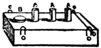
Fig. 18.
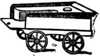
Fig. 19.
|
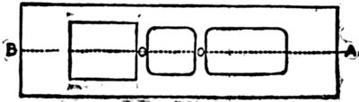
Fig. 21.

Fig. 22.
By this time the framework will be quite dry, no doubt, so
you can, after cleaning and polishing the boiler, attach it to
the frame by a screw or solder at the forward end, and the
steam-pipe N can be screwed on to the projecting piece of
tube left at F, while you also screw a short length of pipe
into the steam box of engine through a hole in the bed plate.
Then bend it up to the steam tap, and solder them carefully
in position; this will hold the after end of the boiler firm.
Go over every soldered joint to see if any small hole is left,
and resolder where necessary, as a hole in the boiler not
larger than a pin's point would prevent you from getting any
pressure of steam in the boiler, as the water would all blow
out.
Now lacquer or paint your boiler, and while it is drying
turn your attention to the lamp, which we picture in Fig. 18.
The Lamp.
The lamp is simply an oblong tin box, about 5 inches
long by 1-1/4 inches wide and three-quarters of an inch deep.
To make it cut a piece of tin 4-1/2 by 5 inches and bend it
to shape. Then solder the two edges together and cut two
ends to fit; push them in and solder in place.
Now cut three pieces of brass quarter-inch tubing into
three-quarter inch lengths; drilling holes in top of lamp, insert
them, allowing a quarter of an inch to project, as at A,
Fig. 17. Then solder them on four pieces of bent wire—C,
C, C, C, Fig. 18—by which to hang the lamp by means of
two wire pins run through them and small holes drilled in
the sides of projecting piece C, Fig. 10.
The screw filler B, Fig. 18, will have to be soldered in,
also, and when complete the tubes A may be filled with cotton
wick and the lamp about three-parts full of a methylated
alcohol, which will give a clear, smokeless flame.
Now you can start your locomotive by filling the boiler
about three parts full of hot water, and then hooking the
lamp underneath; you will soon get up a good pressure of
steam.
See that the taps are all turned off, and if there is no leakage
from careless workmanship, you will find on turning the
steam tap on, that the locomotive will run beautifully and
will travel at great speed either on a smooth oil-cloth or a
board floor.
On rails it would run quicker still, but for this engine, if
you make a small tender of the shape shown in Fig. 19, and
fasten it at any angle by the set-screw on the foot-plate of
the engine shown at N, Fig. 2, the model will run in any
sized circle you may wish without rails, according to the
angle you fix the tender to the engine.
Wooden cars you can make if you wish, but each one added
will reduce the speed of the engine, of course.
Tin is the best material to use for the tender, as no great
strength is required—indeed it should be made as light as
possible. The wheels and axles you must finish in the same
manner as those on the engine, and it can be made into a
tank to hold an extra supply of alcohol by soldering a piece
of tin round the inside and covering it in with another piece
cut to shape and fitted with a screw nut to fill by as shown
in Fig. 18.
Such is the method of constructing a model locomotive
which will run without complicated machinery.
The boy who has succeeded in following these directions
will no doubt be ambitious to try his hand on a more complete
model on a larger scale, something like Fig. 20 for instance,
which is a side view of a large model locomotive in a
finished state.
How to Build a Large Model Locomotive.
In building a large model the first thing to be done is to
decide how large you want it. Sketch your model carefully,
or, if not able to draw plans, get some one who is to help
you. Make your plan the exact size of the model you intend
to build, then you can take all the measurements from it and
save yourself a lot of trouble and time.
Remember, however, that the larger you make the engine
the more expensive the castings and materials will be.
Should you persevere, however, and by good fortune succeed,
you will have a model locomotive that would cost you
two or three hundred dollars to buy ready made. If you
have a lathe and can turn the wooden models for the castings
yourself, use sheet iron for the frame-work, etc., where
possible; the total expense will not be so very great.
Begin your work in the same way you did on the other
model. If you want a bigger engine than the one shown in
Fig. 20, there would be no trouble in increasing the measurements,
which we are about to give, proportionately, remembering
that Fig. 20 is drawn to an eighth-inch scale.
Dimensions.
Make your dimensions as follows: Length over all, 3 ft.
2 in. Length of bed-plate, 3.5 in. Width of bed-plate, 9 in.
Diameter of driving wheels, 8-1/4 in. Diameter of leading
wheels, 5-1/4 in. Gauge—that is width of track on which
model can run—6-1/2 in. Cylinders, 1-3/4 in. bore by 2-1/2
in. stroke. Length of boiler, including smoke box, 28 in.
Diameter of boiler, 5 in.
Cylinders of the above dimensions will drive the engine at
a high rate of speed, with from 30 to 50 lbs. of steam.
Description of Large Model Locomotives.
In Fig. 20, the different parts of the engine are lettered,
and it will be well for the boy who desires to make a locomotive
like it to compare the following description with the
cut, before he does anything else.
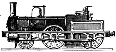
Fig. 20.
A is the smoke stack and B the steam blast used to increase
the intensity of the fire worked by rod C running
through the hollow hand-rail D and ending in handle F. G
is the steam-dome, which with the safety valve is the same
pattern previously used. H is the extra safety valve, worked
from the foot-plate. I is the steam whistle, K wind guard,
L starting lever, M smoke-box with door, N O spring buffers;
P is the line-clearer or wheel guard. Q are the leading
wheels, R R the driving wheels, S is one of the cylinders with
piston rods and guides bolted to frame and showing double
connecting rod at T T. U U are the springs which support
the weight of the boiler, etc., on the axle bearings. The
spring or rear wheel does not show, being inside the safety
guard and hand-rail V. W is the back pressure valve,
through which the water is thrown by the force-pump into
the boiler, and X is the blow-off tap to clear the engine
from all water after having used it. Y shows the side of the
ash-pan.
How to do the Work on the Large Model Locomotive.
First of all comes the frame work. It wants to be of
eighth inch sheet iron squared up perfectly true and flat
and cut as is shown in Fig. 21, beginning 4-1/2 inches from
A, and leaving 6 inches at B, and cutting it 6 inches wide
there by 8 inches long, and continuing it 4 inches wide for
the rest of the distance. Be careful to keep it quite central on
the line A B, and leave two connecting strips 1 inch wide
as at C C.
The side frames come next. These must be much stronger
and quite different from those used in the previous model.
They may be cut from the same eighth inch iron to the
shape shown in Fig. 22.
The center of slot B is 17 inches from one end, the center
of A 10 inches from B, and the center of C 13 inches from B.
In measuring, always start from a given center if you want
to be accurate. That is, from B to A and from B to C; not
from B to A and from C to B.
The slots are each 1-1/4 inches wide by 2 inches deep, leaving
1 inch of iron at the top, as shown. The four large
boles shown in Fig. 23 are only ornamental, and can be now
cut out. They also serve to lighten the frame.
The frames, after being smoothed up can be fastened to
the bed plate in the manner described before, by angle-irons,
or knees, riveted on.
Two end pieces must also be prepared. Let them be 1
inch deep, with the ends hammered square, at right angles,
and then riveted to the bed plate and side frames, as shown
in Fig. 20. Then drill three holes in them, about an inch and
a half from either end, and one in the center, by which to
bolt on the buffer beams by means of a couple of screws put
in at the back. The buffer beams should be mahogany, 1
inch wide by 2 deep by 10 long, squared nicely and sandpapered.
A hook can then be made—Fig. 23—and a hole
being drilled in the center of the beam, you can pass the
hook stem through and into the central hole of framework,
and screw up tight with nut at back, which will hold all
firmly in place. The buffers for this model must be properly
made, with springs to take the pressure in case you should
run into anything.
Fig. 24 shows this buffer. You will have to get it cast.
Turn out in your lathe a wooden mold and get four castings
in brass made from it. A Fig. 24 is cast with a square base
plate 2 inches square, as in front view B, and is secured to
the buffer beam by four flat-headed screws. The piece C
must be turned true and just the size to slide in and out of A
easily. Each part must be finished up in the lathe. A should
be an inch and a half long. Drill a hole in the buffer beam
to allow the head of the pin to work freely, and another hole
in base plate of buffer the size of the pin, whose head prevents
the spring from forcing C entirely away from A.
The spring should be made of thick steel wire; the buffers
can then be screwed in as just mentioned. The wheel-guard
or line-clearer P (Fig. 20) can next be cut out to shape and
bolted on to frame, and should just clear the line by a quarter
of an inch.
We will now proceed to the axle bearings and springs, U,
Fig. 20.
Make a wooden model like Fig. 25, and get 6 castings in
brass made from it. They must then be filed up square and
smooth and fitted into the slots cut at A, B, C, Fig 22, and
either screwed or riveted on by the side holes. Before
finally fixing them prepare 6 brass bearings, B, Fig 25, which
must fit exactly and slide easily in the inner surface of A,
then drilling a hole through each five-eighths of an inch in
diameter. These take the axles, which in this model are all
straight, and three-quarters of an inch in diameter, shouldered
off to five-eighths for the bearings.
Next for the springs. Take 4 pieces of either sheet iron or
brass for the supports, 1-1/2 inches long by 1/4 inch wide. Drill
a hole in either end as shown at C, Fig. 26. A should be three-eighths
of an inch wide, drilled through, a pin put in and all
riveted together loosely.
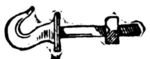
Fig. 23.
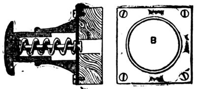
Fig. 24.
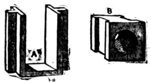
Fig. 25.
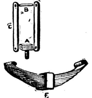
Fig. 26.
Now take a clock spring and cut it into shape, as at D,
Fig. 26. The top piece requires to be made hot with your
blow-pipe, then the ends turned over to hold the pin B. Each
piece of spring must be a little shorter than the one above
it, and the ends neatly tapered, all to be inclosed in the
brass band F, which has a small hole drilled at F to hold the
end of the pin by which the pressure is directed on to the axle
boxes, as shown in Fig. 20. A hole is also to be drilled in
the bed plate over the center of each axle box to allow the
pin to pass through, and also a smaller one an inch and a
half on each side for the support A, Fig. 26, to screw into.
Now all can be fitted into position.
Next come the cylinders. These are to be an inch thick
and three-quarters bore by two and a half inch stroke. They
should be of the fixed slide-valve pattern, with double eccentrics
fitted on the middle axle shaft, and reversing lever
brought to quadrant on foot plate. They had better be
bought ready made.
Fig. 27 shows their working. A A are the eccentrics, B the
slide-valve rod with guide G attached. C C is the bed plate
and D the balance weight, F the rod leading to quadrant and
lever on foot plate. The cranks are put on outside the
wheels and fastened by keys as in Fig. 20. The connecting
rod T should be cut to the form shown in Fig. 28, and the
ends squared out and a brass band fitted in with a hole drilled
from top A to oil by and a set screw B to adjust the
bearings perfectly.
If you wish to fit a force pump it should be placed centrally
between the cylinders and be worked by an eccentric on the
main shaft, but a pump on a model locomotive is next to
useless unless it is also made to work by hand.
In Fig. 29, we have one which can be worked either way.
A is the pump; B the eccentric on main-shaft to work it by
steam power. To work by hand you have only to push up
hook connection C, which disconnects it from the eccentric;
and then by working the handle D, which is screwed into the
bottom of the plunger C, the water is forced into the boiler.
An extra stuffing-box at F will be required. G is the exhaust
water pipe bent up to the back-pressure valve on boiler, and
H the supply pipe carried on to rear of engine.
Two small blow-off cocks will be necessary on each cylinder
to get rid of the condensed steam when starting. They
can be connected with a tye-rod, and both worked from the
foot-plate with a single handle. Now paint to suit your
taste and put away to dry.
Next comes the boiler, which will need extreme care. For
this you will require sheet copper an eighth of an inch thick.
First cut a piece 19 inches long by 16 wide and bend it
round, forming a cylinder 5 inches in diameter. The cap
must be closely riveted and the two ends hammered out into
a flange outward, leaving the body of the boiler 17 inches
long, as in Fig. 30. B is the shape of the piece to be next
riveted on at after end. Now take another sheet 9 inches
wide and hammer a half inch flange round it, so as to fit over
the dotted line at A. Rivet them firmly together and also
another piece in after end. It will then have the appearance
of Fig. 31, and should be 4-1/2 inches deep from A to B, and
forming a copper box 6 inches wide from B to C and 8 inches
from C to D. Then rivet together another box to form the
inner casing 4-1/2 inches wide by 6-1/2 inches long and 9 inches
deep, the bottom to be hammered outward to the dimensions
of B C C D, as shown in section Fig. 32 at A A.
A hole is next to be cut out in the center of rear plate and
also the rear part of inner casing which comes opposite to
it, and 1-3/4 inches by 2-1/2 forming the furnace door.
A casting of that shape and 3/4 of an inch thick, which is
the distance between the inner and outer casing B C, must
be procured and drilled with holes every 3/8 of an inch and
firmly riveted in position, as shown in Fig. 32 at D. Two
pins should project on either side of the inner surface to support
the fire-bars and ash pan, and the bars should be made
of cast iron and small enough to get out easily by tilting
up one side; they should run lengthwise of the engine.
For the boiler tubes some hard drawn brass tubing three-quarters
of an inch in diameter will be required. Cut the
pieces slightly over 17 inches long, then drill 10 holes in the
inner plate as at E, Fig. 32, and in the position and arrangement
shown in Fig. 33. These tubes should have a wire
ring brazed on about a quarter of an inch from either end,
and then being placed in their respective holes in the tube
plate, the projecting portion is to be headed back with a
flange, or you can fit them in as already shown in Fig. 16 by
each being double screwed and nutted. These tubes allow
the smoke and flame to pass through from the furnace to the
smoke box, M, Fig. 20, and so away up the smoke stack, and
by the large surface they expose to the fire, help to raise
steam very quickly. In some engines as many as 300 tubes
are fitted.
The steam supply pipe and regulating lever handle should
now be made and placed in position, and Fig. 34 shows the
shape to make it. A B are the front and rear plates of the
boiler, C is the supply pipe bent with a screw end downward,
after passing plate A, and then upward into the steam dome,
where it should be securely fastened into a cross-piece. D
is the tap or valve which can be turned on or off from the
foot-plate by means of the long rod, F, ending in the lever
handle, G.
The rod must be fitted with a stuffing-box, the same as
those used on the cylinders, and packed with cotton wick to
prevent loss of steam by leakage. When all this is complete,
the forward end of the boiler can be furnished with a tube-plate
riveted on and the tubes flanged over.
Now the boiler must go to a practical brazier, and be
properly brazed. Cut the hole for the steam dome, and let him
braze it on at the same time. If the job is practically done,
your boiler can be heated red-hot without fear.
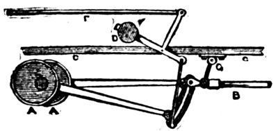
Fig. 27.
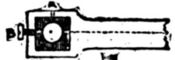
Fig. 28.
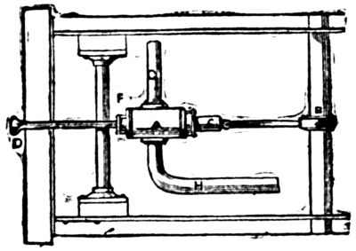
Fig. 29.
Meanwhile buy your pressure gauge—it wants to be one
and a half inches in diameter—and let the brazier test your
boiler to 100 pounds steam to the square inch capacity.
Should it burst you will have to make another. If not you
need thereafter have no fears.
Now make the smoke box, which should be three inches
deep and of the shape and dimensions shown in Fig. 35. This
and the smoke-stack can be made of iron, hammered up to
shape and finished with a brass ring. The smoke-box can
be screwed on the forward flange or boiler.
The door is drawn open to show the amount of bulge it
should be hammered to. In the center a hole should be
drilled through which to pass the screw used to close it,
which is attached to the loose bar, A. The handle, B, is
then screwed up tight.
The door is circular and must be large enough to overlap
the opening about half an inch and have a couple of bright
iron or brass eyes, C, riveted on to form the hinge.
Next comes the back-pressure valve, Fig 36. A is a front
view with plate by which it is bolted to the boiler, as at W,
Fig. 20.
It is very simple to make, and consists of the casting A
with top and bottom covers and the ball-valve B, which
ought to be ground with a little emery and oil to fit perfectly.
It acts in this manner.
The water being forced up C from the pump, raises B and
passes into the boiler. On the up stroke of pump, the pressure
is removed from under B and the pressure of steam in
the boiler causes it to fall back and close the opening entirely,
preventing any water from passing away from the
boiler. A small flange can be put on each outer side of the
boiler near the furnace to support it on bed-plate level with
smoke box.
The boiler should now be covered with flannel, cut to shape
and wrapped round the body part and a casing of sheet tin
put over it and secured by brass bands and small nuts underneath—as
shown in Fig. 20.
The steam supply pipe can now be connected with the
cylinders and it should be made forked as in Fig. 37. A
leads from steam pipe and branches off to each cylinder,
where it must be screwed up with white lead.
The exhaust pipes B B should be of larger tubing and bent
round up the sides of the smoke box so as to be out of the
way when you have to clean the tubes. A small brass pipe,
C, must also be passed through the chimney, bent upwards
and fitted with a tap which should take the steam from
the top of the boiler and be used as shown at D F Fig. 20.
This helps to raise steam very quickly.
Fig. 38 is a rear view of the foot plate and shows the necessary
fittings which you must either make or buy to complete
the model.
The cocks you might make but the water gauge you must
buy. A is the furnace door, B two gauge taps, C starting-lever
handle, D spring balance safety valve, F wind-guard
with two look-out holes, G steam whistle handle, H pressure
gauge, N the quadrant and lever for reversing the engine, O
the rear buffer beam with buffers, P the wheels showing axle,
R R the springs for same and V the safety-guard rail on
either side.
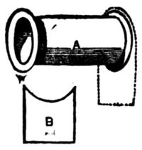
Fig. 30.
|
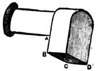
Fig. 31.
|
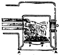
Fig. 32.
|
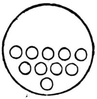
Fig. 33.
|
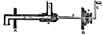
Fig. 34.
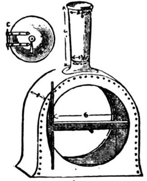
Fig. 35.
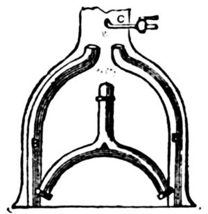
Fig. 37.
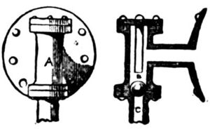
Fig. 36.
When these fittings are all complete holes must be drilled
in rear plate for each piece; they must be firmly screwed in
place with white lead. The glass tube of the water gauge,
the stuffing-box, and the gland of the starting lever should
be closely packed with tallow and cotton wick.
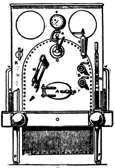
Fig. 38.
Next paint the entire model over again and let it dry. We
give no directions as to colors; use your own taste. After
the paint is thoroughly dry varnish with the best clear, hard
varnish and let it dry again.
While it is drying you can be making the rails.
Get some square bar iron, cut it into six-foot lengths, if
you wish the rails to be portable, and drill a hole in each
end half an inch deep.
The rails can be joined together at each end by means of a
piece of wire and kept at a proper distance apart by being
fastened to pieces of wood placed like sleepers, fastened by
screws passing through holes drilled in the rails every six
inches. These sections can be laid end to end, and your
line be made as long as you wish. If you want a circular
line, each section must be bent to a portion of a circle; one
about 30 feet in diameter is suitable for this model.
When finished place your locomotive on the track and get
up steam. Fill the boiler with water by means of a funnel
until you see it rise up three parts of the way in the glass
water-gauge. Then see that all taps are turned off and start
the fire. Charcoal is the best fuel, as it gives a clear, hot
fire without much smoke once you start it right.
Try the safety-valve occasionally to see how your steam is
getting on, and when it begins to form turn on the blast-tap,
which will soon draw up the fire, and you will presently
see the pressure rise and show itself in the pressure-gauge.
When the gauge shows 30 lbs. of steam you might start
the model by turning on the cocks on cylinders until no
more condensed steam issues from them.
Then shut them off and turn on steam full power and
watch the engine travel, gradually increasing its speed.


