The toys shown opposite page 90 are a few of the many
mechanical toys which can be operated by clockwork,
and they are easy to make, too, requiring no more mechanical
ability than is possessed by the average boy old enough
to handle the simplest of tools.
Generally it is easy to find an old clock somewhere
about the house, and a clock which has been discarded
simply because it has become worthless as a timekeeper
is perfectly good for operating these toys, provided the
mainspring is in working order. It is not necessary to
have a set of works for each toy, for they are so quickly
fastened in place that but a minute is required to transfer
the works from one toy to another.
Before commencing work upon the toys, get together
The Other Necessary Materials. These will consist of
cigar boxes, cardboard, cotton or silk spools, glue, brads,
and a few pieces from the woodpile, with one or two additional
articles which are mentioned later on. Brads
5/8 inch and 1 inch in length should be purchased for fastening
the framework of the toys together, and the cigar
boxes should be about 8 inches by 4 inches by 2 inches
in size. Remove the paper from the boxes as described on
page 175.
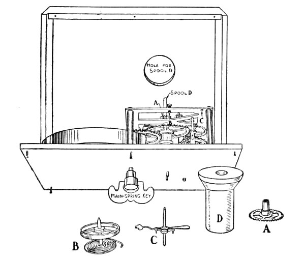
Fig. 139.—How the Clockwork Motor is Fastened to the Cigar-box Cover.
(This Box has been cut down to the Proper Length for the Ferris Wheel.)
To Prepare the Clockwork for use, remove it from its
case, detach the hands and face, and pry off the small
wheel pivoted directly under the hands; this wheel is
shown at A in Fig. 139. Remove also the balance-wheel
B (Fig. 139) and the lever C pivoted next to it, to increase
the speed of the remaining wheels.
Fasten the clockwork motor for
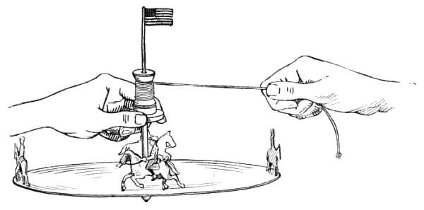
The Merry-go-round shown in Fig. 135 to the cover of
a cigar box, as illustrated in Figs. 136 and 139, boring
holes through the cover with a gimlet for the pivot ends
on the back of the works to set into. Remove the lower
flange from a spool (D, Fig. 139) and fasten the spool
on to the central pivot of the clockwork in the position
formerly occupied by wheel A. The hole in the spool
will be too large for the pivot and must be filled up with
sealing-wax. To do this, hold a piece of sealing-wax
above the spool and melt it with a lighted match, allowing
it to drip into the hole until the latter is about half
full, then press the wax down with the end of a match
until it is compact, smooth it off on the bottom of the
spool, and make a dent in it with a pencil to indicate the
exact center of the hole. Heat the end of the pivot with
a lighted match, and press it into the dent in the wax,
being careful in doing so to get the spool straight upon
the pivot. Cut a hole through the bottom of the cigar
box belonging to the cover to which you have attached
the works, for spool D to project through (Fig. 139).
To Make the Standard for the merry-go-round, cut four
strips of wood 8 inches long, and fasten one to each corner
of the cigar box, turning the bottom side of the box up;
then cut a piece of ½-inch board 10 inches square, locate its
center F by drawing diagonal lines from corner to corner
as shown in Fig. 140, bore a 1-inch hole through it at this
point for spool D (Fig. 136), and then nail the box to the
center of the board as shown in Fig. 140.
The Tent should be laid out upon heavy white paper
as shown in Fig. 141. After describing a circle with a
radius of 9 inches, describe another circle within it with
a radius of 7½ inches, this inner circle (shown by dotted
lines in the diagram) being drawn for a guide in fastening
the tent upon its tent-poles.
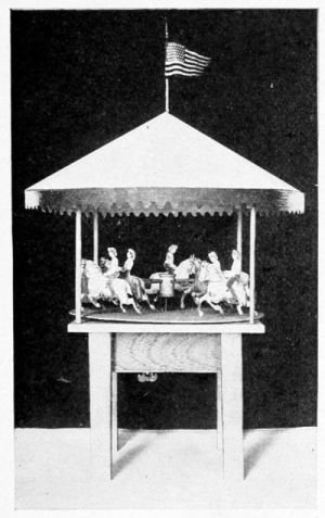
Fig. 135.—A Merry-go-round.
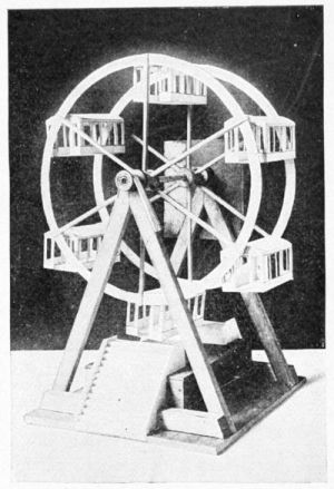
Fig. 137.—A Ferris Wheel.
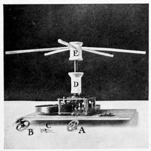
Fig. 136.—A Clockwork Motor.
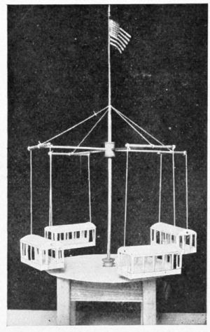
Fig. 138.—The "Flying Airships.
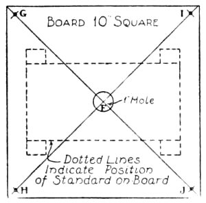
Fig. 140.—Plan of Top of Standard for Merry-go-round.
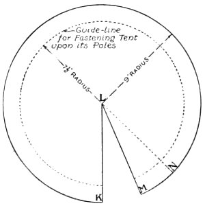
Fig. 141.—Pattern for Tent of Merry-go-round.
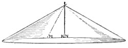
Fig. 142.—The Tent ready to be Fastened upon a Tent-pole.
Cut out the tent
along the outer circle, and from it cut a triangular piece
about the size of that included between lines KL and ML
in the diagram. Cover the under edge of KL and the
upper edge of ML with glue, lap KL over to about NL, and rub
down the edges with a cloth to make as neat a joint between
the pieces as possible (Fig. 142). Bore a hole through
each corner of the standard top (G, H, I, and J, Fig. 140),
then cut four sticks 7 inches long, sandpaper them until
smooth, and glue them into these holes for
The Tent-poles. When the tent has dried, tack it to
the ends of the poles, being careful to make it set evenly
upon them; cut a scalloped border out of red or blue
paper and paste it to the edge all around as shown in
Fig. 135, and stick a small flag in the peak.
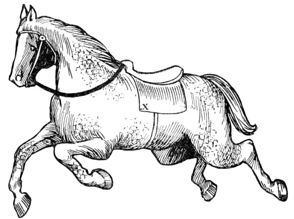
Fig. 143.—Full-size Pattern for the Horses of the Merry-go-round.
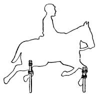
The Horses. A full-size pattern for these is shown in
Fig. 143. Take a piece of tracing-paper or any thin transparent
paper, and place it over the pattern and make an
exact copy; then rub a soft lead-pencil over the other side
of the paper, turn the paper over with the blackened side
down, and transfer the drawing six times upon a piece of
lightweight cardboard. Paint the horses with water-colors,
using the pattern as a guide for shading and marking
them, then cut them out with a sharp knife or a pair of
scissors.
Figure 144 shows the pattern for
The Sleighs. Draw this out upon a piece of cardboard,
cut it out and fold along the dotted lines, then turn
in the flaps and glue them to the dashboard and to the
back. Cut two seats by the pattern given, bend down
the flaps and glue them to the sides of the sleigh, and
make the back for the front seat like that on the back
seat (Fig. 145). Then make another sleigh similar to
the one just completed, for two are required for the merry-go-round.
Paint the sleighs green or yellow with trimmings
of a lighter shade.
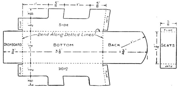
Fig. 144.—Pattern for the Merry-go-round Sleighs.
Figure 136 shows
The Shafts upon which the horses and sleighs are
mounted. Cut them 5½ inches long, whittle them round,
and rub them down with sandpaper. The shafts are
fastened in a spool hub which has five holes bored in it (E,
Fig. 136); bore the holes with a gimlet or small drill,
marking them off first with a pencil to be sure of getting them
spaced at equal distances. Point the ends of the shafts and glue
them into the holes in the hub, then connect this spool to spool
D with a piece of a lead-pencil 2 inches long (Fig. 1366).
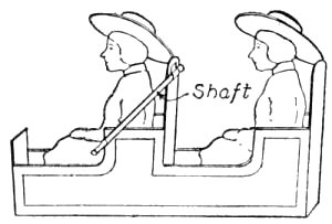
Fig. 145.—A Completed Sleigh showing Attachment to Shaft.
To fasten the horses to the shafts, punch a hole through
three of them at X (Fig. 143) and slip each one over a
shaft, then tack the other three horses to the ends of these
shafts at the point X. To fasten the sleighs to the remaining
shafts, glue one end of a piece of paper to the
back of the front seat and the other end around the shaft
(Fig. 145).
The Girl Riders for the sleighs are shown full size in
Fig. 146, and
The Boy Riders for the horses are shown full size in
Fig. 147. Make tracings from the patterns as you made
that of the horse and prepare four girls and six boys.
Paint their clothes in bright colors. Cut a second leg
for each boy rider, so he can be made to sit astride of his
horse, and glue the leg to his hip as shown in Fig. 148.
Cut a slit in each seat of the sleigh and stick the flaps on
the girl riders in them.
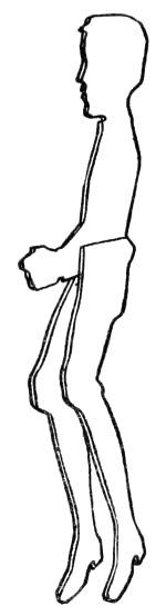
Fig. 148.—How the Second Leg of the Boy is Attached.
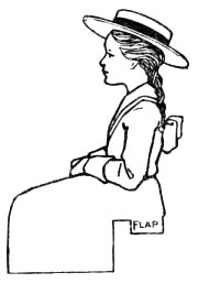
Fig. 146.—Full-size Pattern for the Girl Riders.
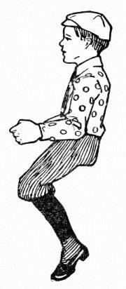
Fig. 147.—Full-size Pattern for the Boy Riders.
For the Platform shown directly under the horses and
sleighs in Fig. 135, cut a piece of cardboard 11 inches in
diameter; if you choose to make the Ferris wheel before
the merry-go-round, you may use the center pieces removed
in cutting out the rims, as noted in Fig. 153. Punch
a hole through the center of this disk large enough for the
peg connecting spools D and E to slip through. This
platform rests upon the top of spool D and revolves with it.
To Operate the Merry-go-round. The key by which
the mainspring is wound up is shown screwed in place on
the under side of the cigar-box cover in Fig. 139. While
winding the mainspring, it will be necessary to have some
means of checking it so it will not unwind at the same
time, and the best scheme for a check is to bore a small
gimlet hole through the cover of the cigar box and stick
a match through this and run it between the spokes of one
of the clock wheels so as to prevent it from turning. Then
when you have wound up the spring and are ready to start
the merry-go-round, all you have to do is to pull out the
match.
The model of this toy which the author has before him
runs for five minutes with one winding, and any boy can
make one which will run as well if he follows the directions
given and uses a reasonable amount of carefulness in the
work.
Other Animals than horses may be used if you wish to
follow the arrangement of some of the latest merry-go-rounds,
and pictures of these may be found among the
colored cut-outs sold in the stationery stores, or if you
can draw well, you may copy them from books and magazines.
Great fun may be had by changing the positions
of the boy riders, making them ride backward part of the
time and sometimes two and three boys on a horse.
Doubtless you have heard of the famous Ferris wheel,
and a good many of you have ridden in the smaller wheels
patterned after it, at the amusement parks, so you will be
interested in making
A Miniature Ferris Wheel like the one shown in Fig. 137.
The Standard for supporting the wheel (Fig. 149)
consists of two triangular supports, one with a spool hub
fastened to its top for the axle of the wheel to run through
and the other with the cigar box inclosing the clockwork
fastened to it. Figures 150, 151, and 152 show the construction
of these supports. Cut strips P and Q 12 inches
long and R 10 inches long, and trim off the upper ends of
P and Q so when they are nailed together the lower ends
will be 8 inches apart; nail strip R to the lower ends of
P and Q (Fig. 150). To
fasten the spool hub to its support, smear one side of
a piece of tape with glue and wind it several times
around the spool (Fig. 151),
then set the spool on top of the support and press the
ends of the tape against the
sides of strips P and Q (Fig. 152).
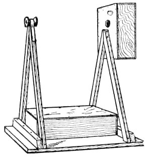
Fig. 149.—Standard for the Ferris Wheel.
The Clockwork Motor for the Ferris wheel is fastened
to the cover of a cigar box just as that for the merry-go-round
was fastened (Fig. 139), but the length of the
box is cut down as much as the clockwork will allow to
make the box as square and compact as possible.
It is very necessary to have the axle bearings exactly
on a line in order to have the wheel run smoothly, so, in
fastening the cigar box to its support, be sure that the center
of the hole in spool D (Fig. 139) is on a level with the
spool hub on the opposite support. Nail the supports to a
10-inch by 12-inch board, 8 inches apart, and fasten a
cigar box between them for
The Station Platform (Fig. 149).
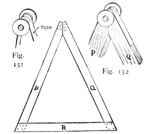
Fig. 150.—Make Two Supports like
this for the Ferris Wheel Standard.
Figs. 151 and 152.—How a Spool is
Fastened to the Top of the Support for a Hub.
To Make the Wheel, first lay out the rims upon a piece
of heavy cardboard, using the radii shown in Fig. 153
for describing the circles, then lay the sheet of cardboard
upon a board and
Cut out the Rims with a sharp knife, being careful
not to run off of the pencil line. The
Hubs of the wheel are spools with six holes bored
in them for the spokes to fit in (Fig. 156). Cut six
Spokes 5¾ inches long
by 1/8 inch thick for each
hub, and cut a slot in one
end of each for the cardboard rims to fit in (Figs. 154
and 157). Use a saw rather than a knife in making the
slots, for it will make a kerf of just the right width to
receive the cardboard and will not be so apt to split the
ends of the slender spokes. Whittle the hub ends of the
spokes to fit the holes in the spool hubs (Figs. 154 and
157). In
Putting together the Spokes, Hubs, and Rims of the
wheel, first stick three spokes in a hub and slip a rim into
the slots in their ends, then stick the remaining spokes
into the hub, one at a time, and spread the rim enough so
it can be slipped into their
slots (Fig. 155).
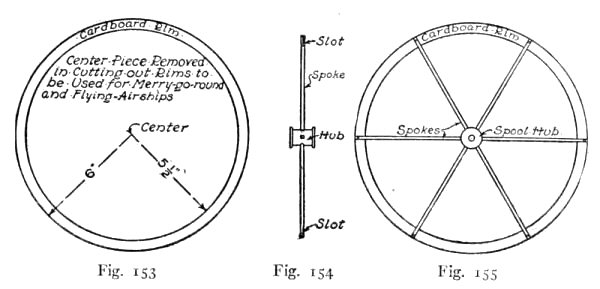
Fig. 153.—How to Lay out the Cardboard Rims of the Ferris Wheel.
Fig. 154.—The Spokes Fitted into the Spool Hub.
Fig. 155.—The Rim Slipped into the End of the Spokes.
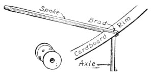
Fig. 156.—A Spool Hub for the Wheel.
Fig. 157.—How the Spokes, Rims, and Axles are Fastened Together.
When the hubs, rims, and spokes have been assembled,
lay them aside and get some heavy wrapping-paper
or thin cardboard out of which
To Make the Cars. The pattern for the cars is shown
in Fig. 158, and on it you will find all the dimensions
necessary for laying it out to the proper size. It will be
understood that the unfigured portions of the drawing
are the same as those with dimensions marked upon them.
The dotted lines at the door and window openings indicate
where the cutting is to be done, while all other
dotted lines indicate where the cardboard is to be scored
and folded.

Fig. 158.—Pattern for the Ferris Wheel Cars.
Use a ruler in making the drawing of the car to get the
lines straight, and when you have finished it go over it
carefully and compare it with the illustration to be sure
it is correct, after which make a careful tracing of it, turn
it over and transfer the drawing five times upon cardboard.
These and your original drawing will give you the required
number of cars. Cut out the openings with a sharp knife
and then do the rest of the cutting with a pair of scissors;
punch a ¼-inch hole in each end of each car with a lead-pencil
(Fig. 158), being careful to get the holes exactly
opposite. In folding and gluing the cars, slip the flaps
inside and bend the roofs so they will follow the curve of
the ends (Fig. 159).
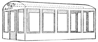
Fig. 159.—A Completed Car for the Ferris Wheel.
When the cars have been completed, cut six sticks
5 inches long, whittle them down until they are about 3/16
inch in diameter, and sandpaper them until they are perfectly
round and smooth. These sticks connect the rims
of the wheel and form
The Axles from which the cars are hung (Fig. 159).
Great care must be used in fastening them between the
rims, for they are easily split, and the best way to do is
to start a hole first in the ends of each axle with an awl
or by driving a brad part way in and then withdrawing
it; then drive a brad through each spoke of one rim into
an axle (Fig. 157); slip the other ends of the axles through
the holes in the ends of the cars (Fig. 159), and nail the
spokes of the other rim to them.
To Mount the Wheel upon its standard, whittle an axle
8½ inches long to fit the hubs, then hold the wheel between
the two uprights, with the hubs on a line with the spool
bearings and run the axle through the holes (Fig. 137).
Build Steps at each end of the platform out of heavy
writing-paper or light cardboard. Fold the paper or cardboard
back and forth, making pleats about ¼ inch wide for
the steps, and after gluing it in place cut out the balustrades
and glue them to the edges of the steps. Make the
top step low enough so there will be about ¼-inch clearance
between it and the bottom of the cars (Fig. 137).
After you have made a final inspection to see that
everything has been put together properly, your toy will
be ready for operation, and I am sure that when you set
the clockwork machinery in motion, and the little wheel
begins to revolve slowly with each little car balancing
upon its axle, you will agree that you have constructed
a very interesting toy.
The "Flying Airships" is a riding device consisting of
a number of cars suspended by steel cables from large
arms pivoted to the top of a tower. When the machinery
is started, the arms begin to revolve slowly, and the
motion produced causes the cars to swing out away from
the center. As the speed of the arms increases, the cars
swing out farther and farther, until when the highest
speed has been reached the cables by which the cars are
suspended have taken an oblique position and raised the
cars some distance above the ground; then the speed of
the engine is gradually diminished, and the cars finally
regain their former position. This piece of apparatus is
also known as an aerostat.
You will find the miniature flying airships (Fig. 138)
easy to construct after making a merry-go-round or Ferris
wheel, as many of its details are identical with those of the
other toys.
The Standard for the toy is made similar to the one for
the merry-go-round (Fig. 135), except that the top board
is omitted and a circular piece of cardboard of the size
of the disks removed in cutting out the rims of the Ferris
wheel is substituted in its place. Cut a hole through the
exact center of the piece large enough so it will fit over
spool D (Fig. 136).
Cut a Mast about 14 inches long and of the diameter
of the hole in the spool and stick it into spool D; then
3 inches below the top of the mast fasten a spool with
four horizontal arms 6 inches long glued into holes bored
in it. Fasten a crosspiece 4½ inches long to the end of
each arm with brads, and from these suspend
Cars made similar to those of the Ferris wheel, with
cords. Set a small flag in a hole bored in the top of the
mast and then run cords from the top of the mast out to
the ends of the arm pieces.
With this toy the cars cannot be swung out obliquely
as on the large flying airships except by
Increasing the Speed of the Clockwork. This can be
accomplished by removing one or two of the wheels of
the clockwork, but it is not advisable to take out more
than one wheel in addition to those removed for the merry-go-round
(Fig. 139) because the mainspring would require
rewinding too often to make the toy enjoyable.
An Electric Motor can be belted to these toys as a substitute
for the clockwork, if you own one and prefer to try
it out.
The clockwork toys just described were invented by the
author for his book "Handicraft for Handy Boys," and
were the first designs, he believes, devised for home-made
mechanical toys of this nature. No doubt you have noticed
that manufacturers of the so-called "construction sets"—steel
and wood strips supplied with bolts and screws for
assembling—have used these very same forms of models to
show what can be made with their outfits. But your
Ferris wheel, merry-go-round, and aerostat, built as described
in this chapter, with materials picked up at home,
will be the equal of any that can be built, and you will have
the satisfaction of knowing that you haven't required an
expensive "construction set" for making them.
All sorts of toy vehicles can be operated by clockwork.
Figure 160 shows
An Automobile, and Fig. 161 shows how the clockwork
motor is mounted upon the chassis and belted to the driving
wheel. The same scheme that was used for the cars of
the toy railway described in Chapter VI will be followed
in making
The Frame of the automobile, as that is about the simplest
way, and makes a light, easy-running vehicle.
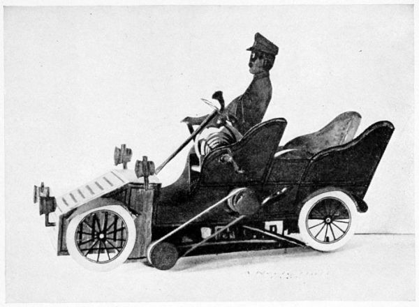
Fig. 160.—The Car Completed.
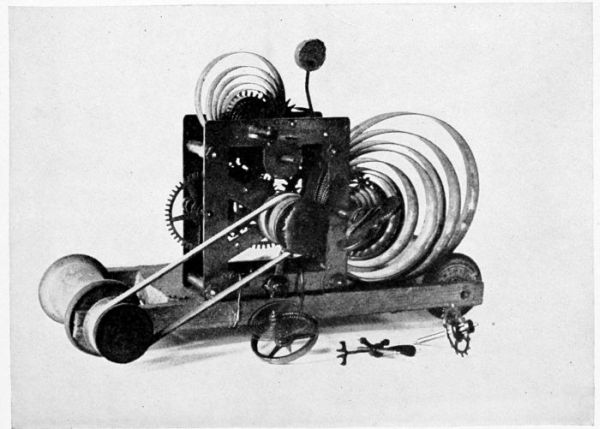
Fig. 161.—The Framework.
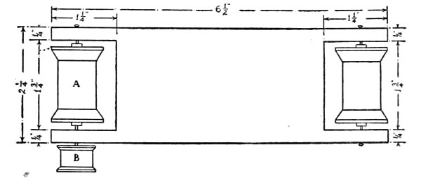
Fig. 162.—Top View of Wooden Frame.
The bed will be cut of a different pattern, however, as will be
seen in Fig. 162. Lay out the piece to the dimensions
shown upon this drawing, and then cut it out, making a
mortise in each end for the wheels to fit in. The spool
wheels should be mounted in the same manner as those
of the railway cars, for which see Fig. 80, Chapter VI, and
the directions upon page 51. One end of spool A should
be pivoted with a longer finishing nail than those used for
the other pivots, so that when driven in place about half
an inch will project beyond the frame. A small silk spool
should be fastened upon this for a belt-wheel (see B, Fig. 162).
The hole in one of these spools is about three-sixteenths
of an inch in diameter, so, in order to make it fit
tightly upon the nail, it is necessary to fill in around the nail
with sealing-wax. To do this, turn the wooden frame
upon its edge and place the spool over the nail, being
careful to get the nail in the exact center of the hole.
Then hold a stick of sealing-wax over the spool, and with
a lighted match melt the end and allow it to drip into the
hole. When the hole has been partially filled, allow the
wax to harden a little, and then press it down around the
nail with the end of a match, being careful not to throw
the spool out of center by doing so. The hole should then
be filled to the top.
We are now ready to prepare the clockwork for mounting
upon the wooden frame. The works shown in Fig. 161
are from an alarm clock, but if you have a striking clock,
or one with works a little different from those shown in the
illustration, it does not make a bit of difference in the
scheme for attaching the works. The three parts shown
in the foreground of Fig. 161 must first be removed from
the works. These will be recognized readily in any clock,
as they are pivoted close together, and regulate the speed
of the other wheels. When they have been removed, the
mainspring will unwind rapidly. The frame of the works
shown in the illustration is held together with nuts, so
that in removing the wheels it was necessary to unscrew
two of them, spring the frame open enough to let the
wheels drop out, and then replace the nuts again in their
former positions. If the frame of your clockwork is
riveted together, the wheels will have to be broken out.
A small silk spool, such as B (Fig. 162), should be fastened
upon the small pivot which originally operated the clock's
hands, for a belt-wheel. Lay the works upon a table with
the face-side down, and, after centering the hole of the spool
upon the pivot, fasten it in place with sealing-wax in the
same manner as you attached spool B (Fig. 161).
The works should now be attached to the wooden
frame. Place them with the striker uppermost, near the
edge of the frame, so that the small belt-wheels are in
line with one another. Then bore a number of gimlet
holes in the wooden frame and run copper wire through
them, passing it around the posts of the clock-frame and
twisting its ends until the works are firmly fastened in
place.
A rubber band about an eighth of an inch wide and long
enough to reach from one belt-wheel to the other should
be procured for
The Belt. This should stretch just enough to cling
upon the spools, as more than that would cause too much
friction.
Before going any further with the construction of the
automobile
Test the Machine, to be sure that it is in perfect running
order. Wind up the mainspring, pressing a finger against
one of the wheels to hold it in check until you are ready to
start the machine. When properly made, the clockwork
automobile should run a distance of from twenty to twenty-five
feet upon a wooden floor, while about three-quarters
of that distance should be covered upon a floor with a fairly
smooth carpet.
The Cardboard Sides and other details of the automobile
should now be made. The patterns for these have
been so shown in Figs. 163 to 170 that they can easily be
laid out to the proper shape and size by means of the process
of enlarging by squares described on page 175, Chapter
XVII. White cardboard should be used upon which to
draw these pieces, and the thinner it is
the easier you will find it to work with.
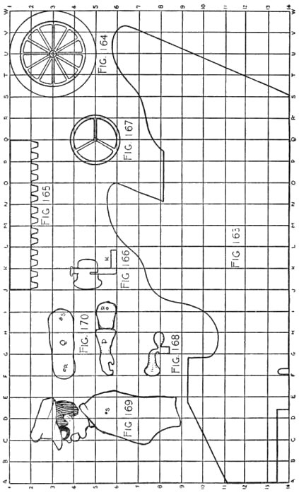
Figs. 163-170.—Patterns for the Automobile Touring-car.
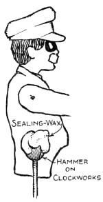
Fig. 171.—Chauffeur.
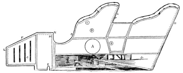
Fig. 172.—Cardboard Side of Automobile.
First prepare the two sides, cutting them out by the pattern of Fig. 163.
Then glue the bottom edge of each side to the edge of the wooden frame, cutting
holes in the left side for the belt-wheels and projecting posts to run through (see
Fig. 160 and A, B, C, D, and E,
Fig. 172). The top to the front of the car
should now be cut as shown in Fig. 173,
the distance between the sides being measured to get the piece of proper
dimensions. Bend the edges as in Fig. 173, and glue them
to the inner surfaces of the side pieces as shown by the
dotted lines in Fig. 172. In the same way cut and glue
a piece of cardboard between the side pieces at G and H
(Fig. 172) for the seat-backs. The bent edges of these
pieces are shown by dotted lines in the illustration. Draw
four
Wheels as shown in Fig. 164, using a compass with which
to describe the circles, and cut them out with a sharp
knife. You can cut out between the spokes, if you wish,
or leave them solid. Glue the wheels to the cardboard,
placing their centers about as located at I and J, Fig. 172. Four
Mud-Guards should be cut like Fig. 165, with flaps made
along one edge. Then bend these guards around the tops
of the wheels, and, after applying glue to the flaps,
press them against the cardboard side, holding your
fingers upon the flaps until
the glue has dried (see Fig. 160). The guards should be
placed a little above the tops of the wheels. Cut four
Lamps like Fig. 166 and glue end K of two upon the
front of the automobile at L (Fig. 172) and one of the
other two upon each side at M. These lamps are shown
in position in the illustration of the completed automobile
(Fig. 160). Draw and cut
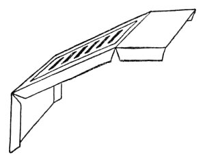
Fig. 173.—The Hood.
The Steering-wheel similar to Fig. 167, and, after pivoting
it to the end of a strip of cardboard with a pin as shown
in Fig. 174, bend the lower end and glue it to the under side
of the cardboard top F at N (see Fig. 172, also Fig. 160).
Make a
Horn like Fig. 168 and glue it to the steering-wheel
as shown in Fig. 174. A strip of cardboard about the size
of that used for the upright of the steering-wheel
should be cut for
The Brake, and glued to the inside surface
of the right side of the car at O (Fig. 172).
The Chauffeur should now be made. Cut
his head and body the shape and size of Fig. 169,
drawing the face upon each side with goggles over the eyes. Cut the arms in
two pieces the shape of P and Q (Fig. 170),
and then pivot P to Q at R and the end of
Q to the shoulder of the body at S, using
thread for fastening the pieces together.
Paint the hat, coat, sleeves, and gloves a leather color, and the face flesh color. The
body should then be fastened to the hammer of the clockworks
with sealing-wax, as shown in Fig. 171, while the
left hand should be glued to the edge of the steering-wheel
and the right to the end of the brake (see Fig. 160). By
thus attaching the body to the end of the hammer, and
winding up the small spring, the chauffeur will shake violently
when the auto runs across the floor, showing the
vibrations of the machine in a greatly exaggerated and
amusing manner.
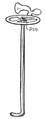
Fig. 174.—The Steering-wheel.
It is now only necessary to
Paint the Machine to complete it. The photograph
(Fig. 160) shows where different colors are needed. The
lamps, top, ends, and sides of the front portion of the car
should be painted the color of brass, and the rest of the
sides, with the exception of a strip along the bottom and
the edge of the arms, should be painted vermilion. Paint
the inside of the car and the edges of the seat-arms tan
color, to represent leather upholstering. With black
paint, or ink, stripe off the door and trimmings upon the
sides and top of the machine, as shown in Figs. 160, 172,
and 173. Blacken the brake and steering-wheel and the
spokes and rims of the wheels. Along the bottom of each
side glue a strip of cardboard for the running-boards.
When you have tired of your touring-car, you can easily
convert it into
An Automobile Delivery Wagon, such as illustrated in
Fig. 175. To make this you will require the same frame
as that used for the touring-car, with the clockworks and
belt-wheels attached in the same manner. If you have
made the touring-car, remove the cardboard sides from its
wooden frame, separating the cardboard from the wood
carefully so you can put the machine together again when
you wish. If you haven't made this automobile, you will
find the details for the construction of the frame in Figs. 161
and 162, and the manner of performing the work
described on pages 104 to 107.
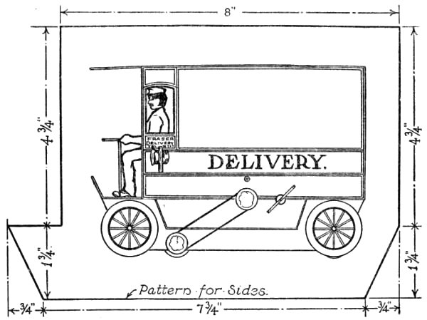
Fig. 175.—An Automobile Delivery Wagon.
The Cardboard Sides are much easier to prepare than
those for the touring-car, as they are straight and require
but little cutting. The outline for these is shown in Fig. 175,
surrounding the drawing of the completed wagon.
Lay out one side upon a piece of cardboard, using the
dimensions given upon the drawing, and then place it upon
a board and cut it out with your knife. Using this as a
pattern, place it upon another piece of cardboard and run
a pencil around its edges, thus marking out the second
side. In cutting out the latter piece, run your knife a little
inside of the line in order to allow for the increase in size
caused by marking it out with the first cardboard side.
Having prepared the two sides, draw panels upon them in
some such form as shown in the illustration, separating
them with three lines. Draw a small window, with its
top slightly arched, near the front edge of each side, and
cut an opening for it (see illustration).
Glue the sides to the edges of the truck in the same
manner as those of the touring-car were done, piercing
holes for the posts of the clockwork to fit in, and openings
for the belt-wheels to project through, in the left side.
Cut a piece of cardboard for the back of the wagon, fit it
between the sides, and fasten it in place by gluing a number
of linen strips to it and the sides upon the inner or unexposed
surfaces. Then cut a piece of cardboard for the
roof, making it about two inches longer than the sides, to
give it the proper projection over the front of the wagon.
Fasten this piece in position in the same manner as you
fastened the back of the wagon.
Make the floor and footboard for the wagon out of a
piece of cardboard bent as shown in Fig. 175, and fasten
it across the top edges of the projecting portions of the sides
with linen strips. Cut a strip for a seat, and fit it between
the sides an inch and one-half above the floor.
The Wheels of an automobile wagon contain fourteen
spokes, but as you have the pattern for the touring-car
wheels of twelve spokes, you can just as well use it in
making the wagon wheels. They should be mounted upon
the sides of the wagon, a trifle above the bottoms of the
spool wheels, as shown in the illustration, so they will not
touch the carpet when the machine is operated.
All Other Portions of the wagon should be made of the
same patterns given for the touring-car, viz. the chauffeur
(Figs. 169 and 170), the steering-wheel (Figs. 167 and 174),
the brake (Fig. 160), and the lamps (Fig. 166). As the
legs of the chauffeur will show, it will be necessary to cut a
pair out of cardboard (the drawing shows the shape clearly
enough to work by) and fasten them to his body. Fasten
the chauffeur upon the seat and glue his left hand to the
steering-wheel, placing the latter in front of him, as shown
in the drawing. Stick the lower end of the cardboard
upright of the steering-wheel upon a pin run through the
wagon floor from the under side. Glue the upper end of
the brake to the chauffeur's hand and the lower end to the
side of the wagon.
Paint the Wagon with water colors, making the sides,
end, and roof olive green, the steering-wheel, brake, and
spokes of wheels black, and the lamps yellow or the color
of brass. In painting the sides show the battery compartments
upon them below what would properly be the bottom
of the wagon (see illustration). Leave the cardboard white
below this box, as it represents no portion of the machine,
but is necessarily brought down so far to conceal the
wooden frame. It will give the machine a more finished
appearance if, after painting, you go over it with black
paint and a fine brush and stripe the panels upon the sides,
following the lines which you drew upon them with a pencil.
Letter the word "Delivery" upon the center panel of
each side, and the firm name in the small panel between the
lamp and window.
By attaching a set of clockworks in the same manner as
described for the automobiles, you can make
A Clockwork Railway, constructing the cars similar
to the street car shown in Fig. 84, Chapter VI, and using
the schemes in the same chapter for the tracks and depots.
Each car should be provided with a clockwork motor,
because a single clockwork is not strong enough to pull
more than one car. Let me know how you succeed in
building a clockwork railway.