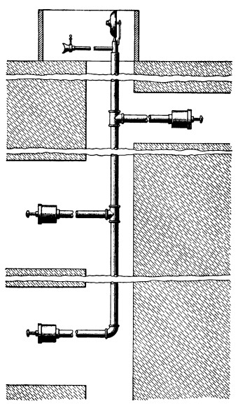
1. The hoist indicator is a mechanism attached to the drum
shaft of a hoisting engine to show the hoisting engineer the position
of the cage or skip in the shaft throughout the time of hoisting. The
use of such indicators is sometimes required by law, but there is a
great diversity of opinion as to the advisability of using them. The
objections to them are that they are liable to get out of order, and
that in general the use of any automatic device that tends to relieve
the hoisting engineer of responsibility and constant attention to his
engine is not to be commended. A hoisting engineer, however, depends
for his stopping point mainly on a mark made on the rope, or on the
drum, or on both, and uses an indicator mostly as a guide for the
position of the cage during the hoist.
TYPES OF INDICATORS
2. Column Indicators.—A very simple indicator, and one that
was formerly very commonly used, is made by inserting a pin into the
center of the end of the drum shaft and using this as a miniature
drum on which to wind and unwind a chain or cord, which corresponds
to the hoisting rope as the pin corresponds to the drum. This chain
or cord is led over a pulley placed at the top of a pair of guides,
representing the shaft, and carries at its end a weight, pointer, or
gong, representing the cage or car, as shown in Fig. 1.

Fig. 1
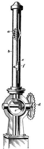
Fig. 2
The different landings in the shaft are marked on the guide; and as
the pointer or gong rises and falls it indicates the position of the
cage in the shaft. If a gong is used, pointer also may be added and
the gong so arranged that it will ring at a point some distance before
the landing is reached and thus attract the engineer’s attention.
Indicators of this kind, though cheap and easily constructed, are not
reliable, for the cord and chain may stretch or they may overlap in
winding on the pin, or may bind in the pulley and thus indicate a wrong
position of the cage.
3. An indicator should have a positive motion and be driven by
gearing or by link belts. Fig. 2 shows a column indicator
that consists of a screw a working inside of a slotted pipe b,
which may be of any length necessary. This screw is revolved by means
of the gears c, which are rotated by the sprocket wheel
d. A nut e travels up and down the screw a and
the pointer f attached to the nut indicates the position of the
cage in the shaft. The pipe standard b is usually painted a dead
black and the different levels may be marked on it with chalk or white
paint. Chalk marks are not safe, as they may be tampered with and the
engineer thus misled.
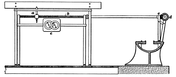
Fig. 3
The pointer a, Fig. 3, is moved by the rotation of
the screw shaft b, which is revolved by the bevel gears c and
d. This indicator also registers the number of hoists by means
of the dials e, for at each hoist the lower end of the pointer
a engages a ratchet wheel behind the two dial faces shown and thus
registers on the dial.
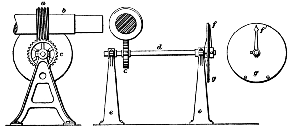
Fig. 4
4. Dial Indicators.—Fig. 4 shows a positive-motion
indicator that is operated as follows: A worm a on the drum shaft b
engages with the worm-wheel c on the small shaft d that
is supported by the bearings e. The pointer f is rigidly
attached to the shaft d and revolves in front of the properly
marked dial g.
5. Fig. 5 shows a dial indicator attached to
drum hoists where the speed of rope is constant for each revolution. The wheel
a of this indicator may be a worm-wheel working in a worm on the
drum shaft, as described in connection with the indicator shown in Fig. 4,
or it may be a sprocket wheel driven by a link belt from a sprocket
wheel on a drum, or it may be a gear-wheel driven directly from another
gear-wheel on the drum. The gear-wheels b revolve a vertical
shaft c fitted at the upper end with a worm d that drives
the worm-wheel e placed on the end of the pointer spindle. The
different levels from which hoisting is to be done may be painted on
the dial, or better, they may be placed on movable targets that are
clamped to the dial and can thus be moved as occasion requires.
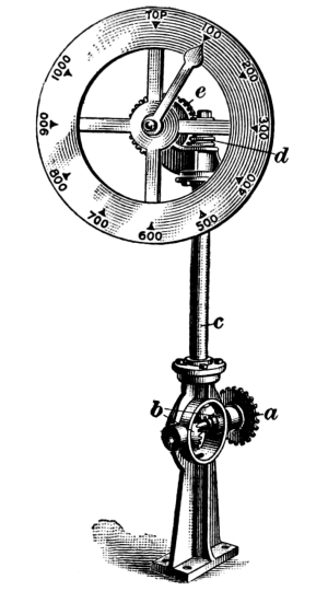
Fig. 5
Example.—An indicator is desired
for a shaft 800 feet deep at which the drum of the hoisting engine to
be used is 10 feet in diameter; what ratio of gearing must be used so
that the pointer will make one revolution during the hoist?
Solution.—The circumference of the
drum is 31.42 ft. (πD = 10 × 3.1416 = 31.416 ft.); hence, the
revolutions per hoist are 800 ÷ 31.42 = 25.46 revolutions. Then, if the
pointer is to make one revolution per hoist, the ratio of the gearing
will be 25.46 to 1. Ans.
6. Special Indicators.—One fault of nearly all indicators is
that they give a regular movement throughout the winding, and the space
over which the pointer travels is too small to enable the engineer to
land the cage accurately. Indicators have been made with a differential
motion to the pointer, the motion being greater at the time of landing
and less during the middle of the hoist. They are also made
with two
pointers, one operating like the dial indicator above described and the
other remaining stationary during all the hoist but the last few feet,
when it moves around its circle.
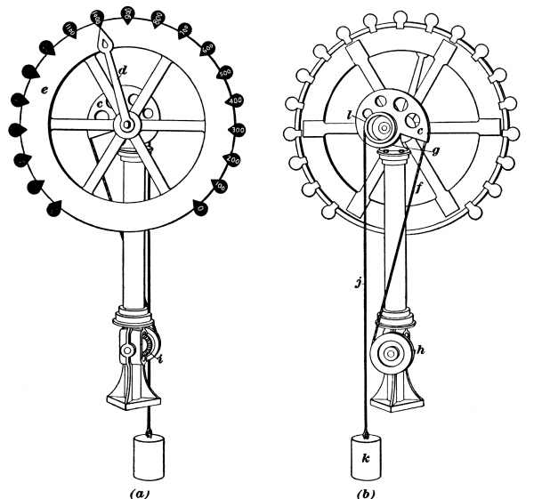
Fig. 6
7. Where flat ropes are used or where round ropes wind on a
conical drum, the length of rope wound or unwound is different for each
turn of the drum. With all the indicators thus far described, while the
speed with which the indicator moves is proportional to the speed at
which the drum and the drum shaft revolve, it is not proportional to
the speed of the rope when winding and unwinding on a conical drum or
on a flat rope reel. Fig. 6 (a) and (b) shows
two views of a compensating dial indicator. By means of the spiral form of sheave
c, the hand d is made to move equal distances around the
disk e for equal distances of cage movement in the shaft. The
rope f passes about the spiral sheave and one end is attached at
the small end g of the spiral, while the other end is fastened
to the periphery of the sheave h, which takes its motion from
the drum shaft or crank-shaft of the hoisting engine by means of the
bevel gear i. Consequently, while the sheave h has a
regular motion dependent directly on the revolution of the hoisting
drum, the pointer d moves irregularly, depending on the position
of the spiral sheave c; that is, whether a small or large
diameter of the spiral is presented to the rope. The rope j
carrying the counterweight k is attached to a small circular
drum l that is on the same shaft as the spiral sheave. The
purpose of this cord and counterweight is to keep the indicator line
f taut and to bring the indicator back to position as the cord
f unwinds from the sheave h.
8. In order that the pointer may not stand at exactly the same
point on the dial when the cage is at the top and at the bottom, and
so that the engineer may be able to distinguish between the top and
the bottom positions of the cage by the pointer, the ratio of the
gearing is usually increased by allowing one or two extra teeth on the
worm-wheel. In the example in Art. 5, assume a ratio
of 27: 1; that is, if a worm-gear is used, the worm-wheel will have 27 teeth.
If the pitch of the teeth is ¾ inch, the circumference of the pitch
circle will be ¾ × 27 = 20.25 inches and the diameter 6.44 inches.
The pitch of the worm will, of course, be the same as that of the
wheel, and its diameter will be whatever is necessary to give
sufficient strength outside of the shaft, since it bears no relation to
the ratio of the gearing.
9. The drum, or reel, of a hoisting engine is the
part on which the rope winds. It is either keyed fast to the engine
shaft or is connected to the shaft by means of a clutch, the shaft
being made extra heavy to carry the strain due to the weight of the
drum and the pull of the rope.
10. The outer part, or shell, of a drum a, Fig. 7,
is supported on rims b, and these rims are connected by arms
or spiders c with the hubs d. The brake rings e
are for the band brakes, of which there may be one or two. The part
a may be lagged with strips of wood bolted to the rims b,
the heads of the bolts being countersunk. Fig. 8 shows the
detailed dimensions of a drum 8 feet in diameter having a 4-foot face designed
to carry heavy loads and a large amount of rope. The shell is of boiler
plate and the spiders of cast-steel.
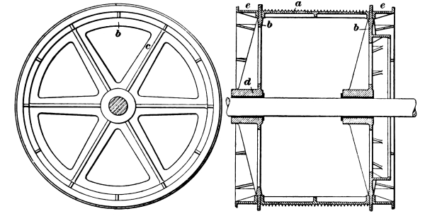
Fig. 7
11. The shell may be cast in one piece for small drums or built
up in sections for large drums, as in Figs. 7
and 8. The shell may have
a smooth surface, Fig. 8, or it may have grooves,
Fig. 7, for the rope
to lie in as it is wound on the drum. On an iron drum without grooves,
the rope will chafe sidewise; and furthermore if the rope winds on a
hard flat surface it bears here and there on a single wire and tends to
flatten, causing internal wear between the wires; while, in the case
of a rope winding in a groove, it is supported on about one-quarter of
its circumference, bringing many more wires to bear on the drum and
dividing the pressure between them. A wooden-lagged drum causes less
wear on a rope than an ungrooved iron-shell drum, as grooves are
gradually worn in the lagging, but is not so good as a grooved iron
drum. It is not good practice to allow a rope to wind on itself, and
the drum should be long enough to take the full length of the rope
required for the hoist. At least two turns of the rope should be on
the drum when the load is at the bottom, as the friction between the
rope and drum thus greatly lessens the strain coming on the rope at
the point where it is fastened to the drum. Allowance for two or three
additional turns of the rope should also be made so that the cage may
be hoisted above the landing.
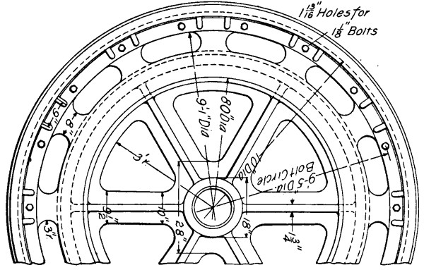
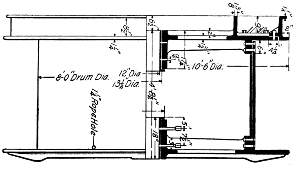
Fig. 8
The shell usually has a flange at each end, as shown in
Figs. 7 and 8,
but it may have a flange at one end only, or may be without flanges
entirely. If, however, the flanges are not used, the drum must be extra
long to prevent the rope running off the end. If the drum is very long,
a third spider is added midway between the other two to stiffen it
against collapse.
Example.—Find the length of a drum
6 feet 3 inches in diameter necessary to hold 1,000 feet of 1¼-inch
wire-rope.
Solution.—The diameter from center
to center of the rope when wound on the drum is 6 ft. 3 in. plus 1¼
in., or 6 ft. 4¼ in., which is equal to 19.96 ft. (approximately 20
ft.) of circumference. Then, to wind 1,000 ft. will require ¹,⁰⁰⁰/₂₀
= 50 turns on the drum. Allowing two turns of the rope to protect the
fastening and three turns in case of overwinding, gives fifty-five
turns to be allowed for on the drum. If the drum is of iron with
grooves turned in it, ¼ in. must be left between adjacent parts of the
rope, or 1½ in. from the center of one turn to the center of the next.
Then, 55 × 1½ = 82½ in. plus ¾ in. at each end = 84 in., or 7 ft. for
the length of the drum between the flanges. Ans.
If the drum has wooden lagging, clearance need not be allowed
between two adjacent coils of rope, as in this case the rope winds
against itself and so takes up only 1¼ in. It will then be 55 × 1¼ in.
= 68¾ in., or 5 ft. 8¾ in. long (say 5 ft. 9 in.). Ans.
12. In hoisting in balance from deep shafts with cylindrical
drums, if no tail-rope is used, or in hoisting from a single shaft
with an unbalanced cage, the hoisting engine is not loaded equally at
different points of the hoist owing to the gradually changing weight of the
unbalanced rope. The following illustrations will further explain this.
13. Hoisting With a Cylindrical Drum.—Suppose that, from a
single-compartment vertical shaft 1,000 feet deep, it is required to hoist
each trip a load, including friction, of 11,000 pounds made up as follows:
| |
Pounds |
| Weight of material |
4,000 |
| Weight of car |
3,000 |
| Weight of cage |
3,000 |
| Friction, 10 per cent. |
1,000 |
| Total |
11,000 |
If a 1⅜-inch cast-steel rope weighing 3 pounds per foot is used,
winding about a drum 7 feet in diameter, the weight of rope is then 3 ×
1,000 = 3,000 pounds and the load on the rope, when the cage is at the
bottom, is 11,000 + 3,000 = 14,000 pounds, while at the top the load on
the rope is only 11,000 pounds. The moment of the load at the bottom
is then the load 14,000 multiplied by the radius 3½, or 14,000 × 3½ =
49,000 foot-pounds; and at the top, 11,000 × 3½ = 38,500 foot-pounds.
This shows that the load against the engine is much greater at the
beginning than at the end of the hoist.
14. Take now a double-compartment vertical shaft of the same
depth as in Art. 13 and assume the same amount
of material hoisted at a trip, in the same mine car and on the same cage; but that
an empty car and cage are lowered in one compartment while the loaded
car and cage are hoisted in the other. The two cars and the two cages
will balance each other, and the loads will be as follows: At the
beginning of the hoist, when the loaded car and cage are at the bottom,
the gross load is 14,000 pounds, made up as follows:
| |
Pounds |
| Weight of material |
4,000 |
| Weight of mine car |
3,000 |
| Weight of cage |
3,000 |
| Friction, 10 per cent.of above |
1,000 |
| Weight of rope |
3,000 |
| Total |
14,000 |
Multiplying this by the radius of the drum, the gross turning moment is
14,000 pounds × 3½ feet = 49,000 foot-pounds, as before, but there is a
counterbalancing load of 6,000 pounds, made up as follows:
| |
Pounds |
| Weight of mine car |
3,000 |
| Weight of cage |
3,000 |
| Total |
6,000 |
| Less friction, 10 per cent. |
600 |
| |
5,400 |
This means a counterbalancing load moment of
5,400 pounds × 3½ feet = 18,900 foot-pounds. The net load moment to be
overcome by the engine at the beginning of the hoist is, therefore,
49,000-18,900 = 30,100 foot-pounds.
At the end of the hoist there is a gross load on the loaded
side of 11,000 pounds, made up as follows:
| |
Pounds |
| Weight of material |
4,000 |
| Weight of mine car |
3,000 |
| Weight of cage |
3,000 |
| Friction, 10 per cent. |
1,000 |
| Total |
11,000 |
This is equal to a gross load moment of 11,000
pounds × 3½ feet = 38,500 foot-pounds, but there is a counterbalancing
load of 8,100 pounds, made up as follows:
| |
Pounds |
| Weight of mine car |
3,000 |
| Weight of cage |
3,000 |
| Weight of rope |
3,000 |
| Total |
9,000 |
| Less friction, 10 per cent. of 6,000 |
600 |
| |
8,400 |
This is equal to a counterbalancing load moment of 8,400 pounds × 3½
feet = 29,400 foot-pounds, and leaves a net load moment against the
engine of 38,500-29,400 = 9,100 foot-pounds. In other words, the load
moment that the engine has to overcome varies from 30,100 foot-pounds
at the beginning of the hoist to 9,100 foot-pounds at the end of the hoist.
15. Hoisting With Conical Drums.—Conical drums are designed to
make the work of the engine as nearly uniform as possible throughout
the hoist. To accomplish this, when the cage is at the bottom of the
shaft, and the load is therefore heaviest, the rope winds on that part
of the drum having the smallest diameter. As hoisting continues, the
rope winds on a gradually increasing diameter of drum, and when the
cage is at the top of the hoist, and the load therefore least, the
rope is winding on that part of the drum having the greatest diameter;
in this way, the moment of the load at every point of the hoist is
approximately the same. The great difference in the loads at different
parts of the hoist is due mainly to the variation in the weight of the
rope hanging from the drum; hence, the less the weight of the rope in
proportion to the total load on the engine, the more nearly uniform is
the load on the engine.
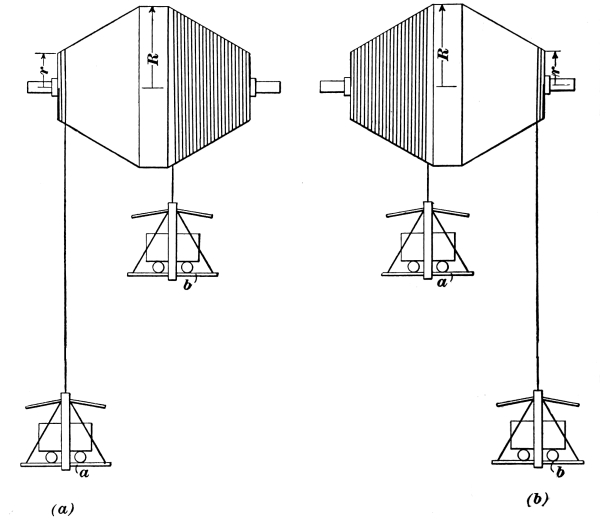
Fig. 9
16. Fig. 9 (a) shows the condition at the
beginning of the hoist when conical drums are used. Cage a is at the bottom
and carries a loaded car; cage b is at the top and carries an
empty car. The net moment that the engine must overcome is the sum of
the weight of the material to be hoisted, weight of the cage and car at
a, and the weight of the rope attached to a, multiplied
by the small radius r of the drum, minus the weight of the car
and cage at b, multiplied by the large radius R of the drum.
Fig. 9 (b) shows the condition of things at the
end of the hoist, when the cage a is at the top and cage b at
the bottom. The loaded car and cage a, whose rope in Fig. 9 (a)
was winding on the smallest diameter of the drum, is now at
the top and the rope is winding on the largest diameter of the drum.
The cage b with the empty car is now at the bottom and the rope
is unwinding from the smallest diameter of the drum. The net moment
that the engine must overcome in this position is equal to the sum of
the weight of the material hoisted, the weight of the cage a and
the car, multiplied by the larger radius R of the drum, minus
the sum of the weights of the cage b, the car, and the rope,
multiplied by the small radius r of the drum.
17. If the moment of the load against the engine at the
beginning of the hoist is to equal that at the end of the hoist, it is
possible to determine what relative diameters of drum will produce such
an effect, as follows:
| Let |
Wₘ |
= |
weight of material hoisted; |
| |
Wₖ |
= |
weight of cage and car; |
| |
Wᵣ |
= |
weight of rope; |
| |
R |
= |
large radius of drum; |
| |
r |
= |
small radius of drum. |
The load moment may be calculated by including friction as ⅒ of the
total weight hoisted, except the weight of the rope, as shown in Art. 14;
or the friction may be disregarded without serious error. Then,
under the conditions shown in Fig. 9 (a),
and disregarding friction,
Load moment = (Wₘ + Wₖ + Wᵣ)r - WₖR (1)
and under the conditions shown in Fig. 9(b),
Load moment = (Wₘ + Wₖ)R - (Wₖ + Wᵣ)r (2)
Placing formula 1 = formula 2,
(Wₘ + Wₖ)R - (Wₖ + Wᵣ)r
= (Wₘ + Wₖ + Wᵣ)r - WₖR,
and
| |
(Wₘ + 2Wₖ + 2Wᵣ) |
|
| R = |
r ———————— |
(3) |
| |
(Wₘ + 2Wₖ) |
|
Since the diameter of a drum is generally given instead of the
radius, it follows that if D = larger diameter, d =
smaller diameter, and then, since D = 2R and d =
2r, formula 3 may be written
| |
(Wₘ + 2Wₖ + 2Wᵣ) |
|
| D = |
d ———————— |
(4) |
| |
(Wₘ + 2Wₖ) |
|
Formula 4 gives only approximate results, which are, however,
sufficiently accurate for the mine superintendent’s use, and for this
reason friction has been omitted, as it would make the formula much
more complex. It may be expressed as a rule as follows:
Rule.—To find the large diameter
of a conical drum, multiply the small diameter by the sum of the
weight of the material to be hoisted, twice the weight of the cage and
car, and twice the weight of the rope; divide this product by the sum
of the weight of the material, and twice the weight of the cage and car.
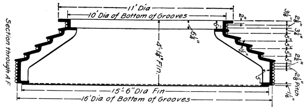
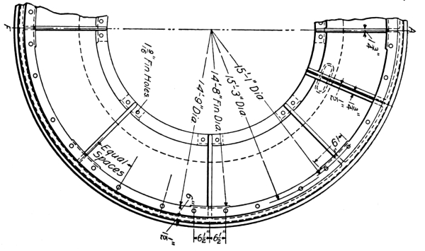
Fig. 10
Applying this rule to the problem given in Art. 14 and omitting
friction,
| |
7(4,000 + 12,000 + 6,000) |
|
| D = |
———————————— |
= 9.6 feet |
| |
(4,000 + 12,000) |
|
The drum would then be 7 feet in diameter at the small end and 9 feet
7¼ inches at the larger end.
18. Fig. 10 shows a special form of combined conical
and cylindrical drum designed for hoisting a total balanced load of 25 tons
through a vertical height of 550 feet.
Fig. 11 shows a combined conical and cylindrical drum; an
unusual feature is the rope reel shown at each end of the drum, which permits
of properly storing a few hundred feet of extra rope, allowing the rope
to be lengthened, when needed, without splicing.
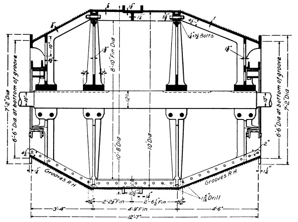
Fig. 11
19. Comparison of Cylindrical and Conical Drums. The
disadvantages of the cylindrical drum lie entirely in the fact that the
load on the engines is variable, but it is possible to overcome this
disadvantage by adding a tail-rope to the cages to balance the weight
of the rope. This system gives its best results where hoisting is done
from one level only, but in deep hoisting it is impracticable because
of the extra weight added and because of possible excessive swaying of
the rope.
The conical drum has two strong points in its favor: first, the load on
the engine may be nearly equalized during the entire hoisting period;
and, second, the starting of the engines with the load requires less power.
The disadvantages of the conical drum are as follows: To maintain a
certain average speed of hoisting, the speed toward the end of the
hoist is of necessity higher than the average and comes at a time
when a slowing up should be taking place, so that more care must be
exercised when making the landing. To prevent the rope from being
drawn out of the grooves, the latter must be made deep and with a
large pitch, thereby increasing the width of the face or length of
the drum. In making a landing, when the rope is on the conical face,
the rope must be kept taut, as any slackness will permit the rope to
leave the groove, with the result that all the rope will pile up in the
bottom grooves of the drum allowing the cage to drop into the mine,
unless it is resting on the chairs. If there are several levels to be
hoisted from, the equalizing of the load on the engines can only be
realized for one level; for all other levels this advantage will be
lost. For large depths, conical drums become very long and require
correspondingly long leads from head-frame to drum. To hold the same
amount of rope, conical drums are heavier than cylindrical ones, and as
a result, the power required in starting the load is somewhat increased
owing to the greater inertia of the rotating parts.
Some of these disadvantages have been overcome by making a combination
of cone and cylindrical drums. The drums are so designed that the
landing takes place only when the rope is on the cylindrical portion
of the drum. For deep hoisting, the greater diameter of the drum and
its length must be inconveniently large if the load is equalized.
The length and diameter can be reduced by making one-half of the
drum cylindrical and by having the rope from each end wind on the
same cylindrical portion of the drum. In all cases, however, these
modifications are made at the expense of the equalization of the load
on the engines, and it is not possible to obtain the latter without
including some serious disadvantage.
There are certain objections to both cylindrical and conical drums:
their great size and weight, for large hoists, make them very
expensive; their width necessitates placing the engines far apart,
which adds to the cost of the engines, foundations, and buildings; the
great weight of the drums is also objectionable, because it forms a
large part of the mass to be put in motion and brought to rest at each hoist.
20. To overcome the objections to conical and cylindrical drums,
several other systems of hoisting have been tried, among them being
one that uses a reel, Fig. 12, and a flat rope. The hub
a is increased in diameter, above what is necessary for strength, to
such a size as is suitable to wind the rope on. It is then cored out from the
inside, so as not to contain too great a mass of metal.
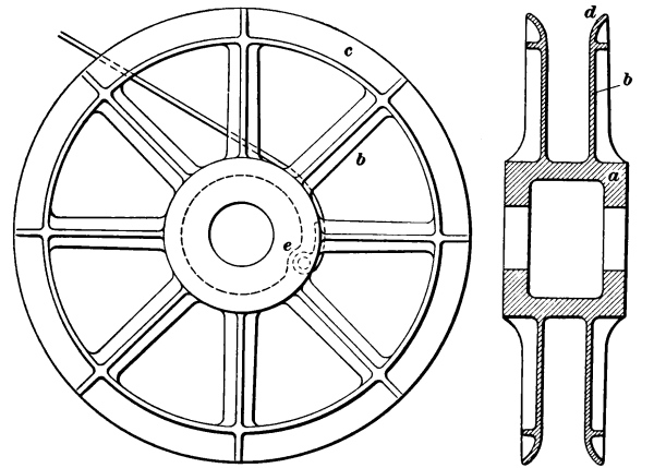
Fig. 12
The arms b of the reel extend radially from the hub to confine
the rope laterally when it is all wound on the drum. These arms are
connected at their outer ends by a continuous flange c, which
flange is flared out, as shown at d, so as to take in the rope
easily, if it is deflected at all sidewise.
In the larger-sized reels, the arms are bolted to the hub, and often
the outer rim connecting the arms is omitted. Hardwood lining was
formerly used on the arms under the impression that the wear on the
rope would be less than with bare iron arms, but sand and grit become
embedded in the wood and grind the rope. Polished iron arms with
rounded corners and lubricated with oil or tar are best. The end of the
rope is fastened in a pocket e provided for it in the hub.
The rope winds on itself, so that the diameter of the reel increases
as the hoist is made and as the load due to the weight of the rope
decreases. This serves to equalize the load due to the rope in the same
manner as the conical drum. Two reels are generally put on the same
shaft, and while one is hoisting from one compartment of the shaft the
other is lowering into another compartment. The periphery of the hub
where the rope winds should not be round but of gradually increasing
radius, for if a flat rope be wrapped about a round hub the rope will
have to abruptly mount itself at the end of the first revolution and so
on for every revolution. The radius of the hub should increase at such
a rate as to raise the rope an amount equal to its thickness in the
first wrap, so that it will wind on itself without jar at the point of
attachment, as well as on succeeding wraps.
21. In America, it is customary to wind on reels of small
diameter, that is, starting at 3 or 5 feet and increasing to 8 or 12
feet; but several large plants have been built with reels starting
at 8 feet and increasing to 19 feet. In England, reels have been
made starting at 16 feet and increasing to 20 or 22 feet. Such large
reels are easier on the rope but require large engines, as hoisting
in balance is used to only a slight extent. The large reel is easy on
the rope, both from the fact that it bends the rope but little and
also gives less pressure on the bottom wraps, as each wrap adds to the
pressure. These reels are driven by means of plain jaw or friction clutches.
The wear of a flat rope is excessive and the rope itself costs more
than a round rope of the same strength, does not last as long, and
requires more care and attention.
22. Calculating Size of Flat Rope and Reel.—The calculation of
the size of a flat rope for given work is not so simple as that of a
round rope, as there is a variable factor in the width and thickness
of the rope that must be taken into account. To illustrate the method
of calculation, suppose that it is required to hoist 5,000 pounds of
material in a 3,000-pound skip from a vertical two-compartment shaft
2,000 feet deep under conditions requiring a factor of safety of about
9 for the rope.
The determination of the size of the rope and the small and large
diameters of the reels must proceed together. The latter calculations
are performed in much the same manner as for conical drums.
Referring to Table relating to flat wire ropes in Hoisting,
Part 2, it is found that a flat steel rope 6 inches by ½ inch in size and
with a breaking strength of 150,000 pounds weighs 5.1 pounds per foot;
hence, 2,000 feet of it weighs 2,000 × 5.1 = 10,200 pounds. The total
load on the rope will then be 19,000 pounds, made up as follows:
| |
Pounds |
| Weight of material |
5,000 |
| Weight of skip |
3,000 |
| Friction, 10 per cent. |
800 |
| Weight of rope |
10,200 |
| Total |
19,000 |
This rope gives a factor of safety of 150,000/19,000 = 7.8, which is
not quite enough when figured from the dead load without that due to
acceleration.
An 8" × ½" rope with a breaking strength of 200,000 pounds weighs 6.9
pounds per foot; hence, 2,000 feet of it weighs 2,000 × 6.9 = 13,800
pounds. The load on the rope will then be 22,600 pounds, made up as
follows:
| |
Pounds |
| Weight of material |
5,000 |
| Weight of skip |
3,000 |
| Friction, 10 per cent. |
800 |
| Weight of rope |
13,800 |
| Total |
22,600 |
This rope gives a factor of safety of 200,000/22,600 = 8.8.
Substituting the foregoing weights of material, skip, and rope in
formula 4, in Art. 17, gives
| |
d(5,000 + 6,000 + 27,600) |
| D = |
———————————— |
| |
(5,000 + 6,000) |
Hence, the equation of moments is D = 3.5d. In other
words, the large diameter, or that of the last coil of rope, should be
3.5 times the small diameter, or that of the reel hub.
23. Fig. 13 represents a coil of flat rope whose
greater diameter D and smaller diameter d are to be determined.
The area of the hub about which the rope is to coil is (¼)πd²,
while the area included by the outer coil of rope is (¼)πD²
hence, the area of annular space occupied by the rope is
(¼)πD² - (¼)πd² = (¼)π(D² - d²).
Such values for D and d must be chosen that the
equation of moments in Art. 22 is satisfied, while
the area (¼)π(D²-d²) must correspond to the space occupied by the
given rope when rolled.
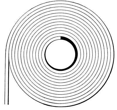
Fig. 13
Illustration.—2,000 feet of rope ½ inch thick requires
| 2,000 × 12 |
|
| ————— |
= 12,000 |
| 2 |
|
square inches in which to be coiled. To satisfy the equation of
moments, D must equal 3.5 d; hence, to satisfy both
these conditions
(¼)π[(3.5d)²
- d²] = 12,000;
- d = 37 inches, or 3 feet 1 inch;
- D = 37 × 3.5 = 129.5 inches, or 10 feet 9½ inches.
The dimensions of the reel will then be: diameter of hub 3 feet 1
inch; width between flanges, 8½ inches, allowing ¼ inch on each side of
the rope for clearance; diameter of the flanges where they flare, 10
feet 9½ inches.
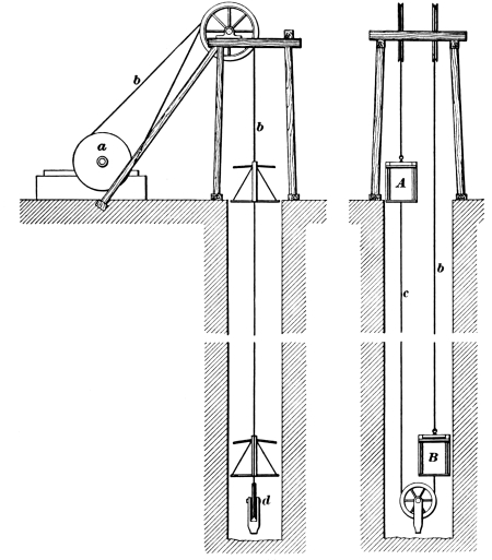
Fig. 14
24. Koepe System.—In its lightest form, a drum requires a
large amount of power to set it in motion, which power is absorbed by the
brake and lost when it is brought to rest again. Furthermore, with
deep shafts requiring long drums, the fleet, or angle that the rope
makes with the head-sheave due to its traveling from one end of the
drum to the other, is not only a disadvantage and possible cause of
accident, but it is a source of wear. To overcome these objections and
also the great cost of large cylindrical or conical drums, the Koepe
system of hoisting, shown in Fig. 14, was devised by Mr. Frederick
Koepe. A single grooved driving sheave a is used in place of a
drum. The winding rope b passes from one cage A up over
a head-sheave, thence around the sheave a and back over another
head-sheave, and down to a second cage B; it encircles a little
over half the periphery of the driving sheave and is driven by the
friction between the sheave and rope. A balance rope c beneath
the cages and passing around the sheave d gives an endless-rope
arrangement with the cages fixed at the proper points. The driving
sheave is stronger than an ordinary carrying sheave, as it has to do
the driving and is usually lined with hardwood, which is grooved to
receive the winding rope, the depth of the groove being generally equal
to twice the diameter of the rope. Instead of being placed parallel,
the head-sheaves are placed at an angle with each other, each pointing
to the groove in the driving sheave, thus reducing the side friction of
the rope on the sheaves.
The system has been in successful operation since 1877, and experiments
made on it have determined that, with a rope passing only one-half
turn around the drum sheave, the coefficient of adhesion with clean
ropes is about .3. If the ropes are oiled, the adhesion becomes
less, and sometimes slippage occurs, producing not only wear of the
driving sheave lining but giving an incorrect reading of the hoist
indicator and thus possibly producing overwinding, unless the position
of the cage is indicated by marks on the rope, or unless the engineer
can see the cage.
At the end of the hoist, if the upper cage is allowed to rest on the
keep, its weight and the weight of the tail-rope are taken from the
hoisting rope, and there is then not enough pull on the hoisting rope
to produce sufficient friction with the drum sheave to start the next
hoist. To prevent this trouble, the keeps are dispensed with, or the
rope is made continuous and independent of the cage. To do this,
crossheads are placed above and below each cage and connected by ropes
or chains outside of the cages. The bridle chains are then hung from
the top crosshead, and when the cage rests on the keeps, the weight of
the winding and tail-ropes remains on the driving sheaves.
25. Advantages and Disadvantages of the Koepe System.—With
this system, only one driving sheave is necessary for the operation of two
compartments, and it is light, inexpensive to build, and very narrow,
admitting of a short sheave shaft and small foundations. This system
permits a perfect balance of rope and cage, so that the work to be done
by the engine is uniform, except for the acceleration, and consists
only in lifting the material and overcoming the friction. There is no
fleeting of the rope between the driving sheaves and the head-sheaves.
The system has the following disadvantages, which prevent its being
used to any considerable extent: Liability to slippage of the rope
on the drum; if the rope breaks, both cages may fall to the bottom;
hoisting from different levels cannot be well done, for, since the
cages are at fixed distances from each other, the length of the rope is
such that when one cage A is at the top, the other cage B
is at the bottom. If hoisting is to be done from the bottom, this is
satisfactory, but if hoisting is to be done from some upper level, cage
B, which is at the bottom, must be hoisted to that level to be
loaded before it can go to the top. Then, when cage B goes to
the top with its load, cage A must go to the bottom, wait there
while cage B is being unloaded, and then be hoisted to the upper
level to receive its load. For each trip, therefore, the time required
for a cage to go from the bottom to the upper level and be loaded
is lost; and two movements of the engines are necessary for a hoist
instead of one.
26. The Whiting System.—This is a system of hoisting with
round ropes, in which two rope wheels placed tandem are used in
place of cylindrical or conical drums. As shown in Fig. 15,
for a two-compartment shaft the rope passes from one cage a up over
a head-sheave c, down under a guide sheave d, and is
then wound three times about the rope wheels e and f, to
secure a good hold, then around a fleet sheave g, and back under
another guide sheave h, up over another head-sheave i,
and down to the other cage b. When the system is to be used
for a single-compartment shaft, one end of the rope carries the cage
and the other end carries a balance weight, which is run up and down
in a corner of the shaft. A balance rope below the cages, as shown,
is generally used, though it is not essential to the working of the
system, as it is in the Koepe system. When sinking a shaft, a balance rope
cannot be used as it interferes with the work at the bottom of the shaft.

Fig. 15
The drums or wheels e, f are light, inexpensive, and
narrow, thus permitting short sheave shafts and small foundations.
They are lined with hardwood blocks, each lining having three rope
grooves turned in it. The main wheel e is driven by a hoisting
engine, which may be either first or second motion. The following
wheel f is coupled to the main wheel by a pair of parallel
rods, one on each side, like the drivers of a locomotive. As the rope
wraps about the wheels e, f three times, there are six
semi-circumferences of driving contact with the rope, as compared
with the one semi-circumference in the Koepe system, and there is no
slipping of the rope on the wheels. The following wheel f is
best tilted or inclined from the vertical an amount equal, in the
diameter of the wheels, to the pitch of the rope on the wheel, so that
the rope may not run out of its groove and may run straight from one
wheel to the other without any chafing between the ropes and the sides
of the grooves.
The capacity of the wheels e, f is unlimited, while
grooved cylindrical drums, conical drums, and reels will hold only the
fixed length of rope for which they are designed.
As shown by the dotted lines, the fleet sheave g is arranged to
travel backwards and forwards, in order to change the working length of
the rope from time to time to provide for an increased depth of shaft,
and for the changes in the length of rope due to stretching and when
the ends are cut off to resocket the rope. The fleet sheave g is
moved a distance equal to half the change in the length of rope.
27. Hoisting from intermediate levels can be readily done with
the Whiting system; for instance, if the cage a is at the top
and cage b at the bottom, and hoisting is to be done from some
upper level, it is only necessary to run the fleet sheave g out,
and thus shorten the working length of the rope until cage b
comes up to the upper level. It can then be loaded and go to the top.
While cage b goes to the top, cage a descends to the same
level, where it can be loaded while cage b is being unloaded,
and can then go directly to the top without any of the lost time, as is
the case in the Koepe system.
The system permits a perfect balance of rope and cage, so that the work
to be done by the engines is uniform, except for the acceleration, and
consists only in lifting the material and overcoming the friction.
There is no fleeting of the rope, so the rope wheels can be placed as
close to the shaft as may be desired.
28. This system was tried as early as 1862 in Eastern
Pennsylvania, but it was not used extensively because hoisting from
great depths was not necessary, since, for depths of less than 1,000
feet, cylindrical and conical drums are quite satisfactory. In the
Lake Superior copper region, there are now three Whiting hoists, two
of which are probably the largest hoisting plants in the world. Each
plant consists of a pair of triple-expansion, vertical, inverted-beam
engines, driving direct a pair of 19-foot drums. The high-pressure
cylinders are 20 inches in diameter, the intermediate cylinders 32
inches, and the low-pressure cylinders 50 inches, and all six of them
have a 72-inch stroke. The rope used is a 2¼-inch plow-steel rope and
hoists 10 tons of material at a trip, in one case from a depth of 4,980
feet, the deepest shaft in the world. Several plants on the Whiting
system have been built in England, and two or more are working in South
Africa.
29. Modified Whiting System.—A modification of the Whiting
system is sometimes used in which a large drum keyed to the crank-shaft
replaces the small tandem drums, and even the slight probability of
the rope slipping in the Whiting system is thus obviated. One rope is
fastened to one end of the drum, and the other rope to the other end in
such a way that while one is winding on the other will be winding off
the drum. One rope passes directly to the head-sheave while the other
passes first around a fleet sheave, similar to that used for the
Whiting system, but preferably placed horizontal, and thence to the
head-sheave. This system possesses the same advantages as the Whiting
system except that the depth of hoist is limited by the size of the
drum, and that there is a fleet of the rope. Up to the limiting depth,
as determined by the size of the drum, this system can be used with
equal economy for any depth. This hoist, as well as the Whiting, is
therefore especially suitable for a place where one mining company
operates several mines, for it enables the company to select one size
for all their permanent work, with all the advantages that come from
duplicate machinery.
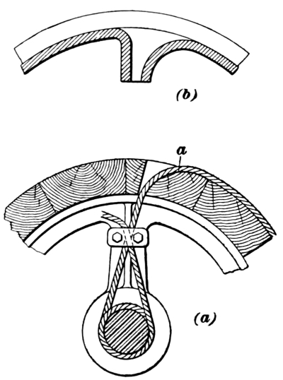
Fig. 16
30. A common method of fastening a rope to a drum, Fig. 16 (a),
is to pass the rope through a hole in the drum rim and then
around the shaft, clamping the end to the rope between the shaft and
shell, as shown. Care should be taken to make the radius of curvature
of the hole at a as large as possible so that the rope will not
be bent any sharper than is necessary. When an iron drum is used, the
thickness of the rim does not afford enough depth in which to bend the
rope and it is necessary to build in a pocket for the purpose, as shown
at Fig. 16 (b). It is well to make both sides of
this pocket with a long radius to avoid damaging the rope in case all the rope
is accidentally unwound and the drum backed so as to bring the rope
against the other side of the pocket.
31. It is often desired to have the drum of a hoisting engine
run loosely on the engine shaft, so that it may run independently
of the engine. With such loose-running drums, the engine generally
runs only in the direction required to hoist the load, while the cage
is lowered entirely by means of the brake. In this way, one engine
provided with several drums may be used for hoisting from several
shafts or from several levels in the same shaft at the same time. Such
a loose-running drum is connected to the engine shaft when a load is to
be hoisted by means of a clutch, of which there are two forms commonly
used for hoisting machinery: jaw or piston clutches and
friction clutches.
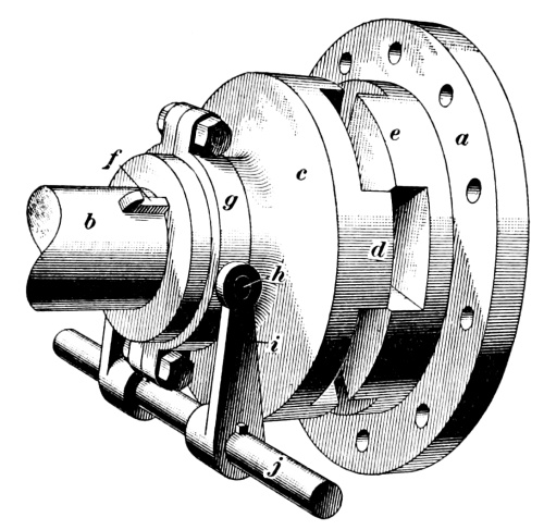
Fig. 17
32. Jaw Clutch.—Fig. 17 shows a jaw clutch,
one-half a of which is shown ready to be bolted to a drum or flat rope
reel, which is loose on the shaft b. The other half c of
the clutch is moved back so that the jaws d are not in contact
with the jaws e on the part a. The half c slides
freely on a feather key f, which is driven tightly into a deep
key seat in the shaft b; a collar g, fitting loosely in
a groove in the hub of c, is provided with trunnions h
on each side; levers i connect these trunnions with the lever
j attached to a suitable handle, by means of which the clutch is
made to slide endwise on the shaft so that the jaws d engage
or disengage the jaws e and thus connect or disconnect the drum
or reel from the clutch. There are generally four or six jaws d
that engage the same number of jaws e on the drum, and it is
necessary to have little or no play between d and e when
the clutch is connected or there will be too much shock. The clutch is
about 2 feet in diameter, and the jaws are 3 or 4 inches deep for the
average 20" × 48" first-motion hoisting engine. Instead of the clutch
being fastened to the shaft by feather keys, the shaft may be hexagonal
where the clutch slides on it and the clutch is machined to match. Jaw
clutches are made of either cast-iron or cast-steel, and should be in
halves, for convenience of repair, and securely bolted together.
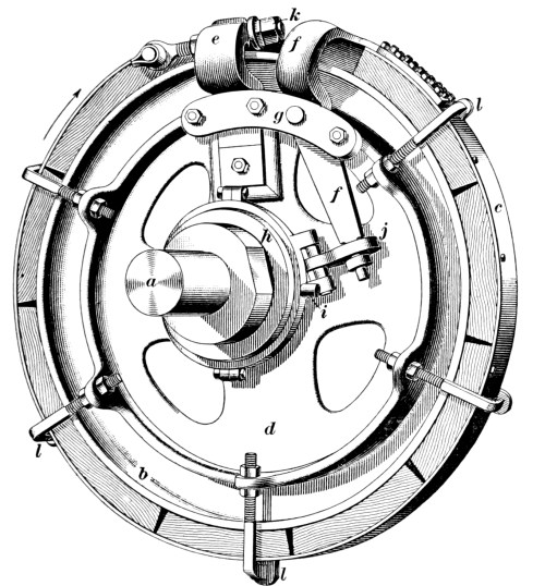
Fig. 18
33. Band Friction Clutches.—Fig. 18 shows a
band friction clutch that is attached to and revolves with the shaft a.
The winding drum runs loosely on the same shaft and has a driving-band
ring or seat b on one end; when the ring c of the clutch
is tightened by means of the mechanism shown, the clutch and driving
band become practically one piece and the drum revolves with the
clutch. The clutch is constructed as follows: The driving disk d
keyed to the driving shaft a is connected to one end of the ring
c by a fixed arm e, which is bolted firmly to the disk
d and revolves with it; a movable arm f that connects
with the other end of the band c turns on the pin g. When
the band c is loose, it can revolve about the seat b
without touching it, but the band can be tightened and made to clamp
b either when revolving or standing still, as follows: The
sliding sleeve h may be caused to slide about 6 inches along
the hub of the disk d by levers (not shown) that take hold of
trunnions i on a ring on the sliding sleeve; this sleeve is
connected to the movable arm f by a link j, and when the
sleeve is on the end of the hub the link stands at an angle of about
60° with the shaft; by sliding the sleeve toward the disk d,
the link is made to move the arm f about 1½ inches at its outer
end and to thus tighten the driving-band c, so that it grips
the ring b. The adjusting nuts k take up the wear of
the wooden blocks with which the ring c is lined. Band lifters
l hold the band clear of the ring when it is loose. The clutch
shown is built to run in the direction indicated by the arrow, but such
clutches may be built to run in either direction; they should always be
run in the direction for which they are designed, so that the load may
always come on the fixed arm. If the band be tightened slowly, there
will be no sudden start or jerk on the rope, as the slip of the band
will prevent the entire force of the grip taking effect at once; and
after the drum reaches full speed, there is little or no slipping of
the driving-band. It is best to keep the band only just tight enough to
do the work, for should the car get off the track, or be overwound, or
should a cage stick in the shaft for any reason, the band will slip and
thus become a safety appliance, and not strain or break the rope, shaft
timbering, or machinery, as would be the case if a positive clutch,
Fig. 17, were used.
34. The Beekman Friction Clutch.—A simple friction clutch is
shown in Fig. 19, in which a is a section of the drum
shell. The wooden blocks b bolted to the side of the gear-wheel c
are made of suitable shape to conform to the V-shaped groove
d in the side of the drum. The steel spring e between the
two steel washers f, f disengages the clutch, as soon as
the pressure is relieved, by reversing the motion of the lever g
and screw h from the opposite end of the drum. When the lever
g is turned, the screw h is forced against the end of the
pin i, which, in turn, presses the cross-key j against
the collar k, forcing the drum against the blocks b and
frictionally engaging the gear-wheel c. This drum shaft is
prevented from moving endwise by means of the collar l and the
grooves m in the babbitted pillow-block. The wide bearings of
the drum on its shaft are lubricated by means of the pipes n.
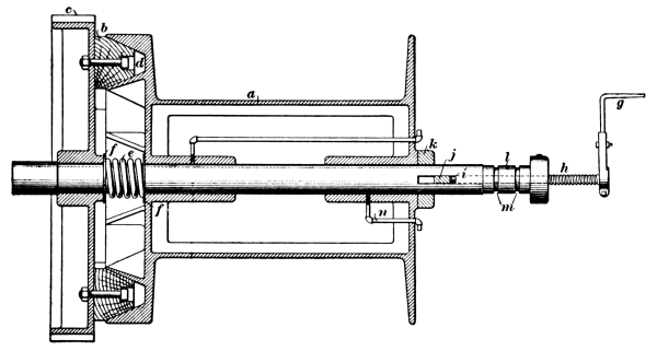
Fig. 19
A clutch is often used to change the length of the hoisting rope when
hoisting from two or more lifts or levels. In this case the shaft
carries two drums, one of which is fixed to the shaft, while the other
is provided with a friction clutch. When it is desired to change the
length of the rope, the cage attached to the loose drum is brought
to, say, the upper landing. The cages both resting on the wings, the
clutch is loosened and the other cage attached to the fixed drum is now
brought to the desired level, when the clutch is again tightened and
hoisting proceeds. The change is made in 2 or 3 minutes.
35. A brake is a device by means of which the motion of
a hoisting drum may be retarded or stopped. This is accomplished by
friction of the brake against the circumference of the brake wheel.
There are three types of brakes, known as block brakes, post
brakes, and strap brakes.
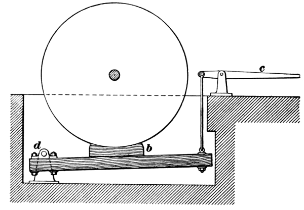
Fig. 20
36. The Block Brake.—The block brake,
Fig. 20, consists of one or more wooden blocks or
shoes b attached to a lever having a fulcrum at d, and
connected by a rod to the lever c. Block brakes are objected
to mainly because they throw a great load on the journals of the drum
when they are applied; they cannot be relied on when there is a heavy
load on the drum, and they require the application of great force to
the lever c for a given braking power. They are, however, cheap
and easily applied to a drum, and the shoe is readily replaced when worn.
37. The Post Brake.—The post brake, Fig. 21,
is composed practically of two block brakes applied at two places on the drum
diametrically opposite each other, thus equalizing the pressure on the
journals. The blocks are generally somewhat longer than in the block
brake, or about one-quarter of the circumference of the drum on each
side. In Fig. 21, a is the drum; b are wooden
brake blocks; c are the posts which in the brake shown are of massive,
built-up, steel construction; d are the fulcrums on the plates
e, which plates are adjustable by means of the nuts f; by
means of these nuts, the fulcrums may be brought closer together as the
wooden blocks b wear away; g is a tension rod generally
furnished with a turnbuckle to adjust its length as the wooden blocks
wear away. Power is applied at the end of the bent lever h, as
shown by the arrow.
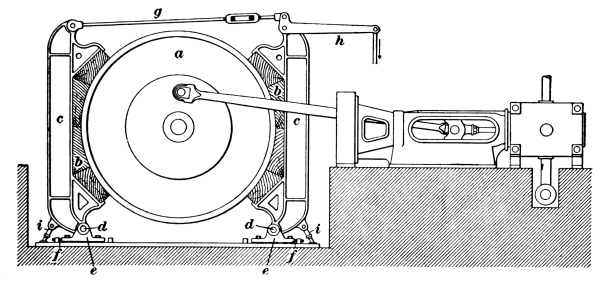
Fig. 21
The stops i are adjusted so that the blocks b on each
side are equally distant from the drum when the brake is off. The
fulcrums d should be some distance below the drum and brake
ring, for if they are too near the drum it will be difficult to swing
the lower end of the wooden blocks far enough to clear the drum.
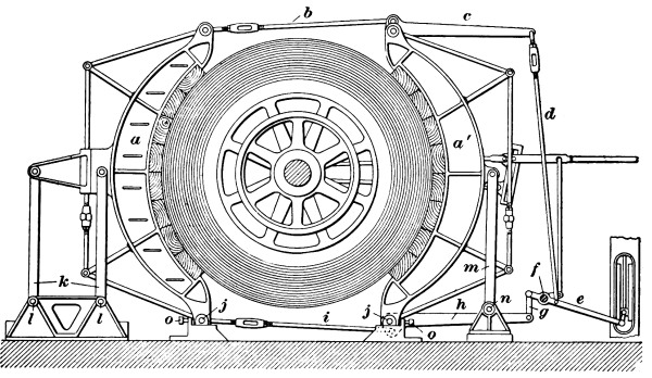
Fig. 22
38. Improved Post Brake.—In order to have an equal clearance at
top and bottom, and to have a more powerful leverage than in the
ordinary post brake, the posts may be made movable at both top and
bottom, Fig. 22. The tops of the posts a a′ are moved, as in
Fig. 21, by the tension rod b and the lever c, the latter
being connected by rod d to lever e. This lever is
pivoted at f and motion is transmitted to the fulcrums j
by the link g, the lever h, and the tension rod i.
The back post a is supported by the uprights k, which are
pivoted at l and swing backwards and forwards like a parallel
ruler. The front post a′ is supported by the single upright
m, pivoted at n. The setscrews o regulate the
motion of the bottom of the posts so as to give equal clearance to the
bottom and top of the posts.
An objection to both the block and the post brake is the fact that, if
the drum surface to which the brake is applied is not perfectly round,
the resistance of the brake will not be uniform when applied while the
drum is in motion.
39. The Strap Brake.—A strap brake consists of a
wrought-iron band or strap that partly encircles the drum and is
connected at its free ends to levers with which the band may be
tightened on the brake wheel and the drum thus firmly held. The iron
or steel band either lies directly against the wooden lagging of the
drum or on wooden blocks bolted to the drum; or else it has bolted to
it a lining of wooden blocks that bear on the drum when the band is
tightened.
The most efficient forms of strap brakes are those in which the strap
or straps are in contact with 270° or more of the circumference of the
drum. The greater the arc of contact, the more securely is the drum
held by the brake. A single strap is sometimes used, but this is only
satisfactory with small drums, say 8 feet or less in diameter; on large
drums two straps are generally used, each extending half way around
the drum. The levers for transmitting the power from the hand lever or
treadle to the brake strap are variously arranged. In some cases, the
force is multiplied by several short levers; in others, by one long
lever. The treadle or foot-lever, however, has been replaced almost
entirely by the hand lever.
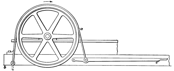
Fig. 23
40. The simplest form of strap brake, Fig. 23,
consists of a single strap a, with one end anchored at b and the
free end attached to the brake lever c. This brake acts on the same
principle as the block brake and is open to the objection that it
brings an undue load on the journals, but it is more efficient and
holds the drum more firmly under a heavy load than a block brake.
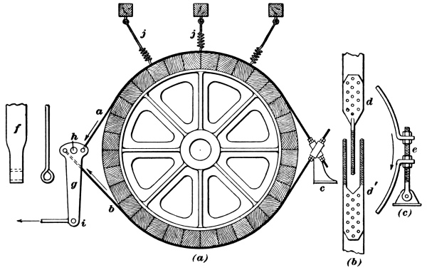
Fig. 24
Block brakes are usually run dry, but in band brakes and post brakes
with ample surfaces and proper leverage the wood may be occasionally
slightly oiled with black oil, which greatly adds to the durability of
the blocks without unduly lessening the power of the brake.
41. A two-strap brake is shown in Fig. 24. One end
of each strap a, b is fastened to the pedestal c by either of
the methods shown in Fig. 24 (a), (b), and (c).
In the method shown in Fig. 24 (a) and (b), the forgings
d, d′, drawn out to the form of bolts, are riveted to
the ends of the straps and passed through a casting c that is
secured to the foundation. The object in giving one bolt to one strap
and two bolts to the other strap is to allow the straps to pass each
other and yet have their lines of action intersect. The bolts are
fastened to c by four nuts on each bolt, i. e., two principal
nuts and two locknuts. This gives a means of adjustment in the length
of the strap to take up the wear.
A second method of securing or anchoring the back ends of the straps
is shown at (c). In this case, a wrought-iron angular piece
is riveted to each strap, and these pieces are passed over the bolt
e that takes the place of the casting of the former arrangement.
Nuts are used, as shown, to adjust the straps for wear. The bolt should
be short and stiff, so as to be well able to stand up to its work when
the drum is moving or tending to move in the direction shown by the arrow.
When the brake is applied, the friction between the brake strap and
the circumference of the brake wheel produces a great strain on the
pedestal c, which must be securely anchored.
The front ends of the straps are worked into eyes, as shown at
f, and by these eyes and suitable pins passing through them the
ends are fastened to the brake lever g. This lever is supported
on and rotates about a pin h, so that when the braking force is
applied at i, in the direction of the arrow, the brake lever
rotates, pulling down on strap a and up on strap b; and,
if the straps are held firmly at the back end, the more force that is
applied at i the tighter will the drum be gripped by a
and b.
The ends of the straps should be brought in as close to the drum as is
practicable, both front and back, so as to give the greatest amount of
contact between the drum and the straps and to get the best effect from
the force applied. The springs j are used with straps that are
not stiff enough to clear the drum when the brake is released.
42. The rotation of the drum may assist or retard the action of
the lever in applying the drop brake. For instance, if, in Fig. 23,
the drum revolves in the direction indicated by the arrow, the pull
of the drum at the brake strap is in the same direction as the pull
of the lever when applying the brake and the action of the lever is
then assisted by the motion of the drum. On the other hand, if the
drum is revolving in the opposite direction, it opposes the action of
the lever and a greater force must be applied to the lever to overcome
this opposing pull of the drum. Hence, in the case of strap brakes, if
possible, that end should be anchored which will cause the revolution
of the drum to assist the lever in applying the brake and throw the
strain on the anchor bolt instead of on the lever.
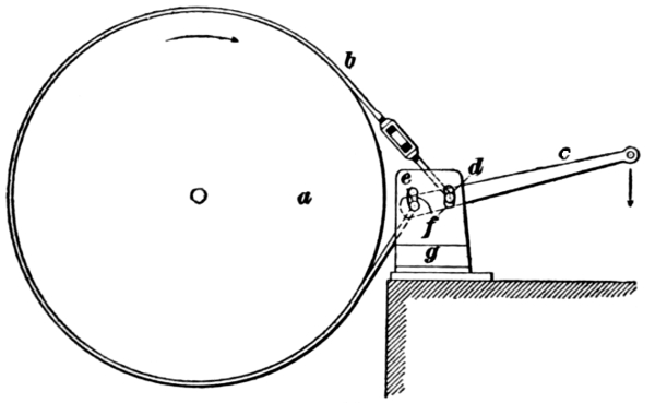
Fig. 25
43. If a brake is required to work with the drum running in
either direction, there are several ways of bringing the strain due
to the load on the anchorage in whichever way the drum runs. One of
the simplest of these is shown in Fig. 25, where a is
a drum with a strap brake b embracing nearly the entire circumference;
c is a lever bar that is attached to the ends of the brake strap
by pins d and e, which work in the slots f in the
iron anchor plates g. One anchor plate is on each side of the
lever, and both are bolted to the foundation. If the band is kept of
the proper length, then, no matter which way the drum is turning, the
pull of the drum will come on the anchorage, and the pull on the lever
need be only sufficient to take up the slack end of the band. To
illustrate: If the drum is turning in the direction indicated by the
arrow, the pin e holding the lower end of the band will be on
the bottom of its slot and the pin d will be free in its slot
and engaged in tightening the slack end of the band through the motion
of the lever c. Were the drum running the other way, the pin
d connected with the upper half of the band would move to the
upper end of its slot and take the main load, while the pin e
at the lower end of the band would only have to take up the slack.
The outer, or long, end of the lever moves downwards in all cases to
tighten the band. Provision must be made to lift the band clear of the
drum when slack, but no anchorage other than at g should be
attempted.
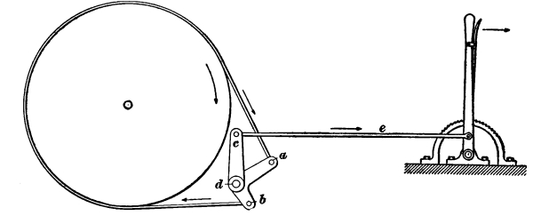
Fig. 26
44. The Differential Brake.—The differential brake has both
ends of the brake strap attached to short lever arms operated by
the brake lever, but these arms are of different lengths and are so
arranged that as the longer arm tightens the brake strap the shorter
arm yields and loosens the strap. The tightening, however, is more than
the loosening or yielding and, as a result, the brake band is tightened
about the brake wheel. The form of the lever arm is immaterial so long
as the differential principle is retained, that is, that the shorter
arm yields when the longer pulls, when the brake is thrown into action.
This principle is illustrated in Fig. 26. In this brake,
no provision is made for anchoring either end of the brake strap, but the entire
load is thrown on the lever arms a and b. These lever
arms are connected with the arm c, which revolves on the
same shaft d and is operated by the reach rod e. The
revolution of the drum is thus resisted by the shaft d.
This brake is self-acting when the drum revolves so as to pull on the
shorter arm, as indicated by the arrows; that is, the motion of the
drum helps to set the brake when the latter is once applied. When,
however, the drum revolves in the opposite direction, the action of
the brake is opposed, instead of being assisted, by the motion of the
drum. As a consequence, this particular form of brake is not adapted to
hoisting drums that revolve in opposite directions at each alternate
hoist. Differential brakes are not generally used.
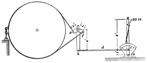
Fig. 27
45. Power for Brakes.—For small drums and light loads, the
brakes are usually applied by hand power through suitable lever
connections. The force that a man can exert can be multiplied
indefinitely by levers and combinations of levers; but while the force
is multiplied, the distance through which it can act is divided in the
same ratio. A certain amount of motion is required to free the brake
band from the drum, when the brake is off; this, then, limits the
leverage that a man can use. Suppose, for instance, that with a strap
brake the band moves from the drum ½ inch, thus increasing the diameter
1 inch, or the circumference about 3 inches. Then, supposing that a
man can exert his force to advantage through 3 feet, or 36 inches, the
available leverage is ³⁶/₃ = 12. That is, if a man can pull 50 pounds
on his hand lever, he can exert 50 × 12 = 600 pounds circumferentially
on the brake band, with simple levers. If any form of differential
levers is used, the ratio by which the force applied at the hand lever
can be increased will be considerably larger. A diagram will explain
this more clearly.
46. In Fig. 27, a is the hand lever, with a fulcrum
at b and a pin at c by which it takes hold of a reach rod or connection
d. This rod is connected to the end h of the brake lever
e, which is connected by pins at f, g to the brake
bands. If the leverage of the hand lever a is made 6 to 1, that
is, if
and a force of 50 pounds is applied at a,
a pull of 300 pounds will be exerted at the pin c and,
consequently, along the rod d to the end of the brake lever
e. Then, if the brake lever is made with a ratio of 4 to 1, that
is, if
| eh |
|
4 |
|
eh |
| —— |
= |
—— |
= |
—— |
| eg |
|
1 |
|
ef |
a pull of 300 pounds × 4 = 1,200 pounds will
be exerted at the pin f or g. This total pull must be
divided equally between the arms eg and ef, giving 600
pounds pull on each. According to the principle of the lever, the
distances through which these forces act are inversely proportional
to the forces acting. It is assumed that the brakeman can exert the
force of 50 pounds through 36 inches; if this is the motion of the end
of the hand lever a, one-sixth of this, or 6 inches, will be
the motion at c and, therefore, at h; one-fourth of 6
inches or 1½ inches will be the motion at f and g; that
is, f will increase its half of the brake band 1½ inches in
circumference, and g will do likewise with its half, making the
total circumference 3 inches more, or the diameter 1 inch more, and
thereby moving the band away from the drum ½ inch radially. The levers
are all shown in mid-position to make the figure more simple, but the
relative leverages remain the same at all points in the motion.
This is an example of simple levers, but the force applied at the hand
lever may be increased in a much greater ratio by the use of a device
known as a differential lever.
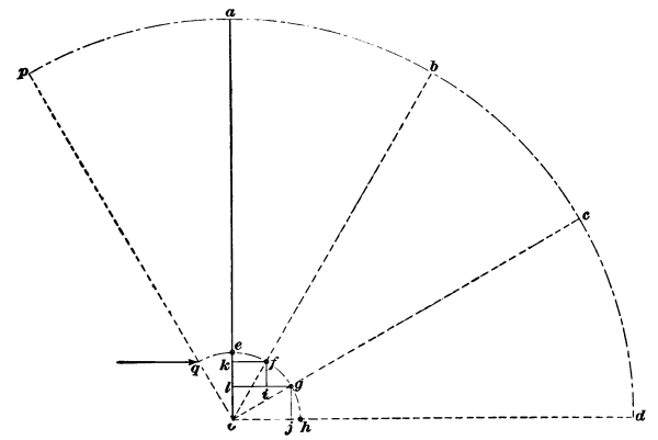
Fig. 28
47. The Differential Lever.—The principle of the
operation of the differential lever with which a constantly
increasing force can be applied to the brake strap is illustrated in
Fig. 28. Let a o represent a straight lever whose
fulcrum is at o; and let the reach rod be attached at e. In this
position, if
the effective lever is 6 to 1. If, now, the lever
is moved through 30° to the position b o, the force applied
at a moves through the distance a b, and the reach rod
through the horizontal distance k f, so that the effective
leverage is increased a small amount e k and the ratio of the
arms becomes
When the lever is moved another 30° to the
position c o, the reach rod moves a distance i g, which
is less than k f, so that the effective leverage is increased by
the amount k l and the ratio of the arms becomes
Again, moving the lever 30° more to the position
d o, the reach rod moves through the still shorter distance
j h, which is less than i g, and the effective leverage
becomes very great. It is evident from this that the farther the lever
is moved toward d the greater becomes the effective leverage. In practice,
it would be impossible to move the lever through the entire quadrant
to advantage, and there would also be more movement of the reach rod
at the beginning of the stroke and less at the end than is needed to
produce the desired effect.
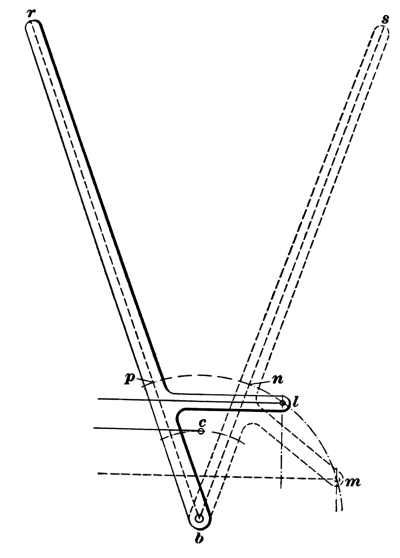
Fig. 29
From the principle just given, it is plain that, if p o, Fig. 28,
represents a brake lever with the reach rod attached at q,
a smaller pull will be exerted on the brake band if the lever is moved
to the position b o than would be exerted if a lever were moved
through the same angle from b o to d o. The movement
from p o to b o is a convenient and easy one for the
engineer to make, while the movement from b o to d o is
inconvenient. To overcome the inconvenience and still to obtain the
advantage of this latter movement, the differential lever shown in
Fig. 29 is used. By means of an arm placed on the lever,
the point of attaching the reach rod is at l instead of p; hence,
when the handle r b is moved to the position s b, the
point l moves to m, thus securing a greater and gradually
increasing pull with the easier movement of the handle.
A differential lever may be advantageously used in connection with any
band or post brake and on a drum running in either direction. Such
levers are considered by many preferable to the differential brake.
48. Power Brakes.—Large drums and heavily loaded drums
cannot be controlled by hand-power brakes, and in such a case some other
form of power, such as steam, compressed air, or water, must be used.
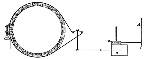
Fig. 30
Fig. 30 shows, in outline, how such power is applied.
The movements of the hand lever A, instead of being directly
communicated to the lever operating the brake, merely control the
valve v connected with the cylinder a. By means of this
valve, steam, compressed air, or water is admitted to either end of
the cylinder and this moves the piston in the direction necessary to
apply or release the brake. There are a number of varieties of such
power brakes, differing in structural details, but the action of all
is essentially the same. With steam or air power, the brake would be
applied with its full force almost instantaneously, thus subjecting
the various parts of the mechanism to very severe and objectionable
strains, unless the valves were modified so as to regulate the
admission of the steam or air. One method of controlling this action
is the use of a valve that requires a long travel to give it a full
opening. Such a valve can be opened a little, so as to allow the steam
to leak through and thereby increase the pressure in the cylinder
gradually. As the motion is difficult to regulate, a better method is
by means of a floating valve, described in Hoisting, Part 1.
49. Crank Brake.—In addition to the brake applied to the
drum and intended for use mainly in emergencies, many hoisting engines
are also fitted with a strap brake applied to the crank-disk. In some
states, crank-brakes are required by law. In order to give a large
bearing surface, the crank-disk is made very large.
HOISTING
(PART 4)
Serial 851D Edition 1