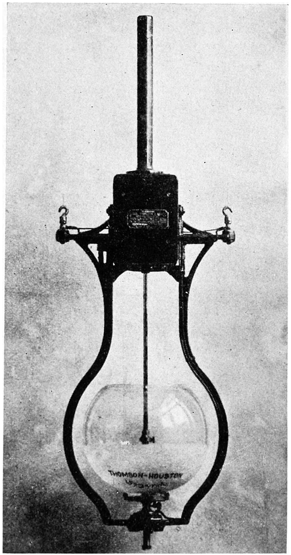
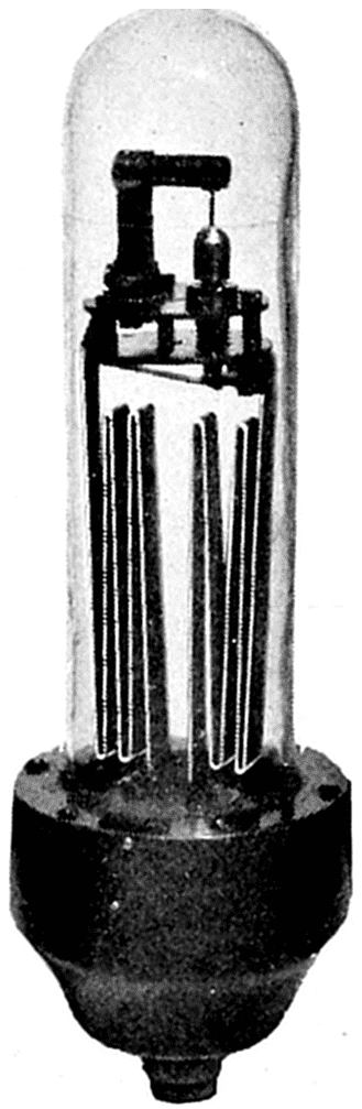
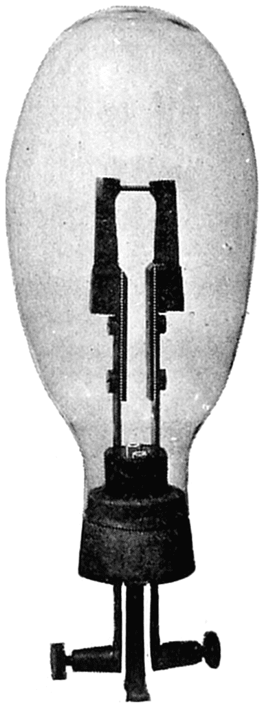
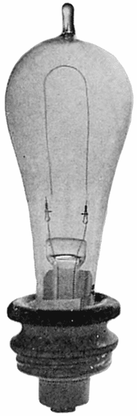
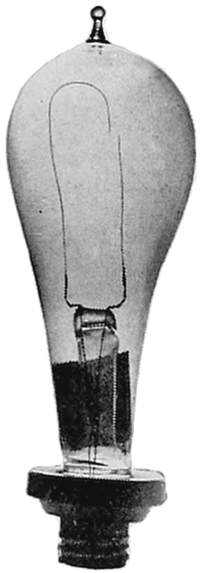
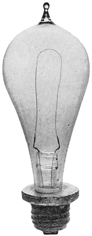
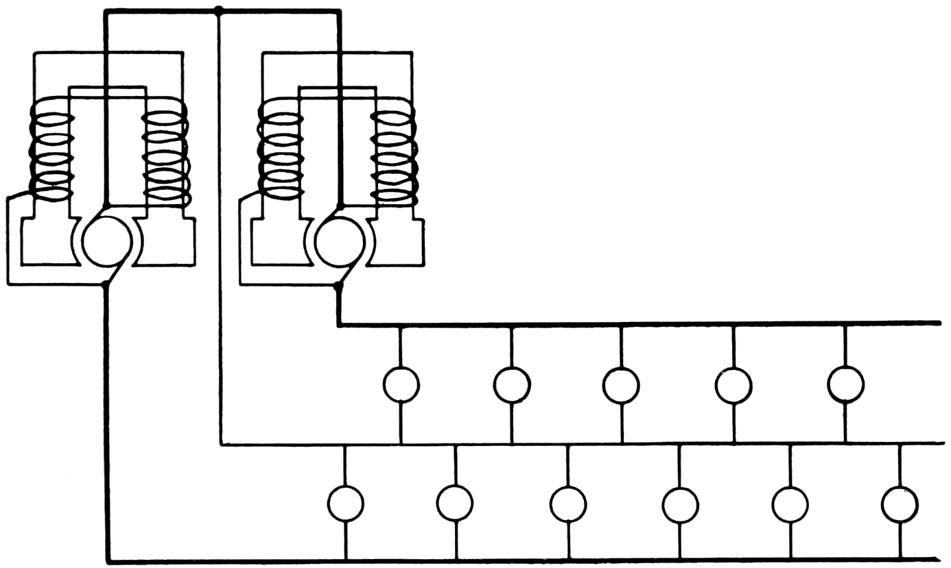
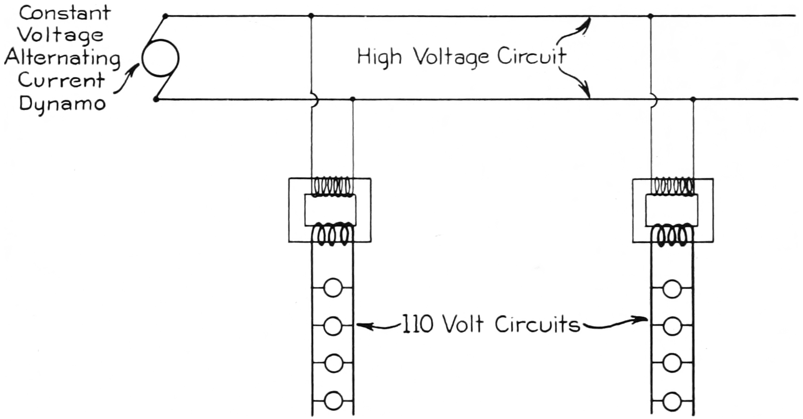
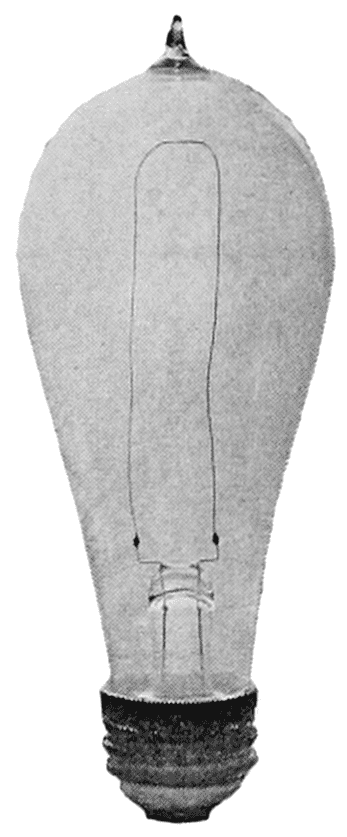
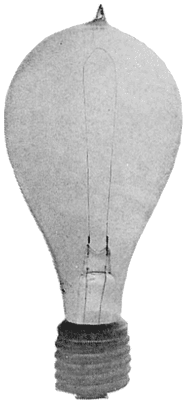
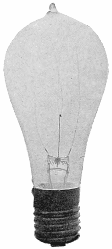
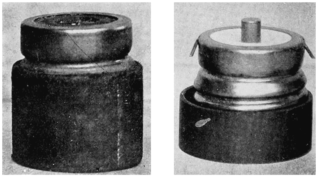
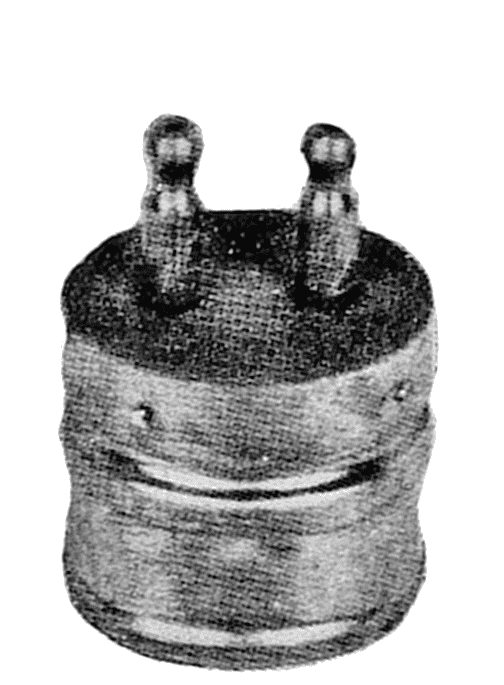
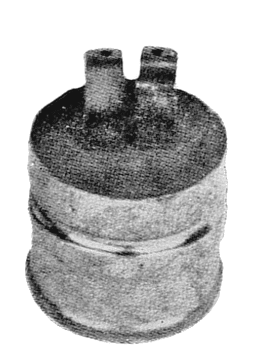
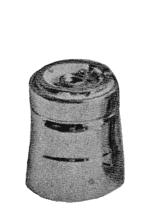
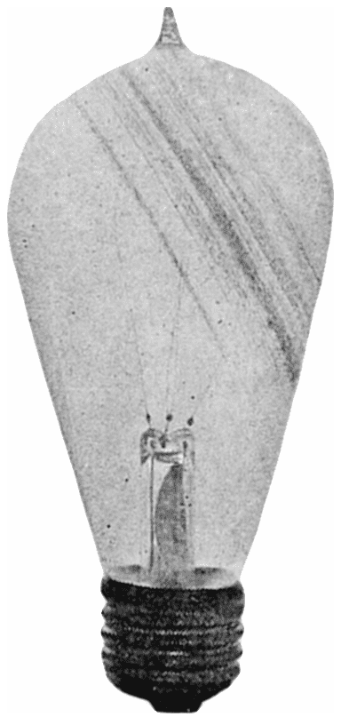
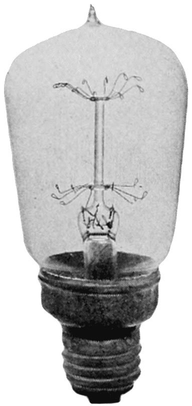
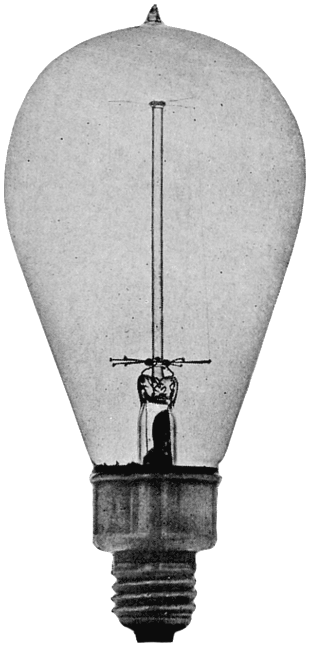
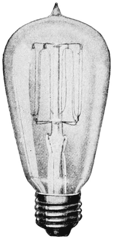
Larger versions of most illustrations may be seen by right-clicking them
and selecting an option to view them separately, or by double-tapping and/or
stretching them.
Cover image created by Transcriber, using illustrations
from the original book, and placed into the Public Domain.
SMITHSONIAN MISCELLANEOUS COLLECTIONS VOLUME 76, NUMBER 2
BY
HENRY SCHROEDER Harrison, New Jersey
FOR THE INCREASE
AND DIFFVSION OF
KNOWLEDGE AMONG MEN
SMITHSONIAN
INSTITVTION
WASHINGTON 1846
(Publication 2717)
CITY OF WASHINGTON
PUBLISHED BY THE SMITHSONIAN INSTITUTION
AUGUST 15, 1923
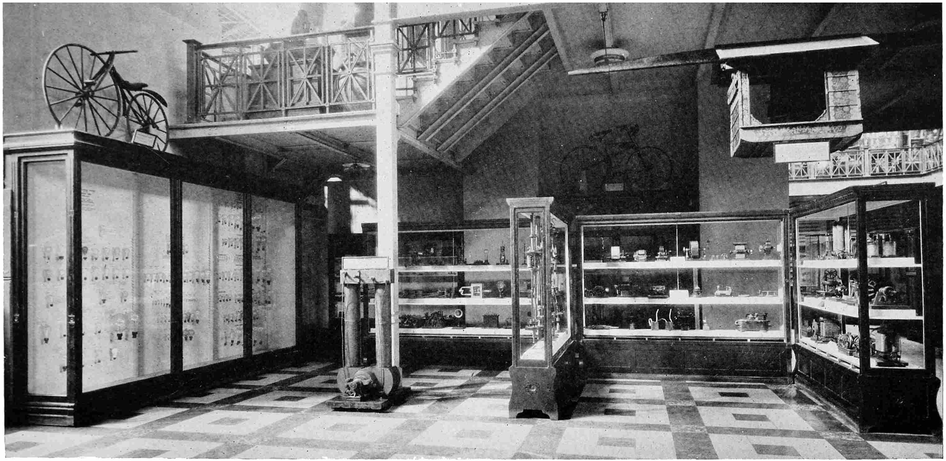
Portion of the Electrical Exhibit in the United States National Museum.
Section devoted to the historical development of the electric light and dynamo.
FOREWORD
In the year 1884 a Section of Transportation was organized in
the United States National Museum for the purpose of preparing
and assembling educational exhibits of a few objects of railroad
machinery which had been obtained both from the Centennial Exhibition
held in Philadelphia in 1876 and still earlier as incidentals to
ethnological collections, and to secure other collections relating to the
railway industry.
From this beginning the section was expanded to include the
whole field of engineering and is designated at present as the Divisions
of Mineral and Mechanical Technology. The growth and enlargement
of the collections has been particularly marked in the fields of
mining and mineral industries; mechanical engineering, especially
pertaining to the steam engine, internal combustion engine and locomotive;
naval architecture, and electrical engineering, particularly the
development of the telegraph, telephone and the electric light.
In the acquisition of objects visualizing the history of electric
light the Museum has been rather fortunate, particularly as regards
the developments in the United States. Thus mention may be made
of the original Patent Office models of the more important dynamos,
arc lights and incandescent lights, together with original commercial
apparatus after these models; a unit of the equipment used in the first
commercially successful installation on land of an incandescent lighting
system, presented by Joseph E. Hinds in whose engraving establishment
in New York City the installation was made in 1881; and a large
series of incandescent lights, mainly originals, visualizing chronologically
the developments of the Edison light from its inception, presented
at intervals since the year 1898 by the General Electric
Company.
The object of all collections in the Divisions is to visualize broadly
the steps by which advances have been made in each field of engineering;
to show the layman the fundamental and general principles which
are the basis for the developments; and to familiarize the engineer
with branches of engineering other than his own. Normally when a
subject is completely covered by a collection of objects, a paper is prepared
and published describing the collection and the story it portrays.
In the present instance, however, on account of the uncertainty of
the time of completing the collection, if it is possible ever to bring this
about, it was thought advisable to publish Mr. Schroeder’s paper
which draws upon the Museum collection as completely as possible.
Carl W. Mitman, Curator, Divisions of Mineral and Mechanical Technology, U. S. National Museum.
CHRONOLOGY OF ELECTRIC LIGHT
1800—Allesandro Volta demonstrated his discovery that electricity
can be generated by chemical means. The Volt, the unit
of electric pressure, is named in his honor for this discovery
of the electric battery.
1802—Sir Humphry Davy demonstrated that electric current can heat
carbon and strips of metal to incandescence and give light.
1809—Sir Humphry Davy demonstrated that current will give a brilliant
flame between the ends of two carbon pencils which are
first allowed to touch each other and then pulled apart. This
light he called the “arc” on account of its arch shape.
1820—André Marie Ampère discovered that current flowing through
a coiled wire gives it the properties of a magnet. The Ampere,
the unit of flow of electric current, is named in his
honor for this discovery.
1825—Georg Simon Ohm discovered the relation between the voltage,
ampereage and resistance in an electric circuit, which is
called Ohm’s Law. The Ohm, the unit of electric resistance,
is named in his honor for this discovery.
1831—Michael Faraday discovered that electricity can be generated
by moving a wire in the neighborhood of a magnet, the
principle of the dynamo.
1840—Sir William Robert Grove demonstrated his experimental
incandescent lamp in which platinum is made incandescent
by current flowing through it.
1841—Frederick De Moleyns obtained the first patent on an incandescent
lamp. The burner was powdered charcoal operating
in an exhausted glass globe.
1845—Thomas Wright obtained the first patent on an arc light.
1845—J. W. Starr invented an incandescent lamp consisting of a
carbon pencil operating in the vacuum above a column of
mercury.
1856—Joseph Lacassagne and Henry Thiers invented the “differential”
method of control of the arc which was universally
used twenty years later when the arc lamp was commercially
established.
1862—The first commercial installation of an electric light. An arc
light was put in a lighthouse in England.
1866—Sir Charles Wheatstone invented the “self-excited” dynamo,
now universally used.
1872—Lodyguine invented an incandescent lamp having a graphite
burner operating in nitrogen gas.
1876—Paul Jablochkoff invented the “electric candle,” an arc light
commercially used for lighting the boulevards in Paris.
1877–8—Arc light systems commercially established in the United
States by William Wallace and Prof. Moses Farmer, Edward
Weston, Charles F. Brush and Prof. Elihu Thomson and
Edwin J. Houston.
1879—Thomas Alva Edison invented an incandescent lamp consisting
of a high resistance carbon filament operating in a high
vacuum maintained by an all glass globe. These principles
are used in all incandescent lamps made today. He also
invented a completely new system of distributing electricity
at constant pressure, now universally used.
1882—Lucien Goulard and John D. Gibbs invented a series alternating
current system of distributing electric current. This has
not been commercially used.
1886—William Stanley invented a constant pressure alternating current
system of distribution. This is universally used where
current is to be distributed long distances.
1893—Louis B. Marks invented the enclosed carbon arc lamp.
1898—Bremer’s invention of the flame arc lamp, having carbons impregnated
with various salts, commercially established.
1900—Dr. Walther Nernst’s invention of the Nernst lamp commercially
established. The burner consisted of various oxides,
such as zirconia, which operated in the open air.
1901—Dr. Peter Cooper Hewitt’s invention of the mercury arc light
commercially established.
1902—The magnetite arc lamp was developed by C. A. B. Halvorson,
Jr. This has a new method of control of the arc. The
negative electrode consists of a mixture of magnetite and
other substances packed in an iron tube.
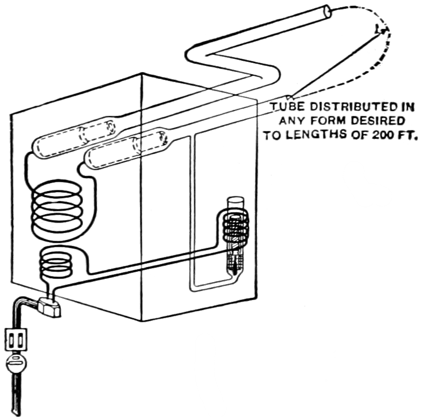
1904—D. McFarlan Moore’s invention of the Moore vacuum tube
light commercially established. This consisted of a long
tube, made in lengths up to 200 feet, from which the air
had been exhausted to about a thousandth of an atmosphere.
High voltage current passing through this rarefied atmosphere
caused it to glow. Rarefied carbon dioxide gas was
later used.
1905—Dr. Auer von Welsbach’s invention of the osmium incandescent
lamp commercially established, but only on a small scale
in Europe. The metal osmium, used for the filament which
operated in vacuum, is rarer and more expensive than platinum.
1905—Dr. Willis R. Whitney’s invention of the Gem incandescent
lamp commercially established. The carbon filament had
been heated to a very high temperature in an electric resistance
furnace invented by him. The lamp was 25 per cent
more efficient than the regular carbon lamp.
1906—Dr. Werner von Bolton’s invention of the tantalum incandescent
lamp commercially established.
1907—Alexander Just and Franz Hanaman’s invention of the tungsten
filament incandescent lamp commercially established.
1911—Dr. William D. Coolidge’s invention of drawn tungsten wire
commercially established.
1913—Dr. Irving Langmuir’s invention of the gas-filled tungsten
filament incandescent lamp commercially established.
HISTORY OF ELECTRIC LIGHT — EARLY RECORDS OF ELECTRICITY AND MAGNETISM
By HENRY SCHROEDER,
HARRISON, NEW JERSEY.
About twenty-five centuries ago, Thales, a Greek philosopher,
recorded the fact that if amber is rubbed it will attract light objects.
The Greeks called amber “elektron,” from which we get the word
“electricity.” About two hundred and fifty years later, Aristotle,
another Greek philosopher, mentioned that the lodestone would attract
iron. Lodestone is an iron ore (Fe3O4), having magnetic qualities
and is now called magnetite. The word “magnet” comes from the
fact that the best specimens of lodestones came from Magnesia, a
city in Asia Minor. Plutarch, a Greek biographer, wrote about
100 A. D., that iron is sometimes attracted and at other times repelled
by a lodestone. This indicates that the piece of iron was magnetised
by the lodestone.
In 1180, Alexander Neckham, an English Monk, described the
compass, which probably had been invented by sailors of the northern
countries of Europe, although its invention has been credited to the
Chinese. Early compasses probably consisted of an iron needle,
magnetised by a lodestone, mounted on a piece of wood floating in
water. The word lodestone or “leading stone” comes from the fact
that it would point towards the north if suspended like a compass.
William Gilbert, physician to Queen Elizabeth of England, wrote a
book about the year 1600 giving all the information then known on
the subject. He also described his experiments, showing, among
other things, the existence of magnetic lines of force and of north and
south poles in a magnet. Robert Norman had discovered a few years
previously that a compass needle mounted on a horizontal axis would
dip downward. Gilbert cut a large lodestone into a sphere, and
observed that the needle did not dip at the equator of this sphere, the
dip increasing to 90 degrees as the poles were approached. From
this he deduced that the earth was a magnet with the magnetic north
pole at the geographic north pole. It has since been determined that
these two poles do not coincide. Gilbert suggested the use of the
dipping needle to determine latitude. He also discovered that other
substances, beside amber, would attract light objects if rubbed.
MACHINES GENERATING ELECTRICITY BY FRICTION
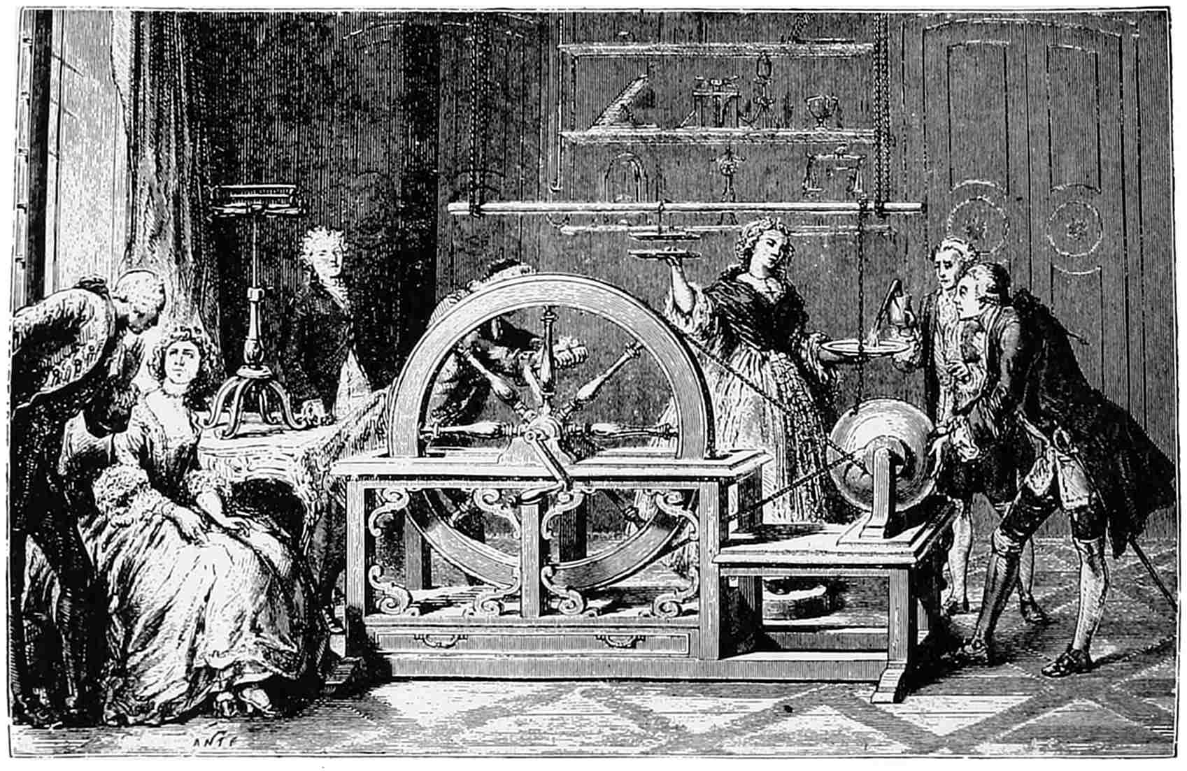
Otto Von Guericke was mayor of the city of Magdeburg as well as
a philosopher. About 1650 he made a machine consisting of a ball
of sulphur mounted on a shaft which could be rotated. Electricity
was generated when the hand was pressed against the globe as it
rotated. He also discovered that electricity could be conducted away
from the globe by a chain and would appear at the other end of the
chain. Von Guericke also invented the vacuum air pump. In 1709,
Francis Hawksbee, an Englishman, made a similar machine, using a
hollow glass globe which could be exhausted. The exhausted globe
when rotated at high speed and rubbed by hand would produce a glowing
light. This “electric light” as it was called, created great excitement
when it was shown before the Royal Society, a gathering of
scientists, in London.
Otto Von Guericke’s Electric Machine, 1650.
A ball of sulphur was rotated, electricity being generated when it
rubbed against the hand.
Stephen Gray, twenty years later, showed the Royal Society that
electricity could be conducted about a thousand feet by a hemp thread,
supported by silk threads. If metal supports were used, this could not
be done. Charles du Fay, a Frenchman, repeated Gray’s experiments,
and showed in 1733 that the substances which were insulators, and
which Gilbert had discovered, would become electrified if rubbed.
Those substances which Gilbert could not electrify were conductors
of electricity.
THE LEYDEN JAR
The thought came to Von Kleist, Bishop of Pomerania, Germany,
about 1745, that electricity could be stored. The frictional machines
generated so small an amount of electricity (though, as is now known,
at a very high pressure—several thousand volts) that he thought he
could increase the quantity by storing it. Knowing that glass was
an insulator and water a conductor, he filled a glass bottle partly full
of water with a nail in the cork to connect the machine with the
water. Holding the bottle in one hand and turning the machine with
the other for a few minutes, he then disconnected the bottle from the
machine. When he touched the nail with his other hand he received
a shock which nearly stunned him. This was called the Leyden jar,
the forerunner of the present condenser. It received its name from
the fact that its discovery was also made a short time after by experimenters
in the University of Leyden. Further experiments showed
that the hand holding the bottle was as essential as the water inside,
so these were substituted by tin foil coatings inside and outside the
bottle.
Benjamin Franklin, American statesman, scientist and printer, made
numerous experiments with the Leyden jar. He connected several
jars in parallel, as he called it, which gave a discharge strong enough
to kill a turkey. He also connected the jars in series, or “in cascade”
as he called it, thus establishing the principle of parallel and series
connections. Noticing the similarity between the electric spark and
lightning, Franklin in 1752, performed his famous kite experiment.
Flying a kite in a thunderstorm, he drew electricity from the clouds
to charge Leyden jars, which were later discharged, proving that
lightning and electricity were the same. This led him to invent the
lightning rod.
ELECTRICITY GENERATED BY CHEMICAL MEANS
Luigi Galvani was an Italian scientist. About 1785, so the story
goes, his wife was in delicate health, and some frog legs were being
skinned to make her a nourishing soup. An assistant holding the legs
with a metal clamp and cutting the skin with a scalpel, happened to
let the clamp and scalpel touch each other. To his amazement the
frog legs twitched. Galvani repeated the experiment many times
by touching the nerve with a metal rod and the muscle with a different
metal rod and allowing the rods to touch, and propounded the theory
of animal electricity in a paper he published in 1791.
Allesandro Volta, a professor of physics in the University of Pavia,
Italy, read about Galvani’s work and repeated his experiments. He
found that the extent of the movement of the frog legs depended
on the metals used for the rods, and thus believed that the electric
charge was produced by the contact of dissimilar metals with the
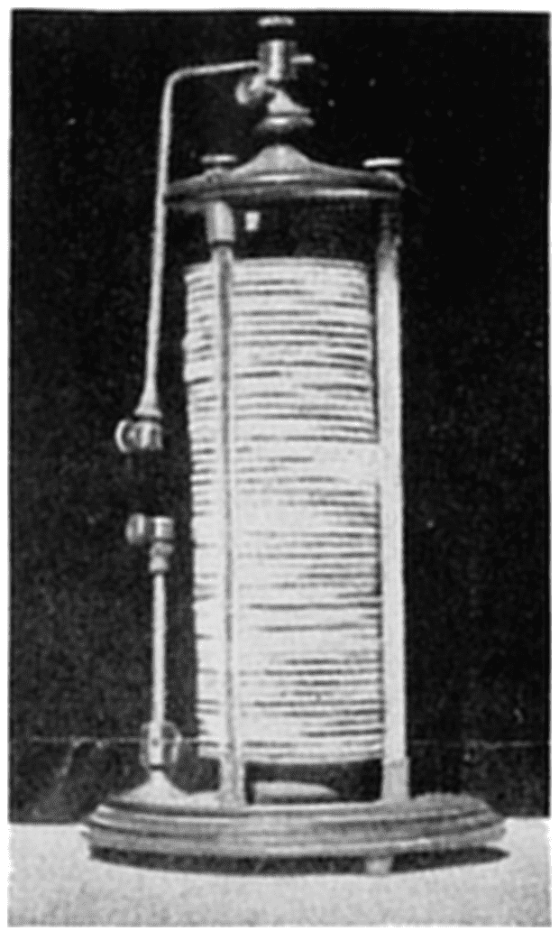
moisture in the muscles. To prove his point he made a pile of silver
and zinc discs with cloths, wet with salt water, between them. This
was in 1799, and he described his pile in March, 1800, in a letter to
the Royal Society in London.
Voltaic Pile, 1799.
Volta discovered that electricity could be generated by chemical
means and made a pile of silver and zinc discs with cloths, wet with
salt water, between them. This was the forerunner of the present-day
dry battery. Photograph courtesy Prof. Chas. F. Chandler
Museum, Columbia University, New York.
This was an epoch-making discovery as it was the forerunner of the
present-day primary battery. Volta soon found that the generation
of electricity became weaker as the cloths became dry, so to overcome
this he made his “crown of cups.” This consisted of a series of
cups containing salt water in which strips of silver and zinc were
dipped. Each strip of silver in one cup was connected to the zinc
strip in the next cup, the end strips of silver and zinc being terminals
of the battery. This was the first time that a continuous supply of
electricity in reasonable quantities was made available, so the Volt,
the unit of electrical pressure was named in his honor. It was later
shown that the chemical affinity of one of the metals in the liquid
was converted into electric energy. The chemical action of Volta’s
battery is that the salt water attacks the zinc when the circuit is
closed forming zinc chloride, caustic soda and hydrogen gas. The
chemical equation is:
Zn + 2NaCl + 2H2O = ZnCl2 + 2NaOH + H2
IMPROVEMENT OF VOLTA’S BATTERY
It was early suggested that sheets of silver and zinc be soldered
together back to back and that a trough be divided into cells by these
bimetal sheets being put into grooves cut in the sides and bottom of the
trough. This is the reason why one unit of a battery is called a “cell.”
It was soon found that a more powerful cell could be made if copper,
zinc and dilute sulphuric acid were used. The zinc is dissolved by
the acid forming zinc sulphate and hydrogen gas, thus:
Zn + H2SO4 = ZnSO4 + H2
The hydrogen gas appears as bubbles on the copper and reduces the
open circuit voltage (about 0.8 volt per cell) as current is taken from
the battery. This is called “polarization.” Owing to minute impurities
in the zinc, it is attacked by the acid even when no current is
taken from the battery, the impurities forming with the zinc a short
circuited local cell. This is called “local action,” and this difficulty
was at first overcome by removing the zinc from the acid when the
battery was not in use.
DAVY’S DISCOVERIES
Sir Humphry Davy was a well-known English chemist, and with
the aid of powerful batteries constructed for the Royal Institution in
London, he made numerous experiments on the chemical effects of
electricity. He decomposed a number of substances and discovered
the elements boron, potassium and sodium. He heated strips of
various metals to incandescence by passing current through them,
and showed that platinum would stay incandescent for some time
without oxidizing. This was about 1802.
In the early frictional machines, the presence of electricity was
shown by the fact that sparks could be obtained. Similarly the breaking
of the circuit of a battery would give a spark. Davy, about 1809,
demonstrated that this spark could be maintained for a long time with
the large battery of 2000 cells he had had constructed. Using two
sticks of charcoal connected by wires to the terminals of this very
powerful battery, he demonstrated before the Royal Society the light
produced by touching the sticks together and then holding them apart
horizontally about three inches. The brilliant flame obtained he called
an “arc” because of its arch shape, the heated gases, rising, assuming
this form. Davy was given the degree of LL. D. for his distinguished
research work, and was knighted on the eve of his marriage,
April 11, 1812.
RESEARCHES OF OERSTED, AMPÈRE, SCHWEIGGER AND STURGEON
Hans Christian Oersted was a professor of physics at the University
of Copenhagen in Denmark. One day in 1819, while addressing
his students, he happened to hold a wire, through which
current was flowing, over a large compass. To his surprise he saw
the compass was deflected from its true position. He promptly made
a number of experiments and discovered that by reversing the current
the compass was deflected in the opposite direction. Oersted announced
his discovery in 1820.
André Marie Ampère was a professor of mathematics in the Ecole
Polytechnic in Paris. Hearing of Oersted’s discovery, he immediately
made some experiments and made the further discovery in 1820
that if the wire is coiled and current passed through it, the coil had
all the properties of a magnet.
These two discoveries led to the invention of Schweigger in 1820,
of the galvanometer (or “multiplier” as it was then called), a very
sensitive instrument for measuring electric currents. It consisted of
a delicate compass needle suspended in a coil of many turns of wire.
Current in the coil deflected the needle, the direction and amount of
deflection indicating the direction and strength of the current.
Ampère further made the discovery that currents in opposite directions
repel and in the same directions attract each other. He also gave
a rule for determining the direction of the current by the deflection of
the compass needle. He developed the theory that magnetism is
caused by electricity flowing around the circumference of the body
magnetised. The Ampere, the unit of flow of electric current, was
named in honor of his discoveries.
In 1825 it was shown by Sturgeon that if a bar of iron were placed
in the coil, its magnetic strength would be very greatly increased,
which he called an electro-magnet.
OHM’S LAW
Georg Simon Ohm was born in Bavaria, the oldest son of a poor
blacksmith. With the aid of friends he went to college and became
a teacher. It had been shown that the rate of transfer of heat from
one end to the other of a metal bar is proportional to the difference of
temperature between the ends. About 1825, Ohm, by analogy and
experiment, found that the current in a conductor is proportional
to the difference of electric pressure (voltage) between its ends.
He further showed that with a given difference of voltage, the current
in different conductors is inversely proportional to the resistance of
the conductor. Ohm therefore propounded the law that the current
flowing in a circuit is equal to the voltage on that circuit divided by
the resistance of the circuit. In honor of this discovery, the unit of
electrical resistance is called the Ohm. This law is usually expressed
as:
C = E/R
“C” meaning current (in amperes), “E” meaning electromotive
force or voltage (in volts) and “R” meaning resistance (in ohms).
This is one of the fundamental laws of electricity and if thoroughly
understood, will solve many electrical problems. Thus, if any two of
the above units are known, the third can be determined. Examples:
An incandescent lamp on a 120-volt circuit consumes 0.4 ampere,
hence its resistance under such conditions is 300 ohms. Several
trolley cars at the end of a line take 100 amperes to run them and the
resistance of the overhead wire from the power house to the trolley
cars is half an ohm; the drop in voltage on the line between the power
house and trolley cars is therefore 50 volts, so that if the voltage at
the power house were 600, it would be 550 volts at the end of the line.
Critics derided Ohm’s law so that he was forced out of his position
as teacher in the High School in Cologne. Finally after ten years
Ohm began to find supporters and in 1841 his law was publicly
recognized by the Royal Society of London which presented him with
the Copley medal.
INVENTION OF THE DYNAMO
Michael Faraday was an English scientist. Born of parents in
poor circumstances, he became a bookbinder and studied books on
electricity and chemistry. He finally obtained a position as laboratory
assistant to Sir Humphry Davy helping him with his lectures and
experiments. He also made a number of experiments himself and succeeded
in liquifying chlorine gas for which he was elected to a Fellowship
in the Royal Institution in 1824. Following up Oersted’s
and Ampère’s work, he endeavored to find the relation between
electricity and magnetism. Finally on Oct. 17, 1831, he made the
experiment of moving a permanent bar magnet in and out of a coil
of wire connected to a galvanometer. This generated electricity in
the coil which deflected the galvanometer needle. A few days after,
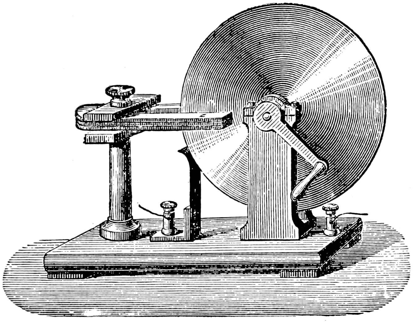
Oct. 28, 1831, he mounted a copper disk on a shaft so that the disk
could be rotated between the poles of a permanent horseshoe magnet.
The shaft and edge of the disk were connected by brushes and wires
to a galvanometer, the needle of which was deflected as the disk was
rotated. A paper on his invention was read before the Royal Society
on November 24, 1831, which appeared in printed form in January,
1832.
Faraday’s Dynamo, 1831.
Faraday discovered that electricity could be generated by means of a
permanent magnet. This principle is used in all dynamos.
Faraday did not develop his invention any further, being satisfied,
as in all his work, in pure research. His was a notable invention but
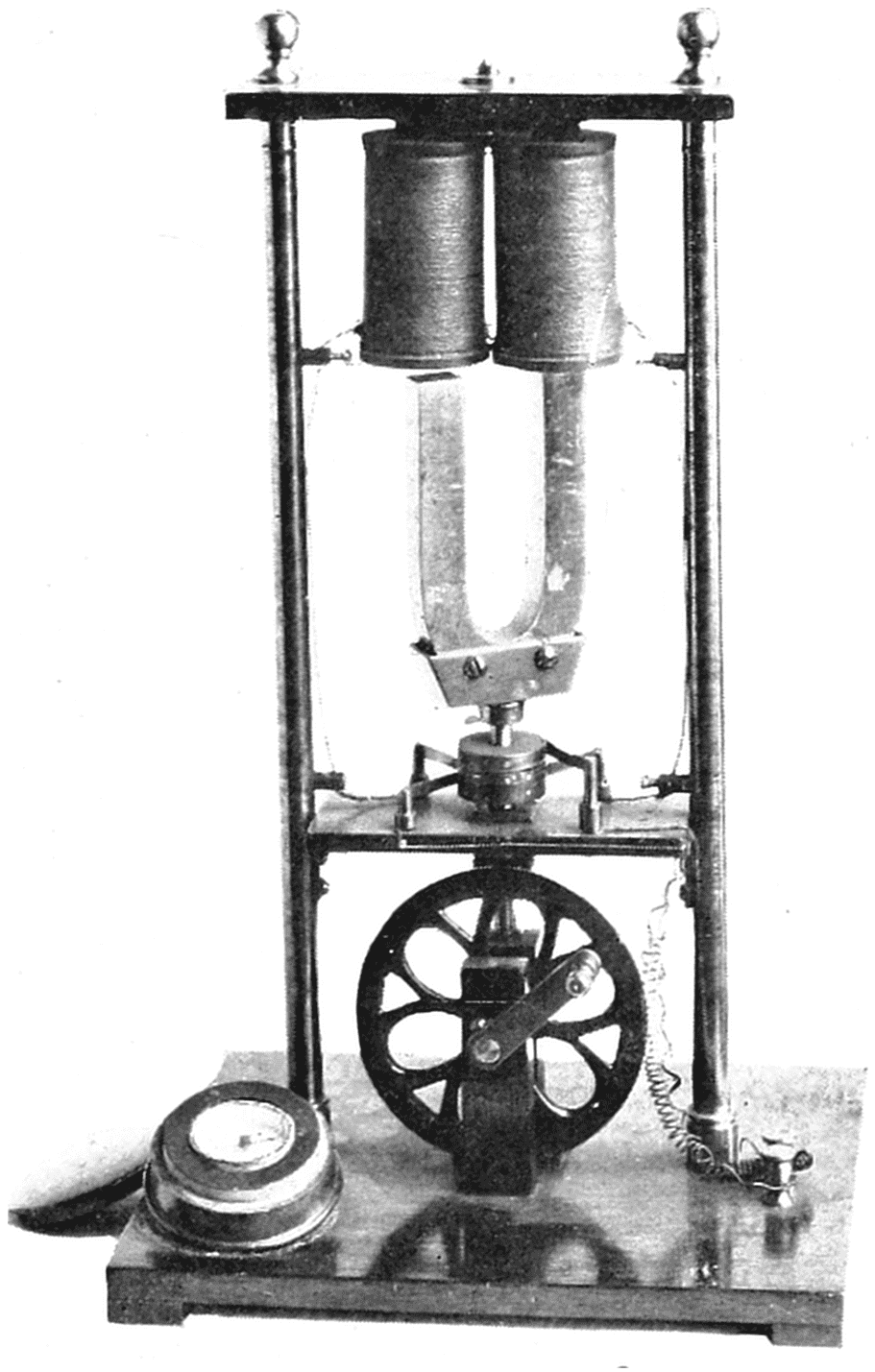
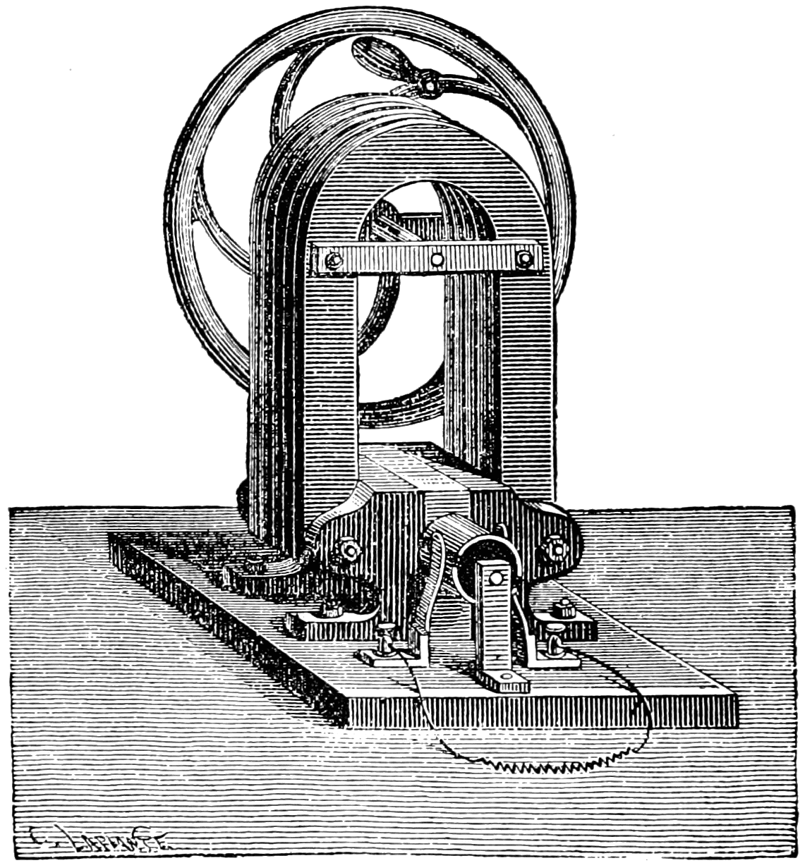
it remained for others to make it practicable. Hippolyte Pixii, a
Frenchman, made a dynamo in 1832 consisting of a permanent horseshoe
magnet which could be rotated between two wire bobbins
mounted on a soft iron core. The wires from the bobbins were connected
to a pair of brushes touching a commutator mounted on the
shaft holding the magnet, and other brushes carried the current from
the commutator so that the alternating current generated was rectified
into direct current.
Pixii’s Dynamo, 1832.
Pixii made an improvement by rotating a permanent magnet in the
neighborhood of coils of wire mounted on a soft iron core. A commutator
rectified the alternating current generated into direct current.
This dynamo is in the collection of the Smithsonian Institution.
E. M. Clarke, an Englishman made, in 1834, another dynamo in
which the bobbins rotated alongside of the poles of a permanent
horseshoe magnet. He also made a commutator so that the machine
produced direct current. None of these machines gave more than
feeble current at low pressure. The large primary batteries that had
been made were much more powerful, although expensive to operate.
It has been estimated that the cost of current from the 2000-cell
battery to operate the demonstration of the arc light by Davy, was
six dollars a minute. At present retail rates for electricity sold by
lighting companies, six dollars would operate Davy’s arc light about
500 hours or 30,000 times as long.
DANIELL’S BATTERY
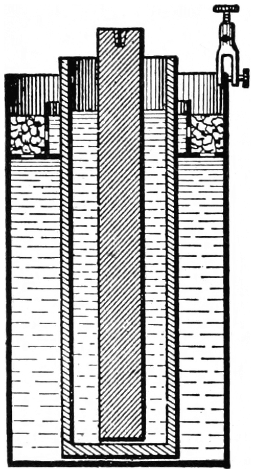
Daniell’s Cell, 1836.
Daniell invented a battery consisting of zinc, copper and copper sulphate.
Later the porous cup was dispensed with, which was used to
keep the sulphuric acid formed separate from the solution of copper
sulphate, the two liquids then being kept apart by their difference in
specific gravity. It was then called the Gravity Battery and for years
was used in telegraphy.
It was soon discovered that if the zinc electrode were rubbed with
mercury (amalgamated), the local action would practically cease,
and if the hydrogen bubbles were removed, the operating voltage of
the cell would be increased. John Frederic Daniell, an English
chemist, invented a cell in 1836 to overcome these difficulties. His
cell consisted of a glass jar containing a saturated solution of copper
sulphate (CuSO4). A copper cylinder, open at both ends and perforated
with holes, was put into this solution. On the outside of the
copper cylinder there was a copper ring, located below the surface of
the solution, acting as a shelf to support crystals of copper sulphate.
Inside the cylinder there was a porous earthenware jar containing
dilute sulphuric acid and an amalgamated zinc rod. The two liquids
were therefore kept apart but in contact with each other through the
pores of the jar. The hydrogen gas given off by the action of the
sulphuric acid on the zinc, combined with the dissolved copper sulphate,
formed sulphuric acid and metallic copper. The latter was
deposited on the copper cylinder which acted as the other electrode.
Thus the copper sulphate acted as a depolarizer.
The chemical reactions in this cell are,
In inner porous jar: Zn + H2SO4 = ZnSO4 + H2
In outer glass jar: H2 + CuSO4 = H2SO4 + Cu
This cell had an open circuit voltage of a little over one volt. Later
the porous cup was dispensed with, the two liquids being kept apart
by the difference of their specific gravities. This was known as the
Gravity cell, and for years was used in telegraphy.
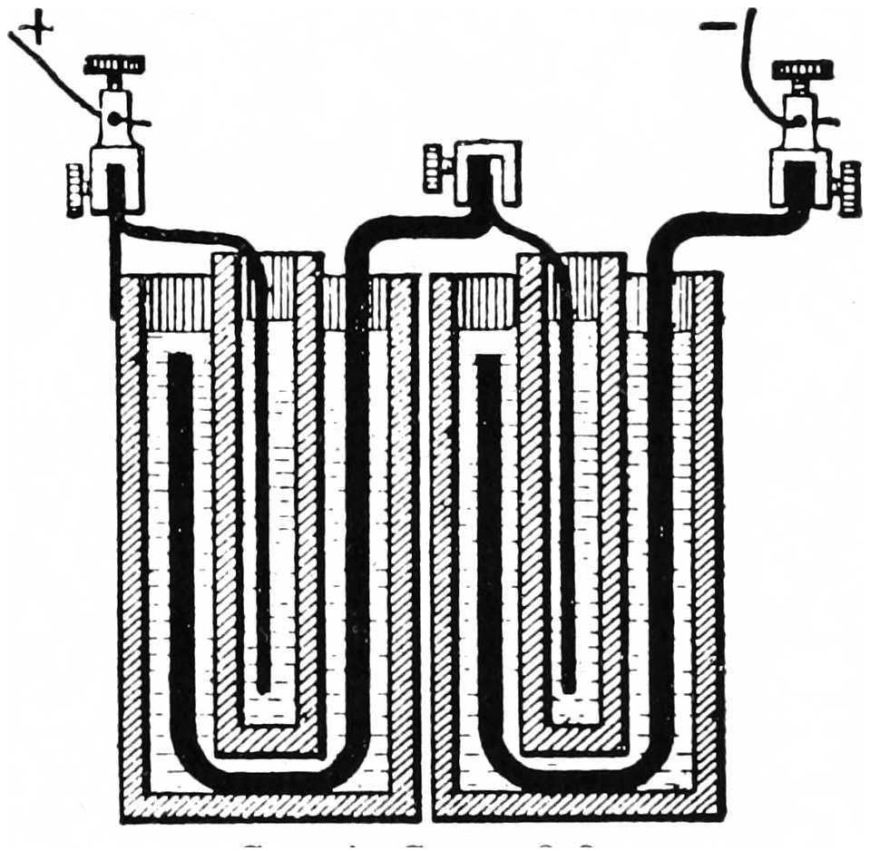
Grove’s Cell, 1838.
This consisted of zinc, sulphuric acid, nitric acid and platinum.
It made a very powerful battery. The nitric acid is called the depolarizer
as it absorbs the hydrogen gas formed, thus improving the operating
voltage.
GROVE’S BATTERY
Sir William Robert Grove, an English Judge and scientist, invented
a cell in 1838 consisting of a platinum electrode in strong nitric acid
in a porous earthenware jar. This jar was put in dilute sulphuric acid
in a glass jar in which there was an amalgamated zinc plate for the
other electrode. This had an open circuit voltage of about 1.9 volts.
The porous jar was used to prevent the nitric acid from attacking the
zinc. The nitric acid was used for the purpose of combining with the
hydrogen gas set free by the action of the sulphuric acid on the zinc,
and hence was the depolarizing agent. Hydrogen combining with
nitric acid forms nitrous peroxide and water. Part of the nitrous
peroxide is dissolved in the water, and the rest escapes as fumes
which, however, are very suffocating.
The chemical equations of this cell are as follows:
An interesting thing about Grove’s cell is that it was planned in
accordance with a theory. Grove knew that the electrical energy of
the zinc-sulphuric acid cell came from the chemical affinity of the two
reagents, and if the hydrogen gas set free could be combined with
oxygen (to form water—H2O), such chemical affinity should increase
the strength of the cell. As the hydrogen gas appears at the other
electrode, the oxidizing agent should surround that electrode. Nitric
acid was known at that time as one of the most powerful oxidizing
liquids, but as it attacks copper, he used platinum for the other electrode.
Thus he not only overcame the difficulty of polarization by
the hydrogen gas, but also increased the voltage of the cell by the
added chemical action of the combination of hydrogen and oxygen.
GROVE’S DEMONSTRATION OF INCANDESCENT LIGHTING
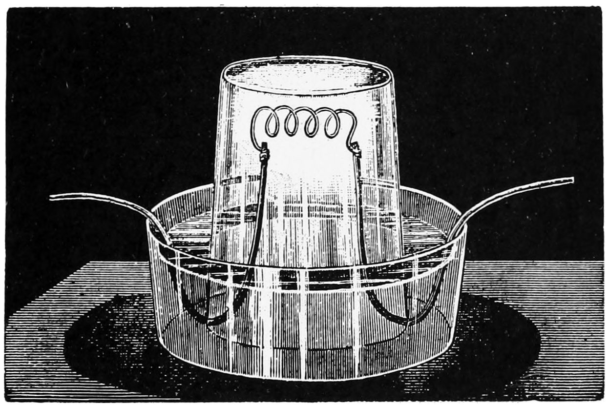
In 1840 Grove made an experimental lamp by attaching the ends
of a coil of platinum wire to copper wires, the lower parts of which
were well varnished for insulation. The platinum wire was covered
by a glass tumbler, the open end set in a glass dish partly filled with
water. This prevented draughts of air from cooling the incandescent
platinum, and the small amount of oxygen of the air in the tumbler
reduced the amount of oxidization of the platinum that would otherwise
occur. With current supplied by a large number of cells of his
battery, he lighted the auditorium of the Royal Institution with these
lamps during one of the lectures he gave. This lamp gave only a
feeble light as there was danger of melting the platinum and platinum
gives but little light unless operated close to its melting temperature.
It also required a lot of current to operate it as the air tended to cool
the incandescent platinum. The demonstration was only of scientific
interest, the cost of current being much too great (estimated at
several hundred dollars a kilowatt hour) to make it commercial.
GRENET BATTERY
It was discovered that chromic anhydride gives up oxygen easier
than nitric acid and consequently if used would give a higher voltage
than Grove’s nitric acid battery. It also has the advantage of a lesser
tendency to attack zinc directly if it happens to come in contact with it.
Grenet developed a cell having a liquid consisting of a mixture of
potassium bichromate (K2Cr2O7) and sulphuric acid. A porous cell
was therefore not used to keep the two liquids apart. This had the
advantage of reducing the internal resistance. The chemical reaction
was:
In order to prevent the useless consumption of zinc on open circuit,
the zinc was attached to a sliding rod and could be drawn up into the
neck of the bottle-shaped jar containing the liquid.
Grove’s Incandescent Lamp, 1840.
Grove made an experimental lamp, using platinum for the burner
which was protected from draughts of air by a glass tumbler.
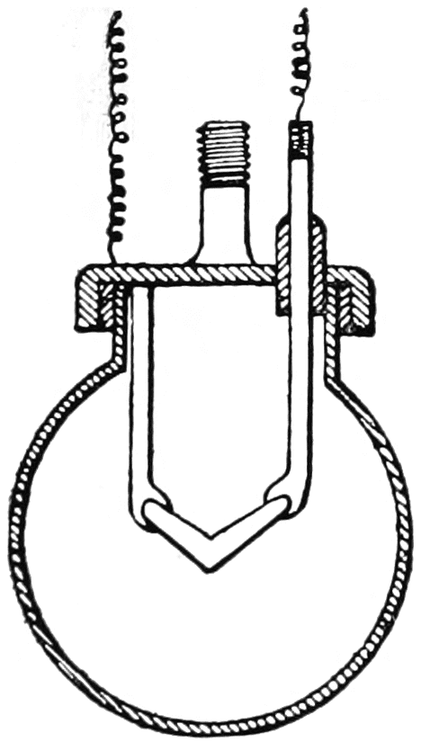
DE MOLEYNS’ INCANDESCENT LAMP
Frederick De Moleyns, an Englishman, has the honor of having
obtained the first patent on an incandescent lamp. This was in 1841
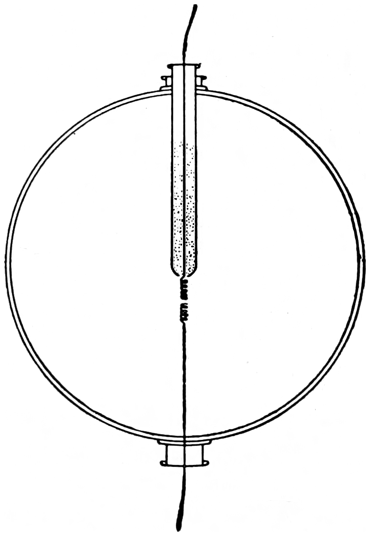
and his lamp was quite novel. It consisted of a spherical glass globe,
in the upper part of which was a tube containing powdered charcoal.
This tube was open at the bottom inside the globe and through it ran a
platinum wire, the end below the tube being coiled. Another platinum
wire coiled at its upper end came up through the lower part of
the globe but did not quite touch the other platinum coil. The powdered
charcoal filled the two coils of platinum wire and bridged the
gap between. Current passing through this charcoal bridge heated
it to incandescence. The air in the globe having been removed as far
as was possible with the hand air pumps then available, the charcoal
did not immediately burn up, the small amount consumed being replaced
by the supply in the tube. The idea was ingenious but the
lamp was impractical as the globe rapidly blackened from the evaporation
of the incandescent charcoal.
De Moleyns’ Incandescent Lamp, 1841.
This consisted of two coils of platinum wire containing powdered
charcoal operating in a vacuum. It is only of interest as the first
incandescent lamp on which a patent (British) was granted.
EARLY DEVELOPMENTS OF THE ARC LAMP
It had been found that most of the light of the arc came from
the tip of the positive electrode, and that the charcoal electrodes were
rapidly consumed, the positive electrode about twice as fast as the
negative. Mechanisms were designed to take care of this, together
with devices to start the arc by allowing the electrodes to touch each
other and then pulling them apart the proper distance. This distance
varied from one-eighth to three-quarters of an inch.
In 1840 Bunsen, the German chemist who invented the bunsen
burner, devised a process for making hard dense carbon pencils which
lasted much longer than the charcoal previously used. The dense
carbon from the inside of the retorts of gas making plants was ground
up and mixed with molasses, moulded into shape and baked at a high
temperature. Bunsen also, in 1843, cheapened Grove’s battery by
substituting a hard carbon plate in place of the platinum electrode.
Wright’s Arc Lamp, 1845.
This lamp is also only of interest as the first arc lamp on which a
patent (British) was granted. Four arcs played between the five carbon
discs.
Thomas Wright, an Englishman, was the first to patent an arc lamp.
This was in 1845, and the lamp was a hand regulated device consisting
of five carbon disks normally touching each other and rotated by clockwork.
Two of the disks could be drawn outward by thumb screws,
which was to be done after the current was turned on thus establishing
four arcs, one between each pair of disks. The next year, 1846, W. E.
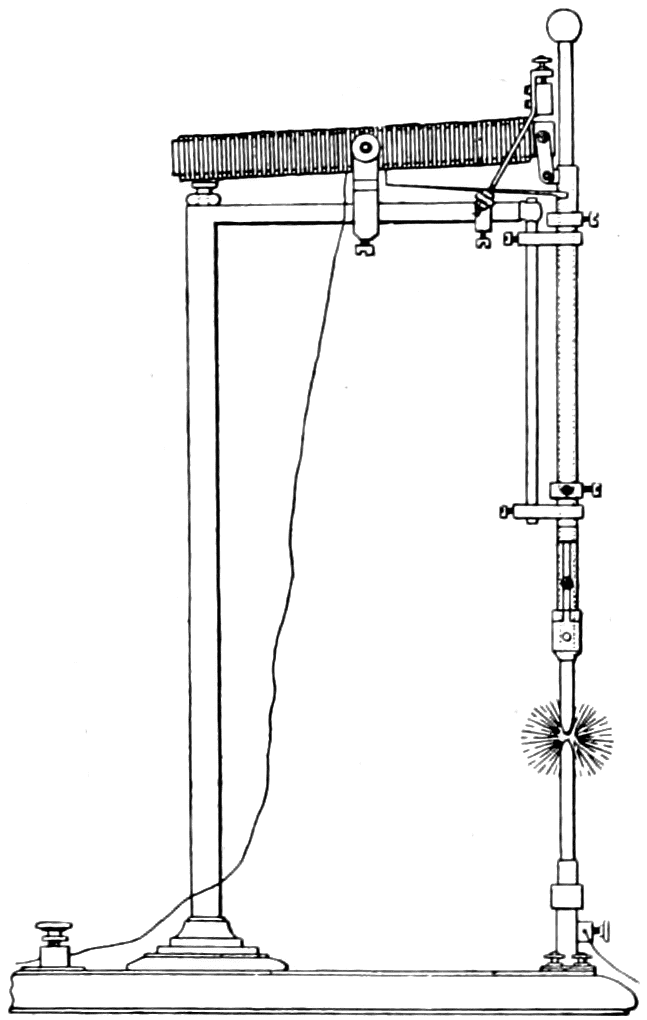
Staite, another Englishman, made an arc lamp having two vertical
carbon pencils. The upper was stationary. The lower was movable
and actuated by clockwork directed by ratchets which in turn were
regulated by an electro-magnet controlled by the current flowing
through the arc. Thus the lower carbon would be moved up or down
as required.
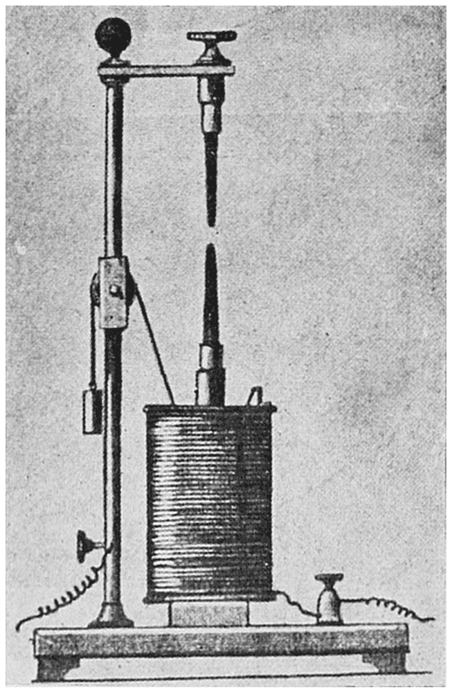
Archereau, a Frenchman, made a very simple arc lamp in 1848.
The upper carbon was fixed and the lower one was mounted on a
piece of iron which could be drawn down into a coil of wire. The
weight of the lower electrode was overbalanced by a counterweight,
so that when no current was flowing the two carbons would touch.
When current was turned on, it flowed through the two carbons and
through the coil of wire (solenoid) which then became energized
and pulled the lower carbon down, thus striking the arc. Two of these
arc lamps were installed in Paris and caused considerable excitement.
After a few weeks of unreliable operation, it was found that the cost
of current from the batteries was much too great to continue their
use commercially. The dynamo had not progressed far enough to
permit its use.
Archereau’s Arc Lamp, 1848.
This simple arc was controlled by an electro-magnet, and two lamps
were installed for street lighting in Paris, current being obtained from
batteries.
JOULE’S LAW
Joule was an Englishman, and in 1842 began investigating the
relation between mechanical energy and heat. He first showed that,
by allowing a weight to drop from a considerable height and turn a
paddle wheel in water, the temperature of the water would increase
in relation to the work done in turning the wheel. It is now known
that 778 foot-pounds (1 lb. falling 778 feet, 10 lbs. falling 77.8 feet
or 778 lbs. falling one foot, etc.) is the mechanical equivalent of
energy equal to raising one pound of water one degree Fahrenheit.
The rate of energy (power) is the energy divided by a unit of time;
thus one horsepower is 33,000 foot-pounds per minute. Joule next
investigated the relation between heat and electric current. He made
a device consisting of a vessel of water in which there were a thermometer
and an insulated coil of wire having a considerable resistance.
He found that an electric current heated the water, and making many
combinations of the amount and length of time of current flowing
and of the resistance of the wire, he deduced the law that the energy
in an electric circuit is proportional to the square of the amount of
current flowing multiplied by the length of time and multiplied by the
resistance of the wire.
The rate of electrical energy (electric power) is therefore proportional
to the square of current multiplied by the resistance. The
electrical unit of power is now called the Watt, named in honor of
James Watt, the Englishman, who made great improvements to the
steam engine about a century ago. Thus, watts = C2R and substituting
the value of R from Ohm’s law, C = E/R, we get
Watts = Volts × Amperes
The watt is a small unit of electric power, as can be seen from the
fact that 746 watts are equal to one horsepower. The kilowatt, kilo
being the Greek word for thousand, is 1000 watts.
This term is an important one in the electrical industry. For
example, dynamos are rated in kilowatts, expressed as KW; the largest
one made so far is 50,000 KW which is 66,666 horsepower. Edison’s
first commercial dynamo had a capacity of 6 KW although the terms
watts and kilowatts were not in use at that time. The ordinary sizes
of incandescent lamps now used in the home are 25, 40 and 50 watts.
STARR’S INCANDESCENT LAMP
Starr’s Incandescent Lamp, 1845.
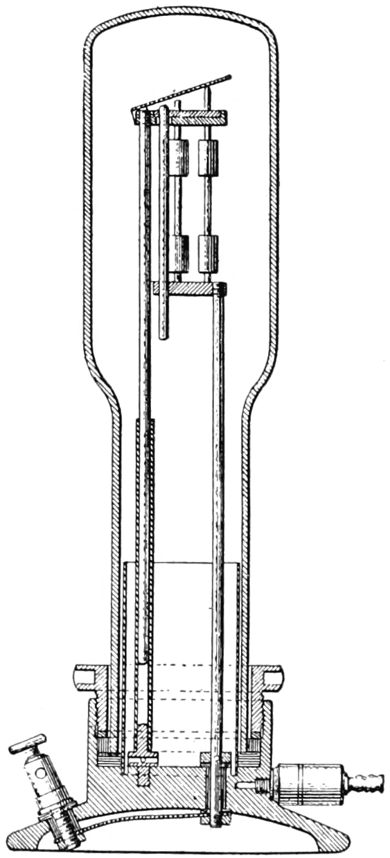
This consisted of a short carbon pencil operating in the vacuum above
a column of mercury.
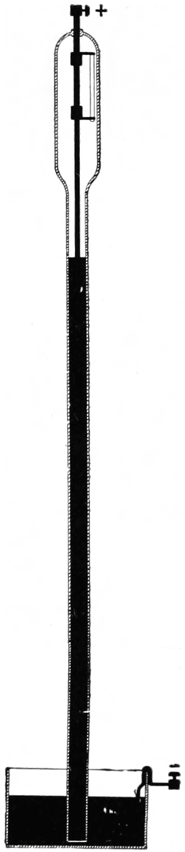
J. W. Starr, an American, of Cincinnati, Ohio, assisted financially
by Peabody, the philanthropist, went to England where he obtained
a patent in 1845 on the lamps he had invented, although the patent was
taken out under the name of King, his attorney. One is of passing
interest only. It consisted of a strip of platinum, the active length of
which could be adjusted to fit the battery strength used, and was
covered by a glass globe to protect it from draughts of air. The other,
a carbon lamp, was the first real contribution to the art. It consisted
of a rod of carbon operating in the vacuum above a column of mercury
(Torrecellium vacuum) as in a barometer. A heavy platinum wire
was sealed in the upper closed end of a large glass tube, and connected
to the carbon rod by an iron clamp. The lower end of the carbon rod
was fastened to another iron clamp, the two clamps being held in
place and insulated from each other by a porcelain rod. Attached to
the lower clamp was a long copper wire. Just below the lower clamp,
the glass tube was narrowed down and had a length of more than
30 inches. The tube was then filled with mercury, the bottom of the
tube being put into a vessel partly full of mercury. The mercury ran
out of the enlarged upper part of the tube, coming to rest in the narrow
part of the tube as in a barometer, so that the carbon rod was then in
a vacuum. One lamp terminal was the platinum wire extending
through the top of the tube, and the other was the mercury. Several
of these lamps were put on exhibition in London, but were not a commercial
success as they blackened very rapidly. Starr started his
return trip to the United States the next year, but died on board the
ship when he was but 25 years old.
OTHER EARLY INCANDESCENT LAMPS
Staite’s Incandescent
Lamp, 1848.
The burner was of platinum
and iridium.
Roberts’ Incandescent
Lamp, 1852.
It had a graphite burner operating
in vacuum.
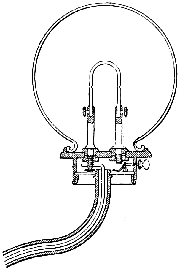
In 1848 W. E. Staite, who two years previously had made an arc
lamp, invented an incandescent lamp. This consisted of a platinum-iridium
burner in the shape of an inverted U, covered by a glass globe.
It had a thumb screw for a switch, the whole device being mounted
on a bracket which was used for the return wire. E. C. Shepard,
another Englishman, obtained a patent two years later on an incandescent
lamp consisting of a weighted hollow charcoal cylinder the
end of which pressed against a charcoal cone. Current passing
through this high resistance contact, heated the charcoal to incandescence.
It operated in a glass globe from which the air could be exhausted.
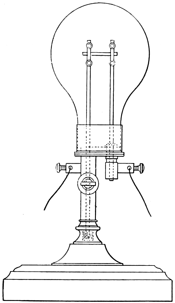
M. J. Roberts obtained an English patent in 1852 on an
incandescent lamp. This had a graphite rod for a burner, which
could be renewed, mounted in a glass globe. The globe was cemented
to a metallic cap fastened to a piece of pipe through which the air
could be exhausted. After being exhausted, the pipe, having a stop
cock, could be screwed on a stand to support the lamp.
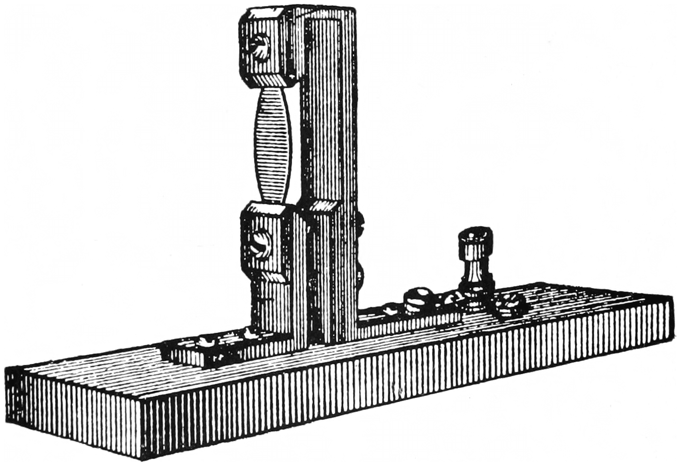
Moses G. Farmer, a professor at the Naval Training Station at
Newport, Rhode Island, lighted the parlor of his home at 11 Pearl
Street, Salem, Mass., during July, 1859, with several incandescent
lamps having a strip of platinum for the burner. The novel feature
of this lamp was that the platinum strip was narrower at the terminals
than in the center. Heat is conducted away from the terminals
and by making the burner thin at these points, the greater resistance
of the ends of the burner absorbed more electrical energy thus offsetting
the heat being conducted away. This made a more uniform
degree of incandescence throughout the length of the burner, and
Prof. Farmer obtained a patent on this principle many years later
(1882).
Farmer’s Incandescent Lamp, 1859.
This experimental platinum lamp was made by Professor Farmer
and several of them lighted the parlor of his home in Salem,
Mass.
FURTHER ARC LAMP DEVELOPMENTS
During the ten years, 1850 to 1860, several inventors developed
arc lamp mechanisms. Among them was M. J. Roberts, who had
invented the graphite incandescent lamp. In Roberts’ arc lamp,
which he patented in 1852, the lower carbon was stationary. The
upper carbon fitted snugly into an iron tube. In the tube was a brass
covered iron rod, which by its weight could push the upper carbon
down the tube so the two carbons normally were in contact. An
electro-magnet in series with the arc was so located that, when energized,
it pulled up the iron tube. This magnet also held the brass
covered iron rod from pushing the upper carbon down the tube so that
the two carbons were pulled apart, striking the arc. When the arc
went out, the iron tube dropped back into its original position, the
brass covered iron rod was released, pushing the upper carbon down
the tube until the two carbons again touched. This closed the circuit
again, striking the arc as before.
Roberts’ Arc Lamp,
1852.
The arc was controlled by an
electro-magnet which held an
iron tube to which the upper
carbon was fastened.
Slater and Watson’s Arc
Lamp, 1852.
Clutches were used for the
first time in this arc lamp to
feed the carbons.
In the same year (1852) Slater and Watson obtained an English
patent on an arc lamp in which the upper carbon was movable and
held in place by two clutches actuated by electro-magnets. The lower
carbon was fixed, and normally the two carbons touched each other.
When current was turned on, the electro-magnet lifted the clutches
which gripped the upper carbon, pulling it up and striking the arc.
This was the first time that a clutch was used to allow the carbon to
feed as it became consumed.
Henry Chapman, in 1855, made an arc in which the upper carbon
was allowed to feed by gravity, but held in place by a chain wound
around a wheel. On this wheel was a brake actuated by an electro-magnet.
The lower carbon was pulled down by an electro-magnet
working against a spring. When no current was flowing or when the
arc went out, the two carbons touched. With current on, one electro-magnet
set the brake and held the upper carbon stationary. The other
electro-magnet pulled the lower carbon down, thus striking the arc.
None of these mechanisms regulated the length of the arc. It was
not until 1856 that Joseph Lacassagne and Henry Thiers, Frenchmen,
invented the so-called “differential” method of control, which made
the carbons feed when the arc voltage, and hence length, became too
great. This principle was used in commercial arc lamps several
years afterward when they were operated on series circuits, as it had
the added advantage of preventing the feeding of one arc lamp affecting
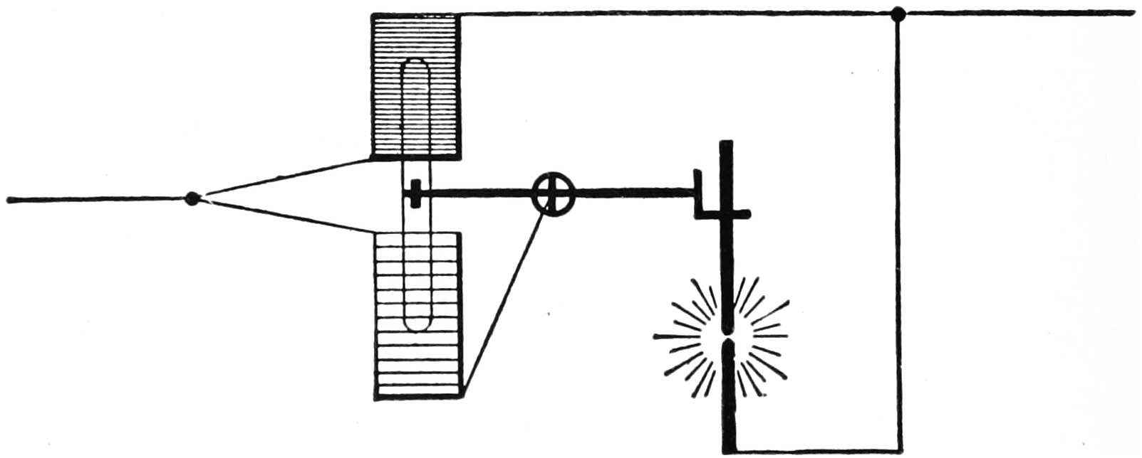
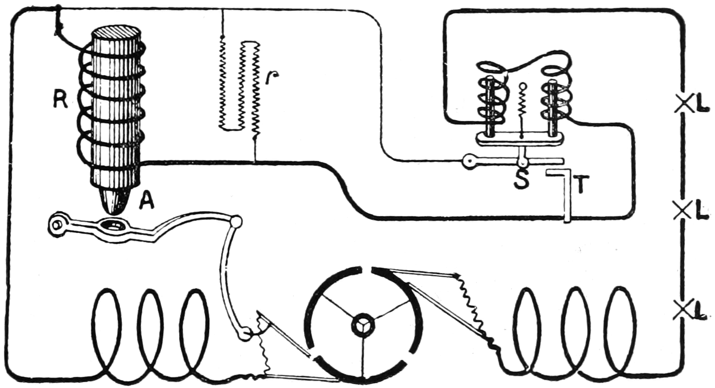
another on the same circuit. This differential control consists in
principle of two electro-magnets, one in series with, and opposing
the pull of the other which is in shunt with the arc. The series magnet
pulls the carbons apart and strikes the arc. As the arc increases in
length, its voltage rises, thereby increasing the current flowing through
the shunt magnet. This increases the strength of the shunt magnet
and, when the arc becomes too long, the strength of the shunt becomes
greater than that of the series magnet, thus making the carbons
feed.
Diagram of “Differential” Method of Control of an Arc Lamp.
This principle, invented by Lacassagne and Thiers, was used in all
arc lamps when they were commercially introduced on a large scale
more than twenty years later.
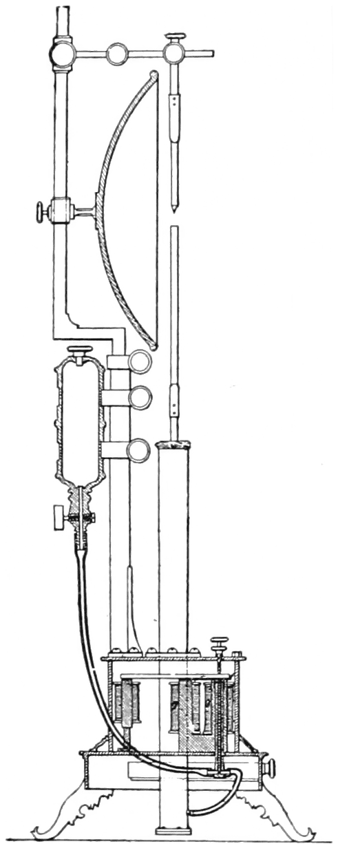
The actual method adopted by Lacassagne and Thiers was different
from this, but it had this principle. They used a column of mercury
on which the lower carbon floated. The upper carbon was stationary.
The height of the mercury column was regulated by a valve connected
with a reservoir of mercury. The pull of the series magnet
closed the valve fixing the height of the column. The pull of the
shunt magnet tended to open the valve, and when it overcame the
pull of the series magnet it allowed mercury to flow from the reservoir,
raising the height of the column bringing the carbons nearer
together. This reduced the arc voltage and shunt magnet strength
until the valve closed again. Thus the carbons were always kept the
proper distance apart. In first starting the arc, or if the arc should
go out, current would only flow through the shunt magnet, bringing
the two carbons together until they touched. Current would then
flow through the contact of the two carbons and through the series
magnet, shutting the valve. There were no means of pulling the
carbons apart to strike the arc. Current flowing through the high
resistance of the poor contact of the two carbons, heated their tips
to incandescence. The incandescent tips would begin to burn away,
thus after a time starting an arc. The arc, however, once started was
maintained the proper length.
Lacassagne and Thiers’ Differentially Controlled
Arc Lamp, 1856.
The lower carbon floated on a column of mercury whose height was
“differentially” controlled by series and shunt magnets.
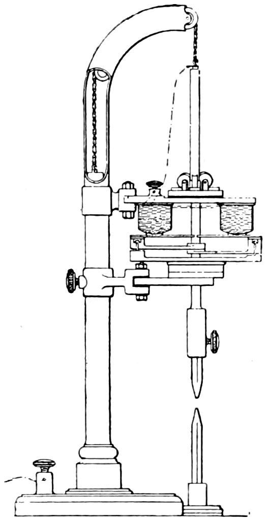
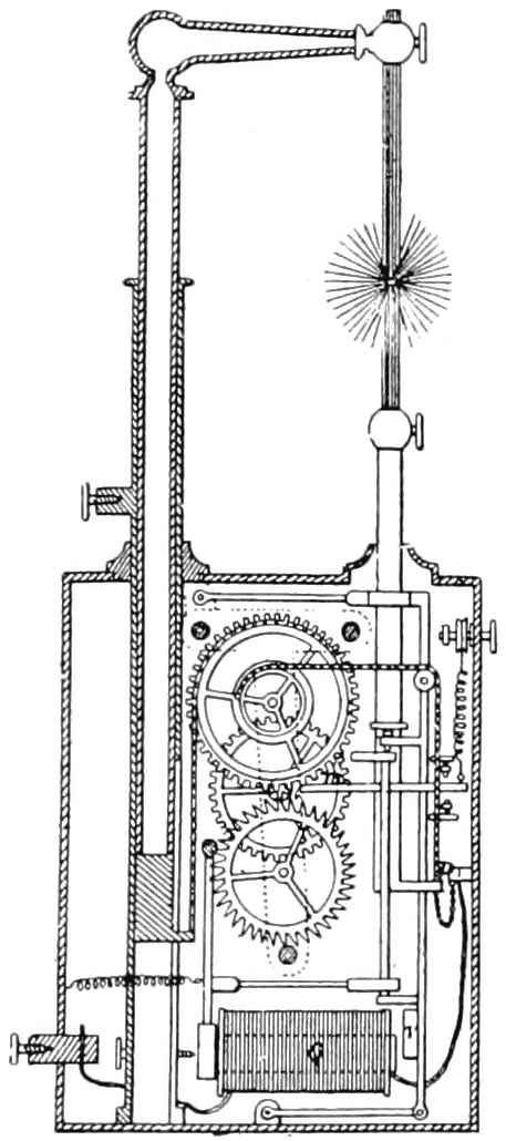
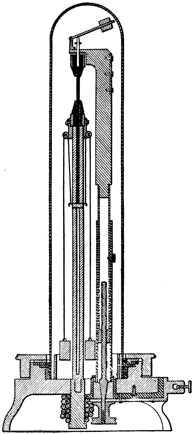
In 1857, Serrin took out his first patent on an arc lamp, the general
principles of which were the same as in others he made. The mechanism
consisted of two drums, one double the diameter of the other.
Both carbons were movable, the upper one feeding down, and the
lower one feeding up, being connected with chains wound around
the drums. The difference in consumption of the two carbons was
therefore compensated for by the difference in size of the drums,
thus maintaining the location of the arc in a fixed position. A train
of wheels controlled by a pawl and regulated by an electro-magnet,
controlled the movement of the carbons. The weight of the upper
carbon and its holder actuates the train of wheels.
Serrin’s Arc Lamp, 1857.
This type of arc was not differentially controlled but was the first
commercial lamp later used. Both carbons were movable, held by
chains wound around drums which were controlled by ratchets actuated
by an electro-magnet.
DEVELOPMENT OF THE DYNAMO, 1840–1860
During the first few years after 1840 the dynamo was only a laboratory
experiment. Woolrich devised a machine which had several
pairs of magnets and double the number of coils in order to make
the current obtained less pulsating. Wheatstone in 1845 patented
the use of electro-magnets in place of permanent magnets. Brett in
1848 suggested that the current, generated in the coils, be allowed to
flow through a coil surrounding each permanent magnet to further
strengthen the magnets. Pulvermacher in 1849 proposed the use of
thin plates of iron for the bobbins, to reduce the eddy currents generated
in the iron. Sinsteden in 1851 suggested that the current from
a permanent magnet machine be used to excite the field coils of an
electro-magnet machine.
In 1855 Soren Hjorth, of Copenhagen, Denmark, patented a
dynamo having both permanent and electro-magnets, the latter being
excited by currents first induced in the bobbins by the permanent
magnets. In 1856 Dr. Werner Siemens invented the shuttle wound
armature. This consisted of a single coil of wire wound lengthwise
and counter sunk in a long cylindrical piece of iron. This revolved
between the magnet poles which were shaped to fit the cylindrical
armature.
Siemens’ Dynamo, 1856.
This dynamo was an improvement over others on account of the
construction of its “shuttle” armature.
THE FIRST COMMERCIAL INSTALLATION OF AN ELECTRIC LIGHT
In 1862 a Serrin type of arc lamp was installed in the Dungeness
lighthouse in England. Current was supplied by a dynamo made by
the Alliance Company, which had been originally designed in 1850
by Nollet, a professor of Physics in the Military School in Brussels.
Nollet’s original design was of a dynamo having several rows of permanent
magnets mounted radially on a stationary frame, with an
equal number of bobbins mounted on a shaft which rotated and had a
commutator so direct current could be obtained. A company was
formed to sell hydrogen gas for illuminating purposes, the gas to be
made by the decomposition of water with current from this machine.
Nollet died and the company failed, but it was reorganized as the
Alliance Company a few years later to exploit the arc lamp.
Alliance Dynamo, 1862.
This was the dynamo used in the first commercial installation of an
arc light in the Dungeness Lighthouse, England, 1862.
About the only change made in the dynamo was to substitute collector
rings for the commutator to overcome the difficulties of commutation.
Alternating current was therefore generated in this first
commercial machine. It had a capacity for but one arc light, which
probably consumed less than ten amperes at about 45 volts, hence
delivered in the present terminology not over 450 watts or about
two-thirds of a horsepower. As the bobbins of the armature undoubtedly
had a considerable resistance, the machine had an efficiency
of not over 50 per cent and therefore required at least one and a
quarter horsepower to drive it.
FURTHER DYNAMO DEVELOPMENTS
In the summer of 1886 Sir Charles Wheatstone constructed a self-excited
machine on the principle of using the residual magnetism in
the field poles to set up a feeble current in the armature which,
passing through the field coils, gradually strengthened the fields until
they built up to normal strength. It was later found that this idea
had been thought of by an unknown man, being disclosed by a clause
in a provisional 1858 English patent taken out by his agent. Wheatstone’s
machine was shown to the Royal Society in London and a
paper on it read before the Society on February 14, 1867. The field
coils were shunt wound.
Wheatstone’s Self-Excited Dynamo, 1866.
This machine was the first self-excited dynamo by use of the residual
magnetism in the field poles.
Dr. Werner Siemens also made a self-excited machine, having
series fields, a paper on which was read before the Academy of
Sciences in Berlin on January 17, 1867. This paper was forwarded
to the Royal Society in London and presented at the same meeting
at which Wheatstone’s dynamo was described. Wheatstone probably
preceded Siemens in this re-discovery of the principle of self-excitation,
but both are given the merit of it. However, S. A. Varley on
December 24, 1866, obtained a provisional English patent on this,
which was not published until July, 1867.
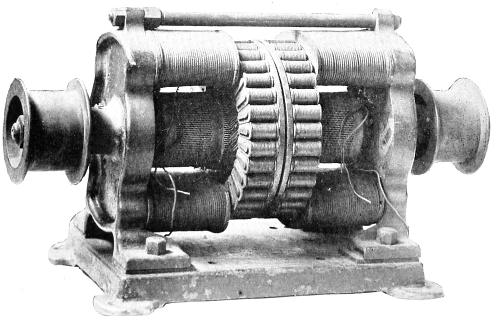
Gramme’s Dynamo, 1871.
These were commercially used, their main feature being the “ring”
wound armature.
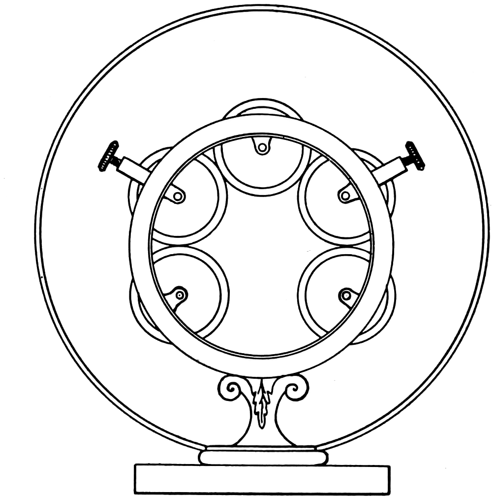
Gramme’s “Ring” Armature.
Wire coils, surrounding an iron wire core, were all connected
together in an endless ring, each coil being tapped with a wire connected
to a commutator bar.
In 1870 Gramme, a Frenchman, patented his well-known ring
armature. The idea had been previously thought of by Elias, a
Hollander, in 1842, and by Pacinnotti, an Italian, as shown by the
crude motors (not dynamos) they had made. Gramme’s armature
consisted of an iron wire core coated with a bituminous compound
in order to reduce the eddy currents. This core was wound with
insulated wire coils, all connected together in series as one single
endless coil. Each coil was tapped with a wire connected to a commutator
bar. His first machine, having permanent magnets for fields,
was submitted to the French Academy of Sciences in 1871. Later
machines were made with self-excited field coils, which were used in
commercial service. They had, however a high resistance armature,
so that their efficiency did not exceed 50 per cent.
Alteneck’s Dynamo with “Drum” Wound Armature, 1872.
The armature winding was entirely on the surface of the armature
core, a principle now used in all dynamos.
Von Hefner Alteneck, an engineer with Siemens, invented the
drum wound armature in 1872. The wires of the armature were all
on the surface of the armature core, the wires being tapped at frequent
points for connection with the commutator bars. Thus in the early
seventies, commercial dynamos were available for use in arc lighting,
and a few installations were made in Europe.
RUSSIAN INCANDESCENT LAMP INVENTORS
In 1872 Lodyguine, a Russian scientist, made an incandescent lamp
consisting of a “V” shaped piece of graphite for a burner, which
operated in nitrogen gas. He lighted the Admiralty Dockyard at
St. Petersburg with about two hundred of these lamps. In 1872
the Russian Academy of Sciences awarded him a prize of 50,000
rubles (a lot of real money at that time) for his invention. A company
with a capital of 200,000 rubles (then equal to about $100,000)
was formed but as the lamp was so expensive to operate and had such
a short life, about twelve hours, the project failed.
Lodyguine’s Incandescent
Lamp, 1872.
The burner was made of
graphite and operated in nitrogen
gas.
Konn’s Incandescent Lamp,
1875.
In this lamp the graphite rods
operated in a vacuum.
Kosloff, another Russian, in 1875 patented a graphite in nitrogen
incandescent lamp, which had several graphite rods for burners, so
arranged that when one failed another was automatically connected.
Konn, also a Russian, made a lamp similar to Kosloff’s except that
the graphite rods operated in a vacuum. Bouliguine, another Russian,
in 1876 made an incandescent lamp having a long graphite rod, only
the upper part of which was in circuit. As this part burned out, the
rod was automatically pushed up so that a fresh portion then was in
circuit. It operated in a vacuum. None of these lamps was commercial
as they blackened rapidly and were too expensive to maintain.
Bouliguine’s Incandescent Lamp, 1876.
A long graphite rod, the upper part of which only was in circuit,
operated in vacuum. As this part burned out, the rod was automatically
shoved up, a fresh portion then being in the circuit.
THE JABLOCHKOFF “CANDLE”
Paul Jablochkoff was a Russian army officer and an engineer. In
the early seventies he came to Paris and developed a novel arc light.
This consisted of a pair of carbons held together side by side and
insulated from each other by a mineral known as kaolin which vaporized
as the carbons were consumed. There was no mechanism, the
arc being started by a thin piece of carbon across the tips of the carbons.
Current burned this bridge, starting the arc. The early carbons
were about five inches long, and the positive carbon was twice as
thick as the negative to compensate for the unequal consumption on
direct current. This, however, did not work satisfactorily. Later
the length of the carbons was increased, the carbon made of equal
thickness and burned on alternating current of about eight or nine
amperes at about 45 volts. He made an alternating current generator
which had a stationary exterior armature with interior revolving field
poles. Several “candles,” as they were called, were put in one fixture
to permit all night service and an automatic device was developed,
located in each fixture, so that should one “candle” go out for any
reason, another was switched into service.
Jablochkoff “Candle,” 1876.
This simple arc consisted of a pair of carbons held together side by
side and insulated from each other by kaolin. Several boulevards in
Paris were lighted with these arc lights. This arc lamp is in the
collection of the Smithsonian Institution.
In 1876 many of these “candles” were installed and later several
of the boulevards in Paris were lighted with them. This was the
first large installation of the arc light, and was the beginning of its
commercial introduction. Henry Wilde made some improvements
in the candle by eliminating the kaolin between the carbons which
gave Jablochkoff’s arc its peculiar color. Wilde’s arc was started by
allowing the ends of the carbons to touch each other, a magnet swinging
them apart thus striking the arc.
Jablochkoff’s Alternating Current Dynamo, 1876.
This dynamo had a stationary exterior armature and internal revolving
field poles. Alternating current was used for the Jablochkoff
“candle” to overcome the difficulties of unequal consumption of the
carbons on direct current.
COMMERCIAL INTRODUCTION OF THE DIFFERENTIALLY CONTROLLED ARC LAMP
About the same time Lontin, a Frenchman, improved Serrin’s arc
lamp mechanism by the application of series and shunt magnets. This
is the differential principle which was invented by Lacassagne and
Thiers in 1855 but which apparently had been forgotten. Several
of these lamps were commercially installed in France beginning with
1876.
ARC LIGHTING IN THE UNITED STATES
Wallace-Farmer Arc Lamp, 1875.
This “differentially controlled” arc lamp consisted of two slabs of
carbon between which the arc played. In the original lamp the carbon
slabs were mounted on pieces of wood held in place by bolts,
adjustment being made by hitting the upper carbon slab with a hammer.
This lamp is in the collection of the Smithsonian Institution.
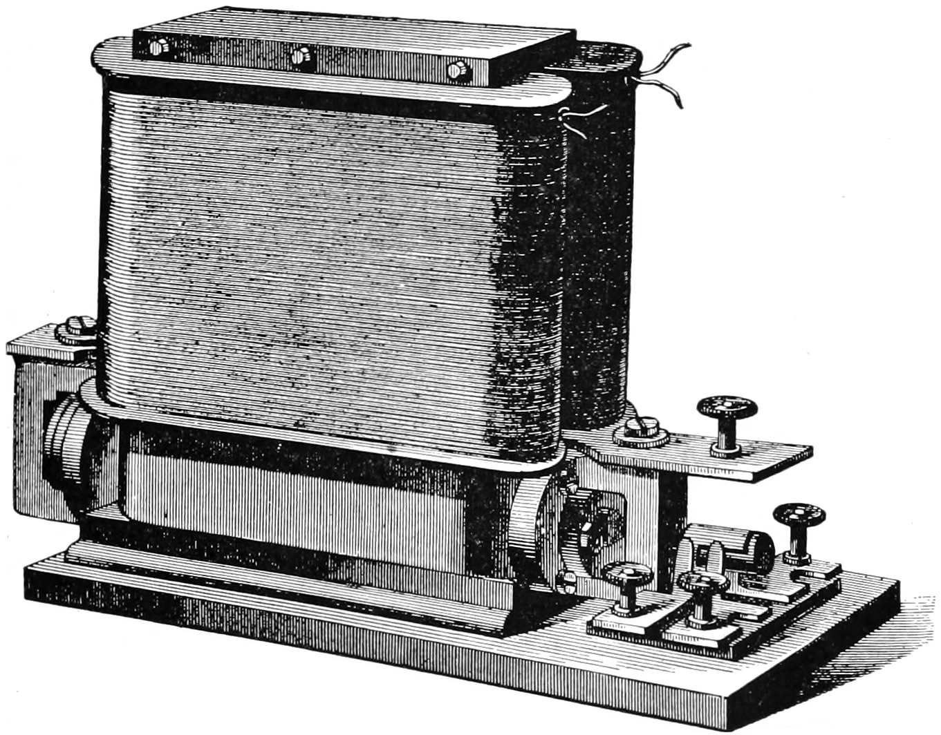
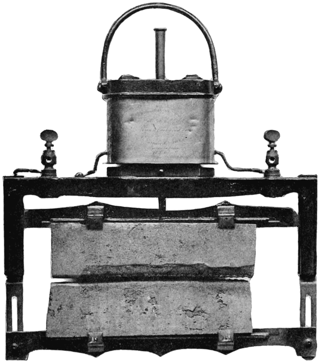
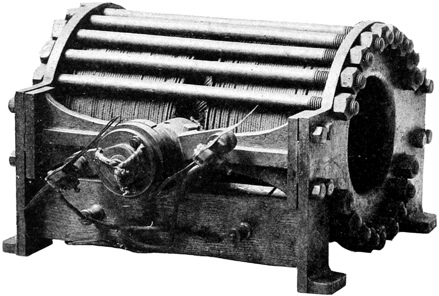
Wallace-Farmer Dynamo, 1875.
This was the first commercial dynamo used in the United States for
arc lighting. This dynamo is in the collection of the Smithsonian
Institution.
About 1875 William Wallace of Ansonia, Connecticut, made an
arc light consisting of two rectangular carbon plates mounted on
a wooden frame. The arc played between the two edges of the plates,
which lasted much longer than rods. When the edges had burned
away so that the arc then became unduly long, the carbon plates were
brought closer together by hitting them with a hammer. Wallace
became associated with Moses G. Farmer, and they improved this
crude arc by fastening the upper carbon plate to a rod which was held
by a clutch controlled by a magnet. This magnet had two coils in one,
the inner winding in series with the arc, and outer one in shunt and
opposing the series winding. The arc was therefore differentially
controlled.
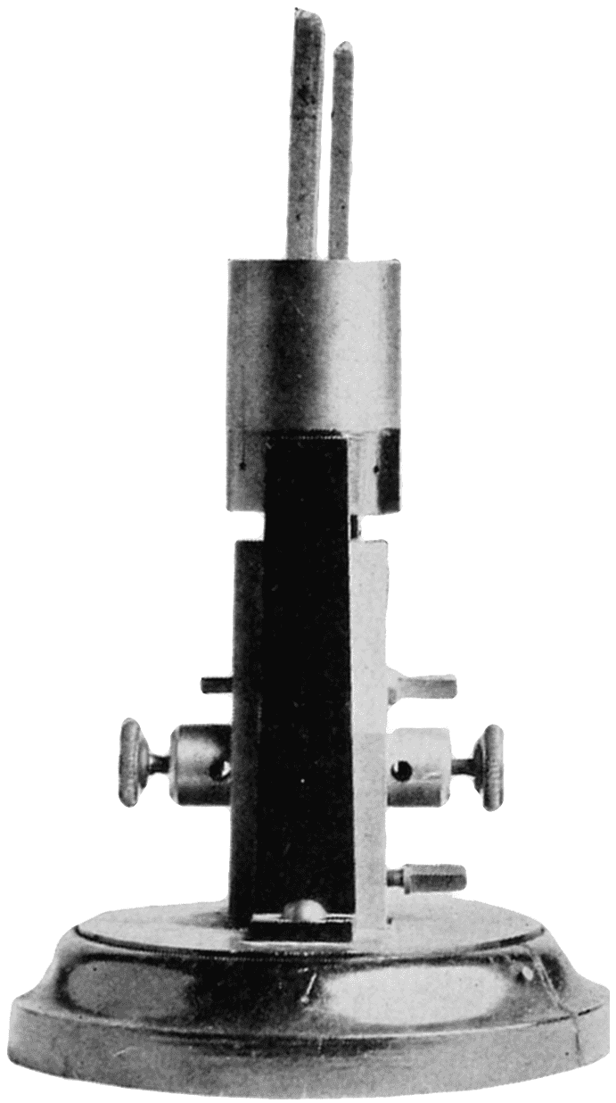
Weston’s Arc Lamp, 1876.
This lamp is in the collection of the Smithsonian Institution.
They also developed a series wound direct current dynamo.
The armature consisted of a number of bobbins, all connected
together in an endless ring. Each bobbin was also connected to
a commutator bar. There were two sets of bobbins, commutators and
field poles, the equivalent of two machines in one, which could be
connected either to separate circuits, or together in series on one
circuit. The Wallace-Farmer system was commercially used. The
arc consumed about 20 amperes at about 35 volts, but as the carbon
plates cooled the arc, the efficiency was poor. The arc flickered back
and forth on the edges of the carbons casting dancing shadows. The
carbons, while lasting about 50 hours, were not uniform in density,
so the arc would flare up and cast off soot and sparks.
Edward Weston of Newark, New Jersey, also developed an arc
lighting system. His commercial lamp had carbon rods, one above the
other, and the arc was also differentially controlled. An oil dash pot
prevented undue pumping of the carbons. His dynamo had a drum-wound
armature, and had several horizontal field coils on each side of
one pair of poles between which the armature revolved. The system
was designed for about 20 amperes, each are taking about 35 volts.
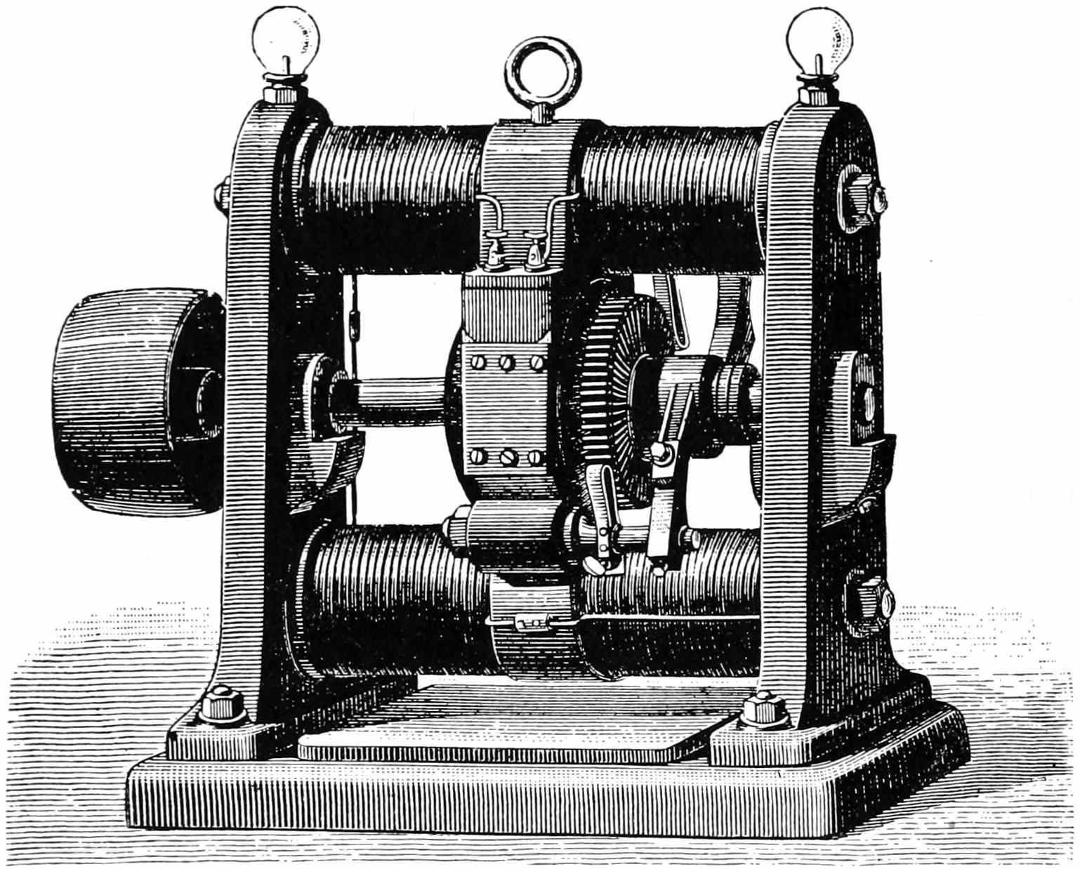
Brush’s Dynamo, 1877.
This dynamo was used for many years for commercial arc lighting.
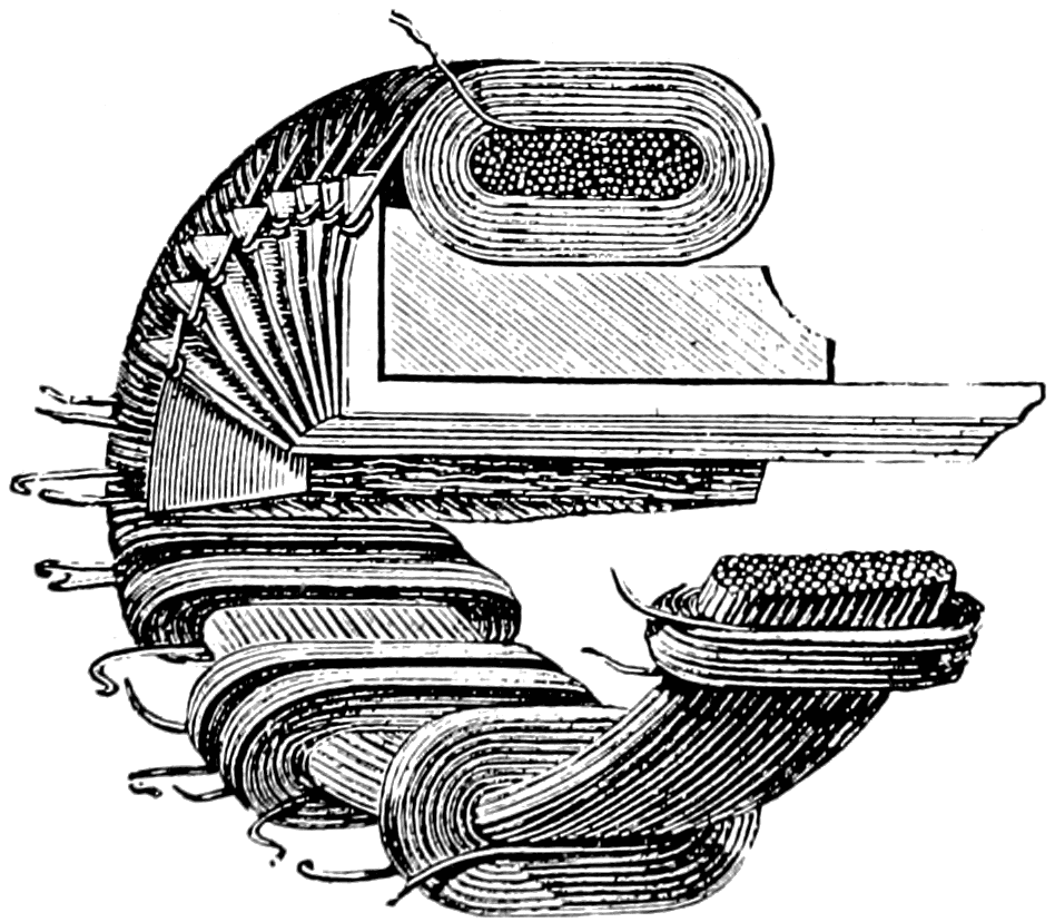
Diagram of Brush Armature.
The armature was not a closed circuit. For description of its operation,
see text.
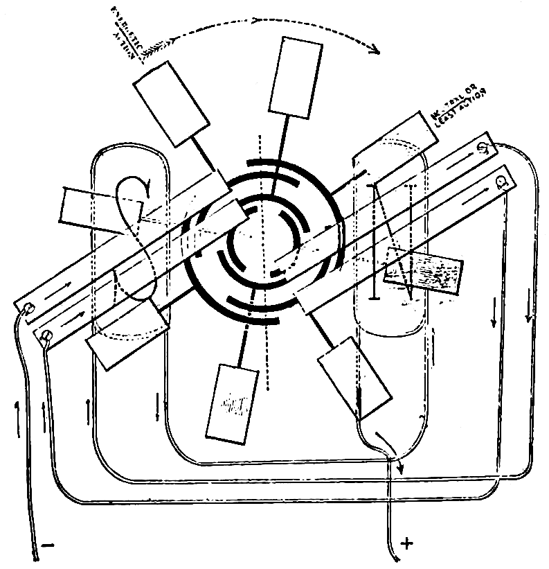
Charles F. Brush made a very successful arc lighting system in
1878. His dynamo was unique in that the armature had eight coils,
one end of each pair of opposite coils being connected together and
the other ends connected to a commutator segment. Thus the armature
itself was not a closed circuit. The machine had two pairs of
horizontal poles between which the coils revolved. One end of the
one pair of coils in the most active position was connected, by means
of two of the four brushes, in series with one end of the two pairs
of coils in the lesser active position. The latter two pairs of coils
were connected in multiple with each other by means of the brushes
touching adjacent commutator segments. The outside circuit was
connected to the other two brushes, one of which was connected to
the other end of the most active pair of coils. The other brush was
connected to the other end of the two lesser active pairs of coils. The
one pair of coils in the least active position was out of circuit. The
field coils were connected in series with the outside circuit.
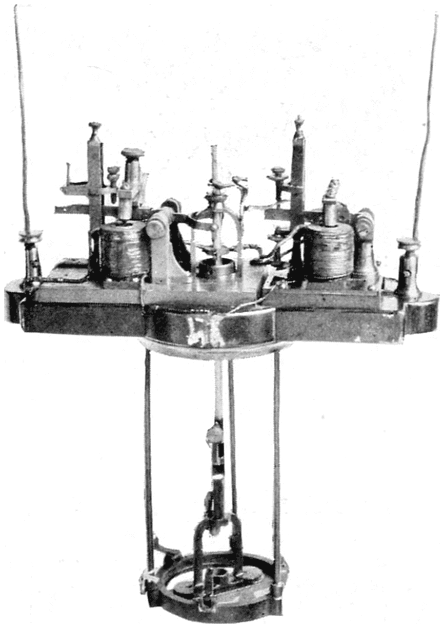
Brush’s Arc Lamp, 1877.
The carbons were differentially controlled. This lamp was used
for many years. This lamp is in the collection of the Smithsonian
Institution.
Brush’s arc lamp was also differentially controlled. It was designed
for about 10 amperes at about 45 volts. The carbons were
copper plated to increase their conductivity. Two pairs of carbons
were used for all-night service, each pair lasting about eight hours.
A very simple device was used to automatically switch the arc from
one to the other pair of carbons, when the first pair was consumed.
This device consisted of a triangular-shaped piece of iron connected
to the solenoid controlling the arc. There was a groove on each of the
outer two corners of this triangle, one groove wider than the other.
An iron washer surrounded each upper carbon. The edge of each
washer rested in a groove. The washer in the narrow groove made a
comparatively tight fit about its carbon. The other washer in the
wider groove had a loose fit about its carbon. Pins prevented the
washer from falling below given points. Both pairs of carbons
touched each other at the start. When current was turned on, the
solenoid lifted the triangle, the loose-fitting washer gripped its carbon
first, so that current then only passed through the other pair of carbons
which were still touching each other. The further movement of the
solenoid then separated these carbons, the arc starting between them.
When this pair of carbons became consumed, they could not feed any
more so that the solenoid would then allow the other pair of carbons
to touch, transferring the arc to that pair.
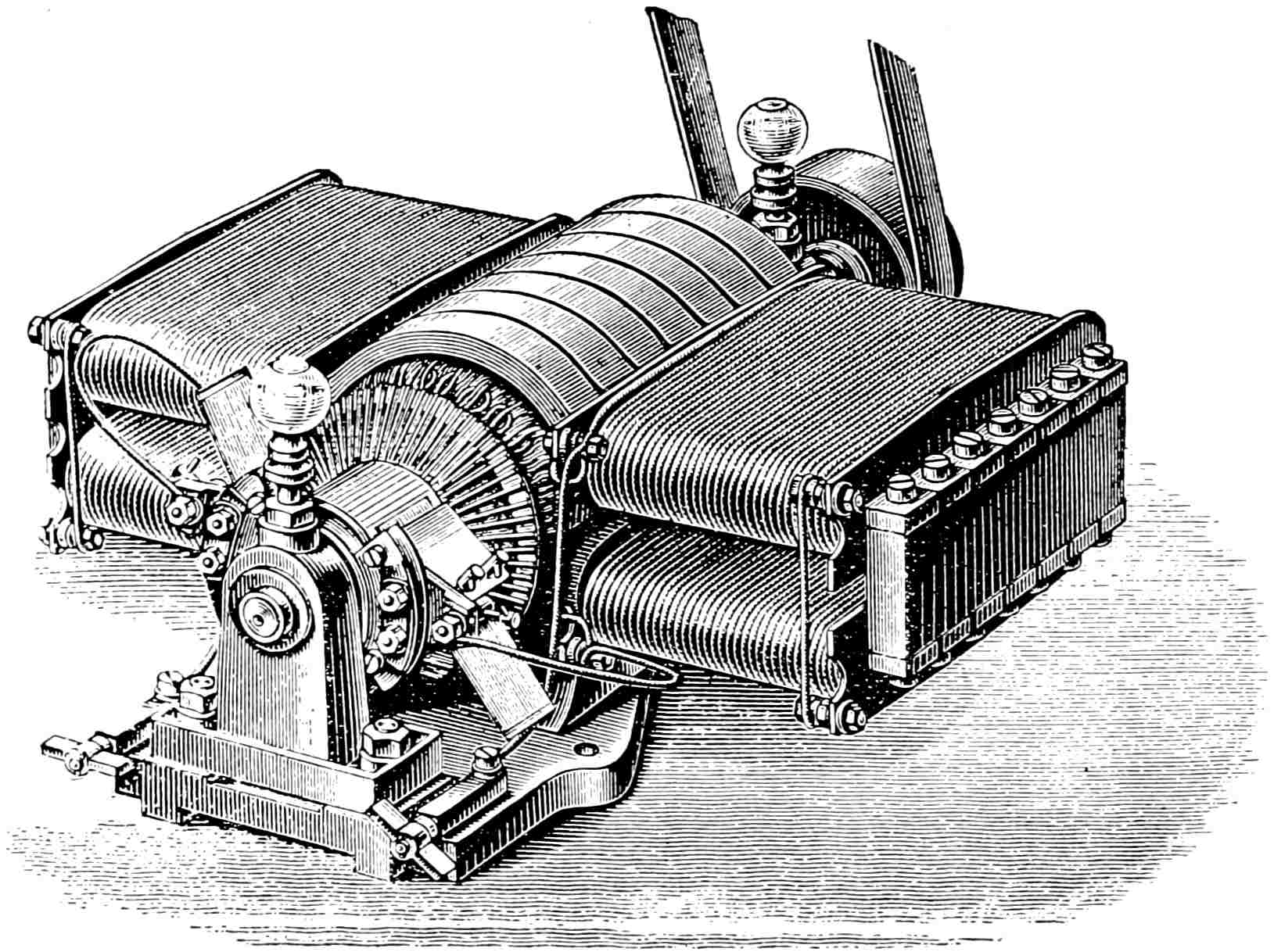
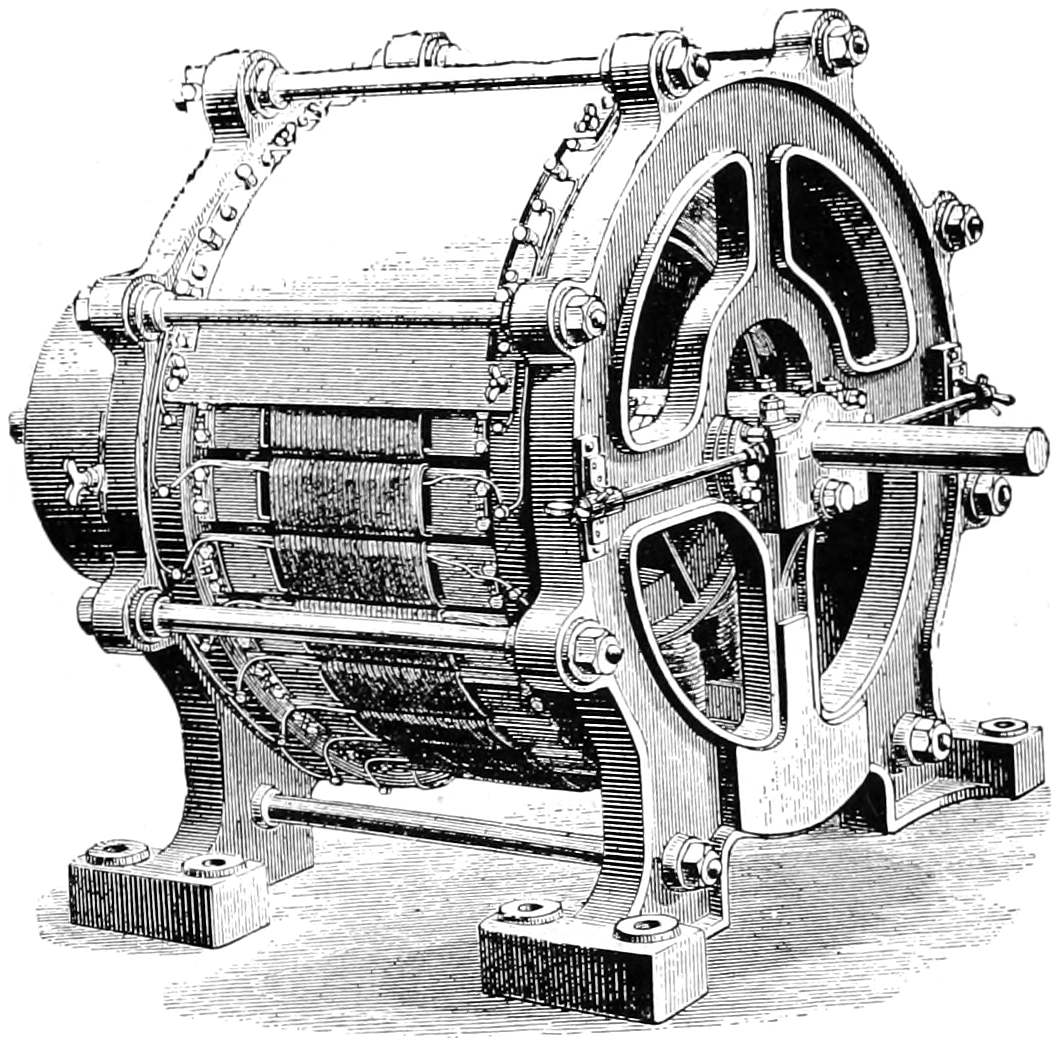
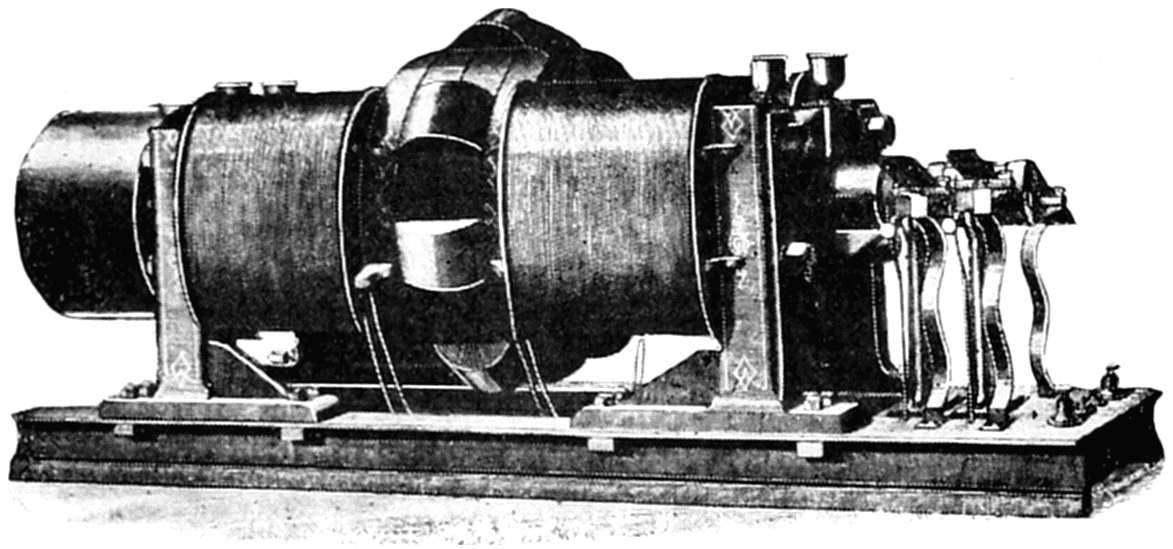
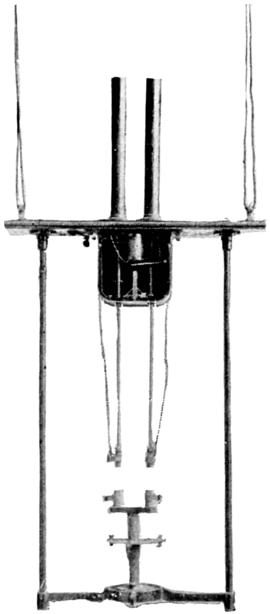
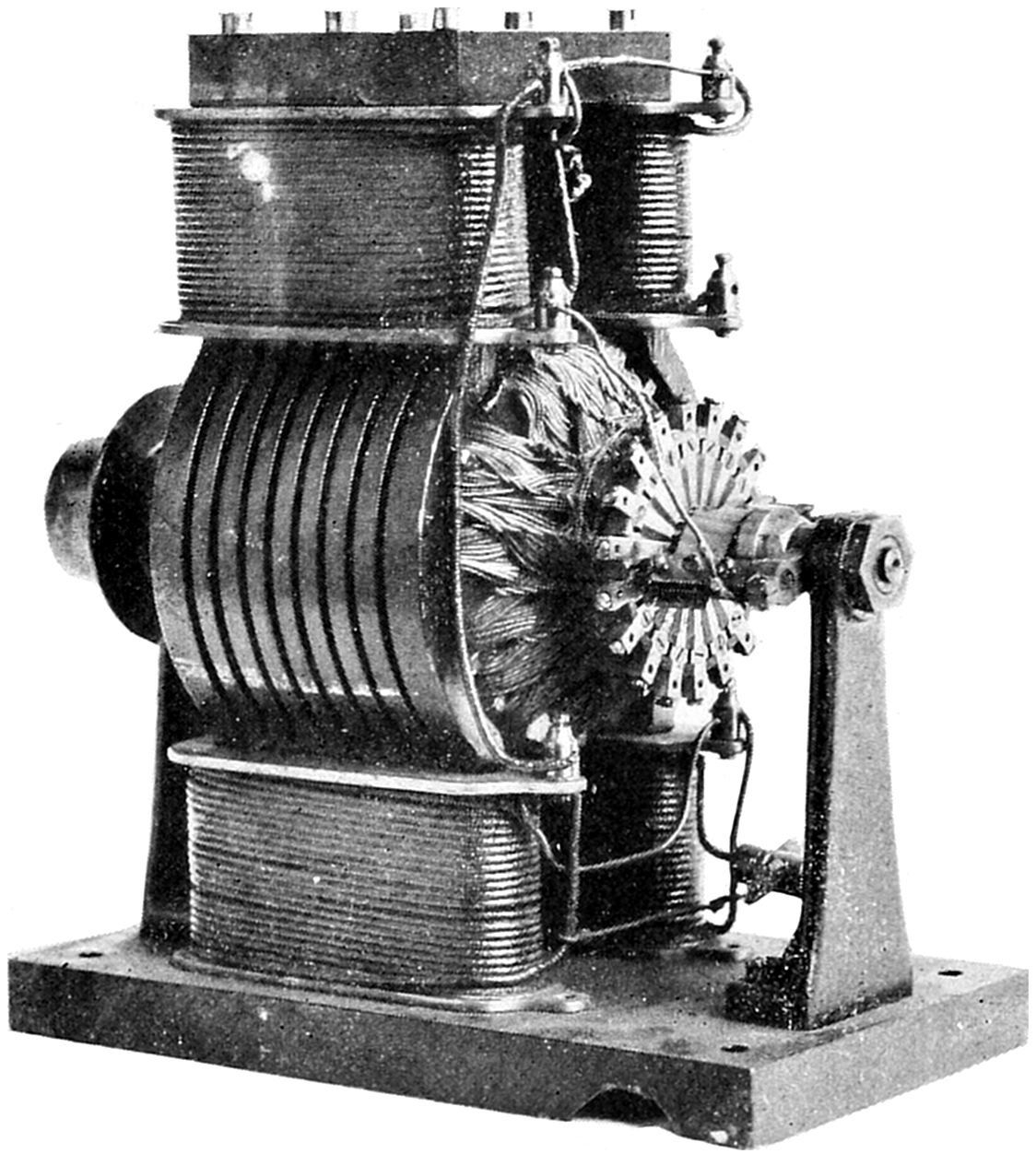
Thomson-Houston Arc Dynamo, 1878.
This dynamo was standard for many years. This machine is in the
collection of the Smithsonian Institution.
Elihu Thomson and Edwin J. Houston in 1878 made a very successful
and complete arc light system. Their dynamo was specially
designed to fit the requirements of the series arc lamp. The Thomson-Houston
machine was a bipolar, having an armature consisting of
three coils, one end of each of the three coils having a common terminal,
or “Y” connected, as it is called. The other end of each coil
was connected to a commutator segment. The machine was to a great
extent self-regulating, that is the current was inherently constant with
fluctuating load, as occurs when the lamps feed or when the number
of lamps burning at one time should change for any reason. This
regulation was accomplished by what is called “armature reaction,”
which is the effect the magnetization of the armature has on the field
strength. Close regulation was obtained by a separate electro-magnet,
in series with the circuit, which shifted the brushes as the load
changed. As there were but three commutator segments, one for each
coil, excessive sparking was prevented by an air blast.
Diagram of T-H Arc Lighting System.
The “T-H” (Thompson-Houston) lamp employed the shunt feed
principle. The carbons were normally separated, being in most types
drawn apart by a spring. A high resistance magnet, shunted around
the arc, served to draw the carbons together. This occurred on
starting the lamp and thereafter the voltage of the arc was held constant
by the balance between the spring and the shunt magnet. As
the carbon burned away the mechanism advanced to a point where
a clutch was tripped, the carbons brought together, and the cycle repeated.
Both the T-H and Brush systems were extensively used in
street lighting, for which they were the standard when the open arc
was superseded by the enclosed.
OTHER AMERICAN ARC LIGHT SYSTEMS
Thomson-Houston Arc
Lamp, 1878.
This is an early model with a single
pair of carbons.
Thomson Double
Carbon Arc Lamp.
This later model,
having two pairs of
carbons, was commercially
used for many
years. This lamp is
in the collection of
the Smithsonian Institution.
Beginning with about 1880, several arc light systems were developed.
Among these were the Vanderpoele, Hochausen, Waterhouse, Maxim,
Schuyler and Wood. The direct current carbon arc is inherently more
efficient than the alternating current lamp, owing to the fact that the
continuous flow of current in one direction maintains on the positive
carbon a larger crater at the vaporizing point of carbon. This source
furnishes the largest proportion of light, the smaller crater in the
negative carbon much less. With the alternating current arc, the
large crater is formed first on the upper and then on the lower carbon.
On account of the cooling between alternations, the mean temperature
falls below the vaporizing point of carbon, thus accounting for the
lower efficiency of the alternating current arc.
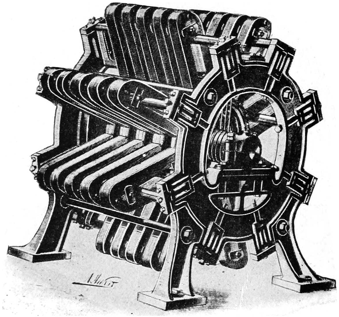
Maxim Dynamo.
This dynamo is in the collection of the Smithsonian Institution.
For this reason all these systems used direct current and the 10
ampere ultimately displaced the 20 ampere system. The 10 ampere
circuit was later standardized at 9.6 amperes, 50 volts per lamp. The
lamp therefore consumed 480 watts giving an efficiency of about 15
lumens per watt. This lamp gave an average of 575 candlepower
(spherical) in all directions, though it was called the 2000 cp (candlepower)
arc as under the best possible conditions it could give this
candlepower in one direction. Later a 6.6 ampere arc was developed.
This was called the “1200 cp” lamp and was not quite as efficient as
the 9.6 ampere lamp.
“SUB-DIVIDING THE ELECTRIC LIGHT”
While the arc lamp was being commercially established, it was at
once seen that it was too large a unit for household use. Many inventors
attacked the problem of making a smaller unit, or, as it was
called, “sub-dividing the electric light.” In the United States there
were four men prominent in this work: William E. Sawyer, Moses G.
Farmer, Hiram S. Maxim and Thomas A. Edison. These men did
not make smaller arc lamps but all attempted to make an incandescent
lamp that would operate on the arc circuits.
Sawyer’s Incandescent
Lamp, 1878.
This had a graphite burner
operating in nitrogen gas.
Farmer’s Incandescent
Lamp, 1878.
The graphite burner operated
in nitrogen gas. This
lamp is in the collection of the
Smithsonian Institution.
Sawyer made several lamps in the years 1878–79 along the lines of
the Russian scientists. All his lamps had a thick carbon burner
operating in nitrogen gas. They had a long glass tube closed at one
end and the other cemented to a brass base through which the gas
was put in. Heavy fluted wires connected the burner with the base
to radiate the heat, in order to keep the joint in the base cool. The
burner was renewable by opening the cemented joint. Farmer’s lamp
consisted of a pair of heavy copper rods mounted on a rubber cork,
between which a graphite rod was mounted. This was inserted in
a glass bulb and operated in nitrogen gas. Maxim made a lamp
having a carbon burner operating in a rarefied hydrocarbon vapor.
He also made a lamp consisting of a sheet of platinum operating in air.
EDISON’S INVENTION OF A PRACTICAL INCANDESCENT LAMP
Edison began the study of the problem in the spring of 1878. He
had a well-equipped laboratory at Menlo Park, New Jersey, with
several able assistants and a number of workmen, about a hundred
people all told. He had made a number of well-known inventions,
among which were the quadruplex telegraph whereby four messages
could be sent simultaneously over one wire, the carbon telephone
transmitter without which Bell’s telephone receiver would have been
impracticable, and the phonograph. All of these are in use today, so
Edison was eminently fitted to attack the problem.
Maxim’s Incandescent Lamp, 1878.
The carbon burner operated in a rarefied hydrocarbon vapor. This
lamp is in the collection of the Smithsonian Institution.
Edison’s first experiments were to confirm the failures of other
experimenters. Convinced of the seeming impossibility of carbon,
he turned his attention to platinum as a light giving element. Realizing
the importance of operating platinum close to its melting temperature,
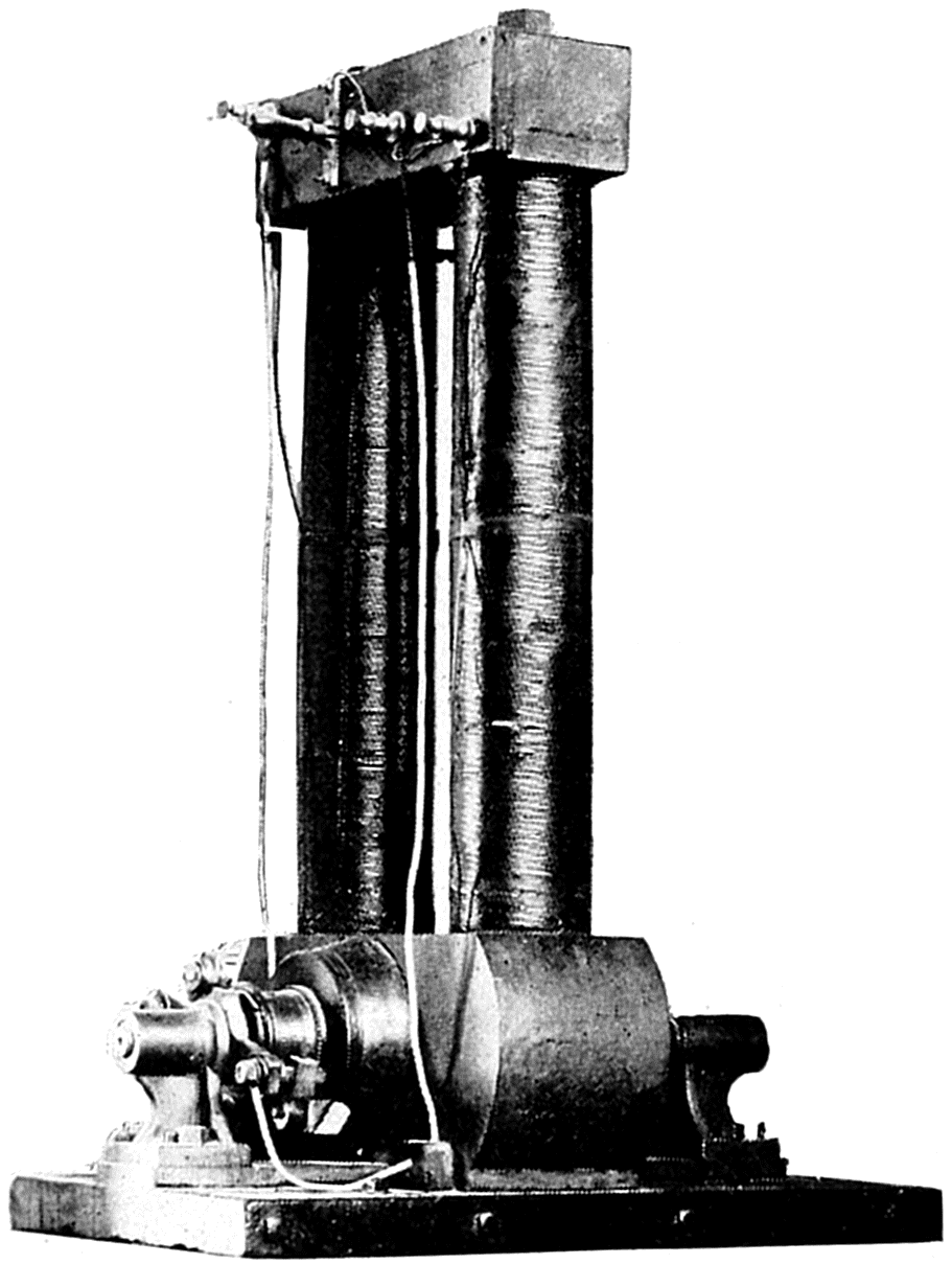
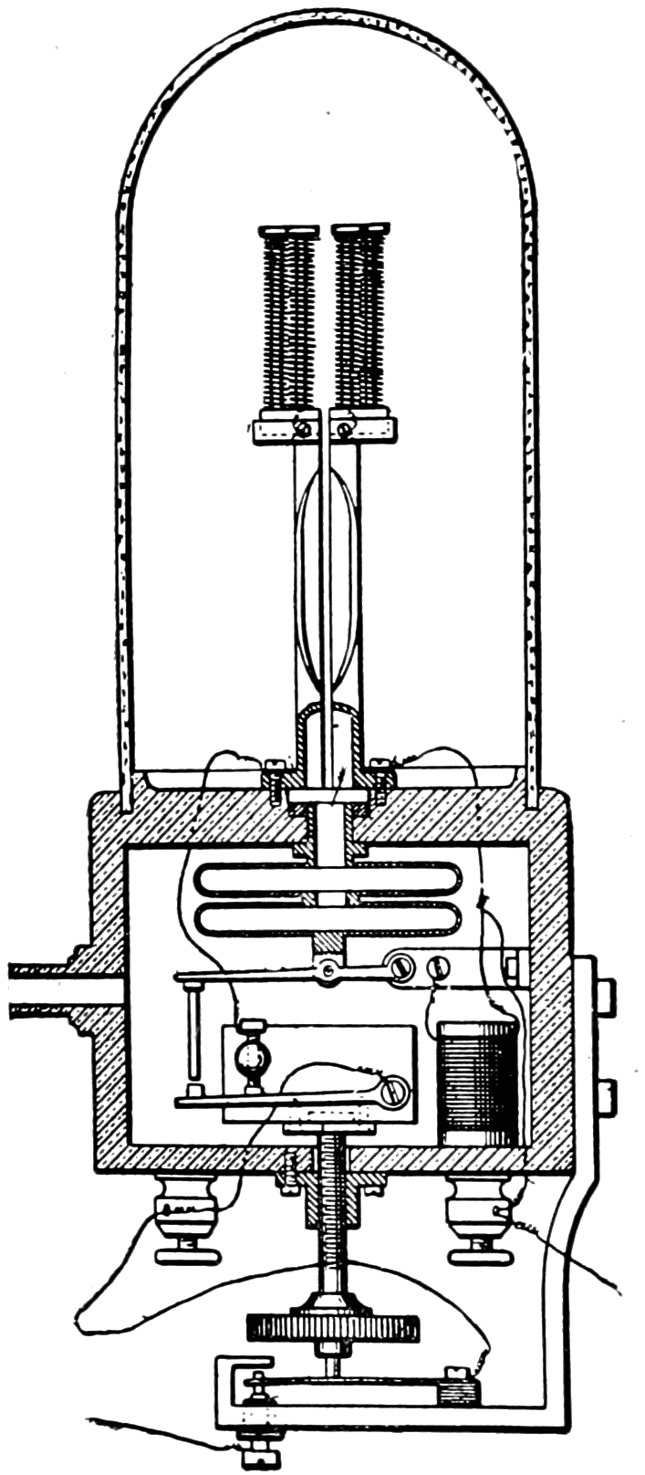
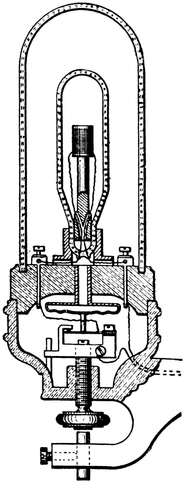
he designed a lamp which had a thermostatic arrangement so
that the burner would be automatically short circuited the moment its
temperature became dangerously close to melting. The burner consisted
of a double helix of platinum wire within which was a rod.
When the temperature of the platinum became too high, the rod in
expanding would short circuit the platinum. The platinum cooled
at once, the rod contracted opening the short circuit and allowing
current to flow through the burner again. His first incandescent lamp
patent covered this lamp. His next patent covered a similar lamp with
an improved thermostat consisting of an expanding diaphragm. Both
of these lamps were designed for use on series circuits.
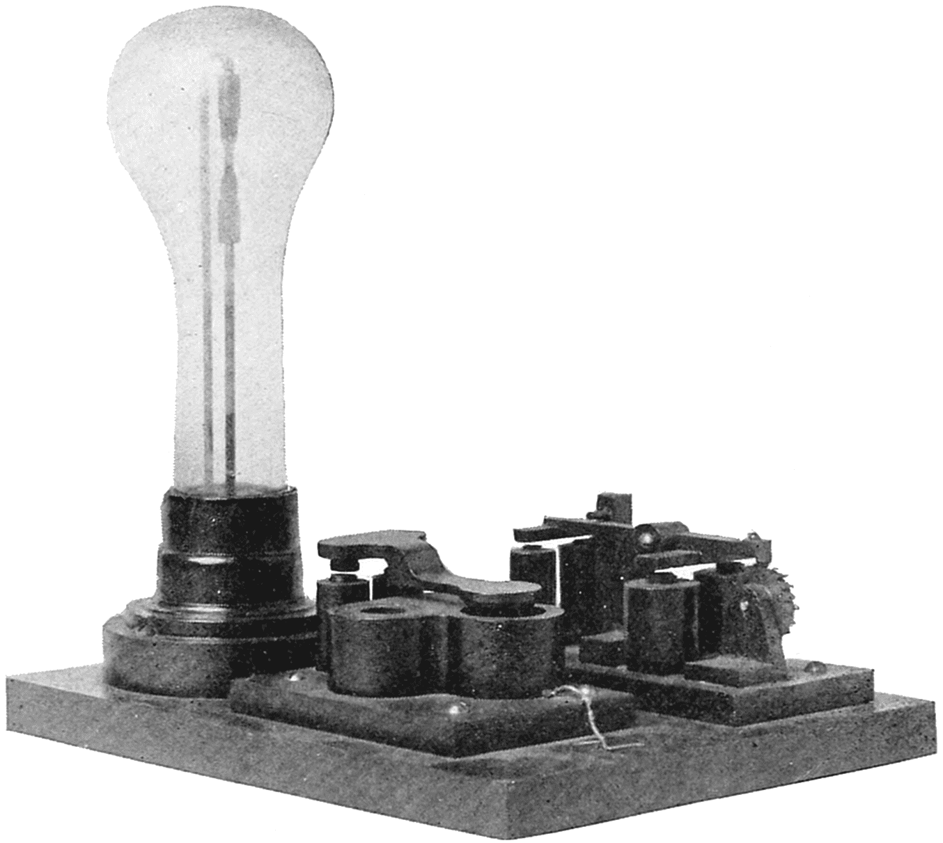
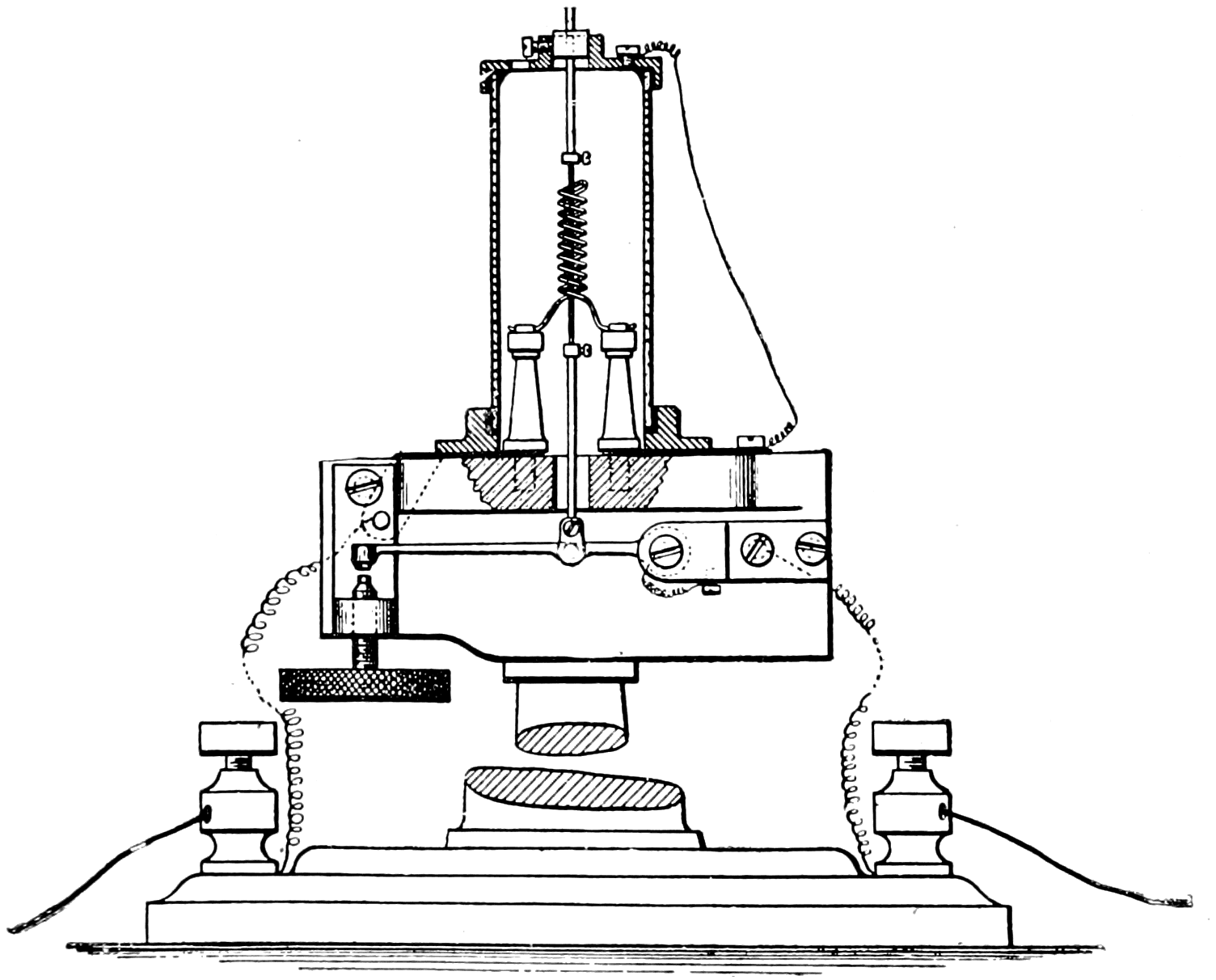
Edison’s First Experimental Lamp, 1878.
The burner was a coil of platinum wire which was protected from
operating at too high a temperature by a thermostat.
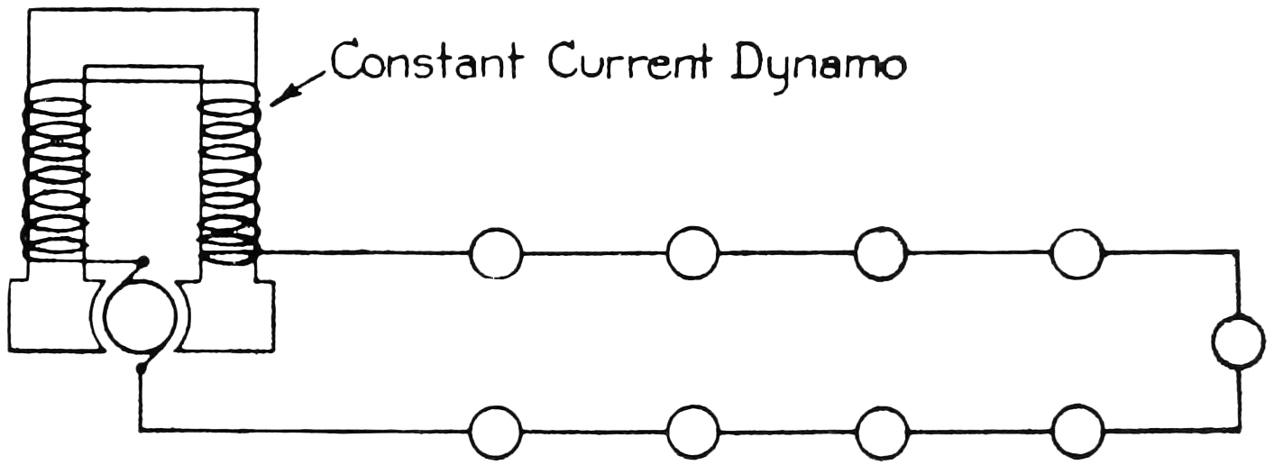
The only system of distributing electricity, known at that time,
was the series system. In this system current generated in the dynamo
armature flowed through the field coils, out to one lamp after another
over a wire, and then back to the dynamo. There were no means
by which one lamp could be turned on and off without doing the same
with all the others on the circuit. Edison realized that while this was
satisfactory for street lighting where arcs were generally used, it never
would be commercial for household lighting. He therefore decided
that a practical incandescent electric lighting system must be patterned
after gas lighting with which it would compete. He therefore made
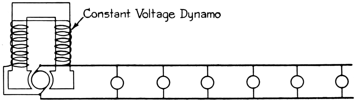
an intensive study of gas distribution and reasoned that a constant
pressure electrical system could be made similar to that of gas.
The first problem was therefore to design a dynamo that would
give a constant pressure instead of constant current. He therefore
reasoned that the internal resistance of the armature must be very
low or the voltage would fall as current was taken from the dynamo.
Scientists had shown that the most economical use of electricity from
a primary battery was where the external resistance of the load was
the same as the internal resistance of the battery, or in other words,
50 per cent was the maximum possible efficiency.
Diagram of Constant Current Series System.
This, in 1878, was the only method of distributing electric current.
Diagram of Edison’s Multiple System, 1879.
Edison invented the multiple system of distributing electric current,
now universally used.
When Edison proposed a very low resistance armature so that the
dynamo would have an efficiency of 90 per cent at full load, he was
ridiculed. Nevertheless he went ahead and made one which attained
this. The armature consisted of drum-wound insulated copper rods,
the armature core having circular sheets of iron with paper between
to reduce the eddy currents. There were two vertical fields above and
connected in shunt with the armature. It generated electricity at about
a hundred volts constant pressure and could supply current up to about
60 amperes at this pressure. It therefore had a capacity, in the
present terminology, of about 6 kilowatts (or 8 horsepower).
Edison Dynamo, 1879.
Edison made a dynamo that was 90 per cent efficient which scientists
said was impossible. This dynamo is in the collection of the Smithsonian
Institution and was one of the machines on the steamship
Columbia, the first commercial installation of the Edison lamp.
A multiple system of distribution would make each lamp independent
of every other and with a dynamo made for such a system, the
next thing was to design a lamp for it. Having a pressure of about
a hundred volts to contend with, the lamp, in order to take a small
amount of current, must, to comply with Ohm’s law, have a high
resistance. He therefore wound many feet of fine platinum wire on
a spool of pipe clay and made his first high resistance lamp. He used
his diaphragm thermostat to protect the platinum from melting, and,
as now seems obvious but was not to all so-called electricians at that
time, the thermostat was arranged to open circuit instead of short
circuit the burner when it became too hot. This lamp apparently
solved the problem, and, in order to protect the platinum from the
oxygen of the air, he coated it with oxide of zirconium. Unfortunately
zirconia, while an insulator at ordinary temperatures, becomes,
as is now known, a conductor of electricity when heated, so that the
lamp short circuited itself when it was lighted.
Edison’s High Resistance
Platinum Lamp, 1879.
This lamp had a high resistance
burner, necessary for the
multiple system.
Edison’s High Resistance
Platinum in Vacuum
Lamp, 1879.
This experimental lamp led
to the invention of the successful
carbon filament lamp.
During his experiments he had found that platinum became exceedingly
hard after it had been heated several times to incandescence
by current flowing through it. This apparently raised its melting
temperature so he was able to increase the operating temperature
and therefore greatly increase the candlepower of his lamps after
they had been heated a few times. Examination of the platinum
under a microscope showed it to be much less porous after heating,
so he reasoned that gases were occluded throughout the platinum
and were driven out by the heat. This led him to make a lamp with
a platinum wire to operate in vacuum, as he thought that more of the
occluded gases would come out under such circumstances.
Edison’s Carbon Lamp of October 21, 1879.
This experimental lamp, having a high resistance carbon filament
operating in a high vacuum maintained by an all-glass globe, was
the keystone of Edison’s successful incandescent lighting system. All
incandescent lamps made today embody the basic features of this
lamp. This replica is in the Smithsonian Institution exhibit of Edison
lamps. The original was destroyed.
These lamps were expensive to make, and, knowing that he could
get the requisite high resistance at much less cost from a long and
slender piece of carbon, he thought he might be able to make the carbon
last in the high vacuum he had been able to obtain from the newly
invented Geissler and Sprengel mercury air pumps. After several
trials he finally was able to carbonize a piece of ordinary sewing thread.
This he mounted in a one-piece all glass globe, all joints fused by melting
the glass together, which he considered was essential in order to
maintain the high vacuum. Platinum wires were fused in the glass to
connect the carbonized thread inside the bulb with the circuit outside
as platinum has the same coefficient of expansion as glass and hence
maintains an airtight joint. He reasoned that there would be occluded
gases in the carbonized thread which would immediately burn
up if the slightest trace of oxygen were present, so he heated the
lamp while it was still on the exhaust pump after a high degree of
vacuum had been obtained. This was accomplished by passing a
small amount of current through the “filament,” as he called it, gently
heating it. Immediately the gases started coming out, and it took eight
hours more on the pump before they stopped. The lamp was then
sealed and ready for trial.
Demonstration of Edison’s Incandescent Lighting System.
Showing view of Menlo Park Laboratory Buildings, 1880.
On October 21, 1879, current was turned into the lamp and it
lasted forty-five hours before it failed. A patent was applied for
on November 4th of that year and granted January 27, 1880. All
incandescent lamps made today embody the basic features of this
lamp. Edison immediately began a searching investigation of the best
material for a filament and soon found that carbonized paper gave
several hundred hours life. This made it commercially possible, so
in December, 1879, it was decided that a public demonstration of his
incandescent lighting system should be made. Wires were run to
several houses in Menlo Park, N. J., and lamps were also mounted on
poles, lighting the country roads in the neighborhood. An article
appeared in the New York Herald on Sunday, December 21, 1879,
describing Edison’s invention and telling of the public demonstration
to be given during the Christmas holidays. This occupied the entire
first page of the paper, and created such a furor that the Pennsylvania
Railroad had to run special trains to Menlo Park to accommodate
the crowds. The first commercially successful installation of the
Edison incandescent lamps and lighting system was made on the
steamship Columbia, which started May 2, 1880, on a voyage around
Cape Horn to San Francisco, Calif.
The carbonized paper filament of the first commercial incandescent
lamp was quite fragile. Early in 1880 carbonized bamboo was found
to be not only sturdy but made an even better filament than paper.
The shape of the bulb was also changed from round to pear shape,
being blown from one inch tubing. Later the bulbs were blown
directly from molten glass.
Dynamo Room, S. S. Columbia.
The first commercial installation of the Edison Lamp, started
May 2, 1880. One of these original dynamos is on exhibit at the
Smithsonian Institution.
As it was inconvenient to connect the wires to the binding posts of
a new lamp every time a burned out lamp had to be replaced, a base
and socket for it were developed. The earliest form of base consisted
simply of bending the two wires of the lamp back on the neck
of the bulb and holding them in place by wrapping string around
the neck. The socket consisted of two pieces of sheet copper in a
hollow piece of wood. The lamp was inserted in this, the two-wire
terminals of the lamp making contact with the two-sheet copper
terminals of the socket, the lamp being rigidly held in the socket by
a thumb screw which forced the socket terminals tight against the
neck of the bulb.
Original Socket for Incandescent Lamps, 1880.
Wire Terminal Base Lamp, 1880.
This crude form of lamp base fitted the original form of lamp
socket pictured above. This lamp is in the exhibit of Edison lamps
in the Smithsonian Institution.
This crude arrangement was changed in the latter part of 1880 to
a screw shell and a ring for the base terminals, wood being used for
insulation. The socket was correspondingly changed. This was a
very bulky affair, so the base was changed to a cone-shaped ring and
a screw shell for terminals. Wood was used for insulation, which
a short time after was changed to plaster of Paris as this was also
used to fasten the base to the bulb. It was soon found that the tension
created between the two terminals of the base when the lamp was
firmly screwed in the socket often caused the plaster base to pull apart,
so the shape of the base was again changed early in 1881, to the form
in use today.
An improved method of connecting the ends of the filament to the
leading-in wires was adopted early in 1881. Formerly this was
accomplished by a delicate clamp having a bolt and nut. The improvement
consisted of copper plating the filament to the leading-in wire.
Original Screw Base
Lamp, 1880.
This first screw base, consisting
of a screw shell and
ring for terminals with wood
for insulation, was a very
bulky affair. This lamp is in
the exhibit of Edison lamps in
the Smithsonian Institution.
Improved Screw Base
Lamp, 1881.
The terminals of this base
consisted of a cone shaped ring
and a screw shell. At first
wood was used for insulation,
later plaster of paris which
was also used to fasten the
base to the bulb. This lamp
is in the exhibit of Edison
lamps in the Smithsonian Institution.
In the early part of the year 1881 the lamps were made “eight to
the horsepower.” Each lamp, therefore, consumed a little less than
100 watts, and was designed to give 16 candlepower in a horizontal
direction. The average candlepower (spherical) in all directions was
about 77 per cent of this, hence as the modern term “lumen” is 12.57
spherical candlepower, these lamps had an initial efficiency of about
1.7 lumens per watt. The lamps blackened considerably during their
life so that just before they burned out their candlepower was less
than half that when new. Thus their mean efficiency throughout life
was about 1.1 l-p-w (lumens per watt). These figures are interesting
in comparison with the modern 100-watt gas-filled tungsten-filament
lamp which has an initial efficiency of 12.9, and a mean efficiency of
11.8, l-p-w. In other words the equivalent (wattage) size of modern
lamp gives over seven times when new, and eleven times on the
average, as much light for the same energy consumption as Edison’s
first commercial lamp. In the latter part of 1881 the efficiency was
changed to “ten lamps per horsepower,” equivalent to 2¼ l-p-w
initially. Two sizes of lamps were made: 16 cp for use on 110-volt
circuits and 8 cp for use either direct on 55 volts or two in series on
110-volt circuits.
Final Form of Screw Base, 1881.
With plaster of paris, the previous form of base was apt to pull
apart when the lamp was firmly screwed into the socket. The form
of the base was therefore changed to that shown, which overcame
these difficulties, and which has been used ever since. The lamp
shown was standard for three years and is in the exhibit of Edison
lamps in the Smithsonian Institution.
EDISON’S THREE-WIRE SYSTEM
The distance at which current can be economically delivered at
110 volts pressure is limited, as will be seen from a study of Ohm’s
law. The loss of power in the distributing wires is proportional to
the square of the current flowing. If the voltage be doubled, the
amount of current is halved, for a given amount of electric power
delivered, so that the size of the distributing wires can then be reduced
to one-quarter for a given loss in them. At that time (1881) it was
impossible to make 220-volt lamps, and though they are now available,
their use is uneconomical, as their efficiency is much poorer than that
of 110-volt incandescent lamps.
Edison invented a distributing system that had two 110-volt circuits,
with one wire called the neutral, common to both circuits so that the
pressure on the two outside wires was 220 volts. The neutral wire
had only to be large enough to carry the difference between the currents
flowing in the two circuits. As the load could be so arranged
that it would be approximately equal at all times on both circuits,
the neutral wire could be relatively small in size. Thus the three-wire
system resulted in a saving of 60 per cent in copper over the two-wire
system or, for the same amount of copper, the distance that current
could be delivered was more than doubled.
Diagram of Edison’s Three-Wire System, 1881.
This system reduced the cost of copper in the multiple distributing
system 60 per cent.
DEVELOPMENT OF THE ALTERNATING CURRENT CONSTANT POTENTIAL SYSTEM
The distance that current can be economically distributed, as has
been shown, depends upon the voltage used. If, therefore, current
could be sent out at a high voltage and the pressure brought down to
that desired at the various points to which it is distributed, such distribution
could cover a much greater area. Lucien Gaulard was a
French inventor and was backed by an Englishman named John D.
Gibbs. About 1882 they patented a series alternating-current system
of distribution. They had invented what is now called a transformer
which consisted of two separate coils of wire mounted on an iron
core. All the primary coils were connected in series, which, when
current went through them, induced a current in the secondary coils.
Lamps were connected in multiple on each of the secondary coils.
An American patent was applied for on the transformer, but was
refused on the basis that “more current cannot be taken from it than
is put in.” While this is true if the word energy were used, the
transformer can supply a greater current at a lower voltage (or vice
versa) than is put in, the ratio being in proportion to the relative
number of turns in the primary and secondary coils. The transformer
was treated with ridicule and Gaulard died under distressing circumstances.
Diagram of Stanley’s Alternating Current Multiple
System, 1885.
This system is now universally used for distributing electric current
long distances.
Information regarding the transformer came to the attention of
William Stanley, an American, in the latter part of 1885. He made
an intensive study of the scheme, and developed a transformer in which
the primary coil was connected in multiple on a constant potential
alternating-current high-voltage system. From the secondary coil a
lower constant voltage was obtained. An experimental installation
was made at Great Barrington, Mass., in the early part of 1886, the
first commercial installation being made in Buffalo, New York, in
the latter part of the year. This scheme enabled current to be economically
distributed to much greater distances. The voltage of the
high-tension circuit has been gradually increased as the art has progressed
from about a thousand volts to over two hundred thousand
volts pressure in a recent installation in California, where electric
power is transmitted over two hundred miles.
INCANDESCENT LAMP DEVELOPMENTS, 1884–1894
In 1884 the ring of plaster around the top of the base was omitted;
in 1886 an improvement was made by pasting the filament to the
leading-in wires with a carbon paste instead of the electro-plating
method; and in 1888 the length of the base was increased so that it
had more threads. Several concerns started making incandescent
lamps, the filaments being made by carbonizing various substances.
“Parchmentized” thread consisted of ordinary thread passed through
sulphuric acid. “Tamadine” was cellulose in the sheet form, punched
out in the shape of the filament. Squirted cellulose in the form of a
thread was also used. This was made by dissolving absorbent cotton
in zinc chloride, the resulting syrup being squirted through a die into
alcohol which hardened the thread thus formed. This thread was
washed in water, dried in the air and then cut to proper length and
carbonized.
Standard Edison Lamp, 1884.
The ring of plaster around
the neck of previous lamps was
omitted. This lamp is in the
exhibit of Edison lamps in the
Smithsonian Institution.
Standard Edison Lamp, 1888.
The length of the base was
increased so it had more
threads. This lamp is in the
exhibit of Edison lamps in the
Smithsonian Institution.
The filament was improved by coating it with graphite. One
method, adopted about 1888, was to dip it in a hydrocarbon liquid
before carbonizing. Another, more generally adopted in 1893 was a
process originally invented by Sawyer, one of the Americans who had
attempted to “sub-divide the electric light” in 1878–79. This process
consisted of passing current through a carbonized filament in an
atmosphere of hydrocarbon vapor. The hot filament decomposed the
vapor, depositing graphite on the filament. The graphite coated filament
improved it so it could operate at 3½ lumens per watt (initial efficiency).
Lamps of 20, 24, 32 and 50 candlepower were developed for
110-volt circuits. Lamps in various sizes from 12 to 36 cp were made
for use on storage batteries having various numbers of cells and giving
a voltage of from 20 to 40 volts. Miniature lamps of from ½ to 2 cp
for use on dry batteries of from 2½ to 5½ volts, and 3 to 6 cp on
5½ to 12 volts, were also made. These could also be connected in
series on 110 volts for festoons. Very small lamps of ½ cp of 2 to
4 volts for use in dentistry and surgery were made available. These
miniature lamps had no bases, wires being used to connect them to
the circuit.
Standard Edison Lamp, 1894.
This lamp had a “treated” cellulose filament, permitting an efficiency
of 3½ lumens per watt which has never been exceeded in a
carbon lamp. This lamp is in the exhibit of Edison lamps in the
Smithsonian Institution.
Lamps for 220-volt circuits were developed as this voltage was
desirable for power purposes, electric motors being used, and a few
lamps were needed on such circuits. They are less efficient and more
expensive than 110-volt lamps, their use being justified however
only when it is uneconomical to have a separate 110-volt circuit for
lighting. The lamps were made in sizes from 16 to 50 candlepower.
Edison.
Thomson-Houston.
Westinghouse.
Brush-Swan.
Edi-Swan (single contact).
Edi-Swan (double contact).
United States.
Hawkeye.
Ft. Wayne Jenny.
Mather or Perkins.
Loomis.
Schaeffer or National.
Indianapolis Jenny.
Siemens & Halske.
Various Standard Bases in Use, 1892.
Thomson-Houston Socket.
Westinghouse Socket.
Electric street railway systems used a voltage in the neighborhood
of 550, and lamps were designed to burn five in series on this voltage.
These lamps were different from the standard 110-volt lamps although
they were made for about this voltage. As they were burned in series,
the lamps were selected to operate at a definite current instead of at
a definite voltage, so that the lamps when burned in series would
operate at the proper temperature to give proper life results. Such
lamps would therefore vary considerably in individual volts, and
hence would not give good service if burned on 110-volt circuits.
The candelabra screw base and socket and the miniature screw base
and socket were later developed. Ornamental candelabra base lamps
were made for use direct on 110 volts, smaller sizes being operated
in series on this voltage. The former gave about 10 cp, the latter in
various sizes from 4 to 8 cp. The miniature screw base lamps were
for low volt lighting.
Thomson-Houston.Westinghouse.
Adapters for Edison Screw Sockets, 1892.
Next to the Edison base, the Thomson-Houston and Westinghouse
bases were the most popular. By use of these adapters, Edison base
lamps could be used in T-H and Westinghouse sockets.
The various manufacturers of lamps in nearly every instance made
bases that were very different from one another. No less than fourteen
different standard bases and sockets came into commercial use.
These were known as, Brush-Swan, Edison, Edi-Swan (double contact),
Edi-Swan (single contact), Fort Wayne Jenny, Hawkeye,
Indianapolis Jenny, Loomis, Mather or Perkins, Schaeffer or National,
Siemens & Halske, Thomson-Houston, United States and
Westinghouse. In addition there were later larger sized bases made
for use on series circuits. These were called the Bernstein, Heisler,
Large Edison, Municipal Bernstein, Municipal Edison, Thomson-Houston
(alternating circuit) and Thomson-Houston (arc circuit).
Some of these bases disappeared from use and in 1900 the proportion
in the United States was about 70 per cent Edison, 15 per cent Westinghouse,
10 per cent Thomson-Houston and 5 per cent for all the
others remaining. A campaign was started to standardize the Edison
base, adapters being sold at cost for the Westinghouse and Thomson-Houston
sockets so that Edison base lamps could be used. In a few
years the desired results were obtained so that now there are no other
sockets in the United States but the Edison screw type for standard
lighting service. This applies also to all other countries in the world
except England where the bayonet form of base and socket is still
popular.
Bernstein.
Heisler.
Thomson-Houston (alternating current).
Thomson-Houston (arc circuit).
Municipal Edison.
Municipal Bernstein.
Various Series Bases in Use, 1892.
The above six bases have been superseded by the “Large Edison,”
now called the Mogul Screw base.
THE EDISON “MUNICIPAL” STREET LIGHTING SYSTEM
Edison “Municipal” System, 1885.
High voltage direct current was generated, several circuits operating
in multiple, three ampere lamps burning in series on each circuit.
Photograph courtesy of Association of Edison Illuminating Companies.
The arc lamp could not practically be made in a unit smaller than
the so-called “1200 candlepower” (6.6 ampere) or “half” size,
which really gave about 350 spherical candlepower. A demand therefore
arose for a small street lighting unit, and Edison designed his
“Municipal” street lighting system to fill this requirement. His
experience in the making of dynamos enabled him to make a direct
current bipolar constant potential machine that would deliver 1000
volts which later was increased to 1200 volts. They were first made
in two sizes having an output of 12 and 30 amperes respectively.
Incandescent lamps were made for 3 amperes in several sizes from
16 to 50 candlepower. These lamps were burned in series on the
1200-volt direct current system. Thus the 12-ampere machine had
a capacity for four series circuits, each taking 3 amperes, the series
circuits being connected in multiple across the 1200 volts. The
number of lamps on each series circuit depended upon their size, as
the voltage of each lamp was different for each size, being about 1½
volts per cp.
A popular size was the 32-candlepower unit, which therefore
required about 45 volts and hence at 3 amperes consumed about 135
watts. Allowing 5 per cent loss in the wires of each circuit, there
was therefore 1140 of the 1200 volts left for the lamps. Hence
about 25 32-candlepower or 50 16-candlepower lamps could be put on
each series circuit. Different sizes of lamps could also be put on the
same circuit, the number depending upon the aggregate voltage of the
lamps.
Edison Municipal Lamp, 1885.
Inside the base was an arrangement by which the lamp was automatically
short circuited when it burned out.
A device was put in the base of each lamp to short circuit the lamp
when it burned out so as to prevent all the other lamps on that circuit
from going out. This device consisted of a piece of wire put inside
the lamp bulb between the two ends of the filament. Connected to
this wire was a very thin wire inside the base which held a piece of
metal compressed against a spring. The spring was connected to one
terminal of the base. Should the lamp burn out, current would jump
from the filament to the wire in the bulb, and the current then flowed
through the thin wire to the other terminal of the base. The thin
wire was melted by the current, and the spring pushed the piece of
metal up short circuiting the terminals of the base. This scheme was
later simplified by omitting the wire, spring, etc., and substituting a
piece of metal which was prevented from short circuiting the terminals
of the base by a thin piece of paper. When the lamp burned
out the entire 1200 volts was impressed across this piece of paper,
puncturing it and so short circuiting the base terminals. Should one
or more lamps go out on a circuit, the increase in current above the
normal 3 amperes was prevented by an adjustable resistance, or an
extra lot of lamps which could be turned on one at a time, connected
to each circuit and located in the power station under the control of
the operator. This system disappeared from use with the advent of
the constant current transformer.
THE SHUNT BOX SYSTEM FOR SERIES INCANDESCENT LAMPS
Shunt Box System, 1887.
Lamps were burned in series on a high voltage alternating current,
and when a lamp burned out all the current then went through its
“shunt box,” a reactance coil in multiple with each lamp.
Soon after the commercial development of the alternating current
constant potential system, a scheme was developed to permit the use
of lamps in series on such circuits without the necessity for short
circuiting a lamp should it burn out. A reactance, called a “shunt
box” and consisting of a coil of wire wound on an iron core, was
connected across each lamp. The shunt box consumed but little
current while the lamp was burning. Should one lamp go out, the
entire current would flow through its shunt box and so maintain the
current approximately constant. It had the difficulty, however, that
if several lamps went out, the current would be materially increased
tending to burn out the remaining lamps on the circuit. This system
also disappeared from use with the development of the constant
current transformer.
THE ENCLOSED ARC LAMP
Up to 1893 the carbons of an arc lamp operated in the open air,
so that they were rapidly consumed, lasting from eight to sixteen
hours depending on their length and thickness. Louis B. Marks, an
American, found that by placing a tight fitting globe about the arc,
the life of the carbons was increased ten to twelve times. This was
due to the restricted amount of oxygen of the air in the presence of
the hot carbon tips and thus retarded their consumption. The amount
of light was somewhat decreased, but this was more than offset by
the lesser expense of trimming which also justified the use of more
expensive better quality carbons. Satisfactory operation required
that the arc voltage be increased to about 80 volts.
Enclosed Arc Lamp, 1893.
Enclosing the arc lengthened the life of the carbons, thereby greatly
reducing the cost of maintenance.
This lamp rapidly displaced the series open arc. An enclosed arc
lamp for use on 110-volt constant potential circuits was also developed.
A resistance was put in series with the arc for use on 110-volt direct
current circuits, to act as a ballast in order to prevent the arc from
taking too much current and also to use up the difference between the
arc voltage (80) and the line voltage (110). On alternating current,
a reactance was used in place of the resistance.
The efficiencies in lumens per watt of these arcs (with clear glassware),
all of which have now disappeared from the market, were
about as follows:
6.6 ampere 510 watt direct current (D.C.) series arc, 8¼ l-p-w.
5.0 ampere 550 watt direct current multiple (110-volt) arc, 4½ l-p-w.
7.5 ampere 540 watt alternating current (A.C.) multiple (110-volt) arc, 4¼ l-p-w.
Open Flame Arc
Lamp, 1898.
Certain salts impregnated in
the carbons produced a brilliantly
luminous flame in the
arc stream which enormously
increased the efficiency of the
lamp.
Enclosed Flame Arc
Lamp, 1908.
By condensing the smoke
from the arc in a cooling
chamber it was practical to enclose
the flame arc, thereby
increasing the life of the
carbons.
The reason for the big difference in efficiency between the series
and multiple direct-current arc is that in the latter a large amount of
electrical energy (watts) is lost in the ballast resistance. While there
is a considerable difference between the inherent efficiencies of the
D. C. and A. C. arcs themselves, this difference is reduced in the
multiple D. C. and A. C. arc lamps as more watts are lost in the
resistance ballast of the multiple D. C. lamp than are lost in the
reactance ballast of the multiple A. C. lamp.
This reactance gives the A. C. lamp what is called a “power-factor.”
The product of the amperes (7.5) times the volts (110) does not give
the true wattage (540) of the lamp, so that the actual volt-amperes
(825) has to be multiplied by a power factor, in this case about 65 per
cent, to obtain the actual power (watts) consumed. The reason is
that the instantaneous varying values of the alternating current and
pressure, if multiplied and averaged throughout the complete alternating
cycle, do not equal the average amperes (measured by an
ammeter) multiplied by the average voltage (measured by a volt-meter).
That is, the maximum value of the current flowing (amperes)
does not occur at the same instant that the maximum pressure
(voltage) is on the circuit.
THE FLAME ARC LAMP
About 1844 Bunsen investigated the effect of introducing various
chemicals in the carbon arc. Nothing was done, however, until
Bremer, a German, experimented with various salts impregnated in
the carbon electrodes. In 1898 he produced the so-called flame arc,
which consisted of carbons impregnated with calcium fluoride. This
gave a brilliant yellow light most of which came from the arc flame,
and practically none from the carbon tips. The arc operated in the
open air and produced smoke which condensed into a white powder.
The two carbons were inclined downward at about a 30-degree
angle with each other, and were of small diameter but long, 18 to
30 inches, having a life of about 12 to 15 hours. The tips of the
carbons projected through an inverted earthenware cup, called the
“economizer,” the white powder condensing on this and acting not
only as an excellent reflector but making a dead air space above the
arc. The arc was maintained at the tips of the carbons by an electro-magnet
whose magnetic field “blew” the arc down.
Two flame arc lamps were burned in series on 110-volt circuits.
They consumed 550 watts each, giving an efficiency of about 35 lumens
per watt on direct current. On alternating current the efficiency was
about 30 l-p-w. By use of barium salts impregnated in the carbons,
a white light was obtained, giving an efficiency of about 18 l-p-w on
direct current and about 15½ on alternating current. These figures
cover lamps equipped with clear glassware. Using strontium salts
in the carbons, a red light was obtained at a considerably lower efficiency,
such arcs on account of their color being used only to a limited
extent for advertising purposes.
Constant Current Transformer, 1900.
This converted alternating current of constant voltage into constant
current, for use on series circuits.
These arcs were remarkably efficient but their maintenance expense
was high. Later, about 1908, enclosed flame arcs with vertical carbons
were made which increased the life of the carbons, the smoke being
condensed in cooling chambers. However, their maintenance expense
was still high. They have now disappeared from the market, having
been displaced by the very efficient gas-filled tungsten filament incandescent
lamp which appeared in 1913.
THE CONSTANT CURRENT TRANSFORMER FOR SERIES CIRCUITS
About 1900 the constant current transformer was developed by
Elihu Thomson. This transforms current taken from a constant
potential alternating current circuit into a constant alternating current
for series circuits, whose voltage varies with the load on the circuit.
The transformer has two separate coils; the primary being stationary
and connected to the constant potential circuit and the secondary
being movable and connected to the series circuit. The weight of the
secondary coil is slightly underbalanced by a counter weight. Current
flowing in the primary induces current in the secondary, the two
coils repelling each other. The strength of the repelling force depends
upon the amount of current flowing in the two coils. The core of the
transformer is so designed that the central part, which the two coils
surround, is magnetically more powerful close to the primary coil
than it is further away.
When the two coils are close together a higher voltage is induced
in the secondary than if the later were further away from the primary
coil. In starting, the two coils are pulled apart by hand to prevent too
large a current flowing in the series circuit. The secondary coil is
allowed to gradually fall and will come to rest at a point where the
voltage induced in it produces the normal current in the series circuit,
the repelling force between the two coils holding the secondary at this
point. Should the load in the series circuit change for any reason, the
current in the series circuit would also change, thus changing the
force repelling the two coils. The secondary would therefore move
until the current in the series circuit again becomes normal. The
action is therefore automatic, and the actual current in the series
circuit can be adjusted within limits to the desired amount, by varying
the counterweight. A dash pot is used to prevent the secondary coil
from oscillating (pumping) too much.
In the constant current transformer, the series circuit is insulated
from the constant potential circuit. This has many advantages. A
similar device, called an automatic regulating reactance was developed
which is slightly less expensive, but it does not have the advantage of
insulating the two circuits from each other.
ENCLOSED SERIES ALTERNATING CURRENT ARC LAMPS
The simplicity of the constant current transformer soon drove the
constant direct-current dynamo from the market. An enclosed arc
lamp was therefore developed for use on alternating constant current.
Two sizes of lamps were made; one for 6.6 amperes consuming 450
watts and having an efficiency of about 4½ lumens per watt, and the
other 7.5 amperes, 480 watts and 5 l-p-w (clear glassware). These
lamps soon superseded the direct current series arcs. They have now
been superseded by the more efficient magnetite arc and tungsten
filament incandescent lamps.
SERIES INCANDESCENT LAMPS ON CONSTANT CURRENT TRANSFORMERS
Series incandescent lamps were made for use on constant current
transformers superseding the “Municipal” and “Shunt Box” systems.
The large Edison, now called the Mogul Screw base, was
adopted and the short circuiting film cut-out was removed from the
base and placed between prongs attached to the socket.
Holder.
Socket.
Holder and socket.
Series Incandescent Lamp Socket with Film Cutout, 1900.
The “Large Edison,” now called Mogul Screw, base was standardized
and the short circuiting device put on the socket terminals.
The transformers made for the two sizes of arc lamps, produced
6.6 and 7.5 amperes and incandescent lamps, in various sizes from
16 to 50 cp, were made for these currents so that the incandescent
lamps could be operated on the same circuit with the arc lamps. The
carbon series incandescent lamp, however, was more efficient if made
for lower currents, so 3½-, 4- and 5½-ampere constant current transformers
were made for incandescent lamps designed for these amperes.
Later, however, with the advent of the tungsten filament, the
6.6-ampere series tungsten lamp was made the standard, as it was
slightly more efficient than the lower current lamps, and was made
in sizes from 32 to 400 cp. When the more efficient gas-filled
tungsten lamps were developed, the sizes were further increased;
the standard 6.6-ampere lamps now made are from 60 to 2500 cp.
THE NERNST LAMP
Dr. Walther Nernst, of Germany, investigating the rare earths used
in the Welsbach mantle, developed an electric lamp having a burner,
or “glower” as it was called, consisting of a mixture of these oxides.
The main ingredient was zirconia, and the glower operated in the open
air. It is a non-conductor when cold, so had to be heated before current
would flow through it. This was accomplished by an electric
heating coil, made of platinum wire, located just above the glower.
As the glower became heated and current flowed through it, the heater
was automatically disconnected by an electro-magnet cut-out.
Nernst Lamp, 1900.
The burners consisted mainly of zirconium oxide which had to be
heated before current could go through them.
The resistance of the glower decreases with increase in current,
so a steadying resistance was put in series with it. This consisted of
an iron wire mounted in a bulb filled with hydrogen gas and was called
a “ballast.” Iron has the property of increasing in resistance with
increase in current flowing through it, this increase being very marked
between certain temperatures at which the ballast was operated. The
lamp was put on the American market in 1900 for use on 220-volt
alternating current circuits. The glower consumed 0.4 ampere.
One, two, three, four and six glower lamps were made, consuming
88, 196, 274, 392 and 528 watts respectively. As most of the light
is thrown downward, their light output was generally given in mean
lower hemispherical candlepower. The multiple glower lamps were
more efficient than the single glower, owing to the heat radiated from
one glower to another. Their efficiencies, depending on the size, were
from about 3½ to 5 lumens per watt, and their average candlepower
throughout life was about 80 per cent of initial. The lamp disappeared
from the market about 1912.
Diagram of Nernst Lamp.
THE COOPER-HEWITT LAMP
In 1860 Way discovered that if an electric circuit was opened
between mercury contacts a brilliant greenish colored arc was produced.
Mercury was an expensive metal and as the carbon arc seemed
to give the most desirable results, nothing further was done for many
years until Dr. Peter Cooper Hewitt, an American, began experimenting
with it. He finally produced an arc in vacuum in a one-inch glass
tube about 50 inches long for 110 volts direct current circuits, which
was commercialized in 1901. The tube hangs at about 15 degrees from
the horizontal. The lower end contains a small quantity of mercury.
The terminals are at each end of the tube, and the arc was first started
by tilting the tube by hand so that a thin stream of mercury bridged
the two terminals. Current immediately vaporized the mercury,
starting the arc. A resistance is put in series with the arc to maintain
the current constant on direct current constant voltage circuits.
Automatic starting devices were later developed, one of which consisted
of an electro-magnet that tilted the lamp, and the other of an
induction coil giving a high voltage which, in discharging, started the
arc.
Cooper-Hewitt Mercury Vapor Arc Lamp, 1901.
This gives a very efficient light, practically devoid of red but of high
actinic value, so useful in photography.
This lamp is particularly useful in photography on account of the
high actinic value of its light. Its light is very diffused and is practically
devoid of red rays, so that red objects appear black in its light.
The lamp consumes 3½ amperes at 110 volts direct current (385
watts) having an efficiency of about 12½ lumens per watt.
The mercury arc is peculiar in that it acts as an electric valve
tending to let current flow through it only in one direction. Thus on
alternating current, the current impulses will readily go through it
in one direction, but the arc will go out in the other half cycle unless
means are taken to prevent this. This is accomplished by having two
terminals at one end of the tube, which are connected to choke coils,
which in turn are connected to a single coil (auto) transformer. The
alternating current supply mains are connected to wires tapping different
parts of the coil of the auto transformer. The center of the
coil of the auto transformer is connected through an induction coil
to the other end of the tube. By this means the alternating current
impulses are sent through the tube in one direction, one half cycle
from one of the pairs of terminals of the tube, the other half cycle
from the other terminal. Thus pulsating direct current, kept constant
by the induction coil, flows through the tube, the pulsations overlapping
each other by the magnetic action of the choke coils. This
alternating current lamp is started by the high voltage discharge
method. It has a 50-inch length of tube, consuming about 400 watts
on 110 volts. Its efficiency is a little less than that of the direct current
lamp.
Diagram of Cooper-Hewitt Lamp for Use on Alternating Current.
The mercury arc is inherently for use on direct current, but
by means of reactance coils, it can be operated on alternating
current.
THE LUMINOUS OR MAGNETITE ARC LAMP
About 1901 Dr. Charles P. Steinmetz, Schenectady, N. Y., studied
the effect of metallic salts in the arc flame. Dr. Willis R. Whitney,
also of Schenectady, and director of the research laboratory of the
organization of which Dr. Steinmetz is the consulting engineer, followed
with some further work along this line. The results of this
work were incorporated in a commercial lamp called the magnetite arc
lamp, through the efforts of C. A. B. Halvorson, Jr., at Lynn, Mass.
The negative electrode consists of a pulverized mixture of magnetite
(a variety of iron ore) and other substances packed tightly in an
iron tube. The positive electrode is a piece of copper sheathed in
iron to prevent oxidization of the copper. The arc flame gives a
brilliant white light, and, similar to the mercury arc, is inherently
limited to direct current. It burns in the open air at about 75 volts.
The lamp is made for 4-ampere direct current series circuits and
consumes about 310 watts and has an efficiency of about 11½ lumens
per watt.
Luminous or Magnetite Arc Lamp, 1902.
This has a negative electrode containing magnetite which produces
a very luminous white flame in the arc stream.
The negative (iron tube) electrode now has a life of about 350
hours. Later, a higher efficiency, 4-ampere electrode was made which
has a shorter life but gives an efficiency of about 17 l-p-w, and a 6.6-ampere
lamp was also made giving an efficiency of about 18 l-p-w using
the regular electrode. This electrode in being consumed gives off
fumes, so the lamp has a chimney through its body to carry them off.
Some of the fumes condense, leaving a fine powder, iron oxide, in the
form of rust. The consumption of the positive (copper) electrode is
very slow, which is opposite to that of carbon arc lamps on direct
current. The arc flame is brightest near the negative (iron tube)
electrode and decreases in brilliancy and volume as it nears the positive
(copper) electrode.
Diagram of Series Magnetite Arc Lamp.
The method of control, entirely different from that of other
arc lamps, was invented by Halvorson to meet the peculiarities of
this arc.
The peculiarities of the arc are such that Halvorson invented an
entirely new principle of control. The electrodes are normally apart.
In starting, they are drawn together by a starting magnet with sufficient
force to dislodge the slag which forms on the negative electrode
and which becomes an insulator when cold. Current then flows
through the electrodes and through a series magnet which pulls up a
solenoid breaking the circuit through the starting magnet. This allows
the lower electrode to fall a fixed distance, about seven-eighths of an
inch, drawing the arc, whose voltage is then about 72 volts. As
the negative electrode is consumed, the length and voltage of the arc
increases when a magnet, in shunt with the arc, becomes sufficiently
energized to close the contacts in the circuit of the starting magnet
causing the electrode to pick up and start off again.
MERCURY ARC RECTIFIER FOR MAGNETITE ARC LAMPS
Mercury Arc Rectifier Tube for Series Magnetite
Arc Lamps, 1902.
The mercury arc converted the alternating constant current into direct
current required by the magnetite lamp.
As the magnetite arc requires direct current for its operation, the
obvious way to supply a direct constant current for series circuits is
to rectify, by means of the mercury arc, the alternating current obtained
from a constant current transformer. The terminals of the
movable secondary coil of the constant current transformer are connected
to the two arms of the rectifier tube. One end of the series
circuit is connected to the center of the secondary coil. The other
end of the series circuit is connected to a reactance which in turn is
connected to the pool of mercury in the bottom of the rectifier tube.
One-half of the cycle of the alternating current goes from the
secondary coil to one arm of the rectifier tube through the mercury
vapor, the mercury arc having already been started by a separate
starting electrode. It then goes to the pool of mercury, through the
reactance and through the series circuit. The other half cycle of
alternating current goes to the other arm of the rectifier tube, through
the mercury vapor, etc., and through the series circuit. Thus a pulsating
direct current flows through the series circuit, the magnetic action
of the reactance coil making the pulsations of current overlap each
other, which prevents the mercury arc from going out.
Early Mercury Arc Rectifier Installation.
INCANDESCENT LAMP DEVELOPMENTS, 1894–1904
With the development of a waterproof base in 1900, by the use of
a waterproof cement instead of plaster of Paris to fasten the base to
the bulb, porcelain at first and later glass being used to insulate the
terminals of the base from each other, lamps could be exposed to the
weather and give good results. Electric sign lighting therefore received
a great stimulus, and lamps as low as 2 candlepower for 110
volts were designed for this purpose. Carbon lamps with concentrated
filaments were also made for stereoptican and other focussing purposes.
These lamps were made in sizes from 20 to 100 candlepower.
The arc lamp was more desirable for larger units.
The dry battery was made in small units of 2, 3 and 5 cells, so
that lamps of about ⅛ to 1 candlepower were made for 2½, 3½ and
6½ volts, for portable flashlights. It was not however until the
tungsten filament was developed in 1907 that these flashlights became
as popular as they now are. For ornamental lighting, lamps were
supplied in round and tubular bulbs, usually frosted to soften the
light.
The Moore Tube Light, 1904.
This consisted of a tube about 1¾ inches in diameter and having
a length up to 200 feet, in which air at about one thousandth part of
atmospheric pressure was made to glow by a very high voltage alternating
current.
THE MOORE TUBE LIGHT
Geissler, a German, discovered sixty odd years ago, that a high
voltage alternating current would cause a vacuum tube to glow. This
light was similar to that obtained by Hawksbee over two hundred
years ago. Geissler obtained his high voltage alternating current by a
spark coil, which consisted of two coils of wire mounted on an iron
core. Current from a primary battery passed through the primary
coil, and this current was rapidly interrupted by a vibrator on the
principle of an electric bell. This induced an alternating current of
high voltage in the secondary coil as this coil had a great many more
turns than the primary coil had. Scientists found that about 70 per
cent of the electrical energy put into the Geissler tube was converted
into the actual energy in the light given out.
In 1891 Mr. D. McFarlan Moore, an American, impressed with the
fact that only one-half of one per cent of the electrical energy put
into the carbon-incandescent lamp came out in the form of light, decided
to investigate the possibilities of the vacuum tube. After
several years of experiments and the making of many trial lamps,
he finally, in 1904, made a lamp that was commercially used in considerable
numbers.
Diagram of Feeder Valve of Moore Tube.
As the carbon terminals inside the tube absorbed the very slight
amount of gas in the tube, a feeder valve allowed gas to flow in the
tube, regulating the pressure to within one ten thousandth part of an
atmosphere above and below the normal extremely slight pressure
required.
The first installation of this form of lamp was in a hardware store
in Newark, N. J. It consisted of a glass tube 1¾ inches in diameter
and 180 feet long. Air, at a pressure of about one-thousand part of
an atmosphere, was in the tube, from which was obtained a pale pink
color. High voltage (about 16,000 volts) alternating current was
supplied by a transformer to two carbon electrodes inside the ends
of the tube. The air had to be maintained within one ten-thousandth
part of atmospheric pressure above and below the normal of one-thousandth,
and as the rarefied air in the tube combined chemically
with the carbon electrodes, means had to be devised to maintain the
air in the tube at this slight pressure as well as within the narrow
limits required.
This was accomplished by a piece of carbon through which the air
could seep, but if covered with mercury would make a tight seal. As
the air pressure became low, an increased current would flow through
the tube, the normal being about a tenth of an ampere. This accordingly
increased the current flowing through the primary coil of the
transformer. In series with the primary coil was an electro-magnet
which lifted, as the current increased, a bundle of iron wires mounted
in a glass tube which floated in mercury. The glass tube, rising,
lowered the height of the mercury, uncovering a carbon rod cemented
in a tube connecting the main tube with the open air. Thus air could
seep through this carbon rod until the proper amount was fed into the
main tube. When the current came back to normal the electro-magnet
lowered the floating glass tube which raised the height of the mercury
and covered the carbon rod, thus shutting off the further supply of
air.
As there was a constant loss of about 400 watts in the transformer,
and an additional loss of about 250 watts in the two electrodes, the
total consumption of the 180-foot tube was about 2250 watts. Nitrogen
gas gave a yellow light, which was more efficient and so was later
used. On account of the fixed losses in the transformer and electrodes
the longer tubes were more efficient, though they were made in various
sizes of from 40 to 200 feet. The 200-foot tube, with nitrogen, had
an efficiency of about 10 lumens per watt. Nitrogen gas was supplied to
the tube by removing the oxygen from the air used. This was accomplished
by passing the air over phosphorous which absorbed the
oxygen.
Carbon dioxide gas (CO2) gave a pure white light but at about half
the efficiency of nitrogen. The gas was obtained by allowing hydrochloric
acid to come in contact with lumps of marble (calcium carbonate)
which set free carbon dioxide and water vapor. The latter was
absorbed by passing the gas through lumps of calcium chloride. The
carbon dioxide tube on account of its daylight color value, made an
excellent light under which accurate color matching could be done.
A short tube is made for this purpose and this is the only use which
the Moore tube now has, owing to the more efficient and simpler
tungsten filament incandescent lamp.
THE OSMIUM LAMP
Dr. Auer von Welsbach, the German scientist who had produced
the Welsbach gas mantle, invented an incandescent electric lamp
having a filament of the metal osmium. It was commercially introduced
in Europe in 1905 and a few were sold, but it was never
marketed in this country. It was generally made for 55 volts, two
lamps to burn in series on 110-volt circuits, gave about 25 candlepower
and had an initial efficiency of about 5½ lumens per watt. It
had a very fair maintenance of candlepower during its life, having
an average efficiency of about 5 l-p-w. Osmium is a very rare and
expensive metal, usually found associated with platinum, and is therefore
very difficult to obtain. Burnt out lamps were therefore bought
back in order to obtain a supply of osmium. It is also a very brittle
metal, so that the lamps were extremely fragile.
Osmium Lamp, 1905.
This incandescent lamp was used in Europe for a few years, but
was impractical to manufacture in large quantities as osmium is
rarer and more expensive than platinum.
THE GEM LAMP
Dr. Willis R. Whitney, of Schenectady, N. Y., had invented an
electrical resistance furnace. This consisted of a hollow carbon
tube, packed in sand, through which a very heavy current could be
passed. This heated the tube to a very high temperature, the sand
preventing the tube from oxidizing, so that whatever was put inside
the tube could be heated to a very high heat. Among his various
experiments, he heated some carbon filaments and found that the high
temperature changed their resistance “characteristic” from negative
to positive. The ordinary carbon filament has a resistance when hot
that is less than when it is cold, which was reversed after heating it
to the high temperature Dr. Whitney was able to obtain. These filaments
were made into lamps for 110-volt service and it was found
that they could be operated at an efficiency of 4 lumens per watt. The
lamps also blackened less than the regular carbon lamp throughout
their life.
Gem Lamp, 1905.
This incandescent lamp had a graphitized carbon filament obtained
by the heat of an electric furnace, so that it could be operated at
25 per cent higher efficiency than the regular carbon lamp. This lamp
is in the exhibit of Edison lamps in the Smithsonian Institution.
This lamp was put on the market in 1905 and was called the Gem
or metallized carbon filament lamp as such a carbon filament had a
resistance characteristic similar to metals. At first it had two single
hair pin filaments in series which in 1909 were changed to a single
loop filament like the carbon lamp.
In 1905 the rating of incandescent lamps was changed from a
candlepower to a wattage basis. The ordinary 16-candlepower carbon
lamp consumed 50 watts and was so rated. The 50-watt Gem lamp
gave 20 candlepower, both candlepower ratings being their mean
candlepower in a horizontal direction. The Gem lamp was made for
110-volt circuits in sizes from 40 to 250 watts. The 50-watt size
was the most popular, many millions of which were made before the
lamp disappeared from use in 1918. The lamp was not quite as
strong as the carbon lamp. Some Gem lamps for series circuits were
also made, but these were soon superseded by the tungsten-filament
lamp which appeared in 1907.
THE TANTALUM LAMP
Tantalum Lamp, 1906.
The tantalum filament could be operated at 50 per cent greater efficiency
than that of the regular carbon incandescent lamp. This lamp
is in the exhibit of Edison lamps in the Smithsonian Institution.
Dr. Werner von Bolton, a German physicist, made an investigation
of various materials to see if any of them were more suitable than
carbon for an incandescent-lamp filament. After experimenting with
various metals, tantalum was tried. Tantalum had been known to
science for about a hundred years. Von Bolton finally obtained some
of the pure metal and found it to be ductile so that it could be drawn
out into a wire. As it had a low specific resistance, the wire filament
had to be much longer and thinner than the carbon filament. A great
number of experimental lamps were made so that it was not until
1906 that the lamp was put on the market in this country. It had an
initial efficiency of 5 lumens per watt and a good maintenance of
candle power throughout its life, having an average efficiency of about
4¼ l-p-w. The usual sizes of lamps were 40 and 80 watts giving
about 20 and 40 candlepower respectively. It was not quite as
strong as the carbon lamp, and on alternating current the wire crystallized
more rapidly, so that it broke more easily, giving a shorter life
than on direct current. It disappeared from use in 1913.
INVENTION OF THE TUNGSTEN LAMP
Alexander Just and Franz Hanaman in 1902 were laboratory assistants
to the Professor of Chemistry in the Technical High School in
Vienna. Just was spending his spare time in another laboratory in
Vienna, attempting to develop a boron incandescent lamp. In August
of that year he engaged Hanaman to aid him in his work. They conceived
the idea of making a lamp with a filament of tungsten and for
two years worked on both lamps. The boron lamp turned out to be
a failure. Their means were limited; Hanaman’s total income was
$44 per month and Just’s was slightly more than this. In 1903 they
took out a German patent on a tungsten filament, but the process they
described was a failure because it produced a filament containing
both carbon and tungsten. The carbon readily evaporated and quickly
blackened the bulb when they attempted to operate the filament at an
efficiency higher than that possible with the ordinary carbon filament.
Finally in the latter part of the next year (1904) they were able to
get rid of the carbon and produced a pure tungsten filament.
Tungsten had been known to chemists for many years by its compounds,
its oxides and its alloys with steel, but the properties of the
pure metal were practically unknown. It is an extremely hard and
brittle metal and it was impossible at that time to draw it into a wire.
Just and Hanaman’s process of making a pure tungsten filament consisted
of taking tungsten oxide in the form of an extremely fine
powder, reducing this to pure tungsten powder by heating it while
hydrogen gas passed over it. The gas combined with the oxygen
of the oxide, forming water vapor which was carried off, leaving the
tungsten behind.
The tungsten powder was mixed with an organic binding material,
and the paste was forced by very high pressure through a hole drilled
in a diamond. This diamond die was necessary because tungsten,
being so hard a substance, would quickly wear away any other kind of
die. The thread formed was cut into proper lengths, bent the shape of
a hair pin and the ends fastened to clamps. Current was passed
through the hair pin in the presence of hydrogen gas and water
vapor. The current heated the hair pin, carbonized the organic binding
material in it, the carbon then combining with the moist hydrogen
gas, leaving the tungsten particles behind. These particles were
sintered together by the heat, forming the tungsten filament. Patents
were applied for in various countries, the one in the United States on
July 6, 1905.
The two laboratory assistants in 1905 finally succeeded in getting
their invention taken up by a Hungarian lamp manufacturer. By the
end of the year lamps were made that were a striking success for they
could be operated at an efficiency of 8 lumens per watt. They were
put on the American market in 1907, the first lamp put out being the
100-watt size for 110-volt circuits. This was done by mounting
several hair pin loops in series to get the requisite resistance, tungsten
having a low specific resistance. The issue of the American patent
was delayed owing to an interference between four different parties,
each claiming to be the inventor. After prolonged hearings, one
application having been found to be fraudulent, the patent was finally
granted to Just and Hanaman on February 27, 1912.
Tungsten Lamp, 1907.
The original 100 watt tungsten lamp was nearly three times as efficient
as the carbon lamp, but its “pressed” filament was very fragile.
This lamp is in the exhibit of Edison lamps in the Smithsonian
Institution.
This “pressed” tungsten filament was quite fragile, but on account
of its relatively high efficiency compared with other incandescent
lamps, it immediately became popular. Soon after its introduction
it became possible to make finer filaments so that lamps for 60, 40
and then 25 watts for 110-volt circuits were made available. Sizes
up to 500 watts were also made which soon began to displace the
enclosed carbon arc lamp. Lamps were also made for series circuits
in sizes from 32 to 400 candlepower. These promptly displaced the
carbon and Gem series lamps. The high efficiency of the tungsten
filament was a great stimulus to flashlights which are now sold by the
millions each year. The lighting of railroad cars, Pullmans and
coaches, with tungsten lamps obtaining their current from storage
batteries, soon superseded the gas light formerly used. In some cases,
a dynamo, run by a belt from the car axle, kept these batteries
charged.
Drawn Tungsten Wire Lamp, 1911.
Scientists had declared it impossible to change tungsten from a
brittle to ductile metal. This, however, was accomplished by
Dr. Coolidge, and drawn tungsten wire made the lamp very sturdy.
This lamp is in the exhibit of Edison lamps in the Smithsonian
Institution.
DRAWN TUNGSTEN WIRE
After several years of patient experiment, Dr. William D. Coolidge
in the research laboratory of a large electrical manufacturing company
at Schenectady, N. Y., invented a process for making tungsten
ductile, a patent for which was obtained in December, 1913. Tungsten
had heretofore been known as a very brittle metal, but by means of
this process it became possible to draw it into wire. This greatly simplified
the manufacture of lamps and enormously improved their
strength. Such lamps were commercially introduced in 1911.
With drawn tungsten wire it was easier to coil and therefore concentrate
the filament as required by focusing types of lamps. The
automobile headlight lamp was among the first of these, which in 1912
started the commercial use of electric light on cars in place of oil
and acetylene gas. On street railway cars the use of tungsten lamps,
made possible on this severe service by the greater sturdiness of the
drawn wire, greatly improved their lighting. Furthermore, as the
voltage on street railway systems is subject to great changes, the
candlepower of the tungsten filament has the advantage of varying
but about half as much as that of the carbon lamp on fluctuating
voltage.
Quartz Mercury Vapor Lamp, 1912.
The mercury arc if enclosed in quartz glass can be operated at
much higher temperature and therefore greater efficiency. The light
is still deficient in red but gives a considerable amount of ultra-violet
rays which kill bacteria and are very dangerous to the eye.
They can, however, be absorbed by a glass globe. The lamp is not
used as an illuminant in this country, but is valuable for use in the
purification of water.
THE QUARTZ MERCURY VAPOR ARC LAMP
By putting a mercury arc in a tube made of quartz instead of glass,
it can be operated at a much higher temperature and thereby obtain
a greater efficiency. Such a lamp, however, is still largely deficient
in red rays, and it gives out a considerable amount of ultra-violet
rays. These ultra-violet rays will kill bacteria and the lamp is being
used to a certain extent for such purpose as in the purification of
water. These rays are very dangerous to the eyes, but they are absorbed
by glass, so as an illuminant, a glass globe must be used on the
lamp. These lamps appeared in Europe about 1912 but were never
used to any extent in this country as an illuminant. They have an
efficiency of about 26 lumens per watt. Quartz is very difficult to
work, so the cost of a quartz tube is very great. The ordinary bunsen
gas flame is used with glass, but quartz will only become soft in
an oxy-hydrogen or oxy-acetylene flame.
Gas Filled Tungsten Lamp, 1913.
By operating a coiled filament in an inert gas, Dr. Langmuir was
able to greatly increase its efficiency, the gain in light by the higher
temperature permissible, more than offsetting the loss of heat by convection
of the gas. This lamp is in the exhibit of Edison lamps in the
Smithsonian Institution.
THE GAS-FILLED TUNGSTEN LAMP
The higher the temperature at which an incandescent lamp filament
can be operated, the more efficient it becomes. The limit in
temperature is reached when the material begins to evaporate rapidly,
which blackens the bulb. The filament becoming thinner more quickly,
thus rupturing sooner, shortens the life. If, therefore, the evaporating
temperature can by some means be slightly raised, the efficiency
will be greatly improved. This was accomplished by Dr. Irving
Langmuir in the research laboratories at Schenectady, N. Y., by
operating a tungsten filament in an inert gas. Nitrogen was first
used. The gas circulating in the bulb has the disadvantage of conducting
heat away from the filament so that the filament was coiled. This
presented a smaller surface to the currents of gas and thereby reduced
this loss. The lamps were commercially introduced in 1913 and a
patent was granted in April, 1916.
Gas Filled Tungsten Lamp, 1923.
This is the form of the lamp as at present made. For 110-volt
circuits the sizes range from 50 to 1000 watts.
An increased amount of electrical energy is required in these lamps
to offset the heat being conducted away by the gas. This heat loss
is minimized in a vacuum lamp, the filament tending to stay hot on the
principle of the vacuum bottle. This loss in a gas filled lamp becomes
relatively great in a filament of small diameter, as the surface in proportion
to the volume of the filament increases with decreasing diameters.
Hence there is a point where the gain in temperature is offset
by the heat loss. The first lamps made were of 750 and 1000 watts for
110-volt circuits. Later 500- and then 400-watt lamps were made. The
use of argon gas, which has a poorer heat conductivity than nitrogen,
made it possible to produce smaller lamps, 50-watt gas-filled lamps for
110-volt circuits now being the smallest available. In the present
state of the art, a vacuum lamp is more efficient than a gas-filled lamp
having a filament smaller than one consuming about half an ampere.
Thus gas-filled lamps are not now practicable much below 100 watts
for 220 volts, 50 watts for 110 volts, 25 watts for 60 volts, 15 watts
for 30 volts, etc.
From the foregoing it will be seen that the efficiency of these lamps
depends largely on the diameter of the filament. There are other
considerations, which also apply to vacuum lamps, that affect the
efficiency. Some of these are: the number of anchors used, as they
conduct heat away; in very low voltage lamps having short filaments
the relative amount of heat conducted away by the leading-in wires
becomes of increasing importance, etc. The 1000-watt lamp for 110-volt
circuits is now made for nearly 20½ lumens per watt; the 50-watt
lamp a little over 10 l-p-w.
The advent of the tungsten filament and especially the gas-filled
lamp sounded the doom of all other electric illuminants except the
magnetite and mercury arc lamps. All other incandescent lamps have
now practically disappeared. The flame arc as well as the enclosed
carbon arc lamp are hardly ever seen. The simplicity of the incandescent
lamp, its cleanliness, low first cost, low maintenance cost and
high efficiency of the tungsten filament have been the main reasons
for its popularity.
TYPES AND SIZES OF TUNGSTEN LAMPS NOW MADE
There are about two hundred different types and sizes of tungsten
filament lamps now standard for various kinds of lighting service.
For 110-volt service, lamps are made in sizes from 10 to 1000 watts.
Of the smaller sizes, some are made in round and tubular-shaped bulbs
for ornamental lighting. In addition there are the candelabra lamps
used in ornamental fixtures. Twenty-five- to five hundred-watt lamps
are made with bulbs of special blue glass to cut out the excess of red
and yellow rays and thus produce a light approximating daylight.
For 220-volt service lamps are made in sizes of from 25 to 1000
watts. For sign lighting service, 5-watt lamps of low voltage are
made for use on a transformer located near the sign to reduce the
110 volts alternating current to that required by the lamps. Lamps
are made from 5 to 100 watts for 30-volt service, such as is found in
train lighting and in gas engine driven dynamo sets used in rural
homes beyond the reach of central station systems. Concentrated
filament lamps are made for stereopticon and motion picture projection,
floodlighting, etc., in sizes from 100 to 1000 watts, for street
railway headlights in sizes below 100 watts and for locomotive headlights
in sizes from 100 to 250 watts. For series circuits, used in
street lighting, lamps are made from 60 to 2500 candlepower. Miniature
lamps cover those for flashlight, automobile, Christmas-tree,
surgical and dental services, etc. They range, depending on the
service, from ½ to 21 candlepower, and in voltage from 2½ to 24.
Standard Tungsten Lamps, 1923.
This illustrates some of the two hundred different lamps
regularly made.
STANDARD VOLTAGES
Mention has been made of 110-volt service, 220-volt service, etc.
In the days of the carbon incandescent lamp it was impossible to
manufacture all lamps for an exact predetermined voltage. The
popular voltage was 110, so lighting companies were requested in a
number of instances to adjust their service to some voltage other
than 110. They were thus able to utilize the odd voltage lamps
manufactured, and this produced a demand for lamps of various
voltages from 100 to 130. Arc lamps had a resistance (reactance on
alternating current) that was adjustable for voltages between 100
and 130.
Similarly a demand was created for lamps of individual voltages
of from 200 to 260. The 200- to 260-volt range has simmered down
to 220, 230, 240 and 250 volts. These lamps are not as efficient as
the 110-volt type and their demand is considerably less, as the 110-volt
class of service for lighting is, with the exception of England,
almost universal. Thus 110-volt service means 100 to 130 volts in
contra-distinction to 200 to 260 volts, etc. The drawn tungsten wire
filament made it possible to accurately predetermine the voltage of
the lamp, so now that the carbon incandescent lamp is a thing of the
past, there is no need for so many different voltages. Several years
ago standard voltages of 110, 115 and 120 were recommended for
adoption by all the electrical societies in the United States, and practically
all central stations have now changed their service to one of
these voltages.
COST OF INCANDESCENT ELECTRIC LIGHT
In the early ’80’s current was expensive, costing a consumer on the
average about twenty cents per kilowatt hour. The cost has gradually
come down and the general average rate for which current is sold
for lighting purposes is now about 4½ cents. During the period 1880
to 1905 the average efficiency of carbon lamps throughout their life
increased from about one to over 2¾ lumens per watt and their list
price decreased from one dollar to twenty cents. The average amount
of light obtained for one cent at first was about five candlepower hours
and in 1904 it was increased to over thirty-six at the average rate
then in effect. The next year with the more efficient Gem lamp 44
candle-hours could be had for one cent. In 1906 the amount was
increased to 50 with the tantalum lamp and with the tungsten lamp
in 1907, even at its high price of $1.50, the amount was further
increased to 63. Since then the average cost of current has been
reduced but slightly, but the efficiency of the tungsten lamp has
materially increased and its cost reduced so that it is now possible to
obtain, with the ordinary 40-watt lamp 170 candle-hours for a cent.
If the gas-filled tungsten lamp were used the amount of light now
obtained for a cent would depend upon the size, which, for the 1000-watt
lamp, would be 382 candle-hours.
STATISTICS REGARDING THE PRESENT DEMAND FOR LAMPS
In the United States there are about 350 million incandescent and
about two hundred thousand magnetite arc lamps now (1923) in use.
They are increasing about 10 per cent each year. The annual demand
for incandescent lamps for renewals and new installations is over
200 millions, exclusive of miniature lamps. The use of incandescent
lamps in all other countries put together is about equal that in the U. S.
The average candlepower of standard lighting lamps has increased
from 16, which prevailed during the period prior to 1905, to over 60.
The average wattage has not varied much during the past twenty-odd
years, the average lamp now consuming about 55 watts. This indicates
that the public is utilizing the improvement in lamp efficiency
by increased illumination. The present most popular lamp is the 40-watt
size which represents 20 per cent of the total demand. Second
in demand is the 25-watt at 18 per cent and third, the 50-watt at 15
per cent of the total in numbers. While the aggregate demand of all
the gas-filled tungsten lamps is a little over 20 per cent in numbers,
they represent, on account of their greater efficiency and wattage, over
half the amount of total candlepower used. In the United States
about 85 per cent of all lamps are for the 110-volt range. About 5
per cent for 220 volts, 2 per cent for street series lighting, 3 per cent
for street railway and 5 per cent for trainlighting and miscellaneous
classes of service.
SELECTED BIBLIOGRAPHY
Alglave and Boulard, “The Electric Light,” translated by
T. O’Connor Sloane, edited by C. M. Lungren, D. Appleton &
Co., New York, 1884.
Barham, G. Basil, “The Development of the Incandescent Electric
Lamp,” Scott Greenwood & Son, London, 1912.
Dredge, James, “Electric Illumination,” 2 vols., John Wiley & Sons,
New York, 1882.
Durgin, William A., “Electricity—Its History and Development,”
A. C. McClurg & Co., Chicago, 1912.
Dyer & Martin, “Edison, His Life and Inventions,” 2 vols., Harper
& Bros., New York, 1910.
Guillemin, Amedee, “Electricity and Magnetism,” edited by Silvanus
P. Thompson, McMillan & Co., London, 1891.
Houston, Edwin J., “Electricity One Hundred Years ago and To-day,”
The W. J. Johnston Co., New York, 1894.
Houston and Kennelly, “Electric Arc Lighting,” McGraw Publishing
Co., New York, 1906.
Hutchinson, Rollin W., Jr., “High Efficiency Electrical Illuminants
and Illumination,” John Wiley & Sons, New York, 1911.
Pope, Franklin Leonard, “Evolution of the Electric Incandescent
Lamp,” Boschen & Wefer, New York, 1894.
Solomon, Maurice, “Electric Lamps,” D. Van Nostrand Co., New
York, 1908.
Transcriber’s Notes
Punctuation, hyphenation, and spelling were made
consistent when a predominant preference was found
in the original book; otherwise they were not changed.
Simple typographical errors were corrected; unbalanced
quotation marks were remedied when the change was
obvious, and otherwise left unbalanced.
Illustrations in this eBook have been positioned
between paragraphs. In versions
of this eBook that support hyperlinks, the page
references in the List of Illustrations lead to the
corresponding illustrations.