The facility with which alternating current can be transformed
from one voltage to another, thus permitting high
pressure transmission of electric energy to long distances through
small wires, and low pressure distribution for the operation of
lighting systems and motors, gives a far greater variety of
systems of transmission and distribution than is possible with
direct current.
Furthermore, when the fact that two phase current can be
readily transformed into three phase current, and these converted
into direct current, and vice versa, by means of rotary
converters and rectifiers, is added to the advantages derived
by the use of high tension systems, it is apparent that the
opportunity for elaboration becomes almost unlimited. These
conditions have naturally tended toward the development of
a great variety of systems, employing more or less complicated
circuits and apparatus, and although alternating current practice
is still much less definite than direct current work, certain
polyphase systems are now being generally accepted as representing
the highest standards of power generation, transmission
and distribution.
A classification of the various alternating current systems,
to be comprehensive, should be made according to several points
of view, as follows:
1. With respect to the arrangement of the circuit, as
- a. Series;
- b. Parallel;
- c. Series parallel;
- d. Parallel series.
2. With respect to transformation, as
3. With respect to the mode of transmitting the energy, as
- a. Constant pressure;
- b. Constant current.
4. With respect to the kind of current, as
- a. Single phase { two wire;
- { three wire;
- b. Monocyclic
- { four wire;
- c. Two phase { three wire;
- { five wire;
- { six wire;
- { three wire;
- { four wire;
- d. Three phase { star connection;
- { delta connection;
- { star delta connection;
- { delta star connection;
- e. Multi-phase { of more than
- { three phases;
5. With respect to transmission and distribution, as
- a. Frequency changing;
- b. Phase changing;
- c. Converter;
- d. Rectifier.
In order to comprehend the relative advantages of the various
alternating current systems, it is first necessary to understand
the principle of vector summation.
Vector Summation.—This is a simple geometrical process
for ascertaining the pressure at the free terminals of alternating
current circuits. The following laws should be carefully noted:
1. If two alternating pressures which agree in phase are connected
together in series, the voltage at the free terminals of the
circuit will be equal to their arithmetical sum, as in the case of
direct currents.
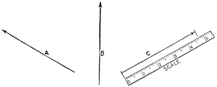
Fig. 2,123.—Vectors. A vector is defined as: a line, conceived to have both a fixed length and
a fixed direction in space, but no fixed position. Thus A and B are lines, each having a
fixed length, but no fixed direction. By adding an arrow head the direction is fixed and
the line becomes a vector, as for example vector C. The fixed length is usually taken
to represent a definite force, thus the fixed length of vector C is 4.7 which may be used
to represent 4.7 lbs., 4.7 tons, etc., as may be arbitrarily assumed.
When there is phase difference between the two alternating
pressures, connected in series, the following relation holds:
2. The value of the terminal voltage will differ from their
arithmetical sum, depending on the amount of their phase difference.
When there is phase difference, the value of the resultant is conveniently
obtained as explained below.
Ques. How are vector diagrams constructed for obtaining
resultant electric pressure?
Ans. On the principle of the parallelogram of forces.
Ques. What is understood by the parallelogram of
forces?
Ans. It is a graphical method of finding the resultant of
two forces, according to the following law: If two forces acting
on a point be represented in direction and intensity by adjacent
sides of a parallelogram, their resultant will be represented by the
diagonal of the parallelogram which passes through the point.
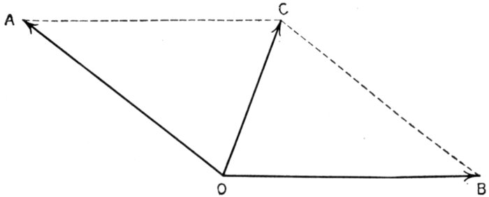
Fig. 2,124.—Parallelogram of forces. OC is the resultant of the two forces OA and OB. The
length and direction of the lines represent the intensity and direction of the respective
forces, the construction being explained in the accompanying text.
Thus in fig. 2,124, let OA and OB represent the intensity and direction
of two forces acting at the point O, Draw AC and BC, respectively
parallel to OB and OA, completing the parallelogram, then will OC,
the diagonal from the point at which the forces act, represent the
intensity and direction of the resultant, that is, of a force equivalent
to the combined action of the forces OA and OB, these forces being
called the components of the force OC.
Ques. Upon what does the magnitude of the resultant
of two forces depend?
Ans. Upon the difference in directions in which they act,
as shown in figs 2,125 to 2,128.
Ques. Is the parallelogram of forces applied when the
difference in direction or "phase difference" of two forces
is 90 degrees?
Ans. It is sometimes more conveniently done by calculation
according to the law of the right angle triangle.
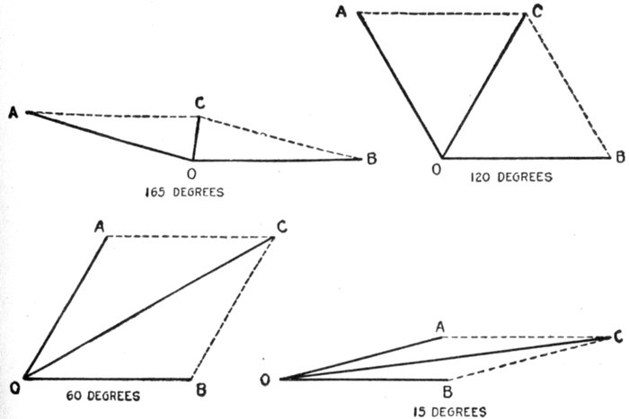
Figs. 2,125 to 2,128.—Parallelograms of forces showing increase in magnitude of the resultant
of two forces, as their difference of direction, or electrically speaking, their phase difference
is diminished. The diagrams show the growth of the resultant of the two equal
forces OA and OB as the phase difference is reduced from 165° successively to 120, 60,
and 15 degrees.
According to this principle, if two alternating pressures have a phase
difference of 90 degrees they may be represented in magnitude and
direction by the two sides of a right angle triangle as OA and OB in
fig. 2,129; then will the hypotenuse AB represent the magnitude and
direction of the resultant pressure. That is to say, the resultant pressure
AB = √((OA)2 + (OB)2) (1)
EXAMPLE.—A two phase alternator is wound for 300 volts on one
phase and 200 volts on the other phase, the phase difference being 90°.
If one end of each winding were joined so as to form a single winding
around the armature, what would be the resultant pressure?
By calculation, substituting the given values in equation (1),
Resultant pressure = √(3002 + 2002) = √(130,000) = 360.6 volts.
This is easily done graphically as in fig. 2,129 by taking a scale, say,
1" = 100 volts and laying off OA = 3" = 300 volts, and at right angles
OB = 2" = 200 volts, then by measurement AB = 3.606" = 360.6 volts.
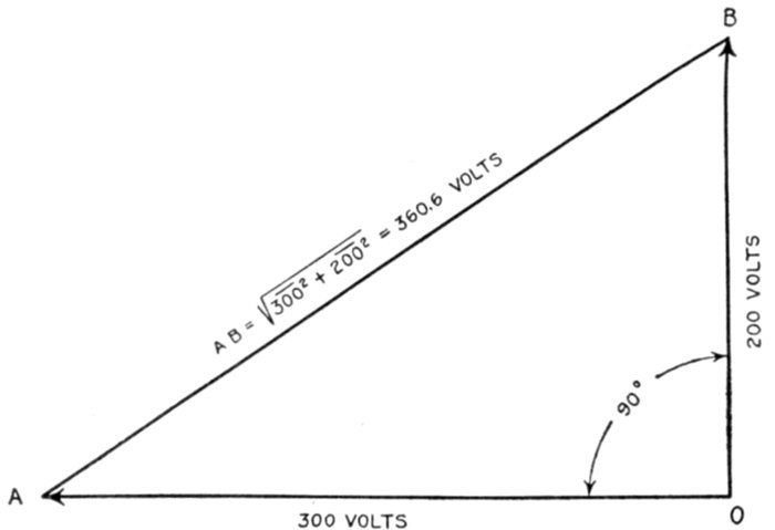
Fig. 2,129.—Method of obtaining the resultant of two component pressures acting at right
angles by solution of right angle triangle. The equation of the right angle triangle is
explained at length in Guide No. 5, page 1,070.
Ques. When the two pressures are equal and the
phase difference is 90°, is it necessary to use equation (1)
to obtain the resultant?
Ans. No. The resultant is obtained by simply multiplying
one of the pressures by 1.41.
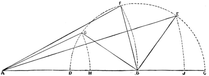
This is evident from fig. 2,130. Here the two pressures OA and OB
are equal as indicated by the dotted arc. Since they act at right angles,
OB is drawn at 90° to OA. According to the equation of the right angle
triangle, the resultant AB = √(12 + 12) = √2 = 1.4142 which ordinarily
is taken as 1.41.
This value will always represent the ratio between the magnitude of the
resultant and the two component forces, when the latter are equal, and have a
phase difference of 90 degrees.
Forms of Circuit.—Alternating current systems of distribution
may be classed, with respect to the kind of circuit
used, in a manner similar to direct current systems, that is, they
may be called series, parallel, series parallel, or parallel series
systems, as shown in figs. 2,131 to 2,134.
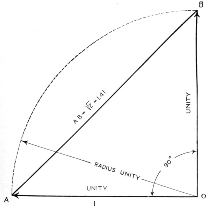
Fig. 2,130.—Diagram for obtaining the resultant of two equal component pressures acting
at right angles.
Series Circuits.—These are used in arc lighting, and series incandescent
lighting, a constant current being maintained; also for
constant current motors and generators supplying secondary
circuits.
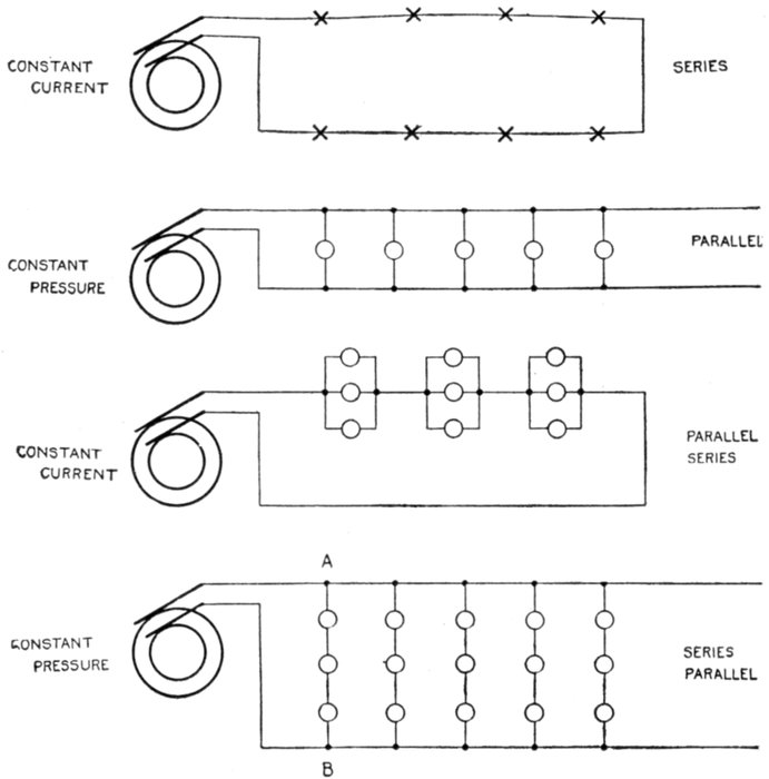
Figs. 2,131 to 2,134.—Various forms of circuit. These well known forms of circuit are used
in both alternating and direct current systems. The simple series circuit, fig. 2,131, is
suitable for constant current arc lighting. Fig. 2,132, shows the parallel constant pressure
circuit; this form of circuit is largely used but is seldom connected direct to the alternator
terminals, but to a step down transformer, on account of the low pressure generally
required. Fig. 2,133 illustrates a parallel series circuit, and 2,134, a series parallel
circuit.
Several forms of constant current alternator, analogous to
the Thompson-Houston and Brush series arc dynamos, have
been introduced. In the design of such alternators self-induction
and armature reaction are purposely exaggerated; so that the
current does not increase very much, even when the machine
is short circuited. With this provision, no regulating device
is required.
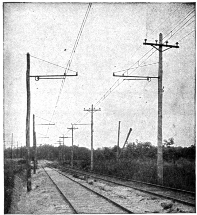
Fig. 2,135.—Typical American overhead 6,600 volt single phase interurban trolley line, Baltimore
and Annapolis short line, Annapolis, Md.
An objectionable feature is that the voltage of a constant
current alternator will rise very high if the circuit be opened,
because it is then relieved of inductance drop and armature
reaction.
To guard against a dangerous rise of voltage, a film cut out or
equivalent device is connected to the terminal of each machine so
that it will short circuit the latter if the voltage rise too high.
Ques. What advantage have constant current alternators
over constant current dynamos?
Ans. The high pressure current is delivered to the external
circuit without a commutator, hence there is no sparking
difficulty.
The above relates to the revolving field type of alternator. There are,
however, alternators in which the armature revolves, the current being
delivered to the external circuit through collector rings and brushes.
This type of alternator, it should be noted, is for moderate pressures,
and moreover there is no interruption to the flow of the current such as
would be occasioned by a tangential brush on a dynamo in passing from
one commutator segment to the next.
In the revolving field machine, though the armature current be of very
high pressure, the field current which passes through the brushes and
slip rings is of low pressure and accordingly presents no transmission
difficulties.
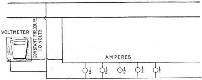
Fig. 2,136.—Diagram of parallel circuit. It is a constant pressure circuit and is very widely
used for lighting and power. If each lamp takes say ½ ampere, the current flowing in
the circuit will vary with the number of lamps in operation; in the above circuit with
all lamps on, the current is ½ × 5 = 2½ amperes.
Ques. State a disadvantage.
Ans. Some source of direct current for field excitation is
required.
Ques. In a constant current series system, upon what
does the voltage at the alternator depend?
Ans. The number of devices connected in the circuit, the
volts required for each, and the line drop.
Parallel Circuits.—These are used for constant pressure
operation. Such arrangement provides a separate circuit for
each unit making them independent so that they may vary in
size and each one can be started or stopped without interfering
with the others. Parallel circuits are largely used for incandescent
lighting, and since low pressure current is commonly
used on such circuits they are usually connected to step down
transformers, instead of direct to the alternators.
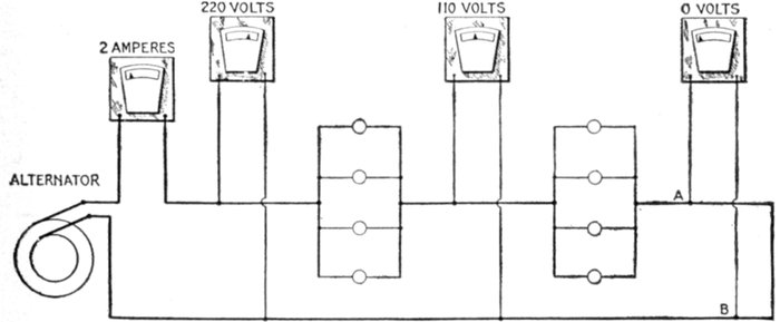
Fig. 2,137.—Diagram of parallel series circuit, showing fall of pressure between units. This
system is very rarely used; it has the disadvantage that if a lamp filament breaks, the
resistance of the circuit is altered and the strength of the current changed. The voltmeter
shows the fall of pressure along the line. It should be noted that, although the
meter across AB is shown as registering zero pressure, there is, strictly speaking, a slight
pressure across AB, in amount, being that required to overcome the resistance of the
conductor between A and B.
Parallel Series Circuits.—Fig. 2,137 shows the arrangement
of a parallel series circuit and the pressure conditions in
same. Such a circuit consists of groups of two or more lamps
or other devices connected in parallel and these groups connected
in series.
Such a circuit, when used for lighting, obviously has the
disadvantage that if a lamp filament breaks, the resistance of
the group is increased, thus reducing the current and decreasing
the brilliancy of the lamps. This arrangement accordingly
does not admit of turning off any of the lights.
Series Parallel Circuits.—The arrangement of circuits of
this kind is shown in fig. 2,134; they are used to economize in
copper since by joining groups of low pressure lamps in series
they may be supplied by current at correspondingly higher
pressure.
Thus, if in fig. 2,134, 110 volt, ½ ampere lamps be used, the pressure
on the mains, that is, between any two points as A and B would be
110 × 3 = 330 volts. Each group would require ½ ampere and the
five groups ½ × 5 = 2½ amperes.
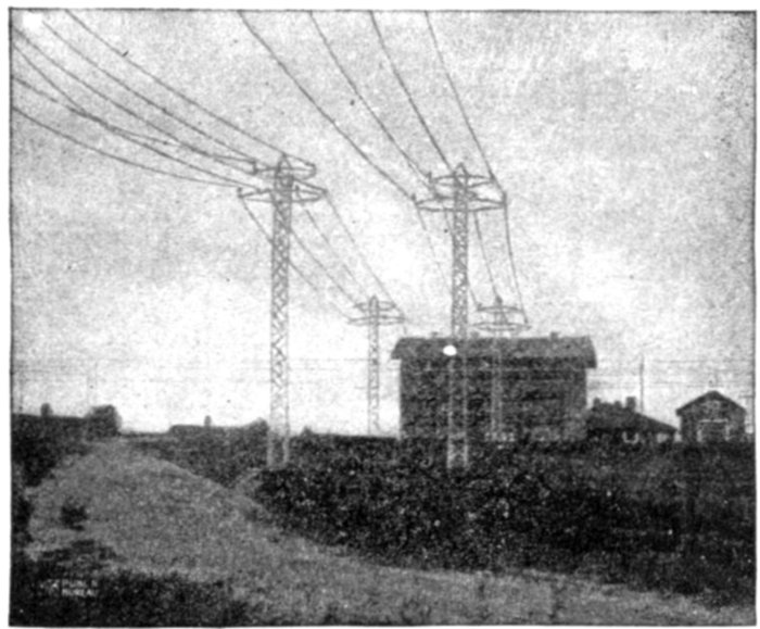
Fig. 2,138.—44,000 volt lines entering the Gastonia sub-station of the Southern Power Co.
The poles used are of the twin circuit two arm type, built of structural steel, their height
varying from 45 to 80 feet, the latter weighing 9,000 pounds each. These poles have
their bases weighted with concrete.
Transformer Systems.—Nearly all alternating current
systems are transformer systems, since the chief feature of
alternating current is the ease with which it may be transformed
from one pressure to another. Accordingly, considerable
economy in copper may be effected by transmitting the current
at high pressure, especially if the distance be great, and, by
means of step down transformers, reducing the voltage at points
where the current is used or distributed.
Ordinarily and for lines of moderate length, current is sent
out direct from the alternator to the line and transformed by
step down transformers at the points of application.
With respect to the step down transformers, there are two
arrangements:
- 1. Individual transformers;
- 2. One transformer for several customers.
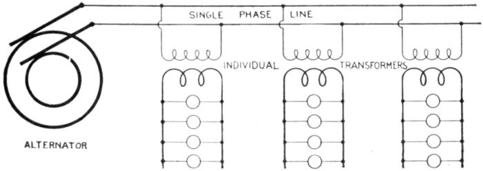
Fig. 2,139.—Diagram of transformer system with individual transformers. The efficiency is
low, but such method of distribution is necessary in sparsely settled or rural districts.
Individual transformers, that is, a separate transformer for
each customer is necessary in rural districts where the intervening
distances are great as shown in fig. 2,139.
Ques. What are the objections to this method of
distribution?
Ans. It requires the use of small transformers which are
necessarily less efficient and more expensive per kilowatt than
large transformers. The transformer must be built to carry,
within its overload capacity, all the lamps installed by the
customer since all may be used occasionally.
Usually, however, only a small part of the lamps are in use, and
those only for a small part of the day, so that the average load on the
transformer is a very small part of its capacity. Since the core loss
continues whether the transformer be loaded or not, but is not paid
for by the customer, the economy of the arrangement is very low.
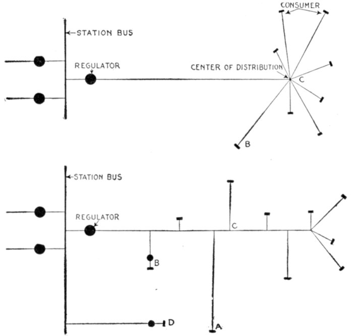
In the second case, where one large transformer may be placed at
a distribution center, to supply several customers, as in fig. 2,140, the
efficiency of the system is improved.
Ques. Why is this arrangement more efficient than
when individual transformers are used?
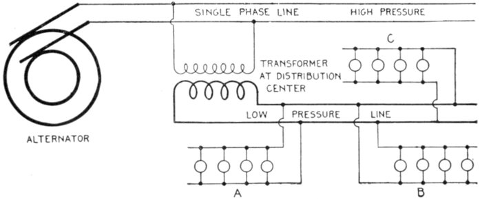
Fig. 2,140.—Diagram of transformer system with one transformer located at a distribution
center and supplying several customers as A, B, and C. Such arrangement is considerably
more efficient than that shown in fig. 2,139, as explained in the accompanying text.
Ans. Less transformer capacity is required than with individual
transformers.
Ques. Why is this?
Ans. With several customers supplied from one transformer
it is extremely improbable that all the customers will burn all
their lamps at the same time. It is therefore unnecessary to
install a transformer capable of operating the full load, as is
necessary with individual transformers.
Ques. Does the difference in transformer capacity
represent all the saving?
Ans. No; one large transformer is more efficient than a
number of small transformers.
Ques. Why?
Ans. The core loss is less.
For instance, if four customers having 20 lamps each were supplied
from a single transformer, the average load would be about 8 lamps,
and at most not over 10 or 15 lamps, and a transformer carrying 30 to
35 lamps at over load would probably be sufficient. A 1,500 watt
transformer would therefore be larger than necessary. At 3 per cent.
core loss, this gives a constant loss of 45 watts, while the average load
of 8 lamps for 3 hours per day gives a useful output of 60 watts, or an
all year efficiency of nearly 60 per cent., while a 1,000 watt transformer
would give an all year efficiency of 67 per cent.
For long distance transmission lines, the voltage at the alternator
is increased by passing the current through a step up transformer,
thus transmitting it at very high pressure, and reducing the voltage
at the points of distribution by step down transformers as in fig. 2,141.
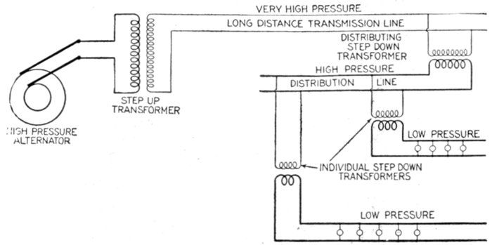
Fig. 2,141.—Diagram illustrating the use of step up and step down transformers on long distance
transmission lines. The saving in copper is considerable by employing extra high
voltages on lines of moderate or great length as indicated by the relative sizes of wire.
Ques. In practice, would such a system as shown in
fig. 2,141 be used?
Ans. If the greatest economy in copper were aimed at, a
three phase system would be used.
The purpose of fig. 2,141 is to show the importance of the transformer
in giving a flexibility of voltage, by which the cost of the line is
reduced to a minimum.
Ques. Does the saving indicated in fig. 2,141 represent
a net gain?
Ans. No. The reduction in cost of the transmission is
partly offset by the cost of the transformers as well as by transformer
losses and the higher insulation requirements.
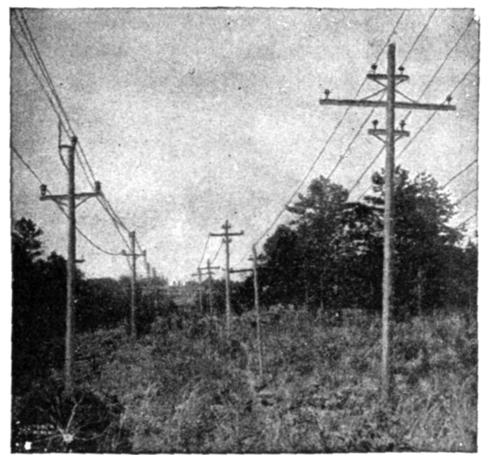
Fig. 2,142.—Single and twin circuit poles (Southern Power Co.). The twin circuit pole at the
right is used for 11,000 volt circuits, while the single circuit poles at the left carry 44,000
volt conductors, being used on another division for 100,000 volt line.
Every case of electric transmission presents its own problem, and
needs thorough engineering study to intelligently choose the system best
adapted for the particular case.
Single Phase Systems.—There are various arrangements
for transmission and distribution classed as single phase systems.
Thus, single phase current may be conveyed to the various
receiving units by the well known circuit arrangements known as
series, parallel, series parallel, parallel series, connections previously
described and illustrated in figs. 2,131 to 2,134.
Again single phase current may be transmitted by two wires
and distributed by three wires. This is done in several ways,
the simplest being shown in fig. 2,143.
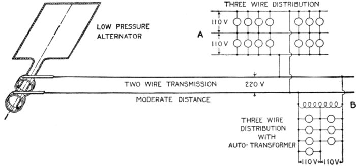
Fig. 2,143.—Diagram illustrating single phase two wire transmission and three wire distribution.
The simplified three wire arrangement at A, is not permissible except in cases of
very little unbalancing. Where the difference between loads on each side of the neutral
may be great some form of balancing as an auto-transformer or equivalent should be used,
as at B.
Ques. Under what conditions is the arrangement
shown in fig. 2,143 desirable?
Ans. This method of treating the neutral wire is only permissible
where there is very little unbalancing, that is, where
the load is kept practically the same on both sides of the neutral.
Ques. What advantage is obtained by three wire
distribution?
Ans. The pressure at the alternator can be doubled, which
means, for a given number of lamps, that the current is reduced
to half, the permissible
drop may be
doubled, the resistance
of the wires
quadrupled, and their
cost reduced nearly
75 per cent.
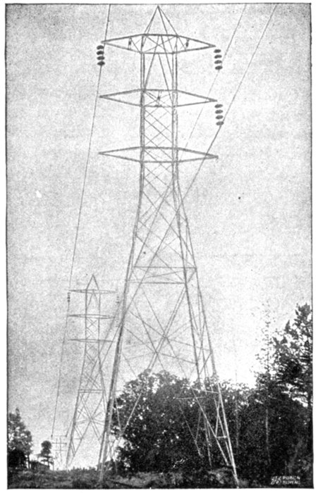
Fig. 2,144.—100,000 volt "Milliken" towers with one circuit
strung (Southern Power Co.). These towers are
mounted on metal stubs sunk 6 feet in the ground.
Where the angle of the line is over 15 degrees, however,
these stubs are weighted with rock and concrete, and
where an angle of over 30 degrees occurs, two and sometimes
three towers are used for making the turn. The
weight of the standard "Milliken" tower is 3,080 lbs.,
and its height from the ground to peak is 51 feet. The
towers are spaced to average eight to a mile and a strain
tower weighing 4,250 lbs. is used every mile. For particularly
long spans a special heavy tower weighing 6,000
lbs. is used. The circuits are transposed every 30 miles.
Multiple disc insulators are used, four discs being used
to suspend each conductor from standard towers and
ten discs to each conductor on strain towers. The
standard span is 600 feet, sag 11 ft at 50° Fahr.
Ques. What
modification of circuit
A (fig. 2,143),
should be made to
allow for unbalancing
in the three
wire circuit?
Ans. An auto-transformer
or "balance
coil" as it is
sometimes called
should be used as at B.
This is a very desirable
method of balancing
when the ratio of
transformation is not
too large.
Ques. For what
service would the
system shown in
fig. 2,143 be suitable?
Ans. For short
distance transmission,
as for instance, in
the case of an isolated plant because of the low pressure at
which the current is generated.
The standard voltages of low pressure alternators are 400, 480, and
600 volts.
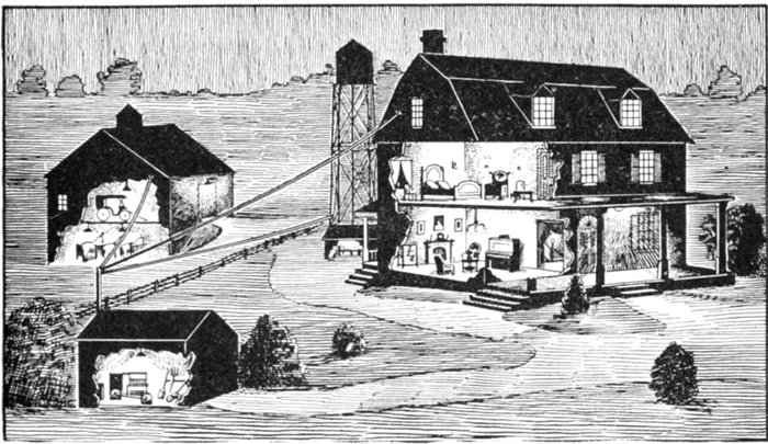
Fig. 2,145.—View of a typical isolated plant. The illustration represents an electric
lighting plant on a farm showing the lighting of the dwelling, barn, tool house
and pump house. The installation consists of a low voltage dynamo with gas engine
drive and storage battery together with the necessary auxiliary apparatus.
Ques. In practice are single phase alternators used
as indicated in fig. 2,143?
Ans. Alternators are wound for one, two or three phases.
Three phase machines are more commonly supplied and in
many cases it will pay to install them in preference to single
phase, even if they be operated single phase temporarily.
For a given output, three phase machines are smaller than single phase
and the single phase load can usually be approximately balanced between
the three phases. Moreover, if a three phase machine be installed,
polyphase current will be available in case it may be necessary to operate
polyphase motors at some future time.
Standard three phase alternators will carry about 70 per cent. of
their rated kilowatt output when operated single phase, with the same
temperature rise.
Ques. How are three phase alternators used for single
phase circuits?
Ans. The single phase circuit is connected to any two of the
three phase terminal leads.
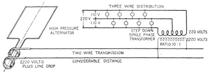
Fig. 2,146.—Diagram showing arrangement of single phase system for two wire transmission
and three wire distribution, where the transmission distance is considerable. In order
to reduce the cost of the transmission line, the current must be transmitted at high pressure;
this necessitates the use of a step down transformer at the distributing center
as shown in the illustration.
Ques. What form of single phase system should be
used where the transmission distance is considerable?
Ans. The current should be transmitted at high pressure,
a step down transformer being placed at each distribution
center to reduce the pressure to the proper voltage to suit the
service requirements as shown in fig. 2,146.
Thus, if 110 volt lamps be used on the three wire circuit, the pressure
between the two outer wires would be 220 volts. A transformation
ratio of say 10:1 would give 2,220 volts for the primary circuit. The
current required for the primary with this ratio being only .1 that
used in the secondary, a considerable saving is effected in the cost of the
transmission line as must be evident.
With the high pressure alternator only one transformation of the
current is needed, as shown at the distribution end.
In place of the high pressure alternator, a low pressure alternator
could be used in connection with a step up transformer as shown in
fig. 2,147, but there would be an extra loss due to the additional transformer,
rendering the system less efficient than the one shown in fig.
2,146. Such an arrangement as shown in the fig. 2,147 might be justified
in the case of a station having a low pressure alternator already in use
and it should be desired to transmit a portion of the energy a considerable
distance.
Ques. How could the system shown in fig. 2,147 be
made more efficient than that of fig. 2,146?
Ans. By using a high pressure alternator in order to considerably
increase the transmission voltage.
Thus, a 2,200 volt alternator and 1:10 step up transformer would
give a line pressure of 22,000 volts, which at the distribution end could
be reduced, to 220 volts for the three wire circuit, using a 100:1 step
down transformation.
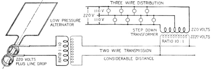
Fig. 2,147.—Diagram illustrating how electricity can be economically transmitted a considerable
distance with low pressure alternator already in use.
Ques. Would this be the best arrangement?
Ans. No.
Ques. What system would be used in practice for
maximum economy?
Ans. Three phase four wire.
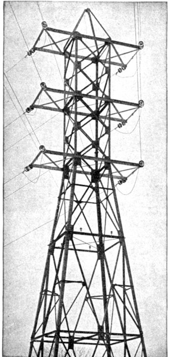
Fig. 2,148.—Angle tower showing General Electric
strain insulators. The tower being subject to
great torsional strains is erected on a massive concrete
foundation. The construction is similar to
the standard tower but of heavier material, and
having the same vertical dimensions but with
bases 20 ft. square.
Ques. What are the objections to single phase generation
and transmission?
Ans. It does not permit of the use of synchronous converters,
self-starting synchronous motors, or induction motor
starting under load. It is poorly adapted to general power
distribution, hence it is
open to grave objections
of a commercial nature
where there exists any
possibility of selling power
or in any way utilizing it
for general converter and
motor work.
Ques. For what service
is it desirable?
Ans. For alternating
current railway operation.
There are advantages of
simplicity in the entire
generating, primary, and
secondary distribution systems
for single phase roads.
These advantages are so
great that they justify considerable
expense, looked
at from the railway point
of view only, the single
phase system throughout
may be considered as offering
the most advantage.
Ques. What are the
objectionable features
of single phase alternators?
Ans. This type of alternator
has an unbalanced
armature reaction which
is the cause of considerable
flux variation in the
field pole tips and in fact throughout the field structure.
In order to minimize eddy currents, such alternators must
accordingly be built with thinner laminations and frequently
poorer mechanical construction, resulting in increased cost of
the machine. The large armature reaction results in a much
poorer regulation than that obtained with three phase alternators,
and an increased amount of field copper is required, also
larger exciting units. These items augment the cost so that
the single phase machine is considerably more expensive than
the three phase, of the same output and heating.

Fig. 2,149.—Elementary alternator developing one volt at frequencies of 60 and 25, showing
the effect of reducing the frequency. Since for the same number of pole, the R.P.M.
have to be decreased to decrease the frequency, increased flux is required to develop the
same voltage. Hence in construction, low frequency machines require larger magnets,
increased number of turns in series on the armature coils, larger exciting units as compared
with machines built for higher frequency.
Ques. What factor increases the difficulties of single
phase alternator construction?
Ans. The difficulties appear to increase with a decrease in
frequency.
The adoption of any lower frequency than 25 cycles may result in
serious difficulties in construction for a complete line of machine,
especially those of the two or four pole turbine driven type where the
field flux is very large per pole.
Monocyclic System.—In this system, which is due to
Steinmetz, the alternator is of a special type. In construction,
there is a main single phase winding an auxiliary or teaser
winding connected to the central point of the main winding in
quadrature therewith.
The teaser coil generates a voltage equal to about 25 per cent. of
that of the main coil so that the pressure between the terminals
of the main coil and the free end of the teaser is the resultant
of the pressure of the two coils.
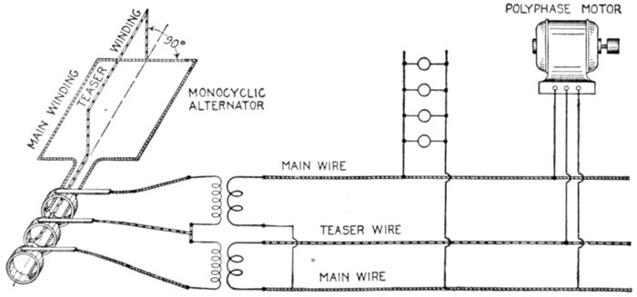
Fig. 2,150.—Diagram of monocyclic system, showing lighting and power circuits.
By various transformer connections it is possible to obtain
a practically correct three phase relationship so that polyphase
motors may be employed.
In this system, two wires leading from the ends of the single
phase winding in the alternator supply single phase current
to the lighting load, a third wire connected to the end of the
teaser being run to points where the polyphase motors are
installed as shown in fig. 2,150.
The monocyclic system is described at length in the chapter
on alternators, Guide No. 5, pages, 1,156 to 1,159.
Two Phase Systems.—A two phase circuit is equivalent to
two single phase circuits. Either four or three wire may be
employed in transmitting two phase current, and even in the
latter instance the conditions are practically the same as for
single phase transmission, excepting the unequal current distribution
in the three wires. Fig. 2,151 shows a two phase
four wire system.
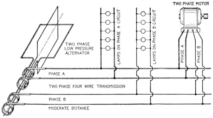
Fig. 2,151.—Diagram of two phase four wire system. It is desirable for supplying current
for lighting and power. The arrangement here shown should be used only for lines of
short or moderate length, because of the low voltage. Motors should be connected to a
circuit separate from the lighting circuit to avoid drop on the latter while starting a
motor.
Ques. For what service is the system shown in fig.
2,151 desirable?
Ans. It is adapted to supplying current for lighting and
power at moderate or short distances.
Either 110 or 220 volts are ordinarily used which is suitable for
incandescent lighting and for constant pressure arc lamps, the lamps
being connected singly or two in pairs.
Ques. Where current for both power and light are
obtained from the same source how should the circuits
be arranged?
Ans. A separate circuit should be employed for each, in
order to avoid the objectionable drop and consequent dimming
of the lights due to the sudden rush of current during the starting
of a motor.
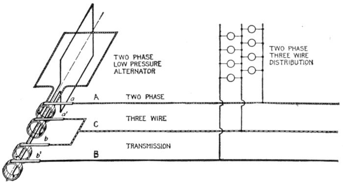
Fig. 2,152.—Diagram of two phase three wire system. A wire is connected to one end of
each phase winding as at A and B, and a third wire C, to the other end of both phases
as shown.
Disagreeable fluctuation of the lights are always met with when
motors are connected to a lighting circuit and the effect is more marked
with alternating current than with direct current, because most types of
alternating current motor require a heavy current usually lagging considerably
when starting. This not only causes a large drop on the
line, but also reacts injuriously upon the regulation of transformers
and alternators, their voltage falling much more than with an equal
non-inductive load.
Ques. What voltages are ordinarily used on two phase
lines of more than moderate length?
Ans. For transmission distances of more than two or three
miles, pressures of from 1,000 to 2,000 volts or more are employed
to economize in copper. For long distance transmission
of over fifty miles, from 30,000 to 100,000 volts and over are used.
Ques. For long distance transmission at 30,000 to
40,000 volts, what additional apparatus is necessary?
Ans. Step up and step down transformers.
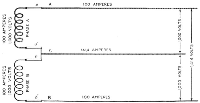
Fig. 2,153.—Diagram illustrating two phase three wire transmission. The third wire C is
attached to the connector between one end of phase A, and phase B windings.
Ques. Explain the method of transmitting two phase
current with three wires.
Ans. The connections at the alternator are very simple as
shown in fig. 2,152. One end of each phase winding is connected
by the brushes a and b', to one of the circuit wires, that is to
A and B respectively. The other end of each phase winding is
connected by a lead across brushes a' and b, to which the third
wire C is joined.
The current and pressure conditions of this system are represented
diagrammatically in fig. 2,153. The letters correspond to those in fig.
2,152, with which it should be compared.
As shown in the figure each coil is carrying 100 amperes at 1,000
volts pressure. Since the phase difference between the two coils is
90°, the voltage between A and B is √2 = 1.414 times that between
either A or B and the common return wire C.
The current in C is √2 = 1.414 times that in either outside wire A or
B, as indicated.
Ques. How should the load on the two phase three
wire system be distributed?
Ans. The load on the two phases must be carefully balanced.
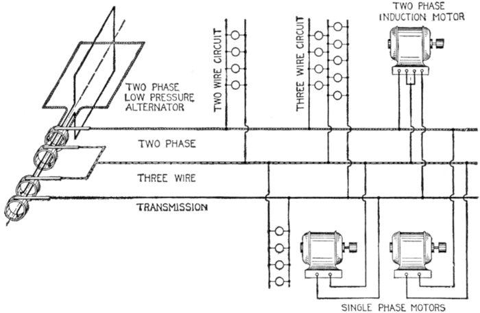
Fig. 2,154.—Diagram of two phase three wire system and connections for motors and lighting
circuits.
Ques. Why should the power factor be kept high?
Ans. A high power factor should be maintained in order to
keep the voltage on the phases nearly the same at the receiving
ends.
Ques. How should single phase motors be connected
and what precaution should be taken?
Ans. Single phase motors may be connected to either or
both phases, but in such cases, no load should be connected
between the outer wires otherwise the voltages on the different
phases will be badly unbalanced.
Fig. 2,154 shows a two phase three wire system, with two wire and
three wire distribution circuits, illustrating the connection for lighting
and for one and two phase motors.
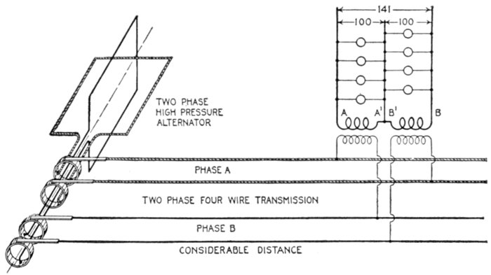
Fig. 2,155.—Diagram of two phase system with four wire transmission and three wire distribution.
In the three wire circuits the relative pressures between conductors are as
indicated; that is, the pressure between the two outer wires A and B is 141 volts, when
the pressure between each outer wire and the central is 100 volts.
Ques. Describe another method of transmission and
distribution with two phase current.
Ans. The current may be transmitted on a four wire circuit
and distributed on three wire circuit as in fig. 2,155.
The four wire transmission circuit is evidently equivalent to two
independent single phase circuits.
In changing from four to three wires, it is just as well to connect the
two outside wires A and B together (fig. 2,152), as it is to connect a´
and b. It makes no difference which two secondary wires are joined
together, so long as the other wires of each transformer are connected
to the outside wires of the secondary system.
Ques. For what service is the two phase three wire
system adapted?
Ans. It is desirable for supplying current of minimum
pressure to apparatus in the vicinity of transformers. It is more
frequently used in connection with motors operating from the
secondaries of the transformers.
Ques. How should the third or common return wire
be proportioned?
Ans. Since the current in the common return wire is 41.4 per
cent. higher than that in either of the other wires it must be of
correspondingly larger cross section, to keep the loss equal.
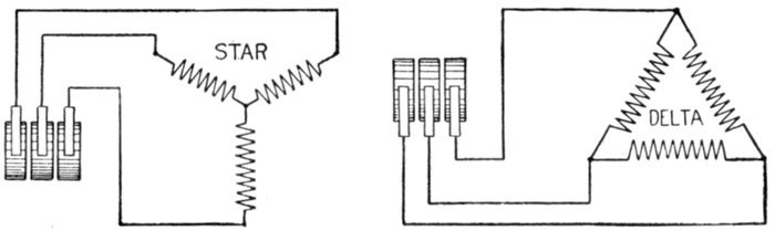
Figs. 2,156 and 2,157.—Conventional diagrams illustrating star and delta connected three phase
alternator armatures.
Ques. What is the effect of an inductive load on the
two phase three wire system and why?
Ans. It causes an unbalancing of both sides of the system
even though the energy load be equally divided. The self-induction
pressure in one side of the system is in phase with
the virtual pressure in the other side, thus distorting the current
distribution in both circuits.
Ques. Describe the two phase five wire system.
Ans. A two phase circuit may be changed from four to five
wires by arranging the transformer connections as in fig. 2,158.
As shown, the secondaries of the transformers are joined in series and
leads brought out from the middle point of each secondary winding
and at the connection of the two windings, giving five wires.
With 1,000 volts in the primary windings and a step down ratio of
10:1, the pressure between A and C and C and E will be 100 volts
and between the points and the connections B or D at the middle of
the secondary coils, 50 volts.
The pressure across the two outer wires A and E is, as in the three
wire system, √2 or 1.41 times that from either outer wire to the middle
wire C, that is 141 volts.
The pressure across the two wires connected to the middle of the
coils, that is, across B and D, is 50 × √2 = 70.5 volts.
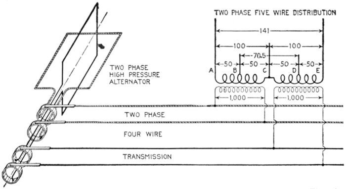
Fig. 2,158.—Two phase four wire transmission and five wire distribution system. The relative
pressures between the various conductors are indicated in the diagram.
Three Phase Systems.—There are various ways of arranging
the circuit for three phase current giving numerous
three phase systems.
1. With respect to the number of wires used they may be
classified as
- a. Six wire;
- b. Four wire;
- c. Three wire.
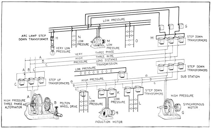
Fig. 2,159.—Line connections of three phase three wire long distance transmission, and distribution system. The three phase alternator
A, is driven by the water wheel B, and furnishes current at say 2,200 volts plus sufficient pressure to compensate for line
drop. With 1:10 step up transformers C, this would give a transmission pressure of 22,000 volts plus line drop. It is this transformation
that secures the copper economy of the system. At the distribution end are the step down transformers; one set
reducing the voltage down to 2,200 volts, and supplying current direct to the synchronous motor, and through another set of other
step down transformers, as L and K, to lighting and power circuits at 220 volts. Another set of step down transformers M reduce
the pressure directly to 120 volts for power and lighting, the pressure being regulated by the regulators G. Arc lamps with individual
transformers further reducing the pressure to 50 volts are connected to this circuit as shown.
2. With respect to the connections, as
- a. Star;
- b. Delta;
- c. Star delta;
- d. Delta star.
The six wire system is shown in fig. 2,160. It is equivalent
to three independent single phase circuits. Such arrangement
would only be used in very rare instances.
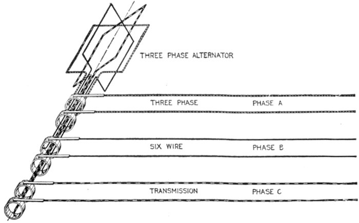
Fig. 2,160.—Three phase six wire system. It is equivalent to three independent single phase
circuits and would be used only in very rare cases.
Ques. How can three phase current be transmitted
by three conductors?
Ans. The arrangement shown in fig. 2,160 may be resolved
into three single circuits with a common or grounded return.
When the circuits are balanced the sum of the current being zero
no current will flow in the return conductor, and it may be dispensed
with, thus giving the ordinary star or Y connected three wire circuit,
as shown in fig. 2,163. The transformation from six to three wires
being shown in figs. 2,161 to 2,163.
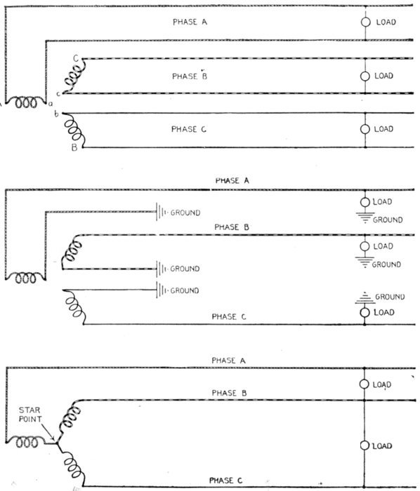
Figs. 2,161 to 2,163.—Evolution of the three phase three wire system. Fig. 2,161 is a conventional
diagram of the three phase six wire system shown in fig. 2,160. A wire is connected
to both ends of each phase winding, giving six conductors, or three independent
two wire circuits. In place of the wires running from A, B, and C, they may be removed
and each circuit provided with a ground return as shown in fig. 2,162. The sum of the
three currents being zero, or nearly zero, according to the degree of unbalancing, the
ground return may be eliminated and the ends A, B, and C of the three phase winding
connected, as in fig. 2,163, giving the so called star point.
Fig. 2,166 is a view of an elementary three phase three wire star
connected alternator.
Ques. What are the pressure and current relations
of the star connected three wire system?
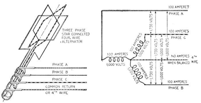
Figs. 2,164 and 2,165.—Three phase four wire star connected alternator and conventional
diagram showing pressure and current relations.
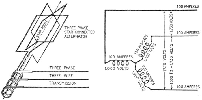
Figs. 2,166 and 2,167.—Three phase star connected alternator, and conventional diagram
showing pressure relations.
Ans. These are shown in the diagram, fig. 2,166 and 2,167.
Assuming 100 amperes and 1,000 volts in each phase winding, the
pressure between any two conductors is equal to the pressure in one
winding multiplied by √3, that is 1,000 × 1.732 = 1,732 volts.
The current in each conductor is equal to the current in the winding,
or 100 amperes.
Ques. Describe the delta connection.
Ans. In the delta connection, the three phase coils are connected
together forming an endless winding, leads being brought
out from these points.
Fig. 2,168 shows a delta connected three phase alternator, the pressure
and current relation being given in fig. 2,169.
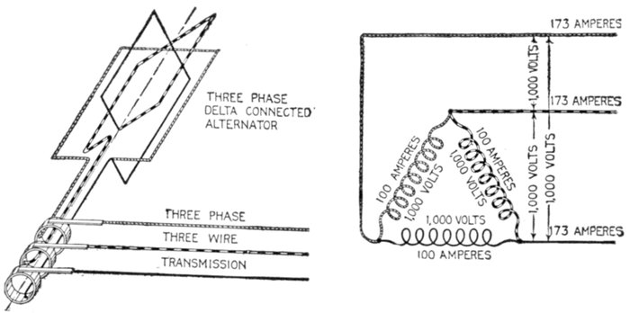
Figs. 2,168 and 2,169.—Three phase delta connected alternator and conventional diagram
showing pressure and current relations.
Ques. What are the pressure and current relations
of the delta connected three wire system?
Ans. They are as shown in fig. 2,169.
Assuming 100 amperes and 1,000 volts in each phase winding, the
pressure between any two conductors is the same as the pressure in
the winding, and the current in any conductor is equal to the current
in the winding multiplied by √3, that is 100 × 1.732 = 173.2 amperes,
that is, disregarding the fraction, 173 amperes.
Ques. What are the relative merits of the star and
delta connections?
Ans. The power output of each is the same, but the star
connection gives a higher line voltage, hence smaller conductors
may be used.
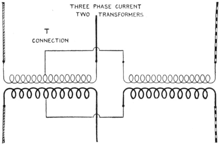
Fig. 2,170.—T connection of transformers in which three phase current is transformed with
two transformers. The connections are clearly shown in the illustration. The voltage
across one transformer is only 86.6% of that across the other, so that if each transformer
be designed especially for its work one will have a rating of .866 EI and the other EI.
The combined rates will then be 1.866 as compared with 1.732 EI for three single phase
transformers connected either star or delta.
When it is remembered that the cost of copper conductors is inversely
as the square of the voltage, the advantage of the Y connected system
can be seen at once.
Assuming that three transformers are used for a three phase system
of given voltage, each transformer, star connected, would be wound
for 1 ÷ √3 = 58% of the given voltage, and for full current.
For delta connection, the winding of each transformer is for 58% of
the current. Accordingly the turns required for star connection are
only 58% of those required for delta connection.
Ques. What is the objection to the star connection
for three phase work?
Ans. It requires the use of three transformers, and if anything
happen to one, the entire set is disabled.
Ques. Does this defect exist with the delta connection?
Ans. No.
One transformer may be cut out and the other two operated at full
capacity, that is at ⅔ the capacity of the three.
Ques. Describe the T connection.
Ans. In this method two transformers are used for transforming
three phase current. It consists in connecting one
end of both windings of one transformer to the middle point of
like windings of the other transformer as in fig. 2,170.
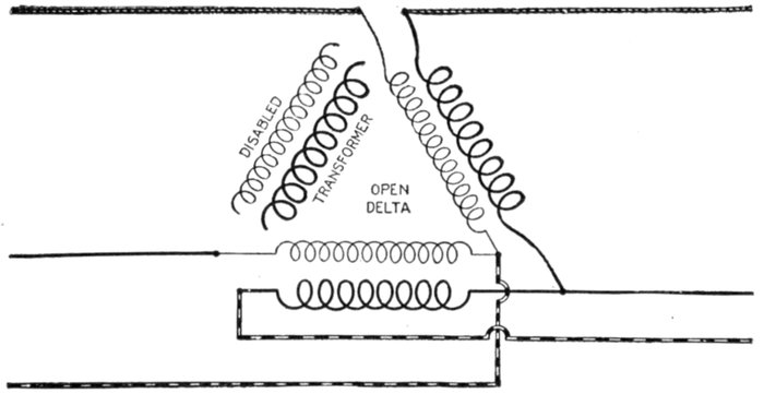
Fig. 2,171.—Open delta connection or method of connecting two transformers in delta for three
phase transformation. It is used when one of the three single phase delta connected transformers
becomes disabled.
Ques. What is the open delta connection?
Ans. It is a method of arranging the connections of a bank
of three delta connected transformers when one becomes disabled
as in fig. 2,171.
Change of Frequency.—There are numerous instances
where it is desirable to change from one frequency to another,
as for instance to join two systems of different frequency which
may supply the same or adjacent territory, or, in the case of a
low frequency installation, in order to operate incandescent
lights satisfactorily it would be desirable to increase the frequency
for such circuits. This is done by motor generator sets,
the motor taking its current from the low frequency circuit.
Synchronous motors are generally used for such service as
the frequency is not disturbed by load changes; it also makes it
possible to use the set in the reverse order, that is, taking power
from the high frequency mains and delivering energy at low
frequency.
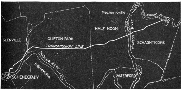
Fig. 2,172.—Course of the Schaghticoke-Schenectady transmission line of the Schenectady Power
Co. This transmission line carries practically the entire output of the Schaghticoke power
house to Schenectady, N. Y., a distance of approximately 21 miles. The line consists
of two separate three phase, 40 cycle, 32,000 volt circuits, each of 6,000 kw. normal capacity.
These circuits start from opposite ends of the power house, and, after crossing the Hoosic
River, are transferred by means of two terminal towers, fig. 2,173, to a single line of transmission
towers. The two circuits are carried on these on opposite ends of the cross arms,
the three phases being superimposed. The power house ends of the line are held by six
short quadrangular steel lattice work anchor poles with their bases firmly embedded in concrete,
the cables being dead ended by General Electric disc strain insulators. This equipment,
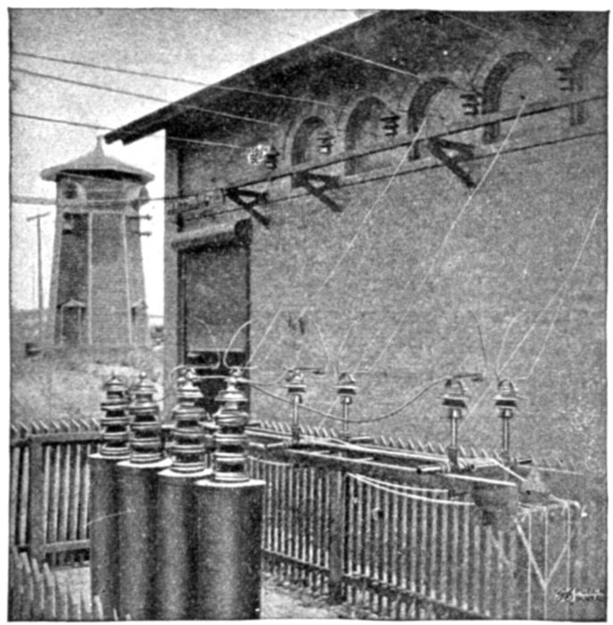
together with the lightning arrester horn gaps and the heavy line outlet insulators mounted
on the roof of the power house, is shown in fig. 2,174. While each circuit carries only
6,000 kw. under normal conditions, either is capable of carrying the entire output of the
station; in this case, however, the line losses are necessarily augmented. This feature
prevents any interruption of the service from the failure of one of the circuits. There are
altogether 197 transmission towers, comprising several distinct types.
Ques. In the parallel operations of frequency changing
sets what is necessary to secure equal division of the load?
Ans. The relative angular position of the rotating elements
of motor and generator must be the same respectively in each set.
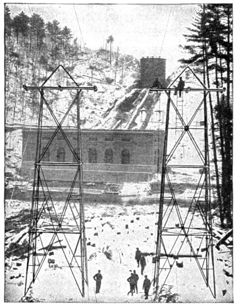
Fig. 2,173.—Beginning of Schaghticoke-Schenectady transmission line; view showing transfer
towers with power house in background.
Ques. How is this obtained?
Ans. Because of the mechanical difficulty of accurately
locating the parts, the
equivalent result is secured
by arranging the
stationary element in
one of the two machines
so that it can be given
a small angular shift.
Transformation of
Phases.—In alternating
current circuits it is
frequently desirable to
change from one number
of phases to another.
For instance, in the case
of a converter, it is less
expensive and more
efficient to use one built
for six phases than for
either two or three
phases.
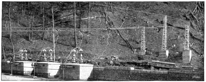
Fig. 2,174.—View from roof of power house of the Schaghticoke-Schenectady transmission line, showing anchor poles,
strain insulators, lightning arrester horn gap and line entrance bushings.
The numerous conditions
met with necessitate
various phase
transformations, as
- 1. Three phase to one phase;
- 2. Three phase to two phase;
- 3. Two phase to six phase;
- 4. Three phase to six phase.
These transformations are accomplished by the numerous
arrangements and combinations of the transformers.
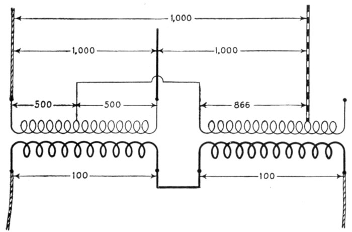
Fig. 2,175.—Three phase to one phase transformation with two transformers. The diagram
shows the necessary connections and the relative pressures obtained.
Three Phase to One Phase.—This transformation may be
accomplished by the use of two transformers connected as in
fig. 2,175 in which one end of one primary winding is connected
to the middle of the other primary winding and the second end
of the first primary winding at a point giving 86.6 per cent. of
that winding as shown. The two secondary windings are joined
in series.
Three Phase to Two Phase.—The three phase system is
universally used for long distance transmission, because it
requires less copper than either the single or two phase systems.
For distribution, however, the two phase system presents
certain advantages, thus, it becomes desirable at the distribution
centers to change from three phase to two phase. This may be
done in several ways.
Ques. Describe the Scott connection.
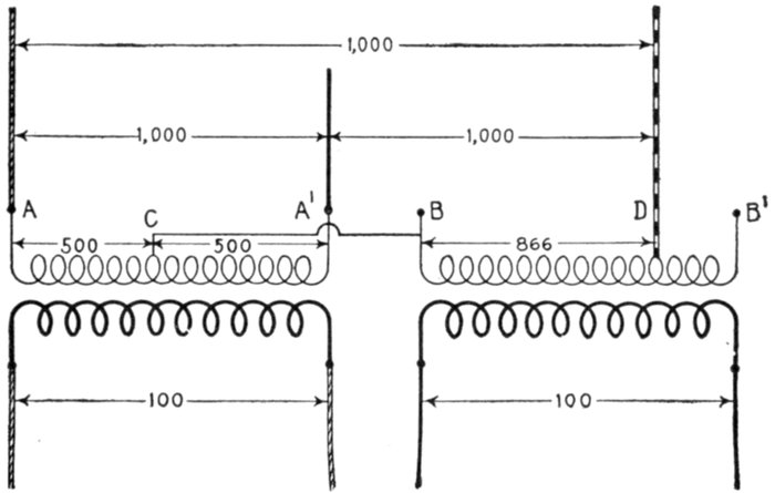
Fig. 2,176.—The Scott connection for transforming from three phase to two phase. In this
method one of the primary wires B of the .866 ratio transformer is connected to the middle
of the other primary as at C, the ends of which are connected to two of the three phase
wires. The other phase wire is connected at D, the point giving the .866 ratio. The
secondary wires are connected as shown.
Ans. Two transformers are used, one having a 10:1 ratio,
and the other, a ½√3:1, that is, an 8.66:1 ratio. The connections
are arranged as in fig. 2,176.
It is customary to employ standard transformers having the ratios
10:1, and 9:1.
Ques. What names are given to the two transformers?
Ans. The one having the 10:1 ratio is called the main
transformer, and the other with the 8.66:1 ratio, the teaser
transformer.
In construction, the transformers may be made exactly alike so that
either may be used as main or teaser.
In order that the connections may be properly and conveniently
made, the primary windings should be provided with 50% and 86.6%
taps.
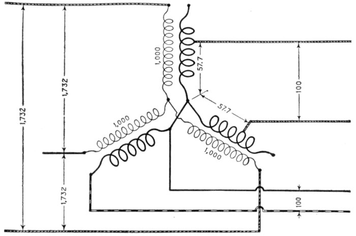
Fig. 2,177.—Three phase to two phase transformation with three star connected transformers.
Two of the secondary windings are tapped at points corresponding to 57.7% of full voltage;
these two windings are connected in series to form one secondary phase of voltage equal
to that obtained by the other full secondary winding.
Ques. Describe another way of transforming from
three to two phases.
Ans. The transformation may be made by three star connected
transformers, proportioning the windings as in fig. 2,177,
from which it will be seen that two of the secondary windings
are tapped at points corresponding to 57.7 per cent. of full
voltage.
Three Phase to Six Phase.—This transformation is usually
made for use with rotary converters and may be accomplished
in several ways. As these methods have been illustrated in
the chapter on Converters (page 1,462), it is unnecessary to
again discuss them here. Fig. 2,178, below shows the diametrical
connection for transforming three phase to six phase.
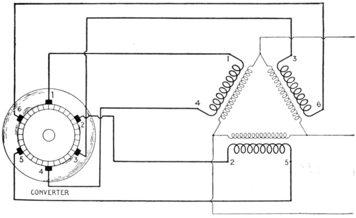
Fig. 2,178.—Diagram of diametrical connection, three phase to six phase. It is obtained
by bringing both ends of each secondary winding to opposite points on the rotary converter
winding, utilizing the converter winding to give the six phases. This transformation
of phases may also be obtained with transformers having two secondary windings.
Alternating Current Systems.—The saving in the cost
of transmission obtained by using alternating instead of direct
current is not due to any difference in the characteristics of the
currents themselves, but to the fact that in the case of alternating
current very high pressures may be employed, thus
permitting a given amount of energy to be transmitted with a
relatively small current.
In the case of direct current systems, commutator troubles
limit the transmission pressure to about 1,000 volts, whereas
with alternating current it may be commercially generated at
pressures up to about 13,000 and by means of step up transformers,
transmitted at 110,000 volts or more.
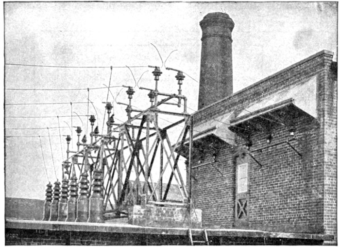
Fig. 2,179.—End of Schaghticoke-Schenectady transmission line at Schenectady; view showing
entrance bushings and lightning arrester horn gaps.
Relative Weights of Copper Required by Polyphase
Systems.—A comparison between the weights of copper required
by the different alternating current systems is rendered
quite difficult by the fact that the voltage ordinarily measured
is not the maximum voltage, and as the insulation has to withstand
the strain of the maximum voltage, the relative value of
copper obtained by calculation depends upon the basis of comparison
adopted.
As a general rule, the highest voltage practicable is used for
long distance transmission, and a lower voltage for local distribution.
Furthermore, some polyphase systems give a multiplicity
of voltages, and the question arises as to which of these
voltages shall be considered the transmission voltage.
If the transmission voltage be taken to represent that of the
distribution circuit, and the polyphase system has as many
independent circuits as there are phases, the system would
represent a group of several single phase systems, and there
would be no saving of copper. Under these conditions, if the
voltage at the distant end be taken as the transmission voltage,
and the copper required by a single phase two wire system as
shown in fig. 2,180, be taken as the basis of comparison, the
relative weights of copper required by the various polyphase
systems is given in figs. 2,181 to 2,188.
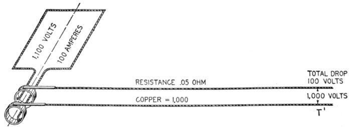
Fig. 2,180.—Single phase line, used as basis of comparison in obtaining the relative weights of
copper required by polyphase systems, as indicated in figs. 2,181 to 2,188.
In the case represented in fig. 2,180, if the total drop on the
line be 100 volts, the generated voltage must be 1,100 volts,
and the resistance of each line must be 50 ÷ 1,000 = .05 ohms.
Calculated on this basis, a two phase four wire system is equivalent
to two single phase systems and gives no economy of copper
in power transmission over the ordinary single phase two wire
system. This is the case also with any of the other two phase
systems, except the two phase three wire system.
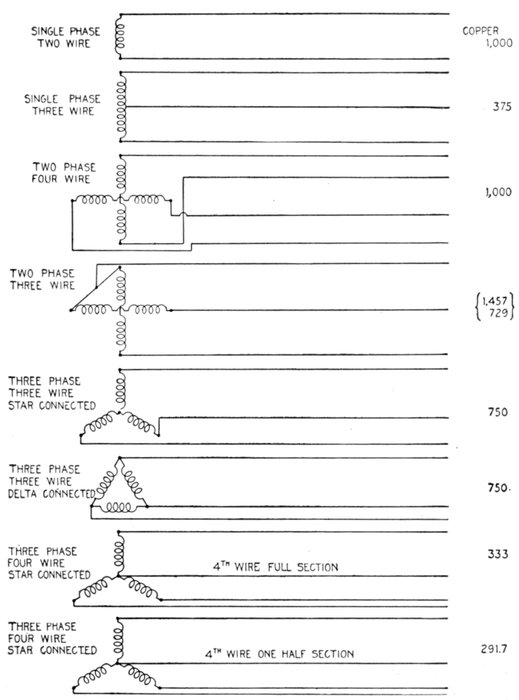
Figs. 2,181 to 2,188.—Circuit diagrams showing relative copper economy of various alternating
current systems.
In this system two of the four wires of the four wire two phase system
are replaced by one of full cross section.
The amount of copper required, when compared with the single
phase system, will differ considerably according as the comparison is
based on the highest voltage permissible for any given distribution,
or on the minimum voltage for low pressure service.
If E be the greatest voltage that can be used on account of the insulation
strain, or for any other reason, the pressure between the other
conductors of the two phase three wire system must be reduced to
E ÷ √2.
The weight of copper required under this condition is 145.7% that
of the single phase copper.
On the basis of minimum voltage, the relative amount of copper
required is 72.9% that of the single phase system.
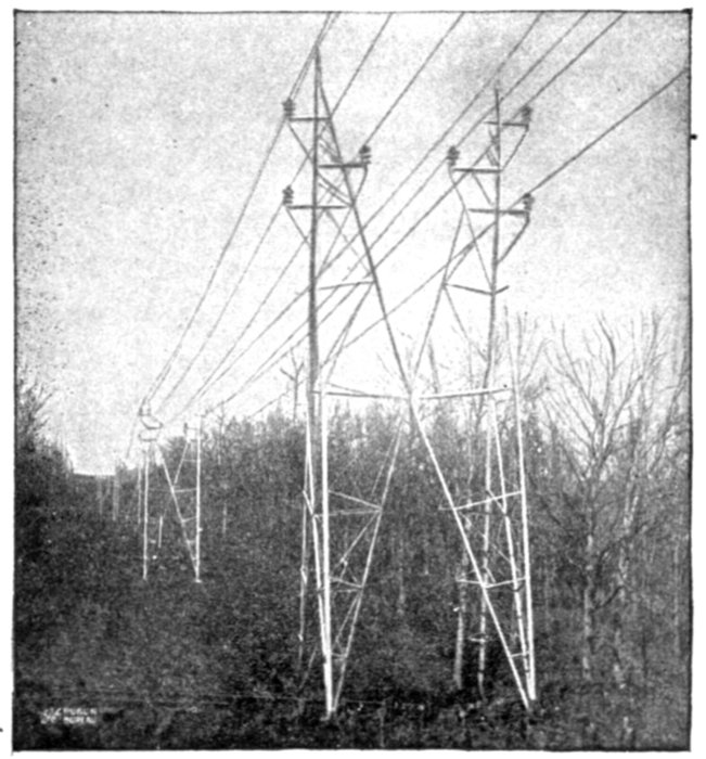
Fig. 2,189.—Twin circuit "aermotor" towers carrying 44,000 volt conductors (Southern
Power Co.). These towers vary in height from 35 to 50 feet, and the circuits are transposed
every 10 miles. The towers are assembled on the ground and erected by means of
gin poles. They are normally spaced 500 feet apart with a sag of 5 feet 8 inches. The
minimum distance between towers is 300 feet and the maximum 700 feet.
Figs. 2,187 and 2,188 are two examples of three phase four wire systems.
The relative amount of copper required as compared with the
single phase system depends on the cross section of the fourth wire.
The arrangement shown in fig. 2,188, where the fourth wire is only
half size, is used only for secondary distribution systems.
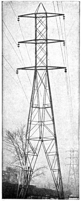
Fig. 2,190.—General Electric standard tower for high tension three phase transmission line.
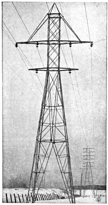
Fig. 2,191.—General Electric transposition tower for high tension three phase transmission line.
Choice of Voltage.—In order to properly determine the
voltage for a transmission system there are a number of
conditions which must be considered in order that the economy
of the entire installation shall be a maximum.
The nature of the diversely various factors which affect the
problem makes a mathematical expression difficult and unsatisfactory.
Ques. What is the relation between the cross sectional
area of the conductors and the voltage?
Ans. For a given circuit, the cross sectional area of the
conductors, or weight varies inversely as the voltage.
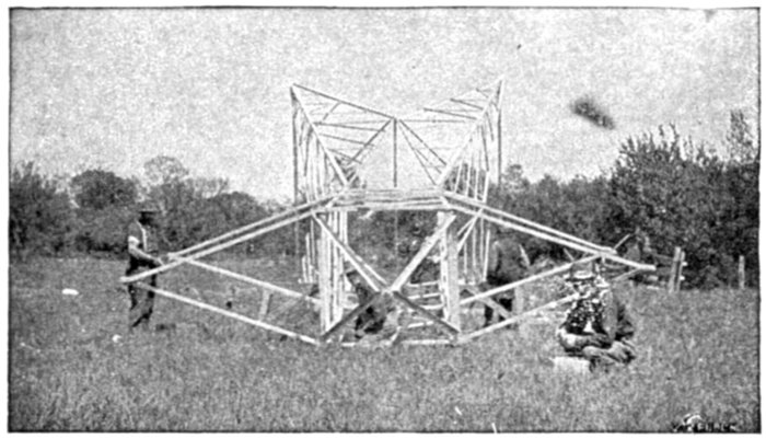
Fig. 2,192.—General Electric standard tower under construction.
Ques. Would the highest possible voltage then be used
for a transmission line?
Ans. The most economical voltage depends on the length
of the line and the cost of apparatus.
For instance, alternators, transformers, insulation and circuit control
and lightning protection devices become expensive when manufactured
for very high pressures. Hence if a very high pressure were used,
it would involve that the transmission distance be great enough so
that the extra cost of the high pressure apparatus would be offset by
the saving in copper effected by using the high pressure.
In the case of the longest lines, from about 100 miles up, the saving
in copper with the highest practicable voltage is so great that the
increase in other expenses is rendered comparatively small.
In the shorter lines as those ranging in length from about one mile
to 50 or 75 miles, the most suitable voltage must be determined in
each individual case by a careful consideration of all the conditions
involved. No fixed rule can be established for proper voltage based
on the length, but the following table will serve as a guide:
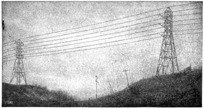
Fig. 2,193.—Line of the Schenectady Power Company crossing the tracks of the Boston and
Maine Railroad near Schaghticoke.
Usual Transmission Voltages
| Length of line in miles |
Voltage |
| 1 |
500 to 1,000 |
| 1 to 2 |
1,000 to 2,300 |
| 2 to 3 |
2,300 to 6,600 |
| 3 to 10 |
6,600 to 13,200 |
| 10 to 15 |
13,200 to 22,000 |
| 15 to 20 |
22,000 to 44,000 |
| 20 to 40 |
44,000 to 66,000 |
| 40 to 60 |
66,000 to 88,000 |
| 60 to 100 |
88,000 to 110,000 |
Ques. What are the standard voltages for alternating
current transmission circuits?
Ans. 6,600, 11,000, 22,000, 33,000, 44,000, 66,000, 88,000.
The amount of power to be transmitted determines, in a measure, the
limit of line voltage. If the most economical voltage considered from
the point of view of the line alone, be somewhere in excess of 13,200,
step up transformers must be employed, since the highest voltage for
which standard alternators are manufactured is 13,200. In a given case,
the saving in conductor by using the higher voltage may be more than
offset by the increased cost of transformers, and the question must be
determined for each case.
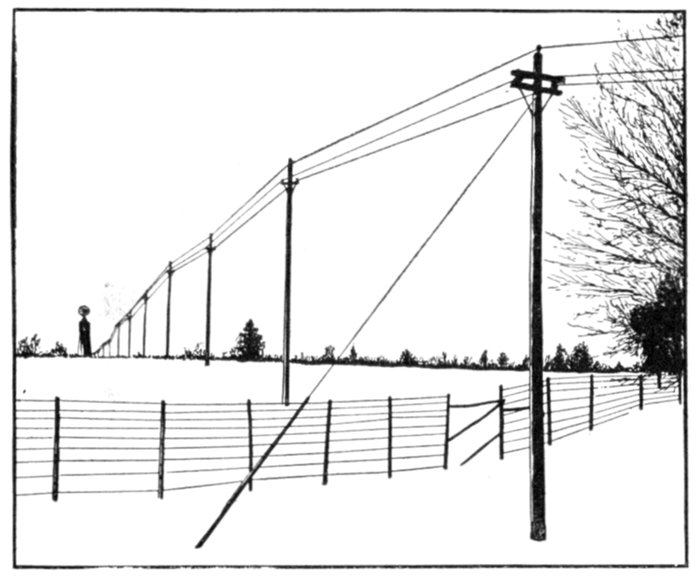
Fig. 2,194.—View of a three phase, 2,300 volt, 60 cycle line at Chazy, N. Y. The current is
transmitted at the alternator voltage 2¾ miles over the single circuit pole line. The
poles are of cedar with fir cross arms, and are fitted with pin insulators. They are from
35 to 40 feet high and are spaced at an average of about 120 feet. The conductors are
bare copper wire No. 00 B. & S. The alternators consist of one 50 kw., and one 100 kw.
General Electric machines.
Ques. What are the standard transformer ratios?
Ans. Multiples of 5 or 10.
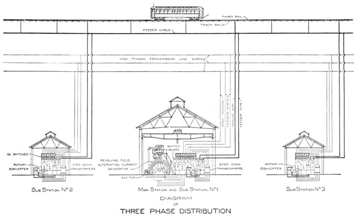
Figs. 2,195 to 2,197.—Diagram showing electric railway system. Three phase current is generated at the main station where it
passes to step up transformers to increase the pressure a suitable amount for economical transmission. At various points
along the railway line are sub-stations, where the three phase current is reduced in pressure to 500 or 600 volts by step down
transformers, and converted into direct current by rotary converters. The relatively low pressure direct current is then conveyed
by "feeders" to the rails, this resulting in a considerable saving in copper.
Mixed Current Systems.—It is often desirable to transmit
electrical energy in the form of alternating current, and distribute
it as direct current or vice versa.
Such systems may be classed as mixed current systems. The
usual conversion is from alternating current to direct current
because of the saving in copper secured by the use of alternating
current in transmission, especially in the case of long
distance lines. Such conversion involves the use of a rotary
converter, motor generator set, or rectifier, according to the
conditions of service.
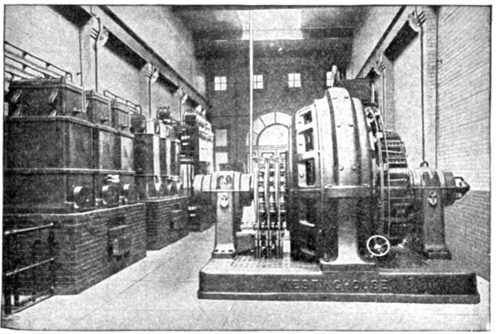
Fig. 2,198.—Example of converter sub-station, showing the Brooklyn Edison Co. Madison
sub-station. The transformers are seen on the left, the converter shown at the right is a
Westinghouse synchronous booster rotary converter, consisting of a standard rotary converter
in combination with a revolving armature alternator mounted on the same shaft
with the converter and having the same number of poles. The function of the machine
is to convert and regulate the pressure. By varying the field excitation of the alternator,
the A. C. voltage impressed on the rotary converter proper can be increased or decreased as
desired. Thus, the D. C. voltage delivered by the converter is varied accordingly. This
type of converter is well adapted for any application for which a relatively wide variation,
either automatic or non-automatic, in direct current voltage is necessary. Also especially
for serving incandescent lighting systems where considerable voltage variation is required
for the compensation of drop in long feeders, for operation in parallel with storage batteries
and for electrolytic work where extreme variations in voltage are required by changes in
the resistance of the electrolytic cells.
The suburban trolley forms a good example of a mixed system,
in which alternating current is generated at the central station
and transmitted to sub-stations, where it is transformed to low
pressure, and converted into direct current for use on the line.
Fig. 2,195 shows the interior of a sub-station of this kind.
Ques. What direct current pressure is usually employed
on traction lines?
Ans. 500 volts.
Ques. Mention another important service performed
by a mixed system.
Ans. If the generator furnish alternating current it must be
converted into direct current in order to charge storage batteries.
 by
by