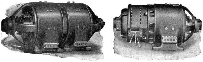
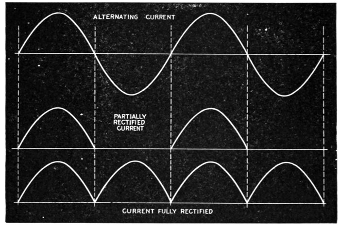
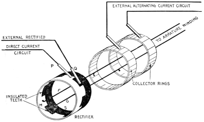
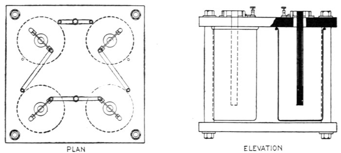
The almost universal adoption of the alternating current
system of distribution of electrical energy for light and power,
and the many inherent advantages of the alternating current
motor, have created the wide field of application now covered
by this type of apparatus.
As many central stations furnish only alternating current, it
has become necessary for motor manufacturers to perfect types
of alternating current motor suitable for all classes of industrial
drive and which are adapted for use on the kinds of alternating
circuit employed. This has naturally resulted in a multiplicity
of types and a classification, to be comprehensive, must, as in the
case of alternators, divide the motors into groups as regarded
from several points of view. Accordingly, alternating current
motors may be classified:
1. With respect to their principle of operation, as
a. SYNCHRONOUS MOTORS;
b. ASYNCHRONOUS MOTORS:
1. Induction motors;
{series;
2. Commutator motors {compensated;
{shunt;
{repulsion.
2. With respect to the current as
- a. Single phase;
- b. Polyphase;
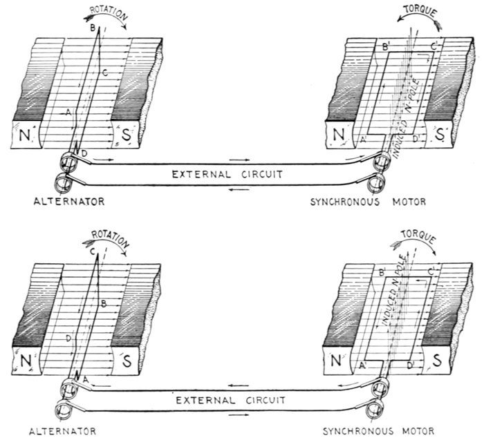
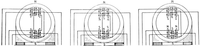
Figs. 1,585 to 1,588.—Synchronous motor principles: I. A single phase synchronous motor
is not self-starting. The figures show an elementary alternator and an elementary synchronous
motor, the construction of each being identical as shown. If the alternator
be started, during the first half of a revolution, beginning at the initial position ABCD,
fig. 1,585, current will flow in the direction indicated by the arrows, passing through the
external circuit and armature of the motor, fig. 1,586, inducing magnetic poles in the
latter as shown by the vertical arrows. These poles are attracted by unlike poles of the
field magnets, which tend to turn the motor armature in a counter-clockwise direction.
Now, before the torque thus set up has time to overcome the inertia of the motor armature
and cause it to rotate, the alternator armature has completed the half revolution, and
beginning the second half of the revolution, as in fig. 1,587, the current is reversed and
consequently the induced magnetic poles in the motor armature are reversed also. This
tends to rotate the armature in the reverse direction, as in fig. 1,588. These reversals
of current occur with such frequency that the force does not act long enough in either
direction to overcome the inertia of the armature; consequently it remains at rest, or to be
exact, it vibrates. Hence, a single phase synchronous motor must be started by some
external force and brought up to a speed that gives the same frequency as the alternator
before it will operate. A single phase synchronous motor, then, is not self-starting, which is
one of its disadvantages; the reason it will operate after being speeded up to synchronism
with the alternator and then connected in the circuit is explained in figs. 1,589 to 1,592.
3. With respect to speed, as
a. Constant speed;
b. Variable speed.
4. With respect to structural features, as
a. Enclosed;
b. Semi-enclosed;
c. Open;
d. Pipe ventilated;
e. Back geared;
f. Skeleton frame;
g. Riveted frame;
h. Ventilated; etc.
Of the above divisions and sub-divisions some are self-defining
and need little or no explanation; the others, however, will be
considered in detail, with explanations of the principles of operation
and construction.
Synchronous Motors.—The term "synchronous" means
in unison, that is, in step. A so called synchronous motor, then,
as generally defined, is one which rotates in unison or in step with
the phase of the alternating current which operates it.
Strictly speaking, however, it should be noted that this condition of
operation is only approximately realized as will be later shown.
Any single or polyphase alternator will operate as a synchronous
motor when supplied with current at the same pressure
and frequency as it produces as a generator, the essential condition,
in the case of a single phase machine, being that it be
speeded up to so called synchronism before being put in the circuit.
In construction, synchronous motors are almost identical with
the corresponding alternator, and consist essentially of two
elements:
- 1. An armature,
- 2. A field.
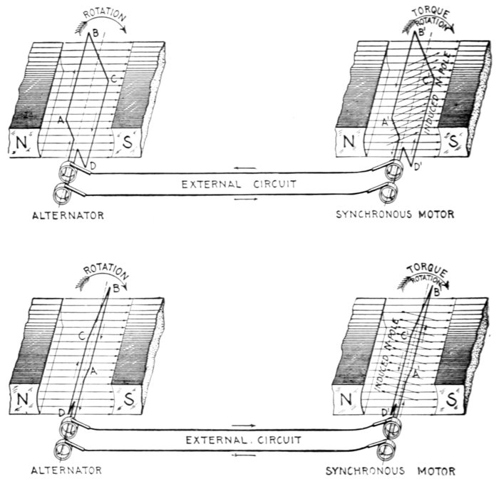
Figs. 1,589 to 1,592.—Synchronous motor principles: II. The condition necessary for synchronous
motor operation is that the motor be speeded up until it rotates in synchronism, that
is, in step with the alternator. This means that the motor must be run at the same frequency
as the alternator (not necessarily at the same speed). In the figures it is assumed that
the motor has been brought up to synchronism with the alternator and connected in
the circuit as shown. In figs. 1,589 and 1,590 the arrows indicate the direction of the current
for the armature position shown. The current flowing through the motor armature
induces magnetic poles which are attracted by the field poles, thus producing a torque in
the direction in which the armature is rotating. After the alternator coil passes the
vertical position, the current reverses as in fig. 1,591, and the current flows through the
motor armature in the opposite direction, thus reversing the induced poles as in fig. 1,592.
This brings like poles near each other, and since the motor coil has rotated beyond the vertical
position the repelling action of the like poles, and also the attraction of unlike poles,
produces a torque acting in the direction in which the motor is rotating. Hence, when the two
armatures move synchronously, the torque produced by the action of the induced poles
upon the field poles is always in the direction in which the motor is running, and accordingly,
tends to keep it in operation.
either of which may revolve. The field is separately excited with
direct current.
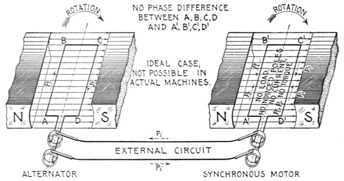
Figs. 1,593 and 1,594.—Synchronous motor principles: III. The current which flows through the
armature of a synchronous motor is that due to the effective pressure. Since the motor
rotates in a magnetic field, a pressure is induced in its armature in a direction opposite
to that induced in the armature of the alternator, and called the reverse pressure, as distinguished
from the pressure generated by the alternator called the impressed pressure.
At any instant, the pressure available to cause current to flow through the two armatures, called
the effective pressure, is equal to the difference between the pressure generated by the
alternator or impressed pressure and the reverse pressure induced in the motor. Now
if the motor be perfectly free to turn, that is, without load or friction, the reverse pressure
will equal the impressed pressure and no current will flow. This is the case of real synchronous
operation, that is, not only is the frequency of motor and alternator the same,
but the coils rotate without phase difference. In figs. 1,593 and 1,594, the impressed and
reverse pressures are represented by the dotted arrows Pi and Pr, respectively. Since in
this case these opposing pressures are equal, the resultant or effective pressure is zero;
hence, there is no current. In actual machines this condition is impossible, because even if
the motors have no external load, there is always more or less friction present; hence, in
operation there must be more or less current flowing through the motor armature to
induce magnetic poles so as to produce sufficient torque to carry the load. The action of
the motor in automatically adjusting the effective pressure to suit the load is explained in
figs. 1,595 and 1,596.
The principles upon which such motors operate may be explained
by considering the action of two elementary alternators
connected in circuit, as illustrated in the accompanying illustrations,
one alternator being used as a generator and the other as
a synchronous motor.
Suppose the motor, as in figs. 1,585 and 1,586, be at rest when
it is connected in circuit with the alternator. The alternating
current will flow through the motor armature and produce a
reaction upon the field tending to rotate the motor armature
first in one direction, then in another.
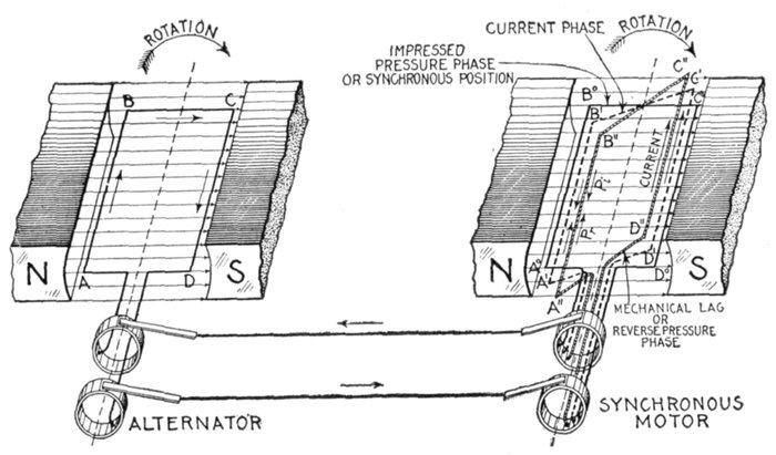
Figs. 1,595 and 1,596.—Synchronous motor principles: IV—A synchronous motor adjusts
itself to changes of load by changing the phase difference between current and pressure. If
there be no load and no friction, the motor when speeded up and connected in the circuit,
will run in true synchronism with the alternator, that is, at any instant, the coils
A B C D and A°B°C°D° will be in parallel planes. When this condition obtains, no
current will flow and no torque will be required (as explained in figs. 1,593 and 1,594).
If a load be put on the motor, the effect will be to cause A°B°C°D° to lag behind the
alternator coil to some position A"B"C"D" and current to flow. The reverse pressure
will lag behind the impressed pressure equally with the coil, and the current which has
now started will ordinarily take an intermediate phase so that it is behind the impressed
pressure but in advance of the reverse pressure. These phase relations may be represented
in the figure by the armature positions shown, viz.: 1, the synchronous position A°B°C°D°
representing the impressed pressure, 2, the intermediate position A'B'C'D', the current,
3, the actual position A"B"C"D" (corresponding to mechanical lag), the reverse pressure.
From the figure it will be seen that the current phase represented by A'B'C'D'
is in advance of the reverse pressure phase represented by A"B"C"D". Hence, by
armature reaction, the current leading the reverse pressure weakens the motor field and
reduces the reverse pressure, thus establishing equilibrium between current and load. As
the load is increased, the mechanical lag of the alternator coil becomes greater and likewise
the current lead with respect to the reverse pressure, which intensifies the armature
reaction and allows more current to flow. In this way equilibrium is maintained
for variations in load within the limits of zero and 90° mechanical lag. The effect of
armature reaction on motors is just the reverse to its effect on alternators, which results
in marked automatic adjustment between the machines especially when a single motor
is operated from an alternator of about the same size. In other words, the current
which weakens or strengthens the motor field, strengthens or weakens respectively the
alternator field as the load is varied.
Because of the very rapid reversals in direction of the torque thus set up,
there is not sufficient time to overcome the inertia of the armature
before the current reverses and produces a torque in the opposite direction,
hence, the armature remains stationary or, strictly speaking, it vibrates.
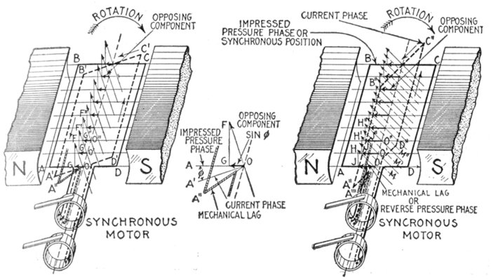
Figs. 1,597 and 1,598.—Synchronous motor principles: V. The effectiveness of armature reaction
in weakening the field is proportional to the sine of the angle by which the current lags
behind the impressed pressure. If a motor be without load or friction, its armature will
revolve synchronously (in parallel planes) with the alternator armature. In the figures
let ABCD represent an instantaneous position of the motor armature when this condition
obtains; it will then represent the phase relationship of impressed and reverse pressures
for the same condition of no load, no friction, operation. Now, if a light load be placed
on the motor for the same instantaneous position of alternator armature, the motor coil
will drop behind to some position as A", fig. 1,597 (part of the coil only being shown).
The reverse pressure will also lag an equal amount and its phase with respect to the impressed
pressure will be represented by A". The armature current will ordinarily take an intermediate
phase, represented by coil position A'B'C'D', inducing a field strength corresponding to
the 9 lines of force OF, O'F', etc. The current being in advance of the phase of the reverse
pressure A", the armature reaction weakens the field, thus reducing the reverse pressure and
allowing the proper current to flow to balance the load. The amount by which the field is
weakened may be determined by resolving the induced magnetic lines OF, O'F', O"F", etc.,
into components OG, GF, O'G', G'F', O"G", G"F", etc., respectively parallel and at right
angles to the lines of force of the main field. Of these components, the field is weakened
only by OG, O'G', O"G", etc. Since by construction, angle OFG = AOA', and calling OF
unity length, OG = sine of angle by which the current lags behind the impressed pressure.
The construction is shown better in the enlarged diagram. For a heavier load the armature
coil will drop back further to some position as A"', fig. 1,598, and the lag of the
current increase to some intermediate phase as A"B"C"D". By similar construction it
is seen that the component OG (fig. 1,597) has increased to OJ (fig. 1,598), this component
thus further weakening the main field, by an amount proportional to the sine of
the angle by which the current lags behind the impressed pressure. The increased current
which is now permitted to flow, causes the induced field to be strengthened (as indicated
by the dotted magnetic lines M, M', M", etc.), thus increasing the torque to balance
the additional load.
Now if the motor armature be first brought up to a speed corresponding
in frequency to that of the alternator before connecting the motor
in the circuit, the armature will continue revolving at the same frequency
as the alternator.
The armature continues revolving, because, at synchronous speed,
the field flux and armature current are always in the same relative position,
producing a torque which always pulls the armature around in the same
direction.
A polyphase synchronous motor is self starting, because, before the
current has died out in the coils of one phase, it is increasing in those of
the other phase or phases, so that there is always some turning effort
exerted on the armature.
The speed of a synchronous motor is that at which it would have to
run, if driven as an alternator, to deliver the number of cycles which is
given by the supply alternator.
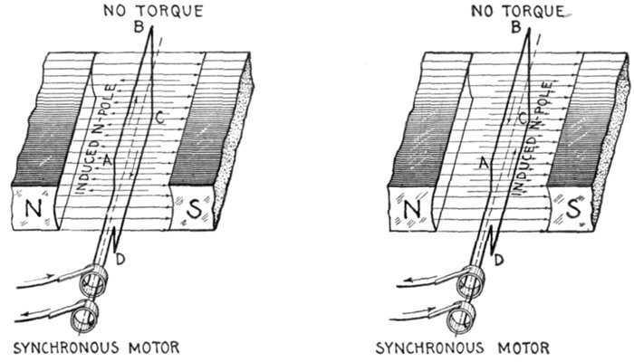
Figs. 1,599 and 1,600.—Synchronous motor principles: VI. A single phase synchronous motor
has "dead centers," just the same as a one cylinder steam engine. Two diagrams of the
motor are here shown illustrating the effect of the current in both directions. When the
plane of the coil is perpendicular to the field, the poles induced in the armature are parallel
to field for either direction of the current; that is to say, the field lines of force and the
induced lines of force acting in parallel or opposite directions, no turning effect is produced,
just as in analogy when an engine is on the dead center, the piston rod (field line of force)
and connecting rod (induced line of force) being in a straight line, the force exerted by
the steam on the piston produces no torque.
For instance a 12 pole alternator running at 600 revolutions per
minute will deliver current at a frequency of 60 cycles a second; an
8 pole synchronous motor supplied from that circuit will run at 900
revolutions per minute, which is the speed at which it would have to be
driven as an alternator to give 60 cycles a second—the frequency of
the 12 pole alternator.
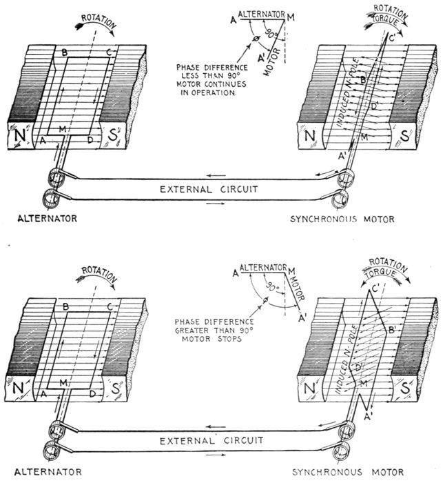
Figs. 1,601 to 1,604.—Synchronous motor principles VII. An essential condition for synchronous
motor operation is that the mechanical lag be less than 90°. Figs. 1,601 and 1,602
represent the conditions which prevail when the lag of the motor armature A'B'C'D' is
anything less than 90°. As shown, the lag is almost 90°. The direction of the current and
induced poles are indicated by the arrows. The inclination of the motor coil is such that
the repulsion of like poles produces a torque in the direction of rotation, thus tending
to keep motor in operation. Now, in figs. 1,603 and 1,604, for the same position of the alternator
coil ABCD, if the lag be greater than 90°, the inclination of the motor coil A'B'C'D' is
such that at this instant the repulsion of like poles produces a torque in a direction opposite
to that of the rotation, thus tending to stop the motor. In actual operation this quickly
brings the motor to rest, having the same effect as a strong brake in overcoming the
momentum of a revolving wheel.
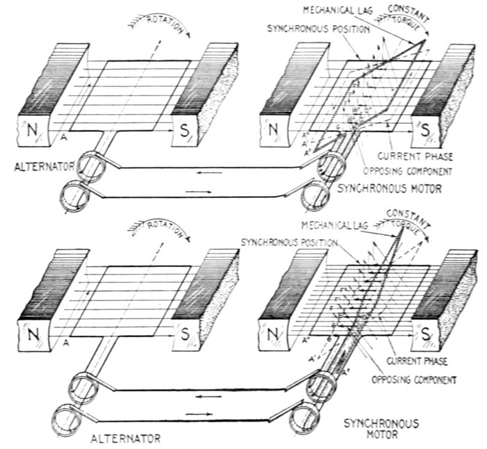
Figs. 1,605 to 1,608.—Synchronous motor principles: VIII. If the torque and current through
the motor armature be kept constant, strengthening the field will increase the mechanical lag,
and the lead of the current with respect to the reverse pressure. In the figures, let A be an
instantaneous position of the alternator coil, A°, synchronous position of motor coil,
A', position corresponding to current phase, A", actual position or mechanical lag of
motor coil behind alternator coil necessary to maintain equilibrium. In fig. 1,606, let A'
and A" represent respectively the relation of current phase and mechanical lag corresponding
to a certain load and field strength. For these conditions OG, O'G', O"G",
etc., will represent the components of the induced lines of force in opposition to the motor
field, that is, they indicate the intensity of the armature reaction at the instant depicted.
Now, assume the field strength to be doubled, as in fig. 1,608, the motor load and current
being maintained constant. Under these conditions, the armature reaction must be
doubled to maintain equilibrium; that is, the components OG, O'G', etc., fig. 1,608, must
be twice the length of OG, O'G', etc., fig. 1,605. Also since the current is maintained
constant, the induced magnetic lines OF, O'F' are of same length in both figures. Hence,
in fig. 1,608 the plane of these components is such that their extremities touch perpendiculars
from G, G', etc., giving the other components FG, F'G', etc. The plane A',
normal to OF, O'F', etc., gives the current phase. By construction, the phase difference
between A° and A' is such that sin A°OA' (fig. 1,608) = 2 × sin A°OA' (fig. 1,606). That
is, doubling the field strength causes an increase of current lag such that the sine of the
angle of this lag is doubled. Since the intensity of the armature reaction depends on the
lead of the current with respect to the reverse pressure, the mechanical lag of the coil must
be increased to some position as A" (fig. 1,608), such as will give an armature reaction of an
intensity indicated by the components OG, O'G', etc.
The following simple formula gives the speed relations between
generators and motors connected to the same circuit and having different
numbers of poles.
in which
- s. Revolutions per minute of the motor;
- p. Number of poles of the motor;
- S. Revolutions per minute of the alternator;
- P. Number of poles of the alternator.
Question. If the field strength of a synchronous motor
be altered, what effect does this have on the speed, and
why?
Ans. The speed does not change (save for a momentary
variation to establish the phase relation corresponding to
equilibrium), because the motor has to run at the same frequency
as the alternator.
Ques. How does a synchronous motor adjust itself to
changes of load and field strength?
Ans. By changing the phase difference between the current
and pressure.
If, on connecting a synchronous motor to the mains, the excitation
be too weak, so that the voltage is lower than that of the supply, this
phase difference will appear resulting in wattless current, since the
missing magnetization has, as it were, to be supplied from an external
source. A phase difference also appears when the magnetization is too
strong.
Ques. State the disadvantages of synchronous motors.
Ans. A synchronous motor requires an auxiliary power for
starting, and will stop if, for any reason, the synchronism be
destroyed; collector rings and brushes are required. For some
purposes synchronous motors are not desirable, as for driving
shafts in small workshops having no other power available for
starting, and in cases where frequent starting, or a strong torque
at starting is necessary. A synchronous motor has a tendency
to hunt[1] and requires intelligent attention; also an exciting
current which must be supplied from an external source.
Ques. State the advantage of synchronous motors.
Ans. The synchronous motor is desirable for large powers
where starting under load is not necessary. Its power factor
may be controlled by varying the field strength. The power
factor can be made unity and, further, the current can be made
to lead the pressure.
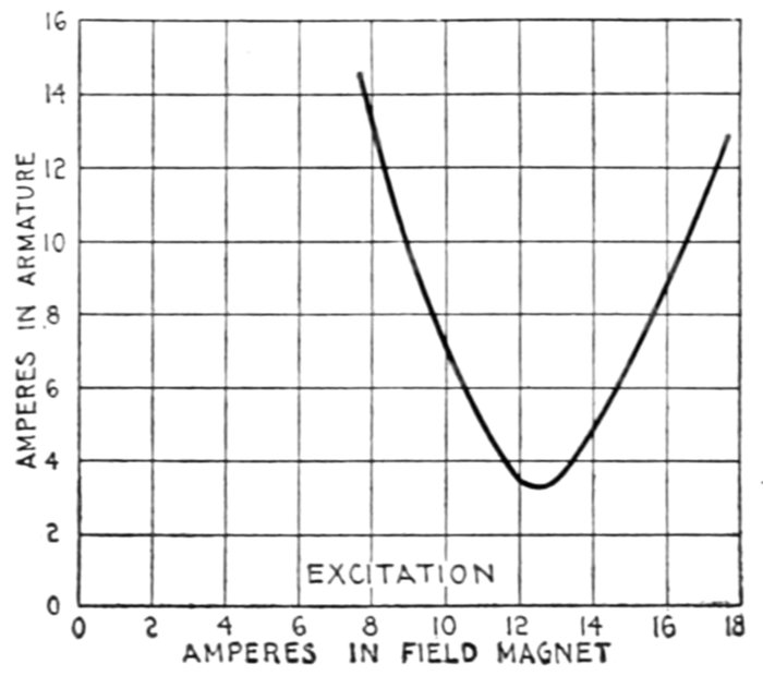
Fig. 1,609.—Diagram illustrating method of representing the performance of synchronous
motors. The V shaped curve is obtained by plotting the current taken by motor under
different degrees of excitation, the power developed by the motor remaining constant.
The current may be made to lag or lead while the load remains constant, by varying
the excitation. By varying the excitation, a certain value may be reached which will
give a minimum current in the armature; this is the condition of unity power factor.
If now the excitation be diminished the current will lag and increase in value to obtain
the same power; if the excitation be increased the current will lead and increase in value
to obtain the same power. The results plotted for several values of the excitation current
will give the V curve as shown. This is an actual curve obtained by Mordey on a 50 kw.
machine running unloaded as a motor. Other curves situated above this one may be
obtained for various loadings of the motor.
A synchronous motor is frequently connected in a circuit solely to
improve the power factor. In such cases it is often called a "condenser
motor" for the reason that its action is similar to that of a condenser.
The design of synchronous motors proceeds on the same lines as
that of alternators, and the question of voltage regulation in the latter
becomes a question of power factor regulation in the former.
Ques. For what service are they especially suited?
Ans. For high pressure service.
High voltage current supplied to the armature does not pass through
a commutator or slip rings; the field current which passes through slip
rings being of low pressure does not give any trouble.
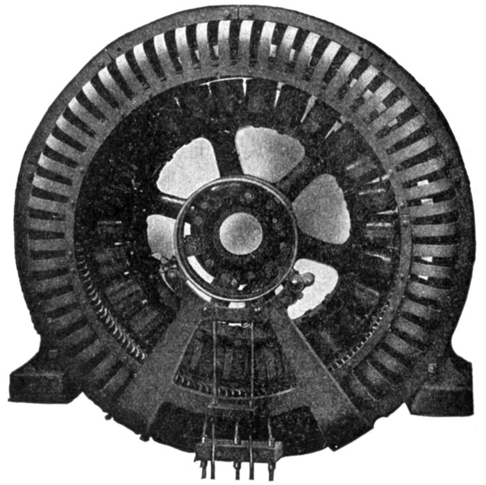
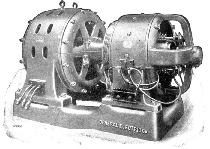
Fig. 1,610.—Westinghouse self-starting synchronous motor. Motors of this type are suitable
for constant speed service where starting conditions are moderate, such as driving
compressors, pumps, and large blowers. Synchronous motors can be made to operate
not only as motors but as synchronous condensers to improve the power factor of the
circuit. The field is provided with a combined starting and damper or amorlisseur winding
so proportioned that the necessary starting torque is developed by the minimum current
consistent with satisfactory synchronous running without hunting. The armature slots are
open and the coils form wound, impregnated, and interchangeable. Malleable iron finger
plates at each end of the core support the teeth. Ventilating finger plates assembled with
the laminations form air ducts. The frames are of cast iron, box section with openings for
ventilation; shoes and slide rails permit adjustment of position. The brush holders are of
the standard sliding shunt type. Two or more brushes are provided for each ring.
Ques. How do synchronous and induction motors
compare as to efficiency?
Ans. Synchronous motors are usually the more efficient.
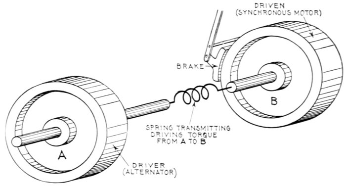
Fig. 1,611.—Mechanical analogy illustrating "hunting." The figure represents two flywheels
connected by a spring susceptible to torsion in either direction of rotation. If the wheels
A and B be rotating at the same speed and a brake be applied, say to B, its speed will
diminish and the spring will coil up, and if fairly flexible, more than the necessary amount
to balance the load imposed by the brake; because when the position of proper torque is
reached, B is still rotating slightly slower than A, and an additional torque is required to
overcome the inertia of B and bring its speed up to synchronism with A. Now before the
spring stops coiling up the wheels must be rotating at the same speed. When this occurs
the spring has reached a position of too great torque, and therefore exerting more turning
force on B than is necessary to drive it against the brake. Accordingly B is accelerated
and the spring uncoils. The velocity of B thus oscillates above and below that of A when
a load is put on and taken off. Owing to friction, the oscillations gradually die out and
the second wheel takes up a steady speed. A similar action takes place in a synchronous
motor when the load is varied.
Hunting of Synchronous Motors.—Since a synchronous
motor runs practically in step with the alternator supplying it
with current when they both have the same number of poles,
or some multiple of the ratio of the number of poles on each
machine, it will take an increasing current from the line as its
speed drops behind the alternator, but will supply current to the
line as a generator if for any reason the speed of the alternator
should drop behind that of the motor, or the current wave lag
behind, which produces the same effect, and due to additional
self-induction or inductance produced by starting up or overloading
some other motor or rotary converter in the circuit.
When the motor is first taking current, then giving current
back to the line, and this action is continued periodically, the
motor is said to be hunting.
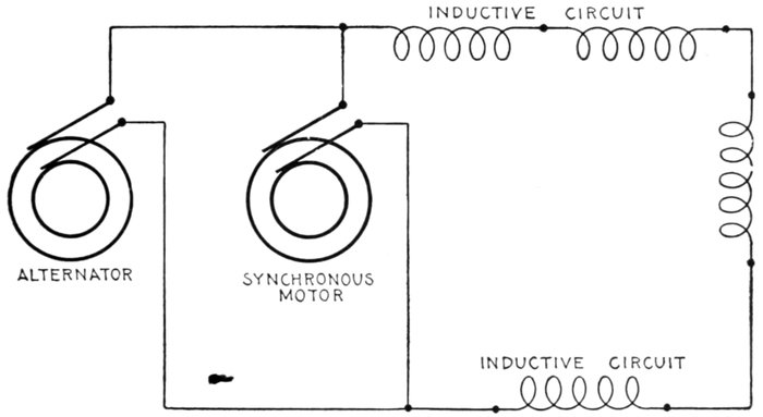
Fig. 1,612.—Diagram illustrating the use of a synchronous motor as a condenser. If a synchronous
motor be sufficiently excited the current will lead. Hence, if it be connected
across an inductive circuit as in the figure and the field be over excited it will compensate
for the lagging current in the main, thus increasing the power factor. If the motor
be sufficiently over excited the power factor may be made unity, the minimum current
being thus obtained that will suffice to transmit the power in the main circuit. A synchronous
motor used in this way is called a rotary condenser or synchronous compensator.
This is especially useful on long lines containing transformers and induction motors.
Ques. What term is applied to describe the behavior
of the current when hunting occurs?
Ans. The term surging is given to describe the current
fluctuations produced by hunting.
The mechanical analogy of hunting illustrated in fig. 1,611 will help
to an understanding of this phenomenon. In alternating current circuits
a precisely similar action takes place between the alternators and synchronous
motors, or even between the alternators themselves.
CHARACTERISTICS OF SYNCHRONOUS MOTORS
Starting.—The motor must be brought up to synchronous speed
without load, a starting compensator being used. If provided with
a self-starting device, the latter must be cut out of circuit at the proper
time. The starting torque of motor with self-starting device is very small.
Running.—The motor runs at synchronous speed. The maximum
torque is several times full load torque and occurs at synchronous speed.
Stopping.—If the motor receive a sudden overload sufficient to momentarily
reduce its speed, it will stop; this may be brought about by
momentary interruption of the current, sufficient to cause a loss of
synchronism.
Effect upon Circuit.—In case of short circuit in the line the motor
acts as a generator and thus increases the intensity of the short circuit.
The motor impresses its own wave form upon the circuit. Over
excitation will give to the circuit the effect of capacity, and under
excitation, that of inductance.
Power Factor.—This depends upon the field current, wave form
and hunting. The power factor may be controlled by varying the
field excitation.
Necessary Auxiliary Apparatus.—Power for starting, or if self-starting,
means of reducing the voltage while starting; also, field exciter,
rheostat, friction clutch, main switch and exciter switch, instruments
for indicating when the field current is properly adjusted.
Adaptation.—If induction motors be connected to the same line
with a synchronous motor that has a steady load, then the field of the synchronous
motor can be over excited to produce a leading current, which
will counteract the effect of the lagging currents induced by the induction
motors. Owing to the weak starting torque, skilled attendance required,
and the liability of the motor to stop under abnormal working
conditions, the synchronous motor is not adapted to general power distribution,
but rather to large units which operate under a steady load and
do not require frequent starting and stopping.
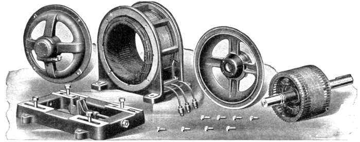
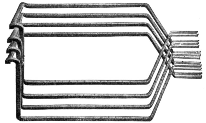
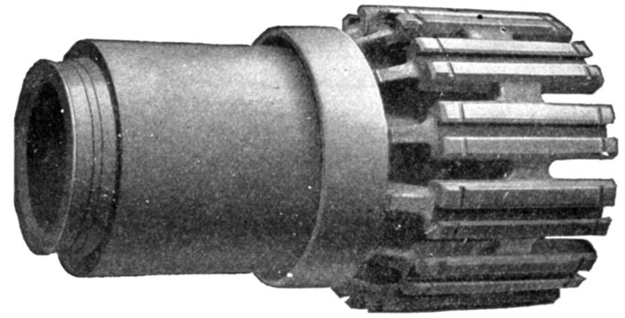
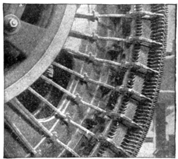
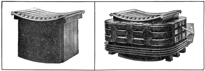
Figs. 1,613 to 1,625.—Disassembled view of Western Electric three phase squirrel cage skeleton frame induction motor.
Induction (Asynchronous)
Motors.—
An induction motor consists
essentially of an
armature and a field magnet,
there being, in the
simplest and most usual
types, no electrical connection
between these two
parts.[2]
According to the kind
of current that an induction
motor is designed
to operate on, it may be
classified as:
- 1. Single phase;
- 2. Polyphase.
The operation of an
induction motor depends
on the production
of a magnetic field by
passing an alternating
current through field
magnets.
The character of this field is either
- 1. Oscillating[3], or
- 2. Rotating,
according as single phase or polyphase current is used.
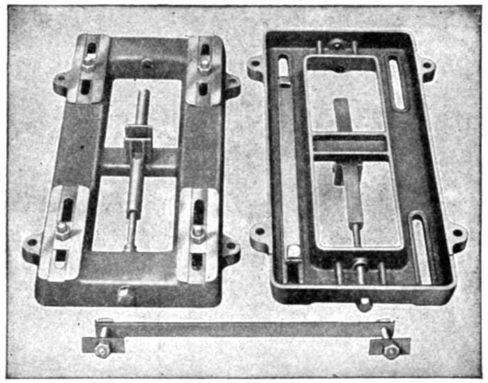
Figs. 1,626 to 1,628.—General Electric base construction for polyphase induction motors.
The base is made of cast iron. Adjusting gear is provided to slide the motor along the
base as shown in the illustrations, the movement being from 6 to 12 inches according to
size. With this design of base, motors are securely held in position under all conditions and
may be run with an upward pull on the belt. Close fitting guides moving in an accurately
machined slot on the base preserve a correct alignment of the motor when adjustment of
the latter is required. The same base can be used whether the motor be supported from
the wall or ceiling or located on the floor. A single adjusting screw is placed under the
center line of the motor frame, which produces an even and balanced draw in either
direction on all parts of the motor when the belt tension is altered. This screw can be
located at either end of the base. The base can be omitted when the motor is direct connected
or when provision for belt adjustment is not required.
Ques. Describe briefly the operation of a single phase
motor.
Ans. A single phase current being supplied to the field
magnets, an oscillating field is set up. A single phase motor is
not self-starting; but when the armature has been set in motion
by external means, the reaction between the magnetic field and the
induced currents in the armature being no longer zero, a torque
is produced tending to turn the armature.
The current flowing through the armature produces an alternating
polarity such that the attraction between the unlike armature and field
poles is always in one direction, thus producing the torque.
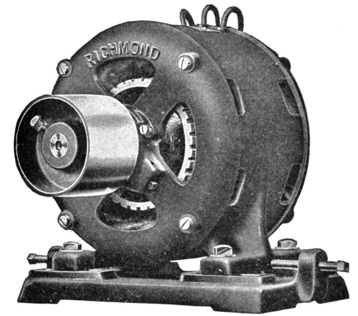
Fig. 1,629.—Richmond three phase induction motor on base fitted with screw adjusting gear
for shifting the position of the motor on the base to take up slack of belt.
Ques. Why is a single phase induction motor not self-starting?
Ans. When the armature is at the rest, the currents induced
therein are at a maximum in a plane at right angles to the
magnetic field, hence there is no initial torque to start the motor.
Ques. What
provision is
made for
starting single
phase induction
motors?
Ans. Apparatus
is supplied
for "splitting
the phase"
(later described
in detail) of the
single phase current
furnished,
converting it
temporarily into
a two phase current,
so as to
obtain a rotating
field which is
maintained till
the motor is
brought up to
speed. The
phase splitting
device is then
cut out and the
motor operated
with the oscillating
field produced
by the
single phase
current.
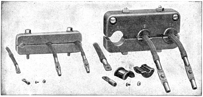
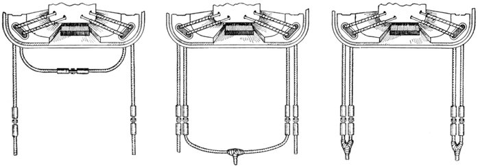
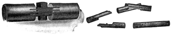
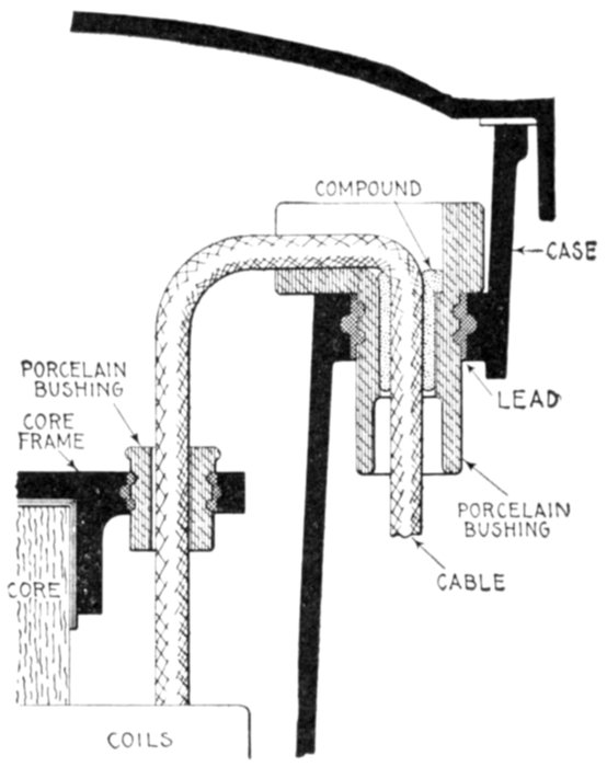
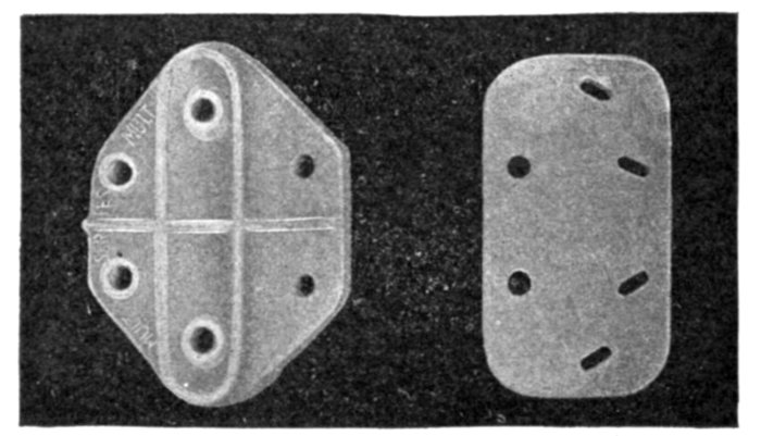
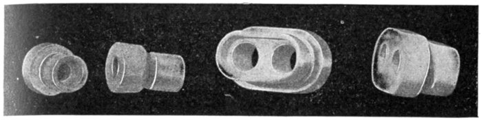
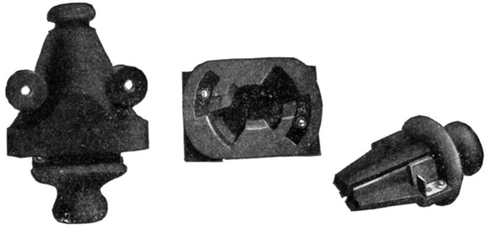
Figs. 1,630 to 1,641.—Terminals for General Electric polyphase induction motors. In order to prevent any mechanical
strain on the leads being transmitted to the motor windings, the terminal cables are clamped in insulated
bushings with a connector for each cable.
Ques. Describe briefly the operation of a polyphase
induction motor.
Ans. Its operation is due to the production of a rotating
magnetic field by the polyphase current furnished. This field
"rotating" in space about the axis of the armature induces
currents in the latter. The reaction between these currents and
the rotating field creates a torque which tends to turn the armature,
whether the latter be at rest or in motion.
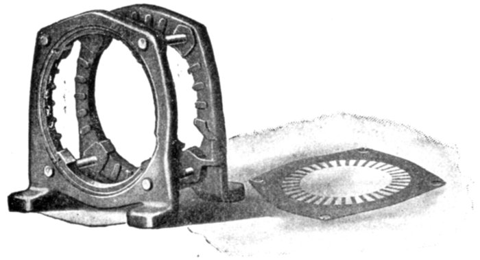
Figs. 1642 and 1643.—Western Electric end flange rivets and punchings of riveted frame induction
motor. The riveted frame is constructed of two cast iron flanges between which the
stator laminations of sheet steel are securely clamped and riveted under hydraulic pressure.
This construction exposes the laminations directly to the air and improves the radiation,
thus insuring high overload capacity and low operating temperatures. The field slots are
overhung or partially closed, affording mechanical protection to the coils.
Ques. Why are induction motors called "asynchronous"?
Ans. Because the armature does not turn in synchronism
with the rotating field, or, in the case of a single phase induction
motor, with the oscillating field (considering the latter in the
light of a rotating field).
Ques. How does the speed vary?
Ans. It is slower (more or less according to load) than the
"field speed," that is, than "synchronism" or the "synchronous
speed."
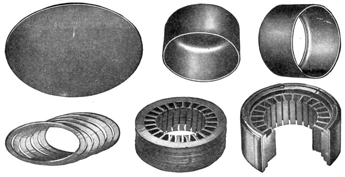
Figs. 1,644 to 1,649.—Construction of General Electric drawn shell fractional horse power motors. The distinguishing feature
of drawn shell motors is the field construction which consists of a steel shell or cylinder supporting and clamping together the
stator or field punchings. This method avoids the cast frame work outside the active magnetic material. A disc is first punched or
"blanked" out of soft steel, fig. 1,644, this disc being faced into the shape, fig. 1,645, with one end closed. The other end of the
shell is then cut out, leaving the small flange as in fig. 1,646. It is now ready to receive the core punchings. In the next operation
a suitable number of spacing rings, fig. 1,647, are forced into the shell and seated against the retaining lip, which may
be seen in fig. 1,646. The field punchings or laminæ, fig. 1,648, are now assembled, after which a second and equal set of spacing
rings are put into place to center the active field iron. The open edge of the shell is then rolled over the punchings under
heavy pressure, thus preparing the field structure for the machining and fitting of the end heads and base. Fig. 1,649 shows
a section of the completely assembled field structure, the parts being cut away to indicate the relation between the field
punchings, spacing rings and shell. After the spacing rings at both frame ends have been turned true and grooved, the
bearing heads, fig. 1,649, are ready for fastening in place by four fillister headed screws. A complete wound field is shown in
fig. 1,858, with flat base casting attached.
Ques. What is the difference of speed called?
Ans. The slip.
This is a vital factor in the operation of an induction motor, since
there must be slip in order that the armature inductors shall cut magnetic
lines to induce (hence the name "induction" motor) currents therein
so as to create a driving torque.
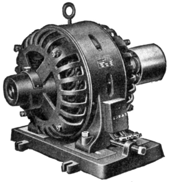
Fig. 1,650.—Ideal fifteen horse power two phase induction motor. The armature core is
supported by a cast iron frame carried on a base, with sliding ways and screw adjustment
for tightening the belt. The armature core is provided with ventilating apertures,
with metal spacers between each tooth. The revolving field is a steel casting with radially
projecting poles, to which the pole shoes are bolted. The overhanging pole tips
retain the field coils. All coils of the smaller sizes are wound with insulated copper wire
of square section, and of the larger sizes, with flat copper, wound on edge, each turn being
insulated by sheet insulation. Motors of this type are adapted for use in small power
plants and isolated plants. The relatively high speed for which they are designed, reduces
considerably the weight and overall dimensions, and likewise the cost. The exciter
is belt driven. The normal kw. capacity of the exciter usually exceeds the kw. required
for the excitation under normal load conditions to permit of station lighting. All exciters
are built as compound wound dynamos, capable of delivering the exciter current up to
125 volts, which is sufficient margin in the field to control the alternating current line
voltage on circuits of unusually low power factor.
Ques. What is the extent of the slip?
Ans. It varies from about 2 to 5 per cent. of synchronous
speed depending upon the size.
Ques. Why are induction motors sometimes called
constant speed motors?
Ans. They are erroneously and ill advisedly, yet conveniently
so called by builders to distinguish them from induction motors
fitted with special devices to obtain widely varying speeds, and
which are known as variable speed induction motors.
The term adjustable would be better.
Motor, Constant Speed.—A motor in which the speed is either constant or does not
materially vary; such as synchronous motors, induction motors with small slip, and ordinary
direct current shunt motors.—Paragraph 46 of 1907 Standardization Rules of the A.I.E.E.
Motor, Variable Speed.—A motor in which provision is made for varying the speed as
desired. The A.I.E.E. has unfortunately introduced the term varying speed motor, to designate
"motors in which the speed varies with the load, decreasing when the load increases, such as
series motors." The term is objectionable, since by the expression variable speed motor a much
more general meaning is intended.
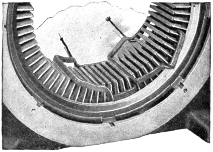
Fig. 1,651.—Western Electric core construction and method of winding field of skeleton
frame induction motor. The coils are wound on forms to give them exact shape and
dimensions required. They are pressed into hot moulds to remove any irregularities and
then the coils are impregnated with hot cement, to bind the layers together in their permanent
shape. The portion of the coil which fits into the slot is wrapped with varnished
cloth and a layer of dry tape is wound over the entire coil. The coils are then impregnated
with an insulating compound and baked, the process being repeated six times. Coils for
1,100 and 2,200 volt motors have an extra covering of insulation and double the amount
of impregnating and baking. The coils may be furnished with special insulation and
treatment for exceptionally severe service conditions, such as exposure to excessive
moisture, extreme heat, acid or alkaline fumes, etc. The coils are accessible and for the
final finish are sprayed with black varnish.
Ques. Why do some writers call the field magnets and
armature the primary and secondary, respectively?
Ans. Because, in one sense, the induction motor is a species
of transformer, that is, it acts in many respects like a transformer,
the primary winding of which is on the field and the
secondary winding on the armature.
In the motor the function of the secondary circuit is to furnish energy
to produce a torque, instead of producing light and heat as in the case
of the transformer. Such comparisons are ill advised when made for
the purpose of supplying names for motor parts. There can be no
confusion by employing the simple terms armature and field magnets,
remembering that the latter is that part that produces the oscillating or
rotating field (according as the motor is single or polyphase), and the
former, that part in which currents are induced.
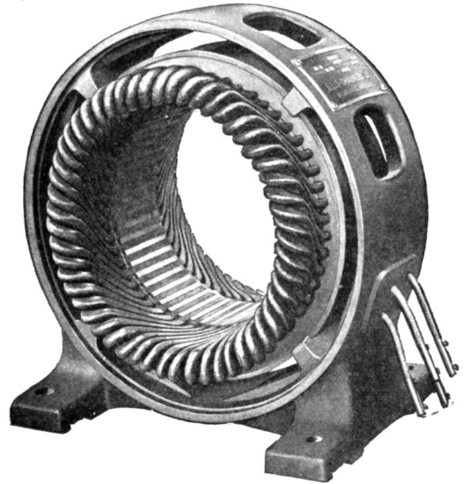
Fig. 1,652.—Armature of Allis-Chalmers squirrel cage induction motor. The frame casting
is of the box type and has large cored openings for ventilation. Lugs are cast on the
interior surface of the frame to support the core, leaving a large air space between.
Ques. Why are polyphase induction motors usually
presented in text books before single phase motors?
Ans. Because the latter must start with a rotating field and
come up to speed before the oscillating field can be employed.
A knowledge then of the production of a rotating field is necessary
to understand the action of the single phase motor at starting.
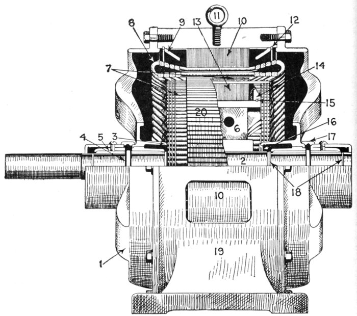
Fig. 1,653.—Sectional view showing parts of Reliance polyphase induction motor. A special
feature of the squirrel cage armature construction is the multiplicity of short circuiting
rings. The holes in the rings are bored slightly smaller than the diameter of the copper
rods, and the force fit gives good contact. The rings having been forced in place are dip
soldered in an alloy of tin of high melting point. The motor parts are: 1, end yoke;
2, shaft; 3, armature short circuiting rings; 4, oil ring; 5, self-aligning bearing bushing;
6, spider; 7, armature bars; 8, field coils; 9, field lamination end plate; 10, field laminations;
11, eye bolt; 12, stator locking key; 13, armature laminations; 14, armature lamination
end plate; 15, armature locking key; 16, dust cap; 17, oil well cover; 18, oil throws;
19, field frame; 20, squirrel cage armature.
Polyphase Induction Motors.—As many central stations
put out only alternating current circuits, it has become necessary
for motor builders to perfect types of alternating current
motor suitable for all classes of industrial drive and which are
adapted for use on these commercial circuits. Three phase
induction motors are slightly more efficient at all loads than two
phase motors of corresponding size, due to the superior distribution
of the field windings. The power factor is higher, especially
at light loads, and the starting torque with full load current is
also greater. Furthermore, for given requirements of load and
voltage, the amount of copper required in the distributing system
is less; consequently, wherever service conditions will permit,
three phase motors are preferable to two phase.
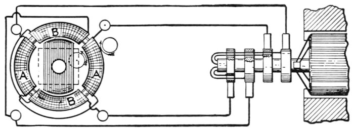
Fig. 1,654.—Tesla's rotating magnetic field. The figure is from one of Tesla's papers as given in
The Electrician, illustrating how a rotating magnetic field may be produced with stationary
magnets and polyphase currents. The illustration shows a laminated iron ring overwound
with four separate coils, AA, and BB, each occupying about 90° of the periphery. The
opposite pairs of coils AA and BB respectively are connected in series and joined to the
leads from a two phase alternator, the pair of coils AA being on one circuit and the coils
BB on the other. The resultant flux may be obtained by combining the two fluxes due to
coils AA and BB, taking account of the phase difference of the two phase current, as in
fig. 1,655.
The construction of an induction motor is very simple, and
since there are no sliding contacts as with commutator motors,
there can be no sparks during operation—a feature which adapts
the motor for use in places where fire hazards are prominent.
The motor consists, as already mentioned, simply of two parts:
an armature and field magnets, without any electrical connection
between these parts. Its operation depends upon:
- 1. The production of a rotating field;
- 2. Induction of current in the armature;
- 3. Reaction between the revolving field and the induced currents.
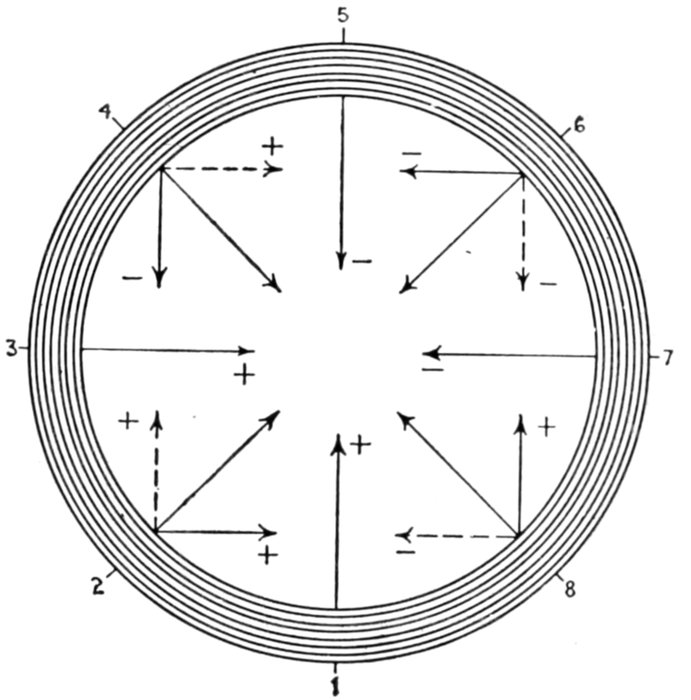
Fig. 1,655.—Method of obtaining resultant flux of Tesla's rotating magnetic field. The
eight small diagrams here seen show the two components and resultant for eight
equivalent successive instants of time during one cycle. At 1, the vertical flux is at
+ maximum and the horizontal is zero. At 2, the vertical flux is still + but decreasing,
and the horizontal is + and increasing, the resultant is the thick line sloping at 45° upwards
to the right. At 3, the vertical flux is zero, and the horizontal is at its + maximum,
and similarly for the other diagrams. Thus at 8, the vertical flux is + and increasing,
while the horizontal is-and decreasing, the resultant is the thick line sloping at 45°
upwards to the left. At points 2, 4, 6, and 8 the increasing fluxes are denoted by full and
the decreasing by dotted lines. The laminated iron of the ring is indicated by the circles,
and the result is that at the instants chosen the flux across the plane of the ring is directed
inwards from the points 1, 2, 3, 4, etc., on the inner periphery of the iron. There will,
therefore, appear successively at these points effective north poles, the corresponding south
poles being simultaneously developed at the points diametrically opposite. These poles
travel continuously from one position to the next, and thus the magnetic flux across the
plane of the ring swings round and round, completing a revolution without change of
intensity during the cycle time of the current.
Production of a Rotating Field.—It should at once be
understood that the term "rotating field" does not signify that
part of the apparatus revolves, the expression merely refers to
the magnetic lines of force set up by the field magnets without
regard to whether the latter be the stationary or rotating member.
A rotating field then may be defined as the resultant magnetic
field produced by a system of coils symmetrically placed and supplied
with polyphase currents.
A rotating magnetic field can, of course, be produced by spinning a
horse shoe magnet around its longitudinal axis, but with polyphase currents,
as will be later shown, the rotation of the field can be produced
Without any movement of the mechanical parts of the electro magnets.
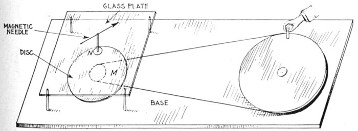
Fig. 1,656.—Arago's rotations. The apparatus necessary to make the experiment consists of
a copper disc M, arranged to rotate around a vertical axis and operated by belt drive, as
shown. By turning the large pulley by hand, the disc M may be rotated with great rapidity.
Above the disc is a glass plate on which is a small pivot supporting a magnetic needle N.
If the disc now be rotated with a slow and uniform velocity, the needle is deflected in the
direction of the motion, and stops at an angle of from 20° to 30° with the direction of the
magnetic meridian, according to the velocity of the rotation of the disc. If the velocity
increase, the needle is ultimately deflected more than 90° and then continues to follow the
motion of the disc.
The original rotating magnetic field dates back to 1823, when
Francois Jean Arago, an assistant in Davy's laboratory, discovered
that if a magnet be rotated before a metal disc, the
latter had a tendency to follow the motion of the magnet, as
shown in fig. 290, page 270 and also in fig. 1,656. This experiment
led up to the discovery which was made by Arago in 1824,
when he observed that the number of oscillations which a magnetized
needle makes in a given time, under the influence of the earth's
magnetism, is very much lessened by the proximity of certain
metallic masses, and especially of copper, which, may reduce the
number in a given time from 300 to 4.
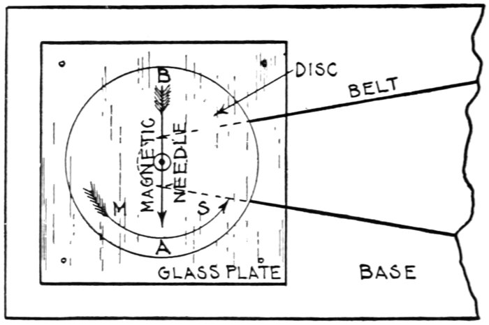
Fig. 1,657.—Explanation of Arago's rotations. Part of fig. 1,656 is here reproduced in plan.
Faraday was the first to give an explanation of the phenomena of magnetism by rotation
in attributing it to the induction of currents which by their electro-dynamic action, oppose
the motion producing them; the action is mechanically analogous to friction. In the
figure, let AB be a needle oscillating over a copper disc, and suppose that in one of its
oscillations it goes in the direction of the arrow from M to S. In approaching the point S,
for instance, it develops there a current in the opposite direction, and which therefore
repels it; in moving away from M it produces currents which are of the same kind, and
which therefore attract, and both these actions concur in bringing it to rest. Again,
suppose the metallic mass turn from M towards S, and that the magnet be fixed; the
magnet will repel by induction points such as M which are approaching A, and will attract
S which is moving away; hence the motion of the metal stops, as in Faraday's experiment.
If in Arago's experiment the disc be moving from M to S, M approaches A and repels it,
while S, moving away, attracts it; hence the needle moves in the same direction as the disc.
If this explanation be true, all circumstances which favor induction will increase the
dynamic action; and those which diminish the former will also lessen the latter.
The explanation of Arago's rotations is that the magnetic
field cutting the disc produces eddy currents therein and the
reaction between the latter and the field causes the disc to follow the
rotations of the field.
The induction motor is a logical development of the experiment
of Arago, which so interested Faraday while an assistant in
Davy's laboratory and which led him to the discovery of the laws
of electromagnetic induction, which are given in Chapter X.
[4]In 1885, Professor Ferraris, of Turin discovered that a
rotating field could be produced from stationary coils by means of
polyphase currents.
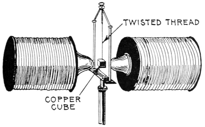
Fig. 1,658.—Experiment made by Faraday being the reverse of Arago's first observation.
Faraday assumed that since the presence of a metal at rest stops the oscillations of a
magnetic needle, the neighborhood of a magnet at rest ought to stop the motion of a
rotating mass of metal. He suspended a cube of copper by a twisted thread, which was
placed between the poles of a powerful electromagnet. When the thread was left to itself,
it began to spin round with great velocity, but stopped the moment a powerful current was
passed through the electromagnet.
[5]This discovery was commercially applied a few years later by
Tesla, Brown, and Dobrowolsky.
The principles of polyphase motors can be best understood by
means of elementary diagrams illustrating the action of polyphase
currents in producing a rotating magnetic field, as explained
in the paragraphs following.
Production of a Rotating Magnetic Field by Two Phase
Currents.—Fig. 1,659 represents an iron ring wound with coils
of insulated wire, which are supplied with a two phase current
at the four points A, B, C, D, the points A and B, and C and D,
being electrically connected.
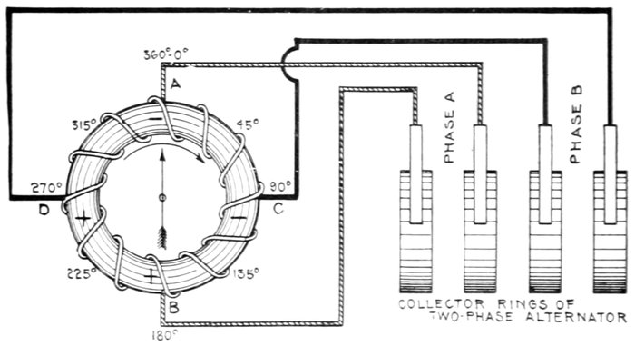
Fig. 1,659.—Production of a rotating magnetic field by two phase currents. The figure represents
an iron ring, wound with coils of insulated wire, and supplied with two phase currents
at the four points A, B, C, and D. The action of the two phase current on the ring in
producing a rotating magnetic field is explained in the accompanying text.
According to the principles of electromagnetic induction, if
only one current a entered the ring at A, and the direction of
the winding be suitable, a negative pole (-) will be produced at
A and a positive pole (+) at B, so that a magnetic needle
pivoted in the center of the ring would tend to point vertically
upward towards A. Now suppose that at this instant, corresponding
to the beginning of an alternating current cycle, a
second current b, differing in phase from the first by 90 degrees,
is allowed to enter the ring at C. As shown in fig. 1,659, when the
pressure of the current a is at its maximum, that of the current
b is at its minimum; therefore, even a two phase current, at the
beginning of the cycle, the needle will point toward A.
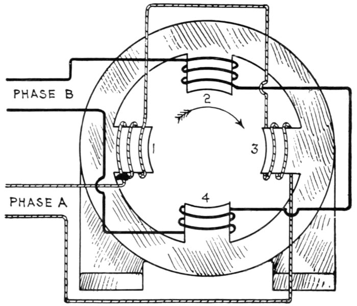
Fig. 1,660.—Production of rotating magnetic field in a two pole two phase motor. The poles
are numbered from 1 to 4 in a clockwise direction. Phase A winding is around poles 1
and 3, and phase B winding, around poles 2 and 4. In each case the poles are wound
alternately, that is, if 1 be wound clockwise, 3 will be wound counter clockwise, thus producing
unlike polarity in opposite poles. Now during one cycle of the two phase current,
the following changes take place, starting with pole 1 of N polarity and 3, of S polarity:
|
One Cycle |
| Degrees |
0° to 90° |
90° to 180° |
180° to 270° |
270° to 360° |
| Polarity |
1N - 3S |
2N - 4S |
3N - 1S |
4N - 2S |
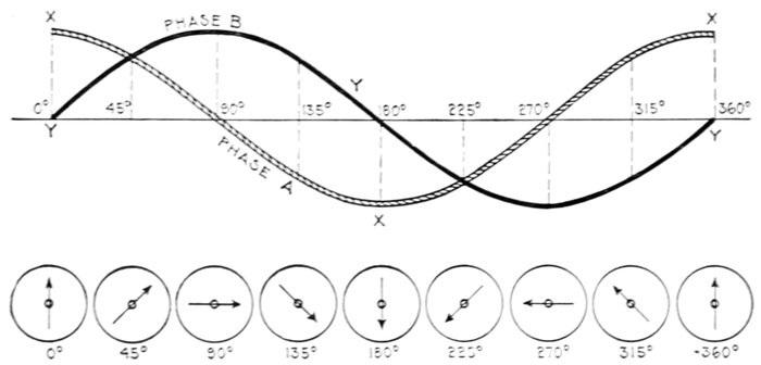
Fig. 1,661.—Diagram showing resultant poles due to two phase current.
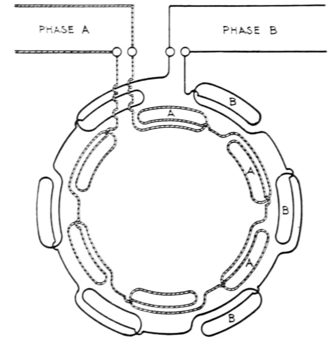
Fig. 1,662.—Diagram of two phase, six pole field winding. There are six coils in each phase,
as shown. The coils of each phase are connected in series, adjacent coils being joined
in opposite senses, thus, for each phase, first one coil is wound clockwise, and the
next counter clockwise.
As the cycle continues, however, the strength of a will diminish
and that of b increase, thus shifting the induced pole toward C,
until b attains its maximum and a falls to its minimum at 90°
or the end of the first quarter of the cycle, when the needle will
point toward C. At 90°, the phase a current reverses in direction
and produces a negative pole at B, and as its strength increases
from 90° to the 180° point of the cycle, and that of phase b
diminishes, the resultant negative pole is shifted past C toward
B, until a attains its maximum and b falls to its minimum at
180°, and the needle points in the direction of B.
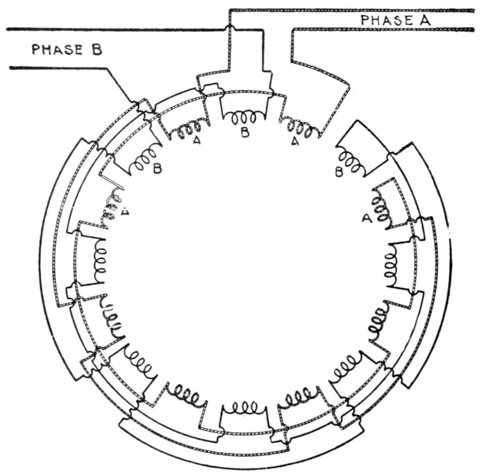
Fig. 1,663.—Diagram of two phase, eight pole field winding. The winding is divided into
16 groups (equal to the product of the number of poles multiplied by the number of phases).
Each group such as at A comprises a number of coils in series, each coil being located in a
separate pair of slots, the end of one being connected to the beginning of the next.
When the currents are in the same direction, the currents circulate in the same direction
in two adjacent groups, a pole then with this arrangement being formed by two
groups, both phases contributing to the formation of the pole. After ½ cycle when the
current in each phase reverses, the pole advances the angular distance, covered by two
groups; hence the field completes one revolution in eight alternations of current.
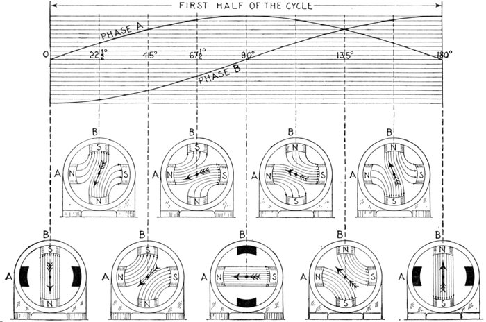
Figs. 1,664 to 1,683.—Sine curves of two phase current and diagrams showing the physical conception of a two phase rotating
magnetic field. The alternating magnetizing current is assumed to be of such strength that, at its maximum strength, the field
produced may be represented by 10 lines of force as indicated by the parallel lines. At the beginning of the rotation, fig. 1,664,
phase A magnetization, according to sine curve is zero, indicated by the solid black poles, while phase B is of strength 10 with
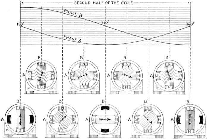
current in the direction to produce a south pole at B. Similarly, in fig. 1,665, the strength of A is 4 lines, and of B, 9 lines, the
resultant magnetization having rotated 22½°. The direction of the resultant magnetization is indicated by the arrow in each
figure. It should be noted in fig. 1,669, that the polarity of B is reversed, the current curve now being above the zero line. By
following the arrow through the successive positions the rotation of the resultant magnetization is clearly seen.
At the 180° point of the cycle, b reverses in direction and produces
a negative pole at D, and as the fluctuation of the pressure
of the two currents during the second half of the cycle, from
180° to 360°, bear the same relation to each other as during the
first half, the resultant poles of the rotating magnetic field thus
produced carry the needle around in continuous rotation so
long as the two phase current traverses the windings of the ring.
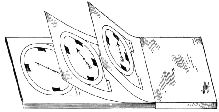
Fig. 1,684.—Moving picture method of showing motion of a rotary magnetic field. A number
of sheets of paper are prepared, each containing a drawing of the motor frame and a
magnetic needle in successively advancing angular positions, indicating resultant directions
of the magnetism. The sheets are bound together so that the axis of the needle on each
sheet coincides. When passing the sheets in one way the revolving field will be seen to
rotate in one direction, while, when moving the sheets backward, the rotation of the
magnetic field is in the opposite direction, showing that the reversal of the order of the
coils has the effect of reversing the rotation of the magnetic field.
Production of Rotating Magnetic Field by Three Phase
Current.—A rotating magnetic field is produced by the action
of a three phase current in a manner quite similar to the action
of a two phase current. Fig. 1,685 shows a ring suitably wound
and supplied with a three phase current at three points A, B, C,
120° of a cycle apart.
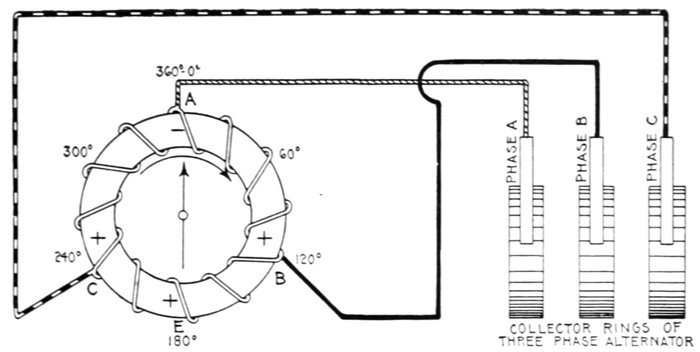
Fig. 1,685.—Production of a rotating magnetic field by three phase current. A ring wound as
shown is tapped at points A, B, and C, 120° apart, and connected with leads to a three
phase alternator. As described on page 1,304, a rotating magnetic field is produced
in a manner similar to the two phase method.
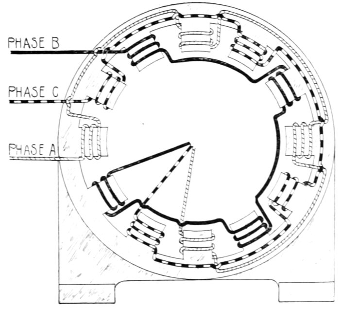
Fig. 1,686.—Diagram of three phase, four pole Y connected field winding.
At the instant when the current a, flowing in at A, is at its maximum,
two currents b and c, each one-half the value of a, will flow out B and C,
thus producing a negative pole at A and a positive pole at B and at C.
The resultant of the latter will be a positive pole at E, and consequently,
the magnetic needle will point towards A.
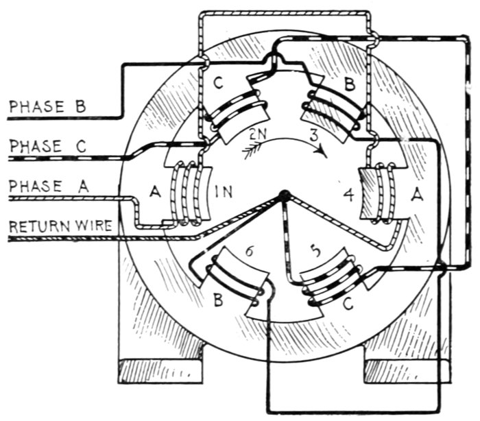
Fig. 1,687.—Production of a rotating magnetic field in a two pole three phase motor. In
order to obtain a uniformly rotating magnetic field, it is necessary to arrange the phase
windings in the direction of rotation, in the sequence ACB, not ABC as indicated on the
magnets. Thus poles 1 and 4 are connected in series to phase A, 2 and 5 in series to phase
C, and 3 and 6 in series to phase B. The different phase windings are differently lined,
and it should be noted that they have a common return wire, though this is not absolutely
necessary. Since the phases of the three currents differ from each other by one-third
of a period or cycle, each of the phase windings will therefore set up a field between
its poles, which at any instant will differ, both in direction and magnitude, from the fields
set up by the other phase windings. Hence, the three phase windings acting together will
produce a resultant field, and if plotted out, the directions of this field for various fractions
of the period is such that in one complete period the resultant field will make one complete
round of the poles in a clockwise direction, as indicated by the curved arrow. The positions
of the resultant field during one complete period may be tabulated as follows:
|
One Cycle |
|
0° to 60° |
60° to 120° |
120° to 180° |
180° to 240° |
240° to 300° |
300° to 360° |
| Polarity |
1N - 4S |
2N - 5S |
3N - 6S |
4N - 1S |
5N - 2S |
6N - 3S |
As the cycle advances, however, the mutual relations of the fluctuations
of the pressures of the three currents, and the time of their
reversals of direction will be such, that when a maximum current is
flowing at any one of the points A, B, and C, two currents each of one-half
the value of the entering current will flow out of the other two
points, and when two currents are entering at any two points, a current
of maximum value will flow out of the other point. This action will
produce one complete rotation of the magnetic field during each cycle
of the current.
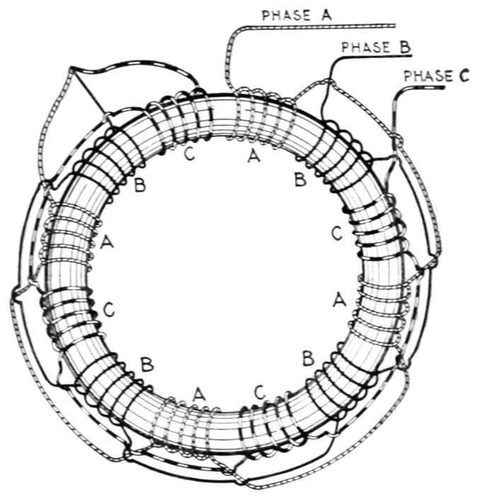
Fig. 1,688.—Production of three phase rotating magnetic field with winding on laminated
iron ring. The winding is divided into twelve sections, which are connected in three groups,
A, B, and C, of four sections each, the sections in each group being evenly placed round
the ring with the sections of the two other groups between them. One end of each group is
to be connected to the line wire and the other end to the common junction J, from which
it follows that the winding given is an example of "star" winding. With three phase
currents the winding will give at every instant four N poles and four S poles round the
ring, and in actual working these poles will be on the inner periphery because of the presence
of an inner ring or cylinder of good magnetic iron placed, with the requisite clearance to
allow of rotation, as close as is mechanically possible to the outer ring. Each one of these
eight poles will make a complete revolution round the ring in four times the periodic time
of the currents supplied. Thus, if the supply current has a frequency of 50, a complete
revolution of the field will take place in .08 (=4/50) of a second, which corresponds to an
angular velocity of 750 revolutions per minute in place of 3,000 revolutions per minute,
which would be the angular velocity with a bipolar field at this periodicity. Similarly a
continuously wound Gramme ring tapped at twelve points, joined in three groups of four
each to the supply mains, would give an eight pole rotary field. In this case the grouping
would be a "mesh" grouping, with each side of the mesh formed of four coils in parallel.
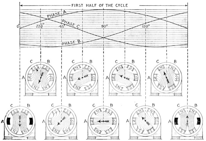
Figs. 1,689 to 1,708.—Sine curves of three phase current and diagrams showing the physical conception of a three phase rotating
magnetic field. The diagrams are constructed in the same manner as explained in figs. 1,664 to 1,683. It should be noted
that the phase windings are arranged in the direction of rotation in the sequence ACB, phase C being wound in opposite
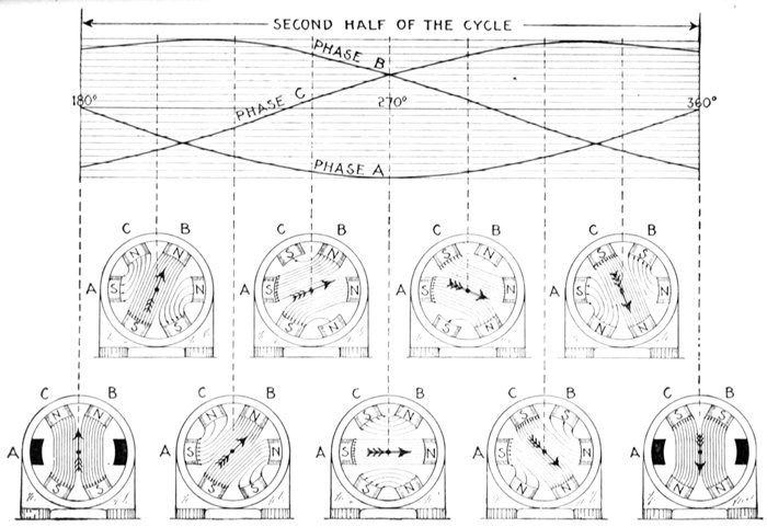
sense to A and B, as indicated by the curves, in that north poles are produced at A and B when the respective curves are
above the zero line, a south pole being produced at C when its curve is above the zero line. The rotation of the resultant
magnetization is clearly seen by following the arrow through its successive positions.
Slip.—Instead of the magnetic needle as was used in the
preceding figures, a copper cylinder may be placed in a rotating
magnetic field and it will be urged also to turn in the same direction
as the rotation of the field.
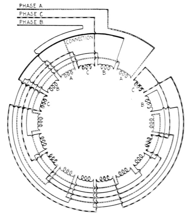
Fig. 1,709.—Diagram of three phase, six pole field winding. There are 18 groups, and the
sequence of phases is ABC in a counter clockwise direction. For a Y connection, the
middle phase is reversed, so that a pole will be formed by the three consecutive phases
when the current is in the same direction in A and C, and opposite in B. The beginning
of the middle coil C, and not the end, as with the other two, is connected to the common
point O. In this case the pole shifts a distance equal to three groups for each alternation,
so that one revolution of the field requires three cycles.
The torque tending to turn the cylinder is due to the induction
of currents of opposite polarity in the cylinder.
For simplicity, the rotating magnetic field may be supposed
to be produced by a pair of magnetic poles placed at opposite
sides of the cylinder and revolved around it as in fig. 1,710.
Now, for instance in starting, the cylinder being at rest any
element or section of the surface as the shaded area AB, will,
as it comes into the magnetic field of the rotating magnet, cut
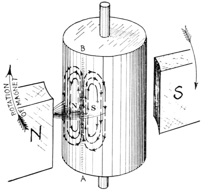
Fig. 1,710.—Copper cylinder and rotating magnet illustrating the principle of operation of an
induction motor. The "rotating magnetic field" which is necessary for induction motor
operation is for simplicity here produced by rotating a magnet as shown. In starting,
the cylinder being at rest, any element as AB, as it is swept by the field will cut magnetic
lines, which will induce a current upward in direction as determined by applying Fleming's
rule (fig. 132, page 133). The inductive action is strongest at the center of the field
hence as AB passes the center the induced pressure along AB is greater than along elements
more or less remote on either side. Accordingly a pair of eddy currents will result as
shown (see fig. 291, page 271). Applying the right hand rule for polarity of these eddy
currents (see fig. 119, page 117) it will be seen that a S pole is induced by the eddy on
the side of the cylinder receding from the magnet, and a N pole by the eddy on the side
toward which the magnet is approaching. The cylinder, then, is attracted in the direction
of rotation of the magnet by the induced pole on the receding side, and repelled in the same
direction by the induced pole on the approaching side. Accordingly, the cylinder begins
to rotate. The velocity with which it turns depends upon the load; it must always turn
slower than the magnet, in order that its elements may cut magnetic lines and induce
poles to produce the necessary torque to balance the load. The difference in speed of
the magnet and cylinder is called the slip. Evidently the greater the load, the greater
is the slip required to induce poles of sufficient strength to maintain equilibrium. The
figure is drawn somewhat distorted, so that both eddies are visible.
magnetic lines of
force inducing a current
therein, whose
direction is easily
determined by applying
Fleming's
rule.[6]
Since the field is
not uniform, but
gradually weakens,
as shown, on either
side of the shaded
area (which is just
passing the center),
the pressure induced
on either side will
be less than that
induced in the shaded
area, giving rise
to eddy currents
(as illustrated in
fig. 291, page 271). These eddy currents induce poles as indicated
at the centers of the whorls, the polarity being determined
by applying the right hand rule (fig. 119, page 117).
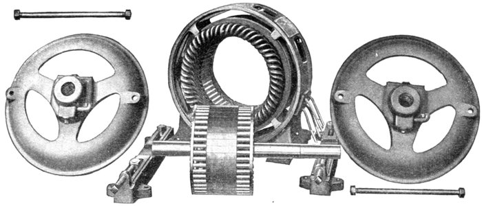
Figs. 1,711 to 1,718.—Parts of Allis-Chalmers polyphase induction motor with squirrel cage armature.
By inspection of fig. 1710, it is seen that the induced pole toward
which the magnet is moving is of the same polarity as the magnet;
therefore it is repelled, while the induced pole from which the
magnet is receding, being of opposite polarity, is attracted. A
torque is thus produced tending to rotate the cylinder.
It must be evident that this torque is greatest when the cylinder
is at rest, because the magnetic lines are cut by any element on
the cylindrical surface at the maximum rate.
Moreover, as cylinder is set in motion and brought up to speed,
the torque is gradually reduced, because the rate with which the
magnetic lines are cut is gradually reduced.
Ques. What is the essential condition for the operation
of an induction motor?
Ans. The armature, or part in which currents are induced, must
rotate at a speed slower than that of the rotating magnetic field.
In the elementary induction motor, fig. 1,710, the cylinder is the
armature, and the rotating magnets are the equivalent of a rotating
magnetic field.
Ques. What is the difference of speed called?
Ans. The slip.
Ques. Why is slip necessary in the operation of an induction
motor?
Ans. If the armature had no weight and there was no friction
offered by the bearings and air, it would revolve in synchronism
with the rotating magnetic field, that is, the slip would be zero;
but since weight and friction are always present and constitute
a small load, its speed of rotation will be a little less than that of
the rotating magnetic field, so that induction will take place, in
amount sufficient to produce a torque that will balance the load.
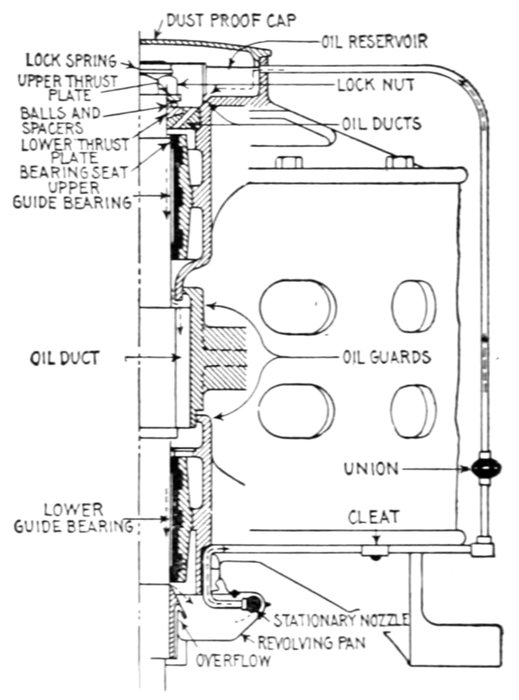
Fig. 1,719.—General Electric vertical type induction motor; sectional view showing oiling
system. It is provided with ball thrust bearings and top and bottom guide bearings, and
a continuous flow of oil is maintained through all the bearings by means of a pump which
is made integral with the motor. The ball thrust bearings are designed to support the
weight of the armature only. In cases where the armature is direct connected a flexible
coupling should be used to prevent additional weight coming on the thrust bearings. In
operation, when the motor starts, the oil, revolving with the pan, flows against the stationary
nozzle and is forced by its velocity at a high pressure through the oil pipe into the
reservoir on top. It then flows down through the ball bearing and upper guide bearing,
through a slot in the armature spider into the lower guide bearing and thence into the
oil pan. Thus a continuous stream of oil is delivered through all bearings.
Ques. How is slip expressed?
Ans. In terms of synchronism, that is, as a percentage of the
speed of the rotating magnetic field.
The slip is obtained from the following formula:
Slip (rev. per sec.) = Sf - Sa
or, expressed as a percentage of synchronism, that is, of the synchronous
speed,
where
- Sf = Synchronous speed, or R.P.M. of the rotatory magnetic field;
- Sa = Speed of the armature.
The synchronous speed is determined the same as for synchronous
motor by use of the following formula:
where
- Sf = Synchronous speed or R.P.M. of the rotating magnetic field;
- P = Number of poles;
- f = frequency.
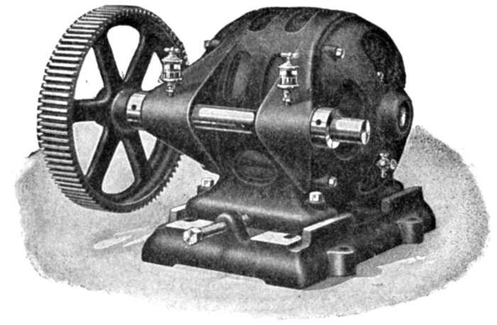
Fig. 1720.—Triumph back geared polyphase induction motor. A great many applications,
especially for direct attachment, require the use of either a very slow or special speed
motor. As these are quite costly, the preferable arrangement, and one equally as satisfactory,
is the use of a standard speed motor combined with a back geared attachment.
Rawhide pinions are furnished whenever possible, insuring smooth running with a minimum
of noise.
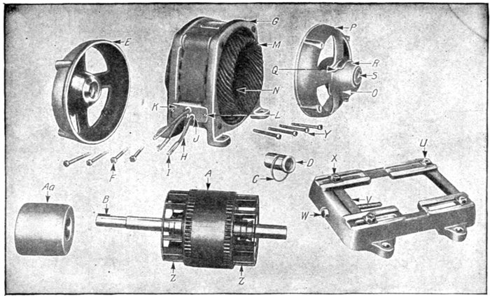
Figs. 1,721 to 1,735.—Parts of General Electric small polyphase induction motors. A, armature; B, key for armature
shaft; C, oil ring; D, bearing lining; E, bearing head, pulley end; F, cap screw for bearing heads; G, field,
complete with winding, terminal plate and leads; H, motor leads; I, terminal connector for motor leads; J, soft
rubber bushing for motor leads; K, terminal plate; L, screw for terminal board; M, field coils; N, wooden top
sticks for field coils; O, oil filler; P, bearing head opposite pulley end; Q, screw for oil well cover; R, oil well
cover; S, socket pipe plug for bearing head; U, motor base; V, yoke for motor base; W, motor base adjusting
screw; X, bolt for motor base and frame (short); Y, cap screw for bearing head; Z, internal directive fan;
Aa, pulley.
The following table gives the synchronous speed for various frequencies
and different numbers of poles:
Table of Synchronous Speeds
| Frequency |
R.P.M. of the rotating magnetic field, when number of poles is |
| 2 |
6 |
10 |
16 |
20 |
24 |
| 25 |
1,500 |
500 |
300 |
188 |
150 |
125 |
| 60 |
3,600 |
1,200 |
720 |
450 |
360 |
300 |
| 80 |
4,800 |
1,600 |
960 |
600 |
480 |
400 |
| 100 |
6,000 |
2,000 |
1,200 |
750 |
600 |
500 |
| 120 |
7,200 |
2,400 |
1,440 |
900 |
720 |
600 |
| 125 |
7,500 |
2,500 |
1,500 |
938 |
750 |
625 |
Ques. How does the slip vary?
Ans. It varies from about 1 per cent. in a motor designed
for very close regulation to 40 per cent. in one badly designed,
or designed for some special purpose.
Ques. Why is the slip ordinarily so small?
Ans. Because of the very low resistance of the armature,
very little pressure is required to produce currents therein, of
sufficient strength to give the required torque. Hence, the
necessary rate of cutting the magnetic lines to induce this pressure
in the armature is reached with very little difference between
the field speed and armature speed, that is, with very little slip.
Ques. How does the slip vary with the load?
Ans. The greater the load the greater the slip.
In other words, if the load increase, the motor will run slower, and
the slip will increase. With the increased slip, the induced currents
and the driving force will further increase. If the motor be well designed
so that the field strength is constant and the lag of the armature
currents is small, the driving force developed or torque will be proportional
to the slip, that is the slip will increase automatically as the
load is increased, so that the torque will be proportional to the load.
According to Weiner, the slip varies according to the following table:
SLIP OF INDUCTION MOTORS
| Capacity of motor H. P. |
Slip at full load per cent. |
Capacity of motor H. P. |
Slip at full load per cent. |
| Usual limits |
Average |
Usual limits |
Average |
| ⅛ |
20 to 40 |
30 |
15 |
5 to 11 |
8 |
| ¼ |
10 " 30 |
20 |
20 |
4 " 10 |
7 |
| ½ |
10 " 20 |
15 |
30 |
3 " 9 |
6 |
| 1 |
8 " 20 |
14 |
50 |
2 " 8 |
5 |
| 2 |
8 " 18 |
13 |
75 |
1 " 7 |
4 |
| 3 |
8 " 16 |
12 |
100 |
1 " 6 |
3.5 |
| 5 |
7 " 15 |
11 |
150 |
1 " 5 |
3 |
| 7½ |
6 " 14 |
10 |
200 |
1 " 4 |
2.5 |
| 10 |
7 " 12 |
9 |
300 |
1 " 3 |
2 |
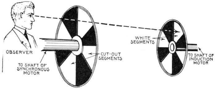
Fig. 1,736.—Sector method of measuring the slip of induction motors. A black disc having
a number of white sectors (generally the same as the number of poles of the induction
motor) is fastened with wax to shaft of the induction motor, and is observed through
another disc having an equal number of sector shaped slits (that is a similar disc with the
white sectors cut out) and attached to the shaft of a small self-starting synchronous motor,
which is fitted with a revolution counter that can be thrown in or out of gear at will; then
the slip (in terms of Nr) = N ÷ (Ns ÷ Nr), in which: N = number of passages of the
sectors; Ns = number of sectors; Nr = number of revolutions recorded by the counter
during the interval of observation. For large values of slip, the observations may be
simplified by using only one sector (Ns = 1), then N will equal the slip in revolutions.
Ques. Describe one way of measuring the slip.
Ans. A simple though rough way is to observe simultaneously
the speed of the armature and the frequency, calculating
the slip from the data thus obtained, as on page 1,315.
This method is not accurate, as, even with the most careful readings,
large errors cannot be avoided. A better way is shown in fig. 1,736.
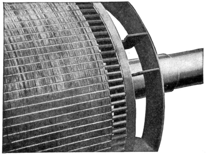
Fig. 1,737.—Detail of Westinghouse squirrel cage armature for induction motor. This is
an example of cast on construction similar to that of Morse-Fairbanks (see figs. 1,752, 1,753
and 1,915). The inductors are embedded in a special cement.
Evolution of the Squirrel Cage Armature.—In the early
experiments with rotating magnetic fields, copper discs were used;
in fact, it was then discovered that a mass of copper or any conducting
metal, if placed in a rotating magnetic field, will be urged
in the direction of rotation of the field.
Ferraris used a copper cylinder as in figs. 1,710 and 1,738,
which was the first step in the evolution of the squirrel cage
armature. The trouble with an armature of this kind is that
there is no definite path provided for the induced currents.
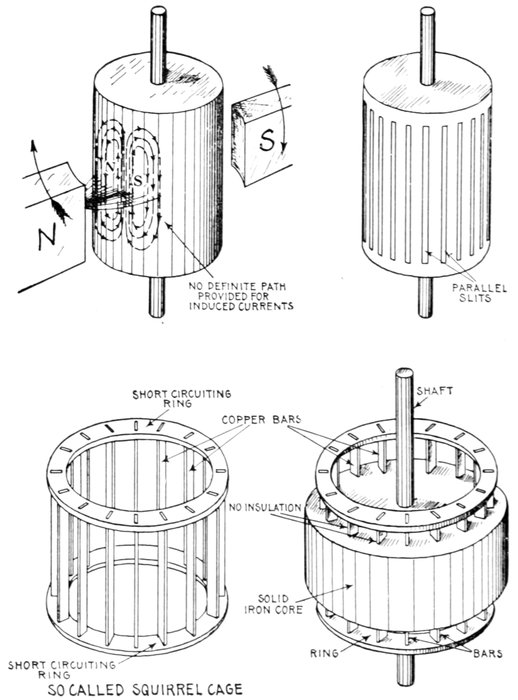
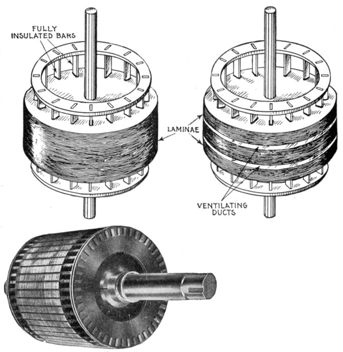
Figs. 1,738 to 1,744.—Evolution
of the squirrel cage armature.
The early experiments of Arago,
Herschel, Babbage and Baily
demonstrated that a mass of
copper or any conducting metal,
if placed in a revolving magnetic
field, will be urged to revolve
in the direction of the
revolving field. They used
discs, but Ferraris used a copper
cylinder as shown in figs.
1,710 and 1,738; this was the first squirrel cage
armature. Figs. 1,739 to 1,744 show the gradual
development of the primitive device shown in fig.
1,738; fig. 1,739, Ferraris' cylinder with slots restricting
the path of induced currents; fig. 1,740,
Dobrowolsky's so called squirrel cage which he
embedded in a solid iron core, as in fig. 1,741;
fig. 1,742, design with insulated bars and laminated core to prevent eddy currents in the
core; fig. 1,743, laminated core with ventilating ducts; fig. 1,744, modern squirrel cage
armature representing the latest practice as built by Mechanical Appliance Co. The core
is built up of discs punched from No. 29 gauge electrical sheet, insulated from each other
and firmly clamped between end plates locked on the shaft. The slots in the discs are
of the same general form as those in the core. Heavy fibre end pieces, punched to match
the discs are placed at each end of the core, to prevent the bars coming in contact with
the sharp edges of the teeth. The winding is made up of rectangular copper bars, passing
through slots in the core, and short circuited on each other by means of copper end rings
of special design. The bars are pressed into holes punched in the end rings, and the contact
is then protected from corrosion by being dipped in a solder bath. The bars are insulated
from the iron of the core by fibre cell projecting beyond the end of the slot. To
secure ventilation the short circuiting rings are set some distance from the end of the
core. In this way the bars between the core and the ring act as the vanes of a pressure
blower, forcing a large volume of air through the field coils and ventilating openings.
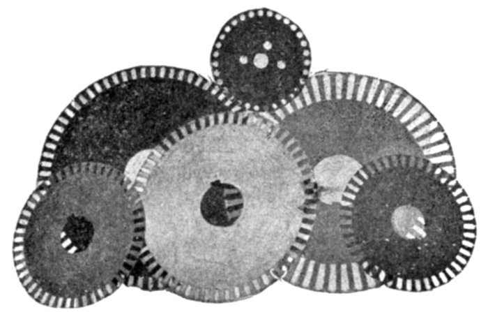
Fig. 1,745.—Mechanical Appliance Co. solid core discs as used on small and medium size
induction motors.
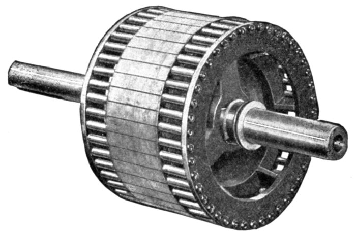
Fig. 1,746.—Allis-Chalmers squirrel cage armature construction. The core laminæ are
mounted on a cast iron spider having arms shaped to act as fan blades for forcing air
through the motor. The spider is pressed on to the shaft. In the smallest sizes the punchings
are mounted directly on the shaft, which is properly machined to hold them firmly.
Copper bars are used as inductors in the larger sizes, and copper rods in the smaller sizes.
The ends of the inductors are turned down somewhat smaller than the body and fit in
holes in the end rings. The shoulder thus formed fits firmly against the end rings. Good
electrical contact is obtained by expanding the inductors in the end ring holes. In large
armatures both bars and end rings are of rectangular cross section, the bars and rings
being fastened by machine steel cap screws.
Obviously, a better result is obtained if, in fig. 1,738, the downward
returning currents of the eddies are led into some path
where they will return across a field of opposite polarity from
that across which they ascended, as in such case, the turning
effect will be doubled. Accordingly the design of fig. 1,738 was
modified by cutting a number of parallel slits which extended
nearly to the ends, leaving at each end an uninterrupted "ring" of
metal. This may be called the first squirrel cage armature, and
in the later development Dobrowolsky was the first to employ
a built-up construction, using a number of bars joined together
by a ring at each end, as in fig. 1,740, and embedded in a solid
mass of iron, as in fig. 1,741; he regarding the bars merely as
veins of copper lying buried in the iron.
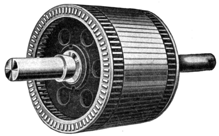
Fig. 1,747.—Triumph squirrel cage armature. In construction thin sheet steel laminations,
japanned, are built up to form the core, and are rigidly clamped together by heavy malleable
iron end plates. Semi-enclosed slots are punched in the outer periphery to receive the
windings, so that none of the centrifugal force is carried by the inductors. These inductors
are set edge on, and are riveted and soldered into resistance rings. These rings
are punched to receive the inductors in such a manner that there is an unbroken strip of
metal completely surrounding them. Moreover, the short circuiting rings are set some
distance from the end of the core, so that the inductors between the core and ring act as
vanes to force air through the coils for ventilation.
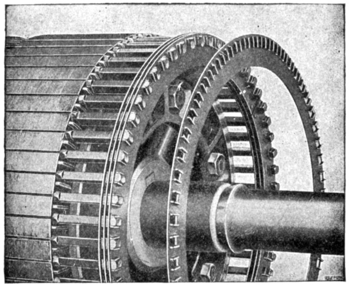
Fig. 1,748.—General Electric soldered form of end ring construction on squirrel cage armatures.
The armature inductors or copper bars laid in the core slots are short circuited by
these end rings, which are also made of copper. For the smaller sizes the rings are thin,
but of considerable radial depth and are held apart by spacing washers. They have rectangular
holes punched near their outer peripheries through which the bars pass. Lips are
formed on the rings, as shown, to which the bars are soldered.
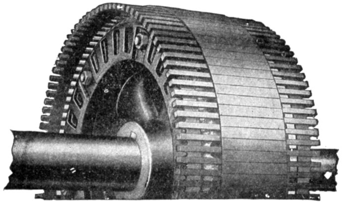
Fig. 1,749.—General Electric welded form of end ring construction on squirrel cage armatures.
Space limitations make it difficult to provide multiple soldered rings of sufficient area for
large motors; hence, on such machines welding is resorted to, as shown. The ring in welded
construction is placed beneath the bars at each end of the armature. Short radial bars
are welded to the edges of these rings and to the inductors or squirrel cage bars, thereby
making good electrical contact.
A solid cylinder of iron will of course serve as an armature, as it is
magnetically excellent; but the high specific resistance of iron prevents
the flow of induced currents taking place sufficiently copiously; hence
a solid cylinder of iron is improved by surrounding it with a mantle of
copper, or by a squirrel cage of copper bars (like fig. 1,740), or by
embedding rods of copper (short circuited together at their ends with
rings) in holes just beneath its surface. However, since all eddy currents
that circle round, as those sketched in fig. 1,738, are not so efficient in
their mechanical effect as currents confined to proper paths, and as they
consume power and spend it in heating effects, the core was then
constructed with laminations lightly insulated from each other, and
further the squirrel cage copper bar inductors were fully insulated
from contact with the core. Tunnel slots were later replaced by designs
with open tops.
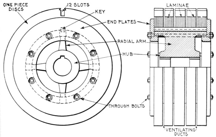
Figs. 1,750 and 1,751.—Built up core construction with discs punched in one piece. The
spider proper consists of a hub provided with four radial arms, which fit the inner diameter
of the disc. The hub is bored out so that it fits very tightly on the shaft, and a key is
provided to avoid any chance of turning. The core disks are clamped firmly in place
by two heavy cast iron end plates which are pressed up and held by the bolts. These
bolts pass under the discs, so that there is no danger of their giving rise to eddy currents.
The key not only prevents the discs turning on the spider but also ensures the alinement of
discs, which is necessary to make the teeth form smooth slots when the core is assembled.
Fig. 1,744 shows a modern squirrel cage armature conforming to the
latest practice, other designs being illustrated in the numerous accompanying
cuts.
In the smaller sizes, the core laminæ are of the solid type as shown
in fig. 1,745, but for larger motors the core consists of a spider and
segmental discs as shown in figs. 1,750 and 1,751.
Fig. 1,748 shows a soldered form of end ring construction, and figs.
1,752 and 1,753 the method of welding the end ring to the inductors.
The Field Magnets.—The construction of the field magnets,
which, when energized with alternating current produce the
rotating magnetic field, is in many respects identical with the
armature construction of revolving field alternators.
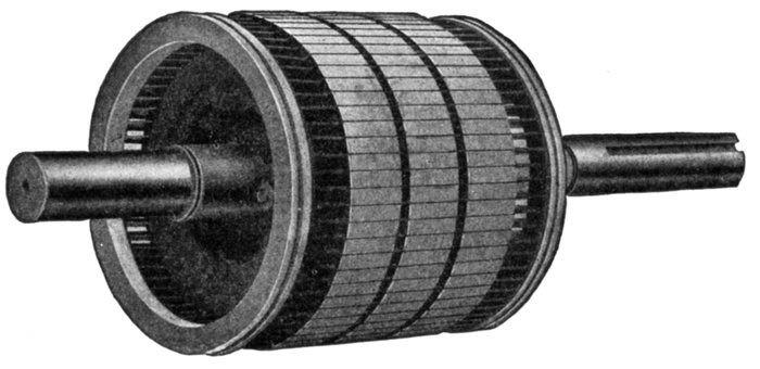
Fig. 1,752.—Fairbanks-Morse squirrel cage armature with cast-on rings showing inspection
grooves. The method consists in fusing the ends of the inductors into an end ring of a
special composition, thereby producing a perfect electrical and mechanically strong joint.
In this process the armature with its bars in place is put into a mould and the molten
metal poured around the inductors, melting their ends and effectually fusing them into
the body of the ring. The ring is then turned down to finished size and polished. An inspection
groove is cut as shown to indicate that the fusion is complete and the joint perfect.
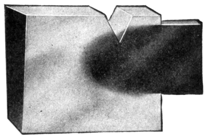
Fig. 1,753.—Section of Fairbanks-Morse "cast-on" joint showing union of end ring and inductor.
The view shows the V-shape inspection groove as described in fig. 1,752.
Broadly, the field magnets of induction motors consists of:
- 1. Yoke or frame;
- 2. Laminæ, or core stampings;
- 3. Winding.
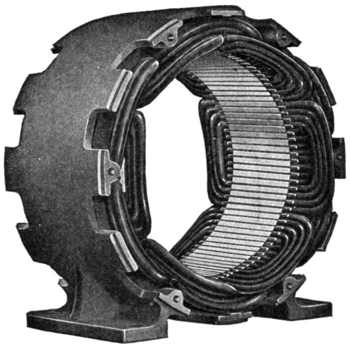
Fig. 1,754.—Richmond field construction for polyphase induction motors, showing style of
winding for use with squirrel cage and wound armature types.
Ques. What is the construction of the yoke and
laminæ?
Ans. They are in every way similar to the armature frame
and core construction of revolving field alternators.
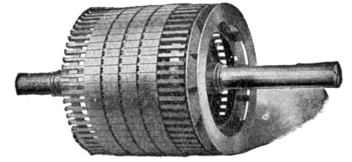
Fig. 1,755.—Western Electric squirrel cage armature of high speed induction motor
for centrifugal pump service. This armature is an example of heavy duty construction.
The inductors are welded to the short circuiting end rings, the latter being located
beneath the inductors, as shown. Fan vanes are provided at one end for ventilation.
In the field construction, the core laminations are assembled in a closed box frame, and
clamped by heavy rings while under hydraulic pressure. The stator coils are form wound
and subjected to a special insulating process, which renders them especially impervious
to moisture, and capable of operating without breakdown in locations which are too
damp for ordinary motors. The bearing brackets are of rigid mechanical construction,
and the pulley end bracket and bearings of all sizes are split to facilitate removal of the
rotor and complete inspection. These machines range in size from 50 to 200 horse power,
the rugged construction adapting them to heavy and severe service, such as is met with
in mining, the construction of dams, canals, aqueducts, tunnels, etc.
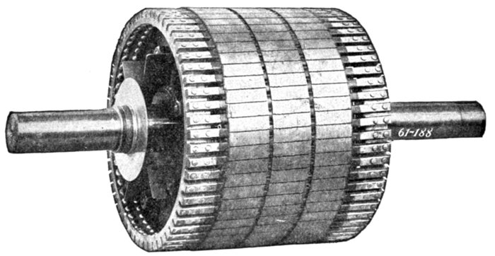
Fig. 1,756.—Wagner squirrel cage armature for polyphase induction motor, as employed on
motors of from 5 to 25 horse power. The features of construction as seen in the illustration
are bar inductors, ventilating passages through the core laminæ, riveted connection
between inductors and end rings ventilating vanes on end plate, extra large end rings.
The object of making the rings unusually large is to make the resistance of the rings lower
than is desirable for some classes of service, in order to obtain motors having minimum
slip, increased efficiency, and maximum overload capacity under normal operation. When
the torque required by some very unusual and entirely abnormal installation exceeds that
of the average conditions, it is an easy matter to reduce the section of the end rings, by turning
them down in a lathe, thereby increasing the resistance and starting torque.
Field Windings for Induction Motors.—The field windings
of induction motors are almost always made to produce
more than two poles in order that the speed may not be unreasonably
high. This will be seen from the following:
If P be the number of pairs of poles per phase, f, the frequency, and
N, the number of revolutions of the rotating field per minute, then
Thus for a frequency of 100 and one pair of poles, N = 60 × 100 ÷
1 = 6,000. By increasing the number of pairs of poles to 10, the frequency
remaining the same, N = 60 × 100 ÷ 10 = 600. Hence,
in design, by increasing the number of pairs of poles the speed of the
motor is reduced.
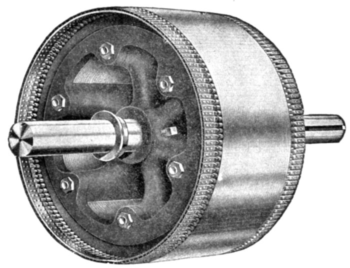
Fig. 1,757.—Richmond squirrel cage armature. The copper bars are double riveted at either
end to the resistance rings, then dipped into a solder bath.
Ques. State an objection to very high speed of the
rotating field.
Ans. The more rapid the rotation of the field, the greater is
the starting difficulty.
Ques. Besides employing a multiplicity of poles, what
other means is used to reduce the speed?
Ans. Reducing the frequency.
Ques. What difficulty is encountered with low frequency
currents?
Ans. If the frequency be very low, the current would not be
suitable for incandescent lamp lighting, because at low frequency
the rise and fall of the current in the lamps is perceptible.
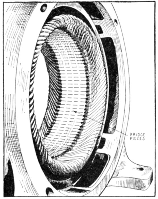
Fig. 1,758.—Field construction of Crocker-Wheeler induction motor with magnetic bridge.
Steel bridges are inserted in the grooves where the coils are placed, to protect them from
dirt and mechanical injury and at the same time provide a path for the magnetic flux
which has a more uniform reluctance, thereby insuring a better distribution of the flux
in the air gap and at the same time retaining open slot construction from which the coils
can be readily removed.
Ques. What is the general character of the field
winding?
Ans. The field core slots contain a distributed winding of
substantially the same character as the armature winding of a
revolving field polyphase alternator.
Ques. Are the poles formed in the usual way?
Ans. They are produced by properly connecting the groups
of coils and not by windings concentrated at certain points on
salient or separately projecting masses of iron, as in direct
current machines.
Ques. How are the coils grouped?
Ans. Three phase windings are usually Y connected.
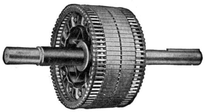
Fig. 1,759.—Western Electric squirrel cage armature. The inductors consist of solid copper
bars embedded in the slots of a laminated core, with their projecting ends securely fitted
and soldered to heavy copper rings.
Ques. What other arrangement is sometimes used?
Ans. In some cases Y grouping is used for starting and Δ
grouping for running.
Starting of Induction Motors.—It must be evident that
if the field winding of an induction motor whose armature is at
rest, be connected directly in the circuit without using any
starting device, the machine is placed in the same condition as a
transformer with the secondary short circuited and the primary
connected to the supply circuit. Owing to the very low resistance
of the armature, the machine, unless it be of very small size,
would probably be destroyed by the heat generated before it
could come up to speed. Accordingly some form of starting device
is necessary. There are several methods of starting, as with:
- 1. Resistances in the field;
- 2. Auto-transformer or compensator;
- 3. Resistance in armature.
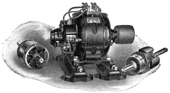
Fig. 1,760.—Holzer Cabot combination polyphase induction motor set, consisting of wound
frame and three rotors: 1, squirrel cage armature, 2, wound armature, 3, rotating field.
The set is intended for school demonstration of induction motor phenomena. The motor
operating with the squirrel cage armature has an inherent constant speed characteristic and
on brake tests will show its exceptionally strong starting torque and ability to take excessive
overloads. This motor can be used as a generator also, in the sense that if connected to the
line and driven above synchronous speed by some external means, it will act as an asynchronous
generator and return power to the line. For variable speed service, an armature
having a winding upon it similar to that on the frame must be used. External resistances
inserted in the armature circuit may be used to produce, first, a reduction of starting current,
second, an increase of starting torque, or third, a variation of speed. Thus an extensive
list of experiments can be performed with this phase wound armature directly along
the line of present engineering practice. The phase wound armature can be used as an
alternator in the same sense as mentioned above for the squirrel cage machine. For
synchronous motor and three phase operation the revolving field with projecting poles
and slip rings would be used, the field being excited from a direct current supply.
Ques. Explain the method of inserting resistances in
the field.
Ans. Variable resistances are inserted in the circuits leading
to the field magnets and mechanically arranged so that the
resistances are varied simultaneously for each phase in equal
amounts. These starting resistances are enclosed in a box
similar to a direct current motor rheostat.
Ques. Is this a good method?
Ans. It is more economical to insert a variable inductance
in the circuit, by using an auto-transformer.
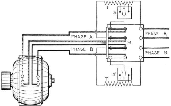
Fig. 1,761.—Westinghouse auto-starter. Polyphase induction motors may be started by
connecting them directly to the circuit with an ordinary switch, and the smaller motors
are started in this way in practice. In the larger motors, however, the starting torque
at normal voltage is several times its full load torque; therefore, they are started on a
reduced voltage, and the full pressure of the circuit is not applied until they have practically
reached their operating speed. The figure shows connections with a two phase
alternating current circuit. The auto-starter consists of two auto-transformers T and T',
each having only a single winding for both primary and secondary, which are tapped at
certain points by switches, thus dividing the winding into a number of loops, so that one
of several voltages may be applied for starting, and the starting torque thus adjusted to
the work that has to be performed. At the highest points tapped by the switches S, and
S', the full pressure, and at the lowest points, the lowest pressure, is applied to the motor
by the operation of the main switch M. This switch has four blades and three positions.
When thrown to the left as indicated, it connects the auto-transformers T and T',
across the circuits A and B respectively, so that the pressure across the transformer
coils, as determined by the position of the switches S and S', is applied to the motor circuits
A and B. The intermediate position of the switch M interrupts both circuits. To start the
motor, the switch M is thrown to the left and a reduced pressure applied; after the motor
has started and come up to speed the switch M is thrown to the right, thus cutting out
the transformer and connecting the motor directly to the circuit. The starting device
can be located at a point remote from the motor, thus eliminating danger from fire due
to possible sparks, in case where it is necessary to install the motors in grain elevators,
woolen mills, or in any place exposed to inflammable gases, or floating particles of combustible
matter. This feature is also valuable in cases where motors are suspended from the
ceiling, or installed in places not easily accessible.
Ques. What is the auto-transformer or compensator
method of starting?
Ans. It consists of reducing the pressure at the field terminals
by interposing an impedance coil across the supply circuit
and feeding the motor from variable points on its windings.
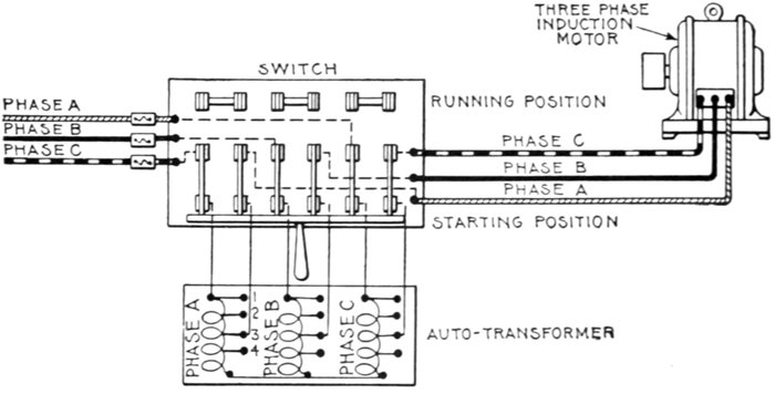
Fig. 1,762.—Auto-transformer or compensator connections for three phase induction motor.
In operation when the double throw switch is thrown over to starting position, the
current for each phase of the motor flows through an auto-transformer, which consists of a
choking coil for each phase, arranged so that the current may be made to pass through
any portion of it (as 1, 2, 3) to reduce the voltage to the proper amount for starting. After
the motor has come up to speed on the reduced voltage, the switch is thrown over to
running position, thus supplying the full line voltage to the motor. [7]In actual construction
fuses are usually connected, so that they will be in circuit in the running position, but not
in the starting position, where they might be blown by the large starting current.]
Internal Resistance Induction Motors.—The armature
of this type of induction motor differs from the squirrel cage
variety in that the winding is not short circuited through copper
rings, but, in starting, is short circuited through a resistance
mounted directly on the shaft in the interior of the armature.
When the motor is thrown in circuit, a very low starting current is drawn
from the line due to the added resistance in the armature. As the motor
comes up to speed, this resistance is gradually cut out, and at full speed
the motor operates as a squirrel cage motor, with short circuited winding.
Ques. How is the resistance gradually cut out in
internal resistance motors?
Ans. By operating a lever which engages a collar free to
slide horizontally on the shaft. The collar moves over the
internal resistance grids (located within the armature spider),
thus gradually reducing their value until they are cut out.
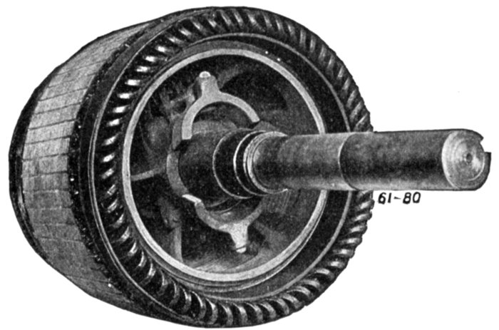
Fig. 1,763.—View of armature interior of Wagner polyphase induction motor with wound
armature, showing the centrifugal device which at the proper speed short circuits all the
coils, transforming the motor to the squirrel cage type. The winding is connected with
a vertical "commutator" so called. Inside the armature are two governor weights, which
are thrown outwards by the centrifugal force when the machine reaches the proper speed,
thus pushing a solid copper ring (which encircles the shaft) into contact with the inner
ends of the "commutator" bars, thus completely short circuiting the armature winding.
Ques. For what size motors is the internal resistance
method suited?
Ans. Small motors.
Ques. Why is it not desirable for large motors?
Ans. The excessive I2R loss in the resistances, if confined
within the armature spider, would produce considerable heating,
and on this account it is best placed external to the motor.
Ques. On what class of circuit are internal resistance
motors desirable?
Ans. On circuits devoted to lighting service as well as power
service, where a high degree of voltage regulation is essential.
The initial rush of current when a squirrel cage motor is thrown on the
line is more or less objectionable and there are central stations which
allow only resistance type of induction motor to be used on their lines.
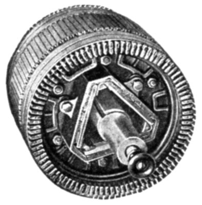
Fig. 1,764.—Western Electric wound armature for internal resistance induction motor. In
starting the inductors are short circuited through a resistance which is gradually cut out
as the motor comes up to speed.
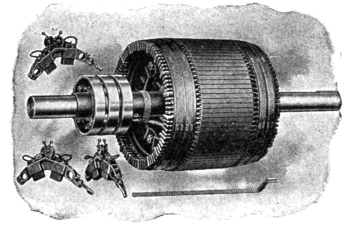
Figs. 1,765 to 1769.—Western Electric wound armature for external resistance, or slip ring
induction motor, showing brush rigging, slip rings and bar winding.
External Resistance or Slip Ring Motors.—In large
machines, and those which must run at variable speed, such as
is required in the operations of cranes, hoists, dredges, etc., it is
advisable that the regulating
resistances be placed externally
to the motor. Motors
having this feature are commercially
known as slip ring
motors, because connections
are made between the external
resistances and the armature inductors
by means of slip rings.
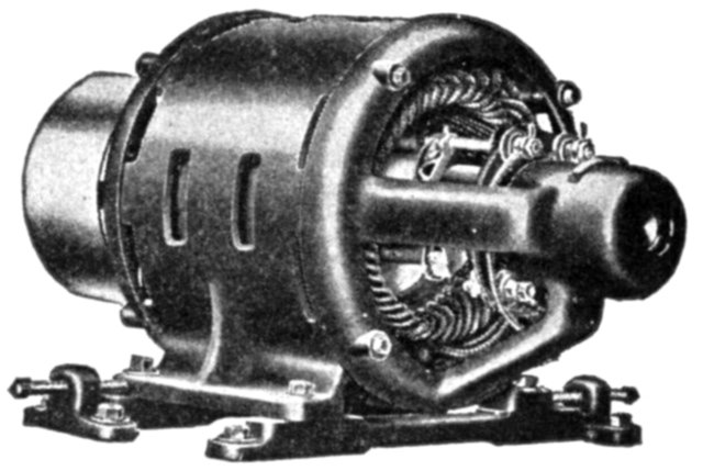
Fig. 1,770.—Richmond slip ring motor.
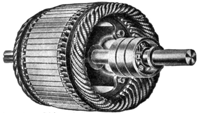
Fig. 1,771.—Richmond slip ring armature as used on motor
in fig. 1,770.
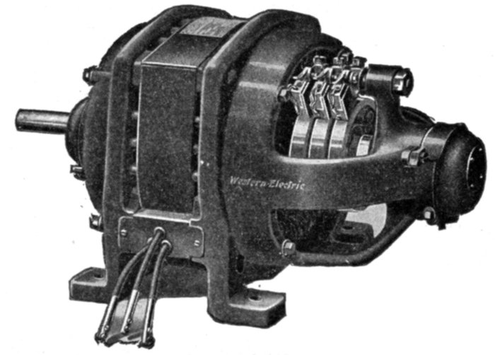
Fig. 1,772.—Western Electric
riveted frame slip ring
induction motor for variable
speed service; adapted
either to continuous or
intermittent operation.
As with the internal resistance
motor the
armature winding of
a slip ring motor is
not short circuited
through copper
rings in starting,
but through a resistance,
which in this
case is located externally.
Ques. How
is the armature
winding
connected?
Ans. It is
connected in Y
grouping and
the free ends
connected to the
slip rings, leads
going from the
brushes to the
variable external resistances, these being illustrated in fig. 1,779.
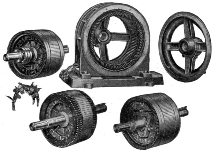
Figs. 1,773 to 1,778.—Sprague skeleton type motor frame with various types of armature.
Fig. 1,777, plain squirrel cage armature; fig. 1,778, internal resistance armature; fig.
1,773 slip ring armature. In the construction of the plain squirrel cage armature, fig. 1,777,
copper bars are inserted in the slots of the core, and are insulated from the core by enclosing
tubes which project about one-half inch beyond the iron at each side. The bars
are short circuited at their ends by copper rings. These rings are thin, but of considerable
radial depth and are held apart by spacing washers. They have rectangular holes punched
near their outward periphery, through which the armature bars pass, and to which they are
soldered. The internal resistance armature, fig. 1,778, is provided with a phase winding,
starting (internal) resistance, and switch located on the shaft. The starting resistance is designed
to give approximately full load torque with full load current at starting. A greater
torque than full load torque can be obtained for starting, if required, by cutting out resistance.
The resistance consists of cast iron grids enclosed in a triangular cover which is bolted
to the end plates holding the armature laminæ together, and is short circuited by sliding
laminated spring metal brushes along the inside surface of the grids. The brushes are
supported by a metal sleeve sliding on the shaft which is operated by a lever secured to
the bearing bracket and located just above the bearing. A rod passing through the end of
the shaft operates the short circuiting arrangement in sizes up to about 25 horse power.
The external resistance or slip ring armature, fig. 1,773, is similar in construction to fig.
1,778, with the exception that slip rings are provided because of the external location
of the resistance. These rings connect the inductor through brushes to a controlling and
external resistance, two or more carbon brushes being provided for each ring, as in fig. 1,776.
Single Phase Induction Motors.—The general utility of
single phase motors, particularly the smaller sizes, is constantly
being enlarged by
the growing practice
of central
stations generating
polyphase current,
of supplying their
lighting service
through single
phase distribution,
and permitting the
use of single phase
motors of moderate
capacity on
the lighting
circuit.
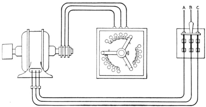
Fig. 1,779.—External resistance or slip ring induction motor connections. The squirrel
cage armature winding is not short circuited by copper end rings, but connected in
Y grouping and the three free ends connected to three slip rings, leads going from the
brushes to three external resistances, arranged as triplex rheostat having three arms rigidly
connected as shown, so that the three resistances may be varied simultaneously and in
equal amounts.
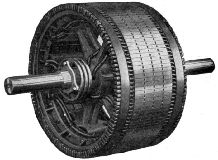
Fig. 1,800.—Allis-Chalmers phase wound external resistance type or slip ring armature construction.
The winding is for three phases and the terminals are brought out to three slip
rings. The front bracket is slightly modified to make room for these rings on the inside.
For starting duty sufficient resistance is supplied to reduce the starting current taken by
the motor to 1¼ times the normal full load current. In the running position the resistance
is all cut out of the circuit. For speed regulation sufficient resistance is supplied to
reduce the speed 50% on normal full load torque.
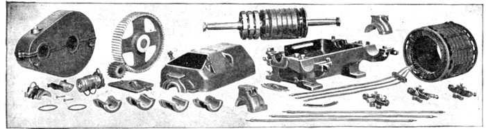
Figs. 1,801 to 1,828.—Disassembled view of Western Electric three phase external resistance or slip ring mill type induction
motor. It is adapted to severe working conditions, such as are met with in steel mills, crane and hoist service, etc. Designed
for 220 or 440 volt, 25 cycle circuits. The frame is divided horizontally into an upper and a lower steel casting, both of
which are bolted together at the corners by four heavy bolts. The lower casting is provided with four feet for bolting the
motor to its foundation. The end of the upper frame which covers the slip rings is equipped with malleable iron covers
held in place by lock bolts. The field and armature are of the usual construction. One end of the armature winding is
protected against mechanical injury by the slip rings which are of heavy construction and of practically the same diameter
as the armature, and the other end by a detachable flange of the same diameter as the outside of the winding. The slip
rings are mounted on the same spider as the armature, so that the shaft can be removed without disturbing any of the
connections. The brushes are equipped with riveted pigtails, and held in brass brush boxes machined to gauge. Heavy
coiled clock springs are used to maintain an even pressure of the brushes on the slip rings. The armature leads are brought
out through holes in the upper half of the frame, and the field leads are brought through a block, which fits in an opening in
the upper edge of the lower half.
The simplicity
of single phase
systems in comparison
with polyphase
systems,
makes them more
desirable for small
alternating current
plants.
The disadvantage
of single phase
motors is that they
are not self-starting.
A single phase
motor consists
essentially of an
armature and field
magnet having a
single phase winding
and also some phase
splitting arrangement
for starting.
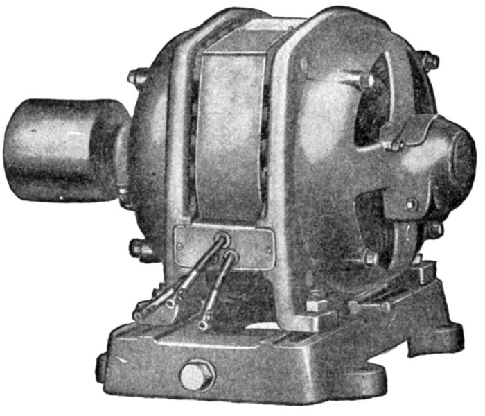
Fig. 1829.—General Electric single phase induction motor. It is suitable for constant speed
service where full load torque at starting does not exceed 140 per cent., and in general is
adapted to drive all geared and belted machinery requiring constant speed with light or
moderate starting torque.
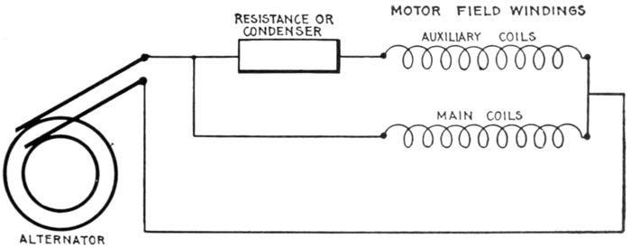
Fig. 1,830.—Simplified diagram showing the principle of phase splitting for starting single
phase induction motors. By the use of an auxiliary set of coils connected in parallel with
the main coils and having in series a resistance or condenser as shown, the single phase
current delivered by the alternator is "split" into two phases, which are employed to
produce a rotating field on which the motor is started.
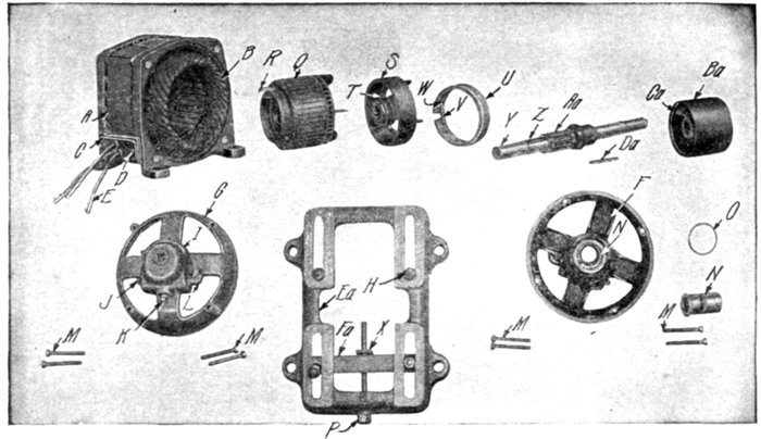
Figs. 1,831 to 1,850.—Parts of Sprague single phase clutch type induction motor. The armature is of
the high resistance smooth core squirrel cage type, the core laminæ being assembled upon a steel
sleeve. On starting the armature revolves freely around the shaft on roller bearings until it
accelerates to about 75% of its rated speed, when a centrifugal clutch engages with an outer shell
keyed directly on the shaft, thus throwing on the load. This type of motor is adapted to drive all
belted, geared, or direct connected machinery requiring constant speed with moderate starting
torque, such as generators, blowers, line shafting in machine shops and factories, drill presses,
laundry machinery, baking machinery, and the like. When greater torque is required at the
moment of starting type RI motors should be used, or clutch couplings may be installed between
the motor and the machine it is to drive. The parts are as follows; A, field frame; B, field coils;
C, terminal block; D, terminal block screws; E, connectors; F, bearing head pulley end; G, bearing
head opposite pulley end; H, motor clamping bolts; I, oil well cover; J, oil well plug; K, drain
plug; L, oil filter; M, cap bolts; N, bearing lining; O, oil ring; P, belt tightener screw; Q, armature
core; R, latch; S, driving shell; T, driving shell set screw; U, clutch ring; V, clutch ring spring;
W, spring adjusting screw; X, nut for belt tightener screw; Y, shaft; Z, driving shell key; Aa,
armature bearing; Ba, pulley; Ca, pulley set screw; Da, pulley key; Ea, sliding base; Fa, yoke.
Ques. Why is a single phase motor not self-starting?
Ans. Because the nature of the field produced by a single
phase current is oscillating and not rotating.
Ques. How is a single phase motor started?
Ans. By splitting the phase, a field is set up normal to the
axis of the armature, and nearly 90° displaced in phase from the
field in that axis. This cross field produces the useful torque.
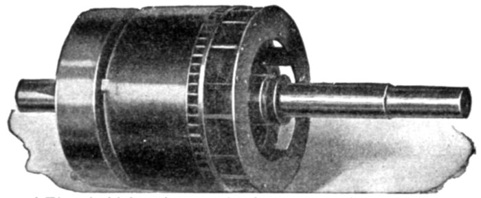
Fig. 1,851.—General Electric high resistance clutch type smooth core squirrel cage armature
of single phase induction motor. The core laminæ are slotted near the circumference to
retain the bar inductors, which extend beyond the core at either end where they are permanently
connected to heavy short circuiting rings.
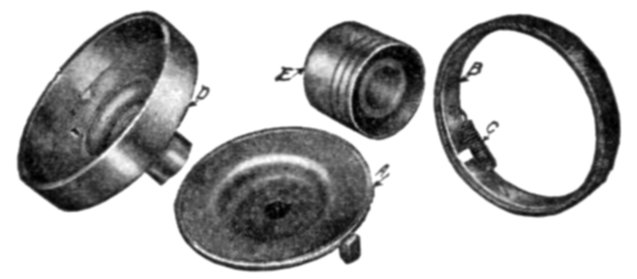
Figs. 1,852 to 1,855.—Parts of General Electric centrifugal clutch pulley as used on clutch
type, single phase induction motor. A, clutch; B, friction band; C, adjusting spring;
D, outer clutch shell with pulley sleeve; E, solid removable pulley; F, internal mechanism
comprising parts A, B, and C; G, outer shell and pulley comprising parts D and E.
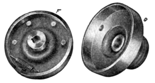
Figs. 1,856 and 1,857.—Partly assembled clutch pulley. F, internal mechanism comprising
parts A, B, C, of fig. 1,852. G, outer shell and pulley, comprising parts D and E of fig. 1,852.
Phase Splitting; Production of Rotating Field from
Oscillating Field.—As previously stated, an oscillating field,
that is, one due to a single phase current, does not furnish any
starting torque. It is therefore necessary to provide a rotating
field for a single phase induction motor to start on, which, after
the motor has come up to speed, may be cut out and the motor
will then operate with the oscillating field.
A rotating field may be obtained from single phase current by
what is known as splitting the phase.
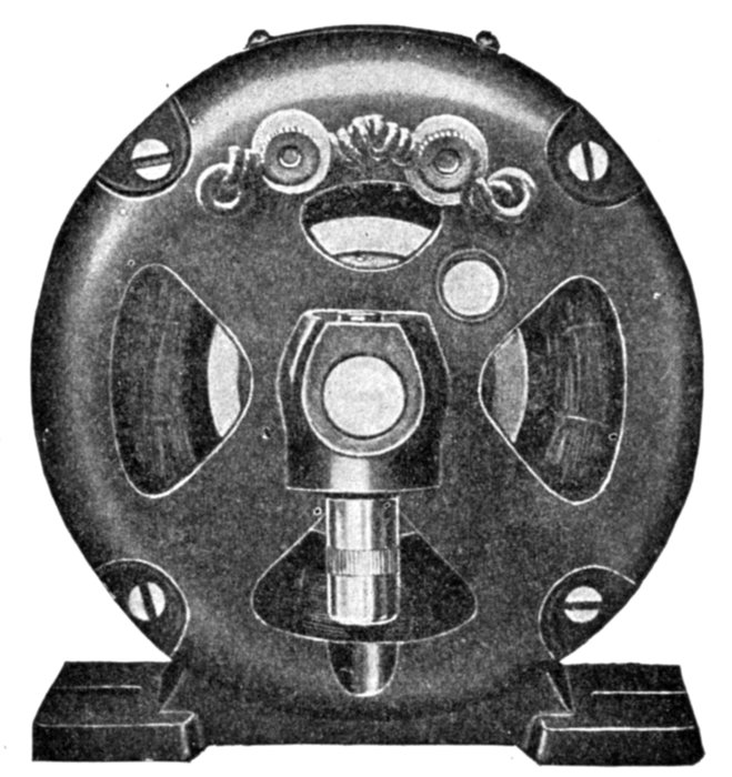
Fig. 1,858.—Switch end view of General Electric drawn shell type fractional horse power
single phase motor.
Ques. Describe one method of splitting the phase.
Ans. The field of the motor is provided, in addition to the
main single phase winding, with an auxiliary single phase winding,
and the two windings are connected in parallel to the single
phase supply mains with a resistance or a condenser placed in
series with the single phase winding, as shown in diagram
fig. 1,830, the two windings being displaced from each other
on the armature about 90 magnetic degrees, just as in the
ordinary two phase motor.
Ques. What is the construction of the two windings?
Ans. The main coils are of more turns than the auxiliary,
being spread over more surface, and are heavier because they
are for constant use; whereas the auxiliary coils are used only
while starting.
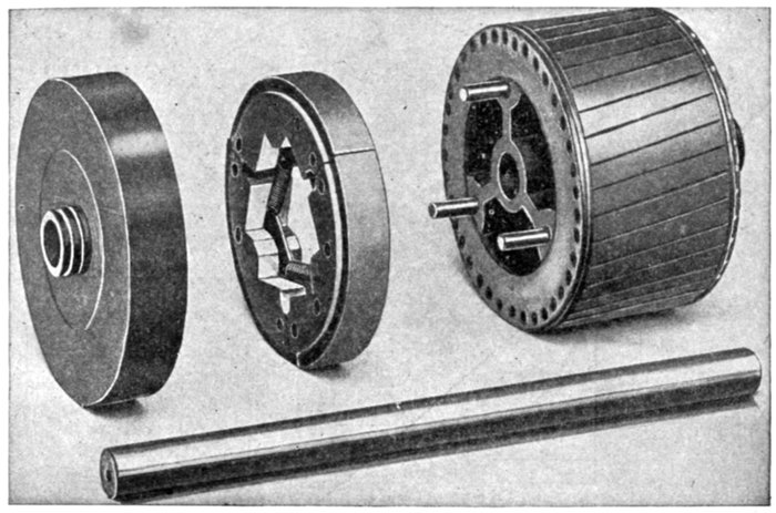
Figs. 1,859 to 1,862.—Detail construction of clutch parts of General Electric drawn shell type
fractional horse power single phase motor. The starting switch, which is assembled within
the motor frame, consists essentially of three parts: a rotating member mounted on the
armature and provided with two spring controlled pivoted levers in contact with an
insulated collector ring.
Ques. What are the auxiliary coils sometimes called?
Ans. Starting coils.
Ques. What are "shading" coils?
Ans. Auxiliary coils as placed on fan motors in the manner
shown in fig. 1,863.
Ques. How can single phase motors be started without
the use of external phase splitting devices?
Ans. Such apparatus may be avoided by having the auxiliary
winding of larger self-inductance than the main winding.
Ques. What is the character of the starting torque
produced by splitting the phase?
Ans. It does not give strong starting torque.
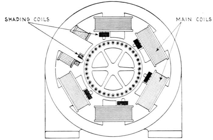
Fig. 1,863.—Single phase fan motor with shading coils for starting. In addition to the main
field coils, one tip of each pole piece is surrounded by a short circuited coil of wire or
frame of copper, as indicated in the figure. This coil, or copper frame, is called a shading
coil and it causes a phase difference between the pulsating flux that emanates from the
main portion of each polar projection and the pulsating flux which emanates from the
pole tip, thus introducing a two phase action on the armature which is sufficiently pronounced
to start the motor.
Ques. How is the plain squirrel cage armature modified
to enable the motor to start with a heavier load?
Ans. An automatic clutch is provided which allows the
armature to turn free on the shaft until it accelerates almost to
running speed.
This type motor is known as the clutch type of single phase induction
motor. In operation when the circuit is closed, the armature starts to
revolve upon the shaft; when it reaches a premeditated speed, a
centrifugal clutch expands and engages the clutch disc, which is fastened
to the shaft.
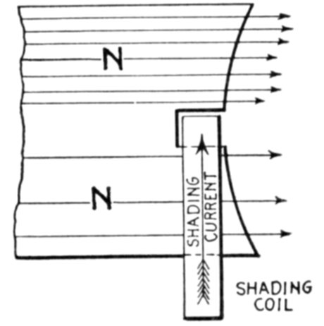
Fig. 1,864.—Diagram showing action of shading coil in alternating current motor. The
extremities of these pole pieces are divided into two branches, one of which a copper ring
called a shading coil is placed as shown, while the other is left unshaded. The action of
the shading coils is as follows: Consider the field poles to be energized by single phase
current, and assume the current to be flowing in a direction to make a north pole at the
top. Consider the poles to be just at the point of forming. Lines of force will tend to
pass downward through the shading coil and the remainder of the pole. Any change of
lines within the shading coil generates an e.m.f., which causes to flow through the coil a
current of a value depending on the e.m.f. and always in a direction to oppose the change
of lines. The field flux is, therefore, partly shifted to the free portion of the pole, while
the accumulation of lines through the shading coil is retarded.
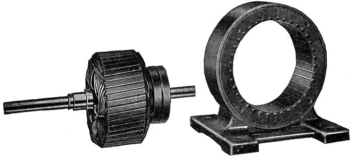
Figs. 1,865 and 1,866.—Fort Wayne split phase factional horse power induction motor with
stationary armature. The object of placing the squirrel cage armature winding on the
stationary part or frame is to decrease the radial depth of the latter more than would be
possible with the usual arrangement where the armature forms the rotating part. The
small radial depth of the stationary armature makes possible a revolving field of maximum
diameter giving in turn an exceptionally large air gap area, which reduces the magnetizing
current, hence improves the power factor of the motor.
Ques. Explain in detail the action of the clutch type of
motor in starting.
Ans. It can start a load which requires much more than full
load torque at starting, because the motor being nearly up to
full speed, has available not only its maximum overload capacity,
but also the momentum of the armature to overcome the inertia
of the driven apparatus. In this it is assisted by a certain amount
of slippage in the clutch, which is the case when the armature
speed is pulled down to such a point as to reduce the grip of the
centrifugal clutch.
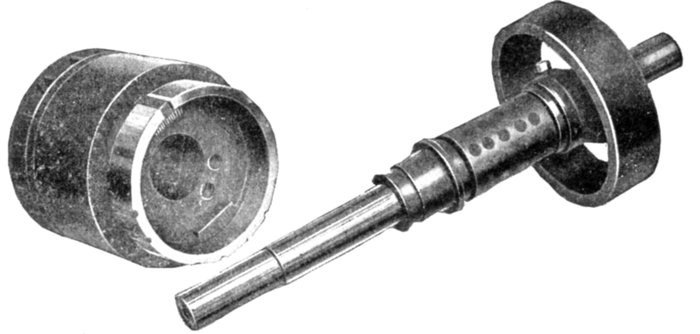
Figs. 1,867 and 1,868.—General Electric disassembled clutch as used on clutch type, single phase
(KS) induction motor. In starting, the armature revolves freely on the shaft until approximately
75 per cent. of normal rated speed is reached. The load is then picked up by the
automatic action of a centrifugal clutch, which rigidly engages an outer shell, keyed
directly to the shaft. The brass friction band of the clutch is permanently keyed to the
pulley end of the armature.
Commutator Motors.—Machines of this class are similar
in general construction to direct current motors. They have a
closed coil winding, which is connected to a commutator.
There are several types of commutator motor, namely:
- 1. Series;
- 2. Shunt;
- 3. Compensated;
- 4. Repulsion.
Since, as stated, commutator motors are similar to direct
current motors, the question may be asked: Is it possible to run a
direct current motor with alternating current? If the mains
leading to a direct current motor be reversed, the direction or
rotation remains the same, because the currents through both
the field magnets and armature are reversed. It must follow
then that an alternating current applied to a direct current motor
would cause rotation of the armature.
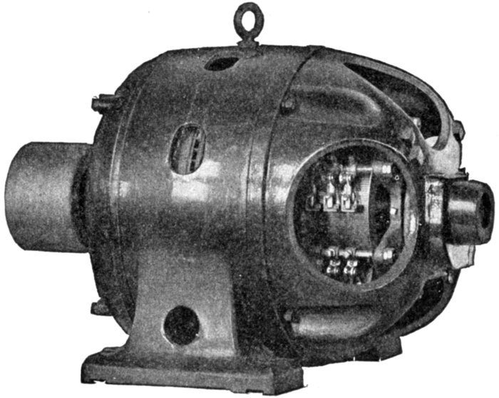
Fig. 1,869.—Wagner single phase variable speed commutator motor. The commutator is of
the regular horizontal type and the brushes remain in contact all the time. As the torque
of alternating motors varies directly as the square of the applied pressure, wide speed
variation may be obtained by varying the voltage applied at the motor terminals.
Action of Closed Coil Rotating in Alternating Field.—When
a closed coil rotates in an alternating field, there are several
different pressures set up and in order to carefully distinguish
between them, they may be called:
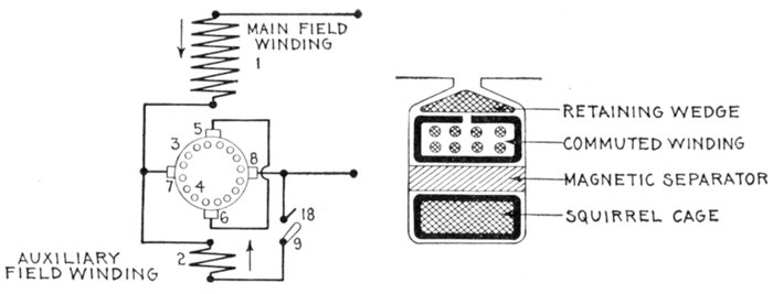
Figs. 1,870 and 1,871.—Diagrams illustrating construction and operation of Wagner "unity
power factor" single phase motor. In the field construction, fig. 1,870, two windings are
used. The main winding 1 produces the initial field magnetization as heretofore; the
auxiliary winding 2 controls the power factor or "compensates" the motor. The main
structural departure is in the armature, the construction of which is more clearly indicated
in fig. 1,871. Here again two windings are employed. The main or principal winding 4
is of the usual well known squirrel cage type and occupies the bottom of the armature slots.
The second or auxiliary winding 3 is of the usual commuted type, is connected to a standard
form of horizontal commutator and occupies the upper portion of the armature slots.
Between the two is placed a magnetic separator in the form of a rolled steel bar. Two
sets of brushes are provided, as indicated in the diagram of connections shown in fig. 1,870.
The main pair of brushes 5-6 is placed in the axis of the main field winding 1 and is
short circuited. The auxiliary pair of brushes 7-8 is placed at right angles to the axis of
the main field winding and is connected in series with it at starting. The auxiliary field
winding 2 is permanently connected to one auxiliary brush 7, and is adapted to be connected
to the other auxiliary brush 8 by means of the switch 9. The purpose of the
peculiar armature construction illustrated in fig. 1,871 and of the brush arrangement and
connections shown in fig. 1,870 is to accentuate, at starting, the effect of the squirrel cage
along the axis 5-6 of the main field winding 1, while suppressing it as far as possible along
the axis 7-8 at right angles to main winding. The magnetic separator placed above the
squirrel cage winding 4 tends to suppress the effect of that winding along all axes, by making
it less responsive to outside inductive effects. But the influence of the separator is nullified
along the axis of the main field winding by the presence of the short circuited brushes 5-6,
while no means are provided for nullifying its effects along the axis at right angles to that
of the main field winding. Thus the main field winding 1 will be able to induce heavy
currents in both armature windings because of the short circuited brushes in the axis 5-6,
and in spite of the magnetic separator; while the armature winding 3, connected in series
with 1, will not be able to produce heavy currents in the squirrel cage winding 4 along the
axis 7-8 because of the magnetic separator between 3 and 4, which shunts or side tracks the
inducing magnetic flux. In operation, at starting, switch 9 of fig. 1,870 is open, the commuted
winding 3 along the axis 7-8 being connected in series with the main field winding 1
and across the mains. The winding 1 induces a large current in the armature windings
3 and 4 along the axis 5-6, and the winding 3 produces a large flux along the axis 7-8.
The armature currents in the main axis co-acting with the flux threading the armature along
the auxiliary axis yield the greater part of the starting torque. As the motor speeds up,
the squirrel cage gradually assumes those functions which it performs in the ordinary
single phase, squirrel cage motor, developing a magnetic field of its own along the axis 7-8
and a correspondingly powerful torque, which increases very rapidly as synchronism is
approached, but falls suddenly to zero at or near actual synchronism. It is known that
the magnetizing currents circulating in the bars of the squirrel cage of a single phase motor
have, at synchronism, double the frequency of the stator currents; the fluxes they produce
must therefore also be of double frequency. Now, the magnetic separator is made of
solid steel, and, while this separator forms a sufficiently effective shunt for the fluxes of
line frequency induced from the field, it is quite ineffective as a shunt for the double frequency
fluxes produced by the armature. With respect to the squirrel cage, the effect of
this magnetic separator diminishes with increasing speed, and at synchronism the machine
operates practically in the same manner as if the magnetic separator did not exist.
- 1. The transformer pressure;
- 2. The generated pressure;
- 3. The self-induction pressure.
These pressures may be defined as follows:
The transformer pressure is that pressure induced in the
armature by the alternating flux from the field magnets.
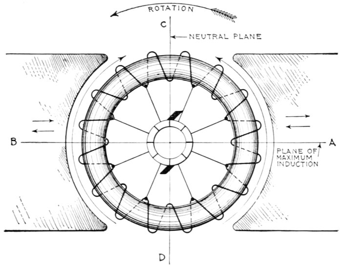
Fig. 1,872.—Diagram of ring armature in alternating field illustrating the principles of commutator
motors.
For instance, assuming in fig. 1,872 the armature to be at rest, as the
alternating current which energizes the magnets rises and falls in value,
the variations of flux which threads through the coils of the ring winding,
induce pressure in them in just the same way that pressure is induced
in the secondary of a transformer.
A ring winding is used for simplicity; the same conditions obtain
in a drum winding.
The generated pressure is that pressure induced in the
armature by the cutting of the flux when the armature rotates.
The self-induction pressure is that pressure induced in
both the field and armature by self-induction.
Nature of the Generated Pressure.—In fig. 1,872, the generated
pressure induced by the rotation of the armature is minimum at the neutral
plane C D and maximum at A B. It tends to cause current to flow up
each half of the armature from D to C, producing poles at these points.
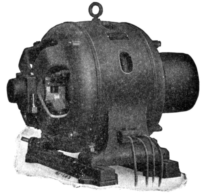
Fig. 1,873.—Wagner single phase repulsion induction commutator motor. Its working
principle is repulsion start and induction operation. Starting with the machine at rest,
brushes in pairs cross connected through a low resistance conductor, bear upon the
commutator, temporarily short circuiting the armature winding then developing a strong
starting torque on the repulsion principle. On attaining full load speed the individual
segments of the commutator are all positively connected together by the operation of an
automatic centrifugal governor, thereby transforming the armature winding to the
squirrel cage form, the motor then continuing as an induction motor. The governor at
the same time removes the brushes from contact with the commutator to save wear. If
the power service should fail for any reason, the motor returns to the starting condition,
and picks up its load when the power comes on again without attention of the operator.
Nature of the Transformer Pressure.—This is caused by variations
of the flux passing through each coil of the armature winding.
Evidently this variation is least at the plane A B because at this point
the coils are inclined very acutely to the flux, and greatest at the plane
C D where the coils are perpendicular to the flux. Accordingly, the
transformer pressure induced in the armature winding is least at A B
and greatest at C D.
The transformer pressure acts in the same direction as the generated
pressure as indicated by the long arrows and gives rise to what may be
called local armature currents.
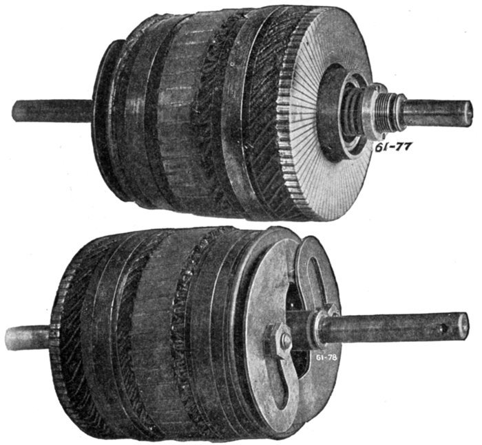
Figs. 1,874 and 1,875.—Armature of Wagner single phase repulsion-induction commutator
motor as seen from the commutator and rear ends, showing the vertical commutator and
type of governor employed on the smaller sizes. The operation is explained in fig. 1,873.
Nature of the Self-induction Pressure.—The self-induction
pressure, being opposite in direction to the impressed pressure, it must
be evident that in the operation of an alternating current commutator
motor, the impressed pressure must overcome not only the generated
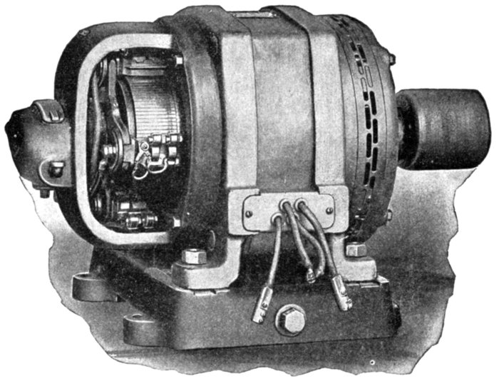
Fig. 1,876.—General Electric single phase compensated repulsion motor. The frame is of
the riveted form and the field winding consists of distributed concentric coils, each being
separately insulated and taped up to each core slot. The compensating winding (depending
usually on the size of frame), forms either the center portion of the main winding
or a separate winding concentric therewith. The polar groupings are arranged for a
frequency of 25 and 60. There are four terminal leads permitting interchangeability of
operation on 110 or 220 volt circuits. By connecting adjacent pairs of these terminals in
multiple, motors of this type are made adaptable for 110 volt service; for double this
pressure the four leading in wires are connected in series. The motor will operate satisfactorily
where the arithmetical sum of voltage and frequency variation does not exceed
10 per cent.; that is, the voltage may be 10 per cent. high if the frequency remain at
normal, or the frequency may be 10 per cent. high assuming no variation in voltage. A
decrease of 5 per cent. in frequency accompanied by a similar increase in voltage is permissible
or, as above stated, any similar combination whose arithmetical sum is within
10 per cent. of normal. The armature winding is of the series drum type connected to a
commutator carrying two sets of brushes, each set being displaced electrically from the other
by 90 degrees. The first set, known as the energy brushes, is permanently short circuited
and disposed at an angle to the lines of field or primary magnetization, as in an ordinary
repulsion motor. The second set, or compensating brushes, is connected to a small portion
of the primary winding included in the field circuit, so as to impress upon the armature
an electromotive force, which serves both to raise the power factor and at the same time
maintain approximately synchronous speed at all loads. The armature laminations are
built up on a cast iron sleeve having the same inside bore as the commutator. In case
the shaft become damaged or worn, it can be readily pressed out and replaced without
disturbing the commutator or windings. The motor is connected to run counter clockwise.
Clockwise rotation is obtained by interchanging the leads to the compensating
brushes and slightly shifting the brush holder yoke. This type motor may be thrown on
the line without the use of a rheostat, and is suitable for operating refrigerating machines,
air compressors, house pumps or similar apparatus where a float switch or pressure regulator
is used to close or open the supply circuit.
pressure but also the self-induction pressure. Hence, as compared to
an equivalent direct current motor, the applied voltage must be greater
than in the direct current machine, to produce an equal current.
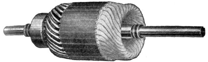
Fig. 1,877.—Armature of General Electric single phase compensated repulsion motor,
assembled ready for dip and banding.
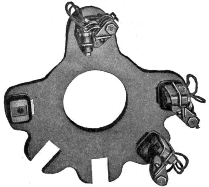
Fig. 1,878.—Cast brush rigging of General Electric single phase compensated repulsion motor
as used for the 3 and 5 horse power motors.
The Local Armature Currents.—These currents produced by
the transformer pressure occur in those coils undergoing commutation.
They are large, because the maximum transformer action
occurs in them, that is, in the coils short circuited by the brushes.
Ques. Why do the local armature currents cause
sparking?
Ans. Because of the sudden interruption of the large volume
of current, and also because the flux set up by the local currents
being in opposition to the field flux, tends to weaken the field
just when and where its greatest strength is required for commutation.
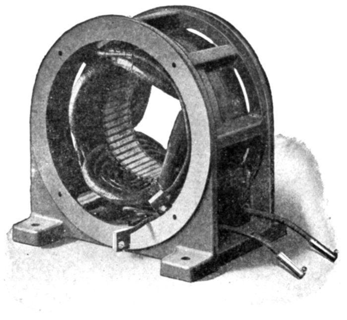
Fig. 1,879.—Field of Sprague single phase compensated repulsion motor. The frame is of the
skeleton form which exposes the core, giving effective heat radiation. The single phase
field winding is of the distributed concentric type. To facilitate connection to circuits of
either 110 or 220 volts, four plainly tagged leads are brought out to the back of the removable
terminal board.
Ques. What is the strength of the local current?
Ans. They may be from 5 to 15 times the strength of the
normal armature current.
Ques. Upon what does the local armature current
depend?
Ans. Upon the number of turns of the short circuited coils,
their resistance, and the frequency.
Ques. How can the local currents be reduced to avoid
heavy sparking?
Ans. 1. By reducing the number of turns of the short
circuited coils, that is, providing a greater number of commutator
bars; 2, reducing the frequency; and 3, increasing the
resistance of the short circuited coil circuit: a, by means of high resistance
connectors; or b, by using brushes of higher resistance.
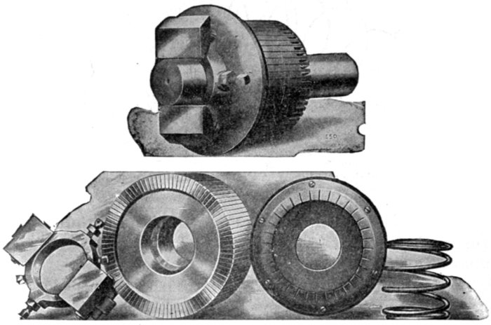
Figs. 1,880 to 1,884.—Assembly and disassembled view of short circuiting device as used on
Bell single phase repulsion induction motor. The armature, which is wound in a similar
manner to those used in direct current motors, has a commutator, and brushes, which
being short circuited on themselves, allow great starting torque, with small starting
current. The motor starts by the repulsion principle, and on reaching nearly full speed,
a centrifugal governor pushes the copper ring against the commutator segments, thereby
short circuiting them, and the motor then operates on the induction principle.
Ques. What are high resistance connectors?
Ans. The connectors between the armature winding and the
commutator bars, as shown in fig. 1,885.
Ques. Does the added resistance of preventive leads, or
high resistance brushes, materially reduce the efficiency of
the machine?
Ans. Not to any great extent, because it is very small in
comparison with the resistance of the whole armature winding.
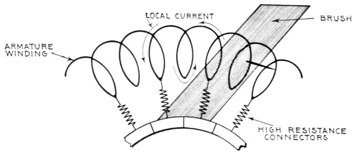
Fig. 1,885.—Section of ring armature of commutator motor showing local current set up by
transformer action of the alternating flux.
Ques. What is the objection to reducing the number of
turns of the short circuited coils to diminish the tendency
to sparking?
Ans. The cost of the additional number of commutator
bars and connectors as well as the added mechanism.
Ques. What effect has the inductance of the field and
armature on the power factor?
Ans. It produces phase difference between the current and
impressed pressure resulting in a low power factor.
Ques. What is the effect of this low power factor?
Ans. The regulation and efficiency of the system is impaired.
The frequency, the field flux and the number of turns in the winding
have influence on the power factor.
Ques. How does the frequency affect the power factor?
Ans. Lowering the frequency tends to improve the power
factor.
The use of very low frequencies has the disadvantage of departing
from standard frequencies, and the probability that the greater cost of
transformers and alternators would offset the gain.
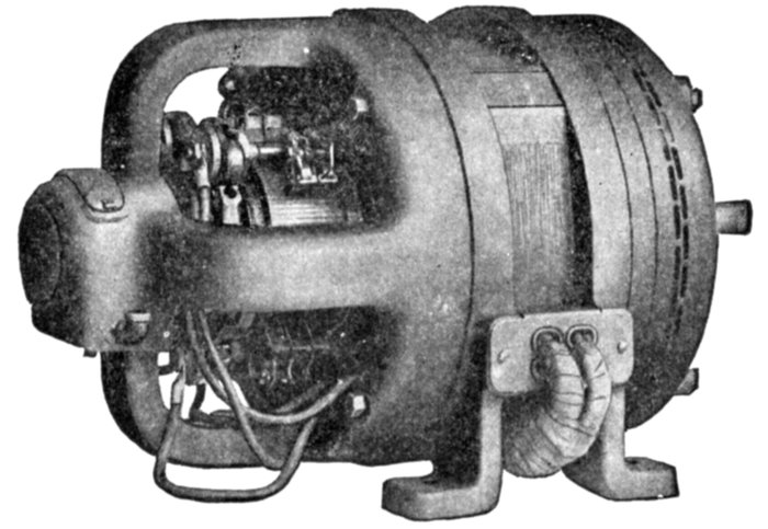
Fig. 1,886.—General Electric 5 H.P., 6 pole adjustable speed single phase compensated
repulsion motor. This type is suitable for service requirements demanding the use of a
motor whose speed can be adjusted over a considerable range, this speed at a fixed controller
setting remaining practically unaffected by any load within the motor's rated
capacity. With the controller on the high speed points, the motor possesses an inherent
speed regulation between no load and full load of approximately 6 per cent. At the low
speed points, under similar load conditions, the speed variation will be approximately 20
per cent. To secure adjustable speed control, the armature circuits employ transformers,
whose primaries are excited by the line circuit. The secondaries of these transformers
are divided into two sections; the first or "regulating" circuit is placed across the energy
brushes; the other section, since it is connected in series with the compensating winding,
maintains the high power factor and speed regulation obtained in the constant speed
type. The speed range is 2:1, approximately one-half of this range being below and
one-half above synchronous speed.
Series Motors.—This class of commutator motor is about
the simplest of the several types belonging to this division. In
general design the series motor is identical with the series direct
current motor, but all the iron of the magnetic circuit must be
laminated and a neutralizing winding is often employed.
It will be readily understood that the torque is produced in
the same way as in the direct current machine, when it is
remembered that the direction of rotation of the direct current
series motor is independent of the direction of the voltage applied.
At any moment the torque will be proportional to the product
of the current and the flux which it is at that moment producing
in the magnetic system, and the average torque will be the product
of the average current and the average flux it produces, so that
if the iron parts be unsaturated, as they must be if the iron losses
are not to be too high, the torque will be proportional simply to
the square of the current, there being no question of power factor
entering into the consideration.
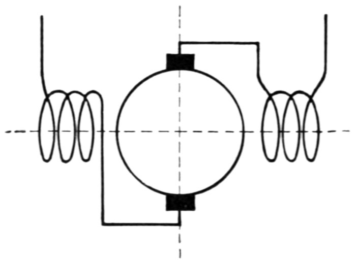
Fig. 1,887.—Diagram of single phase series commutator motor. It is practically the same
as the series direct current motor, with the exception that all the metal of the magnetic
circuit must be laminated.
Ques. What are the characteristics of the series motor?
Ans. They are similar to the direct current series motor,
the torque being a maximum at starting and decreasing as the
speed increases.
Ques. For what service is the series motor especially
suited?
Ans. On account of its powerful starting torque it is particularly
desirable for traction service.
Neutralized Series Motor.—A chief defect of the series
motor is the excessive self-induction of the armature, hence in
almost every modern single phase series motor a neutralizing
coil is employed to diminish the armature self-induction.
The neutralizing coil is wound upon the frame 90 magnetic
degrees or half a pole pitch from the field winding and arranged
to carry a current equal in magnetic pressure and opposite in
phase to the current in the armature.
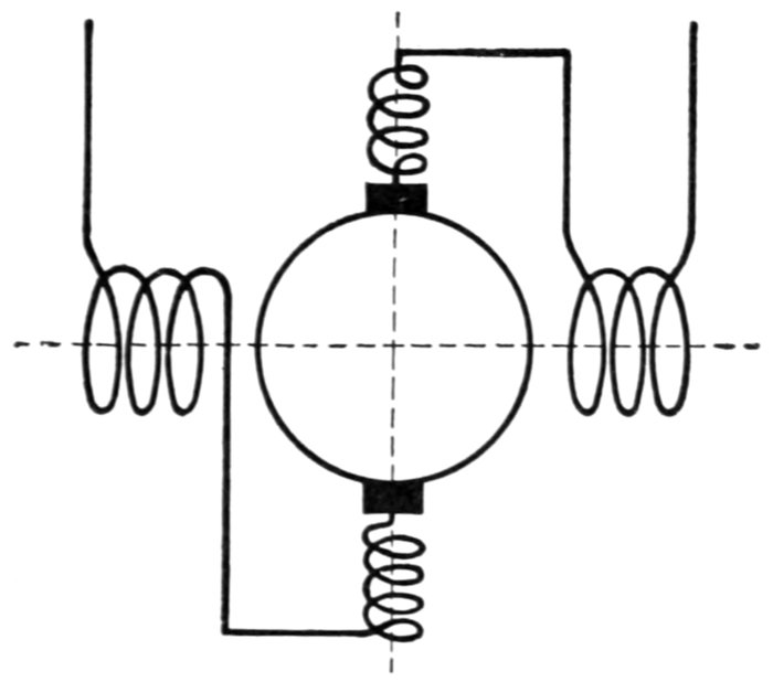
Fig. 1,888.—Diagram of neutralized series motor; conductive method. In the simple series
motor, there will be a distortion of the flux as in the direct current motor. As the distorting
magnetic pressure is in phase with that of the magnets, the distortion of the flux
will be a fixed effect. If the poles be definite as in direct current machines, this distortion
may not seriously affect the running of the motor, but with a magnetizing system like
that universally adopted in induction motors the flux will be shifted as a whole in the
direction of the distortion, which will produce the same effect as if in the former case
the brushes had been shifted forward, whereas for good commutation they should have
been shifted backward. As in direct current machines, this distortion is undesirable
since it is not conducive to sparkless working, and also reduces to a more or less extent
the torque exerted by the motor. The simplest remedy is to provide neutralizing coils
displaced 90 magnetic degrees to the main field coils as shown. The neutralizing current
is obtained by the method of connecting the neutralizing coils in series in the main circuit.
The current through the neutralizing winding may be obtained,
either
- 1. Conductively; or
- 2. Inductively.
In the conductive method, fig. 1,888, the winding is connected in
series as shown.
In the inductive method, fig. 1,889, the winding is short circuited
upon itself and the current obtained inductively, the neutralizing
winding being virtually the secondary of a transformer, of which the
armature is the primary.
Ques. When is the conductive method to be preferred?
Ans. When the motor is to be used on mixed circuits.
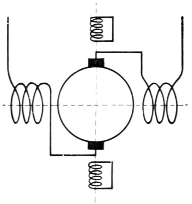
Fig. 1,889.—Diagram of neutralized series motor; inductive method. Although the conductive
method of neutralization is employed in nearly all machines, it is possible merely
to short circuit the neutralizing winding upon itself, instead of connecting it in series with
the armature circuit. In this case the flux due to the armature circuit cannot be eliminated
altogether, as sufficient flux must always remain to produce enough pressure to balance
that due to the residual impedance of the neutralizing coil. It would be a mistake to infer,
however, that on this account this method of neutralization is less effective than the conductive
one, since the residual flux simply serves to transfer to the armature circuit a drop
in pressure precisely equivalent to that due to the resistance and local self-induction of
the neutralizing coil in the conductive method.
Shunt Motors.—The simple shunt motor has inherently
many properties which render it unsuitable for practical use,
and accordingly is of little importance. Owing to the many
turns of the field winding there is large inductance in the shunt
field circuit.
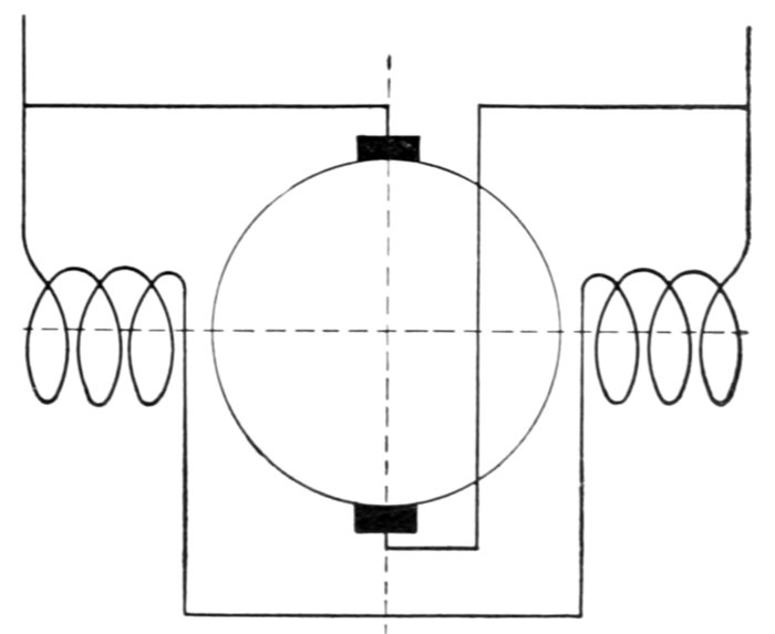
Fig. 1,890.—Diagram of simple shunt commutator motor. Owing to its many inherent
defects it is of little importance.
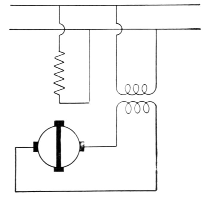
Fig. 1,891.—Compensated shunt induction single phase motor. The transformer shown in
the arrangement is capable of being replaced by a coil placed on the frame having the same
axis as the field winding, so that the flux produced by the field winding induces in the
coil a pressure in phase with the supply pressure. Such a coil will now be at right angles
to the circuit to which it is connected. In a similar manner a coil at right angles to the
armature circuit, that is, the circuit parallel to the stator axis, if connected in series with
that circuit, will also serve to compensate the motor.
Fig. 1,891.—Compensated shunt induction single phase motor. The transformer shown in
the arrangement is capable of being replaced by a coil placed on the frame having the same
axis as the field winding, so that the flux produced by the field winding induces in the
coil a pressure in phase with the supply pressure. Such a coil will now be at right angles
to the circuit to which it is connected. In a similar manner a coil at right angles to the
armature circuit, that is, the circuit parallel to the stator axis, if connected in series with
that circuit, will also serve to compensate the motor.
The inductance of the armature is small as compared with
that of the field; accordingly, the two currents differ considerably
in phase.
The phase difference between the field and armature currents
and the corresponding relation between the respective fluxes
results in a weak torque.
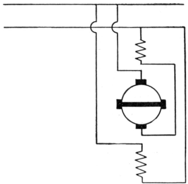
Fig. 1,892.—Fynn's shunt conductive single phase motor. In order to supply along the
stator axis a constant field, suitable for producing the cross flux to which the torque is due
by its action on the circuit perpendicular to the stator axis, the "armature circuit," as it
may be called, has a neutralizing coil in series with it, so that the armature circuit and
neutralizing coil together produce no flux. In addition to this, there is a magnetizing
coil along the same axis, which is connected across the mains and so produces the same
flux as the primary coil in a shunt induction machine. Fynn has proposed a number of
methods of varying the speed and compensating this machine. It is, however, complicated
in itself, and is only suited for very low voltages, so that on ordinary circuits it would
need a separate transformer.
It is necessary to use laminated construction in the field circuit
to avoid eddy currents, which otherwise would be excessive.
Fig. 1,890 is a diagram of a simple shunt commutator motor.
Repulsion Motors.—In the course of his observations on
the effects of alternating currents, in 1886-7, Elihu Thomson observed
that a copper ring placed in an alternating magnetic field
tends either to move out of the field, that is, it is repelled by the
field (hence the name repulsion motor), or to return so as to set
itself edgeways to the magnetic lines.
The explanation of the repulsion phenomenon is as follows:
When a closed coil is suspended in an alternating field so that
lines of force pass through it, as in fig. 1,893, an alternating pressure
will be induced in the coil which will be 90° later in phase
than the inducing flux, and since every coil contains some inductance
the resulting current will lag more or less with respect
to the pressure induced in the coil.
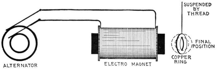
Fig. 1,893.—Effect of alternating field on copper ring. If a copper ring be suspended in an
alternating field so that the plane of the ring is oblique to the lines of force, it will turn until
its plane is parallel to the lines of force, that is, to the position in which it does not encircle
any lines of force. The turning moment acting upon the ring is proportional to the current
in it, to the strength of the field, and to the cosine of the angle ß. Hence it is proportional
to the product sin ß cos ß. The tendency to turn is zero both at 0° and at 90°; in the
former case because there is no current, in the latter because the current has no leverage.
It is a maximum when ß = 45°. Even in this position there would be no torque if there
were no lag of the currents in the ring, for the phase of the induced pressure is in quadrature
with the phase state of the field. When the field is of maximum strength there is no
pressure, and when the pressure reaches its maximum there is no field. If there be self-induction
in the ring causing the current to lag, there will be a net turning moment tending
to diminish ß. The largest torque will be obtained when the lag of the current in
the ring is 45°.
The cosine of this phase relation becomes a negative quantity
which means that the coil is repelled by the field.
It is only when the ring is in an oblique position that it tends to
turn. If it be placed with its plane directly at right angles to the
direction of the magnetic lines, it will not turn; if ever so little
displaced to the right or left, it will turn until its plane is parallel
to the lines.
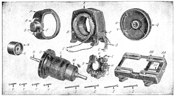
Figs. 1,894 to 1,908.—Parts of General Electric single phase compensated repulsion motor. The field frame employs the riveted
form of construction, so that the ends of the laminations are exposed directly to the air, insuring low operating temperatures
and high overload capacity. The field winding consists of a main winding of the distributed concentric type and a compensating
winding. The series type of winding is employed, and the completed rotor is treated with a special insulating compound,
which renders the coils moisture proof under ordinary conditions. On motors of more than 2 horse power capacity a ventilating
fan is attached to the rotor which provides a continuous supply of cool air while the motor is in operation. Two types of
brush holder yoke are used. The smaller motors use a moulded yoke of insulting compound, reinforced by a cast iron L
section ring embedded in the moulded structure. Cast iron yokes are used on larger motors. The brushes are of carbon
with copper pigtails, which carry all the current. The brushes in this machine remain permanently in contact with the commutator.
The parts are: A, field; B, field winding; C, line terminal; D, tube terminal; E, compensating terminal; F, terminal
board; G, brush yoke; H, brush holder; I, carbon brush; J, brush stud; K, short circuit connection; L, armature;
M, commutator, N, shaft; O, fan; P, commutator end shield; Q, pulley end shield; R, oil well cover; S, oil plugs; T, oil gauge;
U, bearing lining; V, oil ring; W, pulley; X, pulley set screw; Y, commutator end shield holding bolts; Z, pulley end
shield holding bolts; AA, base; BB, float bolts; CC, belt tightener screw.
The production of torque may be explained by saying that the
current induced in the ring produces a cross field which being
out of phase with, and inclined to the field impressed by the
primary alternating current, causes a rotary field, and this in
turn, reacting on the conductor, a turning moment results.
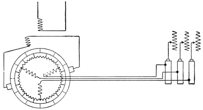
Fig. 1,909.—Fynn's compensated shunt induction motor. This is a combination of the compensated
shunt induction motor with the ordinary squirrel cage form. In one form, in
addition to the ordinary drum winding on the armature, there is another three phase
winding into the "star," of which the drum winding is connected. This second winding
is connected to three slip rings which are short circuited when the machine is up to speed.
Upon the commutator are placed a pair of brushes connected to an auxiliary winding
placed on the frame in such a position that the flux from the primary coil induces in it
a pressure of suitable phase to produce compensation. The same pair of brushes is also
used for starting.
Elihu Thompson took an ordinary direct current armature, placed it
in an alternating field, and having short circuited the brushes, placed
them in an oblique position with respect to the direction of the field.
The effect was to cause the armature to rotate with a considerable torque.
The inductors of the armature acted just as an obliquely placed ring,
but with this difference, that the obliquity was continuously preserved
by the brushes and commutator, notwithstanding that the armature
turned, and thus the rotation was continuous. This tendency of a
conductor to turn from an oblique position was thus utilized by him to
get over the difficulty of starting a single phase motor. With this object
in view he then constructed motors in which the use of commutator and
brushes was restricted to the work of merely starting the armature,
which when so started was then entirely short circuited on itself, though
disconnected from the rest of the circuit, the operation then being solely
on the induction principle.
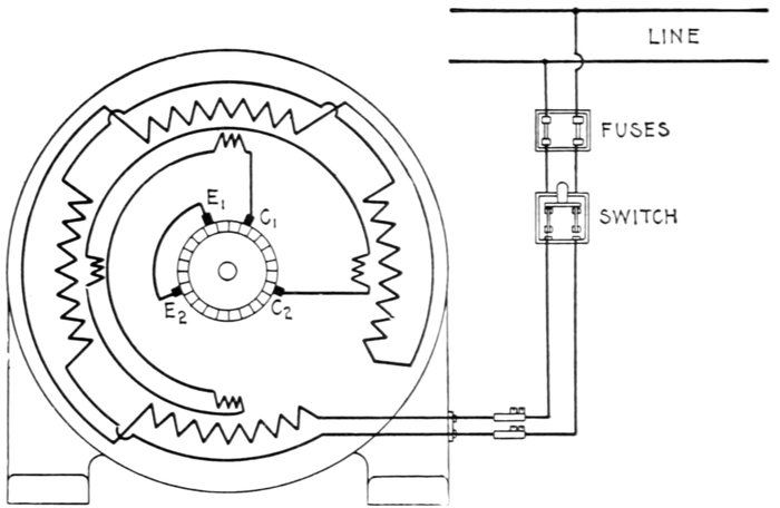
Fig. 1,910.—Diagram of connection of Sprague single phase compensated repulsion motor.
To reverse direction of rotation interchange leads C1 and C2 and slightly shift the brush
holder yoke. Brushes E1 and E2 are permanently short circuited. This diagram of connections
applies also to fig. 1,911.
Ques. What difficulty was experienced with Thomson's
motor?
Ans. Since an open coil armature was used, the torque
developed was due to only one coil at a time, which involved a
necessarily high current in the short circuited coil resulting in
heavy sparking.
Ques. How was this remedied?
Ans. By the use of closed coil armatures in later construction.
Ques. Did this effectually stop sparking?
Ans. No.
Ques. What other means is employed in modern designs
to reduce sparking?
Ans. Compensation and the use of a distributed field winding,
high resistance connectors, high resistance brushes, etc.
Ques. What are the names of the two classes of repulsion
motor?
Ans. The simple and the compensated types.
Ques. Describe a simple repulsion motor.
Ans. It consists essentially of an armature, commutator and
field magnets. The armature is wound exactly like a direct
current armature, and the windings are connected to a commutator.
The carbon brushes which rest on this commutator
are not connected to the outside line, however, but are all connected
together through heavy short circuiting connectors.
The brushes are placed about 60° or 70° from the neutral axis.
The field is wound exactly like that of the usual induction motor.
Ques. What is the action of this type of motor?
Ans. If nothing be done to prevent, the motor will increase
in speed at no load until the armature bursts, just as it will in a
series direct current motor.
Ques. What provision is made to avoid this danger?
Ans. A governor is usually mounted on the armature which
short circuits the windings, after the motor has been started.
The motor then runs as a squirrel cage induction motor. As a
rule the brushes are lifted off the commutator when the armature
is short circuited, so as to prolong their life.
This is a very successful motor, but it is of course more costly than
the simple squirrel cage motor used on two and three-phase circuits.
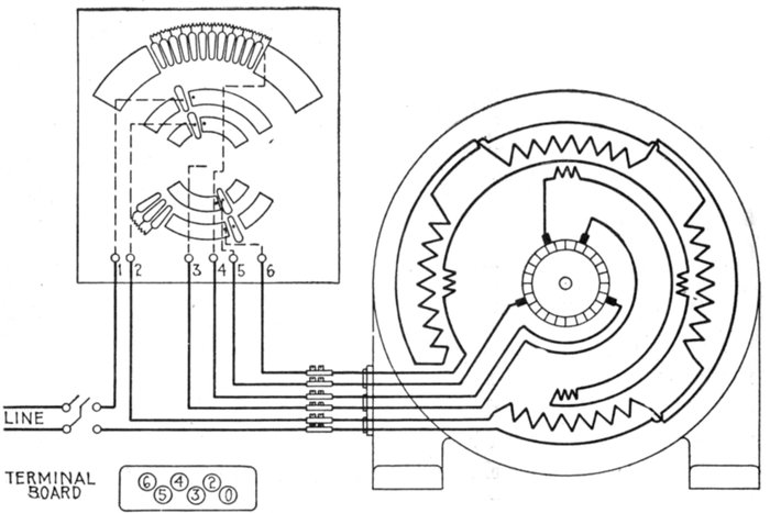
Fig. 1,911.—Diagram of connections of Sprague variable speed single phase compensated
repulsion motor and controller. The controller is designed to give speed reduction and
speed increase as resistance or reactance is inserted in the energy and compensating
circuits. With the exception of the leads brought out from these circuits, the constant
speed and variable speed motors are identical. The standard controller gives approximately
2:1 speed variation.
Ques. What name may appropriately be applied to the
motor?
Ans. It may be called the repulsion induction motor, because
it is constructed for repulsion start and induction running.
Ques. Describe a compensated repulsion motor.
Ans. In its simplest form it consists of a simple repulsion
motor in which there are two independent sets of brushes, one
set being short circuited, while the other set is in series with the
field magnet winding, as in the series alternating current motor.
Ques. What names are given to the two sets of
brushes on a compensated repulsion motor?
Ans. The energy or main short circuiting brushes, and the
compensating brushes.
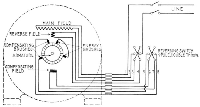
Fig. 1,912.—Diagram of connections of Sprague reversing type of single phase compensated
repulsion motor. As shown, there is a special reverse field winding having terminals for
connection to a four pole double throw switch.
Ques. What is the behavior of the armature of a
compensated repulsion motor at starting?
Ans. It possesses at starting most of the apparent reactance
of the motor, and the effect of speed is to decrease such apparent
reactance, the latter becoming zero at either positive or
negative synchronism, and negative at higher speeds in either
direction.
Ques. What is the nature of the field circuit of the
compensated repulsion motor at starting?
Ans. At starting it is practically non-inductive, the effect
of speed being to introduce a spurious resistance which increases
directly with the speed, and becomes negative when
the speed is reversed.
Ques. For what use is the compensated repulsion
motor especially adapted?
Ans. For light railroad service.
Ques. When employed thus what is the method of
control?
Ans. A series transformer is used in the field circuit.
Ques. What frequencies are employed with this
motor?
Ans. 25 to 60, the preferred frequency being 40.
Ques. To what important use is the repulsion principle
put?
Ans. It is sometimes employed for starting on single phase
induction motors.
In this method, after bringing the motor up to speed, the winding is
then short circuited upon itself, and the motor then operates on the
induction principle.
Ques. What name is given to this type of motor?
Ans. It is called the repulsion induction motor.
Power Factor of Induction Motors.—In the case of a
direct current motor, the energy supplied is found by multiplying
the current strength by the voltage, but in all induction motors
the effect of self-induction causes the current to lag behind the
pressure, thereby increasing the amount of current taken by
the motor. Accordingly, as the increased current is not utilized by
the motor in developing power, the value obtained by multiplying
the current by the voltage represents an apparent energy
which is greater than the real energy supplied to the motor.
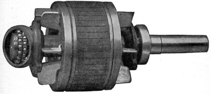
Fig. 1,913.—Fairbanks-Morse squirrel cage armature, showing ball bearings.
It is evident, that if it were possible to eliminate the lag entirely,
the real and apparent watts would be equal, and the
power factor would be unity.
The importance of power factor and its effect upon both
alternator capacity and voltage regulation is deserving of the
most careful consideration with all electrical apparatus, in which
an inherent phase difference exists between the pressure and the
current, as for instance in static transformers and induction motors.
While the belief is current that any decrease in power factor
from unity value does not demand any increase of mechanical
output, this is not true, since all internal alternator and line
losses manifest themselves as heat, the wasted energy to
produce this heat being supplied by the prime mover.
Apart from the poor voltage regulation of alternating current
generators requiring abnormal field excitation to compensate for
low power factor, some of the station's rated output is rendered
unavailable and consequently produces no revenue. The poor
steam economy of underloaded engines is also a serious source
of fuel wastage.
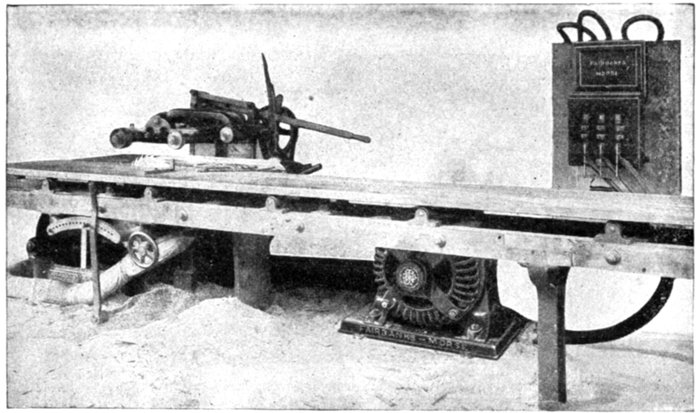
Fig. 1,914.—Fairbanks-Morse 20 horse power squirrel cage induction motor connected to a
20 inch self-feed rip and chamfering saw. The absence of commutator and brushes on
the squirrel cage armature eliminates sparking and therefore renders this type of motor
particularly adapted for use in places where sparking would be dangerous, such as in
wood working plants, textile mills, etc.
Careful investigations have shown that the power factor of industrial
plants using induction motor drive with units of various sizes will average
between 60 and 80 per cent. With plants supplying current to underloaded
motors having inherently high lagging current values, a
combined factor as low as 50 per cent. may be expected. Since standard
alternators are seldom designed to carry their rated kilowatt load at less
than 80 per cent. power factor, the net available output is, therefore,
considerably increased.
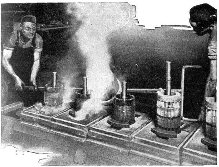
Fig. 1,915.—Method of casting end rings on squirrel cage armatures of Fairbanks-Morse induction
motors. The metal being fused to the bars at a temperature in excess of 1,832
degrees Fahr., it is readily seen that the destructive effect of any subsequent heating is
eliminated. While giving the most intimate contact at the joints, a multiplicity of joints
is avoided as well as solder.
Speed and Torque of Motors.—The speed of an induction
motor depends chiefly on the frequency of the circuit and runs
within 5 per cent. of its rated speed; it will produce full torque
if the line voltage do not vary more than 5 to 10 per cent.
At low voltage the speed will not be greatly reduced as in a
direct current motor, but as the torque is low the motor is easily
stopped when a light load is thrown on.
The current taken by an induction motor from a constant
pressure line varies with the speed as in a direct current motor.
When a load is thrown on, the speed is reduced correspondingly
and as the self-induction or reactance is diminished, more
current circulates in the squirrel cage winding, which in turn
reacts on the field coils in a similar manner and more current
flows in them from the line. In this manner the motor automatically
takes current from the line proportional to the load
and maintains a nearly constant speed.
The so-called constant speed motors require slight variations
in speed to automatically take current from the line when the
load varies.
Induction motors vary in speed from 5 to 10 per cent., while
synchronous motors vary but a fraction of one per cent.
Single phase motors to render efficient service must be able,
where requisite, to develop sufficient turning moment or torque
to accelerate, from standstill, loads possessing large inertia or
excessive static friction; for example, meat choppers and grinders,
sugar or laundry centrifugals; heavy punch presses; group
driven machines running from countershafts with possibly over
taut belting, poor alignment, lubrication, etc.
 by
by