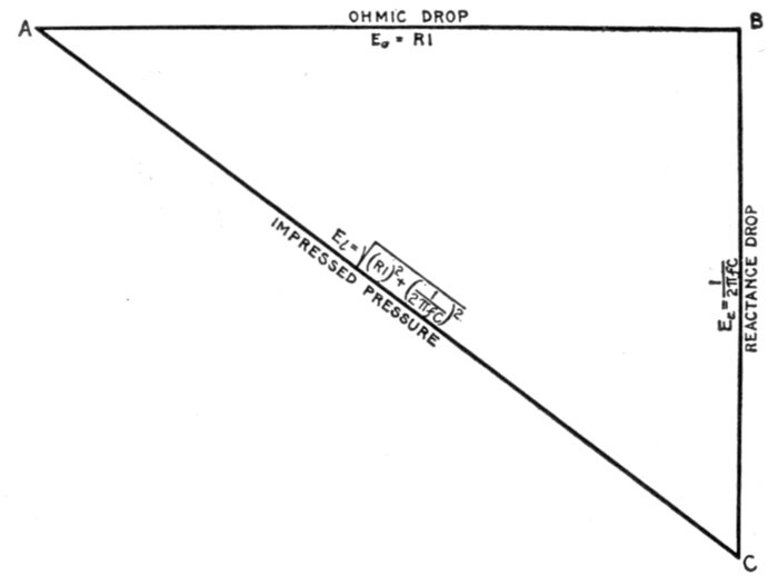
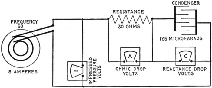
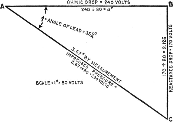
The word "alternating" is used with a large number of
electrical and magnetic quantities to denote that their magnitudes
vary continuously, passing repeatedly through a definite
cycle of values in a definite interval of time.
As applied to the flow of electricity, an alternating current may
be defined as: A current which reverses its direction in a periodic
manner, rising from zero to maximum strength, returning to zero,
and then going through similar variations in strength in the opposite
direction; these changes comprise the cycle which is repeated
with great rapidity.
The properties of alternating currents are more complex than those
of continuous currents, and their behavior more difficult to predict.
This arises from the fact that the magnetic effects are of far more
importance than those of steady currents. With the latter the magnetic
effect is constant, and has no reactive influence on the current
when the latter is once established. The lines of force, however, produced
by alternating currents are changing as rapidly as the current itself,
and they thus induce electric pressures in neighboring circuits, and
even in adjacent parts of the same circuit. This inductive influence in
alternating currents renders their action very different from that of
continuous current.
Ques. What are the advantages of alternating current
over direct current?
Ans. The reduced cost of transmission by use of high voltages
and transformers, greater simplicity of generators and motors,
facility of transforming from one voltage to another (either
higher or lower) for different purposes.
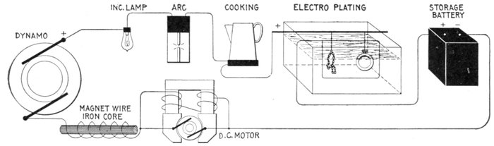
Figs. 1,206 to 1,212.—Apparatus which operates successfully on a direct current circuit. The direct current will operate incandescent
lamps, arc lamps, electric heating apparatus, electro-plating and typing bath, direct current motors; charge storage
batteries, produce electro-chemical action. It will flow through a straight wire or just as freely through the same wire when
wound over an iron bar.
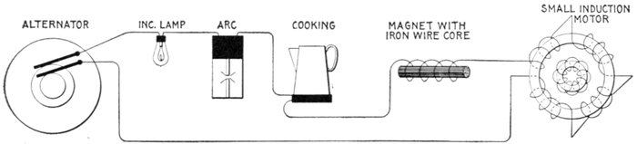
Figs. 1,213 to 1,217.—Apparatus which operates successfully on an alternating circuit. The alternating current will operate incandescent
lamps, arc lamps, electric heating apparatus, alternating current motors. It will flow through a straight wire with
slightly increased retarding effect, but if the wire be wound on an iron bar its strength is greatly reduced.
The size of wire needed to transmit a given amount of electrical energy
(watts) with a given percentage of drop, being inversely proportional
to the square of the voltage employed, the great saving in copper by the use
of alternating current at high pressure must be apparent. This advantage
can be realized either by a saving in the weight of wire required, or by
transmitting the current to a greater distance with the same weight of
copper.
In alternating current electric lighting, the primary voltage is usually
at least 1,000 and often 2,000 to 10,000 volts.
Ques. Why is alternating current used instead of
direct current on constant pressure lighting circuits?
Ans. It is due to the greater ease with which the current
can be transformed from higher to lower pressures.
Ques. How is this accomplished?
Ans. By means of simple transformers, consisting merely
of two or more coils of wire wound upon an iron core.
Since there are no moving parts, the attention required and the likelihood
of the apparatus getting out of order are small. The apparatus
necessary for direct current consists of a motor dynamo set which is
considerably more costly than a transformer and not so efficient.
Ques. What are some of the disadvantages of alternating
current?
Ans. The high pressure at which it is used renders it dangerous,
and requires more efficient insulation; alternating current
cannot be used for such purposes as electro-plating, charging
storage batteries, etc.
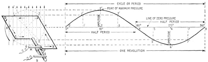
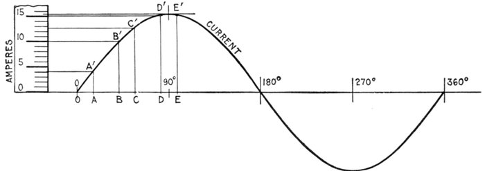
Fig. 1,218.—Application and construction of the sine curve. The sine curve is a wavelike curve used to represent the changes
in strength and direction of an alternating current. At the left of the figure is shown an elementary alternator, consisting
of a loop of wire ABCD, whose ends are attached to the ring F, and shaft G, being arranged to revolve in a uniform magnetic
field, as indicated by the vertical arrows representing magnetic lines at equidistances. The alternating current induced in
the loop is carried to the external circuit through the brushes M and S. The loop, as shown, is in its horizontal position at
right angles to the magnetic field. The dotted circle indicates the circular path described by AB or CD during the revolution
of the loop. Now, as the loop rotates, the induced electric pressure will vary in such a manner that its intensity at any
point of the rotation is proportional to the sine of the angle corresponding to that point. Hence, on the horizontal line which passes
through the center of the dotted circle, take any length as 08, and divide into any number of equal parts representing fractions
of a revolution, as 0°, 90°, 180°, etc. Erect perpendiculars at these points, and from the corresponding points on the dotted
circle project lines (parallel to 08) to the perpendiculars; these intersections give points, on the sine curve, for instance,
through 2 at the 90° point of the revolution of the loop, and projecting over to the corresponding perpendicular gives 2'2,
whose length is proportional to the electric pressure at that point. In like manner other points are obtained, and the
curved line through them will represent the variation in the electric pressure for all points of the revolution. At 90° the
pressure is at a maximum, hence by using a pressure scale such that the length of the perpendicular 2'2 for 90° will measure
the maximum pressure, the length of the perpendicular at any other point will represent the actual pressure at that point.
The curve lies above the horizontal axis during the first half of the revolution and below it during the second half, which
indicates that the current flows in one direction for a half revolution, and in the opposite direction during the remainder of
the revolution.
Alternating Current Principles.—In the operation of a
direct current generator or dynamo, as explained in Chapter
XIII, alternating currents are generated in the armature winding
and are changed into direct current by the action of the commutator.
It was therefore necessary in that chapter, in presenting
the basic principles of the dynamo, to explain the
generation of alternating currents at length, and the graphic
method of representing the alternating current cycle by the
sine curve. In order to avoid unnecessary repetition, the reader
should carefully review the above mentioned chapter before
continuing further. The diagram fig. 168, showing the construction
and application of the sine curve to the alternating
current, is however for convenience here shown enlarged (fig. 1,218).
In the diagram the various
alternating current terms
are graphically defined.
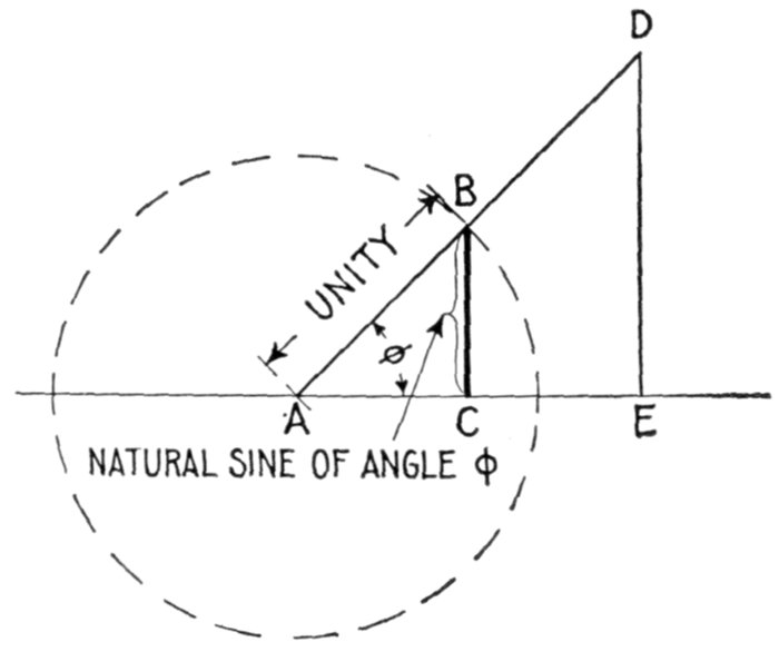
Fig. 1,219—Diagram illustrating the sine of an angle. In order to understand the sine curve,
it is necessary to know the meaning of the sine of an angle. This is defined as the ratio
of the perpendicular let fall from any point in one side of the angle to the other side divided
by the hypotenuse of the triangle thus formed. For instance, in the diagram, let AD
and AE be the two sides of the angle φ, and DE a perpendicular let fall from any point
D of the side AD to the other side AE. Then, the sine of the angle (written sin φ) = DE ÷ AD.
It is evident that if the perpendicular be let fall at a unit's distance from the
apex A, as at B,
This line BC is called the natural sine of the angle, and its values for different angles are given
in the table on page 451.
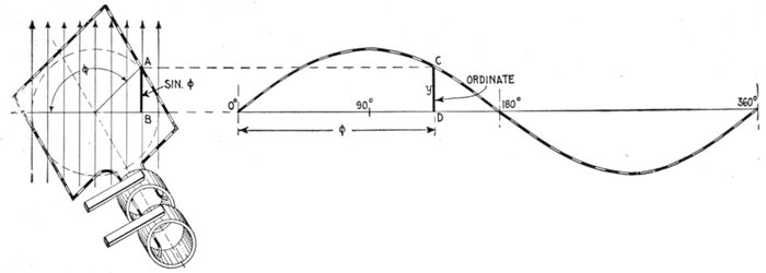
Fig. 1,220.—Diagram illustrating the equation of the sine curve: y = sin φ.
y is any ordinate, and φ, the angle which the coil makes with the
horizontal line, corresponding to the particular value of y taken.
The alternating current,
as has been explained,
rises from zero to a maximum,
falls to zero, reverses
its direction, attains a maximum
in the new direction,
and again returns to zero;
this comprises the cycle.
This series of changes
can best be represented by
a curve, whose abscissæ
represent time, or degrees
of armature rotation, and
whose ordinates, either
current or pressure. The
curve usually chosen for
this purpose is the sine
curve, as shown in fig.
1,218, because it closely
agrees with that given by
most alternators.
The equation of the sine
curve is
y = sin φ
in which y is any ordinate,
and φ, the angle of the
corresponding position of
the coil in which the current
is being generated as
illustrated in fig. 1,220.
Ques. What is an alternation?
Ans. The changes which the current undergoes in rising
from zero to maximum pressure and returning back to zero;
that is, a single positive or negative "wave" or half period, as
shown in fig. 1,221.
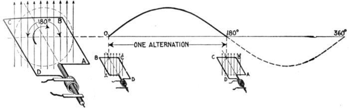
Fig. 1,221.—Diagram showing one alternation of the current in which the latter varies from zero
to maximum and back to zero while the generating loop ABCD makes one half revolution.
Ques. What is the amplitude of the current?
Ans. The greatest value of the current strength attained
during the cycle.
The foregoing definitions are also illustrated in fig. 1,218.
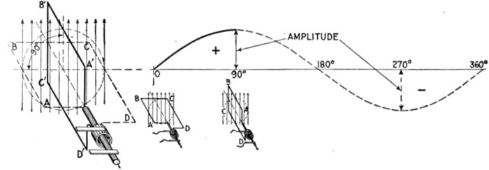
Fig. 1,222.—Diagram illustrating amplitude of the current. The current reaches its amplitude
or maximum value in one quarter period from its point of zero value, as, for instance, while
the generating loop moves from position ABCD to A'B'C'D'. At three-quarter revolution,
the current reaches its maximum value in the opposite direction.
Ques. Define the term "period."
Ans. This is the time of one cycle of the alternating current.
Ques. What is periodicity?
Ans. A term sometimes used for frequency.
Frequency.—If a slowly varying alternating current be passed
through an incandescent lamp, the filament will be seen to vary
in brightness, following the change of current strength. If,
however, the alternations take place more rapidly than about
50 to 60 per second, the eye cannot follow the variations and the
lamp appears to burn steadily. Hence it is important to consider
the rate at which the alternations take place, or as it is called,
the frequency, which is defined as: the number of cycles per second.
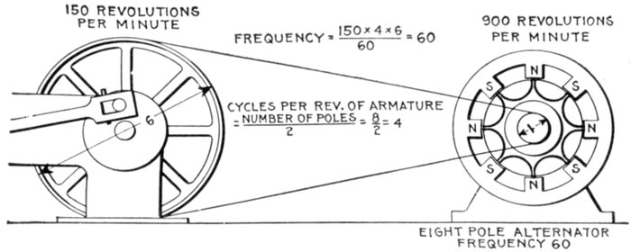
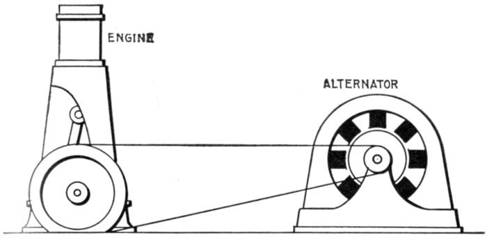
Fig. 1,223.—Diagram of alternator and engine, illustrating frequency. The frequency or
cycles per second is equal to the revolution of armature per second multiplied by one-half the
number of poles per phase. In the figure the armature makes 6 revolutions to one of the
engine; one-half the number of poles = 8 ÷ 2 = 4, hence frequency = (150 × 4 × 6) ÷ 60
= 60. The expression in the parenthesis gives the cycles per minute, and dividing by 60,
the cycles per second.
In a two pole machine, the frequency is the same as the number
of revolutions per second, but in multipolar machines, it is
greater in proportion to the number of pairs of poles per phase.
Thus, in an 8 pole machine, there will be four cycles per revolution.
If the speed be 900 revolutions per minute, the frequency is
The symbol ~ is read "cycles per second."
Ques. What frequencies are used in commercial
machines?
Ans. The two standard frequencies are 25 and 60 cycles.
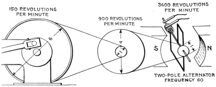
Fig. 1,224—Diagram answering the question: Why are alternators always built multipolar?
They are made multipolar because it is desirable that the frequency be high. It is evident
from the figure that to obtain high frequency would require too many revolutions of the
armature of a bipolar machine for mechanical safety—especially in large alternators.
Moreover a double reduction gear in most cases would be necessary, adding complication
to the drive. Comparing the above illustration with fig. 1,223, shows plainly the reason
for multipolar construction.
Ques. For what service are these frequencies adapted?
Ans. The 25 cycle frequency is used for conversion to direct
current, for alternating current railways, and for machines of
large size; the 60 cycle frequency is used for general distribution
for lighting and power.
The frequency of 40 cycles, which once was introduced as a compromise
between 25 and 60 has been found not desirable, as it is somewhat
low for general distribution, and higher than desirable for conversion
to direct current.
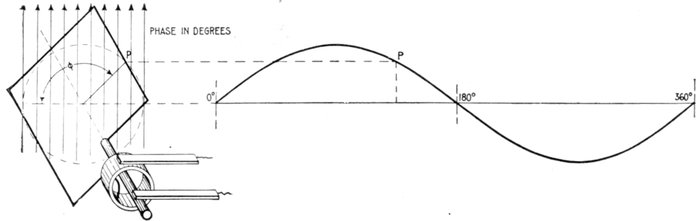
Fig. 1,225.—Diagram illustrating "phase." In wave, vibratory, and simple harmonic motion, phase may be defined as: the
portion of one complete vibration, measured either in angle or in time, that any moving point has executed.
Ques. What are
the advantages of
low frequency?
Ans. The number of
revolutions of the rotor
is correspondingly low;
arc lamps can be more
readily operated; better
pressure regulation;
small motors such as
fan motors can be operated
more easily from
the circuit.
Phase.—As applied
to an alternating current,
phase denotes the
angle turned through by
the generating element
reckoned from a given
instant. Phase is usually
measured in degrees
from the initial position
of zero generation.
If in the diagram fig.
1,225, the elementary
armature or loop be the
generating element, and
the curve at the right
be the sine curve representing
the current,
then the phase of any
point p will be the angle φ
or angle moved through
from the horizontal line,
the starting point.
Ques. What is phase difference?
Ans. The angle between the phases of two or more alternating
current quantities as measured in degrees.
Ques. What is phase displacement?
Ans. A change of phase of an alternating pressure or current.
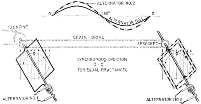
Figs. 1,226 and 1,227.—Diagram and sine curves illustrating synchronism. If two alternators,
with coils in parallel planes, be made to rotate at the same speed by connecting
them with chain drive or equivalent means, they will then be "in synchronism" that is,
the alternating pressure or current in one will vary in step with that in the other. In
other words, the cycles of one take place with the same frequency and at the same time
as the cycles of the other as indicated by the curves, fig. 1,226. It should be noted that
the maximum values are not necessarily the same but the maximum and zero values
must occur at the same time in both machines, and the maximum value must be of the
same sign. If the waves be distorted the maximum values may not occur simultaneously.
See fig. 1,348.
Synchronism.—This term may be defined as: the simultaneous
occurrence of any two events. Thus two alternating currents
or pressures are said to be "in synchronism" when they
have the same frequency and are in phase.
Ques. What does the expression "in phase" mean?
Ans. Two alternating quantities are said to be in phase,
when there is no phase difference between; that is when the
angle of phase difference equals zero.
Thus the current is said to be in phase with the pressure when it
neither lags nor leads, as in fig. 1,228.
A rotating cylinder, or the movement of an index or trailing arm is
brought into synchronism with another rotating cylinder or another
index or trailing arm, not only when the two are moving with exactly
the same speed, but when in addition they are simultaneously moving
over similar portions of their respective paths.
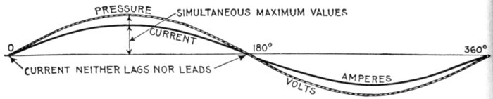
Fig. 1,228—Pressure and current curves illustrating the term "in phase." The current
is said to be in phase with the pressure when it neither lags nor leads.
When there is phase difference, as between current and
pressure, they are said to be "out of phase" the phase difference
being measured as in fig. 1,229 by the angle φ.

Fig. 1,229—Pressure and current curves illustrating the term "out of phase." The current
is said to be out of phase with the pressure when it either lags or leads, that is when the
current is not in synchronism with the pressure. In practice the current and pressure
are nearly always out of phase.
When the phase difference is 90° as in fig. 1,231 or 1,232, the two
alternating quantities are said to be in quadrature; when it is 180°, as
in fig. 1,233, they are said to be in opposition.
When they are in quadrature, one is at a maximum when the other
is at zero; when they are in opposition, one reaches a positive maximum
when the other reaches a negative minimum, being at each instant
opposite in sign.
Ques. What is a departure from synchronism called?
Ans. Loss of synchronism.
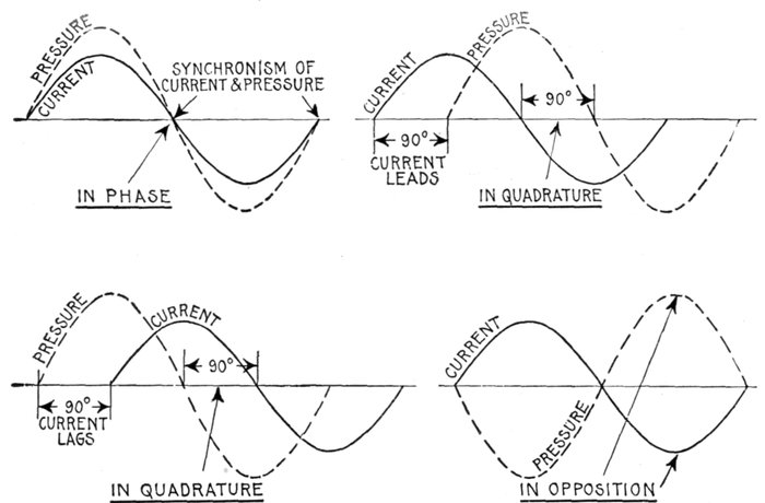
Figs. 1,230 to 1,233.—Curves showing some phase relations between current and pressure. Fig. 1,230, synchronism of current
and pressure, expressed by the term "in phase," meaning simultaneous zero values, and simultaneous maximum values of the
same sign; fig. 1,231, in quadrature, current leading 90°; fig. 1,232 in quadrature, current lagging 90°; fig. 1,233, in opposition,
meaning that the phase different between current and pressure is 180°.
Maximum Volts and Amperes.—In the operation of an
alternator, the pressure and strength of the current are continually
rising, falling and reversing. During each cycle there
are two points at which the pressure or current reaches its
greatest value, being known as the maximum value. This
maximum value is not used to any great extent, but it shows the
maximum to which the pressure rises, and hence, the greatest
strain to which the insulation of the alternator is subjected.
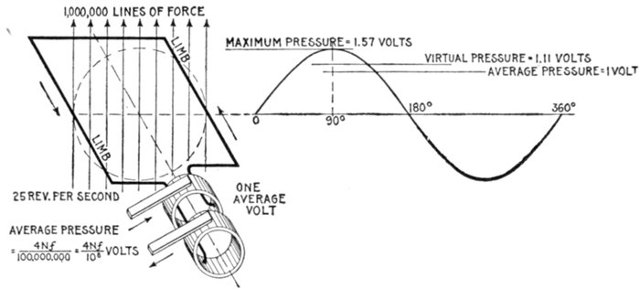
Fig. 1,234.—Elementary alternator developing one average volt. If the loop make one revolution
per second, and the maximum number of lines of force embraced by the loop in the
position shown (the zero position) be denoted by N, then each limb will cut 2N lines per
second, because it cuts every line during the right sweep and again during the left
sweep. Hence each limb develops an average pressure of 2N units (C.G.S. units),
and as both limbs are connected in series, the total pressure is 4N units per revolution.
Now, if the loop make f revolutions per second instead of only one, then f times as many
lines will be cut per second, and the average pressure will be 4N f units. Since the C.G.S.
unit of pressure is so extremely small, a much greater practical unit called the volt is used,
which is equal to 100,000,000, or 108 C.G.S. units is employed. Hence average voltage =
4Nf ÷ 108. The value of N in actual machines is very high, being several million lines
of force. The illustration shows one set of conditions necessary to generate one average
volt. The maximum pressure developed is 1 ÷ .637 = 1.57 volts; virtual pressure =
1.57 × .707 = 1.11 volts.
Average Volts and Amperes.—Since the sine curve is used
to represent the alternating current, the average value may be
defined as: the average of all the ordinates of the curve for one-half
of a cycle.
Ques. Of what use is the average value?
Ans. It is used in some calculations but, like the maximum
value, not very often. The relation between the average and
virtual value is of importance as it gives the form factor.
Virtual Volts and Amperes.—The virtual[1] value of an
alternating pressure or current is equivalent to that of a direct
pressure or current which would produce the same effect; those
effects of the pressure and current are taken which are not
affected by rapid changes in direction and strength,—in the
case of pressure, the reading of an electrostatic voltmeter, and
in the case of current, the heating effect.
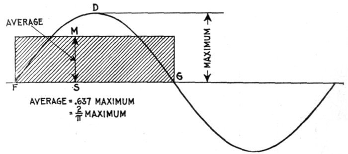
Fig. 1,235.—Maximum and average values of the sine curve. The average value of the sine
curve is represented by an ordinate MS of such length that when multiplied by the base
line FG, will give a rectangle MFSG whose area is equal to that included between the curve
and base line FDGS.
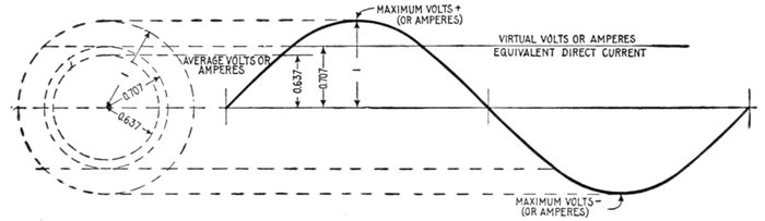
Fig. 1,236.—Diagram illustrating "virtual" volts and amperes. The word virtual is defined as: Being in essence or effect, not in
fact; not actual, but equivalent, so far as effect is concerned. As applied to the alternating current, it denotes an imaginary direct
current of such value as will produce an effect equivalent to that of the alternating current. Thus, a virtual pressure of 1,000
volts is one that would produce the same deflection in an electrostatic voltmeter as a direct pressure of 1,000 volts: a virtual
current of 10 amperes is that current which would produce the same heating effect as a direct current of 10 amperes. Both
pressure and current vary continually above and below the virtual values in alternating current circuits. Distinction should
be made between the virtual and "effective" values of an alternating current. See fig. 1,237. The word effective is commonly
used erroneously for virtual. See note page 1,011.
The attraction (or repulsion)
in electrostatic
voltmeters is proportional
to the square of the volts.
The readings which
these instruments give, if
first calibrated by using
steady currents, are not
true means, but are the
square roots of the means of
the squares.
Now the mean of the
squares of the sine (taken
over either one quadrant or
a whole circle) is ½; hence
the square root of mean
square value of the sine
functions is obtained by
multiplying their maximum
value by 1 ÷ √2, or by
0.707.
The arithmetical mean
of the values of the sine,
however, is 0.637. Hence
an alternating current, if it
obey the sine law, will produce
a heating effect greater
than that of a steady current
of the same average
strength, by the ratio of
0.707 to 0.637; that is,
about 1.11 times greater.
If a Cardew voltmeter
be placed on an alternating
circuit in which the volts
are oscillating between
maxima of +100 and -100
volts, it will read 70.7 volts,
though the arithmetical
mean is really only 63.7;
and 70.7 steady volts would
be required to produce an
equal reading.
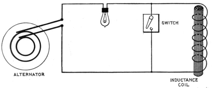
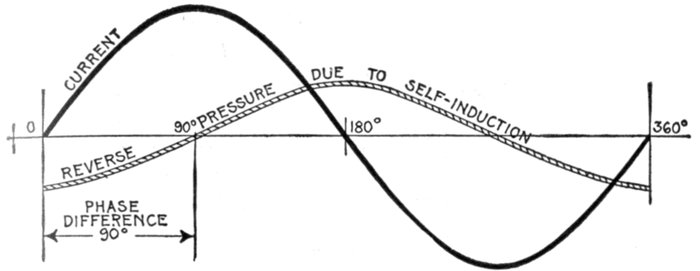
Fig. 1,237.—Diagram illustrating virtual and effective pressure. If the coil be short circuited
by the switch and a constant virtual pressure be impressed on the circuit, the whole of
the impressed pressure will be effective in causing current to flow around the circuit.
In this case the virtual and effective pressures will be equal. If the coil be switched into
circuit, the reverse pressure due to self induction will oppose the virtual pressure; hence, the
effective pressure (which is the difference between the virtual and reverse pressures) will
be reduced, the virtual or impressed pressure remaining constant all the time. A virtual
current is that indicated by an ammeter regardless of the phase relation between current and
pressure. An effective current is that indicated by an ammeter when the current is in phase
with the pressure. In practice, the current is hardly ever in phase with the pressure, usually
lagging, though sometimes leading in phase. Now the greater this phase difference, either
way, the less is the power of a given virtual current to do work. With respect to this
feature, effective current may be defined as: that proportion of a given virtual current which
can do useful work. If there be no phase difference, then effective current is equal to
virtual current.
The matter may be looked at in a different way. If an alternating
current is to produce in a given wire the same amount of effect as a
continuous current of 100 amperes, since the alternating current goes
down to zero twice in each period, it is clear that it must at some point
in the period rise to a maximum greater than 100 amperes. How much
greater must the maximum be? The answer is that, if it undulate
up and down with a pure wave form, its maximum must be √2 times
as great as the virtual mean; or conversely the virtual amperes will
be equal to the maximum divided by √2. In fact, to produce equal
effect, the equivalent direct current will be a kind of mean between the
maximum and the zero value of the alternating current; but it must
not be the arithmetical mean, nor the geometrical mean, nor the harmonic
mean, but the quadratic mean; that is, it will be the square root
of the mean of the squares of all the instantaneous values between zero
and maximum.
Effective Volts and Amperes.—Virtual pressure, although
already explained, may be further defined as the pressure
impressed on a circuit. Now, in nearly all circuits the impressed
or virtual pressure meets with an opposing pressure due to
inductance and hence the effective pressure is something less
than the virtual, being defined as that pressure which is
available for driving electricity around the circuit, or for doing
work. The difference between virtual and effective pressure is
illustrated in fig. 1,237.
Ques. Does a given alternating voltage affect the
insulation of the circuit differently than a direct pressure
of the same value?
Ans. It puts more strain on the insulation in the same
proportion as the maximum pressure exceeds the virtual pressure.
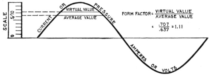
Fig. 1,238.—Current or pressure curve illustrating form factor. It is simply the virtual value
divided by the average value. For a sine wave the virtual value is 1 / √2 times the maximum, and
the average is 2 / π times the maximum, so that the form factor is π/2√2 or 1.11. The induction
wave which generates an alternating pressure wave has a maximum value proportional to
the area, that is, to the average value of the pressure wave. Hence the induction values
corresponding to two pressure waves whose virtual values are equal, will be inversely
proportional to their form factors. This is illustrated by the fact that a peaked wave
causes less hysteresis loss in a transformer core than a flat topped wave, owing to the
higher form factor of the peaked wave. See wave forms, figs. 1,245 to 1,248.
Form Factor.—This term was introduced by Fleming, and
denotes the ratio of the virtual value of an alternating wave to
the average value. That is
Ques. What does this indicate?
Ans. It gives the relative heating effects of alternating and
direct currents, as illustrated in figs. 1,239 and 1,240.
That is, the alternating current will have about 11 per cent. more heating
power than the direct current which is of the same average strength.
If an alternating current voltmeter be placed upon a circuit in which
the volts range from +100 to -100, it will read 70.7 volts, although
the arithmetical average, irrespective of + or-sign, is only 63.7 volts.
If the voltmeter be connected to a direct current circuit, the pressure
necessary to give the same reading would be 70.7 volts.
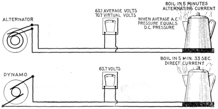
Figs. 1,239 and 1,240.—Relative heating effects of alternating and direct currents. If it takes
say five minutes to produce a certain heating effect with alternating current at say 63.7
average volts, it will take 33 seconds longer with direct current at the same pressure, that
is, the alternating current has about 11 per cent. more heating power than the direct current
of the same average pressure. The reader should be careful not to get a wrong conception
of the above; it does not mean that there is a saving by using alternating current.
When both voltmeters read the same, that is, when the virtual pressure of the alternating
current is the same as the direct current pressure, the heating effect is of course the same.
Ques. What is the relation between the shape of the
wave curve and the form factor?
Ans. The more peaked the wave, the greater the value of
its form factor.
A form factor of units would correspond to a rectangular wave; this
is the least possible value of the form factor, and one which is not
realized in commercial machines.
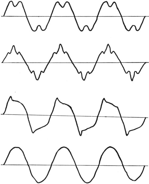
Figs. 1,241 to 1,244.—Various forms of pressure or current waves. Figs. 1,241 to 1,243 show
the general shape of the waves produced by some alternators used largely for lighting
work and having toothed armatures. The effect of the slots and shape of pole pieces is
here very marked. Fig. 1,244 shows a wave characteristic of large alternators designed
for power transmission and having multi-slot or distributed windings.
Wave Form.—There is always more or less irregularity in
the shape of the current waves as met in practice, depending
upon the construction of the alternator.
The ideal wave curve is the so called true sine wave, and is
obtained with a rate of cutting of lines of force, by the armature
coils, equivalent to the swing of a pendulum, which increases
in speed from the end to the middle of the swing, decreasing at
the same rate after passing the center. This swing is expressed
in physics, as "simple harmonic motion".
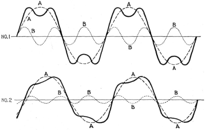
Figs. 1,245 and 1,246.—Resolution of complex curves into sine curves. The heavy curve can
be resolved into the simpler curves A and B shown in No. 1, the component curves A and
B have in the ratio of three to one; that is, curve B has three times as many periods per
second as curve A. All the curves, however, cross the zero line at the same time, and the
resultant curve, though curiously unlike either of them, has a certain symmetry. In No. 2
the component curves, besides having periods in the ratio of three to one, cross the zero
line at different points. The resultant curve produced is still less similar to its components,
and is curiously and unsymmetrically humped. At first sight it is difficult to believe that
such a curious curve could be resolved into two such simple and symmetrical ones. In
both figures the component curves are sine curves, and as the curves for sine and cosine
functions are exactly similar in form, the simplest supposition that can be made for the
variation of pressure or of current is that both follow a sine law.
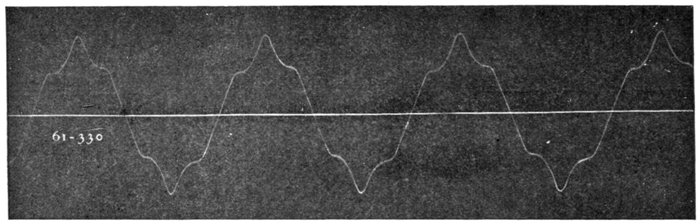
Fig. 1,247.—Reproduction of oscillograph record of wave form of alternator with one coil per phase per pole. Here
the so-called "super-imposed harmonic" is clearly indicated.
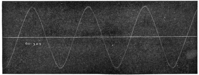
Fig. 1,248.—Reproduction of oscillograph record of Wagner alternator having three coils per phase per pole.
The losses in all secondary apparatus are slightly lower with
the so called peaked form of wave. For the same virtual voltage,
however, the top of the peak will be much higher, thereby submitting
the insulation to that much greater strain. By reason
of the fact that the losses are less under such wave forms, many
manufacturers in submitting performance data on transformers
recite that the figures are for sine wave conditions, stating
further that if the transformers are to be operated in a circuit
more peaked than the sine wave, the losses will be less than
shown.
The slight saving in the losses of secondary apparatus, obtained
with a peaked wave, by no means compensates for the increased
insulation strains and an alternator having a true sine wave is
preferred.
Ques. What determines the form of the wave?
Ans. 1. The number of coils per phase per pole, 2, shape of
pole faces, 3, eddy currents in the pole pieces, and 4, the air gap.
Ques. What are the requirements for proper rate of
cutting of the lines of force?
Ans. It is necessary to have, as a minimum, two coils per
phase per pole in three phase work.
Ques. What is the effect of only one coil per phase per
pole?
Ans. The wave form will be distorted as shown in fig. 1,247.
Ques. What is the least number of coils per phase
per pole that should be used for two and three phase
alternators?
Ans. For three phase, two coils, and for two phase, three
coils, per phase per pole.
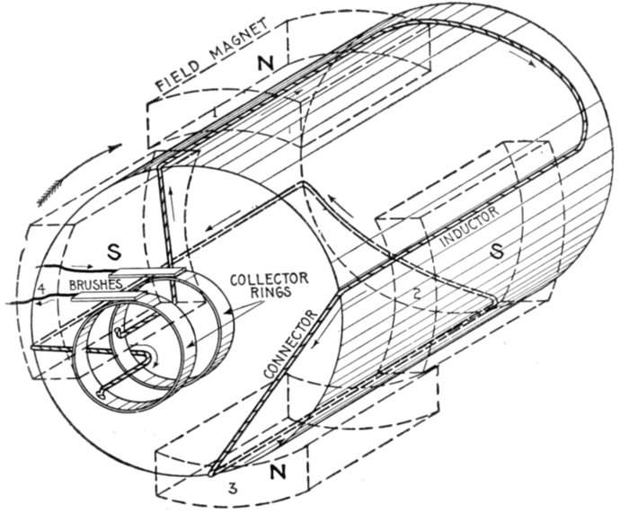
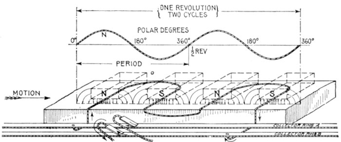
Single or Monophase
Current.—This kind of
alternating current is generated
by an alternator
having a single winding on
its armature. Two wires, a
lead and return, are used
as in direct current.
An elementary diagram
showing the working principles
is illustrated in fig.
1,249, a similar hydraulic
cycle being shown in figs.
1,250 to 1,252.
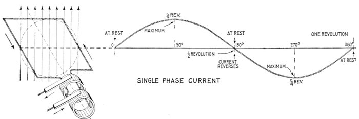
Fig. 1,249.—Elementary one loop alternator and sine curve illustrating single phase alternating current. There are three points
during the revolution at which there is no current: at 0° the position shown, 180°, and 360°; in other words, at the beginning,
middle point and end of the cycle. The current reaches a maximum at 90°, reverses at 180°, and reaches a maximum
in the reverse direction at 270°.
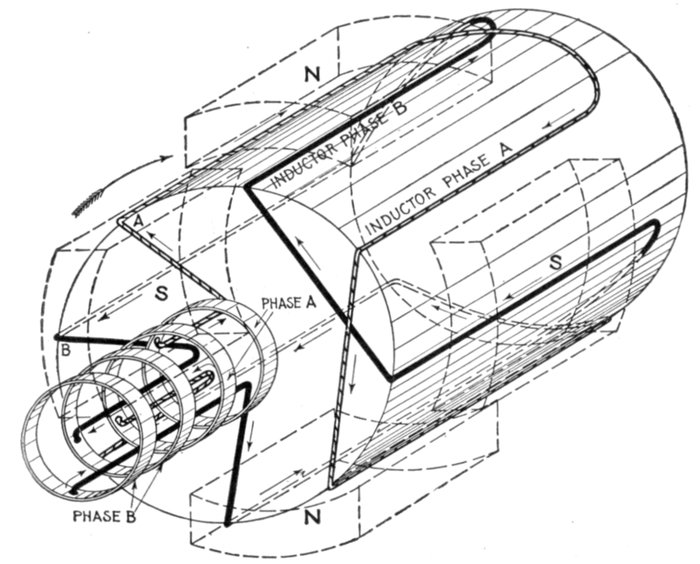
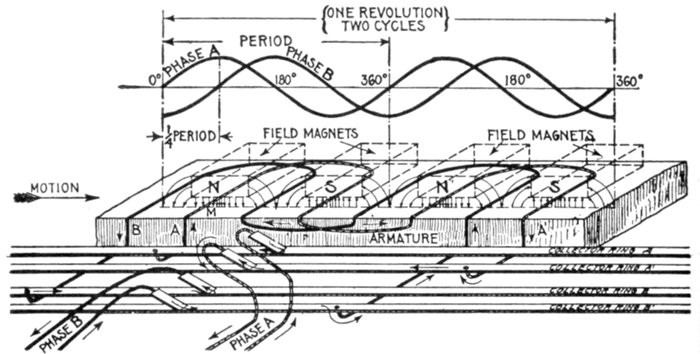
Two Phase Current.—In
most cases two phase
current actually consists of
two distinct single phase
currents flowing in separate
circuits. There is often no
electrical connection between
them; they are of
equal period and equal
amplitude, but differ in
phase by one quarter of a
period. With this phase
relation one of them will
be at a maximum when
the other is at zero. Two
phase current is illustrated
by sine curves in fig.
1,253, and by hydraulic
analogy in
figs. 1,254 and 1,255.
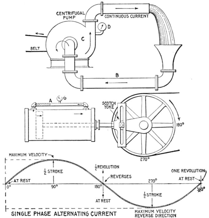
Figs. 1,250 to 1,252.—Hydraulic analogy illustrating the difference between direct (continuous)
and alternating current. In fig. 1,250 a centrifugal pump C forces water to the upper
pipe, from which it falls by gravity to the lower pipe B and re-enters the pump. The
current is continuous, always flowing in one direction, that is, it does not reverse its direction.
Similarly a direct electric current is constant in direction (does not reverse);
though not necessarily constant in value. A direct current, constant in both value and
direction as a result of constant pressure, is called "continuous" current. Similarly in
the figure the flow is constant, and a gauge D placed at any point will register a constant
pressure, hence the current may be called, in the electrical sense, "continuous." The
conditions in fig. 1,251 are quite different. The illustration represents a double acting
cylinder with the ends connected by a pipe A, and the piston driven by crank and Scotch
yoke as shown. In operation, if the cylinder and pipe be full of water, a current of water
will begin to flow through the pipe in the direction indicated as the piston begins its stroke,
increasing to maximum velocity at one-quarter revolution of the crank, decreasing and
coming to rest at one-half revolution, then reversing and reaching maximum velocity
in the reverse direction at three-quarter revolution, and coming to rest again at the end of
the return stroke. A pressure gauge at G will register a pressure which varies with the
current. Since the alternating electric current undergoes similar changes, the sine curve
will apply equally as well to the pump cycle as to the alternating current cycle.
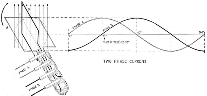
Fig. 1,253.—Elementary two loop alternator and sine curves, illustrating two phase
alternating current. If the loops be placed on the alternator armature at 90 magnetic
degrees, a single phase current will be generated in each of the windings, the
current in one winding being at its maximum value when the other is at zero. In
this case four transmission conductors are generally used, two for each separate
circuit, and the motors to which the current is led have a double winding corresponding
to that on the alternator armature.
If two identical
simple alternators
have their armature
shafts coupled in such
a manner, that when
a given armature coil
on one is directly
under a field pole, the
corresponding coil on
the other is midway
between two poles of
its field, the two currents
generated will
differ in phase by a
half alternation, and
will be two phase
current.
Ques. How must
an alternator be
constructed to
generate two phase
current?
Ans. It must have
two independent
windings, and these
must be so spaced
out that when the
volts generated in
one of the two phases
are at a maximum,
those generated in
the other are at zero.
In other words, the windings, which must be alike, of an equal number
of turns, must be displaced along the armature by an angle corresponding
to one-quarter of a period, that is, to half the pole pitch.
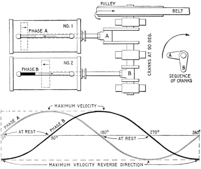
Figs. 1,254 and 1,255.—Hydraulic analogy illustrating two phase alternating current. In the
figure two cylinders, similar to the one in fig. 1,251, are shown, operated from one shaft
by crank and Scotch yoke drive. The cranks are at 90° as shown, and the cylinders and
connecting pipes full of water. In operation, the same cycle of water flow takes place as
in fig. 1,251. Since the cranks are at 90°, the second piston is one-half stroke behind the
first; the flow of water in No. 1 (phase A) is at a maximum when the flow in No. 2 (phase
B) comes to rest, the current conditions in both pipes for the entire cycle being represented
by the two sine curves whose phase difference is 90°. Comparing these curves with fig.
1,253, it will be seen that the water and electric current act in a similar manner.
Figs. 1,254 and 1,255.—Hydraulic analogy illustrating two phase alternating current. In the
figure two cylinders, similar to the one in fig. 1,251, are shown, operated from one shaft
by crank and Scotch yoke drive. The cranks are at 90° as shown, and the cylinders and
connecting pipes full of water. In operation, the same cycle of water flow takes place as
in fig. 1,251. Since the cranks are at 90°, the second piston is one-half stroke behind the
first; the flow of water in No. 1 (phase A) is at a maximum when the flow in No. 2 (phase
B) comes to rest, the current conditions in both pipes for the entire cycle being represented
by the two sine curves whose phase difference is 90°. Comparing these curves with fig.
1,253, it will be seen that the water and electric current act in a similar manner.
The windings of the two phases must, of course, be kept separate,
hence the armature will have four terminals, or if it be a revolving
armature it will have four collector rings.
As must be evident the phase difference may be of any value between
0° and 360°, but in practice it is almost always made 90°.
Ques. In what other way may two phase current be
generated?
Ans. By two single phase alternators coupled to one shaft.
Ques. How many wires are required for two phase
distribution?
Ans. A two phase system requires four lines for its distribution;
two lines for each phase as in fig. 1,253. It is possible, but
not advisable, to reduce the number to 3, by employing one
rather thicker line as a common return for each of the phases
as in fig. 1,256.
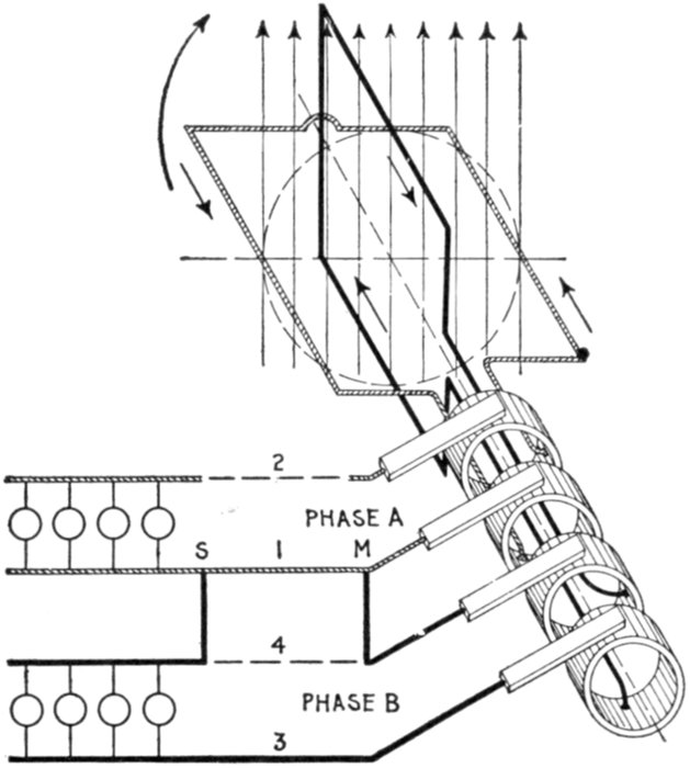
Fig. 1,256.—Diagram of three wire two phase current distribution. In order to save one wire
it is possible to use a common return conductor for both circuits, as shown, the dotted
portion of one wire 4 being eliminated by connecting across to 1 at M and S. For long
lines this is economical, but the interconnection of the circuits increases the chance
of trouble from grounds or short circuits. The current in the conductor will be the resultant
of the two currents, differing by 90° in phase.
If this be done, the voltage between the A line and the B line will be
equal to √2 times the voltage in either phase, and the current in the
line used as common return will be √2 times as great as the current in
either line, assuming the two currents in the two phases to be equal.
Ques. In what other way may two phase current be
distributed?
Ans. The mid point of the windings of the two phases may
be united in the alternator at a common junction.
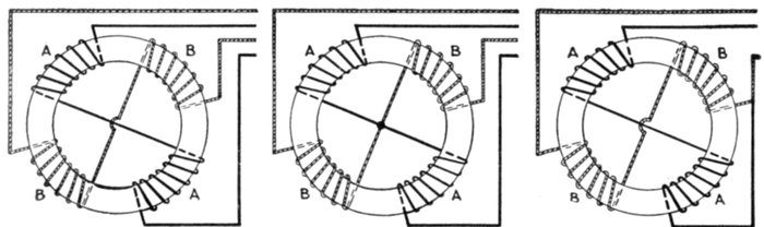
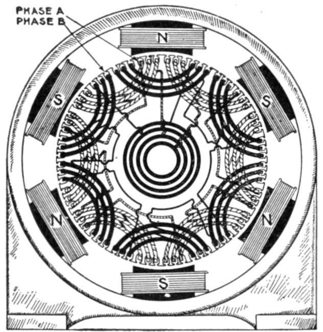
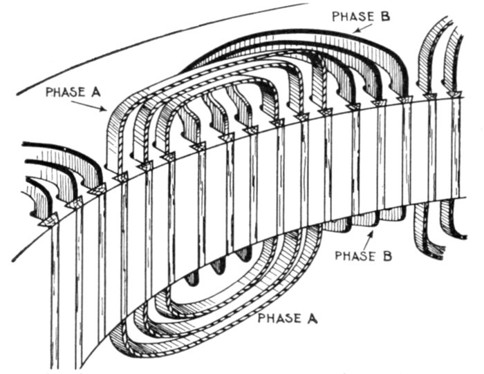
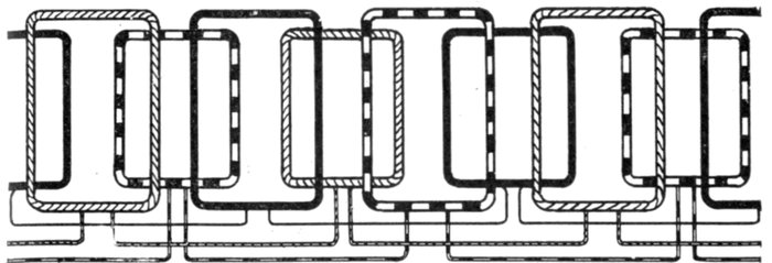
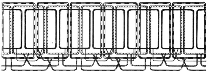
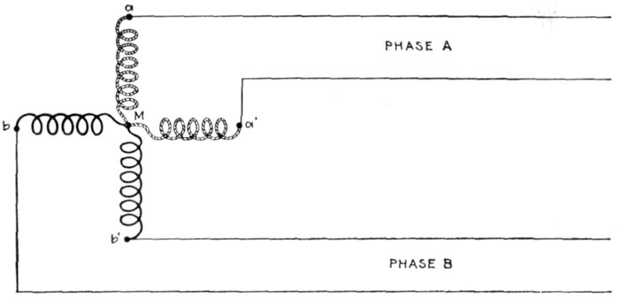
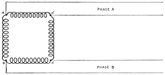
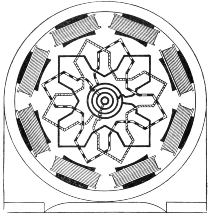
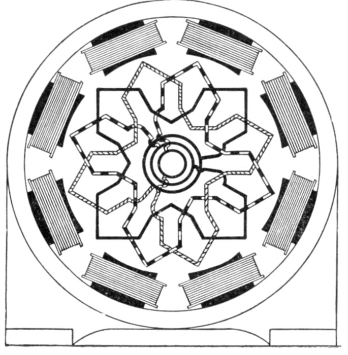
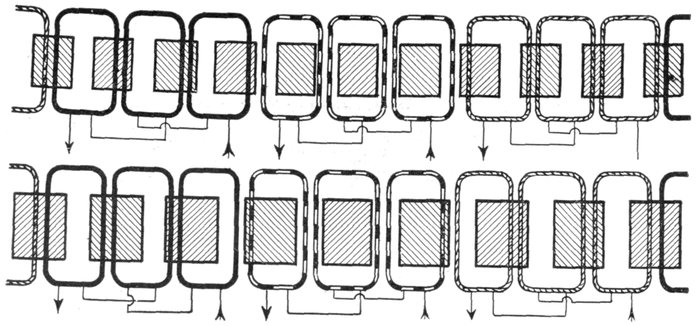
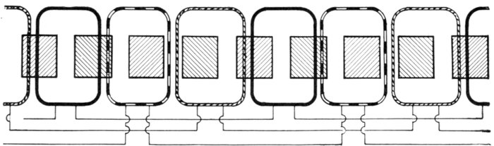
Figs. 1,257 to 1,259.—Various two phase armature connections. Fig. 1,257, two separate
circuit four collector ring arrangement; fig. 1,258, common middle connection, four
collector rings; fig. 1,259, circuit connected in armature for three collector rings. In the
figures the black winding represents phase A, and the light winding, phase B.
This is equivalent to making the machine into a four phase alternator
with half the voltage in each of the four phases, which will then be in
successive quadrature with each other.
Ques. How are two phase alternator armatures wound?
Ans. The two circuits may be separate, each having two
collector rings, as shown in fig. 1,257, or the two circuits may be
coupled at a common middle as in fig. 1,258, or the two circuits
may be coupled in the armature so that only three collector
rings are required as shown in fig. 1,259.
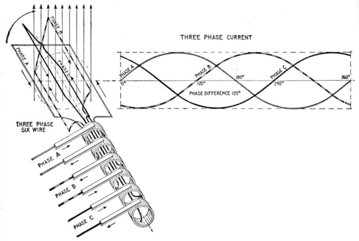
Fig. 1,260.—Elementary three loop alternator and sine curves, illustrating three phase alternating
current. If the loops be placed on the alternator armature at 120 magnetic degrees
from one another, the current in each will attain its maximum at a point one-third of a
cycle distant from the other two. The arrangement here shown gives three independent
single phase currents and requires six wires for their transmission. A better arrangement
and the one generally used is shown in fig. 1,261.
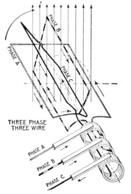
Fig. 1,261.—Elementary three wire three phase alternator. For the transmission of three
phase current, it is not customary to use six wires, as in fig. 1,260, instead, three ends
(one end of each of the loops) are brought together to a common connection as shown,
and the other ends, connected to the collector rings, giving only three wires for the
transmission of the current.
Three Phase Current.—A three phase current consists of
three alternating currents of equal frequency and amplitude,
but differing in phase from each other by one-third of a period.
Three phase current as represented by sine curves is shown in
fig. 1,260, and by hydraulic analogy in fig. 1,262. Inspection of the
figures will show that when any one of the currents is at its
maximum, the other two are of half their maximum value,
and are flowing in the opposite direction.
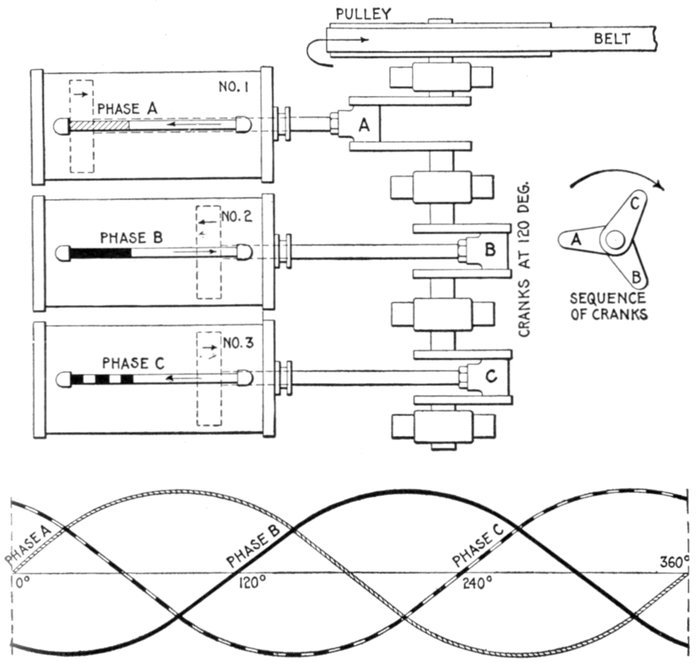
Figs. 1,262 and 1,263.—Hydraulic analogy illustrating three phase alternating current. Three
cylinders are here shown with pistons connected through Scotch yokes to cranks placed
120° apart. The same action takes place in each cylinder as in the preceding cases, the
only difference being the additional cylinder, and difference in phase relation.
Ques. How is three phase current generated?
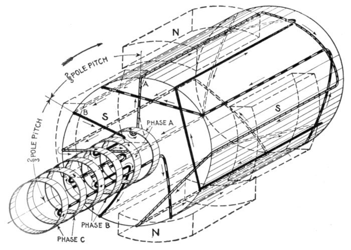
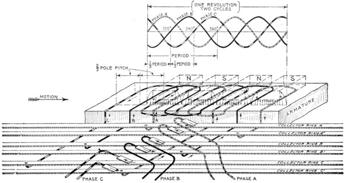
Ans. It requires three equal windings on the alternator
armature, and they must be spaced out over its surface so as
to be successively ⅓ and ⅔ of the period (that is, of the double
pole pitch) apart from one another.
Ques. How many wires are used for three phase
distribution?
Ans. Either six wires or three wires.
Six wires, as in fig. 1,260, might be used where it is desired to supply
entirely independent circuits, or as is more usual only three wires are
used as shown in fig. 1,261. In this case it should be observed that if the
voltage generated in each one of the three phases separately E (virtual)
volts, the voltage generated between any two of the terminals will be
equal to √3 × E. Thus, if each of the three phases generate 100
volts, the voltage from the terminal of the A phase to that of the B
phase will be 173 volts.
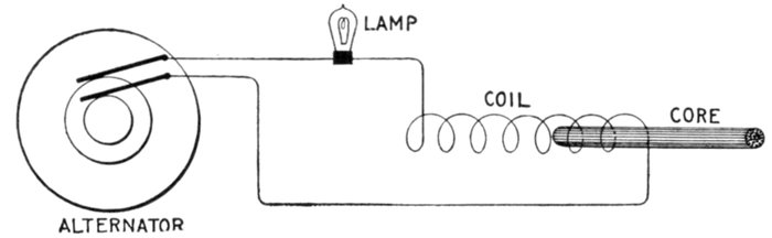
Fig. 1,264.—Experiment illustrating self-induction in an alternating current circuit. If an
incandescent lamp be connected in series with a coil made of one pound of No. 20 magnet
wire, and connected to the circuit, the current through the lamp will be decreased due to
the self-induction of the coil. If now an iron core be gradually pushed into the coil,
the self-induction will be greatly increased and the lamp will go out, thus showing the great
importance which self-induction plays in alternating current work.
Inductance.—Each time a direct current is started, stopped
or varied in strength, the magnetism changes, and induces or
tends to induce a pressure in the wire which always has a direction
opposing the pressure which originally produced the current.
This self-induced pressure tends to weaken the main current at
the start and prolong it when the circuit is opened.
The expression inductance is frequently used in the same sense as
coefficient of self-induction, which is a quantity pertaining to an electric
circuit depending on its geometrical form and the nature of the surrounding
medium.
If the direct current maintains the same strength and flow
steadily, there will be no variations in the magnetic field surrounding
the wire and no self-induction, consequently the only retarding
effect of the current will be the "ohmic resistance" of the wire.
If an alternating current be sent through a circuit, there will
be two retarding effects:
1. The ohmic resistance;
2. The spurious resistance.
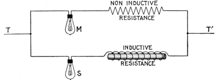
Fig. 1,265.—Non-inductive and inductive resistances. Two currents are shown joined in
parallel, one containing a lamp and non-inductive resistance, and the other a lamp and
inductive resistance. The two resistances being the same, a sufficient direct pressure
applied at T, T' will cause the lamps to light up equally. If, however, an alternating
pressure be applied, M will burn brightly, while S will give very little or no light because
of the effect of the inductance of the inductive resistance.
Ques. Upon what does the ohmic resistance depend?
Ans. Upon the length, cross sectional area and material of
the wire.
Ques. Upon what does the spurious resistance depend?
Ans. Upon the frequency of the alternating current, the
shape of the conductor, and nature of the surrounding medium.

Fig. 1,266.—Inductance test, illustrating the self-induction of a coil which is gradually increased by moving an iron wire core
inch by inch into the coil. The current is kept constant with the adjustable resistance throughout the test and readings taken,
first without the iron core, and again when the core is put in the coil and moved to the 1, 2, 3, 4, etc., inch marks. By
plotting the voltmeter readings and the position of the iron core on section paper, a curve is obtained showing graphically
the effect of the self-induction. A curve of this kind is shown in fig. 1,302.
Ques. Define inductance.
Ans. It is the total magnetic flux
threading the circuit per unit current
which flows in the circuit, and which
produces the flux.
In this it must be understood that
if any portion of the flux thread the
circuit more than once, this portion
must be added in as many times as it
makes linkage.
Inductance, or the coefficient of self-induction
is the capacity which an
electric circuit has of producing induction
within itself.
Inductance is considered as the ratio
between the total induction through a
circuit to the current producing it.
Ques. What is the unit of inductance?
Ans. The henry.
Ques. Define the henry.
Ans. A coil has an inductance of
one henry when the product of the
number of lines enclosed by the coil
multiplied by the number of turns in
the coil, when a current of one ampere
is flowing in the coil, is equal to
100,000,000 or 108.
An inductance of one henry exists in
a circuit when a current changing at the
rate of one ampere per second induces a
pressure of one volt in the circuit.
Ques. What is the henry called?
Ans. The coefficient of self-induction.
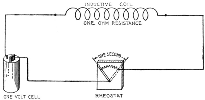
Fig. 1,267.—Diagram illustrating the henry. By definition: A circuit has an inductance of one
henry when a rate of change of current of one ampere per second induces a pressure of one
volt. In the diagram it is assumed that the internal resistance of the cell and resistance of
the connecting wires are zero.
The henry is the coefficient by which the time rate of change of the
current in the circuit must be multiplied, in order to give the pressure
of self-induction in the circuit.
The formula for the henry is as follows:
or
where
- L = coefficient of self induction in henrys;
- N = total number of lines of force threading a coil when the current is one ampere;
- T = number of turns of coil.
If a coil had a coefficient of self-induction of one henry, it would mean
that if the coil had one turn, one ampere would set up 100,000,000, or
108, lines through it.
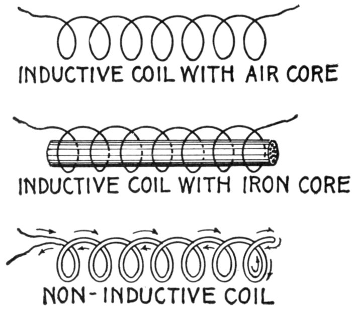
Figs. 1,268 to 1,270.—Various coils. The inductance effect, though perceptible in an air core
coil, fig. 1,268, may be greatly intensified by inserting a core made of numerous pieces
of iron wire, as in fig. 1,269. Fig. 1,270 shows a non-inductive coil. When wound in this
manner, a coil will have little or no inductance because each half of the coil neutralizes
the magnetic effect of the other. This coil, though non-inductive, will have "capacity."
It would be useless for solenoids or electromagnets, as it would have no magnetic field.
The henry[2] is too large a unit for use in practical computations,
which involves that the millihenry, or 1/1,000th
henry, is the accepted unit. In pole suspended lines the
inductance varies as the metallic resistance, the distance between
the wires on the cross arm and the number of cycles per second,
as indicated by accepted tables. Thus, for one mile of No.
8 B. & S. copper wire, with a resistance of 3,406 ohms, the coefficient
of self-induction with 6 inches between centers is .00153, and, with 12 inches, .00175.
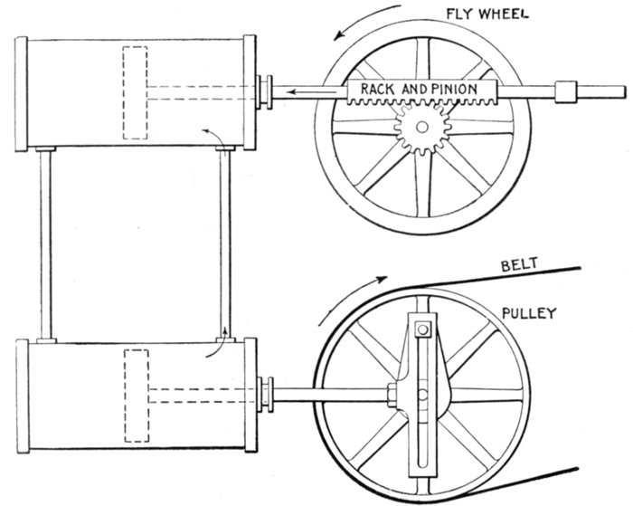
Fig. 1,271.—Hydraulic-mechanical analogy illustrating inductance in an alternating current circuit.
The two cylinders are connected at their ends by the vertical pipes, each being
provided with a piston and the system filled with water. Reciprocating motion is imparted
to the lower pulley by Scotch yoke connection with the drive pulley. The upper
piston is connected by rack and pinion gear with a fly wheel. In operation, the to and fro
movement of the lower piston produces an alternating flow of water in the upper cylinder
which causes the upper piston to move back and forth. The rack and pinion connection
with the fly wheel causes the latter to revolve first in one direction, then in the other, in
step with the upper piston. The inertia of the fly wheel causes it to resist any change
in its state, whether it be at rest or in motion, which is transmitted to the upper piston,
causing it to offer resistance to any change in its rate or direction of motion. Inductance
in the alternating current circuit has precisely the same effect, that is, it opposes any
change in the strength or direction of the current.
Ques. How does the inductance of a coil vary with
respect to the core?
Ans. It is least with an air core; with an iron core, it is
greater in proportion to the permeability[3] of the iron.
The coefficient L for a given coil is a constant quantity so long as the
magnetic permeability of the material surrounding the coil does not
change. This is the case where the coil is surrounded by air. When
iron is present, the coefficient L is practically constant, provided the magnetism
is not forced too high.
In most cases arising in practice, the coefficient L may be considered
to be a constant quantity, just as the resistance R is usually considered
constant. The coefficient L of a coil or circuit is often spoken of as its
inductance.
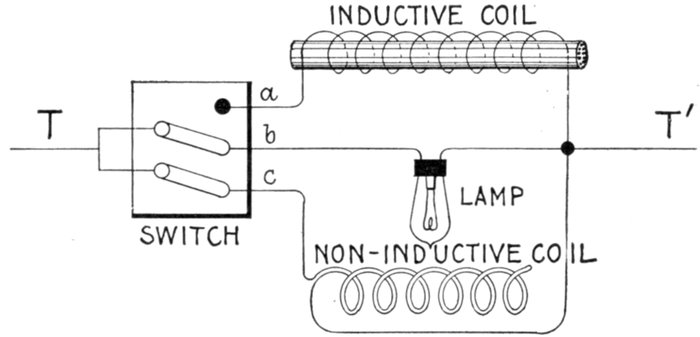
Fig. 1,272.—Experiment showing effect of inductive and non-inductive coils in alternating
current circuit. The apparatus is connected up as shown; by means of the switch, the
lamp may be placed in parallel with either the inductive or non-inductive coil. These
coils should have the same resistance. Pass an alternating current through the lamp
and non-inductive coil, of such strength that the lamp will be dimly lighted. Now turn
the switch so as to put the lamp and inductive coil in parallel and the lamp will burn
with increased brilliancy. The reason for this is because of the opposition offered
by the inductive coil to the current, less current is shunted from the lamp when
the inductive coil is in the circuit than when the non-inductive coil is in the circuit. That
is, each coil has the same ohmic resistance, but the inductive coil has in addition the
spurious resistance due to inductance, hence it shunts less current from the lamp than
does the non-inductive coil.
Ques. Why is the iron core of an inductive coil made
with a number of small wires instead of one large rod?
Ans. It is laminated in order to reduce eddy currents and
consequent loss of energy, and to prevent excessive heating of
the core.
Ques. How does the number of turns of a coil affect
the inductance?
Ans. The inductance varies as the square of the turns.
That is, if the turns be doubled, the inductance becomes four times
as great.
The inductance of a coil is easily calculated from the following
formulæ:
L = 4π2r2n2 ÷ (l × 109) (1)
for a thin coil with air core, and
L = 4π2r2n2μ ÷ (l × 109) (2)
for a coil having an iron core. In the above formulæ:
- L = inductance in henrys;
- π = 3.1416;
- r = average radius of coil in centimeters;
- n = number of turns of wire in coil;
- μ = permeability of iron core;
- l = length of coil in centimeters.
EXAMPLE.—An air core coil has an average radius of 10 centimeters
and is 20 centimeters long, there being 500 turns, what is the
inductance?
Substituting these values in formula (1)
L = 4 × (3.1416)2 × 102 × 5002 ÷ (20 × 109) = .00494 henry
Ques. Is the answer in the above example in the
customary form?
Ans. No; the henry being a very large unit, it is usual to
express inductance in thousandths of a henry, that is, in milli-henrys.
The answer then would be .04935 × 1,000 = 49.35 milli-henrys.
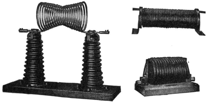
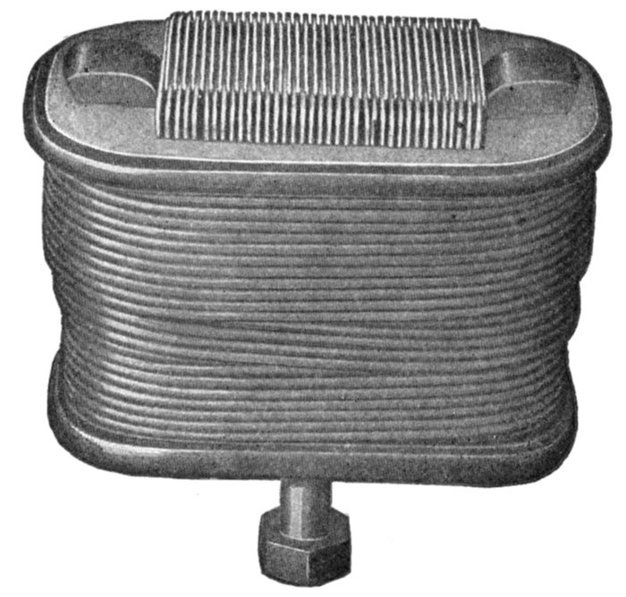
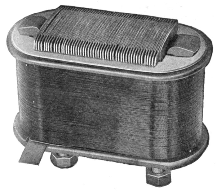
Figs. 1,273 to 1,275.—General Electric choke coils. Fig. 1,273, hour glass coil, 35,000 volts;
fig. 1,274, 4,600 volt coil; fig. 1,275, 6,600 volt coil. A choke coil is a coil with large
inductance and small resistance, used to impede alternating currents. The choke coil is
used extensively as an auxiliary to the lightning arrester. In this connection the
primary objects of the choke coil should be: 1, to hold back the lightning disturbance
from the transformer or generator until the lightning arrester discharges to earth.
If there be no lightning arrester the choke coil evidently cannot perform this function.
2, to lower the frequency of the oscillation so that whatever charge gets through the
choke coil will be of a frequency too low to cause a serious drop of pressure around the
first turns of the end coil in either generator or transformer. Another way of expressing
this is from the standpoint of wave front: a steep wave front piles up the pressure when
it meets an inductance. The second function of the choke coil is, then, to smooth out
the wave front of the surge. The principal electrical condition to be avoided is that of
resonance. The coil should be so arranged that if continual surges be set up in the
circuit, a resonant voltage due to the presence of the choke coil cannot build up at the
transformer or generator terminals. In the types shown above, the hour glass coil has
the following advantages on high voltages: 1, should there be any arcing between
adjacent turns the coils will re-insulate themselves, 2, they are mechanically strong, and
sagging is prevented by tapering the coils toward the center turns, 3, the insulating
supports can be best designed for the strains which they have to withstand. Choke
coils should not be used in connection with cable systems.
EXAMPLE.—An air core coil has an inductance of 50 milli-henrys;
if an iron core, having a permeability of 600 be inserted, what is the
inductance?
The inductance of the air core coil will be multiplied by the permeability
of the iron; the inductance then is increased to
50 × 600 = 30,000 milli-henrys, or 30 henrys.
Ohmic Value of Inductance.—The rate of change of an
alternating current at any point expressed in degrees is equal
to the product of 2π multiplied by the frequency, the maximum
current, and the cosine of the angle of position θ; that is (using
symbols)
rate of change = 2πfImaxcos θ.
The numerical value of the rate of change is independent of
its positive or negative sign, so that the sign of the cos φ is
disregarded.
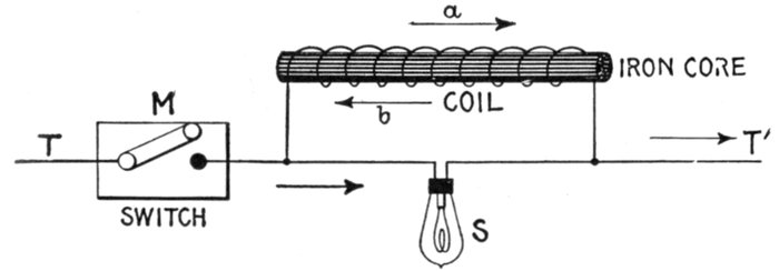
Fig. 1,276.—Inductance experiment with intermittent direct current. A lamp S is connected
in parallel with a coil of fairly fine wire having a removable iron core, and the terminals
T, T' connected to a source of direct current, a switch M being provided to interrupt the
current. The voltage of the current and resistance of the coil are of such values that when
a steady current is flowing, the lamp filament is just perceptibly red. At the instant of
making the circuit, the lamp will momentarily glow more brightly than when the current is
steady; on breaking the circuit the lamp will momentarily flash with great brightness. In the
first case, the reverse pressure, due to inductance, as indicated by arrow b, will momentarily
oppose the normal pressure in the coil, so that the voltage at the lamp will be momentarily
increased, and will consequently send a momentarily stronger current through the
lamp. On breaking the main circuit at M, the field of the coil will collapse, generating a
momentary much greater voltage than in the first instance, in the direction of arrow a,
the lamp will flash up brightly in consequence.
The period of greatest rate of change is that at which cos φ
has the greatest value, and the maximum value of a cosine is
when the arc has a value of zero degrees or of 180 degrees, its
value corresponding, being 1. (See fig. 1,037, page 1,068.)
The pressure due to inductance is equal to the product of the
rate of change by the inductance; that is, calling the inductance L,
the pressure due to it at the point of maximum value or
Emax = 2πfImax × L (1)
Now by Ohm's law
Emax = RImax (2)
for a current Imax, hence substituting equation (2) in equation (1)
RImax = 2πfImax × L
from which, dividing both sides by Imax, and using Xi for R
Xi = 2πfL (3)
which is the ohmic equivalent of inductance.
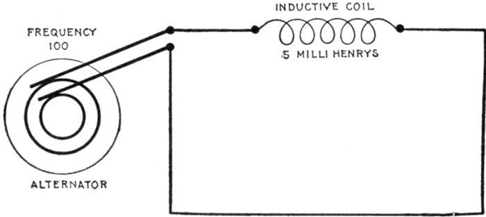
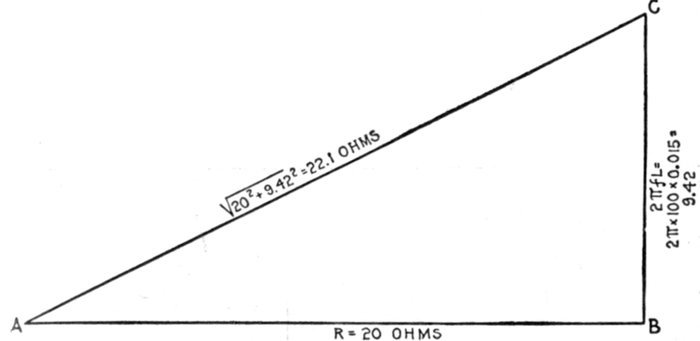
FIG. 1,277.—Diagram showing alternating circuit containing inductance. Formula for calculating
the ohmic value of inductance or "inductance reactance," is Xi = 2πfL in which
Xi = inductance reactance; π = 3.1416; f = frequency; L = inductance in henrys (not
milli-henrys). L = 15 milli-henrys = 15 ÷ 1000 = .015 henrys. Substituting, Xi = 2 ×
3.1416 × 100 × .015 = 9.42 ohms.
The frequency of a current being the number of periods or
waves per second, then, if T = the time of a period, the frequency
of a current may be obtained by dividing 1 second by the time
of a period; that is
substituting 1 / T for f in equation (3)
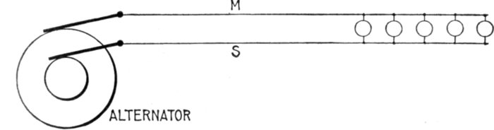
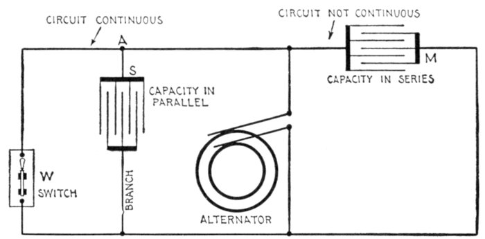
Fig. 1,278.—- Diagram illustrating effect of capacity in an alternating circuit. Considering its
action during one cycle of the current, the alternator first "pumps," say from M to S;
electricity will be heaped up, so to speak, on S, and a deficit left on M, that is, S will be
+ and M-. If the alternator be now suddenly stopped, there would be a momentary
return flow of electricity from S to M through the alternator. If the alternator go on
working, however, it is obvious that the electricity heaped up on S helps or increases the
flow when the alternator begins to pump from S to M in the second half of the cycle, and
when the alternator again reverses its pressure, the + charge on M flows round to S, and
helps the ordinary current. The above circuit is not strictly analogous to the insulated
plates of a condenser, but, as is verified in practice, that with a rapidly alternating pressure,
the condenser action is not perceptibly affected if the cables be connected across by
some non-inductive resistance as for instance incandescent lamps.
Capacity.—When an electric pressure is applied to a condenser,
the current plays in and out, charging the condenser in
alternate directions. As the current runs in at one side and out
at the other, the dielectric becomes charged, and tries to discharge
itself by setting up an opposing electric pressure. This
opposing pressure rises just as the charge increases.
A mechanical analogue is afforded by the bending of a spring,
as in fig. 1,279, which, as it is being bent, exerts an opposing force
equal to that applied, provided the latter do not exceed the
capacity of the spring.
Ques. What is the effect of capacity in an alternating
circuit?
Ans. It is exactly opposite to that of inductance, that is,
it assists the current to rise to its maximum value sooner than
it would otherwise.
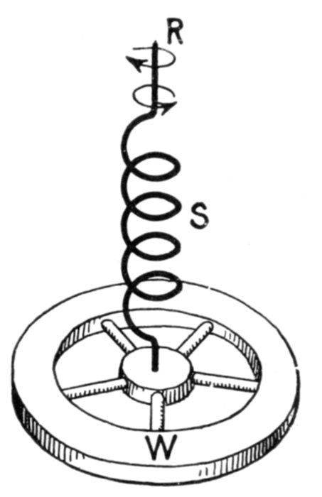
Fig. 1,279.—Mechanical analogy illustrating effect of capacity in an alternating circuit. If an
alternating twisting force be applied to the top R of the spring S, the action of the latter
may be taken to represent capacity, and the rotation of the wheel W, alternating current.
The twisting force (impressed pressure) must first be applied before the rotation of W
(current) will begin. The resiliency or rebounding effect of the spring will, in time, cause
the wheel W to move (amperes) in advance of the twisting force (voltage) thus representing
the current leading in phase.
Ques. Is it necessary to have a continuous metallic
circuit for an alternating current?
Ans. No, it is possible for an alternating current to flow
through a circuit which is divided at some point by insulating
material.
Ques. How can the current flow under such condition?
Ans. Its flow depends on the capacity of the circuit and
accordingly a condenser may be inserted in the circuit as in
fig. 1,286, thus interposing an insulated gap, yet permitting an
alternating flow in the metallic portion of the circuit.
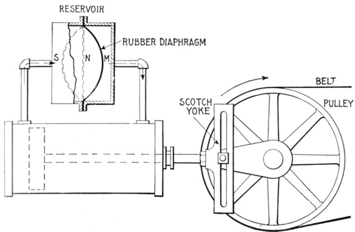
Fig. 1,280.—Hydraulic analogy illustrating capacity in an alternating current circuit. A
chamber containing a rubber diaphragm is connected to a double acting cylinder and the
system filled with water. In operation, as the piston moves, say to the left from the
center, the diaphragm is displaced from its neutral position N, and stretched to some
position M, in so doing offering increasing resistance to the flow of water. On the
return stroke the flow is reversed and is assisted by the diaphragm during the first half
of the stroke, and opposed during the second half. The diaphragm thus acts with the
flow of water one-half of the time and in opposition to it one-half of the time. This
corresponds to the electrical pressure at the terminals of a condenser connected in an
alternating current circuit, and it has a maximum value when the current is zero and a
zero value when the current is a maximum.
Ques. Name the unit of capacity and define it.
Ans. The unit of capacity is called the farad and its symbol is
C. A condenser is said to have a capacity of one farad if one
coulomb (that is, one ampere flowing one second), when stored
on the plates of the condenser will cause a pressure of one volt
across its terminals.
The farad being a very large unit, the capacities ordinarily encountered
in practice are expressed in millionths of a farad, that is, in microfarads--a
capacity equal to about three miles of an Atlantic cable.
It should be noted that the microfarad is used only for convenience,
and that in working out problems, capacity should
always be expressed in farads before substituting in formulæ,
because the farad is chosen with respect to the volt and ampere,
as above defined, and hence must be used in formulæ along with
these units.
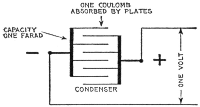
Fig. 1,281—Diagram illustrating a farad. A condenser is said to have a capacity of one
farad if it will absorb one coulomb of electricity when subjected to a pressure of one volt.
The farad is a very large unit, and accordingly the microfarad or one millionth of a farad
is often used, though this must be reduced to farads before substituting in formulæ.
For instance, a capacity of 8 microfarads as given in a problem would
be substituted in a formula as .000008 of a farad.
The charge Q forced into a condenser by a steady electric
pressure E is
Q = EC
in which
- Q = charge in coulombs;
- E = electric pressure in volts;
- C = capacity of condenser in farads.
Ques. What is the material between the plates of a
condenser called?
Ans. The dielectric.
Ques. Upon what does the capacity of a condenser
depend?
Ans. It is proportional to the area of the plates, and inversely
proportional to the thickness of the dielectric between the
plates, a correction being required unless the thickness of dielectric
be very small as compared with the dimensions of the plates.
The capacity of a condenser is also proportional to the specific inductive
capacity of the dielectric between the plates of the condenser.
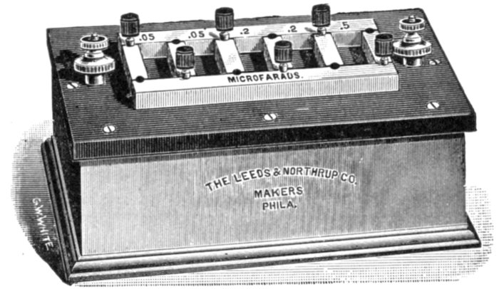
Fig. 1,282.—Condenser of one microfarad capacity. It is subdivided into five sections
of .5, .2, .2, .05 and .05 microfarad. The plates are mounted between and carried by lateral
brass bars which are fastened to a hard rubber top. Each pair of condenser terminals
is fastened to small binding posts mounted on hard rubber insulated posts.
Specific Inductive Capacity.—Faraday discovered that
different substances have different powers of carrying lines of
electric force. Thus the charge of two conductors having a
given difference of pressure between them depends on the medium
between them as well as on their size and shape. The number
indicating the magnitude of this property of the medium is
called its specific inductive capacity, or dielectric constant.
The specific inductive capacity of air, which is nearly the same
as that of a vacuum, is taken as unity. In terms of this unit the
following are some typical values of the dielectric constant:
water 80, glass 6 to 10, mica 6.7, gutta-percha 3, India rubber
2.5, paraffin wax 2, ebonite 2.5, castor oil 4.8.
In underground cables for very high pressures, the insulation, if
homogeneous throughout, would have to be of very great thickness in
order to have sufficient dielectric strength. By employing material of
high specific inductive capacity close to the conductor, and material
of lower specific inductive capacity toward the outside, that is, by
grading the insulation, a considerably less total thickness affords equally
high dielectric strength.
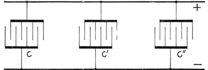
Fig. 1,283.—Parallel connection of condensers. Like terminals are joined together. The joint
capacity of such arrangement is equal to the sum of the respective capacities, that is C =
c + c' + c".
Ques. How are capacity tests usually made?
Ans. By the aid of standard condensers.
Ques. How are condensers connected?
Ans. They may be connected in parallel as in fig. 1,283, or
in series (cascade) as in fig. 1,284.
Condensers are now constructed so that the two methods of arranging
the plates may conveniently be combined in one condenser, thereby
obtaining a wider range of capacity.
Ques. How may the capacity of a condenser, wire, or
cable be tested?
Ans. This may be done by the aid of a standard condenser,
trigger key, and an astatic or ballistic galvanometer.
In making the test, first obtain a "constant" by noting the deflection
d, due to the discharge of the standard condenser after a charge of, say,
10 seconds from a given voltage. Then discharge the other condenser,
wire, or cable through the galvanometer after 10 seconds charge, and
note the deflection d'. The capacity C' of the latter is then
in which C is the capacity of the standard condenser.
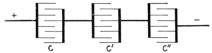
Fig. 1,284.—Series or cascade connection of condensers. Unlike terminals are joined together
as shown. The total capacity of such connection is equal to the reciprocal of the sum of
the reciprocals of the several capacities, that is, C = 1 ÷ (1 / c + 1 / c' + 1 / c")
Ohmic Value of Capacity.—The capacity of an alternating
current circuit is the measure of the amount of electricity held
by it when its terminals are at unit difference of pressure. Every
such circuit acts as a condenser.
If an alternating circuit, having no capacity, be opened, no
current can be produced in it, but if there be capacity at the
break, current may be produced as in fig. 1,286.
The action of capacity referred to the current wave is as
follows: As the wave starts from zero value and rises to its
maximum value, the current is due to the discharge of the
capacity, which would be represented by a condenser. In the
case of a sine current, the period required for the current to pass
from zero value to maximum is one-quarter of a cycle.
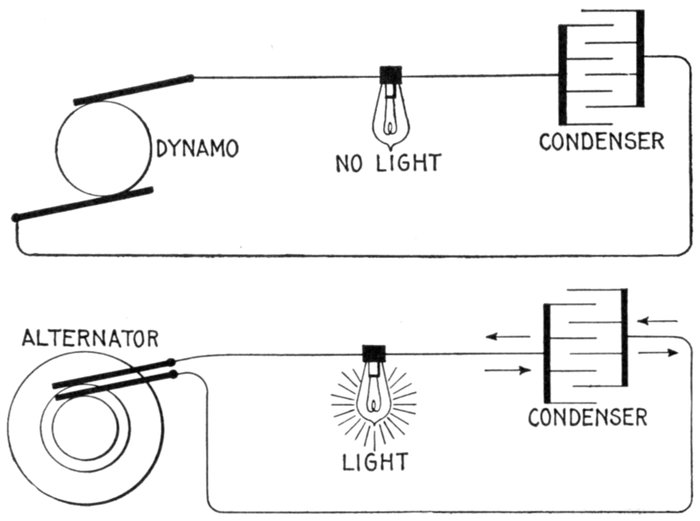
Figs. 1,285 and 1,286.—Diagrams showing effect of condenser in direct and alternating current
circuits. Each circuit contains an incandescent lamp and a condenser, one circuit connected
to a dynamo and the other to an alternator. Since the condenser interposes a gap
in the circuit, evidently in fig. 1,285 no current will flow. In the case of alternating current,
fig. 1,286, the condenser gap does not hinder the flow of current in the metallic
portion of the circuit. In fact the alternator produces a continual surging of electricity
backwards and forwards from the plates of the condenser around the metallic portion of
the circuit, similar to the surging of waves against a bulkhead which projects into the ocean.
It should be understood that the electric current ceases at the condenser, there being no
flow between the plates.
At the beginning of the cycle, the condenser is charged to the
maximum amount it receives in the operation of the circuit.
At the end of the quarter cycle when the current is of maximum
value, the condenser is completely discharged.
The condenser now begins to receive a charge, and continues
to receive it during the next quarter of a cycle, the charge attaining
its maximum value when the current is of zero intensity.
Hence, the maximum charge of a condenser in an alternating
circuit is equal to the average value of the current multiplied
by the time of charge, which is one-quarter of a period, that is
maximum charge = average current × ¼ period (1)
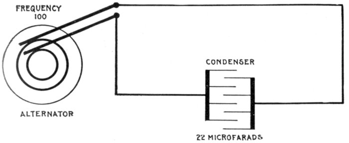
Fig. 1,287.—Diagram showing alternating circuit containing capacity. Formula for calculating
the ohmic value of capacity or "capacity reactance" is Xc = 1 ÷ 2πfC, in which Xc =
capacity reactance; π = 3.1416; f = frequency; C = capacity in farads (not microfarads).
22 microfarads = 22 ÷ 1,000,000 = .000022 farad. Substituting, Xc = 1 ÷
(2 × 3.1416 × 100 × .000022) = 72.4 ohms.
Since the time of a period = 1 ÷ frequency, the time of one-quarter
of a period is ¼ × (1 ÷ frequency), or
¼ period = ¼ f (2)
f, being the symbol for frequency. Substituting (2) in (1)
maximum charge = Iav × ¼f (3)
The pressure of a condenser is equal to the quotient of the
charge divided by the capacity, that is
Substituting (3) in (4)
But, Iav = Imax × 2 / π, and substituting this value of Iav in
equation (5) gives
This last equation (6) represents the condenser pressure due
to capacity at the point of maximum value, which pressure is
opposed to the impressed pressure, that is, it is the maximum
reverse pressure due to capacity.
Now, since by Ohm's law
and as
it follows that 1 / (2πfC) is the ohmic value of capacity, that
is it expresses the resistance equivalent of capacity; using the
symbol Xc for capacity reactance
EXAMPLE.—What is the resistance equivalent of a 50 microfarad
condenser to an alternating current having a frequency of 100?
Substituting the given values in the expression for ohmic value
If the pressure of the supply be, say 100 volts, the current would
be 100 ÷ 31.8 = 3.14 amperes.
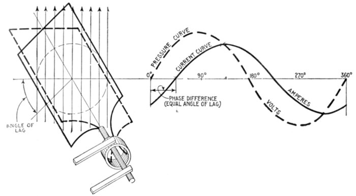
Fig. 1,288.—Pressure and current curves, illustrating lag. The effect of inductance in a circuit
is to retard the current cycle, that is to say, if the current and pressure be in phase, the
introduction of inductance will cause a phase difference, the current wave "lagging"
behind the pressure wave as shown. In other words, inductance causes the current wave,
indicated in the diagram by the solid curve, to lag behind the pressure wave, indicated by
the dotted curve. Following the curves starting from the left end of the horizontal line, it
will be noted that the current starts after the pressure starts and reverses after the pressure
reverses; that is, the current lags in phase behind the pressure, although the frequency of
both is the same.
Lag and Lead.—Alternating currents do not always keep in
step with the alternating volts impressed upon the circuit. If
there be inductance in the circuit, the current will lag; if there
be capacity, the current will lead in phase. For example, fig.
1,288, illustrates the lag due to inductance and fig. 1,289, the
lead due to capacity.
Ques. What is lag?
Ans. Lag denotes the condition where the phase of one
alternating current quantity lags behind that of another. The
term is generally used in connection with the effect of inductance
in causing the current to lag behind the impressed pressure.
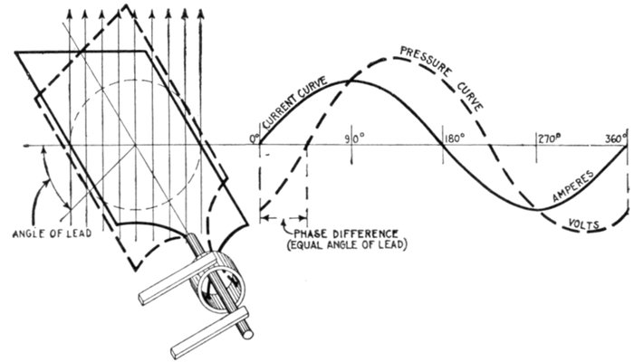
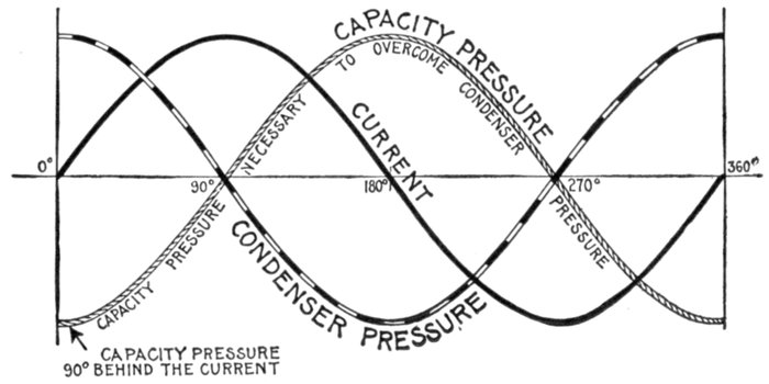
Fig. 1,289.—Pressure and current curves illustrating lead. The effect of capacity in a circuit
is to cause the current to rise to its maximum value sooner than it would otherwise do;
capacity produces an effect exactly the opposite of inductance. The phase relation
between current and pressure with current leading is shown graphically by the two armature
positions in full and dotted lines, corresponding respectively to current and pressure
at the beginning of the cycle.
Ques. How does inductance cause the current to lag
behind the pressure?
Ans. It tends to prevent changes in the strength of the
current. When two parts of a circuit are near each other, so
that one is in the magnetic field of the other, any change in the
strength of the current causes a corresponding change in the
magnetic field and sets up a reverse pressure in the other wire.
This induced pressure causes the current to reach its maximum value
a little later than the pressure, and also tends to prevent the current
diminishing in step with the pressure.
Ques. What governs the amount of lag in an alternating
current?
Ans. It depends on the relative values of the various pressures
in the circuit, that is, upon the amount of resistance and
inductance which tends to cause lag, and the amount of capacity
in the circuit which tends to reduce lag and cause lead.
Ques. How is lag measured?
Ans. In degrees.
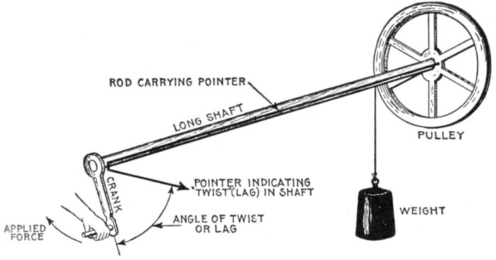
Fig. 1,290.—Mechanical analogy of lag. If at one end force be applied to turn a very long
shaft, having a loaded pulley at the other, the torsion thus produced in the shaft will
cause it to twist an appreciable amount which will cause the movement of the pulley to
lag behind that of the crank. This may be indicated by a rod attached to the pulley
and terminating in a pointer at the crank end, the rod being so placed that the pointer
registers with the crank when there is no torsion in the shaft. The angle made by the
pointer and crank when the load is thrown on, indicates the amount of lag which is
measured in degrees.
Thus, in fig. 1,288, the lag is indicated by the distance between the
beginning of the pressure curve and the beginning of the current curve,
and is in this case 45°.
Ques. What is the physical meaning of this?
Ans. In an actual alternator, of which fig. 1,288 is an elementary
diagram showing one coil, if the current lag, say 45°
behind the pressure, it means that the coil rotates 45° from its
position of zero induction before the current starts, as in fig. 1,288.
EXAMPLE I.—A circuit through which an alternating current is
passing has an inductance of 6 ohms and a resistance of 2.5 ohms. What
is the angle of lag?
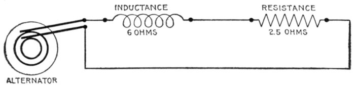
Fig. 1,291.—Diagram of circuit for example I.
Substituting these values in equation (1), page 1,053,
Referring to the table of natural sines and tangents on page 451 the
corresponding angle is approximately 67°.
EXAMPLE II.—A circuit has a resistance of 2.3 ohms and an inductance
of .0034 henry. If an alternating current having a frequency of
125 pass through it, what is the angle of lag?
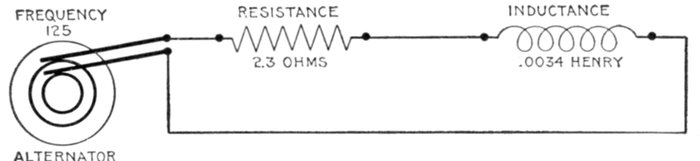
Fig. 1,292.—Diagram of circuit for example II.
Here the inductance is given as a fraction of a henry; this must be
reduced to ohms by substituting in equation (3), page 1,038, which
gives the ohmic value of the inductance; accordingly, substituting the
above given value in this equation
inductance in ohms or Xi = 2π × 125 × .0034 = 2.67
Substituting this result and the given resistance in equation (1),
page 1,053,
the nearest angle from table (page 451) is 49°.
Ques. How great may the angle of lag be?
Ans. Anything up to 90°.
The angle of lag, indicated by the Greek letter φ(phi), is the angle
whose tangent is equal to the quotient of the inductance expressed in
ohms or "spurious resistance" divided by the ohmic resistance, that is
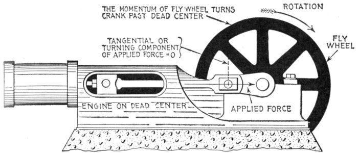
Fig. 1,293.—Steam engine analogy of current flow at zero pressure (see questions below).
When the engine has reached the dead center point the full steam pressure is acting on
the piston, the valve having opened an amount equal to its lead. The force applied at this
instant, indicated by the arrow is perpendicular to the crank pin circle, that is, the tangential
or turning component is equal to zero, hence there is no pressure tending to turn the
crank. The latter continues in motion past the dead center because of the momentum
previously acquired. Similarly, the electric current, which is here analogous to the moving
crank, continues in motion, though the pressure at some instants be zero, because it acts
as though it had weight, that is, it cannot be stopped or started instantly.
Ques. When an alternating current lags behind the
pressure, is there not a considerable current at times
when the pressure is zero?
Ans. Yes; such effect is illustrated by analogy in fig. 1,293.
Ques. What is the significance of this?
Ans. It does not mean that current could be obtained from
a circuit that showed no pressure when tested with a suitable
voltmeter, for no current would flow under such conditions.
However, in the flow of an alternating current, the pressure
varies from zero to maximum values many times each second,
and the instants of no pressure may be compared to the "dead
centers" of an engine at which points there is no pressure to
cause rotation of the crank, the crank being carried past these
points by the momentum of the fly wheel. Similarly the electric
current does not stop at the instant of no pressure because
of the "momentum" acquired at other parts of the cycle.
Ques. On long lines having considerable inductance,
how may the lag be reduced?
Ans. By introducing capacity into the circuit. In fact, the
current may be advanced so it will be in phase with the pressure
or even lead the latter, depending on the amount of capacity
introduced.
There has been some objection to the term lead as used in describing
the effect of capacity in an alternating circuit, principally on the ground
that such expressions as "lead of current," "lead in phase," etc., tend
to convey the idea that the effect precedes the cause, that is, the current
is in advance of the pressure producing it. There can, of course, be no
current until pressure has been applied, but if the circuit has capacity,
it will lead the pressure, and this peculiar behavior is best illustrated
by a mechanical analogy as has already been given.
Ques. What effect has lag or lead on the value of the
effective current?
Ans. As the angle of lag or lead increases, the value of the
effective as compared with the virtual current diminishes.
Reactance.—The term "reactance" means simply reaction.
It is used to express certain effects of the alternating current
other than that due to the ohmic resistance of the circuit.
Thus, inductance reactance means the reaction due to the spurious
resistance of inductance expressed in ohms; similarly, capacity
reactance, means the reaction due to capacity, expressed in ohms.
It should be noted that the term reactance, alone, that is, unqualified,
is generally understood to mean inductance reactance,
though ill advisedly so.
The resistance offered by a wire to the flow of a direct current
is expressed in ohms; this resistance remains constant whether
the wire be straight or coiled. If an alternating current flow
through the wire, there is in addition to the ordinary or "ohmic"
resistance of the wire, a "spurious" resistance arising from the
development of a reverse pressure due to induction, which is
more or less in value according as the wire be coiled or straight.
This spurious resistance as distinguished from the ohmic resistance
is called the reactance, and is expressed in ohms.
Reactance, may then be defined with respect to its usual
significance, that is, inductance reactance, as the component of the
impedance which when multiplied into the current, gives the
wattless component of the pressure.
Reactance is simply inductance measured in ohms.
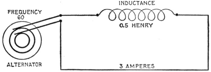
Fig. 1,294.—Diagram of the circuit for example I. Here the resistance is taken at zero,
but this would not be possible in practice, as all circuits contain more or less resistance
though it may be, in some cases, negligibly small.
EXAMPLE I.—An alternating current having a frequency of 60 is
passed through a coil whose inductance is .5 henry. What is the reactance?
Here f = 60 and L = .5; substituting these in formula for inductive
reactance,
Xi = 2πfL = 2 × 3.1416 × 60 × .5 = 188.5 ohms
The quantity 2πfL or reactance being of the same nature as a resistance
is used in the same way as a resistance. Accordingly, since,
by Ohm's law
E = RI (1)
an expression may be obtained for the volts necessary to overcome
reactance by substituting in equation (1) the value of reactance given
above, thus
E = 2πfLI (2)
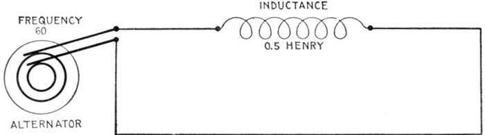
Fig. 1,295.—Diagram of circuit for example II. As in example I, resistance is disregarded.
EXAMPLE II.—How many volts are necessary to force a current of
3 amperes with frequency 60 through a coil whose inductance is .5
henry? Substituting in equation (2) the values here given
E = 2πfLI = 2π × 60 × .5 × 3 = 565 volts.
The foregoing example may serve to illustrate the difference in
behaviour of direct and alternating currents. As calculated, it
requires 565 volts to pass only 3 amperes of alternating current
through the coil on account of the considerable spurious resistance.
The ohmic resistance of a coil is very small, as compared
with the spurious resistance, say 2 ohms. Then by Ohm's law
I = E ÷ R = 565 ÷ 2 = 282.5 amperes.
Instances of this effect are commonly met with in connection with
transformers. Since the primary coil of a transformer has a high reactance,
very little current will flow when an alternating pressure is
applied. If the same transformer were placed in a direct current circuit
and the current turned on it would at once burn out, as very little
resistance would be offered and a large current would pass through the
winding.
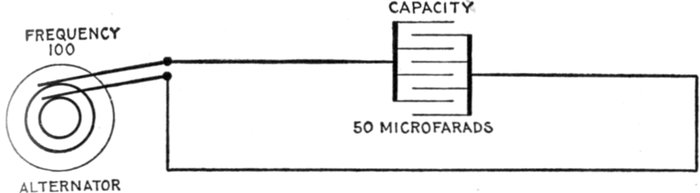
Fig. 1,296.—Diagram of circuit for example III.
EXAMPLE III.—In a circuit containing only capacity, what is the
reactance when current is supplied at a frequency of 100, and the
capacity is 50 microfarads?
capacity reactance, or
Impedance.—This term, strictly speaking, means the ratio
of any impressed pressure to the current which it produces in a
conductor. It may be further defined as the total opposition in
an electric circuit to the flow of an alternating current.
All power circuits for alternating current are calculated with
reference to impedance. The impedance may be called the
combination of:
- Ohmic resistance;
- Inductance reactance;
- Capacity reactance.
The impedance of an inductive circuit which does not contain
capacity is equal to the square root of the sum of the squares of
the resistance and reactance, that is
impedance = √(resistance2 + reactance2) (1)
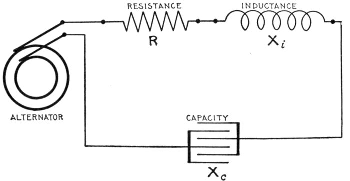
Fig. 1,297.—Diagram showing alternating circuit containing resistance, inductance, and capacity.
Formula for calculating the impedance of this circuit is Z = √(R2 + (Xi - Xc)2) in
which, Z = impedance; R = resistance; Xi = inductance reactance; Xc = capacity
reactance. Example: What is the impedance when R = 4, Xi = 94.2, and Xc = 72.4?
Substituting Z = √(42 + (94.2 - 72.4)2) = 22.2 ohms. Where the ohmic values of inductance
and capacity are given as in this example, the calculation of impedance is very
simple, but when inductance and capacity are given in milli-henrys and microfarads
respectively, it is necessary to first calculate their ohmic values as in figs. 1,295 and 1,296.
EXAMPLE I.—If an alternating pressure of 100 volts be impressed
on a coil of wire having a resistance of 6 ohms and inductance of 8 ohms,
what is the impedance of the circuit and how many amperes will flow
through the coil? In the example here given, 6 ohms is the resistance
and 8 ohms the reactance. Substituting these in equation (1)
Impedance = √(62 + 82) = √(100) = 10 ohms.
The current in amperes which will flow through the coil is, by Ohm's
law using impedance in the same way as resistance.
The reactance is not always given but instead in some problems the
frequency of the current and inductance of the circuit. An expression
to fit such cases is obtained by substituting 2πfL for the reactance as
follows: (using symbols for impedance and resistance)
Z = √(R2 + (2πfL)2) (2)
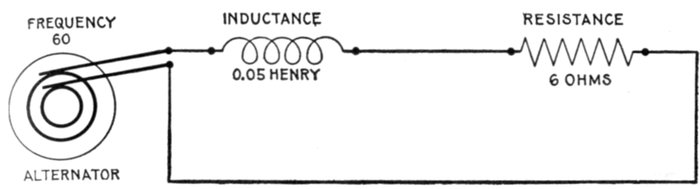
Fig. 1,298.—Diagram of circuit for example II.
EXAMPLE II.—If an alternating current, having a frequency of 60,
be impressed on a coil whose inductance is .05 henry and whose resistance
is 6 ohms, what is the impedance?
Here R = 6; f = 60, and L = .05; substituting these values in (2)
Z = √(62 + (2π × 60 × .05)2) = √(393) = 19.8 ohms.
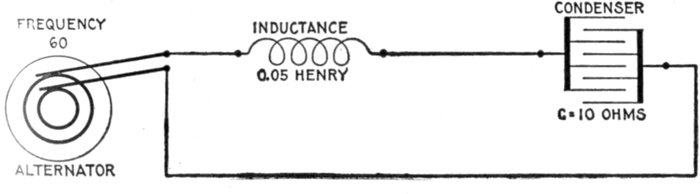
Fig. 1,299.—Diagram of circuit for example III.
EXAMPLE III.—If an alternating current, having a frequency of
60, be impressed on a circuit whose inductance is .05 henry, and whose
capacity reactance is 10 ohms, what is the impedance?
Xi = 2πfL = 2 × 3.1416 × 60 × .05 = 18.85 ohms
Z = Xi - Xc = 18.85 - 10 = 8.85 ohms
When a circuit contains besides resistance, both inductance
and capacity, the formula for impedance as given in equation (1),
page 1,058, must be modified to include the reactance due to
capacity, because, as explained, inductive and capacity reactances
work in opposition to each other, in the sense that the reactance
of inductance acts in direct proportion to the quantity
2πfL, and the reactance of capacity in inverse proportion to the
quantity 2πfC. The net reactance due to both, when both
are in the circuit, is obtained by subtracting one from the other.
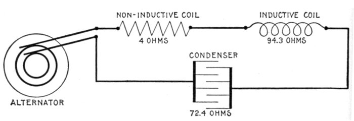
Fig. 1,300.—Diagram of circuit for example IV.
To properly estimate impedance then, in such circuits, the
following equation is used:
impedance = √(resistance2 + (inductance reactance - capacity reactance)2)
or using symbols,
Z = √(R2 + (Xi - Xc)2) (3)
EXAMPLE IV.—A current has a frequency of 100. It passes through
a circuit of 4 ohms resistance, of 150 milli-henrys inductance, and of 22
microfarads capacity. What is the impedance?
a. The ohmic resistance R, is 4 ohms.
b. The inductance reactance, or
Xi = 2πfL = 2 × 3.1416 × 100 × .15 = 94.3 ohms.
(note that 150 milli-henrys are reduced to .15 henry before substituting
in the above equation).
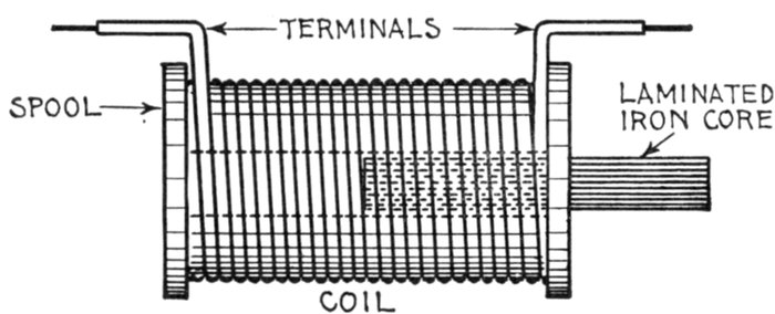
Fig. 1,301.—Simple choking coil. There is an important difference in the obstruction offered
to an alternating current by ordinary resistance and by reactance. Resistance obstructs
the current by dissipating its energy, which is converted into heat. Reactance obstructs
the current by setting up a reverse pressure, and so reduces the current in the circuit,
without wasting much energy, except by hysteresis in any iron magnetized. This may be
regarded as one of the advantages of alternating over direct current, for, by introducing
reactance into a circuit, the current may be cut down with comparatively little loss of
energy. This is generally done by increasing the inductance in a circuit, by means of
a device called variously a reactance coil, impedance coil, choking coil, or "choker." In the
figure is a coil of thick wire provided with a laminated iron core, which may be either
fixed or movable. In the first case, the inductance, and therefore also the reactance of the
coil, is invariable, with a given frequency. In the second case, the inductance and consequent
reactance may be respectively increased or diminished by inserting the core
farther within the coil or by withdrawing it, as was done in fig. 1,266, the results of
which are shown in fig. 1,302.
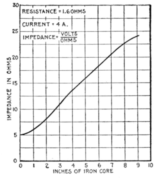
Fig. 1,302.—Impedance curve for coil with variable iron core. The impedance of an inductive
coil may be increased by moving an iron wire core into the coil. In making a test of this
kind, the current should be kept constant with an adjustable resistance, and voltmeter
readings taken, first without the iron core, and again with 1, 2, 3, 4, etc., inches of core
inserted in the coil. By plotting the voltmeter readings and the positions of the iron core
on section paper as above, the effect of inductance is clearly shown.
c. The capacity reactance, or
(note that 22 microfarads are reduced to .000022 farad before substituting
in the formula. Why? See page 1,042).
Substituting values as calculated in equation (3), page 1,060.
Z = √(42 + (94.2 - 72.4)2) = √(491) = 22.2 ohms.
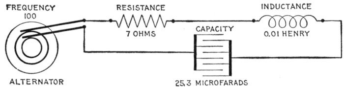
Fig. 1,303.—Diagram of a resonant circuit. A circuit is said to be resonant when the inductance
and capacity are in such proportion that the one neutralizes the other, the circuit
then acting as though it contained only resistance. In the above circuit Xi = 2πfL =
2 × 3.1416 × 100 × .01 = 6.28 ohms; Xc = 1 ÷ (2 × 3.1416 × 100 × .000253) = 6.28 ohms
whence the resultant reactance = Xi - Xc = 6.28 - 6.28 = 0 ohms. Z = √(R2 + (Xi - Xc)2)
= √(72 + 02) = 7 ohms.
Ques. Why is capacity reactance given a negative sign?
Ans. Because it reacts in opposition to inductance, that is
it tends to reduce the spurious resistance due to inductance.
In circuits having both inductance and capacity, the tangent of the
angle of lag or lead as the case may be is the algebraic sum of the two
reactances divided by resistance. If the sign be positive, it is an angle
of lag; if negative, of lead.
Resonance.—The effects of inductance and capacity, as already
explained, oppose each other. If inductance and capacity
be present in a circuit in such proportion that the effect of one
neutralizes that of the other, the circuit acts as though it were
purely non-inductive and is said to be in a state of resonance.
For instance, in a circuit containing resistance, inductance, and
capacity, if the resistance be, say, 8 ohms, the inductance 30, and the
capacity 30, then the impedance is
√(82 + (302 - 302)) = √(82) = 8 ohms.
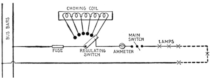
Fig. 1,304.—Application of a choking coil to a lighting circuit. The coil is divided into sections
with leads running to contacts similar to a rheostat. Each lamp is provided with an automatic
short-circuiting cutout, and should one, two, or more of them fail, a corresponding
number of sections of the choking apparatus is put in circuit to take the place of the broken
lamp or lamps, and thus keep the current constant. It must not be supposed that this arrangement
of lamps, etc. is a general one; it being adopted to suit certain special conditions.
The formula for inductance reactance is Xi = 2πfL, and for
capacity reactance, Xc = 1 ÷ (2πfC); accordingly if capacity
and inductance in a circuit be equal, that is, if the circuit be
resonant
from which
Ques. What does equation (1) show?
Ans. It indicates that by varying the frequency in the proper
way as by increasing or decreasing the speed of the alternator,
the circuit may be made resonant, this condition being obtained
when the frequency has the value indicated by equation (2).
Ques. What is the mutual effect of inductance and
capacity?
Ans. One tends to neutralize the other.
Ques. What effect has resonance on the current?
Ans. It brings the current in phase with the impressed
pressure.
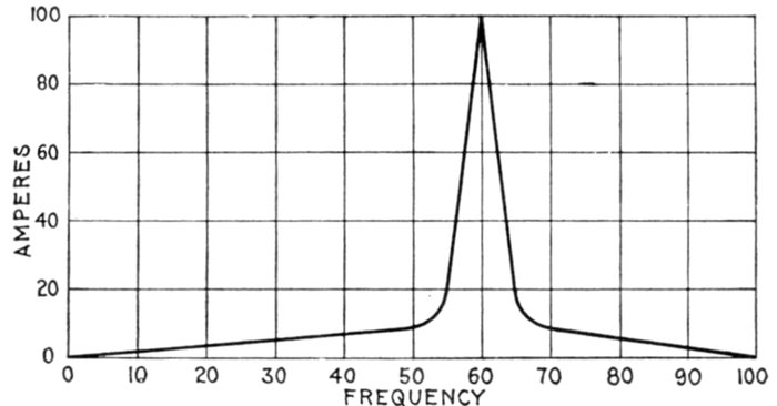
Fig. 1,305.—Curve showing variation of current by increasing the frequency in a circuit having
inductance and capacity. The curve serves to illustrate the "critical frequency" or frequency
producing the maximum current. The curve is obtained by plotting current values
corresponding to different frequencies, the pressure being kept constant.
It is very seldom that a circuit is thus balanced unless intentionally
brought about; when this condition exists, the effect is very marked, the
pressure rising excessively and bringing great strain upon the insulation
of the circuit.
Ques. Define "critical frequency."
Ans. In bringing a circuit to a state of resonance by increasing
the frequency, the current will increase with increasing
frequency until the critical frequency is reached, and then the
current will decrease in value for further increase of frequency.
The critical frequency occurs when the circuit reaches the
condition of resonance.
Ques. How is the value of the current at the critical
frequency determined?
Ans. By the resistance of the circuit.
Skin Effect.—This is the tendency of alternating currents
to avoid the central portions of solid conductors and to flow or
pass mostly through the outer portions. The so-called skin
effect becomes more pronounced as the frequency is increased.
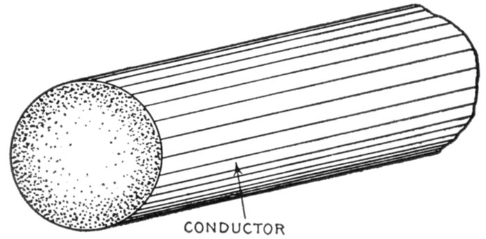
Fig. 1,306.—Section of conductor illustrating "skin effect" or tendency of the alternating
current to distribute itself unequally through the cross section of the conductor as shown
by the varied shading flowing most strongly in the outer portions of the conductor. For
this reason it has been proposed to use hollow or flat conductors instead of solid round
wires. However with frequency not exceeding 100 the skin effect is negligibly small in
copper conductors of the sizes usually employed. Where the conductor is large or the
frequency high the effect may be judged by the following examples calculated by Professor
J. J. Thomson: In the case of a copper conductor exposed to an electromotive force
making 100 periods per second at 1 centimetre from the surface, the maximum current
would be only .208 times that at the surface; at a depth of 2 centimetres it would be
only .043; and at a depth of 4 centimetres less than .002 part of the value at the
surface. If the frequency be a million per second the current at a depth of 1 millimetre
is less than one six-millionth part of its surface value. The case of an iron conductor is
even more remarkable. Taking the permeability at 100 and the frequency at 100 per
second the current at a depth of 1 millimetre is only .13 times the surface value; while
at a depth of 5 millimetres it is less than one twenty-thousandth part of its surface value.
The disturbance of current density may be looked upon as a self-induced eddy current in
the conductor. It necessarily results in an increase of ohmic loss; as compared with a
steady current: proportional to the square of the total current flowing and consequently
gives rise to an apparent increase of ohmic resistance. The coefficient of increase of resistance
depends upon the dimensions and the shape of the cross section, the frequency and
the specific resistance. A similar but distinct effect is experienced in conductors due to
the neighborhood of similar parallel currents. For example in a heavy multicore cable
the non-uniformity of current density in any core may be considered as partly due to eddy
currents induced by the currents in the neighboring cores and partly to the self-induced
eddy current. It is only the latter effect which should rightly be considered as comprised
under the term skin effect.
Ques. What is the explanation of skin effect?
Ans. It is due to eddy currents induced in the conductor.
Consider the wire as being composed of several small insulated wires
placed closely together. Now when a current is started along these
separate wires, mutual induction will take place between them, giving
rise to momentary reverse pressures. Those wires which are nearer the
center, since they are completely surrounded by neighboring wires, will
clearly have stronger reverse pressures set up in them than those on or
near the outer surface, so that the current will meet less opposition
near the surface than at the center, and consequently the flow will be
greater in the outer portions.
Ques. What is the result of skin effect?
Ans. It results in an apparent increase of resistance.
The coefficient of increase of resistance depends upon the dimensions
and the shape of the cross section, the frequency, and the specific
resistance.
Hughes, about 1883, called attention to the fact that the resistance
of an iron telegraph wire was greater for rapid periodic currents than for
steady currents.
In 1888 Kelvin showed that when alternating currents at moderately
high frequency flow through massive conductors, the current is practically
confined to the skin, the interior portions being largely useless
for the purpose of conduction. The mathematical theory of the subject
has been developed by Kelvin, Heaviside, Rayleigh, and others.
 by
by