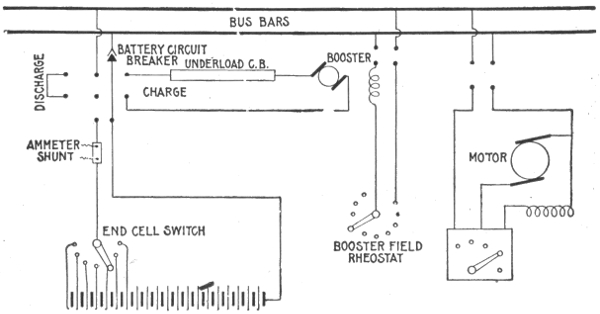
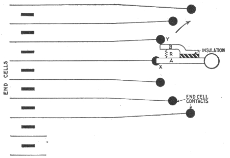
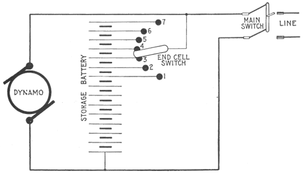
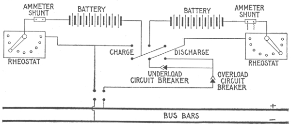
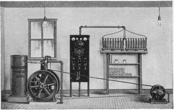
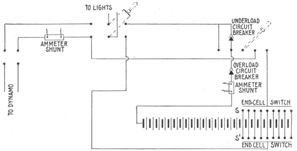
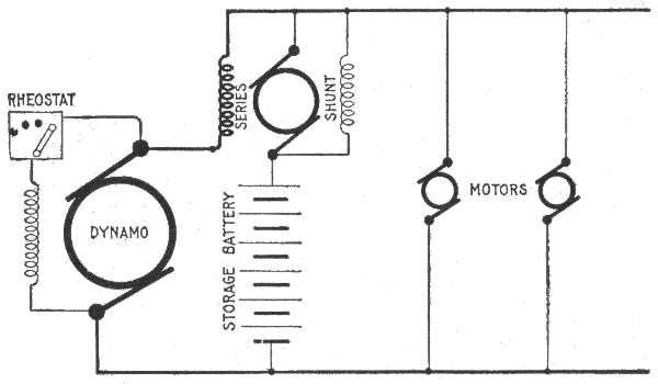
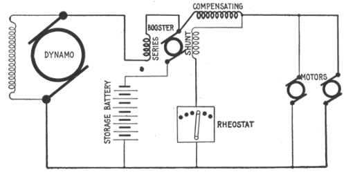
Introduction.—The practical development of the storage
battery is comparatively recent, although a knowledge of the
phenomena upon which its actions are based, dates back to 1801.
In 1800, the year made memorable by Volta's discovery of the
galvanic battery, Nicholson and Carlisle found that a current
from Volta's cell could decompose water.
In 1801, Gautherot discovered that if two plates of platinum or silver,
immersed in a suitable electrolyte, be connected to the terminals of
an active primary cell and current be allowed to flow, a small current
could be obtained on an outside circuit connecting these two electrodes
as soon as the primary battery had been disconnected.
Erman found that the positive pole of such a cell, was the pole which
had been connected to the positive pole of the battery.
In 1803, Ritter observed, with gold wire, the same phenomenon as
Gautherot, and constructed the first secondary battery, by superposing
plates of gold, separated by cloth discs, moistened with ammonia.
Volta, Davy, Marianini, and others added somewhat to the knowledge
on the subject, and in 1837, Schoenbein found that peroxide of lead
could be used in secondary batteries.
Sir William Grove next came forward with the discovery that metal
plates, with a layer of oxide on them, acted better than the plain metallic
plates, and Wheatstone and Siemens found still later that peroxide of
lead was the best for such purposes.
In 1842, Grove constructed a gas battery, in which the electromotive
force came from the oxygen and hydrogen evolved in the electrolysis of
water acidulated with sulphuric acid. By means of fifty such cells, he
obtained an arc light.
Michael Faraday, when electrolyzing a solution of lead acetate, found
that peroxide was produced at the positive, and metallic lead at the
negative pole, and in his "Experimental Researches," he comments on
the high conductivity of lead peroxide, and its power of readily giving
up its oxygen. Although he made no apparent use of this discovery,
it may be considered as the next important step in the development of
the storage battery.
According to Niblett, Wheatstone, de la Rue, and Niaudet were well
aware that peroxide of lead was a powerful depolarizer, but nobody
appears to have made use of this fact until 1860, when M. Gaston Plante
constructed his well known cell with coiled plates. Plante's researches
extended up to 1879, and practically determined the state of the art.
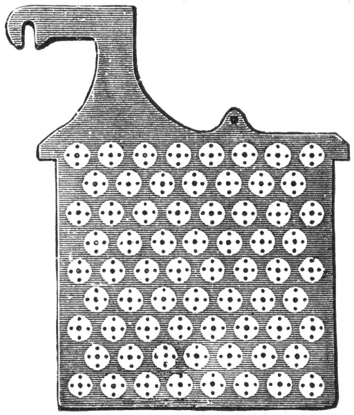
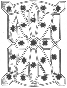
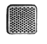
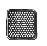
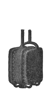
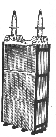
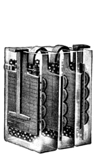
Fig. 1,046.—One plate or "grid" of a type of storage cell constructed by inserting buttons or
ribbons of the proper chemical substances in perforations. Some such cells use crimped
ribbons of metallic lead for inserting in the perforations, others pure red lead or other
suitable material.
As to the theory at this time, it may be stated that Clerk Maxwell,
although the leading electrician of his time, speaks of the storage battery
as storing up a quantity of energy in a manner somewhat analogous
to the ordinary condenser; hence the use of the word "accumulator"
for storage battery.
In 1879, R. L. Metzer did away with the tedious forming process, by
mechanically applying the active material. This important discovery
was not, however, generally known, until 1881, when Camille Faure
obtained important patents concerning the method of shortening the
time of formation.
Charles F. Brush, working independently of either Faure or Metzer,
arrived at the same result, and the United States courts have decided,
after long litigation, that to him belongs the priority of invention in
this country.
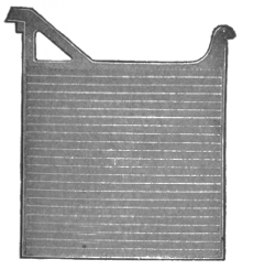
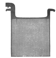
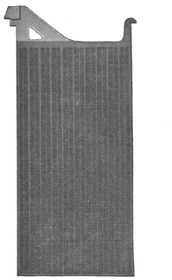
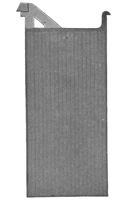
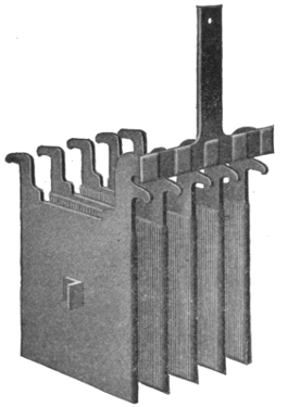
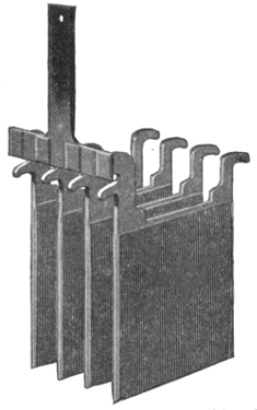
Figs. 1,047 to 1,050.—Electric Storage Battery Co. plates. Fig. 1,047, "Manchester" positive
plate; fig. 1,048, box negative plate; fig. 1,049, "Tudor" positive plate; fig 1,050, pasted
negative plate.
Ques. To what use is the storage battery sometimes
put in electric lighting or power stations?
Ans. To carry the "peak" of the load; that excessive portion
of the load which, for instance, in electric lighting stations
has to be carried only for two or three hours a day. To carry
the entire load at minimum hours. To act as equalizer or reservoir.
Also for equipment of annex or substations.
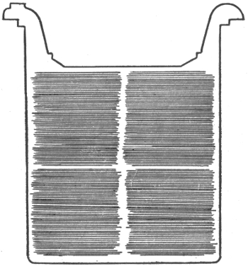
Fig. 1,051.—"Unformed" plate of one pattern of Gould storage cell. The particular plate
shown has total outside dimensions of 6×6 inches. The clear outline of the grooves indicates
absence of oxides, due to action of "forming" solutions, or charging current.
Theory of the Storage Battery.—The action of the storage
battery is practically the same as that of the primary battery
and it is subject to the same general laws. The cells of a storage
battery are connected in the same way as primary cells, and when
charged is capable of generating a current of electricity in a
manner similar to that of a primary battery. It differs, however,
from the primary battery in that it is capable of being recharged
after exhaustion by passing an electric current through it in a
direction opposite to that of the current on discharge. This
difference constitutes the principal advantage of the storage
battery over the primary battery.
Figs. 1,052 and 1,053.—Electric Storage Battery Co., type H "exide" plates. This form of
plate is used for large "stand by" batteries. Fig. 1,052, positive plate; fig. 1,053, negative
plate.
Ques. Describe a storage cell.
Ans. A storage cell consists of plates or of grids in an electrolyte,
of such a character that the electrical energy supplied to
it is converted into chemical energy (a process called charging).
The chemical energy can be reconverted into electrical energy
(a process called discharging).
Ques. Describe the electrolyte generally used.
Ans. It consists of a weak solution of sulphuric acid which
permits ready conduction of the current from the primary battery,
the greater the proportion of acid within certain limits,
the smaller the resistance offered.
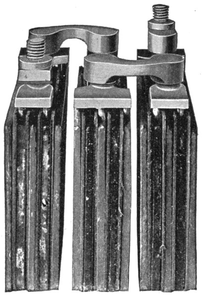
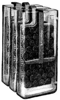
Fig. 1,054.—Elements of 6 volt 40 ampere hour "Aplco" portable (3 cell) storage battery. The
grids are made from an alloy of lead and antimony; hard lead straps which are burned
together, are used for joining the plates. Specially treated separators are used.
Ques. What is the effect of the current passing through
the electrolyte?
Ans. It decomposes the water into oxygen and hydrogen;
this is indicated by the formation of bubbles upon the exposed
surfaces of both plates, these bubbles being formed by oxygen
gas on the plate connected to the positive pole of the primary
battery, and hydrogen on the plate connected to the negative
pole.
Because, however, the oxygen is unable to attack either platinum or
silver under such conditions, the capacity of such a device to act as an
electrical accumulator is practically limited to the point at which both
plates are covered with bubbles. After this point the gases will begin
to escape into the atmosphere.
Ques. What is the prime condition for operation of a
storage battery?
Ans. The resistance of the electrolyte should be as low as
possible in order that the current may pass freely and with full
effect between the electrodes. If the resistance of the electrolyte
be too small, the intensity of the current will cause the water to
boil rather than to occasion the electrolytic effects noted above.
Ques. What happens when the charging current is discontinued,
and the two electrodes joined by an outside
wire?
Ans. A small current will flow through the outside circuit,
being due to the recomposition of the acid and water solution.
The process is in a very definite sense a reversal of that by
which the current is generated in a primary cell.
Hydrogen collected upon the negative plate, which was the cathode, so
long as the primary battery was in circuit, is given off to the liquid
immediately surrounding it, uniting with its particles of oxygen and
causing the hydrogen, in combination with them, to unite with the
particles of oxygen next adjacent. The process is continued until the
opposite positive plate is reached, when the oxygen collected there is
finally combined with the surplus hydrogen, going to it from the surrounding
solution.
This chemical process causes the current to emerge from the positive
plate, which was the anode, so long as the primary battery was in
circuit. The current thus produced will continue until the recomposition
of the gases is complete; then ceasing because these gases, as before
stated, do not combine with the metal of the electrodes.
Types of Storage Battery.—There are three classes of storage
cell which are commercially important:
1. Plante cells;
2. Faure cells;
3. Alkaline cells.
According to construction secondary cells may be classified
as follows:
1. Lead sulphuric acid cells;
2. Lead copper cells;
3. Lead zinc cells;
4. Alkaline zincate cells.
The lead sulphuric acid type includes all those cells belonging to the
Plante and Faure groups.
Lead copper cells consist of sheets of metal coated with lead oxide,
serving as the positive electrode, and copper plates for the negative
electrodes. These plates are immersed in a solution of copper sulphate.
Cells belonging to this class are not employed in commercial practice,
being useful only for laboratory experiments.
Lead zinc cells are similar to the preceding type, but differ by having
zinc for the negative electrode, and zinc sulphate for the electrolyte.
The voltage of these cells is slightly higher than that of the ordinary cell,
and their capacity per unit of total weight is high, but they are apt to
lose their charge on open circuit, besides they possess most of the disadvantages
of the Plante cells.
Alkaline zincate cells have copper for the positive, and iron for the
negative electrode. The electrolyte is composed of sodium, or potassium,
zincate. Cells of this type are used to some extent for traction
purposes.
In addition to the above there are some special forms of cell which
do not belong to the four preceding types.
Ques. Describe the Plante type.
Ans. In the Plante type the lead is chemically attacked and
finally converted into lead peroxide, probably after it has gone
through several intermediate changes. The plates are all formed
as positive plates first and then all that are intended for negative
plates are reversed, the peroxide being changed into sponge lead.
Figs. 1,055 and 1,056.—Willard plates; fig. 1,055, negative plates; fig. 1,056, positive plates.
Both positive and negative plates are of the Planté type, made from one integral piece of
rolled lead. These are grooved plates. The projections are tapered, that is, they are
wider at the base than at the surface, for strength. The center web of each positive plate
is tapered from the top of the plate downward to secure uniform distribution of the current
all over the surface of the plate.
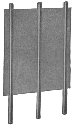
Fig. 1,057.—Wood separator for spacing the plates, as used in the Willard storage cells.
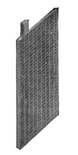
Fig. 1,058.—Positive
plate.
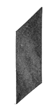
Fig. 1,059.—Perforated
rubber separator.
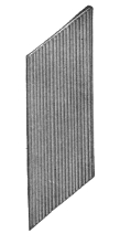
Fig. 1,060.—Wood
separator.
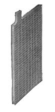
Fig. 1,061.—Negative
plate.
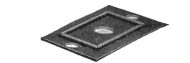
Fig. 1,062.—Hard rubber
cover.
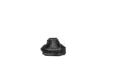
Fig. 1,063.—Vent
plug.
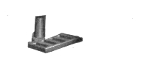
Fig. 1,064.—Pillar
connecting strap.
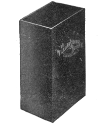
Fig. 1,065.—Hard rubber jar.
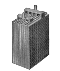
Fig. 1,066.—Complete element.
Figs. 1,058 to 1,066.—Parts of the Willard "Autex" automobile cells.
Ques. What is done to make the Plante plate more
efficient?
Ans. The surfaces are finely subdivided, the following methods
being those common: scoring, grooving, casting, laminating,
pressing, and by the use of lead wool.
Ques. Describe the Faure or pasted type.
Ans. This form of plate is constructed by attaching the
active material by some mechanical means to a grid proper.
The active material first used for this purpose was red lead,
which was reduced in a short time to lead peroxide when connected
as the positive or anode, or to spongy metallic lead when
connected as the cathode or negative, thus forming plates of the
same chemical compound as in the Plante type.
The materials used at the present time by the manufacturers for
making this paste are largely a secret with them, but in general they
consist of pulverized lead or lead oxide mixed with some liquid to make
a paste.
Ques. How do Faure plates compare with those of the
Plante type?
Ans. They are usually lighter and have a higher capacity,
but have a tendency to shed the material from the grid, thus
making the battery useless.
Many ways have been tried for mechanically holding the active material
on the grid, the general method involving a special design in the
shape of the grid. Some of these designs are: 1, solid perforated sheets
of lattice work; 2, corrugated and solid recess plates not perforated;
3, ribbed plates with projecting portions; 4, grid cast around active
material; 5, lead envelopes, and 6, triangular troughs as horizontal ribs.
The Electrolyte.—Sulphuric acid is generally used as electrolyte;
the acid should be made from sulphur and not from pyrites,
as the latter is liable to contain injurious substances.
Ques. How is the electrolyte prepared?
Ans. One part of chemically pure concentrated sulphuric acid
is mixed with several parts of water. The proportion of water
differs with several types of cell from three to eight parts, as
specified in the directions accompanying the cells.
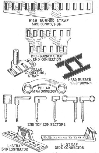
Figs. 1,067 to 1,079.—Willard connecting straps and connectors.
Ques. What test is necessary in preparing the
electrolyte?
Ans. In mixing the water and acid, the hydrometer should
be used to test the specific gravity6 of both the acid and the
solution. The most suitable acid should show a specific gravity
of about 1.760 or 66° Baumé.
Ques. In preparing the electrolyte, how should the
water and acid be mixed?
Ans. The mixture should be made by pouring the acid slowly
into the water, never the reverse. As cannot be too strongly
stated, in mixing, the liquid should be stirred with a clean
wooden stick, the acid being added to the water slowly; the
latter is corrosive and will painfully burn the flesh.
Distilled or rain water should be used in preparing the electrolyte.
When made, the solution should be allowed to cool for several hours
or until its temperature is approximately that of the atmosphere (60
being the average). At this point it should have a specific gravity of
about 1.200 or 25° Baumé. If the hydrometer show a higher reading,
water may be added until the correct reading is obtained; if a lower
reading, dilute acid may be added with similar intent.
The electrolyte should never be mixed in jars containing the battery
plates, but preferably in stone vessels, specially prepared for the purpose.
Furthermore, it should never be placed in the cell until perfectly cool.
Ques. What is the effect of mixing the acid and the
water?
Ans. The mixture becomes hot.
Before using, the mixture should be allowed to cool.
Ques. What kind of a vessel should be used?
Ans. The vessel should be of glass, glazed earthenware, or
lead.
Ques. At what density is the resistance of dilute sulfuric
acid at a minimum?
Ans. At 1.260.
The percentage of concentrated sulphuric acid and of water per
100 parts of the electrolyte for various specific gravities is given by the
following table:
SPECIFIC GRAVITY TABLE
Sulphuric acid
(Per cent.). |
Water
(Per cent.). |
Specific gravity
of Mixture. |
| 50 |
50 |
1.398 |
| 47 |
53 |
1.370 |
| 44 |
56 |
1.342 |
| 41 |
59 |
1.315 |
| 38 |
62 |
1.289 |
| 35 |
65 |
1.264 |
| 32 |
68 |
1.239 |
| 29 |
71 |
1.215 |
| 26 |
74 |
1.190 |
| 23 |
77 |
1.167 |
| 20 |
80 |
1.144 |
| 17 |
83 |
1.121 |
| 14 |
86 |
1.098 |
| 10 |
90 |
1.068 |
The electrolyte of the desired specific gravity may be purchased ready
for use, but in cases where it is desirable to save freight, the acid may
be diluted at the point of installation.
Ques. What is the effect of a deep containing vessel?
Ans. Parts of the plate surface may do more than their share
of the work due to the difference in the density of the electrolyte
at the top and bottom. The containing vessel should, therefore,
never be deeper than about 20 inches unless some artificial
means of acid circulation be used.
Ques. What is the effect of changes in temperature on
the electrolyte?
Ans. The resistance of the electrolyte is changed, being less
for increase of temperature.
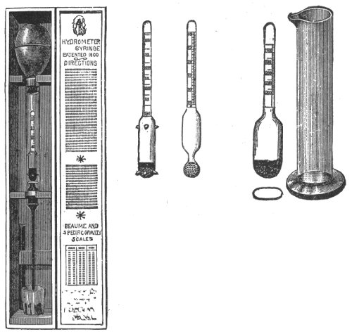
Figs. 1,080 to 1,084—Acid hydrometers for liquids
heavier than water. Fig. 1,080, standard storage
battery hydrometer with guiding points designed
for "hydrometer syringe," shot bulb, with red line
at 25 Baumé, 5 inches long, double scale 10 to 40
Baumé, 1.050 to 1.400 specific gravity. Fig. 1,081,
plain hydrometer with shot bulb, 5 inches long,
double scale 10 to 40 Baumé, 1.050 to 1.400 specific
gravity. Figs. 1,082 and 1,083, hydrometer with
small flat bulb, used in car lighting batteries, shot
bulb, 4½ inches long, single scale, reading from
1.100 to 1.250 specific gravity. Fig. 1,084 jar for
hydrometers.
Ques. How should the cells be filled?
Ans. Enough of the electrolyte should be poured into the
jars to completely cover the plates, or to within about a half
inch of the top edge of the jar.
Large cells should be filled by
means of an acid proof pump
and rubber hose.
Ques. What change
takes place after filling
the jars?
Ans. The specific gravity
of the electrolyte will fall considerably,
but will rise again
when the battery is charged.
Ques. What may be
said with respect to the
density of the electrolyte?
Ans. It should never exceed
1.200 when the battery
is fully charged.
Ques. How much electrolyte
is used per 100
ampere hours battery capacity,
on an 8 hour
rating?
Ans. About ten pounds;
in automobile batteries, about
four pounds is sufficient.
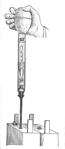
Fig. 1,085.—The hydrometer syringe; a
convenient device for testing electric
vehicle cells. By slightly compressing
the bulb and inserting the slender tube through the vent hole in the cover of the cell
sufficient acid may be drawn up to float the hydrometer within the large glass tube, and
the reading can be made at once. The acid is returned to the cell by again compressing
the bulb, and the reading of the next cell taken. The laborious and uncleanly method
of drawing out sufficient acid by a syringe is thus avoided.
Ques. What may be said with respect to impurities in
the electrolyte?
Ans. The electrolyte should be free from chlorine, nitrates,
acetates, iron, copper, arsenic, mercury, and the slightest trace
of platinum.
Mercury alone has no injurious effect unless it be present in sufficient
quantity to amalgamate the plates, but in combination with any other
metal, may cause local action.
Figs. 1,086 to 1,089.—The "Champion" Accumulator; views showing parts and assembly.
Fig. 1,086, empty plate; fig. 1,087, filled plate; fig. 1,088, complete element, small type;
fig 1,089, cell assembled. The plates are of the envelope type and are made thick. The
active material is held firmly in place by a covering of lead. A few thick plates are used
instead of many thin ones.
The following tests should be made for impurities before the
electrolyte is poured in the cells:
Chlorine.—To a small sample of the electrolyte add a few drops of
silver solution (20 grains of silver dissolved in 1,000 cu. cm. of water).
A white precipitate indicates chlorine.
Nitrates.—Place some of the electrolyte in a test tube, and add 10
grains of strong ferrous sulphate solution. Carefully pour down the
side of the test tube a small amount of chemically pure concentrated
sulphuric acid. A brown stratum between the electrolyte and the
concentrated acid indicates the presence of nitric acid.
Acetic acid.—Neutralize the electrolyte with ammonia, then add
ferric chloride. If the solution turns red, and is afterwards bleached by
the addition of hydrochloric acid, acetic acid is present.
Iron.—Neutralize a sample of the electrolyte with ammonia; boil a
small portion with hydrogen peroxide, and add ammonia or caustic
potash solution until the mixture becomes alkaline. If a brownish red
precipitate forms, it indicates iron.
Copper.—If copper be present, a bluish white precipitate will be
formed when ammonia solution is added to the electrolyte.
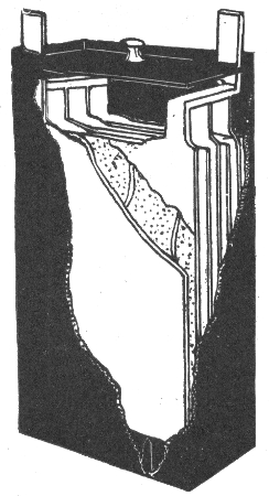
Fig. 1,090.—One cell of the Gould storage battery for electric vehicle use. According to the
data given by the manufacturers, this cell, containing four negative and three positive
plates, has a normal charging rate of 27 amperes; a distance rate of 22 amperes for four
hours; a capacity of 81 ampere hours at 3 hours discharge, and of 90 ampere hours at 4
hours discharge. Forty such cells are generally used for an average light vehicle battery.
Mercury.—This is indicated by an olive green precipitate when a
solution of potassium iodide is added to the electrolyte, or by a black
precipitate when lime water is added.
Platinum.—A rough test for traces of platinum is made by pouring
the electrolyte into a cell in which the battery plates are immersed. If
gassing take place for some time on open circuit, it is an indication of
the presence of platinum.
Ques. What should be done with old electrolyte?
Ans. When a battery is taken down the electrolyte may be
saved and used when re-assembling the battery, providing great
care be exercised when pouring it out of the jar, so as not to draw
off with it any of the sediment. It should be stored in convenient
receptacles, preferably carboys, which have been thoroughly
washed and never used for any other purpose.
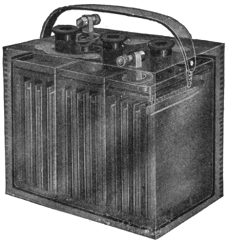
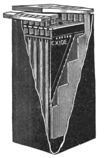
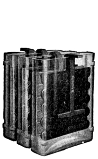
Fig. 1,091.—Phantom view of an "Exide" sparking or ignition battery. It contains three
cells. In this type, the terminal lug has been designed to obviate the creeping of the
electrolyte with its accompanying corrosion. The positive and negative terminals are
for identification.
The electrolyte saved in this manner will not, however, be sufficient
to refill the battery, and as some new electrolyte will be required, in
general it is recommended that the old supply be thrown away and all
new electrolyte (1.200 specific gravity) be used when re-assembling.
Voltage of a Secondary Cell.—This depends on the density
of the electrolyte, the character of the electrodes and condition
of the cell; it is independent of the size of the cell.
The voltage of a lead sulphuric acid cell when being charged
is from 2 to 2.5 volts. While the cell is being discharged, it decreases
from 2 to 1.7 volts. The voltage due to the density of
the electrolyte may be calculated from the following formula:
V = 1.85 + .917 (S - s)
in which
V = voltage;
S = specific gravity of the electrotype;
s = specific gravity of water at the temperature of observation.
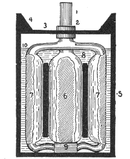
Fig. 1,092.—The Exide storage cell. The positive and negative plates are separated by thin
sheets of perforated hard rubber, placed on both sides of each positive plate. The electrolyte
and plates are contained in a hard rubber jar.
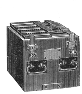
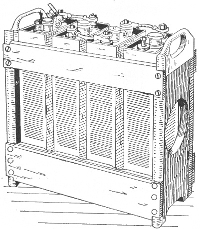
Fig. 1,093.—An Exide battery of five cells. The box which holds the cells is usually made
of oak, properly reinforced, with the wood treated to render it acid proof. The terminals
as shown, consist of metal castings attached to the side of the box and plainly marked.
Connection for Charging.—The dynamo cable connections
may be made either before or after filling the cells. In making
these connections great care should be taken to be sure that the
positive terminal of the battery is connected to the positive
lead of the dynamo, and that the negative terminal of the battery
is connected to the negative lead of the dynamo. In order to
insure that the reverse connections are not made accidentally,
the dynamo leads should be tested by a pole tester, and the positive
and negative poles marked red and black respectively.
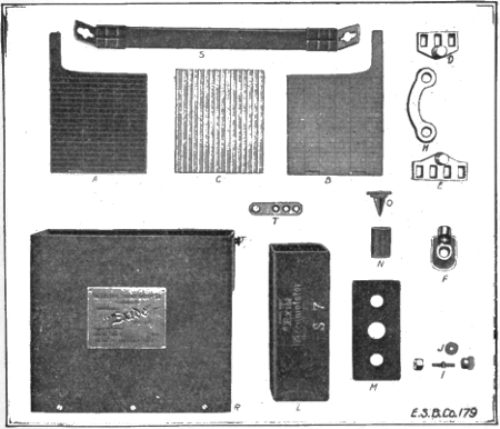
Figs. 1,094 to 1,109.—Parts of the "Exide" sparking battery. A, positive plate; B, negative
plate; C, wood separator; D, positive strap; E, negative strap; F, terminal lug; H, connector;
I, terminal bolt connector, stud, thumb nut and hexagonal nut; J, copper washer
for bolt connector; L, hard rubber jar; M, hard rubber cover; N, hard rubber cylinder
vent; O, vent plug for cylinder vent; R, wood case; S, strap handle; T, fitting for strap
handle. The "Exide" sparking battery is also adapted for electric lighting of automobiles,
for head lights, tail lights, side and interior lights.
The polarity of the dynamo wires being determined, they may
be joined to the proper terminals by means of suitable clamps
or by solder.
Wherever possible the dynamo should be of the direct current,
shunt wound, or special compound type, but in cases where only
alternating current can be obtained, suitable rectifiers or converters
should be used for changing it to direct current.
Charging.—Before beginning to charge a storage battery, it
should be gone over carefully, and any cell that is not up to the
standard should be disconnected and put in working order
before being replaced. In general, if the current used in charging
be too large, it will waste energy by evolving an excess of heat
and gas; if too small, an insulating deposit of white lead sulphate
will be formed on the positive plate, thereby preventing
the formation of the proper amount of lead peroxide.
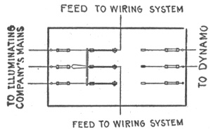
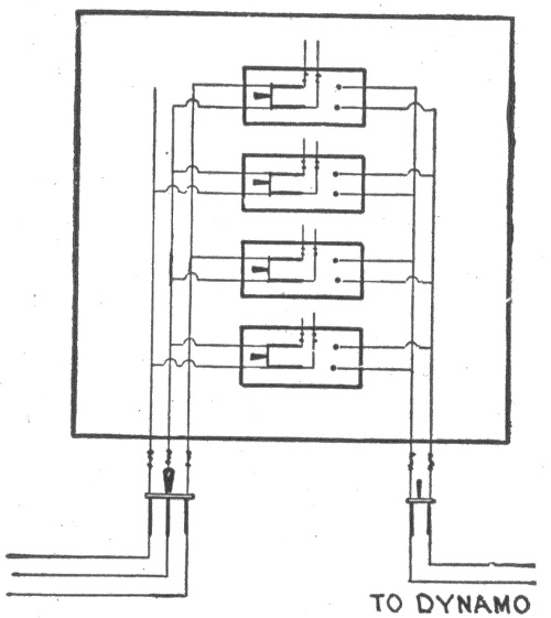
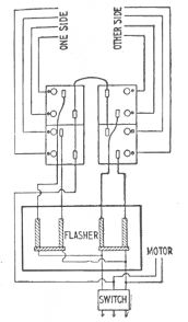
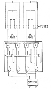
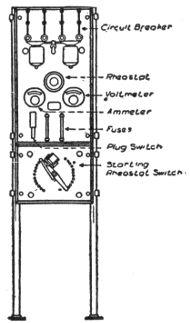
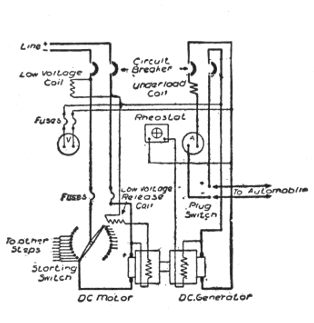
Figs. 1,110 and 1,111.—Switchboard and motor dynamo circuit connections for charging a
battery from direct current mains.
Ques. How should a battery be charged for the first
time?
Ans. It is essential that the current be allowed to enter at
the positive pole at about one-half the usual charging rate prescribed,
but after making sure that all necessary conditions have
been fulfilled, it is possible to raise the rate to that prescribed
by the manufacturers of the battery.
Ques. What is the usual period for charging a new
battery?
Ans. With several of the best known makes of storage battery
the prescribed period for the first charge varies between
twenty and thirty hours.
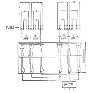
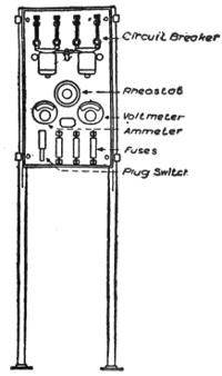
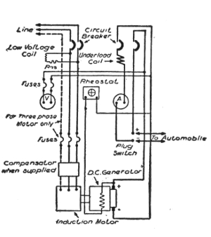
Figs. 1,112 and 1,113.—Switchboard and motor generator circuit connections for charging a
battery from alternating current mains. The connections of a third wire are shown, for
use in case a three phase circuit is available.
Ques. How is the electrolyte affected by the first
charge?
Ans. A change of specific gravity occurs. The specific gravity
should be about 1.200 when the solution is poured into the cells.
At the completion of the first charge, it should, on the same scale
be about 1.225. If it be higher than this, water should be added to the
solution until the proper figure is reached, if it be lower, dilute sulphuric
acid should be added until the hydrometer registers 1.225.
At the first charging of a cell, when the pressure has reached the
required limit, the cell should be discharged until the voltage has fallen
to about two-thirds normal pressure, when the cell should again be
recharged to the normal voltage (2.5 or 2.6 volts).
The manufacturers of a well known cell of the Plante genus prescribe
for the first charge, half rate for four hours, after which the current may
be increased to the normal power and continued for twenty hours
successively.
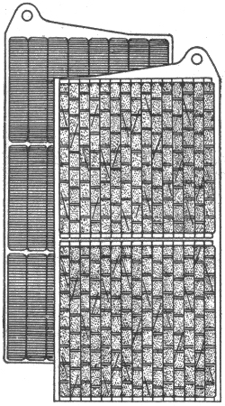
Fig. 1,114.—Plates of Edison storage battery. The positive or nickel plate consists of one or
more perforated steel tubes, heavily nickel plated, filled with alternate layers of nickel
hydroxide and pure metallic nickel in excessively thin flakes. The tube is drawn from a
perforated ribbon of steel, nickel plated, and reinforced with eight steel bands, equidistant
apart, which prevent the tube expanding away from and breaking contact with its contents.
The tubes are flanged at both ends and held in perfect contact with a steel supporting
frame or grid made of cold rolled steel, nickel plated. The negative or iron plate
consists of a grid of cold rolled steel, nickel plated, holding a number of rectangular pockets
filled with powdered iron oxide. These pockets are made up of very finely perforated steel,
nickel plated. After the pockets are filled they are inserted in the grid and subjected to
great pressure between dies which corrugate the surface of pockets and force them into
good contact with the grid.
Ques. What strength of current should be used in
charging a cell?
Ans. It should be in proportion to the ampere hour capacity
of the cell.
Thus, as given by several manufacturers, the normal charging rate
for a cell of 40 ampere hours should be five amperes, or one-eighth of
its ampere hour rating in amperes of charging current.
Ques. What should be the voltage of the charging current
before closing the charging circuit?
Ans. The voltage should be at least ten per cent. higher than
the normal voltage of the battery when charged.
Fig. 1,115.—Complete element of Edison storage battery with insulators. After the plates are
assembled into a complete element, narrow strips of treated hard rubber are inserted
between the plates, thereby separating and insulating them from each other. The side
insulator is provided with grooves that take the edges of the plates, thereby performing
the dual function of separating the plates and insulating the complete elements from the
steel container. At the ends of the element, that is between the outside negative plates
and container, are inserted smooth sheets of hard rubber. At the bottom, the element
rests upon a hard rubber rack or bridge, insulating the plates from the bottom of container.
Fig. 1,116.—Four Edison cells (type A-4) in wooden tray.
Ques. What indicates the completion of a charge?
Ans. When a cell is fully charged the electrolyte apparently
boils and gives off gas freely. The completion of a charge may
be determined by the voltmeter, which will show whether the
normal pressure has been attained.
Ques. How should the voltage be regulated during the
first charge?
Ans. It should be allowed to rise somewhat above the point
of normal pressure.
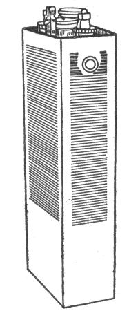 |
Electrical Data Edison Cell
|
B-2 |
B-4 |
B-6 |
| Normal output, ampere hours |
40 |
80 |
120 |
| Maximum output, ampere hours |
48 |
95 |
142 |
| Normal rate of discharge, amperes for five hours |
8 |
16 |
24 |
| Average voltage on normal discharge |
1.2 |
1.2 |
1.2 |
| Normal rate of charge, amperes for seven hours |
8 |
16 |
24 |
| Maximum rate of "boosting charge" (for short time only) |
50 |
100 |
140 |
| Length of containing can (determined by number of plates) |
1½ |
2⅝ |
313/16 |
| Width of containing can |
5⅛ |
5⅛ |
5⅛ |
| Height " " " |
715/16 |
713/16 |
7¾ |
| Height over all |
8¾ |
8¾ |
8⅞ |
| Weight of each cell alone, lbs. |
4.6 |
7.4 |
10.5 |
| Average weight per cell of battery, assembled in trays |
5.5 |
8.7 |
11.8 |
|
Fig. 1,117.—Cell of Edison storage battery. The jar or container is of nickel plated sheet steel
with welded seams; the walls are corrugated to give strength. The cell cover, of sheet steel,
has four mountings, two being pockets to contain stuffing boxes about the terminal posts.
One of the other two is a separator which separates spray from the escaping gas while the
battery is charging. The fourth mounting is for filling with electrolyte. The electrolyte
consists of a 21% solution of potash in distilled water with a small per cent. of lithia.
The density of the electrolyte does not change on charge or discharge.
Ques. How often should a battery be charged?
Ans. At least once in two weeks, even if the use be only
slight in proportion to the output capacity.
In charging a storage battery, it is essential to remember the fact that
the normal charging rate is in proportion to the voltage of the battery.
Thus, a 100 ampere hour battery, charged from a 110 volt circuit at
the rate of ten amperes per hour, would require ten hours to charge, and
would consume in that time an amount of electrical energy represented
by the product of 110 (voltage) by 10 (amperes) which would give
1,100 watts, or 11/10 kw.
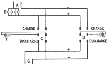
Fig. 1,118.—Diagram illustrating method of charging storage battery of stationary gas engine
ignition system; the system is simple to install and will give satisfactory results. Two
storage batteries are used, one being charged while the other is operating the sparking
coil. Where charging current is available at the point where the batteries are used,
the following diagram shows the system of connections, which can be easily followed,
A represents the source of charging current and B the bank of lamps (or other resistance,
such as an ordinary rheostat) sufficient to cut down the charging voltage to that required
by the battery. C and D are two double pole double throw knife switches connected at
their hinges to two batteries, E and F, each consisting of a group of cells. G represents
the leads to the sparking coil terminals. From the diagram, it will readily be seen that
by throwing the switches in opposite directions one battery will be charging while the
other battery is discharging to the engine, thus giving a constant source of supply, and
insuring that the spare battery will be full and ready for service by the time the other
is discharged. The method of determining the necessary resistance for cutting down the
line voltage for charging the battery is illustrated by the following example: If a battery
require about 3 amperes for charging, how is this current obtained from a 110 volt circuit?
Each 16 candle power carbon filament lamp in the lamp bank would give approximately
1/3 ampere with the cells in series in the lamp circuit. Therefore, 3 x 3 or 9 lamps should
be used in parallel to give 3 amperes.
Ques. If in charging a battery, one or more of the
cells do not boil at the completion of the charge, or fail
to show the proper voltage, what should be done?
Ans. The charging must be continued until the cadmium
test shows the required voltage, but if the prolonging of the charge
be liable to damage the plates in the other cells, the defective
cell or cells should be cut out of circuit when the battery discharges
and then placed in circuit again when the battery is
recharged. If the desired result cannot be attained by this
method, the plates which require additional charging may be
charged in a separate cell.
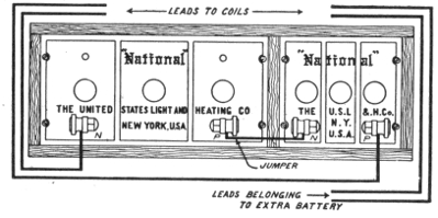
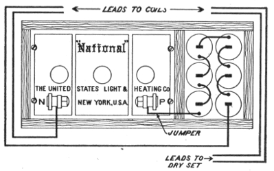
Figs. 1,119 and 1,120.—Emergency connections for weak ignition battery. It sometimes occurs
through carelessness or neglect, that the storage battery is discharged so low that the
engine explosion will not take place, and it is necessary to run somehow or other for a
short time. In such cases the following suggestion may be followed: If there be two storage
batteries, connect them in series. If there be one storage battery and a set of dry cells,
connect the positive terminal of the storage battery to the negative or outside terminal of
the dry cell; set and connect to the coil leads as if they were one battery. The above
suggestions should only be followed in emergency, for it may injure the coils, and is harmful
to the battery.
Ques. How is the cadmium test made?
Ans. A plate of cadmium is mounted in a hard rubber frame
and immersed in the electrolyte. The test consists in taking
voltage readings between the cadmium plate and the positive or
negative plates of the cell. During charge the cadmium plate
reads negative to the negative plate, until the cell is about full,
when the reading should be zero; the charge should be continued
until the cadmium reads 0.2 volt positive to the negative while
charging at the normal rate.
Ques. Name some portable instruments that should
be provided for testing batteries.
Ans. 1, a hydrometer syringe (specific gravity tester); 2, an
acid testing set (can be used instead of the syringe); 3, a low
reading voltmeter; 4, suitable prods, and 5, a thermometer.
Ques. What precaution should be taken in charging
a battery?
Ans. Care should be taken not to have a naked flame anywhere
in its vicinity.
To either charge or discharge a battery at too rapid a rate involves
the generation of heat. Thus, while this is not liable to result in a flame
under usual conditions, the battery may take fire, if it be improperly
connected or improperly used.
Ques. What is the effect of varying the charging current?
Ans. In charging a storage cell, particularly for the first time,
a weaker current than that specified may be used with the same
result, provided the prescribed duration of the charge be proportionally
lengthened. The battery may also be occasionally
charged beyond the prescribed voltage, ten or twenty per cent.
overcharge effecting no injury, although if frequently repeated,
it shortens the life of the battery.
Ques. What are the charge indications?
Ans. The state of the charge is not only indicated by the
density of the electrolyte and the voltage of the cell, but also by
the color of the plates, which is considered by many authorities
as one of the best tests for ascertaining the condition of a battery.
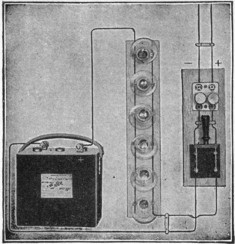
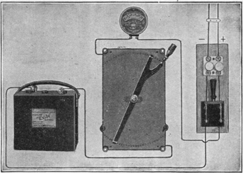
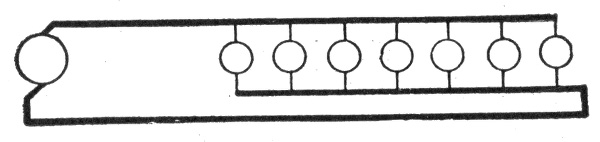
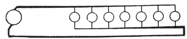
Figs. 1,121 and 1,122.—Two methods of charging from a direct current lighting system. The simplest method of charging is from
an incandescent light circuit, using lamps connected in parallel to reduce the voltage to that of the battery, the current being
adjusted by varying the number of lamps in circuit. The group of lamps is in series with the battery to be charged, and
the combination is connected across the circuit furnishing the current. If the charging source be a 110-120 volt circuit, and
the rate required be 6 amperes, twelve 16 c. p. or six 32 c. p. lamps, in parallel, and the group in series with the battery,
will give the desired charging rate, unless high efficiency lamps be used, when more will be required. In case a lower charging
rate, say 2 amperes be used, then a proportionately fewer number of lamps will be needed; but the length of time required
to complete the charge will be correspondingly increased. Instead of lamps, as in fig. 1,121, a rheostat is sometimes used, as
shown in fig 1,122. Its resistance should be such as to produce, when carrying the normal charging current, a drop in volts
equal to the difference between the pressure of the charging source and that of the battery to be charged; thus, if a battery
of three cells, giving 6 volts, is to be charged from a 110 volt circuit at a 6 ampere rate, the resistance would be, according
to Ohm's law,
(110 - 6) ÷ 6 = 17.3 ohms.
The carrying capacity of the rheostat should be slightly in excess of the current required for charging. An ammeter with
suitable scale should be inserted in the battery circuit to indicate the current. For charging more than one battery at a time
from a 110 volt circuit, the batteries should be connected in series (positive terminal of one battery to the negative of the
next, and so on). The charging rate should be that of the battery with the lowest rate. The resistance to be inserted will
be less than if only one battery is being charged; where lamp resistance is used, this means more lamps in parallel. Care
should be taken to remove each battery from the circuit as it becomes charged, inserting additional resistance to take its place.
Ques. What are the colors of the plates?
Ans. In the case of formed plates, and before the first charging,
the positives are of a dark brown color with whitish or reddish
gray spots, and the negatives are of a yellowish gray. The whitish
or reddish gray spots on the positive plates are small particles of
lead sulphate which have not been reduced to lead peroxide during
the process of forming, and represent imperfect sulphation.
As a general rule, the first charging should be carried on until these
spots completely disappear. After this the positive plates should be of
a dark red or chocolate color at the end of the discharge, and of a wet
slate or nearly black color when fully charged. A very small discharge
is sufficient, however, to change them from black to the dark red or
chocolate color.
If the battery has been discharged to a pressure lower than 1.8 volts,
the white sulphate deposits will reappear, turning the dark red color to
a grayish tint in patches or all over the face of the plate, or in the form
of scales of a venetian red color.
The formation of these scales while charging indicates that the maximum
charging current is too large and should be reduced until the scales or
white deposits fall off or disappear, after which the current can be
increased again.
During charging, the yellowish gray color of the negatives changes
to a pale slate color which grows slightly darker at the completion of
the charge. The color of the negatives always remains, however, much
lighter than that of the positives.
Ques. How are the best results obtained in charging?
Ans. The rate of charge should be normal, except in cases of
emergency. At such a rate, unless the constant voltage method
be employed, the cell may be considered full when the voltmeter
reads 2.5 volts during charge. The electrolyte should be kept
at uniform density throughout the cell; when water is added,
because of evaporation, it should be added by means of a funnel
reaching to the bottom of the cell. Care should be taken never
to add acid after evaporation; otherwise the electrolyte will be
too heavy. Hydrometer readings should be taken regularly;
the reading is an excellent indication of the amount of charge in the
battery. Hydrometer readings are useless, however, unless the
precaution be taken to keep the electrolyte of uniform density.
Ques. What voltage should be used in charging?
Ans. At the beginning of the charge the voltage should be
about 5 per cent. higher than the normal voltage of the battery,
unless the latter has been overdischarged, in which case the
difference of pressure should not exceed 2 per cent., otherwise
the current might be too large.
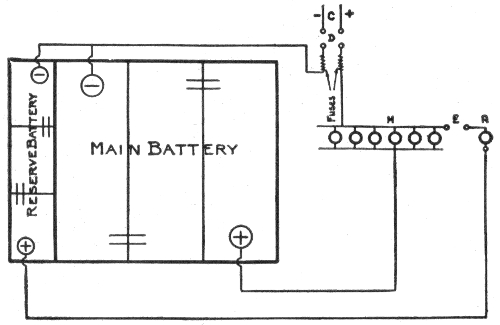
Fig. 1,123.—Diagram showing charging connections for "Exide" duplex sparking battery.
C, charging source; D, double pole single throw switch; E, single pole single throw switch;
M, lamp resistance "main" battery; R, lamp resistance "reserve" battery.
Ques. In what two ways may batteries be charged?
Ans. They may be charged either at constant current or at
constant voltage.
Although the latter method is considered the better one by many
authorities, it is a fact, nevertheless, that if the charging current be
normal at the beginning of the charge, and no means be provided for
keeping it constant, it will diminish as the charging progresses, thereby
greatly increasing the length of the time required for charging, and
resulting in serious injury to the plates.
Ques. How may the charging current be kept constant?
Ans. Its voltage should be gradually increased, first to about
10 or 15 per cent. above the voltage of the battery, and kept at
that point nearly to the end of the charge, where in consequence
of the rapid rise of pressure in the battery it might become
necessary to increase the voltage of the current to 30 or 40 per
cent. above the normal of the battery.
Figs. 1,124 to 1,126.—Electric Storage Battery Co. chloride cells. The voltage of cells of all
capacities is slightly above 2 volts on open circuit, and during discharge at the 8 hour rate
it varies from that point at the beginning to 1.75 volts at the end.
Ques. What tests should be made while charging?
Ans. Occasional voltage and cadmium readings of each cell
should be taken for the purpose of ascertaining their condition
and the behavior of the separate plates.
Ques. What tests should be made after charging?
Ans. Each cell should be tested with a low reading voltmeter
and hydrometer about once a week. If any cell read low, it
should be cut out and examined to see if any material has been
introduced which would cause a short circuit. If this trouble
do not exist, the cell should be given an independent charge.
Charge Indications.—The state of the charge is not only
indicated by the density of the electrolyte and the voltage of the
cell, but also by the color of the plates, which is considered by
many authorities as one of the best tests for ascertaining the
condition of a battery.
In the case of formed plates, and before the first charging, the positives
are of a dark brown color with whitish or reddish gray spots and the negatives
are of a yellowish gray. The whitish or reddish gray spots on the
positive plates are small particles of lead sulphate which have not been
reduced to lead peroxide during the process of forming, and represent
imperfect sulphation.
As a general rule the first charging should be carried on until these
spots completely disappear. After this, the positive plates should be of
a dark red or chocolate color at the end of a discharge and of a wet
slate or nearly black color when fully charged. A very small discharge
is sufficient, however, to change them from black to the dark red or
chocolate color.
If the battery has been discharged to a pressure lower than 1.8 volts,
the white sulphate deposits will reappear turning the dark red color to a
grayish tint in patches or all over the surface of the plate, or in the form
of scales of a venetian red color.
The formation of these scales during charging indicates that
the maximum charging current is too large and should be reduced
until the scales or white deposits fall off or disappear, after which
the current can be increased again.
Ques. Describe the behavior of the electrolyte during
discharge.
Ans. There is a definite change in the density of the electrolyte
for a given amount of discharge.
The density of the electrolyte is, therefore, one of the best indications
of the state of charge, provided, of course, no internal discharge due to
local action takes place. If, when the cell is charged, it show a density
of 1.200, and when discharged 1.130, the difference .07 represents the
total charge. If at any time the density be 1.165, then just one half the
amount of capacity has been taken from the cell.
It is necessary to stir the electrolyte well, in order for these observations
to be reliable.
If the discharge has taken place at a high rate, the cell must stand for
an hour or more before the electrolyte will completely diffuse so that
the density readings are correct.
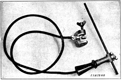
Fig. 1,127.—Electric Storage Battery Co., arc lead burning outfit. In assembling a storage
battery element, a negative plate is laid down with a separator on it, then a positive
plate, separator, negative plate, etc. The plates are so placed that all the lugs of the
positive plates are on one side and all the lugs of the negative plates are on the other side.
A strip, consisting of flat strips of lead or lead alloy, having rectangular openings in it of
the same dimensions as the cross section of the lug of the plates, these openings being
spaced to register with the lugs, is then placed over the plate lugs of the positive plates
and a similar strap is placed over the lugs of the negative plates. The lugs are then
burned into integral union with the straps.
Ques. Define the term "boiling."
Ans. Boiling means the rapid evolution of gas when a cell is
nearly charged.
Ques. What causes boiling?
Ans. The amount of sulphate to be converted into peroxide
becomes less and less as the charge progresses and the plates
therefore become virtually smaller, so that the current becomes
too large for the work demanded of it. The result is, that
part of the current not actually used in the formation of peroxide
decomposes the electrolyte into its constituent elements.
Ques. Why do the gases evolved produce a less milky
appearance of the electrolyte when a battery has been in
use for a considerable time?
Ans. The plates are better formed; consequently a larger
charging current can be used without producing "boiling".
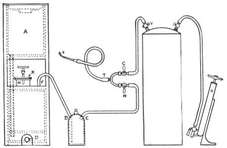
Fig. 1,128.—Hydrogen gas generator for lead burning. A complete lead burning outfit consists
of the following parts: 1, hydrogen gas generator; 2, trap for cleaning the gas and for
preventing the flame getting back in the generator; 3, air pump; 4, air tank; 5, blow pipe;
6, lead burner's mixing tee; 7, length of 150 feet 5/16 inch soft rubber tubing. When the
generator is to be used for lead burning, connect up the different parts of the apparatus
as shown. Fill the trap 2/3 full with water and be sure to connect the gas generator to the
nipple on the bottle marked B. The stop cocks N and C must be closed. See that the rubber
plug at D is secured in place. Put the required amount of zinc in the opening at H.
(No. 1 generator requires: 15 lbs. zinc, 9 gals, water, 3 gal. vitriol. No. 2 generator requires:
20 lbs. zinc, 15 gals. water, 5 gals. vitriol). After putting in the zinc, add the water
and then the sulphuric acid, and note that the water must always be put in before the acid.
When making the connection be sure that there are no low points in the hose between E
and N, as water is liable to accumulate at these low places, which will make the gas damp
which is detrimental to the burning. If water get into the line, kink the hose between
F and B, detach the hose at E and blow out the water with air by opening the cocks, N,
C and V. The length of the hose between T and X must not be longer than five feet as
the cocks N and C must always be within the reach of the man who is using the flame.
When ready to use the flame, open N which allows the hydrogen gas to escape. Light the
same with a match and adjust the air cock C until the desired flame is obtained. Different
classes of work require different flames, which can be obtained by changing the tips and by
varying the amount of gas and air with the cocks N and C. When the generator is laid
up for the night, or when the charge is exhausted, pull the hose off at F and draw off the
solution by removing the plug at D. The generator should then be thoroughly washed by
pouring water in A.
Ques. What may be said of charging a battery as
quickly as possible?
Ans. As a general rule, such a procedure should not be
adopted unless the battery be thoroughly discharged.
Ques. What precaution should be taken?
Ans. The danger to be avoided in rapidly charging a cell is
its tendency to heat.
Ques. What apparatus is necessary in charging a battery?
Ans. The battery may be charged from direct current mains
having the proper voltage. A current as near uniform as possible
is required, and existing conditions must be met in each separate
case. Sometimes a motor dynamo set with a regulating switchboard
is used. Such an apparatus consists of a direct current
dynamo, driven direct from the shaft of a motor, which, in turn,
is energized by current from the line circuit.
With a direct current on the line, a direct current dynamo may be
used; but with an alternating current an induction motor is required.
The speed of the motor is governed by a rheostat, and the output of the
dynamo is thus regulated as desired.
Charging Through the Night.—If an electric vehicle, after
a late evening run, is to be used in the morning, the battery
may be charged during the night without an attendant being
present; but in doing this great care must be taken not to excessively
overcharge.
A careful estimate of the amount of current required should be
made and the rate of charge based on this estimate.
If, say, 72 ampere hours be required to recharge, and the time available
is nine hours, the average rate of charge must be 8 amperes.
If charging from a 110-volt circuit, the rate at the start should be
about 10 amperes; if from a 500-volt circuit, about 9 amperes; as, in
charging from a source with constant voltage, such as a lightning or
trolley circuit, the rate into the battery will fall as the charge progresses.
This also applies if the charging be done from a mercury arc rectifier
without attendance.
Ques. What precautions should be taken in charging
a battery out of a vehicle?
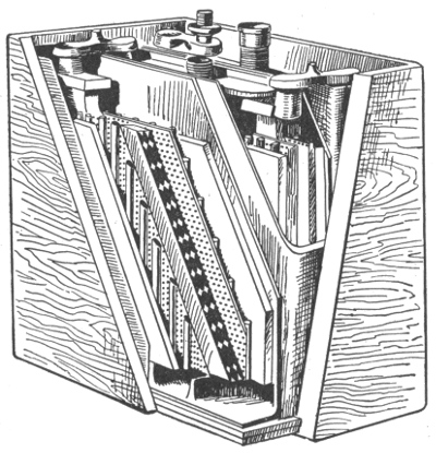
Fig. 1,129.—Interior view Northwestern storage battery. The positive plate is of double grid
construction, and the negative plate consists of a special staggered grid. The separators
used between the plates are hard rubber, ribbed on one side so as to prevent the positive
plate from buckling. It is perforated so as to allow a free circulation of the electrolyte
and to decrease the internal resistance. Rubber separators are better than the commonly
used wood or paper separators because they prevent local action. The flat side of each
separator is placed against a positive plate, preventing shedding or jolting of the active
material of the plate. This checks deterioration. The jars are made of rubber composition;
the walls are thick and the covers well fitted to avoid spilling the electrolyte.
All Northwestern batteries are contained in rubber composition jars. The walls are
thick and the covers fit tightly to prevent spilling the acid. A hard wood box, treated
with a moisture repellant is used for the outer case. These batteries are made in any
voltage desired, the ampere capacity ranging from 25 amp. hrs. to 300 amp. hrs.
Ans. When a battery is being overhauled, the cells must be
connected together in series and to the charging source in
relatively the same manner as if they were in the vehicle; that is,
the positive (+) terminal of one group of cells must be connected
to the negative (-) terminal of the next group, and the two free
terminals, one positive and the other negative, must be connected
respectively to the positive and negative terminals of the
charging circuit, but not until all of the groups have been connected
in series. Great care must always be taken to have the
polarities correct and the wire or cable for the connections of
ample size to carry, without heating, the heaviest current used
in charging.
Charging Small Cells.—For cells of the portable type, having
capacities from 10 to 100 ampere hours, the normal charging and
discharging rate should be about one-tenth the stated capacity,
but the discharging rate may be increased to double this value, in
case of necessity.
If the cells be provided with formed plates and not charged, the
jars should be filled with the proper electrolyte, and then charged
for at least 10 hours steady, or until they boil, then they may be
discharged.
In the case of unformed plates, the charging should be from
30 to 40 hours, until the cells boil, and the plates assume their
proper color.
Ques. How are small cells easily charged from 110 or
220 volt circuits?
Ans. This may be conveniently done by inserting in one of
the charging leads an incandescent lamp which will pass the
required quantity of current. If the current required be as large
as 10 amperes, a suitable resistance or 10 lamps in parallel, each
passing one ampere, may be used. Great care should be taken
to see that the battery is connected properly.
Period of Charging a New Battery.—In the case of batteries
provided with formed plates, the first charge should extend over
a period of not less than 30 consecutive hours, without stopping,
if possible, or for periods of not less than 10 hours a day for three
consecutive days. The electrolyte will then commence to "boil"
or "gas," assuming a milky appearance due to the ascending
bubbles of gas. At this stage the density of the electrolyte as
shown by the hydrometer placed in each cell should be at least
1.200; it is essential that the charging should be continued until
every cell boils equally. From this point the charging should be
prolonged until the pressure, as determined by a voltmeter or a
cadmium tester, rises to about 2.55 volts.
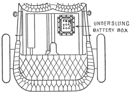
Fig. 1,130.—The Willard underslung battery box for automobiles. The general tendency
in automobile design, is to keep everything off the running board as far as possible, and
to get tool boxes, battery boxes, etc., placed somewhere under cover. To meet these
conditions the box here illustrated is arranged so that it can be underslung beneath the
rear footboard or supported on auxiliary cross members made of strap iron and attached
to the side members of the chassis. It is usually suspended under the rear footboard or
the rear seat. The box has a chemically treated wood lining to make it acid proof. The
lining is so made that there is air space between the battery and the sides of the box,
except at the corners. Ventilation is thus obtained and the battery kept dry. Accumulation
of water or spilled electrolyte in the bottom of the box is prevented by grooves
in the bottom board, extending downward from the corners to an outlet at the center
of the board. The box is also fitted with rubber bushings in the holes where wire
leaves the battery box.
The charging of unformed plates is similar in all respects to that of
formed plates, except that the first charging should extend over a period
of at least 70 consecutive hours without stopping, at the end of which
time the plates should have the characteristic colors of those of a fully
charged battery. If they do not, the charging should be prolonged and
the cell tested for density of electrolyte, and voltage, as already described
until the desired conditions are attained. Then the battery
may be discharged and recharged.
It is probable that a total of 300 to 400 hours of charging with intervening
discharges will be required to form the plates until they acquire
a good color, and the density of the electrolyte becomes stable.
In regular charging, the rate should be rapid when the
battery is nearly exhausted, but it should be greatly reduced
at the end of the charge after passing the point of boiling.
Charging at too low a rate is always injurious.
Ques. What may be said with respect to the capacity
of a new battery?
Ans. A new battery will never give its full capacity till after
about twenty discharges. During this time it should be given
about 25% overcharge. After that, 10% overcharge, that is,
10% more charge than was taken out, will be sufficient for ordinary
work.
High Charging Rates.—Occasionally it is desirable to charge
a battery as quickly as possible. As a general rule, such a
procedure should not be adopted unless the battery be thoroughly
discharged, and not then, unless done by a person who
thoroughly understands what he is about; battery makers will
always furnish data and directions to meet emergencies.
In charging a battery at a high rate, the danger to be avoided is the
tendency of the cells to heat. The troubles that might arise from this
cause may be prevented by immediately reducing the current strength.
The proper rate of charge for a given battery of cells may be thus discovered
by experiment. A battery should never be charged at a high
rate unless it be completely exhausted, since it is a fact that the rate of
charge that it will absorb is dependent upon the amount of energy
already absorbed.
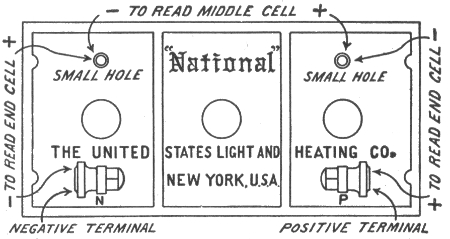
Fig. 1,131.—Instructions for taking voltage readings ("National" batteries). The batteries
are made up of several cells, usually two or three, each cell representing approximately
2 volts when battery is on "open circuit" (neither charging nor discharging). It is sometimes
advisable to take individual readings of the cells, both to determine on charge
if all the cells be evenly charged, and also on discharge to be sure that the cells are evenly
discharged. To do this, a low-reading voltmeter must be used with prods attached to
the voltmeter leads that can be forced into the terminals so as to insure good contacts.
To test the positive end cell, put the positive prod on the positive terminal of the battery
and the negative prod into small hole back of positive terminal in hard rubber cover.
Middle cell (in 6 volt, type "Y" batteries) is tested by inserting the positive prod in the
small hole back of the positive terminal, and the negative prod in small hole back of
negative terminal. In the 120 ampere hour, Auto type of battery, the middle cell is
tested by inserting the positive prod in the small hole back of the positive terminal and
the negative prod on the middle terminal. The negative end cell is tested by putting
the negative prod on the negative terminal and the positive in the small hole in rubber
cover back of the negative terminal. A charging cell at end of charge should read about
2.55 volts. A fully charged cell on open circuit should read about 2.1 volts. Since open
circuit readings vary under different conditions, as to age, acid, etc., little significance
should be attached to them. A discharged cell voltage will vary considerably with the
many different coils, engines, etc., but in the majority of cases should read between 1.8
to 1.9 volts, while motor is in operation.
For rapid charging, when a battery has to be charged in four
hours, the current should vary about as follows:
| 40 |
per |
cent. |
of |
total |
1st |
hour |
| 25 |
" |
" |
" |
" |
2nd |
" |
| 20 |
" |
" |
" |
" |
3rd |
" |
| 15 |
" |
" |
" |
" |
4th |
" |
For quick charging in three hours the rates should be: 50 per cent. 1st
hour; 331/3 per cent. 2nd hour; 162/3 per cent. 3rd hour.
Mercury Arc Rectifier.—This is a device for obtaining direct
current from alternating current for use in charging storage
batteries. The transformation is obtained at a low cost, because
the regulation is obtained from the alternating side of the rectifier,
while the current comes from the direct current side.
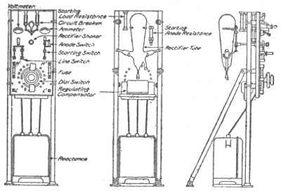
Figs. 1,132 to 1,134.—Mercury arc rectifier outfit, or charging set. The cuts show front, rear,
and side views of the rectifier, illustrating the arrangement on a panel, of the rectifier
tube with its connection and operating devices.
The theory is as follows: In an exhaust tube having one
or more mercury electrodes, ionized vapor is supplied by the
negative electrode or cathode, when the latter is in a state of
"excitation." This condition of excitation can be kept up only
as long as there is current flowing toward the negative electrode.
If the direction of the voltage be reversed, so that the formerly
negative electrode is now positive, the current ceases to flow,
since in order to flow in the opposite direction it would require
the formation of a new negative electrode, which can be accomplished
only by special means. Therefore, the current is always
flowing toward one electrode—the cathode, which is kept excited
by the current itself. Such a tube would cease to operate on
alternating current voltage after half a cycle if some means were
not provided to maintain a flow of current continuously towards
the negative electrode.
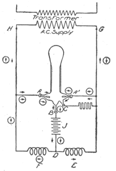
Fig. 1,135.—Elementary diagram of mercury arc rectifier connections. A, A´, graphite anodes;
B, mercury cathode; C, small starting electrode; D, battery connection; E, and F reactance
coils; G and H, transformer terminals; J, battery.
Ques. Describe the construction and operation of a
mercury arc rectifier.
Ans. Fig. 1,135 is an elementary diagram of connections. The
rectifier tube in an exhausted glass vessel in which are two
graphite anodes A, A´, and one mercury cathode B. The small
starting electrode C is connected to one side of the alternating
circuit, through resistance; and by rocking the tube a slight arc
is formed, which starts the operation of the rectifier tube. At
the instant the terminal H of the supply transformer is positive,
the anode A is then positive, and the arc is free to flow between
A and B. Following the direction of the arrow still further, the
current passes through the battery J, through one-half of the
main reactance coil E, and back to the negative terminal G of
the transformer. When the impressed voltage falls below a
value sufficient to maintain the arc against the reverse voltage
of the arc and load, the reactance E, which heretofore has been
charging, now discharges, the discharge current being in the same
direction as formerly. This serves to maintain the arc in the
rectifier tube until the voltage of the supply has passed through
zero, reversed, and built up such a value as to cause the anode A
to have a sufficiently positive value to start the arc between it
and the cathode B. The discharge circuit of the reactance coil E
is now through the arc A'B instead of through its former circuit.
Consequently the arc A'B is now supplied with current, partly
from the transformer, and partly from the reactance coil E. The
new circuit from the transformer is indicated by the arrows enclosed
in circles.
Ques. How is a mercury arc rectifier started?
Ans. A rectifier outfit with its starting devices, etc., is shown
in figs. 1,132 to 1,134. To start the rectifier, close in order named
line switch and circuit breaker; hold the starting switch in opposite
position from normal; rock the tube gently by rectifier
shaker. When the tube starts, as shown by greenish blue light,
release starting switch and see that it goes back to normal
position. Adjust the charging current by means of fine regulation
switch on the left; or, if not sufficient, by one button of
coarse regulation switch on the right. The regulating switch
may have to be adjusted occasionally during charge, if it be desired
to maintain the charging current approximately constant.
Capacity.—The unit of capacity of a storage cell is the
ampere hour, that is, the ability to discharge one ampere continuously
for one hour. For instance, a 100 ampere hour battery
will give a continuous discharge of 12½ amperes for eight
hours. It should theoretically give a discharge of 25 amperes
continuously for four hours, or 50 amperes for two hours, but
in reality, the ampere hour capacity decreases with an increase
of discharge rate.
It requires, theoretically .135 ounces of metallic lead on either
element reduced to sponge lead or to lead peroxide to produce
one ampere hour; in practice, from four to six times this amount
is required.
The reason for this is because it is impossible to reduce all the active
material, to bring every particle in contact with the electrolyte, or to
cause every part to be penetrated by the current.
Experiments show that from .5 to .8 ounces of sponge lead,
and from .53 to .86 ounces of metallic lead converted into
peroxide, are required on their respective elements to produce
a discharge of one ampere hour at ordinary commercial rates.
The capacity increases with the temperature, being about one
per cent. for each degree Fahr. increase in temperature.
Battery capacity depends on the size and number of plates;
the quantity of active material present, and the quantity of
electrolyte.
For an eight hour rate of discharge and 60 degrees temperature,
the capacity of American batteries varies from 40 to 60
ampere hours per square foot of positive plate surface ( = 2 ×
number of positive plates in parallel × length × breadth).
The following table gives the variation of capacity for
different rates of discharge:
Capacity Variation for Different Discharge Rates
| Discharge rate |
Per cent of capacity
at 8 hour rate |
| Plante |
Faure |
| 8 hour |
100% |
100% |
| 6 hour |
96% |
96% |
| 4 hour |
80% |
88% |
| 2 hour |
61% |
70% |
| 1 hour |
56% |
48% |
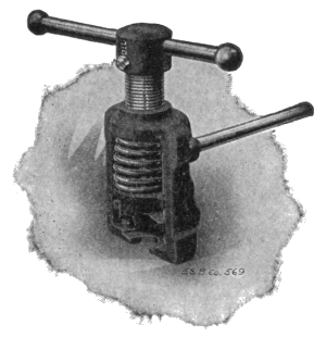
Fig. 1,136.—"Exide" connector puller for removing connectors.
Ques. How may the capacity of a battery be increased?
Ans. By mixing organic materials with the lead oxide, but
any such mixture is always accompanied by a rapid deterioration
of the plates.
Discharging.—In discharging a battery its voltage should
never be allowed to fall below 1.8 volts, under load, thus leaving
about 30 per cent. of the total capacity unused. The normal
discharging current may be equal to the normal charging current,
but a discharge equal to 3 or 4 times the normal may be given
without injury to the plates. Some types may be discharged at
even six or seven times the normal rate. In such cases, however,
the capacity will be reduced in the same proportion, as before
explained in the paragraph dealing with battery capacities.
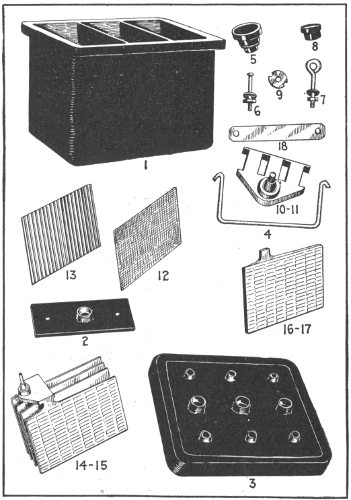
Figs. 1,137 to 1,151.—Parts of the Witherbee battery. 1, jar; 2, inside cover; 3, cover; 4, handle;
5, vent cap; 6, cover, screws, nuts and washers; 7, handle eyes, nuts and washers; 8, rubber
covered nut; 9, spannernut; 10, plate strap for positive plates; 11, plate strap for
negative plates; 12, rubber separator; 13, wood separator; 14, positive group of plates;
15, negative group of plates; 16, positive plate; 17, negative plate; 18, cell connector.
An element consists of a complete set of plates bound together on strap, with wood and
rubber separators for a single cell. Positive plates are brown, negative plates, gray.
Ques. What is the effect of discharging too rapidly?
Ans. It tends to break the plates, and in the case of pasted
plates, a very sudden discharge will dislodge the paste.
Ques. How is the discharge capacity of a storage battery
stated?
Ans. In ampere hours. This, unless otherwise specified, refers
to its output of current at the eight hour rate. Most manufacturers
of automobile batteries specify only the amperage of
the discharge at three and four hours. Thus, at the eight hour
rate, a cell which will discharge at ten amperes for eight hours
is said to have a capacity of eighty ampere hours. It does not
follow that eighty amperes would be secured if the cell were
discharged in one hour. It is safe to say that not more than forty
amperes would be the result with this rapid discharge.
As a general rule, the one hour discharge rate is four times that of the
normal, or eight hour discharge, and considerations of economy and
prudence suggest that it should never be exceeded, if, indeed, it ever be
employed. The three hour discharge, which is normally twice that of
the eight hour, is usually the highest that is prudent, while the four hour
discharge is the one most often employed in vehicles for the average
high speed riding.
Ques. What should be the maximum rate of discharge?
Ans. The one-hour rate; this when used, should not extend
over fifteen or twenty minutes. In the case of regulating batteries
a forty-five minute rate of discharge may be allowed for one
or two minutes during great fluctuations of load.
Ques. How does the capacity decrease?
Ans. It decreases with the increase in current output.
An 80 ampere hour cell, capable of delivering 10 amperes for 8 hours,
would, when discharged at 14 amperes, have a capacity of 70 ampere
hours; when discharged at 20, its capacity would be 60; and when discharged
at 40, its capacity will have decreased from 80 to 40 ampere hours.
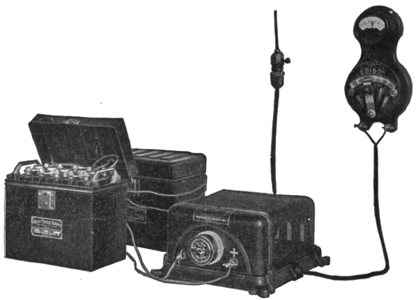
Fig. 1,152.—The Edison alternating current rectifier. It consists of an electro-mechanically operated
valve which allows current waves of only one polarity to pass through it from the alternating
current circuit to the battery which is to be charged. An indicating snap switch
of the usual form controls the starting and stopping of the charging current. The rectifier
gives any desired charging rate within its capacity. The illustration shows the rectifier
connected up and charging an ignition battery of five Edison cells. The connections
consist of the usual connecting cord and plug and a charging lead running from the plus
side of the charging terminals on the rectifier to the plus pole of the battery, and another
lead connecting the negative terminals as shown. In turning the snap switch to the
"on" position, the proper charging current will flow into the battery. When charging
is completed, the switch is turned to the "off" position and the battery leads disconnected.
Ques. What, in general, are the indications of the
quantity of electricity remaining within a cell?
Ans. The voltage, and the density of the electrolyte.
Ques. What should be done after discharging?
Ans. Whenever possible the battery should be immediately
charged.
The Battery Room.—Precautions should be taken to prevent
any direct sunlight falling on the battery cells in glass jars, as
the breakage of such jars due to unequal expansion of the
different portions of the glass, is a source of constant trouble
and danger.
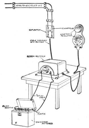
Fig. 1,153.—Permanent connections for Edison rectifier. As shown, the rectifier is connected
to a small switch and cutout.
The exclusion of direct sunlight also tends to keep the evaporation
of the electrolyte at a minimum.
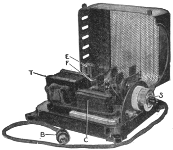
Fig. 1,154.—Edison Alternating Current rectifier; view with cover open showing parts. B,
primary circuit cord; C, condenser; E, primary relay; F, secondary switch; S, alternating
circuit switch; T, transformer.
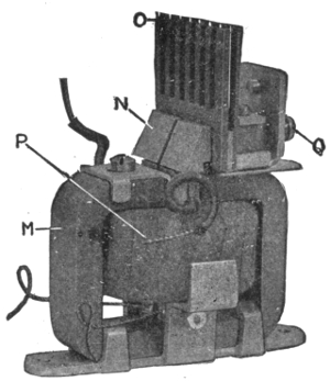
Fig. 1,155.—Vibrating unit of Edison alternating current rectifier. M, permanent magnet;
N, carbon vibrating contact; O, comb radiator; P, primary circuit coil; Q, vibrator adjustment
screw.
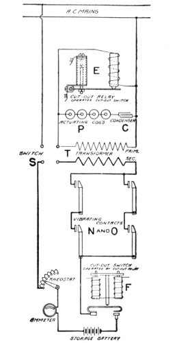
Fig. 1,156.—Elementary diagram of
connections.
The operation of the Edison rectifier
may be explained as follows
with the aid of figs. 1,154 to 1,156
(the parts being uniformly lettered
in the figures): The primary circuit
taken from the alternating current
mains by the cord B, embraces
the primary winding of the transformer
T, a condenser C, and the
coils P, of the vibrating units, fig.
1,155.
The secondary circuit from the
transformer embraces the massive
carbon and copper contacts (N and
O, fig. 1,156) which pass only the
positive waves of the alternating
current, for charging batteries or
other duty.
An ammeter and rheostat may be
placed in this charging circuit if the
current is to be varied, or a fixed
connection may be substituted on
the base of the rectifier if it is to be
used for the maximum duty of 8 or
16 amperes.
The vibrating unit (fig. 1,155),
which operates in a manner similar
to the well known action of a polarized
relay, includes a permanent
magnet M; the coil in the primary
circuit P; the vibrating armature of
steel with removable carbon contact
N; the stationary copper contact
with comb top for heat radiation O,
and the screw Q for adjusting the
amplitude of the armature vibration.
The vibrating armature of each
unit is divided into two parts, which
gives flexibility, affords increased
current capacity and minimizes
sparking, the two leads shown
being connected together in one
circuit.
A primary relay and a secondary
switch (E and F, figs. 1,154 and
1,156), close their contacts when
current is flowing.
Upon failure of the main alternating
current line they operate to open
the charging circuit. A storage battery
is thus prevented discharging
through the rectifier.
Upon resumption of the main
alternating current, the rectifier
starts automatically.
Every battery room should be provided with a water tap and
sink. The floor should be paved with vitrified brick, preferably blue
or yellow in color, of diamond pattern and sloping in all directions
toward suitable drains. A floor of this type can be easily washed
by flooding with water, and its patterns tend to keep it dry
under foot at all times. Wooden floors are rotted very quickly
by acid spillings and by the spray.
The room should be kept absolutely clear of everything,
which may be injured, by the sulphuric acid fumes and it
should be well ventilated to insure the safety and good health
of the attendants.
A battery, even at rest, gives off hydrogen which when diluted
with air forms a mixture which is very liable to explode if brought
in contact with any kind of flame. Unless proper ventilation be
provided, the breaking of the connection when a current is flowing,
or the lighting of a bare flame lamp in the battery room
would be dangerous.
Battery Attendants and Workmen.—Those employed in
setting up batteries are liable to suffer from soreness of hands
and the destruction of clothing unless proper precautions be
taken to prevent the same. In order to avoid these troubles,
the boots should be painted with paraffine mixed with an equal
quantity of beeswax.
The clothing should be of woolen material, which, unlike
cotton, is practically unaffected by the acid. If cotton shirts
be worn, they should be dipped in a strong solution of washing
soda and then rough dried.
An apron of sacking, backed with flannel should be worn over
all the other clothes. A bottle of strong ammonia should be
kept in the battery room at all times, and in case of an accidental
splash of acid on the clothes, the immediate application of a
small quantity of the ammonia, by means of the stopper, will
at once neutralize the acid and prevent it burning a hole in
the material. A pail containing water made strongly alkaline
with washing soda should also be kept conveniently at hand
during all operations in the battery room. The hands should be
dipped occasionally in this water in order to prevent the skin
smarting and becoming sore under the action of the acid.
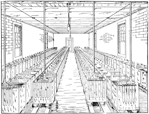
Fig. 1,157.—Interior of storage battery room showing arrangement of cells. A, are the cell
insulators; B, wooden stringers; C, supporting pieces.
If a splash of acid should happen to enter the eye, it should be
washed at once with clean water, warm water preferably, and then put
one or two drops of olive oil into the eye. If olive oil be not immediately
available, any kind of engine oil is better than none at all.
Points on Care and Management.—In setting up storage
cells, they should be placed in as few tiers as possible, and in
such a manner that the direct rays of the sun are not allowed to
fall upon the cells. The rays of the sun are likely to crack the
glass. This is probably due to the unequal expansion of the
glass, for it has been found that jars which are carefully annealed
never crack in this manner. Of course, the latter precaution
does not apply to large batteries, where lead lined wooden tanks
or solid lead boxes are used.
In installing plants where expert attendance is not to be had,
it is well to place in the circuit two magnetic cut outs, one set
for maximum current, and the other for minimum voltage, so
that the battery cannot be discharged too low.
Ques. How should the cells be placed?
Ans. They should be placed as shown in fig. 1,151, on insulators
A, resting on wooden stringers B, and supporting pieces
C placed on the floor. The insulators are usually of glass
or porcelain, which in certain patterns may be filled with oil, to
insure better insulation as shown in figs. 1,165 and 1,166.
In setting up a battery, it should be remembered that plates deteriorate
on standing exposed to the air. They should, therefore, be unpacked
and set up immediately on arrival. When they are entirely connected
up, they are ready for the addition of the electrolyte, and for the forming
charge, which they should receive immediately.
Ques. How should the wooden stringers, shelves, cell
boards, and trays be treated?
Ans. They should be thoroughly varnished to insure cleanliness
as well as good insulation.
Outside of each cell and close to the mouth, melted paraffine should
be applied by means of a brush, so as to form a band about an inch wide,
for the purpose of preventing the electrolyte creeping over the top of
the jar, wetting the outside, and thereby impairing the insulation.
Ques. What should be done to avoid waste of current
by leakage?
Ans. Each cell of the battery must be thoroughly insulated.
Ques. What is the effect of verdigris which forms on
the terminals?
Ans. It is a poor conductor and should therefore be removed
and the terminals kept bright and clean to insure the proper
flow of the current.
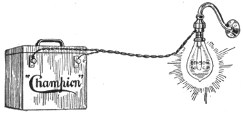
Fig. 1,158.—Charging "Champion" battery with charging plug. Where direct lighting
current is available, recharging may be done by means of the charging plug. First
insert the plug in a regular socket. Then screw a 50 c.p. lamp into the plug and
turn on. To tell the positive from the negative, lay both wires on a small piece of
red litmus or test paper moistened. The negative wire makes a mark on the paper.
This wire must go to the negative post of battery. This will fully charge the "6-25-G"
battery in 15 to 20 hours.
Ques. What precautions should be taken in unpacking
cells?
Ans. The plates should be handled carefully. When they
are sent out from the factory already built into sections, they
should be unpacked without disturbing a single plate. In all
cases, every particle of packing, straw, hay and any chips and
bits of parts should be carefully removed, and all the dust
should be blown out of the spaces between the plates by means
of a bellows or other similar device.
NOTE.—Champion directions for repairs. To replace broken jars in a battery remove
the lid and lift out elements bodily. Empty the good jars with a syringe or by tilting the battery
over. Never put the acid in any vessel except glass, stone or lead. Put new jars in place
same as others and run melted paraffine around the edges. The wax must be broken off the
elements that are to go into new jars and be poured on again. Fill the jars with acid to ¾"
from tops. Melt the broken wax in a tin ladle and pour over the acid about ½" thick. Do not
fill with wax to tops of jars. When the wax gets cold it will be found to have shrunk away
from the edges of the jars. Fill up the opening with a little melted paraffine wax by means
of a squirt can. Cut a small hole in the middle of the wax seal for a vent. Smear the brass
posts and terminals and inside of case with vaseline to prevent creeping of the acid. The
"6-25-G" requires one-half gallon of acid and the "6-50-G" one gallon.
Although such particles are good non-conductors, the action of the
sulphuric acid electrolyte carbonizes them, giving them conducting
properties which tend to produce leakage.
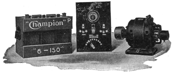
Figs. 1,159 to 1,161.—"Champion" electric light equipment designed especially for use on
launches, yachts, and country residences. The outfit consists of three essential parts:
1, a dynamo run by belt from main engine; 2, a storage battery, and 3, a switchboard
to regulate, measure and control the current.
Ques. How should the cells be assembled?
Ans. In placing the plates or plate sections in the containing
jars or tanks, care should be taken to see that the supporting
frame of paraffined wood bears evenly on the bottom of the jar.
If they do not, wedges of paraffined wood should be placed under
the frame, so as to distribute the weight of the section equally.
Each section should be lowered gently into the jar until it rests
fairly upon the frame, and care should be taken to see that none
of the plates have shifted, and that the section is situated centrally
in the jar, with a small clear space all around.
Ques. How should the cells be arranged?
Ans. They should be so placed that the battery attendant
can see the edges of the plates and consequently the spaces between
them at the same time.
Ques. Describe the method of connecting the cells.
Ans. This is accomplished by means of solder, bolts and nuts,
or clamps, according to circumstances. The use of solder is not
essential if there be a good surface of the lead strip of one cell
in contact with that of the next, and provided these contact
surfaces have been well cleaned. Usually, the ends of the lead
strips are turned up so that the junction of two cells takes the
form of an inverted T as shown in fig. 1,162.
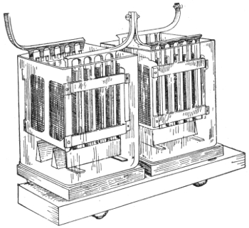
Fig. 1,162.—Two storage cells; view showing the inverted T form of connection.
Ques. What precaution should be taken in joining the
terminals of the cells?
Ans. The contact at the junctions should be very thorough,
otherwise they will become heated when a current is flowing, and
it is desirable that the connections should include as little lead
strip in the circuit as possible, thereby reducing the amount of
useless resistance.
Brass or gun metal clamps may be kept clean by brushing them over
with melted paraffin after they have been screwed up tightly. When
thus treated they serve to indicate points of bad contact by heat, generated
at such points, when the current is flowing, softening the paraffin
and changing its normal color. Vaseline and different kinds of anti-sulphuric
acid varnishes, or preparations that are not attacked by the
electrolyte, may also be used for this purpose. It is a good plan to color
the varnish with vermillion or lamp black and paint the positive connections
red and the negative connections black, and also other parts
of the installation for distinguishing the polarities.
Cell Connections.—The cells may be connected together
either in series or parallel, or in parallel-series or series-parallel
combinations, according to the requirements, but in all cases
it is best to use the simplest arrangement practicable.
For instance: if the cells employed in an installation requiring 110
volts, have only half the capacity required, and 55 cells give the desired
voltage, then the number of cells must be increased to 110, and theoretically
the required number of amperes hours at 110 volts may be
obtained in one of two ways: 1, by connecting the cells in pairs in parallel
and then coupling the pairs together in series, and 2, by arranging the
110 cells in two complete batteries of 55 cells each connected in series,
then coupling the two batteries in parallel.
The first method is quite impracticable, however, as the slightest
difference between the voltages of the two cells of any pair will result
in the one having the greater pressure discharging into the other, thereby
causing the entire battery to quickly deteriorate.
NOTE.—To determine the positive wire. Without a voltmeter, the positive terminal
of the charging circuit can be determined by attaching a piece of clean lead to each wire which
is to be connected to the battery, and immersing them, without touching each other, in a
glass or other insulating vessel containing water to which is added a drop or two of sulphuric
acid. After the current has passed through the circuit for a short time, the positive lead will
commence to discolor, and, if left long enough, will turn brown. Bubbles will arise from the
two terminals immersed, the larger and more frequent ones being from the negative, the
smaller ones from the positive.
NOTE.—Method of disconnecting "National" cells. There are two methods of disconnecting
the cells employing link connectors. First a ⅝ inch bit or twist drill may be used,
boring down into the top of the posts about ¼ inch. The link will then be loosened and can
be removed. This leaves the link, as well as the post, in good condition for reburning. Second
the link may be cut in the center. A flame should be played on the top of the post, at the
same time grasping the end of the half link firmly with pliers. When the connection has
become warmed (care being taken not to melt the lead) the half link can be twisted loose from
the port. New links may be used if desired in re-assembling the cells. It is not necessary to
remove the covers from the element, the links may be cut in the center and the plates removed
from the jars without removing the links from the ports. The links can be afterwards reburned
together in the center. When the cells are equipped with "T" or "L" straps, they
should be cut apart with hack saw or chisel midway between the cells, and in re-assembling,
burned together at this point.
Battery Troubles.—To successfully cope with faults in
storage batteries, there are two requisites: 1, a thorough knowledge
of the construction and principle of operation of the battery,
and 2, a well ordered procedure in looking for the source of
trouble. The faults which are usually encountered by those who
operate storage batteries are here given.
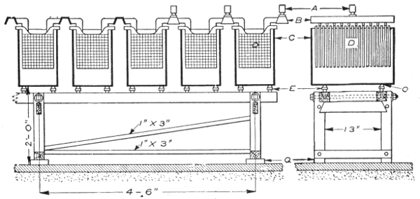
Fig. 1,163.—Arrangement of battery cells and stand. A, cable lugs; B, bus bars; C, glass
tanks; D, plate; E, glass insulators; Q, vitrified brick; O, lead washers. Battery cells
are set up on stands; the one shown being built for a 100 ampere battery. Larger sizes
would, of course, require heavier stands, and if space be limited, the cells may be set
in rows, one above the other. However, it is evidently much better to place the cells in
single rows, where they will be convenient for inspection and repairs or any work that
has to be done on them. There are several other ways of setting a battery, one of
which is to place the stringers on the floor, on vitrified brick or some other insulator, and
then place trays filled with sand on the stringers, setting the cells in the trays on glass
insulators. The battery room should be dry, clean, well ventilated and free from metal
work, also neither too hot nor too cold. Too high a temperature in the battery will
shorten the life of the plates, and although there is no danger of the battery freezing, a
low temperature, while it is maintained, reduces the capacity; otherwise cold has no ill
effect on the battery. A good temperature for the battery room is about 60° F.
A damp, dirty room is conductive to grounds and surface leakage, and there is danger
of impurities getting into the cells. If the room be very damp the electrolyte may absorb
enough moisture to cause the cells to overflow. Strong floors are necessary to support
a battery, as one of a 100 ampere, 125 volt capacity weighs from 12 to 13 tons. A wood
floor may be used, but a cement floor is better, and a glazed vitrified brick floor is better
still. Wooden floors will rot quickly from the acid, which is sure to get onto it more or
less; a cement floor will be disintegrated if too much acid get onto it. This kind of floor
forms a first class ground if there be any chance for one; the glazed brick floor is not
affected by the acid and is an insulator.
Short Circuiting.—A form of derangement that may occasionally
affect storage batteries is short circuiting. It may be
caused by some of the active material—if the cell be of the
pasted variety—scaling off and dropping between the plates, or
by an over collection of sediment in the bottom of the cell.
Should the operator suspect trouble with his battery he may discover
a short circuited cell by the marked difference in color of the plates or
of the specific gravity of the electrolyte, as compared with the other
cells. No particular damage will be caused, if the trouble be discovered
and removed before these symptoms become too marked.
If a foreign substance has become lodged between the plates, it may
be removed by a wood or glass instrument.
If some of the active material has scaled off, it may be forced down
to the bottom of the jar. If excessive sediment be found, the jar and
plates should be washed carefully, and reassembled.
A cell that has been short circuited may be disconnected from
the battery and charged and discharged several times separately
which may remedy the trouble.
Ques. How are internal short circuits indicated?
Ans. Short circuits in a cell are indicated by short capacity,
low voltage and low specific gravity, excessive heating and
evaporation of the electrolyte.
Ques. How are internal short circuits located?
Ans. If the trouble cannot be located by the eye, the battery
should be connected in series and discharged at the normal rate
through suitable resistance. If a suitable rheostat be not available,
a water resistance may be used.
This consists of a receptacle (which must not be of metal) filled with
very weak acid solution, or with salt water in which are suspended two
metal plates, which are connected by wires through an ammeter. The
current may be regulated by altering the distance between the plates,
or by varying the strength of the solution. As the discharge progresses
the voltage will gradually decrease, and it should be frequently read at
the battery terminals; as soon as it shows a sudden drop, the voltage of
each cell should be read with a low reading voltmeter.
While the readings are being taken, the discharge rate should be kept
constant and the discharge continued until the majority of the cells
read 1.70 volts; those reading less should be noted. The discharge
should be followed by a charge until the cells which read 1.70 volts are
up, then the low cells should be cut out, examined, and the trouble
remedied.
Overdischarge: Buckling.—On account of unequal expansion
of the two sides of a plate, or certain portions thereof, the
strains thus set up may distort it and cause it to assume a buckled
shape, that is, bent so one side is concave.
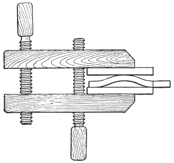
Fig. 1,164.—Method of straightening a buckled plate. Buckling is caused by the unequal
expansion of the plates which is due to the sulphate lodging on the plates, thus preventing
action taking place at that point; and by excessive charging. If the plates be not badly
buckled, they can be placed between 2 boards and with a little pressure, can be straightened
out.
Buckling is due always to over discharge on either the whole, or some
portion of the plate. Occasional buckling may occur with too rapid
charge and discharge.
Sulphation of Plates.—During discharge a storage cell deteriorates
on account of the formation of lead sulphate over the
surface of the plates. This lead sulphate is the product of the
chemical combination of active material with the electrolyte.
It is a non-conductor, white in color and of greater volume, in
proportion than the active material. When the discharge is
over prolonged, sulphation is evidenced by the electrodes becoming
lighter in color, because of the sulphate which lessens the
active surface.
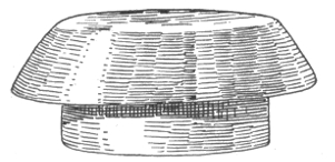
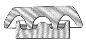
Figs. 1,165 and 1,166.—Oil Insulator; fig. 1,165, general view; fig. 1,166, sectional view. Whenever
a number of open cells are in use, unless precautions be taken, electrical leakage between
the cells invariably occurs. This leakage is due chiefly to the semi-conducting nature of
the thin layer of moisture which frequently covers not only the glass containing cells,
but the unimmersed parts of the elements, and even the shelves on which the cells rest.
To prevent this waste of energy, the outside of the cells should occasionally be well cleaned
and thoroughly dried. A little vaseline or tallow may then be rubbed over them to
advantage. The shelves or supports for the cells, should either be well varnished or coated
with paraffin wax. Electrical leakage is greatly reduced if each cell be mounted on a
glass or earthenware insulator, as shown in the illustrations. The insulator here shown
is in two parts and of a mushroom shape. The lower cup contains a small quantity of
some non-evaporating oil, and as the conducted moisture cannot bridge across this, a
nearly perfect insulating medium is obtained. These insulators are made in various
sizes and may be obtained in earthenware or glass. Those made of glass are found to
give the best results.
Ques. Name some causes of sulphation.
Ans. It is sometimes caused by a too weak or too strong acid
solution, but more generally by continued over discharging, or
too rapid discharging of the batteries, or by allowing them to
remain uncharged for long periods of time.
Ques. What is the effect of sulphation?
Ans. It tends to cause shedding of the active material, buckling
of plates, loss of capacity, increase of resistance and consequent
reduction of efficiency, and increase of temperature with
flow of current. A sufficient amount of lead peroxide and sponge
lead must be retained on the plates to reduce this resistance,
otherwise the charging current cannot flow through the active
material and regenerate the battery.
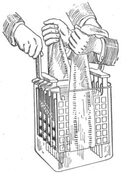
Fig. 1,167.—Illustrating method of placing plates in glass jars.
Ques. What should be done in case of sulphation?
Ans. Charge the battery below the maximum rate, necessarily
prolonging the charge, until the plates assume the proper
color. This is a tedious task, but it must not be hastened, as
rapid charging will cause serious buckling.
NOTE.—How to destroy acid vapor in storage battery rooms: The best remedy is a
good system of thorough and rapid ventilation; failing this the evil effect of the acid may be
minimized by the fumes of a powerful alkali such as ammonia, which will readily combine with
the sulphuric acid to form sulphate of ammonia, an inert and harmless salt. If the use of
liquid ammonia be objectionable, the granulated carbonate of ammonia will do equally well.
The ammonia fumes are best obtained by placing dilute ammonia in shallow dishes, so that an
extensive evaporating surface is obtained. In the same way the corroding dew which is so
frequently deposited on the lugs and connectors of storage battery elements may readily be
neutralized by the application of a solution of ammonia, or even common washing soda. A
good method of protecting metal work in battery rooms is to smear it over evenly with vaseline.
The charging should be done at low rates. Discharge should not be
carried below 1.8 volts per cell, and the charging current should be
stopped when each cell shows 2.4 volts.
If the plates be in a very bad condition, a little of the white sulphate
deposit on each of the positive plates may be removed with a stick, thus
exposing a part of the good surface to the action of the electrolyte.
If the positive plates cannot be restored to their proper color as directed,
it is cheaper to replace them by a new set, rather than to attempt
their recovery by means of reversals.
Electrical Data on "National" Cells
(Size of plate 4⅞" × 8⅝")
| Number of Plates per cell |
5 |
7 |
9 |
11 |
| Discharge in amperes |
{for 4 hours |
12 |
18 |
24 |
30 |
| {for 5 hours |
10¼ |
15¼ |
20½ |
25½ |
| {for 6 hours |
9¼ |
13¾ |
18½ |
23 |
| Ampere hour capacity |
{at 4 hour rate |
48 |
72 |
96 |
120 |
| {at 5 hour rate |
51 |
76 |
102 |
127 |
| {at 6 hour rate |
55 |
83 |
110 |
138 |
| Outside measurements of rubber jar, in inches |
{Length |
1⅞ |
2⅝ |
3⅜ |
43/16 |
| {Width |
55/16 |
55/16 |
55/16 |
55/16 |
| {Height |
11¾ |
11¾ |
11¾ |
11¾ |
| Weight of cell complete, in lbs |
14¼ |
19¼ |
24¼ |
29¾ |
| Weight of electrolyte, in lbs |
1 |
2 |
3½ |
5 |
Lack of Capacity.—This is usually due to the clogging of
the pores in the plate with sulphate which is invisible because the
surface of the plate is maintained in proper condition but the
interior portions of the active material have not been thoroughly
reduced. To correct this condition, the battery should be given
a prolonged overcharge at low current rates, say about one fourth
the normal 8 hour charging rate.
NOTE.—Oxide of lead, litharge, or plumbic oxide is sometimes found native as lead ochre,
and may be artificially made by heating the carbonate or nitrate. It is usually prepared on
a larger scale by heating the lead in air. When the metal is only moderately heated, the oxide
forms a yellow powder which is known as massicot, but at a higher temperature the oxide melts,
and on cooling, it forms a brownish scaly mass, which is called flake litharge. The scaly
pieces are afterwards ground between stones under water, forming buff or levegated litharge.
The litharge of commerce often has a reddish yellow color, due to the presence of some of the
red oxide of lead, and frequently from one to three per cent. of finely divided metallic lead is
found mixed with it. When heated to dull redness litharge assumes a dark brown color, and
becomes yellow again on cooling. At a bright red heat it fuses and readily attacks clay crucibles,
forming silicate of lead. Litharge is a most powerful base, and has a strong tendency to
form basic salts. Hot solution of alkalies, as potash or soda, readily dissolve it, and on cooling,
it crystalizes out in the form of beautiful pink crystals.
Falling off in the capacity may be caused by a dry cell, due to a
leaking jar; some or all of the cells may be in a state of incomplete
charge, due to the battery having been run too low and not sufficiently
charged; or the plates may be short circuited, either by the sediment
(deposit in the bottom of the jar) getting up to the bottom of the plates
or by something that has fallen into the cell.
Electrical Data on "American" Cells
Normal
Capacity |
Number of 30 volt Tungsten lamps that can be run with 16 cells in series for 2, 4, 6 or 8 hours |
Ampere
hours |
2 hours |
4 hours |
6 hours |
8 hours |
| 40 |
14 |
9 |
8 |
7 |
| 60 |
17 |
14 |
12 |
10 |
| 80 |
28 |
18 |
15 |
14 |
| 120 |
42 |
27 |
24 |
21 |
| 160 |
57 |
37 |
31 |
28 |
| 20 |
71 |
45 |
40 |
35 |
| 250 |
88 |
56 |
50 |
44 |
| 300 |
106 |
70 |
60 |
52 |
| 350 |
124 |
81 |
71 |
62 |
| 400 |
142 |
91 |
81 |
71 |
|
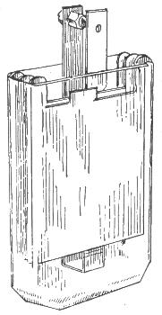
Fig. 1,168.—"American" cell.
|
Ques. What action takes place when a battery stands
idle for some time?
Ans. It loses part of its charge, due to local losses in the cells.
Ques. How should batteries be treated, when used but
occasionally?
Ans. If a battery is not to be used for several days, it should
first be fully charged before standing; if it continue idle, a
freshening charge should be given every two weeks, continuing
the charge when the cells begin to gas freely.
Ques. What should be done in case of lack of capacity?
Ans. If the current consumption be normal, there may be
poor connections or trouble in the battery; there may be a dry
cell, due to a leaking jar; some or all of the cells may be in a state
of incomplete charge, due to the battery having been run too low
and not sufficiently charged, or the plates may be short circuited,
either by the sediment (deposit in the bottom of the jar) getting
up to the bottom of the plates or by something that has fallen
into the cell.
Electrical Data on "Autex" Cells
(Standard plates; size, 5¾" x 8⅝")
| Number of Plates |
7 |
9 |
11 |
13 |
15 |
17 |
19 |
21 |
| Discharge in Amperes for 4 hours |
21 |
28 |
35 |
42 |
49 |
56 |
63 |
70 |
Outside Measurements
Rubber Jars in inches. |
{Length |
2¾ |
3½ |
4¼ |
5 |
5¾ |
6½ |
7¼ |
8 |
| {Width |
6⅛ |
6⅛ |
6⅛ |
6⅛ |
6⅛ |
6⅛ |
6⅛ |
6⅛ |
| {Height |
12⅜ |
12⅜ |
12⅜ |
12⅜ |
12⅜ |
12⅜ |
12⅜ |
12⅜ |
| Weight in Pounds |
{Element |
15¾ |
20¼ |
24¼ |
29¾ |
34 |
38½ |
43 |
47½ |
| {Electrolyte |
4½ |
5 |
5¾ |
6¼ |
7 |
7¾ |
8½ |
9¾ |
| {Complete Cell |
22 |
28 |
34¼ |
40½ |
47 |
53¼ |
59½ |
66 |
NOTE.—Peroxide of lead, pure oxide or plumbic dioxide is the true active material in all
forms of lead storage cell. This lead salt is found native as the mineral plattnerite. It is
a heavy lead ore, forming black, lustrous, six sided prisms. It may be prepared from the red
oxide by boiling it in fine powder, with nitric acid diluted with five parts of water, or by treating
the carbonate when suspended in water with a stream of chlorine gas, and then thoroughly
washing and drying it. It is reduced to a lower oxide on heating or by exposure to bright
sunlight. This salt readily imparts oxygen to other substances; it becomes heated to redness
when thrown into sulphuric dioxide, and takes fire when triturated with sulphur—hence this
oxide is a common ingredient in lucifer match composition. When used in primary or secondary
batteries it readily imparts its oxygen to nascent hydrogen, forming water, and thus it acts
as a powerful depolarizer. When robbed of its oxygen, it readily becomes reoxidized, if subjected
to the action of nascent oxygen liberated by the electrolytic decomposition of water.
If the trouble cannot be located by the eye, connect the battery in
series, and discharge it at the normal rate, through suitable resistance.
If a suitable rheostat be not available, a water resistance may be used.
This consists of a receptacle (which must not be of metal) filled with
very weak acid solution or salt water in which are suspended two metal
plates, which are connected, by wires through an ammeter.
Electrical Data on "Autex" Cells
(Light weight plates; size, 5¾" × 8⅝")
| Number of Plates |
7 |
9 |
11 |
13 |
15 |
17 |
19 |
21 |
23 |
25 |
| Discharge in Amperes for 5 hours |
15¾ |
21 |
26¼ |
31½ |
36¾ |
42 |
47¼ |
52½ |
57¾ |
63 |
| Outside Measurements Rubber Jars in in. |
{Length |
129/32 |
27/16 |
331/32 |
3½ |
41/32 |
49/16 |
53/32 |
5⅜ |
65/32 |
611/16 |
| {Width |
6⅛ |
6⅛ |
6⅛ |
6⅛ |
6⅛ |
6⅛ |
6⅛ |
6⅛ |
6⅛ |
6⅛ |
| {Height |
12⅜ |
12⅜ |
12⅜ |
12⅜ |
12⅜ |
12⅜ |
12⅜ |
12⅜ |
12⅜ |
12⅜ |
| Weight in Pounds |
{Element |
11½ |
14¾ |
18 |
21¼ |
24½ |
27¾ |
31 |
34¼ |
37¼ |
40½ |
| {Electrolyte |
2¼ |
2½ |
3 |
3¾ |
4¼ |
4¼ |
5½ |
6 |
6¾ |
7¼ |
| {Comp. Cell |
15¾ |
20 |
24¼ |
28½ |
33¼ |
38 |
42 |
46¼ |
51½ |
56 |
The current may be regulated by altering the distance between the
plates or by varying the strength of the solution. As the discharge
progresses, the voltage will gradually decrease and it should be frequently
read at the battery terminals. When it shows a sudden drop, the
voltage of each cell should be read with a low reading voltmeter.
While the readings are being taken, the discharge rate should be
kept constant and the discharge continued until the majority of the cells
read 1.70 volts; those reading less should be noted. The discharge should
be followed by a charge until the cells which read 1.70 volts are up; then
the low cells should be cut out, examined and the trouble remedied.
NOTE.—How to prevent lead poisoning. Workmen employed in the manufacture of
lead or lead salts are always liable to lead poisoning, both by inhaling the dust and by contact
of the materials with the hands. Various preventives for this have been employed, and of
these, the most simple seems to be a careful washing of the hands in petroleum. It is said
that three washings a day are sufficient to prevent all serious danger of poisoning. The
benzole in the petroleum appears to scour the skin and remove the loose lead dust, and the
fatty substance in the oil fills up the pores of the skin and prevents the absorption of the
deleterious salts. The employment of petroleum has given such good results that it has been
proposed to use this material as a guard against poisoning in other industries where the salts
of copper or mercury are employed.
Ques. What causes low specific gravity when there are
no short circuits?
Ans. 1, sloppage or a leaky jar (the loss having been replaced
with water alone), 2, insufficient charge, 3, over discharge, or
4, a combination of these abuses. Any of these mean that there
is acid in combination with the plates.
In this case the acid should be brought out into the electrolyte by a
long charge at a quarter of the normal discharge rate.
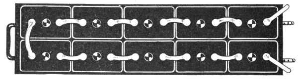
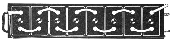
Figs. 1,169 and 1,170.—The "National" storage battery; views showing methods of
assembling cells. Fig 1,169, end assembling; fig 1,170, side assembling.
Ques. How should weak cells be treated?
Ans. They should be grouped by themselves and charged as
a separate battery, care being taken that the positive strap of one
cell, is connected to the negative strap of the adjoining cell and
that the charging connections are properly made. If there be
not sufficient resistance in the charging rheostat to reduce the
current to the proper point, a water resistance should be used.
NOTE.—Pole testing paper. Make a thin solution of white starch and soak strips of
thin white blotting paper in it, and set aside in a clean, dry place to dry. Dissolve ½ oz. of
potassium iodide in one pint of water. Immerse the strips in the solution for a few seconds
and again dry. This paper, when moistened and used in the usual way, turns violet at the
positive pole.
While a cell is being treated, when possible, the cover should be
removed (if sealed, the compound can be loosened by using a hot putty
knife).
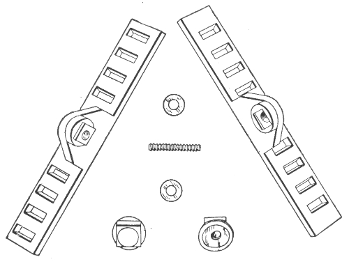
Figs. 1,171 to 1,177.—"National" battery bolt connector and parts. The connector is
equipped with grease cups and antimonious lead washers.
Disconnecting Cells.—The best method of disconnecting
cells assembled with pillar straps, for the purpose of replacing
broken jars, cleaning or taking out of commission, is to use a
five-eighth inch twist drill, in a carpenter's brace, boring down
into the top of the pillar about one-quarter inch; then pull off
the connector sleeve from the pillar. By following this method,
all parts may be used again.
When cells are equipped with top straps, the straps should be cut
with a sharp knife or chisel midway between the cells.
Taking Batteries out of Commission.—Where a battery
is to be out of service for several months, and it is not convenient
to give it the freshening charge every two weeks, it should be
taken out of commission.
COMPARISON OF THE BAUMÉ AND SPECIFIC GRAVITY
SCALES AT 60° FAHRENHEIT
Degrees
Baume |
Specific
Gravity |
Degrees
Baume |
Specific
Gravity |
Degrees
Baume |
Specific
Gravity |
Degrees
Baume |
Specific
Gravity |
| 0 |
1.000 |
17 |
1.133 |
34 |
1.306 |
51 |
1.542 |
| 1 |
1.007 |
18 |
1.142 |
35 |
1.318 |
52 |
1.559 |
| 2 |
1.014 |
19 |
1.151 |
36 |
1.330 |
53 |
1.576 |
| 3 |
1.021 |
20 |
1.160 |
37 |
1.342 |
54 |
1.593 |
| 4 |
1.028 |
21 |
1.169 |
38 |
1.355 |
55 |
1.611 |
| 5 |
1.036 |
22 |
1.179 |
39 |
1.368 |
56 |
1.629 |
| 6 |
1.043 |
23 |
1.188 |
40 |
1.381 |
57 |
1.648 |
| 7 |
1.051 |
24 |
1.198 |
41 |
1.394 |
58 |
1.666 |
| 8 |
1.058 |
25 |
1.208 |
42 |
1.408 |
59 |
1.686 |
| 9 |
1.066 |
26 |
1.218 |
43 |
1.421 |
60 |
1.707 |
| 10 |
1.074 |
27 |
1.229 |
44 |
1.436 |
61 |
1.726 |
| 11 |
1.082 |
28 |
1.239 |
45 |
1.450 |
62 |
1.747 |
| 12 |
1.090 |
29 |
1.250 |
46 |
1.465 |
63 |
1.768 |
| 13 |
1.098 |
30 |
1.261 |
47 |
1.479 |
64 |
1.790 |
| 14 |
1.107 |
31 |
1.272 |
48 |
1.495 |
65 |
1.812 |
| 15 |
1.115 |
32 |
1.283 |
49 |
1.510 |
66 |
1.835 |
| 16 |
1.124 |
33 |
1.295 |
50 |
1.526 |
NOTE.—The characteristic properties of concentrated sulphuric acid are very marked.
Its freedom from odor, oily appearance, and its great weight, distinguish it from other liquids.
The pure concentrated commercial acid has a density which usually reaches 1.842, and its
boiling point is about 640° F. The absolutely pure acid is perfectly colorless, but usually
even that used in laboratories has a peculiar grayish color, due to slight traces of organic
matter. Sulphuric acid is exceedingly hydroscopic, and when exposed to the air it rapidly
increases in bulk, owing to absorption of atmospheric moisture.
NOTE.—Clamps not made of metal similar to that of the connecting strips, frequently
give trouble from the galvanic action due to the contact of dissimilar metals in the presence of
moisture which causes the destruction of either the connecting strip or the clamp. Such
troubles can be avoided by placing a thin strip of sheet zinc between the lead strip and the
clamp. Under these circumstances the zinc will crumble away, and can be replaced without
much inconvenience and very little expense, while the clamps and connecting strips will remain
uninjured.
Strength of Dilute Sulphuric Acid
of
Different Densities at 59° Fahr.
Per cent.
of
Sulphuric Acid |
Specific
Gravity |
Per cent.
of
Sulphuric Acid |
Specific
Gravity |
| 100 |
1.842 |
23 |
1.167 |
| 40 |
1.306 |
22 |
1.159 |
| 31 |
1.231 |
21 |
1.151 |
| 30 |
1.223 |
20 |
1.144 |
| 29 |
1.215 |
19 |
1.136 |
| 28 |
1.206 |
18 |
1.129 |
| 27 |
1.198 |
17 |
1.121 |
| 26 |
1.190 |
16 |
1.116 |
| 25 |
1.172 |
15 |
1.106 |
| 24 |
1.174 |
14 |
1.098 |
Ques. Describe the method of taking a battery out of
commission.
Ans. The battery is charged in the usual manner, until the
specific gravity of the electrolyte of every cell has stopped rising
over a period of one hour (if there be any low cells, due to short
circuits or other cause, they should be put in condition before
the charge is started, so that they will receive the full benefit
of it). The cells may now be disconnected and covers and
elements removed from the jars, (if sealed, the compound is
loosened with a hot putty knife). The elements are placed on
their sides with the plates slightly spread apart at the bottom, the
separators withdrawn, and the positive and negative groups
pulled apart. The electrolyte is washed off with a gentle
stream of water and the plates allowed to drain and dry.7
The positive plates are ready to be put away. When dry, the
negatives are completely immersed in electrolyte (of about 1.275
specific gravity), and allowed to soak for three or four hours.
The jars may be used for this purpose. After rinsing and
drying, they are ready to be put away; wash also the rubber
separators.
Wood separators, after having been in service, will not stand much
handling and had better be thrown away. If it be thought worth while
to keep them, they must be immersed in water or weak electrolyte, and
in re-assembling, the electrolyte must be put into the cells immediately,
as wet wood separators must not stand exposed to the air.
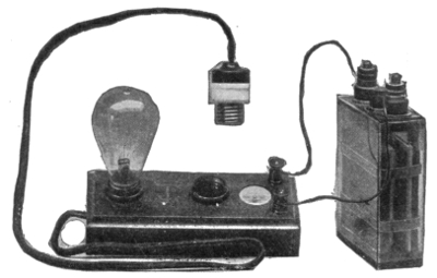
Fig. 1,178.—The "Witham" charging board, for charging from any electric outlet on a direct
current system. The instrument shows the direction of the current, and the candle
power of the lamps used as resistance indicates approximately the strength of the current
passing. Operation: From any convenient electric light fitting remove one of the lamps,
replacing it by the plug attached to the flexible cord. Screw the lamp into one of the
sockets on the charging board. Connect a wire to each binding post, and before joining
up to the battery, hold the ends of the two wires together. The lamp will then light
up and the indicator needle will point to that binding post which must be connected to
the positive (+) terminal of the battery. The other binding post must, of course, be
connected to the negative (-) of the battery. The charging current can be increased
by inserting another lamp into the second socket on the charging board and by using
lamps of higher candle power. If, when the lamp lights up, the indicator needle do not
point to one of the binding posts, but retain its position midway, then the current is an
alternating one and will not charge the battery.
Ques. What precaution should be taken with the jars?
Ans. They should be thoroughly cleaned with fresh water,
no sediment being allowed to remain.
Putting Batteries into Commission.—When re-assembling
a battery, it should be treated in the same manner as if it were
new and the regular instructions for assembling and putting a
new battery into commission followed.
Cleaning Jars.—The jars should be thoroughly cleaned with
fresh water, no sediment being allowed to remain.
Table of Voltage Change as Affected by Discharge Rate8
| 8 |
hour |
rate |
.05 |
volt |
| 6 |
" |
" |
.065 |
" |
| 4 |
" |
" |
.09 |
" |
| 3 |
" |
" |
.11 |
" |
| 2 |
" |
" |
.14 |
" |
| 1½ |
" |
" |
.18 |
" |
| 1 |
" |
" |
.21 |
" |
Condensed Rules for the Proper Care of Batteries.—The
following general instructions should be followed in the care and
maintenance of batteries:
1. A battery must always be charged with "direct" current and in
the right direction.
2. Be careful to charge at the proper rates and to give the right
amount of charge; do not undercharge or overcharge to an excessive
degree.
3. Do not bring a naked flame near the battery while charging or immediately
afterwards.
4. Do not overdischarge.
5. Do not allow the battery to stand completely discharged.
6. Voltage readings should be taken only when the battery is charging
or discharging; if taken when the battery is standing idle they are of
little or no value.
7. Do not allow the battery temperature to exceed 110° Fahr.
8. Keep the electrolyte at the proper height above the top of the
plates and at the proper specific gravity. Use only pure water to replace
loss by evaporation. In preparing the electrolyte never pour water into
the acid.
9. Keep the cells free from dirt and all foreign substances, both solid
and liquid.
10. Keep the battery and all connections clean; keep all bolted connections
tight.
11. If there be lack of capacity in a battery, due to low cells, do not
delay in locating and bringing them back to condition.
12. Do not allow sediment to get up to the plates.