An electric motor is just the reverse of a dynamo; it is a
machine for converting electrical energy into mechanical energy.
The electrical energy delivered by the dynamo must be
obtained from a steam engine, gas engine, or other power;
the mechanical energy obtained from the motor comes from the
energy of the current flowing through its armature.
Ques. What is the construction of a motor?
Ans. It is constructed in the same manner as a dynamo.
Any machine that can be used as a dynamo will, when supplied with
electrical power, run as a motor, and conversely, a motor when driven
by mechanical power, will supply electrical energy to the circuit connected
to it. Dynamos and motors, therefore, are convertible machines,
and the differences that are found in practice are largely mechanical;
they arise chiefly from the conditions under which the motor must work.
Hence, the study of the motor begins with a knowledge of the dynamo,
and accordingly the student should understand thoroughly all the
fundamental principles of the dynamo, as already given, before proceeding
further with the study of the motor.
Principles of the Motor.—All the early attempts to introduce
motors failed, chiefly because the law of the conservation
of energy was not fully recognized. This law states that energy
can neither be created nor destroyed.
Early experimenters discovered, by placing a galvanometer
in a circuit with a motor and battery, that, when the motor was
running, the battery was unable to force through the wires so strong
a current as that which flowed when the motor was standing still.
Moreover, the faster the motor ran, the weaker did the current
become.

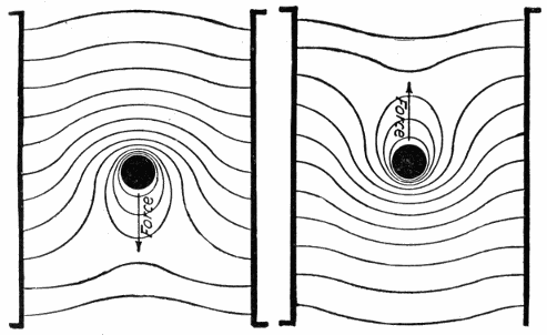
Fig. 389.—Conductor, lying in a magnetic field and carrying no current; the field is not
distorted whether the conductor be at rest or in motion.
Ques. Why does less current flow when the motor is
running than when standing still?
Ans. Because the motor, on account of its rotation acts as a
dynamo and thus tends to set up in the circuit a reverse electromotive
force, that is, an electromotive force in opposite direction
to the current which is driving the motor.
Ques. What is the real driving force which causes the
armature of a motor to rotate?
Ans. The propelling drag, that is, the drag which the magnetic
field exerts upon the armature wires through which the current
is flowing, or in the case of deeply toothed cores, upon the protruding
teeth.
The Propelling Drag.—In fig. 389 is shown the condition
which prevails when a conductor carrying no current is placed
in a uniform magnetic field. The magnetic lines pass straight
from one pole to the other. The field is not distorted whether
the conductor be at rest or in motion, so long as there is no
flow of current. This represents the condition in the air gap
of a motor or dynamo, when no current is flowing in the armature.
Ques. What happens when a current flows in the
conductor of fig. 389.
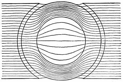
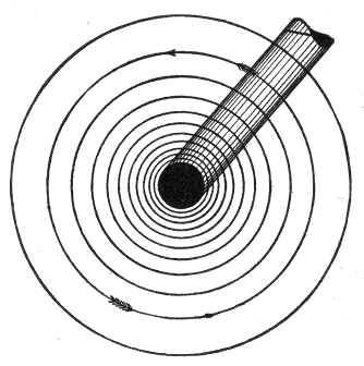
Ans. It sets up a magnetic field of its own as shown in fig.
390.
Ques. What is the effect of this magnetic field?
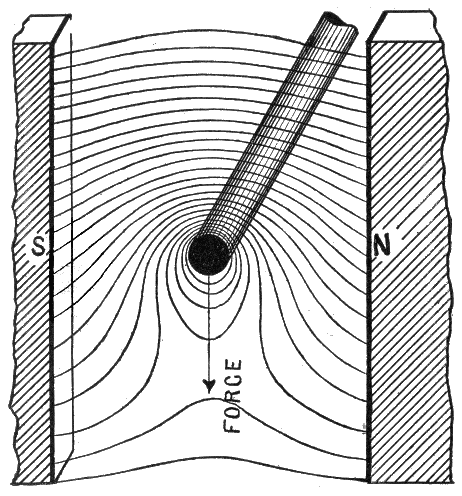
Ans. It distorts the original field (fig. 389) in which the
conductor lies, making the magnetic lines denser on one side
and less dense on the other as in fig. 390.
Ques. What is the nature of these distorted magnetic
lines?
Ans. They tend to shorten themselves to their original form
of straight lines.
Ques. What effect has this on the conductor?
Ans. It produces a force on the conductor tending to push
it in the direction indicated by the arrow, fig. 390.
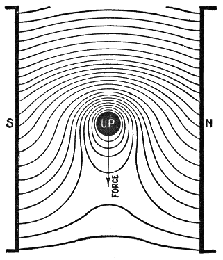
Fig. 390.—Conductor carrying a current in a magnetic field. The current flowing in the
conductor sets up a magnetic field which distorts the original field as shown, making
the magnetic lines denser on one side and less dense on the other. This results in a force
upon the wire, which, in the case of a dynamo (fig. 391) opposes its movement, and
which forms the propelling drag in the case of a motor (fig. 392).
The distorted magnetic lines may be regarded as so many rubber
bands tending to straighten themselves; The result then is clearly to
force the conductor in the direction indicated.
According to Lenz' law, the direction of the current in the armature
of a dynamo is such as to oppose the motion producing it. When the
armature of a dynamo is rotated, the bending of the lines of force of
the main magnetic field due to armature reaction acts as a drag against
the motion of the armature. Armature reaction increases with the
increase of the armature current. Therefore, the effect of the drag
increases with the increase of load and requires an additional expenditure
of power to drive the armature.
In a motor, the direction of the actuating current is the reverse of
that of the armature current of a dynamo, consequently, the armature
reaction which constitutes a drag, acting against rotation of the armature of
a dynamo, becomes a pull in the direction of rotation of the armature of
a motor and constitutes its real turning effect or torque which is used
at the pulley to do mechanical work. The greater the load applied
to the motor, the greater will be the amount of current taken from the
supply mains, and consequently, the greater the torque.
Figs. 391 and 392.—Action of the magnetic force in a dynamo and motor. In the first
instance, according to Lenz' law, the direction of the current induced in the wire is such
as to oppose the motion producing it. In the operation of a motor, the current supplied
in flowing through the armature winding distorts the field and thus produces rotation.
In the figures, the direction of the force is clearly indicated by remembering that the
distorted lines of force act like rubber bands tending to straighten and shorten themselves.
Ques. What are the essential requirements of construction
in a motor?
Ans. They are: 1, a magnetic field, 2, conductors placed
perpendicular to the field, and 3, provision for motion, of the
conductors across the field in a direction perpendicular to both
themselves and the field.
The Reverse Electromotive Force.—When an electric current
flows through some portion of a circuit in which there is an
electromotive force, the current will there either receive or give
up energy, according to whether the electromotive force acts
with or against the current.
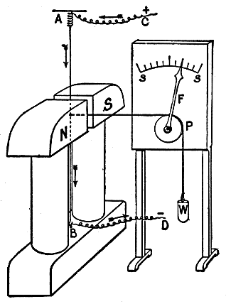
Fig. 393.—Force exerted on a current carrying conductor placed across a magnetic field. Let
N, S, be the pole pieces of an ordinary electromagnet, having their faces flat and with
only a narrow air gap between. In this gap is stretched the vertical copper wire A B,
kept taut by a strong spring at A; current can be passed into the wire from the leads C
and D. Attached to the wire in the middle of the gap is a horizontal cord passing over
a pulley P and kept taut by a weight W; the pulley carries a pointer F which moves in
front of a scale s s. If the electromagnet be now excited and have the polarity indicated,
it will be found that on passing a strong current down the wire, the index F moves toward
the right, showing a similar movement in the wire. The index returns to zero when the
current in the wire ceases, and moves in the opposite direction if the current in the
wire be reversed and sent up instead of down. The experiment can be further varied
by reversing the magnetizing current of the electromagnet.
This is illustrated in fig. 395, which represents a circuit in which
there is a dynamo and a motor. Each is rotating clockwise, and
accordingly, each generates an electromotive force tending upward
from the lower to the upper brush. In both cases the upper brush is
positive. In the dynamo, however, where energy is being supplied
to the circuit, the electromotive force is in the same direction as the
current, and in the motor, where work is being done, the electromotive
force is in the reverse direction to that of the dynamo.
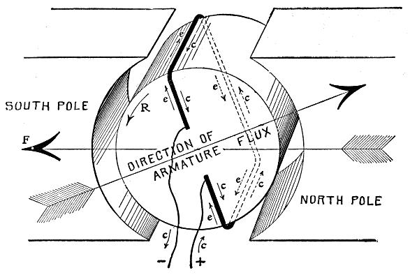
Fig. 394.—Showing relative directions of armature current and reverse electromotive force of a
motor. When a motor is in operation, the wires around the periphery of its armature
"cut" the magnetic lines of force produced by the field magnet exactly as in the case of
the dynamo. Consequently, an electromotive force is induced in each wire, as in the
dynamo armature. This induced electromotive force is in opposition to the flow of current
due to the electromotive force of the supply circuit, and tends, therefore, to keep
down the flow of current. The figure shows a single loop of wire, on the armature core
connected directly to the source of electricity. With current flowing in the loop in the
direction indicated by the arrows marked c, a magnetic field is set up in the direction
indicated by the large arrow marked "direction of armature flux." With the field magnet
energized so as to produce a field in the direction indicated by the large arrow F, the
reaction between the two fields will turn the armature core in the direction indicated by
the arrow R. As the core turns, the upper wire of the loop will cut the flux under the south
pole of the field magnet, and the other side of the loop will cut the flux under the north
pole. The result will be the induction of a reverse electromotive force in the loop, the
direction being indicated by the small arrows marked e. The actual flow of current in the
armature is that due to the difference between the impressed and reverse voltage;
the latter is proportional to the speed of the armature, the number of armature
wires and the strength of the magnetic field in the air gaps between the armature and
the pole faces. The speed of a motor supplied with current at constant voltage varies
directly with the reverse electromotive force, also with other conditions fixed, the
stronger the field, the slower the speed. Weakening the field will increase the speed up
to the point where the increase in reverse electromotive force due to the increased speed
cuts down the armature current below the value necessary to give the requisite pull at the
armature periphery. When this point is reached, any weakening of the field will reduce
the speed of the armature. The pull or torque of a motor armature is directly proportional
to the strength of the magnetic field, and to the strength of the armature current,
the number of armature inductors being fixed. In a field of constant strength, therefore,
the pull of the armature depends on the amount of current passing through the winding.
The torque must be just sufficient to overcome the load; if in excess, the speed will
increase until the increase of the reverse electromotive force reduces the current and the
increase of speed increases the load to the point of equilibrium between load and torque.
If the torque be insufficient for the load, the speed will diminish until equilibrium is
established, assuming the motor is running on constant voltage circuit.
Ques. Describe similar conditions which prevail in the
operation of a dynamo.
Ans. When no current is being generated by the dynamo,
little power is required to drive it, but when the external circuit
is closed and current is forced through it against more or less
resistance, work is being done, hence more power is required.
In other words, there is an opposition to the mechanical force
applied at the pulley which is proportional to the electric power
delivered by the dynamo. An opposing reaction or reverse force
then is set up in a dynamo when it does work.
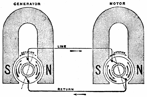
Fig. 395.—Circuit with generator and motor. Whenever current flows through some portion
of a circuit in which there is an electromotive force, the current will there either receive
or give up energy according to whether the electromotive force acts with the current
or against it. In the figure, the generator and motor are rotating clockwise, and hence
each generates an electromotive force tending upwards from the lower brush to the higher.
In each case the upper brush is the positive one. In the dynamo, where energy is
being supplied to the circuit, the electromotive force is in the same direction as the current,
while in the motor where work is being done and energy is leaving the circuit, the electromotive
force is in a direction which opposes the current.
Ques. In the operation of a motor what is the nature
of the reverse electromotive force?
Ans. It is proportional to the velocity of rotation, the
strength of the magnets, and to the number and arrangement of
the wires on the armature, that is, the reverse voltage depends
on the rate at which the lines of force are cut.
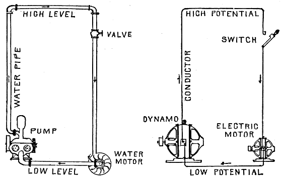
Figs. 396 and 397.—Water and electric circuits. Diagrams showing comparison between water
motor and electric motor.
| In the diagrams: |
| The pump |
corresponds |
to |
the |
dynamo. |
| The high level pipe |
" |
" |
" |
positive conductor. |
| The low level pipe |
" |
" |
" |
negative conductor. |
| The valve |
" |
" |
" |
switch. |
| The water motor |
" |
" |
" |
electric motor. |
| The water pressure (called head) |
" |
" |
" |
electric pressure (called voltage). |
| The flow in gallons per minute |
" |
" |
" |
amperes. |
| The size of pipe |
" |
" |
" |
size of conductor. |
| The foot pounds |
" |
" |
" |
watts. |
The greater the difference between the height of the two pipes the higher the pressure,
and the greater the difference between the pressures of the two conductors the higher the
voltage. The larger the diameter of the pipes the less resistance is offered to the flow of
water, and the larger the diameter of the conductors the less resistance is offered to the
flow of electricity. The more water required by the water wheel, the more power is
required to drive the pump. The more electricity required by the motor the more power
is required to drive the generator.
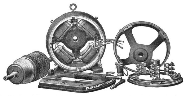
Fig. 398.—Fairbanks-Morse standard TR type motor. This type is built in the smaller sizes and the design is
such that the motor can be installed upon the floor, wall or ceiling, the bearing yokes being attached to the
frame by four equally spaced bolts so that they can be turned to provide for proper operation of the oiling
devices in either position. A substantial base is provided with a thrust screw for adjusting the belt tension.
This base has clamping bolts which permit adjusting the position of the motor while suspended. There is
a cast ring type frame having steel side pieces which press firmly together, the steel laminations making up
the pole pieces. The field coils armature, and armature coils are illustrated in detail in figs. 399 to 401. The
commutator bars are of drawn copper, insulated with mica. The lugs which extend outward from the bars
to receive the lead wires from the armature windings are formed in one piece with the bars, and are of the
full width of the bars with the insulator extending outward between them, so that when assembled
a solid flange is formed to receive the armature connections. Self-oiling bearings are provided and the location
of the bearing sleeves in the housing is adjustable so that the armature may be centered in the magnetic field.
The brush rigging is carried on a skeleton rocker supported in a groove, turned in the edge of the frame. The
brush holders are of the box type with independently adjustable tension spring for each. Standard shunt
windings are for 115, 230 and 550 volts. The compound wound motors operate at approximately the same full
load speeds as the shunt wound, but the no load speeds will be about 20 per cent. higher than the full load
speeds. They have, however, the ability to exert a more powerful starting effort than shunt motors without
drawing such a heavy current from the line, and are, therefore, especially adapted for driving apparatus
that has to be frequently started and stopped under load and where close speed regulation is not required.
Ques. Describe an experiment which shows the existence
of a reverse electromotive force in a motor.
Ans. The apparatus required consists of a small motor,
battery, and ammeter. They should be connected in one circuit
and the deflection of the ammeter observed when the armature
is held stationary, and when it rotates with various loads.
In an experiment of this kind made on a motor with separately excited
magnets, the following figures were obtained:
Apparently, if the motor had been helped on to run at 261½ revolutions
per minute, the current would have been reduced to zero. In
the last result obtained, the current of 5.1 amperes was absorbed in
driving the armature against its own friction at the speed of 195 revolutions
per minute.
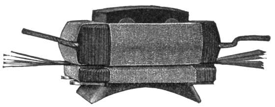
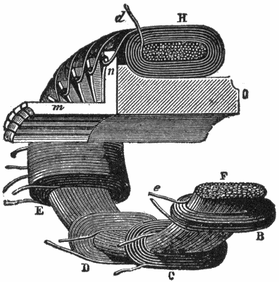
Fig. 399.—Fairbanks-Morse field coil and pole piece. The field coils are wound upon iron
forms, each layer treated with insulating compound. Afterward they are removed from
the forms and baked hard and dry and finally wrapped with insulating materials; all
but the three smaller sizes are wrapped with a protecting cord. The series and shunt coils
of the compound winding here shown are wound separately, the smaller one being the
series coil and the larger the shunt coil.
Ques. Explain the action of the current supplied to a
motor for its operation.
Ans. The motor current passing through the field magnets
polarizes them and establishes a magnetic field, and entering
the armature, polarizes its core in such a way that the positive
pole of the core is away from the negative pole of the magnetic
field, and the negative pole is away from the positive pole of
the magnetic field. The magnetic repulsions and attractions
thus created cause the armature to rotate in a position of magnetic
equilibrium or so as to bring its positive and negative poles
opposite the negative and positive poles respectively of the
magnetic field. It is evident that unless suitable means were
provided to reverse the polarity of the armature core at the
instant it reached the position of the magnetic equilibrium, the
armature would not rotate any further. The construction is such
that the polarity of the armature core, or the direction of the
current in the armature coils is reversed at the proper instant
automatically by the commutator, thus giving continuous
rotation.
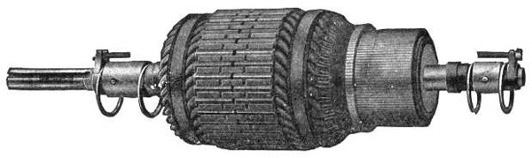
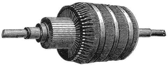
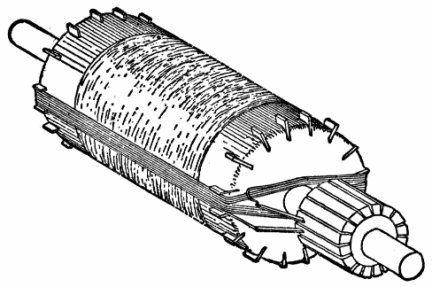
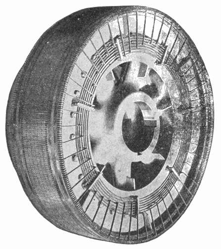
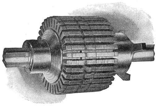
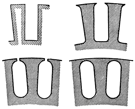
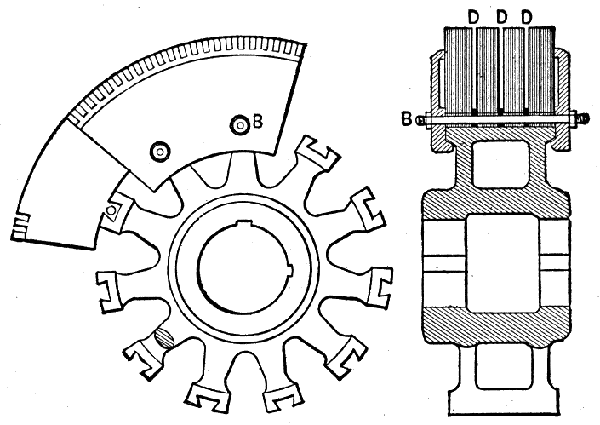
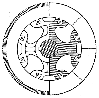
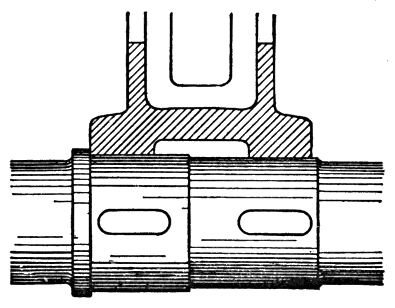
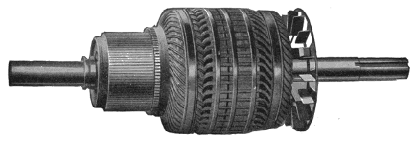
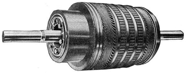
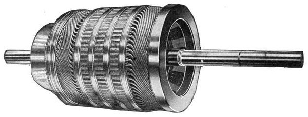
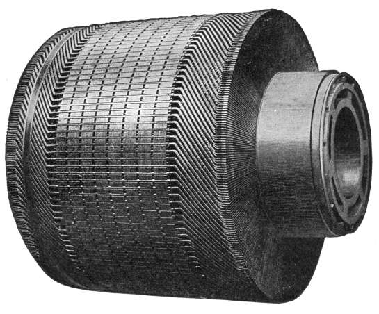
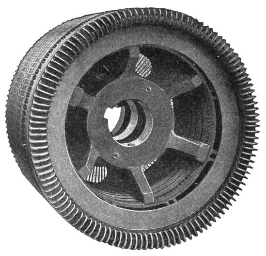
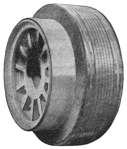
Fig. 400.—Fairbanks-Morse armature for 7½ H. P., 1300 R. P. M., TR type motor. The
armature core is built up of thin sheet steel laminations with notches in the circumference,
which, when the discs are placed together, form grooves or slots to receive the armature
coils. The armature cores for the larger machines are mounted on a cast iron spider, which
also carries the commutator, making the two parts entirely self-contained, and with this
construction, it is possible to remove the armature shaft, without disturbing the core,
commutator or windings. Cores of all sizes are provided with ventilating spaces, running
from the surface to the central opening of the core, so that air is drawn through the core
and blown out over the windings by the revolution of the armature.
Direction of Rotation of Motors.—In the case of either
a motor, or a dynamo used as a motor, the direction in which the
armature will rotate is easily found by the left hand rule, as
illustrated in fig. 411, when the polarity of the field magnets and
the direction of currents through the armature are known.
Ques. How may the rotation of a motor be reversed?
Ans. By reversing either the current through the fields, or
the current through the armature.
Ques. What will happen if both currents be reversed?
Ans. The motor will run in the same direction as before.
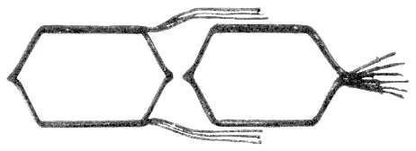
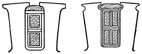
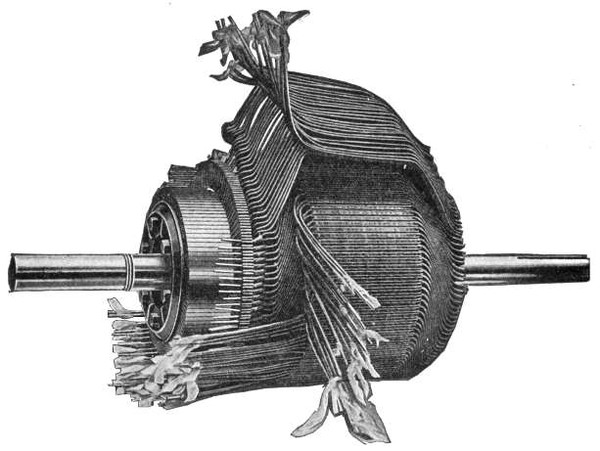
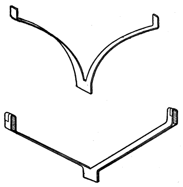
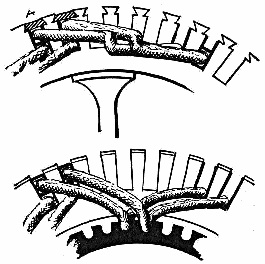
Fig. 401.—Fairbanks-Morse wire wound armature coils. These coils are form wound and are
thoroughly insulated and baked before assembling in the slots. Material of great mechanical
strength as well as high insulating value is used, and the coils are subjected to dippings
in insulating compound and to bakings, thus driving out all moisture and making a coil
which is practically waterproof and which will withstand rough handling. These coils,
when completed, are placed in the slots, where they are retained by bands on the three
smaller sizes and by hardwood wedges on the larger sizes.
Ques. What is the effect of supplying current to a
series dynamo?
Ans. It will run in a direction opposite to its motion as a
dynamo.
Ques. What is the result of reversing the direction of
current at the terminals of a series motor?
Ans. It will not change its direction of rotation, since the
current still flows through the armature in the same direction
as through the field.
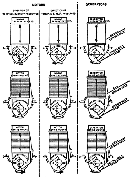
Figs. 402 to 410.—Diagrams showing relative direction of rotation of motors and dynamos.
From figs. 391 and 392, it is seen that the direction of the current in a motor armature
must be such as will increase, by the flux it produces, the intensity at the leading polar
edge and decrease the intensity at the trailing polar edge. In a dynamo, the armature
has to be moved by mechanical force, against a magnetic force, hence the leading polar
edge is weakened, while the trailing edge is strengthened. The magnetomotive force
in a motor armature is, therefore, opposed to the direction of that in a generator armature,
when the direction of rotation and the direction of the field magnetomotive force are
the same. Upon this depends all the relations existing between the direction of rotation
of a machine when acting as a motor or as a dynamo.
Ques. What is the behavior of a shunt dynamo when
used as a motor?
Ans. Its direction of rotation remains unchanged.
Ques. Why is this?
Ans. Because if the connections be such that the current
supplied will flow through the armature in the same direction
as when the machine is used as a dynamo, the current through
the field will be reversed, since the field windings are in parallel
with the brushes.
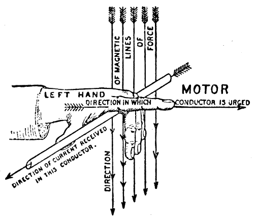
Fig. 411.—The "left hand rule" for direction of motion in motors. Place the left hand, as
shown, so that the thumb points in the direction of the current, the 3rd, 4th and 5th fingers in
the direction of the lines of force, then will the 2nd or forefinger, at right angles to the others,
point in the direction in which the conductor is urged.
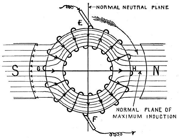
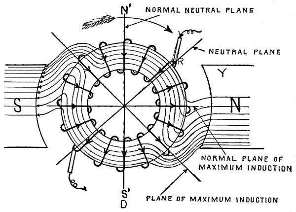
Armature Reaction in Motors.—In the operation of a
motor the reaction between the armature and field magnets
distorts the field in a similar manner as in the operation
of a dynamo. A current supplied from an outside source magnetizes
the armature of a motor and transforms it into an
electromagnet, whose poles would lie nearly at right angles to
the line joining the pole pieces, were it not for the fact that
negative lead must be given to the brushes.
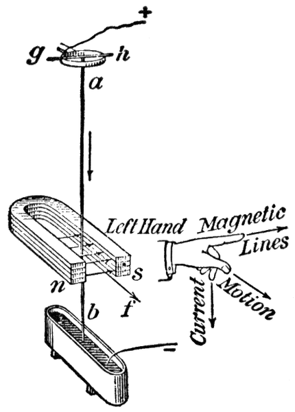
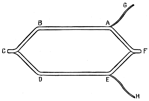
Fig. 412.—Principle of the electric motor as illustrated by experiment showing effect of a
magnetic field on a wire carrying an electric current. Let a vertical wire ab be rigidly
attached to a horizontal wire gh, and let the latter be supported by a ring or other metallic
support as shown, so that ab is free to oscillate about gh as an axis. Let the lower end of
ab dip into a trough of mercury. When a magnet is held in the position shown and a
current from a cell is sent through the wire as indicated, the wire will move in the direction
shown by the arrow f, that is, at right angles to the direction of the lines of magnetic force.
Let the direction of the current in the wire be reversed, then the direction of the force
acting on the wire will be found to be reversed also. The conclusion is that a wire carrying
a current in a magnetic field tends to move in a direction at right angles both to the direction
of the field and to the direction of the current. The relation between the direction of the
magnetic lines, the direction of the current, and the direction of the force, is often remembered
by means of the following rule, known as the motor rule, and which differs from the
dynamo rule only in that it is applied to the fingers of the left hand instead of to those of
the right. Let the forefinger of the left hand point in the direction of the magnetic lines of force
and the middle finger in the direction of the current sent through the wire, then will the thumb,
at right angles to the other two fingers, point in the direction in which the wire is urged.
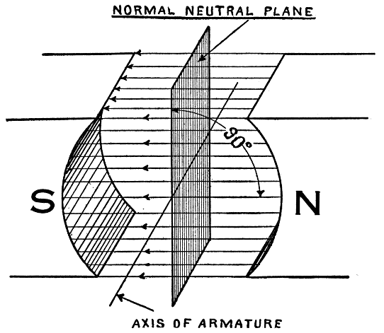
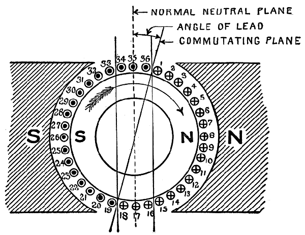
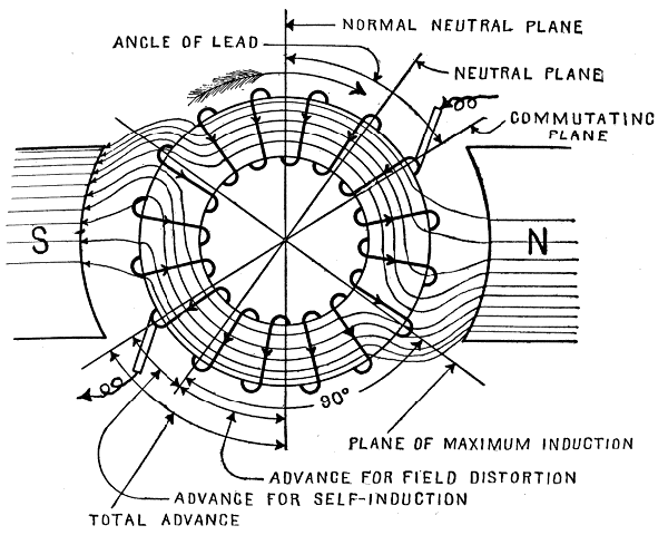
Negative lead is the amount of backward advance of the brushes
against the direction of the rotation of the armature, measured in
degrees from the neutral plane.
If the brushes be given positive lead, that is, placed in advance of the
neutral plane in the direction of rotation, the cross magnetizing force is converted
into one that tends to increase that of the field magnet, while
if they be given negative lead, it tends to demagnetize the field magnet.
Since with positive lead the armature polarity strengthens that of
the field magnet, it is possible, disregarding sparking, to operate a motor
without any other means being taken to magnetize the field magnets,
because the armature will induce a pole in the field magnet and then
attract itself towards this induced pole.
Ques. What effect has the cross magnetizing force on
the field?
Ans. It tends to shift the field around in a direction opposite
to that of the rotation.
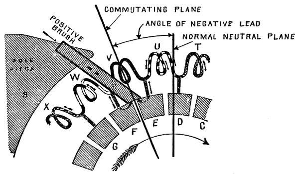
Fig. 413.—Current commutation in a motor. Considering the coil W which is ascending,
current is flowing through it from the top brush, while it is itself the seat of an electromotive
force that tends to stop or reverse its current. The condition for sparkless commutation
requires that during the interval the coil is short circuited by the brush, the
coil should be passing through a field that is not only sufficiently strong but one that
tends to reverse the direction of its current. The coil is already in such a field, hence,
commutation must take place before it passes put of this field. To accomplish this the
brushes must be shifted backward, that is, given negative lead, to overcome sparking.
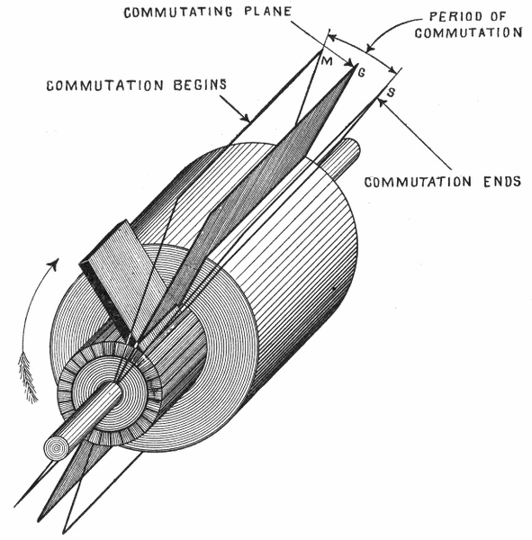
In other words, the commutating plane must be shifted back of the neutral plane in a
motor instead of being placed in advance as in a dynamo.
Ques. What are the conditions of minimum sparking?
Ans. The same conditions must obtain as in a dynamo,
that is, the current in the coil undergoing commutation must be
brought to rest and started again in the opposite direction.
This involves that while the coil is short circuited by the brush,
it should be passing through a field that tends to reverse the
direction of the current. Since the coil is already in such a
field, the act of commutation must take place before it passes
out of this field. Accordingly, a negative lead must be given
the brushes.
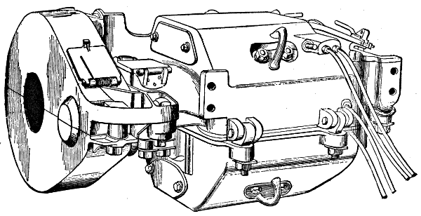
Fig. 414.—Railway motor. This type of motor, since it must operate under cars, has taken
on the peculiar form under which it is most familiar. As illustrated, the case is of such
shape that compactness and water proofing are secured, and the means of attachment
to the car axle and support from the axle and truck frame are provided.
Method of Starting a Motor.—Although motors and dynamos
are practically similar in general construction and either
one of them will act as the other when suitably traversed by
an electric current, there are certain differences between the
connections and accessories of a machine operated as generator
and one employed as a motor. For instance, when a machine
is operated as a dynamo, it is first driven up to speed until it
has excited itself to the right pressure, and then it is connected
to the circuit; but when a machine is used as a motor it will
not start until it has been connected to the circuit, and this
must not be done until the proper precautions have been taken
to ensure that the current, which will pass through it when so
connected, will not be excessive and thereby result in serious
injury to the motor. For this reason a rheostat or variable
resistance, commonly called a starting box is usually inserted
in the armature circuit of a motor to prevent an undue rush
of current before the motor attains its speed, and subsequently
the speed is regulated by the cutting in or out of the circuit
of certain extra resistances which constitute the controller used
on a series motor requiring variable torque at variable speed, as
in the case of elevator or electric traction service.
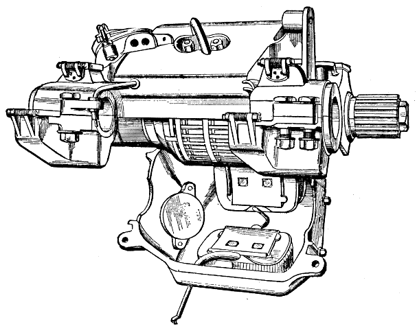
Fig. 415.—View of railway motor, open. The frame is of cast steel for lightness, and which
serves as magnetic circuit and protecting case. It is circular or octagonal in form except
in very large motors. Four short magnets project from the case. The armature is
large in order to secure the required torque. It is always series wound, requiring two
brushes. The brush holders are mounted upon a frame of insulating material which is
attached to the upper half of the case. The brushes are adjustable radially, but usually
it is not necessary to provide for shifting as they remain in the neutral plane. In motors
which receive so little attention as these, special attention must be given to the design
of devices for keeping oil and grease out of the case. These would injure the insulation
of the coils and produce sparking at the commutator. Oil rings are, therefore, placed
on the shaft, and these discharge into chambers connected to the oil wells or allow the oil
to overflow on the track. The bearings are made self-oiling or self-greasing by means of
rings or wicks and will run for weeks without attention.
Classes of Motor.—Motors are classified in the same manner
as dynamos. The fields may be either bipolar or multipolar,
and with respect to the type of armature winding employed,
motors are classed as:
1. Series wound;
2. Shunt wound;
3. Compound wound.
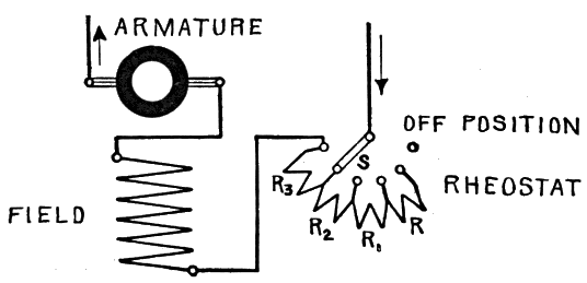
Fig. 416.—Series motor connections. A series motor on a constant voltage circuit does not
have a constant field strength, and does not run at uniform speed. If the load be taken
off it will run at excessive speed. To start the motor, the circuit is completed through
a variable resistance or rheostat by moving the switch S so that the resistances R, R1,
R2, R3, are gradually cut out of the circuit. To stop, the switch S is moved back to its
"off" position.
Series Motors.—A series motor is one in which the field
magnet coils, consisting of a few turns of thick wire, are connected
in series with the armature so that the whole current
supplied to the motor passes through the field coils as well as
the armature. Fig. 416 is a diagram of a series motor showing
the connections and rheostat.
Ques. What are the characteristics of a series motor?
Ans. The field strength increases with the current, since the
latter flows through the magnet coils. If the motor be run on a
constant voltage circuit, with light load, it will run at a very
high speed; again, if the motor be loaded heavily, the speed will
be much less than before.
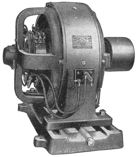
Fig. 417.—General Electric type CL-B motor for slow and moderate speeds. It is of multipolar
construction, having six pole pieces. The advantages of slow speed machinery
are generally understood, and in motors the additional outlay to secure slow speeds is
warranted, inasmuch as it results in diminished wear and friction losses in gearing, belting,
bearings, and commutators, and decreased brush renewals. The comparatively slow
speeds of these motors are of importance in that they permit belting or gearing the motors
directly to ordinary slow speed line shafting without employing intermediate counter
shafting. When motors are geared to heavy duty machines, it is considered better
practice to supply an outboard bearing to take up the additional strain that would otherwise
be put on the gearing and bearing.
Ques. For what kinds of service are series motors
unsuited?
Ans. Series motors should not be employed where the load
may be entirely removed because they would attain a dangerous
speed. They should not be used for driving by means of belts,
because a sudden release of the load due to a mishap to the belt
would cause the motor to "run away."
Very small series motors may be used with belts since their comparatively
large frictional resistance represents an appreciable load,
restraining the motor from reaching a dangerous speed.
Ques. For what service are series motors adapted?
Ans. For gear drive.
In the case of a sudden release of the load the gears provide some load
on account of the frictional resistance of the gear teeth.
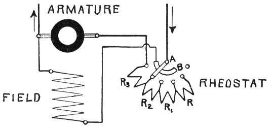
Fig. 418.—Shunt motor connections. A shunt motor runs at constant speed on a constant
voltage circuit. In connecting the motor in circuit, the field coils must be placed in
circuit first, so that there is a certain amount of field strength to produce rotation of the
armature and thus prevent excessive current through the armature. If the field magnets
were not put in the circuit first, the armature, at rest on receiving current, would
probably burn out, because it is of low resistance, and would take practically all the
current supplied, especially since no reverse voltage is generated in the armature at rest.
The method of starting is shown in the illustration. To start, the switch is closed, and
the rheostat lever pushed over so as to make contact with A and B, thus first exciting
the magnets. On further movement of the lever, the rheostat resistances R, R1, R2,
R3, etc., are gradually cut out as the speed increases, until finally all the resistance
coils are cut out. To stop, the lever is brought back to its original position.
Ques. What advantage is obtained with series motors
with respect to the connections?
Ans. A single wire only proceeds from the rheostat to the
motor, so that, with the return wire, only two wires are required.
Ques. For what service are series motors specially
adapted?
Ans. Series motors are used principally for electric railways,
trolleys, and electric vehicles, and similar purposes where an
attendant is always at hand to regulate or control the speed.
They are also used on series arc light circuits in which the current
is of constant strength. Very small motors are generally provided
with series windings.
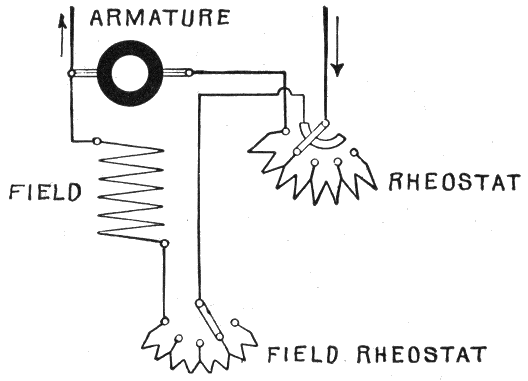
Fig. 419.—Speed regulation of a shunt motor. The speed of a motor depends on the voltage
of the current supplied and the field strength. The motor tends to rotate so fast as to
produce a reverse voltage nearly equal to that supplied to the brushes; hence, the speed
varies with the voltage supplied. By decreasing this voltage then, the speed is decreased.
Accordingly, the speed may be reduced by inserting, by means of a rheostat, a resistance
in series with the motor. By inserting this resistance in the field circuit, the voltage at
the terminals of the motor is lowered, thus giving the condition necessary to reduce
the speed. The arrangement for speed regulation shown in the figure includes a starting
regulator and a shunt regulator.
Shunt Motors.—A shunt motor may be defined as one in
which the field coils are wound with many turns of comparatively
fine wire, connected in parallel with the brushes. The
current then is offered two paths: one through the armature,
and one through the field coils.
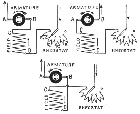
Figs. 420 to 422.—Reversing the direction of rotation of a series motor. Fig. 420 shows the connections for counter clockwise
rotation. The motor may be reversed: 1, by allowing the current to flow in its original direction (from D to C) in the
field magnet coils, and altering the direction of the armature current by changing the two connections on the brushes A and B,
thus connecting C to A and B to the return wire as in fig. 421, or 2, by leaving the direction of the current in the armature in
its original direction, and reversing that of the field current, as in fig. 422. If the wires leading to the rheostat and motor
directly, were reversed there would be no reversal of the motor, because by so doing, both the armature and field magnet
currents would be reversed.
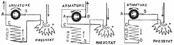
Figs. 423 to 425.—Reversing the direction of rotation of a shunt motor. Fig. 423 shows the connections for counter clockwise
rotation. The motor may be reversed: 1, by allowing the current to flow in its original direction through the field magnet
coils (from D to C), and reversing its direction through the armature (from A to B) as in fig. 424, or 2, by allowing the armature
current to flow in its original direction (from B to A) and reversing the current through the field coils (from C to D) as in fig. 425.
Ques. What may be said with respect to the speed
of a shunt motor?
Ans. It is practically constant with varying loads.
The variation of speed ranges from 1/10 to 5 per cent., except in the
case of small motors, in which the variation may be much greater.
Ques. How should a shunt motor be started?
Ans. To properly start the machine, the field coils must be
fully excited.
It is, therefore, necessary to switch the magnet coils immediately on
to the voltage of supply, while a variable resistance must be provided
for the armature circuit. To get both connections at the same time,
rheostats for shunt motors are arranged as shown in fig. 418.
Influence of Brush Position on Speed.—In the case of
a shunt motor supplied with current at constant pressure, the
speed is a minimum when the brushes are in the neutral plane,
and the effect of giving the brushes either positive or negative
lead is to increase the speed, especially with little or no load.
Ques. Why does the speed increase?
Ans. When the brushes are shifted from the neutral plane,
the reverse voltage between the brushes is decreased, speed
remaining unchanged. Accordingly, the pressure in the supply
mains forces an increased current through the armature thus
producing an increased armature pull which causes the speed
to increase until the reverse voltage reaches a value sufficiently
large to reduce the current to the value required to supply the
necessary driving torque.
Compound Motors.—This type of motor has to a certain
extent, the merits of the series motor without its disadvantages,
and is adapted to a variety of service. If the current flow in
the same direction through both of the field windings, then the
effect of the series coil strengthens that of the shunt coil; this
strengthening is greater, the larger the armature current.
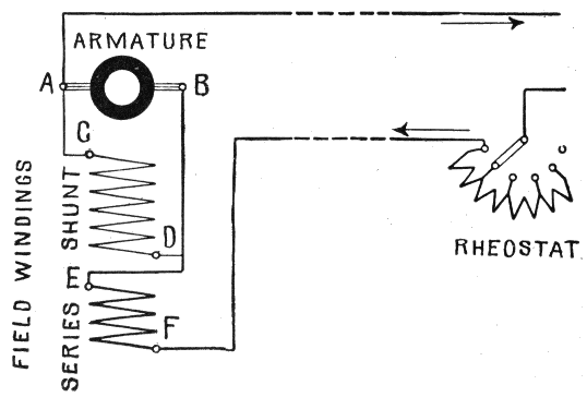
Fig. 426.—Compound motor connections for starting from a distant point. A compound
winding may be used on motors for many different purposes. If the current flow in the
same direction through both windings, then the effect of the series coil strengthens that of
the shunt coil. This strengthening increases with the load. Thus the motor gets, at
increasing load, a stronger magnetic field, and will therefore, if the voltage remain constant
run slower than before. Accordingly, for a given current, the starting power will be
greater than that of a shunt motor. With a decreasing load the motor will run faster.
The compound motor has, to a certain extent, the merits of the series motor without its
disadvantages. By means of compound motors the starting at a distance with only two
mains may be effected, just as in the case of the series motor. The connections are shown
in the diagram. If the motor be regarded as being without the shunt coil, then it is connected
up exactly as the series motor in fig. 416. The current coming from the starter
enters the series coil at F, flows through the series coil and leaves it at E, flowing from
there to the armature brush B, through the armature to brush A, and from there through
the second main back to the generator. The shunt winding is connected directly with
the armature brushes A and B, and gets at starting, therefore, only a very small voltage,
hence its field is nearly ineffective. But on account of the series winding, the motor starts
as a series motor. Obviously such a motor will not develop a very large starting power
like a real series motor, for, on account of the large space occupied by the shunt coils,
there is less space available for the series coils than with a series motor. A compound
motor may, however, even with this arrangement, be easily started, provided the load
on starting be not too heavy. When once running the armature will produce a reverse
voltage and the shunt coil will be supplied with nearly the full terminal voltage.
Ques. Mention some characteristics of the compound
motor.
Ans. Since it is a combination of the shunt and series
types, it partakes of the properties of both. The series winding
gives it strong torque at starting (though not as strong as
in the series motor), while the presence of the shunt winding
prevents excessive speed. The speed is practically constant
under all loads within the capacity of the machine.
Ques. Describe the connections for starting a compound
motor at a distance.
Ans. Control at a distance can be effected with only two
wires, just as in the case of a series motor. In the diagram fig.
426, the current coming from the rheostat enters the series coil
at F, and leaves it at E, thence it flows to the armature brush B,
through armature to brush A, and from here back to the dynamo.
The shunt winding, which is connected across the brushes, gets
a very small voltage at starting and is accordingly very ineffective.
The motor then starts as a series motor. The starting
effect is smaller than in a series motor because of the fewer turns
in the series winding, most of the available space being occupied
by the shunt coils.
Power of a Motor.—The word "power" is defined as the rate
at which work is done, and is expressed as the quotient of the work
divided by the time in which it is done, thus:
The difference between power and work should be clearly
understood.
Work is the overcoming of resistance through a certain distance.
It is measured by the product of the resistance into the space
through which it is overcome, thus:
For instance, in lifting a body from the earth against the attraction
of gravity, the resistance is the weight of the body, and the space, the
height to which the body is raised, the product of the two being the work
done.
The unit of work is the foot pound, which is the amount of work
done in overcoming a pressure or weight equal to one pound through
one foot of space.
The unit of power is the horse power which is equal to 33,000
foot pounds of work per minute, that is:
The unit of power was established by James Watt as the power of a
strong London draught horse to do work during a short interval, and
used by him to measure the power of his steam engines.
In order to measure the mechanical power of a motor, it is
necessary to first determine the following three factors upon
which the power developed depends:
1. Pull of the armature, in pounds;
2. Distance in feet at which the pull acts from the center of
the shaft;
3. Revolutions per minute.
Example.—If the armature pull of a motor having a two foot pulley,
be such that a weight of 500 lbs. attached to the rim, is just balanced,
and the speed be 1,000 revolutions per minute, what is the horse
power?
Here, the distance that the pull acts from the center of the shaft
is one foot, hence for each revolution the resistance of 500 pounds is
overcome through a distance equal to the circumference of the pulley or
π × diameter = 3.1416 x 2 = 6.2832 feet.
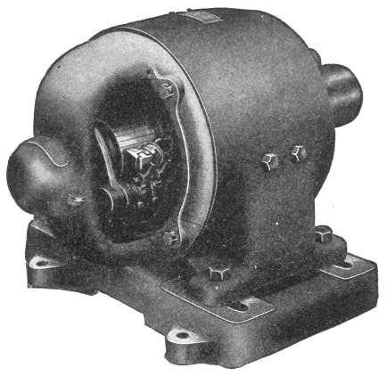
Fig. 427.—General Electric type CQ Motor. These
motors range in capacity from 1/6 to 20 horse power. The small sizes
are bipolar, and the larger sizes have four poles. For installations where
the motor is exposed to dust, mechanical injury or moisture, it may be
partially or entirely enclosed by means of hand hole covers. The standard
voltages are 115, 230 and 550.
The work done in one minute is expressed by the following
equation:
Hence, the power developed is
3,141,600 ÷ 33,000 = 95.2 horse power.
Ques. What is "brake" horse power?
Ans. The net horse power developed by a machine at its
shaft or pulley; so called because a form of brake is applied to
the pulley to determine the power.
Ques. Describe the apparatus used in making a brake
test.
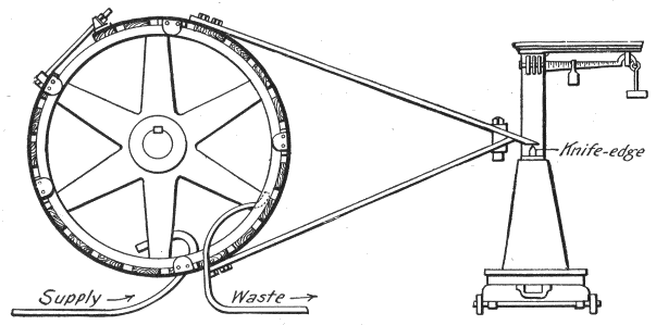
Fig. 428.—Prony brake for determining brake horse power. It consists of a friction band
ring which may be placed around a pulley or fly wheel, and attached to a lever bearing
upon the platform of a weighing scale in such a manner that the friction between the
surfaces in contact will tend to rotate the arm in the direction in which the shaft revolves.
This thrust is resisted and measured in pounds by the scale. In setting up the brake
the distance between the center of the shaft and point of contact (knife edge) with the
scales must be accurately measured, the knife edge being placed at the same elevation as
the center of the shaft. An internal channel permits the circulation of water around the
interior of the rim as shown, to prevent overheating.
Ans. Tests of this kind are usually made with a Prony brake
as shown in fig. 428. It consists of a band of rope or strip iron—the
latter is the arrangement shown—to which are fastened a
number of wooden blocks, several carrying shoulders to prevent
the contrivance from slipping off the wheel rim. The brake
band is drawn tight, as shown, so that the blocks press against
the surface all around. The brake thus formed is restrained
from revolving with the pulley by two arms attached near the
top and bottom centers of the wheels, and joined at the opposite
ends to form a lever which bears upon an ordinary platform
scale, a suitable leg or block being arranged to keep its end level
with the center of the shaft. By this arrangement the amount
of friction between the brake band and the revolving wheel is
weighed upon the scales. Since the brake fits tightly enough
to be carried around by the wheel, but for the arms bearing upon
the scale, the amount of frictional power exerted by the wheel
in turning free within the blocks may be transmitted and measured,
just as would be the case were a machinery load attached,
instead of a friction brake.
Ques. Why must the point of contact of the brake with
the scales be level with the center of the shaft?
Ans. In order to determine the force acting at right angles
to the line joining the point of contact and center of the shaft.
Ques. What is the distance between the center of the
shaft and point of contact with the scales called?
Ans. The lever arm.
Ques. What three quantities must be determined in
a test in order to calculate the brake horse power?
Ans. The lever arm, the force exerted on the scales, and the
revolutions per minute.
Ques. How is brake horse power calculated?
Ans. From the following formula:
in which
| B. H. P. |
= brake horse power; |
| L |
= lever arm, in feet; |
| N |
= number of revolutions per minute; |
| W |
= force in pounds at end of lever arm as measured by scales. |
Example—In making a brake test on a motor, the lever arm of the
brake is 3 ft., and the reading of the scales is 30 lbs. When the motor is
running 1,000 revolutions per minute, what is the brake horse power?
Substituting the given values in the formula,
Now, if the voltmeter and ammeter readings be 220 and 65
respectively, what is the efficiency of the motor at this load?
The amount of power absorbed by the motor, or in other
words, the input is
and since the output is 17.1 horse power,
Speed of a Motor.—The normal speed at which any motor
will run is such that the sum of the reverse electromotive force
and the drop in the armature will be exactly equal to the electromotive
force applied at the brushes. The drop in the armature
is the difference between the applied voltage and the reverse
voltage.
Mutual Relations of Motor Torque and Speed.—The
character of the work to be done not only determines the condition
of the motor torque and speed required, but also the
suitability of a particular type of motor for a given service.
There are three general classes of work performed by motors, and
these require the following conditions of torque and speed:
1. Constant torque at variable speed;
Suitable for driving cranes, hoists, and elevators, etc., where the
load is constant and has to be moved at varying rates of speed.
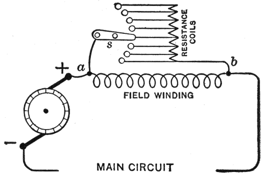
Fig. 429.—Two path method of speed regulation of series motor. A rheostat is connected
in shunt to the field coils as shown. The current passing from a to b divides between the
magnet coils and the rheostat coils; the higher the resistance of the rheostat the less
current passes through it, and the more through the magnet coils, hence the stronger the
field magnet.
2. Variable torque at constant speed;
Suitable for driving line shafting in machine shops, which must
run at constant speed regardless of variations of torque due to variations
in the number of machines in operation at a time, or the
character of work being performed.
3. Variable torque at variable speed.
Suitable for electric railway work. For example: when a car is
started, the torque is at its maximum value and the speed zero, but
as the car gains headway, the torque decreases and the speed
increases.
Speed Regulation of Motors.—The speed of motors connected
to constant voltage circuits is usually regulated by the
two following methods:
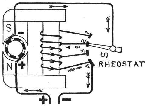
Fig. 430.—Variable field method of speed regulation of series motor. The field winding is
divided into a number of sections with leads connecting with switch contact points as
illustrated. The speed then is regulated by cutting in or out of the circuit sections of the
field winding thus varying the strength of the field.
1. By inserting resistances in the armature circuit of a shunt
wound motor;
2. By varying the strength of the field of a series motor.
The first method is sufficiently explained under fig. 418 and
the second method is illustrated in fig. 430. The controller
switch S is so arranged that a greater or lesser number of field
coils can be inserted in the field circuit. When the switch arm is
on point 1, the motor current will flow through all the field
windings, and the strength of the field will be at its maximum.
When the switch arm is moved so as to successively occupy
positions 2, 3, and 4, thus cutting out of circuit a greater and
greater number of field coils the strength of the field will be
gradually decreased until practically all of the motor current
is led or wired through the armature. Under these conditions,
when the field of a motor is at its maximum strength, the motor
torque will be at a maximum for any given strength of current,
and the reverse electromotive force will also be at a maximum
for any given speed, therefore, when the field strength is increased
the speed will decrease and vice versa.
Ques. What results are obtained by this method of
regulation?
Ans. The speed of a series motor may be nearly doubled,
that is, if the lowest permissible speed of the motor be 250
revolutions per minute it can be readily increased to 500 revolutions
per minute by changing the field coil connections from
series to parallel. It is on this account, as much as on their
powerful starting torque, that series motors have been until
recently almost exclusively employed for electric traction purposes.
Series Parallel Controller.—When two motors are used in
electric railway work, their armatures are connected in series
with each other and an extra resistance which prevents the
passage of an excessive current through the armature before
the motor starts. As the speed of the car increases, the extra
resistance is gradually cut out of circuit and the field winding
connections changed from series to parallel by means of a series
parallel controller, which finally connects each motor directly
across the supply mains, or between the trolley line and the
track or ground return.
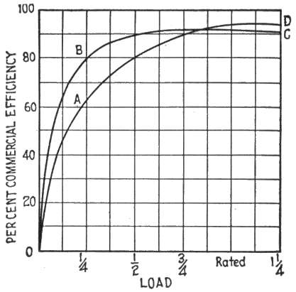
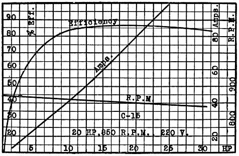
Efficiency of a Motor.—The commercial efficiency of a motor
is the ratio of the output to the input. As a rule, the power
developed by a motor increases as the reverse voltage generated
by it decreases, until this voltage equals one-half of the voltage
applied at the brushes. After this point is reached, the power
developed by the motor decreases with the decrease of the
reverse voltage. Therefore, a motor performs the largest
amount of work when its reverse voltage is equal to one-half
the impressed voltage.
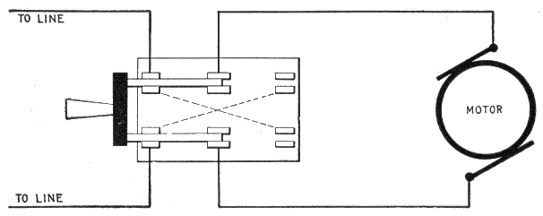
Fig. 431.—Double-throw, double-pole switch for reversing direction of rotation of a motor.
The direction of rotation can be reversed by changing the direction of current in either
the armature or the field coils. It is preferable, however, to reverse the direction of
rotation by changing the direction of current through the armature. The switch is wired
as shown, means of reversal being provided by running the wires as indicated by the
dotted lines.
The efficiency of a motor as just stated is the ratio of the
output to the input; this is equivalent to saying that the efficiency
of a motor is equal to the brake horse power divided by
the electrical horse power.
The electrical horse power is easily obtained by multiplying
the readings taken from volt meter and ammeter, which gives
the watts, and dividing the product by 746, the number of watts
per horse power. That is:
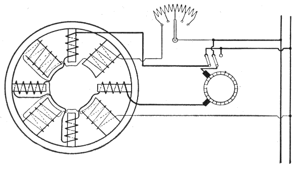
Fig. 432.—Wiring diagram, showing electrical connections between the armature, field, and
interpoles of an interpole motor. As the name implies, an interpole motor has in addition
to the main poles, a series of interpoles which are placed between the main poles,
and whose function is to assist in the reversal of the current under the brushes. They
provide a separate commutating field of a correct value at all loads and speeds, and their
windings are for this purpose connected in series with the armature. The proper functioning
of the interpoles is independent of the direction of rotation of the armature, also
of the load carried over the whole speed range. In an ordinary motor without interpoles,
commutation is assisted by a magnetic fringe emanating from the main poles,
but as the value of this fringe is altered by the load of the motor and by rheostatic field
weakening, if higher speeds be desired from such a machine, commutation becomes
imperfect and sparking results, making a readjustment of the brushes necessary.
Interpole Motors.—An interpole motor has in addition to
the main poles, a series of interpoles, placed between the main
poles. The object of these poles is to provide an auxiliary flux
or "commutating" field at the point where the armature coils
are short circuited by the brush.
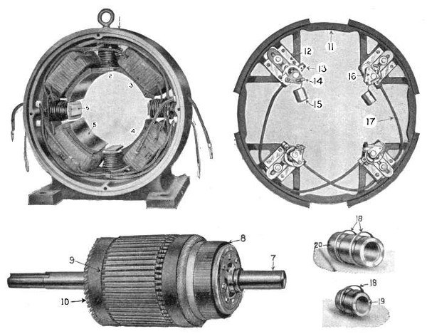
Figs. 433 to 437.—Parts of the type S interpole motor built by Electro Dynamic Co. They are as follows: 1. yoke—commutator
view; 2. interpole coil; 3. top R. H. main coil; 4. bottom R. H. main coil; 5. main pole; 6. interpole; 7.
armature shaft, R. H. bearing; 8. commutator; 9. armature wedge; 10. armature coil; 11. brush ring; 12. brush carrier
insulation; 13. brush carrier; 14. brush guard; 15. carbon brush; 16. brush holder; 17. cross connecting cable; 18. oil
ring; 19. commutator end bearing bushing; 20. pulley end bearing bushing.
Ques. What is the object of the commutating field
produced by the interpoles?
Ans. Its object is to assist commutation, that is, to help
reverse the current in each coil while short circuited by the
brush, and thus reduce sparking.
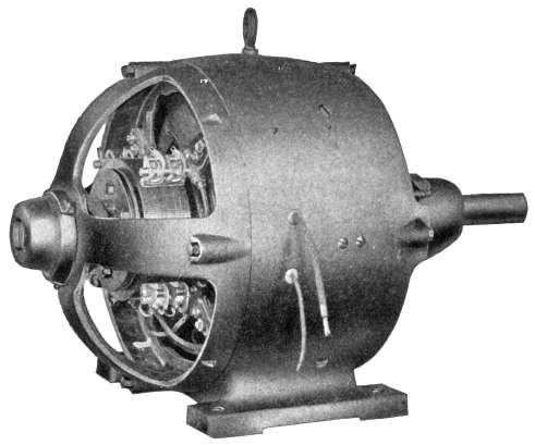
Fig. 438.—Interpole motor as built by the Electro Dynamic Co. This type of motor is
devised to prevent sparking at all loads by the use of interpole magnets, that is, small
magnets placed between the field magnets. The interpoles set up a field in a direction to
stop and reverse the current in the armature coils while they are short circuited by the
brushes.
Ques. What is the nature of the commutating field?
Ans. The excitation of the interpoles being produced by
series turns, the field will vary with the load, and will, if once
adjusted to give good commutation at any one load, keep the
same proportion for any other load, provided the iron parts of
the circuit be not too highly saturated.
Ques. State briefly how sparking is reduced or prevented
by the action of the interpoles.
Ans. Sparking is due to self-induction in the coil undergoing
commutation, which impedes the proper reversal of the current.
The action of the interpoles corrects this in that they set up a
field in a direction that causes a reversal of the current in the
coil while it is short circuited. Thus, the coil at the instant it
leaves the brush, is not an idle coil, but has a current flowing
in it in the right direction to prevent sparking.
Ques. Mention some of the claims made for interpole
motors.
Ans. Constant or adjustable speed, and momentary overloads
without sparking; constant brush position; operation at
adjustable speeds on standard supply circuits of 110, 220, and
500 volts; constant speed with variable load; reversal without
changing the position of the brushes.