The term power station is usually applied to any building
containing an installation of machinery for the conversion of energy
from one form into another form. There are three general classes of
station:
1. Central stations;
2. Sub-stations;
3. Isolated plants.
These may also be classified with respect to their function as
1. Generating stations;
2. Distributing stations;
3. Converting stations.
and with respect to the form of power used in generating
the electric current, generating stations may be classed as
1. Steam electric;
2. Hydro-electric;
3. Gas electric, etc.
Central Stations.—It must be evident that the general type
of central station to be adapted to a given case, that is to say, the
general character of the machinery to be installed depends upon the
kind of natural energy available for conversion into electrical
energy, and the character of the electrical energy required by the
consumers.
This gives rise to a further classification, as
1. Alternating current stations;
2. Direct current stations;
3. Alternating and
direct current stations.
The alternators or dynamos may be driven by steam
or water turbines, reciprocating engines, or gas engines, according to the
character of the natural energy available.
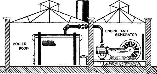
Fig. 2,705.—Elevation of small
station with direct drive, showing arrangement of the boiler and
engine, piping, etc.
Ques. Why is the reciprocating engine being largely replaced by
the steam turbine, especially for large units?
Ans. Because of its higher rotative speed, and absence of a
multiplicity of bearings which in the case of a high speed,
reciprocating engine must be maintained in close adjustment for the
proper operation of the engine.
The higher speed of rotation results in a more compact unit, desirable
for driving high frequency alternators.
Ques. Is the steam turbine more economical than a high duty
reciprocating engine?
Ans. No.
Location of Central Stations.—As a rule,
central stations should be so located that the average loss of voltage in
overcoming the resistance of the lines is a minimum, and this point
is located at the center of gravity of the system. In fig. 2,706
is shown a graphical method of locating this important spot.
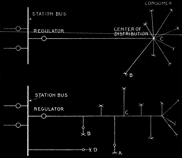
Fig. 2,706.—Diagram illustrating graphical method of
determining the center of gravity of a system in locating the
central station.
Suppose a rough canvass of prospective consumers in a district to be
supplied with electric light or power shows the principal loads to be
located at A, B, C, D, E, etc., and for simplicity assume that these
loads will be approximately equal, so that each may be denoted by 1
for example:
The relative locations of A, B, C, D, E, etc., should be
drawn to scale (say 1 inch to the 1,000 feet) after which the problem resolves
itself into finding the location of the station with respect to this scale.
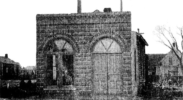
Fig. 2,707.—Exterior of central
station at Lewis, Ia.; example of very small station located in the
principal business section of a town. It also illustrates the use
of a direct connected gasoline electric set. The central station is
located on Main Street, which is the principal thoroughfare, and is
installed in a low one story building for which a mere nominal rental
charge is paid, the company having the option to buy the property
later at the value of the land plus the cost of the improvements and
simple interest on the same. To the front of an old frame building
about 16 feet by 28 feet has been built a neat, well lighted concrete
block room, about 16 feet by 16 feet, carrying the building to
the lot line and affording ample space for the generating set and
switchboards, and such desk room as is needed for the ordinary office
business of the company. In this room, which is finished in natural
pine with plastered walls, has been installed a standard General
Electric 25 kw. gasoline electric generating set consisting of a four
cylinder, four cycle, vertical water cooled, 43-54 H.P. gasoline
engine, direct connected to a three phase, 2,300 volt, 600 R.P.M.
alternator with a 125 volt exciter mounted on the same shaft and
in the same frame. With the generating set is a slate switchboard
panel equipped with three ammeters, one voltmeter, an instrument
plug switch for voltage indication, one single pole carbon break
switch, one automatic oil circuit breaker line switch and rheostats.
Instrument transformers are mounted above and back of the board. For
street lighting service a 4 kw. constant current transformer has
been installed, and with it a gray marble switchboard panel mounted
on iron frames and carrying an ammeter and a four point plug switch.
On a board near the generator set are mounted in convenient reach
suitable wrenches, spanners, and repair parts and tools. To cool the
engine cylinders five 6 × 8 steel tanks have been installed in the
old building, a pump on engine giving forced circulation.
The solution consists in first finding the center of gravity of
any two of the loads, such as those at A and B. Since each of these
is 1, they will together have the same effect on the system as the
resultant load of 1 and 1, or 2, located at their center of gravity,
this point being so chosen that the product of the loads by their
respective distances from this point will in both cases be equal.
The loads being equal in this case the distances must be equal in
order that the products be the same, so that the center of gravity of
A + B is at G, which point is midway between A and B.
Considering, next, the resultant load of 2 at G and the load of 1
at C, the resultant load at the center or gravity of these will be 3,
and this must be situated at a distance of two units from C and one
unit from G so that the distance 2 times the load 1 at C equals the
distance 1 times the load 2 at G. Having thus located the load 3 at
H, the same method is followed in finding the load 4 at I. Then in
like manner the resultant load 4 and the load 1 at E gives a load 5
at S.
The point S being the last to be determined represents, therefore,
the position of the center of gravity of the entire system, and
consequently the proper position of the plant in order to give the
minimum loss of voltage on the lines.
Ques. Is the center of gravity of the system, as obtained in
fig. 2,706, the proper location for the central
station?
Ans. It is very rarely the best location.
Ques. Why?
Ans. Other conditions, such as the price of land,
difficulty of obtaining water, facilities for delivery of coal and removal
of ashes, etc., may more than offset the minimum line losses and copper
cost due to locating the station at the center of gravity of the system.
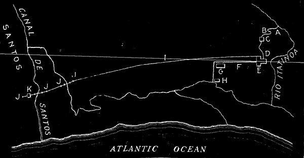
Fig. 2,708.—Map of Cia Docas de
Santos hydro-electric system; an example of station location remote
from the center of distribution. In the figure A is the intake; B,
flume; C, forebay; D, penstocks; E, power house; F, narrow gauge
railway; G, general store; H, point of debarkation; I, transmission
line; J, dead ends; K, sub-station. Santos, in the republic of
Brazil, is one of the great coffee shipping ports of the world, and
for the development of its water front has required an elaborate
system of quays. These have been developed by the Santos Dock
Company, which holds a concession for the whole water front. The
company, needing electric power for its own use, has developed a
system deriving its power from a point about thirty miles from the
city, where a small stream plunges down the sea coast from the
mountain range that runs along it. The engineers have estimated that
100,000 horse power can be obtained from this source.
Ques. How then should the station be located?
Ans. The more practical experience the designer has had, and the more
common sense he possesses, the better is he equipped to handle the
problem, as the solution is generally such that it cannot be worked
out by any rule of thumb method.
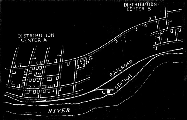
Fig. 2,709.—Station location.
The figure shows two distribution centers as a town A and suburb
B supplied with electricity from one station. For minimum cost of
copper the location of the station would be at G, the center of
gravity. However, it is very rarely that this is the best location.
For instance at C, land is cheaper than at G, and there is room
for future extension to the station, as shown by the dotted lines,
whereas at G, only enough land is available for present requirements.
Moreover C is near the railroad where coal may be obtained without
the expense of cartage, and being located at the river, the plant may
be run condensing thus effecting considerable economy. The conditions
may sometimes be such that any one of the advantages to be secured by
locating the station at C may more than offset the additional cost of
copper.
Ques. What are the general considerations with respect to the
price of land?
Ans. The cost for the station site may be so high as to necessitate
building or renting room at a considerable distance from the district
to be supplied.
If the price of land selected for the station be high, the running
expenses will be similarly affected, inasmuch as more interest must
then be paid on the capital invested.
The price or rent of real estate might also in certain instances
alter the proposed interior arrangement of the station, particularly
so in the case of a company with small capital operating in a city
where high prices prevail. In general, however, it may be stated
that whatever effect the price of real estate would have upon the
arrangement, operation and location of a central station it can quite
readily and accurately be determined in advance.
Ques. With respect to the cost of the land what should be especially
considered?
Ans. Room for the future extension of the plant.
Although such additional space need not be purchased at the time of
the original installation it is well, if possible, to make provision
whereby it can be obtained at a reasonable figure when desired. The
preliminary canvass of consumers will aid in deciding the amount of
space advisable to allow for future extensions; as a rule, however,
it is wise to count on the plant enlarging to not less than twice its
original size, as often the dimensions have to be increased four and
even six times those found sufficient at the beginning.
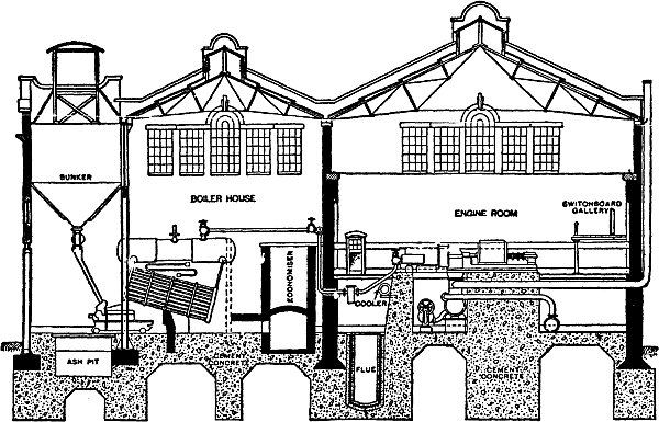
Fig. 2,710.—Section of the central
station or "electricity works" at Derby, showing boiler and engine
room and arrangement of bunkers, conveyor, ash pit, grates, boilers
(drum, heating surface and superheater), economizer, flue, turbines,
condenser pumps, etc.; also location of switchboard gallery and
system of piping.
Ques. What trouble is likely to be encountered with an illy
located plant after it is in operation?
Ans. It may be considered a nuisance by those residing in the vicinity,
occasioning many complaints.
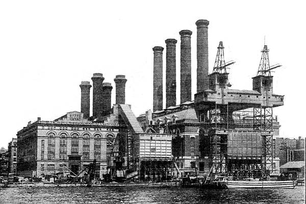
Fig. 2,711.—View of old and new
Waterside stations. The new station at the right has an all turbine
equipment of ten units, some Curtis and some Parsons machines, two
have a capacity of 14,000 kw., and the remaining eight are of 12,000
kw. each. The old Riverside station, seen at the left is described on page 1940.
Thus, if the plant be placed in a residential section of the
community the smoke, noise and vibration of the machines may become a
nuisance to the surrounding inhabitants, and eventually end in suits
for damage against the company responsible for the same. For these
and the other reasons just given a company is sometimes forced to
disregard entirely the location of a central station near the center
of gravity of the system, and build at a considerable distance;
such a proceeding would, if the distance be great, necessitate the
installation of a high pressure system.
There might, however, be certain local laws in force restricting the
use of high pressure currents on account of the danger resulting to
life, that would prevent this solution of the problem. In such cases
there could undoubtedly be found some site where the objections
previously noted would be tolerated; thus, there would naturally
be little objection to locating next to a stable, a brewery, or a
factory of any description.
Ques. Why is the matter of water supply important for a central station?
Ans. Because, in a steam driven plant, water is used in the
boilers for the production of steam by boiling, and if the engines
be of the condensing type it is also used in them for creating a
vacuum into which the exhaust steam passes so as to increase the
efficiency of the engine above what it would be if the exhaust steam
were obliged to discharge into the comparatively high pressure of the atmosphere.
The force of this will be apparent by
considering that the water consumption of the engine ordinarily is
from 15 to 25 lbs. of "feed water" per horse power per hour, and the
amount of "circulating water" required to maintain the vacuum is
about 25 to 30 times the feed water, and in the case of turbines with
their 28 or 29 inch vacuum, much more. For instance, a 1,000 horse
power plant running on 15 lbs. of feed water and 30 to 1 circulating
water would require (1,000 × 15) × (30 + 1) = 465,000 lbs. or 55,822
gals. per hour at full capacity.
Ques. Besides price what other considerations are important with
respect to water?
Ans. Its quality and the possibility of a scarcity of supply.
It is quite necessary that the water used in the boilers should be
as free as possible from impurities, so as to prevent the deposition
within them of any scale or sediments. The quality of the water used
for condensing purposes, however, is not quite so important, although
the purer it is the better.
If the plant is to be located in a city, the matter of water
supply need not generally be considered, because, as a rule, it can
be obtained from the waterworks; there will then, of course, be a
water tax to consider and this, if large, may warrant an effort being
made to obtain the water in some other way. In any event, however,
the possibility of a scarcity in the supply should be reduced to a
minimum.
If the plant be located in the country, some natural source
of water would be utilized unless the place be supplied with
waterworks, which is not generally the case. It is usual, however,
to find a stream, lake or pond in the vicinity, but if none such be
conveniently near, an artesian or other form of well must be sunk.
If abundance of water exist in the vicinity of the proposed
installation, not only would the location of the plant be governed
thereby, but the kind of power to be used for its operation would
depend thereon. Thus, if the quantity of the water were sufficient
throughout the entire year to supply the necessary power, water
wheels might be installed and used in place of boilers and steam
engines for driving the generators. The station would then, of
course, be situated close to the waterfall, regardless of the center
of gravity of the system.
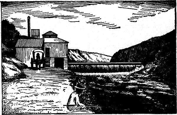
Fig. 2,712.—View illustrating the location
of a station as governed by the presence of a water falls. In such
cases the natural water power may be at a considerable distance from
the center of gravity of the distribution system because of the
saving in generation. In the case of long distance transmission very
high pressure may be used and a transformer step down sub-station
be located at or near the center of gravity of the system, thus
considerably reducing the cost of copper for the transmission line.
Ques. What should be noted with respect to the coal supply?
Ans. The facility for transporting the coal from the supply point to
the boiler room.
In this connection, an admirable location, other conditions
permitting, is adjacent to a railway line or water front so that
coal delivered by car or boat may be unloaded directly into the bins
supplying the boilers.
If the coal be brought by train, a side or branch track will usually
be found convenient, and this will usually render any carting of the
fuel entirely unnecessary.
In whatever way the coal is to be supplied, the liability of a
shortage due to traffic or navigation being closed at any time of the
year should be well looked into, as should also the facility for the
removal of ashes, before deciding upon the final location for the
plant.
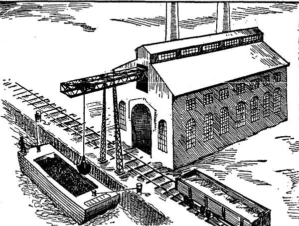
Fig. 2,713.—View of a station admirably
located with respect to transportation of the coal supply. As shown,
the coal may be obtained either by boat or rail, and with modern
machinery for conveying the coal to the interior of the station, the
transportation cost is reduced to a minimum.
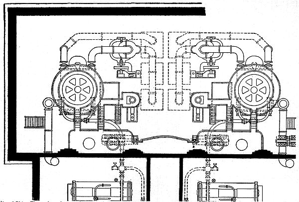
Fig. 2,714.—Floor plan of part of the
turbine central station erected by the Boston Edison Co., showing two
5,000 kw. Curtis steam turbines in place. The complete installation
contains twelve 5,000 kw. Curtis steam turbines, a sectional
elevation being shown in fig. 2,758, page 1,971.
Choice of System.—The chief considerations in the design
of a central station are economy and capacity. When the current
has to be transmitted long distances for either lighting or power
purposes, economy is attainable only by reducing the weight of the
copper conductors. This can be accomplished only by the use of the
high voltage currents obtainable from alternators.
Again, where the consumers are located within a radius of two
miles from the central station, thereby requiring a transmission
voltage of 550 volts or less, dynamos may be employed with greater
economy.
Alternating current possesses serious disadvantages for certain
important applications.
For instance, in operating electric railways and for lighting it
is often necessary to transmit direct current at 500 volts a distance
of five or ten miles. In such cases, the excessive drop cannot be
economically reduced by increasing the sizes of the line wire, while
a sufficient increase of the voltage would cause serious variations
under changes of load. Hence, it is common practice to employ some
form of auxiliary generator or booster, which when connected in
series with the feeder, automatically maintains the required pressure
in the most remote districts so long as the main generators continue
to furnish the normal or working voltage.
The advantage of a direct current installation in such cases over a
similar plant supplying alternating current line is the fact that a
storage battery may be used in connection with the former for taking
up the fluctuations of the current, thereby permitting the dynamo to
run with a less variable load, and consequently at higher efficiency.
Ques. Name some services requiring direct current.
Ans. Direct current is required for certain kinds of
electrolytic work, such as electro-plating, the electrical separation of metals,
etc., also the charging of storage batteries for electric automobiles.
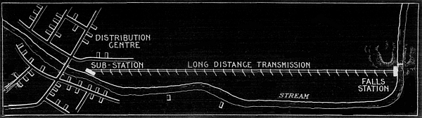
Fig. 2,715.—Example of central station
located remote from the distributing center and furnishing
alternating current at high pressure to a sub-station where the
current is passed through step down transformers and supplied at
moderate pressure to the distribution system. In some cases the
sub-station contains also converters supplying direct current for
battery charging, electro-plating, etc.
Ques. How is direct current supplied?
Ans. Sometimes the central station is equipped with suitable
apparatus for supplying both direct and alternating current. This may
be accomplished in several different ways: By installing both direct
and alternating current generators in the central station; by the use
of double current generators or dynamotors, from which direct current
may be taken from one side and alternating current from the other
side; or by installing, in the sub-station of an alternating current
central station, in addition to the transformers usually placed
therein, a rotary converter for changing or converting alternating
current into direct current.
Thus, it is evident that the character of a central station
will be governed to a great extent by the class of services to be
supplied.
An exception to this is where the entire output has to be
transmitted a long distance to the point of utilization.
In such cases a copper economy demands the use of high
tension alternating current, and its distribution to consumers may
be made directly by means of step down transformers mounted near by
or within the consumers' premises, or it may be transformed into low
voltage alternating current by a conveniently located sub-station.
Where the current is to be used chiefly for lighting and there
are only a few or no motors to be supplied, the choice between
direct current and alternating current will depend greatly upon the
size of the installation, direct current being preferable for small
installations and alternating current for large installations.
If the current is to be used primarily for operating machinery,
such as elevators, travelling cranes, machine tools and other devices of
a similar character, which have to be operated intermittently and at
varying speeds and loads, direct current is the more suitable; but if
the motors performing such work can be operated continuously for many
hours at a time under practically constant loads, as, for instance
in the general work of a pumping station, alternating current may be
employed with advantage.
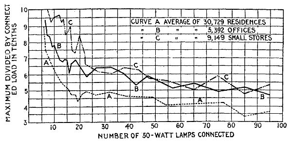
Fig. 2,716.—Diagram illustrating diversity
factor. By definition diversity factor = combined actual maximum
demand of a group of customers divided by the sum of their individual
maximum demands. Example, a customer has fifty (50) watt lamps and,
of course, the sum of the individual maximum demands of the lamps
is 2.5 kw. watts ("connected load"). The customer's maximum demand,
however, is 1.5 kw. Hence, the diversity
factor[A]
of the customer's group of lamps is 1.5 ÷ 2.5 = .6. In the diagram
the ordinates of the curves show the ratio maximum demand to
connected load for various kinds of electric lighting service in Chicago.
Size of Plant.—Before any definite calculation
can be made, or plans drawn, the engineer must determine the probable load.
This is usually ascertained in terms of the number and distances
of lamps that will be required, by making a thorough canvass of the
city or town, or that portion for which electrical energy is to be
supplied. The probable load that the station is to carry when it
begins operation, the nature of this load, and the probable rate of
increase are matters upon which the design and construction chiefly depend.
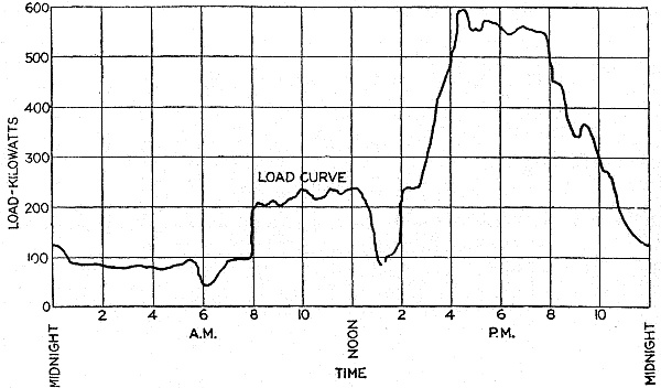
Fig. 2,717.—Load curve for one day.
Ques. What is the nature of the load carried by a central station?
Ans. It fluctuates with the time of day and also with the time of year.
Ques. How is a fluctuating load best represented?
Ans. Graphically, that is to say by means of a curve plotted on
coordinate paper of which ordinates represent load values and the
corresponding abscissæ time values, as in the accompanying curves.
What is the nature of a power load?
Ans. Where electricity is supplied for power purposes to a number of
factories, the load is fairly steady, dropping, of course, during
meal hours. In the case of traction, the average value of the load is
fairly steady but there are momentarily violent fluctuations due to
starting cars or trains.
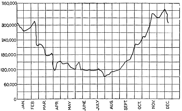
Fig. 2,718.—Load curve for one year.
Ques. What is the peak load?
Ans. The maximum load which has to be carried by the station at any
time of day or night as shown by the highest point of the load curve.
Ques. Define the load factor.
Ans. The machinery of the station evidently must be large
enough to carry the peak load, and therefore considerably in
excess of that required for the average demand. The ratio of
the average to the maximum load is called the load factor.
There are two kinds of load factor: the annual, and the daily.
The annual load factor is obtained as a percentage by multiplying the
number of units sold (per year) by 100, and dividing by the product
of the maximum load and the number of hours in the year. The daily
load factor is obtained by taking the figures for 24 hours instead of
a year.
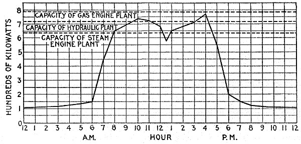
Fig. 2,719.—Load curve of plant supplying
power for the operation of motors in a manufacturing district. The
horizontal dotted lines show suitable power ratings. A properly
designed steam plant has a large overload capacity, a hydraulic
plant has a small overload capacity, and a gasoline engine plant has
no overload capacity. Accordingly, the peak of the load (maximum
load) may be 25 or 30 per cent. in excess of the rated capacity of a
steam plant, not more than 5 or 10 per cent. in excess of the rated
capacity of a hydraulic plant, not at all in excess of the rated
capacity of a gas engine plant.
Ques. What must be provided in addition to the machinery required
to supply the peak load?
Ans. Additional units must be installed for use in case of repairs or
break down of some of the other units.
EXAMPLE.—What would be the boiler horse power required to generate
5,000 kw. under the following conditions: Efficiency of generators
85%; efficiency of engines 90%; feed water of engines and auxiliaries
15 lbs. per I. H. P.; boiler pressure 175 lbs.; temperature of feed
water 150° Fahr? With a rate of combustion of 15 lbs. of coal per sq.
foot of grate per hour and an evaporation (from and at 212°) of
8 lbs. of water per lb. of coal, what area of grate would be required
and how much heating surface?
5,000 kw. = 5,000 ÷ .746 = 6,702 electrical horse power
To obtain this electrical horse power with alternators whose efficiency is 85% requires
6,702 ÷ .85 = 7,885 brake horse power at the engine
This, with mechanical efficiency of 90% is equivalent to
7,885 ÷ .9 = 8,761 indicated horse power
Since 15 lbs. of feed water are required for the engines and
auxiliaries per indicated horse power per hour, the total feed water
or evaporation required to generate 5,000 kw. is
15 × 8,761 = 131,415 lbs. per hour.
that is to say, the boilers must be of sufficient capacity to
generate 131,415 lbs. of steam per hour from water at a temperature
of 150° Fahr. This must be multiplied by the factor of evaporation
for steam at 175 lbs. pressure from feed water at a temperature of
150°, in order to get the equivalent evaporation "from and at 212°."
The formula for the factor of evaporation is
| |
H - h |
|
| factor of evaporation = |
——— |
(1) |
| |
965.7 |
|
in which
H = total heat of steam at the observed pressure;
h = total heat of feed water of the observed temperature;
965.7 = latent heat, of steam at atmospheric pressure.
Substituting in (1) values for the observed pressure
and temperature as obtained from the steam table
| |
1,197 - 118 |
|
| factor of evaporation = |
—————— = |
1.117 |
| |
965.7 |
|
for which the equivalent evaporation "from and at 212°" is
131,415 × 1.117 = 146,791 lbs. per hour
FACTORS OF EVAPORATION
Temp of
feed water. |
Steam Pressure by Gauge |
| Deg. Fahr. |
50 | 60 |
70 | 80 |
90 | 100 |
110 | 120 |
130 |
| 32 | 1.214 |
1.216 | 1.220 |
1.222 | 1.225 |
1.227 | 1.229 |
1.231 | 1.232 |
| 40 | 1.206 |
1.209 | 1.212 |
1.214 | 1.216 |
1.219 | 1.220 |
1.222 | 1.224 |
| 50 | 1.195 |
1.197 | 1.201 |
1.204 | 1.206 |
1.208 | 1.210 |
1.212 | 1.214 |
| 60 | 1.185 |
1.188 | 1.191 |
1.193 | 1.196 |
1.198 | 1.200 |
1.202 | 1.203 |
| 70 | 1.175 |
1.178 | 1.180 |
1.183 | 1.185 |
1.187 | 1.189 |
1.191 | 1.193 |
| 80 | 1.164 |
1.167 | 1.170 |
1.173 | 1.175 |
1.177 | 1.179 |
1.181 | 1.183 |
| 90 | 1.154 |
1.157 | 1.160 |
1.162 | 1.165 |
1.167 | 1.169 |
1.170 | 1.172 |
| 100 | 1.144 |
1.147 | 1.150 |
1.152 | 1.154 |
1.156 | 1.158 |
1.160 | 1.162 |
| 110 | 1.133 |
1.136 | 1.139 |
1.142 | 1.144 |
1.146 | 1.148 |
1.150 | 1.152 |
| 120 | 1.123 |
1.126 | 1.129 |
1.131 | 1.133 |
1.136 | 1.138 |
1.140 | 1.141 |
| 130 | 1.113 |
1.116 | 1.118 |
1.121 | 1.123 |
1.125 | 1.127 |
1.129 | 1.130 |
| 140 | 1.102 |
1.105 | 1.108 |
1.110 | 1.113 |
1.115 | 1.117 |
1.119 | 1.120 |
| 150 | 1.091 |
1.095 | 1.098 |
1.100 | 1.102 |
1.104 | 1.106 |
1.108 | 1.110 |
| 160 | 1.081 |
1.084 | 1.087 |
1.090 | 1.092 |
1.094 | 1.096 |
1.098 | 1.100 |
| 170 | 1.070 |
1.074 | 1.077 |
1.079 | 1.081 |
1.083 | 1.085 |
1.087 | 1.089 |
| 180 | 1.060 |
1.063 | 1.066 |
1.069 | 1.071 |
1.073 | 1.075 |
1.077 | 1.079 |
| 190 | 1.050 |
1.053 | 1.056 |
1.058 | 1.060 |
1.063 | 1.065 |
1.066 | 1.068 |
| 200 | 1.039 |
1.043 | 1.045 |
1.048 | 1.050 |
1.052 | 1.054 |
1.056 | 1.058 |
| 210 | 1.029 |
1.032 | 1.035 |
1.037 | 1.040 |
1.042 | 1.044 |
1.046 | 1.047 |
Temp of
feed water. |
Steam Pressure by Gauge |
| Deg. Fahr. |
140 | 150 |
160 | 170 |
180 | 190 |
200 | 210 |
220 |
| 32 | 1.234 |
1.236 | 1.237 |
1.239 | 1.240 |
1.241 | 1.243 |
1.244 | 1.245 |
| 40 | 1.226 |
1.227 | 1.229 |
1.230 | 1.232 |
1.233 | 1.234 |
1.236 | 1.237 |
| 50 | 1.215 |
1.217 | 1.218 |
1.220 | 1.221 |
1.223 | 1.224 |
1.225 | 1.226 |
| 60 | 1.205 |
1.207 | 1.208 |
1.210 | 1.211 |
1.212 | 1.214 |
1.215 | 1.216 |
| 70 | 1.194 |
1.196 | 1.197 |
1.199 | 1.200 |
1.202 | 1.203 |
1.205 | 1.206 |
| 80 | 1.184 |
1.186 | 1.187 |
1.189 | 1.190 |
1.192 | 1.193 |
1.194 | 1.195 |
| 90 | 1.174 |
1.176 | 1.177 |
1.179 | 1.180 |
1.181 | 1.183 |
1.184 | 1.185 |
| 100 | 1.164 |
1.165 | 1.167 |
1.168 | 1.170 |
1.171 | 1.172 |
1.174 | 1.175 |
| 110 | 1.153 |
1.155 | 1.156 |
1.158 | 1.159 |
1.160 | 1.162 |
1.163 | 1.164 |
| 120 | 1.143 |
1.145 | 1.146 |
1.147 | 1.149 |
1.150 | 1.151 |
1.153 | 1.154 |
| 130 | 1.132 |
1.134 | 1.136 |
1.137 | 1.138 |
1.140 | 1.141 |
1.142 | 1.144 |
| 140 | 1.122 |
1.124 | 1.125 |
1.127 | 1.128 |
1.129 | 1.131 |
1.132 | 1.133 |
| 150 | 1.111 |
1.113 | 1.115 |
1.116 | 1.118 |
1.119 | 1.120 |
1.121 | 1.123 |
| 160 | 1.101 |
1.103 | 1.104 |
1.106 | 1.107 |
1.108 | 1.110 |
1.111 | 1.112 |
| 170 | 1.091 |
1.092 | 1.094 |
1.095 | 1.097 |
1.098 | 1.099 |
1.101 | 1.102 |
| 180 | 1.080 |
1.082 | 1.083 |
1.085 | 1.086 |
1.088 | 1.089 |
1.090 | 1.091 |
| 190 | 1.070 |
1.071 | 1.073 |
1.074 | 1.076 |
1.077 | 1.078 |
1.080 | 1.081 |
| 200 | 1.059 |
1.061 | 1.063 |
1.064 | 1.065 |
1.067 | 1.068 |
1.069 | 1.071 |
| 210 | 1.049 |
1.051 | 1.052 |
1.053 | 1.055 |
1.056 | 1.057 |
1.059 | 1.060 |
Temp of
feed water. |
Steam Pressure by Gauge |
| Deg. Fahr. |
230 | 240 |
250 | 260 |
270 | 280 |
290 | 300 | |
| 32 | 1.246 |
1.247 | 1.248 |
1.250 | 1.251 |
1.252 | 1.253 |
1.254 | |
| 40 | 1.238 |
1.239 | 1.240 |
1.241 | 1.242 |
1.243 | 1.244 |
1.245 | |
| 50 | 1.228 |
1.229 | 1.230 |
1.231 | 1.232 |
1.233 | 1.234 |
1.235 | |
| 60 | 1.217 |
1.218 | 1.219 |
1.220 | 1.221 |
1.222 | 1.223 |
1.224 | |
| 70 | 1.207 |
1.208 | 1.209 |
1.210 | 1.211 |
1.212 | 1.213 |
1.214 | |
| 80 | 1.196 |
1.198 | 1.199 |
1.200 | 1.201 |
1.202 | 1.203 |
1.204 | |
| 90 | 1.186 |
1.187 | 1.188 |
1.189 | 1.190 |
1.191 | 1.192 |
1.193 | |
| 100 | 1.176 |
1.177 | 1.178 |
1.179 | 1.180 |
1.181 | 1.182 |
1.183 | |
| 110 | 1.166 |
1.167 | 1.168 |
1.169 | 1.170 |
1.171 | 1.172 |
1.173 | |
| 120 | 1.155 |
1.156 | 1.157 |
1.158 | 1.159 |
1.160 | 1.161 |
1.162 | |
| 130 | 1.145 |
1.146 | 1.147 |
1.148 | 1.149 |
1.150 | 1.151 |
1.152 | |
| 140 | 1.134 |
1.135 | 1.136 |
1.137 | 1.138 |
1.139 | 1.140 |
1.141 | |
| 150 | 1.124 |
1.125 | 1.126 |
1.127 | 1.128 |
1.129 | 1.130 |
1.131 | |
| 160 | 1.113 |
1.115 | 1.116 |
1.117 | 1.118 |
1.119 | 1.120 |
1.121 | |
| 170 | 1.103 |
1.104 | 1.105 |
1.106 | 1.107 |
1.108 | 1.109 |
1.110 | |
| 180 | 1.093 |
1.094 | 1.095 |
1.096 | 1.097 |
1.098 | 1.099 |
1.100 | |
| 190 | 1.082 |
1.083 | 1.084 |
1.085 | 1.086 |
1.087 | 1.088 |
1.089 | |
| 200 | 1.072 |
1.073 | 1.074 |
1.075 | 1.076 |
1.077 | 1.078 |
1.079 | |
| 210 | 1.061 |
1.062 | 1.063 |
1.064 | 1.065 |
1.066 | 1.067 |
1.068 | |
One boiler horse power being equal to an
evaporation of 34½ lbs. of water from a feed water temperature of
212° Fahr., into steam at the same temperature, the boiler capacity
is accordingly
148,105 ÷ 34.5 = 4,293 boiler horse power.
The rate of evaporation is given at 8 lbs. of water (from and at 212°
Fahr.), for which the fuel required is
148,105 ÷ 8 = 18,513 lbs. of coal per hour.
For a rate of combustion of 15 lbs. of coal per hour per square foot of grate,
grate area = 18,513 ÷ 15 = 1,234 sq. ft.
For stationary boilers the usual ratio of heating surface to grate
area is 35:1, accordingly the heating surface corresponding to this ratio is
1,234 × 35 = 43,190 sq.ft.
The above calculation is based on a rate of evaporation
of 8 lbs. of water per lb. of coal and a rate of combustion of 15 lbs. of coal
per sq. ft. of grate. For other rates the required grate area may be
obtained from the following table:
GRATE SURFACE PER HORSE POWER (KENT)
| |
Pounds
of water
from and
at 212°
per pound
of coal |
Pounds
of coal
per h.p.
per hour |
Pounds of coal burned per square foot of grate per hour |
| 8 | 10 |
12 | 15 |
20 | 25 |
30 | 35 |
40 |
| Square feet grate per horse power |
| Good coal and boiler |
10 |
3.45 | .43 |
.35 | .28 |
.23 | .17 |
.14 | .11 |
.10 | .09 |
| 9 |
3.83 | .48 |
.38 | .32 |
.25 | .19 |
.15 | .13 |
.11 | .10 |
| Fair coal or boiler |
8.61 |
4. |
.50 |
.40 |
.33 |
.26 |
.20 |
.16 |
.13 |
.12 |
.10 |
| 8 |
4.31 | .54 |
.43 | .36 |
.29 | .22 |
.17 | .14 |
.13 | .11 |
| 7 |
4.93 | .62 |
.49 | .41 |
.33 | .24 |
.20 | .17 |
.14 | .12 |
| Poor coal or boiler |
6.9 |
5. |
.63 |
.50 |
.42 |
.34 |
.25 |
.20 |
.17 |
.15 |
.13 |
| 6 |
5.75 | .72 |
.58 | .48 |
.38 | .29 |
.23 | .19 |
.17 | .14 |
| 5 |
6.9 | .86 |
.69 | .58 |
.46 | .35 |
.28 | .23 |
.22 | .17 |
Lignite and poor boiler |
3.45 |
10. |
1.25 |
1.00 |
.83 |
.67 |
.50 |
.40 |
.33 |
.29 |
.25 |
General Arrangement of
Station.—In designing an electrical station, it is
preferable that whatever rooms or divisions of the interior space are
desired should determine the total outside dimensions of the plant in
the original plans of the building than that these latter dimensions
be fixed and the rooms, etc., be fitted in afterward.
SAVING DUE TO HEATING THE FEED WATER
Table showing the percentage of saving for each degree of increase in
temperature of feed water heated by waste steam.
Initial
temp.
of feed. |
|
Initial
temp.
of feed. |
| Pressure of steam in boiler, lbs. per sq. inch above atmosphere |
| 0 | 20 |
40 | 60 |
80 | 100 |
120 | 140 |
160 | 180 |
200 |
| 32° | .0872 |
.0861 | .0855 |
.0851 | .0847 |
.0844 | .0841 |
.0839 | .0837 |
.0835 | .0833 |
32 |
| 40 | .0878 |
.0867 | .0861 |
.0856 | .0853 |
.0850 | .0847 |
.0845 | .0843 |
.0841 | .0839 |
40 |
| 50 | .0886 |
.0875 | .0868 |
.0864 | .0860 |
.0857 | .0854 |
.0852 | .0850 |
.0848 | .0846 |
50 |
| 60 | .0894 |
.0883 | .0876 |
.0872 | .0867 |
.0864 | .0862 |
.0859 | .0856 |
.0855 | .0853 |
60 |
| 70 | .0902 |
.0890 | .0884 |
.0879 | .0875 |
.0872 | .0869 |
.0867 | .0864 |
.0862 | .0860 |
70 |
| 80 | .0910 |
.0898 | .0891 |
.0887 | .0883 |
.0879 | .0877 |
.0874 | .0872 |
.0870 | .0868 |
80 |
| 90 | .0919 |
.0907 | .0900 |
.0895 | .0888 |
.0887 | .0884 |
.0883 | .0879 |
.0877 | .0875 |
90 |
| 100 | .0927 |
.0915 | .0908 |
.0903 | .0899 |
.0895 | .0892 |
.0890 | .0887 |
.0885 | .0883 |
100 |
| 110 | .0936 |
.0923 | .0916 |
.0911 | .0907 |
.0903 | .0900 |
.0898 | .0895 |
.0893 | .0891 |
110 |
| 120 | .0945 |
.0932 | .0925 |
.0919 | .0915 |
.0911 | .0908 |
.0906 | .0903 |
.0901 | .0899 |
120 |
| 130 | .0954 |
.0941 | .0934 |
.0928 | .0924 |
.0920 | .0917 |
.0914 | .0912 |
.0909 | .0907 |
130 |
| 140 | .0963 |
.0950 | .0943 |
.0937 | .0932 |
.0929 | .0925 |
.0923 | .0920 |
.0918 | .0916 |
140 |
| 150 | .0973 |
.0959 | .0951 |
.0946 | .0941 |
.0937 | .0934 |
.0931 | .0929 |
.0926 | .0924 |
150 |
| 160 | .0982 |
.0968 | .0961 |
.0955 | .0950 |
.0946 | .0943 |
.0940 | .0937 |
.0935 | .0933 |
160 |
| 170 | .0992 |
.0978 | .0970 |
.0964 | .0959 |
.0955 | .0952 |
.0949 | .0946 |
.0944 | .0941 |
170 |
| 180 | .1002 |
.0988 | .0981 |
.0973 | .0969 |
.0965 | .0961 |
.0958 | .0955 |
.0953 | .0951 |
180 |
| 190 | .1012 |
.0998 | .0989 |
.0983 | .0978 |
.0974 | .0971 |
.0968 | .0964 |
.0062 | .0960 |
190 |
| 200 | .1022 |
.1008 | .0999 |
.0993 | .0988 |
.0984 | .0980 |
.0977 | .0974 |
.0972 | .0969 |
200 |
| 210 | .1033 |
.1018 | .1010 |
.1003 | .0998 |
.0994 | .0990 |
.0987 | .0984 |
.0981 | .0979 |
210 |
| 220 | — |
.1029 | .1019 |
.1013 | .1008 |
.1004 | .1000 |
.0997 | .0994 |
.0991 | .0989 |
220 |
| 230 | — |
.1039 | .1031 |
.1024 | .1018 |
.1012 | .1010 |
.1007 | .1003 |
.1001 | .0999 |
230 |
| 240 | — |
.1050 | .1041 |
.1034 | .1029 |
.1024 | .1020 |
.1017 | .1014 |
.1011 | .1009 |
240 |
| 250 | — |
.1062 | .1052 |
.1045 | .1040 |
.1035 | .1031 |
.1027 | .1025 |
.1022 | .1019 |
250 |
NOTE.—An approximate rule for the conditions of ordinary practice
is a saving of 1 per cent. made by each increase of 11° in the
temperature of the feed water. This corresponds to .0909 per cent.
per degree. The calculation of saving is made as follows: Boiler
pressure, 100 lbs. gauge; total heat in steam above 32° = 1,185
B.T.U. feed water, original temperature 60°, final temperature 209°F.
Increase in heat units, 150. Heat units above 32° in feed water of
original temperature = 28. Heat units in steam above that in cold
feed water, 1,185-28 = 1,157. Saving by the feed water heater =
150 ÷ 1,157 = 12.96 per cent. The same result is obtained by the use
of the table. Increase in temperature 150° × tabular figure .0864
= 12.96 per cent. Let total heat of 1 lb. of steam at the boiler
pressure = H; total heat of 1 lb. of feed water before entering the
heater = h', and after passing through the heater = h"; then
the saving made by the heater is (h"-h') ÷ (H-h').
Under usual conditions the plans of an electrical station are readily
drawn, as they are generally of a simple nature. The engines and
generators will occupy the majority of the space, and these are
usually placed in one large room; in some stations, however, they are
located respectively in two adjacent rooms. The boilers are generally
located in a room apart from the engines and dynamos, and in some
cases a separate building is provided for them; the pumps, etc., must
be installed not far from the boilers, and space must also be allowed
near the boilers for coal and ashes.
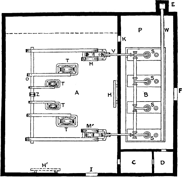
Fig. 2,720.—Floor plan of an electrical
station having a belted drive with counter shaft.
Fig. 2,720 shows the floor plan of an electrical station,
in which a countershaft and belted connections are used between the engines and
generators. Referring first to the plan of the building itself, A
represents the engine and dynamo room, B denotes the boiler room, C
the office, D the store room, and E the chimney connected with the
boilers by means of the uptake w. Referring next to the apparatus
installed, S, S, S, S represents a battery of four boilers; these are
connected by steam piping VV to the two steam engines, M and M, which
are belted to the countershaft O. Belted to the countershaft are the
generators, T, T, T, T, the circuits from which are controlled on the
switchboard, H.
Ques. What are the objections to the arrangement shown in fig. 2,720.?
Ans. The large space required by the belt drive especially
in locations where land is expensive. Another objection is the
frictional loss due to the belt drive with its countershaft, etc.
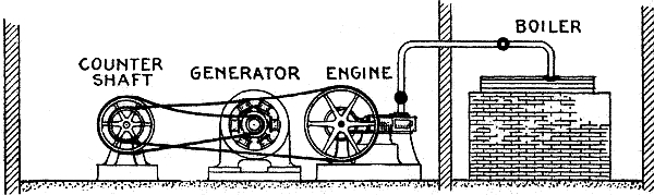
Fig. 2,721.—Elevation of station having a
belted drive with countershaft, as shown in plan in fig. 2,720.
Ques. What are the desirable features of the belt drive?
Ans. High speed generators may be used, thus reducing the first
cost, and the multiplicity of speeds and flexibility of the system
resulting from the use of a friction clutch.
Thus in fig. 2,720, each pulley may be mounted on the
counter shaft O with a friction clutch. A jaw clutch may also be provided at Z,
thus permitting the shaft O to be divided into two sections. It is
therefore possible by this arrangement to cause either of the engines
to drive any one of the generators, or all of them, or both of the
engines to drive all of the generators simultaneously.
Ques. Under what condition is the counter shaft belt drive particularly valuable?
Ans. In case of a break down of any one of the engines or generators,
and also when it becomes necessary to clean them without interrupting
the service.
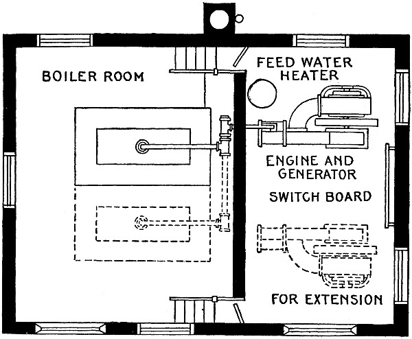
Fig. 2,722.—Plan of station arranged for
extension. The space required for a central station depends upon the
number and kind of lights to be supplied, and upon the character
and arrangement of the machinery. In calculating the size of
building required, two things must be carefully considered: first,
the building must be adapted to the plant to be installed in the
beginning; and second, it must be arranged so that enlargement can be
made without disarranging or interfering with the plant already in
existence. This is usually best secured by providing for expansion in
one or two definite directions, the building being made large enough
to accommodate additional units that will be necessary at some future
time because of the growth of the community and consequent increased
demand for electric current.
Ques. How may the design in fig. 2,720 be modified
for the installation of a storage battery?
Ans. If a storage battery be necessary, a partition may be
constructed across the room A, as indicated by the dotted lines, and
the battery installed in the room thus formed.
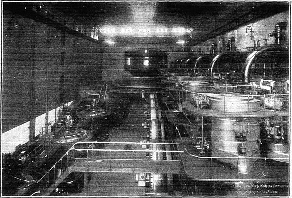
Fig. 2,723.—Interior of old Riverside
station showing at the right, seven 6,000 horse power alternators
driven by reciprocating engines, and at the left, a number of turbine
units aggregating 90,000 horse power.
Ques. Mention a few details in the general arrangement of the
building fig. 2,720.
Ans. Two doors to the room A may conveniently be provided at K
and L, the former connecting with the boiler room B, and the latter
serving as the main entrance to the station. There is little that
need be added to what has already been stated regarding the boiler
room B. The door at F provides for the entrance of coal and the
removal of ashes, while at P, the pump and heaters may conveniently
be located. In the office C, visitors may be received, the station
reports made out, bulletins issued from time to time, and whatever
engineering problems arise may here be solved on paper by the
engineer in charge of the plant. The store room D will be found
convenient for various supplies, tools and appliances needed in the
operation of the station. These may here be kept under lock and key
and the daily waste and loss resulting from carelessness avoided.
Ques. What important point should be noted in locating the engines
and boilers?
Ans. They should be so placed that the piping between them will be as
short and direct as possible.
Ques. Why?
Ans. The steam pipe should be short to reduce the loss of heat
between engine and boiler to a minimum, and both short and direct to
avoid undue friction and consequent drop in pressure of the steam in
passing through the pipe to the engine.
Entirely too little attention is given to this matter on the part of
designers and it cannot be too strongly emphasized that, for economy,
the steam pipe between an engine and boiler should be as short and
direct as possible, having regard of course, for proper piping
methods.
Ques. What should be provided for the steam pipe?
Ans. A heavy covering of approved material should be placed around
the pipe to reduce the loss of heat by radiation. For this purpose
hair felt, mineral wool and asbestos are used.
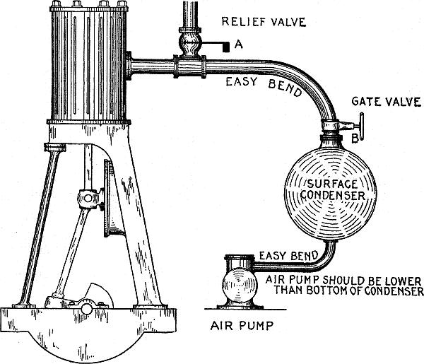
Fig. 2,724.—View of engine and condenser,
showing how to arrange the piping to secure good vacuum. Locate the
condenser as near the engine as possible; use easy bends
instead of elbows; place the pump below bottom of condenser
so the water will drain to pump. At A is a relief valve, for
protection in case the condenser become flooded through failure of
the pump, and at B is a gate valve to shut off condenser in case
atmospheric exhaust is desired to permit repairs to be made to
condenser during operation. A water seal should be maintained
on the relief valve and special attention should be given to
the stuffing box of the gate valve to prevent air leakage.
The discharge valve of the pump should be water sealed.
Ques. How should the piping be arranged between the engine and
condenser, and why?
Ans. It should be as short and direct as possible; especially
should elbows be avoided so that the back pressure on the engine
piston will be reduced as near as can be to that of the condenser.
That is to say, in order to get nearly the full effect of the vacuum
in the condenser the frictional resistance of the piping should be
reduced to a minimum.
Where 90° turns are necessary, easy bends should be used instead of
sharp elbows. The force of this argument must be apparent by noting
the practice of steam turbine builders of placing the turbine right
up against the condenser, and remembering that a high vacuum is
necessary to the economical working of a turbine. See fig. 1,445,
page 1,182.
Ques. What are the considerations respecting the number and type
of engine to be used?
Ans. In the illustration fig. 2,720, two engines M
and M' are employed, one belted to each end of the countershaft O. These
engines should be of similar or identical pattern; for a small output
they may be either simple or compound, as the conditions of fuel
expenditure may dictate, but if the output be large, triple expansion
engines or turbines are advisable.
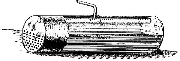
Fig. 2,725.—"Dry pipe" for horizontal
boiler: it is connected to the main outlet and its upper surface is
perforated with small holes, the far end being closed. With this
arrangement steam is taken from the boiler over a large area, so that
it will contain very little moisture. All horizontal boilers without
a dome should be fitted with a dry pipe; most engineers do not
realize the importance of obtaining dry steam for engine operation.
Corliss or similar slow speed engines may advantageously be used in
either case. In all cases the engine should be run condensing unless
the cost for circulating water is prohibitive; even in such cases
cooling towers may be installed and effect a saving.
In operation, during the greater part of the day, one engine running
two or perhaps three of the generators, will carry the load, but when
the load is particularly heavy, as in the morning and evening, both
engines and all the generators may be required to meet the demands.
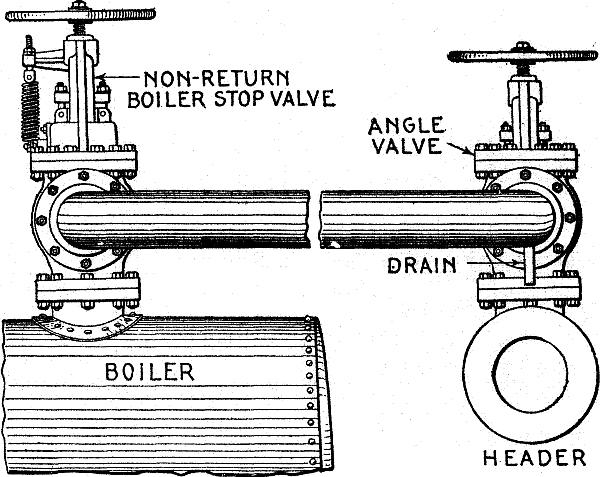
Fig. 2,726.—Method of connecting a header to
a battery of boilers. Where two or more boilers are connected to a
single header, the use of a reliable non-return boiler stop valve is
necessary, and in some countries their installation is compulsory. A
non-return boiler stop valve will instantly close should the pressure
in the boiler to which it is attached suddenly decrease below that
in the header, and thereby prevent the entrance of steam from the
other boilers of the battery. This sudden decrease in pressure may be
caused by a ruptured fitting or the blowing out of a tube, in which
event an ordinary stop valve taking the place of a non-return boiler
stop valve would be inadequate, as the loss of steam from the other
boilers of the battery would be tremendous before an ordinary valve
could be reached and closed, assuming that it would be possible to do
so, which in the majority of cases it is not. Should it be desired
to cut out a boiler for cleaning or repairs, the non-return boiler
stop valve will not permit steam to enter the boiler from the header,
even should the handwheel be operated for this purpose, as it cannot
be opened by hand, but can, however, be closed. A non-return boiler
stop valve should be attached to each boiler and connected to an
angle valve on the header. A pipe bend should be used for connecting
the valves, as this will allow for expansion and contraction. The
pipe should slope a trifle downward toward the header and a suitable
drain provided. This drain should be opened and all water permitted
to escape before the angle valve is opened, thereby preventing any
damage due to water hammer.
By exercising a little ingenuity in shifting the load on different
machines at different times, both engines and dynamos, may readily be
cleaned and repaired without interrupting the service.
Ques. For economy what kind of steam should be used?
Ans. Super-heated steam.
The saving due to the use of superheated steam is about 1% for every
ten degrees Fahr. of super-heat. It should be used in all cases.
Ques. How should the machines be located?
Ans. Sufficient space should be allowed between them that cleaning and
repairing may be done easily, quickly and effectually.
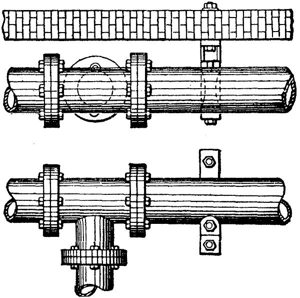
Figs. 2,727 and 2,728.—Method of preventing
vibration and of supporting pipes. The figures show top and side
views of a main header carried in suitable frames fitted with
adjustable roller. While the pipe is illustrated as resting on the
adjustable rollers, nevertheless the rollers may also be placed at
the sides or on top of the pipe to prevent vibration, or in cases
where the thrust from a horizontal or vertical branch has to be
provided for. This arrangement will take care of the vibration
without in any way preventing the free expansion and contraction of the pipe.
Ques. How should the switchboard be located?
Ans. In fig. 2,720, the switchboard H is mounted against
the wall dividing the room A from the room B, and is in line with the machines.
The advantages arising from a switchboard thus installed are, that
the switchboard attendant working thereon can obtain at any time an
unobstructed view of the performance of each individual machine,
and he has in consequence a much better control of them; then, too,
while he is engaged at the engines or generators he can also see the
measuring instruments on the switchboard, and ascertain approximately
the readings upon them.
In cases of emergency it is sometimes necessary for the engineer in
charge of a plant to be in several places at the same time in order to
prevent an accident, and that this seemingly impossibility may
be approximated as nearly as possible, it is essential that the
controlling devices be located as closely together as is consistent,
and that no moving belt or pulley intervene between them.
These conditions are well satisfied in fig. 2,720, and
owing to the short distances between the generators and the switchboard the drop
of voltage in each of the conducting wires between them will be low.
This latter advantage is worthy of notice in a station generating
large currents at a low pressure. To offset the advantages just
mentioned, the location of the switchboard in line with the machines
introduces an element of danger to the switchboard, its apparatus,
and the attendant, on account of the possible bursting of a flywheel
or other parts of the machines from centrifugal force.
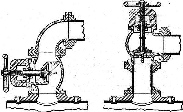
Figs. 2,729 and 2,730.—Points on placing
stop valves. The first and most important feature is to ascertain
whether the valve will act as a water trap for condensed steam. Fig.
2,729 illustrates a common error in the placing of valves, as this
arrangement permits of an accumulation of condensed steam above the
valve when closed, and should the engineer be careless and open the
valve suddenly, serious results might follow owing to water-hammer.
Fig. 2,730 illustrates the correct method of placing the valve. It
sometimes occurs, however, that it is not convenient to place the
valve as shown in fig. 2,730 and that fig. 2,729 is the only manner
in which the valve can be placed. In such cases, the valve should
have a drain, and this drain should always be opened before the large
valve is opened.
If the switchboard be placed in the dotted position at H', or, in
fact, at the opposite end of the room A, the damage to life and
property that might result from the effects of centrifugal force
would be eliminated, but in place thereof would be the disadvantages
of an obstructed view of the machines from the switchboard, an
obstructed view of the switchboard from the machines, inaccessibility
between these two, and a greater drop of voltage in the majority of
the conducting wires between the generators and the switchboard.
Ques. Describe a second arrangement of station with belt drive and
compare it with the design shown in fig. 2,720.
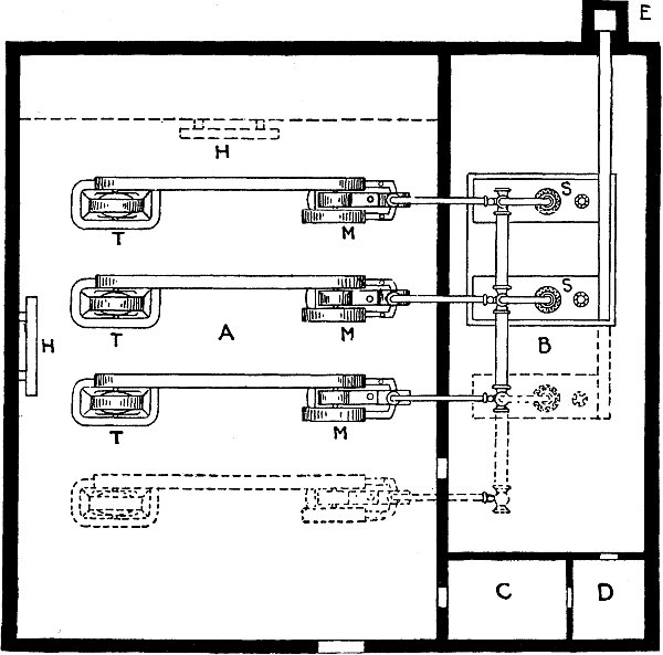
Fig. 2,731.—Plan of electrical station with
belt drive without counter shaft. The installation here represented
consists of two boilers, S, etc., and three sets of engines and
generators, T, M, etc. Sufficient allowance has been made in the
plans, however, for future increase of business, as additional space
has been provided for an extra engine and generator set, as indicated
by the dotted lines.
Ans. A floor plan somewhat different from that presented in fig.
2,720 is shown in fig. 2,731. Here a belt drive is employed,
but no countershaft is used. Each generator, therefore, is dependent upon
its respective engine, and in consequence the flexibility obtained by
the use of a countershaft is lost. On the other hand, there is less
loss of mechanical power between the engines and generators in the
driving of the latter, and less floor space is necessary in the room
A. If, however, the floor area of this room be made the same as in
the previous arrangement and the same number of machines are to be
installed, they may be spaced further apart, affording in consequence
considerably more room for cleaning and repairing them.
In operation, the normal conditions should be such that any two of
the engine and generator sets may readily carry the average load, the
third set to be used only as a reserve either to aid the other two
when the load is unusually heavy or to replace one of the other sets
when it becomes necessary to clean or repair the latter.
The switchboard may perhaps be best located at H, as a similar
position on the opposite side of the room A would bring it beneath
one or more of the steam pipes and thus endanger it should a possible
leakage occur from these pipes. If located at H, however, it will
be in line with the machines, and therefore will be subject to the
disadvantages previously mentioned for such cases; consequently it
might be as well to place it at the further end of the room, either
against the partition (shown dotted) of the storage battery room if
this be built, or else (if no storage battery is to be installed),
against the end wall itself. The nearer end of the room A would not
be very desirable for the switchboard installation on account of
being so far removed from the machines, and therefore more or less
inaccessible from them. Outside of what has now been mentioned, the
division of the floor plan and the arrangement therein is practically
the same as in fig. 2,720, accordingly what has already
been stated regarding the former installation applies, therefore, with equal
force to the present installation.
Ques. Describe a plant with direct drive.
Ans. This type of drive is shown in fig. 2,732. Each
engine is directly connected to a generator, that is, the main shafts of both
are joined together in line so that the generator is driven without
the aid of a belt.
Ques. What is the advantage of direct drive?
Ans. The great saving in floor space, which is plainly shown in fig.
2,732, the portion A' representing the saving which results over the
installations previously illustrated in figs. 2,720
and 2,731.
Ques. How could the floor space be further reduced?
Ans. By employing vertical instead of horizontal engines.
Ques. What should be done before drawing the plans for the station?
Ans. The types of the various machines and apparatus to be
installed should, as nearly as possible, be selected in advance so
that their approximate dimensions may serve as a guide in drawing up
the plans of the building.
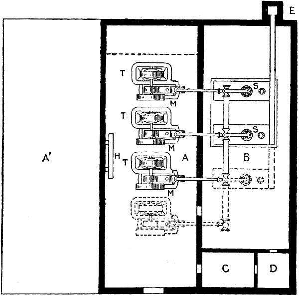
Fig. 2,732.—Plan of electrical station
containing direct connected units. As shown, space is provided for an
extra boiler and engine and generator set, as indicated by the dotted
lines. Space also exists for a storage battery room if necessary, and
the partition dividing this room from the engine and dynamo room is
shown by a dotted line as in previous cases.
Owing to the great difference in these dimensions for the various
types, and in fact for the same types as manufactured by different
concerns, no definite rules regarding the necessary space required can
here be given. In a general way, however, the author has endeavoured
to indicate by the drawings the relative amounts of space that
ordinarily would be considered sufficient.
Ques. What is the disadvantage of direct drive?
Ans. A more expensive generator is required because it must run
at the same speed as the engine, which is relatively low as compared
with that of a belted generator.
Station Construction.—The construction or
rearrangement of the building intended for the plant is a problem
that under ordinary conditions would be solved by an architect, or
at least by an architect with the assistance of an electrical or
mechanical engineer, still there are many installations where the
electrical engineer has been compelled to design the building.
In such instances he should be equipped with a general knowledge
of the construction of buildings.
Foundations.—The foundation may be either natural or
artificial; that is, it may be composed of rock or soil sufficiently
solid to serve the purpose unaided, or it may be such as to require
strengthening by means of wood or iron beams, etc. In either case any
tendency toward a considerable settling or shifting of the foundation
due to the action of water, frost, etc., after the station has been
completed must be well guarded against. To this end special attention
should be given to the matter of drainage.
Ques. How should the foundation be constructed for the machines?
Ans. The foundations constructed for the machines should be
entirely separate from that built for the walls of the building, so
that the vibrations of the former will not affect the latter.
If there be several engines and dynamos to be installed, it is best
to construct two foundations, one for the engines and one for the
dynamos. If, however, there be considerable distance between the
units, it may be advisable to build a separate foundation for each
engine and for each dynamo. The material of which these foundations
are composed should if the machines be of 20 horse power or over,
possess considerable strength and be impervious to moisture. Brick,
stone and concrete are desirable for the purpose, and only the best
quality of cement mortar should be employed. Care must be taken that
lime mortar is not used in place of cement mortar, as the former is
not well adapted to withstand the vibrations of the machines without
crumbling.
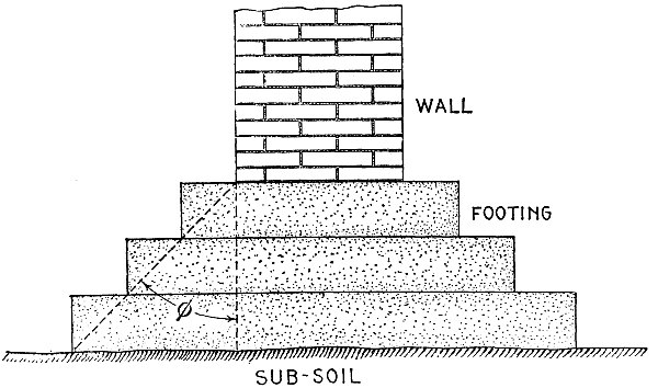
Fig. 2,733.—Angle for foundation footing.
In ordinary practice the footing courses upon which the walls of
the building proper rest, consist of blocks or slabs of stone as
large as are available and convenient to handle. Footings of brick
or concrete are also used in very soft soils; footings consisting
of timber grillage are often employed. A grillage of iron or steel
beams has also been used successfully. The inclination of the angle
φ, of footing should be about as follows: for metal footings 75°; for
stone, 60°; for concrete, 45°; for brick, 30°. Damp proof courses
of slate, or layer of asphalt are laid in or on the foundations or
lower walls to prevent moisture arising or penetrating by capillary
attraction.
Ques. Describe a method of constructing foundations.
Ans. An excavation is made to the desired depth and a form inserted
corresponding to the desired dimensions for the foundation. A
template is placed on top locating all the centers, with iron pipes
suspended from these centers, two or three sizes larger than the
anchor bolts. At the lower end of the pipes are core boxes. Concrete
is poured into the mould thus formed, and when hard, the forms
are removed thus leaving the solid foundation. The anchor bolts
are inserted through the pipes and passed through iron plates at
the lower end as shown in fig. 2,734, being secured
by nuts. By using pipe of two or three bolt diameters a margin is provided
for adjustment so the bolts will pass through the holes in the frame of
the machine thus allowing for any slight errors in laying out the
centers on the template.
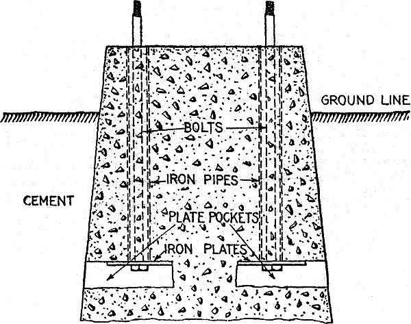
Fig. 2,734.—Concrete foundation showing
method of installing the anchor bolts.
Ques. What is the object of the openings in the bottom of the
foundation?
Ans. In case of a defective bolt, it may be replaced by a new one
without injury to the foundation.
Walls.—Regarding the material for the walls of the station
iron, stone, brick and wood may be considered. Of these, iron in the
form of sheets or plates would be entirely fireproof, but
being itself a conductor would introduce difficulties in maintaining
a high insulation resistance of the current carrying circuits; it
would also make the building difficult to heat in winter and to keep
cool in summer. Stone in the form of limestone, granite or sandstone,
as a building material is desirable for solidity and attractiveness;
it is also fireproof and an insulator, but the high cost of such a
structure for an electrical station usually prohibits its use except
in private plants or in electrical stations located in large cities.
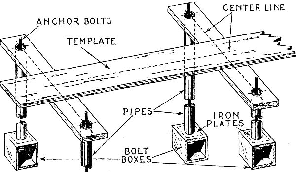
Fig. 2,735.—View showing part of template
for locating anchor bolt centers, pipes through which the bolts pass
and bolt boxes at lower end of bolts. The completed foundation is
shown in fig. 2,734, with template removed. The template
is made of plain boards upon which the center lines are drawn, and bolt center
located. Holes are bored at the bolt centers to permit insertion of
the pipes as shown.
Brick is a good material and is readily obtained in nearly all parts
of the country; it is comparatively cheap, and is also an insulating
and fireproof material. The bricks selected for this purpose should
possess true sharp edges, and be hard burned.
Ques. What are the features of wood?
Ans. Wood forms the cheapest material that can be used for the
walls of electrical stations, and it usually affords satisfaction,
but has the disadvantage of high fire risk.
Roofs.—In fig. 2,736 is shown one form
of construction for the roof of an electrical station. The end view here
presented shows the upper portion of the walls at B and D; these
support the iron trusses C, and the roof proper MN. In many stations
there is provided throughout the length of the building, a monitor or
raised structure on the peak of the roof for ventilation and light.
The end view of the monitor is shown at S in the figure; its sides
should be fitted with windows adjustable from the floor.
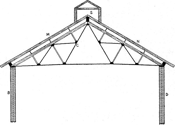
Fig. 2,736.—One form of roof construction.
Floors.—The floor of the station should be so
designed that it will be capable of supporting a reasonable weight,
but as the weights of the machines are borne entirely by their
respective foundations the normal weight upon the floor will not be
great; for short periods, however, it may be called upon to support
one or two machines while they are being placed in position or
interchanged, and due allowance must be made for such occurrences.
Station floors for engine and dynamo rooms are, as a rule,
constructed of wood. Where very high currents are generated, however,
insulated floors of special construction mounted on glass are
necessary as a protection from injurious shocks. Brick, concrete,
cement, and other substances of a similar nature are objectionable
as a floor material for engine and dynamo rooms on account of the
grit from them, caused by constant wear, being liable to get into the
bearings of the machines.
Where there are no moving parts, however, as in the boiler room,
the materials just mentioned possess no disadvantages and are
preferable to wood on account of being fireproof.
THEORETICAL DRAFT PRESSURE IN INCHES OF WATER IN A CHIMNEY 100 FEET HIGH
(For other heights the draft varies directly as the height)
Temp. in
Chimney, °F. |
TEMP. OF EXTERNAL AIR. (BAROMETER 30 INCHES) |
| 0° | 10° |
20° | 30° |
40° | 50° |
60° | 70° |
80° | 90° |
100° |
| 200° | .453 |
.419 | .384 |
.353 | .321 |
.292 | .263 |
.234 | .209 |
.182 | .157 |
| 220 | .488 |
.453 | .419 |
.388 | .355 |
.326 | .298 |
.269 | .244 |
.217 | .192 |
| 240 | .520 |
.488 | .451 |
.421 | .388 |
.359 | .330 |
.301 | .276 |
.250 | .225 |
| 260 | .555 |
.528 | .484 |
.453 | .420 |
.392 | .363 |
.334 | .309 |
.282 | .257 |
| 280 | .584 |
.549 | .515 |
.482 | .451 |
.422 | .394 |
.365 | .340 |
.313 | .288 |
| 300 | .611 |
.576 | .541 |
.511 | .478 |
.449 | .420 |
.392 | .367 |
.340 | .315 |
| 320 | .637 |
.603 | .568 |
.538 | .505 |
.476 | .447 |
.419 | .394 |
.367 | .342 |
| 340 | .662 |
.638 | .593 |
.563 | .530 |
.501 | .472 |
.443 | .419 |
.392 | .367 |
| 360 | .687 |
.653 | .618 |
.588 | .555 |
.526 | .497 |
.468 | .444 |
.417 | .392 |
| 380 | .710 |
.676 | .641 |
.611 | .578 |
.549 | .520 |
.492 | .467 |
.440 | .415 |
| 400 | .732 |
.697 | .662 |
.632 | .598 |
.570 | .541 |
.513 | .488 |
.461 | .436 |
| 420 | .753 |
.718 | .684 |
.653 | .620 |
.591 | .563 |
.534 | .509 |
.482 | .457 |
| 440 | .774 |
.739 | .705 |
.674 | .641 |
.612 | .584 |
.555 | .530 |
.503 | .478 |
| 460 | .793 |
.758 | .724 |
.694 | .660 |
.632 | .603 |
.574 | .549 |
.522 | .497 |
| 480 | .810 |
.776 | .741 |
.710 | .678 |
.649 | .620 |
.591 | .566 |
.540 | .515 |
| 500 | .829 |
.791 | .760 |
.730 | .697 |
.669 | .639 |
.610 | .586 |
.559 | .534 |
Chimneys.—These are generally
constructed of brick and iron, sometimes of concrete. Iron chimneys
cost less than brick chimneys, necessitate less substantial
foundations, and are free from the liability of cracking. They must
be painted to prevent corrosion, are less substantial, and lose
considerably more heat by radiation than do brick chimneys.
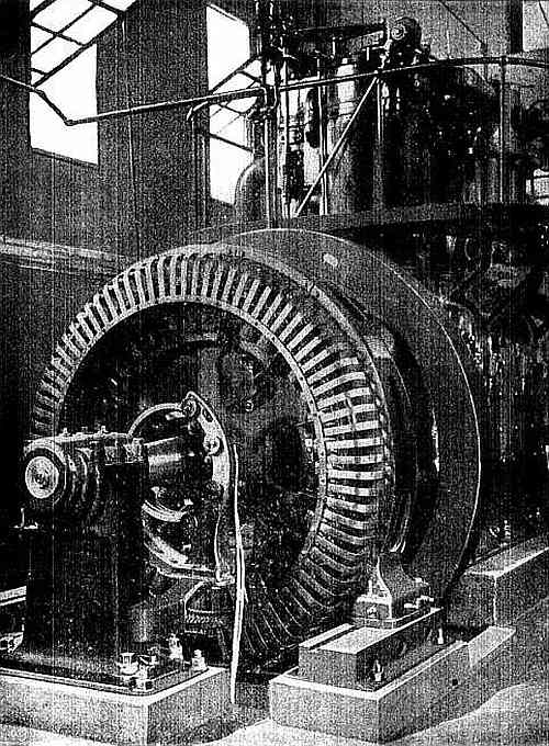
Fig. 2,737.—An example of direct connected
unit with gas engine power. The view shows a Westinghouse 200 kva.,
4,000 volt, three phase, 60 cycle alternator direct connected to a
gas engine.
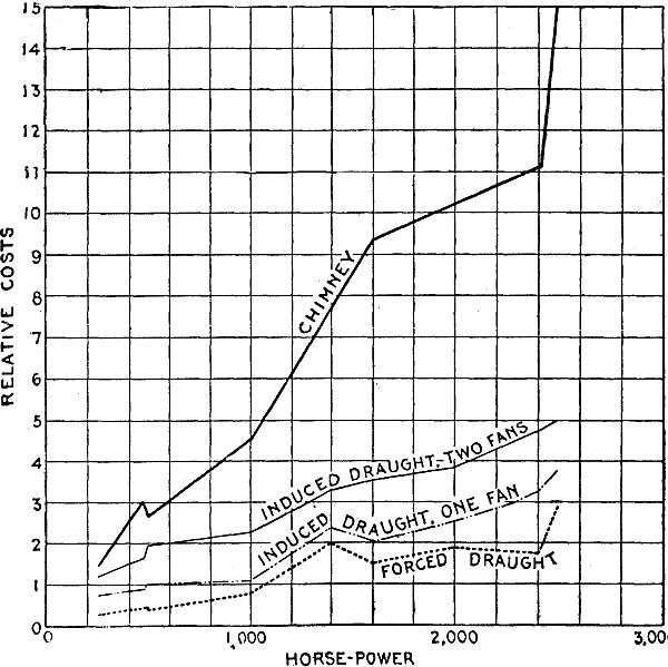
Fig. 2,738.—Curves showing comparative costs
of chimney and mechanical draft. In certain of these, the cost of the
existing chimney is known, and that of the complete mechanical draft
plant is estimated, while in others, the cost of mechanical draft
installation is determined from the contract price, and the expense
of a chimney to produce equivalent results is calculated. Costs are
shown for both single, forced and induced engine driven fans and
for duplex engine driven plants, in which either fan may serve as a
relay. An apparatus of the latter type is the most expensive, and
finds its greatest use where economizers are employed.
Both brick and iron chimneys, require an inner wall or lining of
brick, which forms the flue proper, and in order that this wall be
not cracked by sudden cooling an air space is left between it and
the outer wall. In a brick chimney the inner wall need not extend
much beyond half the height of the chimney, but when iron is used it
should reach to the top.
Ques. Upon what does the force of natural draught in a chimney depend?
Ans. It depends upon the difference between the weight of the column
of hot gases inside the chimney and the weight of a like column of
the cold external air.
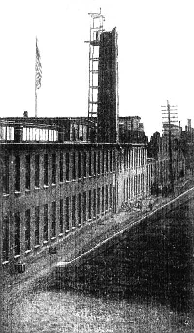
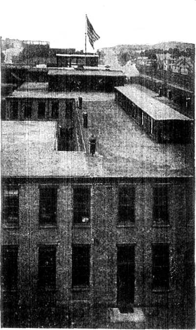
Figs. 2,739 and 2,740.—Substituting
mechanical draught in place of chimney. The relative proportions of a
brick chimney, and of the smoke pipe required when mechanical draft
is introduced are forcibly shown in the illustrations, which show the
works of the B.F. Sturtevant Co., at Jamaica Plain, Mass. The removal
of the boilers to a position too far distant from the existing
chimney to permit of its longer fulfilling its office, led to the
substitution of an induced draft fan and the subsequent removal of
the chimney. The present stack or smoke pipe, barely visible in
fig. 2,740, extends only 31 feet above the
ground, and no trouble is experienced from smoke.
Ques. How is the intensity of the draught expressed?
Ans. In terms of the number of inches of a water column sustained by
the pressure produced.
Ques. Are high chimneys necessary?
Ans. No.
Chimneys above 150 feet in height are very costly, and their
increased cost is not justified by increased efficiency.
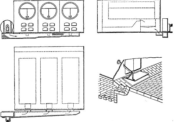
Figs. 2,741 to 2,744.—Installation of
forced draft system to old boiler plant. The figures illustrate
the simplest method. The fan which is of steel plate with direct
connected double cylinder engine, is placed immediately over the
end of a brick duct into which the air is discharged. This duct is
carried under ground across the front of the boilers, to the ash
pits of each of which connection is made through branch ducts. Each
branch duct opening is provided with special ash pit damper, operated
by notched handle bar, as illustrated in the detail. This method of
introduction serves to distribute the air within the ash pit, and to
secure even flow through the fuel upon the grate above. Of course,
the ash pit doors must remain closed in order to bring about this
result. A chimney of sufficient height to merely discharge the gases
above objectionable level is all that is absolutely necessary with
this arrangement. Although the introduction of a fan in an old plant
is usually evidence of the insufficiency of the existing chimney
to meet the requirements, such a chimney, will, however, usually
serve as a discharge pipe for the gases when the fan is employed.
The fan thus becomes more than a mere auxiliary to the chimney; it
practically supplants it so far as the method of draught production
is concerned.
The latest chimney practice is to build two or more small chimneys
instead of one large one. A notable example is the Spreckels Sugar
Refinery in Philadelphia, where three separate chimneys are used for
one boiler plant of 7,500 horse power. The three chimneys are said to
have cost several thousand dollars less than an equivalent single
chimney.
Very tall chimneys have been characterized by one writer as
"monuments to the folly of their builders."
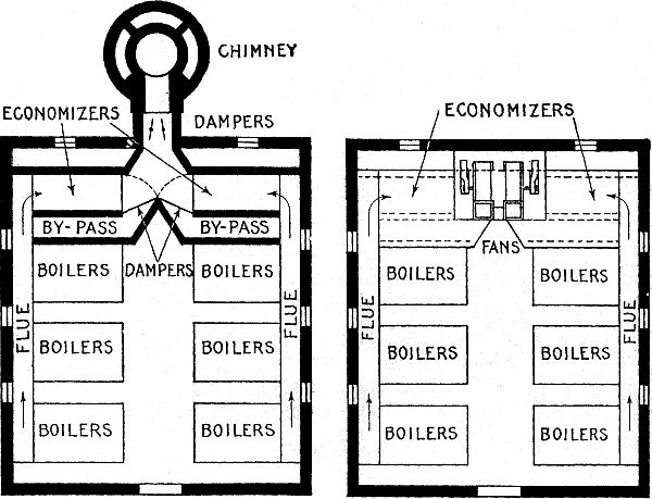
Figs. 2,745 and 2,746.—Comparison of chimney
draft and mechanical draft. The illustrations show a plant of 2,400
H.P. of modern water tube boilers, 12 in number, set in pairs and
equipped with economizers. Fig. 2,745 indicates the location of a
chimney, 9 feet in internal diameter by 180 feet high, designed to
furnish the necessary draft; fig. 2,746 represents the same plant
with a complete duplex induced draught apparatus substituted for the
chimney, and placed above the economizer connections. Each of the
two fans is driven by a special engine, direct connected to the fan
shaft, and each is capable of producing draft for the entire plant. A
short steel plate stack unites the two fan outlets and discharges the
gases just above the boiler house roof. All of the room necessary for
the chimney is saved, and no valuable space is required for the fans.
Ques. How is mechanical draft secured?
Ans. In two ways, known respectively as induced draught and
forced draught.
Ques. Describe the method of induced draft.
Ans. A fan is located in the smoke flue, and which in operation draws
the gases through the furnace and discharges them into a short
chimney.
Ques. Describe the method of forced draft.
Ans. In this method, air is forced into the furnace underneath
the grate bars by means of a fan or a steam jet blower.
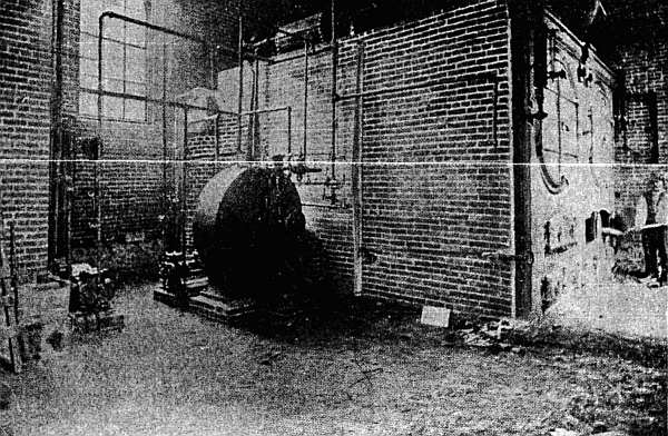
Fig. 2,747.—Forced draft plant with hollow
bridge wall at the Crystal Water Co., Buffalo, N. Y. The air is
delivered to the ash pit via the hollow bridge wall, being supplied
under pressure by the blower seen at the side of the boiler setting.
As shown, the blower is operated by a small reciprocating engine;
however, compact blowing units with steam turbine drive can be had
and which are designed to be placed in the boiler setting.
Ques. What is the application of the two systems?
Ans. Induced draft is installed mostly in new plants, while forced draft
is better adapted to old plants.
Steam Turbines.—It is not the
author's intention to discuss at length the steam end of the electric
plant, because too much space would be required, and also because
the subject belongs properly to the field of mechanical engineering
rather than electrical engineering. However, because of the recent
introduction of the steam turbine for the direct driving of large
generators, and the fact that it is now almost universally used in
large central stations, a detailed explanation of its principles and
construction may not be out of place.
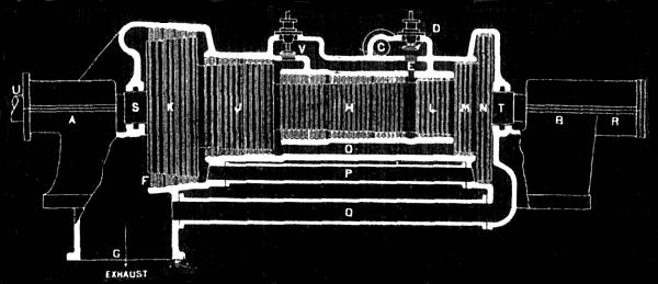
Fig. 2,748.—Longitudinal section of
elementary Parsons type steam turbine. The turbine consists
essentially of a fixed casing, or cylinder, and a revolving spindle
or drum. The ends of the spindle are extended in the form of a shaft,
carried in two bearings A and B, and, excepting the small parts of
the governing mechanism and the oil pump, these bearings are the only
rubbing parts in the entire turbine. Steam enters from the steam
pipe at C and passes through the main throttle or regulating valve
D, which, as actually constructed, is a balanced valve. This valve
is operated by the governor through suitable controlling mechanism.
The steam enters the cylinder through the passage E and, turning
to the left passes through alternate stationary and revolving rows
of blades, finally emerging from them at F and flowing through the
connection G to the condenser or to the atmosphere, depending upon
whether the turbine is condensing or non-condensing. Each row of
blades, both stationary and revolving, extends completely around
the turbine and the steam flows through the full annulus between
the spindle and the cylinder. In an ideal turbine the lengths of
the blades and the diameter of the spindle which carries them
would continuously and gradually increase from the steam inlet to
the exhaust. Practically, however, the desired effect is produced
by making the spindle in steps, there being generally three such
steps or stages, H, J and K. The blades in each step are arranged
in groups of increasing length. At the beginning of each of the
larger steps, the blades are usually shorter than at the end of the
preceding smaller step, the change being made in such a way that the
correct relation of blade length to spindle diameter is secured. The
steam, acting as previously described, produces a thrust tending to
force the spindle toward the left, as seen in the cut. This thrust,
however, is counteracted by the "balance pistons," L, M and N,
which are of the necessary diameter to neutralize the thrust on the
spindle steps, H, J and K, respectively. These elements are called
"pistons" for convenience, although they do not come in contact with
the cylinder, but both the pistons and the cylinder are provided
with alternate rings which form a labyrinth packing to retard the
leakage of steam. In order that each balance piston may have the
proper pressure on both sides, equalizing passages O, P and Q are
provided connecting the balance pistons with the corresponding stages
of the blading. The end thrust being thus practically neutralized by
means of the balance pistons, the spindle "floats" so that it can be
easily moved in one direction or the other. In order to definitely
fix the position of the spindle, a small adjustable collar bearing is
provided at R, inside the housing of the main bearing B. This collar
bearing is adjustable so as to locate and hold the spindle in such
position so that there will be such a clearance between the rings of
the balance piston and those of the cylinder, that the leakage of
steam will be reduced to a minimum and, at the same time, prevent
actual contact under varying conditions of temperature. Where the
shaft passes out of the cylinder, at S and T, it is necessary to
provide against in-leakage of air or out-leakage of steam by means of
glands. These glands are made tight by water packing without metallic
contact. The shaft of the turbine is extended at U and coupled to
the shaft of the alternator by means of a flexible coupling. The
high pressure turbines are so proportioned that, when using steam as
previously described, they have enough capacity to take care of the
ordinary fluctuations of load when controlled by the governor through
the valve D, thus insuring maximum economy of steam consumption at
approximately the rated load. To provide for overloads, the valve V
is supplied to admit steam to an intermediate stage of the turbine.
This valve shown diagrammatically in the illustration, is arranged
to be operated by the governor and is, according to circumstances,
located either as shown by the illustration, or at another stage of
the turbine.
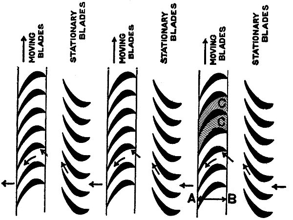
Fig. 2,749.—Arrangement of blading in
Parsons type turbine, consisting of alternate moving and stationary
blades. The path taken by the steam is indicated by the arrows.
A turbine is a machine in which a rotary motion is obtained by
transference of the momentum of a fluid or gas. In general the
fluid is guided by fixed blades, attached to a casing, and, impinging
on other blades mounted on a drum or shaft, causing the latter to
revolve.
Turbines are classed in various ways as: 1, radial flow,
when the steam enters near the center and escapes toward the
circumference; and 2, parallel flow, when the steam travels
axially or parallel to the length of the turning body.
Turbines are commonly, yet erroneously classed as:
1. Impulse;
2. Reaction.
Ques. What is the distinction between these two types?
Ans. In the so called impulse type, steam
enters and leaves the passages between the vanes at the same
pressure. In the so called reaction type, the pressure is less on
the exit side of the vanes than on the entrance side.
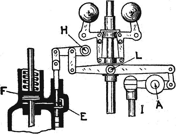
Fig. 2,750.—Sectional view of
Parsons-Westinghouse turbine, showing rotor and governor.
Fig. 2,750 is a sectional view of the Parsons-Westinghouse
parallel flow turbine. Steam from the boiler enters first a receiver in which
are the governor controlled admission valves. These valves are
actuated by a centrifugal governor.
Steam does not enter the turbine in a continuous blast, but
intermittently, or in puffs. The speed regulation is therefore
accomplished by proportioning the duration of these puffs to the load
of the engine, this being effected by the governor, fig. 2,752.
The governor of the turbine has only to move a small pilot valve,
or slide, E, which admits steam under the piston F, and lifts the
throttle valve proper off its seat.
As soon as the pilot valve closes, the spring shifts the main
throttle valve. Thus, at light loads, the main throttle or admission
valve is continually opening and shutting at uniform intervals, the
length of time during which it remains open depending upon the load.
As the load increases, the duration of the valve opening also
increases, until at full load the valve does not reach its seat at
all and the steam flows steadily through the turbine. The steam thus
admitted flows into the annular passage A, fig. 2,750,
by the opening S, and then past the blades, revolving the rotor.
When the load increases above the normal rated amount a secondary
pilot valve is moved by the same means, this in turn admitting steam
to a piston, similar to F, which lifts another throttle valve. This
admits steam into the annular space I, so that it acts upon the
larger diameter of the drum or rotor, giving largely increased power
for the time being.
The levers or arms of the governor are mounted upon knife edges
instead of pins, making it extremely sensitive. The tension spring
may be adjusted by hand while the turbine is running.
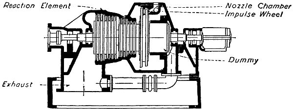
Fig. 2,751.—Sectional view of a combination
impulse and reaction single flow turbine. This is a modification
of the single flow type, in which the smallest barrel of reaction
blading is replaced by an impulse wheel. Steam is admitted to the
nozzle block A, is expanded in the nozzles and discharged against a
portion of the periphery of the impulse wheel. The intermediate and
low pressure stages are identical with the corresponding stages in
the single flow type. The substitution of the impulse element for
the high pressure section of reaction blading has no influence one
way or another on the efficiency. That is to say the efficiency of
an impulse wheel is about the same at the least efficient section
of reaction blading. This design is attractive, however, in that
it shortens the machine materially, and gives a stiffer design of
rotor. The entering steam is confined in the nozzle chamber until its
pressure and temperature have been materially reduced by expanding
through the nozzles. As the nozzle chamber is cast separately from
the main cylinder, the temperature and pressure differences to which
the cylinder is subjected are correspondingly lessened. However,
probably on account of its small diameter at the high pressure
section, the straight Parsons type has always shown itself to be
adequate for all of the steam pressures and temperatures encountered
in ordinary practice.
The governor does not actually move the pilot valve, but shifts the
point L in fig. 2,752. A reciprocating motion is given
to the rod I by a small eccentric on the governor shaft; this is driven by worm
gearing shown near O in fig. 2,750, so that the eccentric
makes one revolution to about eight of the turbine. Thus, with a turbine
running 1,200 revolutions, the rod I would be moved up and down 150
times per minute. As the points A and H are fixed, the motion is
conveyed to the small pilot valve E, thus giving 150 puffs a minute.
The governor in shifting the point L brings the edge of the pilot
valve nearer the port and so cuts off the steam earlier.
The annular diameter or space between the rotor and the stator is
gradually increased from inlet to exhaust, the blades being made
longer in each ring. When the mechanical limit is reached, the
diameter of the rotor is increased as at I and D so as to keep the
length of blade within bound.
Balance pistons as at B, C, F are attached to the rotor, their
office being to oppose end thrust upon those blades in corresponding
diameter of the rotor. Communication is established through the
passage V and pipe M between the eduction pipe and the back of these
pistons, thus increasing the efficiency of their balancing and also
taking care of any leakage past them.
A small thrust bearing T prevents end play of the rotor, and is
adjustable to maintain the proper clearance between the rings of
blades; this varies from ⅛ inch at the admission to 1 inch at the
exhaust. This bearing also takes up any extra unbalanced thrust. A
turbine should operate with a high vacuum, because without this it
does not compare favorably with an ordinary reciprocating engine from
the point of economy.
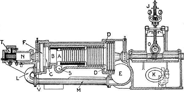
Fig. 2,752.—Sectional view of governor of the
Parsons-Westinghouse turbine.
Separate air pumps are provided to create the vacuum.
Where the ordinary type of vertical air pump is employed, a booster
or vacuum increaser is added, as nothing below 26 inches is
advisable, 28 and 29 inches being always striven for. It is also
preferable to use a certain amount of super-heat with steam
turbines.
To assist in producing the high vacuum, exhaust passages are made
large, the eduction passage E in fig. 2,750 being nearly
twenty-three times the area of the steam pipe.
Among other details, a noteworthy feature is a small oil pump K,
which circulates oil through bearings of the machinery, the oil being
drawn from the tank under the governor shaft and gravitating there
after use. No pressure of oil is employed. Stuffing rings prevent
leakage; these consist of alternate grooves and collars in shaft and
bearing, like the grooves in an indicator piston.
Ques. Why is a high vacuum desirable?
Ans. Because the turbine is capable of expanding the steam to a very
low terminal pressure, and this is necessary for economy.
Ques. What may be said of the working pressures for turbines?
Ans. To meet the varied conditions of
service, turbines are designed to operate with: 1, high pressure, 2,
low pressure, or 3, mixed pressure.
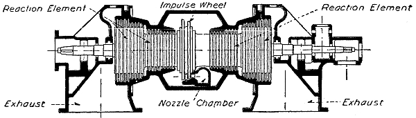
Fig. 2,753.—Sectional view of a double flow
turbine. The maximum economical capacity of a single flow turbine
is limited by the rotative speed. The economical velocity at which
the steam may pass through the blades of the turbine depends on the
velocity of the moving blades. The capacity of the turbine depends
on the weight of the steam passed per unit of time, which in turn
depends on the mean velocity and the height of the blades. For a
given rotative speed, the mean diameter of blade ring practicable
is limited by the allowable stresses due to centrifugal force, and
there is a practical limit for the height of the blades. Now if the
rotative speed be taken only half as great, the maximum diameter
of the rotor may be doubled and, without increasing the height of
the blades, the capacity of the turbine will be doubled. So with
the single flow steam turbine as well as with the single crank
reciprocating engine, there is a practical limiting economical
capacity for any given speed. If this limit be reached with a single
crank reciprocating engine, a unit of double the power may be
produced at the same speed by coupling two single crank engines to
one shaft. Similar results are secured making a double flow turbine
which is in effect, as will be seen from the figure, two single flow
turbines made up in a single rotor in a single casing with a common
inlet and two exhausts. Steam enters the nozzle block, acts on the
impulse element, and then the current divides, one-half of the steam
going through the reaction blading at the left of the impulse wheel;
the remainder passes over the top of the impulse wheel and through
the impulse blading at the right.
High pressure turbines operate at about the same initial pressure as
triple expansion engines.
Low pressure, as here applied, means the exhaust pressure of the
reciprocating engine from which the exhaust steam passes through the
turbine before entering the condenser.
Mixed pressure implies that the exhaust steam is supplemented, for
heavy loads, by the admission of live steam.
Ques. What determines the working pressure?
Ans. When all the power is furnished by
the turbine, it is designed for high pressure; when operated in
combination with a reciprocating engine, low pressure is used for
constant load, and mixed pressure for variable load.
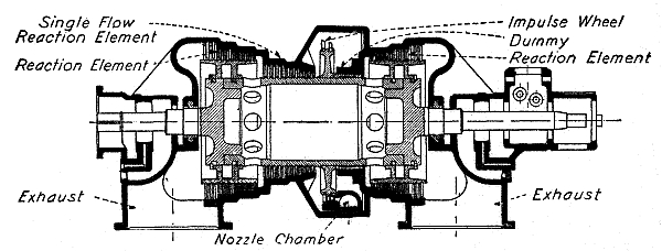
Fig. 2,754.—Sectional view of a semi-double
flow turbine. This is a modification in which the intermediate
section of reaction blading is single flow, and the low pressure
section only is double flow. This would be analogous to a four
cylinder triple expansion engine, that is, one with one high
pressure, one intermediate pressure and two low pressure cylinders—a
design not at all uncommon in very large engines in which the
required dimensions of a single low pressure cylinder would be
prohibitive. Such turbines are useful for capacities greater than
is desirable for a single flow turbine, and which are still below
the maximum possibilities of a double flow turbine of the same
speed. In such machines the best efficiency is secured by making the
intermediate blading in a single section large enough to pass the
entire quantity of steam. A "dummy" similar to those used on the
single flow Parsons type, shown at the right of the impulse wheel,
compels all of the steam to pass through the single intermediate
section of the reaction blading, and balances the end thrust due to
this section. When the steam issues from the intermediate section,
the current is divided, one-half passing directly to the adjacent low
pressure section, while the other half passes through the holes shown
in the periphery of the hollow rotor and through the rotor itself,
beyond the dummy ring, into the other low pressure section at the
left hand end of the turbine.
NOTE.—There are logical engineering reasons for the existence of
the several types of turbine, viz., single flow, double flow, and
semi-double flow. The double flow turbine is not inherently superior
to the single flow design, but is used under conditions for which the
single flow machine is unsuitable. Similarly, the semi-double flow is
recommended only for conditions which it can meet more satisfactorily
than either of the other types.
NOTE.—Low pressure turbines use exhaust steam from non-condensing
engines and are valuable as an adjunct to existing plants for the
purpose of increasing economy and capacity with a minimum outlay for
new equipment.
NOTE.—Bleeder turbines are for use in plants which are required to
furnish, not only power, but also considerable and varying quantities
of low pressure steam for heating purposes. In these turbines a part
of the steam after it has done work in the high pressure stages may
be diverted to the heating system, and the remainder expanded through
the low pressure blading and exhausted into the condenser. In this
way none of the energy of the heating steam, due to the difference of
pressure between the boiler and the heating system is wasted. On the
other hand if no steam is required for heating purposes, the turbine
operates just as efficiently as though the bleeder feature were
absent.
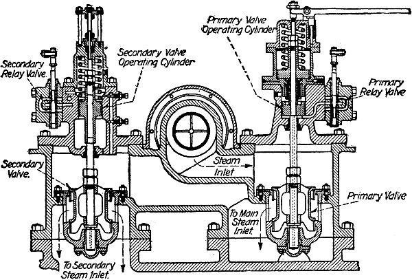
Fig. 2,755.—Westinghouse valve gear with
steam relay. In the smaller turbines, the governor acts directly on
the steam admission valves, opening first the primary valve, and
then, if necessary, the secondary valve, after the primary is fully
open. In turbines of the single flow Parsons type, the governor
actuates two small valves controlling ports leading to steam relay
cylinders which operate the admission valves. The little valve
controlling the relay cylinder for the secondary valve has more lap
than the other and consequently does not come into action until the
primary valve has attained its maximum effective opening. The figure
shows the general design of this type of valve gear.
The De Laval steam turbine is termed by its builders a high speed
rotary steam engine. It has but a single wheel, fitted with vanes or
buckets of such curvature as has been found to be best adapted for
receiving the impulse of the steam jet. There are no stationary or
guide blades, the angular position of the nozzles giving direction
to the jet. The nozzles are placed at an angle of 20 degrees to the
plane of motion of the buckets. The best energy in the steam is
practically devoted to the production of velocity in the expanding
or divergent nozzle, and the velocity thus attained by the issuing
jet of steam is about 4,000 feet per second. To attain the maximum
efficiency, the buckets attached to the periphery of the wheel
against which this jet impinges should have a speed of about 1,900
feet per second, but, owing to the difficulty of producing a material
for the wheel strong enough to withstand the strains induced by such
a high speed, it has been found necessary to limit the peripheral
speed to 1,200 or 1,300 feet per second.
It is well known that in a correctly designed nozzle the adiabatic
expansion of the steam from maximum to minimum pressure will
convert the entire static energy of the steam into kinetic energy.
Theoretically this is what occurs in the De Laval nozzle. The
expanding steam acquires great velocity, and the energy of the jet
of steam issuing from the nozzle is equal to the amount of energy
that would be developed if an equal volume of steam were allowed to
adiabatically expand behind the piston of a reciprocating engine,
a condition, however, which for obvious reasons has never yet been
attained in practice with the reciprocating engine. But with the
divergent nozzle the conditions are different.
The Curtis turbine is built by the General Electric Company at
their works in Schenectady, N. Y., and Lynn, Mass. They are of the
horizontal and vertical types. In the vertical type the revolving
parts are set upon a vertical shaft, the diameter of the shaft
corresponding to the size of the machine.
The shaft is supported by and runs upon a step bearing at the bottom.
This step bearing consists of two cylindrical cast iron plates
bearing upon each other and having a central recess between them
into which lubricating oil is forced under pressure by a steam or
electrically driven pump, the oil passing up from beneath.
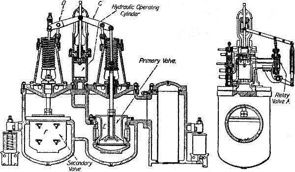
Figs. 2,756 and 2,757.—Westinghouse valve
gear with oil relay. Governors for the larger turbines, particularly
those of the combination impulse and reaction double, or single
double flow type, employ an oil relay mechanism, as shown in the
figure, for operating the steam valves. In these turbines the
lubricating oil circulating pump, maintains a higher pressure than is
required for the lubricating system. The governor controls a small
relay valve A which admits pressure oil to, or exhausts it from the
operating cylinder. When oil is admitted to the operating cylinder
raising the piston, the lever C lifts the primary valve E. The
lever D moves simultaneously with C, but on account of the slotted
connection with the stem of the secondary valve F, the latter does
not begin to lift until the primary valve is raised to the point
at which its effective opening ceases to be increased by further
upward travel. In the Westinghouse designs, the operating valve, A
is connected not only to the governor, but also to a vibrator, which
gives it a slight but continuous reciprocating motion, while the
governor controls its mean position. The effect of this is manifested
in a slight pulsation throughout the entire relay system, which, so
to speak, keeps it "alive" and ready to respond instantly, to the
smallest change in the position of the governor. The oil relay can be
made sufficiently powerful to operate valves of any size, and it is
also in effect a safety device in that any failure of the lubricating
oil supply will automatically and immediately shut off the steam and
stop the turbine.
A weighted accumulator is sometimes installed in connection with
the oil pipe as a convenient device for governing the step bearing
pumps, and also as a safety device in case the pumps should fail, but
it is seldom required for the latter purpose, as the step bearing
pumps have proven after a long service in a number of cases, to be
reliable. The vertical shaft is also held in place and kept steady
by three sleeve bearings one just above the step, one between the
turbine and generator, and the other near the top.
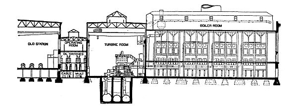
Fig. 2,758.—Elevation of new turbine
central station erected by the Boston Edison Co. The turbine room is
68 feet, 4 inches wide and 650 feet long from outside to outside of the
walls. The boiler room is 149 feet, 6 inches by 640 feet and equipped
with twelve groups of boiler, one group consisting of eight 512 H.P.
boilers for each turbine. The switching arrangements are located in
a separate building as shown in the elevation. The total floor space
covered by boiler room, turbine room and switchboard room is 2.64
square feet per kw. The boilers are all on the ground floor.
See fig. 2,714 for plan.
These guide bearings are lubricated by a standard gravity feed
system. It is apparent that the amount of friction in the machine is
very small, and as there is no end thrust caused by the action of the
steam, the relation between the revolving and stationary blades may
be maintained accurately. As a consequence, therefore, the clearances
are reduced to the minimum.
The Curtis turbine is divided into two or more stages, and each
stage has one, two or more sets of revolving blades bolted upon
the peripheries of wheels keyed to the shaft. There are also the
corresponding sets of stationary blades bolted to the inner walls of
the cylinder or casing.
The governing of speed is accomplished in the first set of nozzles
and the control of the admission valves here is effected by means of
a centrifugal governor attached to the top end of the shaft. This
governor, by a very slight movement, imparts motion to levers, which
in turn work the valve mechanism.
The admission of steam to the nozzles is controlled by piston valves
which are actuated by steam from small pilot valves which are in turn
under the control of the governor.
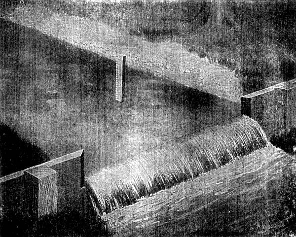
Fig. 2,759.—Illustration of a weir. To
make a weir, place a board across the stream at some point which will
allow a pond to form above. The board should have a notch cut in
it with both side edges and the bottom sharply beveled toward the
intake, as shown in the above cut. The bottom of the notch, which
is called the "crest" of the weir, should be perfectly level and
the sides vertical. In the pond back of the weir, at a distance not
less than the length of the notch, drive a stake near the bank, with
its top precisely level with the crest. By means of a rule, or a
graduated stake as shown, measure the depth of water over the top
of stake, making allowance for capillary attraction of the water
against the sides of the weir. For extreme accuracy this depth may
be measured to thousandths of a foot by means of a "hook gauge,"
familiar to all engineers. Having ascertained the depth of water
over the stake, refer to the accompanying table, from which may be
calculated the amount of water flowing over the weir. There are
certain proportions which must be observed in the dimensions of this
notch. Its length, or width, should be between four and eight times
the depth of water flowing over the crest of the weir. The pond
back of the weir should be at least fifty per cent. wider than the
notch and of sufficient width and depth that the velocity of flow or
approach be not over one foot per second. In order to obtain these
results it is advisable to experiment to some extent.
Speed regulation is effected by varying the number of nozzles in
flow, that is, for light loads fewer nozzles are open and a smaller
volume of steam is admitted to the turbine wheel, but the steam that
is admitted impinges against the moving blades with the same velocity
always, no matter whether the volume be large or small. With a full
load and all the nozzle sections in flow, the steam passes to the
wheel in a broad belt and steady flow.
WEIR TABLE
giving cubic feet of water per minute that will flow over a weir
one inch wide and from ⅛ to 20⅞ inches deep.
Depth
inches | |
⅛ | ¼ |
⅜ | ½ |
⅝ | ¾ |
⅞ |
| 0 | .00 |
.01 | .05 |
.09 | .14 |
.19 | .26 |
.32 |
| 1 | .40 |
.47 | .55 |
.64 | .73 |
.82 | .92 |
1.02 |
| 2 | 1.13 |
1.23 | 1.35 |
1.36 | 1.58 |
1.70 | 1.82 |
1.95 |
| 3 | 2.07 |
2.21 | 2.34 |
2.48 | 2.61 |
2.76 | 2.90 |
3.05 |
| 4 | 3.20 |
3.35 | 3.50 |
3.66 | 3.81 |
3.97 | 4.14 |
4.30 |
| 5 | 4.47 |
4.64 | 4.81 |
4.98 | 5.15 |
5.33 | 5.51 |
5.69 |
| 6 | 5.87 |
6.06 | 6.25 |
6.44 | 6.62 |
6.82 | 7.01 |
7.21 |
| 7 | 7.40 |
7.60 | 7.80 |
8.01 | 8.21 |
8.42 | 8.63 |
8.83 |
| 8 | 9.05 |
9.26 | 9.47 |
9.69 | 9.91 |
10.13 | 10.35 |
10.57 |
| 9 | 10.80 |
11.02 | 11.25 |
11.48 | 11.71 |
11.94 | 12.17 |
12.41 |
| 10 | 12.64 |
12.88 | 13.12 |
13.36 | 13.60 |
13.85 | 14.09 |
14.34 |
| 11 | 14.59 |
14.84 | 15.09 |
15.34 | 15.59 |
15.85 | 16.11 |
16.36 |
| 12 | 16.62 |
16.88 | 17.15 |
17.41 | 17.67 |
17.94 | 18.21 |
18.47 |
| 13 | 18.74 |
19.01 | 19.29 |
19.56 | 19.84 |
20.11 | 20.39 |
20.67 |
| 14 | 20.95 |
21.23 | 21.51 |
21.80 | 22.08 |
22.37 | 22.65 |
22.94 |
| 15 | 23.23 |
23.52 | 23.82 |
24.11 | 24.40 |
24.70 | 25.00 |
25.30 |
| 16 | 25.60 |
25.90 | 26.20 |
26.50 | 26.80 |
27.11 | 27.42 |
27.72 |
| 17 | 28.03 |
28.34 | 28.65 |
28.97 | 29.28 |
29.59 | 29.91 |
30.22 |
| 18 | 30.54 |
30.86 | 31.18 |
31.50 | 31.82 |
32.15 | 32.47 |
32.80 |
| 19 | 33.12 |
33.45 | 33.78 |
34.11 | 34.44 |
34.77 | 35.10 |
35.44 |
| 20 | 35.77 |
36.11 | 36.45 |
36.78 | 37.12 |
37.46 | 37.80 |
38.15 |
NOTE.—The weir table on this page contains figures 1, 2, 3, etc.,
in the first vertical column which indicates the inches depth of
water running over weir board notches. Frequently the depths measured
represent also fractional inches, between 1 and 2, 2 and 3, etc. The
horizontal line of fraction at the top represents these fractional
parts, and can be applied between any of the numbers of inches
depth, from 1 to 25. The body of the table shows the cubic feet, and
the fractional parts of a cubic foot, which will pass each minute
for each inch in depth, and for each fractional part of an inch by
eighths for all depths from 1 to 25 inches. Each of these results is
for only one inch width of weir. To estimate for any width of weir
the result obtained for one inch width must be multiplied by the
number of inches constituting the whole horizontal length of weir.
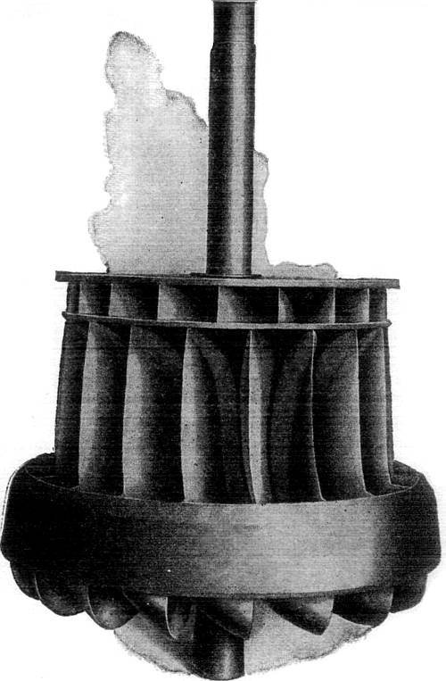
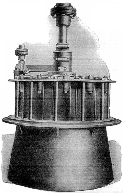
Figs. 2,760 and 2,761.—Samson vertical
runner and shaft, and complete Samson vertical turbine. The runner
is composed of two separate and distinct types of wheel, having
thereby also two diameters. Each wheel or set of buckets receives
its separate quantity of water from one and the same set of guides,
but each set acts only once and singly upon the water used, and the
water does not act twice upon the combined wheel, as some suppose. In
construction, the lower or main set of buckets is made of flanged
plate steel, and cast solidly into a heavy ring surrounding the outer
and lower edges, and into a heavy diaphragm, separating the two sets
of buckets.
Fig. 2,762.—Water discharging from a needle
nozzle due to a pressure of 169 lbs. per sq. in.
Hydro-Electric
Plants.—The economy with which electricity can be
transmitted long distances by high tension alternating currents, has
led to the development of a large number of water powers in more or
less remote regions.
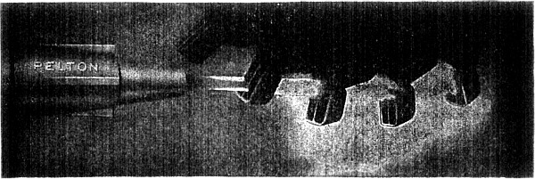
Fig. 2,763.—Photograph of an operating
tangential water wheel equipped with Pelton buckets.
This economy is possible by the facility with which alternating
current can be transformed up and down. Thus at the hydro-electro
plant, the current generated by the water wheel driven alternator is
transformed to very high pressure and transmitted with economy a long
distance to the distributing point where it is transformed down to
the proper pressure for distribution.
A water wheel or turbine is a machine in which a rotary motion is
obtained by transference of the momentum of water; broadly speaking,
the fluid is guided by fixed blades, attached with a casing, and
impinging on other blades mounted on a drum or shaft, causing the
latter to revolve.
There are two general classes of turbine:
1. Impulse turbines;
2. Reaction turbines.
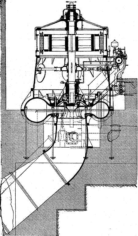
Fig. 2,764.—Sectional elevation of one of
the 5,000 horse power vertical Pelton-Francis turbines directly
connected to generator, as installed for the Schenectady Power Co.
Ques. What is an impulse turbine?
Ans. One in which the fluid is directed by means of a series of
nozzles against vanes which it drives.
Ques. What is a reaction turbine?
Ans. One in which the pressure or head of the water is employed
rather than its velocity. The current is deflected upon the wheel by
the action of suitably disposed guide blades, the passages being full
of water. Rotary motion is obtained by the change in the direction
and momentum of the fluid.
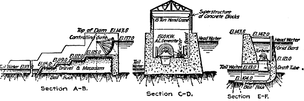
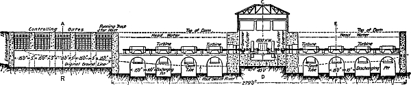
Figs. 2,765 to 2,768.—Cross sections of Lowel dam
power house, and wheel pits containing sixteen Samson turbines: The
section C-D gives an end view of the generator room showing the
locations of the generators below the head level water. They are
secure against flood water, or leakage, by well constructed stuffing
boxes in the iron bulkheads, through which the turbine wheel shafts
pass and connect to the generators. Section E-F gives an end view of
one of these wheel rooms or penstocks, and shows the extension of the
draft tube from wheel case into tail water. The section A-B shows the
sub-structure of gravel and macadam under the controlling gates, this
forming also a portion or extension of the dam proper. These gates
turn on an axis made of two 15 inch I beams securely riveted together
with plates and angle irons to which the wooden frame is attached.
The radius of the gates is 14 feet. They are designed to allow the
water to pass underneath the gate, thus controlling any height of
head water. They are intended to take care of an excess of water at
unusual stages of the river. The whole affair has been well designed
and executed. This plant furnishes a good example of a secure, and
level foundation, since the wheel houses and generator room are
immediately on the rock. It is necessary in all tandem plants to
provide a very secure, substantial super-structure so that the long
line of turbines and shaft will always remain straight and in proper
alignment with the generator and the turbine cases. Users cannot be
reminded of this too often.
Ques. Name three classes of reaction turbines.
Ans. Parallel flow, inward flow, and outward flow.
Parallel flow turbines have an efficiency of about 70% and are suited
for low falls not over 30 feet. Inward and outward flow turbines have an
efficiency of about 85%. Impulse turbines are suitable for high heads.
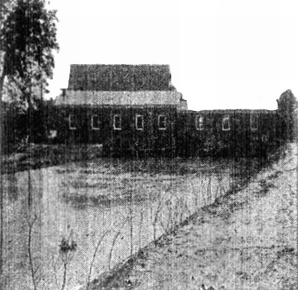
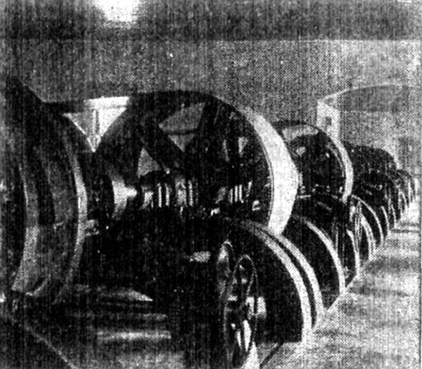
Figs. 2,769 and 2,770.—Exterior and interior
of hydro-electric plant at Harrisburg, Va. It is located on the south
fork of the Shenandoah River, twelve and one-half miles distant. A
dam 720 feet long and 15 feet high was built on a limestone ledge
running across the river; which with a fall of 5 feet from the dam to
the power house, a quarter of a mile distant, secured an effective
head pressure of 20 feet. The power house, comprising the generator
room and the wheel room, also the machinery room, are here shown.
The wheel room, which is 20 × 40 feet, extends across the head race,
and rests upon solid concrete walls, forming the sides and ends of
the wheel pits. The end wall is 6 feet thick at the bottom, and
4½ feet at the top. It has three arched openings, each 8 feet
wide and 9 feet high, through which the water escapes after leaving
the turbines. The intake is protected by a wrought iron rack 40 feet
long. The power is obtained by three 50 inch vertical shaft Samson
turbines, with a 20 inch Samson for an exciter. The three large
turbines have a rating of 1,350 horse power; and are connected to the
main horizontal line shaft by bevel mortise gears 7 feet diameter and
15 inches face. The couplings on the main shaft have 48 inch friction
clutch hubs, permitting either or each turbine being operated, or
shut down independently of the others. The main shaft is 85 feet long
and 6 inches diameter; making 280 revolutions. This shaft carries
two pulleys 70 inches diameter and 38 inches face for driving the
generators. The accompanying illustration shows the harness work,
gears, pulleys, etc., furnished with the turbines. The 20 inch
horizontal shaft Samson turbine of 72 horse power is direct connected
to an exciter generator of 20 kw., running 700 rev. per min. The
two large generators are driven 450 revolutions per minute by belts
producing a three phase current of 60 cycles of 11,500 volts for the
twelve and one-half miles transmission. The line consists of three
strands of No. 4 bare copper wire. This current is used for lighting
and power purposes, and the plant is of the latest improved design
and construction.
Isolated Plants.—When electric power transmission
from central stations first came into commercial use, the distance
from the station at which current could be obtained at a reasonable
cost was exceedingly limited.
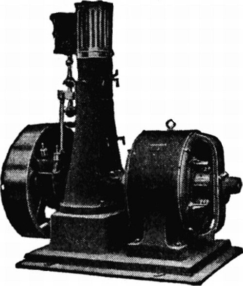
Fig. 2,769a.—Triumph direct current generator
set with upright slide valve engine.
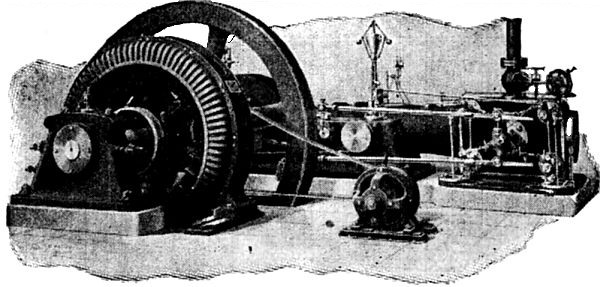
Fig. 2,770a.—Murray alternating current
direct connected unit with high speed Corliss engine and belt driven
exciter, 50, 75 and 100 kva. alternator and 150 R.P.M. engine.
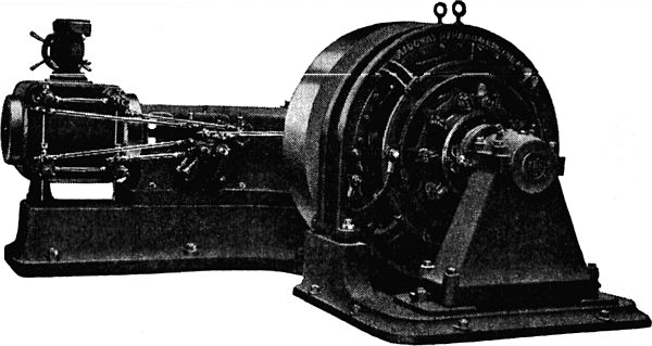
Fig. 2,771.—Direct connected direct current
unit with Ridgway high speed four valve engine.
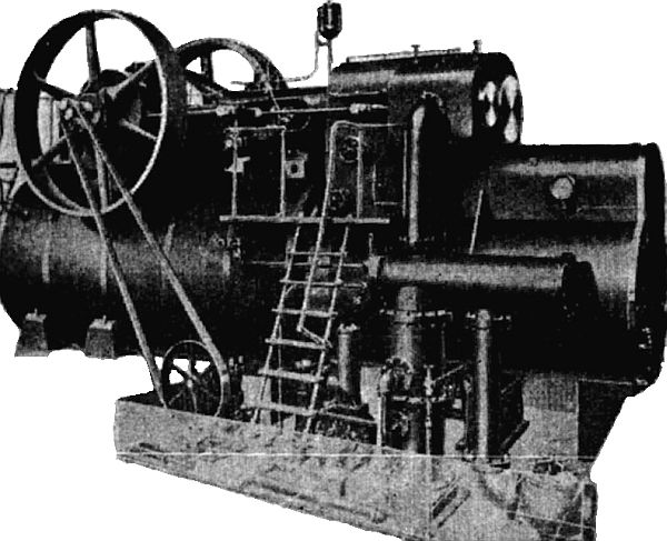
Fig. 2,772.—Buckeye mobile, or self
contained unit consisting of compound condensing engine, boiler,
superheater, reheater, feed and air pumps; it produces one horse
power on 1½ lbs. of coal, built in sizes from 75 to 600 horse power.
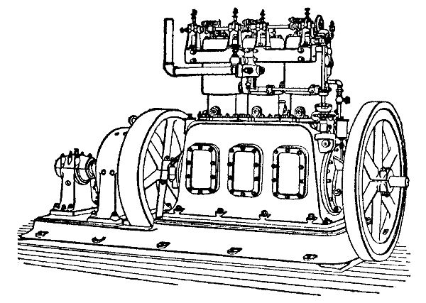
Fig. 2,773.—Westinghouse three cylinder gas
engine, direct connected to dynamo, showing application of gas engine
drive for small direct connected units.
Consequently, persons desiring electrical power were in the majority
of cases forced to install their own apparatus for producing it, this
being the origin of isolated plants.
From the nature of the case it is evident that an isolated plant is
as a rule smaller and more simple in construction than a central
station, and in consequence much more readily operated and managed.
It is generally owned by a private individual or a corporation and
operated in conjunction with other affairs of a similar character. A
basement or other portion of a building is usually set aside in which
the necessary apparatus is installed.
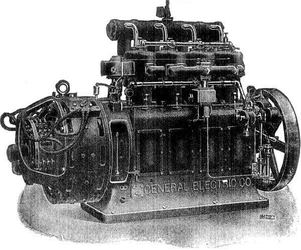
Fig. 2,774.—General Electric 25 kw.,
gasoline electric generating set for lighting and power. The engine
has four cylinders 7¼ × 7½, and runs at a speed of 560 revolutions
per minute. The total candle power capacity in Mazda lamps is 20,000.
The ignition is by low tension magneto, coil and battery. Carburetter
is of the constant level type to which gasoline is delivered by a
pump driven by the engine. Forced lubrication; five crank shaft
bearings babbitted; valves in side; overall dimensions 96 × 34 × 60
high; weight 5,000.
Although electricity is now transmitted economically to great
distances from central stations, there is still a field for the
isolated plant.
The average type of isolated plant has enlarged from a small dynamo
driven by a little slide valve engine located in an out of the way
corner to direct connected generators and engines of hundreds and
even thousands of horse power assembled in a large room specially
adapted to the purpose.
In the more modern of these, the electrical outputs are each
frequently equal to that of a town central station of respectable
size, and the auxiliary equipments are similar in every particular.
As a matter of fact, in certain modern isolated plants the only
feature that distinguishes them from central stations is that in the
former case the owner of the plant represents the sole consumer and
conducts other business in connection with it, whereas in the latter
case there are a large number of consumers uninterested financially
in the enterprise, which is itself generally owned and operated by a
company conducting no other business.
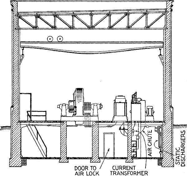
Fig. 2,775.—Plan of sub-station with air
blast transformers and motor operated oil switches and underground
11,000 or 13,200 volt high tension lines.
Sub-Stations.—According to the usual meaning of
the term, a sub-station is a building provided with apparatus for
changing high pressure alternating current received from the central
station into direct current of the requisite pressure, which in the
case of railways is 550 to 600 volts.
Where traffic is heavy and the railway system of
considerable distance, sub-stations are provided at
intervals along the line, each receiving high pressure current from
one large central station and converting it into moderate pressure
direct current for their districts.
Ques. Upon what does the arrangement of the sub-station depend?
Ans. Upon the character of the work and the type of apparatus
employed for converting the high pressure alternating current into
direct current.
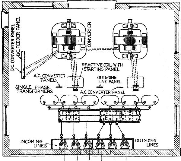
Fig. 2,776.—Plan of small sub-station
with single phase oil insulated self-cooling transformers and hand
operated oil switches 11,000 or 13,200 volts, overhead high tension lines.
In general it should be substantial, convenient to install or replace
the heavy machines, and the layout arranged so that the apparatus can
be readily operated by those in attendance.
An overhead traveling crane is the most convenient method of handling
the heavy machinery, and is frequently used in large sub-stations.
Fig. 2,776 shows a sectional view, and fig. 2,777,
a plan for a small sub-station containing two rotary converters and
two banks of three single phase static transformers operating on
a three phase system at 11,000 or 13,200 volts, together with the
auxiliary apparatus.
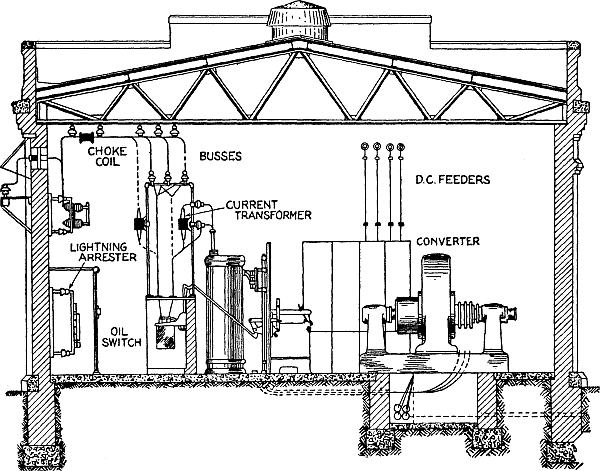
Fig. 2,777.—Elevation of small sub-station,
as shown in plan in Fig. 2,776.
Ques. For three phase installations, what are the merits of
separate and combined transformers?
Ans. With separate transformer for each phase, repairs are more
readily made in case of accident or burnouts in the coils. The three
phase units have the advantage of low first cost.
Sub-station transformers produce considerable heat, due to the
hysteresis and eddy currents, and it is necessary to get rid of it.
Small transformers radiate the heat from the shell and the medium
sizes have corrugated shells which increase the surface and provide
more rapid radiation.
Large transformers are cooled by an air blast supplied by motor
driven blowers or by water pumped through a coil of pipe which is
immersed in the insulating oil of the transformer. The large size oil
insulated, water cooled transformers are used on circuits of 33,000
volts or more. In water turbine plants, the water may be piped to the
transformer under pressure and the pump omitted which cuts down the
cost of operating. Air blast transformers usually have a damper or
shutter for air control.
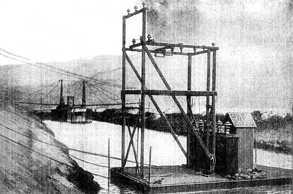
Fig. 2,778.—Marine portable transformer
station on Los Angeles Aqueduct. The view shows three 20 kva.
Westinghouse out door transformers installed on a float, 33,000 volts
high pressure; 440 volts low pressure; 50 cycles.
Ques. Explain the use of reactance coils in sub-stations.
Ans. In order that the direct current voltage of the ordinary rotary
may be regulated by a field rheostat, which calls for a corresponding
change in the alternating current voltage, a reactance coil is
provided between the low tension winding and the converter.
Without such a reactance the maintenance of the same voltage at full
load as at no load involves excessive leading and lagging currents
and consequently excessive heating in the armature inductors, unless
the resistance drop from the source of constant pressure is small, or
the natural reactance of the circuit high.
Ques. What is the effect of weakening the converter field?
Ans. A lagging current is set up which causes
a drop in the reactance coil.
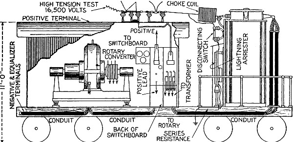
Fig. 2,779.—Sectional elevation of portable
outdoor transformer type sub-station. The high voltage switching and
protective apparatus is mounted, out of the way, on the roof of the
car, but is operated from the switchboard with a standard remote
control handle. The transformer is carried directly over the truck at
the uncovered end of the car and the low-tension leads from it run in
conduit beneath the floor and up into the cab, (which contains the
converter and switchboard) to the converter. The positive lead runs
through a conduit and ends in a terminal on the roof. The energy thus
makes a complete circuit of the car leaving at a point close to that
at which it entered. The low pressure alternating current as well as
the direct current positive leads are carried below the car floor
in iron conduit supported from the channel frame. The field wires
are carried through this conduit to the rheostat. Wiring for the
lights is arranged to supply two, 5 light clusters. One is fed with
the 600 volt direct current and the other with 420 volt alternating
current. All lighting conductors are carried in metal moulding
carried between the flanges of the channel iron ribs. High wiring
is carried entirely on the roof of the car where it is entirely out
of the way and where the operator cannot come in contact with it.
The switchboard should be of the utmost simplicity. Usually the
negative and equalizer switches, and the field break-up switch are
mounted on the frame of the converter. The double throw switch for
starting and running the converter can be mounted under the floor
of the car and operated by handle at the switchboard. The rheostat
can be mounted back of the switchboard on brackets bolted to the car
super-structure. The switchboard need only carry the positive knife
switch and circuit breaker, and the alternating current ammeter,
voltmeter and power factor meter. Sometimes a watthour meter is
added. The positive lead is brought out through a conduit on the
roof of the car and is arranged for bolting to the positive feeder.
The negative and equalizer terminals are located at the cab end of
the car and are arranged so that connection can be easily made from
them to the ground and, if necessary, to an equalizer circuit. There
is usually a sliding door at each end of the cab and two windows on
each side. Above the doors, transoms, extending the width of the cab,
are arranged to drop so that a current of air will circulate through
the cab under the roof, carrying out the heated air. There are also
several ventilating holes beneath the converter in the floor of the
car. These provisions insure a constant circulation of air through
the car which carries away all heated air.
Ques. State the effect of strengthening converter field.
Ans. A leading current is set up which gives a rise of voltage
in the reactance coil.
Hence when a heavy current passes through the series coil of a compound
wound converter and tends to produce a leading current, the reactance
coil will balance it, and improve the power factor of the whole line.
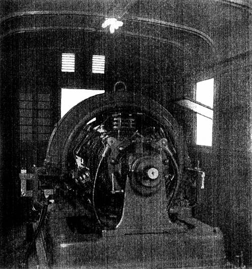
Fig. 2,780.—Westinghouse 300 kw. converter in
portable sub-station.
Portable Sub-Stations.—A portable sub-station constitutes a
spare equipment for practically any number of permanent sub-stations
and renders unnecessary the installation of spare equipment in each.
It can be used to increase the capacity of a permanent sub-station
when the load is unusually heavy, or to provide service while a
permanent sub-station is being overhauled or rebuilt.
The transformer can be used for emergency lighting, the primary being
connected to a high pressure line and the secondary to the load, if
special provision be made at the time the transformer is built to
adapt it for these applications.
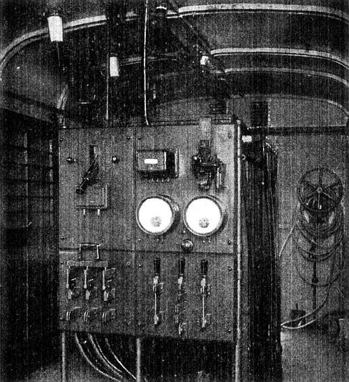
Fig. 2,781.—Switchboard end of Westinghouse
portable sub-station.
When an electric railway has a portable sub-station, direct current
can be provided at any point on the system where there is track at
the high pressure line. The direct current can be made available very
quickly as its production involves only the transferring of the
sub-station, and its connection to the high pressure line.
Portable sub-stations range in capacity from 200 to 500 kw., and for
all alternating current voltages up to 66,000, and frequencies of 25
and 60 cycles.
Although portable sub-stations usually must be of more or less
special design to adapt them to the conditions under which they must
operate, there are certain general features that are common to all.
All members are readily accessible and there are no unnecessary
parts. The weight and dimensions are a minimum insuring ease of
transportation. Live parts are so protected that the danger of
accidental contact with them is minimized.
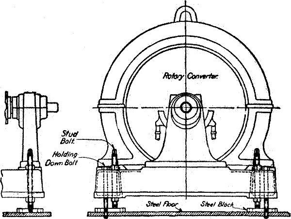
Figs. 2,782 and 2,783.—Views of levelling
device for Westinghouse converter.
Ques. What are the advantages of using outdoor transformers
on portable sub-stations?
Ans. All high pressure wiring is kept out of the car. The transformer
is more effectively cooled and the heat dissipated by the transformer
does not warm the interior of the cab. The transformer is much more
accessible. The car can be run under a crane and the transformer
coils pulled out with a hoist.
Taps for different high and low pressure voltages can be readily
provided at the time the transformer is being built.
CHAPTER LXVII MANAGEMENT
The term "management," broadly speaking, includes not only the
actual skilled attention necessary for the proper operation of the
machines, after the plant is built, but also other duties which must
be performed from its inception to completion, and which may be
classified as
1. Selection;
2. Location;
3. Erection;
4. Testing;
5. Running;
6. Care;
7. Repair.
That is to say, someone must select the machinery, determine where
each machine is to be located, install them, and then attend to the
running of the machines and make any necessary repairs due to the
ordinary mishaps likely to occur in operation.
These various duties are usually entrusted to more than one
individual; thus, the selection and location of the machinery is done
by the designer of the plant, and requires for its proper execution
the services of an electrical engineer, or one possessing more than
simply a practical knowledge of power plants.
The erection of the machines is best accomplished by those
making a specialty of this line of work, who by the nature of the
undertaking acquire proficiency in methods of precision and an
appreciation of the value of accuracy which is so essential in the
work of aligning the machines, and which if poorly done will prove a
constant source of annoyance afterward.
The attention required for the operation of the machines,
embracing the running care and repair, is left to the "man in
charge," who in most cases of small and medium size plants is the
chief steam engineer. He must therefore, not only understand the
steam apparatus, but possess sufficient knowledge of electrical
machinery to operate and maintain it in proper working order.
The present chapter deals chiefly with alternating current
machinery, the management of direct current machines having been
fully explained in Guide No. 3, however, some of the matter here
presented is common to both classes of apparatus.
Selection.—In order to intelligently select a
machine so that it will properly harmonize with the conditions under
which it is to operate, there are several things to be considered.
1. Type;
2. Capacity;
3. Efficiency;
4. Construction.
The general type of machine to be used is, of course, dependent
on the system employed, that is, whether it be direct or alternating,
single or polyphase.
Thus, the voltage in most cases is fixed except on transformer systems
where a choice of voltage may be had by selecting a transformer to suit.
In alternating current constant pressure transmission circuits,
an average voltage of 2,200 volts with step down transformer
ratios of 1⁄10 and
1⁄20 is in general use, and is recommended.
For long distance, the following average voltages are recommended
6,000; 11,000; 22,000; 33,000; 44,000; 66,000; 88,000; and higher,
depending on the length of the line and degree of economy desired.
In alternating circuits the standard frequencies are 25, and 60
cycles. These frequencies are already in extensive use and it is
recommended to adhere to them as closely as possible.
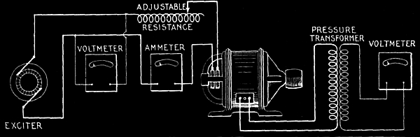
Fig. 2,784.—Diagram of connections for
testing to obtain the saturation curve of an alternator. The
saturation curve shows the relation between the volts generated in
the armature and the amperes of field current (or ampere turns of the
field) for a constant armature current. The armature current may be
zero, in which case the curve is called no load saturation curve,
or sometimes the open circuit characteristic curve. A saturation
curve may be taken with full load current in the armature; but this
is rarely done, except in alternators of comparatively small output.
If a full load saturation curve be desired, it can be approximately
calculated from the no load saturation curve. The figure shows the
connections. If the voltage generated is greater than the capacity of
the voltmeter, a multiplying coil or a step down pressure transformer
may be used, as shown. A series of observations of the voltage
between the terminals of one of the phases, is made for different
values of the field current. Eight or nine points along the curve are
usually sufficient, the series extending from zero to about fifty per
cent. above normal rated voltage. The points should be taken more
closely together in the vicinity of normal voltage than at other
portions of the curve. Care must be taken that the alternator is run
at its rated speed, and this speed must be kept constant. Deviations
from constant speed may be most easily detected by the use of a
tachometer. If the machine be two phase or three phase, the voltmeter
may be connected to any one phase throughout a complete series of
observations. The voltage of all the phases should be observed for
normal full load excitation by connecting the voltmeter to each phase
successively, keeping the field current constant at normal voltage.
This is done in order to see how closely the voltage of the different
phases agree.
In fixing the capacity of a machine, careful consideration should
be given to the conditions of operation both present and
future in order that the resultant efficiency may be maximum.
Most machines show the best efficiency at or near full load. If the
load be always constant, as for instance, a pump forcing water to a
given head, it would be a simple matter to specify the proper size
of machine, but in nearly all cases, and especially in electrical
plants, the load varies widely, not only the daily and hourly
fluctuations, but the varying demands depending on the season of the
year and growth of the plant's business. All of these conditions tend
to complicate the matter, so that intelligent selection of capacity
of a machine requires not only calculation but mature judgment, which
is only obtained by long experience.
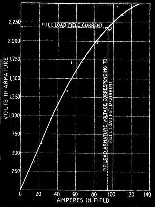
Fig. 2,785.—Saturation curve taken from
a 2,000 kw., three phase alternator of the revolving field type, having
16 poles, and generating 2,000 volts, and 576 amperes per phase when
run at 300 R.P.M.
In selecting a machine, or in fact any item connected with the plant
its construction should be carefully considered.
Standard construction should be insisted upon so that in the event of
damage a new part can be obtained with the least possible delay.
The parts of most machines are interchangeable, that is to say,
with the refined methods of machinery a duplicate part (usually
carried in stock) may be obtained at once to replace a defective or
broken part, and made with such precision that little or no fitting
will be required.
The importance of standard construction cannot be better illustrated
than in the matter of steam piping, that is, the kind of fittings
selected for a given installation.
With the exception of the exhaust line from engine to condenser,
where other than standard construction may sometimes be used to
reduce the frictional resistance to the steam, the author would
adhere to standard construction except in very exceptional cases.
Those who have had practical experience in pipe fitting will
appreciate the wisdom of this.
For installations in places remote from large supply houses, the
more usual forms of standard fittings should be employed, such as
ordinary T's, 45° and 90° elbows, etc.
In such locations, where designers specify the less usual forms
of standard fittings such as union fittings, offset reducers, etc.,
or special fittings made to sketch, it simply means, in the first
instance that they usually cannot be obtained of the local dealer,
making it necessary to order from some large supply house and
resulting in vexatious delays.
As a rule, those who specify special fittings have found that
their making requires an unreasonable length of time, and the cost to
be several times that of the equivalent in standard fittings.
An examination of a few installations will usually show numerous
special and odd shape fittings, which are entirely unnecessary.
Moreover, a standard design, in general, is better than a special
design, because the former has been tried out, and any imperfection
or weakness remedied, and where thousands of castings of a kind are
turned out, a better article is usually the result as compared with a
special casting.
In the matter of construction, in addition to the items just mentioned,
it should be considered with respect to
1. Quality;
2. Range;
3. Accessibility;
4. Proportion;
5. Lubrication;
6. Adjustment.
It is poor policy, excepting in very rare instances, to buy a "cheap"
article, as, especially in these days of commercial greed, the best
is none too good.
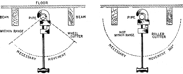
Figs. 2,786 and 2,787.—Wheel and roller
pipe cutters illustrating range. The illustrations show the
comparative movements necessary with the two types of cutter to
perform their function. The wheel cutter requiring only a small arc
of movement will cut a pipe in an inaccessible place as shown, which
with a roller cutter would be impossible. Accordingly, the wheel
cutter is said to have a greater range than the roller cutter.
Perhaps next in importance to quality, at least in most
cases, is range. This may be defined as scope of operation,
effectiveness, or adaptability. The importance of range is
perhaps most pronounced in the selection of tools, especially for
plants remote from repair shops.
For instance, in selecting a pipe cutter,
there are two general classes: wheel cutters, and roller cutters. A
wheel cutter has three wheels and a roller cutter one wheel and two
rollers, the object of the rollers being to keep the
wheel perpendicular to the pipe in starting the cut and to reduce
burning. It must be evident that in operation, a roller cutter
requires sufficient room around the pipe to permit making a complete
revolution of the cutter, whereas, with a wheel cutter, the work may
be done by moving the cutter back and forth through a small arc,
as illustrated in figs. 2,786 and 2,787.
Thus a wheel cutter has a greater range than a roll cutter.
Range relates not only to ability to operate in inaccessible
places but to the various operations that may be performed by one tool.
PROPERTIES OF STANDARD WROUGHT IRON PIPE
| Diameter. | Thick-
ness. |
Circumference. |
Transverse areas. |
Nominal
internal. | Actual
external. |
Actual
internal. | |
External. | Internal. |
External. | Internal. |
Metal. |
| Inches | Inches |
Inches | Inches |
Inches | Inches |
Sq. ins. | Sq. ins. |
Sq. ins. |
| ⅛ | .405 |
.27 | .068 |
1.272 | .848 |
.129 | .0573 |
.0717 |
| ¼ | .54 |
.364 | .088 |
1.696 | 1.144 |
.229 | .1041 |
.1249 |
| ⅜ | .675 |
.494 | .091 |
2.121 | 1.552 |
.358 | .1917 |
.1663 |
| ½ | .84 |
.623 | .109 |
2.639 | 1.957 |
.554 | .3048 |
.2492 |
| ¾ | 1.05 |
.824 | .113 |
3.299 | 2.589 |
.866 | .5333 |
.3327 |
| 1 | 1.315 |
1.048 | .134 |
4.131 | 3.292 |
1.358 | .8626 |
.4954 |
| 1¼ | 1.66 |
1.38 | .14 |
5.215 | 4.335 |
2.164 | 1.496 |
.668 |
| 1½ | 1.9 |
1.611 | .145 |
5.969 | 5.061 |
2.835 | 2.038 |
.797 |
| 2 | 2.375 |
2.067 | .154 |
7.461 | 6.494 |
4.43 | 3.356 |
1.074 |
| 2½ | 2.875 |
2.468 | .204 |
9.032 | 7.753 |
6.492 | 4.784 |
1.708 |
| 3 | 3.5 |
3.067 | .217 |
10.996 | 9.636 |
9.621 | 7.388 |
2.243 |
| 3½ | 4. |
3.548 | .226 |
12.566 | 11.146 |
12.566 | 9.887 |
2.679 |
| 4 | 4.5 |
4.026 | .237 |
14.137 | 12.648 |
15.904 | 12.73 |
3.174 |
| 4½ | 5. |
4.508 | .246 |
15.708 | 14.162 |
19.635 | 15.961 |
3.674 |
| 5 | 5.563 |
5.045 | .259 |
17.477 | 15.849 |
24.306 | 19.99 |
4.316 |
| 6 | 6.625 |
6.065 | .28 |
20.813 | 19.054 |
34.472 | 28.888 |
5.584 |
| 7 | 7.625 |
7.023 | .301 |
23.955 | 22.063 |
45.664 | 38.738 |
6.926 |
| 8 | 8.625 |
7.982 | .322 |
27.096 | 25.076 |
58.426 | 50.04 |
8.386 |
| 9 | 9.625 |
8.937 | .344 |
30.238 | 28.076 |
72.76 | 62.73 |
10.03 |
| 10 | 10.75 |
10.019 | .366 |
33.772 | 31.477 |
90.763 | 78.839 |
11.924 |
| 11 | 12. |
11.25 | .375 |
37.699 | 35.343 |
113.098 | 99.402 |
13.696 |
| 12 | 12.75 |
12. | .375 |
40.055 | 37.7 |
127.677 | 113.098 |
14.579 |
PROPERTIES OF STANDARD WROUGHT IRON PIPE
(Continued)
| Diam. |
Length of
pipe per
square
foot of |
Length of
pipe per
containing
one cubic
foot. |
Nominal
weight
per foot. |
Number of
threads
per inch. |
Nominal
internal. |
External
surface | Internal
surface |
| Inches | Feet. |
Feet. | Feet. |
Pounds. | |
| ⅛ | 9.44 |
14.15 | 2513. |
.241 | 27 |
| ¼ | 7.075 |
10.49 | 1383.3 |
.42 | 18 |
| ⅜ | 5.657 |
7.73 | 751.2 |
.559 | 18 |
| ½ | 4.547 |
6.13 | 472.4 |
.837 | 14 |
| ¾ | 3.637 |
4.635 | 270. |
1.115 | 14 |
| 1 | 2.904 |
3.645 | 166.9 |
1.668 | 11½ |
| 1¼ | 2.301 |
2.768 | 96.25 |
2.244 | 11½ |
| 1½ | 2.01 |
2.371 | 70.66 |
2.678 | 11½ |
| 2 | 1.608 |
1.848 | 42.91 |
3.609 | 11½ |
| 2½ | 1.328 |
1.547 | 30.1 |
5.739 | 8 |
| 3 | 1.091 |
1.245 | 19.5 |
7.536 | 8 |
| 3½ | .955 |
1.077 | 14.57 |
9.001 | 8 |
| 4 | .849 |
.949 | 11.31 |
10.665 | 8 |
| 4½ | .764 |
.848 | 9.02 |
12.34 | 8 |
| 5 | .687 |
.757 | 7.2 |
14.502 | 8 |
| 6 | .577 |
.63 | 4.98 |
18.762 | 8 |
| 7 | .501 |
.544 | 3.72 |
23.271 | 8 |
| 8 | .443 |
.478 | 2.88 |
28.177 | 8 |
| 9 | .397 |
.427 | 2.29 |
33.701 | 8 |
| 10 | .355 |
.382 | 1.82 |
40.065 | 8 |
| 11 | .318 |
.339 | 1.450 |
45.95 | 8 |
| 12 | .299 |
.319 | 1.27 |
48.985 | 8 |
Open construction should be employed, wherever possible, so that
all parts of a machine that require attention, or that may become
deranged in operation, may be accessible for adjustment or repair.
The design should be such that there is ample strength, and the
bearings for moving parts should be of liberal proportions to avoid
heating with minimum attention.
A comparison of the proportions used by different manufacturers for a
machine of given size might profitably be made before a selection is
made.
The matter of lubrication is important.
Fast running machines, such as generators and motors, should be
provided with ring oilers and oil reservoirs of ample capacity, as
shown in figs. 2,788 to 2,794.
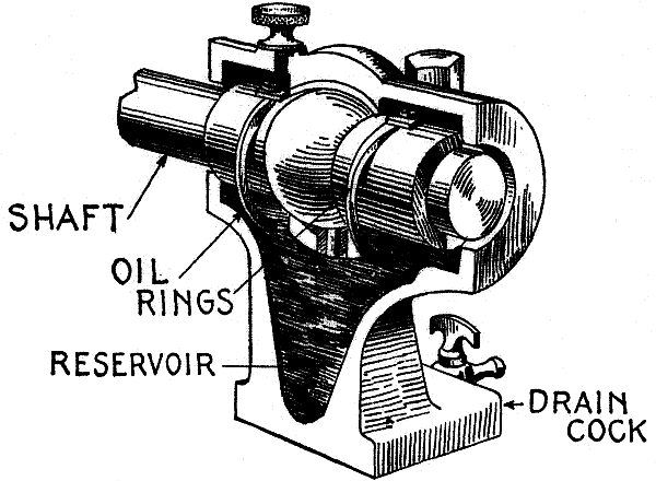
Fig. 2,788.—Sectional view showing a ring
oiler or self oiling bearing. As shown the pedestal or bearing
standard is cored out to form a reservoir for the oil. The rings are
in rolling contact with the shaft, and dip at their lower part into
the oil. In operation, oil is brought up by the rings which revolve
because of the frictional contacts with the shaft. The oil is in this
way brought up to the top of the bearing and distributed along the
shaft gradually descending by gravity to the reservoir, being thus
used over and over. A drain cock, is provided in the base so that the
oil may be periodically removed from the reservoir and strained to
remove the accumulation of foreign matter. This should be frequently
done to minimize the wear of the bearing.
All bearings subject to appreciable wear should be made adjustable
so that lost motion may be taken up from time to time and thus keep
the vibration and noise of operation within proper limits.
Selection of Generators.—This is governed by the
class of work to be done and by certain local conditions which are
liable to vary considerably for different stations.
These variable factors determine whether
the generators must be of the direct or alternating current type,
whether they must be wound to develop a high or a low voltage, and
whether their outputs in amperes must be large or small. Sufficient
information has already been given to cover these various cases;
there are, however, certain general rules that may advantageously be
observed in the selection of generators designed to fill any of the
aforementioned conditions, and it is well to possess certain facts
regarding their construction.
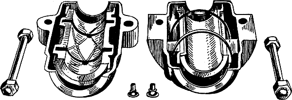
Figs. 2,789 to 2,794.—Self oiling self
aligning bearing open. Views showing oil grooves, rings, bolts etc.
Ques. Name an important point to be considered in selecting a generator.
Ans. Its efficiency.
Ques. What are the important points with respect to efficiency?
Ans. A generator possessing a high efficiency at the average load is
more desirable than a generator showing a high efficiency at full load.
Ques. Why?
Ans. The reason is that in station practice the full load limit
is seldom reached, the usual load carried by a generator ordinarily
lying between the one-half and three-quarter load points.
Ques. How do the efficiencies of large and small generators compare?
Ans. There is little difference.
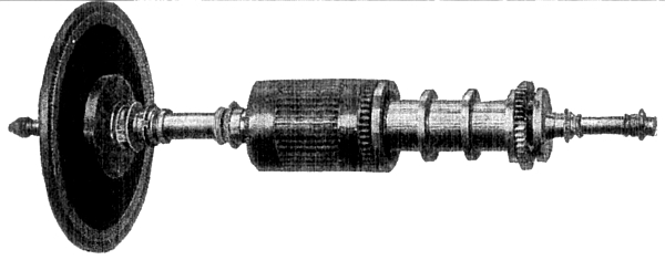
Fig. 2,795.—Rotor of Westinghouse type
T turbine dynamo set. The dynamo is of the commutating pole type
either shunt or compound wound. The turbine is of the single wheel
impulse type. The wheel is mounted directly on the end of the shaft
as shown. Steam is used two or more times on the wheel to secure
efficiency. A fly ball governor is provided with weights hung on
hardened steel knife edges. In case of over speeding, an automatic
safety stop throttle valve is tapped shutting off the steam supply.
This type of turbine dynamo set is especially applicable for exciter
service in modern, superheated steam generating stations where the
steam pressure exceeds 125 pounds. Westinghouse Type T turbines
operate directly (that is, without a reducing valve) on pressures up
to 200 pounds per square inch with steam superheated to 150 degrees
Fahrenheit.
Ques. How are the sizes and number of generator determined?
Ans. The sizes and number of generator to be installed should be
such as to permit the engines operating them being worked at nearly
full load, because the efficiencies of the latter machines decrease
rapidly when carrying less than this amount.
Ques. What is understood by regulation?
Ans. The accuracy and reliability with which the pressure or current
developed in a machine may be controlled.
It is generally possible if purchasing of a reputable concern, to
obtain access to record sheets on which may be found results of tests
conducted on the generator in question, and as these are really the
only means of ascertaining the values of efficiency and regulation,
the purchaser has a right to inspect them. If, for some reason or
other, he has not been afforded this privilege, he should order the
machine installed in the station on approval, and test its efficiency
and regulation before making the purchase.
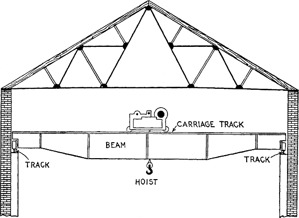
Fig. 2,796.—Cross section of electrical
station showing small traveling crane.
Installation.—The installation of machines and apparatus in
an electrical station is a task which increases in difficulty with
the size of the plant. When the parts are small and comparatively
light they may readily be placed in position, either by hand, by
erecting temporary supports which may be moved from place to place as
desired, or by rolling the parts along on the floor upon pieces of
iron pipe. If, however, the parts be large and heavy, a traveling
crane such as shown in fig. 2,797, becomes necessary.
Ques. What precaution should be taken in moving the parts of machines?
Ans. Care should be taken not to injure the bearings and shafts, the
joints in magnetic circuits such as those between frame and pole
pieces, and the windings on the field and armature.
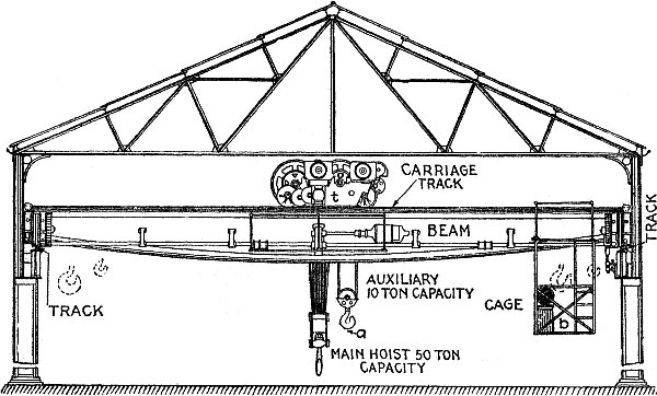
Fig. 2,797.—Cross section of electrical
station showing a traveling crane for the installation or removal of
large and heavy machine parts. A traveling crane consists of an iron
beam which, being supplied with wheels at the ends, can be made to
move either mechanically or electrically upon a track running the
entire length of the station. This track is not supported by the
walls of the building, but rests upon beams specially provided for
the purpose. In addition to the horizontal motion thus obtained,
another horizontal motion at right angles to the former is afforded
by means of the carriage which, being also mounted on wheels, runs
upon a track on the top of the beam. Electrical power is generally
used to move the carriage and also the revolving drums contained
thereon, the latter of which give a vertical motion to the main
hoist or the auxiliary hoist, these hoists being used respectively
for raising or lowering heavy or light loads. In the larger sizes
of electric traveling crane, a cage is attached to the beam for the
operator, who, by means of three controllers mounted in the cage, can
move a load on either the main or auxiliary hoist in any direction.
The insulations of the windings are perhaps the most vital parts of
a generator, and the most readily injured. The prick of a pin or tack,
a bruise, or a bending of the wires by resting their weight upon them
or by their coming in contact with some hard substance, will often
render a field coil or an armature useless.
Owing to its costly construction, it is advisable when transporting
armatures by means of cranes to use a wooden spreader, as shown in
fig. 2,798 to prevent the supporting rope bruising
the winding.
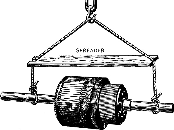
Fig. 2,798.—View of armature in transit
showing use of a wooden spreader as a protection. If a chain be used
in place of the rope, a padding of cloth should be placed around the
armature shaft and special care taken that the chain does not scratch
the commutator.
Ques. If an armature cannot be placed at once in its final
position what should be done?
Ans. It may be laid temporarily upon the floor, if a sheet of
cardboard or cloth be placed underneath the armature as a protection
for the windings; in case the armature is not to be used for some
time, it is better practice to place it in a horizontal position on
two wooden supports near the shaft ends.
Ques. What kind of base should be used with a belt driven
generator or motor?
Ans. The base should be provided with V ways and adjusting screws
for moving the machine horizontally to take up slack in the belt, as
shown in fig. 2,799.
Owing to the normal tension on the belt, there is a moment exerted
equal in amount to the distance from the center of gravity of the
machine to the center of the belt, multiplied by the effective pull
on the belt. This force tends to turn the machine about its center of
gravity. By placing the screws as shown, any turning moment, as just
mentioned, is prevented.
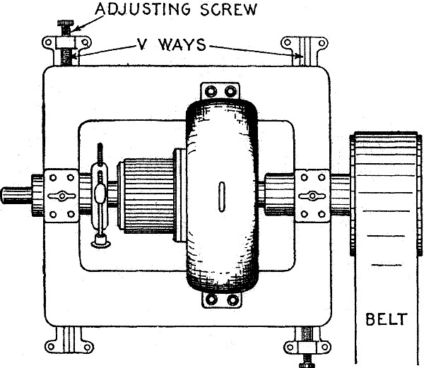
Fig. 2,799.—Plan of belt drive machine
showing V ways and adjusting screws for moving the machine forward
from the engine or counter shaft to take up slack in the belt.
Ques. How should a machine be assembled?
Ans. The assembling should progress by the aid of a blue print, or by
the information obtained from a photograph of the complete machine
as it appears when ready for service. Each part should be perfectly
clean when placed in position, especially those parts between which
there is friction when the machine is in operation, or across which
pass lines of magnetic force; in both cases the surfaces in contact
must be true and slightly oiled before placing in position.
Contact surfaces forming part of electrical circuits must also be
clean and tightly screwed together. An important point to bear in
mind when assembling a machine is, to so place the parts that it will
not be necessary to remove any one of them in order to get some other
part in its proper position. By remembering this simple rule much
time will be saved, and in the majority of instances the parts will
finally be better fitted together than if the task has to be repeated
a number of times.
When there are two or more parts of the machine similarly shaped, it
is often difficult to properly locate them, but in such cases notice
should be taken of the factory marks usually stamped upon such pieces
and their proper places determined from the instructions sent with
the machine.
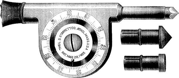
Figs. 2,800 to 2,802.—Starrett's improved
speed indicator. In construction, the working parts are enclosed like
a watch. The graduations show every revolution, and with two rows of
figures read both right and left as the shaft may run. While looking
at the watch, each hundred revolutions may be counted by allowing
the oval headed pin on the revolving disc to pass under the thumb as
the instrument is pressed to its work. A late improvement in this
indicator consists in the rotating disc, which, being carried by
friction may be moved to the starting point where the raised knobs
coincide. When the spindle is placed in connection with the revolving
shaft, pressing the raised knob with the thumb will prevent the disc
rotating, while the hand of the watch gets to the right position to
take the time. By releasing the pressure the disc is liberated for
counting the revolutions of the shaft when every 100 may be noted by
feeling the knob pass under the thumb lightly pressed against it,
thus relieving the eye, which has only to look on the watch to note
the time.
Ques. What should be noted with respect to speed of generator?
Ans. Each generator is designed to be run at a certain speed
in order to develop the voltage at which the machine is rated.
The speed, in revolutions per minute, the pressure in volts, and
the capacity or output in watts (volts × amperes) or in kilowatts
(thousands of watts) are generally stamped on a nameplate
screwed to the machine.
This requirement frequently requires calculations to be made by the
erectors to determine the proper size pulleys to employ to obtain the
desired speed.
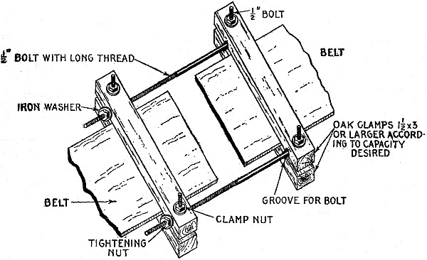
Fig. 2,803.—Home made belt clamp. It is made
with four pieces of oak of ample size to firmly grip the belt ends
where the bolts are tightened. The figure shows the clamp complete
and in position on the belt and clearly illustrates the details of
construction. In making the long bolts the thread should be cut about
three-quarter length of bolt and deep enough so that the nuts will
easily screw on.
Example.—What diameter of engine pulley is required to run a
dynamo at a speed of 1,450 revolutions per minute the dynamo pulley
being 10 inches in diameter and the speed of engine, 275 revolutions
per minute?
The diameter of pulley required on engine is
10 × (1,450 ÷ 275) = 53 inches, nearly.
Rule.—To find the diameter of the driving pulley, multiply
the speed of the driven pulley by its diameter, divide the product by
the speed of the driver and the answer will be the size of the driver required.
Example.—If the speed of an engine be 325 revolutions per minute,
diameter of engine pulley 42 inches, and the speed of the dynamo
1,400 revolutions per minute, how large a pulley is required on dynamo?
The size of the dynamo pulley is 42 × (325 ÷ 1,400) = 9¾ inches.
Rule.—To find the size of dynamo pulley, multiply the speed
of engine by the diameter of engine wheel and divide the product by
the speed of the dynamo.
Figs. 2,804 and 2,805.—A good method of
lacing a belt. The view at the left shows outer side of belt, and at
the right, inner or pulley side.
Example.—If a steam engine, running 300 revolutions per minute,
have a belt wheel 48 inches in diameter, and be belted to a dynamo
having a pulley 12 inches in diameter, how many revolutions per
minute will the dynamo make?
The speed of dynamo will be 300 × (48 ÷ 12) = 1,200 rev. per min.
Rule.—When the speed of the driving pulley and its diameter
are known, and the diameter of the driven pulley is known, the speed
of the driven pulley is found by multiplying the speed of the driver
by its diameter in inches and dividing the product by the diameter of
the driven pulley.
Example.—What will be the required speed of an engine having
a belt wheel 46 inches in diameter to run a dynamo 1,500 revolutions
per minute, the dynamo pulley being 11 inches in diameter?
The speed of the engine is 1,500 × (11 ÷ 46) = 359 rev. per min. nearly.
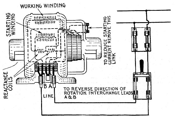
Fig. 2,806.—Wiring diagram and directions
for operating Holzer-Cabot single phase self-starting motor.
Location: The motor should be placed in as clear and dry a
location as possible, away from acid or other fumes which would
attack the metal parts or insulation, and should be located where it
is easily accessible for cleaning and oiling. Erection: The
motor should be set so that the shaft is level and parallel with the
shaft it is to drive so that the belt will run in the middle of the
pulleys. Do not use a belt which is too heavy or too tight for the
work it has to do, as it will materially reduce the output of the
motor. The belt should be from one-half to one inch narrower than
the pulley. Rotation: In order to reverse the direction of
rotation, interchange leads A and B. Suspended Motors: Motors
with ring oil bearings may be used on the wall or ceiling by taking
off end caps and revolving 90 or 180 degrees until the oil wells come
directly below the bearings. Starting: Motors are provided
with link across two terminals on the upper right hand bracket at the
front of the motor and with this connection should start considerable
overloads. If the starting current be too great with this connection,
it may be reduced by removing the link. Temperatures: At full
load the motor will feel hot to the hand, but this is far below
the danger point. If too hot for touch, measure temperature with a
thermometer by placing bulb against field winding for 10 minutes,
covering thermometer with cloth or waste. The temperature should not
exceed 75 degrees Fahr. above the surrounding air. Oiling:
Fill the oil wells to the overflow before starting and keep them
full. See that the oil rings turn freely with shaft. Care: The
motor must be kept clean. Smooth collector rings with sandpaper and
see that the brushes make good contact. When brushes become worn they
may be reversed. When fitting new brushes or changing them always
sandpaper them down until they make good contact with the collector
rings, by passing a strip of sandpaper beneath the brush.
Rule.—To find the speed of engine when diameter of both
pulleys, and speed of dynamo are given, multiply the dynamo speed
by the diameter of its pulley and divide by the diameter of engine
pulley.
Ques. How are the diameters and speeds of gear wheels figured?
Ans. The same as belted wheels, using either the pitch circle
diameters or number of teeth in each gear wheel.
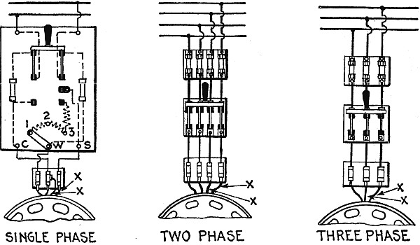
Figs. 2,807 to 2,809.—Wiring diagrams
and directions for operating Holzer-Cabot slow speed alternating
current motors. Erecting: In installing the motor, be sure
the transformer and wiring to the motor are large enough to permit
the proper voltage at the terminals. If too small, the voltage will
drop and reduce the capacity of the motor. Oiling: Maintain
oil in wells to the overflow. Starting: Single phase motors
are started by first throwing the starting switch down into the
starting position, and when the motor is up to speed, throwing it
up into the running position. Do not hold the switch in starting
position over 10 seconds. Starter for single phase motors above
½ H.P. are arranged with an adjusting link at the bottom of the
panel. The link is shown in the position of least starting torque
and current. Connect from W to 2 or W to 3 for starting heavier
loads. Two or three phase motors are started simply by closing the
switch. These motors start full load without starters. The motor
should start promptly on closing the switch. It should be started
the first time without being coupled to the line shaft. If the motor
start free, but will not start loaded, it shows either that the
load upon the motor is too great, the line voltage too low, or the
frequency too high. The voltage and frequency with the motor running
should be within 5% of the name plate rating and the voltage with 10
to 15% while starting. If the motor do not start free, either it is
getting no current or something is wrong with the motor. In either
case an electrician should be consulted. Solution: To reverse
the direction of rotation interchange the leads marked "XX" in the
diagrams. Temperature: At full load the motor should not heat
over 75 degrees Fahr. above the temperature of the surrounding air;
if run in a small enclosed space with no ventilation, the temperature
will be somewhat higher.
Ques. What should be noted with respect to generator pulleys?
Ans. A pulley of certain size is usually supplied with each generator
by its manufacturer, and it is not generally advisable to depart much
from the dimensions of this pulley. Accordingly, the solution of the
pulley problem usually consists in finding the necessary diameter of
the driving pulley relative to that of the pulley on the generator in
order to furnish the required speed.
Ques. What is the chief objection to belt drive?
Ans. The large amount of floor space required.
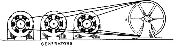
Fig. 2,810.—Tandem drive for economizing
floor space with belt transmission. Belts of different lengths are
used, as shown, each of which passes over the driving wheel d of
the engine, and then over the pulley wheel of one of the generators.
In such an arrangement the belts would be run lengthwise through the
room in which the machines are placed, and it is obvious that since
the width of the room would be governed by the width of the machines
thus installed, this method is a very efficient one for accomplishing
the end in view.
Ques. How may the amount of space that would ordinarily be
required for belt drive, be reduced?
Ans. By driving machines in tandem as in fig. 2,810, or by the double
pulley drive as in fig. 2,811.
Ques. What is the objection to the tandem method?
Ans. The most economical distance between centers cannot be employed
for all machines.
Ques. What is the objectionable tendency in resorting to floor
economy methods with belt transmission?
Ans. The tendency to place the machines too closely together. This is
poor economy as it makes the cleaning of the machines a difficult and
dangerous task; it is therefore advisable to allow sufficient room
for this purpose regardless of the method of belting employed.
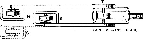
Fig. 2,811.—Double pulley drive for
economizing floor space with belt transmission. Where a center crank
engine is used both pulleys may be employed by belting a machine to
each as shown. Although considerable floor space would be saved by
the use of this scheme if the generators thus belted were placed at M
and G yet still more floor space would be saved by having them occupy
the positions indicated at M and S.
Ques. What is the approved location for an alternator exciter?
Ans. To economize floor space the exciter may be placed between the
alternator and engine at S in fig. 2,811.
Belts.—In the selection of a belt, the quality of
the leather should be first under consideration. The leather must be
firm, yet pliable, free from wrinkles on the grain or hair side, and
of an even thickness throughout.

Fig. 2,812.—Separately excited
belt driven alternator showing approved location of exciter. In
an electrical station where alternating current is generated, the
alternators for producing the current generally require separate
excitation for their field windings; that is, it is usually necessary
to install in conjunction with an alternator a small dynamo for
supplying current to the alternator field. The exciter is a
comparatively small machine; in fact, it requires only about 1 per
cent. of the capacity of the alternator which it excites, and so
being small is often belted to an auxiliary pulley mounted on the
alternator shaft. Considerable floor space would be occupied by an
installation of this nature if the exciter be placed at M, and belted
to the alternator as indicated by the dotted lines. By locating the
exciter at S, between the alternator and the engine, much floor
space will be saved and the general appearance of the installation
improved.
If the belt be well selected and properly handled, it should do
service for twenty years, and even then if the worn part be cut off,
the remaining portion may be remade and used again as a narrower and
shorter belt.
Besides leather belts, there are those made of rubber which withstand
moisture much better than leather belts, and which also possess an
excellent grip on the pulley; they are, however, more costly and much
less durable under normal conditions.
In addition to leather and rubber belts, there are belts composed
of cotton, of a combination of cotton and leather, and of rope. The
leather belt, however, is the standard and is to be recommended.
Equally important with the quality of a belt is its size in order to
transmit the necessary power.
The average strain under which leather will break has been found by
many experiments to be 3,200 pounds per square inch of cross section.
A good quality of leather will sustain a somewhat greater strain. In
use on the pulleys, belts should not be subjected to a greater strain
than one eleventh their tensile strength, or about 290 pounds to the
square inch or cross section. This will be about 55 pounds average
strain for every inch in width of single belt three-sixteenths inch
thick. The strain allowed for all widths of belting—single, light
double, and heavy double—is in direct proportion to the thickness of
the belt.
Ques. How much horse power will a belt transmit?
Ans. The capacity of a belt depends on, its width, speed, and
thickness. A single belt one inch wide and travelling 1,000 feet per
minute will transmit one horse power; a double belt under the same
conditions, will transmit two horse power.
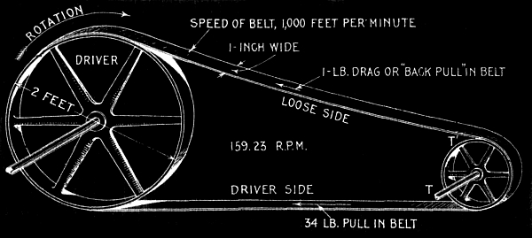
Fig. 2,813.—One horse power transmitted by
belt to illustrate the rule given above. A pulley is driven by a belt
by means of the friction between the surfaces in contact. Let T be
the tension on the driving side of the belt, and T', the tension on
the loose side; then the driving force = T-T'. In the figure T is
taken at 34 lbs. and T' at 1 lb.; hence driving force = 34-1 = 33
lbs. Since the belt is travelling at a velocity of 1,000 feet per
minute the power transmitted = 33 lbs. × 1,000 ft. = 33,000 ft. lbs.
per minute = 1 horse power.
This corresponds to a working pull of 33 and 66 lbs. per inch of
width respectively.
Example.—What width double belt will be required to transmit
50 horse power travelling at a speed of 3,000 feet per minute?
The horse power transmitted by each inch width of double belt travelling
at the stated speed is
( 1 × 3,000 / 1,000 ) × 2 = 6,
hence the width of belt required to transmit 50 horse power is
50 ÷ 6 = 8.33, say 8 inches.
Ques. At what velocity should a belt be run?
Ans. At from 3,000 to 5,000 feet per minute.
Ques. How may the greatest amount of power transmitting capacity
be obtained from belts?
Ans. By covering the pulleys with leather.
Ques. How should belts be run?
Ans. With the tight side underneath as in fig. 2,814.
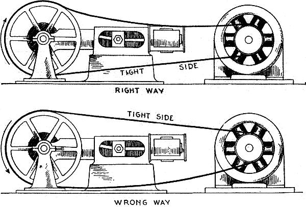
Figs. 2,814 and 2,815.—Right and wrong way
to run a belt. The tight side should be underneath so as to increase
the arc of contact and consequently the adhesion, that is to say, a
better grip, is in this way obtained.
Ques. What is a good indication of the capacity of a belt in operation?
Ans. Its appearance after a few days' run.
If the side of the belt coming in contact with the pulley assume a
mottled appearance, it is an indication that the capacity of the belt
is considerably in excess of the power which it is transmitting,
inasmuch as the spotted portions of the belt do not touch the pulley;
and in consequence of this there is liable to be more or less
slipping.
Small quantities of a mixture of tallow and fish oil which have
previously been melted together in the proportion of two of the
former to one of the latter, will, if applied to the belt at frequent
intervals, do much toward softening it, and thus by permitting its
entire surface to come in contact with the pulley, prevent any
tendency toward slipping. The best results are obtained when the
smooth side of the belt is used next to the pulley, since tests
conducted in the past prove that more power is thus transmitted, and
that the belt lasts longer when used in this way.
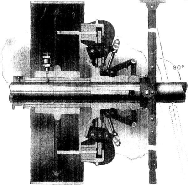
Fig. 2,816.—The Hill friction clutch pulley
for power control. The clutch mechanism will start a load equivalent
to the double belt capacity of the pulley to which the clutch is attached.
Ques. What is the comparison between the so called endless belts
and laced belts?
Ans. With an endless belt there is no uneven or noisy action as with
laced belts, when the laced joint passes over the pulleys, and the
former is free from the liability of breakage at the joint.
Ques. How should a belt be placed on the pulleys?
Ans. The belt should first be placed on the pulley at rest, and then
run on the other pulley while the latter is in motion.
The best results are obtained, and the strain on the belt is less,
when the speed at which the moving pulley revolves is comparatively
low. With heavy belts, particular care should be taken to prevent
any portion of the clothing being caught either by the moving belt
or pulleys, as many serious accidents have resulted in the past from
carelessness in regard to this important detail. The person handling
the belt should, therefore, be sure of a firm footing, and when it is
impossible to secure this, it is advisable to stop the engine and fit
the belt around the engine pulley as well as possible by the aid of a
rope looped around the belt.
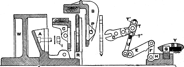
Fig. 2,817—Sectional view of Hill
clutch mechanism. In every case the mechanism hub A, and in a clutch
coupling the ring W, is permanently and rigidly secured to the shaft
and need not be disturbed when removing the wearing parts. When
erected, the adjustment should be verified, and always with the
clutch and ring engaged and at rest. If the jaws do not press equally
on the ring, or if the pressure required on the cone be abnormal,
loosen the upper adjusting nuts T´ on eye bolts and set up the lower
adjusting nuts T´´ until each set of jaws is under the same pressure.
Should the clutch then slip when started it is evident that the jaw
pressure is insufficient and a further adjustment will be necessary.
All clutches are equipped throughout with split lock washers.
Vibration or shock will not loosen the nuts if properly set up. The
jaws can be removed parallel to the shaft as follows: Remove the gibs
V, and withdraw the jaw pins P, then pull out the levers D. Do not
disturb the eye bolt nuts T´ and T´´. The outside jaws B can now be
taken out. Remove the bolt nuts I allowing the fulcrum plates R to be
taken off. On the separable hub pattern the clamping bolts must be
taken out before fulcrum plate is removed. The inside jaws C may now
be withdrawn. Always set the clutch operating lever in the position
as shown in fig. 2,816 to avoid interference with mechanism
parts. Oil the moving parts of the clutch. Keep it clean. Examine at regular
intervals.
Ques. Under what conditions does a belt drive give the best results?
Ans. When the two pulleys are at the same level.
If the belt must occupy an inclined position it should not form a
greater angle than 45 degrees with the horizontal.
Ques. What is a characteristic feature in the operation of
belts, and why?
Ans. Belts in motion will always run to the highest side of a
pulley; this is due partially to the greater speed in feet per
minute developed at that point owing to the greater circumference
of the pulley, and also to the effects of centrifugal force.
If, therefore, the highest sides of both pulleys be in line with each
other, and the shafts of the respective pulleys be parallel to each
other, there will be no tendency for the belt to leave the pulleys
when once in its proper position. In order that these conditions be
maintained, the belt should be no more than tight enough to prevent
slipping, and the distance between the centers of the pulleys should
be approximately 3.5 times the diameter of the larger one.
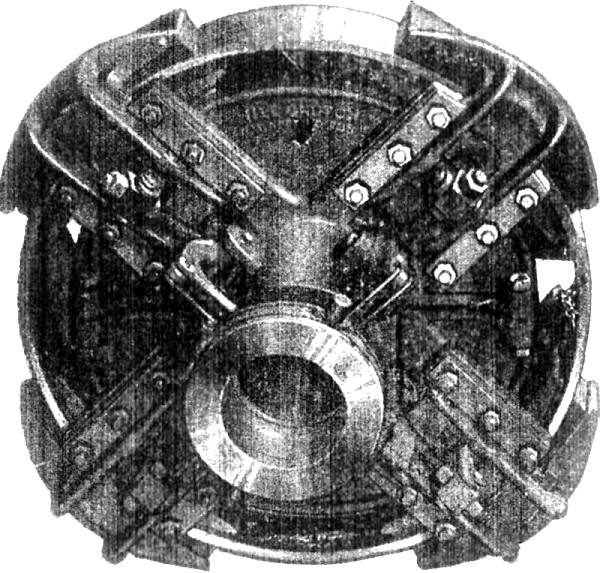
Fig. 2,818.—Hill clutch mechanism Smith
type. The friction surfaces are wood to iron, the wood shoes being
made from maple. All parts of the toggle gear are of steel and
forgings with the exception of the connection lever which is of cast iron.
Ques. What minor appurtenances should be provided in a station?
Ans. Apparatus should be installed as a prevention against accidents,
such as fire, and protection of attendants from danger.
In every electrical station there should be a pump, pipes and hose;
the pump may be either directly connected to a small electric motor
or belted to a countershaft, while the pipes and hose should be
so placed that no water can accidentally reach the generators and
electrical circuits. A number of fire bucket filled with water should
be placed on brackets around the station, and with these there should
be an equal number of bucket containing dry sand, the water being
used for extinguishing fire occurring at a distance from the machines
and conductors, and the sand for extinguishing fire in current
carrying circuits where water would cause more harm than benefit. To
prevent the sand being blown about the station, each sand bucket,
when not in use, should be provided with a cover.
Neat cans and boxes should be mounted in convenient places for greasy
rags, waste, nuts, screws, etc., which are used continually and which
therefore cannot be kept in the storeroom.
While it is important to guard against fire in the station, it is
equally necessary to provide for personal safety. All passages and
dark pits should therefore be thoroughly lighted both day and night,
and obstacles of any nature that are not absolutely necessary in
the operation of the station, should be removed. Moving belts, and
especially those passing through the floor, should be enclosed in
iron railings. If high voltages be generated, it is well to place
a railing about the switchboard to prevent accidental contact with
current carrying circuits, and in such cases it is also advisable
to construct an insulated platform on the floor in front of the switchboard.
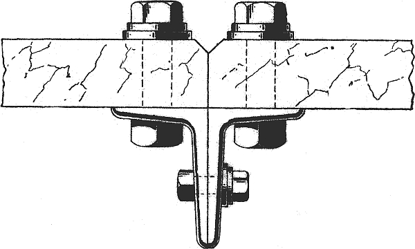
Fig. 2,819.—Method of joining adjacent
switchboard panels.
Switchboards.—The plan of switchboard wiring for alternating
current work depends upon the system in use and this latter may be
either of the single phase, two phase, three phase, or monocyclic
types. The general principles in all these cases, however, are
practically identical.
Fig. 2,820 shows the switchboard wiring for a single
phase alternator. As an aid in reading the diagram, the conductors carrying
alternating current are represented by solid lines, and those
carrying direct current, by dotted lines.
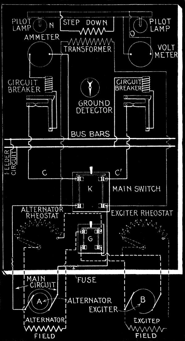
Fig. 2,820.—Switchboard wiring for a single
phase separately excited alternator. The direct current circuits are
represented by dotted lines, and the alternating current circuit, by
solid lines.
The exciter shown at the right is a shunt wound machine. By means of
the exciter rheostat, the voltage for exciting the field winding of
the alternator is varied; this, in turn, varies the voltage developed
in the alternator since the main leads of the exciter are connected
through a double pole switch G to the field winding of the alternator.
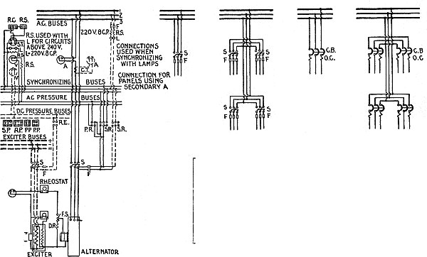
Figs. 2,821 to 2,825.—General Electric
diagrams of connections. A, ammeter; C.B, circuit breaker; C.P,
candle power; C.T, current transformer; D.R, discharge resistance; F,
fuse; F.S, field switch; L, lamp; O.C, overload coil; P.P, pressure
plug; P.R, pressure receptacle; R.C, reactance; rheo, rheostat;
R.P, synchronizing plug, running; R.S, resistance; S, switch; S.I,
synchronism indicator; S.P, synchronizing plug, starting; S.R,
synchronizing receptacle; V, voltmeter.
A rheostat is also introduced in the alternator field winding circuit
to adjust the alternator pressure. It may seem unnecessary to employ
a rheostat in each of two separate field circuits to regulate the
voltage of the alternator, but these rheostats are not both used to
produce the same result. When a considerable variation of pressure
is required, the exciter rheostat is manipulated, whereas for a fine
adjustment of voltage the alternator rheostat is preferably employed.
Sometimes a direct current ammeter is introduced in the alternator's
field circuit to aid in the adjustment.
The main circuit of alternator after being protected on both sides
by fuses, runs to the double pole switch K. These fuses serve as a
protection to the alternator in case of a short circuit at the main
switch. It will be noticed the fuses are of the single pole type and
are mounted a considerable distance apart; this is to prevent any
liability of a short circuit between them in case of action. Enclosed
fuses are now used entirely for such work, since in these there is no
danger of heated metal being thrown about and causing damage when the
fuse wire is melted. Enclosed fuses are also more readily and quickly
replaced than open fuses, the containing tube of each being easy to
adjust in circuit, and when the fuse wire within is once melted the
tube is discarded for a new one.
The main circuit after passing through the main switch is further
protected on both sides by circuit breakers. Leaving these protective
devices, the left hand side of the circuit includes the alternating
current ammeter, and then connects with one of the bus bars. The
right hand side of the circuit runs from the circuit breaker to the
other bus bar. As many feeder circuits may be connected to the bus
bars and supplied with current by the alternator as the capacity of
this machine will permit. If, however, there be more than one feeder
circuit, each must be wired through a double pole switch.
In alternating current work the pressures dealt with are much greater
than those in direct current installations, so that proportionate
care must be taken in the wiring to remove all possibility of grounds.
To locate such troubles, however, should they occur, a ground
detector is provided. For this class of work the ground detector must
be an instrument especially designed for high pressure circuits. Two
of its terminals should be connected to the line wires and the third,
to ground; in case of a leak on the line, a current will then flow
through the detector and by the position of the pointer the location
and seriousness of the leak may be judged.
A step down transformer is also rendered necessary for the voltmeter
and the pilot lamps, owing to the high voltage in use. The primary
winding of the transformer is connected across the main circuit of
the alternator. This connection should never be made so that it will
be cut out of circuit when the main switch is open, for it is always
advisable to consult the voltmeter before throwing on the load by closing this switch.
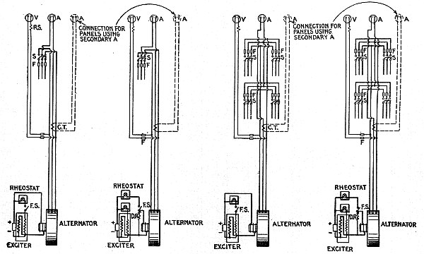
Figs. 2,826 to 2,829.—General Electric
diagrams of connections. A, ammeter; C.B, circuit breaker; C.P,
candle power; C.T, current transformer; D.R, discharge resistance; F,
fuse; F.S, field switch; L, lamp; O.C, overload coil; P.P, pressure
plug; P.R, pressure receptacle; R.C, reactance; rheo, rheostat;
R.P, synchronizing plug, running; R.S, resistance; S, switch; S.I,
synchronous indicator: S.P, synchronizing plug, starting; S.R,
synchronizing receptacle: V, voltmeter.
Ques. How does the switchboard wiring for a two phase system
differ from the single phase arrangement shown in fig. 2,820?
Ans. It is practically the same, except for the introduction of an
extra ammeter and a compensator in each of the outside wires, and in
the use of a four pole switch in place of the two pole main switch.
The ammeters, of course, are for measuring the alternating currents
in each of the two phases or legs of the system, and the compensators
are two transformers with their primary coils in series with the
outside wires and their secondary coils in series with each other
across the outside wires. The transformers thus connected are known
as compensators or pressure regulators, and as such compensate for
the drop in pressure on either side of the system.
Ques. How is the four pole main switch wired?
Ans. Its two central terminals which connect directly with the line
wires, are joined together by a conductor, and from this point one
wire is led off. This wire, together with the two outside wires, form
the feeders of the system.
Ques. How many voltmeters are required for the two phase system?
Ans. One voltmeter is sufficient on the board if a proper switching
device be employed to shift its connections across either of the two
circuits; otherwise, two voltmeters will be necessary, one bridged
across each of these respective circuits.
The same reasoning holds true in regard to ground detectors, so
that one or two of these will be required, depending upon the
aforementioned conditions.
Ques. What are the essential points of difference between the
single phase switchboard wiring as shown in fig. 2,820,
and that required for a three wire three phase system?
Ans. The three phase system requires the use of a three pole
switch in place of the two pole switch; the insertion of an ammeter,
a circuit breaker, and a compensator in each of the three wires of
the system; the presence of two ground detectors instead of one, and
the addition of a voltmeter switch if but one voltmeter be provided,
or else the installation of two voltmeters, connected the one between
the middle wire and outer right hand wire, and the other between the
middle wire and outer left hand wire.
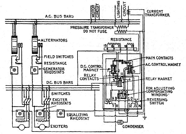
Fig. 2,830.—Diagram of switchboard
connections for General Electric automatic voltage regulator with
two exciters and two alternators.
Ques. Mention a few points relating to lightning arresters.
Ans. In most cases where direct current is used they are mounted
on the walls of the station near the place at which the line wires
enter. If they be mounted outside the station at this point, special
precautions should be taken to keep them free from moisture by
enclosing them in iron cases, but no matter where they are located it
is necessary that they be dry in order to work properly.
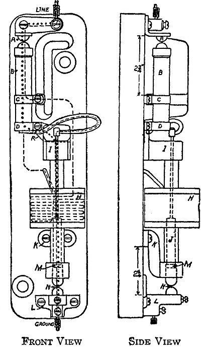
Figs. 2,831 and 2,832.—Garton-Daniels
alternating current lightning arrester; diagram showing connections.
A lightning discharge takes the path indicated by the dotted line,
across the upper air gap A, through resistance rod B, C, D, across
copper strip R on the base, thence flowing to ground through the
movable plunger M, lower on gap N, and ground binding post L.
The discharge path is practically straight, contains an air gap,
distance of but 3/32 inch, a series resistance averaging but 225
ohms. The lightning discharge does not flow through the flexible
lead connecting band D on the lower end of the resistance rod with
the top of the movable plunger. These two points are electrically
connected by the heavy copper strip R, and lightning discharges
generally, if not always, take the path across this copper strip
in preference to flowing through the inductance of the one turn
of flexible cable. When a discharge occurs from line to ground
through any lightning arrester, the air gaps arc over, and so there
is offered a path from line to ground for the line current. This
flow of line current following the lightning discharge to ground
may vary anywhere from a small capacity current where the arrester
is installed on an ungrounded circuit, a moderately heavy flow on
a partially grounded circuit, to a very heavy flow on a grounded
circuit—either a circuit operated as a dead grounded circuit, or a
circuit which has become accidentally grounded during a storm. The
path taken by this flow of line current from line to ground may be
traced by following the path shown by the dashed line. It, as seen,
crosses upper air gap A, flows through section B of the resistance
rod to band C. Leaving band C it flows through the magnet winding
H, thence to band D on the resistance rod, through flexible lead to
upper end of movable plunger, through movable plunger, across lower
air gap N, to ground binding post L, thence to ground. The function
of the short length of resistance rod CD is as follows: It has an
ohmic resistance of about 30 ohms but is non-inductive. Magnet
winding H, connected to bands C and D on the ends of this short
length of rod has an ohmic resistance of 3 ohms, but is highly
inductive. Lightning discharges being of high frequency take the
higher resistance but non-inductive path CD in their passage from
line to ground. The flow of normal current from line to ground being
of a very low frequency, 25 or 60 cycles in ordinary alternating
current circuits, zero in direct current circuits—takes the low
resistance path through coil H in its path to ground. Section CD of
the rod is used therefore simply to shunt the inductance of winding
H to high frequency lightning discharges, leaving the lightning
discharge path in the arrester a non-inductive highly efficient
path. In all Garton-Daniels A. C. lightning arresters operating on
non-grounded or partially grounded circuits, the action of the air
gaps and series resistance are together sufficient to extinguish the
flow of normal current to ground at the zero point of the generator
voltage wave. If, however, as frequently happens, the line grounds
accidentally during a storm, then the arrester does not have to
depend for its proper operation on the arc extinguishing properties
of the air gaps and resistance, but the heavier flow of line current
through the arrester energizes the movable plunger, which raises
upward in the coil, opening the circuit between the discharge point M
and the lower end of the plunger. To limit the flow of line current
to ground the resistance rod B is provided, there being approximately
225 ohms between the discharge point A and clamp C in the 2,500 volt
arrester. This feature is particularly effective where the circuit is
temporarily or accidentally grounded. The series resistance prevents
a heavy short circuit through the arrester and limits the current to
a value that is readily broken by the cut out and is not enough to
impede the passage of the discharge.
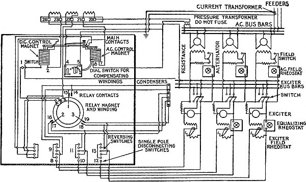
Fig. 2,833.—Diagram of switchboard
connections for General Electric automatic voltage regulator with
three exciters and three alternators.
If possible, one place should be set aside for them and a marble or
slate panel provided on which they may be mounted.
Wooden supports are undesirable for lightning arresters on account of
the fire risk incurred; this, however, may be reduced to a minimum by
employing skeleton boards and using sheets of asbestos between the
arresters and the wood.
In parts of the country where lightning is of common occurrence and
where overhead circuits are installed which carry high pressures,
heavy currents, and extend over considerable territory, it is
advisable to have the station well equipped with lightning arresters
of the most improved types.
In each side of the main circuit, between the lightning arrester
connections and the switchboard apparatus there should be connected a
choke coil or else each of the main conductors at this point should
be tightly coiled up part of its length to answer the same purpose.
A quick and effective way of coiling up a wire consists in wrapping
around a cylindrical piece of iron or wood that part of the conductor
in which it is desired to have the coils, the desired number of
times, and then withdrawing the cylindrical piece. The coils, each of
which may contain 50 or 200 turns, thus inserted in the main circuit
introduce a high resistance or reluctance to a lightning current, and
thus prevent it passing to the generator; there will, however, be an
easy path to earth afforded it through the lightning arrester, and
so no damage will be done. Coils of the nature just mentioned may
advantageously be introduced between the generator and switchboard
to take up the reactive current developed upon the opening of the
circuit, and in the case of suspended conductors, the coils may be
used to take up the slack by the spring-like effect produced by them.
The safety of the operator should be especially considered in the
design of high pressure alternating current switchboards.
Such protection may be secured by screening all the exposed
terminals, or preferably by mounting all the switch mechanism on the
back of the board with simply the switch handle projecting through to
the front; by pushing or pulling the switch handle, the connections
can thus be shifted either to one side of the system or to the other.
Ques. Upon what does the work of assembling a switchboard depend?
Ans. It depends almost entirely upon the size of the plant,
varying from the simple task of mounting a single panel in the case
of an isolated plant, to the more difficult problem of supporting a
large number of panels in a central station.
Ques. When the material chosen for a switchboard must be shipped a
considerable distance, what form of board should be used?
Ans. The board units or "slabs" should be of small dimensions, to
avoid the liability of breakage and expense of renewal when a unit
becomes cracked or machine injured.
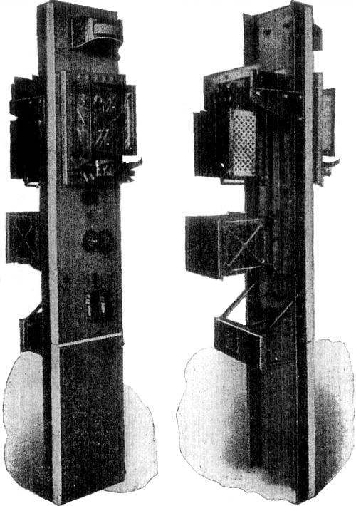
Figs. 2,834 and 2,835.—Front and rear views
showing General Electric automatic voltage regulator mounted on switchboard panel.
Ordinarily, switchboards vary from five to eight feet in height
and the widths of the panels vary from five to six feet. In some
boards the seams between the slabs run vertically, and in others
horizontally. In order to render the assembling of the switchboard
as simple as possible, and its appearance when finished the most
artistic, these seams should run horizontally rather than vertically.
The edges of each of the slabs should also be chamfered so that there
will be less danger of their breaking out when being mounted on the framework.
Ques. In assembling a switchboard, how should the lower slabs be
placed, and why?
Ans. They should be suspended a little distance from the floor to
prevent contact with any oil, dirt, water or rubbish that might be on
the floor.
Ques. How are the slabs or panels supported?
Ans. They are carried on an iron or wooden framework with braces to
give stability.
The braces should be securely fastened at one end to the wall of the
station, and at the other end to the framework of the board, as shown
in fig. 2,836.
To fasten the switchboard end of the brace directly to the slate,
marble or other material composing the board is poor practice and
should never be attempted.
If the station be constructed of iron, these switchboard braces must
be such that they will thoroughly insulate the board and its contents
from the adjoining wall.
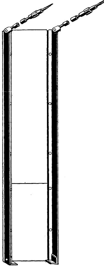
Fig. 2,836.—Method of supporting the framework
of a switchboard.
Ques. What is the usual equipment of a switchboard?
Ans. It comprises switching devices, current or pressure limiting
devices, indicating devices, and fuses for protecting the apparatus and circuits.
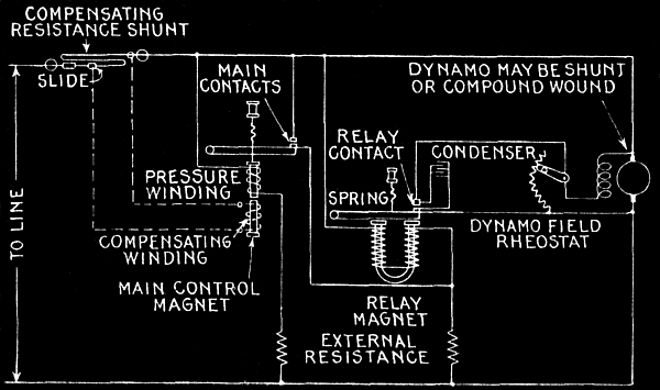
Fig. 2,837.—Diagram showing elementary
connections of General Electric automatic regulator for direct
current. It consists essentially of a main control magnet with two
independent windings and a differentially wound relay magnet. One
winding, known as the pressure winding, of the main control magnet
is connected across the dynamo terminals, the other across a shunt
in one of the load mains. The latter is the "compensating winding"
and it opposes the action of the pressure winding so that as the
load increases, a higher pressure at the dynamo is necessary to
"over compound" for line drop. In ordinary practice, the voltage
terminals are connected to the bus bars, and the compensating shunt
inserted in one of the principal feeders of the system. In operation
the shunt circuit across the dynamo field rheostat is first opened
by means of a switch provided for that purpose on the base of the
regulator and the rheostat turned to a point that will reduce the
generator voltage 35 per cent below normal. The main control magnet
is at once weakened and allows the spring to pull out the movable
core until the main contacts are closed. This closes the second
circuit of the differential relay, thus neutralizing its windings.
The relay spring then lifts the armature and closes the relay
contacts. The switch in the shunt circuit across the dynamo field
rheostat is now closed, practically short circuiting the rheostat,
and the dynamo voltage at once rises. As soon as it reaches the
point for which the regulator has been adjusted, the main control
magnet is strengthened, which causes the main contacts to open,
which in turn open the relay contacts across the rheostat. The
rheostat is now in the field circuit, the voltage at once falls
off, the main contacts are closed, and relay armature released, and
shunt circuit across the rheostat again completed. The voltage then
starts to rise and this cycle of operation is continued at a high
rate of vibration, maintaining not a constant but a steady voltage
at the bus bars. When neither the compensating winding nor pressure
wires are used, there will be no "over compounding" effect due to
increase of load and a constant voltage will be maintained at the
bus bars. The compensating winding on the control magnet, which
opposes the pressure winding is connected across an adjustable shunt
in the principal feeder circuit. As the load increases the voltage
drop across the shunt increases and the effect of the compensating
winding becomes greater. This will require a higher voltage on the
pressure winding to open the main contacts and the regulator will
therefore cause the dynamo to compensate for line drop, maintaining
at the bus bars a steady voltage without fluctuations, which rises
and falls with a load on the feeders, giving a constant voltage at
the lamps or center of distribution. The compensating shunt may be
adjusted so as to compensate for any desired line drop up to 15 per
cent; it is preferably placed in the principal lighting feeder, but
may be connected to the bus bars so that the total current will pass
through it. The latter method, however, is sometimes desirable, as
large fluctuating power loads on separate feeders might disturb the
regulation of the lighting feeders. Adjustment is made by sliding
the movable contact at the center of the shunt. This contact may be
clamped at any desired point and determines the pressure across the
compensating winding of the regulator's main control magnet. Where
pressure wires are run back to the central station from the center
of distribution they may be connected directly to the pressure
winding of the main control magnet, and it is unnecessary to use the
compensating shunt. The pressure wires take the place of the leads
from the control magnet to the bus bars and maintain a constant
voltage at the center of distribution.
On some switchboards are also mounted small transformers for raising
or lowering the voltages, and lightning arresters as a protection
from lightning. In addition to the apparatus previously mentioned
nearly all switchboards carry at or near their top two or more
incandescent lamps provided with shades or reflectors, for lighting
the board.
Ques. What should be done before wiring a switchboard?
Ans. The electrical connections between the various apparatus
mounted on the face or front of the board, are made on the back of
the board. It is necessary that these connections be properly made
else considerable electrical power will be wasted at this point. The
wiring on the back of the board should therefore be planned out on
paper before commencing the work.
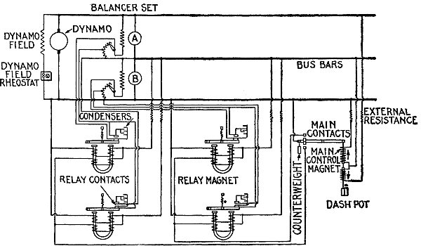
Fig. 2,838.—Diagram showing connections
of General Electric automatic voltage regulator for direct current as
connected for maintaining balanced voltage on both sides of a three
wire system using a balancer set. In operation, should the voltage on
the upper bus bars become greater than that on the lower ones, the
middle and upper contacts on the regulator will close, thus opening
the relay contacts to the left and closing those to the right. This
inserts all the resistance in the field of balancer A, and short
circuits the resistance in the field of balancer B. A will then
be running as a motor, and B as a dynamo, thereby equalizing the
two voltages until that on the lower bus bars becomes greater than
that of the upper ones; then the regulator contacts operate in the
opposite direction and balancer A is run as a dynamo, and balancer B
as a motor. This cycle of operation is repeated at the rate of from
three to four hundred times per minute, thus maintaining a balanced
voltage on the system.
In laying out the plan of wiring care must be taken to allow
sufficient contact surface at each connection; there should be not
less than one square inch of contact surface allowed for each 160
amperes of current transmitted.
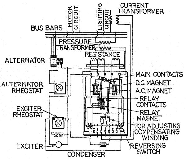
Fig. 2,839.—Diagram of connections of General
Electric voltage regulators for one or more alternators using one exciter.
For the bus bars, which, by the way are always of copper, one square
inch per 1,000 amperes is the usual allowance; this is equal to 1,000
circular mils of cross sectional area per ampere.
Every effort should be made to give the bus bars the greatest amount
of radiation consistent with other conditions, in order that their
resistances may not become excessive owing to the heat developed by
the large currents they are forced to carry. Suppose, for instance,
the number of amperes to be generated is such as to require bus bars
having each a cross sectional area of one square inch. If the end
dimensions of these bars were each 1 inch by 1 inch, there would be
less radiating surface than if their dimensions were each 2 inches by
½ inch.
Operation of Alternators.—The operation of an alternator
when run singly differs but little from that for a dynamo.
As to the preliminaries, the exciter must first be started. This is
done in the same way as for any shunt dynamo. At first only a small
current should be sent through the field winding of the alternator;
then, if the exciter operates satisfactorily and the field magnetism
of the operator show up well, the load may gradually be thrown on
until the normal current is carried, the same method of procedure
being followed as in the similar case of a dynamo.
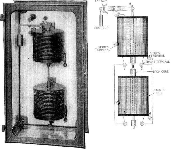
Figs. 2,840 and 2,841.—General Electric
equalizer regulator designed to equalize the load on two machines,
and diagram of connections.
On loading an alternator, a noticeable drop in voltage occurs across
its terminals. This drop in voltage is caused in part by the
demagnetization of the field magnets due to the armature current,
and so depends in a measure upon the position and form of the pole
pieces as well as upon those of the teeth in the armature core. The
resistance of the armature winding also causes a drop in voltage
under an increase of load.
Another cause which may be mentioned is the inductance of the
armature winding, which is in turn due to the positions of the
armature coils with respect to each other and also with respect to
the field magnets.
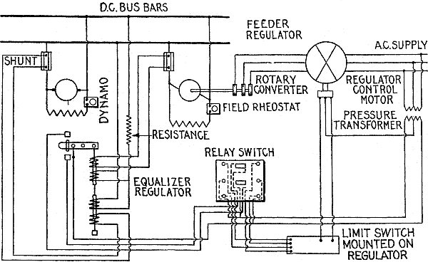
Fig. 2,842.—Connection of General Electric
equalizing regulator for equalizing loads on an engine driven dynamo
and rotary converter running in parallel. Should the load on the
dynamo become greater than that on the rotary converter, the middle
and upper contacts on the regulator close, and thus by means of the
relay switch and control motor, cause the feeder regulator to boost
the voltage on the rotary until the loads again become equal. Should
the load on the rotary converter become greater than that on the
generator, the regulator contacts operate in the reverse direction
and the feeder regulator is caused to buck the rotary voltage.
Alternators in Parallel.—When the load on a station increases
beyond that which can conveniently be carried by one alternator, it
becomes necessary to connect other alternators in parallel with it.
To properly switch in a new machine in parallel with one already in
operation and carrying load, requires a complete knowledge of the
situation on the part of the attendant, and also some experience.
The connections for operating alternators in parallel are shown in
fig. 2,843. In the illustration the alternator A is
in operation and is supplying current to the bus bars. The alternator B is
at rest. The main pole switch B' by means of which this machine can be
connected into circuit is therefore open.
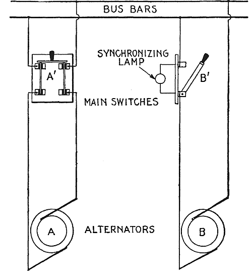
Fig. 2,843.—Method of synchronizing with one
lamp; dark lamp method. Assuming A to be in operation, B, may be
brought up to approximately the proper speed, and voltage. Then if B,
be run a little slower or faster than A, the synchronizing lamp will
glow for one moment and be dark the next. At the instant when the
pressures are equal and the machines in phase, the lamp will become
dark, but when the phases are in quadrature, the lamp will glow at
its maximum brilliancy. Since the flickering of the lamp is dependent
upon the difference in frequency, the machines should not be thrown
in parallel while this flickering exists. The nearer alternator
approaches synchronism, in adjusting its speed, the slower the
flickering, and when the flickering becomes very slow, the incoming
machine may be thrown in the moment the lamp is dark by closing the
switch. The machines are then in phase and tend to remain so, since
if one slow down, the other will drive it as a motor.
Now, if the load increase to such extent as to require the service
of the second alternator B, it must be switched in parallel with A.
In order that both machines may operate properly in parallel, three
conditions must be satisfied before they are connected together, or
else the one alternator will be short circuited through the other,
and serious results will undoubtedly follow.
Accordingly before closing main switch B, it is necessary that
1. The frequencies of both machines be the same;
2. The machines must be in synchronism;
3. The voltages must be the same.
Ques. How are the frequencies made the same?
Ans. By speeding up the alternator to be cut in, or change the speed
of both until frequency of both machines is the same.
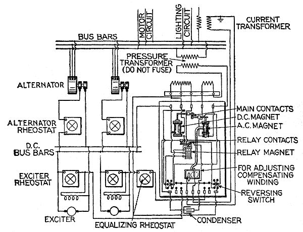
Fig. 2,844.—Diagram of connections of
General Electric automatic voltage regulator for several alternators
running in parallel with exciters in parallel.
Ques. How are the alternators synchronized or brought in phase?
Ans. The synchronism of the alternators is determined by employing
some form of synchronizer, as by the single lamp method of fig. 2,843,
or the two lamp method of fig. 2,845.
Ques. In synchronizing by the one lamp method, when should the
incoming machine be thrown in?
Ans. It is advisable to close the switch when the machines are
approaching synchronism rather than when they are receding from it,
that is to say, the instant the lamp becomes dark.
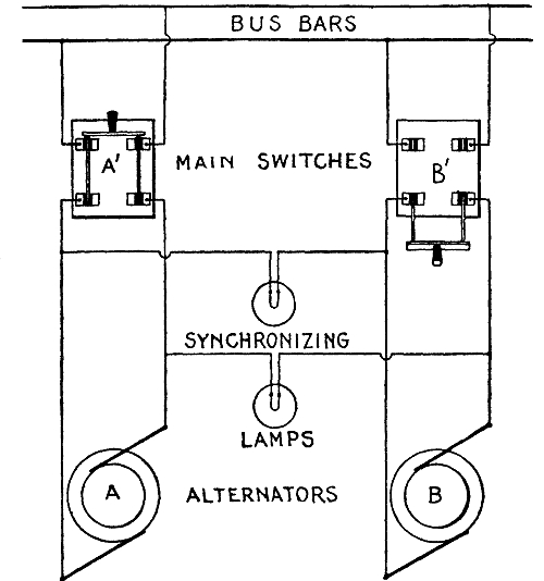
Fig. 2,845.—Method of synchronizing with two
lamps; dark lamp method. The two synchronizing lamps are connected
as shown, and each must be designed to supply its rated candle power
at the normal voltage developed by the alternators. Now since the
alternators are both running under normal field excitation the left
hand terminals of each of them will alternately be positive and
negative in polarity, while the right hand terminals are respectively
negative and positive in polarity. If, however, the alternators be
in phase with each other, the left hand terminals of both of them
will be positive while the right hand terminals are negative, and
when the left hand terminals of both machines are negative the right
hand terminals will be positive. Hence, when the machines are in
phase there will be no difference of pressure between the left hand
terminals or between the right hand terminals of the two machines.
Hence, if the synchronizing lamps be connected as shown, both will
be dark. The instant there is a difference of phase, both lamps
will glow attaining full candle power when the difference of phase
has reached a maximum. As the alternators continue to come closer
in step, the red glow will gradually fade away until the lamps
become dark. Then the switch may be closed, thereby throwing the
two machines in parallel. If the intervals between the successive
lighting up of the lamps are of short duration it is advisable to
wait until these become longer even though the other conditions are
satisfied, because where the phases pass each other rapidly there is
a greater possibility of not bringing them together at the proper
instant. An interval of not less than five seconds should therefore
be allowed between the successive lighting up of the lamps, before
closing the switch.
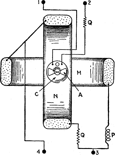
Fig. 2,846.—Inductor type synchroscope.
This type is especially applicable where pressure transformers are already
installed for use with other meters. As it requires only about ten
apparent watts it may be used on the same transformers with other
meters. There are three stationary coils, N, M and C, and a moving
system, comprising an iron armature, A, rigidly attached to a shaft
suitably pivoted and mounted in bearings. A pointer is also attached
to the shaft. The moving system is balanced and is not subjected
to any restraining force, such as a spring or gravity control. The
axes of the coils N and M are in the same vertical plane, but 90
degrees apart, while the axis of C is in a horizontal plane. The
coils N and M are connected in "split phase" relation through an
inductive resistance P and non-inductive resistance Q, and these two
circuits are parallel across the bus bar terminals 3 and 4 of the
synchroscope. Coil C is connected through a non-inductive resistance
across the upper machine terminals 1 and 2 of the synchroscope. In
operation, current in the coil C magnetizes the iron core carried
by the shaft and the two projections, marked A and "iron armature."
There is however, no tendency to rotate the shaft. If current be
passed through one of the other coils, say M, a magnetic field will
be produced parallel with its axis. This will act on the projections
of the iron armature, causing it to turn so that the positive and
negative projections assume their appropriate position in the field
of the coil M. A reversal of the direction in both coils will
obviously not affect the position of the armature, hence alternating
current of the same frequency and phase in the coils C and M cause
the same directional effect upon the armature as if direct current
were passed through the coils. If current lagging 90 degrees behind
that in the coils M and C be passed through the coil N, it will cause
no rotative effect upon the armature, because the maximum value of
the field which it produces will occur at the instant when the pole
strength of the armature is zero. The two currents in the coils M and
N produce a shifting magnetic field which rotates about the shaft as
an axis. As all currents are assumed to be of the same frequency, the
rate of rotation of this field is such that its direction corresponds
with that of the armature projections at the instant when the poles
induced in them by the current in the coil C are at maximum value,
and the field shifts through 180 degrees in the same interval as is
required for reversal of the poles. This is the essential feature of
the instrument, namely, that the armature projections take a position
in the rotating magnetic field which corresponds to the direction of
the field at the instant when the projections are magnetized to their
maximum strength by their current in the coil C. If the frequency
of the currents in the coils which produce the shifting field be
less than that in the coil which magnetized the armature, then the
armature must turn in order that it may be parallel with the field
when its poles are at maximum strength.
Ques. What are the objections to the one lamp method?
Ans. The filament of the lamp may break, and cause darkness, or the
lamp may be dark with considerable voltage as it takes over 20 volts
to cause a 100 volt lamp to glow.
Ques. What capacity of single lamp must be used?
Ans. It must be good for twice the voltage of either machine.
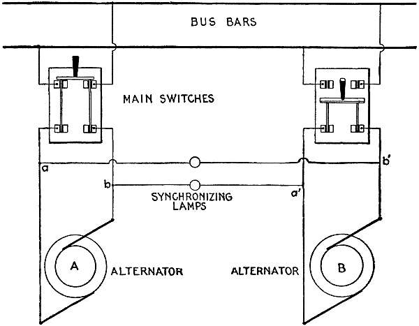
Fig. 2,847.—Brilliant lamp method of
synchronizing. The synchronizing lamps are connected as shown, and
must be of the alternator voltage. When the voltages are equal and
the machines in phase, the difference of pressure between a and a
given point is the same as that between a' and the same point; this
obtains for b and b'. Accordingly, a lamp connected across
a b' will burn with the same brilliancy as across a' b; the
same holds for the other lamp. When the voltages are the same and
the phase difference is 180° the lamps are dark, and as the phase
difference is decreased, the lamps glow with increasing brightness
until at synchronism they glow with maximum brilliancy. Hence the
incoming alternator should be thrown in at the instant of maximum brilliancy.
Ques. What modification of the synchronizing methods shown in
the accompanying illustrations is necessary when high pressure
alternators are used?
Ans. Step down transformers must be used between the alternators and
the lamps to obtain the proper working voltages for the lamps.
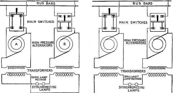
Fig. 2,848.—Synchronizing with high pressure
alternators; dark and brilliant lamp methods. In both methods the
primaries of the transformers are connected in the same way across
the terminals of the alternators as shown. In the dark lamp method,
the connections between the secondary coils of the transformers must
be made so that when each is subjected to the same conditions the
action of the one coil opposes that of the other as in the dark lamp
method; then, if the transformers be both of the same design, there
will be no voltage across the lamps when the alternators are in phase
with each other. If the ratio of each transformer is such as to give,
for example, 100 volts across its secondary terminals, then the two
incandescent lamps since they are joined together in series must
each be designed for 100 volts. One 200 volt lamp could be used in
either method in place of the two 100 volt lamps. When, therefore,
the alternators are directly opposite in phase to each other, both
the lamps will burn brightly; as the alternators come together in
phase the lamps will produce less and less light, until when the
machines are exactly in phase no light will be emitted at all, at
which instant the incoming alternator should be thrown in. It must
be evident, if the transformer secondary connections are arranged as
in the brilliant lamp method, so that they do not oppose each other,
the lamps will be at maximum brilliancy when the alternators are in
phase and dark when the phase difference is 180°, assuming of course
equalized voltage.
Ques. How is the voltage of an incoming machine adjusted so that
it will be the same as the one already in operation?
Ans. By varying the field excitation with a rheostat in the
alternator field circuit.
Ques. How may two or more alternators be started
simultaneously?
Ans. After bringing each of them up to its proper speed so as to
obtain equal frequencies, the main switches may be closed, thereby
joining their armature circuits in parallel. As yet, however, their
respective field windings have not been supplied with current, so
that no harm can result in doing this. The exciters of these machines
after being joined in parallel, should then be made to send direct
current simultaneously through the field windings of the alternators,
and from this stage on the directions previously given may be
followed in detail.
Ques. What are the conditions when two or more alternators are
directly connected together?
Ans. If rigidly connected together, or directly connected to the same
engine, they must necessarily run in the same manner at all times.
When machines connected in this way are once properly adjusted so
that they are in phase with each other, their operation in parallel
is even a simpler task than when they are all started together but
are not directly connected.
Ques. When an alternator is driven by a gas engine, what provision
is sometimes made to insure successful operation in parallel?
Ans. An amortisseur winding is provided to counteract the tendency to "hunting."
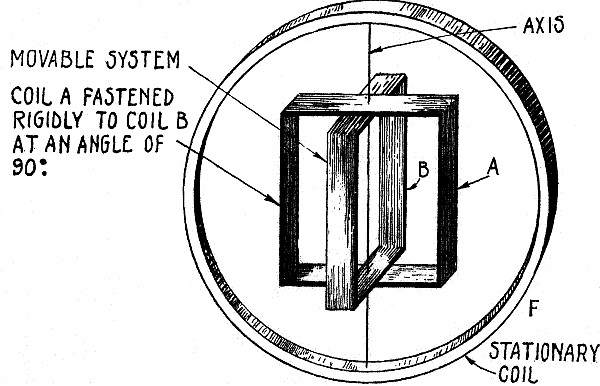
Fig. 2,849.—Diagram of Lincoln Synchronizer.
In construction, a stationary coil F, has suspended within
it a coil A, free to move about an axis in the planes of both coils
and including a diameter of each. If an alternating current be
passed through both coils, A, will take a position with its plane
parallel to F. If now the currents in A and F be reversed with
respect to each other, coil A will take up a position 180° from its
former position. Reversal of the relative directions of currents in
A and F is equivalent to changing their phase relation by 180°, and
therefore this change of 180° in phase relation is followed by a
corresponding change of 180° in their mechanical relation. Suppose
now, instead of reversing the relative direction of currents in A
and F, the change in phase relation between them be made gradually
and without disturbing the current strength in either coil. It is
evident that when the phase difference between A and F reaches 90°,
the force between A and F will become reduced to zero, and a movable
system, of which A may be made a part, is in condition to take up
any position demanded by any other force. Let a second number of
this movable system consist of coil B, which may be fastened rigidly
to coil A, with its plane 90° from that of coil A, and the axis
of A passing through diameter of B. Further, suppose a current to
circulate through B, whose difference in phase relation to that in
A, is always 90°. It is evident under these conditions that when the
difference in phase between A and F is 90°, the movable system will
take up a position, such that B is parallel to F, because the force
between A and F is zero, and the force between B and F is a maximum;
similarly when the difference in phase between B and F is 90°, A
will be parallel to F. That is, beginning with a phase difference
between A and F of zero a phase change of 90° will be followed by a
mechanical change on a movable system of 90°, and each successive
change of 90° in phase will be followed by a corresponding mechanical
change of 90°. For intermediate phase relation, it can be proved that
under certain conditions the position of equilibrium assumed by the
movable element will exactly represent the phase relations. That is,
with proper design, the mechanical angle between the plane of F and
that of A and also between the plane of F and that of B, is always
equal to the phase angle between the current flowing in F and those
in A and B respectively. As commercially constructed coil F
consists of a small laminated iron field magnet with a winding whose
terminals are connected with binding posts. The coils A and B are
windings practically 90° apart on a laminated iron armature pivoted
between the poles of the magnet. These two windings are joined,
and a tap from the junction is brought out through a slip ring to
one of two other binding posts. The two remaining ends are brought
out through two more slip rings, one of which is connected to the
remaining binding post, through a non-inductive resistance, and the
other to the same binding post through an inductive resistance. A
light aluminum hand attached to the armature shaft marks the position
assumed by the armature.
Ques. What is the action of the amortisseur winding?
Ans. Any sudden change in the speed of the field, generates a current
in the amortisseur winding which resists the change of velocity that
caused the current.
The appearance of an amortisseur winding is shown in the cut below
(fig. 2,850) illustrating the field of a synchronous
condenser equipped with amortisseur winding.
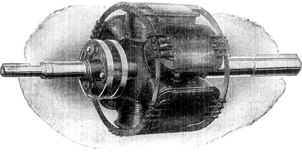
Fig. 2,850.—General Electric field of
synchronous condenser provided with amortisseur winding. Hunting is
accompanied by a shifting of flux across the face of the pole pieces
due to the variation in the effect of armature reaction on the main
field flux as the current varies and the angular displacement between
the field and armature poles is changed. Copper short circuited
collars placed around the pole face have currents induced in them by
this shifting flux, which have such a direction as to exert a torque
tending to oppose any change in the relative position of the field
and armature. This action is similar to that of the running torque
of an induction motor and the damping device has been still further
developed until in its best form it resembles the armature winding
of a "squirrel cage" induction motor. The pole pieces are in ducts,
and low resistance copper bars placed in them with their ends joined
by means of a continuous short circuiting ring extending around
the field. Such a device has proven very effective in damping out
oscillations started from any cause, the same winding doing duty as a
damping device and to assist the starting characteristics.
Ques. How are three phase alternators synchronized?
Ans. In a manner similar to the single phase method.
Thus the synchronizing lamps may be arranged as in fig. 2,581,
which is simply an extension of the single phase method.
Ques. Are three lamps necessary?
Ans. Only to insure that the connections are properly made, after which
one lamp is all that is required.
Ques. How is it known that the connections of fig. 2,851
are correct?
Ans. If, in operation, the three lamps become bright or dark
simultaneously, the connections are correct; if this action takes
place successively, the connections are wrong.
If wrong, transpose the leads of one machine until simultaneous
action of the lamps is secured.
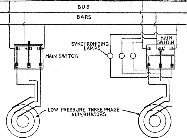
Fig. 2,851.—Method of synchronizing three
phase alternators with, three lamps, being an extension of the single
phase method.
Ques. What is the disadvantage of the lamp method of synchronizing?
Ans. Lack of sensitiveness.
Ques. Which is the accepted lamp method, dark or brilliant?
Ans. In the United States it is usual to make the connections
for a dark lamp at synchronism, while in England the opposite
practice obtains.
With the dark lamp method, the breaking of a filament might cause the
machines to be connected with a great phase difference, whereas, with
the brilliant lamp it is difficult to determine the point of maximum
brilliancy. This latter method, therefore may be called the safer.
Ques. What may be used in place of lamps for synchronizing?
Ans. Some form of synchroscopes, or synchronizers.
Ques. How does the Lincoln synchronizer work?
Ans. The construction is such that a hand moves around a dial so
that the angle between the hand and the vertical is always the phase
angle between the two sources of electric pressure to which the
synchronizer is connected.
If the incoming alternator be running too slow, the hand deflects in
one direction, if too fast, in the other direction. When the hand
shows no deflection, that is, when it stands vertical, the machines
are in phase. A complete revolution of the hand indicates a gain
or loss of one cycle in the frequency of the incoming machine, as
referred to the bus bars.
Cutting Out Alternator.—When it is desired to cut out of
circuit an alternator running in parallel with others, the method of
procedure is as follows:
1. |
Reduce driving power until the load has been transferred
to the other alternators, adjusting field rheostat to obtain
minimum current; |
| 2. |
Open main switch; |
| 3. |
Open field switch. |
Ques. What precaution should be taken?
Ans. Never open field switch before main switch.
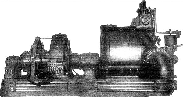
Fig. 2,852.—General Electric 500 kw.,
horizontal mixed pressure Curtis turbine connected to a 500 kw.
dynamo. In a Curtis turbine it is not necessary to use the whole
periphery of the first stage for low pressure steam nozzles. A
section can be partitioned off and equipped with special expanding
nozzles to receive steam at high pressure direct from the boilers.
Such nozzles deliver their steam against the same wheel as do
the low pressure nozzles, but occupy only a small portion of its
periphery. The steam is expanded in these nozzles from high pressure
all the way down to the normal pressure of the first stage, and in
such expansion acquires a high velocity and consequently contains
a great deal of energy—much more than does an equal quantity of
low pressure steam. In consequence of this, high pressure steam is
used with a far lower water rate than is obtained with low pressure
steam, or with high pressure steam reduced to low pressure in a
reducing valve. This construction is called "mixed pressure." Its
function is the same as that of the reducing valve, that is, it makes
up for a deficiency of low pressure steam by drawing direct on the
boilers. With this construction, the full power of the turbine can be
developed with: All low-pressure steam, all high pressure steam, or,
any necessary proportion of steam of each pressure. Furthermore, the
transition from all low pressure to all high pressure, through all
the conditions intermediate between these extremes, is provided for
automatically by the turbine governor; a deficiency of low pressure
steam causes the high pressure nozzles to open automatically.
Ques. What is the ordinary method of cutting out an alternator?
Ans. The main switch is usually opened without any preliminaries.
Ques. What is the objection to this procedure?
Ans. It suddenly throws all the load on the other alternators, and
causes "hunting."
Ques. What forms of drive are especially desirable for running
alternators in parallel, and why?
Ans. Water turbine or steam turbine because of the uniform torque,
thus giving uniform motion of rotation.
With reciprocating engines, the crank effect is very variable during
the revolution, resulting in pulsations driving the alternator too
fast or too slow, and causing cross current between the alternators.
Ques. Is a sluggish, or a too sensitive governor preferable
on an engine driving alternators in parallel?
Ans. A sluggish governor.
Alternators in Series.—Alternators are seldom if ever
connected in series, for the reason that the synchronizing tendency
peculiar to these machines causes them to oppose each other and fall
out of phase when they are joined together in this way. If, however,
they be directly connected to each other, or to an engine, so that
they necessarily keep in phase at all times, and thus add their
respective voltages instead of counteracting them, series operation is possible.
NOTE.—According to the practice of the General Electric Co.,
2½ degrees of phase difference from a mean is the limit allowable in
ordinary cases. It will, in certain cases, be possible to operate
satisfactorily in parallel, or to run synchronous apparatus from
machines whose angular variation exceeds this amount, and in other
cases it will be easy and desirable to obtain a better speed control.
The 2½ degree limit is intended to imply that the maximum departure
from the mean position during any revolution shall not exceed 2½ ÷
360 of an angle corresponding to two poles of a machine. The angle of
circumference which corresponds to the 2½ degree of phase variation
can be ascertained by dividing 2½ by ½ the number of pole; thus, in a
20 pole machine, the allowable angular variation from the mean would
be 2½ ÷ 10 = ¼ of one degree.
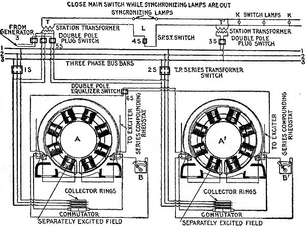
Fig. 2,853.—Diagram of connections for
synchronizing two compound wound three phase alternators. A and
A' are the armatures of the two machines, the fields of which are
partly separately excited, the amount of excitation current being
controlled by the series compounding rheostats B and B', which form
a stationary shunt. It is assumed that the alternator A is connected
to the bus bars 1, 2, and 3, by the switch 1S. If an increase make
it necessary to introduce the alternator A', it is first run up to
speed and excited to standard pressure by its exciter, and then
the double plug switch 3S is closed, connecting the primary of the
station transformer T and T' with the bus bars through the secondary
coil, so that the synchronizing lamps light up when the secondary
circuit is closed through the single pole switch 4S. The primary of
the station transformer T is thus excited through the double pole
switch 5S, connecting it with the outer terminals of the armature
A'. The two alternators will now work in opposition to each other
upon the synchronizing lamps, the transformer T being operated by
the new alternator A' through the switch 2S, and the transformer
T' being operated by the working alternator A, from the bus bars.
If the new alternator be not in step with the working alternator,
the synchronizing lamps will glow, growing brighter and dimmer
alternately with greater or lesser rapidity. In this case, the
armature speed of the new alternator must be controlled in such a
manner that the brightening and dimming will occur more and more
slowly, until the lamps cease to glow or remain extinguished for
a decided interval of time. The extinction of the light is due to
the disappearance of the secondary current, and indicates that
the alternators are in step. The switch 2S should now be thrown,
thus coupling the two machines electrically, and both of them will
continue to operate in step. The double pole equalizer switch 6S
should now be closed, connecting the two field windings in parallel
and equalizing the compounding, so that any variations of load will
affect the two alternators equally. After the alternators have been
connected in parallel, the switches 4S and 5S, may be opened leaving
the switch 3S closed, to operate the switchboard lamps K, K, as pilot
lights from the bus bars.
Transformers.—These, as a whole, are simple in construction,
high in efficiency, and comparatively inexpensive. Their principles
of operation are also readily understood.
The efficiency of a transformer, that is, the ratio between full
load primary and full load secondary is greatest when the load on it
is such that the sum of the constant losses equals the sum of the
variable losses.
In general, transformers designed for high frequencies and large
capacities are more efficient than those designed for low frequencies
and small capacities. As a whole, however, a transformer leaves
but little to be desired as regards efficiency, a modern 60 cycle
transformer of 50 kilowatts capacity or more possesses an efficiency
of approximately 98 per cent. at full load and an efficiency of about
97 per cent. at half load.
Ques. How should a transformer be selected, with respect to efficiency?
Ans. One should be chosen, whose parts are so proportioned that the
point of maximum efficiency occurs at that load which the transformer
usually carries in service.
In many alternating current installations, comparatively light loads
are carried the greater part of the time, the rated full load or an
overload being occurrences of short durations. For such purposes
special attention should be given to the designing or selecting
of transformers having low core losses rather than low resistance
losses, because the latter are then of relatively small importance.
Ques. What kind of efficiency is the station manager interested in?
Ans. The "all day efficiency."
This expression, as commonly met with in practice, denotes the
percentage that the amount of energy actually used by the consumer
is of the total energy supplied to his transformer during 24 hours.
The formula for calculating the all day efficiency of a transformer
is based upon the supposition that the amount of energy used by the
consumer during 24 hours is equivalent to full load on his
transformer during five hours and is as follows:
| |
5w |
| E = |
—————— |
| |
24c + 5r + 5w |
| where |
|
| E = |
the all day efficiency of the transformer, |
| w = |
the full load in watts on the primary, |
| c = |
the core loss in watts, |
| r = |
the resistance loss in watts. |
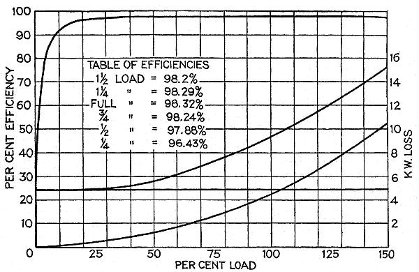
Fig. 2,854.—Performance curves of
Westinghouse air blast 550 kw, 10,500 volt transformer, 3,000
alternations.
Ques. What are the usual all day efficiencies?
Ans. The average is about 85 per cent. for those of 1 kilowatt
capacity, 92 per cent. for those of 5 kilowatts capacity, 94 per
cent. for those of 10 kilowatts capacity, and about 94.5 per cent.
for those of 15 kilowatts capacity.
Ques. What becomes of the energy lost by a transformer?
Ans. It reappears as heat in the windings and core.
This heat not only increases the resistances of the windings and
core, producing thereby a further increase of their respective
losses, but in addition causes in time a peculiar effect on the iron
core which is intensified by the reversals of magnetism constantly
going on within it.
After about two years' service, the iron apparently becomes fatigued
or tired, and this phenomenon is called aging of the iron. Since
the life of the transformer depends to a great extent upon this
factor, the conditions responsible for its existence should as far
as possible be removed. Means must therefore be provided in the
construction to radiate the heat as quickly as it is generated.
Ques. What kind of oil is used in oil cooled transformers?
Ans. Mineral oil.
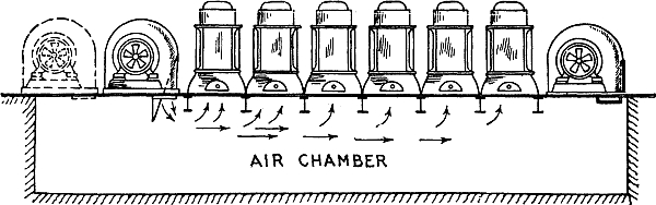
Fig. 2,855.—General arrangement of air blast
transformers and blowers.
Ques. How is it obtained?
Ans. By fractional distillations of petroleum unmixed with any other
substances and without subsequent chemical treatment.
Ques. What is the important requirement for transformer oil?
Ans. It should be free from moisture, acid, alkali or sulphur compounds.
Ques. How may the presence of moisture be determined?
Ans. By thrusting a red hot iron rod in the oil; if it "crackle,"
moisture is present.
Ques. Describe the Westinghouse method of drying oil.
Ans. It is circulated through a tank containing lime, and afterwards,
through a dry sand filter.
Ques. What is the objection to heating the oil (raising its
temperature slightly above boiling point of water) to remove the
moisture?
Ans. The time consumed (several days) is excessive.
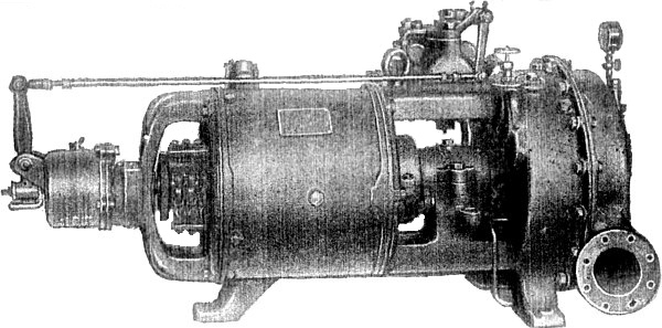
Fig. 2,856.—Small Curtis turbine generator
set as made by the General Electric Co., in sizes from 5 kw.,
to 300 kw. It can be arranged to operate either condensing or
non-condensing, and at any steam pressure above 80 lbs. for the
smaller sizes and 100 lbs. for the larger. There are only two main
bearings. A thrust bearing, consisting of roller bearings and running
between hardened steel face washers located at either end of the
main bearings is provided solely for centering the rotor so as to
equalize the clearance. A centrifugal governor is provided (in the
smaller sizes) completely housed, and mounted directly on the main
shaft end. It controls a balanced poppet valve through a bell crank.
In the larger sizes (75 kw. and above) the governor is mounted on a
vertical secondary shaft geared to the main shaft and controls a cam
shaft which opens or closes a series of valves in rotation, admitting
the steam to different sections of the first stage nozzles. In this
way throttling of the steam is avoided. There is also an emergency
governor which closes the throttle valve in the event of the speed
reaching a predetermined limit. The speeds of operation range from
5,000 R.P.M. for the smallest size to 1,500 R.P.M. for the largest.
The lubrication system is enclosed and is automatic. Air leakage
where the shaft passes through the wheel casing is prevented by steam
seal.
Ques. What effect has moisture?
Ans. It reduces the insulation value of the oil. .06 per cent. of
moisture has been found to reduce the dielectric strength of oil
about 50 per cent. "dry" oil will withstand a pressure of 25,000
volts between two 9½ inch knobs separated .15 inch.
Ques. What is understood by transformer regulation?
Ans. It is the difference between the secondary voltage at no load
and at full load, and is generally expressed as a percentage of the
secondary voltage at no load.
Ques. What governs its value?
Ans. The resistance and reactance of the windings.
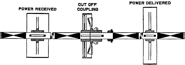
Fig. 2,857.—Cut off coupling for power
transmission by line shafting. It is used to cut off a driving shaft
from a driven shaft. Its use obviates the use of a quill, such as
is shown in fig. 2,858.
Ques. How may the regulation be improved?
Ans. By decreasing the resistances of the windings by employing
conductors of greater cross section, or decreasing their
reactance by dividing the coils into sections and closely interspersing
those of the primary between those of the secondary.
NOTE.—The term "regulation" as here used is synonymous
with "drop." The voltage drop in a transformer denotes the drop of
voltage occurring across the secondary terminals of a transformer
with load. This drop is due to two causes: 1, the resistance of the
windings; and 2, the reactance or magnetic leakage of the windings.
On non-inductive load, the reactive drop, being in quadrature,
produces but a slight effect, but on inductive loads it causes the
voltage to drop, and on leading current loads it causes the voltage
to rise. As the voltage drop of a good transformer is very small even
on inductive load, direct accurate measurement is difficult. It is
best to measure the copper loss with short circuited secondary by
means of a wattmeter, and at the same time the voltage required to
drive full load current through. From the watts, the resistance drop
can be found, and from this and the impedance voltage, the reactive
drop may be calculated. From these data a simple vector diagram will
give, near enough for all practical purposes, the drop for any power
factor, or the following formula may be used which has been deduced
from the vector diagram.
D = √(W + X)2 + (R + P)2 - 100
where R = % resistance drop; X = % reactive drop; P = % power factor
of load; W = % wattless factor of load (√1 - P2); D = %
resultant secondary drop. For non-inductive loads where P = 100 and W = 0,
D = √X2 + (100 + R)2 - 100.
In the case of leading currents it should be considered negative.
In transformers where there is a great difference in voltage between
the primary and secondary windings, however, this remedy has its
limitations on account of the great amount of insulation which must
necessarily be used between the windings, and which therefore causes
the distances between them to become such as to cause considerable
leakage of the lines of force.
Ques. How does the regulation vary for different transformers, and
what should be the limit?
Ans. Those of large capacity usually have a better regulation than
those of small capacity, but in no case should its value exceed 2 per
cent.
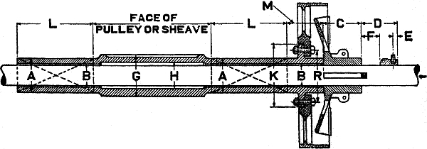
Fig. 2,858.—Quill drive. This is the
proper transmission arrangement substitute for heavy service, requiring
large pulleys, sheaves, gears, rotors, etc. It is a hollow shaft
supported by independent bearings. The main driving shaft running
through the quill is thus relieved of all transverse stresses. The
power is transmitted to the quill by means of a friction or jaw
clutch. When the clutch is thrown out the pulley or sheave stands
idle and the driving shaft revolves freely within the quill. As there
is no contact between moving parts there is no wear. Jaw clutches
should be used for drives demanding positive angular displacement.
They can only be thrown in and out of engagement when at rest. All
very large clutch pulleys, sheaves, or gears designed to run loose on
the line shaft are preferably mounted on quills. The letters A, B, C,
etc., indicate the dimensions to be specified in ordering a quill.
Ques. What advantages have shell type transformers over those of
the core type?
Ans. They have a larger proportion of core surface exposed for
radiation of heat, and a shorter magnetic circuit which reduces the
tendency for a leakage of the lines of force into the air.
Both types have advantages and disadvantages as compared with the
other. In the shell type, there is less magnetic leakage, but also
less surface exposed for radiation, and greater difficulty in
providing efficient insulation between the two circuits; in the core
type there is more surface exposed for radiation and less difficulty
in insulating the windings, but there is also a great leakage of the
lines of magnetic force into the outer air.
Ques. How are the windings usually arranged?
Ans. As a rule, there is only one primary winding but the secondary
winding is generally divided into two equal sections, the four
terminals of which are permanently wired to four connection blocks
which may be connected so as to throw the secondary sections either
in parallel or in series with each other at will.
Ques. What is necessary for satisfactory operation of transformers
in parallel?
Ans. They must be designed for the same pressures and capacities,
their percentages of regulation should be the same and they must have
the same polarity at a given instant.
One may satisfy himself as to the first of these conditions by
examining the name plates fastened to the transformers, whereon are
stamped the values of the respective pressures and capacities of each.
Although equal values of regulation is given as one of the conditions
to be satisfied, transformers may be operated in parallel when their
percentages of regulation are not the same. Ideal operation, however,
can be attained only under the former state of affairs. Suppose,
for instance, a transformer having a regulation of two per cent. be
operated in parallel with another of similar size and design but
having a regulation of one per cent. The secondary pressures of these
transformers at no load will of course be the same, but at full load
if the secondary pressure of the one be 98 volts, that of the other
will be 99 volts. There will, therefore, be a difference of pressure
of one volt between them which will tend to force a current backward
through the secondary winding of the transformer delivering 98 volts.
This reversed current, although comparatively small in value, lowers
the efficiency of the installation by causing a displacement of phase
and a decrease in the combined power factor of the transformers.
Ques. Describe the polarity test.
Ans. The test for polarity consists in joining together by means of a
fuse wire, a terminal of the secondary winding of each transformer,
and then with the primary windings supplied with normal voltage,
connecting temporarily the remaining terminals of the secondary
windings. The melting of the fuse wire thus connected indicates that
the secondary terminals joined together are of opposite polarities,
and that the connections must therefore be reversed, whereas if the
fuse wire do not melt, it shows that the proper terminals have been
joined and that the connections may be made permanent.
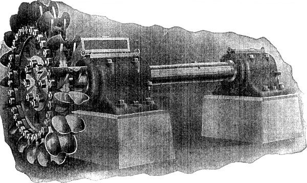
Fig. 2,859.—Single overhung tangential water
wheel equipped with Doble ellipsoidal buckets. The central position
of the front entering wedge or lip of the bucket is cut away in the
form of a semi-circular notch, which allows a solid circular water
jet to discharge upon the central dividing wedge of the bucket
without being split in a horizontal plane.
The object of this test is, obviously, not to determine the exact
polarity of each secondary terminal, but merely to indicate which of
them are of the same polarity.
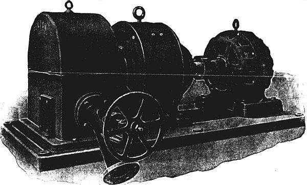
Fig. 2,860.—Motor generator exciter
set driven by a Pelton-Doble tangential water wheel. The water wheel
runner is mounted on the shaft overhung and the jet is regulated by
either a hand actuated or governor controlled needle nozzle. The
speed of the water wheel is equivalent to the synchronous speed of
the induction motor, hence, the latter floats on the line, and under
certain conditions may perform the functions of an alternator by
feeding into the circuit, should the water wheel tend to operate
above synchronous speed. Should any interruption to the operation
of the wheel occur, causing a diminution of speed, the induction
motor would drop back to full load speed and take up the exciter
load, resulting in no appreciable drop of exciter voltage. The only
variation of speed possible is dependent upon the "slip" of the
motor. Where two or more exciter sets are employed in the station,
an advantageous arrangement embraces the installation of a water
wheel driven motor generator set and an exciter set, consisting of
merely the direct current generator and water wheel. The induction
motor being electrically tied into the circuit, the possibility of a
runaway of the water wheel is eliminated, since its speed can only
slightly exceed the synchronous speed of the system.
Motor Generators.—In motor generator sets, either the
shunt or series wound type of motor may be employed at the power
producing end of the set, but the field of the generator is either
shunt or compound wound, depending upon whether or not it is desired
to maintain or to raise the secondary voltage near full load. In
either case a rheostat introduced in the shunt field winding of the
generator will be found very essential. Both generator and motor are
so mounted on the base that their respective commutators are at the
outer ends of the set. By this means ample space surrounds all of the
working parts, and repairs can readily be made.
Motor generators are frequently used as boosters to raise or boost
the voltage near the extremities of long distance, direct current
transmission lines. Of these, electric railway systems in which it is
desired to extend certain of the longer lines, form a typical example.
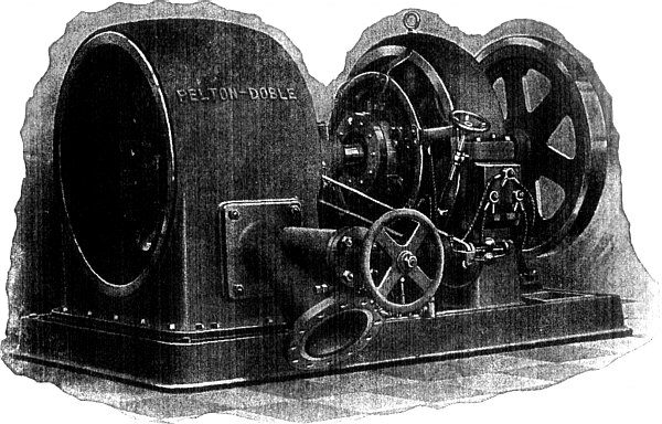
Fig. 2,861.—Automatically governed
Pelton-Doble tangential water wheel driving exciter dynamo. The water
wheel is mounted on one end of the shaft, while the opposite end is
extended to carry a fly wheel of suitable design to compensate for
the low fly wheel effect of the direct current armature. Two bearings
support the shaft which carries the rotating elements of the unit.
A needle nozzle actuated by a direct motion Pelton-Doble governor
(designed for operation by either oil or water pressure) maintains
constant speed.
Owing to the great cost of changing such a system over to one
employing alternating current, or storage batteries, or of
constructing an additional power station, these solutions of the
problem are usually at variance with good judgment and the amount
of money at hand. The choice then remains between the purchase of
additional wire for feeders, the connection of a booster in the old
feeders, or the installation of both larger feeders and a booster.
Of these, it is generally found that either the second or the third
mentioned alternative meets the conditions most satisfactorily.
A booster installed in a railway system for the purpose just
mentioned, would have a series wound motor, and the conditions to
which it must conform would be as follows: The motor having a series
winding must provide for the full feeder current passing through both
armature and field windings.
Owing to the varying loads on a railway system, due to the frequent
starting and stopping of cars, the feeder current varies between
zero and some such value as 150 amperes. This fluctuation of
current through the field winding will, in ordinary cases, vary the
magnetization of the pole pieces from zero almost to the point of
saturation; that is, the maximum feeder current will so nearly fill
the magnet cores with lines of force that it would be quite difficult
to cause more lines of magnetic force to pass through them.
So long as the point of saturation is not reached, however, the
proportion of current to field strength remains constant, and
therefore the ratio of amperes to volts will not vary.
The severe fluctuations of the feeder current would, if the motor
were shunt or compound wound, cause most serious sparking and
various other troubles, but in a series motor where the back ampere
turns on the armature that react on the field vary in precisely
the same proportion as the ampere turns in the field, there exists
at all times a tendency to balance the active forces and produce
satisfactory operation. If, however, the field magnet cores be very
large, they cannot so quickly respond, magnetically, to changes in
the strength of the current, and there is then greater liability of
the armature reaction momentarily weakening the field and thereby
producing temporary sparking.
Ques. Are motor generators always composed of direct current sets?
Ans. No.
Ques. Describe conditions requiring a different combination.
Ans. For purposes where for instance direct currents of widely
different voltages are to be obtained from an alternating current
circuit, and it is desired to install but one set, a motor generator
consisting of an alternating current motor such as an induction
motor, and a dynamo must necessarily be employed.
In such sets, it is common to find both motor and dynamo armatures
mounted on a common shaft, and the respective field frames resting
on a single base, although for connection on a very high pressure
alternating current circuit, separate armature shafts insulated
from each other but directly connected together, and separate bases
resting on a single foundation, are usually employed to afford the
highest degree of insulation between the respective circuits of the
two machines.
Ques. What is the objection to a set composed of alternating
current motor and alternator?
Ans. The commercial field that would be naturally covered by such a
set is better supplied by a transformer.
Ques. Why?
Ans. Because a transformer contains no moving parts, and is therefore
simpler in construction, cheaper in price, and less liable to get out
of order.
Dynamotors.—A dynamotor differs from a motor generator in
that the motor armature and the generator armature are combined
into one, thereby requiring but one field frame. Since the motor
and generator armature windings are mounted on a single core, the
armature reaction due to the one winding is neutralized by the
reaction caused by the other winding. There is, consequently, little
or no tendency for sparking to occur at the brushes, and they
therefore need not be shifted on this account for different loads.
Ques. How is a dynamotor usually constructed?
Ans. It is usually built with two pole pieces which are shunt wound.
Ques. Why does the voltage developed fall off slightly under an
increase of load?
Ans. Because a compound winding cannot be provided.
|
|
Figs. 2,862 and 2,863.—Method of putting on
belts when the driver is in motion, and device used. The latter is
called a belt slipper, and consists, as shown in fig. 2,862,
of a cone and shield, which revolve upon the stem, B, thus yielding easily
to the pull of the belt. A staff or handle C of any convenient length
can be fastened to the socket. The mode of operation is illustrated
in fig. 2,863, which is self explanatory. |
Ques. Describe the armature construction and operation.
Ans. It consists of two separate windings; one of which is joined to
a commutator mounted on one side of the armature for motor purposes, and the
other to the commutator on the other side of the armature for generator purposes.
By means of two studs of brushes pressing on the motor commutator,
current from the service wires is fed into the winding connected to
this commutator, and since the shunt field winding is also excited
by the current from the service wires, there is developed in the
generator winding on the rotating armature a direct voltage which is
proportional to the speed of rotation of the armature in revolutions
per second, the number of conductors in series which constitute the
generator winding, and the total strength of the field in which the
armature revolves. This pressure causes current to pass through the
generator winding and the distributing circuit when the distributing
circuit to which this winding is connected by means of its respective
commutator, brushes, etc., is closed.
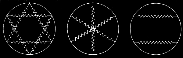
Figs. 2,864 to 2,866.—Converter connections;
fig. 2,864 double delta connection; fig. 2,865 diametrical
connection; fig. 2,866 two circuit single phase connection. For
six phase synchronous converter, two different arrangements of the
connections are generally used. One is called the double delta, and
the other the diametrical connection. Let the armature winding of
the converter be represented by a circle as in figs. 2,864 and 2,865,
and let the six equidistant points on the circumference represent
collector rings, then the secondary of the supply transformers can
be connected to the collector rings in a double delta as in fig.
2,864, or across diametrical pairs of pointer as in fig. 2,865.
In the first instance, the voltage ratio is the same as for the
three phase synchronous converter and simply consists of two delta
systems. The transformers can also be connected in double star, and
in such a case the ratio between the three phase voltage between
the terminals of each star, and the direct voltage will be the same
as for double delta, while the voltage of each transformer coil,
or voltage to neutral, is 1 ÷ √3 times as much.
With the diametrical connection, the ratio is the same as for the two ring
single phase converter, it being analogous to three such systems.
Hence six phase double delta
E1 = √3 E ÷ 2√2 = .612E.
Six phase diametrical, E1 = E ÷ √2 = .707E. The ratio of the
virtual_voltage E0 between any collector ring and the neutral
point is always E0 = (E ÷ 2) √2 = .354E. For single phase
synchronous converters, consisting of a closed circuit armature
winding tapped at two equidistant points to the two collector rings
the virtual voltage is 1 ÷ √2 × the direct current voltage. While
such an arrangement of the single phase converter is the simplest,
requiring only two collector rings, it is undesirable, especially
for larger machines, on account of excessive heating of the armature
conductors. In fig. 2,866, which represents the armature winding of a
single phase converter, the supply circuits from two secondaries of
the step down transformers are connected to four collector rings, so
that the two circuits are in phase with each other, but each spreads
over an arc of 120 electrical degrees instead of over 180 degrees
as in the single phase circuit converter. To distinguish the two
types, it is generally called a two circuit single phase synchronous
converter. The virtual voltage E2 bears to the direct voltage the
same relation as in the three phase converter, that is single phase
two circuit, E1 = √3 ÷ 2√2 =.612E.
Ques. How is a dynamotor started?
Ans. It is connected at its motor end and started in the same manner
as any shunt wound motor on a constant pressure circuit.
Ques. What precautions should be taken in starting a dynamotor?
Ans. The necessary precautions are, to have the poles strongly
magnetized before passing current through the motor winding on the
armature; to increase gradually the current through this winding, and
not to close the generating circuit until normal conditions regarding
speed, etc., are established in the motor circuit.
Ques. How is the current developed in the machine regulated?
Ans. It can be regulated by the introduction of resistance in one or
the other of the armature circuits, or by a shifting of the brushes
around the commutator.
Ques. Are dynamotors less efficient than motor generators of a
similar type?
Ans. No, they are more efficient.
Ques. Why?
Ans. Because they have only one field circuit and at least one bearing
less than a motor generator.
A motor generator has at least three bearings, and occasionally,
four, where the set consists of two independent machines directly
connected together.
Rotary Converters.—An important modification of the dynamotor
is the rotary converter. This machine forms, as it were, a link
between alternating and direct current systems, being in general a
combination of an alternating current motor and a dynamo.
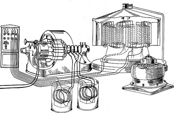
Fig. 2,867.—Skeleton diagram showing wiring
of alternator, exciter, transformer and converter. The cut also shows
switchboard and connections.
It has practically become a fixture in all large electric railway
systems and in other installations where heavy direct currents of
constant pressure are required at a considerable distance from the
generating plant. In such cases a rotary converter is installed
in the sub-station, and being simpler in construction, higher in
efficiency, more economical of floor space, and lower in price than
a motor generator set consisting of an alternating current motor and
a dynamo which might be used in its place, it has almost entirely
superseded the latter machine for the class of work mentioned.
Ques. What is the objection to the single phase rotary converter?
Ans. It is not self-starting.
Ques. What feature of operation is inherent in a rotary converter?
Ans. A rotary converter is a "reversible machine."
That is to say, if it be supplied with direct current of the proper
voltage at its commutator end, it will run as a direct current motor
and deliver alternating current to the collector rings. While this
feature is sometimes taken advantage of in starting the converter
from rest, the machine is not often used permanently in this way, its
commercial application being usually the conversion of alternating
currents into direct currents.
Ques. How does a rotary converter operate when driven by
direct current?
Ans. The same as a direct current motor, its speed of rotation
depending upon the relation existing between the strength of the
field and the direct current voltage applied.
If the field be weak with respect to the armature magnetism
resulting from the applied voltage, the armature will rotate at a
high speed, increasing until the conductors on the armature cut the
lines of force in the field so as to develop a voltage which will be
equal to that applied.
Again, if the field be strong with respect to the armature magnetism,
resulting from the applied voltage, the armature will rotate at a low
speed. If, therefore, it be desired to operate the converter in this
manner and maintain an alternating current of constant frequency,
the speed of rotation must be kept constant by supplying a constant
voltage not only to the brushes pressing on the commutator, but also
to the terminals of the field winding.
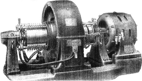
Fig. 2,868.—General Electric synchronous
converter with series booster. This type of converter generally
consists of an alternator with revolving field mounted on the
same shaft as the converter armature. The armature of the alternator,
or booster, as it is usually called, is stationary and connected
electrically in series between the supply circuit and the collector
rings of the synchronous converter. The booster field has the same
number of pole as the converter and is generally shunt wound. A
change in the booster voltage will correspondingly change the
alternating voltage impressed on the converter and this regulation
can, of course, be made so as to either increase or decrease the
impressed voltage by means of strengthening or weakening the booster
field. The voltage variation can be made either non-automatic or
automatic, and in the latter case, it becomes necessary to provide a
motor operated rheostat controlled by suitable relays, or the booster
can be provided with a series field. By means of a booster, it is
possible to vary the direct voltage of the converter with a constant
alternating supply voltage, and this voltage regulation is obtained
without disturbance of the power factor or wave shape of the system.
Synchronous converters are frequently installed in connection with
Edison systems, where three wire direct current is required. The
three wire feature is obtained either by providing extra collector
rings and compensator, as with ordinary direct current generators,
or also by connecting the neutral wire directly to the neutral point
of the secondary winding of step down transformers, if such be furnished.
Ques. How does it operate with alternating current drive?
Ans. The same as a synchronous motor.
Ques. What is the most troublesome part and why?
Ans. The commutator, because of the many pieces of which it is
composed and the necessary lines along which it is constructed, its
peripheral speed must be kept within reasonable limits.
Ques. What should be the limit of the commutator speed?
Ans. The commutator speed, or tangential speed at the
brushes should not exceed 3,000 feet per minute.
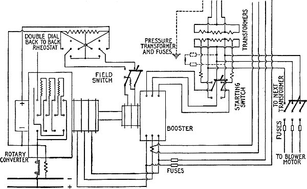
Fig. 2,869.—Wiring diagram for General
Electric synchronous converter with series booster as illustrated in
fig. 2,868.
Ques. Name another limitation necessary for satisfactory
operation.
Ans. The pressure between adjacent commutator bars should not exceed
eight or ten volts.
If the commutator bars be made narrow in order to obtain the
necessary number for the desired voltage with the minimum
circumference and therefore low commutator speed, the brushes
employed to collect the current are liable to require excessive width
in order to provide the proper cross section and yet not cover more
than two bars at once.
Ques. How can the commutator speed be kept within reasonable
limits, other than by reducing the width of the commutator bars?
Ans. By using alternating current of comparatively low frequency.
For a rotary converter delivering 500 volt direct current, the proper
frequency for the alternating current circuit has been found to be 25
cycles per second.
Ques. When a rotary converter is operated in this usual manner
on an alternating current circuit, how can the direct current be varied?
Ans. It may be varied (from zero to a maximum) by changing the value
of the alternating pressure supplied to the machine, or it may be
altered within a limited range by moving the brushes around the
commutator, or in a compound wound converter by changing the amount
of compounding.
Under ordinary conditions, varying the voltage developed by changing
the voltage at the motor end is not practical, hence the voltage
developed can be varied only over a limited range. In addition to
this, the voltage developed at the direct current end bears always
a certain constant proportion to the alternating current voltage
applied at the motor end; this is due to the same winding being used
both for motor and generator purposes. In all cases the proportion
is such that the alternating current voltage is the lower, being
in the single phase and in the two phase converters about .707 of
the direct current voltage, and in the three phase converter about
.612 of the direct current voltage. It is thus seen that whatever
value of direct current voltage be desired, the value of the applied
alternating current voltage must be lower, requiring in consequence
the installation of step down transformers at the sub-station for
reducing the line wire voltage to conform to the direct current
pressure required.
Ques. What is the efficiency of a rotary converter?
Ans. It may be said to have approximately the same efficiency as that
in the average of the same output, although in reality the converter
is a trifle more efficient on account of affording a somewhat shorter
average path for the current in the armature, reducing in consequence
the resistance loss and the armature reaction.
Ques. May a converter be overloaded more than a dynamo of the same
output, and why?
Ans. Yes, because there is usually less resistance loss in the
armature of the converter than in the armature of the dynamo.
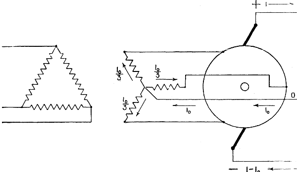
Fig. 2,870.—Wiring diagram for three wire
synchronous converter with delta-Y connected step down transformer
with the neutral brought out. It is evident that in this case each
transformer secondary receives ⅓ of the neutral current, and
if this current be not so small, as compared with the exciting
current of the transformer, it will cause an increase in the magnetic
density.
Thus, a two phase converter may be overloaded approximately 60 per
cent., and a three phase converter may be overloaded about 30 per
cent. above their respective outputs if operated as dynamos.
Ques. Describe how a converter is started.
Ans. There are several methods any one of which may be employed, the
choice in any given case depending upon which of them may best be
followed under the existing conditions.
If it be found advisable to start the converter with direct current,
the same connections would be made between the source of the direct
current and the armature terminals on the commutator side of the
converter as would be the case were a direct current shunt motor of
considerable size to be started; this naturally means that a starting
rheostat and a circuit breaker will be introduced in the armature
circuit.
The shunt field winding alone is used, and this part of the wiring
may be made permanent if, as is usually the case, the same source of
direct current is used normally for separate field excitation.
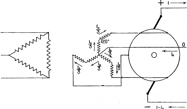
Fig. 2,871.—Wiring diagram of three
wire synchronous converter with distributed Y secondary. This system
eliminates the flux distortion due to the unbalanced direct current
in the neutral. Two separate interconnected windings are used for
each leg of the Y. The unbalanced neutral current flowing in this
system may be compared in action to the effect of a magnetizing
current in a transformer. The effect of the main transformer currents
in the primary and secondary is balanced with regard to the flux
in the transformer core, which depends upon the magnetic current.
When a direct current is passed through the transformer, unless
the fluxes produced by the same neutralize one another, its effect
on the transformer iron varies as the magnetizing current. For
example, assume a transformer having a normal ampere capacity of 100
and, approximately, 6 amperes magnetizing current, and assume that
three such transformers are used with Y connected secondaries for
operating a synchronous converter connected to a three wire Edison
system. Allowing 25 per cent. unbalancing, the current will divide
equally among the three legs giving 8.33 amperes per leg, which
is more than the normal magnetizing current. The loss due to this
current is, however, inappreciable, but the increased core losses
may be considerable. If a distributed winding be used, the direct
current flows in the opposite direction, around the halves of each
core thus entirely neutralizing the flux distortion. Whether the
straight Y connection is to be used is merely a question of balancing
the increased core loss of the straight Y connection against the
increased copper loss and the greater cost of the interconnected Y
system. The straight Y connection is much simpler, and it would be
quite permissible to use it for transformers of small capacities
where the direct current circulating in the neutral is less than 30
per cent. of the rated transformer current.
The direct current may be derived from a storage battery, from a
separate converter, or from a motor generator set installed in the
sub-station for the purpose.
An adjustable rheostat will, of course, be connected in the field
circuit for regulation. Before starting the converter, however,
it is necessary to do certain wiring between the terminals on the
collector side of the machine and the alternating current supply
wires, in order that the change over from direct current motive power
to alternating current motive power may be made when the proper phase
relations are established between the alternating current in the
supply wires and the alternating current in the armature winding of
the converter.
In order that proper phase relations exist, the armature of the
converter must rotate at such a speed that each coil thereon passes
its proper reversal point at the same time as the alternating
current reverses in the supply wires. This speed may be calculated
by doubling the frequency of the supply current and then dividing by
the number of pole pieces on the converter, but a far more accurate
method of judging when the converter is in step or in synchronism
with the supply current consists in employing incandescent lamps as
shown in fig. 2,872.
Ques. How is a polyphase converter started with alternating
current?
Ans. This may be done by applying the alternating pressure directly
to the collector rings while the armature is at rest. There need
be no field excitation; in fact the field windings on the separate
pole pieces should be disconnected from each other before the
alternating voltage is applied to the armature, else a high voltage
will be induced in the field windings which may prove injurious to
their insulation. The passage of the alternating current through the
armature winding produces a magnetic field that rotates about the
armature core, and induces in the pole pieces eddy currents, which,
reacting on the armature, exert a sufficient torque to start the
converter from rest and cause it to speed up to synchronism.
Ques. How much alternating current is required to start a
polyphase converter?
Ans. About 100 per cent. more than that required for full load.
Ques. How may this starting current be reduced?
Ans. Transformers may be switched into circuit temporarily to reduce
the line wire voltage until the speed become normal.
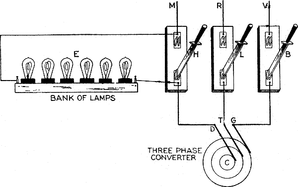
Fig. 2,872.—Wiring diagram showing
arrangement of incandescent lamps for determining the proper phase
relations in starting a rotary converter. The alternating current
side of a three phase converter is shown at C. The three brushes, D,
T and G pressing on its collector rings are joined in order to the
three single pole switches H, L and B which can be made to connect
with the respective wires M, R, and V, of the alternating current
supply circuit. Across one of the outside switches, H, for example, a
number of incandescent lamps are joined in series as indicated at E,
while the three pole switch (not shown) in the main circuit, between
the alternator and the single pole switches is open. If then the
main switch just mentioned and the middle switch L be both closed,
and the armature of the alternator be brought up to normal speed
by running it as a direct current motor, the lamps at E will light
up and darken in rapid succession; the lighting and darkening of
the lamps will continue until, by a proper adjustment of the speed,
the correct phase relations be established between the alternating
current in the supply circuit and the alternating current developed
in the armature of the converter. As this condition is approached,
the intervals between the successive lighting up and darkening of
the lamps will increase until they remain perfectly dark. There is
then no difference of pressure between the supply circuit M R V and
the rotary converter armature circuit, so the source of the direct
current may at that instant be disconnected from the machine, and the
switches H and B, closed. If the change over has been accomplished
before the phase relations of the two circuits differed, the
converter will at once conform itself to the supply circuit and run
thereon as a synchronous motor without further trouble. The opening
of the direct current circuit and the closing of the alternating
current supply circuit may be done by hand, but preferably by
employing a device that will automatically trip the circuit breaker
in the direct current circuit at the instant the switches in the
alternating current circuit are closed.
In conjunction with this method, the method of synchronizing shown in
fig. 2,872 may be used, thus, in starting, there is an
alternating current between the brushes which pulsates very rapidly, but when
synchronism is approached, the pulsations become less rapid until
finally with the converter in step with the alternator the pulsations
entirely disappear.
The light given by the lamps thus connected indicates accurately
the condition of affairs at any one time, varying from a rapidly
fluctuating light at the beginning to one of constant brilliancy at
synchronism.
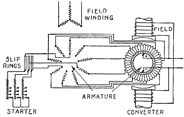
Fig. 2,873.—Diagram of motor converter.
This machine which is only to be used for converting from alternating to
direct current, consists of an ordinary induction motor with phase
wound armature, and a dynamo. The revolving parts of both machines
are mounted on the same shaft and from the figure it is seen that
the armature of the motor and the armature of the dynamo are also
electrically connected. The motor converter is a synchronous machine,
but the dynamo receives the current from the armature of the motor at
a frequency much reduced from that impressed upon the field winding
of the motor. Assuming that the motor and the converter have the same
number of pole, the motor will rotate at a speed corresponding to
one-half the frequency of the supply circuit. The motor will operate
half as a motor and half as a transformer, and the converter, half
as a dynamo and half as a synchronous converter, in that one-half of
the electrical energy supplied to the motor will be converted into
mechanical power for driving the converter, while the other one-half
is transferred to the secondary motor windings and thereby to the
converter armature in the form of electrical power. The capacity of
the motor is theoretically only half what it would be if it were to
convert the whole of the electrical energy into mechanical power
because the rating depends upon the speed of the rotating field and
not on that of the rotor. If the two machines have a different number
of pole, or are connected to run at different speeds, the division of
power is at a different but constant ratio. The machine starts up as
an ordinary polyphase induction motor and the field of the converter
is built up as though it were an ordinary dynamo. Motor converters
are occasionally used on high frequency systems, as their commutating
component is of half frequency, and thus permits better commutator
design than a high frequency converter. The advantage of this type
of machine is that for phase control it requires no extra reactive
coils, the motor itself having sufficient reactance. It is, however,
larger than standard converters, but smaller than motor generators,
as half the power is converted in each machine. Its efficiency is
less than for synchronous converters, and the danger of reaching
double speed in case of a short circuit on the direct current side
is very great. It has been used abroad to some extent for 60 cycle
work, in preference to synchronous converters, but with the present
reliable design of 60 cycle converters, and the general use of 25
cycles, where severe service conditions are met, as in railroading,
motor converters should not be recommended.
Ques. If the armature of the starting motor have a starting
resistance, how must this be connected?
Ans. It should be connected in series with the armature inductors
before the alternating voltage is applied.
As the motor increases in speed, the starting resistance is gradually
short circuited until it is entirely cut out of circuit.
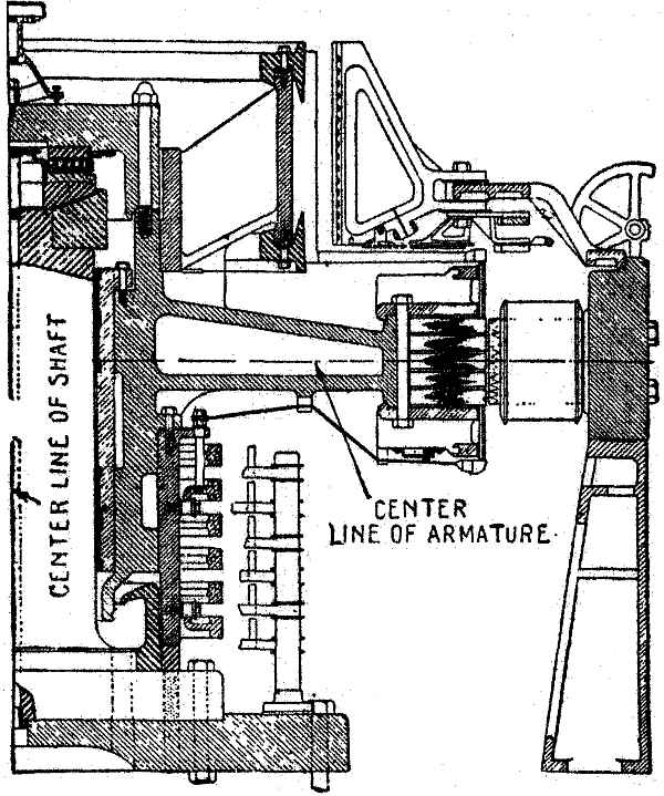
Fig. 2,874.—Sectional view of General
Electric vertical synchronous converter. In this construction, the
field frame carrying the poles is mounted on cast iron pedestals and
is split vertically. This allows the two halves of the frame to be
separated for inspection or repairs of the armature. The armature,
including commutator and collector rings, is mounted on a vertical
stationary shaft, which is rigidly supported from the foundation.
The thrust of the armature is carried on a roller bearing attached
to the top of the shaft and upper side of the armature spider. The
under side of the lower plate of the roller bearing is made spherical
and fits into a corresponding spherical cup on the end of the shaft,
making the bearing self aligning. The armature spider has a babbitted
sleeve along the fit of the vertical shaft, which acts as a guide
bearing and has to take only the thrust due to the unbalancing effect
of the rotating parts. A circulating pump furnishes oil to the roller
bearing, the oil draining off through the guide bearing. A marked
advantage of this type of construction is the accessibility of the
commutator for adjustment of the brushes, etc., as there is no pit or
pedestal bearing to interfere.
NOTE.—Some converters are provided with a small induction motor for
starting mounted on an iron bracket cast in the converter frame, and
whose shaft is keyed to that of the converter. Allowing for a certain
amount of slip in the induction motor, the field of this machine must
possess a less number of magnet poles than the converter in order to
enable the latter machine to be brought to full synchronism. To start
the induction motor, it is simply necessary to apply to its field
terminals the proper alternating voltage. The bracket, and therefore
the motor, is usually mounted outside the armature bearing on the
collector side of the converter.
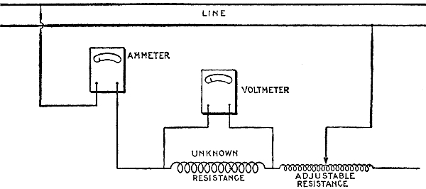
Fig. 2,875.—Resistance measurement by "drop"
method. The circuit whose resistance is to be measured, is connected
in series with an ammeter and an adjustable resistance to vary
the flow of current. A voltmeter is connected directly across the
terminals of the resistance to be measured, as shown in the figure.
According to Ohm's law I = E ÷ R, from which, R = E ÷ I. If then the
current flowing in the circuit through the unknown resistance be
measured, and also the drop or difference of pressure, the resistance
can be calculated by above formula. In order to secure accurate
determination of the resistance such value of current must be used
as will give large deflections of the needle on the instruments
employed. A number of independent readings should be taken with some
variation of the current and necessarily a corresponding variation
in voltage. The resistance should then be figured from each set
of readings and the average of all readings taken for the correct
resistance. Great care must be taken, however, in the readings, and
the instruments must be fairly accurate. For example, suppose that
the combined instrument error and the error of the reading in the
voltmeter should be 1 per cent., the reading being high, while the
corresponding error of the ammeter is 1 per cent. low. This would
cause an error of approximately 2 per cent. in the reading of the
resistance. In making careful measurements of the resistance, it is
also necessary to determine the temperature of the resistance being
measured, as the resistance of copper increases approximately .4
of 1 per cent. for each degree rise in temperature. Use is made of
this fact for determining the increase in temperature of a piece of
apparatus when operating under load. The resistance of the apparatus
at some known temperature is measured, this being called the cold
resistance of the apparatus. At the end of the temperature test the
hot resistance is taken. Assume the resistance has increased by 15
per cent. This would indicate a rise in temperature of 37½ degrees
above the original or cold temperature of the apparatus. Suppose then
that in measuring the cold resistance, results are obtained which are
2 per cent. low, and that in measuring the hot resistance, there be
2 per cent. error in the opposite direction. This would mean that a
total error of 4 per cent. had been made in the difference between
the hot and cold resistances, or an error of 10 degrees. The correct
rise in temperature is, therefore, about 27½ instead of 37½
degrees. In other words, an error of 2 per cent. in measuring each
resistance has caused an error of approximately 36½ per cent. in
the measurement of the rise in temperature. The constant .4 which has
been used above is only approximate and should not be used for exact
work. For detail instructions of making calculations of resistance
and temperature, see "Standardization Rules of the A.I.E.E."
Ques. Describe the usual wiring for the installation of a rotary
converter in a sub-station.
Ans. Commencing at the entrance of the high pressure cables, first
there is the wiring for the lightning arresters, then for the
connection in circuit of the high tension switching devices, from
which the conductors are led to bus bars, and thence to the step down transformers.
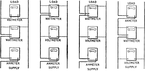
Figs. 2,876 to 2,879.—How to connect instruments
for power measurement. There are several ways of connecting an
ammeter, voltmeter and wattmeter in the circuit for the measurement
of power. A few of the methods are discussed below. With some of the
connections it is necessary to correct the readings of the wattmeter
for the losses in the coil, or coils, of the wattmeter, or for losses
in ammeter or voltmeter. This is necessary since the instruments may
be so connected that the wattmeter not only measures the load but
includes in its indications some of the instrument losses. If the
load measured be small, or considerable accuracy is required, these
instrument losses may be calculated as follows: Loss in pressure
coils is E2 ÷ R, in which E is the voltage at the terminals of
the pressure coil and R is the resistance. Loss in current coil is
I2 R in which I is the current flowing and R the resistance of the
current coil. In general let Ev = voltage across terminals of the
voltmeter; Ew = voltage across the terminals of the pressure
coil of the wattmeter; Iw = current through current coil of
wattmeter; Ia = current through current coil of ammeter; Rv
= resistance of pressure coil of voltmeter; Rw = resistance of
pressure coil of wattmeter; R1w = resistance of current coil of
wattmeter; Ra = resistance of current coil of ammeter. Then the
losses in the various coils will be as follows: E2v ÷ Rv
= loss in pressure coil of voltmeter. E2w ÷ Rw = loss in
pressure coil of wattmeter. I2w ÷ Rv = loss in current
coil of wattmeter. I2aRa = loss in current coil of
ammeter. If connection be made as in fig. 2,876, the correct power of
the circuit will be the wattmeter reading W-(E2v ÷ Rv
+ E2w ÷ Rw) in which Ev = Ew. In fig. 2,877,
the power is W-E2w ÷ Rw. In fig. 2,878, the power is
W-I2wR1w, or the correct power is the wattmeter
reading minus the loss in the current coil of the wattmeter. In fig.
2,879, the power is W-(E2w ÷ Rw + I2aRa)·
The usual method of connection is either as in fig. 2,876 or fig.
2,877. In either case the current reading is that of the load plus
the currents in the pressure coils of the voltmeter and wattmeter.
Unless the current being measured, however, is very small, or extreme
accuracy is desired, it is unnecessary to correct ammeter readings.
In fig. 2,877 a small error is introduced due to the fact that the
actual voltage applied to the load is that given by the voltmeter
minus the small drop in voltage through the current coil of the
wattmeter. If an accurate measure of the current in connection with
the power consumed by the load be required, the connections shown
in fig. 2,879 are used, and if extreme accuracy is required, the
wattmeter reading is reduced by the losses in the ammeter and in
the pressure coil of the wattmeter. The loss in the pressure coil
of a wattmeter or voltmeter may be as high as 12 or 15 watts at 220
volts. The loss in the current coil of a wattmeter with 10 amperes
flowing may be 6 or 8 watts. It can be easily seen that if the core
or copper losses of small transformers are being measured, it is
quite necessary to correct the wattmeter readings, for the instrument
losses. In measuring the losses of a 25 or 50 H.P. induction motor,
the instrument losses may be neglected. A careful study of the above
will show when it becomes necessary to correct for instrument losses
and the method of making these corrections. Connections are seldom
used which make it necessary to correct for the losses in the current
coils of either ammeter or wattmeter, as the losses vary with the
change in the current. On the other hand, the voltages generally
used are fairly constant at 110 or 220, and when the losses of the
pressure coils at these voltages have once been calculated, the
necessary instrument correction can be readily made.
On a three phase system the transformers should be joined in delta
connection, as a considerable advantage is thereby gained over the
star connection, in that should one of the transformers become
defective, the remaining two will carry the load without change
except more or less additional heating. Between the transformers
and rotary converter the circuits should be as short and simple as
possible, switches, fuses, and other instruments being entirely
excluded. The direct current from the converter is led to the direct
current switchboard, and from there distributed to the feeder
circuits.
WATTMETER ERROR FOR A LOAD OF 1,000 VOLT-AMPERES
(For a lag of 1 degree in the pressure coil)
| Power factor |
True watts |
Error |
Error of indication
in per cent
of true value |
| 1. |
1,000 |
.3 |
0.03 |
| .9 |
900 |
7.6 |
0.85 |
| .8 |
800 |
10.5 |
1.31 |
| .7 |
700 |
12.5 |
1.78 |
| .6 |
600 |
13.9 |
2.32 |
| .5 |
500 |
15.1 |
3.02 |
| .4 |
400 |
15.9 |
3.98 |
| .3 |
300 |
16.6 |
5.54 |
| .2 |
200 |
17.1 |
8.55 |
| .1 |
100 |
17.3 |
17.30 |
NOTE.—In the iron vane type instrument when used as a wattmeter,
the current of the series coil always remains in perfect phase
with the current of the circuit, provided series transformers are
not introduced. The error, then, is entirely due to the lag of the
current in the pressure coil, and this error in high power factor
is exceedingly small, increasing as the power factor decreases. In
the above table it should be noted that the value of the error as
distinguished from the per cent. of error, instead of indefinitely
increasing as the power factor diminishes, rapidly attains a maximum
value which is less than 2 per cent. of the power delivered under the
same current and without inductance. It should also be noted that the
above tabulation is on the assumption of a lag of 1 degree in the
pressure coil. The actual lag in Wagner instruments for instance, is
approximately .085 of a degree, and the error due to the lag of the
pressure coil in Wagner instruments is, therefore, proportionally
reduced from the figures shown in the above tabulation.
Ques. In large sub-stations containing several rotary converters
how are they operated?
Ans. Frequently they are installed to receive
their respective currents from the same set of bus bars; that is,
they may be operated as alternating current motors in parallel. They
are also frequently operated independently from single bus bars, but
very seldom in series with each other.
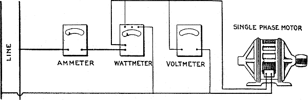
Fig. 2,880.—Single phase motor test.
In this method of measuring the input of a single phase motor of any
type, the ammeter, voltmeter and wattmeter are connected as shown in
the illustration. The ammeter measures the current flowing through the
motor, the voltmeter, the pressure across the terminals of the motor,
and the wattmeter the total power which flows through the motor
circuit. With the connections as shown, the wattmeter would also
measure the slight losses in the voltmeter and the pressure coil of
the wattmeter, but for motors of ¼ H.P. and larger, this loss is so
small that it may be neglected. The power factor may be calculated by
dividing the true watts as indicated by the wattmeter, by the product
of the volts and amperes.
Ques. How may the direct current circuit be connected?
Ans. In parallel.
NOTE.—In motor testing, by the methods illustrated in the
accompanying cuts, it is assumed that the motor is loaded in the
ordinary way by belting or direct connecting the motor to some form
of load, and that the object is to determine whether the motor is
over or under loaded, and approximately what per cent. of full load
it is carrying. All commercial motors have name plates, giving the
rating of the motor and the full load current in amperes. Hence
the per cent. of load carried can be determined approximately by
measuring the current input and the voltage. If an efficiency test
of the apparatus be required, it becomes necessary to use some form
of absorption by dynamometer, such as a Prony or other form of
brake. The output of the motor can then be determined from the brake
readings. The scope of the present treatment is, however, too limited
to go into the subject of different methods of measuring the output
of the apparatus, and is confined rather to methods of measuring
current input, voltage, and watts. The accuracy of all tests is
obviously dependent upon the accuracy of the instruments employed.
Before accepting the result obtained by any test, especially under
light or no load, correction should be made for wattmeter error. See
table of wattmeter error on page 2,075.
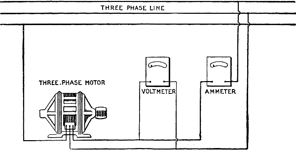
Fig. 2,881.—Three phase motor test;
voltmeter and ammeter method. If it be desired to determine the
approximate load on a three phase motor, this may be done by means
of the connections as shown in the figure, and the current through
one of the three lines and the voltage across the phase measured. If
the voltage be approximately the rated voltage of the motor and the
amperes the rated current of the motor (as noted on the name plate)
it may be assumed that the motor is carrying approximately full load.
If, on the other hand, the amperes show much in excess of full load
rating, the motor is carrying an overload. The heat generated in the
copper varies as the square of the current. That generated in the
iron varies anywhere from the 1.6 power, to the square. This method
is very convenient if a wattmeter be not available, although, it
is, of course, of no value for the determination of the efficiency
or power factor of the apparatus. This method gives fairly accurate
results, providing the load on the three phases of the motor be
fairly well balanced. If there be much difference, however, in the
voltage of the three phases, the ammeter should be switched from
one circuit to another, and the current measured in each phase. If
the motor be very lightly loaded and the voltage of the different
phases vary by 2 or 3 per cent., the current in the three legs of the
circuit will vary 20 to 30 per cent.
Ques. What provision should be made against interruption of
service in sub-stations?
Ans. There should be one reserve rotary converter to every three or
four converters actually required.
Ques. Why does a rotary converter operate with greater efficiency,
and require less attention than does a dynamo of the same output?
Ans. There is less friction, and less armature resistance, the
latter because the alternating current at certain portions of each
revolution passes directly to the commutator bars without
traversing the entire armature winding as it does in a dynamo;
there is no distortion of the field and consequently no sparking,
or shifting of the brushes, since the armature reaction resulting
from the current fed into the machine and that due to the current
generated in the armature completely neutralizes each other.
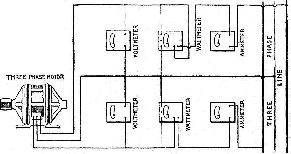
Fig. 2,882.—Three phase motor test by
the two wattmeter method. If an accurate test of a three phase motor
be required, it is necessary to use the method here indicated.
Assume the motor to be loaded with a brake so that its output can be
determined. This method gives correct results even with considerable
unbalancing in the voltages of the three phases. With the connections
as shown, the sum of the two wattmeter readings gives the total power
in the circuit. Neither meter by itself measures the power in any
one of the three phases. In fact, with light load one of the meters
will probably give a negative reading, and it will then be necessary
to either reverse its current or pressure leads in order that the
deflection may be noted. In such cases the algebraic sums of the two
readings must be taken. In, other words, if one read plus 500 watts
and the other, minus 300 watts, the total power in the circuit will
be 500 minus 300, or 200 watts. As the load comes on, the readings of
the instrument which gave the negative deflection will decrease until
the reading drops to zero, and it will then be necessary to again
reverse the pressure leads on this wattmeter. Thereafter the readings
of both instruments will be positive, and the numerical sum of the
two should be taken as the measurement of the load. If one set of the
instruments be removed from the circuit, the reading of the remaining
wattmeter will have no meaning. As stated above, it will not indicate
the power under these conditions in any one phase of the circuit. The
power factor is obtained by dividing the actual watts input by the
product of the average of the voltmeter readings × the average of the
ampere readings × 1.73.
What electrical difficulty is experienced with a rotary
converter?
Ans. Regulation of the direct current voltage.
Ques. How is this done?
Ans. It can be maintained constant only by preserving uniform
conditions of inductance in the alternating current circuit, and
uniform conditions in the alternator.
While changes in either of these may be compensated to a certain
extent by adjustment of the field strength of the converter, they
cannot be entirely neutralized in this manner; it is therefore
necessary that both the line circuit and the alternator be given
attention if the best results are to be obtained from the converter.
Ques. What mechanical difficulty is experienced with rotary converters?
Ans. Hunting.
Ques. What is the cause of this?
Ans. It is due to a variation in frequency.
The inertia of the converter armature tends to maintain a constant
speed; variations in the frequency of the supply circuit will cause
a displacement of phase between the current in the armature and that
in the line wires, which displacement, however, the synchronizing
current strives to decrease. The synchronizing current, although
beneficial in remedying the trouble after it occurs, exerts but
little effort in preventing it, and many attempts have been made to
devise a plan to eliminate this trouble.
NOTE.—Three phase motor test; polyphase wattmeter method.
This is identical with the test of fig. 2,882, except
that the wattmeter itself combines the movement of the two wattmeters.
Otherwise the method of making the measurements is identical. If
the power factor be known to be less than 50 per cent., connect
one movement so as to give a positive deflection; then disconnect
movement one and connect movement two so as to give a positive
deflection. Then reverse either the pressure or current leads of
the movement, giving the smaller deflection, leaving the remaining
movement with the original connections. The readings now obtained
will be the correct total watts delivered to the motor. If the power
factor be known to be over 50 per cent., the same methods should
be employed, except that both movements should be independently
connected to give positive readings. An unloaded induction motor has
a power factor of less than 50 per cent., and may, therefore, be
used as above for determining the correct connections. For a better
understanding of the reasons for the above method of procedure, the
explanation of the two wattmeter method, fig. 2,882, should be read.
The power factor may be calculated as explained under fig. 2,882.
Connect as shown in fig 2,882. The following check on connection may
be made. Let the polyphase induction motor run idle, that is, with
no load. The motor will then operate with a power factor less than
50 per cent. The polyphase meter should give a positive indication,
but if each movement be tried separately one will be found to give a
negative reading, the other movement will give a positive reading.
This can be done by disconnecting one of the pressure leads from the
binding post of one movement. When the power factor is above 50 per
cent. then both movements will give positive deflection.
Ques. What are the methods employed to prevent hunting?
Ans. 1, the employment of a strongly magnetized field relative to
that developed by the armature; 2, a heavy flywheel effect in the
converter; 3, the increasing of the inductance of the armature by
sinking the windings thereon in deep slots in the core, the slots
being provided with extended heads; and 4, the employment of damping
devices or amortisseur winding on the pole pieces of the converter.
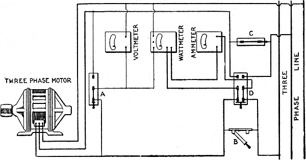
Fig. 2,883.—Three phase motor test;
one wattmeter method. This method is equivalent to the two wattmeter
method with the following difference. A single voltmeter (as shown
above) with a switch, A, can be used to connect the voltmeter across
either one of the two phases. Three switches, B, C and D, are
employed for changing the connection of the ammeter and wattmeter
in either one of the two lines. With the switches B and D in the
position shown, the ammeter and wattmeter series coils are connected
in the left hand line. The switch C must be closed under these
conditions in order to have the middle line closed. Another reading
should then be taken before any change of load has occurred, with
switch A thrown to the right, switch B closed, switch D thrown to the
right and switch C opened. The ammeter and the current coil of the
wattmeter will then be connected to the middle line of the motor.
In order to prevent any interruption of the circuit, the switches
B, D and C should be operated in the order given above. With very
light load on the motor the wattmeter will probably give a negative
deflection in one phase or the other, and it will be necessary to
reverse its connections before taking the readings. For this purpose
a double pole, double throw switch is sometimes inserted in the
circuit of the pressure coil of the wattmeter so that the indications
can be reversed without disturbing any of the connections. It is
suggested, before undertaking this test, that the instructions for
test by the two wattmeter and by the polyphase wattmeter methods be read.
Ques. What method is the best?
Ans. The damping method.
The devices employed for the purpose are usually copper shields
placed between or around the pole pieces, although in some converters
the copper is embedded in the poles, and in others it is made simply
to surround a portion of the pole tips.
In any case its action is as follows: The armature rotating at a
variable speed has a field developed therein which is assumed to
be also rotating at a variable speed; the magnetism of this rotary
field induces currents in the copper which, however, react on the
armature and oppose any tendency toward a further shifting of the
magnetism in the armature and therefore prevent the development of
additional currents in the copper. Since copper is of low resistance,
the induced currents are sufficient in strength to thus dampen
any tendency toward phase displacement, and so exert a steadying
influence upon the installation as a whole.
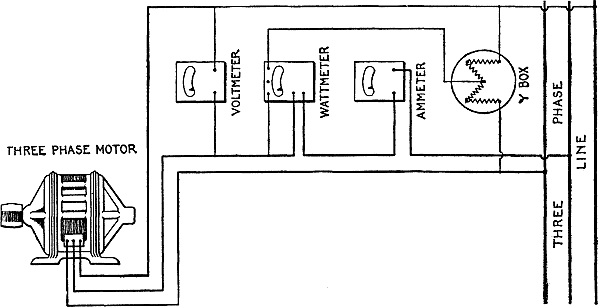
Fig. 2,884.—Three phase motor, one
wattmeter and Y box method. This method is of service, only, provided
the voltages of the three phases are the same. A slight variation of
the voltage of the different phases may cause a very large error in
the readings of the wattmeter, and inasmuch as the voltage of all
commercial three phase circuits is more or less unbalanced, this
method is not to be recommended for motor testing. With balanced
voltage in all three phases, the power is that indicated by the
wattmeter, multiplied by three. Power factor may be calculated as
before.
Electrical Measuring Instruments.—In the manufacture of most
measuring instruments, the graduations of the scale are made at the
factory, by comparing the deflections of the pointer with voltages
as measured on standard apparatus. The voltmeters in most common
use have capacities of 5, 15, 75, 150, 300, 500 and 750 volts each,
although in the measurement of very low resistances such as those of
armatures, heavy cables, or bus bars, voltmeters having capacities as
low as .02 volt are employed.
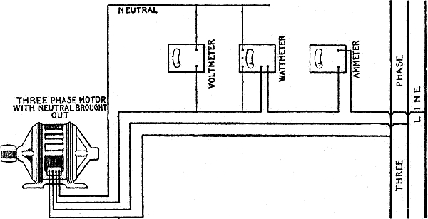
Fig. 2,885.—Test of three phase motor with
neutral brought out; single wattmeter method. Some star connected
motors have the connection brought out from the neutral of the
winding. In this case the circuit may be connected, as here shown.
The voltmeter now measures voltage between the neutral and one of
the lines, and the wattmeter the power in one of the three phases
of the motor. Therefore, the total power taken by the motor will be
three times the wattmeter readings. By this method, just as accurate
results can be obtained as with the two wattmeter method. The power
factor will be the indicated watts divided by the product of the
indicated amperes and volts.
The difference between the design of direct current voltmeters of
different capacities lies simply in the high resistance joined in
series with the fine wire coil. This resistance is usually about 100
ohms per volt capacity of the meter, and is composed of fine silk
covered copper wire wound non-inductively on a wooden spool.
In the operation of an instrument, if the pointer when deflected
do not readily come to a position of rest owing to friction in the
moving parts, it may be aided in this respect by gently tapping
the case of the instrument with the hand; this will often enable
the obstruction, if not of a serious nature, to be overcome and an
accurate reading to be obtained.
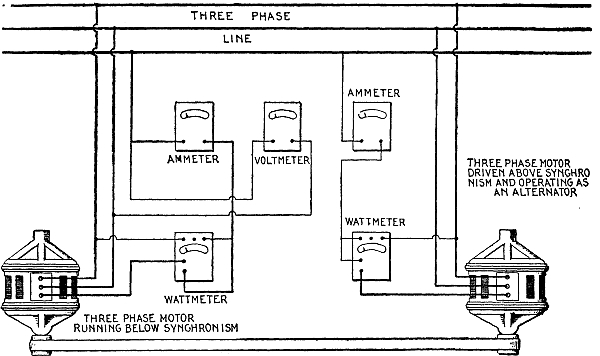
Fig. 2,886.—Temperature test of a
large three phase induction motor. Temperature tests are usually made
on small induction motors by belting the motor to a generator and
loading the generator with a lamp bank or resistance until the
motor input is equal to the full load. If, however, the motor be of
considerable size, such that the cost of power becomes a considerable
item in the cost of testing, the method here shown may be employed.
For this purpose, however, two motors, preferably of the same size
and type, are required. One is driven as a motor and runs slightly
below synchronism, due to its slip when operating with load. This
motor is belted to a second machine. If the pulley of the second
machine be smaller than the pulley of the first machine, the second
machine will then operate as an induction generator, and will return
to the line as much power as the first motor draws from the line,
less the losses of the second machine. By properly selecting the
ratio of pulleys, the first machine can be caused to draw full
load current and full load energy from the line. In this way, the
total energy consumed is equivalent to the total of the losses of
both machines, which is approximately twice the losses of a single
machine. The figure shows the connection of the wattmeters, without
necessary switches, for reading the total energy by two wattmeter
method. Detailed connection of the wattmeter is shown in fig. 2,883.
It is usual, in making temperature tests, to insert one or
more thermometers in what is supposed to be the hottest part of
the winding, one on the surface of the laminae and one in the air
duct between the iron laminae. The test should be continued until
the difference in temperature between any part of the motor and the
air reaches a steady value. The motor should then be stopped and
the temperature of the armature also measured. For the method of
testing wound armature type induction motors of very large size, see
fig. 2,890. For the approved way of taking temperature readings
and interpreting results, see the "Standardization Rules of the A.I.E.E."
Ques. Describe a two scale voltmeter.
Ans. In this type of instrument, one scale is for low voltage
readings and the other for high voltage readings; on these
scales the values of the graduations for low voltages are usually
marked with red figures, while those for high voltages are marked
with black figures. A voltmeter carrying two scales must also
contain two resistances in place of one; a terminal from each
of these coils must be connected with a separate binding post,
but the remaining terminal of each resistance is joined to a wire
which connects through the fine wire coil with the third binding
post of the meter. The two first mentioned binding posts are
usually mounted at the left hand side of the meter and the
last mentioned binding post and key at the right hand side.
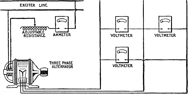
Fig. 2,887.—Alternator excitation or
magnetization curve test. The object of this test is to determine
the change of the armature voltage due to the variation of the field
current when the external circuit is kept open. As here shown,
the field circuit is connected with an ammeter and an adjustable
resistance in series with a direct current source of supply. The
adjustable resistance is varied, and readings of the voltmeter across
the armature, and of the ammeter, are recorded. The speed of the
generator must be kept constant, preferably at the speed which is
given on the name plate. The excitation or magnetization curve of the
machine is obtained by plotting the current and the voltage.
The resistance corresponding to the high reading scale is composed
of copper wire having the same diameter as that constituting the
resistance for the low reading scale, but as the capacity of the
former scale is generally a whole number of times greater than that
of the latter scale, the resistances for the two must bear the same proportion.
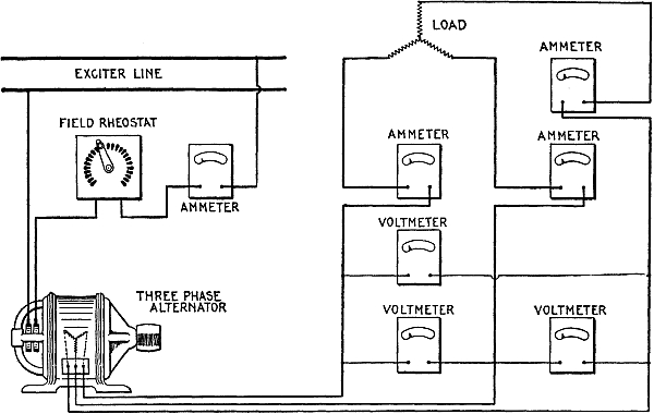
Fig. 2,888.—Three phase alternator
synchronous impedance test. In determining the regulation of an
alternator, it is necessary to obtain what is called the synchronous
impedance of the machine. To obtain this, the field is connected, as
shown above. Voltmeters are removed and the armature short circuited
with the ammeters in circuit. The field current is then varied,
the armature driven at synchronous speed, and the armature current
measured by the ammeters in circuit. The relation between field and
armature amperes are then plotted. The combination of the results of
this test, with those obtained from the test shown in fig. 2,887,
are used in the determination of the regulation of an alternator.
Engineers differ widely in the application of the above to the
determination of regulation, and employ many empirical formulae and
constants for different lines of design.
Ques. How is a two scale voltmeter connected?
Ans. In the connection of a two scale voltmeter in circuit, the
single binding post is always employed regardless of which scale is
desired. If, then, the voltage be such that it may be measured on the
low reading scale, the other binding post employed is that connected
to the lower of the two resistances contained within; if, however,
the pressure be higher than those recorded on the low reading scale,
the binding post connected to the higher of the two resistances
contained within is used.
NOTE.—Three phase alternator load test. By means of the connection
shown in fig. 2,888, readings of armature current and
field amperes can be obtained with any desired load. The field current can be
varied also so as to maintain constant armature voltage irrespective
of load; or the field current may be kept constant and the armature
voltage allowed to vary as the load increases. The connections may
also be used to make a temperature test on the alternator by loading
it with an artificial load. In some cases after the alternator is
installed the connection may be used to make a temperature test,
using the actual commercial load the alternator is furnishing.
Inasmuch as the capacities of the scales are usually marked on or
near the corresponding binding posts, there will generally be no
difficulty in selecting the proper one of the two left hand binding
posts.
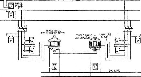
Fig. 2,889.—Three phase alternator
or synchronous motor temperature test. In this test two alternators
or synchronous motors of same size and type are used, and are
belted together, one to be driven as a synchronous motor and the
other as an alternator. The method employed is to synchronize the
synchronous motor with the alternator or alternators on the three
phase circuit, and then connect to the line by means of a three pole
single throw switch. The alternator is then similarly synchronized
with the alternator of the three phase circuit and thrown onto
the line. By varying the field of the alternator it can be made
to carry approximately full load, and the motor will then be also
approximately fully loaded. The usual method is to have the motor
carry slightly in excess of full load, and the alternator slightly
less than full load. Under these conditions the motor will run a
little warmer than it should with normal load, while the alternator
will run slightly cooler. Temperature measurements are made in
the same way as discussed under three phase motors. The necessary
ammeters, voltmeters and wattmeters for adjusting the loads on the
motors and generator are shown in above figure. If pulleys be of
sufficient size to transmit the full load, with, say one per cent.
slip, the pulley on the motor should be one per cent. larger in
diameter than the pulley on the alternator, so as to enable the
alternator to remain in synchronism and at the same time deliver
power to the circuit. With very large machines under test, it is
inadvisable to use the above method as it is sometimes difficult to
so adjust the pulleys and belt tension that the belt slip will be
just right to make up for the difference in diameter of the pulleys,
and very violent flapping of the belt results. To meet such cases,
various other methods have been devised. One which gives consistent
results is shown in fig. 2,890.
Ques. How is a two scale voltmeter connected when the binding
posts are not marked?
Ans. If only an approximate idea is possessed of the voltage to be
measured, it is always advisable to connect to the binding post
corresponding to the high reading scale of the meter in order
to determine if the measurement may not be made safely and more
accurately on the low reading scale. In any case, some knowledge must
be had of the voltage at hand, else the high reading portion of the
instrument may be endangered.
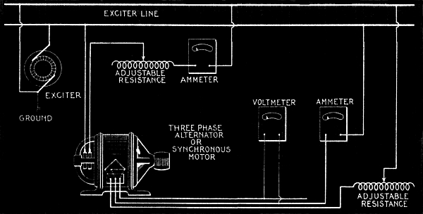
Fig. 2,890.—Three phase alternator
or synchronous motor temperature test. Supply the field with
normal field current. The armature is connected in open delta as
illustrated, and full load current sent through it from an external
source of direct current, care being taken to ground one terminal of
the dynamo so as to avoid danger of shock due to the voltage on the
armature winding. The field is then driven at synchronous speed. If
the armature be designed to be connected star for 2,300 volts, the
voltage generated in each leg of the delta will be 1,330 volts, and
unless one leg of the dynamo were grounded, the tester might receive
a severe shock by coming in contact with the direct current circuit.
The insulation of the dynamo would also be subjected to abnormal
strain unless one terminal were grounded. By the above method the
field is subjected to its full copper loss and the armature to full
copper loss and core loss. Temperature readings are taken as per
standardization rules of the A.I.E.E. This method may also be used
with satisfactory results on large three phase motors of the wound
rotor type. If the alternator pressure be above 600 volts, a pressure
transformer should be used in connection with the voltmeter.
Too much care cannot be taken to observe these precautions whenever
the voltmeter is used, for the burning out or charring of the
insulation either in the fine wire coil or in the high resistance of
the meter by an excessive current, is one of the most serious
accidents that can befall the instrument.
If a voltmeter has been subjected to a voltage higher than that
for which it was designed, yet not sufficiently high to injure the
insulation, but high enough to cause the pointer to pass rapidly over
the entire scale, damage has been done in another way. The pointer
being forced against the side of the case in this manner, bends it
more or less and so introduces an error in the readings that are
afterward taken.
The same damage will be done if the meter be connected in circuit
so the current does not pass through it in the proper direction,
although in this case the pointer is not liable to be bent so much as
when it is forced to the opposite side of the meter by an abnormal
current, since then it has gained considerable momentum which causes
a severer impact. The extent of the damage may be ascertained by
noting how far away from the zero mark the pointer lies when no
current is passing through the instrument. If this distance be more
than two-tenths of a division, the metal case enclosing the working
part should be removed and the pointer straightened by the careful
use of a pair of pinchers.
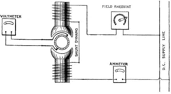
Fig. 2,891.—Direct motor or dynamo
magnetization test. The object of this test is to determine the
variation of armature voltage without load, with the current flowing
through the field circuit. The armature should be driven at normal
speed. The adjustment resistance in the field circuit is varied and
the voltage across the armature measured. The curve obtained by
plotting these two figures is usually called magnetization curve
of the dynamo. It is usual to start with the higher resistance
in the field circuit so that very small current flows, gradually
increasing this current by cutting out the field resistance. When
the highest no load voltage required is reached, the field current
is then diminished, and what is called the descending (as opposed
to the ascending) magnetization curves are obtained. The difference
in the two curves is due to the lag of the magnetization behind the
magnetizing current, and is caused by the hysteresis of the iron of
the armature core.
Ques. What should be noted with respect to location of instruments?
Ans. If they be placed near conductors carrying large currents,
the magnetic field developed thereby will produce a change in the
magnetism of the instruments and so introduce an error in the readings.
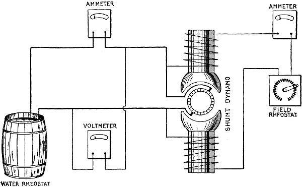
Fig. 2,892.—Shunt dynamo external
characteristic test. The external characteristic of a shunt dynamo
is a curve showing the relation between the current and voltage of
the external circuit. This is obtained by the connection as here
shown. The shunt field is so adjusted that the machine gives normal
voltage when the external circuit is open. The field current is then
maintained constant and the external current varied by varying the
resistance in the circuit. By plotting voltage along the vertical,
against the corresponding amperes represented along the horizontal,
the external characteristic is obtained.
Ques. How should portable instruments be wired?
Ans. The wires must be firmly secured to the supports on which they
rest, so as to reduce the possibility of their being pulled by
accident, and so causing the instruments to fall.
A fall or a rough handling of the meter at once shows its effect on
the readings, for as much harm is done as would result from a similar
treatment of a watch.
The hardened steel pivots used in all high grade voltmeters are
ground and polished with extreme care so as to secure and maintain a
high degree of sensitiveness. The jewels on which the moving parts
revolve are of sapphire, and they too must necessarily be made with
skill and carefulness; if, therefore, the jewels become cracked and
the pivots dulled by careless handling, the meter at once becomes
useless as a measuring instrument.
Ques. How should readings be taken?
Ans. The deflection of the pointer should be read to tenths of a
division; this can be done with considerable accuracy, especially
after a little practice.
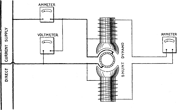
Fig. 2,893.—Load and speed test of direct
current shunt motor. The object of this test is to maintain the
voltage applied to the motor constant, and to vary the load by means
of a brake and find the corresponding variation in speed of the
machine and the current drawn from the circuit. If the motor be a
constant speed motor, the field resistance is maintained constant.
The above indicates the method of connecting instruments for the test
alone; for starting the machine the ordinary starting box, should, of
course, be inserted.
For very accurate results, a temperature correction should be applied
to compensate the effect which the temperature of the atmosphere
has upon the resistance of the meter when measurements are being
taken. In ordinary station practice the temperature correction is
negligible, being for resistance corresponding to the high scale in
first class meters, less than one-quarter of 1 per cent. for a range
of 35 degrees above or 35 degrees below 70 degrees Fahrenheit.
Ques. What attachment is sometimes provided on station voltmeters
used for constant pressure service?
Ans. A normal index.
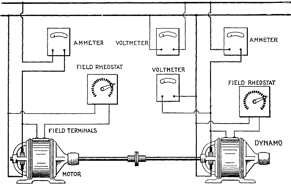
Fig. 2,894.—Temperature test of direct
current motor or dynamo; loading back method. In making temperature
tests on a small dynamo it is usual to drive the dynamo with a
motor and load the dynamo by means of a lamp bank or resistance,
the voltage across the dynamo being maintained constant, and the
current through the external circuit adjusted to full load value. The
temperatures are then recorded, and when they reach a constant value
above the temperature of the atmosphere, the test is discontinued.
Similarly, in making a test on a small motor, the motor is loaded
with a dynamo and the load increased until the input current reaches
the normal full load value of the motor, the test being conducted
as for a small dynamo. When, however, the apparatus, either motor
or dynamo, reaches a certain size, it becomes necessary, in order
to economize energy, to use what is called the loading back
method, as here illustrated. The motor is started in the usual
way, with the dynamo belted to it, the circuit of the dynamo being
open. The field of the dynamo is then adjusted so that the dynamo
voltage is equal to that of the line. The dynamo is then connected to
the circuit and its field resistance varied until it carries normal
full load current. Under these conditions, if the motor and dynamo be
of the same size and type, the motor will carry slightly in excess of
full load, the difference being approximately twice the losses of the
machines. Under these conditions the total power drawn from the line
is equal to twice the loss of either machine. Temperature readings
are taken as in other temperature tests.
Ques. What precaution must be taken in connecting station voltmeters?
Ans. Care must be taken to guard against any short circuiting of the
voltmeter, which, would mean a short circuiting of the generator, and
as a result the probable burning out of its armature.
The high resistance of the voltmeter prevents any such occurrence
when it is connected in the proper way, but should one side of the
circuit be grounded to the metal case or frame of the meter, a
careless handling of the lead connected with the other side of the
circuit would produce the result just mentioned.
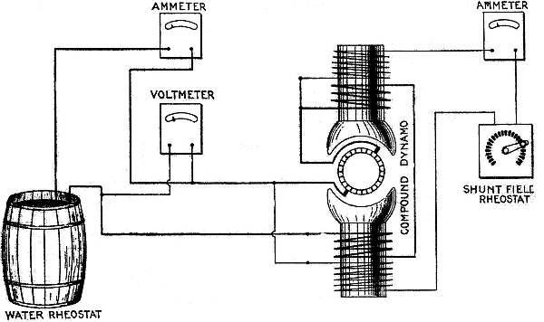
Fig. 2,895.—Compound dynamo external
characteristics test; adjustable load. The object of this test is to
determine the relation between armature voltage and armature current.
Shunt field is adjusted to give normal secondary voltage when the
external circuit is open. The load is then applied by means of an
adjustable resistance or lamp bank, and readings of external voltage
and current recorded. If the machine be normally compounded, the
external voltage will remain practically constant throughout the load
range. If the machine be under-compounded, the external voltage will
drop with load, while if over-compounded, there will be a rise in
voltage with increase in load.
Ques. Why do station voltmeters indicate a voltage slightly lower
than actually exists across the leads?
Ans. Since they are usually connected permanently in circuit; a
certain amount of heat is developed in the wiring of the instrument.
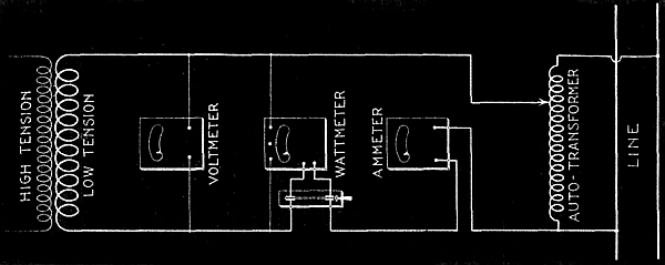
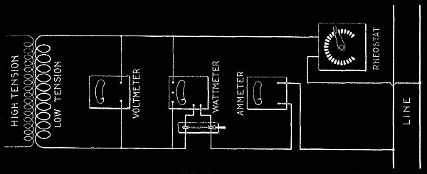
Figs. 2,896 and 2,897.—Transformer core
loss and leakage, or exciting current test. With the primary circuit
open, the ammeter indicates the exciting or no load current. It
should be noted that all instruments are inserted on the low voltage
side, for both safety of the operator and because the measurements
are more accurate. The no load primary current, if the ratio of
transformation be 10: 1, will be one-tenth of the measured secondary
current. The wattmeter connected, as shown, measures the sum of the
losses, in the transformer, in the pressure coil of the wattmeter,
and in the voltmeter. On all standard makes of portable instruments,
the resistance of the wattmeter pressure coil and of the voltmeter
is given, and the loss in either instrument is the square of the
voltage at its terminals, divided by its resistance. Subtracting
these losses from the total indicated upon the wattmeter, gives the
true core or iron loss. It should be noted that in this diagram is
shown an auxiliary transformer with a number of taps for obtaining
the exact rated voltage of the transformer under test. In fig. 2,897
is shown, in general, the same connections as in fig. 2,896,
except that the auto-transformer has been replaced by a resistance. If the
line voltage available be not much in excess of the rated voltage of
the transformer under test, very little error is introduced by the
use of the resistance method. However, if the difference be 10 per
cent. or more the auxiliary transformer shown in fig. 2,896
should be used. Measurements made under the resistance method always give lower
results than those obtained with the auxiliary transformer.
The effect of this heat increases the voltmeter resistance and
consequently reduces the current below that which otherwise would
pass through the meter; since the deflections of the pointer
are governed by the strength of the current, station voltmeters
invariably indicate a voltage slightly lower than that which actually
exists across their leads.
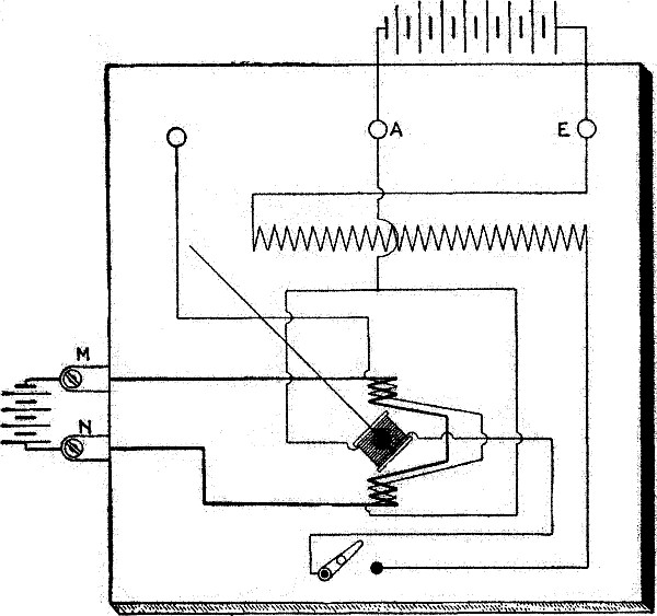
Fig. 2,898.—Diagram of connections for
calibrating a wattmeter. The calibration of a portable wattmeter
is accomplished with direct current of constant value which is
passed through the series winding by connecting the source thereof
with the current terminals. A direct current voltage which may be
varied throughout the range of the wattmeter is also applied to the
instrument between the middle and right hand pressure terminals A and
E the wiring in the meter between these terminals being such that
its differential winding is then cut out of circuit. The method of
procedure consists in comparing the deflections on the wattmeter at
five of six approximately equidistant points over its scale with the
corresponding products of volts and amperes used to obtain them. The
changes in the wattmeter deflections are effected by merely varying
the voltage, the value of the current being maintained constant at a
value which represents the full current capacity of the meter.
NOTE.—Checking up of a recording wattmeter. This may
conveniently be done by noting the deflections at short intervals on
an ammeter connected in circuit, and also the readings on the dial of
the recording wattmeter during this period. If this test be continued
for an appreciable time, the product of the pressure in volts, the
current in amperes, and the time in hours, should equal the number of
watthours recorded on the counters of the dial.
NOTE.—Transformer testing. In the early days of transformer
building, before the commercial wattmeter had been perfected, leakage
or exciting current was the criterion of good design. After the
introduction of the wattmeter, core loss became the all important
factor, and for a long time the question of leakage current was
lost sight of. With the introduction of silicon steel, leakage or
exciting current again assumed prominence. Keeping in mind the
fact that all characteristics of a transformer are of more or less
importance, it is essential that the user of such apparatus have at
hand the necessary facilities for making tests of all such variable
quantities. The tests which all users of transformers should make,
are given in this chapter.
Ques. Can direct current be measured by an alternating current
voltmeter?
Ans. Yes.
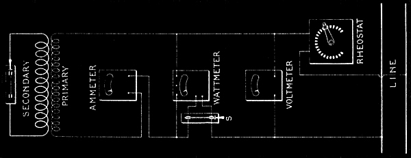
Fig. 2,899.—Transformer copper loss
by wattmeter measurement and impedance. At first glance, this method
would seem better than the calculation of loss after measurement of
the resistance. However, it should be noted that the wattmeter is,
in itself, subject to considerable error under the low power factor
that will exist in this test. The secondary of the transformer is
short circuited, and a voltage applied to the primary which is just
sufficient to cause full load primary current. If full current pass
through the primary of the transformer with the secondary short
circuited, the secondary will also carry full load current. With
connections as shown, and with the full load current, the voltmeter
indicates the impedance volts of the transformer. This divided by
the rated voltage gives what is called the per cent. impedance of
the transformer. In a commercial transformer of 5 kw., this should
be approximately 3 per cent. The iron loss of the transformer under
approximately 3 per cent. of the normal voltage will be negligible,
and the losses measured will be the sum of the primary and secondary
copper losses. As in the discussion of the core loss measurements,
the wattmeter readings must be corrected for the loss in its pressure
coil, the method of correction being the same as that discussed under
the core loss measurement. If the impedance volts, as measured, be
divided by the primary current, the impedance of the transformer
is obtained. The reciprocal of this quantity is known by the term
"admittance." When two or more transformers are connected in
parallel they divide the load in proportion to their admittance.
It is, therefore, important that the users of transformers know the
impedance of the apparatus used, in order to determine whether two
or more transformers will operate satisfactorily in parallel. For
discussion of wattmeter error on low power factor, see note on page
2,075. For accurate measurement of impedance, the voltmeter should
be connected directly across the terminals of the transformer rather
than as shown in the diagram.
NOTE.—Transformer copper loss test. The usual and best method
of obtaining copper losses is to separately measure the primary
and secondary resistance and calculate from these the primary and
secondary copper losses. For general diagram of connections and
discussion of the drop method, see fig. 2,875. The current
should be kept well within the load current of the transformer to avoid
temperature rise during the test. In other words, the resistance of
the coil is the voltage across its terminals divided by the current.
The resistance of the primary coil can be measured similarly. The
copper loss in watts in each coil will then be the product of the
resistance and the square of the rated current for that coil. The
total copper loss will be the sum.
Ques. What would be the effect of placing a direct voltmeter
across an alternating current circuit, and why?
Ans. There would be no deflection of the pointer owing to the rapid
reversals of the alternating current.
Ques. What are the usual capacities of alternating current voltmeters?
Ans. They are 3, 7.5, 10, 12, 15, 20, 60, 75, 120, 150, 300 and 600
volts, but these capacities may each be increased by the use of a
multiplier.
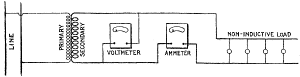
Fig. 2,900.—Temperature test of transformer
with non-inductive load. The figure shows the simplest way of making
the test. Connect the primary of the transformer to the line as
shown, and carry normal secondary load by means of a bank of lamps or
other suitable resistance, until full load secondary current is shown
by the ammeter in the secondary circuit. The transformer should then
be allowed to run at its rated load for the desired interval of time,
temperature readings being made of the oil in its hottest part, and
also of the surrounding air. Where temperatures of the coil rather
than temperatures of the oil are desired, it is necessary to use the
resistance method. This is obtained by first carefully measuring the
resistance of both primary and secondary coils at the temperature
of the room, and then, after the transformer has been under heat
test for the desired time, disconnect it from the circuit and again
measure the resistance of primary and secondary. For proper method
of calculating the temperature rise from resistance measurements,
the reader is referred to the standardization rules of the A.I.E.E.
In making resistance measurements of large transformers by the drop
method care should be taken to allow both ammeter and voltmeter
indications to settle down to steady values before readings are
taken. This may require several minutes. Each time the current is
changed it is necessary in order to obtain check values on resistance
measurements, to wait until the current is again settled to its
permanent value before taking readings. All resistance measurements
must be taken with great care, as small errors in the measurement of
the resistance may make very large errors in the determination of
the temperature rise. The method above described is satisfactory for
small transformers. Where large units are to be tested, the cost of
current for testing becomes an important item. The "bucking test" as
in fig. 2,901, is more economical.
Ques. How are station voltmeters usually attached to the switchboard?
Ans. They are usually bolted to the switchboard by means
of four iron supports mounted on the back of the instrument;
two of these are fastened near each side of the case.
Under certain conditions, however, as in paralleling of alternators,
it is convenient to have the alternating current voltmeter mounted
on a swinging bracket at the side of the switchboard. The voltmeter
may then be swung around in any desired direction so as to enable the
attendant to keep informed of the voltage while switching in each
additional alternator.
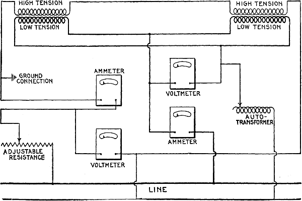
Fig. 2,901.—Transformer temperature "bucking
test." For this purpose two transformers of the same size and ratio
are required. The connections are as shown. Full secondary voltage is
applied, and rheostats or auxiliary auto-transformers are inserted
in the circuit to properly regulate the voltage. The primaries
are connected with one bucking the other, and a voltage equal to
twice the impedance voltage of either transformer inserted in the
primary circuit. It should be noted that when the secondaries are
subjected to the full secondary voltage, a full primary voltage
exists across either primary, but with the primaries connected so
that the voltage of one is bucked against the voltage of the other,
the resultant voltage in the circuit will be zero. By applying to the
primary circuit twice the impedance voltage of either transformer,
full primary and secondary current will circulate through both
transformers. On the other hand, by subjecting the secondaries to
the full secondary voltage, the iron of the transformer will be
magnetized as under its regular operating conditions, and the full
iron loss of the transformer introduced. This method permits the
operation of two transformers under temperature test with their
full losses, without taking energy from the line equal to the rated
capacity. Measurements of temperature are taken in exactly the
same way as above. This method is successfully employed for making
temperature tests on transformers of all sizes.
Ques. How should an ammeter be operated to get accurate readings, and why?
Ans. It should be cut out of circuit except while taking a reading,
because of the error introduced by the heating effect of the current.
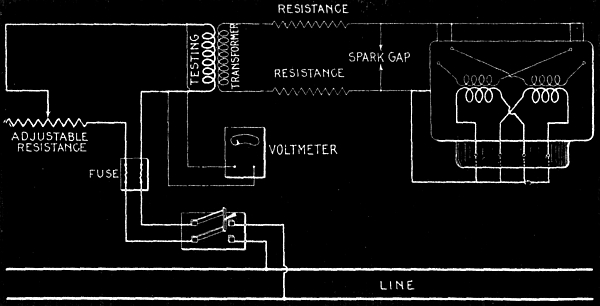
Fig. 2,902.—Transformer insulation test.
In applying a 10,000 volt insulation test between the primary and
secondary of a transformer, the testing leads should be disconnected
from the transformer under test, and a spark gap introduced as shown,
with the test needle set at a proper sparking distance for 10,000
volts. A high resistance should be connected in the secondary before
closing its circuit, and the voltage gradually increased by cutting
out this secondary resistance until a spark jumps across the spark
gap. When the spark jumps across the spark gap, the voltmeter reading
should be recorded and the testing transformer disconnected. The
spark gap should then be increased about 10 per cent. and the high
tension leads connected to the transformer under test as indicated
in the diagram. In order to equalize the insulation strains, all
primary leads should be connected together, all secondary leads not
only connected together, but to the core as well. All resistance
in the rheostat in the low tension circuit should then be inserted
and the switch closed. Gradually cut out secondary resistance until
the voltmeter shows the same voltage as was recorded previously
when the spark jumped across the gap, and apply this voltage to the
transformer for one minute. Insulation tests for a period of over
one minute are very unadvisable, as transformers with excellent
insulation may be seriously damaged by prolonged insulation tests.
The longer the strain to which any insulation is subjected, the
shorter the subsequent life of the insulation. Also the greater the
applied voltage above the actual operating voltage of the apparatus,
the shorter the subsequent life of the insulation. In testing small
transformers, the spark gap may be omitted and the voltage of the low
pressure coil of the testing transformer measured. This multiplied by
the ratio of transformation gives the testing voltage.
In an ammeter having a capacity of 50 amperes, the error thus
introduced will be less than 1 per cent. if connected continuously in
circuit with a current not exceeding three-quarters this capacity.
An ammeter of 100 amperes capacity may be used indefinitely in
circuit with less than 1 per cent. error up to one-half its capacity,
and for five minutes at three-quarters capacity without exceeding the
1 per cent. limit.
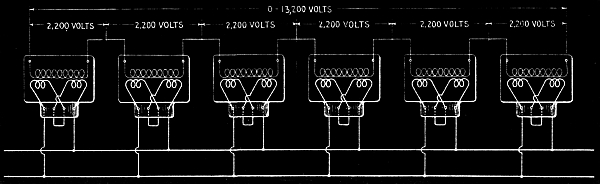
Fig. 2,903.—Transformer insulation test
as made when a special high tension transformer be not available.
In this method a number of standard transformers, connected as
shown may be employed, but great care should be taken to have such
transformer cases thoroughly insulated from the ground and from one
another, in order to minimize the insulation strains in the testing
transformers. Care should be taken to insert in the circuit of
each testing transformer a fuse, not in excess of the transformer
capacity, which will blow, in case of a break down in the apparatus
under test. In testing insulation between secondary and core,
disconnect the primary entirely, apply one terminal of the testing
transformer to the secondary terminals of the transformer under test,
and the other terminal of the testing transformer to the core of the
transformer under test. This test should also not be in excess of one minute.
The 150 scale ammeter may be left in circuit for an indefinite length
of time at one-third its full capacity, and for three minutes at
one-half its full capacity, with a negligible error.
Ammeters of 200 and of 300 ampere capacities must not continuously
carry more than one-quarter of these loads respectively if the
readings are to have an accuracy within 1 per cent. nor more than
one-half these respective number of amperes for three minutes if the
same degree of accuracy be desired.
In order to cut or shunt the ammeter out of circuit when not in use,
it is customary when wiring the instrument in place, to introduce a
switch as a shunt across it; this switch is kept closed except when a
measurement is being taken.
When currents larger than 300 amperes have to be measured, ammeter
shunts are generally employed, although ammeters up to 500 amperes
capacity are manufactured.
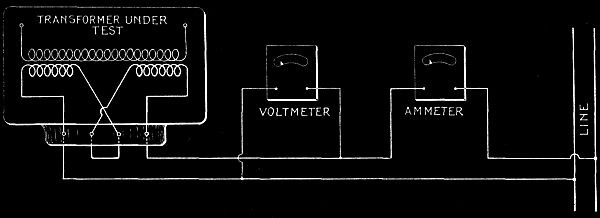
Fig. 2,904.—Transformer internal insulation
test, sometimes called double normal voltage test, from the fact that
most transformers are tested with double normal voltage across their
terminals. If either the primary or secondary of the transformer
be connected to some source of current with voltage double that of
the voltage of the transformer under test, the insulation between
adjacent turns, and also the insulation between adjacent layers
will be subjected to twice the normal operating voltage. It is good
practice to employ high frequency for this test in order to prevent
an abnormal current from passing through the transformer. Sixty
cycle transformers are usually tested on 133 cycles, and 25 cycle
transformers on 60 cycle circuits for this double normal voltage
test. It is necessary to insert the resistance in the circuit of the
transformer and bring the voltage up gradually, the same as applying
other high insulation tests in order to prevent abnormal rises in
pressure at the instant of closing the circuit.
Ques. What is used in place of instrument shunts for high pressure
alternating current measurements?
Ans. Instrument transformers.
Ques. What important attention should be periodically given to
measuring instruments?
Ans. They should be frequently tested by comparison with standards
that are known to be correct.
Electrical measuring instruments, owing to the nature of their
construction and the conditions under which they must necessarily
be used, are subject to variations in accuracy. This feature is an
annoying one on account of the difficulty of detecting it; a meter
may, as far as appearances go, be in excellent working order and yet
give readings which are not to be relied upon.
Ridiculous as it may appear, the average station attendant may
frequently be seen straining his eyes to read to tenths of a division
on the scale of a meter which, if subjected to test, would show an
inaccuracy of over 2 per cent.
In testing a meter, by comparing it with a standard, in order to
obtain the best results there should be one man at each meter so that
simultaneous readings may be taken on both instruments, and the man
at the standard meter should maintain the voltage constant while a
reading is being taken, by means of a rheostat in the field circuit
of the generator supplying the current.
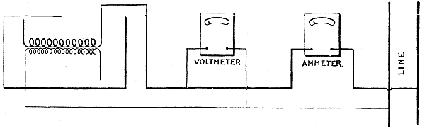
Fig. 2,905.—Transformer insulation
resistance test. The insulation, besides being able to resist
puncture, due to increased voltage, must also have sufficient
resistance to prevent any appreciable amount of current flowing
between primary and secondary coils. It is, therefore, sometimes
important that the insulation resistance between primary and
secondary be measured. This can be done, as here shown. Great care
should be taken to have all wires thoroughly insulated from the
ground, and to have an ammeter placed as near as possible to the
terminals of the transformer under test, in order that current
leaking from one side of the line to the other, external to the
transformer, may not be measured. Great care is required in making
this measurement, in order to obtain consistent results.]
Each meter should be checked or calibrated at five or six
approximately equidistant points over its scale; the adjustable
resistance being varied each time to give a deflection on the
standard meter of an even number of divisions and the deflection on
the other meter recorded at whatever it may be. Having obtained the
necessary readings, the calculation of the constant or multiplying
factor of the meter undergoing test is next in order.
This may best be shown by taking an actual case in which a 150 scale
voltmeter is being tested to determine its accuracy. The data and
calculations are as follows:
Readings on
standard meter |
Readings on
meter tested |
Constant |
| 150 |
149.2 |
150 ÷ 149.2 = 1.005 |
| 125 |
125.0 |
125 ÷ 125.0 = 1.000 |
| 100 |
98.9 |
100 ÷ 98.9 = 1.011 |
| 75 |
73.6 |
75 ÷ 73.6 = 1.019 |
| 50 |
50.0 |
50 ÷ 50.0 = 1.000 |
| 25 |
24.8 |
25 ÷ 24.8 = 1.008 |
| |
|
6.043 |
Average constant for six readings, 6.043 ÷ 6 = 1.007. |
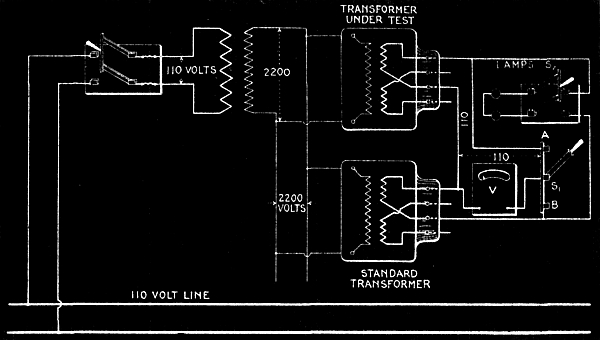
Fig. 2,906.—Transformer winding or ratio
test. The object of this test is to check the ratio between the
primary and the secondary windings. For this purpose a transformer of
known ratio is used as a standard. Connect the transformer under test
with a standard transformer as shown. Leave switch S2 open. With
the single pole double throw switch in position S1B, the voltmeter
is thrown across the terminals of the standard transformer. With
the switch in position S1A, the voltmeter is thrown across the
terminals of the transformer under test. The voltmeter should be read
with the switch in each position. If the winding ratio be the same as
that of the standard transformer, the two voltmeter readings will be identical.
It may be stated in general that before taking the readings for this
test, the zero position of the pointer on the meter tested should
be noted, and if it be more than two-tenths of a division off the
zero mark, the case of the meter should be removed and the pointer
straightened.
Furthermore, it will be noticed from the readings here recorded that
the test is started at the high reading end of the scale; this is
done in order that the pointer may gradually be brought up to this
spot, by slowly cutting out of circuit the adjustable resistance, and
thus show whether or not the pointer has a tendency to stick at any
part of the scale. If the meter seem to be defective in this respect,
it should be remedied either by bending the pointer or scale, or by
renewing one or both of the jewels, before the comparison with the
standard is commenced.
It is obvious from the readings recorded for the 150 scale voltmeter,
that as compared with the corresponding deflections of the standard,
the former are a trifle low.
In order to determine for each observation how much too low they
are, it is necessary to divide each reading on the standard by the
corresponding reading on the meter tested. The result is the amount
by which a deflection of this size on the meter tested must be
multiplied in order to obtain the exact reading. This multiplier is
called a constant, and as shown, a constant is determined for each of
the six observations.
The average constant for the six readings is then found, and this is
taken as the constant for the meter as a whole; that is, whenever
this 150-scale voltmeter is used, each reading taken thereon must be
multiplied by 1.007 in order to correct for its inaccuracy.
The most convenient and systematic way of registering the constant of
a meter is to write it, together with the number of the meter and the
date of its calibration, in ink on a cardboard tag and loop the same
by means of a string to the handle or some other convenient part of
the meter.
NOTE.—Transformer polarity test. A test of importance
in the manufacture of transformers, and sometimes necessary for the
user, is the so called banking or polarity test. The transformers
from any particular manufacturer have the leads brought out in
such a manner that a transformer of any size can be connected to
primary and secondary lines in a given order without danger of
blowing the fuses due to incorrect connections. All manufacturers
of transformers, however, do not bank transformers in the same
way, so that it is necessary in placing transformers of different
makes to test for polarity. This is done as shown in fig. 2,906.
One transformer is selected as a standard and the leads of the
second transformer connected as indicated in the diagram. If the
transformers be 1,100-2,200 volts to 110-220, two 110 volt lamps
are connected in the secondaries of the transformers as indicated,
while the primary of the transformer is connected across the line.
In transformers built for two primary and two secondary voltages, it
is necessary to test each primary and each secondary. The diagram
shows the method of connecting one 2,200 volt coil and one 110 volt
coil to the transformer to be tested. When the primary circuit of the
transformer under test is closed, and if the secondary leads of the
110 volt coil under test be brought out of the case properly, the two
110 volt lamps should be brightly illuminated. If, on the other hand,
the two 110 volt terminals have been reversed, no current will flow
through the lamps. If these two terminals be found to be brought out
correctly, transfer the secondary leads of the transformer under test
to the second 110 volt coil. Upon closing the primary circuit, the
lamp should again be brightly illuminated. Repeat this process with
each of the secondary coils and the other primary coil, and if the
lamps show up brightly in every case on closing the primary circuit,
all leads have been properly brought out. If on any tests the lamps
do not light up brightly, the leads on the transformer must be so
changed as to produce the proper banking.
Ques. What are the usual remedies applied to a voltmeter to
correct a 3 or 4 per cent. error?
Ans. They consist of straightening the pointer, varying the tension
of the spiral springs, renewing the jewels in the bearings, altering
the value of the high resistance, and, in the case of a direct
current instrument, strengthening the permanent magnet.
Ques. How is the permanent magnet strengthened?
Ans. After detaching it from the instrument, wrap around several
turns of insulated wire, and pass through this wire for a short time
3 or 4 amperes of direct current in such a direction as to reinforce
the magnet magnetism.
Ques. How may the value of the high resistance of a voltmeter
be altered?
Ans. Determine the resistance of the voltmeter and add or subtract,
according as the reading is high or low, a certain length of wire
whose resistance is in per cent. of the voltmeter resistance the same
as the per cent. of error.
NOTE.—The complete calibration of a two scale voltmeter does not,
as might be supposed, necessitate that the readings on both scales
be checked with standards, for since the resistance corresponding to
the one scale is always some multiple of the resistance of the other,
the constants of the two scales are proportional. For instance, if S
= the reading at the end of the high scale of the voltmeter; S1
= the reading at the end of the low scale of the voltmeter; R = the
resistance in the meter corresponding to the high scale; R1 =
the resistance in the meter corresponding to the low scale; K = the
constant for the high scale, and K1 = the constant for the low
scale. Then
SK ÷ R = S1K1 ÷ R1
from which
K1 = SKR ÷ S1R
That is to say, if the respective resistances corresponding to the
two scales be known, and the constant of the high scale be determined
by comparison with a standard, then by aid of these known values and
the maximum readings on the two scales, the constant of the low scale
may be calculated. It is also possible to calculate the constant of
the high scale if the constant of the low scale be known, together
with the values of the resistances corresponding to the two scales;
for from the equation previously given.
K = RS1K1 ÷ R1S
Ques. What is a frequent cause of error in an alternating current meter, and why?
Ans. The deterioration of its insulation, which permits the working
parts of the instrument coming in contact with the surrounding metal
case.
A convenient method of testing for deterioration of insulation is
shown in fig. 2,905.
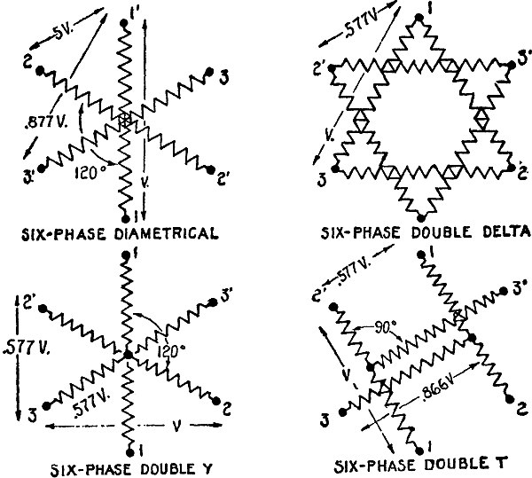
Fig. 2,907.—Diagrams showing various
synchronous converter transformer connections. The diametrical
connection is used most frequently as it requires only one secondary
coil on each transformer, this being connected to diametrically
opposite points on the armature winding. The middle points can be
connected together and a neutral obtained the unbalanced three
wire direct current having no distorting effect. With diametrical
secondaries, the primaries should preferably be connected delta,
except with regulating pole converters where they must be connected
Y. Diametrical secondaries with delta primaries should not be
used with regulating pole converters. Double star connection of
secondaries may, however, be used with delta primaries, and is free
from the trouble of the triple harmonic of the transformer appearing
in the primary. In this case, however, the two secondary neutrals
must not be connected with each other.
How to Test Generators.—In the operation of electrical
stations, many problems dealing with the generators installed therein
can be readily solved by the aid of characteristic curves, which bear
a relation to the generators similarly as do indicator diagrams to steam engines.
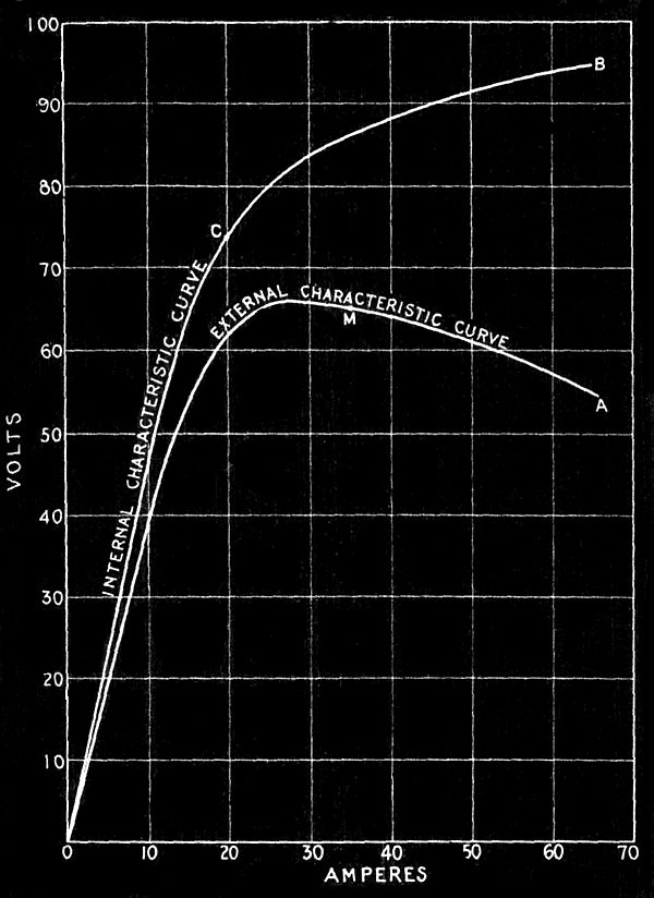
Fig. 2,908.—General form of characteristic
curves for a series dynamo. The general curve that may be expected is
OA. It is obtained practically in the same manner as for the shunt
characteristic curve, except that no field rheostat is employed.
Commencing with no load or amperes, there will probably be a
small deflection noticeable on the voltmeter, due to the residual
magnetism. The other readings are taken with successive reductions
of main current resistance. The curve OA thus obtained for a certain
series generator is practically a straight line at the beginning,
representing thereby a proportional increase of voltage with
increase of current, but after a certain current is reached (about
20 amperes in this case) the curve flattens and takes a downward
direction. The turning point occurs in the characteristic curves
of all series generators, and it denotes the stage at which the
iron magnet cores become so saturated with lines of magnetic force
that they will not readily allow more to pass through them; this
turning point is technically known as the point of saturation, and
the current corresponding (20 amperes in this case) is called the
critical current of the dynamo. The point of saturation in any given
series machine is governed by the amount of iron in the magnetic
circuit; its position in the curve therefore varies according to
the design of the generator as does also the critical current. The
value of the latter is important inasmuch as the valuable features
of a series generator assert themselves only when the machine is
supplying a greater number of amperes than that of the critical
current, for if the series generator be worked along that part M A of
the curve to the right of the point of saturation it becomes nearly
self-regulating as regards current, because as the current increases
the voltage drops. In the diagram in addition to the characteristic
curve O A, which may more definitely be called an external
characteristic curve on account of representing the conditions
external to the generator, there is shown a total characteristic
curve, O C B. The latter curve represents the relation between the
current and the total voltage developed in the armature, and may be
plotted from the external characteristic curve if the resistance of
the armature between brushes and the resistance of the series field
winding be known. For example, assume these combined resistances
amount to .6 ohm. At 30 amperes there would be required 30 × .6 = 18
volts to force this current through the armature and field windings.
At 30 amperes the external pressure is 65 volts, as shown by the
curve O A; the total voltage developed for 30 amperes is, therefore,
the external voltage plus the internal voltage or 65 + 18 = 83
volts. Plotting 83 volts for 30 amperes will give one point for the
external characteristic curve of this machine, and by determining in
like manner the total voltages developed for six or eight different
currents over the scale, sufficient data will be at hand for plotting
and drawing in the curve O C B.
In steam engineering, a man who did not fully understand the method
of taking an indicator diagram would be considered not in touch with
his profession, and in electrical engineering the same would be true
of one ignorant of the method of obtaining characteristic curves.
The necessary arrangement or connection of the generator from which
it is desired to obtain a characteristic curve, consists in providing
a constant motive power so that the machine may be run at a uniform
speed, and when the field magnets of the generator are separately
excited the field current from the outside source must also be
maintained constant, preferably by a rheostat connected in the field
of the auxiliary exciting machine. It is also necessary in every case
that means be provided for varying the main current of the generator
step by step from zero to maximum. This may best be done by employing
a water rheostat, as shown in fig. 2,909.
Ques. What instruments are needed in making a test of dynamo characteristics?
Ans. A voltmeter, ammeter, speed indicator, the usual switches and rheostats.
Ques. How is the apparatus connected?
Ans. It is connected as shown in fig. 2,910.
Ques. Describe the test.
Ans. Having completed the preliminaries as in fig. 2,910,
the test should be started with the main circuit of the generator open. Then,
in the case of the shunt machine, the speed should be made normal and
the field rheostat adjusted until the voltmeter reading indicates
the rated voltage of the machine at no load and readings taken. The
electrodes of the water rheostat should be adjusted for maximum
resistance and main circuit closed, and a second set of readings
taken. Several sets of readings are taken, with successive reductions
of water rheostat resistance. The results are then plotted on
coordinate paper giving the characteristic curve shown in fig. 2,908.
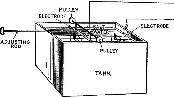
Fig. 2,909.—Water rheostat. It consists
essentially of a tank of suitable size containing salt water into
which are placed two electrodes having means of adjustment of the
distance separating them. The solution depends on the voltage. Pure
water is seldom used for pressures under 1,000 volts. The size of
the tank is determined by the size of the electrodes, and roughly
the size of the latter equal the number of amperes. With a current
density of one ampere per square inch, a water solution gives a
drop of 2,500 to 3,000 volts per inch distance between the plates.
Where high voltage is used, the water must be circulated through and
from the tank by rubber hose allowing for 2,500 volts, a length of
15 to 20 feet of 1 inch hose to prevent grounding. In place of the
arrangement shown above, a barrel may be used for the tank, and for
the electrodes, coils of galvanized iron wire. This is the simplest
form and is satisfactory.
Ques. What does the characteristic curve (fig. 2,911) show?
Ans. An examination of the curve shows that the highest
point of the curve occurs at no load or 0 amperes; that as the
current is increased, the voltage drops, first slightly to the point
B and then rapidly until the point E is reached, when any further
lowering of resistance in the main circuit to increase the current
causes not only a rapid decline in the voltage but also of the
current until both voltage and current become approximately zero.
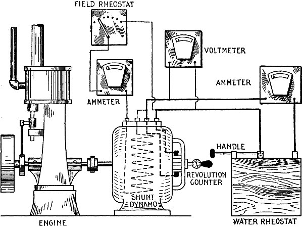
Fig. 2,910.—Connections for test of dynamo.
During the test, one man should be assigned to the tachometer,
another man to the water rheostat, and there should preferably be
one man at each of the electrical measuring instruments. In order
to enable the man at the tachometer to keep the speed constant, he
should be in communication either directly or indirectly with the
source of the driving power, and the man at the water rheostat should
be in plain view of the man reading the ammeter so that the latter
party may signal him for the proper adjustment of the rheostat in
order that the desired increase of current be obtained for each set
of readings.
In some generators, a very slight current results even when the
terminals of the machine are actually short circuited; that is, due
to residual magnetism in the pole pieces, the lower portion of the
curve often terminates, not exactly at zero, but at a point some
distance along the current line.
The working portion of the curve is from A to C, at which time the
machine is supplying a fairly constant voltage. From C to E shows
a critical condition of affairs, while the straight portion D O
represents the unstable part of the curve caused by the field current
being below its proper value.
The position of the point C determines the maximum power the machine
is capable of developing, being in this case (47.5 × 25) ÷ 746 = 1.59
horse power.
Ques. How may the commercial efficiency of a generator be determined?
Ans. To obtain the commercial efficiency, the input and
output must be found for different loads.
The input may be found by running the generator as a motor at its
rated speed, loading it by means of a Prony brake. The generator must
be stripped of all belting or other mechanical connections, supplied with
its normal voltage and full load current, and the pressure of the Prony
brake upon its armature shaft or pulley adjusted until the rated speed
of the armature is obtained. The data thus obtained is substituted
in the formula.
| |
2π L W R |
|
| input in brake horse power = |
—————— |
(1) |
| |
33,000 |
|
in which
L = length of Prony brake lever;
W = pounds pull at end of lever;
R = revolutions per minute.
The output or electrical horse power for the same load is easily
calculated from the formula
| |
amperes × volts |
|
| output in electrical horse power = |
———————— |
(2) |
| |
746 |
|
After obtaining value for (1) and (2) the commercial efficiency for
the load taken is obtained from the formula
| |
output |
|
| commercial efficiency = |
———— |
(3) |
| |
input |
|
Having obtained the commercial efficiency, the difference between the
ideal 100 per cent. and the efficiency found will be due to certain
losses in the generator. These losses may be classified as
1. Mechanical.
2. Electrical.
The mechanical losses are the friction of the bearings and brushes,
and air friction. The electrical losses consist of the eddy current
loss, hysteresis loss, armature resistance loss, and field resistance
loss.
In testing for these losses, the generator to be tested should be
belted to a calibrated motor which latter machine should preferably
be of the constant pressure, shunt wound type.
The friction of the bearings and belt of the generator are determined
together by raising the brushes off its commutator and running it at
the rated speed by means of the calibrated motor.
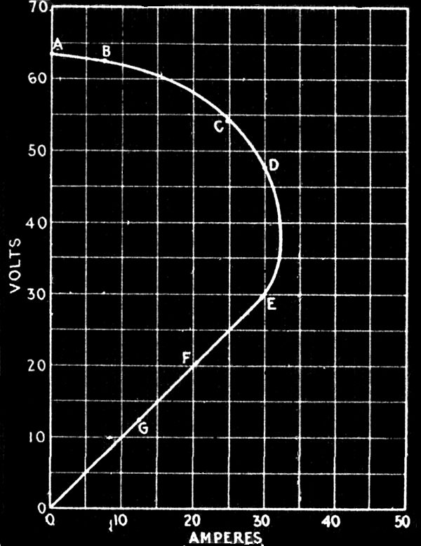
Fig. 2,911.—Characteristic curve of shunt
dynamo. Suppose in making the test, the deflections on the meters
for the first readings be 63 volts and 0 amperes, the plotting of
these values will give the first point on the curve. Similarly, the
second readings with main circuit closed and maximum resistance in
the water rheostat may be assumed to be 62.5 volts and 7.5 amperes,
which plotted gives the second point B. A still further lowering of
the plate will permit a stronger current in the main circuit, and
the value of this together with its corresponding voltage will give
a third point for the curve. Neither for this reading, however, nor
for the following readings of the test should the field rheostat be
altered. When six or eight points ranging from zero to a maximum
current have been obtained and plotted, a curved line should be drawn
through them such as shown through ABCDEFG0, the characteristic
curve of the dynamo. While the curve may be sketched in free hand,
it should preferably be drawn by the aid of French curves. In case
the French curve cannot be exactly made to coincide with all the
points as for instance C and D, it should be run in between giving an
average result, and smoothing out irregularities, or small errors due
to the "personal equation." The meter of course must be correct or
calibrated and the readings corrected by the calibration coefficient.
The amount of power as ascertained from the calibration curve of
the motor for the voltage and current used therein when driving the
generator as just explained, is a measure of these two losses. The
power thus used is practically constant at all loads and is about 2
per cent. of that necessary to drive the generator at full load.
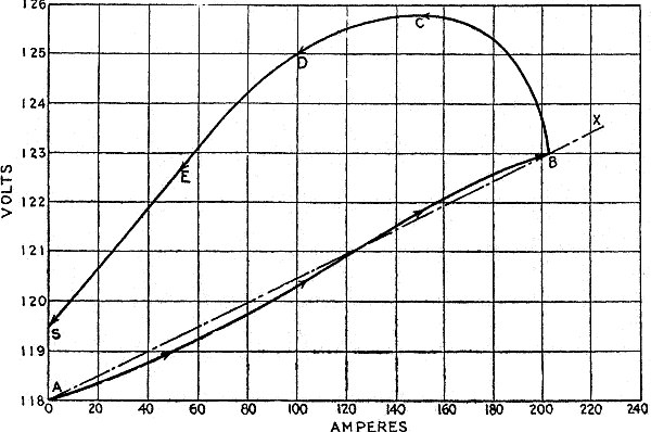
Fig. 2,912.—Characteristic curves
for a compound dynamo. If the machine be over compounded, the
characteristic curve has the form of the curve A B, which curve
was obtained from a machine over-compounded from 118 to 123 volts,
and designed to give 203 amperes at full load. The preliminary
arrangements for testing a compound dynamo are similar to those
for a shunt generator, and if the shunt across the series field
winding be already made up and in position, the readings are taken
precisely in the same manner. It is generally considered sufficient
if observations be recorded at zero, ¼, ½, ¾ and full load. If it be
desired to ascertain the effect which residual magnetism has upon
the field magnets the current is decreased after the full load point
is reached without opening the circuit, and readings are taken in
succession at ¾, ½, ¼ and zero load giving in this case the curve
B C D E S. It is thus seen that residual magnetism exerts no small
effect upon the voltage obtained at the different loads, for had
there been no residual magnetism in the field magnets the curve B C
D E S would have coincided with the curve A B. The curve A B, and
the straight line A X drawn through the points A and B, are almost
identical, and as A X represents the theoretical characteristic curve
for the machine, it is seen that compounding is practically perfect.
In order to insure such accurate results being obtained, providing
the machinery be correctly designed, requires considerable care in
taking the readings; for example, each step or load on the ascending
curve should not be exceeded before the corresponding deflection is
taken, else the residual magnetism will cause the pressure reading
to be higher than it actually should be, and the following pressure
readings will also be affected in the same manner. In case the shunt
to be employed across the series field has not been made up, it is
advisable to perform a trial test before taking the readings for the
curve as previously described. The trial test consists in taking
two readings,—one at no load and the other at full load, the shunt
being so adjusted as to length and section that the desired amount
of compounding will be obtained in the latter reading with normal
voltage at no load. If the first trial fail to produce the desired
result by giving too low a voltage at full load, the length of the
shunt across the series field should be increased, or its section
should be reduced by employing a less number of strips in its makeup;
again, if the voltage at full load be higher than that desired, there
must be made a decrease in length or an increase of section in the
shunt employed.
The friction of the brushes can very conveniently be determined next
by lowering them on the commutator and giving them the proper tension.
The increase in power resulting from the greater current that will
now be taken by the motor to run the dynamo at its rated speed, will
be a measure of this loss. In general, its value will be about .5 per
cent. of the total power required to drive the dynamo at full load,
and this also will remain constant at all loads.
The friction of the air upon the moving armature of the dynamo cannot
be determined experimentally, but theoretically this loss is small
and may be estimated as .5 per cent.; it is also constant at all
loads.
The core loss may be determined experimentally by exciting the
field magnets of the dynamo with the normal full load field current
through the magnet coils, and noting the increase of power required
by the motor to maintain the rated speed of the dynamo thus excited
under no load, over that necessary under the same conditions with no
field excitation. This increase of power will be the value of the
core loss. The core loss is approximately 3 per cent. of the power
required to operate the dynamo at full load, and it is constant at
varying loads. If it be desired to divide the core loss into its
component parts, it is necessary also to run the dynamo under the
same conditions as before with field excitation but at half its rated
speed. If, then,
H = the power lost in hysteresis at rated speed,
E = the power lost in eddy currents at rated speed,
T = the power lost in hysteresis and eddy currents at rated speed,
S = the power lost in hysteresis and eddy currents at half speed.
there may be formed the two following equations:
| |
H E |
| T = H + E, and S = |
— + —, |
| |
2 2 |
from which the elimination of H will give E = 2T - 4S.
The value of the eddy current loss thus found will be about 1½ per
cent., and constant at all loads.
Having previously ascertained the power lost in both eddy currents
and hysteresis, and knowing now the power lost in eddy currents
alone, it is easy to find that lost in hysteresis by simply
subtracting the latter known value from the former. The value of the
hysteresis loss is therefore approximately 1½ per cent., and it is
constant at different loads.
There yet remains to be determined the armature resistance loss and
the field resistance loss. As for the calibrated motor, this may be
disconnected from the dynamo, as it need not be used further in the test.
The armature resistance is the resistance of the armature winding of
the dynamo, between the commutator bars upon which press the positive
and negative brushes. Assume that the value of the armature
resistance be known, call this value R ohms, together with that of
the full load armature current, which is also known and which call
I amperes, this is sufficient data for calculating the armature
resistance loss at full load. It is evident that to force the full
load current I through the armature resistance R will require a
pressure of R volts, and that the watts lost in doing so will be
the voltage multiplied by the current. The armature resistance is
consequently
I R × I = I2R watts
or, expressed in horse power it is
I2R ÷ 746
At full load it is usually about 2 per cent. of the total power
required to drive the generator fully loaded. The armature resistance
loss varies in proportion to the load, in fact, as the last
expression shows, it increases as the square of the armature current.
The field resistance loss is calculated in the same manner as just
explained for the armature resistance loss, it being equal in horse
power to the square of the full load field current multiplied by the
resistance of the field winding and divided by 746. In a shunt dynamo
it is practically constant at 2 per cent. of the total power at full
load, but in a series or in a compound generator it will vary in
proportion to the load.
HAWKINS PRACTICAL LIBRARY
OF ELECTRICITY
IN HANDY POCKET FORM PRICE $1 EACH
They are not only the best, but the cheapest
work published on Electricity. Each number being complete in itself.
Separate numbers sent postpaid to any address on receipt of price.
They are guaranteed in every way or your money will be returned.
Complete catalog of series will be mailed free on request.
ELECTRICAL GUIDE, NO. 1
Containing the principles of Elementary Electricity, Magnetism,
Induction, Experiments, Dynamos, Electric Machinery.
ELECTRICAL GUIDE, NO. 2
The construction of Dynamos, Motors, Armatures, Armature
Windings, Installing of Dynamos.
ELECTRICAL GUIDE, NO. 3
Electrical Instruments, Testing, Practical Management of Dynamos
and Motors.
ELECTRICAL GUIDE, NO. 4
Distribution Systems, Wiring, Wiring Diagrams, Sign Flashers,
Storage Batteries.
ELECTRICAL GUIDE, NO. 5
Principles of Alternating Currents and Alternators.
ELECTRICAL GUIDE, NO. 6
Alternating Current Motors, Transformers, Converters, Rectifiers.
ELECTRICAL GUIDE, NO. 7
Alternating Current Systems, Circuit Breakers, Measuring
Instruments.
ELECTRICAL GUIDE, NO. 8
Alternating Current Switch Boards, Wiring, Power Stations,
Installation and Operation.
ELECTRICAL GUIDE, NO. 9
Telephone, Telegraph, Wireless, Bells, Lighting, Railways.
ELECTRICAL GUIDE, NO. 10
Modern Practical Applications of Electricity and Ready Reference
Index of the 10 Numbers.
Theo. Audel & Co., Publishers.
72 FIFTH AVENUE,
NEW YORK.
Transcriber Notes:
The illustrations have been moved so that they do not break up
paragraphs and so that they are near to the text they illustrate.
Misprints in the table SAVING DUE TO HEATING THE FEED WATER, Pg. 1936
have been corrected, they are:
| Init. Temp. |
Pressure |
Old Value |
New Value |
| 130 | 40 |
.0954 | .0934 |
| 200 | 40 |
.0900 | .0999 |
| 210 | 40 |
.1000 | .1010 |
| 230 | 100 |
.0017 | .1012 |
In the original text, there are two Fig. 2769's and two Fig. 2770's.
The second of each has had an "A" suffix added, i.e. 2769A and 2770A.
On line 10984 the word "impedence" was corrected to "impedance".
Inconsistent spelling and hyphenation has been left as in the original.