The
science of controlling forces is so well understood
and figured out that it becomes a simple mechanical
proposition to adapt the various types of controllers to any
form of power that may be employed. The tremendous
force stored within the mechanism of a great transatlantic
liner is governed by the twist of a man’s wrist. The
locomotive that will pull a hundred cars loaded with coal,
representing a weight of thousands of tons, is started and
stopped by a short lever that is drawn in one direction or
the other by a man’s hand. Great forces of all kinds are
quite as easily controlled as the supply of gas through a
jet—by simply turning the key that lets out so much as
may be required, no matter what the pressure is back of
the flow.
This same principle applies to electricity, but the means of
governing it is vastly different from the methods employed
for other forces. Electricity is an unknown and unseen
force, coming from apparently nowhere and returning to its
undiscovered country immediately upon the completion of
its work. The flow of steam, water, liquid air, gas, and
compressed air through pipes is governed by a throttle or
cock, which allows as much or as little to pass as may be
required; and if the joints, unions, and couplings in the pipes
are not absolutely tight there will be a leakage. Electricity
is controlled by resistance in its passage through solid wires,
rods, or bars, and cannot be confined within a given space
like water, nor held in tanks or pipes as a vapor or gas. It
is invisible, colorless, odorless, and occupies no apparent
space that can be measured; it is the most powerful and
terrible and yet docile force known to man, doing his bidding
at all times when properly governed and regulated. In
some respects, electricity can be compared to water stored
in a tank—for instance, if you have a tank of water containing
fifty gallons at an elevation of twenty-five feet, and a
pipe leading down from it, the pressure of the water at the
outlet of the pipe will be a given number of pounds. Now
if the tank were double the size the pressure at the outlet
of the pipe would be proportionately greater. Now if you
have a battery made up of a number of cells they will develop
a given number of volts, and if the number of the cells
be doubled the voltage will be correspondingly increased.
Or if you have a dynamo giving a certain number of volts,
that number may be increased by doubling the size.
The water contained within the tank represents its pressure
at the outlet of the pipe. The current in volts, generated
in a battery or dynamo, represents its pressure on an
outlet or conductor wire; and both represent the force behind
their respective conductors. The valve, or faucet, at
the end of the pipe plus the friction in the pipe would represent
the resistance to the flow of water, while the resistance-coils
or other mediums plus the size of the wire, or
conductor and switch, would regulate the flow of electric
current. The flow of water in a pipe under certain pressure
would represent its gallons per minute or hour, while with
electricity its flow in a wire or other conductor would represent
its amperage. It is to govern the flow of current
that resisting mediums are employed.
The resistance of electric current is measured in ohms, and
it is with this phase that we are interested in this chapter.
If there is only a small resistance put in the path of a current,
then it requires but a small pressure or voltage to send
it through the wires or circuit. This is easily understood
by the boy who has experimented with small incandescent
lamps in which short pieces of carbon-filament are contained.
It requires the pressure of a few volts only to send
the current through the carbon; but for the large carbon-filaments,
measuring ten or twelve inches in length, from
one hundred to five hundred volts may be necessary. The
ordinary house lamps require one hundred and ten volts
and half an ampere to give sixteen candle-power.
It is easily understood, then, that it requires a high pressure
or voltage to force the current through the resisting
carbon-filament, or across the space from one carbon to the
other in the arc-lamps used for street lighting. The shorter
and larger the conducting wires the less the resistance, and
consequently the lower the voltage or pressure necessary to
force it. Contrariwise the longer and finer the conducting
wares, the greater the resistance. As copper is the best
commercial conductor of electric currents, it is in universal
use, and in it the minimum of resistance is offered to the
current. Iron wire is a poorer conductor, and is not used
for high voltage (such as trolleys or transmission of power),
but is confined to telegraph and telephone lines and low-pressure
work. German-silver wire, one of the poorest
conductors, is not used for lines at all, but is employed
solely as a resisting medium for controlling current.
This is the fundamental formula expressing the relations
between current, electro-motive force, and resistance in an
active electric circuit. It may be expressed in several ways
with the same result, as follows:
1. The current strength is equal to the E. M. F. (electro-motive
force) divided by the resistance.
2. The E. M. F. (electro-motive force) is equal to the
current strength multiplied by the resistance.
3. The resistance is equal to the E. M. F. (electro-motive
force) divided by the current strength.
All these are different forms of the same statement; and
when figuring electrical data, C stands for current, E for
electro-motive force, and R for resistance.
The method by which electricity is controlled is resistance.
No matter how great the voltage of a current, nor its volume
in amperes, it can be brought down from the deadly force
of the electric trolley-current to the mild degree needed to
run a small fan-motor, an electric bell, or a miniature lamp.
This is accomplished by means of resisting mediums, such
as fluids or wires, which hold back the current, and allow
only the small quantity to pass that may be required to
operate the apparatus.
The jump from the high voltage of the trolley-current to
the low one required for the electric bell, a lamp, or a small
motor, is frequently made in traction-work, but in this case
regular transformers are used. For the small apparatus,
that may have its current supplied from a battery, or a
small dynamo driven by a water-motor, the forms of resistance-coils
and rheostats described on the following pages
should meet every requirement.
The standard unit of resistance is called an ohm, so
named after Dr. G. S. Ohm, a German electrician, whose
theory on the subject is accepted as the basis on which to
calculate all electrical resistance. The legal ohm is the
resistance of a mercury column one square millimetre in
cross-sectional area and one hundred and six centimetres in
length, and at a temperature of 0° Centigrade or 32° Fahrenheit,
or the freezing-point for water. The conductivity of
metals is dependent greatly on their temperature, a hot wire
being a much better conductor than a cold one. Since
counter-electro-motive force sometimes gives a spurious resistance,
the ohmic resistance is the true standard by which
all current is gauged.
In technical mechanism and close readings the ohmic
resistance counts for a great deal, but in the simple apparatus
that a boy can make the German-silver resistance coils
and the liquid resistance will answer every purpose.
To give a clearer idea of the principle of the rheostats, a
short description of the mercurial column will first be presented.
During the early part of the last century wires were
not used as a resisting medium for electric currents. In their
place, glass tubes, filled with mercury sealed at one end and
corked at the other, were arranged in rows and supported in
a wooden rack.
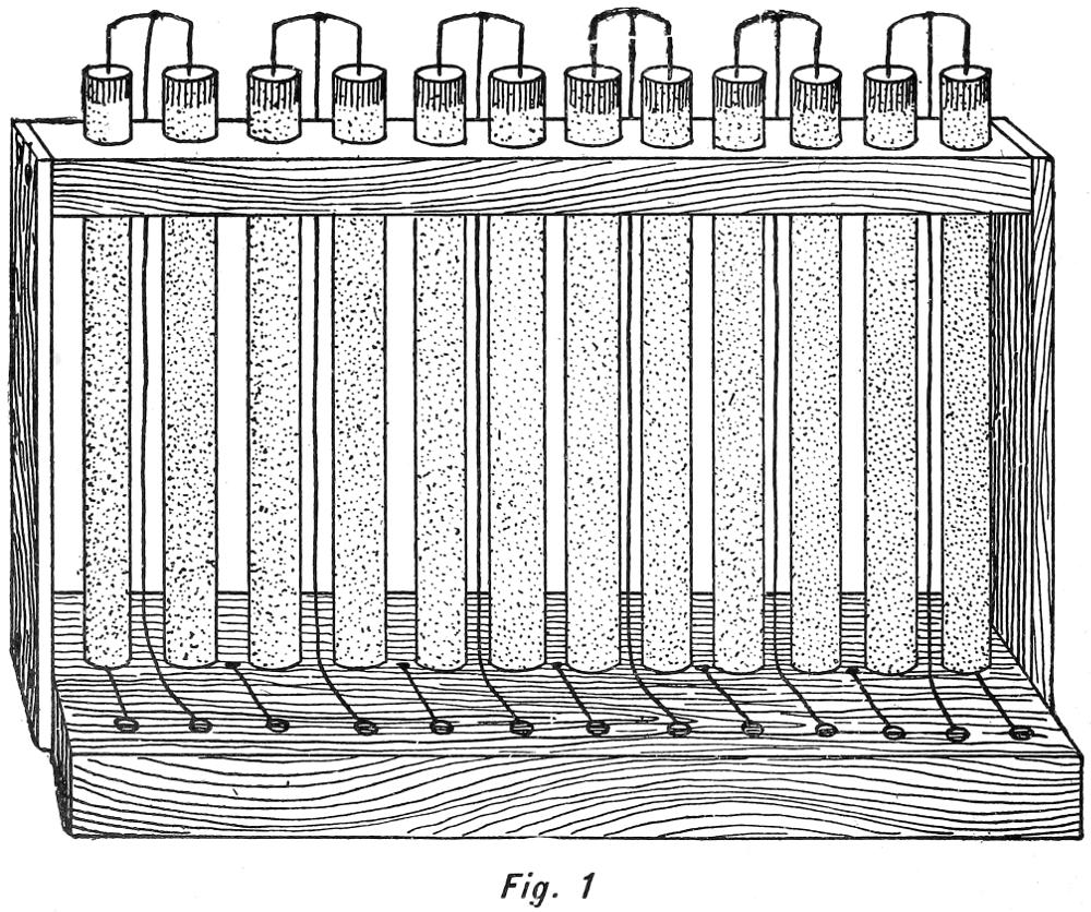
Wires led out from the top and bottom of each tube,
and were brought down to metal buttons arranged in a row
along the front edge of the base-plate, as shown in the illustration
of a mercurial rheostat (Fig. 1). Each tube represented
a certain resistance—one or more ohms, as required.
The outlet wire was attached to the button at one end of the
row, and the inlet could be moved along from button to
button, until the required amount of current was obtained.
The mercurial rheostat was an expensive, cumbersome,
and treacherous thing to handle; it was liable to break, and
its weight often prohibited its use in places where the more
convenient and easily handled German-silver rheostats are
now in universal employment. Overheating the mercury in
the columns caused it to expand, and sometimes, before the
switch could be thrown open, an end would be forced out
and the mercury would climb over the edge of the glass
columns.
All metals have a certain amount of resistance for electric
currents, and some have more than others. German-silver,
for instance—a metal made of a mixture of other metals with
about eighteen per cent. of nickel (see Appendix)—is considered
to be the best commercial resistance medium, while
pure copper is regarded as the best commercial conductor.
Unalloyed copper is universally employed for electric conductors
of high voltage; but for telegraph and telephone
work, galvanized iron wire is still used extensively.
The finer the wire, the higher is its resistance, and the more
resistant the metal, the greater are the number of ohms to a
given length. To nine feet and nine inches of No. 30 copper
wire there is one ohm resistance, while to No. 24—which is
six sizes coarser—there is one ohm to thirty-nine feet and
one inch. In many cases it is necessary to use the coarser
wire and greater length, as the current would superheat or
burn the fine wire, while the coarser would conduct it safely.
For very high voltage and amperage—such as used in traction
cars, in power stations, and in manufacturing plants—castings
of German-silver are employed and linked in series.
They are more easily handled than the coils of wire, and a
greater number of them can be accommodated in a small
space.
For light currents in experimental work, where batteries
are employed, obtain a pound or two of bare German-silver
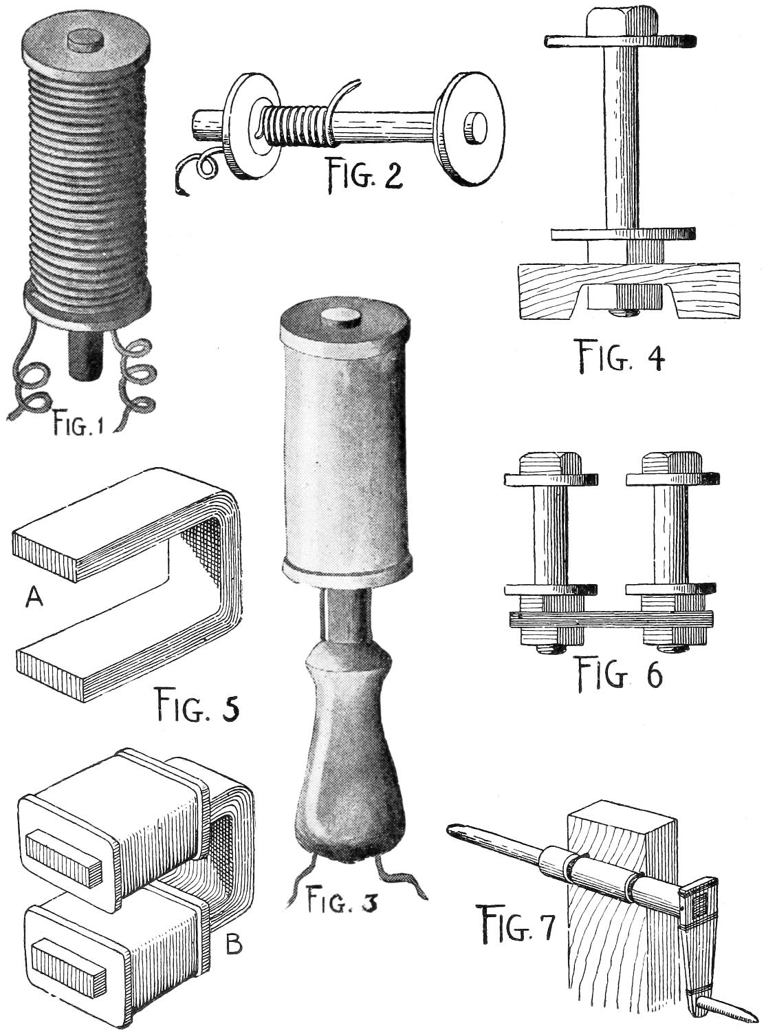
wire, from Nos. 24 to 30, and wind the strands on a round
piece of stick attached to a winder (see Magnets and Induction-Coils,
chapter iv.). Make several of these coils,
two or three inches long, with the wire wound closely and
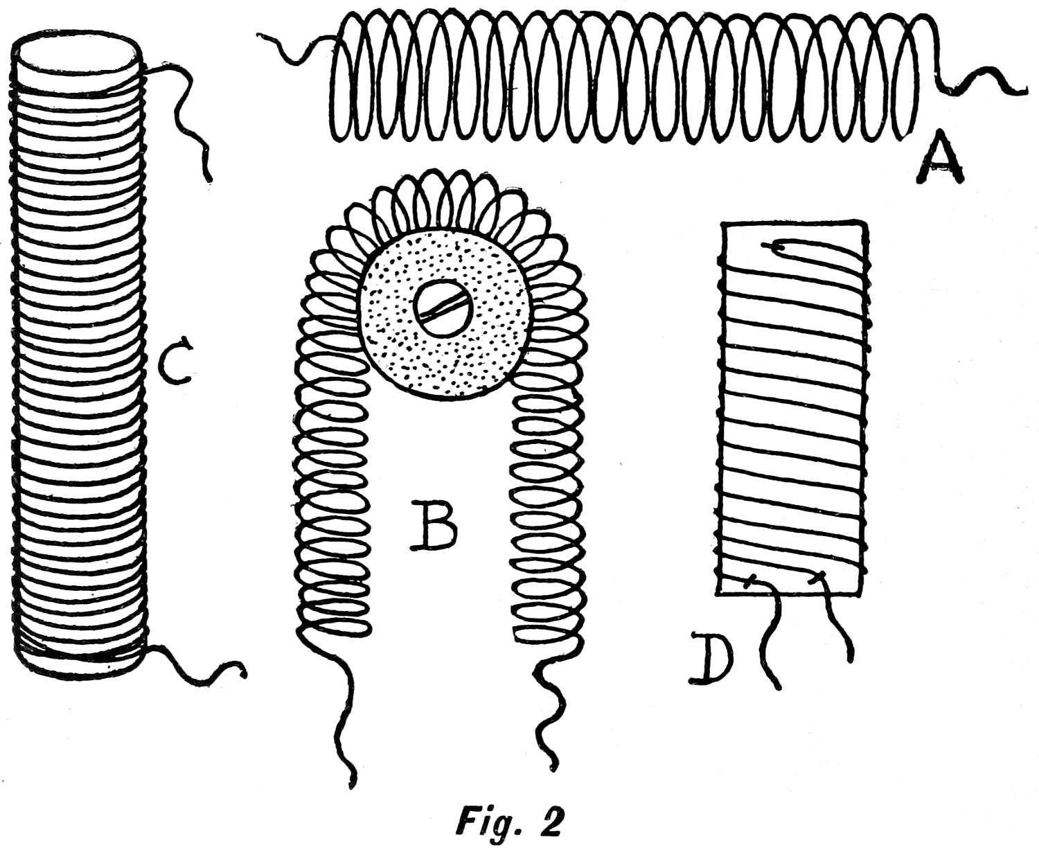
evenly. When pulled apart the coils will appear as shown
in Fig. 2 A, and will resemble a spiral spring. This can
be made fast over a porcelain knob and the ends caught
down, as shown at B in Fig. 2, or it may be drawn over a
round stick, a porcelain tube, or a lug made of plaster of
Paris and dextrine (three parts of the former to one of the
latter), as shown at C in Fig. 2, and the ends securely bound
with a strand or two of wire, twisted tight to keep the ends
from slipping.
The lugs may be made in a mold, using as a pattern a
piece of broom-handle—shellacked and oiled to prevent the
plaster from adhering to it. Obtain a small square and
deep box, and drop some of the wet mixture down in the
bottom; on this place the broomstick, small end down (it
should be slightly tapered), and around it pour in the wet
plaster mixture. While it is setting, turn the stick with the
thumb and fingers, so as to shape the hole perfectly then
draw it out, and a true mold will be the result. When dry
enough, pour some shellac down into the mold and revolve
it, so that the shellac will be evenly distributed, and
let it harden for a day. Then saw off the end of the mold,
so that it will be open at both ends.
In order to make the lugs, pour in the plaster mixture,
taking care to oil the mold before each pouring, so that
the lug can be drawn out when the mixture has set. If it
sticks, tap the small end gently to start it. For coils where
there is little or no heat, ordinary pieces of broom-handle,
or round sticks having a coat or two of shellac, will answer
very well; but where the current heats the core, it must be
of some material that will not char.
Another method of making resistance-coils is to measure
off a length of wire; then double it, and with a small staple
attach the loop end at one end of the (wooden) core. Pay
out the two strands of wire an equal distance apart with the
thumb and fingers, and with the other hand twist the core.
At the other end of the spool catch the loose ends of the
wire under small staples, taking great care not to let the
staples touch or even be driven close together. This arrangement
is shown at D in Fig. 2, and for a field resistance-board
any number of these coils may be made.
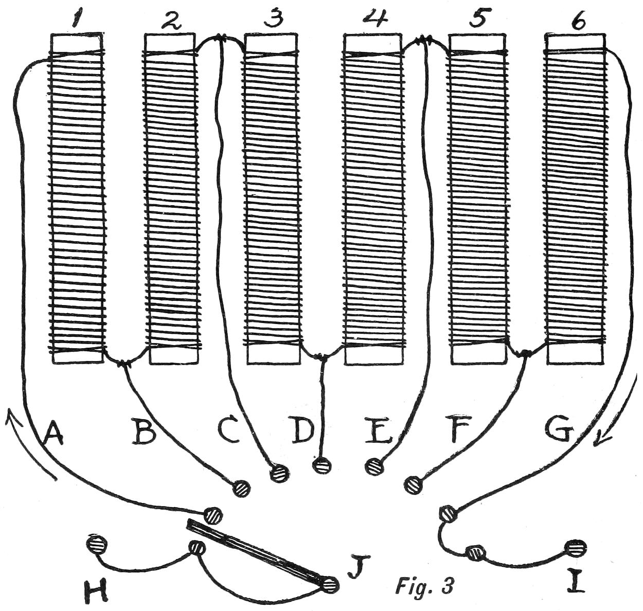
In Fig. 3 the mode of connecting coils is shown. The
dots represent contact-points to which the movable arm can
be shifted. The wires at the bottom of coil, Nos. 1 and 2,
are connected together, while those at the top of No. 2 and
3 are joined, and so on to the end. The leading-in current
is connected at pole H and so on to J, while the leading-out
wire is made fast to pole I. The switch-arm is moved
on the first dot, or contact-point, and the current passes up
wire A, down coil No. 1, up coil No. 2, down No. 3, up No.
4, and so on to No. 6, and down wire G and out at I. Supposing
that this offers too much resistance, the switch-arm
is moved up one point. This cuts out coil No. 1, as the
current passes up wire B, through coil No. 2, down No. 3,
and so on, and out through G and pole I. Another move
of the switch and coil No. 2 is cut out, the current passing
up wire C, down coil No. 3, up No. 4, and so on, and out at
I. Each move of the switch cuts out one coil, lessening the
resistance; but when moved to the last contact-point the
current flows without resistance—in at H, through the
switch-arm, and out at I.
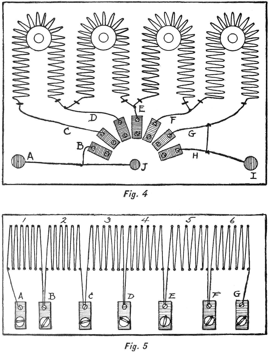
The plan of arranging the coils suggested at Fig. 2 B is
shown in Fig. 4, where four of the coils are arranged in series
over porcelain knobs, and the lower ends made fast to the
base-board with small staples. Small pieces of brass are
used for the switch contact-plates; those are provided with
one plain and one countersunk hole for a flat and round
headed screw.
The screw-heads are arranged in a semicircular fashion,
so that the switch-arm, attached at one end to the screw J,
will touch each plate as it is moved forward or backward.
TWO SIMPLE FORMS OF RHEOSTATS
The current passing in at binding-post A travels to J and
B, the latter being the resting-plate for the switch-arm.
A move of the arm to C sends the current up over the first
coil and down; then over the second, third, and fourth
coils, and out at G; through plate H (which is the rest at the
right side), and out at I.
A move of the switch-arm to D cuts out the first coil; a
move to E, the first and second coils; and so on until the
last plate is reached, when the current will pass without resistance
in at A, through J, and out at I.
A simple arrangement for a resistance-coil is shown in
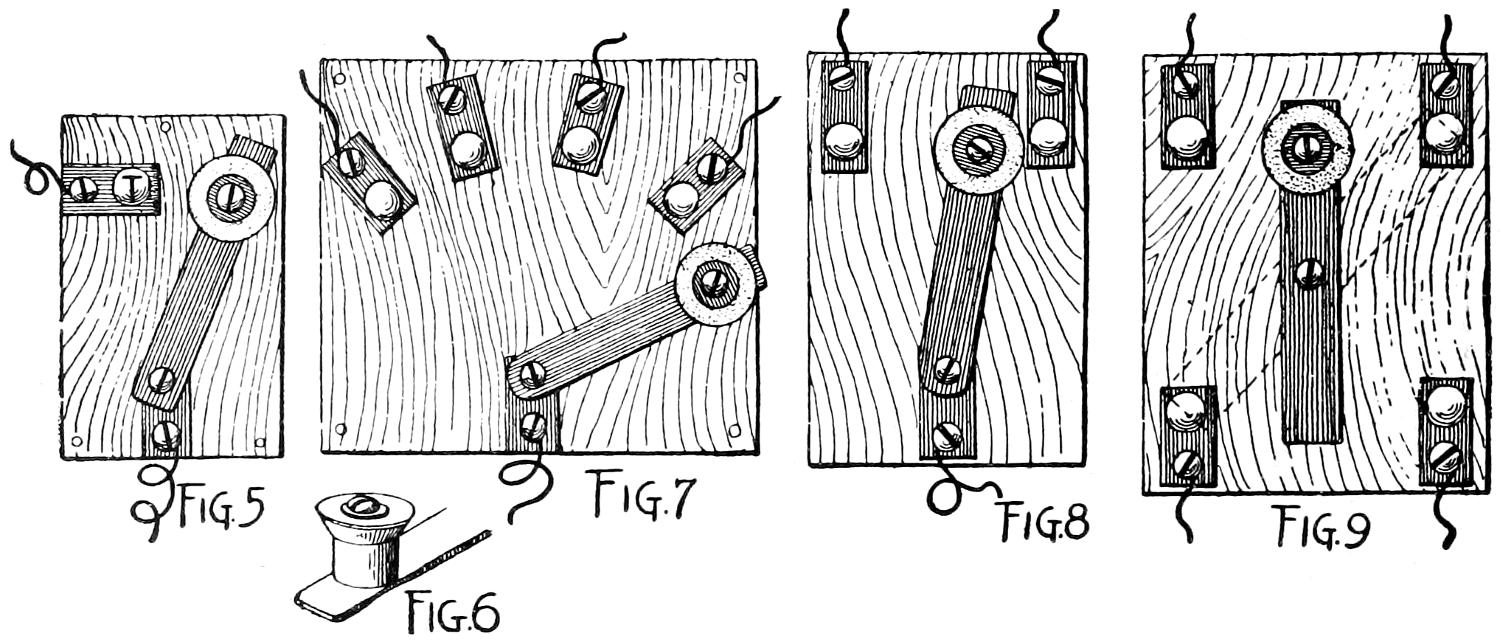
Fig. 5. This consists of a set of small metal plates in which
two holes are made, one for a screw, the other for a screw-eye
(see Binding-posts, chapter iii.). Two lines of steel-wire
nails are driven along a board, and German-silver wire
is drawn around them in zig-zag fashion, beginning at the
left and going towards the right side of the board. One end
of wire is made fast under the screw-head on plate A. The
strand is carried out around the first nail on the lower row
and over the first one on the upper row, then down, up, down
until six nails have been turned. The wire is then carried
down to the screw in plate B, given two turns, and carried
up again and over the nail on the top row, repeating the
direction of zigzag No. 1, until six of them are made. The
end of the wire is then made fast to plate G, and all the
screws are driven in to hold the plates and wire securely.
The inlet wire is attached to A, the outlet to G, and any
degree of resistance can be had by moving the inlet wire to
the various plates along the line, cutting out sections Nos. 1
to 6 as desired.
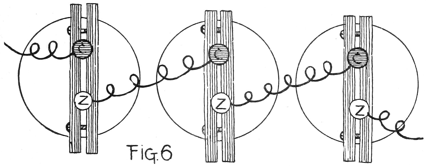
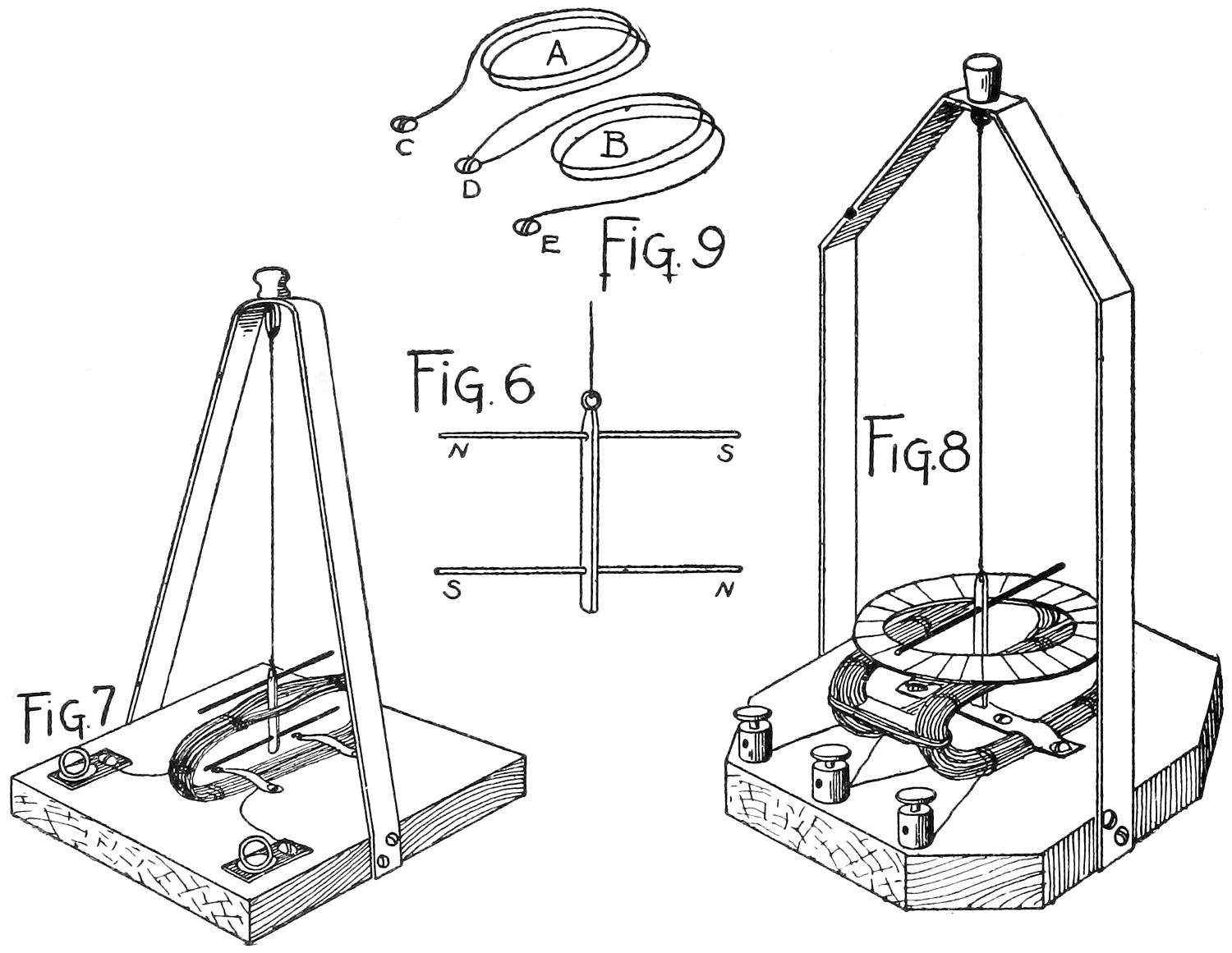
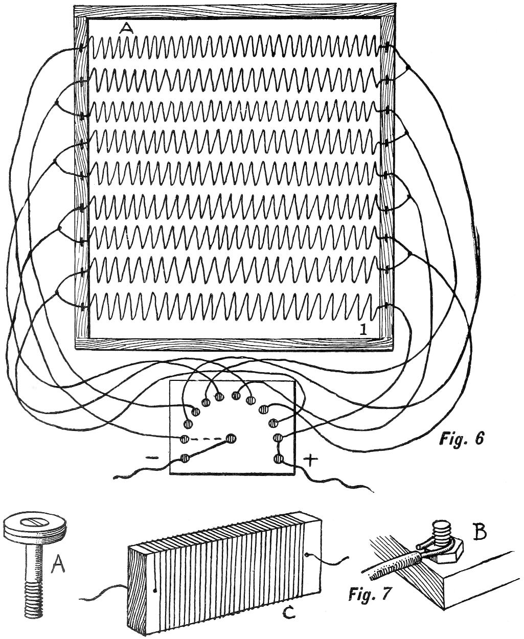
For heavier wire the arrangement as shown in Fig. 6
should be satisfactory.
A frame twelve by fifteen inches is constructed of wood
three-quarters of an inch thick and one inch and a quarter
wide, having the ends securely fastened with glue and
screws. Spirals are wound of German-silver wire (any size
from No. 16 to 22), and drawn apart. The ends are caught
to the frame with small staples, and each alternate coil-end
is joined, as shown in Fig. 6. The leading-out wires to the
contact-points on the switch should be of insulated copper,
and are to run down the sides of the frame, and so to the
switch-board. To clearly illustrate, however, the plan of
wiring, the drawing is made so as to show the leads from
the coil-ends to the switch. Care should be taken to study
this drawing well, so as not to make an error in connecting
a wrong end to a contact-point, thereby causing a short
circuit. When properly connected the current passes in at
A and out at I; but if wires are improperly connected, the
current will jump when the switch-arm reaches the misconnected
contact.
The switch is an important part of every rheostat, and
should be carefully and accurately made. One of the
simplest and most practical switches is constructed from a
short, flat bar of brass or copper having a knob attached at
one end and a hole provided at the other through which a
screw may pass (see Switches, chapter iii.). The contact-points
are made from one or two copper washers, with the
holes countersunk so that a machine screw of brass, with a
flat head, will fit the hole snugly. The top of the head
will then be flush with the top of the washer, as shown at
Fig. 7 A. The bolt is passed down through a piece of board,
then slate or soapstone, and caught with a washer and nut,
as shown at Fig. 7 B. A loop of wire is passed about the
bolt end, then another nut is screwed tightly over it to hold
it in place, as well as to lock the first nut. The binding-posts
that hold the inlet and outlet wires may be made of
bolts and nuts also, as shown at Fig. 7 B;
but the bolt must
be passed through the switchboard so that the head is at
the rear and the ends project out to receive the nuts.
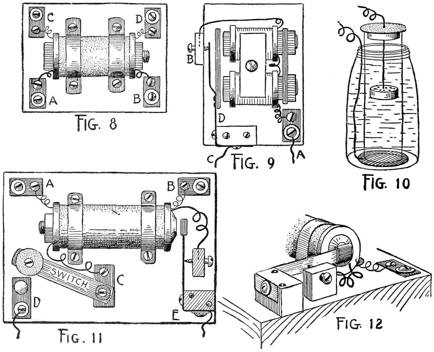
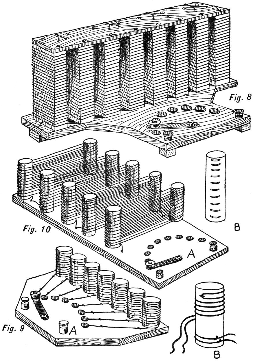
A very compact and simple rheostat and switch is shown
in Fig. 8. It is composed of a base-board, eight blocks of
hard-wood, and a top strip used as a binder to lock the upper
ends of the blocks together. The hard-wood blocks are
three-quarters of an inch thick, one inch and a half wide, and
four inches long. A small hole is made near each end of
the block and through one of them an end of the wire is
passed. The wire is then wound round the block, taking
care to lay it on evenly, and with about one-eighth of an
inch of space between each strand. When the opposite
hole is reached, pass the end of the wire through it and clip
it. The block will then resemble Fig. 7 C. There should
be three or four inches of wire at each end for convenience in
connection, and when the eight blocks are wound they are
to be mounted on end at the rear side of a base-board measuring
ten inches long, three inches wide at the ends, and
nine at the middle (or across the face of the switchboard
to the rear edge behind the blocks). Use slim steel-wire
nails and glue to attach the blocks to the base; or slender
screws may be employed. Across the top lay a piece of
wood a quarter of an inch in thickness, and drive small nails
or screws down through it and into the blocks.
COMPACT FORMS OF RHEOSTATS
Connect the ends of the coils together in series, as already
described, and carry the wires under the base-plate in
grooves cut with a V-shaped chisel. If the sunken wires
are bothersome, the work may be avoided by running the
wires direct to the foot of the contact-points and elevating
the rheostat on four small blocks that may be screwed, or
nailed and glued, under the corners, as shown in Fig. 8.
These will raise the base half an inch or more above the
table on which the rheostat will rest so as to allow room for
the under wires.
A rheostat of round blocks standing on end is shown at
Fig. 9 A. These are pieces of curtain-pole, four inches long
and wound with loops of No. 16 or 18 wire, as shown at
Fig. 9 B. The loop and loose ends are caught with staples,
and when arranged on a base-board they are to be connected
in series as before described. One long, slim screw
passed up through the base-board and into the lower end
of the block will hold each block securely in place. To
keep it from twisting, a little glue may be placed under the
blocks so that when the screw draws the block down to the
base it will stay there permanently upon the hardening of
the glue. The leading wires should be slipped under the
washers forming the contact-points of the switch; or they
may be carried under the board to the nuts that hold the
lower ends of the bolts.
Another form of rheostat (Fig. 10 A) is made by sawing
a one-inch curtain-pole into four-inch lengths and cross-cutting
each piece with eight or ten notches, as shown at
Fig. 10 B. These pieces are screwed and glued fast along
each side of a base-board eight inches wide and fourteen
inches long, so that the notches face the outer edges of the
board. The strand of wire passes round these upright blocks
and fits into the notches so as to prevent them from falling
down.
The top end of wire at each pair of blocks is made fast by
a turn or two of another piece of wire and a twist to hold it
securely; then the loose end is carried down through a hole
and along under the board to the foot of a contact-point.
Any number of these upright coils may be made, and on a
long board the switch may be arranged at one side instead
of at the end, as shown in Fig. 10 A. When making ten or
more coils it is best to use three or four sizes of wire, beginning
with fine and ending with coarse. For instance, in a
twelve-coil rheostat make three coils of No. 26, three of No.
22, and three of No. 18; or if coarser wire is required use
Nos. 20, 16, and 12.
German-silver comes bare and insulated. It is preferable
to have the fine wire insulated, but the heavier sizes may be
bare, as it is cheaper; moreover, if heated too much the insulation
will burn or char off. When cutting out the coils
always begin at the end where the finer wire is wound;
then as the current is admitted more freely the heavier wires
will conduct it without becoming overheated.
For running a sewing-machine, fan, or other small direct-current
motor wound for low voltage, the house current (if
electric lights are used in the house) may be brought down
to the required voltage with German-silver rheostats similar
to these already described. Another and very simple
method is to arrange sixteen-candle-power lamps in series,
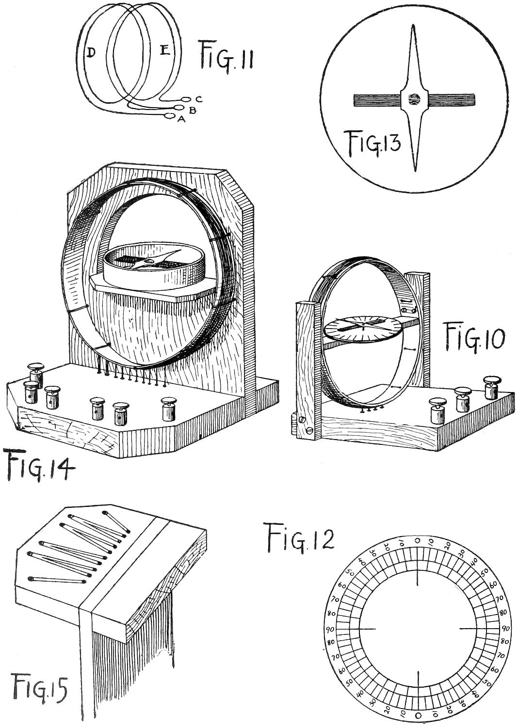
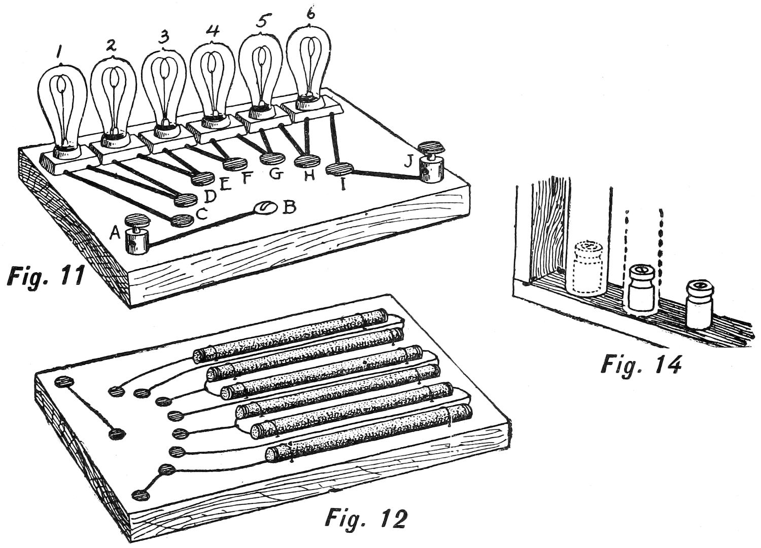
as shown in Fig. 11. Six porcelain lamp-sockets are screwed
fast to a wood base and the leading in and out wires
brought to binding-posts or the contact-points of a switch.
The leading-in wire to the series is made fast at binding-post
A, which in turn is connected with screw B, under the head
of which the switch-arm is held. When the switch is thrown
over to contact-point C the current passes through lamp
No. 1 back to point D; through lamp No. 2 back to E; then
through lamps Nos. 3, 4, 5, and 6, and out through point I
to post J. A turn of the switch to D cuts out lamp No. 1, to
E cuts out No. 2, and so on. The filaments of incandescent
lamps in their vacuum are among the very best mediums of
resistance, and with a short series of lamps a current of
220 volts can quickly be cut down to a few volts for light
experimental work or to run some small piece of apparatus.
Lamps in series are often used to cut down the current for
operating electric toys and trains. The adjustment of the
current should never be left to children, however, but should
be attended to by some one qualified to look after the
apparatus. Otherwise an unpleasant or even dangerous
shock may be received. Another simple form of resistance
apparatus is made from the carbon pencils used for arc
lights. Short pieces will answer very well, but if the long
bare ones can be had they will be found preferable. Do not
use the copper-plated ones as they would conduct the current
too freely; they should be bare and black. Now around
the ends of each piece take several turns of copper wire for
the terminals and cut-out wires. Fasten those pencils down
on a board (as shown at Fig. 12) by boring small holes
through the board, passing a loop of copper wire down
through the holes, and giving the ends a twist underneath.
The leading wires to and from the contact-points should be
insulated and may be above or below the board. From the
descriptions already given, the connections of this rheostat
can readily be understood.
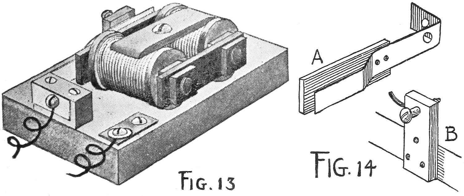
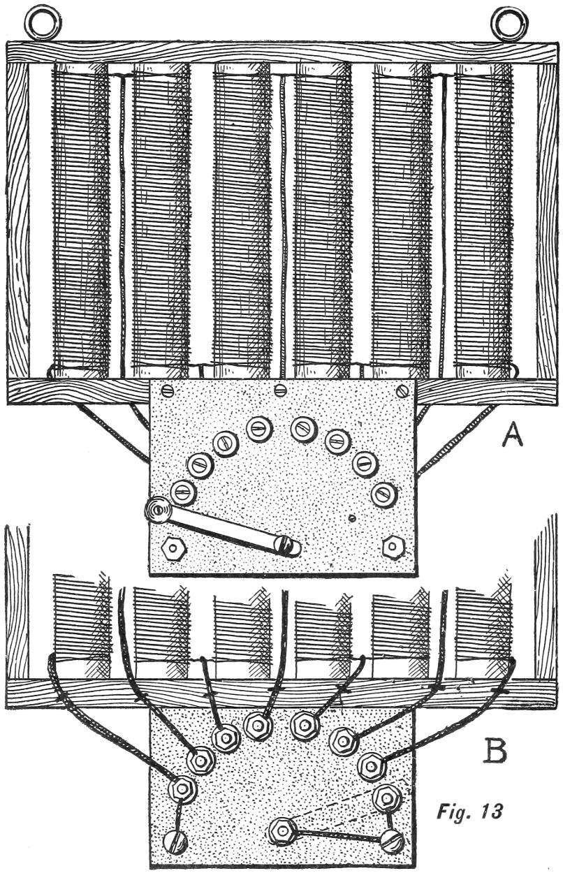
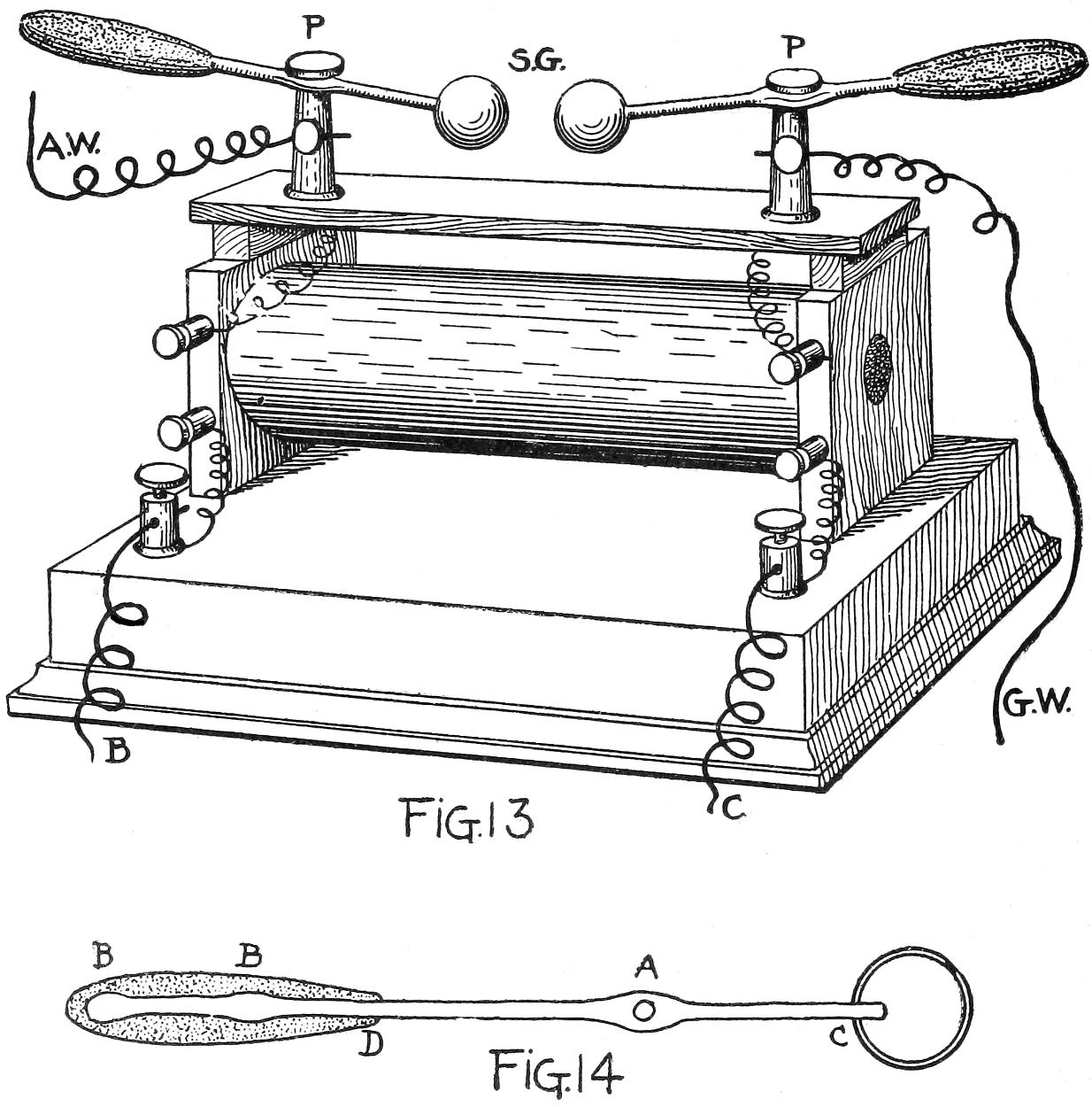
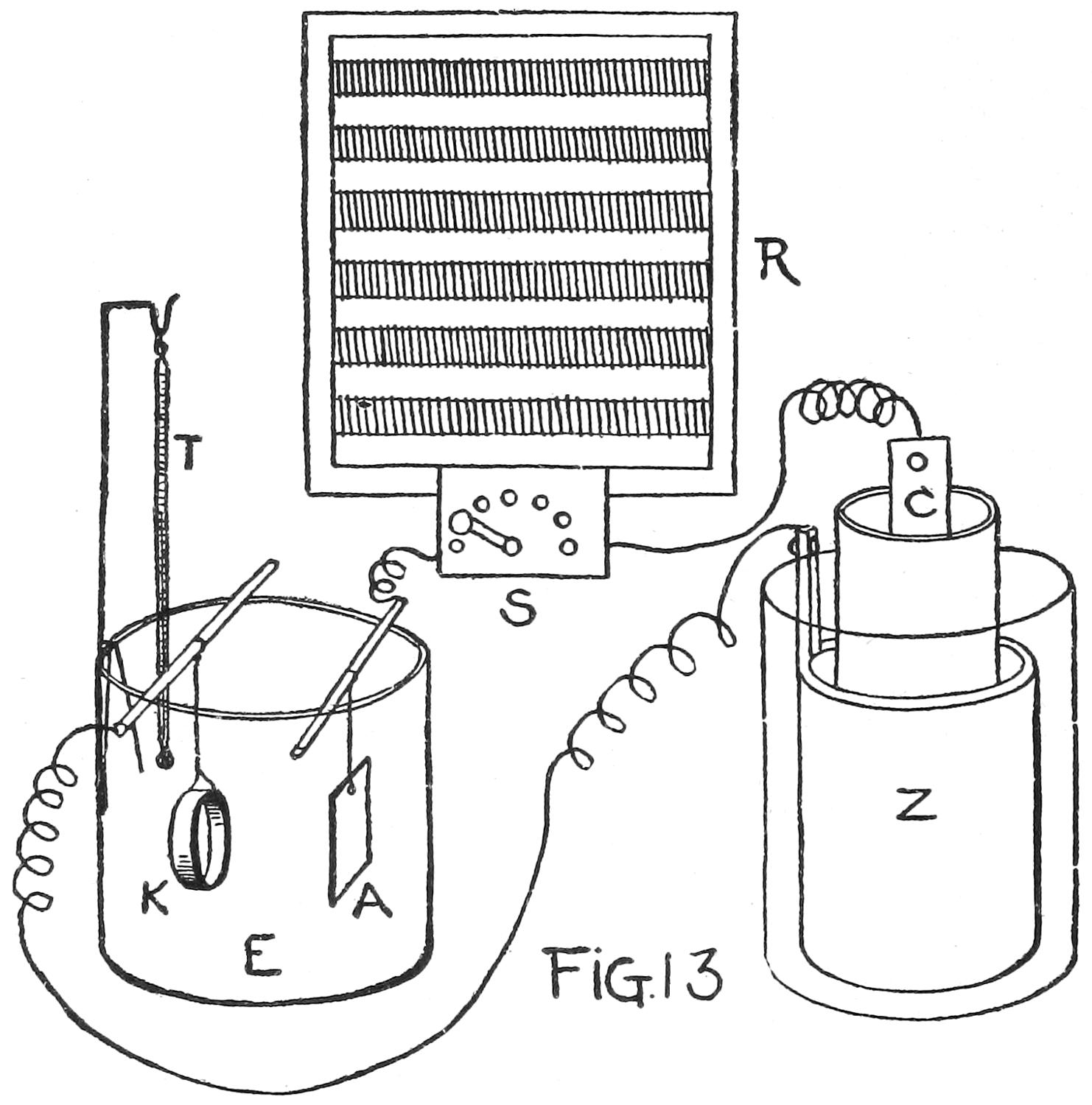
The rheostat shown in Fig. 13 is perhaps the most complete
and practical apparatus that a boy could make or
would need. It is composed of a frame, six porcelain tubes,
a switchboard, and the necessary German-silver and copper
wire.
From an electrical supply-house obtain six porcelain tubes
fourteen by three-quarter inch. Porcelain tubes and rods
warp in the firing and are seldom straight; in purchasing
these select them as nearly perfect as possible in shape, size,
and length.
Buy, also, twelve small porcelain knobs that are the right
size to fit inside the large tubes. These should have holes
bored through them to admit screws. Construct a frame
of hard-wood to accommodate the tubes, as shown in the
drawing, and leave one end loose. With slim screws make
the porcelain knobs fast to the top and bottom strips of the
frame, as shown in Fig. 14. The porcelain rods will fit over
these and will thus be held securely in the frame, one small
knob entering the tube at each end, as indicated by the
dotted lines in Fig. 14.
The first porcelain tube to the left is wound with No. 22
German-silver wire, the next with No. 20, the third with
No. 18, then Nos. 16, 14, and 12; so that in this field a broad
range can be had for a current of 110 volts.
The coils are connected in series, as explained for the other
rheostats, and the leading wires brought down to the back
of a switchboard of which Fig. 13 A is the front and Fig. 13
B the rear view. The switchboard is made of thin slate or
soapstone; or a fibre-board may be employed. Fibre-board
is especially made for electrical work, and can be had from
a large supply-house in pieces of various thickness, three-eighths
of an inch being about right for this board. Brass
bolts and nuts and copper washers are used for the contact-poles,
and when the ends of the leading wires are looped
around the bolts the nuts are to be screwed down tightly so
as to make good contacts. This rheostat may be used when
lying on a table, or it can be hung up by means of two
screw-eyes driven in the top of the frame, as shown in
Fig. 13 A.
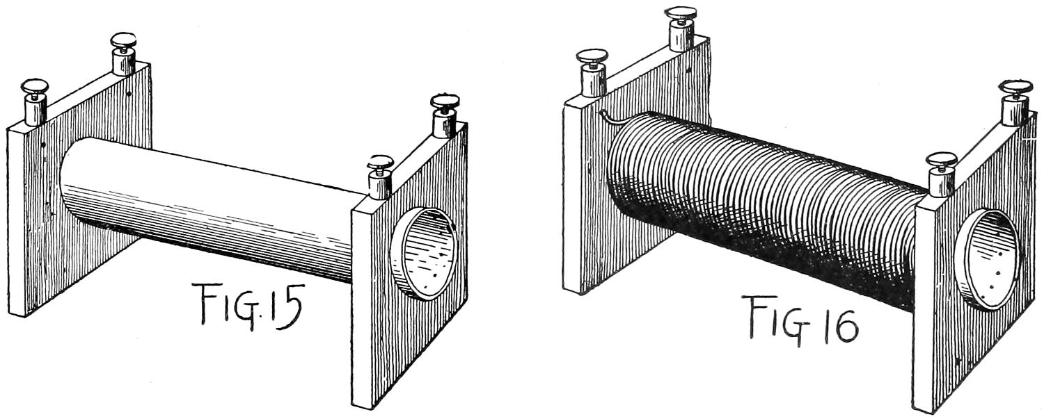
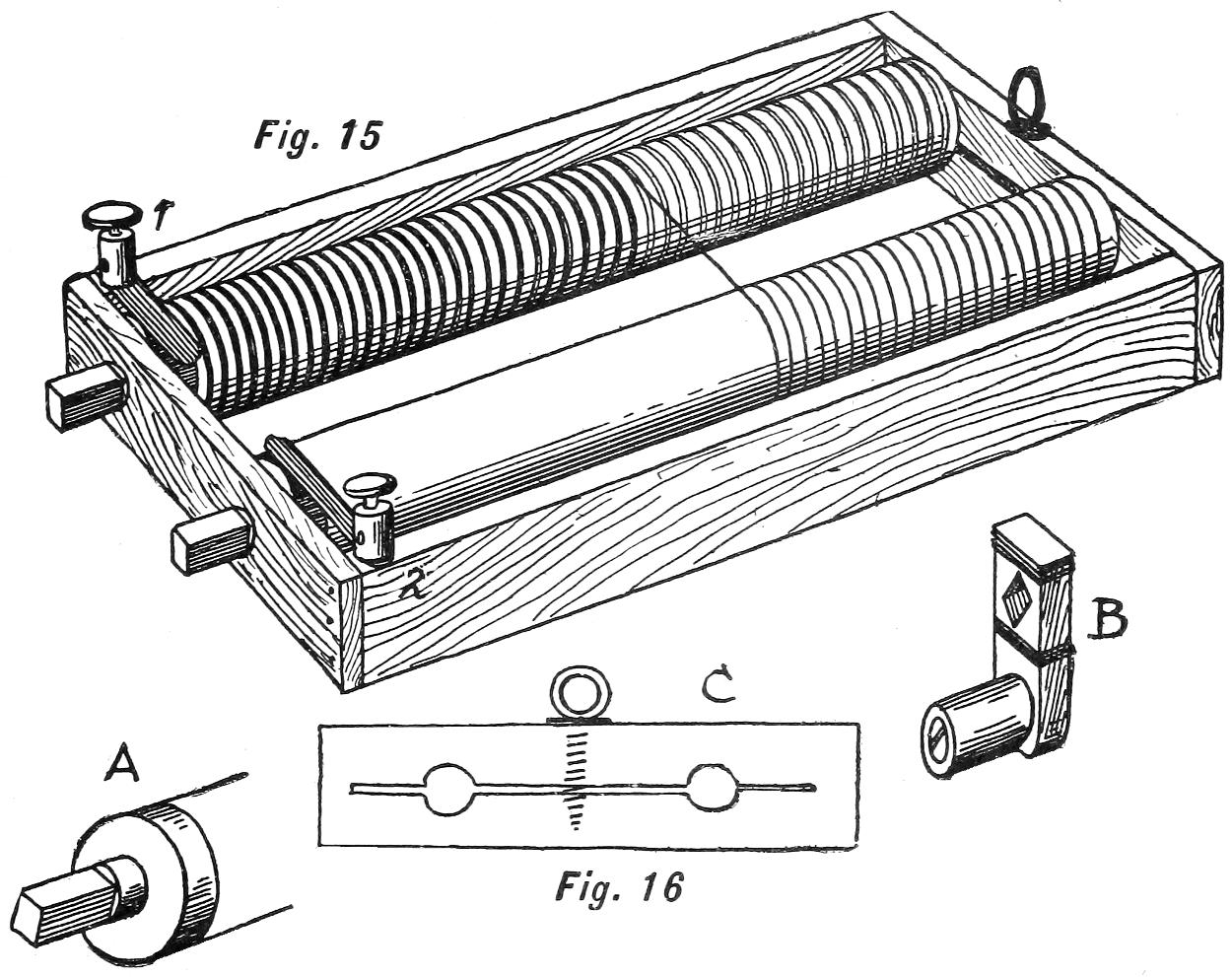
A convenient form of rheostat for fine wire and high
resistance is shown in Fig. 15. This is on the plan of the
well-known Wheatstone rheostat and does not require a
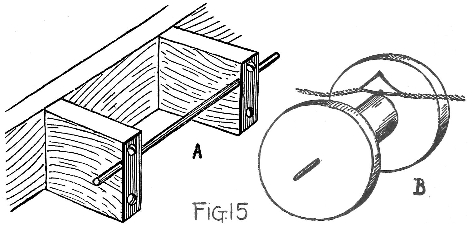
switchboard nor a series of coils. Two rollers, one of wood
the other of metal or brass-covered wood, are set in a frame,
and by means of a handle and projecting ends with square
shoulders, one or the other of the rollers may be turned so
that the wire on one winds up while on the other it unwinds.
The wooden roller may be made from a piece of curtain-rod
one inch in diameter, and it should have a thread cut
on it. This will have to be done on a screw-cutting lathe,
and any machinist will do it for a few cents. There should
be from twelve to sixteen threads to the inch—no more—although
there may be as few as eight. Twelve will be
found a good number, as that does not crowd the coils and
the risk of their touching is minimized. The ends of the
roller should have bearings that will fit in holes made in the
end-pieces of the frame, and at one end of each roller a
square shoulder is to be cut, as shown at A in Fig. 16. A
short handle may be made from two small pieces of wood,
as shown at B in Fig. 16. It must be provided with a square
hole so that it will fit on the roller ends. The metal roller
may be made from a piece of light brass tubing one inch in
diameter through which a wooden core is slipped; or it can
be a piece of brass-covered curtain-pole with the ends shaped
the same as the wooden one. The wood roller should have
a collar of thin brass or copper (or other soft metal except
lead) attached to the front end; or several turns of wire may
be made about the roller so as to form a contact-point. A
piece of spring brass, copper, or tin rests on this collar and
is held fast under a binding-post, which in turn is screwed
to the wooden frame. A similar strip of spring metal is
held under another post on the opposite side of the frame
and bears on the metal roller.
German-silver wire is wound on the wooden roller, one
end having been made fast to the metal collar; and when all
the thread grooves on the wood roller are filled the opposite
end of the wire is attached to the rear end of the metal roller.
The current entering at binding-post No. 1 crosses on the
strip of spring metal to the collar, travels along the coil of
wire, and crosses to the metal roller and is conducted out
at binding-post No. 2 (see Fig. 15). If the resistance is too
great slip the handle over the end of the metal roller and
give it several turns. The current will then pass with
greater freedom as the wire on the wooden roller becomes
shorter. This may be readily seen by connecting a small
lamp in series with a battery and this rheostat. As the
metal cylinder is turned the current flows more freely and
the filament becomes red, then white, and finally burns to
its full capacity. Take care, however, not to admit too
much current as it will burn out the lamp. Some sort of
adjustment should be made to prevent the rollers turning
of themselves and thus allowing the wire coils to slacken.
This may be done by boring the two holes for the rollers to
fit in and then, with a key-hole saw, cutting the stick as
shown at C in Fig. 16, taking care not to split it at the ends.
The result will be a long slot which, however, has nothing to
do with the bearings. Down through the middle of the
stick make a hole with an awl, so that the screw-eye will
move easily in the upper half but will hold in the lower
half. Under the head of the eye place a small copper washer;
then with the thumb and finger drive the screw-eye down
until the head rests on the washer.
A slight turn of the eye when it is in the right place will
draw the upper and lower parts of the stick together and
bind the wood about the bearing ends of the rollers. The
rollers should not be held too tightly as that would strain
the wire when winding it from one to the other. It should
be just tight enough to keep the wire taut.
Two or more of these roller resistance-frames may be
made and connected in series so that a close adjustment can
be had when using battery currents for experimenting.
Apart from metallic, mercurial, or carbon resistance a
form of liquid apparatus is frequently used in laboratory
and light experimental work.
This style of resistance equipment is the least expensive
to make, and will give excellent satisfaction to the boy who
is using light currents for induction-coils, lamps, galvanometers,
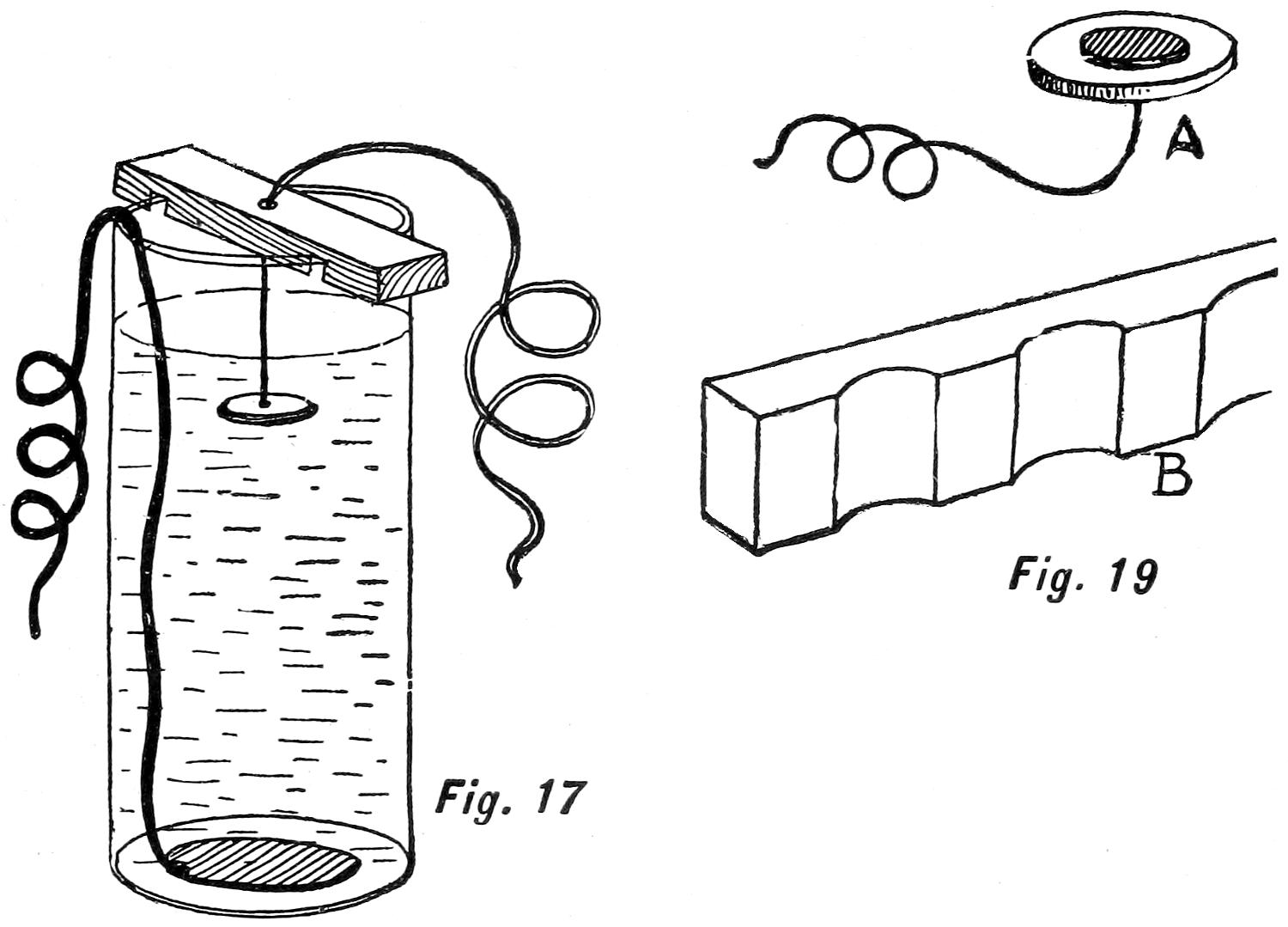
and testing in general. The simplest form of liquid
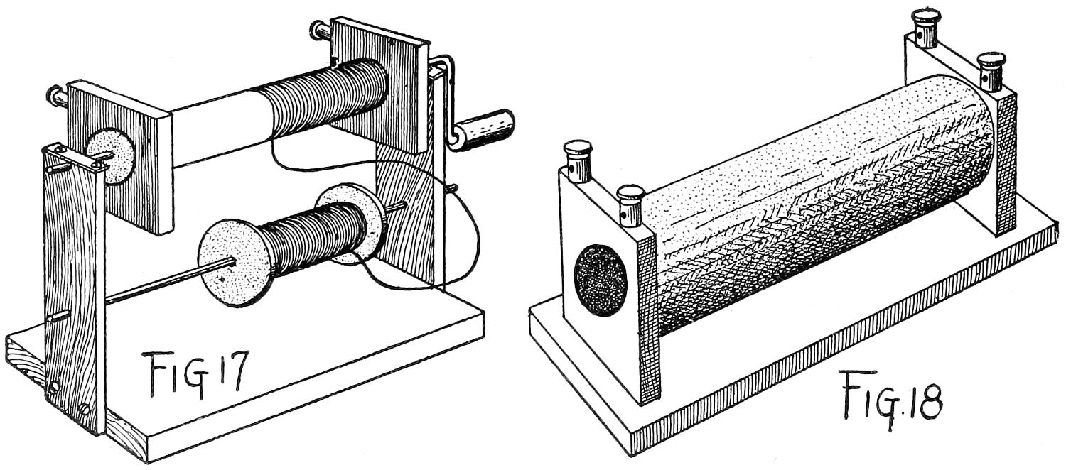
resistance is made by using a glass bottle with the upper
part cut away. The cutting may be done with a steel-wheel
glass-cutter. The bottle should then be tapped on
the cut line until the top part falls away. Go over the sharp
edges with an old file to chafe the edge and round it; then
solder a tin, copper, or brass disk to a piece of well-insulated
wire and drop it down in the bottom of the receptacle, as
shown at Fig. 17. Cut a smaller disk of metal, or use a
brass button, and suspend it on a copper wire which passes
through a small hole in a piece of wood at the top of the jar.
Notches should be cut at the under side of this wood cross-piece
so that it will fit on top of the jar and stay in place.
The jar is to be nearly filled with water, having a teaspoonful
of sulphate of copper dissolved in it. This will turn the
water a bluish color and make it a slightly better conductor,
particularly when the button is lowered close to the round
disk. If a high resistance is desired the copper may be
omitted leaving the water in its pure state. The wires leading
in and out of the jar should be connected between the
apparatus and the battery so that the proper amperage can
be had by raising or lowering the button. A series of these
liquid resistance-jars may be made of glass tubes an inch in
diameter and twelve inches long. One end of them may
be stopped with a cement made of plaster of Paris six parts,
ground silex or fine white sand two parts, and dextrine two
parts. Mix the ingredients together when dry, taking care
to break all small lumps in the dextrine; then add water
until it is of a thick consistency like soft putty. Solder the
ends of some copper wires to disks of copper or brass and set
them on the middle of bone-buttons; these in turn are to be
imbedded in the mixture after the wire has been passed
through a hole in the bottom.
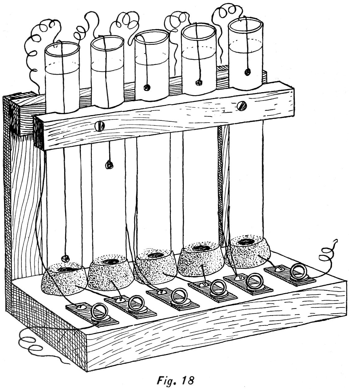
Their location can be seen in the bottom of the tubes
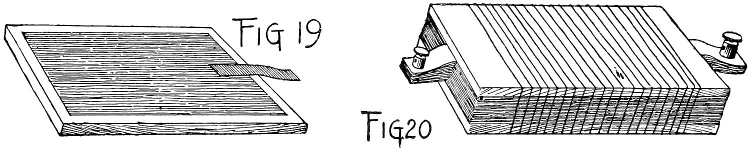
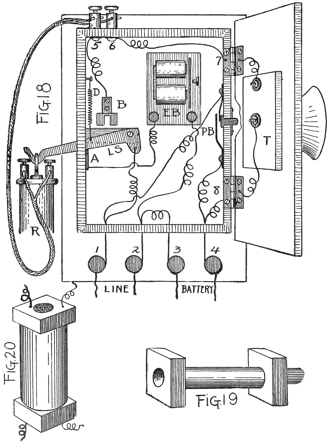
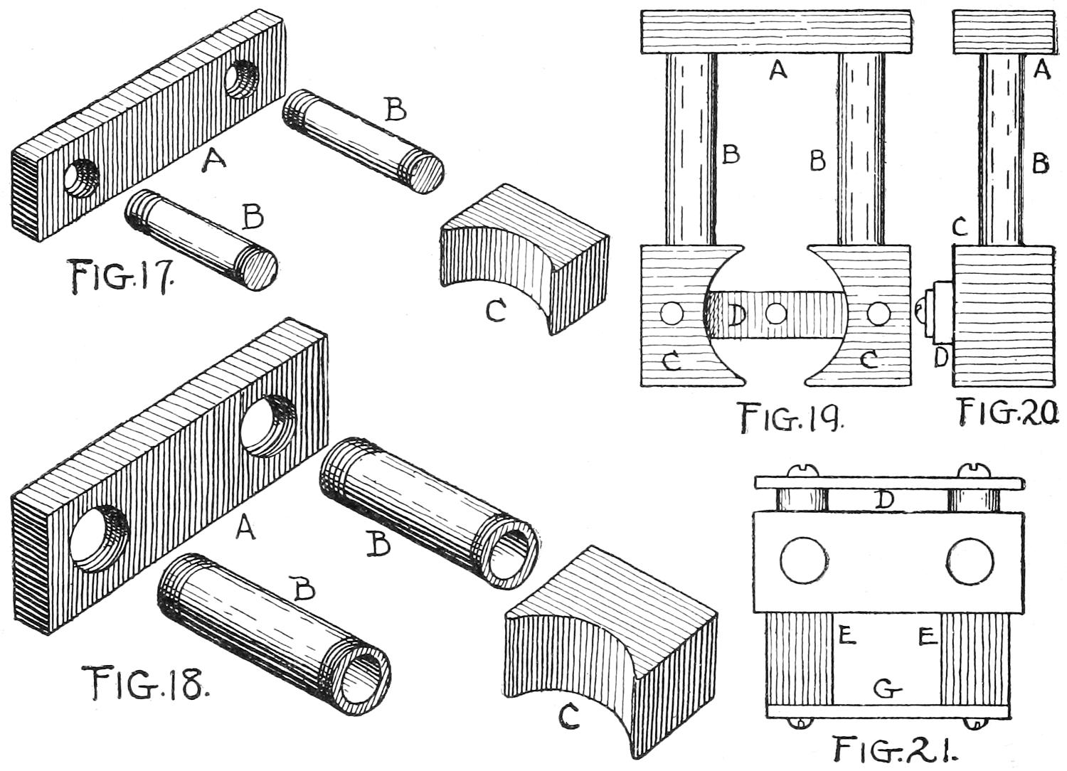
Fig. 18, and Fig. 19 A is an enlarged figure drawing of the
plate, button, and wire. The wires are brought out under
the lower edge of the tubes, and enough of the composition
is floated about the bottom and outer edge of the tube to
form a base, as shown in the drawing. A base-board is
made six inches wide and long enough to accommodate the
desired number of tubes. Two pieces of wood one inch
wide and three-quarters of an inch thick have hollow notches
cut from them at one side, as shown at Fig. 19 B. In these
notches the tubes are gripped. Screws are passed through
one stick and into the other so as to clamp the wood and
tubes securely together. The rear stick is supported on
two uprights which are made fast to the rear edge of the
base-plate with screws and glue.
Along the front of the base-board small metal contact
plates, or binding-posts, are arranged (see Binding-posts,
chapter iii.) and the wires led to them from the tubes, as
shown in the drawing. The top or drop wires in the tubes
are provided with metal buttons at the ends; or the end of
the wire may be rolled up so as to form a little knob. The
manner of connecting the wires was freely explained in the
resistance-coil descriptions and may be studied out by
examining the drawing closely. In this resistance-apparatus
there are two ways of cutting out a medium—first, by lowering
the wire in the tube so that both contact-points meet; and
second, by cutting out the first tube altogether by connecting
the incoming wire with the second binding-post. Then
again the resistance may be regulated quite accurately by
raising or lowering the wires in the liquid.
For example, there is too much resistance if the current
has to travel through all the tubes. If it is too strong when
one tube is cut out, the wire in tube No. 1 is lowered so that
the contacts are an inch apart. Then the more accurate
adjustment is made by dropping the wire in the second tube,
as shown in Fig. 18. The wires leading out at the top of the
tubes are pinched over the edge to hold them in place. They
should be cotton insulated and the part that is in the liquid
should be coated with hot paraffine.
The water may be made a slightly better conductor if a
small portion of sulphate of zinc, or sulphate of copper, is
added to each tubeful.
Hittorf’s resistance-tube is one of the oldest on these lines,
and two or more of them are coupled in series, as described
for this water-tube resistance; glass tubes are employed that
have one end sealed with a permanent composition, as described
for Fig. 18. A metallic cadmium electrode is placed
at the bottom of the tube, and the tube is then filled with
a solution of cadmium iodide one part and amylic alcohol
nine parts, and then corked. A wire passing down through
or at the side of the cork is attached to another small piece
of metallic cadmium, which touches the top of or is suspended
a short distance in the liquid.
As the alcohol is volatile the cork cannot be left out of the
tube, and the wire must be drawn through the cork with a
needle so that no opening is left for evaporation. A number
of these tubes may be made and coupled in series and the
wires led down to the contact-points of a switch.
For
direct communication over short or moderately
long distances, nothing has been invented as yet that
will take the place of the telephone. A few years ago, when
this instrument was first brought out, it was the wonder of
the times, just as wireless telegraphy is to-day. Starting
with the simple form of the two cups with membranes across
the ends, and a string or a wire connecting them, we have
to-day the complex and wonderful electric telephone, giving
perfect service up to a distance of two thousand miles.
Some day inventors in the science of telephony will make it
possible to communicate across or under the oceans, and
when the boys of to-day grow to manhood they should be
able to transact business by ’phone from San Francisco to
the Far East, or from the cities near the Atlantic coast to
London, Paris, or Berlin.
It is hardly necessary to enter into the history of telephones,
as this information may be readily found in any
modern encyclopædia or reference work. But the boy who
is interested in electricity wants to know how to make a
telephone, and how to do it in the up-to-date way, with the
wire and ground lines, switches, cut-outs, bell connections,
and other vital parts, properly constructed and assembled.
In this laudable ambition we will endeavor to help him.
The general principle of the telephone may be explained
in the statement that it is an apparatus for the conveyance
of the human voice, or indeed any sounds which are the
direct result of vibration.
Sound is due to the vibrations of matter. A piano string
produces sound because of its vibration when struck, or
pulled to one side and then released. This vibration sets
the air in rapid motion, and the result is the recording of
the sound on our ear-drums, the latter corresponding to the
film of sheepskin or bladder drawn over the hollow cup or
cylinder of a toy telephone. When the head of a drum is
struck with a small stick it vibrates. In this case the
vibrations are set in motion by the blow, while in the telephone
a similar phenomenon is the result of vibratory waves
falling from the voice on the thin membrane, or disk of
metal, in the transmitter. When these vibrations reach the
ear-drum the nervous system, corresponding to electricity
in the mechanical telephone, carries this sound to our brains,
where it is recorded and understood. In the telephone the
wire, charged with electricity, carries the sound from one
place to another, through the agencies of magnetism and
vibration.
Over short distances, however, magnetism and electricity
need not be employed for the transmission of sound. A
short-line telephone may be built on purely vibratory principles.
Almost every boy has made a “phone” with two
tomato-cans over which a membrane is drawn at one end
and tied. The middle of the membrane is punctured, and
a button, or other small, flat object, is arranged in connection
with the wires that lead from can to can.
A really practical talking apparatus of this simple nature
may be made from two fresh beef bladders obtained from
a slaughter-house or from the butcher. You will also need
two boards with holes cut in them, two buttons, some tacks,
and a length of fine, hard, brass, copper, or tinned iron wire.
The size should be No. 22 or No. 24. The boards should
be ten by fourteen inches and half an inch in thickness.
Cut holes in them eight inches in diameter, having first
struck a circle with a compass. This may be done with a
keyhole saw and the edges sand-papered to remove rough
places. Prepare the bladders by blowing them up and tieing
them. Leave them inflated for a day or two until they
have stretched, but do not let them get hard or dry.
When the bladders are ready, cut off the necks, and also
remove about one-third of the material, measuring from
end to end. Soak the bladders in warm water until they
become soft and white. Stretch them, loosely but evenly,
over the opening in the boards, letting the inside of the
bladder be on top, and tack them temporarily all around,
one inch from the edge of the opening. Test for evenness
by pushing down the bladder at the middle. If it stretches
smoothly and without wrinkles it will do; otherwise the
position and tacks must be changed until it sets perfectly
smooth.
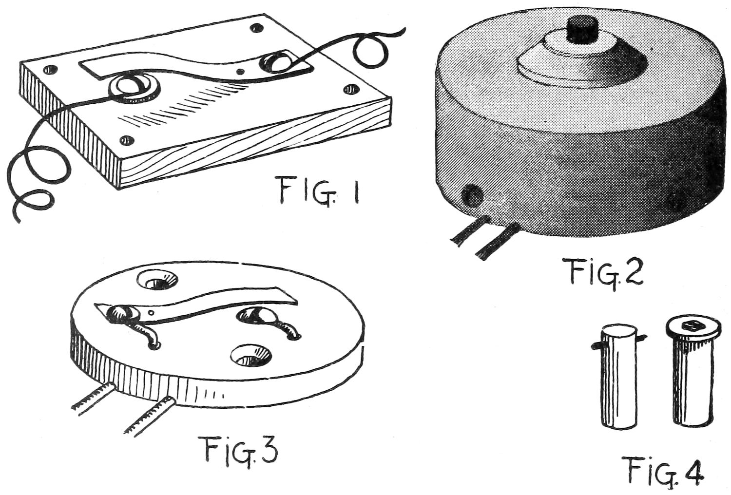
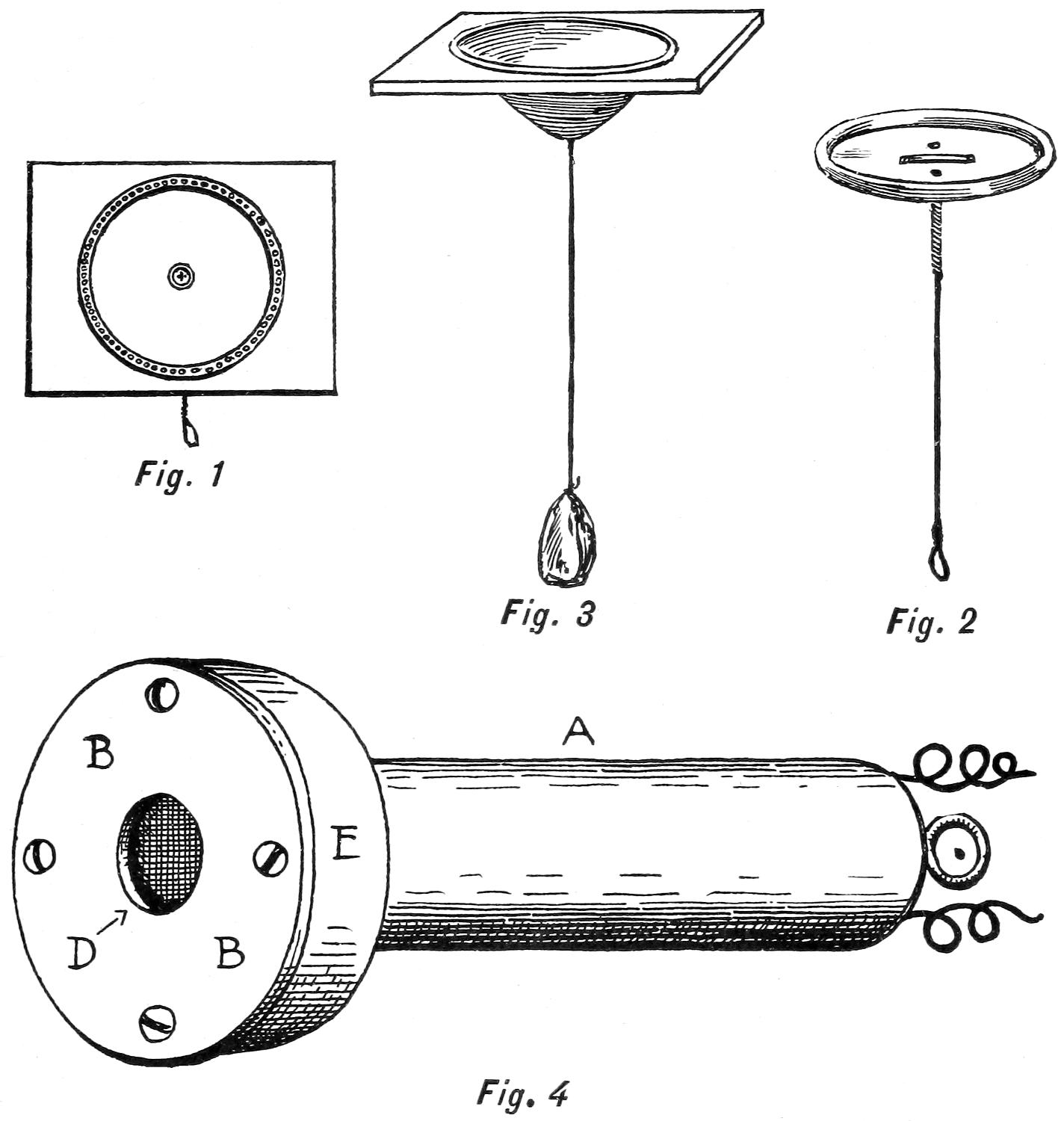
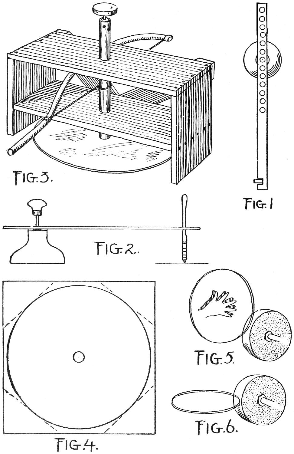
The bladder must now be permanently fastened to the
board by means of a leather band half an inch wide and
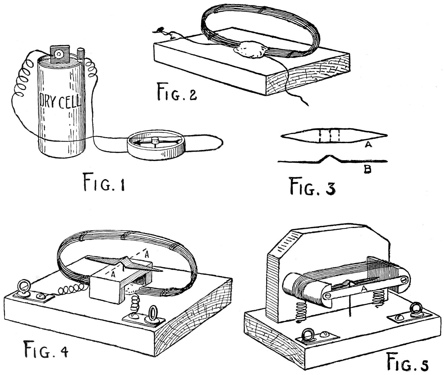
tacks driven closely, as shown in Fig. 1. With a sharp
knife trim away the rough edges of the bladder that extend
beyond the circle of leather. Attach a piece of the fine wire
to a button, as shown in Fig. 2, and pass the free end
through the centre of the bladder until the button rests on
its surface. Then fasten an eight-pound weight to the end
of the wire and set in the sun for a few hours, until thoroughly
dry, as shown at Fig. 3.
When both drums are complete, place one at each end
of a line, and connect the short wires with the long wire,
drawing the latter quite taut. The course of the main wire
should be as straight as possible, and should it be too long
it may be supported by string loops fastened to the limbs of
trees, or suspended from the cross-piece of supports made
in the form of a gallows-tree or letter F. To communicate
it will be necessary to tap on the button with a lead-pencil
or small hard-wood stick. The vibration will be heard at
the other end of the line and will attract attention.
By speaking close to the bladder in a clear, distinct tone,
the sound will carry for at least a quarter of a mile, and the
return vibrations of the voice at the other end of the line
can be clearly recognized.
The principal parts of the modern telephone apparatus
are the transmitter, receiver, induction-coil, signal-bell, push-button,
batteries, and switch. The boxes, wall-plates, etc.,
etc., are but accessories to which the active parts are attached.
The first telephone that came into general use was the
invention of Graham Bell, and the principle of his receiver
has not been materially changed from that day to this, except
that now a double-pole magnet and two fine wire coils
are employed in place of the single magnet and one coil. A
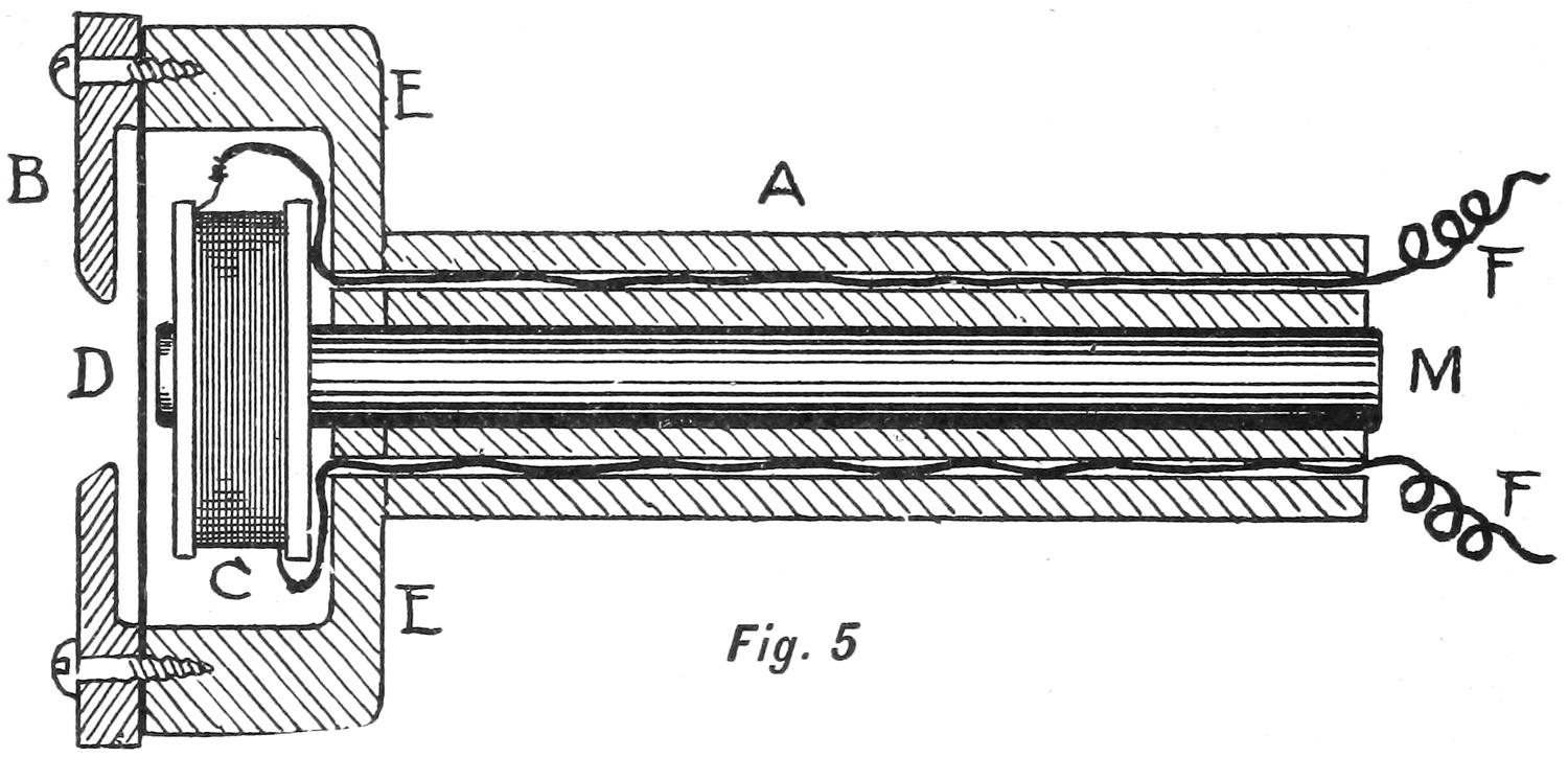
practical form of single magnet receiver that any boy can
easily construct is shown in Fig. 4, and Fig. 5 is a sectional
drawing of the receiver drawn as though it had been sliced
or sawed in two, from front to rear.
It is made from a piece of curtain-pole one inch and an
eighth in diameter and three inches and a half long. A hole
three-eighths of an inch in diameter is bored its entire
length at the middle, and through this the magnet passes.
At one end of this tube a wooden pill-box (E) is made fast
with glue, or a wooden cup may be turned out on a lathe
and attached to the magnet tube. If the pill-box is employed
it should be two inches and a half in diameter, and
at four equidistant places inside the box small lugs of wood
are to be glued fast. Into these lugs the screws employed
to hold the cap are driven. The walls of pill-boxes are so
thin that without these lugs the cap could not be fastened
over the thin disk of metal (D) unless it were tied or wired
on, and that would not look well. If the cup is turned the
walls should be left thick enough to pass the screws into,
and the inside diameter should then be one inch and three-quarters.
The cap (B) is made from thin wood, fibre, or hard rubber.
It is provided with a thin rim or collar to separate its inner
side from the face of the disk (D). Four small holes are bored
near the edge of this cap, so that the screws which hold it
fast to the cup (E) may pass through them. The magnet (M)
is a piece of hard steel three-eighths of an inch in diameter
and four inches and a quarter long. This may be purchased
at a supply-house, and if it is not hard enough a blacksmith
can make it so by heating and plunging it in cold water
several times. It may be magnetized by rubbing it over
the surface of a large horseshoe magnet, or if you live near
a power station you can get one of the workmen to magnetize
it for you at a trifling cost. Should you happen to possess a
bar magnet of soft iron with a number of coils of wire, and
also a storage-battery, the steel bar may be substituted for
the soft iron core and the current turned on. After five
minutes the steel can be withdrawn. It is now a magnet,
and will hold its magnetism indefinitely.
Now have a thin, flat spool turned from maple or boxwood
to fit over one end of the rod, and wind it with a number
of layers of No. 36 copper wire insulated with silk.
This is known in the electrical supply-houses as “phone”-receiver
insulated wire, and will cost about fifty cents an
ounce. One ounce will be enough for two receivers. It
should be wound evenly and smoothly, like the strands of
thread on a spool, and this may be done with the aid of
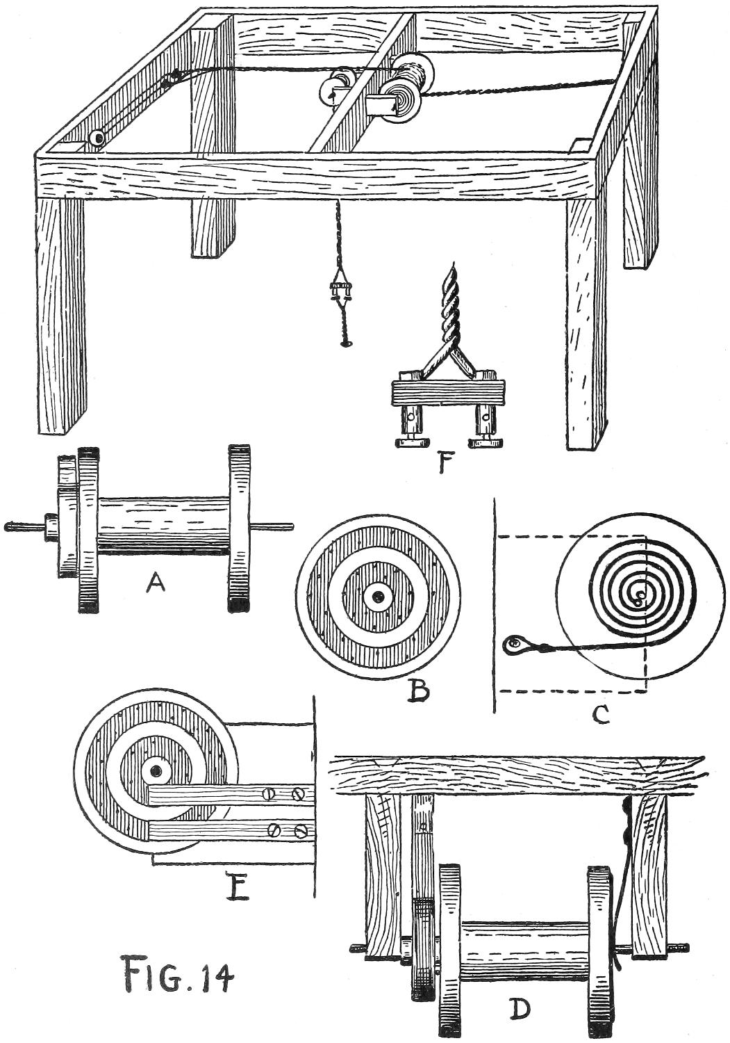
the winder described on page 58.
When the wire is in place a drop of hot paraffine will
hold the end so that the wire will not unwind. The ends
of this spool-winding should be made fast to heavier wires,
which are run through small holes in the tube (A) and project
out at the end, as shown at F F. The magnet, with its
wire-wound spool on the end, is then pushed through the
hole in A until the top end of the rod is slightly below the
edges of the cup (E), so that when the metal disk (D) is laid
over the cup (E) the space between the magnet and disk, or
diaphragm (D), is one-sixteenth of an inch (see Fig. 5). Put
some shellac on the magnet, so that when it is in the right
place the shellac will dry and hold it fast.
The cap (B) holds the disk (D) in place, and protects the
spool and its fine wire from being damaged and from collecting
dust. After giving the exterior a coat of black paint
and a finishing coat or two of shellac, the receiver will be
ready for use.
The original telephone apparatus was made up of these
receivers only—one at each of a line in connection with
a battery, bell, push-button, and switch. On a window-casing,
or the wall through which the wires passed, a lightning-arrester
was arranged and made fast. Using receivers
only, it was necessary to speak through the same instrument
that one heard through, and for a few years this unhandy
method of communication was the only one possible. Then
the transmitter was invented.
Many of these single-receiver lines are still in use, and as
they require but a small amount of constructive skill a
diagram of the wiring and the plan of arrangement is shown
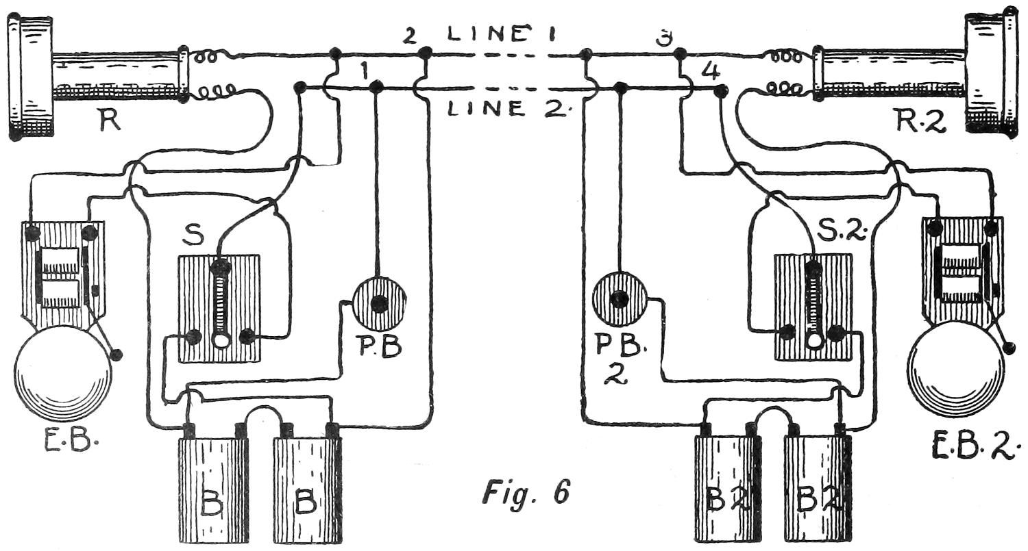
in Fig. 6.
At the left side, R is the receiver at one end of the line
and R 2 that at the other, line No. 1 being a continuous
wire between the two receivers. When the boy at R wishes
to call his friend at R 2 he uses his push-button (P B), and
the battery (B B) operates the electric bell (E B 2) at the
other end. In order to have the bell connections operative,
the switch (S 2) must be thrown over to the left when the
line is “quiet,” while the switch (S) should be thrown to the
right. With the switches in this position the boy at either
end may call his friend at the opposite end.
With the switch (S 2) thrown to the left (the position it
should be in, except when talking over the line), the boy at
the other end pushes his button (P B), first throwing switch
S to the left. This makes connection for the battery (B B),
and the circuit is closed through wires that join line No. 1
and line No. 2 at 1 and 2. The branch lines to the bell
(E B 2) join the main lines at 3 and 4, through switch S 2,
when the bar is thrown to the left. The circuit being complete,
the batteries (B B) at one end of the line ring the bell
(E B 2) at the other end of the line.
In the reverse manner, when the switch (S) is thrown to
the right, the boy at the opposite end rings the bell (E B)
by pressing on the button (P B 2), first throwing switch S 2
over to the right. If the boy at the left is calling up the
boy at the right, the switch (S) should be thrown to the left,
and he keeps ringing until the other operator throws switch
S 2 over to the right. If now he has the receiver (R) up to
his ear he can hear the vibration of the bell (E B 2) ringing
through the receiver (R) at his end of the line. But when
the boy summoned to R 2 takes up the receiver and places
it to his ear, he throws switch S 2 over to the right side, and
the boy at R leaves switch S over on the left side. This
brings the lines into direct connection with the receivers in
series. Be careful, when setting up this line, to have the
batteries (B B) in series with B 2 B 2; otherwise there would
be counter-action. The carbon of one cell should be connected
with the zinc of the next cell, and so on.
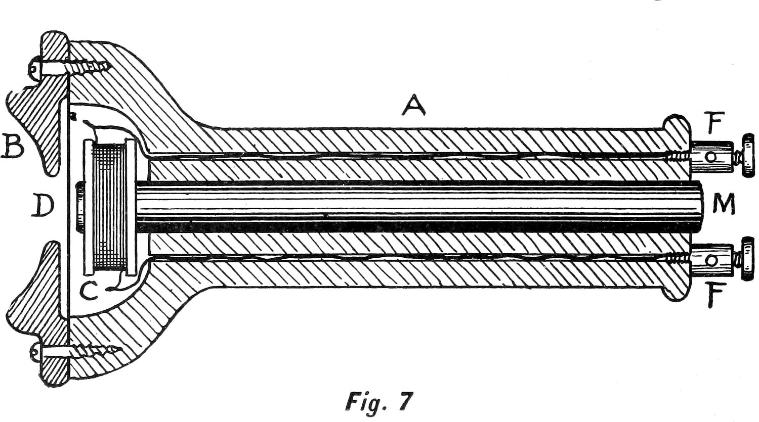
Another receiver is shown at Fig. 7. The tube (A) and
the cup are turned from one piece of wood, and the cap (B)
from another piece. The length of the receiver is five inches,
and the cap is two inches and a half across. The shank, or
handle, through which the magnet is passed measures one
inch and a quarter in diameter.
These wood parts will have to be made by a wood-turner;
and before the long piece is put in a lathe the hole, three-eighths
of an inch in diameter, should be bored. It must be
done carefully, so that the wood shell will be of even thickness
all around the hole. Also two small holes should be
made the entire length of the handle, through which the
wires leading from the coil to the binding-posts may
pass.
The spool for the fine insulated wire coil is turned from
box-wood or maple, and wound as described in chapter iv.,
on Magnets and Induction-coils. Small binding-posts (F F)
with screw ends should be driven down into the holes at
the end of the handle and over the bare ends of the wires
that project out of the holes. The magnet (M) is three-eighths
of an inch in diameter, and is provided with the
spool and coil (C) at the large end of the receiver.
The disk (D) is of very thin iron, and is held in place by the
cap (B) and four small brass screws driven through the edge
of B and into the cup end of A. A screw-eye should be
driven into the small end of the receiver from which it may
hang from a hook. If a double hook and bar is employed
the receiver will hang in the fork, being held there by the
rim of wood turned at the small end of A.
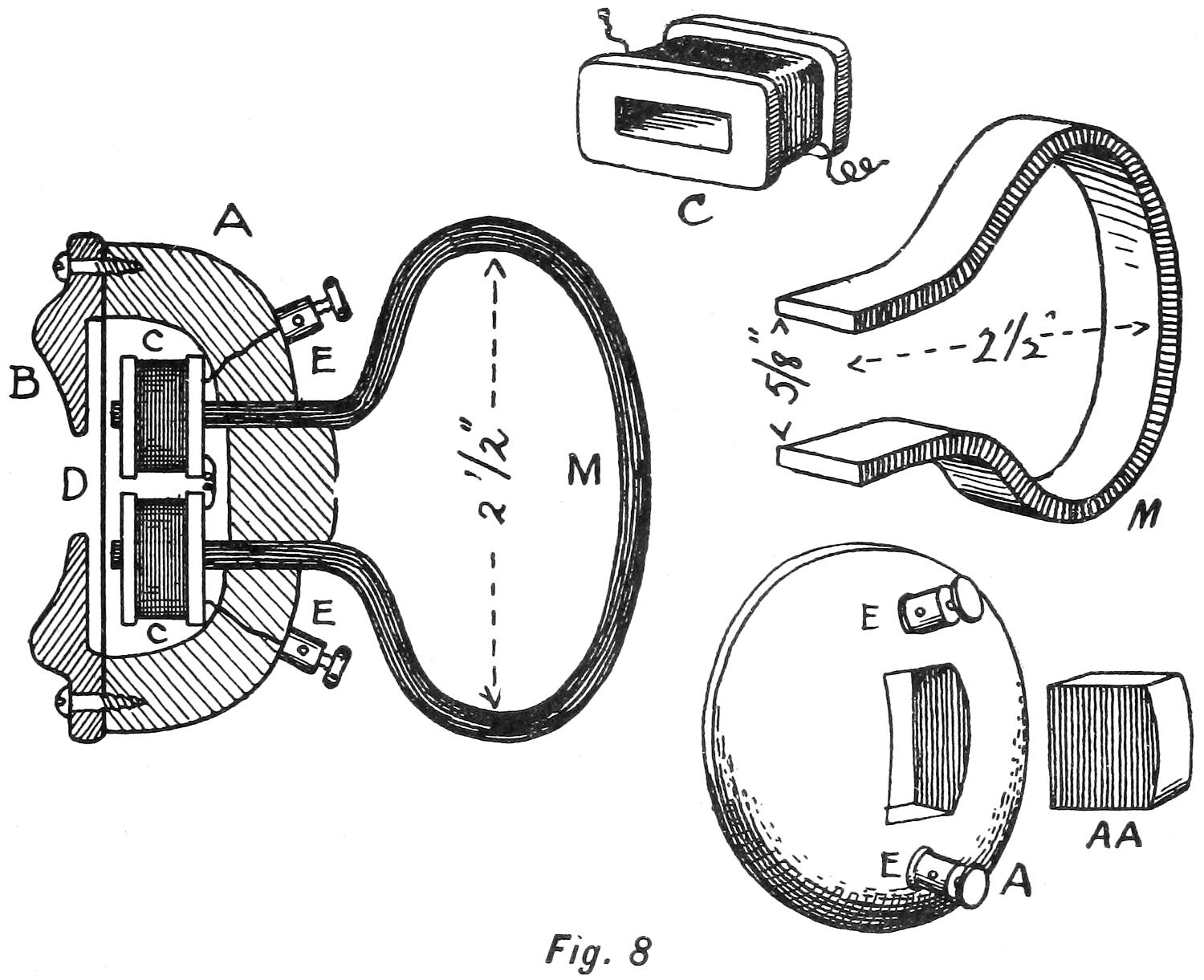
Another form of receiver is shown at Fig. 8. This is a
double-pole receiver, with the coils of fine wire arranged on
the ends of a bent band of steel and located in the cup (A),
so that the ends of the magnet are close to the diaphragm
(D). Fig. 8 is a sectional view of an assembled receiver, but
a good idea can be had from the drawings of the separate
parts. The magnet (M) is of steel one-eighth of an inch thick
and five-eighths of an inch wide. A blacksmith will make
this at a small cost. It should measure two and one-half
inches wide, two and one-half inches long, the ends being
five-eighths of an inch apart.
Thin wooden spools are made from wood or fibre to fit
over the steel ends, and are wound with No. 36 silk-insulated
wire. A wooden cup, or shell (A), is turned from cherry,
maple, or other close-grained wood, and at the back a hole
is cut just large enough for the magnet ends to slip through
exclusive of the coils wound on them. A plug of wood (A A)
is driven between the ends of the magnet to hold them in
place. Some shellac on the edges of the hole and the plug
will harden and keep the parts in place.
The coils (C C) are placed on the magnet ends, and the fine
wires are made fast to the binding-posts (E E), the latter being
screwed fast to the shell (A). The diaphragm (D) is then
arranged in place and held with the cap (B) and the small
screws which pass through it and into the shell (A).
With any one of these receivers a more complete and
convenient telephone can be made by the addition of a
transmitter and an induction-coil.
Following the invention of the receiver, several transmitters
were designed and patented, among them being
the Edison, Blake, Clamond, Western Union, and Hunning.
The Edison and Hunning are the ones in general use, and
as either of them can easily be made by a boy a simplified
type of both is shown in Figs. 9 and 11.
SIMPLIFIED TYPE OF TRANSMITTER
Some small blocks of wood, tin funnels, small screws,
granulated or powdered carbon, some thin pieces of flat
carbon, and a piece of very thin ferrotype plate will be the
principal things needed in making a transmitter similar to
the one shown in Fig. 9. All that is visible from the outside
is a plate of wood screwed to a block of wood, and a
mouth-piece made fast to the thin board.
In Fig. 10 an interior section is shown, which when once
understood will be found extremely simple. The block (A) is
of pine, white-wood, birch, or cherry, and is two inches and
three-quarters square and five-eighths or three-quarters of
an inch thick. A hole seven-eighths of an inch in diameter
is bored in the centre of this block, half an inch deep, and
a path is cut at the face of the block one inch and a half
in diameter and one-eighth of an inch deep. Be careful to
cut these holes accurately and smoothly, and if it is not
possible to do so, it would be well to have them put in a
lathe and turned out.
The face-plate (B) is two inches square, with a three-quarter-inch
hole in it, and the under-side is cut away for one-eighth
of an inch in depth and one inch and a half in diameter.
The object of these depressions in block A and
face-plate B is to give space for the diaphragm (D) to
vibrate when the voice falls on it through the mouth-piece
(C).
From carbon one-eighth of an inch in thickness two
round buttons are cut measuring three-quarters of an inch
across. A small hole is bored in the centre of each button,
and one of them is provided with a very small brass screw
and nut, as shown at F F. One side of the button-hole is
countersunk, so that the head of the screw will fit down
into it and be flush with the face of the carbon. With a
small three-cornered or square file cut the surface of the
buttons with criss-cross lines, as shown at F F. When the
buttons are mounted in the receiver these surfaces will face
each other. Cut a small washer from felt or flannel, and
place it in the bottom of the hole in block A. Line the side
of the hole with a narrow strip of the same goods; then
place the button (F F) in the hole, pass the screw through the
hole and through the block (A), and make it fast with the
nut, as shown at F. Place a thin, flat washer under the nut,
and twist a fine piece of insulated copper wire between
washer and nut for terminal connections, taking care that
the end of the wire under the nut is bare and bright, so that
perfect contact is assured. Since the practice of telephony
involves such delicate and sensitive vibratory and electrical
phenomena, it is best to solder all joints and unions wherever
practicable, and so avoid the possibility of loose connections
or corrosion of united wires.
From very thin ferrotype plate cut a piece two inches
square, and at the middle of it attach the other carbon button
by means of a small rivet which you can make from a
piece of copper wire. Or a very small brass machine screw
may be passed through the button and plate; then gently
tapped at the face of the plate to rivet it fast, as shown
at E. Lay the block down flat and partly fill the cavity
with carbon granules until the button is covered. Do not
fill up to the top of the hole. Over this lay the disk (D), so
that the carbon button at the under side of it will fit in the
top part of the hole between the sides of felt or flannel.
Make the disk fast to the block (A) with small pins made by
clipping ordinary pins in half and filing the ends.
A slim bolt (G) is passed through the block (A), and a wire
terminal is caught under a nut and between a washer at
the back of the block, as described for F. The japan or
lacquer must be scraped away from the disk (D) where the
bolt-head touches it, so that perfect electrical contact will
be the result.
A small tin funnel is cut and made fast to the face-plate
(B), or if an electrical supply-house is at hand a mouth-piece
of hard rubber or composition may be had for a few cents.
The block (B) is then screwed fast to A, forming the transmitter
shown at Fig. 9. When this transmitter stands in a
vertical position the granules, or small particles of carbon,
drop down between the buttons of carbon, packing closely
at the bottom of the cavity. At the middle they are loosely
placed, and at the top there are none. As the high or low
vibrations of the voice fall on the disk (D) they act accordingly
on the carbon granules, which in turn conduct the
vibrations to the rear carbon button, and, by the aid of
electricity reproduce the same sound, in high or low tone,
through the receiver at the other end of a line.
This improved transmitter makes it possible to talk in a
moderate tone of voice over distances up to one thousand
miles, while with the old form of the instrument it was
necessary to talk very loud in order to be heard only a few
miles away. Where a portable apparatus is desired, this
block may be attached to a box or an upright staff.
This transmitter will not work when on its back or so
that the funnel is on top, because the particles of carbon
would settle on the rear button and not touch the front
one. It is essential that the carbon grains should touch
both buttons at the same time, and at the lower part of the
cavity they should lie quite solid. It is not necessary, however,
to pack it in, for the vibratory action of the voice, or
other sounds, will cause the particles to adjust themselves
and settle in a compact mass.
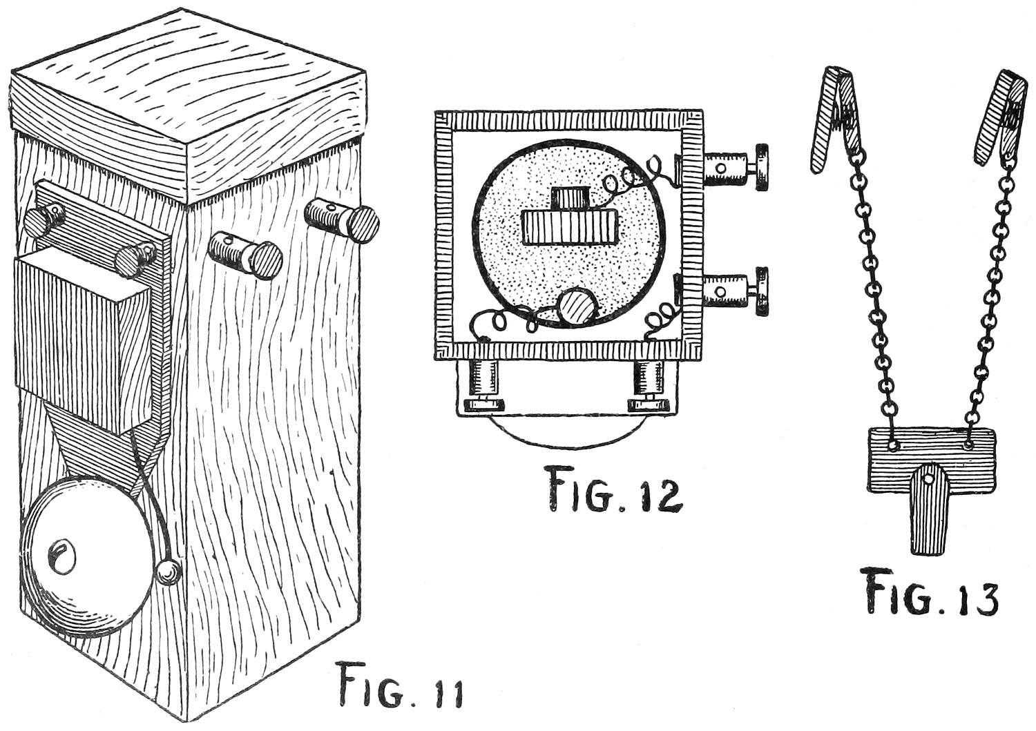
In Fig. 11 another style of transmitter is shown. It is
assembled on the front of a box. This front or cover swings
on hinges, and can be opened so that the mechanism in the
interior of the box may be gotten at easily.
A sectional view of this transmitter is shown in Fig. 12.
A hole one inch and a half in diameter is cut in the cover (A).
A round or square block (B) two inches and a quarter across
and half an inch thick is made fast to the rear of the cover,
and in this a hole is bored seven-eighths of an inch in diameter
and one-quarter of an inch deep.
The sides and bottom of this hole are lined with flannel
or felt, and a carbon button with roughened surface, as
shown at F F, is made fast in it by a small machine screw
and nut (F). A diaphragm (D) is cut from thin ferrotype
plate, and a carbon button is made fast to the middle of it
by a small machine screw or a rivet made from soft copper
or brass. When the block (B) has been screwed fast to A,
place some granules of carbon in the space (H); then lay the
diaphragm over the opening, and make it fast with small
screws or pins driven around the edge.
From a small tin funnel and a tin-can cap make a mouth-piece
(C) by cutting a hole in the cap and slipping the funnel
through it, then cutting the end of the funnel that projects
through the hole and bending back the ears so that they
lap on the inner side of the cap. These small ears may be
soldered to the cap so as to hold the mouth-piece securely in
place. From felt or flannel cut a washer the size of the
can top and about three-eighths of an inch in width. Lay
this over the diaphragm; then place the mouth-piece on it
and fasten it to the door (A) with small screws. The use of
this washer is to prevent any false vibrations in the mouth-piece
affecting the sensitive diaphragm. Make a small hole
through A and B and pass a bolt (E) through this hole,
taking care to lap a thin piece of sheet-brass on the
diaphragm (D), bending it over so that it will lie under the
head of the bolt (E). The diaphragm must be scraped where
the metal touches it, so as to make perfect electrical connection
between D and E. At the rear end of E arrange
a washer and nut (G), so that the current passing in at G
travels through E and D, then through the carbon buttons
and granules, and out at F.
From pine or white-wood one-quarter or three-eighths
of an inch thick make a box four inches wide, six inches
high, and two inches and a half deep. To the front of this
attach a cover, which should measure a quarter of an inch
larger all around than the width and height of the box.
Use brass hinges for this work so that the cover may be
opened. Fasten a transmitter to the front of the cover, or
make one on the cover, as shown in Fig. 11, and attach the
box to a back-board or wall-plate five inches wide and
seven inches high made of pine or white-wood half an inch
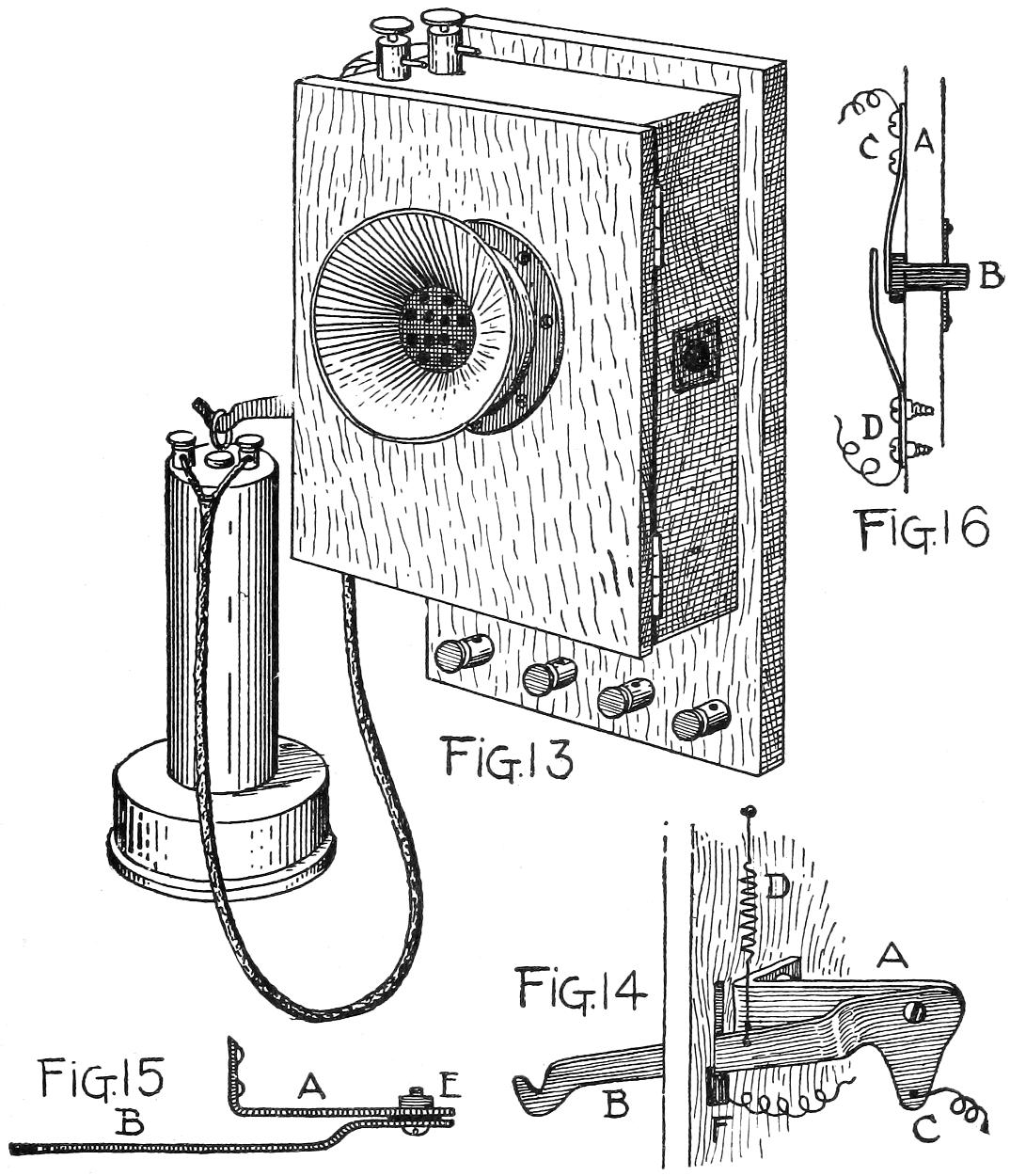
in thickness (see Fig. 13).
At the left side of the box cut a slot through the wood,
so that a lever and hook may project and work up and
down. The end of this lever is provided with a hook on
which a receiver may be hung, as shown in Fig. 13, and the
inside mechanism is arranged as shown at Fig. 14. A is
an angle-piece of brass or copper, which acts as a bracket
and which is screwed fast to the inside of the box. B is the
lever and hook, which is cut from a strip of brass. The
attached end is made wider, and an ear (C), to which a wire
is soldered, projects down beyond the screw.
A view looking down on this lever and bracket is shown
at Fig. 15. A is the bracket, B the lever, and E the screw
or bolt holding the two parts together, with a thin copper
washer between them to prevent friction. When the lever
and bracket are made fast to the box, a spring (D) should
be arranged, so that when the receiver is removed from the
hook the lever will be drawn up to the top of the slot. A
small contact-plate (F) is made of brass, and fastened at the
lower end of the slot. On this the lever should rest when
the receiver is on the hook. A contact-wire is soldered to
this plate, which in turn is screwed fast to the inside of
the box. This mechanism is part of a make-and-break
switch to cut out and cut in the bells or telephone, and
will be more clearly understood by referring to the diagram
in Fig. 17. At the right side of the box a small push-button
is made fast, and this, with two binding-posts at the top
and four at the underside of the box, will complete the
exterior equipment of one end of a line.
The construction of the push-button is shown in Fig. 16, A
being the box and B the button which passes through a small
hole made in the side of the box. C is a strip of spring-brass
screwed fast to the box. It must be strong enough
to press the small bone or hard rubber button towards the
outside of the box. A wire is caught under one screw-head,
and another one is passed under the screw-head which holds
the other spring (D) to the box. When the button (B) is
pushed in, it brings spring C into contact with D, and the
circuit is closed. Directly the finger is removed from B
the spring (C) pushes it out and breaks the circuit. This
button is used only in connection with the call-bells, and has
nothing to do with the telephone. The wires leading from
the interior of the box pass through the wall-plate and along
in grooves to the foot of the binding-posts, which are arranged
below the box on the back-board, as shown in Fig. 13.
A buzzer or bell is made fast to the inside of the box,
unless it is too large to fit conveniently, in which case it
may be attached to the wall above or below the box.
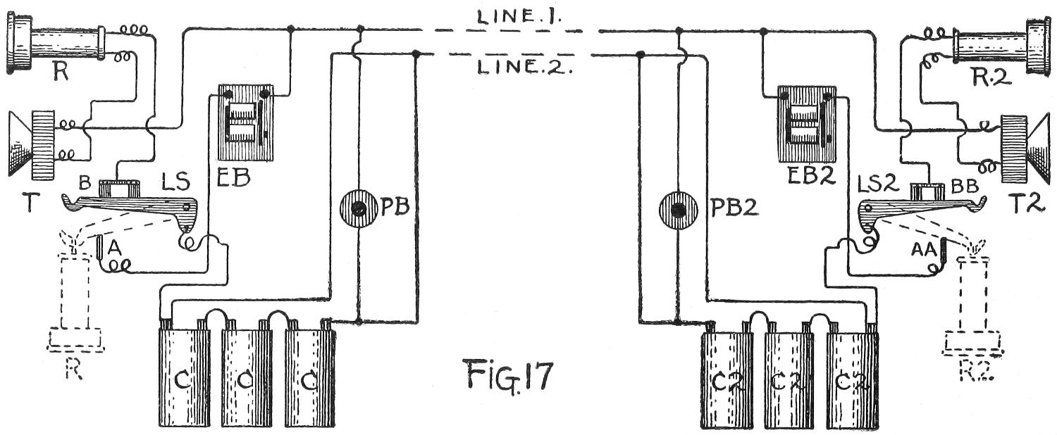
Fig. 17 shows the wiring system for this outfit, which,
when properly set up and connected, should operate on a
circuit or line several miles in length, provided that the
batteries are strong enough.
This system may be installed in the box shown in Fig. 13,
the flexible cord containing two wires being attached to the
binding-posts at the top of the box and to the posts at the
end of the receiver. This system differs from the one shown
in Fig. 6 only in the addition of receivers T and T 2, and in
the substitution of the automatic lever-switches (L S and
L S 2) for the plain switches (S and S 2) in Fig. 6. When the
line is “quiet” the receiver (R) should be hanging on the
lever-switch (L S), which rests on the contact-plate (A). At
the opposite side of the line the receiver (R 2) hangs on the
lever-switch (L S 2), which in turn rests on the contact-plate
(A A). This puts the bell circuit in service.
PLAN OF TELEPHONE CIRCUIT, COMPRISING RECEIVERS, TRANSMITTER, ELECTRIC BUZZERS OR BELLS,
LEVER-SWITCHES, PUSH-BUTTONS AND BATTERIES FOR STATIONS NOT OVER FIVE MILES APART.
If the boy at the left wishes to call up the boy at the
right he removes the receiver (R) from the hook (L S) and
presses on the button (P B). This closes the circuit through
the battery (C C C), and operates the electric buzzer or bell
(E B 2) at the other end of the system, through line No. 1
and line No. 2. The operation may be clearly understood
by following the lines in the drawing with a pointer. The
boy at the left may keep on calling the boy at the right so
long as the receiver (R 2) hangs on the lever (L S 2) and holds
it down against the plate (A A). But directly the receiver
(R 2) is removed, the lever (L S 2) flies up—being drawn upward
by the spring (D) shown in Fig. 14—and closes the telephone
circuit through the spring-contact (B B), at the same
time cutting out the bell circuit. The boy at the left having
already removed his receiver, the telephone circuit is then
complete through lines Nos. 1 and 2 and batteries C C C and
C 2 C 2 C 2, the boys at both ends speaking into the transmitters
and hearing through the receivers. The contacts
B and B B are made from spring-brass or copper, and are
attached inside the boxes at the back, so that when the
levers are up contact is made, but when down the circuit
is broken or opened. In Fig. 18 an interior view of a box
is shown, the door being thrown open and the receiver left
hanging on the hook.
TELEPHONE INSTALLATION. INTERIOR VIEW OF BOX
The arrangement of the several parts will be found convenient
and easy of access. E B is the electric buzzer, L S
the lever-switch, P B the push-button, T the transmitter,
and R the receiver. Nos. 1, 2, 3, 4, 5, 6, 7, 8 are binding-posts
or terminals, and B is the spring-contact against
which the lever-switch (L S) strikes when drawn up by the
spring (D).
The wires that pass from 6 to 7 and from 4 to 8 should be
soldered fast to one side of the hinge, and those running
from the terminals or nuts at the back of the transmitter (T)
to 7 and 8 should be similarly secured. Small brass hinges
are not liable to become corroded at the joints, but to insure
against any such possibility the ends of several fine wires
may be soldered to each leaf of the hinge, so that when the
door is closed the wires will be compressed between the
hinge-plates. For long-distance communication it will be
necessary to install an induction-coil, so that the direct current
furnished by the batteries, in series with the transmitter,
can by induction be transformed into alternating
current over the lines connecting the two sets of apparatus.
This system is somewhat more complicated and requires
more care in making the connections, but once in operation
it will be found far superior to either of the systems hitherto
described.
It will be necessary to make two induction-coils, as described
in chapter iv., page 62, Fig. 8. A telephone coil
for moderately long-distance circuits is made on a wooden
spool turned from a piece of wood three inches and a half
long and one inch square, as shown at Fig. 19. The core-sheath
is turned down so that it is about one-sixteenth of
an inch thick. This spool is given a coat or two of shellac,
and two holes are made at each end, as shown in the drawing.
The first winding or primary coil is made up of two
layers of No. 20 double-insulated copper wire, one end projecting
from a hole at one end of the spool, the other from
a hole at the other end. This coil is given two or three
thin coats of shellac to bind the strands of wire and thoroughly
insulate them, and over the layer a piece of paper
is to be wrapped and shellacked. The secondary coil is
made up of twelve layers of No. 34 silk-insulated copper
wire, and between each layer a sheet of paper should be
wound so that it will make two complete wraps. Each
paper separator should be given a coat of shellac or hot
paraffine; then the turns of wire should be continued just
as thread is wound upon a spool, smoothly, closely, and
evenly, until the last wrap is on. Three or four wraps of
paper should be fastened on the coil to protect it, and it
may then be screwed fast inside a box. The core-hole
within the coil should be packed with lengths of No. 24 soft
Swedes iron wire three inches and a half long. In Fig. 19
the wires are shown projecting from the end of a spool, and
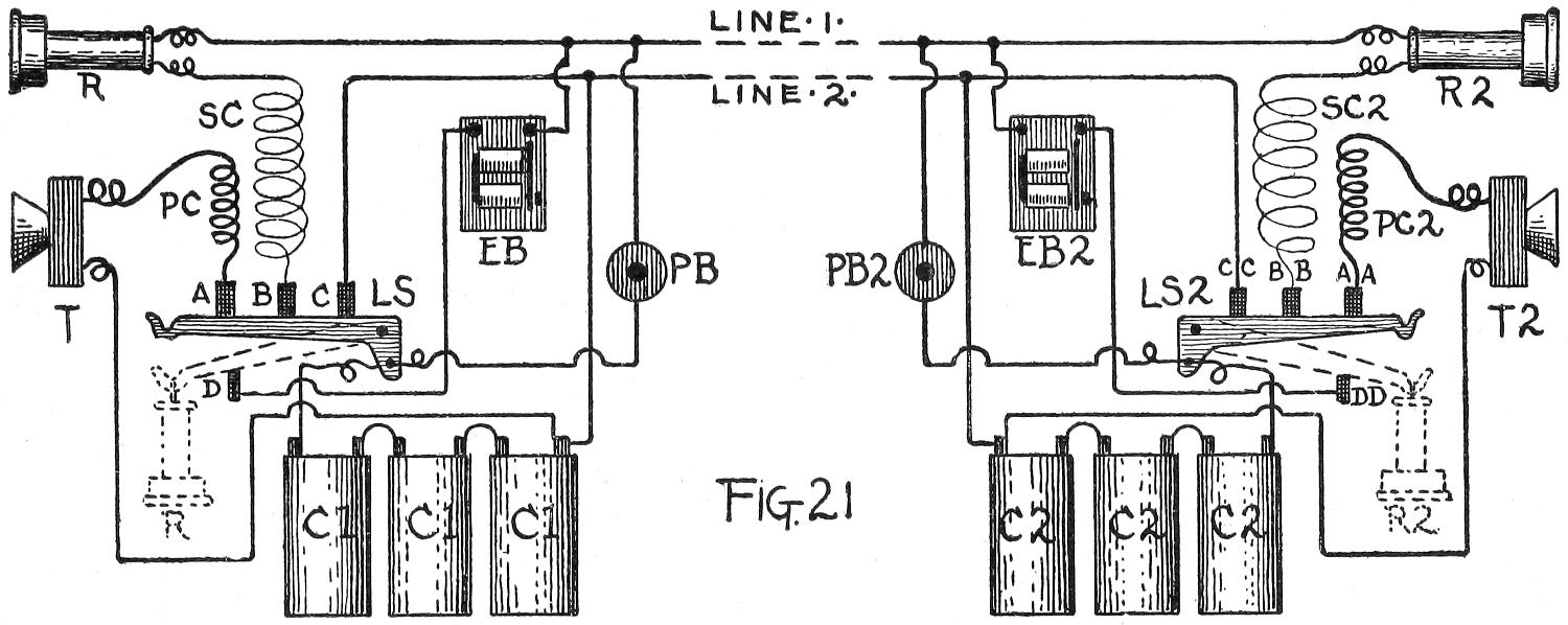
Fig. 20 depicts a completed telephone induction-coil. The
installation of the induction-coils is shown in Fig. 21.
PLAN OF TELEPHONE CIRCUIT, COMPRISING RECEIVERS, TRANSMITTERS, ELECTRIC BUZZERS OR BELLS,
LEVER-SWITCHES, INDUCTION-COILS, PUSH-BUTTONS, AND BATTERIES FOR STATIONS
UP TO FIVE HUNDRED MILES APART.
The wiring is comparatively simple, and may be easily
followed if the description and plan are constantly consulted
when setting up the line. R and R 2 are the receivers, T
and T 2 the transmitters, C 1 and C 2 the batteries, E B and
E B 2 the buzzers or bells, P B and P B 2 the push-buttons,
and L S and L S 2 the lever-switches. For convenience of
illustration the induction-coils are separated. The primary
coil (P C) is indicated by the heavy spring line and the secondary
coil (S C) by the fine spring line. When the line is
“dead” both receivers are hanging from the hooks of the
lever-switches. If the boy at the left wishes to call the boy
at the right he lifts the receiver (R) from the hook (L S) and
presses the button (P B). This throws the battery (C 1 C 1 C 1)
in circuit with lines Nos. 1 and 2, and operates the buzzer
(E B 2). When the boy at the right lifts his receiver (R 2) from
the hook (L S 2), the bell circuit is cut out and the ’phone
circuit is cut in. When the lever-switches are drawn up
against the contact-springs (A, B, and C and A A, B B, and
C C), both batteries are thrown into circuit with the transmitters
at their respective ends through the primary coils
(P C and P C 2). By inductance through the secondary coils
(S C and S C 2), lines Nos. 1 and 2 are electrified, and when
the voice strikes the disks in the transmitters the same tone
and vibration is heard through the receivers at the other
end of the line. While conversation is going on the batteries
at either end are being drawn upon or depleted; but as soon
as the receivers are hung on the hooks and the lever-switches
are drawn away from the contact-springs, the flow of current
is stopped. The buzzers or bells consume but a small
amount of current when operated, and in dry cells the active
parts recuperate quickly and depolarize. The greatest
drain on a battery, therefore, is when the line is closed for
conversation.
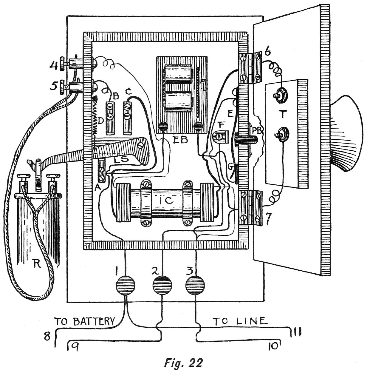
A simple manner in which to install this apparatus in
boxes is shown in Fig. 22. The box is depicted with the
front opened and with the receiver hanging on the hook.
When the lever-switch (L S) is down it rests on the contact-spring
(A), thus throwing in the bell circuit. When the boy
at the other end of the line pushes the button on his box
it operates the buzzer (E B). This can be understood by following
with a pointer the wires from the buzzer to the
outlet-posts (Nos. 1 and 3) at the bottom of the wall-plate.
When the receiver (R) is lifted from the hook (L S), it cuts
out the bell circuit and cuts in the telephone circuit, through
the spring-contacts (B and C). This circuit may easily be
followed through the wires connecting transmitter, receiver,
induction-coil, and batteries. The heavy lines leading out
from the induction-coil are the primary coil wires, and the
fine hair lines are those forming the secondary coil. The
medium lines are those that connect the binding-posts,
batteries, and lines.
When the bell circuit is connected the impulse coming
from the other end of the line enters through wire No. 10
to post No. 3, thence to strip E and plate G, and so on to
E B, which it operates. The current then passes from E B
to contact A, through L S to post No. 1, and out on wire
No. 11.
To operate the buzzer at other end of the line the button
(P B) is pushed in. This moves the spring (E) away from the
plate (G), and brings it into contact with F. This connects
the circuit through the battery wire (No. 8) to post No. 1 to
line No. 11 without going into the box, and from wire No.
9 to post No. 2; thence to hinge No. 7 to plate F, through
E, down to post No. 3, and out through wire No. 10. In
this manner the current is taken from the batteries at the
foot of wires Nos. 8 and 9, and used to ring the buzzer at the
other end of the line.
When the hook (L S) is up the circuit is closed through T,
I C, and battery. The current runs from the battery through
wire No. 8 to post No. 1, to L S, through C and primary coil
out to hinge No. 6, through transmitter to hinge No. 7, to
post No. 2, and back to battery through wire No. 9.
By inductance the sound is carried over the line, in at
wire No. 10, to post No. 3, through secondary coil to post
No. 4, through receiver R to post No. 5, through B and
L S to post No. 1, and out through wire No. 11. At the
other end of the line it goes through the same parts
of the apparatus.
For convenience it is often desirable to have a portable
transmitter, and so avoid the inconvenience of having to
stand while speaking. A neat portable apparatus that will
stand on a ledge or table, and which may be moved about
within the radius of the connecting lines, is shown in Fig. 23.
The wooden base is four inches square and the upright
one inch and a half square. The stand is twelve inches
high over all, and on the bottom a plate of iron or lead must
be screwed fast to make it bottom-heavy, so that it will not
topple over.
The lever-switch may be arranged at the back of the
upright and the push-button at the front near the base, as
shown at A. The wall-box contains the buzzer and induction-coil,
and within it the wiring is arranged from the portable
stand to the batteries and line as shown at C. This
illustration is too small, however, to show the complete
wiring, and the young electrician is therefore referred to
Fig. 22. The battery (B) is composed of as many dry or
wet cells as may be required to operate the line. These
must be connected in series at both ends. At D a rear view
of the upright and transmitter is shown to illustrate the
manner in which the wiring can be done. If a hollow upright
is made of four thin pieces of wood a much neater
appearance may be secured by enclosing the wires.
In all of these telephone systems one wire must lead to
the ground, or be connected with a water-pipe, taking care,
however, to solder the wire to a galvanized pipe so that
perfect contact will be the result. If the wire is carried
directly to the ground it must be attached to a plate, which
in turn is buried deep enough to reach moist earth, as
described in the chapter on Line and Wireless Telegraphs,
page 215.
Care and accuracy will lead to success in telephony, but
one slip or error will throw the best system out of order
and render it useless. This, indeed, applies to all electrical
apparatus; there can be no half-way; it will either work
or it won’t.
Nearly
every boy is interested in telegraphy, and it
is a fascinating field for study and experimental work,
to say nothing of the amusement to be gotten out of it.
The instruments are not difficult to make, and two boys
can easily have a line between their houses.
The key is a modified form of the push-button, and is
simply a contact maker and breaker for opening and closing
an electrical circuit. A practical telegraph-key is
shown in Fig. 1, and in Fig. 2 is given the side elevation.
The base-board is four inches wide, six inches long, and
half an inch in thickness. At the front end a small metal
connector-plate is screwed fast, and through a hole in the
middle of it a brass-headed upholsterer’s tack is driven for
the underside of the key to strike against. Two L pieces
of metal are bent and attached to the middle of the board
to support the key-bar, and at the rear of the board another
upholsterer’s tack is driven in the wood for the end
of the bar to strike on and make a click. The bar is of
brass or iron, measuring three-eighths by half an inch, and
is provided with a hole bored at an equal distance from each
end for a small bolt to pass through, in order to pivot it
between the L plates. A hole made at the forward end
will admit a brass screw that in turn will hold a spool-end
to act as a finger-piece. The screw should be cut off and
riveted at the underside. A short, strong spring is to be
attached to the back of the base-block and to the end of
the key-bar by means of a hook, which may be made from
a steel-wire nail flattened. It is bound to the top of the
bar with wire, as shown in Figs. 2 and 3.
The incoming and outgoing wires are made fast to one
end of the connector-plate and to one of the L pieces that
support the key. When the key is at rest the circuit is
open, but when pressed down against the brass tack it is
closed, and whether pressed down or released it clicks at
both movements. A simple switch may be connected with
the L-plate and the connection-post at the opposite side of
the key-base, so that, if necessary, the circuit may be
closed. Or an arm may be caught under the screw at the
L-plate, and brought forward so that it can be thrown in
against a screw-head on the connector-plate, as shown in
Fig. 3. The screw-head may be flattened with a file, and
the underside of the switch bevelled at the edges, so that
it will mount easily on the screw.
In Fig. 4 (page 191) a simple telegraph-sounder is shown.
A base-board, four inches wide, six inches long, and seven-eighths
of an inch in thickness, is made of hard-wood, and
two holes are bored, with the centres two inches from one end,
so that the lower nuts of the horseshoe magnet will fit in
them, as shown in Fig. 5. This allows the yoke to rest flat
on the top of the base, and with a stout screw passed down
through a hole in the middle of the yoke and into the wood
the magnets are held in an upright position.
From the base-block to the top of the bolt the magnets
are two inches and a quarter high. The bar of brass or
iron to which the armature (A in Fig. 5) is attached is four
inches and a half in length and three-eighths by half an
inch thick. At the middle of the bar and through the
side a hole is bored, through which a small bolt may be
passed to hold it between the upright blocks of wood. At
the front end two small holes are to be bored, so that its
armature may be riveted to it with brass escutcheon-pins
or slim round-headed screws. The heads are at the top
and the riveting is underneath. A small block of wood is
cut, as shown in Fig. 6, against which the two upright
pieces of wood are made fast. This block is two inches
and a half long, one inch and a quarter high, and seven-eighths
of an inch wide. The laps cut from each side are
an inch wide and a quarter of an inch deep, to receive the
uprights of the same dimensions.
At the top of this block a brass-headed nail is driven
for the underside of the bar to strike on. A hook and spring
are to be attached to the rear of the sounder-bar, as described
for the key, and at the front of the base two binding-posts
are arranged, to which the loose ends of the coil-wires
are attached.
Just behind the yoke, and directly under the armature-bar,
a long screw is driven into the base-block, as shown
at B in Fig. 5. It must not touch the yoke, and the head
should be less than one-eighth of an inch below the bar
when at rest. On this the armature-bar strikes and clicks
when drawn to the magnets. The armature must not
touch the magnets; otherwise the residual magnetism
would hold it down. The screw must be nicely adjusted,
so that a loud, clear click will result.
TELEGRAPH KEY AND SOUNDER
When the sounder is at rest the rear end lies on the brass
tack in the block, and the armature is about a quarter of
an inch above the top of the magnets. The armature is of
soft iron, two inches and a half long, seven-eighths of an
inch wide, and an eighth of an inch thick. These small
scraps of metal may be procured at a blacksmith’s shop,
and, for a few cents, he will bore the holes in the required
places; or if you have a breast or hand drill the metal
may be held in a vise and properly perforated.
By connecting one wire from the key directly with one of
the binding-posts of the sounder, and the other with the
poles of a battery, and so on to the sounder, the apparatus
is ready for use. By pressing on the key the circuit is
closed, and the magnetism of the sounder-cores draws the
armature down with a click. On releasing the key the bar
flies back to rest, having been pulled down by the spring,
and it clicks on the brass tack-head. These two instruments
may be placed any distance apart, miles if necessary,
so long as sufficient current is employed to work the sounder.
Two sets of instruments must be made if boys in separate
houses are to have a line. Each one must have a key,
sounder, and cell, or several cells connected in series to form
a battery, according to the current required.
In the plan of the telegraph-line connections (Fig. 7, page
196) a clear idea is given for the wiring; and if the line and
return wires are to be very long, it would be best to have them
of No. 14 galvanized telegraph-wire, copper being too expensive,
although much better. These wires must not touch
each other, and when attached to a house, barn, or trees,
porcelain or glass insulators should be used. If nothing
better can be had, the necks of some stout glass bottles may
be held with wooden pins or large nails, and the wire twisted
to them, as shown in Fig. 8. When the line is not in use
the switches on both keys should be closed; otherwise it
would be impossible for the boy having the closed switch
to call up the boy with the open one. Take great care in
wiring your apparatus to study the plan, for a misconnected
wire will throw the whole system out of order.
To operate the line see that all switches are closed and
that the connections are in good condition. When the boy
in house No. 2 wants to call up his friend in house No. 1
he throws open the switchon key, as shown in the plan,
and by pressing down on the finger-key his sounder and
that in house No. 1 click simultaneously. As soon as he
raises or releases the key the armatures rise, making the
up-click. If he presses his key and releases it quickly the
two clicks on the sounder in house No. 1 are close together;
this makes what is called a dot. If the key is held down
longer it makes a long time between clicks, and this is called
a dash. The dot and dash are the two elements of the
telegraphic code. You will understand that the boy in
house No. 2 hears just what the one in No. 1 is hearing,
since the electric current passing through both coils causes
the magnets to act in unison. So soon as the operator in
house No. 2 has finished he closes his switch, and the other
in house No. 1 opens his switch on the key and begins his
reply. This is the simple principle of the telegraph, and
all the improved apparatus is based on it, no matter how
complicated. The complete Morse alphabet is appended:
Any persevering boy can soon learn the dot-and-dash
letters of the Morse code, and very quickly become a fairly
good operator. Telegraphic messages are sent and received
in this way, and are read by the sound of the clicks.
Various kinds of recording instruments are also employed,
so that when an operator is away from his table the automatic
recorder takes down the message on a paper tape.
In the stock-ticker, employed in brokerage offices, the
recording is done by letters and numerals, and the paper
tape drops into a basket beside the machine, so that any
one picking up the strip of paper can see the quotations
from the opening of business up to the time of reading
them. These quotations are sent out directly from the
floor of the exchanges, and by the action of one man’s hand
thousands of machines are set in operation all over the city.
Perhaps the most unique and wonderful telegraphic
signal-apparatus is that located on the floor of the New
York Produce Exchange and the Chicago Exchange. The
dials, side by side, are operated by direct wire from Chicago.
When the New York operator flashes a quotation it appears
simultaneously on the New York dial and simultaneously
on the Chicago dial, and vice versa.
Electrical instruments are not the only means by which
the Morse alphabet may be transmitted, for in some instances
instruments would be in the way, while in others
the wires might be down and communication cut off.
This is interestingly illustrated by an event in Thomas
A. Edison’s life. When he was a boy and an apprentice
telegraph operator on the Grand Trunk Line, an ice-jam
had broken the cable between Port Huron, in Michigan,
and Sarnia, in Canada, so that communication by electricity
was cut off. The river at that point is a mile and
a half wide, the ice made the passage impossible, and there
was no way of repairing the cable. Edison impulsively
jumped on a locomotive standing near the river-bank and
seized the whistle-cord.
He had an idea that blasts of the whistle might be broken
into long and short sounds corresponding to the dots and
dashes of the Morse code. In a moment the whistle sounded
over the river: “Toot, toot, toot, toot,—toot, tooooot,—tooooot—tooooot—toot,
toot—toot, toot.” “Halloo, Sarnia!
Do you get me? Do you hear what I say?”
No answer.
“Do you hear what I say, Sarnia?”
A third, fourth, and fifth time the message went across,
to receive no response. Then suddenly the operator at
Sarnia heard familiar sounds, and, opening the station door,
he clearly caught the toot, toot of the far-away whistle.
He found a locomotive, and, mounting to the cab, responded
to Edison, and soon messages were tooted back and forth
as freely as though the parted cable were again in operation.
Some years ago the police of New York were mystified
over a murder case. The man they suspected had not fled,
but was still in his usual place, and attending to his business
quite as though nothing had happened to connect him
with the tragedy.
Detectives in plain clothes had been following him and
watching closely his every move in and out of restaurants
and shops and at social affairs; but not the slightest proof
could be secured against him.
One noon-time they followed him into a café, where he
had gone with a friend. The detectives took seats near
him, but each of them sat at different tables in the room
full of people.
When in the café the suspect sat next the wall, a habit
the detectives had noticed. Consequently, only those persons
who sat at one side of him or directly in front could
see his face. During the time they were in the restaurant
the detectives communicated with each other by tapping
on the table tops with a lead-pencil; and something the
man said, which the nearest detective heard, led to the
climax. One detective rose, paid his check, and loitered
near the door; another got up a little later and sauntered
out, but returned with a cardboard sign. Going over to
the table where the suspected criminal and his friend sat,
he deliberately tacked it on the wall above them, then
went out again, leaving the third detective to watch the
face of the man as he read:
$1000 REWARD
for information leading to the arrest of the murderer of ————————
on March ————, 1876
The man cast a glance about the restaurant, then said
to his companion: “Did I show any signs of agitation?”
The third detective rose, stepped over to the man, tapped
him on the shoulder, and said, “I want you.” There would
have been a scene of violence had not the other two detectives
closed in on the man, and within six months he
paid the penalty of his crime.
If it had not been for the dot-and-dash alphabet, tapped
out with lead-pencils, the detectives could not have communicated;
but like Edison, they used the means at hand
to open up and carry on a silent conversation.
Everybody nowadays understands that wireless telegraphy
means the transmission of electrical vibrations through
the ether and earth without the aid of wires or any visible
means of conductivity. The feat of sending an electrical
communication over thousands of miles of wire, or through
submarine cables, is wonderful enough, for all that custom
has made it an every-day miracle. To accomplish this same
end by sending our messages through the apparently empty
air is indeed awe-inspiring and almost beyond belief. And
yet we know that wireless telegraphy is to-day a real scientific
fact.
At first sight it would seem that the instruments must
be complicated and necessarily beyond the ability of the
average boy to make, and far too expensive as well. As a
matter of fact, the young electrician may construct his wireless
apparatus at a very moderate cost, it being understood
that the sending and receiving poles may be mounted on a
housetop or barn.
But first let us consider the theory upon which we are
to work. There is no doubt but that electricity is the highest
known form of vibration—so high, indeed, that as yet
man has been unable to invent any instrument to record
the number of pulsations per second. This vibration will
occur in, and can be sent through, the ordinary form of conductor,
such as metals, water, fluids and liquids, wet earth,
air and ice. Also through what we call the ether.
Now the ether of the atmosphere, estimated to be fifteen
trillion times lighter than air, is the medium through which
the electrical vibrations pass in travelling in their radial
direction from a central point, corresponding to the ripples
or wavelets formed when a pond or surface of still water
is disturbed. Ether is so fine a substance that the organs
of sense are not delicate enough to detect it, and
it is of such a volatile and uneasy nature that it is
continually in motion. It vibrates under certain conditions,
and when disturbed (as by a dynamo) it undoubtedly
forms the active principle of electricity and magnetism.
James Clark Maxwell believed that magnetism, electricity,
and light are all transmitted by vibrations in one common
ether, and he finally demonstrated his theory by proving
that pulsations of light, electricity, and magnetism differed
only in their wave lengths. In 1887 Professor Hertz succeeded
in establishing proof positive that Maxwell’s theories
were correct, and, after elaborate experiments, he proved
that all these forces used ether as a common medium.
Therefore, if it were not for the ether, wireless telegraphy,
with all its wonders, would not be possible. We understand,
then, that the waves of ether are set in motion from a central
disturbing point, and this can be accomplished only
by means of electrical impulse.
Suppose that we strike a bell held high in the air. The
sound is the result of the vibrations of its mass sending its
pulsating energy through the air. The length of the sound-waves
is measured in the direction in which the waves are
travelling, and if the air is quiet and not disturbed by
wind the sound will travel equally in all directions. The
sound of a bell will not travel so well against a wind as it
will with it, just as the ripples on a pond would be checked
by an adverse set of wavelets.
Now the ether can be made to vibrate in a similar manner
to the air by a charge of electricity oscillating or surging
to and fro on a wire several hundred thousand times in
a second. These oscillations strike out and affect the surrounding
ether, so that, according to the intensity of the
disruptive charge at the starting-point, the ether waves
may be made to reach near or distant points.
This is, perhaps, more clearly shown by the action of a
pendulum. In Fig. 9 the rod and ball are at rest, but if
drawn to one side and released it swings over to the other
side nearly as far away from its central position of rest as
from the starting-point. If allowed to swing to and fro it
will oscillate until at last it will come to rest in a vertical
position. This same oscillation (oscillation being a form of
vibration) takes place in the water when a stone has been
flung into it, and in the ether when affected by the electrical
discharge. In Fig. 10 are shown the principal varieties of
vibration—the oscillating, pulsating, and alternating.
It is known that if these oscillations are damped, so that
the over-intense agitation of the central disturbance is
lessened, a new series of vibrations, such as the pulsating or
alternating, is set up, and these secondary vibrations possess
the power to travel around the world—yes, and perhaps
to other worlds in the planetary cosmos.
OSCILLATION AND VIBRATION
The study of ether disturbances, wave currents, oscillating
currents, and the other phenomena dependant upon
this invisible force is most interesting and fascinating, and
were it possible to devote more space to this topic several
chapters could be written on the scientific theory of wireless
telegraphy.[2]
The principle difference between wire, or line, and wireless
telegraphy is that the overhead wire, or underground or
submarine cable, is omitted. In its stead the ether of the
air is set in vibratory motion by properly constructed instruments,
and the communication is recorded at a distance
by instruments especially designed to receive the transmitted
waves.
It seems to be the popular impression that a wireless message
sent from one point to another travels in a straight
line, as indicated by Fig. 11, B representing Boston, which
receives the message from N. Y., or New York. As a matter
of fact, if several sets of wireless receiving instruments
were located on the circumference of a circle the same distance
from New York in all directions, or even at nearer
or farther points, they would all receive the same message.
Instead of travelling in one direction, the ether waves are
set in motion by the electrical disturbance, just as water is
agitated by the stone thrown into it. The ripples, or wavelets,
are started from the central point of disturbance and
radiate out, so that instead of reaching Boston only the
waves travel over every inch of ground, or air space, in all
directions, and would be recorded in every town and village
within the sphere of energy set up by the original force
that put the ether waves in motion. The stronger this
initial force the wider its field of action. This is shown at
Fig. 12, which is an area comprising Philadelphia, Pittsburg,
Buffalo, Washington, and other cities. Moreover, the
waves of electrical disturbance would carry far beyond in
all directions, taking in the cities of the north, south, and
west, and at the east, going far out to sea, beyond Boston
harbor and below Cape Hatteras, where ships carrying receiving
instruments could pick up the messages. Like the
ripples on the water, the radiating waves, or rings, become
larger as they reach out farther and farther from the centre
of disturbance, until at last they are imperceptible, and
lose their shape and force.
At great distances, therefore, the ether disturbance becomes
so slight that it is impossible to record the vibration
or message sent out; and until some improved forms of apparatus
and coherer are invented, or the original disturbing
force is enormously increased, it will be impossible to send
messages at longer distances than four or five thousand
miles from a central point. Both Marconi and De Forrest
assert that they are perfecting coherers which will make
it possible to girdle the earth with a message, and that
within the next few years an aerogram may be sent out from
a station, and, after instantly encircling the earth and being
recorded during its passage at all intermediate stations, it
will return and be received at the original sending-point.
This, of course, is a matter of future achievement; but now
that messages across the Atlantic are a commercial fact, it
seems quite possible that the greater feat of overriding space
and reaching any point on the earth’s surface will soon be
a reality. And now to proceed from theory to the construction
of a practical wireless apparatus having a radial
area of action over some ten or fifteen miles.
The principal parts of a wireless apparatus include the
antennas (or receiving and sending poles with their terminal
connections), the induction-coil, strong primary batteries
or dynamo, the coherer and de-coherer, the telegraph
key and sounder (or a telephone receiver), and the necessary
connection wires, binding-posts, and ground-plates.
A large induction-coil with many layers of fine insulated
wire will be necessary for the perfect operative outfit. The
most practical coil for the amateur is a Ruhmkorff induction-coil.
(See the directions and illustrations for constructing
this coil, beginning on page 59 of chapter iv.)
The sending apparatus is practically the same in all outfits,
and consists of a source of electrical energy, such as
a battery, or dynamo, the essential induction-coil and adjustable
spark-gap between the brass balls on terminal rods,
and the make-and-break switch, or telegraph-key.
It is in the various forms of coherers and receiving apparatus
that the different inventors claim superiority and
originality. The systems also differ in their theory of harmonic
tuning or vibratory sympathy. This is accomplished
by means of coils and condensers, so that the messages
sent out on one set of instruments will not be picked up or
recorded by the receiving apparatus of competitors.
Having made or purchased an induction-coil of proper
and adequate size, it will now be necessary to construct the
parts so that an adjustable spark-gap may be secured.
Make a hollow wooden base for the induction-coil to rest
on. It should be a trifle longer than the length of the coil
and about seven inches wide. This may be made from
wood half an inch thick. The base should be two inches
high, so that it will be easy and convenient to make wire
connections under it. Mount the induction-coil on the
base and make it fast with screws, arranging it so that the
binding-posts are on the side rather than at the top of the
coil, as shown in Fig. 13.
Cut a thin board and mount it across the top of the induction-coil
on two short blocks, and to this attach two
double-pole binding-posts (P P). The fine wires from the
induction-coil are made fast to the foot of each post, and
from the posts the aerial wire (A W) and ground wire (G W)
lead out.
Fasten two binding-posts at the forward corners of the
base, and to them make connection-wires fast to the heavy
or primary wires of the coil. Wires B and C lead out from
these posts to the battery and key, and to complete this
part of the sending, or transmitting apparatus it will be
necessary to have two terminal rods and balls attached to
the top of the binding-posts (P P). This part of the apparatus
is generally called the oscillator, and the rods are balanced
on the posts, so that they can be moved in order to
increase or diminish the space (S G), or spark-gap, between
the brass balls.
When, after experiment, the proper space has been determined,
the set screw at the top of the posts will hold
the terminal rods securely in place.
Obtain a piece of brass, copper, or German-silver rod
three-sixteenths of an inch in diameter. Now cut two
short rods, each six inches long, and two inches from one
end flatten the rods with a hammer, as shown at A in Fig.
14. Flatten the rod in two places at the other end, as shown
at B B in Fig. 14; then bore holes through the flattened
parts (A), so that the binding-screws at the top of the posts
(P P) will pass through them.
Obtain two brass balls from one to one inch and a half
in diameter. If they are solid or cast brass they may be
attached to the ends of the terminal rods by threading, so
that it will be easy to remove them. If the balls are of
spun sheet-metal it will be necessary to solder them fast
to the ends of the rods, and, when polishing the balls, the
rods will have to be removed from the binding-posts. It
is imperative that the balls should be kept polished and in
bright condition at all times, to facilitate the action of the
impulsive sparks.
To counterbalance these balls there should be handles at
the long ends of the rods. These handles may be of wood,
or made of composition molded directly on the rods. A
good composition that can be easily made and molded is
composed of eight parts plaster of Paris and two parts of
dextrin made into a thick paste with water. The dextrin
may be purchased at a paint-store, and is the color of light-brown
sugar. Mix the dry plaster and dextrin together,
so that they are homogeneous; then add water to make
the pasty mass. Use an old table-knife to apply the wet
composition to the bars. The flattened parts will help
to hold the mass in place until it sets. It is best to make
two mixtures of the paste and put one on first, leaving it
rough on the surface, so that the last coat will stick to it.
When the last coat is nearly dry it may be rubbed
smooth with the fingers and a little water, or allowed to dry
hard, and then smoothed down with an old file and sand-paper.
If solid brass balls are used for the terminals the composition
handles may be made heavier; but in any event
the proper amount of composition should be used, so that
when the rod is balanced on a nail or piece of wire passed
through the hole it will not tip down at one end or the
other, but will remain in a horizontal position.
The overhead part of the apparatus employed to collect
the electric waves is called the antennæ, and in the various
commercial forms of wireless apparatus this feature differs.
The general principle, however, is the same, and in Figs.
15, 16, 17,
and 18 some simple forms of construction are
shown.
Great care must be taken to properly insulate the rod,
wire, or fingers of these antennæ, so that the full force of
the vibration is carried directly down to the coherer and
sounder or receiver. For this purpose, porcelain, glass, or
gutta-percha knobs must be employed.
In Fig. 15 the apparatus consists of an upright stick, a
cross-stick, and a brace, or bracket, to hold them in proper
place.
Porcelain knobs are made fast to the sticks with linen
string or stout cotton line. Then an insulated copper wire
is run through the holes in the knobs, and from the outer
knob a rod of brass, copper, or German-silver, or even a
piece of galvanized-iron lightning-rod, is suspended. Care
should be taken to see that the joint between rod and wire
is soldered so as to make perfect contact. Otherwise rust
or corrosion will cause imperfect contact of metals, and interrupted
vibrations would be the result. The upright stick
should be ten or fifteen feet high, and may be attached to
a house-top, a chimney, or on the corner of a barn roof.
Another form of single antenna is shown in Fig. 16.
This is a rod held fast in a porcelain insulator with cement.
The insulator, in turn, is slipped over the end of a staff, or
pole, which is erected on a building top or out in the open,
the same as a flag-pole. Near the foot of the rod, and just
above the insulator, a conducting-wire is made fast and
soldered. This is run down through porcelain insulators
to the apparatus.
If the pole is erected on a house-top it may be braced with
wires, to stay it, but care must be taken not to have these
wires come into contact with the rod, or conducting-wire.
Another form of antennas is shown in Fig. 17, where rods
are suspended from a wire which, in turn, is drawn taut
between two insulators. The insulators are held in a
framework composed of two uprights and a cross-piece of
wood.
This frame may be nailed fast to a chimney and to the
gable of a roof, as shown in the drawing; and to steady the
rods, so that they will not swing in a high wind, the lower
ends should be tied together with cotton string, the ends of
which should be fastened to the uprights. The leading-in
wire is made fast to the top wire, from which the rods are
suspended, and all the exposed joints should be soldered
to insure perfect contact and conductivity. A modified
form of the Marconi antennæ is shown in Fig. 18. This is
made of a metal hoop three of four feet in diameter held in
shape by cross-sticks of wood, which can be lashed fast to
the ring. Leading down from it are numerous copper wires
which terminate in a single wire, the whole apparatus resembling
a funnel. The upper unions where the wires join
the ring need not be soldered, but at the bottom, where they
all come together and join the leading-in wire, it is quite
necessary that a good soldered joint be made. This funnel
may be hung between two upright poles on a house-top, or
suspended from the towers or chimneys.
Almost any metal plate will do for the ground, or the
ground-wire (G W in Fig. 13) may be bound to a gas or
water pipe which goes down deep in the ground, where it is
moist. Rust or white lead in the joints of gas-mains sometimes
prevent perfect contact, but in water-pipes the current
will flow readily through either the metal or the water.
To insure the most perfect results, it is best to have an independent
ground composed of metal, and connected directly
with the oscillator, or coherer, by an insulated copper
wire. A simple and easily constructed ground is a sheet
of metal, preferably copper, brass, or zinc, to the upper edge
of which two wires are soldered, as shown in Fig. 19. This
is embedded in the ground three or four feet below the surface.
Another ground-plate is a sheet of metal bent in V
shape and then inverted. Two wires are soldered to the
angle, and the ends brought together and soldered. This
ground is buried three or four feet deep, and stands in a
vertical position, as shown at Fig. 20. At Fig. 21 a flat
ground is shown. This is a sheet of metal cut with pointed
ends. The ground-wire is soldered to the middle of it, and
it is then buried deep enough to be embedded in moist
earth.
One of the best grounds is an old broiler with a copper
wire soldered to the ends of the handles, as shown at Fig.
22. This is buried deep in the ground in a vertical position,
and the insulated copper wire is carried up to the instruments.
The most important part of the wireless telegraphic apparatus
is now to be constructed, and this requires some
care and patience. The coherer is the delicate, sensitive
part of the apparatus on which hinges success or failure.
There are various kinds of coherers designed and used by
different inventors, but while the materials differ and the
construction takes various forms, the same basic principle
applies to all.
The coherer can best be explained as a short glass tube
in which iron or other metallic filings are enclosed. Corks
are placed in both ends of the tube, and through these corks
the ends of wire are passed, so that they occupy the position
shown in Fig. 23, the ends being separated a quarter of an
inch. Metal filings will not conduct an electric current
the same as a solid rod or bar of the same metal, but resist
the passage of current.
After long periods of experimenting with various devices
to detect the presence of feeble currents, or oscillations,
in the ether, the coherer of metal filings was adopted.
When the oscillations surge through the resonator, the
pressure, or potential, finally breaks down the air film
separating the little particles of metal, and then gently
welds their sharp edges and corners together so as to form
a conductor for the current. Before this process of cohesion
takes place these fine particles offer a very high
resistance to the electrical energy generated by a dry cell
or battery—so much so that no current is permitted to
pass. But once the oscillations in the ether cause them to
cohere—presto! the resistance drops from thousands of
ohms to hundreds, and the current from the dry cell now
flows easily through the coherer and deflects the needle
of a galvanometer. This is the common principle of all
coherers of the granulated metal type, although there are
many modifications of the idea.
The action of the electric and oscillatory currents on
particles of metal can best be understood by placing some
fine iron filings on a board, as shown at Fig. 24, and
then inserting the aerial and ground wires in the filings,
but separated by an eighth or a quarter of an inch.
A temporary connection may be made as shown in
Fig. 25.
A A are aerials on both instruments; C is the open coherer,
or board with iron filings, in which the ends of the
aerial and ground wires are embedded; D C is a dry cell;
and R is a telegraphic relay, or sounder. If the wire across
C was not parted and covered with filings, the dry cell
would operate R, but the high resistance of the particles
of metal holds back the current.
On the opposite side, I C is the induction-coil; K is the
telegraphic key, or switch, which makes and breaks the
current; S B is the storage-batteries, or source of electric
energy; and S G the spark-gap between the brass balls
on the terminal rods. By closing the circuit at K the
current flows through the primary of the induction-coil,
affects the secondary coil, and causes a spark to leap across
the gap between the brass balls. This instantly sets the
ether in motion from A on the right, and the impulse is
picked up by A on the left. This oscillation breaks down
the resistance of the filings at C, and the current from battery,
or dry cell (D C), flows through the filings and operates
the sounder, or relay (R). This operation takes place instantly,
and the particles of metal are seen to cohere, or
shift, so that better contact is established. But as soon
as the spark has jumped across the gap the action of cohesion
ceases until the key (K) is again operated to close the
circuit and cause another spark to leap across the gap.
The shifting of the metal particles on the board (C) is what
takes place in the glass tube of the coherer, Fig. 23, but in
this confined space the particles will not drop apart again
as on the flat surface, but will continue to cohere. A de-coherer
is necessary, therefore, to knock the particles apart,
so that the next oscillatory impulse will have a strong and
individual effect. There are several forms of de-coherers
in use, but for the amateur telegrapher an electric-bell
movement without the bell, or, in other words, a buzzer
with a knocker on the armature, will answer every purpose.
(See description of buzzer on page 64.) It must be properly
mounted, so that on its back stroke, or rebound, the
knocker will strike the glass tube and shake the particles of
metal apart. For this purpose the vibrations of the armature
should be so regulated as to obtain the greatest possible
speed, in order that the dots and dashes (or short and
long periods) will be accurately recorded through the coherer
and made audible by the sounder or telephone receiver.
Another form of coherer is shown in Fig. 26. This is
made of a small piece of glass tube, two rods that will accurately
fit in the tube, some nickel filings, two binding-posts,
and a base-block three inches and a half long. The
two binding-posts are mounted on the block, and through
the holes in the body of the posts the rods are slipped.
They pass into the tube, and the blunt ends press the small
mass of filings together, as shown in the drawing. By
means of the binding-posts these coherer-rods may be held
in place and the proper pressure against the filings adjusted;
then maintained by the set-screws. The nickel
filings may be procured by filing the edge of a five-cent
piece. Obtain a few filings from the edge of a dime and
add them to the nickel, so that the mixture will be in the
proportion of one part silver to nine parts nickel. This
mixture will be found to work better than the iron filings
alone. The aerial and ground wires are made fast to the
foot-screws of the binding-posts, and the base on which
the coherer is mounted may be attached to a table or ledge
on which the other parts of the receiving and recording
apparatus are also installed.
Another form of coherer is shown at Fig. 27. This is
constructed in a somewhat similar manner to the one just
described. A glass tube is provided with two corks having
holes in them to receive the coherer-rods. Two plugs of
silver are arranged to accurately fit within the tube, and
into these the ends of the coherer-rods are screwed or soldered.
Between these silver plugs, or terminals, the filings
of nickel and silver are placed, and the rods are pushed together
and caught in the binding-posts. The aerial and
ground wires are made fast to the foot-screws of the posts.
For long-distance communication it is necessary to have
a condenser placed in series with the sparking or sending-out
apparatus. (See the type of condenser described and
illustrated in chapter iv., page 72.)
An astatic galvanometer is also a valuable part of the
receiving apparatus, and the one described on page 111
will show clearly the presence of oscillatory currents by
the rapid and sensitive deflections of the needle.
For local service, where a moderately powerful battery is
employed, a telegraph-key, such as described on page 190,
will answer very well, but for high-tension work, where a
powerful storage-battery or small dynamo is employed, it
will be necessary to have a non-sparking key, so that the
direct current will not form an arc between the terminals
of a key. Most of the keys used for wireless telegraphy have
high insulated pressure-knobs, or the make and break is
done in oil, so that the spark or arc cannot jump or be
formed between the points.
The plan of a simple non-sparking dry switch is shown at
Fig. 28. This is built up on a block three inches wide and
five inches long. It consists of a bar (A), two spring interrupters
(B and C), a spring (D), and the binding-posts (E E).
They are arranged as shown in Fig. 28, and a front elevation
is given in Fig. 29. The strip (B) lies flat on the block, and
is connected with one binding-post by a wire attached under
one screw-head and run along the under side of the base
in a groove to the foot of the post. Strip C is of spring-brass,
and is made fast to the base with screws. This is “dead,” as
no current passes through it, and its only use is to interrupt.
The bar (A) is arranged as explained for the line telegraph-key,
and the remaining binding-post is connected to
it by a wire run under the base and brought up to one of
the angle-pieces forming the hinge. A high wood or porcelain
knob is made fast at the forward end of the bar, so
that when high-tension current is employed the spark will
not jump from the bar to the operator’s hand. The complete
key ready for operation is shown at Fig. 30, and to
make it permanent it should be screwed fast to the table,
or cabinet, on which the coil and condenser rest. The plan
of a “wet” key is shown in Fig. 31, and the complete key
in Fig. 32.
DRY AND WET NON-SPARKING SWITCHES
A base of wood three by five inches is made and given
several coats of shellac. Obtain a small rubber or composition
pill or salve box, and make it fast to the front end
of the base with an oval-headed brass screw driven down
through the centre of the box. A wire leading to one binding-post
is arranged to come into contact with the screw,
and the other post is connected by wire to one hinge-plate
supporting the bar. The long machine screw, or rivet,
passed down through the knob and into the bar, extends
down below the bar for half an inch or more, so that when
the knob is pressed down the end of the screw, or rivet, will
strike the top of the screw at the bottom of the box without
the bar coming in contact with the edge of the box.
When in operation the composition box is filled with olive
oil or thin machinery oil, so that when contact is made by
pressing the knob down the circuit will be instantly broken,
the spring at the rear end of the bar drawing it back to rest.
The oil prevents any sparks jumping across; and also breaks
an arc, should one form between the contact-points. With
the addition of a good storage-battery (the strength of which
must be governed by the size of the induction-coil and the
distance the messages are sent) and a dry-cell or two for
the receiving apparatus, the parts of the wireless apparatus
are now ready for assembling. Full directions for making
storage-cells is given in chapter ii., page 21, and for dry-cells
in chapter ii., page 29. For short-distance work the
plan shown in Figs. 33 and 34 will be found a very satisfactory
form of apparatus. One of each kind of instrument
should be at every point where communication is to be
established.
In the sending apparatus (Fig. 33) S C are the storage-cells,
K the key, and I C the induction-coil. T T are the
terminals and balls, S G the spark-gap, and P P the posts
that hold the terminal rods. A W is the aerial wire running
up from one post, and G W the ground-wire connecting
the other terminal post with the ground-plates.
In the receiving apparatus (Fig. 34) C is the coherer,
D C the de-coherer, T S the telegraphic sounder, or relay,
and A G the astatic galvanometer. B is the dry-cell, or
battery, and D C S the de-coherer switch, so that when
the apparatus is not in use the dry-cell will not operate the
buzzer or de-coherer. A W is the aerial wire and G W
the ground-wire. Two or more storage-cells may be connected
in series (that is, the negative of one with the positive
pole of the other) until a sufficiently powerful source
of current is secured for the transmission of messages.
To operate the apparatus, the circuit is closed with K,
and the current from S C flows around the primary coil in
I C and affects the secondary coil, causing the spark to
leap across the gap (S G). This causes a disturbance through
the wires A W and G W, and the ether waves are set in
oscillatory motion from the antennæ on the house-top.
This affects the antennæ at the receiving-point, and the impression
is recorded through the coherer (C) on the telegraphic
sounder or relay (T S), which is operated by the
current from dry-cell or battery (B), since the oscillations
have broken the resistance of the filings in the coherer (C).
The instant that the current passes through the coherer
and operates T S, the astatic galvanometer indicates the
presence of current by the deflected needle.
When the apparatus is in operation D C S is closed, so
that the current from B operates the coherer (D C). Directly
communication is broken off, the switch (D C S) should be
opened; otherwise the buzzer would keep up a continuous
tapping. For long-distance work a more efficient sending
apparatus is shown in Fig. 35. This is composed of an induction-coil,
with the terminal rods and brass balls forming
the spark-gap, an oil key (K), and three or more large
storage-cells, or a dynamo (if power can be had to run it).
A condenser is placed in connection with the aerial and
ground wires, so that added intensity or higher voltage is
given the spark as it leaps across the gap. In operation
this apparatus is similar to the one already described.
Where contact is made with K the primary coil is charged,
and by induction the current affects the secondary coil, the
current or high voltage from which is stored in the condenser.
When a sufficient quantity is accumulated the
spark leaps across S G and affects wires A W and G W.
This action is almost instantaneous, and directly the impulse
sets the ether in motion the same impulse is recorded
on the distant coherers and sounders.
There are a great many modifications of this apparatus,
but the principles are practically the same, and while the construction
of this apparatus is within the ability of the average
boy, many of the more complicated forms of coherers
and other parts would be beyond his knowledge and skill.
Marconi has realized his ambition to send messages across
the ocean without wires, and is now doing so on a commercial
basis, and at the rate of twenty-five words a minute.
It is but the next step to establish communication half-way
around the world, and finally to girdle the earth.
To
adequately treat of dynamos and motors, a good-sized
book rather than this single chapter would be
necessary, and only a general survey of the subject is possible.
Its importance is unquestionable; indeed, the whole
science of applied electricity dates from the invention of
the dynamo. Without mechanical production of electricity
there could be no such thing as electric traction, heat,
light, power, and electro-metallurgy, since the chemical
generation of electricity is far too expensive for commercial
use. Surely it is a part of ordinary education nowadays
to have a clear and definite idea of the principles of
electrical science, and in no department of human knowledge
has there been more constant and rapid advance. It
is only a truism to assert that the school-boy of to-day
knows a hundredfold more about electricity and its varied
phenomena than did the scientists and philosophers of
old—Volta and Galvani and Benjamin Franklin. Yet it
was for these forerunners to open and blaze the way for
others to follow. A beginning must always be made, and
the Marconis and Edisons of to-day are glad to acknowledge
their indebtedness to the experimenters and inventors of
the past. And now to our subject.
All dynamos are constructed on practically the same
principle—a field of force rapidly and continuously cutting
another field of force, and so generating electric current.
The common practice in all dynamos and motors is to have
the armature fields revolve within, or cut the forces of the
main fields of the apparatus. There are many different
kinds of dynamos generating as many varieties of current—currents
with high voltage and low amperage; currents
with low voltage and high amperage; currents direct for
lighting, heating, and power; currents alternating, for high-tension
power or transmission, electro-metallurgy, and other
uses. It is not the intention in this chapter to review all
of these forms, nor to explain the complicated and intricate
systems of winding fields and armatures for special purposes.
Consequently, only a few of the simpler forms of generators
and motors will be here described, leaving the more complex
problems for the consideration of the advanced student.
For his use a list of practical text-books is appended in a
foot-note.[3]
The uni-direction current machine is about the simplest
practicable dynamo that a boy can make. It may be
operated by hand, or can be run by motive power. The
field is a permanent magnet similar to a horseshoe magnet.
This must be made by a blacksmith, but if a large parallel
magnet can be purchased at a reasonable price so much the
better, as time and trouble will be saved. This magnet
should measure ten inches long and four inches and a half
across, with a clear space seven inches long and one inch
and three-quarters wide, inside measure. The metal should
be half an inch thick and one inch and a quarter wide. A
blacksmith will make and temper this magnet form; then,
if there is a power-station near at hand where electricity is
generated for traction or lighting purposes, one of the workmen
will magnetize it for you at a small cost; or it can be
wound with several coils of wire, one over the other, and
a current run through it. When properly magnetized it
should be powerful enough to raise ten pounds of iron.
This may be tested by shutting off the current and trying
its lifting power. If the magnet is too weak to attract the
weight the current should be turned on and another test
made a few minutes later.
Before the steel is tempered there should be four holes
bored in the magnet and countersunk, so that screws may
be passed through it and into the wooden base below, as
shown at Fig. 1. This wooden base is fourteen inches long,
eight inches wide, and one inch in thickness. It may be
made of pine, white-wood, birch, or any good dry wood that
may be at hand. The blocks on which the magnet rests
are an inch and a quarter square and seven inches long.
The magnet is mounted directly in the middle of the base,
an equal distance from both edges and ends, as shown in the
plan drawing (Fig. 10). The blocks are attached with glue
and brass screws driven up from the underside of the base.
From a brass strip three-eighths of an inch wide and
one-eighth of an inch thick cut a piece six inches long,
and bore holes at either end through which long, slim, oval-headed
brass screws may pass. Use brass, copper, or German-silver
for this bar, and not iron or steel. To the underside,
and at the middle, solder or screw fast a small block of
brass, through which a hole is to be bored for the spindle
or shaft. This finished bar is shown in Fig. 2. When
mounted over the magnet and held down with brass screws
driven into the wood base, its end view will appear as
shown in Fig. 3, A being the bar, B B the screws which hold
it down, D the base into which they are driven, and C C
the blocks under the magnet (N S). The object of this bar
is to support one end of the armature shaft. From brass
one-eighth of an inch thick bend and form two angles, as
shown at Fig. 4. Two holes for screws are to be drilled in
the part that rests on the base, and one hole, for the shaft
to pass through, is bored near the top of the upright plate.
The centre of this last hole must be the same height from
the base as is the hole in the bar (Fig. 2) when mounted
over the magnet, as shown at Fig. 3. The location of these
plates is shown in the plan (Fig. 10). There is one plate at
each end of the base, as indicated at B and B B, the shaft
passing through the hole in the brass block at the underside
of the bar (C). These angles are the end-bearings for
the armature shaft, and should be accurately centred so
that the armature will be properly centred between the N
and S bars of the magnet.
DETAILS OF UNI-DIRECTION DYNAMO
The armature is made from soft, round iron rod one inch
and a half in diameter and five inches long. A channel is
cut all around it, lengthwise, five-eighths of an inch wide
and half an inch deep, as shown in Fig. 5. This will have
to be done at a machine-shop in a short bed-planer, since
it would be a long and tedious job to cut it out with a
hack-saw. The sharp corners should be rounded off from
the central lug, so that they will not cut the strands of fine
wire that are to be wound round it.
Two brass disks, or washers, are to be cut, one inch and
a half in diameter and from one-eighth to one-quarter of
an inch thick, for the armature ends. A quarter-inch hole
is to be made in the centre of each for the shaft to fit in, and
two smaller holes must be drilled near the edge, and opposite
each other, so that machine-screws may pass through
them and into holes bored and threaded in the ends of the
armature, as shown at Fig. 5. These ends will appear as
shown at Fig. 6, and the middle hole should be threaded so
as to receive the end of a shaft. When the shaft is screwed
in tight the end that passes through the brass disk must
be tapped with a light hammer to rivet the end, and so
insure that the shaft will not unscrew.
The shafts should be of hard brass or of steel. The one
at the front should be one inch and a half in length, and
that at the rear six inches long, measuring from the outer
face of the brass end to the end of the shaft. From boxwood
or maple turn a cylinder three-quarters of an inch in
diameter and an inch long, with a quarter-inch hole through
it. Over this slip a piece of three-quarter-inch brass or
copper tubing that fits snugly, and at opposite sides drill
holes and drive in short screws that will hold the tube fast
to the hub. They must not be so long as to reach the hole
through the centre. Place this hub in a vise, and with a
hack-saw cut the tube across in two opposite places, so
that you will have the cylinder with two half-circular shells
or commutators screwed fast to it, as shown at Fig. 7.
This hub will fit over the shaft at the front end of the
armature, and will occupy the position shown at F in
Fig. 10.
Cut two small blocks of wood for the brushes and binding-posts,
and bore a hole through them, so that the foot-screw
of a binding-post may pass through the block and
into the post, as shown at Fig. 8. From thin spring copper
cut a narrow strip and bend it over the block, catching it at
the top with a screw and lapping it under the binding-post
at the outside.
From boxwood or maple have a small wooden pulley
turned, with a groove in it and a quarter-inch hole through
the centre. This pulley should be half an inch wide and
one inch and a half in diameter, as shown at Fig. 9. This
is to be attached at the end of the long shaft, where it will
occupy the position shown at E in Fig. 10.
All the parts are now ready for assembling except the
armature, which must be wound. Before laying on the
turns of wire the channel in the iron must be lined with
silk, held in place with glue or shellac. A band of silk
ribbon is given two turns about the centre of the iron, and
the sides are so completely covered with silk that not a
single strand of wire will come into direct contact with the
iron. Great care must be taken, when winding on the
wire, not to kink, chafe, or part the strands. The channel
should be filled but not overcrowded, and when full several
wraps of insulating tape should be made fast about the
armature to hold the wire firmly in place and prevent it
from working out at the centre when the armature is driven
at high speed. The armature, when properly wound and
wrapped, will appear as shown at A in Fig. 11, and it is
then ready to have the ends screwed on. Several sizes of
wire may be used to wind the armature, according to the
current desired, but for general use it would be well to use
No. 30 silk-insulated copper wire.
PLAN OF THE UNI-DIRECTION DYNAMO
About four ounces should be enough for this armature,
and the ends are to be passed through small holes in the
brass end (B); see Fig. 11. One end must be soldered to
one commutator, the other end to the other commutator.
The end-piece (B) is attached to the iron armature (A) with
machine-screws; then C is to be made fast in a similar
manner.
When putting the parts together, it would be well to use
some shellac on the wooden cylinder and driving-wheel to
make them hold to the shaft.
By following the plan in Fig. 10, it will be an easy matter
to put the parts together; when they are assembled the
complete machine will appear as shown in the drawing
(Fig. 12).
The driving-wheel should be of wood five-eighths of an
inch thick and six inches in diameter, and held in the frame
of wood and metal brackets by a bolt. A short handle can
be arranged with which to turn the wheel, and a small
leather belt will transmit the power to the small wheel on
the armature shaft. As the armature is revolved the lines
of force are cut and the current is carried out through the
wire attached to the binding-posts on the blocks (G G).
Considerable current may be generated if the armature
is driven at higher speed than the hand-wheel will cause it
to revolve. This can be accomplished by running the belt
over a larger wheel, such as the fly-wheel of a sewing-machine,
or connecting it to a large pulley on a water-motor.
The latter may be attached to a faucet in the wash-tub if
there is pressure enough to do the work.
All dynamos are constructed on the same general principle
as that of the uni-direction machine just described;
but they differ in their windings, the quantities of metal
electrified, the sizes and lengths of wire wound on both
armature and field, and in their shape and speeds.
In large dynamos it is impossible to employ steel magnets
of the required size. In place of them soft iron cores
are used and magnetized by external electric current; or
the wiring is done in “series” or “shunt,” so that the fields
will be self-exciting once the machine has been properly
started.
The principal difference in dynamos is, perhaps, more
clearly illustrated by the diagrams shown in Figs. 13, 14,
15, and 16. In Fig. 13 the arrangement of armature and
field-magnet is the same as in the uni-direction machine,
the field (F) being of magnetized steel, while the armature
(A) is of soft iron wound with coils of fine wire, the ends
of which are brought out at the commutators (C), through
which the current is carried to the brushes (B and B B). If,
however, the soft iron cores are used, a separate magnetizing
electric current must be passed through the coils of wire
wound about the field-pieces, so that they will become temporary
magnets—the same as the cores of an electric bell
movement, a telegraph-sounder, or the induction-coil core
when a current is passed through the primary coil. The
armature (A) is then driven at high speed by power, and
the current is taken off for use through wires that lead
from B and B B.
In all of these figures the armatures rotate, in the space
between the large pole-pieces of the field-magnets, in the
same direction as the hands of a clock move. In these figure
drawings the field-magnets, commutators, and brushes
only are shown, the armature being indicated by the circle
(A).
Figure 13 represents a dynamo, the field-magnets of
which are excited by a separate battery or generator.
This is known as a “separately excited” machine, and is
employed for various uses. The brushes (B and B B) are
connected to the external circuit—that is, with the motor
or other apparatus for which current is to be generated.
The magnetic field in which the armature rotates will be
constant if the exciting current is constant, like the magnetism
in the magnet of the uni-direction current machine.
The induced electro-motive force (which depends upon
the rate at which the lines of force are cut) will be constant
for the given speed at which the armature rotates. This
action is the same as that described for the uni-direction
current machine.
Figure 14 is the diagram of a “series”-wound dynamo.
The field and armature are soft gray iron, and are wound
in series—that is, one end of the magnet-winding is made
fast to the brush B, the other to the brush B B, and the
apparatus to be operated by the current is let in between
B B and the magnet, as shown by the indicated electric arc-light
in the illustration. The field-magnet coils, the armature,
and the external conductors are in series with each
other, forming a simple circuit. When the armature is
driven at high speed the field-magnets become self-exciting,
with the result that current is generated. Its simple course
is through B B to commutators on the hub, thence through
one winding on the iron armature A, to B, through field
F, and back to B B again, operating in its course any pieces
of equipment designed for electric impulse, such as motors,
or lamps, trolley-cars, trains, or electric machinery.
The third type, shown in Fig. 15, is known as “shunt”-winding.
The field-magnet coils and the external resistance
are in parallel, or shunt with each other, instead of in
series. The brushes are connected with the external circuit,
and also with the ends of the field-magnet coils. This
is clearly shown in the drawing. The ends of the field-coils
are connected with brushes B and B B, and the external
circuit wires are connected also with the same brushes,
and pass down to such an apparatus as a plating bath, in
which the current runs through the electrode, the electrolyte,
and the cathode, most of the current generated passing
through the external circuit. The field-coils are of fine wire,
and when the armature is rotated there will always be a
current through the field-magnets, whether the external
circuit is complete or not. If a break occurs in the external
circuit, a more powerful current will consequently pass
through the field-magnets.
In Fig. 16 a “compound”-wound dynamo is shown. It is
a combination of the series and the shunt machine. The
field-magnet coils are composed of two sizes of wire. There
are comparatively four turns of stout wire and many turns
of fine wire, the ends of both being connected, as shown in
the drawing. The stout wire leads out to lamps which are
arranged in series, as shown at the foot of the drawing.
The current developed by this dynamo is one of “constant
potential,” and is used almost exclusively for incandescent
lamps, the “constant” current from the series-wound machine
being used for arc-lamps, power, and other commercial
purposes.
It will not be necessary to use the first or last systems, nor
to experiment with the alternating current, with its phases
and cycles. All that a boy wants is a good direct-current
machine that will light lamps, run sewing-machines or motors,
and furnish the power for long-distance wireless telegraphy
and other apparatus requiring considerable current.
To begin with, it would be better to make a small dynamo
and study its principles as you progress; then it will be a
great deal easier to construct a larger one. It will be necessary
to have the iron parts made at a blacksmith-shop,
since the various cutting, threading, and tapping operations
call for the use of special iron-working tools. Soft iron
should be used, and if a piece of cast-iron can be procured
for the lugs or magnet ends it will give better service than
wrought-iron.
From three-quarter-inch round iron cut two cores, each
three inches and a half long, and thread them at both ends,
as shown at B B in Fig. 17. From band-iron five-eighths
of an inch thick and one inch and a half wide cut a yoke (A),
and bore the indicated holes two inches and three-quarters
apart, centre to centre. These should be threaded so that
the cores (B B) will screw into them. From a bar of iron
cut off two blocks one inch and a half by one inch and a
half by two inches for the lugs. Now, with a hack-saw
and a half-round file, cut out one side of each lug, as shown
at C. These lugs are to be bored and threaded at one end,
so that they can be screwed on the lower ends of the cores
(C C).
For a larger dynamo the yoke should be made six inches
long, one inch thick, and two inches and a half wide. The
cores should be of one-inch iron pipe. These will be hollow,
as shown at B B in Fig. 18. For the ends cast-iron blocks
must be made or cast from a pattern two inches and three-quarters
square and four inches high, as shown at C. The
yoke (A) and the lugs (C) are bored and threaded to receive
the one-inch pipe, and when set up this will constitute an
iron field-magnet six inches wide, two inches thick, and
nine inches high. This, if properly wound, should develop
a quarter of a horse-power.
The parts shown in Fig. 17, when screwed together, will
give you a field-magnet two by one and a half by five and
three-quarter inches high, and will appear as shown in Fig.
19, A being the yoke at the top, B B the cores, C C the
lugs, and D a strip of brass screwed fast across the back of
the lugs (C C), and in which a hole is bored to act as a bearing
for one end of the armature shaft. Between the lugs
and the strip (D) fibre washers three-eighths of an inch in
thickness are placed to keep the strip away from the lugs.
A hole is bored directly through the middle of each lug,
from front to rear, and it is threaded at each end so that
a machine-screw will fit in it. The brass strip (D) is five-eighths
of an inch wide, three-sixteenths of an inch thick,
and four inches long. Copper or German-silver may be
used in place of brass, but iron or steel must not be employed,
since these metals are susceptible to magnetism.
Two holes should be made in the bottom of each lug, and
threaded, so that machine-screws may be passed through a
wooden base and into them in order to hold the dynamo on
the base.
Figure 20 is an end view of the field-magnets showing the
yoke at A, the core at B, the lug at C, and the bearing and
binding-strip of yellow metal at D. Two blocks of hard-wood,
an inch square and one inch and a half long, are cut
and provided with holes, so that they can be fastened to the
lugs C C with long, slim machine-screws, as shown at E E
in Fig. 21. This is a view looking down on the magnets,
blocks, and straps. These blocks are to support the brushes
and terminals, and should be linked across the face with a
brass strap G, so that the other end of the armature shaft
may be supported. Care must be taken, when setting straps
D and G, to have them line. The holes, too, must be centred,
since the armature must revolve accurately within
the field-lugs (C C) without touching them, and there is but
one-sixteenth of an inch space between them.
From hard-wood half an inch in thickness cut a base,
six by seven inches, and two strips an inch wide and five
inches long. With glue and screws driven up from the
underside of the strips fasten them to the base, as shown
at Fig. 22. Then make the field-magnets fast to the base
with long machine-screws, using washers under the heads
at the underside of the base-board. The mounting should
then appear as shown in Fig. 28.
From steel, half an inch in diameter, cut a shaft five
inches long. Have it turned down smaller at one end for
three-eighths of an inch, and at the other end for a distance
of one inch and a half, as shown at Fig. 23. This is for the
armature, and it should fit between D and G in Fig. 21,
and should revolve easily in the holes cut to receive it in
both straps, with not more than one-eighth of an inch
play forward or backward. The long, projecting end should
be at the rear, and should extend beyond strip D for three-quarters
of an inch, so that the driving-pulley can be made
fast to it.
The armature is made up of segments or laminations of
soft iron and insulated copper wire. The laminated armature
works much better than does the solid metal ring or
lug, and a pattern may be made from a piece of tin from
which all the sections can be cut. With a compass, strike a
two-inch circle on a clear piece of tin; then mark it off, as
shown at Fig. 24, and cut it out with shears. The hole at
the centre of the pattern need not be bored, but a small
pinhole should be made so that a centre-punch can be used
to indicate the middle of each plate for subsequent perforation.
Ordinary soft band iron may be employed for
this purpose, and the sections should not be more than one-sixteenth
of an inch in thickness.
It will take some time to cut out the required number of
pieces for this small armature. When they are all ready
they should be slipped over the shaft, and if they have been
properly matched and cut, they should appear as a solid
body, one inch and a half long.
Arrange these laminations on the armature shaft so that
when the shaft is in position the mass of iron will be within
the lugs of the field-magnets. The holes through the iron
plate should be so snug as to call for some driving to put
them in place. Each disk of iron should be given a coat of
shellac to insulate it, and between each piece there should
be a thin cardboard or stout paper separator to keep the
disks apart. These paper washers should be dipped in hot
paraffine, or thick shellac may be used to obtain a good
sticking effect and so solidify the laminations into a compact
mass. When this operation is completed the armature
core should appear as shown in Fig. 25.
From maple, or other hard-wood with a close grain, make
a cylinder three-quarters of an inch long and one inch in
diameter to fit the shaft. Over this drive a piece of copper
or brass tubing, and at four equal distances, near the rear
or inner edge, make holes and drive small, round-headed
screws into the wood. Then, with a hack-saw, cut the tube
into four equal parts between the screws. This is the
commutator. In order to hold the quarter circular plates
fast to the cylinder, remove one screw at a time, and place
thick shellac on the cylinder. Then press the plate firmly
into place and reset the screw. Repeat this with the other
three, and the armature will be ready for the winding.
The voltage and amperage of a dynamo is reckoned by
its windings, the size of wire, the number of turns, and the
direction. This is a matter of figuring, and need not now
concern the young electrician, since it is a technical and
theoretical subject that may be studied later on in more
advanced text-books.
For this dynamo use No. 22 cotton-insulated copper wire
for the armature, and No. 16 double cotton-insulated copper
wire for the field. The armature, when properly wound
and ready for assembling with the brushes and wiring, will
appear as shown in Fig. 26.
A small driving-wheel two inches in diameter and half
an inch thick must now be turned from brass and provided
with a V-shaped groove on its face. The hub, at one side,
is fitted with a set-screw, so that it can be bound tightly on
the shaft. This pulley is made fast to the shaft at the rear
of the dynamo, and on the opposite end to where the commutator
hub is attached.
A diagram of the wiring is shown in Fig. 29, and in Fig.
30 the mode of attaching the ends of the coil wires to the
commutators is indicated. Two complete coils of wire
must be made about each channel of the armature, as illustrated
on the drum of Fig. 30. These are separated by a
strip of cardboard dipped in paraffine and placed at the
centre of a channel while the winding is going on. In some
armatures the coils are laid one over the other; but with
this construction, and in the case of a short-circuit, a broken
wire, or a burn-out, it is impossible to reach the under coil
without removing the good one.
Begin by attaching one end of the fine insulated wire to
commutator No. 1; then half fill the channel, winding the
wire about the armature, as indicated in Fig. 30. When
the required number of turns has been made, carry the end
around the screw in commutator No. 2, baring the wire to
insure perfect contact when caught under the screw-head.
From No. 2 carry the wire around through the channel at
right angles to the first one, and after half filling it bring
the end out to commutator No. 3. Carry the wire in again
and fill up the other half of the first channel, and bring the
end out to commutator No. 4. Fill up the remaining half
of the second channel; then attach the final end to commutator
No. 1, and the armature winding will be complete
without having once broken the strand of wire.
To keep the coils of wire in place, and to prevent them
from flying out, under the centrifugal force of high speed,
it would be well to bind the middle of the armature with
wires or adhesive tape.
After driving down the small screws over the leading-in
and leading-out wires the armature will be ready to
mount in the bearings. As the blocks that support the
brushes and binding-posts partly close the opening to
the cavity at the front, the armature will have to be inserted
from the back into the strip (G) in Fig. 21. Then
the back strip (D) is screwed in place. The armature, when
properly mounted, should revolve freely and easily within
the field-lugs without friction, and the lugs must by no
means touch the armature. From thin spring-copper
brushes may be cut and mounted on the block under the
binding-posts, so that one will rest on top of the commutators
while the other presses up against the underside. The
wiring is then to be placed on the field-magnets. This is
carried out as described for the electric magnets on pages
54-58 of chapter iv., each core receiving five or seven layers,
or as much as it will hold without overlapping the lug or
yoke. The ends of the wires are connected as shown at
Fig. 14 or Fig. 15, the ends being carried down through the
base and up again in the right location to meet the foot of
a binding-post. The complete dynamo will appear as
shown in Fig. 28.
Before the dynamo is started for the first time it would
be well to run a strong current through the field coils.
The residual magnetism retained by the cores and iron parts
will then be ready for the next impulse when the dynamo
is started again. Larger dynamos may be made of this
type. With an armature, the core of which is four inches
in diameter and six inches long, having eight instead of
four channels, and placed within a field of proportionate
size, the dynamo will develop one horse-power.
Another type of dynamo is shown in Fig. 31. This is
composed of a wrought or cast iron split-ring wound for the
field, an armature made up of laminations, and the necessary
brushes, posts, commutators, and wire.
Have a blacksmith shape an open ring of iron, in the form
of a C, three-eighths of an inch thick and four inches wide.
The opening should be three inches wide, as shown in Fig.
32. This ring should measure five inches on its outside
diameter, and the ends are to be bored and threaded to
receive machine-screws. Two lugs are to be made from
wrought-iron to fit on these ends. These should be four
inches long, an inch and a half high, and three-quarters of
an inch thick at top and bottom. They should be hollowed
out at the middle, so that an armature two inches in diameter
will have one-eighth of an inch play all around
when arranged to revolve within them. Holes are made
through the lugs to receive machine-screws, which are driven
into the holes in the ends of the iron (C). Wrought-iron L
pieces are made one inch and a half high and an inch across
the bottom, and with machine-screws they are made fast to
the backs of the lugs to act as feet on which the field-magnet
may rest, as shown in Fig. 33. Across the back of the
lugs, and set away from them by fibre washers, a strap of
brass is made fast. This measures three-quarters of an
inch wide and a quarter of an inch thick, and at the middle
of it a three-eighth-inch hole is bored to receive the rear
end of the armature shaft. This is shown in Fig. 34, which
is a front view of the field, or C, iron, the lugs (L L) and
feet (F F), the armature bearing (S), and the base (B), of three-quarter-inch
hard-wood. The field-magnet is bolted to the
base with lag-screws, so that it will be held securely in place.
The laminations for the armature core are two inches in
diameter, and are cut from soft iron one-sixteenth of an
inch thick. They have eight channels, as shown in Fig. 35,
and the tubing on the commutator hub is divided into four
parts so that the terminals from each coil can be brought
to a commutator, as described for Fig. 30. In the eight-channel
armature, however, there is but one coil of wire in
each channel.
DETAILS OF SPLIT-RING DYNAMO
In Fig. 36 a plan of the armature is shown, S representing
the shaft, B B the bearings, L the laminations, C the commutators
and hub, P the driving-pulley, and N N the nuts
that hold the laminations together and lock them to the
shaft. The shaft is half an inch in diameter, the laminations
four inches thick, and the commutator barrel one inch
in diameter and three-quarters of an inch long. The shaft
is turned down from the middle to where P and C are attached;
then at the front end it is made smaller, where it
passes through the front bearing.
With the detailed description already given for the construction
of the small dynamo, it should be an easy matter
to carry out the work on this one, and a quarter horse-power
generator should be the result. The field-magnet is wound
with five or seven layers of No. 16 double cotton-insulated
wire, and the armature with No. 22 silk or cotton-covered
wire. The connections may be made for either the series
or the shunt windings shown in Figs. 14 and 15. Another
type of field is shown in Fig. 37, where two plates of iron are
screwed to one core, and the lugs are, in turn, made fast to
the inner sides of the plates within which the armature revolves.
The “Manchester” type is shown in Fig. 38, where
two cores, constructed by a top and bottom yoke, are excited
by the coils, and the lugs are arranged between the
cores, so that the armature revolves within them.
The shapes, types, powers, and forms of motors are as
varied and different as those of dynamos, each inventor
designing a different type and claiming superiority. The
one common principle, however, is the same—that of an
armature revolving within a field, and lines of force cutting
lines of force. A motor is the reverse of a dynamo. Instead
of generating current to develop power or light, a
current must be run through a motor to obtain power.
Motors are divided into two classes: the D C, or direct
current, and the A C, or alternating current. For the
amateur the direct-current motor will meet every requirement,
and since the battery, or dynamo current, that may
be available to run a motor, is in all probability a direct
one, it will be necessary to construct a motor that is adapted
to this source of power and for the present avoid the complications
of the alternating current both in generation and
in use.
The direct-current motor is an electrical machine driven
by direct current, the latter being generated in any desired
way. This current is forced through the machine by electro-motive
force, or voltage; the higher the pressure, or voltage,
the more efficient the machine. Be careful lest too much
current (amperage) is allowed to flow, for the heat developed
thereby will burn out the wiring.
Motors are so constructed that when a current is passed
through the field and armature coils the armature is rotated.
The speed of the armature is regulated by the
amount of amperage and voltage that passes through the
series of magnets, and this rotating power is called the
torque.
Torque is a twisting or turning force, and when a pulley
is made fast to the armature shaft, and belted to connect
with machinery, this torque, or force, is employed for
work.
The speed of an armature when at full work is usually
from twelve hundred to two thousand revolutions a minute.
As few machines are designed to work at that velocity, a
system of speeding down with back gears, or counter-shafts
and pulleys, is employed. The motor itself cannot be slowed
down without losing power. The efficiency of motors is due
to the centrifugal motion of the mass of iron and wire in the
armature and the momentum it develops when spurred on
by the magnetism of the field-magnets acting upon certain
electrified sections of the armature. The armature of a
working motor is usually of such high resistance that the
current employed to run it would heat and burn out the
wires if the full force of the current was permitted to flow
through it for any length of time. As the armature rotates
it has counter electro-motive force impressed upon it. This
acts like resistance, and reduces the current passing through.
The higher the speed the less current it takes, so that after
a motor has attained its highest, or normal speed, it is using
less than half the current required to start it.
Reduction of current in the armature reduces torque, so
that the turning force of the armature is reduced as its
speed of rotation increases. On the other hand, the momentum,
or “throw,” produces power at high speed, together
with an actual saving of current. An armature revolving
at sixteen hundred revolutions, and giving half a
horse-power on a current of five amperes, is more economical
than one making three to five hundred revolutions, and
giving half a horse-power on a current of fifteen to twenty
amperes. Thus, a slowly turning armature takes more current
and exerts higher torque than a rapidly rotating one.
To protect the fine wire on the armature from burning,
in high-voltage machines a starting-box, or rheostat, is employed.
The motor begins working on a reduced current,
and as it picks up speed more current is let in, and so on
until the full force of the current is flowing through the
motor. It is then turning fast enough to protect itself
through the counter electro-motive force. This can be
understood better after some practical experience has been
had in the construction and running of motors. Of the
various forms of motors but three will be illustrated and
described; but the boy with ideas can readily design and
construct other types as he comes to need them.
The simplest of all motors is the flat-bed type, illustrated
in Fig. 39. This is composed of a magnet on a shaft revolving
before a fixed magnet attached to the upright board
of the base. Where space is no object, this motor will
develop considerable power from a number of dry-cells or
a storage-battery. Now, in the section relating to dynamos,
four different systems of wiring were shown. In
motors of the direct-current type but one system will be
described—that of the series-winding, illustrated in Fig. 40.
The current, entering at A, passes to the brush (B), thence
through the commutator (C) and the armature coils. It
runs on through the brush (B B), the field-coils (F), and out
at D. This is the same course the current takes in the
series-wound dynamo illustrated in Fig. 14, page 241, and
with such a dynamo current could be generated to run any
series-wound, direct-current motor.
A FLAT-BED MOTOR AND PARTS
From hard-wood half an inch thick cut a base-piece six
inches and a half long by three inches and a half wide.
Arrange this base on cross-strips three-quarters of an inch
wide and half an inch thick, making the union with glue
and screws driven up from the underside. To one end of
this base attach an upright or back two inches and three-quarters
high, and allow the lower edge to extend down to
the bottom of the cross-strip, as shown at the left of Fig.
39. Make this fast to the end of the base and side of the
cross-strip with glue and screws; then give the wood a
coat of stain and shellac to properly finish it.
Now have a blacksmith make two U pieces of soft iron
for the field and armature cores, as shown in Fig. 41. These
are of quarter-inch iron one inch and a half in width.
They are one inch and three-quarters across and the same
in length. One of them should have a half-inch hole bored
in the end (at the middle), and above and below it smaller
holes for round-headed screws to pass through. By means
of these screws the U is held to the wooden back. The
other U is to have a three-eighth-inch hole bored in it so
that it will fit on the armature shaft. Wind the U irons
with six layers of No. 20 cotton-insulated wire, having first
covered the bare iron with several wraps of paper. Use
thick shellac freely after each layer is on, so that the turns
of wire will be well insulated and bound to each other.
Follow the wiring diagram shown in Fig. 40 when winding
these cores, and when the field is ready, make it fast to
the back with three-quarter-inch round-headed brass
screws.
Directly in the middle of the hole through the field iron
bore a quarter-inch hole for the armature shaft to pass
through; then make an L piece, of brass, two inches high,
three-quarters of an inch wide, and with the foot an inch
long, as shown at Fig. 42. Two holes are made in the foot
through which screws will pass into the base, and near the
top a quarter-inch hole is to be bored, the centre of which
is to line with that through the back, at the middle of the
field core. The shaft is made from steel three-eighths of an
inch in diameter and six inches and a half long. One inch
from one end the shaft should be turned down to a quarter
of an inch in diameter, and one inch and a quarter from the
other end it must be reduced to a similar size. The short
end mounts in the back and the long one receives the pulley,
after the latter passes through the L bearing. A piece of
three-eighth-inch brass tubing an inch long is slipped over
the shaft two inches from the pulley end and secured with
a flush set-screw. This tubing is then threaded and provided
with two nuts, one at either end, so that when the
armature U is slipped on the collar the nuts can be tightened
and made to hold the magnet securely on the shaft. This
shaft is clearly shown in the sectional drawings Fig. 43.
At the left side the shaft (S) passes into the wood back
through the quarter-inch hole. At the outside a brass
plate with a quarter-inch hole is screwed fast and acts as
a bearing. The shaft does not touch the field-magnet
(F M), because the hole is large enough for the quarter-inch
shaft to clear it. A fibre washer (F W) is placed on the
shaft before it is slipped through the back. This prevents
the shaft from playing too much, and deadens any sound of
“jumping” while rotating.
At the middle the shaft (S) passes through the brass collar
on which the threads are cut. A M represents the armature
magnet, and W W the washers and nuts employed to
bind it in place. At the right, S again represents the shaft,
B the bearing, C the commutator hub, and P the pulley,
while R is the small block under the hub to which the
brushes and binding-posts are attached.
From the descriptions already given of dynamos, and
with these figure drawings as a guide, it should be an easy
matter to assemble this motor.
The ends of the field and armature magnets should be
separated an eighth of an inch. The hub for the commutators
is three-quarters of an inch long and three-quarters
of an inch in diameter. The commutators are made as described
for the uni-direction current machine, care being
taken to keep the holding screws from touching the shaft.
A three-quarter-inch cube of wood is mounted on the base,
under the commutator hub, and to this the brushes and
binding-posts are made fast, as shown in Fig. 39. Unless
the armature happens to be in a certain position this motor
is not self-starting, but a twist on the pulley, as the current
is turned on, will give it the necessary start. Its speed will
then depend on the amount of current forced through the
coils.
Another type of motor is shown in Fig. 44, where one
field-winding magnetizes both the core and the lugs. The
frame of this motor is made up of two plates of soft iron a
quarter of an inch thick, six inches long, and two inches and
a half wide. Each plate is bent at one end so as to form
a foot three-quarters of an inch long, and a half-inch hole is
drilled one inch and a quarter up from the bottom, at the
middle of each plate. Through this hole pass the machine-screws
which hold the iron core in place between the side-plates.
The core is made of three-quarter-inch round iron
two inches and three-quarters long, and drilled and threaded
at each end to receive the binding machine-screws.
Two lugs are cut from iron, and hollowed at one side so
that an armature two inches in diameter will rotate within
them when made fast to the side-plates. The lugs are two
inches and a half long, an inch wide, and two inches and a
half high.
From iron five-eighths of an inch wide and one-eighth of
an inch thick make two side-strips with L ends. These are
four inches long, and are provided with two holes so that
the machine-screws which hold the lugs to the inside plates
will also hold these strips in place, at the outside, as shown
in Fig. 45. At the rear these strips extend half an inch
beyond the frame. Across the back a brass strip of the
same size as the iron strips is arranged. It is held at the
ends by screws, or small bolts, made fast to the L ends of
the side-strips. Directly in the middle of the back-strip a
hole is made for the armature shaft, and beyond it the pulley
is keyed or screwed fast to the shaft.
At the front a similar strip is made and attached. This
latter has a small hole in the middle of it to serve as a bearing
for the forward end of the shaft. Across the top of the
motor a brass strip or band is made fast with machine-screws;
and at the angles formed by the front ends of the side-strips
and the front cross-strips hard-wood blocks are attached.
To these the brushes and binding-posts are made fast, so
that one brush at the top of the left-hand block rests on
the top of the commutator. The one at the underside of
the opposite block must rest on the underside of the commutator.
The armature core is made up of laminations as described
for the dynamo armatures. In a really efficient motor the
armature should have eight or more channels.
The other parts of the motor may be assembled and
wired as described on the preceding pages. The armature
should be wound with No. 20 or 22 insulated copper wire,
and the field with No. 16 or 18. For high voltage, however,
the armature should be wound with finer wire and a rheostat
used to start it.
The third type is but a duplicate of the series-wound
dynamo, the general plan of which is shown in Fig. 40.
This motor can be made any size, but as its dimensions
are increased the weight of the field-magnets and armature
must be proportionately enlarged. For an efficient
and powerful motor, the field should stand ten inches high
and six inches broad. The iron cores are five inches long
and one inch and a half in diameter. These should be made
by a blacksmith and bolted together. The armature is three
inches in diameter and four inches long, and should develop
two-thirds of a horse-power when sufficient current is running
through the coils to drive it at sixteen hundred revolutions.
The wiring is carried out as shown in Fig. 40, and the
armature hung and wound as suggested for the dynamo
shown in Fig. 28, page 246.
To
the average boy experimenter, electro-plating is one
of the most fascinating of the uses to which electricity
may be put. In scientific language the process is known as
electrolysis, and involves the separation of a chemical compound
into its constituent parts or elements by the action
of an electric current and the proper apparatus. Electrolysis
cannot take place, however, unless the liquid in
the tank, commonly called the electrolyte (no relation to
electric light), is a conductor.
Water, or water with mixtures of chemicals, such as sulphate
of copper, sulphate of zinc, chloride of nickel, cyanide
and nitrate of silver, or uranium and other metallic salts,
are good conductors. Oil is a non-conductor, and a current
will not pass through it, no matter what the pressure may
be. The simplest electro-plating outfit, and the one that
a boy should start with, is the sulphate of copper bath,
such as is commonly employed by makers of electrotypes,
and which is in extensive use by refiners of copper for
high-grade electrical use.
More than half of the total output of copper in the world
is used for electrical work—conductors, switches, and all
sorts of parts—and since any impurity in the copper interferes
with its conducting powers, it is most important that
it should be free from any traces of carbon or arsenic. The
electrolytic refining of copper is now a very important
process in connection with electric work, and about half a
million tons of copper are treated annually to free it from
all impurities. Moreover, the gold, silver, and other valuable
metals which may be found in copper-ore are thus
recovered.
The electro-plating, electrotyping, and refining operations
are one and the same thing; but in the first instance the
object to be plated is left in the solution only a short time
or until a blush of copper has been applied. In the second
process the wax mold is left in long enough for a thin
shell of copper to be deposited; and in the third, the
kathodes are immersed until they are heavily coated with
copper. To carry on any of these operations it will be
necessary to have a small tank or glass jar to hold the
plating-bath or electrolyte. Preferably it should be of a
square or oblong shape. But a serviceable tank may be
constructed from white-wood, pine, or cypress, if proper
care is taken in making and water-proofing (Fig. 1). For
experimental purposes a tank eighteen inches long, ten inches
wide, and twelve inches deep will be quite large enough to
use as a copper bath. For silver, nickel, or gold, smaller
tanks should be employed, as they contain less liquid, or
electrolyte, which in the more valuable metals is expensive.
Obtain a clear plank twelve inches wide, well seasoned,
and free from knots or sappy places. Cut two sides twenty
inches long and two ends eight inches long. With chisel,
saw, and plane shape the ends of the side planks as shown
at Fig. 2; or if there is a mill at hand it would be well to
have the ends cut with a buzz-saw, thus insuring that they
will be accurate and fit snugly. Screw-holes are bored
with a gimlet-bit, and countersunk, so that screws will pass
freely through them and take hold in the edges of the
boards. Screws and plenty of white-lead, or asphaltum
varnish, should be used on these points to make them
water-tight; then the lower edge of the frame is prepared
for the bottom board. Turn the tank bottom up, and,
with a fat steel-wire nail and a hammer, dent a groove at
the middle of the edge of the planks all around, as shown
in Fig. 3. It will not do to cut this out with a gouge-chisel,
because it is intended that the wood should swell
out again if necessary. The object of driving the wood
down is to form a valley into which a line of cotton string-wicking,
soaked in asphaltum varnish or imbedded in
white-lead, may be laid. This should be done (as shown
in Fig. 4) before the bottom is screwed on, so that afterwards
(in the event of the joint leaking) the wood will
swell and force the wicking out, and thus properly close
the fissure.
The bottom board should be provided with holes all
around the edge, not more than two inches apart, through
which screws can be driven into the lower edge of the
tank. Treat the wood, both in and outside, to several
successive coats of asphaltum varnish, and as a result you
will have a tank resembling Fig. 1.
Two shallow grooves are to be cut in the top of each
end board of the tank, for the cross-bars to fit in immovably.
These bars should be about three inches apart; and
the ones holding the anodes, or flat copper plates, should
be close to one side, leaving plenty of room for objects of
various sizes to be properly immersed.
Another manner in which the bottom of the tank can
be attached is shown in Fig. 5, which is a view of the tank
sides turned bottom up. A rabbet is cut from the lower
edges of the sides and ends, before they are screwed together,
and a bottom is fashioned of such shape as to
accurately fit in the lap formed by the rabbet. This rabbet
and the outer edge of the bottom plank should be well
smeared with white-lead, and all put together at the same
time, driving the screws into the edge of the bottom plank,
through the lower edges of the sides and bottom, and also
through the bottom board into the lower edges of the sides
and ends (Fig. 6).
Still another and stronger way in which to make a tank
for a large bath is to cut the planks as shown at Fig. 7.
The sides are then bolted together, locking the ends and
bottom, so that they cannot warp or get away. The bolts
are of three-eighth-inch round iron-rod, threaded at both
ends and provided with nuts. Large washers are placed
against the wood and under the nuts, so that when the
nuts are screwed on tightly they will not tear the wood,
but will bear on the washers. The points are all to be
well smeared with white-lead or acid-proof cement (see
Formulæ) before the parts are put together and bolted, so
as to avoid any possibility of leakage. (Fig. 8 shows the
completed tank.)
Now obtain two copper rods long enough to span the tank,
with an inch or two projecting beyond the tank at either
side. At one end of these attach binding-posts, to which the
wires from a battery can be connected, leaving the opposite
ends free, as shown at Fig. 9 (see page 275). Anodes, or
pure soft copper plates, are hung on the positive rod, while
on the negative one the objects to be plated, or kathodes,
are suspended on fine copper wires just heavy enough to
properly conduct the current. The positive wire leads
from the carbon, or copper pole, of the battery, while the
negative one is connected with the zinc. The anodes are
plates of soft sheet or cast copper, and should be as nearly
pure as possible for electrolytic work; but if they are to be
re-deposited, to free them from impurities, they may be in
thin ingot form, just as the copper comes from the mines.
The general principle of electro-refining of copper is very
simple. A cast plate of the crude copper is hung from the
positive pole in a bath of sulphate of copper, made by dissolving
all the sulphate of copper, or bluestone, that the
water will take up. Drop a few lumps on the bottom of
the tank to supply any deficiency, then add an ounce of
sulphuric acid to each gallon of liquid, to make it more
active and a better conductor.
The crude copper plate is to be the leading-in pole for
the current, while a thin sheet of pure copper, no thicker
than tissue-paper, is suspended from the opposite rod for
the leading-out pole; or in place of the thin sheet, some
copper wires may be suspended from the rod. The electrodes—that
is, the copper plate and the thin sheet or
wires—are placed close together, so that the current may
pass freely and not cause internal resistance in the battery.
The electric current, in its passage from the crude copper
plate to the pure copper sheet or wires, decomposes the
sulphate of copper solution and causes it to deposit its
metallic copper on the sheet or wires; and at the same time
it takes from the crude copper a like portion of metallic
copper and converts it into chemical copper. The electric
current really takes the copper from the solution and adds
it to the pure copper sheet, while the remaining constituents
of the decomposed solution help themselves to some copper
from the crude plate. In this way the crude copper diminishes
and the pure copper sheet increases in size, the
impurities as well as the salts of other metals being precipitated
to the bottom of the tank, or mingled with the
solution, which must be purified or replaced from time to
time by fresh solution. This is the process of copper-plating,
and any metal object may be properly cleansed
and coated with copper by suspending it in the bath and
running the current through it.
When the refining process is employed, any metal will
answer as a depository for the copper, but as the intention
is to produce a pure copper plate which can be melted and
cast into ingots, it is of course necessary to have the original
kathode of the same metal; otherwise an impure mixture
will be the result. If, for example, a piece of cast-iron be
used upon which to deposit the copper, then the iron will
be enclosed in a deposit of pure copper; in other words, the
result will be a heavily copper-plated piece of iron, and the
smelting process will bring about a fusion of the two metals.
It is not necessary to have absolutely pure copper for the
anodes when copper-plating or electrotyping; but the
purer the copper the less the solution is fouled, and it will
not require replenishing so often.
An object intended to receive a plating of copper need
not be of metal at all; it may be of any material, so long as
it possesses a conducting surface. A mold or a cast made
of any plastic material, such as wax or cement, may have
its surface made conductive by the application of graphite,
finely pulverized carbon, or metal dusts held on by some
medium not soluble in water. The wax molds, or impressions
of type and cuts, are dusted with plumbago, and
then suspended in the copper solution. A wire from the
negative pole is connected so as to come in contact with
the plumbago, and the copper deposit immediately begins
to form on the face of the wax. When the film of copper
has become heavy enough, the mold is drawn out of the
solution, and the thin shell of metal removed from the wax
and cut apart, so that each shell is separated from its
neighbor and freed from marginal scraps. Flowers, leaves,
laces, and various other objects can be given a coat of
copper by thus preparing their surfaces, and some most
beautiful effects may be secured by copper-coating roses;
then placing them for a short time in a gold bath, and
afterwards chemically treating the surface plating so as
to imitate Roman, Tuscan, or ormolu gold, in bright or
antique finish. Coins, medallions, bas-reliefs, medals, and
various other things are reproduced by the electro-plating
process, and their surfaces finished in gold, silver, bronze,
or other effects. Years ago this was not possible, because
the old method was to make a fac-simile cast in metal of
the object desired, and then chase or refinish the surface.
This was a costly and tedious task. When Brugnalelli, an
Italian electrician, electro-gilded two silver coins in 1805,
he laid the foundation for the modern process, but it did
not come into general use until about 1839, when electro-plating
and the electro-depositing of metals was begun on
a practical scale. Before the invention of the dynamos
for generating current, batteries had to be employed, and
this made the process somewhat more expensive than the
present method. Our boy amateurs, however, will have to
be content with the battery system, since they are not supposed
to have access to direct-current power, such as is
used for arc or street lighting.
Various forms of batteries may be used for this work,
and they will be described in detail. For the copper-plating
bath it will be necessary to have the anodes of soft,
cast, or sheet, copper sufficiently heavy so as not to waste
away too quickly. These should be of the proper size to
fit within the bath, and either one large one or several
small ones may be employed. Stout copper bands should
be riveted to the top of the plates, by means of which they
may be hung on the bar and so suspended in the solution
(Fig. 10). The contact-points should be kept clean and
bright, so that the current will not meet with any resistance
in passing from the rod to the plates.
In Fig. 9 a complete outfit is shown for any plating process,
the difference being only in the solution and anodes.
For silver-plating a silver solution and silver anodes are
required, while for gold the gold solution and gold anodes
will be necessary. In this illustration, A represents the
tank, B the battery, C C the anodes, D D D the kathodes, or
articles to be plated, E the positive rod, F the negative,
and G, H the leading-in and leading-out wires.
There is often a doubt in a boy’s mind as to how the
battery is to be connected up to the bath and the articles
suspended in it. But there will be no difficulty about it
once that the principle of the process is thoroughly understood.
It is well to remember that the electro-plating bath is
just the reverse of a battery in its action. The process
carried on in a battery is the generation of electricity by
the action of the acid on the positive metal, accompanied
by the formation of a salt on one of the elements; while in
the plating-bath the current from an external source (the
battery or dynamo) breaks up the salts in solution and
deposits the metal on one of the elements (the kathode).
The remaining element in the solution attacks the salts,
in chemical lumps or granular form, and dissolves them to
take the place of the exhausted salts; or it attacks the
metal anode from which these salts were originally made,
and eats off the portion necessary to replace the loss caused
by the action of the current in depositing the fruits of this
robbery in metallic form upon the article to be plated (the
kathode). There should be no confusion in the matter of
properly connecting the poles if one remembers that the
current is flowing through the battery as well as through
the wires and the solution in the tank.
Get clearly in your mind that the current originates in
the battery of zinc and carbon or zinc and copper. The
zinc is electro-positive to carbon or copper, and at a higher
electric level the current flows from the zinc plate inside
the cell to the carbon or copper; therefore, the zinc is the
positive pole. Now the current, having flowed through the
battery from zinc to carbon, or the negative plate, is bound
to flow out of the battery from the carbon through the
apparatus and back again to the zinc in the battery. Therefore,
the wire (G) attached to the carbon of the battery
leads a positive or + current, although the carbon is
negative; in the battery, and the wire (H) leading out is
negative, or -, although it returns the current to the
positive pole of the battery.
This is the simple explanation of the circulation of current;
but to cut it down still more, always remember to
attach the wire from the anode rod to the carbon, or copper,
of the battery, and the kathode rod to the zinc of the
battery.
In copper-plating this is easy to determine without any
regard to wires, because if the wires are misconnected there
will be no deposit, and the kathode will turn a dark color.
If everything is all right a slight rose-colored blush of
copper will appear at once on the kathode. Too little
current will make the process a long and tedious one, while
too much current will deposit a brown mud on the kathode,
which will have to be washed off or removed and the article
thoroughly cleansed before a new action is allowed to take
place.
With a series of cells it is an easy matter to properly govern
the current by cutting out some of the cells or by using
resistance-coils (see chapter vii. on Electrical Resistance).
Cells and batteries for electro-plating may be made or
purchased, and primary batteries should be used. The use
of the secondary or storage-battery is not necessary for
plating purposes, since no great volume of current is needed,
and it can be generated in a battery of cells while the work
is going on.
One of the best primary batteries is the Benson cell,
shown in connection with the plating-bath, and also in Fig.
11. It consists of an outer glass jar (G J), which contains
a cylinder of amalgamated zinc (Z +, or positive) covered
with diluted sulphuric acid—one part acid to three parts
water. An inner porous cup (P C) contains concentrated
nitric acid, into which the carbon (C -, or negative) is
plunged. The liquid in the inner cup and glass cell should
be at the same level.
THE BENSON CELL PRIMARY BATTERY
There is no polarizing in this cell, for the hydrogen
liberated at the zinc plate, in passing through the nitric
acid on its way to the carbon-pole, decomposes the nitric
acid and is itself oxidized. A cell with a glass jar six inches
in diameter and eight inches high will develop about two
volts of electro-motive force; and as its internal resistance
is very low it will furnish a steady current for several hours.
Any number of these cells may be made and connected in
series; but when not in use it would be well to remove and
wash the zincs. Any bichromate battery will answer very
well for plating, the Grenet being an especially good one.
A well-amalgamated zinc plate forms one pole, and a pair
of carbon plates, one on each side of the zinc and joined at
the top, make up the other pole. When not in use the
entire plunge part should be removed from the bichromate
solution, rinsed off in water, and laid across the top of the
jar, ready for its next employment. The zinc and carbons
must be joined together so that they are well insulated, and
with no chance of the zinc coming into contact with the
carbons. This may be done with four pieces of hard-wood
soaked in hot paraffine and then locked together with
stove-bolts and nuts, as shown at Fig. 12. Holes must be
made in the top corners of the carbons and zinc, and with
small bolts and nuts the connecting wires can be made
fast.
To charge this battery, add five fluid ounces of sulphuric
acid to three pints of cold water, pouring the acid slowly
into the water and stirring it at the same time with a glass
or carbon rod. When this becomes cold, after standing a
few hours, add six ounces of finely pulverized bichromate
of potash. Mix this thoroughly, and pour some of the
solution into the glass cell until it is three-fourths full;
then it will be ready to receive the carbons and zinc. When
arranging the wood-clamps on the carbon and zinc plates
it would be well to make two of the clamps longer than the
others so that they will extend out far enough to rest on
the top edge of the jar. To keep them in position at the
middle of the jar, notches should be cut at the underside
of these clamps, so that they will fit down over the edge of
the jar. Any number of these cells may be connected together
to obtain the desired amount of current, or electro-motive
force.
Other batteries suitable for electro-plating are the Edison
primary, Taylor, Fuller, Daniell, gravity, Groves, and
Merdingers. All of these may be purchased at large electrical
equipment or supply houses.
One of the most important operations of the plating
process is to properly cleanse the articles to be plated
before they are placed in the bath. When once cleaned
the surfaces of these objects must not be touched with the
fingers, or any dusty or greasy object; otherwise the electro-deposited
metal will not hold on the surface, but will peel
off, in time, or blister. A very small trace of foreign
matter is sufficient to prevent the deposit from adhering
to the surface to be plated; therefore, great care must be
taken to eliminate all trace of anything that would interfere
with the perfect transmission of metallic molecules to
the prepared surfaces. Acids are chiefly employed to remove
foreign matter from new metallic surfaces; and for
copper, brass, iron, zinc, gold, and silver a table is given on
page 281 which will show the right proportion of acids to
water in order to cleanse the various metals. In the following
scale the numerals stand for parts. For example: the
first one means 100 parts water, 50 parts nitric acid, 100
parts sulphuric acid, and 2 parts hydrochloric acid—making
in all 252 parts. These can be measured in a glass graduate.
| |
Water |
Nitric
Acid |
Sulphuric
Acid |
Hydrochloric
Acid |
| Copper and brass |
100 |
50 |
100 |
2 |
| Gold |
100 |
... |
... |
15 |
| Silver |
100 |
10 |
... |
... |
| Wrought-iron |
100 |
2 |
8 |
2 |
| Cast-iron |
100 |
3 |
12 |
3 |
| Zinc |
100 |
... |
10 |
... |
Twist a piece of fine copper wire about part of the object
to be cleaned and plated; then dip it in the acid and rinse
off in clean warm or hot water, and rub the surface briskly
with a brush dipped in the liquid. Dip it again several
times, and rinse in the same manner; then, when it is bright
and clean, place it in the bath, twist the loose end of the
wire around the negative rod, and start the current flowing,
taking care that the object is thoroughly immersed.
Tarnished gold or silver articles may be cleaned by immersing
them in a hot solution of cyanide of potassium;
or a strong warm solution of carbonate of ammonia will
loosen the tarnish on silver, so that it can be brushed off.
Corroded brass, copper, German-silver, and bronze should
be cleansed in a solution composed of sulphuric acid, three
ounces; nitric acid, one and three-quarters ounces; and
water, four ounces. This soon loosens and dissolves the
corrosion; then the article should be brushed off, dipped in
hot water, and rinsed. Then replace it in the solution for
a minute or two and rinse again, when it will be ready for
the plating-bath.
Corroded zinc should be immersed in a solution of sulphuric
acid, one ounce; hydrochloric acid, two ounces; and
distilled or rain water, one gallon. It should be well brushed
after the acid has bitten off the corrosion.
Rusty iron or steel should be pickled in a solution of
sulphuric acid, six ounces, hydrochloric acid, one ounce,
and water, one gallon. When the rust has been removed,
immerse the object in a solution composed of sulphuric acid,
one pint, and distilled water, one gallon. Before the acid
is added to the water dissolve one-quarter-pound of sulphate
of zinc in the water; then add the acid, pouring it
slowly and stirring the water.
Lead, tin, pewter, and their compounds may be cleansed
by immersing them in a hot solution of caustic soda or
potash, then rinsing in hot water. Take great care if
caustic is used, as it will burn the skin and tissues of
the body. Do not let the fingers come into contact with
any cleansed article, because the oily secretions of the body
will stick to the metal and cause the coat of deposited metal
to strip off or present a spotted appearance.
The object to be plated should not touch the bottom or
sides of the plating-vat, and it should be far enough away
from the anodes to avoid any possibility of coming into
contact with them. It will not do to place the anode and
kathode too close together, as the plate will be deposited
unevenly; the thicker coating will appear on the parts
closest to the anode. Neither should they be separated too
far, as the resistance of the cell is thereby increased, and of
course this means a waste of energy. The knowledge of how
to arrange the anode and kathode is a matter to be learned
by experience, but by carefully watching the deposit it will
not be a difficult matter to determine the proper positions.
For many reasons the glass tank is preferable for amateur
electro-plating work, since the objects may be watched
without disturbing their electric connections and without
removing them from the liquid. A very good plan for the
copper bath, when spherical, cylindrical, or hollow objects
are to be plated, is to line the inside of the tank with strips
or a sheet of copper, hung on hooks that will catch on the
sides; then connect the positive wire directly to these strips.
With this arrangement but one rod, the negative, is in use,
and the objects to be plated are suspended from it. It
follows that the objects will take up the copper deposit
from all sides, and a more evenly distributed coating will
be the result.
It is better to start up the current gradually, rather than
to put on at the beginning a large amount of electro-motive
force. By watching the character of the deposit you can
soon tell if you have the proper strength of current. If
everything is working properly the copper deposit will have
a beautiful flesh tint; but if the current is too strong it
takes on a dark-red tone and resembles the surface of a
brick. This is not right, and the object must be removed
and washed off, the current reduced, and the object replaced
in the bath.
When a sufficiently heavy coating of the copper has been
applied, remove the object and wash thoroughly in running
or warm water to free it from any remaining copper fluid.
If this is not done the surface, in drying, will turn a dull
brown, and will have to be bitten off with the acid solution
for cleansing copper.
The finer the copper deposit the better and smoother it
will be; the grain will be smaller, and it will not present a
rough surface, which is always difficult to plate over with
silver or gold, unless a frosted effect is desired. Non-conducting
objects are usually plated with copper first, and
then replated with the metal desired for the final finish.
To make the surface conductive, finely powdered black-lead,
or plumbago of the best kind, or finely pulverized
gas-carbon is brushed over the surface. This must be thoroughly
done; and if the deposit is slow about appearing at
any spot it may be hastened by touching it with the end of
an insulated wire attached to the main conductor. This,
of course, will only answer for objects strong enough to
stand the brushing treatment; it will not do for flowers,
insects, and other delicate things, that are to be silver or
gold plated. These should be given a film of silver by soaking
in a solution of alcohol and nitrate of silver, made by
shaking two parts of the chemical into one hundred parts
of grain-alcohol, with the aid of heat and in a well-corked
bottle. When dry, the object should be subjected to a
bath of sulphuretted hydrogen gas under a hood. The
sulphuretted hydrogen is made by bringing a bar of wrought-iron
to a white-heat in the kitchen range or furnace fire, and
touching it with a stick of sulphur. The iron will melt and
drop like wax. These drops should be collected in a bottle.
Now pour over them diluted sulphuric acid, one part acid to
three parts water, and the gas will at once rise. It will be
quickly recognized by its odor, which is similar to that of
over-ripe eggs. It can be led off through a tube to the
place where you wish to use it, and when through, the
operation of gas-generation may be stopped by pouring off
the liquid.
All objects prepared in this way should be given a preliminary
coating of thin copper before they are plated with
any other metal.
Plating in silver is done in practically the same way as
described for the coppering process. Thin strips or sheets
of pure silver are used for the anodes, and the electrolyte
is composed of nitrate of silver, cyanide of potassium, and
water.
Dissolve three and one-half ounces of nitrate of silver in
one gallon of water; or if more water is needed to fill the
tank, add it in the proportion of three and one-half ounces
of the nitrate to each gallon of water. Dissolve two ounces
of cyanide of potassium in a quart of water, and slowly add
this to the nitrate solution. A precipitate of cyanide of
silver will be formed. Keep adding and stirring until no
more precipitate is formed, but be careful not to get an
excess of the cyanide in the solution.
Gather this precipitate, and wash it on filtering-paper by
pouring water over it. The filter-paper should be rolled in
a funnel shape thus permitting the water to run away
and leaving the precipitate in the paper. This precipitate
is to be dissolved in more cyanide solution, and added to
the quantity in the tank. There should be about two
ounces of the potassium cyanide per gallon over and above
what was originally put in.
The silver anodes show the condition of the fluid. If
the solution is in good order they will have a clear, creamy
appearance, but will tarnish or turn pink if there is not
sufficient free cyanide in the solution.
The proper strength of current is indicated by the appearance
of the plated objects. A clear white surface
shows that everything is all right, the solution in proper
working order, and the proper current to do the work.
Too much current will make the color of the kathodes
yellow or gray, while too little current will act slowly and
require a long time to deposit the silver.
The adhesion of silver-plate is rendered more perfect by
amalgamating the objects in a solution of nitrate of mercury,
one ounce to one gallon of water. After the objects have
been properly cleansed they are immersed in this solution
for a minute, then placed in the silver-bath and connected
with the negative-rod, so that the electro-depositing action
begins at once.
The gold-bath is made in the same manner as the silver
one just described, with the exception that chloride of gold
is used in place of the nitrate of silver in the first solution.
This solution must be heated to 150° Fahrenheit when the
process is going on; or a cold bath may be made of water,
5000 parts; potassium cyanide, one hundred parts; and pure
gold, fifty parts. The gold must be dissolved in hydrochloric
acid, and added to the water and potassium.
Very pretty effects may be obtained in gold-plating by
changing the tones from yellow to a greenish hue by the
addition of a little cyanide of silver to the solution, or by
the use of a silver anode. A reddish tinge may be had
by adding a small portion of sulphate of copper to the
solution, or hanging a small copper anode beside the gold
one. In the hot gold-bath the articles should be kept in
motion, or the solution stirred about them with a glass
rod.
When the solution is perfectly balanced and working
right the anodes should be a clear dead yellow, and the
articles in process of plating should be of the same hue.
A gold-plating outfit is shown in Fig. 13, and consists of
the tank and bath, a cell, and a resistance-coil (R), through
which the strength of the current is regulated.
The current, passing out of the cell from the carbon (C),
is regulated through the resistance-coils (R) by the switch
(S). From thence it passes to the rod from which the
anode (A) is suspended, across the electrolyte (E) to the
kathode (K), on which the metal is deposited, and then
returns through the negative wire to the zinc (Z) in the
cell. If the hot bath is used the gold solution may be contained
in a glazed earthen jar or a porcelain-lined metal
jar or kettle. But if the latter is used care must be taken
to see that none of the enamel is chipped, or a short-circuit
will be established between the rods. This jar or kettle
may then be placed on a gas-stove, and a thermometer
should be suspended so that the mercury bulb is half an
inch below the surface of the liquid, as shown at T in Fig.
13. As the liquid simmers or evaporates away a little
water should be added from time to time to keep the bulk
of the liquid up to its normal or original quantity.
The nickel-plating process is similar, in a general way,
to the others; it is carried on in a cold bath—that is, at the
normal temperature, without being heated or chilled artificially.
There are a great many formulæ for the nickel as well
as for the other baths, but the generally accepted one is
composed of double nickel ammonium-sulphate, three parts;
ammonium carbonate, three parts; and water, one hundred
parts. Another good one is composed of nickel sulphate,
nitrate, or chloride, one part; sodium bisulphate, one part;
and water, twenty parts.
Nickel anodes are used in bath to maintain the strength,
and great care must be taken to have the bath perfectly
balanced—that is, not too acid nor too alkaline.
To test this, have some blue-and-red litmus paper. If
the blue paper is dipped in an acid solution, it will turn red;
and back to blue again if placed in an alkaline solution.
If the nickel solution is too strong with alkali, a trifle more
of the nickel salts must be added, so that both the red-and-blue
litmus paper, when dipped in the liquid, will not
change color. If the bath is too alkaline, it will give a disagreeable
yellowish color to the deposit of metal on the
kathode; and if too acid, the metal will not adhere properly
to the kathode, and will strip, peel, or blister off.
When the articles have been plated they will have a
somewhat different appearance to what may have been
expected. For instance, copper-plated articles will have a
bright fleshy-pink hue; silver, an opaque creamy-white;
gold, a dead lemon-yellow color, and nickel much the appearance
of the silver, but slightly bluer in its tone. Articles
removed from the bath should be shaken over the bath so
as to remove the solution; then they should be immediately
plunged into hot water, rinsed thoroughly, and allowed to
dry slowly.
When a silvered or gilded object is perfectly dry it should
be rubbed rapidly with a brush and some fine silver-polishing
powder until the opaque white or yellow gives place to
a silver or gold lustre. It will then be ready for burnishing
with a steel burnisher, or the article may be left with a
frosted silver or gold surface. Steel burnishers can be had
at any tool-supply house, and when used they should be
frequently dipped in castile soapy water to lubricate them.
They will then glide smoothly over the surface of the deposited
metal, driving the grain down and making it bright at the
same time. If the soapy water were not used the action of
the hard burnisher over the plate would have a tendency
to tear away the film of deposited metal. The burnisher
must always be clean and bright, otherwise it would scratch
the plated articles; and, when not in use, keep the bright
polishing surfaces wrapped in a piece of oiled flannel.
Small articles, such as sleeve-buttons, rings, studs, and
other things not larger than a twenty-five-cent piece, may
be polished by being tumbled in a sawdust bag. A cotton
bag is made, three feet long and six inches in diameter,
closed at one end and half-filled with fine sawdust. The
articles are then put in the bag and the end closed. Grasp
the ends of the bag with both hands, as if to jump rope with
it; then swing it to and fro, until the articles have had a
good tumbling. Look at them to see if they are bright
enough; if not, keep up the tumbling.
When old work is to be re-plated, or gone over, it will be
necessary to remove all of the old plate before a really good
job can be done. In some cases it may be removed with a
scratch-brush or pumice-stone; but, as a rule, it can be
removed much quicker and more satisfactorily with acids.
Silver may be removed from copper, brass, or German-silver
with a solution of sulphuric acid, with one ounce of
nitrate of potash to each two quarts of acid. Stir the
potash into the acid, then immerse the article. If the
action becomes weak before the silver is all off, then heat
the solution and add more of the potash (saltpetre). Gold
may be removed from silver by heating the article to a
cherry-red, and dropping it into diluted sulphuric acid—one
part acid to two parts water. This will cause the gold
to peel and fall off easily.
The term electrotyping is interpreted in several ways,
but, in general, it means the process of electro-plating an
article, or mold, with a metal coating, generally copper, of
sufficient thickness, so that when it is removed, or separated
from its original, it forms an independent object
which, to all appearances, will be a fac-simile of the original.
To obtain a positive copy a cast has to be taken from a
negative or reverse. This negative is called the mold or
matrix, and can be of plaster, glue, wax, or other compositions.
There are a number of processes in use, but the
Adams process (no relation to the author) will give a boy a
clear idea of this electro-chemical and mechanical art.
This process was patented in 1870, and is said to give a
perfect conduction to wax and other molds, with greater
certainty and rapidity than any other, and will accomplish
in a few minutes that which plumbago (black-lead) alone
would require from two to four hours to effect.
As applied to the electrotyping of type, and cuts for
illustration, the warm wax impression is taken by pressing
the chase or form of type into a bed of wax by power or
hydraulic pressure. Then remove it, and while the wax is
still warm, powdered tin, bronze, or white bronze powder
is freely dusted all over it with a soft hair-brush, until the
surface presents a bright, metallic appearance. The superfluous
powder is then dusted off, and the mold is immersed
in alcohol, and afterwards washed in water to remove the
air from the surface. It is then placed in the copper bath
and the connection made from the negative pole to the face
of the mold, so that the current will flow over its entire
surface. A deposit of copper will quickly appear, and become
heavier as the mold is left in longer.
When a mold has received the required deposit it should
be taken from the bath and the copper film removed from
it. This is done by placing the mold in an inclined position
and passing a stream of hot water over the back of the
copper film. This softens the wax and enables one to strip
the film off, taking care at the same time not to crack or
bend the thin copper positive.
The thin coating of wax, which adheres to the face of the
copper, can be removed by placing it, face up, on a wire
rack and pouring a solution of caustic potash over it, which,
in draining through, will fall into a vessel or tank beneath
the rack.
The potash dissolves the wax in a short time, and the
electro-deposited shell may then be rinsed in several changes
of cold water, or held under the faucet until thoroughly
freed from the caustic.
As many, if not all, of the chemicals used in the various
plating processes, and also the cleaning fluids, are highly
poisonous, great care should be taken when handling them.
Do not let the fingers or hands come in contact with
caustic solutions or cyanide baths.
Never use any of these solutions if you have recently cut
your fingers or hands, and do not allow the cyanides or
caustics to get under the finger-nails. Never add any acid
to liquids containing cyanide or ferro-cyanide while in a
closed room. This should always be done in the open air,
where the fumes can pass away, for the gases which rise
from these admixtures are poisonous when inhaled.
The
field of applied electricity is such a wide one as
to preclude any exhaustive handling of the subject in
a book of this size. The aim has been to acquaint the
young student with the basic principles of the science, and
it is his part to develop these principles along the lines indicated
in the preceding pages. But there are some practical
applications that may be properly grouped under the
heading of this chapter. They may serve as a stimulus to
the inventive faculties of the youthful experimenter, and
since the pieces of apparatus now to be described are useful
in themselves, the time spent in their construction will
not be wasted.
When making a circle of glass it is generally best to let
a glazier cut the disk, otherwise many panes are likely to
get broken before the young workman succeeds in getting
out a perfect one. But with a rotary glass-cutter the task
is a comparatively simple one, and the tool is really an
indispensable piece of apparatus in every electrician’s kit.
(See Figs. 1 and 2.)
The wooden form is turned from pine or white-wood, and
is three inches in diameter at the large end, or bottom, one
inch in diameter at the top, and two inches high. It is
covered with felt held on with glue. Directly in the middle
of the top a small hole is bored one-eighth of an inch
in diameter, and in this aperture an awl or marker is placed,
handle up, as shown in Fig. 2. Notice that the awl is not
made fast to the form, but is removable at pleasure. A
hard brass strip twelve inches long, five-eighths of an inch
wide, and one-eighth of an inch thick is cut at the end to
receive a steel-wheel glass-cutter, as shown at the foot of
Fig. 1.
A number of one-eighth-inch holes are bored along the
strip, and half an inch apart, measuring from centre to
centre. To cut a disk of glass the form is placed at the
centre of the pane, the latter being imposed on a smooth
table-top over a piece of cloth. The strip, or arm, is laid
on the form, and over a small washer, so that one of the
holes lines with that in the form. The awl is passed down
through the strip and into the block, and the cutter is arranged
in the slot at the end of the arm. Press down lightly
on the handle of the awl, to keep the form from slipping;
then the cutter is drawn around the glass, describing the
circle, and cutting the surface of the glass, as shown by the
solid line in Fig. 4. The disk must not be removed from
the pane until the margin is broken away. With a straight-edge
and a cutter score the glass across the corners, as indicated
by the dotted lines in Fig. 4; then tap the glass at
the underside along the line and break off the corners.
After the corners have been removed tap the glass again,
following the line of the circle; then break away the remaining
fragments and smooth the edge.
To smooth the rough edge of glass there are several
methods. The simplest way is to hold the disk or straight-edge
against a fine grindstone and use plenty of water.
The glass must be held edgewise, as shown in Fig. 5, and
not flatwise, as shown in Fig. 6. To properly grind a disk
two workmen are necessary, one to turn the stone, and
the other to hold the disk by spreading the hands and
grasping it at the middle on both sides (see Fig. 5). In
this manner the glass may be held securely, and slowly
turned, so that an even surface will be ground. When the
flat edge is smoothed, tilt the glass first to one side and
then the other, and grind off the sharp edges.
Another method is to lay the glass on a table, upon a
piece of felt or cloth, and allow the edge to project over
the table for two or three inches. Hold the glass down
with one hand to prevent its slipping; then, with a piece
of corundum, or a rough whetstone and glycerine, work
down the edge until it is smooth, turning the glass continually
so that the edge you are working on hangs over
the table. This process of grinding is somewhat tedious,
but perseverance and patience will win out.
Holes may be cut in glass in several ways by an expert,
but the boy who is a novice in this line should stick to
slow and sure methods and take no chances. Fortunately,
glass is little used in voltaic electricity, but it is indispensable
in the construction of the frictional machines, Leyden-jars,
and condensers, where glass is used as the dielectric,
also for the covering-plates to instruments.
The simplest method is that of rotating a copper tube
forward and backward over the glass, using fine emery
dust for the cutting medium and oil of turpentine as a
lubricant. The copper tube must be held in a rack, so
that its location will not shift during the rotating or cutting
motion. The rack in which the tube is held may be
of any size, but to take a disk or square of glass, twenty
inches across, the frame should be twenty-two inches long,
ten inches wide, and twelve inches high, as shown in Fig. 3.
The side-plates are eleven inches high and ten inches
wide, the top is twenty-two inches long and ten inches
wide, while the under ledge is twenty and a quarter inches
long by ten inches wide. This frame is put together with
glue and screws. Across the back, from the corners down
to the middle of the under ledge, battens or braces are
made fast to prevent the frame from racking. A hole is
made through the middle of the top and under ledge for
the copper tube to pass through. If different-sized tubes
are to be used, blocks to fit the top and under board are
to be cut and bored, so that they may be held in place
with screws when in use. To cut a hole in glass, place the
disk or pane on a felt or cloth-covered table, and over it
arrange the frame, so that the tube will rest on the spot to
be drilled. Drop the copper tube down through the hole,
having first spread the bottom of the tube slightly, so that
it will not split the glass. Now put some emery inside the
tube so that it will fall on the glass; then place a wooden
plug in the top of the tube and arrange an awl, or hand-plate,
so that the tube may be pressed down. Take one
turn about the tube with a linen line, or gut-thong, and
make the ends fast to a bow, so that it will draw the string
taut but not too tight. Lubricate the foot of the tube
with oil of turpentine, and draw the bow back and forth.
At first the motion will cause the copper to scratch the
glass, and then cut it, until finally a perfectly drilled hole is
formed. During the operation both glass and frame must
be held securely, and the bow drawn evenly and without
any jerking motion. Holes of different sizes may be cut
with tubes of various diameters. Small holes may be cut
with a highly tempered steel-drill and glycerine, the drill
being held in a hand-drilling tool or in a brace.
In overhead wires, where galvanized or hard copper wire
is used, the hum due to the tension of the wires, and the
wind blowing through them, causes a musical vibration
which becomes most annoying at times. This can be overcome
by a simple device known as an “anti-hum.” It consists
of a knob made of wood or rubber, through which a
hole is bored, and around which a groove is cut. One end
of the wire is passed through the hole and a loop formed,
the loose end being wrapped about the incoming wire.
The other end of the line is passed around the knob in the
groove, and the end twisted about the line-wire. The knob
is then an insulator and a sound-deadener at the same time.
To complete the metallic circuit a loop of wire is passed
under the knob, the ends of which are made fast to the
line-wires, as shown at Fig. 7.
It is not always convenient nor possible to carry about
a heavy roll of wire when hanging a line, especially if it is
No. 12 galvanized wire, of which there are from fifty to a
hundred pounds in one roll. Wire should be unwound as
it is paid out, and not slipped off from the coil, since it is
liable to kink; therefore, some portable means of transporting
it should be provided. Line-wires over long distances
are paid out from a reel-truck drawn by horses. For the
use of the amateur electrician the reel-car shown in Fig. 8
should meet all requirements.
The reel is made from two six-inch boards, a barrel-head
or a round platform of boards, four trunk-rollers, and
a bolt. From a six-inch board cut two pieces five feet
long. Eighteen inches from either end cut one edge away
so as to form handles, as shown at C C C C in Fig. 8, rounding
the upper and under edges to take off the sharp corners.
Cut four cross-pieces sixteen inches long; and from
two-by-four-inch spruce joist cut four legs twelve inches
long, and plane the four sides.
Nail two of the cross-pieces to the legs; then nail on the
side-boards and so form the frame of the reel. Bore a half-inch
hole through a piece of joist; then nail it between the
remaining two cross-boards, taking care to get it in the
centre, as shown at A. Arrange these pieces at the middle
of the frame, making them fast with nails driven through
the side-boards and into the ends of these cross-pieces.
Drive some pieces of matched boards together, and with
a string, a nail, and a pencil describe a circle twenty inches
in diameter. With a compass-saw cut the boards on the
line, and join them with four battens made fast at the underside
with nails. Do not make the battens so that they will
extend out to the edge of the circle, but keep them in an
inch or two, so that the under edge of the turn-table will
rest on four trunk-rollers screwed fast to the top edges of
the side-boards and end cross-pieces, as shown at B. A
half-inch bolt is passed down through a hole made at the
middle of the table, and through the block. Between the
block and the underside of the table several large iron
washers should be placed on the bolt, so that they will keep
the table slightly above the rollers, the main weight of the
table and its load of wire being held by the middle cross-brace.
The object of the trunk-rollers is to relieve the
side strain on the bolt, and also to prevent friction between
the edge of the table and the frame, in case the tension on
the wire pulls it to one side. Bore six holes in the table,
on a circle of twelve inches, and drive hard-wood pegs in
them, as shown in Fig. 8. When a roll of wire is lying on
the table two boys can easily lift and carry the car, and as
they do so the wire will pay out. Give all the wood-work
a coat of dark-green paint, and oil the trunk-rollers and
the wood where the bolt passes through. A pair of nuts
should be placed on the lower end of the bolt and a washer
under its head. These lock-nuts must be screwed on with
two monkey-wrenches, forced in opposite directions, so that
one nut will be driven tightly against the other. This is to
prevent the turning of the table from unscrewing the nuts.
For telegraph and telephone lines, where pole, tree, or
building attachments are necessary, insulators must be used
to carry the wires without loss of current. The regular
glass, porcelain, or hard rubber insulators, made for pole
and bracket use, are of course the best. They can be purchased
at any supply-house for a few cents each, but there
are other devices which will answer equally well and which
will cost little or nothing.
Obtain some bottles of stout glass, the green or dark
glass being the toughest; then carefully break the bottle
part away. In doing this hold the bottle by the neck,
with a piece of old cloth wrapped about it, to prevent the
glass chips from flying. Save all of the neck and part of
the shoulder, as shown in Fig. 9, so that the wire and its
anchoring loop will not slip off and fall down on the peg
or cross-tree.
Hard-wood pegs cut from sticks one inch and a half
square should be whittled down so that they will fit in the
neck and come up to the top. The pegs should be long
enough at the bottom to permit of their being fastened to
the supporting poles, trees, or building. In Fig. 10 three
ways of attaching insulators are shown. At A the peg is
nailed to the top of a pole, or a hole is bored in the pole
and the peg driven down in it. At B two sticks with peg
ends are nailed to a pole in the form of a V, and across
the sticks a cross-brace is made fast to prevent the sticks
from spreading or dropping down. This cross-brace is
made fast to both the sticks and the pole so as to form
a rigid triangle. At C the usual form of cross-tree, or T
brace, is shown. The pegs may be nailed to the face of the
cross-plate, or holes may be bored in the top and the pegs
driven down into them. If the cross-piece is more than
two feet long, bracket-iron should be screwed fast to the
pole and brace at both sides, as shown at C. Where a cross-plate
is made fast to a pole, a lap should be cut out so that
the plate can lie against a flat surface rather than on a
round one (see D in Fig. 10).
The shoulder of the bottle-necks must not rest on a cross-piece,
or touch anything that would lead to the ground or
to other wires. The shoulder acts as a collar, and so sheds
water that in wet weather the current cannot be grounded
through the rain. The underside of the collar should always
be dry, and also that part of the peg protected by the
collar, thereby insuring against the loss of current. The
relative position of insulator and peg is shown at Fig. 9,
and if the pegs are cut carefully the bottle-necks should
fit them accurately.
It is essential in electrical work to have joints, splices,
unions, and contacts made perfectly tight, so that the current
will flow through them uninterruptedly. A poor contact
or weak joint may throw a whole system out of order.
For this reason all joints should be soldered wherever practicable.
In line work, however, this is impossible, except
where trolley-wires are joined, and these are brazed in the
open air by an apparatus especially designed for the purpose.
In telegraph and telephone lines perfect contact is
absolutely necessary, and where attachments are made to
insulators the main-line should never be turned around
the insulator. The wire is brought up against the insulator,
and with a U wire the main-line is tightly bound to
it, as shown at Fig. 11. If it is necessary to bind the main-line
more securely to the insulator, one or two turns may
be taken around the insulator with the U or anchoring wire;
then with a pair of plyers a tight wrap is made.
When joining two ends of wire together, never make
loops as shown in Fig. 12 A. This construction gives poor
contact, for the wire loops will wear and finally break
apart. Moreover, the rust that forms between the loops
will often cause an open circuit and one difficult to locate.
Care must be taken to make all splices secure and with perfect
contact of wires, and the only manner in which this can
be done is to pass the ends of wires together for three or
four inches, as shown in Fig. 12 B.
Grasp one wire with a pair of plyers, and with the fingers
start the coil or twist, then with another pair of plyers
finish the wrapping evenly and snugly. Treat the other
end in a similar manner, and as a result you will have the
splice pictured in Fig. 12 B, the many wraps insuring perfect
contact. This same method is to be employed for inside
wires, and after the wrap is made heat the joint and
touch it with soldering solution. The solder will run in
between the coils and permanently unite the joint. The
bare wires should then be covered with adhesive tape.
Avoid sharp turns and angles in lines, and where it is not
possible to arrange them otherwise it would be well to put
in a curved loop, as shown at Fig. 13. A represents a pole,
B B the line, and C the quarter-circular loop let in to avoid
the sharp turn about the insulator. The current will pass
around the angle as well as through the loop, but a galvanometer
test would show that the greater current passed
through the loop and avoided the sharp turn.
In the chapter on wireless telegraphy several good
“grounds” were described, any one of which would be admirably
adapted to telegraph or telephone circuits. In
Figs. 14, 15, and 16 are illustrated three other “grounds”
that can easily be made from inexpensive material. The
first one, Fig. 14, is an ordinary tin pan with the wire
soldered to the middle of the bottom. The wire must be
soldered to be of use, as the pan would soon rust around a
simple hole and make the “ground” a high-resistance one.
If the pan is buried deep enough in the earth, and bottom
up, it will last for several years, or so long as the air does
not get at it to induce corrosion.
The star-shaped “ground” is cut from a piece of sheet
zinc, copper, or brass, and is about twelve inches in diameter.
The wire is soldered to the middle of it, and it is
buried four feet deep, lying flat at the bottom of the hole.
In Fig. 16 a pail or large tin can is shown with the wire
passing down through the interior and finally reaching the
bottom, where it is soldered fast. The can is filled with
small chunks of carbon, or charcoal, and some holes are
punched around the outer edge and bottom to let the water
out. The can is then buried three or four feet in the
ground. Use nothing but copper wire for “grounds,” and
it should be heavy—nothing smaller than No. 14. The
wire should be well insulated down to and below the surface
for a foot or two, so that perfect action will take place
and a complete “ground” secured.
When Edison was a boy he invented the first electrocution
apparatus on record. At a certain station on the
Grand Trunk Railroad, where Edison was employed as a
telegraph operator, the roaches were so thick that at night
they would crawl up the partition between the windows
and reach the ceiling, where they would go to sleep. During
the day they were apt to become dizzy, lose their footing,
and drop down on the heads of the operators. This did not
suit young Edison, so he devised a scheme for their destruction.
While watching a piece of telegraph apparatus
one day, he saw a roach try to step from a bar charged
with positive electricity to one through which a negative
current flowed. The insect’s feet were moist and so made
a connection between the two bars. As a consequence a
short-circuit of high tension passed through its body and it
dropped dead. This put an idea into Edison’s head, and
the electrocution apparatus was soon in working order.
The “killer” was the most simple device one could imagine,
and was composed of two long, narrow strips of heavy tin-foil
pasted side by side on a smooth board, with a space of
one-eighth of an inch between them, as shown at Fig. 17.
To one strip a positive wire was connected, while to the
other a negative or ground was made fast. High-tension
current, or that from an induction-coil, was connected with
the wires, and the resulting voltage was strong enough to
give one a severe shock if the fingers of one hand were placed
on one plate and those of the other hand on the other plate.
This device was arranged across the window-casing in
the path the roaches were accustomed to travel on their
nightly trips up the side wall. It was not long after dark
before roach number one sauntered up the wall, crossed the
under strip, and stepped over on the upper one. But he
went no farther, and he, with many of his friends and relations,
were gathered up in a dust-pan the next morning and
thrown into the stove.
In electricity, as in many other things, simplicity is the
key-note of success; and from this little device to employ
the alternating current for ridding a house of an insect
nuisance sprang the grim apparatus known as the “death
chair,” used in the execution of first-degree criminals in the
State of New York. Many people think the mechanism for
electrocution is a complicated one, but it is quite as simple
as the Edison roach-killer. One pole is placed at the head
of the criminal and the other at the feet, the latter being
bound fast so that perfect contact can be had. Then an alternating
current of fifteen hundred to two thousand volts
is run through the body, and death is instantaneous and
void of pain.
A modification of the simple roach-killer was recently
used by the author in his laboratory to get rid of some
troublesome mice. A piece of board was cut twelve inches
square, the edges being bevelled so that it would be an easy
matter for the mice to climb up on it. An inch-wide circle
of sheet brass was prepared measuring eleven inches
outside diameter and nine inches inside. Another circle
was cut measuring eight inches and a half outside and six
inches inside diameter. Both circles were attached to the
board with copper tacks and polished as bright as possible,
the finished board appearing as shown in Fig. 18.
Wires were soldered to each strip, and these in turn were
connected to a high-tension current of several thousand
volts. Crumbs and small pieces of meat were placed on the
board inside the circles, and the trap was set in a convenient
place on the floor of the laboratory.
The next morning several mice lay dead on the floor, but
at some distance from the board, and this seemed a little
mysterious. The following night the author worked late
in the laboratory. After finishing what he had on hand,
he turned down the lights and sat down and watched the
trap. Presently Mr. Mouse appeared from somewhere.
He sniffed the air, then approached closer to the board,
sniffed again, and, evidently concluding that he was on the
right trail, he climbed up the side of the board and stood
on the outer strip. He placed one fore-foot on the inner
strip, and, bang! up he went in the air, and landed on the
floor a foot or more away. His jump into space was due to
the electric action on his muscles, for the current literally
tore his nervous system into shreds.
Mr. Mouse lost a great many friends and relatives that
season in the same manner, and the apparatus is confidently
recommended as a certain and humane agent for the destruction
of all small vermin.
Frictional
electricity is high potential, current alternating,
and of high voltage but very low amperage.
Apart from certain uses in laboratory and medical practice,
it is valueless. In its greater volume it is akin to the lightning-bolt
and is dangerous; but in its smaller volume it is
a comparatively harmless toy. From the glass rod, or the
amber, rubbed on a catskin to the modern static machines
is a long jump, and the period of exploitation covers centuries
of interesting experiments, most of which, however,
have been practically useless for any commercial purpose.
Static or frictional electricity is generated by friction
only, without the aid of magnets, coils of wire, or armatures
rotating at high speed. The simple process of the
glass and catskin has been variously modified, until at last
Wimshurst invented and perfected what is known as the
“Wimshurst Influence Machine.” It is self-charging, and
does not require “starting.” It will work all the year
round in any climate and temperature, and is the greatest
improvement ever made in static electric machines.
Apart from its efficiency under all conditions, it is the
simplest of all machines to make, and can easily be constructed
by a boy who is handy with tools, and who can
obtain the glass and brass parts necessary in its construction.
The principal parts of an influence machine are the
glass disks, wooden bosses, driving pulleys and crank, glass
standards, brass arms with the spark-balls at the ends, and
the base with the uprights on which these parts are built up
and held in position.
Obtain a stiff piece of brown paper twenty inches square,
and with a compass describe a circle twenty inches in diameter.
Inside of this circle make another one fourteen inches
in diameter, and near the centre a third circle six inches
in diameter. Another circle four inches in diameter should
be drawn inside of the six-inch circle, so that when the
bosses are made fast to the glass plates they can be properly
centred. Also mark sixteen lines radiating from the centre,
equal distances apart, as shown in Fig. 1.
From a dealer in glass purchase two clear, white panes
of glass eighteen inches square. Be careful not to get the
green glass, as this is not nearly so good as the white for
static machine construction. If it is possible to get crystal
plate so much the better. The panes should be thin, or
about one-sixteenth of an inch in thickness, and free from
bubbles, wavy places, scratches, or other blemishes.
From these panes cut two disks sixteen inches in diameter
with a rotary cutter, as described in the chapter on Miscellaneous
Apparatus, page 294, and rub the edges with a
water-stone (see chapter on Formulæ, page 330.)
From flat, thin tin-foil cut thirty-two wedge-shaped
pieces four inches long. They should be one inch and a
half wide at one end and three-quarters of an inch at the
other, as shown at Fig. 2 A. Give each plate of glass two
thin coats of shellac on both sides; then lay one on the
paper pattern (Fig. 1) so that the outside edge of the glass
will lie on the largest circle. Place a weight at the middle
of the glass to hold it in place; then make sixteen of the
tin-foil sectors fast to the plate, using shellac as the sticking
medium. But first give one side of each sector a thin
coat of shellac, allowing it to dry; then give it another coat
when applying it to the glass. The sectors are to be symmetrically
arranged on the glass, using a line of the pattern
as a centre for each piece (as shown at A in Fig. 1), and the
fourteen and six inch circles as the outer and inner boundaries.
Each piece, as it is applied, should be pressed down
upon the glass, so that it will stick smoothly, without air
bubbles or creases. A very good plan is to lay a piece of
soft blotting-paper over the sector and drive it down with
a small squeegee-roller such as is used in photography, taking
care, however, not to shift the sector from its proper position.
When all the sectors are on, the plate should appear
as shown in Fig. 2. After the shellac, which holds the
sectors to the glass, is dry, run a brush full of shellac around
the inner and outer extremities of the tin-foil strips for half
or three-quarters of an inch in from the ends. The shellac
will hold the sectors firmly to the glass, and will slightly
insulate them as well, thereby preventing the escape of
electricity. Apply the remaining sectors to the other plate
of glass in a similar manner; and as a result two disks of
glass, with the applied strips, will be ready to mount in
the frame.
DETAILS OF WIMSHURST INFLUENCE MACHINE
A hole three-quarters of an inch in diameter should be
made in each glass plate, so that a three-eighths spindle may
pass through them and into the bosses, so as to keep them
in proper line. It is preferable, however, not to bore these
holes if bosses and accurately bushed holes can be made
in the uprights of the frame which support these disks.
At a wood-working mill have two bosses made that will
measure four inches in diameter at the large end, and one
inch and a half at the small one. They should be of such
length that when the plates and two bosses are arranged
in line (to appear as shown in A A at Fig. 9) they will fill
the entire space between the uprights B B. Near the small
end a groove is turned in each boss, so that a round leather
belt will fit in it, as shown in Fig. 3.
The base is made from pine, white-wood, cypress, or any
other wood that is soft and easily worked. It is composed
of two strips twenty-four inches long, three inches wide,
and one inch and a quarter in thickness, and two cross-pieces
fourteen inches long, three inches wide, and one inch
and a half thick.
These are put together with glue and screws, and at both
sides of the base notches are cut to accommodate the feet
of the uprights. The uprights are seventeen inches high,
three inches wide, and one inch and a half thick. The
notch at the foot of each one is cut so that, when fitted in
place, the foot of the upright will rest on a table on a line
with the bottom of the end cross-pieces under each corner.
At the foot of the uprights a piece of sheet rubber should be
made fast, with glue or shellac, so that when in operation
the machine will not move about or slide.
A groove is cut at one side of each upright six inches
above the bottom, as shown at Fig. 4 A. In this groove
the driving-wheel axles fit, and near the top holes are made
in the uprights through which the spindles pass, which in
turn support the bosses and glass disks.
At the middle of each cross-piece forming the ends of
the base a one-inch hole, for the glass standard rods, is
bored through the wood, as shown at Fig. 4 B B. After
attaching the uprights to the base with glue and screws,
and giving all the wood-work several successive coats of
shellac, the frame will be ready for its mountings.
The driving-wheels are of wood seven-eighths of an inch
thick and seven inches in diameter; they should be turned
on a lathe and a groove cut in the edge so that a round
leather belt will fit in it. These wheels are mounted on a
wooden axle that can be made from a round curtain-pole,
with a half-inch hole bored through its entire length. The
axle is as long as the distance between uprights B B in
Fig. 9. The wheels are to be arranged and glued fast to
the axle, so that the grooves will line directly under those
in the bosses, as shown in Fig. 9. A half-inch axle is
driven through the hub, and at one end it is threaded and
provided with two washers and nuts; or a square shoulder
and one washer and nut may be used, so that a crank and
handle may be held fast. Shellac should be put on the
shaft to make it hold fast in the hub.
The complete apparatus of wheels, axle, hub, and handle
is shown at Fig. 5, and in the frame this is so hung that the
iron axle rests in the grooves cut in the uprights. To hold
this in place two metal straps, as shown in Fig. 6, are made
and screwed fast to the wood. When finally adjusted the
driving-wheels should rotate freely whenever the crank is
turned. The wooden bosses, Fig. 3, are given two or three
coats of shellac; then they are made fast to the glass disks
on the same side to which the tin-foil sectors are attached.
The disks should be placed over the paper plan, Fig. 1,
and so adjusted that the outer line tallies with the large
circle. Acetic glue[4] is then applied to the flat surface of
the boss, and the latter is placed at the middle of the disk
to line with the small circle. Place a weight on the end of
the boss to hold it down, and leave it for ten or twelve
hours or until thoroughly dry.
Both bosses should be set at the same time so that they
may dry together.
If the bosses are turned on a lathe a hole should be made
in each one about half-way through from the small end.
This, in turn, should be bushed or lined with a piece of
brass tube, which should fit snugly in the hole. A little
shellac painted on each piece of tube will make it stick.
Pieces of steel rod that will just fit within the tubing are
to be cut long enough to enter the full length of the hole,
pass through the holes made in the top of the uprights, and
extend half an inch beyond, as shown in Fig. 9. The bosses
and axles will then appear as shown in Fig. 7.
Flat places should be filed on each rod where it passes
through the wood upright; a set-screw will then hold it
fast and keep it from revolving. When the hole, or tubing,
is oiled so that the boss and disk will revolve freely on the
axle, the disks, bosses, and axles are ready to be mounted
in the frame.
A red fibre washer, such as is used in faucets, should be
made fast to one glass disk at the centre, so as to separate
the disks and prevent them from touching when they are
revolving in opposite directions. These fibre washers can
be had from a plumber or purchased at a hardware store.
Shellac or acetic glue will hold the washers in place.
Mount one disk by holding the boss with the small end
opposite a hole in one upright, and slip an axle through
from the outside of the upright. Hold the other disk in
place, and slip the remaining axle through the other upright
and into the boss. When both plates are in place
and centred, turn the set-screws down on the flattened axles
to hold them in place.
To reduce the friction between the bosses and the uprights
it would be well to place a fibre washer between
them. A few drops of oil on these washers will lubricate
them properly, and allow the machine to run easier. An
end view of the apparatus, as so far assembled, will appear
as shown in Fig. 9, A being the disks, bosses, and axles,
B B the uprights supporting them, C the hub, and D D
the driving-wheels. The handle and crank (E) extends out
far enough from the side to allow a free swinging motion
without hitting the upright or base. Having arranged these
disks and wheels so as to revolve freely, it will now be
necessary to construct and add the other vital parts and
the connecting links in the chain of the complete working
mechanism.
From a supply-house obtain two solid glass rods an inch
in diameter and fifteen inches long. These fit in the holes
(B B) bored in the end-pieces of the base, Fig. 4. Procure
two brass balls, two or two and a half inches in diameter,
such as come on brass beds, and two short pieces of brass
tubing, one inch inside diameter, that will fit over the ends
of the rods. These tubings are to be soldered fast to the
balls so that both tubes and balls will remain at the top
of the glass rods.
From brass rod three-sixteenths or a quarter of an inch
in diameter make two forks, as shown at Fig. 8, and solder
small brass balls at the ends of the rods. The prongs of
the fork are six inches long and the shank four inches in
length. Along the inside of the forks small holes are bored,
and brass wires, or “points,” are soldered fast. These extend
out for half an inch from the rods, and are known as
the “comb,” or collectors. The forks should be so far apart
that when mounted with the glass disks revolving between
them the points will not touch or scratch the tin-foil sectors,
and yet be as close to them as possible. A hole should be
bored in the brass balls, and the shank of the fork passed
through and soldered in place, as shown in Fig. 10.
A three-eighth-inch hole is bored directly in the top of
each brass ball to hold the quadrant rods, which extend
over the top of the disks.
In the illustration of the complete machine (Fig. 12) the
arrangement of the glass pillars, balls, combs, and quadrant
rods is shown. The rods are three-eighths of an inch in
diameter and are loose in the holes at the top of the balls,
so that they can be moved or shifted about, according as to
whether it is a left or a right handed person who may be
turning the crank.
At the upper end of each rod a brass ball is soldered, one
being three-quarters of an inch in diameter, the other two
inches. The projecting ends of the forks should be provided
with metal handles or brass balls, as shown in Fig. 12;
these may be slipped over the end or soldered fast. Obtain
two small brass balls with shanks, such as screw on iron
bed-posts, and have the extending ends of the axles that
support the bosses threaded, so that the balls will screw
on them. Bore a quarter-inch hole through each ball, and
slip a brass rod through it and solder it fast. Each end of
these rods should be tipped with a bunch of tinsel or fine
copper wires. These are the “neutralizers,” and the ends
are curved so that the brushes of fine wires will just touch
the disks when the latter are revolved, as shown in Fig. 12.
The ball holding the rod is to be screwed fast to the axle;
then the axle is pushed back into the boss and made fast
in the head of the upright with the set-screw.
The rod-and-ball at the opposite side of the disks is
arranged in a similar manner, but the rod points in an
opposite direction to that on the first side. Cord or leather
belts connect the driving-pulleys and bosses, the belt on
one side running up straight over the boss and down again
around the driving-pulley. The belt at the opposite side
is crossed, so that the direction of the boss is reversed; and
in this manner the disks are made to revolve in opposite
directions, although the driving-pulleys are both going in
the same direction.
A portion of the sectors are omitted in the illustration
(Fig. 12) so that a better view of the working parts may be
had. When the disks are revolving the accumulated electricity
discharges from one ball to the other, above the
plates, in the form of bright blue sparks sufficiently powerful
to puncture cardboard if it is held midway between
the balls.
When experimenting with this machine it would be well
to have one or more Leyden-jars to accumulate static
charges. A large one of considerable capacity is easily
made from a battery jar, tin-foil, brass rods and chain, and
some other small parts.
Obtain a bluestone battery jar, and after heating it to
drive all moisture from the surface, give it a coat of shellac
inside and out. With tin-foil, set with shellac, cover the
bottom and inside of the jar for two-thirds of its height
from the bottom, as shown in Fig. 11. Cover the outside
and bottom in a similar manner, and the same height from
the bottom, and provide a cork, or wooden cap, for the top.
If a large, flat cork cannot be had, then make a stopper
by cutting two circular pieces of wood, each half an inch
thick, the inner one to fit snugly within the jar, the other
to lap over the edges a quarter of an inch all around. Fasten
these pieces together with glue, as shown at Fig. 13,
and give them several good coats of shellac. Make a small
hole at the middle of this cap and pass a quarter-inch rod
through it, leaving six inches above and below the cap.
To the top of the rod solder a brass ball. At the foot a piece
of brass chain is to be made fast, so that several links of it
rest on the tin-foil at the bottom of the jar.
To charge a jar from the Wimshurst machine, stand the
jar on a glass-legged stool, and connect a copper wire between
one of the overhead balls on the machine and the ball
at the top of the rod in the stopper of the jar. Make another
wire fast to the other ball at the top of the machine,
and place it under the jar so that the tin-foil on the bottom
touches it. By operating the machine the jar is charged.
To discharge the jar make a T-yoke, as shown at Fig. 14,
by nailing a brass rod fast to a wooden handle and soldering
brass knobs, or hammering a lead bullet, on the ends of the
rod. Hold one knob against the top knob of the jar and
bring the other near the foil coating at the outside, when
a spark will jump from the foil to the knob with a loud
snap.
One of the most useful accessories in playing with frictional
electricity will be a glass-legged stool. A stool with
glass feet is perhaps too expensive for a boy to purchase,
but one may be made at little or no cost from a piece of
stout plank, four glass telegraph line-insulators, and the
wooden screw-pins on which they rest when attached to a
pole.
The general plan of the stool is shown at Fig. 15, and
the top measures twelve by fifteen by two inches. Under
each corner a screw-pin is made fast by boring a hole in
the wood and setting the pin in glue. The pins are cut
at the top, as shown in Fig. 16, and when they are set in
place the glass insulators may be screwed on. The wood-work
should be given a few coats of shellac to lend it a good
appearance and help to insulate it.
There are a great many interesting experiments that
may be performed with static or frictional electricity, and
these may be looked up in the text-books on electricity
used in school. A word of caution will not be misplaced.
Remember that the current, in large volume, is dangerous.
For example, a series of charged Leyden-jars may contain
enough electricity to give a very severe shock to the nervous
system of the person who chances to discharge it. Its
medical use should be under the advice and supervision of
a physician.
In
the construction of electrical apparatus there are
many things, such as paint, cement, non-conducting compounds,
and acid-proof substances, that are necessary in
assembling the parts which make up complete working
outfits. Accurate formulas and directions for these things
will save the amateur trouble and expense, since they indicate
the materials which have been put to the test of time
and wear by others who have had abundant experience
along these lines.
The amateur will not need a large number of compounds,
but such as are necessary should be of the best. Those
which are described in this chapter can be relied upon to
give working results.
One of the best acid-proof cements is made by adding
shellac, dissolved in grain alcohol, to red-lead until it is at
the right consistency. It can be used in liquid form or
in a putty-like paste. The consistency is governed by the
amount of shellac added to the red-lead. The lead should
be pulverized and free from lumps. This cement can be
mixed in a small tin cup or on a piece of glass, with a knife
having a thin blade.
It should be used as soon as it is mixed, since it “sets”
as quickly as shellac, and then dries from the outside towards
the middle. In a week or two it will become dry
and hard like stone.
Another cement, which will also dry as hard as a stone
and will hold soapstone slabs together as if they were of
one solid piece, is made of litharge (yellow lead) and glycerine.
The glycerine is added to the pulverized litharge
to make a paste, or it can be mixed and kneaded like thin
putty. It should be used very soon after mixing, as it sets
rapidly.
A medium hard cement is made from plaster of Paris,
six parts; silex, or fine sand, two parts; dextrine, two parts
(by measure). Mix with water until soft; then work with
a trowel or knife.
A good soft cement is made of plaster of Paris, five parts;
pulverized asbestos, five parts (by weight). Add water
enough to make a soft paste, and use with a trowel or knife.
This is a heat-proof compound and is commonly known as
asbestos cement.
One of the hardest cements that can be made is composed
of hydraulic cement (Portland or Edison), five parts;
silex, or white sand, five parts (by measure). Mix with
water and use like plaster with a trowel or spatula.
Care must be taken when the parts are combined to see
that the cement is free from lumps. These must be broken
before the silex, or sand, and water are added. Then the
two parts should be mixed together at first and moistened
afterwards. The proper way is to place some water at the
bottom of a pan; then add the dry mixture by the handfuls,
sprinkling it around so that the water can enter into
it without forming lumps. Keep adding and mixing until
the mass is at the right consistency to work.
All these cements are acid-proof.
For exterior insulation, where the parts are exposed to
the weather, a superior compound is made up of mineral
pitch, ten parts; silica, six parts; tar, one part (all parts by
weight). This is called Clark’s compound, after the man
who invented it and used it successfully.
It is heated, thoroughly mixed, and used with a brush
or spatula.
A depolarizing solution for use in zinc-carbon batteries
like the Grenet is composed as follows:
Dissolve one pound of bichromate potash or soda in ten
pounds of water (by weight). When it is thoroughly dissolved
add two and one-half pounds of sulphuric acid,
slowly pouring it into the bichromate solution and stirring
it with a glass rod. The addition of the acid will heat the
solution. Do not use it until it has entirely cooled.
To rub the edges of glass, such as the disks for Wimshurst
machines, obtain a piece of hard sandstone, such as is used
for sharpening knives or scythes. The glass is placed on a
table so that the edge extends beyond. Oil of turpentine
is rubbed or dropped on the surface of the stone, and the
edge of the glass is moistened with a rag soaked in the turpentine.
Hold the glass down securely with one hand, and
with the other grasp the stone and give it a forward and
backward motion, grinding the glass along its edge and not
crosswise. With care and patience a rough edge can soon
be brought to a smooth one, and a soft, rounded corner substituted
for the hard, angular, cutting edge that makes the
glass a difficult thing to handle. Use plenty of lubricant in
the form of oil of turpentine to make the work easy.
One of the best glues for glass and wood or glass and
fibre is made by placing some high-grade glue (either flake
or granulated) in a cup or tin and covering it with cold
water. Allow it to stand several hours until the glue absorbs
all the water it will and becomes soft; then pour the
water off, and add glacial acetic acid to cover the glue. The
proportion should be eighteen parts of glue to two of acid.
Heat the mass until it is reduced to liquid, stirring it until
it is thoroughly mixed. When ready for use it should be
poured into a bottle and well corked to keep the air away
from it.
Apart from glass and porcelain, insulators can be made
from non-conducting compounds, the best of which is
molded mica. Ground mica or mica dust is mixed with
thick shellac until it is in a putty-like state. It may then
be forced into oiled molds of any desired shape. Hydraulic
pressure is employed for almost every form of molded
mica that is made for commercial purposes; but as a boy
cannot employ that means to get the best results, he must
use all the pressure that his hands and a flat board will
give.
Another compound is made from pulverized asbestos
and shellac, with a small portion of ground or pulverized
mica added, in the proportion of asbestos, six parts; mica,
four parts. Shellac is added to make a pasty mass, which
is kneaded into a thick putty and forced into oiled molds
until it sets. It is then removed and allowed to dry in the
open air, and the mold used for more insulators.
When working in different materials that seem adapted
to electrical apparatus, it is necessary to know whether they
can be used safely or not. Often a material seems to be
just the thing, but if it should be a partial conductor, when
a non-conductor is desired, it would be hazardous to use
it. A list of non-conductors is therefore valuable to the
amateur. Some of the principal non-conductors, among
the many, are as follows: glass, porcelain, slate, marble,
hard stone, soapstone, concrete (dry), hard rubber, soft rubber,
composition fibre, mica, asbestos, pitch, tar, shellac,
cotton, silk; cotton, silk and woollen fabrics, transite (dry),
electrobestus (dry), duranoid; celluloid, dry wood (well seasoned),
paper, pith, leather, and oil.
While this account of formulæ and material might be extended,
this is not necessary inasmuch as the formulæ and
practical directions which have been given will answer all
usual practical requirements.
There are several good insulating varnishes that can be
used in electrical work, the most valuable being shellac dissolved
in alcohol and applied with a brush. To make good
shellac, purchase the orange-colored flake shellac by the
pound from a paint-store, place some of it in a wide-necked
bottle, and cover it with alcohol; then cork the bottle and
let it stand for a few hours. Shake the bottle occasionally
until the shellac is thoroughly dissolved. It can be thinned
by adding alcohol. Always keep the bottle corked, taking
out only what is necessary from time to time.
Another varnish can be made by dissolving red sealing-wax
in alcohol and adding a small portion of shellac. This
can be applied with a soft brush, and is a good varnish.
When colors are to be applied to distinguish the poles, red
is used for the positive current-poles and blue or black for
the negative, if they are colored at all.
A very good black varnish is made by adding lampblack
to shellac; another consists of thick asphaltum or asphaltum
varnish. This is waterproof, and dries hard, yet with
an elastic finish.
For the upper edges of glass cells, such as the Leclanché
or other open-circuit batteries, there is nothing superior to
hot paraffine brushed about the upper edge to prevent the
sal-ammoniac or other fluids from creeping up over the top.
The paraffine can be colored with red-lead, green dust, or
powders of various colors if desired, but generally the paraffine
is used without color, so that it has a frosted-glass appearance
when it is cool and dry.
A black wax for use in stopping the tops of dry cells
and coating the tops of carbons is composed of paraffine,
eight parts; pitch, one part; lampblack, one part.
Heat the mixture and stir it until thoroughly mixed;
then apply with a brush, or dip the parts into the warm
fluid.
Another good black wax is composed of tar and pitch in
equal parts. They are made into a pasty mass with turpentine
heated over a stove, but not over an open flame,
because the ingredients are inflammable. The compound
should be like very thick molasses, and can be worked with
an old table-knife.
For the use of the cuts in this chapter, the Publishers desire to acknowledge
the courtesy of the General Electric Company, the Thomson Electric
Welding Company, and the Cooper Hewitt Electric Company.
With
the discovery of the reversibility of the dynamo,
the invention of the telephone, and the improvements
in the electric light began the great modern development
of electricity which proved that marvellous agent to be a
master-workman.
Many of the things electrical that we ordinarily think of
as modern inventions are merely modern applications of
phenomena that were discovered many years ago. The
pioneers in the science of dynamic electricity performed
their experiments with the electric light, electro-magnets,
etc., by using galvanic batteries. But for practical purposes
the consuming of zinc and chemicals in such batteries
was too expensive a way to generate electricity, and prevented
any commercial use of the results of their experiments
until cheaper electricity could be had.
The invention of the dynamo, with which we obtain electricity
from mechanical power, changed all that. Instead
of consuming zinc in primary batteries, men could obtain it
by burning coal, which is much cheaper, under the boiler of a
steam-engine used to drive the dynamo. Thus it is that
modern electricity comes from mechanical power. It is
really the energy of a steam-engine or a water-wheel, or some
other “prime mover,” working through the medium of
electricity, that is transmitted to a distance and distributed
over wires. The electricity may then be transmuted into
light, heat, or chemical energy as the case may be, to light
our electric lamps, develop the intense heat of the electric
furnace, and charge storage-batteries.
Moreover, some time after the invention of the dynamo
it was found that the mechanical power put into one of
these machines could be transmitted electrically and reproduced
as mechanical power. In other words, a dynamo
could be made to revolve and give out power, as a motor,
by supplying it with current from another dynamo. This
showed the way to transmute electricity back again into
mechanical power, to run our electric cars and trains, and
all kinds of machinery in our factories and elsewhere. Nowadays
the dynamo is used to generate nearly all the electricity
that we need. Even in such comparatively old
electrical applications as electro-plating and the telegraph
and telephone, primary batteries are being supplanted
by motor dynamos, which we shall learn about
later.
It is from the invention of the dynamo and the discovery
that it was reversible that we date the beginning of what are
known as heavy electrical engineering applications, including
electric light, heat, and power. In this closing chapter it
is purposed to learn a little about these applications, and in
so doing to summarize briefly the things that we have already
studied.
In the chapter on Electrical Resistance we learned that
an electric current always encounters a resistance in passing
through a conductor, and that when the current is strong
enough the conductor is heated up. The electric light is
produced by the heating of a conductor of one kind or another
to incandescence by the electrical friction of the current
passing through it.
The first electric light was made by Sir Humphry Davy
over a hundred years ago. He discovered that when a
current from a great many cells of battery was interrupted
the spark did not simply appear for an instant and
then go out, as it does when only a few cells are used, but
remained playing between the terminals of the circuit. He
found by experiment that if pieces of carbon are used as
the terminals—or “electrodes,” as they are called—the
electricity passes between them in an intensely hot flame,
or “arc.” The latter, which is due to the electrical resistance
of the vapor of carbon, heats up the carbon-points
so that they give a brilliant white light.
Before the dynamo came into use, the electric light was
rarely seen, except as a philosophical experiment; but as
soon as cheap electricity became available, commercial
electric arc-lamps were made by many inventors and have
been continually improved. Fig. 1 shows one form of modern
arc-lamp, with its case removed to show the interior
mechanism. In most arc-lamps the lamp itself consists of
a pair of carbon or other electrodes in the form of long rods
arranged vertically, with their tips normally in contact.
When the current is turned on, the mechanism lifts the upper
electrode away from the lower one. The interruption of
the circuit thus caused “strikes the arc” between the tips,
and the mechanism keeps the arc-distance unchanged as the
carbons burn away. Some arc-lamps are made to burn on
continuous-current, and others on alternating-current circuits.
When continuous current is used, the upper (or
positive) carbon burns away about twice as fast as the lower
one, forming a cup, or “crater,” from which most of the
light comes.
The first commercial use of the arc-light on a large scale
was for street-lighting, to replace the old-fashioned gas-lamps.
But another important use is in search-lights, in
which the arc-lamp is fitted with a powerful reflector for
throwing a very bright light to a distance. Fig. 2 is a view
of a search-light arranged to go on top of a ship’s pilot-house.
In war-time the ships carry search-lights to help them find
the enemy’s ships and repel attack; and they are used in the
army also, by having a portable dynamo and engine drawn
by horses. The arc is also employed in projectors for lecture-rooms,
and sometimes for the headlights of steam and
electric locomotives and interurban electric cars.
The arc-lamp came into wide use for lighting large spaces
like streets, stores, and public halls, but was found to be too
intense for lighting smaller places like private houses. After
many experiments, Edison succeeded in subdividing the
electric light into the small pear-shaped “incandescent”
lamps that we now see everywhere. In this kind of electric
lamp the light comes from a thin “filament” of carbon, contained
in a glass globe from which all air has been removed.
Since there is no oxygen to support combustion, the filament
may be heated white-hot by the current without being
consumed.
In certain other forms of incandescent lamps that are
just coming into use, the filaments are made of rare metals—osmium,
tantalum, etc.—that will stand a high temperature
without melting. The Nernst lamp has a filament
consisting of a mixture of certain materials that has to be
heated before it will conduct electricity.
Then there are the so-called “vapor” lamps, consisting of
a glass tube full of conducting metallic vapor which gives
out light when a current is passed through it. The best-known
form is the Cooper Hewitt mercury vapor-lamp
shown in Fig. 3, which gives a peculiar greenish light.
From the point of view of efficiency, the electric light,
wonderful as it is, leaves much to be desired. The light
always comes from a hot resistance; and whether this resistance
is a mass of conducting vapor, as in the arc and
vapor lamps, or a solid conducting filament, as in the so-called
“incandescent” lamps, much more heat than light
is produced. A needed improvement, therefore, is in the
direction of obtaining a greater percentage of light for a
given amount of electrical energy.
The generation of heat in electrical devices usually means
wasted energy—sometimes a very serious waste, as we have
just seen. There are certain kinds of electrical apparatus,
however, that are designed to transform all of the electrical
energy delivered to them into heat, for various industrial
and household purposes.
By far the most important application of electric heat, as
such, is in electric furnaces, by means of which we attain the
highest temperatures known to man. The electric furnace
consists of a chamber of “refractory” material, containing
the substances to be acted upon by the heat, with a pair of
big carbon electrodes thrust into the centre, as shown in
Fig. 4, which is a picture of Moissan’s electric furnace for
the distillation of metals, and supplied with heavy continuous
or alternating currents. The apparatus is therefore a
sort of gigantic electric arc-lamp, so enclosed that the whole
of the intense heat of the arc is confined and concentrated
on the smelting or other work. In many places where cheap
electric power is to be had—as in the vicinity of the great
Niagara Falls power-plants—electric furnaces are employed
in what are known as electrometallurgical and electrochemical
manufacturing processes. By their aid many metals and
other substances that were formerly scientific curiosities, or
entirely unknown, are produced commercially; such as aluminum,
certain rare metals, and calcium carbide, from
which that wonderful illuminant, acetylene-gas, is obtained.
Another useful application of electric heat is in the welding
of metals. Instead of heating the pieces to be welded
in a forge, their ends are simply butted together and the
electricity—generally from an alternating-current transformer—turned
on. The heat developed by the “contact
resistance” between the pieces quickly softens the metal so
that the pieces may be forced together, forming a perfect
weld in a few minutes without any hammering. Fig. 5 is
a view of one form of electric welding-machine in which this
is accomplished. The electric process can weld certain
metals that cannot be joined securely by ordinary welding
methods, and is used in several special arts.
Welding is also performed by the heat of a special electric
arc-lamp, which a workman holds in his hand like a blow-pipe
or torch. This process is especially useful in joining the
edges of sheet-steel, in making tanks for electric “transformers,”
etc. The workmen have to wear smoked glasses
in order to protect their eyes from the intense glare of the
arc.
Perhaps the simplest and best-known application of electric
heat is the electric car-heater, consisting of coils of high-resistance
wire—such as iron or German-silver wire—mounted
on an insulating, non-combustible frame which is placed
under the seats of the car. Part of the current from the
trolley wire or third rail passes through the resistance-coils,
heating them up and thereby warming the air in the
car.
Nowadays electric heat is being more and more widely
utilized in what are known as household electric heating-appliances.
One of the most useful of these is the electric
flat-iron, shown in Fig. 6. This flat-iron is designed to do
away with the use of a hot stove of any kind, and is internally
heated by means of a resistance-coil of peculiar shape
placed in the bottom of the iron close against its working
face. The iron is connected to an electric-light socket by
means of an attaching plug on the end of a long, flexible
cord. It takes only a few minutes to get hot, and its use
saves much time and labor.
The list of special heating-appliances that are now made
includes curling-iron heaters; heating-pads, for taking the
place of hot-water bags in the sick-room; cigar-lighters, in
which a little grid “resistance” is made incandescent by
pressing a button; foot-warmers; and radiators to dry wet
shoes or skirts on rainy days. For industrial use there are
glue-pots, for bookbinders and pattern-makers; large flat-irons,
for tailor-shops and laundries; and electric ovens, for
drying certain parts of electrical machines and for cooking
various kinds of “prepared foods.”
Many electric cooking-utensils are made for the household,
such as coffee-percolators, egg-boilers, ovens, disk stoves, etc.
Each one is equipped with a resistance-coil like that in the
electric flat-iron just described, so that it contains its own
source of heat, which is under perfect control by means of a
switch. An “electric kitchen” consists of a number of these
utensils, wired to a convenient table or stand, as shown in
Fig. 7.
We have seen that the modern way to generate electricity
is from mechanical energy applied through a dynamo, and
that the “electric power” thus generated may be transmitted
over wires to a distance and there transformed into
other forms of energy, such as light, heat, and chemical energy,
or reproduced again as mechanical energy. The last
mentioned of these transformations is the most important of
them all, because it is the one that means the most for the
advancement of civilization. Before the invention of the
dynamo and the discovery that it was reversible, mechanical
power could be employed only in the place where it was
generated, so that its use was restricted; whereas nowadays
the field of power is broadened and its cost reduced by
electrical transmission and distribution.
In the chapter on Dynamos and Motors we learned how to
make and use those machines. Let us review, very briefly,
just what happens in the double transformation—of mechanical
energy into electricity and then back again at the
end of a line of wires—that we call electric-power transmission.
In the dynamo, the power of the water-wheel, or
whatever other prime mover is used, is exerted in generating
electricity by forcing the electric conductors of the machine
through a magnetic field. The electricity is led away to a
distance—a hundred miles, perhaps—by wires and allowed
to enter another machine similar to the dynamo, but operating
as a motor. Here the first process is reversed: the electricity
passing through the conductors of the motor reacts
upon its magnetic field, causing the machine to revolve and
thus generating mechanical power again. The line-wires
carry the power just as positively as though a long shaft ran
from the prime mover to the receiving end of the line, and
much more economically. The action that goes on is
similar to the operation of the telephone—which is indeed a
special case of electric-power transmission—as already explained
in a former chapter: the sound of the voice being
transformed, at the telephone-transmitter, into electrical
energy in the form of alternating currents, then carried
as such over the line and finally reproduced as sound again
at the receiver.
“Hydro-electric” transmissions—i. e., electric transmissions
of power from a water-wheel as prime mover—are the
most important because they bring into use cheap water-power
that formerly ran to waste. There are many hydro-electric
transmissions in this country, Mexico, and Canada,
some of them utilizing the power of waterfalls or rapids
located in mountainous and inaccessible parts. The alternating
current is nearly always used because by it men
can much more easily and safely generate, transmit, and
receive the high voltages that have to be used than by the
continuous current. The machinery at the “main generating
station” consists of big alternating-current dynamos,
which sometimes have vertical shafts instead of horizontal
ones, so that they may be driven directly by turbines.
The current is generated at a moderate potential, which
is then “stepped-up,” by “static transformers,” to the
comparatively high-line voltage that is required in long-distance
transmissions.
Fig. 8 is a view of a very large transformer of over 2500
electrical horse-power capacity. In the picture the containing-tank
is represented as transparent, so as to show the
transformer proper inside. The latter is really a special kind
of induction-coil, with primary and secondary windings, and
a core, weighing many tons, built up of thin sheets of steel.
In this kind of transformer, the tank is filled with oil, to
keep the transformer cool in operation, and to help insulate
it against the high potential to which it is subjected. At
the receiving end, or “sub-station,” the high-voltage electric
power enters a set of “step-down” transformers, from which
it is delivered again, at moderate potential, to the motors.
Sometimes power is distributed from a single great generating
station to several sub-stations. In the Necaxa
transmission, in Mexico, over 35,000 horse-power is taken
from a waterfall in the mountains and transmitted at 60,000
volts potential to Mexico City, 100 miles away, and
to the mining town of El Oro, seventy-four miles farther
on.
Several kinds of motors are used at the receiving end of
electric-power transmission-lines, according to the work that
they are called upon to do. For “stationary” work, like
driving the machines in mills and factories, two principal
kinds of alternating-current motors are employed—synchronous
and induction motors. The former are built just
like alternating-current dynamos, and when they are running
they keep “in step” with the dynamo at the other end
of the line; i. e., the motion of their field windings relatively
to their armatures keeps exact pace with the same motion
at the dynamo, just as though a long shaft ran from one
machine to the other instead of the electric wires of the transmission-line.
A motor of this type, at work driving an air-compressor,
is shown in Fig. 9. The induction-motor is
really a sort of transformer, the primary winding of which
is the fixed part, or field, and the secondary winding the
rotating armature. It does not keep in step with the dynamo,
like the synchronous motor, but adapts its speed to
the “load,” or amount of work that it is called upon to do,
like a continuous-current motor.
Sometimes alternating-current electric power is transformed
at the sub-station into continuous-current power.
This is done by a special kind of transformer called a “rotary
converter.” The static transformers of which we have
just been speaking are built, like ordinary reduction-coils,
with no moving parts, and operate by taking in alternating
currents at a given potential and giving out alternating
currents at a different potential, higher or lower as the case
may be. The rotary converter, however, is built something
like a dynamo, with a stationary field and a revolving armature,
and ordinarily operates by receiving an alternating
current at a given potential and delivering a continuous
current of the same or a different potential. This kind of
transformation is employed wherever it is desired to obtain
any large amount of continuous current from an alternating-current
transmission-line; and especially to obtain
“500-volt continuous current” for operating street and interurban
electric railways, as we shall see under the next
heading. Fig. 10 shows one form of rotary converter built
for supplying continuous current for trolley service.
Oftentimes the sub-station of a transmission system contains
both static transformers and rotary converters, to
supply both alternating current and continuous current
from the same high-voltage alternating-current line. When
the continuous current has to be transformed from one
voltage to another, a “motor dynamo” is used, consisting
of an electric motor driving a dynamo on a common
shaft.
One of the most interesting features of electric-power
transmission is the care that is taken to avoid the terrible
danger from the high potentials, and at the same time prevent
loss of power on the way. The electricity in the machinery
and in the line-wires that extend across the country
is veritable lightning, and has to be carefully guarded
from doing any damage or escaping. To prevent leakage,
the insulation of all of the station machinery and apparatus
is made extra good, with “high dielectric strength,” so
that it will not be punctured by the high voltage; and the
line-insulators are made very large, and electrically and
mechanically strong—quite unlike the ordinary-sized glass
or porcelain insulators that are employed for telegraph and
telephone lines. Each insulator before being put up is
tested under a “breakdown voltage” much higher than it is
to stand in actual service.
The switching of high-voltage electric power is a knotty
problem. The circuit cannot be interrupted by “air-break”
switches, such as are used in ordinary electric-light stations,
for any attempt to do so would result in a destructive
arc many feet long, that could not be extinguished.
Therefore “oil-switches” are always used to control the
line-circuits at the main generating station and the sub-stations.
In these oil-switches—which are designed to be
operated from a distance, by hand-levers, or sometimes
by electric motors—the circuit is made and broken under
the surface of oil, which prevents the formation of an arc.
Moreover, the switchboard attendant does not have to come
anywhere near the deadly high-voltage wires, but can make
the necessary connections at a safe distance.
The use of the electric motor to propel vehicles of all
kinds is called electric traction. It is, of course, a branch
of electric power, which we have just been considering; and
it is in many respects the most important branch. The
wealth of a country is largely built up and maintained by
its facilities for transportation, such as its canals, highways,
railroads, and street and interurban car-lines.
In this field electric power is playing a most important
part, although it was not many years ago that the first
experimental electric cars were put in to replace horses on
the street-railways of our cities. The change was found to
be so successful that the field of the trolley-car was widened
and extended very rapidly, until now we have our great
suburban and interurban electric railways, with cars almost
or quite as big as those on the steam-railroads and running
at even higher speeds. During the last few years, also, the
sphere of the steam-railroad itself has been invaded by
electricity, by the construction of powerful electric locomotives
to draw passenger and freight trains.
Let us consider just what it is that makes a trolley-car go.
Since electric power is only mechanical energy in another
form, we know that the motionless copper trolley-wire, suspended
over the track in our streets, is the means of propelling
the car just as truly—though in a different way—as
if it were a moving steel cable to which the car was
attached. We must keep in mind the fact that the electricity
is not itself the source of power, but only the medium
of transmission. The engine in the power-house, by turning
a dynamo there, maintains a constant electric pressure, or
“constant potential,” as it is termed, in the trolley-wire.
This pressure of electricity forces the power through the
motors of the car as soon as the motorman makes the
connection to them by turning the handle of his “controller.”
Fig. 11 is a view of one form of continuous-current motor.
There is not much of the motor itself to be seen, because it
is entirely enclosed in a cast-iron case. The shaft of the
motor has a small “spur gear” fixed on one end, driving a
gear-wheel which is fixed on the car axle. By this arrangement
more than one revolution of the motor armature is
required to make one revolution of the car-wheel, which
multiplies the force exerted in turning the wheel.
Fig. 12 is a view of a type of controller that is used on the
platform of trolley-cars. The cover is removed to show the
contacts, inside, by which the electric power is turned on
gradually by the controller handle. The trains of electric
cars that run on the elevated structures and in the subways
of our large cities are supplied with power from a “third
rail” placed by the side of the track, on insulating supports,
and the motors on all the cars are controlled from a single
“master-controller” on the front platform of the forward
car. This system of control, known as the “multiple-unit”
system, gives electric trains several advantages over the
old kind, drawn by steam-locomotives; such as they used
to have on the New York elevated roads, for example. For
one thing, the train can be started much more quickly,
since all the motors begin to turn the car-wheels at the same
instant. Then again, the system enables a long train of cars
to be controlled as easily as a single car, and better “traction”
between wheels and track is obtained.
Several of the great steam-railroads are now adopting the
electric locomotive to draw their trains. Fig. 13 is a view
of one of the great continuous current electric locomotives
that are used by the New York Central Railroad to handle
many of its passenger-trains in and out of the Grand Central
Station, in New York city. The motors of this powerful
electric engine, unlike those of trolley-cars, are “gearless”;
that is, their armatures are fixed directly on the locomotive
axles so that they revolve at the same speed as the driving-wheels.
All of the railway motors considered thus far have been
of the continuous-current type, although the current to
operate them is often obtained from alternating current
transmission-systems, through rotary converters, as described
above. The alternating current is also beginning to
be employed to drive cars and trains. One type of alternating
current railway motor, designed for “single-phase”
operation, is in use on several interurban systems in
this country, running on high-voltage alternating current
most of the time, but on continuous current when within
the city limits.
Electric traction also includes electric automobiles, supplied
by storage-batteries; a slow-speed electric locomotive
for drawing canal-boats, and called “the electric mule”;
and an ingenious gasolene-electric outfit for driving cars by
electric motors without any trolley, third rail, or storage-battery.
The last-mentioned arrangement consists of a set
of electric car-motors mounted on the trucks in the usual
way, but supplied with current by a dynamo mounted on the
car itself and driven by a gasolene-engine. Thus the car
carries its own power-station about with it, and is independent
of any outside source of electricity.
The old alchemists sought to transmute matter from one
form to another; and especially lead and other “base metals”
into gold, in order that they might grow rich by concentrating
the precious metal in their own selfish hands. The
modern miracle that electricity works for us, the transmutation
of energy, is a higher and broader thing, because it
multiplies and distributes the world’s good things.