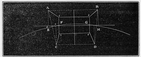
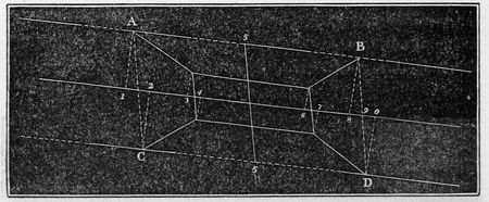
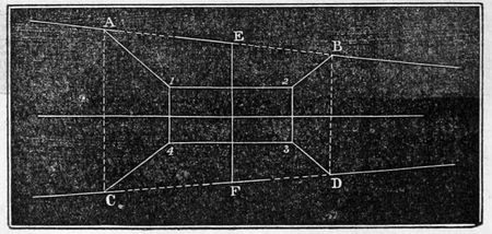
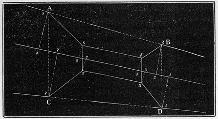
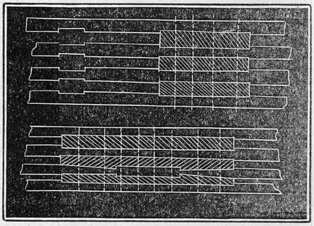
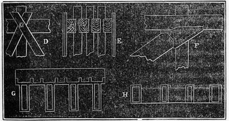
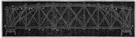
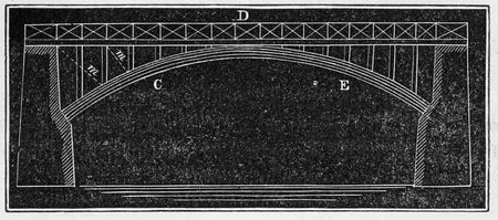
HANDBOOK OF RAILROAD CONSTRUCTION; FOR THE USE OF AMERICAN ENGINEERS. CONTAINING THE NECESSARY RULES, TABLES, AND FORMULÆ FOR THE LOCATION, CONSTRUCTION, EQUIPMENT, AND MANAGEMENT OF RAILROADS, AS BUILT IN THE UNITED STATES. With 158 Illustrations
Transcriber’s Note:
The cover image was created by the transcriber and is placed in the public domain.
BY
GEORGE L. VOSE,
CIVIL ENGINEER
“Rules themselves oblige us to reflect, that we may see whether we have not departed from them.”—Napoleon.
BOSTON AND CAMBRIDGE:
JAMES MUNROE AND COMPANY.
1857.
Entered according to Act of Congress, in the year 1857, by
JAMES MUNROE AND COMPANY,
In the Clerk’s Office of the District Court of the District of Massachusetts.
CAMBRIDGE:
ALLEN AND FARNHAM, PRINTERS.
PREFACE.
iii
The object of this work is to give in the plainest possible
manner all instructions, rules, and tables necessary for the
location, construction, equipment, and management of
railroads.
As a general thing, American engineers are not educated
for their business; and when they do possess a knowledge
of pure science, they are at a loss how to apply it.
The reader is presumed acquainted with the elements of
arithmetic, geometry, algebra, and mechanics: being thus
provided, he will, by a perusal of what follows, be enabled
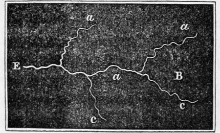
to correctly proportion bridges, of wood, stone, and iron:
abutments, piers, retaining walls, superstructure, and locomotive
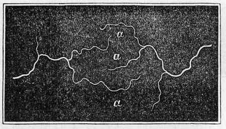
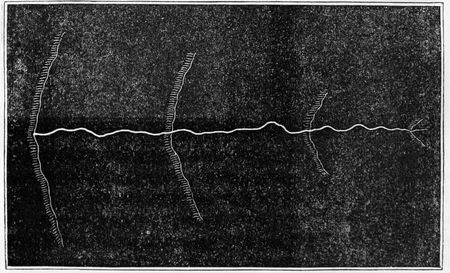
engines; and to plan and lay out, execute, and
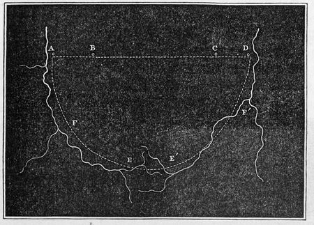
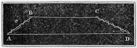
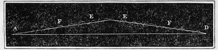
estimate any description of work occurring upon railroads.
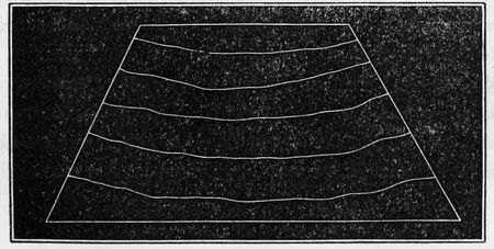
As the object has been more to be useful than original,
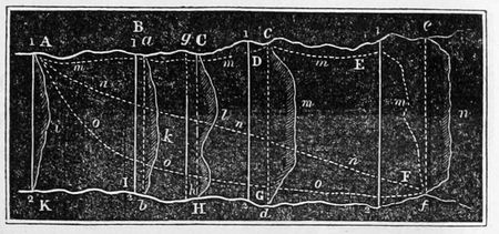
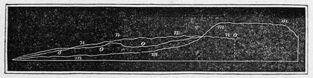
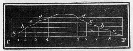
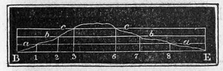
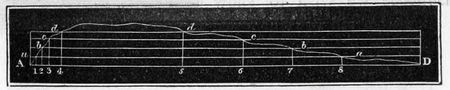
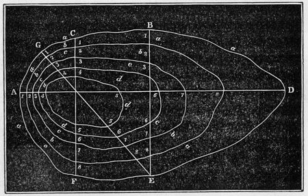
the best engineering writers and experimenters have been
consulted; among whom are,—Gauthey, Navier, Vieat,
ivTredgold, Barlow, Totten, Fairbairn, Hodgkinson, Clark,
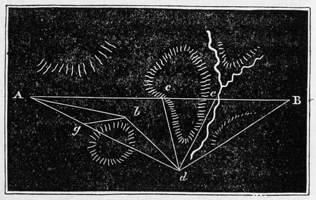
and Lardner. Also a great number of reports by American
civil engineers upon railroad matters.
If assumptions take the place of demonstration, it will
be on good authority. Readers will bear in mind that the
work is a “handbook,” and not a “treatise.” It is intended
more as an office companion than as a text-book for students.
It will give in all cases the actual numerical result
needed, whether it be the scantling of a bridge chord, the
thickness of a wall, or the dimensions of a locomotive
boiler.
In connection, it will be found convenient to use the
works of Trautwine and Henck, on Field Work: of Lieutenant
Smith, on Topography; Davies, on Surveying; and
Gurley, on the Use of Instruments.
Any one wishing a complete treatise on the principles of
bridge construction is referred to the excellent work of
Hermann Haupt.
I take this opportunity of heartily thanking the engineers
who in many ways have aided in making the work, as it is
believed, of some worth.
The reader is particularly requested to apply the following errata before perusing
the work. They are partly mistakes in printing, and partly errors in the original
MS. The only excuse the writer can offer for the number is, that, being engaged in
Missouri, while his publishers were in Boston, he has been prevented from seeing a
single proof-sheet in time for its correction.
— 95, l. 1, for “beach,” read “bench”; l. 3, for “to so,” read “so to”; l. 13, for
“b being 10 ft. back of 2 is ... 100.00,” read “b being 10 ft. back of 2 is
0.1 ft. higher than 2, or ... 100.10.”
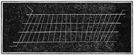
— 102, l. 1, head of middle col., for “Slopes 1¼,” read “Slopes 1½.”
— 103, l. 4 from bottom, for “and ten feet,” read “and one end ten feet.”
— 184, l. 4 from bottom, for “barriers,” read “voussoirs.”
— 187, fig. 96 is upside down; also, fig. 97, page 188, and fig. 98, page 189.
— 193, l. 4, col. 3 of table, for “.00000675,” read “.00000685”; also, l. 16, col. 5, for
“straining,” read “shearing”; l. 7 from bottom, for “15,000,” read “18,000;”
and l. 6 from bottom, for “75,000,” read “105,000.”
— 199, l. 7 from bottom, for “20,132,” read “20,312.”
— 200, l. 4, for “A C,” read “A G”; and l. 6, for “that on A R,” read “that on
A K.”
— 202, l. 7, for “on page 193,” read “on page 138.”
— 204, l. 5 from bottom, for “varied line,” read “versed sine.”
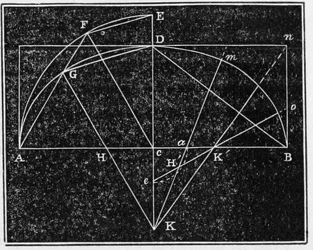
xviii— 207, l. 5 and 6, for “F G, G E, in place of E F, E C,” read “G L, G E, in place
of F L, F C.”
— 210, in place of “f′ = πF 4ph,” put “D = √¾[V2 – d2] – √¾[l2 – d2].
where D = depression,
l = half length of curve before elongation,
V = half length of curve after elongation,
d = half distance between points of suspension.” Omit the remainder of the paragraph.
— 211, omit the 6th and 7th lines, and in place of formula there given, use that on
page 210, (as corrected,) V being the length of semi-curve as elongated by
heat instead of by tension; the elongations, both by heat and tension, being
found by table on page 193.
— 212, l. 2, for “510.69,” read “510.80,” which result, of course, runs through the
whole example.
— 213 and 214. The remarks under “Anchoring Masonry,” are evidently wrong
throughout: 1st, the whole tension should be divided by two, instead of
four, as half of the whole tension acts at each point of suspension; 2d, no
reduction should be made for the direction of the pulling force. One half of
the tension is 3,321,250 lbs.; which is resisted by a column of masonry of
3,321,250 160 = 20,758 cubic feet, or 20 × 20 × 52 feet, or by a mass 15 × 15 × 91
feet.
— 226, l. 3, for “see page 128,” read “see page 193.”
— 227, l. 4, for “detensional,” read “detrusional.”
— 228, in place of equations at l. 16, put “R × a = R′ × (2 d × t)”,
whence d = R × a 2R′ × t;
where a = area of rivet,
d = distance,
t = plate thickness.
— 229, in art. 242, the strengths of “wrought iron,” have been taken for those of
“boiler plate”; that is, 11,000 for 7,500, and 15,000 for 12,740, which is wrong.
— 258, art. 276, in place of “20 2 × 15 × 1 × 100 × 20 3,” put “20 × 15 × 1 × 100 × 2 ×
20 3,” where 2 represents the ratio between Ca 6, and 6–2; thus, 20 × 15 ×
1 × 100 × 6.6 12 × 20 3 = 111,111, for the overthrowing force in place of 100,000.
The overthrowing force is thus large, because the maximum weight of earth
has been assumed to press against the wall with its whole force, no allowance
being made for friction. In practice, 4 10 of the height has been found amply
thick for walls retaining ordinary earth.
— 262, last l. but one, for “superstratum,” read “substratum.”
— 264, in example, l. 5, for “26,667,” read “48,000.”
— 479, l. 10, for “one sixth, with much less,” read “one sixth; with sand, much
less.”
HANDBOOK
OF
RAILROAD CONSTRUCTION.
INTRODUCTION. — RISE AND PROGRESS OF RAILROADS. — INFLUENCE OF RAILROADS. — SAFETY OF RAILROAD TRAVELLING. — PRELIMINARY OPERATIONS. — MECHANICAL PRINCIPLES OF LOCOMOTION. — DETERMINATION OF CHARACTER OF ROAD. — GAUGE. — GENERAL ESTABLISHMENT OF ROUTE.
1
“They build not merely roads of earth and stone, as of old, but they build iron
roads: and not content with horses of flesh, they are building horses of iron, such
as never faint nor lose their breath.”—Dr. Bushnell.
1. In 1825, the Stockton and Darlington Railroad (England),
was opened.
In 1827, the Quincy (of Massachusetts), and Mauch-Chunk
(Pennsylvania), were completed.
In 1829, the Liverpool and Manchester road, (England),
was finished.
In 1833, a road was opened from Charleston, (South
Carolina), to Augusta (Georgia).
In 1840, Belgium opened 190 miles of railroad.
In 1843, the railroad from Paris to Rouen (France),
was completed.
2In 1844, Belgium finished her system of 347 miles.
In 1846, Russia opened a railroad from the Wolga to the
Don.
In 1847, Germany had in operation 2,828 miles.
In 1852, the Moscow and St. Petersburg road was
finished.
2. In 1856, the United States of America had in operation
23,000 miles, and in progress 17,000 miles; employing
6,000 locomotive engines, 10,000 passenger and 70,000
freight cars; costing in all about 750,000,000 of dollars;
running annually 114,000,000 miles, and transporting 123½
millions of passengers, and 30 millions of tons of freight per
annum; performing a passenger mileage of 4,750,000,000,
and a freight mileage of 3,000,000,000.
3. By mileage is meant the product of miles run, by tons or by passengers
carried. Thus, 500 persons carried 100 miles, and 750 persons carried 75 miles,
give a passenger mileage of
500 × 100 + 750 × 75 = 106,250.
4. The rate of progress in the United States has been as
follows:—
In 1828,
there were 3 miles.
In 1830,
41 miles.
In 1840,
2,167 miles.
In 1850,
7,355 miles.
In 1856,
23,242 miles.
At the present time, January 1, 1857, there is probably, in
round numbers, 25,000 miles of completed road, or enough
to extend entirely around the world. As regards the ratio
of completed road to population, and as regards the actual
length of railroad in operation, the United States stand before
any other country.
3
5. The effect of a judicious system of railroads upon
any community is to increase consumption and to stimulate
the production of agricultural products; to distribute more
generally the population, to cause a balance between supply
and demand, and to increase both the amount and
safety of travelling. It is stated that within two years
after the opening of the New York and Erie Railroad, it
was carrying more agricultural produce than the entire
quantity which had been raised throughout the tributary
country before the road was built.
6. The following table, cut from a Chicago paper, shows the effect of railroad
transport upon the cost of grain in that market:—
Wheat.
Corn.
By R. R.
By Wagon.
By R. R.
By Wagon.
At market,
$49.50
$49.50
$25.60
$25.60
10 miles,
49.25
48.00
24.25
23.26
50 miles,
48.75
42.00
24.00
17.25
100 miles,
48.00
34.50
23.25
9.75
150 miles,
47.25
27.00
22.50
2.25
200 miles,
46.50
19.50
21.75
0.00
250 miles,
45.75
12.00
21.00
0.00
300 miles,
45.00
4.50
20.25
0.00
330 miles,
44.55
0.00
19.80
0.00
Thus a ton of corn carried two hundred miles, costs, per
wagon transport, more than it brings at market; while
moved by railroad, it is worth $21.75 per ton. Also wheat
will not bear wagon transport of three hundred and thirty
miles; while moved that distance by railroad it is worth
$44.55 per ton.
7. By railroads, large cities are supplied with fresh
meats and vegetables, butter, eggs, and milk. An unhealthy
4increase of density of population is prevented, by
enabling business men to live five, ten, or fifteen miles
away from the city and yet do business therein. The
amount of this diffusion is as the square of the speed of
transport. If a person walks four miles per hour, and supposing
one hour allowed for passing from the house to the
place of business, he cannot live at a greater distance than
four miles from his work. The area, therefore, which may
be lived in, is the circle of which the radius is four, the diameter
eight, and the area fifty and one quarter square
miles. If by horse one can go eight miles per hour, the diameter
becomes sixteen miles, and area two hundred and
one square miles; and, if by railroad he moves thirty miles
per hour, the diameter becomes sixty miles, and the area
2,827 square miles. The effect of such diffusion is plainly seen
about Boston, (Massachusetts). People who in 1830 were
mostly confined to the city, now live in Dorchester, Milton,
Dedham, Roxbury, Brookline, Brighton, Cambridge,
Charlestown, Somerville, Chelsea, Lynn, and Salem; places
distant from two to thirteen miles.
8. In railroads, as in other labor saving (and labor producing)
machines, the innovation has been loudly decried.
But though it does render some classes of labor useless, and
throw out of employment some persons, it creates new labor
far more than the old, and gives much more than it
takes away. Twenty years of experience shows that the
diminished cost of transport by railroad invariably augments
the amount of commerce transacted, and in a much
larger ratio than the reduction of cost. It is estimated by
Dr. Lardner, that 300,000 horses working daily in stages
would be required to perform the passenger traffic alone,
which took place in England during the year 1848. It is
concluded, also, from reliable returns, that could the whole
number of passengers carried by railroad, have been transported
5by stage, the excess of cost by that method above
that by railroad would have been $40,000,000.
9. If we know that in a given time the whole distance
travelled by passengers was 500,000 miles, and that in such
time there occurred one fatal accident, it follows that when
a person travels one mile, the chances are 499,999 against
one of losing life. If he travel ten miles, the chances are
49,999 against one, or ten times as many of meeting with
loss of life; and generally the chances of accident are as
the distance travelled. In 1855, the whole number of miles
run by passengers in the United States was, in round numbers,
4,750,000,000, while there were killed one hundred and
sixteen; or one in every 41,000,000, very nearly. (The ratio
in England is one in every 65,000,000.) Now if for
each 400,000 miles travelled by stage passengers, (a distance
equal to sixteen times round the world,) one passenger
was killed, and if the whole railroad mileage could be
worked by stages, there would be annually 11,875 lives lost;
or one hundred times the number annually lost by railroad.
Thus it would be one hundred times safer to travel by railroad
than by stage. The danger of steamboat travelling is
far greater than by stage.
10. The first step to be taken in starting a railroad enterprise,
is the choice of a board of directors (provisional),
whose duty is to find all that can be known of the commercial,
financial, and agricultural nature of the country to be
traversed. To determine as near as possible its ability to
6build and support a road; and to obtain the necessary
legislative enactments.
11. The determination of the increase of traffic which
the road may be expected to excite, is a difficult matter.
There can be few rules given for proceeding in such an inquiry.
It seems very easy to prove by what roads have
done, that any project will be profitable.
An abstract of a report lately published, tries to prove that a road will pay
forty-five and one half per cent. net; the working expenses being assumed at
only thirteen and one half per cent. of the gross receipts. The error here lies in
assuming the working expenses too low, as few roads in the country have been
worked for less than forty per cent.; a more common ratio being fifty one-hundredths
of the gross receipts.
Not one half of railroads are built for the original estimate.
In few cases has sufficient allowance been made for
the sacrifice undergone in negotiating the companies’ securities.
All general instructions that can be given relating
to the determination of prospective profits, are, to keep the
estimate of constructing and working expenses high, and
that of the assumed traffic low; not so low, however, as to
require a too lightly built road.
12. The superiority which the modern railroad possesses
over the common, McAdam, plank, or turnpike-road, consists,
first, in the reduction of the resistance to motion, and
second, in the application of the locomotive steam-engine.
13. The effect of grades of a given incline upon a railroad
is relatively more than upon common roads; for as
the absolute resistance on a level decreases, the relative resistance
of grades augments: whence to obtain the full
benefit of the system, we must reduce much more the
7grades and curvature upon a railroad, than on a common
road. For example, if the resistance to moving one ton
upon a level upon a railroad was ten pounds, and upon a
common road forty pounds, where a twenty-three feet
grade would be admissible upon the former, we might use
an incline of ninety-three feet per mile upon the latter.
14. The resistance to the motion of railroad trains increases
rapidly with the speed;[1] whence the grades of a
passenger road where a high average speed is used, may be
steeper than those of a road doing a freight business chiefly.
15. Upon a correct idea of what the road ought to be,
depends in a great degree its success. The amount of capital
expended upon the reduction of the natural surface, depends
upon the expected amount of traffic. The traffic
remaining the same, the greater the capital expended in reducing
grades and curvature, the less will be the working
expense; and the less the construction capital, the
greater that for maintenance. The limit of expenditure
must be such as to render the sum of construction and
maintaining capital a minimum.
The bad effect of grades upon the cost of maintaining
and of working railroads, is not so great as many suppose.
Of the whole cost of working, only about forty per cent.
can be charged to locomotive power; and of this, not more
than sixty-two per cent. is effected by grades.[2]
16. The degree of curvature to be admitted upon any
road depends somewhat upon the speeds at which trains
are to be run. The larger the radius of curvature, the
8greater may be the speed; at the same time the elevation
of the exterior rail upon curves may be less, and therefore
more adapted to freight trains. High rates of speed are
considered upon some competing roads necessary; but are,
even in such cases, necessary evils. The wear of cars and
of engines, of permanent way and of bridges, increase in a
rapid ratio with the velocity. The maximum speed for
freight trains should never exceed fifteen miles per hour, or
for passenger trains from twenty to twenty-five miles per
hour.[3]
17. The agricultural nature of the country and its commercial
position, will determine the nature of the traffic,
whether passenger or freight, and also the amount. The
amount and nature of the traffic will limit the curvature,
and will partially determine the arrangement of grades.
18. The question of broad and narrow gauge has led to
much discussion, and both plans claim among their advocates
some of the best engineers. The narrow gauge
(American and English,) is four feet eight and one half
inches (from inside to inside of rail). The maximum
adopted, is (the Great Western of England) seven feet.
The American maximum (New York and Erie, and Ohio
and Mississippi) is six feet. There is also in America
four feet ten inches, five feet, and five feet six inches.
The advantage of the broad gauge for a road doing an extensive
business, is the increased stowage room in freight
cars, thus rendering admissible shorter trains; by which the
locomotive power is more directly applied on curves. More
9comfortable passenger cars, (the same length of car of
course accommodates the same number of passengers).
The disadvantages of a wide gauge are, increased expense
of cutting, embanking, bridging, and masonry; increased
expense of engines, cars, rails, sleepers, and all machinery;
more wear and tear upon curves, by reason of greater difference
between the lengths of inner and outer rails, and
increased atmospheric resistance to fast trains, from increased
bulk.
19. The general conclusion arrived at by a commission
appointed by the Great Western Railway Company, (England,)
consisting of Messrs. Nicholas Wood, J. K. Brunel,
and John Hawkshaw, was, that four feet, eight and one
half inches was rather narrow, but still enough for a certain
class of roads; that two or three inches made no material
difference; that seven feet was too wide for any road;
that the weight of the broad gauge engine, compared with
the small increase of power, was a serious evil; that engines
could be run with perfect safety upon the narrow
gauge at any speed from thirty to sixty miles per hour, and
that no more had been attained upon the broad; that rolling
friction was less upon the broad, owing to the increased
diameter of wheels, but that friction from curves and atmospheric
resistance was greater.
20. D. K. Clark, in “Railway Machinery,” p. 300, 301,
makes the resistance as deduced from experiments made
upon both the four feet, eight and one half inches, and the
seven feet gauge, considerably greater upon the former
than on the latter; but as the narrow gauge trials were
made upon a curved road, with rails in a bad state, in
average weather, while those upon the broad were made in
good weather, upon a good and straight line, he leaves the
gauge question open, and uses the same formula for all
widths.
1021. Want of increased power, can be an apology for increased
gauge, until the capacity of the narrow gauge has
been filled. The strongest engines in the world are upon
the four feet, eight and one half inch gauge. No engines
in America surpass or compare for absolute strength, with
those upon the Baltimore and Ohio Railroad. The most
powerful passenger engine ever built for high speeds, is
Crampton’s engine “Liverpool,” (London and North-western
Railroad, England,) gauge four feet, eight and one half
inches.
22. The straight and level line connecting any two
points, is of course the best for the completed road; but
this is seldom practicable. Way towns must be accommodated
to a certain extent; but the main line should not be
lengthened on that account, unless the traffic and capital
furnished by such town is not only sufficient to pay for the
construction and maintenance of the extra length, but also
to carry the entire through traffic over such increased distance.
If the town is unable to support such a burden, it
may be able to build and maintain a branch.
23. Routes placed upon the immediate bank of a large
stream, are generally crossed by a great number of deep
gorges, which serve to drain the side lands.
24. Routes placed upon sloping land, when the axis of
the road and the natural descent are at right angles to each
other, are more subject to slides than when placed upon
plateaus or “bottoms.”
25. Lines crossing the dividing ridges of separate waters,
rise and fall a great deal; thus rendering necessary a strong
motive power to work the road. Such roads are the Western
11of Massachusetts, passing from the valley of the
Connecticut at Springfield, to the Hudson River valley at
Greenbush. Also those roads crossing the Alleghanies.
And such will be the Pacific road, crossing first the Rocky
Mountains to the Great Basin, and second, the Sierra Nevada
into the Sacramento valley.
CHAPTER I. RECONNOISSANCE. — GENERAL TOPOGRAPHY. — BAROMETRICAL LEVELLING.
12
26. The object of the reconnoitre is to find approximately
the place for the road, (i. e. within half of a mile,)
to find the general form of the country, and to choose
that part which with reference to the expected traffic, shall
give the best gradients; to determine the elevations of
summits upon competing routes; and, in fine, to prepare
the way for the survey.
27. The general topography of a country may be ascertained
by reference to State maps, where such exist, and
when not, by riding over the district. The direction and
size of watercourses, will
show at once the position
of summits.
Fig. 1.
28. Water flowing as
in fig. 1, indicates a fall
from B to E; and also
traverse slopes from a a
and c c to d d.
13
Fig. 2.
29. Fig. 2 shows a broken ridge a a a from which the
water flows in both directions;
and in general,
the sources of
streams point towards
the higher lands.
Fig. 3.
30. If it be required
to join the points A
and D by railroad, (fig.
3.) it may be better to
pass at once from A through B and C, than to go by the
streams F E, F′ E′. By the latter route the road would
ascend all of the way from A to E; and descend from E′ to
D. By the first if it requires steep gradients to rise from A
to B, and to fall from C to D, still if the section B C is a
plateau, and if the rise between A and B and A and E is
the same, by grouping the grades at B and C we may so
adapt the motive power, as to take the same train from A
14to D without breaking. The general arrangement of
grades by the line
A B C D is then as
fig. 4; and A F E
E′ F′ D, as in fig. 5.
The saving in this
case is by length, as
the same amount of power is required to overcome a given
ascent.
Fig. 4.
Fig. 5.
31. Valleys generally rise much faster near their source,
than at any point lower down; also the width increases as
we approach the debouch. Fig. 6 shows the cross sections
of a valley from its source to the mouth.
Fig. 6.
32. In the case of parallel valleys running in the same
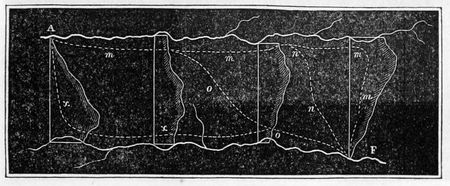
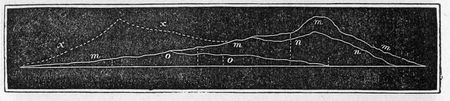
15direction, the form will be as in fig 7. Let 1 2, 1 2, etc.,
represent a datum
level, or
a horizontal
plane passing
through the
lowest point.
The line a b,
shows the
height of the
bottom at B; c d that at D, e f that at E, and g h that at
C. The broken lines i, k, l, m, n, show the general form of
the land. Now by the route m m m m, from A to F, we
have the profile m m m m, fig. 8, by n n n n, the profile
n n n n, and by o o o, the profile o o o.
Fig. 7.
Fig. 8.
Fig. 9.
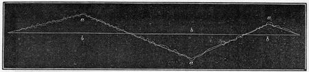
33. In the case of parallel valleys running in opposite
directions, as in fig. 9, we have the form there shown; and
the profiles corresponding to the several lines are shown in
16fig. 10. As we should always adopt the line giving the
least rise and fall, other things being equal, it is plain
which line on the plan we must follow.
Fig. 10.
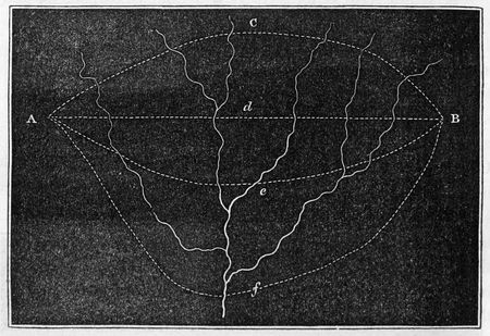
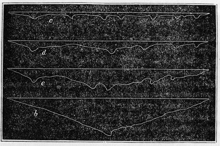
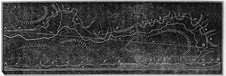
34. In passing from A to B, figs. 11 and 12, by the several
lines c, d, e, f, we have the profiles shown at c, d, e, f,
from which it appears, that the nearer we cross to the heads
of streams, the less is the difference of heights.
Fig. 11.
17
Fig. 12.
Fig. 12 (a).
35. If we wish to go from A to B, fig. 12 (a), we should
of course
take first the
straight line;
but being
obliged to
avoid the hill
C, on arriving
at d, we
should not
try to recover
that line at e,
but proceed at once to B. Also as we are obliged to pass
through d, we ought to go directly to d and not by the way
of c; and the same idea is repeated between A and d; the
last line being A b d B. Few rules can be given in the
choice of routes. Practice only will enable the engineer to
find the best location for a railroad.
18
36. The relative height of summits, the rate of fall of
streams, and absolute elevation, within a few feet, may
be easily, rapidly, and cheaply found by the barometer.
This also affords an excellent check upon subsequent levelling
operations. The results thus obtained depend upon
the physical property, that the density of the air decreases
as the square of the height.
37. The barometer is a glass tube, partly filled with mercury,
having a vacuum in the upper part. By it the exact
density of the air at any point is determined. Accompanying
are two thermometers; one attached, showing the temperature
of the barometer; the other detached, showing the
atmospheric temperature.
38. Knowing now the manner of finding the density of
the air at any two points, and also the relation between
density and height, the operation of levelling by the barometer
is very simple.
The modus operandi is as follows, (see tables A, B, C,
and D):—
Let us have the notes.
Barom.
Attached Therm.
Detached Therm.
Upper Station,
29.75
28.5
27.9
Lower Station,
26.80
36.8
36.3
Latitude 46° N.
We have by table A, against the bar. point,
29.75,
6108.6
also by table A, against the bar. point,
26.80,
5276.6
The difference
832.0
Diff. of attached therm. 36.8°- 28.5° = 8.3°
(table B)
-12.2
819.8
19Double the sum of detached thermometers multiplied by 1 1000 of 819.8 is
2(27.9 + 36.3) × .8198 =
+ 105.3
925.1
Correction (see table C) for lat. 46° N. and approximate height 925.1
+ 3.1
928.2
Final correction by table D. The barometer at the lower station
being 26.80, and the tabular number against 27.56 being 0.22, that
for 26.80 will be 0.31, and we have
1000 to .31 as 928.2 to 0.287, or 0.3,
which add to 928.2 and we have as the final height
928.5 metres, or 928.5 × 3.28 = 3045.48 feet.
The tables above referred to, are those of Mr. Oltman,
and are considered as the most convenient and reliable of
any published.
4. The degrees refer to the centigrade thermometer.
23
TABLE C.
Approximate Height.
0°
15°
40°
55°
200
1.2
1.0
0.6
0.4
400
2.4
2.2
1.4
0.8
600
3.4
3.2
2.0
1.2
800
4.5
4.3
2.8
1.7
1000
5.7
5.3
3.4
2.2
1200
7.0
6.4
4.2
2.6
1400
8.2
7.6
4.8
3.0
1600
9.2
8.8
5.6
3.4
1800
10.4
9.8
6.3
3.8
2000
11.6
11.0
7.0
4.2
2200
12.8
12.1
7.6
4.6
2400
14.0
13.3
8.4
5.1
2600
15.2
14.4
9.2
5.6
2800
16.5
15.6
10.0
6.2
3000
17.7
16.8
10.8
6.6
3200
10.1
18.0
11.5
7.0
3400
20.5
19.3
12.4
7.7
3600
21.8
20.4
13.4
8.2
3800
23.1
21.6
14.3
8.7
4000
24.6
22.9
15.1
9.4
4200
25.9
24.3
15.9
10.1
4400
27.5
25.8
16.9
10.8
4600
28.9
27.1
18.0
11.5
4800
30.4
28.4
19.0
12.1
5000
31.8
29.8
19.9
12.7
5200
33.0
31.0
20.8
13.3
5400
34.3
32.4
21.7
13.9
5600
35.7
33.7
22.6
14.5
5800
37.1
35.0
23.6
15.1
6000
38.5
36.3
24.6
15.7
TABLE D.
Barometrical Height
Metres
15.75
1.71
17.72
1.39
19.68
1.11
21.65
0.86
23.62
0.63
25.59
0.42
27.56
0.22
29.53
0.03
CHAPTER II. SURVEY. — TOPOGRAPHICAL SKETCHING. — GENERAL ESTABLISHMENT OF GRADES. — EQUATING FOR GRADES. — COMPARISON OF SURVEYED LINES.
24
39. Topographical drawing includes every thing relating
to an accurate representation upon paper, of any piece of
ground. The state of cultivation, roads, town, county, and
state boundaries, and all else that occurs in nature. The
sketching necessary in railroad
surveying, however, does not
embrace all of this, but only the
delineation of streams and the
undulations of ground within
that limit which affects the road,
perhaps 500 feet on each side of
the line. The making of such
sketches consists in tracing the
irregular lines formed by the intersection
of the natural surface,
by a system of horizontal planes,
at a vertical distance of five, ten,
fifteen, or twenty feet, according
to the accuracy required.
Fig. 13.
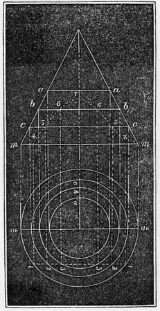
40. Suppose that we wish to
represent upon a horizontal surface
a right cone. The base m
m, fig. 13, is shown by the circle
25 of which the diameter is m, m. If the elevation is cut by
the horizontal planes a a, b b, c c, the intersection of these
planes with the conical surface is shown by the circles a, b,
c, in plan. The less we make the horizontal distances, on
plan, between the circles, the less also will be the vertical
distance between the planes.
Wishing to find the elevation of any line which exists on
plan, as 1, 2, 3, 3, 2, 1, we have only to find the intersection
of the verticals drawn through the points 1, 2, 3, 3, 2, 1,
and the elevation lines a a, b b,
c c; this gives us the curve 4,
5, 6, 7, 6, 5, 4.
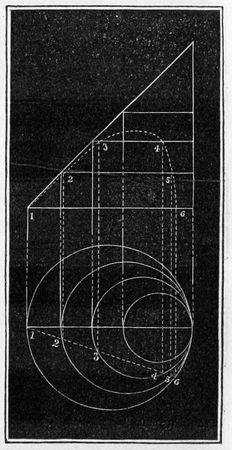
Fig. 14.
41. Again, in fig. 14, the
cone is oblique, which causes
the circles on plan to become
eccentric and elliptic. Having
given the line 1, 2, 3,
as before, we find it upon the
elevation in the same manner.
42. In the section of regular
and full lined figures, the
horizontal and vertical projections
are also regular and full
lined; but in a broken surface
like the ground, the lines become
quite irregular.
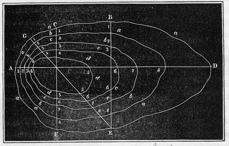
Suppose we wish to show
on plan the hill of which we
26have the plan, fig. 15, and the sections figs. 16, 17, and 18.
Let AD be the profile (made with the level) of the line AD
on plan, fig. 15. B E that of
B E, and C F that of CF.
Fig. 15.
Fig. 16.
Fig. 17.
Fig. 18.
To form the plan from the
profiles proceed as follows:—
Intersect each of the profiles
by the horizontal planes
a a, b b, c c, d d, equidistant
vertically. In the profile A D,
fig. 18, drop a vertical on to
the base line from each of the intersections a, b, c, d, d, c, b,
a. Make now A 1,1 2, 2 3, 3 4, etc., on the plan equal to the
same on the profile. Next draw, on the plan, the line B E,
27at the right place and at the proper angle with A D; and having
found the distances B 1, 1 2, 2 3, etc., as before, transfer
them to the line B E on plan. Proceed in the same manner
with the line C F.
The points a a a, b b b, c c c, are evidently at the same
height above the base upon the profiles, whence the intersections
of these lines with the surface line or 1 1 1, 2 2 2,
3 3 3, etc., on the plan, are also at the same height above
the base; and an irregular line traced through the points
1 1 1, or 2 2 2, will show the intersection of a horizontal
plane, with the natural surface.
When as at A we observe the contour lines near to each
other, we conclude that the ground is steep. And when
the distances are large, as at 6, 7, 8, we know that the
ground falls gently. This is plainly seen both on plan and
profile.
Fig. 15.
Having now the topographical sketch, fig. 15, we may
easily deduce therefrom at any point a profile. If we
would have a profile of G E, on plan, upon an indefinite
28line G E, fig. 19, we set off G 1, 1 2, 2 3, 3 4, etc., equal to
the same distances on
the plan. From these
points draw verticals
intersecting the horizontals
a a, b b, c c;
and lastly, through the
intersections draw the broken line (surface line or profile)
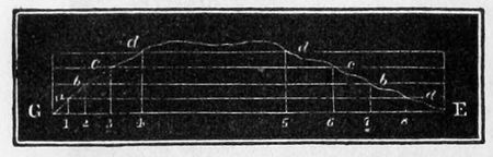
a, b, c, d, d, c, b, a. Thus we see how complete a knowledge
of the ground a correct topographical sketch gives.
Fig. 19.
43. Field sketches for railroad work are generally made
by the eye. The field book being ruled in squares representing
one hundred feet each. When we need a more accurate
sketch than this method gives, we may cross section
the ground either by rods or with the level.
By making a very detailed map of a survey, and filling
in with sketches of this kind, the location may be made
upon paper and afterwards transferred to the ground.
So far we have dealt with but one summit; but the
mode of proceeding is precisely the same when applied to
a group or range of hills, or indeed to any piece of ground.
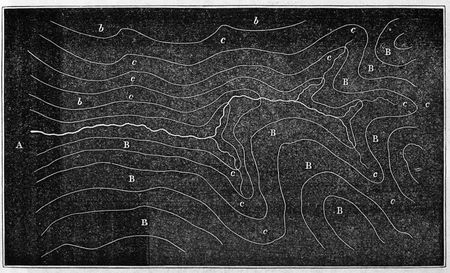
44. As a general thing, the intersection of the horizontal
planes with the natural surface (contour lines) are concave
to the lower land in depressions, and convex to the lower
land on spurs and elevations. Thus at B B B b b, fig. 20,
upon the spurs, we have the lines convex to the stream;
and in the hollows c c c, the lines are concave to the
bottom.
45. Having by reconnoissance found approximately the
place for the road, we proceed to run a trial line by compass.
In doing this we choose the apparent best place,
stake out the centre line, make a profile of it, and sketch in
the topography right and left.
29
Fig. 20.
30
Fig. 21.
Fig. 22.
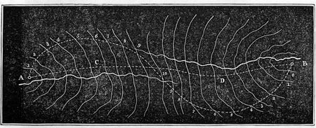
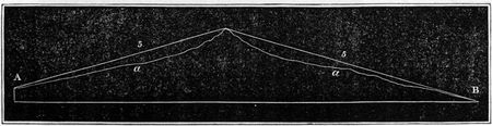
Suppose that by doing so we have obtained the plan and
profile shown in figs. 21 and 22, where A a a B is the profile
of A C D B, on the plan. The
lowest line of the valley though
quite moderately inclined at first, from A to C, rises quite
31fast from C to the summit; and as the inclination becomes
greater, the contour lines become nearer to each other.
Now that the line may ascend uniformly from A to the
summit, the horizontal distances between the contour lines
must be equal; this equality is effected by causing the surveyed
line to cut the contours square at 1, 2, 3, 4, and
obliquely at 5, 8, 10. Thus we obtain the profile A 5 5 B.
Figs. 23 and 24.
46. Having given the plan and profile, figs. 23 and 24,
where A C D B represents the bed of the stream, in profile,
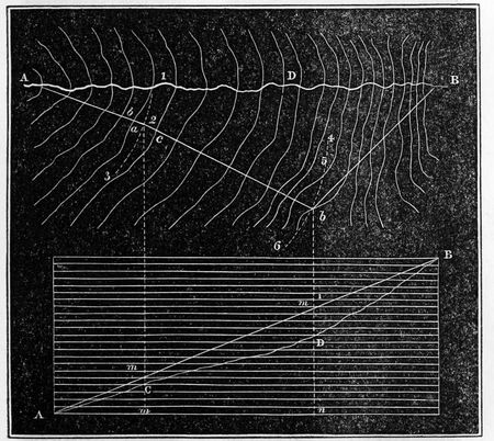
if it were required to put the uniformly inclined line
A m m B, upon the plan, we should proceed as follows.
Take the horizontal distance A m from the profile, and with
32A (on plan) as a centre, describe the arc 1, 3. The point
m on the profile is evidently three fourths of a division
above the bed of the stream. So on the plan we must
trace the arc 1, 3, until we come to a, which is three fourths
of b c, from b. Again, m′ is nine and one half divisions
above m. From a, with a radius m n on profile, describe
the arc 4, 5, 6. Now, as on the profile, in going from m to
m′, we cross nine contour lines, and come upon the tenth
at m′, so on the plan we must cross nine contour lines and
come upon the tenth, and at the same time upon the arc
4, 5, 6.
Proceeding in this way, we find A, a, b, B, on the plan,
as corresponding to A m m′ B on the profile.
To establish in this manner any particular grade, we
have first to place it upon the profile, and next to transfer
it to the plan.
47. It may be remembered as a general thing, that the
steepest line is that which cuts the contour line at right
angles; the contour line itself is level, and as we vary between
these limits we vary the incline.
48. Considerable has been written upon the relation
which ought to exist between the maximum grade, and the
direction of the traffic. Some have given formulæ for obtaining
the rate and direction of inclines as depending upon
the capacity of power. This seems going quite too far, as
the nature of the ground and of the traffic generally fix
these in advance.
49. Between two places which are at the same absolute
elevation, there should be as little rise and fall as possible.
50. Between points at different elevations, we should
if possible have no rise while descending, and consequently
no fall while on the ascent.
3351. Some engineers express themselves very much in
favor of long levels and short but steep inclines. There
are cases where the momentum acquired upon one grade,
or upon a level, assists the train up the next incline. The
distance on the rise during which momentum lasts, is not
very great. A train in descending a plane does not receive
a constant increase of available momentum, but arrives at a
certain speed, where by increased resistance and by added
effect of gravity, the motion becomes nearly regular. Up
to this point the momentum acquired is useful, but not beyond.
Any road being divided into locomotive sections, the section
given to any one engine should be such as to require a
constant expenditure of power as nearly as possible; i. e.,
one section, or the run of one engine, should not embrace
long levels and steep grades. If an engine can carry a load
over a sixty feet grade, it will be too heavy to work the
same load upon a level economically. It is best to group
all of the necessarily steep grades in one place, and also the
easy portions of the road; then by properly adapting the
locomotives the cost of power may be reduced to a minimum.
As to long levels and short inclines the same power is required
to overcome a given rise, but quite a difference may
be made in the means used to surmount that ascent.
Fig. 25.
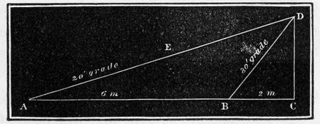
52. Suppose we have the profiles A E D and A B D, fig.
25. The resistance
from A to
D by the continuous
twenty
feet grade is
the same as
the whole resistance
from A to B and from B to D. The reason for
34preferring A E D is, that an engine to take a given load
from B to D would be unnecessarily heavy for the section
A B; while the same power must be exerted at each point,
of A E D. Also the return by A E D is made by a small
and constant expenditure of power, being all of the way
aided by gravity; while in descending by B, we have more
aid from gravity than we require from D to B, after which
we have none.
When the distances A B, B C, are sixty and twenty
miles in place of six and two, we may consider the grades
grouped at B D, and use a heavier engine at that point, as
we should hardly find eighty miles admitting of a continuous
and uniform grade.
53. In comparing the relative advantages of several lines
having different systems of grades, it is customary to reduce
them all to the level line involving an equal expenditure
of power.
The question is to find the vertical rise, consuming an
amount of power equal to that expended upon the horizontal
unit of length. This has been estimated by engineers
all the way from twenty to seventy feet. For simple comparison
it does not matter much what number is used if it
is the same in all cases; but to find the equivalent horizontal
length to any location, regard must be had to the nature
of the expected traffic.
The elements of the problem are, the length, the inclination
or the total rise and fall, and the resistance to the motion
of the train upon a level, which latter depends upon
the speed and the state of the rails and machinery.
From chapter XIV. we have the following resistances to
the motion of trains upon a level:—
35
Velocity, in miles, per hour.
Resistance, in lbs. per ton.
10
8.6
15
9.3
20
10.3
25
11.6
30
13.3
40
17.3
50
22.6
60
27.1
100
66.5
The power expended upon any road is of course the
product of the resistance per unit of length, by the number
of units. Calling R the resistance per unit upon a level,
and R′ the resistance per unit on any grade, and designating
the lengths by L and L′, that there shall be in both
cases an equal expenditure of power, we must have
RL = R′L′,
whence the level length must be
L = L′R′ R.
Thus assuming the resistance on a level as twenty lbs.
per ton, that on a fifty feet grade is
20 + 50 5280 of 2240, or 20 + 21.2 or 41.2,
and if the length of the inclined line is ten miles, the equivalent
level length is
L = 41.2 × 52800 20 = 108768 feet, or 20.6 miles.
Also 10 miles × 41.2 lbs. = 412,
and 20.6 miles × 20 lbs. = 412.
3654. The above may be somewhat abridged as follows:
Let R be the resistance on a level. The resistance due to
any grade is expressed by
W × 1 a,
where 1 a is the fraction showing the grade, and W the weight
of the load.
The vertical height in feet, to overcome which we must
expend an amount of power sufficient to move the train
one mile on a level, must be such that
W × 1 a = R,
or
1 a = R W;
and to find the number by which to equate, we have only to
place the values of R and W in the formula. For example,
let the speed be twenty miles per hour, the corresponding
resistance is 10.3 lbs. per ton. W being one ton, or 2240
lbs., we have
1 a = R W = 10.3 2240 = 1 218 of 5280, (the number of feet in one mile,)
1 218 of 5280 = 24 feet.
In the same manner we have
Speed, in miles, per hour.
Equating number.
15
22
20
24
30
32
40
41
50
53
60
67
100
155
37Thus when we take the speed as thirty miles per hour,
for each thirty-two feet rise we shall consume an amount of
power sufficient to move the train one mile on a level. In
descending, the grade instead of being an obstacle, becomes
an aid; indeed the incline may be such as to move the
trains independently of the steam power. Thus if on account
of ascending grades we increase the equated length,
so also in descending we must reduce the length. The
amount of reduction is not, however, the reverse of the increase
in ascending, as after thirty or forty feet any additional
fall per mile instead of being an advantage is an
evil; as too much gravity obliges us to run down grades
with brakes on. Twenty-five feet per mile is sufficient to
allow the train to roll down, and any more than this is of
very little use. Therefore for every mile of grade descending
at the rate of twenty-five feet per mile we may deduct
one mile in equating, and for every mile of grade descending
twelve and one half feet per mile deduct a proportional
amount; but for any more fall per mile than twenty-five feet,
no allowance should be made; i. e., if we descend at the
rate of forty feet per mile, we may deduct one mile in
equating for the twenty-five feet of fall, and throw aside
the remaining fifteen feet.
55. This is a common method of equating for grades,
and represents a length which is proportional to the power
expended, but not proportional to the cost of working, as
the ratios of power expended and cost of working under
different conditions are very different, double power requiring
only twenty per cent. more working capital. The above
rules, therefore, require a correction.
The cost of working a power represented by unity being expressed by
100;
That of working a power 2 is expressed by
125;
38That of working a power 3 is expressed by
150;
That of working a power 4 is expressed by
175;
That of working a power 5 is expressed by
200.
(See Appendix F.)
Now the resistance on a level being at a velocity of twenty
miles per hour, 10.3 lbs. per ton by the formula
1 a = R W,
the vertical height in feet causing a double expenditure of
power is twenty-four; but as above, the whole expense of
a double power is increased by only twenty-five per cent.;
we should not add one mile for twenty-four feet rise, but
one fourth of a mile only, or one mile for each ninety-six
feet; and by correcting our former table in this manner, we
have the following table:—
Speed, in miles, per hour.
Equating number.
15
88
20
96
25
110
30
128
40
164
50
212
60
268
100
620
So much for equating for the ascents. In descending, we
have allowed one mile reduction for each mile of twenty-five
feet of descending grade; but as in ascending we correct
the first made table, so in descending we must also
correct as follows. If we needed no steam power either
while descending or afterwards, we should only save wood
and water; as a general thing the fire must be kept up
while descending, and the only gain is a small part of the
39expense of fuel; so small, in fine, that with the exception
of roads which incline for the whole or a great part of their
length, no reduction should be made.
56. The requisite data for an approximate comparison
of lines are, the measured length, total rise, total fall.
Let the length of line A be
100
miles,
Let the length of line B be
90
miles,
Whole rise on A
2000
feet,
Whole rise on B
5100
feet,
Whole fall on A
1200
feet,
Whole fall on B
4300
feet.
Assume the number by which to equate, as ninety-six, and
we shall have
Line A.
Ascending, 100 + 2000 96 =
120.83
Descending, 100 + 1200 96 =
112.50
Sum
233.33
Mean
116.66
Line B.
Ascending, 90 + 5100 96 =
143.13
Descending, 90 + 4300 96 =
134.80
Sum
276.93
Mean
138.46
The mean equated length of A is
116.66
The measured length of A is
100.00
The difference
16.66
The mean equated length of B is
138.46
The measured length of B is
90.00
The difference
48.46.
40The cost of construction being assumed as the actual
length, and that of working as the equated length, we have
the final approximate comparison thus:—
Assume the construction cost as $25,000 per mile, and
the cost of maintenance $4,000 per mile, and we have
The line A to the line B as
100 × 25000 + 116.66 × 4000 × 100 6 = 10,277,333, is to
90 × 25000 + 138.46 × 4000 × 100 6 = 11,480,667;
or A is to B as 10.3 to 11.5 nearly, although the line A is ten miles
longer than B.
CHAPTER III. LOCATION. — ALIGNMENT. — FINAL ADJUSTING OF GRADES. — COMPARISON OF LOCATED LINES.
41
57. The broken line furnished by the survey is of course
unfit for the centre line of a railroad. The angles require
to be rounded off to render the passage from one straight
portion to the other easy.
Fig. 26.
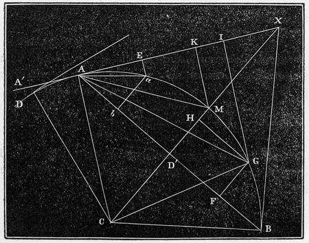
58. Let A X B, fig. 26, represent the angle formed by
42any two tangents which it is required to connect by a circular
curve. It is plain that knowing the angle of deflection
of the lines A X, B X, we obtain also the angles A C X,
X C B. The manner of laying these curves upon the
ground is by placing an angular instrument at any point
of the curve, as at A, and laying off the partial angles
E A a, E A M, E A G, etc., which combined with the corresponding
distances A a, a M, M G, fix points in the curve.
These small chords are generally assumed at one hundred
feet, except in curves of small radius (five hundred feet)
when they are taken less.
The only calculation necessary in laying out curves, is,
knowing the partial deflection to find the corresponding
chord, or knowing the chord, to get the partial angle.
As the radius of that curve of which the angle of deflection
is 1° is 5730 feet, the degree of curvature for any
other radius is easily found. Thus the radius 2865 has a
degree of curvature per one hundred feet of
5730 2865 = 2°;
again,
5730 2000 = 2°.86 or 2° 51.6.
The radius corresponding to any angle is found by reversing
the operation. If the angle is 3° 30′, or 210′, we
have
5730 × 60 210 = 1637 feet radius.
The following figures show the angle of deflection for
chords one hundred feet long, corresponding to different
radii:—
43
Angle of deflection.
Radius, in feet.
¼°
or 15′
22920.0
½°
or 30′
11460.0
¾°
or 45′
7640.0
1°
or 60′
5730.0
1¼°
4585.0
1½°
3820.0
1¾°
3274.0
2°
2865.0
2½°
2292.0
3°
1910.0
3½°
1637.0
4°
1433.0
4½°
1274.0
5°
1146.0
5½°
1042.0
6°
955.4
6½°
822.0
7°
819.0
7½°
764.5
8°
716.8
10°
573.7
Points in any curve may also be fixed by ordinates, as a b,
M D′, G F, or by E a, K M, etc.
For the details of locating, of running simple and compound
curves, and of the calculations therefor, the reader is
referred to the works of Trautwine, and of Henck.
44
Fig. 27.
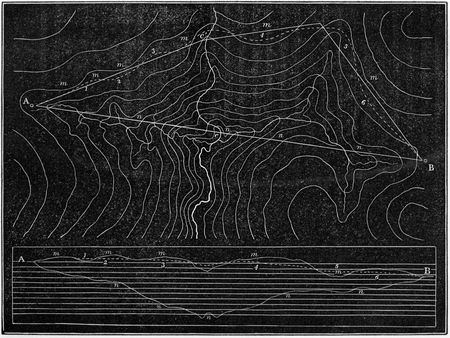
4559. Suppose now that
we have the surveyed lines
m m, and n n, fig. 27, one
of which is to be finally
adjusted to the ground.
The shortest line is the
straight one, which is generally
impracticable. The
most level line is the contour
line, which is also
impracticable. Between
these two lies the right
line, which is to be found
by an instrumental location.
The line A n n n n
B, on the plan, gives the
profile A n n n n B. The
line A m m m m B gives
the profile A m m m m B,
while the finally adjusted
line A 1 2 3 4 5 6 gives the
profile A 1 2 3 4 5 6 B.
Fig. 28.
60. Again, in fig. 28,
the straight line A n n n B
gives the profile A n n n B,
requiring either steep
grades or a great deal of
work. By fitting the line
to the ground, as by the
line A a b c d ... m n o B,
we obtain the profile A a
b c ... m n o B.
46
Fig. 29.
61. The general arrangement of
inclines must not be interfered with
to save work, but a large part of the
excavation and embankment may be
saved by breaking up long grades so
as not to affect materially the character
of the road. Upon some lines the
grades must necessarily undulate, as
in fig. 29. The difference in the
amount of work is plainly seen. The
steepest grades thus applied must not
be greater than the ruling grade upon
the travel of one engine.
62. In long and shallow cuts and
fills, the best plan is to place the grade
line quite high, avoiding much cutting,
and to make the embankments
from side cuttings, (ditching). Banks
must at least be placed two or three
feet above the natural surface, first to
prevent the snow from lodging too
much upon the rails, second, to insure
draining.
63. Snow fences are much used in
the northern parts of the United
States. These are high pieces of lattice-work,
made roughly, but well
braced; from eight to twelve feet high,
and standing from sixty to one hundred
feet from the road. The object
of the fence is to break the current of
47the wind, and cause it to precipitate its snow. Close fences
effect the object no better than the open ones, are more liable
to blow down, and cost more.
64. In locating a road which is to have a double track
eventually, regard must be paid to this fact in side-hill work.
The first track should, if possible, be so placed as not to require
moving when the double line is put on.
65. In this comparison there is an element which does
not enter the approximate comparison of surveyed lines,
curvature. The resistance arising from this cause has never
been accurately determined. Mr. McCallum estimates the
resistance at one half pound per degree of curvature per
one hundred feet; i. e., the resistance due to curvature on a
4° curve, would be two lbs. per ton, (see report of September
30, 1855). Mr. Clark estimates the resistance due to
curves of one mile radius and under, as 6.3 lbs. per ton, or
twenty per cent. of the whole resistance. The average radius
encountered, therefore, by Mr. Clark, would be, at Mr.
McCallum’s estimate,
6.3 0.5 = 12° nearly, or 477.5 feet.
So small a radius is by no means allowable upon English
roads; thus the estimate of Mr. Clark and of Mr. McCallum
differ considerably. Experiments might easily be made
with the dynamometer upon different curves, by which we
might find very nearly the correct resistance caused by
curves.
The curvature on any road cannot be adjusted to trains
moving at different speeds.
66. The tractive power acts always tangent to the curve
48at the point where the engine is, and thus tends to pull the
cars against the inner rail. The tangential force, generated
by the motion of the cars, tends to keep the flanges of the
wheels against the outer rail; and only when a just balance
is made between the tractive and tangential forces, the
wheel will run without impinging on either rail, (the wheel
being properly coned). For these forces to balance, there
must be a fixed ratio between the weight of a car and the
speed, (not the weight of a train, as the shackling allows the
cars to act nearly independently, some indeed rubbing hard
for a moment against the rail, while the next car is working
at ease). Whenever the right proportion is departed
from, as it nearly always is, (and perhaps necessarily in
some cases,) upon railroads, the wheels will rub against one
rail or the other. Thus on any road where the speed on
the same curve, or the radii of curvature under the same
speed, differ, there must be loss of power, and dragging or
pushing against the rails.
67. We are obliged to elevate the outer rail (see chapter
XIII.), for the fastest trains, and the slower trains on such
roads will therefore always drag against the inner rails.
Thus in practice we generally find the inside of the outer
rail most worn on passenger roads, and the inside of the
inner rail upon chiefly freight roads.
68. It has been the practice of some engineers in equating
for curvature, to add one fourth of a mile to the measured
length for each 360° of curvature, disregarding the radius,
as the length of circumference increases inversely as
the degree of curvature.
69. Now in equating for grades, in doubling the power
we do not double the expense of working. We however
increase it more by curvature than we do by grades, because
besides requiring double power, the wear and tear of
cars and rails and all machinery is increased upon curves,
which is not the case upon grades.
4970. The analysis of expense (in Appendix F.) upon the
New York system of roads, gives the following:—
Locomotives,
40
per cent.
Cars,
20
per cent.
Way and works,
15
per cent.
or in all,
75
per cent.
Now each 360° will be equal to 75 100 of one quarter of a
mile, or 75 400 of a mile; whence the number of degrees
which shall cause an expense equal to one straight and
level mile, will be 1920°.
71. The number of degrees by Mr. McCallum’s estimate
would be thus:—
The resistance upon a level being ten lbs. per ton, and
that due to curves one half pound per ton, per degree per
one hundred feet; the length of a 2° curve to equal one
mile will be
10 lbs. 1 lb.,
or ten miles. Also ten miles, or 530 hundred feet by 2°
is 1060°.
72. Again, by Mr. Clark’s resistance of twenty per cent.
of the level resistance, upon curves averaging 2°, we have
as the length of 2° curve
10 2 = 5 miles,
or 265 hundred feet, which by 2° gives 530°.
73. Averaging the first and last, we have as the number
of degrees which should be considered as causing an
amount of expense equal to one straight and level mile,
1225°, which averaging with the estimated resistance by
Mr. McCallum, gives finally 1142½° as causing an expense
50equal to one straight and level mile, or, in round numbers,
1140°.
74. Suppose now that we would know which of the lines
below to choose.
Line A.
Line B.
Description.
100 miles,
110 miles,
Actual length,
5000 feet,
3000 feet,
Rise,
3500 feet,
1500 feet,
Fall,
3600°
9000°
Degrees of curvature.
Assuming the speed as twenty miles per hour, the number
by which to equate for grades, see chapter II., is ninety-six,
also the number of degrees for curvature 1140,
whence,
Line A ascending 100 + 52.1 + 3.16 = 155.26
147.46
Line A descending 100 + 36.5 + 3.16 = 139.66
Line B ascending 110 + 31.25 + 7.89 = 149.14
141.31,
Line B descending 110 + 15.62 + 7.89 = 133.49
and if the cost of construction is as the actual, and the cost
of maintaining and working as the mean equated length,
we have, as a final comparison,
A to B as 100 + 147.46 to 110 + 141.31,
or as
247.46 to 251.31.
Here the extra grades on the one hand nearly equal the
curvature and the extra length on the other hand.
75. As a further example in the comparison of competing
lines, let us take the actual case of the location of the
eastern part of the New York and Erie Railroad.
It was questioned which of the two lines between Binghampton
and Deposit should be adopted, and also between
the mouth of Callicoon Creek and Port Jervis.
51
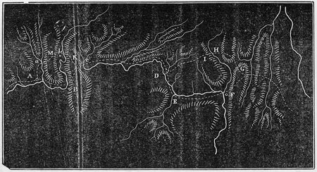
Fig. 30.
Between A
and c, fig.
30, were located
the lines
shown in the
sketch, one
following the
Susquehanna
river from A
to B, thence
crossing the
dividing ridge
between that
river and the
Delaware to
Deposit (c).
The other
passing up the
Chenango river
to a, thence
crossing first
the summit
M to the Susquehanna
at
L, and second
the summit K,
to Deposit (c).
The elements
of the two lines are as follows:—
52
A route, A B c.
B route, A M K c.
Length,
39.29
43.58
Rise A to c,
540.00
1087.00
Rise c to A,
395.00
936.00
Whole rise and fall,
935.00
2023.00
Degrees of curvature,
2371°.00
3253°.00
Estimated cost,
$746,900.00
$628,600.00
Assuming the number by which to equate for grades, as
96, and the equating number of degrees of curvature as
1140°; equating for grades and curvature in both directions,
we have,
Route A. A to c.
Mean, 46.25.
39.29 +
540 96 + 2371 1140 = 39.29 +
5.63 + 2.08 = 47.00
Route A. c to A.
39.29 +
395 96 + 2371 1140 = 39.29 +
4.12 + 2.08 = 45.49
Route B. A to c.
Mean, 56.96.
43.58 +
1087 96 + 3253 1140 = 43.58 +
11.32 + 2.85 = 57.75
Route B. c to A.
43.58 +
936 96 + 3253 1140 = 43.58 +
9.75 + 2.85 = 56.18
Assuming the cost of working and of maintaining as
$4,000 per mile, we have
The cost of building A to B as $746,900 to $628,600
The cost of operating A to B as (46.25 × 4000) × 100 6 to (56.96 × 4000) × 100 6,
or as
$3,083,334
to
$3,797,334
and the sum as
$3,830,234
$4,425,934
53giving the preference of $595,700 to the route A B c, notwithstanding
that the estimate thereon exceeds that on B
by $118,300. The route A B c was adopted.
Again, it was doubtful whether to adopt the route E F,
in going from D to G, or the line I H. The following are
the elements of the two lines:—
I H.
E F.
Measured length,
61.14
58.53
Rise D to G,
1187
454
Rise G to D,
1049
316
Degrees curve,
7609°
4588°
Estimated cost,
$1,094,950
$1,496,430
The mean equated lengths are as follows:—
Line I H. D to G.
Mean, 79.46,
61.14 +
1187 96 + 7609 1140 = 61.14 +
12.36 + 6.68 = 80.18
Line I H. G to D.
61.14 +
1049 96 + 7609 1140 = 61.14 +
10.93 + 6.68 = 78.75
Line E F. D to G.
Mean, 66.56.
58.53 +
454 96 + 4588 1140 = 58.53 +
4.73 + 4.02 = 67.28
Line E F. G to D.
58.53 +
316 96 + 4588 1140 = 58.53 +
3.29 + 4.02 = 65.84
The comparison as to cost is
I H to E F as $1,094,950 to $1,496,430,
and as to working,
I H to E F as (79.46 × 4000) × 100 6 to (66.56 × 4000) × 100 6,
54and the sum as
1,094,950
to
1,496,430
+ 5,297,334
+ 4,437,334
or
$6,392,284
to
$5,933,764
Although the cost of E F is $401,480 more than that of
I H, the line E F was adopted.
CHAPTER IV. PRELIMINARY OPERATIONS. — SPECIFICATION. — 77. Specification for Graduation. — 78. Specification for Masonry. — 84. Specifications for Superstructure. — 85. Specification for Fencing. — 86. General Provisions. — THE CONTRACT. — SOLICIT FOR BIDS. — FORM FOR A BID. — COMPARISON OF BIDS.
55
76. The object of this paper is to define exactly the terms
of the contract as regards execution of work. Every thing
therein should be expressed in a manner so plain as to leave
no room for misunderstanding.
A AND B RAILROAD.
LINE.
The centre of the road-bed to conform correctly to the centre
line of the railroad, as staked out or otherwise indicated
on the ground, and to its appropriate curvatures and grades
as defined and described by the engineer; and the contractor
shall make such deviations from these lines or grades
at any time, as the said engineer may require. The road-bed
to conform to the cross section which shall be given or
described, or to such other instructions as may be given as
hereinafter limited; and the same of the ditches and slopes
56of the work, and of all operations pertinent to the satisfactory
performance of the graduation or masonry on the part
or parts of the line contracted for.
CLEARING.
The ground forming the base of all embankments, and
five feet beyond the foot of the slopes of all embankments,
to be cleared as close to the surface as practicable, of all
timber, saplings, brush, logs, stumps, or other perishable
material. The valuable timber to be laid aside, beyond the
clearing as directed by the engineer, the rest to be burned,
if this can be done safely, otherwise to be moved beyond
the limits of the cleared ground. The ground for ten feet
beyond the top lines of all slopes of cuttings shall be cleared
in like manner, of all timber and saplings. Wherever additional
ground has to be taken in widening excavations to
obtain materials, or in widening embankments to dispose of
surplus material, or in grading for turnouts or depot grounds,
an additional amount of ground shall be cleared in like manner;
and when directed by the engineer, wherever additional
space is required for outside ditching, or for alterations
of roads or watercourses, or otherwise.
GRUBBING.
All stumps and large roots within ten feet of the grade
line shall be grubbed out to the entire width of the work,
and moved at least ten feet beyond the slopes. The cost
of all clearing and grubbing is included in the price for
earth work, which price is also understood to include all
clearing and grubbing necessary in borrowing pits, spoil
banks, road crossings, alterations of roads and watercourses,
57the formation of ditches or otherwise. The necessary clearing
and grubbing in all cases to be kept completed five
hundred feet in advance of any work in progress.
MUCKING.
Wherever mud, muck, or similar soft material occurs in
excavations or embankments, within two feet of subgrade,
it shall be removed and replaced by compact earth or gravel.
GRADE.
The grade lines on the profiles show the true grade, and
correspond with a line two inches below the bottom of the
iron rail of the superstructure. What is called subgrade
corresponds with a line placed eighteen inches below the
grade.[5]
5. The distance between grade and subgrade depends somewhat upon
the climate, but is generally between one and two feet. See chap. XIII.
WIDTH OF ROAD, AND SLOPES.
The width of road-way, unless otherwise directed, shall
be twenty-two feet wide at grade in earth excavations, and
eighteen feet wide in rock excavations. Both rock and
earth shall be taken out eighteen inches below grade for
the entire width of road-way. The bottoming to be replaced
by gravel, broken stone, or spawls, in such manner as
shall be directed by the engineer, leaving the necessary
ditches of the width and depth directed on either side.
The contractor will not be paid for any rock excavated beyond
the slope lines of one to eight from the required width,
or for any earth excavated beyond slope lines of one and
58one half horizontal to one vertical, unless directed by the
engineer to move additional rock or earth.
BLASTING.
All blasting shall be done at the risk of the first party,
who shall be liable to the second parties, or to the railroad
company, for any damages incurred in consequence, to
dwelling-houses, individuals, or otherwise.
DITCHES.
Whenever required, ditches shall be cut along the tops of
the slopes, of the form and size and in the position directed.
SURPLUS MATERIAL.
Whenever the earth or rock required for the adjoining
embankments exceeds the amount in the neighboring excavations,
the contractor, when required, shall increase the
width of said excavations, as directed by the engineer, to a
sufficient width for a double track, provided that this additional
width shall not be extended so as to produce an average
haul of more than eight hundred lineal feet, on said
borrowed stuff. And whenever the earth or rock to be
moved from any cut exceeds in amount the adjoining embankments,
(unless elsewhere wanted,) it shall be applied to
widening the embankment to a width for a double track,
within the same limits of haul; but for a greater haul than
eight hundred feet, the contractor shall be paid 100 of a cent per
yard per hundred feet of excess.
BORROW PITS.
Where the excavation does not furnish sufficient material
to make the adjoining embankments, borrow pits may be
59opened. But no earth shall be deposited in spoil banks nor
borrow pits opened without the knowledge and consent of
the superintending engineer, who shall take care that such
operations are arranged so as not to damage the road or its
slopes, nor interfere with the widening of the road-bed at a
future time for additional tracks.
MATERIAL TO BE SAVED.
If materials be found in the excavations applicable to
useful purposes, such as building stone, limestone, gravel,
minerals, etc., they shall be laid aside in such place as the
engineer may direct, for use, to be applied then or subsequently
to the construction of the road under the conditions
of these specifications and of the contract.
CLASSIFICATION OF MATERIALS.
Earth—every thing except solid and loose rock. Loose
rock—all boulders and detached masses of rock measuring
over one cubic foot in bulk and less than five cubic yards.
Solid rock, includes all work in ledge, which requires drilling
and splitting, and all loose rocks containing more than
five cubic yards.
The prices for excavation include all earth or rock excavated
in ditching, bottoming, borrowing, road crossings, alterations
of road crossings and water channels, and the construction
of temporary roads, provided the average distance
hauled on each section, be the same as stated on the schedule
here annexed; but if the actual average haul on any
section is found, on completion, to have been greater or less
than the distance stated, a corresponding addition or deduction
shall be made, of one cent per cubic yard per hundred
feet which the actual haul exceeds or falls short of that
stated.
60
EMBANKMENTS.
The embankments to be formed fifteen feet wide on the
surface, unless otherwise directed, with slopes of one and
one half horizontal to one vertical. Wherever the embankment
is formed from ditching on either side, such ditching,
and the crest of the slopes thereof shall in no case approach
within six feet, nor within double the depth of ditch, of
the foot of the proper embankment slope, allowing always
on one side for a double track; and no soft mud or muck
shall be allowed to enter the bank. Wherever watercourses
or new channels for rivers require to be formed, they shall
not approach within once and one half of the depth of
such stream, plus twenty-five feet. Care shall be taken in
forming embankments to exclude all perishable material.
SUBSIDENCE.
To allow for the after settlement of materials on embankments,
they shall, when delivered to and accepted by
the second parties, be finished to the full width to the following
heights above subgrades, namely: all banks below
five feet in height to be finished three inches above subgrade;
at ten feet in depth, five inches; at twenty feet, six
inches; and twenty-eight feet, seven inches; at thirty-five
feet, eight inches; and at forty feet in depth, nine inches
above grade; and intermediate heights in proportion; the
engineer having the power to change these proportions at
his discretion.
EXTRA EXCAVATION AND EMBANKMENT.
Whenever it is considered necessary to increase the width
of the road-way for turnouts, water stations, or depot
grounds, whether in excavation or embankment, such work
61shall be done at the contract prices, as may be directed.
The opening of foundation pits in simple excavation, where
coffer-dams or such like expedients are not necessary, and in
places where such expedients are necessary, all excavation
above the water line shall also be done at such increase or
decrease of the contract price as shall be deemed proper by
the engineer.
EMBANKING AT BRIDGES AND CULVERTS.
The contractor for earthwork shall not carry forward in
the usual way any embankments within fifty feet of any
piece of masonry, finished or in progress, (counting from
the bottom of the slopes,) but shall in every such case have
the earth wheeled to the walls or abutments, and carefully
rammed to such width and depth, and in such manner as
may be directed, when the embankment may be carried on
as usual. The expense attendant upon any damage or rebuilding
of mason work, consequent on neglect of these
directions, shall be charged to the account of the first party.
In case the mason work shall not be finished when the embankment
approaches it, the contractor shall erect a temporary
structure to carry over the earth, and proceed with the
embankment on the opposite side; and the expense of said
structure shall be paid by, and charged to, the contractor for
masonry, in case such contractor shall have delayed beyond
the proper or required time, the construction of the mason
work; but if the mason work could not have been ready in
season for the bank, then shall the expense belong to the
contractor for the earthwork, whose price for graduation is
understood to comprehend all such contingencies. For the
above work of wheeling and ramming efficiently the earth
around any piece of masonry, the contractor shall be paid —— cents
per cubic yard, by the engineer’s measurement.
62
ROADS AND WATERCOURSES.
The first party is to make good and convenient road
crossings wherever directed, and shall also make such alterations
of existing roads, or watercourses, or river channels, or
such new pieces of these pertinent the section undertaken
by him, as may be required, and shall be paid for such
work, whether earth, rock, or masonry, the prices, and no
more, applicable to this contract. And such road crossings
or other alterations referred to, he shall make at and within
such times and in such form and manner as the engineer
shall direct; and whenever the operations of the first party
interfere with a travelled road, public or private, either by
crossing or by making required alterations on it, the first
party shall so operate as to afford at all times a safe and
free passage to the public travel; and the first party shall
be liable for any damage to which the second parties or the
railroad company may become lawfully liable by reason of
his neglect to maintain a safe and properly protected passage
for the current travel.
BALLASTING.
Where gravel is used for the ballasting of the road-bed,
it shall be of a quality satisfactory to the engineer, and
shall be spread upon the road-bed to the width and depth
required. When broken stone is used, it shall be of durable
quality, and shall be broken so as to pass through a
ring of three inches in diameter. The quantity will be
measured in the road-bed as finished, and the contractor
will be required to keep the ditches trimmed and clear.
63
RIP-RAP, OR RUBBLE SLOPES.
The first party shall distribute rubble stone over the
slopes of earth embankments, whenever required to do so,
to protect said slopes from the action of water. Such stone
to be arranged by competent hands, and laid to such thickness,
and with stones of such size, as shall be directed.
Where the contractor has rock in the neighboring cuttings
which is available, it shall be reserved and applied to this
purpose; and when not, good rock shall be obtained where
the contractor can conveniently get it.
MEASUREMENTS.
All earth or rock necessarily moved to complete the grading
of this contract according to direction, will be measured
in excavation only; and if the contractor (with the consent
of the engineer,) should find it convenient to waste earth
from an excavation, instead of carrying it to its proper embankment,
and to borrow at some nearer point earth for
said embankment to replace that which was wasted, he
shall be paid for the earth from the original excavation in
the order of its most economical arrangement for the second
parties. All earth moved from borrowing pits shall
also be measured in excavation only.
FIRST CLASS MASONRY.
First class masonry will apply to bridge abutments exceeding
twenty-five feet in height, to the ring stones of
arches, and to the piers of bridges in running water. The
stone shall be laid at the rate of one header to two stretchers,
disposed so as to make efficient bond. No header to be less
64than forty inches long, and no stretcher to be less than
eighteen inches in width. No stone less than twelve inches
in thickness, no stone to have a greater height than width,
all stones to be placed upon the natural bed. The masonry
throughout to have hammer dressed beds and joints. Vertical
joints to be continued back at least ten inches from the
face of the wall. The mortar joints on the face not to exceed
one fourth of an inch in thickness. The stone to be
laid with regard to breaking joints in the adjoining courses.
The stone must be dressed complete before laying, and not
be moved after being placed in the mortar. The face will
not be tooled, but only roughly hewed, except for one half
inch from the beds and joints, where it will be hammered.
The ring stones of arches shall have beds to conform to the
radius of the arch, with the end joints vertical, and be made
to set smoothly on the centering, with the beds with the
proper inclination. Each stone must extend through the
whole thickness of the arch, and not be less than eight
inches thick on the intrados. No spawls or pinners will be
admitted. The ring stone shall be dimension work, according
to the plans furnished, the beds and joints being
truly dressed, but the faces left rough.
All first class work shall be carefully laid in good cement
mortar, (see Art. Cement). Each stone before being laid
shall be carefully cleaned and moistened; and masonry
built in hot weather shall be protected from the sun as fast
as laid, by covering with boards. Copings shall be built of
stone of equal thickness, neatly dressed and laid.
All first class masonry shall be well pointed with cement
pointing.
SECOND CLASS MASONRY.
To be applied to abutments less than twenty-five feet
high, ring and face walls of bridges and culverts, and to
65piers not in running water, shall consist of stones cut in
bed and build to a uniform thickness throughout, before
being laid, but not hammered; they shall be laid on a level
bed, and have vertical joints continued back at right angles
at least eight inches from the face of the wall. The work
need not be carried up in regular courses, but shall be well
bonded, having one header for every three stretchers, and
not more than one third of the stones shall contain less than
two cubic feet, or be less than nine inches thick; and none
of that third shall contain less than one and one half cubic
feet, or be less than six inches thick. No more small stones
shall be used than necessary to make even beds, the whole
to be laid in cement mortar and pointed.
THIRD CLASS MASONRY.
Applicable to culverts, and to the spandrel backing of
arches, shall consist of strong and well built rubble masonry,
laid dry for culverts, but wet for backing. The culverts
to be of such form and dimensions as the engineer
may direct. The foundation courses of the side walls to
consist of large flat stones, from eight to ten inches in thickness,
laid so as to give a solid and regular basis for the side
walls. The side walls to be laid with sound stone, and of
sufficient size, and with beds having a fair bearing surface
and good bond. The covering stone for culverts being not
less than ten inches thick for two feet culverts, twelve inches
for three feet culverts, and fifteen inches for four feet culverts;
to be free from flaw or defect, and to have a well
bedded rest upon each side wall, of not less than twelve
inches for two and three feet culverts; and not less than fifteen
inches for larger ones. In case such stone cannot be
obtained, a dry rubble arch may be thrown instead, well
pinned and backed; but the price for the arch shall not be
66more than the general price for third class masonry, with an
allowance for the centering.
FOURTH CLASS MASONRY.
Applicable to cattle-guards, pavement of culverts, and
slope and protection walls, shall consist of stones of not
less than one cubic foot in contents, so laid and bonded
as to give the greatest degree of strength in preference
to appearance; being laid when directed with beds perpendicular
to the inclined face. Pavements under culverts
shall be made by excavating one foot in depth of that
part to be paved, which space shall be filled with flat
stones one foot wide, set on edge, close together, and
made to present an even upper face.
TIMBER AND PLANK FOUNDATIONS.
Timber and plank foundations require the beds to be perfectly
well levelled, and timber of such dimensions, and so
laid, as shown by the plans; to be well bedded and brought
to an even and level top surface. The spaces between
them to be filled and well rammed with such material as
the engineer may direct. On these timbers planks shall be
laid, and trenailed or spiked if required. The materials
shall be of quality and shape approved by the engineer, and
the price shall be in full for material and labor in laying the
whole in a thorough and workmanlike manner.
PILING.
Piling may be used either as bearing piles for foundations,
or for piled bridges. In the former case they will be
bid for by the running foot driven, and in the latter by the
stick of twenty-five feet in length. The piles in either case
67must be straight round timber, of a quality approved by
the engineer, not less than ten inches in diameter at the
small end, barked, and properly banded and pointed for
driving. They shall be driven in such places, and to such
depths as required, and the heads cut off square, or finished
with a tenon to receive caps, as may be required. Bearing
piles will be cut off so far below the lowest water that any
timber foundation laid thereon shall be at all times entirely
immersed.
CEMENT.
Cement when used shall be of the best quality, hydraulic,
newly manufactured, well housed and packed, and so preserved
until required for use. And none shall be used in
the work until tested and approved by the engineer.
CEMENT MORTAR.
The proportion of sand and cement for construction shall
be one of cement, to two of clean, sharp sand, unless in
special cases the engineer direct otherwise, for which due
allowance shall be made. It shall be used directly after
mixing, and none remaining on hand over night shall be
remixed.
LIME MORTAR.
Lime mortar (which in all cases shall contain cement),
will consist, unless otherwise directed, of two parts of best
quick lime, one of cement, and five of sand; the ordinary
mortar of lime and sand being first properly made, and the
cement thrown in and thoroughly mixed immediately before
using.
68
CONCRETE.
Whenever concrete is required to be used, it shall be
formed of clean broken stone, cement, and sharp, clean
sand. The stone, which shall be of satisfactory quality,
shall be broken so as to pass through a ring three inches in
diameter. The cement and sand shall be thoroughly mixed
in the proportions already described for cement mortar.
Thus prepared, it shall be carefully mixed with the broken
stone in the proportion of one of mortar to two or two and
one half of broken stone, as the engineer upon experiment
shall determine, and shall be immediately laid carefully in
its place, and well rammed. The concrete shall be protected
on the sides by boards, and be allowed to remain undisturbed
after laying until it is properly set; and in special
cases the engineer shall direct the mode of application.
For the proper preparation and laying of such concrete,
there shall be paid the price applicable to second class masonry.
The contractor shall furnish all tools and plank
necessary to the operation.
POINTING.
All masonry in cement or lime will be finished with a
good pointing of cement, without extra charge.
BRICKWORK.
When bricks are required, or allowed to be used, they
shall consist of sound, hard-burned brick, laid in cement, or
common mortar, as directed, and no soft or salmon brick
will be admitted; and none but regular bricklayers must be
employed.
69
CENTERING AND BACKING.
The whole top of all arches, whether brick or stone, shall
be finished by plastering with a good coat of cement, so as
to prevent the percolation of water, and turn it away from
the arch. The centering shall be such as the engineer approves
of in every respect, and shall not be removed until he
directs. The cost of backing to be included in the price
bid. For arches of more than twenty-five feet span, compensation
shall be made, at the engineer’s estimate, for the
extra value and cost of the centering proper for large arches.
GENERAL PROVISION.
79. The engineer reserves the right to require the whole
or any part of the above described work of masonry to be
laid in cement, lime, mortar, or dry, at his discretion. First
and second class masonry, and brickwork, will be bid for
at prices for laying in cement, from which will be deducted
fifty cents per yard if laid in lime mortar, and one dollar if
laid dry. Third and fourth class masonry at prices for laying
dry, to which will be added fifty cents per yard if laid
in lime mortar, and one dollar if laid in cement.
SCAFFOLDING.
80. Nothing shall be allowed for workmanship or timber
of any scaffolding used in the construction of timber bridges,
or in carrying up abutments, piers, coffer-dams, or otherwise.
Should the timber used in any coffer-dam be carried
away by floods, the renewal of it shall fall upon the first
party.
70
FOUNDATIONS.
81. The foundations for all structures shall be executed
by the contractor for masonry in such manner and to such
depth as to secure a safe and secure foundation, of which
the engineer will judge. If a natural foundation cannot be
procured at a reasonable depth, then the contractor shall
prepare such artificial foundation as the engineer may direct.
The stuff moved from the foundations, if of the
proper quality, shall be deposited in the adjoining embankment,
provided the site for said embankment has been
cleared of all perishable material. So much of the stuff as
shall not be fit for the embankment, and all roots, stumps,
etc., shall be deposited beyond the limits of the clearing, so
as not to obstruct roads, watercourses, or ditches.
For the earth moved from such foundations, and for all
earth used according to direction, in the construction of coffer-dams,
there shall be paid —— cents per cubic yard.
Whenever it may be necessary to pump or bale water in
the foundations, the contractor shall furnish the pumps or
buckets, and all scaffolding and apparatus necessary to
work them. He shall be allowed the net cost of all labor
employed in the operations of pumping or baling water,
and shall make a monthly return to the engineer of the
value of such labor, provided that these operations are conducted
in an economical manner, with efficient men, pumps,
and tools, under the direction and to the satisfaction of the
engineer. He shall also be allowed such compensation for
the use of the pumps and apparatus, and for superintendence,
as the engineer shall judge to be fair and reasonable.
71
TRESTLE WORK.
82. Includes all wooden structures commonly used as
substitutes for abutments and piers, and for farm passes,
etc., etc. These shall be built according to the plans furnished,
and directions given by the engineer, of sound, durable
material, to be approved by him. The price bid shall
be by the thousand feet board measure, and will be considered
as in full for all material except iron, and for the labor
of building and erecting complete. The iron used will be
of the best American, and the workmanship of approved
quality. The bids will be by the pound, and will cover all
cost of material and the labor incident to its use. Spikes
and nails when used will be furnished by the contractor at
cost.
BRIDGING.
83. Contractors may submit plans for bridging in connection
with, or separate from their bids; but the engineer
of the company may reject such plans if he choose, and
substitute others, which if the contractor decline building at
the approved prices, may be let to other parties. In every
case, the exact manner of building, erecting, adjusting, and
finishing bridges, and the determination of the nature and
amount of material, will be specified by the engineer. The
price bid must be by the running foot of the whole length
of bridge, as erected and finished complete.
72
SUBSILLS.
To maintain the track in good adjustment until embankments
are settled, subsills will be laid on certain
banks, and likewise in cuts where the imperfect nature of
the bottoming may, in the opinion of the engineer, render
them expedient. These subsills to be fairly bedded in the
earth or ballasting, and carefully adjusted and rammed so
as to correspond with the grade lines given by the engineer.
An additional piece of sill, four feet long, shall be laid at
each joint of the subsill, either under the sill, or alongside,
as may be directed. The sills will be of 3 × 9 plank, in
length of twelve, fifteen, eighteen, and twenty-one feet; of
which one fourth may be below fifteen, one fourth below
eighteen, and one fourth below twenty-one feet. The plank
must be square at the ends, and of sound, durable material,
and not have more than two inches wane on one end only.
There will be about 25,000 feet, board measure, laid per
mile where it may be required, and 660 joint sills, 3 × 9
inches, and four feet long. When the depth of stuff to be
moved to admit the subsills exceeds six inches, an allowance
shall be made for extra labor, the amount of which
shall be noted by the assistants on their receiving notice of
such extra labor from the contractor or his agent.
CROSS TIES.
The cross ties shall be of white, black, or yellow oak,
burr oak, chestnut, red elm, black walnut, or other sound
timber of suitable character in the opinion of the engineer.
Eight feet long, and not more than three inches out of
73straight, hewn to a smooth surface on two parallel plane
faces six inches apart, the faces being not less than seven
inches wide for at least half of the number, and the remainder
not less than six inches wide. The ties shall be carefully
and solidly laid on the subsills, or ballasting, or earth previously
properly prepared, so as to give the true planes required
by the rails, whether on straight or curved lines.
They shall be laid at the rate of eight ties to each eighteen
feet rail. All imperfect ties shall be excluded by the tracklaying
party. The surface of the ties to be faithfully adjusted
to the grades given, and to the web of the rail; and
the rail to be truly laid and firmly spiked so as to correspond
neatly to the alignment of the road. There will be
about 2,500 ties required per mile of road.
CHAIRS AND JOINTS.
When chairs are used, they shall be such as directed by
the engineer, and furnished by the company, and shall be
well and accurately placed and spiked in such manner and
position as required. When chairs are used, the largest
ties shall be selected for the joints. When the joint is
made by fishing, there will be no tie directly under the
joint.
RAILS.
The rails will weigh about sixty pounds per lineal yard.
No rail shall be laid on the tangents which is in any way
twisted or bent. It shall be the duty of the first party to
correct and make true any crooked rails received by him,
also to bend to the proper curve, and in such a manner as
not to affect the strength of the bar, all rails laid in curves.
Punching of rails, and cutting, will also be done by the
contractor.
74
TRACK LAYING.
The materials composing the track will be furnished by
the company, and it will be laid in the best manner according
to the conditions following. The track will be laid
on cross-ties, and the ties at the proper places on subsills.
Where the sills are used, they will be laid with four feet
blocks at the joints, and with six feet blocks at the rail
joints, the whole being set to their places by stakes, and by
the engineer’s directions, and mauled down to a perfect
bearing, being settled at least half an inch by mauling.
The cross ties will be placed uniformly distant, (twenty-eight
inches from centre to centre). The iron must be so
cut or selected that the joints of the parallel rails shall be
within two inches of being opposite to each other; no joint
tie being allowed a greater amount of askew than this,
whether on tangents or curves. A slip of metal shall be
inserted at the rail joints while laying, to keep the rails
apart sufficiently to allow for expansion, which thickness,
(depending upon the temperature,) shall be fixed by the engineer.
Notches to be cut at the centre of each bar, to correspond
with half a spike, to prevent longitudinal motion of
the rails. Each joint chair to be fastened with four spikes.
Two spikes at each end of each tie upon straight lines and
upon curves of less than 1,500 feet radius at the outer end
of the tie two spikes outside and one inside, and at the inner
end two spikes outside and one inside of the rail. Upon
curves the outer rail to be raised by such an amount, depending
on the radius of curvature, as the engineer may
direct.
75
TURNOUTS.
The contractor to put in such turnouts and sidings, with
the necessary frogs and switches, as may be required; the
frogs and switches to be firmly and truly placed in position
so as to work easily.
FILLING AND DITCHING.
The stuff moved in bedding the sills and ties, to be
placed between the latter. The ditches to be properly
cleaned out after the track is laid; the filling never to rise
higher than the top of the cross tie. Any surplus stuff to
be moved out of the cuts, or if on embankment, to be
thrown over the bank, leaving the track and road-bed in a
neat and workmanlike shape.
DELIVERY OF MATERIALS.
The ties and sills to be delivered at some point on the
road as near as possible to the places where they are to be
used, in no case requiring more than one thousand feet of
haul; to be so piled as easily to be counted and inspected.
The bids for ties will be by the piece; the proposal stating
the number and conditions; the sills to be bid for by the
thousand, board measure. All material furnished in connection
with track laying to be delivered in such manner
and time as to comply in good season with the contract for
laying the rails.
MEASUREMENT OF TRACK.
The measurement of track laid shall include the turnouts,
measuring from heel to heel of switch. No extra allowance
being made for putting in frogs or switch machinery.
76
Bids for fencing will be by the running foot, or mile, including
both sides of the road. Where required, it will
consist of posts placed eight feet apart from centre to centre,
set three feet into the ground, either by digging or boring,
and not by mauling. The posts shall be of oak, elm,
chestnut, or other durable wood, not less than eight inches
in diameter at the bottom, barked and charred where put into
the ground. The boards to be 6 × 1 inches, and to square
sixteen feet long, to be placed six inches apart vertically,
and fastened to the posts with tenpenny nails at each bearing,
and breaking joint with each other. There will be five
bars in depth, the top of the uppermost being five feet from
the ground. In side hill and in ground liable to slide, particular
care shall be taken to place the posts firmly in the
ground. At cattle guards, the fence will be turned in to
the proper distance, and such arrangement made as to prevent
the passage of animals.
CLASSIFICATION.
The classification of material excavated will be referred
to the engineer, in all cases where the nature of the material
is questioned, and his judgment taken thereon. Also
all material used in structures will be submitted to the inspection
of the engineer or his assistants.
77
QUANTITIES AND QUALITIES APPROXIMATE.
The quantities and qualities of work presented in the
schedule are merely approximate, and the information given
on the maps and profiles in relation thereto is according to
the best present knowledge. The company retains the right
to change at any time during the progress of the work, the
alignment, grades, and width of the road, or any part
thereof; and also the limits of the sections, or to alter the
character, vary the dimensions, or change the location of
structures, or substitute one kind of work or material for
another, or to omit entirely, when found necessary, or to require
to be built where not now contemplated; and the
contractor shall carry into effect all such alterations when
required, without the contract prices being thereby affected,
unless the aggregate value of all work contemplated by the
contract be changed full twenty per cent., in which case a
fair allowance, either for the company or the contractor,
shall be made by the engineer. In case, however, the aggregate
value of the work be changed by over twenty per
cent. of the original amount, and the contractor be not satisfied
with the altered compensation, then said contractor
may throw up said contract, on condition, that within ten
days after receiving notice from the engineer of such alteration,
he give written notice to the engineer or the company
of his desire to do so. In which case, as in other cases of
throwing up the contract, he shall as soon as desired, give
peaceable possession to the company or their agents; leaving
also in their possession any tools or machinery upon
which they have advanced any thing; and the company
may then settle with the contractor on the measure of damages
which either shall suffer.
78
BASIS FOR ESTIMATING EFFECT OF CHANGES.
The basis for estimating any changes as above mentioned
is understood to be the schedule exhibited at the letting.
NO LIQUOR, AND GOOD ORDER.
The contractor shall not sell, or allow to be sold or
brought within the limits of his work any spirituous liquors,
and will in every way discountenance their use by persons
in his employ. He will do all in his power by his own act,
or by assisting the officers of the county, or of the corporation,
in maintaining the laws and such regulations as conduce
to good order and peaceable progress, and prevent encroachment
on the rights of persons or property; and he
shall discharge from his service, when required by the engineer,
any disorderly, dangerous, insubordinate, or incompetent
person, and refuse to receive into his employ any
who may have been discharged for such cause from other
parts of the work.
MONTHLY ESTIMATES.
Measurements and estimates shall be made by the engineer
once in each month, by means of which may be
known approximately the amount of work done, and the
contractor shall be entitled to payment therefor at such rates
below his contract prices as the engineer or president of the
company deems expedient; it being understood that the
contractor has no claim on account of any material not laid
in its place in the road-way, or for labor bestowed thereon;
and the quantities shall be estimated from the dimensions
when so laid, though on the advice of the engineer, advances
may be made on such material when delivered for use, in
79which case it becomes the property of the company, in the
contractor’s care and keeping, and he becomes liable for its
loss or injury.
EXTRA WORK.
No claim for extra work or for work not provided for in
the contract shall be allowed, unless a written order to perform
such work shall have been given by the engineer; or
that the work be subsequently certified by him, and the certificate
produced at the time of demanding the payment of
the monthly estimate next after such work shall have been
performed.
SUB-CONTRACTS.
The contractor will be required to perform the work himself,
and no sub-contracts relieving him from the responsibility
of a proper performance of his contract will be permitted,
unless by the written consent of the president of
the company. And no moneys shall be paid to any such
sub-contractor for work or materials, without sufficient authority
from the principal contractor.
WHEN WORK TO BE COMMENCED.
On the acceptance of a proposal, the chief engineer will
give notice thereof to the person proposing, by letter directed
to his stated address; and in twenty days from the
date of such notice, provided there be no impediment on
the part of the company, or in twenty days after such impediment
is removed if there be, the work shall be begun
with an adequate force, and from that time be prosecuted
vigorously until its completion.
80
HOW TO PROGRESS.
It shall be understood that proper progress is not made,
if the amount of work done in each month is not in due
proportion to the total amount to be done up to the time
fixed for completion by the contract; in which case the
engineer shall call the attention of the contractor (or whoever
may be in charge of the work if the contractor be
absent,) to the fact, and state to him what additional
exertion is necessary to be made, and what further force is
required, in such reasonable time as may be prescribed.
PUTTING ON MORE FORCE.
In default of the contractor’s making such additional exertion,
and supplying such force, the chief engineer, or president
of the company may have such force sent to the work,
and the necessary buildings may be erected to receive them
at the contractor’s charge and expense, who shall receive the
said force in his employ, and work it at whatever price it
may have been found necessary to employ it, without diminishing
the previous force of the work, and regarding
always such extra force as if employed by himself.
CAUSES FOR DETENTION.
There shall be no claim for detention on account of work
not being laid out, unless a written notice three days in advance,
that it is required, shall have been given to the engineer;
and the damage for such detention shall be estimated
by the engineer. The right of way shall be furnished
by the company, but if it fail to do so for any
particular place, damages for detention shall not be claimed
unless the contractor be detained full twenty days after he
81shall have given written notice to the engineer of his wish
to commence work at such place. Then the engineer may
either estimate to him the amount of damage which he shall
take as satisfactory, or he may extend the time of the completion
of such work by as many days beyond the contract
time, as the contractor is detained beyond the twenty days
following his notice to the engineer.
THE ENGINEER.
In all cases where the word “engineer” is used, the engineer
in charge of construction is meant; but the directions
of any subordinate engineer shall be obeyed when
given in regard to any of the ordinary operations, or where
they are evidently in accordance with the specifications, or
when transmitting the orders of his superiors. In other
cases they may be referred to the resident engineer, and
finally to the chief engineer, he being the authorized officer,
at the time acting in that capacity.
CONTRACTOR.
The word “contractor” applies to and includes all persons
contracting jointly, any one of whom shall be considered
the authorized agent for and in behalf of his associates,
and empowered to receipt payment of moneys,
receive and act upon orders.
87. This is the mutually binding legal article of agreement
between the contractor and the company, specifying
the times of completing, manner of payment, and describing
the work which is to be done. Thus:—
82A AND B RAILROAD COMPANY.
Contract.
Graduation on sections A C D,
Masonry on sections A C D,
Ballasting on sections A C D,
Bridging on sections A X T,
Fencing on sections O O O,
Sills and ties on sections O O O,
Track laying on sections O O O.
____________ }
____________ } Contractors.
Articles of agreement made and concluded this first day
of January, A. D. 1857, between —— of the first part,
and the A and B Railroad Company of the second part,
being a company duly incorporated by the State of ——
of the second part, whereby it is mutually agreed as follows,
namely: The said party parties of the first part hereby agree
to and with the said party of the second part that he they will
perform in a substantial and workmanlike manner the following
work, namely:—
[The work here described.]
The said work to be performed and completed agreeably
to the directions and to the approval of the chief engineer
of said company for the time being, and subject to all the
general provisions of the specification attached to and forming
a part of this agreement, and also subject to such of
the special provisions of said specifications as are applicable
to the work hereby contracted for.
And in consideration of the full and faithful performance
by the said party parties of the first part of this agreement on his their83part, the said party of the second part hereby agrees to pay
for the same in the time and in the manner hereinafter mentioned,
at the rates as follows, namely:—
[Here insert the items and corresponding prices.]
It is mutually agreed that this contract applies only to
those items to which prices are attached, and that where it
embraces both labor and materials introduced in the work,
such prices are in full compensation therefor when introduced
in the manner required. When it embraces materials
only, such prices are in full compensation for the materials
and the labor necessary to deliver the same to the
company, and when it embraces labor only, such prices are
in full compensation for such labor, and every incident
to its complete and proper performance. In every case the
estimate for ascertaining the amount of compensation shall
be made by the engineer from the actual work, from the
material furnished, or from that on which the labor contracted
for is bestowed.
It is also agreed that partial payments shall be made
from time to time during the progress of the work as follows:—
[Times and manner of payment.]
And that in thirty days after the contract is fully completed
to the satisfaction of the chief engineer of the company for
the time being, and the work is surrendered to and accepted
by the company, a final measurement and estimate thereof
shall be made under the direction of the chief engineer, and
be duly certified by him, on the return of which to the president
of the company the whole amount then found to be
due to the said party parties of the first part shall be paid to him them
on demand as follows:—
[Insert mode of payment.]
And it is also hereby further agreed, that bank-bills current
84in the State of —— shall be accepted for cash in payment
for all claims under this contract.
And the said party parties of the first part further agree agrees that in
twenty days after he they shall be notified to do so, as provided
for in said specifications, he they will begin the work hereby
contracted to be performed, with a force of all kinds sufficient
for its completion in the time herein prescribed, and
that he they will finish and deliver the same to the company
fully completed in all its parts as follows:—
And the said specifications hereunto annexed are hereby
made a component part of this contract and (except so far
as any provision therein may not be pertinent to the subject-matter
of the contract or may be specially modified
herein,) shall be looked to in ascertaining the meaning, extent,
and purport of this agreement, and in determining the
rights, powers, duties, privileges, and obligations of the contracting
parties as to any particular embraced therein.
In virtue whereof the said party parties of the first part has have hereunto
set his their hand and seal, and the said party of the second
part have caused their president to subscribe his name and
affix the corporate seal of the company hereto, all done in
triplicate the day and year first above written.
Contractor’s name, [SEAL.]
President’s name, [SEAL.]
88. The approximate estimates, plans, and profiles being
made, and other preliminaries settled, proposals for executing
work are solicited by the public papers. Thus:—
85New York, January 1, 1857. }
Office of the A and B Railroad Company. }
Proposals for executing the graduation, bridging, masonry,
and track laying, and for the supply of materials
upon the A and B railroad will be received at this office
until the 31st day of January, 1857.
Plans, profiles, and schedules of amounts of work may
be seen, and blank bids obtained by application at this
office.
All proposals must be directed to the chief engineer of
the A and B Railroad Company.
No bids will be received after January 31st, at 12, M.
Per order,
C. D., Secretary A and B R. R. Co.
89. That proposers may make their bids in a convenient
form for comparison, a blank, somewhat like the following,
is given them to fill out.
86
Number of Section.
Sec. 1.
Sec. 2.
Sec. 3.
Sec. 4.
Length in miles.
1½
1¼
1¾
1½
Graduation.
Clearing and grubbing,
Price per acre,
Cost on the section,
Earth excavation,
Price per yard,
Cost on the section,
Loose rock excavation,
Price per yard,
Cost on the section,
Solid rock excavation,
Price per yard,
Cost on the section,
Average haul on section,
Ballasting,
Price per yard,
Cost on the section,
Whole cost of graduation,
Masonry.
First class masonry,
Price per yard,
Cost on the section,
Second class masonry,
Price per yard,
Cost on the section,
Third class masonry,
Price per yard,
Cost on the section,
Foundation timber,
Cost per M., b’d measure,
Cost on the section,
Excavation for foundation,
Price per yard,
Cost on the section,
Rip rap,
Price per yard,
Cost on the section,
Whole cost of masonry,
Bridging.
Detailed as above,
Track laying.
Fencing.
87This form being filled out, evidently gives the cost of
each or all of the items upon any one or all of the sections,
the cost of all the items upon any one section being at the
foot of that section, and the whole cost of any one item at
the extreme right and on the line of that item.
On the bottom of the form is printed, “The undersigned
having read the specifications, and made due examination,
hereby proposes to the A and B Railroad Company, to perform
the work in the above schedule, to which he theyhas have set
figures, at those prices and under the conditions described,
and upon acceptance of this proposal by the company,
binds bindhimself themselves to enter into a written contract to that effect,
and to furnish the required security.
Name,
Address,
Name of Surety,
Address of Surety.”
90. The bids being received, are compared as follows:—
Name of bidder.
Graduation.
Masonry.
Sec. 1.
Sec. 2.
Sec. 3.
Sec. 4.
Total.
Sec. 1.
Sec. 2.
Sec. 3.
Sec. 4.
Total.
A
B
C
88_
Name of bidder.
Bridging.
Superstructure.
Sec. 1.
Sec. 2.
Sec. 3.
Sec. 4.
Total.
Sec. 1.
Sec. 2.
Sec. 3.
Sec. 4.
Total.
A
B
C
Name of bidder.
Fencing.
Grand Total.
Sec. 1.
Sec. 2.
Sec. 3.
Sec. 4.
Total.
A
B
C
From which the names may be easily selected either for
one or more sections, for any or all of the items, that shall
give the least cost.
CHAPTER V. LAYING OUT WORK. — SLOPES. — CULVERTS. — MASONRY. — TUNNELS.
89
91. The running of the line consists in placing a stake
at every one hundred feet upon tangents, and at every fifty
feet distance upon sharp curves; also a permanent post at
each tangent point, and at points of compound and reversed
curvature. This is the centre line, the axis of the road, and
the base of all field operations. Wherever the work is
going on, the centre pins should be referred to fixed points
outside of the ground occupied by the road.
92. The first operation in preparing for excavation is to
place side stakes at one half the width of road-bed plus the
ditch, on each side of the centre line.
93. Setting out slopes is a term applied to laying off
upon the ground, on each side of the centre, the distance to
which the slope, commencing at the outer edge of the ditch,
will extend, depending upon the angle of slope, width of
road-bed and ditch, and depth of cutting. There are here
five distinct cases which may occur:—
In embankment when the natural surface is horizontal.
In embankment when the natural surface is inclined. In
excavation when the natural surface is horizontal. In excavation
when the natural surface is inclined.
90In mixed work (side hill,) when the road-bed is partly in
cut and partly in fill. In both excavation and embankment,
when the natural surface is horizontal, we have only
to add the cut, in feet and decimals, multiplied by the
slope, to one half the width of road-bed plus ditch.
Thus suppose the cut is
20.55 feet,
half the road-bed,
10.25 feet,
ditch,
3.00 feet,
slope 1½ horizontal to 1 vertical,
and we have
(20.55 × 1½) + 10.25 + 3.0 = 44.075 feet.
When the ground is inclined transversely to the axis of
the road, first assume a point upon the ground, (apparently
right) find its height above grade with the level, multiply
this by the slope and add one half the distance between the
outer edge of ditches, and see how near it comes to the
measured distance from the centre to the assumed point; if
within a foot, it will answer; if not, a second trial will fix
the place.
94. The length of any structure passing under a railroad
embankment is L – 2Rh, where L is the distance between
slope stakes, R inclination of slopes, h the height of structure
from the natural surface. Thus, suppose the distance
between slope stakes to be 100 feet, slope 1½ to 1, and h
10 feet, we have
L = 100 – (10 × 1½ × 2) = 100 – 30 = 70 feet.
The length of an oblique structure will of course be
greater than that of one at right angles to the road; the
length depending upon the obliquity.
91
95. There are eight general cases which may occur in
laying out such structures as bridge abutments with wings.
1. A right bridge on a level tangent.
2. A right bridge on a level curve.
3. A skew bridge on a level tangent.
4. A skew bridge on a level curve.
5. A right bridge on an inclined tangent.
6. A right bridge on an inclined curve.
7. A skew bridge on an inclined tangent.
8. A skew bridge on an inclined curve.
And these eight cases will vary again according to the natural
surface of the ground, whether horizontal, or inclined
transversely.
96. The general position of wing walls and general form
of the line inclosing the base of the bridge, is shown from
fig. 31 to fig. 38. Fig. 31 represents case one. The points
A, B, C, D, are fixed by squares from the centre line at
E F, G H.
Fig. 31.
92Fig. 32 represents case two. The wings 3c, 4d, must
evidently have a different inclination from A1, B2. The
points A, B, c, d, 1, 2, 3, 4, as before, are laid off by squares
from a tangent to the curve.
Fig. 32.
Fig. 33 explains itself.
Fig. 33.
Fig. 34.
Fig. 34, case five. Here the wings A1, C4, are the
93same, as also B2, D3, the former being longer, on account
of the greater depth of the fill.
Fig. 35.
Fig. 35, case seven. Here each wing is peculiar; the
figure being a compound of figs. 33 and 34.
Figs. 36 and 37.
Figs. 36 and 37, case 8. This is the most difficult of all.
94No two wings have the same length or inclination on plan.
The natural surface being horizontal, the line inclosing the
bridge is A″ B″ C″ D″. If the natural surface descended
from C″ to A, the position taken would be A, B, C, D. Fig.
37 is the elevation of the position A B C D. The several
points are laid off from the line n, n.
The general manner of fixing the lines of figures 31 to 38,
is to assume the angle of some one wing, as A 1, in fig. 34,
to draw A C parallel to E F; and from C, the intersection
of A C with the base of the embankment, C 4 gives the
other wing. Local circumstances will of course often fix
at once the length and angle of the wings. Upon simple
curves, as in fig. 32, the lines A c and B d are made radial.
97. In curving a viaduct, the axes of the piers are made
radial to the centre of the located curve, and the planes of
the springing lines are made parallel to the axes of the
arches. The pier thus becomes a wedge, and should be
strengthened by a starling, upon the outside of the curve,
to resist the resultant of the thrusts of two adjoining arches.
98. We should never try to stake out the exact horizontal
projection of a complicated piece of work upon rough
ground, but only the trenches, which being cut, give a horizontal
surface to work upon. In placing the stakes, we
must be careful to have them so far outside of the work
that they will remain undisturbed while operations are
going on. The pegs for cutting pits and trenches may be
placed at the angles of the latter, but the working pegs
must be so placed that the lines stretched from one to the
other will define the masonry. All measurements made in
laying out work should be made by graduated rods, and
carefully checked.
99. In founding piers, and in aquatic operations generally,
two stakes upon the shore, or a fixed transit, will define
any line in the water. Two transits will define points.
95100. A permanent bench mark should be carefully fixed
at each structure, from which its levels may be obtained.
101. In adjusting oblique bridges, care must be taken so
to place the bridge seats that the floor beams shall lie in a
correct plane, and not be at all warped or winding.
Fig. 38.
102. As an example of laying out work with regard to
heights, take the case of fig. 38. Let the grade of the centre
line be one in 100, the angle of obliquity 45°, the width
of bridge twenty feet, and span on the skew one hundred
feet. Required the elevations of the points a, b, c, d.
Assume the height of (2) as
100.00
That of (3) will be
99.00
b being 10 ft. back of 2 is 0.1 ft. higher than 2, or
100.10
and d 0.1 feet less than (2) or
99.90
also a = 99.00 + 0.10, or
99.10
and c = 99.00 – 0.10, or
98.90
103. The maintaining a correct centre line through tunnels
is generally considered difficult. The fixing of the line
in deep shafts requires great care, owing to the short distance
between the only two fixed points, that can be transferred
from the surface to the bottom of the pit. This is a
matter of manual skill and of instrumental manipulation.
96There is no difficulty in aligning the upper ends of two
plumb-lines; and the lower ones will certainly be governed
by their position. The following method has been found
to answer every purpose.
Let the opening of the shaft be ten feet in diameter.
Place two horizontal bars at right angles to the road across
the opening, upon which slide blocks holding the upper end
of the plumb-lines. Adjust these lines, at the surface, with
a transit; and when fixed, place iron pins at the point
marked by the plumbs at the bottom of the shaft. Upon
these pins fix the exact centres. For keeping the line in
the shaft headings, a straight rod, with steel points at each
end, should be used, which being placed upon the iron centre
pins, fixes the centre line of the tunnel. When the tunnel
is curved, the line should be laid off by offsets from the
tangent to the curve at the shaft.
By this method points at ten feet distance may be fixed
within 1 100 of an inch, a difference of which would cause
an error of ⅒ of an inch per one hundred, or an inch per
thousand feet.
CHAPTER VI. EARTHWORK. — FORM OF RAILROAD SECTIONS. — EXCAVATION AND EMBANKMENT. — TRANSPORT OF MATERIAL. — OF THE AVERAGE HAUL. — CONTRACTOR’S MEASUREMENTS. — DRAINING. — SUBSOIL DRAINING. — METHOD OF CONDUCTING OPERATIONS.
97
104. The reader is presumed to be acquainted with the
manner of finding the areas and cubes of simple geometric
figures and bodies. The following fifteen figures show the
forms which may be taken by the cross section of a railroad
in cutting; for embankment invert the same. They
are easily separable into simple figures.
Fig. 39.
Fig. 40.
Fig. 41.
Fig. 42.
98
Fig. 43.
Fig. 44.
Fig. 45.
Fig. 46.
Fig. 47.
Fig. 48.
99
Fig. 49.
Fig. 50.
Fig. 51.
Fig. 52.
Fig. 53.
Fig. 54.
105. The formation of tables for the amount of earth in
level cutting is very
simple. The area
of the following section,
where B is the
base, and R the horizontal
dimension of
the slope, is
B + B + 2R 2 × h, or 2B + 2R 2 × h,
or finally
B + R × h,
100i. e., the base of a rectangle by its height. Multiply this by
100 and divide the product by 27; or divide by 27 100, and we
have the cubic amount in a prism one hundred feet long.
The road-bed being nineteen feet wide, and slopes one and
a half to one, the formula for the amount of a prism one
hundred feet long is
(19 + 1½h)h 0.27,
and assuming the base of rock cutting as eighteen feet,
and slope one quarter to one, and embankment eighteen
feet at subgrade, we have, rock,
(72 + h)h 1.08,
and embankment,
(18 + 1½h)h 0.27,
the figure being inverted for embankment. For a prism
of ten or of one thousand feet in length, we have only to
move the decimal point. In forming a table, proceed as
follows:—
h
B + 1½h
B + 1½h × h
(B + 1½h) × h 0.27
a
b
c
d
a′
b′
c′
d′
an
bn
cn
dn.
101
Fig. 55.
It is evident from inspection of fig. 55, that c exceeds co
by h × 2r; and that c″ exceeds c′ by h′ × 2r′; and
so on as far as we go; this increase being constant, we
have then to find the area of c, and for the area c + c′
double c, and add the increment; whence the rule:—
Having found the increase (which varies with the angle
of the slope) for the second section, add the increase to
twice the first. For the third, add twice the increase to
three times the first; and for the nth, add n – 1 times the
increment to n times the first area, or algebraically calling
a the first area, a′ the second, a″ the third, an the nth area,
and we have
The first area
a
= a;
The second area
2a + i
= a′;
The third area
3a + 2i
= a″;
The nth area
na + (n – 1)i
= an.
We might operate at once upon the cubic contents, but for
the length to which some decimals run; some indeed circulating.
106. The table thus made may be of the following
form:—
102
Cut (or fill), in feet.
Cubic yards Earth. Slopes 1½ to 1.
Cubic yards Rock. Slopes ¼ to 1.
1
76
68
2
163
137
3
261
208
4
371
282
5
491
356
6
622
433
7
802
512
8
919
593
9
1083
675
10
1260
759
i. e., cut being eight feet, each one hundred feet length gives
nine hundred and nineteen cubic yards; one thousand feet,
9190 yards, and ten feet of length 91.9 cubic yards.
107. The preceding system is intended only for approximate
estimates. Let one person read off the cuts or fills
from the profile, a second give the corresponding number
of yards by the table made as above, while a third sets the
figures down; being careful to separate the cuts from the
fills.
For final measurements, none but the prismoidal formula
should be used; the length of the prismoids being taken
at each one hundred feet, and nearer when the ground is
rough.
108. As an example of the comparative amounts given
by the above formula, and by the common method of
averaging end areas, take the following, the slopes being
1½ to 1.
Base.
Distance.
Cut.
End Area.
Mean Area.
Middle Area.
20
0
0
000
000
000
20
50
5
137
069
059
20
50
10
350
244
236
20
50
15
637
493
483
20
50
00
000
318
236
103By averaging end areas we have
50 ×
69 =
3,450
50 ×
244 =
12,200
50 ×
493 =
24,650
50 ×
318 =
15,900
Sum, 56,200.
And by the prismoidal formula,
50 ×
305
50 ×
1,257
50 ×
2,669
50 ×
1,755
Sum 299,300 ÷ 6 = 49,000,
and 56,200 – 49,000 = 7,200
cubic feet in favor of the method of end areas.
109. The prismoidal formula is algebraically
a + a′ + 4a″ 6L = c,
when L = length,
c = cubic contents,
a = area of one end,
a′ = area of other end,
a″ = middle area;
or, verbally, to the sum of the end areas add four times the
middle area, and multiply the result by one sixth of the
length; the middle area being the area made upon the
mean height of the two ends. Thus if the length is one
hundred feet, and one end ten feet high, the other twenty feet high,
and slopes one and a half to one, the cubic amount is, (the
base being twenty-two feet,)
110. Some writers have considered that the grades of
a road should be so adjusted as to equalize the cutting
and the filling. The total rise and fall might not be much
affected by this, but the mechanical effect of grades might.
A perfect balance between the cuts and fills is not to be
desired. The whole cost of earthwork must be a minimum,
and it is often cheaper to waste and borrow, than to
make very long hauls, and to form the grade line by interchange
of material on the profile only.
111. The transverse slopes depend upon the nature of
the soil in which the cut is made. Gravel will stand at a
slope of one and a half horizontal to one vertical, and in
some cases one and a quarter, or even one to one. Clay
stands nearly vertical for some time, but finally assumes a
very flat slope, in some cases two, three, and even four horizontal
to one vertical. In places where a stratum of clay
underlies more reliable earth, to avoid a very long slope, it
may be economical to support the clay by a wall, and to
slope the earth only.
112. Care should be taken in every case to secure good
drainage and to protect the slopes by surface drains at the
top. The drains in long cuts should be slightly inclined to
insure the running off of the water. A fall of ten feet per
mile is enough; five will answer in many cases. On
side hill cuts a surface drain along the top of the upper
slope will do good service. On many high embankments,
catchwater drains, commencing at the road-bed and gradually
sloping to the base, will prevent, in a great degree, cutting
of the bank.
113. Embankments, when made rapidly, should be finished
to the full width, somewhat above true grade, to allow
for the after settlement. (See specification.)
105114. The following allowances have been made for the
shrinkage of material in some parts of America.
Light, sandy earth
0.12
Clayey earth
0.10
Gravelly earth
0.08
Gravel and sand
0.09
Loam
0.12
Clay
0.10
Clay puddled
0.25
Wet surface earth
0.15
The bulk of quarried rock on the contrary increases from
twenty-five to fifty per cent.
115. When embankments are carried up slowly, in layers
of three or four feet at a time, the after settling is very
little; when carried up all at once it will be more. The
full width must
be kept, even
above the required
height. Fig. 56
shows the forms
of a bank both
before and after
settlement.
Fig. 56.
The best method of forming a bank of bad material is to
ram the layers as in fig. 57; thus the tendency is to consolidate
by settling, and not to destroy the work by sliding.
Fig. 57.
106
116. In the formation of embankments it is not always
advisable to make the whole bank from an adjoining cut or
cuts. The length of haul may be too long. In this case
it is customary to waste a part of the cut and to borrow
earth from some nearer point for the bank. That the transport
shall be effected in the most economical manner, the
product of the cube of earth, by the mean distance, (the
distance between the centres of gravity, of excavation and
embankment) must be a minimum. To determine the
theoretical minimum expense, the problem becomes very
complicated on account of the great number of variable
elements entering therein; and the result obtained is applicable
only to a particular case. Local circumstances more
than any other thing, determine the position of a borrow
pit, and the path over which the material is to be transported.
117. To find the cost of the movement of earth on any
section, we must have, the total amount of earth to be
moved, and the average haul; the latter being the distance
through which, if the whole amount were moved, the cost
would be the same as the sum of the costs of moving the
partial amounts their respective distances. To find the
average haul proceed as follows: First, find the distance
between the centres of gravity of each mass both before
and after moving, which may be done with sufficient accuracy
for practice by inspection of the profile. Next,
118. Divide the sum of the products of the partial amounts
by their respective hauls, by the total amount; the result is
the average haul in feet. Or algebraically, representing the
partial amounts by m, m′, m″, m‴, the respective hauls by
107d, d′, d″, d‴, the total amount by S, and the average haul
by D, we have
md + m′d′ + m″d″ + m‴d‴ S = D.
Example.—Let column 1 show the partial amounts in
cubic yards. Column 2 the corresponding hauls.
1,000
× 200 =
200,000
2,000
× 300 =
600,000
5,000
× 400 =
2,000,000
8,000
× 600 =
4,800,000
16,000
7,600,000
and 7,600,000 16,000 = 475 feet average haul.
Proof.—Assume the cost of moving 1,000 yards one foot
as ten cents, the costs of the separate masses are
1,000 yards 200 feet is
$20.00
2,000 yards 300 feet is
60.00
5,000 yards 400 feet is
200.00
8,000 yards 600 feet is
480.00
Sum,
$760.00
also the cost of moving 16,000 yards 475 feet is
16 × 475 × 10 = $760.00.
119. The movement of earth is effected by shovels, barrows,
horses and carts, or by cars. In round numbers we
can move earth
By shovels alone
10 to
20 feet,
By barrows alone
20 to
100 feet,
By carts
100 to
500 feet,
By cars
500 to
5,000 feet,
108As the haul increases, the number of vehicles of transport
remaining the same, the number of excavators must
decrease. Earths easily removed do not admit of so large a
haul, with a given number of excavators, as hard earths.
The nature of the ground, form of carts, kind of horses,
season of the year, and price of labor are some of the elements
entering the problem of transport. The best illustration
of the matter will be found among the very able
writings of Ellwood Morris, Esq., C. E., in the Journal of
the Franklin Institute. Knowing the value of wages, the
nature of the earth and length of haul, it is easy to see
what mode of transport must have the preference.
120. The price of executing any piece of work is paid
to the contractor at stated intervals, generally once each
month. The amount of work done at these partial payments
is obtained by instrumental reference to the ground.
Towards the completion of operations the most correct and
easiest method of finding the rate of progress is to deduct
the amount already done from the total as given by primary
measurement. The full price is not paid to the contractor,
but a percentage is kept back, which insures a faithful performance
of work. It is impossible to establish a pro rata
price at first, owing to the uncertain nature of the work;
what appears to be earth may be rock. By deducting a
maximum price estimate for all but one of the items, an
approximate pro rata value for that one may be determined.
An analysis of cost will define the minimum limit for advantage
to the contractor; and the pro rata value less the
percentage, the maximum for the company’s benefit.
109
121. When a level is to be drained, or the water carried
off from the surface of a swamp, the first point to be ascertained
is the location of the lowest outfall. The direction
in which aquatic plants lie show the natural fall of the
water, these always pointing down stream. When the
most available outlet has been decided upon, a main drain
should be set out, from which oblique branches are to be
cut, pointing in the direction of the current; into these all
minor cuts are to be collected so that the whole district may
be equally drained. The fall should be greatest at the most
remote points, decreasing as the amount of water increases.
Large and deep rivers run sufficiently fast when the fall is
one foot per mile. For small rivers, double that is necessary.
Ditches and ordinary drains require eight feet per
mile. When the water is made to pass away from the surface,
it should flow very gradually, that the sides and bottom
of the ditches may not be worn away by friction; it
should be in constant motion that the channel may be kept
clean and increase in velocity as it proceeds. When the
surface is a perfect level, the drains should of course be
made straight.
After the quantity of water has been determined by careful
observation, the section of the main and branches must
be fixed, so that regarding both their areas and velocities,
the main drain will not be overcharged.
To facilitate the current, the sides should be inclined
about one and a quarter to one; and the breadth of base
should be two thirds of the depth of water. These results
are obtained from the practice of English engineers, who
have given a great deal of attention to the subject.
110Drains cut through bogs, may have sides nearly, if not
quite vertical, as the fibres of plants forming the soil resist
the action of the water.
Geology has assisted this operation very materially by
rendering us acquainted with the quality and nature, as
well as of the succession of strata. The soils which are
impervious are usually the heaviest, and the porous are
those of lighter quality. Clays, when they receive water,
will only part with it by evaporation, when left in a natural
state; and therefore to make such a surface fit for a useful
end requires considerable ingenuity, and often great expense.
Such a soil is not rendered unstable by underground
springs, and may be effectually drained by boring through,
and letting the water off into an under stratum, when this
is of a porous nature.
When land abounds with springs, or is subject to the
oozing out of subterraneous water, draining is effected in a
different manner. Springs have their origin in the accumulation
of rain water, which falling upon the earth, after
passing the porous strata, lodges upon the impervious, and
glides along the sloping surface until it crops out, generally
in some valley where it forms a watercourse.
Descending streams are easily taken care of by collecting
them into a body before they reach the low lands.
When a morass is to be drained, the strata upon which
it reposes should be examined, and if, as is often the case, a
layer of clay intervenes between the substratum and the
mossy covering, which holds the water, by tapping this in
well chosen places, the whole will sink away.
A fine example of embankment upon a bad bottom was
111performed by Mr. Stephenson, on the Great Western Railroad,
England, at the crossing of Chatmoss. This moss
was so soft that cattle could not walk upon it, and an iron
bar sank into it by its own weight. The moss was first
thoroughly drained by a system of longitudinal and cross
drains, and the embankment made of the lightest material
possible—the dried moss itself. Without this treatment,
the moss would have sank beneath the bank alone; it now
supports the passage of the heaviest railroad trains.
122. The organization of the engineer corps upon a railroad
is as follows, differing somewhat in different parts of
the country.
The Chief Engineer has entire charge of all the work, of all
assistants, appointing and dismissing members of the corps,
designing of all structures, making of specifications, and of
all mechanical operations incident to the thorough, correct,
and timely construction of the road; and should be able
also to specify, generally, the amount and character of the
equipment needed.
The Resident Engineer has charge of the detailed construction
of from twenty-five to fifty miles of road, according
to the nature of the work, being responsible to the chief
engineer for the proper execution of the orders from headquarters;
he returns to the chief engineer a monthly
account of the exact condition of his work, both as to the
amount executed, and also that remaining to be done.
The assistants of the resident engineer are a leveller
and transit man; to whom, under his supervision, is the
duty of laying out, measuring, and estimating the work.
The leveller has with him one or more rodmen. The
transit man, two chainmen, and one or more axemen.
112In some cases, added to the above are inspectors of masonry,
bridging, and superstructure. These are necessary
only when the road embraces a great number of mechanical
structures; too many to leave the proper time to the
resident engineer for his other duties. Once each month
the exact amount of graduation, bridging, and masonry
executed is obtained by the resident and his assistants. The
chief engineer applies the prices to these amounts, and the
percentage deduction being made, the estimate is ready for
the treasurer.
123. The abstract prepared from the monthly estimate
should show clearly, without unnecessary figures, the
amount of work completed, and also that remaining to be
done.
For convenience, the various blanks used on railroads
should fold to the same form and size. The blanks are,
The Contract,
The Specification,
The Resident Engineer’s Monthly Return,
The Assistant’s Weekly and Monthly Returns,
The Force Return,
The Pay Roll,
Vouchers.
The contract and specification are given in chapter IV.
The resident’s monthly return to the chief engineer is somewhat
as follows:—
Monthly return of work done on the first division of the
A and B Railroad, for the month ending ——, showing also
the whole amount of work up to ——; also the present
estimate for completion.
113
Section.
Contractor.
GRADUATION.
Clearing and Grubbing.
Excavation.
In July.
Total to date.
In July.
Total to date.
Acres.
Price.
Am’t.
Acres.
Pr.
Am’t.
Yards.
Pr.
Am’t.
Yards.
Pr.
Am’t.
1
15
100
1500
300
100
30000
44000
10
4400
100000
10
10000
MASONRY.
First Class.
Second Class.
Third Class.
Foundation in Excavation.
Foundation Timber.
In July.
Total to date.
In July.
Tot. to date.
In July.
Tot. to date.
In July.
Tot. to date.
In July.
Tot. to date.
Yds.
Pr.
Am’t.
Yds.
Pr.
Am’t.
BRIDGING AND TIMBERWORK.
Truss Bridges.
Pile Bridges.
Stringer Bridges.
Trestling.
In July.
Total to date.
Feet.
C.
Am’t.
Feet.
C.
Am’t.
SUPERSTRUCTURE AND FENCING.
Superstructure.
Fencing.
In July.
Total to date.
In July.
Total to date.
Miles.
Price.
Am’t.
Miles.
Price.
Am’t.
114
VALUE OF WORK AND PAYMENTS MADE.
Value of Work in July.
Amount paid in July.
Whole value to date.
Whole amount paid.
Amount left due.
VALUE OF LABOR.
Foreman and Mechanics.
Laborers.
Carts with Horses.
Carts with Oxen.
Whole value.
RECAPITULATION.
Value of work done in July.
Value of work up to date.
Remaining Value.
The resident engineer’s assistants return to him weekly a
statement of the amount and value of the force employed
upon the several sections, and monthly the exact amount of
work done on the same, for each of which there should be
a blank. The above forms may be printed and folded in
8vo., or may be the continuous headings of a large sheet.
CHAPTER VII. ROCKWORK. — ROCK EXCAVATION. — BLASTING AND QUARRYING. — TUNNELLING. — SHAFTS.
115
125. The sides of rock excavation are sometimes cut to
a small slope, as one fourth or one fifth horizontal to one
vertical, and sometimes cut quite perpendicularly. The
earth, when it occurs, which covers the rock, is first taken
out at the proper slope; a berm of one or two feet being
left between the foot of the earth and the crest of the rock.
126. Rock is taken out one or two feet below grade, as
well as earth, to allow the introduction of the necessary
ballast.
127. The most common mode of removing rock is by
blasting; for this holes are drilled by steel-edged jumpers,
worked either by hand or by steam. The first object in
cutting a passage through rock, is to open a working face,
so as to get the necessary lines of least resistance, (this
line is that by which the powder finds the least opposition
to a vent at right angles to the length of the drill); these
lines should, if possible, be at right angles to the beds of
stratification; the holes should be drilled parallel to the
seams of the rock, as the powder will then lift off the strata.
In working a vertical face, it may be best to blast out the
lower part first, and so undermine the overhanging mass.
116128. The amount of powder in different charges to produce
proportional results should be as the cube of the line
of least resistance; for example:—
23 is to 4 oz. as 33 is 13½ oz.,
or
8 to 4 as 27 to 13½;
and generally,
L3 : w :: L′3 : w′;
whence
w′ = wL′3 L3.
129. The following charges corresponding to lines of
least resistance are from the works of Sir John Burgoyne.
Line of least resistance.
Charge of powder.
2 feet,
0 lbs.
4 oz.
4 feet,
2 lbs.
0 oz.
6 feet,
6 lbs.
12 oz.
8 feet,
16 lbs.
0 oz.
130. After the powdered stone is removed, the powder is
placed in the lower part of the hole; after which a wad of
turf, or some other light material, follows; next the tamping
of powdered brick, dried clay, or something similar, and
finally a stopper of wet clay, or some other firm substance.
A hole is left through all, communicating with the powder
by ramming the tamping around a wire; through this hole
a fuse is inserted by which to light the charge. The most
perfect tamping would offer a resistance as great as that by
the natural rock. A great improvement upon the above
method is the sand blast; the powder is put in, and the
hole filled with loose, dry sand, simply poured in and settled
by a gentle stirring, but not at all rammed; the explosion
of the powder spreads the sand as a wedge, and causes
117the power of the blast to be exerted sideways. In some
cases a small cone of wood has been placed (base down)
in the hole with the sand, which aids very much in stopping
the exit of the blast through the drill.
131. Of late years an admirable method of lighting
large charges simultaneously has been employed, namely,
voltaic electricity.
132. A gigantic example of the application of this
method has been furnished by the English engineers in
overthrowing a portion of Round Down Cliff, about two
miles from Dover, (England). Two chambers, 13 × 5½ × 4½,
and one 10 × 5½ × 4 feet were cut in the rock. Within
these were placed fifty bags of powder, amounting in all
to eight and one half tons. The charges were lighted
by the voltaic system, by which operation a mass of rock
(chalk) 380 × 360 × 80 feet, amounting to 400,000 cubic
yards, was thrown into the sea, and by which there was estimated
to have been saved nearly $40,000.
133. The following table from Colonel Pasley’s memoranda
on mining, shows the capacity of different drills for
powder, by weight, and also the depth of holes of different
diameters, to contain one pound of powder.
Diameter of hole in inches.
Ounces of powder in one inch depth.
Powder in one foot deep.
Depth of hole in inches to contain one pound.
lbs.
oz.
1
0.4
0
5.0
38.2
1½
0.9
0
11.3
16.9
2
1.7
1
4.1
9.5
2½
2.6
1
15.4
6.1
3
3.7
2
13.2
4.2
3½
5.1
3
13.5
3.1
4
6.7
5
0.4
2.4
4½
8.4
6
5.7
1.9
5
10.5
7
13.6
1.5
5½
12.7
9
8.0
1.3
6
15.1
11
4.9
1.0
118134. Blasting under water has been practised to some
extent, and with great success by Messrs. Maillefert and
Raasloff, both in New York harbor and in the St. Lawrence
River. The method is merely to explode bodies of
powder upon the surface of the rock, the water itself being
a sufficient source of reaction to the blast.
135. Tunnels are driven through hills to avoid very
deep cutting. When in rock of a solid nature, the roof supports
itself; but when in
earth or in loose rock, an
artificial arched lining becomes
necessary. Figs.
58 and 59 show sections
in both rock and earth;
the invert b b is placed in
a bed of concrete. In excavating
earth, a temporary
roof is made use of
while the work is in progress,
which is afterwards
replaced by an arch of
brick or stone. The back
of the arch must be closely
wedged, grouted, and the
earth well rammed in.
Fig. 58.
Fig. 59.
The great disadvantages
attending the construction
of tunnels are want of air,
light, room, and drainage.
To facilitate the latter requirement,
a very light
119grade may be introduced; this may easily be done, as they
generally occur on summits, or on the approach to summits;
1 1000 or five feet per mile is sufficient.
In working a tunnel which is upon a grade, one end naturally
drains itself if the approach is taken out; the other
drains the wrong way, to meet which obstacle we must resort
to pumps which follow the work, keeping always in
the lowest place, or by sinking a well at the shaft through
which the water is raised to the surface.
The ventilation of tunnels is effected by drawing off the
bad air when a fresh supply must enter.
136. In taking out the rock, the expense will depend
much upon the nature and stratification of the rock encountered.
137. In tunnels of considerable length, a long time would
be consumed in working from the ends only. In such cases
it is customary to sink shafts at the most convenient places
(the shallowest when at the proper distance,) and to commence
at the bottom of these to work both ways. This
operation involves considerable expense, as all draining,
ventilating, and removal of excavated materials must be
effected through the shaft.
In leaving openings for the exit of smoke and for admission
of light in artificial arches, regard must be had to their
position. They should be at the springing rather than
at the crown of the arch, as they will thus less affect the
strength of the masonry.
The approaches of tunnels in cities and in other places
where appearance is of importance, are finished with face
coping and wings.
138. Tunnels, when conducted in the most expeditious
120manner, require for their completion a long time. The following
table shows the rate of progress upon some of the
most important tunnels of America.
Name of Tunnel.
Length in feet.
Time in days.
Average daily advance, in feet.
*Penn Railroad,
3,612
697
5.18
*Kingwood B. & O. R. R.
4,100
750
5.47
Board Tree B. & O. R. R.
2,250
675
3.32
*Welling, B. & O. R. R.
1,240
524
2.37
Pacific Railroad,
700
210
3.33
Pittsburgh and Connelsville, (estimated)
4,500
810
5.56
General average daily advance, in feet,
4.205
Those marked * being for a double track.
The following table also gives the time and cost of other
tunnels in different parts of the world.
Name and location of tunnel.
Material.
Length in feet.
Time in days.
Daily average in feet.
Section.
Cost per foot.
$
Nerthe, France,
Hard limestone
15,153
29½ × 26¼
Riqueral, France,
Chalk
18,623
2,139
8.7
26¼ × 26¼
39.89
Pouilly, France,
Chalk & clay
10,928
2,504
4.4
20⅓ × 20⅓
113.96
Arscherville, France,
7,348
1,878
3.9
26¼ × 26¼
68.38
Maurage, France,
15,752
2,085
7.5
25½ × 25½
94.43
Rolleboise, France,
Chalk
8,670
626
13.9
25 × 25
62.98
Roule, France,
5,645
522
10.8
25 × 25
62.98
Lioran, France,
4,548
2,087
2.2
21⅓ × 21⅓
56.98
Kilsby, England,
Clay and sand
7,233
1,252
5.8
27 × 23½
194.31
Belchingly, England,
Blue clay
3,972
626
6.3
24 × 25
102.86
Thames & Medway, Eng’d,
Chalk
11,880
939
12.6
30 × 38⅔
45.59
Box, England,
Marble, freestone and marl
9,680
1,252
7.7
35 × 39
148.15
Harecastle, England,
Rock and sand
8,778
939
9.3
14 × 16
57.05
Nochistongo, Mexico,
Clay and marl
21,659
287
75.4
13¾ × 11½
Blisworth, England,
Rock and clay
9,240
2,191
4.2
16½ × 18
23.18
Sapperton, England,
Rock
12,900
1,878
6.9
15 × 15
12.44
Black Rock, U. S.
Greywacke slate
1,932
19 × 17¼
77.18
Blaisy, France,
Chalk and clay
13,455
1,043
12.9
26¼ × 26¼
136.06
Edge Hill, England,
Clay & freestone
6,600
22 × 16
30.15
Littlebourg, England,
8,607
590
14.6
27½ × 24
129.61
Woodhead, England,
Millstone
15,840
1,800
8.8
121The cost per cubic yard for excavating tunnels in some
places has been as follows:—
Name.
Material.
Cost per cubic yard.
Blackrock, U. S.
hard greywacke slate,
$6.60
Lehigh, U. S.
very hard granite,
4.36
Schuylkill, U. S.
slate,
2.00
Union, U. S.
slate,
2.08½
Blue Ridge, U. S.
——,
4.00
The Blue Ridge tunnel on the Virginia Central Railroad
is 4,280 feet long, made for a single track, 21 × 15 feet.
Lining about four feet thick. Excavation where lining is
used is 26 × 23.
The Hoosac tunnel (Massachusetts) is proposed to be
four and one half miles long, 23 × 22 feet section. To
have two shafts eight hundred and fifty and seven hundred
and fifty feet deep, and ten feet in diameter.
Artificial ventilation becomes necessary in headings over
four hundred and fifty or five hundred feet in length.
The cost of the shafts of the Blechingly tunnel, (England,)
ninety-seven feet deep, and ten and one half feet in diameter,
cut through blue clay, and lined, was $68.44 per yard
down.
The shafts of the Blaisy tunnel average five hundred feet
deep, through clay and chalk and loose earth, (being lined,)
cost $139.11 per yard down.
The shafts of the Black Rock tunnel, one hundred and
thirty-nine feet deep, in hard slate, cost $18.72 per cubic
yard.
CHAPTER VIII. WOODEN BRIDGES. — OF THE FORCES AT WORK IN BRIDGES. — TENSION. — COMPRESSION. — CROSS STRAIN. — DETRUSION. — GENERAL RESISTANCE OF MATERIALS. — ACTUAL STRENGTH OF MATERIALS. — WROUGHT IRON. — CAST-IRON. — GENERAL TABLE OF THE NATURE OF MATERIALS. — RULES FOR PRACTICE. — TENSION. — COMPRESSION. — CROSS STRAIN. — CAST-IRON. — WROUGHT IRON. — OF POSTS. — OF THE TRUSS. — HOWE’S BRIDGE. — BRACES. — RODS. — COUNTERBRACING. — PRATT’S BRIDGE. — SUSPENSION RODS. — COUNTER RODS. — LATTICE BRIDGES. — S. W. HALL’S WOODEN TRUSS AND ARCH BRIDGE. — McCallum’s patent railroad bridge. — THE ARCH. — OF THE ROAD-WAY. — LATERAL BRACING. — OBLIQUE BRIDGES. — PILE BRIDGING. — TRESTLING. — DRAWBRIDGES. — CENTRES.
122
139. Wooden bridging, owing to its cheapness and fitness
for universal application, has been and is being
adopted in all parts of the country. Almost any variety of
form may be seen upon our railroads, and though less durable
than stone or iron, it may with proper precaution be
made to last a long time.
140. There are four distinct strains to which a piece of
timber or a bar of metal may be exposed, each of which
tends to destroy the piece in a different manner. The
amount and character of these strains, depend upon the position
of the bar or beam, and upon the direction of the
force.
A beam may be pulled apart by stretching,—Tension.
It may be destroyed by crushing,—Compression.
It may be broken transversely,—Cross strain.
It may be crushed across the grain,—Detrusion.
123
141. If one thousand pounds were hung from the end of
a suspended timber, so that the direction of the weight coincides
with the axis of the timber, then will the tension
upon the beam be one thousand pounds.
If the direction of the force is vertical, and the beam is
inclined, then the strain is increased by as much as the diagonal
of inclination exceeds the vertical; for example, let
one thousand pounds be suspended from the lower end of a
beam ten feet long, inclined at an angle of 45°. The diagonal
being ten, the vertical will be 7.07 feet, and the strain
is increased as follows:—
7.07 to 10 as 1,000 to 1,414 lbs.
As the angle of inclination, from the horizontal, increases,
the strain from a given load decreases, until the beam is
vertical, when a weight acts with its least power.
142. If a vertical post is loaded with one thousand
pounds, the compressive strain upon that post will also be
one thousand pounds. If a post is inclined, the amount of
strain is increased, as noticed in the case of tension, and to
the same amount, that is, depending upon the inclination.
A piece of wood or metal acting as a post, or pillar, must
not only be able to resist crushing, but also bending or
bulging laterally.
143. A cylinder of which the length is only seven or
eight times the diameter, will not bulge by any force that
can be applied to it longitudinally, but will split. When
the length exceeds this, it will be destroyed by a similar
movement to that produced by a cross strain. When the
124length of a cast-iron pillar is thirty diameters, the fracture
is produced by bending alone; when less, partly by bending
and partly by fracture. When the column is cast hollow,
and enlarged towards the middle, the strength is increased
in a very great ratio.
144. The formula for finding the weight which any beam
acting as a post, will support before bending, is, according
to Barlow, who considers the weight as varying inversely
as the length, as follows:—
WL2 80E = bd3,
and the value of W is
bd3 × 80E L2,
and the weight being given, and the sectional dimensions
assumed, we have
d = ∛(WL2 80Eb),
and
b = WL2 80Ed3,
Where W represents the weight in pounds,
L represents the length in feet,
E represents a constant,
d represents the depth in inches,
b represents the breadth in inches.
145. The amount of strain caused by any weight applied
in a transverse direction, to a beam supported at both
ends, is as the breadth, as the length inversely, and as the
125square of the depth. Whatever depression takes place,
tends to shorten the upper, and to extend the under-side;
whence the fibres of the top part suffer compression, and
those of the bottom extension. The amounts of compression
and extension must of course be equal, and therefore
if any material resists these two strains in a different degree,
the number of fibres opposing each will also be different.
The top being compressed, while the bottom is extended,
of course at some point within the beam there exists a line
which suffers neither compression nor extension. The
position of this line (the neutral axis) depends upon the
relative power of the material to oppose the strains, upon
its form and upon its position. Thus if wood resists two
thousand pounds per square inch of extension, and one
thousand pounds of compression, the axis will be twice as far
from the top as from the bottom.
In some materials the neutral axis changes its place
while the bar is at work; thus wrought iron, after being a
little compressed, will bear a great deal more compression
than when in its original state; also the lower fibres, after
being extended, will resist less than at first; the effect of
which two actions is to move the neutral axis up.
146. The following table shows the relative resisting
powers of wood, wrought and cast-iron; with the corresponding
positions of the axis, with sufficient accuracy for
practice.
Material.
Resistance to extension.
Resistance to compression.
Ratio.
Distance of axis from top, in fractions of the depth.
Wrought iron,
90
66
90 66
90 156
or 0.58
Cast-iron,
20
111
20 111
20 131
or 0.15
Wood,
2
1
2 1
⅔
or 0.66
Thus in beams subjected to a cross strain, as well as to a
126direct extensile or compressive one, the resistance is effected
by the incompressibility and inextensibility of the material.
147. The formula for dimensioning any beam to support
a given weight transversely is
S = 4bd2 e,
Where S represents the ultimate strength in lbs.
b represents the breadth in inches,
d represents the depth in inches,
e represents the length in inches,
148. Detrusion, or crushing across a fixed point, is such
as occurs wherever a brace abuts against a chord, or where
a bridge bears upon a bolster or wall plate; also the shearing
of bolts, pins, and rivets.
149. The resistance to extension, to compression, (as regards
simple crushing,) and to detrusion, is as the area of
cross section; i. e., if we double the area, we double the
strength. The resistance to a cross strain is as the breadth,
as the length inversely, and as the square of the depth; i. e.
if we double the breadth we double the strength; if we
double the length, we divide the strength by two; and if
we double the depth, we multiply the strength by four.
150. Any material will bear a much larger load for a
short time than for a long one. The weight that does not
so injure materials as to render them unsafe, is from one
127third to one fourth only of the ultimate strength. Throughout
the present work one fourth will be the most that will
in any case be used.
151. Extension.
lbs. per square inch.
Mean of 17 experiments by Barlow (p. 270)
62,720
Weisbach’s Mechanics (Vol. ii., p. 71)
60,500
Overman’s Mechanics, (p. 408, 409)
61,333
Brown, Rennie, and Telford, (mean)
65,251
The mean
62,451
Reducing by 4 for safety
15,613
Or in round numbers 15,000 lbs. per square inch, is the
resistance of wrought iron to extension, to be used in
practice.
152. Compression.—Great discrepancies appear among
writers on the strength of materials, as to the compressive
strength of wrought iron. Though all estimate the resistance
to compression, as great as to extension, yet no one
in summing up the general result of experiment, places the
former at more than from 50 to 75 per cent. of the latter.
William Fairbairn gives, as the relative resistances to extension
and compression in bars applied as girders, 2 to 1.
We have by Weisbach
56,000
We have by Rondelet
70,000
We have by Hodgkinson
65,000
The mean
63,667
Reducing by 4
15,917
In round numbers
16,000
lbs. per square inch.
As far as practice is any guide, from 8,000 to 12,000
128pounds per inch is the most to be used. The ratio of 90 to
66, seems to express very nearly the action as in the most
reliable structures; which will, therefore, be adopted, or
11,000 pounds per square inch nearly. The resistance to
compression is very much greater after wrought iron has
been somewhat compressed.
153. Extension.—This material is seldom used to resist
a tensile force. That the tables may be complete, however,
the following is given:—
By Weisbach
20,000
pounds.
By Barlow
18,233
pounds.
By Overman
20,000
pounds.
By Rennie
18,000
pounds.
By Hodgkinson
16,577
pounds.
By the British Iron Commission
15,711
pounds.
The mean
18,087
pounds.
Reducing by 4
4,522
pounds.
In round numbers
4,500
pounds.
154. Compression.
By Weisbach
109,800
pounds.
By Hodgkinson
107,520
pounds.
By Iron Commission
100,000
pounds.
Stirling’s toughened
130,000
pounds.
Mean of Common
105,773
pounds.
Mean of Stirling’s
130,000
pounds.
Reducing by 4 for safety (Common)
26,443
pounds.
Reducing by 4 for safety (Stirling’s)
32,500
pounds.
In round numbers (Common)
25,000
pounds.
In round numbers (Stirling’s)
30,000
pounds.
155. Following are given the condensed results of the
129preceding figures, which may be relied upon as giving perfectly
safe dimensions in practice.
Wrought Iron.
Cast-Iron.
15,000
4,500
Tensile strength,
11,000
25,000
Compressive strength.
For additional remarks on iron, see chap. IX.
156. Nature and Strength of American Woods.
Name of the wood.
Weight per cubic foot.
Resistance to Extension.
Resistance to Compression.
Value of S.
Elasticity.
White Pine
26
12,000
6,000
1,229
Yellow Pine
31
12,000
6,000
1,185
Pitch Pine
46
12,000
6,000
1,727
4,900
Red Pine
35
12,000
6,000
1,527
7,359
Virginia Pine
37
12,000
6,000
1,456
Spruce
48
12,000
6,000
1,036
Larch
33
12,000
6,000
907
2,465
Tamarack
26
12,000
6,000
907
White Cedar
22
8,000
4,000
766
Canada Balsam
34
12,000
6,000
1,123
White Oak
48
15,000
7,500
1,743
8,595
Red Oak
41
15,000
7,600
1,687
Live Oak
72
15,000
7,200
1,862
White Beech
44
18,000
9,100
1,380
5,417
Red Beech
48
18,000
9,000
1,739
Birch
44
15,000
7,000
1,928
Black Birch
41
15,000
7,200
2,061
Yellow Birch
36
15,000
7,200
1,335
Ash
38
16,000
8,100
1,795
6,581
Black Ash
35
16,000
8,000
861
Swamp Ash
57
16,000
8,000
1,165
Hickory
51
15,000
7,200
2,129
Butternut
54
15,000
7,600
1,465
Ironwood
54
16,000
8,100
1,800
Rock Elm
45
16,000
8,011
1,970
2,799
130
The mean tensile strength of wood is
14,080
lbs.
Reducing by 4 for safety
3,520
lbs.
Reducing for want of seasoning
2,000
lbs.
The reduced mean compressive strength
1,000
lbs.
Reduced resistance to detrusion
150
lbs.
Ratio of tensile to compressive strength
2 to 1.
Mean value of S in formula (WL = 4Sbd2) for the woods most used in practice
1,250.
157. The lateral adhesion of fir was found, by Barlow,
to be six hundred pounds per square inch. (Lateral adhesion
is the resistance which the fibres offer to sliding past
each other in the direction of the grain; as, in pulling off
the top of a post where it is halved on to the chord.)
158. As regards the nature of timber, seasoning, time of
cutting, etc., although these are important items, still, generally,
commercial considerations outbalance all else. The
most complete treatise on the nature of woods, is “Du
Hamel, L′exploitation des bois;” from which it appears
that the best oaks, elms, and other large trees, are the
product of good lands, rather dry than moist. They have
a fine, clear bark, the sap is thinner in proportion to the
diameter of the trunk, the layers are less thick, but more
adherent the one to another; and more uniform than those
of trees growing on moist places. The grain of the latter
may look very fine and compact, but microscopic examination
shows the pores to be full of gluten.
The density of the same species of timber, in the same
climate, but on different soils, will vary as 7 to 5; and the
strength, both before and after seasoning, as 5 to 4.
In trees not beyond their prime, the density of the butt
is to that of the top, as 4 to 3; and of centre to circumference,
as 7 to 5. After maturity, the reverse occurs in
both cases.
131Oak, in seasoning, loses from ¼ to ⅓ of its weight; but
its strength is increased from 30 to 40 per cent.
159. The tensile strength of wrought iron assumed as
1,000.
Material.
Tension.
Compression.
Cross Strain.
Sum.
Weight per cubic ft.
Sum divided by weight per cub. ft.
Cast-Iron
300
1,666
31.68
1,997.68
450
4.4
Wrought Iron
1,000
733
55.40
1,788.40
480
3.7
Wood
133
66
5.60
204.60
30
6.8
The advantage possessed by iron over wood, is in durability
only. The above figures show how much more of the
strength of the material is consumed by its own weight in
iron than in wood. In actual practice, however, the method
of making joints and other details often render iron the
lightest material.
160. The tensile strength of any material, is expressed
by the formula
T = Sa,
Where T represents the whole strength,
S represents the strength per square inch,
a represents the area of section in inches.
whence the necessary area of section of any material to
resist a tensile strain, is found by the following rules:—
132Wrought Iron
a = W 15,000,
Cast-Iron
a = W 4,500,
Wood
a = W 2,000.
161. Wrought Iron
a = W 12,000,
Cast-Iron
a = W 25,000,
Wood
a = W 1,000.
162. The power of any material to resist a cross strain,
is shown by the formula
W = 4sbd2 L,
Where W represents the breaking weight in pounds,
s represents the constant in the table of woods,
b represents the breadth in inches,
d represents the depth in inches,
and L represents the length in inches,
133and to reduce the load to one fourth of the breaking weight
W = 4sbd2 4L,
and finally, by substituting for 4s, 4 × 1,250, (1,250 of the
table of woods,) we have
W = 5000bd2 4L.
Also, knowing the weight to be supported, and requiring
the dimensions, we take out the values of d and b, and
have
d = √(W × 4L 5000b) = the depth,
b = W × 4L 5000d2 = the breadth.
As an example of the use of the formula, take the following:—
Let the span, or length, be 20 feet,
The breadth 12 inches, and depth 18,
required the load.
The formula
W = 5000bd2 4L
becomes
W = 5000 × 12 × 182 4 × 240 = 20,250 lbs.
Again, the weight to be supported being 15,000 lbs.,
length 30 feet, breadth 16 inches, the formula for the depth
becomes
163. The formula, expressive of the strength of a cast-iron
beam, is
850bd2 = WL,
from which we have
b = LW 850d2 = the breadth,
and d = √(L × W 850b) = the depth.
164.
952bd2 = WL,
whence
b = WL 700d2 = the breadth,
and d = √(LW 700b) the depth.
Fig. 60.
165. Mr. Hodgekinson found,
that by arranging the material
in a cast-iron beam, as in fig.
60, that the resistance per unit
of section was increased over
that of a simple rectangular
beam, in the ratio of 40 to 23.
He makes the general proportion
of such girders as follows:—
Length
16
Height
1
Area of top flange
1.0
Area of lower flange
6.1
135In this consummate disposition of material, the areas of
top and bottom flanges are made inversely proportional to
the power of cast-iron to resist compression and extension.
166. Mr. Fairbairn found, that in wrought iron flanged
girders, (under which come the various rails, chap. XIII.,)
the top web should contain double the area of the lower
one. This agrees with the conclusion adopted on page 129,
as wrought iron resists more extension than compression.
167. In cast-iron girders, on no account should there be
introduced webs, or openings of any kind, either from economic
or ornamental motives; as the uniformity of cooling
is thereby very much opposed.
168. Mr. Hodgekinson gives, as the result of his experiments,
the following formula for dimensioning the cast-iron
girder above referred to.
W = 26ad L,
Where W is the breaking weight in tons,
a the area of the bottom flange,
d the depth of the girder in inches,
L the length in inches.
As it is not considered safe to load a cast-iron beam with
more than one sixth of the breaking load, the formula may
be expressed as follows:—
W = 26ad 6L,
for the weight in tons which may be safely borne, and
transforming
a = 6WL 26d
for the area of the lower flange.
136Example.—Required the dimensions of a cast-iron beam,
of Mr. Hodgekinson’s form, for a span of thirty feet, to support
a load of ten tons at the centre.
Span
30 feet,
Whence—
Length
34 feet,
Length
34 feet,
Load
10 tons at centre.
Span
30 feet,
Depth
25½ inches,
Lower flange
32.58 square inches,
Upper flange
5.34 square inches,
a = 6 × 10 × 12 × 30 26 × 34 × 12 16 = 32.58
and 32.58 6.1 = 5.34.
and the area of the top flange will be
36 6 = 6,
whence the following dimensions:—
Length
30
feet,
Depth
23
inches,
Lower flange
36
square inches,
Upper flange
6
square inches,
169. A post may be very well able to resist the compressive
strain thrown upon it by any load, but may bulge,
or bend, laterally.
The formula by which beams are dimensioned for this
requirement, changes with the material, and with the form
of section. For rectangular posts of wood, we have the
formula below.
W = 2240bd3 L2,
Where W represents the weight in lbs., which may be safely borne,
b represents the breadth in inches,
d represents the depth in inches,
and L represents the length in feet.
170. The value of the formula for the strength of cast-iron
posts, seems to depend more upon the authority consulted
137than upon the nature of iron. For example, assume
the length of a post as twenty feet, and the diameter as ten
inches; the load which may be safely borne is, according
to six different authorities, as follows:—
A
4,000,000
B
181,100
C
370,000
D
940,000
E
307,242
F
300,000
and assuming the length as ten feet, and diameter as ten
inches, we have
A
8,007,500
B
204,500
C
1,442,500
D
3,640,000
E
1,170,000
F
600,000
showing not only a great difference in the unit resistance
taken, but also in the effect of the ratio between the length
and diameter.
Such being the discrepancy, there will be given no formula;
but in place of such, the table following, which is
calculated from the rules least opposed to experimental
evidence.
138
TABLE SHOWING THE LOAD IN POUNDS SAFELY BORNE BY CAST-IRON COLUMNS.
HOLLOW CYLINDERS.
H AND + SECTIONS.
Diameter in inches.
Length or height in feet.
Metal thickness.
Length or height in feet.
6
8
10
12
15
18
20
22
24
6
8
10
12
15
18
20
22
24
2
6000
5000
4000
3000
2500
1800
1500
1300
1100
¼
4000
3000
2400
1800
1400
1100
1000
900
800
3
16000
14000
13000
11000
9000
7000
6000
5000
5000
⅜
12000
11000
10000
9000
8000
7000
5000
4000
3000
4
30000
29000
26000
24000
22000
18000
16000
14000
13000
½
25000
23000
21000
18000
16000
13000
12000
9000
6000
5
50000
37000
45000
42000
39000
37000
31000
28000
26000
⅝
36000
34000
31000
28000
25000
23000
21000
20000
18000
6
59000
57000
55000
52000
49000
44000
41000
38000
36000
¾
40000
38000
37000
36000
35000
34000
32000
30000
28000
7
101000
99000
96000
92000
88000
81000
76000
72000
68000
13 16
60000
59000
58000
57000
56000
54000
53000
51000
49000
8
131000
129000
126000
122000
118000
109000
105000
100000
96000
⅞
100000
98000
96000
94000
91000
88000
83000
78000
70000
9
169000
167000
164000
160000
156000
146000
141000
136000
131000
1
140000
130000
126000
120000
114000
110000
106000
100000
90000
10
210000
200000
200000
200000
190000
180000
180000
170000
170000
1⅛
190000
180000
170000
160000
150000
140000
130000
125000
120000
11
250000
250000
240000
240000
240000
230000
220000
220000
210000
1¼
230000
220000
210000
200000
190000
180000
170000
160000
150000
12
300000
300000
290000
290000
290000
270000
270000
260000
260000
1½
280000
260000
250000
240000
230000
220000
200000
190000
180000
14
450000
430000
410000
380000
370000
350000
330000
320000
300000
1¾
360000
320000
310000
300000
290000
280000
270000
260000
240000
16
520000
500000
480000
460000
440000
420000
400000
370000
350000
2
460000
430000
400000
370000
350000
330000
310000
300000
280000
18
650000
630000
610000
590000
560000
520000
470000
430000
400000
2½
560000
530000
510000
480000
440000
410000
380000
350000
330000
20
800000
760000
740000
690000
650000
590000
540000
490000
450000
3
600000
580000
550000
520000
500000
460000
430000
400000
380000
Diameter in inches.
6
8
10
12
15
18
20
22
24
Metal thickness.
6
8
10
12
15
18
20
22
24
Length or height in feet.
Length or height in feet.
139
171. The most simple bridge that could be built, consists
of a single piece of timber placed across the opening to be
spanned. This form is applicable to spans under twenty
feet. The proper dimensions are found by the formula:—
d = √(4wL 5000b) = the depth.
Example.—The depth of a beam of twenty feet span,
and twelve inches wide, to support a load of twenty thousand
two hundred and fifty lbs. is
A beam 12 × 18, and of 20 feet span, will therefore bear
safely a load of 20,250 lbs., applied at the centre.
In this manner is formed the following table, giving the
scantling of sticks for railroad stringer bridges, of twenty
feet span and under.
Span.
Breadth.
Depth.
5
12
12
10
12
13
12
12
15
15
12
18
18
12
20
20
12
21
inches.
The first scantlings exceed the requirement of the rule, but
are none too large to resist the shocks to which such sticks
are exposed.
Cross-ties of plank, 2 or 3 by 6 or 8 inches, and plank
braces underneath, (as shown in the fig. at the end of chapter
VIII.,) should be bolted to the main timbers; the same
140bolt passing through the tie beam and plank. The longitudinal
pieces should be firmly notched and bolted to the
wall-plates, and these latter either built in or scribed on to
the masonry.
Fig. 61.
172. For a span of from 20 to 50 feet, we may use the
combination shown in fig. 61. The piece A B, must be so
strong as not to
yield between A
and D, or D and
B. The pieces
C E must be stiff
enough to resist
the load coming
upon them which
is as follows. A locomotive engine of the heaviest class will
not exceed fifty tons weight, each pair of driving wheels will
support ten tons, and on each side five tons, 2240 × 5 = 11,200
lbs.; or to allow for shocks and extra strains, 15,000 lbs.
Each brace, then, must support seven thousand five hundred
pounds, which for compression simply would require only
seven and one half square inches of sectional area; but the
brace being inclined, the strain is increased as follows:—
A E to E C as 7,500 to X.
And A E being ten feet, and A D fifteen feet, E C becomes
eighteen feet, whence
10 to 18 as 7,500 to 13,500 lbs.;
which would require only thirteen and one half inches for
compression, or a piece 4 × 3½. But is this enough for
flexure?
On page 124 the load which may be safely borne, by a
rectangular post of wood, is shown by the formula
141W = 2240bd3 L2.
Substituting for b and d, the dimensions 4 × 4, we have
W = 2240 × 4 × 43 182, or 573,440 324, = 1,770,
which is evidently too small.
Placing 6 × 7, for b × d, we have
W = 2240 × 6 × 73 182 = 14,227;
exceeding by a small amount the requirement.
Fig. 62.
173. It is evidently immaterial whether we support
the point D upon C, or suspend it as in fig. 62, provided
we prevent any
motion in the
feet of the inclines
A c B c.
Abutting them
against A B,
throws a tension
against A B, found as follows:—
Representing by c
D, the applied weight,
draw D E parallel to
c B; also E f parallel
to A B; E f is the
tension. The graphic construction gives results near enough
for practice. Rigorously we have
A c D, similar to E cf;
also,
A c, to E c, as A D, to E f;
and
Ef = Ec × AD Ac.
When a d and c d are differently inclined, proceed as follows.
See fig. 102, p. 200 inverted.
Fig. 63.
142Let d b represent the weight; e h shows the tension. The
triangles a c d, and a b e, are similar; as also e b h and d b c;
whence
b e = a b, c d a c, and e h = c b, b e d c = tension.
In practice place w for b d; i. e. the actual weight.
In this plan, if the chord is able to resist the cross strain
between A and D, it will also resist the tension. This cross
strain is found by the formula already given and illustrated.
174. From what precedes, we have the following dimensions
for bridges such as are shown in figs. 61 and 62.
The details of 62, at f and c, and at E, 61, are shown in figs.
62 A, 62 B, and 61 C.
Fig. 62 A.
Fig. 62 B.
Fig. 62 C.
Span.
Rise.
A B.
C E.
Rod b.
20
8
12 × 12
(5 ×
8)—2
1¼ inches.
25
10
12 × 15
(5 ×
9)—2
1⅜ inches.
30
12
12 × 18
(5 ×
10)—2
1½ inches.
35
13
12 × 20
(5 ×
10)—2
1⅝ inches.
40
14
14 × 21
(5 ×
12)—2
1⅝ inches.
45
15
14 × 22
(6 ×
12)—2
1¾ inches.
50
16
14 × 24
(6 ×
12)—2
1¾ inches.
The braces, (column 4,) being in pairs and blocked together.
In spans exceeding twenty-five feet, the braces d f, and the
143rods f g, should never be omitted. The size of the rod g f,
is found by considering A, d, f, as a small bridge.
175. In all light bridges, like the one under consideration,
all parts should be fastened by bolts, to prevent springing
by reaction. A bridge with but little inertia, or dead weight,
tends to jump up when the engine has passed over it.
Fastening takes the place of weight in a large span.
As soon as the rise admits, the points C, on each side of
the bridge, should be connected to resist lateral motion.
When the height is not enough for this, the same points
may be joined to a floor beam extended out beyond the
truss.
Though the dimensions are given for this plan up to fifty
feet span, it is very seldom advisable to go beyond twenty-five
or thirty feet; as frames consisting of a few long timbers
are not so rigid, and free from vibration, as those made
of a greater number of short pieces.
176. In extending this system one hundred or two hundred
feet, we see at once that the pieces A c, B c, would
become very long and would need to be made large and
heavy. We should always so proportion any beam in a
bridge that it is at once able to resist all of the several
strains to which it may be exposed, without being unnecessarily
large.
As to compression, the above system might be extended
to almost any amount; but the braces would yield by
flexure.
Instead of producing the braces A c, A′ c′, fig. 64, to their
intersection, we stop at c and c′, insert c c′; to prevent the
approach of these points, suspend the points B and B′ from
c and c′, and commence again with the braces B D, B′ D;
and so on as far as necessary.
To prevent the backward motion of the points B, and B′,
144either the chord A A′, or the counter-braces m, m, are necessary.
Fig. 64.
The pieces A c, A′c′ must support all of the load, including
the weight of the bridge, lying within the rectangle B c, B′ c′.
The next set of braces must sustain that part of the load
only which comes over the centre of the bridge. Thus the
braces should decrease in size as the centre is approached.
The rods c B, c′ B′, must resist a tension equal in amount
to the pressure on the braces, only being vertical they do
not need the increase given to the braces on account of their
inclination.
177. There is another method of stiffening a beam, as
shown in figs. 65 and 66, by trussing rods, and a post. The
dimensions being the same, the forces in both cases will be
equal. The second, fig. 66, leaves the passage beneath the
bridge clear.
Fig. 65.
The tension on the
rods A c, B c, fig. 66,
tends to draw the points
A and B together, an
effort which is resisted
by the top chord A B.
In extending this system, as in art. 176, the rods become
145either very long, or
very large, from the
small angle of inclination;
evils
which remedied
as before, by
supporting the post
c B, fig. 64, from
the foot of the first rod, fig. 64, and commencing again
from c.
Fig. 66.
To prevent the motion of the triangle c B G, fig. 64,
about the angle B, we must introduce either the upper
chord c c′, or the counter rod c A. If the lower chord is
omitted the rod D B must be of the same size as E B. In
this truss, either the top or the lower chord simply may
theoretically be omitted, due allowance being made in the
size of the rods. In practice it is never advisable to omit
either, as both are required for lateral bracing, and for support
of the road-way.
Having said thus much of the general ideas that apply
to all bridges, let us now look at some of the plans most in
use; and to become familiar with the subject, work out the
dimensions of an example of each kind.
178. As rods, nuts, and washers are used in all bridges,
the following table may not be out of place:—
Column 1 gives the diameter of rod.
Column 2 strength at 15,000 lbs. per square inch.
Column 3 the weight per lineal foot.
Column 4 side of the square nut.
Column 5 the thickness of the same.
Column 6 the dimensions of washers.
Column 7 the thickness of washers.
Column 8 breadth (side to side) six-sided nut.
Column 9 breadth (across angles) six-sided nut.
146Column 10 thickness of six-sided nut.
Column 11 number of screw threads per inch.
Column 12 gives the diameter of rod.
1
2
3
4
5
6
7
8
9
10
11
12
Diameter.
Strength of Rod.
Weight per Foot.
Square Nut.
Thickness.
Square of Washer.
Thickness of Washer.
Six-Sided Nut.
Six-Sided Nut.
Six-Sided Nut.
Screw.
Diameter.
½
2,940
0.66
1¼
¾
2½
¼
1⅜
1½
9 16
12
½
¾
6,630
1.49
1½
⅞
3
¼
1¾
2
⅞
10
¾
1
11,775
2.65
2
1
4
⅜
1⅞
2¼
1⅛
8
1
1⅛
14,910
3.36
2
1⅛
4½
⅜
2⅛
27 16
1¼
7
1⅛
1¼
18,405
4.17
2¼
1¼
5
½
2¼
211 16
17 12
7
1¼
1⅜
22,260
5.02
2½
1⅜
5½
½
2½
2⅞
17 16
6
1⅜
1½
26,505
5.97
2¾
1½
6
½
2⅝
3⅛
111 16
6
1½
1⅝
31,095
7.01
2⅞
1⅝
6½
⅝
2⅞
35 16
113 16
5
1⅝
1¾
36,075
8.13
3
1¾
7
⅝
3
3½
2
5
1¾
1⅞
41,415
9.33
3¼
1⅞
7½
⅝
3¼
3¾
2⅛
4½
1⅞
2
47,130
10.62
3½
1⅞
8
⅝
3½
4
2¼
4½
2
2⅛
53,190
12.00
3¾
2
8½
¾
3⅝
43 16
2⅜
4
2⅛
2¼
59,640
13.40
4
2⅛
9
¾
3¾
46 16
2½
4
2¼
2⅜
66,450
15.00
4⅛
2¼
9½
¾
4
4⅝
2⅝
4
2⅜
2½
73,620
16.70
4¼
2½
10
¾
4¼
4⅞
2¾
3½
2½
1
2
3
4
5
6
7
8
9
10
11
12
147179. Let us now assume the following data:—
Span
200
feet,
Rise (centre to centre of chords)
25
feet,
Width
20
feet,
Length of panel
15
feet,
Weight (bridge and load) per lineal ft.
4,000
lbs.
Fig. 67.
Fig. 67.
Lower Chords.—The tension,
at the centre of the lower
chord, is found by dividing the
product of the weight of the
whole bridge and load by the
span, by eight times the height,
or
T = W × S 8h,
which becomes, with the above
data,
T = 800000 × 200 200 = 800,000 lbs.
Here the tension and the
total weight are equal, a result
which can occur only when the
rise is one eighth of the span.
This is the best ration between
these dimensions, as then the
horizontal and vertical forces
are equal.
As to the proportion of the
panel, (or the rectangle inclosed
by the chords and any
two adjacent posts,) the ratio
of base to height should be
such as to make the inclination
148of diagonal about 50° from the horizontal; if much
less, the timbers become large and heavy; and if more, the
number of pieces is unnecessarily increased.
The braces at the end of a long span, may be nearer to
the vertical than those near the centre, as they have more
work to do. If the end panel be made twice as high as
long, and the centre panel square, the intermediates varying
as their distance from the end, a good architectural
effect is produced.
To determine the size of the lower chords, to resist the
above 800,000 pounds of tension, proceed as follows: Each
side truss will support one half of the whole load, or
400,000 pounds; which, at 2,000 pounds per inch, will
require 200 square inches of section. Four sticks of 8 × 12
inches, give an area of 384 square inches, which must be
reduced as follows: Deduct 72 square inches for the area
cut out by the splicing blocks, 40 inches for the bolts connecting
the pieces, 28 inches for inserting the foot blocks,
and 10 inches for inserting the washer, and we have remaining
234 square inches; which exceeds by a little the exact
demand. This excess (about one seventh) is a necessary
allowance for accidental strain, to which all bridges are subjected.
Fig. 67 A.
The splices used in bridge framing are shown in fig. 67 A
and fig. 67 B. For the first, the depth of insertion and
length of the block depend upon the tension upon the
149chord. The following
dimensions have
been much used
and are perfectly reliable:—
Span of Bridge.
A C
B C
C D
Feet.
Feet.
Inches.
Feet.
50
1.00
1½
1.50
100
1.25
2
2.00
150
1.75
2½
2.25
200
2.00
3
2.75
There is no need of cutting more than one notch, as in the
figure; the resistance of the triangles is thereby lessened,
and the work increased.
Fig. 67 B.
In fig. 67 B, the rods must of course be able to resist the
tension upon the one piece which is cut.
Upper Chord.—The upper chords of a bridge suffer compression,
to the same amount numerically, as the tension
on the lower chord; as whatever tension is thrown by any
brace upon the lower chord, reacts as just so much compression
upon the upper. In the case at hand, 800,000 lbs.
in all, or 400,000 on each chord.
The resistance to compression being one thousand
pounds per inch, renders necessary four hundred inches of
section to each chord; four pieces 8 × 12 give in all three
hundred and eighty-four inches of section, which requires
no reduction, as the whole chord pressing together and
being properly framed is not weakened by splicing. The
splicing blocks in the upper are merely plain pieces, inserted
one half inch, the only duty being to keep the sticks at the
proper horizontal distance.
The spaces between the pieces should be large enough to
150allow the rods to pass without cutting the chords; (two
inches answers every purpose). The bolts for splicing,
have no very great strain to bear. In small spans from ½
to ⅝, and in large bridges from ⅝ to an inch is enough.
The object in framing a built beam for a bridge chord, is
to make a stick which shall be uniformly strong. This is
done by cutting the pieces in the centre of the panel, and
by having no two joints in either chord in one panel;
though in long spans this cannot always be done.
Figs. 67 D and 67 E (page 153)
The whole load being
800,000 pounds,
Each truss supports
400,000 pounds,
Each set of braces
200,000 pounds,
Each brace (there being 4)
50,000 pounds,
which must be increased for inclination as follows: The
length of diagonal is twenty-nine feet, (the height being
twenty-five and length 15,) whence
25 to 29 as 50,000 to 58,000 lbs.;
which would need fifty-eight square inches, or 7 × 8 for
compression; which, however, is quite too small for flexure.
12 × 12 placed in the formula gives
W = 2240 × bd3 L2,
or
W = 2240 × 12 × 1728 841 = 55,296 lbs.
In practice, smaller braces than 12 × 12 would answer,
because the four braces in a set may be fastened together,
151making a post of four pieces 8 × 12, or in all a built post
of 44 × 12 inches; twelve being the depth, whence
W = 2240 × 44 × 1728 841 = 202,511 lbs.;
the forty-four inches being made by blocking the braces
four inches apart. The second set of braces are to be
treated in the same manner, the weight to be supported
being only the rectangle included by those braces; i. e.
the whole bridge and load less the two end panels.
As the centre of the span is approached, the pressure on
the braces becomes very small; and the scantling of the
braces will be reduced to about 6 × 7 inches.
The weight upon the first set of rods is the same as that
upon the end sets of braces; in the present case 800000 ÷
2 = 400000 on each side truss, and 400000 ÷ 2 = 200000
on each end; and if there are five rods in each set, each rod
bears 40,000 lbs. Referring to the table on p. 146, opposite
to 41,415 lbs., is the diameter 1⅞ inches; whence the
first set must contain five rods, of 1⅞ inches diameter.
The second set decrease in size as the weight is lessened by
the two end panels. The nut and washer for the rod are
also found in the same table.
180. When a load is placed on the point C′, fig. 64, the
truss tends to sink at that point, and a corresponding rise
takes place at C. This motion changes the figure A B C E,
from a rectangle to an oblique angled figure; the diagonal
E B being shortened, and A C lengthened. This motion is
152easily checked by the introduction of the counter brace
E B.
Fig. 64.
The action which this timber is called upon to resist,
being caused by the moving or variable load on one panel,
the brace must resist the load coming thereon, (say fifteen
feet,) and is thus the same size as the brace at the centre of
the span.
The counter braces may be so confined between the
braces, at the intersection, as not to move laterally or vertically,
but must not be fastened to the braces; because the
action of the separate timbers is thus trammelled.
Fig. 67 C.
The manner of adjusting the braces and counter braces
to the chord is shown in fig.
67 C. It was formerly the
custom to abut the braces
against a block on one side
of the chord, and to screw the
rod against a block on the
opposite side; the whole
strain acting to crush the
chord crosswise. This has
been remedied by the arrangement
shown in the figure, the
153two blocks being cast in one
piece and connected by a small
hollow cylinder passing between
the chord sticks.
Fig. 67 D. Fig. 67 E.
This system is known as
Howe’s bridge, and may be
seen in almost any section
of the country; and though
in many cases badly proportioned,
and of bad material,
if properly made answers a
very good end.
The following table has
been formed for the use of
engineers and builders, giving,
together with the table of nuts
and washers, all dimensions
required.
Span.
Rise.
Panel.
Chords.
End braces.
Centre braces.
End rod.
Centre rod.
50
10
7
2—8 × 10
72
5 × 5
2—1⅛
2—1
75
12
9
2—8 × 10
82
5 × 5
2—1½
2—1
100
15
11
3—8 × 10
92
6 × 6
2—1¾
2—1
150
20
13
4—8 × 12
102
6 × 7
3—2
3—1
200
25
15
4—8 × 16
122
7 × 7
5—2
5—1
154
Fig. 68.
181. Assume the following data
for an example:—
Span
100
feet.
Rise
12
feet.
Panel
10
feet.
Weight per lineal ft.
2,500
lbs.
The tension on the lower, or the
compression on the upper chord,
will be
250000 × 100 96 = 260,417 lbs.
The manner of dimensioning the
chord, and of splicing, is the same
as already described for Howe’s.
The first sets of rods, A B, A′ B′,
must sustain the whole weight of
the bridge and load; which is
250,000 lbs. Each side 125,000
lbs.; and each end set of rods
62,500 lbs.; and if each set has
four rods, each rod must support
15,625 lbs.
The rod being inclined, this
amount is increased by the following
proportion:—
12 (height) to 15.8 (diagonal) as 15,625 to 20,573 lbs.
This is half-way between the tabular numbers for rods
155of 1¼ and 1⅜ inches in diameter; 1⅜ will therefore answer.
The next set of rods must be considered as supporting the
whole load, less the two end
panels, and so on as already
explained for Howe’s bridge.
The manner of applying the
rods to the chords is shown
in fig. 68 A. The bevel block
should be connected with the
block at the foot of the post,
so as to prevent crushing the
chord.
Fig. 68 A.
As both top and bottom chords are always used in this
bridge, the counter rods have only the variable load on one
panel to resist. The action is, in amount, the same as that
on the counter braces in Howe’s bridge; but acts in a different
direction, and in the other diagonal.
The weight of a passing load cannot be more than two
thousand pounds per lineal foot. The panel being ten feet
long, the whole weight coming on two sets of counter rods,
(one set in each side truss,) is twenty thousand pounds; or
ten thousand pounds on each set; and if there are put three
rods in each set, we have 3,333 pounds per rod, which increase
for inclination as follows:—
12 : 15.8 :: 3333 : 4389 lbs.,
requiring a rod of three fourths inch diameter.
The posts in this structure, correspond to the braces in
the Howe bridge; only being vertical, they need not be so
large.
156182. The following table gives all the dimensions necessary
for proportioning this truss.
Span.
Rise.
Chords.
End post.
C post.
End rod.
C rod.
Counter rod.
50
10
2—8 × 10
5 × 5
42
2—1⅜
2—1
1—1½
75
12
2—8 × 10
6 × 6
52
2—1⅝
2—1
1—1½
100
15
3—8 × 10
7 × 7
62
2—1¾
2—1
2—1⅛
125
18
3—8 × 10
8 × 8
62
3—1⅞
3—1
2—1⅜
150
21
4—8 × 12
9 × 9
62
3—2⅛
3—1
3—1⅛
200
24
4—8 × 16
10 × 10
62
5—1⅞
5—1
3—1⅛
And the following, the sizes of counter rods, for different
panels.
Length of panel.
Height of panel.
Approximate diagonal of panel.
Diameter of the rod.
One in a set.
Two per set.
Three per set.
10
12
16
1⅝
1⅛
⅞
11
13
17
1⅝
1¼
1⅛
12
14
18
1¾
1¼
1⅛
13
15
20
1¾
1¼
1⅛
14
16
21
1⅞
1⅜
1⅛
15
18
23
1⅞
1⅜
1⅛
16
21
26
2
1⅜
1⅛
18
25
27
2
1⅜
1⅛
The advantage possessed by this bridge, over Howe’s plan,
is that the panel diagonals may be adjusted by the screws;
by which control is had over the form of the truss, and of
the duty done by the several parts. Change of form cannot
be had by working upon verticals. Howe’s bridge must be
adjusted by wedging the braces and the counter braces.
183. The manner of drawing the bevel block in this
bridge, is shown in fig. 68 b. The proportions of the block
depend upon the proportions of the panel; and the dimensions,
upon the size of washer used.
Let C C be the centre line of the post, and A B the chord.
Let o m, and o n, be the panel diagonals, and H and y, the
length of the washers.
157
Fig. 68 B.
The depth of insertion of the block into the chord, depends
upon the horizontal strain upon it. In a span of one
hundred and fifty feet, with the rods at an angle of 50°, two
inches have been found ample at the end of the truss, and
one half inch at centre.
From D, perpendicular to m m, lay off D E; equal to H,
also from E, at right angles to n n, make E E′ = y. From
E′ draw the vertical E′ L.
The strain upon the rod o m, being represented by o m;
and that upon o n, by o n, the resultant is shown, both in
direction and amount, by o V. It is not necessary that this
should pass through the centre of the post, as the excess of
tension on o m, over that on o n, is absorbed by the lower
chord.
Note.—Screwing up truss bridges, is a more scientific operation than is generally
158supposed. Many builders commence at each end, and lift the bridge from
the scaffolding. By this method the greater part of the load is often borne by
a few of the end sets of rods. The better method is to begin at the centre and
work both ways towards the ends, being sure that each set of rods does its duty
before the next is touched. The lift to be made by each set of rods, should first
be calculated, and tested while screwing up, with the level.
184. Town’s lattice, consists of a simple lattice-work of
plank, 3 × 12 inches, treenailed together at an angle of forty,
forty-five, or fifty degrees. It possesses great stiffness, without
by any means having the material disposed in the best
manner. Such bridges might well be made by the mile,
and cut off to order according to the span.
The improved lattice, by Hermann Haupt, Esq., C. E.,
avoids all of the evils attendant upon the common lattice,
and gives a very cheap, strong, and rigid bridge. In this
plan the braces are placed in pairs, with vertical tie planks
between them; by which the twisting seen in the common
lattice, is removed. The braces are also brought to the vertical,
as the point of support is reached, by which a good
bearing is given to the end sets of timbers.
To vary the size of the braces, as the strain upon them
decreases, would be both inconvenient and expensive; but
the same effect may be produced by varying the distance
between them, making it greater as the centre is approached.
Inverting Mr. Haupt’s design for a lattice of improved
construction, (which consists of vertical ties and inclined
braces,) we have the base of the above-named bridge; where
the inclined timbers are used to resist tension, as below.
This being a very good plan, and the arrangement for
159building being such as to secure the thorough execution of
the work in its most minute detail; it is thought best to
extract at some length from a letter from the inventor, dated
July 31st, 1856, not however being confined to the matter
therein.
The first claim, is for a new form of truss, formed of posts
vertical, or nearly so, and tension pieces, inclining downwards
toward the centre; thus differing from nearly all
other plans. Timber resists double as much extension as
compression; and when large enough to resist the simple
tension, does not have to be increased as in resisting compression
for flexure; but requires a larger allowance for
joints, as tension tends to pull the joints apart, while compression
forces them together.
The following result was obtained, showing the superior
strength of timber work in resisting by tension. Two models,
containing the same amount of timber, were tested.
The one built with vertical ties and braces, broke by crippling
the brace, under 2,400 lbs.; while that constructed
with verticals and suspenders, inclining towards the centre,
sustained 4,200 lbs. with no visible change of form.
The second claim is for more efficient bearings and connections
than common, and this with less cutting away of
timber. The arch and arch braces have a full, fair bearing
at top and bottom. The first sets of tension braces, (those
extending from the top of the arch braces towards the centre,)
are sustained by two pins at each joint; which gives
six pin bearings, or twelve for one set of braces, of six inches
each, (the pin being two inches in diameter, and plank three
inches thick,) equal in all, to seventy-two inches of bearing
surface at least, for each five feet lineal of bridge, or one
hundred and forty-four inches for ten feet.
The third claim, is that the bearings, at joints, are central,
160and that the shrinkage of the timber is towards and not
from them as in many plans.
The pin holes are bored by machinery smooth and true;
the treenails when of wood are of seasoned oak or locust,
turned to a perfect fit, and when of iron are made hollow.
These bridges, after three years, stand within an inch of
their shape as framed without exception. One indeed supporting
an aqueduct, which throws upon the truss a constant
load of 2¾ tons per foot, not including the weight of the
bridge, without any apparent settling.
The connections being fast, prevent reaction and vibration
from variable loads, the strains in this case are reversed,
the bridge tending to spring up instead of settling.
The fourth claim, is for the small brace connecting the
lower with the intermediate chord; by which additional
connections are obtained, and smaller timbers rendered
available.
The fifth claim, is the formation of a stronger chord than
by the plan of using a few large sticks. The chord being
made of a great number of small pieces, the strength is of
course less affected at any one point, by a joint, than when
only a few pieces are used.
In the bridges built by the above engineer, are to be seen
some of the most perfect built beams in the country. The
following conditions being observed, the most uniform, and
highest average strength possible is obtained.
First. To cut but one stick in any one panel.
Second. To cut no stick at the centre of the bridge.
Third. To place every joint in the middle of the collateral piece.
The chords are cut by two rows of pins, two inches each;
and if the chord be fifteen inches, the cutting at centre,
where there is no joint, is but four fifteenths of the whole
section. To resist the parting of any two sticks, there is the
161resistance to shearing of ninety-six pins; and the section of
each being three square inches, the whole resistance is two
hundred and eighty-eight inches of area. If the intermediate
chord has the same number, the whole area to resist shearing,
in the lower chord, is five hundred and seventy-six
square inches. The bearing surface of each pin in the
chord stick is 2 × 3 inches, or six inches; and 96 × 6 = 576:
and in both chords 1152 inches.
Sq. in.
The whole chord timber, (both chords,) is (6 × 3 × 14),
252
In the intermediate chord, (6 × 3 × 12),
216
Whole timber section,
468
Deduct 4 pins for both chords, 468 – (4 × 2 × 3 × 6) or 468 – 144 =
324
Deduct for joints 3 × 10 + 3 × 8 or 324 – 54, Square inches of available area.
270
Comparing the amount thus cut away with that cut away
in other plans, we have the following figures;—
A. Hall’s Bridge, (actual bridge,)
30 100
B. Howe’s bridge, (actual bridge,)
35 100
C. Page 163, (Handbook R. R. Construction,)
39½ 100
D. McCallum’s, (Susquehanna bridge,)
58 100
The sixth claim, is the peculiarly convenient form for applying
an arch,—the superiority consisting in convenience
for attachment; in the connections being less affected by
shrinkage than when posts are locked into arches; in the
timbers not being weakened by cutting. The arch is loaded
with the tension timbers, inwardly, and acts as a general
arch brace, transferring at once all of the several tensions to
the abutment, thus really combining the arch with the truss.
The liability of this plan to decay, certainly appears to
be less than that of most plans of wooden bridges now in
use; as will be plainly seen by observing the position of the
162joints; falling rain finds a much easier access to almost
any other joint than the pin hole. The timber work being
made of plank, all the timbers are small, and are thus much
more likely to be sound.
Fig. 69.
The bridges built upon this plan
upon the Alleghany Valley, and
upon the Williamsport and Elmira
roads, illustrate plainly the design.
185. Applying arch braces to
lattice bridges, has suggested The
Arch-brace truss bridge, in which
the whole strength lies in a series of
differently inclined braces, extending
from the abutment to the head
of each post; a very light lattice
being used to prevent reaction, or
as a counter-brace or stiffener.
See fig. 69.
In trusses consisting of a series
of triangles, when the span is
large, (150 to 200 feet,) the immense
weight coming at the feet
of the second and third sets of
braces, causes settling or depressing
at twenty or thirty feet off from
the abutment, which can hardly be
removed. The remedy for such
settling, is to transfer the load at
once to the abutment; which is
completely done in the above-named
bridge. Each brace does
its duty directly and well. Before
the lattice-work is fastened, the
bridge should be loaded with a
163maximum load. Then by fastening the diagonals, the recoil
is prevented; and the effect of a passing load is to ease
the counterbracing lattice, without otherwise affecting the
truss.
Note.—A model of this bridge, made by the writer, of the following dimensions:—
Length,
7 feet.
Height,
1 foot.
Width,
1 inch.
Chords,
¼ × ½ inch.
Braces,
¼ × ⅓ inch.
Lattice,
¼ × 1 16 inch.
Supported 2,500 lbs. at centre, besides a variable load of 150 lbs. applied as a
rolling weight in the most disadvantageous manner. It represented a span of
one hundred and fifty feet, and according to Weisbach’s formula for testing a
model, proved the actual structure, (as far as can be proved by a model,) both
strong and rigid to any desired amount. The longest bridge ever built upon
this principle, was that of Schaffhausen, over the Rhine, which had a single
span of three hundred and ninety feet. This bridge was not stiff, having no
lattice, but was very strong. B. H. Latrobe, Esq. has adopted this form upon
the Baltimore and Ohio Railroad.
The calculations for the parts of this bridge are as follows:—
The Span being
150
feet,
The Rise
20
feet,
The Panel
15
feet,
Weight per foot of bridge and load
3,000
lbs.
The half number of panels is five; the diagonals of
which, neglecting fractions, are
√202 + 152 = 25 feet,
√202 + 302 = 37 feet,
√202 + 452 = 49 feet,
164√202 + 602 = 64 feet,
√202 + 752 = 78 feet.
The weight upon each of these sets of braces, is the
weight of the length of one panel; which, in the present
case, is 3,000 × 15 = 45,000 lbs. As there is a brace under
each chord stick, and assuming four sticks in each chord,
we divide by eight, and have, in round numbers, 6,000 lbs.
per brace; and correcting for inclination, as follows, we
have the numbers below.
20 : 25 :: 6000 : 10000
20 : 37 :: 6000 : 15000
20 : 49 :: 6000 : 20000
20 : 64 :: 6000 : 25000
20 : 78 :: 6000 : 30000.
The last column has the several weights coming upon
the different braces at their several inclinations; to resist
which, the scantling might be very small, for compression,
but flexure requires larger dimensions.
These braces should be confined laterally and vertically,
as they pass each post, but not connected therewith; as this
would not permit a free action of the brace, without straining
transversely the post.
The length of beam, therefore, in which flexure is to be
checked, is the distance between posts in any panel.
In panel No. 1, it will be 25 feet.
In panel No. 2, it will be 18 feet.
In panel No. 3, it will be 17 feet.
In panel No. 4, it will be 16 feet.
In panel No. 5, it will be 16 feet.
and applying the formula
2240bd3 L2 = W
165we get, in round numbers, the following dimensions, the
braces being bolted and blocked together:—
For the 1st panel, 25 feet long, 8 × 10
For the 2d panel, 37 feet long, 8 × 10
For the 3d panel, 49 feet long, 8 × 10
For the 4th panel, 64 feet long, 8 × 10
For the 5th panel, 78 feet long, 8 × 10.
For the lattice-work, a double course on each side of each
truss, in long spans, (150 to 200 feet); and a single course
in shorter spans, of 3 × 6 plank, treenailed at intersections,
is ample.
GENERAL TABLE OF DIMENSIONS FOR ARCH BRACE TRUSS.
Span.
Rise.
Chords.
Ties.
Braces.
Lattice.
50
10
2–8 × 10
1–8 × 10
2–6 × 6
2 × 9 or 3 × 6
75
12
2–8 × 10
1–8 × 10
2–6 × 6
2 × 9 or 3 × 6
100
15
3–8 × 10
2–8 × 10
3–6 × 6
2 × 9 or 3 × 6
150
20
4–8 × 12
3–8 × 10
4–6 × 8
2 × 9 or 3 × 6
200
25
4–8 × 16
3–8 × 10
4–6 × 9
2 × 9 or 3 × 6
166
Fig. 69 K.
Fig. 69 A.
Fig. 69 A, shows the
method of bringing the
arch braces to the chord.
To find the dimensions of
the cast-iron block, make
a complete drawing of all
of the braces, at their
proper angles, and then
draw in the block around
the feet, as shown in fig.
69 A.
Note.—The centre of pressure
of the braces in fig. 69 A, is not,
as might seem, at C; because the
vertical components of the forces,
coming down the brace, are much
less in the braces at small angles
than in those at the end of the
span. The load applied to each
brace being the same, and the inclines
being found, we find the centre
of pressure, or the centre of
bridge seat as follows:—
The length of the brace is to the
vertical height, as the applied load
to the vertical pressure. In fig.
69 A, we have the following lengths
of braces: a, 25; b, 37; c, 49;
d, 64; e, 78; f, 92; and g, 106;
and the weights corresponding
thus,
a, 25 : 20 :: 6000 : 4800.
b, 37 : 20 :: 6000 : 3243.
c, 49 : 20 :: 6000 : 2450.
d, 64 : 20 :: 6000 : 1870.
e, 78 : 20 :: 6000 : 1540.
f, 92 : 20 :: 6000 : 1304.
g, 106 : 20 :: 6000 : 1132.
167In fig. 69 A, assume the foot of the fifth brace (B) as the
centre of pressure, and adding the moments, (or products
of vertical components on the braces by their distance from
B,) and we have the sum on the land side 18,928, and on
the water side 16,930; showing that the centre is taken too
far from the land side. In the same manner A will be
found too far from the land side. A third trial will give
the place.
Fig. 69 B.
Fig. 69 C.
Fig. 69 D. Fig. 69 E. Fig. 69 F.
Fig. 69 G. Fig. 69 H.
Fig. 69 B, shows
the manner of
splicing the arch
braces: being subjected
to compression,
they are
spliced in the
same manner as
the upper chords.
Fig. C, shows the
lower chord
spliced. Figs. D and E, the connection of the posts, chord,
and lattice. Figs. F, G, and H, the casting for applying
168the upper end of the arch brace to the chord. Fig. 69 K,
the method of supporting the tracks at the end of the span,
where the arch braces will not allow the floor beams to
bear upon the lower chord.
Fig. 70.
186. This bridge represents a
class of structures in which the
upper chord is curved upwards
(7½ feet in 200 in the Susquehanna
bridge, New York and Erie Railroad),
which curved chord has the
effect of distributing an applied
load at once to all of the braces
directly, by means of the chord, as
well as indirectly, by means of the
braces, as in the common trusses.
To this bridge is applied the arch
braces A B, A B, fig. 70, which
serves to aid the 2d, 3d, and 4th
pair of diagonal braces in bearing
their load.
The great distributing power of
the curved chord, is shown by the
fact that a bridge of 125 feet span,
actually supported a railroad train
before the diagonal bracing was
introduced. The whole strain was
thrown through the curved chord
and arch braces to the abutments.
The bridge is counterbraced by the
pieces d d and d d, adjustable by
screws at the ends.
The following test was applied
to a span of 190 feet of this plan
169of bridge. Placing the load as near as possible to the centre,
the following deflections were produced.
Load.
Deflection.
41.40 tons,
0.013 feet,
95.35 tons,
0.038 feet,
140.70 tons,
0.061 feet,
187.20 tons,
0.061 feet.
Upon removing the load, the bridge entirely recovered its
form.
187. As the span increases, the benefit derived from the
curved chord also augments; and though in the latter part
of the present chapter its application to small spans is shown,
it may not be worth while to adopt it.
Bridges transferring the load directly, from each panel to
the abutment, would not be aided, to an amount worth the
increased expense, by adopting the curved top chord.
In case of any settling at the centre of the span, the
reverse effect is seen from that produced in a truss with horizontal
chords; i. e., when the ends of the upper chords in
the latter draw in, those of the former push out; and when
in such bridges, arch braces are not used, the top chords of
adjoining spans must be wedged apart, in place of tying
together as in common plans, over the centre of the piers.
188. The arch has been applied to long spans for a great
while, and when care has been taken to prevent flexure,
answers very well. The repair of such bridges, if any of
the arch timbers decay, is difficult; but is effected, in the
largest arches.
The most correct ideas on wooden arch bridge building,
are to be found in Weibeking’s Traite d’une parte essential
de construire les grandes pents en charpente. This engineer,
170(General Director of Roads and Bridges in Bavaria,) has
built a great number of wooden arches of the best description,
which show him to be master of both the science and
the art.
Fig. 71.
The general plan of his bridges is shown in fig. 71. They
consist of curved ribs formed of long pieces scarfed and
bolted together, from which the road-way is supported by
posts.
The bridges of Neucettringin, Freysingin, Bamberg,
Scharding, Wertach, Vilshoven, and Altenmarkt, all testify
to the good judgment of this man. The spans vary from
one hundred to two hundred feet; and the width from
twenty-five to thirty-two feet. The proportions which he
gives for the ratio of rise to span, are valuable; as they are
the result of his own experience. He states, generally, that
one tenth of the span is the best rise; but that for convenience,
it is better to keep it lower. The following table
shows the dimensions he has adopted in practice.
171189.
Name.
Span.
Rise.
Width.
Rad. of Arch.
Scantling of Arch.
Bamberg,
208
16.9
32
422
13½ × 15½
Scharding,
194
18.8
25
258
12½ × 15½
Vilshoven,
179
11.1
27
378
13½ × 15½
Freysingin,
153
11.6
25
246
12½ × 14½
Ettringin,
139
8.0
25
305
12½ × 15½
Ersingin,
126
7.0
25
285
11½ × 14½
Augsberg,
114
10.6
25½
158
12½ × 14½
Neucettringin,
103
6.8
25
200
13½ × 15½
The last column shows the scantling of the arch timbers;
these being placed three deep, in spans of less than 150 feet;
and in larger spans, 3 deep at centre, and 5 deep at ends.
Mr. Weibeking’s formula for determining the scantling of
ribs, is as follows:—
W × (S/2)2 Rn.0011 = Scantling in sq. ft.
Where R is the rise of the arch;
n, the number of ribs;
W, width of bridge;
and S, span of bridge.
Example.—Required the scantling of the ribs of a bridge
of 300 feet span, 20 feet wide, and 30 feet high. The formula
becomes,—
20 × 22500 30 × .0011 = 16½ sq. feet of
section, of all of the arches; or two parallel arches, 2½ feet
wide, by 3¼ feet deep each.
From 100 to 150 feet span, he makes the rise 1 20 span,
From 150 to 200 feet span, he makes the rise 1 18 span,
From 200 to 300 feet span, he makes the rise 1 15 span,
From 300 to 400 feet span, he makes the rise 1 14 span,
From 400 to 500 feet span, he makes the rise 1 13 span.
172190. The bridge built by Mr. Burr across the Delaware
at Trenton, New Jersey, is a good specimen of an arch. It
is composed of white pine planks, from thirty-five to fifty
feet long, and of a scantling 4 × 12. These planks are laid
close together, breaking joint, having an entire depth of
three feet. The arches are stiffened by horizontal tie beams,
supporting the road-way, and by diagonal bracing. The
spans are 160, 180, and 200 feet, and the rise twenty-seven
feet.
191. The bridge over the Susquehanna, at Columbia,
built in the same manner, consists of twenty-nine arches,
each two hundred feet clear span, supported on two abutments
and twenty-eight stone piers. The clear water-way
of this bridge is 5,800 feet; and the entire length, including
piers and abutments, one and one fourth miles. There are
three sets of arches, which allow of two carriage roads and
one railroad, the whole width being thirty feet.
192. An arch to support a passing railroad train must be
very rigid. It is customary to connect them with a light
truss, which effectually counter braces the arch, and prevents
that change of form which would otherwise take place; depending
entirely upon the arch for strength.
Wherever the load is applied, the arch tends to sink, and
a corresponding rise takes place at the opposite point. A
load placed at E, fig. 71, settles the arch at that point and
causes it to rise at C. A load placed at the curve of the
arch depresses the centre, and elevates the haunches. To
counteract these movements a light, stiffening frame may
be used, its strength being able to resist the variable load
passing over the bridge. The strain thrown by the arch
upon the truss, advances from the opposite end to meet the
train, passes it at the centre, and finally goes off from the
bridge behind the load.
173When the arch is the truss, or when a truss is made with
curved chords, the counteracting effect of the truss is not
completely obtained. We should not depend upon the
curved chord as an arch, but only as a member of the truss.
193. Many combinations of arch and truss have been
built in America for railroad bridges. The principle of connecting
the two systems is by some thought bad, as they
can hardly be made to bear equal parts of the load; whence
each must have more than half the necessary strength of the
whole. Others maintain that by a proper arrangement of
parts a perfect adjustment may be made, by which the load
may be placed more or less on either. There seems to be
no very good reason why the two systems should be combined,
as either may be made strong enough to bear the
largest loads.
Both arches and arch braces, however, are very usefully
applied to bridges which have been made too light.
194. The manner of applying arches is well shown in
the bridges of the Pennsylvania Central Railroad, built by
Hermann Haupt, Esq.
These bridges are on Howe’s plan, to which have been
added strong wooden arches. The systems are connected
by adjusting the counter braces against the arch by set
screws. The arrangement is simple and effectual. The
name of the builder is sufficient to warrant the stability of the
bridge.
195. However nicely we may form an arch, it will settle
more or less when the scaffolding is removed, according to
its flatness; which depression increases with time. Mr.
Weibeking expresses it in inches as follows:—
0.806R S
Where R, shows the rise,
and S, shows the span.
174To allow for this settling, the curve when laid down on the
platform for building the arch, should be made a little more
convex than the completed arch is required to be; the
amount of excess being that shown by the formula.
Fig. 72.
As a bridge composed of a curved rib when the span is
large yields at D, C, and E, fig. 71, when the load is applied
in the middle, the strength must of course be increased by
increasing the depth of the rib; and not to make this too
heavy, a framed or built beam should be used as in fig. 72.
Here it must be remembered that the two ribs must be so
framed as to resist both tension and compression; for when
a load is placed at D, the lower rib will be extended at d,
and compressed at c′, and e; while the upper one will be
compressed at D, and extended at C and E.
196. The flooring of any system is about the same; consisting
of transverse floor beams, placed either on the top or
bottom chords, (according as the road-way is more or less
elevated above the water-way,) which support longitudinal
timbers, upon which are placed cross-ties. In some cases,
two curves of diagonal plank have been placed across the
floor beams, spiked at right angles to each other, by which
the bridge is considerably stiffened laterally.
175General dimensions for the floor may be thus:—
Transverse timbers, 3 feet from centre to centre,
8 ×
14
Track strings, notched 2 inches to floor beams,
12 ×
14
Cross-ties placed one foot apart, (clear,)
3 ×
6
Fig. 73.
197. To prevent vibration in a
horizontal direction, a system of
diagonal bracing is necessary.
The chief pressure upon these
braces is caused by wind; and
may be found by considering the
bridge as turned over upon the
side, and loaded with a weight
equal to the maximum pressure of
the wind, which may be taken as
forty pounds per square foot.
It is unnecessary to vary the
size of these braces, except in very
long spans, when they should increase
from the centre to the ends.
For short spans, (less than one
hundred feet,) a brace 5 × 5 is
large enough. For larger spans
7 × 7 is sufficient.
198. Diagonal bracing, when it
can be introduced, is a very desirable
part of a bridge. When the
road is on the lower chord this
cannot have place in full, but may
be applied as in fig. 74.
176
Fig. 74.
By increasing the height of truss in any bridge, the tension
and compression on the chords is lessened; but the
length of posts and rods is increased. As a general thing,
one eighth of the span gives the best results.
199. In framing a large bridge, it is customary to cut the
top chord sticks a little longer than to dimension; to allow
for compression in settling.
200. Bridges in exposed situations have been sometimes
blown off from the masonry. If a bridge slides off from the
masonry, the whole force of the wind must be fifteen twenty-fourths
of the whole weight of the bridge; but if, as is generally
the case, the masonry is rough, (and not hammered,)
no amount of wind will cause the bridge to slide.
The bridge will upset, turning about its lower edge, when
the whole pressure of the wind, multiplied by half the height
of truss, overbalances the whole weight, multiplied by the
half width. In very exposed places the rod A D, fig. 74,
answers a very good end; when the road is upon the upper
chord, and a rod from B to the masonry, when upon the
lower.
177
201. The effect of running a train over a skew bridge, is
to depress one side before the other; as the load comes
upon the centre of one truss before it does upon the opposite
one. This produces a side rocking in the engine, dangerous
alike to the bridge and to itself.
The floor timbers transferring the load to the chords
should not be at right angles to the axis of the road, but
parallel to the abutment. Thus in fig. 75, a wheel at B,
throws one third of
its weight upon the
abutment at E;
and two thirds
upon the chord at
C; while in fig.
75 A, the wheel at
B, throws two
thirds of the load upon C, but one third also upon D.
Fig. 75. Fig. 75 A.
202. In a very long, oblique span, the floor timbers may be
arranged as in fig.
76, that is, inclined
at the entrance
and exit of
the bridge, but at
right angles at the
middle of the span.
Fig. 76.
203. The preservation of timber in wooden bridges may
be accomplished by covering with boards, whitewashing,
painting, and by Kyanizing. Covering and whitewashing
are the best, if care is taken to prevent dry rot by giving a
good circulation of air about the timbers. The oil in
paints prevents the escape of moisture from within as well
as the entrance of that from without; and should not be
178used unless the wood is well seasoned. The best plan is to
thoroughly whitewash and cover the frame of the bridge,
and to paint the outside of the covering.
204. In framing two or more continuous spans, the
chords should always be connected over the piers; as there
is thus given something for the upper chords to pull
against, and a counter thrust for the lower.
205. Bridges should never, when it can be avoided, be
placed either upon a curve or upon a grade; particularly
upon the former, as the effect of a load is thereby very
much increased, in the first case causing a lateral, and in
the second a vertical shock.
206. In shallow water, in marshes, and in similar situations,
where an embankment would be expensive, pile
bridging is very useful. Indeed, whenever we are at liberty
to obstruct the passage beneath the road, it is well to adopt
this system, unless over twenty feet high. It is cheaper
than any other, easier to repair, the parts are quite independent
of each other, and such bridges last full as long as
other wooden structures.
Fig. 77.
Fig. 78.
Different plans for pile bridging are given in figs. 77 to
82. Figs. 77 to 81 show plans for temporary pile work, to
be used during construction. Nothing lighter than fig. 82,
ought to be permanently used. A pile bridge upon a curve
may need stronger lateral bracing upon the convex, than
upon the concave side of the curve; and also in running
water; in which cases, such a form as fig. 81 may do good
service.
179
Fig. 79.
Fig. 80.
Fig. 81.
Fig. 82.
Fig. 82 A.
180(For pile-driving, and for proper dimensions, see chap.
XII.)
207. Trestling is a system of vertical posts, and of caps
and braces, used both for temporary and for permanent
works; temporarily to pass a road over low ground where
embankments are to be made, and permanently over deep,
dry gorges, where the amount of earthwork or masonry
would be too great.
Fig. 83.
American railroads
show all sizes and
arrangements of trestling,
from twenty to
two hundred feet high.
Figs. 83 and 84 show
temporary works, and
fig. 85 permanent.
The main part of
the design in trestles
is to connect the several posts
and caps by well-formed triangles;
the equilateral being
the best.
Fig. 84.
The finest example of this
system of building is the Genesee
high bridge, over Genesee
River near Portageville, on the
Buffalo and New York Railroad;
built by H. C. Seymour,
181Esq. It is eight hundred feet long, and two hundred
and thirty feet above the river. It has eight stone
piers, thirty feet high, upon which are placed trestles one
hundred and ninety feet high, seventy-five feet wide at
base, and twenty-five at top. Upon the top of all is placed
a bridge fourteen feet high. To build this viaduct was used
1,500,000 feet, board measure of timber, which covered, when
standing, two hundred and fifty acres; also, sixty tons of bolts.
The whole time occupied in building was but eighteen
months, the whole cost being $140,000.
Fig. 85.
208. In crossing rivers or bays open to navigation, it is
required from any companies building a bridge, to leave a
182free passage for shipping.
This is done by making that
part of the bridge over the
channel movable; (a draw).
Fig. 86.
Draws may lift up, (being
counterbalanced,) may slide
back upon the fixed part of
the bridge, or may turn on a
pivot. Fig. 86 shows a
draw much used at present,
and answering every purpose.
Each half of the
movable part must be calculated
as a small bridge.
The rods c c c support the
overhanging part of the
draw while open. The
whole revolves upon a centre
pin and a set of rollers.
209. Centres are temporary
wooden frames, used in
the construction of stone
arches. Their duty is to
hold the masonry, while it is
unable to support itself.
For arches from five to
fifteen feet span, a centre
made of boards or planks,
fig. 87, is all that is necessary.
For longer spans,
when the ground beneath
183the arch can be used, the form, fig. 88, answers well. When
there is no support but the abutments or piers, something
similar to fig. 89 must be adopted. This is the plan
adopted by George Rennie, chief engineer at the Waterloo
bridge over the Thames at London.
Fig. 87.
Fig. 88.
Centres are strained in a different manner as the arch
progresses; first at the haunches, and last at the crown.
Excess of weight at any point causes a settling at such,
184and a rise takes place at some other place. By loading the
arch temporarily, such motions are checked.
Fig. 89.
These frames are placed vertically upon the pieces F F,
which being connected with the braces D D by the folding
wedges c c, admit of adjustment of the height of the centre.
The distance between the ribbed frames depends upon the
form of the arch, and the span, or upon the weight to be
supported; varying from one to four feet. The centres are
covered with a course of narrow plank, placed parallel with
the axis of the arch, upon which the voussoirs rest.
210. The method of putting a bridge upon the masonry
is shown in figs. 90, and 91; the former when the road-way
is upon the upper, and the latter when upon the lower
chord.
185
Fig. 90.
Fig. 91.
211. In figs. 92 to 100, are given several plans for spans
from five to seventy-five feet. Fig. 92, shows the simple
beam braced beneath with diagonal plank; the bolts passing
through the ties, stringers, and braces. The stringers are
bolted to the wall plates, and when the bridge is upon a
curve notched also, by cutting the bolster. Fig. 92 A
shows the plan. This form answers for openings from five
to twenty feet. From fifteen to thirty feet, we may use
figs. 94, 95, 96, and 97. From twenty-five, to fifty and
sixty feet, figs. 93, 97, and 98. And from fifty to seventy-five
feet, figs. 99 and 100.
The following tables give reliable dimensions for bridges
upon the above plans.
186
Fig. 92. 5 to 20 feet.
Fig. 92 A.
Span.
Bolsters.
Stringers.
Ties.
Braces.
Bolts.
5
12 × 12
12 × 12
6 × 10
2 × 10
1 inch
10
12 × 12
12 × 13
6 × 10
2 × 10
1 inch
15
14 × 14
12 × 18
6 × 10
2 × 10
1 inch
20
14 × 14
12 × 24
6 × 10
2 × 10
1 inch
The ties being notched three inches on to the stringers,
without cutting the latter.
187
Fig. 95. 15 to 30 feet.
Span.
Rise.
Bolster.
Stringer.
Braces.
Rod.
15
6
12 × 12
12 × 12
2—5 × 6
1 inch
20
7
14 × 14
12 × 12
2—5 × 8
1¼ inch
25
8
14 × 14
12 × 15
2—5 × 9
1⅜ inch
30
10
15 × 15
12 × 18
2—5 × 10
1½ inch
Fig. 96. 15 to 30 feet.
Span.
Rise.
Stringer.
Post.
Rod.
15
5
12 × 12
8 × 8
1⅛
20
6
12 × 13
9 × 9
1¼
25
7
12 × 15
10 × 10
1½
30
8
12 × 18
10 × 12
1⅝
188
Fig. 94. 15 to 30 feet.
Span.
Rise.
Stringer.
Braces.
Rods.
Lattice.
15
5
2—8 × 8
2—5 × 5
1
2 × 6
20
6
2—8 × 9
2—5 × 6
1¼
2 × 8
25
7
2—8 × 10
2—5 × 8
1⅜
2 × 9
30
9
2—8 × 12
2—5 × 9
1½
2 × 10
Fig. 97. 15 to 30 feet.
Span.
Rise.
Stringer.
Post.
Rods.
Braces.
15
5
2—8 × 8
8 × 8
1
4 × 5
20
6
2—8 × 9
9 × 9
1⅛
4 × 6
25
7
2—8 × 10
10 × 10
1¼
5 × 6
30
9
2—8 × 12
10 × 12
1½
6 × 6
Fig. 93. 25 to 50 feet.
Span.
Rise.
Chords.
Braces.
Posts.
Rods.
25
8
2—6 × 8
6 × 6
6 × 8
1
40
10
2—7 × 9
6 × 7
8 × 8
1⅛
50
10
2—8 × 10
6 × 8
8 × 10
1¼
189
Fig. 97. 25 to 50 feet.
Span.
Rise.
Chords.
Posts.
Braces.
Rods.
25
8
2—6 × 8
8 × 8
5 × 5
1⅛ or 2—⅞
40
10
2—7 × 9
9 × 9
5 × 8
1⅜ or 2—1⅛
50
10
2—8 × 10
10 × 10
6 × 8
1¾ or 2—1¼
Fig. 98. 25 to 50 feet.
Span.
Rise.
Chords.
Posts.
Braces.
Rods.
25
8
2—6 × 8
6 × 8
5 × 5
2—1 or 1—1⅜
40
10
2—7 × 9
6 × 9
5 × 8
2—1⅛ or 1—1⅝
50
10
2—8 × 10
6 × 12
5 × 10
2—1¼ or 1—1¾
Fig. 99. 50 to 75 feet.
Span.
Rise.
Chord.
Posts.
Braces.
Lattice.
50
8
2—8 × 10
1—8 × 10
2—6 × 7
2 × 6
60
9
2—8 × 10
1—8 × 10
2—6 × 7
2 × 6
75
10
3—8 × 10
2—8 × 10
3—6 × 8
2 × 6
Fig. 100. 50 to 75 feet.
190
Span.
Rise.
Chords.
Posts.
Braces.
Centre braces.
Rods.
No. 1.
No. 2.
50
8
2—8 × 10
1—8 × 10
2—6 × 7
5 × 5
1½
1
60
9
2—8 × 10
1—8 × 10
2—6 × 7
5 × 5
1⅝
1⅛
75
10
3—8 × 10
2—8 × 10
2—6 × 8
5 × 6
1¾
1¼
212. In dimensioning small bridges, like the above, in
estimating the maximum load, more regard must be given
to the weight of momentary loads than (as in large bridges)
the weight per lineal foot, as the weight of the bridge itself,
when under fifty or sixty feet span, is inconsiderable. The
greatest load that can come upon a single post or rod, is
that from the driving wheels of a locomotive. If the whole
engine weighs forty tons, there will be ten tons on each
pair of drivers, or five tons or 11,200 lbs. on each wheel;
which, being applied over a length of ten feet only, may be
considered as at a single point, and all parts must be able
to bear such load. In large spans, where the weight is
great, if the truss is strong enough to support the bridge
and load, it will safely resist the effects of a sudden application
of passing trains.
Note.—On the Static and Dynamic deflection of Bridges. Considerable variance
of opinion exists as to the relative deflection of bridges, produced by stationary
and by moving loads. Neither experiment nor theory has exactly settled the
point.
Experiments upon the Elwell bridge, (Epsom and Croydon Railway, England).
Velocity in feet per second.
Deflection in inches.
0
0.215
25
0.215
31
0.230
32
0.225
54
0.245
75
0.235
The bridge being a cast-iron girder of forty-eight feet span, load thirty-nine
tons.
191Experiments on the Godstone bridge, (S. E. R. R. England).
Mr. W. H. Barlow, (Eng.) observed, “that in case of a timber viaduct, a
freight train, at a low speed, produced a certain deflection; but an extra train,
with a much lighter engine, seemed to push the bridge like a wave before it.”
The Britannia tubular bridge was depressed three fourths of an inch by two
locomotives and a train of two hundred and eighty tons standing still; but at
seventy miles per hour, the deflection was sensibly less.
CHAPTER IX. IRON BRIDGES. — NATURE AND STRENGTH OF IRON. — 218. GENERAL RATIOS OF THE STRENGTH OF IRON. — OF THE STRENGTH OF BOILER PLATES. — CLASSIFICATION OF IRON BRIDGES. — COMBINATIONS OF CAST AND WROUGHT IRON. — WHIPPLE’S IRON BRIDGES. — SUSPENSION BRIDGES. — OF THE CABLES. — CABLES. — ANCHOR CHAINS. — ANCHORING MASONRY. — TOWERS. — SUSPENDING RODS. — OF THE STIFFENING TRUSSES, GIRDERS, AND STAYS. — BOILER PLATE BRIDGES.
192
“A little knowledge is a dangerous thing.”
213. Within the past ten years iron has been brought
extensively into use for railroad bridging; and when employed
by those who understand its chemical and mechanical
nature is unequalled for strength, durability, and elegance
of appearance; but when, as is too often the case in
America, it is intrusted to men who neither know nor care
for any thing but the price they get for it, nothing can be
more unsafe. No material requires so complete a knowledge
of its properties, to be safely used, as cast-iron.
214. The table below shows the properties of the several
descriptions of iron used in engineering.
193
Wrought Iron.
Cast-Iron.
Iron Wire.
Boiler Plate.
Designation of the quality.
480
450
480
Weight per cubic foot in lbs.
15000
4500
25000
12740
Resistance to extension in lbs. per sq. inch.
11000
25000
7500
Resistance to compression in lbs. per sq. in.
.0000066
.00000608
.00000685
.0000066
Expansion per degree Fahrenheit in lengths.
.0000000424
.000000106
.0000000446
.0000000524
Extension per lb. per square inch.
.000000149
.000000083
.000000189
Compression per lb. per square inch.
90 to 66
20 to 111
127 to 75
Ratio of extensive to compressive strength.
12500
17500
Resistance to detrusion, or shearing.
55
31
Relative transverse strength.
Column four refers to boiler plate when built into tubes.
After wrought iron has become a little compressed, its
power to resist a crushing force is very much increased.
215. The tenacity of wrought iron is increased by heating.
Experiments upon thirty varieties gave the following
mean result, the temperature ranging from 500° to 700°
Fahrenheit.
Strength when
Cold.
Hot.
Cooled.
60,000
64,000
70,000
216. Stirling’s process of toughening cast-iron, by the
addition of malleable scrap, increases the strength in the
following ratio:—
The mean tensile strength of cast-iron being
18,000 lbs.
And the compressive strength being
105,000 lbs.
When Stirling-toughened the tensile strength is
23,000 lbs.
And the compressive strength
130,000 lbs.
The strength of cast-iron increases rapidly up to the
twelfth or fifteenth recasting, when it is nearly doubled;
after the fifteenth melting the strength decreases.
194217. Wrought iron exposed for some time to vibration,
as in the case of railroad axles, or iron which has been
wrought with light hammers, loses its toughness and becomes
“short,” (crystalline). The fibre may be restored in
such cases by reheating and cooling slowly.
Tension.
Compression.
Cross Strain.
Cast,
300
1,666
31.68
Wrought,
1,000
733
55.40
219. The strength of rolled boiler plates is no greater in
the direction of the fibres than crosswise, but is more regular;
whence the length of the fibre must be placed as nearly as
possible with the direction of the force.
A mean of twelve experiments, by Mr. Fairbairn, gives
the tensile strength of wrought iron plates as 50,960 lbs.
per square inch; and the compressive strength of plates,
when built into tubes, as 30,464 lbs., or for safe use in practice,
for extension, 12,740 lbs., and for compression, 7,500
lbs. In the remarks upon girder bridges the matter of riveting
will be considered.
220. Iron bridges may be classified as follows:—
Those entirely of cast-iron, or Arch and Girder bridge.
Those of wrought iron alone, or Tubular and Girder.
Those of iron wire, or Suspension bridges.
Those of cast and wrought iron, or Trussed bridges.
The order in which these bridges may be placed as regards
195cost of construction, and extent of application, is as follows:—
Number.
Span.
Description of bridge.
1
10 to
50 feet
Cast-iron girder.
2
50 to
200 feet
Cast and wrought combinations.
3
200 to
2000 feet
Suspension.
4
200 to
500 feet
Cast arch.
5
25 to
100 feet
Boiler plate girder.
6
100 to
500 feet
Tubular.
Numbers 2, 3, and 5, are the forms which are in use upon
American roads. No. 1, is very liable to failure, requires
much more knowledge and care in building, and is far more
expensive than a wooden truss, or trussed girder. No. 4, is
very expensive, and causes a greater obstruction to the water-way
than any other. The enormous expense of No. 6,
should, and will prevent its adoption in the United States.
Let us look at the principles of construction of numbers 2,
3, and 5.
221. Under this head come all of the iron trussed frames
used in this country.
As before observed, skill in bridge construction consists
in using always that material which with the least expense
is the best able to resist the particular strain to which it may
be exposed. Thus wrought iron must always be used to
resist tension, and cast-iron compression. Posts, braces,
and upper chords should always be cast, while ties and lower
chords should be made of wrought iron.
The strength of a railroad bridge must be such as to resist
all extra shocks and strains, such as are produced by derailment
of engines, and breakage of axles; also incidental
196strains arising from change of form by expansion and contraction
of the metal, and
from high winds and gales.
Fig. 101.
Every part of a bridge
not resisting some force is
worse than useless, as it
adds to the weight. Lightness
not only increases
the economy directly, but
indirectly by removing a
part of the permanent
load.
222. Foremost in class
number two stands Wendel
Bollman’s Iron Suspension
and trussed bridge.
For simplicity of construction
and directness of
action, this bridge is unsurpassed.
The weight at
each post is transferred at
once to the abutment or
pier. The upper chord is
of cast iron, hollow, octagonal
without, and circular
within. The posts consist
of an ᕼ casting, the central
web cast open and the
flanges whole. The top
is adjusted to the chord,
and the bottom to the
tension or suspending
rods. These latter are of
wrought iron, rectangular
197in section, joined when the length requires it by an eye bolt.
Each set after leaving the foot of the post, passes through
the chair at A B, fig. 101, and is secured by a nut. The
junction of the tension rod A C, and the counter rod
B C, is attached indirectly to the foot of the post by a pendulum
or link; which serves to equalize the effect of expansion
upon the rods. Vibration and reaction are prevented
by the panel diagonal ties D H, and C E. The floor is supported
by flanges at the foot of each post. The lateral
bracing consists of a system of hollow cast-iron posts, and
of wrought diagonal tie rods. A lower chord is plainly unnecessary,
its place being taken by the rods C B, F B, F A,
G A.
A bridge of this description upon the Baltimore and Ohio
Railroad of the following dimensions,
Clear span,
124 feet
Length of top chord,
128 feet
Length of panel,
15 feet
Height of truss,
17 feet
Width,
16 feet
Lbs. of cast-iron,
65,137
Lbs. of wrought iron,
33,527
Whole weight,
98,664
Weight per lineal foot,
796
was subjected to the following tests.
Three locomotives with tenders attached, and weighing
in all one hundred and twenty-two tons, (nearly one ton
per foot,) were run over the bridge at eight miles per hour,
when the deflection at centre was one and three eighths
inches, and at the first post nine sixteenths of an inch. The
following tests were applied to a bridge of seventy-six feet
span upon the Washington branch of the same road:
An engine and tender weighing forty tons, caused a deflection
198of five eighths of an inch. A fast passenger train
deflected the bridge nine sixteenths of an inch.
Two engines and tenders, back to back, at rest, and weighing in all 77½ tons, caused a deflection of
11 16 inch,
The same at ten miles per hour,
13 16 inch,
Engines head to head at four miles per hour,
13 16 inch,
Engines head to head at eight miles per hour,
13 16 inch,
Engines head to head at twenty miles per hour,
14 16 inch.
The extreme expansion of the one hundred and twenty-eight
feet chord from heat, was five sixteenths of an inch at each
end, or five eighths of an inch in all, or 1 2457th of the length;
and that without the slightest derangement of masonry.
The rod C B, being five times as long as C A, expands five
times as much, but at the same time the lengths D A, D B,
being so nearly proportional to C A, and C B, expand also
in the ratio of one to five; and thus no bad result is experienced.
The estimate of strains upon this bridge is extremely simple;
the whole consisting of as many separate systems as
there are posts. Each set of rods sustain a rectangle equal
to one panel, i. e., the two adjacent half panels. Thus A C,
and C B, support the rectangle m m, m m, the rods A F, F B,
the rectangle n n, n n. Allowance must of course be made
for the inclination of the rods. The dimensions of the central
pair will of course be the same; but those of the other
sets will vary. The diagonals D H, and H L, prevent reaction;
and must be able to resist the action produced by the
variable load upon one panel (as noticed in Chapter VIII).
Any load, one at C D for example, gives to the posts a
tendency to revolve on A, as a centre towards the abutment;
to oppose which, there must be a force in the opposite
direction. The most proper direction in which to resist
such motion is the line C K, i. e., the line of the lower chord.
199In this bridge there is no lower chord, but in place of such
are put the rods A G, A K, B H, and B C; which prevent
the change of form (by the motion of the triangle) and act
against the upper chord.
As an example of the estimate of strains upon this bridge
take the following.
Span,
90
feet.
Rise,
18
feet.
Panel,
15
feet.
Weight per lineal foot,
2,500
lbs.
Whole weight,
225,000
lbs.
Weight on each side truss,
112,500
lbs.
Weight on each post,
18,750
lbs.
The weight borne by each system, i. e., one post and the
two supporting rods, is 18,750 lbs. The strain to be resisted
by any one rod depends upon its inclination.
The following figures show the elements of the truss in
question:—
Rod.
Length.
Applied weight.
Increased strain.
Section of the bar in inches.
A B =
90.0
C D =
18.0
A C =
23.4
(18750 – 3125) =
15625 which by
23.4 18 = 20312
1⅓
A H =
35.0
18750 × 60 90 =
12500 which by
35 18 = 24306
1⅔
A F =
48.5
18750 × 45 90 =
9375 which by
48.5 18 = 25260
1⅔
A K =
62.6
18750 × 30 90 =
6250 which by
62.6 18 = 21736
1⅓
A G =
77.6
18750 × 15 90 =
3125 which by
77.6 18 = 13472
1
Column 1, gives the name of the rod; col. 2, the calculated
diagonal length; col. 4, the applied weight, (the varying
200weight by reason of the varying inclination) found by
multiplying the whole weight upon one panel or post by the
distance of that post from the abutment, and dividing the
product by the span. (Thus the load applied to A G is
W × IB S,
that on A K is
W × BX S,
and so on.) Col. 6, shows the increase found by col. 5 on
account of inclination as noticed in Chap. VIII.; and finally,
col. 4 gives the necessary sectional area of the bars or rods.
The compression on the top chord is evidently the sum
of the compressions of the separate systems; the compression
from any one system is as follows, fig. 102.
Fig. 102.
Let a d, c d be the rods, and a b c the chord; also b d, the
post; now if d b represents the weight, e h shows the tension
on a lower, or the compression on an upper chord; the
triangles a c d and a b e are similar; as also e b h and d b c;
whence
be = ab × cd ac;
and
eh = cb × be dc compression.
Numerically we have the following figures:—
201In the first system,
be = 15 × 77.6 90 = 13,
also
eh = 75 × 13 77.6 = 12.
In the second system,
be = 30 × 62.6 90 = 21,
also
eh = 60 × 20 62.6 = 20.
In the third system,
be = 45 × 48.5 90 = 24,
also
eh = 45 × 24 48.5 = 23,
that is, the compression from the system A C B, is to the
weight on the post, as twelve is to the length of the post;
or actually
18 to 12 as 18,750 to compression;
whence
compression = 18750 × 12 18 = 12500
in system one, and in the second system
18 to 20 as 18750 to 20833.
In the central system,
18 to 23 as 18750 to 24000.
Doubling the sum of the first and second systems, and
adding thereto the central, we have
2(12500 + 20833) + 24000 = 90666 lbs.,
as the whole compression upon one side of the bridge.
As to compression only, this would require a section of
202about four square inches of cast-iron, which may be obtained
by a tube of four and one half inches inside, and five inches
outside diameter. We may however need to increase this
amount to resist flexure, or transverse strains; in which
case the length of tube in one panel is to be regarded as the
height of a post, or the length of a beam; and the size will
be found by the table on page 138.
Each post must bear 18,750 lbs., and these being of cast-iron,
to resist flexure, by the same table above referred to,
should, if made as a hollow cylinder, be a little over four
inches in diameter, and one half inch thick; and if of + or
ᕼ section, should have a square of nearly five inches.
The flooring will be dimensioned by the rules given in
Chapter VIII. for single beams.
There is nothing about this bridge to burn, in case of fire,
except the floor; and that might easily be made of iron.
To use the words of the inventor, “The permanent principle
in bridge building sustained throughout this mode of
structure, and in which there is such gain in competition with
any other, namely, the direct transfer of weight to the abutment,
renders the calculation simple, the expense certain,
and facilitates the erection of secure, economical, and
durable structures.”
223. The bridges built by the above-named engineer are in
all respects well proportioned, rigid, safe, and durable. Cast-iron
is used as a top chord, and wrought iron is employed
to resist the tensile forces. The plan put up upon the New
York and Erie Railroad, consists of a hollow cast-iron top
chord, circular in section. Lower chords of wrought iron
rods. Posts cast cruciform in section. Diagonal tension
rods, as in Pratt’s bridge, (Chapter VIII.). The whole
203structure is in iron exactly what the above-named bridges
are in wood; and the method of calculation is the same. For
spans not exceeding one hundred feet, this form answers
every purpose as a railroad bridge. It is open to the same
objection in larger spans as are all trusses transferring the
load by a series of triangles through which the weight passes
successively, namely, the effect of an enormous pressure at
the feet of the second and third pairs of braces, which should
be taken up by arch braces, as in fig. 69; or by rods from
the top of the abutment pillars to the feet of the second and
third sets of posts.
A span of this plan, upon the New York and Erie Railroad,
of forty feet, and which weighed only three tons, supported
a load of fifteen hundred pounds per lineal foot for
two days; when the bridge had settled nearly one half inch.
A load of rails weighing 1318 lbs. per foot (of bridge) was
then rolled over, upon a truck without springs, thus making
the whole load upwards of 2,800 lbs. per foot, when the
whole deflection was three fourths of an inch. Upon removing
the load the bridge returned to its original position,
within one fourth of an inch.
224. Suspension bridges of large span have been generally
considered as entirely unfit for railroad purposes; but John
A. Roebling has proved the contrary by erecting a wire suspension
railroad bridge of eight hundred feet clear span
across Niagara River; which with heavy loads and violent
gales has shown itself to be both stiff and strong to any
desired amount. The construction of a bridge upon any
other plan would have been hardly possible at the site of
Mr. Roebling’s Niagara bridge, there being no opportunity
for scaffolding or for piers, pontoons or hydraulic presses.
204The simple road-way supported by cables, possesses great
strength with very little stiffness. It must be accompanied
by stays and trusses to check vibration.
No bridge involves more simple calculations, and in none
can we proceed with more absolute safety, than in the wire
suspension. European suspension bridges are generally
formed of cables made by linking bars of wrought iron
together. This method is more expensive and more liable
to failure than the American plan of forming cables of iron
wire. An apparently good bar may be defective inside,
while we are sure of every component fibre of the cable;
indeed it is very little trouble to test each wire as it is laid
into the cable.
The parts to be considered in proportioning a suspension
bridge are
The anchoring masonry,
The anchor chains,
The towers and plate,
The suspension cables,
The suspending rods,
The stiffening arrangement,
The road-way.
The data given in the construction of a bridge of this
description are
The span,
The load to be supported.
The assumed data
The versed sine of the cable,
The width.
And the required elements
The length of cable,
Lengths of suspending rods,
205Angle of tangent of cable at point of suspension with axis of tower,
Tension upon the cables,
Section of the anchor irons,
Amount of anchoring masonry,
Size of the towers,
Dimensions of trussing and of road-way.
225. The curve formed by the cable of a suspension
bridge lies between the parabola and the catenary. When
loaded the curve is nearly the former, and when unloaded
the latter.
Problem 1.
Given the horizontal distance between the points of suspension
and the versed-sine, to find the length of the cable,
fig. 103.
Fig. 103.
Represent C E by b, and E F by a, and the length of the
semi-curve is
L = b[1 + ⅔(a b)2].
206Let the half span be five hundred feet, and the versed-sine
or deflection eighty feet, the formula becomes
which is the half length of cables between towers.
Problem 2.
226. To find the length of the suspending rods. Calling
E the horizontal distance between the vertical suspenders,
we have the formula
X = Y2 b2 × a,
in which we place E, 2E, 3E, etc., in place of Y, thus calling
the rods one hundred feet apart, we have
Centre.
Rod 1.
Rod 2.
Rod 3.
Rod 4.
Rod 5.
0
E2 b2 × a
4E2 b2 × a
9E2 b2 × a
16E2 b2 × a
25E2 b2 × a
0
1002 5002 × 80
2002 5002 × 80
3002 5002 × 80
4002 5002 × 80
5002 5002 × 80
0
3.20
12.80
28.80
51.20
80.00
Problem 3.
227. To find the angle E C G, fig. 103. The formula for
the angle between the axis of the tower, and the tangent to
the curve of the cable at the point of suspension is
tang a = E C G = 2a b.
Span being one thousand feet, b is five hundred; and a
being eighty feet, we have
207tang E C G = 160 500 = log 160 – log 500:
or 2.204120 – 2.698970 = tang 9.505150 = 17° 45′ = E C G.
Also, 90° – 17° 45′ = 72° 15′ = angle G C A, or A C H.
When the points of suspension are not at the same elevation,
we proceed in the same manner: only using G L, G E, in place
of F L, F C, in fig. 103 A.
Fig. 103 A.
That the resultant of the forces acting upon the top of
the tower may be vertical, the angles G C A, and A C H,
fig. 103, must be equal; if not, the masonry must be so
arranged as to cause the resultant to pass through the
centre of gravity. When more than one span is used, and
the openings are unequal, that the intermediate pier or piers
shall not be pulled over, the cable of the largest, and consequently
heaviest span, must have a greater inclination
from the horizontal than that of the shorter span; the
product of the tensions by their respective inclinations
must be equal. Mr. Roebling’s plan in connecting several
spans, is to attach the cables of adjacent spans to a pendulum
208upon the pier, by which arrangement the difference in
tension upon the different cables swings the pendulums,
without racking the masonry.
Problem 4.
228. Given the weight per foot of bridge and load, to find
the tension at the lowest point of the curve. The formula for
the minimum tension, that at the vertex F of the curve, is
T = ph2 2f;
where p is the weight per foot of bridge and load, h the
half distance between the points of suspension, and f the
versed-sine. Thus the span being one thousand feet, the
versed-sine eighty feet, and the load per lineal foot six thousand
lbs., the formula becomes
T = 6000 × 5002 160 = 9375000 lbs. or 4185 tons.
The maximum tension is at the points of support, and is
expressed by the formula
T = ph 2f[h2 + 4f2]½:
which, in the case before us, becomes
T = 6000 × 500 160[5002 + 4 × 802]½ = 4395 tons.
229. The object of the anchoring is to connect the cable
with a resistance upon the land side, which shall more than
balance the weight and momentum of the bridge and load
upon the opposite side. The anchoring of the Niagara
bridge consists of an iron chain made of flat links, 7 feet
long, 7 inches wide, and 1.4 inches thick; the chain links
consist alternately of six and of seven of these bars; see
fig. 104.
209
Fig. 104.
In the Fribourg bridge (Switzerland) the anchorage is
made as in fig. 105, (see p. 220,) by a cable in place of the
chain. In M. Navier’s suspension bridge at Paris, over the
Seine, the anchorage depended somewhat upon the natural
cohesion of the earth forming the bank of the river, and this
being destroyed by the bursting of a water-pipe in the
vicinity, the bridge fell. When there is no natural rock for
an anchorage, the masonry of the shaft must, by its own
weight, resist the tension.
230. The height of the towers must be at least as much
as the versed-sine of the cable. Their duty is to support
the whole bridge and load. The breadth and thickness of
these columns must be determined more with a view to
opposing lateral, than downward strains. The former
result from the horizontal vibrations of the bridge caused
210by the action of the wind. Tremor and vibration caused
by a passing load, tend to pull the towers into the river.
The section for weight only might be very small. From
the practice of the best builders, a mean section of one
fifth of the height seems to give the best results; thus, if a
tower is sixty feet high, the mean thickness should be
twelve feet; or the top being 8 × 8 feet, the bottom should
be 16 × 16 feet.
If the bridge is so little braced laterally as to swing, a
dangerous momentum will be generated which would very
much increase the strain, both upon the masonry and upon
the cables.
231. The object of the stiffening truss is to transfer the
weight applied at any one point over a considerable length,
and to prevent vibration. Its dimensions should, therefore,
be those of the counterbracing in an ordinary truss.
Any applied load produces a certain depression in the
bridge: to use the words of Mr. Roebling, “every train that
passes over the bridge causes an actual elongation of the
cables, and consequently produces a depression. If the
train is long, and covers nearly the whole length of the
bridge, and is uniformly loaded, the depression will be uniform.
If the train is short, and covers only a part of the
floor, the depression will be less general and more local;
and will be the joint result of an elongation of the cables,
and of a disturbance of the equilibrium. Depressions will
be in direct proportion to the loads, and indirectly as the
length of train.” The amount of depression depends on
the elongation of the cables; the elongation upon the
length. The depression is shown by the formula
D = √¾[V2 – d2] – √¾[l2 – d2].
where D = depression,
l = half length of curve before elongation,
V = half length of curve after elongation,
d = half distance between points of suspension.”
211The effect of heat, by expanding the cables, is also to
depress the road-way; the amount being shown by the expression
D = √¾[V2 – d2] – √¾[l2 – d2].
V being the length of semi-curve as elongated by
heat instead of by tension; the elongations, both by heat and tension, being
found by table on page 193.
Upon the top of the towers is placed a pair of cast-iron
plates separated by rollers; the upper plate (the saddle) is
thus enabled to move over the lower one when pulled
either way by the movement of the cables.
The length of the half cable between towers being generally
greater than the distance from the top of the tower
to the anchoring, expands more, when the saddle moves
towards the land side. The dimensions of these castings
must be sufficient to resist the whole weight of bridge and
load.
232. As an example of the preceding formula, take the
following:—
Assume the span as
1,000
feet.
Height of towers
100
feet.
Deflection of cables
90
feet.
Weight per foot (lineal) of bridge
2,500
lbs.
Weight per foot (lineal) of load
2,000
lbs.
Whole weight per foot
4,500
lbs.
Total weight
4,500,000
lbs.
The formula for the half length of cables between tops
of towers is
L = b[1 + ⅔(a b)2],
212which becomes
L = 500[1 + ⅔(90 500)2] = 510.80,
which doubled, is 1021.38. To this add double the distance
from the top of tower to the anchorage, (see page 206,)
which is found as follows:—
tang E C G = 2a b.
Also, tang E C G = log 2a – log b, or 2.255273 – 2.698970 =
tang 9.556303 of which the angle is 19° 48′ and 90° – 19° 48′ is
70° 12′ = angle G C A or A C H.
The height of the tower being one hundred feet, and the
angle at the tower 70° 12′, we have
Sin 19° 48′
9,529,864
Sin 90° 00′
10,000,000
log height (100)
2,000,000
log distance (295.2)
2,470,136
which double, and we have 590.4; finally, add twice the
breadth of the tops of the towers, and the whole length of
cable is, from anchorage to anchorage,
1021.38 + 590.40 + 16 = 1627.78 feet.
The formula for the maximum tension, (that at the point
of suspension,) is
T = ph 2f√h2 + 4f2,
which becomes
T = 4500 × 500 180√250000 + 32400 = 2966 tons.
Number 10 iron wire (20 feet per lb.) will support 1,648
lbs. per strand; this is the ultimate strength; the maximum
213load for safety is 400 lbs. per strand; whence 2,966 tons, or
6,642,500 lbs. will require 16,606 strands; and if we use
two cables, each must have 8,303 wires; or four cables of
4,151 each. The permanent load on suspension bridges
should never be more than one sixth of the ultimate
strength; one eighth is a good standard. The accidental
load should never exceed one fifth of the whole strength of
the cables. The permanent weight supported by the
Niagara bridge is only one twelfth of the ultimate strength
of the cables.
The maximum tension being 6,642,500 lbs. the whole
section of the four anchorings will need to be
6642500 15000 = 443 inches,
or 111 square inches for each shaft; which is obtained by
eleven links ten inches wide and one inch thick. If we so
attach the anchor chains to the masonry as to reduce the
tension one fourth at the first arch, (see Fribourg anchoring,)
we may fasten three bars of the chain at that point, and
descend from the first to the second arch with eight bars;
and leaving two bars at that point, proceed to the bottom
with the remaining six.
Where there is no natural rock to build the masonry into
or against, enough artificial stone must be put down to
balance the bridge and load.
The entire weight of the bridge and load being 4,500,000
lbs. and the whole tension, as above found, 6,642,500 lbs., or
upon each tower 3,321,250 lbs.; this is the tension tending
to draw the masonry out of each shaft. This tension must
214be reduced on account of the inclination of the pulling
force. The tower is one hundred feet high. The distance
on the line of tension from the top of the tower to the
anchoring, as already found, is 295.2 feet; whence the
actual effort to move the anchor masonry, is thus,
295.2 to 100 as 1,660,625 to the effort or 562,542 lbs. If rock
weighs 160 lbs. per cubic foot, which is resisted by a column of masonry of
3,321,250 160 = 20,758 cubic feet, or 20 × 20 × 52 feet, or by a mass 15 × 15 × 91
feet.
The height of towers being one hundred feet, and the
mean thickness being one fifth of the height, we have mean
section 20 × 20; or top 12 × 12, and base 28 × 28.
Assuming the horizontal distances between the centres
of the vertical suspenders as five feet, their lengths, then,
will be found by formula
X = Y2 b2 × a;
and placing for Y2 the distances 5, 10, 15, 20, etc., we have,
commencing at the centre,
Centre.
5
10
15
20
25
30
35
40
45
50
d
0
52 5002 × 90
102 5002 × 90
152 5002 × 90
202 5002 × 90
252 5002 × 90
302 5002 × 90
352 5002 × 90
402 5002 × 90
452 5002 × 90
502 5002 × 90
d2 b2 × a
0
.009
.036
.081
.144
.225
.360
.490
.576
.729
.900
h
215and so on, until we arrive at the tower. Whatever distance
above or below the vertex of the curve the road-way is
placed, is of course constant, to be added to or taken from
the above lengths.
The manner of putting in any camber is simple both in
theory and practice. The strain upon the suspenders is
merely the direct weight of the road-way and load. If this
is 3,500 lbs. per foot, the five feet supported by two rods
(one each side) will weigh 17,500 lbs.; each rod or wire
rope must hold 8,750 lbs.; this can be done by a section of
one half inch area. For extra strains, however, on so large
a span as 1,000 feet, one inch of area is not too large.
The object of the girders supporting the rails is to diffuse
the applied weight; these girders may be made of a Howe
truss four or five feet deep, by trussed girders, only simply
deep and stiffly framed track strings. They should be able
to distribute the load applied at one point at least fifteen or
twenty feet. The side trusses transfer to a still greater extent
any applied load. Mr. Roebling estimates the combined
effect of trusses and girders in the Niagara bridge as
transferring the weight of a locomotive over a length of two
hundred feet. This transferring counteracts the local depression.
The Niagara truss is formed by a system of vertical
posts, five feet apart, and diagonal rods passing from the
top of the first post to the foot of the fifth; the inclination
216being 45°, spreads the weight placed upon any one pair of
posts over twice the height of the truss, or about forty
feet. As to the actual dimensions
of the girders supporting
the rails, if we intend
them to spread an applied
weight over forty feet, they
must be as stiff as a bridge
of forty feet span. And as
regards the truss, if we would
effectually distribute the applied
weight and check vibration,
the trussing should be
as strong as the counterbracing
in a large span upon the
ordinary plans. The principle
of trussing a suspension
bridge may be thus explained.
See fig. 106. Suppose that
in place of supporting the
three trusses D s w, s m m′,
and m′ m d, upon piers at
w and m′, we suspend these
points from the cable A c B.
The cable is flexible, and
when we apply a load at m,
the truss will assume the
position D s c n d, but between
D and s, s and n, n
and d, the truss will be quite
stiff. What we require, then,
is to make the figure o p m m′,
incapable of changing its
form, which is done by
diagonal bracing.
Fig. 106.
217233. Undoubtedly the finest specimen of a bridge of large
span upon the suspension principle, or indeed upon any
principle, is that built by John A. Roebling, across the
Niagara River, a short distance below the falls. The
dimensions below of this admirable structure are from the
final report of the above-named engineer.
Length of bridge from centre to centre of tower
821′
4″
Length of floor between towers
800
ft.
Number of wire cables
4
Diameter of each
10″
Solid wire section of each cable
60.40
sq. in.
Total section of four cables
241.60
sq. in.
Whole section of lower links of anchor irons
276
sq. in.
Whole section of upper links of anchor irons
372
sq. in.
Ultimate strength of chains
11,904
tons.
Whole number of wires in cables
14,560
Average strength of a wire
1,648
lbs.
Ultimate strength of four cables
12,000
tons.
Permanent weight supported by cables
1,000
tons.
Resulting tension
1,810
tons.
Length of anchor chains
66
ft.
Length of upper cables
1,261
ft.
Length of lower cables
1,193
ft.
Deflection of upper cables (mean temperature)
54
ft.
Deflection of lower cables (mean temperature)
64
ft.
Number of suspenders
624
Aggregate strength of suspenders
18,720
tons.
Number of over-floor stays
64
Aggregate strength
1,920
tons.
Number of river stays
56
Aggregate strength
1,680
tons.
Elevation of grade above mean water
245
ft.
Depth of river
200
ft.
Cost of the bridge
$400,000.
218231. The following items are extracted from the report
above referred to:—
“The trains of the New York Central, and Canada
Great Western Railroads have crossed regularly at the
rate of thirty trips per day for five months. (At present
over two years.)
“A load of forty-seven tons caused a depression at the
centre of five and a half inches.
“An engine of twenty-three tons weight, with four driving
wheels, depressed the bridge at the centre 0.3 feet. The
depression immediately under the engine was one inch; the
effect of which extended one hundred feet.
“The depression caused by an engine and train of cars
is so much diffused as scarcely to be noticed.
“A load of three hundred and twenty-six tons produced
a deflection of 0.82 feet only. The Conway tubular bridge
deflects 0.25 feet under three hundred tons; the span being
only one half that of the Niagara bridge.
“The specified test for the wire was, that a strand
stretched over two posts four hundred feet apart should not
break at a greater deflection than nine inches; also, that it
should withstand bending square and rebending over a pair
of pliers without rupture. This test corresponds to a tensile
strain of 90,000 lbs. per square inch, or I,300 lbs. per wire
of twenty feet per pound.”
The wire is preserved from oxidation by coating with
linseed oil and paint. Upon the durability of wire cables
employed for suspension bridges the following fact came to
light: Upon taking down the cables of the footbridge, put
up in 1848, by Mr. Ellet, the wire was found so little impaired
that Mr. Roebling did not hesitate to work it into
the new cables; also, the original oil was found to be still
soft and in good condition, having been up six years.
219That iron-work lying under ground has been completely
covered with cement grout, as this is found by the above-named
engineer to be an effectual guard against oxidation.
Engineers wishing to study the details of the Niagara
bridge, will find the final report of Mr. Roebling full of
valuable matter, both as regards the making of cables,
anchoring, stiffening, and the effect of passing trains.
Note.—This engineer is at present engaged upon a still greater work,
namely, a railroad suspension bridge across Kentucky River, of 1,224 feet
span, 300 feet above the water. There is no lower road-way in this bridge, the
cross section being a triangle base upwards.
235. Note.—The Britannia tubular bridge, across the Menai Straits, is
doubtless a great work, and also an enormously extravagant one. If no other
structure were possible it would be admissible; but it is equalled in strength and
by far surpassed in economy by Mr. Roebling’s system of trussed suspension
bridges. The cost of material alone in one span of the Britannia bridge, of 460
feet, exceeds the entire cost of the Niagara bridge of 800 feet span; add to this
that we are sure of the strength of wire cables, but not of tubes, and that the
800 feet span of the Niagara bridge weighs only 1,000 tons in itself against 1,400
in a 460 feet span of tube, and it will not be difficult to prove the superiority of
the suspension over the tubular system; thus,
A suspension bridge of 800 feet span costs $400,000.
A tubular bridge of 460 feet span costs $500,000.
When we double the linear dimensions we increase the weight by the cube;
and the cost of a tube is very nearly as the weight; whence a tubular bridge of
800 feet span will cost 2 × 2 × 2, or eight times 500,000, or $4,000,000 against
$400,000. Thus,
Suspension
400,000
1
Tubular
4,000,000
10
220
Fig. 105.
Fig. 105, shows the anchoring of the Fribourg bridge.
221
Fig. 107.
Fig. 108.
Fig. 107, the manner of fastening the ground stays of the
Niagara bridge.
Fig. 108, connection between cable and suspender.
Fig. 109.
Fig. 109 A.
Figs. 109, 109 A, another method of effecting the same.
222
Fig. 110.
Fig. 111. Fig. 112.
Fig. 110, floor beam
attachment to suspender.
Figs. 111, 112, floor
beam attachment in
Niagara bridge.
Fig. 113.
Fig. 113, connection of
land and water cables in
Fribourg bridge.
Fig. 114. Fig. 114 A.
Figs. 114, 114 A, fastening
of cables at G, (fig.
105).
223
Fig. 115.
Fig. 115, Mr. Roebling’s pendulum
connection for the cables
of two adjacent spans.
Spans from 25 to 100 feet.
236. These structures fulfil every requirement of safe, durable,
and rigid bridges; being open however to the contingency
attendant upon all similar structures of wrought iron,
namely, the becoming crystalline when exposed to vibration.
Time only will show whether this is a sufficient cause for
their non-adoption.
Each side truss consists as it were of a top and bottom
chord connected by a vertical web. The whole being of
wrought iron, requires that the section of the upper chord
should be to that of the lower, as ninety to sixty-six.
The general plan of such bridges is shown in fig. 116.
This is the patent wrought iron girder bridge of Mr. Fairbairn.
The upper chord is formed by connecting the four
plates a a a a, by angle irons. The web is formed either by
a single or a double plate, stiffened laterally by T iron placed
at the vertical plate joints, as shown generally at B, and
detailed at C and D; or by a pair of plates separated by a
space as at B′, thus forming a rectangular tube. The lower
chord is made by bending horizontally the lower part of the
web, and to the flanges thus formed riveting the plate m m.
The suspending rod f is applied to the upper chord by a
washer as at E.
224
Fig. 116.
The central connecting web, acting as do the braces and
ties in a wooden truss, should be more stiff at the ends of
225the span than at the centre. This is easily effected by
joining the web plates towards the end by stronger T irons
than at the centre. The joints for the rib, or the vertical
plates, either single or double, are shown in figs. C and D.
An example of the need of such increased stiffness towards
the ends, was given to the experimenters upon the Britannia
model tube, which (tube) was found to yield by buckling
near the ends of the span sooner than elsewhere. Thus
advised, the vertical plates were made thicker as the end of
the span was approached. Examination of the principles
of proportioning a common wooden truss would have shown
this without experiment.
The tensile and compressive strength of rolled boiler
plates (by the table on page 193,) is, extension 12,740 lbs.
per square inch, compression 7,500 lbs. The strength of
such work depends in a very great measure upon the size
and disposition of rivets. In plates exposed to compression,
the strength is not so much affected by riveting as in those
subjected to tensile strains; as to whatever amount the
plate is cut away, by the same amount is the resistance to
tension reduced.
237. Mr. Fairbairn found that to obtain the maximum
strength of riveted plates, the section of the rivets should
equal that of the plates, that is, in a plate four inches wide,
if there are two rivets, the area of each must be one inch;
or the diameter 1⅛ inches; thus leaving a section of
4 – 2¼ = 1¾ inches,
which divided by four gives seven sixteenths of an inch as
the distance from the edge of the plate to the side of the
first rivet; and seven eighths of an inch between rivets. If
the bolt yields by shearing, the rim is destroyed by detrusion,
or crushing across the fibres. That the rivets and plates
226may be equally strong, their products of area of section by
the actual strength per unit of area must be equal. The
detrusive strength of wrought iron (see page 193) is 12,500
lbs. per inch, whence the proportion
12,500 : 15,000 :: 1 : d
where 1 is the resisting length of the plate at right angles
to tension, and d, the sum of rivet diameters. Thus suppose
we have a plate 13.2 inches wide, to be fastened with
nine rivets of 0.8 inch diameter; we have
9 × 0.8 = 7.2 = d,
and the above proportion becomes
15,000 : 12,000 :: 7.2 to 6 inches,
which is the length of plate section at right angles to tension.
As there are nine rivets, there will be eight spaces
between them, and one space at each edge of the plate, half
as large as those between; or reducing all to the same size,
8 × 2 = 16, 16 + 2 = 18;
and as the whole plate section after punching is six inches,
6 18 = .33 or ⅓ inch
for the edge space, and two thirds inch between rivets.
Proceeding thus, the result compares with the practice of
Mr. Fairbairn as follows:—
Diameter of rivet.
Distance between rivets.
Mr. Fairbairn
⅝ inch, or 0.625 inch,
0.8
Handbook
⅔ inch, or 0.666 inch,
0.8
The difference between the results, or 0.041 inch, less than
227one sixteenth inch, will be partially absorbed by the remark
of Mr. Fairbairn that the area of the rivet should be nearly
as much as that of the plate, and partly by the difference in
results showing the detrusional force of iron.
Fig. 117.
238. In experimenting to determine the resistance of rivets,
Mr. Fairbairn found that by the common plan of riveting,
fig. 117, the
strength of
plates when
whole, single,
and double riveted,
was as
follows, the
section of the
punched plate
being in each case equal to that of the whole one.
Whole plate,
100.
Single riveted,
56.
Double riveted,
70.
This loss of strength made him fearful of the ability of the
tension plates of the Britannia bridge to do their duty; and
he was led to adopt what he terms “chain riveting,” which
consists in placing the rivets as in fig. 118, or in the same
line of tension. The strength of plates thus made he considers
as great at the joints as elsewhere.
239. As to the diameter of rivets, we have the following
results of the practice of the best English engineers.
Thickness of plate,
¼,
5 16,
⅜,
7 16,
½,
9 16,
⅝,
11 16,
¾.
Diameter of rivet,
⅝,
6 8,
⅞,
1,
1,
1⅛,
1¼,
1⅜,
1½.
240. As to the distance in the direction of the force from
rivet to rivet, also from the first rivet to the plate end, we
228gather the following from the best executed works in boiler
plate. See fig. 118.
Plates exposed to compression,
cb = 2 diam., df = 1½ diam.
Plates exposed to extension,
cb = 2½ diam., df = 2 diam.
the diameter being that of the rivet.
The distance at right angles to the force has already been
given.
241. If we knew the lateral adhesion of rolled plates, that
is, the resistance of the fibres to sliding horizontally past
each other; we should determine the distance of rivets in
the direction of tension as follows:—
Let R, equal the resistance per unit of area for detrusion
or shearing, R′ the lateral adhesion of rolled plates, and we
should have
R × a = R′ × (2 d × t);
whence d = R × a 2R′ × t;
where a = area of rivet,
d = distance,
t = plate thickness.
also
2d′ + d = R × d R′;
and
2d′ = R × d R′ – d;
whence
d′ = [R × d R′ – d]/2
and finally
d′ = ½[R × d R′ – d]
supposing the piece 1, 2, 3, 4, fig. 118, to split out.
The diameter of the semi-spherical head of the rivet should
be three times the thickness of the plate to be riveted; that
229of the conical head four times; and the height of both of
the heads, one and one half the plate thickness.
242. Examples of the application of the preceding
remarks.
Suppose we wish to build a boiler plate bridge of one
hundred feet span, twelve feet rise, weight of bridge and
load 3300 lbs. per lineal foot. The tension by formula
T = WS 8h (see Chap. VIII.)
becomes
33000000 96 = 343,750 lbs.
Each side truss will bear one half of this or 171,875 lbs., and
as wrought iron resists eleven thousand pounds of compression
per square inch, the required section of the top chord
will be
171875 7500 = 22.9 square inches.
Also the lower chord resisting fifteen thousand pounds per
square inch, must have
171875 12740 = 13.5 square inches
of area nearly.
If we make the tube at top of one fourth inch iron, and 8
× 10 inches; fastening the plates by one fourth inch angle
iron, four inches on the side, the section becomes
One top plate
10 × ¼ =
2½
square inches.
One bottom plate
10 × ¼ =
2½
square inches.
Two side plates
8 × ¼ =
4
square inches.
Four angle irons
¼ × 8 =
8
square inches.
In all,
17
square inches.
In the lower chord, if we bend the web plates (of ⅜ inch)
230so as to form a flange of eighteen inches in width, and to
that rivet a bottom plate 18 × ¼, we shall have
In the flanges,
18 × ⅜ =
6¾
Bottom plate,
18 × ¼ =
4½
In all,
11¼
The web acting as both ties and braces, must be able to
support the following load.
Whole weight of bridge and load is, in round numbers,
344,000 lbs.
One half,
172,000 lbs.
And upon each end of the truss,
86,000 lbs.
to resist which, at eleven thousand pounds per square inch,
requires eight inches nearly, regarding the plate as a brace.
Now the side of the bridge being one hundred feet long,
and twelve feet wide, will contain any system of bracing
that we choose to draw thereon. Suppose, for example, that
we chalk a line upon the erected bridge representing an
arch-brace, extending from the end to the centre. Such a
brace has actual existence in the bridge; and the same
idea holds good for any system of braces that may be assumed.
We ought, therefore, to take the most disadvantageous
system that can have place, and giving such a good
bearing upon the abutment, estimate its width and thickness.
Suppose that we draw a natural size representation of
Howe’s bridge, the end braces must support a load of
eighty-six thousand pounds, which at eleven thousand lbs.
per inch, requires a section of nearly eight inches; and if
the plate is one half inch thick, the brace must be sixteen
inches deep. The manner, however, in which the plate
would yield is by bulging laterally; which is to be checked
by the before-mentioned T connecting irons at the sides.
It may be thought that the above method of considering
231the plates as braces, would give very little thickness by
assuming very wide plates. The answer to this is, that the
side plates must not be so thin as to need more stiffening
angle irons by weight, than a thicker plate with less stiffening.
Of course the weight should be minimum.
243. As an actual example of this plan we have the following,
built by Mr. Fairbairn for the Blackburn and Bolton
Railroad, across the Leeds and Liverpool Canal.
Span,
60 feet,
Length,
66 feet,
End bearings, each,
3 feet,
Rise,
5 feet,
Width,
28 feet,
for a double track. Top chord of three eighths iron, web
of five sixteenths, lower flange of three eighths, and vertical
web plates stiffened by T irons.
This bridge was tested as follows:—
Three engines, weighing twenty tons each, running from
five to twenty-five miles per hour, deflected the bridge .025
feet. Two wedges, one inch high, being placed upon the
rails, and the engines being dropped from that height, the
bridge was deflected at the centre .035 ft.; with wedges
of one and one half inches the deflection was .045 ft. The
cost of this bridge (in England) was estimated by Mr. Fairbairn
at $4,500, while that of a cast-iron bridge of the same
span was $7,150.
244. Example 2.—Manchester, Sheffield, and Lincolnshire
Railroad (England) Bridge, at Gainsborough, on the
river Trent. Two spans, each one hundred and fifty-four
feet. Rise twelve feet. Top chord, double rectangular
tube, 36¾ × 16 inches, vertical web as before, and horizontal
plate for the lower chord. The floor beams are wrought
232iron girders, cruciform in section, ten inches wide, and one
foot three inches (15″) deep, placed four feet apart.
245. Example 3.—Fifty-five feet boiler plate bridge,
built by James Millholland, in 1847, for the Baltimore and
Susquehanna Railroad Company. Each truss consists of
two vertical plates 55 × 6 feet, formed of plates thirty-eight
inches wide by six feet deep, the plates being fastened together
by bolts passing through cast-iron sockets. The
lower chord is formed by riveting two bars 5 × ¾ inches
to each side of each truss plate; making in all eight.
Top chord—one bar of the same size on each side of each
plate, compression being made up by a wooden chord between
the plates. Height of bridge, six feet; length,
fifty-five feet; width, six feet; weight, fourteen tons; cost,
$2,200, or forty dollars per foot. The inventor thinks thirty
dollars per foot enough when a considerable amount of such
bridging is wanted.
Note.—White, buff, or some light color should be used in painting iron
bridges, as such throw off, and do not absorb heat from the sun.
CHAPTER X. STONE BRIDGES. — CONTRACTION OF THE WATER-WAY. — OF THE FORM OF THE ARCH. — THE FIVE CENTRED CURVE. — THICKNESS OF VOUSSOIRS, (RING STONES). — THICKNESS AND FORM OF ABUTMENTS. — PIERS.
233
A complete treatise on stone bridging would be of little
practical value to the American engineer, and would occupy
too much of the necessarily small space allowed here. The
object in the present chapter is to give the manner of dimensioning
stone arches of from ten to sixty feet span, and of
proportioning retaining walls, piers, and abutments.
246. In building a bridge across a stream, we must be
careful not to obstruct the water-way so as to prevent free
passage to the highest floods. Regard must be had to this
in fixing the size of the spans, and the thickness and number
of the piers. By contracting the width of the stream
the velocity is increased beneath the arches, the same
amount of water being obliged to pass through a smaller
space, and when the bottom is of such a nature as to yield
to this action, there is danger of the foundation being undermined.
If the form and size of the piers be so arranged as
not to increase the velocity, such danger will be avoided
and floods will pass without harm. In bridges crossing
234navigable streams, if the bottom is not destroyed the velocity
may be made so great as to impede navigation.
247. The following table is from Gauthey, Construction
des Ponts, showing the velocities which are just in equilibrium
with the material composing the bottom of the
stream.
State of the water.
Velocity in feet per second.
Nature of bottom.
Torrents,
10′ 0″
Large rocks.
Floods,
3′ 3″
Loose rocks.
Common,
3′ 0″
Gravel and stones.
Regular,
2′ 0″
Fine gravel.
Moderate,
1′ 0″
Sand.
Slow,
0′ 6″
Clay.
Very slow,
0′ 3″
Common earth.
248. If b represents the width of the natural water-way;
c, that as reduced by the structure; V, the velocity of the
stream in the natural state; then the augmented velocity
is expressed by
W = mVb c;
and c = mbV W;
where m is a constant quantity expressing the contraction
which takes place in passing the narrow place, which,
according to Du-Buat, is 1.09; but depending somewhat
upon the form of the bridge piers; adopting which value,
we have
W = 1.09Vb c;
and c = 1.09bV W.
Example.—Let the bottom be gravel, the width of the
235natural water-way one hundred feet, the velocity one foot
per second: now for a gravel bottom the velocity must not
exceed two feet per second, whence
c = 1.09 × 100 × 1 2 = 54½ feet;
which is the width of the contracted water-way; and
100 – 54½, or 45½ feet may be occupied by piers or other
obstructions.
The amount of fall which the water suffers in passing the
pier is found by the following formula, the notation being
the same,
fall = V2m2b2 – c2 64c2
Thus the velocity being one foot per second, m being 1.09
and b = 100; also, c = 54½, we have
The velocity of a river is greatest at its surface and at
the centre of the stream. In the same river the velocity is
nearly as the square root of the depth; thus the surface
velocity being known, that for any other depth may be
easily found. The velocity of streams should always be
noted at the times of the highest floods. For measuring
the velocity of running water a bottle enough filled with
water to maintain an upright position, with a small rod
placed through the stopper having a red flag upon the upper
end, answers very well. Velocities of undercurrents may
also be measured by so loading the bottle as to cause it to
float two, four, six, or ten feet below the surface.
236
249. There are three general forms which may be given
to the intrados of a stone arch.
Semicircular, or one hundred and eighty degrees.
Segmental, less than one hundred and eighty degrees.
Basket handle, nearly elliptical, being formed by a number of
circular curves.
Full centre (semicircular) arches offer the advantages of
great solidity and ease of construction; but unless the
springing lines are high, contract considerably the water-way.
Segmental arches give the freest passage to the water,
are easily built, but throw a great horizontal strain upon the
abutments.
The basket handle gives free passage to the water, when
not too flat are very strong, are easily adjustable to different
ratios between the span and the distance between grade
and the spring line, and except making the centres, are
easily built. Whatever the form of the arch, the line of
arch springing should not be below high water.
The manner of tracing the full centre and segmental
curves is too simple to need remark.
250. In tracing the basket handle curve, the following
conditions must be observed:—
The tangents at springing must be vertical.
The summit tangent must be horizontal.
The curve at springing must inclose the ellipse.
The radius of summit must not be greater than the span.
The number of arches composing the curve must not be
less than three, nor more than eleven; and must be uneven.
Perronet’s fine bridge of Neuilly, over the Seine at Paris,
237has eleven centres. In spans of sixty feet and under, it is
unnecessary to use more than five centres.
Fig. 119.
251. The three
centred curve is
described as follows,
fig. 119:—
Let A B represent
the span, and
c D the rise, with
c as a centre and
c A as radius, describe
the quadrant
A F E; make
the angle A C F
60°. Parallel to F E draw D G, and parallel to F C draw
G K. H is the centre, and A G the arc of the springing
curve; also GD is the arc, and K the centre of the summit
curve.
252. The common construction of the five centred curve
leaves the radii of the extreme curves to be assumed. The
following method fixes all of the dimensions when the span
and rise are given:—
Let c B be half the span and c D the rise.
Join D B.
Draw n K through n perpendicular to D B.
Make B a equal to c D.
Also c e to c a.
Draw e K′ o and K a m.
K H′ and K′ are the centres, and H′ m and H′ o the lines separating
the several curves.
For spans of from twenty-five to one hundred feet, the five
238centred arch answers every purpose; making a strong and
well proportioned structure.
253. The thickness of the voussoir, or arch stone, depends
upon the form and size of the arch, the nature of the masonry,
and the character of the stone. No authority gives
more reliable results than Gauthey, who, for stone of average
quality, with hammer dressed beds, laid in cement, gives
the following proportions between the span and depth of
key:—
For spans under six feet the depth should be thirteen inches.
From six to fifty feet, 13 inches plus 1 48 of the span.
From fifty to one hundred feet, 1 24 of the span.
For over one hundred feet, 1 24 of 100 plus 1 48 of the remainder.
Thus for a span of one hundred and ninety-six feet we
have
100 × 12 24 + 96 × 12 48,
or, 50 + 24 equal in all to seventy-four inches, or six feet
and two inches; whence the following table:—
Span of arch in feet.
Thickness of voussoir in inches.
6
13 +
0 = 13
8
13 +
2 = 15
10
13 +
3 = 16
12
13 +
3 = 16
15
13 +
4 = 17
18
13 +
5 = 18
20
13 +
6 = 19
25
13 +
7 = 20
30
13 +
8 = 21
35
13 +
9 = 22
23940
13 +
10 = 23
45
13 +
11 = 24
50
13 +
13 = 26
60
= 30
inches.
254. The above depend upon the span and form of the
arch, the height of the abutment, and character of the masonry.
Different methods of determining the thickness of an
abutment have from time to time been given; several very
correct rules have been arrived at, but difficult of application.
The most simple rule is given by Hutton in the
course of mathematics edited by Rutherford; it is as follows:—
Fig. 120.
Let A B, C D, fig.
120, be one half of
the arch and A G F
the abutment.
From the centre of
gravity K of the arch,
draw the vertical K L;
then the weight of the
arch in the direction
K L will be to the
horizontal thrust, as K L to L A. For the weight of the
arch in the direction K L, the horizontal thrust L A, and
the thrust K A will be as the three sides of the triangle
K L, L A, K A; so that if m denotes the weight of the
arch,
LA KL × m,
240will be its force in the direction L A, and
LA KL × GA × m
its effect on the lever G A to overturn the wall, or cause it
to revolve about the point F.
Again, the weight or area of the pier is as EF × FG,
and therefore EF × FG × ½FG, or ½FG2 × EF, is its
effect upon the lever ½FG, to resist an overthrow. Now
that the abutment and the arch shall be in equilibrium these
two effects must be equal to each other; whence we must
have
½FG2 × EF = LA RL × GA × m;
whence
FG = √(2GA × LA EF × RL × m).
The following table has been calculated for the use of
builders and engineers, giving the thickness of abutments
for different spans and heights.
255. THICKNESS OF RECTANGULAR ABUTMENTS.
Semicircular arch.
Basket-handle arch.
The height being.
Span.
5
8
10
15
5
8
10
15
6
3
3
3¼
3½
3½
4
4
5
8
3½
4
4¼
4½
4
4½
5¼
6
10
4
5
5
5
4½
5¾
6¼
7
15
4½
5¼
5½
6
5
6½
7¼
8
20
5
5½
6
7
6
7¼
8
9
25
5½
6
6½
7¼
7
7½
8¼
9½
30
6
7
8
8½
8
8½
9¼
10
35
6½
7
8¼
9
9
9¼
10
11
40
7
7½
8¾
9½
9½
10
11
12
45
7½
8¼
9¼
10
10
10¾
11½
12½
50
8
9
10
11
10¼
11½
12¼
13
241
Fig. 121. Fig. 121 B.
Fig. 121 A.
256. The form of a bridge abutment will depend upon
the locality and upon the use to which the bridge is
to be put, whether used for a railroad, or for common
travel; whether near a large city, or in a location where
appearance need not be regarded. Where a river acts
dangerously upon a shore, wing walls will be necessary.
These wings may be curved or straight, and may be simply
the abutment produced, or may be swung around into the
242bank at any required angle, until the winged abutment, as
in figs. 121, 121 A, 121 B, becomes the U abutment, fig.
124; or by moving the walls, W and W, parallel to themselves,
takes the form of the T abutment, fig. 122.
Fig. 122.
The curved wing, in fig. 121, being arched, requires a
little less thickness, but at the same time is longer. B B,
show the bridge seats. The slope of
the wings may be battered with an inclined coping, or off-setted
at each course. Wing walls, subjected to special
strains or to particular currents of water, require positions
and forms accordingly. In skew bridges, as in Chap. V.,
the wing, at the acute angle, is longer and inclines less from
the face of the abutment than that at the obtuse angle. The
more the wing departs from the face line and swings round
into the slope, the greater the thrust becomes upon it, as
243the centre of pressure is raised; the thrust becomes a maximum
when the
wing is inclined
from forty-five
to seventy degrees
from the
face of the abutment.
The body
of an abutment,
as well as
any other retaining
wall, may be
much stronger
by giving it a
trapezoidal instead
of a rectangular
section,
as the resisting leverage
is thereby
much increased. Abutments
may be
to advantage buttressed
in order to
resist special strains,
as in case of the
arches or braces of
wooden bridges.
Fig. 123.
Fig. 124.
257. Railroad
abutments except
for a double track,
require but little
breadth on top, except
where the truss itself rests. The common T abutment
244originated by Captain John Childe, and now in very extensive
use, seems to fulfil any requirement of a good abutment,
see fig. 122, page 242. B B is the bridge seat, and
the mass T T takes the place of wings. The difference of
level of the top and of the bridge seat depends upon the
difference between the height of the bearing of the lower
chord of the bridge, and grade. The line of contact between
the earth and the wall is shown by s s′ s″ s‴. The length
of the top of the masonry is found thus. Suppose the slope to be
one and one half to one, and the whole height thirty feet,
the whole horizontal length of slope is then forty-five feet;
from this we take the sum of the horizontal distances, s s′
and s′ s″, and suppose these to be, respectively, six and eight
feet, we have the whole operation thus:—
30 × 1½ – 6 + 8 = 45 – 14 = 31 feet.
It may be advisable in very high abutments to lighten the
masonry by an arched opening as in fig. 123. The walls,
also, of the U abutment (see fig. 124), when large, may be
pierced with arches to save masonry.
Probably the cheapest mode of bringing a bridge to the
embankment is that shown in fig. 125; A being the bridge
seat for the main truss, and B that for the trussed girder.
Fig. 125.
245
258. The thickness of a pier may be considered either as
depending upon the weight of the superstructure, or as resisting
the thrust of arches or braces. For the first requirement,
very little thickness would suffice; for the second, it
may require to be considerable. The objection to thick
piers is the expense, and the contracting too much the
water-way; the benefit, a large bearing surface, and in stone
bridges where there are several continuous spans, a saving
of centring; as where the piers are not able to resist the
thrust of the arches, they must all be carried up at once.
259. Piers supporting truss bridges, require very little
thickness provided a good foundation is obtained. The
following table shows the sufficient dimensions for the piers
of wooden or iron trussed bridges, when the masonry is good.
(See First Class Masonry, specification, Chap. IV.) From
ten to twenty feet in height the batter is assumed at one
twelfth; from twenty to fifty feet in height at one twenty-fourth.
Span.
Length of bridge seat.
Width of seat.
20 to
40 feet,
20 feet,
4
feet,
40 to
60 feet,
20 feet,
4½
feet,
60 to
80 feet,
22 feet,
5
feet,
80 to
100 feet,
23 feet,
5½
feet,
100 to
125 feet,
23 feet,
6
feet,
125 to
150 feet,
24 feet,
6½
feet,
150 to
200 feet,
24 feet,
7
feet.
260. Upon the form of the up-stream end of the pier, or
the starling, depends, in a considerable degree, the contraction
of the water-way. In sluggish water the form is not
of much importance, but in swift flowing rivers a great deal
depends upon the choice. The forms in use are the rectangle,
the rectangle terminated by right-lined triangles, and
246the same terminated by curved-lined triangles, and finally
the ellipse.
The latter is that which causes the least disturbance to
the water, but is also the most costly.
The effect of gyration at the shoulder, deserves notice, as
it may be the cause of the ruin of the foundation when the
bottom is of yielding material.
River beds being porous, springs work up through them
with a force equal to the whole depth of water; and whenever
there is a means of escape for such, its pressure will
act upwards against any structure that comes within its
reach; and if four or five feet deep, is capable of moving
enormous weights. Such springs gave a great deal of
trouble at the foundation of the United States Dry Dock, at
Brooklyn, N. Y. When checked in one place they burst
up in another, and to proceed with the work it was necessary
to allow them a passage through which to flow.
Fig. 126.
261. However proper it may be to give to piers the proper
form to cause as little contraction as possible to the water,
it is no less necessary to give them strength to oppose the
247shocks to which they are subject from floating ice, timber
and shipping. The best method of breaking up ice, when
it comes in large masses, is by inclining the front of the
pier, as shown in fig. 126. The angle of the front being
inclined from 30° to 50°. The ice running up this slope
breaks by its own weight, and falls off on either side.
The foundations of piers may be protected by sheet
piling, (see chap. XII.,) or the bottom, if soft, may be
dredged out for a few feet and filled in with loose rock.
The form of the down-stream end is not of so much importance
as of the upper one, but deserves consideration;
as when the water is swift or the bottom soft and yielding,
the eddies caused by sharp angles wear upon the soil in a
dangerous manner.
CHAPTER XI. MASONRY. — STONES. — LIMES, CEMENTS, MORTARS, AND CONCRETES. — SAND. — FLASHING MORTAR. — POINTING MORTAR. — GROUT. — CONSTRUCTION OF ARCHES. — CULVERTS AND DRAINS. — RETAINING WALLS.
248
262. The varieties of this material most commonly used
in engineering operations are granites, limestones, sandstones,
slates, brick, and artificial stones; the latter being
made by compounding clays, limes, and cements.
Rock taken from the surface, which has been exposed to
the atmosphere, is of an inferior quality to that found at a
depth where it has been exposed to a strong pressure; and
is consequently denser. Therefore, in opening a quarry it
is advisable to excavate upon a hill-side and come at once
to the sound stone. Rock is generally found in beds,
divided by joints or seams, at which the natural adhesion
is broken and the layers are easily separated. When the
quarry shows no natural line of separation, one may be
produced by drilling a line of holes at equal distances from
each other, into which conical steel pins are driven, and the
stone splits; the pins being placed in the plane of the
required seam.
263. Stone is used almost entirely to resist a compressive
strain; as in the voussoirs of an arch, or in the courses of a
pier. The resistance of stone to crushing, is as follows:—
249
Pounds per square inch.
Granite
10,000 to 16,000
Limestone
12,000 to 14,000
Sandstone
10,000
Marble
9,000 to 14,000
Firm, hard burned brick
2,600
Yellow burned brick
1,500
Red brick
1,200
Pale-red brick
900
Chalk
750
264. When stone cannot be found, brick forms an excellent
substitute; being made from clay earths, which can be
found in almost any locality. Bricks are well fitted for nice
work, are cheap, and easy of transport. The French, at
Algiers, have used concrete, rammed in boxes so as to make
large cubes and other shapes. The structures built of this
material are found to be very nearly if not quite as strong
as those of natural rock.
265. Nothing is more important in the construction of
masonry than good cement; and generally, no part of construction
is intrusted to more ignorant persons. Under the
above head are to be considered limes, cements, sands,
common mortar, hydraulic mortar, and concrete.
266. Lime is obtained by burning off the carbonic acid
from the pure limestones; when it is put up in air tight
barrels and is unslacked lime. Natural cements are composed
of pure lime mixed with argil, magnesia, iron, and
manganese. Artificial cements are prepared by mixing
with pure lime, calcined clay, forge scales, powdered bricks
which are underburnt, and other materials of like nature.
Cements made thus artificially, are as good as those naturally
hydraulic.
250Lime is termed rich, poor, hydraulic, and eminently
hydraulic, according to its properties.
Rich or fat limes are those which double their volume in
slacking and dissolve in fresh water to the last particle.
They absorb about 300 per cent. of their weight of water.
Poor limes do not much increase their volume, do not
dissolve completely, and absorb 200 per cent. of water.
Hydraulic limes set in fifteen or twenty days after immersion,
and continue to harden as they grow older. After
one year their consistency is about that of hard soap.
Eminently hydraulic limes set in five or six days, and
continue to harden.
Limes are said to set when they will bear, without
depression, a rod of 1 20 of an inch diameter loaded with ten
or twelve ounces.
Note.—The following test was applied to every tenth cask of Rosendale
cement used upon the masonry of the United States Dry Dock at the Brooklyn
(N. Y.) Navy Yard. Cakes two inches in diameter and three fourths of an inch
in thickness, after being immersed five days, were required to bear a rod of one
twenty-fourth of an inch diameter loaded with fifty lbs. Two bricks united with
the cement and immersed five days, were required to resist one hundred lbs. before
separating. The following shows the progress of hardening. The force
required to thrust a rod one twenty-fourth of an inch in diameter through a cake
three fourths of an inch in thickness, was, after
24 hours,
65 lbs.
48 hours,
70 lbs.
72 hours,
75 lbs.
15 days,
150 lbs.
50 days,
390 lbs.
267. Sand is the product of the decomposition of granitic
and schistose rocks, and weighs, per unit of bulk, somewhat
less than one half of the rock producing it; owing to the
spaces between the grains. The amount of lime necessary
251to fill these spaces must be known before we can form a
solid mass with the least lime. The amount of void may
be found by filling a measure with sand, and then pouring
in water: the volume of water is that of the spaces. In
pebbles of one half inch in diameter the void amounts to
about one half, in gravel about five twelfths, in common
sand two fifths, and in very fine sand, one third. Clean
sharp sand obtained from the beds of rivers is the best for
mortars.
268. In mixing the ingredients for mortar, the lime is
first spread on a platform and wet by sprinkling with water,
which causes it to give off a great deal of heat and vapor,
and fall into a powder. The sand is then applied, and the
whole brought with water to a consistent paste.
The proportions for common mortar for dry work are
Sand,
1½ to 2
Lime,
1
It is well always to use a small quantity of cement; the
parts which have in practice been found perfectly satisfactory
are
Cement,
1
Lime,
3
Sand,
6
For hydraulic mortar the following proportions have been
used with success:—
Cement,
2
Sand,
3
269. Concrete is made by mixing broken stone, brick, or
shells, with cement mortar; it is used for foundations, backing
of arches, and for making artificial stone. The common
proportions are
252
Cement,
1
or
2
Sand,
1½
or
3
Broken stone,
5
or
10
The cement and sand are first mixed as for cement
mortar; the broken stone is added and the whole well
mixed and immediately applied before it has time to set.
Both concrete and cement mortar should be made as
required for use, and in no case applied after standing over
three hours.
270. Flashing consists of a thin coat of cement mortar
made with a very large part of cement. It is used to protect
the face of walls exposed to the wet; such as the top
of arches. Stone liable to disintegration may be protected
by flashing.
271. Pointing is used to protect the joints of masonry,
and is made by mixing cement and sand with a minimum
of water. The joint is first cut out to the depth of from
one half to one inch, carefully brushed clean, moistened
with water, and filled with the mortar, which is well rubbed
with a steel tool. To give architectural effect, plaster of
Paris (Gypsum) is sometimes used in pointing.
272. Grout is thin-tempered mortar, composed almost
entirely of cement and water. It is run into the joints, and
is useful in filling crevices in masonry which cannot be
filled with mortar.
253
273. The foundations being secured, and the piers and
abutments being carried up to the springing line of the
arch, the centres are carefully adjusted to their places and
the arch is commenced. When the voussoirs begin to bear
upon the centre (which is when the angle of the joint with
the horizontal is greater than the angle of repose of one
stone upon another), the frame is liable to change of form,
(particularly when the arch is flat,) which must be provided
for by counter loading the centre in various points as the
work proceeds. Great care should be taken to make each
stone point in the direction of the radius of the arch. To
do this effectually, their thickness should be marked upon
the outer rib of the centre. The line of the joint may then
be fixed by a straight-edge placed both on the centre and
the rib mark, or by a template so cut that when one side is
level the other shall stand at the proper angle. Excess of
weight upon one side of the centre causes a depression at
that point, and a corresponding rise at the opposite side of
the arch. Both sides being loaded, the haunches settle, and
the crown rises. The point where the centre is first loaded
will determine the point where the frame is to be temporarily
weighted. Such precautions, however, need only to
be taken in arches of over fifty feet span, unless the curve
is quite flat. The keystone should be put into the proper
place, but not driven until the rest is finished. The back
joints are then closely wedged and cemented with thin tempered
mortar, and the whole is left to set. The masonry of
the spandrels is brought up to about one fourth the height
of the arch, or enough to prevent by their weight any
change of form of the curve. The centres are then struck
and the soffit and voussoir joints cleaned and pointed. The
facing and road-way may next be carried up; the parapet
254coping and drains finished
off; and the
whole pointed. Parapets
are shown in figs.
127 and 128. The
spandrels, fig. 129, may
be carried up solid or
hollow; their weight
must be enough to
stiffen sufficiently the
arch. It should, at
least, be carried up
solid to the line c c c;
the shaded mass being of well-cemented rubble. Above
this the filling may be of masonry, solid or arched, or even
of well-rammed layers of earth. The road-way should, in
all cases, be well drained, that the water may not sink
through to the masonry.
Fig. 127. Fig. 128.
Fig. 129.
The apparatus for handling stone (cranes, lewises, and
derricks) is much better understood by inspection than by
description.
Wherever walls support masses of earth, the thrust may
be somewhat lessened by ramming the earth behind the
wall in layers inclining backward. In laying up the courses
255each should be well cleaned and moistened before the
mortar is laid upon it. When a stone has been once placed
upon the mortar bed, it should not be moved at all laterally,
but may be gently mauled on top.
274. Small culverts are made by covering two side walls
with large flat stones; the bottom being paved with stone
at least nine inches deep, laid dry. The general dimensions
of such structures depend somewhat upon the class of masonry,
but as this is generally the third or fourth, will not
vary much.
Opening.
Side walls.
Cover.
Heads.
2 × 2
3 × 2
12
2 × 10
2 × 3
3 × 3
12
3 × 10
3 × 3
3 × 3
12
3 × 11
3 × 4
3½ × 4
15
4 × 12
4 × 4
3½ × 4
15
4 × 13
4 × 5
3½ × 5
18
5 × 15
5 × 5
4 × 5
18
5 × 16
5 × 6
4 × 6
18
6 × 18
Figs. 130, 131, and 132, show plans for culverts of from
5 to 25 feet span.
Fig. 130.
256
Fig. 131. Fig. 132.
275. A wall made to sustain a mass of earth or water,
to resist overthrow, requires a certain thickness. A body of
earth assumes what is termed the natural slope, the inclination
of which depends upon the adhesion of the soil, but
may be taken as one and one half horizontal, to one vertical,
(1½ to 1), as an average.
The problem is, knowing the height of the wall and the
form of the mass of earth to be supported, to find the thickness
of the wall.
Let A B 6 F, represent the thickness of the wall. Its centre
of gravity is at O, and is horizontally projected at m.
The centre of gravity of the thrusting triangle of earth, B 4 6,
is C, (found by the cutting of lines joining any two angles
to the centre of the opposite sides,) is horizontally projected
at Ca, and the horizontal component of the thrust is
exerted at 2, tending to overthrow the wall with a leverage,
6 2.
257
Fig. 133.
The overthrowing power is, then, the area of the triangle
B46 × the weight of the unit of area × the leverage 6 2.
And the resisting power, the area AB × B6 × the weight
of a unit of area by one half breadth, or m 6; or, calling w258the weight of the wall, and w′ that of the triangle, B 4 6,
and L and L′ the leverage respectively of the wall to resist
and of the earth to overthrow; we must have at least
wL = w′L′,
and to insure stability,
wL > w′L′
or,
L = w′L′ w,
and as L = half base finally, the thickness, or
2L = 2w′L′ w
276. Example.—Let the height of wall be twenty feet,
slope one and one half to one; if a cubic foot of earth
weighs one hundred lbs., and of masonry, one hundred and
sixty lbs., we have the overthrowing force,
20 × 15 × 1 × 100 × 2 × 20 3,
and the resisting force, (assuming the thickness as eight
feet, in order to get the area),
20 × 8 × 1 × 160 × 8 2.
Or performing the operations,
For overthrowing,
100,000 lbs.
For resisting,
102,400 lbs.
If the wall in place of retaining only the mass B 4 6, retains
the bank B E Fa, the pressure will evidently be increased.
The centre of gravity of the trapezoid B E Fa 6,
is at C′, which is horizontally projected at C′a, and the horizontal
component of the thrust acts at 3 with the leverage
63.
259Any superincumbent load, as a train of cars at E Fa, will
again increase the pressure, not only by reason of weight,
but from shocks and vibration.
For resisting lateral pressure, the beds of masonry are best
when rough dressed. For vertical loads, hammer dressed
beds are the best.
The leverage of resistance is very much increased by battering
the wall in front, as at A D. The centre of gravity
is then horizontally projected at m′, but the distance D m′
is much greater than F m.
Fig. 134.
The amount of masonry remaining
the same, by decreasing the top, and
increasing the base, the strength is
very much increased.
When retaining walls are exposed
to shocks or pressures special
directions, they may be very much
aided by buttresses opposing directly
such forces, as in fig. 134.
The increase of strength thus made
by a small bulk of masonry is very
great.
All abutments, wing-walls, and side
walls of culverts, come under the
head of retaining walls.
When the face of the wall does not
by its position admit of buttresses, as
in fig. 134, it may be dovetailed into
the earth; the latter being firmly
rammed around the masonry, as in
fig. 135.
260
Fig. 135.
277. The weight of the different earths and stones are
shown in the following table.
Name of material.
Weight per cubic foot.
Brick, common
97 to 125
Brick, stock
115 to 135
Brickwork, (average,)
90 to 95
Chalk,
144 to 166
Granite,
164 to 187
Marble,
111 to 117
Mortar, (hair,) dry
80 to 86
Puzzolano,
160 to 178
Slate,
157 to 180
Stone, (average,)
140 to 150
Clay, (common,)
110 to 125
Clay and gravel,
150 to 170
Earth, common,
95 to 126
Gravel,
100 to 110
Quick-lime,
50 to 55
Quartz sand,
170 to 175
Common sand,
88 to 93
Shingle,
88 to 92
Earth, loose
90 to 95
Stone work, (hewn,) in wall,
160 to 175
Stone work, (unhewn,) in wall,
125 to 140
CHAPTER XII. FOUNDATIONS. — PILE DRIVING. — MITCHELL’S SCREW PILE. — DR. POTTS’S ATMOSPHERIC SYSTEM. — COFFER-DAM. — FOUNDATION BY CAISSON.
261
278. Foundations may be divided into four classes.
Those on firm, dry land.
Those on unfirm dry land.
Those on solid bottom, under water.
Those on unfirm bottom, under water.
Foundations upon firm dry land require only to be placed
at a sufficient depth to be out of the way of frost; varying
from one foot in the Southern, to two and three feet in the
Middle, and four and five feet in the Northern States. The
first course should consist of small, flat stones placed dry,
but well packed by hand, upon the bottom; upon the top
of this layer, the mortared or cement masonry should be
commenced. The object of the first course of small stones
is to apply the weight of the superincumbent masonry as
equally as possible to the ground. All boulders and rounded
stones should be carefully kept out of the foundation.
Unfirm soils are prepared by driving piles, upon which
a platform holding the masonry is placed; or by placing
the lower courses directly upon the heads of the piles.
262Sand piles are made either by driving and withdrawing a
wooden pile and filling the hole thus made with sand; or
by digging trenches and filling such with sand. The applied
weight is thus spread over the entire surface of the
sides and bottom, instead of being placed upon the bottom
only. When the weight of a heavy structure is thrown
upon a few small points of support, they may be made the
piers and abutments of a series of inverted arches, by which
the whole surface beneath the structure is made to assist in
bearing the load. Foundations upon yielding or sandy and
wet soils may be secured by piling around the whole structure;
by which the earth is kept from spreading. Foundations
upon dry land do not generally give much trouble
to the engineer; but operations carried on under water
require all the science and patience that he is master of.
279. Three methods of founding under water may be
noticed,
By driving piles.
By coffer-dam.
By caisson.
In very shallow water, where no danger arises from contracting
the water-way, we may throw in loose stones until
the surface is reached; and commence thereon the lower
courses of the masonry. This is termed “Enrockment.”
This operation has for its object the consolidation of naturally
weak bottoms; for piles driven close together tend to
prevent that compression that might take place under a
heavy structure. Piles may resist either by friction against
the soils through which they are driven, or by bearing upon a
firm substratum at too great a depth to be reached by
uncovering. Piles driven in clay have sometimes acted as
263a conductor to water, which, insinuating itself along the
side of the wood, produced settling which would not otherwise
have taken place.
Experience has shown that four feet apart from centre to
centre, when there is a good substratum, is near enough to
bear the heaviest loads.
The fact that a pile refuses to enter further, does not show
that it has reached a bed strong enough to bear the required
load; for though it may bear upon a solid bottom, or resist
penetration by side friction, when the load has been for
some time upon the pile, it may be found too weak to stand.
Piles have in some cases refused to enter the ground from
the blow of a 1,500 lbs. ram, falling twenty feet, when first
driven, and have afterwards gone down three feet from a
ram of 1,000 lbs.
The following formula, showing the resistance which a
pile should offer, is given by Weisbach in Mechanics of Engineering,
Vol. I. p. 285. First, when the ram remains
upon the pile after the blow,
Ps = G′2 × H G + G′.
And, second, when the ram does not remain upon the pile,
Ps =(G′ G + G′)2 × GH
Example.—A pile weighing five hundred lbs. is driven
two feet, by forty blows of a 1,000 lbs. ram falling six feet.
Required the weight which may be safely supported by the
pile without further penetration.
The notation in the formula above is thus,
G = the weight of the pile.
G′ = the weight of the ram.
H = the fall of the ram.
264s = penetration per blow.
P = the weight in lbs.
The penetration per blow will be 2 40 or .05 feet; and the
formula for the second case
(1000 1000 + 500)2 × 500 × 6 .05 = 48,000 lbs.
Of which one tenth or one twelfth only is the maximum
load which should be placed upon the pile permanently.
The surest test of the power of a pile is to load it temporarily,
when the time and place admit.
Perronet considered fifty tons, or 112,000 lbs. as not too
great for a twelve inch pile; and allowed twenty-five tons
for a pile of nine inches in diameter.
That the point of the pile may not be shattered by contact
with the hard earth, an iron shoe is sometimes fitted
to the lower end; and that the head may not split, an iron
ring is driven on to the top.
The force of the blow given by a ram depends upon the
weight of the ram or monkey, and upon the velocity at
which it strikes the pile; the velocity depends upon the
height from which it falls. The velocities of bodies falling
freely being as the times, and the spaces fallen through as
the squares of the times, we have the following rules; and
from them the table succeeding.
Given the velocity of a body to find the space through
which it must fall,
(Velocity in feet per second 8)2 = space in feet.
Thus a weight to acquire a velocity of two hundred feet
per second, must fall through a height of
(200 8)2 = 625 feet.
265Given the space fallen through, to find the velocity.
√height in feet × 64.3 = velocity in feet per second.
Thus the velocity of a body falling twenty feet will be
√20 × 64.3 = 36 feet per second.
Momentum is the product of weight by velocity; therefore,
to find the force of the blow given by a ram of given
weight, falling a given height, we find, first, the velocity by
rule two. Also, given the weight of ram, the necessary
velocity to produce any required effect being found, it is
easy to find the height, and the reverse.
Examples.—Suppose we have a ram weighing 2,000 lbs.
and wish to strike a blow of 25,000 lbs.; the velocity must
be
25000 2000 = 12½ feet per second;
and to acquire that velocity, the height fallen must be (rule
one)
(12½ 8)2 = 2.43 feet.
Again, if we have a pile-engine which admits of a fall
of fifteen feet, and we wish to strike a blow of 18,000 lbs.,
we first find the velocity (rule two) thus:—
√15 × 64.3 = 31 feet per second nearly,
whence the weight
18000 31 = 581 lbs.
The form of the common pile-engine is too well known
to need description.
266Mr. Nasmyth’s system of pile-driving consists in forcing
the pile into the ground by a great number of blows following
each other in rapid succession. Piles were driven by
his engine at the United States Dry Dock, at Brooklyn, (N.
Y.,) as follows: A pile was sunk fifty-seven feet by a hammer
of 4,500 lbs.; it was driven forty-two feet in seven
minutes by three hundred and seventy-three blows.
Mitchell’s screw pile is a cast-iron column, around the
lower part of which is a spiral flange. It is screwed into
the ground, and offers great resistance to vertical pressure,
on account of the large bearing surface obtained.
280. All methods of placing foundations in difficult positions
must yield to the above plan, which consists in exhausting
the air from a hollow cast-iron cylinder; when the
pressure upon the surface of the ground, outside of the
cylinder, forces the earth immediately under the pile to its
interior; at the same time the pile sinks into the opening
thus made, both by its weight and by the atmospheric
pressure from the outside. The earth is moved from the
interior of the pile; and when sunk to the necessary depth,
the interior is filled with concrete.
A very successful application of the above system was
made at the Goodwin Sands, at the mouth of the Thames
River, (England). These sands change their position with
every violent storm, and are yet so compact that a steel bar
could be driven only eight feet with a sledge hammer; and
a pointed rod three inches in diameter, when sunk thirteen
267feet deep, required forty-six blows from a one hundred lbs.
ram falling ten feet to drive it one inch. But a hollow pile
two and a half feet in diameter was sunk seventy-eight feet,
at the rate of ten feet per hour for a part of the time. In
case of meeting with rock, the pile may be converted into a
diving-bell, and the obstruction moved.
The pile is cast in lengths of ten or twelve feet, and
flanged together with cemented joints.
In founding a bridge at Rochester, (England,) a pile of
this nature was loaded with thirty tons of iron rails, which
caused a settlement of three fourths of an inch. The rails
being removed and the air exhausted, by a single effort the
pile descended six and a half feet. One hundred tons of
rails were then placed upon the pile, when the settlement
was again three fourths of an inch. (This small depression
was owing to the compression of the soil.)
The piles supporting the Shannon bridge, on the Midland
Great Western Railroad, (England,) were sunk by this
system; and are ten feet in diameter, and filled with concrete.
After wooden piles have been driven, they are cut off at
the proper level to receive the lower courses of the masonry.
In some cases square timber caps are placed upon the pile
heads, and thereon a plank floor. In others, the spaces between
the piles are filled with cement and concrete.
281. In founding in water from five to twenty-five feet
deep, a contrivance called a “coffer-dam,” is sometimes used.
It is formed by driving a double or triple row of piles
around the foundation; which rows are made water tight,
either by tongued and grooved square piles, or by round
268piles, to which is fastened a sheathing of plank. The space
between the courses of piling is emptied of water and
packed closely with clay or other material impervious to
water. The interior of the dam is then pumped dry and
the masonry laid as on dry land. The thickness of the dam
depends upon the depth of water; the pressure upon the
lower part being of course much greater than that at the
upper. If it was considered as a mass resisting by its
weight, overthrow from the pressure of the water, the thickness
would be easily calculated. Thus, if the water is
twenty feet deep the whole hydrostatic pressure upon each
lineal foot of the dam is 20 × 1 × 10 × 62½ = 12,500 lbs.;
and as the weight of water increases in the order of the
terms of an arithmetical progression, as also the pressure,
it may be expressed by the elements of a triangle, of which
the height is the depth; and as the centre of gravity of a
triangle is at two thirds of the height from the vertex, the
pressure may be regarded as concentrated at one third of
the depth from the bottom; and the leverage of the above
12,500 lbs. is
20 3 = 6.67 feet;
and the overthrowing force is 83,375 lbs. The resisting
force of a clay dam twenty feet high and ten feet thick,
would be
20 × 10 × 110 × 10 2 = 110,000 lbs.
Determining the thickness thus, would make the dam,
when in deep water, very thick; and it is generally best to
brace the inside against the ground, and when the masonry
will admit, against that.
Dams of the following thickness have proved perfectly
secure:—
269
Depth of water.
Thickness.
6 feet.
3 feet.
10 feet.
5 feet.
15 feet.
8 feet.
20 feet.
12 feet.
25 feet.
14 feet.
The best form for a large coffer-dam is circular, or elliptical;
as the pressure is thus resisted more equally in all
places than when there are flat sides and angles in the plan.
To keep the dam dry while the work is going on, pumps
are rigged along one side of the dam the lower ends of
which are placed in a trench or well which drains the bottom.
The piers of the Victoria bridge at Montreal, (Canada,)
are put down by coffer-dams. Some of the piers being in
but few feet of water, and upon a rocky bottom, which did
not admit of the driving of piles; the dams for such were
built in sections, floated to the site and anchored.
282. In deep water the coffer-dam becomes very expensive,
on account of the size and length of the piling, and
the quantity of bracing required. In such cases recourse is
had to the caisson; which is simply a box in which the masonry
is built, and afterwards sunk to the proposed site.
The manner of putting down a piece of masonry by caisson
will best be shown by an example.
Suppose we wish to sink a pier thirty feet long, twenty
feet high, and six feet wide, in twenty feet of water.
Let the caisson bottom be of two courses of square
12 × 12 timbers, fastened strongly at right angles to each
other. Let the courses of masonry be two feet thick. Assume
270the weight of a cubic foot of stone as one hundred
and sixty lbs., a cubic foot of wood at thirty, and of water
sixty-two lbs. per foot.
Every floating body will sink until it has displaced a
quantity of water equal to its own weight.
If the bottom is ten feet wide and thirty-five feet long, it
will weigh
35 × 10 × 2 × 30 = 21,000 lbs.
one course of masonry weighs
30 × 6 × 2 × 100 = 57,600 lbs.
one course of side timbers, 12 × 12, which are laid upon the
sides of the raft,
(2 × 35 + 2 × 8) × 30 = 2,580 lbs.
Now load the bottom with one course of masonry and
three courses of side timbers, and we have
Stone
57,600
lbs.
Bottom of caisson
21,000
lbs.
Three side courses
7,740
lbs.
In all:
86,340
lbs.
which divided by 62, gives 1,392; which divided by the
area of the caisson bottom, gives
1392 350 = 3.98
or nearly four feet, for the depth at which the caisson will
float. This leaves the sides one foot above the water surface.
Putting on a second course of masonry and three more
side courses of timber, we have
271
Floor
21,000
lbs.
Two courses masonry
115,200
lbs.
Six side courses
15,480
lbs.
In all
151,680
lbs.
which divided by 62, and by 350, gives seven feet very
nearly; leaving the top one foot above the surface.
In the same manner we proceed until the caisson grounds
upon the bed, which has been previously prepared, either by
pile-driving or by dredging. The bottom being reached,
the sides are taken off, and the masonry remains upon the
floor. The caisson may at any time be grounded by filling
with water, and may be raised again by pumping out.
The masonry may be laid either from barges or rafts at the
site, or at the shore. Guide piles are necessary to insure
the descent in the proper manner, and to prevent overturns.
In laying stone under water, it is to be remembered that
masonry submerged loses 62 100 nearly of its weight, and is
consequently more liable to be injured by shocks than when
above the surface.
CHAPTER XIII. SUPERSTRUCTURE. — TIMBERWORK. — SECTION OF THE RAIL. — OF THE ACTUAL DIMENSIONS OF RAILS. — THE HEAD. — THE VERTICAL RIB. — THE BOTTOM FLANGE. — OF THE INCLINATION. — OF THE HEAD CURVATURE. — OF THE VERTICAL DEPTH (HEIGHT) OF THE RAIL. — CHAIRS AND JOINTS. — OF THE LIFE OF RAILS. — TABLE OF THE WEIGHT PER MILE OF DIFFERENT RAILS. — TRACK-LAYING. — FROGS. — SWITCHES. — SIDINGS AND CROSSINGS. — ELEVATION OF THE EXTERIOR RAIL.
272
283. Nothing aids more the proper accomplishment of
any object than a correct idea of what is wanted. The following
definition is given by Mr. W. B. Adams, of what
good superstructure should be:—
“The principal requirements of permanent way are:
That it shall be well drained, especially in contiguity to the
substructure; that the weight and damaging power of the
locomotives and rolling stock should be considered the data
for calculation; that the strength, hardness, and tenacity
of rails, and the immobility of the substructure should be
adapted to the hardest work to which the railway is to be
subjected; that the substructure should have an amount of
bearing surface proportioned to the load to be borne, and
the nature of the rail and ballast; and a sufficiently fair
hold in the ground to prevent looseness or lateral motion,
from the side lurches of the engines and trains; that the
rails should possess so much vertical and lateral stiffness,
either in themselves or in their fastenings, as to prevent all
deflection; and have sufficient hardness of surface not to
laminate or to disintegrate beneath the rolling loads; also,
273to have sufficient breadth or tread surface to diminish the
crushing effect of the wheels.
“They should be as smooth as possible, to prevent concussion,
and be laid at the proper angle, and the curves
regularly bent, so as to insure the accurate tread of the
wheels. The joints should be so made that the rails may
practically become continuous bars, yet with freedom to
contract and expand without being too loose. And with
all this there should be interposed between the rails and the
solid ground, some medium sufficiently elastic to absorb the
effect of the blows of the wheels, without being crushed or
forced down into the ballast, and yet stiff enough to keep
the upper surface of the rails in a uniform plane.”
284. The timber-work supporting the rails consists either
of cross ties of wood, hewn flat on top and bottom, of dimensions
from 6 × 7 to 7 × 9, and 2½ or 3 feet longer than
gauge; or of longitudinal sawed timbers rectangular in section,
placed directly beneath the rail, and giving it a bearing
throughout the whole length.
Longitudinal bearings seem to possess no advantage over
cross ties, but are subject to some decided disadvantages.
In case of removal, two rails at least must be taken up to
admit of the replacing a timber; while with cross ties any
one may be taken out and replaced without even affecting
the immediate passing of a train. A continued bearing is
no better than a broken one, as the strength of the timber
itself offers very little resistance to the weight of a locomotive.
Strength is not to be expected in the timber-work;
it is only the elastic medium between the rail and the
274ground serving to maintain the rail in a proper position.
The strength is in the rail. The distance at which to place
cross ties depends upon the weight of engines traversing
the road, the nature of the ballast, and the strength of the
rail; somewhere between two and four feet from centre to
centre.
The amount of superficial bearing which the timber-work
ought to give per lineal foot of rail, is differently estimated
by different engineers.
Upon the 4′ 8½″ gauged roads of America, 1¾ square feet
per lineal foot of rail has been allowed.
Several of the English roads give the following:—
Name of road.
Gauge.
Square feet per lineal foot of rail.
London and N. W. Railway,
4′ 8½″
3
Great Western,
7′ 0″
2½
S. and W. of Ireland,
5′ 3″
3⅔
Midland G. W. of Ireland,
5′ 3″
27 12
If ties are made eight inches wide, and eight feet long;
we have the following amounts of bearing surface per lineal
foot of the rail with different distances of the ties.
Distance C to C of tie.
Superficial feet per lin. foot.
2
2.66
2½
2.13
3
1.78
3½
1.53
Of course the longer the tie is made the greater may be the
distance between, provided the rail will bear it. Mr. Peter
Barlow, in his report of August, 1835, to the directors of
the Liverpool and Manchester Railway, fixes the following
dimensions for superstructure.
275
Distance between insides of ties being
3′
3′ 9″
4′
5′
6′
Weight in lbs. per yard.
50
59
61
67
79
Depth of rail in inches.
4½
4⅝
4¾
5
55 16
At the time these dimensions were given, however, much
less weight was applied to the rails than at the present day.
As the bearing is increased, the rail must become heavier
and more expensive; but the number and cost of the ties is
lessened. The report above referred to, concludes that five
feet bearings, involving heavier rails, would cost no more,
after the road bed is consolidated, than shorter ones; but
that on embankments and soft subsoils, it would be at first
somewhat more expensive.
285. The object of the ballast is, first, to transfer the applied
load over a large surface; second, to hold the timber-work
in place, horizontally; and third, to carry away the
rain water from the superstructure; it also furnishes the
means of adjusting the timber-work to the proper position.
It should be at least one half way up the depth of the tie,
and deep enough below the under surface to prevent the
timber being forced down by the passing weight. From
various observations it appears that there should be one
and a half times the depth of the tie of ballast, beneath the
under surface; or the whole depth of ballast should be from
two to two and one half times the depth of tie.
For ballast, broken stone, gravel, or other dry, durable,
and porous material, is suitable.
A perfectly inelastic road bed is not to be desired. Something
is necessary to absorb the shocks given by the wheels,
and prevent their reaction against the machinery. To supply
this amount of elasticity, and to transmit the weight
evenly to the ground, is the duty of the ballast and timber-work.
276Of late years there has been applied, in England, cast-iron
hemispherical bowls, designed to take the place of both tie
and chair. Such answers very well when there is no lack
of ballast, and where wooden ties are worth from seventy-five
cents to one dollar each.
286. A good rail must be able to act as a girder, or supporter,
between the ties, as a lateral guide upon curves;
and must possess a top surface of sufficient hardness and
size to resist the rolling wear of the wheels.
Lbs. per yard.
Tons per mile. (2,240 lbs.).
One square inch
of rail section weighs,
9.9
15.72
Two inches
of rail section weighs,
19.8
31.42
Three inches
of rail section weighs,
29.7
47.14
Four inches
of rail section weighs,
39.6
62.84
Five inches
of rail section weighs,
49.5
78.56
Six inches
of rail section weighs,
59.4
94.28
Seven inches
of rail section weighs,
69.3
110.00
Eight inches
of rail section weighs,
79.2
124.50
Nine inches
of rail section weighs,
89.1
140.01
Ten inches
of rail section weighs,
99.0
155.57
Single line of rails.
Double line of rails.
Thus, at sixty dollars per ton, each square inch of section
costs $943.20 per mile, or $94,320 per one hundred miles,
whence the necessity of rolling the rail to the form which
shall give the greatest strength with the least weight.
The sections most in use in America are shown in fig.
136, and 137.
277
Fig. 136.
Fig. 136 gives the most direct bearing, is compact, and
brings the fibres at top and bottom more directly in opposition
with the compressive and extensive strains. The top
of the rail being curved to a radius of ten or twelve inches,
the load is applied nearly to a single point; whence the
whole resistance in fig. 137, depends upon the lateral resistance
of the piece a b c d to being pushed down.
An objection is sometimes made to fig. 136, on the ground
that it splits off on the line n n: this will not be the case
when the head is joined to the web by a proper curve, as in
278fig. 136. This splitting off happens full as often in fig. 137
as may be seen where it is in use; and it might be supposed
to act in that manner; because if the weight is transferred
at all from the point of application to the web, it must be in
the direction e f.
Fig. 137.
The rails in present use upon our roads, weigh from fifty
to seventy-five lbs. per lineal yard; and are laid upon cross
ties placed at a distance of from two and one half to four
feet from centre to centre.
Digesting carefully the results of the experiments of Barlow,
Fairbairn, and Hodgekinson, and the experience of Mr.
W. B. Adams, and other English engineers; also the conclusions
arrived at by the Berlin Convention of 1850,
appointed to determine the best form of section, we come
to the following limiting dimensions.
Mr. Barlow limits the width of head at two and one half
inches as the maximum; the Berlin Convention, at two and
one fourth inches; W. B. Adams, at two and one half; and
279all of the above recommend supporting the edges of the
head well from the rib.
The experiments of the Prussian engineers fix the thickness
for a rail four inches high, at one half of an inch, and
a rail four and one half inches high, at 0.6 or 6 10 inch. Mr.
Barlow makes it six tenths of an inch for a four and one
half inch rail, and 0.75, or three fourths inch for a rail four
and five eighths inches high, and for four and three fourths
inches high, 0.8, eight tenths inch.
The use of this is more for bearing and fastening, than
for supporting strength. The Prussian engineers make
three and one half inches an ample base for a rail five inches
high. The edge for one half or three fourths of an inch,
should be nearly horizontal, or parallel with the base, to
allow the spike to have a good bearing.
As the tread of the wheel is conical, the top of the rail
must be inclined to fit this cone, otherwise the wear will
come upon the inner edge of the rail only. This may be
done in two ways; by placing the rail base level, and inclining
the vertical axis of the cross section of the rail, and
making the tread square with that axis; or by making the
rail section true, and inclining the base, either by cutting
the tie, or by a wedge placed between the rail and the tie.
If the top surface of the rail were perfectly flat, and the
280wheel tire does not happen to fit it exactly, (from want of
the proper position of the rail, by settling, or other cause,)
the wheel will bear entirely upon one edge, and would soon
destroy the rail. To remedy this, a slight convexity is given
to the top. Mr. Clark (in R. R. Mach.), recommends the
top to be curved to a radius of ten or twelve inches.
Mr. Barlow’s general results are as follow:—
Distance from inside to inside of tie.
Height of rail.
3′ 0″
4½″
3′ 9″
4⅝″
4′ 0″
4¾″
5′ 0″
5″
6′ 0″
51 16″
In the London edition (1836) of Barlow’s Strength of
Materials, page 402, in a report to the London and Birmingham
Railway Co., upon the best form and upon the
strength of rails; after a carefully conducted set of experiments,
and an elaborate theoretical deduction of results,
the writer comes to the following five sections of rails
possessing the maximum strength, with the least weight.
Dimensions.
No. 1.
No. 2.
No. 3.
No. 4.
No. 5.
Height,
4½
4⅝
4¾
5
55 16
Breadth at top,
2¼
2¼
2¼
2¼
2¼
Depth of top,
1
1
1
1
1
Thickness of rib,
0.6
0.75
0.8
0.85
1.0
Width of lower flange,
1¼
1½
1½
1⅔
1⅔
Depth of lower flange,
1
1
1
1⅛
1½
Weight per yard,
51.4
58.8
61.2
67.4
79
Distance C. to C. of ties,
3′
3′9″
4′
5′
6′
This table shows the ratio of material which should be
placed in the top and bottom.
281With the above dimensions, and joining the curve of the
head to the rib at two and one fourth inches from the top
of the head, we obtain a strong and well-shaped rail, with
the least material possible. See fig. 136.
As an example of the application of the above, the table
below has been formed, showing four standard forms, which
will be found to unite all of the requirements of good rails;
the general form being that of fig. 136.
Dimensions.
The weight of the rail being, in lbs.,
60
65
70
75
Width of head,
2½
2½
2½
2½
Rad. of top,
12
12
12
12
Height of rail,
4
4¼
4½
4¾
Thickness of rib,
0.6
0.6
0.65
0.7
Breadth of base,
3½
3½
3¾
4
Depth of head at point A B,
2¼
2¼
2½
2½
Thickness at edge of lower web,
½
½
½
½
and the following figures show the weights which should be
applied to differently spaced sleepers.
Distance centre to centre of tie.
Distance clear.
Weight of rail.
1½ feet,
1 feet,
60 lbs. per yard.
2 feet,
1½ feet,
60 lbs. per yard.
2¼ feet,
1¾ feet,
60 lbs. per yard.
2½ feet,
2 feet,
60 lbs. per yard.
2¾ feet,
2¼ feet,
65 lbs. per yard.
3 feet,
2½ feet,
65 lbs. per yard.
3¼ feet,
2¾ feet,
70 lbs. per yard.
3½ feet,
3 feet,
75 lbs. per yard.
The amount of inclination or bevel to be given to the
cross section of the rail, depends directly upon the cone of
the wheel, and indirectly upon the gauge of the track. (See
Chapter XIV. part 2.) The radius of curvature being
averaged at 2°, or 2,865 feet,
282
Feet or
Inches.
For the 4′ 8½″ gauge it should be
.0017
.020
For the 5′ gauge,
.0017
.020
For the 5½′ gauge,
.0019
.022
For the 6′ gauge,
.0021
.025
in the width of the rail, or two and one half inches.
The above dimensions embrace all of the best results of
experiment and experience, and at the same time satisfy the
conditions demanded by the mechanical and physical nature
of the material—iron.
287. The chairs most common at present are made of a
wrought iron plate, with two lips, either cut and punched
up, or forged up, to hold the lower web of the rail. Such
chairs weigh from six to ten pounds each, and are less liable
to break than the common form of cast-iron chairs. It is
probable that a cast-iron chair may be made, however, with
properly shaped lips, and so hollowed out as to be at once
strong and light. (See Clarke’s R. R. Machinery, “Permanent
Way.”)
Of late the chair of Mr. David L. Davis, of Dedham,
Mass., has attracted considerable attention, and bids fair to
be the means of obtaining a better rail surface than has
heretofore been possible. This gentleman has been for
twenty years Road-master of the Boston and Providence
Railroad, and has had ample opportunity for considering
the subject of track laying in every respect. The rail bears
upon a cap of wrought iron, which rests upon a piece of
rubber, lying in the chair. The testimony of the leading
managers of the New England Railroads bears witness of
the excellence of the arrangement.
283The practice of notching each end of the rail causes the
expansion to be exerted directly against the fastenings, which
should not be the case. Some point should be fixed longitudinally,
to resist the end shocks from the wheel. This
point should be either the centre or one end of the rail. End
chairs may hold the rail laterally, and vertically, but not
longitudinally.
The weakest part of the track is that, where, to resist the
concussions of the wheels it should be strongest, namely,
at the joint: here we lose the strength of the rail and depend
entirely upon the tie. The flattened ends of rails which
have been laid for a few years show the bad effect of the
common joint. The complete remedy for this is, so splicing
the rail that it is as strong at the joint as elsewhere. The
method termed “fishing,” is not much more expensive than
the ordinary method of jointing, it is perfectly effectual, and
has had the test of long and successful use. It consists in
bolting a plate two and one half feet long, two
and one half or three inches wide, and from
one third to one half inch thick, to the ends
of both rails making the joint; one plate
being placed on each side. The plates are
convexed a little from the rail as in fig. 138,
so that being sprung by screwing on the nuts,
the latter shall not work loose by the vibration of the rail.
Fig. 138.
In the above arrangement there is no tie below the joint,
but the latter lies midway between two sleepers.
Another method of “fishing” is, to place a piece of ᕼ or
⊤ iron beneath the rail, bolting it firmly to the lower flanges.
In bolting rails together at the ends, the bolt holes must
be cut a little larger than the bolt, to allow for the expansion
of the iron.
The effect of the joint upon the passing carriage, is the
284jumping motion; the middle of each rail being a summit,
and the end a depression, (the strength at the joint being
taken away); and if the joints are not opposite to each other,
there is generated a very injurious and dangerous side
rocking. Figs. 138, 138 A, and 138 B, show the methods
of fishing.
Fig. 138 A.
Fig. 138 B.
Fig. 139.
To avoid the wear caused by frequent joints, various
forms of compound rails have been proposed; consisting
of two or more parts breaking joint. One form has been
contrived in which the section is vertically halved; another
of three parts, a head placed on top of a double vertical
web. Fig. 139 shows what would seem
to answer any purpose (if compound rails
are at all allowable). The joint is here
divided into four parts, so that the strength
of the bar at any point is reduced only
one fourth. In bolting the parts together
the joints should be left open enough (see in advance) to
allow for contraction; and the bolt-holes, as before noticed,
should be longer than the bolts. (This enlargement, extending
only in the direction of contraction, and not in the line
of the force.) The upper part of such a rail should be
285hardened to resist the rolling of the wheels, while the webs
must possess the strength to act as a girder.
It is questionable whether, by dividing the rail, particularly
when it is done horizontally, we do not prevent the
mutual extensile and compressive actions which ought to
have place in the top and bottom; for we cannot make the
bolts perfectly tight because of expansion.
Some of the compound rails which have been laid in
America have given good results, others have not.
Mr. W. B. Adams observes, that a compressed rail to be
as strong as a sixty pound whole rail, must weigh ninety
lbs. per yard.
Some engineers have proposed such a rail that when one
side becomes worn it may be turned over so that the lower
may become the upper table. This is quite wrong in principle;
as when the lower fibres have been subjected for
some time to extension, they are entirely unfitted to oppose
compression.
288. The time which a rail will last, depends upon the
form and weight, and on the quality of the iron; and upon
the number, weight, and speed of engines and cars passing
over it.
Note.—The effect of quality is altogether too little regarded in America.
How worthy of attention it is may be seen by the following.
Upon the same road were used two kinds of seventy-two pound rails, each five
inches deep, and having a bearing surface of 2.7 inches in width. The one was
worn out with a tonnage of 41,000,000 tons, the other of 22,000,000 tons; the
difference being entirely in the quality of the iron.
Upon the Philadelphia and Reading Railroad there have been used forty-five
pound rails of reheated and refined iron, which have lasted for eighteen years;
and that with a very heavy traffic upon them. While upon other American
roads, English sixty pound rails have required renewing in one, two, three, and
four years.
286The durability of rails is practically independent of time,
and depends entirely upon the amount of work done. The
repairs of iron, depending upon flaws and other physical
defects, will be greater at the commencement of operations
than afterwards. After the first one or two years the regular
depreciation begins. The first Liverpool and Manchester
rail weighed thirty-five lbs. per yard, and the locomotive
seven and a half tons. As the traffic increased, so did the
necessary weight of engines, and a corresponding increase
in the strength and weight of rails was also rendered necessary.
In 1831, the average weight of engines with tenders
was eighteen tons. In 1855, the maximum engine with
tender, fuel, and water weighed sixty tons; and in like
manner the rails increased from thirty-five to eighty-five lbs.
per yard.
Messrs. Stephenson and Locke, in a report to the London
and North-western Railroad Company, in 1849, recommend
the adoption in future of an eighty-five lb. rail.
Upon the roads of Belgium are used rails of fifty-five
and sixty-four lbs. per yard; but it is asserted that an eighty
lb. rail would allow of ten times more traffic.
For the average of American roads, when the iron is
good, (in quality,) fifty-five, sixty, and at most sixty-five lbs.,
will probably be found ample for the heaviest traffic: the
rail being of the form already given, and supported on
ties not more than two and a half feet from centre to
centre.
Mr. Belpaire, (of the Belgium engineers,) concludes, from
many experiments, that in sixty miles, each engine abrades
2.2 lbs.; each empty car 4½ oz.; and each ton of load
1.4 oz.; the amounts being in direct ratio to the several
weights.
Captain Huish, of the London and North-western Railroad,
(England,) estimates (Report of April, 1849) that fifty
287trains per day, or 18,250 trains per annum, for twenty years,
would wear out a seventy lb. rail.
The Belgian engineers have concluded that 3,000 trains
per annum, for one hundred and twenty years, would wear
out a fifty-five lb. rail.
Now 120 × 3,000 = 360,000 Belgian, and 20 × 18,250 =
365,000 English, a very satisfactory coincidence, as the different
observers did not know of each other’s proceedings.
The difference, 5,000 trains, being accounted for by the use
of heavier engines upon the roads of England.
From the above results the following table is formed,
showing the life of rails under from two to one hundred
trains per day. American roads being less nicely finished, as
regards the road-bed, will of course wear out rails faster
than the roads of Europe. The table will serve as a base
for estimates.
Trains per day.
Trains per year.
No. of years’ life of rails.
2
600
604
4
1,200
302
6
1,800
201
8
2,400
151
10
3,000
121
12
3,600
100
14
4,200
86
16
4,800
75
18
5,400
67
20
6,000
60
30
9,000
40
40
12,000
30
60
18,000
20
80
24,000
15
100
30,000
12
Probably one half of the above numbers of years would
show the full life of rails upon American roads.
288As those rails which are most used wear out the soonest,
they should be made accordingly heavier. Such are those
at depot grounds and at sidings.
Note.—From the reports of the Reading (Penn.) Railroad it appears that in
1846 153 209 of the damaged rails were split; and that in 1845 285 295 were split.
As regards the quality of railroad iron, it is generally notoriously bad, and its
makers know it as well as those who buy it. Railroad companies are not willing
to pay for good iron. Comparisons between American and English iron amount
to little. First rate iron can be made in England or in America, and so can that
which will last about two years. Time will convince companies that the most
expensive iron is the cheapest.
Weight in lbs. per yard.
Tons per mile. (2,000 lbs.)
Tons per mile. (2,240 lbs.)
50
44.00
39.29
55
48.00
43.21
60
52.80
47.19
62
54.56
48.71
64
56.32
50.28
66
58.05
51.86
68
59.84
53.43
70
61.60
55.00
72
63.36
56.57
74
65.12
58.14
76
66.88
59.71
78
68.64
61.28
80
70.40
62.86
289. As wrought iron expands 0.0000068 of its length
per degree (Fahrenheit) of heat, a change of 130° will cause
the following expansions:—
In a 15 feet rail .0135 ft.
In a 18 feet rail .0162 ft.
In a 20 feet rail .0176 ft.
289and that the track may be kept in the right vertical and
horizontal line, rails laid in cold weather must not be placed
in contact; but separated by space enough to allow expansion
to take place. In hot weather they may be placed
close together. Calling 100° the maximum and -30° the
minimum, we form the following table for the average
lengths of rail, (20 feet).
At
100°
place the rails in contact.
90°
at a distance of .00136 feet .016 inches.
80°
at a distance of .00272 feet .032 inches.
70°
at a distance of .00408 feet .049 inches.
60°
at a distance of .00544 feet .065 inches.
50°
at a distance of .00680 feet .082 inches.
40°
at a distance of .00816 feet .092 inches.
30°
at a distance of .00952 feet .114 inches.
20°
at a distance of .01088 feet .131 inches.
10°
at a distance of .01224 feet .147 inches.
0°
at a distance of .01360 feet .163 inches.
-10°
at a distance of .01496 feet .179 inches.
-20°
at a distance of .01632 feet .196 inches.
-30°
at a distance of .01768 feet .212 inches.
Fig. 140.
The proper distance
of rails may be fixed
by the use of the steel
plates shown in figs.
140 and 140 A, which
are marked with the
temperature, according
to their thickness,
as in the above table.
To incline the rail
base may be used,
when the rail is not
bevelled, wedges one
290foot long and six inches
wide, spiked with the
rail to the tie. When
the chairs are of cast-iron,
they may be cast
to the required slope.
Fig. 140 A.
290. When one line of
rail crosses another, a
contrivance called a frog is used; see figs. 141 and 142.
Fig. 141.
That the wheel may run smoothly from a to c, fig. 141,
the rail b f must be cut at D, and the rail a c must be cut
at the same point. Cutting the two gives the form shown
in the figure, and further developed in fig. 142.
In order that the flange of the wheel shall not leave the
line a c, when at the break D, the guard rail m m is used to
confine the opposite wheel. It should be placed at a distance
of two inches from, and parallel with, the main rail
g g, from opposite six inches below the frog point at s, to
six inches above the shoulder at s′. From the ends of the
parallel line n n the guard rail should gently curve away at
both ends. Thus the wheel will be gradually brought into
the right line, kept so until the break in the rail is passed,
291and finally easily
released. To place
and maintain the
guard rail in the
right position, it is
well to put both it
and the main rail
into a double chair,
which is spiked to
the sleeper.
Fig. 142.
The form and
dimensions of the
cast-iron frog depends
upon the
angle at which the
cutting rails cross,
and upon the size
of the wheel tire.
To draw the
frog, proceed as
follows:—
292
Fig. 142 A.
Let a c b be the
angle. Parallel
with and two
inches from b c
draw d e, e being
in a c produced.
In the same manner
fix the point g.
At the width of
the rail head (from
2¼ to 2½ inches)
draw, parallel to
a c, L 8. The point
8 is the limit to the solid steel. At double the rail width,
or 4½ inches, draw, also, parallel to a c, 16. 6; 5. 6 is the limit
of the flat steel, generally about half an inch in thickness.
This is the least amount of steel allowable; it is best to
steel the whole tongue, and all of that part of the wings
acted upon by the wheels. The geometric point is generally
very thin, and is omitted to a distance far enough
back to make the point a third or half an inch wide,
which is rounded off; e L and d k are made two and a
half inches; as also f m and g n; k 10 and m 11 are made
six or seven inches, and joined to d and f by a curve,
abrupt at first, but afterwards more gentle. The distances,
5 a and 6 b must be such that a 9 is three and one
eighth inches, (depending upon the breadth of rail base,)
o m″ is from three to four inches. At the other end of the
frog e h must be enough to make s t at least an inch, when
e h and i g are from three to four inches; i m′ being, as at
293the other end, three or four inches. The steel plates N N
are one half inch in thickness. The surface, N, is two
inches above the bottom, M. The lower plate, M, is two
inches thick. A B, C D, and E F are six or seven inches
wide, and one inch thick. The spike holes 11 16 square, the
spike being one half inch. The sharp edges, i g, e h, a c, b c,
should be rounded off to fit the wheel at A, fig.
142 A. The surface of the tongue N 9 should be formed to
a double incline to fit the wheel cone.
Note.—Fig. 142 A gives the shape and dimensions of the largest tires.
Another method of making a frog is to cut and weld the
rails a and b of the track, as in fig. 143. The continuations
of these rails are bent as shown in the figure.
Fig. 143.
The whole angle is placed upon a firm wooden bearing.
There is no weaker part of the track than the frog. To
make up the strength at such places a heavy longitudinal
timber twelve feet long will answer a good end.
294
291. The object of the switch
is to adjust a single line of
rails to two or more pairs,
so that any two lines may be
made continuous. The form in
general use consists of two rails,
as at a b, a b, fig. 144, moving
upon a and a as centres.
Here the tangent point of the
turnout curve is at c. The data
given for the switch are the
length of switch rail and the
motion at the toe (c) (which
determine the direction of the
starting tangent) and the radius
of curvature of the turnout
curve. The required elements
are, the angle of frog at b and
the distance from a to the point
of the frog.
Fig. 144.
The following formula and
table are by Josiah Hunt, Esq.,
(at present chief engineer of the
Hannibal and St. Joseph Railroad,
Mo.). The formula was
first published in Appleton’s Mechanics’
Magazine, vol. 1, p. 575.
D = 2(g – s) × cot. S × cot. F cot. S + cot. F.
Where S = angle of switch.
F = angle of frog.
s = the movement.
g = the gauge.
295Example.—How far from the toe of the switch is the
point of the frog, the gauge being 4′ 8½″, the rail twenty
feet long, and moving five inches; the frog being six feet
long, six inches wide across the head, and three inches at
the mouth?
In laying the rails, the distance from the point to the end
of the frog (towards the switch) is to be taken from the
above.
Table showing the distance between the frog and switch,
gauge 4′ 8½″, movement of switch-rail five inches. Frog
six inches across head, and three inches at mouth. Main
track being straight.
Length of frog.
LENGTH OF SWITCH RAIL.
12
14
16
18
20
22
3
29.1
29.7
30.1
30.4
30.7
30.9
3½
33.3
34.0
34.5
35.0
35.3
35.6
4
37.3
38.2
38.8
39.4
39.8
40.2
4½
41.1
42.2
43.0
43.7
44.3
44.7
5
44.8
46.1
47.1
47.9
48.5
49.1
5½
48.3
49.8
51.0
51.9
52.7
53.2
6
51.7
53.4
54.8
55.9
56.8
57.6
6½
55.0
56.9
58.5
59.8
60.8
61.7
7
58.1
60.3
62.1
63.4
64.7
65.7
7½
61.2
63.6
65.6
67.2
68.5
69.6
292. When the switch rail is short, the angle between the
main line and the switch rail, when switched, is considerable;
and causes quite a shock to the passing engine. The
switch shown in fig. 145 remedies the evil, makes the machinery
296compact, and the calculation
simple. The tangent point of
the turnout curve is at n n (the
usual heel). In place of adjusting
the single to the double line of
rails, the double is adjusted to the
single line. The data given are
the gauge and radius of curve;
and as before, the elements required
the frog angle and distance
from switch to frog point.
Fig. 145.
Now
Rad.2 – Rad. less gauge2 = distance2,
or R2 – R – g2 = D2,
and D = √R2 – (R – g)2.
The angle of frog is also
Sin angle of frog = Sin 90 log D log R.
The length of this switch rail depends upon the radius of
curvature. The distance between the two rails at S must
be enough to admit the wheel flange, that is, at least two
inches.
Let A B, fig. 146, be the straight rail; E D the curved
one. Draw G H parallel with and two inches distant from
the inner edge of A B. No point of the curved rail must
fall within G H; whence E is the turning-point, and E D
the length, found as follows.
Let R equal the radius of curve to outside of outer rail;
d equal two inches plus width of rail, or i e, and D equal
D E.
297Then
D = √R2 – (R – d)2.
Fig. 146.
Example.—Let the radius of outer rail be five hundred
feet, and the gauge five feet. We have, then, the distance
(A.) D = √5002 – 4952 = 72 feet, very nearly.
Also, Sin E C D = Sin 90 log D log R,
(B.) or Sin 90 log 72 log 500 = 8° 17′,
and the length of switch
(C.) √5002 – 499.652 = 18¾ feet nearly.
Five hundred feet is, therefore, about the longest radius
for which such switches should be used.
298
Crossings occur where two tracks cross, and consist of
four frogs, with the corresponding guard rails, as in fig. 147.
Fig. 147.
293. The motion of a train of cars around a curve is
accompanied by a tangential force, depending in amount
299upon the velocity of the train and the radius of curvature.
This force tends to throw the cars from the track; and is
counteracted by elevating the exterior rail.
The centrifugal force of any body in motion in a curved
line is shown by the formula
WV2 32R.
Where W is the weight in lbs.
V the velocity in feet per second.
R the radius of curvature,
and 32 the accelerating force of gravity.
The force tending to throw the car from the rail is not
centrifugal but tangential, but it matters not whether the
body is kept in position by tension upon the inside or by
compression on the outside; the amount of the force is the
same.
Fig. 148.
The horizontal projection
of the centre of
gravity of the car, when
at rest, is at c, fig. 148,
and when in motion
the direction of the
weight should be a b;
and the inclination,
c′ a′ b′, must be such
that a b will be perpendicular
to c′ a′; to effect
which, c′ b′ should be
to a′ b′ as the weight
to the tangential force; or E being the elevation of the
rail, g the gauge, W the weight, and c the tangential force;
we have
E : g :: c : W,
300or E = cg W, and c being = WV2 32R;
finally E = (WV2 32R)g/W or V2g 32R = E.
Where W = weight of a car.
V = speed of train in feet per second.
g = gauge of road.
R = radius of curve.
E = elevation of outer rail in feet and decimals.
g and R are the only fixed quantities in
the formula; and the average weight and
speed of a car must be assumed.
Examination of the formula shows how
important it is that all trains should run
at such a velocity as to demand the same
elevation of rail. The absolute elevation
must be arranged to meet the requirement
of the fastest trains; and other trains must
conform, even at a disadvantage.
Note.—The subject of the mechanics of traversing railroad
curves, is yet quite in the dark. The action of the
train, as caused by its own momentum, is tangential;
while the action of the engine tends to pull the cars
against the inner rail, being opposed to the first motion.
This might require a reduction of the elevation given by
the formula when the engine is exerting a strong tractive
power, but when running without steam the full elevation
is needed, (see chapter III.)
Fig. 149.
In laying and maintaining the rails to
the proper elevation, a clinometer attached
to a rail gauge, as in fig. 149, answers a
good end: the small arc being graduated according to the
301different elevations required by curves of different radii.
Thus the index of the level being placed at 2°, when the
rails are fitted to A and B, the elevation is correct for a 2°
curve; or for a curve of 2,865 feet radius.
The difference in gauge of one foot makes a difference
in the elevation of but 0.009 feet, or about ⅒ of an inch.
The following table is calculated for the average of the
different gauges in use, thus,—
4.7
5.0
5.5
6.0
4)21.2
Average gauge,
5.3
feet.
TABLE OF ELEVATION OF OUTER RAIL.
Radius of curve in feet, being
ELEVATION OF OUTER RAIL IN FEET AND DECIMALS, THE VELOCITY IN MILES PER HOUR BEING
10.
15.
20.
25.
30.
40.
250
.130
500
.070
1,000
.037
.079
2,000
.018
.040
.074
.111
3,000
.013
.026
.048
.074
.106
4,000
.009
.020
.037
.058
.079
.154
5,000
.007
.016
.031
.045
.065
.119
6,000
.006
.013
.024
.037
.053
.095
7,000
.005
.011
.021
.033
.046
.086
8,000
.004
.010
.018
.029
.039
.077
10,000
.003
.008
.010
.022
.032
.059
CHAPTER XIV. EQUIPMENT. — PART I. LOCOMOTIVES. — BIRTH AND GROWTH OF THE LOCOMOTIVE. — THE ENGLISH LOCOMOTIVE OF 1850. — THE AMERICAN LOCOMOTIVE OF 1855. — GENERAL DESCRIPTION. — MECHANICAL AND PHYSICAL PRINCIPLES GOVERNING THE CONSTRUCTION OF THE LOCOMOTIVE ENGINE. — RESISTANCE TO THE MOTION OF RAILROAD TRAINS. — TRACTION AND ADHESION. — FUEL. — GENERATION OF STEAM. — APPLICATION OF STEAM. — OF BOILER PROPORTIONS. — REVIEW OF THE FORMULÆ AND FORMATION OF THE TABLES. — ADAPTATION OF THE LOCOMOTIVE ENGINE TO THE MOVEMENT OF RAILWAY TRAINS. — GENERAL CLASSIFICATION. — PART II. CARS. — WHEELS AND AXLES. — CLASSIFICATION OF CARS. — RETARDING OF TRAINS.
302
As the locomotive engine is the power by which railroads
are worked, and as its proportions and dimensions are so
intimately connected with the physical character of the road,
it is thought proper to take space enough at this point to
examine the general principles of its construction, and of its
adaptation to the work required of it upon railroads.
Under the general principles, we recognize the production
and consumption of steam, the disposition of weight upon
the several pairs of wheels which shall secure the necessary
adhesion, the application of the power generated in the
boiler to the moving of the wheels, and that general arrangement
of parts which shall render the use of power economical.
294. The first idea of the application of steam to locomotion,
is due to the unfortunate Solomon de Caus, of Normandy
303(France), who was confined in a madhouse for insisting
that steam could be made to move wheeled carriages.
295. In the year 1784, William Murdoch, the friend and
assistant of James Watt, built a non-condensing steam
locomotive engine, on a scale of about one inch per foot,
having
Cylinders,
¾ × 2 inches,
Wheels,
9½ inches,
and
Weight,
10 lbs.
This little engine, however, accomplished the speed of ten
miles per hour.
296. In 1802, Richard Trevethick patented the application
of the non-condensing steam-engine to the propelling
of carriages on railroads; his engine was fitted with one
horizontal cylinder, which applied its power to the wheels
by means of spur gear.
297. In 1825, the truck was first applied, to relieve the
driving wheels of a part of the weight, and to enable the
engine to pass freely around curves.
298. In 1827, Timothy Hackworth applied the blast pipe,
for the purpose of draft. He applied, also, spring balances
to the safety-valves, and used the waste steam to heat the
feed water. This engine drew one hundred tons, at five
miles per hour, and forty-five tons on a fifty feet grade.
299. In 1828, M. Seguin (France) introduced the multitubular
boiler.
300. In 1829, the directors of the Liverpool and Manchester
Railroad offered a premium for the best locomotive,
which should draw three times its own weight, at ten miles
miles per hour. The “Rocket,” by Robert Stephenson, of
Newcastle on Tyne, was the successful competitor, and
drew the load required, seventy miles, at an average speed
of 13.8 miles per hour; its maximum velocity was twenty-nine
304miles per hour; it evaporated 5.4 lbs. of water per
pound of coke, and 18.24 cubic feet per hour of water.
301. From 1830 to 1840, the changes that were made
were rather those of dimension, proportion, and arrangement,
than of essential elements of steam producing.
302. In 1840, several truck frame engines were sent to
England from the Norris Works of Philadelphia. These
locomotives would draw a load of one hundred and twenty
tons over a sixteen feet grade, at the rate of twenty miles
per hour.
303. In 1845, the Great Western Railroad, of England,
was supplied with an engine of twenty-two tons weight,
having cylinders 15¾ × 18, wheels 7 feet, heating surface
829 square feet. This locomotive carried seventy-six and
one half tons at a velocity of fifty-nine miles per hour. The
consumption of coke was 35.3 lbs. per mile, and of water,
201.5 cubic feet per hour.
304. The “ne plus ultra” for the seven feet gauge (Great
Western Railway) by Gooch, has inside cylinders 18 × 24
inches, one pair of eight feet driving wheels, grate area
twenty-one square feet. Fire-box surface, one hundred and
fifty-three feet. Three hundred and five two inch tubes, giving
1,799 feet of surface. Total heating surface, 1,952 square
feet. Weight of engine, empty, thirty-one tons; of tender,
eight and one half tons; whole weight with wood and water,
fifty tons. Evaporating power, three hundred cubic feet
of water per hour. This engine can draw two hundred
and thirty-six tons, at forty miles per hour.
The maximum for the London and North-western Railroad,
four feet, eight and one half inches gauge (Crampton’s
305patent), has cylinders 18 × 24 inches; wheels, eight feet;
two hundred two and three sixteenths inch (outside diameter)
tubes; grate, twenty-one and one half square feet; fire surface,
one hundred and fifty-four feet; tube surface, 2,136 feet;
whole heating surface, 2,290 square feet; weight, loaded,
thirty-five tons; twelve tons upon driving wheels; tender,
twenty-one tons, loaded; whole weight, fifty-six tons.
305. The engine “Charles Ellet, Jr.,” drew on the 9th of
August, 1854, forty tons, over a grade of two hundred and
seventy-five feet per mile, and over grades of two hundred and
thirty-eight feet, upon curves of three hundred feet radius.
This engine has wheels four and one half feet in diameter
coupled seven feet apart; cylinders 14 × 26 inches; and
weighs, including wood and water, 53,058 lbs. This is a
tank locomotive, the tender is dispensed with, and in its
room a tank containing one hundred cubic feet of water,
and one cord of wood is used. This engine was built by
Richard Norris and Son.
An engine built by the Cuyahoga Steam Furnace Co. of
Cleveland, Ohio, performed the following feat.
An ordinary passenger train was carried one hundred and
one miles, over a total ascent of 1,255 feet of grades, making
twenty stops, at an average speed of twenty-five miles per
hour, with a consumption of only ninety cubic feet of
wood.
The same engine drew an average load of three and one
third cars four hundred and thirty miles, making seventy-five
stops, surmounting a total ascent of 5,439 feet, averaging
twenty-five miles per hour, with one tender full of wood
only.
306In the months of July and August, 1856, two engines
upon the Pacific Railroad (Missouri), one by R. K. and G.,
and one by Palm & Robertson, ran each one hundred and
twenty-five miles, with three passenger and one baggage
cars, using only one cord of wood.
Note.—For an interesting example of what can be done by the American
locomotive, and an illustration of engineering peculiarly American, the reader
is referred to a description of the “Mountain top track” at the Rock-fish Gap
crossing of the Blue Ridge (Va.), by the Virginia Central Railroad, given by
the engineer under whose direction the work was proposed and executed
(Charles Ellet, Esq.), from which is extracted the following:—
“The eastern slope is 12,500 feet long, and rises 610 feet; the average grade
being 2574 10 feet, and the maximum 29568 100 feet per mile. The least radius of
curvature 234 feet; upon which curve the grade is 2376 10 feet per mile. The
western slope is 10,650 feet long, and falls 450 feet; the average grade being
223⅒, and the range 27984 100 feet per mile.
“The engines, which have taken loads ranging from twenty-five to fifty tons up
one slope at seven and one half miles per hour, and down the opposite one at six
miles per hour, making four trips of eight miles per day for three years, were
designed and built by M. W. Baldwin & Co., Philadelphia, and have three pair
of forty-two inch wheels all coupled, the flange base being 9′ 4″, cylinders
16½ × 20 inches, weigh, with wood and water, 55,000 lbs., or twenty-seven and
one half tons. They run without a tender, the engine carrying its own feed;
thus gaining the double advantage of increasing the adhesion of the engine, and
avoiding the resistance of a tender.”
306. The locomotive is a non-condensing, high pressure
engine, working at a greater or less degree of expansion,
according to the labor to be performed, and placed upon
wheels which are so connected with the piston, that any
motion of the latter is communicated to the former, by
which the whole is moved.
The power exerted in the cylinder and referred to the
circumference of the driving wheel, is called traction; its
307amount depends upon the cylinder diameter and steam pressure,
upon the diameter of wheel and stroke, this latter being
the distance between the wheel centre and point of application
of power.
The means by which the “traction” is rendered available
for moving the engine and its load, is the resistance which
the wheel offers to slipping on the rail, or its bite, and is
called adhesion; it is directly as the weight applied to the
wheels, but depends also upon the state of the rails. It
varies from nothing, when there is ice on the rail, to one
fifth of the weight upon the driving wheels when the rail is
clean and dry, and in some cases has reached as high as
nearly one third. It should be enough to resist the maximum
force of traction, that is, the wheel should not slip
when the engine is doing its greatest work.
Steam producing, Traction, and Adhesion, are the three
elements which determine the ability of an engine to perform
work. The proportions and dimensions of the machine
depend upon the duty required of it; sufficient
adhesion for a required effect should be obtained rather by
a proper distribution, than by increase of weight.
Fig. 150 shows the relative position of parts in the locomotive
engine as at present constructed in America.
1 2,
Grate upon which the fuel is placed.
1 2 3 4,
Interior fire-box.
5 6,
Exterior fire-box.
7 7 8 8,
Shell of the boiler.
9 9,
Boiler flues.
10 11 12 13,
Exhaust chamber, or smoke box.
14,
Steam dome, entrance to steam pipe.
15,
Steam pipe.
16,
Piston.
18,
Piston rod.
19,
Connecting rod.
30820,
Crank.
21,
Driving wheel.
22,
Blast pipe.
23,
Chimney.
27 28,
Leading wheels, supporting the front end of the engine, turning on a swivel, 29.
30,
“Blow off” safety-valve.
Fig. 150.
309307. The operation of generating and applying steam
for the production of motion is as follows:—
The boiler and the space between the two fire-boxes
being filled with water, (high enough at least to cover the
flues and the top of the inner box,) fire is applied to the fuel
placed upon the grate; the heat which fills the fire-box and
tubes, is communicated to the water and converts the same
to steam; which entering the mouth of the pipe, 15, flows
to the cylinder, where it forces the piston to the end of the
stroke. This motion is transferred through the connecting
rods and cranks to the wheels, which revolving, move the
engine upon the rails. At the same time the eccentrics,
placed upon the driving axle, give a motion to the valve
gear, and thence to the valves, by which the admission of
steam is stopped at the first end of the cylinder, and commenced
at the other. The volume of steam which entered
during the first half stroke is forced out of the cylinder by
the returning piston, up the blast pipe, and out at the chimney,
where a vacuum is produced, which can be supplied
with air only from the chamber 10 11 12 13; after a few
strokes the air is exhausted from the chamber, which can be
refilled only by the external air drawn through the fuel, furnace,
and tubes. The more complete this vacuum, the
stronger the current of air drawn through the fire, which
(current) is the draft. The admission of fresh air is regulated
by a damper placed at 2. The fuel is placed upon
the grate by means of a door in the rear of the fire-box.
310The necessary height of water is maintained in the boiler
by pumps worked by the engine, in such a manner as to
secure at all times the proper supply. The proportions and
dimensions of the boiler, the engine, and the carriage, with
the rules for obtaining the same will be considered shortly.
DUTIES EXPECTED OF LOCOMOTIVE ENGINES.
308. The work required of any engine depends upon the
nature and amount of traffic, and upon the physical character
of the road.
The nature of the traffic, whether bulky or compact, and
whether requiring quick or slow transport, determines somewhat
the number and size of the trains, and consequently
the number and power of the engines.
A road with steep grades and sharp curves, with the same
amount of traffic, will need stronger engines than a road
with easy grades and large curves.
The amount of motive power and cost of working it, depends
in a great degree upon the disposition of grades as
regards the direction of the traffic movement. The most
economically worked road will be either a level one, or one
where the bulk of the traffic is moved down hill.
The mineral, commercial, or agricultural nature of the
country, determines the direction of the traffic, and the
physical nature, the arrangement of the grades.
The different kinds of labor required of locomotives, necessitate
the employment of engines of different proportions;
and the different classes of railways, require engines possessing
different amounts of power.
309. The classification of locomotives should be determined
according to the following relations.
Department depends upon commercial duty.
Division depends upon character of road.
311Order depends upon weight of trains.
Class depends upon speed of trains.
Note.—The general classification is given at the end of this chapter.
High rates of speed are generally combined with light
loads, and heavy trains are required to move at the lower
velocities.
Great speeds require the rapid production and consumption
of a large bulk of steam of but little density; large
wheels and short stroke, that the ratio of velocities of piston
and wheel may be as great as possible.
Heavy trains consume less steam by bulk, per mile, but
of a much greater density, and combine a long stroke
with a small wheel, by which great leverage is obtained.
In general, engines for winter use should be heavier than
those for summer, upon the same ground, as natural causes
are more liable to resist adhesion in the winter.
The locomotive engine may be so proportioned as to run
at any speed from ten to sixty miles per hour, over grades
from ten to two hundred feet per mile, and to carry loads
from two hundred to two thousand tons.
The rules by which the necessary dimensions to perform
any required duty are fixed, depend upon the very simplest
mechanical laws.
Note.—The formulæ expressing the most proper relations to exist between
the several steam-producing and steam-consuming parts are more reliable than
the assertions of any machinist in America, and though taken from books, are
the result of the experience of the most able and practical men for twenty years.
Operatives are too apt to despise book knowledge, forgetting that the very knowledge
so despised is the result of more practice than a lifetime can afford them.
Railroad managers are too apt to receive as indisputable, the opinions of men
who are practical, simply because they understand nothing of principle.
Since the work of D. K. Clark (England) has appeared, any dimension from
the beginning to the end of a locomotive may be fixed, to the eighth of an inch,
with absolute correctness, and there is no excuse for departing from the proper
312proportions. It does not follow that because a locomotive does actually start off
and draw the train, that it is properly made. A race-horse can draw a plough,
and a yoke of oxen a “trotting buggy,” but this is by no means the correct
adaptation of power.
310. The elements which govern the requirements of
power are
The maximum grades.
The weight of the train.
The required speed.
And the elements which govern our ability to produce the
power needed,
The grate area.
The heating surface.
The cylinder diameter.
The steam pressure.
The stroke.
The diameter of wheels.
The weight upon driving wheels.
311. The exact resistance to the motion of a railroad
train cannot be determined, as some of the elements are so
variable; for example, the state of the weather. An approximate
estimate, near enough for practice, is easily obtained.
To arrive at correct data the observations must be
made upon trains working under the same conditions that
they are subject to in practice.
The whole resistance is made up of several partial resistances,
some of which are constant at all speeds, and some
of which increase with the velocity.
313The engine and tender resistance is composed of the
friction of pistons, cross heads, slide valves, cranks, eccentrics,
pumps, the back pressure of the blast, and various
erratic movements, rolling, twisting, and pitching together
with both wheel and axle friction, which is common to the
engine and tender.
The atmospheric resistance is not due to the direct action
of the air upon the front and sides of the train entirely, but
chiefly to the exhausting action in the rear. The train has,
as it were, to pull along a large column of air like the
water in the wake of a ship; form or amount of frontage
has little or no effect. The resistance depends upon the
bulk of the train and its velocity. A train with the same
frontage offers more resistance as its bulk increases.
Oscillatory resistance is caused by irregularities in the
surface of the rails, and increases with the velocity, and
also with increase of height of the centre of gravity of the
car or engine.
Frictional resistance may be divided into wheel and axle
friction. That of the axle is composed of two parts, the
direct vertical friction on the journal, and the side friction
on the collar, consequent upon lateral motion. The vertical
friction is independent of the surface pressed or of velocity,
but is directly proportional to the pressure, and the same
remark applies to that of the collars. As the diameter of
wheel increases, the oscillation is increased, the centre of
gravity being raised. The direct cause of the vertical friction
is the weight of the car or engine, and of the lateral
irregularities in the surface of the rails, which cause the car
to sway from side to side. Wheel friction which acts between
the periphery of the wheel and the surface of the
rail increases with the load, and decreases as the wheel
diameter augments.
314For the total resistance to the motion of a railroad train,
D. K. Clark gives the following formula:—
V2 171 + 8 = R,
Where R is the resistance in lbs. per ton,
and V the velocity in miles per hour.
From this expression we form the following table:—
Velocity in miles per hour.
Resistance in lbs. per ton.
10
8.585
12
8.842
15
9.315
20
10.339
25
11.655
30
13.263
40
17.356
50
22.620
60
29.052
100
66.480
From a great number of experiments made by Mr. Clark,
the relative resistance to the motion of inside and outside
connected engines is as follows:—
Inside connections
17
Outside connections
14
The effect of curves, bad state of the road, and adverse
winds, amounts (according to the same author) to the following
percentages:—
Bad state of the road
40
Curves
20
Strong head and side winds
20
In all
80
315The resistance due to grades depends entirely upon the
rate of incline, and is quite independent of all other considerations.
The relative effect of grades decreases with
the absolute increase of resistance on a level. Thus common
roads admit of steeper grades than do railroads, because
the level resistance is much more upon the former
than on the latter.
The exact determination of the resistance due to any
grade depends upon the very simple mechanical principle,
regulating motion upon the inclined plane. For each foot
rise of grade per mile, the resistance per ton is
2240 × 1 5280.
Thus the resistance to one ton upon a forty feet grade is
2240 × 40 5280 or 17 lbs.
And if we are moving at thirty miles per hour the sum
of all other resistances is, by the formula, or the table at
the end of Chapter XIV., part I., 13.3 lbs. per ton; whence
the whole resistance to the motion of one ton, at thirty
miles per hour, upon a forty feet grade, is
17 + 13.3 or 30.3 lbs.
and one hundred tons would be one hundred times as much.
Table 1, at the end of Chapter XIV., part I., gives the whole
resistance to the motion of trains of from fifty to one thousand
tons, moving at speeds varying from ten to one hundred
miles per hour, and table 2 gives the resistance upon grades
from ten to one hundred feet per mile.
316
312. The whole steam pressure upon both pistons, referred
by means of the crank, connecting, and piston rods, and
wheel, to the rail, is called “traction.” It is the drawing
power of the engine. Its amount depends upon the
diameter of cylinder, steam pressure, stroke, and diameter
of wheel.
By increasing the steam pressure, we increase the power.
By increasing the cylinder diameter, we increase the power.
By increasing the stroke, we increase the power. By decreasing
the wheel diameter, we increase the power. And
by adjusting the dimensions of the above parts, we may
give any desired amount of power to the engine.
The formula expressing the tractive power of an engine,
of any dimensions, is
(2A) P × 2S C.
Where A = the area of one piston.
P = the steam pressure in cylinder per square inch,
S = the stroke in inches.
C = the circumference of the wheel in inches.
The formula is expressed verbally as follows: Double the
stroke and multiply it by the total steam pressure on both
pistons; divide the product by the circumference of the
driving-wheel in inches.
ADHESION.
313. As observed on page 307, the adhesion or the bite
of the wheels upon the rail is, as an average, from one fifth
to one sixth of the weight; one fifth when the rail is in a
good state, and less when wet or greasy; we cannot depend
upon more than one sixth in practice. Therefore, if the
317tractive power of an engine is 3,000 lbs. we must, to make
it available, place 3,000 × 6 or 18,000 lbs. upon those wheels
which are connected with the machinery, (driving wheels).
314. The fuels employed in the locomotive engine for
the evaporation of water are wood, coal, and coke. In
England the latter is used exclusively. In America the
first has, on account of its cheapness, been quite generally
adopted; but of late railroad companies have been turning
their attention to coal and coke.
The immense beds of coal distributed throughout the
United States will furnish fuel to railroad companies
almost without limit. Its position as well as its amount
will render its adoption practicable in nearly all of the
States. Ohio alone contains more coal than all of Great
Britain. The following table is from the iron manufacture
of Frederick Overman.
Name of State.
Area of Coal-fields.
Georgia
150
square miles.
Maryland
550
square miles.
Alabama
3,400
square miles.
Tennessee
4,300
square miles.
Michigan
5,000
square miles.
Missouri
6,000
square miles.
Indiana
7,700
square miles.
Ohio
11,900
square miles.
Kentucky
13,500
square miles.
Pennsylvania
15,437
square miles.
Virginia
21,195
square miles.
Illinois
44,000
square miles.
In all
133,132
square miles.
318315. The following table (also from the works of Overman)
gives the nature and evaporative power of the different
American coals.
Name of Coal.
State where found.
Percentage of carbon.
Steam of 212° evaporated per lb.
Quantity of heat by volume.
Percentage of coke by weight.
Anthracite.
Beaver Meadow,
Pa.
88.9
10.4
94
Forest Improvement,
Pa.
90.7
10.8
94
Lehigh,
Pa.
89.1
9.6
94
Lackawanna,
Pa.
87.7
10.7
94
Coke.
Midlothian,
Va.
10.3
92
.66
Cumberland,
Md.
10.3
92
.75
Bituminous.
Maryland,
Md.
73.5
11.2
85
Cumberland,
Md.
74.3
11.0
85
Blossburg,
Pa.
73.4
10.9
85
.83
Karthans,
Pa.
73.8
9.8
85
.88
Cambria County,
Pa.
69.4
10.2
85
Clover Hill,
Va.
56.8
8.5
85
.68
Tippecanoe,
Va.
64.6
8.5
85
Pittsburgh,
Pa.
55.0
8.9
85
.68
Missouri,
Mo.
.57
316. The employment of the several varieties of wood
depends more upon the commercial than the chemical
character. The following table shows the specific gravity,
the nature and the evaporative value of the different
species.
319
Species.
Specific gravity green.
Specific gravity air dried.
Specific gravity kiln dried.
Degrees of heat which may be generated.
Percentage of Charcoal.
Quantity of heat as to volume.
Weight of one cord in lbs.
Relative value as fuel.
Species.
Hickory,
3000
44.69
25
4469
1.00
Hickory.
White Oak,
1.07
0.71
0.66
3000
21.62
25
3821
0.81
White Oak.
Black Oak,
3000
23.80
25
3254
0.71
Black Oak.
Red Oak,
1.05
0.68
0.66
3000
22.43
25
3254
0.69
Red Oak.
Beech,
0.98
0.59
0.58
3000
32.36
25
3236
0.65
Beech.
Birch,
0.90
0.63
0.57
3000
25
Birch.
Maple,
0.90
0.64
0.61
3000
27.00
25
2700
0.57
Maple.
Yellow Pine,
2800
24.63
23
2463
0.54
Yellow Pine.
Chestnut,
3000
25.25
25
2333
0.52
Chestnut.
Pitch Pine,
2800
19.04
23
1904
0.43
Pitch Pine.
White Pine,
0.87
0.47
0.38
2800
18.68
23
1868
0.42
White Pine.
Species.
Specific gravity green.
Specific gravity air dried.
Specific gravity kiln dried.
Degrees of heat which may be generated.
Percentage of Charcoal.
Quantity of heat as to volume.
Weight of one cord in lbs.
Relative value as fuel.
Species.
Of the relative value of wood and coal, we have the following
results of experience.
In the engines of the Baltimore and Ohio Railway 2.55
lbs. of pine wood were found equal to one pound of Cumberland
coal.
320On the Reading Railroad (Pennsylvania), three pounds
of pine wood equal to one pound of Anthracite coal.
Mr. Haswell estimates the best varieties of wood fuel to
contain twenty per cent. of carbon.
Walter R. Johnson found that one pound of wood, upon
an average, evaporated two and one half pounds of water.
The average percentage of coke from American bituminous
coal from the above table is seventy-three per cent.,
and the average percentage of carbon, sixty-seven and one
half per cent.
317. The following table shows the relative properties
of good coke, coal, and wood.
Name of fuel.
Weight per cubic foot, in lbs.
Degrees of heat generated.
Percentage of carbon, in the fuel.
Economic bulk, or cubic feet required to stow one ton.
Economic, or stowage weight per cubic foot.
Cubic feet of air to evaporate one lb. of water.
Equivalent economic bulk, to evaporate the same weight of water.
Weight of water evaporated per lb.of fuel in ordinary practice.
Relative value as fuel, disregarding the actual cost.
Coke.
63
4300
95
80
28
22.4
13
8½
100
Coal.
80
4000
88
44
51
32.0
10
6
71
Wood.
30
2800
20
107
21
16.0
60
2½
29
The power of fuel depends upon the amount of carbon
in it.
Pure coke is solid carbon.
Hence its superior value as a heat generator.
OF THE PROCESS OF COKING.
318. Anthracite coal is used for locomotive fuel in its
natural state. It is employed chiefly upon those roads on
the eastern slope of the Alleghanies. The bituminous coal
lies in the Mississippi valley, and may be found anywhere
between the summits of the Alleghanies and the Rocky
321Mountains. This, in its natural state, contains so much
pitchy matter as to render it unfit for locomotive purposes.
Upon being heated, it melts, runs into a mass, and clogs
the grate; requiring frequent poking and a strong draft.
But when the bitumen is burnt off by slow and careful
baking, (as described below,) no fuel equals it.
Just as carbonized wood is charcoal, so carbonized coal
is coke. Coke is bituminous coal deprived of its bitumen,
the raw coal being baked in ovens having vents so regulated
as to admit air enough to char, without consuming the coal.
The ovens being closed at the proper time, the fire is gradually
extinguished, and the coke, compacted into large
masses, requiring to be broken up before taken out. Coal
may be coked by piling loosely in heaps, covering with
earth, and firing through openings, which, after forty or
fifty hours, are closed. In preparing coke, however, in the
large quantities required for railroads, and that it may be of
the very best quality, a good deal of care must be taken.
Probably in no place more or better coke is made, or the
operation more skilfully carried on, than at the Camden-town
station of the London and North-western Railroad,
(England).
The company have built eighteen ovens, in two rows, all
discharging their volatile gases into a horizontal flue terminating
in a chimney one hundred and fifteen feet high; having
an internal diameter of eleven feet, and being three feet
thick, (making the external diameter seventeen feet). The
ovens are elliptical, 11 × 12 feet inside, with walls three
feet thick. The height is ten feet, the first three feet from
the ground being solid, and furnished with a fire brick floor,
on which the coal is placed. Each oven communicates
with the flue by an opening in the top two and one half
feet by twenty-one inches; which opening is closed by an
iron damper, to regulate the draft. The openings for the
322doors are three and one half feet square outside, and two
and three fourths inside, being closed with iron doors four
and one half by five feet, lined with fire brick, and balanced
in opening by counterweights. (The object of the chimney
and horizontal flue is to carry the smoke and unburned
gases so far up that they shall not be a nuisance. In
America we might allow the smoke of each oven to escape
through a low chimney of its own, (ten or twelve feet high,)
and save the cost of a large stack; like the coking ovens in
our foundries).
The operation of coking is carried on as follows:—Each
alternate oven is charged between eight and ten A. M. every
day, with three and one half tons of good coals. A whisp
of straw is then thrown in, which takes fire from radiation
from the top, and inflames the smoke then arising from the
surface, by the reaction of the hot sides and bottom upon
the body of the fuel. In this way the smoke is consumed
at the very point of the process, where it would otherwise
be the most abundant. The coking process is a complete
combustion of the volatile principles of the coal. The mass
of coal being first kindled at the surface, where it is supplied
with an abundance of oxygen, because the doors in front
and vents in the rear are open, no more smoke goes from
the chimney than from that of a common kitchen fire. The
gas generated from the slightly heated coal cannot escape
destruction in passing up to the bright flame of the oven.
Any deficiency in oxygen for consuming the smoke is supplied
by the air entering the grooves of the dampers.
As the coking process advances most slowly from the top
to the bottom, only one layer is consumed at a time; while
the surface is covered with red-hot cinders, ready to consume
any particles of carburetted or sulphuretted hydrogen
gases which may escape from below. The greatest mass
cannot emit more gases than the smallest heap.
323The coke being perfectly freed from all smoky and volatile
matters, by a calcination of forty hours, is cooled down to
a moderate ignition by sliding in the dampers and opening
the doors, which had been partly closed during the latter
part of the operation.
The coal is now converted into a clean, crystalline, porous,
columnar mass, of a steel-gray color, and so hard as to
cut glass. This is broken up and taken out—coke. It is
sometimes extinguished by a watering-pot. This is wrong,
it ought not to be wet, and even more, ought to be immediately
shut up in fire-proof boxes and bins. Even left to
itself in the air, it absorbs moisture rapidly, which must be
burned off in the boiler; it should by all means be kept in
a dry place. Mr. Woods (England) observes, that coke
may absorb as much as eight per cent. of water in going
from the oven to the storehouse. The amount of absorption
depends upon the nature of the coke. D. K. Clark records
the following, the coke being immersed in water.
No. 1. Close-grained and good, absorbed 14.5 per cent. of water.
No. 2. Porous and ordinary, absorbed 21 per cent.
No. 3. Very close-grained and good, 9 per cent.
The time of coking may be stated generally as fifty hours,
though it is somewhat improved by being allowed forty
hours more; this gives time for a better consolidation, and
gives a firmer, brighter, and more crystalline mass.
Mr. Gooch, of the Great Western (England) Railroad,
experimented upon the time of coking with the following
results.
In oven.
Yield per ton of coal.
Water evaporated per lb. of coke.
Result.
48 hours
12.71 cwt.
7.1 lbs.
902.
72 hours
12.00 cwt.
7.7 lbs.
924.
Thus, though the yield per ton is decreased by a greater
324time, the value of the coke per pound is augmented, and
the increase overbalances the decrease.
Firstrate coal gives from seventy-five to eighty per cent.
by weight, of compact glistening coke, weighing about
14 cwt. per chaldron, (thirty-six bushels). The bulk is increased
from ten to fifty per cent.
In breaking out the coke from the ovens, a great deal is
unavoidably reduced too fine for use in the locomotive furnace
under a strong draft; such may, however, be used in
firing up, in standing still, and at the stations.
In taking the coke from the ovens it should be separated
into the three following classes.
Large coke.
Cubes of 9 inches to the side.
Medium coke.
Cubes of 6 inches to the side.
Small coke.
Cubes of 3 inches to the side.
Pittsburgh coal carefully coked for forty-eight hours, gives
seventy-five per cent., by weight, and one hundred twenty-five
per cent. by bulk, of firstrate, firm, bright, clean coke.
The best test for coke is to place it in water. Water,
weighing sixty-two and one half pounds per cubic foot,
should not float good coke, which ought to weigh sixty-three
pounds per cubic foot, therefore if the coke floats it is
too light.
Much of the bituminous coal in the Mississippi valley
does not coke, but burns up. A large part cokes moderately
well, but not so well as the Pittsburgh coal. In estimating
for a comparison of fuels, the particular coal of any location
must be tested.
OF THE COMPARATIVE VALUE OF WOOD, COAL, AND COKE.
This question divides itself into two parts,
325The relative cost of the different fuels,
and The relative power to produce heat.
319. It does not follow that because coke in England,
anthracite in Pennsylvania, or wood in New England, is the
most economical fuel, that either of the above will be so in
Ohio, Indiana, or Illinois, or because wood is the cheapest
in some parts of a State, that it is so throughout, or even
that one fuel should be applied to the whole length of a
single road.
The heat used to evaporate water in the locomotive
boiler is developed by combustion; combustion is produced
by chemically combining the oxygen of the air with the
carbon of the fuel; whence, that material containing in a
given cost the largest amount of carbon will produce heat
the most economically.
From the table on page 320, we see that, by bulk, thirteen
of coke are equal to sixty of wood; that one pound of
coke evaporates eight and one half pounds of water; that
one pound of wood will evaporate two and one half pounds
of water. Tables of specific gravity give as an average
weight per cubic foot of hard wood, thirty pounds. A cord
of wood, by very careful measurement, contains one hundred
cubic feet solid, or one hundred twenty-eight feet as
piled, taking the average size of wood; whence a cord will
weigh three thousand pounds. And we have as the relative
evaporative efficiency of a cord of wood and a ton of coke,
2240 × 8½ =
19040,
3000 × 2½ =
7500.
Now if the cost of a cord of wood is to the price of
a ton of coke as 7,500 to 19,040, it is immaterial which
we use.
As an example of the use of the above proportion, when
326the absolute cost of wood, coal, coke, and labor are known,
take the following.
If wood, cut and ready for burning, costs $3.00 per cord,
how much may be given for a ton of coke?
As 7,500 is to 19,040, so is 300 to 762, or $7.62.
From the same proportion we form the following table.
Cost per cord of wood ready for burning.
Price that may be paid per ton for coke.
(Cents.)
(Cents.)
200
508
225
571
250
635
275
698
300
762
325
825
350
877
375
952
400
1016
425
1079
450
1143
475
1206
500
1270
In the comparison above, the maximum evaporative
power of wood has been used, 2½ lbs., and the ordinary
power of coke, 8½ lbs. of water per pound of fuel.
320. In making coke in large quantities, the ovens
should be at the mines, as we thus save transporting the
extra weight of coal over coke.
The cost of making coke, exclusive of the cost of the coal,
is approximately as follows:—
10 ovens capable of making annually 5,000 tons of coke,
$5,000
Sheds, and apparatus to correspond,
3,000
In all,
8,000
327
Annual interest at 6 per cent.,
480
Annual cost of attendance, 2 men,
1,000
The sum of which is,
$1,480
And the cost per ton,
0.296 10
or in round numbers, thirty cents per ton; and if coal is
$1.50 per ton, adding twenty-five per cent. we have $1.87
as the cost of coal that will make one ton of coke, to which
add the cost of making per ton, thirty cents, and we have as
the whole cost of one ton of coke $2.17; and from the rule
on page 327 we see that wood must not cost over $0.85
per cord to be as economical as coke at $2.17; of course
inferior qualities of coal will give less good coke and change
the comparison.
COMBUSTION.
321. The combustible element in all fuels is carbon; the
heat necessary for steam producing, is obtained by combining
the carbon of the fuel with the oxygen of the air, forming
carbonic acid gas.
Carbonic acid gas consists of
Oxygen
16
Parts by weight.
Carbon
6
Atmospheric air consists of
Oxygen
8
Parts by weight.
Nitrogen
28
Whence, for the combustion of one pound of carbon, we
require
Carbon
1.00
Oxygen
2.66
328But to obtain 2.66 of oxygen from the atmospheric air,
we also use nitrogen in the proportion of 28 nitrogen to 8
oxygen; whence, for converting one pound of carbon to
carbonic acid, we require
Oxygen
2.66
Nitrogen
9.31
Or
11.97
lbs. of atmospheric air.
From careful observations on the gases passing through
the chimneys of well-constructed boilers, oxygen is found
free, varying in amount from one quarter to one half of the
quantity necessary for combustion; this is owing to the
mechanical obstructions to the perfect conversion of the air
arising from leakage through the fuel.
More than the above 11.97 lbs. of air should, therefore, be
applied to the fire for each pound of carbon consumed.
Twenty-five per cent. is found by experience to be a sufficient
surplus allowance to convert the carbon.
Whence, to
11.97
add
3.03
and we have
15.00
lbs. of atmospheric air per lb. of carbon.
Air weighs .075 lbs. per cubic foot, whence 15 .075 or 200
cubic feet of air are necessary for the proper combustion of
one lb. of pure carbon.
Knowing the necessary amount of air for one lb. of carbon,
and also the percentage of carbon in the different kinds
of fuel, it becomes a simple arithmetical operation to fix the
bulk of air required for any species of coal, coke, or wood.
The result of such a calculation is shown in the seventh
column of the table on page 320.
“There are two causes why all the heat which fuel may
furnish is not obtained. First, that the inflammable gases
329evolved by the heat are not all consumed from want of a
sufficient supply of oxygen, the air drawn through the fire
being only sufficient to decompose more fuel than when decomposed
it could burn, or supply with oxygen. The thick
smoke that escapes from a chimney when fresh fuel is
thrown on a hot fire, is unconsumed gas; decomposed from
the fuel, but without oxygen enough to burn—although
there may have been a sufficient supply of heat. From this
cause it is, perhaps, that flame is seen coming from the top
of a steamboat chimney which appears to be continuous
from the furnace; but which, in fact, is ignited by contact
with the air, having retained sufficient heat for that purpose.
“All smoke-consuming furnaces are simply means of
admitting fresh air to the unconsumed gases above the fire,
which, in a common chimney, will effect the object, as so
large a mass of smoke retains the necessary amount of
heat. This only prevents the nuisance of smoke. To render
the gases thus reheated useful in evaporating water,
this supply of oxygen must be added while the gases are
yet in the flues.” This might seem difficult. Mr. McConnell
(England) divides the flues of his locomotives into two
parts, connecting the front ends of the first part and the
back ends of the second part by a space of twelve or fifteen
inches, (called by him a ‘combustion chamber,’) into which
he admits any required amount of fresh air. (See appendix
E.)
“A second cause why the full value of the fuel produced is
not obtained is, that so much is abstracted from the gases
in passing through long tubes, that there is not enough left
to continue combustion, although the inflammable gas is
still there. That a tube or any substance in the way of the
hot gases does absorb the heat enough to prevent the burning
of the gas, is proved by the action of Davy’s Safety
330Lamp; this is a common light surrounded by a wire gauze,
which so absorbs the heat from the flame as to extinguish
the latter at the wire; by applying fire above the gauze, the
gas is again kindled, showing plainly that want of heat
above had quenched the flame.” See Stöckhardt’s Chemistry;
translation by C. H. Peirce, M. D., Cambridge, Mass.,
1852, page 105.
We require, then, in every boiler, first, to have a sufficient
supply of oxygen to decompose the fuel; next, a quantity
above the fire to consume the produced gases; third, such
an arrangement of communicating surface that so much
heat shall not be abstracted from the gases as to deaden
their combustion, until just as they are discharged, at which
period they ought to be consumed. (See appendix E.)
322. The means of producing the power is of course of
the first importance.
The heat generated in the fire-box is conducted through
the tubes to the exhaust chamber; during which passage it
is imparted to the metal, and from thence absorbed by the
adjacent water, which being thereby made lighter, rises to
the surface and gives place to a new supply. The duty of
the furnace is to generate, and of the tubes to communicate,
heat.
The power of a plain surface to generate steam, depends
upon its position and on the ability of the material to
transmit heat An experiment recorded in Clark’s Railway
Machinery, gave the following results: A cubic metallic box
submerged in water and heated from within, generated
steam from its upper surface more than twice as fast as
from the sides when vertical, while the bottom yielded none
331at all. By slightly inclining the box the elevated side produced
steam much faster, while the depressed one parted so
badly with it as to cause overheating of the metal.
Acting upon this result, most builders of engines of the
present day give an inclination of from one inch to one
quarter of an inch per foot to the sides of the inner fire-box.
That the heat should be applied in the most effectual manner
to the water, the latter should circulate freely around the
hot metal, carrying off the heat as soon as it reaches the
surface. As the heat is applied to the inside of the furnace
and tubes, it must, therefore, be the inside dimensions which
determine the amount of heating surface.
Note.—If we multiply the interior surface of a tube by the intensity of heat
applied, and divide the product by the exterior surface, we shall have the intensity
at the outside. We also apply more heat to the outside of a tube, which,
passing to the inner surface, augments in intensity per unit of area.
The area of the inner fire-box is not all available for heating,
but requires to be reduced as follows:—
For the fire-door.
For the ferrule area.
For the top stays.
For the side stay bolts.
The area is, therefore,
Sides, twice length by height, less stay bolts.
Back, height by width, less fire-door.
Front, height by width, less ferrule area.
Top, length by width, less top stays.
TUBES.
323. The tubes or flues, varying in number from one
hundred to three hundred, in diameter from one and a half
to three inches, and in length from eight to sixteen feet, furnish
332the real communicating surface. The amount of heating
surface thus obtained for any length, number, and
diameter, is given in table 10, Chapter XIV., Part I. The
surface of a single tube is found by the formula
Ld3.1416 144.
Where L = the length,
and d = the diameter, both in inches.
The efficiency of circular tubes is a matter not yet fully
understood. They certainly give a large amount of surface
in a small boiler. Pambour considered the value of
tube area per unit of surface, in terms of the furnace area,
as one third only; that is, three square feet of tube surface
as equal to one foot of furnace area, in power of generating
steam. D. K. Clark makes no distinction between the two
surfaces, but observes “there is reason to believe that in the
upper semicircular part of each tube the efficiency principally
resides. The winding progressive motion, observable
in tubes of considerable diameter, confirms this conclusion,
as it is with much probability due to the cooling of the
upper portion of the gases of combustion, which, as they
cool also, become heavier and descend laterally, to make
room for the hotter smoke next the bottom of the flue; the
general result of which is the spiral motion of the current
in its progress onwards.” Certainly the upper half of the
tube would part much easier with the steam than the
under one, even supposing the applied heat to be the same.
At page 340 of “Overman’s Mechanics,” is the following:
“The application of heat to a concave surface is wrong
in principle. The heat in gases is conducted to other
bodies, and among themselves by convection only. This
quality of gases causes the convex form of a vessel to be
333the most profitable in absorbing the heat of ascending
gases, because the motion of the gas causes a constant
change of particles on the convex body. On a concave surface
exposed to the influence of moving gases, but little
effect is produced; because the particles of gas in the concavity
are at rest. A plane surface is for the same reason
an imperfect form for absorbing heat; it must be exposed
at an angle of 45° to obtain the best effect of the heating
gases. In all cases if we wish to obtain the best effect
from the fuel, we should expose a convex surface to the
current of hot air. The direction of the motion of the hot
gases decides the position of the metal which is to absorb
the heat; if the current is horizontal the pipes must be vertical.
Gases do not convey heat by radiation. Tubes and
other vessels containing water must be so placed that the
hot gases play around the outside.
“If we lead a current of hot air around a cylinder we
shall observe that a particle of air plays but a short time
upon its surface, when it gives way to another; the particles
play almost around the cylinder, and a concentration
or increase of density behind the pipe is the result. The
relative position of pipes in the range is not indifferent, and
the distance of one from the other must be related to their
diameter.”
The conducting power of the metal composing the fire-box
and tubes, is one condition which limits the rate of
evaporation, when the heat is abundant on the one side and
circulation free on the other, as the water certainly carries
off the heat as fast as it arrives at the outer surface.
All the heat should be extracted if possible from the
gases before they enter the smoke box. We should so
arrange the flues, that without so much contracting the passage
for the exit of the gases as to need too strong a blast,
yet to confine the gases until their full value is extracted.
334Several attempts have been made to apply the ideas of
Clark and Overman, but as yet they have been very indirect
and have met with only moderate success. (See Appendix,
E.)
EVAPORATION, PRESSURE, TEMPERATURE, AND DENSITY.
324. The character of work to be done determines the
nature of the steam to be used.
The quantity of work to be done shows the amount of
steam to be produced.
The amount and character of the steam required, fixes
the dimensions and proportions of the boiler.
A cubic foot of water, at a temperature of 62°, weighs
62.321 lbs.
A cubic foot of steam, generated at 212° Fahrenheit,
under the atmospheric pressure (14.7 lbs. per square inch)
weighs .03666 lbs.
Whence one cubic foot of water boiled at 212°, makes
1,700 cubic feet of steam.
The total heat of saturated steam (steam produced in
contact with the water), consists of two parts at all temperatures;
the latent and the sensible. The sensible heat is
that shown by the thermometer, and varies with the pressure.
The latent heat absorbed during the generation of
steam, amounts to three fourths of the whole. As the temperature
at which the steam is produced increases, the bulk
produced from a given unit of water decreases, but the
pressure and the total heat increase. (See C. R. M. p. 59,
61, Regnault’s experiments.)
Table 8, Chapter XIV., Part I., gives the properties of
saturated steam, produced under pressures varying from
fifty to one hundred and fifty pounds per square inch.
The steam produced over water is called saturated, and
335an application of heat to an isolated volume of this steam,
raises both the temperature and pressure, the volume and
density remaining the same. The saturation is then no
more, and the steam is surcharged. If the heat be withdrawn,
pressure and density fall, and a precipitation of
water takes place. The priming of steam in a cylinder is
an illustration of this. D. K. Clark, in Railway Machinery,
urges the necessity of thoroughly drying the steam before
applying it to the pistons in this manner, he says, ten per
cent. may be gained at low velocities, and in some cases
forty per cent. at high speeds.
MOTION OF STEAM IN PIPES.
325. Steam may flow from any vessel into a vacuum,
into the open air, or into steam of a less density. The
velocity of efflux of steam is the same as that of a stream
of water flowing under a pressure equal to that of the
steam. Steam flowing into the atmosphere of course has
14.7 lbs. per inch resistance to meet, which is equivalent to
a reduction of 14.7 lbs. of its pressure. The following
numbers show the velocity of efflux of steam into the open
air under different pressures.
Pressure.
Velocity, in feet per second.
50
1791
60
1838
70
1877
80
1919
90
1936
100
1957
110
1972
120
1990
130
2004
336
LOSS OF PRESSURE CAUSED BY THE MOTION OF STEAM.
326. The loss of power suffered by the steam during its
motion from the boiler to the cylinder is caused by condensation
in passing through cold pipes, and by friction and
sharp bends. The total fall that may be caused by a combination
of circumstances is from ten to fifteen per cent. at
low velocities, and from fifty to sixty per cent. at high
speeds. The fall of pressure decreases as the square of the
velocity of motion, that is, the fall at a velocity of 1,600
feet per second is four times as great as the fall at a velocity
of eight hundred feet. By well protecting the steam pipes
and cylinders, and by drying, it may be worked at nearly
its initial pressure.
327. The steam being generated in the boiler, and conveyed
to the cylinders, is admitted alternately to the opposite
sides of the piston, by which its reciprocations are
produced. The first valve applied to regulating the admission
of steam to the cylinder was so arranged that the
steam was admitted during the whole stroke; at the end
of which, ingress stopped and egress commenced at the first
end, and ingress commenced at the second end simultaneously;
this caused an unnecessary resistance to the
return movement, by preventing the quick escape of the
first cylinder-full, which had to be pushed out, instead of
flowing out. The continuance of the full pressure upon the
piston also, until the end of the stroke, caused a dangerous
momentum to be given to the reciprocating machinery.
These evils are obviated by causing the exhaust passage
to open, and the entering port to close a little before the end
337of the stroke. This is effected by moving the valve bodily
forward.
Now it is well ascertained, that with very free steam
entrances, if we allow the cylinder to be only partially filled,
and then cause the steam to expand itself, more work is
accomplished with a given bulk than when the cylinder is
completely filled. That the steam may have time thus to
expand itself, the return of the piston must not take place
until after the suppression (the stopping of admission).
328. There are four positions of the valve during each
half stroke, and three distinct actions of steam in the same
period, which are as follows:—
Position of valve.
Action of steam.
Admission (A).
Entrance.
Suppression.
Expansion.
Release.
Compression.
Admission (B).
The longer the time between suppression and release, of
course the more complete will be the expansion. The entire
force of the steam should not (even if possible) be extracted,
as a certain force is necessary to produce a blast.
The time of expansion is regulated by the proportions of
the valve cover; which may be so adjusted as to fix suppression
or release at any desired part of the stroke.
By the above means any rate of expansion may be established,
but when once fixed will remain the same, the
valve being invariably connected with the eccentric, and
thus partaking of its motion.
329. The great step which has been taken in locomotive
construction since 1840 is the invention of the “link motion,”
338by Williams, which, perfected by Howe, admits of
varying the travel of the valve, and thus using the steam
under any desired rate of expansion. By this arrangement,
the power of regulating the force applied to the piston,
according to the work to be done, is placed in the engineer’s
hands, to be used at any time under whatever conditions
the engine may be working.
By this arrangement, two eccentrics to each cylinder are
required, (and in some dispositions of the link, only one).
Fig. 150 shows the general plan of varying the expansion.
A fixed relation evidently exists between the points A and
B, two distinct motions are communicated by the eccentrics
C and D through the rods E and F, to the two ends G H,
of the curved link L; the eccentrics are so adjusted upon
the driving axle as to cause the two ends of the link to
move in opposite directions, whence at some point midway
there is no motion; the link is movable (vertically) upon
the suspended point L, so that by bringing L to one end or
the other, the motion given to the rod m partakes of the
motion of that eccentric which is nearest to it. Thus the
movement of the valve may be checked, or even reversed in
a second, while the engine is in motion, and that without
sudden shocks.
The link is moved by the levers n n′ n″ terminating in the
bar O, placed at the foot board of the engine in reach of
the engineer. Applied to this is an iron sector h h′ h″ made
fast to the frame of the engine. Now when the point L is
in such a part of the link as to place the valve in a position
admitting steam for any fraction of the stroke, let the point
at which the bar O stands upon the sector be marked for
that admission; and so also for any number of different
degrees of expansion. It is plain that the engineer may
thus, by fixing the lever O, use any percentage of admission
that is required; and may always know just what duty the
339engine is doing. Five minutes’ examination of the reversing
gear upon an engine will render the operation plain.
330. If we cut the steam off at half stroke and then
allow it to expand, of course the mean pressure during the
whole stroke is less than that at entering. The effective
mean pressure obtained by any degree of expansion is
shown by the following formula, deduced from a mean of
forty-nine experiments with the Great Britain locomotive,
(Great Western Railroad, England,) having cylinders
18 × 24.
13.5(√a – 28) = mean pressure
where a is the percentage of admission.
From this formula, table 11 is made.
331. Mr. Clark deduces as general results, from a very
extensive and carefully conducted system of experiments,
the following.
That the maximum useful admission is seventy-five per
cent.
The minimum useful admission is ten per cent.
The greatest possible gain by working expansively is one
hundred per cent., which is effected by an admission of ten
per cent.
The best admission for engines having ports 1 14 of the
area of the piston, and blast area from 1 13 to 1 16 of piston, at
high speeds (from thirty to sixty miles per hour) and with
considerable loads, is from sixty to sixty-six per cent. With
a wider port and blast area, the best admission is seventy-five
per cent.
The resistance due to the back pressure of the blast,
varies as the speed squared, and inversely as the square of
the area of blast orifice.
332. From the experiments made by Daniel Gooch, with
the engine “Great Britain,” the following results appear.
340The loss of fuel at seventy-five per cent. admission, the
blast orifice being from ⅒ to 1 11 of piston at sixty miles per
hour, is from ⅓ to ⅒; at thirty or forty per cent. admission,
the loss is from ⅛ to 1 50; and at thirty miles per hour, (seventy-five
per cent. admission,) from 1 11 to 1 40.
The resistance from steam compressed in the cylinder,
increases with the speed, and also with the degree of expansion;
it varies from eight per cent. in full gear, (seventy-five
per cent.,) to twenty-eight per cent. at an admission of
forty per cent.
At the highest velocities, the whole resistance from back
pressure is nearly the same for all expansions; for compression
increases as blast pressure decreases.
The above deductions hold good for speeds under forty
miles per hour, with steam ports at least 1 14, and blast orifice
from 1 12 to 1 15 of the piston area.
333. The dimensions of American locomotives seem to
depend more upon the shop whence they come, than upon
any special duty required of them. It is not surprising that
the utmost economy is seldom attained when a railroad
president orders a lot of locomotives, from the cheapest
builder, to suit his own ideas of an engine; or when engines
are ordered by a superintendent of machinery who does not
know the difference between a sixty foot grade and a level.
It is the affair of the company’s agent and not of the machinist
to know just what a railroad needs. It is a common,
and most absurd practice, for a man who is completely
ignorant of machinery to order five or ten engines, without
the least regard to the character of the road or of the traffic.
334. The particular characteristics of each class of engines
341is entirely a matter of figures. There is no reason
why a general table should not be formed embracing all
divisions, orders, and classes of locomotives, in which the
requirements and general dimensions corresponding thereto
should be laid down for machine shop reference. Such a
table would at once establish a mutual understanding between
railroad companies and builders. Such a general
classification is shown hereafter. The dimensions of engines
are not given, as it was thought best to let each
person fill it up according to his own ideas. By so doing
some valuable general proportions may be arrived at.
335. Thus far experience has been the only guide to
proportion (in America at least). Practice, in many things,
is the only correct path to the right results, but locomotives
are too expensive for philosophical apparatus; correct experiments
upon imperfect machines will lead to the means
of avoiding errors. The following is the modus operandi
of D. K. Clark in his “Railway Machinery.”
A number of engines of different proportions are chosen,
and observations made upon the amounts of fuel and water
consumed upon the work done, and under what conditions.
These results are so tabulated as to show the effect in difference
of construction upon the performance of the engine,
whence the proportioning of parts becomes a simple arithmetical
operation. The reduction of experiments to tables,
and the deduction from tables of formulæ, is a simple
operation compared with the skill and care required in
observing the operation of a machine, subject to so many
disturbances as a locomotive engine in rapid motion. None
have had a better opportunity of observing, have conducted
experiments with more care, or have obtained results which
show fewer discrepancies than the English engineers Clark
and Gooch, and the French and German observers Le Chatlier
and Nollau.
342336. Three essential parts of the locomotive are the grate
area, heating surface, and cylinders. No two writers upon
this subject arrive at the same dimensions to perform the
same work. They not only differ, but differ widely. They
cannot all be right; all but one, or all must be wrong.
American builders have fixed the dimensions of their engines
by observing the performance of constructed machines,
not by rules deduced from any systematic experiments, but
upon a system of remedying visible errors. If a chimney
diameter of ten inches is found too small and twenty too
large, fifteen has been assumed as about right.
337. As an example of the difference in the results obtained
by different authors, take the following:—
An engine to do the same work must have, according to
7. Norris’s Handbook for Locomotive Engineers and Machinists.
8. D. K. Clark’s Railway Machinery, calculated for coke.
9. D. K. Clark’s Railway Machinery, calculated for wood.
From these figures, the work done being the same, Mr.
Clark gives forty per cent, more grate area than either Colburn
or Norris, an easier blast, and greater heating surface.
Norris makes the steam and water room equal, while Colburn
makes the latter almost double the former. It is to
343be observed that Colburn gives only rules adopted by different
builders, not vouching for their correctness, while Norris
lays down his rules as fixed and right. The engines used
by the English experimenters in their observations, vary in
dimension between the following wide limits, whence the
universal application of their results.
Grate area
9 to
24
square feet.
Fire surface
50 to
100
square feet.
Tube surface
400 to
1,000
square feet.
Whole surface
450 to
1,100
square feet.
Blast orifice
10 to
20
sq. inches, area.
Speed of engine
12 to
20
miles per hour.
338. The result of some sixty experiments upon forty-five
different engines (detailed in Clark’s Railway Machinery,
page 156), gives the following formula, expressing the relations
which ought to exist between grate area, heating surface,
and consumption of water; that evaporation may be
carried on in the most economical manner.
S = √ac × 21.2 = surface.
Where S is the heating surface in square feet.
a is the grate area in square feet.
c is the hourly consumption of water in cubic feet.
From which we deduce the value of a or c thus,
a = (S/21.2)2 c = grate area;
and c = (S/21.2)2 a = hourly water consumption.
The maximum evaporation which should be carried on
per square foot of grate is found, by Mr. Clark, to be sixteen
344cubic feet per hour. Thus, if we wish to evaporate 160
cubic feet of water per hour, we must have a grate area of
at least 160 16 or ten square feet.
339. The above formula for the grate area gives the
dimension for a coke-burning furnace. Locomotives burning
wood or coal require a modification of the above, as
follows:—
To produce a given amount of heat, a certain amount of
carbon must be burnt. As wood contains much less carbon
than coke, a correspondingly larger bulk must be burnt, and
a larger grate is necessary; not, however, larger in proportion
to the larger bulk of fuel, as we may have a deeper
wood than coke fire. The relative depth of fire being as
the stowage bulk, and the actual depth of a coke fire being
1.9 feet, that of a wood fire will be 2.5 feet.
Now let A be the number of lbs. of coke per foot of water
evaporated.
B the number of lbs. of coal per foot of water evaporated.
C the number of lbs. of wood per foot of water evaporated.
Call d the depth at which if is the most economical to
burn coke; d′ the same depth for coal, and the depth for
wood d″. Then will the area of a coke grate be
A d;
Of a coal grate
B d′;
And of a wood grate
C d″.
345To be able to fix the proper grate area for any fuel, we
must know its evaporative power, and a depth of a layer
in the furnace. Knowing the absolute value for coke, it remains
only to obtain the relative value for any other. Thus
far we have disregarded the difference in time of burning
wood and coke. To produce a given amount of heat, we
burn a certain chemical value of fuel; a much larger
bulk of wood than of coke is needed. If we burn wood
and coke at the same depth and in the same time, the
grate areas would be proportional to the bulks of fuel to
produce the same heat; but, first, we burn fuel in a depth
proportioned to the economic stowage bulk, or as 2.5 to 1.9,
which decreases the wood area; and, second, a layer of coke
1.9 feet deep burns in one hour, while a layer of wood 24
feet deep burns in fifteen minutes; whence 60 m. divided by
15 m. = 4 layers of 2½ feet deep each, or in all ten feet,
which into the bulk (equal to a mass of coke 1 foot square
× 1.9 high) or 1 foot square by 14 high, gives 14 ÷ 10 =
1.4; or, finally, the area of the wood grate should be 1.4
times that of a grate to burn coke.
OF THE SIZE AND USE OF THE SMOKE BOX.
340. The smoke box is the general termination of the
flues, and the place where the vacuum is produced, which
causes the draft. The size of the boiler being the same,
the vacuum varies directly as the blast pressure. The
power of the blast is of course affected by the capacity of
the smoke box. Mr. Clark fixes the capacity of the exhaust
chamber at three cubic feet per square foot of grate. The
vacuum in the furnace varies from one to two thirds of that
in the smoke box. The less the resistance to the hot gases
experienced in the flues, the less may be the vacuum.
Upon the vacuum depends the amount of air drawn
346through the grate; upon the bulk of air drawn through
the grate depends the combustion; upon the combustion
the evaporation. Whence the evaporation cet. par. depends
the vacuum in the smoke box.
The velocity of any fluid depends upon the power applied
to it, (being as the square root,) the pressure applied
to the gases in the furnace of a locomotive is the vacuum
in the smoke box; thus the combustion or rate of evaporation
is as the square root of this vacuum. To double the
evaporation it is necessary to quadruple the vacuum.
BLAST PIPE.
341. The blast pipe conducts the waste steam from the
cylinder, which drives the air from the chimney and produces
the vacuum in the smoke box; its form should permit
the freest escape of the steam from the cylinder. The
blast pipe area should nowhere be smaller than the exit
port, except at the contraction at the top. “Too much
care,” says Mr. Clark, “cannot be taken to adjust the blast
pipe concentrically with the chimney; one half inch has
been known to spoil the draft of a locomotive.” “The
area of orifice is the most critical and most important item
in the composition of the locomotive.”
For the form, dimensions, and influence of this important
member, the reader is referred to Clark’s Railway Machinery.
As the grate area increases, the blast may decrease.
The greater the flue area the easier may be the blast; decrease
of smoke box capacity and of chimney diameter,
both allow a milder blast.
342. The following proportions are collected from the
work of Mr. Clark. The order in which the different parts
of the engine stand in importance with relation to the blast,
347is shown in column 1. The figures show the ratios (the
best) which may be had under the most favorable circumstances.
Grate area
1
Ferrule area (area of section of tubes at back flue sheet)
⅕
Tube, sectional area
¼
Capacity of smoke box, cubic feet
3
Chimney, height four diameters, area of section
1 15
Blast orifice
1 75
The vacuum in the smoke box is somewhat regulated by
a damper placed in front of the ash pan, by a valve in the
chimney, or by a Venetian blind covering the front ends of
the tubes.
TUBE SECTION AND LENGTH.
343. The section of the tubes (crosswise) is the space
through which the hot gases pass off. By increasing the
length or decreasing the diameter, we of course require a
stronger blast.
That the steam may escape as soon as generated, there
must be a certain clearance between the tubes, which Mr.
Clark fixes as follows:—
Divide the number of tubes by thirty and the result is
the clearance in eighths of an inch; or algebraically
C = (N/30) 8 = clearance in inches;
Or otherwise
C = N 240 = clearance in inches.
348
PROPORTIONS OF CYLINDERS AND WHEELS.
344. The above proportions depend entirely upon the
nature and amount of work to be done, and upon the character
of the road. Small wheels and long stroke are to be
applied to heavy trains and steep grades. Short stroke and
large wheels to fast trains and level roads.
There are some advantages in a long cylinder, even with
a constant ratio between the stroke and wheel diameter.
The steam has more time to expand; the action of the machinery
is slower, and the erratic movements of the engine
caused by the movement of the reciprocating machinery
are lessened, at the same time the centre of gravity is
raised and oscillation increased.
OF THE CARRIAGE.
345. The arrangement of the wheels, axles, springs, and
draw-link, and the distribution of the weight of the engine
upon its several bearings so as to provide the necessary adhesion,
and to run steadily upon the rails, is a matter well
worthy of more attention than is commonly given to it.
The frame is the base of the engine, to which every thing
should be attached. The cylinders and the wheel both
being attached to it, it of course becomes the counterpart
to the piston and connecting rod; the former holding the
cylinder and wheel together, while the latter pushes them
apart. The frame should form a rigid connection between
the piston and the wheel; and its strength must be able to
resist the whole power of the engine, applied alternately as
compression and as extension.
The wheels of a locomotive answer three several purposes,
and are classed as follows:—
349Leading wheels.
Driving wheels.
Trailing wheels.
The duty of the driving wheels is to transfer the power
of the engine to the rails, by which the motion is produced.
That of the leading wheels, to guide the engine; and that
of the trailing wheels, to support the after end of the engine.
The weight upon the driving wheels must be enough for
sufficient adhesion. That upon the leading wheels, sufficient
to guide the engine upon curves, (decreasing as their
distance from the centre of gravity becomes greater, and
increasing with the speed.)
The centre of gravity of an engine is generally at a distance
of from one quarter to one sixth of the length of the
barrel from the furnace horizontally and forwards, and in
the lower part of the barrel, vertically.
The weight upon any one pair of wheels is as their distance
from the centre of gravity; by changing their position
we change the applied weight.
The flange base[10] must increase as the engine becomes
heavier, when applied to fast trains, as more leverage is
necessary to keep it on the rails. Heavy freight engines
with four or five pairs of wheels, and no truck, wear the
rails and strain themselves very much. We should make
the wheels of such very small and near together, in order
to contract the flange base.
10. Wheel base,—Horizontal length between centres of extreme wheels. Flange
base,—Horizontal length between centres of extreme fixed flanged wheels.
350
DISTRIBUTION OF WEIGHT.
346. Suppose the whole load upon the wheels is 60,000
lbs. If the centre of gravity is half-way between the
wheels (there being two pairs), each will support 30,000 lbs.
If the centre of gravity is twice as near to one axle as to
the other, the furthest one will support 20,000 lbs., and the
nearest one 60,000–20,000, or 40,000 lbs.
Suppose the engine has six points of support, or three
points in the side elevation, (the ordinary four driving
wheels and a truck engine). Let the centre of gravity be
one foot behind the middle axle and the distances between
the wheel centres eight feet.
The weight upon the middle axle being H, that upon the
hind axle is H 7, because that axle is seven times more distant
from the centre of gravity than the middle one, and for
the same reason the weight upon the front axle is H 9.
Now H + H 7 + H 9 = 60,000 lbs.
Whence H = 47,976 lbs.
Also, H 7 = 6,853 lbs.
And H 9 = 5,331 lbs.
And the same laws (see article Lever, in any work on
Mechanics) apply to any arrangement of wheels and to any
position of centre of gravity.
Springs are employed to absorb the shocks received by
the wheels from irregularities in the surface of the rails.
They must be equally stiff on both sides of the engine, or
lateral rocking will be generated.
351When, as is generally the case, the springs are connected
by compensating levers, their stiffness being as the load
upon them, the arms of the connecting lever must be
inversely proportional to the applied weights. The shock
received by one wheel is by the lever communicated to the
whole four, (or even more when there are such). The truck
springs of some builders are also connected by an equalizing
lever.
According to Mr. Clark, not more than twelve tons should
ever be placed upon one axle; whence engines requiring a
tractive power of twelve tons and less may be of the form
shown in fig. 151. Between
twelve and twenty-four
tons, of the form fig. 152;
and over the forms figs. 153,
154, and 155.
Fig. 151.
The weight upon the
leading wheels of fast
passenger engines should
be as much as one fifth of
the whole weight. Upon
freight engines it need not
be more than one sixth.
Fig. 152.
The line of traction of
a locomotive ought to be as
near as possible at the same
vertical height as the driving
wheel centres. If much below
this the load will tend to
lift the engine off from the
leading wheels, upon the
drivers as a fulcrum, thus increasing the adhesion and
lessening the leading power.
Fig. 153.
352If the traction bar (draw
link) is above the wheel
centres, it will tend to lift
the rear of the engine from
the rails.
Fig. 154.
The general form of
engines used in America
are shown in figs. 151, 152,
153, 154, and 155.
Fig. 155.
Fig. 151 is the express
passenger locomotive.
Fig. 152 is the ordinary
passenger, mail, and mixed
engine.
Fig. 153 is the heavy freight engine.
We have, also, engines with three, four, and five pairs of
small wheels without a truck, for heavy grades and large
amounts of work.
OF ERRATIC MOVEMENTS.
347. The erratic movements of a locomotive in motion
are due to three separate causes.
To the motion of the machinery.
To the arrangement of the frame and wheels.
To the state of the surface of the rails.
Those caused by the motion of the machinery are as follows:
Longitudinal fore and aft movement, generated by the
reciprocations of the piston rod, cross head, connecting rod,
and crank; and depending in amount upon the weights of
the moving parts, steam pressure, and velocity of motion.
Pitching of the engine, arising from the oblique action of the
cross heads upon the guides, which tends to lift the front
353end of the engine from the rails; and depends in amount
upon the ratio between the stroke and length of connecting
rod. Rocking laterally, arising from the difference of time
of action of the cross heads; one acting with its greatest
vertical power, when the opposite one acts with none.
Vibration in plan about the centre of gravity of engine, produced
by the pressure between the piston and crank pin,
and by the momentum of the reciprocating machinery.
This last, combined with lateral rocking, produces sinuous
or spiral motion.
The amounts of these several irregularities depend considerably
upon the arrangement of carriage; that is, upon
the position of wheels; being less as the base included by
the bearing points is greater.
The influence of the state of the rails is shown by the
vertical and lateral shocks arising from the rail joints and
from bad adjustment, both horizontally and vertically.
The amounts of these irregularities increase very rapidly
with the speed. Le Chatelier’s experiments make them
increase nearly as the square of the velocity.
Longitudinal fore and aft motion is nearly balanced by
applying a counterweight to the wheel, opposite the point
to which the connecting rod is attached. The remedy for
pitching consists in placing the guide bars under the
heaviest part of the engine; by which, a great weight is
opposed to the vertical action of the cross heads. Crampton’s
engine is quite free from this disturbance, as the guide
bars are almost directly under the centre of gravity.
The only counteracting effort (remedy it is not) for sinuous
motion yet applied, is extension of wheel and flange
base, thus giving the guiding wheels more control over the
mass of the engine.
The remedy, however, which applies at once to all of the
354erratic movements, is reduction of speed, as when we divide
the velocity by two we decrease the disturbances nearly
fourfold.
No. 1.
348. Given the weight and velocity of a train, to find
the necessary traction on a level.
Formula.
W × R,
W being the weight of the train in tons, and R the resistance
in lbs. per ton; found by the formula
V2 171 + 8 = R.
By this formula is formed table 1, giving the traction required
to move trains of from fifty to one thousand tons
weight, at speeds from ten to one hundred miles per hour.
No. 2.
349. To find the traction due to a grade.
Formula.
W × R L,
where W is the weight of the train in tons, R the rise,
and L the length of the incline. By this rule is formed
table 2, giving the necessary traction to overcome grades
355from ten to one hundred feet per mile, with loads from one
to one thousand tons.
To obtain the whole traction required, add the amounts
taken from tables 1 and 2; thus the traction necessary to
draw five hundred tons at twenty miles per hour over fifty
feet grades is,
By table 1,
5,170
lbs.
By table 2,
10,605
lbs.
In all,
15,775
lbs.
or, algebraically,
(W × R) + (WR L) = T,
the letters standing for the same quantities as above.
No. 3.
350. To find the weight to place on the driving wheels.
Formula.
6T,
where T is the whole tractive power. (Table 3.)
Nos. 4 and 5.
The tractive power of an engine is expressed by
T = (2A)P × 2S C,
Where T is the tractive power.
P, steam pressure in lbs. per square inch.
S, stroke in inches.
C, circumference of wheel in inches.
A, area of one piston in inches.
356From this formula we get the values of the several factors
as follows:—
The steam pressure, or P = TC (2A)2S.
(A.)
The stroke, or S = CT (2A)(2P).
(B.)
The piston area, or A = TC 4SP.
(C.)
The wheel circumference, or C = 2A × P × 2S T.
(D.)
And from (C) we get the diameter of piston by the following:—
d = √(area .7854).
And in like manner from (D) the diameter of wheel by
d = c 3.1416.
(See tables 4 and 5.)
No. 7.
351. To find the capacity of cylinders of any dimension.
Formula.
D2 × .7854 × Stroke 1728.
This gives the capacity in cubic feet. The dimensions
above (see D and S) being in inches. (Table 7.)
357No. 6.
352. To find the hourly steam consumption in terms of
the capacity of one cylinder, (that is, the number of cylinderfuls
per hour).
Formula.
N5280 c × 4,
where N is the number of miles per hour, c the wheel
circumference. (Table 6.)
No. 8.
353. Knowing the hourly consumption of steam, to reduce
it to water.
Formula.
B N,
B being the bulk of steam in cubic feet, and N the relative
volume of steam and water. (The values of N are
given in table 8.)
No. 9.
354. Knowing the hourly water consumption, to find the
grate area and heating surface.
First, Cubic feet of water per hour 16 = grate area in square ft.
Second, S = √ac × 21.2 = heating surface,
where a is the grate area, and c the hourly consumption
of water in cubic feet.
358From the same formula,
Grate area, or
a = (S/21.2)2 c
Also water consumption, or
c = (S/21.2)2 a
(See table 9.)
No. 10.
355. To find the necessary number of tubes to give any
amount of heating surface.
Formula.
N = S Ldπ,
when N is the number, S the required surface, L the length,
d the diameter, both in feet, and π = 3.1416. (See Table
10.)
No. 11.
356. To find the mean cylinder pressure for any percentage
of admission.
Formula.
13.5√a – 28,
where a is the percentage of admission. (See Table 11.)
As to the internal arrangement of the barrel of the boiler,
we must of course have the length of tubes the same as that
of the barrel, (that is, in the general plan of boiler, some
makers have moved the back flue plate ahead). The length
of tubes will of course be the same as the distance between
359the tube sheets. The number is governed by their diameter
and by the proper clearance, which is found by the formula,
N |30| 8 in eighths of inches, or N 240 inches.
The upper fifteen to eighteen inches of the barrel must
be left for steam room.
OF THE DIAMETER OF BARREL.
357. To find the diameter of a barrel to contain a given
number of tubes,
Represent the inside diameter of boiler by
D,
Diameter of one tube
d,
Clearance between tubes
c,
Number of tubes
n,
Sectional area of boiler, in inches
A,
Water section, in inches
B,
we shall have as the area of water room per tube,
(d + c)2,
and the whole area of water room,
(d + c)2 × n,
the whole section of the barrel,
A B[(d + c)2n],
and the diameter of that area,
D = √([(d + c)2n]A/B .7854)
which is the boiler diameter in inches, to which add D/16 on
360each side, or in all D/8 as the room to be left between the
sides of the boiler and first tube.
The diameter finds its maximum limit in the gauge less
the two half breadths of tire, and two or three inches allowance
for attachment to the frame and other mechanical
incidentals. The length must be enough to carry the leading
wheels a sufficient distance from the centre of gravity
of the engine.
358. First, as regards the nature of the traffic.
There are certain necessary causes of a bad application
of power upon railroads; for example, when the trains are
very much heavier in one direction than in the other, as we
are obliged to use the same engine both ways, because
when it arrives at one end of the road it must go back to
start again. Where the traffic requires to be worked chiefly
up hill, we use an engine much heavier to ascend with the
load than is necessary to descend without a load. Different
objects of transport require different speeds. Perishable
freight, such as ice, beef, pork, cattle, &c., requires to be
moved in much less time than grain, lumber, flour, coal, and
manufactured articles. As a general thing, the difference
between the characters of freight engines, as regards the
nature of the traffic, can be adapted only with a view to
amount, disregarding the nature.
With passenger traffic, however, there is a great variety
of speeds made use of, and consequently may be a greater
difference in the proportions of engines depending entirely
upon the nature of the traffic.
361
ADAPTATION AS REGARDS THE PHYSICAL CHARACTER OF THE ROAD.
The best adaptation of locomotive power to any system
of grades, would be that which should render the mileage
a minimum; and this will be done, as nearly as possible,
by applying engines, the strength of which shall be proportional
to the resistance to be overcome. The best mode of
comparing different adaptations of power is by reducing
the grades to a level; or by equating for grades by means
of the capacity of motive power.
This is done as follows:—
The length of an incline being
L,
The resistance on a level being
R,
The ratio of the resistance due to the grade to the resistance on a level by
r,
The equivalent horizontal length by
L′,
and we shall have,
(R + r)L = L′.
Example.—Let the length of a grade be seventy-five
miles; the value of
r = R 3;
and we have
(3 3R+R 3)L = (4R 3)75 = 100 miles.
Let us now compare the mileage of some of the large
roads of America, as given by a good, and also by a bad
adaptation of power.
The Massachusetts Western Railroad may be divided
into the four sections below (including the Boston and
Worcester road).
362
Length miles.
Maximum grade.
Boston to Worcester,
44
30
Worcester to Springfield,
54½
50
Springfield to Pittsfield,
52
83
Pittsfield to Albany,
49½
45
Assume the speed of freight trains as fifteen miles per
hour, the resistance on a level will be 9.3 lbs., or for simplicity
call it ten pounds per ton.
The resistance due to a
30 feet grade is
13
lbs. per ton.
The resistance due to a
50 feet grade is
21
lbs. per ton.
The resistance due to a
83 feet grade is
35
lbs. per ton.
The resistance due to a
45 feet grade is
19
lbs. per ton.
And the value of r for a
30 feet grade is
13 10
lbs. per ton.
And the value of r for a
50 feet grade is
21 10
lbs. per ton.
And the value of r for a
83 feet grade is
35 10
lbs. per ton.
And the value of r for a
45 feet grade is
19 10
lbs. per ton.
And the relative length of the several sections will be,
Boston to Worcester,
10 10 + 13 10 =
23 10 of
44
=
101
Worcester to Springfield,
31 10 of
54½
=
169
Springfield to Pittsfield,
45 10 of
52
=
234
Pittsfield to Albany,
29 10 of
49½
=
144
And the sums,
200
648
the equated distance being 3¼ times the actual length.
This length assumes the resistance of the several sections
to be for their whole length that given by their maximum
grade. This might seem erroneous; but its correctness will
be seen when it is remembered that the greatest load that
can be taken over any section is limited by its maximum
grade.
Now suppose that the engine employed is of the following
dimensions (as it is very nearly).
363
Cylinders
16 × 20 inches,
Wheels
54 inches.
Assume the cylinder pressure 110 lbs., and the tractive
power of the engine is 5,287 lbs.
A load of 500 tons, upon a 30 feet grade, requires a traction of
11,500 lbs.
Upon a 50 feet grade,
15,500 lbs.
Upon an 83 feet grade,
22,500 lbs.
Upon a 45 feet grade,
14,500 lbs.
To move the above load from Boston to Worcester we should require
2 engines,
From Worcester to Springfield,
3 engines,
From Springfield to Pittsfield,
5 engines,
From Pittsfield to Albany,
3 engines,
And the products of the number of engines by the lengths
of the corresponding divisions, are
Boston to Worcester,
44
×
2
=
88
Worcester to Springfield,
54½
×
3
=
163½
Springfield to Pittsfield,
52
×
5
=
260
Pittsfield to Albany,
49½
×
3
=
148½
660
Suppose that by making the engines on the several sections
strong in proportion to the resistance of those sections,
one engine is capable of taking the whole load over all of
the grades. The mileage becomes as follows:—
Boston to Worcester,
44
× 1 =
44
Worcester to Springfield,
54½
× 1 =
54½
Springfield to Pittsfield,
52
× 1 =
52
Pittsfield to Albany,
49½
× 1 =
49½
200
miles.
364The mileage before was
660
miles,
And the saving therefore
400
miles.
or about 70 per cent. of the first mileage.
359. From a recent report of the New York and Erie
Railroad it appears that the same power will draw
28 tons on the Western division,
80 tons on the Susquehanna division,
85 tons on the Delaware division,
and 20 tons on the Eastern division,
neglecting the assistance required from Susquehanna to
Deposite. In the following table are given the actual
lengths of the several divisions, and the sum of the products
of three lengths both by the relative and a uniform resistance
on each.
Division.
Length.
Miles run by an engine not adapted.
Miles run by an engine adapted.
Difference.
Western,
128
128 × 3.04
128 × 1.0
261.12
Susquehanna,
139
139 × 1.06
139 × 1.0
8.35
Delaware,
104
104 × 1.00
104 × 1.0
0.00
Eastern,
88
88 × 4.25
88 × 1.0
286.00
Sum of differences,
555.47
miles,
that is, the miles run by engines adapted to the work on
the several divisions will be 555.47 less than the miles run
by engines not adapted. (See Appendix F.)
PENNSYLVANIA CENTRAL RAILROAD.
360. The physical character of this road is as follows:—
Length.
Max. grades.
Philadelphia to Harrisburg,
106
45
Harrisburg to Altoona,
131
21
Altoona to Johnstown,
48½
92
Johnstown to Pittsburgh,
78½
53
365The value of r will be here
45 feet grades,
19 10
21 feet grades,
9 10
92 feet grades,
39 10
53 feet grades,
25 10
Whence the equation,
106
×
(10 10 + 19 10)
=
307
131
×
(10 10 + 9 10)
=
249
42½
×
(10 10 + 39 10)
=
208
78½
×
(10 10 + 25 10)
=
275
Sum,
358
Sum,
1039
and 1039 – 358 = 681.
361. On the Baltimore and Ohio Railroad we have,
Miles.
Max. grade.
Baltimore to Harper’s Ferry,
80
82
Harper’s Ferry to Cumberland,
98
40
Cumberland to Raccoon,
88.2
116
Raccoon to 148⅔ miles,
60.5
40
148⅔ miles to Wheeling,
51.3
80
And as before,
80 × (10 10 + 35 10) = 360
98 × (10 10 + 17 10) = 265
88.2 × (10 10 + 49 10) = 520
60.5 × (10 10 + 17 10) = 163
51.3 × (10 10 + 35 10) = 231
Sum of Col. 1 = 378, Sum of Col. 3 = 1539; difference 1161.
Thus by the most correct adaptation of power, upon the
above-named railroads, the following percentages of mileage
may be saved.
366
Massachusetts Western,
70
New York and Erie,
55½
Pennsylvania Central,
68
Baltimore and Ohio,
75
Of these roads the Baltimore and Ohio is that which has
actually the best adaptation; and the Western road of
Massachusetts that which has the worst.
362. To determine the actual dimensions of the engines
which should be used upon any road, from the tables, proceed
as follows:—Let the load be one hundred tons, the
maximum grade thirty feet per mile, and speed twenty-five
miles per hour.
Referring to the tables in succession we have,
By table 1, Traction for 100 tons, on a level, at 25 miles per hour,
1,550
lbs.
By table 2, Traction for 100 tons, on a 30 feet grade,
1,273
lbs.
Whole traction required,
2,823
lbs.
By the formula, table 3, the weight upon the drivers
must be
2823 × 6 = 16938 lbs., or 8 tons.
By table 4, with a wheel five feet in diameter, and a
stroke of twenty inches, we have the decimal .2122.
By table 5, the mean cylinder pressure being sixty pounds
per inch, and piston twelve inches in diameter, we have as
the total pressure
On both pistons,
13,572 lbs.
And finally, 13572 × .2122 =
2,880 lbs.
The requirement being
2,823 lbs.
By table 6, we see that five feet wheels at twenty-five
miles per hour, use 33,600 cylinders of steam per hour.
By table 7, the capacity of a cylinder 12 × 20 is 1.31
367cubic feet; also 33600 × 1.31 = 44016 cubic feet of steam
per hour.
Assuming the mean cylinder pressure at sixty pounds,
and the entering pressure at eighty pounds, also the loss in
passing from the boiler at twenty pounds, we must generate
the steam at one hundred pounds per square inch.
By table 8, we see that when steam is produced under
one hundred pounds pressure per inch, each cubic foot of
water makes 293 cubic feet of steam; whence
44016 293 = 150,
is the number of cubic feet of water to be evaporated per
hour. At sixteen cubic feet of water per hour per square
foot of grate, we thus require
15.0 16 or 9.4 feet, nearly;
and by table 9, we find the heating surface necessary to
evaporate 150 cubic feet of water per hour, with nine square
feet of grate surface, to be 779 square feet; and by the formula,
with 9.4 square feet, we have,
S = √9.4 × 150 × 21.2 = 797 square feet,
the fuel being coke; for wood, multiply the grate area (as
mentioned before) by 1.4 and the grate area will be 1.4 ×
9.4 = 13.16. The tube surface of course remains the same,
as, when the necessary amount of heat is developed, the
same surface only is enough to apply it to the water.
To obtain 779 square feet of heating surface, we see, by
table 10, that it is given by
100 tubes
17
feet long and
1¾
inch diameter,
or
100 tubes
16
feet long and
1⅞
inch diameter,
368or
100 tubes
15
feet long and
2
inch diameter,
or
100 tubes
14
feet long and
2⅛
inch diameter,
or
100 tubes
12½
feet long and
2⅜
inch diameter,
or
100 tubes
12
feet long and
2½
inch diameter,
or by consulting the table, and having given the number
and length, the number and diameter, or the length and diameter,
we may easily find the third factor of the surface.
Thus the length being eleven feet, and diameter two inches,
779 feet is obtained by
779 11 × 3.1416 × 167 = 135 tubes.
To obtain the diameter of barrel to contain 135 two inch
tubes, we use the formula
D = √(A/B[n(d+c)2] .7854).
We have already found d = 2 inches, n = 135, whence c
will be by formula,
c = N 240 = 0.54,
and
d + c = 2.54,
also,
(d + c)2 = 6.45,
and
135 × 6.45 = 871+;
and allowing three fourths of the boiler cross section to be
filled with tubes, we have,
4 3 of 871 = 1161;
also,
1161 .7854 = 1478,
the square root of which is 38.5 nearly, to which add 38.5 8369or 4.8 inches, (see page 359), and we have
38.5 + 4.8 = 43.3 inches,
as the inside diameter of boiler, whence the following locomotive
to meet the requirement as stated.
Weight upon driving wheels,
16,938 lbs.,
Cylinders,
12 × 12 inches,
Wheels,
5 feet,
Tubes,
135—11 feet × 2 inches,
Grate,
13.16 square feet,
Barrel, (inside diameter,)
43.3 inches,
and under the most favorable circumstances, the chimney
may be 40 inches high, 12.7 inches in diameter; the blast
orifice 5.8 inches in diameter; and the capacity of smoke
box 39½ cubic feet.
363. We may vary the tractive power of an engine by
using the steam at a greater or less degree of expansion,
but the adhesion remains the same. If an engine was built
able to work a road partly level, and partly on steep grades,
varying the power simply by varying the expansion, it
would be unnecessarily heavy for the easy parts of the road.
The expansive principle may be advantageously employed
in adjusting the power to the difference of resistance on
any one division of a road, and also to the varying load
which each day’s traffic will present.
Suppose we would move a load of two hundred tons
over the road below; and suppose, also, that we require the
cylinder pressures set opposite the several divisions.
10 miles, level,
60 lbs.,
10 miles, 10 feet per mile,
80 lbs.,
10 miles, 20 feet per mile,
100 lbs.,
10 miles, 30 feet per mile,
120 lbs.
370The boiler pressure being 150 lbs., and the pressure at
entering the cylinder 145 lbs.,
An admission of 71 per cent. gives a mean pressure of 120 lbs.,
An admission of 55 per cent. gives a mean pressure of 100 lbs.,
An admission of 40 per cent. gives a mean pressure of 80 lbs.,
An admission of 28 per cent. gives a mean pressure of 60 lbs.,
And if the 1st notch of the sector admits, 75 per cent,
And if the 2d notch of the sector admits, 70 per cent,
And if the 3d notch of the sector admits, 65 per cent,
And if the 4th notch of the sector admits, 60 per cent,
And if the 5th notch of the sector admits, 55 per cent,
And if the 6th notch of the sector admits, 50 per cent,
And if the 7th notch of the sector admits, 45 per cent,
And if the 8th notch of the sector admits, 40 per cent,
And if the 9th notch of the sector admits, 35 per cent,
And if the 10th notch of the sector admits, 30 per cent.
We should work the engine as follows:—
From 0 to 10 miles, use the 10th notch,
From 10 to 20 miles, use the 8th notch,
From 20 to 30 miles, use the 5th notch,
From 30 to 40 miles, use the 2d notch,
371APPLICATION OF LOCOMOTIVE ENGINES TO RAILROADS.
372The speed is assumed from twelve to fifteen miles per
hour. The mean cylinder pressure is assumed at sixty lbs.
per square inch; the initial pressure at ninety pounds, and
the boiler pressure at 120 lbs. per square inch. The grate
areas are designed for coke; for wood multiply the same
by 1.4.
373The engines in the Northern States require more power
in winter than in summer.
To the above classification might be added, an engine
for “making up trains,” and similar station work; such an
engine should be able to start easily the extreme weights
of trains, from fifty to one thousand tons, and should be
fitted with a power of varying its adhesion.
374FORMULA.
W × [V2 171 + 8] = R.
Example.
The speed being thirty miles per hour, and load 250 tons.
R will be [(30 × 30) 171 + 8] × 250 = 3315 lbs.
375366. Table 1. Showing the required traction on a level
for loads from fifty to one thousand tons, and for velocities
from ten to one hundred miles per hour.
Velocity.
50 Tons.
75 Tons.
100 Tons.
250 Tons.
500 Tons.
750 Tons.
1000 Tons.
10
429
643
858
2146
4292
6435
8585
12
442
663
884
2210
4421
6630
8842
15
465
698
931
2328
4657
6982
9315
20
517
773
1034
2585
5170
7735
25
582
874
1165
2912
5825
30
663
994
1326
3315
6630
40
868
1302
1736
4340
50
1131
1696
2262
5655
60
1452
2180
2905
100
3324
4986
6648
376FORMULA.
WR L.
Example.
The tractive power to overcome the resistance of 750 tons
upon a sixty feet grade is
750 × 60 5280 = 19050.
377367. Table 2. Showing the tractive power necessary to
overcome grades from ten to one hundred feet per mile with
loads from one to one thousand tons.
Grade.
1 Ton.
50 Tons.
75 Tons.
100 Tons.
250 Tons.
500 Tons.
750 Tons.
1000 Tons.
Grade.
10
4
212
318
424
1061
2121
3181
4240
10
20
8
424
636
848
2122
4242
6362
8480
20
30
13
636
955
1273
3170
6363
9545
12730
30
40
16
848
1272
1696
4244
8484
12724
16960
40
50
20
1060
1590
2120
5305
10605
15905
21200
50
60
26
1272
1910
2546
6340
12726
19050
25460
60
70
30
1500
2240
3000
7500
15000
22400
30000
70
80
33
1697
2545
3393
8489
16969
25459
33950
80
100
40
2120
3180
4240
10610
21210
31810
42400
100
Grade.
1 Ton.
50 Tons.
75 Tons.
100 Tons.
250 Tons.
500 Tons.
750 Tons.
1000 Tons.
Grade.
378FORMULA.
6T.
Example.
Required traction 5,000 lbs.; upon driving axles the
weight is 5000 × 6 = 30,000 lbs.
379368. Table 3. Giving the weight which should be placed
upon the driving axles to secure any amount of adhesion;
the latter being one sixth of the weight.
Required traction.
Weight in pounds.
Weight in tons.
500
3000
1.34
1000
6000
2.69
2000
12000
5.36
3000
18000
8.04
4000
24000
10.80
5000
30000
13.40
6000
36000
16.07
7000
42000
18.75
8000
48000
21.43
9000
54000
24.11
10000
60000
26.80
12000
72000
32.14
14000
84000
37.50
16000
96000
42.86
18000
108000
48.22
20000
120000
53.60
380FORMULA.
2S c.
Where S = stroke.
c = circumference of wheel, (both in inches.)
Example.
Let stroke be twenty inches, and diameter of wheel five
feet, the ratio will be
40 188.4 = 0.2122.
381369. Table of decimals, which, multiplied by the total
piston pressures (table 5) will give the traction in pounds,
or ratio between double stroke and wheel circumference.
Table 4.
Wheel.
STROKE IN INCHES.
Wheel.
18
20
22
24
26
28
30
32
34
36
3½
2728
3031
3334
3638
3½
3¾
2553
2837
3120
3404
3688
3¾
4
2386
2652
2918
3182
3444
3708
4
4¼
2250
2500
2750
3000
3250
3500
3750
4¼
4½
2151
2390
2593
2830
3071
3294
3529
3764
4½
4¾
2012
2235
2459
2682
2905
3129
3352
3575
3800
4¾
5
1910
2122
2334
2546
2766
2979
3192
3405
3617
3830
5
5½
1736
1929
2122
2315
2500
2692
2885
3077
3273
3473
5½
6
1591
1768
1945
2122
2321
2500
2678
2857
3036
3215
6
6½
1468
1632
1796
1958
2131
2295
2459
2623
2790
2951
6½
7
1364
1516
1667
1819
1970
2121
2273
2424
2576
2727
7
7½
1272
1414
1556
1691
1831
1972
2114
2254
2394
2535
7½
8
1194
1326
1417
1592
1688
1818
1948
2078
2208
2337
8
Wheel.
18
20
22
24
26
28
30
32
34
36
Wheel.
STROKE IN INCHES.
382FORMULA.
2(d2 .7854 × p) = P.
Where d = diameter.
p = pressure per inch.
Example.
The whole pressure at one hundred pounds per inch on
two sixteen inch pistons will be
2[16 × 16 × 0.7854 × 100] = 40212.
383370. Table 5. Total pressures upon pistons from ten to
twenty-four inches in diameter, and for steam pressures
from fifty to one hundred and fifty pounds per square inch.
Diam. of cyl’r.
Area of one Piston.
WHOLE PISTON PRESSURE ON BOTH PISTONS, AT A PER INCH PRESSURE OF
Diam. of cyl’r.
50
60
70
80
90
100
110
120
130
140
150
10
78.5
7950
9420
10990
12560
14130
15700
17270
18840
20410
21980
23550
10
11
95.0
9500
11400
13300
15200
17100
19000
20900
22800
24700
26600
28500
11
12
113.1
11310
13572
15834
18096
20358
22620
24882
27144
29406
31768
33930
12
13
132.7
13270
15924
18564
21232
23906
26540
29194
31848
34502
37156
39810
13
14
153.9
15390
18468
21546
24624
27702
30780
33858
36756
40014
43092
46170
14
15
176.7
17670
21204
24738
28272
31806
35340
38874
42408
55942
49476
53010
15
16
201.1
20110
24132
28154
32176
36198
40220
44242
48264
52062
56308
60330
16
17
227.0
22700
27240
31780
36320
40860
45400
49940
54480
59020
63560
68100
17
18
254.5
25450
30540
35630
40720
45810
50900
55990
61080
66170
71260
76350
18
19
283.5
28350
34020
39690
45360
51030
56700
62370
68040
73710
79380
85050
19
20
314.2
31420
37704
43988
50272
56556
62840
69124
75408
81692
87976
95260
20
21
346.4
34640
41568
48496
55424
62352
69380
76208
83136
90064
96992
103920
21
22
380.1
38010
45612
53214
60816
68418
77020
83622
91224
98826
106428
114030
22
23
415.5
41550
49860
58170
66480
74790
83100
91410
99720
108030
116340
124650
23
24
452.4
45240
54288
63336
72384
81432
90480
99528
108576
117626
126672
135720
24
384FORMULA.
N = 5280 c × 4.
Where N = the number.
c = wheel circumference.
Example.
Speed twenty-five miles per hour, wheels four and a half
feet, the number of cylinders per hour is
25 × 5280 4 × 3.1416 × 4 = 37348
385371. Table 6. Showing the hourly consumption of steam
in terms of the capacity of one cylinder, with wheels from
three and a half to eight feet, and speeds from ten to sixty
miles per hour.
Wheel.
Wheel in inches.
Revolutions per mile.
NUMBER OF CYLINDERS PER HOUR AT A VELOCITY OF
10
12
15
20
25
30
40
50
60
3½
42
480
19200
23040
3¾
45
449
17960
21552
26940
4
48
421
16840
20208
25260
33681
4¼
51
397
15880
19056
23820
31760
39700
4½
54
373
14920
17904
22380
29840
37300
4¾
57
361
14440
17328
21660
28880
36100
5
60
336
20160
26880
33600
5½
66
306
18360
24480
30600
36720
6
72
281
22480
28100
33720
44960
6½
78
259
20720
25900
31080
41440
51800
62160
7
84
240
19200
24000
28800
38400
48000
57600
7⅛
90
224
22400
26880
35840
44800
53760
8
96
211
21109
25320
33760
42200
50640
386FORMULA.
D2 × .7854 × Stroke 1728 = C.
Example.
Cubic content of a cylinder 15 × 24 is
15 × 15 × 0.7854 × 24 1728 = 2.44 cubic feet.
387372. Table 7. Capacity of cylinders in cubic feet of
from ten to twenty-four inches in diameter, and from eighteen
to thirty-six inches stroke.
Diam. of cyl’r.
CAPACITY OF CYLINDERS IN CUBIC FEET, STROKE BEING
Diam. of cyl’r.
18
20
22
24
26
28
30
32
34
36
10
082
091
100
109
118
127
136
145
10
11
093
104
115
126
137
148
159
170
181
11
12
118
131
144
157
170
183
196
209
222
235
12
13
133
149
165
181
197
213
229
245
261
277
13
14
160
178
196
214
232
250
268
286
304
322
14
15
184
204
224
244
264
284
304
324
344
364
15
16
208
232
255
278
301
324
347
370
393
416
16
17
235
263
289
315
341
367
393
419
445
471
17
18
263
294
323
352
381
410
439
468
497
526
18
19
361
394
427
460
493
526
559
592
19
20
400
437
474
511
548
585
622
659
20
21
481
521
561
601
641
681
721
21
22
528
572
616
660
704
748
792
22
23
625
674
723
772
821
876
23
24
681
733
785
837
889
941
24
389373. Table 8. Giving the volume, pressure, temperature,
and density of steam.
Steam pressure.
Relative volume or cubic feet of steam, water being 1.
Temperature.
Total heat.
Weight of a cubic foot.
Steam pressure.
50
552
281
1200
1129
50
60
467
293
1203
1335
60
65
434
298
1205
1436
65
70
406
303
1206
1535
70
75
381
307
1208
1636
75
80
359
312
1209
1736
80
90
323
320
1212
1929
90
100
293
328
1214
2127
100
110
269
335
1216
2317
110
120
249
341
1218
2505
120
130
231
347
1220
2698
130
140
216
353
1221
2885
140
150
203
358
1223
3070
150
390FORMULA.
S =√ac × 21.2.
Where S = surface.
a = grate area.
c = cubic feet of water per hour.
Example.
Grate area sixteen square feet, cubic feet of water per
hour two hundred, surface is
√16 × 200 × 21.2 = 1199.92.
391374. Table 9. Showing the necessary amount of grate
area and heating surface for an hourly consumption of
water.
Cubic ft. of water evap’d per hour.
GRATE AREAS IN SQUARE FEET.
7
8
9
10
11
12
13
14
15
16
17
18
19
20
21
22
23
24
25
26
27
28
29
30
HEATING SURFACE CORRESPONDING TO ABOVE GRATE AREAS AND TO SIDE COLUMN.
100
561
599
636
670
703
734
764
793
821
848
874
900
924
948
972
995
1017
1039
1060
1081
1102
1122
1142
1161
110
588
628
667
702
737
770
802
831
861
888
916
943
969
994
1018
1042
1066
1089
1111
1133
1155
1176
1197
1217
120
614
657
697
734
770
805
837
869
900
927
957
985
1013
1039
1064
1089
1114
1138
1162
1184
1207
1229
1251
1272
130
639
683
725
764
801
837
871
904
936
965
996
1025
1053
1081
1107
1133
1159
1184
1208
1232
1255
1278
1300
1323
140
663
709
752
793
831
869
904
938
972
1003
1034
1064
1093
1122
1150
1177
1203
1229
1254
1279
1303
1327
1351
1374
150
686
734
779
821
860
900
935
971
1006
1038
1070
1101
1131
1161
1190
1218
1245
1272
1298
1323
1350
1373
1398
1422
160
758
805
848
889
927
966
1004
1039
1073
1106
1138
1169
1199
1229
1258
1286
1314
1341
1367
1393
1419
1444
1469
170
782
829
874
916
957
996
1034
1071
1106
1140
1173
1205
1236
1266
1296
1325
1354
1382
1409
1436
1462
1488
1514
180
805
853
900
943
985
1025
1064
1102
1138
1173
1207
1240
1272
1303
1334
1364
1393
1422
1450
1478
1505
1532
1558
190
877
924
969
1013
1053
1093
1132
1169
1205
1240
1274
1307
1339
1370
1401
1431
1461
1490
1518
1546
1573
1600
200
900
948
995
1039
1081
1122
1161
1199
1236
1272
1307
1341
1374
1406
1437
1468
1499
1529
1558
1586
1614
1642
210
928
974
1019
1064
1107
1149
1189
1229
1264
1298
1336
1374
1408
1441
1473
1505
1536
1566
1596
1625
1654
1683
220
1000
1042
1089
1133
1176
1217
1258
1291
1324
1365
1406
1441
1475
1508
1541
1572
1603
1634
1664
1693
1722
230
1019
1067
1114
1159
1203
1245
1286
1323
1359
1398
1437
1473
1508
1542
1575
1607
1639
1663
1701
1724
1761
240
1091
1138
1184
1229
1272
1314
1354
1393
1431
1468
1505
1541
1575
1609
1642
1675
1692
1738
1754
1799
250
1111
1162
1208
1254
1298
1341
1380
1422
1458
1499
1533
1572
1606
1642
1675
1709
1733
1774
1797
1836
260
1184
1232
1278
1323
1367
1406
1450
1484
1529
1560
1603
1636
1675
1708
1743
1774
1809
1840
1872
270
1207
1256
1303
1349
1401
1433
1478
1515
1557
1592
1634
1668
1692
1741
1776
1808
1843
1875
1908
280
1279
1327
1374
1435
1460
1505
1546
1586
1624
1664
1700
1738
1774
1809
1842
1877
1910
1943
290
1302
1351
1400
1452
1486
1532
1573
1614
1653
1693
1729
1754
1804
1841
1873
1910
1939
1977
300
1374
1425
1469
1512
1558
1600
1642
1682
1722
1758
1799
1834
1872
1904
1943
1968
2011
320
1469
1516
1564
1610
1654
1696
1738
1778
1816
1859
1894
1932
1970
2008
2024
2078
340
1564
1612
1658
1704
1748
1792
1833
1872
1915
1954
1993
2032
2069
2096
2141
360
1658
1706
1754
1800
1844
1886
1928
1971
2012
2050
2090
2128
2166
2204
380
1753
1802
1848
1894
1938
1982
2025
2066
2107
2148
2187
2226
2264
400
1800
1848
1900
1944
1990
2034
2077
2120
2162
2204
2244
2284
2322
425
1950
2014
2056
2077
2142
2187
2226
2268
2317
2353
2396
450
2014
2056
2120
2150
2190
2200
2300
2332
2374
2417
2459
475
2175
2210
2268
2310
2353
2416
2445
2480
2523
500
2332
2370
2412
2459
2523
2565
2608
392FORMULA.
N = S Ldπ or S Ld3.1416.
Where S = whole surface,
Where L = length,
Where d = diameter, in feet,
Where π = 3.1416,
Where N = the number.
Example.
Diameter two inches, surface 1466, length fourteen feet,
we have,
N = 1466 14 × 0.167 × 3.1416 = 200.
393375. Table 10. Giving the number and dimensions of
tubes to obtain any given amount of surface.
L’gth.
Diam. 1½
Diam. 1¾
Diam. 1⅞
Diam. 2
Diam. 2⅛
Diam. 2¼
Diam. 2⅜
Diam. 2½
L’gth.
8
314
336
397
419
445
471
504
523
8
8½
334
389
422
445
473
500
535
556
8½
9
352
411
447
471
507
530
566
588
9
9½
372
435
471
497
523
559
597
621
9½
10
392
457
496
524
556
589
628
655
10
10½
411
480
521
549
584
618
659
687
10½
11
431
503
545
576
612
647
690
720
11
11½
451
526
570
602
640
677
721
753
11½
12
471
549
595
628
667
705
752
786
12
12½
490
572
620
654
695
735
783
818
12½
13
510
595
645
681
723
764
814
851
13
13½
530
617
669
707
750
793
845
884
13½
14
549
640
695
733
778
823
876
916
14
14½
569
663
719
759
806
852
907
949
14½
15
589
686
744
785
834
882
938
982
15
15½
608
708
769
811
861
911
969
1015
15½
16
628
731
794
837
889
941
1000
1048
16
16½
648
754
819
863
917
971
1031
1081
16½
17
668
777
843
889
945
1000
1062
1114
17
394FORMULA.
13.5√a – 28,
where a is the percentage of admission.
Example.
What is the mean pressure, with an initial pressure of
one hundred pounds, and sixty per cent. admission.
13.5√60 – 28 = (13.5 × 7.7) – 28 = 76 100 of 100, or 76 lbs.
395376. Table 11. Showing the mean cylinder steam pressure
for any percentage of admission, the initial pressure
being from 50 to 150 lbs. per inch.
Initial pressure in pounds.
MEAN CYLINDER PRESSURE, ADMISSION BEING IN HUNDREDTHS OF THE STROKE.
10
15
20
25
30
35
40
45
50
55
60
65
70
75
50
7
12
16
20
23
26
28
31
33
36
38
40
42
44
60
9
14
19
24
28
31
34
37
40
43
46
49
51
53
70
10
17
22
28
33
36
40
43
47
50
54
57
59
62
80
12
19
26
32
38
42
41
49
54
58
62
65
68
71
90
13
22
29
36
42
47
51
54
60
65
69
73
76
80
100
15
24
32
40
47
52
57
62
67
72
77
81
85
89
110
16
26
35
44
52
57
63
68
74
79
85
89
93
98
120
18
29
38
48
56
62
68
74
80
86
91
97
102
107
130
19
31
42
52
61
68
74
81
87
94
99
105
110
116
145
21
34
45
56
65
73
80
87
94
101
107
113
119
125
160
22
36
48
60
70
78
85
93
100
108
114
121
127
134
396
377. Of the mechanical details of car building it is not
necessary here to speak; but of those matters which fit a
car for special duty, and depend upon particular characteristics
of any road, such as the gauge, something must be
said.
The trend of the wheel tire, as remarked in Chapter
XIII., is not turned cylindrical, but conical. A perfectly
straight road would of course require no cone upon the
wheels; the object of the latter being to vary the wheel
diameter when upon curves. The general practice is to
give a certain standard cone to all wheels, for all gauges.
This is quite wrong, as will be seen by the following formula,
which is from “Pambour on the Locomotive Engine.”
Fig. 156.
Let m m′, fig. 156, represent the
outer rail, and n n′ the inner one.
The circumferences upon the
same axles must evidently vary
as the length of these curves,
which are included between the
same radii.
Let D, be the diameter of the
first wheel, and d, that of the second; and we shall have,
mm′ nn′ = (πD)/(πd),
or otherwise
mm′ = 3.1416 D,
and
nn′ = 3.1416 d.
397We have also,
mm′ nn′ = mo no.
Expressing the radius of curvature by r, and the half
gauge by e, the above proportion may be expressed by
mm′ nn′ = r + e r – e,
and also
D d = r + e r – e,
and finally
D – d = 2eD r + e.
This equation shows the difference in diameters that
ought to exist between the inner and outer wheels, that the
required effect, (no dragging of the outer and no slipping of
the inner wheel,) is produced.
Example.
Let the radius of curvature be
1,000 feet.
The gauge of the road,
6 feet.
The wheel diameter,
4 feet.
And the formula becomes
2ed r + e = 24 1003 = .024 feet,
or .288 inch on both wheels, or 0.144 inch for each wheel;
which for four inches breadth, gives a curve of 1 28 of the
width, or decimally, 0.144, and vulgarly, ⅐ of an inch. For
a three feet wheel, the rule gives a cone of 0.11 inch.
Note.—Messrs Bush and Lobdel cone their wheels 0.08 inches in a four inch
tire; or ¼ inch per foot. The formula above for a three feet wheel, and 4′ 8½″
gauge, gives a curve of 0.09 inches.
398The wheel most used upon American roads is made of
cast-iron, in one piece, and consists either of two side plates,
connected by a hub and rim, or of a central plate ribbed on
the sides. Messrs Whitney and Son, (Philadelphia,) pass
all their wheels through an annealing process, which renders
them much less liable to fracture from shocks and from
cold than when the wheel is allowed to cool at once, when
hot from the foundery.
The wheels used upon English roads are made with a
wrought iron rim and spokes, with a cast hub, the tire being,
put on separately. Such wheels are less liable to fracture,
but cost more than the American wheel.
378. A very frequent cause of accident upon railroads, is
the breakage of axles. Experiments made at Wolverhampton,
(England,) upon differently formed axles, show
very plainly that it is quite wrong to reduce the diameter
of the axle at the middle. That if any variation exists it
should be in making the middle the largest. That the effect
of a shoulder behind the wheel was to decrease very much
the strength. Probably the strongest and most economical
railroad axle, would be a wrought iron tube. Certainly a
hollow axle is much stronger in resisting tension than a
solid one containing the same amount of material.
Note 1.—Thomas Thorneycroft, of Wolverhampton, England, an educated
man, and a manufacturer of railway axles, observes:—That the various forms
of axles, as generally made, possess within themselves the elements of destruction.
That there are certain fixed principles to be observed in proportioning
axles, and that just as such principles are departed from, just so much is liability
to failure increased.
He says:—It is doubtful whether the wheel is the support and the journal
the loaded part, or the reverse. If the latter is the case, then the cone of the
wheels causes a lateral strain, tending to bend the axle; and should that bending
extend no further than one half of the elastic limit, if long continued, fracture
must result; and should the elastic limit be exceeded, the plane of the wheel
will be removed from that in which it ought to revolve.
399The object of the first experiment was to determine the effect of the form of
the longitudinal section of the axle upon its elastic limit.
By reducing the diameter of the axle from 45 16 inches at centre, to 3¾ inches;
the limit of elasticity was reduced from .343 to .232 inches; and the load, to produce
that elasticity, from fourteen to seven tons.
Experiment second was to ascertain the effect of a reduction of diameter at
the centre, upon the ability to resist sudden shocks. One half of the axle was
made 4½ inches in diameter from middle to end, and the other half was reduced
from 4½ to four inches at centre. The wheel being fixed, and a ram allowed to
fall upon the journal, when the following result was obtained. Under forty-six
blows, the unreduced end was bent to an angle of eighteen degrees. Under sixteen
blows, the reduced end was bent to twenty-two degrees.
Experiment third was to ascertain the effect of a shoulder behind the wheel,
one end being turned with a shoulder of one eighth of an inch, as a stop to the
wheel, the other end turned plain. Tested by hydraulic pressure, the shouldered
end broke with sixty tons, the plain end with eighty-four tons.
The object of the fourth experiment was to find the influence of the position
of the wheel, as regards the end of the journal. An axle was fastened
into a cast-iron frame, in a line with the neck of the journal, when the latter
was broke with seven blows of a ram falling ten feet. The other end was
keyed into the frame, with the neck of the journal projecting 1½ inch, and broke
at the twenty-fourth blow of the same ram, falling ten feet.
The results of the trials are thus summed up by the experimenter:—That
axles should never be smaller at the centre than at the ends, but on the contrary,
that if a difference in size is made, the centre should be the largest.
The best authorities on the strength of materials, give the hollow tube as three
times stronger in resisting twisting, than the solid bar possessing the same weight.
Thus an axle with an external diameter of five inches, and an internal diameter
of 3¾ inches, is three times as strong as a solid axle of 3¾ inches diameter.
Note 2.—The following experiments were prepared by M. Bourville, and
executed by the Austrian government. The apparatus consisted of a bent axle,
which was firmly fixed up to the elbow in timber, and which was subjected to
torsion by means of a cog-wheel connected with the end of the horizontal part.
At each turn the angle of torsion was twenty-four degrees. A shock was produced
each time that the bar left one tooth to be raised by the next. An index
adapted to the apparatus, indicated the number of revolutions and shocks.
Seven axles, submitted to this trial, presented the following results:—
1st. The movement lasted one hour; 10,800 revolutions and 32,400 shocks
were produced. The axle, two and six tenths inches in diameter, was taken
from the machine and broken by an hydraulic press. No change in the texture
of the iron was visible.
4002d. A new axle, having been tried four hours, sustained 129,000 torsions, and
was afterwards broken by means of an hydraulic press. No alteration of the
iron could be discovered, by the naked eye, on the surface of rupture; but tried
with a microscope, the fibres appeared without adhesion, like a bundle of needles.
3d. A third axle was subjected, during twelve hours, to 388,000 torsions, and
broken in two. A change in its texture, and an increased size in the grain of
the iron, was observed by the naked eye.
4th. After one hundred and twenty hours, and 3,888,000 torsions, the axle
was broken in many places; a considerable change in its texture was apparent,
which was more striking towards the centre; the size of the grains diminished
towards the extremities.
5th. An axle, submitted to 23,328,000 torsions during seven hundred and
twenty hours, was completely changed in its texture; the fracture in the middle
was crystalline, but not very scaly.
6th. After ten months, during which the axle was submitted to 78,732,000
torsions and shocks, fracture, produced by an hydraulic press, showed clearly an
absolute transformation of the structure of the iron; the surface of rupture was
scaly like pewter.
7th. Finally, as a last trial, an axle submitted to 128,304,000 torsions, presented
a surface of rupture like that in the preceding experiment. The crystals
were perfectly well defined, the iron having lost every appearance of wrought
iron.
379. Railroad cars come under three general heads,
Those for passenger transport,
Those for freight traffic,
Those for repairs of the road.
380. The American passenger car consists of a body
about fifty feet long, ten feet wide, and seven feet high,
containing seats for about sixty passengers, being cushioned,
warmed, lighted, and ventilated. Except for emigrants,
second and third class cars are but little used in America.
House, box, or covered freight cars, differ from the “flat,”
or platform car, only in having a simple rectangular house,
about six feet high and nine feet wide, built upon the floor.
401This is used for the protection of such freight as will not
bear exposure; as furniture, books, dry goods, hardware,
and small machinery. Carriages, boxes, bales, masts, lumber,
and fuel are carried by platform cars. Bulky machinery,
and first and second class freight too large for the box
cars, should be protected by tarpaulins.
381. The general arrangement of wheels, springs, and
brakes, is the same for the several classes of cars, the chief
difference being in the ease of springs. Each car rests upon
two “trucks,” consisting of four, six, or eight wheels, so
connected by levers and springs, as best to absorb shocks,
and connected with the body by a pin only, by which the
passage of curves is made quite easy.
Cars used for the movement of earth are so arranged as
to allow the body to be tipped up, that the contents may
be quickly “dumped,” either at the sides, ends, or middle,
as desired.
382. Upon some roads, a continuous draw bar is passed
under the whole train, the several cars being attached to it,
and to each other by safety chains only. By adopting this,
and at the same time by springing the buffer beams tight
upon each other, the whole train becomes one piece; and
the jerks at stopping and at starting are in a great measure
avoided.
As lightness combined with strength is a desideratum in
all cases, it will be found best to truss the longitudinal
frame pieces of the car with rods, rather than to use large
and heavy beams, as done by many builders.
383. As regards the mode of retarding trains of cars, the
practice of applying blocks to the wheels is justly considered
by many as quite wrong. The brake should be applied to
the rail and not to the wheel. Blocks drawn against the
wheel are supplied with friction by means of levers worked
402by a brakeman, who can at pleasure cause the wheels to
slide upon the rail. A shoe, sliding upon the rail, may be
supplied with friction from the whole weight of the car.
The retarding force should be applied at once to every car
alike; if too much in front, the rear cars are driven against
those in advance; if too much behind, the train is liable
to break.
The proper place for the brakeman is upon the top of
the train, where all signals may be quickly seen.
CHAPTER XV. STATIONS. — CLASSIFICATION OF BUILDINGS. — LOCATION OF BUILDINGS. — TERMINAL PASSENGER HOUSE. — TERMINAL FREIGHT HOUSE. — ENGINE HOUSE AND APPURTENANCES. — WOOD SHED AND TANK. — OF THE WATER SUPPLY. — EXAMPLE OF USE OF PRECEDING RULES.
403
384. The entire establishment of buildings for operating
a railroad, consists of the
Terminal,
Passenger,
Stations.
Freight,
Way,
Passenger,
Stations.
Freight,
Engine houses.
Repair shops, (for engines).
Repair shops, (for cars).
Wood sheds.
Water tanks.
And appertaining to these, scales for the weighing of cars
and freight; turntables, transfer tables, switch and gate
houses.
385. The location of the several buildings mentioned
above will depend upon the situation of the terminus, the
character of the traffic, and the number of trains arriving
and departing.
386. The passenger house should be at the most convenient
point of access to the persons using it. The freight
404buildings should be at the most convenient point for receiving,
shipping, and distributing merchandise.
The engine and car houses, with the shops for repair,
may be placed where the land is cheap, and so distant from
dwelling-houses as not to cause inconvenience to the inmates
thereof by smoke and noise. The wood sheds, tanks,
turntables, etc., etc., are generally at the engine houses;
weigh scales, etc., at the freight buildings.
387. A railroad which connects the interior with a seaport,
would probably bring two classes of freight; one for
export and one for home consumption. The first should
be carried at once to the wharves and loaded into the ships
with one transshipment; while the second should be delivered
as near as possible to the centre of home trade.
The departments of arrival and departure should be kept
quite distinct, when the amount of business transacted is
considerable; otherwise operating will become complicated.
The arrival part of a large passenger house requires a great
number of doors, that exit may be easy to the large number
of passengers that arrive at once. The departure rooms
require few doors, as departing passengers come singly or
in small bodies. Thus, in large cities the front of a long
rectangle is given to departure, while a long side, communicating
with an outside platform, forms the arriving
room.
One thing in particular ought to be looked to by American
railroad companies,—the arrangement of public
vehicles that shall secure travellers from the impositions
and extortions of hack-drivers. No person whatever should
have access to any building except passengers and the railroad
officials. The places of the several carriages, and the
rates of pay for the same, should be fixed by the company;
the fare being paid by checks bought by the traveller from
a company agent at the station.
405
388. The terminal freight house should contain all of the
apparatus necessary for receiving and embarking freight.
When the central part of the building is occupied by tracks,
and the sides by platforms, the landing platform should incline
gently from the car to the door; and that for loading,
from the door to the car. This arrangement facilitates the
handling of freight. The interior of the building may be
divided into departments, either according to the destination
or the class of the freight.
389. A terminal engine house, with a table in the centre,
to contain
10 engines, must be 145 feet in diameter.
15 engines, must be 150 feet in diameter.
20 engines, must be 167 feet in diameter.
25 engines, must be 183 feet in diameter.
30 engines, must be 200 feet in diameter.
35 engines, must be 217 feet in diameter.
40 engines, must be 233 feet in diameter.
45 engines, must be 250 feet in diameter.
50 engines, must be 267 feet in diameter.
The diameter of the table being forty-five feet, and the
engine occupying, when off from the table, fifty feet. Again,
thirty-two engines would require a diameter of
32 × 10 3.1416 + (2 × 50) = 202 nearly.
The engines within the house may be supplied with
water from small tanks between each alternate pair of pits,
(each tank holding five thousand gallons,) or the entire
building may be furnished from a cast-iron pipe running
around the whole, and being in connection with a large
tank. In such pipe there should be a gate over the centre
of each pit, and near its upper end. It may be convenient
406to connect all to a series of small tanks, by a pipe, that the
water level may be kept nearly constant.
Repair shops for engines and for cars, may be plain, rectangular
buildings, so arranged as to accommodate the
necessary machinery.
Turntables consist of simply a circular framework of
wood or iron, placed at the centre upon a solid iron pintle
which bears the whole weight, and guided at the circumference
by a series of fifteen, eighteen, or twenty wheels
fourteen or fifteen inches in diameter. The wheels are
placed in an independent spider frame, and run upon a
curved rail placed on the bottom masonry, and the table
runs upon the top of the wheels, so that the motion of the
circumference of the table is double that of the wheels.
The frame consists, first, of a pair of timbers ten or
twelve inches wide and fifteen or sixteen inches deep, upon
which the rails are placed, strongly trussed so as to throw
the load upon the centre. At right angles to these are
placed, at a distance of eight or ten feet, timbers 5 × 10,
also trussed, which serve to connect the load more completely
with the wheels. The whole is stiffened by diagonal
bracing, and is strongly floored. The table is turned by a
pinion upon itself, working into a rack fastened to the
foundation or to the side masonry. The trusses, as also the
centre bearing, should be capable of adjustment vertically.
The cost of the table, exclusive of masonry, is from
$1,200 to $1,800.
Weigh scales are made similar to, but stronger than, the
ordinary hay-scales, being rigid and strong enough to bear
the weight of a locomotive. Every car (freight) placed
upon the road should have the number and the exact
weight painted upon it in some conspicuous place, so that
the contained load may, at any time, be found by placing
the car upon the scale.
407
At way stations the freight and passenger houses, wood
and water station, may all be combined; the plan and size
depending upon the location and importance of the station.
The relative position of the tank, wood shed, and passenger
house should be such that when the tender is at the proper
place for receiving its supplies the centre of a passenger
train of ordinary length shall be at the passenger door.
390. The number of engines leaving the terminus of a
road determines the amount of water necessary at the principal
stations; and the character of the road and of the
traffic fixes the location and size of the way water stations.
The amount of traffic being pretty equally distributed over
the length of the road, the tanks should be placed at equal
equated distances; thus the engines will need to water at
closer points upon steep grades than upon level roads.
Generally, however, the water is taken where it can be got,
the location of streams and springs fixing the place. Steam,
hydraulic, wind, human, or animal power may be employed
to raise the water to the tank. Oftentimes high springs
will fill the tanks without the application of artificial power.
As we find the liquid water in nature it is more or less impregnated
with vegetable, gaseous, and saline matter, which
often impairs its fitness for mechanical purposes. These
admixtures are derived from the rocks and ground over or
through which the water flows. The incrustations which
form in boilers are caused by the precipitation of the impurities
in consequence of the concentration of water in the
boiler. They may be effectually removed, no matter what
their nature, by boiling charcoal in the water. If the water,
previous to filtration, can be heated, to expel all the air and
carbonic acid gas, which is often the solvent of the foreign
408matter, the filtering process will be accelerated, and will be
more effectual. Rain water is more pure than any other;
practically, perfectly so. River water comes next to it.
Spring water is generally adulterated with basic salts in
various forms, most of which may be precipitated by gently
heating and filtering through charcoal.
391. Fig. 157 shows a convenient form for a tank house,
with pump and heater.
Fig. 157.
A shows half interior
section of the
tank.
B, half elevation
of tank.
C, pump; C′, supply
pipe; d, suction
pipe and strainer.
E, heater.
e, the short, and h,
the long pipe.
H, the discharge
pipe.
G, discharge
valve.
I, counter weight
for discharge pipe.
K, wheel for
weight rope.
L, scale showing
amount of water in
the tank.
The heater shown in the cut is made of a coil of two
inch pipe of iron. The short pipe descends from within six
inches of the bottom of the tank to within two or three feet
of the floor; then bending four or five times around spirally,
409turns up through the centre of the coil, and runs three or
four feet into the tank. A small grate is placed in the
lower part of the coil, and the whole apparatus is cased in
sheet iron. By such an arrangement of pipe, circulation is
obtained, and the water in the tank is kept quite warm.
The following rules and tables may be found convenient.
392. The velocity of water in any pipe necessary to discharge
a given quantity, in a fixed time, is expressed by
144C a.
Where C is the number of cubic feet per hour, and a the
area of the pipe.
393. The head necessary to send water through a given
length of pipe, of any diameter, is shown by the formula
C D + C′ = H.
Where C = a constant.
C′ = constant for diameter of pipe.
D = diameter of pipe.
H = heads required.
The experimental values of C and C′ are as follows: Let
V equal the velocity in feet per minute, and we have
V.
C.
60
8.62
70
11.40
80
14.58
90
17.95
100
21.56
120
29.70
140
38.90
150
44.00
180
62.13
410Also, the values of C′ are
Diameter of pipe.
C′.
2
.000
3
.006
4
.028
5
.053
6
.078
7
.104
8
.134
Required the head of water necessary to send 1,333 cubic
feet of water, or 10,000 gallons per hour, through an eight
inch pipe one thousand feet long.
The velocity by rule one will be
1333 × 144 82 × .7854 = 3818 feet per hour, or 64 feet per minute.
By rule two (the value of C for 60 being 8.62, and for 70
11.40, that for 64 is 10 nearly), we have
10 8 + 0.134 = 1.23,
which multiplied by ten (the number of times that one hundred
is contained in one thousand feet, the distance), gives
the result, twelve inches or one foot, which is the required
head; and if the entrance to the tank is twenty feet high,
we have, as the necessary head, 20 + 1 = 21 feet.
394. The formula expressing the power of an engine to
raise a given amount of water is
WV 33000.
411Where W is the weight of a column of water, and V the
velocity in feet per minute; also 33,000 the expression of a
horse-power. For example, how many horse-power must
an engine possess to raise one thousand cubic feet of water
per hour through a six inch pipe fifty feet high?
The velocity will be
1000 × 144 62 × 0.7854 = 5093 feet per hour,
or eighty-five feet per minute. The weight of a column
of water fifty feet high and six inches in diameter is
62 × 0.7854 × 50 × 12 1728 × 62½ = 613.6 lbs.
Also,
612½ × 83 33000 = 1½ horse-power nearly.
395. Among the pumps now in use for raising water at
railroad stations are Carpenter’s rotary, Worthington’s, McGowan’s,
and that of Messrs. Perkins and Bishop, either of
which answers every purpose.
396. TABLE SHOWING THE WEIGHT AND COST PER FOOT OF CAST-IRON PIPE.
Diameter of bore. Inches.
Thickness of metal. Inches.
Weight of pipe per lineal foot. Lbs.
Cost of pipe per lineal foot. Cents.
1
¼
3.06
15
1¼
¼
3.67
18
1½
¼
4.29
21
1¾
⅜
7.81
39
2
⅜
8.73
44
2¼
⅜
9.65
48
2½
½
14.70
73
2¾
½
15.93
80
3
½
17.15
86
412The weight of a cubic foot of cast-iron being 450 lbs.,
and the price being five cents per lb.
TABLE SHOWING THE CAPACITY OF McGOWAN’S DOUBLE ACTING PUMPS.
Explanation.
No. 1.
No. 2.
Time required to fill a 6600 gallons tank.
Stroke in inches,
5
8½
Hours.
Diameter of plunger,
2⅝
3⅛
Area of plunger,
5.278 in.
7.70 in.
Small pump, No. 1.
Large pump, No. 2.
Cube of half stroke in gallons,
0.114
0.283
Discharge in gallons per hour.
At 10
Full strokes per minute.
136.8
339.6
49
19
At 20
273.6
679.2
24
10
At 30
410.4
1018.8
16
7
At 40
547.2
1358.4
12
5
At 50
684.0
1698.0
10
4
At 60
820.8
2037.6
8
3½
At 70
957.6
2377.2
7
3
At 80
1094.4
2716.8
6
2½
At 90
1231.2
3058.4
5
2¼
At 100
1368.0
3396.0
5
2
CHAPTER XVI. MANAGEMENT. — ORGANIZATION OF EMPLOYEES. — DUTIES OF EMPLOYEES. — NUMBER OF TRAINS TO BE USED. — AMOUNT OF SERVICE OF ENGINES. — EXPENSES, RECEIPTS, PROFITS. — EXPENSES. — RECEIPTS AND PROFITS. — EXPRESS TRAINS. — INCREASED COST OF WORKING. — COST AND MAINTENANCE OF WAY AND WORKS. — OF THE INCREASED DANGER OF FAST TRAVELLING. — COMPARATIVE COST OF WORKING HEAVY AND LIGHT TRAINS. — BRANCH ROADS. — REPRODUCTION OF ROAD AND STOCK. — RAILS. — SLEEPERS. — BRIDGES. — EXTRAS. — WORKING RAILROADS BY CONTRACT. — CLASSIFICATION OF FREIGHT. — TIME TABLES. — LOCOMOTIVE REGISTERS. — TELEGRAPH. — NEW YORK AND ERIE RAILROAD.
413
All that is required to render the efforts of railroad companies in every respect
equal to that of individuals, is a rigid system of personal accountability through
every grade of service.—D. C. McCallum.
397. Railroad management may be divided into two
grand departments,—
Financial management.
Operating management.
The first of these does not properly come into a work of
the present kind. It embraces the entire system of accounts.
Its officers are a president, secretary, treasurer, attorney,
and directors.
398. The operating management is subdivided as follows:—
The mercantile department.
The mechanical department.
The first embracing every thing relating to the adjusting
of tariffs, the transport of passengers and freight, the embarking
414and delivering of goods, and the weighing and
measuring, ticket and receiving offices, steamboat, stage,
and railroad connections. The second, the maintaining the
road-bed, superstructure, bridging, masonry, buildings, and
fixed stock in working order; making all repairs, renewals,
enlargements, and alterations, and the purchase, inspection,
maintaining, and operating of the rolling stock. These departments
are again divided and subdivided until we come
to the minutest details.
Note.—That part of Chapter XVI. in italics is extracted, by permission,
from the elaborate Report of D. C. McCallum to the stockholders of the New
York and Erie Railroad, (March 25, 1856).
399. The following general principles govern the formation
of an efficient system of operations.
First. A proper division of responsibilities.
Second. Sufficient power conferred to enable the same to
be fully carried out, that such responsibilities may be real in
their character.
Third. The means of knowing whether such responsibilities
are faithfully executed.
Fourth. Great promptness in the report of all derelictions
of duty, that evils may at once be corrected.
Fifth. Such information to be obtained through a system of
daily reports and checks that will not embarrass principal
officers nor lessen their influence with their subordinates.
Sixth. The adoption of a system, as a whole, which will
not only enable the general superintendent to detect errors
immediately, but will also point out the delinquent.
400. A system of operations to be efficient and successful
should be such as to give to the principal and responsible
head of the running department a complete daily history of
details in all their minutiæ. Without such supervision the
procurement of a satisfactory annual statement must be regarded
415as extremely problematical. The fact that dividends
are made without such control does not disprove the position,
as in many cases the extraordinarily remunerative nature of
an enterprise may insure satisfactory returns under the most
loose and inefficient management.
All subordinates should be accountable to, and directed
by, their immediate superiors only. Each officer must have
authority, with the approval of the general superintendent,
to appoint all persons for whose acts he is held responsible,
and to dismiss any subordinate when in his judgment the
interests of the company demand it.
401. The following table shows the rate and direction of
subordination for a first class railroad:—
{Road-master.
{Section men.
{Superintendent of Road.
{Section men.
{
{Road-master.
{Section men.
{
{Section men.
{
{
{Foreman Machine shop, Machinists.
{
{Foreman Blacksmith shop, Blacksmiths.
{Superintendent of Machinery.
{Foreman Car shop, Carpenters,
{
{Foreman Paint shop, Painters.
{
{Engineers (not on trains), Firemen.
{
{Car-masters, Oil men and cleaners.
{
{
{Conductors
{Brakemen.
{
{Mail agents.
{Engineers (on trains).
{
{Ticket collectors.
General Superintendent
{
{
{General passenger agent.
{Station agents.
{Hackmen.
{
{Switchmen.
{
{
{
{Express agents.
{
{Police.
{
{
{Conductors.
{Brakemen.
{
{Engineers (on trains).
{General freight agent.
{Station agent.
{
{Weighers.
{
{Gaugers.
{
{Yard-masters.
{
{Supply agent.
{Clerks, Teamsters furnishing supplies.
{Fuel agent.
{All men employed about the wood sheds.
402. The General Superintendent has entire control of all
of the heads of departments; he issues his orders to the
heads only, and is the main agent for transferring the
resolves of the directors to the operating department, and
416the channel through which the reports of the departments
go to the directory.
The Superintendent of the Road has complete charge of
the road-bed, superstructure, bridging, masonry, and buildings;
also all removals, enlargements, and alterations. He
should be a thorough civil engineer, able in every respect to
build a railroad from beginning to end.
The Superintendent of Machinery has charge of the purchase,
inspection, repair, and operating of all of the rolling
and fixed machinery, of shops, engine houses, turntables,
tanks, and weigh scales. He is responsible for the good
condition, proper adaptation and efficiency of the entire
equipment of engines and cars.
The General Passenger Agent fixes, under the direction
of the president and general superintendent, the prices of
passenger transportation, has charge of all conductors,
ticket sellers, station police, mail and express agents, of
stage, steamboat, and railroad connections, and of all operations
incident to transporting passengers.
The General Freight Agent has charge of all persons
occupied at all of the stations in forwarding and receiving
merchandise, in measuring and weighing, in receiving
money, and bookkeeping, station agents, and train hands.
He makes and regulates, with the approval of the president
and general superintendent, the tariff for freights; contracts
with connecting roads, and insures the benefits of such
agreements, examines all claims for damages to freight, and
sees that such are properly settled.
The Agent for Wood contracts, with the approval of the
general superintendent, for the supply of the necessary
amount of fuel; attends the measurement, inspection, and
delivery at the proper places; registers each month the
amount of fuel supplied and used, and the location and
amount on hand.
417The Supply Agent has charge of the supply of all materials
in use in all departments; iron, timber, engines, rails,
bridges, and every thing in use upon the road; charging
each department with its correct quantity and quality of
material received.
Road-masters will have charge, under the superintendent
of the road, of the maintenance of the road-bed and superstructure
of divisions of from twenty-five to fifty miles in
length, depending upon the care that the road-way may
need. They will have charge of gravel trains, and of wood
trains, which run under the orders of the superintendent of
the road. They should pass over their divisions at least
once per day. Under them are placed section men, having
care of ten miles each, being supplied with the proper tools
and signals. They must pass over their respective sections
at least once per day in a hand car. They should see that
every switch, frog, chair, and rail on their section is in
proper order, and report at once any defects, which cannot
be remedied by them, in the track, to the road-master.
Engineers are subject to the superintendent of machinery
when off, and to the conductor when on, the trains. None
but a man well acquainted with the details of machinery,
and who has served in a locomotive machine shop, and is
in every respect temperate and steady, should fill this berth.
Foremen of the blacksmith, machine, carpenter, and car
shops, are subject to the superintendent of machinery, and
have charge of the repairs and cleaning of the engines, cars,
and other machinery.
Car-masters have charge of the men employed in cleaning,
oiling, and examining the cars and their wheels. The
cars should be thoroughly examined at the end of each trip,
and at each stop, by an inspector who accompanies the
train and looks to the wheels, axles, boxes, and brakes.
418Conductors.—A conductor of a train should be a machinist,
a prompt, active man, who should station himself
on the top of the cars in such a position as to see the whole
train, and able at any moment to communicate with the
engineer. He should direct the running of the train, and
control the engineer and the person who takes the fares.
The latter should confine himself to the inside of the cars.
403. This is determined by the quantity and quality of
the material to be transported, and by the character of the
road. The train should not be so heavy as to be beyond
the power of the engines upon the steepest grades, nor so
light as to increase unnecessarily the number. A road
doing a large passenger business must accommodate the
public as far as possible as regards the time of departure
and arrival, and the connections with other roads. A freight
road must regard more the character of the road. Some
classes of freight (ice, beef, etc.) do not admit of delay. As
we increase the number of trains, the ratio of time employed
in actual work to the whole train under steam is decreased,
as there must be much time lost on sidings in waiting
for trains to pass. Liability to accidents is also incurred.
Commercial circumstances, more than any other, will determine
the proper number and class of trains.
404. This is much less than is generally supposed. The
number of engines required to perform any amount of work
is considerably greater than the number actually in motion,
419because of liability to accident, time required for cleaning
and repair. The New York State Engineer’s Report for
1854 gives, as the number of engines on 2,500 miles, 668, or
one engine per 3¾ miles. Also, 668 engines run per annum
11,393,000 miles, or 17,055 miles per annum per engine;
thus requiring .00005863 of an engine per mile run per
annum.
This is very nearly fifty-five miles per day, (313 days per
annum). Also, 968 2500 gives 27 100 of an engine per mile of road,
and the same report gives the following:—
One locomotive for 3¾ miles of road.
One passenger car for 2½ miles of road.
One freight car for 32 100 miles of road.
Or each mile needs
27 100 of a locomotive.
40 100 of a passenger car.
3 freight cars.
Or to one engine 781 100 passenger cars, and 1072 100 freight cars.
From Lardner’s Railway Economy it appears that the
average daily run of an engine is forty-two miles, or seventy-five
miles per day, working four days in the week. That
the daily service is two hours working, and three and three
quarters hours standing with steam up. The maximum
annual mileage mentioned by Lardner is that upon the
Belgium lines, and was 21,737. The maximum in America
has been, as far as we have been able to ascertain, 22,000,
and this for eighteen years.
Note 1.—Two little eight ton, four wheeled, Stephenson engines, cylinders
10 × 16, four and a half feet drivers, inside connection, copper fire-boxes, have
averaged 22,000 miles per annum, with trains weighing forty tons exclusive of
engine and tender, for eighteen years, costing about $700 per annum each for
repairs, or $3.18 cents per mile run, upon the Bangor and Oldtown Railroad
(Maine).
420Note 2.—In the Report of the Railroad Commissioners of the State of New
York for the year ending September 30, 1855, is the following:—
One engine is required for each three and a half miles; or one engine in constant
use for five and a quarter miles. The average run per annum by each
engine in actual use is 22,823 miles; or 16,302 to all of the engines. Also, as
regards the work done by cars.
Effective in constant use.
Miles per car.
Distance run per annum per car.
Passenger,
650
4
45.126
Baggage,
246
11
Freight,
7500
0.35
11.970
the number of miles being 2,615.
405. American railroad reports as a general thing do not
analyze the cost of working. The gross expense is given,
and in some cases is primarily divided. Besides the retrospective
use of a minute division of expenses, which enables
us to see what system is the most economical, there is a
prospective use, namely, the formation of estimates for
future operations and a correct base for establishing tariffs.
If the circumstances of the traffic remain the same, an estimate
of what the cost will be at any time is easy; but if
they change, the data for the estimate change also. That
we may at all times possess these data, we should know
every year just the cost of working each article of traffic.
It is not enough that the gross receipt exceeds the whole
expense; even then the road may be working unprofitably.
Unless each item of transport pays for itself, we are taxing
unjustly some other item, (except, indeed, in such cases as
adopting low rates in order to fill trains running in one
direction which would otherwise run empty). An analysis
of cost will also show whether or not it is best to attract
an increased amount of business by a reduction of rates.
421406. The whole cost of operating and of maintaining a
railroad may be generally and specially divided as follows:—
{Cost of Road-bed.
{Cost of Superstructure.
(A) Interest on construction and equipment capital.
{Cost of Buildings.
{Cost of Engines.
{Cost of Cars.
{Fixed machinery.
{Road-bed.
{Material.
{
{Labor.
{
(B) Maintenance of way and works.
{Buildings.
{Material.
{
{Labor.
{
{Superstructure.
{Material.
{
{Labor.
{
{
{Working.
{Fuel, oil, and waste.
{
{
{
{Salaries.
{
{Passenger.
{
{
{
{Maintaining.
{Material.
{
{
{
{Labor.
{Locomotives.
{
{
{
{Working.
{Fuel, oil, and waste.
{
{
{
{Salaries.
{
{Freight.
{
{
{
{Maintaining.
{Material.
{
{
{
{Labor.
(C) Maintenance of the fixed and rolling stock.
{
{
{
{Working.
{Warming, lighting, and cleaning.
{
{
{
{Oil and waste.
{
{Passenger.
{
{Cars.
{
{Maintaining.
{Material and labor.
{
{
{
{Freight.
{Working.
{Oil and waste.
{
{
{Maintaining.
{Material and labor.
{
{Fixed machinery.
{In shops.
{Machinery.
{Oil and waste.
{
{On road.
{Tanks and tables.
{Materials and labor.
{
{Conductors.
{
{Ticket Sellers.
{Passenger.
{Clerks.
{
{Brakemen.
(D) Salaries of hands employed in and about trains.
{
{Porters.
{
{
{Conductors.
{Freight.
{Station agents.
{
{Brakemen.
{
{Weighers and gaugers.
{Passenger.
{Warming and lighting.
{
{Police.
(E) Station expenses.
{
{Freight.
{Warming and lighting.
{
{Police.
{Salaries.
{Travelling expenses.
(F) General superintendence.
{Office expenses.
{Stationery.
{Advertising, &c., &c.
The actual general division of the operating expenses
422upon the New York State system of roads was, for 1854,
as follows. (See State Engineer’s Report).
Way and works,
1,123
dollars per mile of road.
Machinery,
2,072
dollars per mile of road.
Salaries on and about trains,
640
dollars per mile of road.
Stations,
30
dollars per mile of road.
General superintendence,
333
dollars per mile of road.
Total,
4,198
dollars per mile of road.
That the detailed expenses may be charged to the proper
departments, and that we may be able to take out the exact
cost of working any one class of trains, or of carrying any
article of transport, the following form should be filled.
423
407. TABLE SHOWING THE GENERAL AND DETAILED EXPENSES OF WORKING AND MAINTAINING THE RAILROADS OF NEW YORK STATE, FOR 1854, AND THE NEW YORK AND ERIE RAILROAD FOR THE YEAR ENDING SEPTEMBER 30, 1855.
WAY AND WORKS.
LOCOMOTIVE ENGINES, CARS, AND FIXED MACHINERY.
Station expenses.
Salaries of employees in and about trains.
General superintendence.
Grand Total.
Nature of the item is shown in horizontal columns.
Cost per passenger or per ton, per mile run, or cost per mile of road.
Passenger Locomotives.
Freight Locomotives.
Total cost.
Passenger cars.
Freight Cars.
Total cost of cars.
Repairs, oil and waste, labor, and machinery.
Name of railroad.
Fuel.
Oil and waste.
Salaries
Whole.
Repairs.
Total.
Fuel.
Oil and waste.
Salaries.
Whole.
Repairs.
Total.
Operating.
Maintaining.
Total.
Operating.
Maintaining.
Total.
424_
Cost, in dollars, per mile, upon N. Y. State Railroads
351
140
22
F. 513
44 F.
841
371
180
1905
453
88
27
P. 568
395
50
140
585
237
822
202
31
122
355
191
546
1368
50
145
195
45
206
251
446
55 P.
1072
246
170
2056
Cost in cents, per ton, or per passenger per mile run, N. Y. and Erie Railroad.
.020
.161
.010
F. .191
.015 F.
.466
.023
.240
.045
.965
.157
.021
.107
.285
.109
.394
.205
.018
.080
.303
.081
.384
.778
.020
.079
.099
.022
.045
.067
.166
.035
.207
.011
P. .253
.018 P.
.511
.026
.159
.053
1.002
NOTES.
RECAPITULATION.
SUMMARY.
DEDUCTIONS.
425408. The following general measures are recommended
by Lardner in his Railway Economy, as being the means of
obtaining increased economy in the working of railroads.
1st. So to manage the traffic as to cause the cars to
carry more complete loads.
2d. To encourage the transport to long distances.
3d. To regulate the tariff so as to give the largest possible
number of cars to each engine.
4th. To adjust the tariffs where the business is chiefly in
one direction, so as to attract return traffic, that the cars
may not run without a load.
5th. Not to increase the number of trains beyond a reasonable
accommodation of traffic.
6th. To diminish as far as possible express trains, if it be
not practicable to abolish them altogether.
409. The distribution of expenses, as we have seen, is
somewhat complicated, and is systematically done upon a
very few roads. The classification of receipts is, however,
very easy, and is properly detailed in nearly all railroad
reports. Upon the New York State railroads, the following
was the division for the year 1854.
Average receipts per mile of road,
Passengers,
$4,074.16
Freight,
3,776.72
Extras,
427.28
Whole,
$8,278.16
Whole expense,
$4,710.14
or fifty-seven per cent. of the receipts.
426Receipts per mile run by trains,
Passengers,
$1.32
Freight,
2.02
Extras,
1.67
Whole,
$5.01
Average,
1.67
Whole expense per mile run by train,
$0.97
Average receipts per passenger and per ton, per mile,
Passenger,
1.95
cents,
Ton,
2.79
cents,
Average of passenger or ton,
2.37
cents,
Average expense of passenger or ton,
1.38
cents,
410. Upon the New York and Erie Railroad for the year
ending September 30, 1856.
Receipts per mile of road,
Passengers,
$3,397.34
Freight,
7,143.42
Express and mail,
397.84
Whole,
$10,938.60
Whole expense per mile of road,
5,263.00
or forty-eight per cent, of the receipts.
Receipts per mile run by trains,
Passengers,
$1.16
Freight,
2.13
Average receipts per passenger and per ton, per mile,
Passenger,
2.02 cents,
Ton,
2.37 cents.
411. Upon the New York State roads,
427
Average number of passengers per mile run,
57.4
Average distance travelled by passengers,
81.4
Average tons per mile run,
90.0
Average distance, whole number of tons carried,
177.0
Length,
496 miles,
Freight tonnage,
150,673,997 miles,
Passenger,
84,069,398 miles.
412. It is of course an object on every railroad to make
the gross receipts overbalance the gross expense by the
largest possible amount. The elements which determine
the gross receipts are,
The charge per mile, for transport,
The number of units transported,
The distance carried,
of which the company’s directors can control the first only,
except as adjustment of rates may attract business.
Reduction of tariff, to a certain degree, has the effect of
increasing the receipts by augmenting the number of fares;
but the reduction may be carried too far. So, also, for a
certain distance, increased rates will increase the whole
receipts; but in this case, also, the extreme must be avoided.
The point to be arrived at is, evidently, that at which the
difference of expense and receipt is the greatest, and this is
not necessarily when receipts are the greatest.
We can make the receipts nothing either by making the
charges so large that nothing can bear them, or so small as
to vanish. Even when the receipts are 0, we still have the
expense of moving the empties.
By forming a table in which one column shall show the
different charges, and the second the corresponding amounts
transferred, with the consequent receipts and cost of working,
we shall find which rate of charge will give the
greatest difference between expense and receipt.
428
413. Express trains are a source of vast expense, directly
and indirectly, which can never be repaid by any
practicable tariff to be levied upon them. Dr. Lardner, (1850):—
Resolved, That this meeting
recommend the adoption of a higher rate of fare upon express
passenger trains, corresponding in some degree to
the increased cost of such trains.—American Railroad Convention
of 1854.
This is due to the extra wear and tear of engines, cars,
and road, from increased speed, and also to the delays
occasioned to other trains in motion at the same time.
The influence of express trains is felt not only by themselves,
but by nearly all the trains upon the road.
Note.—To determine the most economical speed, regard need only be had
to the variable elements of cost, namely: cost of power, and maintenance of
superstructure, and rolling stock; assuming the power expended as the resistance,
and the cost of repairs of machinery and superstructure as the velocity, we
form the following table:—
Velocity in miles per hour.
Resistance in pounds per ton.
Hours con. in going 300 miles.
Product of column 2 × 3.
Cost of repairs.
Result.
10
8.6
30
258
100
358
15
9.3
20
186
150
336
20
10.3
15
154
200
354
25
11.6
12
139
250
389
30
13.3
10
133
300
433
35
15.2
8.60
131
350
481
40
17.3
7.50
130
400
530
45
19.8
6.67
132
50
22.6
6
136
60
29.1
5
145
100
66.5
3
200
429The result is found by adding the product of columns 2 and 3, or column 4 to
column 5, from which the minimum cost is seen to be produced by a very little
more than fifteen miles per hour. The variable (and above assumed) element is
the rate of increase of cost of maintenance.
All trains in motion at the same time within a certain
distance of the express, must be kept waiting with steam
up, or be driven with extra velocities in order to keep out of
the way.
Where the time table is so arranged as to call for speed
nearly equal to the full capacity of the engine, it is very obvious
that the risks of failure in “making time” must be much
greater than at reduced rates; and when they do occur, the
efforts made to gain time must be correspondingly greater
and uncertain. A single example will be sufficient to show
this:—
A train whose prescribed rate of speed is thirty miles an
hour, having lost five minutes of time, and being required to
gain it, in order to meet and pass an opposing train at a station
ten miles distant, must necessarily increase its speed to
forty miles an hour; and a train whose prescribed rate of
speed is forty miles an hour, under similar circumstances,
must increase its speed to sixty miles an hour; in the former
case it would probably be accomplished, whilst in the latter it
would more probably result in failure; or, if successful, it
would be so at a fearful risk of accident.
But a failure in either case would have the effect of retarding
the movement of the opposing train, deranging the time
of those of the same and of an inferior class in both directions,
involving, perhaps, on the part of the latter, the necessity of
similar struggles for time, and thus may prove the primary
cause of accident to all trains whose movements may have
been affected thereby.
The first cost of locomotives, (assuming the cost to increase
430with the weight,) is thirty per cent. greater for express
trains, than for those of the second or third class.
The cost of repairs being assumed as the product of the
weight by distance run, and this distance being the same,
is as the weight, or increased thirty per cent. (This assumes
the power to be equally well adapted.)
The cost of cars does not (though it ought), differ much
for express or slow trains; the cost of repairs will certainly
be increased.
The interest of construction capital to be charged to
expresses, will be, their mileage proportion plus any expense
which may have been incurred in reducing curves and
grades; the proportion of repairs of superstructure, charged
to expresses, will depend on their weight. The locomotive
causes 25 29 of the wear of rails, and as the weight of the engines
is increased thirty per cent., the increased wear will
be of 15 58.
The use of stations and of employees costs no more for
express than for accommodation trains.
The repairs of locomotives will be nearly, if not quite, as
the product of their weight by the distance run; and this,
from the above, will be thirty per cent. greater on an express
than on an ordinary train, the distance being the same.
The carriages for express trains ought to be at once
stronger and more convenient than those for the slower
work, the shocks arising from irregularities in the rails being
very much greater as velocity increases; and the runs being
very long, passengers require easier seats, even, in some
cases, accommodation for sleeping. The cost for repairs,
therefore, of express cars, would be somewhat greater than
for any others.
431
As the speed is increased, the relative effect of grade and
curves is lessened, but the absolute danger of passing curves
is increased. Express trains require larger radius of curvature,
or greater elevation of exterior rail than others, which
extra elevation causes an unnecessary resistance to all other
trains. The rails to resist large and heavy wheels must be
heavier and more firmly fastened. All bridges and viaducts
(particularly if on grades or curves), will require more
strength to resist the increased shocks to which they will be
subject. The wear of rails is nearly as the weight passing
over them; the wear of rails consequent upon stopping and
starting the trains depends upon the momentum of the train
which is to be imparted to them.
The proportion, in which the working expenses are distributed
under the several heads on the larger railways of
Great Britain, is as follows:—
Direction and management,
7
Way and works,
16
Locomotive department,
35
Cars,
38
Sundries,
4
100
And the percentage of increase due to fast travelling, to be
applied to the several items of expense, with the resulting
increase in total expense, is shown below.
Direction and management,
7
0
=
0.0
Way and works,
16
27
=
4.3
Locomotive department,
35
30
=
10.5
Cars,
38
10
=
3.8
Sundries,
4
0
=
0.0
100
18.6
or 18 per cent. increase, nearly.
432Express trains, as worked on many roads, run at an unnecessary
speed, to make up for frequent stops. Overcoming
a long distance in a short time, depends as much
on decrease in the number of stops, as increase in the speed.
The following figures show the effect of decreasing the
number of stops.
A train running 400 miles, and stopping once in fifty
miles, each stop being five minutes, (including coming to
rest and starting,) to pass over the whole distance in eight
hours, must run fifty-five miles per hour.
Stopping once in twenty miles, sixty-three miles per hour.
Stopping once in ten miles, eighty-six miles per hour.
The following table shows the velocities of the different
classes of trains in England, France, and Belgium, including
and excluding stops.
EXCLUDING STOPS.
Express.
1st class.
2d class.
3d class.
England,
43.9
32.8
32.8
25.2 miles per hour.
France,
27.5
24.3
28.1 miles per hour.
Belgium,
26.2
25.7
27.6 miles per hour.
INCLUDING STOPS.
Express.
1st class.
2d class.
3d class.
England,
36.5
24.8
24.8
17.5 miles per hour.
France,
22.1
17.9
19.9 miles per hour.
Belgium,
20.7
19.3
18.1 miles per hour.
The distances at which the different classes of trains stop
in the several countries, are as follows:—
TRAINS STOP ONCE IN
1st class.
2d class.
3d class.
Express.
England,
8 miles,
8 miles,
5 miles,
24 miles.
France,
10 miles,
6 miles,
6 miles,
—— miles.
Belgium,
6.8 miles,
5.6 miles,
5 miles,
—— miles.
433
The causes of accident, beyond the control of passengers,
are
Collision by opposition.
Collision by overtaking.
Derailment by misplaced switches and draws.
Derailment by obstacles upon the rails.
Breakage of machinery.
Failure of track or bridges.
Fire.
Boiler explosions.
Those causes which are aggravated by fast travelling are
the first, second, fifth, and sixth; the effects of all are worse
at high speeds than at low.
The proportion of accidents due to each of these causes,
taken at random from one hundred cases on English railways,
are as follows:—
Collision,
56
Breaking of machinery,
18
Failure of the road,
14
Misplaced switches,
5
Obstacles on rails,
6
Boiler explosion,
1
100
In collision by opposition, the engines, tenders, and baggage
cars must be demolished before the shock reaches the
passengers; in collision by overtaking, the engine of the
rear train plunges at once into the last passenger car of the
leading train; the force in the last case is the difference of
the speeds, in the former the sum. The increase of danger
from this cause, attendant upon express trains, is due, first,
434to the longer time required in stopping, and second, in the
greater shock if collision occurs.
Breakage of machinery is more liable to take place while
wheels are revolving 25,000 times per hour, than when the
speed is less.
Failure of the superstructure of bridges, (particularly
when on curves or grades,) is more liable to take place at
high than at low velocities.
Accidents from obstacles upon the track, from fire, boiler
explosions, and misplaced switches, are no more attendant
upon express than upon other trains, but the consequences
are worse with the high speeds.
From the analysis above, of one hundred accidents, it
appears that eighty-eight per cent. of the cases are due to
the causes that are aggravated by increase of speed, and if
we assume the aggravation of collision, and breakage of
machinery, to be (speed being doubled) as two to one, the
danger of travelling a fixed distance, by express, is eighty-eight
per cent. greater than by a slow train.
414. The question is sometimes asked, if it would not be
better to run a greater number of trains and reduce the
weight of engines. A comparison of cost is easily made.
The cost of working trains consists of
Fuel, oil, and waste.
Engine-men’s wages.
Wear of rails.
Conductor and brakemen.
Wear of cars.
435Suppose we have to move 1,000 tons per day over any
road. If we do it by one engine and 100 cars, the whole
cost will be
One Engineer
$2.00
One Fireman
1.50
One Conductor
1.75
Four Brakemen
5.00
$10.25
And if we move 1,000 tons by ten trains of one hundred
tons each,
Ten Engine-men at
$2
$20.00
Ten Firemen at
1½
15.00
Ten Conductors at
1¾
17.50
Ten Brakemen at
1¼
12.50
$65.00
Difference of salaries in favor of the heavy train, of $54.75.
As the whole weight upon the drivers must be the same
to move a given load by either method, the only difference
in weights of engines will be that upon the truck. To lead
well a truck must have five tons upon it. The whole
weight upon ten trucks is, then, fifty tons, and that upon
one, five tons, which leaves an excess of forty tons to be
daily carried over the road by the small trains. The
heaviest freight engine will not cost over $15,000; the cost
of an engine to draw one hundred tons cannot be less than
$5,000.
10 × 5000 = 50000 less 15000 is $35000. 6 100 of 35000 is $2100.
Add to this five times as much fuel used in firing up and
standing with steam up, ten times as much oiling, cleaning,
and repairing, ten times as much engine house and shop
accommodation; also that the cars in frequent trains are
436much less loaded than in seldom ones, increased delay and
chance of accident from increased number of trains, and
estimating all of them at $170.00 per day, (the cost of the
large engine being assessed at $30 per day, and that of
each of the small ones as $20, the daily difference is $170,)
and we have, as the whole daily increased cost of working
ten small over one large train,
170.00 + 54.75 × (6 100 of 35000)/313 or 6.71 = $231.46 per day,
or $72,446.98 per annum, which employs a capital of
$1,207,449.
415. These lines, when belonging to the main road, are
generally worked at a loss; and when independent, are a
poor investment. At a meeting of the directors of the
Boston and Worcester (Mass.) Railroad in February, 1855, it
was declared that out of six branches, but one was profitable.
That four of them gave an income upon cost of from
one and a quarter to one and three quarter per cent.
Independent branch lines generally share a joint business
by the mileage standard; and here is where they lose, for
if the branch trains do not traverse the main line, and the
tribute passengers help to fill a train which runs at any rate
upon the main, then the branch expense of carrying the
passengers is to that of the main, as (say ninety to ten),
and the branch should take 90 100 of the receipts. In this
case the branch is charged with using both the cars and
road of the main. If it runs its own cars over the main,
(as when the branch is near the terminus,) it should be
charged only with the wear of the road.
In like manner several roads, forming a continuous line,
437should not divide the receipts according to the mileage; but
according to the cost of working that mileage. Thus if we
have the continuous line below, column one shows the
length; column two, the cost of building; column three,
that of maintaining; and column four, the division of receipts.
Division.
Length.
Construction Capital.
Maintaining Capital.
Result.
1
8
10
4
10 + 4 = 14
2
9
6
3½
6 + 3½ = 9½
3
6
7
2¾
7 + 2¾ = 9¾
4
10
4
1¼
4 + 1¼ = 5¼
416. Besides the annual repairs necessary to maintain a
road in proper working order, there is needed a periodic expenditure
for reproduction. Evidently the time will come,
upon all roads, when rails and sleepers, buildings, bridges,
etc., need to be replaced. Knowing the life of rails, we
also know the annual depreciation, and from that can easily
find what sum must annually be laid aside, which being
properly invested, shall, at the end of the life of the rail, together
with its interest, be equal to the cost of renewing.
Suppose rails to last ten years, the annual depreciation is
ten per cent. At sixty lbs. per yard we have one hundred
and five tons per mile, which, at $60 per ton, amounts to
$6,300. Let the cost of rerolling and relaying be $30 per
ton, the depreciation is then $30 per ton for ten years, or
$3 per ton per annum, or $315 per mile per annum.
438
If sleepers last seven years, and cost forty cents apiece,
their annual depreciation per mile (at 2,400 per mile) will
be $138 per mile (nearly).
If wooden bridges cost $30 per lineal foot, and last
twenty years, the annual depreciation per foot will be $1.50,
and if there is ten feet per mile of road, $15 per annum per
mile.
Allowing for the annual depreciation per mile of buildings,
fences, etc., $33, we have as the whole annual depreciation,
$500 per mile; and the amounts which yearly reserved
and placed at compound interest for each of the ten years,
will pay for reproducing the road, are as follows:—
At the end of the 1st year $298
At the end of the 2d year 315
At the end of the 3d year 333
At the end of the 4th year 354
At the end of the 5th year 373
At the end of the 6th year 397
At the end of the 7th year 417
At the end of the 8th year 446
At the end of the 9th year 472
At the end of the 10th year 500
which, at six per cent., gives, at the end of the tenth year,
$500 each.
Note.—Reproduction of rolling stock has been proved to be nothing more
than repairs, as a locomotive may be fitted with one and another new part until
none of the original machine remains. See Lardner’s Railroad Economy.
439As the business upon a railroad increases, so does the
amount of station accommodation necessary, and also of
rolling stock, which increase should be debited to capital,
and not to revenue.
The permanent investors in a railroad are in favor of having
capital maintained, even at the expense of revenue.
The temporary shareholders, and the speculators in stock,
wish most to produce large dividends, even at a sacrifice of
capital, and would charge nothing to revenue.
The rights of both of the above classes are to be regarded,
as the road is often built mainly by the efforts of the temporary
investors.
417. An experiment has lately been tried upon the working
of railroads which bids fair to reduce very considerably
the cost of operating; and to render the enterprises more
profitable, namely, working the several departments by contract;
that is, paying certain persons a fixed price for supplying
the necessary amount of power, cars, or material per
annum, thus bringing into play private interest and individual
enterprise. There is no doubt but that by a judicious
system of this kind, correctly applied, many roads which
are now worthless could be made to pay, while the value of
good roads would be also increased.
418. Freight is classified according to its nature, the commercial
nature of the country traversed by the road, and the
direction of the principal market. The distribution adopted
upon some of the large roads is as follows:—
440 CLASSIFICATION OF ARTICLES.
[Articles marked thus * at owner’s risk.]
Double First Class.
Baskets, * Band Boxes;
* Camphene;
* Carboys, and contents;
* Demijohns, and contents;
* Eggs;
Feathers, in bags;
Furs;
Hobby Horses;
Musical Instruments;
* Plaster of Paris, (ornaments);
Pictures, in frames;
Teazles, in casks;
Wagons, (children’s);
Willow Ware.
First Class.
* Ale, in glass;
* Apples, green, pre-paid;
Bacon, loose;
Batting;
Bells;
* Berries, pre-paid;
* Blinds, (window) in packages;
Bonnets;
* Books, in boxes;
Boots;
Bran, in bags;
Brass, in sheets and pigs;
Brass Castings;
Brass Vessels;
Bread and Biscuit;
Brooms, in bales or bundles;
Broom Handles, in boxes or bundles;
Brushes;
Buffalo Robes, packed;
Buttons;
* Candies and Confectionary, canvassed;
Cane;
Cards;
Carpeting;
Caps;
China Ware;
Chocolate;
* Cigars, in boxes;
Cinnamon;
* Clocks, in boxes;
Cocoa;
Cassia;
Coffee, ground;
Collars;
Combs;
Copper, in sheets and pigs;
Copper Vessels;
Corks;
* Cotton, in bales;
* Cotton Waste;
Covers and Sieves;
* Cranberries;
* Cutlery;
Deer Skins, in bundles;
Doors;
Dry Goods;
Fancy Goods;
* Figs, in boxes;
Fire-arms;
* Fish, fresh, pre-paid;
Flour, in bags;
Forks, hay and manure;
* Fruits, fresh, pre-paid;
* Game, pre-paid;
Garden Seeds;
Ginger;
* Glass, in boxes;
* Glass Ware, in boxes or casks;
Glue;
* Grapes, pre-paid;
Gun Stocks, in boxes or bundles;
Hair, in sacks;
Hams, loose;
Harness;
Hides, dry;
Hoe Handles;
* Hollow Ware;
* Honey;
Hops, pressed;
* Ice, pre-paid;
Indigo;
Ink;
Iron Castings, light;
Ivory;
Japan Ware;
Joiners Work;
* Lemons, in boxes, canvassed;
* Looking-glasses, well boxed;
* Machinery, boxed, light;
Marble, wrought, at owner’s risk of breakage;
Mats;
Mattrasses, double, at 150 pounds each;
Mattrasses, single, at 100 pounds each;
441Mill Stuffs, in bags or casks;
Measures;
* Meat, fresh, pre-paid;
Meat, in bulk, salted;
Medicines;
* Melons, pre-paid;
Moss, in sacks;
Nuts, in sacks or casks;
* Oranges, in boxes, canvassed, pre-paid;
* Oysters, in cans or kegs;
Palm Leaf, in bales;
Paper, brown wrapping and straw, (light);
Paper Hangings;
Pelts;
* Porter, in glass;
* Poultry, dressed, pre-paid;
* Prunes;
Rags, (see second class);
* Raisins;
Rake Handles;
Rattan;
Rugs;
Saddle Trees;
Saddlery;
* Sash, in packages;
Scale Beams;
Scythe Snaths;
Shoes;
Shovel Handles;
Soap, fancy;
Soda;
Spices;
* Spirits Turpentine;
Stationery;
Straw Goods;
Teas, (see third class);
Tin Ware, in crates or hhds.;
Toys;
Trunks, empty, 80 pounds each;
Tubs;
Turners’ Work;
* Vegetables, pre-paid;
Veneering;
Wadding;
Warp, on beams;
Warp Beams;
Waste, woollen;
Wax;
Whalebone;
Wheelbarrows;
Whips;
Wicking;
* Wines, in baskets or boxes;
* Wooden Ware;
Wool;
Woollens.
Second Class.
Alcoholic Liquors;
* Ale, in casks;
Apples, dried;
Alum;
Anchors;
Anvils;
Ashes, pot or pearl;
Axes, in boxes;
Axles, iron;
Bacon, packed;
Bagging;
Barilla;
Bark, tanner’s, 1¼ cord per ton;
Beans;
* Beef, in casks or boxes;
Beer, in casks;
Bleaching Salts;
Bones;
* Bottles, packed, (empty);
Brimstone;
Burr Blocks;
Burlaps, in original packages;
* Butter, in firkins;
* Candles, in boxes;
Cannon;
Canvas;
Castings, heavy;
Cement;
Chains;
Chalk;
Chair and turned Stuff in bales or bdls.;
Cider, in casks;
Cheese, in boxes or casks;
Clay, Coal, and Coke, in casks or boxes;
Clover Seed;
Coffee, in sacks;
Copperas;
Cordage;
Crockery Ware, well packed;
Domestics, in original packages;
Dye Stuffs, in woods;
Earthen Ware, well packed;
* Fire Brick;
Fish, dried or salted;
Flax Seed;
Flocks;
Floor Cloth, painted;
Flour, in barrels, 20 barrels or less;
Furnaces;
Grain, of all kinds;
* Grindstones;
Groceries, generally heavy, not otherwise specified;
Includes the following articles in quantities of 8,000 pounds, and less than 16,000
pounds, in any one shipment from one consignor to one consignee. Same articles
shipped in like manner, in quantities of 16,000 pounds and upwards, will be taken
at special rates.
Anchors;
Anvils;
Ashes, pot and pearl, in casks;
Axes, iron;
Bacon, packed;
Bark, tanner’s, 1¼ cord per ton;
Beans, in sacks or casks;
Beef, packed;
Burr Blocks;
Cannon;
Cement, in barrels or casks;
Chain Cable;
Cider;
Clay;
Coffee;
Copper, in boxes;
Flaxseed, in sacks or casks;
Flour, in barrels;
Grain, of all kinds;
Grindstones;
443Hams, packed;
High Wines;
Iron, pig, bar, bloom, sheet, hoop, or rod;
Iron Castings, heavy;
Lard, in casks or barrels;
Lead, sheet, pig, or pipe;
Lime, in barrels;
Marble, unwrought, at owner’s risk of breakage;
Molasses;
Nails, in kegs;
Plaster, in barrels;
Pork, packed;
Potatoes, in sacks or casks;
Railroad Iron, Chairs and Spikes;
Salt, in sacks and barrels;
Shot;
Slate;
Spikes, in kegs;
Sugar, in casks;
Teas;
Tobacco, in boxes or hhds.;
Vinegar, in barrels;
Whiskey, in barrels.
Besides the above regular articles, are the following
special objects of transport:—
Stores;
Cabinet Ware;
Brick;
Charcoal;
Pressed Hay;
Broom Corn;
Boxes of Cigars;
Barrels;
Bags;
Corn in the Ear;
Poultry;
Looking-glasses;
Trees and Shrubbery;
Safes;
Mill-stones;
Steam-engines;
Machinery;
Agricultural Implements;
Lumber;
Live-Stock;
Carriages;
Coal and Coke.
Fig. 158, (see end of volume).
419. The most complete graphic solution of an engineering
problem, is doubtless the time table of S. S. Post,
Esq., chief engineer of the New York and Erie Railroad.
Let the vertical lines represent time in spaces of ten minutes
each, and the horizontals, distances, the heavy lines representing
the several way stations. Suppose now that we
leave station A at six, A. M., and wish to arrive at K at two,
P. M., stopping ten minutes at each station; the number of
way stations being eight, the whole time consumed in stops
will be 10 × 8 = 80 minutes. From two, P. M., and on the
line K, go back eighty minutes or to M, and from A draw
A B, in the direction A M, which cuts the line B B at B,
which is four miles, or thirteen minutes from A. Now, as
444we wait ten minutes, pass along on the line B B one division
(ten minutes) to B′ and start again parallel to A B, arriving
at C at one and a half hours from starting. Proceeding
thus, we arrive at K at the required time. The inclination
of the line shows the speed. Thus, if it passes twenty
horizontal spaces in six vertical divisions, we have twenty
miles in sixty minutes, or twenty miles per hour.
Suppose now we would start an express train at eight,
A. M., from A to arrive at K at one, P. M., (see line 8 F,) it
will pass the first train at station F, and will run at the rate
of seventeen miles per hour from A to F, at the same rate
from F to G, and at thirteen miles per hour from G to 1.
Suppose also that we start a train from K at six, A. M., to
arrive at A at eleven, A. M., we pass the before-mentioned
trains at E and D.
Also a freight train which is required to pass the above
named trains, leaving K at eight, A. M., and arriving at A at
one, P. M., will stop ten minutes at G, ten minutes at M,
pass the first train at L, wait ten minutes on a siding at
two and a half miles from L, and run to A at nearly a uniform
rate of speed.
So also may the motion of any train be laid down and
traced through the hours of the day upon the table. By
plotting the profile of the road upon the line A K, the places
are shown at which grades will oblige us to use a less speed.
Curves also may be shown by increasing the steepness of
the grades; or by making a grade on the profile when the
road is level, steep enough to involve an amount of power
equal to that consumed by the curve.
420. American railroad reports are, as a general thing,
quite destitute of detailed accounts of the performance of
445the power. Some of the large roads, indeed, are of late
improving in this respect.
That fares and tolls may be properly applied to the different
articles of transport, the cost of moving each article
should be known.
Such items as the salaries of employees, and repairs of
machinery, are easily distributed to the proper heads; but
the correct amount of fuel, oil, and waste, to be charged to
any department, is not so evident. What we require is,
the exact amount of fuel, oil, and waste used, and work
done by each engine; to obtain which, some system of
registering these quantities must be adopted.
The following five blanks being filled, we have all that is
required:—
Number 1 is the engineer’s weekly return to the master
of machinery, and gives, as seen, the times of arriving at,
and departing from, each station. The fuel should always
be ready at each station for delivery, in cords and half cords,
or in tons and fractions, when coal or coke. It may be delivered
either from a small car placed on a pair of rails at
right angles to the track, or from a box hung upon a crane,
which may be at once swung over and lowered into the
tender; the box which is already in, being first removed.
The latter method gives the most correct results, as whatever
fuel is left at the station may be credited to the engine.
The whole operation of wooding would not take longer
than it does to describe it, and would lead to a systematic
and economical method of working.
The tanks and pumps being charged to construction, we
may, without material error, charge the cost of the water
supply to the trains according to their mileage.
Number 2 is the wood register, showing the amount of
fuel delivered to the several engines from the different stations,
and should be weekly signed and returned by the station
446wood master to the fuel agent. The engineer’s fuel
receipts (No. 1) check these reports.
Number 3 is the conductor’s mileage account, giving
the exact weight left at, and taken from, each station; and,
consequently, the load carried between stations, which is
checked by the station master’s return.
Number 4 is the monthly account of the performance
of engines, compiled from the weekly return by the superintendent
of machinery, and reported to the superintendent.
Number 5 gives the annual performance of each and
all of the engines upon the road, and is obtained from the
monthly reports, and from those of the repair and transportation
departments.
The work done by different classes of cars should be
registered in like manner.
Knowing the amount of material used, and also the work
done, it is easy to find the cost per mile of moving any
article of transport, regard of course being had to the character
of the parts of the road traversed by the several engines.
An engine working a sixty feet grade should be
allowed more fuel than one which works a level only.
447Number 1.
A. and B. Railroad. Report of amount of material consumed,
and of work done by Engine No. 50, during the
week ending July 4, 1856.
————————, Engineer.
MONDAY.
Name of train.
Name of station.
Time of arriving.
Time of departing.
Fuel taken.
Whole cost fuel consumed
Whole time under steam
Whole time running
And the same for each day of the week.
WEEKLY MEMORANDA.
Cords of wood used
Gallons oil used
Pounds tallow used
Pounds waste used
Miles run
Whole time running
Whole time under steam
Time under repairs
Cost of repairs
————, Master of Machinery.
448
Number 2.
—— RAILROAD. AMOUNT OF FUEL DELIVERED TO ENGINES FROM —— STATION DURING WEEK ENDING ——.
Name of Engine.
A.
B.
C.
D.
E.
F.
G.
H.
K.
Total.
Monday.
Morning.
Afternoon.
Tuesday.
Morning.
Afternoon.
Wednesday.
Morning.
Afternoon.
Thursday.
Morning.
Afternoon.
Friday.
Morning.
Afternoon.
Saturday.
Morning.
Afternoon.
Total to each engine.
Wood Station Master ——.
449Number 3.
A. and B. Railroad. Conductor’s mileage return, for
week ending July 4, 1856, showing work done by Engine
No. 54.
MONDAY.
Train.
Station.
Cars taken.
Cars left.
Cars in train.
Weight of train.
Eq’d distance.
Eq’d mileage.
Total equated mileage
And the same for each day of the week.
450Number 4.
A. AND B. RAILROAD. PERFORMANCE OF LOCOMOTIVE ENGINES FOR MONTH ENDING ——.
Number.
Use.
Miles run.
Time.
Wages.
Fuel.
Oil, waste, and tallow.
Repairs.
Totals.
Work done.
Comp, work done.
Working.
At rest.
Under repairs.
Cost.
Cost per mile.
Cords.
Miles per cord.
Gallons oil used.
Miles per pint.
Pounds of waste.
Pounds of tallow.
Cost of oil, waste, and tallow.
Cost per mile of oil, waste, and tallow.
Cost.
Cost per mile.
Cost.
Cost per mile.
Freight.
Passenger.
Equated freight mileage.
Cost per ton per equated mile.
Equated passenger mileage.
Cost per ton per equated mile.
——, General Superintendent.
451Number 5.
A. AND B. RAILROAD. ANNUAL REPORT OF COST OF MAINTENANCE OF, AND WORK DONE BY THE LOCOMOTIVE POWER, ALSO THE COST PER TON AND PASSENGER PER MILE, TOGETHER WITH THE NATURE AND AMOUNT OF REPAIRS, THE DIMENSIONS, & THE PRESENT STATE OF THE STOCK, 1856.
Name or Number of the engine.
Name of the builder or manufactory from whence bought.
Use to which it is applied.
Date of commc’g work upon the road.
GENERAL CHARACTER AND PRINCIPAL DIMENSIONS OF THE ENGINES.
Number of miles run
WHOLE EXPENSE OF WORKING AND OF MAINTAINING THE LOCOMOTIVES, AND EXPENSE PER MILE.
TIME OF SERVICE.
RECEIPTS, OR AMOUNT OF WORK DONE BY LOCOMOTIVES.
Total equated mileage of engines.
Comparative effect of engines.
Nature of repairs.
Present condition of machinery.
Weights.
Capacity of tender in gallons.
Cylind’rs.
Mode of connection.
Driv’g wheels.
Relative power, or traction at a mean cylinder pressure of 75 lbs.
Boiler
Cost of enginemen and firemen.
Cost of oil, waste, and tallow.
Cost of fuel.
Repairs.
Total.
Time, in days, of active s'vice.
Time, in days, at rest.
Time while under repair.
Passenger.
Merchandise.
Mixed trains.
Whole weight of engine with fuel and water.
Weight upon the driving wheels.
Weight of the tender with feed.
Diameter of bore.
Stroke.
Number.
Diameter.
Grate area.
Whole heating surface.
Area of blast orifice.
Gallons of oil used.
Miles run to one pint of oil.
Pounds of waste used.
Pounds of tallow used
Cost for oil waste, and tallow.
Cost per mile run for oil, waste, and tallow.
Cords of fuel used.
Cost of fuel.
Cost per mile run for fuel.
Cost of repairs of engine.
Cost per mile run for repairs of engine
Total cost.
Total cost per mile run.
Cars carried one mile.
Cost per car per mile.
Freight cars carried one mile.
Cost per mile for freight cars.
Tons of freight carried one mile
Cost per ton per mile for freight.
Mileage of mixed trains.
Cost per ton (gross) per mile for mixed trains.
Recapitulation, No. 1.
Recapitulation, No. 2.
Recapitulation, No. 3.
Recapitulation, No. 4.
Recapitulation, No. 5.
Cost per equated mile, per ton, of working freight engines.
Cost per equated mile, per passenger, of working engines.
Of —— freight engines —— are in working order, or —— per cent. of the whole. Average work of an engine is —— days per annum, and for each day at work —— days repairing and —— at rest.
Same as 3; for passenger, in place of freight engines.
Relative cost per equated mile of gross to net tons of freight carried. Relative cost per equated mile of gross to net tons of passengers carried.
______________________________________________
Engineer and fireman. Fuel. Oil, tallow, and waste. Repairs.
Total.
Engineer and fireman. Fuel. Oil, tallow, and waste. Repairs.
Total.
Gen’l Superintendent.
454
421. The magnetic telegraph has lately come into use as
a means of communication along the lines of long railroads,
and nothing serves better the purposes of adjusting the
movement of trains, of transmitting orders, and of keeping
the general superintendent informed at all hours, of the
exact condition in detail of the whole road, and of all its
trains. The following is extracted from Mr. McCallum’s
Report, before referred to:—
“A single track railroad may be rendered more safe and
efficient, by a proper use of the telegraph, than a double
track railroad without its aid,—as the double track can
only obviate collisions which occur between trains moving
in opposite directions, whilst the telegraph may be used
effectually in preventing them, either from trains moving in
an opposite, or the same direction; and it is a well established
fact deduced from the history of railroads, both in Europe
and in this country, that collisions between trains moving
in the same direction have proved by far the most fatal and
disastrous, and should be the most carefully guarded against.
I have no hesitation in asserting, that a single track railroad,
having judiciously located turnouts, equal, in the aggregate,
to one quarter of its entire length, and a well-conducted
telegraph, will prove to be a more safe and
profitable investment than a much larger sum expended
in the construction of a continuous double track, operated
without a telegraph.
“Collisions between fast and slow trains, moving in the
same direction, are prevented by the application of the following
rule:—‘The conductor of a slow train will report
himself to the superintendent of the division, immediately
on arrival at a station where by the time table he should be
455overtaken by a faster train; and he shall not leave that
station until the fast train passes, without special orders
from the superintendent of the division.’ A slow train
under such circumstances, may, at the discretion of the
division superintendent, be directed to proceed. He, being
fully apprised of the position of the delayed train, can readily
form an opinion as to the propriety of doing so, and thus,
whilst the delayed train is permitted to run without regard
to the slow train, the latter can be kept entirely out of its
way.
“Note.—In moving trains by telegraph, nothing is left to chance. Orders
are communicated to the conductors and engineers of the opposing trains, and
their answers returned giving their understanding of the order before either is
allowed to proceed.
“Their passing place is fixed and determined, with orders
positive and defined that neither shall proceed beyond that
point until after the arrival of the other; whereas, in the
absence of a telegraph, conductors are governed by general
rules and their individual understanding of the same; which
rules are generally to the effect, that in cases of detention,
the train arriving first at the regular passing place, shall,
after waiting a few minutes, proceed cautiously, ‘expecting
to meet the other train,’ until they have met and passed, the
one failing to reach the ‘half way post’ between stations
being required to back (always a dangerous expedient),
and the other permitted to proceed; the delayed train
being subjected to the same rule in regard to all other trains
of the same class it may meet, thus pursuing its hazardous
and uncertain progress during the entire trip. The history
of such a system furnishes a serious commentary on the
imperfection of railroad regulations.
“The liability to collision under the system referred to
has prompted the invention of various expedients for suddenly
456arresting the progress of trains; and which seem to
have been conceived under the impression, more imaginary
than real, that the difficulties they were designed to obviate,
are unavoidable in their character; but which may, by the
exercise of ordinary care and the use of the telegraph, be
subjected to perfect control. Some of these inventions undoubtedly
possess sufficient merit to entitle them to adoption
under any circumstances, whilst others, for the above reasons,
are entirely valueless—indeed it is questionable
whether a reliance on their use may not in many cases lead
to danger, by producing recklessness, and thus increase instead
of diminish the evils sought to be avoided.”
422. As a fine specimen of American railroad engineering,
and American railroad management, stands the above-named
line, extending from Jersey City to Lake Erie, at
Dunkirk; embracing with its branches 496 miles of road,
employing over 1,000,000 dollars worth of labor per annum,
upwards of 200 locomotive engines, and about 3,000 cars;
earning annually over 5,000,000, and expending 2,680,000
dollars.
The whole cost of the road up to September 30, 1855,
was, with the equipment, nearly $33,750,000. There are
129 truss bridges, amounting in all to 15,692 feet in length;
64 trestle, stringer, and pile bridges, of 5,489 feet total length;
3 viaducts, of length 1,274 feet in all; 167 arch culverts, of
from 3 to 30 feet span; 527 box culverts, from 1 to 12 feet
span; 92 wood sheds, 14,200 feet total length; 435 buildings;
433 switches, of 387,914 feet available length, and
504,205 feet total length.
Notwithstanding the immense amount of business transacted
457by such a road, so complete is the organization and
management of employees, that the general superintendent,
sitting in his New York office, can at any moment tell,
within one mile, where each car or engine is, what it is
doing, with what loaded, the consignor and consignee, and
the time of arriving and departing the several stations, and
other trains; and thus at any moment may perceive and
correct faults and remissness, and in reality control the
whole road.
APPENDIX. — A. DECIMAL ARITHMETIC. — B. ALGEBRAIC FORMULÆ. — C. WEIGHTS AND MEASURES. — D. VALUE OF THE BIRMINGHAM GAUGES. — E. LOCOMOTIVE BOILERS. — F. EFFECT OF GRADES ON THE COST OF WORKING RAILROADS. — G. SPECIFICATION FOR A PASSENGER LOCOMOTIVE ENGINE FOR THE A. AND B. RAILROAD. — Requirement. — General Plan and Dimensions. — Detailed Specifications. — General Provision. — H. RELATIVE COST OF TRANSPORT BY RAILROAD AND BY STAGE. — I. FORM FOR RECORDING THE RESULTS OF EXPERIMENTAL TRIPS WITH LOCOMOTIVES. — K. PROPER WEIGHT OF LOCOMOTIVES.
459
The advantage of a Decimal system of Arithmetic and of mensuration,
as applied to engineering, can hardly be overstated. Civil
and mechanical engineers both use “per force” some decimal expressions,
as 0.7854, 3.1416, etc., etc. Why not adopt the system
entirely? All calculations are much easier made decimally, and measurements
made with more exactness. The most perfect system of
weights and measures is doubtless that of the French. All lengths
are based upon the meter as a unit, and whether the mechanic is
making a watch or a locomotive his scale is metrical. The meter
is exactly 1 10000000 of the distance from the pole to the equator,
and was found, by measuring a meridian line from Rhodes to Dunkirk
(France), 570 miles long. The metrical scale is thus,
Millimetre
.001
or 1 1000
Centimetre
.01
or 1 100
Decimetre
.1
or ⅒
Metre
1.
Decametre
10.
Hectometre
100.
Kilometre
1000.
Myriametre
10000.
460The metre is 3.280899 ft., or 39.370788 English inches. The English
and American foot is ⅓ of the yard; the yard is 35000 351393 of a pendulum
vibrating seconds at the latitude of London, at the level of
the sea, in a vacuum. The standard American scale is an eighty-two
inch bar made by Troughton of London for the United States
Coast Survey. In civil engineering the decimal division is almost
entirely adopted; indeed, any other would lead to almost endless
calculation. The chain is one hundred feet long and divided into
one hundred links. The tape is graduated to feet, tenths, and hundredths.
The levelling rod to feet, tenths, hundredths, and thousandths.
As the English foot is so universally adopted, and as it
may at any time be got from a pendulum, it might not be best to
attempt to introduce the metre, but the foot should certainly be
divided decimally. The division should be thus,
.001
or 1 1000
.01
or 1 100
.1
or ⅒
1.
10.
100.
1000.
thus preserving a constant ratio, and not changing the proportion at
each increase or decrease as follows:—
8 8 = 1 inch.
12 inches = 1 foot.
16½ feet = 1 rod.
40 rods = 1 furlong.
8 furlongs = 1 mile.
3 feet = 1 yard.
6 feet = 1 fathom.
461
As this work may come into the hands of those who are unacquainted
with the solution of algebraic problems, it was thought best
to give the following:—
a + a, signifies a added to a, or 2 a.
a – a, denotes a less a, or 0.
a × a, a multiplied by a, or a square, a2 (see below).
a ÷ a,}
}
a divided by a, or 1.
or a a}
a2, the square of a, or a × a
a3, the third power of a, or a × a × a.
√a, the square root of a, or a½
∛a, the cube or third root of a, or a⅓
a + b + c d, shows that the sum of a, b, and c, is to be divided by d.
(a + b + c) d or a + b + c × d, denotes that the sum of a, b, and
c, is to be multiplied by d.
Generally in place of writing a × b to express multiplication, we
put simply a b.
The above signs may be compounded in any manner; thus,
∜([[(a + b)c d]/m]¾).
Here we have, first, the product of c by the sum of a and b; this
is divided by d, and three quarters of the quotient is divided by m;
and, finally, the fourth root of the last result is extracted, which is
the value of the expression.
The following examples show the use of formulæ. See Chapter
VI., on Earthwork, art. Average Haul:—
462Required the average haul of several masses of earth. Let m
m′ m″ mn represent the several masses, and d d′ d″ dn the respective
hauls; S the sum of the masses, D the average haul, and we have
In Chapter VIII., Wooden Bridging, we have the expression
S = 4bd2 l;
and if b = 10
d = 12
and l = 20
S becomes
4 × 10 × 144 20 = 288.
In Chapter IX., Iron Bridges, we have
T = ph 2f√h2 + 4f2;
and making p =
4000
h =
500
f =
80
we have
4000 × 500 2 × 80√(5002 + (4 × 802)) = 6562202.
463In Chapter XIII., Elevation of Exterior Rail,
E = (WV2 32R/W)g,
and when W =
50
V =
20
g =
5
R =
2000
we have
E = (50 × 400 32 × 2000/50)5 = 0.03
And finally, in the latter part of Chapter XIV., we have the
formula
D = √([n(d + c)2] 0.7854)A B,
and making n =
200
d =
1
c =
1½
A =
4
B =
3
we have
D = √([200(2 + 1½)2] 0.7854)4 3,
Now 1 + 1½ = 5 2 and (5 2)2 is 25 4,
also, 200 × 25 4 = 1250,
1250 × 4 3 = 1666,
1666 ÷ 0.7854 = 2121,
finally, √2121 = 446 very nearly.
464
Name of material.
Weight per cubic foot.
Air
0.077 lbs.
Earth
112. lbs.
Water
62.5 lbs.
Ice
58.0 lbs.
Sand
132.0 lbs.
Clay
120.0 lbs.
Chalk
155.0 lbs.
Brick
110.0 lbs.
See Chap. XI., masonry.
Brickwork
95.0 lbs.
Dry mortar
96.0 lbs.
Sandstone
140.0 lbs.
Limestone
142.0 lbs.
Average 86 to 198.
Granite
175.0 lbs.
Coal, Bituminous
60 to 80.0 lbs.
Coal, Anthracite
85 to 95.0 lbs.
Coke
50 to 65.0 lbs.
Coal, Cannel
75 to 80.0 lbs.
Wrought Iron
480.0 lbs.
Cast-Iron
450.0 lbs.
Steel
487.0 lbs.
Hard Wood.
Green
62.0 lbs.
Air dried
46.0 lbs.
Kiln dried
40.0 lbs.
Soft Wood.
Green
53.0 lbs.
Air dried
30.0 lbs.
Kiln dried
28.0 lbs.
Weight per bushel.
Wheat
60 lbs.
Corn on the cob
70 lbs.
465Corn, shelled
56 lbs.
Rye
56 lbs.
Oats
35 lbs.
Barley
47 lbs.
Potatoes, Irish
60 lbs.
Potatoes, Sweet
55 lbs.
Beans, White
60 lbs.
Beans, Castor
46 lbs.
Bran
20 lbs.
Clover Seed
60 lbs.
Timothy
45 lbs.
Hemp
44 lbs.
Flax
56 lbs.
Buckwheat
52 lbs.
Peaches, Dried
33 lbs.
Apples, Dried
24 lbs.
Onions
57 lbs.
Salt, Coarse
50 lbs.
Malt
38 lbs.
Corn Meal
48 lbs.
Salt, Fine
55 lbs.
Number.
Size in inches.
0
0.340
1
.300
2
.284
3
.259
4
.238
5
.220
6
.203
7
.180
8
.105
9
.148
46610
.134
11
.120
12
.100
13
.095
14
.083
15
.072
16
.065
17
.058
18
.049
19
.042
20
.035
21
.032
22
.028
23
.025
24
.022
25
.020
26
.018
27
.016
28
.014
29
.013
30
.012
If the ideas of Clark and Overman are correct, the value of vertical
flues with the water inside, as compared with horizontal flues
with water outside, is comparatively as follows: One half of the surface
of the horizontal tube (the upper half) is available, but this
half generates steam twice as fast as the same area of upright tube
surface. Thus the amount of evaporation will be the same in either
position, for the same absolute tube surface, not considering the increased
diameter by applying the heat to the outside, or the advantage,
so highly estimated by Overman, of applying the heat to the
convex surface.
467The following application of Montgomery’s vertical flue boiler to
the locomotive engine for heat generation and application, seems to
satisfy nearly all requirements. Retaining the original furnace shell,
produce it forwards so that it shall just clear the driving axle, let
the sides drop to within two feet of the rail, and close up the bottom.
Next, inside of this place a rectangular box which shall be a continuation
of the inner box, the top being about nine inches above
the diametric chord of the semicircular crown, leaving a water space
of three or four inches between the sides and bottom of the two
boxes. Fill the inner box with vertical tubes, the top and bottom
being flue plates, the tubes being screwed in at one end and fitted
with a screw thimble at the other, may be removed for cleaning at
any time and will effectually stay the inner box against the enormous
pressure upon the top and bottom. The pressure being inside
of the tubes will tend to keep the end joints tight, where, in the
common boiler, the reverse is the case.
That the burning gases may retain sufficient heat to burn until
they are discharged, there should be less tube surface at the back
than at the front end, a requirement which is easily satisfied by decreasing
the number and increasing the size of tubes from the front
to the back end. In the common boiler the ferrule area being less
than the flue area, a stronger blast is used than is really necessary
to draw the hot gases through the tubes, while in the vertical tube
boiler the gas area may be equally large at all points.
Again, any amount of oxygen may be applied to the gases at any
point of their passage from the furnace to the smoke box, by the
admission of fresh air to any part of the barrel. Thus the advantage
of a combustion chamber (if there is any) is obtained without
the sacrifice of a single inch of heating surface, as we only require
to admit air between the tubes and not into them; this may be done
either by hollow stay bolts or by larger openings, to be open or shut
at pleasure.
If the gases in passing through the boiler are left to themselves,
we get, without an effort, the effect produced by Montgomery’s third
claim, namely, the application of the heat to the upper half of the
tubes; and, however we wish to apply the passing heat to the flues,
468complete control over the motion of the gases may be had by the
use of a Venetian blind damper in the smoke box, in two parts; the
upper and the lower parts moving independently, allow us to throw
the heat upon any part of the length of the tubes. Of course, by
heating most the upper part of the flues, we stand a better chance
of getting circulation.
It might be objected that so much flat boiler surface would give a
form more liable to explosion than the circular barrel. Experiments
lately made by William Fairbairn, (England,) induced by the bursting
of a locomotive fire box, show that the flat surfaces are the
strongest forms of the boiler, or, to use his own words, “are conclusive
as to the superior strength of flat surfaces as compared with the
top, or even the cylindrical parts of the boiler.” His experiments
show that two plates one fourth and three eighths inch thick,
connected by screw stay bolts four inches from centre to centre, will
resist over one thousand lbs. per square inch.
By such a plan of engine we may always have any amount of
heating surface with a moderate sized boiler, and a low centre of
gravity.
The excess of cost of the engine, above described, over the common
form would be about $500, the annual interest of which is $30,
which must be saved by the new plan, (say ten cords of wood).
Any saving beyond this is pure gain.
The cost of working a railroad will be increased by augmenting
the steepness of grades. First, because of the mechanical effect of
the inclines; second, on account of decreased capacity of the road.
The cost of maintaining and working a road consists of items, a
few of which are functions of grades and many which are not. The
chief items which are affected by grades are, fuel consumption, first
cost of locomotives, and perhaps wear of rails, where grades are so
469steep as to require sand ascending, and application of brakes descending,
the rails will be somewhat more worn. When not so
steep as this the repair of superstructure will not be much increased.
Steeper inclines involve the use of heavier engines, or more of them.
Heavy engines generally have no more weight on one pair of wheels,
and often not so much, as lighter ones; and though there is more abrasive
power on increased total rolling weight, there is less deflection
of rails, by means of less concentrated loads. It would seem, therefore,
that the effect of grades upon the wear of superstructure was
but little, if not inconsiderable. The first cost of engines may be
increased from $1,000 to $2,500 to enable them to work steep
grades. If the wheels are the same size in both engines, we should
require greater steam pressure, consequently (see Chapter XIV.)
more fuel; and if the steam power was the same, smaller wheels or
larger cylinders, also requiring (Chapter XIV.) more fuel.
In doubling the work done by the engine we by no means double
the amount of fuel consumed, (see Chapter XIV.,) but increase it
by about ninety per cent.
The division of expenses upon five of the largest English railroads
was for a certain time as follows:—
Salaries
$6.83
Way and works
15.76
Locomotives
35.15
Cars
38.14
Sundries
3.69
$100.00
Percentage for engines
35.00
Upon the roads of Belgium,
Salaries
$5.47
Way and works
26.62
Locomotives
49.96
Cars
14.80
Sundries
3.15
$100.00
Locomotive percentage
50.00
470Upon the railroads of New York State (2,200 miles) (State Engineer’s
Report, 1854),
Salaries
$10.00
Way and works
15.00
Locomotives
40.00
Cars
20.00
Sundries
15.00
$100.00
Locomotive percentage
40.00
Average percentage of all of the above charged to locomotives
41⅔ of the whole locomotive expense; fuel absorbs 62½ percent.;
and as a double amount of work requires ninety per cent. more fuel,
we have, as the cost of working a grade causing a double resistance
(say twenty-five feet per mile), 90 100 of 62 100 of 42 100, or very nearly
22 per cent. of the cost of working the train; to which add ⅒ more,
interest on locomotive capital, and we have, as the bad effect of a
twenty-five feet grade, when
C = locomotive capital,
D = annual cost of working,
⅒ of 6 100C + 22 100D.
Example.
Locomotive capital
$1,000,000
Cost of working
200,000
Annual expense of a level road (at six per cent.)
$60,000
+ 200,000
$260,000
And upon a road with continuous 25 feet grades
$60,000
+ 6,000
+ 200,000
+ 200,000 × 22 100, or
44,000
Total
$310,000
471or 120 per cent. of the cost of working the level road, the increase
being twenty per cent., or allowing five per cent. for other contingencies,
twenty-five per cent.; also the increase due to a fifty feet
grade, fifty per cent.; and so on as long as only one engine is required
to draw the full train, (its power being increased by varying
its dimensions). When the train has to be broken and two or more
engines are needed, the percentage will of course increase. The
point at which the train ought to be broken may be found easily,
either as depending upon the load or the grade, by a comparison of
working expenses.
Speed 20 miles per hour, including stops; fuel, wood; weight of
train 150 tons; maximum grade 60 feet per mile; sharpest curve
3° or 1,910 feet radius; rail 60 lbs. per yard on ties 2 feet from
centre to centre.
Outside connections; four five feet driving wheels with best Ames’s
tire, all tires being flanged; level cylinders 15 inches diameter of
bore and 20 inch stroke. Centre-bearing truck, with inside and outside
bearings, and Lightener boxes. Square wrought iron frame
well braced, 4–30 inch Whitney and Sons’ cast-iron truck wheels,
spread 60 inches centre to centre. Lifting link motion working
through rockers, valves described hereafter. Truck supplied with
fore and aft safety chains, and safety beams beneath axles. Weight
on drivers 30,000 lbs., on truck 10,000 lbs. Tender to be mounted
on two trucks, each of 4–30 inch Whitney and Sons’ wheels, spread
54 inches from centre to centre. To have square iron frames well
braced with outside Lightener boxes; tank to hold 1,600 gallons.
472
Boiler.—Grate 38 inches wide, 54 inches long, surface 20″ above
rail, grate bars cast solid for 6 inches of the front end, to be 4 inches
deep, and ¾ inch thick, placed ¾ inch apart in the clear; lower edges
chamfered on each side by a chamfer of ½ inch deep and ¼ inch
wide; centre of grate bars to be supported by a wrought iron bar
1 inch thick and 4 inches deep, attached as in drawing. Fire-box.—Outer
sides of furnace shell 51 inches wide by 62 inches
long; crown 8 feet above rail, to be made of ⅜ inch iron plates with
a 16 inch necking of angle iron to carry the rear dome; corners to
be joined by flanges rounded to a 4 inch radius. The crown of the
shell to be raised 9 inches above the barrel crown, the connection
being made by a sloping offset 20 inches long on top. End plates
lap jointed to sides and top; the seams joining the fire-box to the
waist, to be double riveted. Furnace to be made of ½ inch copper
plates, ¾ inch at tubes, lap jointed, 42¼ inches wide, and 51½ inches
long inside; side water spaces to be 3 inches clear at the bottom,
widening (by sloping inwards the sides of the furnace) to 4 inches
at the top of inner box; front spaces 4 inches, rear spaces 4 inches
at bottom and 5 inches at top. Doorway made with a wrought iron
ring fastened with ⅝ inch rivets, door of ⅜ inch plate with ¼ inch
shield. Furnace joined to shell with ⅞ inch copper stay bolts,
screwed and riveted at both ends, placed 44 inches from centre to
centre. Eight roof-ribs laid widthwise of the crown of the furnace,
being each 6 inches deep and ¾ inch thick, double welded at the
ends and riveted at the centre, held down by T head bolts 5 inches
between centres, bars to be raised above the crown sheet by ⅜ inch
thimbles. Dome opening, neckling to be made of angle iron which
shall be connected with the roof-ribs by 4–1⅛ inch stays, connected
and placed as in the drawing. The back and tube sheets of the
furnace are flanged over on top; the crown is flanged downwards
on the sides, but not on the back and front. One dome is placed on
the crown of fire-box shell 26 inches diameter and 24 inches high;
opening of dome into boiler 16 inches diameter. Lower part of
dome of wrought, top of cast-iron, put on with a ground joint.
473Furnace and shell to be connected at bottom by a wrought iron bar
3 inches wide, 2½ inches deep. The whole boiler to be thoroughly
caulked inside and out. Barrel of ¼ inch best Philadelphia stamped
charcoal iron, 44 inches diameter outside of main crown next the
fire-box, and 43 inches next the smoke box end, 10 feet long with
3 inch angle irons at ends. Front dome of ½ inch plate worked in
one piece, 23 inches diameter. End plates of boiler stayed with
six 1 inch rods, cottered into blocks, riveted to plates; barrel plates
riveted with ¾ inch rivets, and 1¾ inch pitch. Smoke box, 2′ 4″ long,
same diameter as barrel, of 3 16 inch plates well riveted, bolted to the
angle iron so as to be easily removed for inside repairs; front tube
sheet 6 8 inch. Tubes, 140 two inch (outside) diameter No. 9 thickness
at fire end, No. 14 at smoke end 10 feet long, placed ½ inch
apart. The smoke box end of tubes to be closed at pleasure by a
venetian blind damper. Chimney of ¼ inch iron outside, diameter
16 inches, top 6′ 6″ above crown of barrel, fitted with proper stack,
cone, and sparker. Ash pan of ¼ inch plate made with 1½ inch
angle iron, and band on upper edge, fitted with doors both before
and behind, 7 inches deep and riding 6 inches clear of the rail.
Steam pipes, 6 inch pipes of No. 10 copper running the whole
length of the boiler, connected at the domes with 5 inch cast-iron
stand pipes. Cast-iron branch pipes in smoke box leading to valve
chests, 5 inches diameter. Throttle to be in a cast-iron chest in
smoke box, as shown in drawing, having an area at least as large as
the steam port. Changes of direction in pipes to be made by curves
and not by angles. Exhaust pipe of No. 10 copper, 5 inches
diameter at lower end, fitted with a variable blast orifice, ranging
from eight to four square inches area, to be inclosed in a petticoat
pipe.
Cylinders, 15 inches bore, and long enough for a 20 inch stroke,
or 28¾ inches from outside to outside of ground faces, casting ⅞ inch
thick, covers 1⅛ inch thick, placed level and firmly bolted to main
frame and to horizontal truss brace, as shown in drawing; heads to
go on with ground joint. Valve seat to have steam ports 14 × 1⅜
inches; exhaust port 14 × 2½ inches; outside lap of valve ⅝ inch,
inside nothing; 1 16 inch lead on 4¾ inch throw of valve, gradually
474increasing as the throw is reduced, to scant 5 16. Steam chests bolted
to a level face, ground joint with ¾ inch bolts pitched 4 inches.
Valve motion.—Shifting link with lifting shaft, sector, lever,
rocker, etc., of the most approved form; four solid eccentrics of 5¼
inches throw, fastened to axle by four square ended set screws pressing
hardened steel dies, cut with sharp grooves on their ends,
against the axle; the friction of the dies against the axle holding
the eccentric in place. Eccentric straps of cast-iron, with oil caps
cast on, and grooved out inside so as to shut over the eccentric and
exclude dust. Link forged solid and case hardened, 17 inches by
2¼ inches inside the slot; thickness of iron all around the slot 1½
inches, whole lateral thickness 2 inches. Eccentric rods of ⅞ iron
3 inches deep, 5½ feet between centres, fastened to link and to
eccentric, as shown in the drawing. Link curved to a radius 6 inches
less than the distance between the centre of driving axle and centre
of link at mid gear. The links, boxes, stack, etc., to be of wrought
iron, case hardened. Pistons with one outside composition ring and
two circumferential grooves filled with Babbitt metal, and one inside
ring of wrought iron; outside ring cut obliquely at one place with a
small wrought iron flap on each edge to prevent leakage of steam at
the point of division. Glands of piston and valve rod stuff boxes
of cast-iron with tight brass or composition bushings.
Frame forged from good scrap 4×2 inches, the main bar being
straight from end to end with pedestals welded on; the rear end
piece to be a heavy forged foot plate, the front end an oak beam
7×14 inches placed on the flat side. All the pedestals on one side
having adjustable keys. Flat boiler braces averaging 4½ × ⅞ inches
with broad palms riveted to the boiler; the attachment at the furnace
to be made by the Rogers expansion brace, details of the frame
as in the drawing; frame to be placed true wherever needed to receive
the working parts of the engine.
Wheels, axles, and springs.—Four cast-iron driving wheels tired
with best flanged Ames’s tires 2 inches thick, diameter with tire five
feet, tires to be turned to a true cone of .072 inches per wheel,
wheels to be truly balanced. Rest scrap or bloom axles, front 7 and
rear 6 inches in diameter, bearings 8 inches long, collars of cast-iron
475held by set screws, axles to be cylindrical and not smaller at
the centre than at the end. Four springs of seventeen steel plates,
each 4 × ⅜ × 40 inches; equalizing lever between springs. Inside
bearing springs of truck hung from equalizer, which latter bears
upon the axle boxes.
Slides, pumps, connecting rods, etc., etc.—Slides, flat wrought
iron bars 3 × 1¼ inches, case hardened. Cross head bearing of cast-iron
16 inches long and 2 inches thick. Pumps, full stroke brass
pumps 5 16 inch thick with 1⅞ inch plungers, ram of wrought iron
with an eye fixed on cross head and worked by it. Waterways in
body 2 inches, in valves 1¾ inches. Three ball valves with 2¼ inch
hollow balls, one for suction and two for delivery; pipes ⅛ inch thick,
2 inches diameter, suction of iron, delivery of copper, cock of brass
on delivery pipe worked by rod at cab. Air chamber on forcing
side of pump equal to capacity of barrel; on suction side half the
same. Flat connecting rods forged from solid piles without welds.
Babbett lined boxes upon all stub ends. Straps held on each by
two bolts, one key to each bearing. Safety-valves, one to be 3½
inches diameter, placed on the rear dome, and one forward, 4 inches
diameter, both to be well fitted and supplied with the proper beams
and spring balances. Barrel to be covered with hair felting ½ inch
thick, to be furnished with a Russia iron jacket. Cylinders to be
protected by an ½ inch felt coat and cased in brass.
The engine to have all the usual fixtures, bell, whistle, gauges,
heater, pet, blow-off, and other cocks, name plates, oil cups, sandbox,
tools, oil cans, etc., etc. Pilot to be 5 feet long, of flat horizontal
wooden bars 2½ × 4 inches with a heavy centre piece, the
whole to be well hung and firmly braced. Cab to be neatly built,
with a projecting cornice, and windows, doors, etc., to be furnished
in the best manner. The whole engine to be well painted and varnished.
The draw bar to be strongly attached to the frame of the
engine at 30 inches above the rail, and connected by a double elliptical
spring to the centre beam of the tender.
Tender.—Tank to hold 1,600 gallons, top and side plates ⅛ inch,
and bottom plate ¾ inch well riveted and caulked inside and out.
Brakes to apply from a single wheel to each side of all of the
476wheels, that is, at sixteen points; brake blocks hung with safety
chains and springs to carry them away from the wheels. One
spring 26 inches long, of ten levers 3 × 5 16 inches over each wheel.
Frame of seasoned oak 10 × 4 inches, centre beam 5 × 20 inches.
The whole to be thoroughly painted and varnished.
All of the material, both of engine and tender, to be of the very
best quality, and all of the construction done in the most thorough
and workmanlike manner. The engine and tender being in every
respect equal to the best that has heretofore been sent from the
—— shops. For more detailed information, see plans accompanying.
Too great a reduction of the cost of travel was both expected of
and given by railroad companies at the commencement of the system,
as the following will show:—
Voted, “That the directors are hereby earnestly and urgently
requested forthwith to increase the rates of transportation, both for
passengers and freight, in all cases in which, in their opinion, they
are now too low, and hereafter to decline all business that will not
give to the corporation a full remuneration for expenses and a fair
profit for its transportation.”
Why the railroad rates should have been placed so low, it would
be hard to show.
The cost of moving eight passengers by stage one hundred miles,
would be somewhat as follows. Let a common road cost one thousand
dollars per mile, and suppose the stage travel to use one tenth
of the capital expended; the daily interest for one trip is
477
(100 × 1000 × 6 100)/365 ÷ 10 or
$1.64
Ten horses and one stage,
(1500 + 500 × 6 100)/365 or
0.33
Daily salary of driver and stable hands,
5.00
Daily interest on stable cost, repairs, &c., &c.,
1.03
Whole cost of moving 8 passengers 100 miles,
$8.00
Cost of moving one passenger one mile,
.01
Again. Let a railroad cost $25,000 per mile, one hundred miles cost $2,500,000, and if we run ten trains per day the daily interest, at six per cent., for one train is
(2500000 × 6 100)/365 ÷ 10 =
$41.10
A locomotive costs $10,000,
Two cars cost 4,000,
and (14000 × 6 100)/365 is
2.30
And the daily cost of road and equipment,
$43.40
divide by 100, for the cent per mile,
0.43
The average number of passengers carried in one car, (see New York State Engineer’s Report,) is 17; two cars, 34, whence 43 34 =
1⅓ cents
The daily cost per mile, per passenger, is then, for the use of the road and equipment,
1⅓ cents
The cost of maintaining and working is, per passenger, per mile, (see New York State Engineer’s Report for 1854.)
1¼ cents
Whence the whole cost of carrying one passenger one mile upon a railroad will be
27 12 cents
The relative cost of transport is, then, thus,
By stage,
1 cent
By railroad,
27 12 cents
478and the relative charge thus,
By stage,
5 cents
By railroad,
3 cents
And the comparative profit as 5 less 1, or 4; to 3 less 27 12, or 5 12;
or as 1 to 9.6.
In comparing the work done by different locomotives, we must
know not only the relative amounts of material consumed, but also
the exact nature of the work done, as depending upon speed, load,
curves, and grades. The following blank, when filled, has been
found to give complete information, for comparison.
Station,
Time of arriving,
Time of departing,
Time running,
Time standing,
Distance,
Rise,
Fall,
Degrees of curvature,
Equated distance,
Cars taken,
Cars left,
Load between stations,
Equated mileage of train,
Gauge pressure,
Notch of sector,
Fuel used,
Water used,
Lbs. of fuel per gallon of water,
479Lbs. of fuel per equated mileage, per ton or per passenger,
Comparative effect,
To move a given load the engine requires a certain amount of
power; to exert such power there is needed load enough on the
drivers to prevent slipping on the rail. This load varies from three
times the tractive power, (in the best state of the rails,) to ten times
the tractive power, and even more, (in the worst state). A fair
working average (without sand), being one sixth; with sand, much less.
Sand must be used upon grades and upon bad rails. To find then
the proper weight, we have only to estimate the tractive power upon
the hardest point of the road, and multiply it by six.
Examples.
How heavy an engine is needed to draw two hundred tons (including
engine and tender) at twenty miles per hour over sixty
feet grades?
The resistance on a level is
200 ×(20 × 20 171 + 8) =
2,060
pounds.
The resistance due to the grade
200 × (60 5280 × 2240) =
5,200
pounds.
The resistance due to curves
200 × 5=
1,000
pounds.
And the whole resistance,
8,260
pounds.
which multiplied by 6, is
49,560
pounds.
or 22.1 tons, to which add 5 tons as the necessary load upon the
480truck, and the whole weight is 27.1 tons, which is the necessary
weight of an engine to draw 200 tons over 60 feet grades, at 20
miles per hour.
Or, generally,
Let W
=
Weight of engine, tender, and train, in tons,
Let V
=
Speed in miles per hour,
Let a b
=
Fraction expressing the grade,
Let c
=
Resistance, in pounds per ton due to the sharpest curve, which, assume as 5 lbs., as we have no reliable data,
and we have, as the weight of the engine,
[W(V2 171 + 8) + a b × 2240 + 5]6/2240 =
weight of engine exclusive of weight on truck.
If we assume the adhesion as one fourth of the weight on the
drivers, and load 150 tons, speed twenty miles per hour, and grade
forty feet per mile, the above formula becomes,