The same general principle is involved in nearly all flytraps in use,
though superficially they may appear quite different. The flies are
attracted into a cage, as it were, by going through a passage the
entrance of which is large and the exit small, so that there is little
chance of the flies, once in, finding their way out again. This principle
is modified to fit different conditions. For instance, the window
trap, devised by C. F. Hodge, catches the flies as they endeavor
to enter or leave a building; the garbage-can trap, for which Professor
Hodge is also to be credited, catches the flies that have entered
garbage cans; and the manure-box trap retains the flies bred from
infested manure put into the box or pit.
The attractant used to induce flies to enter traps may consist of
(1) food, as in baited traps; (2) odors, as in window traps placed in
windows from which odors are emitted; and (3) light, as in traps
on manure boxes. Of course, light is an important factor in the success
of all traps, for, as is well known, flies have a marked tendency
to go toward the light, and they usually enter the trap by flying
toward the light after having been attracted beneath it by bait or
after entering a room in search of food.
A number of traps of this general type are on the market, but most
of these are of small size. Nearly all are constructed with a dome
instead of a cone, and on this account the catching power is reduced
about one-third. Moreover, the farmer, dairyman, or anyone with a
few tools can construct traps at a small fraction of the sale price of
ready-made ones.
There are now being made by certain firms in the Southwest traps
of the dimensions and with the desirable features discussed in the
following pages. These traps are all metal and some are built so
that they can be taken apart for shipment.
A trap which appears from extensive tests made by E. W. Laake
and the writer to be best for effective trapping, durability, ease of
construction and repair, and cheapness may be made as follows:
The trap consists essentially of a screen cylinder with a frame
made of barrel hoops, in the bottom of which is inserted a screen
cone. The height or the cylinder is 24 inches, the diameter 18 inches,
and the cone is 22 inches high, and 18 inches in diameter at the
base. Material necessary for this trap consists of four new or secondhand
wooden barrel hoops, one barrel head, four laths, 10 feet
of strips 1 to inches wide 1½ one-half inch thick (portions of
old boxes will suffice), 61 linear inches of 12 or 14 mesh galvanized
screening 24 inches wide for the sides of the trap and 41 inches of
screening 26 inches wide for the cone and door, an ounce of carpet
tacks, and two turn-buttons,
which may
be made of wood.
The total cost of the
material for this trap,
if all is bought new
at retail prices is
about $1. In practically all cases, however, the barrel hoops,
barrel head, lath, and
strips can be obtained
without expense.
This would reduce
the cost to that of
the wire and tacks,
which would be about
80 cents. If a larger
number of traps are
constructed at one
time, the cost is considerably
reduced.
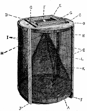
Fig. 1.—Conical hoop flytrap, side view. A, hoops forming
frame at bottom; B, hoops forming frame at top;
C, top of trap made of barrel head; D, strips around
door; E, door frame; F, screen on door; G, buttons
holding door; H, screen on outside of trap; I, strips
on side of trap between hoops; J, tips of these strips
projecting to form legs; K, cone; L, united edges of
screen forming cone; M, aperture at apex of cone
One of these traps
is illustrated in Figures 1 and 2. In constructing the trap
two of the hoops are
bent in a circle (18
inches in diameter on
the inside), and nailed
together, the ends
being trimmed to
give a close fit.
These form the bottom of the frame (A), and the other two,
prepared in a similar way, the top (B). The top (C) of the trap
is made of an ordinary barrel head with the bevel edge sawed
off sufficiently to cause the head to fit closely in the hoops and
allow secure nailing. A square, 10 inches on the side, is cut out of
the center of the top to form a door. The portions of the top (barrel
head) are held together by inch strips (D) placed around the
opening one-half inch from the edge to form a jamb for the door.
The door consists of a narrow frame (E) covered with screen (F)
well fitted to the trap and held in place (not hinged) by buttons (G).
The top is then nailed in the upper hoops and the sides (H) formed
by closely tacking screen wire on the outside of the hoops. Four
laths (I) (or light strips) are nailed to the hoops on the outside of
the trap to act as supports between the hoops, and the ends are
allowed to project 1 inch at the bottom to form legs (J). The legs
are made to project inches when the traps are to be used with
bait pans 4 inches deep in trapping screw-worm flies. The cone
(K) is cut from the screen and either sewed with fine wire or soldered
where the edges meet at (L), or a narrow lath may be nailed along
these edges. The apex of the cone is then cut off to give an aperture
(M) 1 inch in diameter. It is then inserted in the trap and closely
tacked to the hoop around the base.
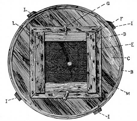
Fig. 2.—Conical hoop flytrap, top view. Letters designate parts as in
Figure 1
The construction of a cone of any given height or diameter is
quite simple if the following method be observed. It is best to cut
a pattern from a large piece of heavy paper, cardboard, or tin.
Figure 3 illustrates the method of laying out a cone of the proper
dimensions for the above trap. An ordinary square is placed on
the material from which the pattern is to be cut; a distance (22
inches) equal to the height of the cone is laid off on one leg of the
square at A, and a distance (9 inches) equal to one-half of the
diameter of the base of the cone is laid off on the other leg at B,
and a line is drawn between the points A and B. With the distance
between these points as a radius and with the point A as a center,
the portion of a circle, CD, is drawn. With a pair of dividers, the
legs of which are set 1 inch apart, or with the square, lay off as many
inches on the arc CD, starting at C, as there are inches around the
base of the cone, which in this case is about 56½ inches, reaching
nearly to the point E. Then add one-half inch for the lapping of
the edges of the cone, and one-half inch which is taken up when the
cone is tacked in, thus making a total distance from C to E of 57½
inches. Draw a line from A to C and another from A to E, and cut
out the pattern on these lines and on the arc from C to E, as shown
in Figure 3. The edges AC and AE are then brought together,
lapped one-half inch, and sewed with wire or soldered. After the
aperture of the cone is formed by cutting off the apex, as previously
described, it is ready for insertion in the trap.
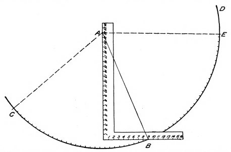
Fig. 3.—Method of laying out a pattern for the construction of a cone. Cut out on
curved line from C to E and on dotted lines from A to C and A to B
In order to figure the distance around the base of a cone of any
given diameter, multiply the diameter by 3.1416 or 31⁄7.
The height of the legs of the trap, the height of the cone, and the
size of the aperture in the top of the cone, each is of importance in
securing the greatest efficiency.
A modification of the previously described trap has been made by
D. C. Parman of the Bureau of Entomology. The principal point
of advantage in this type is that it can be made more quickly and
with fewer tools. The principles and dimensions are the same, the
most striking difference being the absence of a wooden top. A
single hoop with the thick edge down forms the upper frame of
the cylinder and the entire top is made of screen. A circular piece
of screen with a diameter about 3 inches greater than the diameter
of the cylinder is cut; a hoop with a diameter equal to the inside
of the top of the trap is then made of heavy wire and laid upon
the disk of screen and the edges of the screen bent in over it.
By folding in and crimping the edges of the wire over the wire
hoop it will remain in position without difficulty and the edges of the
screen disk are used to lift the top of the trap out for emptying flies.
It is important to have the screen top fit the inside of the cylinder
very snugly at all points. If there is any space left where flies can
escape it is a good plan to bind the edge of the top with a strip of
burlap. This not only helps to close the openings but keeps the hoop
in place and aids in removing the top. Another difference is that the
screen forming the sides of the cylinder is placed on the inside of the
hoops and legs, the frame being built first and then the cylinder
formed by tacking the wire on the inside of the hoops and nailing in
along the upright strips and against the wire short pieces of laths
with their upper ends against the lower edge of the hoop forming
the top of the trap and extending downward along the legs about two-thirds
of their length. These strips hold the wire in place and give
rigidity to the trap, and they are thick enough to project beyond the
inner surface of the hoop and form a support upon which the edges
of the screen top rest.
Conical traps with galvanized-iron frames are satisfactory, but
they are less easily rescreened. These, of course, can be constructed
only by shops with considerable equipment. Traps constructed with
a wooden disk about the base of the cone, and a similar disk around
the top to serve as a frame, or those with a square wooden frame at
the bottom and top, with strips up the corners, are fairly satisfactory.
It should be borne in mind, however, that the factor which
determines the number of flies caught is the diameter of the base of
the cone, if other things are equal. Therefore, the space taken up by
the wooden framework is largely wasted, and if it is too wide it will
have a deterrent effect on the flies which come toward the bait. For
this reason it is advisable that the wood around the base of the cone
should be as narrow as consistent with strength—usually about 3
inches.
Under no condition should the sides or top of the trap be of solid
material, as the elimination of light from the top or sides has been
found to decrease the catch from 50 to 75 per cent.
Where large numbers of traps are to be constructed, and especially
if they are to be used for trapping screw-worm flies on the range, it is
desirable to make them with metal rather than wooden frames. Traps
with galvanized-iron frames are now being used extensively on
ranches in central and western Texas in combating the screw-worm
fly. Mechanics may wish to vary details of construction from those
given in the specifications, but the dimensions and general features
of the trap should not be altered. The cost of the metal-framed traps
varies from about $3.50 to $5 each according to the number ordered,
the workmanship, and the kind of materials used. For the guidance
of those who desire such traps the following directions, together with
a working drawing (fig. 4), are given:
Dimensions—As per working drawing.
Wire—14-mesh galvanized or preferably copper screen wire.
Cylinder—Wire gauze, to be soldered completely around inside of top ring
and at intervals of 2 inches or less in groove of bottom ring. Vertical seam to
be soldered entire and placed behind one leg. Where shipment of traps is not
contemplated the diameter of the top of the cylinder may be the same as that
of the bottom.
Top—Wire gauze to be soldered completely around periphery on inside of
top ring.
Cone—Wire gauze to be soldered completely around inside of cone ring and
vertically along seam. A 1-inch inlet hole shall be formed at apex of cone.
Frame—To be made of 24-gauge galvanized iron. This includes top and
bottom rings and legs.
Legs—Galvanized-iron channels made as per detailed drawing and secured
to top and bottom rings with four rivets, 1⁄8 inch in diameter, to each leg.
First turned and drilled as per drawing.
Bottom cylinder ring—J shaped, with bottom edge of cylinder dropped into
J—crimped and soldered to secure. Ends of ring riveted to secure.
Cone ring—Galvanized-iron band with 3⁄16-inch round iron wire rolled into
lower edge, as per cross-section drawing of "cone ring."
Wing nuts—Four copper wing bolts and nuts, as per drawing, to hold cone
securely in place.
Manure pits or boxes are desirable for the temporary storage of
manure, especially in towns and cities. These have been widely
advocated, but the difficulty has been that manure often becomes
infested before it is put into them, and flies frequently breed out
before the boxes are emptied and often escape through the cracks.
To obviate these difficulties a manure box or pit, with a modified
tent trap or cone trap attached, is desirable. Arthur Swaim, of
Florida, has devised a form of manure trap consisting of a series of
screen tents with exit holes along the ridges of these, over which is a
screen box. The latter retains the flies as they pass through the
holes in the tents. The entire trap is removable.
In order to retain the fertilizing value of manure to the greatest
extent, it is advisable to exclude the air from it as much as possible
and to protect it from the leaching action of rains. This being the
case, there is really no necessity to cover a large portion of the top
of the box with a trap, but merely to have holes large enough to
attract flies to the light and cover these holes with ordinary conical
traps with the legs cut off so the bottom of the trap will fit closely
to the box. The same arrangement can be made where manure is
kept in a pit. In large bins two or more holes covered with traps
should be provided for the escape of the flies.
Manure boxes should be used by all stock owners in towns and
cities, and they are also adaptable to farms. The size of the manure
bin should be governed by the individual needs, but for use on the
farm it is desirable to make it large enough to hold all of the manure
produced during the busiest season of the year. A box 14 feet long,
10 feet wide, and 4 feet deep will hold the manure produced by two
horses during about five months. About 2 cubic feet of box space
should be allowed for each horse per day. The bin should be made
of concrete or heavy plank. When the latter is used the cracks
should be battened to prevent the escape of flies. The bin should have
a concrete floor or it may be set in the ground several inches and the
dirt closely banked around the outside. For the admission of the
manure a good-sized door should be provided in either end of a large
bin. A portion of the top should be made easily removable for convenience
in emptying the box, or one entire end of the box may be
hinged. On account of the danger of the door being left open
through carelessness it is advisable to arrange a lift door which can
be opened by placing the foot on a treadle as the manure is shoveled
in. The door should be heavy enough to close automatically
when the treadle is released.
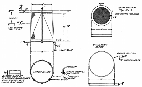
Fig. 4.—Working drawings of all-metal flytrap. The cones are removable and
traps and cones can be telescoped for shipment. The trap may be made 18 inches in diameter
at the top as well as at the bottom if traps are not to be shipped.
[Click on image to view larger sized]
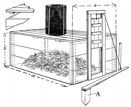
Fig. 5.—Use of flytrap in connection with manure bin. A, block of wood set in ground
to which lever raising door is hinged
A concrete pit set on a slope so that the manure may be dumped in
from a wheelbarrow is convenient for dairy farms. For large stock
farms it may be desirable to have a concrete pit so constructed as to
permit of the manure being taken directly into it with a litter carrier
and doors provided which are large enough to admit a wagon or
manure spreader for the removal of the material.
A manure bin with flytrap attached is shown in Figure 5.
Attention is directed to a maggot trap devised by R. H. Hutchison,
as described in Farmers' Bulletin 851 of the Department of Agriculture.
Where large quantities of manure are produced on a farm,
this method of storing the manure on a platform and trapping the
maggots which breed out may be more convenient than the manure bin.
C. F. Hodge has designed a trap which is really a modified tent
trap adapted to use in a window. This trap is constructed so
as to catch the flies as they enter or leave through the window. It
is adaptable to barns which are fairly free from cracks or other places
where flies may enter. It may also be used on windows of buildings
where foodstuffs are prepared and where flies endeavor to enter
through the windows or escape after having gained entrance through
other passageways. All openings not provided with traps should be
closely screened, and on large buildings traps may be installed in
every third window.
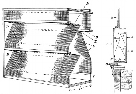
Fig. 6.—Hodge type window trap. At left, trap with end removed to show construction;
at right, cross section of trap placed in a window. A, end of trap; B, upper side of
folds in screen; C, lower side of folds in screen; D, portion of end of trap sawed out
and returned after attaching screen; E, holes along apex of folds; F, door for
removing dead flies; G, window sill; H, upper window sash; I, inside entrance for
flies; O, outside entrances
This trap is essentially a screen box closely fitted to the frame of a
window. (See fig. 6.) The thickness of the box at A should be about
12 inches. Instead of the screen running straight down over the box
on either side, it is folded inward nearly to the center of the frame
in V-shaped folds running longitudinally across the window. One,
two, or even more folds may be made in the screen on either side.
The upper side of the fold B should extend toward the center almost
at right angles with the side of the trap; that is, parallel with the
top and bottom; and the lower side C should slant downward as
shown in the drawing. The sides of the frame may be cut out at
the proper angle and the pieces D returned after the screen has been
tacked along the edges. Along the apex (inner edge) of each fold is
punched a series of holes E about one-half inch in diameter and 1
inch apart. The apices of the folds on either side of the window
should not be directly opposite. A narrow door F opening downward
on hinges should be made on one side of the trap at the bottom
for removal of the dead flies. The entire trap is fastened to the window
by hooks so that it may be readily taken off. An additional
trapping feature may be added by providing a tent trap fitted in the
bottom of the box. A narrow slit is left along the base to allow the
flies to enter beneath the tent. Bait may be placed under the tent to
attract the flies.
It has been found that the use of these window traps will aid in
protecting animals in barns from stable flies and mosquitoes, and in
some cases horseflies and other noxious species are caught. They
tend to exclude the light, however, and are somewhat cumbersome,
especially in thin-walled buildings.