Notes on the Development,
Use and Care of Modern Field Artillery
Equipment, Including the
3” Field Gun, American, French and
British 75s, the 4.7” Gun, 155-mm
Howitzer, GPF, Fire Control Instruments,
Signal Equipment and small
arms used by the Field Artillery—automatic
pistol, automatic rifle and
the Browning machine gun.
Compiled by
JAMES P. KELLY
1ST LIEUT. FIELD ARTILLERY
U. S. ARMY
COPYRIGHT
BY
THE UNIVERSITY CO-OPERATIVE STORE UNIVERSITY OF MISSOURI
COLUMBIA, MO.
1920
DEDICATION
To those efficient officers and
inspiring gentlemen who interested
the “youngsters” of the Yale batteries
in the service of their country,
and, in a time of peace, prepared
them for the duties which
they later performed in a time of
war, this book is gratefully and
respectfully dedicated.
ARTILLERY OF THE FUTURE.
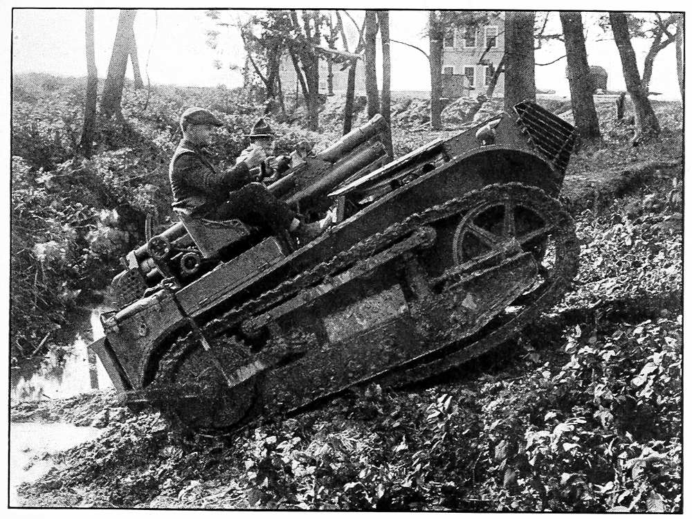
SELF-PROPELLING CATERPILLAR MARK VII 75-MM. GUN. MODEL 1916.
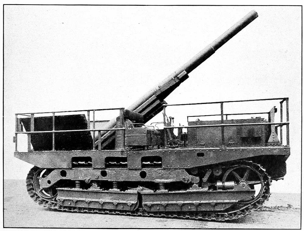
SELF-PROPELLING CATERPILLAR MARK II 155-MM. FILLOUX GUN.
INTRODUCTION.
The compiler of this volume believes that the Field
Artillery student should possess a broad, general knowledge
of the history and development of ordnance, with some idea
of the elements of gun construction; that he should be acquainted
with the organization, ideals and practicalities of
modern field artillery armament; that he should know the
ammunition and the guns in our Field Artillery service with
their care and maintenance.
It is also believed that in the R. O. T. C. units of Field
Artillery the student should make the complete 3” equipment
the basis of his knowledge of materiel. He should become
thoroughly and familiarly acquainted with this weapon, and,
to a lesser extent, with the other light pieces which are in
present use. The reason for this being that our experience in
the World War has shown that a thorough knowledge of one
class of materiel permits a ready adaptation to any other type.
He should also know the manner of functioning of the 4.7”
and 155-mm rifles, with a somewhat more intensive knowledge
of the 155-mm howitzer—and with a sound knowledge of the
capabilities and limitations of all.
To complete his instruction in materiel he should know
the use and care of Fire Control equipment, Signal equipment,
and the small arms used in the field artillery, pistol, automatic
rifle and machine gun.
The lack of a single volume covering the above has been
the cause of the compilation of this book. The compiler
hopes the R. O. T. C. student will find in it a text which will
be interesting, instructive and comprehensive. To the lieutenants
in charge of Department “A” and to those who aspire
to that responsibility it is hoped that this work will prove a
valued addition to their professional libraries.
The subjects covered herein have been taken wholly or
in part from the various official handbooks, from “Ordnance
and Gunnery, U. S. M. A.,” “Naval Gunnery, U. S. N. A.,”
“America’s Munitions,” “Gun Making in the U. S. A.,”
“Ordnance and Gunnery for Field Artillery Officers,” “Artillery
Firing,” “The Field Artillery Journal,” Ordnance Doc.
2033, from lecture notes taken at the School of Fire, Brigade
Training Pamphlets, and various other sources.
The compiler is indebted to Lt. Col. Lloyd E. Jones, F. A.
and Major H. C. Jackson, F. A. for the valuable advice and
the helpful assistance they rendered in this compilation.
Biblical references—Use by Romans in Punic wars—Greeks; Chinese use of pyrotechmy; French field artillery in the time of Charles VIII; Gustavus Adolphus and artillery in the 17th century; Louis XIV; Gribeauval’s work in 1765; Shrapnel, 1808; Smooth bores to rifles, middle of 19th century; French “75;” Period 1897 to date.
Discussions of types of artillery and their organization; missions and guns suitable to accomplish different missions; ideal and practical types for divisional corps and army artillery.
Oils and cleaning materials; tools and accessories; care and cleaning of different parts of carriages, emptying, cleaning and filling cylinders, cleaning bore, breech, springs, etc.; general instructions for care of cloth, leather and metal equipment. Cleaning schedules.
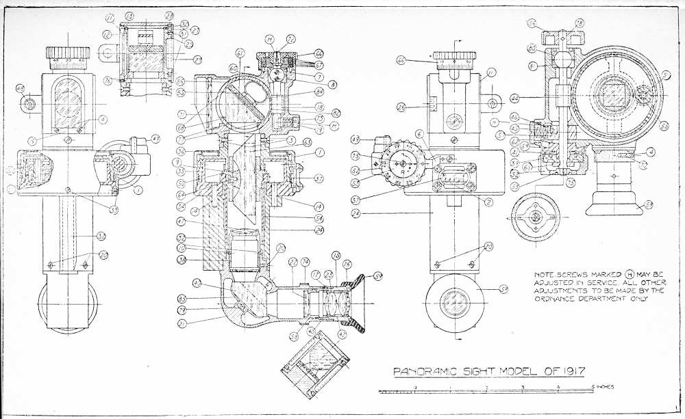
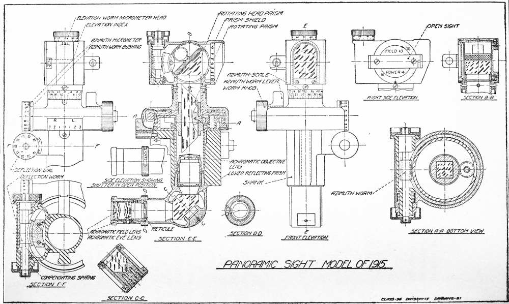
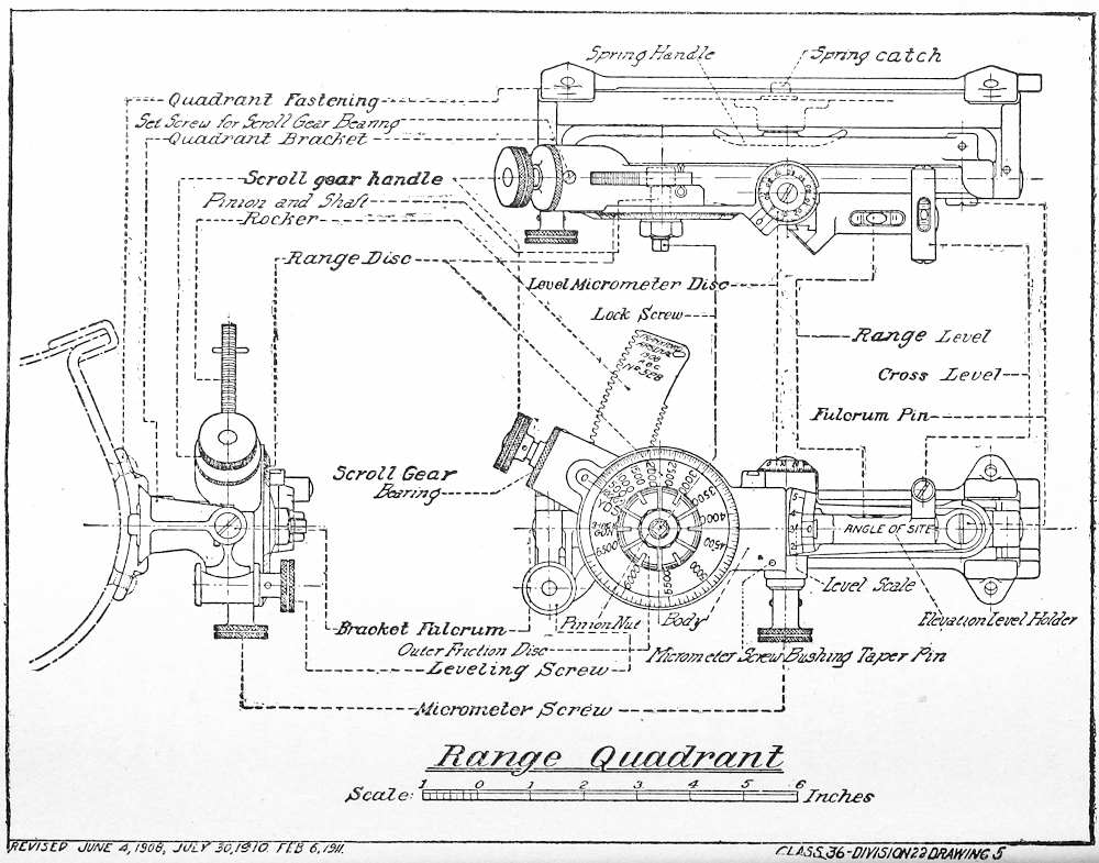
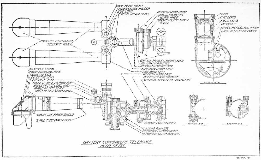
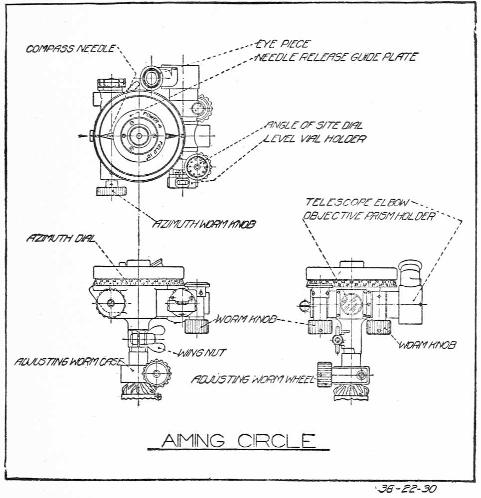
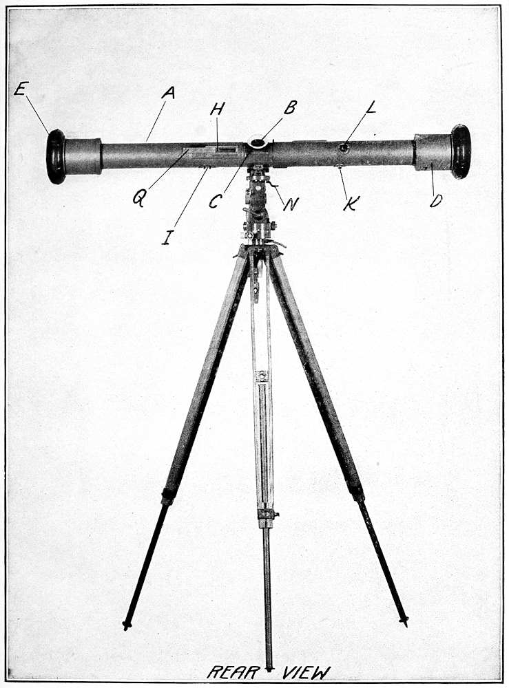
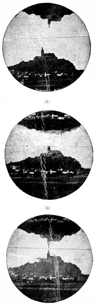
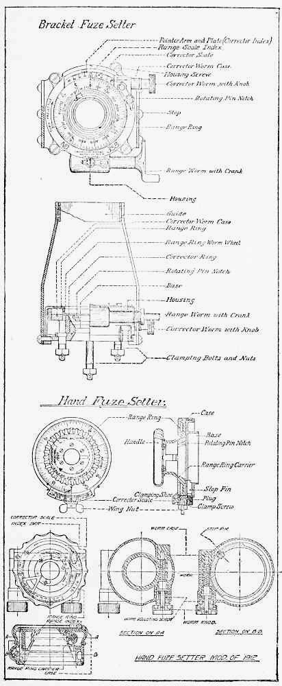
Sights—line, front and rear, panoramic; model 1915 and 1917 with their use, care and verification. Range Quadrant, care, use and adjustment. B. C. Telescope, model 1915 and Aiming Circle model 1916, with their use, care and adjustment. Range Finder, 1 meter base, use, care and adjustment. Field Glasses. Fuse Setters.
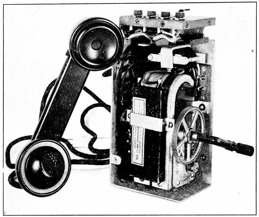
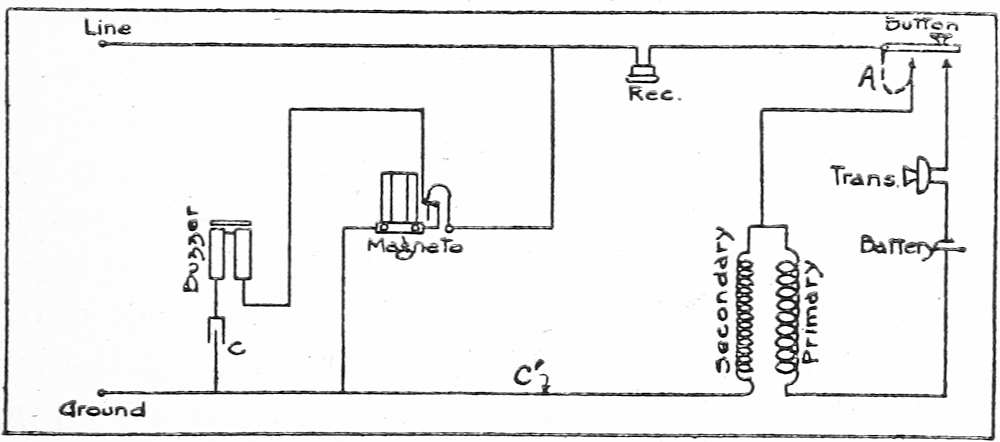
Telephones and Monocord Switchboards—description, use, adjustments, trouble shooting and care.
Projectors—description, use, adjustment, service code for lamps and buzzer, conventional signals.
Pyrotechnical signaling, classification of rockets, use, code.
Panels—liaison with airplanes, signals, description of panels, panel code.
Flags—classification, use of semaphore and wig-wag.
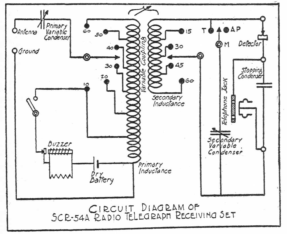
Radio—Description of equipment, SCR-54 and SCR-54-A Sets, methods of operation, use of vacuum detectors, precautions, sources of trouble, maintenance, reception of airplane signals.
In the study of any subject which is rather technical in
nature, it is absolutely essential that the reader be familiar
with the meaning of the words and phrases which must be
used in the matter to be discussed. If the subject matter
is to be understood there must be a common phraseology. The
reader is therefore strongly urged to perfect his knowledge of
the following short vocabulary before passing on to the matter
which follows.
Ammunition. A general term applied to all forms of powders,
shells, cartridges, primers, etc.
(a) Fixed Ammunition. When the powder charge is enclosed
in a metallic container which is fixed to the projectile,
it is called “Fixed Ammunition.”
(b) Semi-Fixed Ammunition. When the charge and metallic
container are a fixed unit but are not fastened to the
projectile, it is called “Semi-Fixed Ammunition.”
(c) Separate Ammunition. When the powder charge is
contained in bags separate from the projectile and containing
not a fixed but a varying charge, it is called “Separate
Ammunition.”
Artillery. All firearms not carried by hand, excepting machine
guns. It is divided into two general classifications:
(1) artillery of position, and (2) mobile artillery.
(1) Artillery of Position is that which is permanently
mounted in fortifications.
(2) Mobile Artillery consists of two classes: first, artillery
designed to accompany an army in the field; second,
railway artillery which requires tracks for its transportation.
Ballistics. The science of hurling projectiles or of the motion
of projectiles in their flight.
Bore. The hole which extends from the muzzle to the breech.
The passageway for the projectile. That part of the
tube which is bored out.
Breech. The rear end of the gun, tube, or barrel.
Caisson. A two-wheeled vehicle which supports an ammunition
chest. The wheeled equipment of a gun section
consists of one gun with its limber and one caisson with
its limber. For a caisson section it consists of two caissons
with their limbers.
Caliber (Calibre). The diameter between the highest points
in the bore.
Carriage, gun. Usually understood to mean all the piece
except the tube with its appurtenances and the limber.
Cartridge case. A hollow cylinder shaped to fit the bore. A
container for the propelling charge.
Charge.
(a) Propelling. A quantity of powder used in the bore to
generate the gases which propel the projectile from the
gun.
(b) Bursting. A quantity of powder used in shrapnel to
strip off the head of the projectile and to force out the
balls.
(c) Explosive. The matter used in a shell to detonate it
at the end of its flight.
Cradle. In general, that part of the carriage which houses the
recoil and counter-recoil mechanisms.
Elevating Mechanism. The device used to elevate the gun
through a vertical arc in order to give the gun an elevation
corresponding to the desired range at which the
piece is to be fired.
Fire Control Equipment. Those instruments used to compute
firing data, observe and correct the fire, such as B. C.
Telescopes, Aiming Circles, Range Finders, etc.
Firing Mechanism. A device located in the breechblock for
exploding the primer and thus causing the ignition of the
powder charge.
Fuze. That part of the round which is fastened to the point or
to the base of the projectile and causes the latter to be
detonated or exploded near the time or the place desired.
Fuze Setter. A device used to set time fuzes in such a manner
that shrapnel or shell will burst at or near the desired
height in air.
Gun. A metallic tube from which projectiles are hurled
by gases generated from the ignited powder. In general,
all fire arms; but in Field Artillery terms, comparatively
long-barreled weapons using relatively high muzzle
velocity in contra-distinction to the howitzers and mortars.
Howitzer. A weapon which differs from a gun in that for
the same caliber it uses a shorter tube, lower muzzle
velocity and generally a more curved trajectory. From
two to seven varying strengths of propelling charges may
be used in the howitzer. This gives it selective angles of
fall, and allows the howitzer to reach targets that are
hidden from the flat trajectories of guns.
Initial Velocity. The speed with which the projectile first
moves.
Limber. A two-wheeled carriage which is sometimes used
to carry an ammunition chest and always used to support
the weight of the trail of the piece or caisson. It adds
the other two wheels to make a four-wheeled vehicle.
Materiel. A term used in the Field Artillery in contra-distinction
to Personnel.
Mortar. A weapon using for the same caliber, a barrel much
shorter than the corresponding howitzer. Used at short
ranges with extreme steep angles of fall to reach highly
defiladed targets.
Muzzle. The front end of the bore.
Muzzle Velocity. Speed or velocity of the projectile measured
as it leaves the muzzle.
Ogive. The rounded shoulder of the projectile.
Ordnance. Arms, ammunition, and their accessories.
Piece. A fire arm, small or large.
Primer. Device used to insure ignition of the propelling
charge.
Projectile. The effect-producing part of the round. The
bullet-like form which is thrown toward the target.
Quadrant, gunners. A device for measuring angles of elevation.
Recoil Mechanism. That part of the piece which checks the
recoil—or kick—that always occurs when a piece is
fired. It generally includes the counter-recoil mechanism
which restores the tube “into battery” after it has
fired.
Rifle. A gun. A weapon with a comparatively long barrel
and high muzzle velocity. Rifles under 6 inches seldom
use over two different charges. Term used in contrast
to Howitzer or Mortar.
Rifling. The lands and grooves in the bore of the piece which
imparts to the projectile during its passage through the
bore, the rotary motion that increases accuracy and range.
Round. Consists of the primer, cartridge case or powder
bags, projectile and fuze. For light Field Artillery the
round weighs about 18 lbs and the projectile about 15.
Shell. A projectile which secures its effect by the force of its
detonation, the bursting of its walls, and the fragmentation
and velocity of the fragments. Also used as a gas
carrier.
Shrapnel. A projectile which secures its effect by the expulsion
in the air of lead balls with shot-gun like effect.
Trail. That part of the piece which extends from the axle
to the rear and transmits the force of recoil to the ground
through the trail spade. Usually supports the elevating
and traversing mechanisms.
Traversing Mechanism. A device used to give the piece
direction by moving it through a horizontal arc.
CHAPTER II HISTORY AND DEVELOPMENT OF MATERIEL.
In taking up the study of materiel, the Field Artillery
student should know something of the history and development
of ordnance and the reasons for the various changes
which have taken place from time to time.
The sole use of a gun is to throw a projectile. The earliest
projectile was a stone thrown by the hand and arm of man—either
in an attack upon an enemy or upon a beast that was
being hunted for food. Both of these uses of thrown projectiles
persist to this day, and, during all time, from prehistoric
days until the present, every man who has had a missile to
throw has steadily sought for a longer range and a heavier
projectile.
In ancient times the man who could throw the heaviest
stone the longest distance was the most powerfully armed.
During the Biblical battle between David and Goliath, the
arm of David was strengthened and lengthened by a leather
sling of a very simple construction. Much practice had given
the youthful shepherd muscular strength and direction, and
his stronger arm and straighter aim gave him power to overcome
his more heavily armed adversary.
Projectile-throwing machines were developed after the
fashion of a crossbow mounted upon a small wooden carriage
which usually was a hollowed trough open on top and upon
which a stone was laid. The thong of the crossbow was drawn
by a powerful screw operated by man power, and the crossbow
arrangement when released would throw a stone weighing
many pounds quite a distance over the walls of a besieged
city or from such wall into the camps or ranks of the besiegers.
This again was an attempt by mechanical means to develop
and strengthen and lengthen the stroke of the arm and the
weight of the projectile. The Bible states that King Usia
(809-757 B. C.) placed types of artillery on the walls of Jerusalem.
The Romans used it in the Punic Wars. The Alexandrian
technicians established scientific rules for the construction
of early weapons. Athenaeus reports catapults having
a range of 656 meters and that the gigantic siege tower at
Rhodes successfully resisted stone projectiles weighing 176
pounds.
References to explosives are to be found in works as old
as Moses. Archimedes is said by Plutarch to have “cast huge
stones from his machines with a great noise;” Caligua is said
by Dion Cassius to have had machines which “imitated
thunder and lightning and emitted stones;” and Marcus
Graecus in the eighth century gives a receipt of one pound of
sulphur, two of willow charcoal and six of saltpetre, for the
discharge of what we should call a rocket.
The use of Greek fire was understood as early as the sixth
century, but powder was earliest used in China, perhaps a
thousand years before Christ, and was introduced to European
notice by the Saracens.
From the discovery of gunpowder by the English monk
Bacon in 1248, sixty-five years elapsed before a Franciscan
monk produced the first gun in Germany, about 1313. The
first guns were of a small breech-loading type, supported in
front by crossed sticks and anchored by a spike at the breech.
Later these guns were fastened to cradles, the latter being
mounted on sleighs, and finally, in 1376, the Venetians produced
the first wheel mounts, which had become common by
1453, when the Turks took Constantinople.
The ancient carriages were remarkable because of the
fact that in general design they embodied the same principals
which are included in the field carriages of to-day. One example
from the fifteenth century shows a breech-loading
gun mounted in a cradle supported by trunnions on the forward
extension of the trail over the axle. The cradle was
elevated by a pin-and-arc arrangement, supported on the trail.
The axle supported by wheels passes through the trail to the
rear of and below the cradle trunnion support and in front of
the point of attachment of the elevating arc.
Field guns fell into disuse about 1525 with the introduction
of musketry, and remained so until 1631, when Gustavus
Adolphus gave artillery its true position on the battlefield.
Swedish artillery reigned supreme in the early part of the
seventeenth century. Gustavus introduced marked changes
by making the guns and the carriages lighter and handier,
and by adapting their movements to those of the other arms
and to the requirements of the battlefield. In this, as in all
his military efforts, his motto was mobility and rapidity of
fire.
In 1624 Gustavus had all his old types of guns recast into
newer models and the following year he himself contrived a
gun which three men and one horse could maneuvre to good
effect. It was an iron three and four pounder with a cartridge
weighing less than a pound and consisting of a charge held in
a thin wooden case wired to a ball. This was the first artillery
cartridge, the original fixed ammunition. The gun was afterwards
used in other European armies and known as the “piece
Suedoise.” Not only had it the advantage of lesser weight
but its cartridge was always ready to fire and it could be
fired eight times to the six times of the infantry musket of
that day.
In the wars against the Poles, Gustavus employed with
profit the so-called leather cannon, a fact which shows how
lacking the times were in artillery power. These guns were
invented in the early 1620s by a Colonel Wurmbrandt, and
consisted of a thin copper tube reinforced by iron bands and
rings, then bound with rope set in cement, the whole covered
with sole leather. The tube was made to screw in and out
because it grew heated by from eight to twelve charges and
had to be cooled. The gun carriage was made of two planks
of oak. The gun without the carriage weighed about ninety
pounds and was fired with a light charge. They were used
during 1628-29 and then gave way for four pounder cast-iron
guns which remained in common usage in Europe until artillery
was reorganized by Frederick.
Gustavus’ batteries excited universal admiration. Grape
and canister were generally employed in the field guns and
round shot only in the siege guns. Artillery was used massed
or in groups and also with regiments of foot soldiers. Gustavus
was probably the first to demonstrate the real capabilities
of artillery.
Mortars throwing bombs were first used at the siege of
Lamotte in 1634. Hand grenades, shells, fire-balls, etc.,
came into more general use as the German chemists made their
new discoveries. Artillery practice grew to be something of
a science; experts took it up and the troops were better instructed.
Regimental artillery, that is, artillery with the infantry,
was attended by grenadiers detailed for the work.
There were special companies for serving the reserve guns.
The period following the Thirty Years’ War—the middle
of the seventeenth century—gave no great improvement to
the art of war but there were many marked advances in the
matter of details of construction. During the era of Gustavus
it was Sweden that led in making war more modern; during
the era of Louis XIV it was France.
Artillery ceased to be a guild of cannoneers as it long had
been and became an inherent part of the army. More intelligence
was devoted to it and more money spent on this arm
of the service; it grew in strength and importance, and was
markedly improved. But while the artillery service ceased
to be a mere trade, it did not put on the dignity of a separate
arm, nor was the artillery of any great utility in the field until
well along in the eighteenth century. Guns, however, in
imitation of the Swedes, were lightened, particularly so in
France; powder was gradually compounded on better recipes;
gun-metal was improved; paper and linen cartridges were introduced;
gun carriages were provided with an aiming wedge;
and many new styles of guns and mortars, and ammunition
for them were invented.
Science lent its aid to practical men, and not only exhausted
chemical ingenuity in preparing powder and metal, but
mathematical formulas were made for the artilleryman, and
value of ricochet firing was discovered. Louis XIV founded
several artillery schools, and initiated the construction of
many arsenals. Fontainebleau, the French artillery school
which trained many Americans during the World War had
its beginning in this period. Finally, the artillery was organized
on a battery and a regimental basis, and careful
rules were made for the tactics of the guns. These were
served by dismounted men and generally hauled by contract
horses.
Although sensibly improved, the artillery was far from
being skillfully managed and was slow firing; it usually stood
in small bodies all along the line of battle. It was heavy and
hard to handle and haul, principally because the same guns
were used for both siege and field work, and was far from being,
even relatively to the other arms, the weapon which it is to-day.
In 1765 General Gribeauval of France introduced artillery
improvements, especially in the carriages, and formed a distinct
artillery service for the field which was lighter than the
old service and was drawn by teams which were harnessed
double as they are to-day.
Howitzers were introduced in France in 1749. The weapons
were given an early sort of perfection by the Dutch.
The term “howitzer” comes from the German “haubitz.”
In 1808 the first shrapnel appeared at Vimera. It was invented
by an English colonel by the name of Shrapnel. At
the time it was known as case shot. The type employed by
Napoleon, had a fuze that could be used at two different
ranges. The French still have this type in their armament.
Field artillery now began to appear in the form which it
was to retain with but a few changes, until the era of the modern
field carriage. The cradle disappeared, muzzle-loading
guns cast with trunnions taking its place, and a stepped wedge
resting on the trail superseded the pin and arc. With the
exception of the gun, most parts of these carriages were of
wood and were to remain so until 1870, when metal carriages
came into general use. Muzzle loading guns had supplanted
breech-loaders because of the poor obturation and the many
accidents resulting from use of the latter type. Although
numerous experiments were made, breech-loading guns did
not come into vogue again until 1850, when the experiments
of Major Cavalli (1845), the Walnendorff gun (1846) and
the Armstrong gun (1854), produced satisfactory types.
Up to 1860 practically all guns were smooth bore. Even
during the Civil War the smooth bore was generally used,
although the rifled gun began to make an appearance and
was used in small numbers by both sides at the battle of
Gettysburg. Some breech loaders began to appear at the
same time. Improvement in the ballistic properties of the
gun necessitated a corresponding improvement in the sighting
facilities. In 1880 rifled breech loading and built-up steel
cannon came into general use. Rifled guns shoot accurately
and as a result, improved methods in direct laying were devised.
The period between from 1880 to the present, has brought
about changes in gun construction which, possibly, have been
equaled in importance to artillery only by the present change
which is taking place in the means of artillery transportation
and self-propelling mounts. In this period in rapid succession
came the modern breechblock and with it the rapid firing gun.
This brought about the change to the present system of breaking
the force of recoil of the gun and restoring it to its firing
position without disturbing the position of the carriage. This
added to the possibilities of rapid and more accurate fire.
Then came the invention and use in the field artillery of
smokeless powder. Previous to this time the great amount
of smoke produced by the black powder when the piece was
fired retarded the rapidity of fire because it enveloped the
materiel in a thick cloud of smoke which obscured the target
and made it impossible to fire again until the smoke had blown
away. It made concealed positions for the artillery almost
impossible. The advent of smokeless powder made firing
more rapid and made possible the selection of concealed
positions. This in turn made indirect fire feasible and necessitated
the development of better sights. Indirect fire increased
the rapidity of fire and gave to the commanders of
firing units a greater control over their fire. With the use of
recoil mechanisms and shields for the guns, the cannoneers
were permitted to serve the piece continuously—a condition
which was impossible with the recoiling carriage. The shields
made it almost impossible to put the gun out of action unless
some vital part of the mechanism was destroyed.
The first of the modern carriages which were produced
in the early nineties should be classified as semi-rapid carriages,
as the recoil brakes were so abrupt that the carriage
was not stable and jumped considerably, gaining for the type
the sobriquet of “grass-hopper guns.”
In 1897 the immortal French “75” was born, the pioneer
of all modern quick-firing field guns, which still maintains
its superiority in many respects over later designs.
In 1902 our own 3-inch field gun was produced and still
finds favor among many of our field artillery officers, even over
the French “75.”
The Deport carriage brought to this country from Italy,
in 1912, introduced to us the split trail, high angle of fire,
wide traversing type of field gun carriage. This carriage
was extensively tested by the Ordnance Department; by the
Field Artillery Board at Fort Riley, Kansas; and by the School
of Fire for Field Artillery, at Fort Sill, Oklahoma. The
Field Artillery Board unqualifiedly approved of the Deport
carriage and recommended that it be adopted. The School
of Fire for Field Artillery also approved of this type.
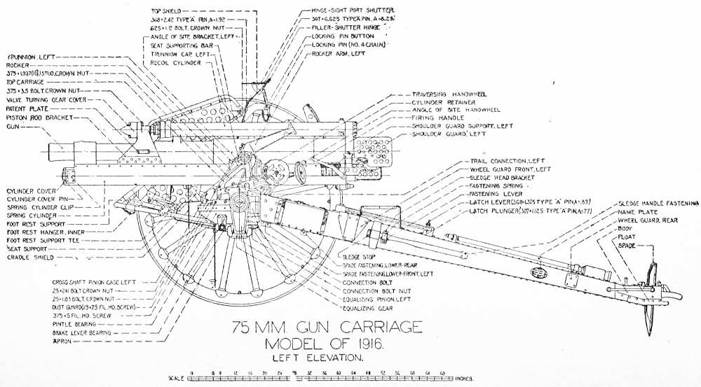
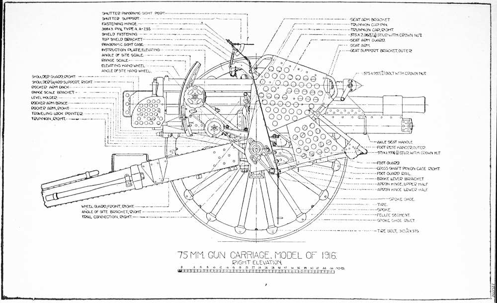
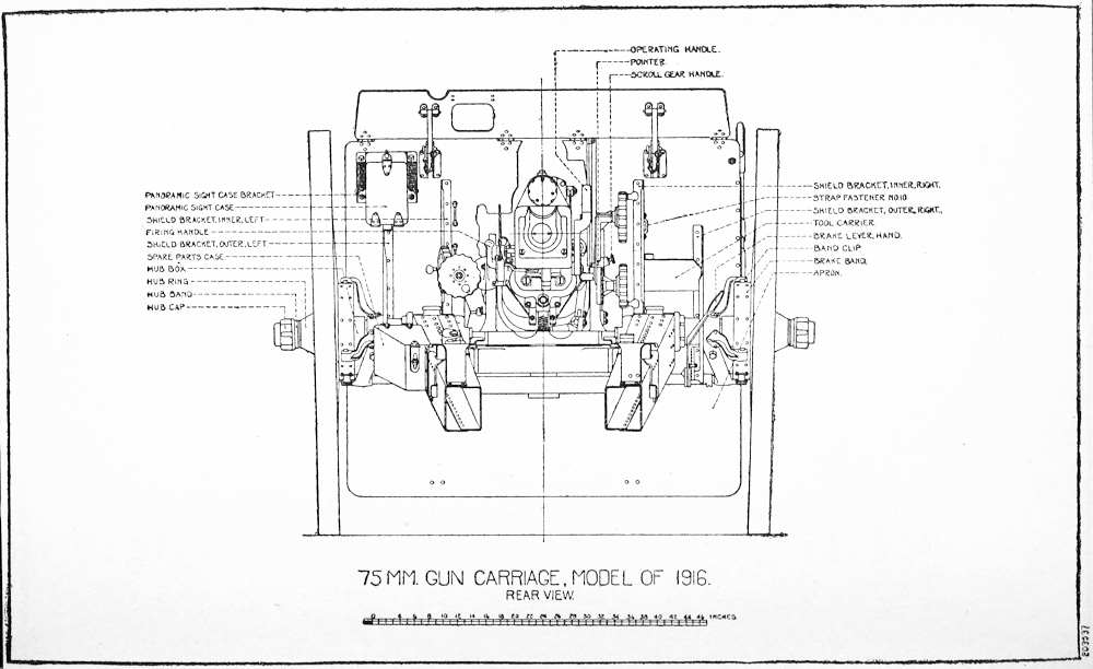
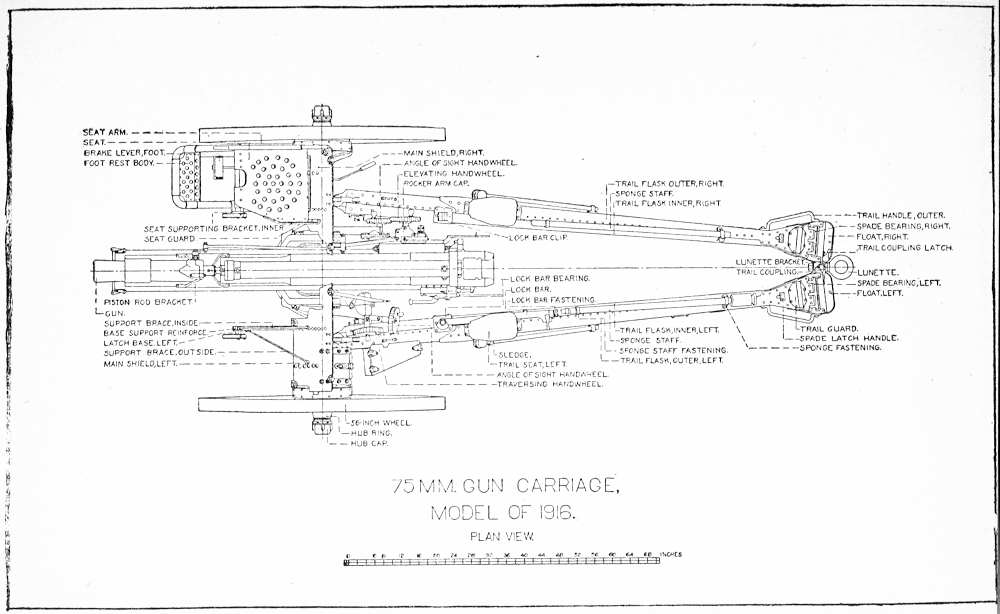
In 1916 the United States produced a 75-mm field gun
which featured a split trail with an elevation of 57 degrees
which permits its use as an anti-aircraft weapon and a variable
length of recoil which prevents the breech from hitting the
ground at the extreme elevations. It has a traverse of 800
mils in comparison to the 106 of the French 75 and the 142
and 140 of the British 75 and American three-inch field gun.
The outbreak of the late war saw all modern armies
largely equipped with guns resembling the French “75”
in a long-run recoil mechanism, weight of projectile and weight
of carriage, etc. The fact that the largest number of horses
which could best be handled to maneuver the light guns—about
6—could not pull over a long period a gun or caisson
with its limber if the weight was more than about 4500 pounds,
resulted in the practical standardization of light guns in all
armies. So in 1914 we see that time and development had
given light gun perfection and mastery of artillery technique
to the French while the Germans, probably, possessed the most
efficient artillery program. The German types of weapons
were more varied and perhaps better suited to the varying
artillery needs in rendering that assistance to the infantry
for which the artillery exists.
In our service during the World War, French 75s and the
155-mm Howitzer were used as divisional artillery. Two
regiments of the light guns and one regiment of 155-Howitzers
were assigned to each infantry division. As the war progressed
guns and howitzers ranging from the 4.7” rifle, up to, and including
14 and even 16-inch naval guns on railroad mounts,
were used as Corps and Army artillery.
Thus artillery development has gone steadily forward.
Every military power has striven with the aid of its best
engineers, designers and manufacturers to get a stronger
gun, either with or without a heavier projectile, but in every
case striving for greater power. As a special development
and a not too important one, due to its lack of effectiveness in
comparison to its cost, we find the now famous long range
gun of the Germans, successfully delivered a projectile approximately
9 inches in diameter into Paris punctually every
twenty minutes from a point about 75 miles distant. The
Germans used three of these guns in shelling Paris. Their
life was probably limited to about 75 rounds due to the excessive
demands made upon the materiel.
The American Field Artillery Service now has before it
four types of field gun carriages, namely our 3” model of 1902;
the French 75 M-1897; the British 18 pounder, M-1905 converted
to a 75-mm (known as the model of 1917); and our
75-mm model, 1916. There is being produced (1919-20)
an improved model of 1916 75-mm carriage on which the St.
Chamond pneumatic recuperator, adopted jointly by the
American and French governments, will be substituted for the
spring recuperators; and the French 75-mm gun will be substituted
for our shorter calibered type. From these types one
must be selected. An intelligent selection involves a consideration
of what may be expected in the future in order that
it may best fit in with the new types yet to be evolved.
For horsed artillery—and horse artillery will be with us
for some years to come—the limiting features of draft and
man power will still pertain.
For tractor-drawn mobile artillery, the limiting feature
is the tractive power of the tractor with relation to the weight
of the gun and carriage, the unit being physically limited in
weight by the supporting-power of the pontoon bridge which
is about 10,000 pounds per vehicle.
For Caterpillar Artillery.—By that is meant guns
mounted on caterpillar tractors—the limiting features are
power and weight, coupled with the weight limitations of the
pontoon bridge. To circumvent the question of weight, the
load may be divided by mounting the motor by an electric
generator on one caterpillar and the gun with an electric
motor, on the other, a transmission cable connecting the two
vehicles.
In conclusion it might be said that one of the greatest
changes which has ever taken place in the development of
field artillery is now underway in the form of motorization.
Prior to 1917 horse traction had been the sole means of transporting
mobile field artillery. The limit of the capabilities
of horse traction placed a weight limit upon gun construction
and to some extent upon artillery tactics. The increase in
the ratio of field artillery to infantry, the corresponding demand
for artillery types of horses and the decrease in the
availability of the latter as the war continued, combined with
the great improvements which were constantly being wrought
in mechanical transportation as the war lengthened, opened
the way for artillery motorization.
The French began by placing their 75s on trucks for
rapid changes of position. All the armies saw the possible
advantages to be gained from the use of trucks with artillery
but none planned—nor have any since put into practice—the
extensive use of trucks, caterpillar tractors and motor transportation
for personnel, which the United States planned on
her entrance into the war. It was planned to equip about one-third
of the A. E. F. artillery regiments with complete motor
equipment. This plan did not entirely materialize but after
the armistice the 3rd Field Artillery Brigade of the 3rd
Division was completely motorized and its practice marches
in Germany were most successful and full of promise for the
future. To date the motorization of all our mobile Field
Artillery, with the exception of about fifty per cent of the
light field guns, has been authorized.
Motor traction gives a better performance than animal.
While the latter, especially with the light field guns, possesses
great mobility, it is not a sustained nor a persistent mobility;
it is more easily exhausted and requires longer to recuperate.
These are points of vital importance from a military viewpoint.
In 1920 a self-propelling caterpillar mounted with a 75-mm
gun, model 1916, was tested with a view to ascertaining
the ability of the motor to function in water, i. e. fording
streams, etc. The caterpillar successfully moved through
ice water which completely submerged the carburetor.
Passenger cars for the transportation of personnel, four
wheel drive trucks with caterpillar tractors for the transportation
of the materiel, and the development of self-propelling
mounts for the 75 and 155 rifles are the latest and the most
important developments in field artillery materiel.
CHAPTER III ELEMENTS OF GUN CONSTRUCTION AND DESIGN — TUBES — THE WIRE-WRAPPED GUN. — THE BUILT-UP GUN. — TWIST. — OUTER CYLINDERS. — BREECHBLOCKS. — GUN CARRIAGES. — TRAVERSING MECHANISMS. — ELEVATING MECHANISMS. — RECOIL MECHANISM. — SHIELDS. — SIGHTS. — WHEELS. — AXLES. — TRAILS. — CONCLUSION.
“A gun is a machine by which the force of expanding gas
is utilized for the purpose of propelling a projectile in a definite
direction.” It is essentially a metal tube closed at one
end, of sufficient strength to resist the pressure of the gases
caused by the combustion of the powder charge in the confined
space at the closed end of the tube behind the projectile.
The rapid combustion of the powder, which produces a high
temperature, gives rise to a pressure uniformly exerted in all
directions within the confined space. The energy exerted is
used in forcing the projectile from the tube.
Due to the effort of the large amount of superheated
gas generated, which tends to expand in all directions, tremendous
rending stresses are set up in the tube. Formerly
these stresses were met by a sheer mass of metal, but, as the
size of the projectiles increased and the necessary pressure to
give them muzzle velocity increased, the size of the guns increased
beyond the practical limits of mobility. This was at first
offset by forgings of refined alloyed steels, but even these failed
to keep pace with the increasing pressure desired. The new
condition was met by the introduction of the “built-up” and
the “wire-wrapped” guns. The modern built-up gun is
made by assembling one or more superimposed cylinders
around a central tube. The superimposed cylinders, whose
inside dimensions are slightly smaller than the outside dimensions
of those on which they are to be assembled, are expanded
by heat sufficiently to allow them to be assembled over the
tube. The subsequent contraction on cooling causes each
of them to exert a uniform pressure on the cylinder immediately
underneath. This method of assembling is called
“shrinkage.” This gives a compression to the inner tube and
a slight tension to the outer one. The compression is so
much additional strength to the tube because it must first be
overcome before the powder gases can exert a tension on the
inner tube fibers. The exact amount of the compression and
tension for all parts of a gun at rest or resisting an explosion
is a matter of mathematical calculation. The built-up construction
has been used in practically all our present day types
of field artillery.
Wire-wrapped guns consist of:
(a) An inner steel tube which forms a support on which
the wire is wrapped and in which the rifling grooves are cut.
(b) Layers of wire wrapped upon the tube to increase
its resistance by the application of an exterior pressure as well
as to add to the strength of the structure by their own resistance
to extension under fire.
(c) One or more layers consisting of a steel jacket and
hoops placed over the wire with or without shrinkage. The
jacket generally furnishes longitudinal strength to the guns,
and the breech block is screwed into the jacket, or into a
breech bushing, which is screwed into the jacket.
The principal advantages of this type of gun over the
built-up is economy of manufacture and greater facilities for
inspection of materiel in the layers over the tube. The wire
wrapping has itself a large reserve of strength due to the high
elastic limits that may be given it. Two methods are used to
wrap the wire: (a) at constant tension (b) at varying tension
so that when the gun is fired with the prescribed pressure,
all layers of wire shall be subjected to the same tangential
stress. The latter method is theoretically better, but because
of the ease of manufacture, together with the large
factor of safety possible, the wire is usually wrapped at a
constant pressure.
All army guns except small howitzers or mortars are of
the built-up or wire-wrapped type. Built up guns of less than
5” caliber, or howitzers up to 8” caliber consist of an inner
tube and a jacket shrunk onto this tube. The jacket covers
the breech end of the gun and extends forward to the center
of gravity. Built-up guns of larger caliber have one more
layer of hoops in addition to the jacket, one layer of hoops
usually extending to the muzzle.
The bore of the tube forms the powder chamber, the seat
for the projectile and the rifled bore. Rifling consists of a
number of helical grooves cut in the surface of the bore. The
soft metal of the rotating band of the projectile is forced into
these grooves causing the projectile to take up a rotary motion
as it passes through the bore. This is necessary in order to
keep the projectile stable in its flight.
By twist of rifling is meant the inclination of one of the
grooves to the element of the bore at any point. Rifling is
of two kinds: (a) Uniform twist, or that in which the twist
is constant throughout the bore, (b) Increasing twist or
that in which the twist increases from the breech towards the
muzzle.
The twist of rifling is usually expressed in the number of
calibers length of bore in which it makes one complete turn.
The twist actually required at the muzzle to maintain the
stability of the projectile varies with the kind of projectile
and the muzzle velocity. If a uniform twist be used, the
driving force on the rotating band will be at a maximum when
the pressure in the guns is at a maximum—or near the origin
of rifling (seat of the projectile). The increasing twist
serves to reduce the maximum driving force on the band thus
lessening the danger of stripping the band. This is its principal
advantage over the uniform twist, though it also reduces
slightly the maximum pressure in the gun. The principal
disadvantage of the increasing twist is the continued change
in form of the grooves pressed in the rotating band, as the projectile
passes through the bore. This results in increased
friction and a higher value for the passive resistance than with
a uniform twist. (Note: greater ranges obtained by cutting
grooves in projectile, principal used on the long range gun by
the Germans.) If the twist increases from zero at the breech
uniformly to the muzzle, the rate of change in the tangent to
the groove is constant. A twist in this form offers less resistance
than the uniform twist to the initial rotation of the projectile.
To still further diminish this resistance a twist that
is at first less rapid than the uniformly increasing twist and
later more rapid has been generally adopted for rifled guns.
Formerly in our service the twist was uniform; one turn
in 25 calibres for guns and one turn in 20 calibres for howitzers.
All the latest model army guns, however, have an increasing
twist of one turn in 50 calibres at the breech to one turn in
25 calibres at a point from 2 to 4 calibres from the muzzle.
In howitzers and mortars the twist is sometimes one turn in
40 calibres at the breech to one turn in 20 calibres at a point
several calibres from the muzzle. Some mortars are rifled
with a uniform twist and some guns have a rifling which begins
with a zero twist. (The 1905 3” gun, 0 to 1 in 25.)
Outside of the tube is the jacket. It extends to the rear
of the tube a sufficient distance to allow of seating the breech
block. In this manner the longitudinal stress due to the pressure
of the powder gases on the face of the breech block is
transmitted to the jacket thus relieving the metal of the tube
from this stress. In all built-up guns there is some method
devised for locking the tube to the jacket so as to prevent relative
movement of these parts.
Considering the gun alone the greatest range is obtained
at an angle of about 43 degrees from that gun which fires
the heaviest projectile with the greatest velocity. The caliber
being limited to from 2.95 inch to 3.3 inch, the projectile is
limited in weight to from 12 to 18 pounds. The weight of the
gun is limited to between 700 and 1000 pounds and in length
to between 27 and 36 calibers. The longer the gun, the greater
the weight and velocity from the same charge of powder.
A pressure of 33,000 pounds per square inch with a corresponding
velocity of 1700 f. s. has been found to be as high a
pressure and velocity as are desirable for a reasonable length
of life for a field gun, the average life of which is 10,000 accurate
rounds.
Under the French school of artillery, which dominates
our service at present, our bore is 75-mm, the weight of our
shell 12 pounds, our shrapnel 16 pounds, the velocity for the
one about 1,750 f. s. and for the other about 1,680 f. s.
The breechblock appears in four distinct types. Our
own service has for years used the swinging interrupted screw
breechblock which in the 1905 model is the equal of any of
that type in existence. The swinging block has serious
disadvantages for high angle fire in that it requires an excessive
amount of room to operate and is difficult to load at
high elevations.
The Italians have introduced a new breechblock in one
of their recent guns, consisting of a half cylinder with superimposed
spherical face on its cylindrical surface rotating vertically
about a horizontal axis perpendicular to the axis of
the bore. The gun is loaded through a groove in the breechblock
when the latter is in its horizontal position. The block,
which is semi-automatic, is very satisfactory. It is adapted
to high angle fire.
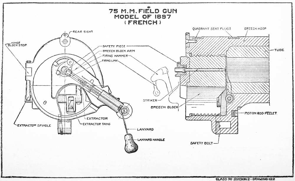
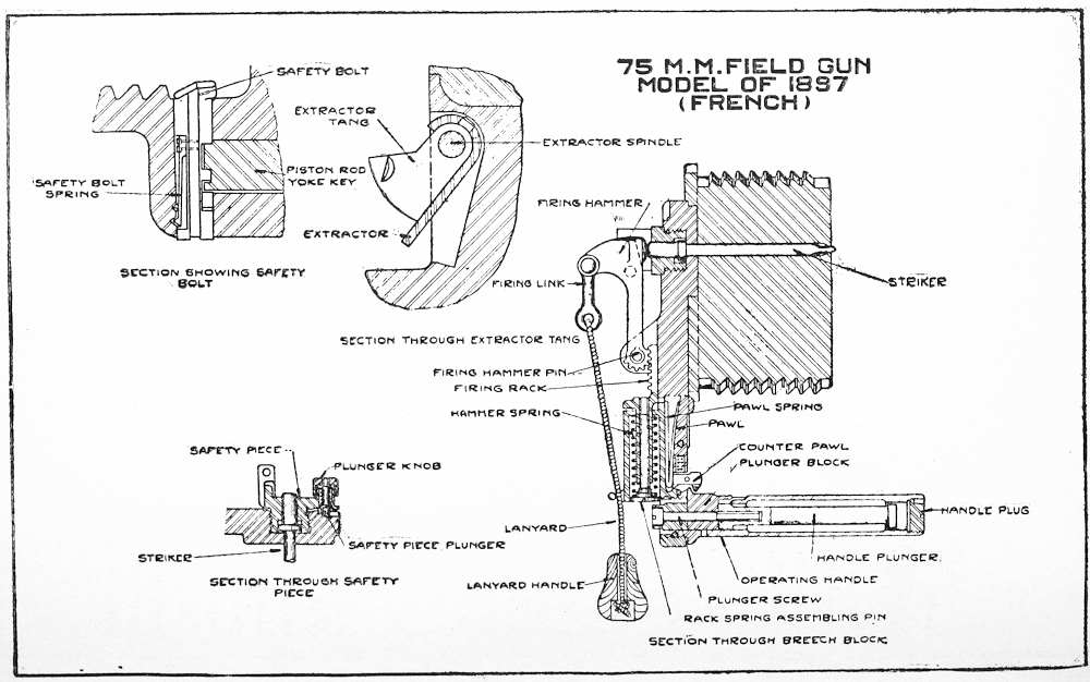
The French in their “75” have used the rotating eccentric
screw type, which is rapid in movement and lends itself fairly
well to high angle fire. It is completely enclosed and of
rugged construction.
The Germans have used the sliding wedge type of block,
moving in a horizontal direction, which does not lend itself
to high angle fire.
The United States in its recent field carriage adopted the
sliding wedge type in a vertical plane on account of its manifest
superiority in fire at high angles. This block is rather
difficult to manufacture and the type has a tendency to stick.
The automatic closing necessitates a strong closing spring
which fatigues the block operator, No. 1 in the gun squad.
It is interesting to note that in a prospective new design for
the 1916 gun carriage the American Ordnance Department
adopted the French breechblock; and the St. Chamond Company,
designing for the American Expeditionary Forces,
adopted the American drop block.
Requirements for a breech mechanism:
The following may be said to be the principal requirements
for a successful breech mechanism.
1. Safety. To be safe: (a) the gas must be restrained
from escaping to the rear; this sealing or obturation must be
automatic, greater pressure insuring better obturation. (b)
The breech of the gun must not be weakened by the fitting
of the breech mechanism. (c) The parts must have ample
strength to prevent any portion from being blown to the rear.
(d) The danger of premature discharge must be minimized.
(e) The breechblock must be securely locked to prevent
opening on firing.
2. Ease and Rapidity of Working. Otherwise, rapid
and continuous fire cannot be maintained. Hence this would
include facility in loading and certainty of extraction for
rapid fire guns.
3. Not Easily Put Out of Order. In other words it
must be able to meet service conditions and hard usage. Parts
should have a reserve strength.
4. Ease of Repair. Parts most exposed to wear should
be so designed as to permit being replaced. This will also
include accessibility to parts, so that breakage of a part will
not disable the mechanism for a long time.
5. Interchangeability. Not only should individual parts
be made interchangeable by accurate workmanship, but the
whole mechanism should be capable of being mounted on
similar guns. This is to meet service conditions.
A modern gun carriage is expected to stand steady on
firing, so that in the first place it requires no running up,
and in the second place it maintains the direction of the gun
so that only a slight correction in elevation and direction is
required after each round. The carriage is maintained in
position by the spade, which sinks into the ground, and by the
friction of the wheels upon the ground. If the force of the
recoiling gun were communicated directly to the anchored
carriage the effect would be to make it jump violently, which
would not only disturb the lay, but would prevent the cannoneers
from maintaining their position. The hydraulic recoil
brake is therefore interposed between gun and carriage.
If the guns were rigidly attached to the carriage the latter
would be forced back a short distance at each round, and the
whole of the recoil energy would have to be absorbed in that
short motion. Instead of this the gun alone is allowed to
recoil several feet and although the recoil energy is in this
case greater than it would be if gun and carriage recoiled
together yet it is so gradually communicated to the carriage
that instead of a violent jerk we have a steady, uniform
pull, the only effect of which is to slightly compress the earth
behind the spade. In a well designed carriage the amount of
this pull is always less than that required to lift the wheels
off the ground by rotating the carriage about the spade.
The only motion of the carriage which takes place is that
due to the elastic bending and rebound of its parts under the
cross strains set up on discharge. These strains are inevitable
since the direction of recoil cannot be always exactly in the
line of the resistance of the earth behind the spade. This
movement of the axis is known as jump and must be determined
by experiment for the individual piece in its particular
mounting.
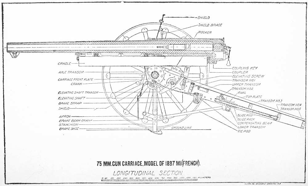
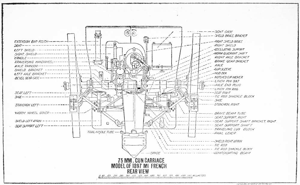
The principal parts of the typical gun carriage are the
cradle, a device for mounting the cradle—called in the different
models rocker, pintle yoke, and top carriage, the trail, the
wheels and axle. The gun slides in recoil on the upper surface
of the cradle and the cradle contains the recoil controlling
parts.
In the design of the carriage the constructional difficulty
lies not so much in preventing the carriage from recoiling but
in preventing the wheels from rising off the ground on the
shock of discharge. The force of the recoil of the gun, acting
in the line of motion of the center of gravity of the recoiling
parts, tends to turn the carriage over backwards about the
point of the trail or center of the spade. This force is resisted
by the weight of the gun and carriage, which tends to keep the
wheels on the ground. The leverage with which the overturning
force acts is due to the distance of its line of action
above the center of the spade; the leverage with which the
overturning force acts is that due to the horizontal distance of
the center of gravity of the gun and carriage from the center
of the spade.
It follows that the steadiness of the carriage for a given
muzzle energy may be promoted by four factors.
(a) Increasing the weight of the gun and recoiling parts.
This reduces the recoil energy.
(b) Increasing the length of recoil allowed. This reduces
the overturning pull.
(c) Keeping this gun as low as possible either by reducing
the height of the wheels, or by cranking the axle downwards.
This reduces the leverage of the overturning force.
(d) Increasing the length of the trail. This increases
the leverage of the steadying force.
The well designed gun carriage is one that combines these
factors in a practical way so as to give the greatest possible
steadiness to the carriage at the same time keeping within
the limits of weight imposed by the necessity of mobility.
Gun carriages are constructed so as to permit movement
of the tube in the vertical and generally in the horizontal
plane. These two motions may be made simultaneous if so
desired by proper combination of the two motions and the axis
of a gun aligned in any desired direction within the limits of
motion of its mount. The two motions referred to are designated
as follows: (a) Rotation of the piece about a vertical
axis, its inclination with the horizontal remaining unchanged
is called “traverse.” (b) Movement of the piece in a vertical
plane, the direction of the horizontal projection of the axis
of the bore remaining unchanged is called “elevation.”
In order to permit of the two motions mentioned, gun
carriages are provided with mechanisms for giving the piece
accurately controlled motion in both elevation and traverse.
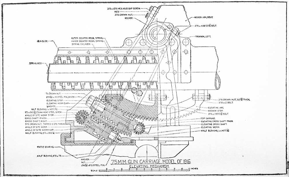
The elevating gear of most American guns is an application of
the Chinese or Telescopic screw. This gives a short assembled
length with the necessary extended length required for modern
ranges. It also gives the necessary rapidity for action. An
entirely different mechanism is used in our howitzers and
American 75s. In this case motion is communicated to the
rockers, which carry the gun and cradle, through the engagement
of worms with teeth cut on the lower circular edge of
the rockers, the latter being pivoted on the cradle trunnions.
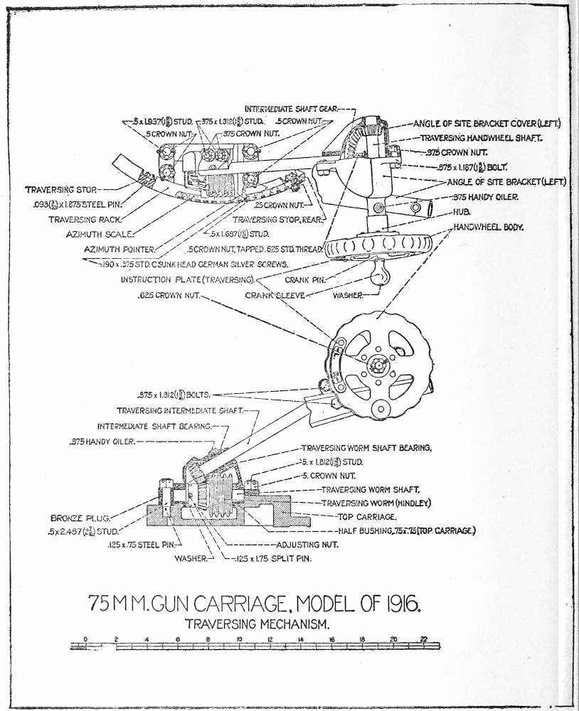
Movement of the gun in traverse is accomplished in two
general ways.
(a) Pivot on the gun carriage axle.
1. The gun and cradle move around a vertical pintle or
pivot placed in a saddle or rocker which itself pivots on horizontal
trunnions or bearings usually attached to the axle.
The rear end of the rocker forms a seat or bearing on which the
cradle and gun move in traverse. The upper end of the elevating
screw is also attached to the rear end of the rocker.
This allows the rocker and cradle to be moved together in
elevation and the cradle to move on the rocker in traverse.
2. The gun and cradle are mounted by means of horizontal
cradle trunnions on a top carriage. The top carriage
moves in traverse around a vertical pintle or bearing attached
over the axle and between the front end of the trail flasks.
The rear end of the top carriage moves on bearings attached
to the top of each side of the trail flasks. This allows the gun,
cradle and rocker to move in elevation with respect to the top
carriage and the top carriage bearing the gun, cradle rocker
and elevating mechanism to move in traverse with respect
to the bottom carriage.
(b) The gun, cradle and trail move in traverse by sliding
along the axle of the carriage on bearings provided for that
purpose. In this case the trail spade is the point of pivot.
The first system is the one generally used on all American
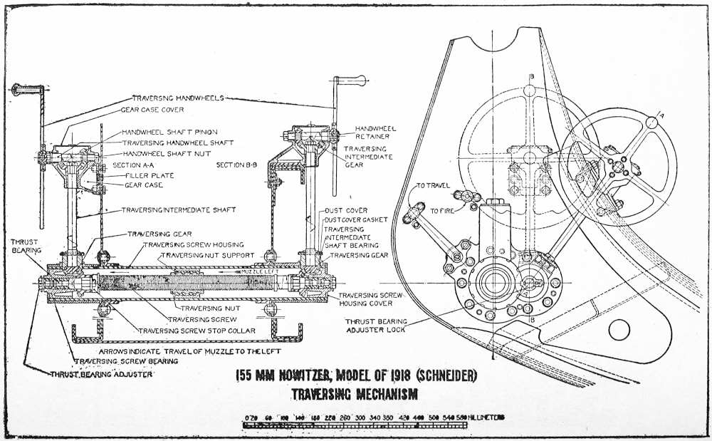
gun carriages except the 155-mm Howitzer. It gives ease
and speed in the manipulation of the piece in traverse, but has
the disadvantage of rendering the carriage less stable in firing
due to the fact that the direction of recoil of the gun is in the
direction of the line joining the trail spade and the central pivot,
only when the gun is absolutely in the center of its traverse.
In all other positions, which will be the usual case, there is a
component at right angles to the line of trail spade-central
pivot which tends to throw the gun off from its proper direction
making it necessary to relay each time the gun is fired.
The second method is that in use on the French 75-mm gun
and the French and American 155 howitzer. While not so
easy of manipulation and giving less freedom of movement in
traverse (about 106 mils) it still has the advantage in that
it gives greater stability in firing due to the fact that the gun
always recoils along the line through the trail spade, perpendicular
to the axle.
There are two general classifications of gun carriages
according to the manner in which the laying for elevation is
effected. The 3” gun is an example of one type in which the
total quadrant angle of departure is laid off as one angle
necessitating at each resetting of a range a new resetting of
the range bubble. It is evident that this militates against
both speed and accuracy in laying for elevation. The other
type is illustrated by the American 75 and by the French and
British 75-mm gun carriages which have what is called the
“independent line of site.” It differs from the other type in
that there is placed between the top carriage and the cradle
an intermediate carriage or rocker arm pivoting on the gun
trunnions at one end, and carrying at the other the support
for the elevating device which gives to the cradle and the
gun the proper elevation for the range. This intermediate
carriage or rocker arm has a toothed edge geared with a pinion
fastened to the trail flask, by means of which, gun cradle and
elevating device may be moved in elevation without disturbing
the relation between itself and the gun, this being done by
gears independent of the elevating mechanism. An angle
of site may be set off for the intermediate carriage and after
the bubble is centered this actuating pinion may be blocked
and no further concern be paid to the angle of site. A cannoneer
therefore has only to set his range accurately on the
index to give the changes in range ordered.
Elevation is accomplished by telescoping screws, by
circular racks and pinions, and by worms and arcs. Telescoping
screws are good for from 15 to 20 degrees in elevation
only, as for greater angles they become rather too large and
cumbersome. The elevating arc is attached on the top, on the
bottom or on the side of the cradle and, if possible, at its
center. When the latter is not possible, two arcs are generally
used to prevent torsional strains developing. Top racks are
exposed to fire, side circular racks or arcs interfere with the
traverse, with the placing of the sights, and with the general
handling of the carriage. The bottom of the cradle is perhaps
the best location for the rack. As in the traversing mechanism,
a train of bevelled gears transmits the power from the hand
wheel to the elevating mechanism.
In both the traversing and elevating mechanism, strength,
simplicity, power, accessibility, non-interference and absence
of lost motion are the features sought. To secure these
is one of the most difficult things in gun-carriage design; for,
since the traversing and elevating are the last two elements
considered, they must, therefore, be the ground for modification
and the means of adapting the great main elements—namely,
wheels, axle, trail, recoil mechanism and gun—into
a unit.
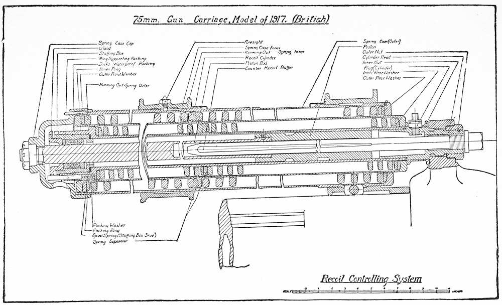
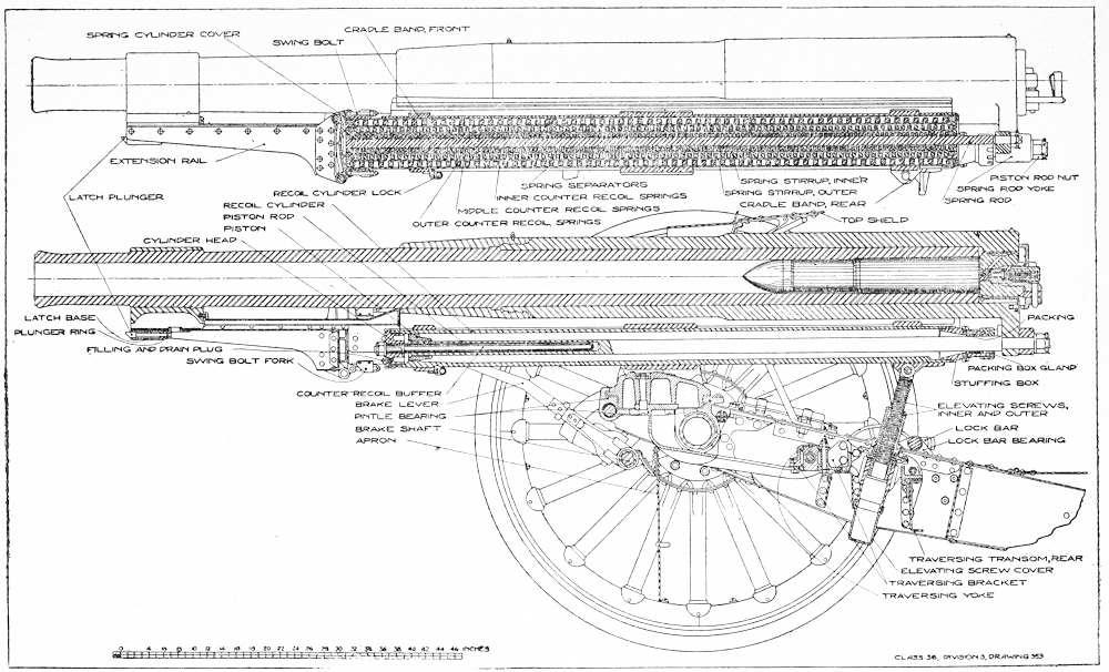
The recoil system of the gun carriage consists of a recoil
brake, a counter recoil mechanism and a counter recoil brake.
The function of each part is apparent from its name. Various
systems of checking recoil on field guns have been used,
among them may be mentioned; friction devices including
brakes on the wheel, inclined planes, pneumatic and hydraulic
brakes. All have either been superseded by the last named or
are used in connection with hydraulic brakes. The power of
the brake lies in the pressure produced in the cylinder through
the resistance to motion offered by the liquid flowing through
apertures. By varying the size of these apertures the braking
effect may be controlled so as to fulfill the conditions demanded
by the service. In designing the brake, the effect of the
counter recoil system, angle of fire, length of recoil, friction
and pressure within the cylinder must all be considered. In
howitzers which are designed to be fired at high angles of
elevation, the recoil must be shortened to prevent the breech
striking the ground, a condition successfully met. Since
the pressure due to recoil is ultimately led into the ground
through the trail and spade, consideration must be given to
the problem of the moment of inertia about the trailspade.
The tendency to turn over backward about the spade as the
center is offset by the amount of the weight of the carriage
with respect to the same point. This raises the question as to
how much pressure may be allowed to act to the rear; all of
which must be considered in designing the carriage. The
counter recoil systems in general use are two: spring or
pneumatic. The former is illustrated in our 3” and 75-mm
field guns, the latter by the French 75-mm gun and 155-mm
howitzer. Their purpose, of course, is to return the gun “into
battery” after it has recoiled on the carriage.
The recoil mechanism is a study in itself, of which there
are two schools—the advocates of the spring and of the air
recuperators. Great Britain, Germany and the United States
have been the advocates of spring recuperation and France
of air recuperation. Great Britain and the United States
were of the spring school, undoubtedly, because of the lack of
a satisfactory air recuperating system; which is rather strikingly
proven by the fact that both countries have adopted
air recuperation since they have procured or developed satisfactory
types.
Both schools have grounds for their position, however.
The spring school has in its favor simplicity of design and manufacture
and ease of replacement, which can be done in the
field. On the other hand, spring recoils have many breakages
and greater weight combined with a high replacement of
weakened springs, the life varying from 3000 to 8000 rounds.
The air school has in its favor a high order of efficiency—smoother
action, general all around efficiency and less weight.
But the air recuperator is difficult to manufacture, costly, and
when damaged must go to the rear to be repaired; which,
however, it seldom needs.
In mounting the spring recuperator, the most recent practice
has separated the recoil mechanism from the springs in
order to distribute the piston rod pull, thus preventing whip
and allowing easy access to the various parts for replacement,
refilling and repairs. In order to lower the center of gravity,
the gun is slung under the recoil cylinder with the two spring
recuperators below and on either side.
Air recuperators are invariably located below the gun for
protection and because of their large size and shape, which
adapt them for attaching the elevating mechanism.
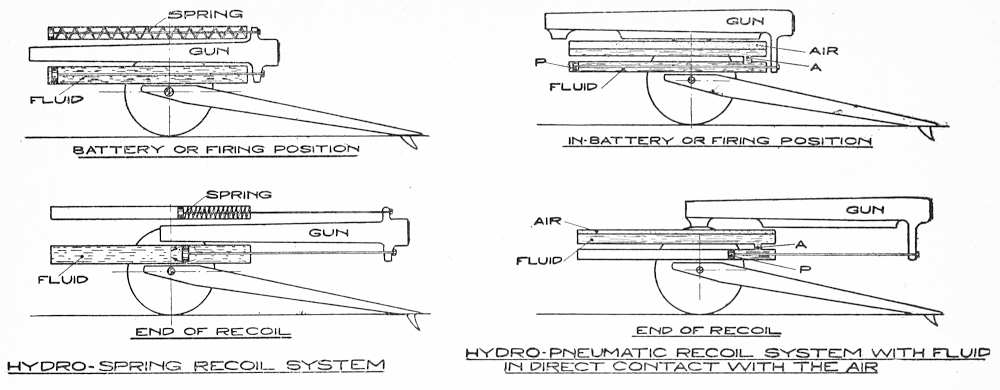
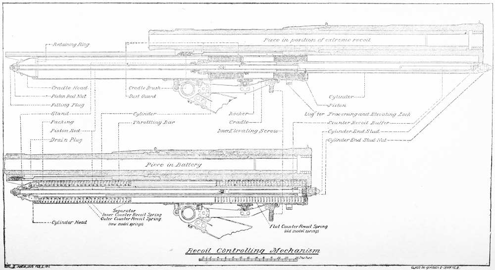
BATTERY OR FIRING POSITION
IN-BATTERY OR FIRING POSITION
HYDRO-SPRING RECOIL SYSTEM
HYDRO-PNEUMATIC RECOIL SYSTEM WITH FLUID
IN DIRECT CONTACT WITH THE AIR
In either system, the recoil is taken up by means of oil or
glycerine and water passing through an orifice created by a
slotted piston passing over ribs of varying height, or through
a valve on the pressure side of the piston, or by a solid or perforated
piston passing through a perforated intermediate
cylinder.
The latter type is particularly adapted to variable recoil
guns as the intermediate cylinder can be rotated, thus throwing
varying orifices into position for the flow of oil.
Counter recoil is accomplished by the springs or by the
air pressure in the hydro-pneumatic system, in which the air
pressure is sufficient to hold the gun in battery at all elevations
and is built up at recoil.
In all counter recoil systems, it is necessary to insert a
buffer to take up the remaining energy of the springs or air
pressure so as to bring the gun into battery without appreciable
jar. Numerous types have been developed and perfected.
The counter recoil brake or buffer in our 3”-gun is a
slightly tapered bronze rod, tightly fitting in the cylindrical
bore of the piston rod. The retardation caused by forcing
the oil in the piston rod out through the small clearance
between the buffer and bore of the piston rod eases the return
to battery without jar to the gun, which has been forced
back by the counter recoil springs.
The physical law that action and reaction are equal has
a peculiar emphasis when applied to the firing of a piece of
high powered artillery. The force exerted to throw a heavy
projectile 7 miles or more from the muzzle of the gun is toward
the breech of the weapon in its recoil. How some of these
forces are handled safely and easily by mechanical means
are almost beyond the mind’s grasp. Not long ago a touring
car, weighing two tons, traveled at the rate of 210 miles
an hour along a Florida beach. Conceive of such a car going
337 miles an hour—which is much faster than any man ever
traveled; then conceive of a mechanism which would stop
this car, going nearly six miles a minute, stop it in 45 inches of
space and one-half a second of time without the slightest
damage to the car. This is precisely the equivalent of the
feat performed by the recuperator of a heavy howitzer after
a shot.
Although cover for the cannoneers had been used off and
on since the invention of guns, it had fallen into disuse until
it was firmly established as an essential feature by the French
on their 75-mm in 1897. All modern field guns have such
protection both for the cannoneers and for the delicate parts
of the material which would be damaged by shrapnel balls or
shell fragments. The shield is made of hardened steel capable
of withstanding the impact of a bullet of a service rifle
at a 100 yds. range at a standard velocity. For convenience
the shield is divided into three parts known as the top shield,
main shield and apron, with suitable ports equipped with
shutters for the line of vision from sights. The main is fastened
to the axle and is rigid. The apron is hinged to the
main shield or the axle-swinging forward for the traveling
position. The top shield is fastened to the main shield by
hinges and swings forward and downward for traveling position.
The sights serve three important functions. They improve
the vision of the gunner and lay the gun in elevation
and direction. The simplest sight is the one over the line of
metal which lays for direction only, the second is the tangent
sight mounted on a range arc centered on the axis of rotation
in elevation usually having a deflection scale to correct for
drift and to lead the moving target. This unit lays for range
and direction. The last sight is the telescopic or panoramic
sight which is mounted on a range arc and lays for direction
only, it is the unit for indirect fire, laying for direction, and
markedly improving the vision of the gunner. The latest
model of the American panoramic sight is superior to any in
existence.
For precision in indirect fire, practically all carriages are
equipped with some form of range quadrant, containing a
means of setting off the angle of site and the range angle. All
instruments are equipped to compensate for difference in
wheel level. The British carriage automatically corrects for
deviation, simplifying the firing date by that element.
The height of the wheels affects the draft, weight, clearance,
and stability of the carriage both as to road stability—i.
e., low center of gravity; and firing stability—i. e., the overturning
movement about the end of the trail. It is now believed
that entirely too much stress has been laid on road
clearance. Reducing the height of wheel reduces the weight
and road clearance, lowers the center of gravity and increases
the firing stability; but it also reduces the angle of gun elevation
unless the trail is shortened. Firing stability in general
is increased by adding to the weight of the gun, lengthening
the recoil, slinging the gun as low as possible and lengthening
the trail. The less the height of the wheel exceeds four feet
the better, despite the poor draft feature, which is compensated
for to some extent by a reduction in weight and turning radius.
Axles are straight or of the offset type. The straight
axle is stronger for its weight. The drop axle allows the center
of gravity to be lowered.
Most modern trails are of the sectional built-up type.
Some, however, are of tubular and telescopic. The most
variable portion of the trail is the spade. It consists of two
parts, the spade proper and the float. The former prevents
recoil, the latter the burying of the trail. The spades proper
are of three types: the fixed, as in the French 75-mm; semi-fixed,
as in the 155-mm howitzer; and driven, as in the Deport
and American 1916 75-mm. Each has advantages and disadvantages.
The driven spade is considered essential for the
split trail carriage, as the latter has no means of seating itself;
and should one spade take, and not the other the carriage
might be damaged when the gun is fired at an extreme traverse.
Split trails introduced a novelty in field gun carriages,
in that a compensating device became necessary to adjust for
the difference in ground level of the two spades.
Guns are designed to function in a certain way. They
are not temperamental. They follow absolutely and certainly
fixed mechanical laws. If they fail there is a reason and it
can be remedied. Certain parts are given certain shapes and
forms, are machined to nice adjustments, and in taking down
and assembling them, brains and dexterity are the tools to
use rather than force and sledge-hammers. Learn from your
text when and how to apply force and above all when not to
use it. Treat these guns as you would a friend on whom you
know you can depend. They will not fail you.
CHAPTER IV MODERN ARMAMENT. — THE ARTILLERY OF A FIELD ARMY; ITS FUNCTIONS. — DIVISION ARTILLERY. — CORPS ARTILLERY. — ARMY ARTILLERY. — ANTI-AIRCRAFT GUNS.
The artillery assigned to a field army should be of such
mobility, power, variety and number as to insure the success
of its purpose and to enable this success to be gained with the
minimum of casualties. The latter point must receive careful
consideration in studies of organization, for without adequate
artillery preparation and support the successes of the most
gallant infantry can in a series of actions become little more
than pyrrhic victories. Many actions of our divisions in
France resulted in casualties whose numbers decreased in proportion
to the number of guns with which divisions were supported.
The proportion of guns to the thousand gross
strength of infantry, cavalry, and machine guns adopted
by the armies of the first class powers before the opening of
the present European War in 1914 was:
British, 6.8; French, 4.6; German, 6.4; American 3.2
(Greble Board).
During the war this proportion was constantly increased
until at the close under conditions of position or entrenched
warfare it was between 8 and 12 per thousand; this varied
of course with the activity in different sectors. In quiet
sectors and under conditions of maneuver, or open warfare,
which necessitated leaving much artillery behind, it was about
6 per thousand.
A program of types of artillery weapons should be founded
on the object and the means—that is, the destruction of the
target and the projectile to accomplish this. In the study of
an artillery program there are two methods of approaching
the subject. First, by starting with a minimum weight of
projectile and working up to a reasonable maximum, according
to some law and taking the corresponding calibers, a theoretical
series of guns and howitzers can be expressed. For
instance, if the law be doubling the weight of the projectile
the series of types could be:
Projectile of
13
pounds, caliber
3”.
Projectile of
26
pounds, caliber
4”.
Projectile of
52
pounds, caliber
5”.
Projectile of
104
pounds, caliber
6”.
Projectile of
208
pounds, caliber
8”.
Projectile of
416
pounds, caliber
10”.
Projectile of
832
pounds, caliber
12”.
Projectile of
1664
pounds, caliber
14”.
The second and more logical method, and one followed
in our service, is to consider the artillery missions and determine
the types best suited irrespective of any theoretical
series of weights and calibers. However, in the discussion of
artillery missions and the proper types for their fulfillment
there is a remarkable degree of unanimity of thought on these
subjects; and the above table actually contains, with slight
variations, the types that are most strongly recommended.
While granting the great variety of artillery missions that
often shade into each other, it is believed that they can best
be considered in three great classes that follow the tactical
composition of a field army: those of division, corps and army
artillery.
Missions. The division artillery, first of all, must have
the mobility that will permit it to accompany the infantry
of a division and the maximum power consistent with that
mobility; its object must be primarily the infantry of the opposing
division. It is therefore bound to its own infantry
with the closest bonds and its tactical use cannot be separated
from that of the infantry. The division artillery must fire,
accurately, a man killing projectile and be prepared for quick
changes of targets; it must have a great range because of depth,
both of its own and the enemy division; it must continually
harass the enemy, prevent his movement and force him into
cover or protected trenches. On the defensive it must break
up the opposing infantry formations by preparing a counter-offensive
fire and by annihilating fire on points from which the
enemy attacks emerge; and, failing in these, be prepared to use
the barrage and shrapnel fire at close range. In the offensive
the division artillery must play its part in the complex schemes
of artillery preparation by cutting wire, destroying machine
gun nests, gassing areas, concentrating on infantry positions
and taking the principal part in the deep barrage that should
precede the infantry attack. Its fire, accompanying the
infantry movement, requires its own movement and by its
mobility it often becomes for some time the sole artillery protection
in the preparation and holding of a position which
has been taken.
Light Gun and Howitzer. The consensus of opinion of
artillery officers is that the division artillery missions are
best fulfilled by a light field gun and a light field howitzer
having a range of at least 11,000 yards. While differing in
mechanical features, the field guns of the different European
countries are practically of the same type and, though constant
effort is being made to improve details, they can be
stated as generally satisfactory to their own governments
and not liable to any radical changes. The general type of
field gun, while capable of fulfilling most of the division artillery
missions, must be supplemented by a proper howitzer. There
are many instances where the terrain or the lay of the land
offers such protection to the infantry that the field gun cannot
bring an effective fire. The howitzer has the great advantage
that with the proper set of propelling charges and,
therefore, choice of trajectories for the same range, protected
positions can be chosen for howitzers that guns could not
use, and angles of fall obtained on objectives that the normal
ammunition of guns would not give. The low muzzle velocity
of howitzers admits of their almost continuous use in harassing
fire and allows the use of a projectile double the weight of that
of a field gun. Such a howitzer renders excellent service in
wire cutting and is a useful projector of gas shells. To insure
the mobility required of all divisional artillery the weight of
the howitzer and carriage should not exceed that of the field
gun, or about 4,500 pounds.
Light Gun Discussion. The consensus of opinion of all
artillery officers—French, English and American—is that the
75-mm gun, or approximately this caliber, firing a 15-pound
projectile or a projectile of approximately this weight, and
having a range of not less than 11,000 yards, is a satisfactory
weapon at the present time for use with the division artillery.
The projectile in question, whether a shrapnel or a high explosive
shell, satisfies adequately the criterion of man-killing.
At the close of the war the nations were not entirely in accord
with respect to their conception of an up-to-date carriage for
a light field gun. All the nations whose tendencies have been
considered in this report have experienced to a varying degree
with field gun carriages, particularly in a desire to design a
carriage permitting a greater angle of elevation and greater
movement of the gun in the traverse. The Italians have expressed
themselves in the modified Deport Carriage; this
vehicle is of the split trail type and permits an elevation in
excess of 75 degrees, and a traverse on each side of the center
of the carriage of about 20 degrees—about 356 mils. Up to
the time that the board left France it was not possible to learn
the French decision in the matter of a split trail carriage for
their light field gun. It is known, however, that several types
of this carriage have been designed and tested; it is known,
also, that considerable favor has been found with the American
1916, which type has been tested under the auspices of the
French Government. In England, however, the board was
not able to develop any enthusiasm for the split trail type,
although the matter had been seriously considered. In that
country the up-to-date field gun carriage appears to be adequately
expressed in their new 18-pounder. The vehicle
upon which this gun is mounted permits an elevation of 37
degrees and an axle traverse of 4½ degrees on each side. The
trail is a box trail and the carriage is simple and steady in its
construction and lends itself to rapid production.
Motorization. At some time in the future it is probable
that all the division artillery will be motorized. The result
of such a change in the prime mover would be to remove the
present restriction as to weight of gun and carriage. The
board senses a demand in the near future for a light field gun
having a maximum range of approximately 15,000 yards;
such a range may be achieved by increasing the muzzle velocity
and, perhaps, the weight of the projectile, although change in
the form of projectiles will give some improvement over the
present ranges. It is probable that the limiting features in
the design of field guns of the future will be the requirement
that it should pass safely over temporary pontoon bridges and
that the weight and form and size of ammunition must be
such that the present rate of fire will not be slowed down.
The board is of the opinion that, except as to perfection of
details, the limit of carriage design, as expressed by the
most modern type of box-trail and split-trail carriages, has
been reached; and feels that with the advent of motor transportation
the tendency will be toward a gun mounted on a
self propelling carriage and expressing the desires of the field
artillery with respect to maximum horizontal and vertical
arcs of fire.
Light Gun. Ideal. A gun of about 3” caliber on a carriage
permitting a vertical arc of fire of from 5 degrees depression
to 80 degrees elevation and a horizontal arc of fire of 360
degrees; a projectile weighing not over 20 pounds, shrapnel
and high explosive shell of satisfactory man-killing characteristics
with maximum range of 15,000 yards; fixed ammunition,
smokeless, flashless propelling charge; time fuse for shrapnel.
With shell having safe fuses with different lengths of delayed
action after they land. The high explosive shell should be
of one type only. Two propelling charges should be furnished,
a normal charge for about 11,000 yards range and a super
charge for maximum range. The proportion should be 90%
of the former and 10% of the latter. A maximum rate of
fire of 20 rounds per minute is deemed sufficient.
Light Gun. Practical. For the present, arm brigades
with 75-mm materiel. Models 1916, 50%, and 1897
(French), 50%.
Transport. Ideal. Mechanical transport is the prime
mover of the future. The introduction of mechanical transport
will undoubtedly cause far-reaching changes in the types
of gun carriages. It is not possible now to state just how far
this will go or whether a gun mounted on a self propelled
vehicle or one mounted on some type of trailing vehicle will
be the final result. Both types may be necessary. It is
urgent that study and development be carried along these
lines, as we are on the verge of changes fully as radical as the
introduction of the long recoil field gun and carriage, and the
country first utilizing the new capabilities opened up by mechanical
traction and the caterpillar will have a great advantage
in the next war. A limit of 4,500 pounds behind the team has
heretofore been imposed on the artillery of this class. The
corresponding limit in the future will probably be that imposed
by pontoon bridges.
Transport. Practical. Therefore it is thought that four
regiments of 75-mm guns (two regiments of French Model
1897, and two regiments of U. S. Model 1916) should be immediately
equipped with motors, the remainder to be horsed;
mechanical transport to gradually replace horse only after
the tractor demonstrates its superiority in service.
Light Howitzer Discussion. The consensus of opinion
of American army officers consulted is that a howitzer about
4” in caliber, firing a projectile weighing from 25 to 30 pounds
at a maximum range greater than 10,000 yards, is required.
This opinion is concurred in by the French, Italians and
English, and it appears to be definitely established that the
mobility of the light field howitzer should be practically the
same as that of the light field gun. The British army was
equipped with a 4½” howitzer, firing a projectile weighing
35 pounds and with a maximum range of 7,700 yards; the
weight of the howitzer limbered is 4676 pounds—150 pounds
more than the weight of the 18-pounder field gun. No evidence
was found that the British Government intended making
any alterations in the design of this howitzer; naturally
they will attempt to increase the range, power and accuracy
of the projectile by change in its weight, its capacity and its
form. The French artillery was not equipped with the light
field howitzer of approximately the same weight as the 75-mm
field gun. During the war it was found impracticable to
construct a lighter howitzer without interfering with the
production of other calibers which were considered more
important. In the earlier stages of the war the Italian artillery
was not equipped with a light field howitzer; however, before
the end of 1917 orders were placed for several hundred howitzers
of the 105-mm type. It should be noted that several
hundred howitzers of this caliber were being constructed
before the armistice and that many have been captured from
the Austrians by the Italians; this, so far as the Italians were
concerned, makes it certain that a light field howitzer will be
furnished by the Italian army. The German and Austrian
armies were equipped with a howitzer of the light field type;
this weapon had a caliber of 105-mm type.
It fired a projectile weighing 34.54 pounds at a maximum
range of 10,500 yards. (Streamline shell.) The weight of
the howitzer limbered was 4,500 pounds. In the opinion of the
board, the Germans have proceeded on sound principles in
their development of the light field howitzer. Their ’98 model
was a companion piece to their ’96 field gun and in the years
that passed from 1898 to 1916, which included their early war
experience, they kept to the idea of the relation of the two
pieces even to the extent of including in a field artillery regiment
one battalion of light howitzers. Their 1916 models
of both light gun and howitzers show the endeavor to keep
the pieces in the same class; that is, the weight of the gun and
howitzer in action nearly the same, 2,750 pounds and 2,700
pounds; the weight of the gun limbered and the howitzer
limbered are the same, 4,500 pounds; the elevation of both
the same—minus 10 to plus 40 degrees; the carriages are of
the same type; and the extreme ranges of gun and howitzer are
respectively 11,700 and 10,500 yards. From the foregoing
it is seen that all the important belligerents except the French
and the Americans were equipped with a light field howitzer
firing a projectile about twice the weight of the light field
gun projectile and having otherwise the same general characteristics.
There is no evidence to show that the fire of the
French and the American artillery was not fully effective as
that of any other artillery; however the testimony of the
French and American artillery officers is to the effect:
(a) That the lightest howitzer in use, i. e., the 155-mm,
was not sufficiently mobile to be a suitable companion piece
for the 75-mm gun.
(b) That many times the fire of the 75-mm gun proved
ineffective due to its flat trajectory; a howitzer would have
been more effective in the attack of certain targets.
(c) That a large volume of fire is necessary.
(d) That while the 155-mm howitzer is more powerful
than the light field howitzer its consumption of ammunition
for many purposes is wasteful and extravagant and its volume
of fire is insufficient.
(e) That the light howitzer is particularly suited for the
destruction of wire entanglements; its better accuracy and
more powerful projectile make it more suitable than the field
gun for that purpose.
(f) That the 75-mm field gun projectile is not so satisfactory
a gas shell as the howitzer projectile which has greater
weight.
Light Howitzer. Idea. A weapon of about 105-mm
caliber on a carriage permitting a vertical arc of fire from minus
5 degrees to plus 65 degrees, and a horizontal arc of fire of 360
degrees. Efforts should be made to develop a carriage
which can be used interchangeably for the division light gun
referred to above and this howitzer. The projectile should
weigh about 30 to 35 pounds and should include both shell
and shrapnel. A maximum range of 12,000 yards will be
satisfactory. Semi-fixed ammunition with varying charges
should be used, otherwise the ammunition should be similar
to that provided for the 75-mm guns.
Light Howitzer. Practical. For the present, the division
should be armed with the 155 howitzer, Schnieder, but active
development and test should be made on a type as stated under
“Ideal” above, and with the ammunition and other accessories
to it. Upon the development of the carriage as nearly approximating
the ideal as may be practically possible, efforts
should be made to secure quantity production in order that it
may be incorporated in the division as recommended. In
addition, a split trail carriage for this howitzer should be
developed.
Transport. The light howitzer should have the same
means of transport as the light field gun and the same remarks
heretofore made as to the probable future development
of the field gun also apply to the howitzer carriage.
Missions. It will be noted above that the division artillery
missions did not include their own protection against
the enemy artillery. This counter-battery work is the principal
mission of the corps artillery. The corps artillery has
also the mission of extensive harassing and interdicting fire
along the corps front and to a greater depth than the capabilities
of the division artillery; also of destructive fire on
strong points as well as on railroad facilities and points of
supply. For the accomplishment of these corps artillery
missions there are two types of artillery necessary, a gun and
a howitzer, each having 16,000 yards range and each weighing
with the carriage about 11,000 pounds. There is another
class of artillery called anti-aircraft artillery to be considered.
This is used first in providing anti-aircraft defense for army
zones, for certain areas in rear of armies or along a certain
line of anti-aircraft defense.
Medium Gun Discussion. The consensus of opinion of
artillery officers—Italian, English and American—is that a
medium gun of about 6” caliber is necessary. The medium
type gun furnished to the American army was the 4.7 (Model
1906). This gun has a maximum elevation of 15 degrees
with a corresponding maximum range of 8,750 yards. The
British army was equipped with the 5” gun—the carriage
permits a maximum elevation of 21 degrees and 30 minutes,
giving a maximum range of 12,500 yards. The French army
was equipped with, to a certain extent, the 105-mm and the
140-mm gun. The 105-mm gun a maximum elevation of
37 degrees, with a maximum range of 13,900 yards. The
140-mm gun has a maximum elevation of 30 degrees and, with
a high velocity, has a maximum range of 19,500 yards. The
French 105-mm gun is a modern weapon (1913). The German
artillery was equipped with a 105-mm gun (M-1917) with
a maximum elevation of 45 degrees, and a maximum range
of 16,000 yards. The German army was also equipped with
the 130-mm gun, having a maximum range of 16,500 yards.
The Austrian army was similarity equipped. The Italians
were equipped with a 105-mm gun essentially of the same characteristics
as the French 105-mm M-1913.
Medium Gun. Ideal. A caliber of between 4.7 and
5” on a carriage permitting a vertical arc of fire of from minus
5 degrees to plus 80 degrees; a horizontal arc of fire of 360
degrees. Shrapnel and shell weighing not over 60 pounds,
maximum range 18,000 yards; with semi-fixed or separate
loading ammunition permissible.
Medium Gun Practical. Corps artillery should be armed
with the present type 4.7” gun, Model 1906, except that at
least one regiment should be armed with the British type
5”-guns purchased abroad.
Transport. All corps guns should be developed for long,
rapid hauls. Similar ammunition vehicles should be developed.
The wheels for the gun carriage should be rubber-tired.
Medium Howitzer. In the opinion of the French, Italians,
British and the Americans, the 155-mm howitzer (Schnieder)
was conspicuously successful in the present war. It should,
therefore, be retained as a type. The howitzer and carriage
as it stands at present, is a highly satisfactory and efficient
piece of armament. For the future it is believed that effort
should be made to increase the range by improvements in the
form of projectile, and it is believed that the form of howitzer
and carriage should be studied with a view of obtaining,
through modifications, a maximum range of approximately
16,000 yards.
Many batteries of 155-mm howitzers (Schnieder) were
motorized in the American Army in France, and the consensus
of opinion is definitely toward the retention of this
form of prime mover. It is interesting to note that all the
important belligerents have settled upon a howitzer of approximately
6” in caliber, and otherwise essentially of the
same ballistic characteristics as the type in question. The
projectile of this caliber is the smallest projectile which can be
called upon to give adequate mining effect against material
targets of semi-permanent nature. The place of this howitzer
is, therefore, determined by considerations of its destructive
ability. It is a splendid destruction and neutralizing
weapon.
Medium Howitzer. Ideal. A caliber of about 155-mm
on a carriage permitting a vertical arc of fire of from minus
5 degrees to plus 65 degrees; and a horizontal arc of fire of 360
degrees. The projectile should not weigh over 100 pounds
and should be interchangeable with projectiles for other guns
of this caliber referred to later on. High explosive shell,
only, should be supplied.
Medium Howitzer. Practical. The corps should be
armed with the 155-mm (Schnieder) howitzer referred to
above. The type of fuses for shell should be super quick and
long delay.
Missions. In addition to the division and corps artillery
fulfilling the missions outlined above there must be additional
artillery available. There are missions of interdiction, neutralization
and destruction which fall beyond the activities or
capabilities of the normal corps or medium field types; there
must exist a surplus of division or corps types, properly transported,
for strategic reinforcements of divisions and corps
during such times as the normal allotment to such units is
insufficient; there must be artillery of special purpose—mountain
artillery, trench and super guns and howitzers. Of the
above additional artillery, a type of heavy field gun and a type
of heavy field howitzer are considered normally necessary in
the armament of a field army; the gun should have a range
of approximately 25,000 yards, and the howitzer a range of
about 18,000 yards. These weapons are more powerful than
the medium field types, add range to the interdiction and
harassing and to the neutralization and destruction possible
with the corps type. Considering the paragraphs pertaining
to divisional artillery and the introduction to corps artillery
it will be seen that the normal artillery of a field army can be
accomplished by the assignments of two caliber, i. e., two light
weapons, two medium weapons and two heavy weapons—a
gun and a howitzer in each class—and a satisfactory anti-aircraft
gun.
Heavy Field Gun. The consensus of opinion of all artillery
officers—British, Italian and American—is that the heavy
field gun should be of approximately 6” caliber and that guns
of greater caliber than this are necessary in limited number for
field operations. The French were constructing 194-mm
guns during the latter stages of the war. It is believed that
in developing this type of gun the French were actuated
almost entirely by the necessity for increased range, since the
German 150-mm gun, Model 1916, outranged the G. P. F. by
approximately 5,500 yards. The French have recently made
considerable progress in securing the necessary increase in
range with the G. P. F. All of the principal nations engaged
in the war used a heavy field gun of approximately 6” caliber.
This type has given such general satisfaction that its continuance
is assured. The principal mission of the heavy field
gun is harassing and interdiction fire, and for these uses the
6” projectile is sufficiently heavy. The maximum practicable
traverse and elevation should be provided by the carriage of
the heavy field gun. The G. P. F. carriage has given general
satisfaction, but its wide tread and the excessive time required
to occupy a position are very objectionable features. It is
the consensus of all artillery officers—French, British and
American—that the heavy field gun should be of approximately
6” caliber and with a range in excess of 25,000 yards,
with not less than 60 degree traverse, weighing not more than
12 tons, limbered, capable of occupying and leaving a position
quickly, and with a width of tread which does not prevent
two-way traffic on ordinary roads. The Italians differ from
this opinion only in that they are satisfied with a maximum
range of 18,000 yards.
Heavy Field Gun. Ideal. A caliber of about 155-mm
on a carriage permitting a vertical arc of fire from 0 degrees to
plus 65 degrees; with a horizontal arc of fire of 360 degrees.
The maximum range should be about 25,000 yards.
Heavy Field Gun. Practical. Arm with the present
type 155-mm G. P. F. and carry on experiments for type of
carriage as outlined for division field gun. The fuses should
be super-quick and short delay.
Transport. All artillery of this type should be motorized
and tested and experiments for ammunition vehicles to correspond
with the types of carriages developed, and should be
carried on simultaneously.
Heavy Field Howitzer. No type of heavy field howitzer
developed during the war has given general satisfaction. The
consensus of all army artillery officers—French, English and
American—is that two calibers of howitzers are necessary—one
a companion piece for the 6” gun and one of the maximum
possible power consistent with the necessary mobility. The
lighter of these two howitzers should have the same mobility
as the 6” gun, with a caliber of about 8” and a maximum
range of not less than 16,000 yards. The heavy field howitzer
should be of about 9.5” caliber with a range in excess of 16,000
yards; the carriage should provide for wide traverse and must
have sufficient mobility to accompany the army in the field.
It will probably be necessary to transport this howitzer in
more than one load, and the maximum weight of any load
should not exceed 12 tons. The average time necessary for
occupying a position should not exceed six hours under actual
field conditions.
Heavy Field Howitzer. Ideal. A caliber of about 8”
on a carriage permitting a vertical arc of fire of from 0 to
plus 65 degrees; and a horizontal arc of fire of 360 degrees.
The maximum range should be 18,000 yards.
Heavy Field Howitzer. Practical. Use at present 8”
material of British design which is on hand.
Railway Artillery. The war has demonstrated the necessity
for long range and powerful guns for distant interdiction
and harassing work and for super-heavy howitzers for the
destruction of semi-permanent fortifications. Artillery of
these types can best be mounted on railway carriages and this
type of mount offers no serious disadvantages since these guns
will not be used except with large forces which require extensive
railroad systems for their supply. This does not
apply to guns of the type used to bombard Paris; such guns
have no military value and their construction is not justifiable.
Light Gun. Ideal. Caliber about 3” with initial velocity
of at least 2,600 f. s.; semi-automatic breechblock, mounted
on carriage, permitting 80 degrees elevation and 360 degrees
traverse; projectiles weighing not less than 15 pounds, of one
type high explosive shell with maximum ballistic qualities
and as large explosive charge as possible; fixed ammunition;
smokeless, flashless powder, mechanical fuse. In this type
every effort must be made to increase the rate of fire and decrease
time of flight; this latter is limited only by considerations
of a reasonable accuracy life for the gun.
Light Gun. Practical. Arm units with present 3” anti-aircraft
equipment. Continue experiments leading to the
development of the ideal.
Transport. Ideal. Caterpillar mount or caterpillar
trailer mount drawn by caterpillar tractor, each unit to permit
a sustained speed of 12 miles per hour.
CHAPTER V THE 3-INCH FIELD GUN. — THE GUN. — Weights and Dimensions. — THE BREECH MECHANISM. — THE GUN CARRIAGE. — Action of the Mechanism. — Weights and Dimensions. — THE 3-INCH GUN (CAISSON) LIMBER. — Weights and Dimensions. — THE CAISSON — Weights and Dimensions. — To Dismount and to Assemble Parts of the Gun and Carriage.
The Gun is known officially as the 3-inch Field Gun,
Model 1905. It is a built-up construction of nickel-steel and
consists of a tube with a rifled bore, 3 inches in diameter, upon
which are shrunk the jacket, locking hoop and front clip hoop.
The jacket reinforces the rear half of the tube. The locking
hoop serves to secure the jacket from any longitudinal movement
to the rear. On the under side of the gun, extending
the entire length of the jacket, locking hoop, and front clip,
are formed two recoil guides or clips which fit over and secure
the gun to the guide rails of the cradle. When the gun is
fired, it slides along the guide rails. The dust guard covers
the part of the guide rails between the locking hoop and the
front clip. The rifling of the bore is right-hand twist and starts
with 0 turns at the breech increasing to 1 turn in 25 calibers
at 10 inches from the muzzle, then uniform to the muzzle.
Weight of gun
788 lbs.
Calibre
3 inches
Length
about 7 feet
Number of lands and grooves
24
Muzzle velocity
1700 ft. sec.
Maximum pressure per sq. in.
33,000 lbs.
Limit of depression
(90 mils.) 5 degrees
Maximum elevation
(265 mils.) 15 degrees
Maximum range, trail sunk, about
8,500 yds. (5 M)
Range at 15° elevation (265 mils)
6,000 yds. (3½ M)
3 Inch Field Gun, Models of 1904 & 1905.
Breech Mechanism Assembled.
Nomenclature of parts of Gun:—
Jacket.
Locking hoop.
Tube.
Bore.
Rifling.
Lands.
Grooves
Breech recess.
Front clip.
Muzzle.
Dust guard.
Recoil guides or clips.
Chamber.
Recoil lug.
Line sight (front and rear).
Handy oilers.
The breechblock is of the interrupted-screw type, and is
provided with four threaded and four slotted sectors. The
front end of the axial recess in the block is closed by a bushing.
Four ventholes lead from a cavity in the bushing and permit
the escape of gas to the rear in case of a ruptured primer. On
the rear face of the breechblock are cut gear teeth, in which
the gear teeth of the operating lever bevelgear mesh. The
breechblock is concentrically mounted on a hub on the block
carrier, in which the firing-lock case is fitted. Its position in
the breech of the gun with reference to the axis of the bore is
eccentric.
The breechblock is closed or locked by a continuous movement
of the operating lever. When the block is swung to the
closed position the front face of the block latch comes in contact
with the rear face of the breech of the gun, thus forcing
the latch out of the notch in the breechblock and back into a
recess in the carrier. By continuing the motion of closing the
mechanism, the breechblock is then rotated on the hub of the
carrier and its threads engage with corresponding ones in the
gun. When the breechblock is in the closed position, a lug
on the firing-lock case serves to lock the carrier to the breechblock
and prevents displacement due to a blowback.
The firing mechanism belongs to that type known as a
continuous-pull mechanism; that is, no cocking of the firing-pin
is required.
The firing-lock case is eccentrically fitted in the hub of the
block carrier, in such a position that the axis of the firing-pin
is always in line with the bore of the gun. The vent bushing
in the front end of the breech block through which the firing
pin passes when in the fired position, is fitted eccentrically with
reference to the breechblock. This eccentric arrangement of
the breechblock, masks the point of the firing-pin and prevents
any possible contact between the pin and the primer in the
cartridge case when the block is unlocked. The block will be
practically fully locked before any contact between the
firing-pin and primer can take place.
Nomenclature of important parts of Breech & Firing
Mechanism.
Mod. 1905:—
Name of Part
Where located
Breech Block
On block carrier
Vent Bushing
Front end of block
Block Carrier
Hinged to jacket; supports block
Block Stop
Screwed into front face of carrier
Hinge Pin
Hinges carrier to jacket
Hinge Pin Catch
In hinge pin
Extractor
In breech recess
Extractor Lever
Mounted on hinge pin
Operating Lever
Pivoted on block carrier
Lever Pivot
Pivots lever on block carrier
Lever Latch
In operating lever
Lever Latch Spring
In operating lever, lower part
Lever Latch Pivot
In operating lever, lower part
Block Latch
In recess in carrier
Block Latch Spring
Around latch bolt
Firing Lock Case
In hub of the block carrier
Locking Bolt Nut and Pin
On firing lock case, rear face of carrier
Firing Pin
In axle hole, center of firing lock case
Firing Pin Spring
Around firing pin
Firing Spring Sleeve
Around firing pin spring
Sear
In slot in firing lock case
Trigger Fork
Rear end firing lock case
Trigger Shaft
On rear end firing lock case
Trigger Shaft Detent
On trigger shaft
Firing Pallet
On pallet shank
Pallet Shank
On recoil lug of gun
Firing Handle
On firing handle shaft
Firing Handle Bracket
Attached to right side of cradle
Firing Handle Shaft
Assembled in bracket, right side of cradle
Trip Latch
Attached to trip latch plunger
Trip Latch Plunger
Assembled to firing handle
Adjusting Screw
Assembled to firing handle bracket
Check Nut
Assembled in adjusting screw
3 Inch Gun Carriage, Model of 1902. Plan
The gun carriage for the 3-inch gun Model 1905 is of the
type known as the long-recoil, in which the gun is permitted
a sufficient length of recoil (about 45 inches) upon the carriage
to render the latter stationary under firing stresses. The gun
is mounted upon a cradle which forms a housing for the recoil
controlling parts. The cradle rests upon the rocker and has
a small traversing motion of 70 mils on each side of the axis
of the carriage. The rocker is journaled upon the axle and its
rear end is supported by the elevating mechanism, which is
seated in the trail.
The principal parts of the carriage are the wheels, axle,
trail and elevating mechanism forming the lower carriage, the
cradle and recoil-controlling parts constituting the upper
carriage, and the rocker and traversing mechanism intermediate
between the two. In addition there are provided shields,
ammunition carriers, the road brake, and the axle seats.
The Wheels and the Axle. The wheels are a modified
form of the Archibald pattern, 56 inches in diameter, with
3-inch tires. The axle is hollow and forged from a single piece
of steel. The wheels are held on by the wheel fastenings.
Trail.—The trail consists of two steel flasks of channel
section with the flanges turned inward, tied together by transoms
and plates to form the sight and the tool boxes. Attached
to the trail are the trail spade, float trail handspike,
trail handles and the lunette.
Elevating Gear.—The elevating gear is of double-screw
type and consists of an inner and outer elevating screw,
an elevating-gear bracket, an elevating bevel gear, two elevating
bevel pinions, and two elevating crank shafts. The inner
elevating screw is a steel screw, threaded with a right-hand
thread. It is attached at its upper end by the elevating pin
to the rear end of the rocker. The outer elevating screw is of
bronze and is threaded on the exterior with a right-hand
thread to take the inner elevating screw. On the exterior are
also cut two longitudinal keyways, in which the keys of the
bevel gear work.
Traversing Mechanism.—The traversing mechanism
consists of a shaft, called the traversing shaft, mounted
in bearings in the traversing-gear case, and a traversing nut
moving longitudinally on the shaft, but restrained from turning
with it by its bearings in the gear case. A cylindrical lug
on top of the nut fits in a hole in a bronze traversing link, the
right end of which is pivoted by the traversing-link pivot to
the traversing lug on the underside of the cradle. This pivot
is secured to the cradle-traversing lug by a nut and split pin.
The left bearing of the traversing shaft is split for the purpose
of assembling and rests between two collars on the shaft. The
bearing, with the shaft in place, is slipped into its seat in the
gear case, where it is held in position by two pins.
TRAVERSING GEAR, VERTICAL SECTION
Elevating GearHalf Elevation and Half Section
The Cradle Complete.—The cradle supports the gun,
guides it in recoil, and forms a housing for the recoil-controlling
parts; it consists of a flange steel body with the upper edges
flanged outward. The flanges are bronze lined, engage the
clips on the gun, forming the guide rails for the gun on recoil.
Riveted to the bottom of the cradle are four steel forgings, the
pintle, traversing lug, rear clip, and elevating and traversing
lock lug. The pintle fits the pintle socket in the rocker and
forms a bearing upon which the cradle is traversed. The
traversing lug has been heretofore mentioned as affording a
point of attachment for the traversing-link pivot. The cradle
rear clip, in addition to embracing the rear end of the rocker,
has a broad bearing on the latter directly over the point of
attachment of the elevating screw.
To relieve the pointing mechanism from all strains in
travelling, an elevating and traversing lock is provided, by
which the cradle may be securely locked to the trail.
The recoil-controlling parts contained inside the cradle
are the cylinder, the piston rod, the counter-recoil buffer, the
counter-recoil springs and the spring support.
To the rear end of the cradle is riveted a steel cradle
head, rear, through which the cylinder moves in recoil and
projects for attachment to the recoil lug on the gun by means
of the cylinder end stud and nut. The front end of the cradle
is closed by the cradle head, front, and the retaining ring.
Recoil Controlling Mechanism
The cylinder lies inside the cradle and is surrounded by
the counter-recoil springs. Its rear end is closed and has a
projection on the inside to which is screwed the counter-recoil
buffer, a tapered bronze rod which fits with small clearance
into a bore at the rear end of the piston-rod. The front end
of the cylinder is closed by a bronze oiltight gland, through
which the piston-rod slides. The cylinder is filled with a
neutral oil called hydroline. The interior of the cylinder is
cylindrical. Three longitudinal ribs or throttling bars of uniform
width but varying height extend along the interior from
the rear end to within 19 inches from the front end. Three
notches are cut in the piston head, forming ports for the
passage of the liquid from one side of the piston to the
other. The height of the throttling bars is calculated so
that the resistance which the liquid offers, plus the resistance
of the springs, is constant and such that the recoil will be
checked at the desired point. During recoil the front end
of the cylinder is supported by the spring support.
The piston rod is of steel, and is provided with a bronze
piston head, screwed against a shoulder at the rear end.
The head has three notches cut in its perimeter, which fit over
the throttling-bar projections on the cylinder wall. The
rear end of the piston is bored out to take the counter-recoil
buffer. In counter recoil the oil in this bore can escape only
by a small clearance. In this way the return of the gun into
battery is so eased and regulated that very little shock and
consequent derangement of the aim of the piece occur. The
front end of the piston-rod is attached to the cradle head,
front, by means of the piston-rod nut.
The counter-recoil springs (three in number each 36
inches long) are helical, being made from a rectangular steel
bar coiled on edge. They are assembled in the cradle, end
to end around the cylinder and bear in front against the spring
support and in the rear against the cradle head, rear. They
are assembled under an initial compression of approximately
750 lbs. which is sufficient to return the gun into battery at
the maximum elevation. In place of the single counter-recoil
springs a set of three inner and three outer counter-recoil
springs is also being issued.
The spring support forms a support for the front end of
the cylinder and a bearing for the front end of the spring
column. It has guide lugs which fit into and glide along guide
rails inside the cradle during recoil. The spring support is
held in place by the retaining ring.
The action of the recoil mechanism when the gun is fired
is as follows:—The gun moves to the rear 45 inches on the
cradle, carrying with it the cylinder and compressing the recoil
springs. The piston rod being attached to a fixed part of the
carriage in front, (the cradle-head) does not move. Therefore,
since the cylinder moves to the rear, the oil in it must pass
from one side of the piston head to the other. The energy of
recoil of the gun is therefore absorbed by the resistance which
the oil offers when being forced through small openings between
the notches in the piston head and the throttling bars along
the inside of the cylinder and also by the resistance of the
counter-recoil springs to additional compression. The energy
stored up by the springs during this compression, returns
the gun and cylinder to the firing or original position. This
return movement is eased and regulated by the counter-recoil
buffer. The piston rod pull and the spring resistance are transmitted
to the carriage, but owing to the latter’s weight and
the resistance opposed to the trail spade by its engagement in
the ground the carriage remains stationary.
Weight of gun and carriage complete
2,520 lbs.
Width of track
60 inches
Length of recoil on carriage
45 inches
Amount of traverse of gun on carriage
140 mils
Nomenclature of important parts of the Gun Carriage:—
Axle
Trail, consisting of—
Flasks (right and left)
Tool box
Elevating gear transom
Rear sight box
Spade
Spade Edge
Float
Handspike fulcrum
Cradle, head, rear
Gun slides or Guide Rails
Cradle Pintle
Traversing lug
Rear clip
Lug for elevating and traversing lock
Bracket seat, firing handle
Quadrant fastening
Rear-sight bracket support
Front-sight bracket support
Spring-support guides
Retaining ring, with hasp and fastening
Cradle head, front
Shoulder guard
Cradle brush
Recoil-indicator throw
Recoil indicator
Cylinder head
Cylinder with cylinder end screwed in
Cylinder end stud and nut
Counter-recoil buffer
Rings, packing
Gland
Piston rod, with plug, screwed in
Piston
Piston-rod nut
Filling plug with gasket
Drain plug
Spring support
Counter-recoil springs
Rocker
Cradle Pintle socket
Elevating and traversing lock
Traversing mechanism, consisting of—
Traversing-gear case
Traversing plate
Handwheel with handle and spindle
Traversing shaft
Traversing-shaft bearing in two parts
Traversing link with bushing
Traversing-link pivot with nut
Azimuth pointer and scale
Elevating mechanism, consisting of—
Elevating pin
Inner elevating screw
Outer elevating screw
Wheels guards
Trail handles
Trail seats
Trail-seat supports
Sponge-staff socket
Name plate
Handspike
Lunette
Cradle, consisting of—
Cradle body
Elevating bevel gear
Elevating bevel pinions
Elevating crank shafts, with handles
Elevating screw cover
Axle seats, include—
Seat arms
Seat-arm guards
Foot rests
Tie rods
Shield braces
Apron shield
Apron latches
Main shield, consisting of—
Main shield
Hood
Shutter, open-sight port
Shutter, panoramic-sight port
Top shield, consisting of—
Top shield
Top shield fastenings
Road brake, includes—
Brake beams
Brake shoes
Springs with covers
Brake rods
Brake lever
Brake shaft
Brake segment with two segment racks
Ammunition carriers
Range quadrant case
Panoramic sight case
Front sight
Rear sight, consisting of—
Rear-sight bracket with shank socket
Rear-sight shank
Panoramic sight
Range quadrant
Wheels, consisting of—
Felloe, segments
Spokes
Tires
Hub boxes
Hub liners
Hub-latch plungers
Oil Valve
Carriage bolts and nuts
Hub bands
Hub caps
Wheel fastenings
Plugs
The limber is of metal throughout excepting the spokes
and felloes of the wheels. The principal parts are the wheels,
axle, pintle, frame, ammunition chest, pole, doubletree,
singletrees, and neck yoke.
The wheels and wheel fastenings are the same as, and
interchangeable with those used on the carriage. Seats for
three cannoneers are provided by a perforated metal bucket-holder
on top of the chest. The paulin issued to each limber
serves as a seat cushion and is held in place by paulin straps.
Grip straps are also provided for use by the cannoneers when
the carriage is moving at rapid gaits. On the sides and front
of, and under the ammunition chest, suitable straps, brackets
and connections are provided for securing all tools and accessories.
With each limber are issued three tubular oil cans,
each in the form of a cartridge and with a capacity of two-thirds
of a gallon. These are intended to hold hydroline,
lubricating and coal oil and are carried in the central row of
cartridge holes in the ammunition chest.
3 INCH GUN CAISSON LIMBER, MODEL OF 1916
SIDE AND REAR VIEWS.
Weight of limber, completely equipped and loaded
1740 lbs.
Weight of gun, carriage and limber, completely equipped and loaded
4260 lbs.
Number of rounds carried
36
Nomenclature of important parts of limber:—
Pole, complete, consisting of—
Pole body
Neck-yoke counter stop
Neck-yoke stop
Neck-yoke chafing plate
Butt reinforce
Doubletree
Doubletree rods
Name plate
Limber prop
Foot rest
Tie-rods
Pintle with bearing, consisting of—
Pintle
Pintle latch
Pintle latch spring
Wheels and wheel fastenings
Axle
Middle rail
Side rails
Ammunition chest, consisting of—
Hand rail
Door chains
Shot bolts
Bucket holder
Chest rails
Chest-rail connections
Body
Door
Cartridge holes
Diaphragms
Lantern brackets
Grip-straps
Paulin straps
Various tool brackets
Various tools
Paulins
Picket ropes
Lanterns
Canvas buckets
The Caisson is made of metal throughout with the exception
of the spokes and felloes of the wheels. The principal
parts are the wheels, axle, pintle, lunette, apron shield, fuze
setter bracket, frame, road brake, and ammunition chest.
Caisson, Plan
The wheels and wheel fastenings are interchangeable
with those of the gun carriage and the limber. The caisson
road brake is modeled after that of the gun carriage, all parts
as far as possible being interchangeable. The frame upon
which the ammunition chest rests, is diamond shaped, and
consists principally of two steel side rails riveted to lugs on the
axle, meeting in front to form the lunette for attachment to
the limber, and in rear to form a pintle for attachment of
another caisson in case it is desired to tow several caissons by
one team and limber, as for instance in the ammunition train.
In other respects the construction is similar to that of the
limber excepting that the ammunition chest is much larger and
has a capacity of 70 rounds. The front of the chest and the
chest door are made of armor plate. A bracket for the fuse
setter is also provided. An apron shield, similar to the one
on the gun carriage is hinged under the axle, giving the cannoneers
at the caisson full protection. A spare-pole body
can be carried under the caisson frame, large end of pole to the
front. On the sides and front of, and under the ammunition
chest, suitable straps, brackets and connections are provided
for securing all tools and accessories. To lock the caissons
and limbers, a padlock is provided. These locks are
interchangeable and can be unlocked by the same key. This
key is marked “Ammunition.”
Weight of caisson only, completely equipped and loaded
2820 lbs.
Weight of caisson and limber, both completely equipped and loaded with 106 rounds
4560 lbs.
Number of rounds of ammunition carried in caisson only
70
Nomenclature of important parts of Caisson:—
Wheels
Wheel fastenings, complete
Axle
Middle-rails
Side rails
Pintle with bearing, consisting of—
Pintle
Pintle latch
Pintle-latch spring
Name plate
Channel supports
Frame handles
Lunette, with nut
Caisson prop, with chains
Road brake, consisting of—
Brake-beams
Brake shoes
Brake rods
Brake-rod springs and covers
Brake shaft, with two keys
Brake segment
Segment rack
Brake lever
Spare-pole fastening
Ammunition chest, consisting of—
Diaphragms
Grip-straps
Paulin-straps
Chest rails
Foot rest
Handrails
Door props
Door handles
Hand rails
Supports and Brackets for attaching various tools and accessories
Apron
Apron latches
Fuze-setter bracket
Fuze-setter latch
Fuze setter
Paulin
Picket ropes
Various tools and accessories
Spare pole
To dismantle and to assemble the breech mechanism.—Grasp
the operating lever and open the breech; when the block
is open, force the block latch out of its seat in the block by
gently pressing it into its seat in the carrier. Take hold of the
block and revolve it to the left until it stops; then pull it to
the rear, taking care not to drop it. The block latch can now
be readily removed. After the firing-lock case has been removed
the operating lever can be removed by forcing its
pivot up from beneath by a gentle pressure from the palm
of the hand. The lever latch can be removed by pressing
in on the latch at a point near its lower end opposite its
pivot; a hole in the latch is cut eccentric with reference to
the pivot and a shoulder on the pivot prevents their displacement
until the latch is forced in and the hole is concentric
with the pivot. When this occurs, the pivot can be readily
pulled out and the latch removed. To remove the block
carrier force the hinge pin up by hand until it can be caught
by the head, and by swinging the carrier back and forth, if
the pin sticks, it can readily be removed, taking care not to
drop the extractor lever. The extractor can now be removed
from the gun.
To dismantle and to assemble the firing-lock case and
mechanism.—Take hold of the milled headed locking bolt
situated at the lower end of the firing-lock case, pull it to the
rear; at the same time revolve the firing-lock case upward
about 45° and pull it gently to the rear. This will remove
the case with the firing mechanism complete from the gun.
Press the trigger-shaft detent until it disengages from the
notch in the firing-lock case. This will allow the trigger shaft
with its detent, to be withdrawn. Then gently press on the
front end of the firing pin, forcing it back into the casing. This
will allow the trigger fork to fall out. Then, with one finger
placed on the front end of the sear, force it outward; at the
same time grasp the front end of the firing pin, which is
roughened for the purpose. Give it a sharp pull. This will
remove the firing-pin spring and sleeve from the casing.
Then place the front end of the firing pin against a block of
wood, bear down on the firing-spring sleeve until the spring is
compressed sufficiently to disengage the slot in the rear end
of the sleeve from the small lug on the rear end of the firing
pin; slightly turn the sleeve, and then the sleeve can be separated
from the spring and pin. By an unscrewing motion the
spring can be removed from the pin. The sear can be removed
by gently pressing it in toward the center of the casing.
To assemble, reverse these operations, taking care before
driving too hard on the end of the trigger shaft that the square
hole in the trigger fork is in position to receive the tapered
end of the trigger shaft. No tools are required for assembling
or dismantling this mechanism.
To remove the recoil indicator.—The ends of the clips
of the recoil-indicator guide are bent down to form stops to hold
the indicator in place. To remove the indicator, these parts
are opened up sufficiently to permit sliding the indicator
out of the guide. When the indicator is assembled, these
clips should always be closed down to prevent its loss.
To dismount the gun.—Elevate the muzzle slightly.
Remove the recoil indicator throw, unscrew the cylinder-end
stud nut, and shove the gun to the rear until the clips are free
from the guides. As the gun slides off the cradle, it must be
properly supported. For this purpose, from 6 to 8 men working
in pairs with lifting bars are required.
To mount the gun.—Depress the muzzle slightly. Shove
the piece from the rear over the cradle guides with the clips
engaging the guides. Assemble the cylinder-end stud nut,
taking care that the locking stud on the recoil lug enters one
of the recesses provided for it in the end of the cylinder.
Assemble the recoil indicator throw. The dust guard should
be assembled with the gun.
In moving the gun on or off of the cradle particular care
must be taken to support the breech end so that the gun clips
remain in line with the gun slides. The firing shaft is also
quite liable to injury during this operation, and care should be
taken to prevent its being struck by the nozzle of the gun
or by implements in the hands of the cannoneers. The cradle
should be placed at the desired elevation and azimuth before
beginning either of these operations and not changed during
its progress, since the working of either the elevating or traversing
mechanisms when the gun is only part way in battery
brings an excessive and unnecessary strain and wear upon those
parts.
To dismount the cylinder.—Bring the gun to approximately
zero degrees elevation; unscrew the cylinder-end stud
nut and the piston-rod nut; remove the cradle head, front.
The cylinder is now free and may be pulled out to the front.
To assemble the cylinder in the cradle.—The counter-recoil
springs and the retaining ring being in assembled
position, shove the cylinder (turned so that the drain plug in
cylinder head comes on top) into its seat from the front, with
the projecting stud on the recoil lug of the gun entering one of
the recesses provided for it in the cylinder end; assemble the
cradle head; screw in place the piston-rod nut and cylinder-end
stud nut.
Be sure that the projecting stud on the gun enters one of
the holes for it in the cylinder end before screwing the cylinder-end
stud nut up all the way.
To assemble the parts of cylinder after cleaning.—The
parts should be reassembled immediately after cleaning and
inspection, and the cylinder filled with hydroline oil issued
for that purpose. The piston should be moved back and
forth in the cylinder by hand to make sure that all parts
are correctly assembled and are without interference. The
cylinder should then be assembled in the cradle and the
gun pulled from battery by hand and permitted to counter
recoil rapidly to insure that all parts are in proper position
for firing. This should never be done, however, unless
the cylinder is known to be filled with oil. In reassembling the
parts the condition of the vulcanized-fibre washers between
cylinder head and cylinder, and between cylinder-end stud and
cylinder end should be noted; they should be replaced whenever
necessary to prevent leakage. In removing and inserting
the piston rod care should be taken to keep it central in
the cylinder, so as not to bind, burr, or spring any parts.
The dismounting and reassembling of the parts of the cylinder
should in every case be supervised by a commissioned officer.
Before firing an inspection should be made to ascertain that
the different parts, especially the piston rod and the cylinder-end
stud nuts, are correctly assembled.
To pack the stuffing box.—The stuffing box is packed
with five rings of Garlock’s hydraulic waterproof packing,
0.25 inch square. The packing is issued cut into rings of such
size that the ends meet around the piston rod. The latter
being assembled, each ring, placed so as to break joints with
the preceding one, is forced in succession into its seat by a
packing tool of copper or hard wood, one end of which is
shaped like a carpenter’s gouge and the other end forms a
handle strong enough to stand light taps from a hammer.
Such a tool may be readily improvised by one of the battery
mechanics. After the five rings are firmly seated in the box,
screw the gland down on the packing.
In assembling the glands be sure that at least four of its
threads are engaged with the threads of the cylinder head;
otherwise the threads of the gland may be stripped in firing.
With new packing it may be found difficult to insert more than
four rings and secure sufficient engagement of the gland. In
such a case the box should be packed with four rings and
the piece fired a few rounds, after which the fifth ring should be
inserted.
Adjustment of the gland.—The adjustment of the gland
will require the exercise of some judgment. If screwed up too
tight, the frictional resistance of the packing on the piston
rod will be increased so much that the counter-recoil springs
may fail to return the gun to battery, especially at high angles
of elevation. It should be screwed up just tight enough to
prevent the leakage of oil through the stuffing box. Ordinarily
this can be done by hand, but in cases where hand power is
not sufficient the wrench provided for the purpose should be
used. When its proper adjustment is determined, the gland
should be lashed with copper wire to prevent it from screwing
up or unscrewing.
To remove the piston rod.—Unscrew the gland sufficiently
to release the pressure of the packing upon the rod; unscrew
and remove the cylinder head. The rod may then be withdrawn
from the cylinder. In dismounting and assembling the
cylinder head (and also the cylinder-end stud), the cylinder
should be held from turning by a spanner applied to the head
retainer or flange on the front end of the cylinder. It should
never he clamped in a vise, as its walls are thin and not intended
to withstand such usage.
To remove the counter-recoil buffer.—Remove the cylinder-end
stud screw; unscrew and remove the cylinder-end
stud; the counter-recoil buffer is attached to the latter.
To dismount the springs.—Bring the gun to approximately
zero degrees elevation; unscrew the cylinder-end stud
nut and the piston-rod nut; shove the gun about 1 inch from
the battery; attach the sleeve end of the spring compressor to
the cylinder-end stud and put sufficient strain on the compressor
to relieve the retaining ring from spring pressure; then remove
retaining ring (and cradle head) by loosening and swinging
aside the retaining-ring bolts; ease off slowly on the spring
compressor until the springs are free.
To assemble the double counter-recoil springs.—With
the cradle at maximum elevation and the trail horizontal,
place one outer and one inner spring in the cradle until the
front ends are about 2 inches in; set up a separator against
the forward end of these sections and enter the second outer
and inner springs, keeping the separator upheld between the
sections; similarly when the outer end of the second section
is 2 inches inside the cradle set up the second separator;
place the third outer and inner sections on the recoil cylinder.
Screw the spring centering tool onto the cylinder-end stud,
the small end pointing rearward; pass the sleeve end of the
spring compressor through the gun lug and the inner springs
and attach it to the cylinder-end stud. Enter the rear end
of the cylinder in the spring at the front end of the cradle
and push the cylinder back until the springs are at free height,
keeping the spring compressor taut. Attach the block and
fall carried in the battery wagon to the spade of the carriage
or to some improvised support and connect it to the
spring compressor; put sufficient strain on the spring compressor
to bring the spring column to its assembled height.
As the spring column approaches its assembled height
the spring support must be turned so that its guide lugs properly
enter in the spring-support guide grooves in the cradle;
assemble the retaining ring, disconnect the spring compressor
and the spring centering tool from the cylinder-end stud;
push the gun back into battery and assemble the cylinder-end
stud nut. When the retaining ring is assembled the nuts for
the retaining ring bolts should be screwed up until they just
come into contact with the retaining ring. If these nuts are
screwed up too tight they will deform the retaining ring, with
the result that it becomes difficult to assemble and dismount
the cradle head. A wrench is provided for turning the spring
support to its proper position.
To assemble the single counter recoil spring.—The same
method is followed except that no separators are used.
The spring compressor is provided with a second eye at
its large end which may be used in case the sleeve end should
become broken; in case this end is used, however, it will be
necessary to pass the compressor through the cradle from
front to rear, through the gun lug. For disconnecting the
compressor the method used is identical to that previously
described.
The cylinder-end stud nut should never be removed when the
gun is at an elevation, and the gun should not be elevated when
the cylinder-end stud nut is not in place. To prevent the
cylinder-end stud from rotating a screw for the cylinder end
is provided. This screw for the cylinder end must be removed
before attempting to unscrew the cylinder-end stud.
Since the springs are assembled under an initial load of
over 750 pounds, a pull of more than 750 pounds must be
exerted upon the spring compressor in assembling them.
This can be done by passing a handspike through the loop at
the rear end of the compressor and making use of the service
of the entire gun squad, or the block and tackle may be
used as described above. To avoid the possibility of injury
to the gun squad in compressing or releasing the springs, all
should be required to keep arms and bodies away from the front
of the spring column during these operations.
CHAPTER VI FRENCH 75 — GUN. — Weights and Dimensions. — CARRIAGE. — Weights and Dimensions. — THE CARRIAGE. — CARE AND PRESERVATION OF FRENCH 75. — Dismountings. — Care of Recoil Mechanism. — ( Chief Mechanic Only )
Weight
1015 lbs.
Total Length
(about) 107 in.
Rifling
24 grooves
Twist—right-hand slope, 7 degrees, 1 turn in 25.6 calibers.
Weight complete
1642 lbs.
Weight of gun and carriage complete
2657 lbs.
Weight at end of trail, carriage limbered
114 lbs.
Diameter of wheels
52.5 in.
Length of recoil
(about) 45 in.
Maximum angle of elevation
(338 mils.) 19 degrees
Maximum angle of depression
(178 mils.) 10 degrees
Amount of traverse of gun on carriage
(106 mils.) 6 degrees
The gun is of the built-up type and consists of a forged
steel tube which extends from muzzle to breech. A breech
hoop is shrunk over the rear of the tube and extends beyond it
to provide a breech recess. This recess is threaded with
seven threads to take the breechblock. A bronze jacket encircles
the central portion of the tube. Inner and outer locking
hoops screw to and firmly fasten the tube, hoop and jacket
together and prevent them from separating under the stresses
of recoil. A muzzle hoop is screwed on the tube at the end
of the muzzle.
75 M.M. FIELD GUN MODEL OF 1897 (FRENCH)
75 M.M. FIELD GUN
MODEL OF 1897
(FRENCH)
A recoil lug on the under side of the breech hoop forms a
point of attachment between gun and recoil mechanism
through the media of a piston rod and coupling key.
The rear sight is attached to the rear portion of the
breech hoop. On top of the hoop at its rear end are two
quadrant seat plugs. The front sight is fixed on top of the
rear end of the jacket. A sweeper plate which sweeps and
lubricates the roller is secured to the front end of the jacket.
The breechblock is the Nordenfeld rotating type, cylindrical
with seven threads which serve to screw it into the
rear of the breech. The breech is opened and closed by rotating
the block 120 degrees around its axis. The block advances
during the rotation due to the pitch of its threads and forces
the cartridge case into the bore. The gun cannot be fired until
the block has been completely closed, a condition which must
exist before the striker of the firing mechanism is in line with
the primer cartridge of the projectile.
The extractor consists of three parts:
1. Two arms connected by a hollow shaft.
2. A spindle which passes through the shaft and fastens
it to the breech.
3. An extractor tang.
The action of the extractor is as follows: When the breech
is closed the arms of the extractor are pressed against the face
of the tube by the rim of the cartridge case which bears against
them. The extractor tang projects into a groove in the inner
face of the breechblock known as the loading groove. This
groove is circular and its depth is equal to the projection of the
extractor tang. It terminates in a helical guide surface called
the “ejecting ramp.”
75 M.M. FIELD GUN
MODEL OF 1897
(FRENCH)
The first part of the movement of opening the breech
serves to move the grooves in front of the extractor tang.
This pressure forces the extractor tang back into its slot in the
breech hoop and as the extractor tang is firmly seated in the
extractor, the arms of the latter are rotated around the extractor
spindle. The arms being brought to the rear, press
against the rim of the cartridge case, which is thereby started
and ejected.
Inversely (the breech being open) when a cartridge case
is smartly inserted in the chamber the rim carries the arms
of the extractor forward. The extractor tang is thereby forced
against the beveled surface of the ejecting ramp and automatically
starts the closing movement of the breechblock.
A safety catch is provided to keep the breech locked between
the time that the breech is closed and the shot is
fired.
The firing mechanism consists of a striker or firing pin
seated in the breechblock, a firing hammer, firing rack, spring
and lanyard. By pulling the lanyard the hammer is drawn
back and the rack moves forward against the compression
of the spring due to its being geared to the hammer. When
the lanyard is released, the spring forces the rack back which
in turn causes the hammer to fly forward and strike the primer.
A safety device is provided for locking the hammer while the
piece is in the traveling position.
The gun is mounted upon a cradle which encloses the
recoil and counter-recoil mechanisms. The device for elevating
the gun through the angle between the horizontal and the
line gun-target (angle of site) is interposed between the trail
and the rocker while the device for giving the gun elevation
for range is placed between the rocker and the cradle. This
arrangement is known as the independent angle of site or independent
line of sight. It has the advantage over the three-inch
type in that it allows the range elevation to be altered
without disturbing the elevation for site.
75 MM. GUN CARRIAGE, MODEL OF 1897 MI(FRENCH). LONGITUDINAL SECTION
75 MM. GUN CARRIAGE
MODEL OF 1897 MI FRENCH
REAR VIEW
75 MM. GUN CARRIAGE
MODEL OF 1897 MI(FRENCH)
LEFT SIDE
75 MM. GUN CARRIAGE
MODEL OF 1897 MI(FRENCH)
RIGHT SIDE
75 MM. GUN CARRIAGE
MODEL OF 1897 MI(FRENCH)
PLAN VIEW
The principal parts of the carriage are: trail, axle, wheels,
brakes, shields, angle of site elevating mechanism, range
elevating mechanism, traversing mechanism, rocker, cradle
and sights.
When traveling or resting, the tube rests on the cradle
which supports it by means of the jacket. When firing, it
recoils on the cradle by means of the rollers. The jacket has
two pairs of rollers, and the muzzle hoop is provided with a
single pair of rollers. On the upper part of the cradle are the
lower slides, on which the jacket rollers, supporting the tube,
roll during the recoil. When the jacket rollers are about to
leave the lower slides, the muzzle rollers come under the upper
slides; the tube is then supported until the end of the recoil
by the muzzle rollers and the more forward of the two pairs
of jacket rollers. This device gives the gun a long recoil upon
short slides. Inclined planes are used in such a manner that
when the gun returns into battery the rollers rise from the
lower slides thereby relieving the slides from the weight of
the tube when the tube is in the traveling position.
The carriage supports the cradle which in turn supports
the tube. The cradle and the tube together are displaced,
during the laying for elevation with respect to the carriage
which remains stationary. The carriage is held steady on the
ground by means of the trail spade which with abatage prevents
the carriage from recoiling on the ground.
Abatage consists of elevating the wheels on the brake
shoes which are provided with small spades which prevent
lateral movement. The brake shoes are fastened to brake
beams attached to a sliding rack beneath the trail in such a
manner that the abatage frame may be placed under the carriage
during travel. In preparing to fire, the frame may be
adjusted to allow the brake shoes to slip from a position in
rear of the carriage wheels to a point directly beneath the
wheels.
75-MM. GUN CARRIAGE, MODEL OF 1897, MI(FRENCH) WHEEL BRAKE MECHANISM
Abatage is accomplished as follows: (1) The brake shoes
are dropped to the ground in rear of the point of contact of the
wheels with the ground; (2) The trail is lifted, turning around
the axle, until the spade is about five feet in the air. Tie
rods and a slide working on a rack beneath the trail move
forward in this action; (3) The trail is then brought down.
The rack prevents the slide from moving to the rear and the
carriage turns on the abatage frame until the wheels rest upon
the brake shoes. This gives the gun a three point support,
two small spades under the wheels and a larger one at the
end of the trail.
Laying in direction is accomplished by traversing the
piece on the axle. The trail spade is fixed and the axle is
straight and rigid so that in the movement of the gun to the
right and left on the axle both wheels must turn—one to the
front and one to the rear. The device for laying for direction
is composed of a threaded axle, which is prevented from
rotating by a spur and a sliding nut which is contained in a
box fixed on the left flask of the gun. This nut bears one of
the bevel gears, which is put in motion by the hand wheel.
The traverse is three degrees either side of the center or a total
of 6 degrees or about 105 mils.
Laying for elevation. To obtain greater accuracy and
speed in firing the 75 has an independent angle of site. A
rocker with two trunnions is interposed between the cradle
and the carriage. The rocker trunnions are seated in the
cradle trunnions and support them. This gives the same rotating
axis to both rocker and cradle. This is necessary for the
mechanical addition of the angle of site elevation and for the
range elevation. When the angle of site handwheel is revolved
it turns a pinion, which meshes in the rocker rack and
thus causes the rocker to move in relation to the carriage.
This gives the cradle through the rocker the elevation equal
to the difference in elevation between the target and the
gun. It is independent of the angle given to the gun for the
elevation due to range to the target.
75 MM. GUN CARRIAGE, MODEL OF 1897 MI(FRENCH). RANGE ELEVATING MECHANISM
The angle given the gun for range is effected through a
telescopic screw. This screw is fastened at one of its extremities
in the rocker and at the other in the cradle. The nut
which receives the elevating screw is seated in an oscillating
support which allows it to always remain perpendicular to the
axis of the bore at any elevation.
The angular displacements of the cradle with respect to
the rocker (angle of elevation) are recorded by the elevating
system composed of a graduated arc and a range drum. The
lower part of the arc is connected with the right arm of the
rocker. The arc is graduated in meters. When the range
handle is turned the arc does not move, but a brass slide block
connected with the gun and the cradle and bearing an index
slides along the arc. It is thus possible to set the range in
meters.
However, the arc graduations are not very legible and
it has been supplanted by a graduated range drum having
more legible readings.
The black part of the arc bears a rack which meshes
with a pinion, which in turn rotates around an axle fixed on
the cradle. When the cradle moves, the pinion rotates and
carries with it the range drum.
The elevation on level ground varies from a minus 11
degrees to a plus 20 degrees. Greater elevation may be obtained
by sinking the spade.
The Recoil and Counter-recoil mechanisms are of the
Hydro-pneumatic type. Their accurate description is a
secret. The following brief description will give only a general
idea of the working of the mechanism. The whole apparatus
is inside of the cradle through which are bored two cylinders:
an upper cylinder 40 mm diameter, and a lower cylinder 66
mm diameter. These cylinders may communicate through
a large hole. A piston moves in the upper cylinder, the piston
rod, 24 mm diameter, being fast to the gun.
In the lower cylinder are: (1) The valve carrier pipe
screwed in the rear part of the cylinder supporting spring
valves; in the inner walls of the pipe are cut two grooves;
the valve carrier pipe is ended by a circular ring. (2) The
diaphragm with its hollow rod. (3) The loose piston with its
small rod, which may come in contact with the upper rack of
the gauge. The two cylinders are full of liquid, usually Russian
oil. The front part of the upper cylinder in front of the piston
may communicate freely with the air through the Front Plug.
The front part of the lower cylinder is closed by a plug and
contains compressed air at a pressure of 150 kg. per sq. cm.
Operation. In recoil the piston of the upper cylinder
compresses the liquid, which has to pass through the spring
valves and between the circular ring and the hollow rod of the
diaphragm. The passage of the liquid through these different
openings constitutes the braking effect. In so moving the
liquid opens the valves, which are widely opened at the beginning
of the recoil and gradually close in proportion to the
decrease of the speed of the recoil. At the same time, the air
of the recuperator is compressed by the action of the liquid
on the diaphragm.
When the recoil is finished, the compressed air pushes
back the diaphragm. The liquid thus compressed acts
on the small cylinder piston and obliges it to come back into
its initial position, bringing with it the tube.
The liquid in flowing back completely closes the valves
and must pass between the diaphragm rod and the inner wall
of the pipe. At beginning of the return into battery, the
space between the rod and the bottom of the groove is large.
This space decreases in proportion to the progress of the return.
The passing of the liquid through this constantly decreasing
space causes the braking which at the end reduces the
speed of the return to nil.
Cannoneer Dismountings.
A.
Breechblock.
1.
Safety piece.
2.
Striker.
3.
Lanyard.
4.
Striker hammer.
5.
Hammer spindle.
6.
Spring assembling pin.
7.
Rack springs.
8.
Rack.
9.
Latch pin. (Pawl Pin.)
10.
Latch (Pawl).
11.
Latch spring. (Pawl spring.)
B.
Extractor.
1.
Clow. (Tang.)
2.
Spindle.
3.
Arms.
C.
Level.
D.
Sight case.
E.
Wheels.
F.
Limber pole.
G.
Fuze setter from caisson.
H.
Luggage frame from limber.
Mechanic Dismountings.
A.
Coupling keg.
B.
Push gun back on slides.
C.
Safety bolt.
D.
Friction piece. (Sweeper plate.)
E.
Wiper. (Guide piece.)
F.
Front plug.
G.
Filling hole plug.
H.
Elevating screw pin.
I.
Elevating screw.
J.
Trunnion caps.
K.
Rocker Trunnion caps. (Half Rings.)
Daily Cleaning and Lubricating.
(By cannoneers.)
1.
Clean sight support and socket.
2.
Lubricate oil holes 20, 21, 22, 23, 24.
3.
Clean base of sight column.
4.
Clean levels.
5.
Lubricate range mechanism. (Holes Nos. 1 and 2.)
6.
Clean and oil rocker trunnion caps.
7.
Oil holes 7 and 8.
8.
Clean and grease exposed parts of axle.
9.
Dismount and clean breech and all its parts.
10.
Clean and grease the bore if the gun has been fired.
11.
Clean and grease the slides if the gun has been fired.
12.
Grease the wheels if the gun has been on the road.
13.
Clean fuze setter.
14.
The life of a gun depends on “Daily Care.”
Forbidden Practices.
1.
Readjustment of French Sights.
2.
Fitting with files.
3.
Forging and Riveting.
4.
Unauthorized Dismountings.
Caution.—Never remove piston rod nut, as piston is
under pressure and would pull piston rod into cylinder.
The recoil apparatus proper cannot be dismounted.
If properly taken care of the recoil mechanism will not
go wrong for years; but if neglected, its destruction is only
a matter of very little firing.
The position of the gauge finger is the index as to whether
or not the recoil is being properly absorbed.
The joints are not absolutely tight, the slight leakage
which takes place during fire or even when gun is at rest is
not important.
In normal firing conditions the recoil apparatus contains
a slightly greater quantity of oil than absolutely necessary;
this quantity is called the “reserve.” When the reserve is
exhausted any loss is liable to reduce the quantity strictly
necessary. The loss may prevent the gun from fully returning
to battery when firing.
The amount of reserve is indicated by the position of the
gauge.
No reserve: The gauge finger is down deep in its recess.
Full reserve: The end of the gauge finger is level with the
gauge index.
Excess reserve: The gauge finger projects beyond the index.
No firing should be done with an excess reserve.
The gauge finger should be between the index and ⅛ inch
below the index.
It is the duty of the Chief Mechanic to see that the gauge
finger is in the proper position before firing.
It is the duty of the Executive and the Chief of Section
to see that the gauge finger is in the proper position during
fire; if it moves from this position the Chief Mechanic will
be called to make the proper adjustments.
When the gauge finger has been brought to the proper
position there are only two conditions which call for tampering
with recoil apparatus.
1. The gun goes into battery too slowly, or has to be
pushed in.
In this case the gauge finger will usually be found too deep
in its seat, and the pump will have to be used. If the gauge
is in the proper position look at the slides. Either they will
be found dirty or bits of the wiper may be nicked off. In
the latter case the gun can be fired without the wiper.
2. The gun jumps badly. In this case the gauge finger
will generally be found beyond the index. When this is the
case the oil extractor must be used until the gauge finger is
in the proper position.
If after cleaning slides, putting gun in abatage and adjusting
gauge finger, the gun still jumps badly—complete draining
of the reserve and refilling will frequently remedy the
trouble.
CHAPTER VII. 75-MM. FIELD GUN MODEL 1916. — THE GUN. — Description of the 75-MM Field Gun. — Description of the Breech Mechanism. — CARRIAGE. — Description. — DISMOUNTING AND ASSEMBLING CARRIAGE. — I. To Remove Recoil Cylinder. — II. To Disassemble Recoil Cylinder. — III. To Assemble Recoil Cylinder. — IV. To Dismount Gun. — V. To Remove Counter-recoil Springs. — VI. To Remove Breechblock. — VII. To Replace Piston Rod Gland Packing. — VIII. To Remove Wheel. — IX. To Remove Shields. — X. To Remove Spring Cylinder. — XI. To Remove Sight. — XII. To Remove Rocker and Rocker Arms. — XIII. To Remove Top Carriage. — XIV. To Remove Equalizing Gear and Pinions. — XV. To Remove Brake Mechanism. — XVI. To Remove Trails. — GENERAL INSTRUCTIONS. — Filling Recoil Cylinder (Cylinder Mounted on Carriage.)
Weights and Dimensions.
Weight
Kg
339.74
pounds
749.
Caliber
mm
75.
inches
2.953
Total length
mm
2,308.5
inches
90.9
Length of bore
mm
2,134.
inches
84.
Length of rifled portion of
bore
mm
1,847.
inches
72.72
Number of grooves
24
Width of grooves
mm
7.30
inches
.2874
Depth of grooves
mm
.501
inches
.02
Width of lands
mm
2.52
inches
.0992
Twist, right hand, zero turns from origin to a point 2.89
inches from origin. Increasing from one turn in 119 calibers
at a point 2.89 inches from origin to one turn in 25.4 calibers
at a point 9.72 inches from muzzle. Uniform from a point
9.72 inches from muzzle to the muzzle.
The gun is built up of alloy-steel forgings, consisting
of a tube, jacket, breech hoop, and clip. All of the parts are
assembled with a shrinkage.
The tube extends from the muzzle to the rear end of the
powder chamber and two recesses are cut in its rear face to
form seats for the lips on the extractors.
The jacket is assembled over the muzzle end of the tube.
The jacket carries two flanges on its lower side, which form
guides for the gun in the cradle of the carriage, and a lug on
top near the forward end which contains a T slot, which holds
the recoil cylinder in place. The rear end of the jacket is
threaded on the outside to receive the breech hoop.
The breech hoop is threaded at its forward end and screws
on to the rear of the jacket. The breech ring carries a recoil
lug at the top for the attachment of the hydraulic recoil cylinder,
and another lug at the bottom for attachment of the two
spring piston rods. The rear part of the breech hoop is cut
away to form the breech recess.
The clip is a short hoop shrunk on the tube near the
muzzle. It carries two lugs on its under side which form
guides for the gun in the carriage.
The rear ends of the guides on the jacket are extended to
the face of the recoil lugs by short extensions riveted in place
to prevent entrance of dust between surfaces of the guides
and their bearing surfaces on the cradle. For the same purpose
the forward ends of the guides on the jacket are connected
by steel-plate dust guards with the rear ends of the guides on
the clip.
The mechanism is known as the drop-block type, and is
semi-automatic in design in that the block closes automatically
when a round of ammunition is inserted. A rectangular hole
extending through the rectangular section of the breech hoop
forms seat for the sliding block. The upper part of the breech
hoop in rear of this slot is cut away, leaving a U-shaped opening
which permits the passage of the cartridge case.
75-M.M. FIELD GUN BARREL
75-M.M. FIELD GUN
MODEL OF 1916 MIII
BREECH MECHANISM.
75-MM. FIELD GUN
MODEL OF 1916 M III
BREECH MECHANISM
Recesses cut in both the side faces of the breech recess
form seats for trunnions for the two extractors. Holes bored
into these recesses from the rear face form seats for the extractor
plungers, springs and plugs. The block slides up and down
in the breech recess under the action of the operating arm
which is pivoted on the operating shaft and acts as an oscillating
crank in raising and lowering the block. The operating
shaft which rotates the operating arm is actuated by the
operating handle. The operating handle is provided with a
latch to keep it in the closed position and is connected by a
chain, piston, and piston rod to the closing spring, which is
carried in the closing-spring case. The closing spring is under
compression and tends to keep the block closed or to close the
block when it is opened.
When the block is opened as far as it will go, it is locked
in that position by the inside trunnions on the extractors.
These trunnions are forced over horizontal shoulders on the
block by means of the extractor plungers and holds the block
in the open position. When a cartridge is pushed smartly
into the gun, its rim striking against the lips on the extractor
frees the trunnions from the shoulders on the block and
allows the block to close under the action of the closing spring.
A continuous-pull firing mechanism is carried in the recess
bored out in the center of the block and is operated by the
trigger shaft which projects from the bottom of the block.
This mechanism is cocked and fired by one continuous motion
of the trigger shaft so that in case of a misfire the primer may
be struck a second blow by releasing the shaft and rotating
it again. A lanyard may be attached to the projecting end of
the trigger shaft.
Weights and Dimensions.
Weight of carriage, complete, fully equipped, without the gun
2280 pounds
Weight of gun and carriage fully equipped
3045 pounds
Weight of lunette, carriage limbered
140 pounds
Diameter of wheels
56 inches
Width of track, center to center of wheels
60 inches
Length of recoil of gun on carriage, variable recoil
18 to 46
Height of axis of gun about ground
42 approx.
Amount of elevation with elevating handwheel
42 degrees
Total limits of elevation
7 to plus 53 degrees
Maximum traverse either side of center
400 mils
Over all width of trails, spread
130 inches
Over all length, muzzle of gun to end of lunette
173 inches
Limits of elevation with angle of site handwheel, minus 7 degrees depression to 11 degrees elevation.
The carriage is of the split trail, variable long-recoil type.
The length of recoil is regulated automatically, so that the
breech of the gun will not strike the ground on recoil at an
angle of elevation of less than 47 degrees. At elevations
greater than 47° a hole must be dug for the breech in recoil.
The gun is mounted in slides on a cradle formed by the
spring cylinder. The spring cylinder is suspended by trunnions
mounted in bearings in the top carriage, which is supported
by the pintle bearing to which are attached axle arms
bearing in the wheels.
The carriage has an independent angle of site elevating
mechanism, by means of which a maximum depression of seven
degrees and an angle of elevation of 11 degrees may be obtained.
The remaining elevation is obtained through the elevating
handwheel.
The principal parts of the carriage are:
Trail
Cradle
Recoil mechanism
Top carriage
Pintle bearing
Equalizing gear
Shields
Angle of site mechanism
Elevating mechanism
Traversing mechanism
Axle seat
Brake mechanism
Shoulder guards
Firing mechanism
Sight, model of 1916
Wheels.
75 MM. GUN CARRIAGE
MODEL OF 1916.
LEFT ELEVATION.
75 MM GUN CARRIAGE. MODEL OF 1916.
RIGHT ELEVATION.
The trail is made in two halves of box section built of
bent and riveted steel plate. Each half is bolted to a lug on
the equalizing gear, so that it may be rotated horizontally
from the junction point of the trail to the point where the trail
hits the wheel.
The trails are locked together in traveling position by
means of a cone-shaped vertical lug on the lunette bracket
which fits in a socket in the trail coupling, and is locked in place
by the trail-coupling latch. Trail-coupling latch has a handle
and catch with a vertical spindle seated in a socket in the
lunette bracket. A handle-return spring is assembled around
the spindle and the latch engages a catch on the trail coupling
when trails are fixed in the traveling position. Latch is
opened by moving handle forward.
Lunette consists of a ring for attaching the carriage to the
limber and is bolted through the lunette bracket.
Floats are attached to the bottoms of both trails at their
rear ends, consisting of flanged steel plates for the purpose of
increasing bearing area of the trails on soft ground.
Spade bearings are riveted to rear of the trails and form
bearings for spades in firing position. Spades are driven
through the bearings, and their upward movement relative
to the trails is prevented by spade latch.
Spade-latch bracket consists of a bronze plate with a
cylindrical chamber for a spring and plunger and two bearings
for latch-handle pin. Bracket is riveted to the inside top of
trail in front of the spade. Spade-latch plunger, with a spring
assembled around it, is seated in the chamber and the spade-latch
handle is pinned in the bearing. Top of handle extends
through the trail and is roughened for use as a foot pedal.
Lower part of handle engages with the plunger. When the
spade is driven the plunger is forced into a notch in the spade
by means of the spring, and the slope on face of plunger allows
a downward movement of the spade and prevents upward
movement. To release spade the foot pedal on latch
handle is pressed down, disengaging plunger from spade, and
the spade is removed.
Trail handles are riveted to outside of both trails for
lifting trails. Name plate is riveted to outside lower left
trail. It is important that the number of carriage on this
plate be recorded by the officer in charge of the unit to which
it is assigned and that this number be used as a reference in
all correspondence. Wheel guards, rear, are plates riveted to
the outside lower left of both trails for the protection of trail
bodies against contact with limber wheels on short turns.
Trail guards are bent plates riveted to the top of trail in front
of trail-coupling latch to prevent battering of trails by sledges
used for driving the spades.
Sponge-staff fastenings are riveted to tops of both trails.
Sponge staffs are inserted in upper rings of staff fastenings
and the lower ends are clamped in place. The smallest section
of sponge staffs fits in sponge fastenings.
Sledge fastenings are similar to sponge staff fastenings and
are riveted to the outside of each trail. Wheel guards (front)
are plates riveted to the outside of trails near the front to prevent
contact of trails with wheels when the trails are separated.
Spare parts case is a steel box with a hinged steel cover
provided with a bolt snap and padlock riveted to the outside
of front left trail. This case contains spare parts for
emergency use.
Trail seats are made of formed bent plates riveted to the
tops of trails near breech of gun. Oiler support with springs
is under the right-hand trail seat. Oiler rests on this support
and is held in place by springs.
75-MM. GUN CARRIAGE, MODEL OF 1916.
REAR VIEW.
75 MM. GUN CARRIAGE,
MODEL OF 1916.
PLAN VIEW.
Traveling lock bar consists of a forged steel bar pinned to
lock bar bearing on left trail and made to swing across trails
in traveling position and along left trail in firing position. In
traveling position the socket in the middle of the lock bar
engages with the traveling lock stud in the bottom of cradle,
and right end of lock bar is held in lock bar clip on right trail
by the latch. To disengage the latch for firing, the latch
handle is lifted and the lock bar swung to fastening in left
trail, where it latches.
To lock the cradle, the gun is brought to 0 azimuth and the
traveling lock pointer on right trunnion cap brought to line
marked “March.” In this position the traveling lock socket
fits over stud, and the lock is latched. The latch consists of
a lever pinned at one end to the lock bar with a plunger pinned
in center extending through the bar with a spring around the
plunger body to hold the latch in place.
Trail connections are riveted to front end of trail and
bolted to equalizing pinions.
The cradle comprises the spring cylinder with attached
parts.
The spring cylinder is below and shorter than the gun.
It is in the form of two cylinders joined at the center, with
axes in the same horizontal plane. Above the cylinders are
the gun ways, parallel to the cylinders, bronze lined, and opening
toward the center line of cylinders. Traveling lock stud
is bolted through a lug at the rear and below the cylinders.
Firing-shaft bracket is riveted to the left side and range-scale
bracket to the right side of the cylinder at its rear end.
Shoulder guards are pinned in sockets in both firing-shaft
and range scale brackets to prevent contact of the gun during
recoil, with the cannoneers. Trunnions are riveted and keyed
to the cylinder near center. Elevating arc is bolted to lugs
on the bottom of cylinder at trunnions. Piston-rod bracket
is riveted to projections on the cylinder above the gun slides
near the front end. Cylinder cover is pinned to cylinder
clips, which are riveted to the front of spring cylinder. (Note:
On some carriages the clips are made integral with the cylinder.)
75 MM GUN CARRIAGE, MODEL OF 1916.
LONGITUDINAL AND TRANSVERSE SECTIONS
The recoil mechanism is designed for variable recoil, the
length of which is regulated automatically by the elevation
of the gun. The following table gives lengths at various elevations:
(These lengths are based on theoretical calculations.
Actual lengths of recoil between 8’ and 45’ elevation are generally
greater.)
Elevation.
Length of Recoil.
-7.0 to plus 8.0 degrees
46 inches.
-8.0 to plus 16.47 degrees
46 to 28 inches.
-16.47 to plus 27.20 degrees
28 inches.
-27.20 to plus 36.7 degrees
28 to 18 inches.
-36.7 to plus 53 degrees
18 inches.
The breech of the gun on short recoil will strike the
ground at the level with the bottom of the wheels at an elevation
of 47 degrees or over.
The recoil mechanism is of the hydraulic spring type, with
the recoil cylinder mounted above the gun and the counter-recoil
springs in the cradle below the gun. The recoil cylinder is
held in place by a slot machined in the gun jacket at the front
and rests in the cylindrical opening in the gun lug above the
rear of the gun. It is held in place by the cylinder retainer,
which screws into the rear cylinder parallel to the center line.
The recoil valve is a cylinder with a collar at the front end
and three lands inside and parallel to the bore. Three rows
of holes are bored at the lands. The recoil valve fits inside the
cylinder, resting on the lands, and is held in place by a collar
bearing against the edge of the counterbore in the cylinder
at the front, while the rear end of the valve bears against the
inside rear end of the cylinder.
The piston is screwed and pinned to the piston rod and is
of bronze, slotted to fit lands and grooves in the recoil valve.
The piston rod is hollow for almost the entire length. The
front end passes through the gland in the cylinder head and
piston-rod sleeve. The front of the recoil cylinder is closed
by the front cylinder head, which is screwed in place with a
gasket. A bronze gland with four rings of 5/16 inch Garlock
packing prevents leakage around the piston rod.
The counter-recoil buffer consists of a buffer rod screwed
into the buffer nut at the rear end of the recoil cylinder, and
extending through the buffer bushing into the interior of the
piston rod. The buffer head is screwed and pinned into the
front end of the buffer rod. The buffer head is of two diameters
and connected by a short cone. The rear end is the
smaller diameter and is threaded inside to screw over the
buffer rod. The coned surface contains slots leading to a
hollow chamber in front. The front end of head is faced and
provided with a central bearing for valve stem. The bearing
is supported by webs to main body of guide. Valve stem has
a stop on rear and a valve screwed to front. Valve is faced
to seat on front of the bearing, webs and circular face of main
body of guide.
The counter-recoil springs are assembled around spring
rods in spring cylinder. Spring rods fit in gun lug and are
fixed in place by taper keys driven diagonally through lug
and rod. The rod is hollow for entire length, except at the
rear, where the outside diameter is decreased to permit entrance
in gun lug. Collars are screwed and pinned to front
ends of rods. Three coils of inner counter-recoil springs are
assembled over the spring rod, surrounded by three coils of
outer springs. Inner and outer springs are coiled in opposite
direction to prevent nesting, and sets of coils are separated
by a bronze separator. Rear ends of cylinder are bushed for
spring rods.
The operation of recoil mechanism is as follows:
When the gun is fired it moves back in slides on cradle,
carrying with it spring rods, buffer rod, recoil cylinder, and
recoil valve. The piston, piston rod, and spring cylinder remain
stationary, being fixed to carriage.
75 MM GUN CARRIAGE, MODEL OF 1916.
LONGITUDINAL SECTION, RECOIL AND COUNTER RECOIL MECHANISM
The recoil cylinder being full of oil, this oil is forced by the
piston through holes in recoil valve in front of piston up into
annular space between valve and cylinder and into space behind
and vacated by the piston. The hydraulic resistance
caused by forcing the oil through the holes in valve absorbs
most of the recoil energy of the gun, and the remaining energy
is taken up by compression of the counter-recoil springs and
friction.
When the gun reaches the end of recoil all of the recoil
energy has been absorbed and the counter-recoil springs acting
against spring-rod piston force the gun back to battery position.
The purpose of the counter-recoil buffer is to overcome the
tendency for gun to return to battery too rapidly, at the same
time allowing sufficient speed of counter recoil to permit maximum
rapidity of fire. Buffer action is necessary, as the
strength of springs required to return the gun to battery at
high elevations is greater than is required at lower elevations.
The action of counter-recoil buffer is as follows:
As the buffer rod moves backward in piston rod the valve
in buffer-rod head is opened by the pressure of oil in back of
valve and the vacuum in front, which forces oil into buffer
chamber in front of the buffer-rod head. At full recoil the
buffer chamber is full of oil and buffer-rod head is inside the
rear end of piston rod. When springs force gun back in counter
recoil, buffer rod moves forward, compressing oil in chamber
and forcing valve closed. This prevents escape of oil
through valve and forces oil to throttle between outside surface
of buffer-rod head and inside surface of piston rod, offering
resistance to spring action and thus easing the gun into
battery. The inside bore of piston rod is tapered at front
end to increase resistance and obtain desired decrease in
counter-recoil velocity.
If guns fails to return to battery after a few rounds of
rapid firing, it is probably due to expansion of oil. This may
be determined and corrected by loosening filling plug. If oil
spurts out, allow it to run until gun is back in battery. It may
be necessary to relieve oil two or three times immediately
after filling. Gun should never be allowed to remain out of
battery more than 1 inch on counter recoil without determining
and correcting the cause.
If gun remains out of battery and the relief of oil does not
cause it to return, it is due to:
(a) Weak or broken springs; (b) piston-rod gland too
tight; (c) dirt or lack of lubrication in gun slides; (d) distortion
of gun on gun ways; (e) distortion of piston rod due to improper
counter recoil action.
The majority of cases are due to (a), (b) and (c).
(a) Can be determined only by removing springs, and
should be undertaken only after all other methods have been
tried.
(b) Can be determined by loosening piston-rod gland.
If gland is too tight, gun will return to battery when it is
loosened. If gland cannot be loosened, piston-rod is probably
distorted.
(c) Flood slides with oil, and if possible retract gun and
examine gun ways and slide for dirt.
(d) If possible allow gun to cool for 15 or 20 minutes.
In case of (a), (c) or (d) gun can generally be pushed back
into battery by hand.
(e) If piston rod or interior mechanism is distorted,
mechanism must be disassembled and defective parts replaced.
If distortion has occurred, it can generally be identified
by very rapid counter recoil for round on which gun does
not return to battery. This may be caused by foreign matter
in oil causing buffer valve to stick, or by lack of sufficient oil.
If distortion has occurred, it will be near gland and can generally
be felt by running hand along rod from bracket to gland.
75 MM. GUN CARRIAGE
MODEL OF 1916
VALVE TURNING GEAR AND RECOIL CYLINDER ASSEMBLED.
In case of any improper functioning of recoil mechanism
during recoil or counter recoil, cease firing until cause has
been determined and corrected. A piece is out of action when
recoil mechanism is not operating properly and will almost
certainly be damaged seriously if further firing is attempted.
After dismounting any part of recoil mechanism or filling
recoil cylinder, gun is to be retracted and released to allow
counter recoil if possible. In performing this test, valve-turning
mechanism must be disconnected and valve turned to
correspond to an elevation of carriage of 53° before gun is
retracted. Gun must not be held out of battery more than
10 seconds before being released.
Variable recoil is obtained by varying the area of effective
throttling holes in the recoil valve. An arm on the trunnion
cap is connected by means of connecting rod, valve-turning
arm, valve-turning gear, and a piston-rod gear, to the piston
rod itself. As the gun is elevated the relation of the cylinder
to the trunnion changes, causing the piston rod to turn by
means of the valve-turning mechanism. Slots in the piston
engage lands in the valve, causing the valve to turn with the
piston. As the cylinder remains stationary the location of
the lands inside of the cylinder change with relation to the three
rows of holes in the valve, and these rows of holes are covered
to produce variations in the length of recoil. At long recoil
all the rows are uncovered; at intermediate recoil one row is
uncovered; and at short recoil two rows are uncovered. The
setting of the valve in degrees elevation is shown by the scale
on the piston-rod sleeve and index mark on the edge of the
piston-rod bracket bushing at the top of the piston rod.
The top carriage carries trunnions of the spring cylinders
and rests on pintle bearing. The top carriage bears on the
circular bronze slides in upper part of pintle bearing and is
centered on the bronze pintle collar of the pintle bearing.
The pintle bearing carries the top carriage, the equalizing
pinions and the equalizing gear, and is supported by the axle
arms, which are shrunk in the arms of the pintle bearing.
Axle arms bear in the wheels.
The object of the equalizing gear is to increase the stability
of the carriage in firing when the wheels are at different
elevations. Equalizing gear is an H-section with bevel tooth
sector on each end and bronze-bushed bearing in the center.
It bears over the vertical journal below the pintle bearing and
is held in place by equalizing-gear support screwed inside the
journal. Vertical deflection is prevented by the equalizing-gear
bolts which are fixed to the pintle bearing by means of
nut and shoulder, pass through slots in equalizing gear,
and support gear on bolt heads. Equalizing pinions are bevel
pinions sectors, bronze bushed, bearing over the arms of the
pintle bearing, and have the lugs for trail connection bolts.
Pinions are held in place by locking rings screwed over axle
arms and are free to revolve about the pintle bearing arms.
Equalizing pinions mesh with equalizing gear.
When the carriage is laid with wheels at different elevations,
it is more unstable than when wheels are level. If
fired under this condition, the force of recoil tends to overturn
the carriage. The function of the equalizing gear is to overcome
this tendency. When carriage is fired, firing stresses
are transmitted to trails, and the side on which the smaller
stress is exerted tends to rise. This motion is transmitted
through equalizing pinion and equalizing gear to equalizing
pinion on other side, applying downward force on this trail
and preserving the stability of carriage.
The angle of site mechanism is designed to give the gun
a maximum depression of about 6° and a maximum elevation
of 11°, independent of the elevating mechanism. The mechanism
is operated by two handwheels, one on each side of
gun.
75 MM GUN CARRIAGE MODEL OF 1916.
DIAGRAM OF ANGLE OF SITE MECHANISM.
Handwheel on right side operates through bevel gear on
handwheel shaft and intermediate shaft, both mounted in
angle of site bracket, right, and cross shaft mounted in bronze
bushings in top carriage. Handwheel on left side operates
through bevel gears on handwheel shaft, mounted in angle of
site bracket, left, and cross shaft mounted in bronze bushings
in top carriage. Bevel gears on ends of both cross shafts
mesh with bevel gear on angle of site worm, which is mounted
in bushings in top carriage and held in place by angle of site-worm
caps. This worm meshes with teeth cut in rocker.
Rocker is a U-shaped piece with bearings at the tops of
both arms and teeth cut in bottom of U. The bearings bear
over and are free to revolve about trunnions on cradle independent
of trunnion bearing in top of carriage. Top half of
right bearing is formed by rocker arm, right, which extends
back and carries angle of site scale, pointer, rack, and level
and forms a bearing for elevating handwheel shaft. Rear
of rocker arm, right, is braced by rocker arm brace, a diagonal
hollow rod attached to rocker arm and rocker. Top half of
left bearing is formed by rocker arm, left, a diagonal arm extending
upward to the rear to form a support for sight. Movement
of the angle of site mechanism is limited in elevation by
the rocker stop bolted to the side of the rocker and in depression
by a screw in the arc.
The elevating mechanism is designed to allow an elevation
of the gun of 42° independent of the angle of site mechanism.
The mechanism is operated by one handwheel on the
right side of carriage, which is turned in a clockwise direction
to elevate gun.
75 MM GUN CARRIAGE, MODEL OF 1916.
ELEVATING MECHANISM.
The elevating mechanism is operated through bevel
gears on elevating handwheel shaft mounted on a rocker arm,
right, elevating intermediate shaft inside rocker-arm brace,
elevating cross shaft, mounted in an elevating cross-shaft
bearing bolted to the rocker, and the elevating worm, which
bears inside lower part of the rocker. The elevating worm
meshes with the elevating arc, which is bolted to the bottom
of the spring cylinder.
In indirect fire the angle of site in mils is laid off on the
angle of site scale with the pointer and the desired range of
graduation brought opposite the pointer by means of the
elevating handwheel.
Operation of the Angle of Site and Elevating Mechanism.
The angle of site mechanism is operated by turning
handwheel, the movement of which is transmitted through the
shafts and gears to the angle of site worm meshing with
the rocker. Movement of the rocker is transmitted directly
through the elevating worm, elevating arc, and spring cylinder
to the gun, and through the rocker arms to the elevating
mechanism, gun, cradle, and sights. The elevating mechanism
moves only gun and cradle through movement of handwheel
shafts, and the elevating worm inside the rocker, which
meshes with the elevating arc.
The angle of site scale is graduated in mils from 170 to 500.
The range scale is graduated in meters. The zero setting of
the gun is with O on the range scale opposite 300 on the angle
of site scale and the level bubble on the rocker arm, right, at
the center of the tube. This allows the maximum depression
of 7 degrees (about 130 mils) or the maximum elevation of
11° of angle of site mechanism to be read on the angle of site
scale against the zero of the range scale.
The sight, model of 1916, which acts as a support for the
panoramic or peep sight, is attached to the rocker arm, left.
75 MM. GUN CARRIAGE, MODEL OF 1916.
TRAVERSING MECHANISM.
In direct fire, the axle of the bore is brought on the line
of site by operating the angle of site handwheel until the cross
hairs of the sight are on the target and the range is laid off
independently by bringing the desired range graduation opposite
300 on the angle of site scale. Line of site may be set
independent of the range, as there are two angle of site handwheels.
Traversing Mechanism. The total traverse of the gun
on the carriage is 800 mils. The traversing handwheel is
located on the left side of the carriage and turns in a clockwise
direction for left traverse.
The traversing handwheel shaft is mounted in the angle
of site bracket, left, and the angle of site bracket cover, left.
A bevel pinion on upper end of the shaft meshes with bevel
gear on traversing shaft, which bears in angle of site bracket,
cover, left and intermediate shaft bearing bolted to top carriage.
A bevel pinion at lower end of the intermediate shaft
meshes with bevel gear on end of traversing-worm shaft,
which is mounted in bearing in top carriage. Traversing
worm meshes with traversing rack which is screwed to pintle
bearing. Traversing stops are filister head screws between
end teeth of traversing racks to limit movement of worm in
rack.
The movement of handwheel is transmitted through
shafts and bevel gears to worm and rack. Rack is mounted
in pintle bearing, which remains stationary, and top carriage
moves about its bearing in center of pintle bearing and bronze-lined
slides around the outside of pintle bearing. Traversing
scale is screwed to pintle bearing above rack, and pointer is
formed on traversing worm-shaft bearing.
Note.—The first and most important precaution to be
observed in assembling guns and carriages is that all parts
must be clean.
Where dismounting but not assembling operation is described,
assembling is approximately the reverse of dismounting.
I.
To remove recoil cylinder.
II.
To disassemble recoil cylinder.
III.
To assemble recoil cylinder.
IV.
To dismount gun.
V.
To remove counter-recoil spring.
VI.
To remove breechblock.
VII.
To replace piston rod, gland pkg.
VIII.
To remove wheel.
IX.
To remove shields.
X.
To remove spring cylinder.
XI.
To remove sight.
XII.
To remove rocker and rocker arms.
XIII.
To remove top carriage.
XIV.
To remove equalizing gear and pinions.
XV.
To remove brake mechanism.
XVI.
To remove trails.
1. Remove valve turning gear cover (take out four
⅜” bolts attaching it to the piston rod bracket).
2. Remove valve turning gear, valve turning arm and
connecting-rod as a unit by removing split pin, nut, and connecting
rod pin from trunnion cap, right.
3. Remove piston rod (remove lash wire and two 3/16”
split pins) slide piston rod gear forward and remove.
4. Remove ¼” locking screw from top of piston rod
bracket.
5. Remove 3/16” cylinder retainer screw and loosen
cylinder retainer, but do not remove retainer.
6. Remove brass spring-rod plugs from rear ends of
both spring rods.
7. Screw spring compressor eye into rear of left spring
rod. Make loop in compressor and attach double sheave
close to cradle. Attach single sheave to lunette by means of
loose cord of sheave rope.
8. Man pulling rope with from four to six men, retract
gun not less than 10”, and secure rope to lunette.
9. Remove cylinder retainer, slide cylinder forward
until free of groove in gun and remove cylinder. Handle
carefully.
10. Allow gun to return to battery slowly by slacking off
on pull rope.
Note.—The interior parts of recoil cylinder are made with
great accuracy to insure proper operation and must be handled
with care to avoid injury.
1. Remove recoil cylinder from carriage. (See I.)
2. Drain recoil cylinder by resting on blocks at front and
rear, removing both filling plugs and drain plug, and tipping
rear end up to allow all oil to flow out of drain-plug hole.
3. Unscrew buffer-rod nut from rear cylinder head, draw
out buffer rod until wrench can be applied on flats, and remove
nut. Push rod back into cylinder.
4. Remove lower split pin from gland lock, swing
gland lock back until free of notches in gland, and loosen
gland with gland wrench. Unscrew front cylinder head with
special wrench. Threads may be started by striking handle
of wrench with soft hammer. Do not hold cylinder in a vise.
5. Draw out piston rod slowly, supporting it at both
ends as it leaves cylinder. Hold recoil valve in cylinder with
ends of fingers. Keep receptacle under front of cylinder to
catch surplus oil.
6. Drain surplus oil from piston rod by holding vertically
over receptacle with piston down and holding buffer rod in
place.
7. Rest piston rod on blocks, remove buffer-bushing
locking screw, and unscrew buffer bushing, holding piston
rod by wrench on flats at front end of rod. Have supporting
blocks under both ends of rod so that rod will not be strained.
8. Draw out buffer rod carefully.
9. Draw out recoil valve with fingers. Remaining parts
can now be easily disassembled. Buffer head is locked in place
with bronze pin, which must be driven out before head can
be unscrewed.
This operation is the reverse of II. Be sure that all
gaskets and locking screws and pins are replaced and are in
good condition. Be sure that all parts of mechanism are
perfectly clean and dry, and that oil is clean. Oil must be
strained through double thickness of clean cloth and if clean
oil is not available use new oil. Do not make piston-rod gland
too tight. Tighten with hand and screw up with wrench one
additional notch to lock gland. Fill recoil cylinder before
replacing on carriage, as follows:
(a) With drain plug in place and filling plugs out, pour
hydroline oil into filling hole slowly to avoid the formation
of air bubbles.
(b) When oil is level in filling-plug openings, tilt cylinder
slightly to allow escape of air and replenish oil.
(c) Loosen filling plug in front end of piston rod enough
to allow oil to drip, and tighten plug.
(d) Replace rear filling plug, raise front of cylinder about
6 inches, and tap cylinder lightly with wood block or lead
hammer to remove air. Level cylinder, fill, and replace front
filling plug. Be sure that all gaskets are in place and properly
centered.
Note.—After recoil mechanism has been disassembled and
replaced on carriage gun should be retracted 46 inches and
eased back into battery slowly to be sure that it is properly
reassembled.
1. Remove recoil cylinder (see I) and breechblock (see
VI).
2. Raise and block up trails in horizontal position,
elevate gun until axis of bore is parallel with trails, and attach
retracting mechanism (see I-7) to left spring rod, retract gun
about 6 inches, remove 3-16-inch split pin in left spring-rod
key, and drive out key with bronze drift. Ease gun into
battery slowly and permit further forward movement of spring
rod until rope is slack and front end of spring-rod rests against
spring cylinder cover.
3. Transfer retracting apparatus to right spring-rod,
retract gun about ¼ inch, remove split pin and spring-rod
key, ease gun into battery until spring-rod rests against
spring-cylinder cover, and detach retracting mechanism.
Note.—In this position full pressure of springs is against
cylinder cover and gun is free to slide in ways. Men should
be kept from in front of spring-cylinder and care must be
exercised to prevent tipping of cradle to the rear, which may
cause gun to slide off.
4. Bring gun to maximum depression.
5. Lower trails to ground, spread trails against wheels,
set brake, and bring gun to zero elevation.
6. Requires seven men and four pick handles or implements
of almost the same length and strength. Slide gun
about 36 inches to the rear by hand, place one pick handle in
bore of gun at breech with one man, one pick handle with a
man on each side under gun slides at front of cradle, and four
men with two pick handles under gun as gun is drawn out.
7. Push gun out of ways, supported by men, and remove.
Note.—In using pick handles do not place them under
dust guards at gun lugs. Care must be taken to keep gun
properly supported at same level as cradle guides at all points
until free of guides.
In remounting gun on cradle be sure that ways are well
oiled and ways and slides thoroughly clean. Mounting gun
is the reverse of IV.
1. Close and latch trails. (Open spring-cylinder cover.)
2. Set brake and drive one spade (to secure carriage).
3. Remove breechblock (see VI.)
4. Attach spring-compressor to right spring rod (see
I-7).
5. Secure single block of retracting apparatus to fixed
point, such as “dead man,” driven spade, or tree. The holding
power of this fixed point must be at least equivalent to a
driven spade and attaching point of rope should not be higher
than center of spring rod.
Note.—Sufficient slack of rope must be allowed to permit
spring compressor to travel full length of spring cylinder and
be detached from spring rod at front end.
6. Retract gun about 6 inches, remove split pin in spring-rod
key and drive out spring-rod key with bronze drift.
7. Release retracting mechanism gradually until spring
compressor rope is slack, draw spring rod out of front end of
spring cylinder, and detach spring compressor.
8. Attach retracting mechanism to spring rod, right.
9. Retract spring rod about ½ inch, remove split pin,
and drive out spring-rod key.
10. Release retracting mechanism gradually until spring
compressor rope is slack, draw spring rod out of front end of
spring-cylinder and detach spring compressor.
Note.—Assembly of counter-recoil springs is reverse of
removal. The following precautions must be observed in
assembling:
(a) If tension-spring compressor brings spring rod up
solid against spring cylinder bushing in rear of spring cylinder,
ease off rope slightly and pry up rod with bronze drift until
it will enter the bushing.
(b) Before key slot enters gun lug see that keyways in
spring-rods and keyways in gun lugs are in line. If not, turn
spring-rod by means of drift until keyways are in line.
1. Remove operating-shaft detent, slide operating handle
to the right as far as the chain will permit, remove 1-16 inch
split pin from studlink pin.
2. Remove chain, piston rod, spring piston, piston-rod
nut, and locknut as a unit by drawing out of closing-spring
case.
3. Remove closing spring from case.
Note.—For complete instructions regarding disassembly
of the breech mechanism see page 19.
4. Remove trigger-shaft detent split pin and trigger-shaft
detent by drawing it out of the breechblock to the right.
5. Remove trigger shaft by prying gently straight down
with screw driver or similar tool. Keep breechblock supported
for all succeeding operations.
6. Remove operating handle by sliding to the right and
off operating shaft.
7. Remove operating shaft by sliding to the left.
8. Raise breechblock as far as possible (about 3-8 inch),
move bottom part of operating arm to the rear, and remove
operating arm.
9. Remove breechblock by sliding down free of breech
ring.
10. Remove extractors by sliding toward center line of
gun.
1. Remove lower split pin from gland lock, swing gland
lock up out of notch in gland.
2. Unscrew gland with special wrench and slide forward
on rod.
3. Remove packing with bent wire.
4. Insert five rings of new packing, one ring at a time,
and push each ring home with packing tool of copper or hardwood
to fit into gland recess. Break joints in rings and tap
packing tool lightly with hammer to drive each ring of packing
home.
5. Screw up gland by hand and not more than three
additional notches with wrench so that gland lock will catch
and replace split pin.
Note.—For the first few rounds after inserting new packing
there will be some leakage at gland and occasional tightening
will be necessary. Gland should not be screwed up tight
with a wrench, as it can be made sufficiently tight by hand to
prevent leakage if properly packed.
1. Raise and support carriage under equalizing gear
near each end (about 12” each side of center.)
2. Disengage hubcap latch; unscrew and remove hubcap.
3. Disengage wheel fastening plunger and remove wheel
fastening.
4. Remove wheel.
A. Top shield.—1. Remove four ⅜” pins, two ⅜”
locking pins, and lift off shield.
B. Apron.—1. Remove four ⅜” hinge pins and remove
apron.
C. Cradle Shield.—1. Remove two 3/32” split pins,
nuts and bolts. On carriages number 625 to number 678
inclusive, remove two cradle shield extensions.
D. Main Shield, left.—1. Remove six ½” bolts from
shield bracket outer left. 2. Remove three ⅜” bolts from
shield socket, inner left. 3. Lift off shield.
Main Shield, right—1. Remove right wheel (see VII).
2. Remove ½” pin from brake band end, remove adjusting
nut and force (by hand) brake band out of position, to clear
main shield, right. 3. Remove four ½” bolts from shield
bracket, outer right, and two ½” bolts from brake lever
bracket. Remove two 2/16” bolts from tool and remove tool
carrier. Remove three ⅜” bolts from shield bracket, inner
right. 4. Lift out shield.
2. Remove trunnion caps (right and left) by raking
out four split pins, loosening swing bolt nuts, and withdrawing
½” trunnion cap pins.
3. Remove rocker stops (right and left) by taking out
four split pins and ⅜” bolts.
4. Unlatch and spread trails.
Note.—Seven men and four pick handles (or similar
implements) are required for succeeding operations.
5. Post two men with one pick handle at rear, two men
with one pick handle immediately in front of elevating arc,
and two men with one pick handle at front end of spring cylinder.
6. Raise cradle slowly, slightly to the rear until rocker
clears top carriage. Carry to the rear sufficiently to rest middle
pick handle in trunnions and transfer two men with handle
to rear of carriage. Continue to the rear sufficiently to rest
front pick handle in trunnions, transfer men to rear, and remove
spring cylinder.
1. Remove three ⅜” bolts from rocker arm, left.
2. Remove one ⅜” pin from sight lever in left trunnion.
3. Remove sight and sight link.
1. Remove spring cylinder (see X).
2. Remove two 3/32” split pins, with ⅜” nuts and bolts,
two ⅜” cap screws with lock washers, four ⅛” screws, driving
out four O.247” by O.34” by O.872” keys from rocker arms,
right and left.
3. Remove rocker arm, left, by sliding up and out of
rocker.
4. Remove cross-shaft bearing cover by taking out
three 3/32” split pins and removing three 3/16” nuts.
5. Drive out ⅛” pin from intermediate shaft pinion,
remove two ⅛” split pins, two ½” nuts, one ⅛” split pin,
and one ½” cap screw from rocker-arm cap and remove
rocker-arm cap.
6. Lift out elevating handwheel and handwheel shaft as
a unit.
7. Draw intermediate shaft up and out of rocker-arm
brace, draw rocker down from trunnions (keeping in line with
rocker-arm bearings) and remove. Swing rocker arm, right,
up and around trunnions until free of range-scale bracket
and remove.
1. Remove spring cylinder (see X) rocker and rocker
arms (see XII).
2. Remove angle of site bracket, left, by removing
three split pins and nuts from ⅜” bolts in angle of site bracket
cover, left, taking off cover, removing nut and split pin from
traversing handwheel shaft, removing handwheel and drawing
shaft out to the left.
3. Remove two split pins and ¼” nuts from cross shaft
pinion case (left) bolts, extract bolts, and remove case.
4. Remove cross shaft pinion case, right, as in XIII-3.
5. Remove split pins and two nuts from cross shafts,
right and left.
6. Remove split pins and nuts from four ½” studs
securing angle of site bracket, left, and remove bracket with
attached parts as a unit.
7. Remove angle of site bracket, right, as in XII-5.
8. Draw out cross shafts, right and left, and remove cross
shaft pinions, right and left.
9. Traverse top carriage to the right (by turning intermediate
shaft gear by hand) sufficiently to allow traversing
stop, rear to be removed. Extract split pin, remove nut, and
take off traversing stop, rear.
10. Traverse top carriage to the left until traversing
worm is disengaged from rack, remove split pins and nuts from
four studs securing traversing worm shaft bearing to top carriage,
and remove bearing and attached parts as a unit.
11. Lift out traversing worm with attached parts as a
unit.
12. Turn top carriage to the right 90 degrees from zero
azimuth, remove three screws that attach traversing rack to
pintle bearing and remove traversing rack.
13. Turn top carriage to the right 90 degrees (180
degrees from zero azimuth), remove four screws that attach
dust guard to pintle bearing and remove dust guard.
14. Remove two screws that secure clip to pintle bearing
and take off clip.
15. Raise top carriage from pintle bearing.
1. Remove top carriage (see XIII), wheels (see VIII),
brake mechanism (see XV) and trails (see XVI).
2. Turn pintle bearing bottom side up, remove 29
screws which attach washers and binders and remove equalizing-gear
cover.
3. Remove split pins and nuts from both locking ring-clamp
bolts, unscrew and remove rings (one right, one left).
4. Slide equalizing pinion off axle arms.
5. Remove split pins from right equalizing-gear bolts,
hold nuts tight, unscrew and remove bolt, remove nut and
washer, remove left equalizing-gear bolt, nut, and washer in
the same manner.
6. Remove locking screw and equalizing-gear support
(using special wrench). Lift up and remove equalizing gear.
1. Remove wheels (see VIII).
2. Remove brake bands, right and left, by extracting
four split pins and removing four brake pins from ends of
brake shaft.
3. Remove one split pin from each type “A” pin securing
brake lever, foot to brake lever bracket and to sleeve
extension. Remove type “A” pins and brake lever.
4. Extract two split pins from brake lever sleeve near
center of carriage, draw out and remove brake shaft, left.
5. Remove shield bracket, outer right, brake shaft,
right and brake lever sleeve with all permanent parts attached,
by removing main shield (see IX, D and E), removing split
pin and nut from brakehanger bolt, taking out bolt, and
sliding parts off axle arm.
6. Remove shield bracket, outer left, by removing split-pin,
nut, and brake hanger bolt and sliding brake hanger with
permanent parts attached, off axle arm.
1. Support carriage at front of pintle bearing.
2. Remove two split pins and nuts from connection
bolts, drive out bolts with copper drift, slide trails to the rear
and remove.
If the recoil cylinder is not completely filled, loss of stability
will occur and there is danger of serious damage to material.
Before firing, a commissioned officer should always verify the
filling of cylinder by removing one filling plug (with gun level)
in which case oil should be visible above recoil valve.
To fill recoil cylinder when assembled to carriage, elevate
the gun about five degrees, remove both filling plugs and pour
Hydroline oil in slowly with funnel until oil appears at rear
filling plug hole. Level gun and again fill until oil appears at
both filling holes. Shake carriage gently and continue to refill
slowly until air ceases to come out of cylinder. Replace
rear plug, elevate gun about five degrees, remove valve turn-gear
cover, and loosen plug in end of piston rod sufficiently
to allow oil to drip out. As soon as oil starts to drip, tighten
plug; be sure that gasket is centered. Replace rear filling
plug, rock carriage to permit air to escape from filling hole
and fill with oil. Replace plug, level gun, and perform same
operation with rear filling hole. When air is all out of cylinder,
tighten both plugs and elevate to five degrees, allow to
stand for about five minutes, then remove front plug and again
refill. Loosen drain plug and drain out about ¼-gill of oil
into receptacle. Do not allow oil to run down into gun slides.
About four quarts of Hydroline oil is required to fill recoil
cylinder. Oil must be clean and free from dirt and should
be strained through clean linen or muslin cloth before using.
In emergencies glycerin and water, or any buffer or engine
oils may be used in recoil cylinders, but should be replaced by
Hydroline as soon as possible. Where the above liquids are
used, all interior parts of recoil mechanism must be emptied,
disassembled, thoroughly cleaned and dried before refilling.
CHAPTER VIII 75-MM FIELD GUN MODEL 1917 (BRITISH). — DESCRIPTION.
Weights and Dimensions.
Weight
995 lbs.
Caliber
2.95 in.
Total length
88.21 in.
Length of bore
83.915 in.
Length of rifled portion
72.72 in.
Rifling 24 grooves, right hand twist, zero turns at the origin to 1 turn in 75 in. (25.4 calibers) at 9.72 in. from the muzzle thence uniform.
The Carriage.
Weight of carriage, complete
1950 lbs.
Weight of gun and carriage complete
2945 lbs.
Weight at end of trail carriage limbered
96 lbs.
Diameter of wheels
56 in.
Width of track
60 in.
Length of recoil
49 in.
Maximum angle of elevation
16 degrees
Maximum angle of depression
5 degrees
Maximum amount of traverse of gun on the carriage
142 mils
The gun is a combination of a built up and a wire wrapped
gun. It consists of a tube, a series of layers of steel wire,
jacket and breech ring. The tube extends from the rear end
of the chamber to the muzzle. Over the rear portion of the
tube are wound 15 layers of O.04 by O.25” steel wire. The
jacket is fitted over the wire and the tube, and is secured
longitudinally by corresponding shoulders and the breech
ring, which is screwed over the jacket at the rear, and secured
by a set screw. The breech ring is prepared for the reception
of the breech mechanism, and is provided on the upper side
with a lug for the attachment of the hydraulic buffer.
75 mm. Field Gun, Model of 1917 (British).
75 mm Field Gun, Model of 1917 (British) Breech Mechanism Assembled
The breechblock is of the swinging type, interrupted screw
with two threaded and two slotted sectors instead of the four
we are familiar with in the 3”. The firing mechanism is of
the continuous pull type.
The ammunition used is similar to that used with the
American and French types of 75s.
The Principal Parts of the Carriage are:
Trail
Top Carriage
Cradle
Recoil cylinder
Springs
Elevating gear
Range gear
Traversing gear
Firing Mechanism
Brakes
Shield
Axle and wheels
Sights
Gravity tank
The trail is tubular. The top carriage houses bearings
to receive the cradle trunnions and in travel it is locked to the
trail. The bronze cradle pivots on the top carriage. The
cradle trunnions support the sight.
The recoil system is of the hydraulic-spring type. The
recoil cylinder is surrounded by the counter-recoil springs
which in turn are enclosed by a steel case—all of which is
screwed on top of the cradle above the gun. The system
operates in the same manner as the 3” materiel with the exception
that it possesses the additional feature of a gravity
tank which replaces oil lost during firing.
75-mm. Gun Carriage, Model of 1917. (British) Recoil Controlling System
75 mm. Gun Carriage, Model of 1917. (British) Plan
The elevating mechanism is of the doubled-ended screw
type with the independent angle of site. The gears are so
arranged that the elevation for range can be made without
disturbing the laying for difference in elevation of the gun
and the target, that is, the line of sight. The handwheel on
the right is for range to the target while the handwheel on
the left is for the angle of site.
The traversing mechanism is of the pintle type, consisting
of a crosshead, link nut, and an actuating screw with a handwheel.
It permits of a 72 mil. traverse either side of the center.
A scale strip and a pointer indicate the angle of traverse.
The firing mechanism like that of the American 75 is
located on the left side of the gun instead of the right side as on
the 3” and the French 75. The gun can be fired when it is
within 2 inches of the “in battery” position, which increases
the possible speed of firing.
CHAPTER IX THE 4.7” RIFLE, MODEL 1906. — GUN.
Weights and Dimensions.
Weight
2,688 lb.
Caliber
4.7 in.
Total length
134.92 in.
Length of bore
129.42 in.
Length of rifling
111.9 in.
Number of grooves
42
Twist
Right hand.
Weight of proj. based fuse
60 lb.
Weight of proj. point fuse
45 lb.
Weight of powder charge
95 oz.
Muzzle velocity, 60 lb. proj.
1,700 ft. per second
Muzzle velocity, 45 lb. proj.
2,050 ft. per second
Maximum range
11,000 meters
THE CARRIAGE.
Weight of carriage complete
5,320 pounds
Weight of carriage and gun complete
8,068 pounds
Maximum elevation
15 degrees
Maximum depression
5 degrees
Maximum traverse
140 mils.
The gun is built up and consists of a tube, jacket, locking
hoop and clip. The jacket covers the rear half of the tube
and projects beyond the tube at the rear to form the breech
recess. The jacket also has a recoil lug on the under side for
connecting the recoil cylinder. The clip is a short hoop near
the muzzle and has guides formed on it to guide the gun in
the cradle on recoil. The jacket also has guides formed on
it. The length of the gun is approximately 11 feet.
4.7” Rifle
The breechblock is of the interrupted screw type having
four threaded and four plain sectors. It is operated by a
handle which swings from left to right turning and withdrawing
the breech with one motion. An extractor is fitted for
throwing out the shell case when the breech is opened after
firing.
The firing mechanism is of the type known as a continuous
pull mechanism, that is, the mechanism is cocked and
fired by the pull on the lanyard or by downward pressure on
the firing handle located at the right side of the breech.
The recoil system is of the hydro-spring type.
The two parallel steel tubes (the spring cylinders) are
fitted into a frame surmounted by heavy steel rails which form
the gun slides thus forming the cradle. The recoil cylinder
is fitted between these two.
The recoil and counter-recoil piston rods are attached to
the gun lug and recoil with the gun, while the spring cylinders
and recoil cylinder remain stationary.
The recoil is constant, being 70 inches for all elevations.
The recoil cylinder uses hydroline oil as the buffer medium.
Throttling is obtained by three throttling bars running lengthwise
of the cylinder which are of varying height to give a
throttling effect with corresponding slots in the recoil piston.
A counter-recoil buffer is fitted in the piston rod to take up the
shock when the springs return the gun into battery.
The trunnions on the cradle are mounted in bearings
formed by a yoke which swivels in a pintle bearing provided
at the front of the trail.
Traverse is obtained by means of a handwheel and screw
mounted on the left side of the trail which swings the yoke in
traverse carrying the gun with it. A traverse of 70 mils on
each side of center is possible.
The piece is elevated by a double screw type of mechanism.
The upper end is attached to the cradle and so raises
and lowers it. The screw is operated thru gearing by two
handwheels one on each side of the trail from 5° elevation dep.
to 15° elevation.
The trail is of the solid type made up of flasks of channel
section. It has housings for the axle and carries the pintle
bearing in which the top carriage or yoke swings. A tool box
is provided in the trail. A seat is provided on each side of the
trail for the cannoneers. The lunette transom is fitted about
27 inches from the rear of the trail and carries a bearing that
fits the limber pintle.
A trail prop is provided for supporting the trail when
limbering.
The spade can be released and folded up on the trail
when traveling.
A traveling lock is provided on the trail for locking the
gun when traveling. The piston rod and spring rods must be
disconnected before the gun can be drawn back far enough
to lock.
The wheels are 61 × 6 inch with rubber tires and band
brakes. Some older vehicles have steel tires and are fitted
with tire brakes.
An armor plate shield is fitted to the carriage for the
protection of the personnel.
The instruments for sighting and laying the piece included
a line sight, a rear sight, a front sight, a panoramic sight and
a range quadrant.
The line sight consists of a conical point as a front sight
and a V notch as a rear sight. These are located on the Jacket
of the gun, and are useful for giving a general direction to the
gun.
4.7” Rifle
The sighting is similar to the 3”, 1902.
The rear sight and front sight are used for direct aiming.
The rear sight is a peep sight mounted on a range scale quadrant
by a bracket on right side of the cradle. The front sight
is a pair of cross wires mounted in a ring attached by a bracket
on the cradle about 3 ft. ahead of the rear sight.
The range scale quadrant has a socket in which the
Standard U. S. Panoramic sight may be mounted.
For indirect fire the gunner on the left of the carriage
lays for direction only.
On the right side of the cradle is mounted the Range
Quadrant which has in combination with it the Angle of Site
Mechanism. For indirect fire the gunner on the right of the
piece lays for range with this instrument.
Fixed ammunition is used with this gun. Shrapnel and
high explosive shell are used. The base fuzed steel shell and
the shrapnel weigh 60 lbs. The point fuzed steel shell weighs
45 lbs. Gas shell are also issued identical with the 45 lb. steel
shell.
CHAPTER X THE 155-MM FILLOUX GUN.
WEIGHTS, DIMENSIONS, ETC.
Weight of Gun including breech mechanism
8,795 lbs.
Length
232.87 inches.
Caliber
155-mm (6.1042 inches.)
Muzzle velocity
2,380 ft.-sec.
Rifling, one turn in 2.989. Caliber, right hand uniform.
Weight of projectile
95 lbs.
Maximum range
16,200 meters.
Weight of maximum powder charge
25¼ lbs.
Weight of carriage
11,065 lbs.
Weight of gun and carriage, complete
19,860 lbs.
Diameter of wheels
1,160mm.
Width of track
2,250 mm.
Height of axis of gun
1,482 mm.
Elevation
0 to 35 degrees.
Maximum traverse
60 degrees.
Weight of limber complete
3,190 lbs.
Weight of gun carriage and limber
23,050 lbs.
The distance from center line of carriage axle to center line of limber axle, approximately
4,500 mm.
155 M.M. GUNMODEL OF 1918
(FILLOUX)
The gun is of the built-up type and consists of the tube
strengthened by the following jackets and hoops beginning at
the breech end: The breech ring, the jacket, the hoop A,
the hoop B, the clip hoop, the clip hoop set on the hoop B
and the muzzle bell. The length of the gun from the muzzle to
the breech base is approximately 18½ feet.
A recoil lug on the underside of the breech ring provides
means of attaching the recoil and recuperator rods.
Hinge lugs for the breech are also formed on the breech ring.
Bronze clips to serve as guides in the cradle are screwed to the
sides of the jackets.
The breechblock is of the interrupted screw type, having
four plain and four threaded sectors. The breech mechanism
is of the plastic obturator type, having the forward mushroom-shaped
head of the breechblock equipped with the asbestos
ring, known as the obturator pad. Upon firing, this
ring is compressed and acts as a gas check to prevent the leakage
of powder gases back through the breech. It has sufficient
resiliency to resume its original form after firing. The
firing mechanism is of the French percussion primer type
which is described under “155-mm Schneider howitzer”
and is interchangeable with the guns enumerated therein.
The cradle is a steel forging pivoted by trunnions in the
trunnion bearings of the top carriage. It is bored with three
parallel cylinders for housing the recoil and recuperator mechanism.
On its upper side are slots for the gun slides and the
elevating rack is bolted to the lower side.
The recoil mechanism is of the hydro-pneumatic variable
recoil type. The larger of the three cylindrical bores in the
cradle block contains the recoil mechanism; the two smaller
ones, the parts of the recuperator mechanism.
155 MM GUN CARRIAGE
MODEL OF 1918 (FILLOUX)
LONGITUDINAL SECTION IN BATTERY
The recoil mechanism consists of a piston and piston rod
and a counter rod. The piston rod is connected to the breech
lug and, therefore, recoils with the gun. Grooves of variable
depth are milled along the length of the counter rod, controlling
the flow of oil through the ports of the piston during the recoil.
This counter rod assembles within the bore of the piston rod.
It does not move longitudinally, but rotates. The amount of
this rotation changes the area of the orifices through which the
oil can pass. Its rotation is accomplished as the gun is elevated
by means of an arm and gear sectors in such a manner as
to shorten the recoil as the gun elevates.
A replenisher or gravity tank is provided in connection
with the recoil cylinder which assures the recoil cylinder being
full at all times and also takes care of any expansion of the
oil due to heating. Its capacity is about 17 quarts.
The recuperator mechanism consists of two connected
cylinders, one containing the piston and piston rod which are
attached to the breech lug, while the other contains a mushroom
valve and a diaphragm. The diaphragm separates the oil
contained in the first cylinder and part of the second cylinder
from the high pressure air which compels the return of the
gun into battery after recoil. Normally a small amount of
oil must be between the valve and diaphragm. Oleonapth
is the liquid used in this recoil mechanism. The amount of
oil in the recoil and recuperator mechanism is shown by an
indicator so that it can always be seen whether or not they
need filling.
The top carriage is a large steel casting mounted on the
bottom carriage on which it pivots to traverse the piece.
The handwheels and mechanism for both elevating and
traversing, are mounted on the top carriage. The tipping
parts are carried on the trunnions of the top carriage.
Belleville Springs carry the weight of the gun when
traversing, but on firing the springs compress and the firing
stresses are taken on the bearing surfaces between the top
and bottom carriages.
The bottom carriage is a large steel casting suspended
from the axle (in traveling position) by a heavy multiple leaf
spring. It supports the top carriage, houses the axle and provides
hinge connections for the trail. When firing the axle
is unshackled from the left spring and the bottom carriage
bears directly on the axle.
Traversing is accomplished by turning the top carriage
which pivots on the bottom carriage. This is done by means
of a rack and train of gears which are operated by the handwheel
on the left side of the carriage. A traverse of 60 degrees,
30 degrees right and 30 degrees left, is possible.
Elevating is accomplished by a rack on the cradle operated
through gears by the handwheel located on the gear box at
the left of the top carriage. Elevations from 0 degrees to 35
degrees can be obtained.
The trail is of the split type and consists of steel plate
beams of box section. Locks are pivoted at the forward end
of the trails for securing them in the open position. When
closed together they are clamped and attached to the limber.
A traveling lock is provided on the trail for retaining the gun
in retracted position.
Two types of spade are pivoted, one for soft and one for
hard ground. When traveling the spades are always removed
from the trail.
The wheels are of cast steel, each wheel having two solid
rubber tires.
Wheel shoes for traveling over soft ground are provided,
which assemble over the rubber tires. They consist of twelve
plates for each wheel which give a broad bearing surface under
the wheel. The wheels are equipped with band brakes.
The sighting equipment is exactly the same as that described
with the 155-mm Schneider howitzer.
The ammunition used is of the separate loading type.
Either shrapnel or high explosive steel shell is used, as well
as gas shells and other special ammunition. The projectile
weighs 95 lbs. The propelling charge of smokeless powder
is a sectionalized charge made up of two sections; a base
charge and one smaller increment. The weight of the charge
is 25 lbs.
The fuzes commonly used are the 31 sec. combination
fuse for use with shrapnel and combining time and percussion
elements: the point detonating fuse Mark IV used with the
steel high explosive shell and the mark III point detonating
fuze used with gas shell.
155-MM. HOWITZER CARRIAGE, MODEL OF 1918 (SCHNEIDER). TRAVELING POSITION.
155-MM. HOWITZER CARRIAGE, MODEL OF 1918 (SCHNEIDER). RIGHT SIDE VIEW.
CHAPTER XI THE 155 HOWITZER, MODEL 1918 — THE HOWITZER. — General Description. — Howitzer Description. — THE CARRIAGE. — NOTES ON CARE OF THE 155 HOWITZER.
Weights and Dimensions.
Material
Alloy steel.
Weight (including breech mechanism)
1,248 kg.—2,745 lbs.
Caliber
155-mm.—6.1 inch.
Total length
2,332-mm.—91.8 inch.
Length of bore
2,177-mm.—85.7 inch.
Length of rifled portion of bore
737-mm.—68.4 inch.
Rifling
Number of grooves
48.
Width of grooves
7.145-mm.—0.2813 inch.
Depth of grooves
1-mm.—0.03937 inch.
Width of lands
3-mm.—0.1181 inch.
Twist, right hand, uniform, one turn in 25.586 cal.
Powder chamber:
Diameter
158.75-mm.—6.25 inch.
Length
339.85-mm.—13.38 inch.
Volume
6,965.75 cu. in.—425 cu. in.
Obturation
Pad.
Firing mechanism
Percussion.
The 155-mm howitzer, Model of 1918 (Schneider) is of
the hydro-pneumatic long recoil type, which may be used for
direct fire, but was specially designed for siege fire. On account
of its high trajectory it is able to direct shells on targets
inaccessible to standard 6-inch howitzers of limited elevation.
This howitzer has given satisfactory results in service and
has proven to be more superior than guns of similar caliber.
It has a muzzle velocity of 1,480 foot-seconds and attains a
maximum range of 12,600 yards, the projectile weighing about
95 pounds.
A maximum rate of fire of four or five rounds per minute
may be attained, but heating as well as difficulty of preparing
and transporting the ammunition by the gun crew renders
such rate impossible for more than a few minutes. However,
the normal rate of fire is two per minute and may be
loaded at any degree of elevation.
The howitzer is mounted on a sleigh and rigidly secured
by means of a breech key and the holding down band. The
sleigh contains the recoil and recuperator mechanisms which
permits long recoil and insures stability at low elevations.
When the gun is fired the sleigh recoils on bronze slides on the
cradle, which is a U-shaped steel plate and rests in the trunnion
bearings of the trail.
This howitzer may be elevated from 0 degrees to 42 degrees
by means of the elevating mechanism. The traverse
is 52.2 mils right and left, the carriage sliding on the axle
and pivoting on the spade, which prevents the carriage recoiling
when the gun is fired. The customary shield protects the
gunners from flying shrapnel and fragments.
155 M.M. HOWITZER
MODEL OF 1918
(SCHNEIDER)
In traveling position the howitzer is retracted and locked
to the cradle, the cradle locked to the trail, the spade revolved
and secured to the bottom of the trail. The lower end of
trail rests on the carriage limber, which is used to carry the
proportionate share of the load of the howitzer and carriage
in traveling position. The limber is equipped with a connecting
pole for motor traction. The carriage and limber
wheels are rubber tired and considered able to negotiate any
roads suitable for field artillery.
The howitzer, consists of a tube and jacket. The
jacket is shrunk over, approximately, the rear half of the tube
and screwed to it by a short thread near the rear end
of the tube. The rear end of the tube is prepared for the
reception of the breechblock. On the right of the jacket at
its rear are two lugs which receive the hinge pintle of the
operation lever. A flat seat with two transverse slots is
machined on the top of the jacket at the rear end for receiving
the counterweight. The counterweight is securely fastened
to the jacket by six screws, and two lugs which engage the slots
in the jacket. The bridle is fitted to the underside of the
jacket near the rear end and held in place by four screws.
The breech key passes through the bridle and holds the howitzer
in its seat on the sleigh. On the underside of the jacket
just forward of the bridle seat are seven square threads which
engage corresponding threads on the sleigh. A holding-down
band which encircles the jacket at its forward end also secures
the howitzer to the sleigh.
On the top surface of the counterweight are two nickel
silver leveling plates.
Vertical and horizontal axis lines are cut on the breech
and muzzle faces. A line showing the actual center of gravity
with the breech mechanism in place is cut on the upper side
of the jacket marked C. of G. The name and model of the
howitzer are stamped on the left side of the jacket just below
the counterweight. The name of the manufacturer, year of
manufacture, serial number of the howitzer and the weight of
the howitzer, including the breech mechanism, are stamped on
the muzzle face.
155 M.M. HOWITZER MODEL OF 1918
(SCHNEIDER) BREECH MECHANISM ASSEMBLY
155 M.M. HOWITZER MODEL OF 1918
(SCHNEIDER) BREECH MECHANISM ASSEMBLY
The breech mechanism is of the plastic obturator, interrupted
screw type having four plain sectors and four threaded
sectors. The block can be loaded with one-eighth of a turn.
Two of the plain sectors are relieved to permit the breechblock
to enter the breech recess. The breechblock is screwed
into the block carrier and rides on the hub of the latter.
The block carrier is hinged to the right side of the jacket
by means of the pintle hinge of the operating lever.
The pintle hinge is fitted at the lower end with an operating
lever collar and detent. The dead weight of the breech
is carried by the block carrier hinge plate.
The block is rotated by means of a rack which engages
teeth cut in the upper surface of the block at its rear end. The
rack is actuated by a lug on the under side of the operating
lever which engages a slot in the rack. The rack is located
in the inside face of the block carrier. When the breech is
tightly closed this lock bears against the breech face of the
howitzer and is forced back against the rack lock spring leaving
the rack free to move. As the breech starts to open the rack
lock is forced up by its spring and locks the rack, preventing
further rotary motion of the breechblock.
The operating lever is provided with an operating lever
handle which is kept in its raised position by the operating
lever handle spring. When the breech is closed and locked
the lower portion of the operating lever handle engages the
block carrier lever catch. When the breech is fully open the
operating lever latch which extends through the operating
lever, engages the operating lever catch and holds the breech
in that position.
155-MM HOWITZER MODEL OF 1918
(SCHNEIDER) FIRING MECHANISM
The obturator spindle is of the mushroom head type. It
passes through the center of the breechblock and is screwed
into the front end of the firing mechanism housing, which fits
into the hub of the block carrier. The obturator spindle is
prevented from turning by the firing mechanism housing key
spring. A vent for the passage of the primer flame is drilled
through the center of the obturator spindle. The obturator
spindle bushing is screwed into the front end of the obturator
spindle and the obturator spindle plug into the rear end—the
latter forming a chamber for the primer.
The obturator spindle spring bears against the firing
mechanism housing and the breechblock, keeping the head of
the obturator spindle tightly against the gas check pad. The
gas check pad or plastic obturator is composed of a mixture
of one part asbestos and three parts nonfluid oil, contained
in a canvas covering. The pad is protected by the front,
rear and small split rings. A steel filling-in disk is placed
between the gas check pad and the breechblock.
The firing mechanism housing is provided with a firing
mechanism safety plunger which is forced by the firing mechanism
safety plunger spring against the inside circumference
of a circular boss on the face of the breechblock. When
the breechblock is rotated to its locked position, the plunger
slips into a notch in the boss and permits the entrance
of the firing mechanism block. When the breech is unlocked
the lower end of the firing mechanism safety plunger extends
into the firing mechanism housing and obstructs the entrance
of the firing mechanism block. This safety device makes it
impossible to unlock the breech while the firing mechanism
block is in place or to insert the firing mechanism block while
the breech is unlocked.
The firing mechanism block is provided with a handle,
and screws into the firing mechanism housing. The primer
seat plug is screwed into the front end of the firing mechanism
block and is provided with a notch into which the primer is
inserted. The firing pin guide is located just back of the primer
seat plug and forms a guide for the firing pin as well as
a bearing for the firing pin spring. The firing pin housing is
screwed into the rear end of the firing mechanism block and
held in place by the firing pin housing holding screw. The
firing pin passes through the firing pin housing and the
firing pin guide and is forced to the rear by the firing pin spring.
The firing mechanism block is provided with a flange at its
outer edge in which a slot is cut to receive a projection on the
front of the percussion hammer. This prevents the hammer
from striking the firing pin when the firing mechanism block
is not screwed home. The firing mechanism block latch is
located on the outer face of the block carrier and prevents the
firing mechanism block from being unscrewed accidentally.
The firing mechanism block is interchangeable with the
firing mechanism blocks used on the following cannon:
155-mm. gun, model of 1918 (Filloux).
8-inch howitzer, model of 1917 (Vickers Mark VI and
VIII½).
240-mm. howitzer, model of 1918 (Schneider).
The percussion hammer is carried by the percussion hammer
operating shaft which is journaled in the percussion hammer
operating shaft housing. This housing is secured to the
breech face by means of a dove tail projection which fits into
a slot, cut across the entire breech face just below the breech
opening. The percussion hammer operating shaft is fitted
with a lever at its right end which receives the blow of the
firing mechanism striker when the lanyard is pulled. The
percussion hammer shaft plunger and spring are located in the
percussion hammer operating shaft housing to the left of the
hammer. When the breech is open the plunger is forced up
by its spring, thereby causing a projection on the plunger to
engage in a recess in the operating shaft, locking the shaft
so that the hammer cannot be operated. When the breech
is closed the underside of the block carrier strikes on the
beveled head of the shaft plunger, forcing it down and thus
unlocking the mechanism.
The percussion hammer lock bolt is screwed to the face
of the carrier to the left of the percussion hammer. Its function
is to lock the hammer in the traveling position when the
howitzer is not in use.
Operation of the Breech Mechanism. When the breech
is closed and locked, the threaded portions of the breechblock
mesh with the threads in the breech recess. The operating
lever is held by the lower end of the operating lever handle
which engages the block carrier lever catch, thus preventing
any rotary motion of the breechblock at the instant of firing.
The firing pin receives the blow of the percussion hammer and
fires the primer. The flame passes through the vent in the
obturator spindle, igniting the propelling charge. The gas
pressure in the bore forces the mushroom head of the obturator
spindle hard against the gas check pad causing the latter
to expand and press against the walls of the chamber, forming
a gas-tight joint. After the explosion the elasticity of the
pad causes it to resume its former shape, allowing the obturator
to be withdrawn freely from its seat when the breech is
unlocked.
To Open the Breech. After the piece has been fired, and
before unlocking the breech, press back the firing mechanism
block safety latch, screw out the firing mechanism block and
remove the used primer. The breech can not be unlocked
with the firing mechanism block in place. An attempt to
do so will result in jamming of the firing mechanism safety
plunger. It is therefore important that the firing mechanism
block should be removed before attempting to unlock the
breech.
Press down on the handle of the operating lever in order to
disengage it from the block carrier lever catch. Move the
lever toward the rear and then to the right. In the first part
of this movement, the operating lever turns freely around the
hinge pin and its lug operates the rack which turns the breechblock.
The threaded parts of the breechblock are thus
disengaged from the threads in the breech recess. As the
rack reaches the limit of its travel, the block carrier is swung
on its hinge drawing the breechblock out of the breech recess.
As the block carrier leaves the breech face of the howitzer
the rack lock is forced by its spring into the recess in the rack
preventing any further rotary motion of the breechblock in
either direction. As the breech reaches its full open position
the right end of the operating lever catch engages the operating
lever catch, locking the breech in open position.
In loading, care should be taken to ram the projectile
home and to enter the propelling charge in such a way that the
igniter of the base charge will be in contact with the mushroom
head of the obturator spindle when the breech is closed.
To Close the Breech. Press down on the operating lever
handle to disengage the operating lever latch from the operating
lever catch and move the operating lever to the left and
forward. As the block carrier comes in contact with the
breech face of the howitzer, the rack lock is pushed back into
its seat, freeing the rack. Further movement of the operating
lever forces the rack to the left, rotating the breechblock until
its threaded portions mesh with the threads in the breech
recess. At the end of the movement of the operating lever,
the operating lever handle engages the block carrier lever
catch and fastens the breech in locked position.
Insert a new primer in the primer seat plug and replace
the firing mechanism block. The firing mechanism block
can not be entered until the breech is closed and locked. Any
attempt to do so may cause damage to the firing mechanism
safety plunger or some part of the firing mechanism.
For the purpose of description, the carriage is considered
as composed of the following groups: Sleigh (including recoil
mechanism), cradle, trail, traveling lock, elevating mechanism,
traversing mechanism, wheels, road brake, and shield.
The sleigh contains the recoil and counter-recoil mechanism
and serves as a support for the howitzer, being secured to
it by the breech key and the holding-down band. The recoil
counter-recoil cylinders, and two air cylinders are bored in
the sleigh and form the recoil mechanism. The ends of the
recoil and counter-recoil cylinders are attached to the cradle
and when the howitzer is fired the sleigh and howitzer recoil,
sliding on the cradle sides.
The holding down band is anchored on either side to the
front band clips, which are secured to the sleigh. Grooves
are cut underneath the two top edges of the sleigh, and are
lined with bronze liners, known as sleigh slides. These liners
slide on the cradle clips and guide the howitzer during recoil.
Five longitudinal cylinders are bored in the sleigh, the two
upper cylinders running about one-third the length of the
sleigh, forming air tanks and are closed at the front end by
the air tank heads. The left air tank head is provided with
an opening in which the gage-cock body is assembled. A
pressure gage may be assembled through an adapter to this
gage-cock for ascertaining the pressure in the counter recoil
system. The gage-cock is also provided with a pointer which
registers the quantity of liquid in the system on a scale provided
on the air tank head. The two lower cylinders extending
the full length of the sleigh, form a housing for the
recoil mechanism, the right cylinder being the counter-recoil
cylinder and the left the recoil cylinder. The small equalizing
cylinder in the center of the sleigh, extending only a short
distance, is closed at the front end with the filling valve,
through which air or liquid is introduced into the system.
155 MM HOWITZER, MODEL OF 1918 (SCHNEIDER)
SECTION, IN BATTERY
The counter recoil cylinder is connected by a passage to
the right air tank and also to the small equalizing cylinder,
the latter being connected to the left air cylinder, thus maintaining
equal pressure in both air cylinders and in the counter-recoil
cylinder. The counter-recoil cylinder is closed at the
rear end with the counter-recoil cylinder head and at the front
end with the stuffing box, through which the counter-recoil
rod and its piston moves. The recoil cylinder is closed at the
rear end with the recoil cylinder head and at the front end with
the recoil cylinder stuffing box, through which the recoil piston
rod operates. This rod is hollow and serves as a buffer
chamber for the buffer rod, which is securely screwed to the
recoil cylinder head at one end, the other end carrying the
counter-recoil valve. The recoil and counter-recoil rods are
fitted with the piston rod nuts on the front end which engage
the piston rod lock plate.
The cradle is a steel U-shaped plate reinforced by several
transoms and supported by the trunnion bracket, elevating
segment brackets, and in traveling position by the cradle band
which engages the clips on which the howitzer recoils when in
action. The sleigh traveling locks are mounted at the extreme
ends of the cradle and used to lock the sleigh to cradle when
the howitzer is in traveling position.
The cradle is mounted on trunnions on the carriage, and
by means of elevating segments geared with the elevating
mechanism may be inclined at various firing angles. When
carriage is traveling the rear end of the cradle rests on the
cradle traveling lock, thereby relieving the elevating mechanism
of the weight of the howitzer, sleigh and cradle.
The left trunnion of the cradle is bored out to receive the
sight and bracket. The shoulder guard is located on left
side of the cradle just back of the trunnion bracket and protects
the gunner from the recoiling parts. The firing mechanism
is located on the right side of the cradle and provided
with a safety device which prevents the piece from being
fired when the piston rod nuts are not engaged by piston lock.
The recoil indicator is located just back of the trunnion
bracket on the right side of the cradle and consists of a
steel spring which is adjusted by means of a nut so that the
pointer bears against a scale engraved on the edge of the
sleigh indicating the length of recoil. The front end of the
cradle is covered by the cradle head and provided with an
opening through which the pressure-gauge adapter may be
assembled to the gauge-cock body. The lower half of the
front end of the cradle is closed by the front transom, forming
a guide for the piston-rod lock which is operated by means of
a lever. When this lever is lowered the lock plate moves to the
right, releasing the piston-rod nuts. When the lever is raised
the lock moves to the left, locking the nuts in firing position.
The locking device is protected by the cradle front cover which
holds the lever in firing position when closed. The filling
valve is accessible through the cradle bottom cover located on
the bottom of the cradle to the rear of the front transom. The
pump bracket is located on the left side of the cradle near the
front.
155 MM HOWITZER, MODEL OF 1918 (SCHNEIDER)
LEFT SIDE ELEVATION, IN BATTERY
155 MM HOWITZER, MODEL OF 1918 (SCHNEIDER)
ELEVATING MECHANISM
Recoil and Counter-Recoil Mechanisms. When the howitzer
is fired the recoil mechanism exercises its retarding influence
by means of a liquid which is obliged to pass through
an orifice whose size diminishes as the movement proceeds,
thus checking the recoiling mass. The recoiling movement
of the gun actuates at the same time the counter-recoil mechanism,
which acts on the counter-recoil liquid and forces it into
two reservoirs, thus further compressing a gas therein contained.
When the recoil movement is ended the expansion
of gas forces the counter-recoil mechanism back “into battery,”
and the recoil cylinder again exercises its retarding influence
to prevent a too rapid return and shock. The normal recoil
is 51.375 inches (1.305 meters).
When the piece is fired the howitzer and sleigh move to
the rear, the recoil and counter-recoil rods, which are held by
the piston-rod lock remaining stationary. The liquid in the
counter-recoil cylinder is thus forced into the air cylinders,
building up a pressure sufficient to return the howitzer to battery.
The liquid in the recoil cylinder is forced through the
orifices in the recoil piston rod and then through the throttling
ring. The tapered buffer rod, which is attached to the recoil
cylinder head, moves through the throttling ring, gradually
closing the orifice, thus keeping the pressure constant as the
velocity of recoil is reduced. As the buffer rod moves to the
rear the counter-recoil valve is opened, allowing the liquid
to pass freely into the buffer chamber. As the gun returns
to battery the buffer valve closes, forcing the liquid to pass
through the small clearance around the valve, thus absorbing
the energy of counter recoil.
By means of the elevating mechanism the howitzer,
sleigh and cradle are inclined at the various firing angles,
varying from zero to 42 degrees, by rotation in the trunnions
of the cradle.
Two elevating segments attached to the cradle are actuated
by the elevating pinion shaft operating in bearings integral
with the elevating worm wheel case secured to trail. To
lower end of worm shaft is fitted a worm which engages a worm
wheel and pinion shaft in the gear case. On upper end of
worm shaft is attached the elevating hand wheel fitted with
a handle and plunger enabling the operator to lock the howitzer
at any desired elevation. The motion of the handwheel
is transmitted through the worm gear to the pinion shaft and
thence to the elevating segments.
155 MM HOWITZER, MODEL OF 1918 (SCHNEIDER)
TRAVERSING ROLLERS
The handwheel is provided with a handle of a spring locking
type, downward pressure on which unlocks it from the
handwheel latch plate, permitting the mechanism to be operated.
Traversing Mechanism. The traverse of the carriage is
obtained by means of the traversing mechanism causing the
carriage to slide on the axle, the trail pivoting on the spade.
The movement is 3 degrees each side of center or a total of
105 mils.
At the center of the axle is rigidly attached a bronze
traversing nut through which passes the traversing screw
which may be operated from either side of the carriage by
means of handwheels connected to the screw through bevel
gears and shaft. The traversing screw operates in the travelling
housing longitudinally and held in position by thrust
bearings and thrust bearing adjusters at both ends of the
screw. When either of the handwheels is operated the traversing
screw is rotated and moves to the right or left as the
case may be, carrying the entire carriage which moves across
the axle on traversing rollers.
In order to reduce friction during the traversing operation
the carriage rests on the axle through Belleville springs
and two concave faced traversing rollers mounted on roller
shafts in the axle housing. When gun is fired the Belleville
springs are compressed and the carriage rests on the axle
through the bronze traversing roller boxes.
On top of axle projecting to the left of carriage is riveted
an azimuth scale graduated in mils so that the position of the
carriage on the axle may easily be seen at any time. When
in traveling position the carriage should be locked to the axles
by the axle traveling lock, thus relieving the traversing mechanism
from unnecessary stress.
155 MM HOWITZER, MODEL OF 1918 (SCHNEIDER)
TRAVERSING MECHANISM
The axle traveling lock is a device employed to relieve
the traversing mechanism from unnecessary stress when the
carriage is in traveling position. When the carriage is prepared
for traveling the traveling lock engages a series of square
grooves cut in the center of the axle. The lock is operated
by an eccentric on the end of the traveling lock shaft which
is controlled by the lock lever fixed on outer end. The lock
lever may be placed in two positions marked “to travel” and
“to fire,” by means of its handle which is provided with a spring
plunger engaging the traveling lock catch. In order to properly
lock the carriage in traveling position it is necessary to
traverse the carriage to the center position on the axle, thus
permitting the locking device to engage the grooves cut in the
center of the axle.
The air pump is furnished for the purpose of charging
and maintaining the necessary pressure in the counter recoil
reservoirs. When in operation it is attached to a bracket on
the carriage by means of a screw clamp and connected to the
reservoir by the filling pipe. The pump will operate against
a pressure of 400 to 600 pounds per square inch.
The liquid pump is a single-acting-plunger used for charging
the counter-recoil system and for the purpose of replenishing
losses of liquid from the cylinders. Power is applied
through a hand lever connected by parallel links and a cross-beam
at the lower end of the piston. The hand lever is detachable
and also used in connection with the air pump. When
in operation the pump is attached to a bracket on the carriage
by means of a screw clamp. The filling pipe is employed to
connect the liquid pump with the recuperator cylinder.
The reservoir for compressed gas is a commercial seamless
cylinder with a capacity of 2,842 cubic inches and is
charged with nitrogen gas at a working pressure of 2,000
pounds per square inch (140 kilograms per square centimeter).
The reservoir is provided with a needle valve and a connection
for the pressure gage or filling pipe. This cylinder is used
for charging the counter-recoil system and may be carried
on the artillery supply truck furnished with 155-mm organizations.
155 MM HOWITZER, MODEL OF 1918 (SCHNEIDER)
AIR AND LIQUID PUMPS
155 MM HOWITZER, MODEL OF 1918 (SCHNEIDER)
TRAVELING POSITION
The filling pipe is used to connect the counter-recoil reservoirs
with the air or liquid pump or with the compressed gas
reservoir.
Pressure Gage. The gage for the compressed gas reservoir
is calibrated from 0 to 150 kilograms per square centimeter.
It is used to ascertain the pressure of gas in the reservoir
and must be attached before screwing on the filling pipe.
The gage for the pressure-gage adapter is calibrated from 0 to
60 kilograms per square centimeter, is screwed into the side of
the adapter and used to test the pressure in the counter-recoil
system.
The quadrant sight, model of 1918 (Schneider), is
mounted on the left trunnion of the carriage, both in traveling
and in action, and should not be removed by the battery
mechanics. The principal features of the quadrant sight are:
The cross-leveling mechanism, the elevating mechanism, and
the angle of site mechanism.
The cross-leveling mechanism principally consists of the
leveling worm, leveling stop, antibacklash spring, leveling
clamp, and cross levels. By means of the cross-leveling
mechanism the quadrant sight is adjusted to proper alignment
with the bore of the howitzer.
The bracket fits into the trunnion on the left side of the
carriage and is provided with four tennons which engage
slots in the face of the trunnions keeping the sight in proper
alignment with the bore of the howitzer. The bracket is
screwed in place by the bracket bolt; the front end of the body
of the quadrant sight fits into the cylindrical part of the bracket
and is held in place longitudinally by four lugs.
QUADRANT SIGHT, MODEL OF 1918.
(SCHNEIDER)
The body of the sight is rotated by the leveling worm engaging
the worm segment cut on the under side of the body.
The outer end of the worm is provided with a knurled hand
wheel by means of which the leveling mechanism is operated.
The leveling stop, secured to bracket, engages slot in the body,
thus limiting the angular motion of the body in either direction.
The rear end of the cylindrical part of the bracket is
split and provided with a leveling clamp by means of which
the body may be locked in position after it has been leveled.
The cross level is located on the rear edge of the sight shank
and serves the gunner in determining the level position of the
instrument. The level vial is a glass tube, closed at both ends,
and partially filled with a liquid consisting of 4 per cent alcohol
and 60 per cent ether, a small bubble remaining in the tube.
Graduations are etched on the circumference of the tube to
indicate the central position of the bubble. The vial is held
in a level-vial tube, the ends being wrapped in paper and set
in plaster of paris. The knurled cross-level cover fits over
the holder and, together with the level-vial tube, are held in
place by the cross-level caps, which close the ends of the holder.
When closed, the cover serves as a protection for the vial.
The elevating mechanism consists principally of a sight
shank, elevating worm wheel, antibacklash pinion, elevating
worm, elevating worm eccentric, elevating scale drum, and
scale drum housing.
The executive should be perfectly familiar with the
working of the recoil and know when to put a gun out of action
due to faulty recoil. The length of the recoil should be such
that the end of the gun slides do not recoil over the end of the
cradle rails. In counter-recoil, the sleigh should be perceptibly
slowed down at a point about 10 centimeters from the
front of the cradle, and from there on should ease gently into
battery without a sound or shock. Strict watch should be kept
to see that no excessive leakage takes place through the stuffing
boxes, the valve in the gauge adapter, or the oil hole in the
cylinder end nut. Slight leakage can hardly be helped, as one
of the stuffing boxes is under more than four hundred pounds
of pressure per square inch when the gun is at rest, and three
or four times that amount when the gun is in full recoil.
However, if a pool of liquid is found after the gun has been
standing all night, it is time to report the matter and have the
packings replaced. The gun must be dismounted, the stuffing-box
repacked, and the dermatine inspected. The dermatine
packing is a compound resembling rubber, but it has the quality
of resisting any chemical action that the liquid may set up
in the recuperator. A worn dermatine packing may be replaced
by the simple expedient of turning it wrong side out
and then using it again as before. This has actually been tried
and found to give good results. Another temporary repair
was effected by cutting a ring from a solid truck tire and using
it in the place of the dermatine, until a packing of the latter
could be obtained.
The French obtain a very tight fit in their stuffing boxes
by the peculiar design that allows the liquid pressure to actuate
a strong spring which in turn expands the packing against
the rod or cylinder wall. Leakage through the recuperator
stuffing box will be noticed by the liquid coming out of the
oil hole in the right-hand cylinder end nut.
In dismounting French materiel, care must be used to
replace the same nuts on the bolts from which they were taken.
Threads are not standardized as to diameter; hence, trouble
is likely to occur when remounting.
To dismount the tube from the recoil mechanism, or
sleigh as it is denoted, a suitably strong overhead beam is
selected and the carriage run beneath it. Mount two one-ton
duplex blocks on the beam over either end of the tube
and thread the bore with a half-inch wire cable sling, in such
a manner as to leave a bight at both muzzle and breech ends.
Into these loops the hooks of the block catch. Gunny sacks
form a suitable packing at the muzzle and breech to prevent
the cable damaging these parts of the tube. Provide several
blocks of two by four or four by four stuff, to block up the
sleigh as it is moved to the rear—as we shall soon see that it
does. Remove the locking hoop by knocking out the retaining
bolts, and also remove the cradle bolts from their housing on
the cradle. This will allow the sleigh to move to the rear of
the cradle. Take a strain on the blocks and carefully move
the sleigh back over the trail until the recoil-lug key (locking
the recoil lug to the sleigh) clears the end of the cradle. Remove
the set screw from the bottom of the sleigh which locks
the tapered key in place, and proceed to drive the key out with
a sledge hammer and a block of wood. During this operation
the rear of the sleigh must be blocked up on the trail in order
to take the strain off the cradle rails. After the key is
cleared, the tube may be raised by means of the two blocks,
care being taken to make the lift vertical, otherwise the slots
and grooves just in front of the breech will jam and be damaged.
Remove the carriage and lower the tube onto blocks.
The process of mounting is just the reverse of the above.
The elevating and traversing mechanisms give little
trouble, if all gear cases are kept packed in grease. It is
extremely important that, in laying for elevation with this
piece, the final turns of the handwheel should bring the gun
into correct position by raising the breech and not by lowering
it. In this way all backlash is taken out of the gearing and
the howitzer rests solidly for firing. The gunner may easily
be taught to remember this by always having him bring the
range bubble to the front of the glass and then slowly elevate
the breech, bringing the bubble to him.
The traversing mechanism moves the whole carriage,
including gun, along the axle, about the spade as the center
of rotation. The traversing screw moves the carriage by
being rotated through nut set solidly in the axle. The axle
and nut are stationary and the screw moves laterally by means
of the traversing handwheel. Hence, the carriage being attached
to the screw, must move when the screw moves. Inasmuch
as the axle is straight, it must accommodate itself to
the arc of the circle described about the spade as the center.
It does so by moving tangent to the arc, and consequently one
end moves to the front and the other end moves to the rear,
carrying the wheels with them. From this it will be seen that
before attempting to traverse the piece, the brake must be
“off.” The movement of the wheels may be easily seen, if a
pencil line be drawn across the tire just above the brake shoe
and then the piece traversed. The line will be seen either to
raise or lower according to whether the piece be traversed to
the right or left.
In filling the “brake” or recoil cylinder, good results have
been obtained by merely leveling the gun and filling the
brake cylinder until full. Trying to pour out one hundred
cubic centimeters of the liquid after the brake is full, as the
French drill regulations lay down, is almost impossible; and
no bad effects will be noticed provided the gun does not become
excessively warm during the firing. If it should become
warmed up sufficiently to affect the recoil, level the gun, unscrew
filling plug to release the pressure, rescrew, and continue
the fire. In using the manometer gauge, to measure the pressure
and the height of the liquid in the recuperator, it will be
found that the valve in gauge adapter will sometimes stick
open to the extent of letting out all the air in the recuperator
tanks. The only sure remedy for this is entirely to dismount
the gun, remove the adapter, and replace its valve packing,
which no doubt will be found to be worn and frayed, or else
some foreign substance will be found to be lying between it
and its seat. The gauges should be tested about once in three
months by means of a standard steam gauge testing apparatus,
making the appropriate transformations if the tester be
graduated to pounds per square inch as most steam testers
are. It will be found that the maximum steam pressures
used are rather lower than these gauges read, hence only the
lower readings may ordinarily be tested.
To set the pointer to the correct pressure reading, pull the
pointer loose and apply a known pressure to the gauge. Set the
pointer at the corresponding reading on the manometer and press
it on tightly. In general, this is sufficient for practical work.
After each firing the breechblock should be entirely dismounted
and each part washed in caustic soda solution and
then stippled with oil before reassembling.
The wheels are made of smaller members than those that
we are accustomed to see in our own materiel. It must be
remembered, however, that the French designed their wheels
for much better roads than ours; and, in comparison with
our materiel throughout, this fact must be borne in mind.
The wheels must be carefully watched, especially through the
dry weather, for they tend to check and crack. Remedies
are tire shrinking and soaking in water over night, followed
by a thorough and careful application of linseed oil. Fast
travel, as when the piece is coupled to a truck, must be avoided
if the life of the carriage is to be assured.
According to the French drill of the gun squads, in going
into action, the piece is first unlimbered and the trail is then
laid on the ground, and the cannoneers change posts to the
extent of the gunner going to his position by his sight; while
the remaining cannoneers lift the trail again and set the spade.
This is slow and cumbersome work. Much better results may
be obtained by setting the spade at the time that the piece
is unlimbered, without moving the cannoneers from their posts.
CHAPTER XII EXPLOSIVES, AMMUNITION AND FUSES. — EXPLOSIVES. — The General Shape and Nomenclature of Projectiles. — Three-inch Ammunition. — Precautions to be Observed with Fixed Ammunition. — With Blank Ammunition. — FUZES. — Methods of Arming. — Fuzes Classification. — Fuse Tables. — Notes on Ammunition Marking. — PRECAUTIONS IN SEPARATE LOADING PROJECTILES.
As a matter of practical interest, explosives may be divided
into three classes, namely:
(1) Progressive or propelling explosives called low explosives.
(2) Detonating or disruptive explosives, termed high
explosives.
(3) Detonators or exploders, known as fulminates.
The first includes all classes of gun powders used in firearms
of all kinds; the second, explosives used in shell, torpedoes,
and for demolitions; the third, those explosives used
to originate explosive reactions in the two first classes. Corresponding
names are given to the phenomena characteristic
of each class of explosives, (1) explosions proper, of low order,
progressive, or combustions, (2) detonations, of high order,
(3) fulminations, this last possessing exceptional brusqueness.
The explosion of low order is marked by more or less
progression; the time element is involved as a controlling factor,
the time required to complete the explosive reaction being
large compared with that of the other forms of explosion.
The second class of explosion is of a different nature.
The explosive reaction is not limited or confined to the surfaces
exposed but appears to progress in all directions throughout
the mass radially from the point of initial explosion. It
has been determined experimentally that the velocity of propagation
of the explosive wave throughout a mass of guncotton
is from 17,000 to 21,000 feet per second.
Fulmination is a class of explosion still more brusque
than the last. The abruptness of their explosion and the consequent
sharpness of the blow and the concentration of heat
on the point of ignition constituting their efficiency as originators
of explosions of the first two classes.
Methods of Exploding. Explosives may be exploded by
three methods; in reality but two, by heat and by application
of energy as by a blow. The heat may be applied directly
by friction, by electricity and detonating cap, these two
methods of applying the heat giving rise to the three practical
methods above mentioned. As it is not practical to apply heat
directly to the charge, small charges of special explosives are
made up into primers and these are exploded in one of the ways
above mentioned and so communicate the explosion to the
main charge. Fulminate of mercury is one of the high explosives
fulfilling the requirements and it is readily exploded
by any one of the methods mentioned. It is used in all detonating
caps. Primers for cannon also contain an additional
charge of black powder to increase the flame. For this purpose
also igniting charges of black powder are attached to the
smokeless powder charges for the larger calibers.
Uses. The chief use of low or progressive explosives
is as a propelling charge in guns and for blasting where it is
desired to exert a pushing effect rather than a blow. High
explosives are used when it is desired to exert a high pressure
and shatter the container, as in a shell, mine, etc. This class
is not satisfactory as a propelling charge for the reason that
its rapidity of action is so great that the pressure exerted
would burst the gun before the projectile could start. Low
explosives are not satisfactory shell fillers for the reason that
their action is so low that the shell would break at its weakest
point before all the explosives had exploded and what remained
would be wasted. With a high explosive, all or most
of the charge explodes before the shell can break up. The
greater the rapidity of action of an explosive the finer the
fragmentation of the projectile. With too rapid action the
pieces are too small; with too slow action they are too large.
Experience teaches the proper rapidity of action to attain
the fragmentation most efficient against animate and material
targets.
Propelling Charges. Up to the present time nitrocellulose
powder has complied better with the requirements of a suitable,
smokeless powder than any other that has been proposed
and is used in our service for propelling charges in guns. The
danger of manufacture is also less than that of nitroglycerine
powders. Moreover the latter, which was formerly used in
our service and still is in the British and some others, causes
too much erosion of the tubes due to the greater heat of explosion.
It has the advantage of requiring a smaller charge
for the same muzzle velocity and therefore a smaller powder
space and consequent lighter weight of gun.
Shell Fillers. High explosives for shell fillers. Up to
the present explosive “D,” trinitrotoluol and picric acid are
the principal high explosives which fulfill the requirements as
shell fillers. Explosive “D” on account of its great insensitiveness
to shock is used in armor piercing projectiles and also in
field gun and howitzer shell. It is detonated by a fuze.
Trinitrotoluol is used in submarine mines and in general demolition
work as it is much easier to explode than explosive
“D.”
Table of Explosives. The following table gives a good
idea of the principal explosives in use in our service and the
characteristics of each:
Fulminate of mercury, chlorate of potash (potassium chlorate).
High Explosives. The principal high explosives used
as shell fillers in our service are: picric acid, explosive “D”
and trinitrotoluol, or more popularly known at TNT. The
picric acid and picrates used as shell fillers are secret compositions.
Mellinite, essentially picric acid alone or with
some other substance is used as a shell filler by the French.
It is poured into the shell in a fused state and allowed to
harden, thus giving a very compact charge and one easily
handled. It has the disadvantage however of forming unstable
compounds with the metal of the shell and great care
must be exercised in coating the interior of the shell with a
protective coat before pouring in the fused mellinite. Lyddite
is the English equivalent of mellinite. Picric acid was
also used by the Japanese or it may be a mixture of picric
acid and some nitro compound. The most successful explosive
of this type is explosive “D” invented by Colonel
Dunn of our Ordnance Department and sometimes known as
“Dunnite.” It is not fusible and must be compressed for use
as a shell filler, being forced into the shell by compression.
This is a disadvantage as compared to mellinite as the density
of loading is less and weight for weight therefore less efficient.
It is little sensitive to shock and therefore not very dangerous
to load even under great pressure. Trinitrotoluol is also used
as a shell filler but its chief use is in demolition work and as
the charge for submarine mines.
Nitrogen Compounds. It may be interesting to note that
all of the principal explosives with which we have been dealing
are compounds containing nitrogen. In fact the war has
been fought with fixed nitrogen which explains the great interest
taken in the various attempts to fix the free nitrogen
of the air which is the world’s great storehouse of free
nitrogen. As nitrogen is also a necessary ingredient in the
various fertilizers, the result to the world of a commercial
process for speeding up the cycle of changes through which
nitrogen passes in its life giving mission from free nitrogen
in the air to its various compounds in the nitrogeneous animal
and vegetable tissues is almost limitless and as usual war has
been the incentive to speed up a process which will result in
incalculable value to mankind.
Classification. Guns are loaded with three kinds of
ammunition: fixed, semi-fixed and separate loading ammunition.
In fixed ammunition the round is complete and projectile
and powder loaded into the chamber at the same time. In
semi-fixed the projectile is separate from the powder charge,
which however is put up and loaded into the chamber in a
container. In separate loading ammunition the powder is
loaded into the chamber in bags. In the first two cases
the cartridge case furnishes the means for sealing the rear of the
powder chamber against escape to the rear of the powder
gases. In the last case some form of obturating device is
made a part of the breechblock furnishing a gas check to seal
the rear of the powder chamber.
Fixed Ammunition. All of our field guns below 5 inches
in calibre use fixed ammunition. The powder is placed loose
in the cartridge case, the space not filled with powder being
stuffed with packing paper, excelsior, or felt wadding next to
the projectile so as to hold the powder in contact with the
primer, in some fixed ammunition a brass diaphragm is
soldered to the inside of the case for the same purpose and to
keep out moisture, (4.7” Gun). An igniting charge of black
powder is a part of the primer and in some cases an additional
charge is placed at the forward end of the powder space in the
cartridge case to insure rapid ignition of the smokeless powder.
In this case it is held in place between two quilted disks of
crinoline.
Semi-fixed ammunition is employed in our 6” and 4.7”
field howitzers. The cartridge case contains three weights
of propelling charge for firing in the three zones designed to
give a high angle of all with these weapons. Access to the
charge is had by tearing off the brass diaphragm closing the
forward end of the cartridge case. By removing the first
charge the remaining charge is that prescribed for the second
zone, and by removing the top two charges the remaining
charge is that of the first zone. The three charges are tied
together and the middle charge has an igniting charge of
black powder attached. The removal of charges is facilitated
by the separate container for the powder charge and the round
is more easily handled in the two parts especially in the case
of the six-inch howitzer, where the projectile weighs 120 lbs.
The same primer is used as in fixed ammunition, the cartridge
case performing the function of an obturator.
BREECH MECHANISM OF 155 GUN SHOWING
DE BANGE OBTURATOR.
Separate Ammunition.—Obturation. The 155-mm Filloux
gun and 155-mm howitzer use separate ammunition.
In such guns there must be provided some form of a gas check
which will prevent the powder gases from rushing to the rear
into the threaded portion of the breechblock, as this would
soon erode the thread sectors and render the gun useless
beside losing a large amount of pressure in the bore. The
device used as a gas check is called an obturator. There are
two systems of obturation in use, named after their inventors:
The DeBange and the Freyre. The former is used in the
155’s. It consists of a steel mushroom head closing the rear of
the powder chamber, the spindle of which passes through a
central hole in the breechblock. Between the mushroom
head and the face of the breechblock is a pad of asbestos,
paraffine and tallow, pressed into shape by a hydraulic press
and covered by canvas or asbestos wirecloth. Split rings
having hardened outer surfaces are fitted, one just behind the
mushroom head and one just in front of the face of the breechblock.
Their diameter is slightly greater in the free state
than the conical surface of the bore where they bear when the
breech is closed so that they always close the rear of the
powder chamber. The pressure of the powder gases forces
the mushroom head to the rear and this compresses the asbestos
pad which in turn forces the split rings to bear with
greater force against the walls of the powder chamber thus
securely closing the rear opening of the powder chamber. For
more details of this device see pages 302 to 306 Tschappat’s
O & G.
Powder Bags. Cartridge bags for separate loading are
made of raw silk, and are sewed with silk thread. Other materials
are apt to produce flare-backs or premature explosions because
they are not entirely consumed in the bore or continue
to burn if not consumed. The raw silk however either is
entirely consumed or if not, the parts ignited immediately
go out as soon as the flame is removed and do not smoulder.
Specially treated cotton fibre bags have been tried but so
far as I know have not as yet superseded the raw silk for
the purpose. The gases remaining in the bore after the discharge
of a charge of smokeless powder are explosive and with
air form an explosive mixture, hence the danger upon opening
the breech if any smouldering particles remain in the bore.
21 GRAIN PERCUSSION PRIMER MARK II-A
Primers. The devices for initiating explosions of propelling
charges in military guns are called primers. With
fixed and semi-fixed ammunition the primers are seated in the
base of the cartridge case. In the case of separate loading
ammunition the primers are inserted separately in the breechblock,
the expanding gases of the detonated primer forcing
the walls of the primer case tightly against the bore through the
breechblock and thus sealing this channel of escape for the
gases from the powder chamber. This necessitates a much
larger and stronger case for separate loading primers than for
those inserted in the base of a cartridge case.
Classes of primers. Primers are divided into three classes
according to the method by which they are fired: (a) friction
primers, (2) electric primers, (3) percussion primers. Combination
primers are made which may be fired by any two of
these methods, usually electric and one of the others. The
characteristics of a good primer are, certainty of action,
safety in handling, no deterioration in storage, simplicity in
construction and be cheap to manufacture. They are also
divided into obturating and non-obturating depending upon
whether they close the vent during discharge or not.
Primer pressing. Primers for fixed ammunition are inserted
in the base of the cartridge cases by means of a special
press for this purpose. The primer body is a trifle larger than
the seat in the cartridge case provided. This seat is rough
bored to a diameter less than the finished size and then mandreled
to finished dimensions with a steel tapered plug. This
process toughens the material of the case around the primer
seat and prevents the expansion of the primer seat under
pressure of the expanding gases.
Percussion primers. Except for very heavy siege guns
and railroad artillery the guns handled by the Field Artillery
use percussion primers. The 110-grain percussion primer is
the one in use in our service and as typical will be described.
The charge consisting of 110 grains of compressed black powder
makes the charge burn like a torch rather than explode, which
facilitates the ignition of the charge of smokeless powder, with
which the flame comes in contact. The diametral holes
spray the flame in several directions thus insuring ignition at
many points simultaneously. The percussion element consists
of a percussion primer cup, the percussion composition and
an anvil, all of which are assembled together in a cup in the
rear face of the primer case. The percussion composition
is made up of chlorate of potash, sulphide of antimony, ground
glass and sulphur. A blow upon the cap by the firing pin
detonates the percussion composition and the flame from this
detonation ignites the black powder which in turn explodes
the charge of smokeless powder.
The reason for the particular shape of shells may not be
clear to all. In the first place all matter has the property
known as inertia, which we may define as that tendency of
matter to remain in a state of rest or to continue at a uniform
velocity if in motion. It offers a resistance to any change in
the state of either rest or motion whether of amount or direction.
Consequently when we apply a sudden and tremendous
force to the base of a projectile by means of the expansive
force of exploding powder gases, there will be set up in the
metal a resistance to this force in which every particle of the
projectile will resist by an amount proportional to the mass
of particles beyond the point of application of the force to
itself. The actual force will be proportional to the weight
and acceleration produced by the applied force in the projectile.
This explains the reason why the walls of the projectile
are thicker near the base. It also explains the method of
calculating the thickness of walls, for if we know the weight
at any cross section and the co-efficient of strength of the
metal we may calculate the thickness of walls necessary to
withstand the pressure for any given muzzle velocity which is
fixed by other considerations. It explains also the preference
for steel in projectiles as for the same weight the steel is much
stronger making it possible to throw a greater amount of
shrapnel or high explosives in shell.
155-MM COMMON STEEL SHELL MK IV
The necessity for compact loading, especially in the case
of high explosive shell is also noted as otherwise the shock
due to inertia would break up the charge and perhaps cause
a premature explosion. Hence it is very necessary to guard
against airholes in filling shell cavities.
In order to secure regular and uninterrupted movement
of the projectile through the bore it is necessary that the
projectile and bore have the same geometric axis. Also the
projectile must be seated exactly and uniformly for succeeding
rounds in its seating in the bore. This latter is necessary
in order that the powder chamber may not vary as this would
give irregular pressures. The liability of strapping the rotating
bands or setting off the fuze in certain kinds of fuzes are
also explained by inertia. It might even cause sufficient
shock to detonate the charge in the shell. The remedy is
accurate seating of each projectile by reason of trained gun
crews using the same amount of force at each ramming.
The first condition, coincidence of axes, is obtained by means
of the ogival head which has a diameter some tenths of a
millimeter smaller than the diameter of the bore, and serves
as a front support for the projectile while the rotating bands
center it in rear. Were it not for the bell the projectile, held
only by the soft material of the rotating band, would wabble
in its travel through the bore and tumble soon after leaving it.
It is also necessary that the center of gravity of the projectile
be on its geometric axis. Otherwise it will travel on a spiral
of the same pitch as the grooves and knock the tube walls
as it travels through the bore and without the support of the
bell might cause a premature explosion by actuating the
fuze.
155M/M SHRAPNEL—95 LBS.—MARK-I.
COMMON STEEL SHELL MARK I.
COMMON STEEL SHELL MODEL OF 1905.
SHRAPNEL.
CARTRIDGE CASE.
4.7” Gun Ammunition.
Fixed ammunition is used in the 3” field guns, and is
made up with either common shrapnel, high explosive shrapnel,
or common steel shell. The rounds as made up vary in length
with the type of projectile used. The ammunition chests of
the battery are of sufficient size to take any one of the rounds
furnished, so that the number of each kind to be carried is a
matter for regulation by proper authority. Each round is
issued with projectile filled and fused. The weight of the
projectile is 15 pounds, and the total weight of one round is
18.75 pounds. The components of one round are the cartridge
case with primer, the powder charge, igniter, projectile
and fuze.
The cartridge case.—The cartridge case is a solid drawn-brass
case 10.8 inches long; it has a capacity of 66.5 cubic
inches, and weighs, with primer, 2.25 pounds. A circular
groove is cut in the base of the cartridge case and the groove
is painted red for high explosive shrapnel, yellow for common
shrapnel, and black for high explosive shell.
The primer.—The percussion primer, known as the “110-grain
percussion primer,” contains an igniting charge of 110
grains of black powder in addition to the essential elements of
a percussion primer. The purpose of the black powder is to
insure the ignition of the smokeless powder charge in cartridge
case.
Common Steel Shell. Common Shrapnel. Cartridge Case. Semple Tracer. High Explosive Shrapnel.
3” AMMUNITION
The powder charge.—The powder is a nitrocellulose powder
composed of multiperforated (7 perforations) cylindrical
grains, each 0.35” long and 0.195” in diameter. The charge
varies slightly for different lots of powder, but is approximately
24 ounces. The charge gives a muzzle velocity for shrapnel
of 1,700 feet per second (1600 f/s for shell) with a maximum
pressure in the bore not exceeding 33,000 pounds per square
inch. At the front end of the cartridge case there is an igniter
of black powder weighing about ¼ oz. which assists in
the uniform ignition of the smokeless powder charge.
The projectiles.—All projectiles have a copper rotating
band 1.2” from the base. This band engages in the rifling
of the bore of the piece, and gives the projectile a rapid
rotation about its long axis during flight. This causes it to
travel straight, point on, without tumbling.
Common shrapnel.—The common shrapnel is a base-charged
shrapnel fitted with a combination fuze. The case is
of steel with solid base. The shrapnel filling is composed of
252 balls, each approximately 167 grains in weight (42 to the
pound). The balls are approximately 0.5” in diameter. The
balls are poured around a central tube and rest upon a steel
diaphragm, the interstices containing a smoke-producing matrix.
The bursting charge consisting of 2¾ oz. of black
powder is in the base and is covered by the diaphragm which
supports the central tube, affording a conduit to the flame
leading from the fuze to the bursting charge.
In action the case is not ruptured upon the explosion of
the bursting charge; the head is stripped and the balls are shot
out of the case with an increase of velocity of about 274 feet
per second. The remaining velocity of the shrapnel at 6,500
yards is approximately 724 feet per second and the time of
flight 22 seconds, so that at that extreme range, with the
increase of velocity due to the bursting charge, this shrapnel
with 21-second fuze will be effective. The weight of the
shrapnel with fuze is 15 pounds.
Shrapnel is a projectile containing a great number of
hardened steel balls, each approximately ½” diameter,
which may be projected from a point in the air (called the
point of burst) close to but short of the target. Each ball is
capable of killing a man or horse at a distance up to 250 or 300
yards from the point of burst. Taken collectively, the paths
of these balls form a cone, called the cone of dispersion. The
ground section of this cone is elliptical in shape with its longer
axis approximately in the plane of fire. At mid-range when
burst at normal height of burst (H. B. = 3 mils), the dimensions
of this area are approximately 20 yards wide by 250 yards
deep. These dimensions will however vary with the angle
of fall, the height of burst, the slope of the ground at the target,
and the relation between the linear and the rotational velocities
of the shrapnel at instant of burst in the air. A 3-mil H. B.
is chosen because this gives an average density of 1 hit per
square yard of vertical target area. An infantry skirmisher
(standing) with his interval occupies approximately 1 square
yard.
Shrapnel has very little effect upon material objects.
It is very effective against personnel not protected by cover,
or to search an area which is known to be occupied, or which
must be traversed, by hostile troops.
Ehrhardt High-explosive shrapnel.—The Ehrhardt high-explosive
shrapnel is fitted with a combination fuze and a high
explosive head. The case is drawn steel with solid base. The
shrapnel filling is composed of 285 balls, each approximately
138 grains in weight (50 to the pound). The balls are poured
around the central tube and rest upon the steel diaphragm,
the interstices containing a matrix of high explosive.
In time action (burst in air), the case is not ruptured upon
the explosion of the bursting charge, but the head is forced out
and the balls are shot out of the case with an increase of velocity
of from 250 to 300 feet per second. In the meantime
the head continues its flight, detonating on impact.
If the fuze be set at “safety” or for a time greater than the
actual time of flight, this shrapnel may be used in lieu of high-explosive
shell. Upon impact a high-explosive shrapnel is
detonated by means of the percussion element of the combination
fuze, the head being detonated first, which detonation
causes the sympathetic detonation of high-explosive matrix
surrounding the balls.
Common steel shell.—This steel shell is high-explosive
and fitted with a base detonating fuze. The case is hollow
and made of drawn steel. It is provided with an ogival head.
The steel shell contains a bursting charge of 13.12 ounces of
Explosive D. The weight of the shell with bursting charge
and fuze is 15 pounds. The shell is always issued filled and
fuzed.
This shell bursts on impact and with great force exerted
in all directions. It is a powerful instrument for the destruction
of material objects such as guns, intrenchments, houses,
stone walls, etc. The effect, however, is very local.
Frankford Arsenal combination fuzes.—These fuzes are
point fuzes with combination time and percussion elements for
use with common shrapnel. They are of the type known as
the ring or “dial” fuze, in which the time train is set by turning
a graduated ring which carries part of the train. These
fuzes may be reset as often as desired.
Ehrhardt combination fuze for high explosive shrapnel.—This
fuze is similar to the Frankford Arsenal Combination
time and percussion fuze but in addition contains a high
explosive head and detonating element. Due to this arrangement,
both the projectile and the high explosive head have
a high-explosive shell effect when striking on impact.
The service base detonating fuze.—The details of the
detonating fuze and the composition of the detonator are kept
secret. A detonating fuze is necessary in order to produce a
higher order of explosion by causing an instantaneous conversion
of the high explosive compound called “Explosive D”
with which the shell is charged. If an ordinary percussion
fuze were used only an ordinary explosion would be produced
as in the explosion of black powder.
Preparation of blank metallic ammunition.—Blank metallic
ammunition will always be assembled under the personal
supervision of a commissioned officer, who will be held
responsible that it is prepared in the manner prescribed. (G.
O. 9, War Dept., Jan. 11, 1908.)
For this purpose there are issued blank-cartridge cases,
black powder in bulk, tight-fitting felt wads, rubberine, or
other quick-drying paint, primers, etc.
Before assembling, the cartridge cases should be carefully
inspected to see that they are in sound condition and
thoroughly clean and dry. They should also be tested by
trying them in the gun, to determine whether they have become
deformed. Any cases that do not readily enter the
chamber in the gun or that are otherwise seriously deformed
should be laid aside for resizing. After inspecting the cartridge
cases the blank ammunition should be prepared as
follows:
(a) Insert the primers with the primer-inserting press.
(b) Pour into the cartridge case the proper weight of
black powder and shake it down well.
(c) Insert the felt wad and press it down hard until it
rests squarely on the powder charge.
(d) Give the upper surface of the felt wad and the inside
of the cartridge case just above the wad a good coat of the
rubberine or other quick-drying paint furnished for the purpose,
using a brush, and allow the case to stand until this coat
is dry. Then apply another coat of rubberine paint in a similar
manner. The object of using rubberine paint, which is
strongly adhesive, is to thoroughly seal the joint between the
wad and the case to prevent any powder grains from leaking
out, and at the same time to firmly hold the wad in place.
The reloading and cleaning outfit.—This outfit consists
of the following parts, and is furnished to each battery:
Primer-inserting press, small
Bushing
Powder measure, saluting
Decapping tool, with guide
Cleaning brush
Hammer
Case holder
Case-holder stand
Storage chest
The bushing is used in the primer-inserting press for the
insertion of new primers.
The decapping tool and case holder and stand are used for
removing exploded primers from the cartridge cases. A light
blow on the rod with a piece of wood or the bronze hammer
generally removes the primer.
A powder measure to suit the saluting charge for the gun
is furnished, and when level full holds the required charge.
The cleaning brush is furnished for cleaning the cartridge
cases after they have been used and should be ordered to suit
the size of case for which intended.
Care of Cartridge Cases.—As soon after firing as practicable
the exploded primers should be removed from the
cartridge case by means of the decapping tools furnished with
the reloading outfit. The case should then be thoroughly
washed in a strong solution of soft soap and soda to remove
all powder residue. It should then be thoroughly dried.
If the cartridge cases are carefully cleaned and washed
immediately after firing, not only will less labor be required
but the life of the cartridge case will be greatly prolonged.
A good solution for washing cartridge cases may be prepared
by using ingredients in the following proportions: 1 gallon
of water, 2½ ounces of soft soap, 5½ ounces soda. The
mixture should be boiled and stirred until the ingredients are
entirely dissolved.
In washing cartridge cases this solution should be used
hot and in sufficient quantity to completely immerse the cases.
Neither acids nor solutions of acids will be used for cleaning
cartridge cases.
(a) Do not unnecessarily expose ammunition to the
sun or load it into a warm gun before time for firing; if this is
done, erratic shooting will result.
(b) Handle carefully, otherwise cartridges may become
deformed and cause jams.
(c) Never use force or any implements on the base of
the cartridge in loading.
(d) See that fuzes set at safety or are provided with
waterproof brass cover for transport.
(e) Do not fire ammunition which has been under water
with the waterproof brass cover removed.
(f) Both service and blank ammunition should never
be carried in the battery at the same time. If conditions are
such that both may be used in exercises, only one kind should
be in the firing battery; the other should be under lock and key
outside the firing position.
(g) Misfires and hangfires are of exceedingly rare occurrence.
In case of a failure to fire, the firing handle should
be pulled again in order to snap the trigger. If this fails to fire,
the breech should not be opened until after the expiration of at
least one minute, when the round or cartridge should be removed
and placed to one side. Defective ammunition, cartridges
and primers should be reported.
Firing with blank ammunition will be greatly facilitated
by a careful observance of the following:
(a) Before firing, a careful examination should be made
of the assembled rounds to see that the felt wads have not
become displaced or the cartridge cases dented or deformed by
careless handling. If the cartridge cases have been properly
resized and are clean, no difficulty should be experienced in
inserting them in the gun, provided the chamber of the latter
is clean. The continued insertion of cartridge cases that are
not clean causes an accumulation in the gun chamber which
may make the insertion of subsequent rounds difficult or
impossible.
(b) In firing blank ammunition the gun chamber will
be sponged after each round with a damp sponge, to extinguish
sparks and remove powder residue resulting from the previous
round, before the insertion of another round.
(c) Care will be taken to see that the sponges are not
worn and that they thoroughly fit the chamber. The interval
between rounds in firing blank ammunition should be sufficient
to allow thorough sponging of the chamber and examination
to ascertain that all sparks have been extinguished.
(d) Wads for the preparation of blank metallic ammunition
are made to tightly fit in the cartridge case. No wads
should be used that are not a tight fit in the case.
Principle of operation.—We have just learned something
of the force of inertia in connection with a projectile. Most
fuzes are actuated by this force. From our knowledge of the
trajectory we know that usually a projectile does not strike
on its nose. Therefore we cannot devise our fuzes to work
like the driving of a nail into a board. The striking element
is the anvil and is a fixed pointed spur against which a sliding
element containing a fulminate strikes. The sliding block
carries a small charge of black powder which is set off by the
fulminate, thus igniting the train which leads to the high
explosive charge detonator. Were this sliding block left free
to slide back and forth at all times it would be unsafe to transport
the fuze, as it might be set off by accident. There must
be therefore some means of holding it safely away from the anvil
until it is desired to detonate the charge. There are thus
two conflicting conditions to be met: safety during transportation
and sensitiveness at the point of departure. It may not
be understood at first why sensitiveness at the point of departure
should be a condition to be met. Suffice it to say that
all fuzes are designed to arm at discharge or soon after leaving
the bore for they must be ready to act at any time after leaving
the muzzle. Were they to be safe during flight they might be
so safe that the remaining velocity would not be sufficient
to set them off. All fuzes are designed to arm as we say either
during travel through the bore or immediately after.
Spring method.—Let us suppose that after our projectile
has started on its way the sliding block is free to move within
a cavity at the forward end of which is the anvil. If the
projectile comes to a sudden drop or even sudden reduction of
velocity the block if unrestrained will, according to the principle
of inertia, keep on going till something stops it. The
something in this case is the anvil and the fulminate cap is
set off. But it is not so simple. For while the projectile is
in flight it is acted upon by the air resistance and slows down
but the block in the cavity of the head is not subjected to this
resistance. It therefore gains on the projectile or creeps
forward in the cavity unless restrained as it is by a spring.
Now one more point and this type of fuze is complete. We
supposed that our block was free to slide. For safety’s sake
it is pinned to the cavity. Again we call upon inertia to bread
the pin so as to leave the block free to slide. The strength of
the pin is calculated so that the force of inertia of the mass of
the block is greater than the resistance of the safety pin and
when the projectile starts the pin breaks and the spring forces
the block to the rear of the cavity until the sudden stop of the
projectile permits the block to slide forward as explained.
Such a fuze requires a comparatively high initial velocity and
is not adapted to howitzers using low muzzle velocities.
There are three other methods in use to arm the fuze.
They are inertia of a sleeve; centrifugal force and powder
pellet system, that is, combustion of a grain of powder holding
the sliding block from the anvil by means of an arm resting
against the unburned powder grain. These are more sensitive
than the type described.
In the first system, a sleeve fitting around the plunger
carrying the cap slides to the rear by inertia when the projectile
starts and two clips engage in notches on the plunger body
making the sleeve and plunger thereafter move as one body,
they are thus held together by a plunger spring which before
arming held the plunger away from the anvil. The safety
spring held the sleeve and plunger away from the anvil and
after arming prevents forward creeping by the plunger and
sleeve now locked together. Upon striking, the plunger and
sleeve move forward as one body and the cap strikes the anvil.
In centrifugal systems the primer plunger is kept safely
away from the anvil by a lock which is kept in place by springs.
When the rotational velocity reaches a certain point the force
of the springs is overcome by the centrifugal force and the
locks are thrown aside or opened and the plunger is free to
move forward on impact.
In the powder pellet system (the one largely used by the
Germans) there is a well or channel filled with compressed
powder, this is set off by a fulminate cap which is fired by inertia,
a small plunger-anvil striking the cap. When the powder
is consumed it leaves a channel into which an arm attached to
the sliding block carrying the igniting fulminate for the charge
may slide, thus permitting the block to slide forward to the
anvil fixed in the forward part of the cavity. It is held from
creeping forward after the compressed powder is burned by a
safety spring, thus insuring sufficiently hard an impact to set
off the cap.
Heretofore in our service the fulminating cap has been
fixed and the plunger carried the anvil or as we call it the
firing pin. Such is now the system in our base detonating
fuzes, and in our combination fuze.
The new point detonating fuzes are patterned after the
French and are practically French fuzes.
Fuses are classified as:
(a) Percussion if it acts on impact, producing a low
order of explosion.
(b) Time when it acts in the air at a certain point of the
trajectory.
(c) Combination if it is able to act in the air or upon
impact.
(d) Detonating when it contains a fulminate which will
bring about detonation upon impact.
The detonator may be separate or incorporated in the fuse.
For the 75-mm gun and the 155-mm howitzer it forms a part
of the fuze.
Many fuzes are armed on set-back. An exception to this
is the long detonating fuse, MK 111, which is armed by the
unrolling of a brass spiral holding together two half rings made
of steel so fitted as to prevent the anvil and the head of the fuse
from getting close together. The spiral unrolls when the
rotational velocity of the projectile reaches a certain speed,
thus drawing away the two steel rings and arming the fuse.
DETONATING FUZE—MARK-III.
DETONATING FUZE—MARK-V.
It is of great importance that the spiral spring be not
unrolled during transportation or storage. This is prevented
by winding a tape of tarred canvas around the spirals, the
head being covered by a thin band of tinfoil. Just before
loading the projectile the head and tape are removed by pulling
the free end of the tape.
The following precautions concerning fuses must be rigidly
observed to prevent grave accidents:
1. All detonators and detonating point fuses must be
fitted with a felt washer underneath, thus insuring proper
seating in the central tube.
2. Never disassemble a fuse by unscrewing.
3. Any fuse, the parts of which have become accidentally
unscrewed, must be destroyed at once. If fired it may cause
a premature burst; if handled a grave accident may result.
4. Any fuse or projectile which has been fired is dangerous,
because it may then be able to detonate by a very slight
shock. It is forbidden to touch it.
5. Never remove the tin hood from the long fuse before
having screwed the fuse in the central tube.
6. After having removed the tin hood, be sure that the
spiral is in its proper position. Never use a long fuse without
the spiral.
7. Be sure the men understand that this spiral must not
be removed. It has happened that men have removed this
spiral, thinking that it was a device similar to the safety ring
in trench mortar fuzes, MK VII E.
8. See that the ring of the long fuze which connects the
powder train to the fuze body cannot be unscrewed. If it
can be unscrewed the fuze should be sent back to the depot.
9. If it is necessary to remove a shell with a long fuze
by means of the rammer, be sure to have a special rammer cup
in the shape of a hollow cylinder of wood which will fit between
the shell and the rammer.
10. Time and combination fuzes cannot be made absolutely
water-tight; the cover must therefore not be removed
until the projectile is about to be loaded.
Tables showing American and French fuses to be used
by our Field Artillery, with information concerning markings,
color, time of delay, size of fuse, etc.
DETONATING FUSES.
Time of delay.
Color.
Size of Fuse.
Corresponding to.
Cannon.
MK I
2-100
White head.
Short.
Russian 3GT.
3” gun for target practice only.
M II (non delay)
2-100
8”, 9.2”,
MK II (non delay)
2-100
White top.
Short.
204-m/m.
MK II (short delay)
5-100
Black top.
Short.
Modified.
Gun and Howitzer.
M II (long delay)
15-100
Black head.
Short.
Russian.
MK III (Supersensitive)
zero
No color.
Long.
French IAL.
75 G; 3.8”G and H; 4.7 in. G and H; 6”H; 155H; all gas shells.
MK IV (non-delay)
2-100
White top.
Short.
French 24/31 SR (99-15).
Howitzer only.
MK IV (short delay)
5-100
Black top.
Short.
French 24/31 AR (99-15).
Howitzer only.
MK IV (long delay)
15-100
Black top violet detonator socket.
Short.
French 24/31 SR (99-15).
Howitzer only.
MK V (non-delay)
2-100
White top.
Short.
French 24/31 SR (99-08).
All guns, but not Howitzers.
MK V (short delay)
5-100
Black top.
Short.
French 24/31 AR (99-08).
All guns, but not Howitzers.
Mark—VII (non delay)
2-100
White.
Short
6” T. M.
Mark VII (long delay)
20-100
Black top with violet detonator socket
Short
6” T. M.
Letter “E” after mark VII indicates safety device.
Note:—All American point detonating fuses are stamped on head cap in letters and figures, .125 in high, with name of
use, amount of delay, initials of loader, lot and number; thus: PDF. MIV, xx Delay, FA, Lot No. xx.
45-SECOND COMBINATION FUZE MARK I.
21 SECOND COMBINATION FUZE MODEL OF 1907 M.
COMBINATION FUSES.
Fuse.
Total time burning Sec.
Corresponding French Type.
On what projectile used.
By what cannon fired.
Wt. of fuse.
21 s/comb. F. A., 1907 M.
21
22/31M 1897, 24 sec.
Com. Shrapnel. MKi.
All 3” and 75-mm guns
1¼ lbs.
21 s/comb. F.A., 1915
21
22/31M 1916, 24 sec. AA.
Com. Shrapnel. MKi.
All 3” and 75-mm guns
1¼ lbs.
31 s/comb. F. A. 1915
31
30/55M 1889, 40 sec.
Com. Shrapnel.
4.7” gun.
2 lbs.
45 s/comb. F. A. 1907 M.
45
Same as above.
30/55M 1889, 40 sec.
Com. Shrapnel, MKi.
155 How.
30/55M 1913, 40 sec. AA.
C. S. Shell AA MKiii AA. Shrapnel.
4.7” gun Anti-aircraft.
ACTION OF AMERICAN AND FRENCH DETONATING FUSES.
Time
zero
1/100
2/100
5/100
15/100
Color
No color.
Red.
White.
Black.
Black with violet socket.
American
MKii
None being made.
MK i
MK ii (SD)
MK ii (LD)
Detonating
Fuse is considered
MK ii (ND)
MK ii (SD)
MK iv (LD)
unsafe
MK iV (ND)
MK V (SD)
safe
MK iV (ND)
MK V (SD)
Fuses
Will be abandoned by French
MK V (ND)
French detonating fuses
iAL.
1
SR.
AR.
LR.
Marks on H. E. Shell. These are of two kinds.
(a) Stamped marks made with a steel punch on the
body of the projectile just above the rotating band. These
refer to the manufacture of the projectile.
(b) Painted marks or bands which are clearly visible.
They refer to the loading, to the weight of the projectile and to
the special purposes for which the projectile is to be used.
Painted marks referring to loading are found on the ogive.
H. E. shells are usually painted red.
Marks referring to weight are painted in black just above
the rotating band, as follows:
L.—
very light.
+—
light.
++—
normal.
+++—
heavy.
++++—
very heavy.
A white cross above these marks means that a plate has
been welded on the base. These marks are also painted on
the boxes.
Shells fitted with cartridge cases (fixed ammunition) are
not painted below the rotating bands.
Special Shell.
Incendiary shells.—These incendiary shells are filled with
some flame-producing liquid, alumino thermic charge or incendiary
cylinder composed of slow burning linstock and string
strongly impregnated with saltpeter.
Markings.—Green with red ogive.
All shells containing black powder are more or less incendiary.
Percussion shrapnel is incendiary.
75-mm Ammunition.
Star Shells.—For 155 howitzer. Upon bursting, they
liberate eight white stars fitted with silken parachutes. The
stars are projected backward through the base of the projectile
at the point of burst. The parachutes open, the stars
descending very slowly, illuminating the surrounding objects
for about 45 sec. The best height of burst is about 300 m.;
the burst interval should not be over 300. These shells are
also incendiary. Markings: a blue star and an “E.”
Gas shells are either toxic or tear-producing.
(a) Toxic shells are numbered either 4 or 5. The liquids
4 and 5 volatize, immediately upon contact with the air. The
gases are quickly diffused and easily carried by the wind.
Effect.—Liquid 4 acts immediately and is felt instantly.
Liquid 5, on the contrary, works more slowly and its
effects are apparent only after several hours. Markings:
Green with white bands, and numbers 4 or 5 on the ogive.
(b) Tear shells.—These shells are numbered 11, 12 and
13. They are filled with two liquids, either mixed or separated,
one liquid being tear producing, the other smoke producing.
When the shell bursts, a greater part of the liquid is volatilized,
the remainder being projected to the ground in small
drops which volatize with variable speed. Markings: Green
with numbers 11, 12 or 13 on the ogive.
Tracer shell.—This shell is fitted with a time fuse which
ignites the inside charge, the flames of which pass through the
holes in the ogive thus tracing the trajectory. Tracer shells
are used in fire for adjustment on aircraft. They are also
incendiary. Markings: White with blue ogive. Letter “T”
painted on body.
All projectiles must be seated accurately and carefully
in loading, otherwise not only inaccurate fire will result but
also premature detonations may occur.
Rotating bands should be smoothed and lightly greased
just before loading. In transport and in storage the bands
should be protected by rope bands, straw tithes, etc., to prevent
deformation.
CHAPTER XIII CARE AND PRESERVATION. — OILS AND CLEANING MATERIAL, TOOLS AND ACCESSORIES FOR ARTILLERY MATERIEL WITH THEIR USE. — TOOLS AND ACCESSORIES. — CARE AND CLEANING OF THE DIFFERENT PARTS OF THE CARRIAGES. — GENERAL INSTRUCTIONS FOR THE CARE AND MAINTENANCE OF MATERIEL — Assembling and Disassembling. — Care of Materiel. — Firing, Precautions and Preparations for. — Cleaning and Care of Leather. — Care of Cloth Equipment. — Care of Metal. — Care of Guns During and After Firing. — A CLEANING SCHEDULE FOR MATERIEL. — Daily. — Weekly. — Monthly. — Every Three Months. — Every Six Months. — PRECAUTIONS AND GENERAL INSTRUCTIONS.
In order that all parts of the materiel may function easily,
it is necessary that all the working and bearing surfaces may
be properly cleaned and lubricated with the appropriate
lubricant. Where such surfaces are not directly accessible, oil
holes are provided; these holes should be kept free from grit
and dirt. Except during oiling, they should be kept fully
closed by the means provided.
For use in service, for the cleaning and preservation of
this materiel, the ordnance department issues hydroline oil,
lubricating oil, clock oil, vaseline, sperm oil, coal oil, neat’s-foot
oil and light slushing oil. Each of these oils are suited
for the particular purpose for which it is issued, as stated below,
and care should be taken that it is not used for other
purposes.
Hydroline oil.—Used in the recoil cylinders of the carriage
and for no other purpose. Never used as a lubricant. It is
characterized by its low freezing point and its non-corrosive
action on metals.
Lubricating oil (Engine oil Number 1).—A light petroleum
oil used exclusively in all oil holes of the materiel, and in
lubricating such parts as wheels and axles, guns and cradle
slides, cradle pintle and socket elevating and traversing
mechanisms, exterior of cylinders, brake bearings, hinges,
different surfaces of breechblocks, threads, breech recess, et
cetera.
Clock oil.—Used on the spindle and all gearings of the
Battery Commander’s telescope, bearings of the panoramic
sight, range quadrants and fuze setters. In all cases clock
oil should be used only when the instruments mentioned are
disassembled for cleaning. It should be applied by dropping
from the end of the dropper attached to the end of the cork.
In case of emergency, use as a substitute either sperm oil or
Engine oil No. 1, in the order mentioned.
Vaseline (Petrolatum).—The heavy petroleum oil free
from rosin. Used on the worm gears and the worm racks of
the panoramic sight, the hand and bracket fuze setter, B. C.
telescope, and on the micrometer screw and bushing of the
quadrant. The spare parts of the breech mechanism should
also be coated with vaseline and each piece then wrapped in
paper to prevent the oil from being rubbed off.
Sperm oil.—A lighter lubricant than the lubricating oils,
and may be used on the gears of sights, fuze setters, ranges,
quadrants, parts of revolvers, et cetera; lubricating oil may
also be used on such parts. It is also used as a temporary
rust preventive. Its low viscosity and light body make it
unsuitable for this purpose for more than a few days.
Coal oil.—Used for cleaning purposes. In the field it may
be used for lanterns. Coal oil for general illuminating purposes
is furnished by the quartermaster department.
Neat’s-foot Oil.—An animal oil used for softening and
preserving leather. Applied with a moistened cloth to the
flesh side of moistened leather.
Light slushing oil.—The heavy petroleum oil similar to
cosmic. Used as a rust preventive. Essentially a mineral
oil containing a large per cent of rosin. Prescribed for use
in the protection and preservation of all bright or unpainted
of steel or iron on all parts of the equipment when the materiel
is to remain unused for an appreciable length of time. Its
use as a lubricant for mobile artillery is forbidden. Before
applying the slushing oil to any surface, the parts should be
thoroughly cleaned so as to be free from rust, coal oil, lubricating
oil, et cetera, as their presence will cause rusting under the
slushing oil. The slushing oil should then be applied in a
thin, uniform coat, since this is all that is necessary to give
good protection. Except in very cold weather it can be
applied by using a paint brush as when painting, in cold
weather it should be applied by stippling—that is, by holding
the brush perpendicular to the surface to be coated and then
tapping the surface with the point of the brush. It can be
applied through the bore of the gun by a slush brush issued
for that purpose. In cold weather it should be warmed before
used in the bore of the gun. It may be readily removed
by burlap or waste dipped coal oil.
Borax.—Issued for use as a flux in welding.
Lavaline.—A metal polish issued interchangeable with
Gibson’s soap polish. Used on bits and collars.
Lye, powdered.—When dissolved in water, one pound to
six quarts with sufficient lime to give a consistence of paint,
is used to remove old and blistered paint.
Napthaline.—A moth preventive, effective only after
eggs and grubs already present have been removed. Used
in the storage of blankets, et cetera.
Polish, Gibson’s Soap.—A metal polish issued interchangeably
with lavaline. Used on bits and collars.
Paint, rubberine.—Used in connection with loading
ammunition in accordance with instructions regarding the
same.
Primer, brown enamel.—A hard, quick drying enamel
used for painting parts of horse collars, draft springs, et cetera.
Sal Soda, Bicarbonate of Soda.—A saturated solution of
soda and water makes an alkaline solution that will not rust.
The solution must be saturated, that is, at least 20% or one-fourth
pound of soda (6 heaping spoonfuls to one cup of water).
This solution is an effective solvent of powder fouling and
should always be used after firing, whether metal fouling
solution is to be used or not. It reduces the labor of cleaning
with oil alone by more than half. Used also in a weaker
solution (one-half pound to 8 quarts of water) in washing
surfaces to be painted and to remove dirt and grease.
Soap, H. & H.—A neutral naphtha soap used in washing
blankets, web and cloth equipment. Applied in the form
of a solution (one cake to 9 cups of hot water). If for any
cause this soap is not obtainable, a good laundry soap (ivory
or equal) may be used, but in no case should yellow soap
containing a large percentage of alkali be used.
Soap, castile.—An alkaline soap used in cleaning leather
equipment. Applied on a moistened sponge.
Soap, saddle (Hollingshead).—A soap used as a dressing
for leather equipment. Applied with a thick lather on a
moistened sponge.
Swabbing solution, contains.—Ammonium persulphate,
60 grains or one half spoonful smoothed off. Ammonia 28%,
6 oz. or ⅜ of a pint or 12 spoonfuls. Water, 4 oz. or ¼ pint
or 8 spoonfuls. Dissolve the ammonium persulphate in the
water and add the ammonia. Keep in a tightly corked bottle.
Pour out only what is necessary at a time and keep the bottle
corked.
In the repair of all equipment, it is literally true that “a
stitch in time saves nine,” and that a timely repair will save
the entire article.
Tool Kits will be kept complete and serviceable; edges of
cold chisels free from nicks; drifts and punches properly
shaped immediately after using; and files kept clean.
To prevent unscrewing, copper wire is used to lash nuts
and other threaded parts which are not secured by split pins.
Contents of Leather Pouch for Spare Parts (carried in
Trail Boxes of 3-inch Guns):—
For Breechblock—
50
Split pins
1
Block latch and spring
1
Firing pin and spring
1
Firing pin sleeve
2
Handy oilers, 5-16 inch
1
Hinge pin catch
1
Lever latch spring
1
Locking bolt, nut and pin
1
Locking bolt spring
2
Oil hole covers with screws
1
Pallet pin
1
Sear
2
Trigger shaft detent
For Hand Fuze Setter—
2
Corrector scale screws
1
Guide plate lock screw
2
Index bar screws
1
Index plunger and spring
2
Oil hole screws
1
Range index
3
Range ring screws
1
Stop pin screw
For Bracket Fuze Setter—
1
Corrector scale screw
3
Guide screws
4
Housing screws & split washers
1
Knob washer
1
Range worm crank & knob taper pin
1
Range worm crank handle
2
Range ring screws
3
Split pins (0.125)
1
Spring and spring cover with screw
2
Stop pins with rivets
For Cylinder—
1
Drain-plug, cylinder
1
Elevating & traversing lock spring
1
Filling plug (piston rod)
5
Rings Garlock packing, ¾ in
Special Wrenches, Spanners, other tools and accessories
will be used only for the purposes for which they are intended.
This purpose is usually stamped upon the tool.
In assembling or disassembling parts of the materiel,
no part will be struck directly with a hammer. If force is
necessary, a piece of wood or copper should be interposed between
the hammer and the part struck. All nuts are provided
with split pins as keepers.
A pair of wire cutting pliers is provided for use in pulling
split pins, cutting wire lashings, etc. When a nut is assembled
the split pin should always be inserted and properly opened.
Axes, hatchets, picks, pick mattocks and shovels are
carried on the carriage for use in the field and will not be put
to other uses. The working edges will be kept bright and
lightly oiled, the edges being sharpened if intended for cutting,
or smooth if intended for digging. Deformed blades, edges or
points should be straightened at the anvil and forge or in a
vise. Shovel points are straightened with a hammer on a
block of wood.
The side edges of shovel blades should not be used as a
mattock, as such treatment will deform the blade. In the
field, split handles should be wrapped with a cord until they
can be replaced by new handles.
Canvas Buckets are used for watering animals, for washing
carriages and equipment. Whenever possible, they should be
dried before folding and replacing in the holders on the carriages.
A rip or hole may be patched and made practically water-tight
by a coat of shellac.
Lanterns are used for illuminating purposes in the field
only.
Paulins are used to cover the harness and guns when in
the field or in park. On the march they are carried on the
carriages, being folded to serve as seat cushions. Holes and
tears should always be properly sewed, stitched or darned as
soon as practicable.
Picket Ropes are used in the field as drag ropes for the
carriages or as picket lines for the animals. The ropes must
be in a serviceable condition and free from knots. To keep
them in a serviceable condition, splicing may often be necessary.
To disassemble and to clean the cylinder.—For cleaning,
the cylinder is dismounted and emptied and the cylinder head,
counter recoil buffer, and piston rod removed. The interior
of the cylinder, the piston, the counter recoil buffer and
the stuffing box should then be thoroughly cleaned by
the use of cotton waste. The removal of the packing is
not necessary in cleaning. The cylinder bore should be
carefully inspected, and if any rust has formed it should be
removed with coal oil, using if necessary, fine emery cloth.
The latter must be used with great care to prevent any increase
in the clearance between the piston and the cylinder.
If rubbing, burring, or scoring of the parts is noted, the rough
spots should be carefully smoothed down by a skilled workman
with a dead smooth file or with emery cloth, and the
cause of the roughness ascertained and removed. Where
unusual rubbing or scoring has occurred, the facts will be
reported to the Officer of the Ordnance Department charged
with the duty of keeping the battery in repair, for his information
and action. The exterior of the cylinder should be kept
well oiled and free from rust and dirt, and an inspection made
at least once a month to ascertain its condition. Where rust
has formed it should be removed with coal oil, and, if necessary,
emery cloth. For shipment or storage, or where the
carriage is to stand without firing for extended periods, the
cylinder should be coated with the light slushing oil used for
the bore of guns.
To fill the recoil cylinder.—If the cylinder is not completely
filled, loss of stability will occur and higher stresses
than normal will be developed in the carriage. For this reason
the cylinder should be filled with the greatest care, a
commissioned should, himself, verify that the cylinder is full
and that no air is left in it, exception of the void noted below.
It is far easier to fill the cylinder when it is disassembled from
the cradle. If assembled in the cradle, bring the gun to its
maximum elevation and remove both filling and drain plugs.
It is necessary that the drain plug holes should be lubricated
on top of the cylinder. Fill through the hole in the piston
rod. Allow a few minutes for the air to escape and the oil to
settle.
Refill and repeat two or three times. When satisfied
that the cylinder is entirely full of oil, insert both plugs, and
depress the gun to its maximum depression. After a few
moments elevate again to its maximum elevation and unscrew
both plugs. Now refill as described above. When entirely
full, allow not more than two cubic inches (about one-fourth
of a gill) of the oil to escape, insert both plugs and lash them
with copper wire. It may happen that after firing a few
rounds the gun will not return to battery. This may be due
to, first, weakness of springs, second, stuffing box gland being
screwed up too tight, or third, the oil having expanded, due
to heat. It any case the cause must be ascertained and
remedied, if due to expansion of oil, it is proven by the fact
that the gun cannot be pushed into battery by force exerted
on the breech of the gun. In that case elevate the gun to its
maximum elevation and remove the filling plug. The oil
will now escape permitting the gun to return to battery. In
emergencies, water may be used in the cylinder. This should
be done only when absolutely necessary, and never in freezing
weather, and as soon as practicable the cylinder should be
emptied, cleaned, and thoroughly dried and filled with hydroline
oil. About 9 pints of hydroline oil are required for filling
the recoil cylinder.
To empty the recoil cylinder.—The cylinder may be
emptied either when assembled or disassembled from the
cradle. In either case, remove both the filling and drain
plugs, depress the forward end of the cylinder and drain the
contents into a clean can or other receptacle over which a
piece of linen or muslin has been stretched, for straining the
oil.
To clean the recoil cylinder oil.—The hydroline oil used
in the cylinder should be cleaned and free from grit and dirt.
The oil should be stored in the closed cans provided for the
purpose, and be carefully protected from dirt, sand, or water.
Oil withdrawn from the cylinders and containing any sediment
must not be used again until it has been allowed to
settle for not less than 24 hours. When sediment has thus
been permitted to settle great care must be taken not to
disturb it in removing the oil. To insure the cleanliness of
all cylinder oil it should be strained through a clean piece of
linen or muslin before using.
To clean the bore of the gun.—After firing and at other
times when necessary, the bore of the gun should be cleaned
to remove the residue of smokeless powder, and then oiled.
In cleaning, wash the bore with a solution made by dissolving
one-half pound of Sal Soda in one gallon of boiling water.
After washing with the soda solution, wipe perfectly dry and
then oil the bore with a thin coating of the light slushing oil
furnished for that purpose. Briefly stated, the care of the
bore consists of removing the fouling resulting from firing, in
obtaining a chemically clean surface and in coating this surface
with a film of oil to prevent rusting. The fouling which
results from firing of two kinds—one, the production of
combustion of powder, the other, copper scraped off the rotating
band. Powder fouling because of its acid reaction, is
highly corrosive, that is, it will induce rust and must be removed.
Metal fouling of itself is unactive, but its presence
prevents the action of cleaning agents. It should be removed
if it accumulates. At every opportunity in the intermission
of fire, the bore of the gun should be cleaned and lubricated.
To clean the breech mechanism.—The breech mechanism
should be kept clean and well lubricated. It should be dismounted
for examination and oiled when assembled.
To clean the recoil springs.—Dismount to clean. All
rust should be removed and the springs well oiled before
assembling. When the springs are dismounted the interior
of the cradle should be cleaned and examined for defective
riveting, missing rivet heads and scoring. The condition of
the spring support guide should be noted and all burrs or
scores carefully smoothed off.
To clean, lubricate and care for the elevating and traversing
mechanism.—The contact surfaces between the
cradle and the rocker should be kept clean, thoroughly oiled,
and free from rust. If indications of rusting, cutting, or
scoring of these surfaces appear, the cradle should be dismounted,
the rust removed, and rough spots smoothed away.
The elevating and traversing mechanisms should be dismounted
for thorough cleaning and overhauling. They
should be kept well oiled and should work easily. If at any
time either mechanism works harder than usual, it should be
immediately overhauled and the cause discovered and removed.
In traveling, the cradle should be locked to the
trail by means of the elevating and traversing lock, so as to
relieve the pointing mechanism of all travel stresses.
To clean, lubricate and care for the wheels.—The wheel
and wheel fastenings should be dismounted periodically and
the fastenings, hub boxes, axle arms, and axle bore cleaned
and examined. All roughness due to scoring or cutting should
be smoothed off. The hollow part of the axle acts as a reservoir
for the oil to lubricate the wheel bearings. Experience
will show how much oil is needed, but enough should be used
to insure that the oil will pass through the axle arms to the
hub caps. The nuts on the hub bolts should be tightened
monthly during the first year of service and twice a year
thereafter. The ends of the bolts should be lightly riveted
over to prevent the nut from unscrewing. When the hub
bolts are tightened, the hub band should be screwed up as
tightly as possible against the lock washer at the outer end
of the hub ring.
(a) Cradle mechanism, cylinder, springs et cetera.
All work upon recoil cylinders, sights, and other optical
equipment should be done in the presence of a commissioned
officer. The recoil cylinder should never be clamped in a vise,
but when necessary to hold it from turning, a spanner applied
to the front end of cylinder should be used. Never remove the
cylinder end stud nut when the piece is at an elevation. See
that proper kind of oil is used in cylinders and for lubrication.
Strain the oil used in filling the cylinders through a fine clean
cloth and be sure that the receptacles used in handling the
oil are clean. Take every precaution to keep the interior of
the cylinders clean and to prevent the entrance of foreign
particles. In assembling the gland be sure that at least four
threads of the gland are engaged with the threads of the cylinder
head. Lash parts with copper wire to prevent unscrewing.
Close down the ends of the recoil-indicator guide to
avoid loss of the indicator. Prevent possible injury to cannoneers
by causing them to stand clear of the counter-recoil
spring column in assembling or dismounting. Remove cylinder
end stud screw before trying to unscrew cylinder end stud.
(b) Gun
In moving the gun on or off the cradle, provide ample
support for the breech end, so that the gun clips are in prolongation
of the cradle guides; if this is not done the cradle
guides may be ruined.
(c) Elevating and traversing mechanism.
If the gun will not remain at the elevation at which
set, the crank shafts are probably not correctly assembled.
If the elevating screw do not house in traveling, they are incorrectly
assembled.
(d) Sights and quadrant.
Frequently verify the adjustments of sights and quadrant.
Require special care in handling sights. Do not permit cannoneers
to use front sight as a handle in mounting. Be sure
that the range disk of the quadrant and range strip of the rear
sight shank are graduated for the particular type of ammunition
used by the battery. This also applies to the fuze setter.
(a) Parts of the Carriages.
All nuts are secured by split pins, which should be replaced
and properly opened when nuts are screwed home. Do not
strike any metal part directly with a hammer; interpose a
buffer of wood or copper. All working and bearing surfaces of
the carriage require oiling; those not directly accessible for this
purpose are provided with oil holes closed by spring covers or
handy oilers. Do not permit brake levers to be released with a
kick or blow. It has been found that the apron hinges occasionally
become broken, and that the apron hinge pins are
frequently lost. Whenever this happens the hinge or hinge-pins
should be immediately replaced. For if this is not done
the apron, which is very expensive is apt to become cracked
or broken. When the lunette becomes loosened the lunette
nuts should at once be tightened.
(b) Wheels.
Keep hub bolts and hub bands properly tightened. To
tighten the hub bands screw them as tightly as possible with a
wrench and then force them farther by striking the end of the
wrench with a hammer. All wheels and pintle bearings
should be frequently oiled.
(c) Inspections.
Battery commander should frequently make a detailed
inspection of all the vehicles in the battery, to see if any parts
of them are broken or if any screws, nuts, split-pins, et cetera
are missing. If any such defects are found they should immediately
take steps to replace missing or broken parts. At
these inspections the material should also be examined to
ascertain whether the cleaning schedules have been properly
carried out. Compliance with these instructions will do much
toward prolonging the life of the carriage.
Before firing, inspect to see that cylinders are properly
closed and that the cylinder end stud nut and piston rod-nut
are in place. If time permits, oil slides before firing. Note
length of recoil for the first few shots to be sure that the recoil
mechanism is working properly. There is no danger as long
as the recoil does not exceed 48 inches. Therefore, for first
shot always set recoil indicator for about 42 inches. If the
gun fails to return fully into battery, it is probably due (1)
to dirt on slides and guides, (2) to cutting of slide surfaces on
account of lack of oil, (3) to gland being screwed up too tightly,
(4) to dirt or foreign particles in the cylinder, and especially
in the counter recoil buffer recess, (5) to weakness of springs,
90% of such cases will be found to be due to 1, 2 or 3. Lock
the cradle to the trail at drill and at traveling to avoid unnecessary
strain upon the pointing mechanism. After unlimbering,
release elevating and traversing lock before attempting to
elevate or traverse gun.
All leather contains more or less oil. When the amount of
oil decreases the leather becomes harder, less pliable, and
shows a tendency to crack. It loses its elasticity and breaks
more readily under sudden strains. Exposure to the sun
evaporates the oil and exposure to the rain washes it out,
both conditions tending in the long run to bring the same
result, namely, hardening and stiffening of the leather. Accumulations
of foreign substances are very injurious for they
tend to absorb the oil from the leather underneath, leaving it
dry and hard, or they retain moisture on the surface, prevent
the air from getting to it and rot the leather. Also many substances
such as perspiration and excretion from the horse
contain chemicals which are very injurious. For these reasons
all leather must be kept clean. The cleaning agent
used is castile soap with water. All pieces should be taken
apart and as much dirt and dust as possible removed with a
damp sponge or cloth. All remaining dirt is then removed by
washing with castile soap and water. In doing this always
use as little water as possible. Wring the sponge out nearly
dry, rub it on the soap and work it with the hands until a
thick, creamy lather is formed. Then scrub the leather
thoroughly until all dirt is removed. Special care should
be taken around spots that have been in contact with metal
perspiration or excreta. If there is an old accumulation of
dirt a soft stick may be used to scrape this off. Never allow
a knife or a piece of glass to be used or any sharp edged instrument.
After all dirt is removed run the sponge in one direction,
all the way along the leather to remove all remaining
dirt and extra lather. Never allow the pieces to be rinsed
off in a bucket of water. Metal parts should be washed
thoroughly and dried and if necessary any rust removed with
a crocus cloth. Although as little water as possible is used
some of the oil in the leather will certainly be washed out, and,
to keep the leather in proper condition, it must be replaced.
After an ordinary cleaning this is normally done by an application
of saddle soap. Saddle soap is not a cleaning agent—only
a dressing for leather. It contains enough oil to replace,
if properly applied, all loss through ordinary use. It is used in
the same manner as castile soap, in the form of a thick, creamy
lather, rubbed well into the leather and allowed to dry.
The leather should be well rubbed with the hands while drying,
to keep it soft and pliable, and to work the oil in. Always
allow it to dry in the shade, preferably for several hours, and
never assemble pieces, especially fastening straps into buckles
until thoroughly dry. Oil is never applied directly to leather
unless it has become so hard and dry that saddle soap is not
sufficient to soften it. There is only one oil issued for that purpose.
That is “Neat’s Foot Oil.” This should only be applied
to the flesh side of the leather and very lightly. Several light
applications give much better results than a few heavy ones.
The oil should be well rubbed in with the hands and should be
preferably applied after cleaning the leather with castile soap
and water, as the pores of the leather are then more open and
the oil penetrates much better. Never oil leather until it
becomes greasy, for, besides wasteful, it makes the leather
too spongy. In emergencies, where Neat’s Foot Oil cannot
be procured any good vegetable oil may be used, preferably
olive oil. This is only for emergencies and is not to be used
unless Neat’s Foot Oil or saddle soap cannot be had. All
new leather equipment should be cleaned with castile soap and
water as soon as unpacked as leather very often becomes covered
with mold after being packed in boxes for some time.
Ordnance leather as it comes to the battery is very dry and
should be thoroughly oiled before being used. New equipment
after being washed thoroughly, should be given, in several
light applications as much oil as it will absorb without
becoming greasy. Each application should be allowed to dry
thoroughly and should be given frequent rubbings to soften
the leather. With the proper kind of preparation for use there
is no excuse for the large amount of broken new leather equipment
which is so common. In packing harness for shipment,
especially into harness sacks the harness should be cleaned
and oiled and then dried for at least twenty-four hours before
putting into the sacks. After removing from the sacks at the
destination, cleaning and dressing with saddle soap is sufficient.
When the leather is dirty, clean it—not to improve its looks
but to preserve it. When wet allow it to dry in a warm (not
hot) place, in cold weather; or in the shade in summer. When
it is dry apply saddle soap or oil. Never hang any piece of
equipment over a nail or sharp edge as cracks always develop
where the leather has been folded over sharply. Ordinary
oils and greases rot leather, so all such equipment must be
kept away from contact with them. Never leave any piece
of leather where it will chafe against any sharp edge or corner
and never leave it exposed to the sun longer than necessary.
All cloth equipment should be kept as clean as possible
by continual brushing. The fewer times necessary to
wash it, the longer its life. Canvas goods such as paulins,
webbing, etc., when it becomes necessary to wash them
should be scrubbed with Paco, or H. & H. soap and water.
Make a solution of one cake of either soap in nine cups of hot
water. Brush the article to be cleaned thoroughly and spread
it on a clean table. Scrub with the above solution and scrubbing
brush until a good lather appears. Rinse in clean water
and hang in the shade to dry. Woolen articles may be
cleaned in the same manner or with ordinary laundry soap.
The first method being always the best. It is preferable to
wash these in cool or warm water, as hot water shrinks them.
Never wring woolens out, but after washing, rinse in clean
water and hang immediately up to dry. Saddle blankets
should be kept well brushed and should be frequently unfolded,
hung in the sun and beaten with a whip. When removed
from the horse they should be doubled over with the
wet side out and put in the shade to dry. If no shade is available,
and they must be exposed to the sun, always fold the wet
side inward. With these precautions, saddle blankets should
not need washing oftener than twice a year. In washing
immerse the blanket in tepid soap suds repeatedly until clean,
rinse in clean water, and hang in the sun to dry. Do not
scrub the blanket.
All metal equipment should be kept clean and free from
rust. Coal oil is used to remove rust, but it must always be
removed as it will rust the metal if allowed to remain. The
coal oil should be applied to the metal and if possible allowed
to remain for a short time. This will loosen and partially dissolve
the rust so that it can be rubbed off with a rag or a sponge.
Continued applications may be necessary if there is much
rust. A solution of Sal Soda is also a good rust remover.
The articles must be washed thoroughly after using this to
remove all traces of the soda as it is a very active corrosive.
Never scour metals to remove rust if it can be avoided as this
leaves a roughened surface which will rust again much more
easily. Polished surfaces such as brass fittings should be
cleaned and polished with Lavaline. This may also be used
on the bearing surfaces of steel collars. All surfaces after
cleaning should be dried thoroughly and if not painted should
be greased with cosmis or cosmoline. These form an air-proof
coating over the metal surface so that no moisture may
reach it and cause rusting. If the metal is not dried thoroughly,
some moisture may be held between the grease and the
metal surface which will in time cause rust to appear. Care
must be taken that the grease covers the surface completely.
All surfaces against which there is no friction should be
painted and kept so. Ordinary olive drab or collar paint is
very satisfactory for this purpose.
Always while firing keep the bore as clean as possible.
If there is time to swab out between shots, do so. During
continued firing a bucket of water should be kept near the gun,
and the sponge on the rammers staff kept wet while swabbing.
Watch the recoil indicator and occasionally push it ahead so as
to be sure you are getting a correct reading. Be sure that the
gun returns fully into battery after each shot. Keep the ammunition,
and especially the rotating bands, free from dust
and dirt.
The rotating band should be greased very lightly with
cosmis just before inserting the projectile into the
breech. In continued firing, oil the slides frequently. Keep
the fuze setter clean and be careful that no dirt gets down
around the stop pin. Examine the breech recess frequently
and wipe out all dirt and brass filing that may accumulate.
The gun should be cleaned thoroughly immediately after
firing. Make a solution of one pound of sal soda in one
gallon of boiling water. Remove the breechblock and carrier,
and let one man clean and oil it thoroughly while the rest of the
gun is being cleaned. Remove the sponge from the rammer
staff, and over the brass rammer, fit a piece of folded burlap.
Fold this burlap as many times as you can and still force it
through the bore. Soak the burlap in the sal soda solution and
swab the bore out thoroughly. Be careful to remove all
copper filing, and the bore should be as bright as a piece of
glass when finished. After cleaning it is best though not
absolutely necessary to swab out with clean water. Then dry
thoroughly with a dry swab, and grease every exposed surface.
In cleaning the breechblock and firing mechanism always dismantle
it completely. Clean and oil the slides, fuze setters
and all parts of the carriage. Decap the empty cartridge
cases and wash them out thoroughly with the sal soda solution.
There is a decapping set with every battery. Rinse
out in clean water and set them in the sun to dry.
Before leaving the park:
1. Unlock boxes and chests and secure them with snaps.
2. See that all tools, paulins, etc., are secure.
After returning to the park:
1. Remove from carriages all dust, excess oil and mud.
Examine for missing nuts, split pins, broken parts and parts
that need adjustment. Make necessary repairs.
2. Clean and oil breech recess and breechblock; after
firing, clean bore with salsoda solution, wipe perfectly dry
and oil.
3. Oil wheels, elevating and traversing mechanism,
tools if necessary.
4. See that all oil holes are properly closed and that carriages
are ready for immediate use.
5. Clean and oil without dismounting; rear sight, quadrant
and fuze setter.
6. Lock all boxes and chests.
7. Signal detail: clean all instruments, oil all exposed
bearing surfaces. Test telephones and go over all wire used
that day and repair same by covering exposed parts. Have
all instruments, wire etc., ready for immediate use.
8. Clean all collars and bits and dry the blankets; wipe
dirt from the harness.
9. Clean and oil all pistols and revolvers that have been
used that day.
1. Wash and clean entire carriage.
2. Disassemble and clear all oil breech mechanism.
Always do so immediately after firing.
3. Clean out and fill with oil, all oil holes of gun clips and
cradle pintle.
4. Clean all leather straps as you would clean harness.
5. Take apart and thoroughly clean all parts of harness.
6. Take apart and clean and oil all pistols and revolvers.
7. Clean with castile soap and harness soap all leather
of the personal equipment.
1. Disassemble the following and clean and oil: elevating
mechanism, traversing mechanism.
2. Pull from battery and clean and oil guide rails and
clips. Trip gun and test recoil.
3. Tighten all hub nuts and inspect wheels for dish.
4. Take off wheels, clean and oil axles and hubs. Replace
hub liner when necessary.
5. Dismount poles, double trees and spare pole, clean
and oil.
6. Dismount rear sight bracket from support, clean and
oil. Do the same for the front sight.
1. Dismount, clean, oil and assemble the recoil mechanism.
2. Inspect the surplus kits and replace all articles that
are not in proper condition.
3. Unpack, clean, oil and repack the battery and store
wagons, forge limber.
1. Inspect all articles of the permanent camp equipment,
dry, oil and repair when needed. Pitch tentage for examination
and drying.
2. Examine all articles in store such as leather, harness
and spare metal parts. Clean the harness, dub the leather,
oil all metal parts.
1. Never allow steel parts to be struck with a steel
hammer. Always use a copper drift between the hammer and
the steel part.
2. Never try to force a delicate part if stuck. The
sticking is probably due to rust and the parts can be loosened
by soaking in coal oil or by heating the exterior surfaces with
a torch.
3. Be careful in using screw drivers or wrenches not
to let them slip and thus ruin the heads of the screw or nut.
4. Insist upon the rule that any part needing repairs
be repaired immediately upon arrival in garrison or camp.
5. Never allow a broken part to be stored except for the
action of an inspector or survey.
6. Before any article is put away for storage, have it
thoroughly inspected and make necessary repairs.
7. See that all articles of your equipment are always
marked or stamped with the insignia and the battery number.
8. Hold all members of your organization responsible
for any carelessness or negligence in the care of the equipment.
CHAPTER XIV FIRE CONTROL EQUIPMENT. — SIGHTS. — PANORAMIC SIGHT, MODEL 1917. — Description. — Use of the Panoramic Sight for Direct Fire. — For Indirect Fire. — Panoramic Sight, Model of 1915. — THE RANGE QUADRANT — CARE AND INSPECTION OF SIGHTS. — OBSERVING INSTRUMENTS. — B. C. Telescope, M. 1915. — Care and Instructions. — Aiming Circle, M, 1916. — Care and Instructions. — Adjustments B. C. Telescope and Aiming Circle. — FIELD ARTILLERY RANGE FINDER, 1 METER BASE (Bausch & Lomb.) — Care and Instructions. — Adjustments. — FIELD GLASSES. — THE BRACKET FUZE SETTER, MODEL 1905 M. — THE HAND FUZE SETTER, MODEL 1912.
The instruments provided for sighting and laying the gun
include a line sight, a rear sight, a front sight, a panoramic
sight, and a range quadrant.
Line sights.—The line sight consists of a conical point
as a front sight and a V notch as a rear sight, located on the
top element of the gun. They determine a line of sight parallel
to the axis of the bore, useful in giving general direction to the
gun.
Front and rear sights.—The front and rear sights are for
general use in direct aiming. The front sight carries cross
wires. The rear sight is of the peep variety, constructed as
follows: To the sight bracket is attached the shank socket
upon which a spirit level is mounted for the necessary correction
due to difference in level of wheels. The sight shank consists
of a steel arc, the center of which is the front sight. It
slides up and down in the shank socket and is operated by a
scroll gear. A range strip is attached to the face of the shank
and is graduated up to 6500 yards, least reading 50 yards.
To the left side of the shank is an elevation spirit level, permitting
approximate quadrant elevations to be given with
the sight shank when the quadrant is out of order.
The peep sight and its deflection scale are mounted above
the shank. This peep traverses along a screw operated by a
knurled head. A socket and ratchet are also provided for
the attachment of the panoramic sight.
Rear Sight.
Nomenclature of the important parts of the Rear Sight:—
Peep sight
Elevation level
Deflection scale
Peep sight screw and head
Range strip
Shank
Shank socket
Cross level
Leveling screw
Scroll gear and handle
Rear sight bracket
Panoramic sight socket and ratchet
The panoramic sight is a vertical telescope so fitted with
an optical system of reflecting prisms and lenses that the
gunner can bring into his field any point in a plane perpendicular
to the axis of the telescope. The optical characteristics
of the instruments are as follows:
Power = 4.
Field of view = 10°.
The rotating head prism has a movement of 600 mils in a
vertical plane; movement is obtained by turning elevation
micrometer. The amount and direction of rotation is indicated
on a scale in the head by the elevation index and micrometer.
The scale is graduated in 100-mil intervals, the
micrometer in mils. One complete turn of the micrometer
is equivalent to one space on the sale. The head is level when
the index is opposite 3 and micrometer at zero.
PANORAMIC SIGHT MODEL OF 1917
Movement in azimuth is obtained by turning azimuth
worm. The amount of rotation is read from the scale on the
azimuth circle and the azimuth micrometer. The azimuth
micrometer may be turned independently of the azimuth worm
to set any desired deflection. Figures in black are for right-hand
deflection and in red for left-hand deflection. The scale
on the azimuth circle is graduated in 100-mil divisions from
0 to 32 in each half circle. The micrometer is graduated for
every mil. For larger angular deflections, by turning the
throw-out lever the azimuth worm is disengaged, permitting
the head to be turned to any desired position.
The reticule is provided with a horizontal and a vertical
cross line. The horizontal line is graduated in mils.
An open sight attached to the side of the rotating head is
for approximate setting of the instrument.
No disassembling or adjustment of the panoramic sight,
except as described herein, is to be made, except by ordnance
personnel detailed for such work.
The panoramic sight is seated in a T slot in a socket of the
sight, model of 1916, in firing, and is carried in a panoramic
sight case on the shield when traveling.
Level rocker with zero on range scale opposite 300 on
angle-of-site scale and gun at center of traverse. Set azimuth
scale at zero, azimuth micrometer knob at zero, micrometer
index at zero, elevation scale at 3, and elevation micrometer
knob at zero. By means of cross-leveling knob on sight
socket bring cross-level bubble level.
Correct for deflection in azimuth by turning azimuth
micrometer until required deflection is opposite fixed arrow
pointer; bring zero on micrometer index to zero on azimuth
micrometer by means of micrometer-index knob.
Elevate gun by means of angle-of-site handwheel and
traverse until cross hairs of panoramic sight are on target.
Level rocker and set scales for zero setting as directed in
first paragraph under “direct fire.”
Lay off required deflection in azimuth by means of micrometer
index and azimuth worm knob, so that deflection may
be read from azimuth index and azimuth micrometer. Traverse
gun until vertical cross hair of panoramic sight is on aiming
point.
Vertical angles may be read by means of elevation scale
and micrometer scale. Zero point of elevation scale is 3.
Each division on elevation scale represents 100 mils.
All scales are graduated in mils.
The open sight on side of rotating head is used to obtain
preliminary direction of sight.
In turning azimuth angles greater than 100 mils the throw-out
lever may be pressed and rotating head turned to nearest
division in even hundreds desired. Each unit on azimuth
scale represents 100 mils.
The panoramic sight is a vertical telescope so fitted with
an optical system of reflecting prisms and lenses that the gunner
with his eye at the fixed eyepiece in a horizontal position
can bring into the field of view an object situated at any point
in a plane perpendicular to the axis of the telescope.
The rays coming from the object are reflected downward
from the rotating head prism into the rotating prism. The
rotating prism rectifies the rays; after their passage through the
achromatic objective lens, the lower reflecting prism reflects
them in such a way that there is presented to the eyepiece a
rectified image, which the eyepiece magnifies. A glass reticule
marked with graduated cross lines is located in the focal plane
of the instrument, with the intersection of the cross lines coincident.
The instrument has a universal focus, a magnifying power
of 4 and field of view of 180 mils.
PANORAMIC SIGHT MODEL OF 1915
The principal parts of the panoramic sight are the rotating
head, the elevation device and its micrometer, the azimuth
mechanism with limb and micrometer, the rotating prism
mechanism, the deflection mechanism, R and L scale and micrometer,
the shank and the eyepiece.
The limb or azimuth scale is divided into 64 parts, each
division representing 100 mils.
The azimuth micrometer is divided in 100 equal divisions
or mils, numbered every 5 mils. One complete revolution of
the azimuth micrometer is equal to the distance between divisions
on the azimuth scale. The limb of the deflection scale
is divided into six divisions; three on each side of the zero, red
for right and black for left, each division representing 100 mils.
The deflection micrometer, engraved upon the front end, is
graduated into 100 equal divisions, numbered every 10 mils,
red and black in opposite directions.
The range quadrant consists of the quadrant spring fastening
and bracket, rocker, body, scroll gear, range disk, range
and cross levels with suitable leveling screws, and a micrometer
to set off the angle of site.
The range disk is graduated to 6500 yards, least reading
every 50 yards, scale numbered every 500 yards. This disk
is operated by a scroll gear. Large changes in range may be
made by pulling out the handwheel, thus disengaging the
scroll gear, and moving the body and index to the approximate
range, whereupon the handwheel is released, and the
range accurately set by again turning the handwheel.
The micrometer has 100 divisions and is operated by a
milled head. The limb of the micrometer, called the level
scale, is graduated from 2 to 5, each division corresponding to
one complete revolution of the micrometer. The arbitrary
reference point or mean position of the level holder is 300 which
corresponds to a point on the same level as the gun.
RANGE QUADRANT
REVISED JUNE 4, 1908, JULY 30, 1910, FEB 6, 1911.
CLASS 36-DIVISION 22 DRAWING 5
Rear sight Bracket.—Should not be bent, broken or
cracked. Must be seated firmly in the bracket support.
Shank Socket Mechanism.—Not bent or burred; interior
of shank socket, scroll and worm gears free of scratches, burrs
or deformed threads. Sight shank easily inserted and moved
up and down in the socket. Scroll gear securely held in mesh
with rack of sight shank. For large movements of shank,
should be easily disengaged by pulling out scroll gear handle;
must be securely held in place by spring when released. Keep
interior well lubricated. See that level vials of cross and elevation
levels are intact and bubbles not too large.
Sight Shank.—Rack on right side must engage with scroll
gear; keep lightly oiled. Sight shank should remain in fixed
position except when disengaged or operated by scroll gear
handles. For changes in range of 300 yards or less use only
the scroll gear; over 300 yards pull scroll gear handle and slide
shank up or down in socket by hand, making accurate setting
with the scroll gear.
Panoramic Sight.—Lug must fit snugly in T slot of rear
sight and then held fast by clamp screw and ratchet. When
making ready for march order, first set the azimuth and R & L
deflection scales at zero, and the elevation scale at 300. Release
clamp screw and ratchet. In removing panoramic sight,
grasp at center below the azimuth gear case, lift vertically
out of the socket, lower the top of sight to the left and replace
in panoramic sight box.
Quadrant.—Must fit snugly in its bracket, spring catch
engaging. Nut on range disk must be tight to prevent slipping.
To remove quadrant, press on spring catch before
sliding off bracket.
The sights are correctly adjusted when, at zero elevation
and deflection, correction having also been made for difference
of level of wheels, the line of sight is parallel to the axis of the
bore.
The range quadrant is correctly adjusted when, with the
range disk set at zero, level set at 300, axis of gun horizontal
and corrected for difference of level of wheels, the bubble of
the range level is centered.
In adjusting sights, the panoramic sight should first be
corrected. If the rear sight is adjusted first, it will require
readjustment if the subsequent adjustment of the panoramic
sight causes a change in position of the rear-sight range strip.
To adjust the panoramic sight.—Select a well defined
point at least 2000 yards distant. If the bore sights are not
available, stretch two threads or hairs from the tail of a horse
across the grooves marked on the face of the muzzle and fasten
them by a strap or rubber band. Remove the firing-lock
case from the hub of the block-carrier. By sighting through
the hole in the vent bushing of the breechblock, adjust the
intersection of the cross hairs on the distant point, using the
elevating and traversing mechanisms of the gun. Now without
moving the gun or disturbing the laying of the cross hairs,
bring the cross wires of the panoramic sight on the same distant
point by means of the azimuth scale worm-knob and the
scroll gear of the rear sight (on panoramic sights, M1915, to
the deflection R & L scale should first be made to read 0, and the
elevation scale of the objective to read 300). The cross hairs of
the gun and the cross wires of the panoramic sight will thus be
laid on the same point. Now adjust the azimuth micrometer
scale to read 0 by means of unscrewing and tightening the
screw on the milled head. Loosen the nut on the range strip;
move it up or down until it reads (0) 100. Tighten the nut
again. Verify the laying. For this adjustment, it is not
necessary to have the wheels or the carriage on a level platform;
cross level should be leveled.
To adjust the rear sight.—Having adjusted the panoramic
sight and the rear sight range strip as described above, and
without disturbing the laying of the gun, shift the deflection
scale of the peep sight and raise or lower the front sight until
the cross wires of the latter are laid upon the same distant
point. Now loosen the two screws of the deflection scale and
place the 0 of this scale opposite the index of the peep sight.
The front sight is raised or lowered by removing the split
pins and then turning the front sight in the sight bracket sleeve
either up or down.
To adjust the quadrant.—(a) If an adjusted B. C. telescope
or another gun with its quadrant in proper adjustment
is available, the angle of site of some distinctly visible and distant
point is measured by either of these means. The gun to
be adjusted is then laid upon this distant point either with the
bore sights, or with the tangent sight set at 0 (or some other
convenient) range. The measured angle of site is then set off
on the level scale of the quadrant and the bubble of the range
level is centered by turning the handwheel of the range disk.
By using the quadrant wrench, the range disk is then adjusted
to read 0 range, (or the convenient range previously set off on
the tangent sight).
(b) If no means are at hand to correctly measure the
angle of site of a distant point, the quadrants may be adjusted
by using two guns as follows: Unlimber two guns at about
the same level, first seeing that the sights are in adjustment
(par. 75). Lay both guns upon some distant point by means
of the panoramic sight set at 0 range. Now set both quadrants
for the same angle of site (roughly estimated A. S. of
the distant point) and center the bubbles of the range level by
turning the handwheel of the range disks. By means of
the quadrant wrench, adjust the range disk of one of the
quadrants to agree with the other. Whatever error exists
will now be the same in each quadrant.
Now move one of the guns about 100 yards away and turn
the muzzles toward each other. With the sights set at 0
range, lay the panoramic sights upon each other and measure
the angle of site of each gun. Half the difference of the two
readings will be the slope of the line of sight between the two
guns. On the level scale of the quadrant which read the greater
angle of site, set off 300 plus the half-difference, on the
other quadrant set off 300 minus the half-difference. Now
center the bubble of the range level by turning the handwheel
of the range disk. By using the quadrant wrench, adjust the
range disk until it reads 0 range. Having thus adjusted two
guns, the others may be adjusted by the first means described.
The B. C. Telescope, M. 1915, is a binocular observing
instrument of the scissors type. The two tubes of the telescope
may be clamped either in a vertical or a horizontal position.
In the former position the objectives are 12 inches above
the eyes of the observer, and in the latter position they are
24 inches apart and at the same height as the eyes of the observer.
In both cases they permit the observer to take advantage
of some shield or other cover and still obtain a full
view of the sector of observation. The tubes may be adjusted
for the observer’s interpupillary distance in either the vertical
or the horizontal position. The eyepieces may be adjusted to
the eyes of the observer by screwing in or out.
BATTERY COMMANDER’S TELESCOPE
MODEL OF 1915. 36-22-31
The principal parts of the telescope are:—Leveling mechanism,
azimuth mechanism, elevating mechanism, angle of
site mechanism, the telescopes and the tripod. A carrying
case is provided separately for the instrument and for the tripod.
In garrison a storage case is also provided.
The leveling mechanism consists of a ball and socket joint
operated by the vertical spindle clamping screw.
The azimuth mechanism consists of the azimuth worm
knob with its lever, operating the azimuth worm and worm
wheel; the adjusting or slow motion knob and the azimuth
clamp. The azimuth limb is divided into 64 parts, each
division representing 100 mils. The azimuth micrometer is
divided into 100 equal parts or mils, numbered every 10 mils.
One complete revolution of the micrometer is equal to one division
of the limb. The scales therefore correspond to those
on the panoramic sight, 6400 mils to the circumference.
The leveling mechanism is operated by the small elevation
worm knob.
The angle of site mechanism consists of the level, the angle
of site scale and micrometer with its worm knob.
The telescopes consist of the eyepieces, telescopic tubes
with their optical systems. In the right eyepiece is a graduated
cross wire which can be rotated for either the horizontal
or the vertical position.
The tripod is similar to the usual telescopic instrument
tripod.
The optical characteristics of the instrument are as follows:—Power
10; field of view 75 mils; focal length of objectives
11½ inches; the field is flat, free from chromatic and
spherical aberration, coma and distortion.
To set up the telescope.—First set up the tripod, clamping
and propping the legs so as to obtain the desired cover and
view. By means of the vertical spindle clamping lever, approximately
center level on azimuth worm case and clamp
tightly. Carefully take out B. C. telescope from case and
while pressing on locker plunger, place telescope on vertical
spindle so that the projection on the azimuth worm case
will fit into the corresponding slotted segment of the telescope.
Release the locking plunger.
To focus the eye pieces.—Adjust each eye piece separately
by turning the same until the image of a distant object appears
sharply defined. Read the diopter scale, plus or minus,
and note for future use.
To adjust the interpupillary distance.—The eye pieces
having been focussed, loosen the large friction clamp knob in
front. Grasp both tubes with the hands and separate or close
them in (either in the vertical or horizontal position) until
the fields of view of the two eye pieces are exactly coincident
and present a single image to the eyes. This can be tested by
alternately closing one eye and then the other, noting any
movement in the image. Tighten the large friction clamp
knob. Read the interpupillary scale and note for future use.
To lay 0 on any point.—Level the instrument by means of
the vertical spindle clamping screw. Bubble must remain approximately
centered while instrument is turned 1600 mils.
Set both the azimuth index and the micrometer to read zero.
Release the azimuth clamp shaft knob; turn the telescope
toward the point and tighten the azimuth clamp shaft knob.
Bring the vertical wire accurately on the point by turning the
azimuth adjusting worm knob.
To measure the deflection and site of a target.—Lay the
zero on the aiming point as above. If the line of sight must be
moved through a large angle, press down the azimuth worm
lever as far as it will go and while holding it down move the
azimuth mechanism until the line of sight is approximately
directed upon the target; then release the worm lever and bring
the cross wires accurately on the target by turning the azimuth
worm knob (for deflection) and the elevation worm knob (for
elevation). Center the site level. Read the deflection
and site.
For carrying the B. C. telescope assembled on the tripod,
clamp tightly the vertical spindle clamping lever; close in and
clamp the tubes of the telescope; slide up and clamp the lower
tripod legs; then carry the telescope over the shoulder by grasping
the tripod legs, tube bases of telescope resting on the
shoulder.
To dismount the B. C. Telescope and to pack in carrying
case.—Screw in both eye pieces. Press on the locking plunger
and lift the telescope vertically off the spindle. Unclamp the
large friction clamp knob, bringing the tubes together and
insert in the carrying case; close and lock the lid. In dismounting
the tripod the leg separators of the upper sections
should first be unclamped. After the lower legs have been
assembled, they should be clamped. To set up the tripod the
operation is reversed.
The Aiming Circle is an angle measuring instrument only
and consists of a telescope, leveling mechanism, angle of site
device, elevating mechanism, azimuth circle and compass,
mounted on a tripod.
Its leveling, azimuth and angle of site mechanisms are
similar to those in the B. C. Telescope, as is also the tripod.
The elevating mechanism consists of elevating worm knob
and gear connecting it with the telescope. The telescope has
a universal focus, magnifying power of 4, and a field of 180
mils. The cross wires are illuminated by a window. The
compass is secured by the needle release button.
Glass compass cover should fit tightly. Compass needle
when clamped should not rotate while instrument is revolved
or tipped. When release button is pressed, compass must
swing freely on pivot and again remain clamped when button
is released. Compass should be released only when aiming
circle is set up and horizontal.
AIMING CIRCLE 36-22-30
Bubble must remain approximately centered while instrument
is turned 1600 mils.
To lay 0 on any point.—Set both the azimuth index and
the micrometer to read zero. Release the wing nut; turn the
telescope toward the point and again tighten the wing nut.
Bring the vertical wire accurately on the point by turning the
adjusting worm wheel.
To measure the deflection and site of a target.—Lay 0
on the aiming point as above. If the line of sight must be
moved through a large angle, press down on the azimuth worm
lever as far as it will go and while holding it down, move the
azimuth mechanism until the line of sight is approximately
directed upon the target; then release the worm knob (for
deflection) and the elevation worm knob (for elevation).
Center the site level. Read the deflection and site.
To measure the compass deflection of a target.—Set
both the azimuth index micrometer to read 40. Release the
wing nut; turn the telescope until the N and S poles of the compass
are respectively near the N and S points marked on the
compass box. Make the coincidence accurately with the adjusting
worm wheel. Now proceed to measure the deflection
and site of the target as described above.
The Tripod and Azimuth Gear Case.—The leather cover
protecting the ball and socket joint must fit snugly both above
and below, and be free of rips or holes. The ball and socket
joint and the tripod legs should be easily adjusted and moved,
but should remain fixed when clamped by the clamping levers.
For carrying the aiming circle assembled on the tripod,
the wing nut and the vertical spindle clamping lever should be
clamped tightly and the instrument carried over the shoulder
by grasping the tripod legs, head of tripod resting on the
shoulder.
The B. C. Telescope and the Aiming Circle are correctly
adjusted when the following conditions prevail: Telescope
properly focussed; plane of level perpendicular to the vertical
axis of the instrument; angle of site scale reading 300 when the
line of sight is horizontal; lost motion on worm gears eliminated.
In principle, the adjustments of the B. C. Telescope and of
the Aiming Circle are exactly the same. The leveling and
focusing have already been described. Detailed instructions
of the operations in eliminating lost motion in the worm
gears will be found in the Handbook for F. A. Fire Control
Equipment, 1916.
To make the site scale read 300 when the line of sight is
horizontal.—Set up the telescope or aiming circle. Level the
instrument so that the bubble on the azimuth worm case
will remain centered while the instrument is turned 1600 mils.
Lay on some point of a stake or other vertical linear object
which is at a convenient distance but not closer than 100 yards
to the instrument. The point selected should be at such a
height that the telescope can later be set up close to it, with
the objective at the same height as the selected point. Read
the angle of site. This reading will be equal to (300 + S +
E), in which S is the angle of slope of the line of sight, and E
is the error in the site adjustment. Before leaving this station,
set up a second stake near the telescope and mark on it a point
which is at the height of the objective.
Now move the telescope to the first stake; set up and level
the instrument with the objective at the height of the point
marked on this stake. Lay on the marked point of the second
stake and read the site. This angle will be equal to (300 -
S × E). Subtracting one reading from the other we have:—(300
× S × E) - (300 - S × E) = 2S; or one-half the
difference of the two readings is equal to the angle of slope of
the line of sight. Therefore with the cross wires directed upon
the marked point of the second stake, center the bubble of the
site level. Now loosen the angle of site locking screw and turn
the micrometer to read (300 - S), being careful to keep the
bubble centered. Screw up the locking screw. The instrument
is now in adjustment.
After one telescope has been adjusted, other telescopes,
aiming circles and quadrants may be adjusted by merely
measuring the site of some distant point. The other telescopes
and guns, being in position near the adjusted telescope, are
then made to read the proper site when laid upon the distant
point.
The instrument and accessories consist of the range finder
proper, the tripod mount, the tripod, the adjusting bar, the
carrying-case and the storage box.
The optical parts of the range finder are embodied in a
seamless, steel tube (A) covered with canvas and asbestos, to
minimize the effects of the change of temperature. The eyepiece
(B) is located in the center of the instrument and is
equipped with a focusing device graduated in diopters. A soft
rubber eye cap is furnished to protect the observer’s eye from
shocks and stray light. A ray filter having two sets of glass
is operated by a small lever (C) situated to the lower left of the
eyepiece housing.
DIAGRAM TO ILLUSTRATE THE
GENERAL PRINCIPLE OF RANGE-FINDERS.
The objective openings on the end boxes are opened and
closed by means of rotating shutters (D). Buffers (E) are
provided on the ends as a protection against shocks.
The range finder is of the type known as the fixed base,
invert, single coincidence. The magnifying power is 15;
actual field of view 50 mils; shortest distance measurable 400
yards. The instrument weighs about 20 pounds. Under
favorable conditions and with expert operators the average
errors are:
1000 yds.
5 yds.
2000 yds.
15 yds.
3000 yds.
30 yds.
4000 yds.
55 yds.
5000 yds.
90 yds.
6000 yds.
130 yds.
7000 yds.
175 yds.
8000 yds.
225 yds.
In practical use under ordinary conditions and with average
operators, the errors are three times as great.
The tripod mount consists of a spring catch (a); clamping
lever (N); elevation worm case (b); elevation worm knob
(c); worm wheel support (d); angle of site micrometer (e);
angle of site housing (f); angle of site vial holder (g); clamp
screw handle (h); azimuth worm knob (i); azimuth micrometer
(j); azimuth worm lever (k); azimuth scale (m); adjusting
worm knob (n); and the vertical spindle clamping lever
(p). The tripod, consisting of spindle bushing locking screws
(t); tripod legs upper (r); tripod legs lower (q); clamping wing
nuts (w); and locking clamp arms (x), is similar to that provided
for the B. C. telescope and the aiming circle.
To set up the Range Finder.—Set up the tripod as heretofore
prescribed, take the range finder from its case, holding
it with the eye piece toward the body, hook down. Place the
instrument on the support and engage the spring catch (a).
The instrument is then firmly seated on the tripod. Remove
the protective hood from the eye piece and the rotating shutters
(D) from the objective apertures. Loosen the locking
lever so that the range finder may be made horizontal, then
turn toward the target and clamp the lever. To dismount the
range finder the operations are executed in an inverse manner.
RANGE FINDER. REAR VIEW
RANGE FINDER.
To Measure a Distance.—Focus the eye piece. In very
bright light or in thick haze use the amber ray filter in the eye
piece. By means of the clamps and worm knobs of the azimuth
mechanism and the worm knob of the elevation mechanism,
lay the range finder on the target roughly by looking
through the open sight on top of the instrument. Final
adjustment in deflection is made by the adjusting worm knob
(n) and in elevation by the elevation worm knob (c).
Now, look into the instrument. The field of view is
divided into two parts by a horizontal line. In the lower part
the image is erect, in the upper part inverted. By turning the
elevation worm knob (c), the images are lined up so that the
same points will touch the dividing line. Now, by turning
the measuring roller (M) on the right hand top side of the
range finder, the upper image is shifted laterally until the same
vertically disposed points of the target are exactly opposite
each other. The range is then read on the range scale (H),
which is protected by a sliding shutter (Q).
In case the target is without prominent vertical features,
such as a crest line, the distance is measured by first turning
the instrument to a vertical position (Plate XV). This is
accomplished by the clamp screw handle (h) on the tripod
mount. Final adjustment in deflection is then made by the
elevation worm knob (c), and in elevation by the clamping
lever (N).
Adjustment for Height.—The erect and invert images
sometimes do not touch the dividing line with similar point
so that one image reaches this line before the other. In this
case, lay the range finder on an object having a sharply defined
horizontal line or very prominent point, and bring the
images of this point exactly opposite each other by means of
the measuring roller (M). The two images are then brought
to the dividing line, the lower image by means of the elevation
worm knob (c), and the upper image by means of the halving
adjusting roller (J).
Adjustment for Range.—Three methods are available for
adjusting the range finder for range; the artificial infinity
method, using the adjusting bar; the actual infinity method
using the sun, moon, star, or a very prominent distant point;
the known range method, using a point the range to which
is known. Of the three, the first is the best and should habitually
be used.
By the Adjusting Bar.—Set up the range finder; take the
adjusting bar and place it 100 yards from the instrument,
sighting through the peep sight (y) of the adjusting bar
and moving it until the range finder appears in the center
of the field of view. Set the range scale at infinity by turning
the measuring roller (M), then make an observation
on the adjusting bar. The right hand line of the upper image
of the adjusting bar and the left hand line of the lower image
should now be coincident, in which case the instrument is in
adjustment (Fig. 10). If not, bring these lines in coincidence
by turning the key which fits the square shaft (K), which operates
the range correction dial (L). This operation should be
repeated at least three times, the reading of the range correction
dial being noted each time. Now, set the range correction
dial at the mean of the three readings. Remove the key.
The instrument is now in adjustment. Before using, always
note the reading of the range correction dial.
THREE STEPS IN MEASURING A DISTANCE.
By the Actual Infinity Method.—This method is in all
respects the same as the one with the adjusting bar, except
for the images. After the instrument is set for infinity, actual
coincidence is made as in paragraph 99.
By the Known Range Method.—Operate the measuring
roller (M) until the range dial reads the actual distance to the
object. After the range finder has been set for this known
range, actual coincidence is obtained by using the key which
operates the range correction dial.
The instruments for focusing the eyepieces and for adjusting
the interpupillary distance are the same as for the telescope.
The two barrels should revolve easily about the central
pivot and clamp in any position of the interpupillary scale.
After being once adjusted, the field glasses should fit into
the case without being changed.
Carrying strap, button strap and rain shield should always
be part of the equipment. Amber shades and camels
hair brush should be carried in the case for use.
The vertical scale in the Type EE Field Glass represents
the Infantry range scale and does not apply to Field Artillery.
Compass should always be securely clamped except when
in use.
The bracket fuze setter is attached to the rear end of the
fuze setter bracket on the caisson. It consists of the following
principal parts: Base, housing, corrector-worm case, guide,
range and corrector worms, rings, and scales.
The corrector scale reads from 0 to 60, numbered every
10 points, 30 being the normal or mean arbitrary point. The
range ring is graduated to 6400 yards, numbered every 500
yards, least reading 50 yards. These rings are graduated for
the F. A. fuze on one side and for the Ehrhardt fuze on the
other. Care should be taken that the proper side is up when
firing the two different kinds of shrapnel.
The hand fuze setter is provided for the same purpose as
the bracket fuze setter, and is intended to supplement the
latter. One hand fuze setter is issued in a leather case and
is carried in the trail box of each gun. It is intended for the
use in case the bracket fuze setter should become disabled,
or in case the gun should for any reason be separated from its
caissons. The principal parts are the case, the range index
mechanism, range mechanism, corrector mechanism, and
guide plate.
HAND FUZE SETTER, MOD. OF 1912
CHAPTER XV SIGNAL EQUIPMENT. — CLASSIFICATION. — The Camp Telephone. — The Monocord Switchboard. — Disadvantages of the Monocord Switchboard. — Advantages of the Monocord Switchboard. — Common Faults and Remedies of the Magneto Telephone. — Signaling by Means of Lamps. — PRECAUTIONS IN LAMP SIGNALING. — SIGNALING RANGE OF LAMPS. — GENERAL SERVICE CODE AND CONVENTIONAL SIGNALS FOR USE WITH PROJECTORS, BUZZERS AND WIGWAG. — Manner of Sending Messages. — Signaling by Means of Fireworks. — The Fireworks Code. — Classification of Fireworks. — 1. Very Pistol Cartridges. — 2. VB Cartridges. — 3. Rockets. — 4. Flares. — THE USES OF VARIOUS CLASSES OF FIREWORKS. — Signaling by Means of Panels. — Miscellaneous Methods of Visual Signaling. — Radio Equipment. — Type SCR-54 Set. — Method of Operating. — Use of a Vacuum Tube Detector with the SCR-54 Set. — Precautions, Sources of Trouble, Maintenance.
The most important and widely used means of communication
used by artillery with their advantages and disadvantages
follow:
(a) Telephone. The telephone is the quickest and most
satisfactory means of communication, and is the most generally
used of all means. Near the front, in areas subjected
to fire it is often difficult to maintain lines and unless a line
be a very carefully insulated and transposed metallic circuit,
conversations held over it are picked up by the enemy listening
service. To guard against such information being of
value to him, telephone codes have been devised, for use in
important messages.
(b) Radio. Radio provides a reasonably certain means
of communication, but such messages are always intercepted
by the enemy. Its use requires enciphered messages.
(c) Projectors. Projectors afford a very reliable means
of communication, but their use depends, to a great extent, on
atmospheric conditions, and frequently they may not be used
from rear to front and are slow in operation.
(d) Flags. Semaphore and wig-wag prove fairly satisfactory
only on exceptionally favorable conditions and in
open warfare.
(e) Runners. Used as a last resort. Slow and wasteful
but usually reliable.
In each battalion (F. A.) there are a radio officer, telephone
officer, and enlisted personnel for the maintenance of
the communication system.
This telephone, which supersedes the field telephone,
was developed by the Signal Corps for use in connection with
camp telephone systems and small arms target range systems,
and may be installed in tents and structures, or considered a
portable instrument for use in the field for testing lines or other
purposes. It is of local battery type. The battery employed
is one unit of Tungston Type A which is made up of two
small cells so placed in a rigid paper that they are connected
in series. The combination gives a total voltage of 3—1½
being normal voltage of each cell. The instrument is made as
compact as practicable and is contained in an oak case 4¼
× 7 × 10” high. The top consists of a metal hinged cover
with circuit diagram on inside, held rigid when closed by a
spring snap which can be readily released by depressing a
button. The bottom of the case is covered by a flanged piece
of metal, the flange projecting approximately one-half inch
up sides of case. Through one side of the case are six three-eighths
inch holes which are covered on the outside by a
close mesh metal screen held in place by a metal frame. These
apertures are for the purpose of allowing the ringer to be distinctly
heard. The case is equipped with a substantial, adjustable
carrying strap, each end of which is fastened to the
case by means of hinged metal rings. A small 3-bar magneto
generator, small ringer, induction coil, aluminum chamber for
the single unit of tungston Type A dry battery, hard rubber
block upon which are mounted line binding posts, plug connections
for the handset used with the instrument, hook
switch and hook operating it and auxiliary battery binding
posts, are all mounted on a common base which may be readily
removed from case after removing magneto generator crank,
metal housing for it and three screws which extend through the
case. The instrument may be operated with cover closed
which is highly advantageous in inclement weather. To
accomplish this there is a suitable opening for leading out the
3-conductor cord to receiver and transmitter, the two latter
being mounted in the form of a unit, termed a handset. This
handset consists of a transmitter and a receiver mounted on
a metal piece and is so designed that when the transmitter is
normally placed to the mouth, the receiver is automatically
adjusted to the ear. The hook of hook switch is so designed
that it protrudes through the case. When it is desired to
transport the instrument or to remove the base upon which
is mounted all parts of the instrument, it is merely necessary
to depress the hook and push it toward the base. By this
arrangement the hook is not only held in the down position
thereby opening the battery circuit, but it is also protected.
The aluminum chamber for housing the single unit of tungston
type A battery is equipped with a spring catch so located
that when upper hinged piece is depressed to proper position,
the battery compresses a helical spring, thereby insuring continual
contact. The base is equipped with two screw binding
posts which may be used to connect leads to an outside battery
in the event of there being no tungston type A batteries available.
An aluminum frame which is supported on the base
previously mentioned forms a compartment for the handset
when instrument is being transported. When the instrument
is installed for a temporary period, unless in actual operation,
the proper place for the handset is hanging on hook of
hook switch, there being a ring on the handset for this purpose.
A small screwdriver which will fit practically all the
screws used in the construction of the instrument is supported
by the metal frame and is furnished with each instrument.
The instrument complete weighs about 11 pounds.
THE CAMP TELEPHONE.
CAMP TELEPHONE WIRING.
The liaison of telephone intercommunication between
army units is frequently such that a temporary, quickly installed
and flexible type of small central exchange located in
the field, is essential. Such an exchange is usually placed in
a well protected dugout at the infantry battalion headquarters,
artillery battalion headquarters, central artillery observation
post, etc., where it will be the central terminal point of from
four to twelve or more lines connecting with the headquarters
of the higher command, with the several units working with
the battalion, and with the joining similar battalions. The
switchboard which has been designed to meet these requirements
is called the “monocord switchboard” and is made up of
either four, eight or twelve of the type EE-2 switchboard
units.
The monocord switchboard is made up of unit panels, on
each of which is mounted all the apparatus needed for the
central exchange end of one telephone line. These panels
are made of insulating material and are mounted in special
wooden frames in groups of four, eight and twelve units, according
to the size of the installation necessary. The two sizes
most commonly used in overseas work are the four unit and
twelve unit boards. Each unit is removable from the frame,
thereby lending flexibility to the board and facilitating repair
and replacement. Generally, this type of board is used only
for a small number of lines as the operating facilities do not
permit speedy connections, and it is always better practice
to use only three lines on a four unit board and 11 lines on a
twelve unit board in order to have a spare unit immediately
available.
The monocord switchboard may be used with either a
magneto telephone, camp telephone, field telephone Model
1917, buzzerphone or service buzzer. The operator’s telephone
set is not furnished as a part of the switchboard and a
separate telephone set of one type previously mentioned must
be supplied for this purpose.
Switchboard Frame.—The switchboard frame is made of
hard wood, varnished in order to make it moisture proof. Its
function is to hold the various units together and to protect
them from dust and mechanical injury. In the back of the
frame there are three horizontal brass bars extending the
width of the board. In addition to providing a mechanical
support for the various units, the top bar serves as a common
ground connection and the middle and bottom bars as common
night bell and battery connections for all units. Three Fahnestock
clips on American made boards and binding posts on
French made boards are installed at the top of the frame and
four at the bottom. On the French made boards the upper
three binding posts are marked S1, S2 and T, and are used for
connecting by independent wires, respectively, the night bell
and ground. The two posts at the bottom of the frame
marked ZS and CS are used for connecting the two poles of
the night bell battery. To the other two marked P1 and P2
are connected the operators telephone and the operators plug.
The terminals at the top of the American made boards are
marked A, A1 and G, corresponding with the French S1, S2
and T, and those at the bottom are marked B, B1, L1 and
L2, corresponding to ZS, CS, P1 and P2, respectively.
If two or more multi-unit boards are connected in parallel
for operation at one exchange, the interconnections between
boards in order to use one ground, one night bell and one
battery for the whole exchange are made. The corresponding
binding posts at the top and bottom of the frames are
simply connected to each other, as S1 and S2 of No. 1 board
to S1 and S2, respectively, of No. 2 board.
Unit Panel.—Each unit comprises all the necessary apparatus
for the exchange terminals of one line (two wires).
The various parts are listed below according to their position
on the panel from top to bottom:
Two connecting blocks for the line wires.
Lightning arrester between these blocks.
Two fuses.
Line number plate.
Line drop signal and night bell contact.
Jack.
Cord and line plug.
Each unit is held in the frame by means of two machine
screws, one at the top and one at the bottom of the unit, which
engages the brass bars in back of the board and hold the
unit firmly in place. Rigidity of construction is essential, as
constant use and transferring from one place to another tend
to loosen the units from the frame and disturb the sensitiveness
of the adjustment of the line drop.
Lightning Arrester.—The lightning arrester is a simple
toothed washer held against the panel by the supporting
screw. This screw is grounded through the upper brass bar.
If lightning comes in on the line wires, the main portion of
it jumps the small air gap from the binding post to the
grounded washer and thence passes to the ground, so that
only a small portion of the high frequency current flows
through the switchboard apparatus. If the latter portion
is at all heavy, the fuses burn out, opening the circuit through
the switchboard with a much wider gap, and hence higher
resistance than that in the circuit to ground across the arrester.
Line Fuses.—Two glass enclosed removable fuses, which
fit into spring connections, are provided to protect each side
of the line from excessive currents. In order that burned out
fuses may be readily seen, the panel is painted white behind
them. The glass is usually smoked up more or less when a
fuse burns out and this against the white background is easily
noticed.
Line Number Plate.—The line number plate is a small
white celluloid strip on which the line number is written.
This number may easily be erased if it is necessary to change
it.
Line Drop Signal.—The line drop signal consists of a shutter
held normally in a vertical position by a brass trip latch.
This trip latch is attached to the armature of a small electromagnet
which is normally connected across the line through
the anvil and the jack tip contact spring of the switchboard
jack. When the coils of the magnet are energized by a current
sent over the wire from a calling station, the armature
and trip latch are lifted, thereby releasing the shutter, which
falls by gravity to a horizontal position and attracts the attention
of the operator. The electromagnet is adjusted to
operate on a very small current. For locking the shutter in
the vertical position and protecting it from mechanical injury
during transport, a flat spring lever is provided which may
be turned up from a pivot at one end to press against the shutter.
Night Bell Spring Contact.—The night bell contact is
located in the back of the panel. The battery and bell circuit
through this contact is closed when the line signal drop
shutter is released by the electromagnet, this forcing the
spring back against the contact point. The night bell spring
contact consists of a narrow flat brass spring, screwed at one
end to the drop mounting plate. The contact point is mounted
on the back of the panel, the rear end of this rod making contact
with the night bell bus bar, against which the rod presses
when the panel is screwed in place on the bars along the back
of the switchboard.
Switchboard Jack and Line Plug.—Each unit is provided
with a jack and plug. The jack consists of a cylindrical
opening in the panel of the unit, behind which are arranged
the tip contact spring, the sleeve contact spring and the anvil.
The tip spring is connected through one of the fuses to one of
the line wires. The anvil is connected to the other line wire
through the electromagnet coils and the other fuse. The
magnet circuit is normally closed across the line when there
is no plug in the jack, as the tip spring and the anvil are then in
contact. A current coming in over the line, then, would energize
the coil. The sleeve spring of the jack is connected
directly to the same line wire as the anvil, the line plug is
bridged across the tip and sleeve contact spring. It is a standard
two-contact type, the tip and the sleeve making direct
connection to the line.
Operators Equipment.—Any equipment which is not individual
to a line, but which is used in common to all lines in
the process of interconnection, is called the operator’s equipment.
This consists of an ordinary telephone set, employing
either magneto or buzzer and including a transmitter,
receiver, induction coil, generator, battery and connection,
together with the wiring and the associate parts necessary to
co-ordinate them with the rest of the apparatus. An operator’s
equipment also includes a night bell and battery.
Carrying Case.—Carrying cases made of fiber and provided
with hand straps are furnished with monocord switchboards
to provide a convenient means of carrying them and
to protect them from damage during transportation. These
cases are made so that they will hold not only the frame with
the assembled unit, but also the switchboard cords. To move
the board it is necessary to disconnect the night bell battery,
the night bell, the ground connection, the operator’s set and
the several line wires.
Care and Adjustments.—Care must be exercised when a
board is installed to make sure that the frame is in a vertical
and level position. When assembled at the factory, all adjustments
are made with the board in a vertical position
and all operations conductive to satisfactory service depends
on this prerequisite being observed. The line signals of the
monocord switch boards are of the gravity type and require
careful adjustment. Any adjustment further than that
done at the factory should be made by an expert who is thoroughly
familiar with this work. During transportation and
installation of this board, the line drop shutters should be held
closely by the flat springs previously described. The burning
out of a fuse when excessive current comes in on a line that is
detached by an open circuit on that line. A bad fuse generally
shows plainly against the white background on the panel.
However, if it is not possible to see whether or not the fuse is
burned out, the line may be short circuited momentarily by
means of a piece of bare copper wire placed across the two line
terminals. The operators is then inserted in the jack of the
unit under test, and the magneto crank turned. If the fuse
is burned out, the crank will turn over easy; if not, it will
turn hard, indicating that the open circuit is elsewhere on the
line. A burned out fuse should be replaced immediately in
order to keep all lines working. Several spare fuses should
be kept on hand at all times but in case no fuse is available, a
strand of small copper wire may be connected across the upper
and lower fuse clips. To remove a fuse, take the bottom metal
cap of the fuse between the thumb and finger and push upward
against the spring holder on the line terminal block, at
the same time pulling outward. To install a fuse, hold it in
the same manner and put the other end of the fuse in the upper
spring contact, forcing it upward until the bottom ends slip
into place. Care should be taken to keep the small air gap
between the toothed washer and the line terminal clean. If
this precaution is not taken, and the air gap is allowed to clog
up with dust and dirt, it will introduce a leak to ground or
between wires with resulting poor transmission. All mounting
screws and all wire connections should be kept tight.
Whenever the unit is damaged, it should be replaced by
another one, the damaged unit being sent back to headquarters
for repair. In this connection it should be noted that the
American unit panels and parts have been made interchangeable
with the French to facilitate repair. To remove a unit
from the frame, it is only necessary to disconnect the line terminals
and remove the top and bottom screws which engage the
brass bars behind the board. In handling the switchboard
cords, they should be grasped by the plug, not by the cord.
The connection of the wires to the tip and sleeve of a plug
will break, is subject to undue strain or abuse, and by taking
hold of the plug while inserting it and pulling it out, the likelihood
of breaking the internal connections and wearing out the
wires will be reduced to a minimum.
1. It does not afford as quick connections as the by-cords
switchboard type.
2. It is not self-contained. A self-contained switchboard
includes operators, receiver and transmitter and ringing
and night alarm circuits.
3. The operator’s telephone is usually equipped with a
hand set, (receiver and transmitter) which leaves him with
only one free hand for making connections.
4. One switchboard is equipped with but one master,
or operators cord, this affords only one means of answering
and calling.
1. Small, compact, light weight.
2. Simple wiring.
3. Quickly installed.
4. Particularly suited for small central exchanges.
5. Units can be removed quickly, in case of trouble in
interior circuits. Any unit can be removed without disturbing
other units.
The most common trouble in telephone instruments are
due generally to one of three causes. (1) Loose or dirty
connections at the binding posts of the instrument, at the
binding posts of the batteries, or in joints of the line wires,
(2) exhausted, poor, or weak batteries, (3) crossed, open, or
defective wires. These troubles, of course, do not include
those arising from inferior or defective instruments. If the
connections are dirty, corroded or greasy, scrape the wires
and clean out the binding posts, then screw the wires firmly
in place. If the telephone does not then work properly,
examine the batteries and see whether they are run down or
whether the zincs are eaten away. With wet batteries, it
may be possible that the water has evaporated; in dry batteries,
the zincs may be eaten through or the batteries
may be otherwise defective. The simplest way to test a
battery is to try a new battery, and see whether it will make
the telephone work properly; if it does, the trouble is with the
old battery. If the trouble is present after changing the
battery, examine the line connections and the line outside;
if any loose connections are found, correct them at once.
When inspecting the line outside see that it does not touch
anything except the insulators, and that it is neither crossed
nor broken. On grounded lines—grounded lines are obsolete
now in modern warfare on the account of the many means of
detecting and picking up messages now employed; in fact the
metallic circuit telephone lines are now used within a mile of
the front lines except for messages which would be of no value
to the enemy—examine the ground connections the first thing
and see whether it is in good condition, and if a plate is used
see that it is in moist ground. The frequent trouble with
transmitters is the frying noise; that is usually caused by induction
or static electricity, and may also be caused by loose
connections.
1.
Open Line.
Effect: Cannot receive a call or get central.
Test: Follow line with portable magneto test set and ring; if central gets ring, open is toward station or visa versa.
2.
Open Battery.
Effect: Can hear and receive central call but cannot talk.
3.
Open primary winding.
Test: Strap out primary winding or transmitter with test receiver, and leaving the receiver off the hook at station, listen in either for click while moving switchhook up and down. If no noise be heard, battery circuit must be open, and circuit should be followed with test receiver, which will click loud where battery is found to be O. K.
4.
Open Transmitter.
5.
Short Circuited Line.
Effect: No signal will show at magneto switchboard, and use of station instrument will be impaired and magneto will turn hard.
6.
Wet or short Circuited Instrum’t.
Test: Open line and ring; if magneto still turns hard open connections one at a time, where available throughout entire winding until magneto turns freely.
7.
Line crossed with another line.
Effect: Other talking heard on the line when the receiver is off the hook.
Test: Ring magneto and with central’s help try to locate other party; then trace line.
8.
Open secondary winding.
Effect: Can ring and hear central ring but cannot hear in receiver although can be heard.
9.
Open receiver.
Test: Strap test receiver across open part.
10.
Receiver diaphragm missing or badly dented.
11.
Weak battery Cells.
Effect: Can hear well but cannot be heard clearly.
Test: Use ampere meter and see if each cell be weak.
12.
Open Bell.
Effect: Can talk and hear in receiver but bell does not ring.
Test: Strap bell coils out with test receiver and listen in.
13.
Open magneto Armature Winding.
Effect: Bell rings from central but does not ring when magneto handle is turned nor can central be called.
Test: Ring with another magneto or test set.
14.
Slight Short Circuit (escape) to Ground.
Effect: Can ring operator but cannot hear nor be heard clearly.
Test: Open line, one line at a time, and follow circuit with test set. Escapes are due to wires touching damp walls, metal roof, or other grounded wire where insulation has been rubbed off.
Visual signaling by means of the lamp has been found to
be very important and efficient. Experience has shown that
during the first hours of a battle, particularly in an advance,
before it has been possible to establish the telephone systems,
the lamp has furnished the most dependable means of communication
both by day and night. Even in stationary or
trench warfare in sectors with well organized systems of communication,
the lamp is most serviceable in transmitting
short messages such as calling for a barrage, reinforcements,
etc., for which arbitrary signals are used. In fact, this method
is more precise than the use of rockets and more rapid than the
telephone in transmitting information covered by these arbitrary
signals. For these reasons, all important telephone
lines near the front are paralleled by the lamp system.
Description of the Lamps.—The signaling lamps are made
in three sizes called the 14, 24 and 35 centimeter lamps. These
dimensions indicate the diameter of the reflector. The 24
cm lamp consists of a portable searchlight, similar in principal
to an automobile headlight, but equipped with a sighting
or aiming tube on top, a hinged lid to cover the glass reflector,
and a two-wire cable used to connect the batteries for operating
the bulb. The battery comprises eight dry cells in series,
carried in two leather pouches, each holding four cells. These
pouches are attached to a leather belt supported by shoulder
straps. The belt has also an additional pouch in which three
extra lamp bulbs are carried. A brass push button which
projects through this pouch is used as a key in completing
the battery and lamp circuit to make signals of short and long
flashes. Connection between the lamp and battery is completed
by the two wire cable and the plug and socket connector.
The complete apparatus, comprising the lamp and
the belt and three spare light bulbs and eight dry batteries, is
furnished in a wooden carrying case. The 14 cm lamp is
similar to the 24 cm, but smaller, using a battery of four dry
cells and being slightly different in the manner in which it is
carried. The 14 cm lamps come three in a wooden case with
extra batteries and lamp bulbs. The 35 cm lamp is a larger
model of the 24 cm lamp, is not as readily portable and employs
a storage battery. it is used only for permanent installations.
Method of Operation. The lamp and battery circuit is
completed by means of the plug and socket connector. The
lid covering the reflector is then opened and the operator sights
through the tube to locate the station with which he is to
communicate, and signals by means of the push button key.
It is essential that the lamp be held rigidly and the sighting
tube be continuously aimed exactly at the receiving station
during signaling. A slight movement of the lamp makes the
signals appear blurred or entirely invisible to the receiving
station. A lamp station should always be located in the shade
or protected from direct sun rays, which would otherwise produce
a continuous glare from the reflector and make the electric
light signals invisible. A lamp may be held in the hand
while signaling or fastened to anything that will aid stability.
In permanent and semi-permanent stations an arrangement
for holding the lamp in a fixed position, directed at the receiving
station, should be installed. In addition, a wooden
tube tapering down in size toward the outer end and being
6 ft. to 9 ft. long and approximately the size of the lamp at the
inner end, should be constructed and also permanently aligned
on the receiving station. This reduces the diffusion of the
rays of the lamp, and also minimizes the possibility of the
signals being read where not intended.
Adjustments of Lamps.—The reflecting apparatus of a
lamp is carefully adjusted before it is issued. However, it is
possible that a slightly different adjustment will give better
results when a new bulb is inserted. To focus the lamp the
light is flashed on some dark background, such as wall a few
yards away, and the screws supporting the parabolic mirror
carefully turned until the light becomes concentrated in the
smallest possible circle. The adjustment screws are then
tightened, but they should never be set tight. If the receiving
operator is having trouble in receiving signals, he will inform
the sending station by sending a series of dots. The sending
operator will then examine his apparatus to see if the lamp is
properly directed at the receiving station, if the reflector is
out of focus, or if the battery has become weak. The receiving
operator indicates the manner in which he is receiving the
signals by the method in which he sends the dots. If the
signals become worse, the dots are made more rapidly. As
the adjustment becomes better, the dots are made more
slowly. When a good readable adjustment has been obtained,
he will signal BR, meaning “go ahead.”
Don’t leave the lamp cover open when not in use.
Don’t forget to open it when you start to transmit.
Don’t touch the mirror. If necessary, it should be cleaned
by wiping with gauze or cotton or wiped with clean water.
Don’t pull the wire cable fastened to the bottom of the
lamp when removing from the box.
Don’t return broken or burned-out globes to the pouch,
but throw them away unless ordered to turn them in. Don’t
use the lamp for illuminating purposes.
Don’t neglect to keep a constant watch on the stations
with which you are supposed to communicate.
Day.
Night.
14 cm
1 to 3 kilometers
2 to 6 kilometers.
24 cm
1 to 6 kilometers
3 to 10 kilometers.
35 cm
5 to 10 kilometers
8 to 15 kilometers.
Signals may be transmitted by using either white or red
bulbs, but the range when using red bulbs is reduced approximately
50%.
A .-
G --.
M --
S ...
Y -.--
5 .....
B -...
H ....
N -.
T -
Z --..
6 -....
C -.-.
I ..
O ---
U ..-
1 .---
7 --...
D -..
J .---
P .--.
V ...-
2 ..---
8 ---..
E .
K -.-
Q --.-
W .--.
3 ...--
9 ----.
F ..-.
L .-..
R .-.
X -..-
4 ....-
10 -----
Messages are sent by using the General Service Code and
should always be as short as possible. Every time a letter
can be omitted, the chance of error is reduced. A dot is made
by a short flash of about ½ second duration. A dash is a
longer flash of about two seconds duration. The interval
between dot and dash is about ½ second duration. The interval
between letters is about 2 seconds duration. The
interval between words is about 4 seconds duration. In order that
lamp signals may be easily read, it is necessary that the signals
be not too rapid, 15 to 20 characters per minute should be
taken as the upper limit. Successive letters must be well
spaced. An interval of 2 seconds between letters will enable
the receiving operator to call off each letter to his assistant as
he receives it. In general, two men for each shift are necessary
to operate a lamp station. At the sending station one
man dictates the message letter by letter, and watches the
receiving station for breaks. The other sends the message.
At the receiving stations, one man receives the message and
calls it off by letter to his helper who writes it down. To call
a station, its call letter should be sent several times and at
intervals the station calling should signal its own call letter.
As soon as a station observes that it is being called, it will
answer by signaling its call letter and the signal BR, “go
ahead.” The message is then transmitted and the receiving
station acknowledges receipt of each word. By one dot, if it
has been understood. By the interrogation mark, if it has
not been understood and repetition is desired. (While the
interrogation is official, two dots are invariably used for this
signal.) At the end of a message the sending station signals
AR, meaning, “end of message.” The receiving station sends
a dot if the message has been understood.
The use of fireworks in modern battles for sending signals
has been greatly developed and is now one of the most important
means relied upon to send a few fundamental signals
from the front line of the infantry to the supporting artillery
within the division and between the ground and the airplanes.
As the signals that are made by fireworks are always of
the most important character, it is essential that the system
for their use be so perfectly worked out that there will be no
chance of confusion. The smaller the number of signals to
be sent by fireworks, the less chance there is of confusion.
The fireworks now being used by the American Army are
divided into the following classes:
1. Very Pistol cartridges.
2. VB cartridges (commonly called “Tromblons”).
3. Rockets.
4. Flares.
The complete directions for firing these various fireworks
are generally attached to the container or box in which they
are packed. They are fully discussed in Annex 14, Translation
of the 1917 “Instruction on Liaison for Troops of all Arms,
A. E. F.”
The Very pistol cartridges are made in two sizes, a 25-mm
size, which is issued to the companies of infantry, and a 35-mm
size, which is used by the airplanes. These Very pistols
fire both signal and illuminating cartridges.
The VB cartridges are fired from a cylinder which is attached
to the end of a rifle. This cylinder, on account of its
resemblance to the old-fashioned blunderbuss (which the
French call “Tromblon”) has taken the name of tromblon and
now even the VB cartridges, which are fired from this cylinder,
are often spoken of as Tromblons.
The rockets comprise fireworks which are made in the
form of cartridges attached to a wooden stick and fired from
a tube or trough. They are used both for signaling and illuminating.
Flares are used only in the front lines to mark the position
of the advanced troops when called for by an airplane.
It will be seen that the above classification of fireworks
is an arbitrary one, made according to the method of projecting
them. The same signal can be made by several different
means. The means employed depend upon the type of fireworks
issued to the particular unit using them and also upon
the distance through which the signal must be read.
Flares are not projected at all and consequently have the
most limited range of visibility in any but a perpendicular
direction.
The 25-mm Very pistol projects its signals about 200 ft.
and can be seen from the immediate vicinity.
The tromblon projects its signals to a height of 300 ft.
and is next in range of visibility.
The rockets which project a signal at the height of 1000
ft. or over have the maximum range of visibility.
The 35-mm Very pistol projects signals which are larger
than those of the 25-mm pistol, but throws them a shorter distance
(about 150 ft.). As its use is confined to the airplane
this is not a factor in its visibility.
The following are important uses that may be made of
fireworks:
1. By the infantry platoon, company or battalion commander
in signaling to the artillery for a barrage, or otherwise
directing the fire of the artillery.
2. For signaling between the front line troops and the
contact airplane in an advance.
3. Warning of enemy gas attack given by the fireworks
signaler nearest to where the gas is discovered.
4. As a method of acknowledging various visual signals.
5. Occasionally, during the preparation of an attack and
upon orders from the General Staff, fireworks may be used in
liaison between the artillery and the artillery airplanes.
The increasing use of the airplane in modern warfare has
necessitated the development of reliable communication between
it and the earth. This has gradually been worked out
in the following methods:
1. The direct dropping of messages by the airplane.
2. The use of radio apparatus.
3. The use of visual signaling by means of lamps,
fireworks and panels.
Panels are pieces of cloth or other materials of various
designs which are spread out on the ground in a manner to be
easily seen by the airplane. They are for three purposes.
1. To signal to an airplane the identity and location of a
unit’s headquarters by the use of its distinctive panel, called
its “identification panel.” This is displayed either when the
airplane requests it (by means of radio) or when the headquarters
desires to attract the attention of the airplane.
2. To signal to the airplane other brief information by
the use of rectangular panels known as “signaling panels”
and arranged in various ways, either by themselves or in conjunction
with the unit’s identification panel.
3. To signal to the airplane the position of the front line
in a daylight advance by the use of special panels called
“marking panels.” These are displayed only when called
for by the airplane.
All panels are removed as soon as an acknowledgment is
received from the airplane.
As the use of panels is always in conjunction with airplanes,
all panel signallers should understand some of the
uses of the various airplanes.
Wig-Wag Flags.—Flags for use in wig-wagging are now
issued to divisions under the name of “kits, flag, combination,
standard.” Each kit includes one wig-wag staff and two wig-wag
flags, and also two semaphore staff and two semaphore
flags. A division is supplied with 1,022 of these kits. The
use of the wig-wag flags is already fairly well known in the
American Army. Signals are transmitted by describing an
arc of 90 degrees to the right and left to form dots and dashes,
and spaces by a downward front motion. The general service
can be transmitted by this means. Wig-wag flag signaling
should be thoroughly understood and practiced by all signal
men, as it forms an excellent method for becoming familiar
with the code. Signals can be sent by this means merely by
the use of the hand, and consequently the system forms an
excellent way for troops to put in their time when traveling
by train or on shipboard. Its use in the present war has been
limited, but it will undoubtedly be used more and more, especially
when open warfare is resumed.
Semaphore.—Signals by semaphore are transmitted by
the arms, either alone or with the semaphore flags that are
issued in the standard combination flag kits. It is a standard
means of communication in the American Navy and well
known in the army. It is not used by the armies of Europe,
but it might serve a useful purpose to linemen and others for
intercommunication.
The Radio receiving sets, type SCR-53 and SCR-54-A
form the standard units for the reception on the ground of
signals from airplanes, and in general, of all damped wave
signals or modulated wave signals. The use for these sets
may perhaps be said to be that in connection with the work of
the fire control airplanes in directing the fire of the artillery.
But in addition, they are used for so many other classes of
radio work, that they may indeed be considered among the
most important radio sets.
Circuit Diagram of
SCR-54A Radio Telegraph Receiving Set
The type SCR-54 set is very similar to the French type
A-1 receiving set. The SCR 54-A set is an improved American
product, designed along the same general lines as the type SCR-54
but differing in some respects, both mechanical and electrical,
to improve the operating characteristics. The type
A-2 and A-2-B antennae are fully described in Radio Pamphlet
No. 2. With their use the receiving sets have a wave
length range of approximately from 150 to 650 meters. If
properly operated, they afford quite sharp tuning. This feature
and their compact, rugged and simple construction have
made them of very considerable value on the Western Front.
As shown in the wiring diagram, Fig. 1, the type SCR-54A
receiving set comprises a primary (antenna) circuit and a
secondary circuit, both of which may be tuned by means of
the variable capacitance and variable inductance comprised
in both circuits. The secondary circuit may also be made
aperiodic by placing the switch M on the position marked
“AP.” This connects the condenser in or disconnects it
from the circuit. A separate buzzer circuit is installed in the
cover of the box to excite the set when adjusting the crystal
detector.
The adjustable capacitance in each circuit is a variable
air condenser which is adjusted by means of an insulating
handle, marked “Primary” or “Secondary,” mounted directly
on the rotating shaft of the condenser. The relative amount of
capacitance in the circuit, corresponding to the various positions
of these handles, is indicated by a pointer fastened to the
shaft, which moves over a dial graduated from 0 to 90. The
position 0 corresponds to the minimum and the position 90
to the maximum capacitance of the condenser. The two condensers
are identical in design, and have a maximum capacitance
of 500 micro-mfd.
The primary and secondary inductances are varied by
means of two dial switches marked “P” and “S,” respectively.
The primary inductance comprises 60 turns of wire divided
into six steps of 10 turns each, while the secondary inductance
comprises 60 turns divided into four steps of 15 turns each.
These two inductance coils are wound on separate wooden
cylinders so arranged that their relative positions may be
readily varied. The coupling of the two circuits, which is
accomplished by the mutual induction effect of these two coils,
is varied by changing the relative mechanical positions of the
coils. The secondary coil may be rotated by means of a
handle marked “Coupling,” and a pointer moving over a scale
graduated from 0 to 90 indicates its position. When in the 0
position the axes of the two coils are at right angles to each
other, and the degree of coupling is 0. When in the position
“90” the axes are parallel, and the coupling is a maximum.
The telephone and detector circuit shunts the secondary
condenser. This circuit consists of a crystal detector connected
in series with the telephone receiver which are shunted by
so-called stopping condensers. The latter is a .002 mfd. mica
condenser. Two crystal detectors are furnished with a set;
one of them is enclosed in a glass tube, which protects the
crystal from dust or dirt. The other is open, having no such
protecting casing. Either one may be used by screwing it
to the two binding posts of the set marked “Detector.”
The buzzer is mounted in a compartment of set box
cover, and consists of a small buzzer connected in series with a
dry battery type BA-4, and a switch. The buzzer is energized
when this switch is closed. A spare dry for the buzzer, a
screwdriver, the enclosed detector, some spare wire and spare
crystals are normally stored in compartments or metal clips
in the cover. Two type P-11 telephone head sets are kept in
a special compartment in the box. This set box when closed
may be carried by a leather strap attached to it.
The first step in putting the set in operating condition is
to select a suitable place and set up the antenna. The set
box is then installed in a dry and protected place, and the
arial and ground (or counterpoise) leads are connected to
their respective terminals on the operating panel, and the
telephone head set plugged into the jack with the installation
thus completed the first step is to adjust the crystal detector.
To do this, place the “Coupling” handle near the maximum
position, and connect the short piece of wire from the terminal
clip in the buzzer circuit to the “Antenna” or “Ground”
terminal of the operating panel. Close the buzzer switch
to energize the buzzer, and carefully explore the surface of the
crystal with the spring contact point until a sensitive spot is
found, as evidenced by a good audible sound in the telephone
receiver. The short wire running from the buzzer to the panel
is then removed and the buzzer stopped by opening the buzzer
switch. Care should be taken not to disturb the crystal adjustment
by mechanical vibration or shock. This adjustment
is very delicate, and if destroyed, it must be restored before
any signals can be received. With the crystal adjusted, the
set is then ready for tuning. The procedure varies somewhat
according to whether the wave length of the station it is desired
to receive is known or not.
(a) Wave Lengths of Signals Unknown.—The switch
M in the center of the panel is thrown to the position “AP”
(aperiodic). This disconnects the secondary condenser, and
makes the secondary circuit responsive to signals of any wave
length. The coupling is made a maximum, and the secondary
inductance dial switch S placed at the position “60.” The
primary inductance switch P is then placed successively at
the positions marked 10, 20, 30, 40, 50 and 60, and, at each
point, the handle of the primary condenser is slowly turned
over its full range, until the loudest signals are obtained in the
telephone. The station is then identified by its call letters,
and if it is the station desired, tuning of the set is completed
as explained below. It may happen however, that in this
search for signals, several stations are heard, simultaneously
or for different positions of the handles. The process of searching
is kept up until the desired station, as identified by its call
letters, is heard with the greatest intensity.
The coupling pointer is then moved toward the minimum
position, so that the signals will be just loud enough to be
easily read. The switch M is placed in the position T (tune),
which connects the secondary condenser in the secondary circuit.
The secondary circuit is then tuned by operating the
secondary inductance dial switch S and the secondary in the
same way that was followed in tuning the primary. The secondary
circuit is in tune when the signals are heard loudest.
The set is then ready for operation.
If necessary, the strength of the signals may be increased
by increasing the coupling, but this should not be done unless
the signal become too faint to be read, since increasing the
coupling increases the likelihood of interference by other sending
stations. When the coupling is changed, some slight
adjustments of the primary and secondary condensers will
be found to improve the signals.
(b) Wave lengths of Signals Known.—When the receiving
operator has been advised of the wave length of the
signals he is to pick up, the process of tuning in is somewhat
facilitated by the use of the table of wave lengths which is
pasted in the cover of the box.
The primary circuit of the set is first tuned, as explained
above, with the switch on “AP,” the secondary inductance on
“60” and with maximum coupling. After the signals have
been identified and the primary has been tuned to give maximum
loudness, the coupling is reduced as before and the switch
M moved to T. The secondary inductance setting to be used
is then given in the table. Thus, for a wave length of 280
meters, the setting may be 30 or 45. It is best to use the higher
value 45. The final secondary adjustment is then made as
before by means of the secondary condenser.
It is sometimes desirable to use a vacuum tube detector
in place of the crystal detector supplied with the set. In
this case, the telephone stopping condenser of the set must be
short circuited by inserting a dummy brass plug in the telephone
jack. The crystal detector is then disconnected, and
wires are connected from the detector binding posts of the
set to the proper terminals of the vacuum tube detector set.
The telephone receivers should not be plugged in, as before,
in the jack of the set box, but must be connected to the proper
terminals or jack of the vacuum tube detector box.
In using this set, care should be taken to always keep it
in as dry a place as possible. It should be kept in a clean condition,
especially the operating panel, the contacts, binding
posts, dial switch studs, and the telephone jacks. Oil or grease
on these contacts will make the connections uncertain and
unsteady and impair or even prevent the satisfactory operation
of the set.
The set should be handled carefully to avoid warping
the condenser plates or otherwise damaging the set. No
foreign substance should be placed in the set box. Care should
be taken that the telephone receiver cords do not get wet, for
the resulting leakage of current through them would considerably
decrease the strength of signals and introduce an
annoying noise. The telephones do not require any adjustment,
and the earpieces should always be kept screwed up
tight. The telephone receiver should never be taken apart,
since their adjustment at the factory is very accurate and permanent.
If it becomes necessary to remove the cord connections
from either the telephones or the plug, the wires must be
connected as found, according to their different colors. This
is important since otherwise the permanent magnets will be
partially demagnetized and the efficiency of the telephone
receivers will be seriously impaired. In packing the set for
transportation the telephone head set receivers are placed
face to face so that the diaphragms will be protected and kept
free of mud and dirt. The telephone cord is then wound
around the head band in such a way as to hold the receivers
together. The telephone plug is finally slipped inside the coil
thus formed by the connection cord, and the entire set is carefully
placed in its compartment in the set box. Among the
troubles most frequently encountered are those considered
below. It may happen that the buzzer does not work. This
may be due to a poor adjustment of the buzzer vibrator, or
to a run down dry battery. If the radio does not work it may
be because the crystal detector is not making contact with the
sensitive spot. Readjust it with the aid of the buzzer. No
sound in the receiver may be due to the fact that the telephone
is not all the way in the jack, or that it is dirty. In
this case see that the plug is clear in, or remove it and wipe
it off with a clean cloth. Also, the dummy brass plug may be
in the telephone jack. This would prevent operation entirely
with the crystal detector.
Scratching noises in the telephone may be the result of
wet connection cord, or the connection at the plug or either
telephone receiver may be loose.
If the antenna or ground connections is loose, or if the
ariel or lead in wire is grounded through a branch of a tree,
or in some other way, the set will fail to operate. Make sure
of good insulation all around. It sometimes happens that a
wire will break inside the set box. This generally occurs to
one of the wires connecting the secondary induction coils to
the various taps to the secondary dial switch. One way to
discover this fault is to turn the “Coupling” handle back and
forth; the signals may then suddenly stop for a certain position
of the handle, although they will be audible with the
handle on either side of this position. Finally, a plate of
one of the variable air condensers may become warped and
short circuit the condenser. This is generally evidenced by the
fact that the condenser, when varied over its whole range, does
not change the loudness of the signals. In active service, the
receiving sets are required to be in continuous working condition.
To insure this, spare parts must be kept on hand at
all times in order to replace defective parts with the least
possible delay. Such spare parts should include spare crystals,
telephones and telephone cords. Complete extra set should
always be in stock at the central Radio supply station to provide
for replacement promptly when sets are destroyed. The
sets in use should also be frequently tested to determine and
readiness for an intensive and continuous activity. The
condenser and inductance circuits should be tested to make
sure that each part of each circuit is in perfect working condition.
Testing of circuit parts may be simply done with a
head phone and dry cell, a click through closed circuits, and
the absence of a click through the condenser circuits, being the
indication which should be noted.
CHAPTER XVI. SMALL ARMS. — Notes on the Automatic Pistol, Cal. 45, Model 1911. — Interesting Facts about the Pistol. — Precautions. — Care and Cleaning of the Automatic Pistol. — MACHINE GUNS AND AUTOMATIC RIFLES AS EMPLOYED BY THE ARTILLERY. — Defense on the March. — (B.) Defense of the Position. — Types of Anti-Aircraft Mounts. — BROWNING MACHINE GUN—MODEL 1917. — THE BROWNING AUTOMATIC RIFLE. — General Description. — Operation. — Cooling System.
The pistol is known as the Automatic Pistol, Cal. 45,
Model 1911. By caliber is meant the caliber of the bore. All
pistols used in the service are marked on the left side of the
receiver, “United States Property,” and on the right side with
the serial number, which must be memorized by the person
to whom the pistol is issued.
It is important that every man have a thorough knowledge
of the nomenclature, care and repair, method of assembling
and dismounting the pistol as well as its use and operation.
The principal parts of the pistol are the receiver, the barrel
and the slide.
To Dismount and Assemble the Pistol:—Press the magazine
catch and remove the magazine. Press the plug inward,
turn the barrel bushing to the right and by easing off on the
spring let the plug and spring protrude gradually. Draw the
slide to the rear until the small recess is opposite the thumb
piece of the slide stop. Press gently against the end of the
pin of the slide stop on the opposite side and remove the slide
stop. This releases the link and allows the barrel and the
slide with all its parts to be slid forward off the guide rails of
the receiver.
To Disassemble the Slide:—Remove the plug by turning
it to the left and withdraw the recoil spring with its guide from
the rear; or remove the recoil spring guide and withdraw the
coil spring with its plug from the front. Turn the barrel
bushing to the left and withdraw it forward from the slide.
The barrel may now be withdrawn from the slide. To remove
the firing pin, press the rear end of the pin forward until
it clears the firing pin stop. Then withdraw the stop downward
from its seat, whereupon the firing pin, the firing pin
spring, and the extractor are removed by withdrawing them
to the rear.
For ordinary cleaning, no further dismounting will be
found necessary and no disassembling of the receiver should
be permitted except by permission of an officer. When the
interior of the pistol has been exposed to water, or when it is
desired to make repairs, the receiver may be completely dismounted
as follows:
Cock the hammer, move the safety lock to a position
half way between its upper and lower position. Press the end
of the safety lock pin on the opposite side and withdraw the
safety lock. Now lower the hammer by pressing the trigger.
Push out the hammer pin and take out the hammer and
strut. Next push out the housing pin. This may require a
little extra pressure. It is the only pin pushed out by pressure
from the left side of the receiver. The main-spring housing
may then be withdrawn downward and the grip safety withdrawn
to the rear. This exposes the sear spring, which is
easily removed. By pushing out the sear pin, the sear and the
disconnector are released.
The main-spring housing is disassembled by compressing
the main spring, pushing out the small main-spring cap pin,
whereupon the main-spring cap, the main spring and the
housing pin retainer will come out. The main spring may be
easily compressed by using the pin of the slide stop.
THE AUTOMATIC PISTOL, CALIBER 45, MODEL 1911.
RECEIVER, BARREL AND SLIDE.
To remove the magazine catch, press the button inward.
By means of a small screw driver or the short leaf of the sear
spring, give the screw head of the magazine catch lock a quarter
turn to the left and remove the magazine catch. The trigger
can then be withdrawn to the rear.
The hammer strut, a small nail or the long arm of the
screw driver may be used to push out all pins except the main
spring cap pin and the ejector pin. To remove these a tack or
pin may be found necessary.
To assemble the pistol proceed in the reverse order,
except that the main spring housing should be left to project
about one-eighth inch. Do not push the main-spring housing
home and insert the housing pin until after the safety lock is
replaced and the hammer lowered.
The Operation of the Pistol.—The act of drawing back
the slide in loading cocks the hammer, compresses the recoil
spring, permitting the magazine follower to raise the upper
cartridge into the path of the slide. Upon releasing the slide,
the recoil spring forces the slide forward, carrying the first
cartridge into the chamber of the barrel. As the slide approaches
its forward position, it encounters the rear end of
the barrel, forcing the latter forward. Since the front of the
barrel pivots in the barrel bushing and the rear end is free to
swing upward on the link, the rear end of the barrel is raised,
causing the locking ribs on the outside of the barrel and the
inside of the slide to engage, thus positively locking the barrel
and the slide together. The joint forward movement of the
barrel and the slide (about three-eights of an inch) is stopped
when the barrel lug encounters the pin of the slide stop.
The pistol is then ready for firing. When the hammer
is cocked, the hammer strut moves downward, compressing
the main spring. The sear, under the action of the long leaf
of the sear spring, engages its nose in the notch of the hammer.
Upon pulling the trigger and pressing on the grip safety, the
sear is moved, thus releasing the hammer. The latter then
strikes the firing pin which transmits the blow to the primer
of the cartridge. The explosion of the cartridge generates
the necessary gas pressure to force the bullet through the
barrel, the initial muzzle velocity being about 800 ft. per
second. The pressure exerted to the rear against the face of
the slide carries the latter and the barrel to the rear together.
But due to the link attachment, the barrel is almost immediately
swung down and unlocked from the slide, leaving
the slide to continue its movement to the rear, thus opening
the breech, cocking the hammer, extracting and ejecting the
empty cartridge and compressing the recoil spring. When the
slide reaches its rearmost position the magazine follower
raises another cartridge into the path of the slide. This
cartridge is then forced into the barrel by the forward movement
of the slide as before described.
Although it might be supposed that the downward swinging
of the barrel would affect the accuracy of the fire, this is
not the case. The bullet has gained its maximum velocity
and passed out of the muzzle before the unlocking movement
between the barrel and slide commences.
When the magazine has been emptied the magazine
follower is free to press against the projection on the slide
stop, thus forcing the slide stop into the front recess of the
slide, thereby locking the slide in the open position and reminding
the person firing that the empty magazine must be
replaced before firing can be continued.
(a) Weight 2½ pounds. Trigger pull, about 7 pounds.
(b) Rifling, 6 grooves with left-hand twist. The drift
due to the rifling is therefore to the left, but this is more than
neutralized by the pull of the trigger when the pistol is fired
from the right hand.
(c) For ranges up to 75 yards the trajectory is very flat
and the drift slight, giving the pistol great accuracy.
(d) Beyond 250 yards the trajectory is very curved and
the drift becomes considerable. Firing is therefore very inaccurate.
(e) To hit a target at ranges over 75 yards it will be
necessary to lay on a displaced point above and to the right of
target for ranges approximately as follows:
Vertical
Lateral
Range, Yards.
Displacement.
Displacement, right.
100
½
yard
½
yard
150
1½
yards
¼
yard
200
3
yards
1
yard
250
5
yards
2
yards
(f) The striking energy of the bullet is sufficiently great
to surely disable a man by causing a dangerous wound at all
ranges up to 500 yards.
(g) The pistol has been fired by experts at 25 yards,
aimed fire, at the rate of 21 shots (3 magazines) in 30 seconds.
Such rapidity is, however, not necessary or desirable in service
firing. Accuracy is always the first consideration.
1. Whenever the pistol is taken out of or returned to the
arm rack, also both before and after drill or other exercises
with the pistol, remove the magazine and see that it is empty.
Then draw back the slide which will eject any cartridge in the
chamber. Finally look through the bore to see that the pistol
is unloaded and the bore not obstructed by a plug or wad.
Replace all parts, come to raise pistol and lower hammer.
2. Never place the trigger finger within the trigger guard
until it is intended to fire and the pistol pointed toward the
target.
3. Do not carry the pistol in the holster with the hammer
cocked and the safety lock on, except in an emergency.
4. Always press the trigger with the forefinger.
5. After each shot relieve the pressure on the trigger so
that the sear may re-engage.
6. When inserting the magazine be sure that it engages
the magazine catch. Never insert the magazine by striking
it smartly; always apply a continuous push.
7. The pistol must be kept clean, free from rust and
properly oiled.
8. Never disassemble the receiver except by permission
of a officer.
9. In disassembling the receiver be sure that (a) the
disconnector and sear are properly assembled; (b) that the
hammer is not snapped when the pistol is partially assembled;
(c) that the stocks are not removed; (d) that no hammer is
used in either assembling or disassembling.
In cleaning the barrel of the automatic pistol after firing
proceed as follows: Swab out the bore with soda solution to
remove powder fouling. Remove and dry with a couple of
patches. Examine to see that no patches of metal fouling
are in evidence, then swab out with the swabbing solution—a
dilute metal-fouling solution. The amount of swabbing required
with the swabbing solution can be determined only by
experience assisted by the color of the flannel patches. Normally
a couple of minutes’ work is sufficient. Dry thoroughly
and oil with sperm oil.
The proper method of oiling a barrel is as follows: Wipe
the cleaning rod dry; select a clean patch and thoroughly
saturate it with sperm or light slushing oil, being sure that the
oil has penetrated the patch; scrub the bore with the patch,
finally drawing the patch smoothly from the muzzle to the
breech, allowing the cleaning rod to turn with the rifling. The
bore will be found now to be smooth and bright so that any
subsequent rust or sweating can be easily detected by inspection.
The principles as outlined above apply equally well for
the care of the barrel of the sub-calibre cartridge.
The field artillery employs machine guns and automatic
rifles only defensively, either against hostile aircraft, or against
enemy infantry in case of a break-through. For this reason
the tactical use of these weapons by the artillery is considerably
different from that by the infantry, and the dispositions
that must be made are adapted to particular needs.
The field artillery must defend itself:
(a) On the march. (b) In position. (c) At the echelon (horse-lines).
1. Machine Gun.
Machine guns may be used on the march in case of surprise
attack or against low-flying aeroplanes. Fire on roads
and convoys from low-flying aeroplanes has been developed
to such an extent that it is imperative at all times for a column
to be prepared to defend itself against such attacks.
1. When a battery is in the advanced zone, one machine
gun is mounted on a special mount on the second caisson of the
fifth section. This gun is kept ready for fire at all times, the
loaded belt if it is a Browning, being kept in the loaded position.
About 500 rounds Cal. 30 ammunition are carried on
the caisson. The machine gunner in charge of the gun marches
with the 5th section.
A mechanic can very easily modify the special mount for
the Browning, for use against aircraft, so that it also will be
adaptable for use on the caisson.
One gun is attached to the fifth section, so that on subdivision
of the battery for action, the other gun will be with the
Combat Train or echelon, being carried in the battery wagon
or the park wagon.
The second gun may be carried stored in the battery
wagon or on escort wagon. In position warfare the firing battery
goes into position usually at night. The escort wagon
then goes up with tools, officers’ rolls, etc. and the machine
gun with its special mount, the regular tripod, and about
2000 rounds of ammunition. If not carried as stated, provision
must be made for carrying the gun with the firing battery.
2. Automatic Rifles.
The automatic rifles are assigned one to each section.
All eight automatic rifles should be in readiness for instant
use when on the march. They should be evenly distributed
throughout the battery, and handled by men who have had
special training. At least two magazines per gun (40 rounds)
should be instantly available. While it is difficult to bring
down a plane with a machine gun or rifle, a well directed
fire will limit the action of hostile planes.
It should be borne in mind that often when in the advanced
zone friendly aeroplanes are detailed to guard a battery
on the march. Great care must be taken to make no
mistakes in identifying aeroplanes. Never shoot at a ship unless
the distinctive markings on the wings are clearly distinguished
and identified. Upon subdivision for action, the automatic
rifles go with the section to which assigned. This, of
course, may be varied according to the situation.
The machine gun emplacement should be carefully
selected and constructed. The first consideration is a good
field of fire; the second is good concealment.
Usually it is placed on a flank of the battery. Situated
on the flank of the battery, a greater field of fire is obtained
for the gun. Moreover when firing against hostile airplanes,
the position of the battery will not necessarily be disclosed.
In case the battery is shelled, the position of the machine gun
on the flank renders it less liable to be hit.
The emplacement for a machine gun at a battery position
differs from those generally built by the infantry in that it is
designed primarily for anti-aircraft shooting.
There can be no overhead cover, all protection being provided
by well constructed concealment. Camouflage must be
arranged for and so placed that it can be instantly thrown
aside for firing.
The plans for close defense of the battery should include
the assignment of positions and sectors of fire for the automatic
rifles.
The methods of fire and the technical points involved, in
firing against hostile airplanes, will be considered elsewhere.
A sentinel equipped with a pair of field glasses must be on
duty in the emplacement at all times. The members of the
machine gun squad are detailed for this duty by roster.
The Ordnance Department furnishes no anti-aircraft
mount, but improvised mounts can be easily made.
The Browning Machine Gun, Model 1917, is water-cooled
and is chambered for caliber .30 U. S. Standard Rifle Ammunition.
The gun is classed as a heavy water-cooled gun, recoil
operative and belt fed.
The water jacket holds about 7 pints of water and is perfectly
smooth on its interior. The steam escape tube is in the top
of the water jacket, and is made up of two tubes. They slide
one upon the other, the outer one being a little shorter than
the inner one. This allows the outer tube to slide toward
either end and uncover the highest steam escape hole. The
force of recoil is utilized to perform the various mechanical
operations of feeding in the cartridges, loading, cocking,
firing the gun and ejecting the empty shells through the bottom.
The several cams of the gun make each moving part of
the gun have a positive motion.
The feed belt is made of woven fabric and has no metal
parts to cause feed jams and to add extra weight to the piece.
Also the metallic disintegrating links are used with the aeroplane
gun. The fibre belt usually contains from 250 to 500
rounds. The metallic belts can be made to contain any
number of rounds desired.
The gun has very few screws and springs. It is composed
of about forty parts which may be taken down in the field.
There are a few parts which can be assembled incorrectly and
it cannot be determined that they are so assembled until the
gun is ready to be put into action. At this point the gunner
will find that the gun will not operate, therefore great care
should and must be used in the study of a quick and positive
assembling.
The weight of this gun is about 30 pounds without water.
This weight makes it necessary to use the gun on a tripod or
other suitable mount.
General Data.
Weight of the gun—no water
30 lbs.
Weight of the gun filled
36.75 lbs.
Weight of the belt, 250 rounds
15.25 lbs.
Length of the barrel
24 in.
Weight of the belt, empty
7.5 oz.
Sight graduated to
2800 meters.
Rate of fire (shots per minute)
400-525.
Aimed shots per minute
120.
Calibre of bore
.30 in.
Weight of bullet
150 grs.
Weight of cartridge
394 grs.
Chamber pressure lbs. per sq. in.
47,000-50,000.
Muzzle velocity (ft. per sec., theoretical)
2700.
The Browning Automatic Rifle, Model of 1918, is chambered
for the United States standard ammunition. This
rifle is classified as a light automatic rifle commonly referred
to as the “Light Browning.” It has been fired 148 shots per
minute, semi-automatic, while marching, and 110 shots per
minute, semi-automatic, from the shoulder while in prone position.
The rates of fire, which give the best results are from 80
to 100 rounds per minute, semi-automatic marching fire and
50 to 60 shots per minute, semi-automatic aimed fire.
Expanding powder gases furnish the energy for the operation
of the gun. After the gun is fired and the bullet has
passed the gas port in the barrel, the live powder gases expand
through the gas port into the gas cylinder and impinge against
the head of the piston. This sudden blow forces the piston to
the rear, compressing the recoil spring and storing up energy
for the return movement. The various lugs and cams actuate
the feeding, firing, extraction and ejection, and also control the
operation of the gun. The feeding is accomplished through
a magazine holding 20 or 40 rounds in double rows. It is held
between the sides of the receiver, in front of the trigger guard.
This magazine is composed of a rectangular tube and a round
wire spring wound to fit the tube. Also there is a bottom plate
which slide in the bottom and forms the rest for the spring.
On top of the spring is a follower, which forces the cartridge
up against the lips of the magazine tube and which holds it in
place until stripped out by the lug on the bottom of the bolt.
The automatic action of this gun is not disturbed by holding
it in any position whatever. The magazine can be inserted
while the mechanism of the gun is in either the cocked or forward
position.
All parts of the gun are designed so as to impose a minimum
of shock and strain upon them. They are also made
strong enough to hold up under the maximum amount of work
that they can be made to perform. There are few parts that
can be assembled incorrectly but the gun will not function
unless these parts are assembled correctly. The dismounting
and assembling of the rifle can be accomplished without the
aid of a single tool unless the barrel and gas cylinder are removed
which necessitates the use of a special spanner wrench
provided in the kit.
General Data.
Weight of gun
15 lbs. 8 oz.
Weight of Magazine, empty (20 rounds)
7 oz.
Weight of Magazine, filled (20 rounds)
1 lb. 7 oz.
Length of barrel
24 inches.
Sights graduated up to
1,600 yards.
Calibre bore
0.30 inch.
Gas port form muzzle
6 inches.
Rate of fire
500 shots p’m.
Aimed shots per minute, semi-automatic
60 shots p’m.
Weight of bullet
150 grains.
Weight of Powder
47 grains.
Weight of Cartridge (total)
395.5 grains.
Chamber pressure, pounds per square inch
47,000 to 50,000.
Muzzle velocity
2,682 ft. p’s.
Habitual type of fire
semi-automatic.
It has no special cooling system or device, the barrel
merely being exposed to the air and the hand of the firer being
protected on the under side of the barrel by a large wooden
forearm. Since the barrel soon becomes very hot, care must
be taken to avoid touching it during firing or for five or ten
minutes thereafter.
CHAPTER XVII. MOTORS. — RECONNAISSANCE CAR. — Brief Description. — ARTILLERY TRACTOR, 5-TON MODEL OF 1917. — Brief Description. — Outline Specifications. — AMMUNITION TRUCK. — Weights and Dimensions. — Brief Description of Ammunition Truck Body. — Outline Specifications of all 2-Ton Chassis, Nash Models — Brief Description, Models 4017-A, 4017-L, and 4017-F. — HOW TO DRIVE. — To Start the Car. — To Shift Gears (Increasing Speed). — To Shift Gears (Decreasing Speed). — To Stop the Car. — Driving Suggestions. — ENGINE TROUBLES.
The reconnaissance car as supplied to regiments of 155-mm
howitzers, motorized, consists of two units: Reconnaissance
body, model 1918; 1-ton truck chassis, White, T E B-0.
Further information concerning these units will be found
in Ordnance Handbooks “Reconnaissance Body, Model 1918;”
“1-Ton Truck Chassis White, T E B-0” (No. 1972).
Weights and Dimensions.
Rated load capacity (body allowance plus normal load)
1 ton—1,040 kg.
Body weight allowance
1,500 lb.—862 kg.
Chassis only
3,850 lb.—1,750 kg.
Oil, water and gasoline
190 lb.—86.5 kg.
Chains
69 lb.—31.5 kg.
Tool kit
37 lb.—16.8 kg.
Chassis weight on front tires (without load)
54%.
Chassis weight on rear tires (without load)
46%.
Gross weight (capacity load)
7,150 lb.—3,250 kg.
Load weight on front tires
0.78%.
Load weight on rear tires
99.22%.
Gross weight on front tires
27%.
Gross weight on rear tires
73%.
Overall length of chassis (without body)
205 in.—5,220-mm.
Overall width of chassis (at widest part)
61 in.—1,550-mm.
Chassis wheel base
140 in.—3,560-mm.
Permissible loading space back of driver’s seat
97 in.—2,470-mm.
Width of frame (outside dimension, widest part)
34 in.—865-mm.
Height of rear end of frame from ground (empty)
33.75 in.—856-mm.
Diameter of turning circle (right)
60 ft.—18.3 meters
(left)
45 ft.—13.7 meters.
Tread of wheels
56 in.—1,422-mm.
Road clearance under front axle (lowest point)
10.75 in.—273-mm.
Road clearance under rear axle (lowest point)
10 in.—254-mm.
Length of reconnaissance body, overall
160 in.—4,072-mm.
Width of body
59.875 in.—1,522-mm.
Height of body, overall (including top)
62.125 in.—1,580-mm.
Weight of body (without equipment)
1,180 lbs.—536 kg.
The reconnaissance car is provided with a special steel
body, mounted on a 1-ton truck chassis, White Model T E B-0.
Four seats are built into the body. The two front seats are
placed back to back. The two rear seats have a space between
them of about 2 feet and are also placed back to back.
There is a compartment between the two pairs of seats.
The floor boards at the back end are extended to form a foot
rest for the rear seat. The car is protected by a canopy top
and roll curtains. A full set of tools is carried on the car.
Also five chests are provided in which are carried all the special
equipment assigned to the car. One chest slides into the body
compartment under the rear front seat, one into the compartment
between the rear seats, and the other three under the
rear seat.
The chassis used is similar to that used with the Staff
Observation car on page 95. A complete description and
directions for care, operation, and maintenance are contained
in the “Handbook of the Reconnaissance Car, Model of 1918.”
Ordnance pamphlet No. 1972.
Weights and Dimensions.
Overall length (armored)
133.5 in.—3,400-mm.
Overall width
63 in.—1,605-mm.
Height (armored, to top of muffler)
72.5 in.—1,845-mm.
Length of ground contact
91 in.—2,315-mm.
Ground clearance
11 in.—280-mm.
Weight (complete with full equipment)
9,200 lbs.—4,180 kg.
Ground pressure (9 and 11 inch treads)
5.6-4.5 per sq. in.—0.394-0.316 kg. per sqcm.
Weight of each track
545 lbs.—548 kg.
Weight of each track shoe (9-in.)
12 lbs.—5.45 kg.
Width of track shoes
9-11 in.—299-280-mm.
Tread of tracks (center to center of tracks)
48.875 in.—1,243-mm.
Diameter of turning circle (overall clearance)
176 in.—4,425-mm.
Engine, number of cylinders
4
Bore
4.75 in.—220.8-mm.
Stroke
6 in.—152.5-mm.
Horsepower at 1,200 revolutions per-min
56.
Oil reservoir capacity
3.25 U. S. Gal—12.22 liters.
Road speed-gear used (per hour)
Low speed at 1,200 rev. per minute of engine
1.94 miles—3.12 kilos.
Direct speed at 1,200 rev. per minute of engine
3.92 miles—6.31 kilos.
High speed at 1,200 rev. per minute of engine
7.37 miles—11.85 kilos.
Reverse speed at 1,200 rev. per minute of engine
1.41 miles—2.27 kilos.
Capacity of main gasoline tanks (two) combined
24 U. S. Gal.—90.5 liters.
Capacity of auxiliary tank under armor
10 U. S. Gal.—37.85 liters.
Capacity of transmission case
3 U. S. Gal.—11.3 liters.
Capacity of track oiler tank
2.5 U. S. Gal.—9.43 liters.
The 5-ton artillery tractor, Model 1917, is a self-propelled
road vehicle of the “Track laying” type; that is, the
power is transmitted to the ground through a flexible endless
chain which acts as a track and is composed of steel links
and shoes cast integral and connected by hardened steelpins.
The advantage of this type of tractor as compared with the
usual type of wheel tractor or truck, is its ability, due to very
low unit ground pressure, to negotiate very soft and uneven
surfaces, impassable to the usual type of self-propelled vehicle
except under the most extreme difficulties.
The general design and construction of the 5-ton tractor
does not differ materially from that of the modern truck except
in the method of transmitting the power from the transmission
unit to the ground. It is used solely as a power vehicle for
hauling howitzers carriages and caissons. Each carriage and
carriage limber are drawn by one tractor and each pair of
caissons are drawn by one tractor.
A complete description and instructions for care, maintenance,
and operation are contained in the “Handbook of
5-Ton Artillery Tractor, Model of 1917.” (No. 1996).
Engine.—Four cylinder, four cycle, valve-in-the-head
type. Bore 4.74”. Stroke, 6”. Cylinder case in pairs.
Horsepower 56 at 1,200 revolutions per minute.
Radiator.—Honey-comb tubular type. Eight separate
headers.
Ignition.—Eisemann, Model G-4, high tension magneto
with automatic impulse starter.
Carburetor.—Model A Schebler carburetor with Stewart
vacuum feed system; 1.5”.
Governor.—Centrifugal flyball type mounted on special
shaft and driven off camshaft gear.
Master Clutch.—Dry plate multiple disk type.
Transmission.—Selective sliding gear type. Three speeds
forward, one reverse. Direct drive on second. Stepped up
on high.
Drive.—From transmission through bevel gears to steering
clutch shaft through steering clutches to spur pinions,
which mesh with intermediate spur gears, thence through outside
gears, encased, to sprocket drive sleeve and drive sprockets.
Steering Clutches.—Two used of dry plate multiple disk
type.
Steering.—By means of steering clutches operated from
hand steering device and brake bands operated by foot
pedals, which act on outside of steering clutch drums.
Control.—Steering gear located on the right hand side.
Change gear, master clutch operating lever, and brake lever,
left of steering gear, left to right respectively. Spark and
throttle levers operate on sector clamped to steering column.
Steering clutch pedals right and left at bottom of, and in
front of steering column.
Brakes.—One set. External contracting type. Raybestos,
or equal, lined. Operate on steering clutch housings.
Gasoline Tank.—Terneplate tanks. Two independent
duplicate tanks each of 12 gallon capacity. Auxiliary terneplate
tank under armor, 10-gallon capacity.
Main Frame.—Cast in one piece-open hearth steel.
Roller Frames.—Four frames steel channel, joined by
oscillating shaft. Two frames right and left front. Two
frames right and left rear.
Truck Rollers.—Six on each side of tractor, fitted with
roller bearings, turned on steel gudgeons, flanked to follow
track rail.
Track.—Made up of malleable iron track shoes with
track links. Integral, fitted with space blocks, and 1.25”
pins.
Track Drive Sprockets.—Two. Teeth mesh with opening
in tracks.
Blank Sprockets.—Two. Fitted with roller bearings
which turn on steel gudgeons. Used to adjust track tension.
Track Supporting Rollers.—Four on each side of tractor,
two mounted on brackets attached to front roller frame
channel, and two in the rear mounted on spring bracket
which is bolted to main frame.
Springs.—Four double coil springs at rear, two on each
side between rear roller frame and bracket on main frame
and four—two on each side of equalizing bar at front.
Equalizing Bar.—Spring supported on front roller frame
sections.
The ammunition truck supplied to regiments of 155-mm
howitzers, model of 1918, motorized, consists of two units:
Ammunition truck body, model of 1918; 2-ton truck chassis,
Nash model 4017-A and 4017-L.
Further information concerning those units will be found
in the Ordnance Handbooks. “Ammunition truck body,
model of 1918” (No. 2002); “2-ton truck chassis, Nash
model 4017-A and 4017-L.”
Weight of body
1,200 pounds.
Overall length of body
120 inches.
Overall width of body
56 inches.
Overall height of body
54 inches.
Width of floor (inside)
43 inches.
Length of floor (inside)
114 inches.
Height of sides (inside)
36 inches.
The ammunition truck body, model of 1918, consists of
a box-type steel body opening only at its rear end. The body
is designed to accommodate original packing cases of any
type of ammunition. When this vehicle is used near the
front lines all four sides and its floor are lined with detachable
heavy cocoa matting to prevent undue noise. A tarpaulin
cover attaches to the body, and so protects its contents.
AMMUNITION TRUCK.
In addition to the designation of “ammunition truck,”
as explained the ammunition body with various loads is designated
when mounted on chassis models as follows: “Wireless,”
“Telephone,” “Tanks,” “Personnel,” “Baggage,” and “Ration.”
The chassis and bodies for the above are identical for
all purposes. The differences in chassis and body equipment
and the load carried when the truck is used for different purposes
are noted under tables of equipment on page 161. All
of the above bodies are mounted on a 2-ton Nash truck chassis.
Rated load capacity
4,000 lb.—1,820 kg.
Body weight allowance
1,200 lb.—546 kg.
Weight of chassis only
6,700 lb.—3,030 kg.
Maximum gross weight (including chassis, body and load)
11,900 lb.—5,420 kg.
Percentage of chassis weight on front tires (without load)
66.66%
Percentage of chassis weight on rear tires (without load)
33.33%
Percentage of load weight on front tires
30.00%
Percentage of load weight on rear tires
70.00%
Percentage of gross weight on front tires
45.00%
Percentage of gross weight on rear tires
55.00%
Overall length of chassis (without body)
202.50 inches—5,100-mm.
Overall width of chassis (at widest part)
78.50 inches—1,950-mm.
Chassis wheelbase
124.00 inches—3,155-mm.
Length of frame back of drivers seat
117.13 inches—2,980-mm.
Width of frame (outside dimensions)
38.13 inches—968-mm.
Height of rear end of frame from ground loaded
35.50 inches—890-mm.
Height of rear end of frame from ground unloaded
38.50 inches—980-mm.
Diameter of turning circle
50.00 feet—15.25 meters.
Tread of front wheels
60.50 inches—1,540-mm.
Tread of rear wheels
60.50 inches—1,540-mm.
Road clearance under front axle (lowest point)
14.75 inches—374-mm.
Road clearance under rear axle (lowest point)
14.75 inches—374-mm.
The chassis of all these models is of 124-inch wheel base
and is fitted with a Buda model H-U four-cylinder engine,
dry disk clutch, four speed transmission, and a drive to all
four wheels through shafts and internal gearing. Although
the greater number of units in all three chassis are alike, there
are certain structural differences which exist, mainly in the
model 4017-F chassis as against the other two. The 4017-F
is a two wheel steer chassis, while the others have four wheel
steering. All of them use four wheel drive and braking.
The models 4017-A and 4017-L are fundamentally the same,
differing only in certain details of equipment. Model 4017-L
has an acetylene generator and searchlight, and oil side and
tail lamps, both speedometer and odometer and an impulse
starter on the magneto shaft, while the 4017-A has no
impulse starter, uses a Bijur electric generator, storage battery
and electric lamps, and is fitted with an odometer only.
Aside from the two wheel steering and the necessary changes
brought about by it, models 4017-F and 4017-L are practically
the same, though a few slight differences exist in the dash,
the brake cross shaft and rods and the wheel universals as
described in detail in the Ordnance Handbook No. 1999.
The engine is a standard design L-head, Buda model
H-U using force-feed lubrication, pump cooling, and fitted
with a Stromberg carburetor feeding through cored passages
in the cylinder block, and Eisemann magneto, and on the
model 4017-A only, with a Bijur generator.
The clutch is of the dry plate type and the drive from it
is through an open two-joint propeller shaft to a four speed
sliding jaw-clutch type transmission. From the latter extend
two-joint propeller shafts, one forward and one rearward, to
internal gear-drive axles. The live member has exposed
axle shafts extending from it, and the ends of these shafts
are fitted with a universal joint and a spur pinion, the latter
meshing with an internal gear bolted to a disk steel wheel.
All the wheels are interchangeable and are all driving and
steering wheels in models 4017-A and 4017-L, while in the
model 4017-F only the front wheels steer.
A complete description of the 2-ton truck chassis, models
4017-A, 4017-L, and 4017-F, with instructions for care, maintenance,
and operation, is given in the “Handbook of the 2-ton
Chassis Nash Models 4017-A, 4017-L and 4017-F,” Ordnance
Pamphlet No. 1999.
Before starting an engine the driver should see that the
gear shift lever is in neutral position and that the emergency
brakes are set. The spark lever should be set at the proper
position. If battery ignition is used it is best to have the
lever in full retard position, as the spark will occur no matter
how slow the engine is cranked. If magneto ignition is
used the lever should be advanced slightly as a hotter spark
is obtained in the advanced position than in the retarded.
There is less probability of a kick back when starting on
magneto since it is necessary to turn the engine at a fairly
high rate of speed, approximately 100 R. P. M. to generate
sufficient current to produce a spark.
The position of the throttle hand control should be set
so that the throttle will be slightly open. In case the carburetor
is equipped with an air-choking device this should be
closed to cause a rich mixture for starting.
The ignition switch should be turned on and the engine
cranked by pulling up quickly on the crank handle a quarter
turn at a time. If an electric cranking motor is provided
depress the starting button and advance the spark. If
magneto ignition is used it is best to spin the engine. Crank
the engine with the left hand if possible and stand in such a
position that if the engine should kick back the crank will
not cause injury.
After the engine has started release the choke on the
carburetor advance the spark and close the throttle to a position
which will prevent racing. If a special dash adjustment
is provided for regulating the mixture allow this to remain
in a position to cause a rich mixture until the engine warms
up.
Allow the engine to warm up sufficiently to overcome
missing and to run smoothly. When satisfied that the engine
is running properly release the emergency brake. In case
the car is on a grade apply the foot brake to prevent the car
from moving. Press the clutch pedal all the way down and
move the gear shift lever to first speed position. The clutch
should be allowed to engage gradually and at the same time
the throttle should be opened sufficiently to prevent stalling,
but not cause racing of the engine. If the foot brake has been
employed it should be released as the clutch is engaged.
After the clutch has been fully engaged the throttle should be
opened sufficiently to accelerate the car to change to the next
higher speed. The throttle should be controlled by the foot
accelerator pedal. Once the car is in motion the driver must
at all times keep his eyes on the road in the direction in which
the car is moving or about to move when changing direction.
Before starting a driver should practice moving the gear
shift lever to the different positions and getting his feet and
hands accustomed to the location of the foot pedals and hand
levers. Then it will not be necessary to look away from the
road in order to shift gears or in any other way to control
the operation of the car. To change gears the clutch pedal
should be depressed (it may not be necessary to push it all
the way down against the floor boards) and the foot removed
from the accelerator pedal at the same time. Move the gear
shift lever from first to neutral position, pausing if necessary
and then move to second speed position. Engage the clutch
immediately and open the throttle with either hand or foot
control as soon as the clutch is engaged. The process of
changing from second to third or third to fourth is identical.
Bear in mind that before each change is made the speed of the
car should be accelerated. Care should be taken when changing
from lower to a higher speed that the car is moving at
a sufficient rate of speed so that an undue strain will not be
put on the engine. Practice alone in driving the particular
apparatus will acquaint the driver with the necessary speed
required to change from one gear ratio to another.
When it is desired to change from a higher to a lower gear
ratio release the clutch and allow the hand or foot throttle
control to remain open far enough so that the engine will
speed up. Move the gear shift lever to the neutral position
and again engage the clutch for an instant. Release the clutch
immediately and quickly move the gear shift lever from
neutral to the next lower speed position and engage the clutch
immediately, opening the throttle by hand or foot control.
Another method of shifting to a lower gear ratio is to
leave the throttle open and release the clutch just enough to
allow it to slip and the engine to speed up. The gear shift
lever should then be moved through neutral directly to the
next lower speed position and the clutch engaged. This
method does not require as much practice but is objectionable
since it wears or burns the clutch facing.
To stop the car, the throttle should be closed, the clutch
released, and the brakes applied, all being performed at the
same time. The amount of pressure applied at the brake
pedal depends upon the distance in which the driver desires
to stop the car. Before allowing the clutch to engage after
the car has stopped, move the gear shift lever to the neutral
position. If the car is to stand apply the emergency brakes.
If the engine is to be stopped speed it up by opening the
throttle just before turning the ignition switch to the position
“off.” If the weather is cold use the choke when stopping
the engine or set dash adjustment to give a rich mixture.
This will make starting easier if the engine is started in a
reasonable length of time.
In operating a car it is always best to alternate the service
and emergency brakes rather than to use one continuously,
to equalize the wear on them. When approaching a very
steep down grade it is safest to move the gear shift lever to a
lower speed position, closing the throttle and permitting the
car to drive the engine. When the grade is not excessively
steep the engine can be used as a brake with the position of the
gear shift lever remaining unchanged. This will save the
brakes and tend to cool the engine. The brakes should never
be applied suddenly enough to slide the driving wheels except
in cases of emergency. When a stop is to be made apply the
brakes soon enough so that the motion of the car will be gradually
diminished and brought to a stop at the point desired.
To avoid accidents on the road all rules and regulations
governing the driving of motor vehicles on the road should be
observed. When turning corners or approaching cross-roads
warning should be given to avoid collision with other vehicles
which may be hidden from the view of the driver. Before
backing the machine the driver should be sure that the road
is clear. In manipulating the car the front wheels should
never be turned by moving the steering wheel when the car
is not in motion. This puts undue strain on the steering
apparatus and will cause lost motion in the steering gear.
If it becomes necessary to move the front wheels of a car while
it is standing still, they should be moved by applying force
not only to the steering wheel but also by pulling the front
wheels around.
When a car skids, the tendency is for an inexperienced
driver to apply the brakes and turn the front wheels in the
opposite direction to that in which he is skidding. This
should not be done as it only accentuates the skidding and the
car may be ditched or skid into another vehicle or the curbing.
When the machine starts to skid turn the steering
wheel in the direction in which the car is skidding and partially
close the throttle but not entirely, or it will have the
same effect as applying the brakes. When the car straightens
out the power may again be applied gradually, and the machine
brought back to the center of the road. When skidding on
narrow roads it is best to apply the power and steer to the
center of the road. This will aggravate the skid for a moment
but brings the machine around at an angle with the
front wheels in the center of the road. The momentum of the
car will cause the rear wheels to climb back onto the road
again.
If the machine will not start the trouble, can only be
located by a systematic search. It is always best to look
over the ignition system first, then see if there is any gasoline
in the carburetor. It will often take some time to find the
trouble. However, if the engine once starts there is little
difficulty in locating the trouble as there will always be an
indication which should point to the source of trouble. The
great difficulty with inexperienced drivers is that they do
not reason out the matter carefully before attempting to
remedy it. Also an inexperienced man usually looks for
trouble in the same place no matter what the indication may
be. Nearly all difficulties arise from one of three sources,
ignition, carburetion, or engine. These are outlined in the
following table. The trouble is located by the trouble it
gives the driver.
I. Engine misses:
A. Ignition.
1. Plugs.
a. Short circuit.
b. Broken porcelain.
c. Too large a gap.
2. Cable.
a. Broken.
b. Grounded.
3. Instrument.
a. Dirty carburetor.
b. Interrupter points on magneto.
B. Carburetor.
1. Water in carburetor.
2. Dirt in the line.
3. No pressure or no gas.
4. Too lean a mixture.
C. Engine.
1. Cold.
2. Valves sticking.
II. Back Fires Through Carburetor:
A. Ignition
1. Wired wrong.
2. Timed wrong.
B. Carburetor.
1. Water in carburetor.
2. Dirt in line.
3. No pressure or no gas.
4. Too lean a mixture.
C. Engine.
1. Valve sticking (Inlet).
III. Engine Knocks:
A. Ignition.
1. Retarded spark. Spark too far advanced.
B. Engine.
1. Carbonized cylinders (pre-ignition).
2. Overheated engine.
3. Loose bearings.
4. Loose pistons.
IV. Engine Lacks Power:
A. Ignition.
1. Retarded spark.
B. Carburetor.
1. Too rich a mixture.
C. Engine.
1. Exhaust valve not seating.
2. Carbon in cylinder.
3. Overheated engine.
4. Lack of lubrication.
5. Governor connections sticking.
D. Brakes.
1. Dragging.
E. Clutch.
1. Slipping.
V. Engine Overheats.
A. Ignition.
1. Retarded spark.
B. Carburetor.
1. Rich mixture.
C. Engine.
1. Cooling system.
a. Fan belt off.
b. No water.
c. No circulation.
d. Anti-freezing mixture.
2. Carbonized cylinder.
3. Lack of lubrication.
VI. Engine Stops:
A. Engine and car stop gradually.
1. Trouble with fuel.
B. Engine and car stop suddenly.
1. Mechanical trouble.
C. Engine stops suddenly, car gradually.
1. Trouble with ignition.
VII. Engine Won’t Stop:
A. Ignition.
1. Cable.
2. Switch.
B. Pre-ignition.
1. Carbon in cylinders.
2. Overheated engine.
Consider how each of these indications may differ so
that it is possible to locate the exact source of trouble without
first investigating. If the car has been on the road for some
time and the engine misses it will either miss regularly in one
or more cylinders or irregularly in all cylinders. If the former,
the miss is due to ignition. The cylinder in which the miss
is occurring can be easily determined by short circuiting each
plug with a screw driver. This is done by allowing the screw
driver to touch the central electrode of the plug and also the
engine. When a plug is short circuited and it does not affect
the operation of the engine, it shows there was no spark
jumping across the electrodes of the plug. If the cable to
this plug is disconnected and held a short distance from the
electrode of the plug from which it was removed, a spark will
or will not jump this gap. If it does jump the gap it shows
that the plug is short circuited. Then the plug is either carbonized
or the insulator is broken. If a spark does not occur
place the cable near the engine and if a spark occurs it shows
that the gap was too large at the electrodes of the plug. If
no spark occurs it shows that the trouble is not in the plug
but at some point ahead of this. If the engine is firing on all
but one cylinder the trouble must be some place between the
distributor rotor and the plug. First see if the distributor is
dirty and then check up the cable to see if it is broken or
grounded. One point to be remembered is that the parts of
the magneto or the battery ignition system incorporated in the
instruments will affect the operation on all the cylinders and
there is no need of looking for the trouble there if only one
cylinder misses. If every other cylinder to fire misses and
magneto ignition is used, it is often due to the time lever
housing being jammed over to one side so that the interrupter
points are opened only by one cam. In no case is it necessary
to file the interrupter points to overcome a miss, for the interrupter
affects the operation on every cylinder and not on one.
If the miss is irregular it is due to carburetor or to fuel
trouble. To locate the trouble open the pet cock at the bottom
of the carburetor and if there is any water in the carburetor
it will run out. This operation also shows whether
or not the gas runs freely. If it does not there may be dirt
in the line or no gasoline supply. After everything else has
been tried to overcome the trouble, adjust the carburetor to
compensate for too lean a mixture.
When an engine is first started it will often miss. This is
due to the engine being cold. Under no circumstances should
time be wasted to overcome missing until the engine is warm.
If an exhaust valve sticks it will cause the engine to miss as
the gases will be forced out on the compression stroke. This
is difficult to locate as it is a regular miss but usually results
from an overheated engine.
If an engine backfires when first started and does so continuously
it is best to check up on the wiring and timing of the
ignition system. If the engine is running smoothly and suddenly
starts to backfire through the carburetor it is possible
that the magneto coupling has slipped.
If there is water in the carburetor it may suddenly shut
off the supply of gasoline and cause so lean a mixture that
backfiring results. Dirt in the line or running out of gasoline
would have the same effect. If backfiring in the carburetor is
experienced in addition to the missing of the engine it is probably
due to too lean a mixture. Backfiring also results from
the inlet valve sticking or not seating properly.
If the engine suddenly develops a knock while in operation
it may be due to the ignition being too far advanced for
the condition for which the car is operating and the spark
lever should be retarded. This will be noticed mostly when
the car is under a hard pull such as on hard hills or going
through sandy roads. If the engine develops a knock, after
having been run for a short while, which can not be overcome
by retarding the spark it may be due to carbon in the cylinders
or an overheated engine, both of which would cause pre-ignition
of the charge. By pre-ignition is meant that the incoming
charge when under compression is ignited due to the heat
in the cylinder regardless of when the ignition spark takes
place. Loose bearings and loose pistons will knock but these
should be easily distinguished from ignition knocks as they
are present at all times.
If the engine shows a lack of power it may be that the
ignition system is too far retarded due to the coupling driving
of the magneto having slipped. If too rich a mixture is
used it will cause a loss of power but can easily be distinguished
by the black smoke which is given off at the exhaust pipe.
Every precaution should be taken to locate the trouble when
an engine shows a lack of power as it may be caused from
the valve not seating properly, carbon in the cylinders, overheated
engine, lack of lubrication, or the governor connection
sticking. If lack of lubrication is causing the trouble it will
soon lead to mechanical trouble such as scoring the cylinder
walls or burning out the bearings. An engine will often give
an apparent indication of a lack of power due to the brakes
dragging or the clutch slipping.
If an engine overheats it is best to check up and see
whether or not the car is being operated on a retarded spark
or if the mixture is too rich. The usual trouble of the engine
overheating are troubles experienced with the cooling system.
Fan belts often break or slip, the water may have leaked out
somewhere in the cooling system, or the circulation may be
stopped up in some way. If anti-freezing mixtures are
allowed to remain in the cooling system in warm weather they
will cause overheating of the engine due to their low conductivity
of heat. Carbon in the cylinder causes the cylinder
to overheat and is detrimental to its operation. If the engine
is not lubricated properly it will overheat due to the additional
friction of the parts.
If after the car is in operation the car and engine slow down
gradually the trouble is without doubt due to lack of fuel or
some trouble with the fuel system or the carburetor. When
the car stops under these conditions the engine usually backfires
into the carburetor just before the car stops.
If the car and the engine stop suddenly it is an indication
of some mechanical trouble such as a frozen bearing, broken
connecting rod, or some other part which suddenly puts a
brake on the movement of the car.
If the engine suddenly stops operating and the car continues
to coast the trouble can be traced to the ignition system.
A disconnected or a broken wire usually causes the trouble.
If the engine will not stop when the ignition switch is
thrown to the “off” position it is possible with magneto ignition
that the cable between the switch and the magneto is
broken or disconnected. That is, the switch does not connect
the primary of the magneto to the ground. If the engine
is overheated, due to lack of proper cooling or carbon in the
cylinders, the engine will continue to operate due to the pre-ignition.
APPENDIX “A” GUNNERS’ EXAMINATIONS. — PREPARATION. — Setting the Panoramic Sight. — Setting the Peep Sight. — Setting the Quadrant. — Fuse Setting. — Drill of the Gun Squad. — Materiel. — REGULATIONS FOR THE EXAMINATION OF GUNNERS. — Direct Laying. — Indirect Laying. — Laying for Range. — Fuse Setting. — Drill of the Gun Squad. — Materiel. — DON’TS FOR CANNONEERS. — TRAINING GUN CREWS.
In the preparation for the gunners’ examination men
should pay particular attention to the following points.
Before starting to use the panoramic sight, the peep sight
should be turned as far as possible to the right or left. This
should be done to make it easier for the gunner to look through
the panoramic sight and also to prevent him from looking
through the peep sight.
Men should get in the habit of working from the top of
the sight down, performing their duties always in the same
order—this is very important. In other words in indirect
laying he sets the deflection, applies the deflection difference,
levels the cross level bubble and then lays for direction. In
direct laying, he sets the deflection, sets the range, levels the
cross level bubble, and lays the piece for direction and range.
In setting the range on the sight shank the gunner should
place his eye on a level with the index so that the range can be
set exactly. If a range of over 500 yards is given, the fast
motion of the scroll gear should be used. As soon as he has
laid his gun he will call “Ready” and step clear of the piece.
After he has called “Ready” under no circumstances will he
attempt to finish any of his duties. If he does he will lose
that trial.
All scales should be set rapidly. In order to do this, men
must not try to make any mathematical calculations. The
setting of sights should be absolutely mechanical. The gunner
should know exactly in what direction to turn the knobs,
wheels and cranks in order to increase or decrease the settings
and to move the bubbles in any particular direction. A list
of reasons for disqualification are given in the Regulations
for Gunners’ Examination.
It is most important in indirect laying that the gunner
be assisted by TRAINED chiefs of sections and No. 2’s.
Men should be picked for this during the earlier part of the
course and trained for that work. A great deal depends on
the ability of these men.
In using the peep sight in direct laying the panoramic
sight head should be turned to either flank so that there will
be no chance of the gunners looking through the panoramic
sight. The gunner in looking through the peep sight should
keep his eye about six inches from it.
Candidates should get in the habit of performing the
required duties in the following order: (1) Setting the site
with his right hand. (2) Setting the range with his left hand
as prescribed for No. 1 (Instruction Memorandum No. 11—5th
hour, 1st week). (3) Centering the cross level bubble
with his right hand. (4) Leveling the range bubble with his
right hand. The candidate should be sure to look and see
where the bubble is before he starts to turn the elevating
crank handle. He should turn the handle quickly. After
leveling the range bubble he calls “Set” and steps clear of the
wheels.
Candidates in setting the bracket fuze setter should stand
immediately in rear of it and should crouch down. The corrector
should be set first and the range next, both scales being
set with the right hand. His assistant should stand immediately
to the left and should pass the round to the candidate
who is being examined, as No. 5 passes the round to
No. 4 in percussion fire. The candidate after setting the
scales rises up, grasps the projectile and inserts it in the fuze
setter. He then sets the fuze and calls “Ready.” The assistant
should hold the projectile so that the lug on the time ring
is at 10 o’clock (vertical clock face). The candidate when he
inserts the round in the fuze setter should place it so that the
lug on the time ring falls just to the left of the rotating pin
notch. This is done so that the two shall engage as soon as
possible.
In setting the fuze with the hand fuze setter, the candidate
takes the position prescribed for No. 3 in the service of
the piece, his assistant takes the position of No. 5 when the
hand fuze setter is used. The candidate must be sure to press
down on the hand fuze setter while setting the fuze.
Candidates must be cautioned to remember all necessary
data. They cannot ask the examining officer for any. It
must be impressed on them also that under no circumstances
can they start to set the scales before the instant prescribed
by the Regulations for the Gunners’ Examinations.
Candidates should be familiar with the following paragraphs
of the D. and S. R. F. A.: Formation of the gun squads
(135, 138); to form the gun squad (170-173); to tell off the
gun squad (174); post of the gun squads (175-177); to post
the gun squad (178-179); post of the cannoneers, carriages
limbered (180-182); to mount the cannoneers (183-185); to dismount
the cannoneers (186-187); to change posts (189-190);
to move by hand the carriages limbered (191-192); to leave
the park (204); action front (199); posts of the cannoneers,
carriages unlimbered but not prepared for action (188);
limber front and rear (202); action rear (200); limber rear
(203); to move by hand the carriages unlimbered (937); prepare
for action (938); march order (942); posts of the cannoneers,
carriages unlimbered and prepared for action (941);
duties in detail of the gunner (845-869); duties in detail No. 1
(807-891); duties in detail of No. 2 (892-901); duties in detail
of No. 3 (902-911); duties in detail of No. 4 (913-918); duties
in detail of No. 5 (919-924); methods of laying (985-988); and
methods of fire (995-1008).
The questions will only cover the important points
covered in the paragraphs above.
Candidates should be familiar with the following (Handbook
of the 3-inch Materiel): Nomenclature of harness and
of the parts and accessories of the wheeled materiel; use of
oils; method of cleaning and lubricating parts and mechanisms;
method of cleaning cylinder oil and of emptying and filling
cylinders; use of tools; the kinds of projectiles, of fuses, and
of powder actually issued for use, and their general purpose
and effect, omitting questions as to construction, weight,
manufacture, and technical description; the care and preservation
of saddle and harness equipment in use. Description of:
breech mechanism to dismount, to assemble, elevating screws,
to dismount; to assemble; hub liner, to remove, to assemble;
brakes, piece and caisson, to adjust; wheel, to remove, to
replace.
A record of marks will be kept during the examination,
and at the conclusion thereof it will be submitted directly
to the commander ordering the examination. The mark
received by each man in each subject will appear opposite
the man’s name and the appropriate totals will be carried out.
The tabular list, upon approval by the commander ordering
the examination, will be published in orders.
Men, to be classified as expert first class gunners, must
attain an average of not less than 85% in each of the subjects
which follow: to be classed as first class gunners, a general
average of not less than 85% with an average in each subject
of not less than 75%; to be classed as second class gunners,
a general average of not less than 75%, with an average in
each subject of not less than 65%.
Examinations will include the following:
Subject.
Value of Subjects. Gun Batteries.
Direct laying
24
Indirect laying
24
Laying for range
18
Fuse setting
18
Drill of the Gun Squad
8
Materiel
8
The following general rules will govern the Examining
Officers:
1. The conditions of examination will be made, as nearly
as possible, the same for all of the men.
2. Setting of scales will be considered correct if any part
of the index is coincident with any part of the line of the
graduation of the setting ordered.
3. Settings ordered will always be even divisions of the
scale, and not fraction thereof. When a number greater than
five is used, it will be a multiple of five, except in settings of the
angle of site and corrector scales.
4. The man may select any of the assistants authorized.
5. The man is permitted to traverse the piece to the
middle point of traverse before each trial at direct laying.
6. The sight, quadrant, or fuse setter, etc., will be in
the position in which it would be in service before the command
for trial with it is given; the scales will be set at readings
different from those to be given for the trial.
7. The trials for direct laying will be with different deflections
and ranges; for indirect laying with different deflections
and deflection differences; for laying for range, with
different angles of site and ranges. The trail will be shifted
in three trials at direct laying.
8. Changes in setting of scales required of men will not
exceed the following: Deflection scale of peep sight, 15 mils;
of panoramic sight, 200 mils; deflection difference scale, 30
mils; corrector scale, 10 mils; angle of site scale, 10 mils;
range scales, 800 yards. At direct laying the deflections announced
will be between 6370 and 30. At direct laying the
cross level of the tangent sight will be thrown out of level by
the examiner for the trials requiring shifting of the trail.
In time trials, time will be taken from the word at which
the candidate is instructed by this order to commence his
trial to the candidate’s “Ready,” or to the last word of any
announcement required. No credits will be allowed if the
candidate performs any part of the trial after this interval
or if the time taken exceeds the maximum given in the appropriate
table of those shown hereinafter.
Should any trial be vitiated through the fault of an examiner,
of an assistant, of the sight or other instrument used,
that trial will be void and the candidate will be given immediately
another trial of the same nature.
12 trials: Six with the peep sight and six with the panoramic
sight.
The target will represent a shielded gun and caisson and
will be placed, as nearly as practicable, at a distance of 1,000
yards from the gun used in the trials.
The candidate being seated on the gunner’s seat, an
officer of the battery commands, for example:
1. Target, that gun.
2. Deflection, 10.
3. 2400.
At the indication of the target, the candidate causes an
assistant at the trail to point the piece in its general direction;
at the last word of the last command he sets off the deflection
and the range ordered; corrects for difference of level of the
wheels; operates the elevating and traversing apparatus so
as to bring the line of sight upon the target; calls “Ready,”
and steps clear.
No credits will be given in the following cases:
(1) If the sight is incorrectly set for deflection or range.
(2) If, when the bubble of the cross level is accurately
centered, the line of sight is found not to be on any portion
of the target.
If the piece is found to be correctly laid within the limits
prescribed, credits will be given as follows
Time in seconds, exactly, or less than
16
18
20
21
22
23
Credits
2.0
1.9
1.7
1.5
1.4
1.3
12 trials.
Two aiming points will be selected, one toward the front
and one toward the rear. They should be of the type used in
actual firing and, for the purpose of this examination, should
be about 2 mils in width, well defined, of such height as
readily to be brought within the field of view, and about 1500
yards distant. They should be clearly pointed out to the
candidates.
All of the guns of the battery will be placed in the order
in battery and a candidate will be assigned to each.
For all trials the board will assume a situation in the conduct
of fire for adjustment by battery, commencing with the
first salvo, that will require commands involving a shift of
the trail for this first trial, and, for all trials, such deflection
and deflection difference settings and changes of settings of
scales, not exceeding the limits prescribed in paragraph 5
of this order, as may reasonably be expected in service.
When the aiming point is in rear the candidate will be
allowed an assistant who, from a position in front of the axle,
signals to a man at the end of the trail to move it, if necessary,
so as to bring the aiming point within the field of view
of the sight. When the aiming point is in front, an assistant
at the end of the trail is allowed.
The candidates being seated on the gunners’ seats, an
officer of the battery commands, for example:
1. Aiming point, the chimney on that white house.
2. Deflection, 440.
3. On No. 2 close 10.
At the last word of command for the deflection each man
sets off the deflection; applies the correction for deflection
difference appropriate for his piece; causes the trail to be
shifted until the sight is directed upon the aiming point; corrects
for difference of level of the wheels; raises or lowers the
panoramic sight until the field of view will include the aiming
point; traverses the piece until the vertical hair is on the aiming
point; calls “Ready” and steps clear.
The trial being completed and the men again being seated,
the officer commands for example, in continuance of the assumed
situation:
1. Right, 120.
2. On No. 4, close 5.
At the last word of command for the deflection, each man
operates the sight and, if necessary, the trail as before; traverses
the piece until the vertical hair is on the aiming point;
calls “Ready” and steps clear.
The third and fourth trial is similarly conducted.
No credits will be given in the following cases:
1. If the sight is incorrectly set for the deflection or
deflection difference.
2. If, when the bubble of the cross level is accurately
centered, the vertical cross hair is found not to be on the aiming
point.
3. If, at any time during the trial, the man has operated
the elevating device.
If the piece is found to be correctly laid within the limits
prescribed, credits will be given as follows:
Time in seconds, exactly, or less than
18
20
21
22
23
24
Credits
2.0
1.9
1.7
1.5
1.4
1.3
Six trials, using the range quadrant.
The man being seated on the seat on the right side of
the trail, an officer of the battery commands, for example:
1. Site, 280.
2. 3400.
At the last word of the command, the man sets off the
angle of site; sets the quadrant for range; corrects for difference
of level of wheels; turns the elevating crank so as to center
the range bubble; calls “Ready” and steps clear.
No credits will be given in the following cases:
1. If the quadrant is incorrectly set for angle of site or
range.
2. If no part of the bubble of the cross level is between
the middle two lines on the glass tube.
3. If there be found to be an error of more than 50 yards
in laying for any range less than 1,500 yards or more than 25
yards for any equal range to or exceeding 1,500 yards.
If the piece is found to be correctly laid within the limits
prescribed, credits will be given as follows:
Time in seconds, exactly, or less than
14
16
18
19
20
21
Credits
3.0
2.3
2.6
2.4
2.2
2
12 Trials: 6 with the bracket fuse setter, 6 with the hand
fuse setter.
Drill cartridges with fuses in good order set at safety are
placed as in service. An officer of the battery commands, for
example:
1. Corrector, 24.
2. 2700.
At the last word of the command for the corrector, in
trials with the bracket fuse setter, the man sets the fuse setter
at the corrector, and, as the data are received, at the range
ordered, receives the cartridge from an assistant, inserts its
head in the instrument, sets the fuse and calls “Ready.”
At the last word of the command for the corrector, in
trials with the hand fuse setter, the candidate sets the fuse
setter at the corrector, and, as the data are received at the
range, ordered; with the aid of an assistant, sets the fuse,
and calls “Ready.”
No credits are given in the following cases:
1. If the fuse setter is incorrectly set for corrector or
range.
2. If the candidate fails to obtain a correct fuse setting
within one-fifth of a second.
If the fuse setter is found to be correctly set and is properly
operated, credits are given as follows:
Time in seconds, exactly, or less than
8
9
10
11
12
13
Credits
1.5
1.4
1.3
1.2
1.1
1.0
The subjects will embrace such parts of the following
exercises (D. and S. R. F. A.) as will thoroughly test the candidate’s
familiarity with the service of the piece: Formation of
the gun squad (135, 138); to form the gun squad (170-173);
to tell off the gun squad (174); post of the gun squads (175-177);
to post the gun squad (178-179); posts of the cannoneers,
carriages limbered (180-182); to mount the cannoneers (183-185);
to dismount the cannoneers (186-187); to change posts
(189-190); to move by hand the carriages limbered (191-192);
to leave the park (204); action front (199); posts of the cannoneers,
carriages unlimbered but not prepared for action
(188); limber front and rear (202); action rear (200); limber
rear (203); to move by hand the carriages unlimbered (937);
prepare for action (938); march order (942); posts of the
cannoneers, carriages unlimbered and prepared for action
(941); duties in detail of the gunner (845-869); duties in detail
of No. 1 (870-891); duties in detail of No. 2 (892-901);
duties in detail of No. 3 (902-911); duties in detail of No. 4
(913-918); duties in detail of No. 5 (919-924); methods of
laying (985-988); and methods of fire (995-1008).
The questions will only cover the important parts covered
in the paragraphs above.
The examination of each candidate will be sufficiently
extended to test his familiarity with the use and care of the
materiel of his organization, and will be theoretical. The
examination will be conducted by questions on the following
subjects: Nomenclature of harness and of the parts and accessories
of the wheeled materiel; use of oils; method of cleaning
and lubricating parts and mechanisms; method of cleaning
cylinder oil and of emptying and filling cylinders; use of tools;
the kinds of projectiles, of fuses, and of powder actually issued
for use, and their projectiles, of fuses, and of powder actually
issued for use, and their general purpose and effect, omitting
questions as to construction, weight, manufacture, and technical
description; the care and preservation of saddle and harness
equipment in use. Description of: breech mechanism,
to mount, to assemble; elevating screws, to dismount, to
assemble; hub liner, to remove, to assemble; brakes, piece and
caisson, to adjust; wheel, to remove, to replace.
Chevrons will be issued to those candidates who qualify
and will be worn as prescribed in orders.
Don’ts for All Cannoneers:
—Sacrifice accuracy for speed.
—Guess at the data.
—Expose yourself.
—Let your attention be distracted.
—Make unnecessary moves.
—Talk.
Don’ts for Chief of Section:
—Forget that you are responsible for the work of your squad.
—Fail to assist the gunner in laying on the aiming point.
—Say “Muzzle Right (left),” merely move your hand in the direction
you desire the trail shifted.
—Write down the data.
—Forget your proper pose, covering No. 3 opposite the float.
—Forget to extend your arm vertically, fingers joined, after the
gunner has announced “Ready.”
—Fail to caution “With the Lanyard” for the first shot.
—Fail to look at both gunner and executive.
—Command “Fire;” merely drop your arm.
—Fail to designate who shall assist No. 2 when he is unable to
shift the trail.
—Forget to announce “Volley Complete.”
—Forget to select the individual Aiming Points for the gunner.
—Forget to announce “No. (so & so) on Aiming Point,” in reciprocal
laying.
—Ever say “Range 3000,” merely “3000.”
Dont’s for Gunner:
—Forget to place the sight bracket cover in the left axle seat.
—Forget to put the sight shank cover in the trail box.
—Forget to close the panoramic sight box, and fasten it with your
left hand.
—Forget to clamp the panoramic sight in its seat.
—Forget to close the ports in the shield.
—Forget to put your weight against the shoulder guard while
laying.
—Touch any adjustment after calling “Ready.”
—Forget to move your head from the panoramic sight after calling
“Ready.”
—Lean against the wheel.
—Fail to take up lost motion in the proper direction.
—Fail to watch the executive after calling “Ready.”
—Signal with your hand for movements of the trail.
—Fail to identify Aiming Points or Targets.
—Fail to secure hood on sight bracket.
—Say “Whoa” to No. 2 while the trail is being shifted. Say
“Trail Down.”
—Fail to lower the top shield at once at the command “March
Order.”
—Forget to relay vertical hair on A. P. at completion of sweeping
volley.
—Forget to set range 1000, deflection zero in “Fire at Will.”
—Forget to say “Ready” just loud enough for the chief of section
to hear.
—Forget to chalk up the deflection on the main shield in reciprocal
laying.
—Forget to set site and level bubble (British).
—Forget to release the brake in trail shifts (British).
—Forget to count “1001, 1002” to preserve proper firing interval.
Dont’s for Number 1:
—Touch the firing handle until you announce “Set.”
—Fire the piece with the right hand.
—Try to throw the drill cartridge over the float by jerking the
breech open.
—Slam the breech.
—Fail to level bubbles.
—Fail to set and release brake in trail shifts.
—Fail to look squarely at the scales of the quadrant.
—Fail to take up lost motion properly.
—Forget to close the quadrant box.
—Fire the piece until the command is given.
—Lean against the wheel.
—Forget to keep up with the range in direct laying.
—Forget to lower the top shield immediately at “March Order.”
—Talk.
Dont’s for Number 2:
—Throw the breech cover on the ground.
—Fail to engage the handspike.
—Slam the apron.
—Put feet on the float.
—Wait for the command in shifts of 50 mils or more.
—Move the trail in a series of shifts.
—Fail to mark off 11 lines 50 mils apart at once on taking your
post.
—Fail to secure the breech cover.
—Fail to secure the handspike in “March Order.”
—Run between carriages.
—Fail to throw empty cartridge cases out of the way of the
cannoneers.
—Forget the tow and waste.
—Talk.
Dont’s for Number 3:
—Run between the carriages.
—Throw the muzzle cover on the ground.
—Throw the front sight cover on the ground.
—Slam the apron.
—Fail to see that fuze is set at safety at “March Order.”
—Fail to look directly down at the fuze setter while adjusting
scales.
—Take right hand from the corrector worm knob and left from
the range worm crank, during drill.
—Forget to set range zero in “Fire at Will.”
—Cross your legs.
—Forget to set each announced range regardless of the kind of
fire being used.
—Talk.
Dont’s for Number 4:
—Throw the fuze setter cover on the ground.
—Slam the apron.
—Forget to set the fuze at “Safety” in “March Order.”
—Fail to glance into the bore to get the alignment.
—Touch a round after inserting it in the breech.
—Fail to completely set each fuze.
—Forget to take the round from No. 5 from beneath in percussion
fire and from the top when the hand fuze setter is used.
—Forget to say, “3200, 2, last round,” only loud enough to reach
the chief of section.
—Forget to secure the cover on the fuze setter.
—Attempt to move the caisson with the door open.
—Forget to set and release the caisson brake (Model 1902).
—Turn the round to the left after setting.
—Talk.
Dont’s for Number 5:
—Slam the apron.
—Attempt to move the caisson with the door open.
—Forget to put your left elbow on the outside of your left knee
in using the hand fuze setter.
—Forget to set the brake on the 1916 caisson.
—Throw the waterproof caps under your feet.
—Talk.
This article is not intended to cover all of the work of
the gun crew, it is intended merely to cover certain points
sometimes lost sight of. References are to the 3” gun, but
any crew efficient in serving that excellent weapon will
have little trouble in mastering any other.
All refinements taught have but one prime object, that is
accuracy of fire. It is of no value to make atmospheric and
velocity corrections if still greater variations are constantly
introduced by poor service of the piece. The foundation of
battery efficiency is well-trained gun crews. Officers may be
able to lay out orienting lines with the greatest facility, may
know the range tables in the dark, but it will avail little if they
cannot train men to apply properly and accurately the data
determined.
The safety of our own infantry and the effectiveness of
our fire are absolutely dependent on the continuous training
of gun crews, and the resultant precision and sureness with
which they perform their work. This can only be obtained
by constant drill from the day the recruit joins until the day
of his discharge; not by long drills in which he grows tired
and loses interest, but by short periods broken by instruction
in other subjects; not by many hours one week and none the
next, but by a short period every day of the week. The
best gunners grow rusty in a very few days; constant short
drills will give results and are the secret of success. Every
man must get instructions every day, be he raw recruit or
expert gunner.
Cannoneers should be taught that the greatest crime that
can be committed in laying the piece is to make an error—the
only crime for which there is no punishment. An error
or mistake in the correct service of the piece should not be
punished, but it should be carefully explained how the efficiency
of the battery depends on each member, and to insure
that crime is not committed again, additional hours of instruction
beyond that required for the rest of the crew will be
necessary.
Every man must be on his toes from the time he comes in
sight of his gun, every movement at the piece must be at a
run. Slow and sleepy motions of one man will kill all the
snap and energy of every other member of the crew. Do not,
however, confuse speed of performing any given motion with
hurry in execution of detail. For example, the gunner must
move with snap and energy in getting his eye back to the sight
and his hand on the traversing handwheel after the piece is
fired, but he must never be hurried in getting the vertical
wire exactly on the aiming point, or in making the ordered
changes in the deflection setting. Stop watches should not
be used. They are a fruitful cause of errors. Speed comes
from continual practice and it cannot be artificially attained
by stop-watch timing. Do not understand that speed is not
desirable, it is highly desirable, but practice alone will give
it and it will nearly always be found that the best-trained
crew is the fastest crew. Competitions between crews must
be for accuracy, not speed. If every motion is made with
a snap and at a run the results as regards speed will be satisfactory.
The accuracy of fire is affected by brakes not being adjusted
for equal tension, by direction of recoil not being in line
with the trail, by No. 2 sitting on the handspike and shifting
his weight after the gunner has called “Ready;” by No. 1
jerking the firing handle; by the gunner not keeping his
shoulder against the guard; by elevating cranks not being
properly assembled; by sights and quadrants not being properly
adjusted or locked with means provided (this subject
deserves several pages); by variations in the amount of oil
in the cylinder; by improper adjustment of the gland; by the
gunner coming on to the aiming point sometimes from the
right, sometimes from the left; by the No. 1 centering the
bubble sometimes from front to rear, sometimes from rear
to front.
You may have stood behind a battery firing and noticed
how one or two guns jump violently in recoil, while others
would hardly disturb the proverbial glass of water on top of
the wheel, although all guns of equal service. This was due
almost entirely to the lack of proper adjustment of some of
the parts mentioned above.
Every member of the crew must know his duties so well
as to make his motion automatic; the direction to turn the
various handwheels, milled heads, and gears to obtain the
desired result, and he must always do these things in the same
way. The effect of small differences in laying may be graphically
shown the gun crew by firing sub-caliber ammunition
at a small arms steel target which rings a bell when a bull’s-eye
is made. Erratic shots means poor adjustments of
equipment or poor training of the gun crew. Pleas that
worn material or lost motion, or defective ammunition are the
causes of erratic shooting are largely excuses for ignorance,
laziness, and lack of proper instruction. Worn materiel requires
more makeshifts, takes longer to lay and more careful
watching, so that fire cannot be so rapid, but except for wear
in the bore of the gun it is possible to do almost as accurate
shooting with worn materiel, especially if the new materiel
has not been thoroughly worked in.
Among the more important duties of the men may be
mentioned in the following:
Chief of Section.—Must teach his men to have pride in
the gun they serve, and the reputation of the section. He
shows each member how the accuracy of firing is dependent
on him, and that one man may ruin the best efforts of all the
others. He must keep his materiel as clean as when it left
the makers hand, every part functioning properly, every screw
and nut tightened, no burred nuts or bolts, or missing split
pins. He helps each member to take a pride in keeping the
part for which he is responsible as clean as a new pin and in
perfect condition. He sees that the various canvas covers
and sponge and rammer never touch the ground where they
will gather dirt. He knows the proper use of his tools, and
the correct adjustment of the firing mechanism. He must be
able to assemble and disassemble blindfolded the firing lock
and breech mechanism. In firing he knows the settings of
all scales without reference to a data book.
The Gunner.—Knows that turning the levelling screw
clockwise moves cross bubble to the right; that turning scroll
gear clockwise increases the range; that turning the peep sight
screw clockwise increases deflection, and so on with all handwheels,
etc., that he operates and must know these things so
well that he operates them in the proper direction automatically.
Must always bring vertical wire on aiming point
from the left to take up any play in traversing mechanism.
He verifies that he is on the aiming point after the breech is
closed and if there is any delay, again immediately before
firing. He gets his eye back to the sight and relays immediately
the gun returns to battery. He knows his scale readings
at all times. He keeps his sight scrupulously clean,
never permits his finger to touch the objective prism when
turning the rotating head, nor wipes off eye piece with hand.
He keeps his shoulder against the guard at all times.
The Number 1.—He knows his site and range scale readings
without having to look at them. In centering the bubble
he brings it always from front to rear to take up play in the
elevating mechanism. He centers the bubble so accurately
that it is not the thickness of a sheet of tissue paper nearer
one graduation than the other, and what is most important
he sees that it stays there until he fires the pieces, when he
promptly recentres it. (The latitude allowed in centring
the bubble by our gunners’ examination is responsible for
20 per cent. of our field probable error.) He must not fire
the piece with a jerk but with a constant even pressure, else
he may destroy all his accuracy of levelling. The same
principle applies if he uses the lanyard. He keeps his quadrant
free from any sign of dirt and assures himself that it is
in perfect condition. If the gunner fails to keep his shoulder
against the guard when the piece is fired he reminds him of it.
In centring the bubble or setting the scales he gets his eye
squarely opposite the scale or bubble.
The Number 2.—He knows the width of the spade, float,
etc., in mils, and is able to make any shift under two hundred
mils, within 5 mils. He shifts the trail so as to bring the direction
of recoil in line with it (except for moving targets). In
receiving empty cases he should not permit them to strike the
trail or throw them against each other, as they must then be
resized before they can be again used. If he sits on the handspike
he must not shift his weight after the piece is laid.
The Number 3.—He knows that turning the corrector
worm knob clockwise decreases the setting; turning the range
worm crank clockwise increases the range. In making these
settings he keeps his eye squarely over the scales. He knows
his scale settings at all times. He is taught to keep his fuze
setter and its cover clean, and is shown how a small pile of
dirt or wax behind the stop pin or in the rotating pin notch
can throw out his settings and ruin the reputation of his section.
Gum from the fuze often collects in these places. The
surest way is to keep a match stick handy and clean out these
places whenever there is a lull in the firing.
The Number 4.—If necessary to reset the fuze he must
turn the projectile until it brings up against the stop pin, then
cease all turning movement and draw the projectile straight
out of the fuze setter. If he continues the turning motion
unconsciously he can easily alter the setting by a fifth of a
second. In loading he is careful not to strike the fuze against
the breech and so alter the fuze setting.
The Number 5.—He knows where the rotating pin notch
is in the fuze setter, and where the corresponding pin is on
the fuze. He places the fuze so that the pin is seated in the
notch with little or no turning movement and turns rapidly
but with no more force than required. He is careful to set all
fuzes with the same force, that is, not turn one with a violent
twist and the next barely up to the stop.
APPENDIX “B”—Comparative table of guns used in World’s War.