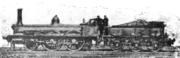
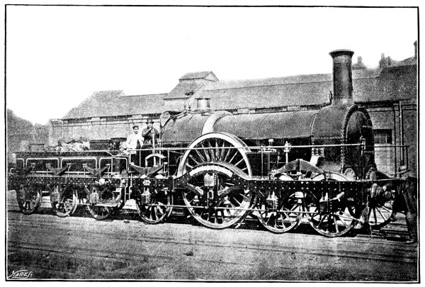
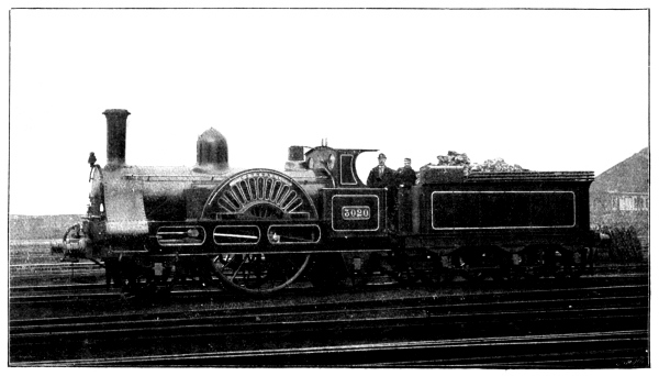
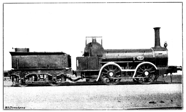
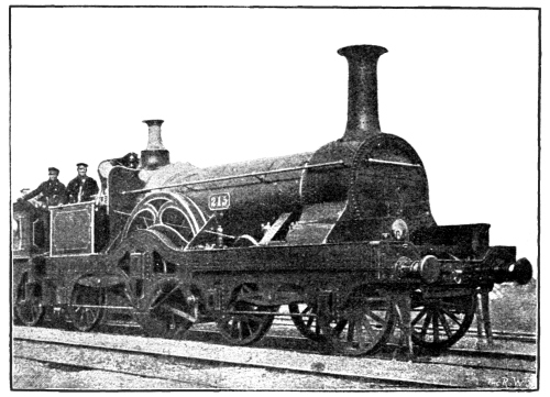
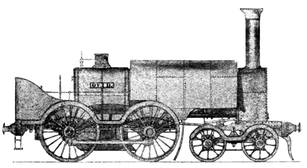
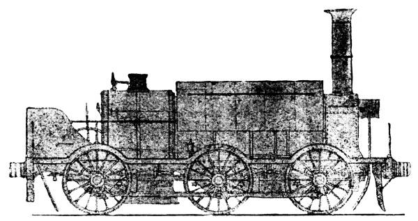
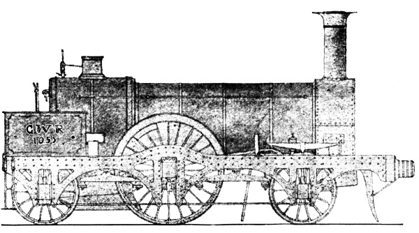
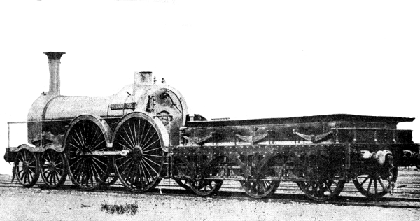
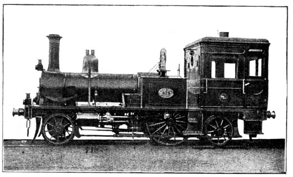
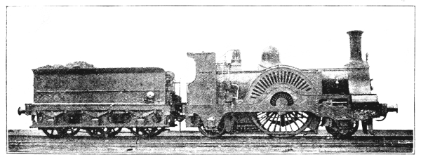
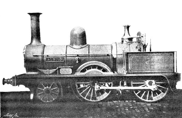
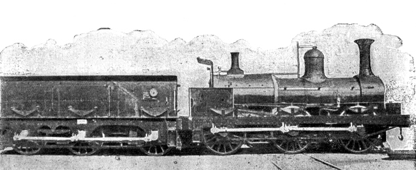
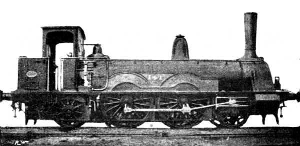
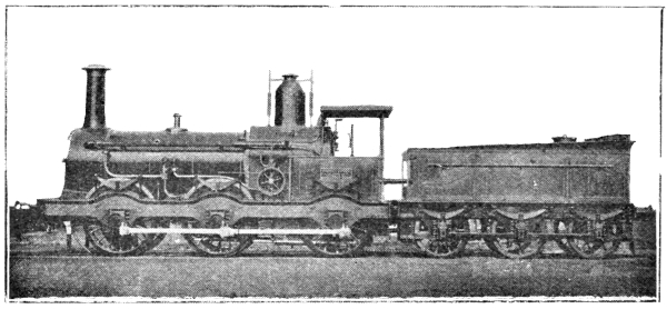
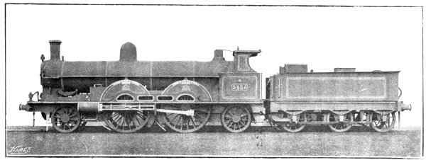
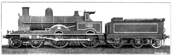
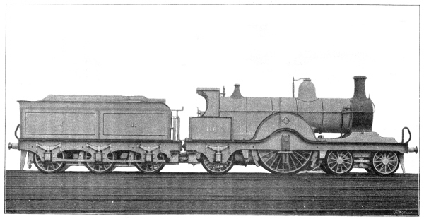
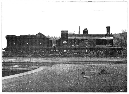
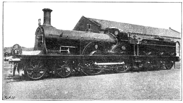
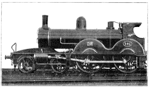
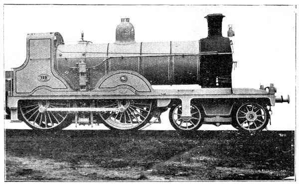
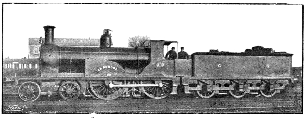
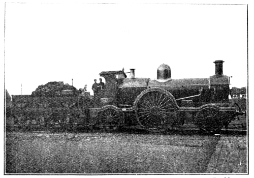
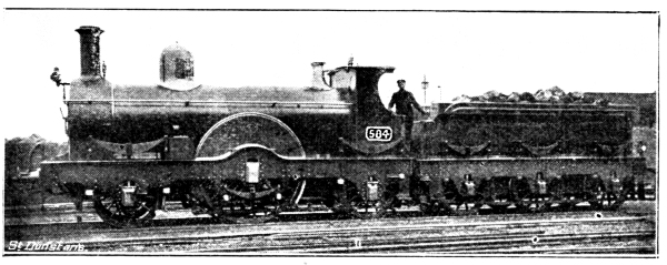
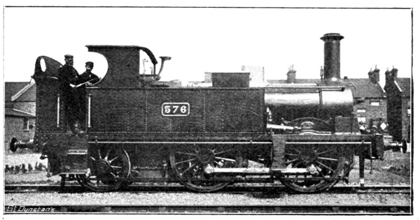
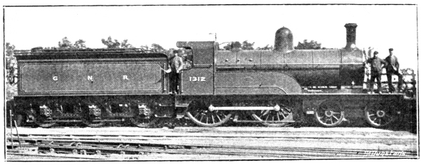
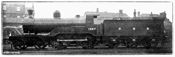
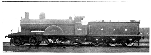
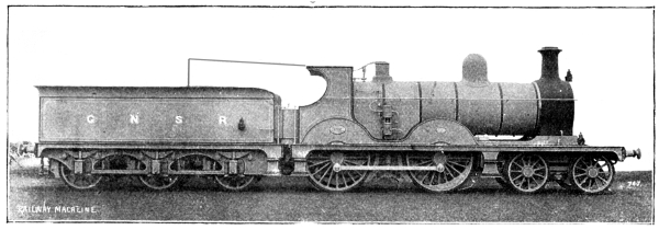
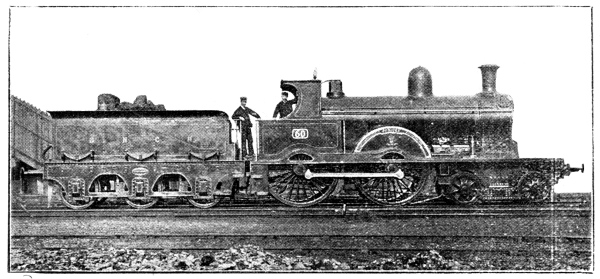
AN ENGLISH TEN-WHEELER, DESIGNED BY MR H. A. IVATT, LOCO. SUPT.
BUILT AT THE G.N.R. LOCOMOTIVE WORKS, DONCASTER
(1803 TO 1898.)
BY G. A. SEKON
Editor of the “Railway Magazine” and “Railway Year Book,” Author of “A History of the Great Western Railway,” &c., &c.
London:
THE RAILWAY PUBLISHING CO., Ltd.,
79 to 83, Temple Chambers,
Temple Avenue, E.C. 1899.
PREFACE.
In connection with the marvellous growth of our railway system there is
nothing of so paramount importance and interest as the evolution of the
locomotive steam engine.
At the present time it is most important to place on record the actual
facts, seeing that attempts have been made to disprove the correctness
of the known and accepted details relative to several interesting, we
might almost write historical, locomotives.
In this work most diligent endeavours have been made to chronicle only
such statements as are actually correct, without reference to personal
opinions.
In a broad sense, and taken as a whole, the old works on locomotive
history may be accepted as substantially correct.
From these, therefore, and from authentic documents provided by the
various railways, locomotive builders, and designers, together with
the result of much original research, has the earlier portion of
this account of the evolution of the locomotive steam engine been
constructed. The various particulars of modern locomotive practice have
been kindly supplied by the locomotive superintendents of the different
British railways, so that no question can arise as to the strict
accuracy of this portion of the work.
Nearly forty years ago it was authoritatively stated: “That kind of
knowledge of the locomotive engine which answers the purpose of a
well-informed man has already become so popular that it almost amounts
to ignorance to be without it. Locomotive mechanism is very simple in
its elementary nature, and the mind is naturally disposed to receive
and retain any adequate explanation of striking phenomena, whether
mechanical or otherwise; and hence it is that there are thousands
of persons who, although in no way concerned in the construction or
working of railway engines, are nevertheless competent to give a fair
general explanation of their structure and mode of working.”
If such were true at that time it is abundantly evident that
it is more so at the threshold of the 20th century, considering
the growth of inquiry into, and appreciation of, scientific
and mechanical knowledge by an ever widening and increasing
circle of general readers, which has been one of the marked
signs of intellectual development during recent years. Under
such circumstances it is not surprising that the locomotive and its
history have received a large share of public attention. Whilst
railway officers, with the intelligence for which they are justly
distinguished, have always evinced a proper desire to be acquainted
with the evolution of the “steam horse,” the spread of education
has increased and quickened a desire for knowledge concerning the
locomotive amongst all classes in a remarkable manner. Many of the
numerous illustrations that embellish the book have been specially
collected for the purpose, and several will be quite new to the
majority of readers. Special pains have been taken to admit only such
illustrations the authenticity of which was known to the author, and
for the same reason many otherwise interesting pictures, upon the
accuracy of which suspicion rested, were excluded from the collection.
Despite these exclusions, we believe that no other book on locomotive
history in the English language is so fully illustrated.
As it is proposed to deal with the railway locomotive only, it is not
necessary to make more than a passing reference to the more or less
crude proposals of Sir Isaac Newton, the Marquess of Worcester, Savery,
Dr. Robinson, Leupold, and other writers and scientists, who hinted at
the possibility of steam locomotion. Nor does the writer propose to
discuss the alleged use of railways and steam locomotives in Germany at
a date prior to their general introduction into England. The claims of
Cugnot, Symington, Evans, Murdoch, and others as builders or designers
of actual or model steam road locomotives will also be passed without
discussion.
We take this opportunity of expressing our sincere thanks to the
locomotive superintendents of British railways, who have all been so
willing to assist the author, not only in supplying accurate data
concerning the locomotives of their own design, but also for so kindly
revising the portions of the volume that relate to the locomotive
history of the particular railway with which each one of these
gentlemen is connected.
In conclusion, we leave the “Evolution of the Steam Locomotive” to the
kindly consideration of our readers, hoping that from a perusal of it
they may derive both information and pleasure.
Trevithick’s triumph; his first steam
locomotives—Mistaken for the devil—The Coalbrookdale engine—A
successful railway journey at Myrthyr Tydvil—Description of the
engine—“Catch-me-who-can”—The locomotive in London— Blenkinsopp’s
rack locomotive—Chapman’s engine—Did Chapman build an eight-wheel
locomotive?—Brunton’s “steam horse”—Its tragic end.
To Richard Trevithick, the Cornish mine captain and engineer, belongs
the honour of producing the first locomotive—true, his original essay
was a road locomotive. As long ago as 1796 he constructed a model
locomotive which ran round a room; and on Christmas Eve, 1801, he made
the initial trip with his first steam locomotive through the streets
of Camborne. This machine carried several passengers at a speed in
excess of the usual walking pace of a man. Trevithick was joined in
the enterprise by his cousin Vivian, who provided the money to build
the steam engines, and to patent them, their first patent being dated
24th March, 1802. It is described as “for improving the construction
of steam engines, and the application thereof for drawing carriages on
rails and turnpike roads and other purposes.” It was claimed that their
engine would produce “a more equable rotary motion on the several parts
of the revolution of any axis which is moved by the steam engine, by
causing the piston-rods of two cylinders to work on the said axis by
means of cranks, at a quarter turn asunder.”
Among other improvements claimed in the specification, mention should
be made of the return tube boiler, bellows to urge the fire, and a
second safety valve, not under the control of the driver.
A steam carriage with these improvements was constructed, and Vivian
and Trevithick commenced a journey on it from Camborne to Plymouth,
from which port it was shipped to London. On the road to Plymouth
a closed toll-bar was met, and the steam carriage stopped for the
gate to be opened. “What have us got to pay here?” demanded Vivian.
The affrighted toll-keeper, shaking in every limb, and his teeth
chattering, essayed to answer, and at last said, “Na—na—na—na.”
“What have us got to pay, I say?” demanded Vivian. “Na—noth—nothing
to pay, my de—dear Mr. Devil; do drive on as fast as you can. Nothing
to pay.”
It must be remembered that to Cornishmen of a century ago the devil was
a very real personage; and, seeing the horseless carriage proceeding
with a fiery accompaniment, the poor toll-keeper thought he had at last
seen his Satanic majesty. He also appears to have remembered that it is
well “to be civil to everyone, the devil included; there is no knowing
when you may require his good wishes.” Hence the toll-keeper’s reason
for calling Vivian “my dear Mr. Devil.”
As early as August, 1802, R. Trevithick (according to his life, as
written by his son, F. Trevithick) appears to have constructed a
railway locomotive at Coalbrookdale. This engine had a boiler of
cast-iron 1½in. thick, with an interior return wrought-iron tube.
The length of the boiler was 6ft., and the diameter 4ft. The cylinder
working this engine was 7in. in diameter, the stroke being 3ft. The
next railway locomotive was that constructed for the Pen-y-darren
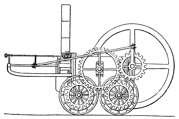
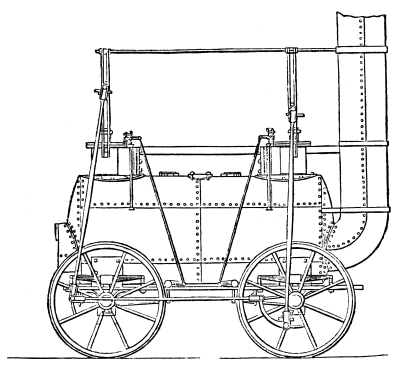
Tramroad near Myrthyr Tydvil. Of this particular locomotive (Fig. 1)
it is possible to obtain authentic particulars, although much that
is legendary already clusters around this historic locomotive. For
instance, we read that the locomotive in question had a brick chimney,
and that it was demolished by colliding with an overhanging branch
of a tree. Then the amount of the bet between Mr. Homfray, the owner
of the tramroad, and his friend, as to whether the locomotive would
successfully perform a journey from Pen-y-darren to the navigation at
Plymouth, is a variable quantity. The amount staked has been stated to
be £500 a side, and also £1,000 a side.
Fig. 1.—THE FIRST
RAILWAY LOCOMOTIVE OF WHICH AUTHENTIC PARTICULARS ARE KNOWN
It is evident that some days prior to February 10th, 1804, the engine
successfully performed the journey, and that overhanging trees and
rocks considerably impeded the travelling, several stoppages having to
be made whilst these obstacles were removed. Mr. Homfray, however, won
the bet. On February 21st another trip was made by the locomotive. On
this occasion the load consisted of 5 wagons, 10 tons of bar iron, and
70 passengers, the weight of the engine, with water and fuel, being 5
tons; the journey of nine miles being performed in 4 hours 5 minutes,
including several stoppages; the average speed when travelling being
five miles an hour. On the return journey the engine hauled the empty
wagons up an incline of 1 in 18 at the rate of five miles an hour.
Several of the tram-plates, which weighed only 28lb. per yard, were
broken on the downward trip. Early in March the engine conveyed a load
of 25 tons from the iron works to the navigation.
It will be observed that this engine from the first decided the
practicability of conveying loads by means of smooth wheels on
smooth rails, simply by adhesion. Yet, strange to say, for several
years after, it was the firmly-fixed belief of succeeding locomotive
constructors that it was impossible to obtain sufficient adhesion
between a smooth surface and a smooth rail to successfully work a
locomotive. The result was the invention of many curious methods to
overcome this apparent difficulty, which, as a fact, never existed,
save in the minds of the designers of the early locomotives. These
men do not seem to have been fully acquainted with the results of
Trevithick’s experiments on the Pen-y-darren tramroad in 1804.
A description of this locomotive prototype is of interest. The boiler
was cylindrical, with a flat end. The fire-door and chimney were both
at the same end, an extended heating surface being obtained by means
of the return tube; above the fire-door was the single horizontal
cylinder, the diameter of which was 8¼in.; a considerable portion
of the cylinder was immersed in the boiler, the exposed portion being
surrounded by a steam jacket. The stroke was 4ft. 6in.! The piston-rod
worked on a motion frame extending in front of the engine. At the other
end of the boiler was a fly-wheel some 9ft. 6in. in diameter, the
motion being conveyed to it by connecting-rods from the cross-head;
a cog-wheel on the fly-wheel axle conveyed the motion by means of an
intermediate wheel to the four driving wheels, which are stated to have
been 4ft. 6in. in diameter. The exhaust steam appears to have been
turned into the chimney, not for the purpose of a blast, but only as an
easy method of getting rid of the vapour. It will be remembered that
Trevithick, in his patent specification, specially mentioned bellows
for urging the fire, and was, therefore, not acquainted with the nature
of the exhaust steam blast. It is important to bear this in mind, as
the reader will find in a later chapter. This engine is stated to
have blown up through not being provided with a safety valve, though
Trevithick specially ordered one to be fixed to the boiler, but his
instructions do not appear to have been carried out.
Trevithick made another locomotive, called “Catch-me-who-can.” This
ran on an ellipse-shaped railway specially laid down for it at Euston
Square, London, and was visited by many people during the few days it
was on view. Another locomotive was constructed from the drawings of
Trevithick’s Coalbrookdale locomotive of 1802, to the orders of
Mr. Blackett, the owner of Wylam Collieries. This engine weighing
4½ tons, had a single cylinder 7in. diameter, 3ft. stroke, and, of
course, a fly-wheel. For some reason or another this engine does not
appear to have been used on the Wylam tramroad, but was used in a
Newcastle foundry to blow a cupola. Mr. Armstrong, a former Locomotive
Superintendent of the Great Western Railway, was acquainted with this
engine of Trevithick’s at the time it was so employed at Newcastle.
Having given an outline of Trevithick’s invention of the tramroad
locomotive, and the other locomotive engines designed by him, we will
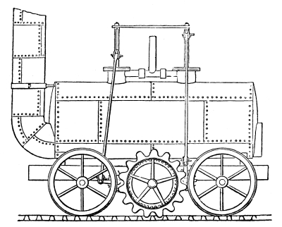
deal with the locomotive built for J. Blenkinsopp (Fig. 2),
of the Middleton Colliery, near Leeds, who, on April 10th, 1811, obtained
a patent for a self-propelling steam engine, worked by means of a
cog-wheel, engaging in a rack laid side by side with one of the rails
forming the tramway.
The erroneous idea that the locomotive of itself had not sufficient
adhesion between the smooth wheel and the surface of the rail to propel
itself and draw a load was strongly entertained by Blenkinsopp, hence
his patent rack and pinion system. Blenkinsopp having this opinion,
which he published by means of his patent specification, caused
succeeding inventors to fall into the same error regarding the adhesive
properties of the locomotive, and consequently considerably retarded
the development of the railway engine.
Although this engine is generally known as Blenkinsopp’s, it was
constructed by Matthew Murray, the Leeds engineer. The boiler was
cylindrical, with slightly convex ends, a single flue ran through
it, which was in front turned upwards, and so formed the chimney;
the fire-grate was at the other end of the flue, as in the modern
locomotive.
This engine was provided with two cylinders, and was, in this respect,
an improvement on Trevithick’s single cylinder engines. The cylinders
were 8in. in diameter, and placed vertically, the major portion of
them being placed within the boiler. The stroke was 20in., and the
motion was conveyed by means of cross-heads, working connecting-rods;
these came down to two cranks on either side below the boiler. The
cranks worked two shafts fixed across the frames, on which were toothed
wheels, both working into a centre toothed wheel, which was provided
with large teeth, these engaged on the rack rail previously described.
The cranks were set at right angles, so that one piston was exerting
power when the other was at its dead centre, and vice versâ.
The engine was supported on the rails by four wheels 3ft. 6in. in
diameter. The two cylinders were connected by a pipe which conveyed the
exhaust steam and discharged it into the atmosphere through a vertical
tube. The engine weighed 5 tons, burned 75lb. of coal per hour, and
evaporated 50 gallons of water in the same time. This locomotive could
haul 94 tons on the level at 3½ miles an hour, or 15 tons up an incline
of 1 in 15; its maximum speed was 10 miles an hour. The engine cost
£400 to construct, and worked from August, 1812, for a period of about
20 years, and in 1816 the Grand Duke Nicholas, afterwards Emperor of
Russia, inspected the machine. The tramway on which it worked was about
3¾ miles long.
Fig. 2.—LOCOMOTIVE
BUILT BY MURRAY FOR BLENKINSOPP’S RAILWAY
In September, 1813, Murray supplied two of Blenkinsopp’s engines to the
Kenton Colliery.
On December 30th, 1812, a patent was granted to William and Edward
Chapman for a method of locomotion. A chain was stretched along the
railway and fastened at each end; connected to the locomotive by
spur gear was a barrel, around which the chain was passed. When the
barrel rotated, the chain was wound over it, and since the chain was
secured at either end, the engine was of necessity propelled. An engine
on this principle was tried on the Heaton Colliery Tramroad, near
Newcastle-on-Tyne. The machine was supported on wheels travelling on
the rails. The boiler was of Trevithick’s design, and fanners were used
to excite the combustion of the fuel. The weight of Chapman’s engine
was 6 tons. After a few trials the scheme was abandoned, as it was
found impracticable to successfully work such a system. Every eight or
ten yards the chain was secured by means of vertical forks, which hold
it when disengaged from the drum of the locomotive.
By this method the pressure of one engine on the chain was limited to
the fork on either side of the drum instead of being spread over the
whole length of the chain, and it would, therefore, have been possible
for several engines to have used the chain at one and the same time.
According to Luke Herbert and Lieut. Lecount, Chapman also built an
8-wheel locomotive for the Lambton Colliery. This engine, it was
stated, had vertical cylinders, and the motion was conveyed by means of
spur wheels. It weighed 6 tons loaded, and drew 18 loaded wagons, of a
gross weight of 54 tons, from the colliery to the shipping place on the
Wear; with the above load it attained a speed of four miles an hour up
an incline of 1 in 115. The dimensions and capabilities accredited to
this engine appear suspiciously similar to those related of the first
Wylam locomotive.
On May 22nd, 1813, Mr. W. Brunton, of the Butterfly Ironworks, obtained
a patent for a novel method of steam locomotion. This locomotive
inventor was also suffering from the common belief that it was
impossible to obtain sufficient adhesion between a smooth rail and
smooth wheels, despite the successes that had already been obtained in
this direction by Trevithick. He therefore built an engine supported
on four flanged carrying wheels, but propelled from behind by means of
two legs. Indeed, another inventor considered the idea of steam legs so
natural that he constructed a steam road-coach that was to be propelled
by four legs, one pair partaking of the character and motion of the
forelegs of a horse, and the other pair being fashioned on the model of
the hind legs of the same quadruped.
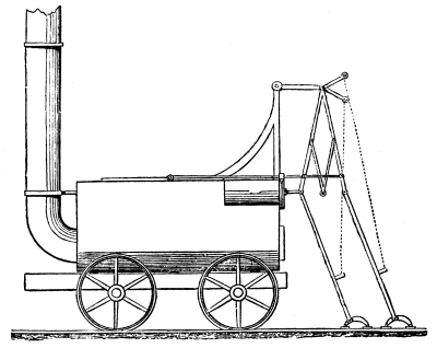
In Brunton’s leg-propelled steam locomotive (Fig. 3) we
find that the boiler was cylindrical, with a single horizontal tube passing
through it, and turned up in front in a vertical position, thus forming the
chimney. The motion was obtained from a single horizontal cylinder,
fixed near the top of the boiler, the piston-rod projecting behind;
the end of the piston-rod was attached to a jointed rod, the bottom
portion of which formed one of the legs. The upper portion of this
rod was attached to a framework fixed above the boiler of the engine,
which formed a fulcrum, and then by an ingenious arrangement of levers,
an alternate motion was given to the second leg. Each leg had a foot
formed of two prongs at the bottom; these stuck in the ground, and
prevented the legs from slipping. Upon steam being applied, the piston
in the ordinary way would have travelled to the end of the cylinder,
but the leg, having a firm hold of the ground, presented a greater
resistance to the steam than did the weight of the engine, so the steam
acting on the surface that presented the lesser resistance, caused the
cylinder to recede, and with it the engine, to which it was, of course,
firmly attached. By means of the reciprocating levers, a horizontal rod
travelled on the top of the boiler and over a cog-wheel; then on
the other side of this cog-wheel was another horizontal rod, which,
actuated by the cog-wheel, travelled in a contrary direction, and
being attached to the other leg of the engine, as the machine receded
from the first leg, it drew the second leg close up to the back of the
engine. The second leg was now ready to propel the engine, which it did
upon the steam being applied to the other side of the piston, and the
process was alternated with each admission of steam to the front or
back of the piston.
Whilst the legs were returning towards the engine the feet were raised
by means of straps or ropes fastened to the legs and passing over
friction-wheels, movable in one direction only by a ratchet and catch,
and worked by the motion of the engine.
Brunton called his locomotive a “mechanical traveller,” and stated
that the boiler was of wrought-iron, 5ft. 6in. long and 3ft. diameter,
weighing 2¼ tons, stroke of piston, 2ft., and at 2½ miles per hour,
with a steam pressure of 451b. per square inch, was equal in power to
nearly six horses. This locomotive curiosity blew up at Newbottle in
1816, and about a dozen people were thereby either killed or seriously
injured.
CHAPTER II.
Who is entitled to the honour of
constructing the Wylam locomotives?—The claims of Hackworth, Hedley
and Foster—“Puffing Billy”—Rebuilt as an eight-wheel engine—Stewart’s
locomotive—Sharp practice causes Stewart to abandon locomotive
building—George Stephenson as a locomotive builder—His hazy views
as to his first engine—“Blucher”—The German General proves a
failure—Stephenson and Dodd’s engine—Stephenson’s third engine, with
(so-called) steam springs—Competent critics condemn Stephenson’s
engines—The “Royal William”—The “Locomotion”—Hackworth, General Manager
of the Stockton and Darlington Railway—Horse haulage cheaper than
Stephenson’s locomotives—Hackworth to the rescue—The “Royal George,”
the first successful locomotive—The “exhaust” steam blast—Rival
claimants and its invention—Locomotive versus stationary engine —“Twin
Sisters”—“Lancashire Witch”—“Agenoria”—The “Maniac”, a Forth Street
production.
We have now arrived at a point in the evolution of the steam locomotive
where the claims of several men are in competition. The facts as to the
experiments and construction of the engines at Wylam are not disputed.
The question at issue is as to whom the honour of the success should
be given. Christopher Blackett, of the Wylam Colliery, as previously
stated, ordered a locomotive of Trevithick, but never used it. He,
however, determined to make a trial of steam haulage on his plate way,
and in 1811 some kind of experiments were made, having in view the
above-mentioned object. At this time Timothy Hackworth was foreman of
the smiths (he would now be called an engineer), and William Hedley
was coal-viewer at Wylam. The friends of both Hackworth and Hedley
claim for their respective heroes the honour of these early essays
in locomotive construction. But it is probable the honours should be
shared by both, as well as by Jonathan Foster, who also assisted in the
experiments and construction of the Wylam locomotives.
Hedley was colliery-viewer at Wylam, and therefore, most likely,
Hackworth was, to an extent, under his orders, and probably had to
defer to, and act under, the instructions of Hedley.
But Hackworth’s position as foreman-smith did not preclude him from
making suggestions and introducing improvements of his own into the
locomotives under construction.
It is stated that Hedley was jealous because Hackworth obtained the
praise for building the Wylam locomotives (or “Timothy’s Dillies,”
as they were locally called), and to force Hackworth to leave Wylam,
Hedley required him to do some repairs to the machinery on Sundays.
Now, Timothy was a fervent Wesleyan, and spent his Sundays in local
preaching, so he naturally refused to violate his conscience by working
on that day. Consequently Hackworth sought employment elsewhere.
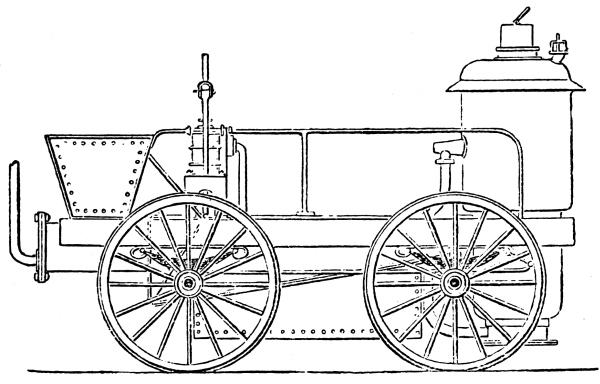
Fig. 4.—HACKWORTH’S
“WYLAM DILLY,” GENERALLY KNOWN AS HEDLEY’S “PUFFING BILLY”
On the other hand, it was a sore point with Hackworth that George
Stephenson spent his Sundays at Wylam taking sketches and particulars
of the locomotives at that time at work on the Wylam Railway, the
result of which observations was apparent in the locomotive built by
Stephenson at Killingworth in 1814.
The Wylam experimentalists in October, 1812, constructed a four-wheel
vehicle driven by manual power working cranks connected with spur
wheels. The carriage was loaded until sufficient weight had been placed
upon it to cause the wheels to turn round without progressing.
The experiment, however, satisfied Mr. Blackett that locomotive engines
with smooth wheels could be employed in drawing loads on his tramroad;
and the construction of an engine was immediately proceeded with. This
was completed and put to work early in 1813. It had a cast-iron boiler,
and a single internal flue; the solitary cylinder was 6in. in diameter,
and a fly-wheel was employed after the model of Trevithick’s engine.
The steam pressure was 50lb. This four-wheel engine drew six coal
trucks at five miles an hour, and, therefore, did the work of three
horses—not a very powerful example of a steam locomotive, it will be
observed. This engine being somewhat of a failure, it was decided to
build another, and one with a wrought-iron boiler and a return tube was
constructed. In his engine (Fig. 4) it will be noticed
the fire-box and chimney were both at the same end of the boiler.
Two vertical cylinders were fixed over the trailing wheels of
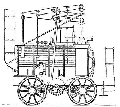
“Puffing Billy” (for it is this historical locomotive, now preserved
in the South Kensington Museum, that is now being described). The
piston-rods were connected to beams of the “Grasshopper” pattern,
being both centred at the funnel end of the engine. The driving-rods
were connected with these beams at about their centres, and passed
down to spur wheels, which, by means of toothed wheels on either
side, communicated the motion to the four carrying wheels. The spent
steam was conveyed from the cylinders to the chimney by means of
two horizontal pipes laid along the top of the boiler. It was soon
discovered that the cast-iron tram-plates, which were only of four
square inch section, were unable to bear the weight of “Puffing Billy,”
and another change was decided upon.
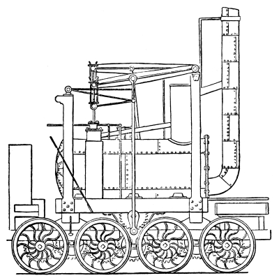
The engine was therefore placed on two four-wheel trucks (Fig. 5),
so that the weight was distributed on eight instead of four wheels, the
same method of spur gearing was employed, and the whole of the wheels
were actuated by means of intermediate cog-wheels. To prevent, as
far as possible, the noise caused by the escaping steam, a vertical
cylinder was fixed on the top of the boiler between the cylinders and
the funnel. Into this chamber the spent steam was discharged, and
from it the same was allowed to escape gradually into the chimney. In
addition to the improvement of a return tube, with its extended heating
surface, with which this class of engine was provided, the funnel was
only 12in. in diameter, as compared with 22in. diameter as used by
Stephenson in his early engines. As already stated, the Wylam
locomotives were locally called “Timothy’s Dillies,” after Timothy
Hackworth, to whose inventive genius they were popularly ascribed.
In 1830, the cast-iron plates on the road from Wylam to Leamington
were removed, and the course was relaid with edge rails, so that the
necessity for eight-wheel engines was at an end. “Timothy’s Dillies”
were then reconverted to four-wheel locomotives, and continued at work
on the line till about 1862.
Fig. 5.—HACKWORTH’S
OR HEDLEY’S SECOND DESIGN, AS USED ON THE WYLAM RAILWAY IN 1815
Not many locomotive writers are acquainted with the fact that in 1814
William Stewart, of Newport, Mon., constructed a locomotive for the
Park End Colliery Company, which was tried on the Lydney Railway, and
found to work in a satisfactory manner. The Park End Colliery Company
were paying about £3,000 a year to contractors for horse haulage of
their coal to the Forest of Dean Canal, and Stewart undertook to do the
same by locomotive power for half that sum. The Company accepted his
terms, and he set about the construction of his engine. Whilst this
was progressing the contractors who provided the horses were told at
each monthly settlement that the Company were going to use a locomotive
to haul the coal, as horse-power was too expensive. By means of these
threats the contractors were induced each month to accept a less price
than previously for “leading” the coal over the tramroad. Upon the
specified date Stewart’s locomotive was duly delivered on the line, and
accepted by the Park End Colliery Company for doing the work required;
but the engineer was informed that the horse-power contractors were
then only receiving £2,000 a year for the work, and that as Stewart
had agreed to provide locomotive power at one-half of the sum paid for
horses, he would only receive £1,000 a year.
Stewart was so highly indignant at this piece of sharp practice that
he refused to have anything further to do with the Park End Colliery
Company, and at once removed his locomotive off their tramroad, and
took it back to Newport.
The earliest attempts of George Stephenson in connection with the
evolution of the steam locomotive now deserve attention. Stephenson
himself is not very clear about his first engine, for, speaking at
Newcastle at the opening of the Newcastle and Darlington Railway in
1844, he said that thirty-two years ago he constructed his first
engine. “We called the engine ‘My Lord,’ after Lord Ravensworth, who
provided the money for its construction.” Both these statements are
erroneous, for Stephenson did not build his first engine till 1814,
and thirty-two years before 1844 would have been 1812. Then the engine
could not have been called “My Lord,” after Lord Ravensworth, for the
title did not exist in 1814, the gentleman alluded to being only Sir
Thomas Liddell till the coronation of King George IV. in 1821, when he
was created Lord Ravensworth.
The “Blucher,” as this engine was in fact usually called, was first
tried on the Killingworth Railway on July 25th, 1814; she had a
wrought-iron boiler, 8ft. long and 2ft. 10in. diameter, with a single
flue 20in. diameter, turned up in front to form a chimney. The power
was applied by means of two vertical cylinders located partly within
the boiler, and projecting from its top, close together, and near the
middle. The cylinders were 8in. diameter, the stroke 2ft. The motion
was conveyed to the wheels by means of cross-heads and connecting-rods
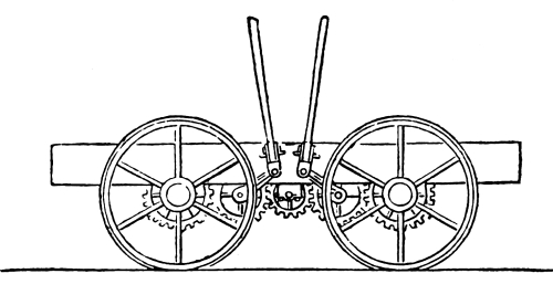
working on small spur wheels (Fig. 6), which engaged
the four carrying wheels by means of cogged wheels fitted on the axles of
the flanged rail-wheels; these were only 3ft. in diameter, and were
3ft. apart. The spur wheels engaged another cogged wheel, placed
between them, for the purpose of keeping the cranks at right angles.
No springs were provided for the engine, which was mounted on a wooden
frame, but the water barrel was fixed to one end of a lever, and also
weighted; the other end of this lever was fixed to the frame of the
engine. This arrangement did duty for springs!
Fig. 6.—STEPHENSON’S
INITIAL DRIVING GEAR FOR LOCOMOTIVES
The best work done by “Blucher” was the hauling of loaded coal-wagons,
weighing 30 tons, up an incline of 1 in 450, at about four miles an
hour. This first effort of Stephenson had no original points about
it; the method of working was copied from the Wylam engines, whilst
Trevithick’s practice was followed with regard to the position of the
cylinders—i.e., their location, partly within the boiler. The
average speed did not exceed three miles an hour, and after twelve
months’ working the machine was found to be more expensive than the
horses it was designed to replace at a less cost. The absence of
springs was specially manifested, for by this time the engine was so
much shaken and injured by the vibration that the Killingworth Colliery
owners were called upon a second time to find the money to enable
Stephenson to construct another locomotive.
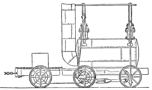
The second engine (Fig. 7) constructed by
George Stephenson was built under the patent granted to Dodd and
Stephenson on 28th February, 1815. In this engine vertical cylinders,
partly encased in the boiler, were again employed; but their position
was altered, one being placed at each extremity of the boiler over the
wheels, the intermediate spur wheels formerly used for keeping the
cranks at right angles were abandoned, and the axles were cranked. A
connecting-rod was fitted on these cranks, thus coupling the two axles.
To give greater adhesion, the wheels of the tender were connected
with those of the engine by means of an endless chain passing over
cogs on the one pair of engine wheels, and over the adjoining pair of
tender wheels; by these methods six pairs of wheels were coupled. The
mechanics engaged were not, however, capable of forging proper crank
axles, and these had to be abandoned, and an endless chain coupling
employed for the engine wheels, similar to the one connecting the
tender and engine, as previously described.
Fig. 7.—STEPHENSON
AND DODD’S PATENT ENGINE, BUILT IN 1815
This engine had no springs, and, to avoid excessive friction arising
from the bad state of the tramroad, Stephenson employed “ball
and socket” joints between the ends of the cross-heads and the
connecting-rods. In this way the necessary parallelism between the ends
of the cross-heads and the axles was maintained. The spent steam in the
engine was turned into the chimney, as in Trevithick’s Pen-y-darren
locomotive. This locomotive commenced to work on 6th March, 1815.
George Stephenson constructed a third engine (Fig. 8),
under a patent granted to Lock and Stephenson on 30th September, 1816; this
patent covered several matters, the most important in connection with the
engine being malleable iron wheels, instead of cast-iron, and what has
been described as “steam springs.” The patentees called them “floating
pistons”; of this description Colburn says emphatically “they are not,”
and the same authority continues, “and they (Lock and Stephenson)
added, evidently without understanding the true action of the pistons,
which were different in principle from the action of springs, that
inasmuch as they acted upon an elastic fluid, they produced the desired
effect, with much more accuracy than could be obtained by employing the
finest springs of steel to suspend the engine. The whole arrangement
was, on the contrary, defective in principle and objectionable on
the score of leakage, wear, etc.; and, as a matter of course, was
ultimately abandoned.”
Fig. 8.—STEPHENSON’S
IMPROVED ENGINE, AS ALTERED, FITTED WITH STEEL SPRINGS (INVENTED BY
NICHOLAS WOOD)
In the drawings attached to the patent specification this engine is
shown with six wheels, and the chain coupling is employed. Lecount
says: “The six wheels were continued in use as long as the steam
springs were applied, and when steel springs were adopted they were
again reduced to four.” So much praise has been given to Stephenson for
the “great improvements” he is supposed to have introduced into the
construction of the locomotive, that it will not be uninteresting if
we here reproduce the extremely pertinent remarks of Galloway, the
well-known authority on the steam engine, which go far to prove that
it was only the great success obtained by George Stephenson from the
construction of the Liverpool and Manchester and other railways, that
caused historians and biographers to either magnify his locomotive
successes, or to gloss over the evident faults in the design and
construction of his engines. In his “History of the Steam Engine,”
published in 1827, Galloway says: These locomotive engines have been
long in use at Killingworth Colliery, near Newcastle, and at Hilton
Colliery on the Wear, so that their advantages and defects have been
sufficiently submitted to the test of experiment; and it appears that,
notwithstanding the great exertions on the part of the inventor, Mr.
Stephenson, to bring them into use on the different railroads, now
either constructing or in agitation, it has been the opinion of several
able engineers that they do not possess those advantages which the
inventor had anticipated; indeed, there cannot be a better proof of
the doubt entertained regarding their utility than the fact that it
has been determined that no locomotive engine shall be used on the
projected railroad between Newcastle and Carlisle, since, had their
advantages been very apparent, the persons living immediately on the
spot in which they are used, namely, Newcastle, would be acquainted
therewith.
“The principal objections seem to be the difficulty of surmounting
even the slightest ascent, for it has been found that a rise of only
one-eighth of an inch in a yard, or of eighteen feet in a mile, retards
the speed of one of these engines in a very great degree; so much so,
indeed, that it has been considered necessary, in some parts where
used, to aid their ascent with their load, by fixed engines, which
drag them forward by means of ropes coiling round a drum. The spring
steam cylinders below the boiler were found very defective, for in the
ascending stroke of the working piston they were forced inwards by the
connecting-rod pulling at the wheel and turning it round, and in the
descending stroke the same pistons were forced as much outwards. This
motion or play rendered it necessary to increase the length of the
working cylinder as much as there was play in the lower ones, to avoid
the danger of breaking or seriously injuring the top and bottom of the
former by the striking of the piston when it was forced too much up or down.”
Stephenson must have felt himself to be a personage of some importance
when he received an order from the Duke of Portland for a steam
locomotive. The engine, which had six wheels, was duly built and
delivered in 1817, when it was put to work on the tramroad connecting
the Duke’s Kilmarnock Collieries with the harbour at Troon; but,
after a short trial, its use was abandoned, as the weight of the
engine frequently broke the cast-iron tram-plates. It has been stated
that “this engine afterwards worked on the Gloucester and Cheltenham
Tramroad until 1839, when the Birmingham and Gloucester Railway bought
the line, and took up the cast-iron tram-plates.”
There is no doubt that a six-wheel engine with vertical cylinders
partly encased in the top of the boiler, and called the “Royal
William,” was actually at work on this line—the fact having been
commemorated by the striking of a bronze medal; but there is nothing to
show that the “Royal William” and the engine built for the Kilmarnock
and Troon Tramroad were one and the same locomotive; whilst it is
certain that the Gloucester and Cheltenham Tramroad was not purchased
by the Birmingham and Gloucester Railway, but jointly by the Cheltenham
and Great Western Union Railway and the Birmingham and Gloucester
Railway, the price paid being £35,000.
It would appear from a letter written by George Stephenson, and dated
Killingworth Colliery, 28th June, 1821, that he had but little idea
to what a great degree the development of the steam locomotive would
be carried. The letter, which was addressed to Robert Stevenson, the
celebrated Edinburgh engineer, proceeded as follows: “I have lately
started a new locomotive engine with some improvements on the others
which you saw. It has far surpassed my expectations. I am confident
that a railway on which my engine can work is far superior to a canal.
On a long and favourable railway I would start my engine to travel 60
miles a day, with from 40 to 60 tons of goods.” Taking Stephenson’s
“day” to mean twelve working hours, his idea of maximum speed did not
exceed five miles an hour at that time. Before this—in December,
1824—Charles MacLaren had published in the Scotsman his opinion
that by the use of the steam locomotive “we shall be carried at the
rate of 400 miles a day,” or an average speed of 33⅓ miles an hour.
Yet such is the irony of fate, that MacLaren, the true prophet, is
forgotten, and George Stephenson is everywhere extolled.
The Hetton (Coal) Railway was opened on November 18th, 1822, and five
of Stephenson’s “improved Killingworth” locomotives were placed upon
the level portions. These engines were capable of hauling a train of
about 64 tons, the maximum speed being four miles an hour.
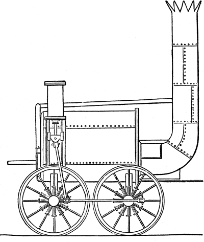
Fig. 9.—“LOCOMOTION,”
THE FIRST ENGINE TO RUN ON A PUBLIC RAILWAY (THE STOCKTON AND
DARLINGTON RAILWAY)
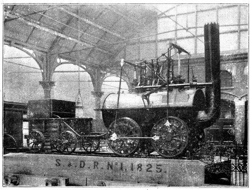
The Stockton and Darlington Railway, the first public railway, was
opened on September 27th, 1825. The “Locomotion” (Fig. 9)
was the first engine on the line. It was constructed at the Forth Street Works of
R. Stephenson and Co., at Newcastle-on-Tyne. At this early period these
now celebrated Forth Street Works were little better than a collection
of smiths’ forges.
Timothy Hackworth had been manager of these works, and he had a good
deal to do with the construction of “Locomotion.” His improvement of
the coupling-rods in place of the endless chain previously used for the
purpose by Stephenson is worthy of passing notice. George Stephenson
expressed a very strong desire that Hackworth should remain in charge
of the Forth Street Works, and went so far as to offer him one-half of
his (Stephenson’s) share in the business if he would remain. Hackworth
agreed to do so if his name were added to that of the firm and he were
publicly recognised as a partner; but this proposition was not accepted
by Stephenson.
Hackworth then took premises in Newcastle, and intended to commence
business as an engine-builder on his own account, he having already
received several orders from the collieries, etc., where his skill
was well known and appreciated. George Stephenson, having heard of
Hackworth’s plans for carrying on a rival engine factory at Newcastle,
saw Hackworth, and persuaded him to relinquish the proposition and
accept the office of general manager and engineer to the Stockton and
Darlington Railway.
Hackworth commenced these duties in June, 1825, and removed to
Darlington. The “Locomotion” had four coupled wheels, 4ft. in diameter;
two vertical cylinders, 10in. in diameter, placed partly within the
boiler; the stroke was 24in.; steam pressure, 25lb. per square inch;
weight in working order, 6½ tons. The tender was of wood, with a coal
capacity of three-quarter ton, and a sheet-iron tank holding 240
gallons; weight loaded, 2¼ tons. The tender was supported on four
wheels, each of 30in. diameter. This engine worked on the Stockton
and Darlington Railway till 1850. In September, 1835, “Locomotion”
engaged in a race with the mail coach for a distance of four miles, and
only beat the horses by one hundred yards! She was used to open the
Middlesbrough and Redcar Railway on June 4th, 1846, being under the
charge of Messrs. Plews and Hopkins on this occasion, when she hauled
one carriage and two trucks, and took thirty-five minutes to cover the
eight miles. From 1850 to 1857 she was used as a pumping engine by
Pease at his West Collieries, South Durham, after which she was mounted
on a pedestal at North Road Station, Darlington. This engine was in
steam upon the Darlington line during the celebration of the Stockton
and Darlington Railway jubilee in September, 1875. She has been
exhibited as follows:—1876, at Philadelphia; 1881, Stephenson
Centenary; 1886, Liverpool; and 1889, Paris. In April, 1892, she was
removed from North Road to Bank Top, Darlington.
The Forth Street Works in 1826 supplied three more engines to the
Stockton and Darlington Railway, named “Hope,” “Black Diamond,” and
“Diligence.” These locomotives possessed many faults; indeed, they were
frequently stopped by a strong wind, and the horse-drawn trains behind
the locomotive-propelled ones were delayed because the engines could
not proceed. “Jemmy” Stephenson (brother to George) was the principal
engine-driver, and he was known far and near as most prolific in the
use of oaths of a far from Parliamentary style.
“Jemmy” would be cursing his engine and the horsemen cursing “Jemmy”
for the delay; and, indeed, the usual result was a general skirmish.
We have already stated that Hackworth was a deeply religious man, and
these scenes of lawlessness made a deep impression on his mind, so that
he sought for some means to improve the locomotives, the radical fault
of which was the shortness of steam—Hackworth knowing that if things
progressed smoothly “Jemmy” would have fewer occasions to display his
oratorical gift. After eighteen months’ working of the Stockton and
Darlington Railway it was found that locomotive haulage was much more
expensive than horse-power; indeed, for every pound spent on horse
power about three pounds were paid for locomotive power for doing an
exactly similar amount of work.
The £100 stock of the Stockton and Darlington Railway quickly fell to
£50, and the shareholders began to get alarmed.
There were two opposite interests at stake—that of the general body
of shareholders and that of the locomotive builders (Messrs. Pease and
Richardson), who were also large shareholders in, and directors of the
Stockton and Darlington Railway, as well as partners in the firm of R.
Stephenson and Co. The question as to retaining the use of locomotive
engines was fully discussed at a meeting of the principal proprietors,
and Hackworth, as manager and engineer of the railway, was asked to
give his opinion on the point. He replied: “Gentlemen, if you will
allow me to make you an engine in my own way, I will engage that it
shall answer your purpose.” To have refused him permission would have
shown clearly to the other proprietors that Pease and Richardson did
not care for the principles of steam locomotion, but that it was the
locomotives constructed at the Forth Street Works they wished to
retain. Therefore, after some discussion, it was agreed that “as a last
experiment Timothy shall be allowed to carry out his plan.”
Hackworth’s opportunity had now arrived, and the result was the
production of the first really successful locomotive steam engine.
But although the shareholders “as a last experiment” gave Hackworth
leave to build a locomotive on his own plan, they do not appear to have
had much belief in the success of the venture, for the boiler of an old
locomotive was given him to use in the construction of the new engine.
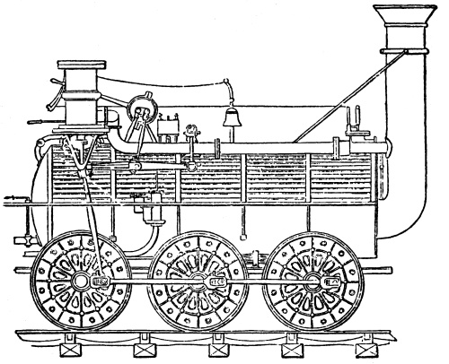
Fig. 10.—THE
FIRST SUCCESSFUL LOCOMOTIVE, HACKWORTH’S “ROYAL GEORGE,”
STOCKTON AND DARLINGTON RAILWAY, 1827
The engine was originally a four-wheel engine, provided with four
cylinders, two to each pair of wheels, and it is stated to have been
the first built in which a single pair of wheels was worked by two
pistons actuating cranks placed at right angles to each other. She was
built by Wilson, of Newcastle, and was the fifth engine supplied to the
Stockton and Darlington Railway.
This boiler was a plain cylinder, 4ft. 4in. in diameter, and 13ft.
long. A wrought-iron tube of [symbol] shape provided the heating
surface, the vapour from the furnace travelling from the fire-grate up
and down the tube to the chimney, which was at the same end of the
boiler as the grate; indeed, the chimney was an elongation of the tube
continued through the end of the boiler and turned up vertically.
This return tube gave the new engine twice the heating surface of the
ordinary engines, which were only provided with one straight tube. The
locomotive was called the “Royal George” (Fig. 10),
and was supported on six-coupled wheels, each of 4ft. diameter.
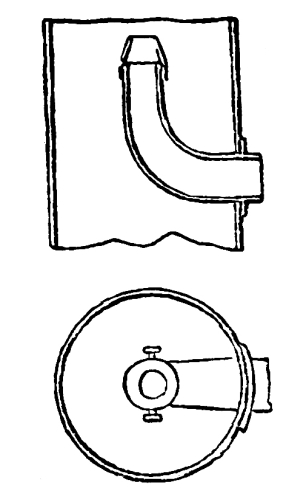
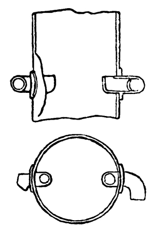
Fig. 11.—HACKWORTH’S
BLAST PIPE IN THE “ROYAL GEORGE”.
The cylinders were placed in a vertical position over the pair of
wheels farthest from the chimney. They were 11in. diameter, the stroke
being 20in. Four of the wheels were provided with springs, but the
pair connected to the pistons were not so fitted, the position of the
cylinders rendering it impossible for springs to be used. The other
improvements to be noted in the construction of the “Royal George” are:—
(1.) Springs instead of weights for the safety valves.
(2.) The short-stroked pumps.
(3.) Self-lubricating bearings fitted with oil reservoirs.
(4.) The cylinders placed central with the crank
journals and the centre of its orbit.
(5.) The first example of six-coupled wheels.
(6.) The first really spring-mounted locomotive,
the springs performing the double functions of “bearing springs” and
“balance beams.”
(7.) A portion of the exhaust steam used as a
jet beneath the fire-grate and part also for heating the feed-water;
and last and most important—so important, indeed, that it has been
described as the “life-breath of the high-pressure locomotive”—the
Steam Blast. (Fig. 11.)
Trevithick, Nicholson, Stephenson, Gurney, and others have been
credited with the production of this valuable contrivance, but an
inquiry into the facts conclusively proves that before Hackworth built
the “Royal George” the real nature of the exhaust steam blast was
not understood by any of those who have since been credited with the
invention.
Doubtless several locomotive experimentalists, after various endeavours
to get rid of the spent steam, at last turned the escape pipe into the
chimney, as the most practical way of discharging the exhaust steam.
Trevithick did so, and George Stephenson and others simply followed
Trevithick’s example, but knew nothing of the value of the exhaust
steam as a means of increasing the heating powers of the locomotive.
Fig. 12.—WASTE
STEAM-PIPE IN STEPHENSON’S “ROCKET”
The claims of both Stephenson and Trevithick appear to be founded on
the use of the words “steam blast” by N. Wood in his “Treatise,” when
describing the exhaust steam arrangement. This he probably did, not
understanding the true nature of the blast, or contracted orifice, as
invented by Hackworth.
It is abundantly evident that Trevithick was absolutely ignorant of
the effect of the blast on the fire, for in his patent (No. 2,599) no
mention is made of it, although the specification is most minutely
drawn; indeed, thirteen years later Trevithick actually patented
“fanners, etc., for creating an artificial draught in the chimney.”
Nicholson, in his patent (No. 2,990) dated November 22nd, 1806, also
says, “The steam must be high pressure; the steam draught cannot be
produced by exhaust steam”. This clearly shows he was not aware of
the exhaust steam blast; indeed, he expressly states that exhaust
steam cannot be used. With regard to George Stephenson, the fact
that as late as July 25th, 1828, he wrote to Timothy Hackworth, “We
have tried the new locomotive engine (‘Lancashire Witch’) at Bolton; we
have also tried the blast to it for burning coke, and I believe it will
answer. There are two bellows, worked by eccentrics underneath the
tender.” It will, therefore, be observed that Stephenson’s “blast”
was produced by bellows. This letter was written ten months after
Hackworth had successfully used the steam blast in the “Royal George.”
It will be shown later that it was only at the Rainhill trials, in
October, 1829, that Stephenson learned Hackworth’s secret of the blast
pipe. Although Gurney, in 1822, used a coned pipe, he expressly states
that the steam must be continuously ejected at a high velocity from a
high-pressure boiler, which distinctly shows he did not use exhaust
steam as Hackworth did.
Walker and Rastrick were the engineers engaged by the directors of the
Liverpool and Manchester Railway to report on the advantages to be
gained from the adoption of stationary or locomotive engines on the
Liverpool and Manchester Railway. They decided in favour of the former,
but they stated in their report, “Hackworth’s engine (‘Royal George’)
is undoubtedly the most powerful that has yet been made, as the amount
of tons conveyed by it, compared with the other engines, proves.” The
first year’s work of the “Royal George” consisted of conveying 22,442
tons of goods 20 miles, at a cost of only £466, whilst the same amount
of work performed by horses cost £998, showing a saving by the use
of the “Royal George” of £532 in one year. The “Royal George” was
numbered, 1½, in the books of the S. and D. R.
This was the first time that a locomotive engine had worked for a whole
year at a cheaper rate than horses. Upon this result being known to the
Stockton and Darlington Railway directors, one of them exclaimed, “All
we want is plenty of Timothy’s locomotives.” The “Royal George” worked
night and day upon the Stockton and Darlington Railway until December,
1840, when she was sold to the Wingate Grange Colliery for £125 more
than her original cost.
R. Stephenson and Co. in 1828 supplied a six-wheel coupled engine,
“Experiment,” to the Stockton and Darlington Railway. This locomotive
had inclined outside cylinders, 9in. diameter, with a stroke of 24in.;
the wheels were 4ft. diameter. This engine did not give nearly so
satisfactory results as Hackworth’s “Royal George.”
Reference must here be made to Stevenson’s locomotive, “Twin Sisters,”
used in the construction of the Lancashire and Manchester Railway. She
had two fire-boxes and boilers, and two chimneys; she was supported on
six-coupled wheels of 4ft. diameter; the cylinders were outside in an
inclined position. The “Lancashire Witch” (previously mentioned) was
built by Stephenson and Co. in 1828 and sold to the Bolton and Leigh
Railway. She was supported on four coupled wheels, 4ft. diameter; the
cylinders were outside, 9in. diameter, fixed in an inclined position,
projecting over the top and at the rear of the boiler. The engine is
only mentioned for the purpose of noticing the fact that the fire was
urged by means of bellows, worked by eccentrics fixed on the leading
axle of the four-wheeled tender, which was specially built with outside
frames for the purpose of allowing sufficient room to locate the
bellows, etc. Yet some people have assurance enough to state that at
the time Stephenson built this engine, and provided it with bellows for
the purpose of urging the fire, he was fully acquainted with the nature
and advantages of the steam blast!!
In the South Kensington Museum there is preserved the “Agenoria,” a
locomotive built for the Shutt End Railway by Foster, Rastrick and Co.
in 1829, the engine being put to work on June 2nd in that year. It is a
four-wheel engine, with vertical cylinders, 7½in. diameter, placed at
the fire-box end; the stroke is 3ft., and the motion is taken from two
beams fixed over the top of the boiler, which is 10ft. long and 4ft.
diameter. The slide-valve eccentrics are loose upon the axle, and to
enable the engine to work both ways a clutch is provided, as also is
hand gear to the valves, to enable the axle to make a half turn, and so
bring either the forward or backward clutch into action. The chimney
was of abnormal height. The “Agenoria” worked for some thirty years.
In 1829 R. Stephenson and Co. supplied an engine named “Rocket,” No. 7,
to the Stockton and Darlington Railway, similar in general design to
“Experiment,” No. 6 (already referred to). This engine was delivered at
the time Hackworth was attending the Rainhill locomotive contest, and
a director of the Stockton and Darlington Railway wrote to Hackworth,
describing the shortcomings of this engine as follows:—“The new
one last sent was at work scarcely a week before it was completely
condemned and not fit to be used in its present state. The hand gear
and valves have no control in working it. When standing without the
wagons at Tully’s a few day ago it started by itself when the steam
was shut off, and all that Jem Stephenson could do he could not stop
it; it ran down the branch with such speed that old Jem was crying out
for help, everyone expecting to see them dashed to atoms; the depôts
being quite clear of wagons, this would have been the case had not the
teamers and others thrown blocks in the way and fortunately threw it
off. A similar occurrence took place on the following day in going down
to Stockton. As soon as the wagons were unhooked at the top of the run,
away goes ‘Maniac,’ defying all the power and skill of her jockey, old
Jem; nor could it be stopped until it arrived near the staiths. Had a
coach been on the road coming up, its passengers would have been in
a most dangerous position. The force-pump is nearly useless, having
had, every day it was at work, to fill the boiler with pails at each
of the watering-places. No fewer than three times the lead plug has
melted out. This ‘Maniac’ was a Forth Street production, and at last
was obliged to be towed up to the ‘hospital’ by a real ‘Timothy’ in
front, on six wheels, and actually had twenty-four wagons in the rear
as guard. It is now at headquarters at Shildon.”
Such was the opinion expressed by a director of the Stockton and
Darlington concerning a Stephenson locomotive!
CHAPTER III.
The Liverpool and Manchester Railway Locomotive
Competition—The conditions of the contest—The competitors—The
“Novelty”—The “Sanspareil”—The secret of the steam blast stolen—Mr.
Hick’s history of the “Sanspareil”—The “Rocket”—Colburn’s comparison
of the “Rocket” and “Sanspareil”—Booth’s tubular boiler fitted to the
“Rocket”—The prize divided—History of the “Rocket”—The “Perseverance”
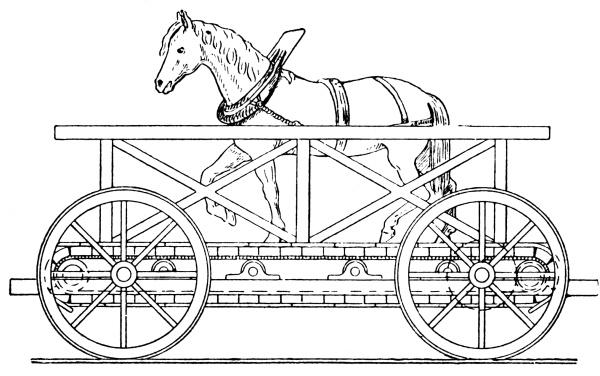
wihtdrawn from competition—The “Cycloped” horse-propelled locomotive—
Winan’s manumotive vehicles for the Liverpool and Manchester
Railway—The directors purchase a dozen.
Although Walker and Rastrick had reported to the directors of
the Liverpool and Manchester Railway in favour of stationary engines,
there were some of them who were enlightened enough to be desirous
of giving steam locomotives a fair trial. The Stephensons being
locomotive engine builders, naturally were not behindhand in fully
and frequently describing the superiority of locomotive traction.
Finally, at the suggestion of Mr. Harrison, the directors offered a prize
of £500, to be awarded to the locomotive that at the trial appeared
to be the best machine competing. The following is a copy of the
notice detailing the conditions of the competition:—
“Railway Office, Liverpool, 25th April, 1829.
“Stipulations and Conditions on which the Directors of the Liverpool
and Manchester Railway offer a premium of £500 for the most improved
Locomotive Engine:—
“1st. The said engine must effectually consume its own smoke,
according to the provisions of the Railway Act, 7, George IV.
“2nd. The engine, if it weighs six tons, must be capable of drawing
after it, day by day, on a well-constructed railway, on a level plane,
a train of carriages of the gross weight of twenty tons, including the
tender and water-tank, at a rate of ten miles per hour, with a pressure
of steam on the boiler not exceeding fifty pounds per square inch.
“3rd. There must be two safety valves, one of which must be
completely out of the control of the engineman, and neither of which
must be fastened down while the engine is working.
“4th. The engine and boiler must be supported on springs, and
rest on six wheels, and the height from the ground to the top of
the chimney must not exceed fifteen feet.
“5th. The weight of the machine, with its complement of water in
the boiler, must at most not exceed six tons; and a machine of less
weight will be preferred if it draw after it a proportionate weight;
and, if the weight of the engine, etc., does not exceed five tons,
then the gross weight to be drawn need not exceed fifteen tons, and in
that proportion for machines of still smaller weight; provided that
the engine, etc., shall still be on six wheels, unless the weight (as
above) be reduced to four-tons and a half or under, in which case the
boiler, etc., may be placed on four wheels. And the Company shall
be at liberty to put the boiler, fire-tube, cylinders, etc., to a
test of pressure of water not exceeding 150 pounds per square inch,
without being answerable for any damage the machine may receive in
consequence.
“6th. There must be a mercurial gauge affixed to the machine with
index rod showing the steam pressure above forty-five pounds per square
inch.
“7th. The engine to be delivered complete for trial at the Liverpool
end of the railway not later than the 1st of October next.
“8th. The price of the engine which may be accepted not to exceed
£550, delivered on the railway, and any engine not approved to be taken
back by owner.
“N.B.—The Railway Company will provide the engine
tender with a supply of water and fuel for the experiment. The distance
within the rails is four feet eight inches and a half.”
Fig. 13.—THE
“NOVELTY,” ENTERED BY BRAITHWAITE AND ERICSSON FOR THE RAINHILL PRIZE
At this period there were but few men who understood even the outlines
of locomotive construction, and unfortunately all of these did not
take part in the competition. The fifth condition, limiting the weight
of the loaded locomotive to six tons, probably deterred some makers
from competing. Others had commenced constructing locomotives for the
competition, but were unable to finish them by the date mentioned in
the conditions.
The actual entries were as follows: 1. Braithwaite and Ericsson’s
“Novelty”; 2. Timothy Hackworth’s “Sanspareil”; 3. R. Stephenson’s
“Rocket”; 4. Burstall’s “Perseverance”; and 5. Brandreth’s “Cycloped.”
The “Novelty” (Fig. 13) was far and away the favourite
engine at Rainhill, its neat appearance and smartness attracting universal
attention. It was a “tank” engine, and probably the first locomotive
constructed to carry its supply of water and coal on the engine,
being thus complete without a tender. This raised a difficulty in
apportioning the load, as in the conditions it was arranged that the
tender was to be counted as part of the load hauled. The machine with
water and coal weighed 3 tons 17 cwt. 14 lb.; the allowance made for
the tender and fuel reduced the theoretical weight of the “Novelty,”
as an engine only, to 2 tons 13 cwt. 2 qr. 3½ lb.; the gross weight
hauled, including the locomotive, being 10 tons 14 cwt. 14 lb.
The “Novelty” was first tried upon October 10th, 1829—she had not
previously been upon a railway—and it was found necessary to make some
alterations to her wheels. Timothy Hackworth, although he had an engine
running in competition with the “Novelty,” generously offered to repair
the defect, and he personally took out the broken portion, welded it,
and replaced it in position with his own hands.
The trials were conducted upon a level portion of line at Rainhill,
on a course only one and a half miles in length, and at either end an
additional eighth of a mile was allowed for the purpose of getting up
the speed and stopping after the run of a mile and a half. The engines
had to make forty runs over the course, or a distance of sixty miles,
in all, which was computed to be equal to a return journey between
Liverpool and Manchester.
After running two trips of one and a half miles each, the pipe from the
pump to the boiler burst, in consequence of the cock between the boiler
and pump having, by accident, been closed. The “Novelty” and train
covered the first trip in five minutes thirty-six seconds, and the
return in six minutes forty seconds; being at the rate of 16.07 and 13½
miles an hour respectively. After being repaired, the engine, with its
train, made an unofficial trip, and developed a speed of 21 ⅙ miles an
hour. Without a load the “Novelty” attained a speed of nearly thirty
miles an hour.
The “Novelty” was again tried on October 14th, but upon its third
trip part of the boiler gave way, and it was decided to withdraw the
locomotive from competition.
The boiler of the “Novelty” was partly vertical and partly horizontal;
the latter portion was about 12ft. long and 15in. in diameter. In the
former was the fire-box, surrounded by water, coke being supplied
through what at first might be mistaken for the funnel of a steam
fire-engine. This was, however, kept air-tight, the fuel being
introduced by means of a descending hopper. The area of the fire-grate
was 1.8 sq. ft., the fire-box heating surface 9½ sq. ft., and the
heating surface of the tubes, 33 sq. ft.
The air entered below the fire-bars by a pipe traversing the length of
the engine, and connected with bellows fixed above the frame at the
other extreme of the engine. The bellows were worked by the engine,
so that the “Novelty” was provided with a forced draught. The heated
air was forced through a tube, which made three journeys through
the horizontal portion of the boiler, and was consequently 36ft. in
length. It was 4in. in diameter at the grate end, and 3in. at the
other extreme, where it was turned up as a chimney. The cylinders were
located over the pair of wheels at the bellows end of the machine. They
were fixed vertically, the diameter being 6in., and length of stroke
12in. The piston-rods worked through the top covers, and by means of
cross-heads, side-rods, and bell-cranks the motion was conveyed to the
crank axle beneath the vertical portion of the boiler, although, as
previously mentioned, the cylinders were over the other pair of wheels.
The wheels were 4ft. 2.1in. in diameter, and chains were provided for
coupling the wheels together; but these were not used at Rainhill.
The water was carried in a tank located between the axles below the
frame. The construction of the “Novelty” was only decided upon on
August 1st, 1829, but so expeditiously was the work carried out that
she was constructed in London, and delivered in Liverpool—a lengthy
journey at that time—by September 29th, 1829. Her distinguishing
colours at Rainhill were copper and blue.
After the conclusion of the Rainhill Competition several alterations
were made in the design of this engine, the position of the cylinders
being altered from vertical to horizontal by Watson and Daglish, and in
1833 she was working on the St. Helens and Runcorn Gap Railway.
Although, through an accident, the “Novelty” had to be withdrawn from
competing for the prize at Rainhill, the directors of the Liverpool and
Manchester Railway were so well satisfied with her performances that
they gave Braithwaite and Ericsson an order for some locomotives of the
same design. A description of these will be found in Chapter IV.
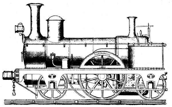
Fig. 14.—HACKWORTH’S
“SANSPAREIL,” ONE OF THE COMPETITORS AT RAINHILL
The engine next in order was Timothy Hackworth’s “Sanspareil,”
(Fig. 14), now preserved in the South Kensington Museum.
The engine-shops at Shildon were not in a position to construct the
whole of this locomotive; consequently Hackworth was forced to obtain
the boiler and cylinders from other makers. The former was constructed
at Bedlington Ironworks, and was of cylindrical form, 6ft. long, 4ft.
2in. diameter, with one end flat and the other hemispherical. The
heating surface was provided by means of a double return tube, the
fire-grate and chimney being both at the same end.
The area of the fire-grate was 10 sq. ft., the heating surface of same
15.7 sq. ft., the remaining heating surface 74½ sq. ft.
The cylinders were constructed by B. Stephenson and Co., and six had to
be made before two perfect ones were obtained, the sixth one, indeed,
only being fitted at Liverpool when the contest was in progress.
It has been stated that these cylinders were purposely constructed
in a faulty manner to prevent the “Sanspareil” beating the “Rocket.”
This may or may not be true, but it is very evident that, save for
Stephenson’s imperfect workmanship in this respect, the “Sanspareil”
would have won the £500 prize. When the “Sanspareil” was competing
for the prize, one of the cylinders supplied by Stephenson and Co.
burst, and it was found that the metal was only one-sixteenth of an
inch thick! A nice state of things certainly! The cylinders were 7in.
diameter, the stroke being 18in. The engine was carried on four wheels,
4ft. 6in. diameter. Total weight of engine, 4 tons 15 cwt. 2 qr.
She was, of course, fitted with Hackworth’s exhaust steam blast.
During some preliminary trips at Rainhill, Stephenson was greatly
surprised to see how well the “Sanspareil” ran, and he noticed she
always had a good supply of steam, so he got upon the engine and had
a ride on her. During this trip he said to Hackworth, “Timothy, what
makes the sparks fly out of the chimney?” Hackworth touched the exhaust
pipe near the cylinders, and answered, “It is the end of this little
fellow that does the business.”
After Stephenson got off the engine, John Thompson, the driver (he
was Hackworth’s foreman at Shildon), said to Hackworth, “Why did you
tell him how you did it, sir? He will be trying to fit up the ‘Rocket’
in the same way.” Hackworth said he did not think so, but Thompson
determined to watch the “Sanspareil” all night. He therefore locked
himself in the shed containing the engine that night, but towards
daybreak sleep overcame him, and when he awoke he saw two men getting
out of the window of the shed, and he found the chimney door of the
“Sanspareil” open, and some materials inside the chimney. The secret of
the exhaust steam blast was stolen! The next evening the “Rocket” again
appeared; this time she was fitted with a similar contrivance. The
above is Hackworth’s foreman’s version of the theft, but the “Practical
Mechanic’s Journal” for June, 1850, gives the tale as told by the man
who committed the theft.
When in repair, the “Sanspareil” ran faster, took a heavier load,
and consumed less coke than the “Rocket,” and whilst the latter was
remodelled within twelve months of the Rainhill contest, the former
worked with practically no alteration until 1844. In 1864 she was
presented to the South Kensington Museum by Mr. John Hick, M.P., Bolton.
The following is an extract from her history, as supplied by Mr. Hick
to the Museum authorities:—
“After the Rainhill trial the engine was purchased by the Liverpool
and Manchester Railway Company, and used by them for various purposes.
In 1831, the engine was purchased by Mr. John Hargreaves, of Bolton,
and was employed by him in the conveyance of passengers and general
traffic on the Bolton and Leigh Railway for several years. In 1837, Mr.
Hargreaves had the engine thoroughly repaired, and put on a pair of new
cylinders of larger dimensions than the old ones, so as to increase the
power. The original wood-spoked wheels were also removed at this time,
and replaced with cast-iron hollow-spoked wheels.
“One pair of these are under the engine at the present time. The engine
continued regularly at work in conveying coals, general goods, and
passengers until 1844, when, being found much too small and short of
power for the rapidly increasing traffic, Mr. Hargreaves took her to
his colliery at Coppull, near Chorley, Lancashire, where the engine was
fixed near a coal-pit. One axle and one pair of wheels were removed,
and upon the other toothed gear was fitted, in order to give motion
to winding and pumping apparatus, and the engine commenced its work
as a regular fixed colliery engine, pumping and winding in the most
satisfactory manner until the end of the year 1863; having raised many
thousand tons of coal and many million gallons of water, and even
at the time above named was in fair working order, and only removed
because the coal in the pit was exhausted.
“I hope the old engine will now find a permanent resting place in the
Kensington Museum, where her end will be peace, if not pieces. Mr.
Hargreaves has kindly given me the old engine, in consequence of my
having told him of my intention with regard to her. And having restored
her as far as possible by collecting and putting together the available
materials, I have pleasure in presenting this interesting relic to the Museum.”
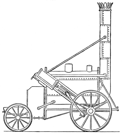
Fig. 15.—STEPHENSON’S
“ROCKET,” THE WINNER OF THE RAINHILL PRIZE OF £500.
The “Rocket” (Fig. 15), was entered in the name of Robert
Stephenson, and was constructed at the Forth Street Works, Newcastle-on-Tyne, in
1829. Her distinguishing colours were yellow and black, with a white
chimney. She was the first engine to be tried at Rainhill. Her weight
was 4 tons 5 cwt.; load (including tender), 12¾ tons; total, 17 tons.
During the first twenty trips she attained a maximum speed of 24.43
miles an hour, the average being 13.42 mile’s an hour; during the
second twenty trips an average speed of 14.2 miles an hour was the
result, with a maximum speed of 24 miles an hour. These short trips of
one and a half miles each just suited the design of the “Rocket,” as
the steam raised before starting on each trip was sufficient to work
her the one and a half miles; had the trips been longer, she—not then
being furnished with a proper blast, but with that illustrated on Page
25—would probably have stopped for want of steam. Of this Z. Colburn
significantly states: “The ‘Rocket,’ on the first day of her trial,
derived but little benefit from the discharge of the exhaust steam up
the chimney; and, indeed, made steam nearly as freely when standing as
when running.” Without a load, or tender even, she attained a speed
of 29½ miles an hour. The authority just quoted says: “The real power
of the ‘Sanspareil’ is to be estimated by its rate of evaporation,
which was one-third greater than that of the ‘Rocket,’ and thus the
‘Sanspareil,’ after allowing for its greater weight, was the most
powerful engine brought forward for trial.... As far as it had gone,
the mean rate of speed (of the ‘Sanspareil’) was greater than that of
the ‘Rocket’ up to the same stage of the experiment.”
The boiler of the “Rocket” was cylindrical, with flat ends, 6ft. long,
3ft. 4in. diameter; the fire-box was 3ft. long, 2ft. broad, and about
3ft. deep; between the box and the outer casing was a space of 3in.
filled with water. The cylinders were placed at an angle of 45 degrees
at the fire-box end, the connecting-rod being attached to a pin on the
leading wheels, which were 4ft. 8½in. diameter, that of the cylinders
being 8in.; the stroke was 16½in.
The “Rocket” had a great advantage over other engines because she was
supplied with a tubular boiler, containing 25 tubes of 3in. diameter.
The idea of the tubular boiler did not originate with the Stephensons.
Mr. Booth, the Secretary of the Liverpool and Manchester Railway,
suggested their use in the “Rocket”; but before this the tubular
locomotive boiler had been patented by a Frenchman (M. Sequin), on
February 22nd, 1828. Mr. Booth, however, states that he was unaware
of the French patent, and, so far as he was concerned, the tubular
boiler was an original discovery. The use of these tubes increased
the evaporating power of the boiler three-fold, and at the same time
reduced the consumption of coke 40 per cent.; yet the “Rocket,” with
this great advantage, was not equal to the “Sanspareil,” until the
former was fitted with Hackworth’s blast. When this had been done, the
“Rocket” was capable of hauling 20 tons (engine included) up an incline
of 1 in 96, at 16 miles an hour, for a distance of one and a half
miles. The prize of £500 was divided between Robert Stephenson, the
constructor of the “Rocket,” and Mr. Booth, the suggester of the
tubular boiler, which enabled that locomotive to be entitled to the
prize. Tubular boilers had been successfully used in steam road coaches
as early as 1821.
After running a year or so, the “Rocket” was rebuilt, the cylinders
being placed in a slightly inclined position over the trailing wheels,
but still working the leading wheels; a smoke-box was added, and other
improvements introduced.
The “Rocket” was bought in the year 1837, from the Liverpool and
Manchester Railway, by Mr. J. Thompson, of Kirkhouse, the lessee of the
Earl of Carlisle’s coal and lime works.
Here the engine was worked for five or six years on the Midgeholme
line—a local line belonging to Mr. Thompson—for forwarding his coals
from the pits towards Carlisle.
Soon after the engine was placed on this line the great contest for
East Cumberland took place, when Sir J. Graham was superseded by Mayor
Aglionby, and she was used for conveying the Alston express with the
state of the poll from Midgeholme to Kirkhouse. Upon that occasion the
“Rocket” was driven by Mr. Mark Thompson, and accomplished her share
of the work, a distance of upwards of four miles, in 4½ minutes, thus
reaching a speed nearly equal to 60 miles an hour. On the introduction
of heavier and more powerful engines, the “Rocket” was “laid up in
ordinary” in the yard at Kirkhouse. This historic steam locomotive
is now preserved in the South Kensington Museum. It must not be
forgotten, however, that the “Rocket” has been rebuilt, and its design
considerably altered, since the Rainhill competition of 1829.
The last of the steam locomotives entered for trial at Rainhill remains
to be described. The “Perseverance” was constructed by Mr. Burstall,
of Edinburgh. He was already known as a maker of steam road coaches.
Unfortunately for the success, or rather want of success, of the
“Perseverance,” Mr. Burstall designed his railway locomotive on much
the same lines as his steam coaches.
The “Perseverance” had the misfortune to have some damage done to its
wheels, etc., when being unloaded at Rainhill off the wagon on which it
had been conveyed from Liverpool. A preliminary trial was made, and Mr.
Burstall, finding the engine was unable to attain a higher speed than
about six miles an hour, withdrew his locomotive from competition.
The boiler was horizontal, and the water was admitted to shallow trays
placed over the fire, and in this way was immediately converted into
steam. The cylinders were vertical, and worked horizontal beams placed
above them; the wheels were worked by cranks fixed on the beams about
half-way between the cylinders and the centre pivots of the beams. The
second pair of wheels was driven by means of an axle with bevel wheels
at each end, which conveyed the motion from the one axle to the other.
This engine was distinguished by having the wheels painted red.
Although not “steam” locomotives, we think it right to give a few
details of the “Cycloped,” (Fig. 16), and also of
Winans’ manumotive carriage, both of which were exhibited at Rainhill.
The former was worked by a horse or horses fastened on a frame
supported by four wheels; the horses walked at a speed of one and a
quarter miles an hour, on an endless platform formed of planks of wood.
The horses being firmly attached to the frame could not go forward when
they essayed to walk, and the consequence of their using their legs
was the revolving of the floor, which worked round drums geared to the
driving wheels. This motion caused the vehicle to move forward on the
rails at a speed of about three miles an hour, with a load of fifty
passengers. Had the horses moved at a quicker rate, the speed of the
“Cycloped” would have been increased in a proportionate ratio.
Fig. 16.—WINANS’
“CYCLOPED” HORSE LOCOMOTIVE
Winans’ carriage was worked by two men, who turned a windlass, which
actuated the wheels. It accommodated six passengers, and it was
facetiously proposed that those passengers who worked at the windlasses
should be conveyed by such vehicles at reduced rates. Although we now
smile at the simplicity of such vehicles ever having been suggested for
working on a railway, the Directors of the Liverpool and Manchester
Railway were considerably taken with the idea of Winans’ man-propelled
carriages, and they engaged two well-known engineers to report on
their adaptability for passenger traffic on the railway. As might be
expected, the experts reported against the proposed use of Winans’
machines; but, despite this adverse report, the Directors of the
Liverpool and Manchester Railway actually bought twelve of these
“manumotive” carriages of Winans. The purchase was made prior to March,
1830, and as we do not read of their being used after the railway was
opened in September, 1830, we may conclude that during the six months
that elapsed between the purchase and the opening of the line the
Directors had come to the same conclusion regarding the machines as did
the engineers who reported against their use on the railway.
CHAPTER IV.
An important improvement in the
locomotive—Bury’s original “Liverpool,” the first inside cylinder
engine—Bury’s own account of his invention—Other authorities agree
with Bury—Extract, supplied by the Secretary of the L. & N.
W. Rly., from the minute books of the Liverpool and Manchester
Rly.—An early authentic list of Bury’s locomotives—Description
of Bury’s “Liverpool”—Last hoard of on the Bolton and Kenyon
Railway—The “Invicta” for the first Kentish railway—Still preserved
by the S.E.R—First official trip on the Liverpool and Manchester
Railway—Formal opening of the L. & M.R.—The locomotives that took
part in the ceremony—The “William the Fourth” and “Queen Adelaide”
for the L. & M. Rly.—Hackworth’s “Globe” for the Stockton and
Darlington Railway—The romance of her construction, life, and
end—Stephenson’s “Planet”—Some of her feats on the L. & M.
Rly.—Heavier locomotives for the L. & M. Rly.—Dodd’s engine for the
Monkland and Kirkintilloch Rly.—Historical locomotive sold by auction
for 20 guineas—Bury’s “Liver” for the L. & M. Rly.—More Hackworth
“iron horses” for the Stockton and Darlington Rly—Despite their
peculiarities, they prove most successful—The “Caledonian.”
We have now to deal with one of the most important improvements in the
locomotive—viz., that introduced by Mr. Edward Bury, of the Clarence
Foundry, Liverpool, in the design of his celebrated “Liverpool,” (Fig. 17).
Of late years many extraordinary statements concerning various
types and designs of locomotives have been made, and the “romancing”
relative to the original “Liverpool” is perhaps the most conspicuous,
whilst at the same time its utter incorrectness is easily proved.
One of these statements is that “the first engine built by Bury at
Clarence Foundry was an outside cylinder engine, the ‘Dreadnought,’
which was completed March 30th, 1830, but proved a failure. However,
he lost no time, but, with the assistance of his foreman, Mr. Kennedy,
got out working drawings for a new engine, to be named the ‘Liverpool.’
This engine, No. 2 in the locomotive order book, and class A in
the description book, was commenced early in January, 1831; it was
completed in March of that year, and in May, 1831, it was put to work
on the Petersburg Railroad of America. It had four coupled wheels of
4ft. 6in. diameter.”
Now, as to the facts, Bury’s books were sold by auction by his
creditors on August 15th and 16th, 1851; and, even if the books are now
in existence (which is extremely unlikely), it is obviously impossible
for them to contain the particulars quoted above, for the very
simple and conclusive reason that the facts relative to the original
“Liverpool” are quite different to the statement just quoted.
There are three improvements with which Bury is justly credited in
the locomotive now under review—viz., the adoption of (1) horizontal
inside cylinders below the smoke-box, (2) cranked driving axle, and (3)
coupled driving wheels of the (then) great diameter of six feet.
In describing this historical “Liverpool” locomotive we cannot do
better than quote Bury, the maker and designer of it, and Kennedy,
his foreman, who constructed it. The former, at a meeting of the
Institute of Civil Engineers, held on March 17th, 1840, read a paper
on the locomotive, and, speaking of the inside cylinder engine, said:
“This form of engine Was adopted by the author as early as 1829, when
he constructed the ‘Liverpool,’ which was the original model engine,
with horizontal cylinders and cranked axles. It was set to work on the
Liverpool and Manchester Railway in July, 1830.”
Fig. 17.—BURY’S
ORIGINAL “LIVERPOOL,” THE FIRST ENGINE WITH INSIDE CYLINDERS AND
CRANKED DRIVING AXLE COUPLED WHEELS, 6ft. DIAMETER
About 1843 there was considerable discussion amongst engine builders
and locomotive engineers as to the relative safety of inside and
outside cylinder, engines, and also regarding the superiority of the
four-wheel or six-wheel locomotive. Bury and Co. thereupon issued a
circular giving a history of the locomotive practice of their firm, and
the various advantages claimed for their locomotive designs.
From this circular we extract the following remarks, as bearing upon
the point now under discussion:—“It was the good fortune Of the
conductor of this foundry to originate the construction of four-wheel
engines, with inside framing, crank axles, and cylinders placed in the
smoke-box.... The first engine on this principle was manufactured
in this foundry in 1829, prior to the opening of the Liverpool and
Manchester Railway.” Such are Mr. Bury’s statements concerning the
original “Liverpool.”
We will now see what his partner, Mr. James Kennedy, the then President
of the Institution of Mechanical Engineers, had to say regarding the
“Liverpool.”
At a meeting of the Institute of Civil Engineers, held on November
11th, 1856, a communication was read from Mr. Kennedy, in which
he stated that “the late George Stephenson had told both Bury and
Kennedy, after having seen the ‘Liverpool’ engine on the Liverpool
and Manchester Railway, that his son, the present Robert Stephenson,
had taken a fancy to the plan of the ‘Liverpool,’ and intended to
make immediately a small engine on the same principle.” This he
afterwards did, Stephenson’s “Planet” being the said engine “on the
same principle.” Kennedy went on to state that “the letter-book of
the firm (Bury and Co.) for the year 1830 contained the whole of the
correspondence on the subject between the Directors of the Liverpool
and Manchester Railway and Bury.”
The reader can readily judge as to which statement is likely to be
correct—those of such well-known men as Bury and Kennedy, which are
concise, straightforward statements of known and accepted facts, or the
recently published remarks concerning the “books, etc.”
Fortunately, students of locomotive history are not even obliged to
decide either one way or the other on the statements pro and con
already quoted concerning the original “Liverpool,” but are able to
gain independent and conclusive evidence on this important point in
locomotive history. For the purpose of finally clearing up the point,
the writer communicated with the Secretary of the London and North
Western Railway, asking him to examine the Directors’ Minute Books of
the Liverpool and Manchester Railway for the year 1830, to see if these
authentic documents contained any reference to Bury’s “Liverpool.”
Mr. Houghton most generously had the search we required made, and the
result was as might have been expected. But let the letter tell its own tale.
“London and North Western Railway,
“Secretary’s Office, Euston Station, N.W. “June, 3rd, 1896.
“Dear Sir,—With further reference to your request for information
relative to Bury’s locomotives, I have had the Minute Books of the
Liverpool and Manchester Railway searched for the years 1829-30.
“Towards the end of 1830 the Board sanctioned the [further] trial of
the ‘Liverpool,’ and it was consequently allowed to work on the railway
in competition with one of Mr. Stephenson’s engines. The engineer was
dissatisfied with the size of the wheels, which were 6ft. instead of
his maximum 5ft.; and there was a long controversy as to the respective
merits of circular and square fire-boxes, which was ultimately referred
to arbitration, when the square boxes recommended by Mr. Stephenson
were given the preference.—Yours truly,
“(Signed) T. Houghton.”
The above letter conclusively settles the points in dispute—viz., that
the “Liverpool” was tried on the Liverpool and Manchester Railway in
1830, and that the diameter of the wheels was 6ft.
We have thus pricked the specious bubble that stated the “Liverpool”
was duly commenced to be built in 1831, and that the diameter of the
wheels was but 4ft. 6in.!
Readers may wonder why such obviously inaccurate statements should be
published. One can only conjecture. Many lists of early locomotives
have during the past few years been published. These should, however,
be accepted with the very greatest caution. The following table of
dimensions of Bury’s early engines appeared as long ago as September
18th, 1857, in the Engineer. As this was nearly forty years
before “locomotive lists” had any marketable value, there can be no
reason to call in question its accuracy:—
No. of Engines
Diam. of Cylinder.
Length Stroke
Diam. of Wheels.
No. of Tubes.
Diam. of Tubes.
No. of Tubes.
Diam. of Tubes.
Length of Tubes.
Inside Diam. of Fire-box.
Area of Tubes.
Total Surface.
No.
Ins.
Ins.
Ft.
Ins.
No.
Ins.
No.
Ins.
Ft.
Ins.
Ft.
Ins.
Inches.
Sq. Feet.
2
12
18
6
0
79
1¾
52
1½
7
11½
3
9
19
450.26
3 & 4
11
16
5
0
73
¾
24
1½
7
1
3
0
16⅜
303.58
5
8
16
4
6
40
1¾
13
1½
6
5
2
7½
(6) 12⅝(7)
150.28
6 & 7
12
18
5
6
76
2
13
1¾
8
6
3
7
18½ 18¹/₁₆
390
8 & 9
9
16
5
0
40
1¾
13
1½
6
11
2
10½
12⅜
162
10
9
16
4
4
43
2
9
1¾
7
1
3
0
14⅛
189.1
11
8
16
4
6
40
1¾
13
1½
6
7½
2
9½
12⅝
155.2
12 & 13
10
16
4
6
51
2
9
1¾
7
2½
3
0½
15¼
222.74
14
8
16
4
6
43
1¾
9
1½
6
8
2
10½
12⅝
155
15, 16, & 17
12
18
4
6
58
2½
2
2
8
2
3
7
19⅛ 19¹/₁₆
318.40
18 & 19
10
16
4
6
76
2
—
1¾
7
2½
3
2
15¼
251
At the present time there exists a market for early, locomotive
details; as with other marketable commodities, given a demand, a supply
(of some kind) will be forthcoming.
We have a copy of the report prepared by the arbitrators, appointed
by the Directors of the Liverpool and Manchester Railway, to inquire
into the question of the round or square fire-box, as mentioned in Mr.
Houghton’s letter. The report was made by John Farey and Joshua Field,
two celebrated engineers of that period, and was in favour of the
square fire-box.
It will now be of interest to give a description of Bury’s original
“Liverpool,” which was designed and her construction commenced in 1829.
She contained many unusual features. Instead of a tubular boiler a
number of convoluted flues were used. The fire was urged by bellows
fixed under the tender; the driver stood at one end of the engine in
front of the smoke-box, and the fireman at the other end, behind the
fire-box; the cylinders were horizontal, placed inside the frames
beneath the smoke-box; their diameter was 12in., the stroke being
18in.; the four wheels were 6ft. in diameter, and were coupled, and the
driving axle was, of course, cranked.
The “Liverpool,” in this her original state, was used as a ballast
engine in the construction of the Liverpool and Manchester Railway, but
not being very successful, was withdrawn., After some alterations, she
was again put to work on July 22nd, 1830. Then the crank axle appears
to have broken, and she was again removed for repairs, and again put
to work on the Liverpool and Manchester Railway on October 26th,
1830. After the report previously mentioned, the Directors refused to
purchase the “Liverpool,” and Bury removed her to the Bolton and Kenyon
Railway. Here she attained a speed of 58 miles an hour with twelve
loaded wagons. On this line one of her wheels broke, and the driver was
killed. As a result of this accident, she was then rebuilt and sold
to Hargreaves, the contractor, for locomotive power on the Bolton and
Kenyon Railway, and continued to work on that line for some years.
The Canterbury and Whitstable Railway was opened on May 3rd, 1830, and
was the first locomotive line in the South of England. The original
engine, the “Invicta” (Fig. 18), is still preserved by
the South Eastern Railway at Ashford, but it is a mere chance that this engine
did not disappear nearly sixty years ago. The Canterbury and Whitstable
Railway Company, after a short time, let the working of the line to
contractors, and they preferred to work it by horse-power, and we find
that in October, 1839, the contractors were advertising the “Invicta”
for sale, describing her as of “12 horse-power, 18in. stroke, cylinders
24in. long, 9½pin. diameter, wheels 4ft. in diameter.” Fortunately for
students of early locomotives, there was no demand for the engine
anywhere in the neighbourhood of Whitstable, there then being no other
locomotive line nearer than Greenwich, on which she could have been
used; so no buyer was forthcoming, and the “Invicta” was thereupon
laid up. The dimensions of the “Invicta,” as supplied to us by Mr.
J. Stirling, are as follows: Cylinders, 10½in. diameter, fixed
in inclined position over leading wheels, and working the trailing
wheels; stroke, 18in.; four-coupled wheels, 4ft. diameter; wheel base,
5ft.; boiler, 10ft. 5in. long, 3ft. 4in. diameter, containing a single
flue 20in. diameter; distance from top of boiler to rails, 6ft.; from
top of chimney to rails, 11ft. 1in.; chimney, 15in. diameter; total
length over all, 13ft. 6in. At the bottom of the chimney is a kind of
smoke-box, measuring about 2ft. 4in. high, 1ft. 8in. long, and 2ft.
4in. wide. The South Eastern Railway exhibited the “Invicta,” at the
jubilee of the Stockton and Darlington Railway in 1875, and at the
Newcastle Stephenson Centenary in 1881. The “Invicta,” when originally
built, is said to have had a tubular boiler.
Fig. 18.—THE
“INVICTA,” CANTERBURY AND WHITSTABLE RWY., 1830
The Directors of the Liverpool and Manchester Railway in 1829 ordered
of Stephenson and Co. seven engines of somewhat similar design to the
“Rocket.” The Directors made their first trip by railway from Liverpool
to Manchester and back on Monday, June 14th, 1830. The train was drawn
by the “Arrow,” and consisted of two carriages and seven wagons;
the total weight, including the engine, was 39 tons, the journey to
Manchester being made in two hours one minute, whilst the return trip
to Liverpool only took one and a half hours, a speed of 27 miles being
attained for some distance.
The Liverpool and Manchester Railway was formally opened on September
15th, 1830, when the “Northumbrian” (Fig. 19), driven by
George Stephenson, hauled the train consisting of the Duke of Wellington’s
carriage, the band, etc., on one line, whilst the “Phœnix,” “North
Star,” “Rocket,” “Dart,” “Comet,” “Arrow,” and “Meteor,” each hauled a
train upon the other line. Starting from Liverpool, the eight trains
proceeded towards Manchester. At Parkside Mr. Huskisson was run over by
the “Rocket,” and he was placed on the “Northumbrian” and conveyed to
Eccles in 25 minutes, or at the rate of 36 miles an hour.
Fig. 19.—THE
“NORTHUMBRIAN,” THE ENGINE THAT OPENED THE LIVERPOOL AND MANCHESTER RAILWAY
The Duke of Wellington’s carriage was now left without an engine, and
a curious sight was witnessed; a long chain was obtained, and the
trains which had been up to this point hauled by the “Phœnix” and
“North Star,” consisting of ten carriages, were joined together. The
chain was then fixed to the Duke of Wellington’s train on the other
line, and so the rest of the journey was performed by the two engines
and ten carriages on one line hauling another train upon a parallel
set of rails. It may be of interest to observe that the carriage built
for the Duke of Wellington was provided with eight wheels, so it will
be noticed that eight-wheeled passenger stock is not at all a modern
introduction, but, on the contrary, has been in use ever since the
opening of the first railway built for the conveyance of passengers.
The vehicle in question was 32ft. long and 8ft. wide.
The two engines ordered by the Directors of the Liverpool and
Manchester Railway of Braithwaite and Ericsson after the style of the
“Novelty,” were named “William the Fourth,” (by special permission
of that monarch) and “Queen Adelaide.” They were delivered to the
Liverpool and Manchester Railway immediately the railway was opened,
and on September 22nd, 1830, the “William the Fourth” ran off the rails
on the Sankey Viaduct. A very considerable number of trials were made
with these locomotives on the Liverpool and Manchester Railway; but,
as was the case with Bury’s “Liverpool,” Stephenson strongly objected
to any other maker’s engines being used on the line, and he was,
therefore, always ready to find out some fault in the engines not of
his construction tendered to the company. Braithwaite and Ericsson
claimed four great advantages for their class of engines—viz., (1) the
total absence of all smoke; (2) the dispensing with a chimney; (3) a
saving of 120 per cent. in the cost of the fuel, and of 30 per cent. in
the space required to store it; (4) a saving of 400 per cent. in the
space occupied by the boilers.
Several improvements were introduced into the “William the Fourth,” and
“Queen Adelaide,” so that they differed somewhat from the “Novelty.”
They were provided with four-wheeled tenders, which were placed in
front of the engines. The four wheels of the engines were 5ft. in
diameter, the wheel base being 6ft. 9in. The horizontal portion of the
boiler was 8ft. long, the vertical portion, containing the fire, etc.,
being 6ft. 6in. high and 4ft. diameter. The cylinders were vertical,
but worked downwards; they were located one on each side of the
vertical portion of the boiler, and a little to the rear of the leading
wheels, to which the motion was conveyed by means of bell-cranks and
connecting-rods—the latter joined the axle within the wheels, so that
the driving axle was cranked.
The next engine that requires our attention is the celebrated “Globe”
(Fig. 20), designed for the Stockton and Darlington Railway
by Timothy Hackworth, and built by R. Stephenson and Co. The “Globe” was built
for passenger traffic; she was provided with a steam dome, and was the
first locomotive built with this advantageous appendage for obtaining
dry steam. The valve motion was reversible by a single lever. The
heating surface was provided for by means of a single fire-tube, whilst
behind the fire-bridge, and extending to the chimney, were seven small
radiating tubes crossing the main flue.
This idea of Hackworth’s was afterwards introduced by Galloway in his
stationary engine boilers, and patented by him. The engine “Globe” had
a cranked axle and inside cylinders.
Hackworth explained the construction of the “Globe” to the Directors
of the Stockton and Darlington Railway, and he was instructed to go to
Newcastle and arrange for the building of the “Globe” by Stephenson and
Co. He saw the officials at the Forth Street Works on March 3rd, 1830,
and after the examination of the plans there, it is stated that one of
the officials objected to the crank axle, saying “it would certainly
involve a loss of power, as the efficient length of lever could only
be calculated from the inside of the journal to the axle’s centre.”
It is well known that Geo. Stephenson had previously seen Bury’s
“Liverpool,” and said of it, “My son has taken a fancy to the plan of
the ‘Liverpool’ engine, and intends to make immediately a small engine
on the same principle.” Hackworth’s reply to the objection to the crank
axle was “that he held Stephenson responsible only for supplying good
workmanship, and not for any failure of the design, should such occur.”
Fig. 20.—HACKWORTH’S
“GLOBE” FOR THE STOCKTON AND DARLINGTON RAILWAY. THE FIRST LOCOMOTIVE
WITH A STEAM DOME
On March 3rd, 1830, Hackworth, in company with Harris Dickinson, one of
R. Stephenson and Co.’s foremen, drove over to Bedlington Iron Works to
order the boiler plates required for the construction of the “Globe.”
Hackworth remained at Newcastle till March 6th, and being satisfied
that the construction of the “Globe” would be immediately proceeded
with, he returned to Darlington, having obtained a promise of quick
delivery. The boiler plates were delivered at the Forth Street Works,
April 14th, 1830.
The completion of the engine was, however, delayed until after R.
Stephenson and Co. had delivered the “Planet,” inside cylinder
locomotive, to the Liverpool and Manchester Railway. The “Globe” opened
the Stockton and Middlesbrough Branch of the Stockton and Darlington
Railway on December 27th, 1830. Her speed frequently exceed 50 miles an
hour with passenger trains.
In consequence of a deficiency of water, she blew up in 1839. The
engine was provided with a copper globe for the purpose of obtaining
dry steam—hence her name “Globe.” She had four wheels, each of 5ft. diameter.
Fig. 21.—STEPHENSON’S
“PLANET,” LIVERPOOL AND MANCHESTER RAILWAY
Stephenson soon put into practice the borrowed idea of inside cylinder
locomotives, to his own advantage, and on October 4th, 1830, he
delivered the first engine of his construction containing inside
cylinders, placed in the smoke-box, as suggested to R. Stephenson by
Trevithick. This locomotive was named the “Planet,” and was constructed
for the Liverpool and Manchester Railway. The cylinders were 11in.
diameter, stroke 16in. The boiler was 6ft. 6in. long, 3ft. diameter,
and contained 129 tubes. She weighed eight tons; the driving wheels
were 5ft. diameter, and were placed just in front of the fire-box. The
leading wheels were 3ft. diameter, and projected beyond the front of
the smoke-box. The frames were outside the wheels, and were of oak
lined with iron plates. As the “Planet” embodied several improvements
not before used in the engines constructed by Stephenson for the
Liverpool and Manchester Railway, it is natural that the locomotive
should be able to perform better service than the earlier ones. On
November 23rd, 1830, she conveyed a train from Manchester to Liverpool
in one hour, including a stop of two minutes for water.
On December 4th, 1830, the “Planet” (Fig. 21) hauled
a mixed train, weighing 76 tons without the engine and convoy (tender) from
Liverpool to Manchester in two hours thirty-nine minutes’ running time.
Stephenson continued to supply various locomotives to the Liverpool
and Manchester Railway with different minor improvements; thus the
“Mercury,” built in December, 1830, had the outside frame placed above
the driving axle, an improvement on the “Planet,” which had the frames
below the driving axle. But all these early engines of Stephenson were
of a very unsatisfactory character. Pambour, writing in 1834, says
of them: “When an engine requires any repair, unless it be for some
trifling accident, it is taken to pieces and a new one is constructed,
which receives the same name as the first, and in the construction of
which are made to serve all such parts of the old engine as are still
capable of being used with advantage. The consequence of this is that
a reconstructed or repaired engine is literally a new one. The repairs
amount thus to considerable sums, but they include also the renewal of
the engines.”
The directors of the Liverpool and Manchester Railway soon found the
method of working their heavy trains with four or five locomotives
was far from economical, and Stephenson was required to supply more
powerful engines for the merchandise traffic. He, therefore, built the
“Samson” and “Goliath.” These were only four-wheel engines, but all
the wheels were made of one size and coupled together. The former was
delivered in January, 1831, and on February 25th she conveyed a train
weighing 164 tons (without reckoning the weight of engine or tender)
from Liverpool to Manchester in two and a half hours. The dimensions of
the engines were: Cylinders 14in. diameter, stroke 16in., wheels 4ft.
6in. diameter, heating surface 457.10 sq. ft.
In 1831, the Directors of the Monkland and Kirkintilloch Railway
decided to work their line by locomotives, and instructed Mr. Dodd,
their engineer, to design engines for the purpose. He, however, merely
adopted the plan used in the construction of the “Locomotion” (Stockton
and Darlington Railway), with the cylinders placed partly within
the boiler over the wheels, working by means of cross-heads and
connecting-rods. He also adopted the tubular boiler, which was, of
course, wanting in the “Locomotion.” The engines were constructed by
Murdoch and Aitken, of Glasgow, and were the first locomotives built in
that city. The first was put to work on May 10th, 1831, and the second
on September 10th, 1831. The boilers of these two locomotives were
lagged with wood, and metallic packing was for the first time employed
in connection with the pistons. The cylinders were 10½in. diameter,
stroke 24in., steam pressure 50lb. The locomotives were supported on
four coupled wheels, the coupling-rods having ball-and-socket joints
at each end. A speed of six miles an hour was attained with Dodd’s
engines, and, although of rough design, they were much more economical
in fuel and repairs than the engines supplied about the same time by
Stephenson to the neighbouring Glasgow and Garnkirk Railway. These
latter two engines were named the “St. Rollox” and “George Stephenson.”
Their dimensions were as follows:—
Diameter of cylinders.
Stroke.
Wheels
Weight in working order.
Driving.
Leading.
St. Rollox
11in.
14in.
4ft. 6in.
36½in.
6 tons.
George Stephenson
11in.
16in.
4ft. 6in.
4ft. 6in.
8 tons.
The gauge of this line was only 4ft. 6in. The “St. Rollox” cost the
G. and G. Railway about £750; that company sold it to the Paisley and
Renfrew Railway for £350, and the latter, in December, 1848, when
the gauge of their line was altered, disposed of the locomotive by
auction for £13. It had wooden wheels. At the same auction the other
two locomotives of the Paisley and Renfrew Railway were also sold, and
realised only 20 guineas each, although about ten years previously the
Paisley and Renfrew Railway had paid Murdoch, Aitken, and Co. £1,100
for each of them. They were six-wheel tank engines. The Scotch engines
we have just been describing, all burnt coal in place of coke, and as
they caused a good deal of smoke they were much objected to on that account.
We have previously stated that upon the advice of two engineers the
Directors of the Liverpool and Manchester Railway had refrained from
purchasing more locomotives from E. Bury, but other people soon saw the
good points of his engines, and in 1832 the Liverpool and Manchester
Railway considered it policy to purchase another locomotive from the
Clarence Foundry. This engine was called the “Liver.” She had cylinders
11in. diameter, 16in. stroke, and driving wheels 5ft. diameter. The
“Liver” worked very successfully, and in 1836 her fire-box was altered
to burn coal, but this experiment turned out somewhat of a failure.
Towards the end of 1831, and during 1832, the increasing traffic on the
Stockton and Darlington Railway made a considerable increase in the
number of locomotives necessary. Hackworth designed two new classes of
engines to work the trains. One type was known as the “Majestic” class,
and six engines of this description were soon at work.
The “Majestic” locomotives had each six-coupled wheels. The heating
surface was obtained from a tube 9ft. long, 2ft. 6in. diameter, one
end of which communicated with the fire-grate; the other was divided
from the boiler by a partition-plate, inserted in which were 104 copper
tubes 4ft. long, and reaching to the smoke-box. It should be observed
that the boiler was 13ft. long. The cylinders were fixed in a vertical
position in front of the smoke-box, the connecting-rods working on a
straight shaft or axle parallel with the wheel axles: this driving
shaft was coupled by outside rods to the six wheels. The slide-valves
had “lap,” and were worked by two eccentrics, which also worked the
force pumps. The engine was reversed by means of a single lever. This
class of engines included:—
“Majestic,” built by Hackworth.
“Coronation,” built by Hawthorn.
“William the Fourth,” built by Hackworth.
“Northumbrian,” built by Hackworth.
“Director,” built by Stephenson.
“Lord Brougham,” built by Hackworth.
All of them were built from Hackworth’s designs, the leading dimensions
being: Cylinders, 14½in. diameter, stroke, 16in.; boiler, 13ft. long,
3ft. 10in. diameter; weight of engine—empty, 10¼ tons; full, 11¾ tons.
The other class of engines designed by Hackworth at this time included:—
“Darlington,” built by Hawthorn.
“Shildon,” built by Hackworth.
“Earl Grey,” built by Hawthorn.
“Lord Durham,” built by Stephenson.
“Adelaide,” built by Stephenson.
“Wilberforce,” built by Hawthorn.
“Wilberforce,” an illustration of which is given (Fig. 22),
was built by Hawthorn, of Newcastle, and commenced to work in 1832; it had six
coupled wheels 4ft. in diameter; the cylinders were 14¾in., with 16in.
stroke. Like many of the locomotives of that period, the “Wilberforce,”
as will be observed, had two tenders, one at each end of the engine. On
the tender at the front end, which only carried coals (the fire-door
being at the chimney end of the engines), the fireman stood; whilst the
other tender, at the foot-plate end, carried water in a barrel, and also
the tool boxes. The engine wheels were made of two separate castings or
rings, and the axles were all straight, the crank-shaft being carried
in separate bearings beneath the foot-plate. There were no tail lamps in
those early days; to make up for this deficiency a cresset containing
burning coal was used. In some cases, when it was necessary to indicate
the destination of the engine, or the section to which it belonged, as
many as three of these cressets of glowing coals were employed on the
same locomotive.
Fig. 22.—“WILBERFORCE,”
A STOCKTON & DARLINGTON RAILWAY LOCOMOTIVE
On certain favourable gradients the “Wilberforce” was capable of taking
36 loaded chaldron wagons, equal to about 171 tons, and its coal
consumption is given as 68lb. per mile. During the year ending June,
1839, this engine ran 16,688 miles, conveyed 635,522 tons over one
mile, and cost £318 10s. 8d., or 4.5d. per mile run, for repairs. The wages
of the driver and fireman during the same period amounted to £353 12s. 8d.
The engines of this class, in their time, performed a greater amount
of work than any others then existing. As late as 1846 one of the
principal officials of the Stockton and Darlington Railway said of
them: “Take them, weight for weight, they surpass any engine on the line.”
The cylinders were 14½in. diameter, 16in. stroke; the valve gearing,
wheels, etc., were similar to the “Majestic” class, but the cylinders
were fixed on a framing extending 6ft. beyond the boiler over the
driving shaft, which was coupled to the six wheels, each of 4ft. diameter.
The heating surface of the engines was on a different system, a “return
multitubular fire-tube” being employed. This comprised a principal
tube 8ft. long and 28in. diameter at the fire-grate end, and 24in. at
the other. Here was fixed a D-shaped box; from this, 89 copper tubes
conveyed the heated air back through the boiler to the semi-circular
box fixed at the fire-grate end; the chimney came out of this smoke-box
extension. These flues proved most economical, many lasting as long as
six years, and, when necessary, duplicate ones could be fixed, and the
engine again at work in three days. The boiler was 10ft. long and 4ft.
4in. diameter, weight of engine 10¼ tons empty, 11¾ tons loaded.
The “Magnet,” built by Hackworth, at Shildon, in 1832, was an
improvement on the above. The cylinders were 15in. diameter, 16in.
stroke. The fire-tube at the furnace end was 2ft. diameter, and was
divided in the middle by a 4in. fire-brick partition. The number of
return tubes was 110. These were 7ft. 6in. long. Hackworth was at this
time hauling all the trains on the Stockton and Darlington Railway by
contract, at the rate of 2-5d. per ton of goods per mile; afterwards
reduced to a still lower price. He paid the Stockton and Darlington
Railway interest at 5 per cent. on the cost of locomotives employed
on the line, which were the property of the Stockton and Darlington
Railway Company, but leased to him.
Fig. 23.—GALLOWAY’S
“CALEDONIAN,” BUILT FOR THE LIVERPOOL AND MANCHESTER RAILWAY IN 1832
An engine named “Caledonian” (Fig. 23) was supplied to
the Liverpool and Manchester Railway in 1832, by Galloway, Borman and Co. She
had inside frames, four coupled wheels 5ft. diameter, and a domed fire-box.
The curious point about the locomotive was the location of the
cylinders, which were placed on the frame in front of the smoke-box,
and were fixed vertically, with the piston-rods working through the
upper cover, connecting-rods working downwards to the leading wheels,
the axle of which was below the frames, in front of the smoke-box.
As might be expected, the “Caledonian” was far from being an
easy-running locomotive, and, after several times running off the
rails, she was rebuilt with inside cylinders and a crank axle.
CHAPTER V.
A Stephenson “bogie” engine for America—The
genesis of a world-famous locomotive film—Its initial effort in
locomotive construction, the “Experiment”—Her cylinder valves—Two
early Scotch locomotives—Stephenson favours 6-wheel engines, and
constructs the “Patentee”—Forrester’s “Swiftsure”—Opening of the
Newcastle and Carlisle Rwy.—The “Comet”— R. Stephenson’s early
“ultimatum,” the “Harvey Combe” —Hackworth to the front with a
locomotive novelty— The first locomotive in Russia—The “Goliath”—The
“Tyne” and her steam organ—Other early Newcastle and Carlisle Rwy.
engines—An engine-driver’s reminiscences —No eight hours day then—The
“Michael Longridge”— Opening of the Grand Junction Rwy.—Its first
locomotives.
R. Stephenson and Co., in 1833, constructed a locomotive for the
Saratoga and Schenectady Rail Road of America, which deserves mention
from the fact that it had a leading bogie, rendered necessary because
of the sharp curves on the Saratoga and Schenectady Rail Road. R.
Stephenson named this locomotive the “Bogie,” because the low wagons
used on the quarries at Newcastle were locally called “bogies,” and
it was from these vehicles that he developed the idea of providing a
small truck to carry the leading end of the locomotive in question.
Ever since 1833 the swivelling truck used for supporting locomotives and
other railway rolling stock has, in England, been designated the “bogie.”
Richard Roberts, of the firm of Sharp, Roberts and Co. (the
predecessors of Sharp, Stewart and Co., Limited), in the year 1833,
turned his attention to locomotive construction. His initial effort
was of a somewhat novel kind. Four locomotives of his first design
were constructed, one—“Experiment”—for the Liverpool and Manchester
Railway, and the others for the Dublin and Kingstown Railway. The
cylinders, which were 11in. diameter, were placed in a vertical
position on the frames, just at the point were the boiler entered
the smoke-box. By means of cross-heads and side-links the motion was
conveyed to a bell-crank, and so transmitted by a connecting-rod to
the driving wheels. There was, of course, a similar arrangement of
cylinder, crank, etc., on both sides of the engine. The stroke was
16in. The driving wheels, 5ft. in diameter, were placed in front of
the fire-box, and had inside bearings; the leading wheels were located
below the vertical cylinders, and had outside bearings. The pump was
placed in a horizontal position above the frame over the driving
wheels, and was worked by a rod actuated by the vertical member of the
bell-crank.
The “Experiment” (Fig. 24) was unsuccessful,
and was rebuilt, when a third pair of wheels was added, and the
position of the cylinders, bell-crank, etc., altered. The valves
were, also of a novel kind, patented by Mr. Roberts in 1832. Colburn
thus describes them: “The valve, of wrought-iron, was formed of two
concentric tubes or pipes, the larger pipe having holes perforated to
admit steam from the steam-pipe into the annular space. This annular
space was closed steam-tight at each end of the valve, and steam could
only escape from it alternately to each end of the cylinder through the
slots. The exhaust steam passed from one end of the cylinder directly
into the waste pipe, and from the other end it traversed the interior
of the pipe of the cylindrical valve. These valves did not work well,
as they did not expand equally with their cast-iron casings when heated
by steam. For this reason the cylinder valves were soon abandoned. It
should be mentioned that, in Mr. Roberts’ first engines, the valve for
each cylinder was worked with a motion derived from the opposite side
of the engine. No eccentrics were employed, the requisite motion being
taken from a pin near the fulcrum of each bell-crank, and transmitted
thence through suitable gearing to the valve attached to the cylinder
on the opposite side of the engine.”
Fig. 24.—ROBERTS’S
“EXPERIMENT,” WITH VERTICAL CYLINDERS, BELL-CRANK, CONNECTING-ROD,
AND CYLINDER VALVES
The engines used on the Dundee and Newtyle Railway, constructed in
1833, partook somewhat of the character of Roberts’s “Experiment,”
inasmuch that right-angled cranks and vertical cylinders were employed,
the diameter of the latter being 11in., and stroke 18in. These
engines were named “Earl of Airlie” and “Lord Wharncliffe,” and were
constructed by J. and C. Carmichael, of Dundee. Both these engines were
delivered at the end of September, 1833. The “single” driving wheels
were placed in the leading position, the axle being just behind the
smoke-box. The cylinders were placed on the side frames, about midway
between the two ends.
The piston-rods worked upwards, and the motion was conveyed by means
of rods from the piston cross-heads. These connecting-rods passed down
outside the pistons, and were connected to one end of the bell-cranks,
which were fixed beyond the cylinders, with the pivots over the centre
of the second pair of wheels. From the lower ends of the bell-cranks
the driving-rods were pivoted, the other ends being connected to the
outside cranks of the driving wheels. The fire-box end of the engines
was supported on a four-wheel truck or bogie. These engines weighed
9½ tons each, and cost £700 each. An ordinary four-wheel wagon,
fitted with a water-butt, was used for a tender.
An engine of similar design was ordered from Stirling and Co., of the
East Foundry, Dundee, and delivered on March 3rd, 1834.
Mr. A. Sturrock, the first manager of Swindon Works, and afterwards
locomotive superintendent of the Great Northern Railway, helped to
construct this engine, which was named “Trotter.” Mr. Sturrock was at
the time an apprentice at the East Foundry.
The gauge of the Dundee and Newtyle Railway was only 4ft. 6in., but
when the line was taken over by the Dundee and Perth Railway the gauge
was altered to the normal gauge of Great Britain. The original engine,
“Earl of Airlie,” after some alteration, of course, could not run on
the railway, but for some years after the change the “Earl of Airlie”
was employed as a stationary pumping engine.
Stephenson’s four-wheel passenger engines with a short wheel base were
found to be very unsteady at the very moderate speeds then attained,
and he, therefore, added a pair of trailing wheels, thus constructing
a six-wheel “single” passenger engine. Stephenson considered that the
moderate wheel base of these small engines with six wheels would,
on the easy curves of the Liverpool and Manchester Railway, offer
considerable resistance, so he took out a patent, in which he provided
that the middle or driving pair of wheels should be without flanges
(or flanchès, as they were then called). He claimed that by this
modification the six-wheel passenger engine would pass round curves
with much less strain and greater safety. The first engine so
constructed by Stephenson he designated the “Patentee,” and she was
delivered to the Liverpool and Manchester Railway in January, 1834. She
had outside frames, inside cylinders, 18in. stroke, 12in. diameter; the
driving wheels were 5ft. diameter.
George Forrester and Co., Vauxhall Foundry, Liverpool, in 1834
constructed a six-wheel engine named “Swiftsure.” This locomotive
possessed many novel features. It had outside horizontal cylinders;
the frames were also outside, thus making the cylinders a considerable
distance apart. The connecting-rods were keyed on cranks, at some
distance outside the frames, whilst the fact that the driving wheels
were not counterbalanced caused the engines of this class to be most
unsteady at even moderate speeds, and they were soon known by the
sobriquet of “Boxers.” Colburn says: “A few pounds of iron properly
disposed in the rims of the driving wheels would have redeemed the
reputation of these engines.” The arrangement of cylinders and frames
allowed the leading wheels to be placed well forward, the total length
of the frames of the “Swiftsure” being 17ft. The driving wheels were
5ft. diameter, and the cylinders 11in.; the stroke was 18in.
Fig. 25.—HAWTHORN’S
“COMET,” THE FIRST ENGINE OF THE NEWCASTLE AND CARLISLE RAILWAY, 1835
In the “Boxer” Forrester employed his patent valve gear, with vertical
gab ends and four eccentrics.
A portion of the Newcastle and Carlisle Railway was opened March 9th,
1835, and R. and W. Hawthorn constructed the first engines for that
railway. No. 1 was the “Comet,” (Fig. 25), a four-wheel
(coupled) locomotive; the cylinders (12in. diameter, 16in. stroke) were placed
below the smoke-box, the connecting-rods passing under the leading
axle. The wheels were 4ft. diameter. Hawthorn’s valve gear was used in
the engines of this class, which was actuated by four fixed eccentrics.
The “Comet” continued to work on the Newcastle and Carlisle Railway for
a number of years, and was afterwards used as a stationary engine for
driving the steam saws at the Forth Bank Engine Works, Newcastle. She
was so engaged up to and subsequently to 1863.
About 1836 short-stroke locomotives came into favour, and Tayleur
and Co. built ten for the Liverpool and Manchester Railway. Although
the cylinders were 14in. diameter, the stroke was only 12in. We need
scarcely add the experiment was not successful, although some of the
original broad-gauge engines were built with short strokes. These will,
however, be dealt with fully later on.
In 1836 R. Stephenson and Co. constructed the “Harvey Combe”
locomotive. She was a ballast engine, and was engaged in the
construction of the London and Birmingham Railway. R. Stephenson had
a minute description of this engine written by W. P. Marshall, and
the work in question is stated to be “the most perspicuous and the
illustrations of the most elaborate kind of any work describing a
locomotive.”
The fact that at once strikes the intelligent reader as peculiar is
that, although the “Harvey Combe” was designed “for conveying the
earth excavated in the construction of a line of railway,” as Marshall
“perspicuously” puts it (but which we should shortly describe as a
“ballast” engine), she is a “single” engine! and, therefore, is not
much like a modern six-coupled ballast engine. She cost £1,400, and was
of 50 horse-power.
The principal dimensions of the “Harvey Combe” were: Cylinders, 12in.
by 18in.; driving wheels, 5ft., and leading and trailing 3ft. 6in.
diameter; 102 tubes, 1⅝in. internal diameter; total heating surface,
480ft.; weight, empty, 10 tons; with fuel and water, 11 tons 18 cwt.
No flanges were provided to the driving wheels. Although the “Harvey
Combe” was built for, and had rough usage as, a ballast engine, yet,
when at the end of 1837 Nicholas Wood was making experiments for the
purposes of his report to the Great Western Railway as to the
broad-gauge, the “Harvey Combe” was the principal narrow-gauge engine
with which he experimented. With a gross load (including engine,
etc.) of 81 tons, she attained a speed of 25 to 53 miles an hour, and
consumed 0.47lb. of coke per ton per mile. With a gross load of 50 tons
the speed reached was only 32.88 miles an hour, with the above coal
consumption.
In 1836, Hackworth built a locomotive of novel construction—viz., with
double-acting ram or trunk engines, by means of which piston-rods were
dispensed with, the connecting-rods being pivoted directly on to the
piston and oscillated within the trunk.
This was the first locomotive engine ever seen in Russia. She commenced
work on the Zarskoe-Selo Railway on November 18th, 1836, a religious
service being held and the locomotive consecrated before the first
train was run. Of this engine the Russian Emperor remarked in English,
“It is the finest I ever saw.” An old officer of the Stockton and
Darlington Railway, informs the writer that a locomotive on the
double-acting trunk principle was also built by Hackworth for that
line, and so far as his memory serves him, he believes it was the
“Arrow” passenger engine. The “Arrow” had leading and trailing wheels
3ft. 6in. diameter; driving wheels, 5ft. 6in. diameter; 135 tubes in
the boiler of 1¾in. diameter; cylinders, 20in. in diameter, and with a
stroke of only 9in.!
We have already mentioned the first engine (the “Comet”) supplied to
the Newcastle and Carlisle Railway, but several of the other early
locomotives used on that line were powerful ones, and their design
in advance of the generality of locomotives then in use. Thus, the
“Goliath,” one of the first engines supplied to the line by Hawthorn,
in March, 1837, hauled a train consisting of 63 wagons of coal,
weighing 267 tons, 12 miles in less than 40 minutes.
The “Goliath” had six-coupled wheels 4ft. diameter, cylinders 14in.
diameter, 18in. stroke. Total heating surface 550.91 sq. ft. Weight,
empty, 11¾ tons; in working order, 13 tons. The “Atlas,” built by R.
Stephenson and Co. in 1836, drew a train of 100 wagons, loaded with
coal, coke, and lime, and weighing 450 tons, 10¾ miles in 45 minutes,
but this was on a falling gradient, varying from 1 in 215 to 1 in 106.
This locomotive was also six-coupled, the wheels being 4ft. diameter;
cylinders, 14in. by 18in. stroke; heating surface, 553.77 sq. ft.,
weighing 10 tons 6 cwt. empty, and 11 tons 6¾ cwt. in working trim.
Another small locomotive on the Newcastle and Carlisle Railway, named
“Tyne,” built by Hawthorn, is worthy of notice, for the reason that
the first steam organ was fitted to the engine. This was the invention
of the Rev. James Birket, of Ovingham. It was fixed on the top of the
fire-box, and was thus described: “The organ consists of eight pipes,
tuned to compass an octave, but without any intervening tones or
semi-tones. This is the first attempt to adapt a musical instrument to
the steam engine capable of producing a tune, and though not so perfect
as to admit of all the pleasing variety and combination of sound
capable of being produced by the instrument to which we have compared
it, there is no doubt but very considerable improvements will be made
in this steam musical instrument by the inventor, who is a skilful
musician as well as an ingenious mechanic.”
The “Tyne” had cylinders 13½in. by 16in. stroke, and four wheels, 4ft.
6in. diameter; she weighed only 9½ tons. After working for many years,
a pair of trailing wheels 3ft. 6in. diameter was added, thus making her
a six-wheel engine, with the leading and driving wheels coupled. She
continued to work on the Newcastle and Carlisle Railway till the end of
1857, when she was sold, but even at that time the “Tyne” was in good
working order. Three other old locomotives were sold at the time—viz.,
“Eden,” “Meteor,” and “Lightning.”
The “Eden” was built by R. Stephenson and Co. in 1836, and had
four-coupled wheels of 4ft. 6in. diameter, and a third pair 3ft. 6in.
diameter; cylinders, 14in. by 15in. stroke, afterwards increased to
16in. stroke. Weight, empty, 10 tons, 6 cwt.
The “Meteor” was built by Bury and Co., of Liverpool, and had only
four wheels of 4ft. diameter; cylinders, 12in. diameter. The stroke at
first was 15in., but afterwards was made 16in. Steam pressure, 55lb.
She was provided with hand-gear, the slide-valves working into the
front of the steam chest by means of weight bars located between the
front buffer beam and the smoke-box end. The piston connecting-rods,
of course, actuated the rear axle, but the eccentric sheaves were upon
the leading axle, so that if the crank pins upon which the side-rods
worked went a bit loose, the side-rods had to be disconnected, and the
valves worked by the gear handles. This was rather hard work for the
driver and fireman, who, upon such occasions, took it in turns to thus
work the valve gear. This Bury locomotive opened the line from Blaydon
to Newcastle on Sunday, October 31st, 1839. The man who was fireman on
this engine at that time thus relates his experiences:—“The ‘Meteor’
engine was sent to Redheugh Station to work the passenger trains
between that station and Blaydon, also coal trains and other things,
with this tiny engine of about eleven tons all told. We formed the
connection at Blaydon with all trains to and from the west. For this
new arrangement of running I was to be called out of bed by a watchman
close after two o’clock each morning, to gather up my fire-bars, put
them into the box, and get a fire as best I could as usual, and have
steam ready by 5 a.m. to take our first train from Gateshead to Blaydon
at 5.20 a.m. I had also to clean most of the little engine, the driver
doing part. I had to clean up the shed, take all ashes out, coke the
tender, etc. To turn the engine the tender had to be taken off, and
pushed on one side to get past it, and reunited as often as we made a
short trip. There is nothing like it in the divorce court. For this
work my pay was 2s. 8d. per day, commencing at 5 a.m., when my driver
made his appearance, little overtime being allowed, and we did well to
finish by 8.45 p.m. I worked about 18½ hours daily, with one exception,
weekly, and on this particular time we had our boiler to clean out, and
had to fill by hand buckets—this after our train work was finished.
Water being a little scarce in the shed, it was frequently necessary
to haul out of the river Tyne and carry to the shed, and pour into
the boiler by the safety valve or man-hole by the driver, the fireman
having the honour of carrying it from the river quay.
“This work took so much labour and time that our only rest on that
particular night and morning was upon the soft side of a plank while
the steam was rising in the engine boiler, to leave for Blaydon at
5.20 a.m. with our usual first train. Then we were again at work until
8.45 p.m. There was not a guard for our passenger train, so I had the
closing of the carriage doors, etc., to attend to, to fill up my spare
time, and to keep myself awake. We had to load coals during part of
the day from Wylam, etc., to Dunston, so that there was not much fear
of falling asleep. I was coupler and guard for this work. When not
otherwise engaged I had my cleaning to attend to, and tubes to keep
clean daily, so I was really never committed for going to sleep during
working hours. I was at this work over the winter almost the whole of
1839-40, when early one morning I had a fall from the boiler top in the
shed, and came down the wrong end first. I injured one shoulder very
much, which laid me off work one month. I kept at work all the day
after falling, but only one arm was of any use to me, and I was
compelled to give up.
“A bone-setter in North Shields had to do the needful for me, as they
have often had to do for others before and afterwards.”
The “Lightning” was an engine with dimensions similar to those of the
“Eden,” previously described.
Longridge and Co., of Bedlington, supplied the Stanhope and Tyne
Railway in 1837 with a very powerful locomotive named the “Michael
Longridge.” She had six-coupled wheels, 4ft. diameter; cylinders, 14in.
diameter; and a stroke of 18in.
The Grand Junction Railway was opened in July, 1837, and R. Stephenson
and Co. (together with other builders), supplied the original
locomotives. Stephenson’s engines at this time had become a little more
dependable, for we find it chronicled that three of them which had run
uninterruptedly since they were first employed had, between July 8th
and September 30th, 1837, accomplished the following distances—viz.:
the “Wildfire,” 11,865 miles; “Shark,” 10,018 miles; and “Scorpion,”
11,137 miles; and, moreover, they were then still running in perfect
working condition. They were six-wheel locomotives, with leading and
trailing wheels 3ft. 6in. diameter, driving, 5ft. diameter; cylinders,
12½in. by 18in. stroke; weighing in working order 9 tons 12 cwt.
Fig. 26.—“SUNBEAM,”
BUILT BY HAWTHORN FOR THE STOCKTON AND DARLINGTON RAILWAY
In 1837, No. 43, of the Stockton and Darlington Railway, the “Sunbeam”
(Fig. 26) was turned out by Hawthorn. It was a “single” engine,
having driving wheels 5ft. in diameter, and cylinders 12in. in diameter, with
18in. stroke. The “Sunbeam” worked well for 19 years, and in 1863 was
reported as being “still in good working order, but too small for the
present heavy traffic”. The boiler of the ”Sunbeam” was 8ft. long by
3ft. 2in. in diameter, and contained 104 copper tubes. The “Dart,” No.
41, was built by Hackworth in 1840, at Shildon, and was a four-wheeled
engine, the wheels being 4ft. 6in. in diameter. The boiler, containing
122 tubes, was 8ft. 2in. long and 3ft 3in. in diameter. The fire-box
was 4ft. high, 3ft. 10in. long, and 3ft. wide. The boiler pressure was
100lb., and the heating surface of the engine 602 square feet; the
cylinders were 14in. in diameter, and the stroke 16in. The extreme
length of the engine and tender was 35ft. 3in., and the regular speed
attained is said to have been thirty miles an hour.
CHAPTER VI.
An important epoch in locomotive
history.—The first broad-gauge engines.—Absurd incorrect statements
regarding these locomotives.—The facts concerning same; extracts
from directors’ report.—Brunel and the engine builders.—The delivery
of the first engines to the Great Western Railway.—Further extract
from the directors’ report.—Daniel Gooch appears on the scene.—Trial
of the broad-gauge engines.—Table of the original Great Western
engine.—The “Vulcan”— “Æolus”— “Bacchus”— “Venus”— “Apollo”— “Mars”
and “Ajax,” 10ft.-wheel engines.—The builders’ account of one of these
giants.—“Ajax,” a sister engine.— 10ft. disc wheels.—Dr. Lardner.—The
“boat” engines. —T. R. Crampton and the “Ajax.”—The “Ariel.”—“Atlas.”
—“Hurricane,” a locomotive monstrosity with 10ft. driving wheels.—The
“Thunderer,” a geared engine on Harrison’s system.—Gooch’s opinion
of these two curious locomotives.—The Haigh Foundry geared engines,
described by an eye-witness.—Table showing results of trials with
the original broad-gauge engines.—The last of “Lion,” “Planet,” and “Apollo.”
We have now come to an important era in the evolution of the steam
locomotive—viz., the first appearance in the arena of broad, or 7ft.,
gauge locomotives. Readers are probably aware that very much has been
written on the subject of the early Great Western Railway locomotives
during the past few years, and a surprising lack of knowledge of the
subject has been exhibited by people taking part in discussions that
have arisen. The facts are clearly established, so that it would be
waste of time to recapitulate the many inaccurate statements that have
been made relative to the original broad-gauge locomotives. Thus we
read that “the first portion of the Great Western Railway was opened
in 1837,” also that “Mr. Brunel designed the ‘Hurricane.’” These
statements are, of course, utterly at variance with the facts, but they
prepare one for yet more extraordinary statements on the same subject,
such as “the directors of the Great Western Railway having appointed
Mr. (afterwards Sir Daniel) Gooch as locomotive superintendent, the
duty devolved upon him to design and provide the necessary engines.
Mr. Gooch, having inspected all the locomotives on other railways,
considered that 5ft. 6in. wheels were far too small; he therefore
designed the engines for the Great Western with driving wheels of 6ft.,
7ft., and 8ft. diameter, and placed orders for their construction with
the leading builders of that time.”
To commence with, therefore, it will be as well to give the exact
particulars as to the ordering and delivery of the original broad-gauge
locomotives, for the opening of the first portion of the Great Western
Railway.
The facts as given in the directors’ reports to the shareholders,
stated at the meetings of the shareholders, or mentioned in the various
reports of Brunel, Wood, and Hawkshaw, are as follows:—The first
locomotive engines were ordered prior to August, 1836. The directors
in their report of that date thus mentioned them:—“Difficulties and
objections were at first supposed by some persons to exist in the
construction of engines for this increased width of rails, but the
directors have pleasure in stating that several of the most experienced
locomotive engine manufacturers in the North have undertaken to
construct these, and several are now contracted for, adapted to the
peculiar track and dimensions of this railway, calculated for a minimum
velocity of thirty miles an hour.”
Instead of the builders having personal interviews to obtain orders
for engines, as has been recently stated, it appears from Brunel’s
report of August, 1838, that he “left the form of construction and
the proportions entirely to the manufacturers, stipulating merely
that they should submit detailed drawings to me for my approval. This
was the substance of my circular, which, with your sanction, was
sent to several of the most experienced manufacturers. Most of these
manufacturers, of their own accord, and without previous communication
with me, adopted the large wheels as a necessary consequence of the
speed required. As it has been supposed that the manufacturers may have
been compelled or induced by me to adopt certain modes of construction,
or certain dimensions in other parts, by a specification—a practice
which has been adopted on some lines—and that these restrictions may
have embarrassed them, I should wish to take this opportunity to state
distinctly that such is not the case.”
Then, as to the delivery of the engines, from the directors’ report it
is clear that on August 12th, 1838, eleven locomotives were actually
on the line. According to a statement drawn up by Mr. C. A. Saunders,
the superintendent of the Great Western Railway, for the purposes
of Mr. N. Wood’s report, the following engines were then in use on
the railway:—“North Star,” “Æolus,” “Venus,” “Neptune,” “Apollo,”
“Premier,” and “Lion.” This leaves four engines to be accounted for.
Sir Daniel Gooch states that the six engines built by the Vulcan
Foundry Company could be depended upon. We can, therefore, take it for
granted that the “Vulcan” and “Bacchus” were two of the four, whilst
the geared “Thunderer” was delivered before April 26th, 1838, and the
“Ariel” before June 1st, 1838.
The directors stated that the railway company had only accepted eight
of these engines, and the three others required alterations before the
engineer would accept them.
This report continues with the following significant paragraph:—“The
directors are under the necessity of declining to receive two engines
made for them, in consequence of a material variation in the plan of
them since it was submitted to and approved by their engineer.” These
two engines may be the “Ajax” and her sister 10ft. wheel engine, the
“Mars,” constructed by Mather, Dixon and Co., or the two geared engines
built by the Haigh Foundry Company; although it is probable that
the two latter engines had not been delivered at this date. Besides
the eleven engines already on the line, and the two refused by the
engineer, the directors stated that nineteen others were then in course
of construction, making a total of thirty engines. Of the seven engines
mentioned as being in use on the line, according to Mr. Brunel, only
four were really used for the passenger service, the fifth being kept
with steam up to take the place of one of the other four in case of a
breakdown, and the other two were used for conveying ballast, etc.,
for the construction of the line. According to Hawkshaw’s report,
dated October 4th, 1838, fourteen engines had at that time been
delivered to the Great Western Railway, and seven more were approaching
completion, the nine remaining to complete the thirty not having then
been put in hand. Mr. Daniel Gooch commenced his duties as locomotive
superintendent of the Great Western Railway on August 18th, 1837.
At this period the following engines had been ordered for the Great
Western Railway:—Six from the Vulcan Foundry, where Gooch had served
under Stephenson; four from Mather, Dixon and Co., Liverpool; two from
Hawthorn and Co., Newcastle; two from the Haigh Foundry Company, and,
curiously, two from R. Stephenson and Co.
Mr. Gooch states in his “diaries” that these two engines were
constructed for a Russian railway with a 6ft. gauge, and that he
himself prepared the working drawings from which they were constructed.
There, however, appears to be some doubt as to whether it was a Russian
or American railway for which the two locomotives in question were
originally built. When ready for delivery the purchase money was not
forthcoming, so the careful firm of R. Stephenson and Co. did not part
with the “North Star” and her sister engine. They afterwards widened
the frames, fitted longer axles to the two locomotives, and then sold
them to the Great Western Railway as 7ft. gauge engines.
The “Vulcan,” built by the Vulcan Foundry Company, was the first engine
delivered to the Great Western Railway. One of Mather and Dixon’s
10ft. wheel engines arrived a few days after, having been sent by sea
from Liverpool to Bristol in December, 1837, and forwarded by canal
from Bristol to West Drayton. A preliminary trial of these two engines
was made on Wednesday, January 18th, 1838, and the following extract
details the working of the two locomotives on this occasion:—“A full
trial was made during the whole of Wednesday in running the engines on
two or three miles of the line near West Drayton, between London and
Maidenhead. The object of the trial was to prove the rails, and most
satisfactory was the result, both as to the increased width of gauge
and the use of continuous bearers of kyanised wood confined by piles,
on which plan the line is constructed. An engine with 8ft. drawing
wheels, made by Messrs. Tayleur and Co., Warrington, weight 23 tons,
with the tender, water, coke, etc., and another engine made by Messrs.
Mather, Dixon and Co., weight about 19 tons, with the tender, etc., ran
the whole day without producing the slightest vibration either in the
rails or the wood under them. The rails are, in fact, so beautifully
firm, smooth, and true, that the engines glided over them more like a
shuttle through a loom or an arrow out of a bow than like the effect
on any previous railway. There is literally no noise—no apparent
effort—nor can there ever be discovered any difference between the
centre and the joint in the rails. A maximum speed was not attempted,
as on so short a piece the momentum would be no sooner attained than it
would require to be lowered, in preparation for stopping the engine. A
speed of forty-five to fifty miles an hour was attained, and when the
engines are run, as they will be, either next or the following week, on
an eight or ten-mile length, there is no doubt they will as easily run
at a very much greater speed.”
The following table gives particulars of the original locomotives as
supplied to the Great Western Railway. These engines were ordered by
Brunel before Sir D. Gooch was appointed Locomotive Superintendent;
the first duty of the latter was to inspect these locomotives, then
in course of construction, and he was not at all pleased with their
dimensions:—
Builder.
Name of Engine.
Diameter of Driving Wheels.
Diameter of Cylinder
Stroke.
Grate area.
Heating Surface.
Tubes
Fire- box.
Total
feet.
inches.
inches.
feet.
sq. ft.
sq. ft.
sq. ft.
Vulcan Foundry Co.
Vulcan
8
14
16
9.58
534
35.0
589 !
Æolus
8
14
16
530
57.15
587 !
Bacchus
8
14
16
530
57.15
587 !
Venus
8
12
16
458
52.35
510 †
Neptune
8
12
16
458
52.35
510 †
Apollo
8
12
16
458
52.35
510 †
Mather, Dixon & Co.
Mars
10 @
14
10 or
10.22
417
57.3
474 ‡
Ajax
10
14
11
10.22
417
57.3
474 ‡
Premier
7
14
14
326
51.71
377 §
Ariel
7
14
14
326
51.71
377 §
R. Stephenson & Co.
North Star
7
16
16
13.0
654
70.10
724 ¶
Morning Star
6½
16
16
13.0
654
70.10
705
Sharp, Roberts, & Co.
Lion
6
14
18
427
51.17
478
Atlas
6 in.
14
18
427
51.17
478
Haigh Foundry Co.
Viper #
6 4
◊◊
Snake
6 4
◊◊
Hawthorn & Co.
Thunderer
6
16
20
17.12
515
108.26
623 %
Hurricane
10
16
20
17.12
515
108.26
623 %
!—These engines had
the driving axles above the frames. There is some question as to this,
as at one time the diameter of the cylinders was 14 inches.
†—Gooch, N. Wood,
Whishaw, C. A. Saunders, Z. Colburn, and other reliable authorities all
state that these three engines had cylinders 12 inches in diameter.
‡—J. Locke in his
evidence before the Gauge Commissioners in 1846 stated that the stroke
of these engines was only 10 or 11 inches.
§—It will be noted
that these two engines, also built by Mather, Dixon and Co., had very
short strokes.
¶—Stroke was
afterwards increased to 18 inches.
◊◊—These engines were
geared, so that the driving wheels were equal to 12 feet diameter.
%—The engines and
boilers were on separate carriages. The “Thunderer” was geared up 3 to
1.
@—Although the “Mars”
was built with 10ft. driving wheels, it is probable that the size was
reduced after her trial trips on the G.W.R. After running 10,000 miles
the G.W.R. Co. sold the “Mars.”
#—It is not certain
that the “Viper” and “Snake” were the geared engines built by the Haigh
Foundry Co., but they are generally accepted as such.
The “Vulcan,” it would seem, was a conspicuous failure. The Great
Western Railway officials did not consider her good enough to be used
in the experiments made during the autumn of 1838 for the purpose of
Nicholas Wood’s report to the Great Western Railway in connection with
the gauge controversy. Whishaw only gives an account of one trip to
West Drayton and back with the “Vulcan.” This was made on the 12th of
August, 1839, when, with a load of 18 tons, she attained a speed of 50
miles an hour on a falling gradient, the average speed for the trip
of 13 miles being 28.32 miles an hour. On the return trip, with a load
of only 14½ tons, the average speed was only 21 miles an hour. The
“Vulcan” was afterwards converted into a tank engine, and worked the
traffic on a branch line for a few years.
The “Æolus” appears to have been a somewhat better engine than her
sister (although, by the way, Sir D. Gooch states that, excluding the
“North Star,” the engines from the Vulcan Foundry were the only ones
he could depend upon). N. Wood, in his tables, states that “Æolus” was
capable of hauling 32 tons at fifty miles an hour, with a consumption
of 0.76lb. of coke per ton per mile, the water evaporated in an hour
being 115.3 cubic feet. The greatest load drawn by “Æolus” during
N. Wood’s experiments was 104 tons, the speed attained being 23
miles an hour, and the consumption of coke .30lb. per ton per mile.
Whishaw details four experiments with this engine, the most successful
being on November 6th, 1838, when with a load of about 20 tons she
attained an average speed of 31.39 miles an hour; the maximum on
this occasion being 48 miles an hour. Whishaw’s remarks concerning
another journey are worth repeating. It was on July 21st, 1838, when
“Æolus” took a train consisting of three first-class carriages, two
open and one closed second-class carriages, and two stage coaches on
trucks, or a load of 96,164lb., or about 43 tons, and essayed a trip
to Maidenhead; but “after about two and a half miles the train was
suddenly stopped, and remained in statu quo for 21¾ minutes. In
the meantime, ‘Æolus’ moved slowly away to recover her strength, and
having sufficiently exercised herself, returned after a lapse of 21¾
minutes to lead the train forward”; but the engine did not appear to
have quite recovered her strength by this exercise (!) for she had to
stop at Slough, where she took water. This journey took 150 minutes to
complete; but, deducting the 34 minutes spent in four stoppages, the
average travelling rate was 11.71 miles per hour.
On January 11th, 1840, the “Æolus” is stated to have made a remarkable
trip. At this time certain Chartists were being tried at Monmouth, and
the Dispatch, a Democratic Sunday paper, published detailed
reports of the trial. Special messengers were despatched by road from
Monmouth to Maidenhead, where an engine (the “Æolus”) was engaged to
carry the messengers to London. She is said to have covered the first
ten miles in seven minutes, or at the rate of 85 miles an hour. Here
the preceding train was overtaken, and the whole journey of 31 miles
was completed in about twenty-five minutes.
Whishaw records a trip with “Bacchus” on December 13th, 1839, when,
with a train of two second and one first-class (four-wheel) carriages,
she covered 13 miles at an average speed of 29 miles an hour, the
highest speed attained on the trip being 44.11 miles an hour. On
January 9th, 1840, Whishaw made a trip to West Drayton and back with
the “Bacchus.” On the down journey, with a load of three coaches, 50
miles an hour was attained. On the up trip a similar maximum speed was
attained three times, twice for a distance of a quarter-mile, and once
for a half-mile.
With “Venus” Whishaw records one experiment with a load of 25½ tons,
made up of one open second-class, one first-class carriage, and two
stage coaches on trucks. The average speed was 21 miles an hour, the
highest being 48 miles an hour. The “Venus” was not much used during
the first four months following the first opening of the Great Western
Railway, her total mileage during that period being only 240 miles. Mr.
Gooch found this engine was so extremely unsteady that he did not make
use of her, save when no other engine was conveniently available—hence
her small mileage. The “Venus” was afterwards rebuilt as a tank engine,
and her driving wheels reduced to 6ft. in diameter. When so rebuilt she
worked the Tiverton branch traffic for some years.
The “Apollo” drew the first up-train on the Great Western Railway,
leaving Maidenhead for Paddington at 8 a.m. on June 4th, 1838; whilst
the next day, when leaving Maidenhead with the afternoon train of 13
carriages, she broke down, in consequence of a tube bursting, the train
being delayed for some hours, and great excitement being caused in
London consequent upon the exaggerated reports of the mishap.
It will be noticed that in the table of the original Great Western
Railway locomotives we have given the diameter of the cylinders of
“Venus,” “Neptune,” and “Apollo” as 12in., and we have also given
the names of several men (whose probity is unimpeachable) as our
authorities on the point. Nor is that all the weight of evidence in
favour of 12in. being the original diameter of the cylinders. N. Wood,
in his report to the Great Western Railway directors, specially refers
to the point, thus: “... The performance of engines, such as ‘Venus,’
‘Neptune,’ and ‘Apollo,’ with 12in. cylinders.” This is in addition to
the statement contained in Wood’s Table, No. 3, where also he gives the
dimensions as 12in. It is now, however, stated that the cylinders of
these engines were 14in. in diameter.
We now have to deal with the two locomotives with 10ft. driving wheels,
constructed by Mather, Dixon and Co. for the Great Western Railway.
Fortunately, one of the people who assisted in the construction
of these engines is still living, and in the Engineer for
January 3rd, 1896, he gave a detailed account of the building of the
locomotive, and also a drawing of the “Grasshopper” (a nickname for the
“Ajax” or “Mars”), which is here reproduced:—
Fig. 27.—THE
“GRASSHOPPER,” ONE OF THE TWO BROAD-GAUGE ENGINES (“AJAX” AND “MARS”),
WITH 10FT. DRIVING WHEELS, DISC PATTERN,
BUILT FOR THE GREAT WESTERN RAILWAY COMPANY BY MATHER, DIXON AND CO.
The gentleman in question has favoured the writer with the following
particulars concerning this engine:—“The engine was designed by
John Grantham, draughtsman at Mather, Dixon, and Co., North Foundry,
Liverpool. The outside view resembled a steamer, the driving wheel
splashers like a paddle-box, and the handrail plates, brought to the
buffer planks, shaped like the stem of a vessel, and intended to
take the wind pressure off the front end of the engine. The great
diameter of the driving wheel shows that Brunel had something to say
about it—perhaps ordered it to be made twice the size of any other
then made. The staff employed in the works then were: John Grantham,
principal of drawing office, afterwards partner; Robert Hughes, manager
of the marine department, afterwards of the Royal Arsenal, Woolwich,
and inspector of steamships; Mr. Banks, locomotive foreman, well known
at Derby on the Midland Railway; Mr. Buddicomb, first locomotive
superintendent of the Grand Junction Railway, and of the locomotive
works at Rouen, France; Josiah Kirtley, first locomotive
superintendent of the Midland Counties; George Harrison, first
locomotive superintendent Scottish Central, and manager at Brassey’s,
Birkenhead; Mr. Potts, afterwards of the firm of Jones and Potts,
Newton-in-the-Willows, locomotive builders, where the first solid
locomotive wheel was made by the wheelsmith Frost.”
“All the above named were apprentices and journeymen with me in my time.
“William Tait, of the firm of Tait and Mirlees, Scotland Street,
Glasgow, was the erector of the 10ft. wheel locomotive; I worked as
mate with him on the same engine. Tait was manager of Neilson’s Hyde
Park Locomotive Works, Glasgow, in 1845, and his mate—John Wilson—was
manager from 1864 to 1884 under Mr. James Reid, sole owner of Neilson’s
Works. James Smith Scarf welded the 10ft. tyres. The crank axles were
forged at the Mersey Forge, when Mr. Norris was manager, and turned by
Charles Ackers. Ned Bursing turned the rims and tyres on a large lathe,
driven by the gearing of the boring mill. I remember, having worked on
the same lathe, that they had to cut a curved piece out of the shop
wall for clearance.”
The “Ajax” and “Mars” (Fig. 27), the 10ft. wheel engines
supplied by Mather, Dixon, and Co., had the driving wheels of peculiar
construction. Instead of the usual spokes, the circumference and the
centres were connected by means of iron plates, bolted together in
segments, and slightly convex in form.
These disc wheels were constructed under a patent granted to Mr. B.
Hicks, of Bolton, in October, 1834. The primary object of Mr. Hicks’s
patent was not, however, the disc wheels, but a three-cylinder engine,
with the cylinders placed vertically above the crank axle. Steam was
only to be admitted at the top of the piston, so that the force of
the steam was always pressing downwards; by this method Mr. Hicks
expected to considerably augment the adhesive properties of the engine.
We cannot discover that an engine with three such cylinders was ever
constructed, although the disc wheels were used in the “Mars,” “Ajax,”
and other locomotives.
As will be seen from the illustration of the “Grasshopper,” these two
10ft. wheel engines had a projecting front, and the splashers covering
the wheels above the frames were made to represent paddle-boxes of a
a steamboat. For these reasons, Dr. Lardner says, they were generally
known as the “boat engines,” and he goes on to remark that they
were found incapable of working the passenger trains (probably in
consequence of the time lost in starting and stopping the monsters),
and were used to haul the ballast trains during the construction of
the Great Western Railway. Mr. Brunel gave the following evidence
relative to these 10ft. wheel engines before the Gauge Commissioners in
1845:—“Three engines were made for 10ft. The idea did not originate
with me, but it was proposed by certain manufacturers, and although I
expressed some fear of the feasibility of constructing 10ft. wheels,
I thought it worth the trial. They were made, and it so happened that
the three engines to which they were applied totally failed in other
respects, and the whole engine was cast aside.... The engines to
which I refer were a pair made in Liverpool by a maker there, who was
also making other engines for us. I take the whole responsibility, of
course, of having allowed the 10ft. wheel to be made; but the engines,
from other circumstances, were not successful, and the construction of
the wheels was one which we should certainly never again adopt. It was
an entire plate, and that with such a diameter is heavy, and offers
such an enormous surface to the side wind that it certainly would not
do to adopt it. In the other engine (‘Hurricane’), which was tried with
a 10ft. wheel, the wheel worked very well, but accidental circumstances
threw the engine out of use; the wheels got broken by an accident which
would have broken any wheels, and no further attempt was made to use it.”
Mr. T. R. Crampton, the designer and patentee of the famous Crampton
engines, gives the following particulars of the “Ajax”:—“Area of
fire-grate, 10.22ft.; total heating surface, 474.0ft.; diameter of
driving wheels, 10ft.; diameter of cylinders, 14in.; length of stroke,
20in.; surface in fire-box, 57.3ft.; cubic contents of both cylinders,
7.09ft.; proportion of capacities to the wheel, 1: 1.41.”
The “Ariel” appears to have come into collision with the “Hurricane”
at Bull’s Bridge (Hayes) on November 6th, 1838, whilst the “Lion”
broke down near the same spot at five o’clock on July 30th, and was
unfortunate enough to run over and kill a man at Ealing on November 6th, 1838.
About midnight on March 3rd, 1839, the “Atlas” was hauling a ballast
train of 25 wagons towards Paddington, and instead of stopping at the
usual place, the train continued on into the engine house, colliding
with the “North Star,” and doing considerable damage to that renowned
locomotive; then, proceeding on its victorious career, it next charged
the wall of the engine house, and, finally, came to a stop. Upon
inquiring into the cause of the accident it was discovered that both
the driver and stoker were asleep on the engine, and that the train had
been running for some miles with no one in charge. Although there were
fifty men on the wagons, none of them were seriously injured.
Fig. 28.—THE
“HURRICANE,” A BROAD-GAUGE ENGINE WITH 10ft.
DRIVING WHEELS, BUILT ON HARRISON’S SYSTEM
Great excitement was caused in London on the evening of October
26th, 1838, by the report that Mr. Field (a partner in the firm of
Maudslay and Field, the well-known engineers) had been run over and
killed by the “Hurricane” (Fig. 28), but this
was not quite correct. The true facts were as follows:—Dr. Lardner and
his assistant, a youth of 19, named Field, were making experiments at
Acton on the deflection of the rails, for the purpose of Wood’s report
to the directors, and were using the up line. The “Hurricane” was the
engine employed, and this engine came down from Paddington on the up
line for their use. Young Field was stooping down to measure the amount
of deflection as the engine passed, and just at the moment overbalanced
himself in front of the “Hurricane,” and, although it was only
travelling at the rate of five miles an hour, it could not be pulled up
in the short space, and he was, unfortunately, run over and killed.
In December, 1836, T. E. Harrison patented an arrangement for carrying
the boiler of the locomotive on one carriage and the machinery on
another, the idea being that when repairs were necessary to the boiler
portion it could be disconnected from the machinery, and another
boiler carriage substituted, and vice versâ. Considering the
amount of repairs necessary to locomotives at this early period of
their evolution, great economy was expected from the adoption of the
arrangement.
The “Thunderer” (Fig. 29) was constructed in
1837 by Hawthorn’s of Newcastle. The boiler portion of the machine was
carried on six wheels, and viewed from its exterior, it appeared to
be similar to an ordinary locomotive. In front, at the chimney end,
was the machinery carriage, carried on four-coupled wheels of 6ft.
diameter. The gearing being 3 to 1, therefore, one revolution of the
prime driving wheels caused the travelling wheels to turn three times,
thus making them equal to driving wheels 18ft. in diameter.
The cylinders were horizontal, and the connecting-rods were attached
to a double-cranked axle, on which was the cogged wheel; this worked
a pinion on the axle of the driving wheels. The axle of the driving
wheels had a motion up and down, to allow for imperfections in the
road; and the cogged wheel and pinion were kept at the requisite
distance in gear by the supports of the cranked axle being fixed over
and connected with those of the driving wheels, and thus moving in
conjunction with them. Two eccentrics on the cogged wheel axle worked
the slides with the usual levers and hand-gear, and the exhaust steam
from the cylinders was discharged into the chimney.
The two carriages were connected by a bar, and the steam pipes had a
ball-and-socket joint for lateral motion, with a metallic ring packing;
they also were composed of two parts which slid one within the other,
allowing by this means a motion in the direction of their length. The
tank was under the boiler, and the engine wheels were coupled, in order
to have the whole weight for the purpose of obtaining adhesion. To keep
the teeth at the right pitch, and prevent backlash on reversing the
motion, the pinion was in two parts, one of which was movable round the
axle, and by means of keys these might be set so as to place the two
halves of the teeth a little out of the right line, and thus tighten
their action.
The diameter of the boiler was 44in., that of the 135 tubes, 1⅝in.
(internal); the tubes were 8ft. 7in. long. The fire-box was provided
with a mid-feather.
Fig. 29.—THE
“THUNDERER,” A BROAD-GAUGE ENGINE BUILT ON HARRISON’S PLAN, WITH
DRIVING WHEELS 6ft. DIAMETER, GEARED
UP TO 18ft.
On Friday, January 18th, 1839, the “Thunderer” drew a heavy ordinary
train from Maidenhead to Paddington in 32 minutes, including the time
occupied in stopping at Slough.
The “Hurricane” was of the same general design and dimensions as the
“Thunderer,” with, of course, the wide difference as to the mode of
working. The machinery vehicle of the “Hurricane” was supported on six
wheels, the leading and trailing being 4ft. 6in. diameter, whilst the
driving wheels were 10ft. in diameter, the piston-rod connections
working direct on the crank axle. The axle-boxes were above the frames,
as was also the case with the two 10ft. wheel locomotives previously
described.
In a so-called locomotive history what purports to be an illustration
of the “Hurricane” is given; the wheels are there shown with direct
radiating spokes. The spokes of both these curious locomotives were,
however, of the V description, as shown in the illustrations (Figs. 28
and 29), and in Colburn’s “Locomotive Engineering.”
At the end of September, 1839, when the 31 miles of the line was open
to Twyford, the driver of the “Hurricane,” having obtained a promise
from the directors that they would provide for his wife and family if
an accident happened to him, undertook to drive the “Hurricane” to
Twyford at the speed of 100 miles an hour; and, allowing three miles
for getting up speed and stopping, it is stated that he successfully
covered 28 miles at the rate of 100 miles an hour.
In 1846, Grissell and Peto, the well-known railway contractors,
undertook the task of removing the mammoth bronze equestrian statue
of the Duke of Wellington from Mr. Wyatt’s studio in the Harrow Road,
near the Great Western Railway locomotive shops, to Hyde Park. The car
weighed 20 tons, and was borne by four wheels 10ft. in diameter, lent
by the Great Western Railway, one pair being open-spoked wheels from
under the “Hurricane,” the other pair being constructed of disc sheet
iron, and were from under the “Mars” or “Ajax.” Both pairs are clearly
illustrated in the Illustrated London News for October 10th, 1846.
Of the original Great Western locomotives there now only remain to be
described the two geared engines supplied to the Great Western Railway
by the Haigh Foundry Company. Unfortunately, little is known of these.
Sir D. Gooch thus writes of them (after describing the spur and pinion
gearing of the “Thunderer”):—“The same plan of gearing was used in the
two engines built by the Haigh Foundry; their wheels were 6ft.[A]
diameter, and the gearing 2 to 1, but the cylinders were small. I
felt very uneasy about the working of these machines, feeling sure
they would have enough to do to drive themselves along the road.” In
the face of this emphatic and distinct statement of Sir D. Gooch.
respecting the two geared engines built by the Haigh Foundry Company,
it has been stated that Sir D. Gooch was referring to the Haigh Foundry
valve gear! Fancy reading “the same (spur and pinion) plan of gearing
was used in the two engines built by the Haigh Foundry ... the gearing
being 2 to 1,” and then being told that it was the Haigh valve gear
that was meant!
[A]
The records at Swindon Locomotive Works show that the
“Snake” and “Viper” had wheels 6ft. 4in. in diameter.
In addition to Sir D. Gooch’s statement, we are fortunate to have the
evidence of an independent person. This eye-witness, who saw one of the
Haigh geared-up engines at Paddington in August, 1838, gives a very
interesting and lucid account of this engine and its trial trips. He
writes:—“I have just returned from witnessing the performance of an
engine on the Great Western Railway, built by the Haigh Company, upon
somewhat of a new principle, which combines what the writer deems to
be essential to the perfectibility of the locomotive engine—namely,
slower motion of piston with increased speed of engine. The experiment
was completely successful, and, although Mr. Harrison has abandoned his
plan, the principle of giving increased speed by the application of
tooth and pinion gear is fully established by this experiment.
“The engine started from Paddington with five carriages to Maidenhead,
and returned with five carriages and two wagons loaded with iron, and
frequently travelled at the rate of 40 miles an hour.
“The engine then took the five o’clock train with passengers to
Maidenhead, and performed the journey at the rate of 36 miles an hour
with from 120 to 150 passengers.”
It will be noticed in the above statement that Harrison had already
discontinued the 3 to 1 gearing of the “Thunderer.” Sir D. Gooch says
that he had to rebuild one-half of the original engines to make them of
any service. It is more than probable that the two Haigh geared engines
were thus rebuilt. Indeed, the fact that the books of the Great Western
Railway show that the “Snake” and “Viper” had driving wheels 6ft. 4in.
in diameter is evidence that such was the case, as the geared engines
when delivered had wheels 6ft. in diameter, and allowing that the
small spur wheels were in a certain position, it would only be
necessary to remove the spur wheels, slightly alter the length of the
connecting-rods, and place wheels of 6ft. 4in. diameter on the crank
axle to make ordinary locomotives of the engines in question.
It is also possible that the discs of the “Ajax” wheels were cut down
to 8ft., and new tyres provided, which would account for the fact that
in 1842 Whishaw gives the diameter of “Ajax’s” driving wheels as only 8ft.
The following interesting table gives the result of the working of some
of the original Great Western Railway locomotives:—
Load.
Rate of Travelling.
Coke Consumed.
Names of Engines.
Carriages, etc.
Engine and Tender
Gross Load.
Distance.
Average time in 22½ miles.
Mean Rate.
Total Quantity.
Lbs. per mile
Lbs. per ton per mile.
Tons.
Tons.
Tons.
Miles.
Min.
Miles per hour.
In lbs.
Goods.
Gross load.
North Star
40.5
28.5
69
8,848
.884
25.45
420,784
47.5
1.17
.69
Æolus
40.5
28.4
68.9
7,292
.237
23.81
353,360
48.4
1.19
.71
Venus
40.5
26.5
67
240
.100
22.5
12,656
52.7
1.3
.78
Neptune
40.5
26.5
67
4,728
.949
23.83
188,384
39.8
.95
.59
Apollo
40.5
26.5
67
4,392
.942
28.81
193,080
43.9
1.08
.65
Premier
40.5
25
65.5
3,024
.99
22.73
159,936
52.8
1.3
.87
Lion
40.5
24
64.5
3,973
.96
23.43
226,576
57
1.4
.89
In consequence of the deficiency in the heating surface of many of
the original broad-gauge engines, they had but a short career; among
the first discarded were the “Ajax,” “Planet,” “Lion,” “Apollo,”
“Hurricane,” and “Thunderer.”
Although their lives as locomotives were ended, they were made to
perform the functions of stationary engines; thus, during repairs
to the beam engine in the fitting shops at Swindon Works in 1846 or
1847, the “Lion” and “Planet” supplied the motive power to actuate
the machinery, while the “Apollo” supplied steam to work the first
Nasmyth’s steam-hammer erected at Swindon.
CHAPTER VII.
Opening of the London and Birmingham
Railway.—“Wallace,” with feed-water heating apparatus.—Dr. Church’s
tank engine, “Eclipse.”—Balanced locomotives.—Smoke-consuming
locomotives.—Opening of the London and Southampton Railway.—“Soho,” a
locomotive without eccentrics.—A double flanged wheel engine.—Hancock’s
attempts to supply railway locomotives.—American engines for
England.—Particulars of the engines and their working.—Gooch commences
to design engines for the Great Western Railway.—His patent steeled
tyres.—Gray introduces expansive working.—Trial of his valve gear.—The
“long boiler” fallacy.—Stephenson’s design for the York and North
Midland Railway.—Rennies build a powerful locomotive.—Inventor of the
link motion: Howe, Williams, or Stephenson?—America claims the credit
for the improvement.—Beyer’s single-plate frame engines.—Early Crewe
engines.—Robertson fits a steam brake to a locomotive.—Engines for
working the Cowlairs incline.—Bodmer’s reciprocating or “compensating”
engines.—Tried on the Sheffield and Manchester, South Eastern, and
London and Brighton Railways.—They prove failures.—McConnell’s “Great
Britain.”—Dewrance’s coal-burning “Condor.”
Edward Bury, the celebrated locomotive engineer, of Liverpool,
contracted to supply the London and Birmingham Railway with
locomotives. The first portion of the line was opened on June 20th,
1837, and four-wheel Bury engines of his well-known types hauled the
trains. Fig. 30 shows one of his standard passenger
engines for the London and Birmingham Railway.
In 1838 Kimmond, Hutton, and Steele, of Dundee, built a locomotive,
named “Wallace,” for the Dundee and Arbroath Railway, at a cost of
£1,012, including the tender. This engine had inside frames and
inclined horizontal outside cylinders, 13in. diameter, 18in. stroke;
the driving wheels were 5ft. 6in. diameter, the leading and trailing
being 3ft. 6in. diameter; the valve chests were on top of the
cylinders. The exhaust steam was turned into the tender for the purpose
of heating the feed-water. The “Wallace” was described as being,
“without exception, one of the most splendid and beautifully finished
pieces of mechanism; indeed, all present who had seen the ‘Scorpion,’
‘Spitfire,’ and other celebrated English engines, gave the preference
to the ‘Wallace.’” The gauge of the Dundee and Arbroath Railway was 5ft. 6in.
Fig. 30.—BURY’S
STANDARD PASSENGER ENGINE FOR THE LONDON AND BIRMINGHAM RAILWAY
Dr. Church, a celebrated scientific experimentalist of Birmingham,
constructed a four-wheel tank engine in 1838, named the “ Eclipse.”
This locomotive was used in the construction of the London and
Birmingham Railway. The cylinders were placed outside in a horizontal
position, and were 11½in. diameter, the stroke being 24in. The leading
or driving wheels were 6ft. 2½in. diameter, and are said to have been
the largest used up to that time on the narrow-gauge, being 2½in.
larger than the 6ft. wheels of the original “Liverpool.” The trailing
wheels were 3ft. diameter. The water-tanks were placed beneath the
boiler, and when loaded the driving wheels sustained a weight of 9
tons, and the trailing 5 tons. The “Eclipse” hauled a load of 100
tons, and when running “light” attained a speed of 60 miles an hour.
It will be observed that for the size of the driving wheels, weight of
engine, design, and speed, the “Eclipse” was a considerable advance on
the narrow-gauge practice then obtaining. The “Eclipse,” after being
rebuilt, was at work at Swansea in 1861.
In 1838, two important improvements were introduced in locomotive
construction—viz., the balancing of the reciprocating parts of the
engine, and the partially successful use of coal in place of coke as
fuel. Heaton, an engineer of Birmingham, introduced the balancing of
locomotive wheels. This was in August, 1838, when he made a model
engine on the suggestion of a director of the London and Birmingham
Railway. The “Brockhall,” one of the engines of the Company, was
repaired at the Vulcan Works, Birmingham, early in 1839, and was then
fitted with Heaton’s improvement. Sharp, Roberts and Co. had, in the
previous December, supplied an engine to the London and Southampton
Railway fitted with balancing weights just within the wheel rim; while
Heaton’s weights took the form of an extension of the crank-throws
on the opposite side of the axle, a method still employed in modern
engines. The first locomotive that ever burned coal in a satisfactory
manner, without the smoke causing a nuisance, was the “Prince George,”
a six-wheel engine belonging to the Grand Junction Railway. In 1838 it
was fitted with Chanter’s patent furnace, the fire-bars of which sloped
from the fire-box door to the tube-plate at an angle of 45 degrees;
over the fire-bars was a deflector. The motion of the engine caused
all the fuel to fall to the lower end. Early in 1839 another six-wheel
engine belonging to the Grand Junction Railway, the “Duke of Sussex,”
with cylinders 13in. by 18in., was fitted with a Chanter furnace. This
time the fire-bars did not slope so much, and on a trip from Crewe to
Liverpool the engines covered several consecutive miles at the speed
of 60 miles an hour, the officials of the company at the same time
declaring that the engine emitted no more smoke than the engines
burning coke.
Fig 31.—“GARNET,”
ONE OF THE FIRST ENGINES SUPPLIED TO THE LONDON AND SOUTHAMPTON RAILWAY
The first portion of the London and Southampton Railway (now the London
and South Western) was opened on May 12th, 1838, from London to Woking.
The original locomotives were, with four exceptions, six-wheel “single”
engines, with driving wheels 5ft. 6in. diameter. Fig. 31,
“Garnet,” is an illustration of one of these locomotives; the cylinders were 13in.
diameter, and the stroke 18in. The leading and trailing wheels were
3ft. 6in. diameter. The “Garnet” weighed 13 tons empty.
In 1839, Peel, Williams, and Peel, of Soho Works, Ancoats, sent the
first locomotive constructed by them to the Liverpool and Manchester
Railway. This engine was named “Soho,” and took a train of 25 loaded
wagons, weighing 133 tons 18 cwt. 2 qrs., from Liverpool to Manchester;
whilst for a fortnight before this she was running with the ordinary
passenger trains, and “no failure had taken place, and the trains
having usually been brought in before their time.” The improvement
introduced into this engine consisted of a new method of working the
valves. The “Soho” had no eccentrics, but in place of them were two
spur wheels, staked on to the crank axle, driving two other wheels of
equal diameter placed immediately over them, so as to preserve the
distance between the centres constantly the same, and unaffected by the
motion of the engine on its springs. The wheels last mentioned were
attached to a short axle, carrying at each end a small crank-arm, which
drove a connecting-rod attached to the valve spindle.
Fenton, Murray, and Jackson, of Leeds, in 1839, supplied a six-wheel
engine named “Agilis” to the Sheffield and Rotherham Railway. We have
only very meagre details relating to this locomotive, but she is said
to have had flanges an each side of the wheels, and also “that if
either one or all the eccentrics which move the valves were broken,
disarranged, lost off, or taken away, she is still under the control of
the engineer, who can safely conduct her along the railway nearly as
well as if those parts had remained entire.” No explanation is given as
to “how it was done”!
In 1840, Walter Hancock, of Stratford, Essex, who was well known as
a steam road-coach builder, constructed a locomotive on somewhat the
same system as his steam coaches. This engine was tried on the Eastern
Counties Railway. The boiler was of peculiar design, containing a
number of separate chambers, each enclosing several tubes. Each chamber
or set of tubes connected with two general reservoirs, one at the
bottom for the supply of water, the top one being a reservoir for the
steam. The connection from each chamber to the water, steam pipes, and
reservoirs had self-acting valves, so that should an accident happen
to any one chamber the self-acting valves were closed by the pressure
of the steam above, or the water beneath, so that the remainder of the
boiler retained its efficiency, the only result of the accident being
a reduction of the heating surface. An accident of this kind was not
so serious as a burst tube, as the damaged portion was automatically
thrown out of use. Another advantage of this locomotive was the great
heating surface contained in a comparatively small space; a further
improvement was a reciprocating set of fire-bars. The cylinders were
vertical, and actuated an independent crank-shaft; the progressive
motion was conveyed to the wheel axle by means of endless chains
working over pulleys fixed on the driving wheel axles, the diameter of
the pulleys being graduated, so that the engine could be geared up or
down, as either speed or power was required.
As the machinery did not directly drive the wheels, it was possible
to put that portion out of gear when it became necessary to work the
feed pumps, etc. This was a considerable improvement on the usual
locomotive, which upon such occasions either had to make a few trips
for the purpose of supplying the boiler with water, or else perform
over a “race.”
In 1839, Norris, the locomotive builder of Philadelphia, U.S.A., made
an offer to the directors of the Birmingham and Gloucester Railway to
provide engines for working the severe gradient known as the Lickey
Incline, 2 miles 3.35 chains in length. The agreement stipulated
that the “locomotive engines were to be of a higher power, greater
durability, and less weight than could be obtained in this country.
They were to be subjected to 15 trials within 30 days, and prove their
capability by drawing up a gradient of 1 in 330 a load of 100 tons
gross weight, at a speed of 20 miles an hour, and up a gradient of 1
in 180 a load of 100 tons at the speed of 14 miles an hour.” If the
American locomotives fulfilled these conditions the Birmingham and
Gloucester Railway were under a contract to accept ten of the engines,
at a price not exceeding £1,600 each, including the 20 per cent. import
duty. Captain Moorsom, the engineer of the railway, stated that the
“engines had not strictly complied with the stipulated conditions, yet
he considered them good, serviceable engines.” It will be observed that
no guarantee was given as to what work these engines would accomplish
on the Lickey Incline.
The first three engines to arrive were the “England,” “Columbia,” and
“Atlantic,” and, according to the arrangements between the builder
and the Birmingham and Gloucester Railway, they underwent a series
of trials, on the Grand Junction Railway before the directors of
the Birmingham and Gloucester Railway accepted the engines. These
trials took place during April and May, 1839, between Birmingham and
Liverpool, a double journey of 156 miles being frequently made in one
day. The requisite load could not always be obtained, and it then
became necessary to add empty wagons to the train to make up the right
weight. The trains on some of the occasions exceeded 220 yards or ⅛
mile in length. With a steam-working pressure of 62lb. per square inch,
the results tabulated were as follows:—On a rising gradient of 1 in
330, with a load ranging between 100 and 120 tons, the speed ranged
from 13⁴/₅ miles to 22½ miles an hour; on an incline of 1 in 177, with
a load of 100 tons, the variation in speed ranged between 9⁴/₅ miles
and 13⁴/₅ miles an hour. Twenty-one trial trips were made, and in only
five were the stipulated performances carried out, in five others doubt
existed as to the work performed, but in eleven the engines failed to
do the required amount of work.
These experiments showed a curious result with regard to the fuel
consumed. The aggregate rise of the gradients from Liverpool to
Birmingham is about 620ft.; that from Birmingham to Liverpool in
about 380ft. (exclusive in both cases of the Liverpool and Manchester
Railway); the difference, therefore, up to Birmingham is about 240ft.
In seven journeys of 596 miles up to Birmingham, the engine conveyed
682 tons gross, evaporated 12,705 gallons of water, and consumed 177
sacks of coke (1½ cwt. each). In seven journeys of 596 miles down from
Birmingham, the same engine conveyed 629 tons gross, evaporated 12,379
gallons of water, and consumed 177 sacks of coke. It would thus appear
that the consumption of fuel was the same in both cases, and the only
difference was the evaporation of 326 gallons of water more in the
journey up than in the journey down, conveying nearly the same load
both ways. The construction of these engines was very simple, and the
work plain. The boiler was horizontal, and contained 78 copper tubes
2in. diameter and 8ft. long, with an iron fire-box. The cylinders,
10½in. diameter, were inclined slightly downwards, and so placed that
the piston-rods worked outside the wheels, thus avoiding the necessity
of cranked axles.
The framing of these American engines was supported by six wheels;
the two driving wheels of 4ft. diameter were placed close before the
fire-box; the other four wheels, of 30in. diameter, were attached to
a truck, which carried the front end of the boiler, and was connected
with the frame by a centre-pin, on which it turned freely, allowing the
truck to accommodate itself to the exterior rail of the curve, and,
with the assistance of the cone of the wheels, to pass round with very
little stress upon the rails.
Tons
cwt.
The weight of the engine with the boiler and
fire-box full was
9
11¼
That of the tender with 21 cwt. of coke and
520 gallons of water was
6
4¼
Total weight
15
15½
These engines, when empty, weighed only eight tons each.
Another of the American bogie engines supplied to the Birmingham
and Gloucester Railway was named the “Philadelphia.” She was a more
powerful locomotive than the three mentioned above, and Captain
Moorsom, the engineer of the railway, in a letter dated from Worcester
on June 22nd, 1840, gives an interesting account of her trial on the
Lickey Bank. “Seventy-six chains in the incline of 1 in 37½ were made
ready with a single way, and three chains nearly level were laid
temporarily to rest upon before starting. The road was quite new, and
consequently not firm or well gauged, and the works going on close at
hand occasionally covered the rails with dirt. The wagons used were of
a large class, like those on the Manchester and Leeds line, and weighed
when empty rather more than 2½ tons, and at first worked very stiffly.
They were loaded with 4 tons, and generally weighed, including persons
upon them, about 6¾ tons. The ‘Philadelphia’ weighed (as she worked)
about 12 tons 3 cwt., and her tender weighed nearly 7 tons, being in
all 19 tons. She had 12½in. cylinders, 20in. stroke, 4ft. driving wheel
not coupled. The weight on her driving wheels was 6⅓ tons (as weighed
at Liverpool) without water.
“The usual load she took was eight wagons, engine, and tender, with
persons, equal to 74 tons gross weight, in ten minutes, or nearly 6
miles per hour, the last quarter of a mile being at the rate of 9¾
miles per hour. Seven wagons, etc., equal to 67¼ tons gross weight,
in about 9 minutes, or 6½ miles per hour mean speed. Six wagons,
etc., equal to 61 tons gross weight, in sometimes 5¼ and sometimes 6½
minutes, say in 6 minutes average, or 9 miles per hour mean speed, the
last quarter of a mile usually giving a speed of nearly 11 miles an
hour. Five wagons, equal to about 53 tons gross, were usually taken at
a speed of 13 miles per hour for the last half-mile up. The foregoing
results occurred generally during fine weather, but sometimes the rails
were partially wet, and this occasioned a difference of speed in the
ascent of half a minute to a minute and a half. One day when showery
the men walked over the rails with marl on their boots, rendering the
way very greasy and slippery, also the lower part of the plane had been
formed only a few hours, and was very soft and badly gauged.
“Under these circumstances the ‘Philadelphia’ took five wagons, self,
and tender, being a gross weight, including persons, of about 53 tons,
up at a mean rate of rather more than 5 miles per hour, and the last
quarter of a mile was passed at the rate of 8 miles per hour. Two
wagons were then taken off, and the ‘Philadelphia’ took the remaining
three wagons, self, and tender, being a gross weight, including
persons, of 40 tons, up at a mean rate of 12 miles nearly per hour, her
maximum speed being nearly 16 miles per hour.”
Sir D. Gooch was not at all satisfied with the original broad-gauge
locomotives, and in 1839 he obtained the sanction of the directors of
the Great Western Railway to design two classes of locomotives for the
railway. These engines were known as the “Firefly” class and the “Fury”
class, the former having 7ft. driving wheels, cylinders 15in. diameter,
18in. stroke, and 700ft. of heating surface; the latter had 6ft.
driving wheels, cylinders 14in. diameter and 18in. stroke, and 608ft.
of heating surface.
Fig. 32.—“HARPY,”
ONE OF GOOCH’S “FIREFLY” CLASS OF BROAD-GAUGE ENGINES
One hundred and forty-two locomotives of the “Fury” and “Firefly”
design were constructed. Sir D. Gooch states that the best were built
by Fenton, Murray and Jackson, of Leeds. The sixty-two of the “Firefly”
class were built as follows:—Twenty, by Fenton, Murray and Jackson,
Leeds; sixteen, by Nasmyth, Gaskell and Co., Manchester; ten, by Sharp,
Roberts and Co., Manchester; six, by Jones, Turner and Evans, Newton;
six, by Longridge and Co., Bedlington; two, by Slaughter and Co.,
Bristol; and two, by G. and J. Rennie, London.
It will be observed that most of these were built in the North
of England, and it is a significant fact that these broad-gauge
locomotives were conveyed on narrow-gauge trucks for some hundreds of
miles to the Great Western Railway, thus showing that it would have
been quite possible to widen the existing narrow-gauge railways, by
simply decreasing the space between the two roads, comparatively at a
small expense.
All these engines were built from the specifications and drawings
supplied by the Great Western Railway to the makers, and thin
iron templates were also supplied of those parts which were to be
interchangeable. Fig. 32 illustrates the
“Firefly” type.
The “Firefly,” built by Jones and Co., Viaduct Foundry, Newton, was
the first of these engines delivered. On March 28th, 1840, she made
an experimental trip from Paddington to Reading, with a load of
two carriages, containing 40 passengers, and a carriage truck; she
performed the journey in 46 minutes 25 seconds from start to stop. A
spring of one of the tender wheels broke on the journey, necessitating
careful running. On the return trip, between the 26th and 24th mile
posts, a speed of 56 miles an hour was reached, and the average speed
from Twyford to Paddington was over 50 miles an hour. On the occasion
of the Queen’s accouchement in August, 1844, the news was brought to
London by a special messenger travelling on one of these engines.
The journey from Slough to Paddington, 18¼ miles, was accomplished
in 15 minutes 10 seconds, or at the rate of 75 miles an hour. The
illustration (Fig. 33) shows the interior of the
old Paddington engine shed, and amongst the locomotives to be seen are
the “Ganymede” and “Etna.” All the engines had domed fire-boxes, and
outside frames, the principal dimensions, in addition to those already
given, being: Leading and trailing wheels, 4ft. diameter; boiler
barrel, 8ft. 6in. long, 4ft. diameter; 131 tubes, 2in. diameter, 9ft.
long; weight, in working order on leading 4¾ tons, driving 11 tons 13
cwt., trailing 7 tons 16 cwt.; total, 24 tons 4 cwt.
On November 20th, 1840, Daniel Gooch obtained a patent for steeled
tyres, and the locomotives of the “Fury” and “Firefly” classes were
fitted with these patent tyres. Although the tyres only contained
one-fifth part of shear steel, yet the use of Gooch’s tyres did not
become general, as 56 years ago steel was an expensive commodity, and
consequently railway rolling stock generally was not fitted with steel
tyres; indeed, the Great Western Railway went no further than using the
improvement for their locomotive and tender wheels. Many locomotives
fitted with these patent tyres ran nearly 300,000 miles before new
tyres were required.
Fig. 33.—INTERIOR OF PADDINGTON
ENGINE HOUSE, SHOWING THE BROAD-GAUGE LOCOMOTIVES OF 1840
These first essays of Daniel Gooch as a locomotive designer at once
placed him at the very head of locomotive engineers, and Gooch himself,
usually so modest, says of these locomotives, “I may with confidence,
after these engines have been working for 28 years, say that no better
engines for their weight have since been constructed, either by myself
or others. They have done, and continue to do, admirable duty.” This
candid eulogium of these engines by their designer certainly did not
go beyond the truth in describing their good points. Gooch’s first
design of broad-gauge goods locomotives had six-coupled wheels 5ft. in
diameter, inside cylinders 16in. diameter, and a stroke of 24in. The
fire-box was of the domed pattern. Fig. 34 (“Jason”)
represents one of these engines.
John Gray, who was in 1840 locomotive superintendent of the Hull and
Selby Railway, introduced a striking improvement into the construction
of locomotives at that time. (Gray had, on July 26th, 1838, taken out
a patent for his valve gear; and whilst on the subject of valve gears,
it will be of interest to note that Dodds and Owen patented their wedge
motion on September 16th, 1839.) In Gray’s improvements in the Hull and
Selby engines, he adopted inside bearings for the driving wheels, an
extended base for the springs, and, of course, his patent valve motion
and expansive working. Shepherd and Todd, of the Railway Foundry,
Leeds, constructed the engines in question. The driving wheels were
6ft. diameter, cylinders 12in. diameter by 24in. stroke, fire-box 2ft.
by 3ft. 6in. (inside), and 94 2in. tubes, 9ft. 6in. long. Two of these
locomotives, “Star” and “Vesta,” were tried in competition with other
engines on Tuesday, November 10th, 1840. Sixteen trips were made by the
“Star” and “Vesta,” the average loads being 55.4 tons, or 1,718 tons
over one mile; coke consumed, 465lb., or 0.271lb. per ton per mile;
water evaporated, 2,874lb., or 1.62lb. per ton per mile.
Fig. 34.—“JASON,”
ONE OF GOOCH’S FIRST TYPE OF GOODS ENGINES FOR THE GREAT WESTERN RAILWAY
Two other classes of locomotives were tried in competition with Gray’s
patent—viz., the usual kind of engines then in use, and the same with
the addition of Gray’s expansion gear.
The result of the trials is shown in the following table:—
(A) = Loads in Tons Conveyed over 1 mile in lbs.
(B) = Elsecar Coke used per trip of 31 miles in lbs.
(C) = Coke used per mile in lbs. per mile in lbs.
(D) = Coke used per ton per mile in lbs.
(E) = Water used per trip of 81 miles in lbs.
(F) = Water per mile in lbs.
(G) = Water per ton per mile in lbs.
Class of Engine
(A)
(B)
(C)
(D)
(E)
(F)
(G)
Patent
1649.4
446.98
14.41
0.271
2672
86.19
1.62
Altered
1649.4
686.15
22.13
0.416
4601.6
148.43
2.90
Unaltered
1649.4
1007.78
32.59
0.611
6432.8
207.5
3.97
The financial annual result of the three classes of engines for coke
and boilers, with such a traffic as that of the Hull and Selby line,
was about:—
£4,500 for the unaltered engines.
£3,250 for the altered engines.
£2,000 for the patent engines.
We have now reached the era of another development of the
locomotive—viz. the introduction of “long boiler” engines; but
although the idea was well “boomed,” it never was thought much of by
competent locomotive engineers; indeed, many severely condemned the
plan.
In 1841 Robert Stephenson patented a new form of valve gear, with a
top and bottom gab fixed to the valve spindle, and the ends of the
eccentric rods kept apart by a straight link. Here, again, Stephenson
introduced nothing new, his gear being but a clumsy adaptation of
Roberts’s valve gear. An engine of this description (generally known
as Stephenson’s patent “long boiler” engine) was tried on the York and
North Midland Railway in January, 1842, the dimensions being:—
Diameter of Cylinder
14
inches
Length of Stroke
20
”
Diameter of Driving Wheels
5½
feet
Diameter of small wheels.
3
”
There are 150 tubes, giving a heating surface of
765
”
Copper Fire-Box, with a heating surface of
30
”
Total heating surface
795
feet
Length of Boiler, including fire and smoke boxes
17
”
Weight of the Engine in working order
15
tons
During a journey of 90 miles, a speed of 48 miles an hour was attained,
but the train then consisted of only five carriages of light weight.
The consumption of fuel during the above experiment was 19.2lb. per
mile, with a load of eight coaches over half the distance (45 miles)
and five coaches over the remaining half.
This consumption included the whole of the fuel used in lighting the
fire and raising the steam.
R. Stephenson introduced tubes of wrought-iron instead of brass or
copper, in order that the increased heating surface might be obtained
without a corresponding augmentation in the price of the engine. This
he did not adopt without making several experiments.
During the last twelve months he had several boilers working under his
own eye with iron tubes, for the special purpose of determining how
far he could recommend them for general adoption. The result was all
that he could desire; and owing to this he introduced them with great
confidence. The valve gear is thus eulogised: “In ordinary engines the
mechanism for working the slide-valves was very liable to derangement
and considerable wear and tear.
“This part of the engine he so far simplified that it required only a
simple connection between the eccentrics and slide-valves, thus doing
away with a considerable number of moving parts.
“This was attained by placing the slide-valves vertically on the sides
of the cylinders, instead of on the top as heretofore, so that the
direction of the sliding motion of the valves and the central line of
the valve-rods intersected the central line of the main axle at the
point where the eccentrics were placed. In this case the eccentric-rods
were connected immediately to the prolongation of the valve-rods,
without the usual intermediate levers and weigh bars; the slide
valves of both cylinders were placed in one steam chest, between the
cylinders.” Another improvement was in the working of the feed pumps;
it consisted in connecting the pump-rods to the eccentrics used for
reversing the engine. By this arrangement the velocity of the moving
part of the pump was greatly diminished, by which was secured greater
regularity of action.
Messrs. G. and J. Rennie, of Holland Street, Blackfriars, S.E., in
1841, constructed a locomotive named the “Lambro” for the Milan and
Monzo Railway. The “Lambro” was built from the design of Mr. Albano,
the engineer to the railway; the cylinders were 13in. diameter, 18in.
stroke, driving wheels 5ft. 6in. diameter, steam pressure 50lb., weight
22 tons. Her average coke consumption with trains weighing 143 tons at
36 miles an hour, was only 22lb. per mile. The locomotive engineer of
the railway reported that “no engine he had seen at all approached the
locomotive engine ‘Lambro’ in any respect whatever, in the economy of
fuel, in her immense dragging power, and in the excellency and solidity
of her framing and working gear.”
The particular evolution now about to be described occupies a foremost
position in locomotive history. Like many other useful inventions, the
link motion has been proclaimed as the production of different people.
Its popular title, the “Stephenson” link motion, is a well-known
misnomer; indeed, Stephenson never appears to have put forward a claim
in which he figured as the inventor of the curved link motion, perhaps,
at first, he did not fully appreciate its value.
The germ of the idea belongs to Williams, of Newcastle, who, in
1842, designed a form of straight link coupling the two eccentrics
together. Of course, such an arrangement was utterly impossible
in practice, as the crank, in revolving, would soon place the two
eccentrics in such a position that the link would be destroyed. The
curved link, placed half-way between the valves and eccentrics, was
soon evolved from Williams’ crude idea, and up to 1846 it was most
generally called Williams’ motion. In an article describing expansion
valves, in the Practical Mechanics’ Magazine for April, 1846,
it is so described; but in the May number of the magazine a letter
appears from William Howe, a fitter employed by R. Stephenson and Co.,
Newcastle. In this communication Howe states that Williams proposed
the straight link, previously mentioned, but that Howe saw its utter
impracticability, and evolved the curved link. Williams made no reply
to this communication; although he may not have seen Howe’s letter
claiming the invention. Be this as it may, Howe was thereafter given
the credit for the curved link. It is, however, significant that he
never patented it, and it is probable that at first neither he nor
Stephenson saw its value as a means of effectually working the valves
expansively, or one or the other would have protected the invention,
seeing that Stephenson had then quite recently patented the top and
bottom gab-gear. Then, again, Howe’s supposed claim may have been a
reason for not protecting it.
In the invention of the link motion, this country does not appear to
have been forestalled by the Celestial Empire, as (it is asserted) is
the case with so many useful discoveries. But the glory does not rest
with us, for it has been shrewdly “guessed” that the idea originated
with one of our American cousins, W. T. James, of New York, who, as
early as 1832, constructed the “James” locomotive, which was provided
with link motion. The invention at this period does not appear to have
been considered of any value, for its use was not perpetuated in later
locomotives in America until after it had been re-discovered by the
Williams-Howe experiments of 1842-3.
In 1843, Mr. C. Beyer, then employed with Messrs. Sharp Brothers and
Co., but afterwards of the well-known firm of locomotive builders,
Messrs. Beyer, Peacock and Co., Manchester, introduced the single iron
plate for locomotive frames.
Trevithick’s son directed his attention to the evolution of the steam
locomotive, and while chief engineer of the Grand Junction Railway, the
now world-famous Crewe Works were erected, being opened in 1843. Mr.
A. Allan became manager at Crewe, and under his superintendence a new
class of engines was constructed, the novel points being the coupling
of the driving and trailing wheels—Allan having, in 1863, publicly
claimed this innovation as wholly and solely due to him.
The engines in question are usually described as “the old Crewe goods
class,” and had outside cylinders, 15in. by 14in. The coupled wheels
were 5ft. diameter, and were placed one pair before and the other
behind the fire-box; these wheels had inside bearings, and the small
leading pair had outside bearings. The steam pressure was 120lb. These
useful engines weighed 19½ tons, and were used for goods traffic for
many years. Mr. Ramsbottom afterwards rebuilt several of them as tank
engines, and some, as such, are still in use on the London and North
Western Railway. Alexander Allan, who died as recently as 1891, was
noted for his invention of a straight link motion in 1855.
The need of a powerful brake has always been one of the greatest
necessities of locomotive engineers. For a long time they all agreed
that it was not advisable to brake the driving wheels of locomotives;
but Peter Robertson, the locomotive superintendent of the Glasgow
and Ayr Railway, was of a different opinion, and in April, 1843, he
fitted a locomotive on that railway with his patent steam brake. The
apparatus consisted of a flexible metal band, of a semi-circular shape,
surrounding the upper half of the driving wheel. One end of the band
fastened to a hinge, and the other was fixed to a piston-rod. When
“off,” the piston-rod held the band away from the tyre of the driving
wheel, but when steam was applied behind the piston the band was
tightly pressed against the tyre. Such was the simple, but effective,
application of Robertson’s steam brake. A familiar example of its
action can be seen in the hand brakes still fitted to cranes.
The Cowlairs incline at Glasgow is the bête noir of the North
British Railway, and is situate just outside the Glasgow terminus
of what was originally the Edinburgh and Glasgow Railway. When
first opened this incline was (as is, indeed, at present the case)
worked by stationary engines; but towards the end of 1843 Mr. Paton,
the locomotive superintendent, and Mr. Millar, the engineer of the
Edinburgh and Glasgow Railway, designed and built a powerful locomotive
for working this two-mile incline of 1 in 42. The engine was put to
work in January, 1844, and during that year the cost of working the
incline was, with the locomotive, one-third of the amount expended
during the previous twelve months on the stationary engine.
ELEVATION
Fig. 34a.—PATON
AND MILLAR’S TANK ENGINE FOR WORKING ON THE COWLAIRS INCLINE, GLASGOW
Upon reference to the illustration (Fig. 34a)
of this remarkable locomotive, the first detail that attracts notice is the
immense steam dome. The engine was supported on six-coupled wheels
of 4ft. 3½in. diameter. The cylinders were “outside,” fixed in an
inclined position about half-way up the smoke-box, their diameter being
15½in. The stroke was 25in. These dimensions, it will be noticed, were
considerably in advance of the general practice obtaining 55 years ago.
The valve chests were above the cylinders, and the eccentrics were
fixed on the driving axle, within the frames; the springs were
underhung, and all the wheels were counterbalanced. Two lever safety
valves were provided. The heating surface of the fire-box was 60 sq.
ft., that of the tubes 748ft. The other principal dimensions of this
engine were:—Fire-box, 4ft. long by 4ft. 6in. deep; smoke-box, 2ft.
6in. long by 4ft. 4in. deep; 136 tubes, 2in. diameter, and 10ft. 6in.
long. This engine, it should be observed, was of the “tank” class,
200 gallons of water being stored in a tank below the smoke-box, that
amount being sufficient for two trips. The water was supplied from a
stand-pipe, and not from the usual columns.
The driving wheels were furnished with brakes, the levers of which were
worked by a screw, the handle of the latter being placed within reach
of the engineer.
The trailing pair of wheels had a steam brake, something like those
applied to the engines of the Ayr line by Mr. Robertson. Sand-boxes
were placed in front on each side of the water-tank for dropping sand
on the rails, which was done by the stoker on the foot-plate, by a
handle and rod from valves or stoppers in the boxes. The most effectual
remedy against slipping was to keep the rails clean, which was done by
means of two jets from the boiler in going down the incline plane. When
very dirty two other jets of cold water were used, a small air vessel
and one of the feed pumps being used for that purpose.
The total weight of the engine was 26½ tons; the rate of speed with 12
carriages of the gross weight of 54 tons was 15 miles per hour; the
rate of speed with 20 trucks of goods of a gross weight of 104 tons was
9 miles per hour, up the Cowlairs incline.
WORK OF ENGINE FOR THE MONTH OF NOVEMBER, 1844.
TOTAL WORK DONE ON INCLINE PLANE.
Carriage.
Trucks.
Brakes.
Gross Total.
Lifts.
Piloting.
Week ending Nov.
No.
Tons.
No.
Tons.
No.
Tons.
Tons.
Total
Hrs
335
1,675
694
3,817
298
1,937
7,429
121
120
7
344
1,720
673
3,701½
268
1,742
7,163½
107
118
14
375
1,878
658
3,619
248
1,612
7,106
104
118
21
376
1,900
640
5,525½
254
1,660
7,076½
103
118
28
1,430
7,170
2,665
14,663
1,068
6,951
28,775
435
474
—
The table on page 99 gives the results of one month’s working of a
second locomotive of similar design, the cylinders, however, being
16½in. diameter, and additional heating surface being provided by means
of a water space dividing the fire-box. The second engine was put to
work towards the end of 1844.
These engines were named “Hercules” and “Sampson,” and were built at
Cowlairs, whilst two others of the same general design, and named
“Millar” and “Hawthorne,” were constructed at Newcastle.
Mr. A. E. Lockyer states that these engines “had not run any length of
time, however, before the foreman platelayer complained of the engines
destroying the rails, which, it must be remembered, were only 58lb. per
yard, with the sleepers 3ft. apart.” In consequence of this report the
incline was relaid, the distance between the sleepers being reduced
to 2ft. between the centres. This did not much mend matters, and to
crown all, the Forth and Clyde Canal began to leak, in consequence, no
doubt, of the vibration induced by the constant passage of the heavy
locomotives. A strategic movement to the rear then became necessary,
and an eminent engineer (Mr. McNaught) was appointed by the directors
to strengthen the land engine, and put it in proper working order, so
as to reintroduce the haulage system for working the incline.
A Newcastle firm (R. S. Newall and Co., the original inventors and
patentees of untwisted iron rope) supplied the railway company with
one of their wire ropes. The land engine was finished by March 4th,
1847, and on trial under the new conditions the haulage system proved
highly satisfactory, so much so that the four locomotives were removed
altogether.
The Manchester and Sheffield line was, in 1845, supplied with four
powerful goods locomotives, built on Bodmer’s patent principle. The
cylinders were 18in. diameter, stroke 24in.; the six-coupled wheels
were 4ft. 6in. diameter; but the weight of these engines was only 24
tons each. They are, however, stated to have been equal to hauling a
gross load of over 1,000 tons. Bodmer’s locomotives deserve recognition
in the evolution of the steam locomotive, because of their curious
construction, and also because other locomotive histories do not
mention these peculiar engines.
The engines are described as “compensating,” the whole strain being
confined to the pistons, piston-rods, connecting-rods, and cranks.
There were two pistons in each cylinder, one being connected with one
crank and the other with the opposite crank of an axle with double
cranks on each side, so that the driving axle was fitted with four
cranks.
The steam was admitted alternately between the two pistons at the time
the pistons met in the middle of the cylinders, also between the ends
or tops of the cylinders and the pistons when the latter arrived at the
other end of the stroke.
Bodmer claimed that by this arrangement the engine was perfectly
balanced, and no oscillation or pitching of the engine resulted, no
matter what speed was attained. Another engine of this description
was supplied to the Sheffield and Manchester Railway, constructed by
Sharp Bros. and Co. The cylinders were 14in. diameter, stroke 20in.
(two strokes of 10in. each in both cylinders), driving wheels 5ft.
diameter, steam pressure 90lb. per square inch. During November, 1844,
the average coke consumption of this engine amounted to only 21.92lb.
per mile.
A larger and more powerful engine on the same principle was supplied
to the Joint Locomotive Committee of the South Eastern and London and
Brighton Railways, and when the Committee was dissolved the engine
was taken over by the South Eastern Railway in 1845, and was numbered
123. The cylinders were 16in. diameter and 30in. stroke, or rather,
two pistons each working a stroke of 15in. Heating surface was: box 73
sq. ft.; tubes 769 sq. ft.; steam pressure 95lb.; weight 18 tons; coke
consumption 15lb. per mile. The driving wheels were 5ft. 6in. diameter.
Shortly after the South Eastern Railway took over this engine it broke
down, and one of the men in charge was killed.
Bodmer also supplied the London and Brighton Railway with one of these
patent reciprocating engines. This was in December, 1845; and she ran
the first 5 p.m. express from London to Brighton. The locomotive in
question was No. 7, and had single driving wheels, 6ft. diameter. The
cylinders were 15in. diameter, and the 20in. of stroke was, of course,
covered by two pistons in each cylinder working 10in. The fire-box was
of the well-known “Bury” type. No. 7 was rebuilt in January, 1850, when
Bodmer’s reciprocating pistons were taken out, and ordinary ones put
in. In later years No. 7 was named “Seaford.”
Bodmer designed another engine on this plan, with outside cylinders
22in. diameter and 24in. stroke—i.e., two pistons of 12in.
stroke each. The driving wheels were 7ft. diameter. The boiler pressure
of this extraordinary engine was 100lb. and the coke consumption was
estimated at 10lb. per mile, with trains of 12 coaches. This engine was
fitted with cylindrical slides and expansion valves, under a patent
obtained by Bodmer.
In 1845, J. E. McConnell, then locomotive superintendent of the
Birmingham and Gloucester Railway, determined to construct a more
powerful engine for working the Lickey Incline than the American
engines previously described. The “Great Britain” was the result of
his essay. She was a six-wheel coupled saddle-tank locomotive. The
wheels were 3ft. 1Oin. diameter, and the cylinders 18in. by 26in.
stroke. This powerful “iron-horse” easily hauled trains weighing 150
tons up the Lickey Bank. McConnell also rebuilt one of the American
engines, as a saddle-tank locomotive, for working the Tewkesbury branch
of the Birmingham and Gloucester Railway. This curious specimen of a
saddle-tank engine had outside cylinders 10½in. diameter, 20in.
stroke, single driving wheels 4ft. diameter, and a leading bogie.
Mr. Dewrance, of the Liverpool and Manchester Railway, about this time
turned his attention to the experiments which were, ever and anon,
being made towards the long-wished-for goal of a perfect coal-burning
locomotive. In the “Condor” he tried the effect of two fire-boxes. The
fuel was inserted in the usual manner into the exterior fire-box; the
second, or combustion chamber being designed to consume the gaseous
matter that escaped from the first furnace.
During the period of special attention to the working of the “Condor”
this system of coal-burning appears to have been of a fairly successful
character. The idea of a combustion chamber as a solution of the vexed
question of a successful smoke-consuming locomotive was afterwards
tried by other locomotive designers. The division between the two
fire-boxes of the “Condor” consisted of a transverse water space,
fitted with short tubes. Air was admitted to the combustion chamber by
means of a pipe, with a head perforated with small holes.
CHAPTER VIII.
Stephenson’s “long boiler” goods
engines for the Eastern Counties Railway—Gray’s prototype of
the “Jenny Lind”—Hackworth builds twelve of the class for the
Brighton Railway—Stephenson and Howe’s three-cylinder locomotive
not a success—The “Great A,” another Stephenson absurdity—The
competitive trials between broad and narrow-gauge locomotives—Gooch
to the rescue!-The “Premier,” the first engine constructed at
Swindon—The “Great Western” the forerunner of the standard express
engine of to-day—Trial trip of this “mammoth”—A notable run of
the “Great Western”—The “Great Western” altered to an eight-wheel
engine—Galloway’s incline climbing locomotive tried on the Great
Western—Beyer’s “Atlas” for the Manchester and Sheffield Railway—The
Eastern Union “Essex” draws 149 loaded goods wagons—Stephenson’s
“White Horse of Kent”—Crampton, as a locomotive designer, the “Namur”
constructed—Gooch’s “Iron Duke” and “Lord of the Isles” make the
broad-gauge still more popular—The “Jenny Lind,” a “storm-in a
tea cup”—Trial of the “Jenny Lind” and “Jenny Sharp”—Trevithick’s
“Cornwall,” a locomotive monstrosity—Exhibited at the 1851
Exhibition—Rebuilt in her present form, and still running—McConnell’s
“counterbalancing” experiments—The “most powerful narrow-gauge engine
ever built”—“No. 185” of the Y.N. and B.R.—The oldest locomotive now
running, “Old Coppernob,” of the Furness Railway—“Lablache,” another
locomotive freak—“Cambrian” locomotives, and the peculiarities of their
construction—The “Albion,” of 1848—Half a century later, the writer
unearths the working drawings of this engine and her sisters.
During 1845 R. Stephenson and Co. built seven of their “long boiler”
engines, with outside cylinders, for working the goods traffic of the
Eastern Counties Railway. Fig. 35 is an illustration of
one of these ungainly specimens of locomotive construction. The
boiler barrel was no less than 13ft. 6in. in length, all the axles
were beneath the barrel, the leading wheels were 3ft. diameter, and
the driving and trailing (coupled) wheels 5ft. 9½in. diameter. The
cylinders were 16in. diameter, the stroke being 21in. In working
order, these locomotives weighed 23 tons 12 cwt. After looking at the
illustration, it is scarcely necessary to add that these engines were
very unsteady when travelling, the oscillation being excessive.
In the arrangement of inside and outside bearings to the various wheels
of the patent engines, designed by John Gray for the Hull and Selby
Railway (previously described), we make acquaintance with the embryo
design, afterwards perfected, and known the whole world over as the
“Jenny Lind” class.
Fig. 36.—GRAY’S
PROTOTYPE OF THE “JENNY LIND,” No. 49, LONDON AND BRIGHTON RAILWAY
In 1846 Gray had become locomotive superintendent of the Brighton
Railway, and he prepared another design of express engines for
that line, in which the type now known as “Jenny Lind” was further
developed. J. Hackworth and Co. obtained the contract for the supply of
twelve of these locomotives, and in November, 1846, they delivered the
first pair, numbered 53 and 54. Fig. 36 represents No. 49,
one of these engines. The leading and trailing wheels were 3ft. 6in. diameter,
the drivers being 6ft. diameter. Cylinders 15in. by 24in. stroke. Heating
surface: tubes, 700 sq. ft.; fire-box, 79 sq. ft. Inside bearings
were provided to the driving, and outside to the leading and trailing
wheels; the engines were fitted with Gray’s “horse-leg motion,” and
several of the dozen had two square-seated steam domes, one located on
the centre of the boiler barrel, the other over the fire-box. Each dome
was provided with a steam safety valve. The steam pressure was 100lb.
per square inch.
These engines were found to be good at hauling heavy loads (as computed
50 years ago) at speeds up to and slightly exceeding 40 miles an hour.
In 1846 Stephenson and Howe obtained a patent for a three-cylindered
engine. Z. Colburn, in his “Locomotive Engineering,” exposes the
fallacy of the idea that the action of the steam admitted alternately
to cylinders whose centres are far apart, sets up a dangerous sinuous
motion. The object of Stephenson and Howe’s three-cylinder engine was
to overcome this winding motion. Colburn states that a “few pounds
of counterweight would have served a better purpose than the extra
cylinder and working parts.” Two engines appear to have been built on
this plan before the true cause of the rocking motion and the real way
of overcoming it, were fully grasped by the patentees. The outside
cylinders were only 10½in. diameter and 22in. stroke; whilst the centre
or inside cylinder was 16⅜in. diameter, but the stroke in this case was
restricted to 18in. It is needless to add that these three-cylinder
locomotives were not successful.
Passing reference must be made to the celebrated gauge experiments
which took place during the last days of December, 1845, and resulted
so greatly in favour of the broad-gauge, despite the fact that the
Great Western Railway had no new engines prepared for the competition,
but used those regularly in work on the broad-gauge railways.
The narrow-gauge experiments were made on the Great North of England
Railway, a special engine being built for the purpose by R. Stephenson
and Co., and called “A.” The “A” was a six-wheel long boiler engine,
with outside cylinders and 6ft. 6in. driving wheels. Hot water for
supplying the boiler was used on the narrow-gauge in place of cold
on the broad-gauge. The latter started from a state of rest, but the
narrow-gauge approached the starting-point at as great a velocity
as possible; yet, notwithstanding these sharp practices of the
narrow-gauge officials, they were completely beaten in the experiments.
The Swindon Works commenced to build locomotives early in 1846; and,
as its name implies, the “Premier” was the first engine constructed at
these now world-famous locomotive shops.
She was a six-coupled goods engine, with wheels 5ft. diameter.
Numerous engines of this type, with slight modifications, were built at
Swindon; “Hero” (Fig. 37) is a good example of the G.W.
standard goods engine at the time.
Fig. 37.—“HERO,”
A GREAT WESTERN RAILWAY SIX-COUPLED BROAD-GAUGE GOODS ENGINE
The narrow-gauge engineers having made frantic efforts to produce
locomotives as powerful as those in use on the Great Western Railway,
the directors of the latter company decided to have a larger and more
powerful engine constructed, and Mr. Gooch received orders to construct
a colossal locomotive, and to have it in work before the commencement
of the Parliamentary Session of 1846. From the time the decision was
arrived at, until the “Great Western” was at work, only 13 weeks
elapsed, during which short period the design of the engine had to be
decided upon, the drawings made, the patterns prepared, and the whole
of the complex machinery made and put together; yet those three months
were sufficient to produce this most famous locomotive.
As originally constructed, the “Great Western” (Fig. 38)
was a six-wheel engine, the dimensions being:—Cylinders, 18in. diameter
and 24in. stroke; driving wheels, 8ft. diameter; leading and trailing
wheels, 4ft. 6in. diameter; 278 tubes, 9ft. long, 2in. diameter;
fire-box (outside), 5ft. 6in. by 6ft., inside 4ft. 1Oin. by 5ft. 4in.,
with partition through the centre; heating surface, tubes 1,591 sq.
ft.; fire-box, 160 sq. ft.; grate area, 20ft.; height, from level of
rail to top of boiler, 9ft. 6in.; the chimney was 5ft. 2in. high;
length of engine, 24ft.; weight (empty), 36 tons. In this engine
Gooch retained the Gothic fire-box, as supplied to the engines he
had previously designed. By the way, a picture, purporting to be an
illustration of this engine, was given in a book on locomotive history,
with the flush top fire-box and four leading wheels! The “Great
Western” continued to work trains on the Great Western Railway until
the end of 1870, having run a total distance of 370,687 miles during
the 23¾ years she was in work.
Fig. 38.—THE
“GREAT WESTERN” BROAD-GAUGE ENGINE AS ORIGINALLY CONSTRUCTED
On Saturday, June 13th, 1846, the “mammoth” locomotive (as the “Great
Western” was usually called) made a sensational trip from London to
Bristol and back, and, but for the failure of one of the six-feed
pumps, necessitating slower running, even better results would have
been attained. But, despite the accident, the result of the trip came
like a “bolt from the blue” upon the narrow-gauge engineers.
The train weighed 100 tons, and consisted of ten first-class carriages,
seven of which were ballasted with iron, the other three being occupied
by the directors and those interested in the experiment. The train
started from Paddington at 11 hours 47 minutes 52 seconds; at Didcot
a stop of 5¼ minutes was made; Swindon was reached in 78 minutes.
After staying there 4 minutes 27 seconds, the journey was continued
to Bristol, the whole distance of 118½ miles being covered in 2 hours
12 minutes, or at the rate of 54 miles an hour, or, excluding the 9¾
minutes spent in the two stoppages, at about 59 miles an hour for the
complete journey, including the slowing down and getting up speed again
on three occasions. The maximum speed was obtained between the 82nd
and 92nd mile-posts (from the 80th to the 85th mile there is a falling
gradient of 8ft. per mile, and from the 85½th to about the 86½th mile
there is a falling gradient of about 1 in 100, and a fall of 8ft. per
mile then reaches to about the 90½th mile-post; a rising gradient of
8ft. per mile then succeeds and extends beyond the 92nd mile-post),
performing the ten miles in 9 minutes and 8 seconds, or at an average
speed of nearly 66 miles an hour. The 87th and 88th miles, on a falling
gradient of 8ft. per mile, were run over at a rate of 69 miles per hour.
One Monday early in June, 1846, the “Great Western” was attached to
the 9.45 a.m. express Paddington to Exeter, the crack train of that
time, which, indeed, continued to be the fastest ordinary passenger
train until the establishment of the “Flying Dutchman” many years
later. When it was advertised that this train would perform the journey
between London and Exeter in 4½ hours, people said it was impossible;
what, then, must have been thought of the run performed by the “Great
Western” and chronicled below? The 193¾ miles from Paddington to Exeter
were covered in 214 minutes (3 hours 34 minutes) running time, being
an average rate of 55¼ miles per hour. The actual running time on the
journey was as follows:—
From
Paddington to Didcot
53
miles
55
minutes
”
Didcot to Swindon
24
”
30
”
”
Swindon to Bath
29¾
”
33
”
”
Bath to Bristol
11½
”
14
”
”
Bristol to Taunton
44¾
”
45
”
”
Taunton to Exeter
30¾
”
37
”
193¾
214
The return journey was performed in less time, and could have been
accomplished with ease at a rate exceeding 60 miles an hour The actual
running time, exclusive of stoppages, was as follows:—
From
Exeter to Taunton
30¾
miles
34
minutes
”
Taunton to Bristol
44¾
”
43
”
”
Bristol to Bath
11½
”
14
”
”
Bath to Swindon
29¾
”
34
”
”
Swindon to Didcot
24
”
26
”
”
Didcot to Paddington
53
”
56
”
Miles,
193¾
Minutes,
208
After the engine had been running a short time, Gooch found the weight
on the leading axle too much to be safely carried by one axle, and he
fitted another pair of leading wheels to the “Great Western” (Fig. 39),
making her an eight-wheeled engine, having a group of four wheels
in front of the driving wheels. It must be remembered that these four
wheels were not affixed to a bogie frame. So well satisfied were the
directors of the Great Western Railway with the “Great Western” that 29
more engines of almost similar design (except the domed fire-box)
were constructed during the next eight years, and these engines, with
a few of the same design, built at a more recent period, worked the
famous broad-gauge expresses between London and Newton Abbot until the
abolition of the broad-gauge in May, 1892.
Fig. 39.—THE
ORIGINAL “GREAT WESTERN” AS REBUILT WITH TWO PAIRS OF LEADING WHEELS
In March, 1847, the Great Western Railway laid down a length of line
at Maidenhead for the purpose of testing Elijah Galloway’s system of
locomotive propulsion with horizontal driving wheels. The horizontal
wheels gripped a centre rail, and the engine not being dependent upon
the weight placed upon the driving wheels for adhesion, was enabled to
ascend inclines that were impossible for ordinary locomotives; whilst
the fact that the two horizontal driving wheels were pressing one
on either side of the centre rail enabled the engine to safely pass
round curves of extremely short radii, such as would be impossible
with ordinary locomotives. The line put down at Maidenhead was on an
incline of 1 in 19, but a model engine and train successfully ascended
an incline of 1 in 6. Mr. D. Gooch gave the following account of the
experiments:—
“The following is the result of the experiment I made with Mr.
Galloway’s locomotive engine, in which the driving wheels are placed
horizontally, and act against the sides of a centre rail:—
Weight of engine
20
tons.
Weight of load
13½
”
33½
tons.
“This weight was taken at a slow speed up an incline of 1 in 19,
with a pressure on the boiler of 60lb. on the inch, and calculating
the power of the engine and actual duty performed, we have as follows:
—With steam at 60lb. in the boiler, the average effective pressure
on the pistons, after deducting back pressure, will be about 50lb.
on the inch, then the area of the two cylinders
308 × 50 = 15,400 lb.,
and double stroke of piston equals 32in., and
circumference of driving wheel 116in.
“Therefore, as 116in. : 15,400 :: 32 : 4,248
tractive power on the rim of the wheel,
And gravity per ton, 1 in 19 =
118
lb.
Friction ditto
7
lb.
125 × 33.5 tons =
4,187.5
lb.
resistance overcome.
therefore, 4,248 - 4,187 = 61lb., the total loss
from the friction of the working parts of the engine, which I think, is
as small a loss as can be hoped for in any class of engines, and from
the facility of applying screws to increase the weight on the driving
wheels to any required amount, there is no difficulty from slipping.
“(Signed) Daniel Gooch.”
The “Atlas,” constructed for the Manchester and Sheffield Railway,
deserves notice. She was built by Sharp Bros. and Co., from the designs
of Mr. Beyer, their then chief engineer, but afterwards head of the
well-known firm of locomotive builders, Beyer, Peacock and Co., of Manchester.
The “Atlas” commenced work in May, 1846, and during the succeeding 17
months she travelled 40,222 miles, with a coke consumption of 36.53lb.
per mile, although engaged in hauling heavy goods trains. The engine
had inside cylinders, 18in. diameter, 24in. stroke; the whole of the
framing and bearings were inside the wheels; the boiler was 13ft. 6in.
long and 3ft. 6in. diameter, and contained 175 brass tubes of 1⅝ in.
external diameter; the wheels were cast-iron, 4ft. 6in. diameter; a
copper fire-box was provided, its inside measurements being 3ft. 8in.
long, 3ft. 3½in. wide, and 3ft. 4½in. from the fire-bars to the top.
The water space around the fire-box was 3in., and a mid-feather, 4in.
wide, divided the fire-box.
The cylinders were secured to each other by internal flanges, which
formed the bottom of the smoke-box, and also the chief cross-stay
between the frames. The valves were in one chest, located below the
cylinders, and inclined towards each other. The weight of the valves
was carried by spindles working through stuffing-boxes. The regulator
was provided with two perforated discs, so that the steam was admitted
very gradually, the volume increasing as the two sets of perforations
came opposite each other.
The weight of the “Atlas” was 24 tons, and five other engines of exactly
similar designs were supplied to the Manchester and Sheffield Railway.
Another engine of the same description was supplied to the Manchester
and Birmingham Railway, and on October 3rd, 1836, “No. 30” hauled a
train of 101 wagons, weighing 597 tons, from Longsight to Crewe, a
distance of 29 miles, at the average speed of 13.7 miles an hour.
The mention of a powerful engine and a record train on one railway
naturally suggests a better one on another line, so we have the “Essex”
going “one better” than “No. 30.”
This time we have a load of 149 loaded wagons (probably equal to 890
tons), and forming a train nearly half a mile long. The “Essex” is
also stated to have hauled a train of 192 empty trucks. The engine
in question was built for the Eastern Union Railway by Stothart,
Slaughter, and Co., Bristol, in 1847, and had wheels 4ft. 9in.
diameter, cylinders 15in. by 24in. stroke, weight 22 tons.
In 1846, Stephenson and Co. supplied the South Eastern Railway with
an engine called the “White Horse of Kent” (the “White Elephant of
Newcastle” would have been a far more descriptive name). This engine
probably exhibited the “long boiler” folly in a more marked manner
than any other engine of that notorious class. She was 21ft. 10in.
long, with a wheel base of only 10ft. 3¼in.! She had cylinders 15in.
by 22in. stroke, 5ft. 6in. driving wheels, and weighed 18¾ tons. Gooch
says this engine was so unsteady that it was necessary to be tied on to
make experiments on the smoke-box temperature, and that the tubes were
so long that one end of the engine was actually condensing the steam
generated at the other end!
At this time Mr. T. R. Crampton turned his attention to locomotive
construction, and patented a design of locomotive. He claimed for his
design the following advantages—viz., a reduction of the rocking and
vibrating motion, obtained by lowering the centre of gravity, and by
locating the greater portion of the weight between the supports; an
increased heating surface; and a superiority of arrangement of the
working parts, the whole of which were placed immediately under the eye
of the driver.
The first engine constructed on this principle was the “Namur” (Fig. 40),
built under Crampton’s patent by Tulk and Ley, of the Lowcra
Works, Whitehaven, for the Namur and Liège Railway.
The illustration shows that the chief peculiarity of the “Namur” was
the position of the driving wheels, the axle of which was behind the
fire-box, so that the axle extended across the foot-plate. One spring,
formed of plates, also extended across the back of the fire-box, parallel
with and above the driving axle, and acting upon it at the bearings.
The chimney was 6ft. 6in. high; the smoke-box was very narrow, being
no wider than the diameter of the chimney; all the wheels had inside
bearings; the cylinders were outside, and horizontal; the valve chests
were on the outer side of the cylinders, so that the eccentrics were at
the extreme ends of the axles, beyond the wheels, and quite exposed.
Fig. 40.—THE
“NAMUR,” THE FIRST ENGINE BUILT ON CRAMPTON’S PRINCIPLE
The boiler barrel was surmounted by an immense fluted dome, which was
fitted with two lever safety valves, whilst a third one, of the spring
pattern, was provided on the fire-box casing.
The following are the principal dimensions of the “Namur”:—
Diameter of driving wheels, 7ft.; diameter of leading and middle
wheels, 3ft. 9in.; total wheel base, 13ft.; cylinders, 16in. diameter,
20in. stroke; number of tubes, 182—length 11ft., external diameter
2in.; fire-box, 4ft. 3in. long, 3ft. 5in. wide; area of fire-tube,
14ft. 6in.; heating surface: fire-box 62ft., tubes 927ft., total 989ft.
The engine was completed early in February, 1847, and previous to its
exportation, it was tried for several weeks on the London and North
Western Railway, running over 2,300 miles. All classes of traffic were
hauled by the engine, and she gave general satisfaction. A speed of 75
miles an hour was attained between Willesden and Harrow, when running
“light.” On another occasion, 50 miles an hour was attained on a trip
from Camden Town to Wolverton with a coke train, weighing 50 tons,
between Tring and Wolverton.
The “Namur” weighed 22 tons, of which 7½ tons were on the leading
wheels, 4 tons on the centre wheels, and 10½ tons on the driving wheels.
The L. and N.W.R. were so satisfied with the “Namur” that Tulk and Ley
were instructed to build a Crampton engine for that railway; and the
“London” (Fig. 41) was produced in 1848 in response to this
order. She was the first engine on the southern division of the L. and N.W.R. to
have a name. The driving wheels were 8ft. diameter, the cylinders 18in.
diameter and 20in. stroke. The boiler was oval in shape, its vertical
diameter being 4ft. 8in., and its horizontal diameter 3ft. 10in. The
heating surface was 1,350 sq. ft. The fire-box extended below the
driving axle.
Fig. 41.—CRAMPTON’S
“LONDON,” THE FIRST ENGINE WITH A NAME ON THE SOUTHERN DIVISION
OF THE L. & N.W.R.
Fig. 42.—“GREAT
BRITAIN,” ONE OF GOOCH’S FAMOUS 8ft.
“SINGLE” BROAD-GAUGE ENGINES FOR THE G.W.R.
In April, 1847, Mr. D. Gooch’s famous broad-gauge express engine,
“Iron Duke,” commenced to run. Fig. 42 represents an engine
of this class. She was the first of a set of twenty-nine locomotives of almost
similar construction, designed to work the Great Western express
trains. The “Iron Duke” was an improvement on the celebrated “Great
Western,” previously described; the most noticeable difference was the
absence of the domed fire-box in the “Iron Duke.” The total mileage of
this engine, up to October, 1871, when it was withdrawn from service,
amounted to 607,412 miles. The best-known engine of the class is
“Lord of the Isles,” built at Swindon in 1850, and exhibited at the
International Exhibition, London, 1851; she commenced to run July,
1852, and continued in active service on the Great Western Railway for
29 years, during which time 789,300 miles were covered by the “Lord of
the Isles.” This famous broad-gauge locomotive is still preserved by
the Great Western Railway.
Fig. 43.—“No. 61,”
LONDON AND BRIGHTON RAILWAY
The next point in the evolution of the locomotive that deserves
attention is the famous class of engines known as the “Jenny Lind” design.
Much has been written concerning these engines during recent years,
and many uncorroborated and absurd statements have been made; but it
was most clearly demonstrated that to Mr. David Joy was due the chief
honour of designing the successful class of locomotive known far and
near as “Jenny Linds.” Such a design was elaborated from the adoption of
the best features of the several descriptions of locomotives then in use.
The first of the type of engine afterwards known as the “Jenny Lind”
class was constructed for the London and Brighton Railway by E. B.
Wilson and Co., Railway Foundry, Leeds, and was commenced building in
November, 1846, and completed in May, 1847. The principal features of
the engines may be summarised as follows:—Steam pressure 120lb. per
square inch, inside bearings to driving and outside bearings to the
leading and trailing wheels, outside frames, outside pumps located
between the driving and trailing wheels, and worked by cranks fixed on
the outside of the driving axles. The engine had a raised fire-box; the
dome was fluted and had a square seating; the safety valve was enclosed
within a fluted column, and fixed on the fire-box.
Polished mahogany lagging was used for both the boiler and fire-box,
the same being secured by bright brass hoops. The tops of the safety
valves and dome were bright copper. The first trip of the “Jenny
Lind” was from Leeds to Wakefield and back. Ten engines of this class
were supplied to the London and Brighton Railway, and were numbered
61 (Fig. 43) to 70. The principal dimensions were:—Driving
wheels 6ft. diameter; leading and trailing wheels, 4ft. diameter; cylinders
(inside), 15in. diameter, 20in. stroke; boiler, 11ft. long, 3ft. 8in.
diameter; 124 tubes, 2in. diameter. A water space of 3in. was left
between the inner and outer shells of the fire-box. Heating surface,
tubes 700 sq. ft., fire-box 80 sq. ft.
It is significant to note that in the original description of the
“Jenny Lind,” published in 1848, we are informed that “in establishing
this class of engine Messrs. Wilson have studied less the introduction
of dangerous novelties than the judicious combination of isolated
examples of well-tried conveniences.” This statement exactly agrees
with those recently made by Mr. Joy.
The great success of the “Jenny Lind” type caused Sharp Bros. and Co.
to introduce a rival class of engines nicknamed “Jenny Sharps.”
The engines were provided with a mid-feather in the fire-box for the
purpose of augmenting the heating surface. The principal dimensions of
the “Jenny Sharps” were as follow:—Steam pressure, 80lb.; cylinders,
16in. diameter, 20in. stroke; driving wheels, 5ft. 6in. diameter;
heating surface, tubes (of which there were 161, each 10ft. long and
2in. diameter) 847 sq. ft., fire-box, 72 sq. ft.; total, 919 sq. ft.
Mr. Kirtley, the locomotive superintendent of the Midland Railway,
arranged a trial between the rival “Jennies,” and the event came off on
May 4th, 5th, and 6th, 1848.
Sharp’s engines were Nos. 60 and 61, and Wilson’s Nos. 26 and 27. The
first trip was with a load of 64 tons, made up of nine carriages and
two brake-vans, weighted with iron chairs to 64 tons.
Sharp’s No. 60 took the first train, the weight being, engine 21 tons
9 cwt., tender 12 tons 11 cwt., load 64 tons; total, 98 tons, or,
including officials, etc., about 100 tons.
The journey was from Derby to Masborough, 40¼ miles, the line rising
for the first 20 miles at about 1 in 330, and falling for the remainder
of the distance at about the same rate. The weather was fine, the
metals dry, and there was no wind.
William Huskinson drove the train, which left Darby at 3h. 39min. 5½
sec. p.m., and arrived at Masborough at 4.28 p.m. Among the passengers
were Messrs. Kirtley, locomotive superintendent; Marlow, assistant
locomotive superintendent; Harland, carriage superintendent; E. B.
Wilson and Fenton, of the firm of E. B. Wilson and Co.; and T. R.
Crampton.
The first 18 miles up the bank of 1 in 330 were covered in 25 minutes
12½ seconds, being at an average speed of nearly 43 miles an hour.
Before starting, the water in the tender had been heated to nearly
boiling point; 16 cwt. of coke were consumed, or 44.8lb. per mile;
10,290lb. of water were evaporated, equal to 5.7lb. of water to 1lb.
of coke.
Wilson’s engine, No. 27, was next tried. She weighed 24 tons 1 cwt.,
and her tender, loaded, 15 tons 13 cwt., the total load with train
thus being 103 tons 14 cwt. William Carter drove the train, which left
Derby at 7h. 10min. 20sec., and arrived at Masborough at 7h. 56min.
42sec., the speed averaging 52 miles an hour. The first 18 miles were
negotiated in 22 minutes. 44¾ seconds, or at nearly 47 miles an hour.
Only 13 cwt. of coke was used, equalling 36.4lb. per mile.
The following table shows the working of the two engines up the bank to
the seventeenth mile-post:—
“Jenny Sharp.”
“Jenny Lind.”
Mile Post.
Miles per hour.
Miles per hour.
1
21.6
21.9
2
39.6
44.5
3
42.0
51.0
4
42.5
51.4
5
45.4
51.4
6
46.8
51.2
7
44.5
48.9
8
46.2
50.0
9
47.0
52.5
10
46.8
52.0
11
45.9
51.4
12
45.9
53.3
13
45.6
52.7
14
46.6
51.8
15
—
51.8
16
48.0
51.4
17
47.0
51.8
Trials were then made with trains of 17 coaches, weighted to 99 tons
16 cwt. Twenty passengers were carried, including Captain Symmons, the
Government Inspector. The gross load was 101 tons.
William Mould drove the Sharp engine, and William Barrow the Wilson
engine (No. 26).
The coke consumption was—Sharp’s, 16 cwt., or 44.8lb. per mile;
Wilson’s, 12 cwt., or 33.6lb. per mile.
Water evaporated—Sharp’s, 10,840lb., equal to 27.1lb. per mile, or
6lb. of water by 1lb. of coke; Wilson’s, 10,116lb., equal to 25.29lb.
per mile, or 7.5lb. of water by 1lb. of coke.
The first 18 miles up the bank were covered in 26 minutes 19 seconds by
the “Jenny Lind,” and in 27 minutes 55 seconds by the “Jenny Sharp.”
The tables show the speeds at which the posts were passed:—
Sharp’s Engine.
Wilson’s Engine.
Mile Post.
Miles per hour.
Miles per hour.
1
15.0
18.3
2
36.5
40.9
3
48.0
45.6
4
42.4
46.8
5
43.9
46.8
6
43.9
46.2
7
41.9
43.4
8
42.4
43.4
9
43.9
44.5
10
43.9
44.5
11
44.5
44.5
12
43.9
45.0
13
43.4
45.0
14
43.4
44.5
15
—
45.0
16
42.9
43.9
17
42.9
42.4
18
41.9
41.4
Beyond the thirtieth mile-post Wilson’s engine, which had been
considerably in advance, according to the time taken, began to lose
ground, in consequence of the driver allowing the fire to get low, and
upon arrival at Masborough he had scarcely sufficient steam to shunt
the train.
Mr. Kirtley considered the trial unsatisfactory for this reason, and a
second one was arranged for the next day, but with no more satisfactory
result, as upon this occasion, after travelling a mile, a joint cover
of one of the cylinders worked loose, consequently a great deal of
steam escaped during the remaining 39 miles of the trip. We have given
the real facts in connection with the original “Jenny Linds” at some
length, for the purpose of placing on permanent record the details of
these capital locomotives, and so prevent our readers and students
of locomotive history generally from being misled by the absurdly
inaccurate romances that have, for some obscure purpose, been recently
circulated concerning the “Jenny Lind.” (Fig. 44.)
Fig. 44.—THE
“JENNY LIND,” A FAMOUS LOCOMOTIVE BUILT BY WILSON AND CO.,
LEEDS, IN 1846.
The original design of the locomotive now to be described is so
singular that we are reminded of the extravagant examples of locomotive
construction appertaining to 1830, or thereabouts, rather than to the
year how under review. Yet, strange as it may appear, the “Cornwall”
(Fig. 45) is still running express trains, although it
must be confessed it has undergone a complete metamorphosis since it was
built at Crewe in 1847. The engine in question was designed by Mr.
F. Trevithick, son of the famous “father of the locomotive,” and was
intended to be a narrow-gauge improvement on Gooch’s famous “Great
Western,” as Trevithick wished to build a locomotive that would be able
to attain a higher rate of speed than the renowned broad-gauge engine.
To do this, he considered an increase of the diameter of the driving
wheels a sine qua non. He therefore constructed the “Cornwall”
with driving wheels 8ft. 6in. in diameter. His next proposition was
that as 8ft. was then considered the limit of size for driving wheels
on the broad-gauge, with the boiler above the driving axle, it was
necessary to place the boiler below the driving axle with wheels
8ft. 6in. diameter on the narrow-gauge. And, therefore, Trevithick
constructed the “Cornwall,” with underhung boilers, i.e., beneath the
driving axle. The cylinders were outside, 17½in. diameter, with a
stroke of 24in. The heating surface was 1,046 sq. ft. The locomotive
was carried on eight wheels—a group of four leading wheels, the
driving, and a single pair of trailing wheels. Weight of engine in
working order, 27 tons. The “Cornwall” was very successful in attaining
high rates of speed, and, indeed, far exceeded Trevithick’s
expectations in this respect.
It has been stated that she attained a speed equal to 117 miles an
hour down the Madeley Bank. Such a statement must be accepted with
reserve—not that the bonâ fides of the engineer who made it are
doubted, but rather because of the difficulty of obtaining correctly
the exact speed of engines when travelling at a great rate, even when
proper instruments are employed. We know that with an ordinary watch
correct results are almost impossible, and an error of a second or two
when calculating a quarter of a mile will make a very great difference
when arriving at the approximate rates in miles per hour. However,
be this as it may, it is generally acknowledged that the “Cornwall”
attained speeds that may fairly be called phenomenally high.
Fig. 45.—TREVITHICK’S
“CORNWALL.” WITH 8ft. 6in.
DRIVING WHEELS, AND BOILER BELOW THE DRIVING AXLE
On November 9th, 1847, the “Cornwall” was hauling a goods train from
Liverpool, and upon rounding the curve near Winsford Station, ran
into a coal train, the result being the death of the driver of the
“Cornwall,” the engine being thrown across both lines, whilst the
tender and trucks were projected over the engine, and did not come to a
standstill for several yards.
Photo F. Moore
Fig. 46.—TREVITHICK’S
8ft. 6in. “SINGLE” LOCOMOTIVE, “CORNWALL,”
AS NOW RUNNING ON THE L. & N.W.R. BETWEEN LIVERPOOL AND MANCHESTER
The “Cornwall” was one of the features of the first International
Exhibition (held in Hyde Park, London, in 1851). In 1862 Mr. J.
Ramsbottom rebuilt the “Cornwall,” and placed her new boiler over
the driving wheels. She was numbered “173,” and still works the
three-quarter-of-an-hour express trains between Liverpool and
Manchester. She completed her jubilee of active service last year, and
is still running. The present number of the “Cornwall” is “3020,” and
she is now only a six-wheeled engine.
McConnell made an experiment in counterbalancing a locomotive on the
London and North Western Railway in 1848. The engine in question
was the “Snake,” No. 175, built by Jones and Potts on Stephenson’s
long boiler principle. McConnell’s plan was to provide a connecting-rod
attached to a block working between slide bars, on the opposite side of
the driving axle to that on which the piston, etc., were located. By
this method he considered that, providing his extra rod-block, etc.,
weighed the same as the pistons and other reciprocating parts, he had
attained a perfect method of counterbalancing. The result was a rude
disillusion of the idea, and a complete wreckage of both the theory and
the “Snake,” the engine breaking down on its first trip, after being
fitted with this reciprocating counterbalance. The only result of such
an addition to the “Snake” was an increase in the weight of the engine
and an augmentation of the friction and axle strains.
In the spring of 1848 McConnell built an engine which he expected “to
prove the most powerful narrow-gauge engine ever yet built.”
It had outside cylinders 18in. diameter, and 7ft. 6in. between centres.
The driving wheels were 6ft. diameter, leading and trailing 3ft. 10in.
The boiler was 4ft. 3in. external diameter, 12ft. 7in. long, and
contained 190 tubes of 2in. diameter. Height of top of boiler from rail
level, 7ft. 9in.
The fire-box was 5ft. 9¼in. wide, by 5ft. 5in. long, and of the same
height. The wheel base was as follows:—Leading to driving, 6ft. 8in.;
driving to trailing, 10ft. 6in.
Another combination design in locomotive practice is to be found in
engine “No. 185,” delivered to the York, Newcastle, and Berwick Railway
on October 3rd, 1848, by R. Stephenson and Co.
This engine had inside cylinders, but outside valve gearing and
eccentrics. The cylinders were 16in. diameter, with 20in. stroke. The
boiler was 3ft. 10in. diameter and 11ft. long; there were 174 tubes,
1⅞in. outside diameter, and 11ft. long; the heating surface being:
tubes, 964 sq. ft.; fire-box, 82 sq. ft. The driving wheels were 6ft.
6in. diameter, the leading and trailing being 3ft. 9in. diameter.
Inside bearings were provided for the driving wheels and outside
bearings for the leading and trailing wheels. Inside and outside
iron-plate frames, 1in. thick and 8in. deep, were provided. This engine
weighed 22 tons in working order, and consumed 18lb. of coke per mile
with express trains of four carriages. The peculiar feature of “No.
185” was the vertical valves, worked by eccentrics outside the driving
wheels; the pumps were also worked off the same eccentrics, and were
consequently outside, as in the “Jenny Lind” design. The exhaust ports
were below the cylinders, the pipes from which united at the blast orifice.
Fig. 47.—“OLD
COPPER NOB,” No. 3, FURNESS RAILWAY, THE OLDEST LOCOMOTIVE NOW AT WORK
Locomotives that attain their “jubilee” of active service are indeed
very few and far between, and it redounds much to the honour of the
late firm of Bury, Curtis and Kennedy, of the Clarence Foundry,
Liverpool, that locomotives constructed by them in the year 1846 are
still engaged in hauling trains on an English railway.
This firm of builders ceased to exist 46 years ago, but engines Nos. 3
(Fig. 47) and 4 of the Furness Railway are continuing monuments
of the good material and sound workmanship of Bury, Curtis and Kennedy. The
locomotives in question are mounted on four wheels (coupled) of 4ft.
9in. diameter, the cylinders are 14in. diameter, and stroke 24in.,
the valves being between the cylinders. The wheel base is 7ft. 6in.
The boiler is 11ft. 2in. long, with a mean diameter of 3ft. 8in., and
contains 136 tubes of 2in. diameter, the total heating surface being
940 sq. ft. Steam pressure, 110lb. The tenders are carried on four
wheels of 3ft. diameter, the wheel base being 6ft. 9in. The tank holds
1,000 gallons of water, and the coal space is 100 cubic feet. The
engines weigh 20 tons each, and the tenders 13 tons each.
The prominent “Bury” features—bar framing and round back fire-boxes
with dome tops—are, of course, en évidence.
The chimneys appear abnormally high when viewed side by side with
modern engines; whilst the pair of Salter safety valves with long
horizontal arms, the one reaching from the centre to the back of the
fire-box, and its fellow continuing to the front, are also noticeable
objects. These engines are usually employed in shunting goods trains
in the Barrow Docks and goods yards, and are locally called the “old
copper nobs.”
Two further peculiarities of these Bury engines are worth
recording—viz., the splashers, which are extended in a curious way
over the rear of the wheels, and reach within a few inches of the
rails, and the round “old copper nobs.”
The period under review was a time of considerable competition between
the rival gauges, and this competition naturally led to the projection
of various extraordinary designs in locomotive construction, such
designs being the results of the efforts made by the narrow-gauge
engineers to equal the splendid broad-gauge locomotives then recently
introduced.
During the first weeks of 1848 E. Wilson and Co., of the Railway
Foundry, Leeds, turned out a remarkable specimen of locomotive
construction; the engine in question was named “Lablache” (after a
celebrated singer). This locomotive had two inside cylinders 16in.
diameter, 20in. stroke, and was supported on four wheels each 7ft.
diameter; the wheel base was 16ft.
It is necessary to describe the mode of working introduced into the
“Lablache.” Between the two pairs of wheels was a straight bar, or
shaft, extending under the boiler, parallel with the axles, and
projecting on each side beyond the frames. Between the frames two
levers were attached to this shaft, and the other extremities of these
levers were attached to the pistons by the usual piston-rod and
connecting-rods. Now comes the difference in working; the driving
axle, it will be observed, was not cranked, but provided with arms.
The axle did not revolve, but simply vibrated backwards and forwards.
Outside the frames were double-ended levers, one end being coupled
to a crank on the leading wheel, and the opposite end connected in a
similar manner to the trailing wheels. The wheels on both sides of
the locomotive were connected in the same way that a rotary motion
is communicated to a lathe by a treadle. When first constructed
india-rubber springs were provided for this engine’s bearings.
Another engine of a similar design was built, but much lighter. It ran
upon the York, Newcastle, and Berwick line for some years. We may say
that no other engine on this system was ever built. With a train of
three carriages, an average speed of 75 miles an hour is said to have
been maintained between Rugby and Leicester. This was, however, due
to the high pressure of the steam. Upon another occasion 80 miles an
hour was attained; and the engine hauled a train of 53 loaded wagons,
weighing 430 tons, at an average speed of 30 miles an hour. After some
little time, the fire-box of the “Lablache” was destroyed, and she was
then returned to the Railway Foundry, and altered into a four-coupled
engine of the usual type, and sold to a railway contractor.
Another locomotive of peculiar design now deserves notice. At a first
glance it might be supposed that the “Albion” was propelled on the same
principle as the “Lablache” previously described. Such is not, however,
the case, the machinery being of an entirely different character. We
have been fortunate enough to secure the original working drawings
of the “Albion” and the three other engines constructed on the same
method, designated the “Cambrian” system. A patent for this method
of working steam engines was obtained in 1841 by Mr. John Jones, of
Bristol, and applied to stationary engines.
Broadly speaking, the modus operandi is as follows:—A central
shaft is provided, extending under the boiler of the locomotive and
projecting beyond the frames on both sides. Between the frames the
shaft passes through a segmental cylinder, within which and fitted to
the shaft was a species of disc piston, made to vibrate throughout the
length of the hollow segment of the cylinder. It will, therefore, be
observed that the motion was obtained from a vibrating disc engine, the
blades of which were fixed on the driving shaft; the difference between
Wilson’s locomotive and the ones we are now describing being that the
former was actuated by two horizontal engines working a rocking shaft
by connecting-rods, whilst the latter were driven by a disc engine,
fixed directly upon the rocking-shaft. The arrangement for connecting
the driving wheels with the shaft was very similar in both classes of
engines.
The premier “Cambrian” locomotive was named “Albion” (Fig. 48),
and was built in 1848 by Messrs. Thwaites Bros., of the Vulcan Foundry,
Bradford. She was a six-wheel engine, the leading and middle pairs of
wheels both receiving motion by means of the connecting-rods from the
outside levers attached to the driving shaft. The top of the fire-box
was considerably above the level of the top of the boiler barrel. Upon
this raised fire-box was fitted a steam dome with a square seating,
above the dome was an enclosed Salter pattern safety valve.
The principal dimensions of the “Albion” were:—Leading and driving
wheels, 5ft. 6in. diameter, and trailing, 3ft. 9in. diameter; wheel
base—leading to driving, 9ft. 6in.; driving to trailing, 5ft. 8in.;
boiler, 12ft. long, containing 149 tubes; throw of cranks, 20in.
It should be observed that the “Albion” was fitted with the “link”
motion.
The patentee claimed the following advantages for locomotives built on
the “Cambrian” system—viz., perfect balance of working parts, thus
entirely doing away with the centre pressure and strain; the complete
avoidance of all dangerous oscillation; the ends of the oscillating
levers, in passing through the greater part of a circle, gained
increased power at the extremities of the stroke, and so compensated
for the loss of power in the cranks as they approached the dead centres.
This is explained by observing that as the lever approaches the
extremities of the stroke the actual length diminishes, and becomes
from 18in. to 17¾in., 16in., 15½in., 14in., and 13¼in. at the centres,
so that the power of the lever increases in proportion to its
diminution in length.
The wear and tear of the machinery was less than in an ordinary
locomotive, there being fewer working parts, whilst the centre of
gravity was considerably lowered.
The above advantages summarised amounted to the advantages of the
long-stroke crank without a long-stroke cylinder, and consequently the
absence of a high-piston velocity.
Fig. 48.—THE
“ALBION,” A LOCOMOTIVE BUILT ON THE “CAMBRIAN” SYSTEM
The “Albion” made its initial trip in June, 1848, the length of line
selected being from Bradford to Skipton, on the Leeds and Bradford
Railway; the distance was about 18 miles. The speed attained and
the low fuel consumption are stated to have more than satisfied the
builders and others concerned. The “Albion” was afterwards tried on
the Midland Railway between Derby and Birmingham, and the result of
these trials showed that the coke consumption was 5lb. per mile less
than with the ordinary locomotives, although the trains hauled were
of greater weight than usual. We have been unable to obtain further
details of the working of this interesting locomotive. The patentee
appears to have sent details of the duties performed by the “Albion”
to the Institution of Mechanical Engineers in 1849; but these were not
printed in the “Proceedings,” nor is the Secretary of the Institution
now able to find any trace of the papers in question among the archives
of the Institution. Messrs. Thwaites Bros., the builders, inform
us that about 30 years ago the engine in question was working at
Penistone, near Sheffield, and that she was afterwards taken over by
the Manchester, Sheffield and Lincolnshire Railway.
Unfortunately, the locomotive department of that railway does not
appear to have preserved any particulars relating to the “Cambrian”
locomotive after it came into the possession of the Manchester,
Sheffield and Lincolnshire Railway.
The other three engines with “Cambrian” machinery were tank
locomotives. Two of these were propelled in a similar manner to the
“Albion,” the segmental cylinder being below the frames, and located
between the driving and leading wheels, both pairs of which were 5ft.
3in. diameter, the trailing wheels being 3ft. 9in. diameter. One of
these two tank engines had a raised fire-box, similar to that of the
“Albion”; but the other had a “Gothic” fire-box, with the wood lagging
exposed to view. The other features of the former were a boiler 12ft.
long, and a steam dome on the fire-box, fitted with two Salter safety
valves, placed side by side. This engine had the “link” motion. Three
water-tanks were provided, one beneath the foot-plate, the second
below the frames between the leading and driving wheels, and the third
extended from the front of the leading axle under the smoke-box, and
terminated at the buffer beam. The wheel base was, L. to D. 9ft. 6in.,
D. to T. 5ft. 8in. The engine had inside frames and bearings.
The locomotive with the “Gothic” fire-box was fitted with a gab
reversing gear, worked off the leading axle; the throw of the cranks
was 19in. The boiler was 12ft. long and 3ft. 5in. diameter, and
contained 121 tubes. Two water-tanks were provided—one beneath the
foot-plate, the other below the frames between the leading and driving
wheels. The wheel base of this engine was, L. to D. 11ft., D. to T. 5ft. 8in.
The third Cambrian tank engine of which we possess the drawings was a
six-wheel locomotive, with single driving wheels 5ft. 6in. diameter,
the leading and trailing wheels being 3ft. 9in. diameter. The wheel
base was 15ft. 5in., equally divided.
This engine also had a “Gothic” fire-box, and was provided with a
sledge brake, which acted on the rails between the driving and trailing
wheels. The reversing gear was of the fork pattern. The water-tanks
were fixed—one below the foot-plate, the other beneath the frames,
between the driving and trailing wheels. The boiler was 11ft. 2in.
long, and contained 126 tubes. The machinery in this engine was
arranged in an entirely different manner, the segmental cylinder being
below the smoke-box. The driving shaft passed through the cylinder, and
projected beyond the frames on either side of the engine, and vibrated
in an arc, as did that of the “Albion”; but instead of a lever being
attached to each end of the cranks, the latter only extended in one
direction, so that at one end the crank was fixed on the driving shaft,
while to its other extremity was pivoted a connecting-rod, 4ft. long,
the other end of which was pivoted on a vertical arm, the upper end of
this arm being attached to the frame by a horizontal bolt, on which it
hung. It is very difficult to explain the method of propulsion without
a drawing, but it will be understood that the connecting-rod from the
driving shaft to the hanging-rod only vibrated. Another crank, 6ft.
long, was also attached to the bottom end of the vertical swinging-rod;
the other end of this crank was connected with the driving wheel by
means of the usual outside pin. It will, therefore, be seen that by
means of the hanging-rod the vibrating motion was transformed into a
rotary one. The feed pumps were worked off the vertical rod, the motion
of which was similar to that of a pendulum, with the connecting-rods
fastened to its bottom end. The drawings of these four remarkable
locomotives are on a large scale, and are well executed; parts of them
being coloured, they are also mostly in a good state of preservation.
CHAPTER IX.
The era of “light” and combination
locomotives—Samuel’s “Lilliputian” and “Little Wonder”—The broad-gauge
“Fairfield,” constructed by Bridges Adams—Samuel’s “Enfield”—Original
broad-gauge “singles” converted into tank engines—The rise of “tank”
engines, “saddle,” and “well”—Adams’ “light” engines on Irish
railways—The Norfolk Railway adopts them—England’s “Little England”
exhibited at the 1851 Exhibition—Supplied to the Edinburgh and
Glasgow, the Liverpool and Stockton, Dundee and Perth, and Blackwall
Railways—Hawthorne’s “Plews” for the Y.N. and B.R.—Crampton’s monster
“Liverpool”—Taylor’s design for a locomotive—Pearson’s prototype of the
“Fairlie” engine—Ritchie’s non-oscillating engine—Timothy Hackworth
again to the front—His celebrated “Sanspareil, No. 2”— His challenge
to Robert Stephenson unaccepted—Bury’s “Wrekin”—Caledonian Railway
locomotive, No. 15—“Mac’s Mangle” on the L. and N.W.R.
Many curious contrivances were introduced into the construction of
the locomotive about the period now under review. Among these early
proposals for the improvement of locomotion, few are more interesting
than the combined locomotive and carriage introduced some fifty years
ago by Mr. W. Bridges Adams.
Mr. Adams had a wide experience of every section of railway
construction. Indeed, in the preface to one of his books, in writing
of his experience, he says that he had “years of practical utility in
planning the construction of nearly all machines that run on roads and
rails also—from navvy’s barrow up to a locomotive engine.”
Nor are Mr. Adams’ contributions to railway literature inconsiderable,
for, besides writing several books between 1838 and 1862, he was at
one time editor of a periodical, and also wrote voluminously under the
pseudonym of “Junius Redivivus.”
Having thus briefly mentioned Mr. W. B. Adams as being entitled to a
far more important position in the evolution of our locomotives than
is usually accorded him, we will now proceed to discuss the subject of
combined locomotives and railway carriages, of which Mr. Adams was the
chief advocate. The first machine of the kind, however, appears to have
been constructed by Mr. Samuels, of the Eastern Counties Railway, for
the purpose of quickly and economically conveying the officials of the
railway over the system.
This engine was apparently called both the “Lilliputian” and the
“Little Wonder.” It was constructed in 1847, and made its first trip to
Cambridge on Saturday, October 23rd, leaving London at 10.30 a.m., and
reaching the University town at 2.45 p.m. Stops were made at three
intermediate stations for water, etc., which occupied about half
an hour, so that the 57½ miles were covered in about 105 minutes’
running time.
The total length of the “Little Wonder” was 12ft. 6in., in which space
was included the boiler, machinery, water-tank, and seats for seven
passengers. The frame was hung below the axles, and carried on four
wheels 3ft. 4in. diameter.
The floor was 9in. above rail level. The machinery consisted of two
cylinders, 3½in. diameter, and placed one on each side of the vertical
boiler; the driving axle was cranked. The stroke was 6in. The boiler
was cylindrical in shape, 19in. diameter and 4ft. 3in. high; it
contained 35 tubes, 3ft. 3in. long and 1½in. diameter; the tube heating
surface being 38 sq. ft. The fire-box was circular in shape, 16in.
diameter and 14in. high, its heating surface being 5½ sq. ft.
The link motion, feed pumps, etc., were provided. The water-tank held
40 gallons, and was placed under the seats. The usual speed of the
“Little Wonder” with a full load was 30 miles an hour; and as high a
rate as 44 miles an hour was often attained. The coke consumption was
only 2½lb. per mile. The weight of the whole vehicle, including fuel
and water, was only 25½ cwt.
Samuels’ initial effort with light locomotives having been so
successful, it occurred to him that branch traffic could be much more
cheaply worked by means of a combined engine and carriage, instead of
the usual locomotive and train of carriages.
Mr. Adams also had for some time been in favour of a combination of the
kind, and Mr. Gregory, the engineer of the Bristol and Exeter Railway,
was also in favour of the system being tried on the short branches of
that railway, the passenger carriages on one at least of which were
at that time drawn by horses. Acting upon the advice of Mr. Gregory,
the directors of the Bristol and Exeter Railway ordered Mr. Adams to
construct a vehicle and engine for working the traffic on the Tiverton
branch. The machine was completed in December, 1848, and a satisfactory
trial of it was made upon the broad-gauge metals of the West London
Railway. This combination, which was constructed by Mr. Adams at
Fairfield Works, Bow, E., was called the “Fairfield” (Fig. 49),
and was brought into use on the Tiverton branch on December 23rd, 1848.
Its length was 39ft., and the boiler was placed in a vertical position.
The driving wheels were 4ft. 6in. diameter, and were originally made of
solid wrought-iron. The middle and trailing wheels, 3ft. 6in. diameter,
were of wood, and loose on their axles as well as their journals, the
middle wheels having a lateral transverse of 6in.
Fig. 49.—THE
“FAIRFIELD,” ADAMS’S COMBINED BROAD-GAUGE ENGINE AND TRAIN, FOR THE
BRISTOL AND EXETER RAILWAY
The boiler was vertical, 3ft. in diameter and 6ft. high, and contained
150 tubes; the fire-box was 2ft. high and 2ft. 6in. in diameter. The
cylinder was 8in. diameter, with 12in. stroke. The connecting-rods
worked on a separate crank-shaft, which communicated with the driving
wheels by side-rods, the axle of the driving wheels being straight,
with crank pins on the outside.
The boiler was placed behind the driving axle, the tank, capable of
holding 200 gallons of water, being in front of it; and the coke-box
was attached to the front part of the carriage behind the driver. The
working pressure was 100lb.
The bottom of the framing was within 9in. of the rails, so that by
keeping the centre of gravity low greater safety might be ensured at
high speed, and freedom from oscillation obtained.
The first-class carriage was in the form of a saloon, and accommodated
sixteen passengers; whilst the second-class compartment seated
thirty-two. The entire weight of the machine was about 10 tons, and
when occupied with forty-eight passengers it amounted to about 12½ tons.
On the experimental trip, on December 8th, 1848, the “Fairfield” left
Paddington Station at 10.30 a.m. for Swindon, 77 miles down the line,
with a party of gentlemen connected with various railways. Mr. Gooch
officiated as driver on both the up and down journeys.
Though the rails were greasy from the prevailing rain, in addition to a
head wind—and, what was worse, a leak in the boiler—the machine soon
attained considerable speed, and for a portion of the way reached
the rate of 49 miles an hour. On arriving at Swindon the fire was
extinguished, the leak partially repaired, and, after a reasonable
sojourn, the party returned to town. The run back was exceedingly
satisfactory, the speed of 49 miles being maintained for a considerable
part of the way, the passage from Slough to Paddington being performed
in 30 minutes.
As previously stated, the crank-shaft was unprovided with wheels, the
motion being conveyed to the driving wheels by means of cranks fixed on
the outsides of the driving axle, and connected to similar cranks on
the driving wheels by means of connecting-rods.
This method has erroneously been called “Crampton’s system,” but it
should be noticed that Adams used it for several years previous to
Crampton adopting the plan in question. These combined engines and
carriages were, in fact, built under a patent obtained by Mr. Adams
in 1846, and, therefore, some time before Crampton adopted the inside
cylinder and intermediate driving shaft.
It was found in practice that the vertical boiler of the “Fairfield”
was not a success, so after some nine months’ trial it was replaced by
a horizontal tubular boiler. Then, after further experience, several
drawbacks to the efficient working of branch line traffic by means
of the combined engine and carriage were evident. So the engine was
disconnected from the carriage and given an extra pair of wheels, and
became, in fact, a miniature four-wheeled tank locomotive, a style of
engine Adams afterwards became noted for building.
Mr. Samuel having obtained the sanction of the directors of the
Eastern Counties Railway, Mr. Adams constructed a locomotive carriage
for the Enfield branch traffic. The “Enfield” (Fig. 50),
in appearance resembled a four-wheel tank engine and a four-wheel
carriage, built together on a continuous frame, instead of being
connected by couplings and buffers.
The whole framing, with the exception of the two buffer bars, was
of wrought-iron, and was 8ft. 6in. in width, bound together by deep
cross-bars.
The engine was of the outside cylinder class. The cylinders were 7in.
in diameter, with a 12in. stroke. They were simply bolted down to the
surface of a stout wrought-iron plate, in the middle of which the
boiler was placed.
The driving wheels were 5ft. in diameter, and, as well as the front
pair of wheels of the carriage, were without flanges, those of
the leading engine wheels and the hind pair of the carriage being
sufficient to retain the engine on the rails, whilst greater freedom
was thus obtained for passing around curves. The boiler was constructed
in the usual manner, and was 5ft. in length by 2ft. 6in. in diameter,
and had 115 1½in. tubes 5ft. 3in. long, giving 230ft. of tube-heating
surface. The dimensions of the fire-box were 2ft. 10½in. by 2ft.
6in., being an area of 25 sq. ft., making the total heating surface
255 sq. ft. The water was carried below the floor of the carriage in
wrought-iron tubes 12in. in diameter and 12ft. long.
The coke was carried in a chest placed behind the foot-plate of the
engine and immediately in front of the carriage head. The side frames
were ingeniously trussed by diagonal bars of iron, and were thus
rendered of great strength without adding much weight to the machine.
Fig. 50.—THE
“ENFIELD,” COMBINED ENGINE AND TRAIN FOR THE EASTERN COUNTIES RAILWAY
The leading engine wheels, together with the running wheels of the
carriage, were 3ft. in diameter. The carriage was divided into four
compartments, the two middle ones being for first-class and the two
external ones for second-class passengers. The guard’s seat was on the
top of the carriage head. A vertical shaft with a hand-wheel on its
upper end passed down the side of the head, and was connected beneath
the framing with two transverse rocking shafts, carrying the brake
blocks, placed one on each side of the driving wheels, thus giving the
guard a ready means of control over the speed of the engine.
To bring up the buffers to the line of those of ordinary carriages,
separate timber beams were passed across each end of the carriage, the
front one being supported by neat wrought-iron brackets, rising from the
framing. The total weight of the whole was not more than 10 tons,
including its supply of coke and water, and accommodation was afforded
for 42 passengers, to convey which, at 40 miles per hour, the
calculated consumption of coke was 7lb. per mile.
Mr. Samuel stated that the accommodation provided by the combined
engine and carriage was not sufficient for the traffic, so two
additional carriages (one with a guard’s compartment) were added, the
train thus having accommodation for 150 passengers. The “Enfield”
worked this train regularly at 37 miles an hour speed.
From January 29th to September 9th, 1849, the train travelled 14,021
miles, and was in steam 15 hours daily, but only five of which were
spent in running. The total time in steam during the above period was
2,162 hours, the total coke consumed being 1,437 cwt., of which 743
cwt. was consumed in running, 408 in standing, and 286 in raising
the steam. The average coke consumption per mile was 11.48lb., but
a considerable portion of this was spent in standing, the actual
consumption for running being only about 6lb. per mile.
In addition to the passenger traffic, the “Enfield” hauled all the
goods and coal traffic on the branch, which, during the period under
review, amounted to 169 tons of goods and 1,241 tons of coal. On June
14th, 1849, the “Enfield” took the 10 a.m. train from Shoreditch to
Ely, 72 miles, the train consisting of three passenger carriages and
two horse-boxes; but the “Enfield” arrived eight minutes before time,
and the coke consumed only amounted to 8¾lb. per mile for the trip,
including that used in raising steam.
When tried between Norwich and London, the “Enfield” performed the
journey of 126 miles in 3 hours 35 minutes, including stoppages. An
ordinary train had, at that time, never made the journey so quickly.
Although the “Enfield” appeared to use so little fuel, the broad-gauge
“Fairfield” does not seem to have been an economical machine. A special
trial was made between Gooch’s famous 8ft. single “Great Britain” and
“Fairfield,” between Exeter and Bristol. A loaded wagon weighing 10
tons was drawn by the “Fairfield,” making a total weight of 26½ tons,
of which the engine portion can be reckoned at 9½ tons and 17 tons for
the weight of the train. The distance is 76 miles, and the time allowed
for the 8 a.m. train, including ten stops, was 2 hours 35 minutes; but
the “Fairfield” took 3 hours 17 minutes to cover the distance, and
consumed 13lb. of coke per mile, only 6.3lb. of water being evaporated
for each pound of coke.
The duty performed by the two locomotives is thus tabulated:—
Load in tons.
Coke per mile.
Consumption of Coke per ton per mile.
“Great Britain”
100
26 lb.
0.26 lb.
“Fairfield”
17
13 lb.
0.76 lb.
But, in comparison with the old “Venus,” the “Fairfield” comes out no
better.
The “Venus,” it will be remembered, was one of the original broad-gauge
engines built for the Great Western Railway by the Vulcan Foundry
Company, with 8ft. driving wheels. This engine had her driving wheels
reduced to 6ft. diameter, and a small water-tank fitted on the
foot-plate in place of a tender, thus being converted into a six-wheel
“single” tank engine. The “Venus” only used 14lb. of coke per mile in
working the Tiverton branch; while the “Fairfield” consumed 19lb. of
coke per mile on the same work. The evaporating powers of the “Venus”
had been greatly improved since N. Wood’s experiments in 1838, as at
that time she consumed 52.7lb. of coke per mile run.
Fig. 51.—“RED STAR,”
A 7 ft. SINGLE BROAD-GAUGE SADDLE TANK
ENGINE. CYLINDERS, 16in. BY 18in.
In addition to “Venus,” several other of the early broad-gauge
locomotives were reconstructed as tank engines. Fig. 51 (“Red Star”)
is a good example of the peculiar tank locomotives on the G.W.R. 60 years ago.
In addition to the “Fairfield” and “Enfield,” combined engines and
carriages were constructed by Mr. Adams for several other railways.
One for the Cork and Bandon Railway had cylinders 9in. diameter, and
accommodation for 131 passengers. This engine was constructed in such
a manner as to enable it to run independently of the carriage. Another
engine and carriage was built for a Scotch railway, and was guaranteed
to work at 40 miles an hour. But the advantage of having the engine
separate from the carriage was so great that Mr. Adams soon ceased to
build the combination vehicles, and instead constructed his celebrated
“light” locomotives; these, and the somewhat similar “Little England”
engines, built by England and Co., were at one time very popular.
Fig. 52, representing “No. 148,” one of the first batch of
outside cylinder engines on the Southern Division of the L. and N. W. R., shows
also a good example of Stephenson’s “long boiler” locomotive. “148” was
built by Jones and Potts, of Newton-le-Willows in 1847. The cylinders
were 15in. diameter, the stroke being 24in. The driving wheels were
without flanges, and were 6ft. 6in. in diameter. The leading wheels
were 4ft. diameter. This engine was destroyed in a collision at Oxford
on January 3rd, 1855, in which accident seven people lost their lives.
Fig. 52.—“No. 148,”
LONDON AND NORTH WESTERN RAILWAY; AN EXAMPLE OF STEPHENSON’S
“LONG BOILER” ENGINES
At this period a fashion for “tank” engines had become prevalent,
and most of the locomotive builders produced designs, each having
characteristic features. Thus Sharp Brothers and Company’s “tank”
engines had outside cylinders, with the tank between the frames and
below the boiler, whilst the coal was carried in a bunker affixed to
an extension of the foot-plate. Somewhat similar “single tank” engines
were made by the same firm for the Manchester and Birmingham Railway
(London and North Western Railway). The two engines in question were
Nos. 33 and 34, and were used in working the traffic between Manchester
and Macclesfield, the daily duty of each averaging 114½ miles. These
engines commenced work in May, 1847. They weighed 21 tons in working
order; the driving wheels were 5ft. 6in. diameter, and the leading
and trailing 3ft. 6in. Two water-tanks were provided, one between the
leading and driving wheels, the other under the coal bunker, at the
rear of the trailing wheels. The two tanks contained 480 gallons of
water. A wooden float attached to a vertical rod was fitted to show
the amount of water in the tanks! The bunker contained half a ton of
coals. These engines were fitted with sand-boxes; but these were placed
in front of the leading wheels only, although the locomotives were
specially constructed for running either bunker or chimney in front.
However, the introduction of the sand-box was a step in the right
direction; yet Tredgold only mentions the innovation in an apologetic
manner. He says (after describing the working of the apparatus) that
“it is very seldom required on the Macclesfield line, owing to the
ballast between the rails being mostly sand; but when the rails are
moist it is necessary in starting a heavy train to open the sand-cock.”
Tredgold then proceeds to give a detailed explanation of “how it is done.”
In September, 1849, Walter Neilson, of Glasgow, obtained a patent for
his design of tank engine.
The tank was of the now well-known “saddle” kind, and covered the
whole boiler, barrel, and smoke-box; the bottom of the saddle tank
rested on the frames on either side of the boiler, so that the tank
was semi-circular in shape, instead of being but an arc, as is the
practice with modern “saddle tanks.” Neilson was, however, sufficiently
ingenious not to limit the design of his saddle tank, for we find that
“the tank may be supported from the boiler, instead of the framing, if
necessary, and its length may be made shorter than that of the boiler,
if required.” The boiler was fed with water drawn from the smoke-box
end of the tank, to obtain the advantage of the escaping heat. The coal
bunkers were placed at the sides of the fire-box, and extended some
distance towards the back buffer beam, but a bunker was not provided at
the end, so as to allow “of ready access to the couplings of the wagons
behind.” The engine in question had inside frames, underhung springs,
outside cylinders, single driving wheels, unprovided with flanges, and
small leading and trailing wheels. A short cylindrical dome was placed
over the fire-box, and on this were fixed two “Salter” pattern safety
valves, covered by a brass casing.
“Light locomotives” was the popular name of tank engines when the
general use of such engines was being urged as a method of reducing the
working expenses of unremunerative railways. We have previously alluded
to Mr. W. Bridges Adams and his combined engines and carriages. This
gentleman and Mr. England were the principal advocates of the “light”
locomotive, and both attained some success in connection therewith.
The engines in question would now be considered absurdly light, but
nearly fifty years ago far different ideas of “light” and “heavy,” as
applied to locomotive engines, obtained.
Fig. 53.—ADAMS’S
“LIGHT” LOCOMOTIVE FOR THE LONDONDERRY AND ENNISKILLEN RAILWAY
The practice of Adams and England regarding “light” locomotives
differed considerably. The former was a firm advocate of four wheels
and a long wheel base. England, on the other hand, preferred his light
locomotives to be supported by six wheels. In 1847, Adams built a
light locomotive (Fig. 53) for the Londonderry and Enniskillen
Railway (Ireland), with outside cylinders 9in. in diameter, the stroke being
15in. The driving wheels were 5ft. in diameter, and located in front
of the fire-box; the other pair of wheels were 3ft. diameter, and were
placed beneath the smoke-box. The fire-box was 2ft. 9in. long, the
boiler 2ft. 3in. diameter and 10ft. 3in. long; height of top of boiler
from rails, 5ft. 8in. The connecting-rods were 5ft. 3in. long; the
steam pressure was 120lb. The water-tank was placed beneath the boiler,
and reached to within a few inches of the surface of the rails. Mr.
Adams built a similar engine for the St. Helen’s Railway. In November,
1849, a broad-gauge light locomotive was built at Mr. Adams’ Fairfield
Works, for service on the Holyhead breakwater. The engine in question
was from designs prepared by Mr. Thos. Gray, resident engineer of C.
and J. Rigby, the contractors for the breakwater. This engine had
cylinders 8in. diameter, the stroke being 18in.
In July, 1849, Adams supplied two of his light engines to the Cork and
Bandon Railway. These differed from those already described, as the
driving wheels were the leading ones, the smaller pair of wheels being
at the rear. The Irish names of the engines signified “Running Fire”
and “Whirlwind.”
In August, 1853, the engineer of the Cork and Bandon Railway
reported that “the cost of repairs to the engines was very small,
more particularly on the light engines, which have worked all the
fast passenger trains in a satisfactory manner, and with the same
consumption of coke as heretofore—viz., about 10lb. per mile. These
engines were put upon the line in July, 1849, since which period they
have been daily working the passenger traffic. The principal item of
cost in their repairs during the four years has been a new crank axle
to each of the two light engines, as also a new set of tyres on the
driving wheels. The light special trains conveyed by these engines
generally occupy about 26 minutes between the two termini of Cork and
Bandon.” These two light locomotives continued to work traffic over the
Cork and Bandon Railway for several years.
On May 1st, 1851, Mr. Peto, the chairman of the Norfolk Railway,
provided four light engines with 12in. cylinders, and weighing 10 tons
each, to work the branch traffic of that railway under the following
circumstances.
The Norfolk Railway was worked by the Eastern Counties, and the branch
or local trains of the former were supposed to meet the main line
trains of the latter line at the junctions.
But the Eastern Counties trains had a habit of being behindhand,
putting in an appearance at the junctions any time between thirty
minutes and an hour after the times given in the time-tables. As
a result, the traffic on the Norfolk branch lines was thoroughly
disorganised; indeed, so little could it be depended upon that local
passengers almost completely neglected the line. Then the Eastern
Counties Railway worked the Norfolk branches with the main line
engines, and charged the Norfolk Railway the average expense per mile
incurred in working with these engines.
Such a method did not meet with the approval of the chairman of the
Norfolk Railway, so Mr. Peto obtained the sanction of the Eastern
Counties Railway to allow the Norfolk Company to work the local
branch traffic itself, and independent of the arrival and departure
of the main line trains. Mr. Peto’s new system met with instantaneous
and complete success, a great saving being effected. Thus the coke
consumption of Adams’ light engines, introduced by Mr. Peto, only
averaged 10lb. per train mile; but the Norfolk Railway had been paying
the Eastern Counties Railway at the rate of 27lb. per mile, that being
the average coke consumption of the Eastern Counties Railway main line
engines. A large and remunerative local passenger traffic was built up
by reason of the improved local services.
The advantages claimed by Mr. Adams for his light engines were as
follows:—Less dead weight, less friction, and less crushing and
deflecting of the rails.
We will now proceed to give some account of England’s light
locomotives, popularly called “Little Englanders”; but this cognomen
then had a very different meaning, as applied to locomotives, than
the words have at the present time in their application to certain
individuals. England constructed his premier light engine in 1849,
and the “Little England” (Fig. 54) was exhibited at the
Exhibition of 1851. The chief dimensions were:—Driving wheels, 4ft. 6in. diameter,
located in front of the fire-box; leading and trailing wheels, 3ft.
diameter; inside cylinders, placed between the leading and driving
wheels, and not under the smoke-box; the frames were outside. The
fire-box was of the Bury type, with safety valves, similar to those
previously described as on the Bury engine still at work on the Furness
Railway. A dome was placed on the boiler barrel over the cylinders, so
that the steam pipes proceeded in a curved vertical line from the dome
to the cylinders. The dome was on a square seating. An auxiliary pipe
for the escape of the steam was provided at the back of the chimney,
but was only about one-half as high as the chimney. At the rear of the
foot-plate was a well-tank, holding water sufficient for a 50-mile
trip. A prize medal was awarded to this engine at the Exhibition.
England and Co. in August, 1850, sent one of their light engines to the
Edinburgh and Glasgow Railway on the following conditions: A guarantee
that the engine should work the express trains between Edinburgh and
Glasgow, consisting of seven carriages, and keep good time as per
time-bill, while the fuel consumption was not to exceed 10lb. of
coke per mile. If the light engine performed these conditions to the
satisfaction of the railway company’s engineer, the Edinburgh and
Glasgow Railway was to purchase the locomotive for £1,200. But if the
work done and the quantity of fuel consumed were not as guaranteed, England
and Co. were to remove the engine and pay all expenses of the trial.
Fig. 54.—ENGLAND
& CO.’S “LITTLE ENGLAND” LOCOMOTIVE, EXHIBITED AT THE PREMIER
INTERNATIONAL EXHIBITION, LONDON, 1851
This “Little England” was tried in competition with the “Sirius,”
the coke consumption of the former being 8lb. 3oz. per mile against
29lb. 1oz. of the “Sirius,” both performing exactly the same work. The
“Little England” so frequently ran in before her time that the driver
had to be ordered to take longer time on the trips for fear of an
accident happening in consequence of the train arriving before it was
expected. The speed of this light engine frequently exceeded 60 miles
an hour, and during the heavy winds and gales of January, 1851, the
“Little England” was the only locomotive on the line that kept time.
With a train of five carriages the coke consumption only amounted to
6½lb. per mile. On the Campsie Junction line, the “Little England”
hauled a train of seven carriages and a brake-van, all of which were
overloaded with passengers, over the several gradients of Nebrand,
at 30 miles an hour. Although the train stopped at a station on the
incline, the light engine successfully started from the station and
continued the ascent. An ordinary engine was sent to assist the train
at the rear, in case the “Little England” proved unequal to the task,
but it is said that the bank engine was unable to keep up with the train!
The following table shows the result of the trial of the “Little
England” on the Edinburgh and Glasgow Railway:—
(A) = Including lighting up and standing 4 hours
between each trip.
Number of Carriages per Train.
Daily Mileage (47½) each way.
No. of Stoppages (3 each way).
Time on each trip.
Coke Consumed.
While running. Per Mile.
(A)
lbs.
oz.
lbs.
oz.
7
95 miles.
6
90 min.
8
3
9
7
7
8
3
9
7
5
7
4
9
7
4
6
5
8
5
On September 7th, 1850, another “Little Englander” commenced service on
the Liverpool and Stockport Railway, under guarantee to haul a train
of seven carriages up an incline of 1 in 100, stopping and starting
upon it, at a speed of 25 miles an hour, and consuming not more than
10lb. of coke per mile; on the level the speed was to be 45 miles an
hour. This engine frequently drew ten carriages under the conditions
laid down for only seven. In June, 1849, a “Little Englander” had been
supplied to the Dundee and Perth Railway for working the mail train of
four carriages. This the engine did successfully for a considerable time.
After the abolition of rope traction on the Blackwall Railway “Little
Englanders” were used for the passenger trains.
England and Co. guaranteed these light engines to haul trains of six
carriages at a speed of 40 miles an hour on gradients of 1 in 100, at
a coke consumption of only 10lb. per mile. These engines cost £1,200
each, and the builders were willing to back them for 1,000 guineas
a side, with a load in proportion to the weight of any other engine,
or the amount of fuel consumed. We do not think anyone ever cared to
accept this challenge.
In March, 1848, a patent was granted to McConochie and Claude, of
Liverpool, for various improvements in the locomotive. The cylinders
were inside, behind the leading wheels, the valve gearing being outside
the frame and worked by eccentrics on the naves of the driving wheels.
It will be remembered that the valve gearing of Stephenson’s “No. 185”
was on this plan. The pumps were worked off the driving wheels, as in
the “Jenny Linds.” A double-beat safety valve was provided.
To enable a low-pitched boiler to be employed, the axle was cranked at
the extreme ends, so that at each extremity of the axle only one return
crank-arm was provided, the wheel itself forming the second one, and a
pin connecting the wheel and axle-crank formed the shaft upon which the
connecting-rod worked.
To increase the weight upon the driving axle, a toggle joint was
placed between the bearing of the trailing axle and the springs; a rod
connected the knuckle of the toggle joint with the piston of a small
steam cylinder.
When the driver wished to obtain additional adhesion for the driving
wheels, he admitted steam to this auxiliary cylinder, which drove the
toggle joint into an upright position, thereby removing the weight from
the trailing wheels and placing it upon the driving wheels. Several
other novel proposals were included in the specification in question.
In 1848, Hawthorne, of Newcastle, built an engine named “Plews,” No.
180, of the York, Newcastle, and Berwick Railway (makers’ number of
engine, 711). The locomotive had a copper fire-box. The boiler was
10ft. 8in. long, of oval shape, and consequently had to be stayed with
four plates; 229 brass tubes of 1¾in. external diameter were provided;
two lever safety valves were fixed on a raised fire-box and enclosed in
a brass casing; the steam pressure was 120lb. A very large cast-iron
dome placed on the centre ring of the boiler was a characteristic of
the “Plews.”
The cylinders were placed between the outside and inside frames,
diameter 16in. and stroke 20in.; whilst the slide-valves were outside
the cylinders, being worked by four eccentrics, on the outside of the
wheels, but within the outside frames. The driving wheels were 7ft.
diameter, the leading and trailing being 4ft. diameter; the whole of
the bearings were outside.
When at rest, the steam was turned into the tender for the purpose of
heating the feed-water. The tender was carried on six wheels of 3ft.
6in. diameter, and was capable of holding 1,400 gallons of water.
Brake blocks were provided for both sides of the six wheels, and an
ingenious arrangement of tooth wheels and rack applied the whole of the
blocks by means of a few turns of the brake handle.
Crampton’s engine, “Liverpool” (Fig. 55),
has been described as the “ultimatum for the narrow-gauge.” Why, we
are at a loss to understand; many other narrow-gauge engines have
been constructed of greater power, and certainly of more compact and
pleasing design. The “ultimatum of locomotive ugliness” would have been
a correct title for the “Liverpool.”
Fig. 55.—CRAMPTON’S
“LIVERPOOL,” L. AND N.W.R.
The engine in question was built by Bury, Curtis, and Kennedy, for the
London and North Western Railway, in 1848. The one good point about the
engine was the immense heating surface, which amounted to 2,290 sq. ft.
When our locomotive superintendents make up their minds to construct
express locomotives with such an amount of heating surface, we shall
hear no more of “double engine running,” and our express trains may
be expected to average a speed of over 50 miles an hour from start to
finish (including stops) on all trips.
The general arrangement of the “Liverpool” was similar to the engines
on Crampton’s system already described—viz., the driving wheels at
the back of the fire-box and outside cylinders fixed about the centre
of the frames. This engine had three pairs of carrying wheels under
the boiler, in addition to the driving wheels. The cylinders were
outside, fixed upon transverse bearers, formed of iron plates 1¼in.
thick, curved to the shape of the boiler and passing below it. The
cylinders were 18in. diameter, the stroke being 24in. Metallic packing,
consisting of two concentric rings of cast-iron, each with a wedge and
circular steel spring, was used for the purpose of making the pistons
steam-tight. The valves were above the cylinders, and were inclined, the
eccentrics being of large size and outside the driving wheels. The
regulator was located in a steam-box on the top of the boiler barrel;
the steam reached the valves by means of curved vertical copper pipes
outside the boiler, whilst the exhaust was conveyed to the smoke-box by
similar horizontal “outside” pipes. The two exhaust pipes united within
the smoke-box beneath the bottom of the chimney, the blast orifice
being 5½in. diameter.
The leading wheels were 4ft. 3in. diameter, the two intermediate
pairs 4ft., and the driving wheels 8ft. in diameter. The area of the
fire-grate was 21.58ft. The tubes were of brass, 12ft. 6in. long; 292
were 2³/₁₆th in diameter, the remaining eight being 1¾in. diameter.
The heating surface was:—Tubes, 2,136.117 sq. ft.; fire-box, 154.434
sq. ft. The pumps were horizontal, fixed on the frames over the leading
wheels; they were worked by extension piston-rods, worked through the
covers of the cylinders.
The engine weighed (loaded) 35 tons, of which weight 12 tons were on
the driving axle. The tender weighed 21 tons. With a light load the
“Liverpool” attained a speed of nearly 80 miles an hour, whilst on one
occasion she hauled the train conveying Franconi’s troupe and horses,
consisting of 40 vehicles, from Rugby to Euston under the schedule
time. Three engines had been engaged to haul the same train from
Liverpool to Rugby, when time was lost. The power of the “Liverpool”
would, therefore, appear to have exceeded that of three of the usual
London and North Western Railway locomotives of that date.
Adams’ idea of a straight driving shaft connected by means of
outside rods with the driving wheels soon attracted attention, and
in 1849 Crampton incorporated the principle in his patent locomotive
specification of that year. But it was some two years later before any
engines were built under this particular patent of Crampton’s. These
locomotives will be described in due sequence.
We will now give a few details of some engines that would have been
most interesting had we knowledge that they were ever built. We possess
drawings of the engines in question, but lack authentic details of
their performances, so we will mention the principal features of the
designs, as given in the patent specifications. George Taylor, of
Holbeck, Leeds, obtained his patent on June 3rd, 1847. The drawing
shows the boiler to be hung below the wheels, of which there are only
four; these were to be 15ft. diameter, and in addition the wheels were
geared up 2 to 1, so that one revolution of the cogged driving
wheel would have propelled the engine six times the distance of a
driving wheel of 5ft. diameter. The cylinders were inside the frames,
over the boiler, and, of course, at the rear of the smoke-box; the
connecting-rods were attached to cranks on either side of a central
cog-wheel, which engaged with a cog-wheel of half its diameter,
fixed on the centre of the rear axle. The motion being conveyed to
the centre of the axle, instead of alternately on each side, as is
usual, practically abolished the oscillating motion so apparent in
two-cylinder engines. An examination of the drawing of this locomotive
design of George Taylor shows with what ease and slight alteration it
was possible for the two geared engines supplied to the Great Western
Railway by the Haigh Foundry to have been altered to ordinary direct
action engines.
Large wheels were also to be used for the tender, the axles passing
through the water-tank, so that the centre of gravity was lowered.
James Pearson, the locomotive superintendent of the Bristol and
Exeter Railway, obtained a patent on October 7th, 1847, for a double
locomotive. Fairlie’s “Little Wonder” narrow-gauge engines were
probably suggested by Pearson’s design of 1847; whilst the latter’s
famous broad-gauge double-bogie tanks were decidedly evolved from his
earlier form of locomotive.
The boiler was to have the fire-box in the centre, the latter being
divided into two parts, connected below the furnace doors; the driving
axle was across this central foot-plate, to allow of very large wheels
and a low centre of gravity. Each boiler (there being practically
two, one each side of the central double fire-box) was carried on a
four-wheel bogie, so that the locomotive was carried on ten wheels, as
in the later design. The bogie frames were connected by tension-rods,
passing outside the fire-box. India-rubber springs were employed, their
use being to allow each bogie to adjust itself to any inequality of the
road, and to bring the bogies back to the straight position on an even
road. The coke was to be stowed in bunkers over the boilers, and the
water could be either in tanks between the tops of the boilers and the
coke bunkers, or a separate tender could be provided. The steam domes
were on the fire-box, and were to be of abnormal height, and connected
over the head of the foot-plate, thus forming the roof of the cab. An
exhaust fan was fixed in the smoke-box to draw the heated air through
the tubes and discharge it up the chimney, or it could be used again
as a hot blast for the furnace, and a chimney and a smoke-box were
provided for each boiler. The fans were to be driven by pulleys off one
of the axles, and it was claimed that, as the exhaust steam was not
required for the purpose of creating a blast, extra large exhaust pipes
could be used, and the cylinders thereby relieved of “back pressure.”
The cylinders were outside, and the valves were beyond the cylinders.
These were fixed between the wheels of one of the bogies. The general
design of this engine, as shown in the drawings, was very ingenious,
and is certainly the most symmetrical “double-ended” type of engine
we have seen illustrated. Pearson for some reason did not construct
an engine after this style, but produced the well-known 9ft. “single”
(double-bogie) tanks instead.
The third patent now to be described had also for its leading feature
extra large driving wheels. The specification is that of Charles
Ritchie, of Aberdeen, the patent being granted to him on March 2nd,
1848. The principal feature was the providing of two piston-rods to
each piston, one on each side. Four driving wheels were proposed, one
pair placed in front of the smoke-box and one pair behind the fire-box.
The cylinders were outside, and were, of course, fixed at an equal
distance between the two pairs of driving wheels. One pair of carrying
wheels was to be used, placed below the cylinders. It was claimed
that this arrangement of pistons and connecting-rods exactly balanced
the reciprocating parts of the machinery, and therefore abolished
oscillation. Another improvement related to the slide-valves, the
starting, stopping, and reversing of the engine, together with the
expansive working of the steam, the whole to be controlled by a wheel
on the foot-plate, connected by cogs with the link of the valve gear.
Other improvements were compensating safety valves, an “anti-primer,”
and an improved feed-water apparatus. The last is described as
follows:—“Upon steam being admitted from the boiler into the cylinder,
through the steam-port, the piston will be acted upon, and the ram be
withdrawn; the water will then raise the valve and enter the barrel,
to occupy the space previously occupied by the ram. By this time the
piston will have acted upon a lever, so as to cause the slide-valve to
uncover one port and cover the other, thereby allowing the steam on the
other side of the piston to escape through the exhaust pipe.
“The piston will now be impelled in a contrary direction, and the ram
entering the barrel will cause the one valve to be closed and the
other to be opened by pressure of the water therein, which, as the ram
advances, will be forced into the boiler.”
Another part of the specification related to an “anti-fluctuator.”
A partition-plate was to be fixed between the tube-plate and the
fire-box, and the water was to be let into the boiler at the fire-box
end, and would only reach that portion of the boiler beyond the
fire-box by flowing over the top of the partition-plate. By this means
the fire-box would always be covered with water. It will be seen
that the specification contained several useful propositions, which,
however, do not appear to have been put into practice.
Fig. 56.—TIMOTHY
HACKWORTH’S “SANSPAREIL NO. 2”
We have previously, upon more occasions than one, shown the important
position occupied in the evolution of the steam locomotive by the
engines built or designed by Timothy Hackworth. We now have to give an
account of his last locomotive, the “Sanspareil No. 2.”
A comparison of the drawings of this engine (copies of which are in
our possession) with Hackworth’s earlier efforts of 20 years before,
clearly discloses the remarkable strides made in the improvement of the
locomotive during that period, and also most clearly shows that in 1849
Hackworth was still in the very van of locomotive construction, even as
he had been in the days of his “Royal George.”
The “Sanspareil No. 2” (Fig. 56) was
constructed by Timothy Hackworth at his Soho Engine Works at Shildon.
The patent was obtained in the name of his son, the late John Wesley
Hackworth. We are indebted to the executor of the will of Timothy
Hackworth for many of the following details concerning the engine now
under review.
The locomotive was of the six-wheel “single” type, with outside
bearings to the L. and T. wheels, and inside bearings of the driving
wheels. The cylinders were inside. A cylindrical steam dome was
placed on the boiler barrel close to the smoke-box. The fire-box was
of the raised pattern, and on it was an encased Salter safety valve.
Cylindrical sand-boxes were fixed on the frame-plates in front of the
driving wheels. The principal dimensions of the engine were:—Driving
wheels, 6ft. 6in. diameter; leading and trailing, 4ft. diameter;
cylinders, 15in. diameter, 22in. stroke. Weight in working order:—L.,
8 tons 6 cwt.; D., 11 tons 4 cwt.; T., 4 tons 5 cwt. Total, 23 tons 15 cwt.
It would be well if we mentioned the principal novelties in
construction—viz.: Welded longitudinal seams in boiler barrel; the
boiler was connected to the smoke-box and fire-box by means of welded
angle-irons, instead of the usual riveted angle-irons; the lagging of
the boiler was also covered with sheet-iron, as is now general, instead
of the wood being left to view, as was at that time the usual practice.
A baffle-plate was fitted at the smoke-box end of tubes, as well as at
the fire-box end.
The pistons and rods were made of wrought-iron in one forging.
The valves were constructed under Hackworth’s patent, and were designed
to allow a portion of the steam required to perform the return stroke
to be in the cylinder before the forward stroke was completed, and thus
to form a steam cushion between the piston and cylinder covers. Such
working was said to economise 25 to 30 per cent. of fuel.
The engine conveyed 200 tons 45 miles in 95 minutes, consuming 21 cwt.
of coke, and evaporating 1,806 gallons of water. She also drew a train
of six carriages over the same distance without a stop, in 63 minutes,
with an expenditure of 13 cwt. of coke and 1,155 gallons of water.
Upon the completion of this engine, J. W. Hackworth sent the following
challenge to Robert Stephenson:—
“Sir,—It is now about 20 years since the competition for the
premium of locomotive superiority was played off at Rainhill, on
the Liverpool and Manchester Railway. Your father and mine were the
principal competitors. Since that period you have generally been looked
to by the public as standing first in the construction of locomotive
engines. Understanding that you are now running on the York, Newcastle
and Berwick Railway a locomotive engine which is said to be the best
production that ever issued from Forth Street Works, I come forward to
tell you publicly that I am prepared to contest with you, and prove
to whom the superiority in the construction of locomotive engines now
belongs.
“At the present crisis, when any reduction in the expense of working
the locomotive engine would justly be hailed as a boon to railway
companies, this experiment will no doubt be regarded with deep interest
as tending to their mutual advantage. I fully believe that the York,
Newcastle and Berwick Railway Company will willingly afford every
facility towards the carrying out of this experiment.
“Relying upon your honour as a gentleman, I hold this open for a
fortnight after the date of publication.
“I am, Sir, yours, etc., John W.
Hackworth.”
We do not think Robert Stephenson accepted the challenge; at all
events, no records of such a competition have ever been made public,
and had it taken place the victor would have doubtless well published
the result.
The “Sanspareil” frequently attained a speed of 75 miles an hour on
favourable portions of the line. She was sold to the North Eastern
Railway by the executors shortly after the death of Timothy Hackworth,
something like £3,000 being obtained for the engine, which continued
to work upon the North Eastern Railway until recent years, having, of
course, been rebuilt during the long time it was in active service.
We have now to describe another specimen of the locomotives constructed
by the celebrated firm of Bury, Curtis and Kennedy. This locomotive was
one of the last engines built by the firm before its final dissolution.
The “Wrekin” was a six-wheel engine with inside bar frames and inside
cylinders, and was constructed for the Birmingham and Shrewsbury
Railway in 1849.
The special points noticeable in the construction of the engine in
question are the width of the framing, which was arranged horizontally
instead of vertically, and only two bearings to each axle. The
axle-boxes of the leading wheels were bolted to the frames, those of
the other wheels being welded to the frames, and the cylinders were
also directly affixed to the framing. An advantage claimed by the
builders, as resulting from the method of construction employed, was
that the weight being placed entirely within the wheels, such weight
had a tendency to press down the axle between the bearings, and so
counteract the constant tendency arising from the flanges of the
wheels, when pressing against the edge of the rails, especially in
passing round curves.
The cylinders were 15in. diameter, the stroke being 20in. The driving
wheels were 5ft. 7in. diameter, the leading 4ft. 1in. and the trailing
3ft. 7in.
The boiler contained 172 brass tubes, 11ft. 6in. long and 2⅛in.
external diameter. The heating surface was: Tubes, 1,059 sq. ft.;
fire-box, 80 sq. ft.; total, 1,139 sq. ft. Grate area, 15 sq. ft.
No steam dome was provided, the main steam-pipe being of iron, with
a longitudinal opening ³/₁₆th inches wide along the top; this pipe
extended to the smoke-box, at which end of it the regulator valve was
placed; the actuating-rod passing through the main steam-pipe from end
to end. Two encased Salter safety valves were fixed on the fire-box.
The wheel base of the “Wrekin” was: leading to driving, 8ft. 1in.;
driving to trailing, 6ft. 11in.
In 1849 the Vulcan Foundry Company supplied the Caledonian Railway with
an engine known as “No. 15.” In general appearance the locomotive was
very similar to Allan’s “Velocipede” engine on the London and North
Western Railway.
“No. 15” (Fig. 57) was a six-wheel engine, with inclined
outside cylinders, 15in. diameter and 20in. stroke. The driving wheels were
6ft. diameter, leading and trailing wheels 3ft. 6in. diameter. The
boiler barrel was 9ft. 9in. long and 3ft. 6¾4in. diameter, containing
158 brass tubes of 1¾in. external diameter. Wheel base, L. to D., 6ft.;
D. to T., 6ft. 6½in. The chimney was 6ft. 6in. high; on the centre
of the boiler was a man-hole, surmounted by a column safety valve of
Salter’s pattern, the blowing-off steam pressure being 90lb. The steam
dome was of brass, placed on the raised fire-box, and surmounted with a
second Salter’s safety valve. The driving and leading wheels were
provided with underhung springs, but the trailing wheels had the
springs over the axle-boxes. These latter springs were of elliptic
shape, and were provided with a screw device fixed on the foot-plate,
by means of which the weight was taken off the trailing wheels and
thrown upon the driving wheels.
In addition to the semi-circular brass name-plates (i.e.,
Caledonian Railway) affixed to the splashers of the driving wheels,
brass number-plates of diamond shape (12in. long by 6in. diameter) were
fixed on the buffer beams of “No. 15.” The tender was supported on four
wheels, 3ft. 6in. diameter, and held 800 gallons of water.
Fig. 57.—CALEDONIAN
RAILWAY ENGINE, “No. 15”
During June, 1849, “No. 15” made a number of trial trips between
Glasgow and Carlisle, with seven, eight, and nine coaches of an average
weight of five tons each, the weight of the engine and tender being 28
tons. On the trips to Glasgow the Beattock Summit had, of course to be
climbed. This consists of 10 miles of stiff gradients, varying between
1 in 75, 80, and 88. The run of 13½ miles from Beattock to Elvanfoot,
consisting of the 10 miles just described and of 3½ down at 1 in 100,
was negotiated by “No. 15” in 33 minutes, with a train of six coaches;
with seven coaches the time was 41 minutes, and with a pilot and eleven
coaches, 30 minutes, or at the rate of 27 miles an hour. These were
considered exceptionally good specimens of hill-climbing performances
48 years back, but are, of course, entirely out of comparison with
modern Caledonian records over the same line with much heavier trains.
Fig. 58.—“MAC’S MANGLE,”
No. 227, L. & N.W.R.
McConnell, the locomotive superintendent of Wolverton, turned out
several remarkable locomotives for the London and North Western
Railway, and No. 227, or, as she was generally called, “Mac’s Mangle,”
(Fig. 58), was one of these peculiar specimens of McConnell’s
design. The cylinders were of large size, being 18in. diameter, with a 24in.
stroke; they were outside, as were also the axle bearings—a very
uncommon combination. No. 227 was a six-wheel “single” engine, the
driving wheels being 6ft. 6in. diameter, and the leading and trailing
wheels 4ft. diameter. The fire-box was of the raised pattern, and a
Salter safety valve (encased) was fixed on it. A huge steam dome was
provided, located, originally, close to the smoke-box end of the boiler
barrel, but afterwards (in 1850) placed near the fire-box end, over
the driving wheels. The boiler-heating surface of “Mac’s Mangle” was
1,383 sq. ft. No. 227 enjoyed but a short locomotive career, being
built in April, 1849, and “scrapped” in May, 1863. It is stated that in
consequence of the extreme width of this engine, caused by outside
cylinders being employed in conjunction with outside axle-boxes, it
became necessary to set back the platforms at some of the stations, so
that the engine could clear these erections without coming to grief.
Fig. 59.—“PRESIDENT,”
ONE OF McCONNELL’S “BLOOMERS,” L. & N.W.R AS ORIGINALLY BUILT
In 1850 McConnell designed a very powerful class of passenger
engines for the L. and N. W. R. These are generally called the
“Bloomers.” “President” (Fig. 59) illustrates
this favourite class of L. and N. W. R. locomotive, when built. The
cylinders were inside, 16in. diameter, with a stroke of 22in. The
driving wheels were 7ft. in diameter. The heating surface was 1,152
sq. ft. These engines weighed 28¾ tons. (Fig. 60)
is from a photo of a “Bloomer” as rebuilt by Ramsbottom.
Fig. 60.—ONE
OF McCONNELL’S “BLOOMERS” AS REBUILT BY RAMSBOTTOM
CHAPTER X.
The locomotive exhibits of 1851—The
“Hawthorn”—Wilson’s two-boiler engine, the “Duplex”—Fairbairn’s
tank engine—The S.E.R. “Folkestone” on Crampton’s system—Sharp’s
“single” engines for the S.E.R.—J. V. Gooch’s designs for the Eastern
Counties Railway—The “Ely,” Taff Vale Railway—Beattie’s “Hercules”—A
much-vaunted locomotive, McConnell’s “300” L. & N.W.R—London and
Birmingham in two hours—The chief features of “300”—Competitive trials
with other engines—Coal v. coke—An earlier “recessed” boiler—Dodd’s
“Ysabel”—The first compound locomotive—Another Beattie design—Pasey’s
compressed air railway engine—Its trial trips on the Eastern Counties
Railway—The original (Great Northern engines Sturrock’s masterpiece,
“No. 215,” G.N.R.)—Pearson’s famous 9ft. “single” double-bogies,
Bristol and Exeter Railway—Rebuilt with 8ft. drivers, and a tender
added by the G.W.R.—More old Furness Railway engines—Neilson’s outside
cylinder locomotives—A powerful goods engine on the Maryport and
Carlisle Railway—Gooch’s 7ft. coupled broad-gauge locomotives—His first
narrow-gauge engines.
The premier International Exhibition, which, as all the world well
knows, was held in Hyde Park, London, 1851, brought together quite a
respectable collection of railway appliances. The British exhibitors
showed the following locomotives:—
London and North Western Railway’s “Cornwall” and “Liverpool.”
Great Western Railway’s “Lord of the Isles.”
Hawthorne’s express, “Hawthorn.”
Adams’ combined engine and carriage, “Ariel’s Girdle,”
built by Wilson and Co., Leeds.
England’s light locomotive, built by Fairbairn.
Fairbairn’s tank engine.
South Eastern Railway’s “Folkestone.”
E. B. Wilson and Co.’s double boiler tank engine.
Several of these have been described in an earlier chapter, whilst
details of other types (such as the “Lord of the Isles” type) have
also been given, so that it is not necessary to describe such designs
again. We have, however, to give particulars of Hawthorne’s express,
Fairbairn’s tank, the “Folkestone,” and Wilson’s “double boiler” tank
engine. The dimensions of the first are: cylinders, 16in. diameter,
22in. stroke; driving wheels, 6ft. 6in.; leading and trailing wheels,
3ft. 9in. diameter; heating surface of fire-box, including water
bridge, 110 sq. ft.; tubes, 865.4 sq. ft. The tubes were of brass, of
2in. external diameter, and 158 in number.
The “Hawthorn” had inside cylinders and double sandwich frames,
a raised fire-box, with an enclosed safety valve, no dome, but a
perforated steam-pipe for the collection of the steam was provided.
The engine was designed for running at 80 miles an hour; the special
features of the engine being double-compensating beams for distributing
the weight uniformly on all the wheels, equilibrium slide-valves, and
an improved expansion link suspended from the slide-valve rods. Instead
of fitting a spring to each wheel, two only were placed on each side
of the engine between the wheels. These springs were inverted, and
sustained by central straps attached to the framing. Their ends were
connected by short links to the wrought-iron double-compensating beams
placed longitudinally on each side of the engine, inside and beneath
the framing.
The two inner contiguous ends of these beams were linked by a
transverse pin to an eye at the bottom of the axle-box of the driving
axle, whilst the opposite ends of the beams were respectively linked
in a similar manner to eyes on the top of the leading and trailing
axle-boxes. The action of these beams was obvious. By them a direct
and simultaneous connection was given to all the axle bearings, and
consequently a uniform pressure was always maintained on all the
wheels, irrespective of irregularities on the permanent-way. The slide
valves were placed on vertical faces in a single steam chest, located
between the two cylinders. One slide-valve had a plate cast on its
back, and the other had an open box cast on its back to receive a
piston, which had its upper end parallel with the valve face. This
piston was fitted steam-tight in the box, and its planed top bore
against the face of the plate in working. By this arrangement the
slides were relieved from half of the steam pressure; and to assist a
free exhaust, a port was made in the back plate of one of the slides,
so providing an additional exit for the spent steam by means of the
piston and the exhaust ports of the opposite valve.
The expansion link was placed in such a position as to allow the bottom
of the boiler to be quite near the axle. The link, instead of being
fixed to the ends of the eccentric-rods, so as to rise and fall with
them when the reversing lever was moved, was suspended from its centre,
by an eye, from the end of the slide-valve spindle. This removed
the weight of the link, etc., from off the reversing gear. The
eccentric-rods were jointed to the opposite ends of the link
slide-block, to secure steadiness and durability of the parts. It
was claimed that this method of a fixed link-centre as fitted to the
“Hawthorn” ensured a more correct action of the valves.
Wilson and Co., of the Railway Foundry, Leeds, exhibited a curious tank
engine at the Exhibition of 1851, called the “Duplex,” in consequence
of it being provided with two boilers. The idea of the designer was to
obtain sufficient steam from an engine of light weight to haul a heavy
train. The original drawings of this engine are still in the possession
of Mr. David Joy, who designed it; and at first it was proposed to
build the “Duplex” with three cylinders and six-coupled wheels, but
afterwards fresh drawings were prepared, and it was from these latter
ones that the engine was built. The two boilers were placed side by
side, and these each measured 10ft. 6in. long by 1ft. 9in. diameter,
and together contained 136 tubes of 1¾in. diameter, the heating surface
of which was 694 sq. ft., that of the fire-box being 61 sq. ft., making
a total of 755 sq. ft. The cylinders were outside, their diameter
being 12½in., and the stroke 18in. The leading wheels were 3ft. 6in.
diameter; the driving and trailing (coupled) 5ft. diameter. Some other
dimensions were:—Total length, 24ft. 3in.; breadth, 5ft. 3in.; height
from rail to top of chimney, 13ft. 6in.; weight, empty, only 16 tons,
with fuel and water 19 tons 17 cwt. The capacity of tank was 520
gallons, sufficient for a journey of 25 miles; coke bunker, 42 cubic
feet, equal to 26 bushels, or 15 cwt. The “Duplex” was sold to a Dutch
railway after the Exhibition, and its further career is, therefore,
unknown to those interested in it.
Fairbairn’s tank locomotive was of the “well” type, supported on six
wheels, the driving pair being 5ft. diameter, and the L. and T. each
3ft. 6in. diameter. The cylinders were inside, measuring 10in. by 15in.
stroke. The boiler was 8ft. long by 3ft. diameter, and contained 88
brass tubes of 2in. diameter. The heating surface amounted to 480 sq.
ft. The internal fire-box was of copper, and measured 2ft. 5in. long,
3ft. wide, and 3ft. 5in. deep. The tank behind and under the foot-plate
held 400 gallons of water. The coke consumption of this little engine
was only 10lb. per mile with trains of six carriages, the weight in
working order only 13 tons; and it may interest our readers to know that
this diminutive locomotive was described as “a fair specimen of the
heavier class of tank engine.
Fig. 61.-THE
“FOLKESTONE,” A LOCOMOTIVE ON CRAMPTON’S SYSTEM. BUILT FOR THE S.E.R., 1851
The engine calling for the greatest attention at the Exhibition of
1851 was the “Folkestone” (Fig. 61), exhibited by the South
Eastern Railway. This was an engine built by R. Stephenson and Co., under one
of Crampton’s patents, but the principal feature in its design was
an intermediate driving axle, connected by means of outside cranks,
and coupling-rods to the driving wheels, which were (under Crampton’s
patent) behind the fire-box, the axle extending across the foot-plate.
It will be well, perhaps, if we at this point reiterate the fact
that the method of working locomotives by means of an intermediate
crank-shaft was not introduced by Crampton, it having been used some
years previously by W. B. Adams, not to mention some of the early
Stockton and Darlington Railway engines, where the same arrangement was
employed, but with vertical cylinders. Readers will, therefore, see it
is incorrect to describe locomotives with this system of machinery as
“Crampton’s patent,” although it is quite possible for a “Crampton
patent” locomotive to be provided with an intermediate driving shaft,
as was the case with the “Folkestone.”
Eight engines of this type were built by Stephenson and Co. for the
South Eastern Railway, and were numbered 136 to 143, the first of which
was named “Folkestone.” These engines were supported by six wheels, a
group of four being arranged close together at the smoke-box end. Their
diameter was 3ft. 6in. The driving wheels were 6ft. in diameter, the
wheel base 16ft. These engines weighed 26¼ tons each, of which only
10 tons were on the driving wheels, the remainder of the weight being
supported by the four leading wheels. The cylinders were inside, 15in.
diameter, and the stroke 22in. The fire-box top was flush with the
boiler barrel, the straight lines of which were unrelieved by a dome,
but an encased safety valve was fixed near the back of the fire-box
top. The boiler contained 184 tubes, of 2in. diameter and 11ft. in length.
The “Folkestone” ran its trial trip on Monday, March 31st, 1851,
when Mr. McGregor, the chairman of the South Eastern Railway, Mr.
R. Stephenson, the builder of the engine, Mr. Barlow, the South
Eastern engineer, and Mr. Cudworth, the South Eastern locomotive
superintendent, were present. From London Bridge to Redhill no great
speed could be attained, as a Brighton train was in front; but beyond
the latter station, and with a train of nine carriages, the 19½
miles to Tonbridge were covered in 19½ minutes, a maximum speed of
75 miles an hour being attained. After a short stop, the journey to
Ashford was resumed, and that town was reached in 20½ minutes after
leaving Tonbridge. The times and distances were as follow:—Redhill to
Tonbridge, 19 miles 47 chains, start to stop in 19½ minutes; Tonbridge
to Ashford, 26 miles 45 chains, start to stop in 20½ minutes, or at the
rate of 78 miles an hour; the whole 46 miles 12 chains being covered
in 40 minutes, running time, or, including the stop at Tonbridge, in
43 minutes. It must be remembered that the line between Redhill and
Ashford is, perhaps, the most level and straight in England for so long
a distance.
These eight engines did not prove very successful in general working,
and they were afterwards rebuilt as four-coupled engines, an ordinary
cranked axle with wheels being provided in place of the intermediate
driving shaft.
It will not be out of place if we here mention eight “single” engines
built by Sharp Bros. in 1851 for the South Eastern Railway, and
numbered 144 to 151. The general dimensions were similar to the
Cramptons, except that the wheel base was only 15ft., and that the
heating surface was 1,150 sq. ft. The admission of the steam to the
cylinders was controlled by a hand lever, with catch and notches,
similar to and placed by the side of the ordinary reversing lever. Six
eccentrics were on the driving axle, two of them working the pumps.
The framing and springs of these engines were afterwards perpetuated
by Cudworth in his later and better known types of South Eastern locomotives.
Fig. 62.—ONE
OF J. V. GOOCH’S “SINGLE” TANK ENGINES, EASTERN COUNTIES RAILWAY
The locomotives of the despised “Eastern Counties,” that were designed
about 1850 by Mr. J. V. Gooch, will now be concisely described. They
were of three kinds—viz., “single” tanks, “single” express, and
four-wheels-coupled tender engines. Of the tanks, three sizes were
constructed, chiefly at the “Hudson Town” (or Stratford Works). The
largest of these were provided with outside cylinders, 14in. diameter
and 22in. stroke, the boiler being 10ft. 6in. long, and containing
164 tubes of 1³/₁₆th in. diameter. The leading and trailing wheels
had outside bearings, the driving wheels being provided with inside
bearings only. A steam dome was placed over the raised fire-box, and a
screw-lever safety valve on the boiler barrel. The water was stored in
two tanks, fixed between the frames, one below the boiler and the other
beneath the foot-plate. These tank engines were known as the “250”
class, and some of our readers may recollect that when Peto, Brassey
and Betts leased the London, Tilbury and Southend Railway, engines
of this design were used to work the traffic on that railway. We
understand it is now 20 years since the last of them (No. 08) reached
the final bourne of worn-out locomotives—the “scrap heap.”
The dimensions of the smallest class of these tanks (Fig. 62)
were: Cylinders, 12in. diameter, 22in. stroke; boiler, 10ft. long and 3ft.
2in. diameter, 127 tubes of 1⅞th in. diameter; the total heating
surface was 709 sq. ft.; grate area, 9.7 sq. ft. The driving wheels
were 6ft. 6in. diameter, and the L. and T. 3ft. 8in. The total weight
of these engines was 23 tons 19 cwt., of which 9 tons 14 cwt. was on
the driving axle. The wheel base was: L. to D., 6ft. 3in.; D. to T.,
5ft. 9in.
J. V. Gooch’s four-coupled, or “Butterflies,” had leading wheels 3ft.
8in. diameter, and driving and trailing (coupled) 5ft. 6in. Wheel base,
L. to D., 6ft. 3in.; D. to T., 7ft. 9in. The cylinders were 15in.
diameter, the stroke being 24in. The boilers of this class, and also of
the singles, next to be described, were of the same dimensions as those
of the “250” class of tanks.
The “single” expresses were provided with 6ft. 6in. driving wheels, and
cylinders 15in. diameter and a 22in. stroke; in this class also the
leading and trailing wheels were 3ft. 8in. diameter. The wheel base
was 14ft., the driving wheels being 6ft. 9in. from the leading and
7ft. 3in. from the trailing wheels. Ten engines of this design were
constructed, some at Stratford, and others at the then recently opened
Canada Works of Brassey and Co. at Birkenhead. Their official numbers
were from 274 to 283.
The “Ely” (Fig. 63) represents the type of
6-wheel passenger engine in use on the Taff Vale Railway at this
period. She was built in 1851 by Messrs. Kitson and Company, from
Taff Vale designs. She had 13in. cylinders, with 20in. stroke, and
four-wheels-coupled, of 5ft. 3in. diameter. She carried a pressure of
100lbs., she had a four-wheel tender, carrying 900 gallons of water,
and as the gross weight of the tender was about 11 tons in working
order, the gross weight of the engine and tender would be 33 tons. The
“Ely” could not take a train of three carriages, weighing only 21 tons,
up the Abercynon bank of 1 in 40 without the assistance of a “bank” engine.
In 1851 Mr. Beattie, the locomotive superintendent at Nine Elms, built
for the London and South Western Railway the four-wheels-coupled
engine, “Hercules,” No. 48. The frames of this engine were of the
“lattice” type, examples of which can be still seen on some of the
older Great Northern Railway tanks.
The diameter of wheels was: L., 3ft. 6in.; D. and T., 5ft. 6in.;
tender, 3ft. 6in.; wheel base, L. to D., 7ft. 1in.; D. to T., 6ft.
6in.; T. to leading tender, 7ft. 3½in.; the tender wheel base being
10ft. 3in. equally divided.
Fig. 63.—“ELY,”
A TAFF VALE RAILWAY ENGINE, BUILT IN 1851
The weight was distributed as follows:—Engine, L. axle, 8 tons 17
cwt.; D., 9 tons 17 cwt.; T., 9 tons 16 cwt.; tender, L., 4 tons
19 cwt.; M., 6 tons 19 cwt.; T., 7 tons 10 cwt. The cylinders were
15in. by 22in.; tractive force on rail, 7,500lb.; 1,800 gallons of
water could be carried in the tender tank. The “Hercules” had a flush
top boiler, and a raised fire-box surmounted by a large inverted,
urn-shaped dome. This design of locomotive was a favourite one on the
London and South Western Railway for many years, but the last engine of
the kind has now been scrapped.
Having favoured the London and South Western Railway, to equalise
matters, we cannot do better than give a description of a locomotive
belonging to its cousin-german, the London and North Western Railway.
The latter was indeed the more famous, being no other than McConnell’s
notorious “No. 300,” (Fig. 64) which, being
introduced with a vast amount of publicity, became a nine days’ wonder,
then sank into quiescent mediocrity, and after a brief locomotive
career, was seen no more—a rather different fate, be it observed, to
that of the London and South Western Railway’s “Hercules.”
It has been stated that only one drawing of this engine exists. This is
incorrect; the writer possesses a complete set of drawings relating to
“No. 300,” together with the whole of the specifications from which the
engine was constructed. To reproduce this specification in detail would
give too technical a character to this narrative, and would try the
patience of even the most ardent locomotive enthusiast.
The directors of the London and North Western Railway in 1851
expressed their determination to run their express trains from London
to Birmingham in two hours, and gave instructions to McConnell, the
locomotive superintendent at Wolverton, to design the necessary
locomotives. The salient features of the design were: Inside cylinders,
18in. by 14in.; six wheels, with inside and outside frames; driving
wheels, 7ft. 6in. diameter; leading, 4ft. 6in.; and trailing, 4ft. diameter.
The boiler was 11ft. 9in. long and 4ft. 3¼in. external diameter. The
tubes were of brass, 303 in number, only 7ft. in length, and 1¾in.
outside diameter. The crank axle bearings were—outside, 7in. deep and
10in. in length, the inside ones being 7in. and 4¼in. respectively. The
leading and training axles were hollow, the metal being 1½in. thick,
and the hollow centre 4½in. diameter, thus making the total diameter of
the straight axles 7½in. The slide-valves had an outside lap of 1¼in.
The principal innovations were: Coleman’s patent india-rubber springs,
fitted below the driving axle and above the leading and trailing
axles, and also to the buffers. McDonnell’s patent dished wrought-iron
pistons, forged in one piece with the piston-rod, and encased with
continuous undulating flat metal packing. The steam-pipe was of flat
section, and passed through a superheating chest in the smoke-box; the
steam was thus dried during its journey from the dome to the cylinders.
The great feature of the design was the arrangement of the fire-box,
with a mid-feather, a combustion chamber, hollow stays for a free
supply of air to the fire-box, and the cutting away of the bottom of
the fire-box to obtain clearance for the cranks and yet retain a low
centre of gravity with large driving wheels. Assertion to the contrary
notwithstanding, it should be observed that so much did McConnell
insist upon a low centre of gravity that he specially mentioned it in
his patent specification of February 28th, 1852.
A more particular description of the fire-box, etc., is requisite. It
extended into the cylindrical portion of the boiler a distance of 4ft.
9in., so that the boiler tubes were only 7ft. long. The whole length
of the fire-box was 10ft. 6in.; depth at front-plate 6ft. 5in., at
door-plate 6ft. 10in.; length on fire-bars 5ft. 10¼in., thus leaving
4ft. 7¾in. for the portion over the axle and the combustion chamber. At
its narrow part (directly at the top of the recess above the driving
axle) the fire-box was only 2ft. 3in. in height; height at tube-plate
3ft. (beyond the cut away portion); width at tube-plate 3ft. 9in. It
will be noticed that Webb’s “Greater Britain” class of locomotives is
designed with the long fire-box and combustion chamber; but as Mr.
Webb, unlike McConnell, does not object to the high pitched boiler, the
former does not recess the boiler barrel for the purpose of obtaining
a low centre. Webb also divides his tubes into two sets by having
the combustion chamber between them. McConnell’s combustion chamber
was a continuation of the fire-box. We must now describe the general
appearance of this engine.
Fig. 64.—McCONNELL’S
“300,” LONDON AND NORTH WESTERN RAILWAY
The cylinders were inclined upwards from the front, and the
valve chests were above them, below the smoke-box. Two Salter safety
valves were provided, encased within a sheet-brass covering of
Stirling’s Great Northern pattern. The steam pressure was 150lbs.
The dome was also of brass, with a hemispherical top surmounting the
cylindrical lower part. The steam regulator was at the mouth of the
steam-pipe, which was placed at the top of the dome (inside, of course).
The heating surface was: Tubes, 980 sq. ft.; fire-box, 260 sq. ft.
Wheel base, 16ft. 10in. Sufficient steam could be raised in 45 minutes
after lighting the fire to move the engine. Two of these engines
were built about the same time—one (No. 300) by Fairbairn and Co.,
Manchester, the other by E. B. Wilson and Co., Leeds. The orders were
given early in July, 1852, and the engines delivered the second week
in November, Wilson and Co. having occupied but eight weeks in the
construction of the one given to them.
Both engines were delivered at Wolverton on the same day, and on
Thursday, November 11th, 1852, Wilson’s engine was tried for the first
time, when on her first journey to Euston she attained a speed of 60
miles an hour.
It was soon found that “No. 300” and her sister engine were unable
to cover the 111 miles—Euston to Birmingham—in two hours, as
was confidently predicted, and the failure to do so was—perhaps
justly—attributed to the inferior condition of the permanent-way. On
March 8th, 1853, “No. 300” hauled a train of 34 carriages, weighing 170
tons, from Birmingham to London in three hours eight minutes, including
five stoppages. A similar train drawn by the “Heron” and “Prince of
Wales” took ten minutes longer to perform the same journey. These two
engines had cylinders 15in. by 20in., and 6ft. driving wheels. The
results of this trial are thus tabulated:—
Coke.
Coke. per mile.
Average speed per hour.
Maximum speed per hour.
No. 300
4,529 lb.
40.8 lb.
36.4 miles
54
“Heron” & “Prince of Wales”
4,851 lb.
43.7 lb.
34.5 miles
48
Upon the result of this run it was claimed that McConnell’s patent
engines were considerably superior to two of the ordinary London and
North Western Railway locomotives, and one of Stephenson’s “long
boiler” abortions was altered by McConnell, being fitted up with his
patent combustion chamber, short tubes, and the other innovations, as
mentioned in our description of “No. 300.”
The “long boiler” originally had 1,013 sq. ft. of tube-heating surface;
when altered, the length of the tubes was reduced to 4¾ft., and some
additional ones were fixed diagonally across the combustion chamber. By
this alteration the tube-heating surface was reduced to 547 sq. ft.,
and the engine is stated to have drawn 170 tons at 60 miles an hour,
and to have attained a speed of 70 miles an hour with light trains.
From the working of this locomotive the following table (by which a
reduction of 23 per cent. in the amount of fuel consumed was claimed
for the altered engine) was prepared:—
Miles run.
Average load.
Coke consumed.
Coke per mile.
Coke per ton per mile.
Original
29,442
115 tons
1,715,952 lb.
58.28 lb.
.564 lb.
Altered
12,060
144 tons
519,120 lb.
43.04 lb.
.298 lb.
But D. K. Clark’s paper on “Locomotive Boilers,” read before the
Institution of Civil Engineers, soon placed a very different complexion
upon the result of the trials between the ordinary and patent engines,
resulting in the “air-tubes” to the combustion chamber being speedily
abandoned. The attention of the directors of the London and North
Western Railway was called to the failure of these engines, with the
result that they ordered Messrs. Marshall and Wood to report on the two
classes of engines—viz., the ordinary London and North Western type
and McConnell’s patent locomotives. This report was ready in August,
1853, but for some reason its publication was suppressed at the time,
but the directors countermanded the construction of other engines
already ordered on McDonnell’s patent principle.
In the summer of 1854 Marshall and Wood conducted another set of
experiments for the directors of the London and North Western Railway,
with the object of determining the relative value of coke and coal as
fuel for the locomotives.
The engines chosen were McConnell’s patent “No. 303” and the “Bloomer,”
No. 293. Double trips were run between Rugby and London daily for six
consecutive days, coal being burnt on three days and coke on the three
alternate days. The trains chosen were the 12.55 p.m. up and 5.45 p.m. down.
It was found that 1lb. of coal evaporated 5.83lb. of water, and 1lb. of
coke 8.65lb. of water; but the monetary saving was 6s. 9d. per ton in
favour of coal.
McConnell’s patent engines were again condemned. Marshall and Wood’s
report concluded as follows: “Although we consider the experiments we
made with No. 303 engine satisfactory in point of smoke burning, we
cannot resist the belief that the consumption of coal is in excess of
what it ought to be, and that there is room for considerable
improvement in this respect, by means which shall tend to utilise the
heat which is at present wasted.”
The whole report is of great interest to the technical reader; it is,
however, too long to reproduce in extenso.
It is abundantly evident that there is no great pecuniary gain from
locomotive designing, or we should be treated to great law-suits
regarding the validity of the patents, such as have recently been
the case with pneumatic tyres and incandescent gas-burners. We have
already, upon more occasions than one, pointed out that certain
patented locomotive designs had previously been anticipated, although
the later patentees were probably unaware of the fact. We find this
to have been the case with McConnell’s “recessed” boiler locomotives
just described, for on December 2nd, 1846, W. Stubbs and J. J. Grylls,
of Llanelly, enrolled a design of locomotive. The specification in
question not only mentioned the recessing of the boiler for the purpose
of allowing the use of a large driving wheel and yet retaining a low
centre of gravity, but it even anticipated McConnell’s combustion
chamber between the fire-box and tubes. An adaptation of Bodmer’s
double piston motion was also specified by Stubbs and Grylls. The two
cylinders were placed below the boiler, four wheels being connected by
means of side-rods with the cross-heads of the two cylinders in such
a manner that from each cylinder two wheels were driven, by means of
a cross-head, and each cross-head, by means of two connecting-rods,
rotating the wheels. Another claim under this patent related to driving
a locomotive by eccentrics fitted with antifriction rollers as a
substitute for the ordinary cranks.
Although in the “Evolution of the Steam Locomotive” it is only
intended to describe locomotives for British railways, it may not
be out of place to mention an engine for a foreign railway, for two
reasons—first, because it was built by an English firm in England,
and, secondly, because it was tried on an English railway before
exportation. The “Ysabel” was constructed in 1853 by Dodds and Sons,
of Rotherham, for the “Railway of Isabella II. from Santander to Abar
del Rey,” and was tried on the Lickey incline of 1 in 37 for two miles,
under the direction of Mr. Stalvies, the locomotive superintendent at
Broomsgrove. The “Ysabel” had four-coupled wheels 4ft. 6in. diameter;
cylinders, 14¼in. by 20in. stroke; 137 tubes, 1⅞in. diameter, and 11ft.
3in. in length, and was fitted with Dodds’ patent wedge expansive
motion, which required only two eccentrics. For the purpose of easy
transportation, the “Ysabel” was so constructed that when disconnected
no single portion weighed more than six tons; in addition to the
fittings necessary to secure the boiler, the only connections between
it and the frames, machinery, etc., were the steam-pipe and the two
feed-pump connections. When tried upon the Lickey bank this locomotive
hauled six trucks weighing 45 tons 12¾ cwt. up the two miles one
furlong in 12 minutes 12 seconds, and with a train weighing 29 tons 4¼
cwt. the incline was negotiated in seven minutes five seconds.
The compound locomotive is not quite so modern an invention as is
popularly supposed, for, putting aside the suggestion emanating in 1850
from John Nicholson, an Eastern Counties Railway engine-driver, whose
plan of continuous expansion is generally accepted as the foundation of
the compound system, we find that in 1853 a Mr. Edwards, of Birmingham,
patented a “duplex” or in other words a compound engine, the steam,
after working in a high-pressure cylinder, being used over again in a
low-pressure one. The cylinders were so placed that the dead centre in
one occurred when the other piston was at its maximum power.
In 1853 Beattie constructed for the London and South Western Railway
at Nine Elms Works, the “Duke,” No. 123, a six-wheel “single” express
engine; driving wheels, 6ft. 6in. diameter; L. and T. 3ft. 6in.
diameter; cylinders, 16in. by 21in. stroke. The weight was arranged in
an extraordinary manner, 10 tons 9 cwt. being on the leading axle, only
9 tons 9 cwt. on the driving axle, and 5 tons 11 cwt. on the trailing
axle. The wheel base was, L. to D., 6ft. 8½in.; D. to T., 7ft. 6in.
The “Duke” had a raised fire-box, surmounted by a large dome similar
to that of the “Hercules,” whilst another dome was located on the
centre of the boiler barrel. The shape of this centre dome resembled a
soup-tureen turned upside down.
At this point we take the opportunity to briefly describe a railway
locomotive which, although not propelled by steam, deserves to be
mentioned as an initial attempt at railway haulage by means of
compressed air.
The engine in question was constructed by Arthur Pasey, and was tried
on the Eastern Counties Railway in July, 1852. This machine was, in
point of size and power, nothing more than a model, the dimensions
being: Cylinders, 2½in. diameter, 9in. stroke; driving wheels, 4ft.
diameter; weight, 1½ tons; air capacity of reservoirs, 39 cubic ft.
Fig. 65.—PASEY’S
COMPRESSED AIR LOCOMOTIVE, TRIED ON THE EASTERN COUNTIES RAILWAY IN 1852
By reference to the illustration (Fig. 65) it will be
seen that this curious little locomotive had the six wheels of 4ft. diameter
within the frames, and the horizontal cylinders outside the frames, and
actuating the centre pair of wheels. Above the frames was placed a
cylindrical air reservoir, with egg shaped ends. This extended from
the buffer beam at one end of the vehicle to the leading axle, a
distance of about 12ft. The remainder of the space, about 4ft., was
occupied by the pressure-reducing and other apparatus, and afforded
a place of vantage for those in charge of the machine. The reservoir
was constructed to withstand a pressure of 200lb., but the engine was
only pressed to 165lb., and this at the time of the trial at Stratford
was reduced to 20lb. working pressure. With a load of eight people,
the engine ran the four miles, Stratford to Lea Bridge and back, in 30
minutes. The incident of the trial so aroused the curiosity of the men
engaged at the Stratford Works, that they all left their employment
for the purpose of witnessing the trial of so great an innovation as
Pasey’s compressed air locomotive. For this reason no further trials
could be held at Stratford, but on July 2nd a second trip was made at
Cambridge, and on this occasion, with six passengers, the following
results were recorded: Starting from the 60th mile-post near the
Waterbeach Junction, with a working pressure of 15lb. per sq. in., the
first mile was covered in five minutes. By increasing the pressure on
the pistons, the second mile was covered in four minutes; the pressure
was then reduced to 18.85lb., and 3½ additional miles were covered
in ten minutes. The designer of this little machine gives eight reasons
by which he apparently succeeds—at all events to his own
satisfaction—in proving the great superiority of compressed air
traction over that of steam. Unfortunately for Mr. Pasey’s theory,
steam is still triumphant, and compressed air dead—or nearly so—for
tractive purposes.
Fig. 66.—THE
FIRST TYPE OF GREAT NORTHERN RAILWAY PASSENGER ENGINE,
ONE OF THE “LITTLE SHARPS”
The opening of the Great Northern Railway next claims our attention.
The first locomotives were supplied by contract, an order for 50
passenger engines having been given to Sharp Bros. and Co. These were
six-wheel single engines (Fig. 66), the driving wheels being
5ft. 6in. diameter. The cylinders were 15in. by 20in. stroke. Weight of engine,
loaded, 18 tons 8½ cwt. These engines were called “Little Sharps,” and
(Fig. 66) is an illustration of one of them.
We will now describe the famous “No. 215” (Fig. 67) of
the Great Northern Railway, designed towards the end of 1852 by Mr. Archibald
Sturrock, constructed by Hawthorn and Co., Newcastle, and delivered to
the Great Northern Railway on August 6th, 1853.
Fortunately, Mr. Sturrock has supplied the writer with complete and
authentic details, together with a drawing, of this engine, so that
readers may rely upon the information being strictly accurate, although
it should be noted that it does not correspond in several particulars
with other statements concerning “No. 215” that have been published.
It is a matter of railway history that in 1852 the “Gladstone” award
settled the great rivalry existing at that period between the London
and North Western and Great Northern Railways. The competition had
been carried on in a manner still in favour in American railroad
warfare—viz., the cutting of rates and fares; but Mr. Gladstone having
decided this point, the Great Northern Railway introduced the method of
rivalry now universally recognised as English railway competition—that
is, trial of speed. Mr. Sturrock, with the experience gained under the
daring broad-gauge leaders, was, of course, conversant with what a
locomotive could do, and his published reasons for the construction of
“No. 215” are as follow:—
Fig. 67.—STURROCK’S
MASTERPIECE, THE FAMOUS G.N.R. “215”
“This engine was constructed to prove to the directors of the Great
Northern Railway that it was quite practicable to reach Edinburgh
from King’s Cross in eight hours, by only stopping at Grantham, York,
Newcastle, and Berwick. This service was not carried out, because there
was no demand by travellers for, nor competition amongst, the railways
to give the public such accommodation.”
Although delayed for 35 years, the demand for such a service arose in
1888, and Mr. Sturrock then had the satisfaction of seeing runs such
as he had built “No. 215” to perform become daily accomplished facts.
It should be noted that when “No. 215” was originally built, she was
fitted with a leading bogie, such an arrangement being a principal
feature of Mr. Sturrock’s original design for the engine. The bogie
and trailing wheels were 4ft. 3in. diameter, the driving wheels being
7ft. 6in. diameter; the cylinders were inside, and had a diameter of
17½in., with a stroke of 24in. The heating surface was large, this
being another of the strong points in Mr. Sturrock’s design. Tubes,
1,564 sq. ft.; fire-box, 155.2 sq. ft.; total heating surface, 1,718.2
sq. ft. The weight was, empty, 32 tons 11 cwt. 2 qr.; in working order,
37 tons 9 cwt. 2 qr. Wheel base, 21ft. 8½in. Water capacity of tender,
2,505 gallons. The frames and axle bearings were outside; the latter were
curved above the driving axle, as in the broad-gauge “Lord of the Isles” type.
The boiler and raised fire-box were also after the same pattern. The
engine had no dome, but an encased safety valve on the fire-box—a
further evidence of attention to the Swindon practice. Compensation
beams connected the two pairs of bogie wheels, and the underhung
springs of the driving wheels were also connected with the trailing
axle springs by means of compensation levers. “No. 215” frequently ran
at 75 miles an hour. She appears to have been broken up about 29 years
back, for in 1870 Mr. Stirling built an engine, “No. 92,” in which
he used the 7ft. 6in. driving wheels of Mr. Sturrock’s famous “215.”
Engine No. 92, is still at work, so that the driving wheels must be 45
years old. A comparison of Mr. Sturrock’s “215” with McConnell’s “300”
will show the immense superiority of the former, especially with regard
to the amount of heating surface, the pitch of the boiler, and the
bogie in place of the rigid wheel base.
Fig. 68.—PEARSON’S
9ft. “SINGLE” TANK ENGINE, BRISTOL AND EXETER RAILWAY
In the last chapter, Mr. Pearson’s initial patent for a locomotive was
described, and a description of his famous double-bogie tank engines,
with 9ft. “single” driving wheels, is given below. The design (Fig. 68),
which was brought out in 1853, was a modification of the patent
specification already alluded to. The engines were constructed by
Rothwell and Co., Union Foundry, Bolton-le-Moors, and were famous for
the low average cost for repairs and fuel consumption per mile run;
indeed, a feature of most of the broad-gauge locomotives was the low
average cost of maintenance and working. The ends of the frames were
supported on a four-wheel bogie, the wheels of which were 4ft. in
diameter, and the driving wheels 9ft. diameter; these latter had no
flanges. The cylinders (the ends of which projected beyond the front
of the smoke-box) were 16½in. diameter and 24in. stroke; the driving
axle was above the frame. The boiler was 10ft. 9in. long and 4ft. ½in.
diameter; it contained 180 brass tubes of one and thirteen-sixteenths
inch external diameter. The steam pressure was 130lb. No dome was
provided, and the Salter safety valves were located on the top of the
fire-box and enclosed by a brass casing. The weight of the engine, in
working order, was 42 tons. The water was stored in three tanks, one
beneath the boiler, another below the fire-box, and the usual well
tank, behind the foot-plate. The two suspended tanks were connected by
means of a stuffing-box jointed pipe, which was continued to the bottom
of the wheel tank, so that the water in the three tanks was thus able
to pass from one tank to any other one. The feed pumps were worked from
the piston-rod cross-head, and the feed-pipes passed along behind the
splashers to the boiler. To steady the suspended tanks, link-rods were
passed between the two. There were also “bogie safety links” connecting
the bogie frames with the main frame at each end, and similar links
connected the suspended tanks with the other ends of the bogie frames.
These links were each fitted with india-rubber disc buffers, to allow
of the necessary elastic working. The parts were thus so strongly
linked together, that should a bogie centre-pin break, or should the
bogie movement fail in any way, the wheels would still remain in their
right position. The whole of the springs were of the india-rubber disc
kind. Those of the driving axle presented some remarkable peculiarities.
They were double, an elastic connection being formed between the boiler
and the axle-boxes by large plate brackets projecting from the boiler
barrel, and carrying centre studs for a short double-armed lever; each
end of this lever had a separate spring-box attached to it by a long link.
The inner spring-box worked down behind the disc plate of the
driving wheel splashers, whilst the outer one worked parallel to it,
outside the driving wheel.
The springs for the other wheels were all beneath their axles, and were
very compact and neat in appearance. The brake action was confined to
the after bogie, all four wheels being used for the frictional effect,
the sliding bars carrying the brake blocks being actuated in reverse
directions by a screw spindle, which carried a winch to be worked by
the driver.
Fig. 69.—ONE
OF PEARSON’S 9ft. “SINGLE” TANKS,
TAKEN OVER BY THE GREAT WESTERN RAILWAY
The regulator valve was a slide, worked in a simple and certainly a
convenient manner by a short lever, set on a pillar stud on the front
of the fire-box, and passing through a slot in the end of the slide
spindle. This was a far more effective plan of working the valve than
the ordinary rotatory handle.
These engines were remarkable for their steady running at high speeds,
80 miles an hour and over being a daily performance of the engines on
certain portions of the main line between Exeter and Bristol.
One reason for the freedom from excessive oscillation for which these
engines were famous was attributable to the 9ft. driving wheels, and
the slow piston velocity arising therefrom; thus with 6ft. wheels at a
speed of 60 miles an hour, the pistons have to make no less than 280
double strokes per minute without making allowance for “slip.” With the
9ft. driving wheels the double piston strokes per minute at 60 miles
an hour fall to 186, and consequently with so considerable a reduction
in the movements of the reciprocating and rotating machinery of the
locomotive, it is only reasonable to expect and obtain a much more
steady movement of the machine.
In the matter of coal consumption the engines were no less successful.
Writing in August, 1856, Mr. Pearson reported: “Engine No. 40 has run
81,790 miles since her delivery in October, 1853, and has consumed 794
tons 17 cwt. 2 qr. of coke, or 21.76lb. per mile; the repairs as yet
have been very trifling, consisting chiefly of re-turning the tyres.
This engine has been working passenger trains on the main line almost
the whole of the time since she was delivered. Our mileage is rather
heavy, each engine averaging 750 miles per week.”
After 1876, when the Bristol and Exeter Railway was amalgamated with
the Great Western Railway and the former company’s locomotive stock
became the property of the latter, 4 of the 8 original 9ft. tank
engines then in existence were rebuilt, and their character and design
entirely remodelled. The diameter of the driving wheels was reduced to
8ft., and tyres fitted to them, a pair of trailing wheels were provided
in place of the rear bogie, and a separate tender was added, the tanks
being done away with. The B. and E.R. numbers of these engines were
39 to 46. The G.W.R. numbered the four taken over 2001 to 2004. The
latter was hauling the “Flying Dutchman” when the Long Ashton accident
happened on July 27th, 1876. It was in consequence of this disaster
that the engines were rebuilt with 8ft. wheels. In concluding this
sketch of Pearson’s famous broad-gauge double tanks, we may state that
until recent years, when phenomenally high locomotive speeds have been
recorded, these engines held the “blue ribbon” in that respect with an
authenticated speed of 81 miles an hour. Figures 69
and 70 represent them as rebuilt.
Fig. 70.—A BRISTOL
& EXETER RAILWAY TANK ENGINE, AS REBUILT (WITH TENDER) BY THE G.W.R.
The Furness Railway Company is certainly notorious for the manner in
which it preserves its locomotives; not only has it the two old Bury
engines (already described) yet in active service, but there are still
at work on the same Company’s iron roads other engines manufactured
as long ago as 1854. These locomotives are first cousins to Bury’s
four wheel (coupled) goods engines; they were built by Fairbairn, of
Manchester, and have cylinders 15in. diameter, with a stroke of 24in.
Of course, they are technically inside cylinder—i.e., of the Bury
“inside” type, with the cylinders within the frames, but below the
smoke-box, instead of within it. The cylinders are, in fact, but a few
inches above rail level; they incline upwards, and the connecting-rods
pass beneath the leading axle and actuate the trailing axle; the four
wheels are 4ft. 9in. diameter, and are coupled by means of round
section side-rods; the wheel base is 7ft. 9in.; the frames are of the
inside bar pattern; the fire-box is round, with circular top, and
surmounted by a double Salter safety valve. The boiler is 11ft. 2in.
long and of 3ft. 11in. mean diameter; it contains 148 tubes, 2in.
diameter. The total heating surface is 940 sq. ft.; steam pressure,
120lb.; weight of engine in working order, 22½tons. There is no dome on
the boiler; but some modern attachments have been fixed on the upper
portion of the round fire-box, the steam pressure gauge being very
noticeable. The tender is supported on four wheels of 3ft. diameter,
the wheel base being 8ft., capacity of tank 1,000 gallons, and coal
space 100ft.; weight in working order, 14½ tons. The tender has outside
frames, and the brake actuates blocks to both sides of the four wheels.
These engines are used for working goods and mineral traffic over the
Furness Railway. The particular engine we have been describing is “No. 9.”
“Ovid” (Fig. 71) represents a type of bogie saddle-tank
engines, with four-coupled wheels, designed by D. Gooch for working the passenger
trains on the steep inclines of the South Devon Railway. The cylinders
were 17in. diameter, with a stroke of 24in. The coupled wheels were
5ft. in diameter. Weight, in working order, 38½ tons, Steam pressure,
120 lbs. per square inch. “Ovid” was built by Hawthorn in 1854.
“Plato” (Fig. 72) was one of the six-coupled banking engines,
designed by Gooch for the South Devon Railway. She was built at Swindon in 1854.
The steam pressure, cylinders, stroke, and weight were the same as in
the “Ovid” class. The wheels were 5ft. in diameter. The tanks contained
740 gallons of water. The rectangular projection in front of the
smoke-box is the sand-box!
Neilson and Co., of the Hyde Park Works, Glasgow, produced in 1855 a
type of outside cylinder goods engine. Readers will remember that at
that period goods locomotives were not necessarily of the six or eight
wheels coupled description; they more generally had but the leading and
driving wheels coupled. This type of engine, it will be remembered, is
now usually described as “four-coupled in front” or a “mixed traffic”
engine. The locomotive in question was built for the Edinburgh and
Glasgow Railway, and was numbered “353” in Neilson and Co.’s books.
Fig. 71.—“OVID,”
A SOUTH DEVON RAILWAY SADDLE TANK ENGINE, WITH LEADING BOGIE
The boiler was of considerable length, and appeared longer from the
fact that the fire-box top was not raised, so that a long, unbroken
line of boiler top met the eye, relieved at the extremity of the
fire-box end by being surmounted by an immense steam dome, on the top
of which was fixed an enclosed Salter safety valve. The horizontal
outside cylinders were below the foot-plate side frames, located as
usual at the smoke-box end. Their diameter was 16in. and stroke 22in.
The coupled wheels were 5ft. and the trailing wheels 3ft. 6in. diameter.
The frames were “inside,” and the driving and leading wheels were
provided with inside bearings only, but by a curious practice of
bolting on to the main frames—at about the middle of the fire-box—an
elongated portion, which curved outwards, the trailing wheels were
provided with outside bearings. The rams actuating the boiler
feed pumps were simply extensions of the piston-rods, the pumps being
fixed between the leading and driving wheels. The engine was provided
with a steam-pressure gauge, fixed on a vertical pillar over the top
of the fire-box—indeed, in much the same position the steam gauge
still occupies, save that “No. 353” had no cab or weather-board, and it
therefore appeared singular to see the gauge in the place indicated.
Fig. 72.—“PLATO,”
A SIX-COUPLED SADDLE TANK BANKING ENGINE, SOUTH DEVON RAILWAY
Rotatory valves for locomotives are almost annual “inventions,” and as
old friends as the “biggest gooseberry” and “sea serpent,” which appear
regularly year by year. Under such circumstances, we may be excused for
giving an account of Locking and Cook’s patent rotatory valve, fixed
to the York and North Midland Railway engine, “No. 48,” on January
26th, 1854, and taken out in May of the same year, the locomotive in
the interim having run 10,000 miles. “No. 48” was used on the Hull and
Bridlington branch; and although she was an old engine, having been
built for the Hull and Selby Railway in 1840, yet with the rotatory
valve, good old “48” is stated to have consumed 20 per cent. less coke
than a modern engine doing the same work on the same branch; we also
read that when the valve was removed no perceptible wearing was to be
noticed. We are not, however, aware that “No. 48” or any other of the
York and North Midland Railway locomotives were afterwards fitted with
Locking and Cook’s patent rotatory valves.
Mr. G. Tosh, locomotive superintendent of the Maryport and Carlisle
Railway, designed in 1854 a powerful goods engine to work the heavy
mineral traffic over the railway. This engine had six-coupled wheels,
4ft. 7in. diameter; cylinders, 16¾in. by 22in. stroke; heating
surface—tubes, 1,181ft.; fire-box, 84ft.; total, 1,265 sq. ft.; steam
pressure, 120lb.; weight, 26 tons 12 cwt.; cost, £2,175. She hauled
a train of 100 loaded wagons, weighing 445 tons, for a distance of
28 miles in 1¾ hours. The line is of a very undulating character,
including an ascent nine miles long, one mile of which is 1 in 192. The
wagons were borrowed from the Newcastle and Carlisle Railway, and the
100 only weighed 172 tons, or an average of less than 1¾ tons each.
The dead weight of mineral wagons has largely increased since 1854,
although it is to be feared their carrying capacity has not increased
in the same proportion.
Fig. 73.—THE
FIRST TYPE OF NARROW-GAUGE PASSENGER ENGINES ON THE
GREAT WESTERN RAILWAY
About this time, the growth of narrow-gauge lines in the districts
served by the G.W.R., together with the amalgamations and alliances of
narrow-gauge railways with the G.W.R., made it necessary for the latter
railway to provide narrow-gauge engines. Fig. 73
represents one of the first narrow-gauge Great Western locomotives. It
will be seen that Daniel Gooch introduced all his well-known features
into these engines. These locomotives were built by Beyer, Peacock, and
Co. The “single” driving wheels were 6ft. 6in. diameter, the cylinders
being 15½in. diameter, and the stroke 22in. Compensation levers
connected the leading and driving springs.
Fig. 74.—“ROBIN HOOD,”
A BROAD-GAUGE EXPRESS ENGINE, WITH COUPLED WHEELS
7ft. IN DIAMETER
In 1855 Sir D. Gooch designed a class of coupled express broad-guage
engines for the Great Western Railway. These engines had a group of four
leading wheels, like the “Lord of the Isles” class. The driving and
trailing wheels were coupled, and were 7ft. in diameter. At that time,
no coupled wheels of so large a diameter had been constructed. The
cylinders were 17in. diameter, with a 24in. stroke. R. Stephenson
and Co. built the engines, of which there were 10. They were a most
successful class of engine, and ran about 500,000 miles each before
being “scrapped.” “Robin Hood” (Fig. 74) was one of these
engines. By reference to the illustration, it will be seen that the tender was
fitted with the sentinel box for the “travelling porter” that formerly
accompanied the G.W. broad-gauge expresses.
Fig. 75 represents the inspection or cab
engine of the N.B.R., it is numbered 879, and was originally built
by Messrs. Neilson and Co., in 1850, for the Edinburgh and Glasgow
Railway. She is now used for inspection purposes. The cylinders are
10in. diameter by 15in. stroke. Other dimensions are: Wheels, leading
and trailing, 3ft. diameter; driving, 5ft. diameter; wheel base, 15ft.
8in.; centre of leading to centre of driving, 10ft. 8in.; centre of
driving to centre of trailing, 5ft. Tubes, No. 88, 1¾in. diameter
outside. Heating surface: Tubes, 324 sq. ft.; fire-box, 35 sq. ft.;
total, 359 sq. ft. Fire-grate, 5 sq. ft. Weight, in working order, 22
tons 1cwt. 3qrs. Tank capacity, 426 gallons.
Fig. 75.—NORTH
BRITISH RAILWAY INSPECTION ENGINE, No. 879
CHAPTER XI.
Improvements in coal-burning
locomotives—Beattie’s system—Trials of the “Canute”—Yorston’s
plan—Cudworth’s successful efforts—Yarrow’s apparatus—D. K. Clark’s
system tried on the North London and other railways—Wilson’s plan
fitted to engines working the O.W. & W.R.—Lee and Jacques’
experiments—Frodsham’s device tried on the E.C.R.—Douglas’ system—The
various plans reviewed—“Nunthorpe,” a S. & D.R. engine—Double
engine on the Turin and Genoa Railway—Crampton’s engines on the
E.K.R.—French locomotives on the E.C.R.—Gifford’s invention of the
injector—First fitted to the “Problem” —Ramsbottom’s water “pick-up”
apparatus—Brunel’s powerful B.G. tanks for the Vale of Neath Railway—
Incorporation of the Metropolitan Railway—Trial of Fowler’s “hot-brick”
engine—Its end—Fletcher’s saddle tanks—“75,” T.V.R.—Second-hand
locomotives on the L. & S.W.R.—The “Meteor”—Early L.C. & D.R.
engines.
We have now reached an era in the “evolution of the steam locomotive”
which, in its after development, amounted to a complete revolution in
the character of the fuel used for locomotive purposes. The year 1855
found the locomotive, or rather those responsible for its working, on
the threshold of successful experiments, which resulted in the complete
substitution of the “black diamonds” in their natural state for
locomotive fuel in preference to the use of coal after it had undergone
the process of carbonification necessary to form coke.
It must not be forgotten that steam-users never had a preference for
coke, but they were compelled to use it, because the more volatile coal
produced so much smoke in the process of combustion that legislative
action (which compels locomotive engines to be so constructed as “to
consume their own smoke”) practically prevented the use of coal until
science discovered a method of consuming the smoke.
There had been various attempts to reach this desirable state, and we
have from time to time in this series of articles described certain
of these efforts; but none of them up to the date under review had
been sufficiently successful to warrant the adoption of any one of the
methods proposed as a complete smoke-consumer.
The successful efforts made by Beattie, of the London and South Western
Railway, to solve the problem of smoke consumption in the locomotive
so as to admit of coal being used as fuel stand out prominently. The
salient points of his smoke-consuming locomotive comprised an enlarged
fire-box, a combustion chamber, the transverse division of the fire-box
by means of an inclined water bridge, and the fire-box arched with
fire-bricks. A perforated fire-door for the admission of air to the
fire-box was another of the features of Beattie’s system, as were
also the use of the ashpan dampers and the employment of an auxiliary
steam jet in the chimney for use when the engine was at rest and the
ordinary exhaust blast consequently not available. With the addition of
a feed-water heating apparatus Beattie reduced the fuel consumption to
.12 from .17lb. per ton mile.
The dimensions of the London and South Western Railway locomotive
“Canute” (an engine filled with Beattie’s coal-burning apparatus)
were:—Cylinders (outside), 15in. diameter, 21in. stroke; driving
wheels, 6ft. 6in. diameter. The fire-box was 4ft. 11in. long, 3ft.
6in. wide, 5ft. 1in. deep at the back, and 4ft. 1in. in front. The
combustion chamber had a flat roof, was 4ft. 2in. long, and 3ft. 6in.
diameter. The tubes were 6ft. long, 1¼in. diameter, and 373 in number.
Total area of fire-grate, 16 sq. ft.
The heating surface of the “Canute” was as follows:—Box, 107 sq.
ft.; combustion chamber, 37 sq. ft.; tubes, 625 sq. ft.; total, 769
sq. ft. in addition to which red-hot bricks presented a surface of 80
sq. ft., not, however, for heating the water, but for the purpose of
burning the smoke. Four series of trials were made with the “Canute”
engine No. 135, and these are detailed in “Locomotive Engineering.”
The experiments are described as “1st, the engine in its usual order,
with coal, bricks, and hot feed-water; 2nd, with coal, bricks, and cold
water; 3rd, with coke, bricks, and hot feed-water; 4th, with coal and
hot feed-water, but without the bricks.” Three different kinds of coals
were used for the experiments. The following is a brief summary of the
experiments:—1st, a regular express train, of 10½ coaches, weighing
66 tons, or with the engine and tender, 99 tons. Average speed,
exclusive of stoppages, 34 miles an hour; consumption of coal, 15lb.
per train mile; water evaporated, 9.35lb. per lb. of coal consumed;
average temperature of heated feed-water, 187 degrees. 2nd trial, a
weighted train of 28 coaches, weighing with engine and tender 236
tons. Average speed, exclusive of stoppages, 30¾ miles an hour; coal
consumed, 28¾lb. per mile, 8.87lb. of water evaporated by each pound of
coal; temperature of feed-water, 212 degrees. 3rd experiment, with an
express train, but without the fire-bricks in the fire-box, showed that
a saving of 12 per cent. was due to the use of the fire-bricks, and
with coke instead of coal as fuel, the saving was 24 per cent. in
favour of coal; whilst the use of the feed-water heating apparatus
showed a saving of 30 per cent. of fuel. Beattle’s apparatus is illustrated
by Fig. 76, the “Dane,” being a similar locomotive
to “Canute.”
Fig. 76.—THE “DANE,”
L. & S.W.R., FITTED WITH BEATTIE’S PATENT APPARATUS FOR BURNING COAL
As the feed-water heating apparatus was an important innovation in
locomotive practice, it will be of interest if we append a description
of the same. In outward appearance, the most noticeable portion of
the apparatus was the condenser, a cylindrical appendage placed in
a vertical position on the top of the smoke-box and in front of the
chimney. From a casual glance, the condenser much resembled the
steam-pipe of a steamship which is usually to be observed outside the
smoke-stack. From the bottom of the condenser, outside the engine, a
pipe conveyed the heated water and steam back to the tender. The method
of working was for the exhaust steam to be discharged from the blast
pipe into the condenser, which, as previously explained, was on the top
of the smoke-box, and consequently right over the blast orifice. Here
the exhaust steam was mixed with a jet of cold water, which was pumped
into a condenser. The result of such meeting was the condensing of the
steam and heating of the water, which flowed by gravitation through the
pipe previously described. The supply pump for the boiler was worked
off this pipe, and both the heated water and that from the tender were
together pumped into the boiler. If the boiler were not being fed,
the heated water from the condenser, instead of passing into the
boiler, flowed through the pipe into the tender, and thus raised the
temperature of the whole of the water in that vessel.
It should be mentioned that before entering the boiler the temperature
of the feed-water was further increased by passing through a special
heating apparatus, fixed in the smoke-box. This smoke-box chamber was
heated by the exhaust steam, which passed through it after leaving the
blast pipe, and before entering the external condenser placed above it.
By these methods the temperature of the feed-water was raised above the
boiling point before entering the boiler.
The engines of this design gave satisfaction, both as regards
smoke-consuming and feed-water heating, and to Beattie, therefore, is
due much of the honour of successfully overcoming the defects that
previously existed in so-called “smoke-consuming” locomotives. The
“Canute” can, therefore, be considered amongst the earliest of the
locomotives burning coal in such a manner as to consume the smoke. It
should be mentioned that in later engines built under Beattie’s patent
the external condenser fixed on the top of the smoke-box in front of
the funnel was not used, a modified form of interior apparatus being
substituted.
It must not be supposed that at this period Beattie was alone in the
field of experiment relating to “smoke-consuming” locomotives. Several
other engineers were engaged in the same useful research, amongst whom
we mention Yorston, Cudworth, Yarrow, D. K. Clark, Wilson, Lee and
Jacques (jointly), Sinclair, and Douglas. Yorston’s plan was patented
by Sharp, Stewart, and Co. in 1855. The fire-box was divided into two
parts by a transverse mid-feather, which was perforated by a series of
tubes, to allow the coal gases to escape and air to enter. The coal was
fed into the portion of the fire-box next the tubes, the front part
being reserved for coke; separate fire-doors were used for introducing
the coke and coal into the fire-box. The air entering through the
perforations in the fire-box, at the tube-plate end, was expected to
force the smoke, etc., from the coal fire over the incandescent coke,
where the combustion of the coal would be completed. The system,
however, appears to have been better in theory than practice, as no
particular steps were taken to push the invention in question.
With Cudworth’s system the opposite course was adopted, and resulted in
his engines taking a foremost position among those burning coal as fuel.
Mr. Cudworth, the locomotive superintendent of the South Eastern
Railway appears to have made his first experiments with engine No. 142,
which during July, 1857, was tried as a coke-burning locomotive; but
during October and November of the same year experiments were made with
this engine, fitted with Cudworth’s patent grate, etc.
FIG. 77.—CUDWORTH’S
SLOPING FIRE-GRATE, FOR BURNING COAL, AS FITTED TO SOUTH EASTERN
RAILWAY LOCOMOTIVES
The principal dimensions of Cudworth’s standard passenger engines were
as follows:—Cylinders, 16in. by 24in. stroke; driving wheels, 6ft.
diameter; wheel base, 15ft.; heating surface, 965ft.; grate area, 21
sq. ft. Total weight in working order 30½ tons, of which the leading
axle supported 9 tons 9 cwt., driving 10¾ cwt., and trailing 10 tons 6
cwt. The tender was carried on six wheels, and weighed in working order
20½ tons. These engines had inside cylinders and “back-coupled” driving
wheels, and for many years comprised the principal type of South
Eastern passenger locomotives. Several of them are still running, but
rebuilt, their former distinguishing features—viz., the large brass
dome on the centre of the boiler barrel, the raised fire-box, with a
brass encased Salter safety valve, the sloping fire-grate, and the
peculiar chimney—all having been removed during the present locomotive
régime.
The chief feature in Cudworth’s system was the long, sloping
fire-box, which was 7ft. 6in. in length, the grate being 7ft. long,
illustrated by Fig. 77. The fire-box was divided
into two parts by a longitudinal mid-feather, thus forming two
furnaces, with separate doors; the two furnaces united at the lower
end—in front of the tube-plate. The coal was introduced alternately
into each furnace, being placed just within the doors; the sloping
grate and the motion of the engine caused the fuel to gradually slide
down the grate towards the tube-plate, and by the time the fuel had
reached the lower end of the grate, the smoke had become separated from
the carbon of the coal, and was consumed by the incandescent mass of
fire at the lower end of the grate, as it passed over the same on its
way to the tubes.
Cudworth employed neither combustion chambers nor air-bricks in his
system; but air was admitted to the fire-box by means of a damper fixed
in the front of the lower end of the grate. A steam-jet was fixed in
the chimney to create a sufficient draught when the engine was still.
Cudworth’s “smoke-consuming” locomotives were as economical in coal as
Beattie’s, whilst the former’s system was much more simple.
On March 18th, 1857, Thomas Yarrow, of Arbroath, was granted a patent
for his smoke-consuming apparatus for locomotives, which was used on
the Scottish North Eastern Railway. The leading characteristic of the
design was a flat arch of fire-bricks constructed inside an ordinary
fire-box. The lower end of the arch commenced below the bottom row of
tubes, and the arch was continued upwards in a slanting direction till
within 8 or 10 inches of the roof of the fire-box. Upon the top of this
arch were fixed a number of tubes, through which the vapours passed
before reaching the ordinary boiler tubes. Hot air was supplied to the
fire by means of pipes with trumpet-shaped mouths placed in front of the
ashpan. The fire-bars were fixed on a transverse rocking-shaft fitted
with several short arms, upon which the ends of the fire-bars rested.
To prevent the formation of clinkers, an occasional rock was given to
the fire-bars by the fireman, a sector being provided for the purpose.
Yarrow’s system required the coal to be placed at the extreme front of
the fire-box, so that the smoke was forced by the brick arch to return
towards the fire-door before it could get over the arch and enter the
tubes, and in the passage the denser portion of the smoke was burnt.
The patent also included the use of a steam-jet in the chimney for use
when the engine was not working, and the heating of the feed-water by
means of the exhaust steam.
Late in 1857 D. K. Clark devised his system of smoke-consuming
furnaces: the air was forced through tubes into the fire-box by the
action of minute jets of steam, which acted much in the same way as the
blast pipe in the smoke-box. The air-tubes were 1½in. diameter,
with the steam-jet orifice contracted to one-sixteenth inch diameter.
The first locomotive fitted with D. E. Clark’s system was one of the
North London Railway’s tanks. This was in January, 1858, but only one
side of the fire-box was fitted; four air-tubes were employed, and with
a small fire the prevention of smoke was complete. In April of the same
year one of the passenger engines on the Eastern Counties Railway was
fitted with Clark’s apparatus. Four air-tubes were fitted to one side
of the fire-box, and three to the other side. In the following January
a South Eastern Railway passenger locomotive was fitted with two rows
of seven tubes each, through the front and back of the fire-box. In
March, 1859, a Great North of Scotland Railway engine was fitted with
tubes on Clark’s system, with such satisfactory results that the
whole locomotive stock of that railway was speedily fitted with the
apparatus. No complete investigation appears to have been made as to
the work performed by the jets of steam as employed by Clark. It is
generally supposed that the steam had a merely mechanical effect—viz.,
that of drawing the air into the fire-box. It has also been suggested
that the steam produced a chemical combination which facilitated the
combustion of the volatile gases, besides precipitating the unconsumed
carbonaceous matter on the fire. The result of the adoption of the
system on the Great North of Scotland Railway’s locomotives was such
that the coal consumption fell to under .2lb. of coal per ton mile.
A trial was also made of Clark’s system on the London, Brighton, and
South Coast Railway, one of the old passenger engines being fitted
with air-tubes and steam-jets to the front of the fire-box, with good
results.
In 1858 Mr. Edward Wilson, who supplied the Oxford, Worcester, and
Wolverhampton Railway with locomotive power by contract, fitted his
system to several of the engines on that line. Mr. David Joy, the
inventor of the celebrated Joy valve gear, was at that time locomotive
superintendent of the Oxford, Worcester, and Wolverhampton Railway,
and he possesses records of many runs of the engines so fitted, and
the comparisons between the fitted and unfitted engines show an
immense saving of fuel by the former; indeed, the coal consumption
was remarkably low considering the severe nature of the line between
Oxford and Worcester. Some short time ago Mr. Joy showed the writer the
tabulated results of these trials, and, if memory serves correctly, the
coal consumption averaged about 21lb. per train mile. Wilson’s system
consisted in fixing several tubes from the bottom of the fire-box
underneath the whole length of the boiler and smoke-box, so that the
mouths of the air-tubes projected in front of the engine, and the
resistance of the train when travelling forced the air through the
tubes into the fire-box. By his method Wilson obtained a forced draught
without the expenditure of the steam, which was necessary in Clark’s
system.
Lee and Jacques’ system was introduced on the East Lancashire Railway
in July, 1858. It consisted of a narrow fire-brick arch, and a
deflector fixed at the top of the underhung fire-door. The deflector
projected in a downward sloping direction into the fire-box. A valve
for controlling the supply of air to the fire-box was fitted to the
fire-door, and this valve was worked by means of a sector. The air
entered the fire-box through the valve, and the deflector caused the
air to be projected downwards on to the fuel, whilst the brick arch
prevented the immediate escape of the gases, and kept them within the
fire-box sufficiently long for the smoke to be consumed.
In December, 1858, Mr. Sinclair, the locomotive superintendent of the
Eastern Counties Railway, commenced to fit some locomotives with the
deflecting plate, etc., on a plan introduced by a Mr. Frodsham. The
fire-door was underhung, and the baffle-plate was fixed above it, to
direct the air down on to the fuel; whilst instead of a brick arch, two
steam-jets were used, one on each side of the door. These also helped
to force the air on to the burning fuel and to drive the liberated, but
unconsumed, smoke back into the fire, when it was consumed.
Mr. Douglas’s plan was adopted by the Birkenhead Railway. He combined
the use of an inclined fire-grate of large area, and a baffle-plate. In
January, 1858, when first introduced, the deflector was fixed to the
inner side of the fire-door, but in June of the same year an underhung
fire-door and movable baffle-plate were employed. These afterwards gave
place to a plain inverted scoop, to project the air right on to the fire.
Fig. 78.—“NUNTHORPE,”
A STOCKTON AND DARLINGTON RAILWAY PASSENGER ENGINE, BUILT IN 1856
After reading the description of the various plans adopted for the
consumption of the smoke, readers will at once observe that each
and every designer had the same object in view—viz., to supply
a sufficient volume of air to the fire, and mix the air with the
unconsumed gases given off by the burning coal, and then to prevent
the immediate escape of this gaseous mixture from the fire-box. Being
retained within the heated fire-box, the temperature of the vapour was
raised sufficiently, so that the vapour readily burnt when forced by
the steam deflector, or brick arch (according to the system adopted),
back on to the incandescent fuel. As stated, the object of all the
inventors was the same, but the methods adopted were different, and
these latter (though some systems had advantages that others lacked)
were successful in each case; but from the whole could be chosen
some that certainly were more noteworthy, both as regards simplicity
of application and design, and others that were more successful in
attaining the object in view—viz., a consumption of the smoke given
off by the coal. In these four years—1855-59—however, the problem of
consuming the coal smoke, was successfully accomplished, and the era of
the coal-burning locomotive definitely inaugurated.
Fig. 78 is an illustration of the “Nunthorpe,”
No. 117 of the Stockton and Darlington Railway. This engine shows a
distinct advance in locomotive construction; indeed, it is possible
at the present time to see on some lines engines somewhat similar in
appearance still at work. She was built by Gilkes, Wilson and Co.,
in 1856, and was intended for passenger traffic. Four of the six
wheels were coupled, these being 5ft. in diameter. The cylinders were
inside, 16in. in diameter, and with 19in. stroke. The tender was on
six wheels, and the tank capacity was 1,200 gallons. The cost of the
engine was £2,550. It will be observed that the weather-board of the
“Nunthorpe” afforded very little protection to the driver and fireman,
but its inclusion in the design of the engine was a step in the right
direction.
Fig. 79.—BEATTIE’S
4-COUPLED TANK ENGINE, L. & S.W.R., 1857
In 1857 Beattie designed a handy class of passenger tank engines for
the L. and S.W.R. Three were built at first, and named “Nelson,”
“Howe,” and “Hood.” They had four coupled wheels, 5ft. diameter, and a
small pair of leading wheels. The cylinders, which were outside, were
15in. diameter, the stroke being 20in. These engines are illustrated by
Fig. 79. They were good locomotives, and “Hood” and
“Howe” continued in work till 1885.
Fairlie is usually given the credit of introducing double locomotives
with a centre foot-plate. By reference to Chapter IX., it will be seen
that the design was patented by Pearson, of the Bristol and Exeter
Railway, as long ago as 1847, and in 1855 a double engine, built by R.
Stephenson and Co., was at work on the Giovi incline of the Turin and
Genoa Railway. The incline in question commences 7¾ miles after leaving
Genoa, and is six miles long, the average gradient being 1 in 36. The
double locomotive was of the tank type. The wheels were 3ft. 6in.
diameter, the cylinders 14in. diameter, and the stroke 22in. The
machine actually appears to have been two engines placed fire-box
to fire-box, and connected by means of a foot-plate between the two
fire-boxes. The combination, with fuel and water, weighed 50 tons. In
fine weather a load of 100 tons was hauled up the Giovi bank at 15
miles an hour; in bad weather the load was reduced to 70 tons.
The first portion of the East Kent Railway from Chatham to Faversham
was opened in January, 1858, the original locomotives being designed
by Crampton, who was one of the contractors for the construction of
the line. The engines in question were “tanks,” and weighed 32 tons
each—at that period considered an excessive weight for an engine. They
were also unsteady and generally unsatisfactory, frequently running off
the metals.
Mr. Robert Sinclair was appointed locomotive superintendent of the
Eastern Counties Railway in 1858, and his first design of engines
was a class for working the goods traffic, of which only six were
constructed, Rothwell and Co. being the builders. The engines had a
pair of leading wheels, 3ft. 7in. diameter, and two pairs of coupled
wheels, 5ft. diameter; the cylinders were 18in. diameter, the stroke
being 22in.
During the following years another class of goods engines (Fig. 80)
were built by various firms from Mr. Sinclair’s improved design.
Indeed, as will be seen later on, some were even constructed by the
French firm of Schneider and Co. These had outside cylinders, and
inside frames to all wheels. The coupled wheels (D. and T.) were 6ft.
3in. diameter, and the leading 3ft. 9in. diameter. The boiler was 10ft.
9in. long by 4ft. 2in. diameter, and contained 203 tubes, of 1¾in.
diameter; heating space, 1,122 sq. ft.; weight, 35½ tons. Twenty-one of
these engines, built by Neilson and Co., had Beattie’s patent fire-box,
which was surmounted by a large dome. These were numbered 307 to 327.
When Mr. W. Adams was appointed locomotive superintendent of the Great
Eastern Railway, he rebuilt several of these engines with a leading
bogie in place of the pair of wheels.
In November, 1858, a design of locomotive engine was patented, four
pairs of coupled wheels being employed, all of which were located
under the boiler barrel. The two leading pairs of wheels had outside
axle-boxes, and the two trailing pairs inside axle-boxes, the latter
having a lateral motion. The cylinders were inside, under the
smoke-box, but the method proposed for working the locomotive was of
a curious type, being somewhat after the fashion employed in ancient
steamboats, the pistons working out towards the front buffer beams, but
connected to the leading wheels by outside cranks working off the cross-heads.
A design for four-wheel tank engines was patented by S. D. Davison, in
February, 1859, the leading feature being plate-iron frames formed into
tanks for holding a supply of water.
Attention must now be given to an invention that has proved of enormous
value to the locomotive engineer, but which from its simplicity of
action, yet apparent impossibility, was not at first deemed worthy
of practical use. On July 23rd, 1858, a patent was granted to H. J.
Giffard, a Frenchman, for his injector, or boiler feeder, which in
a short period almost completely superseded feed pumps, with their
attendant friction, uncertainty of action, and excessive outlay for
maintenance and repair. But above these minor disadvantages of the feed
pumps, the injector removed from the minds of locomotive engineers that
great source of danger, a short supply of water in the boilers, as
well as the additional expense and inconvenience of “exercising” the
locomotives solely for the purpose of filling the boiler, or, where
such a method was inconvenient, of working the engine over a “race” for
the same purpose. The theory of the injector did not originate with
Giffard, for as long ago as 1806 Nicholson mentioned it as applicable
for forcing water, whilst other philosophers have suggested its
utility; indeed, the principle was used in connection with vacuum sugar
boiling pans 20 years before Giffard’s patent. The story of Giffard’s
accidental discovery of the action of steam and water in supplying a
steam boiler with additional water reads almost like an extravagant
romance, but many other great inventions and scientific discoveries
had beginnings that appeared quite as improbable. The action of the
injector, although curious, is well known, and therefore needs no
description here. It is stated that Ramsbottom’s “Problem,” built at
Crewe in November, 1859, was the first locomotive fitted with Giffard’s
“injector.” This engine was the prototype of the world-famous “Lady
of the Lake” class. Her dimensions were, outside cylinders, 16in. by
24in.; single driving wheels, 7ft. 7½in. diameter; weight in working
order, 27 tons. These engines have inside frames and bearings to all
the six wheels.
An invention of Mr. Ramsbottom in connection with the improvement of
the working of the locomotive deserves attention at this point. We
refer to his self-filling tender apparatus, as introduced in 1860 on
the London and North Western Railway system, and afterwards partially
on the Lancashire and Yorkshire Railway, but which until the last
year or so has not been used on other lines. The speed competition of
recent years, and the expiration of the patent, has now caused the
Great Western, Great Eastern, and North Eastern to adopt the water
pick-up apparatus. One advantage of the system is, of course, the
considerable reduction in the dead weight—a not unimportant factor
in express train running. The superiority of Ramsbottom’s system is
easily seen by comparing the small light tenders in use on the London
and North Western Railway with the gigantic ones adopted by the Great
Northern, Midland, and other lines running long distances without
stopping, but which systems are unsupplied with the water trough and
the necessary pick-up apparatus. The first pair of water troughs appear
to have been put down near Conway, on the North Wales section of the
London and North Western Railway. They were of cast-iron, 441 yards
long, 18in. wide, and 7in. deep, the water being 5in. deep. At each
end of the main trough was an additional length of 16 yards, rising
1 in 100. It was towards the end of 1860 that the first trial of the
trough system was made. Here, again, as in the case of the “injector,”
the arrangement requisite to produce the effect is so simple that at
first blush the effect appears to be the result of some marvellous
secret power rather than the operation of a simple natural law, the
effect of the travelling scoop upon the water being exactly the same
as if the water were forced against a stationary scoop at a velocity
equal to that at which the train is travelling. The lowest speed at
which the apparatus works properly is something about 22 miles an hour.
This speed, however, brings it within the scope of fast goods trains,
whilst express trains can scoop up the water when travelling at 50
miles an hour, and can pick up about 1,500 gallons in the length of
the trough—quarter of a mile. The speed of the train would not appear
to have much effect upon the water picked up in passing over a trough,
as although with a slower train less water would be raised per second,
yet the extra length of time spent in travelling over the trough would
compensate for the smaller amount of water raised per second. The water
supply-pipe is fixed inside the tender; it is slightly curved throughout
its entire length, and is expanded towards its upper end to about ten
times the area of the bottom, in order to reduce the speed or force of
the incoming stream, which is directed downwards by the bent end or
delivering mouth at the top of the pipe. To the lower end of this pipe
is fitted a movable dip-pipe, which is curved forward in the direction
of the motion of the tender, so as to act as a species of scoop. This
dip-pipe is rendered movable and adjustable in various ways, with a
view to its being drawn up clear of any impediments, such as ballast
heaps lying on the way, and also to regulate the depth of immersion
in the water of the feed-water trough, the dip-pipe being capable of
sliding up inside the feed-pipe by a convenient arrangement of rods and
levers.
In order that the dip-pipe may enter and leave the feed-trough freely
at each end, the rail surface at that part of the line is lowered a few
inches, a descending gradient at one end of the trough serving to allow
the dip-pipe to descend gradually into the trough, whilst a rising
gradient at the opposite end enables it to rise out of the trough
again, the intervening length of line between the two gradients being
level. To meet emergencies, Mr. Ramsbottom provided a small ice-plough,
to be used occasionally during severe frost for the purpose of breaking
up and removing any ice which might form in the trough. This plough
consisted of a small carriage mounted on four wheels, and provided with
an angular-inclined perforated top, which worked its way under the ice
on being pushed along the bottom of the trough, and effectually broke
it up and discharged it over each side.
A very powerful class of broad-gauge saddle tank locomotives was
designed by Brunel for working the heavy coal traffic over the severe
gradients of the Vale of Neath Railway. These engines were supported
by six-coupled wheels of 4ft. 9in. diameter, the cylinders being 18in.
diameter, and the stroke 24in. The heating surface was 1,417.6 sq.
ft.; the water capacity of tanks was 1,500 gallons. The engines, which
were fitted with Dubs’ wedge motion, were built by the Vulcan Foundry
Company, and weighed 50 tons in working order. A noteworthy performance
of one of these locomotives consisted in hauling a train of 25 loaded
broad-gauge trucks, each weighing 15 tons, the gross weight, including
the engine, amounting to 425 tons. This train travelled up a bank of 1
in 90 for a distance of 4½ miles. Such a load on the gradient mentioned
is equal to one of 1,275 tons on the level, and in a general way we do
not find engines hauling trains of the latter weight upon our most
level lines. The Vale of Neath performance must, therefore, be regarded
as an exceptional locomotive feat. These engines were numbered 13,
14, and 15, and not being provided with compensating beams between
the wheels, it is stated that one axle frequently carried 20 tons of
the total weight. During 1860 these three locomotives were, under the
advice of Mr. Harrison, rebuilt as tender engines, to reduce the weight
on the wheels, the excessive amount of which had been very destructive
to the permanent-way. The cost of the alterations to the engines and
the addition of the tenders was £700 each engine. About the same
time some of the other Vale of Neath six-wheels-coupled engines were
converted into four-wheels-coupled bogie locomotives.
The locomotive now to be described had but a very shadowy existence; it
was rather a tentative essay to produce a steam locomotive without the
aid of a fire. The idea when proposed by Sir John Fowler was not new,
for more or less successful essays had already been made on a small
scale, with engines, the steam for propelling which was generated in
the same manner as in Fowler’s locomotive.
In 1853 a railway was incorporated as the North Metropolitan; the
next year a new Act was obtained, and the title changed to the
Metropolitan. This authorised the construction of a railway from
the Great Western Railway at Paddington to the General Post Office;
powers were afterwards obtained to allow the City terminus to be in
Farringdon Street instead of at the Post Office. The Great Western
Railway subscribed £175,000 of the capital, and for the convenience
of that Company’s through traffic the Metropolitan was laid out on
the mixed-gauge, and when it was first opened it was worked on the
broad-gauge only, by the Great Western Railway—a most sensible
arrangement, and one which ought never to have been relinquished,
seeing how well adapted the wider vehicles were for conveying the
immense crowds that travel by every train on this line.
The Act of Incorporation specially provided that the line was to be
worked without annoyance from steam or fire. At first it was proposed
to convert the water into steam by means of red-hot bricks placed
around the boiler, and Mr. (afterwards Sir) John Fowler designed such
a locomotive, which was built by a Newcastle firm, and tried on the
Metropolitan Railway between Bishop’s Road and Edgware Road Stations
before the line was opened. The first trial took place on Thursday,
November 28th, 1861. The following is an account of the trip:—“The
engine was of considerable size, and it was stated that it could run on
the railway from the Great Western at Paddington to Finsbury Pavement
without allowing the escape of steam from the engine or smoke from
the fire. A few open trucks were provided with seats, and when the
gentlemen were seated, the new engine propelled them under the covered
way of the Metropolitan Railway to the first station at the eastern
side of the Edgware Road, and back again to the Great Western Station,
the steam and smoke being shut off. The tunnel, or covered way, was
perfectly fresh and free from vapour or smoke. On the signal being
given to work the engine in the ordinary way, a cloud of smoke, dust,
and steam soon covered the train, and continued until it emerged from
the tunnel into the open air. The experiment was perfectly successful,
but it was understood that engines so constructed would be rather more
expensive to work than those running in the ordinary way.” To work the
Metropolitan Railway on this system would have required the erection
of immense boilers at both ends of the line to heat the water for the
locomotive, and also furnaces for making the bricks red-hot, whilst the
charging of the locomotive boilers with hot water and the fire-boxes
with hot bricks would have occupied some considerable time at the end
of each trip.
It is, of course, well known that the experiment was very far from
being “perfectly successful.” Indeed, “failure” would be a much
better definition of the hot-brick engine, since the proposed method
of working was not carried out. We understand the engine was sold
to Mr. Isaac Watt Boulton, the well-known purchaser of second-hand
locomotives, and for some time remained in his “railway museum” before
being finally scrapped. The Metropolitan Railway had, consequently,
upon the failure of the hot-brick engine, to fall back upon the Great
Western Railway for working the underground line, until Sir John
Fowler’s later design of engines, constructed by Beyer, Peacock, and
Co., were ready to work the traffic.
In 1862 Fletcher, Jennings, and Co., of Whitehaven, designed a handy
type of saddle tank engine for shunting purposes, etc. The engine ran
on four wheels, 3ft. 4in. diameter, the wheel base being 6ft. The
cylinders were 10in. diameter, with 20in. stroke. Allan’s straight link
motion was employed, and was worked off the leading axle (it will be
understood that the four wheels were coupled). This method of actuating
the valves was not conducive to good working, as, of course, if the
coupling-rods worked slack the valve gear motion became disorganised.
Fig. 81 is a photograph of engine No. 75, of the
Taff Vale Railway, built at the Company’s Cardiff Works in 1860. The
six-coupled wheels were 4ft. 8in. diameter, the cylinders were 16in.
diameter, and the stroke was 24in. No. 75 weighed 32 tons in working
order; the steam pressure was 130 lbs. per sq. in. She was employed in
the heavy mineral traffic of the Taff Vale Railway, and from her design
well calculated to work over the heavy gradient of that system.
Fig. 81.—SIX-COUPLED
MINERAL ENGINE, TAFF VALE RWY., BUILT 1860
In 1862 the L. and S.W. Railway purchased some second-hand engines from
a contractor. They were built by Manning, Wardle, and Co., Leeds, and
comprised six-wheels-coupled saddle tank engines. The wheels were 3ft.
diameter; cylinders, 12in. by 18in. stroke; wheel base, 10ft. 3in.;
length over buffers, 21ft. 6in.; weight, empty, 14 tons 8 cwt., loaded,
16 tons 4 cwt. The fire-box was surmounted by a safety valve enclosed
within a high fluted pillar. The steam pressure was 120lb. One of these
engines is leased to the Lee-on-the-Solent (Light) Railway, and may be
seen working the traffic on this little line, which, by the way, spends
over twopence to earn each penny of its gross income.
Before leaving the London and South Western Railway and its goods
locomotives, it is as well to record the dimensions of the “Meteor,” No.
57, constructed at Nine Elms in 1863 from the designs of Mr. Beattie.
The cylinders were 16½in. diameter, 22in. stroke; the leading wheels
were 3ft. 3in., and the coupled (D. and T.) wheels 5ft. diameter; the
wheel base was 14ft., of which 8ft. 2½in. was between the coupled
wheels. The leading wheels were under the boiler, and the front buffer
beam was about 6ft. in advance of the centre of this axle. An immense
dome was fixed on the raised fire-box; the safety valve was within an
inverted urn-shaped case on the boiler barrel. The weather-board had
slight side-wings, and was curved upwards at the top, and so formed
an incipient cab. The fire-box sloped from the tube-plate towards the
foot-plate. The total weight, in working order, was 32 tons 18 cwt., of
which 11 tons 9 cwt. was on the leading, 11½ tons on the driving, and
9 tons 18 cwt. on the trailing axle. The tender was supported on six
wheels, 3ft. 9¾in. diameter, and had a tank capacity of 1,950 gallons.
By a marvellous addition of a big head and a bigger tail (to say
nothing of various legs), the diminutive body of the East Kent Railway
had, in August, 1859, blossomed into the London, Chatham and Dover
Railway; and for this railway 24 locomotives were supplied by various
firms from Crampton’s designs. They were numbered 3 to 26. The design
was peculiar—a leading bogie having wheels 3ft. 6in. diameter, and
a base of 4ft., and four-coupled wheels 5ft. 6in. diameter. The
cylinders were outside, and had a stroke of 22in., the diameter being
16in. As in the “London” and other Crampton engines, the cylinders
were placed about midway between the smoke and fire-boxes, whilst
the connecting-rods actuated the rear pair of coupled wheels, so that
in describing the position of the wheels of these engines we should
have to enumerate them as “leading bogie,” “centre,” and “ driving.”
A compensation lever connected the centre and driving wheels. Gooch’s
valve gear was used. Like other engines of Crampton’s design, this
class was a failure, and within three or four years they were rebuilt
as six-wheel engines, with inside cylinders and outside frames; some of
them, as reconstructed without a bogie, are still in active service on
the London, Chatham and Dover Railway.
Before the grave faults inherent in the previously described class of
engines had been, fully appreciated, the London, Chatham, and Dover
Railway had arranged for a second batch of engines from another of
Crampton’s designs. These consisted of five engines constructed by R.
Stephenson and Co. in 1862. The locomotives in question were worked on
the principle patented by W. Bridges Adams, and previously described
in an earlier chapter—viz., an intermediate driving shaft, coupled by
outside rods to the driving wheels, situated behind the fire-box. The
cylinders were 16in. diameter by 22in. stroke, and within the frames.
The driving wheels were 6ft. 6½in. diameter, and bogie wheels 4ft.
0½in. diameter. Cudworth’s sloping fire-box, fitted with a longitudinal
mid-feather, was employed. The heating surface amounted to 1,200 sq.
ft., made up of 130 sq. ft. fire-box and 1,070 sq. ft. tubes, which
were 2in. diameter, 10ft. 10in. long, and 189 in number. The grate area
was 26 sq. ft.
The engines in question were named, etc., as follows:—
Company’s No.
Name.
Builder’s No.
27
“Echo”
1381
28
“Coquette”
1382
29
“Flirt”
1383
30
“Flora”
1384
31
“Sylph”
1385
As remarked in describing the previous class, Crampton’s engines were
in this case also found to be unsuitable, so that the London, Chatham
and Dover Railway rebuilt the five engines, when the intermediate
driving shaft was provided with a pair of wheels, and the engines
became “four-coupled bogies.” The diameter of the cylinders was
increased to 17in.; the Cudworth fire-box was dispensed with, and the
heating surface reduced, the present dimensions being—fire-box, 100
sq. ft.; tubes, 987 sq. ft.; grate area, 16¼ sq. ft.; weight in working
order: on bogie, 14 tons 12 cwt.; driving wheels, 14 tons 12 cwt.; and
on trailing wheels, 10 tons; total, 38 tons 16 cwt.
CHAPTER XII.
“Brougham,” Stockton and Darlington
Railway—L. & N.W.R. engines at the 1862 Exhibition—Sinclair’s
“Single” engines for the G.E.R.—French locomotives on the
G.E.R.—L. & S.W.R. tank engines, afterward converted to tender
engines—Conner’s 8ft. 2in. “Single” engine on the Caledonian
Railway—The lilliputian “Tiny,” the Crewe Works locomotive—“Dignity
and Impudence”—Bridges Adams’ radial axle tank engines—His
springtyres— Account of the St. Helens Railway locomotive with these
innovations—Broad-gauge engines for the Metropolitan Railway—Rupture
between the Great Western and Metropolitan —Sturrock to the rescue—G.N.
tender engines on the Metropolitan—Delivery of the Underground
Company’s own engines—Great Northern “condensing” locomotives—The
Bissell bogie truck well advertised—End of the “hot-brick”
engine—Sturrock’s steam-tender engines on the G.N.R.—Sinclair’s tank
engine with Bissell trucks—Fell’s system of locomotive traction—Tried
on the Cromford and High Peak line—Adopted on the Mount Cenis
Railway—Spooner’s locomotives for the Festiniog Railway—Fairlie’s
double-bogie engines—The “Welsh Pony” and “Little Wonder”—Fairlie’s
combined trains and engines—Cudworth’s trailing bogie North London
engines, a model for tank locomotive constructors—Pryce’s designs for
the North London Railway.
Fig. 82 illustrates the “Brougham,” No. 160,
of the Stockton and Darlington Railway. This engine was designed for
hauling passenger trains. She was a bogie engine, as will be noticed
by reference to the illustration, and had four-coupled wheels 6ft.
in diameter. The cylinders, placed outside, were 16in. in diameter,
with a stroke of 24in. The tender was on six wheels, and the tank was
capable of carrying 1,400 gallons. No. 160 was constructed in 1860,
not a very long time prior to the amalgamation with the North Eastern
Railway Company, by R. Stephenson and Co., of Newcastle, at a cost of
£2,500.
The London and North Western Railway exhibited at the London
International Exhibition of 1862 a locomotive constructed at Wolverton
from the designs of Mr. McConnell; the engine was built the previous
year, was numbered 373, and named “Caithness.” The cylinders were 18in.
by 24in.; driving wheels, 7ft. 7⅛in. diameter; L. and T., 4ft. 7½in.;
steam pressure, 150lb.; wheel base, 18ft.; heating surface (14 tubes
1⅞in. diameter, 9ft. 4in. long), 980.319 sq. ft.; fire-box, 242.339
sq. ft.; weight in working order (engine and tender) 59 tons 14 cwt. A
combustion chamber 2ft. 8in. long was provided. Two other engines of
this design were built, No. 372 “Delamere” and No. 272 “Maberley.”
Apparently these engines were not very successful, as we do not find
accounts of their later performances.
In 1862 Fairbairn and Co. constructed for the Great Eastern Railway
a class of “single” engines designed by Mr. R. Sinclair. These
locomotives had outside cylinders, 16 ft. by 24 in.; driving wheels,
7 ft. 3 in., and leading and trailing wheels, 3 ft. 9 in. diameter;
heating surface, tubes (203, 1¾ in. diameter), 957.6 sq. ft.; fire-box,
94.9 sq. ft.; grate area, 15.27 sq. ft.; weight, 32 tons, of which 13 tons
13 cwt. 1 qr. was on the driving axle. Gooch’s link motion was employed.
Fig. 82.—“BROUGHAM,”
No. 160, STOCKTON AND DARLINGTON RAILWAY
The design in question was of rather attractive appearance, the open
splasher being an attractive feature, as was also the cab—somewhat of
an innovation 35 years ago. Mr. S. W. Johnson succeeded Mr. Sinclair
at the end of 1865 as Great Eastern Railway locomotive superintendent,
and under the régime of the former some of these engines were
rebuilt with a leading bogie, and the diameter of the cylinders was
increased to 18 in. Another form of cab was introduced, the Salter
safety valve on the dome was removed, and one of Ramsbottom design
placed on the flush top fire-box, which had superseded the raised
pattern as employed in this class of engine by Mr. Sinclair. One of the
engines of this class (No. 0295) was in active service as recently as
July, 1894. In connection with this class of engine a special
circumstance needs mention—viz., that 16 of these locomotives
were made—not “in Germany,” but in the country of her foe; the
French engineering firm with the German name of Schneider, in 1865,
contracting to supply the 16 locomotives at a less price than any
English maker. This event was certainly a curiosity in the economic
history of this country’s trade. We import many articles; let us hope,
however, that foreign locomotives will not again be seen on English
railways. There is some consolation to be found in the statement that
all the British locomotive builders were so full of orders at the time
that they practically refused to accept orders for the engines in
question by tendering for them at outside prices, so that consequently
the order had to be given to a foreign firm.
In 1863 Beyer, Peacock and Co. commenced to construct a class of tank
engines for the London and South Western Railway from the designs of
Mr. J. Beattie. The locomotives in question had outside cylinders
16½in. by 20in. stroke; four coupled wheels, 5ft. 7in. diameter; and a
pair of leading wheels, 3ft. 7¾in. diameter. The boiler contained 186
tubes, 1⅝in. diameter. The heating surface was made up of tubes 715.17
sq. ft., and fire-box 80 sq. ft. The grate area was 14.2 sq. ft.
A lock-up safety valve was placed on the front ring of the boiler
barrel, and two of Salter’s pattern on the immense dome which
surmounted the raised fire-box. The steam pressure was 130lb. The
engine weighed in working order 29 tons 17 cwt., of which 10½ tons
was on the driving axle. We have already stated that the engines were
built as tanks, but Mr. W. Adams, who had succeeded Mr. J. Beattie as
locomotive superintendent of the London and South Western Railway,
added tenders to some of their engines in 1883. It is a common practice
to rebuild tender engines as “tanks,” but the opposite practice is
somewhat of a novelty. The tenders were supported on six wheels, 3ft.
9¾in. diameter, and weighed 20¾ tons in working order, the water
capacity being 1,950 gallons.
An engine that attracted considerable attention at the 1862 Exhibition
was one built by Neilson and Co. from the designs of Mr. B. Conner,
locomotive superintendent of the Caledonian Railway (Fig. 83).
The engine in question had outside cylinders, 17¼in. diameter, with a
stroke of 24in.; driving 8ft. 2in. in diameter, with inside bearings
and underhung springs. The trailing and leading wheels had outside
bearings. The engine had 1,172 sq. ft. of heating surface; the grate
area was 13.9 sq. ft.; wheel base, 15ft. 8in.; weight, empty, 27¼ tons;
in working order, 30 tons 13 cwt., of which 14 tons 11 cwt. was on the
driving axle.
Colburn describes the locomotive as a “fine, well-constructed engine,
standing gracefully on its wheels, large, yet compact, and qualified to
run at any speed with ease and steadiness.” Nor can this description
be in any measure contradicted. For, until Stirling built his famous
8ft. 1in. “singles” for the Great Northern Railway, Conner’s 8ft. 2in.
Caledonian engines were far and away the most graceful locomotives ever
placed on the 4ft. 8½in. gauge. In general design, the engine was a
modification of the old Crewe pattern engine. The dome was, however,
of rather a peculiar shape: it was placed on the top of the raised
fire-box. The driving axle was of cast steel, and the tyres of Krupp
steel. The large number of spokes in the driving wheels was noticeable,
being at only 10in. centres at the rim of the wheels. The slide-valves
were provided with 1½in. lap. A great improvement was the provision
of a cab, and that of not disproportionate dimensions, considering
the “year of grace” in which the engine was constructed. Trains of
nine carriages were hauled at an average speed of 40 miles an hour,
with a coal consumption of 2½lb. per mile; 14 loaded carriages were
frequently taken up the terrible Beattock bank, 10 miles in length, at
30 miles an hour.
The late Khedive of Egypt was so taken with the appearance of this
engine when it was at the Exhibition that he immediately ordered one
for his own railway. He was searching for a locomotive to convey him at
70 miles an hour, and Conner’s 8ft. 2in. single appeared to be the one
most likely to fulfil his requirements. Nor do we hear that he was in
any way disappointed with his purchase.
It is interesting to know that the Caledonian Railway has still a
specimen of this notable design unscrapped—may it ever remain so. To
prevent our appetite becoming vitiated with a galaxy of Brobdingnagian
locomotives, we will descend to the other end of the scale, and detail
the Lilliputian “Tiny,” as used in the Crewe locomotive works. The
railway is of 18in. gauge, and was opened in May, 1862, for a length
of three-eighths of a mile. In its course the engine traverses curves
of 15ft. radius each, no difficulty being found in going round these
curves with loads of 12 to 15 tons, or in taking 7ft. 6in. wheel
forgings or tyres on edge by means of trucks specially adapted for the
purpose. This engine has four-wheels-coupled; inside cylinders, 4¼in.
diameter, and 6in. stroke; the wheels are 15in. in diameter, on a base
of 3ft. The total heating surface is about 42 sq. ft. A No. 2 Giffard’s
injector supplied the boiler with water; this precious liquid is stored
in a saddle tank, with a capacity of 28 gallons. “Tiny,” when “right
and tight and ready for action,” weighs only 2½ tons.
The duties of the Lilliputian engines consist in hauling materials to
and from different parts of the works, and as the 18in. rails are in
most places laid parallel with the standard gauge lines, “Tiny” is also
called upon to fly shunt the trucks, etc., when necessary.
An engine of this type, the “Nipper,” forms with the giant “Cornwall”
that well-known photographic picture—the railway “Dignity and Impudence.”
Fig. 84 represents Sharp, Stewart, and Co.’s
standard design of passenger engine of this period. The “Albion” was
delivered to the Cambrian Railway in May, 1863. She was an inside
cylinder engine, with a pair of leading wheels, and an enclosed Salter
safety valve. Altogether, the “Albion” is a fair example of locomotive
practice 36 years ago.
We have on previous occasions referred to the improvements in
locomotive construction introduced by Mr. W. Bridges Adams, and we now
have again to record a successful employment of his design. In the
first week of November, 1863, Mr. James Cross, locomotive engineer of
the St. Helens Railway, completed a tank locomotive, supported on eight
wheels, the leading and trailing pairs of which were fitted with the
radial axle-boxes patented by Mr. W. B. Adams; whilst the four coupled
wheels were fitted with spring tyres, which were another invention of
the same engineer.
Fig. 84.—“ALBION,”
CAMBRIAN RAILWAYS, 1863
The St. Helens Railway was famous—or, from an engineer’s point of
view, we should say, perhaps, infamous—for the severe gradients, sharp
curves, and numerous points, crossings, and junctions. The inclines
were as steep as 1 in 35, 1 in 70, and 1 in 85, whilst the curves were
constructed with radii of 300ft. and 500ft., and reverse or S curves
were also more frequent than pleasant. The St. Helens Railway was
only 30 miles long, but within two miles of the St. Helens Station no
less than 12 miles of sidings were located. We do not mean to suggest
that the whole line of railway was so thickly covered with siding
connections, but such were distributed over the remaining mileage of
the railway in too plentiful profusion. Here, then, was a length of
railway containing the three great hindrances to smooth and quick
running, but the locomotive about to be described was so constructed as
to successfully overcome these impediments.
This engine had inside cylinders, 15in. diameter and 20in. stroke. The
coupled wheels were 5ft. 1in. in diameter, the rigid wheel base being
8ft., but as these wheels had spring tyres, each pair of wheels was
practically as free to traverse the curves as uncoupled wheels. Other
dimensions were:—Heating surface, 687 sq. ft.; grate area, 16.25 sq.
ft.; total wheel base, 22ft.; weight in working order, on leading
wheels, 7 tons 15 cwt.; on driving, 11¾ tons; on rear coupled, 11¼
tons; on trailing, 10 tons, including 4¼ tons water and 1¼ tons coal.
Total weight, 40¾ tons.
The boiler contained 121 tubes, 10ft. 11in. long, and 1⅞in. diameter;
steam pressure, 140lb.; water capacity of tank, 950 gallons. The
fire-grate was 5ft. long, and sloped from the door to the tube-plate.
The springs of the coupled wheels were connected by means of a
compensation lever. The dome was placed on the raised fire-box, and
fitted with a screw-down safety valve; a second valve of the same
pattern was fixed on the boiler barrel. A roomy and well-enclosed cab,
fitted with side windows, thoroughly protected the enginemen.
Adams’ radial axle-boxes are, of course, still in use on the Great
Northern Railway, London, Chatham, and Dover Railway, and other lines,
so that a detailed account here is not necessary, the salient feature
being that they are made with a radius, having its centre in the centre
of the adjoining axle, the axle-box guide-boxes being curved to fit. In
the engine we are now describing the radius of the boxes was 7ft., and
the lateral play of the boxes was 4½in. on each side. The spring-pins
were not fixed on the top of the boxes, but were each fitted with a
small roller to allow the boxes to freely traverse. The axle-boxes
weighed 3½ cwt. each.
It will be understood that when an engine fitted with these boxes
enters a right-hand curve the flanges of the leading wheels draw the
boxes to the right, so that the engine itself remains a tangent to
the curve, whilst, since the axle-boxes are themselves curved, the
effect is that the right-hand side axles are brought nearer the rigid
wheels, and consequently the radial wheels on the opposite side of the
engine further from the fixed wheels, the whole effect of the radial
axle-boxes being that the trailing and leading axles actually become
radii of the curves being traversed, although the flanges continue
parallel to the rails.
Adams’ spring tyres require a more precise description, and before we
describe them, readers may perhaps be reminded that Adams had strong
views on the subject of railway rolling stock wheels. He enters rather
fully into the matter in his book, “Roads and Rails,” especially in the
chapter dealing with “the mechanical causes of accidents.” In this,
Adams maintains that the usual forms of wheels are in reality rollers,
and not wheels.
The spring tyres had been tried on the North London Railway, Eastern
Counties, and on another locomotive on the St. Helens Railway, before
the engine now under review was constructed. Upon the coupled wheels
of the new locomotive for the latter railway, double spring hoops were
employed, the single form having been used in the three previously
mentioned engines. The plan adopted was as follows:—
“The tyres chosen were constructed with a deep rib in front; this was
bored out, internally, to a depth of ¾in., and to a conical section,
and, of course, parallel to the tread. A flat edge, ⅜in. wide, was thus
left on either side.
“The springs, formed of tempered hoop steel, were placed on the inner
surface of the tyres. Corresponding curves were turned across the outer
circumference of the wheels. The wheels were forced into the cones
containing the springs, and retained by three 1in. bolts, and a flat
ring in the groove at the back of the tyre, the effort of the spring
tyres being to allow of a slight lateral motion in running round curves
and also to give a better grip of the rails, as the tyres, by reason
of the weight upon them being transmitted through the tyre springs,
slightly flattened upon the rails, and so presented a larger surface
for adhesion between the tyres and rails.”
The following interesting account of the working of the radial axle
and spring tyre locomotive on the St. Helens Railway is extracted from
a paper by Mr. J. Cross, the designer of the locomotive, and read
before the Institution of Civil Engineers. Mr. Cross stated that “the
engine was completed in the first week of November, 1863, and has since
been running very regularly, taking its turn of duty with passenger
trains or coal trains, or as a shunting engine; and about the numerous
works connected by sharp curves with the St. Helens line. The motion
round curves is free from all jerking, and on straight lines the
speed is more than 60 miles an hour; either end of the engine being
first, without any train behind to give steadiness; and the motion is
so smooth that it has only been by taking the actual time that the
engineers have convinced themselves of the fact of the speed exceeding
40 miles an hour. It was built to traverse curves of 200ft. radius.
This it does with the greatest facility, and it has regularly worked
the passenger trains round a curve of 1,000ft. radius, going directly
off the straight line by a pair of facing points at a speed of more
than 30 miles an hour, and it has gone round curves of 132ft. radius.
It has also run a train of 12 passenger carriages, weighted up to 100
tons, exclusive of its own weight, at 60 miles an hour on the level.
From the advantages it possesses over the ordinary mixed engines for
weighting the trailing coupled wheel, it, without difficulty, on a wet,
slippery day, started, and took this load up a gradient of 1 in 70,
drawing seven of the carriages with a load weighing 72 tons 5 cwt.,
up a gradient of 1 in 36, round a curve of 440ft. radius; and coal
trains of 250 tons are worked over long gradients of 1 in 200 with the
greatest ease.
“It is evident, then, that engines on this principle, affording
facilities for the use of high power in hilly countries, are peculiarly
adapted for Metropolitan lines, where sharp curves are a necessity
(being equally safe whichever end is foremost), and are also well
suited for light lines in India and the Colonies. It may likewise
be remarked that carriages and wagons on this principle would carry
heavier freights, with a saving in the proportion of dead weight, while
their friction round curves would be less than at present.”
The improvements adopted in the construction of this locomotive for the
St. Helens Railway were so successful that, as usual, other claimants,
who appropriated the radial axle-boxes as their invention, were soon
contending with Adams and Cross as to who was entitled to the honour of
introducing the improvement.
The first portion of the Metropolitan Railway was opened on January
18th, 1863, and the line was then worked on the broad-gauge by the
Great Western Railway for a percentage of the receipts. The Great Western
Railway provided the stations, staff, locomotives, and rolling stock.
Mr. D. Gooch, in 1862, designed a special class of tank engines for
working the Metropolitan Railway. They were six-wheel engines, the
driving and trailing wheels being 6ft. diameter and coupled. The
cylinders were outside. A special form of fire-box and baffle-plate was
employed, and tanks were provided beneath the boiler barrel, into which
the exhaust steam was discharged by means of a reversing valve fitted
to the bottom of the blast pipe. When in the open air, the waste steam
escaped up the chimney in the usual manner.
The first of these engines were named: Bee, Hornet, Locust, Gnat, Wasp,
Mosquito, Bug, Khan, Kaiser, Mogul, Shah, and Czar. Later ones were
named after flowers and Great Western Railway officers.
A dispute arose between the two companies at the beginning of August,
1865, and immediately developed into a complete rupture. The smaller
quasi vassal railway, through the energy displayed by its chief
officers, successfully overcame the apparently insurmountable obstacles
that beset it, and consequently the Metropolitan Railway asserted its
complete independence of the Great Western Railway, and has since maintained it.
It was indeed a nine days’ wonder that the Metropolitan Railway was
called upon to perform, for it had to obtain from somewhere locomotives
and carriages to work the underground line, commencing on the morning
of August 10th, 1863.
Mr. Sturrock, the locomotive superintendent of the Great Northern
Railway, had at this time under construction a class of condensing-tank
engines that he had designed to work the Great Northern Railway traffic
over the Metropolitan Railway. The directors of the Metropolitan
Railway in this emergency applied to Mr. Sturrock for assistance, and
by working day and night he managed to fit up some Great Northern
tender engines with a temporary condensing apparatus.
The difficulty was to provide some kind of condensing apparatus on
the Great Northern tender engines, it being necessary to use flexible
connecting pipes between the engine and tender strong enough to
withstand the steam pressure, but Mr. Sturrock was successful enough to
contrive the necessary flexible pipes by which the exhaust steam was
conveyed from the engine to the water-tank of the tender, but these
pipes very frequently burst, and all concerned were far from sorry when
the proper engines were delivered.
An order for eighteen had already been placed with a well-known
Manchester firm of locomotive builders by the Metropolitan Railway,
Beyer, Peacock, and Co. building them from the designs of the late Mr.
(afterwards Sir) John Fowler.
The type is well known to London readers, the engines having side
tanks, a leading bogie, the wheels of which were 3ft. diameter, with a
base of 4ft. The driving and trailing wheels (coupled) were 5ft 9in.
diameter, their base being 8ft. 10in.; the total wheel base being 20ft.
9in., or to centre of bogie, 18ft. 9in. The cylinders were outside,
slightly inclined from the horizontal, 17in. diameter, and 24in.
stroke. The grate area was 19 sq. ft. The fire-boxes had sloping
grates, which were 6in. deeper at the front than the back. The boiler
barrel was 4ft. in diameter, and 10ft. 3in. long; it contained 166
tubes, 2in. diameter, the total heating surface being 1,014 sq. ft. The
working pressure was nominally 130lb. per sq. in., but when working
through the tunnels, condensing the steam, and with the dampers closed,
a very much lower pressure resulted. The frames were inside, the dome
(fitted with a Salter valve) was on the boiler barrel, close to the
smoke-box, a sand-box being also fixed on the boiler barrel at the back
of the dome.
The bogie truck was built of plate frames, and was on the Bissell
system, turning on a centre-pin fixed to the engine frame, at a radial
distance of 6ft. 8in. from the centre of the truck. “Locomotive
Engineering” says that “this radial length ensures a nearly correct
radiality of the bogie to curves of all radii, the proper length of
the radius to ensure exact radiality of the centre of the bogie for
all curves being 7ft. 2in., or 6in. more than the actual length—a
difference which is, perhaps, of no great importance in practice.”
For the purpose of effectually condensing the exhaust steam the side
tanks were only filled with water to within 6in. of the top, and the
steam was discharged upon the surface of the water, from a 7in. pipe on
each side—one to each tank. Into the mouth of these 7in. pipes a 4in.
pipe was projected a short distance, and the other end of the 4in. pipe
was below the surface of the water, so that a portion of the steam was
discharged right into the water in the tanks, and agitated the water
sufficiently to prevent the surface of the water from becoming too hot,
as would have been the case if the same portion of the water had always
been presented to the waste steam. The tanks held 1,000 gallons, and at
the end of a journey the water had become too warm to properly condense
the exhaust, and it therefore became necessary to quickly empty the
tanks and to take in a fresh supply of cold water.
To expeditiously perform the former operation, each tank was provided
with a pipe 7in. in diameter; this led to a cast-iron valve-box being
placed below the foot-plate. By means of a screw, worked from the
foot-plate, a 10in. valve was operated, and the water in the tanks
could be discharged into the pits below the engine in the course of
some 60 seconds.
The following list gives the names and builders’ numbers of the first
locomotives constructed for the Metropolitan Railway:
Engine No.
Name.
Builder’s No.
Engine No.
Name.
Builder’s No.
1
Jupiter.
412
10
Cerberus.
421
2
Mars.
413
11
Lutona.
422
3
Juno.
414
12
Cyclops.
423
4
Mercury.
415
13
Daphne.
424
5
Apollo.
416
14
Dido.
425
6
Medusa.
417
15
Aurora.
426
7
Orion.
418
16
Achilles.
427
8
Pluto.
419
17
Ixion.
428
9
Minerva.
420
18
Hercules.
429
These engines were fitted with a very small coal bunker, only 18in.
wide. Weight of engine in working order: on bogie, 11 tons 3½
cwt.; driving, 15 tons 9½ cwt.; and trailing, 15 tons 10 cwt.
Total weight, 42 tons 3 cwt.
Mr. Sturrock’s engines for working the Great Northern trains over the
Metropolitan Railway were numbered 241 to 250, their leading dimensions
being:—Cylinders (inside), 16½in. diameter, 22in. stroke;
leading and driving wheels (coupled), 5ft. 6in.; trailing wheels, 4ft.
diameter; wheel base, L. to D., 7ft. 6in.; D. to T., 11ft. 9in.; total,
19ft. 3in. Weight, empty, 32 tons 4 cwt. 1 qr.; in working order, 39
tons 12 cwt. 2 qrs.
These Great Northern Railway locomotives were fitted with Adams’ radial
axle-boxes to the trailing wheels, and commenced working at the end of
October, 1865.
The patentee of the Bissell bogie truck did not intend to hide
the light of his invention under a bushel, for he advertised the
improvement in a truly American style. The following advertisement was
to be found in the columns of the sober railway newspapers soon after
the Metropolitan locomotives were at work:—
“Important to Railway Directors, Engineers, and
the Travelling public.
“No more accidents from engines running off the
line (see Queen’s letter to Railway Directors copied in the railway
papers January 28th, 1866).
“The Bissell bogie, or safety truck, for
locomotive engines, so much prized on American and foreign railroads
for the great safety and economy it affords on curved roadways, after
years of probationary trial in England, has at length been adopted by
John Fowler, Esq., C.E., F.G.S., upon all the new engines, eighteen
in number, now working on the Metropolitan Railway, and by Robert
Sinclair, Esq., C.E., upon twenty new eight-wheeled engines on the
Great Eastern Railway, which may be seen daily. The royalty for the
use of the Bissell Patents has been reduced to £10 per engine, so that
every engine requiring a bogie underframe should be provided with the
Bissell safety truck. Apply to——.”
Whilst on the subject of railway advertisements we take the opportunity
to record the obituary announcement of the tentative “hot-brick”
engine, previously referred to, designed to work on the Metropolitan
Railway. It appeared in the railway newspapers during the early months
of 1865, and was to the following effect: “Metropolitan Railway. One
locomotive engine for sale, either entire or in parts. For particulars
apply to the Locomotive Superintendent, Bishop’s Road, Paddington.”
Reference must here be made to Mr. Sturrock’s system of steam tenders,
as adopted by him to work the heavy coal and goods trains on the Great
Northern Railway. In addition to the usual engine, the pistons of a
pair of cylinders, 12in. diameter, with a stroke of 17in. actuated
the centre axle of the tender, and the six tender wheels were coupled
by outside rods. The tender wheels were 4ft. 6in. diameter. The
steam tenders weighed about 35 tons, with water and coal, and of
this weight over 13 tons was on the driving wheels. After use in the
tender cylinders, the exhaust steam was condensed in the tender tank.
Forty-six of these steam tenders were constructed, and some are still
running, but as simple tenders, the propelling apparatus having been
done away with many years ago. Fig. 85a represents
a Great Northern engine fitted with one of Sturrock’s patent steam tenders.
Mr. Robert Sinclair, whilst locomotive superintendent of the Great
Eastern Railway, only designed one type of tank engine, and Neilson
and Co. constructed the first of this class in 1864. Twenty of the
class were built, being originally intended to work the Enfield Town
Branch, but in later years these engines were used on the North
Woolwich line. The engines (Fig. 86a)
were supported by eight wheels, the leading and trailing being 3ft. 7in. diameter,
and the driving and back coupled 5ft. 6in. diameter. The cylinders
were outside, 15in. diameter, and 22in. stroke. The leading and
trailing wheels were fitted with the Bissell truck, referred to in the
advertisement just quoted. So that although the whole wheel base was
17ft. 4in., the rigid base—that of the coupled wheels—was only 6ft.
The boiler was 13ft. 6in. long, and the water was carried in the tanks
beneath the boiler and between the frames. An enclosed cab with front
and rear spectacle plates was provided.
Fig. 85a.—A GREAT
NORTHERN RAILWAY ENGINE, FITTED WITH ONE OF STURROCK’S
PATENT STEAM TENDERS.
This improvement so delighted the Great Eastern Railway drivers that
they presented a testimonial to Mr. R. Sinclair in May, 1864, in which
they described him as the “inventor” of the weather-board or “cab,” as
fitted to locomotives. The tank engines in question weighed 38 tons 6 cwt.
3 qrs., of which weight 20 tons 5 cwt. 2 qrs. was on the coupled wheels.
Fig. 86a.—SINCLAIR’S
DESIGN OF TANK ENGINE FOR THE EASTERN COUNTIES RAILWAY
In January, 1863, Mr. J. B. Fell patented a locomotive designed for
working over extremely steep gradients. At that time there was a break
47 miles long in the continuity of the iron road communication between
France and Italy by the Mount Cenis route. This break has in later
years been abolished by the construction and working of the famous
Mount Cenis tunnel. Brassey and Co. in 1863 proposed that during
the construction of the tunnel a temporary mountain railway worked
on Fell’s system should be built over the mountain. An experimental
locomotive was, therefore, constructed at the Canada Works, Birkenhead.
This engine weighed 14½ tons loaded. The boiler was 2ft. 9in. diameter,
and 7ft. 9½in. long, and contained 100 tubes of 1½in. external
diameter. The heating surface was 420 sq. ft., and the grate area 6½
sq. ft. The engine had two sets of machinery—one for working the
vertical wheels, acting on the ordinary carrying rails, and the other
actuated the special horizontal clutch wheels, which were pressed
against the centre rail. The outside cylinders which worked the
four-coupled vertical wheels, of 2ft. 3in. diameter, were 11¾in.
diameter, the stroke being 18in. The horizontal coupled wheels were
16in. diameter, with a base of 19in.; these were driven by inside
cylinders 11in. diameter and 10in. stroke. A pressure of 12 tons,
actuated by means of a screw apparatus, could be applied to the
horizontal wheels.
By permission of the London and North Western Railway, an experimental
railway, 800 yards long, was laid down upon the Whalley Bridge Incline
of the Cromford and High Peak Railway.
The gauge was 3ft. 7⅝in., and there were 180 yards of straight line on
a gradient of 1 in 13.5, and 150 yards of curves, with radii of 2½ and
3½ chains, on a gradient of 1 in 12. The third rail upon this line, to
be clipped between the horizontal driving wheels of the engine, was
laid on its side, 7½in. above the other rails.
In the course of a series of experiments carried on from September,
1863, to February, 1864, the engine, working up to a pressure of 120lb.
to the square inch, never failed, with a maximum load of 30 tons, to
take a load of 24 tons up the above inclines and round the curves. The
outer cylinders working on the four vertical wheels could only draw
up, besides the weight of the engine, a loaded wagon weighing seven
tons; while the inside cylinders, acting upon the horizontal wheels,
which pressed with 12 tons against the middle rail, enabled the engine
to take up 24 tons on the same day and under the same conditions. The
inside cylinders alone were able to carry up the engine itself, round
the curves, and exhibited the power of taking up altogether 17 tons.
The results of the experiments on the High Peak Railway were considered
so satisfactory that the line up Mount Cenis was commenced without
delay. The engine was not properly adapted for working the mountain
traffic, in consequence of the crowded and complicated nature of the
machinery, and also because the feed-oil dropped on to the horizontal
wheels and lessened the bite on the centre rail. The weight on the
horizontal wheels was increased to 16 tons, and an additional pair of
guide wheels acting on the centre rail was provided at the trailing end
of the engine, after the High Peak experiments.
The Board of Trade was at that time so far interested in railway
matters as to send out Captain Tyler, one of its inspectors, to report
on the Mount Cenis Railway. We extract from his report the following
account of the working of this engine on the mountain railway:—
“In the course of two days I took six trips with this engine up and
down the experimental line, carrying each time a load of 16 tons, in
three wagons, including the weight of the wagons, and it performed in
the ascent 1,800 metres in 8⅛min., with a loss of 14lb. of steam and of
5⅓in. of water in the gauge-glass, at steam pressure, varying between
92 and 125lb. to the square inch in the boiler, as the average of all
those experiments.
“The speed attained was in every case greater than that which it is
proposed to run with the same load with the express trains; and the
average speed, as above given, was at the rate of 13⅓ kilometres (or 8⅓
English miles) per hour, instead of 12 kilometres (or 7½ English miles)
per hour, which is the highest running speed allowed in the programme
given to the French Government for this part of the line.
“The weather was fine and calm, and the bearing rails were in
first-rate order; but the middle rail, as well as the horizontal
wheels, were oily, and, therefore, in a condition very unfavourable for
good adhesion.”
A second engine was built on Fell’s system specially for working
over the steep Mount Cenis Railway, and in its construction several
improvements, suggested by the shortcomings of the first engine, were
introduced.
The second engine was built partly of steel, and weighed 13 tons empty,
and 16 tons 17 cwt. fully loaded, afterwards increased to 17 tons 2
cwt. The boiler was 8ft. 4½in. long, and 3ft. 2in. in diameter, and
contained 158 tubes of 1½in. external diameter. Fire-box and tubes
contained altogether 600 superficial feet of heating surface, and
there were 10ft. of fire-grate area. There were only two cylinders,
with a diameter of 15in. and stroke of 16in., which worked both the
four-coupled horizontal and four-coupled vertical wheels, which were
all 27in. in diameter. The wheel base of the vertical wheels was
6ft 10in., and that of the horizontal wheels, 2ft. 4in. The maximum
pressure in the boiler was 120lb., and the effective pressure on the
piston was 75lb. to the square inch.
Besides possessing a greater amount of boiler power, this engine
travelled more steadily than No. 1, its machinery was more easily
attended to, and the pressure upon its horizontal wheels could be
regulated by the engine-driver at pleasure from the foot-plate. This
pressure was applied through an iron rod connected by means of right
and left-handed screws, with a beam on each side of the middle rail,
and these beams acted upon volute springs which pressed the horizontal
wheels against that rail.
The pressure employed during the experiments was 2½ tons on each
horizontal wheel, or 10 tons altogether; but the pressure actually
provided for, and which when necessary was employed, was 6 tons upon
each, or 24 tons upon the four horizontal wheels.
The vertical wheels were worked indirectly by piston-rods from the
front, and the horizontal wheels directly by piston-rods from the back
of the cylinders.
Having already given Captain Tyler’s account of his experiments with
the first engine, we cannot do better than reproduce his statement
concerning the second of the Fell engines, built for the Mount Cenis
Railway.
Captain Tyler stated that with the new engine he “was able to take up
1,800 metres of the experimental line with the same load as before, of
16 tons in three wagons, in 6¼ minutes, or at a speed of 17¾ kilometres
per hour, as against 12 kilometres per hour which it is proposed to run
with the express trains. The steam pressure in the boiler fell from
112lb. to 102½lb., and 3in. of water were lost in the gauge-glass,
the feed having been turned on during the latter period only of this
experiment.
“The engine exerted in this instance, omitting the extra resistance
from curves, about 177 horse-power; or, adding 10 per cent. for the
resistance from curves, 195 horse-power, or more than 12 horse-power
to each ton of its own weight, and nearly 60 horse-power in excess of
what was required to take the same load up the same gradient and curves
at 12 kilometres per hour, as proposed in the programme. I observed
on the following day that 40lb. of steam-pressure in the boiler, or
one-third of the maximum pressure employed, was sufficient to move the
engine alone up a gradient of 1 in 12½; and the friction of carriages
or wagons being proportionately much less than that of an engine, the
same engine ought, à fortiori, to be able to move a gross load
of three times its own weight, or 48 tons, at its greatest working
pressure, up the same gradient.”
Having now given some details of locomotives constructed for working on
a foreign steep grade railway, it will not be out of place to describe
the special forms of engines designed for the Welsh narrow-gauge line,
usually called the Festiniog Railway. The line has been open for a
great number of years, but up to June, 1863, had only been used for
conveying slates from the quarries to the shipping port. Horses were
employed to haul the empty trucks up to the quarries, the loaded wagons
running down to Portmadoc by gravity.
The average gradient for 12½ miles was 1 in 92, the steepest 1 in 60.
The radii of the curves ranged between two and four chains. Unlike the
Mount Cenis line just reviewed, the Festiniog Railway was worked with
locomotives depending solely on the adhesion of the carrying wheels, no
central rail being provided. The gauge was 1ft. 11½in.
The engines were designed by Mr. C. E. Spooner, the engineer of the
railway. At first two were constructed, England and Co. being the
builders. These miniature iron horses (one was more correctly called
the “Welsh Pony”) had two pairs of coupled wheels, with a wheel
base of 5ft. The cylinders, which were outside the framing, were
8½in. in diameter, with a length of stroke of 12in., and they were
only 6in. above the rails.
The maximum working pressure of the steam was 200lb. to the square
inch. Water was carried in tanks surrounding the boilers, and coal in
small four-wheel tenders.
The heaviest of these engines weighed 7½ tons in working order, and
they cost £900 each. They could take up, at 10 miles an hour, about 50
tons, including the weight of the carriages and trucks, but exclusive
of that of the engine and tender. They actually conveyed daily on
the up journey an average of 50 tons of goods and 100 passengers,
besides parcels. Two hundred and sixty tons of slates were taken down
to Portmadoc daily. The engines were well adapted for convenience in
starting and in working at slow speeds, but their short wheel base and
the weight overhanging the trailing wheels gave them more or less of a
jumping motion when running.
Safety guards, similar in form to snow ploughs, were afterwards added
in front of the engines, behind the tenders, and under the platforms of
the brake-vans, in consequence of their being so near to the rails.
After a few years’ experience of these four-wheel locomotives, the
directors of the Festiniog Railway determined to experiment with an
engine constructed on Fairlie’s double-bogie system, and the “Little
Wonder” was constructed. In February, 1870, several trials were made
with this engine, when a train of 72 wagons, of a total length of
648ft., and of a gross weight, including the engine, of 206 tons 2
qrs., was drawn up an incline of 1 in 85 at a speed of five miles an
hour, the steam pressure being 200lb. per square inch. The “Welsh
Pony’s” best performance in these trials upon the same gradient, but
with a pressure of 150lb., consisted in drawing 26 wagons, the gross
load of which, with engine, amounted to 73 tons 16 cwt. Tabulated, the
result of these trials were as follows:—
Total resistance. lbs. per ton gross.
Gravity. lbs. per ton.
Frictional resistance. lbs. per ton.
“Little Wonder”
40
26.3
13.7
“Welsh Pony”
with
150lbs steam
51.4
26.3
25.1
”
”
130lbs steam
44.5
26.3
18.21
The general arrangements of the “Little Wonder” may be described as
follows. The boiler was double, having two fire-boxes united back to
back with two distinct barrels and sets of flue-tubes, and consequently
a chimney at each end. A bogie was placed under each barrel, and each
bogie had two pairs of wheels coupled together, worked independently
by a pair of steam-cylinders to each bogie. Thus a total wheel base
of 19ft. 1in. in length was covered by the bogies; each bogie had a
5ft. wheel base, and the distance between the centres of the bogies
was 14ft. 1in. The four cylinders were 8³/₁₆in. in diameter, and
had a stroke of 13in.; the wheels were 2ft. 4in. in diameter. The
combined grate area was 11 sq. ft., and the heating surface 730 sq. ft.
Fairlie’s system of double engines soon came into repute for working
steep gradients, and many very powerful engines were and are still
constructed on his system for use on foreign railways. Fairlie, in
conjunction with Samuels, adapted his system to a species of combined
locomotive and carriage, and, in 1869, one was constructed for working
on the London, Chatham, and Dover Railway between Swanley Junction and
Sevenoaks. Seven passenger compartments were provided in this vehicle,
accommodation comprising seats for 16 first-class and 50 second-class
passengers; its total length was 43ft., and weight, empty, 13½ tons.
The leading end was supported by the engine bogie, and the trailing end
by an ordinary bogie truck. Curves of only 50ft. radius were easily
passed over by the combination vehicle.
Leaving Fairlie and his combinations, both of locomotives and
carriages, and also of double locomotives, we now glance at a class
of tank engines designed by Cudworth for working the trains between
Cannon Street and Charing Cross upon the opening of the former terminus
in 1866. These engines were seven in number, and were constructed at
the Canada Works. They were of the “coupled in front” pattern, with a
trailing bogie. The cylinders were inside, 15in. diameter and 20in.
stroke. The coupled wheels were 5ft. 6in. diameter. Outside frames were
employed, and also compensation beams both to the coupled and bogie
wheels. The coal bunker, with water-tank under, was of exceptional
length. It was always a puzzle to the writer as to how a stout driver
could manage to squeeze through the narrow entrances to the foot-plate,
especially as these apertures were situate at the side of the fire-box;
but evidently the “trick was done” by following the axiom, “Where
there’s a will there’s a way,” and doubtless the drivers, if asked,
would have replied, “It’s very easy if you only know the way.” These
South Eastern Railway locomotives were numbered 235 to 241.
Mr. Wm. Gowan, locomotive superintendent of the Great North of
Scotland Railway, designed a class of engine, which Neilson and Co.
constructed. The design was stated to be that of a “goods” locomotive,
but upon examination we find the engines in question to be no other
than the popular four-coupled behind, with a leading bogie and
outside cylinders. The latter were arranged in a horizontal position
immediately below the frames. The coupled wheels were 5ft. 6½in.
diameter, with underhung springs connected by means of an equalising
lever-beam. The bogie wheels were 3ft. in diameter, with a base of 6ft.
Inside bearings were supplied to the bogie axles. The boiler barrel
measured 10ft. 10⅛in. between the tube-plates, its external diameter
was 4ft. 1in., and it contained 206 tubes of 1¾in. diameter. The engine
was fitted with D. K. Clarke’s system of smoke-consuming apparatus,
previously described. The fire-box was of the raised pattern, and the
steam dome was placed on it. The engine weighed 39 tons 13 cwt., and
the tender 27 tons, in working order.
In general appearance this “goods” engine resembled in a remarkable
degree the London and South Western Railway express passenger engines
as built by Mr. Adams. The tender was carried on six wheels.
Fig. 85b represents
Beattie’s standard design of goods engine for the L. and S.W.R.
in 1866, the wheels were 5ft. 1in. diameter, the cylinders being
inside, and having a diameter of 17in., the stroke 24in. Beyer,
Peacock and Co. were the builders. Fig. 86b
represents an engine of this class as rebuilt some years later at Nine Elms Works.
In 1868 Mr. W. Adams placed upon the North London Railway the
first locomotive constructed from a design which has, in its broad
features and general outline, ever since been a model of simplicity,
attractiveness, and utility, showing, as the design does, what engines
constructed to work important local traffic should be like.
Fig. 85b.—BEATTIE’S
STANDARD GOODS ENGINE, L. & S.W.R., 1866
In its original form there were some points that need alteration, as
they certainly spoilt the general symmetrical effect of an otherwise
artistic appearance. We may as well allude to these defects at once,
and then proceed to detail the locomotive.
The first of such blots on the design was the placing of a cylindrical
sand-box on the top of the boiler barrel, between the chimney and
the dome. To show that such a position for this useful appendage was
not necessary, we mention that only the driving wheels were supplied
with sand from this unsightly excrescence, the supply of sand for the
trailing wheels (for use when running bunker in front) being placed
in an unobtrusive position. If the latter sand-boxes could thus be
located, why was it necessary to place that for the leading wheels
in so conspicuous a position? This example of awkward location of so
useful an adjunct is further emphasised when we remember that these
engines run just as frequently bunker first as chimney first. Further,
in consequence of the position of this sand-box, the rod for working
the sand valves was carried along the top of the boiler barrel, several
inches above its surface, thus still more detracting from the symmetry
of the design. The other feature we wish to allude to, is the shape of
the dome cover, the whole of which was of a needlessly ugly contour.
Then, again, in later years an enclosed cab was added, the back and
front of which, being of sheet-iron, extending to the extreme of the
coal bunker, and with no return sides, has given a rather toy-like
appearance to these otherwise fine locomotives. We are glad to be able
to mention that when these engines were rebuilt, the objectionable
sand-box was removed, and a more pleasing form of steam dome provided,
but this improvement was in a great measure negatived by the black
enamelled iron which is now used for the cover in place of the bright
brass formerly employed for the purpose.
Fig. 86.—BEATTIE’S
GOODS ENGINE, L. & S.W.R., REBUILT
Having thus mentioned the defects in appearance, rather
than utility, of the North London Railway passenger tanks
(Fig. 87), we can proceed to do justice to
this really fine class of engines designed by Mr. Adams.
The outside cylinders were 17in. diameter, and the stroke was 24in.
The driving and trailing wheels (coupled) were 5ft. 3in. diameter, the
bogie wheels being 2ft. 9in. diameter. The heating surface was 1,015
sq. feet. The boiler was 4ft. 1in. diameter, and contained 200 tubes
of 1¾in. diameter. A good feature in the design was the high steam
pressure employed—viz., 160lb. per sq. in.—and there can be no doubt
that much of the success of this class of engine can be traced to the
use of so high a pressure of steam at a time—29 years ago—when other
lines were using a much lower pressure. Indeed, to-day it is only
necessary to watch a North London and any of several other railway
companies’ trains starting side by side, and it will be observed that
the North London generally gets away first; these engines are, in fact,
capital at starting, and soon attain a high rate of speed.
Fig. 87.—ADAMS’S
PASSENGER TANK ENGINE, N.L.R., AS REBUILT BY MR. PRYCE
The weight was as follows:—
Empty. tons cwt.
Loaded. tons cwt.
On bogie wheels
15
14
14
14½
On driving wheels
11
11
14
5
On trailing wheels
11
7
14
12½
Total
38
12
43
12
Fig. 88.—PRYCE’S
6-COUPLED TANK GOODS ENGINE, NORTH LONDON RAILWAY
It will be observed that, when empty, the bogie axles supported 19½
cwt. more of the gross weight than when the engine was in working order.
The wheel base of the bogie was 5ft. 8in. The coupled wheels have
underhung springs connected by a compensation beam. India-rubber
springs are used in connection with the hanging of the springs, and
also to guide the bogie, etc., and it was found that such springs
answered the use to which they were put in a most admirable manner.
In all the new engines that have lately been built, and when rebuilding
old engines of this type, the cylinders have been increased to 17½in.
diameter, and other things considerably modified in detail.
Fig. 89.—LOCOMOTIVE
AND TRAVELLING CRANE, N.L.R.
Mr. Pryce has also built 24 powerful six-wheel tank engines (Fig. 88)
for dealing with the N.L.R. goods traffic. These engines are very
efficient. They have outside cylinders 17in. diameter, 24in. stroke,
and 4ft. 4in. coupled wheels. Boiler pressure, 160lb. per sq. in.
Weight in working order, 45 tons 9 cwt., all available for adhesion.
The total wheel base is 11ft. 4in.; consequently, they take curves easily.
The coal consumption of these engines was very satisfactory. The trains
of the North London Railway consist of twelve vehicles, weighing, empty,
90 tons 14 cwt., and loaded 112 tons 6 cwt., but the coal consumption, with
very frequent stoppages, only averaged 30.28lb. per mile.
Fig. 89 represents the combined saddle-tank
locomotive and crane belonging to the North London Railway, as recently
rebuilt by Mr. Pryce.
CHAPTER XIII.
Beattie’s express engines—Kendall’s
three-cylinder engine for the Blythe and Tyne Railway—Heavy engines
for the Metropolitan and St. John’s Wood Railway—Sold to the Taff Vale
Railway—“The most powerful locomotive in the world” for sale—“Jinks’s
Babies”—The “Areo-steam” locomotive on the Lancashire and Yorkshire
Railway—Tank engines on the Furness Railway—Patrick Stirling’s
world-famous “8ft. singles” for the G.W.R.—Webb’s “Precedents” for the
L. and N.W.R.—The “John Ramsbottom” —“The Firefly,” an engine that
has “played many parts”—J. Stirling’s 7ft. coupled engines on the G.
and S.W.R.—Stirling’s reversing apparatus—Watkin’s express engines
for the S.E.R.—Stroudley’s “Grosvenor,” L.B. and S.C.R.—The era of
“compounds”—W. F. Webb’s first compound locomotive—Bowen-Cooke’s
views on the subject—The “Experiment”—7ft. 1in. compounds—“Queen
Empress”—“Black Prince”—Wordsell compounds—Midland coupled
expresses—Stroudley’s “Gladstone” class—The “General Managers” on the
North Eastern—N.B.R locomotive, “No. 592”—Holmes’s “633” class—Great
Eastern 7ft. coupled—Holden’s liquid fuel locomotives—Serve tubes in
locomotives—Sacre’s 7ft. 6in. “Singles.”
Fig. 90 represents the “Python,” one of J.
Beattie’s four-coupled express engines, constructed for the L. and
S.W.R. The cylinders were outside, 17in. diameter by 22in. stroke. The
coupled wheels were 7ft. 1in. diameter, and the leading wheels 4ft.
diameter. The heating surface was 1,102 sq. ft. Weight of engine in
working order, 35 tons 11 cwt. For some years this class of engine was
the favourite express engine on the L. and S.W.R.
Fig. 90.—“PYTHON,”
A 7ft. 1in.
COUPLED EXPRESS ENGINE, LONDON AND SOUTH WESTERN RAILWAY
Locomotive engineers have always one great difficulty to provide
for—viz., the extra power required to start locomotives, especially on
steep inclines, and as such grades are particularly en évidence
on the mineral lines, it is not surprising to find Mr. W. Kendall, of
Percy Main, Northumberland, patenting a locomotive designed to overcome
the defects just indicated. The patent is dated October 26th, 1867. The
engine was of the three-cylinder type, with one inside and two outside
cylinders. When running on a level road only the inside cylinder was
used, but for starting or ascending inclines the power of all three was
brought into use, the whole arrangement of the power being actuated by
the reversing gear apparatus. By a peculiar adaptation of the lap of
the valves, a small quantity of steam was admitted to the valves of
the outside cylinders when these cylinders were not working, for the
purpose of lubrication. The engine in question was built at the Percy
Main Works of the Blythe and Tyne Railway. She was of the “four-coupled
behind” type, with a single pair of leading wheels. The inside
cylinder was connected in the usual manner to the cranked axle of the
centre wheels, the outside cylinders actuating the trailing pairs of
wheels. Without diagrams it is rather difficult to explain the method
employed to prevent the pistons, etc., of the outside cylinders from
reciprocating, but shortly it may be stated that the connecting-rod
was divided into two pieces, and at the joint each end fitted into an
enclosed link. When disconnected, that portion of the rod coupled to
the wheels which was in the link merely travelled up and down the link,
whilst the part connected with the piston, etc., was at rest. By means
of a screw gear this latter portion of the connecting-rod was lowered
in the link, and engaged with the other part of the rod, which was
coupled to the wheels, and so the outside cylinders were brought into
action. If required, the outside cylinders could be used independently
of the one inside cylinder, so that the engine could be a one, two, or
three cylinder locomotive. Separate regulators were provided for the
inside and outside cylinders, but the handles were coupled together,
so that, if required, one movement actuated the admission of steam to
all the cylinders. To prevent too strong a blast, the driver could, by
the operation of a ball valve, discharge the exhaust steam from the
outside cylinders into the atmosphere by means of a pipe in front of
the engine. On the other hand, the whole of the exhaust from the three
cylinders could be discharged up the chimney in the usual manner if
preferred.
Upon April 13th, 1868, the Metropolitan and St. John’s Wood Railway was
opened for traffic. The line branches from the Metropolitan Railway at
Baker Street, and was worked by the Metropolitan Company. The gradients
on the short line are very severe, and it was not considered advisable
to attempt to work the railway by the usual type of engine employed on
the underground line; so Mr Burnett, the then locomotive superintendent
of the Metropolitan Railway, designed a special class of engine for
the St. John’s Wood Railway. These were constructed by the Worcester
Engine Company, and were numbered 34 to 38. They were provided with six
coupled wheels of 4ft. diameter, with outside bearings; the cylinders
were 20in. diameter, with a 24in. stroke; they were placed within
the frames at 2ft. 2in. centres. The wheel base of these powerful
locomotives was divided as follows:—L. to D., 6ft. 10in.; D. to T.,
7ft. 2in. The boiler was 11ft. long, and 4ft. 3in. diameter, and
contained 176 tubes of 2in. diameter.
The fire-boxes were exceptionally large, the measurements being:
Length, outside 7ft. 1in., inside 6ft. 6in.; width, outside 4ft.,
inside 3ft. 6in. The depth was 5ft. 5in. in front, sloping to 3ft.
11in. at back. The steam pressure was 140lb.; heating surface, 1,165
sq. ft.; grate area, 22½ sq. ft. The water capacity of the tanks was
1,000 gallons.
These mammoth engines weighed 46 tons in working order, and it was
soon discovered that they were far too powerful for working the light
traffic over the St John’s Wood line, the ordinary type of Metropolitan
locomotives being quite capable of successfully working the trains over
these inclines. So, in 1873, when the Taff Vale Railway was in urgent
need of some powerful engines for hauling the heavy coal trains over
the Penarth Dock lines, the Metropolitan Railway succeeded in disposing
of these five engines to the South Wales Company, and they can still be
seen employed on work more adapted to their construction than was that
of hauling light passenger trains on the St. John’s Wood Railway.
It is evident that both the patentee and builders of the “double-bogie”
locomotives had a very exalted opinion of the capabilities of these
peculiar engines. In December, 1870, G. England and Co. were advertising
for sale by private tender to the best bidder “the most powerful
locomotive at present known upon any railway in the United Kingdom,
irrespective of gauge.”
This “most powerful” locomotive was constructed for the 4ft. 8½in.
gauge on Fairlie’s double-bogie system. She had four cylinders, 15in.
diameter and 22in. stroke, eight wheels, all drivers of 4ft. 6in.
diameter, and with steel tyres.
Amongst other useful features claimed for this “most powerful”
locomotive, we read that she “would take a load up an incline at a
speed exceeding that of any other engine at present known, and would
round the sharpest curves with ease.”
“Jinks’s Babies” consisted of a batch of ten engines constructed
towards the end of 1871, and early in 1872. They had outside cylinders,
17in. diameter and 30in. stroke, with a leading bogie and four coupled
wheels of 7ft. diameter; they had, perhaps, as good a right to the
title “most powerful” as the Fairlie engine just mentioned.
Be this as it may, however, “Jinks’s Babies” were not successful.
They were built at the Stockton and Darlington Locomotive Works, at
Darlington, and originally numbered 238 to 240, etc., and upon the
consolidation of the North Eastern Railway were renumbered 1238 to
1240, etc. They were rebuilt by Mr. Fletcher as six-wheel engines,
the bogie giving place to a single pair of leading wheels, and the
stroke of the pistons was reduced from 30in. to 26in. Even after this
metamorphosis, “Jinks’s Babies” could not be truthfully described as
successful locomotives. Amongst other peculiarities the circular valves
should be enumerated. The steam pressure was 140lb. per sq. in.
In 1871 the Lancashire and Yorkshire Railway fitted up an engine with
an apparatus said to have been invented by Mr. Richard Eaton, but
called “Warsop’s Aero-Steam system,” by means of which a continuous
supply of heated air was forced into the bottom of the boiler, so
causing the water to be continually agitated, and thereby preventing
incrustation of the metal, as well as more quickly generating steam,
and last—but far from least—economising the fuel. The engine
experimented upon was a six-coupled goods, No. 369, with cylinders
15in. by 24in., 5ft. wheels, and working at a pressure of 130lb. per
sq. in. An air pump, single acting, 6in. diameter by 2ft. stroke, with
piston and metallic rings, driven from one of the main cross-heads,
was secured to the framework of the engine in the place originally
occupied by the feed-pump. The compressed air passed along a pipe 1½in.
in diameter, 6ft. long, to a coil of 1½in. lap-welded iron pipe, within
the smoke-box, 61ft. in length, so arranged as to avoid contact with
the blast pipe or the ashes deposited in the smoke-box by the action of
the blast. After traversing the coil, the expanded air became heated
to a temperature nearly as high as that of the waste gases, and thus
ranging between 500 degrees and 800 degrees, or 850 degrees Fahr.,
lifted the self-acting valve, and entered the perforated distributing
pipe within the boiler, and was constantly passing in jets through
the water to the steam space, whence the combined powers of steam and
air proceeded to the cylinders to carry out their duty. A very simple
apparatus was used when desirable to stop compression, by keeping the
inlet valve open when steam was shut off; otherwise an undue proportion
of air would enter the boiler, and impede the feed-water injectors.
At the same time, occasions arose where a judicious use of the air
injection was made with great advantage, even with steam shut off. It
is stated that “on March 21st, 1872, there was a heavy fall of snow,
and the driver of No. 369 had to make the most of his resources. In
coming down Rainford bank he had but 100lb. of steam at Balcarres
siding, with steam shut off. He allowed the air pump to continue work,
and in 400 yards his gauge rose to 140, when he opened his regulator
again to mount the incline with his heavy load, and so successfully
gained the summit.” The annexed table shows the working of engine No.
369, with and without the apparatus, and also of an exactly similar
engine, No. 38, employed on the same length of line, and hauling the
same trains. No. 38 was not fitted with the apparatus.
Engine.
Miles run.
Coal consumed.
Average lbs. per mile.
Tons.
cwt.
369 (without apparatus)
21,948
403
6
42.92
369 (with apparatus)
27,934
472
10
37.89
38 (without apparatus)
28,053
550
10
43.95
Although the above glowing statement is made about this invention,
which was fitted to no less than six engines, and tried for a period of
about five years, it was not found to be commercially successful, the
power consumed in working the pump, and the cost of repairs running
away with the economy supposed to have been gained in the original
experiment.
About this time the Furness Railway introduced a powerful design of
six-coupled tank engines. The cylinders were: Inside, 18in. diameter
and 24in. stroke; heating surface tubes, 1,048 sq. ft.; fire-box,
96 sq. ft.; grate area, 15 sq. ft. The frames were “inside.” The
side tanks were capable of containing 1,000 gallons of water.
Weight in working order: L., 13 tons 13 cwt.; D., 16 tons 6 cwt.;
T., 14 tons 15 cwt.; total, 44 tons 14 cwt. On the level this class
of engine hauled 372 tons at 20 miles an hour, and up an incline of
1 in 80 a load of 367 tons was drawn at 11¾ miles an hour. The steam
pressure was 145lb., and the coal consumption 40.16lb. per mile.
The name of Patrick Stirling, the late locomotive superintendent of
the Great Northern Railway, will long be remembered and held in high
honour amongst those of his confrères, consequent upon his
successful design of 1870, in which year he built the first of his now
world-famous 8ft. 1in. singles, a type of locomotive which immediately
leaped into public favour, which for elegance and simplicity of
design it is not saying too much in stating that no modern engine
has surpassed or is likely to surpass. These engines soon showed the
travelling public that really express speed could be safely indulged
in for continuous runs of great length without fear of accident or
failure. Indeed, modern express speed can date its foundation from the
introduction of these engines. The Great Northern Railway undoubtedly
owes its popularity and fame as the “express” route to the successful
running of Patrick Stirling’s 8ft. 1in. outside cylinder “single” engines.
The following may be accepted as a correct description of the earlier
type of this locomotive design. Later engines of the same class have,
in common with the development of locomotive design, increased in
weight, grate, tube, and cylinder area, and steam pressure; but the
general outline to-day, as seen in Fig. 91, is the same
as that of 27 years ago, and we do not think this compliment can be paid to
the design of any other locomotive built at the present time. The cylinders
were 18in. diameter, with a length of stroke of 28in. The small ends of
the connecting-rods were furnished with solid bushes of gun metal. The
inner and the outer fire-boxes were connected together by stays, screwed
into each of the plates, without the intervention of iron girder bars.
By this arrangement, which had been in use for some time in Belgium,
the large amount of deposit generally existing upon girder-boxes
was prevented, the facility for cleansing was much greater, and the
liability of the tube holes in the copper-plate to become oval had been
got rid of.
Fig. 91.—8ft.
1in. “SINGLE” EXPRESS ENGINE, GREAT NORTHERN RAILWAY
The heating surface in this engine was, in the tubes, 1,043, and in
the fire-box 122 sq. ft. The fire-grate had an area of 17.6 sq. ft.
When the engine was in working order, the weights upon the driving,
trailing, and bogie wheels were 15, 8, and 15 tons respectively. The
distance from the centre of the trailing wheels to the centre of the
bogie pin was 19ft. 5in. These engines were capable of drawing a weight
of 356 tons on a level at a speed of 45 miles an hour, with a working
pressure of 140lb. to the sq. in. The consumption of coal, with trains
averaging sixteen carriages of 10 tons weight each, had been 27lb. per
mile, including getting up steam and piloting. The cost of maintaining
and renewing passenger engines on the Great Northern Railway was in
1873 estimated to amount to 2½d. per mile.
The contemporary type of engines on the “West Coast” route was the
celebrated “Precedent” class, illustrated by “John Ramsbottom”
(Fig. 92).
Fig 92..—“JOHN
RAMSBOTTOM,” ONE OF WEBB’S “PRECEDENT” CLASS, L. & N.W. RWY.
These London and North Western Railway locomotives were constructed
at the Crewe Works, from the designs of Mr. F. W. Webb, locomotive
superintendent, the first of them being constructed in December, 1874.
The engines, as our readers well know, have four-coupled wheels, 6ft.
6in. diameter, and a leading pair of wheels 3ft. 9in. diameter. The
principal dimensions originally were—they may vary a little in some
details in certain engines—inside cylinders, 17in. diameter, with a
stroke of 24in. Heating surface, 980 sq. ft. in tubes, and 103.5 sq.
ft. in fire-box; grate area, 17.1 sq. ft.; weight in working order, L.,
10 tons 5 cwt.; D., 11 tons 10 cwt.; T., 11 tons; total, 32 tons 15
cwt. Steam pressure, 120lb.; wheel base, 15ft. 8in.
The most famous engine of this class is the “Charles Dickens,” No. 955,
built at Crewe in 1882; the “Inimitable” is shedded at Manchester,
and the daily journey to and from Euston consists of 366½ miles;
the trains worked by this engine are the 8.30 a.m. up, and the 4 p.m.
down. As long ago as September 21st, 1891, the “Charles Dickens” had
obtained the premier position in engine mileage. On that day “she”—if
the shades of “Boz” will allow the bull—completed her millionth mile,
consisting, of 2,651 trips between Manchester and London, in addition
to 92 other journeys. During this period of 9 years 219 days the engine
had burned 12,515 tons of coal. Up to the end of February, 1893, the
total mileage of “Charles Dickens” amounted to 1,138,557, and up to the
present time it has exceeded the enormous total of 1,600,000 miles!
Fig. 93.—“FIREFLY,”
A L. & S.W.R. OUTSIDE CYLINDER TANK ENGINE
In April, 1874, Mr. Webb introduced another type of locomotive for the
London and North Western Railway: the “Precursor,” No. 2145, gives its
title to the design in question.
The cylinders were 17in. by 24in. stroke. The leading wheels were 3ft.
6in. diameter, whilst the driving and trailing wheels (coupled) were
5ft. 6in. diameter. The tubes contributed 980 sq. ft., and the fire-box
94.6 sq. ft., of the heating surface. The weight in working order was
31 tons 8 cwt.
“Firefly”, (Fig. 93) is one of the numerous
six-wheel outside cylinder tank engines built from the designs of J.
Beattie by Beyer, Peacock and Co. for the L. and S.W.R. between 1863
and 1875. The cylinders were 15½in. by 20in. stroke, the leading wheels
3ft. 7¾in. diameter, and the coupled wheels 5ft. 7in. diameter. The
heating surface was 795.17 sq. ft.; the weight, in working order,
34 tons 12 cwt. A number of these engines had the cylinder diameter
increased to 16½in, and a tender added by W. Adams in 1883. “Firefly”
was built in 1871.
Fig. 94.—“KENSINGTON,”
A 4-COUPLED PASSENGER ENGINE, L.B. & S.C.R.
“Kensington” (Fig. 94), a L., B. and S.C.
locomotive, was, in December, 1872, rebuilt by Mr. Stroudley in the
form illustrated. The cylinders were 17in. by 24in. stroke; coupled
wheels, 6ft. 6in. diameter; leading wheels, 4ft. 3in. diameter. In
1872, “Kensington” was domeless, that appendage being added later. This
engine was originally a single engine, built by R. Stephenson and Co.
in 1864. Altogether, this engine, like many individuals, has “played
many parts.”
We have now reached a period in locomotive history when the engines to
be described are of comparatively modern construction, a very large
proportion of them being still in work on the various lines of railway,
and readers interested in such matters are probably acquainted with the
particulars of the locomotives. Under such circumstances, a detailed
and particular account of each design would be rather wearisome,
therefore the general features of modern engines will be less fully
described. At the same time any uncommon points in their design or
construction will be mentioned.
The standard type of express passenger engines now used on the South
Eastern Railway has developed from a class introduced by Mr. J.
Stirling, when locomotive superintendent of the Glasgow and South
Western Railway.
In 1873 he constructed at the Kilmarnock Works an engine with a leading
bogie and four coupled wheels of 7ft. diameter. The cylinders were
inside, 18in. diameter and 26in. stroke. In this design, as in the
later type on the South Eastern Railway, the boiler was unprovided with
a dome, but in the latter the duplex safety valve is placed about the
centre of the boiler barrel, whilst on the Glasgow and South Western
Railway engines it surmounts a flush top fire-box.
Mr. Stirling’s reversing apparatus is a very useful contrivance; it
enables the driver to reverse his engine without the expenditure of any
muscular power. At first the new reversing gear was frequently mistaken
for the Westinghouse air-brake pumps. It consists of two vertical
cylinders placed tandem fashion at the side of the boiler barrel. One
piston-rod passes through both cylinders, and the pistons are attached
to it; this rod is connected with the reversing apparatus. One cylinder
contains steam, the other oil. The duty of the latter is to prevent
the movement of the piston or rod. It will be understood that, since
the cylinder is quite full of oil, it is impossible for the piston and
connections to move unless the oil can pass from one side of the piston
to the other.
This is accomplished by a handle, which also actuates the valve of the
steam reversing cylinder so that when the steam is admitted into one
cylinder to move the piston, the oil is at the same time permitted to
flow through a valve to the other piston, and the reversing apparatus
is worked.
The oil keeps the piston in any desired position. As soon as the oil
cannot pass from one side of the piston face to the other, the gear is
firmly locked.
Mr. A. M. Watkin became locomotive superintendent of the South Eastern
Railway in 1876, and he introduced a very pretty design of express
passenger engines. Twenty engines of the type were constructed: Nos.
259 to 268 by Sharp, Stewart, and Co., and Nos. 269 to 278 by the
Avonside Engine Company. Inside frames were provided; the leading
wheels were 4ft. and the four-coupled wheels 6ft. 6in. diameter. The
cylinders were 17in. diameter and 24in. stroke. The weight in working
order was 34½ tons; the total heating surface, 1,103½ sq. ft. The
splashers to the coupled wheels were of open-work design. The chimney
was of the rimless South Eastern pattern; a dome was provided on the
centre of the boiler barrel, and a duplex safety valve on the fire-box
top. A cab very much resembling the standard London and North Western
Railway pattern was fitted to the engines.
Several of these engines, as rebuilt by Mr. Stirling, remain in work
at the present time; they are principally employed on the Mid-Kent services.
In 1874 Mr. Stroudley, the then locomotive superintendent of the
London, Brighton and South Coast Railway, built the “Grosvenor” with
6ft. 9in. single driving wheels, inside cylinders 17in. by 24in., and a
total heating surface of 1,132 sq. ft. The “Stroudley” speed indicator
was fitted to this engine. On August 13th, 1876, the “Grosvenor”
conveyed a train from Victoria to Portsmouth (87 miles) without a stop.
This was the first occasion on which such a trip had been performed;
the time taken was 110 minutes.
No other engine exactly similar to the “Grosvenor” was constructed; but
in 1877 the “Abergavenny”—with 6ft. 6in. single drivers and cylinders
16in. by 22in.—was built, and in 1880 the first of the “G” class of
singles was turned out at the Brighton Works. These also have single
driving wheels 6ft. 6in. in diameter, but the cylinders are 17in.
diameter, the stroke being 24in. The weight on the driving wheel is 13
tons.
An interesting era in the evolution of the steam locomotive is at this
point arrived at—viz., the first really practical trial of compound engines,
or the use of steam twice over for the purpose of propelling a locomotive.
To Mr. Webb, the chief mechanical engineer of the London and North
Western Railway, is due the honour of introducing the compound system
on an extended scale in railway practice. Although 21 years have now
passed since the premier attempt of giving the system a fair trial
on an English railway was made, it does not seem to have gained much
favour with English locomotive engineers. Indeed, at the present
time, excepting a few minor trials elsewhere, the London and North
Western Railway is the only company that constructs and uses compound
locomotives.
Mr. Webb employs the three-cylinder type of engine, which is an
adaptation of the system introduced by M. Mallet on the Bayonne and
Biarritz Railway. Three engines were built from Mr. Mallet’s design by
Schneider and Co., Creusot, and were brought into use in July, 1876.
In these locomotives Mallet employed two outside cylinders, one being
15¾in. and the other 9½in. diameter.
Mr. Webb uses three cylinders: an inside cylinder for the l.p. steam
and two outside cylinders for the high-pressure steam. But at first
one of Trevithick’s old “single” engines was fitted up on Mallet’s
two-cylinder plan. This was in 1878. The engine worked successfully for
five years on the Ashley and Nuneaton branch of the London and North
Western Railway, and thereupon Mr. Webb decided to construct compound
engines on his three-cylinder system.
The first of such engines was the “Experiment.” Her outside h.p.
cylinders were 11½in. diameter, the inside l.p. being 26in. diameter.
Joy’s celebrated valve gear was employed to regulate the admission of
steam to the cylinders.
“Webb” compounds have two pairs of driving wheels, but these are
uncoupled, so that practically the engines are “singles.” Whether
the four driving wheels work well together, or whether, on the other
hand, there exists a considerable amount of either slip or skidding is
another matter. The trailing pair of wheels is driven from the h.p.
cylinders, and the middle pair from the inside or l.p. cylinder.
Mr. Bowen-Cooke, an authority on London and North Western Railway
locomotive practice, sums up the advantages of the “Webb” compound
system under the five following heads:—
1. Greater power.
2. Economy in the consumption of fuel.
3. The whole of the available power of the steam used.
4. A more even distribution of the strains upon the working parts, and
larger bearing surfaces for the axles.
5. The same freedom of running as with a single engine, with the same
adhesion to the rails as a coupled engine.
The 6ft. wheel type of London and North Western Railway compound was
introduced in 1884. The outside cylinders are 14in. and the inside
30in. diameter, stroke 24in. Joy’s gear is used for all the valves; the
valves to the outside cylinders are below, and the valve of the l.p.
cylinder is above the cylinder. The boiler steam-pressure is 175lb. per
square in., but it is reduced to 80lb. when entering the low-pressure
cylinder. The weight of the engine in working order is 42 tons 10 cwt.
Heating surface: Tubes, 1,242 sq. ft.; fire-box, 159.1 sq. ft.; total,
1,401.5 sq. ft. Grate area, 20.5 sq. ft.
Fig. 95.—“TEUTONIC,”
A L. & N.W.R. “COMPOUND” LOCOMOTIVE ON WEBB’S SYSTEM
An engine built to this design—the “Marchioness of Stafford”—was
exhibited at the London Inventions Exhibition of 1885, and gained the
gold medal.
In 1890 the first of the “Teutonic” (Fig. 95) class of
7ft. 1in. compounds was constructed at Crewe Works. The leading wheels of this
type are 4ft. 1½in. diameter. Total weight in working order, 45 tons 10
cwt. In these engines Mr. Webb’s loose eccentric motion is used for the
low-pressure inside cylinder, but Joy’s gear is retained for the h.p.
outside cylinders.
Fig. 96.—“QUEEN
EMPRESS,” ONE OF WEBB’S COMPOUND LOCOMOTIVES, L. & N.W.R.
Another type of compound is the “Greater Britain.” During 1897 the
“Greater Britain” and other engines of the class were coloured red,
white, and blue, and employed to haul the Royal train when travelling
over the London and North Western Railway system. They were then
nicknamed the “Diamond Jubilees.”
The special feature of this class is the length of the boiler, which is
divided into two portions by means of a central combustion chamber. The
heating surface is: fire-box, 120.6 sq. ft.; combustion chamber, 39.1
sq. ft.; front set of tubes, 875 sq. ft.; back set of tubes, 506.2 sq.
ft. total, 1540.9 sq. ft. The two pairs of driving wheels are located
in front of the fire-box, and in addition there are a pair of leading
and a pair of trailing wheels.
An engine of this class—the “Queen Empress” (Fig. 96)—was
exhibited at the World’s Fair held at Chicago in 1893. Her leading dimensions
are: Two high-pressure cylinders, 15in. diameter by 24in. stroke; one
low-pressure cylinder, 30in. diameter by 24in. stroke; wheels—driving,
7ft. 1in. diameter (four in number); leading, 4ft. 1½in. diameter;
trailing, 4ft. 1½in. diameter. Weight on each pair of driving wheels,
16 tons. Total weight of engine in working order, 52 tons 15 cwt. Total
wheel base, 23ft. 8in. Centre to centre of driving wheels, 8ft. 3in.
The most recent type of compound goods locomotives constructed by
Mr. Webb has eight-coupled wheels, three pairs of which are located
under the fire-box, the trailing pair being close to the back of the
fire-box. The outside cylinders are below the top of the frame-plate,
and incline towards the rear. This type of engine was designed by Mr.
F. W. Webb, chief mechanical engineer of the London and North Western
Railway, principally for working the heavy mineral traffic over that
Company’s South Wales district, the first engine being built in 1893.
The wheels (all coupled) are 4ft. 5½in. in diameter, with tyres 3in.
thick. The distance between the centres of each pair is 5ft. 9in., the
total wheel base being 17ft. 3in. All the cylinders drive on to one
axle—the second from the front of the engine; the two high-pressure
cylinders are connected to crank pins in the wheels set at right angles
to each other, the low-pressure cylinder being connected to a centre
crank-pin set at an angle of 135 degrees with the high-pressure cranks;
the high-pressure cylinders are 15in. diameter by 24in. stroke, and
the low-pressure cylinders are 30in. diameter by 24in. stroke. All
the cylinders are bolted together and in line, the low-pressure being
placed immediately under the smoke-box, and the high-pressure cylinders
on each side outside the frames, the steam chests being within the frames.
The engine weighs, in working order, 53 tons 18 cwt.
The empty weights are as follows:—
Tons.
Cwts.
Leading wheels
12
10
Driving wheels
14
8
Intermediate wheels
12
14
Trailing wheels
9
15
Total (Empty)
47
47
The latest type of a passenger compound locomotive built by Mr Webb is
the 7ft. four-wheels-coupled engine “Black Prince” (Fig. 97),
which was built at the Crewe Works in July, 1897.
The engine has two high-pressure and two low-pressure cylinders, all
being in line, and driving on to one axle, the high and low pressure
cranks being directly opposite each other.
One of the features of this engine is the method adapted for working
the valves, two sets of gear only being used for working the four
valves.
Joy’s valve motion is used for the low-pressure valves, the valve
spindles being prolonged through the front of the steam chest, and on
the end of the spindle a cross-head is fixed which engages with a lever
of the first order, carried on a pivot firmly secured to the engine
frame. The other end of this lever engages with a cross-head fixed on
the end of the high pressure valve spindle, and by this means the
requisite motion is given to the high pressure valve.
The leading end of the engine is carried on a double radial truck, the
centre of which is fitted with Mr. Webb’s radial axle-box and central
controlling spring. This arrangement permits of 1in. side play, and
gives greater freedom to the truck when passing round curves than is
possible in the ordinary type of bogie with a rigid centre-pin.
One important object aimed at in the construction of this engine has
been to get all the bearing surfaces throughout as large as possible.
Each of the four journals in the radial truck is 6¼in. diameter and
1Oin. long. The driving axle, in addition to the two ordinary bearings,
which are each 7½in. diameter and 9in. long, has a central bearing
between the two cranks, 7in. diameter and 5½in. long. In the trailing
axle the journals are 7½in. diameter, by 13½in. long.
This engine made its first trip on August 2nd, 1897, and since then has
been principally engaged in working the “up” dining saloon express,
which leaves Crewe at 5.20 p.m., running through to Willesden without a
stop—a distance of 152½ miles—and returning the same night with the
Scotch sleeping saloon express, which leaves Euston at 11.50 p.m.,
running through to Crewe without a stop, 158 miles.
Fig. 97.—“BLACK PRINCE,”
L. & N.W.R., A 4-COUPLED 4-CYLINDER, COMPOUND ENGINE, WITH
DOUBLE RADIAL TRACK
The total distance run by this engine up to June 30th, 1898, was 52,034
miles.
The high-pressure cylinders are 15in. diameter by 24in. stroke, and the
low-pressure cylinders are 20½in. diameter by 24in. stroke.
The heating surface is: Tubes, 1,241.3 sq. ft.; fire-box, 159.1 sq. ft.;
total 1,409.1 sq. ft. Grate area, 20.5 sq. ft.
A concise survey of other compound locomotives will be of interest at
this juncture.
Mr. Wordsell, the then locomotive superintendent of the Great Eastern
Railway, in 1882 built a compound engine, with two inside cylinders,
the h.p. 18in. and the l.p. 26in. diameter; the stroke was 24in.; steam
pressure, 160lb. per sq. in. The coupled wheels were 7ft. diameter. The
engine was fitted with a leading bogie, the wheels of which were 3ft.
1in. diameter; with her tender she weighed 77 tons in working order;
her number was 230. A similar engine, No. 702, with Joy’s valve gear,
was built in 1885.
Mr. Wordsell also built a two-cylinder, six-coupled goods engine for
the Great Eastern Railway, on the compound principle. This was fitted
with the ordinary link motion.
Mr. Wordsell, upon his appointment as locomotive superintendent of the
North Eastern Railway, introduced compound engines on that line. These
were provided with two cylinders, both inside, with the valves on top.
The h.p. cylinder is 18in. and the l.p. 26in. in diameter, the stroke
being 24in. Mr. Worthington thus describes the North Eastern Railway
standard compound goods engine:—“In outside appearance this engine is
neat, simple, and substantial. It weighs 40 tons 7 cwt., and has six
coupled 5ft. 1¼in. in diameter.
“The cylinders are placed, as in the passenger compound engines,
beneath the slide-valves and inside the frames.
“The chief features of this goods engine to be observed are the
starting and intercepting valves, which enable the engine-driver to
start the engine by admitting sufficient high-pressure steam to the
large cylinder without interfering with the small cylinder, in case the
latter is not in a position to start the train alone.
“The two valves are operated by steam controlled by one handle. If the
engine does not start when the regulator is opened, which will occur
when the high-pressure valve covers both steam ports, the driver pulls
the additional small handle, which closes the passage from the receiver
to the low-pressure cylinder, and also admits a small amount of steam
to the low-pressure steam chest, so that the two cylinders together
develop additional starting power.
“After one or two strokes of the engine the exhaust steam from the
high-pressure cylinder automatically forces the two valves back to their
normal position, and the engine proceeds working compound.”
The North Eastern Railway has other compound engines constructed on
the Wordsell and Van Borries system, a 6ft. 8¼in. four-coupled, with a
leading bogie of locomotive, being turned out in 1886. Engines of this
type have a heating surface of 1,323.3 sq. ft., a grate area of 17.33
sq. ft., and a working pressure of 175lb. per sq. in.
Another North Eastern Railway type of compound has 7ft. 6in. single
driving wheels and a leading bogie. The h.p. cylinder is 20in., and the
l.p. 26in. diameter, compared with 18in. and 26in. in the four-coupled
class, the stroke being the same in each design—viz., 24in.
The first of the 7ft. 6in. compound class of locomotives was
constructed at the Gateshead Works in 1890. The engines of this design
appear capable of doing very heavy work with a low coal consumption,
the average being 28lb. per mile, which, considering the heavy traffic
and speed maintained, is low, being, in fact, 2lb. per mile below that
of any other class of engine engaged on the same traffic.
With a train of 18 coaches, weighing 310 tons (including 87 tons, the
weight of the engine and tender), a speed of 86 miles an hour was
attained on a level portion of the road, the horse-power indicated
being 1,068. These engines have a commodious cab, and the tenders
carrying 3,900 gallons of water, thus making it possible for the run of
125 miles, from Newcastle to Edinburgh, to be performed without a stop.
There is also a class of six-coupled tank engines, with a trailing
radial axle. The stroke is 24in., and the diameter of cylinders h.p.
18in., and l.p. 26in. Compound engines have also been tried on the
Glasgow and South Western Railway and on the London and South Western
Railway.
The advantages of express locomotives being fitted with leading bogies
were speedily recognised by most of the locomotive superintendents. Mr.
S. W. Johnson, the Midland chief, introduced a design of such engines
in 1876. The steam pressure of the early engines of this class was
140lb., but in later years this was increased to 160lb., whilst in the
recent engines the pressure is still further augmented.
The same progress is to be noticed in the diameter of the cylinders of
the Midland engines, the diameter having increased from 17½in. in 1876
to 19½in. at the present time. The size of the coupled wheels has also
increased from 6ft. 6in. to 7ft. 9in. The length of stroke has been the
same in all engines of this design—viz., 26in.
The new Midland single express engines are illustrated by Fig. 98.
These locomotives have inside cylinders 19½in. diameter, with a stroke
of 26in. The driving wheels are 7ft. 9in. in diameter. By standing on
a railway station platform alongside one of these engines, one gets a
good idea of their immense proportions, the abnormally high pitch of
the boiler being especially noticeable.
Mr. Stroudley, in his “Gladstone” class of engines for the London,
Brighton and South Coast Railway, adopted an entirely opposite
practice. His engines had the leading and driving wheels coupled,
and a pair of smaller trailing wheels. The coupled wheels are 6ft.
6in. diameter, and the trailing 4ft. 6in. diameter. The cylinders are
inside, and measure 18¼1in. diameter, the stroke being 26in.
The reversing apparatus is actuated by means of compressed air,
supplied by the Westinghouse brake pump; whilst part of the exhaust
steam is projected against the flanges of the leading wheels, and upon
condensation upon the flanges forms a lubricant to the flange surface,
when pressing against the inner sides of the rails. Fig. 99
is from a photograph of “George A. Wallis,” an engine of the “Gladstone” class.
Fig. 99.—“GEORGE
A. WALLIS,” AN ENGINE OF THE “GLADSTONE” CLASS, L.B. & S.C.R.
The “Tennant” (Fig. 100) class of express
engines, on the North Eastern Railway, deserves mention, being the
design of a general manager during the North Eastern locomotive
interregnum of 1885.
The engines have four-coupled wheels, 7ft. diameter, and a leading pair
of small wheels, cylinders being 18in. diameter, and 24in. stroke.
The cab is somewhat similar to the Stirling pattern on the Great
Northern Railway.
The North British Railway engine, No. 592, was exhibited at the
Edinburgh Exhibition of 1886, and Mr. Holmes, her designer, was awarded
the gold medal.
The driving and trailing wheels are coupled, their diameter being 7ft.
The fore part of the machine is supported on a four-wheeled bogie.
The symmetrical appearance of this and other North British Railway
locomotives is spoilt by having the safety valve located above the dome
casing. The cylinders are 18in. diameter, and 26in. stroke. No. 602,
another engine of this design, is notorious as being the first engine
to cross the Forth Bridge, when formally opened by the Prince of Wales
on March 4th, 1890, the Marchioness of Tweeddale driving the engine
upon the occasion.
Mr. Holmes, in 1890, introduced another very similar design of North
British Railway engines, but with coupled wheels only 6ft. 6in.
diameter. These are known as the “633” class, illustrated by
Fig. 101.
Turning to the Great Eastern Railway, we have to chronicle some types
of locomotives designed by Mr. Holden. The express passenger engines
have a pair of small leading wheels and four-coupled wheels of 7ft.
diameter, with cylinders 18in. by 24in. The valves are below the
cylinders, which, by the way, are both cast in one piece.
Fig. 100.—“1463,”
N.E.R., ONE OF THE “TENNANT” LOCOMOTIVES
In connection with this design of locomotive, the triumph of skilled
mechanism, combined with the application of scientific research,
deserves record, seeing that a troublesome waste product has been
turned into a valuable calorific agent. We refer to the introduction of
liquid fuel for locomotive purposes, as carried out under Mr. Holden’s patent.
Fig. 101.—HOLMES’S
TYPE OF EXPRESS ENGINES FOR THE NORTH BRITISH RAILWAY
Now, sanitary authorities have large powers, and they are very fond of
abusing these powers, and pushing matters to extreme issues—although
at times, as we know from personal experience, they sometimes exceed
their statutory powers, and find themselves in a tight place from which
they can only retreat by payment of compensation and heavy law costs.
In connection with the pollution of streams the authorities have
very wide powers, and when they found the waters of the never clear
or limpid Channelsea and Lea were further polluted by some oily,
iridescent matter, with a pungent odour, the sanitary inspectors were
soon ferreting out the offenders. The waste products from the Great
Eastern Railway oil-gasworks at Stratford were found to be responsible
for the nuisance, and the service of a notice requiring immediate
abatement of the same was the result of the discovery.
Mr. Holden, remembering the good old proverb, “Necessity is the mother
of invention,” soon commenced to experiment with the matter which the
sanitary authorities refused to allow to be emptied into the already
impure waterways under their jurisdiction. The result of a series
of trials on, first a six-coupled tank engine, and then on a single
express, was a four-coupled express engine on the G.E.R., No. 760,
named “Petrolea.”
This locomotive was constructed in 1886, and in general appearance is
similar to the four-coupled express engine just described. The heating
arrangements are, however, supplemented by the liquid fuel burning
apparatus, which may be briefly described as follows: The oil fuel is
carried on this engine in a rectangular tank of 500 gallons capacity,
but in later examples occupies two cylindrical reservoirs, which
contain 650 gallons, placed on the top of the tender water-tanks, one
on each side.
The liquid fuel is supplied to these reservoirs through man-holes at
the foot-plate end. The feed-pipes from these tanks unite on the tender
foot-plate at the centre, and from this junction the oil is conveyed by
the flexible hose pipe to the engine, where the supply is again divided
to feed the two burners situated on the fire-box front just under the footboard.
Both the liquid in the tanks and the injected air are heated before
use, the former by means of steam coils in the tanks, and the latter
by coiled pipes in the smoke-box. The heated liquid fuel and air are
injected into the fire-box, through two nozzles in the form of fine
spray, steam being injected at the same moment through an outer ring of
the same nozzles. The steam divides the mixture of air and liquid into
such fine particles that it immediately ignites when in contact with
the incandescent coal and chalk fire already provided in the fire-box.
The fire-box is fitted with a brick arch deflector.
Fig. 102.—7ft.
SINGLE ENGINE, G.E.R., FITTED WITH HOLDEN’S LIQUID FUEL APPARATUS
The whole of the apparatus is controlled by a four-way cock fitted on
the fire-box case, near the position usually occupied by the regulator.
The positions of the cock in question are: (1) steam to warm coils in
liquid fuel tank; (2) steam to ring-blowers on injectors; (3) steam to
centre jets of ejectors; and (4) steam to clear out the liquid fuel
pipes and ejectors. The success of “Petrolea” was so apparent and
unquestionable that Mr. Holden’s patent system of burning liquid fuel
was immediately fitted to other Great Eastern Railway locomotives, with
the result that at the present time a number are fitted with his patent
apparatus.
The following Great Eastern Railway locomotives have been fitted to
burn liquid fuel:—
and the 10 engines of the new class of “single”
bogie expresses. (Fig. 103.)
The application of the “Serve” corrugated tube has also been introduced
on the Great Eastern Railway in connection with the liquid fuel. The
goods engine and also two of the express passenger engines have the
“Serve” tubes. The experiment of burning liquid fuel has been very
successful, only 16lb. of oil having been consumed per mile run,
against an average of 35lb. of coal per mile, with coal-fired engines.
Some very handsome Bogie Single Express Locomotives have recently been
built at the Stratford Works of the G.E.R. Company to the designs of
Mr. James Holden. They have been specially constructed for running the
fast Cromer traffic. The boiler has a telescopic barrel 11ft. long,
in two plates, and is 4ft. 3in. diameter outside the smaller ring.
It contains 227 tubes 1¾in. external diameter, and the height of its
centre line above the rail level is 7ft. 9in.
The fire-box is 7ft. long, and 4ft. ½ in. wide outside, and has a grate
area of 21.37 sq. ft., and is fired with oil fuel. The total heating
surface is 1,292.7 sq. ft., the tubes giving 1,178.5 sq. ft., and the
fire-box 114.2 sq. ft. The working pressure is 160 lbs. per sq. in.
The driving wheels are 7ft., the bogie wheels are 3ft. 9in., and the
trailing wheels 4ft. diameter. The total wheel base is 22ft. 9in., the
bogie wheels centres being 6ft. 6in. apart, from centre of bogie pin to
centre of driving wheel is 10ft. 6in., and from centre of driving wheel
to centre of trailing is 9ft. The total length of engine and tender,
over buffers, is 53ft. 3in.
The cylinders are 18in. diameter by 26in. stroke, the distance between
centres being 24in. The slide-valves are arranged underneath, and are
fitted with a small valve, which allows any water that may collect in
the slide-valve to drain off.
Fig. 103.—“No. 10,”
THE LATEST TYPE OF G.E.R. EXPRESS ENGINE, FIRED WITH LIQUID FUEL
Steam sanding apparatus is fitted at front and back of the driving wheels.
Macallan’s variable blast pipe is used, the diameter of the pipe being
5¼in., and of the cap 4¾in.
This variable pipe is being adopted on all the Company’s engines. The
pipe has a hinged top, operated from the foot-plate. When the hinged top
is on the pipe, the area is that of a suitable ordinary pipe, and when
the top is moved off the area is about 30 per cent. larger.
It is found that a large proportion of the work of the engines can be
done with the larger exhaust outlet, the result being a reduced back
pressure in the cylinders and also a reduced vacuum in the smoke-box,
and less disturbance of the fire and consequent saving of fuel.
The tender is capable of carrying 2,790 gallons of water, 715 gallons
of oil fuel, and 1½ tons of coal. It is provided with a water scoop for
replenishing the tank whilst running.
The weights of the engine and tender in working order are: engine, 48½
tons; tender, 36 tons; total, 84½ tons.
The oil-firing arrangements embody a number of ingenious details, among
them the supply of hot air for combustion from a series of cast-iron
heaters placed around the inside of the smoke-box, the air being drawn
from the front through the heaters to the burners for the exhausting
action of the steam-jets used for injecting the oil fuel. The latter
is warmed before leaving the tender in a cylindrical heating chamber,
through which the exhaust steam from the air-brake pump circulates.
The regulation of the oil supply is effected by a neatly designed gear
attached to the cover and hood of the ordinary fire-door, and finally
the burners or injectors are so constructed that should one require
cleaning, inspection, or renewal, the internal cones can all be removed
from the casing by simply unscrewing one large nut. These engines have
polished copper chimney tops, and are painted and lined in the standard
G.E.R. style, and fitted with the Westinghouse automatic brake.
CHAPTER XIV. — Passenger Engines with Tenders. — Passenger Tanks. — GOODS ENGINES WITH TENDERS. — MINERAL TANK ENGINES.
Modern L.B. and S.C.R.
locomotives—Four-coupled in front passenger tank—Six-coupled tank with
radial trailing wheels—Goods engines—“Bessemer,” four-coupled bogie
express—“Inspector”—Standard L.C. and D.R. passenger engines—Goods
locomotives—Three classes of tanks—Cambrian locomotives, passenger,
goods, and tank—S.E. engines—A “Prize Medal” locomotive—Stirling’s
goods and tank engine—His latest type of express engines—Adams’
locomotives on the L. & S.W.R.—Mixed traffic engines—Passenger and
six-coupled tanks—Drummond’s “Windcutter” smoke-box—His four-cylinder
express engine—North British passenger locomotives—Engines for the West
Highland Railway—Holme’s goods and tank engines—His latest express
type of engine—Classification of N.B.R. locomotives—N.B.R. inspection
or cab engine—L. and Y. locomotives—Aspinall’s water “pick-up”
apparatus—Severe gradients on the L. and Y. system—7ft. 3in. coupled
expresses—“A” class of goods engines—Standard tank engines—L. and Y.
oil-burning tank locomotives—Caledonian Railway engines—Drummond’s
famous “Dunalastairs”—Excelled by his “Dunalastairs 2”—Six-coupled
“condensing” tender engines—“Carbrooke” class—Dimensions of 44 types of
Caledonian locomotives
The modern engines on the London, Brighton, and South Coast Railway are
designed by Mr. Billinton, and comprise—
The four-coupled in front tank with a trailing bogie, of which
“Havant,” No. 363, is an example. This engine was built at Brighton
Works, 1897. Inside cylinders, 18in. by 26in.; diameter of coupled
wheels, 5ft. 6in. diameter. Heating surface, 1,189 sq. ft. Steam
pressure, 160lb. Weight in working order, 47 tons.
“Watersfield,” No. 457, built at Brighton in 1895, is a specimen of the
six-coupled goods tank engines, with radial trailing wheels. This class
have inside cylinders, 18in. by 26in.; heating surface, 1,200 sq. ft.;
diameter of wheels, 4ft. 6in.; steam pressure 160lb.; weight in working
order, 51 tons.
No. 449 represents the six-coupled goods tender engines, built by
Vulcan Foundry Co. in 1894, from Mr. Billinton’s designs. Inside
cylinders, 18in. by 26in.; wheels, 5ft. diameter; heating surface,
1,212 sq. ft.; steam pressure, 160lb.; weight in working order: engine,
38 tons; tender, 25 tons.
“Bessemer,” No. 213, is one of the new type of four-coupled express
passenger engines, with leading bogie, and was built at Brighton Works,
1897. Inside cylinders, 18in. by 26in.; diameter of coupled wheels,
6ft. 9in.; heating surface, 1,342 sq. ft.; working pressure, 170lb.;
weight in working order: engine, 44 tons 14 cwt.; tender, 25 tons.
Fig. 104 is from a photograph of “Goldsmith,”
an engine of this class.
Before closing this short description of the London, Brighton, and
South Coast Railway locomotives, attention must be called to the
combined engine and carriage named “Inspector,” No. 481 (Fig. 105).
This engine was constructed in 1869 by Sharp, Stewart, and Co., as an
ordinary four-coupled passenger tank, and rebuilt in its present form
some 11 years or so ago.
Fig. 104.—“GOLDSMITH,”
ONE OF THE NEW L.B. & S.C.R. EXPRESS PASSENGER ENGINES
The cylinders are inside, 10½in. diameter, 16in. stroke; coupled
wheels, 4ft. diameter; weight in working order, about 20 tons; steam
pressure, 120lb. In addition to the coupled wheels there are also a
pair of leading and a pair of trailing wheels. There is no steam dome,
and the side tanks are as long as the boiler barrel, being extended on
each side to the smoke-box. The inspection car is fixed on to the back
of the coal bunker, its floor is some distance below the level of the
engine frames, and the car is entered from a platform at the end, which
is in turn entered from the outside by steps on either side, as in a
tram-car. The back of the platform is quite open, whilst the partition
dividing the platform from the enclosed portion of the car is glazed,
so that anyone sitting with his back to the coal bunker can see the
permanent-way, etc., over which “Inspector” has just passed without
leaving his seat if necessary. There is a speaking tube, to enable
those in the saloon to communicate with the driver.
A special form of indicator board, not used for any other train, is
carried by “Inspector”—viz., a white board with black horizontal stripes.
The modern locomotives of the London, Chatham and Dover Railway are
built from designs prepared by Mr. William Kirtley, the Company’s
locomotive superintendent. The main line passenger engines (Fig. 106)
are of the M3 class, and have the following dimensions:—
Cylinders, 18in. diameter, 26in. stroke;
Coupled wheels, 6ft. 6in. in chamber;
Bogie” 3ft. 6in.”
Heating surface: tubes, 1,000.2 sq. ft.; fire-box, 110 sq. ft.
Grate area, 17 sq. ft.; working pressure, 150lb.
Weight, in working order, 42 tons 9 cwt., of which the driving
and trailing coupled wheels support 28 tons 18 cwt.
Fig. 105.—“INSPECTOR,”
LONDON, BRIGHTON, AND SOUTH COAST RY.
The standard tender, for both goods and passenger engines, is carried
on six wheels, and, loaded, weighs 34 tons; accommodation is provided
for 4¾ tons of coal, and 2,600 gallons of water.
The standard goods engines have six-coupled wheels, 5ft. in diameter.
The dimensions of those for working the main line and suburban services
are as follows:—
Inside cylinders, with an incline of 1 in 10, 17in. diameter; 24in.
stroke. Wheels, four-coupled in front, 5ft. 6in. diameter. A trailing
bogie with 3ft. wheels. Heating surface: tubes, 971.7 sq. ft.;
fire-box, 99.3 sq. ft.; grate area, 16¼ sq. ft. Tank capacity, 1,100
gallons of water, 2 tons of coal. Weight, in working order, 49 tons 15
cwt. Steam pressure, 150lb. per sq. in.
These engines are officially described as Class R.
Fig. 106.—“No. 192,”
ONE OF THE STANDARD EXPRESS PASSENGER LOCOMOTIVES, LONDON,
CHATHAM AND DOVER RAILWAY
The A class of bogie tank engines were specially designed for working
through tunnels. The inside cylinders are 17½in. diameter, and 26in.
stroke. The coupled (leading and driving) wheels are 5ft. 6in.
diameter, the wheels of the trailing bogie being 3ft. in diameter. The
heating surface is made up as follows: Tubes, 995 sq. ft.; fire-box,
100 sq. ft.; grate area, 16½ sq. ft.; working pressure, 150lb.; water
capacity of tanks, 970 gallons; fuel space, 80 cubic ft.; weight, in
working order, 51 tons.
All of these engines are fitted with steam condensing apparatus to
allow of working over the Metropolitan Railway between Snow Hill and
King’s Cross and Snow Hill and Moorgate Street.
Class T comprises the goods or shunting tanks. These have six-coupled
wheels of 4ft. 6in. diameter, with a wheel bore of 15ft. The cylinders
are inside, with a 17in. diameter and 24in. stroke. The heating surface
is as follows: Tubes, 799.3 sq. ft.; fire-box, 88.7 sq. ft.; grate
area, 15 sq. ft.; steam pressure, 150lb.; tank capacity, 830 gallons;
coal bunker, 48 cubic ft.; weight, in working order, 40¾ tons.
In 1889 these shunting engines were fitted with the Westinghouse
Automatic Brake, which is the continuous brake adopted by the London,
Chatham and Dover Railway.
In general outline the modern locomotives on the Cambrian Railways are
similar to those of the London, Chatham, and Dover Railway.
The express passenger engines (Fig. 107) on the Cambrian
Railway have a leading bogie, with wheels 3ft. 6in. diameter, and four coupled
wheels of 6ft. diameter. The inside cylinders are inclined 1 in 15, and
are 18in. diameter, and 24in. stroke. The heating surface is: Tubes,
1,057 sq. ft.; fire-box, 99½ sq. ft.; grate area, 17 sq. ft. There are
230 tubes, 10ft. ⁵/₁₆th in. long, and 1¾in. diameter. The wheel base
is: Centre to centre of bogie, 5ft. 6in.; leading to trailing, 7ft.;
centre of bogie to driving, 9ft. 3½in.; and driving to trailing, 8ft.
3in.; Boiler pressure, 16lb. per sq. inch. These engines have underhung
springs to the driving and trailing wheels, are fitted with a steam
sanding apparatus, the vacuum brake, screw reversing gear, and other
improvements. They were built by Sharp, Stewart, and Co., Atlas Works,
Glasgow, the particular one we have described having been turned out in 1893.
The modern goods engines numbered 73 to 77 were built by Neilson and
Co., Glasgow, in 1894, the maker’s numbers being 4,691 to 4,695. The
six-coupled driving wheels are 5ft. 1½in. diameter; the wheel base
being: leading to driving, 7ft. 5in.; driving to trailing, 7ft. 10in.
The springs to all the wheels are underhung, the driving wheel springs
being of Timmis’ patent design. Steam sanding apparatus is provided in
front of the leading wheels. The cylinders are inside, and are inclined
1 in 10. The boiler barrel is 10ft. 3in. long, and contains 204 tubes
of 1¾in. diameter; the heating surface being: tubes, 986.2 sq. ft.;
fire-box, 98.3 sq. ft.; fire-grate area, 16½ sq. ft.; working pressure,
160lb. per sq. in.
The tenders have six wheels, 3ft. 10in. diameter, with a wheel base of
12ft., equally divided. Water capacity, 2,500 gallons; coal space, 200 cubic ft.
Fig. 108.—STANDARD
PASSENGER TANK ENGINE, CAMBRIAN RAILWAYS
The above dimensions are those of the Cambrian Railways modern standard
tender, and apply both to the passenger and goods engines.
The bogie passenger tank engines (Fig. 108) have inside
cylinders, 17in. diameter, 24in. stroke, inclined 1 in 9. The coupled wheels
(leading and driving) are 5ft. 3in. diameter, the bogie wheels being
3ft. 1½in. diameter. The boiler barrel is 10ft. 2¾in. long, and
contains 134 tubes of 2in. diameter, and 38 tubes of 1¾in. diameter
Boiler pressure, 160lb. per sq. inch. Heating surface: Tubes, 920.1 sq.
ft.; fire-box, 90 sq. ft.; grate area, 13.3 sq. ft. The tanks contain
1,200 gallons of water, and the bunkers 2 tons of coal. The total
wheel base is 20ft. 1in., the coupling side-rods being 7ft. 8in. long.
Weight, in working order, 45 tons 9 cwt. 3 qrs.
These engines were built by Nasmyth, Wilson, and Co., Ltd., Bridgewater
Foundry, near Manchester.
Mr. James Stirling, the present locomotive superintendent of the South
Eastern Railway, soon after his appointment, took steps to thoroughly
renovate and classify the various types of locomotives on the system.
He has now succeeded in doing so; indeed, save for a few 6ft. D. and
T. coupled, of Cudworth’s design, now rebuilt without a dome, and the
six-wheel four-coupled express engines built during the short Watkin
locomotive régime, and now rebuilt by Mr. Stirling, nearly every
engine on the South Eastern Railway is from Mr. Stirling’s own designs.
It should be mentioned that Mr. James Stirling, like his brother, the
late Patrick Stirling, of Great Northern Railway fame, does not believe
in a steam dome. Another feature of resemblance in their designs is
discovered in the style of cab. Patrick favoured a brass encased safety
valve, located on the top of the fire-box; whilst James chooses the
boiler barrel for the position of that useful feature in a locomotive,
which he, however, constructs after the Ramsbottom type.
The modern South Eastern Railway engines all have inside cylinders, and
Mr. Stirling’s excellent reversing gear previously described. They may
be divided into the following classes:—
Four-wheels coupled bogie express engine—of two sets of dimensions.
Four-wheels coupled bogie passenger engine.
Four-wheels coupled bogie tank engine.
Six-wheels coupled goods engine.
Six-wheels coupled shunting tank engine.
The standard express class of engines was introduced about 15 years
ago, and the locomotives were then painted black, but fortunately for
their appearance, Mr. Stirling has recently reverted to the South
Eastern Railway colour obtaining before his appointment as locomotive
superintendent, and the newer engines are now painted a pleasing tint of
olive green. “No. 240” (Fig. 109), an engine of
this class, was exhibited at the Paris Exhibition of 1889, and obtained
the Gold Medal.
The leading dimensions are: Cylinders, 19in. diameter, 26in. stroke
(incline 1 in 30); leading bogie wheels, 3ft. 9in. diameter; wheel
base of bogie, 5ft. 4in.; driving and trailing wheels (coupled), 7ft.
diameter; wheel base of coupled wheels, 8ft. 6in. The driving wheels
have Timmis’s springs; the trailing wheels underhung laminated springs.
The tender is carried on six wheels of 4ft. diameter, with a wheel
base of 12ft., equally divided. The tender tank holds 2,650 gallons of
water, and the coal capacity is 4 tons.
Fig. 109.—“No. 240,”
THE SOUTH EASTERN RAILWAY ENGINE THAT OBTAINED THE GOLD MEDAL
AT THE PARIS EXHIBITION, 1889
Weight, in working order: on bogie, 13 tons 12 cwt.; driving wheels, 15
tons 18 cwt.; on trailing wheels, 13 tons; tender. L., 10 tons 6 cwt.;
centre, 10 tons 1 cwt.; T., 10 tons 3 cwt.; total weight of engine and
tender, 73 tons.
From the above description it will be seen that these locomotives are
finely proportioned and should be capable of doing excellent service.
They are good for hauling heavy loads, and the “direct” line viâ
Sevenoaks has some severe gradients, which these engines negotiate in
fine style.
Another point in their favour is the coal consumption, the average
being low, although the fuel is of inferior quality.
The speed, however, of the fast trains is disappointing. Probably it is
not right to blame the engines for this, but rather the timing of the trains.
Whilst other railways are accelerating their services, the South
Eastern Railway retrogrades in the matter of speed.
Yet there is not a finer length of line in the kingdom for showing what
an engine can do than that between Redhill and Folkestone, or leaving
the main line at Ashford and on to Ramsgate. For many miles these
tracks are practically straight and level; but no advantage is taken of
the circumstances so far as speed is concerned; hence travellers are
apt to blame the locomotives. These probably have never had a chance to
show what speed they are capable of.
Fig. 110.—STANDARD
GOODS ENGINE, SOUTH EASTERN RAILWAY
Mr. Stirling’s other class of bogie tender engines is very similar
in appearance to the one just described, but of smaller dimensions.
The engines now to be described were first constructed some years
before the 7ft. coupled expresses; indeed, soon after Mr. Stirling
was appointed locomotive superintendent. They are principally used
for working the passenger trains on the North Kent line (London to
Maidstone).
Cylinders, 18in. by 26in. (incline 1 in 15); bogie wheels, 3 ft. 8in.
diameter; wheel base, 5ft. 4in.; driving and trailing wheels (coupled),
6ft. 0½in. diameter (wheel base, 8ft. 2in.); springs and framing
similar to the 7ft. class; tender wheels, 3ft. 8in. diameter; wheel
base, 12ft., equally divided; water capacity, 2,000 gallons; coal, 3
tons. Weights in working order: on bogie, 12 tons 12 cwt.; driving
axle, 14 tons 2 cwt.; trailing, 11 tons 5 cwt.; tender, L., 8 tons
12 cwt.; centre, 8 tons 2 cwt.; T., 9 tons; total weight (engine and
tender), 63 tons 13 cwt.
The tender goods engines (Fig. 110) have
six wheels (coupled) of 5ft. 2in. diameter; cylinders, 18in. by 26in.
(incline 1 in 9); wheel base, L. to D., 7ft. 4in.; D. to T., 8ft. 2in.
The tenders are of similar dimensions to the 6ft. passenger engines,
with 100 gallons additional water capacity. Weights in working order:
engine, L., 12 tons 2 cwt.; D., 15 tons 3 cwt.; T., 11 tons. Tender,
L., 9 tons 5 cwt.; C., 9 tons 1 cwt.; T., 9 tons 17 cwt.; total (engine
and tender), 64 tons 18 cwt.
Fig. 111.—STANDARD
PASSENGER TANK LOCOMOTIVE, S.E. RWY.
The four-wheels-coupled bogie tanks (Fig. 111)
have the leading and driving wheels coupled; these are 5ft.
6in. diameter; cylinders, 18in. by 26in. (incline 1 in 9); trailing
bogie, with wheels, 3ft. 9in. diameter; side water-tanks, capacity,
1,050 gallons; coal bunker capacity, 30 cwt.; wheel base, L. to D.,
7ft. 5in.; D. to bogie centre, 11ft. 11in.; bogie wheel base, 5ft. 4in.
Weight in working order: L., 13 tons 17 cwt.; D., 16 tons; bogie, 18
tons 16 cwt.; total, 48 tons 13 cwt.
The above is a capital type of passenger tank engine, of which the
South Eastern Railway possess a large and increasing number. They are
mostly constructed by Glasgow firms, whilst the tender engines are
built at Ashford Works.
There is a similar type of bogie tanks, fitted with condensing
apparatus, and used for working the through South Eastern trains over
the Metropolitan Railway to the Great Northern Railway. Some of these
engines were also used for hauling the South Eastern trains through the
Thames Tunnel, when the through service between Croydon (Addiscombe
Road) and Liverpool Street was in operation. For this purpose they were
fitted with a short funnel, to enable them to clear the Thames Tunnel.
The illustration (Fig. 112) shows Mr.
Stirling’s latest type of express engine for the South Eastern Railway,
the first of which commenced to work at the end of July, 1898. Several
differences of detail compared with Mr. Stirling’s previous South
Eastern Express engines are introduced. The more noticeable are the
large bright brass stand upon which the safety valves are mounted, the
improvement in the shape of the cab on the engine, whilst the sides of
the tender are painted in two panels, with the Company’s coat of arms
between (Mr. Stirling, it will be observed, has not slavishly copied
other practice in lettering the tenders S.E.R.); the springs are below
the frames, and steps at the back are provided on either side of the
tender.
The diameter of the wheels and cylinders, the stroke, and wheel base
remain the same. The tender is a trifle longer, making the total length
over buffers 52ft. 8in., instead of 52ft. 4in. The working pressure
is now 170lb. per sq. in., there being 215 tubes of 1⅝in. external
diameter, 10ft. 4½in. long. The other differences in the dimensions are
tabulated below:—
“440” Class, illustrated by Fig. 112.
“240” Class, illustrated by Fig. 109.
Rail level to centre of Boiler
7ft. 10in.
7ft. 5in.
Total Heating Surface
1,100 sq. ft.
1,020½ sq. ft.
To top of Chimney is 13ft. 4in. in both classes,
the new Engines having Funnels 2in. shorter.
Weight loaded—
Engine.
Engine.
Bogie.
15 tons.
Bogie.
13 tons 12 cwt.
D.
16 tons 8 cwt.
D.
15 tons 0 cwt.
T.
14 tons 13 cwt.
T.
13 tons.
Tender.
Tender.
L.
10 tons 15 cwt.
L.
10 tons 6 cwt.
C.
10 tons 18 cwt.
C.
10 tons 1 cwt
T.
12 tons 9 cwt.
T.
10 tons 3 cwt.
Total
80 tons 3 cwt.
Total
73 tons.
Water Capacity of Tender
3,000 galls.
2,650 galls.
Coal””
3 tons.
4 tons.
Fig. 112.—LATEST
TYPE OF EXPRESS PASSENGER ENGINE, SOUTH EASTERN RAILWAY
With the increased weight, boiler pressure, and heating surface of
these engines, coupled with a compromise towards a steam dome, such
fine locomotives ought to be quite equal to hauling the heavy trains
run by the South Eastern Railway at high speeds. Mr. Stirling is to be
congratulated upon the appearance of the machines.
The standard engines now in work on the London and South Western
Railway were constructed from the designs of Mr. Adams, the late
locomotive superintendent, who resigned about three years ago. Mr.
D. Drummond, who succeeded Mr. Adams, has built several new types of
engines, viz., large bogie tank engines, six-wheels-coupled goods
engines, four-wheels-coupled bogie express engines, as well as a
“four-cylinder” engine, which latter is decidedly a new departure in
London and South Western Railway practice. The most important of Mr.
Adams’ designs can be classified thus:
Four-coupled bogie express engine and tender.
Four-wheels-coupled in front, mixed engine and tender.
Six-wheels-coupled goods engine and tender.
Four-wheels-coupled bogie tank engine; and
Six-wheels-coupled bogie shunting tank engine.
There are two classes of four-wheels-coupled bogie passenger engines,
both of the same design, but of different dimensions.
The appended table will show the variations in the two classes:
(A) = Design No.
(H) = Heating Surface Tubes.
(B) = Cylinders.
(I) = Fire-Box.
(C) = Boiler Pressure.
(J) = Grate Area.
(D) = Length of Boiler Barrel.
(K) = Number of Tubes.
(E) = Length of Fire-box.
(L) = Tractive Force on Rails.
(F) = Diameter of Bogie Wheels.
(M) = Water Capacity of Tender.
(G) = Diameter of Coupled Wheels.
(A)
(B)
(C)
(D)
(E)
(F)
(G)
(H)
(I)
(J)
(K)
(L)
(M)
in. in.
lbs.
ft.
ft. in.
ft. in.
ft. in.
Square feet.
lbs.
gals.
26
17½×26
160
11
6 0
3 3
6 7
1121
110
17
216
10,079
3,000
43
10 × 26
175
11
6 10
3 7
6 7
1193.7
112.12
19.75
230
13,069
3,300
These engines (Fig. 113) have outside
cylinders, underhung springs to the coupled wheels, the springs being
connected by means of a compensation beam; a dome on the boiler barrel,
and a Ramsbottom safety valve on the fire-box. A notable feature in the
design is the distance the frames project in front of the smoke-box.
The style of cab is also very neat.
A great feature in Mr. Adams’ later engines was his patent vortex blast
pipe, the introduction of which very considerably reduced the coal
consumption of the locomotives fitted with the invention.
The mixed traffic engines have inside cylinders, 18in. diameter,
26in. stroke, leading and driving wheels (coupled) 6ft. diameter, and
trailing wheels 4ft. diameter, underhung springs and compensation beams
to the coupled wheels; steam pressure, 160lb. The heating surface and
grate area are similar to the “26” design. Tractive force on rails,
11,700lb. Tender capacity the same as “43” design.
The six-coupled goods engines have inside cylinders, 17½in. diameter,
26in. stroke; wheels, 5ft. 1in. diameter; steam pressure, 140lb.;
underhung springs; boiler barrel, 10ft. 6in. long, 4ft. 4in. diameter;
fire-box, 5ft. 10in. long, 5ft. high. The smoke-box front inclines,
so that the box is wider at the base than at the top, as is the case
with the London and North Western goods engines. There are 218 tubes of
1¾in. external diameter; the heating surface being: tubes, 1,079 sq.
ft.; fire-box, 108 sq. ft.; grate area, 17.8 sq. ft. Tractive force on
rails, 10,442lb.; water capacity of tender, 2,500 gallons.
Fig. 113.—ADAMS’S
STANDARD EXPRESS ENGINE, LONDON AND SOUTH WESTERN RAILWAY
The suburban and other short distance passenger traffic is performed
by tank engines, having the leading and driving wheels coupled, and a
trailing bogie. The cylinders are inside, 18in. diameter, 26in. stroke;
coupled wheels, 5ft. 7in. diameter; bogie wheels, 3ft. diameter;
heating surface and grate area the same as in the “26” class and the
mixed traffic engines already described. Steam pressure, 160lb. per
sq. in.; fuel space of bunkers, 80 cubic ft.; water capacity of tanks,
1,200 gallons. Tractive force on rails, 12,573lb.
The six-wheels-coupled shunting tanks are altogether of smaller
dimensions, the cylinders being 17½in. diameter, and having a 24in.
stroke wheels, 4ft. 10in. diameter; boiler barrel, 9ft. 5in. long and
4ft. 2in. diameter, containing 201 tubes of 1¾in. external diameter.
The heating surface is: tubes, 897.76 sq. ft.; fire-box, 89.75 sq. ft.;
the fire-box is 5ft. long and 4ft. 9in. high, the grate area being
13.83 sq. ft.; the steam pressure, 160lb. Tractive force on rails,
12,672lb.; fuel capacity of bunker, 77½ cubic ft.; capacity of water
tanks, 1,000 gallons.
Photo by F. Moore
Fig. 114.—A
“WINDCUTTER” LOCOMOTIVE ENGINE, “No. 136,” L. & S.W.R.,
FITTED WITH A CONVEX SMOKE-BOX DOOR
Fig. 115.—DRUMMOND’S
4-CYLINDER ENGINE, LONDON AND SOUTH WESTERN RAILWAY
The London and South Western Railway at one time had an extraordinarily
large number of different designs of locomotives, and at the present
time the number of designs in use probably exceeds that on any other
British railway, despite the fact that the older classes are being
rapidly “scrapped,” although some of the very ancient types have in
recent years been rebuilt with new boilers. The older engines of
Beattie design mostly have names, but this practice, unfortunately,
has been disregarded by recent London and South Western Railway
locomotive superintendents, save in the case of one tank engine, named
“Alexandra,” under special circumstances, and even this name has lately
been removed.
Since Mr. Drummond has become chief at Nine Elms, two at least of
his innovations deserve notice. One is an experiment with a windcutter
smoke box door (Fig. 114), constructed in the
belief that the wind resistance is thereby decreased. In addition to
the tender engine 136 being so fitted, this form of convex smoke-box
door is fitted to a L. and S.W.R. tank engine, and also to some of the
tender goods engines.
Another type of engine, designed by Mr. Drummond, that has attracted
considerable attention, is the four-cylinder engine (Fig. 115),
built at Nine Elms at the end of 1897. This engine is supported on four
driving wheels (uncoupled) of 6ft. 7in. diameter, and a leading bogie.
Joy’s valve gear is used for the outside cylinders; all the cylinders
are 15in. diameter; the stroke is 26in. A very large heating surface,
including the water tubes in the fire-box, amounting to 1,700 sq. ft.,
is provided. The steam pressure is 175lb. per sq. in. The tender is
carried on two four-wheel bogies, and carries 4,300 gallons of water.
The motion is reversed by means of a steam apparatus. A portion of the
exhaust steam is discharged at the back of the tender.
The locomotive works of the North British Railway are situated at
Cowlairs, Glasgow, and Mr. M. Holmes is the present locomotive
superintendent.
Originally the North British Railway works were located at St.
Margaret’s, near Edinburgh, but when the Edinburgh and Glasgow Railway
was amalgamated with the North British, in 1865, the Cowlairs works of
the former were chosen as the locomotive headquarters of the Company.
Considerable power is required to work the trains over the North
British system, as not only are the trains heavy, but many are run at a
good speed, whilst steep gradients are not unknown.
It is not, therefore, surprising that “single” engines should be absent
from the locomotive stock.
The passenger engines are mostly of the four-coupled leading bogie
type. (Fig. 116).
The principal passenger engines have the coupled wheels of 6ft. 6in.
and 7ft. diameter, both with cylinders 18in. by 26in. The steam
pressure is 140lb. usually, but some of the engines are credited with
an additional 10lb. per sq. in.
The other dimensions are:
7ft. Wheels.
6ft. 6in. Wheels.
Heating Surface Tubes
1,007
sq. ft.
1,148
sq. ft.
Fire-box
119
”
118
”
Grate Area
22
”
20
”
Weight in Working order
45 tons 5 cwt.
46 tons 10 cwt.
The driving wheels of both sizes have a weight of 15 tons 12 cwt. upon
them. The tenders weigh 32 tons, and hold 5 tons of coal and 2,500
gallons of water.
Fig. 116.—FOUR-COUPLED
PASSENGER ENGINE WITH LEADING BOGIE, N.B.R.
Engines of these classes work the East Coast expresses between
Edinburgh and Berwick, 57 miles 42 chains. The booked time is 72
minutes, but the runs are frequently performed under the hour; indeed,
a train has been timed from start to stop in 57 minutes 21 seconds, on
the journey up from Edinburgh to Berwick.
For working the West Highland Railway Mr. Holmes designed a class of
four-coupled bogie engines of exceptional power. The coupled wheels are
only 5ft. 7in. in diameter; cylinders, 18in. diameter, 24in. stroke;
heating surface tubes, 1,130.41 sq. ft.; fire-box, 104.72 sq. ft.; grate
area, 17 sq. ft.; steam pressure, 150lb. per sq. in.; weight of engine in
working order, 43 tons 6 cwt., of which 14½ tons rest on the driving axle.
The tender is similar to that previously described.
Goods engines are very numerous on the North British Railway, the most
modern ones being known as the “18in. standard” type. These have six
coupled wheels of 5ft. diameter; cylinders, 18in. by 26in. stroke;
heating surface tubes, 1,139.96 sq. ft.; fire-box, 107.74 sq. ft.;
grate area, 17 sq. ft.; weight in working order, 40 tons 13 cwt., of
which 15 tons 8 cwt. are supported by the driving wheels. The tender is
of the usual type. Other goods engines have cylinders 17in. diameter,
with 26in. stroke.
The short distance passenger traffic is worked by four classes of tank
engines, one type of which is very similar to the London, Brighton,
and South Coast “terriers,” though of larger dimensions. These have
cylinders 15in. by 22in., coupled wheels, 4ft. 6in. diameter, tanks to
hold 600 gallons of water, and weigh 33½ tons in working order. Another
class of bogie tank has coupled wheels 5ft. in diameter, a leading
bogie with solid wheels 2ft. 6in. diameter, cylinders 16in. by 22in.
stroke. These engines originally condensed the exhaust steam, but the
usual practice is now followed, and the exhaust is used as a blast for
increasing the draught.
The two other classes of tank engines have the following
dimensions:
494 Class: Cylinders, 17in. by 26in.; diameter
of driving wheels, 6ft.; water capacity, 950 gallons; coal, 30 cwt.;
weight, 47 tons 4 cwt.
586 Class: Cylinders, 17in. by 24in.; diameter
of driving wheels, 5ft. 9in.; water capacity, 1,281 gallons; coal, 50
cwt.; weight, 50 tons 7 cwt.
There is a handy little type of saddle tanks, known as “shunting pugs.”
These run on four (coupled) wheels of 3ft. 8in. diameter; they have
outside cylinders, 14in. diameter and 20in. stroke. The wheel base
is 7ft.; weight in working order, 28 tons 15 cwt.; water capacity of
saddle tank, 720 gallons.
Mr. Holmes’ latest type of express engines for the N.B.R. (Fig. 117)
has a working pressure of 175lb. per sq. in. The principal dimensions
being: Cylinders, 18¾in. diameter by 26in. stroke. Wheels: Bogie, 3ft.
6in. diameter; driving and trailing, 6ft. 6in. diameter; wheel base,
22ft. 1in.; centre of bogie to centre of driving wheels, 9ft. 10in.;
centre of driving to centre of trailing wheels, 9ft. Tubes No. 254,
1¾in. diameter outside. Heating surface: Tubes, 1,224 sq. ft.;
fire-box, 126 sq. ft.; total, 1,350 sq. ft. Fire-grate, 20 sq. ft.
Weight of engine in working order, 47 tons. Weight of tender in working
order, 38 tons. Tank capacity, 3,500 gallons.
The North British Railway locomotive stock comprises about 800 engines,
but many of these are in the A or duplicate list, and are not,
therefore, included in the statutory returns.
Fig. 117.—HOLMES’S
LATEST TYPE OF EXPRESS ENGINE, NORTH BRITISH RAILWAY
The North British Railway tender locomotives are classified under seven
headings—four goods and three passenger.
By a recent return the number of engines under each head was:
GOODS.
18in. cylinder, 6 wheels coupled main line
144
1st class, 6 wheels coupled
267
2nd class, 6 wheels coupled
8
(Of which 1 (No. 17a) is on the duplicate list.)
3rd class, 6 wheels coupled
75
(Of which 2 (18a and 250a)
are on the duplicate list.)
PASSENGER.
1st class, 4 wheels coupled
121
2nd class, 4 wheels coupled
22
(Of which 5 {268a, 269a, 394a, 395a, and 404a}
are on the duplicate list.)
3rd class, 4 wheels coupled
29
(One (247a) is on the duplicate list.)
The locomotive works of the Lancashire and Yorkshire Railway are
situate at Horwich, in the vicinity of Bolton, and are the newest of
the immense assemblages of workshops and factories designated by the
various railways as their “works,” which have been erected by the
principal railway companies. It is not, therefore, surprising to find
that the Horwich works are quite equal to all, and exceed many other,
of the railway establishments in the matter of modern machine tools,
and in the general completeness of the undertaking.
Mr. J. A. F. Aspinall is chief mechanical engineer of the Lancashire
and Yorkshire Railway, and under his supervision the locomotive stock
of the railway has been raised to a degree of excellence seldom
equalled and never exceeded.
This position has been attained because Mr. Aspinall has always shown
a determination to introduce the best features of all kinds into his
locomotive designs. The Joy valve gear is very extensively employed
in the construction of Lancashire and Yorkshire locomotives, and has
always given excellent results on that line.
For many years past the Lancashire and Yorkshire Railway has adopted
the Ramsbottom system of water-tanks, while the pick-up apparatus is
actuated by a vacuum arrangement patented by Mr. Aspinall. The water
troughs are situate at nine different places on the system—viz:—
Register No.
Horbury Junction: East end of Horbury Junction Station
3
Hoscar Moss: Between Hoscar Moss and Burscough Bridge
7
Kirkby: Between Kirkby and Fazakerly
5
Lea Road: Between Lea Road and Salwick
6
Rufford: Between Rufford and Burscough North Junction
8
Smithy Bridge: West end of Smithy Bridge Station
1
Sowerby Bridge: West end of Sowerby Bridge Tunnel
2
Walkden: Between Moorside and Wardley and Walkden
4
Whittey Bridge: West end of Whittey Bridge Station
9
Very severe gradients are to be found on the Lancashire and Yorkshire
Railway, many stretches of 1 in 50, between which rate of inclination
and that of 1 in 100 very many banks exist, some of which are of
considerable length; whilst from Baxenden to Accrington the line falls
1 in 40 for two miles at a stretch, and at the same rate for 1¼ miles,
from Padiham Junction to Padiham Station, and also for 1¾ miles at 1 in
40 from Hoddlesden Junction to Hoddlesden. From Britannia to Bacup the
gradients are as follows:
Fall 286 yards,
1 in 61.
Fall 550 yards,
1 in 35.
Fall 154 yards,
1 in 70.
Fall 1,056 yards,
1 in 34.
But this bank is even eclipsed in severity by the Oldham incline of 1
in 27 for three-quarters of a mile. All these stiff banks are worked by
locomotive engines without the help of stationary engines.
Every train which leaves Victoria Station, Manchester, in an eastward
direction, has to start off by ascending a serious incline of 1 in 77,
followed by another of 1 in 65, round a sharp S curve, on its way to
Newton Heath, or else to ascend gradients towards Miles Platting of 1
in 59 and 1 in 49.
Fig. 118.—FOUR-WHEELS-COUPLED,
SADDLE TANK ENGINE, LONDON AND NORTH WESTERN RAILWAY
The locomotive stock consists of 1,333 engines. Of this number, 590 are
of the standard types described below as being of the three leading
types designed by Mr. Aspinall. The balance is made up mainly of
engines of older forms, which are gradually being replaced with engines
of the standard type, though a large number of these engines have been
altered so as to require a boiler of one type only.
The locomotive sheds of the Lancashire and Yorkshire Railway are
situate and numbered as below:—
Fig. 118a.—STANDARD
EXPRESS PASSENGER LOCOMOTIVE, LANCASHIRE AND YORKSHIRE RAILWAY
We will now proceed to describe some of the types of Lancashire and
Yorkshire locomotives.
The “H” or Standard class of four-wheels coupled passenger engines is
illustrated by engine No. 1,093 (Fig. 118a).
The cylinders are inside, and the axles also have the bearings inside. The principal
dimensions are:
Cylinders, 18in. diameter by 26in. stroke.
Bogie wheels, 3ft. 0½in. diameter.
Coupled wheels (driving and trailing), 7ft. 3in. diameter.
Wheel base, 21ft. 6½in.
Centre of bogie to centre of driving wheel, 10ft. 2½in.
Centre of driving to centre of trailing wheel, 8ft. 7in.
Weight loaded (bogie), 13 tons 16 cwt.
”” (driving), 16 tons 10 cwt.
”” (trailing), 14 tons 10 cwt.
Total, 44 tons 16 cwt.
Boiler, 4ft. 2in. diameter, 10ft. 7⅜in. long.
Fire-box, 6 ft. long, 4ft. 1in. wide, 5ft,. 10in. high.
Fig. 119.—STANDARD
8-WHEEL PASSENGER TANK ENGINE, L. & Y.R.
The “A” or standard class goods engines have cylinders, boilers,
heating surface, steam pressure, etc., the same as the “H” class of
passenger engines just described; whilst a similar pattern of tender is
employed, the six-coupled wheels are 5ft. 1in. diameter; the wheel base
is: L. to D., 7ft. 9in.; D. to T., 8ft. 7in.; total, 16ft. 4in. Weight
in working order: L., 13 tons 16 cwt. 2 qr.; D., 15 tons; T., 13 tons 6
cwt. 2 qr.; total, 42 tons 3 cwt.
Tank engines are employed to work the trains between Manchester and
Blackburn, a distance of 24½ miles, of which 13 miles are on rising
gradients, and six on falling gradients, most of them being steeper
than 1 in 100. The most serious gradients affecting the working of this
line are those from Bolton up towards Entwistle, where, for a mile and
a quarter, the gradient is 1 in 72, and for the following 4½ miles is 1
in 74; a more serious incline than the celebrated one over Shap Fell.
These tank engines are fitted with the water pick-up apparatus which
can be used when running either chimney or bunker in front. The trains
each consist of thirteen coaches, which including the engine weigh
about 250 tons.
The engines (Fig. 119) have eight
wheels—viz., a pair of leading radial, two pairs of coupled, and a pair
of trailing radial. The cylinders are inside, and have 26in. stroke,
the diameter being 18in. The diameters of the wheels are:—
Radial, 3ft. 7¾in.
Coupled (driving and trailing), 5ft. 8in.
Wheel base, 24ft. 4in., divided as follows:—
Front radial wheel to centre of driving,
7ft. 10½in.; driving to rear coupled,
8ft. 7in.; rear coupled to trailing radial, 7ft. 10½in.
Fig. 120.—OIL-FIRED
SADDLE TANK SHUNTING ENGINE, LANCASHIRE AND YORKSHIRE RAILWAY
The boiler, fire-box, etc., dimensions are the same as the “H” class.
The tanks of these locomotives hold 1,340 gallons of water, and the
bunkers two tons of coal.
The above three classes form the leading types of locomotives of
Mr. Aspinall’s designing. Fig. 120 illustrates
a four-wheel-coupled saddle tank locomotive designed by Mr. Aspinall,
and fired with oil, on Holden’s system. It is used for shunting at Liverpool.
Fig. 121.—“DUNALASTAIR,”
CALEDONIAN RAILWAY
At the present time the locomotives of the Caledonian Railway hold
first place in the popular mind for speed and hauling capacity. This
result has been attained through the remarkable performances of the
engines of the “Dunalastair” class, constructed at St. Rollox Works from
the designs of Mr. J. F. McIntosh, the present locomotive
superintendent of the Caledonian Railway.
These engines (Fig. 121) have been frequently described,
but it is as well to recapitulate the leading dimensions. The cylinders are inside,
18¼in. diameter and 26in. stroke. The engine is supported by a
leading bogie, and by four-coupled wheels of 6ft. 6in. diameter. The
bogie wheel base is 6ft. 6in.; centre of bogie to driving wheel, 9ft.
11in.; D. to T., 9ft.; total length over buffers (engine and tender),
53ft. 9¾in. The weight in working order is: Engine—bogie, 15 tons
14 cwt. 3 qr.; D., 16 tons; T., 15 tons 5 cwt.; tender—L., 12 tons 13
cwt.; M., 13 tons 4 cwt.; and T., 13 tons 4 cwt. 2 qr.; total, 86 tons
1 cwt. 1 qr.
The tractive force is 14,400lb. Water capacity of tender is 3,570
gallons. The working pressure is 160lb. The leading feature of the
engine consists of the large heating surface—viz., tubes, 1,284.45 sq.
ft., and fire-box, 118.78 sq. ft. To obtain this result the boiler has
been “high pitched,” giving the engine a rather squat appearance, and
causing the driving wheels to appear to be of smaller diameter than is
actually the case.
An extended cab is provided for the protection of the driver and
fireman. The splendid work performed by these machines has frequently
been chronicled, the principal feature being the daily run from
Carlisle to Stirling, 118 miles, in 123 minutes, without a stop; this
trip includes the tremendous pull up the Beattock Bank, with a rise of
650ft. in ten miles. Yet Sir James Thompson, the general manager of
the Caledonian Railway, said of this class of engine, “But, effective
as it is, we are already improving upon it, and it will undoubtedly be
superseded by our next type of engines.”
As Sir J. Thompson intimated, Mr. McIntosh improved upon the above
type, the result being the excellent “Dunalastair 2” (Fig. 123).
These fine engines also are employed to haul the heavy West Coast corridor
trains between Carlisle and Glasgow, and Edinburgh and the North.
Fig. 122.—ONE
OF McINTOSH’S FAMOUS “DUNALASTAIR 2,” CALEDONIAN RAILWAY
EXPRESS LOCOMOTIVES
From Glasgow to Carlisle one of the engines hauls the 2.0 p.m. corridor
train without a pilot throughout the journey, the weight of the train,
excluding passengers, luggage, and tender of engine, is upwards of 350
tons. The dimensions are: wheels, 6ft. 6in., D. and T. coupled, with
leading bogie; cylinders 19in. by 26in. Tender runs on two four-wheel
bogies; water capacity, 4,125 gallons. The weights on wheels are
as follows: engine—bogie, 16 tons 6 cwt.; driving wheels, 16 tons
17 cwt.; trailing, 15 tons 17 cwt.—total, 49 tons. Tender: front
bogie, 22 tons 11¾ cwt.; hind bogie, 22 tons 6¼ cwt.—total, 45 tons.
Total weight of engine and tender in working order, 94 tons. Total
length over buffers (engine and tender), 57ft. 3¾in.; tractive force,
16,840lb.; working pressure, 175lb. per sq. in. Heating surface: tubes,
1,381.22 sq. ft.; fire-box, 118.78 sq. ft.—total, 1,500 sq. ft.
Bogie wheel base, 6ft. 6in.; centre of bogie to driving, 10ft. 11in.;
driving to trailing, 9ft.; distance between bogie centres of tender,
11ft. 3in.; total tender wheel base, 16ft. 9in.
Another new type of engine introduced by Mr. McIntosh has 5ft. 6in.
coupled wheels. It is a passenger-goods, or mixed traffic engine (Fig. 123),
for working goods, mineral and heavy passenger and excursion
trains through the Glasgow Central Underground Railway. Wheel base,
L. to D., 7ft. 6in.; D. to T., 8ft. 9in.; cylinders, 18in. by 26in.;
six-wheeled tender; water capacity, 2,800 gallons.
Another good design of Caledonian Railway engines is the “Carbrook”
(Fig. 124) class, constructed from Mr. D. Drummond’s
specification with a leading bogie, and four-coupled wheels of 6ft. 6in. diameter.
The weight of these engines is: bogie, 14 tons 15 cwt.; D., 15 tons 4 cwt.;
T., 15 tons; L., 10 tons 16 cwt. 2 qr.; M., 14 tons 6 cwt. 3 qr. Wheel
base: bogie, 6ft. 6in.; centre of bogie to D., 9ft. 1Oin.; D. to T.,
9ft.; total length over buffers (engine and tender), 54ft. 6in. Water
capacity of tender, 3,560 gallons. The safety valve is located on top
of the dome, an unsymmetrical practice which spoils the outline. There
is also another type of Mr. Drummond’s engines, with cylinders, 18in.
by 26in. stroke. Wheel base and water capacity as in the “Dunalastair”
class; but the weight and tractive force are dissimilar. The former, on
bogie, is 14 tons 13 cwt. 2 qr.; D., 15 tons 7 cwt. 3 qr.; tender, L.,
12 tons 13 cwt.; M., 13 tons 4 cwt.; T., 13 tons 4 cwt. 2 qr.; total,
84 tons 6 cwt. 3 qr. The tractive force is 12,900lb.
Fig. 124.—“CARBROOK,”
ONE OF DRUMMOND’S EXPRESS ENGINES FOR THE CALEDONIAN RAILWAY
To give full details of all the 44 types of Caledonian Railway engines
would be rather wearisome to the reader, so of the remaining classes,
particulars only are appended:—
Diameter of Driving Wheels:
5ft. 9in. four-coupled, with leading bogie.
Cylinders, 18in. by 26in. stroke.
7ft. single, with leading bogie and pair of
trailing wheels. Cylinders, 18in. by 26in. stroke.
7ft. four-coupled, with leading bogie. Cylinders,
18in. by 24in. stroke. (This is a rebuilt type of engine.) Tender only
holds 1,880 gallons.
7ft. four-coupled, with a small pair of leading
wheels. Cylinders, 17in. diameter by 24in. stroke. No dome on
boiler.
6ft. 6in. four-coupled (D. and T.), with a small
pair of leading wheels. Cylinders, 17in. by 24in. stroke. No dome to
engine, and only four wheels to tender, with a water capacity of 1,428
gallons.
6ft. D. and T. coupled, small leading wheels. No
dome. Cylinders, 17in. diameter by 22in. stroke. Six-wheel tender.
8ft. 2in. single, small leading and trailing
wheels. No dome. Cylinders, 17in. diameter by 24in. stroke. Six-wheel
tender.
6ft, D. and T. coupled, small loading wheels,
rebuilt by Drummond, with safety valve on dome. Cylinders, 18in. by 24in.
5ft. D. and T. coupled, with leading bogie.
Cylinders, 18in. by 24in. Four-wheel tender; water capacity, 1,550
gallons.
7ft. single. Cylinders, 17¾in. by 22in. No dome.
Four-wheel tender, 1,384 gallons.
5ft. L. and D. coupled, trailing bogie; cylinders,
16in. by 22in.; Drummond valve; water capacity of tanks, 830
gallons.
5ft. single (for use of officials): cylinders,
9½in. diameter by 15in. stroke; well-tank holds 520 gallons; bunker,
30 cwt. of coal; wheel base: L. to D., 6ft. 6in.; D. to T., 7ft, 6in.
Weight: L., 7 tons 10 cwt. 3 qr.; D., 11 tons 6 cwt. 2 qr.; T., 7 tons
16 cwt, 1 qr.; tractive force, 2,489lb.
5ft. D. and T. coupled; cylinders, 17½in. by
22in. Water, 820 gallons.
5ft. 6in. L. and D. coupled; cylinders, 16in. by
20in. Water, 450 gallons.
4ft. 6in. L. and D. coupled with trailing bogie;
cylinders, 18in. by 22in. Water capacity, 950 gallons.
3ft. 8in. L. and D. coupled, and pair of trailing
wheels; cylinders, 14in. by 20in. stroke. The saddle tank holds 800
gallons.
5ft. 8in. radial L. and T. wheels, and 4 coupled
wheels (eight wheels in all); cylinders, 17½in. by 22in. Water in side
tanks, 1,200 gallons. Coal in bunker, 3 tons.
5ft. D. and T. coupled with leading bogie;
cylinders, 17in. by 24in.
5ft. 9in. L. and D. coupled, with trailing
bogie; cylinders, 18in. by 26in. This class is fitted with condensing
apparatus. (Fig. 125.)
6ft. D. and T. coupled, with pair of leading
wheels. Cylinders, 18in. diameter, by 24in. stroke. Six-wheel tender;
water capacity, 1,840 gallons.
5ft. six-wheels coupled. Cylinders 18in. by 26in.
6-wheel tender; water capacity, 2,500 gallons.
The following engines have no domes:—
5ft. 6-wheels coupled. Inside cylinders, 17in. by
24in. 6-wheel tender; water capacity, 1,800 gallons.
5ft. (mineral engine) L. and D. coupled, small
trailing wheels, no dome. Cylinders, 17in. by 24in. 4-wheel tender;
1,542 gallons.
5ft. 6-wheels-coupled mineral engine. Wheel base:
L. to D., 5ft. 6in.; D. to T., 5ft. 6in.; all wheels under boiler
barrel. Cylinders, 18in. by 24in. 6-wheel tender; water capacity, 1,840
gallons.
5ft. 6-wheels coupled mineral engine. Cylinders,
17in. by 24in. 4-wheel tender; water capacity, 1,383 gallons.
5ft 6in. L. and D. coupled and small pair
trailing wheels; inside cylinder, 16in. by 20in. 4-wheel tender.
4ft, 8in. L. and D. coupled, mineral engine.
Cylinders, 17in. by 20in. 4-wheel tender; water capacity, 1,000
gallons.
(A similar class of engines has cylinders 17in. diameter
by 18in. stroke.)
5ft. D. and T. coupled, with pair of small
leading wheels. Cylinders, 17in. by 24in. 4-wheel tender; 1,545
gallons.
5ft. D. and T. coupled, with small leading
wheels. Cylinders, 17in. by 20in. 6-wheel tender; water capacity, 1,700
gallons.
4ft. 6in. 6-wheels coupled, saddle tank, holding
1,000 gallons of water; safety valves on dome; cylinders 18in. by
26in.
4ft. 6in. 6-wheels coupled, side tanks, with
condensing apparatus; cylinders, 18in. by 26in.
4ft 6in. 6-wheels coupled; saddle tank;
cylinders, 18in. by 26in.
There is a similar class of engine built by
Neilson’s, the difference being in the weight. That of the former is,
on leading axle, 13 tons 14 cwt. 1 qr.; on driving axle, 13 tons 13
cwt. 1 qr.
Weight of Neilson’s class: L., 13 tons 10 cwt. 3 qr.;
D., 13 tons 9 cwt. 1 qr.
3ft. 8in. 6-wheels-coupled, saddle tank; water
capacity, 900 gallons. Drummond’s safety valves. Cylinders, 14in. by
20in. stroke.
Lastly, a class of 4-wheel engines, with coupled
wheels, 3ft. 6in. diameter; side tanks hold 500 gallons. No dome, cab,
or weather-board; wheel base, 6ft. 3in. Cylinders, 14in. diameter,
22in. stroke.
Fig. 126.—“No. 143,”
TAFF VALE RAILWAY INCLINE TANK LOCOMOTIVE
Engine “No. 143” (Fig. 126) is one of three peculiar
locomotives, specially constructed for working on the Pwllyrhebog Incline, of
1 in 13, on the Taff Vale Railway. The fire-box and roof slopes backwards,
so that when the engine works bunker first up the incline, the water is
level over the top of the fire-box. She is fitted with, two draw-bars
for attaching a wire rope. This rope is coupled to a low draw-bar under
the drag-plate, so as to keep the rope below the axles of the wagons,
which follow the engine down the incline, or are pushed up before the
engine. “143” has cast-iron “Sleigh” brakes acting on the rails, in
addition to the usual steam brakes on the wheels. The dome is placed on
the fire-box, and the regulator is within it, so as to ensure dry steam
when working on the incline. Wheels, 5ft. 3in. diameter. Cylinders,
17½in. by 26in. Weight, 44 tons 15 cwts.
A FAVOURITE LOCOMOTIVE OF THE ISLE OF WIGHT
CENTRAL RAILWAY
CHAPTER XV.
Great Western “convertible” locomotives—The
value of names in locomotive practice—Water troughs on the G.W.R—Dean’s
7ft. 8in. singles—His “Armstrong” class—An extension smoke-box on
the G.W.R.; the “Devonshire” class—7ft. “singles”—“2202” and “3225,”
four-coupled G.W. engines—The “Barrington”—Great Western passenger
tanks—“Bull Dog” design—“No. 36,” Great Western Railway —A six-wheel
coupled goods engine with a leading bogie —Ivatt’s advent on the Great
Northern, and his innovations —“Domes” to the fore—New goods and tank
engines —Rebuilt “Stirlings”—Ivatt’s inside cylinder four-coupled bogie
engines—His chef d’œuvre “990”—A ten-wheel tank on the G.N.R—“266,”
the latest Great Northern engine—Possibilities of the future—Great
North of Scotland locomotives—Manson’s designs—James Johnson’s tank and
tender engines—Furness engines, passenger and goods—The 1896 “express”
design—Pettigrew’s new goods engines—Highland Railway engines—A Great
Central Railway locomotive—Some Irish locomotives—Belfast and Northern
Counties Compounds—The “Restrevor” class, G.N. (I.)—Great Southern and
Western standard passenger design—A locomotive for an Irish “light” railway.
The broad-guage having been finally abandoned on the G.W.R. in May,
1892, it became necessary to re-arrange the locomotive power. Previous
to that date Mr. W. Dean, the G.W.R. Locomotive Superintendent, had
constructed at Swindon several six-wheeled express locomotives (Fig. 127),
with “single” driving wheels, 7ft. 8in. in diameter, inside
cylinders 20in. in diameter, and a stroke of 24in., and weighing 44
tons 4 cwt., of which 13 tons 4 cwt. was on the leading axle.
This class of engine was designed to work the West of England expresses
between London and Newton Abbot, consequent upon the conversion of
the gauge, and the locomotives were therefore built upon strictly
narrow-gauge dimensions, but some few of them were worked on the West
of England expresses whilst the gauge was yet broad, and for this
purpose the wheels were fixed outside the framing. In this condition
they had a very curious and ungainly appearance, intensified by the
squat chimney, large dome, and bulged fire-box covering.
After the alteration of the gauge had been effected, and the wheels
of the engines of this class had been fixed in their normal position,
their appearance was considerably improved, but there still remained
about the locomotives a somewhat indescribable want of symmetry and
unison of outline. However, it was decided to substitute a bogie for
the pair of leading wheels, whilst the diameter of the cylinders was
reduced to 19 itches. These alterations, coupled with other minor
improvements, added to the admittedly good qualities of the engines as
locomotive machines, soon caused the class, thus improved, to gain a
high place in the estimation of both experts and the railway public.
The amount of bright brass about the engines and the names carried by
them—mostly those of famous broad-gauge engines, or popular broad and
narrow-gauge, Great Western Railway officials—have also added to the
prestige of the design. Let cynics say what they will, one feels more
interest for, say, the “Rover” than he can ever expect to for plain
“No. 999.”
The adoption of water troughs on the Great Western Railway, and the
addition of the “pick-up” apparatus to the tenders of these engines,
enables the Great Western Railway to perform many daily runs for length
and speed that, a few years back, would rightly have been considered
quite phenomenal. Happily, we improve with giant strides in matters
locomotive at the tail end of the 19th century.
Photo F. Moore
Fig. 127.—7ft.
8in. “SINGLE” CONVERTIBLE ENGINE, GREAT WESTERN RAILWAY
With the adoption of the normal gauge over the whole of the Great
Western Railway system, engines of this class are now used on the
expresses on all sections where the character of the gradients allows
such engines to be run with proper economy. Under these circumstances,
it is not surprising to learn that additional batches of engines of
Mr. Dean’s 7ft. 8in. “single” design (Fig. 128) are being
added to the Great Western Railway locomotive stock at not infrequent intervals.
At the present time, there are 71 of these engines at work, and nine
others under construction—probably a larger number of one class of
modern express locomotives than can be found elsewhere.
Fig. 128.—“EMPRESS
OF INDIA,” A STANDARD GREAT WESTERN 7ft.
8in. SINGLE EXPRESS LOCOMOTIVE
The huge pipe for delivering the feed-water to the boilers of these
engines, formerly placed in a conspicuous position, has been removed,
an alteration that has added much to the beauty of outline of these
fine-looking locomotives.
Mr. Dean has constructed a class of four-coupled engines, with a
leading bogie, known as the “Armstrong” class. In its salient features,
the design is a modification of the 7ft. 8in. single class described
above, but naturally several of the dimensions are dissimilar in the
two classes. “Armstrong” is No. 7, “Gooch” (Fig. 129),
No. 8, “Charles Saunders,” No. 14, and “Brunel,” No. 16.
Fig. 129.—“GOOCH,”
A 4-COUPLED EXPRESS ENGINE, GREAT WESTERN RAILWAY
Immediately subsequent to the change of gauge in May, 1892, a class of
tank engines, with wheels four-coupled in front and a trailing bogie,
was built for working the fast passenger traffic west of Newton Abbot.
The bogies of these engines were fitted with Mansel wheels—quite an
exceptional practice in locomotive building.
Mr. Dean has since designed another class of locomotive to work the
fast train traffic over the severe gradients and curves so common to
the Great Western Railway main line west of Newton Abbot.
Fig. 130.—“PENDENNIS
CASTLE,” ONE OF THE GREAT WESTERN “HILL CLIMBERS”
These engines are popularly called the “Devonshire” or “Pendennis
Castle” class (Fig. 130), after the name given to the
first engine constructed on the plan. A prominent feature of the design is the
“extension” smoke-box—a feature copied from modern American practice.
Before constructing the “Pendennis Castle,” Mr. Dean had fitted another
engine—No. 426—with an extended smoke-box, and the result of the
trials made with this locomotive satisfied the Great Western Railway
locomotive superintendent as to the advantages of the arrangement.
The cylinders of this class are 18in. diameter, the stroke being 26in.
The coupled wheels (D. and T.) are 5ft. 7½in. diameter, that of the
(leading) bogie being 3ft. 7½in. The use of Mansel wheels has also
been adopted both for the bogies and the tenders of the locomotives of
this class. The frames are double, and are specially contracted at the
smoke-box end to allow sufficient play to the bogie wheels. Both inside
and outside bearings are provided for the driving axle. The boiler is
of steel, the heating surface being: Tubes, 1,285.58 sq. ft.; fire-box,
112.60 sq. ft.; steam pressure, 160lb.; grate area, 19 sq. ft.; weight
of engine, 46 tons, of which 15 tons 7 cwt. is on the driving axle,
17½ tons on the bogie, and 13 tons 3 cwt. on the trailing (coupled)
axle. The tender holds 2,000 gallons of water, and weighs, loaded,
24 tons. Ten engines of this design were originally constructed at
Swindon—viz.:—
3252 Duke of Cornwall.
3253 Pendennis Castle.
3254 Boscawen.
3255 Cornubia.
3256 Excalibur.
3257 Guinevere.
3258 King Arthur.
3259 Lizard.
3260 Merlin.
3261 Mount Edgcumbe.
These proved so satisfactory in performing the peculiar duties required
from passenger engines on the West of England main line of the Great
Western Railway that a second batch of twenty was put in hand. These
commenced running in the early months of 1898. They are named and
numbered as follows:—
3262
Powderham.
3277
Earl of Devon.
3263
Sir Lancelot.
3278
Eddystone.
3264
St. Anthony.
3279
Exmoor.
3265
St. Germans.
3280
Falmouth.
3266
St. Ives.
3281
Fowey.
3267
St. Michael.
3282
Maristowe.
3268
Tamar.
3283
Mounts Bay.
3269
Tintagel.
3284
Newquay.
3270
Trevithick.
3285
St. Erth.
3271
Tre Pol and Pen.
3286
St. Just.
3272
Amyas.
3287
St. Agnes.
3273
Armorel.
3288
Tresco.
3274
Cornishman.
3289
Trefusis.
3275
Chough.
3290
Torbay.
3276
Dartmoor.
3291
Tregenna.
Several of these engines have the tenders fitted with the water
pick-up apparatus.
The names, it will be observed, should specially please the patrons of
the Great Western Railway residing in Devon and Cornwall, and help to
palliate the keen regret with which the abolition of the broad-gauge
was felt in those counties.
Among types of Great Western locomotives, one may be mentioned—the
7ft. “singles” (Fig. 131), largely used for
hauling the express trains on the Birmingham and Northern lines. The
cylinders are 18in. diameter, the stroke being 24in. Heating surface,
1,250.31 square feet.
Fig. 131.—SINGLE
EXPRESS ENGINE, 6-WHEEL TYPE, GREAT WESTERN RAILWAY
Many of the passenger trains on the Gloucester and Weymouth sections
are worked by the 6ft. 6in. four-coupled engines, illustrated by engine
2,202 (Fig. 132). The leading dimensions of this
class are: Cylinders, 17in. diameter; stroke, 24in.; heating surface,
1,363.5 sq. ft. Weight of engine and tender, in working order, 59 tons 8 cwt.
Fig. 132.—6ft.
6in. 4-COUPLED PASSENGER LOCOMOTIVE, GREAT WESTERN RAILWAY
North of Wolverhampton, for working the West to North expresses,
and for other
fast trains in the North Western district of the G.W.R., the engines
represented by 3,225 (Fig. 133) are largely
used. This class has cylinders 18in. by 24in. stroke; leading wheels
4ft. diameter, and coupled, driving, and trailing wheels, 6ft.
diameter. The heating surface totals to 1,468.82 sq. ft.; and the
weight of engine and tender, including the load of 4 tons of coal and
3,000 gallons of water, amounts to 74½ tons.
Fig. 133.—6ft.
4-COUPLED PASSENGER ENGINE, GREAT WESTERN RAILWAY
Fig. 134.—“BARRINGTON,”
NEW TYPE OF 4-COUPLED ENGINE, GREAT WESTERN RAILWAY
“Barrington” (Fig. 134) is one of Mr. Dean’s latest type of express
passenger engine. These powerful locomotives are somewhat of the
“Devonshire” type, having an extended smoke-box, whilst the “Belpaire”
fire-box is also introduced. In the framing, it will be noticed,
early G.W. practice is reverted to. The cylinders are 18in. by 26in.
stroke. The bogie wheels are 4ft., and the coupled wheels 6ft. 8in. in
diameter. The engine weighs 51 tons 13 cwt.; the tender, with the same
amount of water and coal as “3,225” class, 32½ tons.
A good deal of the G.W. passenger trains are hauled by smart little
six-wheel (four-coupled) tank engines, which are specially noted for
getting away quickly, and immediately attained high speeds. “No. 576”
(Fig. 135) represents a coupled in front engine
of this description, but the more generally known Great Western Railway
passenger tank engines have the driving and trailing wheels coupled;
these are 5ft. diameter, the cylinders being 16in. diameter by 24ft. stroke.
Fig. 135.—4-COUPLED
IN FRONT PASSENGER TANK ENGINE, G.W.R.
Mr. Dean’s latest creation for the Great Western Railway is named “Bull
Dog,” No. 3,312, and the design will be known as the “Bull Dog” class.
Except that the bogie wheels have spokes, the wheels, framing, and
motion are similar to the “Devonshire” class (Fig. 130).
The boiler is of gigantic proportions; the fire-box is of the Belpaire type,
and projects over the top and sides of the boiler barrel. The smoke-box
is extended, and steaming reversing gear is employed, whilst another
improvement, Davies and Metcalfe’s patent exhaust steam injector, is
fitted to the engine, and is being extensively adopted on Great Western
Railway locomotives. The name-plates are on the sides of the fire-box;
the clack valves are below the boiler barrel, behind the smoke-box. The
cab of the “Bull Dog” extends to the edge of the foot-plate, with a door
in the front on the fireman’s side.
Before closing these remarks on modern Great Western Railway
locomotives, some description of No. 36 is necessary. Here again we
have an adaptation of American practice—a six-wheels-coupled engine,
with a leading bogie, and an extension, smoke-box. The cylinders are
inside, 20in. diameter by 24in. stroke, with the steam chests below
them. The driving wheels are 4ft. 6in. diameter, the bogie wheels only
2ft. 8in. diameter. All the wheels have outside bearings, and the
driving wheels have inside bearings in addition. The boiler contains
150 “Serve” tubes of 2½in. diameter. The total heating surface is 2,385
sq. ft.; steam pressure, 165lb.; grate area, 35 sq. ft. The weight is
as follows: On bogie, 12 tons 6 cwt.; leading coupled wheels, 15 tons
12 cwt.; driving wheels, 16 tons 11 cwt.; and trailing wheels, 15 tons
1 cwt. Total weight of engine, 59½ tons; of tender, 32 tons; together,
91½ tons. The tender is fitted with a water pick-up apparatus. This
locomotive has been employed in hauling goods trains for many months
past, and it is stated to have hauled a train weighing 450 tons through
the Severn Tunnel—despite the severe gradients and length—in ten
minutes, although for such a load two goods engines of the usual Great
Western design would be required, and they would take 18 minutes to
perform the trip.
Consequent upon the death of the late Mr. Patrick Stirling—one of
the best locomotive superintendents of his time—the directors of the
Great Northern Railway appointed Mr. H. A. Ivatt to the supreme command
at Doncaster. Mr. Ivatt received his early training in the science
of locomotive construction at Crewe, and left the Great Southern and
Western Railway (Ireland), where he was locomotive superintendent, to
succeed Mr. P. Stirling on the Great Northern Railway.
Mr. Ivatt, having decided opinions of his own relative to locomotive
design, soon set to work to introduce his ideas on the Great Northern
system; so that after many years—more than two decades—of domeless
locomotives, Doncaster awoke one morning to find a Stirling 8ft.
“single” fitted with a steam dome encased in a green-painted cover. It
was certainly a great surprise—the colour especially, for many had
hoped to see bright brass—but those interested survived the shock, and waited
to see some engines of Mr. Ivatt’s design on the Great Northern Railway.
Several engines, with pronounced Ivatt features, were soon running,
but the main designs of all of them are cast after distinctly Stirling
models, as they were already under construction at the time of Mr.
Ivatt’s appointment.
In the 1070 class (four-coupled, six-wheeled engines) we find that the
dome and cab, amongst external signs, are the work of the new chief
at Doncaster; whilst those of the 1073 design have his leading bogie,
splasher over the coupled-wheels, dome, and cab.
Fig. 136.—“No. 1312,”
ONE OF MR. IVATT’S (1073) SMALLER CLASS OF 4-COUPLED BOGIE ENGINES FOR
THE GREAT NORTHERN RAILWAY
Coming to “No. 34,” a rebuilt 8ft. “single,” Mr. Ivatt is responsible
for the dome, cab, and safety valve casing, whilst in the 1206, six-coupled
saddle tanks, we again find the dome and new pattern valve casing.
Readers will notice that we have only referred to the apparent details
that are attributed to Mr. Ivatt, but, by reference to the appended
tables of dimensions, they will find that several alterations that
do not so readily meet with notice have been made in other matters
connected with the Great Northern locomotives.
6ft. 6in.
FOUR-WHEELS COUPLED ENGINE, No. 1070.
CYLINDERS.
Diameter
17½in.
Stroke
26 in.
WHEELS.
Driving
6ft. 6in. diameter.
Trailing
6ft. 6in. diameter.
Leading
4ft. 0in. diameter.
WHEEL CENTRES.
From centre of trailing to centre of driving wheels
8ft. 3in.
From centre of driving to centre of leading wheels
From centre of trailing to centre of driving wheels
8ft. 3in.
From centre of driving to centre of bogie pin
9ft. 9in.
Centres of bogie wheels
6ft. 3in.
Total wheel base
21ft. 3in.
BOILER.
Length of barrel
10ft. 1in.
Diameter of barrel
4ft. 5in.
Length of fire-box casing
5ft. 6in.
HEATING SURFACE.
Tubes
1,020.7sq. ft.
Fire-box
103.1sq. ft.
Total
1,123.8sq. ft.
Grate area
17.8sq. ft.
Tubes
215—1¾in. diameter outside.
Fig. 137.—THE LATEST
TYPE OF 6ft. 6in.
COUPLED ENGINE, GREAT NORTHERN RAILWAY
Fig. 137 represents the larger and later type (just out)
of the 6ft. 6in. four-coupled engine, with a leading bogie, on the Great Northern
Railway. In these engines the boiler diameter has been augmented by
3in., so that it bulges out over the splashers; the heating surface is
increased to 1,250 sq. ft., while the fire-box is greatly enlarged,
having 120 sq ft. This enlargement of the fire-box has involved a
lengthening of the side-rods and coupled-wheel base by 9in. The
fire-grate area is 20.8in., instead of 17.8in., in the smaller engines.
The chimney, which is much shorter owing to the height of the boiler,
is built up in three pieces.
8ft. SINGLE PASSENGER ENGINE No. 34.
CYLINDERS.
Diameter
18in.
Stroke
28in.
WHEELS.
Driving
8ft. 0in. diameter.
Trailing
4ft. 6in. diameter.
Bogie
3ft. 10in. diameter.
WHEEL CENTRES.
From centre of trailing wheel to centre of driving
9ft. 0in.
From centre of driving wheel to centre of bogie pin
10ft. 9in.
Centres of bogie wheels
6ft. 6in.
Total wheel base
23ft. 3in.
BOILER.
Length of barrel
11ft. 2in.
Diameter of barrel
4ft. 2in.
Length of fire-box casing next to barrel
6ft. 9in.
Length of fire-box casing at bottom
7ft. 2in.
HEATING SURFACE.
Tubes
980sq. ft.
Fire-box
114.2sq. ft.
Total
1,094.2sq. ft.
Grate area
23.6sq. ft.
Tubes
184—1¾in. diameter outside.
4ft. 6in. SIX-WHEELS COUPLED
SADDLE TANK ENGINE, No. 1206.
CYLINDERS.
Diameter
18in.
Stroke
26in.
WHEELS.
Driving
4ft. 6in. diameter.
Trailing
4ft. 6in. diameter.
Leading
4ft. 6in. diameter.
WHEEL CENTRES.
From centre of trailing to centre of driving wheels
8ft. 3in.
From centre of driving to centre of leading wheels
7ft. 3in.
Total wheel base
15ft. 6in.
BOILER.
Length of barrel
10ft. 6in.
Diameter of barrel
4ft. 5in.
Length of casing
5ft. 6in.
HEATING SURFACE.
Tubes
1,061.13sq. ft.
Fire-box
103.1sq. ft.
Total
1,164.23sq. ft.
Grate area
17.0 sq. ft.
Tubes
215—1¾in. diameter outside.
Mr. Ivatt’s express passenger engine No. 990 (illustrated as a
frontispiece to this volume) is quite a new departure in British
locomotive practice, having a leading bogie, four-coupled wheels in
front of the fire-box, and a pair of trailing wheels under the
foot-plate. The dimensions are:—
CYLINDERS.
Diameter
19in.
Stroke
24in.
WHEELS.
Trailing
3ft. 6in.
Coupled
6ft. 6in.
Bogie
3ft. 6in.
WHEEL CENTRES.
From centre of trailing to centre of driving wheels
8ft. 0in.
Centres of coupled wheels
6ft. 10in.
Centre of leading coupled to centre of trailing
bogie wheels
5ft. 3in.
Centres of bogie wheel
6ft. 3in.
Total wheel base
26ft. 4in.
BOILER.
Length of barrel between tube-plates
13ft. 0in.
Diameter of barrel
4ft. 8in.
Length outside fire-box casing
8ft. 0in.
HEATING SURFACE.
Tubes
1,302sq. ft.
Fire-box
140sq. ft.
Total
1,442sq. ft.
Grate Area
26.7sq. ft.
Tubes
191—2in. external diameter.
Mr. Ivatt has also designed a new class of 10-wheel tank engines for
the G.N.R., the leading dimensions being—
CYLINDERS.
Diameter
17½in.
Stroke
26in.
WHEELS.
Coupled
5ft. 6in.
Trailing
3ft. 6in.
Bogie
3ft. 6in.
WHEEL CENTRES.
From centre of trailing to centre of back-coupled
6ft. 0in.
From centre of back-coupled to centre of driving
8ft. 3in.
From centre of driving to centre of trailing bogie
6ft. 9in.
Centres of bogie wheels
6ft. 3in.
Total wheel base
27ft. 3in.
BOILER.
Length of barrel
10ft. 1in.
Diameter of barrel
4ft. 5in.
Length of fire-box casing
5ft. 6in.
HEATING SURFACE.
Tubes
1,020.7sq. ft.
Fire-box
103sq. ft.
Total
1,123.7sq. ft.
Grate Area
17.8sq. ft.
Tubes
215—1¾in. external diameter.
Fig. 138.—LATEST
TYPE OF GREAT NORTHERN RAILWAY EXPRESS LOCOMOTIVE;
7ft. 6in. “SINGLE,” WITH INSIDE
CYLINDERS AND A LEADING BOGIE
There now remains to be described Mr. Ivatt’s newest engine, a 7ft.
6in. single-wheeler with leading bogie, a large boiler, 11ft. 4in. long
and 4ft. 5in. diameter, giving 1,268 sq. ft. of heating surface, 175lb.
steam pressure, and a fire-box 7ft. long. The boiler centre stands 8ft.
3in. above the level of the rails. The cylinders are 18in. diameter
by 26in. stroke. The grate area is 23 sq. ft. As this engine is only
just out of the Doncaster shops none of her performances have as yet
been recorded, but if she prove as good as she looks the Great Northern
Railway will have a valuable addition to its already numerous “single”
locomotives.
And now, perhaps, may be ventured an opinion on Mr. Ivatt’s innovations
in Great Northern locomotive practice. In the first place, from an
aesthetic point, there can be no two opinions that a dome greatly
improves the appearance of a locomotive, but one of bright brass is
infinitely superior to one covered with green paint. “To win the eye is
to win all,” and plenty of bright brass about a locomotive is certainly
an attraction; a large amount of the popularity of the Great Western
engines is due to the fine display of brass. The same reason that
causes us to prefer a brass dome makes us sorry to see the Stirling
brass casing of the safety valve give place to Mr. Ivatt’s design.
Green paint undoubtedly is a good thing, but then you can have “too
much of a good thing.” Again, a curved splasher for coupled wheels,
following the outlines of both wheels, looks much neater than the
design used with Class 1073. The bogie is decidedly an improvement; so
is an extended cab, but graceful outlines might be used in connection
with the latter. Mr. Ivatt has certainly introduced some decided
improvements into the composition of the Great Northern Railway
locomotives, but the tout ensemble might be more pleasing;
a few alterations in matters of detail would give observers a more
appreciative opinion of modern Great Northern Railway engines.
Now water troughs are so much in fashion, it should not be difficult to
find suitable locations for them on the Great Northern system, and with
a double-bogie tank engine, with, outside cylinders, a 9ft. or larger
driving wheel, York ought to be reached in less than three hours from
King’s Cross, and without an intermediate stop. Will the 19th century
see such an achievement? We hope so, but fear to prophesy; its sands
are almost run.
The Manson engines of the Great North of Scotland Railway deserve
notice. As long ago as 1878 and 1879 it was decided to place heavier
and more powerful engines on that railway. The engines weighed 41
tons 5 cwt. each, and the tender 28 tons 5 cwt. in working order. The
working pressure was 150lb. per square inch.
In 1884 Mr. Manson, who succeeded Mr. Cowan, got some six-wheel coupled
inside cylinder tank engines from Kitson and Co., of Leeds. The
following are the principal dimensions, viz.:—
Cylinders
16in. by 24in.
Coupled wheels
4ft. 6in. diameter.
Wheel base
13ft. 8in.
Tubes
140—1¾in. external diameter.
Heating surface—Tubes
690sq. ft.
Heating surface—Fire-box
66sq. ft.
Total
756sq. ft.
Working steam pressure
140lb. per sq. in.
Weight in working order
37 tons 7 cwts.
In the same year Messrs. Kitson and Co. also supplied some four coupled
passenger engines, with leading bogie and a six-wheeled tender.
The cylinders are “inside,” and the bogie is Kitson’s swing link type,
which this Company has used since 1884. These engines were delivered
with a brick arch in the fire-box, but this was afterwards taken out
and air-tubes put into the front and rear of the fire-box, so as to
consume the smoke. The principal dimensions are:—
Cylinders
17½in. by 26in.
Coupled wheels
6ft. 0in. diameter.
Bogie wheels
3ft. 0in. diameter.
Tender wheels
(6), 3ft. 9in. diameter.
Wheel base of engine
20ft. 8in.
Wheel base of tender
11ft. 0in.
Total wheel base of engine and tender
40ft. 3⅝in.
Tubes
189—1¾in. external diameter.
Heating surface—Tubes
946sq. ft.
Heating surface—Fire-box
90sq. ft.
Total
1,036sq. ft.
Tank capacity
2,000 gallons.
Working steam pressure
140lb. per sq. in.
Weight in working order—Engine
37 tons 2 cwts.
”” ”
Tender
29 tons 0 cwts.
Total
66 tons 2 cwts.
In 1888 Mr. Manson brought out his engine with inside cylinders,
having the valves placed on the top, which were of the balanced type
introduced by Mr. Cowan. The valves were driven by the ordinary
Stephenson link motion working on a rocking-shaft. In other respects
the engine very much resembled those just described, except that the
engine and tender were coupled by a central bar and one solid central
rolling block in place of side spring buffers.
The cylinders were
18in. by 26in.
and the coupled wheels
6ft. 0½in. diameter.
The engine weighed
41 tons 9 cwts.
The tender weighed
29 tons 0 cwts.
In working order.
They were built by Messrs. Kitson and Co.
In 1890 Mr. Manson increased the capacity of the tender to 3,000
gallons, and in doing this introduced a bogie tender. The tender was
carried on eight wheels 3ft. 9½in. diameter. The four trailing
wheels were fixed, and the four leading carried a bogie similar to that
on the engine.
Fig. 139.—“No. 100,”
ONE OF THE “T” CLASS, 4-COUPLED PASSENGER ENGINES,
GREAT NORTH OF SCOTLAND RAILWAY
The wheel base of the tender was 16ft. 6in., and the weight in working
order 38 tons. The engine for these tenders was the same as that just
described. These were built by Stephenson and Co.
In 1893 Mr. James Johnson, who succeeded Mr. Manson, designed some
heavy bogie tank engines. They were four-wheels-coupled in front, with
trailing four-wheeled bogie. The valves were of the ordinary type,
placed between the cylinders, which were “inside.”
These engines were fitted with the brick arch, and since that time all
the Company’s engines have had the air-tubes removed, and brick arches
fitted.
The following are the principal dimensions:—
Cylinders
17½in. by 26in.
Coupled wheels
5ft. 0in. diameter.
Bogie wheels
3ft. 0½in. diameter.
Fixed wheel base
7ft. 6in.
Bogie wheel base
5ft. 6in.
Total wheel base
22ft. 0in.
Tubes
220—1¾in. external diameter.
Heating surface—Tubes
1,093.5sq. ft.
”” Fire-box
113.5sq. ft.
Total
1,207.0sq. ft.
Grate area
18sq. ft.
Working steam pressure
165lb. per sq. in.
Tank capacity
1,200 gallons.
Bunker capacity
2 tons coal.
Weight in working order
53 tons 15 cwts.
Built by Neilson.
In the same year Mr. Johnson designed some inside cylinder passenger
engines (Fig. 139), which had the same size of
boiler as the bogie tank engines.
They had a four-wheeled bogie in front, and four-coupled driving
wheels. The tender was on six wheels, and carried the same amount of
water as the bogie tenders previously described. Spring buffers are
used between engine and tender. The principal dimensions are:—
Cylinders
18in. by 26in.
Coupled wheels
6ft. 1in. diameter.
Bogie wheels
3ft. 9½in. diameter.
Tender wheels
6—4ft. 1in. diameter.
Wheel base of engine
21ft. 9½in.
Wheel base of tender
13ft. 0in.
Total wheel base of engine and tender
43ft. 4½in.
Working pressure
165 lb. per sq. in.
Weight in working order—Engine
43 tons 18 cwts.
”””
Tender
35 tons 0 cwts.
Total
78 tons 18 cwts.
Built by Neilson and Co.
This is the present standard type of passenger engines on the Great
North of Scotland Railway.
In addition to the engines of the Furness Railway, previously
described, others deserve recognition, and it should be placed on
record that the red-brown colour distinguishing the locomotives of
this line has been the standard colour for a number of years. Some
sixteen years or so back, the Midland Railway discarded green as the
distinguishing colour for its engines, and adopted the red-brown shade
of the Furness Railway. Some people have imagined that the Furness
Railway locomotives are painted in imitation of the Midland, but the
facts show the opposite to be the case.
In 1870 a type of four-wheels-coupled passenger engines were introduced
on the Furness Railway. The leading dimensions of these were:—
Diameter of cylinders
1ft. 4in.
Stroke
1ft. 8in.
Diameter of coupled wheels
6ft. 7½in.
Diameter of leading wheels
3ft. 8in.
CENTRE TO CENTRE OF WHEELS.
Leading to driving
6ft. 6in.
Driving to trailing
7ft. 9in.
Total wheel base
14ft. 3in.
Diameter of boiler (mean)
3ft. 11in.
Length of barrel
10ft. 0in.
Length of fire-box (shell)
4ft. 4in.
Number of tubes
157—2in. external diameter.
HEATING SURFACE.
Tubes
839.5sq. ft.
Fire-box
77.0sq. ft.
Total
916.5sq. ft.
TENDER (Four Wheels).
Grate area
11.5sq. ft.
Diameter of wheels
3ft. 8in.
Wheel base
9ft. 6in.
Capacity of tank
1,200 gallons.
Capacity coal
3 tons.
Total wheel base, engine and tender
12ft. 0in.
WEIGHTS IN WORKING ORDER.
T.
C.
Q.
Leading
8
10
0
Driving
11
10
0
Trailing
10
5
0
Total
30
5
0
Total weight of tender
17
5
0
Working pressure in lbs. per sq. in.
120.
At this period the standard goods engines of the Furness Railway were
six-wheels-coupled, of the following dimensions:—
Diameter of cylinders
1ft. 4in.
Stroke
2ft. 0in.
Diameter of coupled wheels
4ft. 7½in.
Diameter of leading wheels
3ft. 8in.
CENTRE TO CENTRE OF WHEELS.
Leading to driving
6ft. 9in.
Driving to trailing
8ft. 0in.
Total wheel base
14ft. 9in.
Diameter of boiler (mean)
3ft. 11in.
Length of barrel
10ft. 4in.
Length of fire-box (shell)
4ft. 11½in.
Number of tubes
156—2in. external diameter.
HEATING SURFACE.
Tubes
871.27sq. ft.
Fire-box
88.08sq. ft.
Total
959.35sq. ft.
TENDER (Four Wheels).
Grate area
13.8sq. ft.
Diameter of wheels
3ft. 8in.
Wheel base
9ft. 6in.
Capacity of tank
1,600 gallons.
Capacity coal
3 tons.
Total wheel base, engine and tender
32ft. 7in.
WEIGHTS IN WORKING ORDER.
T.
C.
Q.
Leading
10
11
0
Driving
11
10
0
Trailing
8
18
0
Total
30
19
0
Total weight of tender
19
10
0
Working pressure in lbs. per sq. in.
120.
The modern main line Furness Railway passenger engines have four wheels
coupled of 6ft. diameter, with a leading bogie, the wheels of which are
3ft. 6in. diameter. The cylinders are inside 18in. diameter, with a
24in. stroke. The other dimensions are:—
CENTRE TO CENTRE OF WHEELS.
Centre of bogie to centre of driving axle
9ft. 6½in.
Centre of driving to trailing
8ft. 6in.
Centres of bogie wheels
5ft. 9in.
Total wheel base
20ft. 11in.
Diameter of boiler (mean)
4ft. 3in.
Length of barrel
10ft. 3in.
Length of fire-box (shell)
5ft. 9in.
Number of tubes
230—1¾in. external diameter.
HEATING SURFACE.
Tubes
1,109.0sq. ft.
Fire-box
99.5sq. ft.
Total
1,208.5sq. ft.
TENDER (6 wheels).
Grate area
17sq. ft.
Diameter of barrel
3ft. 10in.
Wheel base
12ft. 0in.
Capacity of tank
2,500 gallons.
Capacity coal
4½ tons.
Total wheel base, engine and tender
42ft. 1in.
WEIGHTS IN WORKING ORDER.
T.
C.
Q.
Leading bogie
13
12
0
Driving
14
10
0
Trailing
13
4
0
Total
41
6
0
Total weight of tender
28
5
0
Working pressure in lbs. per sq. in.
150.
This express class of passenger engines was introduced in 1896.
Fig. 140.—PETTIGREW’S
NEW GOODS ENGINE FOR THE FURNESS RAILWAY
When Mr. W. Pettigrew, M. Inst.C.E., who was, during the latter years of
Mr. Adams’ régime, practically the chief at Nine Elms Locomotive
Works, was appointed locomotive superintendent at Barrow, to succeed
Mr. Mason, he got out designs for a new and powerful class of goods
engines, which are now being delivered to the Furness Railway. Fig. 140
represents one of these engines, the leading dimensions of which are:—
Diameter of cylinders
18in.
Stroke
26in.
Diameter of coupled wheels
4ft. 8in.
Wheel base of engine
5ft. 6in.
Diameter of boiler (inside)
4ft. 4in.
Length of barrel
10ft. 6in.
Length of fire-box (outside)
6ft. 9in.
The boiler contains
208 tubes, 1¾in. external diameter.
HEATING SURFACE.
Tubes
1,029sq. ft.
Fire-box
105sq. ft.
Total
1,134sq. ft.
Grate surface
20.5sq. ft.
Weight of engine in working order
(about)
38½ tons.
Working pressure
150lbs. per sq. in.
TENDER.
Diameter of wheels
3ft. 10in.
Wheel box
12ft.
Weight in working order (about)
28¼ tons.
Capacity of tanks
2,500 gallons.
Coal
4 tons.
Total wheel base of engine and tender
37ft. 11in
Total weight in working order (about)
66¾ tons.
Fig. 141 represents one of the Highland Railway’s 10-wheel
main line engines, with outside cylinders. The six-coupled wheels make this design
to be well adapted for the heavy traffic of the system, whilst the
leading bogie gives sufficient facility for easily negotiating the
curves of the Highland Railway.
The first newest class of express engines, designed by Mr. P. Drummond,
is just delivered, and is very similar to those designed for the
Highland Railway by Mr. D. Jones, the late locomotive superintendent,
except that the new class has inside cylinders, whilst those built two
years ago had outside cylinders. The dimensions of No. 1, “Ben-y-Gloe,”
just delivered, are: cylinders, 18¼in. by 26in. The coupled wheels 6ft.
and the leading bogie wheels 3ft. 6in. diameter. Heating surface, 1,175
sq. ft. Steam pressure, 175lb. per sq. in. Weight, in working order:
engine, 46 tons; tender, 37½ tons.
Mr. H. Pollitt’s design of locomotive for working the express traffic
over the London extension of the Great Central Railway has four-coupled
wheels 7ft. diameter; cylinders, 18½in. by 26in., with piston valves;
a Belpaire fire-box, and steam-pressure 170lbs. per sq. in. The tender
holds 4,000 gallons of water and 5 tons of coal.
Fig. 141.—SIX-WHEELS-COUPLED
BOGIE ENGINE, WITH OUTSIDE CYLINDERS, HIGHLAND RAILWAY
Before closing this account of locomotive evolution, some few details
of modern Irish locomotives will be of interest.
Fig. 142 represents a four-coupled passenger
engine of the Belfast and Northern Counties Railway. This engine is of
the compound type, and is fired by petroleum on Holden’s system.
Fig. 142.—LIQUID
FUEL ENGINE, BELFAST AND NORTHERN COUNTIES RAILWAY
“Jubilee” (Fig. 143) is also a compound
express passenger engine of the same railway. Both these engines were
designed by Mr. B. Malcolm, the Company’s locomotive superintendent.
The modern passenger engines on the Great Northern Railway (Ireland)
are of the four-coupled type, with a leading bogie, and are known as
the “Rostrevor” class. The leading dimensions are as follows:—
Fig. 144 represents one of the engines of
the Great Northern (Ireland) Railway, as decorated to haul the Duke of
York’s train during his recent visit to Ireland.
Fig 144.—“No. 73,”
STANDARD PASSENGER ENGINE, GREAT NORTHERN RAILWAY (IRELAND)
Fig. 145.—FOUR-COUPLED
BOGIE EXPRESS ENGINE, GREAT SOUTHERN AND WESTERN RAILWAY
Fig. 145 is from a photograph of one of the
standard passenger engines of the Great Southern and Western Railway.
This engine was designed by Mr. R. Coey, the Company’s locomotive
superintendent. The coupled wheels are 6ft. 6in. diameter, the
cylinders being 18in. diameter, with a stroke of 24in.
Our last illustration (Fig. 146) is produced
from a photograph of “Peake,” one of the “light” engines of the Cork
and Muskerry Light Railway. Engines of this type are specially designed
for working on “light” railways.
Fig. 146.—“PEAKE,”
A LOCOMOTIVE OF THE CORK AND MUSKERRY LIGHT RAILWAY
INDEX.
[N.B.—The lettersB.G.denote a Broad-Gauge locomotive.]
A
Adams, Bridges, combination engines and carriages, 130, 133