THE DYNAMO; WHAT IT DOES, AND HOW
Electricity compared to the heat and light of the Sun—The simple
dynamo—The amount of electric energy a dynamo will generate—The
modern dynamo—Measuring power in terms of electricity—The
volt—The ampere—The ohm—The watt and the kilowatt—Ohm's Law of
the electric circuit, and some examples of its application—Direct
current, and alternating current—Three types of direct-current
dynamos: series, shunt, and compound.
What a farmer really does in generating electricity from water that
would otherwise run to waste in his brook, is to install a private Sun
of his own—which is on duty not merely in daylight, but twenty-four
hours a day; a private Sun which is under such simple control that it
shines or provides heat and power, when and where wanted, simply by
touching a button.
This is not a mere fanciful statement. When you come to look into it
you find that electricity actually is the life-giving power of the
Sun's rays, so transformed that it can be handily conveyed from place
to place by means of wires, and controlled by mechanical devices as
simple as the spigot that drains a cask.
Nature has the habit of traveling in circles. Sometimes these circles
are so big that the part of them we see looks like a straight line,
but it is not. Even parallel lines, according to the mathematicians,
"meet in infinity." Take the instance of the water wheel which the
farmer has installed under the fall of his brook. The power which
turns the wheel has the strength of many horses. It is there in a
handy place for use, because the Sun brought it there. The Sun, by its
heat, lifted the water from sea-level, to the pond where we find
it—and we cannot get any more power out of this water by means of a
turbine using its pressure and momentum in falling, than the Sun
itself expended in raising the water against the force of gravity.
Once we have installed the wheel to change the energy of falling water
into mechanical power, the task of the dynamo is to turn this
mechanical power into another mode of motion—electricity. And the
task of electricity is to change this mode of motion back into the
original heat and light of the Sun—which started the circle in the
beginning.
Astronomers refer to the Sun as "he" and "him" and they spell his name
with a capital letter, to show that he occupies the center of our
small neighborhood of the universe at all times.
Magnets and Magnetism
The dynamo is a mechanical engine, like the steam engine, the water
turbine or the gas engine; and it converts the mechanical motion of
the driven wheel into electrical motion, with the aid of a magnet.
Many scientists say that the full circle of energy that keeps the
world spinning, grows crops, and paints the sky with the Aurora
Borealis, begins and ends with magnetism—that the sun's rays are
magnetic rays. Magnetism is the force that keeps the compass needle
pointing north and south. Take a steel rod and hold it along the
north and south line, slightly inclined towards the earth, and strike
it a sharp blow with a hammer, and it becomes a magnet—feeble, it is
true, but still a magnet.
Take a wire connected with a common dry battery and hold a compass
needle under it and the needle will immediately turn around and point
directly across the wire, showing that the wire possesses magnetism
encircling it in invisible lines, stronger than the magnetism of the
earth.
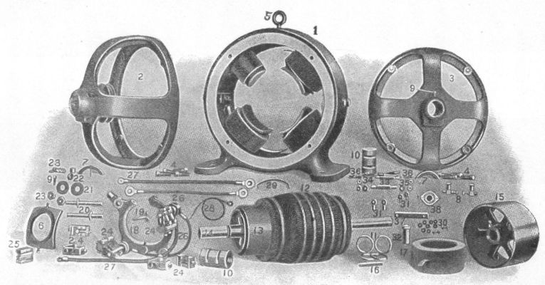
A direct-current dynamo or motor, showing details of construction
(
Courtesy of the Crocker-Wheeler Company)
Insulate this wire by covering it with cotton thread, and wind it
closely on a spool. Connect the two loose ends to a dry battery, and
you will find that you have multiplied the magnetic strength of a
single loop of wire by the number of turns on the spool—concentrated
all the magnetism of the length of that wire into a small space. Put
an iron core in the middle of this spool and the magnet seems still
more powerful. Lines of force which otherwise would escape in great
circles into space, are now concentrated in the iron. The iron core
is a magnet. Shut off the current from the battery and the iron is
still a magnet—weak, true, but it will always retain a small portion
of its magnetism. Soft iron retains very little of its magnetism. Hard
steel retains a great deal, and for this reason steel is used for
permanent magnets, of the horseshoe type so familiar.
A Simple Dynamo
A dynamo consists, first, of a number of such magnets, wound with
insulated wire. Their iron cores point towards the center of a circle
like the spokes of a wheel; and their curved inner faces form a circle
in which a spool, wound with wire in another way, may be spun by the
water wheel.
Now take a piece of copper wire and make a loop of it. Pass one side
of this loop in front of an electric magnet.
As the wire you hold in your hands passes the iron face of the magnet,
a wave of energy that is called electricity flows around this loop at
the rate of 186,000 miles a second—the same speed as light comes to
us from the sun. As you move the wire away from the magnet, a second
wave starts through the wire, flowing in the opposite direction. You
can prove this by holding a compass needle under the wire and see it
wag first in one direction, then in another.
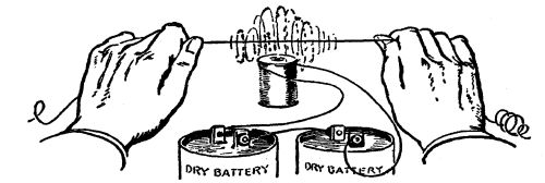
A wire "cutting" the lines of force of an
electro-magnet
This is a simple dynamo. A wire "cutting" the invisible lines of
force, that a magnet is spraying out into the air, becomes
"electrified." Why this is true, no one has ever been able to explain.
The amount of electricity—its capacity for work—which you have
generated with the magnet and wire, does not depend alone on the
pulling power of that simple magnet. Let us say the magnet is very
weak—has not enough power to lift one ounce of iron. Nevertheless,
if you possessed the strength of Hercules, and could pass that wire
through the field of force of the magnet many thousands of times a
second, you would generate enough electricity in the wire to cause the
wire to melt in your hands from heat.
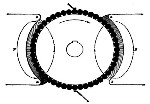
Cross-section of an armature revolving in its field
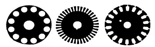
Forms of annealed steel discs used in armature
construction
This experiment gives the theory of the dynamo. Instead of passing
only one wire through the field of force of a magnet, we have hundreds
bound lengthwise on a revolving drum called an armature. Instead of
one magnetic pole in a dynamo we have two, or four, or twenty
according to the work the machine is designed for—always in pairs, a
North pole next to a South pole, so that the lines of force may flow
out of one and into another, instead of escaping in the surrounding
air. If you could see these lines of force, they would appear in
countless numbers issuing from each pole face of the field magnets,
pressing against the revolving drum like hair brush bristles—trying
to hold it back. This drum, in practice, is built up of discs of
annealed steel, and the wires extending lengthwise on its face are
held in place by slots to prevent them from flying off when the drum
is whirled at high speed. The drum does not touch the face of the
magnets, but revolves in an air space. If we give the electric
impulses generated in these wires a chance to flow in a circuit—flow
out of one end of the wires, and in at the other, the drum will
require more and more power to turn it, in proportion to the amount of
electricity we permit to flow. Thus, if one electric light is turned
on, the drum will press back with a certain strength on the water
wheel; if one hundred lights are turned on it will press back one
hundred times as much. Providing there is enough power in the water
wheel to continue turning the drum at its predetermined speed, the
dynamo will keep on giving more and more electricity if asked to,
until it finally destroys itself by fire. You cannot take more power,
in terms of electricity, out of a dynamo that you put into it, in
terms of mechanical motion. In fact, to insure flexibility and
constant speed at all loads, it is customary to provide twice as much
water wheel, or engine, power as the electrical rating of the dynamo.
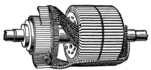
An armature partly wound, showing slots and commutator
We have seen that a water wheel is 85 per cent efficient under ideal
conditions. A dynamo's efficiency in translating mechanical motion
into electricity, varies with the type of machine and its size. The
largest machines attain as high as 90 per cent efficiency; the
smallest ones run as low as 40 per cent.
Measuring Electric Power
The amount of electricity any given dynamo can generate depends,
generally speaking, on two factors, i. e., (1) the power of the water
wheel, or other mechanical engine that turns the armature; and (2) the
size (carrying capacity) of the wires on this drum.
Strength, of electricity, is measured in amperes. An ampere of
electricity is the unit of the rate of flow and may be likened to a
gallon of water per minute.
In surveying for water-power, in Chapter III, we found that the
number of gallons or cubic feet of water alone did not determine the
amount of power. We found that the number of gallons or cubic feet
multiplied by the distance in feet it falls in a given time, was the
determining factor—pounds (quantity) multiplied by feet per
second—(velocity).
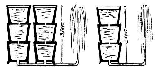
Showing the analogy of water to volts and amperes of
electricity
The same is true in figuring the power of electricity. We multiply the
amperes by the number of electric impulses that are created in the
wire in the course of one second. The unit of velocity, or pressure of
the electric current is called a volt. Voltage is the pressure which
causes electricity to flow. A volt may be likened to the velocity in
feet per second of water in falling past a certain point. If you
think a moment you will see that this has nothing to do with quantity.
A pin-hole stream of water under 40 pounds pressure has the same
velocity as water coming from a nozzle as big as a barrel, under the
same pressure. So with electricity under the pressure of one volt or
one hundred volts.
One volt is said to consist of a succession of impulses caused by one
wire cutting 100,000,000 lines of magnetic force in one second. Thus,
if the strength of a magnet consisted of one line of force, to create
the pressure of one volt we would have to "cut" that line of force
100,000,000 times a second, with one wire; or 100,000 times a second
with one thousand wires. Or, if a magnet could be made with
100,000,000 lines of force, a single wire cutting those lines once in
a second would create one volt pressure. In actual practice, field
magnets of dynamos are worked at densities up to and over 100,000
lines of force to the square inch, and armatures contain several
hundred conductors to "cut" these magnetic lines. The voltage then
depends on the speed at which the armature is driven. In machines for
isolated plants, it will be found that the speed varies from 400
revolutions per minute, to 1,800, according to the design of dynamo
used.
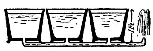
Pressure determines volume of flow in a given time
Multiplying amperes (strength) by volts (pressure), gives us watts
(power). Seven hundred and forty-six watts of electrical energy is
equal to one horsepower of mechanical energy—will do the same work.
Thus an electric current under a pressure of 100 volts, and a density
of 7.46 amperes, is one horsepower; as is 74.6 amperes, at 10 volts
pressure; or 746 amperes at one volt pressure. For convenience (as a
watt is a small quantity) electricity is measured in kilowatts, or
1,000 watts. Since 746 watts is one horsepower, 1,000 watts or one
kilowatt is 1.34 horsepower. The work of such a current for one hour
is called a kilowatt-hour, and in our cities, where electricity is
generated from steam, the retail price of a kilowatt-hour varies from
10 to 15 cents.
Now as to how electricity may be controlled, so that a dynamo will not
burn itself up when it begins to generate.
Again we come back to the analogy of water. The amount of water that
passes through a pipe in any given time, depends on the size of the
pipe, if the pressure is maintained uniform. In other words the
resistance of the pipe to the flow of water determines the amount.
If the pipe be the size of a pin-hole, a very small amount of water
will escape. If the pipe is as big around as a barrel, a large amount
will force its way through. So with electricity. Resistance,
introduced in the electric circuit, controls the amount of current
that flows. A wire as fine as a hair will permit only a small quantity
to pass, under a given pressure. A wire as big as one's thumb will
permit a correspondingly greater quantity to pass, the pressure
remaining the same. The unit of electrical resistance is called the
ohm—named after a man, as are all electrical units.
Ohm's Law
The ohm is that amount of resistance that will permit the passage
of one ampere, under the pressure of one volt. It would take two
volts to force two amperes through one ohm; or 100 volts to force 100
amperes through the resistance of one ohm. From this we have Ohm's
Law, a simple formula which is the beginning and end of all electric
computations the farmer will have to make in installing his
water-power electric plant. Ohm's Law tells us that the density of
current (amperes) that can pass through a given resistance in ohms (a
wire, a lamp, or an electric stove) equals volts divided by
ohms—or pressure divided by resistance. This formula may be
written in three ways, thus:

Or to express the same thing in
words, current equals volts divided by ohms; ohms equals
volts divided by current; or volts equals current multiplied
by ohms. So, with any two of these three determining factors known,
we can find the third. As we have said, this simple law is the
beginning and end of ordinary calculations as to electric current, and
it should be thoroughly understood by any farmer who essays to be his
own electrical engineer. Once understood and applied, the problem of
the control of the electric current becomes simple a b c.
Examples of Ohm's Law
Let us illustrate its application by an example. The water wheel is
started and is spinning the dynamo at its rated speed, say 1,500
r.p.m. Two heavy wires, leading from brushes which collect electricity
from the revolving armature, are led, by suitable insulated supports
to the switchboard, and fastened there. They do not touch each other.
Dynamo mains must not be permitted to touch each other under any
conditions. They are separated by say four inches of air. Dry air is
a very poor conductor of electricity. Let us say, for the example,
that dry air has a resistance to the flow of an electric current, of
1,000,000 ohms to the inch—that would be 4,000,000 ohms. How much
electricity is being permitted to escape from the armature of this
110-volt dynamo, when the mains are separated by four inches of dry
air? Apply Ohm's law, C equals E divided by R. E, in this case is 110;
R is 4,000,000; therefore C (amperes) equals 110/4,000,000—an
infinitesimal amount—about .0000277 ampere.
Let us say that instead of separating these two mains by air we
separated them by the human body—that a man took hold of the bare
wires, one in each hand. The resistance of the human body varies from
5,000 to 10,000 ohms. In that case C (amperes) equals 110/5,000, or
110/10,000—about 1/50th, or 1/100th of an ampere. This illustrates
why an electric current of 110 volts pressure is not fatal to human
beings, under ordinary circumstances. The body offers too much
resistance. But, if the volts were 1,100 instead of the usual 110 used
in commercial and private plants for domestic use, the value of C, by
this formula at 5,000 ohms, would be nearly 1/5th ampere. To drive
1/5th ampere of electricity through the human body would be fatal in
many instances. The higher the voltage, the more dangerous the
current. In large water-power installations in the Far West, where the
current must be transmitted over long distances to the spot where it
is to be used, it is occasionally generated at a pressure of 150,000
volts. Needless to say, contact with such wires means instant death.
Before being used for commercial or domestic purposes, in such cases,
the voltage is "stepped down" to safe pressures—to 110, or to 220, or
to 550 volts—always depending on the use made of it.
Now, if instead of interposing four inches of air, or the human body,
between the mains of our 110-volt dynamo, we connected an incandescent
lamp across the mains, how much electricity would flow from the
generator? An incandescent lamp consists of a vacuum bulb of glass, in
which is mounted a slender thread of carbonized fibre, or fine
tungsten wire. To complete a circuit, the current must flow through
this wire or filament. In flowing through it, the electric current
turns the wire or filament white hot—incandescent—and thus turns
electricity back into light, with a small loss in heat. In an ordinary
16 candlepower carbon lamp, the resistance of this filament is 220
ohms. Therefore the amount of current that a 110-volt generator can
force through that filament is 110/220, or ½ ampere.
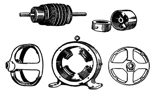
Armature and field coils of a direct current dynamo
One hundred lamps would provide 100 paths of 220 ohms resistance each
to carry current, and the amount required to light 100 such lamps
would be 100 × ½ or 50 amperes. Every electrical device—a lamp, a
stove, an iron, a motor, etc.,—must, by regulations of the Fire
Underwriters' Board be plainly marked with the voltage of the current
for which it is designed and the amount of current it will consume.
This is usually done by indicating its capacity in watts, which as we
have seen, means volts times amperes, and from this one can figure
ohms, by the above formulas.
A Short Circuit
We said a few paragraphs back that under no conditions must two bare
wires leading from electric mains be permitted to touch each other,
without some form of resistance being interposed in the form of lamps,
or other devices. Let us see what would happen if two such bare wires
did touch each other. Our dynamo as we discover by reading its plate,
is rated to deliver 50 amperes, let us say, at 110 volts pressure.
Modern dynamos are rated liberally, and can stand 100% overload for
short periods of time, without dangerous overheating. Let us say that
the mains conveying current from the armature to the switchboard are
five feet long, and of No. 2 B. & S. gauge copper wire, a size which
will carry 50 amperes without heating appreciably. The resistance of
this 10 feet of No. 2 copper wire, is, as we find by consulting a wire
table, .001560 ohms. If we touch the ends of these two five-foot wires
together, we instantly open a clear path for the flow of electric
current, limited only by the carrying capacity of the wire and the
back pressure of .001560 ohms resistance. Using Ohm's Law, C equals E
divided by R, we find that C (amperes) equals 110/.001560 or 70,515
amperes!
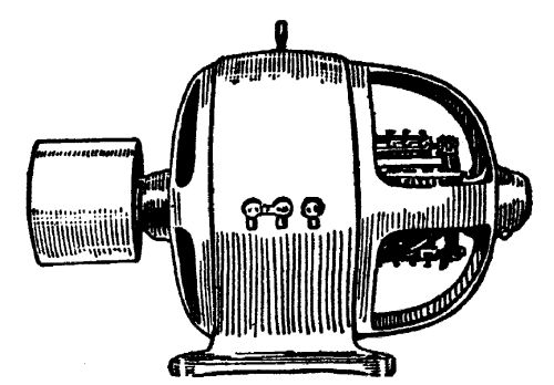
A direct current dynamo
Unless this dynamo were properly protected, the effect of such a
catastrophe would be immediate and probably irreparable. In effect, it
would be suddenly exerting a force of nearly 10,000 horsepower against
the little 10 horsepower water wheel that is driving this dynamo. The
mildest thing that could happen would be to melt the feed-wire or to
snap the driving belt, in which latter case the dynamo would come to a
stop. If by any chance the little water wheel was given a chance to
maintain itself against the blow for an instant, the dynamo, rated at
50 amperes, would do its best to deliver the 70,515 amperes you called
for—and the result would be a puff of smoke, and a ruined dynamo.
This is called a "short circuit"—one of the first "don'ts" in
handling electricity.
As a matter of fact every dynamo is protected against such a calamity
by means of safety devices, which will be described in a later
chapter—because no matter how careful a person may be, a partial
short circuit is apt to occur. Happily, guarding against its
disastrous effects is one of the simplest problems in connection with
the electric plant.
Direct Current and Alternating Current
When one has mastered the simple Ohm's Law of the electric circuit,
the next step is to determine what type of electrical generator is
best suited to the requirements of a farm plant.
In the first place, electric current is divided into two classes of
interest here—alternating, and direct.
We have seen that when a wire is moved through the field of a magnet,
there is induced in it two pulsations—first in one direction, then in
another. This is an alternating current, so called because it
changes its direction. If, with our armature containing hundreds of
wires to "cut" the lines of force of a group of magnets, we connected
the beginning of each wire with one copper ring, and the end of each
wire with another copper ring, we would have what is called an
alternating-current dynamo. Simply by pressing a strap of flexible
copper against each revolving copper ring, we would gather the sum of
the current of these conductors. Its course would be represented by
the curved line in the diagram, one loop on each side of the middle
line (which represents time) would be a cycle. The number of
cycles to the second depends on the speed of the armature; in
ordinary practice it is usually twenty-five or sixty. Alternating
current has many advantages, which however, do not concern us here.
Except under very rare conditions, a farmer installing his own plant
should not use this type of machine.
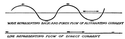
Diagram of alternating and direct current
If, however, instead of gathering all the current with brushes bearing
on two copper rings, we collected all the current traveling in one
direction, on one set of brushes—and all the current traveling in the
other direction on another set of brushes,—we would straighten out
this current, make it all travel in one direction. Then we would have
a direct current. A direct current dynamo, the type generally used
in private plants, does this. Instead of having two copper rings for
collecting the current, it has a single ring, made up of segments of
copper bound together, but insulated from each other, one segment for
each set of conductors on the armature. This ring of many segments, is
called a commutator, because it commutates, or changes, the
direction of the electric impulses, and delivers them all in one
direction. In effect, it is like the connecting rod of a steam engine
that straightens out the back-and-forth motion of the piston in the
steam cylinder and delivers the motion to a wheel running in one
direction.
Such a current, flowing through a coil of wire would make a magnet,
one end of which would always be the north end, and the other end the
south end. An alternating current, on the other hand, flowing through
a coil of wire, would make a magnet that changed its poles with each
half-cycle. It would no sooner begin to pull another magnet to it,
than it would change about and push the other magnet away from it, and
so on, as long as it continued to flow. This is one reason why a
direct current dynamo is used for small plants. Alternating current
will light the same lamps and heat the same irons as a direct current;
but for electric power it requires a different type of motor.
Types of Direct Current Dynamos
Just as electrical generators are divided into two classes,
alternating and direct, so direct current machines are divided into
three classes, according to the manner in which their output, in
amperes and volts, is regulated. They differ as to the manner in which
their field magnets (in whose field of force the armature spins) are
excited, or made magnetic. They are called series, shunt, and
compound machines.
The Series Dynamo
By referring to the diagram, it will be seen that the current of a
series dynamo issues from the armature mains, and passes through the
coils of the field magnets before passing into the external circuit to
do its work. The residual magnetism, or the magnetism left in the
iron cores of the field magnets from its last charge, provides the
initial excitation, when the machine is started. As the resistance of
the external circuit is lowered, by turning on more and more lights,
more and more current flows from the armature, through the field
magnets. Each time the resistance is lowered, therefore, the current
passing through the field magnets becomes more dense in amperes, and
makes the field magnets correspondingly stronger.
We have seen that the voltage depends on the number of lines of
magnetic force cut by the armature conductors in a given time. If the
speed remains constant then, and the magnets grow stronger and
stronger, the voltage will rise in a straight line. When no current is
drawn, it is 0; at full load, it may be 100 volts, or 500, or 1,000
according to the machine. This type of machine is used only in street
lighting, in cities, with the lights connected in "series," or one
after another on the same wire, the last lamp finally returning the
wire to the machine to complete the circuit. This type of dynamo has
gained the name for itself of "mankiller," as its voltage becomes
enormous at full load. It is unsuitable, in every respect, for the
farm plant. Its field coils consist of a few turns of very heavy wire,
enough to carry all the current of the external circuit, without
heating.
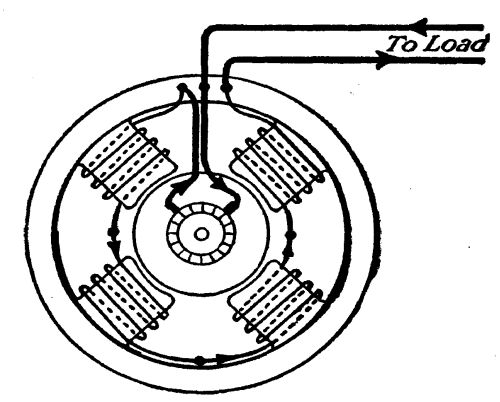
Connections of a series dynamo
The Shunt Dynamo
The shunt dynamo, on the other hand, has field coils connected
directly across the circuit, from one wire to another, instead of in
"series." These coils consist of a great many turns of very fine wire,
thus introducing resistance into the circuit, which limits the
amount of current (amperes) that can be forced through them at any
given voltage. As a shunt dynamo is brought up to its rated speed, its
voltage gradually rises until a condition of balance occurs between
the field coils and the armature. There it remains constant. When
resistance on the external circuit is lowered, by means of turning on
lamps or other devices, the current from the armature increases in
working power, by increasing its amperes. Its voltage remains
stationary; and, since the resistance of its field coils never
changes, the magnets do not vary in strength.
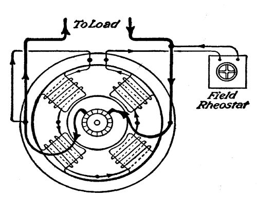
Connections of a shunt dynamo
The objection to this type of machine for a farm plant is that, in
practice, the armature begins to exercise a de-magnetizing effect on
the field magnets after a certain point is reached—weakens them;
consequently the voltage begins to fall. The voltage of a shunt dynamo
begins to fall after half-load is reached; and at full load, it has
fallen possibly 20 per cent. A rheostat, or resistance box on the
switchboard, makes it possible to cut out or switch in additional
resistance in the field coils, thus varying the strength of the field
coils, within a limit of say 15 per cent, to keep the voltage
constant. This, however, requires a constant attendance on the
machine. If the voltage were set right for 10 lights, the lights would
grow dim when 50 lights were turned on; and if it were adjusted for 50
lights, the voltage would be too high for only ten lights—would cause
them to "burn out."
Shunt dynamos are used for charging storage batteries, and are
satisfactory for direct service only when an attendant is constantly
at hand to regulate them.
The Compound Dynamo
The ideal between these two conditions would be a compromise, which
included the characteristics of both series and shunt effects.
That is exactly what the compound dynamo effects.
A compound dynamo is a shunt dynamo with just enough series turns on
its field coils, to counteract the de-magnetizing effect of the
armature at full load. A machine can be designed to make the voltage
rise gradually, or swiftly, by combining the two systems. For country
homes, the best combination is a machine that will keep the voltage
constant from no load to full load. A so-called flat-compounded
machine does this. In actual practice, this voltage rises slightly at
the half-load line—only two or three volts, which will not damage the
lamps in a 110-volt circuit.
The compound dynamo is therefore self-regulating, and requires no
attention, except as to lubrication, and the incidental care given to
any piece of machinery. Any shunt dynamo can be made into a compound
dynamo, by winding a few turns of heavy insulated wire around the
shunt coils, and connecting them in "series" with the external
circuit. How many turns are necessary depends on conditions. Three or
four turns to each coil usually are sufficient for "flat compounding."
If the generating plant is a long distance from the farm house where
the light, heat, and power are to be used, the voltage drops at full
load, due to resistance of the transmission wires. To overcome this,
enough turns can be wound on top of the shunt coils to cause the
voltage to rise at the switchboard, but remain stationary at the spot
where the current is used. The usual so-called flat-compounded dynamo,
turned out by manufacturers, provides for constant voltage at the
switchboard. Such a dynamo is eminently fitted for the farm electric
plant. Any other type of machine is bound to cause constant trouble
and annoyance.
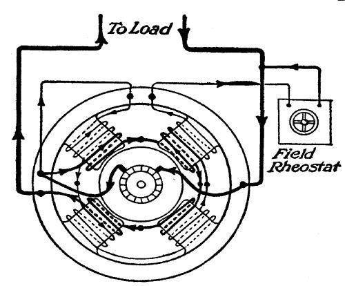
Connections of a compound dynamo
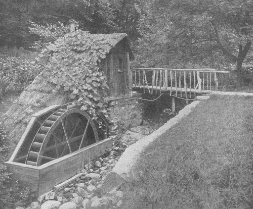 Even the tiny trout brook becomes a thing of utility as well as of
joy
Even the tiny trout brook becomes a thing of utility as well as of
joy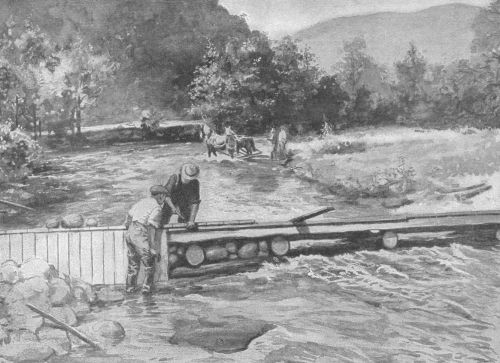 Farm labor and materials built this crib and stone
dam
Farm labor and materials built this crib and stone
dam
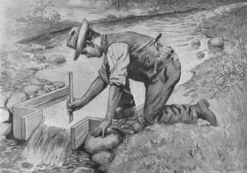 Measuring a small stream with a weir
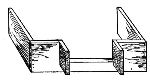 Detail of home-made weir
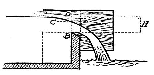 Cross-section of weir










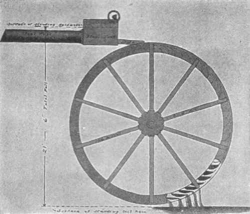 The Fitz overshoot wheel

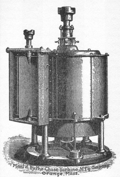 A typical vertical turbine
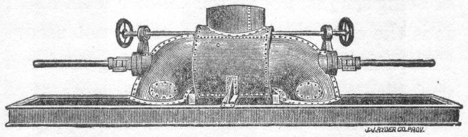 Two wheels on a horizontal shaft


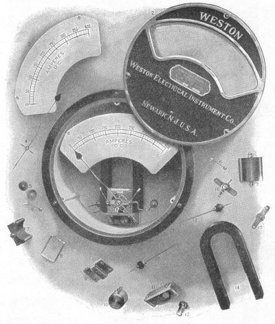 Details of voltmeter or ammeter
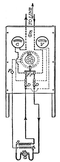 A switchboard and its connections: G. Dynamo; A.
Shunt field coils; B. Series coils; DD. Fuses; FF. Main switch;
F. Field switch; C. Ammeter; V. Voltmeter; E. Lamp; R.
Rheostat. Dotted lines show connections on back of board
A switchboard and its connections: G. Dynamo; A.
Shunt field coils; B. Series coils; DD. Fuses; FF. Main switch;
F. Field switch; C. Ammeter; V. Voltmeter; E. Lamp; R.
Rheostat. Dotted lines show connections on back of board
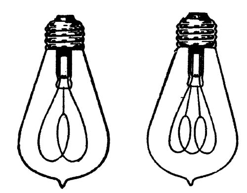 Carbon Lamps Gem Type (¼ scale)
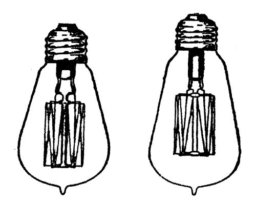 25 and 40 watt Mazda tungsten lamps (¼ scale)
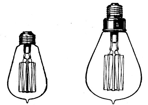 60 and 100 watt Mazda tungsten lamp. These lamps may be
had in sizes from 10 to 500 watts (¼ scale)
60 and 100 watt Mazda tungsten lamp. These lamps may be
had in sizes from 10 to 500 watts (¼ scale)
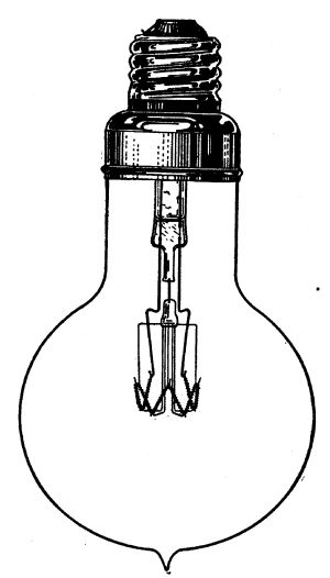 The lamp of the future. A 1000 watt Mazda nitrogen
lamp, giving 2000 candlepower (¼ scale)
The lamp of the future. A 1000 watt Mazda nitrogen
lamp, giving 2000 candlepower (¼ scale)
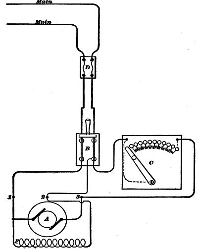 Connections of shunt motor and starting rheostat

 Splicing transmission wire


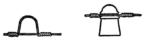 Transmission wire on glass insulator


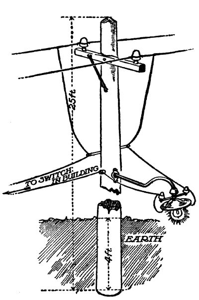 A barn-yard light



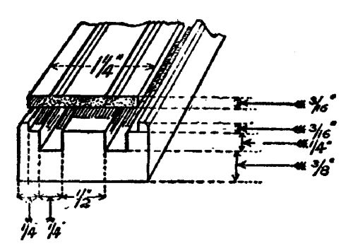 Detail of wooden moulding
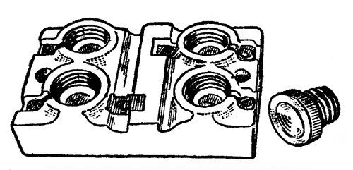 Porcelain cut-out and plug fuse
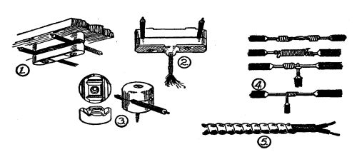 Examples of cleat and knob wiring, 1, 2, 3; wire
joints, 4; flexible armoured conductor, 5
Examples of cleat and knob wiring, 1, 2, 3; wire
joints, 4; flexible armoured conductor, 5

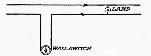 Snap switch connections

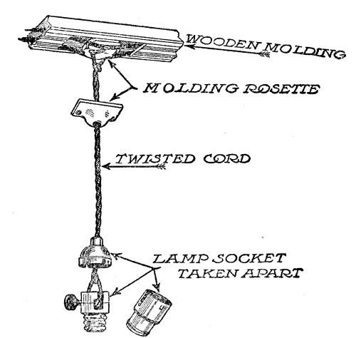 Detail of simple hanging lamp supported by rosette
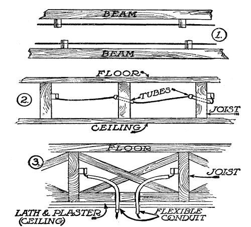 Knob and cleat wiring
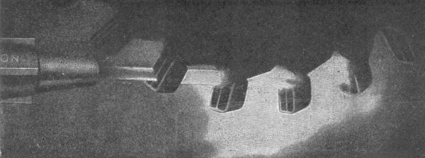 Instantaneous photograph of high-pressure water jet
being quenched by buckets of a tangential wheel
Instantaneous photograph of high-pressure water jet
being quenched by buckets of a tangential wheel
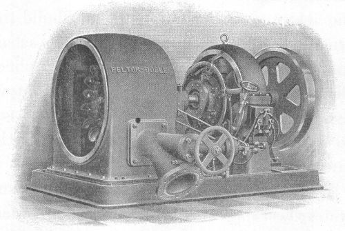 A tangential wheel, and a dynamo keyed to the same
shaft—the ideal method for generating electricity. The centrifugal
governor is included on the same base
A tangential wheel, and a dynamo keyed to the same
shaft—the ideal method for generating electricity. The centrifugal
governor is included on the same base

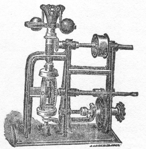 A centrifugal governor
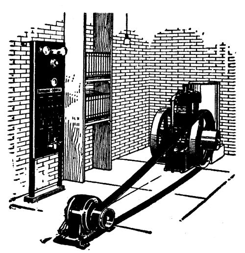 The Fairbanks Morse oil engine storage battery set
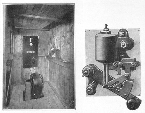 A rough-and-ready farm electric plant, supplying two
farms with light, heat and power; and a Ward Leonard-type
circuit-breaker for charging storage batteries
A rough-and-ready farm electric plant, supplying two
farms with light, heat and power; and a Ward Leonard-type
circuit-breaker for charging storage batteries
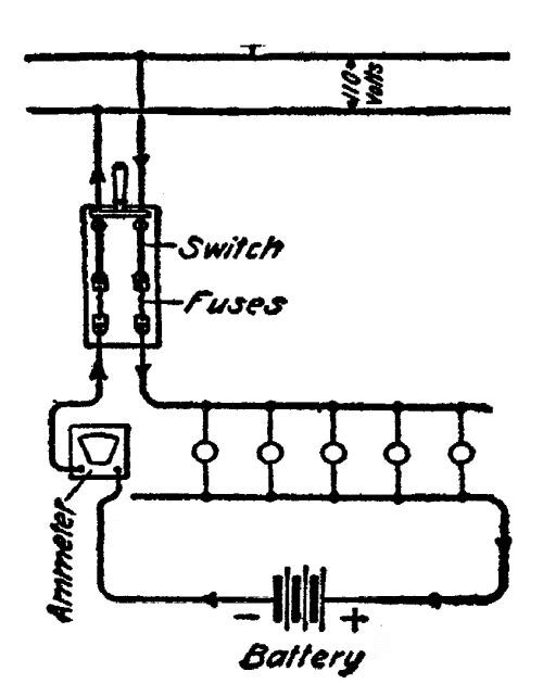 Connections for charging storage batteries on 110-volt
mains
Connections for charging storage batteries on 110-volt
mains