E-text prepared by
Kevin Handy, John Hagerson, Matthew Wheaton,
and the Online Distributed Proofreading Team
(http://www.pgdp.net)
IDAHO Agricultural
Extension Service
BULLETIN 396
JUNE, 1962
T-1
Safety
Uses
Economy
DIVISION I
4-H ELECTRIC
UNIVERSITY OF IDAHO College of Agriculture
HOW TO USE THIS BOOK IN FULFILLING THE GOALS OF THE 4-H ELECTRIC PROJECT FOR THE FIRST AND SUCCEEDING YEARS
The minimum goals for credit in the
4-H Electric project vary according to the
4-H member's age and the number of years
he or she has taken the electric project. For
example, if you are a 4-H member beginning
the 4-H Electric project at the age of 10,
you will not be required to earn as many
credit points as a 14-year-old 4-H member
beginning the 4-H Electric project. However,
if you are a 12-year-old in your second
year of electricity you must earn as
many credit points in that year as a 14-year-old
does in his or her first year.
Each lesson or goal has been designated
a certain number of credit points. These
are shown near the title of each lesson or
goal. You decide on the lessons you want
to study, list them, and add up the credit
points.
For a full year's 4-H project credit, the
total of your credit points should be at least
as many as shown in the following table:
Examples of reading the table below are
as follows: (a) An 11-year-old member is
required to complete 13 credit points the
first year, (b) A 14-year-old is required to
complete 17 credit points his first year, (c)
A 14-year-old taking the electric project for
the third year must complete 16 credit points
that year.
We recommend that, if you are taking
the 4-H Electric project, you start with the
first lesson in the book and go on through
to the back of the book in advanced years.
But you may skip the less important or less
interesting parts so long as you learn the
basic lessons. A way to find out whether
you know the basic lessons is to read them
through and try to answer all questions
under the heading "What Did You Learn."
If you can answer these questions you may
not wish to spend the time doing the things
listed under "What To Do."
Minimum Number of Credit Points
Required for Each Year's Work in the 4-H Electric Project
4-H Member's Age
4-H Member's Year in 4-H Electric Project
1st Year
2nd Year
3rd Year
4th or Later Years
10-11
13
15
12-13
15
17
19
20
14-15
17
19
21
21
16 & over
19
21
21
21
This system of credit points makes it possible for you to do the things you want to do with
electricity and get credit for them in the 4-H Electric project.
UNIVERSITY OF IDAHO
COLLEGE OF AGRICULTURE
AGRICULTURAL EXTENSION SERVICE
Eric B. Wilson, Extension Agricultural Engineer
1962
Published and distributed in furtherance of the Acts of May 8 and June 30, 1914, by the
University of Idaho Extension Service, James E. Kraus, Director; and the U. S. Department
of Agriculture, Co-operating.
LESSON NO. B-1 — Electrical Conductors — Electrical Insulators — Play It Safe — Electrical Terms — WHAT TO DO: Make A Circuit Board — Parallel Wiring — Series Wiring — SUGGESTED DEMONSTRATIONS — Water And Electricity — For More Information — What Did You Learn?
Credit Points 3
GETTING ACQUAINTED WITH ELECTRICITY
Electricity serves you best when you understand
how it works and use it properly.
As a 4-H member, you should know about
electricity and help to show others the way to
obtain its tremendous work-saving benefits as
well as how to use it with safety.
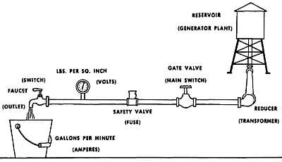
A good way to think of electricity is to
compare it with water. It acts a lot like water.
However it is made of tiny parts of atoms
called electrons. When there are more than
the normal number of electrons in anything,
it is said to be negatively charged; when there
is a shortage of electrons, it is positively
charged. As water flows downhill, "seeking
it's level," electrons flow from negative to
positive, seeking to "balance" the charge.
Even if you're never going to repair a
lamp or make a chick brooder, you should
know about conductors and insulators. This
is because you happen to be a fairly good
conductor of electricity. Electricity will pass
easily through you to other conductors—the
ground, for instance. When this happens you
may get a shock, burn, or serious injury.
But it doesn't ever have to happen, if you learn
to understand your friend, electricity.
Silver, copper, iron, aluminum and many
other metals are very good conductors.
Water, acids, and salts are too. Electricity
passes over or through them very easily.
Like water pipes, the larger the conductor,
the more electricity it can carry. When conductors
are too small for the amount of
electrons trying to move over them, they get
hot, melt, may start fires. That's why wire
size is important.
Insulators are the opposite of conductors.
Electricity has trouble passing through some
materials. Rubber, most plastics, dry wood,
oils and glass are some of the good insulators.
It's the amount and kind of insulation
that counts. If it has enough force, electricity
can pass through just about anything—even
jump gaps!
Electricity, like water, flows along the
easiest paths. It is always trying to get to
the ground. The earth attracts it. It stays
on the wires unless a person, a wet branch,
or some other conductor gives it a path to
the ground. Do not touch any wire which
might be carrying electricity.
If you should touch a "hot" wire accidentally
and are standing on a dry piece of
wood, the conducting pathway to the ground is
not good and the electricity may keep running
along its wire. But do not touch some
other conductor with another part of your
body. This would complete a circuit through
your body and would be very dangerous. Always
make sure there is plenty of good insulation
material or plenty of distance between
you and anything which might be carrying
electricity.
Remember, too, insulation is of little use
when it is wet. Dew, mist, rain, condensation,
a damp floor can change the whole picture.
If you understand electricity and how it
acts, you'll be safe enough, because you won't
take chances or expose yourself to injury.
Alternating Current—Usually referred to as
"AC," alternating current is current which
reverses its direction of flow at regular
intervals, 60 times a second.
Direct Current—"DC" current flows only in
one direction. Battery current is DC.
Ampere—Amperes are units by which the rate
of flow of electrical current (electrons) is
measured. An ampere is 6.3 billion electrons
passing one point in a circuit, in one second.
This compares with the way the flow of water
is measured in gallons per second.
Volts—A volt is a unit to measure the tendency
of electrons to move when they are
shoved. Voltage is the amount of "push"
behind the electrons. It's like water pressure
in a pipe. Home power lines carry 115
volts (110 to 120 volts). For appliances
such as electric stoves, washers and driers,
a second 115-volt line should be added, giving
230 volts (220 to 240 volts).
Watts—Watts equal volts times amperes.
Light bulbs, electric irons and other appliances
are usually marked with the voltage
they require and the number of watts.
Kilowatts—Your electric bill usually reads
in kilowatt hours. A kilowatt is 1000 watts.
A kilowatt hour equals 1000 watts used for 1
hour. One kilowatt equals about 1-1/3 horsepower.
A kilowatt is usually indicated by
"kw" and a kilowatt hour by "kwh."
Circuits—A closed circuit is one in which
the electricity is flowing, lighting a light, running
a motor, or some other appliance. The
circuit runs all the way from the place the
electricity is being generated to your home,
through the appliance or light bulb, and back
to the generator.
Circuits are opened and closed by
switches. When the circuit is opened, the
electricity stops at the switch. Before working
on a switch, socket, fuse, or any part of
the wiring be sure to open the main switch.
The main switch is usually at the fuse box
or near it. Appliances should be disconnected
when you work on them. Everyone in the
family should know where the main switch is
so it can be pulled in case of accidents, fire,
flood, or windstorm damage.
Fuses and Circuit Breakers—These are the
safety valves of your electrical system.
The different electrical circuits in your home
are meant to carry only certain amounts of
electricity. Some carry only 15 amps, others
can carry 20 or more. They are marked to
show capacity.
When a fuse burns out or a circuit breaker
opens, look for an overload of lights and
appliances on the circuit before you try to replace
the fuse or close the circuit breaker.
Without these safeguards, the overloaded
electric line will heat up and may start a fire.
Even if no fire starts, electricity will be
wasted and the homeowner will be paying for
electricity that's doing no good.
Remember: If you ever have to replace
a fuse, pull the main switch first. Keep a
flashlight handy in your house. It seems that
fuses usually blow at night, and it doesn't pay
to stumble or fumble around electric wires
in the dark.
So that you can show others how electricity
travels from here to there, and how it behaves
under different conditions, make an electric
circuit board.
Materials Needed:
Piece of 3/4" board about 4" x 6"
l-l/2-volt No. 6 dry cell battery
Two pieces of bell wire, each 24" long, one black, one white
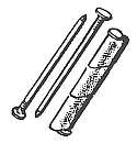
Two 10-penny box nails (3")
Three 3-penny box nails (1")
Two small screws or carpet tacks
Two 2-inch rubber bands
Two miniature sockets with solder terminals
Two l-l/2-volt flashlight bulbs
Tools Needed:
Ruler, pencils, hammer, pliers or vise.
Making the Board:
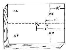
1. Lay out the board with a pencil and ruler
as indicated in Figure 1.
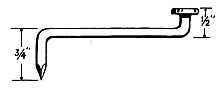
2. Bend the three-inch nail as shown in Figure
2, using pliers, vise and hammer.
3. Pound the one-inch nails into the board for
a half-inch at points A, C, and D. Use the
three-inch nail to make a hole a half-inch
deep at B. Put the crank nail in this
hole and pound in a little farther. Attach
the lamp socket brackets at E and F.
Stretch the rubber band as in Figure 3.
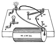
4. Lay out the electricity path, the circuit
(Figure 3). Use the black wire for the
positive side of the circuit (the center
pole of battery). Twist it around the
switch crank B, and the center pole of
battery. Run another piece to the outside
terminal of bulb socket at E. Run white
piece to negative pole of battery from the
other terminal at E.
Figure 1 (Circuit Board)
Figure 2 (Switch)
5. Close the switch. The rubber band should
hold the switch nail tightly against nail at
C. Does the bulb light? __________
If it doesn't, check the connections.
Now you have a circuit—a closed circuit
when the electricity runs all the way from the
positive pole to the negative pole. The black
wire is the hot side, the live wire, because it
carries the full load of the battery up to the
bulb.
Remember, battery current is direct current,
DC. In the case of alternating current,
AC, such as most homes and buildings use,
the electricity flows in first one direction and
then the other.
Figure 3 (Closed Circuit)
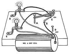
To make this circuit hookup, attach another
white wire to the negative pole of battery
and a terminal of the second flashlight
bulb. Run a black wire from the other terminal
to the switch terminal at C (Figure 4).
Close switch. Both bulbs will light.
Trace the circuit. Electricity is going
equally to each bulb, the same amount that
went to the single bulb. The difference is that
the battery will last only half as long. It's like
a pail of water with two open spigots. The
pail empties twice as fast as it would with just
one spigot open. This type of wiring is called
parallel wiring. If one bulb is unscrewed,
the other will stay lit.
Figure 4 (Parallel Wiring)
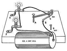
To do this, run the negative wire to one
terminal of the second bulb and attach a wire
from the other terminal to a terminal of the
first bulb. The other terminal connects with
the switch at C (Figure 5). This is series
wiring. If one bulb is unscrewed, the other
will fail to light because the circuit is broken
for both. Anything that breaks the circuit has
the effect of opening the switch.
Figure 5 (Series Wiring)
Show there is a circuit through the bulb
by screwing and unscrewing it. Also, "jump"
the socket by running the wire from C to the
other terminal of the bulb at E while it is unscrewed.
Bulb at F will light. Trace this
circuit.
Using the Circuit Board, you can give
many demonstrations of the way electricity
flows, works and behaves.
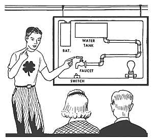
To help others understand electricity
better, draw a water system on an electric
circuit board paralleling the circuit. For the
battery show a water tank, pipes instead of
wires, faucets instead of switches. Somewhere
on the board paste a comparison of
electrical terms with terms used in describing
water, such as the following:
Wire equals Pipe
Volts equal Pressure
Amperes equal Rate of Flow - gallons per second
Watts equal Pressure times Rate of Flow
Switch equals Faucet
Current equals Flowing Water
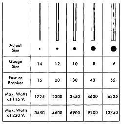
Show how to figure the wattage that a circuit
protected by a 15 ampere fuse can handle.
Do it with actual things or cut-out pictures
of light bulbs, irons, toasters, coffee-makers,
etc.
You know that Amperes times Volts equal
Watts. If the voltage is 115, a 15 amp circuit
can handle 115 volts times 15 amps, or 1725
watts.
The name plates on electric motors indicate
the amperage at full load. You can convert
this to watts, of course, by multiplying
amperage by the line voltage. Motors require
an additional amount of electricity when they
start. You need to allow for this fact, so fuses
will not blow or circuits trip when a motor is
turned on. You will learn more about this
when you study electric motors.
Your leader has many other sources of
information about electricity and demonstrations
you can perform. Ask him. Also,
libraries have many books about electricity
and its history, which are very interesting and
useful. Maybe you can find an electrician,
someone from your power supplier, or an
equipment dealer who will talk to your club on
electricity or electrical safety.
(Underline the correct answers then discuss in
the group.)
1. In a water pipe system water flows. In an
electrical circuit (electrons) (atoms) (charges)
flow.
2. Electricity or electrons flow (easier) (harder)
(about the same) in a conductor than in an
insulator.
3. Rubber is a good (conductor) (insulator)
(ground).
4. The most common material used as an electrical
conductor is (glass) (silver) (copper).
5. The unit of electrical pressure or push is
the (ampere) (volt) (watt).
6. The rate of flow of electricity is measured
in (gallons) (amperes per minute) (amperes).
7. Volts times amperes equals (watts) (kilowatt
hours) (alternating current).
8. A dry cell battery (stores) (makes) (uses)
electrical energy.
9. In a parallel circuit the electricity has (one)
(two or more) (no) paths to travel.
10. In a series circuit with two bulbs and a
switch the bulbs are (brighter) (dimmer) (the
same) as when they were in the parallel circuit.
LESSON NO. B-2 — TOOLS FOR ELECTRICIANS — Basic Tools for Electrical Work — WHAT TO DO: Build a Tool Chest — Demonstrations You Can Give — For Further Information
Credit Points 4
Who goeth a borrowing
Goeth a sorrowing
Few lend (but fools)
Their working tools
Tusser 1524-1580
Whenever a job comes up, it saves time
and trouble when you have the right tools
and they are all where you can find them.
Electrical work takes some special tools
and some everyday tools.
If you have ever watched a good electrician
at work, you've seen how neatly he
stores his tools in a box so every one
of them is handy. When a lineman climbs a
pole, he has his regular tools in a holster on
his belt. Special tools are kept in a box in
racks in the repair truck, all ready for instant
use. Wouldn't you like to have electrician's
tools all handy, ready for use, and
know how to use them properly?
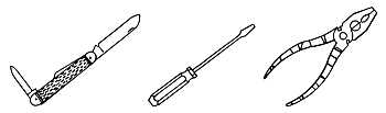
Knife
A good knife with a sharp blade is one of
the most useful tools. A camper's or electrician's
type knife is probably best because
it has other useful parts besides the cutting
blades—a screwdriver or punch, for instance.
Of course, you'll never use the cutting blades
as a screwdriver. This knife should be kept clean,
dry, sharp, and free from rust. Put
a little oil on the joints from time to time.
Remember, "Never whittle toward you and
you'll never cut yourself."
Pliers
A pair of electrician's pliers should be
part of your kit. Wrap the handles with
plastic insulating tape. Even though you're
not going to work on "hot" electric lines,
it pays to play safe. Later on, as you learn more
about electricity, you'll want a pair of
needle-nose pliers for the fine work.
Screwdrivers
You'll want a screwdriver which has true
corners. A 4 to 6 inch plastic handled screwdriver
with a narrow blade is best. You'll
probably need more than one size to fit the
various size screws you'll be turning.
Screwdrivers are easily damaged if you
try to use them as chisels and pry bars, or
use them in screw slots which are too large
for the blade.
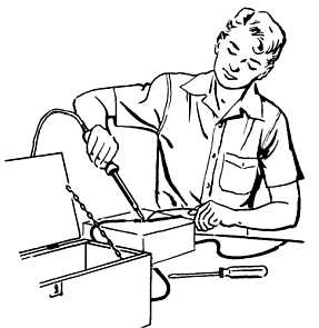
You can be hurt by the screwdriver if
you try to screw or unscrew things you are
holding in your hand. Keep your free hand
away from the end of the screwdriver. Place
the work on a bench or where it can be
handled easily.
Soldering Iron
A good 100 to 250-watt electric soldering
iron will be useful. Later on you may want
to buy a soldering gun, but unless you are doing
a lot of soldering it won't be necessary.
A supply of resin-core electrician's solder
will be needed. Acid-core solder reacts
with copper and in time causes a bad splice.
Tape
Once it was necessary to use two types of
tape on splices—rubber tape with friction
tape over it. Now there is a plastic tape on
the market which takes the place of both and
has good insulating quality. It is called
electrical tape, or plastic tape, and resists
water, oils (which would damage rubber tape),
and acids. You'll need a lot of tape in your
electrical work, so keep a roll on hand.
Other Tools and Equipment
As you go along in electrical work, you'll
be adding tools and other equipment, such as
a trouble light and maybe an ammeter or
voltmeter. Other tools you'll want to add will
be a Phillips screwdriver, open end wrenches,
a crescent wrench, small hack saw, hand drill
and bits.
You'll also be using some regular carpenter's
tools such as hammers, saws, and so on.
Unless you use them frequently, you don't
need to keep them in your electrical kit.
It's a good idea to start acquiring a supply
of electrical parts—lengths of wire, fuses,
switches, sockets, plugs, and other items that
will come in handy. There are parts you can
salvage from old lamps, motors, and other
equipment. Such a collection can be a real
treasure chest when you need a part in a
hurry. But be sure to throw away all faulty
parts.
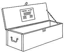
Figure 1. Completed tool chest.
To keep your tools always ready for use,
a tool chest will be very handy. It's the 4-H
way to work. You'll be surprised how much
easier it makes a job when you have your
tools, various parts and repair equipment all
in one place. You can make the chest (Figure 1)
with a saw, plane, screwdriver, pencil,
ruler or carpenter's square, and hammer.
Materials You'll Need:
A piece of lumber 1" by 10" by 8 feet
long. (1" lumber is actually only 3/4" thick—this
is the thickness you'll be working with.)
2 small hinges, with wood screws
1 small hasp, with wood screws
2 small handles with wood screws, or one
large handle
1 small chain, 10" to 12" long
Some No. 6 penny finishing nails or wood
screws about the same length
Making The Chest:
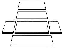
1. Cut your lumber into the following
pieces:
1 piece 10" x 18" for top
1 piece 8-1/2" x 16-1/2" for bottom
2 pieces 6" x 8-1/2" for two ends
2 pieces 6" x 18" for front and back
2. Lay out pieces as shown in Figure 2.
Figure 2.
Then, set up the two end pieces and nail
to bottom section. Refer back to Figure 1 as
you go along to see that box is shaping up as
shown. Nail the front and back sections to
the ends along the bottom. Wood screws can
be used instead of nails.
3. Lay the top in place and attach hinges
to the back side, about two inches in from
each end.
4. Attach one part of hasp to the top, and
the other part to front board in center. Fasten
the handles to each end.
5. Attach chain to the top and front so the
top will stay open when chain is fully extended.
Now you can invent your own improvements
for your chest. You can paint it, put
your name on it, and your club emblem and
name if you wish. You can put a rack on the
inside of the cover to hold your work sheets
and other booklets and materials. You can install
special slots or straps to hold each tool
in its place along the sides of the box. Maybe
you will want to put some partitions in the
box to separate various electrical equipment
such as wires, fuses, switches, and plugs.
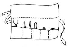
A Working Kit
An accessory which you may want to add
to your tool chest is an apron or holster to
wear when you are moving around on the job.
An apron can be made of a size of cloth about
18 by 20 inches. It should be folded up from
the bottom, and sewn to fit the number and size
of tools you have. Figure 3 shows such an
apron.
Figure 3. Apron
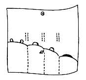
You can make a lineman's holster in the
same way, using plastic or soft leather.
Merely make belt loops by cutting on the
dotted lines. A snap fastener will hold the
flap over the tools so they won't fall out.
Figure 4. Lineman's Holster.
Show and tell others the proper handling,
care and use of tools.
Show and tell how to build an electrician's
tool kit.
Ask your power supplier or an electrician
to tell the club about the various tools of the
electrician's trade and demonstrate them.
Ask your leader how to get exhibit material
or information about electrical tools and their
use and then tell the club about them.
LESSON NO. B-3 — What's In A Lamp? — WHAT TO DO—Rewire A Lamp — How To Do It: — What Did You Learn? — SUGGESTED DEMONSTRATIONS — For More Information
Credit Points 4
REWIRE A LAMP—BE A LAMP DETECTIVE
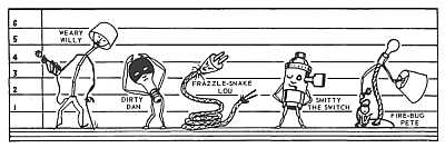
The Line-Up Of Lamp Suspects
One of the duties of a law officer is to
prevent crime. It's that way with the
lamp detective. You can become one. In the
average home there are lamps about to commit
the crime of shocking people, starting
fires, and stealing electricity. Some are refusing
to do their job well and some are no-goods,
sitting in closets or attics, doing
nothing. You can put these lamps to working
again safely and well. Become the lamp expert
in your family.
A lamp gives light for comfortable and
convenient use in the home. It consists
normally of a stand, switch, cord, lampshade
holder, and shade. Some lamps have diffusing
bowls which reduce glare and shadows.
The most common fault found in an old
lamp is in the cord, but sometimes the
switch or the wiring in the lamp is bad. Look
over all the lamps in your home and find
the ones needing to be fixed.
Somewhere around your house you can
probably find a lamp that is no longer used or
needs repairing. You can make it useful again
and at the same time learn how to wire a lamp.
Materials Needed:
Tools: Pocket knife, small or medium
screwdriver, and pliers (electrician type is
best).
New Lamp Cord: For each lamp to be rewired,
you'll need 6 feet of cord plus the
length of wire within the lamp stand. Lamp
cord wire comes in two sizes, No. 18 and No.
16 AWG (American Wire Gauge). No. 18 is
smaller than No. 16, but is adequate for most
lamps. Cords are made with surface coverings
of several different materials: braided
cotton, rayon or silk, and molded rubber or
plastic. Braided cord is decorative, but rubber
or plastic is easier to work with and is
usually more desirable.
Switch: If the switch is bad, get a new one.
Socket switches are made with push-through,
turn-knob, or pull-chain controls. The pull-chain
type is seldom used on modern table or
floor lamps. Your lamp may have a separate
push-switch in the base. In this case, get the
same kind for replacement. Some switches
are "3-circuit" switches for use with high,
medium, and low-light bulbs.
Plug: Plugs are made of various materials,
mostly hard rubber or molded plastic.
Some have a shank or handle for better grasping.
This type is more desirable. The plug
on the old cord may be good, and if so, may
be used on the new cord.
1. If the plug on the old cord is good and you
plan to use it, remove it from the old cord.
2. Measure and cut a new lamp cord equal to
the length of the cord within the lamp, plus
6 feet.
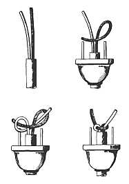
3. Pass one end of the new cord through the
center of the plug. Strip 2 inches of the
fabric insulation off cord, or in case of a
rubber cord, split cord back two inches. Be
sure no bare wire shows in long split section
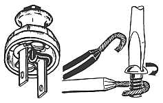
(Figure 1).
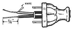
4. Use knife to strip insulation off wire for
3/4" on end of each cord. Be careful. Don't
cut yourself. Don't cut wires. Use a light
touch, slope the knifeblade and slice with knife
edge away from you (Figure 1).
Figure 1 (Ready to Wire Plug)
5. Twist exposed strands of each wire tightly
to make a good conductor, and place each
conductor around its proper terminal in the
direction in which the screw tightens (Figure 2).
6. Tighten screws on terminal posts. Pull
cord until slack is out. Lay aside until ready
to attach to lamp.
Figure 2 (Attaching Cord to Plug)
7. Remove lamp shade, shade-holder, bulb,
and diffusing bowl, if there is one.
8. Separate the metal shell of socket from its
cap by pressing on shell at place marked
"press," and pull socket from cap.
9. Pull on socket body to get some slack in
lamp cord. Loosen screws and detach cord.
Pull cord out through base of lamp. You can
splice new cord to the old one and use the
latter to "string" the new wire.
10. Pass the new cord up through the lamp
base and socket cap, tie a simple half-hitch
knot in the cord to prevent strain on
the terminals, and attach wires to the terminals
on the socket (Figure 3). If there is
likely to be any strain on cord, use an Underwriters'
knot. Twist strands and attach wire
in direction in which screw tightens.
11. Pull slack out of cord in lamp so that
socket rests in socket cap, replace shell and
reconnect cap. Be sure the fiber insulator
is in the shell. You'll feel or hear a click
when the notches in shell are locked to the
projections in the cap.
12. Replace bulb, inspect carefully, and test.
(In floor lamps where the cord runs through
the center post and out under the base, the
cord will last longer if it is fastened with
tape so it doesn't rub edge of lamp base
when lamp is moved.)
13. If the lamp has a porcelain socket,
simply disconnect the wires at the terminals,
remove the old wire and connect the
new one.
Figure 3 (Socket and Switch Assembly)
Underline correct answers then discuss in the
group. (There may be more than one correct
answer.)
1. The part of the lamp that usually wears
out first is (the socket) (the cord) (the
plug).
2. Lamps that waste electricity are those
which have (bad wiring) (frayed cords) (dirty
shades or bulb).
3. To unplug a lamp you should grasp (cord)
(plug) firmly and pull.
4. Wire in lamp cord usually comes in sizes
16 or 18. Size 16 is the smaller (true) (false).
5. In fastening wire around a terminal post
it should go around in a (clockwise) (counter-clockwise)
direction.
6. When the switch on a lamp is turned off,
the electricity only goes as far as (the wall
plug) (the switch).
7. An Underwriters' knot should be used
(only when there is room for it in the plug)
(whenever there is likely to be strain on the
cord, even if you have to replace the plug
with a larger one).
Show how to inspect a lamp and its cord.
You might tie tags on the cord and lamp at
points of danger or failure—at the plug,
wear points next to lamp base, bad sockets.
Demonstrate the process of repairing a
lamp cord, socket and plug.
Make a board display of the parts of the
lamp socket showing cord attached.
Make a display of the types of lamp cords
and plugs in common use.
Using two lamps, one with clean bulb and
shade, the other dusty, show how the former
gives more light.
Lamps have an interesting history. Look it
up in your local library. Ask someone from
your power supplier or electric dealer to talk
to the club about the different kinds of lamps.
Your leader has or can get additional information
on lamps, if you wish.
What Did You Exhibit
What Did You Demonstrate
LESSON NO. B-4 — MAKE A TROUBLE LIGHT. — What Size Cord? — Cord, Plug and Guard — How to Make the Trouble Light — What Did You Learn? — Ideas for Demonstrations and Exhibits — For More Information
Credit Points 3
A handy piece of equipment in the home
and on the farm is a heavy-duty extension
cord with a shielded light and a side
outlet on it. When you want to work on the car
or tractor in the yard at night, the trouble
light is better than a flashlight. You can use
it both for light and as an extension cord. It
is safer than matches or a lantern, especially
around the garage or barn.
It is easy to make a trouble light, and it
gives you good practice in electrical work.
Of course you can buy one, but you wouldn't
have the fun of making it nor would it suit
your needs. Trouble lights are not for permanent
use—they're for emergency use and
to provide light or electricity in places where
they are seldom needed. When you find a
trouble light being used as permanent wiring,
that's the place to install an outlet.
Choose the right kind of cord. What length
will be best for your various uses? A cord
too long may be bothersome to use and store.
What will be the heaviest load you are likely
to put on the cord, in amperes? Check appliances
you may want to connect to it. No. 16
wire can carry 10 amperes safely for a distance
of 50 feet, while No. 18 can carry only
up to 7 amperes for a distance of 40 feet.
You'll want a "hard service" cord, called S,
ST, or SO-type cord by electricians. Junior
hard service cords, known as SJ, SJT, or
SJO, are fine for lighter duty.
A rubber-handled socket should be used
for safety and to withstand hard knocks. It
should have a switch on it, preferably a push
switch in a recess in the handle.
The connector or attachment plug should
be of rubber or solid plastic and have a metal
cord grip fastened to it. This grip will hold
the cord firmly and prevent strain on the
terminal connections.
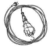
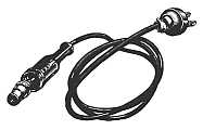
Finished Trouble Light
Get a good lamp guard. If the wire is too
light, it may bend and break the bulb when
hit or dropped. For the lamp itself, get a
rough service lamp. An ordinary lamp won't
last long with rough usage.
Tools Needed:
Your 4-H electrician's kit or screwdriver,
knife and soldering iron
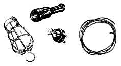
Materials Needed:
1. About 20 feet of 2-wire, No. 16 heavy
duty (hard service)
2. A rubber-handled socket with switch
and a side outlet
3. A shielded lamp guard
Materials Needed
4. A good connector plug cap, preferably
with a clamp-type grip for the cord
5. A rough service lamp bulb
6. Solder and flux
Steps to Take:
1. Remove about 2 inches of the outer
covering of cord at one end.
2. Separate the wires and cut away the
filler material.
3. Remove 3/4 inch of the conductor insulation
from the end of each wire and
tightly twist the strands together to
form a firm conductor. Be careful not
to cut any of the fine wires. Ends may
be soldered.
4. Slide the plug in position on the cord.
5. If there is no cord grip, tie the underwriters'
knot (Figure 1). If there isn't
room enough, make an "S" loop by
passing the wires around the prongs
before fastening them to the terminal
screws as explained in the next step.
6. Loop the bare part of the wire around
the screw in the direction the screw
is turned to tighten (clockwise direction).
This will prevent the wires
from being forced out from under the
head of the screw as it is tightened.
Now repeat with the second wire,
wrapping it around the other prong of
the plug.
Connecting the socket.
1. Separate the parts of rubber-handled
socket (Figure 2).
2. Prepare the other end of the cord as
in steps 1, 2, and 3 above.
3. Insert the cord through the rubber
handle and socket guard.
4. Tie the holding knot (underwriters'
knot) as explained in Step 5.
5. Connect wires to terminal screws and
assemble the rubber-handled socket.
6. Screw in the rough service lamp and
test your cord.
7. Put the shielded lamp guard on the
socket and tighten the holding clamp
until it is firmly in place. You are
now ready to use or demonstrate your
trouble light.
8. After you've made your trouble light,
decide on a good place to keep it where
it will be handy for use. Loop it carefully
and hang it over a wooden dowel
rather than a nail. It will last longer.
Figure 1 Tying an Underwriter's Knot
Figure 2 Disassembled Light
(Underline correct answer)
1. A Junior Hard Service Cord is known as
an (SO-Type) (SJO-Type) cord.
2. You disconnect a cord by (jerking it from
the socket) (grasping plug and pulling it
out).
3. Brass sockets are unsafe because (they
break too easily) (the exposed metal can
cause short circuits).
4. Rubber-covered cord is safer for emergency
cords than fabric because (it will
stretch) (it will insulate and protect the
wires inside).
5. In a trouble light (any kind of bulb will
do) (a rough service bulb is best).
1. Show how to make your trouble light and
a method of storing it.
2. Show a safe trouble light, and an unsafe
trouble light with danger points marked.
3. Show cutaway pieces of different types of
cord.
Ask your power supplier, county highway
engineer, police official or leader to tell you
about various types of portable emergency
lights and their uses.
LESSON NO. B-5 — WHAT MAKES MOTORS RUN — Motors Are Magnets — We Can Improve It — We Need An Electromagnet — Switching Poles Automatically — Increasing Efficiency — WHAT TO DO: Make A Motor — Step No. 1-Armature — Step No. 2-Commutator — Step No. 3-Field — Step No. 4—Armature Supports and Brushes — Demonstrations You Can Give — For Further Information
Credit Points 5
What makes an electric motor run? Can
you make an electric motor that will
run? Certainly you can, and by doing so
you'll learn why it runs. It won't be mysterious
any more and you'll be ahead of all
the millions of people who use motors every
day and never know why or how the motor
converts electrical energy into useful
power.
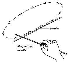
You know how one end of a compass
needle always points to North. No matter
how you turn the compass, the same end of
the needle always swings to the North. The
earth itself and that small compass are
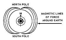
both magnets (Figure 1). Each has a North
pole and a South pole. Around the poles of
each there are magnetic fields, invisible
lines of force that attract and repel.
Figure 1. The same end of the compass needle always points to the earth's magnetic North Pole.
The N poles repel each other and so do
the S poles. The N and S poles attract each
other. In other words, opposite poles attract;
poles that are alike repel each other.
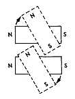
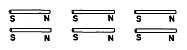
Lay 2 bar magnets on a table side-by-side.
If both N poles are at one end, they'll
repel each other and almost flip around until
there's a N pole lying next to a S pole
(Figure 2).
Figure 2. Small bar magnets laid side by side move
so that the North pole of one is near the South pole
of the other.
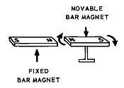
Now suppose we place one of the bar
magnets on the table. The other, we'll fix
on a pivot so it can spin around. This one
we'll move so its N pole almost touches the
fixed magnet's N pole. As soon as we release
it, the movable magnet will spin around
so its S pole will be near the N pole of the
stationary magnet. That's an electric motor—almost.
Figure 3. A movable bar magnet pivots so its South pole is near the North pole of a stationary magnet.
It's not quite a motor because the rotating
magnet will just move as far as it
has to in order to get the opposite poles
together. You might be able to cause the
movable bar magnet to make turn after
turn. You could do this by turning the fixed
magnet quickly end for end. This wouldn't
be very practical as a motor.
If we could change the pole on one end of
the rotating magnet just as soon as it
reaches the attracting pole, it could make
a complete circle. In doing that, the pole
at the near end of the rotating magnet would
be repelled by the stationary magnet and
pushed away. As soon as the opposite end
of the rotating magnet would come into the
magnetic field, it would be drawn to the
stationary magnet. In order to keep the
"motor" running, we would have to constantly
change the poles at each end on
every half revolution.
We can't reverse the poles on simple
bar magnets, but we can on electromagnets.
We can make one by wrapping a wire several
times around an iron core to form a coil.
This magnet will also have a N and a S pole
when connected to electrical current. The
big difference is that the poles can be
changed instantly by reversing the current
in the wire.
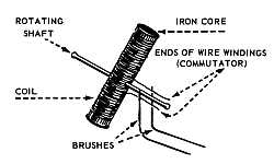
The rotating electromagnet will have to
be connected to the 2 wires through which
we pass the current. Since it's rotating on
a center shaft, we can't have a solid connection.
Instead we have to extend the
wires from the coil out along the shaft and
let the electric contact be made with
brushes which touch the wires along the
shaft.
Figure 4. A rotating electromagnet changes poles as contacts are made first one way, then the other.
This is a simple way to reverse the current
in the coil of the electromagnet.
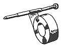
Instead of using only one pole of a
stationary magnet, we can use both. This
is done by shaping the stationary magnet
around the path of the rotating electromagnet.
This way we have the benefit of
the attracting and repelling forces from
both poles. The effect is doubled.
We can also wrap wires around this
circular iron and make an electromagnet
of it. But when we wire this magnet we
use no brushes because we want the current
to flow in one direction only.
The stationary electromagnet is called
the field. The rotating electromagnet is
the armature.
Tools Needed:
Pocket knife, hammer, vise (or 2 pairs
of pliers).
Materials Needed:
1 roll of No. 24 enameled wire
1 roll of electrician's tape
3 - 4" (20-penny) nails
4 - 2-1/2" (8-penny) nails
4 - 3" brads (10 penny)
Wood board for motor base
2 staples or 4 small brads
2 tacks
2 - 3 volt dry cell batteries (or a 6
volt transformer).
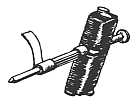
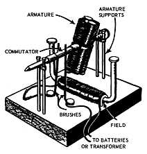
Wrap about 1-1/2" of a
4" nail with two layers of
tape. This will be the
shaft.
The iron core will be
made of two pairs of
2-1/2" nails. Wrap tape
around each pair with
heads and points alternated.
Center both pairs on each
side of the shaft. Place
them about 1" from the
head of the shaft nail.
Wrap them together with
two layers of tape from
tip to tip.
Start at the shaft and wind
No. 24 enameled wire to
one end and back. Then
do the same on the other
end. Always wind in the
same direction. Leave 6"
of spare wire at start and
finish.
Scrape all insulation off the ends of the wire.
Bend the bare ends back and forth as
shown. Lay them flat over the taped shaft-one
on each side of the shaft.
Hold the commutator down with narrow
strips of tape. Wrap tightly near the core
and at the opposite end.
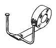
Make the core by bending
two 4" nails in the middle
at right angles. Space the
heads about 3" apart to
form a horseshoe. Wrap
together with two layers
of tape.
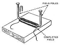
Wind about 400 turns of wire around the
center. Leave 4" of spare wire at start
and finish. Attach to wood base with staples
at each end of the wire. Small brads, bent
over, will do just as well.
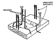
Scrape the insulation from the ends of two
6" pieces of wire. Tack them to the base
and bend them as shown to make brushes.
Drive two pairs of 3" brads into the base
about 3-1/4" apart and in a line midway
between the field poles. Wrap wire around
the supports to form armature bearings.
Scrape insulation off ends of wire from the
field. Connect one end to a brush wire.
Assemble As Shown
Adjust the position of commutator and
tension of brushes against it for best operation.
Take the armature off the motor and
connect the commutator wires to a dry
cell battery. Test the polarity of each end
of the armature with a compass. Switch
the connections on the commutator and
test again. See how the compass needle
changes direction?
With the armature still off, connect the
field coil directly to the dry cell. Test the
polarity of each end of the field with the
compass. How can you reverse the polarity?
Try it. It's easy.
Reassemble the motor again and start
it. Push the field poles slightly out of
alignment with the turning armature. What
happens to the motor's speed? Can you
tell why?
This time, push the field poles completely
out of the way. Test the polarity of
the armature as you slowly turn it by hand.
Do you see what happens and why it does?
Try to reverse the direction of rotation
of your motor by reversing the connections
at the battery. What happens? Can you explain
why?
Make a display board showing the parts
of the toy motor and explain how each part
works compared with the parts of a commercial
motor.
There are several other types of toy
motors you can build. Your club leader or
power supplier can help you find information
about them.
1. Did your toy motor run?
2. Did your motor speed up or slow down when you pushed the field poles out of line?
Why?
3. What happens to the magnetic polarity of the armature when you turn it slowly by hand and
check it with a compass?
4. How can you reverse the direction of rotation of your toy motor?
Is there another way too?
What is it?
LESSON NO. B-6 — TAKING CARE OF ELECTRIC MOTORS — You'll Need — WHAT TO DO — What Did You Learn? — Demonstrations You Can Give — For Further Information — ELECTRIC MOTORS SERVICE CHART Sample
Credit Points 3
Through the magic of electric motors,
much of our work is done faster and
better at lower cost than we could do it
without the help of the electric motor.
People who use motors and treat them properly
have much more time for other work
and for leisure time activities. A 1/4-horsepower
motor running quietly and steadily
hour after hour will do the work of one
man, and operate all day for about 5 cents
without tiring. On many jobs it will work
without "supervision", turning on and off
automatically, as required. It does this on
water pumps, in heating and cooling units,
and on fans and similar appliances.
All that a motor needs to do its work is
electricity and a little care. Let's see what
you can do to give proper care to motors in
your home and on your farm.
A light oil (SAE 10) for motors of less
than one horsepower and a slightly heavier
oil (SAE 20) for larger motors. See if you
need grease for cups which may be on large
motors. If so, be sure you use ball-bearing
grease and not ordinary cup grease. Cotton
waste or clean rags will be needed for wiping
off the motors, and a tire pump or
vacuum cleaner for blowing out the dust or
dirt.
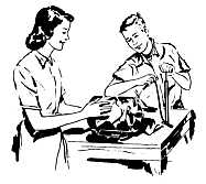
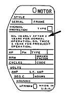
Some motors have instructions for oiling on the name-plate.
1. First, make a list of all the electric
motors that work for your home. You may
wish to make a separate list for your farm
buildings. You'll probably be surprised at
how many there are. Don't forget the sewing
machine, the refrigerator, the freezer,
the vacuum cleaner and other small but important
motors. Don't touch any motor that
is running. Disconnect them before you
touch them.
2. Make a motor service chart with
columns headed: Use, Location, Horsepower,
Volts, Amperes, Service Required,
Date Serviced and What was Done. (See
sample) Then list all the motors that require
any servicing. Some will have the instructions
on the motor or appliance; the
instruction booklet that came with the
motor or appliance will also tell what servicing
is required.
Step 1. Plan the job. Start with the
motors in the home. Then you can care for
the motors on the farm.
Step 2. Be sure that any motor on which
you are going to work is disconnected.
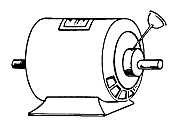
Then wipe the outside case clean with a
cloth. If the motor has openings in the end,
use a vacuum cleaner to suck out dust, dirt
or chaff. A tire pump may also be used to
blow out this dirt. If you use compressed
air, be sure the pressure is not high as it
may damage wiring inside the motor. Dust-proof
motors should be used in dusty or
dirty places.
Step 3.
If there are oil holes, oil according to the manufacturer's instructions.
If there are no instructions, remember
a little oil goes a long way as far as motors
are concerned. Motors of less than one
horsepower require only 3 or 4 drops (not
squirts) of oil every 3 or 4 months if the
motor is used frequently. Too much oil
can damage the motor. It spoils the insulation.
If there are no oil holes or grease cups
on the motor, it is probably lubricated by
means of grease sealed in the bearings at
the factory, or it may use greaseless bearings,
and does not need to be oiled or
greased periodically. Indicate on your
chart all motors which need periodic care
and see that it is given according to
schedule.
Wipe away any excess oil or grease. Be
sure oil holes are capped or covered.
Step 4. Reconnect motor and run for a
moment.
Step 5. Record on the chart the date you
serviced the motor and what was done.
How many motors are there in your home?
______ On the farm? ______
How many motors need regular oiling or
grease? ______
How many are less than one-horsepower? ______
SAE Oil ______ is used to oil motors up to
1/2 horsepower. How much oil?______
SAE Oil______ is used for larger motors.
1. Show how to clean a small motor.
2. Explain proper lubrication of motors.
3. Using the chart prepared in this work
sheet, give a talk about the motors that
work for you-the job each one does,
which ones need oil or grease, which
need no attention, and why, etc.
4. Use a homemade toy motor to explain
"what makes motors run."
5. Show proper way to replace worn cord
on a small motor.
Ask your county Extension agent or 4-H
leader for more literature on motors. They
can help you obtain a film or a speaker
such as a power supplier, a local electric
dealer, or electrical contractor to discuss
motors.
Also visit your public library and see a
science teacher for more information on
motors.
Use a table like the following to list the motors around your farm and home.
10/6-Cleaned w/vacuum; Oiled, #10 oil. 10/20. Had switch repaired
Pump
Pump house
1/3
120
7.2
Oiling, cleaning
9/26-Cleaned w/tire pump; oiled w/10 oil
LESSON NO. B-7 — READING THE ELECTRIC METER — Reading a Meter — What's Your Electric Bill? — Estimating Operating Costs — Adding Low Cost Helpers — WHAT TO DO: Find the Cost of Operating Electrical Equipment — Demonstrations You Can Give — For Further Information
Credit Points 4
There is no question but what electricity
is one of the lowest cost services in
the home and on the farm. A few pennies
worth of electricity will provide the power to
run machines that take the place of a man or
of several men working all day. However, we
all like to know what things cost.
Sometime you may have to decide between
different methods—man, horse, gasoline engine
or electric motor power. Then you'll
want to know how to figure the cost of electricity,
as well as the cost of the original
equipment. First of all, you should know
how to read an electric meter.
Electric meters read in kilowatt hours, just
as a water meter reads in gallons and a gas
meter in cubic feet. A kilowatt hour is the
electrical energy consumed by 1000 watts of
electricity used for one hour. Ten 100-watt
light bulbs burning for one hour would use
one kilowatt-hour—one kwh.
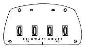
Figure 1. Some meters give the reading directly, like the mileage total on a speedometer.
Some meters are read directly, as shown
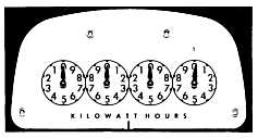
in Figure 1. The more common type has four
dials which are read from right to left—just
the opposite from the way things are usually
read. The hand on the extreme right turns
clockwise, the next hand turns counter-clockwise,
the next clockwise; the last hand on
the left turns counter-clockwise.
The first dial on the right can register
up to 10 kilowatt-hours; the second up to 100
kwh; the third, to 1000 kwh; the fourth, to
10,000 kwh. After that, the meter starts over
again. To take a reading you must read all
four dials of the meter, from right to left.
Figure 2. Meter dials are read from right to left.
To read each dial, you use the number
last passed by the dial hand. This may not be
nearest the hand. For instance, if the pointer
has passed 6 and is almost on 7, you read it
as 6. Write down the figures in the same
order you read the dial, from right to left.
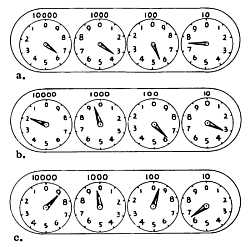
Practice reading the meters shown in Figure
3 on the following page.
Meters aren't set back each month when
the meter reader comes around. The difference
in the readings from one month to the
next shows how many kilowatt-hours have
been used. If you know your electric rates,
you can figure your bill by yourself. Your
power supplier will furnish you with a rate
schedule on request.
Figure 3. See if you can read the above correctly. The answers are shown in a box on the next page.
It will be interesting to you to find out
how much it costs to operate the various
electric appliances in your home. A sample
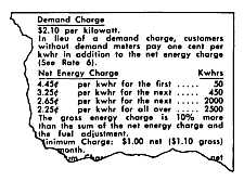
rate schedule is shown in Figure 4.
Figure 4. Sample rate schedule. Note that as the use of electricity increases, the average cost per kwh is reduced.
To find the cost of operating any single
appliance, three steps are necessary:
1. Learn the wattage of the appliance.
2. Estimate how many hours the appliance
is used.
3. Find its operating cost.
To Find Wattage:
Watts, you know, are the measure of
electrical power. They are the product of
voltage (pressure) times amperes (rate of
flow). Volts times Amps equals Watts. The
nameplate on the appliance will give the voltage
required for proper operation as well as
either amperage or watts. If it gives wattage,
you have the information you want. Otherwise
you must multiply volts times amps to
get the wattage. When voltage is given as
110-120, use 120 as your voltage. 120 volts
is nominal today.
How Much Will You Use?
Now that you know the wattage of the appliance,
multiply this figure by number of
hours the equipment operates in one day.
Divide this by 1000 to get the kwh. Now multiply
the result by the number of days the
appliance is used each month. This tells you
the number of kwh used by the appliance during
the month.
Example No. 1
Yard Light: 300-watt lamp
Amount of use: 3 hours per night.
Multiply lamp wattage times hours of use
per night to get watt-hours per night.
300 times 3 = 900 watt-hours per night.
Divide watt-hours by 1000 to get kwh per night.
900 divided by 1000 = .9 kwh per night.
Multiply kwh per night times 30 to get kwh per month.
.9 times 30 = 27 kwh per month.
If the yard light is used 3 hours per night, it consumes 27 kwh per month.
Multiply wattage of coffee maker times
hours of use per day to get watt-hours per day.
550 times 1/2 hour = 275 watt-hours per day.
Divide watt-hours by 1000 to get kwh per day.
275 divided by 1000 = .275 kwh per day.
Multiply kwh per day times 30 to get kwh per month.
.275 times 30 = 7.250 kwh per month.
If the coffee maker is used l/2 hour daily,
it consumes 7.25 kwh per month.
Calculate Operating Cost Per Month
Now that you know the number of kilowatt
hours an appliance uses, go to your rate
schedule and your electric bill to see what the
average kwh costs. Find the average cost of
1 kwh by dividing the amount of your bill by
the total number of kwh used in a month.
Example: 410 kwh used.
$14.35 total monthly bill
Average cost per kwh equals $14.35 divided
by 410 kwh-3-1/2 cents per kwh.
Therefore, the cost of operating the coffee
maker for a month would be 3-1/2 cents
times 7.25 kwh—25.4 or 25 cents. Cost of
operating the yard light would have been 94.5
or 95 cents a month.
(a) 6357 nbsp; (b) 1963 (c) 8996
Correct answers to the meter readings
shown on the preceding page.
You can see, by looking at your rate schedule,
that the average cost per kwh gets lower
as you use more electricity. To find the
cost of operating additional electrical equipment,
the cost per kilowatt hour is found from
the last "step" in the bill—the lowest cost
per kwh of the electricity you're now using.
Sometimes power suppliers give special rates
for such equipment as electric water heaters.
Make and fill in the blanks of a chart
showing the electrical equipment you have
and the operating costs per month.
Make a chart for the home (refer to chart
one). Show the probable operating cost of
equipment you might add to what you now
have.
Show how to read a meter, making one
with plywood or cardboard. Dials can be
painted on the main board. Arrows can be
attached so they will revolve to give different
readings.
Show how to find the wattage of various
types of equipment.
Show how to figure the cost of the average
kwh in a home.
Your leader can get additional material
for you or you may want to have someone
from your power supplier talk to your club,
telling about meters, how they work and how
they are regularly checked for accuracy.
Chart One-THE HOME
Column No.
1.
2.
3.
4.
Item
Wattage Rating
Hours Used per Month
KWH per Month (col. 1 x 2) / (1000)
Cost per Month (Col. 3 x av.kwh cost)
Remarks
Electric Iron
1100
30
33
.80
Stove
880
60
52.8
1.21
(Special rate.)
LESSON NO. B-8 — IRONING IS FUN WITH THE MODERN HAND IRON — Important Things to Know — The Iron and Safety — WHAT TO DO: Learn About Your Iron — IRONING IS FUN — Demonstrations You Can Give — For More Information
Credit Points 3
When you are getting ready to go to
school or to a party, it probably gives
you a good feeling to put on a clean,
freshly-ironed skirt, blouse or dress. But
did you ever think about the electric iron
that helps so much to give you that well-dressed
feeling? When you were younger,
you may have had a play iron and pretended
to iron your doll's dresses. Now
you are old enough to learn about real
irons—the different kinds of irons, how
the iron heats, the kind of cord needed, the
type of outlet necessary, how to use safety
rules when you iron, and even how to help
with the ironing.
There are many different irons, but the
two kinds most important for you to know
about now are the regular dry iron and the
combination steam-and-dry iron.
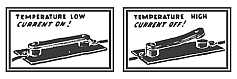
The thermostat keeps the iron at an even temperature.
It isn't weight alone that makes an iron
do its job, but the heat of the iron. The heat
is given off in the sole plate. The automatic
iron has what is called a thermostatic control
which holds the temperature of the
iron at the heat you want. Some clothes
need to be ironed with a very hot iron,
while others need only to be pressed lightly
with a cool iron. The thermostat keeps
the iron at an even temperature after you
set it for the heat you want. The thermostat
is the heart of the iron.
Take a look at the iron used in your
home. It isn't heavy to lift, and has a
handle that fits your hand easily. It looks
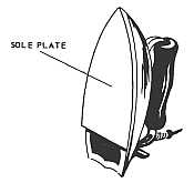
graceful and has a smooth bottom, called
the sole plate. And it may have a narrow,
pointed tip which is helpful in ironing pleats,
corners and gathers.
Your iron has a smooth bottom called the sole plate.
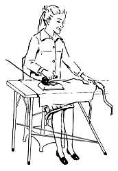
If you are going to learn to do some
ironing yourself, the most important thing
for you to remember is SAFETY. You
should read all about the iron first in the
instructions which came with it.
Never use an iron carelessly. Remember
the safety rules:
1. An iron should never be left even for
a few minutes without being disconnected.
Turn off by removing the plug from the outlet,
or by turning the control lever to "off."
Take hold of the plug—not the cord—when you disconnect
it from the outlet.
2. Let the iron cool before putting it
away.
3. Wrap the cord carefully around the
iron after it is cold.
4. Always stand the iron where it will
not fall off on a child or pet or your own
toes.
Materials Needed: An automatic iron, some
old play clothes, towels, napkins or handkerchiefs,
and an ironing board.
Steps to Take:
1. Watch an experienced person iron.
2. Ask questions about what clothes
need to be sprinkled.
3. Study the thermostat settings on the
dial or indicator.
Most irons have a dial to set for the proper heat for different fabrics.
4. Ask about the kind of fabric each piece
of clothing is—cotton, linen, silk, nylon,
etc.—and why the iron should be at high
heat for some, cooler for others.
5. Set the thermostat for the amount of
heat needed, and with an older person
watching you, iron some handkerchiefs,
napkins, bath towels, and a pair of play
shorts or blue jeans.
6. During a month iron some of these
articles for your family, keeping a record
of how many you do and what they were.
7. Take care of your iron. Be responsible
for storing it.
Date
No. Aricles Ironed
Type of Article
Stored Iron Properly (check)
1. I (use) (do not use) an adjustable ironing Board at home. If I do, I adjust it to the height
that just clears my knees easily as I sit in a comfortable chair. Yes No
2. There are three kinds of irons usually used—dry iron, steam iron or a combination steam
or dry iron. I use a —— iron.
3. I (have) (do not have) the instruction book. (If you do, read about the iron.) I know the
iron's parts by their correct names. They are——.
4. I disconnect the iron if I leave it even for only a minute. This is a safety measure as fires
have been known to start from irons left connected. Yes No
5. I take hold of the plug—not the cord—when disconnecting the iron. Yes No
6. I wait until the iron is cold before wrapping the cord around the handle and storing the iron
because——.
7. Most irons have a thermostatic control. The iron I am using has settings for——.
8. The purpose of the thermostat is——.
9. These fabrics need high temperature.——
These fabrics need medium temperature.——
These fabrics need low temperature.——
10. These fabrics need sprinkling.——
11. The heat and smoothness of the sole plate smoothes the wrinkles. Pushing down on the
handle or moving the iron rapidly only makes ironing hard work. I will iron slowly and
steadily arranging and moving the garment with the left hand while guiding the iron with
the right hand. (Or the other way for the left handed.) Yes No
12. I have watched an experienced person iron. Yes No
13. I have practiced on handkerchiefs, napkins and pillow cases.
14. Here is my record of ironing for one month
Month____________
Your Name _____________________
Date I have ironed:
_____________________________________________________
|
|
|
|
|
|
|
|
1. Show a dry iron and a steam-and-dry
iron. Tell the difference between them and
when each is to be used.
2. Display garments that look nice because
they have been ironed properly, and
those that have been ironed improperly.
Explain about the heat, thermostat, type of
iron and why results differ.
At a club meeting ask a parent to give a
demonstration of ironing different articles.
Some power suppliers or dealers have
people who will demonstrate the proper way
to iron, and how to care for irons.
LESSON NO. B-9 — WHAT TO DO: — SAFETY TIPS — 4-H Electric Hazard Hunt Guide — How Many Hazards Did You Find? — Demonstrations You Can Give — For Further Information
Credit Points 2
LET'S BE FRIENDS WITH ELECTRICITY
Plan a Hazard Hunt
Electricity can be your important lifelong
friend and helper, so you will want to
know all you can about it and how to treat it
properly. However, careless and improper
use of electricity can do a lot of harm. Used
properly, and treated with respect, electricity
can do wonderful things to help you every
day in many ways.
For safe and proper use of electricity,
all wiring, fittings, insulation, cords and
plugs must be in good condition. You can be
a detective and track down defects in any
such type of electrical equipment that you
may be using in your home or on your farm.
When you find anything that is wrong, and
know where it is, and know what to do about
it, you can very likely correct the condition
yourself, such as replacing a worn extension
cord with a new one. If you find defects in
permanent wiring, or some places where
wires are bare or terminals are needed, you
should tell your parents about them.
SAFETY FIRST, remember, should always
be on your mind when working with
anything electrical.
1. Have A Hazard Hunt
Go on a Hazard Hunt to see how many
electrical hazards you can find. Look for
defects such as broken insulation, worn
cords, splices that are not properly soldered
and taped, loose connections, or switches
that aren't working properly.
There are many ways to have a Hazard
Hunt. Choose the method that will be the
most fun. Use the Hazard Hunt Guide in this
outline to check your home, and other buildings.
Maybe you'll want to have a friend help
check your home, then you help him check
his. Or, why not give each member of your
family a Hazard Hunt Guide and have a contest?
Parents may want to team up against
you and other younger members of your
family to see which team can find the most
electrical hazards in some set time—say 30
minutes.
Have a Hazard Hunt Committee in your
club check all member's homes and buildings
and report its findings at the next club
meeting.
To Make It More Fun
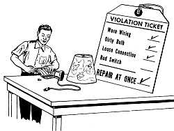
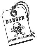
1. Put a hazard tag, like the one shown,
(Figure 1) by each hazard that is found.
Leave it until the hazard is corrected.
Have another contest to see which member
of the family corrects the most
hazards.
Figure 1
2. Report on your Hazard Hunt at the next
club meeting. Tell about the Hazards
found, and what you have done or plan to
do about them.
3. Suggest that the entire club have an Electric
Hazard Hunt at your club meeting
places or any community building. This
could be part of one meeting.
4. Have a contest between two teams in the
club to see which team can get the most
homes in your community checked by the
Hazard Hunt Guide. Losers could give a
party for the winners.
2. Get Others Interested
Promote a community Electric Hazard
Hunt. Enlist the support of power suppliers,
electric supply and equipment dealers,
schools, newspapers, radio and television
stations.
What To Look For
Make a complete tour of your home and
other buildings and see how many hazards
you can locate. When you find a hazard, put
a tag near it to mark it.
Put hazard tags near the hazard
but not directly on broken or frayed
wires, insulators, fittings, or other
wiring equipment. Do not touch them
either. Badly-frayed wires should be
disconnected immediately from the
power supply. In this way, you will
not expose yourself to shock by accidentally
touching an exposed live
wire that may be carrying current.
Wiring and Protective Devices
1. Cable or conduit splices not
in boxes——
2. Cable or conduit not securely
clamped in boxes——
3. Conduit or armored cable not
properly grounded——
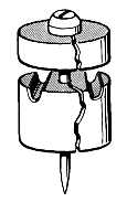
4. Cracked or broken insulators
(Figure 2)——
5. Wire not completely covered
with insulation——
6. Worn insulation on wire——
Figure 2
7. Old unused wiring not yet
removed——
8. Outlets, junction and switch
boxes not securely fastened
and covers not in place——
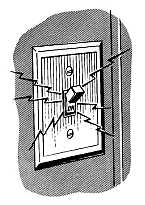
9. Switches not working properly
(sparks fly as switch is flipped)
(Figure 3)——
10. Fuses not of proper ampere
rating for circuit——
11. Extension cord used in place
of permanent wiring——
12. Pull chain socket without an
insulating link in the chain——
13. Pull chain socket near plumbing
fixtures or where hands
may be wet or one may stand
in water——
Figure 3
14. No moisture-proof cords for
outside weather conditions or
heavy rubber cords for
motors and motor driven
appliances
Lighting
1. Fixtures in farm buildings
installed so that they might
be easily damaged
2. Lights in haymows and other
dusty locations not protected
by dustproof globes
3. Outside sockets not waterproof
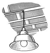
4. Heat lamps not properly supported
by non-current carrying
wire, chains, or brackets
(Figure 4)
5. Light bulbs not frosted,
shaded, or placed so that light
is diffused to prevent glare
Figure 4
Auxiliary Wiring
1. Outlets overloaded—in other
words, "octopus wiring"
2. Extension cords placed under
rugs
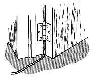
3. Extension cords run through
doorways (Figure 5)
Figure 5
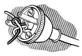
4. Extension cords or lamp
cords should use underwriters'
knot (Figure 6)
Figure 6
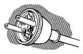
5. Plug connections fuzzy (Figure
7)
Figure 7
6. Extension cords run over
heaters or radiators
7. Extension cords, or appliance
or lamp cords, worn or frayed
8. Heating appliances without
regular asbestos covered
wire
9. Open sockets or outlets
where a baby or small child
might stick a finger or metal
toy
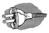
10. Broken plugs (Figure 8)——
11. Loose prongs on appliance
or lamps plugs——
Figure 8
Make a chart listing the hazards, their
locations and what you did about them. Make
your own chart and list what you find.
Show and tell others how to have a Hazard
Hunt.
Check with your leader, then ask your
power supplier or a local electrician to tell
you about safe electrical wiring, connections
and fixtures.
Hazard
Location
What I Did
Loose prong on lamp plug
Living Room
Replaced with new plug
Cracked insultor on service wire in house
Back of house
Notified power supplier
Conduit not securely clamped to box
Basement by fuse box
Notified parents
Extension cord, old and worn
Basement, by washing machine
Replaced with new rubber-covered one and protected it from water
LESSON NO. B-10 — HOW ELECTRIC BELLS WORK—FOR YOU — What to Do — Bells and Buzzers Can Tell a Lot — Why They Buzz or Ring—Electromagnetism — A Special Kind of Electricity — How to Control Them — Pick the Right Bell or Buzzer — How to Plan Your System — Materials You'll Need — Install According to Your Plan — Demonstrations You Can Give — For More Information
Credit Points 3
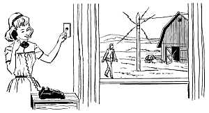
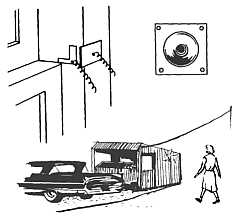
When was the last time you wanted to get
a simple message like "You're wanted
on the telephone," "There's someone here to
see you, "or "There's a car in the driveway,"
to someone around your place? Did you have
to walk or run some distance and perhaps
shout, too, to be heard by the other person?
Perhaps you had to stop some other work, or
interrupt your favorite kind of fun, to do this
bit of messenger work.
If the nature of the message is like one of
those mentioned, and the number of people
in hearing is not too great, then perhaps you
can use bells or buzzers or both to do some
of your messenger work for you. Even
though a bell or a buzzer can't talk, it can
convey a message.
1. Learn how bells and buzzers work,
and learn about the many different kinds.
2. Plan and install a bell system for your
home or farm.
Electric bells and buzzers use the same
basic principle as the telegraph system, invented
by Samuel Morse in 1840. Although
not as important today as it was before radio,
telephone, and teletype became common, the
telegraph is still in use.
Bells and buzzers, however, are very common
and have many uses. They are most
often seen in the form of doorbells, and rare
is the new home that does not have one or
more. Service stations have bell systems to
let the operator know that a car is waiting at
the gas pumps. A clock signal reminds the
homemaker when the cooking time is completed.
Children are called to and released
from school classes by means of bells and
buzzers.
Also, various alarms employing bells and
buzzers warn us when it's time to get up, or
even that the place is on fire, or that a burglar
is trying to break in!
Let's find out how bells and buzzers work,
what different kinds there are, the different
ways you can control them, and how you can
put them to work for you.
You'll find that buzzers and bells can help
you with your 4-H projects, and with the
proper controls, can be your eyes and voice
in a dozen places at once.
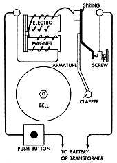
If we were to look at an electric bell with
the cover off, we'd find that it would be very
much like Figure 1.
A push on the button, which is just a switch
that is normally held "open" or off by means
of a spring, sends the current from the battery
or transformer through the circuit.
Figure 1
You will see that the current passes first
through two small coils of wire, and each
coil has at its center a piece of soft iron
called the core. When the current is on, the
core becomes magnetized and attracts another
piece of iron called the armature with its
clapper attached.
This action rings the bell, but it also breaks
the current by pulling the spring away from
the screw on its return to the power supply.
With the power off, the electromagnet lets
the spring return the armature to its normal
position, contact is made again, and the
cycle starts all over again—just as long as
you continue to push on the button.
Buzzers work exactly the same way, except
that they do not have a bell and depend
instead on the vibration of the armature for
a noise that's not as loud or as musical.
Gongs or chimes, that strike only once
when the button is pushed, are made by connecting
the armature with the screw by means
of a flexible wire.
Most buzzers and bells work on a much
lower voltage than you normally find in the
wires in your house. Some are made to work
at 6 volts, others at 10 volts, and still others
at slightly higher voltages.
You can get these low voltages by using one
or more batteries, or by using a transformer
connected to your house current. Most bells
and buzzers are now powered through transformers.
The push button is the most common means
of control. You can use one button to control
several bells, or several buttons to control
one bell, or have several buttons control
several bells. Because low voltage is used,
adding extra buttons is simple, inexpensive,
and safe.
Buzzers and bells can also be controlled
by: clocks, as in the interval timer on an
electric range or in a school class bell system;
temperature detectors, as in a fire
alarm or freezer alarm; door and window
trips, as in a one-man repair shop or in a
burglar alarm; and treadles, as in the driveway
of a service station.
Figure 2
Some of the many different types of bells,
and various ways of controlling them are
suggested in the table below. Just remember
that no matter what the job or conditions,
you can probably find a bell or buzzer and
controls that suit your need.
SOME TYPICAL JOBS FOR BELLS & BUZZERS
Job
Type of bell or buzzer
Number and location of bells and buzzers
Type of control
Number and location of controls
Summon others to the telephone
In the house— small to medium buzzers
In outbuildings— medium to large bells
Outdoors— large weatherproof bell
All transformer-powered
Enough to cover all usual work locations
Push-buttons
One at the telephone and each extension phone
Notify club member that car is at his produce stand
Medium to large bell— transformer-powered
One may be enough—if mounted on the back of the stand
Hose diaphragm
(Complete driveway units including control, are available, ready to plug in.)
One—in the driveway
Warn of power failure to incubator or brooder
Battery-powered buzzer, medium size
One near the poultryman's bedroom
Relay, held open as long as power is on, closed by spring if interruption occurs
One, at main switch of hatchery or brooder house
Warn of dangerously warm temperature in freezer
Battery-powered buzzer, medium size
One, in or near the kitchen
Temperature detector (sensitive thermostat)
One, with bulb inside freezer
To save your time and steps when the telephone
rings for someone else in your family
who is some distance away, you can install a
simple bell or buzzer system to summon that
person.
First, you must plan what you are going to
do. On a large sheet of paper, draw to scale
(roughly) a plan of your house and grounds,
including those places where phones are located.
It will help if you rule off your paper
in 1/8" or 1/4" squares and let each square
equal one foot. Show the location of poles
supporting your wiring.
Next, pick out those areas where you or
others would likely be when someone else
would answer the phone and want to call you
to it.
After you have thought about this, and
talked it over with members of your family,
show locations on your plan where you think
you would like to have buzzers or bells, and
show a button beside each telephone. (Generally,
you should have a bell or buzzer near
each phone, also.)
Figure 3 shows diagrams of various types
of systems, and will help you determine the
number of wires you will have to install to
connect the buttons and bells that you have
planned.
Inside, you will connect your transformer
and the various buttons and bells with ordinary
indoor bell wire. Outdoors, however, you
should use weatherproof 2-wire or 3-wire
telephone twist.
Show on your plan the distances that must
be traversed by each type of wire, and show
the number of conductors in each. Don't
overlook the vertical distances (one floor to
another).
Figure 3
Because no two situations are just alike,
it will be necessary for you to make your own
list of materials.
As a guide, however, here is a list of
typical materials, with the quantities left
blank, for you to fill in as your own requirements
and measurements dictate.
10-volt transformer
_____ Door buzzers
_____ Doorbells
_____ Weatherproof outdoor type bells
_____ ft. indoor bell wire
_____ ft. 2-wire weatherproof telephone twist
_____ ft. 3-wire weatherproof telephone twist
_____ lbs. staples (insulated)
_____ entrance insulators (for attaching
weatherproof to buildings and poles)
Because your transformer must be wired
into your regular house current, you should
have some help on this from an electrician
or other qualified person. Also, you should
get that person to review your plans and materials
list before you place an order.
With the aid of an electrician or other
qualified person, install your transformer,
and test it.
You may then go ahead and complete your
signal system, checking carefully with your
plan, and making sure that your installations
are both electrically and mechanically secure.
Test your system in all possible ways that
it might be used.
Build a demonstration board incorporating
a farm or home layout, with pushbuttons or
other controls and bells and buzzers appropriately
located. Show and tell how the system
would save time and energy.
Show and tell how some of these work, and
their value: power-off alarm, freezer alarm,
fire alarm, driveway alarm.
Ask your power supplier or your nearest
electrical supply house for catalogs or literature
on various types of signal systems, or
ask a dealer to show you equipment he has in
stock.
LESSON NO. B-11 — FIRST AID FOR ELECTRICAL INJURIES — What to Do — Electricity Can Kill — Prevent Accidents — Think, Then Act — First Aid — Mouth-To-Mouth Rescue Breathing — What Did You Learn? True or False — Demonstrations You Can Give — For More Information
Credit Points 2
What would you do if you saw someone who
had been hurt by electricity?
Did you know that you could save his life,
if you had taken the time to learn and practice
a few simple rules of electrical first aid?
First aid training equips you to know what
to do and what not to do for the injured until
medical help can be obtained. While the main
benefits are for you and your family, no one
can call himself a good citizen if he fails to
help a stranger who has been hurt.
The information given here is only for electrical
injuries. Perhaps what you learn will
inspire you to take a complete course in first
aid.
Learn how to prevent electrical accidents,
and what to do if an electrical accident occurs.
1. Make an electrical hazard hunt in your
home or on your farm. Point out to your
parents everything that should be repaired
or replaced for safety's sake.
2. Read the first aid suggestions that follow.
Learn them.
3. Get to know the six steps that are outlined
for mouth-to-mouth rescue breathing.
Practice them on your brother, sister, or
parents. Teach the entire family how to do
it.
In this day of hundreds of uses of electricity,
you should know about electrical
dangers. Electrocution can occur from either
low voltage (household type) or high voltage
currents. Sometimes household voltages are
more hazardous because people underestimate
the dangers involved.
A fraction of an ampere passing through
your heart muscles can be fatal. Your body
offers some resistance to the flow of electricity
to ground. If you are standing on wet
ground or in water, or if your skin is damp,
this resistance is greatly reduced.
Wire cables within walls and cords on appliances
are all insulated with a shock proof
covering. Continued use, age, or damage
may expose a bare wire and create a hazard.
The point of exposure need be only a fraction
of an inch. Cords are often used and abused.
Exposed wires and signs of wear are danger
signals.
Always be wary of overhead wires. People
have been injured or killed when kite strings,
model plane control lines, irrigation pipe,
and water well equipment have come in contact
with the power supplier's or their own
overhead wiring.
Underwriters' Laboratories (UL) have
taken steps to see that minimum safety standards
are met in the manufacture of electrical
equipment. Look for the UL label when you
buy cords or appliances. Never place cords
under carpets or furniture, or drape them
over a nail. Replace or repair worn cords
without delay.
Be especially careful when operating electric
devices in the bathroom. Keep in mind
the dangers of a wet floor, grounded metal
pipes, and wet skin. Turning on an AC radio
while you are taking a bath is asking for real
trouble.
There may be shorts in electric devices.
Keep your hands dry when using them, and
do not touch them along with grounded metal
objects. If you ever get a slight shock, sound
the danger signal and do something about it.
Your first thought in rescuing a victim
from an electrical accident should be your
own safety. Speed is also important, because
a few seconds or minutes may save a
life.
The first question you should ask yourself
is "Can I quickly turn off the power?" This
would be easier to do in the home than outside.
In the case of a victim trapped in a
bathtub from a radio accidentally knocked into
the water, it might mean simply removing
the plug from the wall outlet. If a victim is
found grasping shorted, permanently installed
equipment and cannot let go, the main switch
might be used for quick release of the current.
Outdoors, especially with high tension
wires, your danger in rescue is much greater.
To handle the victim, touch him only with a
long dry stick, dry rope, or a long length of
dry cloth. Be sure your hands are dry and
that you are standing on a dry board. A
broom might be a good lever to pry a victim
from a high tension wire but never use a
green stick containing sap.
Once the rescue has been made and the
victim is free of further danger, check to
see if breathing has stopped. If so, start
artificial respiration immediately and send
someone for a doctor.
Artificial respiration must be started as
soon as possible after normal breathing
ceases. Most persons will die within 6 minutes
or less if breathing stops completely
unless they are given artificial respiration.
Precious minutes may have passed before
you get to the victim. Since the victim may
be within seconds of death by the time you
are able to touch his body, you should seek
to obtain an air flow to and from the lungs
immediately.
The victim may seem stiff as an effect of
the current, so don't give up easily. Continue
the procedure for several hours. If
transportation is necessary, remember that
there may be internal injury, fractures, or
severe burns.
There are various effective ways to give
artificial respiration, each with its advantages
and disadvantages. The mouth-to-mouth
method is recommended as a good one to
master. It can be used on victims of drowning,
suffocation, and asphyxiation, too.
People have been known to save lives with
less exposure to the correct procedure than
you are getting by reading this. So, pay attention
and remember what you read.
Step 1. Turn the victim on his back. Wipe
out victim's mouth quickly. Turn his head
to the side. Use your fingers to get rid of
mucus, food, sand, and other matter.
Head Position
Step 2. Straighten victim's head and tilt
back so that chin points up. Push or pull his
jaw up into jutting out position to keep his
tongue from blocking air passage. This position
is essential for keeping the air passage
open throughout the procedure.
Push Jaw Up
Pinch Nostrils
Step 3. Take a deep breath, place your
mouth tightly over victim's mouth, and pinch
nostrils closed to prevent air leakage. For
a baby, cover both nose and mouth tightly
with your mouth. (Breathing through handkerchief
or cloth placed over victim's mouth
or nose will not greatly affect the exchange
of air.)
Breathe
Step 4. Breathe into victim's mouth or
nose until you see his chest rise. (Air may
be blown through victim's teeth, even though
they may be clenched.)
Step 5. Remove your mouth and listen for
the sound of returning air. If there is no
air exchange, recheck jaw and head position.
If you still do not get air exchange, turn
victim on side and slap him on back between
shoulder blades to dislodge matter that may
be in throat. Again, wipe his mouth to remove
foreign matter.
Step 6. Repeat breathing, removing mouth
each time to allow air to escape. For an
adult, breathe about 12 times per minute.
For a child, take relatively shallow breaths,
about 20 per minute. Continue until victim
breathes for himself.
1. A broken arm should be splinted before
artificial respiration is applied to a victim
who is not breathing.
2. A person who has been severely shocked
with an electric current should lie down.
3. A doctor should be called even though
you successfully have revived a victim's
breathing.
4. A fraction of an ampere through the
human heart muscles can be fatal.
5. A copper wire would provide a better
path than your body for stray currents, therefore
all appliances should be grounded if
possible.
6. Outside wires are never a hazard because
they are covered with insulation when
they are installed.
7. Cords need not be repaired until you
can see bare wires.
8. Tuning in an AC radio while you are
bathing is always dangerous, even though
your hands are dry.
9. In an emergency, a broom is an acceptable
tool for prying a victim off a high
tension wire.
10. In mouth-to-mouth breathing, an
adult's lungs should be filled 12 times per
minute and a child's 20.
Show how to deal with an electrical first
aid "problem" given to you by your leader.
Ask your leader to have a first aid expert
put on a demonstration. (Many industrial
plants and power suppliers have such people.)
LESSON NO. B-12 — HOW ELECTRICITY HEATS — What to Do — "Resistance" Makes Heat — Make a Simple Resistance Heater — Conduction is "Touching" Heat — Convection Depends on Air — Radiation is Like the Sun — Make Popcorn 3 Ways — What Did You Learn?
Credit Points 3
In ancient times, people thought that heat
was a material just as air is. They
called it "caloric". When something got
warm, they said, caloric flowed into it.
When something cooled off, caloric flowed
out of it. It did not bother them that they
could not see caloric. They could not see
air either!
Now we know that heat is not a material.
It does not take up space. It does not weigh
anything. Instead, it is a form of energy.
And when we say that heat is a form of energy,
we mean that it can be used to do work.
1. Make a simple resistance heater.
2. Make some popcorn by:
(a) conduction (b) convection
(c) radiation
There are at least four ways that electricity
can make heat. The one that we'll
cover here is resistance heating. (The others
are: dielectric heating, where the lines of
force of an electrostatic field pass through a
non-conductive material and heat it; the heat
pump, which is a refrigerator in reverse;
and electronic heating, which uses high frequency
waves similar to radio waves to create
high speed movement of the molecules or tiny
particles which rub together to make heat.)
Resistance heating occurs because every
conductor of electricity opposes the flow of
current through it. Some conductors resist
more than others. When they do, a certain
amount of warming takes place. The more
resistance that is offered, the more heating
there is.
Some materials, like silver, copper, and
aluminum, offer little resistance. We say
they are good conductors.
Other materials, like iron, offer more
resistance. They are still conductors, but
not as good as the others mentioned.
The size of the conductor, and its length
are the other two things that affect its resistance.
The smaller it is, the greater its
resistance. Also, the longer it is, the
greater its resistance. Therefore, when we
only want to move electricity from place to
place, we want relatively large, "good" conductors.
Here, we do not want to make heat.
In fact, we want to avoid it, because too
much heat in the wrong place can cause a
fire.
But when we want heat, we choose relatively
small, "poor" conductors, and the
more heat we want, the longer they must be.
If you will think of the filament inside a lamp
bulb; you may recall that it is a very fine
wire, coiled so as to get a maximum length,
and made of tungsten which has a high resistance.
Because of all these factors, this filament
glows at a white heat, and is a source of
both light and heat.
Materials you will need:
1 dry cell battery
1 foot iron picture wire
Pliers
Use a short strand of iron picture wire
and hook the ends to the terminals of a dry
cell battery. Use pliers so that you do not
burn your fingers. Disconnect the wires as
soon as they become hot. Tell why the wires
heat.
Conduction occurs when you set a pan containing
food right on a heating element. An
egg cooking in a hot frying pan is a good example
of conduction at work. This method
is the most efficient single way of using electric
heat for cooking.
Convection warms food in pans that are
not actually touching the heating element. It
uses the hot air around the element to carry
heat to the pan.
Your oven in your range works by convection.
Most houses are warmed in winter in
the same way. The heat produced in a furnace
warms the air as it circulates through.
This air in turn keeps your body warm.
Radiation heating is more difficult to explain.
It results when heat or energy waves
strike an object and are converted into heat.
The energy we receive from the sun is a good
example. When you are wearing dark clothes
on a chilly day, you may become uncomfortably
hot. The sunshine warms you even
though the air around you has not been heated.
Radiant energy has a way of being absorbed
by dark objects and reflected by light colored
or shiny surfaces. Did you ever notice how
snow melts faster on a black top road than it
does on a concrete road?
The electric heat lamp is one of the most
familiar sources of radiant heat. Other examples
are panels and cables that are built
into the walls and ceilings of homes to provide
heat.
How do you make popcorn? Did you know
that you can do this kind of a heating job three
different ways?
Materials Needed
Popcorn
Cooking oil or shortening
Salt and butter
4-qt. saucepan, with cover. (A glass cover is preferred.)
Potholder
Electric range
2 250-watt heatlamps
2 spring clamp type lampholders
Wire mesh corn popping basket or wire mesh kitchen strainer (improvise a screen wire cover)
First, make popcorn the way you usually
do. Set a front surface unit control on the
range at "medium high". Pour enough oil to
very lightly cover the bottom of the pan.
When the pan is hot, pour in enough popcorn
to cover the bottom with one layer of kernels.
Use the potholder in one hand to hold the
cover on, and with the other move the pan
back and forth across the unit. When the
popping stops, remove from the heat.
How did the heat get to the popcorn?
Second, make popcorn in the oven. Add
the oil to the pan, cover it and put it in the
oven. Turn the oven on, with the automatic
control set at 400°. When the oven indicator
light goes off, this means that the proper
temperature has been reached. With the
potholder, remove the pan and add one layer
of popcorn kernels. Replace the pan in the
oven. When the popping stops (listen for it)
remove the pan.
What kind of heating took place here?
Third, make popcorn with the heat lamps.
Clamp the lampholders to the back of a chair
or other vertical support. They should be 6
to 8 inches apart and pointed directly at each
other. Put about 2 tablespoonfuls of popcorn
in the Wire basket or strainer. Do not add
oil. Hold the basket midway between the two
lamps. When the popping stops, turn off the
lamps.
What kind of heating was this?
Now, butter and salt the popcorn you have
made and share it with others.
1. How is heat transferred from one body
to another?
2. Could chicks or pigs receive warmth
from a heat lamp without the air in the pens
becoming warm? Explain.
3. How does a broiler unit in a range cook
meat?
4. How does an oven bake food?
5. Tell why iron picture wire was used
instead of copper wire for your heating demonstration.
LESSON NO. B-13 — MYSTERIOUS MAGNETISM — What to Do — "See" a Magnetic Field — Make an Electro-Magnet — Make a Permanent Magnet — See How They Attract and Repel — Make Many From One — Magnetism and Animals — What Did You Learn?
Credit Points 2
In ancient times, people found certain
rocks that clung together in bunches.
These rocks were very mysterious. People
didn't understand them and many superstitions
grew up about lodestones, as these rocks
were called. Lodestone (sometimes spelled
loadstone) means leading stone. People even
told Columbus not to sail out of sight of land
because a giant lodestone was just over the
horizon waiting to pull all the nails out of his
ships.
The Chinese were the first to use magnets.
They found that if you hung a lodestone by a
string, one end of the stone would always
point in the direction of the North Star. They
had the first magnetic compasses.
An artificial magnet can be made by stroking
or gently rubbing a piece of steel with a
lodestone. This piece of steel then can be
used to magnetize another piece of steel.
This can be continued on and on. Lodestones
are not always available but you can get the
same results with an electric current. So,
magnetism and electricity are very closely
related.
Learn about magnetism by doing the experiments
that follow.
Seeing is believing!
Materials You Will Need
2 dry cell batteries (#905)
A few feet of No. 18 bell wire
3 steel knitting needles or similar hard steel
2 ft. of light thread
Sheet of light cardboard or stiff paper
Permanent magnet (bar or horseshoe)
Compass
1 or more large nails or spikes
Red and black china-marking pencils or crayons
Iron filings
Wire cutters
Carpet tacks
(Iron filings usually can be found under the
grinding wheel in a shop. If you can't find
any, rub some steel wool pads together to
produce bits of metal that will do.)
Cover the permanent magnet with the cardboard
or paper. Sprinkle iron filings on the
paper. Tap the paper and note the pattern
formed. Strings or lines of filings pass from
one pole of the magnet to the other. The
area covered by the filings is the center of
the magnetic field. To remember this, you
might compare the magnetic lines of force
that arrange the iron filings to the contour
strips in a farmer's field.
This magnetic field is one of the important
things in our everyday life with electricity.
If it were not for the magnetic field, we would
not have electric motors. Telephones,
radios, television, and many other things we
use every day also depend on this magnetic
field.
Figure 1
You can make magnetism work for you by
winding several turns of insulated wire around
one or more large nails or spikes (soft iron).
Connect one end of the wire to the battery.
Touch the other end of the wire to the other
terminal for a few seconds and see how many
tacks you can pick up. Repeat the experiment
using as many turns as possible. How
many more tacks were you able to pick up?
Figure 2
You have made what we call an electromagnet.
When you disconnect the wire, the
nails fall off. This is one of the advantages
of an electromagnet. We can turn magnetism
on and off as we wish. Picture a crane operator
throwing the switch and picking up scrap
iron and steel. Then he opens the switch to
drop the scrap metals.
Soft iron can be magnetized easily as you
have just seen, but loses its magnetism in a
short time. Steel is harder to magnetize but
holds its magnetism almost indefinitely.
Wrap the insulated bell wire around the
steel knitting needle. The wire should be
wrapped the full length of the needle. One
end of the wire is connected to the battery.
The other end of the wire is then touched for
just a few seconds to the other terminal. This
should make the needle into a permanent bar
magnet. If you did not get results, try two
batteries in series, wind more turns of wire
on the needle, and leave it connected a little
longer. Do the same thing with the second
knitting needle. In the same way, you can
magnetize a screwdriver, so that you can use
it to pick up and hold steel screws. Don't
do it unless you want your screwdriver to be
magnetized.
Figure 3
Take one of the magnetized needles and
hang it with a thread. A thread stirrup
(Figure 4) will help keep it level. Be sure
it is not near other large pieces of steel.
Watch the needle. Does it settle down, pointing
in one direction? (Check to see if this
is the same direction as your compass). If
it does, you have made a compass. The tip
of the needle pointing north is called the
North Pole (North-seeking pole). The other
end is called the South Pole. Mark the North
Pole with a stroke of the red marking pencil.
Mark the South Pole black. Do the same
thing with the second needle. You can show
this with a sewing needle, and a notched
cork, and a bowl of water. Rest the needle
in the notched cork, and float it on the water.
Figure 4
Hold the compass near the North Pole of
the needle. What happens? Does the South
Pole of the needle attract the North or South
Pole of the compass? Try this with the second
magnetized needle. See if you can prove
the rule that like poles repel (drive away)
and unlike poles attract.
Figure 5
Connect one end of a wire loop to the battery
and run the wire directly over the compass.
Touch the other end of the wire to the
battery. Which way does the compass point
now? If you get some motion out of the compass
needle, this proves there is a magnetic
field around the wire when current is flowing.
This relation between electricity and magnetism
is the thing that makes electric motors
and generators work.
Figure 6
Lay the third needle (unmagnetized) on a
table and stroke it with one of the magnetized
needles. (See diagram) Always stroke it in
the same direction. Raise the magnetized
needle at least two inches on each return
stroke. Thus you can magnetize the needle
by using the other needle.
Figure 7
Use the wire cutters to cut the first magnetized
needle in short lengths. (Cover the
needle with a cloth to keep the pieces from
flying.) Can you show by using the compass
that each piece is a complete magnet? Hold
one end, then the other, of each piece to a
compass. Does each piece have both a North
Pole and a South Pole?
The things you have done show that electricity
and magnetism are related in many
ways. Magnetism is mysterious, and there
are still things to discover about it. It is
thought that animals and birds are aided in
their sense of direction by magnetism. It is
commonly known that when a person gets lost
in the woods, he tends to go around in circles.
Possibly this is caused by the earth's magnetic
field.
1. Where are natural magnets obtained?
2. How can artificial magnets be made?
3. What material is needed for a permanent magnet? For a temporary magnet?
4. How can you find out which is the North Pole of an unmarked magnet?
5. How many poles does a magnet have?
6. Which magnetic poles attract each other?
7. Why couldn't you make a compass out of a strip of plastic?
8. What causes the compass to change direction
when a wire carrying battery current
is held over the needle?
9. List the materials you would need and
tell how you would build a homemade compass.
10. Tell what you enjoyed most about becoming
acquainted with mysterious magnetism.
LESSON NO. B-14 — Give your appliances and lights a square meal — What to Do — Count Your Electrical Blessings — Some Homes Are Behind Times — Watch for Signs of Starvation — Each Circuit Big Enough — Only One Fuse Size Right — Make a Circuit Chart — Check the Wire Sizes — BE CAREFUL! — Replace Any Wrong-Size Fuses — Talk it Over With Your Parents — What Did You Learn? — Demonstrations You Can Give — For More Information
Credit Points 2
Would you say that having enough to eat
was pretty important in the home that
you know?
The "food" for your appliances and lights
is electricity, and like you they must be
"fed" enough.
1. List the appliances and lights in your
home.
2. See if any of them are "starving" for
the electricity they need.
3. Learn how the electricity gets to where
it's used.
4. Make a chart of the electrical circuits
in your home.
5. Make sure that each circuit is protected
with the right fuse or circuit breaker.
Many people in much of the rest of the
world wish that they could trade places with
us, because we have so many electrical appliances
in our homes.
Of course, we have not always had as
many appliances as there are today. When
electricity first came along, people used it
only for lights. Then, they began to add
flatirons, washing machines, refrigerators,
coffee percolators, and radios.
Then more and more electrical things
were made for people to use and enjoy. Now
we have dozens and dozens of uses for electricity
in our homes.
How many different uses for electricity
are there in your home today? Ask your
parents how many there were when your
home was built or first wired. How many
were common when your parents began to
keep house?
Many older homes were built before electricity
was available, and were wired later.
And like them, some older homes that
were wired as they were built had only enough
wiring for lights and a few other appliances,
because those were the only uses that were
known at that time.
But people kept on living in these homes,
and kept adding to the uses they made of
electricity without adding to their wiring.
What has this meant? Well, if electricity
were like cars and trucks, you could say
that some people are trying to put turnpike
traffic through a back-country dirt road!
Of course, as your state has done with its
highways, some people have expanded and
modernized their wiring. But many others
have not yet seen this need, or if they have,
they may have to do it again.
Here's why:
Your power supplier delivers current to
you at the right voltage or electrical pressure.
If the wires in your house are large
enough, they will pass this full voltage on to
the appliances.
But if your wiring is too small, the electricity
arrives at the appliances so weak
that they can't work properly, and much of
what you pay for is wasted.
Here are some things you can watch for
in your own home. They will tell you whether
your appliances are getting enough electrical
"food" or not.
1. A shrinking TV picture—If it draws
in from the sides of the screen, fades, loses
contrast, or if the sound becomes distorted,
you may have low voltage.
2. Too much fuse blowing or circuit
breaker tripping.
3. Heating appliances are slow to do their
jobs.
4. Lights dimming, when motors or other
appliances are turned on.
There Should Be Enough Ways
to Get "Appliance-Food" Around
If appliances in your home show these
starvation signs, then you may not have
enough ways for the electricity to get to
where it's used.
There are three kinds of these electrical
highways or circuits, and your home should
have enough of each:
1. General purpose circuits—These
serve lights all over the house, and convenience
outlets everywhere except in the
kitchen, laundry, and dining areas.
A rule-of-thumb is: There should be at
least one general purpose circuit for each
500 sq. ft. of floor space.
2. Small appliance circuits—These are
not used for lights, but instead they supply
convenience outlets in the kitchen, laundry,
and dining areas where portable appliances
are most used.
Every home should have at least two
small-appliance circuits.
3. Individual or special-purpose circuits—One
of these is needed for each: electric
range, dishwasher, water heater, freezer,
automatic washer, clothes dryer, air conditioner,
pump, and house heating equipment.
Wire sizes commonly used in homes
The capacity of each circuit is limited by
the size of its wires. The chart above shows
you the actual sizes of wires commonly used
in permanent home wiring, and what each
will carry. Notice that each size is given a
number, and the smaller the number, the
bigger the wire.
Also notice that a given size of wire will
carry twice as many watts at 230 volts as it
will at 115 volts. (Watts are figured by
multiplying amps times volts.)
General purpose circuits usually are
either Number 14 or Number 12 wire, at
115 volts. What is the capacity of each, in
watts? (Number 12 wire is recommended
for all new general purpose circuits.)
Small appliance circuits are required to
be at least Number 12 wire.
Individual circuits are always sized according
to the appliance they serve. Find
the size wire that should be used for a
10, 000-watt, 230-volt range; a 1500-watt,
115-volt dishwasher; a 4500-watt, 230-volt
clothes dryer. ________ ________ ________
A fuse in an electrical circuit is like an
alert traffic policeman—stopping everything
if there's danger. A circuit breaker serves
the same purpose, and the right size is installed
when the wiring is done.
A policeman uses his brain to tell him
when to blow his whistle, but a fuse depends
on the size of the little fusible (meltable)
metal link that you see under the glass.
If too great an electrical load is added to
a circuit, this link will melt and prevent a
dangerous overload. If you put in a fuse
with too heavy a link, it will not melt in
time, and the wiring and equipment may be
damaged.
Therefore the right size of fuse is very
important, and is something that you should
check in your own home.
See the chart above for the right fuse for
each size wire.
At one or more places in your home there
is a box or panel containing the fuses or
breakers for the various circuits. Attached
to the inside of the door of each such panel
should be a chart something like this:
Notice that in our chart we have made
columns for a description of what each circuit
serves, its number or position in the
panel, and the proper size fuse for it.
Because most such charts leave out this
last very important bit of information, you
should make a complete new chart, like the
one shown. Provide as many lines as there
are fuse positions. Paste or tape it to the
inside of the panel door.
Then, ask permission of your parents to
disconnect all the circuits by unscrewing the
fuses or flipping the circuit breakers. Do
not touch anything but the fuse rim. Then
reconnect them, one at a time, to find out
what each circuit serves. Turn on as many
lights as you can, to help you in your detective
work. Use a test lamp at those outlets
that do not have a light connected to
them. Write two or three words describing
each circuit on the proper line on your chart.
On a separate sheet, keep track of the
appliances and lights that are on each circuit,
and add up the watts. (If the name-plate
of any appliance gives "amperes",
"amps", or "A" instead of watts, just remember
that amps times volts equals watts.)
This will tell you if any of them are overloaded.
Show this sheet to your parents.
Disconnect the main switch, and determine
the size of the wires in each circuit.
Don't include the insulation in your measurement.
Even though you have disconnected
the main switch, the wires coming
into it are still "live". So, do not touch
any wires. Instead hold the wire size
chart near them so that you can tell
which gauge each one is.
Write in the proper size fuse for each
circuit on your chart.
Do the fuse sizes you have written on your
chart agree with the ones that are in place
in the panel?
Get the right size fuses and replace any
that are wrong. Make sure that you have a
reserve supply of the right sizes, and that
they are handy for future use.
Do you think that your home has enough
of the proper size circuits? If not, talk it
over with your parents. They may want to
ask an electrician to go over the wiring and
make the necessary changes.
(Underline the right answer.)
1. A (television set, radio) is very sensitive
to changes in voltage.
2. Dimming lights mean (static in the
wires, an electrical overload).
3. Wires that become warm from overload
make it (more expensive, cheaper) to
operate the equipment.
4. A home of 2,000 sq. ft. should have
at least (three, four) general purpose circuits.
5. One solution to low voltage symptoms
is (heavier fuses, more circuits).
6. Full capacity for a Number 14 wire
circuit at 115 volts is (1725 watts, 3000
watts).
7. A room air conditioner should be on
(a general purpose, an individual) circuit.
8. The purpose of a fuse is to (let you
disconnect the circuit, automatically prevent
overloading the circuit).
9. The right size fuse is determined by
(wire size, the store where you buy it).
10. A circuit chart should give (circuit
description and fuse size, the maker's
name).
Ask your leader to help you plan a demonstration.
You can show how lights dim
when too many other appliances are connected,
how a fuse protects against overloading,
and the danger of using too large a
fuse.
Ask your Extension agent, power supplier,
or electrician for additional help.
LESSON NO. B-15 — YOU CAN MEASURE ELECTRICITY — What to Do — How They Work — Detect a Magnetic Field — Detect a Tiny Current — Make a Simple Galvanoscope — Measure the Voltage of Batteries — Test for Induced Current — What Did You Learn? — Demonstrations You Can Give — For More Information
Credit Points 4
Instruments that can detect or measure
the flow of electricity have helped to
make possible the wonders of electricity as
we know them today.
Scientists in laboratories must have measuring
devices for experiments leading to
new uses of electricity. Power suppliers
must have instruments that tell what the generating
equipment is doing and to measure
the amount of electricity being sold to users.
Factories need instruments that keep tab on
electrical equipment to make sure electricity
is being used efficiently.
In fact, almost anywhere you find electric
power at work you'll find electrical instruments—even
in your home. The one you
know best measures the amount of electricity
used. Another, in the family car, shows
whether the generator is charging the battery
or if the battery is discharging.
1. Make a simple kind of direct-current
meter that will show you that there's a magnetic
field around a wire carrying an electric
current and that will detect a very tiny
current.
2. Make a more refined D.C. instrument
(galvanoscope) and measure the voltage of
different sizes of dry batteries, and show
how an electric current can be induced.
Tools and Materials You'll Need:
Pair of pliers, knife, small hammer
30 feet of No. 24 bell or magnet wire
Compass
Two coins—a penny and a dime
Fine sandpaper
Blotting paper
Plastic or cellophane tape
Wooden blocks (See Figure 4)
Glue
2 small nails
One #905 dry cell, a penlight battery, and two regular flashlight batteries
Table salt
Drinking glass
2 paper clips
Two machine bolts
Like many electrical things, most electrical
instruments depend on the action of
magnetism created by an electric current.
There is a magnetic field or lines of force
around any wire carrying an electric current.
If this field is controlled and made to
react on a sensitive device, like an easily
moved pointer, we have an electrical instrument.
First, let's prove that there is a magnetic
field around any wire carrying an electric
current. Take a piece of wire about
two feet long and scrape off about an inch of
insulation from each end. Connect one end
to a battery terminal. Make a loop of wire
that crosses the face of your compass, north
to south. Now touch the other end of the
wire to the other battery terminal.
(DO NOT attempt to substitute
alternating current, as from a model railroad
transformer because its alternating
current will cause the compass needle to
swing rapidly from one side to the other.)
Figure 1.
Put your right hand beneath the wire so
that your fingers point the way the needle deflects,
and your thumb will point in the direction that the
current is flowing.]
What happens? Your compass needle
should move to one side because it is very
sensitive to magnetic influences. This
proved that the wire created a magnetic
field or lines of force when we passed electricity
through it. (Figure 1)
How sensitive is your simple electric
meter? Take about five feet of wire and
wrap it around your compass as in Figure 2,
keeping the turns bunched together as much
as you can. Leave about six inches at both
ends of the wire extended for leads. Scrape
the insulation off the last inch of both. Rotate
the coil and compass until the needle
and coil are parallel, both pointing north
and south.
Figure 2
Take a copper penny and a dime, and
clean off any corrosion or film on the coin
faces with a bit of fine sandpaper. Now take
a piece of blotting paper about the size of
the penny and dip it into strong salt water.
Place the damp blotting paper between the
penny and the dime. Place one of your compass
coil leads against the dime, and the
other against the penny as shown in Figure
3. Be sure you have good metal-to-metal
contact between the wires and the coins.
Figure 3
At the instant that you squeeze the leads
against the coins, watch what is happening
to the compass needle. It should move for
an instant from the north position each time
you press the leads against the two coins.
Obviously, the little coin battery you have
just made produces a very weak electrical
current. Even so, your instrument should
be able to detect it.
Now let's make a meter that is a little
more practical to use. Broadly speaking, a
galvanoscope is an instrument that detects
the presence of electric currents. It sounds
complicated but it is really quite simple. It
is named in honor of an Italian professor
named Galvani who made important early
experiments with electricity.
A refinement of the galvanoscope is today's
galvanometer. Other related instruments
are the voltmeter and ammeter. These
are very important instruments to the electrical
engineer.
Using a glass or anything three to four
inches in diameter, wind about 20 turns of
wire in a "bunched" coil as in Figure 4.
Wrap the coil at several points with cellophane
or plastic tape to keep it from unwinding.
Figure 4
Make a wood base for your coil as shown
in Figure 4. The compass support blocks
can be thin wood slats. Do not attach them
with steel nails or tacks. Use glue instead.
Hold the coil in the slot between the blocks
with glue or melted wax or use copper
staples. Place the compass on the supports
and rotate the base so that the compass
needle and coil are parallel, pointing north
and south.
Do you know what difference the size of
dry cell battery makes in the voltage it supplies?
Your meter can tell you.
To test the voltage of batteries we must
be able to control our galvanoscope. To do
this, connect a glass of strong salt water in
series with the battery as shown in Figure
5. Make sure the wire ends immersed in
the salt water are scraped free of enamel.
Figure 5
With one of the batteries connected, move
the wires in the salt water first closer, then
farther apart (keeping them parallel to each
other) while watching your compass needle.
When the needle stays 15 to 20 degrees off
north, lock the wires in the salt solution in
place with paper clips.
Now disconnect the battery you have been
using and connect a smaller battery. If both
batteries are fresh, the compass needle
should return to almost the same spot. This
proves that both batteries regardless of size
put out the very same voltage. The larger
ones, however, are designed to last longer.
Measure the Difference
between Series and Parallel
Using the salt solution as in the previous
experiment, connect two flashlight batteries
in series as shown in Figure 6. The compass
needle should move about twice as far
as it did with one battery connected. This
shows that when you connect batteries this
way you double their voltage.
Figure 6
Now place your batteries side by side and
connect the two top terminals and the two
bases as shown in Figure 7. The compass
needle should move only as much as it did
for one battery. This is called a parallel
connection. You can see that this arrangement
does not double the voltage, even
though you used two batteries.
Figure 7
While you have this hookup, try reversing
the position of the leads connected to your
batteries. Notice that reversing the direction
of current flow in the coil causes the
compass needle to swing in the opposite direction.
Make a simple coil by winding about 50
turns of wire around a machine bolt core.
The bolt should be 1/4 to 1/2" in diameter
and about two inches long. Connect the coil
to your galvanoscope as shown in Figure 8.
Pass the coil back and forth close to the end
of a permanent magnet.
Figure 8
Notice a slight deflection of the compass
needle with each pass. You have shown that
electricity can be induced in a wire coil by
moving it through a magnetic field. Currents
generated in this way are called induced currents.
Figure 9
Now make another coil and core just like
the first one and arrange them and a connection
as shown in Figure 9. If you make
and break the current to the second coil,
you will build up and collapse a magnetic
field around the first coil and again induce
a current in it. You will see the compass
needle swing back and forth again.
These last two experiments give you a
crude idea of how an electric generator
works, producing electric current by induction
as a coil-wound rotor revolves within
a magnetic field.
What does every current-carrying wire
have around it? How does this help us to
measure electricity? How sensitive are
electrical instruments? What is the difference
in voltage between (a) a large and a
small dry cell? (b) batteries connected in
series and in parallel? (c) your original
connection and the reverse of it? What
similarity does the test for induced current
show between movement through a magnetic
field and the making and breaking of a direct
current?
Show others how your galvanoscope can
detect: whether a battery is producing current,
which way the current is flowing, and
whether a current is strong or weak. Demonstrate
how a current can be generated
using magnetism.
Ask your power supplier representative
to show you some of the instruments used
by his organization, and to give you a brief
explanation of how they work. Ask him or
an electrician to give you a demonstration
of a split-core ammeter.