Printed by Journal of Commerce Co., Providence, R. I.
TO
ELISHA T. JENKS, WHOSE EARNEST EFFORTS TO INSTIL A FEW MECHANICAL IDEAS
INTO THE BRAIN OF THE AUTHOR WERE MET WITH
BUT INDIFFERENT SUCCESS, THIS BOOK
IS RESPECTFULLY DEDICATED.
PREFACE.
In putting this work before the public, the author is well
aware that it will meet with criticism from those who are better
informed on the subject than he; but a careful search in the
bookstores and through the catalogues of the largest publishing
firms failing to show a work of this kind, has led him to take up
the task; and, although better fitted by experience for the file
than the pen, has done the best that he could. It is essentially
a shop book, written by a shopman, and intended for shop use.
Many of the dies shown were made by him personally, others
were made from sketches, and under his personal supervision,
while others were made and used in various pressrooms of which
he had an intimate knowledge; and the rest, especially those on
bicycle tools, are from the columns of the American Machinist
and other papers devoted to mechanics.
Certain parts of these articles have been published in the
columns of the American Machinist; also a few pages can be
found in the catalogue of the Mossberg & Granville Manuf’g Co.,
which were contributed by the writer.
Trusting this work may prove a help to the great army of
die-makers now pushing their way to the front, is the wish of
THE AUTHOR.
Providence, R. I., September 30, 1897.
THE ORIGIN OF DIES.
The origin of dies is, without doubt, very obscure. Perhaps
the frontispiece in Mr. Oberlin Smith’s excellent work on “The
Press Working of Metals” will give as good a likeness of the
original die-maker as we shall ever find. A search in some of
the best libraries and museums has failed to reveal any information
that is at all ancient, and that can be relied upon. The
samples of old coins that have been handed down to us, show
that the art of die-sinking was known to the ancient Greeks at
least eight hundred years before the Christian era, but they do
not show that the use of punches and dies was equally well
known.
The first record of punches and dies used in a machine or
press (having guides or ways to ensure the punch entering the
die correctly) is in the fifteenth century, when they were used
in the manufacture of hinges, by a German locksmith. Later on,
in the sixteenth century, we find them in use both in Germany
and France; and as early as the year 1796 a patent was granted
to one “De Vere,” of France, for dies for punching and drawing
of sheet metal.
In 1827, M. Gagalott took out a patent for press and tools
for drawing up cartridge shells from sheet copper. These were
nearly the same shape as those in use at the present time, and
the dies were probably of the same design.
In the article on “Drawing Presses,” on page 22, will be
found a history of the first drawing press made in this country,
used for drawing up kitchen utensils,—the facts of which can
be vouched for, and were related to the writer by one of the
workmen employed, Mr. J. L. Kirby, now superintendent of the
Dover Stamping Co. The facts relating to the use of drop
presses for “striking up” sheet metal were also obtained from
the same source.
The author would be pleased to learn any facts relating to
the use of dies prior to that time, and would like to hear from
any of his readers on this subject.
PROPER SELECTION OF STEEL FOR DIES.
Steel intended for punches and dies should in all cases when
possible be ordered directly from the mill, giving all the information
possible as to the use to which it is to be put, and the class
of work it is intended to punch. The steel should be annealed
at the mill, as the extra cost is more than offset by the ease with which
it is worked, and the certainty with which it can be hardened.
Much of the trouble now experienced with die steel could be
avoided by this method, except that caused by improper heating
by the smith in hardening. Steel for dies should be free from
seams and flaws and of even color, not to be high in carbon
(from .007 to .009 per cent. is a good proportion) and capable
of being hardened without shrinking or changing its shape to any
great extent, except in the case of drawing dies, where this fault
is a desirable one, as the die can be (when worn) reduced to size
by being re-hardened, thus increasing the amount of work the die
will perform.
When you have once found a grade of steel that you know to
be suited to your work, “stick to it” (and don’t be induced by a
smart agent with a box of cigars to give him an order even if he
claims that he has a brand that will not shrink or change in the
least, and would stand any degree of heat without injury). If
you find that it is impossible to get any one grade that will fill
the bill for all kinds of dies, mark each brand so that you or
your men can tell at a glance what kind of stock it is. A good
way is to paint a stripe the whole length of the bar, and a different
color for each make or brand of stock. The stripe the whole
length of the bar, indicates the make no matter how short the
piece may be, and as shellac is usually the most abundant paint in
the shop, use red, black, and white shellac, and but three grades
of steel.
For drop-press work for cold dropping, use a steel that is a
little high in carbon, and give the dies plenty of stock to avoid
breakage. For very large dies for drop-press work and where they
are to be used on thin stock, as tin or sheet iron, a die made of a steel
casting and case hardened will give good results. Where a large
amount of labor is necessary to produce the die as in the case of
watch or clock dies, get the best steel that can be found, as it is a
poor policy to try and use a poor grade of steel for intricate work.
MAKING A PLAIN PUNCH AND DIE.
Having found a brand of steel that is suitable for the work to
be punched it should first be machined to the proper size and
shape, which will depend on the class of work it is to do, and the
style of die-shoe it is intended to be used in. A good way, and one
that is adapted to a large class of work, is to bevel the edge of the
bar to an angle of 10 degrees, leaving the ends as they come from
the forge or saw. To get out these blanks cheaply, cut the steel
up into two or three lengths, plane up and bevel the edges to the
proper angle, and then saw off as wanted to the required lengths.
This style of die can be held by a key or set-screws, whichever
the practice may be.
The upper surface of the die should be finished on the surface
grinder if there is one, or by hand with the use of the file and
scraper, as the time thus spent is saved in the laying out of the
die, and the work can be laid out better, and more distinctly than
on the rough machined surface of the blank.
The surface of the die is now covered with what the die-maker
calls “blueing,” but what is really sulphate of copper, and is made
by dissolving sulphate of copper or blue vitriol in water (a proportion
of ten parts of water and one of crystals makes a good
solution), this leaves a thin deposit of copper on the surface of
the steel, leaving an excellent surface for laying out the die. The
outline of the piece to be punched should now be traced on the
upper surface of the die; care should be taken in laying out to avoid
waste of metal, also that the grain of the stock to be punched runs
in the proper direction so that it can be easily prepared for punching.
A margin equal to the thickness of the metal to be punched
must be allowed between the blanks, and if the stock is ¹⁄₁₆″ or
less, it is better to increase this proportion.
The die being neatly laid out from either drawing or template,
all round corners should be drilled with a drill of the proper diameter
to leave the corner the shape, and then reamed with a reamer
of the proper taper to give the die the clearance wanted; the rest
of the stock is now removed by drilling. Every die-maker has a
way of his own for this part of the work; one will drill so that the
holes will cut into each other and thus avoid broaching, while the
next man will drill holes so that there will be ¹⁄₃₂″ or more between
them, and then cut out the stock with a flat, square-ended
tool called a “broach.” This is the best and
quickest way. The bulk of the stock being removed,
if there is a die-sinker in the shop, the die can be partially
finished on it, and by using a mill of the proper
taper, the necessary clearance can
be given; this will vary from ¹⁄₄ to
3°. Excessive clearance is given
when it is essential that the blank
should drop from the die before the
next piece is punched.
Fig. 2.
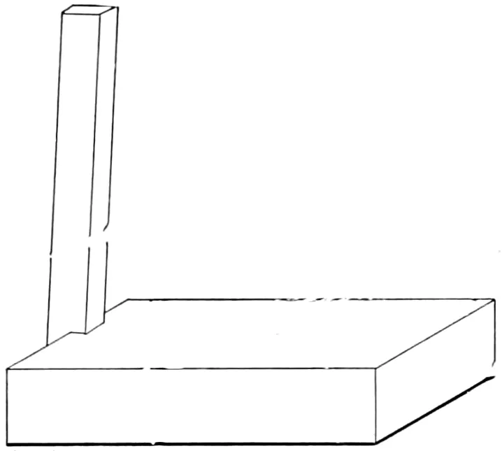
The die being worked out as far as the machine will do it, is
now finished with the file, using the die square (Fig. 2) to give it
the proper clearance, and if the shape is an intricate one that must
be closely followed, a template made of thin sheet metal and
soldered to the end of a bent wire will be found a help in making
the required shape.
If the die is for a press room using a large number of dies, it
should be marked with a shelf and rack number, so that it can be
quickly found by the die-setter; the die is now ready to harden.
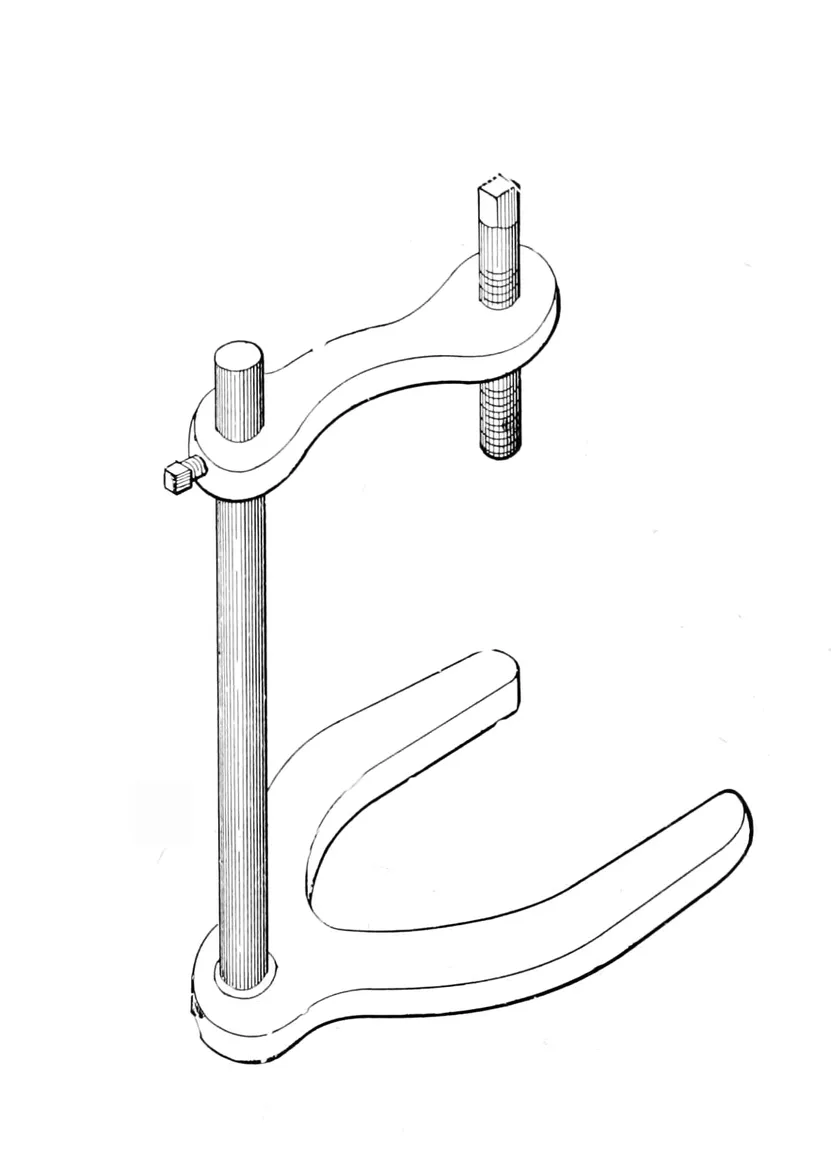
The die being finished, the blank for the punch, which, if the
shape of the die demands it,
should be a forged one (but
if possible, should be cut from
the annealed bar), should be
machined on both ends, and one
end finished, then clamped
firmly on to the face of the
die, using a die clamp (Fig.
3); now scribe through the
die, and mark the outline of
the punch on the finished end
of the blank. This should be
nicely marked with a centre
punch. The stock can best be
removed by the use of a milling
machine, as a base or
shoulder, of the same shape
but of a larger area, can be
more easily left with this tool than the
shaper. The object of this base is to
give the punch better support, and
increase the length of time it can be
used.
The stock having been removed
close to the lines, the punch should
be placed over the die and then forced
into it ¹⁄₁₆″, thus giving a “witness”
mark to file to. This is called “shearing
in,” and is the method
usually employed in this country.
The reverse of this operation,
known as the “French”
way, consists of finishing and
hardening the punch, and
then broaching out the die
with it. The results obtained
by this practice are not as
accurate as those by the first
process described, as the die will change to a greater extent
in hardening, than the punch, and it is not so easily finished. The
punch should now be carefully filed to the lines formed by the
“shearing in” process, and if the work requires it, should be
hardened; but should in all cases be left softer than the die.
When possible, the punch and shank should be in one piece, but
if not, care should be taken to see that it has a good bearing on
the punch back, and is held firmly to it.
Fig. 3.
Fig. 4.
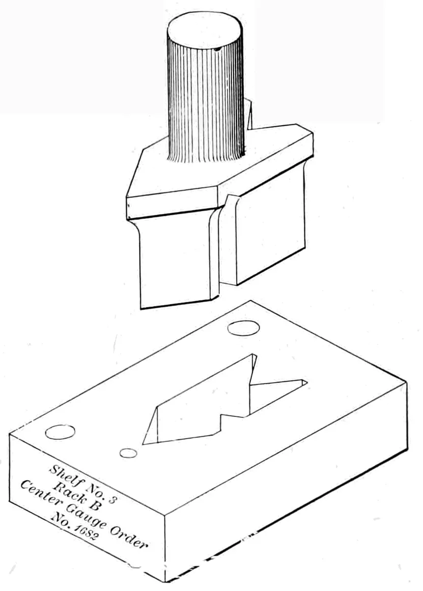
Fig. 4 shows a plain die for blanking out a tool that all are
familiar with. No stripper is shown, but the two holes at the back
are intended to hold one on.
The letter “C” denotes the brand of steel that the die is
made of, and is very useful in keeping a record of the results
obtained from the different brands of steel.
BLANKING DIES.
A set of blanking dies consist of a male die, or punch, and
the lower or female die; they are made in almost every form and
size for cutting out flat blanks from steel, iron, paper, mica, etc.
Usually both punch and die are hardened and tempered; sometimes
the punch is left soft, and as it gets worn, is set out and
refitted by being forced or shoved into the die; sometimes it is
best to reverse this operation, as in punching paper, playing cards,
etc., and harden the punch and leave the die soft.
A shear is usually given to the punch or die, determined by
the work it has to do; when it is intended to use the blanks, or
pieces punched out, the shear should be given to the die, as less
distortion is given to the metal by this method, but where the hole
is the object sought,—as in rivet holes in boiler plates, etc.,—the
shear should be given to the punch.
Cutting or blanking dies are usually held in a shoe or die
holder, or if a large die, it is fastened to the bed of the press
direct, but as a rule the fewer pieces intervening between the
press and the die the better results will be obtained.
Very large blanking dies are usually made in one of two ways;
either as rings set in a cast-iron holder, or by welding the rings
directly on to a wrought-iron holder or die plate; the latter method
is the best in making plain dies, but cannot be used in compound
dies. The welding of the steel rings together, and then on to the
wrought-iron plate, calls for good work on the part of the smith.
Some of the finest work of this kind we have ever seen is done at
the works of the E. W. Bliss Co., at Brooklyn, N. Y., large steel
rings, both round and square, being welded to wrought-iron beds
or die-plates, and the joints so perfect they could scarcely be
detected.
In the former method the rings are first welded and then
turned, hardened, and ground true in the universal grinder, then
set in a groove turned in the holder as shown in the sketch
(Fig. 9, page 20), and held there by being bolted from the back
of the holder. The distortion of these rings, caused by long use
of the die, is something that is hard to account for, the lower or
die ring often being dished to such an extent as to close in the
top or cutting edge of the die so much that it is necessary to grind
it out and refit it to the punch, a ring of 20″ diameter, and made
of 2″ square steel, being out over ¹⁄₈″ on the bottom or lower edge;
this is caused, it is thought, by the strain left in the ring in hardening,
and which is released by the grinding of the die.
In making dies for hot work (as the blanking out of nuts and
other thick work from red-hot metal), a die made of chilled cast-iron,
with a good clearance, will give good results, as the temper
is not affected by the heat of the stock punched, the punch being
made of steel and fitting the die loosely (in very thick stock a
difference of ¹⁄₁₆″ or more in the diameter of the punch and die is
not too much), and if a nice job is wanted, the work can be shaved,
or re-punched, as it is called, by forcing it through a second die
that is a trifle smaller than the first, leaving a true and smooth
surface.
In the re-punching of brass and copper, the use of buttermilk
as a lubricant will give a better result than any oil or soap water
that we have yet found. Dies for re-punching or finishing work
are not in general use to the extent that they would be if the
saving that could be effected by this method were well known.
Many jobs now performed on the milling machine could be re-punched,
and better results obtained at less cost than by the
former method.
The power required to blank out a piece of metal depends
largely on the shape of the blank and the number of cutting
inches in the die; a long, narrow blank requiring more power than
a round blank of the same area, the shear of the dies being equal.
If the work will admit of the face of the punch being slightly
rounding, less pressure will be required than with a flat-ended
punch.
The first thing to be considered to determine whether a punch
and die should be used to produce work, is the number of pieces
wanted. If it is standard work, and the demand is 100 or more
per week, it is both desirable and economical to have a die made,
for after the die is once made the work can be produced at a very
low cost. Oftentimes when a large number of pieces are wanted,
and a power feed is used, the cost will not exceed two cents per
1,000 blanks.
BENDING DIES.
Fig. 5.
Bending sheet iron or wire can be done to good advantage in
either drop or power presses, and a few styles of dies suitable for
this class of work are shown. The one shown in Fig. 5 is intended
for bending any ordinary thickness of sheet metal or wire
where a square bend is wanted. It is known as a Universal
bending die, and will be found very useful, from the fact that it
will do a very large range of bent work. The different steps are
for bending an angle near the end of a strip, and for making
bends of different depths.
Fig. 6. COMPOUND BENDING DIE.
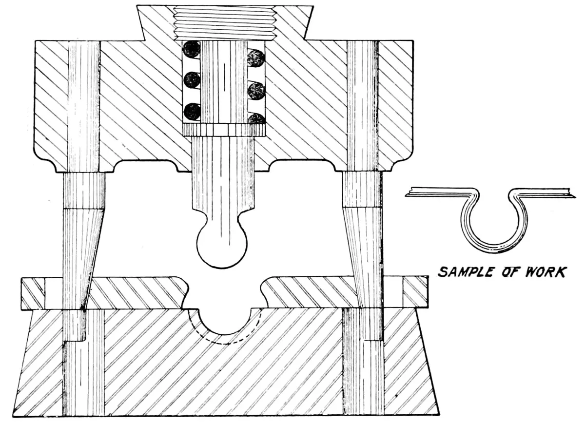
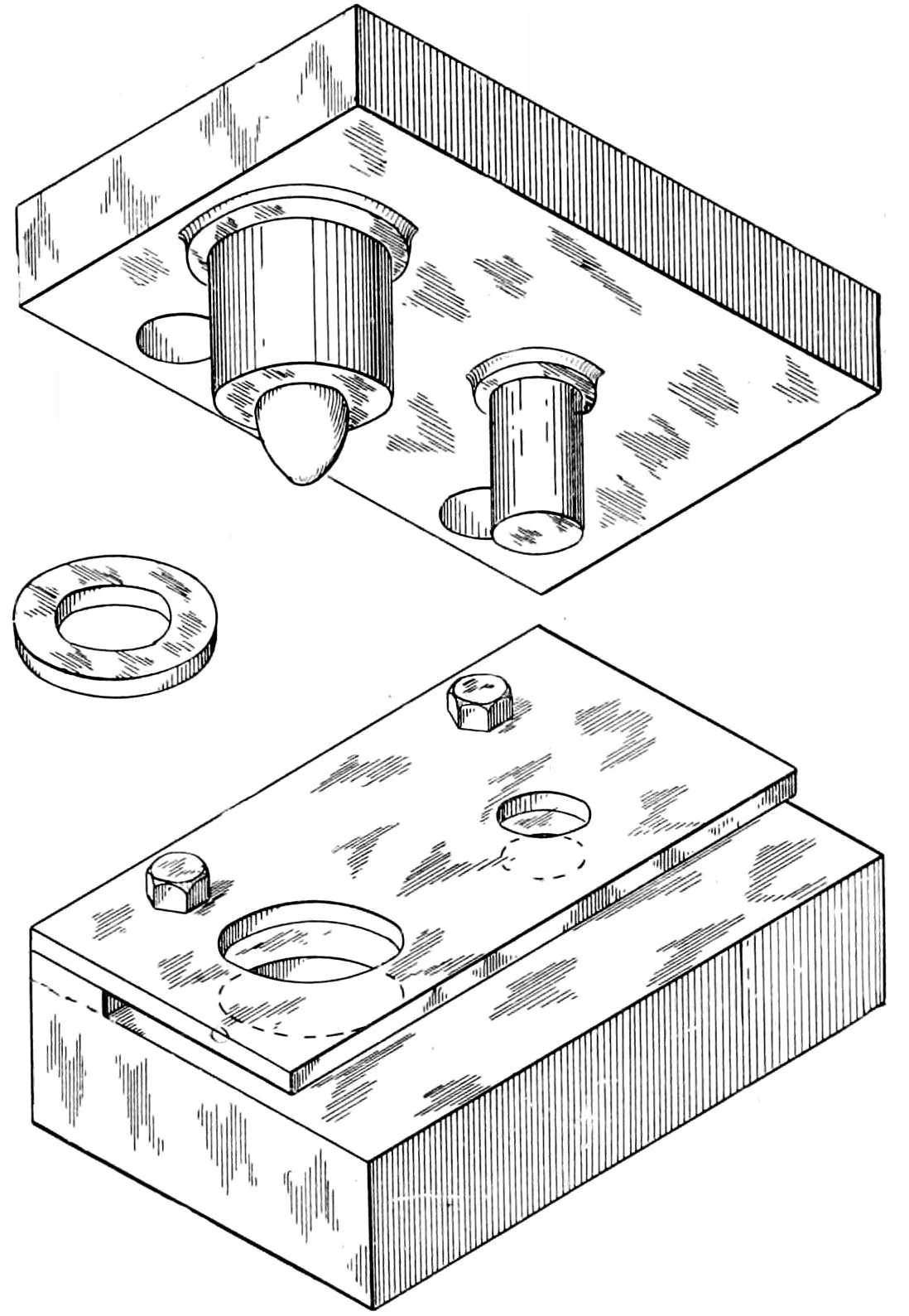
The second die shown is for bending up a loop in a wire shown
by the small sample at one side of the die. It will be found very
effective in making looped wire for armature connections, switchboard
work or other places where a looped wire is required. The
wire is placed in the die by hand, against a stop,—not shown in
the illustration,—and as the punch descends, the loop is bent
down by the same, and as the end of the punch strikes the bottom
of the die the spring gives way and allows the side benders,—to
be forced in by the inclined wedges (formed on the lower end of
the two pins,)—to force the wire solidly against the center punch,
and as the punch rises the side bending jaws are carried back by
the wire itself which is removed from the punch by hand, the end
of the punch being ball-shaped to facilitate the removal of the
same. The loop just formed acts as a guide for forming the next
loop, the wire being moved along and the loop held against the
stop (not shown) while the second loop is being formed; and then
this operation is repeated indefinitely, according to the length of
wire desired. This is a very successful style of die, as it does in
one stroke of the press what would otherwise require a second
operation.
Fig. 7.
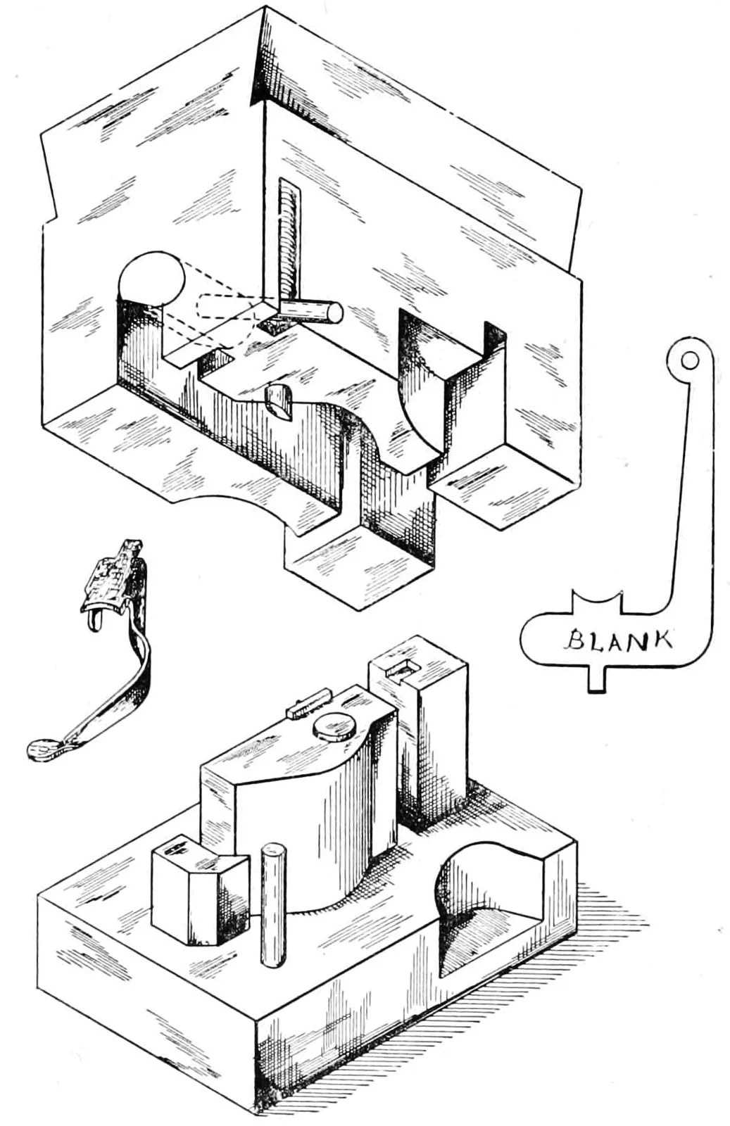
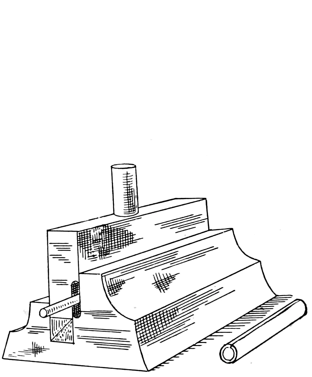
The third die, Fig. 7, is for bending the piece on the right-hand
side of the punch. This is blanked out by a previous
operation placed in the die by hand, and is bent as shown by the
finished piece on the left-hand side, which does not show it so
clearly as it should. The two sides of the blank are bent down,
and the long one on the right is curved around the punch shown,
and the ring on the end is twisted around to a right angle to the
rest of the arm.
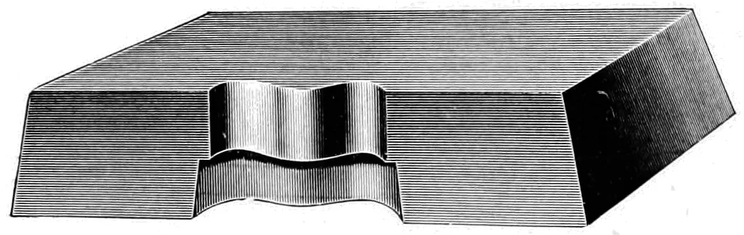
The punch is made from a single block of steel which is planed
up to fit the press, and then machined out as shown in the cut.
The twister, which is for turning the ring at right angles to the
rest of the arm, is counter-bored in and held in place by the
quarter-inch pin driven into the side, and which is held up by the
spiral spring seen at the upper right-hand corner of the sketch.
The die is self-contained as is used in an ordinary single-stroke
press, and requires no extra attachments to enable it to do the
work. This same principle can be used in many cases, and the
bending performed in one operation which would otherwise require
two or more strokes of the press.
COMPOUND DIES.
Fig. 8.
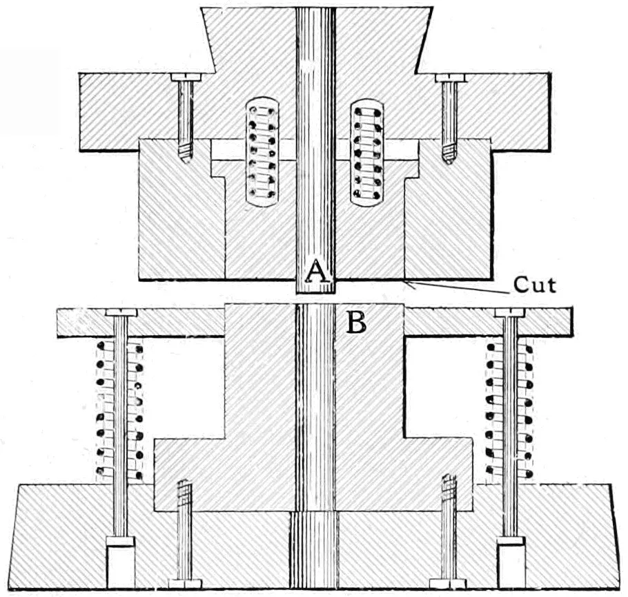
A compound die is, as
the word indicates, a compound
of a die and punch,
or to speak more clearly,
the upper half consists of a
punch set inside of a die,
and the lower or bottom
half of a die set into a
punch, the punch cutting
the outside diameter of the
blank, which is at the same
time pierced in the centre
by the upper punch, thus
finishing a blank at one
stroke of the press, that would otherwise require two or more
operations if done on plain dies.
The work from a die of this class is far better than when done
by the ordinary gang or double die, as the accuracy of the work
depends on the care with which the die is made, and not on the
skill of the operator. They are especially efficient when used on
mica, paper and other substances that do not admit of the use of
a gang die; also on work that must be practically perfect, for
example—the blanks for watch and clock movements, sheet-iron
disks for electric armatures, and other work where the relation of
the centre or other holes to the outside diameter must be perfect.
The invention of the compound die, and the adaptation of the
same to the finer grades of work, as watch and clock movements,
is due to A. L. Dennison, of Waltham, Mass., and was used in
connection with the sub press, also designed by him.
Though originally designed for the smallest work, the idea
has been extended, and it is now used for dies of the largest size,
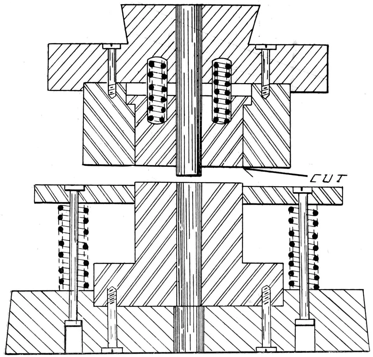
for both light and heavy work. The die shown in Fig. 8 is a
washer die, intended for cutting washers out of scrap mica, the
centre punch (A) piercing the hole at the same time the outside
is being cut by the die, and as a perfect washer is punched out of
scrap mica at each stroke of the press, its advantages can be
easily seen.
Fig. 9.
The above illustration shows a method of making plain compound
dies for electrical work that will be found very serviceable—dies
that can be easily made and kept in order. The upper and
lower cutting rings are forged up and welded, finished in a lathe,
and ground to size after being hardened.
The centre punches are made from solid stock in the same
manner. Both inside and outside strippers are shown, for removing
the scrap, and are made from machine steel; the whole die is
seated into a cast-iron holder. The illustration shows the
construction of the die so plainly that further description is
unnecessary.
Fig. 10.
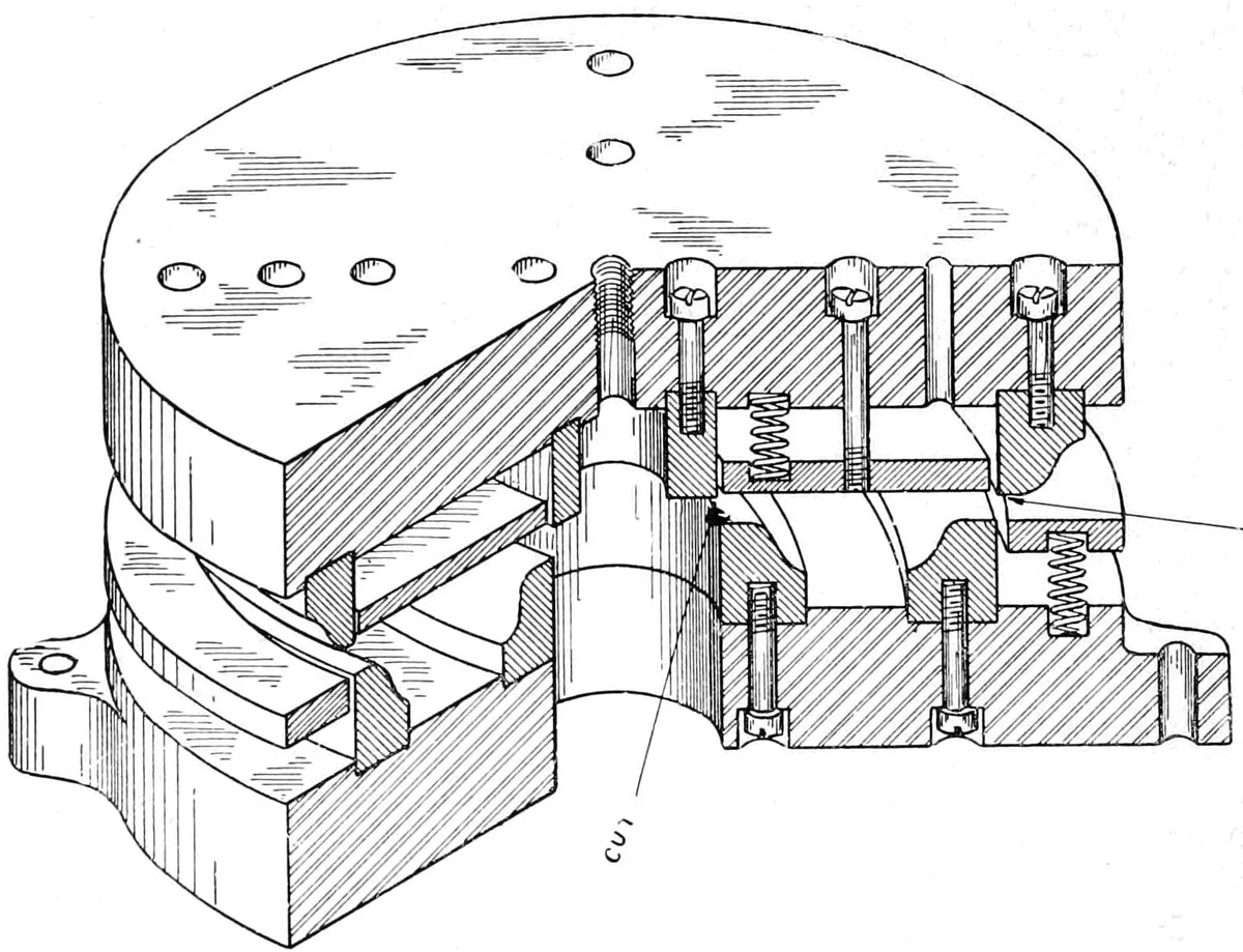
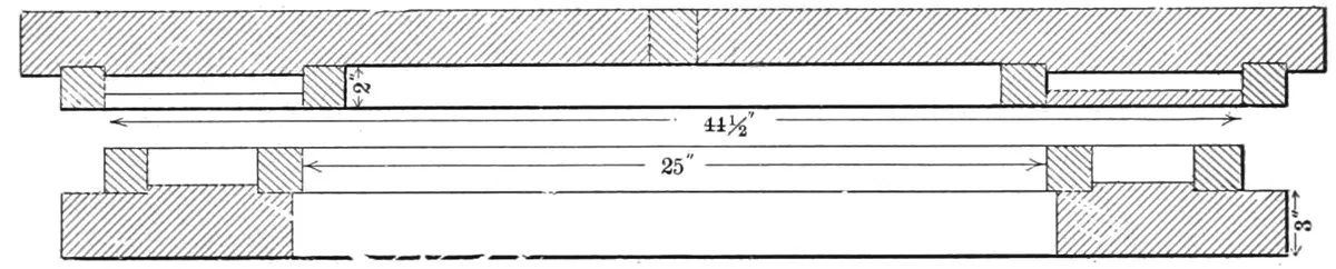
Fig. 10 is a sketch of the largest compound round die of
which we have any knowledge, but should any of the readers of
this book know to the contrary, we should be pleased to hear
from them.
There are many dies containing more cutting surface, but in
actual diameter, we think this exceeds them; it is used for
blanking sheet-iron disks for the armatures of large electric
railway generators for street car service:
Outside diameter
45
in.
Inside diameter
25
in.
Weight of Punch
1,200
lbs.
Weight of die
1,100
lbs.
Cutting surface
290
in.
In work where the stock is too heavy to admit of the use of
springs, the press is fitted with a “knock-out” for the lower and
upper dies, thus doing away with the springs. The pressure
required to strip a complicated piece of work from the dies is
very great; and a test made with a die of 16″ diameter, and
containing 274″ of cutting edge, the force required was between
3,500 and 4,000 lbs.; thickness of stock, .025″ sheet iron.
DRAWING PRESSES.
The use of presses for shaping or “drawing up” sheet metal
is of comparatively recent origin, and although it was not
original with the French mechanics, it was improved, perfected
and first put to practical use by them, for while evidence can be
found of their being in use in Germany in the sixteenth century,
there are no details that are worth publishing.
In 1796 a patent was granted to one DeVere, for a press and
dies for working sheet metal, and in 1827 M. Gazalott took out a
patent for a cartridge shell drawn up from sheet copper. These
were nearly the same shape as those in use at the present time,
and probably the drawing tools were of the same design as those
now made.
In the early ’60’s, two French workmen came to this country
bringing with them a wooden model of a drawing press. This
had been made from drawings taken from a press upon which they
had been employed in France. This wooden press was secreted
in a barn near the city of Wilmington, Del., and was finally
shown to Henry Marchand, who was a brother-in-law of one
of the men. Marchand, who was a mechanic of fine ability, saw
at once the value of the invention, and, as he afterward expressed
it, “would rather have seen the press than had five hundred
dollars in gold.”
Mr. Marchand at once started to raise funds to build and
operate the press, and after many delays a company was formed,
known as the Higgins & Marchand Co. Work was commenced
on the press at Philadelphia, but Mr. Marchand soon discovered
that they were secretly copying each part of the press as fast as
it was made, and the parts of the half finished press were taken
to Wilmington, and finished at what was afterward known as the
Higgins & Marchand shop. It was set up in one corner of the
shop, which was boarded in, and only three men were allowed in
the room, to one of whom, Mr. J. L. Kirby, now Superintendent of
the Dover Stamping Co., Cambridge, Mass., the author is indebted
for this information. The press was a single-action cam press,
the cam being used to force the drawing punch through the die,
the blank holder being held down to the work with a 3,000 lb.
weight which was worked by a long 16′ lever, extending through
the wall. The first piece of work drawn up was a wash basin,
made from a 14″ blank, and was probably the first piece of drawn
work ever made in America.
The second press was a great improvement over the first, the
long lever and weight being discarded, and side cams for the blank
holder substituted in its place. This press is still in use in the
shops of the Dover Stamping Co. The blank holder has been
removed, and the top hamper taken off; the press is now used for
a few special jobs. No punching was done on the press, as it was
used for drawing only. It had been in constant operation for
nearly forty years, when it was displaced by one of E. W. Bliss’s
latest presses, about a year ago. This is an authentic, if not an
exhaustive, account of the origin of the drawing press in this
country.
There is one thing about drawing up a long shell out of a
round blank that is a puzzle. That is, if you draw up a long
tube 1″ in diameter, out of, say, a 12″ round blank, where does
the edge of the blank go? It is 36″ around that piece of metal
when you start to work on it, and only 3″ when you get through.
Where has the 33″ of edge gone? “It is,” as one of the boys said
one day, “all crumpled up and drawn out into the shell.”
DRAWING DIES.
Drawing dies may be divided into three kinds, plain drawing,
or “push through” dies, solid bottoms or “knock-out,” and
combination dies. These last named may be subdivided into
single, double or triple action, or the number of operations may
be extended as far as the ingenuity of the die-maker will carry
him. In the private press room of the Plume & Atwood shops
at Waterbury, Conn., seven distinct operations are performed on
one piece of work before it leaves the press, the stock being fed
in automatically, and the work carried from one set of dies to the
next in the same manner. Such presses are only possible when
the work is to be done in large quantities, and the cost of the
press and dies is very great, three of the presses spoken of costing
nearly $30,000.00.
PLAIN DRAWING DIES.
Fig. 11.
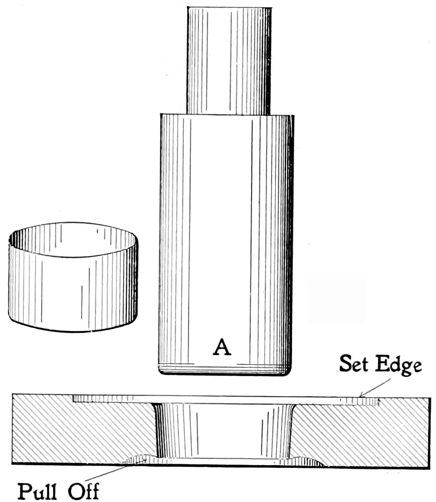
In sketch Fig. 11, we show a plain “push through” drawing
punch and die, the blank being punched out to fit the “set edge”
and then “drawn up,” or rather, it is pushed through the die by
the punch, and as the punch rises, the work is stripped from the
punch by the “pull off,” which is made very sharp for that purpose.
A “draw” of about one-quarter to one-half of a degree is
given the die, making it that much larger on the upper side or
face, and the upper edge is rounded over and left very smooth,
and as hard as fire and water will make it. “Don’t draw a drawing
die.” The lower end of the punch is rounded and left in the
same shape; often the die will work better if the finish is
changed from a circular to a lateral polish. The diameter of
the punch is equal to that of the die, minus double the thickness
of the stock to be drawn. A die of this kind can only be used
on shallow work, or in redrawing or reducing the diameter of the
work that has been previously drawn up; if used on deep drawing
it will pucker or crimp around the edge. To avoid this, we must
have a blank holder to hold the stock firmly while it is being
drawn.
SINGLE ACTION COMBINATION DIES.
Fig. 12.
Fig. 12 shows a single-action cutting and drawing die, better
known as a single-action combination die. A combination die is,
as the name indicates, a combination of a drawing die and cutting
die in one; it punches the blank, and at the same stroke of the
press, draws it up into a cup or shell. The die shown is intended
to be used in an ordinary single-stroke power press, and will draw
up work not over one or two inches deep.
SOLID BOTTOM DIES.
Fig. 13.
The die shown in Fig. 13 is the same general design as the
previous one, except that it is a “push back” or “solid bottom”
die, and is used for taper and flared work that could not be done in
a “push through” die, such as thimbles, taper ferules and lamp
burner parts. The action is the same as the “push through” style,
except that the work is pushed back by a “follow plate” worked
by a “knock-out” attached to the press, and so arranged, that, as
the drawing punch rises from the work, the “knock-out” strikes
the plate pin and pushes the work from the die, and is removed
either by a swinging arm, or by the use of an inclined press.
DOUBLE ACTION DIES.
Fig. 14.
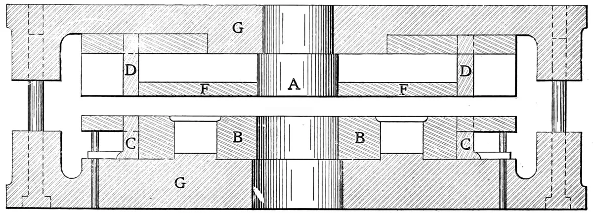
A double-action die is a modification of a single-action die, to
be used in a double stroke press; it can be used on work that is
too deep for single-action dies. The one shown in the sketch,
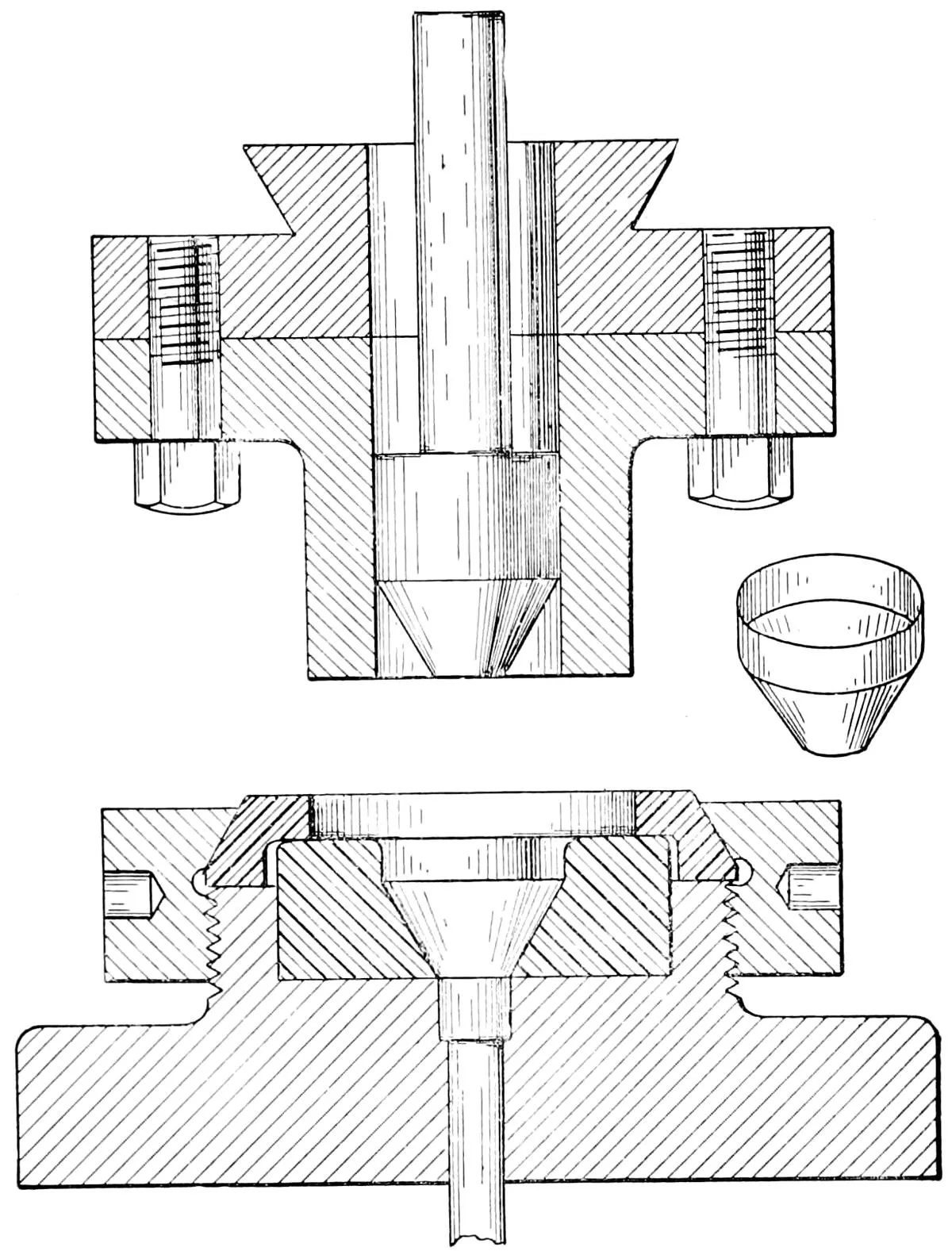
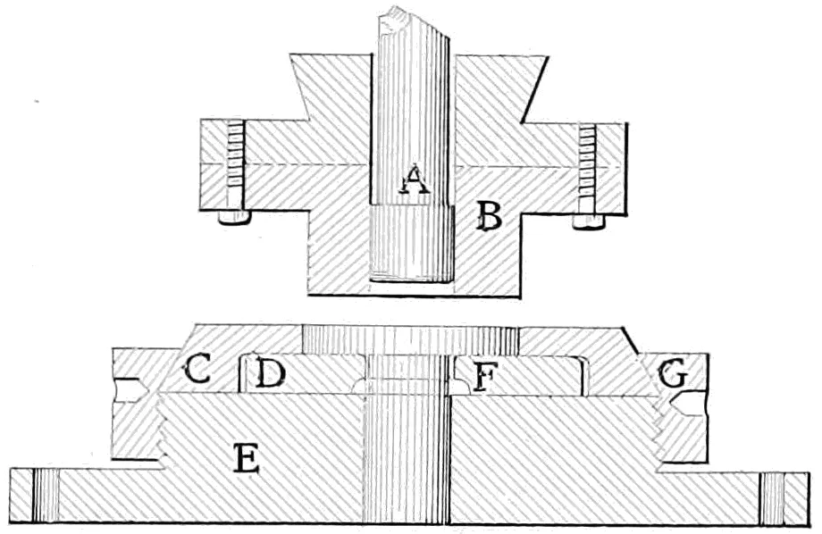
Fig. 14, is known as a “push through” die. It is somewhat like
the single-action die, except that the shell is cut by the punch
(B), and is carried to the drawing die (D), and the lower surface
of the die acting as a blank holder is held there while the
drawing punch (A) forces it through the drawing die, and as the
punch withdraws, the shell is removed by the lower edge of the
die, which is ground very sharp for that purpose, and is known
as the “pull off.” The drawing die is held in place by the
cutting die being clamped upon it by the ring (G).
This style of die has this advantage; the cutting and drawing
dies are independent of each other, and can be changed for a
longer or shorter shell, or either die can be repaired or replaced
without changing the other.
TRIPLE ACTION DIES.
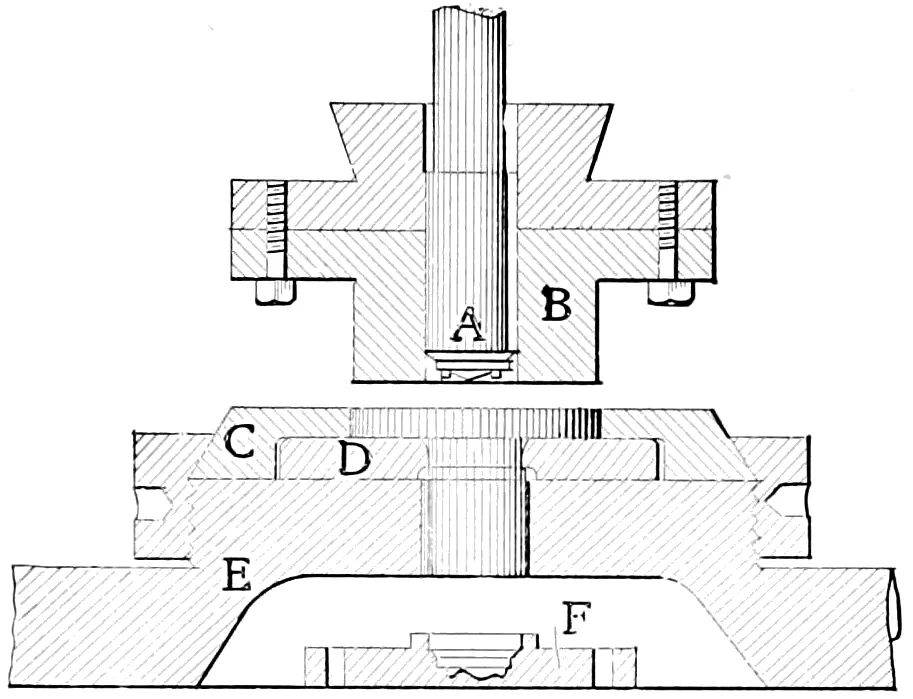
Fig. 15.
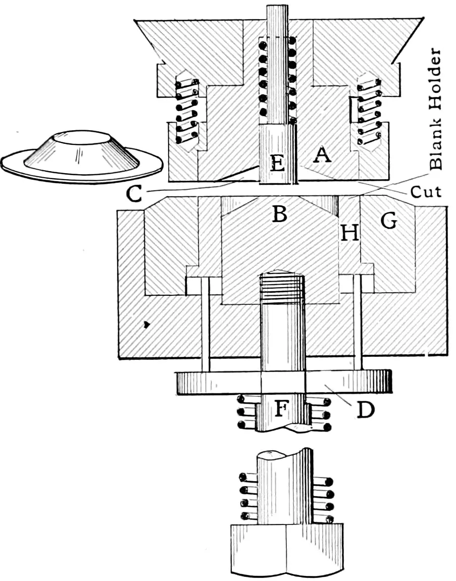
Triple-action dies are intended to punch, draw and stamp the
work at the same stroke of the press. The construction is the
same as the double-action, except that the die block (E) is cut
away to allow the stamping die (F) to be set in place, and the
shell is carried down to the stamping die and “struck up” between
that and the matrix formed on the end of the drawing punch; as
the punch rises, the work is stripped from the punch by the “pull
off,” and is removed from the dies by the use of an inclined press,
or by a swinging arm attached to, and operated by the press, that
catches the work as it falls from the punch.
This style of die is largely used on blacking box covers, lard
pail lids, or other work where a stamped or embossed cover is
wanted. A die of this class should always be used in an arched
press, as the strain of the stamping process is very severe on the
“open back” style press, and is apt to crack the body of the press.
In making a drawing die, use a steel that is high in carbon, and
if it shrinks a little in hardening so much the better. There is on
the market at least one grade of steel which will stand three successive
hardenings, and will shrink each time so that the die as it
wears out, can be “shrunk up” and then ground out to size again.
Various modifications of a drawing die are necessary in order
to successfully draw up the different metals. Zinc works better
when the soap suds, or whatever lubricant may be employed, is
used hot as possible, as that metal works much better at a heat of
about 125°.
In drawing up very delicate work where the nature of the
metal is such that the die is inclined to clog, or as the press hand
calls it “copper up,” the use of buttermilk will be found very
effective.
In drawing very thick work the drawing die can be made bell
mouthed, as the thickness of the metal will reduce the tendency
to crimp or pucker. The same method of making the die is
followed when it is desired to draw a shell that is very short in
proportion to its diameter.
The possibilities of what can be done by this method of forming
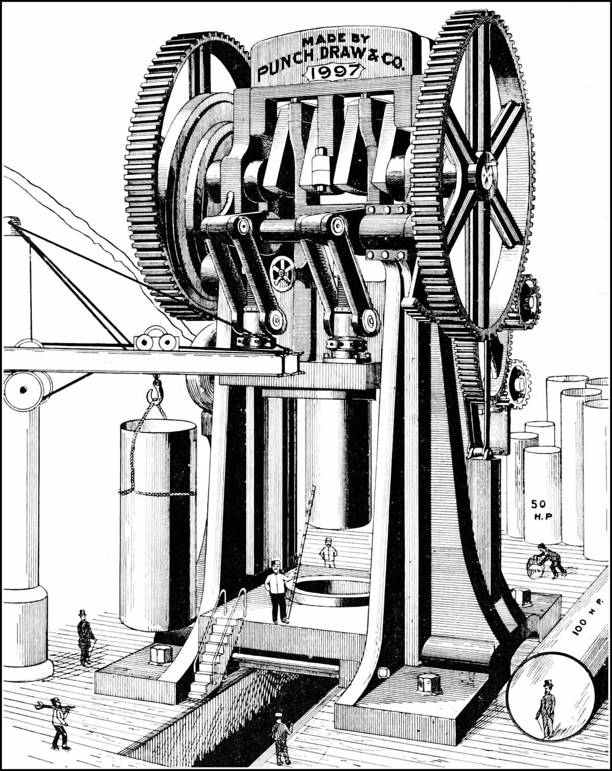
up sheet metal are almost unlimited, and the press of the future
as shown by the frontispiece, is not an exaggeration of what will
be performed at no distant day, as trunks, wheelbarrows, sinks
and the copper boiler for hot water service are every-day productions
at the present time.
The great secret of drawing up work is to have good metal,
and to properly adjust the blank holder, so as to hold the metal
just hard enough to prevent it from puckering. In drawing up
metal, always keep one thing in mind, that is, that metal has some
of the properties of water, and it will flow where it can go the
easiest. A grade of steel which will harden good, a little
knowledge of tool making, and a good deal of experience are
what is needed to make a good drawing die.
DROP PRESS DRAWING DIES.
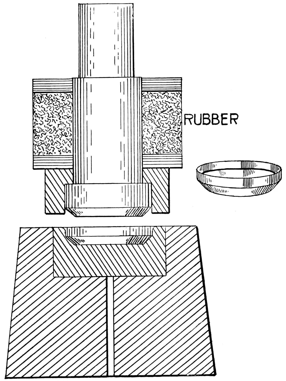
Fig. 16.
The use of drop presses for
stamping and forming work is very
ancient. The first information of
the drop press being used in
this country was in 1833,
when the Dover Stamping
Company was
founded by Mr. Horace
Whitney, at
Dover, N. H.
They were used
for making tinware,
which
previous to that time had
been formed up by hand.
In 1847, Mr. Whitney
started manufacturing,
using a number of tools
of this kind, some of
which are still in existence
at the works of
the Dover Stamping
Company, now at Cambridgeport,
Mass.
These presses are used where the nature of the work demands
that it shall receive a blow or force to enable it to retain the shape
given it by the dies, and which cannot be readily given in a power
press. They are also used for drawing up shells or cups in place
of the ordinary press, as the work can be done cheaper than by the
use of the power press, unless furnished with a roll or automatic
feed. In the die shown, Fig. 16, the blank is held in place by the
“set edge,” and as the punch comes down, the blank holder
strikes the work and prevents it from crimping while the punch
compressing the rubber spring draws the blank down into the die,
and give it the shape desired. Drop dies are also used for striking
up work that has been previously drawn up in the drawing
press; also the bending and forming of both sheet metal and
wire. For important improvement in this class of tools see page 88.
JACK DIES.
Figs. 17 and 18.
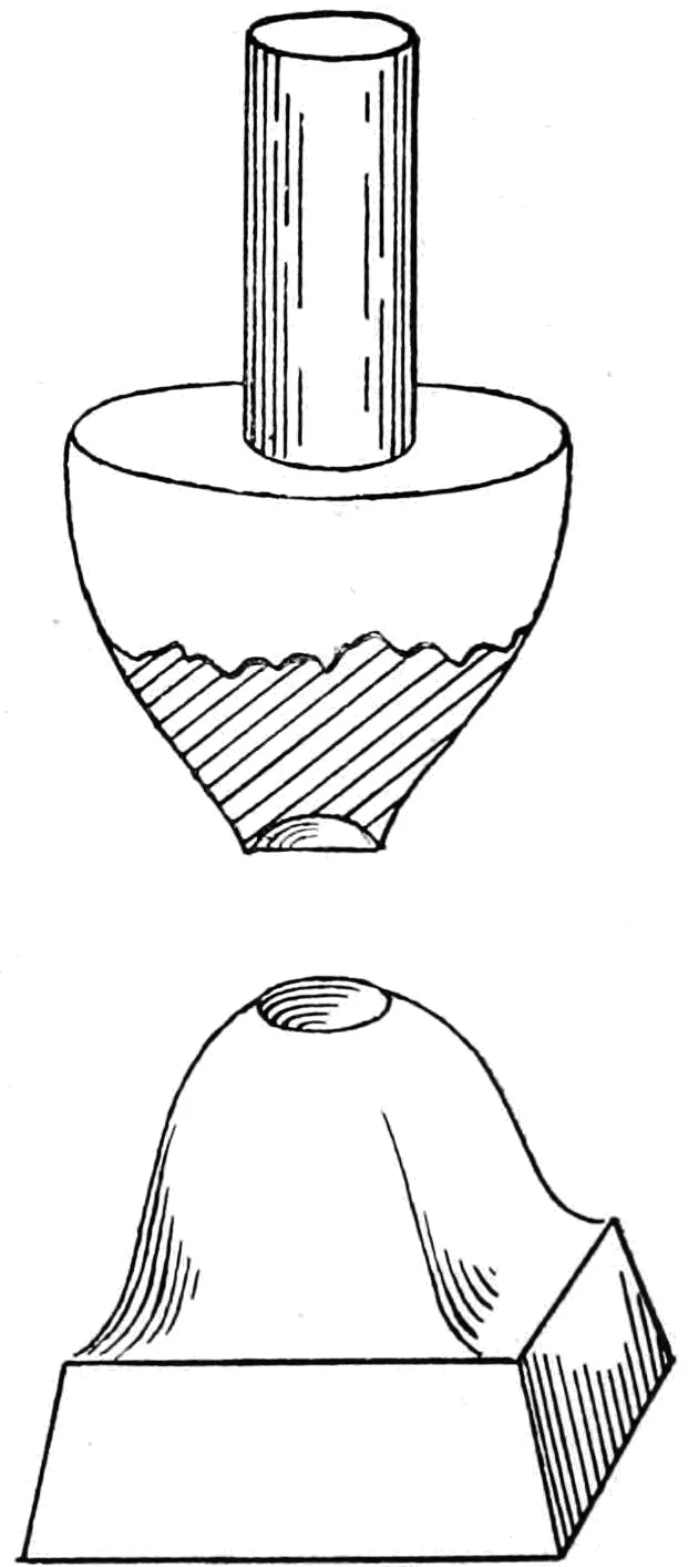
The illustrations show two methods of holding the upper die,
or as it is sometimes known in shop language, the “jack” or “pick-up”
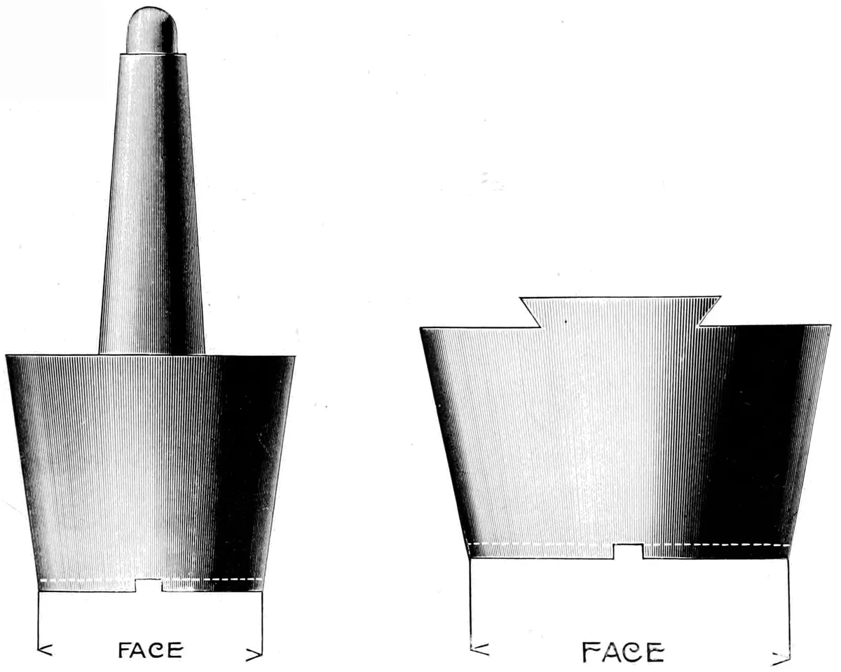
die; the die being held by a taper shank which fits into the
hammer of the drop, or by the dovetail which is keyed into the slot.
The former method is best adapted to hammers of 100 lbs.
weight or less, and the latter to large dies or pick-ups. The under
or face side of the jack is scored across with two or more slots at
right angles to each other, and the face hardened. The lower die
is made and finished, and the blank for the upper die or force is
heated to a cherry red, and placed under the hammer which
is brought down with all the force that can be applied, driving the
hot metal both into the slots in the pick-up, and into the lower
die, forming the punch or force, and at the same operation attaching
it to the hammer.
This seems to be a crude method of holding what is often a
nice piece of work, but careful search proves it to be the one
universally practiced in all sections of this country.
ARMATURE DIES.
Fig. 19.
The phenomenal growth of the electrical industry in the last
few years, and especially in the use of notched or slotted sheet-iron disks for the armature cores, has stimulated the invention and
use of compound dies of large diameter and complicated designs.
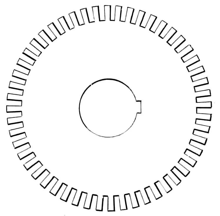
The modern armature resembles somewhat a gear that is built
up of thin sheet-iron plates or disks, usually about .010″ to .040″
thick, and from 12″ to 100″ diameter. These are, in the best
of armatures, punched from sheet iron, with centre holes, keyway
and the teeth, or, as they are called, “the winding slots,” at one
stroke of the press; the smaller ones in a complete disk, the larger
sizes in as large sections as it is possible to procure the iron; and
as some of the styles are very intricate, the ingenuity of the die-maker
has been taxed to the utmost to produce what is wanted.
The method first adopted was to blank out the plain sheets,
and then put in the centre hole and keyway with a separate die.
The sheets were assembled on the shaft and turned to size on the
lathe; the slots for the winding coils were then cut in a milling
machine, and the core was ready to wind. It was soon found
that the contact of the sheets caused by the milling process was
detrimental to the electrical efficiency of the armature, and the
use of a dial-feed press was adopted for punching the slots before
the sheets were assembled on the shaft. This gave better results,
except that irregularities of the punched sheets required a good
deal of filling to correct them, the effect of which was the same as
that caused by the milling process, except to a less extent. This
led to the development of compound dies that would punch sheets
so perfectly that they could be assembled on the shaft or spider,
and the armature wound without any further labor expended on it.
Fig. 20.
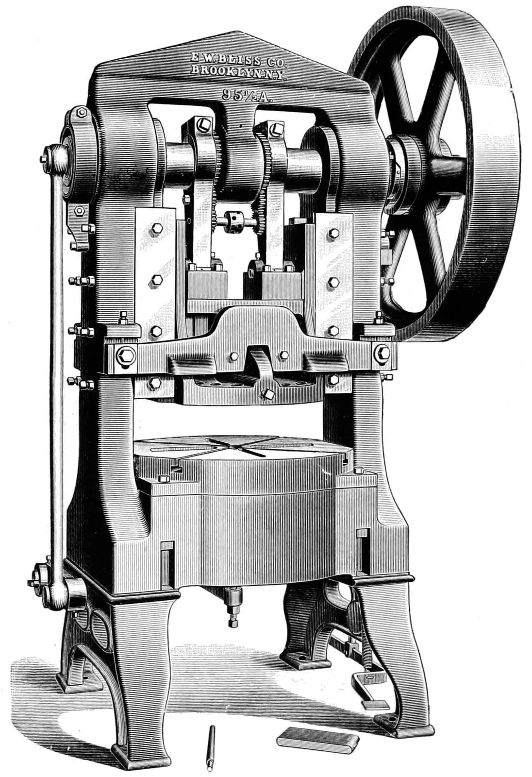
Fig. 20 shows one of the latest designs of these dies, adapted
for use in an E. W. Bliss, No. 95 press, which comes nearer meeting
the requirements called for, than any other in the market.
This press is fitted with a “knock-out” capable of exerting a
force of 5,000 lbs., thus obviating the use of springs in the lower
stripper. The upper stripper is also worked by a stationary
“knock-out” attached to the body of the press.
This die is a sectional one, is set into a steel casting, instead
of cast-iron, as is generally done. The rings “A,” “B” and
“C” are of tool steel hardened and ground to size, and the rest
of the rings are left soft.
These dies are invariably sub-pressed, as the utility of the die
is greatly increased by this process.
A die of this kind, well made, and run at a speed of 55
revolutions per minute, operated by two men, will produce 4,000
to 6,000 20″ sheets per day of ten hours, using 10,000 to 15,000
lbs. of iron.
The cost of these dies varies from $100.00 to $800.00 each,
according to design of the armature, and they weigh from 1,000
to 2,000 lbs. each.
Fig. 21.
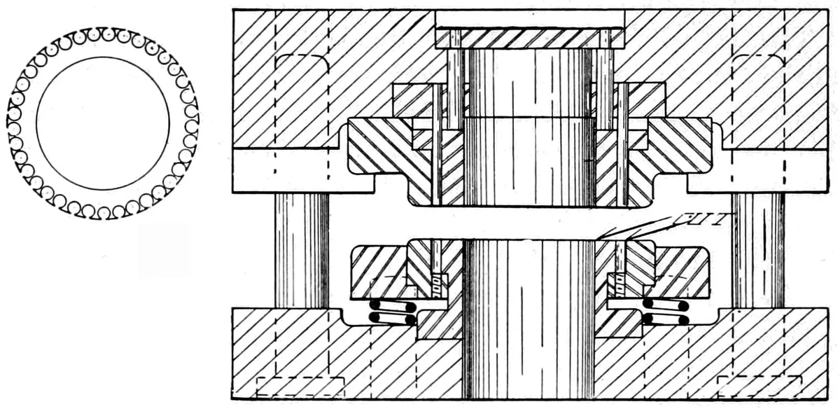
The above illustration shows a die for a small armature blank
for fan motor work; also a punching from the same. The die is
a compound one, sub-pressed by the use of four pins, two of which
are shown in the illustration.
The difficulties of making the die were such that, at first, it
was deemed impracticable; but the urgent necessity of getting out
the work, which was being done by the use of a dial-feed press,
made it advisable to make a trial of this method of punching.
The lower die was made precisely as shown by the punched
blank, of a piece of Styrian steel, which was carefully annealed,
turned to the required shape, drilled for the thirty-seven holes,
and then slotted on a milling machine and left soft.
The upper punch, or, as it really is, the die, was made in two
pieces; the inner punch hardened and ground and forced into
place in the upper casting, and the outer cutting die made in the
same manner and seated in a recess machined out concentric with
the centre punch.
The knock-outs or strippers were made, the lower one in two
pieces, and then held together by the outer ring shown, which
was forced on, holding them firmly together. This knock-out was
fitted with thirty-seven pins of the same diameter as the holes in
the disk, so arranged that as the punch was withdrawn the scrap
was forced from the holes by the action of the spring shown in
the illustration.
The upper knock-out, for removing the blank itself, was
actuated by a knock-out attached to the body of the press, and so
arranged that when the press reached the highest point of the
stroke it was forced against the plate shown in the centre of the
upper part of the die.
The die was a success, and was run continuously, day and
night, producing several million sheets before being replaced by a
new one.
NEEDLE DIES.
Fig. 22.
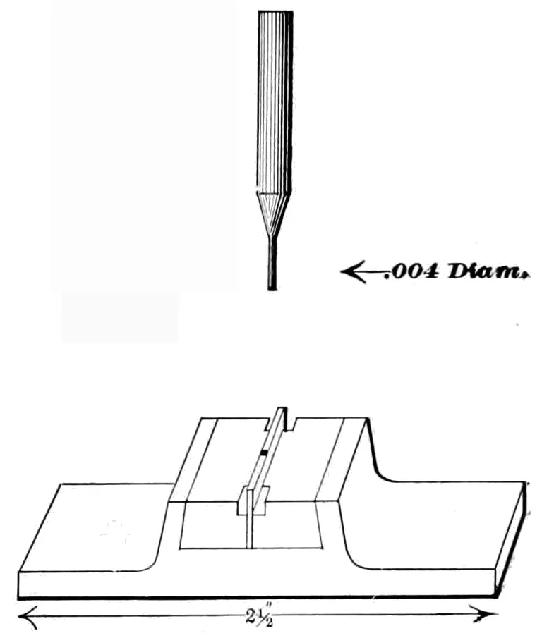
The illustration, Fig. 22, shows
a small die and holder which is
largely used in needle factories for
punching the eyes of sewing-machine
needles, and is intended to
be used in a press adapted to that
class of work. The die is a sectional
one, made in three pieces, the centre
one projecting up above the
surface of the two sides and into
the groove of the needle, thus supporting
the latter while it is being
punched. This centre piece is cut
out with a U-shaped slot, the width
of the slot being equal to the length
of the eye of the needle, the two blocks forming the sides of the
die, and the whole held firmly together by a set-screw not shown.
The press is so arranged that the needle is first clamped (not
shown) and then punched, the speed of the punch at the moment
it enters the die being very slow. The punches are made of
Stubb’s wire about .080 diameter, milled down to a diameter equal
to the length of the punch, and are then hardened and the sides
are ground in a special grinder. A punch of .004 diameter is
used on the finest needles, and a punch of .008 to .010 is a common
size in every-day use.
FLUID PUNCHES.
Fig. 23.
The well known fact that water cannot be compressed to any
great extent, has led to the use of fluid punches for shaping and
expanding work that would otherwise be impossible to do in a
press, and may be used as a medium for conveying force, as in the
case of a hydraulic press, or the fluid may be applied directly to
the work with or without the use of a packing ring.
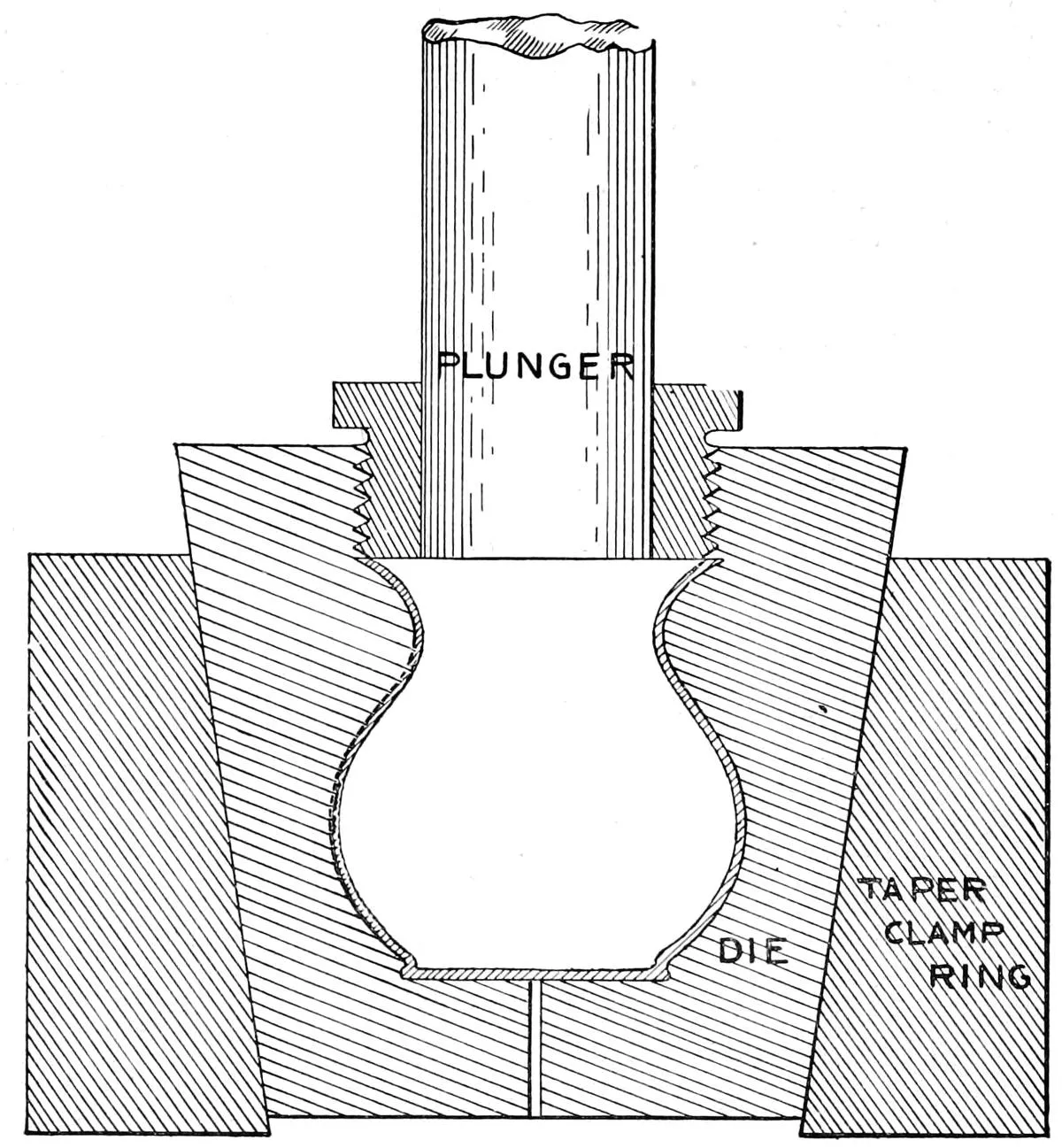
The illustration shows a die designed for shaping ice pitchers,
and intended for use in a heavy drop press, the die being made in
two parts.
The pitcher is placed in the die, which is then closed and placed
in the clamp ring, force being applied by the plunger swelling out
the work to the shape of the die. A special preparation of wax
is often used in place of water or oil in connection with dies of
this kind. In presses used for the manufacture of hats, 800 lbs.
pressure to the square inch is applied to the work. The lower die
which is of cast-iron or spelter, is placed on the bed of the press
and then brought up to the water cylinder and locked. The water
is then turned on and a bag of thin rubber is expanded, filling
the entire inside of the hat and allowing the whole pressure of the
water to come upon the material, remaining some ten seconds,
when it is removed the press unlocked and the hat removed. When
the water is applied directly to the work, it is usually done in a
drop press as the pressure can be applied very quickly and but
little packing is required. This method of press work is also
followed in the manufacture of silverware, or where it is desired
to swell the centre of the work to a diameter larger than the end
of the same.
RIVETING DIES.
Fig. 24.
Where a large amount of riveting has
to be done, the work can be produced
better on a riveting machine arranged to
spread the head of the rivet by a revolving
heading tool than it can on a press, but
ofttimes it is desirable to do a limited
amount on a press, and the die shown will
be found a very good one for the purpose.
The illustration is so plain that it explains
itself. It is intended for bicycle chain
work, the upper and lower dies are made
convex, and the rivets headed by rapid
reciprocating blows of the same. A stiff
short stroke press is necessary for riveting.
When a large number of holes are required
to be riveted, and the work is of a
nature that it can be done at one blow, the
drop press will be found preferable. In a
shop engaged in the manufacture of
wrenches, seven to ten rivets are headed
at a single blow of the drop. On page 47
will be found an illustration of a die for imitation rivets, which,
as it is not really a riveting operation, is shown separately, that
it may not be confounded with the one just described.
GANG DIES.
Fig. 25.
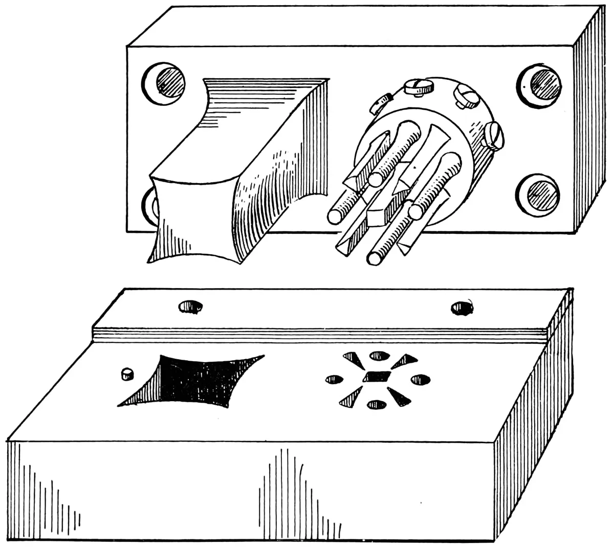
Fig. 25 shows a die intended for punching out a diamond
shaped piece pierced with four round and four triangular holes,
and a square hole in the centre. The die being a small one is
made in one piece of steel.
Laying out of work of this kind required skill on the part
of the die-maker. Proper allowance must be made for the “creeping”
of the stock, also for the margin between the pieces punched.
The large punch should be fitted with a centre pin projecting into
the square hole which has been previously punched by the centre
gang punch; the pin, however, is not shown in the cut.
When the die is a large one, and especially if the holes or
work is round, it is preferable to make the dies separately, and
then set them into a cast-iron holder.
Gang dies are also used very extensively when a large number
of blanks of the same kind are wanted, also in punching rivet
holes in tank or boiler work, and making perforations in gas or
lamp burners, as high as 1,500 holes often being pierced at one
stroke of the press. In work of this kind it will be found advisable
to have the stripper fit the punches very tightly, so that it
will act as a guide, and support the punches while they are entering
the stock. A good illustration of a stripper of this kind is
found on page 64.
SECTIONAL DIES.
Fig. 26.
Dies of large sizes or of a
difficult shape, can usually be
made to better advantage in sections,
for in the former class the
dies can be separately made and
tempered, and set in place in
the holder, thus forming a complete
die, requiring less stock.
Should a part be spoiled in making
or hardening, it can be easily
replaced; whereas, in a solid die,
the whole would be spoiled.
Fig. 26 shows a method of
making a small compound die in
sections that was adopted because
it was found impossible to
produce work that would meet
the requirements of the case,
with the best solid die that could
be made. The pieces wanted
were simply flat blanks of .014″
thin sheet iron 2″ × 4″ in size,
with ³⁄₈″ centre hole. A limit of
.002″ was all that could be given
on the dimensions. A large number
of these was wanted, requiring
the use of dies that must not
vary over .002″ from each other.
After many trials with solid
dies, which failed on account of the contraction caused by hardening,
also by the changing of the die as it wore out, on account of the
clearance given, a die was made like the sketch, the sides and ends
of the die were made in separate pieces, hardened and ground to
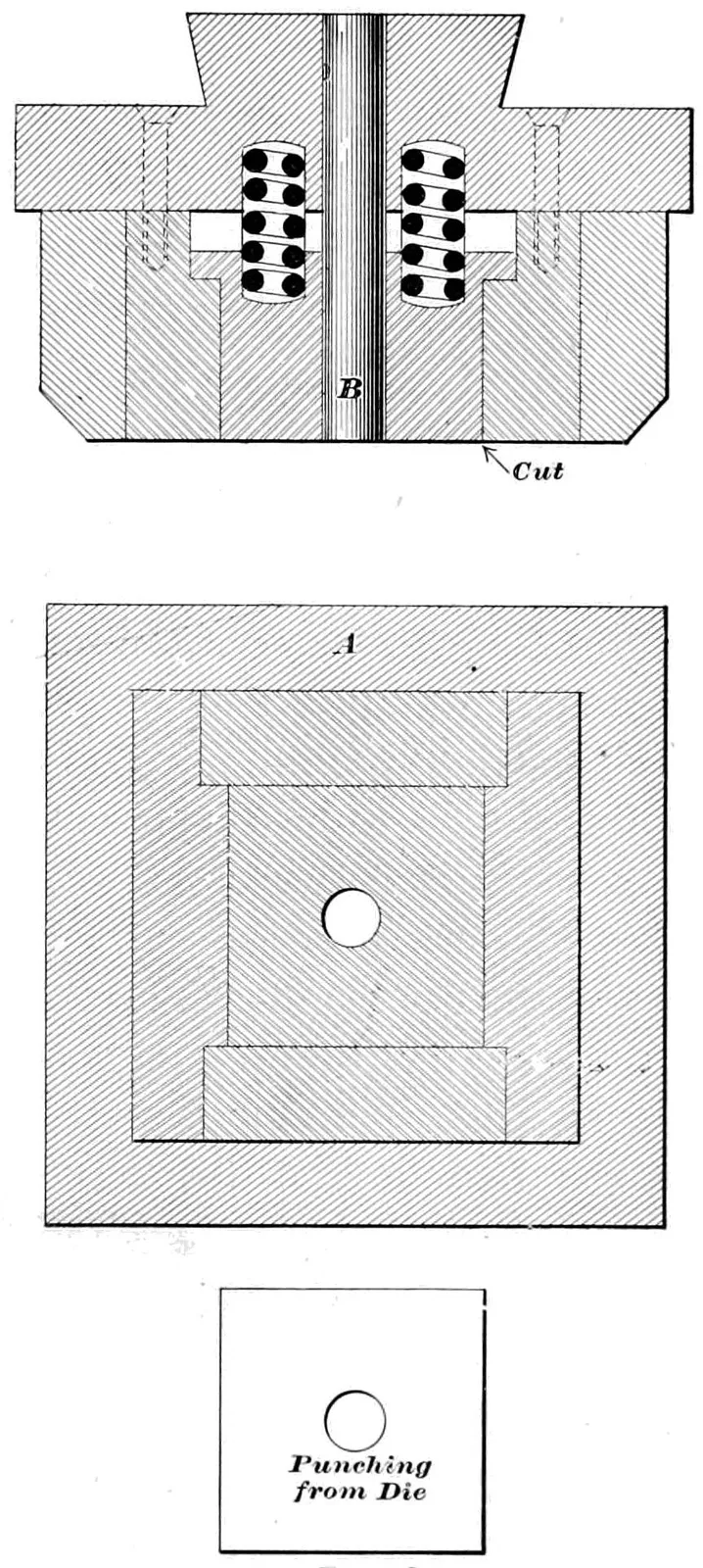
size, and held in place by the shrink ring, the centre punch “B”
perforating the blank at the same time that the outside is cut. No
clearance was given to the die, as the work was removed by a
spring stripper, thus rendering the clearance unnecessary, and enabling
the die to hold its size until worn out. This style of die
gave such good satisfaction that it was used exclusively for this
class of work, and the extra cost of the die was more than offset
by the decreased cost of the work produced.
Fig. 27.
Fig. 27 illustrates a large punch and die that was made sectional,
from the fact that it was impossible to get steel of the
proper size for the die, as soon as wanted. The punch and die
were both made in sections, and ground to a perfect fit after being
hardened. The dotted lines show the manner in which the joint
was made. The results obtained from the die, in cutting qualities
and shape, were better than had it been made solid. The size of
the die was about 18″ × 20″, and the stock punched was thin
sheet iron. The labor cost of the work, though somewhat more
than it would have been for a solid die, was more than offset by
the saving in the amount of stock used. The die was set in a
cast-iron holder having eight lugs which were fitted with set-screws,
forcing it firmly together and making a solid die.
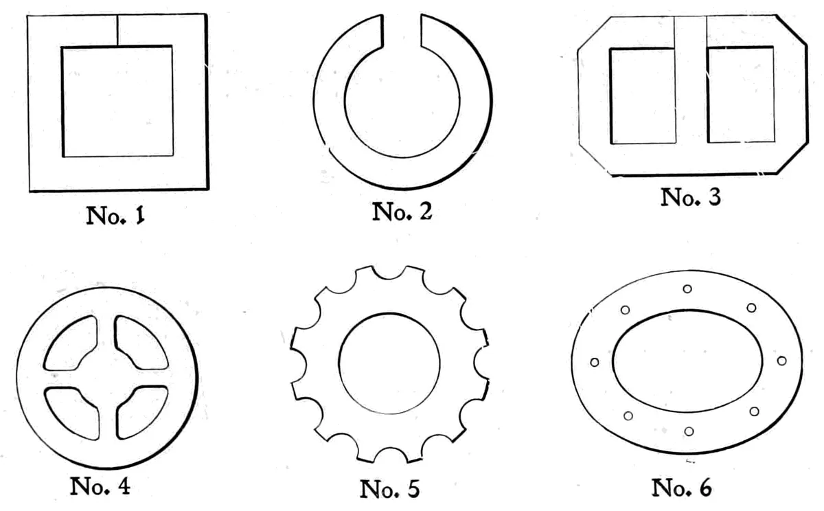
Fig. 28.
Dies for armature sheets are almost invariably made in sections,
so arranged that each piece may be taken out and replaced
without disturbing the rest of the die. Fig. 28 shows some of
the shapes made in this style.
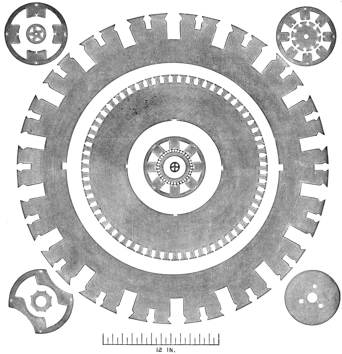
No. 1—A square sheet-iron disk with centre hole, also cut
across the side.
No. 2—A washer with a section cut out.
No. 3—A transformer sheet.
No. 4—A clock wheel blank.
No. 5 and 6—Armature sheets, punched at one stroke of the
press, the dies made in sections.
BURNISHING DIES.
Fig. 29.
When a nicely finished piece of punched work is wanted, the
piece is first blanked out a little larger than the finished size and
then pushed through a die that is slightly tapered, that is, it is
made larger at the top or upper side. The cutting edge of the
die is a little smaller than the blank so that a shaving is taken off
around the edge, and then it is forced through the die, which is
made very smooth on the upper part. This leaves a finely finished
surface on the edge, and is used on work that would otherwise
require milling or buffing, such as bicycle chain links, and the
large and small sprockets, for finishing operations. The die shown
is intended for finishing bicycle links by the use of a dial feed.
The centre hole is punched at the same time the link is blanked,
and is centered on the burnishing die by the use of a pin that
enters the hole and holds the links firmly while passing through
the die.
It is important that the inside of the die is made smooth,
well finished after being hardened. This style of die will, when
made and properly used, save a large amount of milling and buffing,
and will produce work that is uniformly accurate.
WASHER DIES.
Fig. 30.
These illustrations show three distinct methods of producing
washers, each of which has its advantages according to the material
used.
The compound washer die in Fig. 30 is used for thin work,
and where an accurate cutting die is wanted, for punching paper,
mica, thin sheet iron or brass. The illustration shows so plainly
the method of making the die that little explanation is necessary.
The spring stripper is used on the lower die, as it is called—which
is in reality a punch—and a spring shedder or knock-out for
ejecting the blank from the upper die. The advantage of a die
of this kind is that the material is pressed flat and smooth by the
spring stripper before being cut, thus giving a more perfect washer
than can be made by any other method.
REVERSED WASHER DIE.
Fig. 31.
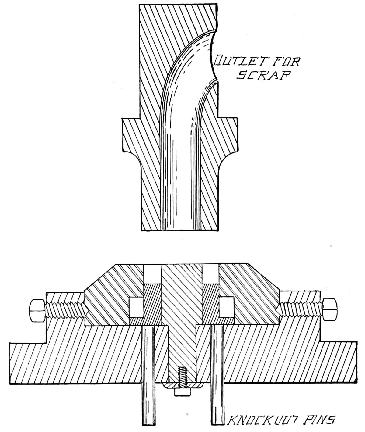
The die shown in Fig. 31 is intended for thick washers, the
punch being made with an outlet through the shank of the same
for the scrap from the centre of the washer, the blank remaining
in the die until it is ejected by the shedder which is actuated by
a knock-out motion applied to the press. This die can be used for
washers ¹⁄₄″ and ³⁄₈″ thick, and will produce perfect work even
when using scrap stock, which is a difficult thing to do when
using the gang washer die shown on the following page. It is
especially adapted to collars and ball cups for bicycle work.
GANG WASHER DIE.
Fig. 32.
This illustration shows a gang washer die intended for punching
washers of any description, and is the style ordinarily used.
It is necessary in using a die of this kind that one edge of the
stock be straight, in order that in feeding it may be kept firmly
against the back gauge so as to ensure its being properly fed.
Another method of producing washers may be described, and
consists of first cutting out the blank with a gang of punches, the
press being fitted with a roll feed, and punching 25,000 washers
per hour, or from one to two tons per day. These are then put
through a second operation for piercing holes in the same, the
press being fitted with two dies which are fed by tubes, the washer
being carried to the bottom of the tube and deposited under the
centre of the punch which pierces about 200 washers per minute,
or about one-half ton per day.
TRIPLE DIES.
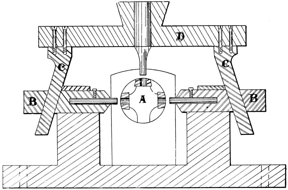
Fig. 33.
This illustration shows a die intended for slotting the ends of
tubes or other shell work, and is intended to be used in any
ordinary power press.
The dies are held by a hollow stud which fits the inside of the
tube or shell to be punched, the scrap passing into the cavity
(A) and dropping through the outlet below, left for that purpose;
the punches being held in the side carriers (B), which are driven
by the inclined studs (C) secured by the punch holder (D).
The die is self-contained, and can be removed from the press
and set in the die rack in the usual manner. The punches are
straight pieces of steel wire of the proper shape to fit the die,
and are held in the same manner as shown on page 51, Fig. 39,
and not by the set-screws as shown in the illustration.
The advantage of a die of this kind is the reduced cost of
the work, and the better results obtained, as it is impossible to
get out imperfect work if the die is properly made and used.
IMITATION RIVET DIES.
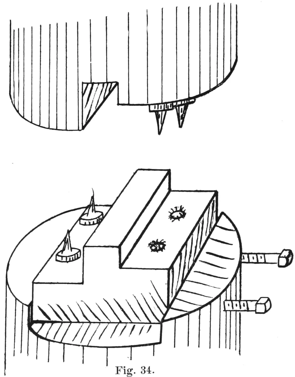
Fig. 34.
The above illustration shows a die for imitation rivets intended
to be used on thin sheet-iron work, such as hoops for tubs and water
pails, tinware, attaching hinges to stove ovens, or other work of a
similar character.
The advantage of the die is, that no stock is removed from
the parts to be joined, and no rivets are required. The punch is
driven through the double thickness of stock on the first set of
punches, and then finished on the second set. The only object of
the second set of punches is to avoid turning the work over, as
the operation could be performed equally well on a single set.
It is not really a riveting operation, being more of the nature
of an eyelet than a rivet, but is described as such from the fact
that it is often used in place of solid riveting, especially on thin
work, such as pail hoops, band iron, and in putting handles on
the cheaper grades of tinware. The operation can be rapidly performed,
and applied to many classes of work not specified.
FOLLOW DIES.
Fig. 35.
Follow dies, so called when two or more operations follow
each other, that is, the piece is first stamped, pierced and then
blanked out. Sometimes this order of operation is reversed and
the piece is stamped and cut off at the same time, the holes having
been punched at a former stroke of the press.
The illustration shows a die for making a clip, used for holding
armature binding wires, and will be recognized by many of our
readers. The stock is first stripped the proper width and fed into
the dies by hand and the finished clip is knocked off the die in the
same manner.
The same idea can be used for a large variety of work. Slots
or holes can be punched in either or both ends of the blank, and
any style of bend can be made that does not exceed an angle of
ninety degrees, and where the depth of the bend is not more than
three-eighths or one-half inch.
The difficulty of making a long bend is that the cutting punch
must do the work before the bending die comes into use, and must
necessarily pass down into the die whatever the depth of the bend
may be. The work should be entirely cut off by the punch just
at the moment it is struck by the bending die, otherwise it will be
apt to be moved from its proper place, resulting in imperfect work.
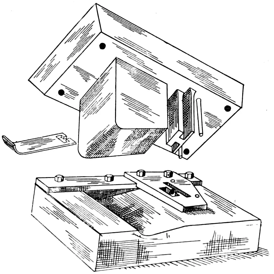
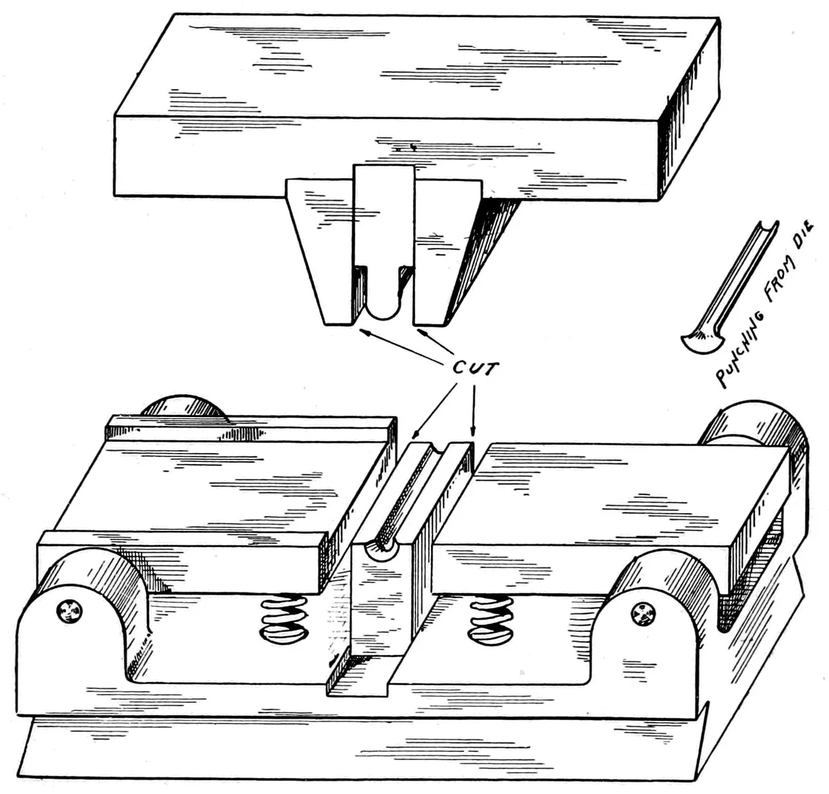
ARMATURE LEAD DIE.
Fig. 36.
The illustration, Fig. 36, shows a die intended for cutting and
forming a half-round piece, or, as it is called, a lead, which was
formerly in great demand for armature work. The stock is fed
from the left of the die, covering the small die shown in the bottom
holder, and as the upper die comes down the stock is trimmed on
both edges and bent to the shape shown, as the press reaches the
full length of the stroke.
The piece shown at the right of the die is a gauge, and is supported
on pointed screws, held up by the springs in the centre, so
that as the upper knives come down it is depressed out of the way,
but rises to its place again as soon as the punch returns.
This idea can be used for a large class of die work, and requires
no attachments of any kind applied to the press.
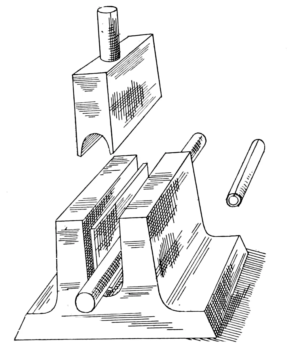
TUBE BENDING DIES.
Fig. 37.
Fig. 38.
The illustrations show
two methods of forming
up a tube at one stroke
of the press, doing the
work with a single operation.
The first of these,
shown in Fig. 37, is published
by permission of
Mr. C. H. Hardinge of
Chicago, who gives the
origin of the same as
follows: That he obtained
the same from a
die-maker of his acquaintance
who learned
the trick from a tramping
journeyman.
The second sketch is for the same purpose; the action of the
dies are the same; the method of construction being changed to
obviate the necessity of cutting out the deep slot shown in the
first die.
These sketches are
taken from the columns
of the American
Machinist, and not
having seen the same in
practical operation, it is
impossible to state
whether satisfaction
equal to that obtained
by the use of two
sets of dies can be had
by their use.
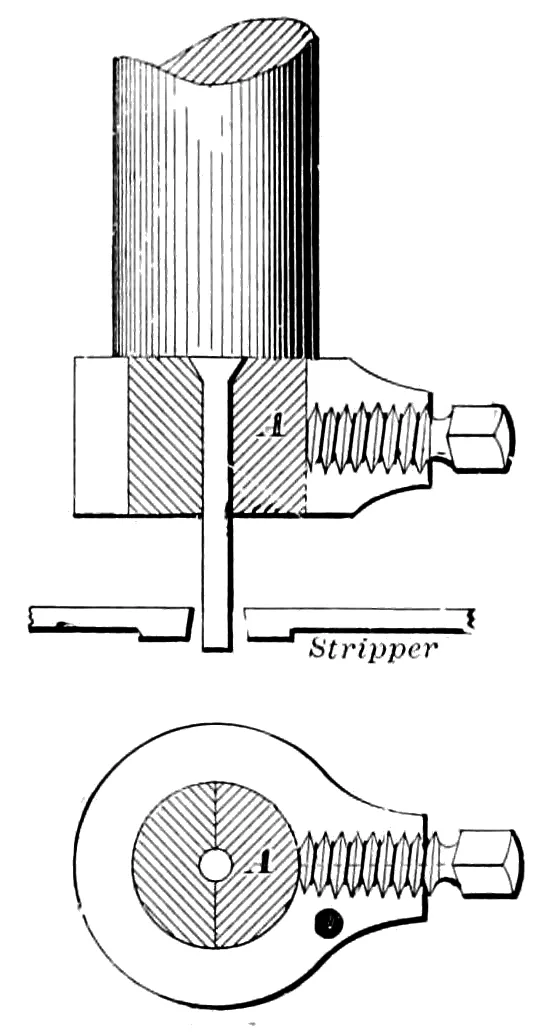
HOLDING SMALL PUNCHES.
Fig. 39.
Small punches always give more or less trouble from breaking
and then sticking in the punch back or holder. The method
shown in Fig. 39 is designed to overcome this difficulty. The
punches which are straight pieces of Stubb’s steel wire, are cut off
and headed on the upper end and hardened. The chuck, which
is made with a removable collar, is split in the centre, one side of
which can be removed by loosening the set-screw. The ease with
which this can be done makes it unnecessary to send the job out
of the press room. The punches can be made and kept in stock
and renewed, and the punch replaced without the necessity of
removing the die from the press.
Small punches are broken, not in punching the work, but in
the withdrawal of the same. The cross section of the stripper in
the centre of the cut shows how it should be made so as to prevent
this trouble, the stripper being machined off on each side so as to
have a bearing on the work to be punched, close up to the punch.
When possible, the stripper should be bolted on to both sides of
the die.
Out of many methods and plans devised for holding punches,
this one gives the best satisfaction, on account of the ease of
making and removing the punches.
SUB PRESS DIES.
Fig. 40.
Fig. 41.
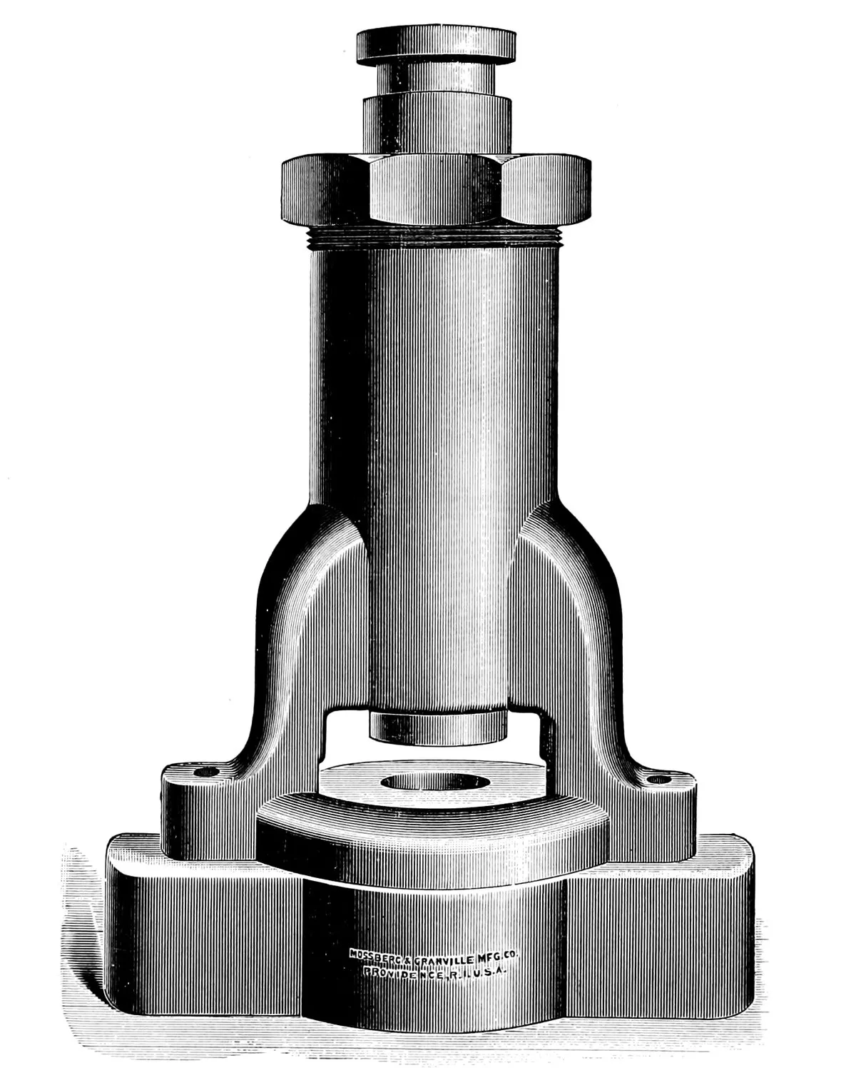
A sub press, is, as the name indicates, a press set under a
press, and was designed by Mr. A. L. Dennison of Waltham, Mass.,
for the making of watch movements, and at first consisted of two
pins acting as guides for the moving part of the sub press, which
being quite a distance from the punch, served to make it enter the
die correctly.
A very interesting article on the origin of the sub press, as
well as the illustration and description of the first die thus made,
by Mr. Dennison, can be found in the American Machinist of
March 5th, 1891, and will repay anyone for looking it up who is
interested in this subject.
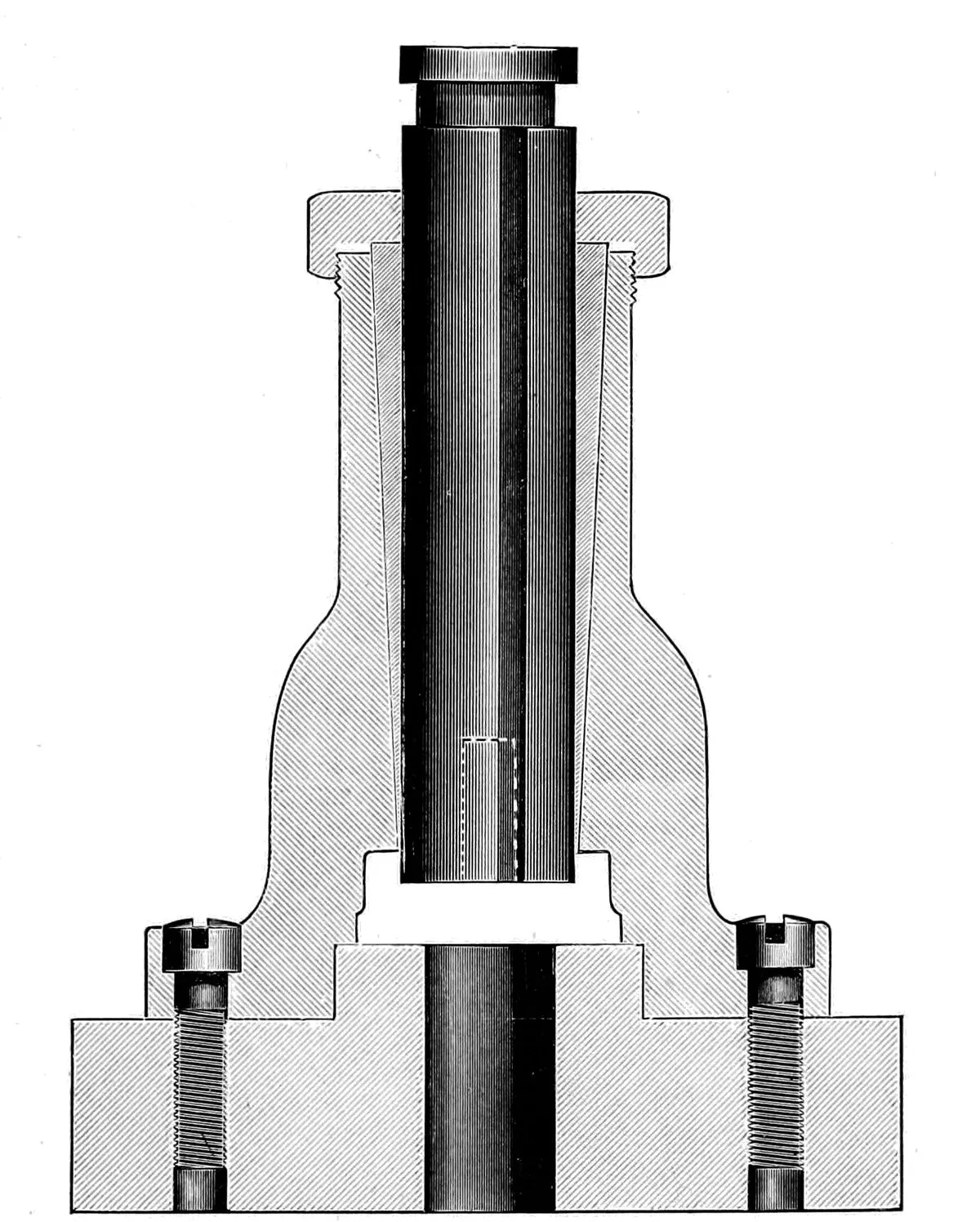
For regular sub-pressed die work, the form shown in Figs. 40
and 41 will be found a good style to use. The inside of the
casting, shown in cross section, is made tapering, and bored out
true with the plunger, and a heavy nut is fitted to the top, as
shown in the illustration, so that the babbitt with which the
sub press is filled is kept tight by screwing down the nut and
forcing the babbitt into the taper and against the plunger.
In making a die for the sub press, it is made and fitted in the
usual manner and set in its place. The punch is then carefully
set, and the space around the plunger is filled with the best quality
of babbitt metal. The plunger has three parallel grooves milled
to prevent the liability of its turning in use, and the upper half or
arch of the press is shouldered on to the base and then held to the
same by screws, shown in the cross section Fig. 41. The plunger
is driven by the slot shown at the top, and is attached loosely to
the gate of the press. No dependence whatever is placed on the
ways of the press, but the stiffer the press in which the die is run
the better the results obtained, as it is considered good practice
that the punch should never enter the die, but should come down
and punch out the work without the edges coming in contact.
The illustration on page 34, shows how a die may be fitted up
when the height of the die space in the press will not admit of a
regular sub press casting being used. The punch and die are made
in the regular way, and after being finished the punch is entered
into the die about ¹⁄₁₆″ and is kept in position by parallels being
placed between the two. They are firmly clamped together, and
while thus clamped the holes are drilled, reamed and the four
pins, only two of which are shown in the illustration (which are
hardened and ground), are fitted in the holes in the bed of the
lower die, then the clamps and the parallels are removed and the
die is ready for use.
These pins insure the punch entering the die perfectly, and do
not depend on the ways of the press or the skill of the operator in
setting the same.
The advantage of having a die sub-pressed, especially if it is a
complicated one, can hardly be overestimated, as a die which
before being sub-pressed would cut but two to four thousand
blanks with the ways of the press as carefully adjusted as it was
possible cut twelve to forty thousand after it had been thus
arranged, and the work was of a superior quality.
SOFT PUNCHES AND DIES.
When punching thin stock, sheet iron, or soft metal such as
copper, brass, etc., a soft punch will give equally good results to a
hardened one, for when worn it can be taken out and upset
and then “sheared in” by putting it in the press and forcing it
through the die. When the blank or the piece punched out is the
object sought, as in playing cards or cards for photograph work,
the reverse of this plan is followed. The punch is made straight,
hardened, the die is left soft as it gets worn, is set in with a peen
of the hammer and the punch forced through it, thus practically
making a new die, also keeping it exact to the size wanted for
the work. Where the stock is very thin, machine steel will be
found equal if not better than tool steel, and the operation of upsetting
the punch will harden it, so that it will become very tough.
A punch of this kind well fitted will run off eight to sixteen
thousand blanks from soft metal, and with less injury to the die
than though a hard punch was used. For forming up sheet tin or
other kitchen ware, cast-iron dies and a lead force are often used;
the die being set in the press and a punch shank is secured in the
hammer and then the melted lead poured around the shank, filling
the die and forming a lead force. This is an ancient practice and
is seldom followed in an up-to-date shop.
In exceptional cases the punch and dies can both be left soft
to good advantage. This is particularly the case when the work
to be punched is very thin or soft metal, or an intricate pattern
that would be liable to crack or change in hardening; or if they
are to be used on paper, which if cut in thin sheets is a very
easy material to work, but when large numbers are punched at
the same time it is one of the most obstinate of substances, on
account of the toughness of the same.
A most interesting article on the punching of paper or fibre,
which is practically the same thing, appeared some months ago in
the columns of the American Machinist, by Mr. Oberlin Smith,
who has made some most interesting tests on the power and tools
required. Although not classed as soft punches, fluid punches
are often used in expanding or distending work described on
page 36.
A SET OF DIES.
Fig. 42.
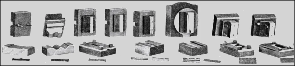
The illustration shows a set of
dies designed for blanking, forming
and piercing a set of springs and
holders intended for holding cartridges
in rapid firing army rifles.
The second and third dies are
plain gang dies designed for blanking
and piercing the clip.
The large die shown at the right
is for bending up one of the clips at
one operation, and is constructed on
the same principle as the one shown
on page 46, the side benders completing
the springs at one stroke of
the press.
The fourth and fifth dies, and the
three punches over them, are for
bending the second spring, three
operations being required.
The fourth and last dies are for
bending and piercing the springs,
one of which requires three operations,
and the other but one, the
whole being shown to illustrate the
number of tools often required for
very small articles.
An attempt has been made by
the photographer to illustrate the
work done, by placing a spring in
front of each die, with, however,
but partial success.
CHUCK FOR MAKING PUNCHES.
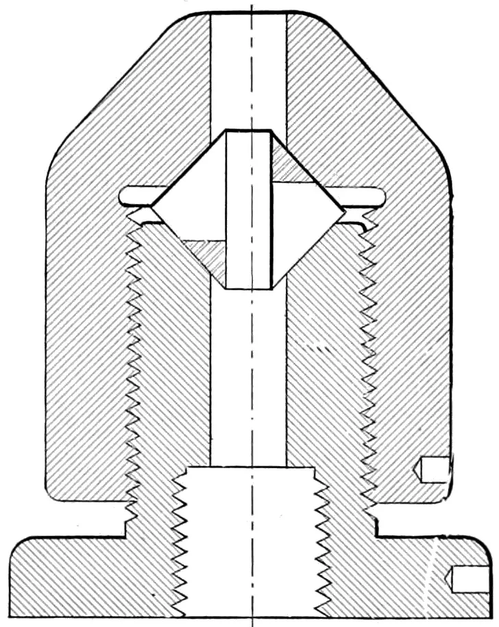
Fig. 43.
The advantage of having a chuck for turning out punches from
solid stock, capable of taking a heavy chip without springing and
still run perfectly true, is well known.
The illustration shown, represents one which will fill all wants
in that direction. It is simple, and can be made in the shop, no
special tools being required. The boys in the shop used to call it
a “Pratt & Whitney” chuck, because a part of the tool, at least,
is similar to one which is largely used by that firm, but the split
cone is, I think, original. The base or internal portion of the
chuck is screwed on to the mandrel of the lathe in the usual manner,
and the split cone, which is provided with bushings to accommodate
all sizes of steel, from one inch down, is gripped by the
outer shell, which is worked by a spanner similar to the ordinary
chuck.
For those who have much of this class of work to do, they will
be well repaid for the trouble and expense required to make them,
for made in the shop, the cost will not exceed $15.00 each. If
some enterprising firm would take hold of the matter, they probably
could be produced for half this sum.
SPRING DIES.
Figs. 44 and 45.
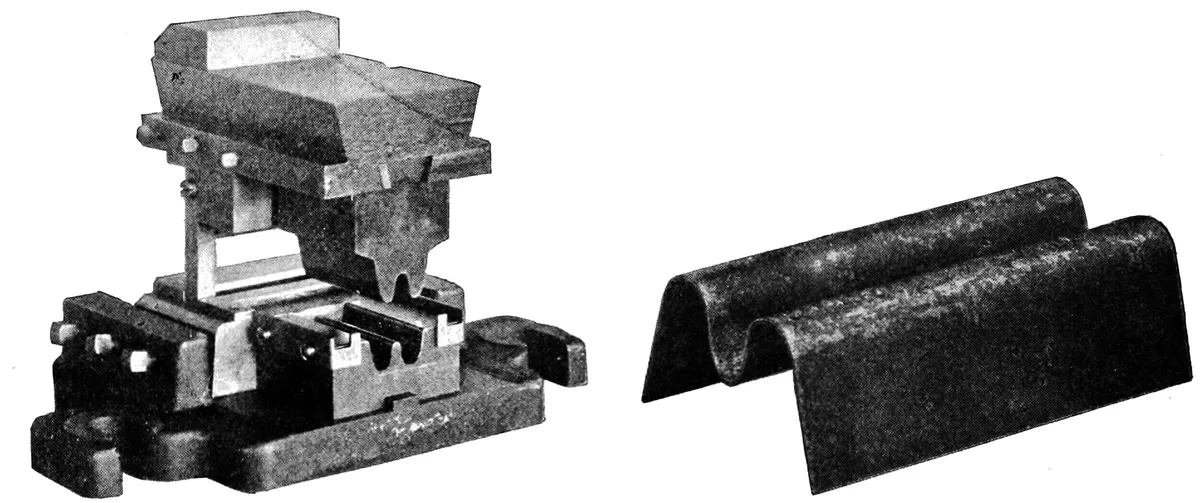
The half-tones show a
combination punch and die
for cutting and bending a
sheet metal spring, the
stock being fed in with a
roll feed, and then removed
by the use of an inclined
press, shown on the opposite
page. Any length of
spring, up to the length of
the die, is made by simply
changing the length of
feed. The stock is cut off
and fed by gravity to the bending die, and after being bent, is
removed in the same manner, the bending up of the ends of the
spring allowing it to pass freely from the die.
Considerable trouble was experienced in getting the die to
work nicely, but it was accomplished, finally, by the use of kerosene
as a lubricant on the under die.
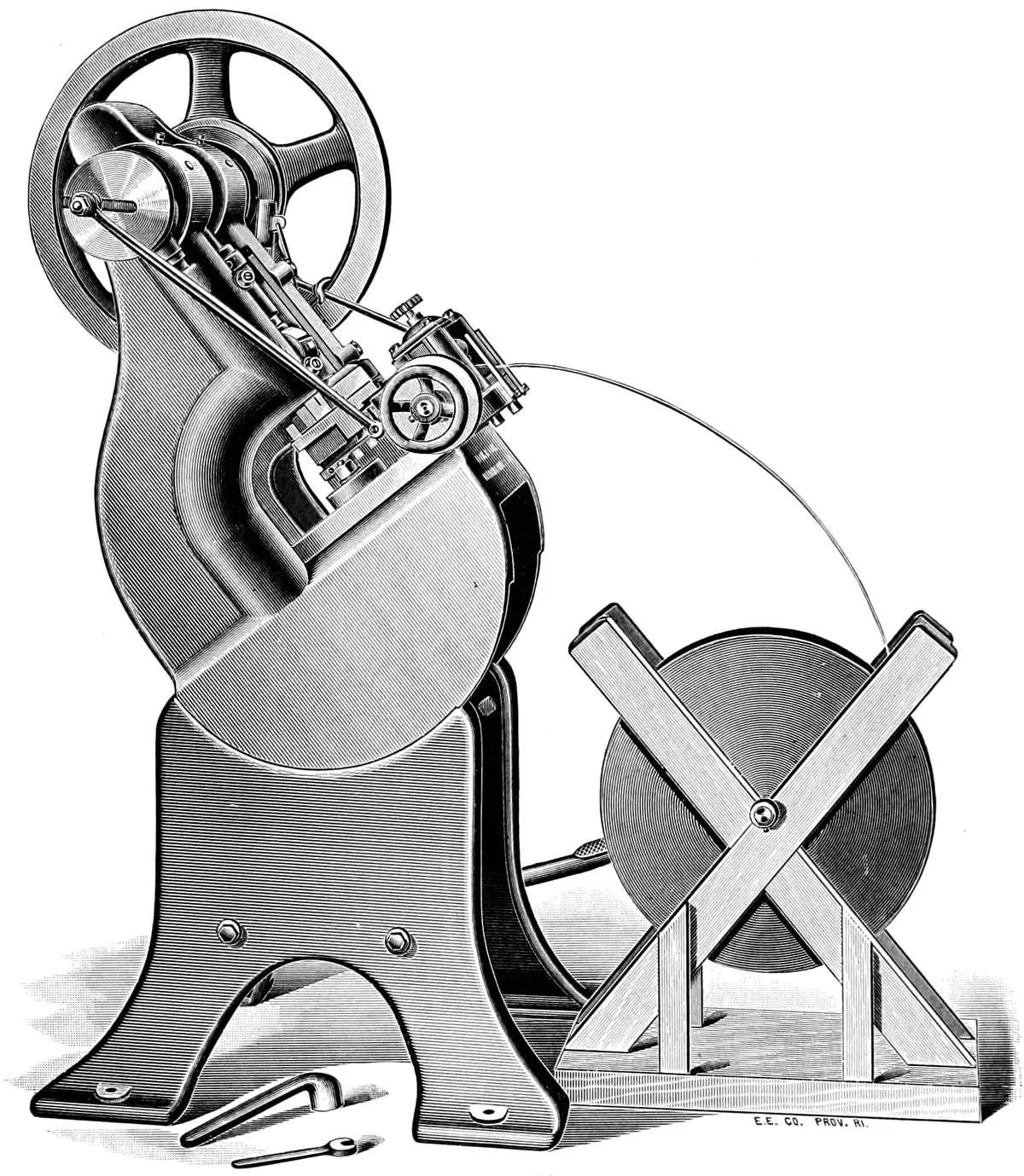
The press shown is what is known as a “Style B” Press, and
the illustration is loaned by
the courtesy of the Mossberg
& Granville Mfg. Co.,
by whom the dies shown
were made. The same
style of press is largely
used on can, pail, and other
tinware, in connection
with a single-action die
shown on page 25.
INCLINED POWER PRESS.
Fig. 46.
The advantage of a press of this kind is that single-action
combination dies, shown on page 25, can be used either in
connection with a roll feed or without, and the work removed
without any special attachment; the operation of the die being
that, as the punch rises, the work is raised to the top of the die
and removed by gravity. The expense of the die is greater, but a
larger amount of work can be accomplished than with the “Push
Through” double-action die shown on page 27.
The greatest disadvantage of the inclined press is the inconvenient
position of the press for die setting. This is avoided in the
style shown, which can be instantly changed to the upright position.
DIE HOLDERS AND BOLSTERS.
Fig. 47.
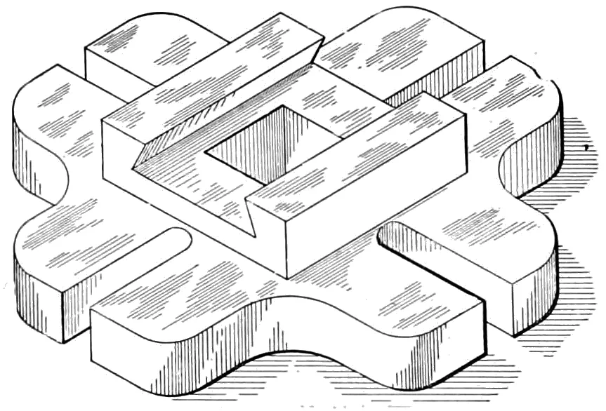
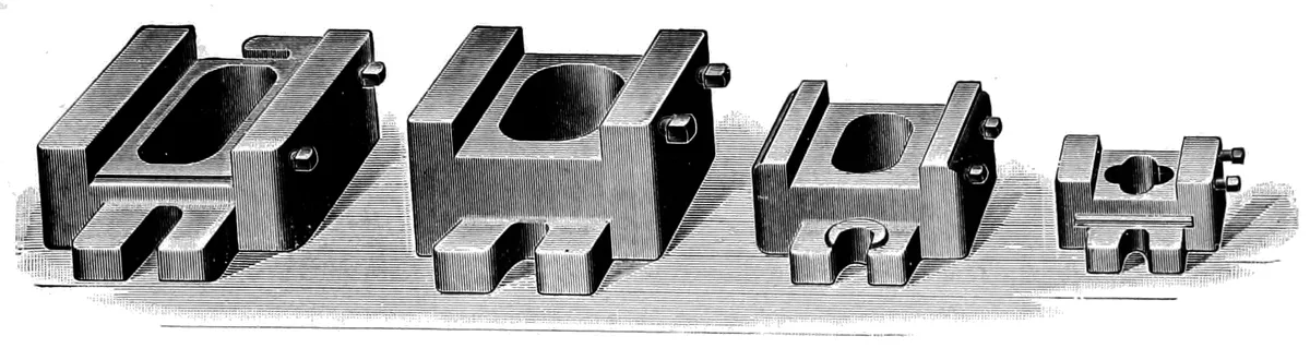
Die holders and bolsters are used for holding dies to the bed
of the press, the holder often being used to support some part of
the die that would otherwise be unable to stand the strain of
punching. They are usually made of cast-iron, except for heavy
work, when steel casting will be found preferable, as steel does
not crack under any strain, and will stand more abuse than the
cast-iron holder.
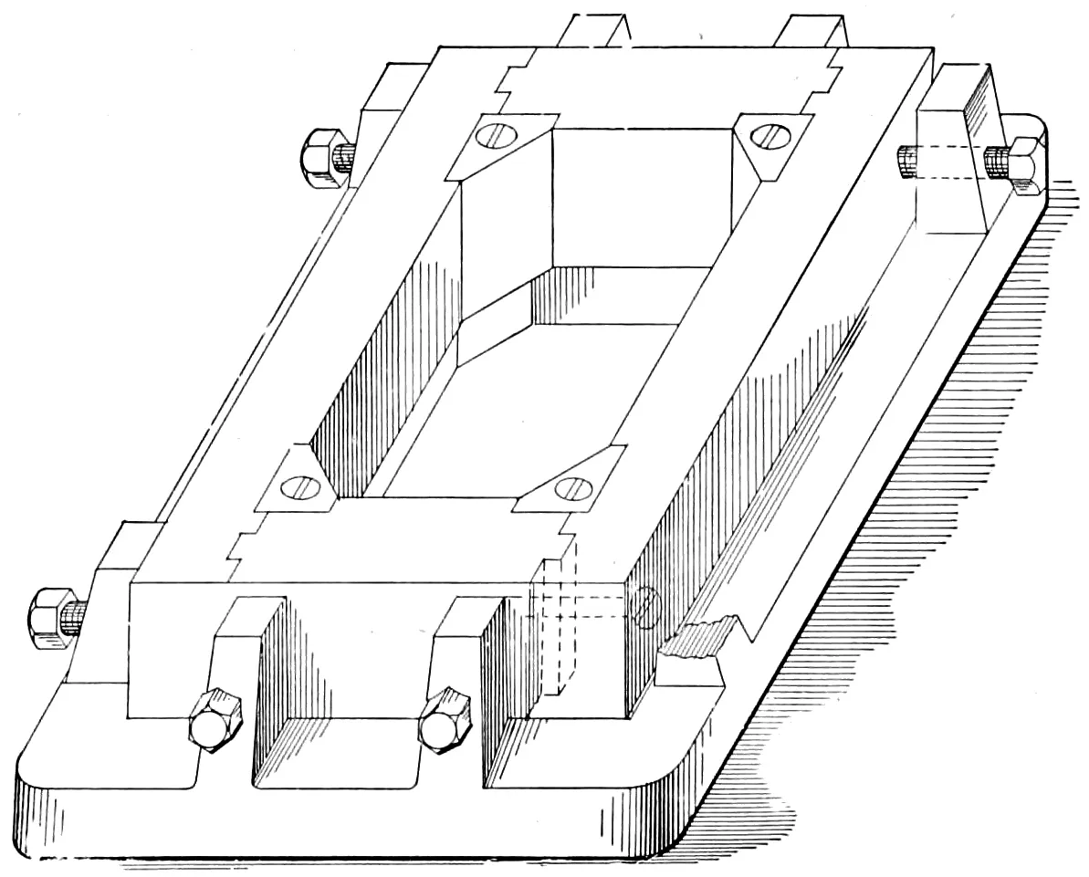
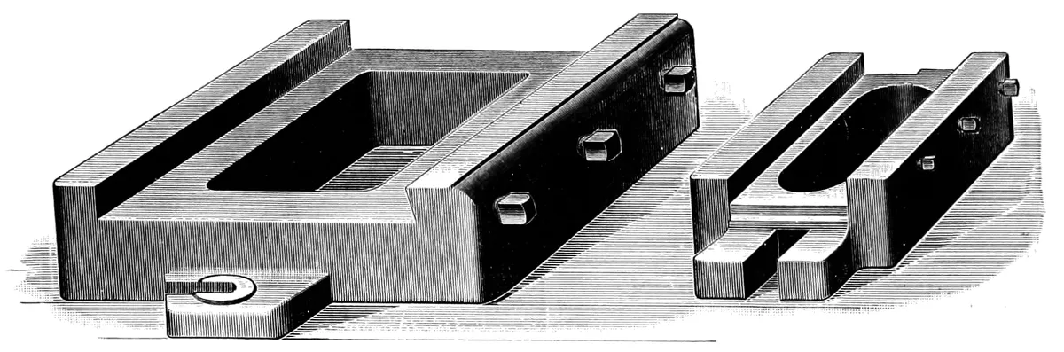
The holder shown in Fig. 47 is a good style, and is adapted to
a large variety of work. It can be set either way in the press, and
with either keys or set-screws for holding the dies. If screws are
used, the dies should be made of standard width, as 2″, 4″ and 6″,
and thus avoid a large variety of holders. Dies for drop presses
are usually held in a round block, as they can be more readily set
in the drop, and are held by four or six screws, known as “poppets,”
as shown in Fig. 82 on page 84. This manner of holding a die
will give good results, and it is suitable for all drop-press work,
except drop forgings, for which the dovetail slot in both hammer
and anvil will be found preferable.
Fig. 48.
Fig. 49.
The four holders shown in Fig. 48, are intended
for taking a uniform range of dies, and the shoe is so designed
that it may be removed and replaced by simply loosening the bolt,
as it is not necessary to remove the nut, the slot being so designed
that the holders may be pulled forward, and then sideways, and
thus removed from the press.
Fig. 50.
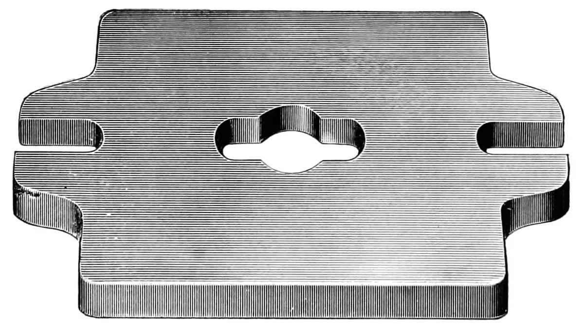
The bolster plate, Fig. 50, is intended to
be placed on the bed of the press, and the die holder fastened by
the use of two cap screws or stud bolts, which are not shown in
the illustration. The die holder and bolster are used as shown on
the press on page 59.
A GANG PRESS.
Fig. 51.
Fig. 52.
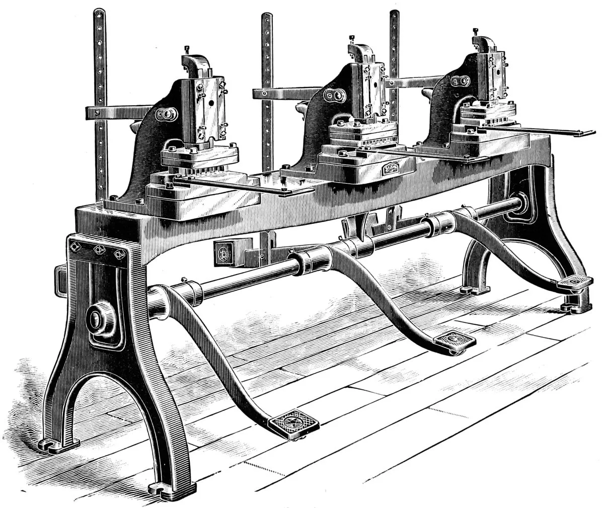
Fig. 51, shows a gang of
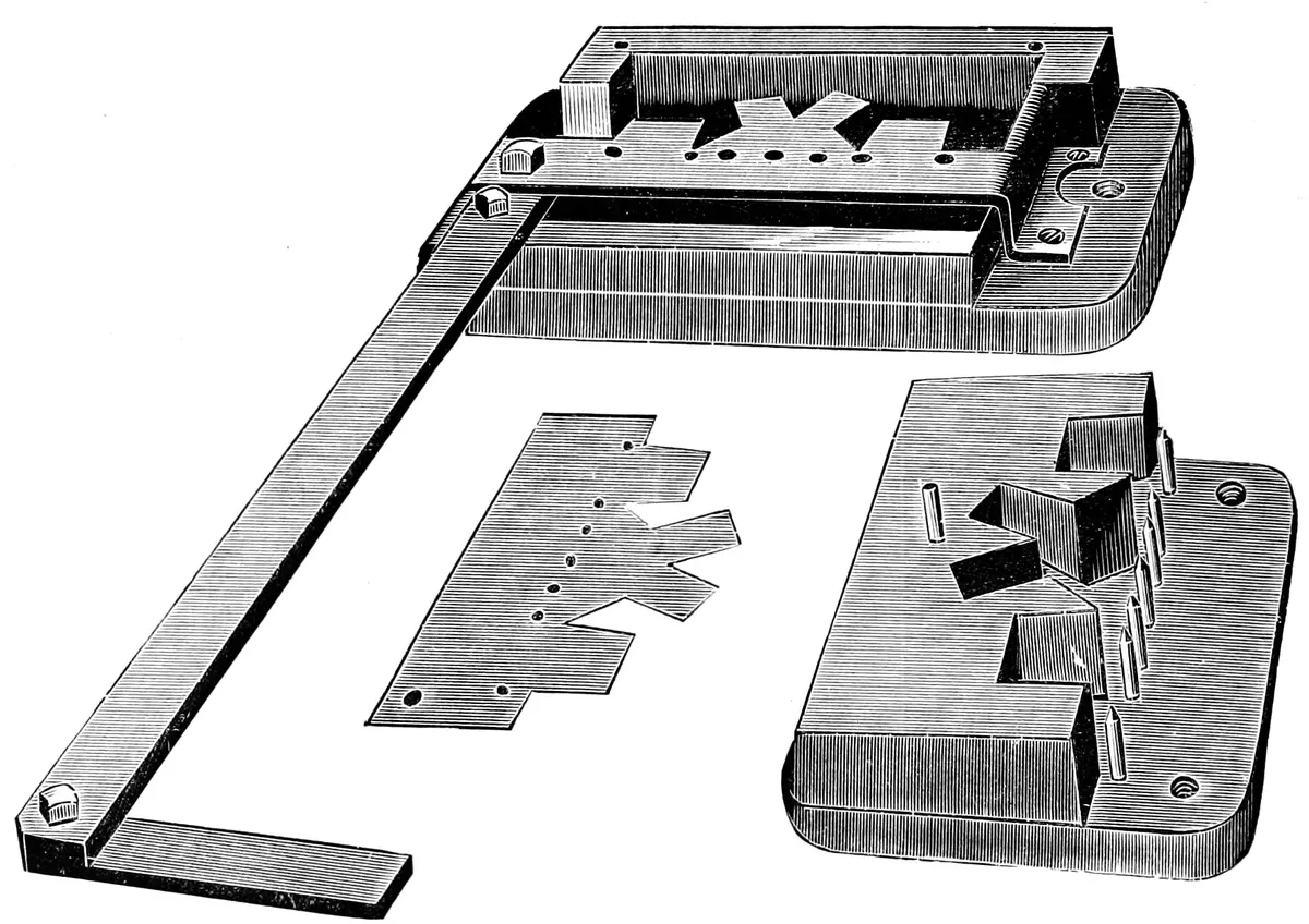
foot presses; Fig. 52, one of the dies used in the same, and intended
for notching and mitering skylight bars. They are made with
three, four or six presses on one table, and intended to be used in
consecutive order, each press being fitted with dies for performing
a certain operation on the bar.
The die and punch, which are shown with the stripper removed,
are so arranged that the back of the die acts as a guide and prevents
the punches from sheering and being forced away from the
die when cutting.
The press is made by the West Manufacturing Company of
Buffalo, N. Y., through whose courtesy the illustration of the
same is shown.
CAM STRIPPERS.
Fig. 53.
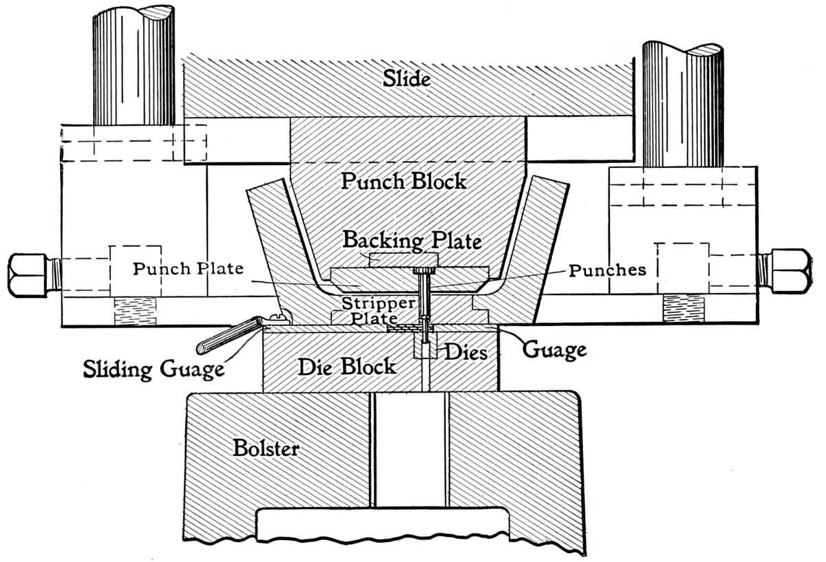
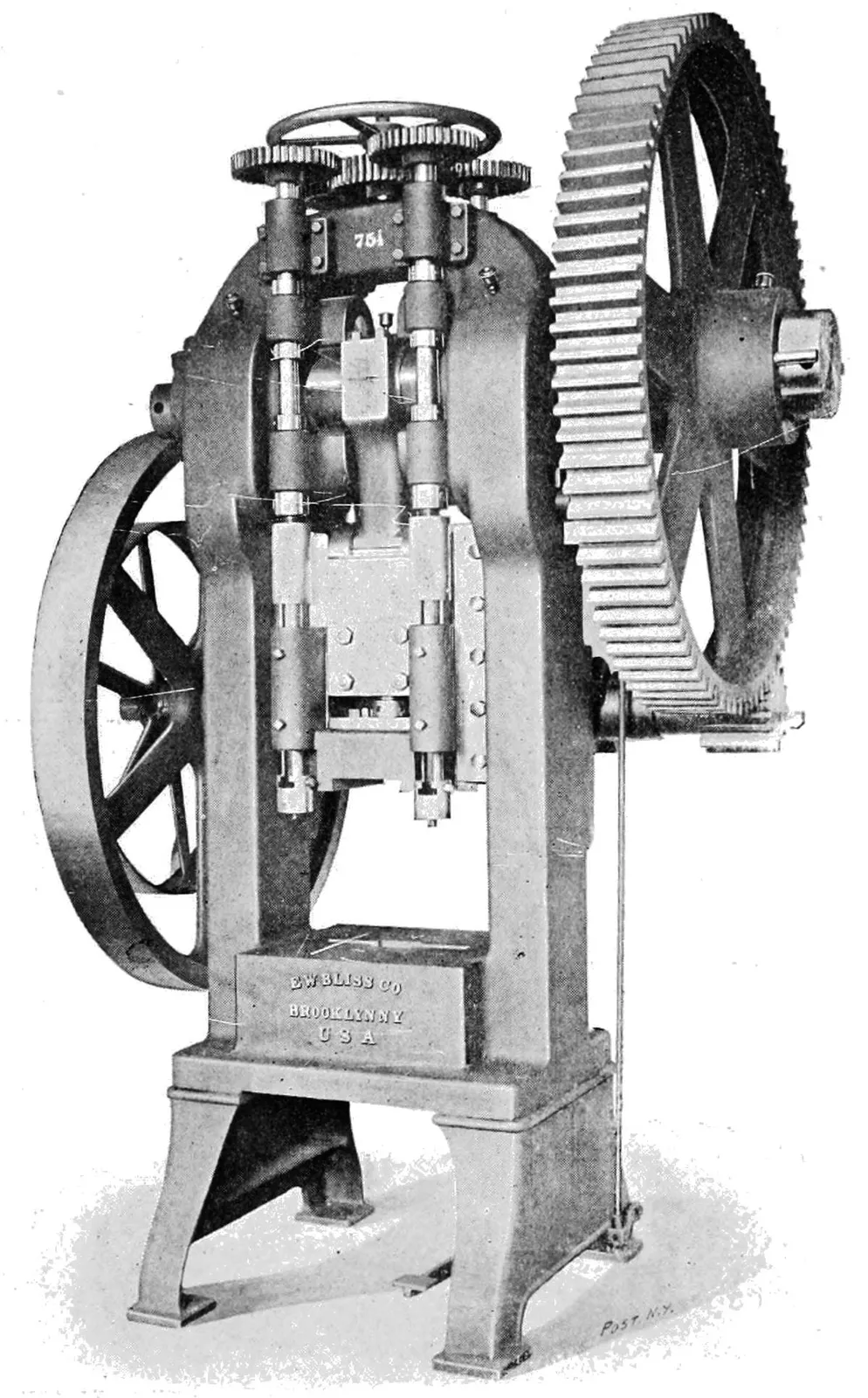
Figs. 53 and 54 show a die having a cam-actuated stripper, also
press specially adapted to the use of the same, illustrations of
which are loaned through the courtesy of the E. W. Bliss Co.
The great advantage of a stripper of this kind is less liability
of breaking the punches, and the thicker stock that can be punched
on account of the decreased length of punches that can be used,
which are made very short, and are held in a punch back. The
stripper plate is fitted with bushings, which guide the punches and
support them while piercing the metal.
Fig. 53 shows the details of the die and punches, the punches
being held in the punch block which is fitted with a backing plate
of hardened steel; the stripper plate is attached to four vertical
rods which receive their motion from two cams on the main shaft.
When the stripper is up, a free space is left between punch and
die, enabling the operator to manipulate his work quickly and
accurately. The stripper comes down on the blank, straightening
it and clamping it tight before the punches enter, and holds it
while the punching and stripping is done, and the work comes out
perfectly straight and true. As the stripper moves up and down
with the punches, they may be made shorter than a stationary
stripper would permit, and the punches used are therefore more
rigid and lasting. This also enables the punching of smaller holes
in proportion to the thickness of the stock, the stripper acting as a
guide for the punches up to the moment when they enter the
metal.
Fig. 54. CAM-ACTUATED STRIPPER PRESS.
The press shown has a 6″ crank shaft, weighs about 15,000
pounds, and is geared 7¹⁄₂ to 1, and is one of the latest productions
of the E. W. Bliss Co.
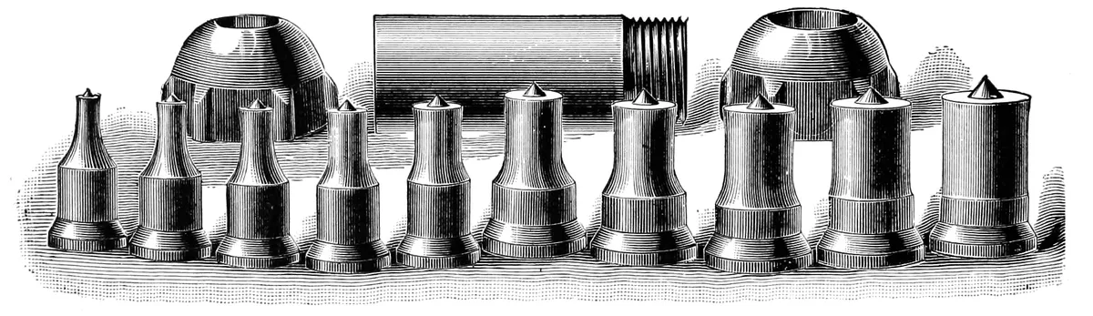
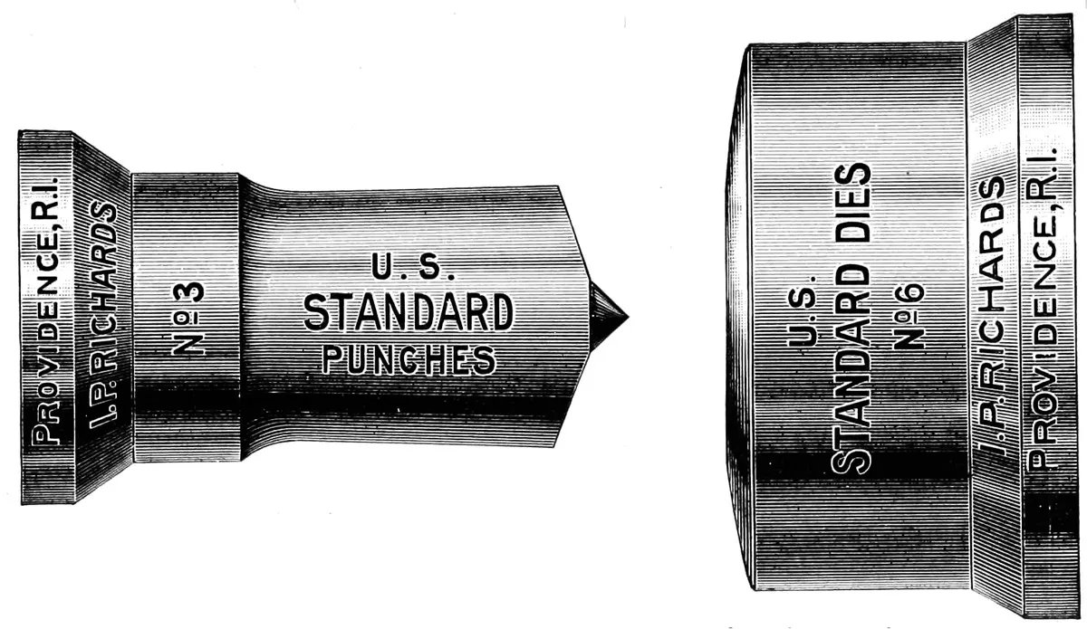
U. S. STANDARD PUNCHES AND DIES.
Fig. 55.
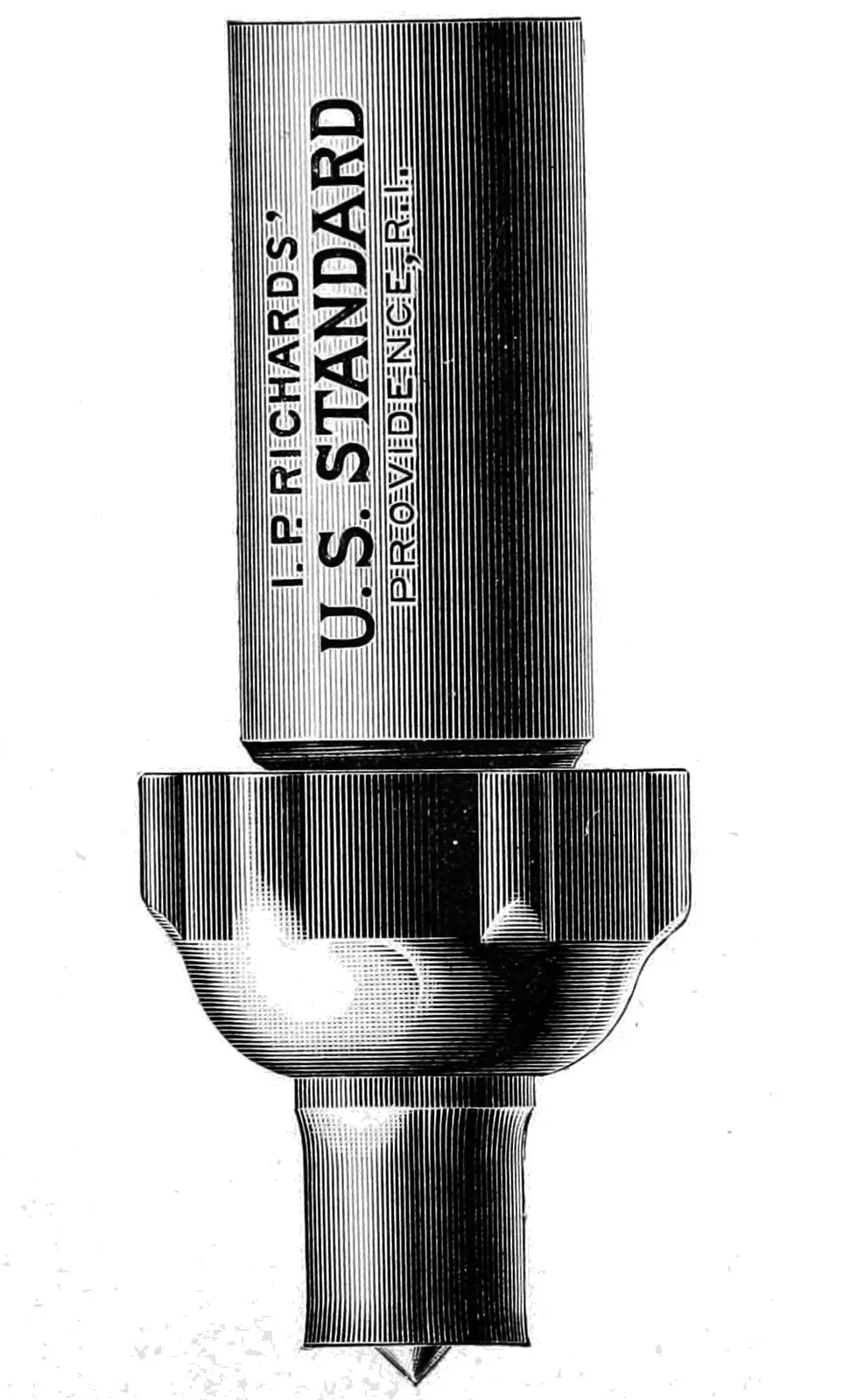
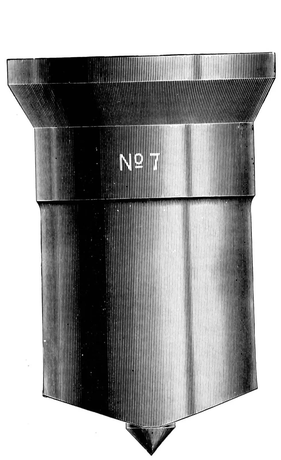
The following illustrations are loaned through the courtesy
of Mr. I. P. Richards, the well known inventor of the only standard
for round punches and dies, and the best method for holding
the same. The shank which is shown in Fig. 57 is fitted to the press,
and the punches are held in place by the coupling. The punches
being a standard length, can be easily renewed when worn, or exchanged
for a larger or smaller size without disturbing the adjustment
of the press. They are made in all sizes
from ¹⁄₈″ to 4″ diameter, and adapted to almost
all classes of round work, but more especially
for punching out holes for boiler, tank, and
other work which is secured by riveting.
Fig. 56.
Fig. 57.
Fig. 58.
The punch shown in Fig. 58 is ground
shearing thus reducing the power required
for operating the same. These punches are
furnished by the inventor, Mr. Richards, at
a less cost than they can be made by consumers,
although the patent on the same having
expired, they are open to the public, and are
extensively copied by other manufacturers,
often, we are sorry to say, without giving Mr.
Richards the credit which is due for
the invention and his efforts to introduce
and maintain a standard punch.
While we have no data of the power
required to operate these punches, we
have reason to believe the statement
that 40% is saved by their use.
PUNCHES AND DIES FOR NUT WORK.
Fig. 59.
Figs. 60 to 63
In the manufacture of nuts it is customary to make each operation
a separate one; that is, the bar is first cut up into short
lengths, and then the holes punched the entire length of the bar;
the nut is then roughly blanked out, and put through, or rather
under, a crowning punch which presses the corners, and leaves
the circle on the top, shown in Fig. 62. The nut is then put
through one, two, or three shaving dies, each of which takes off a
thin shaving, and leaves the side of the nut very smooth. The
greater the number of operations the nut passes through, the better
the finish obtained.
Various attempts have been made to reduce the number of
operations required in this work, and thus produce a nut at a less
cost. These attempts have met with more or less success. Perhaps
the nearest approach in this direction has been made by the
Port Chester Nut Co., who punch a blank and shave a nut at each
stroke of the press. This is a patented process, and for that
reason is not shown here.
The Figs. 59, 60, 61, 62 and 63 show the first, second, third,
fourth and fifth processes. The curvature of the bar is caused by
the first punching, as the metal invariably stretches more on the
under side; this however is but of little consequence as it does
not show in the finished nut.
FORGING BICYCLE SPROCKETS.
Fig. 64.
Fig. 64 illustrates a method of making bicycle sprockets that
is both better and cheaper than that usually followed, and one
that is not in general use. It is the invention of Mr. L. B.
Munger,—who is well known for his improved methods of manufacturing
bicycle parts,—and has been copied to some extent by
his competitors.
The sprocket is blanked out in the usual manner, and the cross
area of the stock that is left to form the spoke is carefully calculated,
so that after the sprocket has been through the forging die,
no fin is left around the edges of either spoke or hub. This calls
for good judgment as well as accurate measurement on the part
of the die-maker, as it has proved a failure in several cases where
an attempt has been made to adopt Mr. Munger’s method.
The tail shown on the blank is intended to be grasped in the
tongs while heating, and in placing the blank upon the forging
dies, and cut off after that operation.
This same method is followed by Mr. Munger in all kinds of
forgings the work being first punched out to the proper size,
leaving the required amount of stock necessary to fill the die, and
is then forged, leaving little or no fin, and avoiding the trimming
process after the work has been forged.
This method has been jealously guarded by Mr. Munger, and
is here published for the first time with his full permission.
Fig. 65. A GROUP OF ARMATURE PUNCHINGS.
Illustration Fig. 65 shows a group of armature punchings, all
of which are blanked out by means of compound dies, the largest
of the group being 36″ diameter, and the smallest one, which is
shown in the centre, 1¹⁄₈″ diameter; the others being respectively
4″, 6¹⁄₄″ and 20″ diameter.
A detailed description of the dies for producing this work is
given on page 32. The methods of constructing the dies are so
varied that it is impossible to give a plan which will fit all styles
of armature sheets. Plans or sketches for dies for any work of
this character will be furnished on request.
Fig. 66. A GROUP OF SMALL PUNCHINGS.
The above illustration shows a large variety of different
articles which are produced wholly, or in part, by press work.
The four corner illustrations will be recognized by those
interested in bicycle manufacture, being punchings of sprocket
wheels made by four of the leading manufacturers. The figures
14, 15, 19, 21, 31 and 35, are also parts for bicycles; and numbers
32, 42, 44 and 47 represent the pieces used in the construction of
the well known bicycle whistle.
SPEED OF PRESSES.
The speed at which a press can be operated depends upon the
nature and thickness of the stock being punched, the quality of
the steel of which the tools are made, and the material used for
lubricating the same. In punching a soft material, such as paper,
cloth or very thin sheet metal, a speed of 200 to 350 revolutions per
minute is practical, as the fiber of the metal does not require to
be broken, as is the case when operating on thick or hard material.
The old-fashioned rule that a punch will penetrate metal equal
in thickness to the diameter of itself, is fast being exploded, as it
is a well known fact that a ¹⁄₂″ punch can be put through a 2″ bar
of iron, provided the tools are properly made, and a speed of not
over one stroke in two and one-half minutes be given to the same;
breaking the punch being the result of an increase of this speed.
In ordinary punching sheet metal, .014″ to .04″ thick, 125 to
150 revolutions per minute has been found as high a speed as
it is practical to run; in blanking out large sheet-iron armature
disks, .025″ thick, and 20″ diameter, more work is produced at 60
revolutions than at 90, as the dies will stand up to the work
and run off a larger number of sheets without being ground, than
when used at higher speed.
The speed of drawing punches depends largely on the work done,
and the material used for the same, as a slow speed will often
enable work to be produced that would rupture at a high speed.
On large and deep shells, a speed of two to four revolutions is
often necessary, while small and shallow work will stand a speed
of 150 to 200 strokes per minute.
The stroke of the press is an important factor which must be
taken into consideration when estimating the speed at which work
may be punched, the idea being that the tools must have time to
break or rupture the grain of the metal, and this can be facilitated
by giving the proper amount of clearance to the punch, as well as
the usual clearance to the die; also care being taken when punching
a thick metal that the punch and die do not fit too closely.
Probably more trouble is caused by this one defect in tool making
than any other. It is hard to convince a good die-maker that the
punch and die must not fit nicely when used on thick work; often
a difference of ¹⁄₃₂″ to ¹⁄₁₆″ should be given on work ³⁄₈″ in thickness
or over. On thin sheet metal the tools must fit nicely in order to
produce the work without burr, and the speed of the same can be
greatly increased; 90,000 to 100,000 per day being the usual output
of a press running at 200 revolutions per minute, the stock
being fed with either roll or ratchet feed.
DIE SETTING.
Setting punches and dies in the press is often done without
due regard for the tools,—that they are properly set and adjusted
for the work they have to do. From a mistaken idea of economy,
this work is often put into the hands of an operator who has little
idea of the value of the tools which he is adjusting, and to whom
any accident caused by improper setting is a small matter.
To set a punch and die in the press, remove the belt from the
wheel, unless the press is provided,—as all presses should be,—with
a countershaft. Place the die and holder, (into which the
die can be keyed to better advantage on the bench), on the bolster
plate, and enter the punch carefully by hand; now bring the gate
or slide of the press down until the bottom of the slide strikes the
shoulder of the punch and prevents it from being moved out
of the die; next ease up slightly on the slide, so that the punch,
die and holder can be moved along by hand into their proper places
in the press. The punch, if secured in the head block or chuck of the
press, is pushed to the left-hand side of the dovetailed slot in the
slide, and the key driven in. The bolt or stud holding down the
die holder should now be slightly tightened, and a few raps with
the hammer be given to the die; this causes it to find its proper
place on the bolster; the holder is now secured to the bolster plate,
and the punch withdrawn from the die and then entered again, to
be sure that the operation of setting has been properly performed.
No specified distance can be given as to the distance the punch
should enter the die. In sub press dies for watch work, the punch
should come to the surface of the die and enter the least possible
amount; while in rough crude dies used for thick sheet iron or
boiler plates, the removal of the scrap or the piece punched out will
be greatly facilitated if the punch enter ³⁄₈″ or more.
The above method will not meet with the approval of many,
but a large experience in different methods of die setting has led to
the description just given.
There is one good rule which, if followed, would practically
prevent the accidents now so common in large press rooms, and
that is: never allow the hand or fingers to be placed under the
punch while the press is in motion. Many of the accidents which
occur are caused by gross carelessness on the part of the operator
who is induced to take the chances of accidents because of the
larger amount of work which can be produced.
BROACHING.
Fig. 67.
Although not usually classed with punches
and dies, the operation of broaching is analogous
with punching, and for that reason is properly
entitled to description here. The broach is
really a punch, the cored or drilled hole in the
work broached forming a die for the same. It
is used for finishing holes which may be either
punched, cored or drilled in brass, iron or steel,
and which may be round, square or any other
desired shape. The operation is best performed
in a press designed for the purpose, having an
adjustable stroke of 1″ to 12″. The broach
shown is intended for finishing a cored hole,
and is 2¹⁄₂″ × ¹⁄₂″ rectangular section, about 8″ in
length. The teeth being very coarse on the
lower end, are intended for taking out the bulk
of the stock, until the centre of the broach is
reached, when they are sheared in opposite directions,
thus breaking the chip off, and then the
teeth decrease in size until the upper end of the
broach is reached, when the same is left perfectly
straight for about 2″, forming a sizer, keeping
the finished hole a standard size. The broach is best driven when
operated on by a V block secured in the press in the same manner
that the punch is usually held, and as the plunger comes down, the
broach will find its own centre with less liability of breaking or
making an imperfect hole. Broaching of almost any length can be
done in a press having a short stroke, by using a successive number
of blocks, the broach being inserted in the hole, and driven down
the full stroke of the press. A block of the same thickness as the
stroke of the press is then inserted, and the operation can be repeated
until the desired length of drive is obtained. The results
obtained are not equal to a continuous stroke broaching press, as
the stopping of the broach when partly through the work, gives
the metal an opportunity to settle into the teeth of the broach,
thus increasing the liability of breakage.
There are on the market several machines designed expressly
for this work, several of which perform the operation by pulling
the broach through the hole, which is an improvement over the
method just described, but as it does not come under the jurisdiction
of this work, the description of this machine is omitted here.
REVOLUTION COUNTERS FOR PRESS USE.
Fig. 68.
The use of a revolution counter or indicator for keeping
account of the work produced by a press, is preferable to the
ordinary manner of weighing up or trusting to the intelligence of
the operator to determine the amount of work done. This fact
has led it to be adopted by several of the largest press rooms in
the country, and with satisfactory results.
The above illustration shows a style which is adapted to all
makes of presses, as it can be connected either directly to the shaft
itself, or to the centre, or can be located in front, on the upper
part of the press, and then connected by a lever from the slide,
and will give an accurate record of the revolutions made. It is
simple, having no springs or gears, and can be furnished with
either four, five or six dials. The five figure indicator shown in
the illustration will count up to 99,999, and then repeat automatically.
A dial can be set to zero, or the counter can be had
without the thumbscrews for re-setting.
In using the counter in connection with gang punches, that is,
in work that requires one or more strokes of the press to properly
start the strip of metal used in feeding, there is a loss of six to
nine per cent. from the number actually indicated. This fact
being thoroughly understood, the proper amount of work can be
produced, making the necessary allowance for the false strokes.
BALL CHUCK.
Fig. 69.
The illustration Fig. 69 shows a chuck for bench use, which
is adapted for “working out” punches and dies or any work
which can be done more conveniently by placing it at an angle, so
as to use a hammer and chisel to good advantage. The chuck
was originally designed for and is usually used in die-sinking, but
the advantages mentioned has led to its use in the die room, and
once introduced, it will be found to be a good tool.
A base provided with a cavity of the same radius as the
bottom of the ball is intended to be used in connection with the
chuck, and is usually made by coiling up an old belt, and then
striking the chuck firmly down into the same. The die is held in
the slot, secured by the two set-screws.
The advantages obtained from the use of this chuck will be
appreciated by those who have experienced the difficulties of
chipping out an odd-shaped die.
FINISHING PRESS WORK.
Fig. 70.
Perhaps a few words on finishing punched work may be of
interest to those who have the good or bad fortune to have charge
of that kind of work, and the barrel shown is specially adapted
to work of this kind; being a modification of the ordinary tumbling
barrel, so arranged that the incline may be varied, giving a greater
or less effect on the work as may be wanted.
All punched work as it comes from the press is in an unfinished
condition, owing to the soap, oil or other substance which is used
for lubricating the dies, and the advantage of tumbling cannot be
overestimated. Burrs can be removed with practically no expense,
and work put in a salable condition which would otherwise
be consigned to the scrap.
For abrasive materials to be used in tumbling the work, there
is nothing better than broken emery wheels for rough tumbling or
taking off heavy burrs, and for finishing light, delicate work,
leather chips and sawdust will give good results. For polishing
buttons of hard rubber or papier mache, old woolen rags will be
found to give a high polish without marring the work.
For tumbling shells which have been drawn, but are to be put
through a second operation, a solution of strong soap water, either
hot or cold, will be found to give a good polish and also leave the
work in good condition for the second drawing.
BELTING UP PRESSES.
To belt up a power press properly, set it in line with the countershaft
or main shafting, and fasten securely to the floor, taking
care that it is properly leveled, and that each leg has an equal
bearing on the floor. The better the foundation, the better results
will be obtained. Take double the distance from the centre of
counter or main shaft to centre of crank shaft on the press, and add
one-half the circumference of both pulley and balance wheel, and
the result will be the length of belt required. If the press is an inclined
one, and it is to be used in an upright position also, set the
press on an incline and cut the belt to the proper length;
then set it upright and set a piece of belt of the proper length to
be used when the press is in that position. Put on a belt the full
width of the wheel. Do not put a 2″ belt on a 4″ balance wheel,
and then expect the momentum of the wheel to do the rest. Do
not set the press directly under the main or countershaft when it
is possible to avoid it. Set it at least 2 ft. away, even if you have
to sacrifice floor space to do so. Run the belt with the grain side
next to the pulley. A long belt is preferable to a short one, as the
adhesion caused by the weight of the belt is more desirable than
that obtained by tight lacing, and the belt will wear longer and
give better results.
FEEDING PRESSES.
Fig. 71.
Feeding by hand is the oldest and most common
method of feeding press work, and a few words on
this subject may be of interest.
When work is to be punched from short stock, as
most sheet tin stock comes, or where irregular stock
is used, an automatic
feed is of
doubtful utility,
for the operation
of keeping the
feed supplied is
certainly as
troublesome as
feeding the
press itself. In cases of this kind it is best to feed by hand as a
skillful operator moves his hands with the press and will produce
work rapidly, but if the work will admit of it, a power feed should
be used.
We describe a few of the many kinds in use: roll, finger, slide,
double roll, reel, tube, grip, ratchet and friction dial feeds, combination
feeds and knock-outs.
When large quantities of the same general class of work are
wanted, and the stock can be procured in long strips or rolls, fit
the press with a plain roll feed, Fig. 72, as they are easily applied,
and can be quickly adjusted and changed from one class of work
to another. They are made in several styles, to feed from front
to back, left to right, or the reverse,
single or double and with
ratchet, friction, or “pinch”
adjustments of rolls. The
amount that can be fed is usually
regulated by the diameter
of the rolls except in special
cases where a rack and pinion,
giving any amount of feed
wanted, can be used.
Fig. 72.
A finger feed is an adjustable “finger” fitted to and worked
by the slide of the press, so adjusted that it is raised at each
stroke just enough to allow the stock to pass under, and then
catches in the hole punched by the preceding stroke. It is inexpensive,
and is not in the way when not in use. When fitted with
a power reel to wind up the scrap, it becomes one of the most
useful feeds known, and can be used equally well on both single
and double acting presses.
Tube feeds are used for feeding work that has been previously
punched out by a plain die. It is best adapted for coining, swagging,
etc. The work is caught in a tube as it falls from the
blanking die, and is then transferred into a second tube placed on the
press. An automatic moving slide delivers the lowest piece in
the tube to the dies at the proper time. This feed is largely used
on coins, medals, buttons, etc.
An automatic slide feed consists of a mechanical hand which
grips the work and then slides it to the proper place on the dies,
and is specially adapted to a fragile material, as cardboard, paper,
etc., and is also one of the most accurate style of feed in use.
A grip or claw feed is so arranged as to enter the first hole in
the stock just punched, and then draw it ahead the proper distance
for the next blank. It is easy to adjust, and can be run at a very
rapid speed.
Dial feeds, Fig. 71, are used to hold a blank on which it is
desired to perform a second operation, as armature blanks, or to
act as a carrier to present the blank in successive rotation to the
punch, and in some cases to remove the work after the punch has
performed its duty. They may be belt, ratchet, or friction driven,
and may be a smooth disk as used for cartridge work, or fitted
with sockets to hold and carry the work.
A combination feed is two or more feeds in one, as they are
usually adapted for special operations, and can not be changed
with the same ease as the roll or finger feed.
Knockouts are fitted to many presses to assist in removing the
work from the dies. They are applied to either the slide or body of
the press, and in the latter case are connected by a pitman to the
end of the crank shaft, so that as the punch rises from the die, the
work is forced out.
HARDENING DIES.
So much has been said on the subject of hardening steel that
we are disposed to let it alone, but feeling that a work of this kind
would not be complete without it, will give the results of our experience.
For heat we prefer a gas furnace of any good make,
but this not available, a clean charcoal fire is nearly as good.
Fill all holes in the die that you do not wish to have a cutting
edge, such as the stripper holes, with fire clay; use plenty of good
hard wood charcoal, heat slowly but steadily to an even red. Dip
the die entirely below the surface in salt water, for while there are
baths that are good for special work, steel that will not harden in
clean salted water is not fit to make a die of, keep it in the water
until it is entirely cold, then put it on the fire again and warm it
until the heat is as great as the hand can bear, then cool off and
polish and draw to a light straw. The object of the second heating
is to lessen the liability of fire cracking.
For large dies it is indispensable to have a tank properly
arranged for cooling the steel quickly. This is best arranged by
having two rods fixed across the tank about 10″ below the surface
of the water; the water supply is led down below the surface nearly
to the bottom of the tank. The end is bent up so that as the die
is plunged into the tub the valve is opened and a circulation of
water is created in the tank. This method will prevent the soft
spots often met with in hardening. Fig. 73 shows the arrangement
so clearly that no further explanation is required.
Fig. 73.
Fig. 74. AN ANCIENT TRIP HAMMER.
Although not properly classed as a punch and die, and yet
clearly the result of the laws of evolution, the above illustrated
tool is entitled to be represented here; and shows the trip hammer
in its most primitive form. It is taken from a German illustration,
loaned through the kindness of the Bradley Co., of Syracuse,
N. Y., for insertion here.
The mode of operating the hammer is clearly shown in the
illustration, the water-wheel attached to one end of the revolving
drum carries the collar and dog for raising the hammer.
The method of keying the lower die in the anvil shown, is
identical with that practiced at the present time, the force of the
blow being controlled by the in-flow of water actuated by the
knotted rope which hangs within easy reach of the smith. The
swinging seat, however, would not be tolerated with the methods
of operating the hammers now practiced.
The exact antiquity of the sketch could not be ascertained, but
it is not far from the 16th century.
BROWN & SHARPE MFG. CO., Providence, R. I.
TOOLS FOR DIE WORK.
Fig. 75.
1-2″ Micrometer.
Fig. 76.
Micrometer Calipers.
Made to measure from ¹⁄₂″ to 24″, and to read to .0001″.
Fig. 77.
Height Gauge.
ATTACHMENTS USED WITH BROWN & SHARPE UNIVERSAL MILLING
MACHINE FOR DIE WORK.
Fig. 78.
Vertical Spindle Milling Attachments.
Figs. 79 and 80.
High Speed Milling Attachment and Driving Fixture.
Fig. 81.
Universal Vise.
PAWTUCKET MFG. CO., Pawtucket, R. I.
Fig. 82.
Press for Blanking, Champering and Trimming Nuts.
MOSSBERG & GRANVILLE MFG. CO., Providence, R. I.
Automatic Drop Press.
Designed for all classes of stamping and bending operations and can be
operated by inexperienced labor without danger of injury.
Single Acting Power Press.
Fitted with instantaneous clutch and stop motion. Designed
for all classes of punching operations, and can be fitted with roll,
finger or dial feeds.
E. W. BLISS CO., Brooklyn, N. Y.
PRESSES, DIES, SHEARS, DROP HAMMERS, DOUBLE
SEAMERS, TRIMMERS.
Toggle Drawing Press.
The toggle drawing press as shown in above cut is used in the manufacture of wash
bowls, milk and pudding pans, tea kettle bodies and breasts, sauce pans, bucket and pot
covers, small scoops, cuspidors, coal hod bottoms, trays, dust pans, brass and copper goods.
This press is fitted with an automatic friction clutch; it can be stopped and started at
any point of the stroke, by operating hand lever not shown.
The toggle movement as applied to this press has greatly increased the durability and
smoothness of action, insuring a more perfect “dwell” of the blank holder than can be
maintained in presses of any other design.
EMBOSSING PRESSES, SHEET METAL WORKING
MACHINERY, SPECIAL MACHINES.
Armature Disk Cutting Press.
The press shown in above cut is specially designed for cutting the outside
and inside of armature disks simultaneously, insuring exact concentric of
outside and inside circumference.
This press is fitted with a positive knock-out device.
The same general style of presses also supplied in larger and smaller
patterns.
NEW DOTY MFG. CO., Janesville, Wis., U. S. A.
Above cut represents a combined punches and shears in which
the knives for flat and round iron are independent of each other
and of the punch; and both sets of knives as well as punch are at
all times ready for use without any change. While it is a
single end, it has all the advantages of a double end machine, and
is much less expensive.
E. S. STILES PRESS CO., Watertown, N. Y., U. S. A.
METAL CUTTING, SHAPING and FORMING TOOLS, PRESSES,
DIES, DROP HAMMERS and SPECIAL MACHINERY.
No. 19 Adjustable Incline Press.
No. 3 Punching Press.
WATSON AND STILLMAN, New York, N. Y.
Hydraulic Open Jaw Die Sinking Press.
A very small press with short motion, on which small medals
may be struck without the annoying shock of the drop hammer,
and is an adaptation of their improved hydraulic punch, strengthened
in the jaw to avoid spring.
The body is steel, and from its method of construction irregular
dies may be used. The lower lever can, if desired, be made
self raising by weighting it at the rear.
Power, 60 to 125 tons pressure.
Heavy Hydraulic Die Press.
Adapted for hubbing up very heavy dies.
HILLES AND JONES, Wilmington, Delaware.
No. 4 Horizontal Power Press for Very Heavy Work.
For punching boiler heads, crooked furnace plates, bent, angle or
tee iron, boiler legs and all close or crooked work.
G. A. CROSBY & CO., 176 So. Clinton St., Chicago, Ill., U. S. A.
Manufacturers of presses, dies, and designers and builders of
patent automatic machinery for making cans. Write for catalogue
and information.
No. 2 Power Punching Press.
THE WATERBURY FARREL FOUNDRY & MACHINE CO.,
Waterbury, Conn.
300 Ton Knuckle-Jointed Embossing Press.
These presses are constructed upon an improved plan which
permits a powerful machine to be made in more compact form than
formerly. The main frame is made very rigid and as short as
possible (by allowing the guides for the crosshead to be placed in
front of the knuckle-joints) thereby reducing the spring or elasticity
of the frame to a minimum.
A specialty is made of designing and building machinery for
specific requirements. Some of our standard machines are as
follows: automatic rivet machines, automatic nut blanking
machines, thread rolling machines, machinery for making hinges
and butts from sheet steel and brass, machinery for making shot-shell
and ball cartridges. Patent hydraulic presses, pumps and
accumulators.
FERRACUTE MACHINE CO., Bridgeton, N. J.
Power Punching
Press P4.
This press is for
heavy cutting, punching,
shearing and
forming.
12 sizes of this style
of press, and a great
variety of other designs.