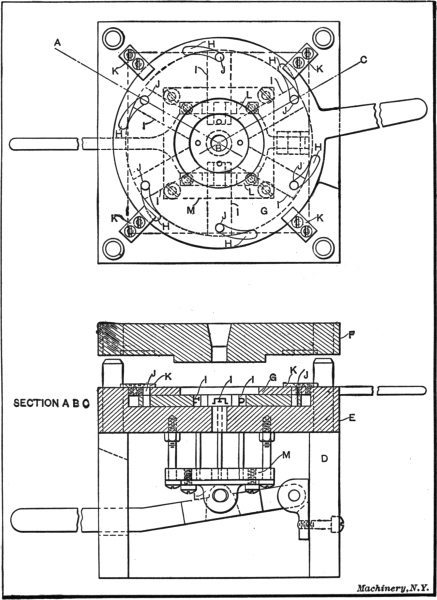
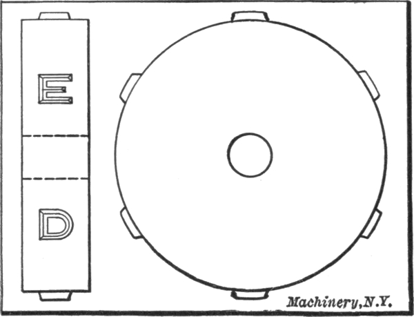
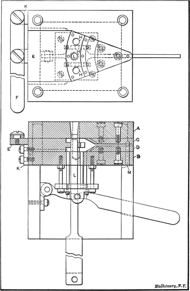
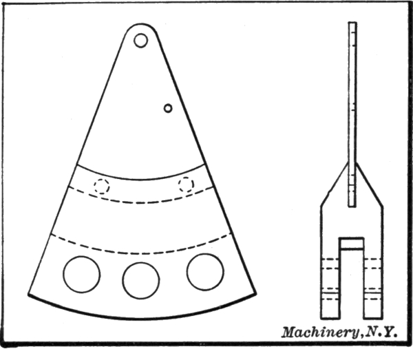
In 1907, Mr. E. B. Van Wagner, of Syracuse, N. Y., established the
E. B. Van Wagner Mfg. Co. for the production of die-castings. The factory
comprises the office section, the machine shop where the dies and
casting machines are built, the metallurgical laboratory where the
metals are alloyed, the casting department shown in Fig. 17 where the
die-castings are made, and the trimming department.
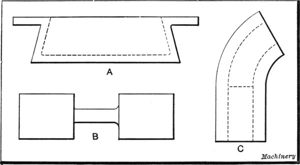
Fig. 16. Die-casting Constructions to be avoided
At the outset we may say that it is possible to die-cast almost any
piece, but it is not by any means practicable to do so. It must be
remembered that to die-cast on a practical basis the dies must be constructed
in such a manner that the cost of their operation and up-keep
will be light, or there will be no profit in die-casting. It is impracticable
to produce under-cut work, that is, work having no draft and
which is therefore impossible to draw from the die. Such an instance
is that illustrated at A, Fig. 16, and by the internal section of M,
Fig. 21, and the internal groove in O, also shown in Fig. 21. If absolutely
necessary, work of this kind can be done by the use of collapsible
cores; but here, again, we meet resistance in maintaining the dies
in proper condition, and, moreover, this method is commercially impracticable,
owing to the difficulty of operating these cores rapidly.
Hollow work, requiring curved cores, like faucets and bent piping of
the character illustrated at C in Fig. 16, are difficult to produce. If,
in designing the piece, it can be planned to have the parts of such a
shape that the cores can be readily withdrawn, employing a two-piece
core with a slight draft in each direction, the division coming as indicated
by the core line of C in Fig. 16, the problem becomes simpler.
Oftentimes this work can best be done by casting in a straight piece,
afterward bending the die-casting. It does not pay to cast
rough heavy work that can be made just as efficiently by sand
casting. Generally speaking, the greatest saving can be
effected by die-casting small pieces which have previously
required a large amount of machining to produce. On large
plain work the amount of metal required for the casting
makes the cost excessive on account of the difference in cost
of the metals. If, however, the large work must be finely
finished by polishing, etc., it is oftentimes found of advantage
to die-cast. Corners, especially those joining thick and thin
sections, as at B, Fig. 16, should be heavily filleted as shown
on one side of this piece. Regarding the casting of thin sections,
it is not practicable to try to cast sections under 3/64
inch in thickness, as the metal runs with difficulty into such
narrow places. A casting having walls 1/16 inch, like that
shown at X, Fig. 24, is easily cast. Threaded sections,
if the threads are fine, say, under twenty-four to the inch, should not
be die-cast, because under moderate pressure they will strip. A good
way to treat constructions of this kind is to enclose brass or steel
bushings in the die-castings in which the threads are required.
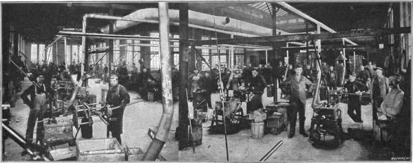
Fig. 17. View of the Casting Room
As to the accuracy with which die-castings may be produced, it is
possible to keep dimensions within 0.0005 inch of standard size, but to
do so requires considerable expense in keeping the dies in condition.
A limit of 0.002 inch, however, is entirely practicable, and can be maintained
easily. In specifying the accuracy with which die-castings are
to be made, only those parts which are absolutely essential should be
held to size, in order to keep the cost of the work nominal. One of the
great advantages of the use of die-castings is that no finishing is required
after the pieces leave the molds. Finish requirements should
be plainly stated in ordering die-castings, as the alloy must be suited
to these requirements.
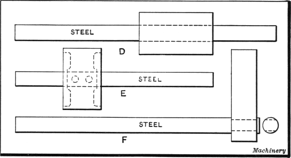
Fig. 18. Methods of attaching Die-cast Gears, etc., to Shafts
Another great saving is effected on lettered work, either raised or
sunken. One of these jobs is illustrated at Q, Fig. 22, which shows an
example of die-cast lettering. Sunken lettering is to be preferred to
raised lettering, as the latter is more easily injured. Knurled work
may be produced easily, if straight knurls are used, and threaded sections
over ¼ inch in size are entirely practicable, either internal or
external. External die cast threads are illustrated at R and S, Fig. 22.
The casting of gears and segments is a familiar application of die-casting;
this is illustrated by the large gear at N, Fig. 21, and the
segment at W, Fig. 23, which give an idea of the general character of
this class of work. The casting of pulleys, gears, and similar parts on
shafts may be easily effected as shown by the gear on the shaft at N,
in Fig. 21. The views shown in Fig. 18 are intended to convey an
idea of three methods of die-casting around shafts. At D is shown a
die-casting cast around a steel shaft. If the surface of the shaft
coming within the pulley has been previously knurled, the pulley will
grip it much better, but for ordinary purposes the shrinkage of the
die-cast metal around the shaft is sufficient. If any heavy strain is to
be imposed on the work, it is better to provide anchor holes through
the shaft, like those indicated at E. It will be readily seen that the
die-cast metal runs through these holes in the shaft, forming rivets
which are integral with the casting. For locating levers upon the ends
of shafts, etc., a good way is to flatten opposite sides of the shaft and
cast around them, as shown at F, Fig. 18. The screw seen projecting
beneath the piece at Q, Fig. 22, was die-cast in place. Any of these
methods are to be recommended, and a proper knowledge of possibilities
of this kind will increase the scope of die-casting.
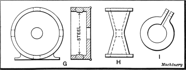
Fig. 19. A Few Possibilities of Die Casting
Another phase of die-casting which can well be borne in mind is
the possibility of inserting steel or other parts in the die-casting. Such
an instance is shown at G in Fig. 19—a die-casting which was made
by the Van Wagner Co. as a part of an electrical apparatus, the steel
inserts being contact points. Oftentimes it is found advisable to include
brass bearing rings to give additional durability at points where
the die-cast metal would not stand up. The die-casting shown at U,
Fig. 23, in which the brass ring at T has been incorporated, is typical
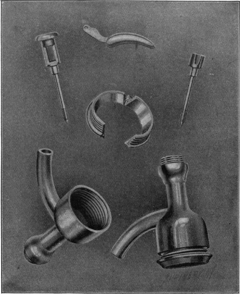
of such cases. To die-cast pieces like those shown at H in Fig. 19, and
similarly at V in Fig. 23, having inverted conical openings, might at
first thought seem difficult, but this is entirely practicable. Similarly,
split bushings like those shown at I, Fig. 19, and at W, Fig. 23, may
be cast with projecting lugs for the reception of screws for clamping
upon shafts, etc., but this construction should not be used if frequent
tightening or loosening will be necessary.
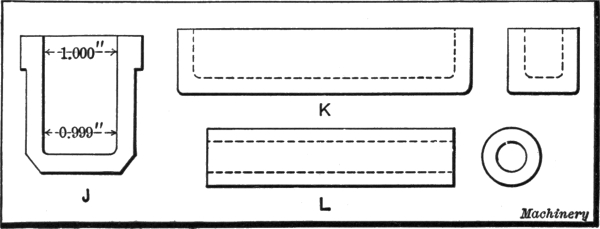
Fig. 20. Castings which illustrate Points of Shrinkage and Draft
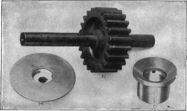
Fig. 21. Die-castings showing Impractical Under-cut Sections; also a
Large Gear die-cast on Shaft
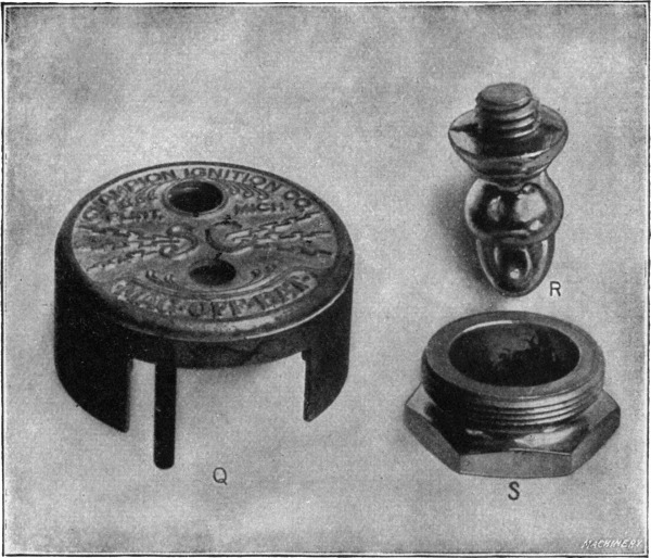
Fig. 22. Die-castings which show Lettering and Thread Castings
The shrinkage problem manifests itself in die-casting in the same
measure that it does in other casting operations. Different metals
shrink in different degrees, as will be explained later on. However, one
important point can be mentioned at this time: that is, the amount of
shrinkage is often dependent upon the shape of the piece. For instance,
pieces like those shown at K in Fig. 20 or at X in Fig. 24, will
shrink very little on account of the fact that the steel mold is of such
shape that the central core will prevent the die-casting from shrinking.
However, pieces like those shown at L in Fig. 20, or at V in Fig. 24,
which have nothing to hold them from pulling together as they
cool, will shrink to the greatest extent. All of these points must be
taken into consideration when designing work for die-casting. Practically
no draft is necessary on a die-casting, except on very deep sections,
as indicated at J in Fig. 20, where a draft of 0.001 inch to the
inch is desirable. Perfectly straight sections, however, can be cast,
as the shrinkage of the metal is usually enough to free it from the
die.
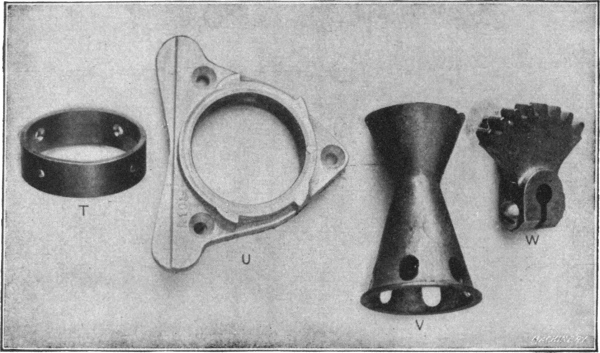
Fig. 23. Typical Die-castings illustrating Various Points
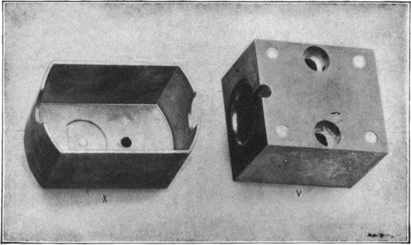
Fig. 24. Die-castings illustrating the Extremes of Shrinkage
It is the opinion of the Van Wagner Co. that die-casting costs can be
materially reduced if designers will bear this point in mind when
bringing out new designs. Even though it is often possible to cast
special pieces, incorporating several parts in one, and thereby accomplishing
what seems to be a great stunt to the designer, it is sometimes
more practicable to make the piece in several sections and later
assemble it. Not only is this simpler for the die caster, but it is also
more economical for the customer. Such points as avoiding thin sections,
including large fillets at corners, as well as taking account of
the under-cut problem, are simply matters of common sense, but they
can profitably be considered by the designer.
The first essential to good die-casting is a good casting machine.
Perhaps the best known types of casting machines are of the familiar
plunger type, of which there are several varieties, the pneumatic type
and the rotary or automatic type. (For descriptions of various types of
die-casting machines, see “Die Casting Machines,” Machinery’s Reference
Book No. 108.) For the economical production of die-castings,
however, the hand-operated machines are rather too slow, and automatic
machines are applicable only to a class of work which may be
made in very large quantities. For these reasons, therefore, the Van
Wagner Co. employs the compressed air type of die-casting machine
which was patented by Mr. E. B. Van Wagner in 1907. In the casting
department of the Van Wagner shop, illustrated in Fig. 17, there are
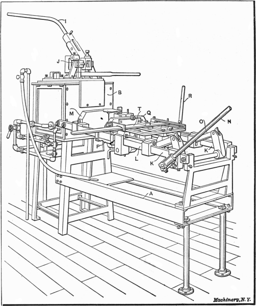
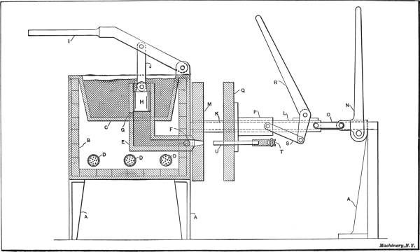
installed about thirty machines. Fig. 27 shows a die-casting
machine in the open position. Fig. 26 shows a closer view of the die-operating
mechanism and Fig. 25 is presented to give a general idea
of the construction of the entire machine.
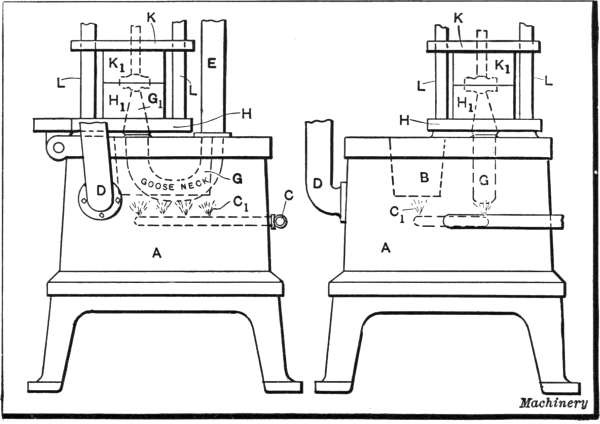
Fig. 25. Drawing illustrating Principle of Van Wagner Die-casting
Machine
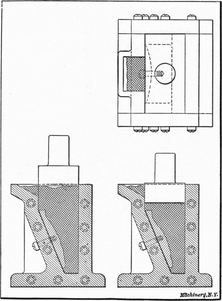
By referring to the line illustration Fig. 25, which shows the Van
Wagner pneumatic die-casting machine in part, and comparing this
illustration with Fig. 26, which shows the general appearance of the
die-operating and other mechanism of the casting machine, a good idea
may be obtained of its construction and working. At A may be seen
the base of the machine in which is located the melting pot B. This
melting pot is heated by means of fuel oil passing through the supply
pipe C to the burners C1. A vent pipe D is provided to take away the
gases incident to combustion. The pressure for “shooting” the metal
into the die cavity is supplied by air through the supply pipe E. A
valve controls this air supply. The pressure is regulated to suit the
particular casting or die, the proper amount being determined by experiment.
Similarly, an air exhaust pipe F, which may be seen
directly above the supply pipe, sub-divides into two tubes which extend
to the die cavity to exhaust the air before the metal is admitted.
There are two methods of overcoming the presence of air in
the die cavity—the exhaust method and the venting method, and it is
the former that is here described.
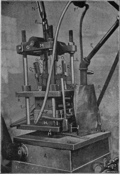
Fig. 26. View of Machine showing Die-operating Mechanism
A “goose-neck” G, shown in Fig. 25, serves to temporarily contain
the metal which is forced into the mold. An amount of metal
slightly in excess of that required for one die-casting is placed in this
goose-neck with a hand-ladle, previous to each operation of the machine.
One end of the goose-neck is connected to the air pipe, E, while the
other end terminates in the nozzle G1. This nozzle may best be seen
by referring to the illustration of the machine shown in Fig. 27, in
connection with Fig. 25. One of the advantages in using this goose-neck
is that the entire air pressure is expended upon the metal in the
goose-neck, and, by reason of its isolated position, the goose-neck and its
contents are kept slightly hotter than the contents of the melting pot.
The die-operating mechanism of the machine is contained within
a hinged framework, shown in position for the removal of the die-casting
in Fig. 27. Referring to Fig. 26, in connection with the line
illustration Fig. 25, it will be seen that the die-holding mechanism is
all supported upon the lower die-holding plate H, which is hinged to
the edge of the base of the machine. A lock J serves to hold the dies
and operating mechanism in the upright operating position, and by
means of a counterbalance, suspended from an overhead rope which
connects with the top of the mechanism at P, the changing of the position
of this mechanism is easily effected, and when thrown into the
horizontal position, as indicated in Fig. 27, it rests upon a support
while the dies are being opened and the castings ejected.
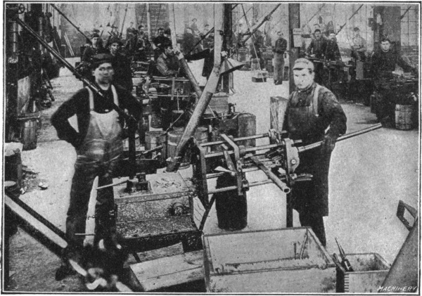
Fig. 27. Die-casting Machine in Position for Removal of Casting
The lower die is shown at H1 and the upper die K1 is mounted upon
the upper die-holding plate K. Four rods L act as guiding members
for the upper die-holding plate to slide upon. These rods L are mounted
in fixed positions at the corners of the lower die-holding plate H, and
at their upper ends the operating shaft supporting plate M is located
in a fixed position, serving to support the upper ends of these rods.
The position of this plate M is adjustable upon the rods by means of
check-nuts, thus providing for the accommodation of thick as well as
thin dies. A shaft O is supported in this top plate, and by means of
the operating lever N working through slotted levers O1 and links O2,
the upper die-holding plate and die can thus be removed from contact
with the lower die at will.
The metal enters the die cavity through the nozzle G1 and after
setting, it is necessary to cut the sprue formed by the surplus metal that
remains outside the die cavity. For this purpose, a sprue-cutter,
operated by means of hand-lever Q1, is employed. This sprue-cutting
lever is hinged in the fulcrumed link Q2, and is held in its casting position
by means of an adjustable stop on bracket Q3.
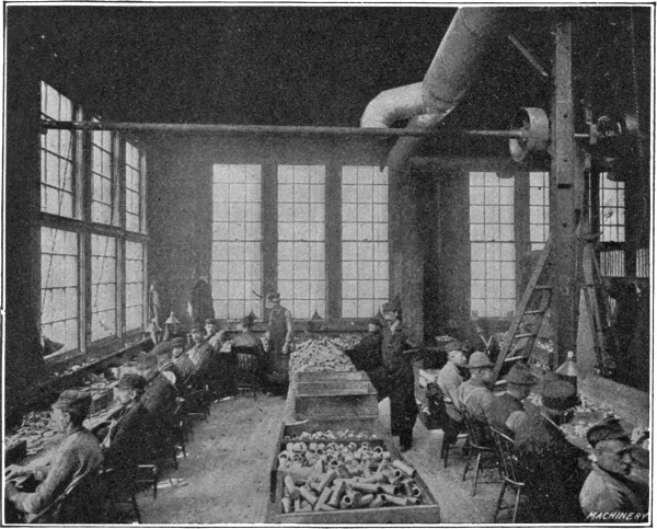
Fig. 28. General View of Trimming Department
In many dies, it is necessary that water be circulated through the die-blocks
to keep them cool during the die-casting operation. In Fig. 26,
the water pipe may be seen at R, and hose pipes run from this supply
to each side of the die-blocks, thus providing a cooling circulation. In
this illustration, the pipes used for exhausting the air from the die
cavity are apt to be confused with the cooling pipes, but by following
the two pipes leading vertically down to the machine, the exhaust pipes
may be seen and kept distinct from the water pipes.
In order to clearly understand the operation of the die-casting machine,
let us follow the sequence of events that takes place in producing
a casting. Two men are required to operate the machine. In Fig. 27,
the operators may be seen in their working positions. The first step
is taken by the operator at the left who, with a hand-ladle, dips enough
metal for one casting from the melting pot and pours it through nozzle
G1 into the goose-neck. The second operator in the meantime is replacing
the cores in the dies, adjusting the position of the sprue-cutter and
closing the dies preparatory to making a casting. This being done, he
elevates the dies and their operating mechanism, which are hinged and
counterbalanced, as previously described, bringing them to an upright
position. The die operator now mounts the box, raises the sprue-cutter
to its open position to admit the metal; after which the machine operator
turns the air valve with his left hand. The operation of this air
valve admits the air behind the metal, forcing it into the die, and the
same movement opens the exhaust valve slightly in advance. The
exhaust valve is located upon the second length of piping just above
the air valve, and as a link connects the two valves, the single motion
exhausts the air from the die cavity and immediately afterward the air
is admitted behind the metal, thereby “shooting” the metal into the die.
This being done, the air is shut off and the die operator cuts the sprue
by means of lever Q1, withdraws the cores in the die, throws the dies
to the open position (which is indicated in Fig. 27), and operates the
ejecting mechanism, thus removing the casting from the die. In the
meantime, the machine operator is tending to his metal supply and
getting a ladle full of metal ready for the next die-casting operation.
By referring to the machines shown in Fig. 17, it will be noticed that
only a few are provided with exhaust piping for venting the dies.
Another venting method will be described later.
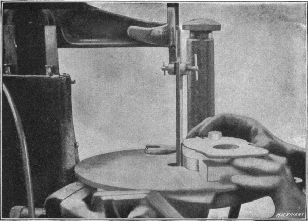
Fig. 29. Trimming Die-castings on a Filing Machine
The number of die-castings which can be made on one machine per
day of ten hours varies with the character of the pieces being die-cast,
the number of pieces made at each operation of the machine and the
ease with which the dies may be worked, which depends, of course,
upon the number of cores and parts to be handled at each die-casting
operation. The dies shown in the machine in Fig. 26, produce four
bearings at each operation.
At the end of each run the operators of the machines go over their
work, breaking the castings from the sprues and throwing out all that
are defective. No matter how carefully the die-casting molds have been
made, there is always a certain amount of trimming to be done on the
finished die-castings, on account of the crevices left in the die for air
vents, or which exist from improper fitting of the parts of the dies.
These “fins,” as they are called, are trimmed by hand operators in a
special department. A general view of this trimming room is shown
in Fig. 28. Usually it is sufficient to scrape these fins off with a scraping
knife, but if the casting is especially difficult to produce, so that a large
opening is required to admit the metal, it is sometimes necessary to
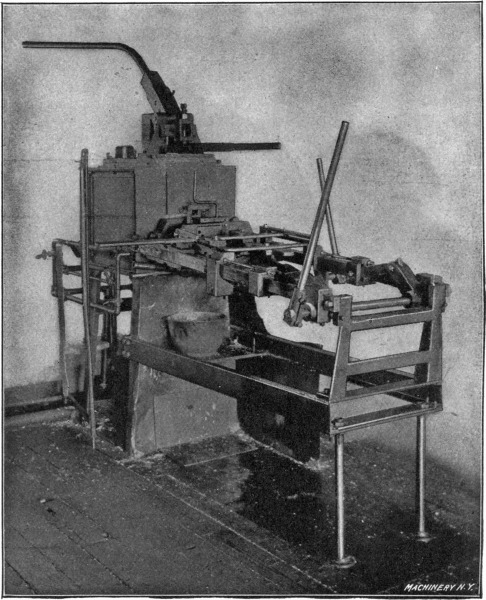
trim unusually thick sprue sections by filing. Fig. 29 illustrates the
method of trimming such die-castings on a filing machine.
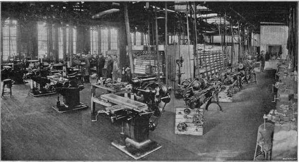
Fig. 30. General View of E. B. Van Wagner Co.’s Die making Department
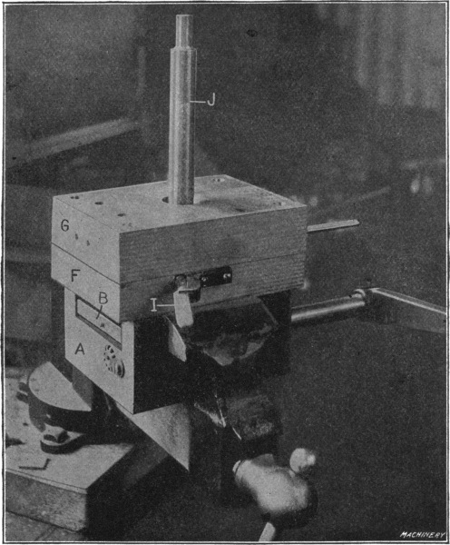
Fig. 31. A Typical Die-casting Mold
Next to the casting machine, the dies or molds are the most important
necessary factor. A general view of the Van Wagner Co.’s die-making
department is shown in Fig. 30. In order to gain a proper
conception of the work required in producing a high-grade die-casting
mold, we will follow the different steps which are necessary in making
the mold. The first and most important step is the proper planning of
the die. Before any work at all can be done, it is necessary to plan the
die, i. e., to decide just where the parting lines will come; just what
method will be used for ejecting the piece; what alloy will be used;
where the casting will be gated; and a hundred and one minor points,
all of which have a direct bearing upon the performance of the finished
dies. All these decisions have to be made by the diemaker, and in Fig. 37
he is shown, micrometer in hand, computing the shrinkage allowances
that he will make in the dies. This is a very important factor on
accurate work as the shrinkage varies from 0.001 to 0.004 inch, according
to the alloy and the general shape of the piece.
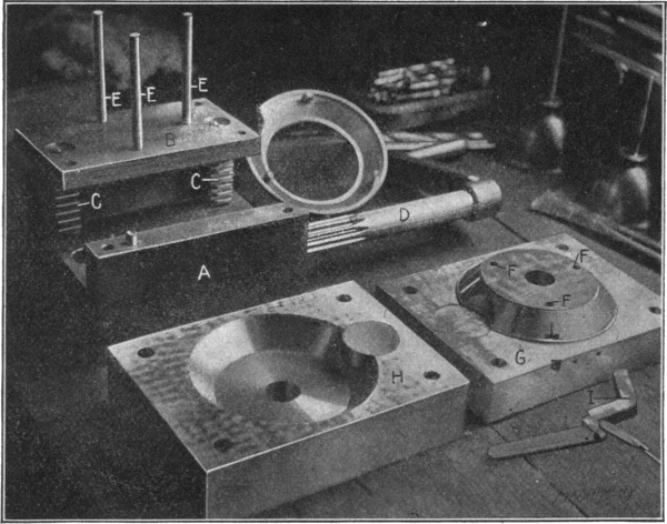
Fig. 32. Die-casting Mold shown in
Fig. 31, disassembled
Before taking up the actual machining operations of the mold-making
as conducted in this factory, it will be well to take a typical die-casting
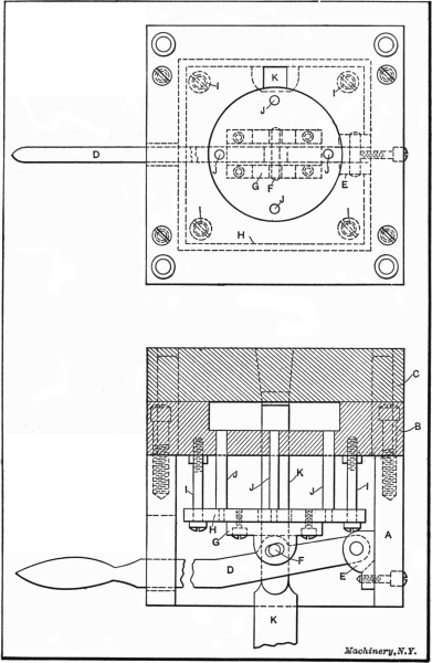
mold and note its general construction. Fig. 31 shows a typical die-casting
mold closed, while Fig. 32 shows the same mold disassembled on
the bench to show its construction. The piece for which the mold has
been made is also shown. Fig. 33 shows a similar die in section. From
the three illustrations a good idea of an average die-casting mold can
be obtained. Referring to these illustrations, the principal parts of this
die are the ejector box A, and the ejector plate B which is operated by
the racks C. For operating the ejector plate, the pinion shaft D having
a handle suitable for turning, is furnished. This, of course, fits into a
bored hole in the ejector box, bringing the pinion into mesh with the
racks for raising the ejector plate. In the ejector plate are three ejector
pins E for removing the casting from the mold. The ejector pins
operate through holes F. Beyond the pinion shaft may be seen the
casting for which this mold has been made. It will be noticed that
the top side of the casting has three projecting lugs through which are
small holes. Provision for forming this side of the die-casting is made
in the lower half of the mold G, while the upper half of the die-casting
is taken care of by the top plate H. One of the toggles for operating the
core pins through these three lugs is shown at I. These parts will be
described more fully later. The sprue cutter is shown in position in
the die at J.
As will be noticed from Fig. 30, the machinery in the die-making
department is of modern design, for no other class of work demands as
good tool equipment and as much skill in the making as die-casting
molds. The die-blocks are made of machinery steel. Fig. 34 illustrates
the first step in making a
die-casting mold after the
die-block has been shaped
approximately to size. This
operation consists in carefully
facing off the die surfaces
on a vertical-spindle
grinding machine. This, of
course, is a quick method of
surfacing the die-block, and
it insures that the top and
bottom surfaces of these
plates will be parallel, permitting
the die-faces to come
together properly.
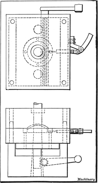
Fig. 33. Section through a Die-casting Mold
The next step consists of
laying out the die, as shown
in Fig. 36. This is done in
the usual manner, by working
on a coppered surface,
using dividers, scales, and a
center punch. When laying
out the die, the necessary
allowances are made for
shrinkage and finish, these
points having been planned
before actual work on the
die has been started. As in
other phases of die-work,
the machining operations
are performed, as far as possible,
before any hand-work
is done. In Fig. 38 may be seen a die-maker turning the cavity in a
part of the die-casting mold. The highest type of skilled workmanship
is called for on this machine work, and as may be surmised from
Fig. 38, where the die-maker is shown measuring the die with a vernier
caliper, the measurements must be exact, for no grinding operations
follow the machine work.
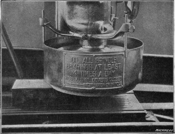
Fig. 34. First step in making the Mold—Grinding Surfaces of Blocks
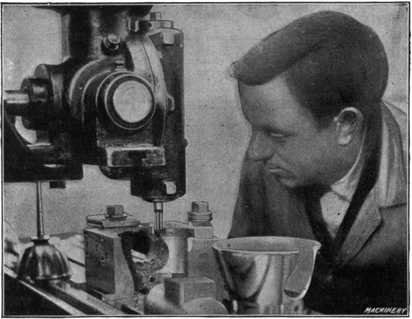
Fig. 35. A Milling Operation on a Die
Figs. 35 and 39 show typical milling operations being performed on
die-casting molds. In Fig. 39 the diemaker is shown indicating a pin
in one corner of the mold cavity, preparatory to doing additional milling.
The block is held in the usual manner by being clamped on the
bed of the milling machine, and after it has been properly located under
the cutter head, tools are substituted for the indicator and the milling
of the cavity is completed. Fig. 35 shows one of the sections of the die-casting
mold which is to be used in producing the casting shown at
the right of the work. In this case the diemaker is milling the recess
for the steel arbor which may be seen directly in the foreground.
This will be fitted in place to provide for the forming
of the hole in the side of the piece.
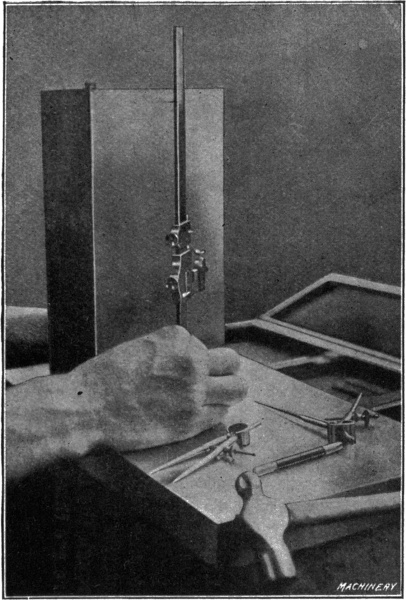
Fig. 36. Laying out One of the Mold Parts
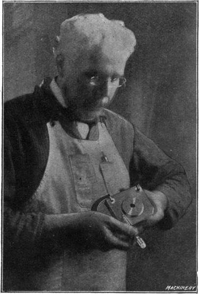
Fig. 37. Planning the Die-casting Mold
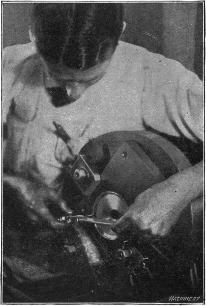
Fig. 38. Turning out a Die-casting Mold
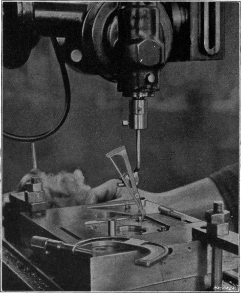
Fig. 39. Indicating a Mold on the Milling Machine
Fig. 40 illustrates several important points in the making
of a die-casting mold. This illustration shows the ejector
box with the lower half of the mold on it, the ejector
plate being held against the under side of the die-plate by means
of the pinion shaft. The operation being done is the drilling of
the ejector-pin holes. Referring back to Fig. 32, which by the
way shows the die here illustrated disassembled, the holes being
drilled are those shown at F for the reception of the pins E. The
method employed is to drill the holes through the die and into the
ejector plate, afterward reaming all holes to size and driving the pins
into position in the ejector plate, while they are allowed to slide freely
through the die-plate. We will now assume that the ejector box and
plate have been completed and fitted, a pinion shaft for operating this
plate also fitted, the lower and upper dies completed by the machining
operations previously described, and all assembled. The final operation
of the fitting of the pins is shown in Fig. 41 in which the die-maker
may be seen filing off the ends of these pins so that when dropped
to the lower position they will lie flush with the surface. If of uneven
lengths, these pins will cause irregular spots in the casting. It now
remains to describe the toggles used for operating the cores which form
the holes through the three lugs in the casting. One of these toggles,
of which there are three, is shown at I, in Fig. 31, and also in Fig. 32.
These toggles consist of brackets which are attached to the die-plate,
and levers which are fulcrumed at the ends of the brackets so that
their operation works the core pins. It is necessary to remove these
core pins after each casting has been made and position them before
another casting can be produced.
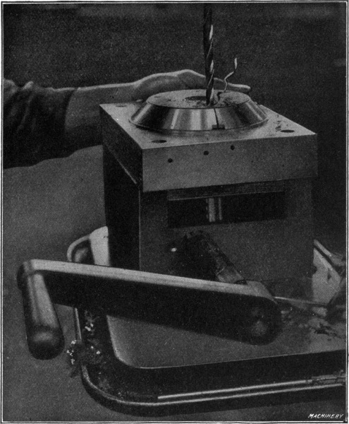
Fig. 40. Drilling the Ejector-pin Holes
The fitting of the parts of a die-casting mold is one of the most
important parts of the work. It demands the highest type of workmanship,
for a poorly fitted die means a die which works hard in
addition to producing poor castings. It is very important that all movable
parts should work freely. Fig. 42 shows the assembling operation
on a die-casting mold, the casting which is to be duplicated being
shown in the immediate foreground. These parts must all be screwed
into their respective places, making the joints as nearly air-tight as
possible. One cause of poor die-castings arises from the trapping of
air in the die, and different methods are employed for overcoming this
trouble.
There are two methods of preventing air from being trapped in die-casting
molds; either by constructing the dies so that the air may be
exhausted from the mold cavity before admitting the metal, or by
venting the die so that the air may be forced out by the inrushing
metal. In the first of these methods it is necessary that the joints in
the mold be made as close as possible, otherwise it will be impossible to
produce anything like a vacuum in the mold cavity. If, however, it
has many parts which must be fitted, it is usually considered advisable
to provide the die with vents consisting of milled recesses a few thousandths
inch deep. Several vents are provided, from which the air can
escape when the metal is admitted to the dies. The hot metal, of
course, “shoots” through them in thin ribbons, but not enough escapes
to affect the pressure on the metal which goes into the casting.
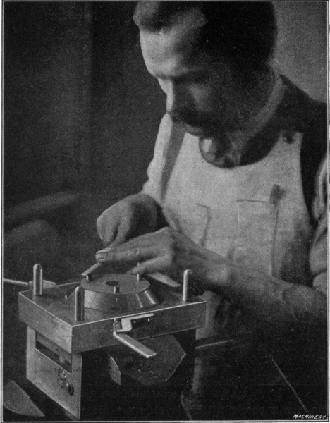
Fig. 41. Fitting Ejector-pins
No matter how carefully a die may have been constructed, or how
carefully it has been assembled, there is always a certain amount of
“babying” to be done before it will work satisfactorily. The casting
may stick a little here, or there may be a rough spot there, and it is
the successful elimination of these troubles which constitutes the production
of a good die-casting.
One of the purposes of this book is to correct several erroneous impressions
which are prevalent in regard to die-casting possibilities.
Many people seem to think that nearly all metals can be die-cast, but as
a matter of fact, those metals which can be successfully die-cast can be
numbered on the fingers of one hand, being alloys of lead, zinc, tin,
copper and antimony. The tin base metals shrink very little, while the
zinc base metals shrink considerably, and those with a large per
cent of aluminum have a very high shrinkage. Without doubt, the
most used die-casting metals are the zinc base metals. A typical metal
of this class contains about 85 per cent zinc; 8 per cent tin; 4 per cent
copper and 3 per cent aluminum. The melting point of this metal is
about 850 degrees F. While this alloy is one of the most common,
it is not by any means the best, as there is too little tin employed, but
it is a comparatively cheap metal, which probably accounts for its large
use. This metal is easily affected by heat and cold, and rapidly deteriorates
with age. The lead base metals may be typified by
an alloy containing 80 per cent lead; 15 per cent antimony; 4 per cent
tin; and 1 per cent copper. This composition melts at approximately
550 degrees F. and is used for castings subjected to little wear and
where no great strength is required. The weight of this metal is its
greatest objection, and it is also quite brittle because of the large percentage
of antimony.
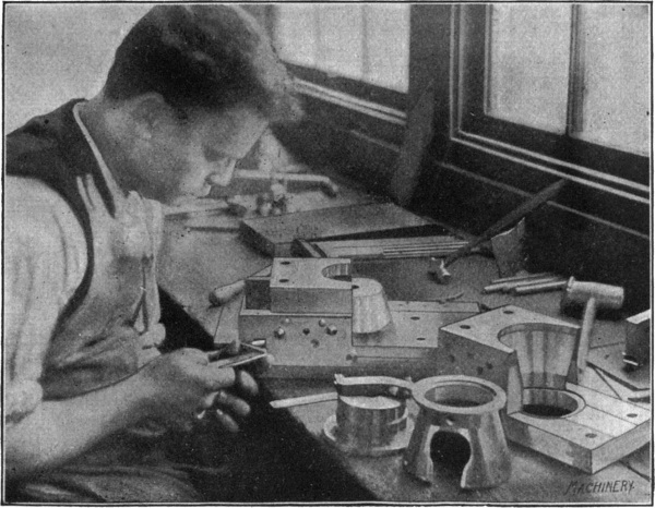
Fig. 42. Assembling a Die-casting Mold
For the best class of die-castings, the tin base metals are employed.
These range from 60 to 90 per cent tin, and from 2 to 10 per cent
copper, together with a little antimony. The melting point of a mixture
of this composition is about 675 degrees F. The castings have a good
color and they are much better in quality than any of the other alloys.
It is absolutely essential that tin base metals be used for carbureter
parts or other parts coming in contact with gasoline. Also, the tin
base metals must be used for parts which come in contact with food
products, as the lead or zinc alloys have a contaminating effect.
Aluminum alloys have been cast in France and Germany in limited
quantities, but very seldom in this country on account of their high
melting point, as well as their effect upon the die. After aluminum
alloys have been run in the dies for a short time, the surfaces of the
molds become pitted. Through some unexplained cause, the metal seems
to flake out particles of the steel in the molds. When an aluminum
alloy is to be used, a good mixture is 80 per cent aluminum, 3 per cent
copper and 17 per cent zinc. This alloy has a high shrinkage and it
has also the same deteriorating effect upon the dies, but to a much less
degree than pure aluminum.