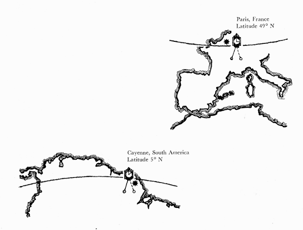
Figure 1.—A study of the figure of the earth was one of the earliest projects of the
French Academy of Sciences. In order to test the effect of the earth’s rotation on its
gravitational force, the Academy in 1672 sent Jean Richer to the equatorial island of
Cayenne to compare the rate of a clock which was known to have kept accurate time in
Paris. Richer found that the clock lost 2 minutes and 28 seconds at Cayenne, indicating
a substantial decrease in the force of gravity on the pendulum. Subsequent pendulum
experiments revealed that the period of a pendulum varied not only with the latitude but
also regionally, under the influence of topographical features such as mountains. It
became clear that the measurement of gravity should be made a part of the work of the
geodetic surveyor.
The history of gravity pendulums dates back to the
time of Galileo. After the discovery of the variation of
the force of gravity over the surface of the earth, gravity
measurement became a major concern of physics and
geodesy. This article traces the history of the development
of instruments for this purpose.
THE AUTHORS: Victor F. Lenzen is Professor of
Physics, Emeritus, at the University of California at Berkeley
and Robert P. Multhauf is Chairman of the Department
of Science and Technology in the Smithsonian
Institution’s Museum of History and Technology.
The intensity of gravity, or the acceleration of a
freely falling body, is an important physical quantity
for the several physical sciences. The intensity of
gravity determines the weight of a standard pound
or kilogram as a standard or unit of force. In physical
experiments, the force on a body may be measured
by determining the weight of a known mass which
serves to establish equilibrium against it. Thus, in
the absolute determination of the ampere with a current
balance, the force between two coils carrying
current is balanced by the earth’s gravitational force
upon a body of determinable mass. The intensity of
gravity enters into determinations of the size of the
earth from the angular velocity of the moon, its
distance from the earth, and Newton’s inverse square
law of gravitation and the laws of motion. Prediction
of the motion of an artificial satellite requires an
accurate knowledge of gravity for this astronomical
problem.
The gravity field of the earth also provides data for
a determination of the figure of the earth, or geoid,
but for this problem of geodesy relative values of
gravity are sufficient. If g is the intensity of gravity
at some reference station, and Δg is the difference
between intensities at two stations, the values of
gravity in geodetic calculations enter as ratios (Δg)/g
over the surface of the earth. Gravimetric investigations
in conjunction with other forms of geophysical
investigation, such as seismology, furnish data to test
hypotheses concerning the internal structure of the
earth.
Whether the intensity of gravity is sought in absolute
or relative measure, the most widely used instrument
for its determination since the creation of classical
mechanics has been the pendulum. In recent decades,
there have been invented gravity meters based
upon the principle of the spring, and these instruments
have made possible the rapid determination of
relative values of gravity to a high degree of accuracy.
The gravity meter, however, must be calibrated at
stations where the absolute value of gravity has been
determined by other means if absolute values are
sought. For absolute determinations of gravity, the
pendulum historically has been the principal instrument
employed. Although alternative methods of
determining absolute values of gravity are now in use,
the pendulum retains its value for absolute determinations,
and even retains it for relative determinations,
as is exemplified by the Cambridge Pendulum Apparatus
and that of the Dominion Observatory at
Ottawa, Ontario.
The pendulums employed for absolute or relative
determinations of gravity have been of two basic
types. The first form of pendulum used as a physical
instrument consisted of a weight suspended by a fiber,
cord, or fine wire, the upper end of which was attached
to a fixed support. Such a pendulum may be called
a “simple” pendulum; the enclosure of the word
simple by quotation marks is to indicate that such a
pendulum is an approximation to a simple, or mathematical
pendulum, a conceptual object which consists
of a mass-point suspended by a weightless
inextensible cord. If l is the length of the simple
pendulum, the time of swing (half-period in the sense
of physics) for vibrations of infinitely small amplitude,
as derived from Newton’s laws of motion and the
hypothesis that weight is proportional to mass, is
T = π√(l/g).
The second form of pendulum is the compound, or
physical, pendulum. It consists of an extended
solid body which vibrates about a fixed axis under
the action of the weight of the body. A compound
pendulum may be constituted to oscillate about one
axis only, in which case it is nonreversible and
applicable only for relative measurements. Or a
compound pendulum may be constituted to oscillate
about two axes, in which case it is reversible (or
“convertible”) and may be used to determine absolute
values of gravity. Capt. Henry Kater, F.R.S.,
during the years 1817-1818 was the first to design,
construct, and use a compound pendulum for the
absolute determination of gravity. He constructed
a convertible pendulum with two knife edges and
with it determined the absolute value of gravity at
the house of Henry Browne, F.R.S., in Portland
Place, London. He then constructed a similar
compound pendulum with only one knife edge, and
swung it to determine relative values of gravity at a
number of stations in the British Isles. The 19th
century witnessed the development of the theory and
practice of observations with pendulums for the
determination of absolute and relative values of
gravity.
The pendulum has been both an objective and an
instrument of physical investigation since the foundations
of classical mechanics were fashioned in the
17th century.[1] It is tradition that the youthful
Galileo discovered that the period of oscillation of a
pendulum is constant by observations of the swings
of the great lamp suspended from the ceiling in the
cathedral of Pisa.[2] The lamp was only a rough
approximation to a simple pendulum, but Galileo
later performed more accurate experiments with a
“simple” pendulum which consisted of a heavy ball
suspended by a cord. In an experiment designed to
confirm his laws of falling bodies, Galileo lifted the
ball to the level of a given altitude and released it.
The ball ascended to the same level on the other side
of the vertical equilibrium position and thereby
confirmed a prediction from the laws. Galileo also
discovered that the period of vibration of a “simple”
pendulum varies as the square root of its length, a
result which is expressed by the formula for the time
of swing of the ideal simple pendulum. He also
used a pendulum to measure lapse of time, and he
designed a pendulum clock. Galileo’s experimental
results are important historically, but have required
correction in the light of subsequent measurements
of greater precision.
Mersenne in 1644 made the first determination of
the length of the seconds pendulum,[3] that is, the length
of a simple pendulum that beats seconds (half-period
in the sense of physics). Subsequently, he
proposed the problem to determine the length of
the simple pendulum equivalent in period to a given
compound pendulum. This problem was solved
by Huygens, who in his famous work Horologium
oscillatorium ... (1673) set forth the theory of the
compound pendulum.[4]
Huygens derived a theorem which has provided
the basis for the employment of the reversible compound
pendulum for the absolute determination of
the intensity of gravity. The theorem is that a given
compound pendulum possesses conjugate points on
opposite sides of the center of gravity; about these
points, the periods of oscillation are the same. For
each of these points as center of suspension the other
point is the center of oscillation, and the distance
between them is the length of the equivalent simple
pendulum. Earlier, in 1657, Huygens independently
had invented and patented the pendulum clock,
which rapidly came into use for the measurement
of time. Huygens also created the theory of centripetal
force which made it possible to calculate the
effect of the rotation of the earth upon the observed
value of gravity.
The theory of the gravity field of the earth was
founded upon the laws of motion and the law of
gravitation by Isaac Newton in his famous Principia
(1687). It follows from the Newtonian theory
of gravitation that the acceleration of gravity as
determined on the surface of the earth is the
resultant of two factors: the principal factor is the
gravitational attraction of the earth upon bodies,
and the subsidiary factor is the effect of the rotation
of the earth. A body at rest on the surface of the
earth requires some of the gravitational attraction
for the centripetal acceleration of the body as it is
carried in a circle with constant speed by the rotation
of the earth about its axis. If the rotating earth is
used as a frame of reference, the effect of the rotation
is expressed as a centrifugal force which acts to
diminish the observed intensity of gravity.
From Newton’s laws of motion and the hypothesis
that weight is proportional to mass, the formula for
the half-period of a simple pendulum is given by
T = π√(l/g). If a simple pendulum beats seconds,
1 = π√(λ/g), where λ is the length of the seconds
pendulum. From T = π√(l/g) and 1 = π√(λ/g), it follows
that λ = l/T2. Then g = π2λ. Thus, the intensity of
gravity can be expressed in terms of the length of
the seconds pendulum, as well as by the acceleration
of a freely falling body. During the 19th century,
gravity usually was expressed in terms of the length
of the seconds pendulum, but present practice is to
express gravity in terms of g, for which the unit is
the gal, or one centimeter per second per second.
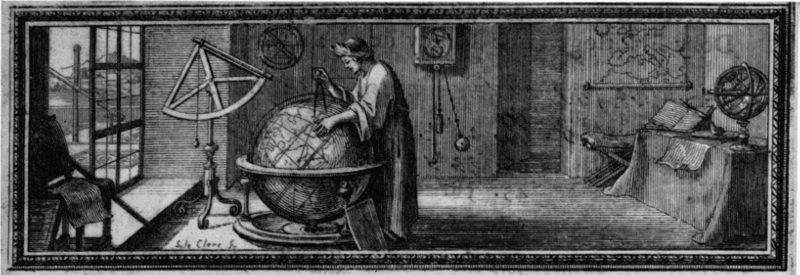
Figure 2.—This drawing, from Richer’s Observations astronomiques et physiques faites en l’isle de
Caïenne (Paris, 1679), shows most of the astronomical instruments used by Richer, namely,
one of the two pendulum clocks made by Thuret, the 20-foot and the 5-foot telescopes and
the large quadrant. The figure may be intended as a portrait of Richer. This drawing
was done by Sebastian Le Clerc, a young illustrator who made many illustrations of the
early work of the Paris Academy.
A principal contribution of the pendulum as a
physical instrument has been the determination of the
figure of the earth.[5] That the earth is spherical in
form was accepted doctrine among the ancient
Greeks. Pythagoras is said to have been the first to
describe the earth as a sphere, and this view was
adopted by Eudoxus and Aristotle.
The Alexandrian scientist Eratosthenes made the
first estimate of the diameter and circumference of
a supposedly spherical earth by an astronomical-geodetic
method. He measured the angle between
the directions of the rays of the sun at Alexandria
and Syene (Aswan), Egypt, and estimated the distance
between these places from the length of time
required by a caravan of camels to travel between
them. From the central angle corresponding to the
arc on the surface, he calculated the radius and hence
the circumference of the earth. A second measurement
was undertaken by Posidonius, who measured
the altitudes of stars at Alexandria and Rhodes and
estimated the distance between them from the time
required to sail from one place to the other.
With the decline of classical antiquity, the doctrine
of the spherical shape of the earth was lost, and only
one investigation, that by the Arabs under Calif
Al-Mamun in A.D. 827, is recorded until the 16th
century. In 1525, the French mathematician Fernel
measured the length of a degree of latitude between
Paris and Amiens by the revolutions of the wheels of
his carriage, the circumference of which he had determined.
In England, Norwood in 1635 measured
the length of an arc between London and York with a
chain. An important forward step in geodesy was
the measurement of distance by triangulation, first
by Tycho Brahe, in Denmark, and later, in 1615, by
Willebrord Snell, in Holland.
Of historic importance, was the use of telescopes in
the triangulation for the measurement of a degree of
arc by the Abbé Jean Picard in 1669.[6] He had been
commissioned by the newly established Academy of
Sciences to measure an arc corresponding to an angle
of 1°, 22′, 55″ of the meridian between Amiens
and Malvoisine, near Paris. Picard proposed to the
Academy the measurement of the meridian of Paris
through all of France, and this project was supported
by Colbert, who obtained the approval of the King.
In 1684, Giovanni-Domenico Cassini and De la Hire
commenced a trigonometrical measure of an arc
south of Paris; subsequently, Jacques Cassini, the son
of Giovanni-Domenico, added the arc to the north
of Paris. The project was completed in 1718. The
length of a degree of arc south of Paris was found to
be greater than the length north of Paris. From the
difference, 57,097 toises[7] minus 56,960 toises, it was
concluded that the polar diameter of the earth is larger
than the equatorial diameter, i.e., that the earth is a
prolate spheroid (fig. 3).
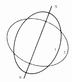
Figure 3.—Measurements of the length of a degree
of latitude which were completed in different parts
of France in 1669 and 1718 gave differing results
which suggested that the shape of the earth is not
a sphere but a prolate spheroid (1). But Richer’s
pendulum observation of 1672, as explained by
Huygens and Newton, indicated that its shape is
that of an oblate spheroid (2). The disagreement
is reflected in this drawing. In the 1730’s it
was resolved in favor of the latter view by two
French geodetic expeditions for the measurement
of degrees of latitude in the equatorial and polar
regions (Ecuador—then part of Peru—and Lapland).
Meanwhile, Richer in 1672 had been sent to
Cayenne, French Guiana, to make astronomical
observations and to measure the length of the seconds
pendulum.[8] He took with him a pendulum clock
which had been adjusted to keep accurate time in
Paris. At Cayenne, however, Richer found that the
clock was retarded by 2 minutes and 28 seconds per
day (fig. 1). He also fitted up a “simple” pendulum to
vibrate in seconds and measured the length of this
seconds pendulum several times every week for 10
months. Upon his return to Paris, he found that
the length of the “simple” pendulum which beat
seconds at Cayenne was 1-1/4 Paris lines[9] shorter than
the length of the seconds pendulum at Paris. Huygens
explained the reduction in the length of the seconds
pendulum—and, therefore, the lesser intensity of
gravity at the equator with respect to the value at
Paris—in terms of his theory of centripetal force as
applied to the rotation of the earth and pendulum.[10]
A more complete theory was given by Newton in
the Principia.[11] Newton showed that if the earth is
assumed to be a homogeneous, mutually gravitating
fluid globe, its rotation will result in a bulging at the
equator. The earth will then have the form of an
oblate spheroid, and the intensity of gravity as a
form of universal gravitation will vary with position
on the surface of the earth. Newton took into
account gravitational attraction and centrifugal action,
and he calculated the ratio of the axes of the
spheroid to be 230:229. He calculated and prepared
a table of the lengths of a degree of latitude and of
the seconds pendulum for every 5° of latitude from
the equator to the pole. A discrepancy between his
predicted length of the seconds pendulum at the
equator and Richer’s measured length was explained
by Newton in terms of the expansion of the scale
with higher temperatures near the equator.
Newton’s theory that the earth is an oblate spheroid
was confirmed by the measurements of Richer, but
was rejected by the Paris Academy of Sciences, for
it contradicted the results of the Cassinis, father and
son, whose measurements of arcs to the south and
north of Paris had led to the conclusion that the
earth is a prolate spheroid. Thus, a controversy
arose between the English scientists and the Paris
Academy. The conflict was finally resolved by the
results of expeditions sent by the Academy to Peru
and Sweden. The first expedition, under Bouguer,
La Condamine, and Godin in 1735, went to a region
in Peru, and, with the help of the Spaniard Ullo,
measured a meridian arc of about 3°7′ near Quito,
now in Ecuador.[12] The second expedition, with
Maupertuis and Clairaut in 1736, went to Lapland
within the Arctic Circle and measured an arc of
about 1° in length.[13] The northern arc of 1° was
found to be longer than the Peruvian arc of 1°, and
thus it was confirmed that the earth is an oblate
spheroid, that is, flattened at the poles, as predicted
by the theory of Newton.
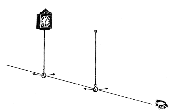
Figure 4.—The direct use of a clock to measure the force of gravity was found to be limited in accuracy
by the necessary mechanical connection of the pendulum to the clock, and by the unavoidable difference
between the characteristics of a clock pendulum and those of a theoretical (usually called “simple”) pendulum,
in which the mass is concentrated in the bob, and the supporting rod is weightless.
After 1735, the clock was used only to time the swing of a detached pendulum, by the method of “coincidences.”
In this method, invented by J. J. Mairan, the length of the detached pendulum is first accurately
measured, and the clock is corrected by astronomical observation. The detached pendulum is then
swung before the clock pendulum as shown here. The two pendulums swing more or less out of phase,
coming into coincidence each time one has gained a vibration. By counting the number of coincidences
over several hours, the period of the detached pendulum can be very accurately determined. The length
and period of the detached pendulum are the data required for the calculation of the force of gravity.
The period from Eratosthenes to Picard has been
called the spherical era of geodesy; the period from
Picard to the end of the 19th century has been called
the ellipsoidal period. During the latter period the
earth was conceived to be an ellipsoid, and the determination
of its ellipticity, that is, the difference of
equatorial radius and polar radius divided by the
equatorial radius, became an important geodetic
problem. A significant contribution to the solution
of this problem was made by determinations of
gravity by the pendulum.
An epoch-making work during the ellipsoidal era
of geodesy was Clairaut’s treatise, Théorie de la figure
de la terre.[14] On the hypothesis that the earth is a
spheroid of equilibrium, that is, such that a layer of
water would spread all over it, and that the internal
density varies so that layers of equal density are
coaxial spheroids, Clairaut derived a historic
theorem: If γE, γP are the values of gravity at the
equator and pole, respectively, and c the centrifugal
force at the equator divided by γE, then the ellipticity
α = (5/2)c - (γP - γE)/γE.
Laplace showed that the surfaces of equal density
might have any nearly spherical form, and Stokes
showed that it is unnecessary to assume any law of
density as long as the external surface is a spheroid of
equilibrium.[15] It follows from Clairaut’s theorem
that if the earth is an oblate spheroid, its ellipticity
can be determined from relative values of gravity
and the absolute value at the equator involved in c.
Observations with nonreversible, invariable compound
pendulums have contributed to the application
of Clairaut’s theorem in its original and contemporary
extended form for the determination of the figure and
gravity field of the earth.
The pendulum employed in observations of gravity
prior to the 19th century usually consisted of a small
weight suspended by a filament (figs. 4-6). The
pioneer experimenters with “simple” pendulums
changed the length of the suspension until the pendulum
beat seconds. Picard in 1669 determined the
length of the seconds pendulum at Paris with a
“simple” pendulum which consisted of a copper ball
an inch in diameter suspended by a fiber of pite
from jaws (pite was a preparation of the leaf of a
species of aloe and was not affected appreciably by
moisture).
A celebrated set of experiments with a “simple”
pendulum was conducted by Bouguer[16] in 1737 in
the Andes, as part of the expedition to measure the
Peruvian arc. The bob of the pendulum was a double
truncated cone, and the length was measured from
the jaw suspension to the center of oscillation of the
thread and bob. Bouguer allowed for change of
length of his measuring rod with temperature and
also for the buoyancy of the air. He determined the
time of swing by an elementary form of the method
of coincidences. The thread of the pendulum was
swung in front of a scale and Bouguer observed how
long it took the pendulum to lose a number of vibrations
on the seconds clock. For this purpose, he
noted the time when the beat of the clock was heard
and, simultaneously, the thread moved past the
center of the scale. A historic aspect of Bouguer’s
method was that he employed an “invariable”
pendulum, that is, the length was maintained the
same at the various stations of observation, a procedure
that has been described as having been
invented by Bouguer.
Since T = π√(l/g), it follows that T12/T22 = g2/g1.
Thus, if the absolute value of gravity is known at one
station, the value at any other station can be determined
from the ratio of the squares of times of swing
of an invariable pendulum at the two stations. From
the above equation, if T1 is the time of swing at a
station where the intensity of gravity is g, and T2
is the time at a station where the intensity is g + Δg,
then (Δg)/g = (T12/T22) - 1.
Bouguer’s investigations with his invariable pendulum
yielded methods for the determination of the internal
structure of the earth. On the Peruvian
expedition, he determined the length of the seconds
pendulum at three stations, including one at Quito,
at varying distances above sea level. If values of
gravity at stations of different elevation are to be
compared, they must be reduced to the same level,
usually to sea level. Since gravity decreases with
height above sea level in accordance with the law of
gravitation, a free-air reduction must be applied to
values of gravity determined above the level of the
sea. Bouguer originated the additional reduction for
the increase in gravity on a mountain or plateau
caused by the attraction of the matter in a plate.
From the relative values of gravity at elevated stations
in Peru and at sea level, Bouguer calculated
that the mean density of the earth was 4.7 times
greater than that of the cordilleras.[17] For greater
accuracy in the study of the internal structure of the
earth, in the 19th century the Bouguer plate reduction
came to be supplemented by corrections for irregularities
of terrain and by different types of isostatic
reduction.
La Condamine, who like Bouguer was a member of
the Peruvian expedition, conducted his own pendulum
experiments (fig. 4). He experimented in 1735 at
Santo Domingo en route to South America,[18] then
at various stations in South America, and again at
Paris upon his return to France. His pendulum consisted
of a copper ball suspended by a thread of pite.
For experimentation the length initially was about 12
feet, and the time of swing 2 seconds, but then the
length was reduced to about 3 feet with time of swing
1 second. Earlier, when it was believed that gravity
was constant over the earth, Picard and others had
proposed that the length of the seconds pendulum be
chosen as the standard. La Condamine in 1747
revived the proposal in the form that the length of the
seconds pendulum at the equator be adopted as the
standard of length. Subsequently, he investigated the
expansion of a toise of iron from the variation in the
period of his pendulum. In 1755, he observed the
pendulum at Rome with Boscovich. La Condamine’s
pendulum was used by other observers and finally was
lost at sea on an expedition around the world. The
knowledge of the pendulum acquired by the end of the
18th century was summarized in 1785 in a memoir by
Boscovich.[19]
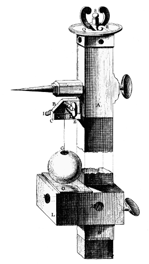
Figure 5.—An apparatus for the practice measurement
of the length of the pendulum devised on the basis of a
series of preliminary experiments by C. M. de la Condamine
who, in the course of the French geodetic expedition
to Peru in 1735, devoted a 3-month sojourn on the island
of Santo Domingo to pendulum observations by Mairan’s
Method. In this arrangement, shown here, a vertical rod
of ironwood is used both as the scale and as the support
for the apparatus, having at its top the brass pendulum
support (A) and, below, a horizontal mirror (O) which
serves to align the apparatus vertically through visual
observation of the reflection of the pointer projecting from
A. The pendulum, about 37 inches long, consists of a
thread of pite (a humidity-resistant, natural fiber) and
a copper ball of about 6 ounces. Its exact length is
determined by adjusting the micrometer (S) so that the
ball nearly touches the mirror. It will be noted that the
clock pendulum would be obscured by the scale. La
Condamine seems to have determined the times of
coincidence by visual observation of the occasions on
which “the pendulums swing parallel.” (Portion of plate
1, Mémoires publiés par la Société française de Physique, vol. 4.)
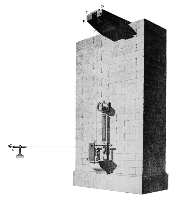
Figure 6.—The result of early pendulum
experiments was often expressed in terms of the
length of a pendulum which would have a
period of one second and was called “the seconds
pendulum.” In 1792, J. C. Borda and J. D.
Cassini determined the length of the seconds
pendulum at Paris with this apparatus. The
pendulum consists of a platinum ball about 1-1/2
inches in diameter, suspended by a fine iron
wire. The length, about 12 feet, was such that
its period would be nearly twice as long as that
of the pendulum of the clock (A). The interval
between coincidences was determined by observing,
through the telescope at the left, the
times when the two pendulums emerge together
from behind the screen (M). The exact length
of the pendulum was measured by a platinum
scale (not shown) equipped with a vernier and
an auxiliary copper scale for temperature
correction.
When, at the end of the 18th century, the
French revolutionary government established
the metric system of weights and measures, the
length of the seconds pendulum at Paris was
considered, but not adopted, as the unit of
length. (Plate 2, Mémoires publiés par la Société
française de Physique, vol. 4.)
The practice with the “simple” pendulum on the
part of Picard, Bouguer, La Condamine and others
in France culminated in the work of Borda and Cassini
in 1792 at the observatory in Paris[20] (fig. 6). The
experiments were undertaken to determine whether
or not the length of the seconds pendulum should be
adopted as the standard of length by the new government
of France. The bob consisted of a platinum
ball 16-1/6 Paris lines in diameter, and 9,911 grains
(slightly more than 17 ounces) in weight. The bob
was held to a brass cup covering about one-fifth of
its surface by the interposition of a small quantity of
grease. The cup with ball was hung by a fine iron
wire about 12 Paris feet long. The upper end of the
wire was attached to a cylinder which was part of a
wedge-shaped knife edge, on the upper surface of
which was a stem on which a small adjustable weight
was held by a screw thread. The knife edge rested on
a steel plate. The weight on the knife-edge apparatus
was adjusted so that the apparatus would vibrate
with the same period as the pendulum. Thus, the
mass of the suspending apparatus could be neglected
in the theory of motion of the pendulum about the
knife edge.
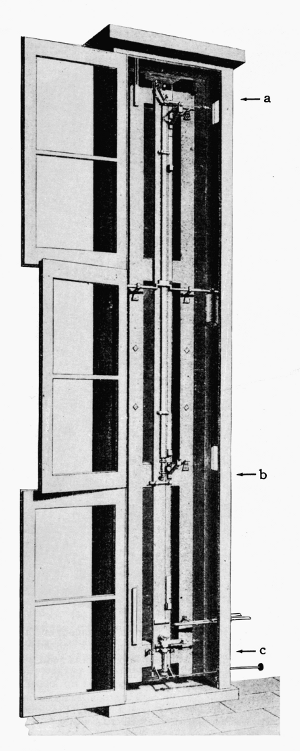
Figure 7.—Results of experiments in the determination
of the length of the seconds pendulum at Königsberg by a
new method were reported by F. W. Bessel in 1826 and
published in 1828. With this apparatus, he obtained two
sets of data from the same pendulum, by using two different
points of suspension. The pendulum was about 10
feet long. The distance between the two points of suspension
(a and b) was 1 toise (about six feet). A micrometric
balance (c) below the bob was used to determine the increase
in length due to the weight of the bob. He projected
the image of the clock pendulum (not shown) onto
the gravity pendulum by means of a lens, thus placing the
clock some distance away and eliminating the disturbing
effect of its motion. (Portion of plate 6, Mémoires publiés
par la Société française de Physique, vol. 4.)
In the earlier suspension from jaws there was uncertainty
as to the point about which the pendulum
oscillated. Borda and Cassini hung their pendulum
in front of a seconds clock and determined the time of
swing by the method of coincidences. The times on
the clock were observed when the clock gained or
lost one complete vibration (two swings) on the pendulum.
Suppose that the wire pendulum makes n
swings while the clock makes 2n + 2. If the clock
beats seconds exactly, the time of one complete
vibration is 2 seconds, and the time of swing of the
wire pendulum is T = (2n + 2)/n = 2(1 + 1/n). An error
in the time caused by uncertainty in determining the
coincidence of clock and wire pendulum is reduced
by employing a long interval of observation 2n. The
whole apparatus was enclosed in a box, in order to
exclude disturbances from currents of air. Corrections
were made for buoyancy, for amplitude of swing and
for variations in length of the wire with temperature.
The final result was that the length of the seconds
pendulum at the observatory in Paris was determined
to be 440.5593 Paris lines, or 993.53 mm., reduced
to sea level 993.85 mm. Some years later the methods
of Borda were used by other French investigators,
among whom was Biot who used the platinum ball of
Borda suspended by a copper wire 60 cm. long.
Another historic “simple” pendulum was the one
swung by Bessel (fig. 7) for the determination of
gravity at Königsberg 1825-1827.[21] The pendulum
consisted of a ball of brass, copper, or ivory that was
suspended by a fine wire, the upper end of which
was wrapped and unwrapped on a horizontal
cylinder as support. The pendulum was swung
first from one point and then from another, exactly
a “toise de Peru”[22] higher up, the bob being at
the same level in each case (fig. 7). Bessel found the
period of vibration of the pendulum by the method
of coincidences; and in order to avoid disturbances
from the comparison clock, it was placed at some
distance from the pendulum under observation.
Bessel’s experiments were significant in view of the
care with which he determined the corrections. He
corrected for the stiffness of the wire and for the lack
of rigidity of connection between the bob and wire.
The necessity for the latter correction had been
pointed out by Laplace, who showed that through
the circumstance that the pull of the wire is now on
one side and now on the other side of the center of
gravity, the bob acquires angular momentum about
its center of gravity, which cannot be accounted for
if the line of the wire, and therefore the force that it
exerts, always passed through the center. In addition
to a correction for buoyancy of the air considered
by his predecessors, Bessel also took account of the
inertia of the air set in motion by the pendulum.
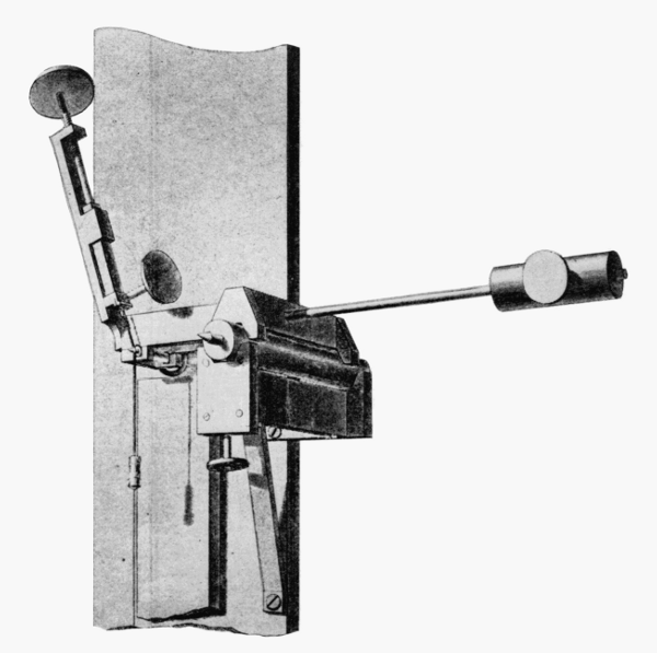
Figure 8.—Mode of suspension of Bessel’s pendulum is
shown here. The iron wire is supported by the thumbscrew
and clamp at the left, but passes over a pin at the
center, which is actually the upper terminal of the pendulum.
Bessel found this “cylinder of unrolling” superior
to the clamps and knife edges of earlier pendulums. The
counterweight at the right is part of a system for supporting
the scale in such a way that it is not elongated by its own
weight.
With this apparatus, Bessel determined the ratio of
the lengths of the two pendulums and their times of vibration.
From this the length of the seconds pendulum was
calculated. His method eliminated the need to take into
account such sources of inaccuracy as flexure of the pendulum
wire and imperfections in the shape of the bob.
(Portion of plate 7, Mémoires publiés par la Société française
de Physique, vol. 4.)
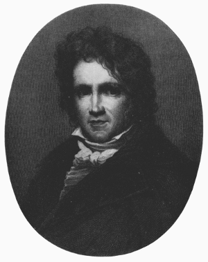
Figure 9.—Friedrich Wilhelm Bessel (1784-1846),
German mathematician and astronomer. He became
the first superintendent of the Prussian observatory
established at Königsberg in 1810, and
remained there during the remainder of his life.
So important were his many contributions to precise
measurement and calculation in astronomy that he
is often considered the founder of the “modern” age
in that science. This characteristic also shows in
his venture into geodesy, 1826-1830, one product
of which was the pendulum experiment reported in
this article.
The latter effect had been discovered by Du Buat in
1786,[23] but his work was unknown to Bessel. The
length of the seconds pendulum at Königsberg,
reduced to sea level, was found by Bessel to be
440.8179 lines. In 1835, Bessel determined the
intensity of gravity at a site in Berlin where observations
later were conducted in the Imperial Office of
Weights and Measures by Charles S. Peirce of the
U.S. Coast Survey.
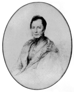
Figure 10.—Henry Kater (1777-1835),
English army officer and
physicist. His scientific career began
during his military service in
India, where he assisted in the
“great trigonometrical survey.”
Returned to England because of
bad health, and retired in 1814, he
pioneered (1818) in the development
of the convertible pendulum
as an alternative to the approximation
of the “simple” pendulum for
the measurement of the “seconds
pendulum.” Kater’s convertible
pendulum and the invariable pendulum
introduced by him in 1819
were the basis of English pendulum
work. (Photo courtesy National Portrait
Gallery, London.)
Figure 11.—The attempt to approximate
the simple (theoretical) pendulum in
gravity experiments ended in 1817-18
when Henry Kater invented the compound
convertible pendulum, from which
the equivalent simple pendulum could be
obtained according to the method of
Huygens (see text, p. 314). Developed in
connection with a project to fix the
standard of English measure, Kater’s pendulum
was called "compound" because it
was a solid bar rather than the fine wire
or string with which earlier experimenters
had tried to approximate a "weightless"
rod. It was called convertible because it
is alternately swung from the two knife
edges (a and b) at opposite ends. The
weights (f and g) are adjusted so that the
period of the pendulum is the same from
either knife edge. The distance between
the two knife edges is then equal to the
length of the equivalent simple pendulum.
The systematic survey of the gravity field of the
earth was given a great impetus by the contributions
of Capt. Henry Kater, F.R.S. In 1817, he designed,
constructed, and applied a convertible compound
pendulum for the absolute determination of gravity
at the house of Henry Browne, F.R.S., in Portland
Place, London.[24] Kater’s convertible pendulum (fig.
11) consisted of a brass rod to which were attached a
flat circular bob of brass and two adjustable weights,
the smaller of which was adjusted by a screw. The
convertibility of the pendulum was constituted by the
provision of two knife edges turned inwards on
opposite sides of the center of gravity. The pendulum
was swung on each knife edge, and the adjustable
weights were moved until the times of swing were the
same about each knife edge. When the times were
judged to be the same, the distance between the
knife edges was inferred to be the length of the
equivalent simple pendulum, in accordance with
Huygens’ theorem on conjugate points of a compound
pendulum. Kater determined the time of swing by
the method of coincidences (fig. 12). He corrected
for the buoyancy of the air. The final value of the
length of the seconds pendulum at Browne’s house in
London, reduced to sea level, was determined to be
39.13929 inches.
The convertible compound pendulum had been
conceived prior to its realization by Kater. In 1792,
on the occasion of the proposal in Paris to establish
the standard of length as the length of the seconds
pendulum, Baron de Prony had proposed the employment
of a compound pendulum with three axes of
oscillation.[25] In 1800, he proposed the convertible
compound pendulum with knife edges about which
the pendulum could complete swings in equal times.
De Prony’s proposals were not accepted and his
papers remained unpublished until 1889, at which
time they were discovered by Defforges. The French
decision was to experiment with the ball pendulum,
and the determination of the length of the seconds
pendulum was carried out by Borda and Cassini by
methods previously described. Bohnenberger in his
Astronomie (1811),[26] made the proposal to employ a
convertible pendulum for the absolute determination
of gravity; thus, he has received credit for priority in
publication. Capt. Kater independently conceived
of the convertible pendulum and was the first to
design, construct, and swing one.
After his observations with the convertible pendulum,
Capt. Kater designed an invariable compound
pendulum with a single knife edge but otherwise similar
in external form to the convertible pendulum[27]
(fig. 13). Thirteen of these Kater invariable pendulums
have been reported as constructed and swung
at stations throughout the world.[28] Kater himself
swung an invariable pendulum at a station in London
and at various other stations in the British Isles.
Capt. Edward Sabine, between 1820 and 1825, made
voyages and swung Kater invariable pendulums at
stations from the West Indies to Greenland and
Spitzbergen.[29] In 1820, Kater swung a Kater invariable
pendulum at London and then sent it to Goldingham,
who swung it in 1821 at Madras, India.[30] Also
in 1820, Kater supplied an invariable pendulum to
Hall, who swung it at London and then made observations
near the equator and in the Southern Hemisphere,
and at London again in 1823.[31] The same
pendulum, after its knives were reground, was delivered
to Adm. Lütke of Russia, who observed
gravity with it on a trip around the world between
1826 and 1829.[32]
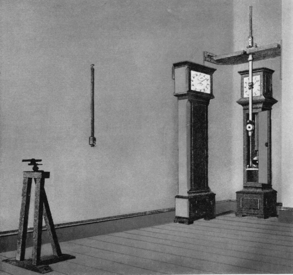
Figure 12.—The Kater convertible pendulum in use is placed before a clock, whose
pendulum bob is directly behind the extended “tail” of the Kater pendulum. A white
spot is painted on the center of the bob of the clock pendulum. The observing telescope,
left, has a diaphragm with a vertical slit of such width that its view is just filled by the tail
of the Kater pendulum when it is at rest. When the two pendulums are swinging, the
white spot on the clock pendulum can be seen on each swing except that in which the two
pendulums are in coincidence; thus, the coincidences are determined. (Portion of plate
5, Mémoires publiés par la Société française de Physique, vol. 4.)
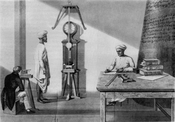
Figure 13.—This drawing accompanied John Goldingham’s report on the work done in India with Kater’s
invariable pendulum. The value of gravity obtained, directly or indirectly, in terms of the simple pendulum,
is called “absolute.” Once absolute values of gravity were established at a number of stations, it became
possible to use the much simpler “relative” method for the measurement of gravity at new stations.
Because it has only one knife edge, and does not involve the adjustments of the convertible pendulum, this
one is called “invariable.” In use, it is first swung at a station where the absolute value of gravity has been
established, and this period is then compared with its period at one or more new stations. Kater developed
an invariable pendulum in 1819, which was used in England and in Madras, India, in 1821.
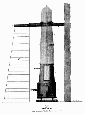
Figure 14.—Vacuum chamber for use with
the Kater pendulum. Of a number of
extraneous effects which tend to disturb the
accuracy of pendulum observations the most
important is air resistance. Experiments reported
by the Greenwich (England) observatory
in 1829 led to the development of a
vacuum chamber within which the pendulum
was swung.
While the British were engaged in swinging the
Kater invariable pendulums to determine relative
values of the length of the seconds pendulum, or
of gravity, the French also sent out expeditions.
Capt. de Freycinet made initial observations at Paris
with three invariable brass pendulums and one
wooden one, and then carried out observations at
Rio de Janeiro, Cape of Good Hope, Île de France,
Rawak (near New Guinea), Guam, Maui, and various
other places.[33] A similar expedition was conducted
in 1822-1825 by Captain Duperry.[34]
During the years from 1827 to 1840, various types
of pendulum were constructed and swung by Francis
Baily, a member of the Royal Astronomical Society,
who reported in 1832 on experiments in which no less
than 41 different pendulums were swung in vacuo,
and their characteristics determined.[35] In 1836,
Baily undertook to advise the American Lt. Charles
Wilkes, who was to head the United States Exploring
Expedition of 1838-1842, on the procurement of
pendulums for this voyage. Wilkes ordered from the
London instrument maker, Thomas Jones, two unusual
pendulums, which Wilkes described as “those
considered the best form by Mr. Baily for traveling
pendulums,” and which Baily, himself, described as
“precisely the same as the two invariable pendulums
belonging to this [Royal Astronomical] Society,”
except for the location of the knife edges.
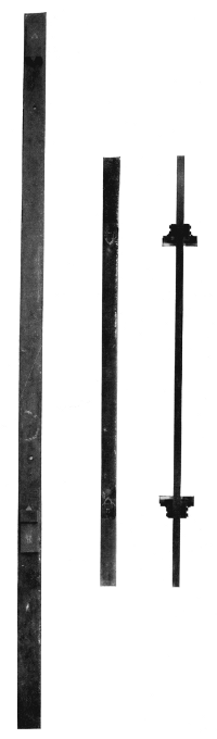
Figure 15.—One of Francis Baily’s pendulums
(62-1/2 inches long), shown on the left, is now in the
possession of the Science Museum, London, and,
right, two views of a similar pendulum (37-5/8 inches
long) made in the late 19th century by Edward
Kübel, Washington, D.C., which is no. 316,876 in
the collection of the U.S. National Museum.
Among a large number of pendulums tried by
Baily in London (1827-1840), was one which
resembles the reversible pendulum superficially, but
which is actually an invariable pendulum having
knife edges at both ends. The purpose was apparently
economy, since it is equivalent to two separate
invariable pendulums. This is the type of pendulum
used on the U.S. Exploring Expedition of
1838-1842. It is not known what use was made of
the Kübel pendulum.
The unusual feature of these pendulums was in
their symmetry of mass as well as of form. They were
made of bars, of iron in one case, and of brass in the
other, and each had two knife edges at opposite ends
equidistant from the center. Thus, although they
resembled reversible pendulums, their symmetry of
mass prevented their use as such, and they were rather
equivalent to four separate invariable pendulums.[36]
Wilkes was taught the use of the pendulum by
Baily, and conducted experiments at Baily’s house,
where the latter had carried out the work reported on
in 1832. The subsequent experiments made on the
U.S. Exploring Expedition were under the charge of
Wilkes, himself, who made observations on 11 separate
occasions, beginning with that in London (1836) and
followed by others in New York, Washington, D.C.,
Rio de Janeiro, Sydney, Honolulu, “Pendulum Peak”
(Mauna Loa), Mount Kanoha, Nesqually (Oregon
Territory), and, finally, two more times in Washington,
D.C. (1841 and 1845).
Wilkes’ results were communicated to Baily, who
appears to have found the work defective because of
insufficient attention to the maintenance of temperature
constancy and to certain alterations made to the
pendulums.[37] The results were also to have been
included in the publications of the Expedition, but
were part of the unpublished 24th volume. Fortunately
they still exist, in what appears to be a
printer’s proof.[38]
The Kater invariable pendulums were used to
investigate the internal constitution of the earth.
Airy sought to determine the density of the earth by
observing the times of swing of pendulums at the top
and bottom of a mine. The first experiments were
made in 1826 at the Dolcoath copper mine in Cornwall,
and failed when the pendulum fell to the bottom.
In 1854, the experiments were again undertaken in the
Harton coalpit, near Sunderland.[39] Gravity at the
surface was greater than below, because of the attraction
of a shell equal to the depth of the pit. From
the density of the shell as determined from specimens
of rock, Airy found the density of the earth to be 6-1/2
times greater than that of water. T. C. Mendenhall,
in 1880, used a Kater convertible pendulum in an
invariable manner to compare values of gravity on
Fujiyama and at Tokyo, Japan.[40] He used a “simple”
pendulum of the Borda type to determine the absolute
value of gravity at Tokyo. From the values of gravity
on the mountain and at Tokyo, and an estimate of
the volume of the mountain, he estimated the mean
density of the earth as 5.77 times greater than that
of water.
In 1879, Maj. J. Herschel, R.E., stated:
The years from 1840 to 1865 are a complete blank, if
we except Airy’s relative density experiments in 1854.
This pause was broken simultaneously in three different
ways. Two pendulums of the Kater pattern were sent
to India; two after Bessel’s design were set to work in
Russia; and at Geneva, Plantamour’s zealous experiments
with a pendulum of the same kind mark the
commencement of an era of renewed activity on the
European continent.[41]
With the statement that Kater invariable pendulums
nos. 4 and 6 (1821) were used in India between 1865
and 1873, we now consider the other events mentioned
by Herschel.
As we have noted, Bessel made determinations of
gravity with a ball (“simple”) pendulum in the
period 1825-1827 and in 1835 at Königsberg and
Berlin, respectively. In the memoir on his observations
at Königsberg, he set forth the theory of the
symmetrical compound pendulum with interchangeable
knife edges.[42] Bessel demonstrated theoretically
that if the pendulum were symmetrical with respect
to its geometrical center, if the times of swing about
each axis were the same, the effects of buoyancy and
of air set in motion would be eliminated. Laplace
had already shown that the knife edge must be
regarded as a cylinder and not as a mere line of
support. Bessel then showed that if the knife edges
were equal cylinders, their effects were eliminated
by inverting the pendulum; and if the knife edges
were not equal cylinders, the difference in their effects
was canceled by interchanging the knives and again
determining the times of swing in the so-called erect
and inverted positions. Bessel further showed that
it is unnecessary to make the times of swing exactly
equal for the two knife edges.
The simplified discussion for infinitely small oscillations
in a vacuum is as follows: If T1 and T2
are the times of swing about the knife edges, and if
h1 and h2 are distances of the knife edges from the
center of gravity, and if k is the radius of gyration
about an axis through the center of gravity, then
from the equation of motion of a rigid body oscillating
about a fixed axis under gravity T12 = π2(k2 + h12)/gh1,
T22 = π2(k2 + h22)/gh2. Then (h1T12
- h2T22)/(h1 - h2) = (π2/g)(h1 + h2) = τ2.
τ is then the time of swing of a simple pendulum
of length h1 + h2. If the difference T1 - T2 is sufficiently
small, τ = (h1T1 - h2T2)/(h1 - h2). Prior to its publication
by Bessel in 1828, the formula for the time of
swing of a simple pendulum of length h1 + h2 in terms
of T1, T2 had been given by C. F. Gauss in a letter
to H. C. Schumacher dated November 28, 1824.[43]
The symmetrical compound pendulum with interchangeable
knives, for which Bessel gave a posthumously
published design and specifications,[44] has
been called a reversible pendulum; it may thereby
be distinguished from Kater’s unsymmetrical convertible
pendulum. In 1861, the Swiss Geodetic
Commission was formed, and in one of its first sessions
in 1862 it was decided to add determinations of
gravity to the operations connected with the measurement—at
different points in Switzerland—of the arc
of the meridian traversing central Europe.[45] It was
decided further to employ a reversible pendulum of
Bessel’s design and to have it constructed by the firm
of A. Repsold and Sons, Hamburg. It was also
decided to make the first observations with the pendulum
in Geneva; accordingly, the Repsold-Bessel pendulum
(fig. 16) was sent to Prof. E. Plantamour,
director of the observatory at Geneva, in the autumn
of 1864.[46]
The Swiss reversible pendulum was about 560 mm.
in length (distance between the knife edges) and the
time of swing was approximately 3/4-second. At the
extremities of the stem of the pendulum were movable
cylindrical disks, one of which was solid and heavy,
the other hollow and light. It was intended by the
mechanicians that equality of times of oscillation
about the knife edges would be achieved by adjusting
the position of a movable disk. The pendulum was
hung by a knife edge on a plate supported by a
tripod and having an attachment from which a
measuring rod could be suspended so that the distance
between the knife edges could be measured by a
comparator. Plantamour found it impracticable to
adjust a disk until the times of swing about each
knife edge were equal. His colleague, Charles Cellérier,[47]
then showed that if (T1 - T2)/T1 is sufficiently
small so that one can neglect its square, one can
determine the length of the seconds pendulum from
the times of swing about the knife edges by a theory
which uses the distances of the center of gravity from
the respective knife edges. Thus, a role for the position
of the center of gravity in the theory of the
reversible pendulum, which had been set forth earlier
by Bessel, was discovered independently by Cellérier
for the Swiss observers of pendulums.
In 1866, Plantamour published an extensive memoir
“Expériences faites à Genève avec le pendule à réversion.”
Another memoir, published in 1872, presented
further results of determinations of gravity
in Switzerland. Plantamour was the first scientist
in western Europe to use a Repsold-Bessel reversible
pendulum and to work out methods for its employment.
The Russian Imperial Academy of Sciences acquired
two Repsold-Bessel pendulums, and observations
with them were begun in 1864 by Prof. Sawitsch,
University of St. Petersburg, and others.[48] In 1869,
the Russian pendulums were loaned to the India
Survey in order to enable members of the Survey to
supplement observations with the Kater invariable
pendulums nos. 4 and 6 (1821). During the transport
of the Russian apparatus to India, the knives became
rusted and the apparatus had to be reconditioned.
Capt. Heaviside of the India Survey observed with
both pendulums at Kew Observatory, near London,
in the spring of 1874, after which the Russian pendulums
were sent to Pulkowa (Russia) and were
used for observations there and in the Caucasus.
The introduction of the Repsold-Bessel reversible
pendulum for the determination of gravity was
accompanied by the creation of the first international
scientific association, one for geodesy. In 1861, Lt.
Gen. J. J. Baeyer, director of the Prussian Geodetic
Survey, sent a memorandum to the Prussian minister
of war in which he proposed that the independent
geodetic surveys of the states of central Europe be
coordinated by the creation of an international
organization.[49] In 1862, invitations were sent to the
various German states and to other states of central
Europe. The first General Conference of the association,
initially called Die Mittel-Europäische Gradmessung,
also L’Association Géodésique Internationale, was
held from the 15th to the 22d of October 1864 in
Berlin.[50] The Conference decided upon questions
of organization: a general conference was to be held
ordinarily every three years; a permanent commission
initially consisting of seven members was to be the
scientific organ of the association and to meet annually;
a central bureau was to be established for the
reception, publication, and distribution of reports
from the member states.
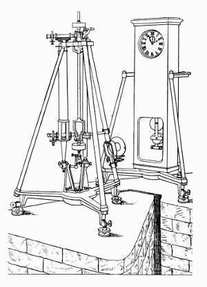
Figure 16.—From a Design Left by Bessel,
this portable apparatus was developed in
1862 by the firm of Repsold in Hamburg,
whose founder had assisted Bessel in the
construction of his pendulum apparatus
of 1826. The pendulum is convertible,
but differs from Kater’s in being geometrically
symmetrical and, for this
reason, Repsold’s is usually called “reversible.”
Just to the right of the pendulum
is a standard scale. To the left is a
“vertical comparator” designed by Repsold
to measure the distance between the
knife edges of the pendulum. To make
this measurement, two micrometer microscopes
which project horizontally through
the comparator are alternately focused on
the knife edges and on the standard scale.
Under the topic “Astronomical Questions,” the
General Conference of 1864 resolved that there
should be determinations of the intensity of gravity
at the greatest possible number of points of the
geodetic network, and recommended the reversible
pendulum as the instrument of observation.[51] At the
second General Conference, in Berlin in 1867, on the
basis of favorable reports by Dr. Hirsch, director of
the observatory at Neuchâtel, of Swiss practice with
the Repsold-Bessel reversible pendulum, this instrument
was specifically recommended for determinations
of gravity.[52] The title of the association was
changed to Die Europäische Gradmessung; in 1886, it
became Die Internationale Erdmessung, under which
title it continued until World War I.
On April 1, 1866, the Central Bureau of Die Europäische
Gradmessung was opened in Berlin under the
presidency of Baeyer, and in 1868 there was founded
at Berlin, also under his presidency, the Royal
Prussian Geodetic Institute, which obtained regular
budgetary status on January 1, 1870. A reversible
pendulum for the Institute was ordered from A.
Repsold and Sons, and it was delivered in the spring
of 1869. The Prussian instrument was symmetrical
geometrically, as specified by Bessel, but different in
form from the Swiss and Russian pendulums. The
distance between the knife edges was 1 meter, and
the time of swing approximately 1 second. The
Prussian Repsold-Bessel pendulum was swung at
Leipzig and other stations in central Europe during
the years 1869-1870 by Dr. Albrecht under the
direction of Dr. Bruhns, director of the observatory
at Leipzig and chief of the astronomical section of the
Geodetic Institute. The results of these first observations
appeared in a publication of the Royal Prussian
Geodetic Institute in 1871.[53]
Results of observations with the Russian Repsold-Bessel
pendulums were published by the Imperial
Academy of Sciences. In 1872, Prof. Sawitsch
reported the work for western Europeans in “Les
variations de la pesanteur dans les provinces occidentales
de l’Empire russe.”[48] In November 1873, the
Austrian Geodetic Commission received a Repsold-Bessel
reversible pendulum and on September 24,
1874, Prof. Theodor von Oppolzer reported on observations
at Vienna and other stations to the Fourth
General Conference of Die Europäische Gradmessung in
Dresden.[54] At the fourth session of the Conference,
on September 28, 1874, a Special Commission,
consisting of Baeyer, as chairman, and Bruhns, Hirsch,
Von Oppolzer, Peters, and Albrecht, was appointed
to consider (under Topic 3 of the program): “Observations
for the determination of the intensity of
gravity,” the question, “Which Pendulum-apparatuses
are preferable for the determination of many points?”
After the adoption of the Repsold-Bessel reversible
pendulum for gravity determinations in Europe, work
in the field was begun by the U.S. Coast Survey under
the superintendency of Prof. Benjamin Peirce. There
is mention in reports of observations with pendulums
prior to Peirce’s direction to his son Charles on November
30, 1872, “to take charge of the Pendulum Experiments
of the Coast Survey and to direct and inspect all
parties engaged in such experiments and as often
as circumstances will permit, to take the field with
a party....”[55] Systematic and important gravity
work by the Survey was begun by Charles Sanders
Peirce. Upon receiving notice of his appointment,
the latter promptly ordered from the Repsolds a
pendulum similar to the Prussian instrument. Since
the firm of mechanicians was engaged in making
instruments for observations of the transit of Venus in
1874, the pendulum for the Coast Survey could not be
constructed immediately. Meanwhile, during the
years 1873-1874, Charles Peirce conducted a party
which made observations of gravity in the Hoosac
Tunnel near North Adams, and at Northampton and
Cambridge, Massachusetts. The pendulums used
were nonreversible, invariable pendulums with conical
bobs. Among them was a silver pendulum, but
similar pendulums of brass were used also.[56]
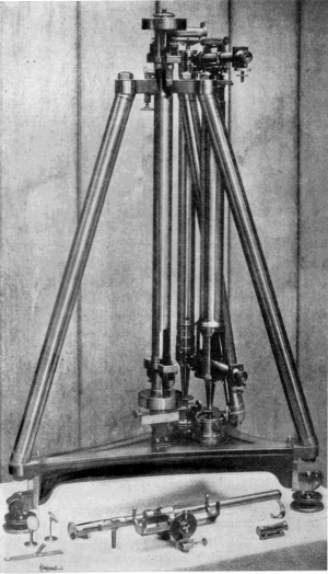
Figure 17.—Repsold-Bessel reversible pendulum apparatus
as made in 1875, and used in the gravity work of
the U.S. Coast and Geodetic Survey. Continental
geodesists continued to favor the general use of convertible
pendulums and absolute determinations of gravity, while
their English colleagues had turned to invariable pendulums
and relative determinations, except for base stations.
Perhaps the first important American contribution to
gravity work was C. S. Peirce’s demonstration of the
error inherent in the Repsold apparatus through flexure
of the stand.
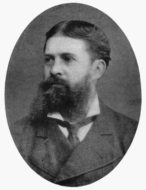
Figure 18.—Charles Sanders Peirce (1839-1914),
son of Benjamin Peirce, Perkins Professor of
Astronomy and Mathematics at Harvard College.
C. S. Peirce graduated from Harvard in 1859.
From 1873 to 1891, as an assistant at the U.S.
Coast and Geodetic Survey, he accomplished the
important gravimetric work described in this article.
Peirce was also interested in many other fields,
but above all in the logic, philosophy, and history
of science, in which he wrote extensively. His
greatest fame is in philosophy, where he is regarded
as the founder of pragmatism.
In 1874, Charles Peirce expressed the desire to be
sent to Europe for at least a year, beginning about
March 1, 1875, “to learn the use of the new convertible
pendulum and to compare it with those of the European
measure of a Degree and the Swiss and to compare”
his “invariable pendulums in the manner which
has been used by swinging them in London and
Paris.”[57]
Charles S. Peirce, assistant, U.S. Coast Survey,
sailed for Europe on April 3, 1875, on his mission to
obtain the Repsold-Bessel reversible pendulum ordered
for the Survey and to learn the methods of
using it for the determination of gravity. In England,
he conferred with Maxwell, Stokes, and Airy concerning
the theory and practice of research with
pendulums. In May, he continued on to Hamburg
and obtained delivery from the Repsolds of the pendulum
for the Coast Survey (fig. 17). Peirce then
went to Berlin and conferred with Gen. Baeyer, who
expressed doubts of the stability of the Repsold stand
for the pendulum. Peirce next went to Geneva,
where, under arrangements with Prof. Plantamour,
he swung the newly acquired pendulum at the
observatory.[58]
In view of Baeyer’s expressed doubts of the rigidity
of the Repsold stand, Peirce performed experiments
to measure the flexure of the stand caused by the
oscillations of the pendulum. His method was to set
up a micrometer in front of the pendulum stand and,
with a microscope, to measure the displacement
caused by a weight passing over a pulley, the friction
of which had been determined. Peirce calculated
the correction to be applied to the length of the seconds
pendulum—on account of the swaying of the stand
during the swings of the pendulum—to amount to
over 0.2 mm. Although Peirce’s measurements of
flexure in Geneva were not as precise as his later
measurements, he believed that failure to correct for
flexure of the stand in determinations previously made
with Repsold pendulums was responsible for appreciable
errors in reported values of the length of the
seconds pendulum.
The Permanent Commission of Die Europäische
Gradmessung met in Paris, September 20-29, 1875.
In conjunction with this meeting, there was held on
September 21 a meeting of the Special Commission
on the Pendulum. The basis of the discussion by the
Special Commission was provided by reports which
had been submitted in response to a circular sent
out by the Central Bureau to the members on
February 26, 1874.[59]
Gen. Baeyer stated that the distance of 1 meter between
the knife edges of the Prussian Repsold-Bessel
pendulum made it unwieldy and unsuited for transport.
He declared that the instability of the stand
also was a source of error. Accordingly, Gen. Baeyer
expressed the opinion that absolute determinations
of gravity should be made at a control station by a
reversible pendulum hung on a permanent, and therefore
stable stand, and he said that relative values of
gravity with respect to the control station should be
obtained in the field by means of a Bouguer invariable
pendulum. Dr. Bruhns and Dr. Peters agreed with
Gen. Baeyer; however, the Swiss investigators,
Prof. Plantamour and Dr. Hirsch reported in defense
of the reversible pendulum as a field instrument, as
did Prof. von Oppolzer of Vienna. The circumstance
that an invariable pendulum is subject to changes in
length was offered as an argument in favor of the
reversible pendulum as a field instrument.
Peirce was present during these discussions by the
members of the Special Commission, and he reported
that his experiments at Geneva demonstrated that
the oscillations of the pendulum called forth a flexure
of the support which hitherto had been neglected.
The observers who used the Swiss and Austrian
Repsold pendulums contended, in opposition to
Peirce, that the Repsold stand was stable.
The outcome of these discussions was that the
Special Commission reported to the Permanent Commission
that the Repsold-Bessel reversible pendulum,
except for some small changes, satisfied all requirements
for the determination of gravity. The Special
Commission proposed that the Repsold pendulums
of the several states be swung at the Prussian Eichungsamt
in Berlin where, as Peirce pointed out, Bessel
had made his determination of the intensity of gravity
with a ball pendulum in 1835. Peirce was encouraged
to swing the Coast Survey reversible pendulum at the
stations in France, England, and Germany where
Borda and Cassini, Kater, and Bessel, respectively,
had made historic determinations. The Permanent
Commission, in whose sessions Peirce also participated,
by resolutions adopted the report of the Special
Commission on the Pendulum.[60]
During the months of January and February 1876,
Peirce conducted observations in the Grande Salle du
Meridien at the observatory in Paris where Borda,
Biot, and Capt. Edward Sabine had swung pendulums
early in the 19th century. He conducted observations
in Berlin from April to June 1876 and, by
experiment, determined the correction for flexure to
be applied to the value of gravity previously obtained
with the Prussian instrument. Subsequent observations
were made at Kew. After his return to the
United States on August 26, 1876, Peirce conducted
experiments at the Stevens Institute in Hoboken,
New Jersey, where he made careful measurements of
the flexure of the stand by statical and dynamical
methods. In Geneva, he had secured the construction
of a vacuum chamber in which the pendulum
could be swung on a support which he called the
Geneva support. At the Stevens Institute, Peirce
swung the Repsold-Bessel pendulum on the Geneva
support and determined the effect of different pressures
and temperatures on the period of oscillation of
the pendulum. These experiments continued into
1878.[61]
Meanwhile, the Permanent Commission met October
5-10, 1876, in Brussels and continued the discussion
of the pendulum.[62] Gen. Baeyer reported on
Peirce’s experiments in Berlin to determine the flexure
of the stand. The difference of 0.18 mm. in the
lengths of the seconds pendulum as determined by
Bessel and as determined by the Repsold instrument
agreed with Peirce’s estimate of error caused by
neglect of flexure of the Repsold stand. Dr. Hirsch,
speaking for the Swiss survey, and Prof. von Oppolzer,
speaking for the Austrian survey, contended, however,
that their stands possessed sufficient stability and that
the results found by Peirce applied only to the stands
and bases investigated by him. The Permanent Commission
proposed further study of the pendulum.
The Fifth General Conference of Die Europäische
Gradmessung was held from September 27 to October 2,
1877, in Stuttgart.[63] Peirce had instructions from
Supt. Patterson of the U.S. Coast Survey to attend
this conference, and on arrival presented a letter of
introduction from Patterson requesting that he,
Peirce, be permitted to participate in the sessions.
Upon invitation from Prof. Plantamour, as approved
by Gen. Ibañez, president of the Permanent Commission,
Peirce had sent on July 13, 1877, from New
York, the manuscript of a memoir titled “De
l’Influence de la flexibilité du trépied sur l’oscillation
du pendule à réversion.” This memoir and others
by Cellérier and Plantamour confirming Peirce’s
work were published as appendices to the proceedings
of the conference. As appendices to Peirce’s contribution
were published also two notes by Prof. von
Oppolzer. At the second session on September 29,
1877, when Plantamour reported that the work of
Hirsch and himself had confirmed experimentally
the independent theoretical work of Cellérier and the
theoretical and experimental work of Peirce on
flexure, Peirce described his Hoboken experiments.
During the discussions at Stuttgart on the flexure
of the Repsold stand, Hervé Faye, president of the
Bureau of Longitudes, Paris, suggested that the swaying
of the stand during oscillations of the pendulum
could be overcome by the suspension from one support
of two similar pendulums which oscillated with equal
amplitudes and in opposite phases. This proposal
was criticized by Dr. Hirsch, who declared that exact
observation of passages of a “double pendulum”
would be difficult and that two pendulums swinging
so close together would interfere with each other.
The proposal of the double pendulum came up again at
the meeting of the Permanent Commission at Geneva
in 1879.[64] On February 17, 1879, Peirce had completed
a paper “On a Method of Swinging Pendulums
for the Determination of Gravity, Proposed by M.
Faye.” In this paper, Peirce presented the results
of an analytical mechanical investigation of Faye’s
proposal. Peirce set up the differential equations,
found the solutions, interpreted them physically,
and arrived at the conclusion “that the suggestion of
M. Faye ... is as sound as it is brilliant and offers
some peculiar advantages over the existing method of
swinging pendulums.”
In a report to Supt. Patterson, dated July 1879,
Peirce stated: “I think it is important before making
a new pendulum apparatus to experiment with Faye’s
proposed method.”[65] He wrote further: “The
method proves to be perfectly sound in theory, and as
it would greatly facilitate the work it is probably
destined eventually to prevail. We must unfortunately
leave to other surveys the merit of practically
testing and introducing the new method, as our appropriations
are insufficient for us to maintain the leading
position in this matter, which we otherwise might
take.” Copies of the published version of Peirce’s
remarks were sent to Europe. At a meeting of the
Academy of Sciences in Paris on September 1, 1879,
Faye presented a report on Peirce’s findings.[66] The
Permanent Commission met September 16-20, 1879,
in Geneva. At the third session on September 19,
by action of Gen. Baeyer, copies of Peirce’s paper on
Faye’s proposed method of swinging pendulums were
distributed. Dr. Hirsch again commented adversely
on the proposal, but moved that the question be
investigated and reported on at the coming General
Conference. The Permanent Commission accepted
the proposal of Dr. Hirsch, and Prof. Plantamour
was named to report on the matter at the General
Conference. At Plantamour’s request, Charles Cellérier
was appointed to join him, since the problem
essentially was a theoretical one.
The Sixth General Conference of Die Europäische
Gradmessung met September 13-16, 1880, in Munich.[67]
Topic III, part 7 of the program was entitled “On Determinations
of Gravity through pendulum observations.
Which construction of a pendulum apparatus
corresponds completely to all requirements of science?
Special report on the pendulum.”
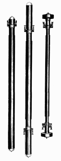
Figure 19.—Three pendulums used in early work
at the U.S. Coast and Geodetic Survey. Shown on
the left is the Peirce invariable; center, the Peirce
reversible; and, right, the Repsold reversible.
Peirce designed the cylindrical pendulum in 1881-1882
to study the effect of air resistance according
to the theory of G. G. Stokes on the motion of a
pendulum in a viscous field. Three examples of
the Peirce pendulums are in the U.S. National
Museum.
The conference received a memoir by Cellérier[68] on
the theory of the double pendulum and a report by
Plantamour and Cellérier.[69] Cellérier’s mathematical
analysis began with the equations of Peirce and used
the latter’s notation as far as possible. His general
discussion included the results of Peirce, but he
stated that the difficulties to be overcome did not
justify the employment of the “double pendulum.”
He presented an alternative method of correcting for
flexure based upon a theory by which the flexure
caused by the oscillation of a given reversible pendulum
could be determined from the behavior of an
auxiliary pendulum of the same length but of different
weight. This method of correcting for flexure was
recommended to the General Conference by Plantamour
and Cellérier in their joint report. At the
fourth session of the conference on September 16,
1880, the problem of the pendulum was discussed
and, in consequence, a commission consisting of
Faye, Helmholtz, Plantamour (replaced in 1882 by
Hirsch), and Von Oppolzer was appointed to study
apparatus suitable for relative determinations of
gravity.
The Permanent Commission met September 11-15,
1882, at The Hague,[70] and at its last session appointed
Prof. von Oppolzer to report to the Seventh General
Conference on different forms of apparatus for the
determination of gravity. The Seventh Conference
met October 15-24, 1883, in Rome,[71] and, at its
eighth session, on October 22, received a comprehensive,
critical review from Prof. von Oppolzer entitled
“Über die Bestimmung der Schwere mit Hilfe verschiedener
Apparate.”[72] Von Oppolzer especially expounded
the advantages of the Bessel reversible
pendulum, which compensated for air effects by
symmetry of form if the times of swing for both
positions were maintained between the same amplitudes,
and compensated for irregular knife edges by
making them interchangeable. Prof. von Oppolzer
reviewed the problem of flexure of the Repsold stand
and stated that a solution in the right direction was
the proposal—made by Faye and theoretically
pursued by Peirce—to swing two pendulums from the
same stand with equal amplitudes and in opposite
phases, but that the proposal was not practicable.
He concluded that for absolute determinations of
gravity, the Bessel reversible pendulum was highly
appropriate if one swung two exemplars of different
weight from the same stand for the elimination of
flexure. Prof. von Oppolzer’s important report recognized
that absolute determinations were less accurate
than relative ones, and should be conducted only at
special places.
The discussions initiated by Peirce’s demonstration
of the flexure of the Repsold stand resulted, finally,
in the abandonment of the plan to make absolute
determinations of gravity at all stations with the
reversible pendulum.
The Repsold-Bessel reversible pendulum was designed
and initially used to make absolute determinations
of gravity not only at initial stations such as
Kew, the observatory in Paris, and the Smithsonian
Institution in Washington, D.C., but also at stations
in the field. An invariable pendulum with a single
knife edge, however, is adequate for relative determinations.
As we have seen, such invariable pendulums
had been used by Bouguer and Kater, and after
the experiences with the Repsold apparatus had been
recommended again by Baeyer for relative determinations.
But an invariable pendulum is subject to
uncontrollable changes of length. Peirce proposed
to detect such changes in an invariable pendulum in
the field by combining the invariable and reversible
principles. He explained his proposal to Faye in a
letter dated July 23, 1880, and he presented it on
September 16, 1880, at the fourth session of the sixth
General Conference of Die Europäische Gradmessung,
in Munich.[73]
As recorded in the Proceedings of the Conference,
Peirce wrote:
But I obviate it in making my pendulum both invariable
and reversible. Every alteration of the pendulum will
be revealed immediately by the change in the difference
of the two periods of oscillation in the two positions.
Once discovered, it will be taken account of by means
of new measures of the distance between the two supports.
Peirce added that it seemed to him that if the reversible
pendulum perhaps is not the best instrument to
determine absolute gravity, it is, on condition that
it be truly invariable, the best to determine relative
gravity. Peirce further stated that he would wish
that the pendulum be formed of a tube of drawn brass
with heavy plugs of brass equally drawn. The cylinder
would be terminated by two hemispheres; the
knives would be attached to tongues fixed near the
ends of the cylinder.
During the years 1881 and 1882, four invariable,
reversible pendulums were made after the design of
Peirce at the office of the U.S. Coast and Geodetic
Survey in Washington, D.C. The report of the superintendent
for the year 1880-1881 states:
A new pattern of the reversible pendulum has been invented,
having its surface as nearly as convenient in the
form of an elongated ellipsoid. Three of these instruments
have been constructed, two having a distance of
one meter between the knife edges and the third a distance
of one yard. It is proposed to swing one of the
meter pendulums at a temperature near 32° F. at the
same time that the yard is swung at 60° F., in order to
determine anew the relation between the yard and the
meter.[74]
The report for 1881-1882 mentions four of these
Peirce pendulums.
A description of the Peirce invariable, reversible
pendulums was given by Assistant E. D. Preston in
“Determinations of Gravity and the Magnetic Elements
in Connection with the United States Scientific
Expedition to the West Coast of Africa, 1889-90.”[75]
The invariable, reversible pendulum, Peirce
no. 4, now preserved in the Smithsonian Institution’s
Museum of History and Technology (fig. 34), may be
taken as typical of the meter pendulums: In the same
memoir, Preston gives the diameter of the tube as
63.7 mm., thickness of tube 1.5 mm., weight 10.680
kilograms, and distance between the knives 1.000
meter.
The combination of invariability and reversibility
in the Peirce pendulums was an innovation for relative
determinations. Indeed, the combination was
criticized by Maj. J. Herschel, R.E., of the Indian
Survey, at a conference on gravity held in Washington
in May 1882 on the occasion of his visit to the United
States for the purpose of connecting English and
American stations by relative determinations with
three Kater invariable pendulums. These three
pendulums have been designated as nos. 4, 6 (1821),
and 11.[76]
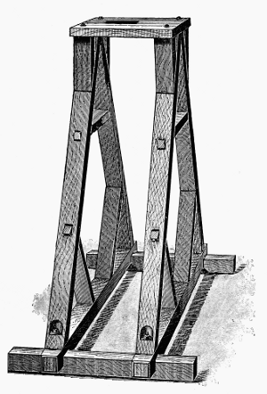
Figure 20.—Support for the Peirce pendulum,
1889. Much of the work of C. S. Peirce was concerned
with the determination of the error introduced
into observations made with the portable apparatus
by the vibration of the stand with the pendulum.
He showed that the popular Bessel-Repsold apparatus
was subject to such an error. His own pendulums
were swung from a simple but rugged wooden
frame to which a hardened steel bearing was fixed.
Another novel characteristic of the Peirce pendulums
was the mainly cylindrical form. Prof. George
Gabriel Stokes, in a paper “On the Effect of the
Internal Friction of Fluids on the Motion of Pendulums”[77]
that was read to the Cambridge Philosophical
Society on December 9, 1850, had solved the hydrodynamical
equations to obtain the resistance to the
motions of a sphere and a cylinder in a viscous
fluid. Peirce had studied the effect of viscous
resistance on the motion of his Repsold-Bessel
pendulum, which was symmetrical in form but not
cylindrical. The mainly cylindrical form of his
pendulums (fig. 19) permitted Peirce to predict
from Stokes’ theory the effect of viscosity and to
compare the results with experiment. His report
of November 20, 1889, in which he presented the
comparison of experimental results with the theory
of Stokes, was not published.[78]
Peirce used his pendulums in 1883 to establish
a station at the Smithsonian Institution that was to
serve as the base station for the Coast and Geodetic
Survey for some years. Pendulum Peirce no. 1
was swung at Washington in 1881 and was then taken
by the party of Lieutenant Greely, U.S.A., on an
expedition to Lady Franklin Bay where it was swung
in 1882 at Fort Conger, Grinnell Land, Canada.
Peirce nos. 2 and 3 were swung by Peirce in 1882
at Washington, D.C.; Hoboken, New Jersey;
Montreal, Canada; and Albany, New York. Assistant
Preston took Peirce no. 3 on a U.S. eclipse
expedition to the Caroline Islands in 1883. Peirce
in 1885 swung pendulums nos. 2 and 3 at Ann
Arbor, Michigan; Madison, Wisconsin; and Ithaca,
New York. Assistant Preston in 1887 swung Peirce
nos. 3 and 4 at stations in the Hawaiian Islands,
and in 1890 he swung Peirce nos. 3 and 4 at stations
on the west coast of Africa.[79]
The new pattern of pendulum designed by Peirce
was also adopted in France, after some years of
experience with a Repsold-Bessel pendulum. Peirce
in 1875 had swung his Repsold-Bessel pendulum at
the observatory in Paris, where Borda and Cassini,
and Biot, had made historic observations and where
Sabine also had determined gravity by comparison
with Kater’s value at London. During the spring of
1880, Peirce made studies of the supports for the
pendulums of these earlier determinations and calculated
corrections to those results for hydrodynamic
effects, viscosity, and flexure. On June 14, 1880,
Peirce addressed the Academy of Sciences, Paris,
on the value of gravity at Paris, and compared his results
with the corrected results of Borda and Biot and
with the transferred value of Kater.[80]
In the same year the French Geographic Service
of the Army acquired a Repsold-Bessel reversible
pendulum of the smaller type, and Defforges conducted
experiments with it.[81] He introduced the
method of measuring flexure from the movement
of interference fringes during motion of the pendulum.
He found an appreciable difference between dynamical
and statical coefficients of flexure and
concluded that the “correction formula of Peirce
and Cellérier is suited perfectly to practice and
represents exactly the variation of period caused
by swaying of the support, on the condition that one
uses the statical coefficient.” Defforges developed a
theory for the employment of two similar pendulums
of the same weight, but of different length, and hung
by the same knives. This theory eliminated the
flexure of the support and the curvature of the knives
from the reduction of observations.
Pendulums of 1-meter and of 1/2-meter distance
between the knife edges were constructed from
Defforges’ design by Brunner Brothers in Paris
(fig. 21). These Defforges pendulums were cylindrical
in form with hemispherical ends like the Peirce
pendulums, and were hung on knives that projected
from the sides of the pendulum, as in some unfinished
Gautier pendulums designed by Peirce in 1883 in
Paris.
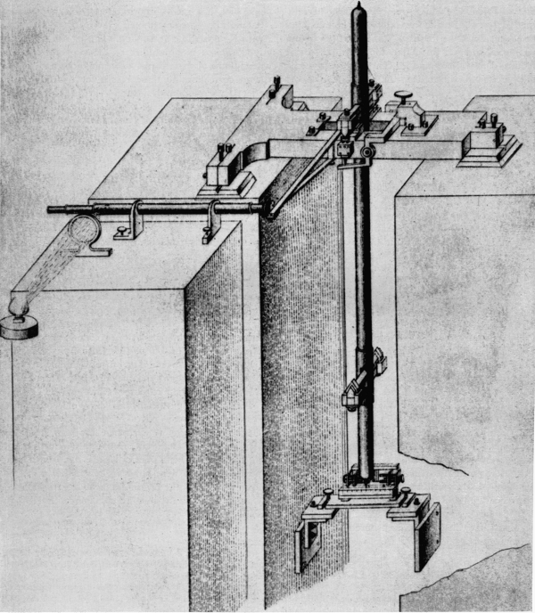
Figure 21.—Reversible pendulum apparatus of Defforges, as constructed by Brunner, Paris,
about 1887. The clock and telescope used to observe coincidences are not shown. The
telescope shown is part of an interferometer used to measure flexure of the support. One
mirror of the interferometer is attached to the pendulum support; the other to the separate
masonry pillar at the left.
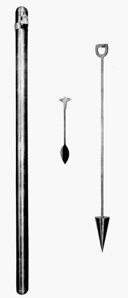
Figure 22.—Because of the greater simplicity of
its use, the invariable pendulum superseded the
convertible pendulum towards the end of the 19th
century, except at various national base stations
(Kew, Paris, Potsdam, Washington, D.C., etc.).
Shown here are, right to left, a pendulum of the
type used by Peirce at the Hoosac Tunnel in
1873-74, the Mendenhall 1/2-second pendulum of
1890, and the pendulum designed by Peirce in
1881-1882.
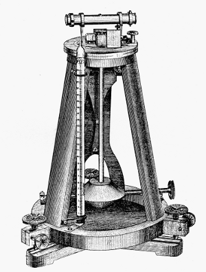
Figure 23.—The overall size of portable pendulum
apparatus was greatly reduced with the introduction of
this 1/2-second apparatus in 1887, by the Austrian military
officer, Robert von Sterneck. Used with a vacuum
chamber not shown here, the apparatus is only about 2
feet high. Coincidences are observed by the reflection of
a periodic electric spark in two mirrors, one on the support
and the other on the pendulum itself.
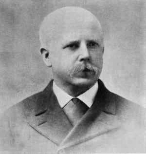
Figure 24.—Thomas C. Mendenhall (1841-1924).
Although largely self-educated, he became the first
professor of physics and mechanics at the Ohio
Agricultural and Mechanical College (later Ohio
State University), and was subsequently connected
with several other universities. In 1878, while
teaching at the Tokyo Imperial University in
Japan, he made gravity measurements between
Tokyo and Fujiyama from which he calculated
the mean density of the earth. While superintendent
of the U.S. Coast and Geodetic Survey,
1889-94, he developed the pendulum apparatus
which bears his name.
While scientists who had used the Repsold-Bessel
pendulum apparatus discussed its defects and limitations
for gravity surveys, Maj. Robert von Sterneck
of Austria-Hungary began to develop an excellent
apparatus for the rapid determination of relative
values of gravity.[82] Maj. von Sterneck’s apparatus
contained a nonreversible pendulum 1/4-meter in
length, and 1/2-second time of swing. The pendulum
was hung by a single knife edge, which rested on a
plate that was supported by a tripod. The pendulum
was swung in a chamber from which air was exhausted
and which could be maintained at any desired
temperature. Times of swing were determined by the
observation of coincidences of the pendulum with
chronometer signals. In the final form a small
mirror was attached to the knife edge perpendicular
to the plane of vibration of the pendulum and a second
fixed mirror was placed close to it so that the two
mirrors were parallel when the pendulum was at rest.
The chronometer signals worked a relay that gave a
horizontal spark which was reflected into the telescope
from the mirrors. When the pendulum was at rest,
the image of the spark in both mirrors appeared on
the horizontal cross wire in the telescope, and during
oscillation of the pendulum the two images appeared
in that position upon coincidence. In view of the
reduced size of the pendulum, the chamber in which
it was swung was readily portable, and with an
improved method of observing coincidences, relative
determinations of gravity could be made with rapidity
and accuracy.
By 1887 Maj. von Sterneck had perfected his
apparatus, and it was widely adopted in Europe for
relative determinations of gravity. He used his
apparatus in extensive gravity surveys and also applied
it in the silver mines in Saxony and Bohemia, by the
previously described methods of Airy, for investigations
into the internal constitution of the earth.
On July 1, 1889, Thomas Corwin Mendenhall
became superintendent of the U.S. Coast and Geodetic
Survey. Earlier, he had been professor of
physics at the University of Tokyo and had directed
observations of pendulums for the determination of
gravity on Fujiyama and at Tokyo. Supt. Mendenhall,
with the cooperation of members of his staff in
Washington, designed a new pendulum apparatus
of the von Sterneck type, and in October 1890 he
ordered construction of the first model.[83]
Like the Von Sterneck apparatus, the Mendenhall
pendulum apparatus employed a nonreversible, invariable
pendulum 1/4-meter in length and of slightly
more than 1/2-second in time of swing. Initially, the
knife edge was placed in the head of the pendulum
and hung on a fixed plane support, but after some
experimentation Mendenhall attached the plane
surface to the pendulum and hung it on a fixed knife
edge. An apparatus was provided with a set of
three pendulums, so that if discrepancies appeared
in the results, the pendulum at fault could be detected.
There was also a dummy pendulum which
carried a thermometer. A pendulum was swung
in a receiver in which the pressure and temperature
of the air were controlled. The time of swing was
measured by coincidences with the beat of a chronometer.
The coincidences were determined by an
optical method with the aid of a flash apparatus.
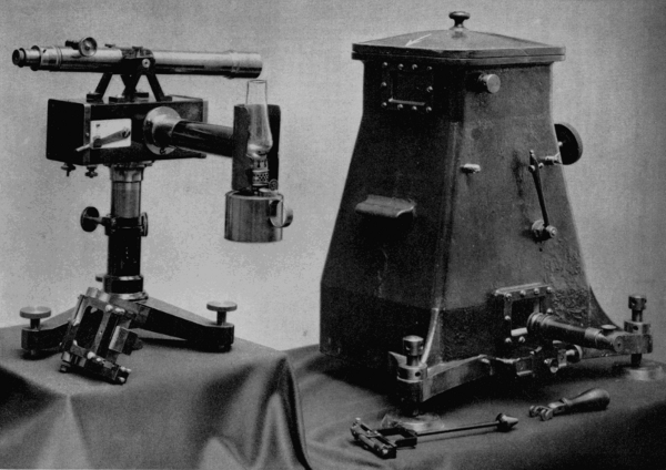
Figure 25.—Mendenhall’s 1/4-meter (1/2-second) apparatus. Shown on the left is the flash
apparatus and, on the right, the vacuum chamber within which the pendulum is swung.
The flash apparatus consists of a kerosene lantern and a telescope, mounted on a box
containing an electromagnetically operated shutter. The operation of the shutter is controlled
by a chronograph (not shown), so that it emits a slit of light at regular intervals.
The telescope is focused on two mirrors within the apparatus, one fixed, the other attached
to the top of the pendulum. It is used to observe the reflection of the flashes from these
mirrors. When the two reflections are aligned, a “coincidence” is marked on the chronograph
tape. The second telescope attached to the bottom of the vacuum chamber is for
observing the amplitude of the pendulum swing.
The flash apparatus was contained in a light metal
box which supported an observing telescope and
which was mounted on a stand. Within the box was
an electromagnet whose coils were connected with a
chronometer circuit and whose armature carried a
long arm that moved two shutters, in both of which
were horizontal slits of the same size. The shutters
were behind the front face of the box, which also had
a horizontal slit. A flash of light from an oil lamp or
an electric spark was emitted from the box when the
circuit was broken, but not when it was closed. When
the circuit was broken a spring caused the arm to
rise, and the shutters were actuated so that the three
slits came into line and a flash of light was emitted.
A small circular mirror was set in each side of the
pendulum head, so that from either face of the pendulum
the image of the illuminated slit could be reflected
into the field of the observing telescope. A
similar mirror was placed parallel to these two mirrors
and rigidly attached to the support. The chronometer
signals broke the circuit, causing the three slits
momentarily to be in line, and when the images of
the slit in the two mirrors coincided, a coincidence
was observed. A coincidence occurred whenever the
pendulum gained or lost one oscillation on the beat
of the chronometer. The relative intensity of gravity
was determined by observations with the first
Mendenhall apparatus at Washington, D.C., at stations
on the Pacific Coast and in Alaska, and at the
Stevens Institute, Hoboken, New Jersey, between
March and October 1891.
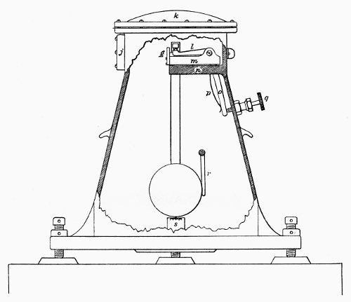
Figure 26.—Vacuum receiver within which the Mendenhall pendulum is swung. The pressure
is reduced to about 50 mm. to reduce the disturbing effect of air resistance. When
the apparatus is sealed, the pendulum is lifted on the knife edge by the lever q and is
started to swing by the lever r. The arc of swing is only about 1°. The stationary mirror
is shown at g. The pendulum shown in outline in the center, is only about 9.7 inches long.
Under Supt. Mendenhall’s direction a smaller, 1/4-second,
pendulum apparatus was also constructed
and tested, but did not offer advantages over the
1/2-second apparatus, which therefore continued in
use.
In accordance with Peirce’s theory of the flexure
of the stand under oscillations of the pendulum,
determinations of the displacement of the receiver
of the Mendenhall apparatus were part of a relative
determination of gravity by members of the Coast and
Geodetic Survey. Initially, a statical method was
used, but during 1908-1909 members of the Survey
adapted the Michelson interferometer for the determinations
of flexure during oscillations from the shift of
fringes.[84] The first Mendenhall pendulums were
made of bronze, but about 1920 invar was chosen
because of its small coefficient of expansion. About
1930, Lt. E. J. Brown of the Coast and Geodetic
Survey made significant improvements in the Mendenhall
apparatus, and the new form came to be known
as the Brown Pendulum Apparatus.[85]
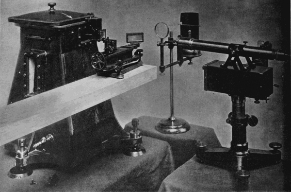
Figure 27.—The Michelson interferometer. The horizontal component of the force
acting on the knife edge through the swinging pendulum causes the support to move in
unison with the pendulum, and thereby affects the period of the oscillation. This movement
is the so-called flexure of the pendulum support, and must be taken into account in
the most accurate observations.
In 1907, the Michelson interferometer was adapted to this purpose by the U.S. Coast
and Geodetic Survey. As shown here, the interferometer, resting on a wooden beam, is
introduced into the path of a light beam reflected from a mirror on the vacuum chamber.
Movement of that mirror causes a corresponding movement in the interference fringes
in the interferometer, which can be measured.
The original Von Sterneck apparatus and that of
Mendenhall provided for the oscillation of one
pendulum at a time. After the adoption of the Von
Sterneck pendulum in Europe, there were developed
stands on which two or four pendulums hung at the
same time. This procedure provided a convenient
way to observe more than one invariable pendulum
at a station for the purpose of detecting changes in
length. Prof. M. Haid of Karlsruhe in 1896 described
a four-pendulum apparatus,[86] and Dr. Schumann of
Potsdam subsequently described a two-pendulum
apparatus.[87]
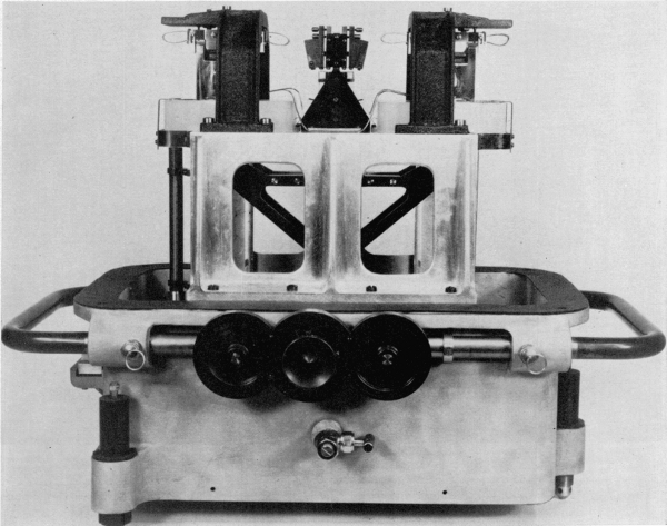
Figure 28.—Apparatus which was developed in 1929 by the Gulf Research and Development
Company, Harmarville, Pennsylvania. It was designed to achieve an accuracy
within one ten-millionth of the true value of gravity, and represents the extreme development
of pendulum apparatus for relative gravity measurement. The pendulum was
designed so that the period would be a minimum. The case (the top is missing in this
photograph) is dehumidified and its temperature and electrostatic condition are controlled.
Specially designed pendulum-lifting and -starting mechanisms are used. The problem of
flexure of the case is overcome by the Faye-Peirce method (see text) in which two
dynamically matched pendulums are swung simultaneously, 180° apart in phase.
The multiple-pendulum apparatus then provided a
method of determining the flexure of the stand from
the action of one pendulum upon a second pendulum
hung on the same stand. This method of determining
the correction for flexure was a development from a
“Wippverfahren” invented at the Geodetic Institute
in Potsdam. A dynamometer was used to impart
periodic impulses to the stand, and the effect was
observed upon a pendulum initially at rest. Refinements
of this method led to the development of a
method used by Lorenzoni in 1885-1886 to determine
the flexure of the stand by action of an auxiliary
pendulum upon the principal pendulum. Dr. Schumann,
in 1899, gave a mathematical theory of such
determinations,[88] and in his paper cited the mathematical
methods of Peirce and Cellérier for the theory of
Faye’s proposal at Stuttgart in 1877 to swing two
similar pendulums on the same support with equal
amplitudes and in opposite phases.
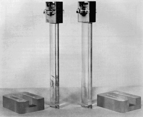
Figure 29.—The Gulf pendulum is about 10.7 inches long, and has a period of .89 second.
It is made of fused quartz which is resistant to the influence of temperature change and to
the earth’s magnetism. Quartz pendulums are subject to the influence of electrostatic
charge, and provision is made to counteract this through the presence of a radium salt in
the case. The bearings are made of Pyrex glass.
In 1902, Dr. P. Furtwängler[89] presented the mathematical
theory of coupled pendulums in a paper in
which he referred to Faye’s proposal of 1877 and reported
that the difficulties predicted upon its application
had been found not to occur. Finally, during the
gravity survey of Holland in the years 1913-1921, in
view of instability of supports caused by the mobility
of the soil, F. A. Vening Meinesz adopted Faye’s
proposed method of swinging two pendulums on the
same support.[90] The observations were made with
the ordinary Stückrath apparatus, in which four Von
Sterneck pendulums swung two by two in planes
perpendicular to each other. This successful application
of the method—which had been proposed by
Faye and had been demonstrated theoretically to be
sound by Peirce, who also published a design for its
application—was rapidly followed for pendulum apparatus
for relative determinations by Potsdam,[91]
Cambridge (England),[92] Gulf Oil and Development
Company,[93] and the Dominion Observatory at
Ottawa.[94] Heiskanen and Vening Meinesz state:
The best way to eliminate the effect of flexure is to use
two synchronized pendulums of the same length swinging
on the same apparatus in the same plane and with
the same amplitudes but in opposite phases; it is clear
then the flexure is zero.[95]
In view of the fact that the symmetrical reversible
pendulum is named for Bessel, who created the theory
and a design for its application by Repsold, it appears
appropriate to call the method of eliminating flexure
by swinging two pendulums on the same support the
Faye-Peirce method. Its successful application was
made possible by Maj. von Sterneck’s invention of the
short, 1/4-meter pendulum.
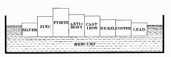
Figure 30.—The accumulated data of gravity observations over the earth’s
surface have indicated that irregularities such as mountains do not have
the effect which would be expected in modifying gravity, but are somehow
compensated for. The most satisfactory solution to this still unanswered
question has been the theory of isostasy, according to which variations in
the density of the material in the earth’s crust produce a kind of hydrostatic
equilibrium between its higher and lower parts, as they “float” on the earth’s
fluid core. The metals of different density floating in mercury in this
diagram illustrate isostasy according to the theory of Pratt and Hayford.
The development of the reversible pendulum in the
19th century culminated in the absolute determination
of the intensity of gravity at Potsdam by Kühnen
and Furtwängler of the Royal Prussian Geodetic Institute,
which then became the world base for gravity
surveys.[96]
We have previously seen that in 1869 the Geodetic
Institute—founded by Lt. Gen. Baeyer—had acquired
a Repsold-Bessel reversible pendulum which
was swung by Dr. Albrecht under the direction of
Dr. Bruhns. Dissatisfaction with this instrument was
expressed by Baeyer in 1875 to Charles S. Peirce,
who then, by experiment and mathematical analysis
of the flexure of the stand under oscillations of the
pendulum, determined that previously reported results
with the Repsold apparatus required correction.
Dr. F. R. Helmert, who in 1887 succeeded Baeyer as
director of the Institute, secured construction of a
building for the Institute in Potsdam, and under his
direction the scientific study of the intensity of gravity
was pursued with vigor. In 1894, it was discovered
in Potsdam that a pendulum constructed of very
flexible material yielded results which differed
markedly from those obtained with pendulums of
greater stiffness. Dr. Kühnen of the Institute discovered
that the departure from expectations was the
result of the flexure of the pendulum staff itself during
oscillations.[97]
Peirce, in 1883, had discovered that the recesses cut
in his pendulums for the insertion of tongues that
carried the knives had resulted in the flexure of the
pendulum staff.[98] By experiment, he also found an
even greater flexure for the Repsold pendulum. In
order to eliminate this source of error, Peirce designed
a pendulum with knives that extended from each
side of the cylindrical staff, and he received authorization
from the superintendent of the Coast and Geodetic
Survey to arrange for the construction of such
pendulums by Gautier in Paris. Peirce, who had
made his plans in consultation with Gautier, was
called home before the pendulums were completed,
and these new instruments remained undelivered.
In a memoir titled “Effect of the flexure of a pendulum
upon its period of oscillation,”[99] Peirce determined
analytically the effect on the period of a pendulum
with a single elastic connection between two
rigid parts of the staff. Thus, Peirce discovered
experimentally the flexure of the staff and derived for
a simplified case the effect on the period. It is not
known if he ever found the integrated effect of the
continuum of elastic connections in the pendulum.
Lorenzoni, in 1896, offered a solution to the problem,
and Almansi, in 1899, gave an extended analysis.
After the independent discovery of the problem at
the Geodetic Institute, Dr. Helmert took up the problem
and criticized the theories of Peirce and Lorenzoni.
He then presented his own theory of flexure in
a comprehensive memoir.[100] In view of the previous
neglect of the flexure of the pendulum staff in the
reduction of observations, Helmert directed that the
Geodetic Institute make a new absolute determination
of the intensity of gravity at Potsdam. For this
purpose, Kühnen and Furtwängler used the following
reversible pendulums which had been constructed
by the firm of A. Repsold and Sons in Hamburg:
1. The seconds pendulum of the Geodetic Institute
procured in 1869.
2. A seconds pendulum from the Astronomical Observatory,
Padua.
3. A heavy, seconds pendulum from the Imperial and
Royal Military-Geographical Institute, Vienna.
4. A light, seconds pendulum from the Imperial and
Royal Military-Geographical Institute.
5. A 1/2-second, reversible pendulum of the Geodetic
Institute procured in 1892.
Work was begun in 1898, and in 1906 Kühnen and
Furtwängler published their monumental memoir,
“Bestimmung der Absoluten Grösze der Schwerkraft
zu Potsdam mit Reversionspendeln.”
The acceleration of gravity in the pendulum room
of the Geodetic Institute was determined to be 981.274
± 0.003 cm/sec2. In view of the exceptionally careful
and thorough determination at the Institute, Potsdam
was accepted as the world base for the absolute value
of the intensity of gravity. The absolute value of
gravity at some other station on the Potsdam system
was determined from the times of swing of an invariable
pendulum at the station and at Potsdam by the
relation T12/T22 = g2/g1.
Thus, in 1900, Assistant G. R. Putnam of the Coast
and Geodetic Survey swung Mendenhall pendulums
at the Washington base and at Potsdam, and by transfer
from Potsdam determined the intensity of gravity
at the Washington base to be 980.112 cm/sec2.[101]
In 1933, Lt. E. J. Brown made comparative measurements
with improved apparatus and raised the
value at the Washington base to 980.118 cm/sec2.[102]
In view of discrepancies between the results of
various relative determinations, the Coast and Geodetic
Survey in 1928 requested the National Bureau
of Standards to make an absolute determination for
Washington. Heyl and Cook used reversible pendulums
made of fused silica having a period of
approximately 1 second. Their result, published in
1936, was interpreted to indicate that the value at
Potsdam was too high by 20 parts in 1 million.[103]
This estimate was lowered slightly by Sir Harold
Jeffreys of Cambridge, England, who recomputed
the results of Heyl and Cook by different methods.[104]
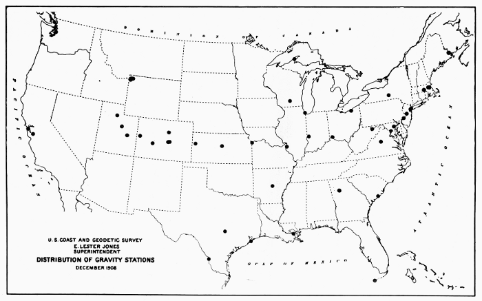
Figure 31.—Map showing the distribution of gravity stations throughout the United States as of December 1908.
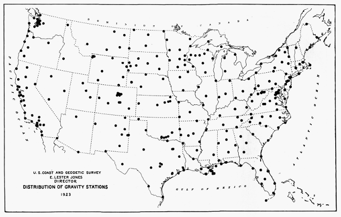
Figure 32.—Map showing the distribution of gravity stations throughout the United States in 1923.
In 1939, J. S. Clark published the results of a
determination of gravity with pendulums of a non-ferrous
Y-alloy[105] at the National Physical Laboratory
at Teddington, England, and, after recomputation
of results by Jeffreys, the value was found to be
12.8 parts in 1 million less than the value obtained by
transfer from Potsdam. Dr. Hugh L. Dryden of the
National Bureau of Standards, and Dr. A. Berroth
of the Geodetic Institute at Potsdam, have recomputed
the Potsdam data by different methods of adjustment
and concluded that the Potsdam value was too high
by about 12 parts in a million.[106] Determination of
gravity at Leningrad by Russian scientists likewise
has indicated that the 1906 Potsdam value is too
high. In the light of present information, it
appears justifiable to reduce the Potsdam value of
981.274 by .013 cm/sec2 for purposes of comparison.
If the Brown transfer from Potsdam in 1933 was
taken as accurate, the value for the Washington base
would be 980.105 cm/sec2. In this connection, it is
of interest to note that the value given by Charles
S. Peirce for the comparable Smithsonian base in
Washington, as determined by him from comparative
methods in the 1880’s and reported in the Annual
Report of the Superintendent of the Coast and Geodetic Survey
for the year 1890-1891, was 980.1017 cm/sec2.[107] This
value would appear to indicate that Peirce’s pendulums,
observations, and methods of reduction of data
were not inferior to those of the scientists of the
Royal Prussian Geodetic Institute at Potsdam.
Doubts concerning the accuracy of the Potsdam
value of gravity have stimulated many new determinations
of the intensity of gravity since the end of World
War II. In a paper published in June 1957, A. H.
Cook, Metrology Division, National Physical Laboratory,
Teddington, England, stated:
At present about a dozen new absolute determinations
are in progress or are being planned. Heyl and Cook’s
reversible pendulum apparatus is in use in Buenos Aires
and further reversible pendulum experiments have been
made in the All Union Scientific Research Institute of
Metrology, Leningrad (V N I I M) and are planned at
Potsdam. A method using a very long pendulum was
tried out in Russia about 1910 and again more recently
and there are plans for similar work in Finland. The
first experiment with a freely falling body was that
carried out by Volet who photographed a graduated
scale falling in an enclosure at low air pressure. Similar
experiments have been completed in Leningrad and
are in progress at the Physikalisch-Technische Bundesanstalt
(Brunswick) and at the National Research
Council (Ottawa), and analogous experiments are being
prepared at the National Physical Laboratory and at
the National Bureau of Standards. Finally, Professor
Medi, Director of the Istituto Nazionale di Geofisica
(Rome), is attempting to measure the focal length of
the paraboloidal surface of a liquid in a rotating dish.[108]
We have noted previously that in the ancient and
early modern periods, the earth was presupposed to
be spherical in form. Determination of the figure of
the earth consisted in the measurement of the radius
by the astronomical-geodetic method invented by
Eratosthenes. Since the earth was assumed to be
spherical, gravity was inferred to be constant over
the surface of the earth. This conclusion appeared
to be confirmed by the determination of the length
of the seconds pendulum at various stations in Europe
by Picard and others. The observations of Richer in
South America, the theoretical discussions of Newton
and Huygens, and the measurements of degrees of
latitude in Peru and Sweden demonstrated that the
earth is an oblate spheroid.
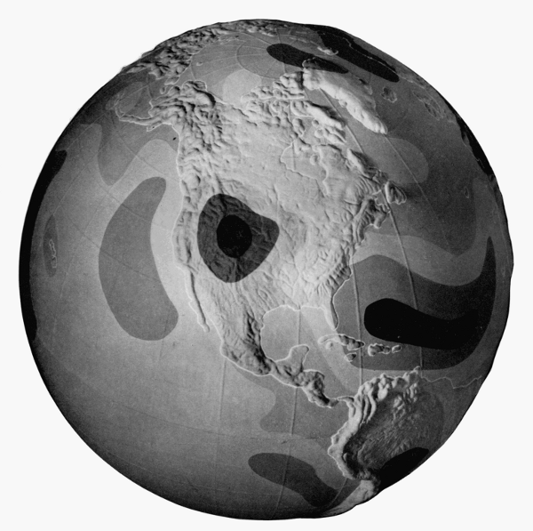
Figure 33.—Gravity characteristics of the globe.
Deductions as to the distribution of matter in the earth
can be made from gravity measurements. This globe
shows worldwide variations in gravity as they now appear
from observations at sea (in submarines) as well as on
land. It is based on data from the Institute of Geodesy
at Ohio State University.
The theory of gravitation and the theory of central
forces led to the result that the intensity of gravity
is variable over the surface of the earth. Accordingly,
determinations of the intensity of gravity became of
value to the geodesist as a means of determining
the figure of the earth. Newton, on the basis of the
meager data available to him, calculated the ellipticity
of the earth to be 1/230 (the ellipticity is defined by
(a-b)/a, where a is the equatorial radius and b the polar
radius). Observations of the intensity of gravity
were made on the historic missions to Peru and
Sweden. Bouguer and La Condamine found that at
the equator at sea level the seconds pendulum was
1.26 Paris-lines shorter than at Paris. Maupertuis
found that in northern Sweden a certain pendulum
clock gained 59.1 seconds per day on its rate in
Paris. Then Clairaut, from the assumption that the
earth is a spheroid of equilibrium, derived a theorem
from which the ellipticity of the earth can be derived
from values of the intensity of gravity.
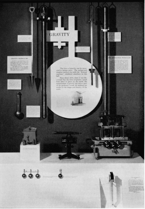
Figure 34.—An exhibit of gravity apparatus at the Smithsonian Institution. Suspended
on the wall, from left to right, are the invariable pendulums of Mendenhall (1/2-second),
Peirce (1873-1874), and Peirce (1881-1882); the double pendulum of Edward Kübel
(see fig. 15, p. 319), and the reversible pendulum of Peirce. On the display counter, from
left to right, are the vacuum chamber, telescope and flash apparatus for the Mendenhall
1/4-second apparatus. Shown below these are the four pendulums used with the Mendenhall
apparatus, the one on the right having a thermometer attached. At bottom, right, is
the Gulf apparatus (cover removed) mentioned in the text, shown with one quartz
pendulum.
Early in the 19th century a systematic series of
observations began to be conducted in order to determine
the intensity of gravity at stations all over
the world. Kater invariable pendulums, of which
13 examples have been mentioned in the literature,
were used in surveys of gravity by Kater, Sabine,
Goldingham, and other British pendulum swingers.
As has been noted previously, a Kater invariable
pendulum was used by Adm. Lütke of Russia on
a trip around the world. The French also sent
out expeditions to determine values of gravity.
After several decades of relative inactivity, Capts.
Basevi and Heaviside of the Indian Survey carried
out an important series of observations from 1865 to
1873 with Kater invariable pendulums and the
Russian Repsold-Bessel pendulums. In 1881-1882
Maj. J. Herschel swung Kater invariable pendulums
nos. 4, 6 (1821), and 11 at stations in England and
then brought them to the United States in order to
make observations which would connect American
and English base stations.[109]
The extensive sets of observations of gravity provided
the basis of calculations of the ellipticity of the
earth. Col. A. R. Clarke in his Geodesy (London,
1880) calculated the ellipticity from the results of
gravity surveys to be 1/(292.2 ± 1.5). Of interest is the
calculation by Charles S. Peirce, who used only
determinations made with Kater invariable pendulums
and corrected for elevation, atmospheric effect,
and expansion of the pendulum through temperature.[110]
He calculated the ellipticity of the earth
to be 1/(291.5 ± 0.9).
The 19th century witnessed the culmination of the
ellipsoidal era of geodesy, but the rapid accumulation
of data made possible a better approximation to the
figure of the earth by the geoid. The geoid is
defined as the average level of the sea, which is
thought of as extended through the continents.
The basis of geodetic calculations, however, is an
ellipsoid of reference for which a gravity formula
expresses the value of normal gravity at a point on
the ellipsoid as a function of gravity at sea level at
the equator, and of latitude. The general assembly
of the International Union of Geodesy and Geophysics,
which was founded after World War I to continue
the work of Die Internationale Erdmessung, adopted
in 1924 an international reference ellipsoid,[111] of
which the ellipticity, or flattening, is Hayford’s
value 1/297. In 1930, the general assembly adopted
a correlated International Gravity Formula of the form
γ = γE(1 + β(sin2 φ) + ε(sin2 2φ))
where γ is normal gravity at latitude φ, γE is the
value of gravity at sea level at the equator, β is a
parameter which is computed on the basis of Clairaut’s
theorem from the flattening value of the meridian,
and ε is a constant which is derived theoretically.
The plumb line is perpendicular to the geoid, and
the components of angle between the perpendiculars
to geoid and reference ellipsoid are deflections of
the vertical. The geoid is above the ellipsoid of
reference under mountains and it is below the
ellipsoid on the oceans, where the geoid coincides
with mean sea level. In physical geodesy, gravimetric
data are used for the determination of the
geoid and components of deflections of the vertical.
For this purpose, one must reduce observed values
of gravity to sea level by various reductions, such as
free-air, Bouguer, isostatic reductions. If g0 is observed
gravity reduced to sea level and γ is normal gravity
obtained from the International Gravity Formula,
then Δg = g0 - γ is the gravity anomaly.[112]
In 1849, Stokes derived a theorem whereby the
distance N of the geoid from the ellipsoid of reference
can be obtained from an integration of gravity
anomalies over the surface of the earth. Vening
Meinesz further derived formulae for the calculation
of components of the deflection of the vertical.
Geometrical geodesy, which was based on astronomical-geodetic
methods, could give information
only concerning the external form of the figure of
the earth. The gravimetric methods of physical
geodesy, in conjunction with methods such as those
of seismology, enable scientists to test hypotheses
concerning the internal structure of the earth.
Heiskanen and Vening Meinesz summarize the
present-day achievements of the gravimetric method of
physical geodesy by stating[113] that it alone can give:
1. The flattening of the reference ellipsoid.
2. The undulations N of the geoid.
3. The components of the deflection of the vertical ζ
and η at any point, oceans and islands included.
4. The conversion of existing geodetic systems to the
same world geodetic system.
5. The reduction of triangulation base lines from the
geoid to the reference ellipsoid.
6. The correction of errors in triangulation in mountainous
regions due to the effect of the deflections of
the vertical.
7. Geophysical applications of gravity measurements,
e.g., the isostatic study of the earth’s interior and the
exploration of oil fields and ore deposits.
With astronomical observations or with existing
triangulations, the gravimetric method can accomplish
further results. Heiskanen and Vening Meinesz state:
It is the firm conviction of the authors that the gravimetric
method is by far the best of the existing methods
for solving the main problems of geodesy, i.e., to determine
the shape of the geoid on the continents as well as
at sea and to convert the existing geodetic systems to
the world geodetic system. It can also give invaluable
help in the computation of the reference ellipsoid.[114]
Since the creation of classical mechanics in the 17th
century, the pendulum has been a basic instrument for
the determination of the intensity of gravity, which is
expressed as the acceleration of a freely falling body.
Basis of theory is the simple pendulum, whose time of
swing under gravity is proportional to the square root
of the length divided by the acceleration due to
gravity. Since the length of a simple pendulum
divided by the square of its time of swing is equal to
the length of a pendulum that beats seconds, the intensity
of gravity also has been expressed in terms of
the length of the seconds pendulum. The reversible
compound pendulum has served for the absolute
determination of gravity by means of a theory developed
by Huygens. Invariable compound pendulums
with single axes also have been used to determine
relative values of gravity by comparative times
of swing.
The history of gravity pendulums begins with the
ball or “simple” pendulum of Galileo as an approximation
to the ideal simple pendulum. Determinations
of the length of the seconds pendulum by French
scientists culminated in a historic determination at
Paris by Borda and Cassini, from the corrected observations
with a long ball pendulum. In the 19th
century, Bessel found the length of the seconds pendulum
at Königsberg and Berlin by observations with
a ball pendulum and by original theoretical considerations.
During the century, however, the compound
pendulum came to be preferred for absolute and relative
determinations.
Capt. Henry Kater, at London, constructed the first
convertible compound for an absolute determination
of gravity, and then he designed an invariable compound
pendulum, examples of which were used for
relative determinations at various stations in Europe
and elsewhere. Bessel demonstrated theoretically the
advantages of a reversible compound pendulum which
is symmetrical in form and is hung by interchangeable
knives. The firm of A. Repsold and Sons in Hamburg
constructed pendulums from the specifications of
Bessel for European gravity surveys.
Charles S. Peirce in 1875 received delivery in Hamburg
of a Repsold-Bessel pendulum for the U.S. Coast
Survey and observed with it in Geneva, Paris, Berlin,
and London. Upon an initial stimulation from
Baeyer, founder of Die Europäische Gradmessung,
Peirce demonstrated by experiment and theory that
results previously obtained with the Repsold apparatus
required correction, because of the flexure of
the stand under oscillations of the pendulum. At
the Stuttgart conference of the geodetic association in
1877, Hervé Faye proposed to solve the problem of
flexure by swinging two similar pendulums from the
same support with equal amplitudes and in opposite
phases. Peirce, in 1879, demonstrated theoretically
the soundness of the method and presented a design
for its application, but the “double pendulum” was
rejected at that time. Peirce also designed and had
constructed four examples of a new type of invariable,
reversible pendulum of cylindrical form which made
possible the experimental study of Stokes’ theory of the
resistance to motion of a pendulum in a viscous fluid.
Commandant Defforges, of France, also designed and
used cylindrical reversible pendulums, but of different
length so that the effect of flexure was eliminated in
the reduction of observations. Maj. Robert von
Sterneck, of Austria-Hungary, initiated a new era in
gravity research by the invention of an apparatus with
a short pendulum for relative determinations of
gravity. Stands were then constructed in Europe on
which two or four pendulums were hung at the same
time. Finally, early in the present century, Vening
Meinesz found that the Faye-Peirce method of swinging
pendulums hung on a Stückrath four-pendulum
stand solved the problem of instability due to the
mobility of the soil in Holland.
The 20th century has witnessed increasing activity
in the determination of absolute and relative values of
gravity. Gravimeters have been perfected and have
been widely used for rapid relative determinations,
but the compound pendulums remain as indispensable
instruments. Mendenhall’s replacement of knives by
planes attached to nonreversible pendulums has been
used also for reversible ones. The Geodetic Institute at
Potsdam is presently applying the Faye-Peirce method
to the reversible pendulum.[115] Pendulums have been
constructed of new materials, such as invar, fused
silica, and fused quartz. Minimum pendulums for
precise relative determinations have been constructed
and used. Reversible pendulums have been made with
“I” cross sections for better stiffness. With all these
modifications, however, the foundations of the present
designs of compound pendulum apparatus were
created in the 19th century.
U.S. GOVERNMENT PRINTING OFFICE: 1965
For sale by the Superintendent of Documents, U.S. Government Printing Office
Washington, D.C., 20402—Price 70 cents.
Airy, G. B., 319, 324, 332
Albrecht, Karl Theodore, 322, 338
Al-Mamun, seventh calif of Bagdad, 306
Almansi, Emilio, 339
Aristotle, 306
Baeyer, J. J., 321, 322, 324, 338, 346
Baily, Francis, 317
Basevi, James Palladio, 345
Berroth, A., 342
Bessel, Friedrich Wilhelm, 313, 314, 319, 320, 324, 325, 338, 346
Biot, Jean Baptiste, 325, 329
Bohnenberger, Johann Gottlieb Friedrich, 315
Borda, J. C., 311, 312, 315, 325, 329, 346
Boscovitch, Père R. J., 310, 311
Bouguer, Pierre, 307, 309, 327, 343, 345
Brahe, Tycho, 306
Brown, E. J., 334, 339
Browne, Henry, 304, 314
Bruhns, C., 322, 324, 338
Brunner Brothers (Paris), 329
Cassini, Giovanni-Domenico, 306, 307
Cassini, Jacques, 306
Cassini de Thury, J. D., 311, 312, 315, 325, 329, 346
Cellérier, Charles, 320, 321, 325, 326, 329, 336
Clairaut, Alexis Claude, 308, 309, 343, 345
Clark, J. S., 342
Clarke, A. R., 345
Colbert, Jean Baptiste, 306
Cook, A. H., 342
Cook, Guy S., 339, 342
Defforges, C., 314, 329, 346
De Freycinet, Louis Claude de Saulses, 317
De la Hire, Gabriel Philippe, 306
De Prony, M. G., 314
Dryden, Hugh L., 342
Du Buat, L. G., 314
Duperry, Capt. Louis Isidore, 317
Eratosthenes, 306, 308, 342
Eudoxus of Cnidus, 306
Faye, Hervé, 325, 336, 346, 347
Fernel, Jean, 306
Furtwängler, P., 337
Galilei, Galileo, 304, 305, 346
Gauss, C. F., 320
Gautier, P., 339
Godin, Louis, 307
Goldingham, John, 316, 345
Greely, A. W., 329
Gulf Oil and Development Company, 338
Haid, M., 335
Hall, Basil, 316
Heaviside, W. J., 321, 345
Heiskanen, W. A., 338, 345, 346
Helmert, F. R., 338, 339
Helmholtz, Hermann von, 326
Herschel, John, 319, 328, 345
Heyl, Paul R., 339, 342
Hirsch, Adolph, 322, 324
Huygens, Christiaan, 304, 305, 307, 314, 342, 346
Ibañez, Carlos, 325
Jeffreys, Sir Harold, 342
Jones, Thomas, 318
Kater, Henry, 304, 314, 325, 327, 329, 345, 346
Kühnen, F., 338, 339
La Condamine, Charles Marie de, 307, 310, 311, 343
Laplace, Marquis Pierre Simon de, 309, 313, 320
Lorenzoni, Giuseppe, 336, 339
Lütke, Count Feodor Petrovich, 316, 345
Maupertius, P. L. Moreau de, 308, 343
Maxwell, James Clerk, 324
Medi, Enrico, 342
Mendenhall, Thomas Corwin, 319, 331, 332, 334, 347
Mersenne, P. Marin, 305
Newton, Sir Isaac, 303, 307, 308, 342, 343
Norwood, Richard, 306
Oppolzer, Theodor von, 322, 324
Patterson, Carlile Pollock, 325, 326
Peirce, Charles Sanders, 314, 322, 332, 336, 342, 345
Peters, C. A. F., 322, 324
Picard, Abbé Jean, 306, 308, 342
Plantamour, E., 319, 324
Posidonius, 306
Preston, E. D., 328, 329
Putnam, G. R., 339
Pythagoras, 306
Repsold, A., and Sons (Hamburg), 320, 322, 338, 339, 346
Richer, Jean, 307, 342
Sabine, Capt. Edward, 315, 325, 329, 345
Sawitsch, A., 321, 322
Schumacher, H. C., 320
Schumann, R., 335, 336
Snell, Willebrord, 306
Sterneck, Robert von, 331, 332, 335, 338, 346
Stokes, George Gabriel, 324, 328, 329, 345, 346
Ulloa, Antonio de, 308
Vening Meinesz, F. A., 337, 338, 345
Volet, Charles, 342
Wilkes, Charles, 317, 318
Formatting of equations has been altered from the original to display them
‘in line,’ and brackets have been added to clarify expressions where necessary.
Footnotes have been moved to the end of the paper. Illustrations and the
Glossary of Gravity Terminology section have been moved to avoid breaks
in paragraphs. Minor punctuation errors have been corrected without
note. Typographical errors and inconsistencies have been corrected as
follows:
P. 320 ‘difference T1 - T2 is sufficiently’—had ‘sufficlently.’
P. 321 ‘faites à Genève avec le pendule à réversion’—had ‘reversion.’
P. 326 ‘Schwere mit Hilfe verschiedener Apparate’—had ‘verschiedene.’
P. 328 ‘between the yard and the meter.’—closing quote mark deleted.
P. 334 ‘Mendenhall apparatus were part of’—‘was’ changed to ‘were.’
P. 342 ‘of the Geodetic Institute at Potsdam’—had ‘Postdam.’
P. 345 ‘The gravimetric methods of physical’—had ‘mtehods.’
Footnote 1 ‘Société française de Physique’—had ‘Française.’
Footnote 3 ‘Cogitata physico-mathematica’—had ‘physica.’
Footnote 10 ‘mathématiques et de physique par MM. de l’Académie Royale’—had ‘mathematiques,’ ‘Royal.’
Footnote 12 ‘par ordre du Roy au Pérou, pour observer’—had ‘Perou, pour observir.’
Footnote 19 ‘Opticam et Astronomiam’—had ‘Astronomian.’
Footnote 20 ‘connaître la longueur du pendule qui’—had ‘connaitre la longuer.’
Footnote 21 ‘Abhandlungen der Königlichen Akademie’—had ‘Königliche.’
Footnote 25 ‘pour déterminer la longueur du pendule’—had ‘longeur.’
Footnote 41 ‘Survey of India (Calcutta, 1879)’— had ‘Surey.’
Footnotes 45 and 47 ‘Société de Physique et d’histoire’—had
‘d’historire.’
Footnote 49 ‘Über die Grösse und Figur der Erde’—had ‘Grosse.’
Footnote 53 ‘Bestimmung der Länge’—had ‘Lange’; ‘Astronomisch-Geodätische Arbeiten’—had
‘Astronomische’; ‘Veröffentlichungen des Königlichen’—had ‘Königliche.’
Footnote 55 ‘(1768), vol. 58, pp. 329-335.’—had ‘329-235.’
Footnote 66 ‘Comptes-rendus de l’Académie’—had ‘L’Académie.’
Footnote 81 ‘Sur l’Intensité absolue’—had ‘l’Intensite.’
Footnote 89 ‘Sitzungsberichte der Königlicher’—had ‘Königliche.’
Footnote 100 ‘Veröffentlichungen des Königlichen’ had ‘Veröffentlichungen Königliche.’
Capitalisation of ‘Von’/‘von’ has been regulaized to ‘von’ for all
personal names, except at the beginning of a sentence, and when
referring to the Von Sterneck pendulum.