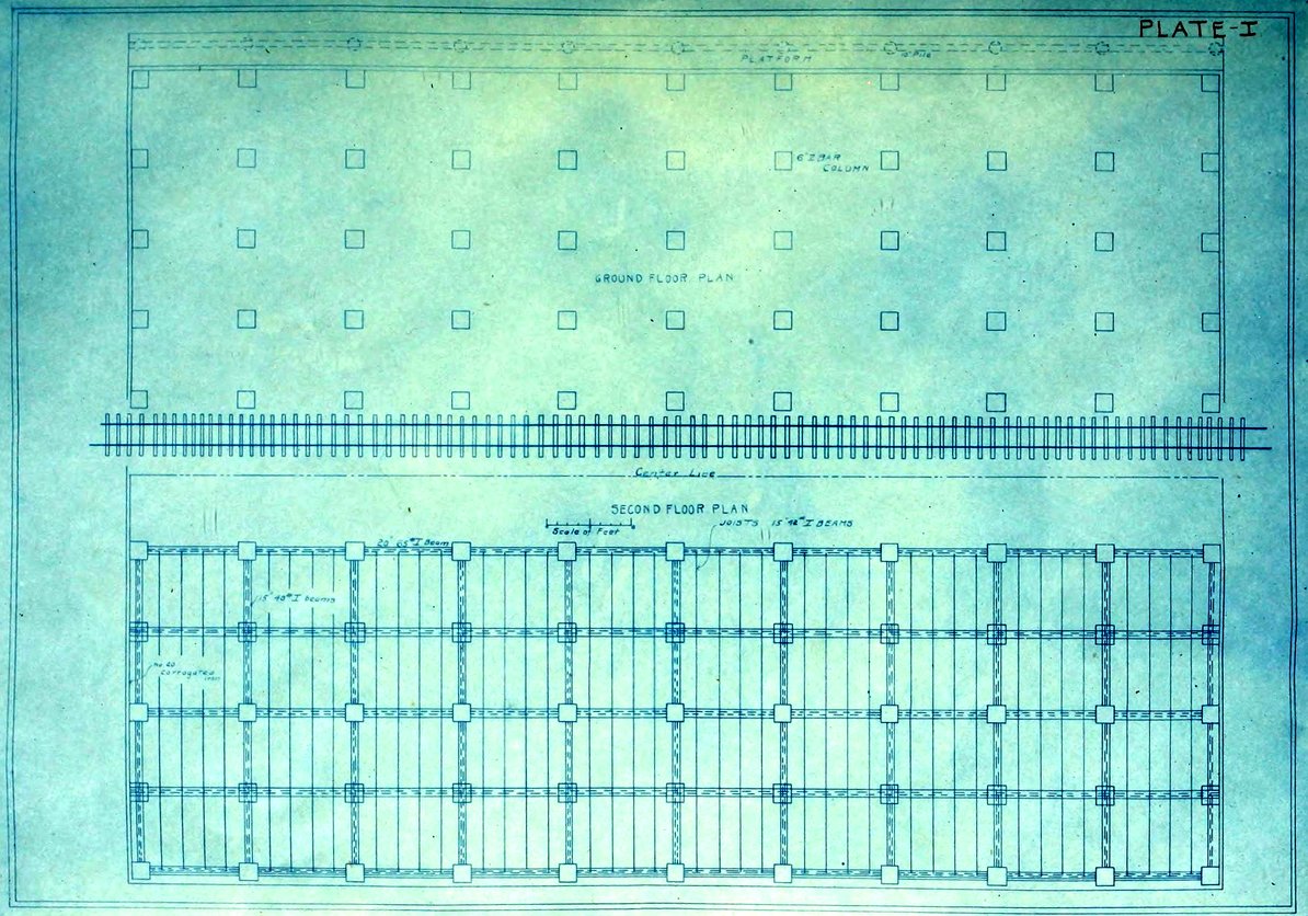
The site for the warehouse has been
taken at New Orleans, Louisiana, on the property
of the Illinois Central fronting the gulf known
as Stuyvesant Docks. The design, however,
is adapted to any sea-board town where a great
deal of heavy freight is received from railroads
for shipment by water, or vice versa.
It might also with a few variations be suitable
for an inland town.
The warehouse will be 600 ft. long.
This length is chosen because it represents
the length of wharf available for that purpose.
The width of the building will be 148 ft., of
which 20 ft. in the center will be occupied by
two tracks spaced fifteen feet center to center,
which allows an ample passage-way between
12the tracks and also between the floor and
the track.
Load. The size of warehouse having been
decided upon, the next thing is to select the
proper floor load to be allowed for. This depends
upon the class of freight to be expected and also
upon the manner of storing it. Passage-ways
will at most times be left in the freight for
accessibility, which will make some difference
in the loading; but as the passageways are
likely to be omitted at some time, the unit
load should be on the side of safety and cover
all contingencies. A load of 250 lbs per. sq. ft.
on both the upper and lower floor has been
taken in this design, which it is believed
will be ample as iron ore, lead, etc., will not
be stored here.
Support of Upper Floor. The columns
will be spaced 20 ft. apart in the direction of
the length of the building, and 15 ft. in the
13other direction. The girders will run parallel
to the length of the building and therefore
the girders will be 20 ft. long and the joists 15.
The economic length of the girder is somewhat
less than 20 ft. but by this spacing of the
columns more clear room will be obtained,
which is a thing worthy of some consideration.
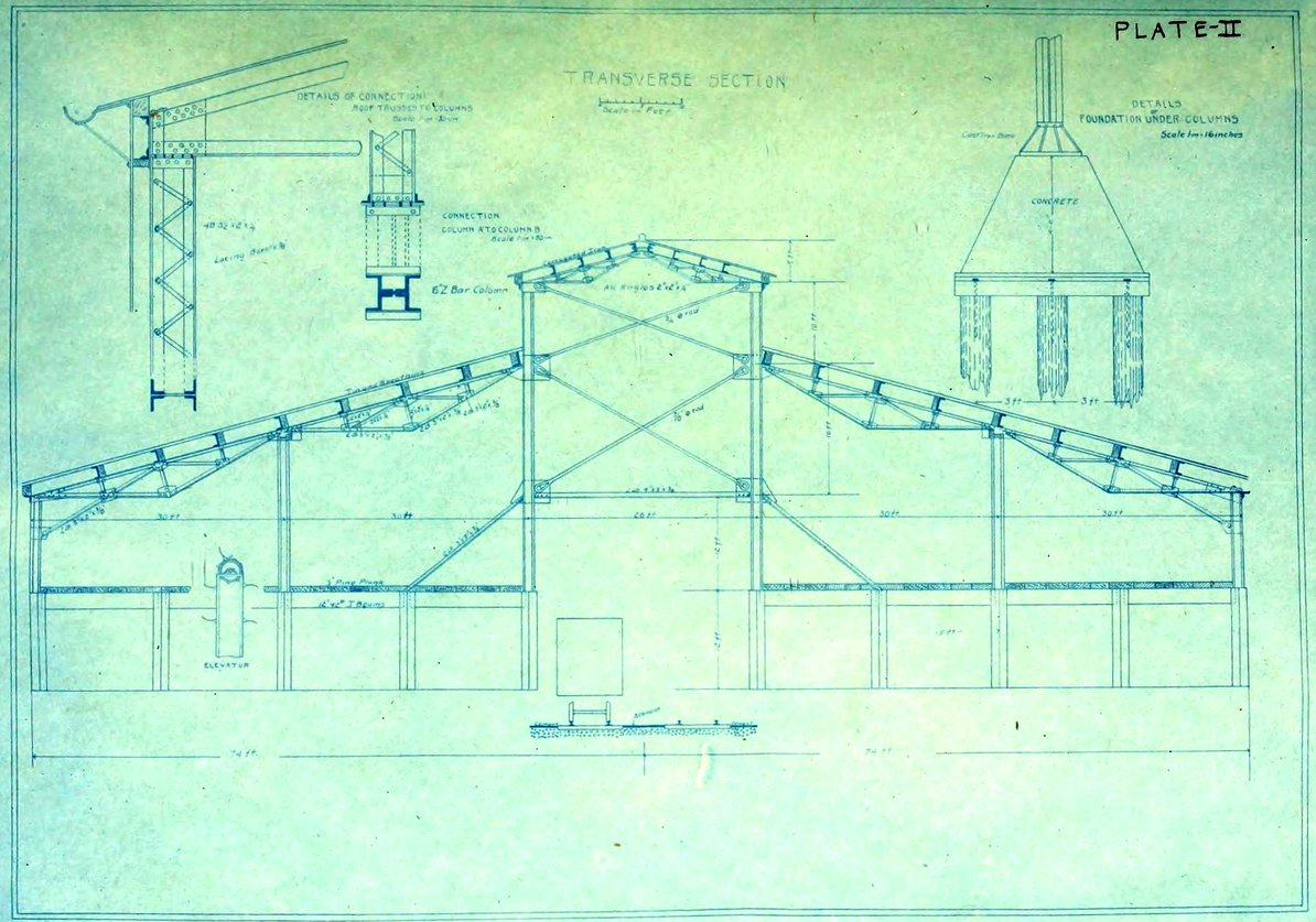
Roof Trusses. The vertical load on the
roof will be taken as 35 lbs. per. sq. ft. of horizontal
projection, of which 20 lbs. is supposed to
cover the weight of the roof itself, and 15 a
possible load due to wind. The horizontal
effect of the wind is taken as 30 lbs. per. sq. ft.
of the vertical projection. A design was first
made in which it was intended to span 60 ft.
with one Fink truss, but this required such
heavy construction in the truss members,
that the span of the trusses was reduced to
30 ft. and a column was projected up
through the second story to carry one end of
14the trusses.
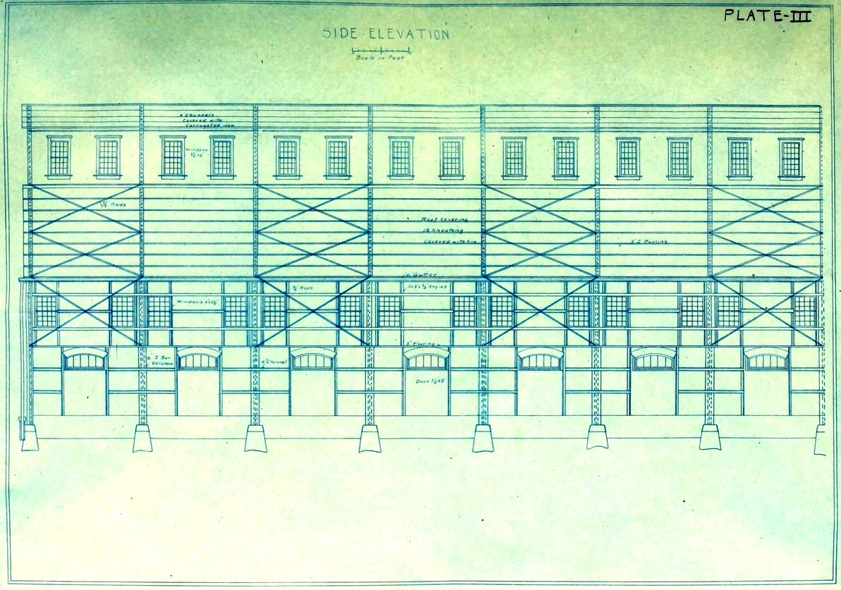
For an elevation of the trusses see Plate III,
page 23. The stresses in the several members of
the trusses were found by graphical resolution.
In many cases a stress was found smaller
than would be safely carried by a 2 × 2–inch angle,
but on account of riveting a smaller section could
not be used. For details of the trusses see Plate
III, page 23.
Purlins. The purlins are spaced 7 ft. apart
and have a span of 20 feet. This requires rather
a heavy purlin, and on account of the length
there will be more or less deflection in it; but
this will not be in the least detrimental.
Five-inch nine-pound channels will be used,
and on these will be bolted the nailing pieces.
Roof Covering. Over the purlins will be
laid 1½–inch fine sheathing covered with tin.
Tin is used in preference to corrugated iron,
as it may be soldered so as to be absolutely
15water-tight. On the underside of the sheathing
will be nailed a layer of asbestos to prevent sparks
from the engines below setting fire to the woodwork.
Flooring. The flooring for the upper story
will be 3–inch well-seasoned long leaf yellow
pine surfaced to a thickness and laid with
square joints. The floor can safely carry the
required load with a span of 4 feet, and therefore
the joists will be spaced 4 feet center to
center. The joists will be supported by girders
which are in turn supported by the columns.
The joists will be 15–inch 42 lb. I beams, and
the girders 20–inch 65–lb. I beams.
Columns. Only two columns will be designed:
one having only a part of the roof to support,
and one that supports this column and the
load on the upper floor. The first is designated
A on Plate III, page 23, and the second B.
Column A. The load due to the weight of
16truss, wind and snow is 24000 lbs. A
column composed of 4 angles 3½ × 2½ × 3
16–in. and
2 × ½–in. lacing will be used. The cross-section
is shown in the figure
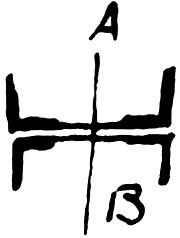 .
The moment
of inertia about the axis AB = 20.4 × 4 = 81.6 inches,
and the distance C, from the center of gravity
of the cross section to the most extreme fibre,
= 4. The bending moment, M, caused by the wind
on the roof = 1,442,000 inch pounds. Substituting
these values in the formula M = SI ÷ C and solving
for S, we obtain a value of 7100 lbs. per. sq.
in. The stress per. sq. in. due to the weight
of the trusses = 3300 lbs. Therefore the total
stress = 7100 + 3300 = 10400 lbs. per. sq. in. The
allowable stress = 16000 − (45 l
v). l
v = 13.7. Therefore
the allowable stress = 11400 lbs. per. sq. in.
Column B. The dead load caused by
column A is 12 tons, and the load on the column
due to the second floor is 41.5 tons, making a
total of 53.5 tons. The length of column is 12 ft.
17Try a column composed of four 3 × ½ in. Z
bars laced. Half of the wind pressure on the windward
side above the floor is transmitted by the
roof and the lateral bracing to the columns on
the leeward side of the building, and half is
carried directly by the columns on the windward
side. The wind pressure to be resisted
by 10 columns = 46 × 30 × 20 = 27,600 lbs. The columns
being fixed at the base, the total moment of
the wind = 27,600 × 12 × 6 = 1,987,200 in. lbs. and
the moment resisted by one column = 198,720 in. lbs.
I ÷ C for this column = 35.1. By substitution in
the equation M = SI ÷ C, S = 2300 lbs. per sq. in (approx.).
The area of the column = 9.31 sq. in.; and the
stress in the column due to the dead load =
83000 ÷ 9.31 = 8900 lbs. per. sq. in.
The other columns will be stressed less
than this one; but this section will be used
throughout for the columns on the lower floor.
Wind Bracing. Only the method of
18designing member AD (see Plate III, page 23)
will be explained. The wind pressure to be transmitted
= 4800 lbs. The secant of the angle of
inclination = 1.06. Therefore the stress in AD = 4800
× 1.06 = 5100 lbs. A ¾–in. round rod will be used.
In the same way the sizes of the members
CE, EF, and FG are determined.
Foundation. The maximum load for
the column is about 55 tons. The foundation will
be built on piling, as experiments made by
F. J. Llewellyn—Engineering News, May 11 1899—show
that the safe load for the soil at New
Orleans is only about 700 lbs. per. sq. ft. Nine
piles will be used in supporting each column.
The depth of pile necessary to safely support
the load will be found by driving a few
trial piles and using what is known as
the Engineering News formula (Baker’s Masonry
Construction page 245) P′ = 2Wh ÷ d + 1, in which
P′ = the safe load in tons; and d is the
19penetration in inches under the last blow.
W is the weight of the hammer in tons; and h
h is the fall in feet. The piles will be of good
quality straight-grained white oak, and before
being driven, the entire bark will be stripped
off. No pile less than 15 in. at the top will be
used. The piles will be spaced 3 ft. center to
center. A detail drawing of the foundation is
shown in Plate III, page 23. The concrete used
in the foundation will be composed of 1 part
Louisville Natural cement and 4 parts of sandstone
broken to pass a 2½–in. ring, the part
passing a ½–in. ring being screened out. The
concrete is assumed to have a compressive
strength of 10 tons per sq. ft., and then the area
of the cast iron base to support the column
will be 55 ÷ 10 = 5.5 sq. ft. A base 30 inches
square will be used.
The first floor will be composed of 6–inches
of concrete made as that for the foundation
20resting directly on the ground. Over this
will be spread ½–in. of neat Portland cement
to give the floor an even surface.