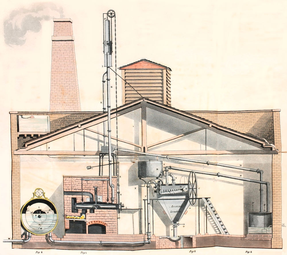
The name of gas holder, or, as it is improperly
called, gasometer, is given to the vessel employed
for collecting the gas and storing it up for use. In
the principle and construction of this part of the
gas light machinery, peculiarly valuable improvements
have of late been made. They have contributed
to lessen the expence of the apparatus so
much, that a reservoir for storing up any quantity
of gas, may now be furnished for nearly one half
the sum which such a vessel cost as originally
constructed.
In the infancy of the art of lighting with coal
gas, the reservoir was encumbered with a heavy appendage
of chains, wheel-work and balance weights,
and from the construction of the machine, it was
necessary to guard it from the impulse of the wind,
the action of which on the gas holder, would have
rendered the lights which the machine supplied
with gas, unsteady.
Hence it was necessary to inclose the gas holder
in a building, called the gasometer house, which
formed one of the largest items of expenditure
which the proprietor of a gas light establishment
was called upon to defray.
Now, however, the whole of these expensive
appendages is dispensed with, nor is the gasometer
house to contain the gas holder any longer necessary,
and the machine as now constructed may be
fixed in the open air.
The gas holder, of the original construction, consists
of two principal parts; first, of a cistern or
reservoir of water, usually constructed of masonry,
or of cast-iron plates, bolted and screwed together;
and secondly, of an air-tight vessel which is closed at
top and open at bottom, inverted with its open end
downwards into the cistern of water. This vessel
is always made of sheet-iron plates rivetted together
air-tight, and was suspended by a chain or chains,
passing over wheels, supported by a frame work.
If the common air be allowed to escape from the
inner vessel, when its open end is under the edge
of the water in the outer cistern, it will freely descend,
and water will occupy the place of the air; but
if the avenue of the escape be stopped, and air be
made to pass through the water, the suspended
inverted vessel will rise to make room for the air.
And, again, if the suspended vessel be counterpoised
by a weight, so as to allow it to be a little heavier
than the quantity of water which it displaces, it
will descend, if, the entering gas be withdrawn
through an outlet made in the vessel to permit the
gas to escape. But if the outlet be stopped, and air
again be admitted under the vessel, it will rise again.
The apparatus, therefore, is not only a reservoir for
storing up the gas introduced into it, but serves to
expel the gas which it contains, when required,
into the pipes and mains connected with this machine.
According to this construction of the apparatus
the interior inverted vessel forms strictly what is
termed the gas holder. It is suspended as already
stated in the outer cistern, by a chain or chains,
passing over pullies, supported by blocks and frame
work, and to the chain there is affixed a counterpoise
balance, of such a relative weight, as to allow the
gas holder a slow descent into the water, in order
to propel the gas into the mains or vessel destined
to receive it, with a very small and uniform
weight.
It will be obvious, that when a gas holder of this
construction becomes immersed in the water, it
loses as much of its weight as is equal to the bulk
of water which it displaces, and hence to render its
descent uniform, and to preserve the gas within,
of an invariable density, at any degree of immersion,
a greater counterpoise is required as the gas holder
rises out of the water.
Among various methods which have been
adopted to attain this object, the ends of the chains
by which the gas holder is suspended, have been
fastened in separate grooves, in the edge of a large
wheel or pulley, of such a diameter, that the gas
holder rises to its full height, before the wheel
makes one revolution.
In another groove in the edge of the same wheel,
was fixed the end of another chain, to which a
balance weight was suspended. This weight was
made nearly equal to the weight of the gas holder.
To equalize the density of the gas within the gas
holder, at any degree of immersion of the vessel,
the weight chain was made to pass over a wheel,
furnished with a spiral groove, so as to make the
radii of the wheel, change reciprocally with the
relative weight of the gas holder, and consequently
to render the pressure of the gas holder constant
and uniform.
Another and more elegant method of obtaining an
uniform elasticity of the gas within the gas holder,
and which has been more generally adopted, consists
in passing the chain or chains by which the
gas holder is suspended over a pully or wheels, and
making the weight of that portion of the chain,
which is equal to the depth of the gas holder, or
that part of it which becomes immersed into the
water, equal to one half of the weight of the specific
gravity of the gas holder.
It is obvious that before the purified gas can be
admitted into the gas holder, the vessel must be
allowed to descend to the bottom of the exterior
cistern, in order to get rid of the common air which
it contains. This may be effected rapidly by opening
the man hole at the top of the gas holder, to
cause the vessel to descend completely into the outer
cistern filled with water. The man hole is then
screwed up again air-tight, and the machine is ready
to receive the gas. It is obvious that the operation
of opening the man hole for letting out the common
air, requires only to be done once prior to the commencing
of the working of the apparatus.
It must be obvious that the gas holder, of which
a description has been given in the preceding page,
requires a machinery at once ponderous and very
delicate, qualities not easily reconciled in the
construction of such a machine. It is necessary
that the specific gravity apparatus, or regulating
chain, wheel work and balance weight, should be
constructed so correctly as never to suffer the gas
within the vessel, to alter its elasticity. The machinery
requires an expensive framing for its support,
and independently of this, the gas holder
must be inclosed in a building, in order to protect
it from the impulse of the wind, the action of which
would render the lights supplied from the apparatus
unsteady, as already stated. The expensive and
cumbersome specific gravity apparatus has been
wholly superseded by an ingenious contrivance
called the regulator or governor. The action of this
machine, for which we are indebted to Mr. Clegg,
is, that it regulates the density of the gas prior to
its entering into the mains, to any required degree,
whatever its density may be in the gas holder.
To accomplish this object, the apparatus through
which the gas passes into the mains, is provided
with an aperture which is capable of being enlarged
or diminished by a very slight force. To effect
this object the gas is made to enter a small
vessel, and then to pass through a regulating aperture,
the capacity of which becomes enlarged or
diminished by the velocity of the gas to a certain
standard. If the pressure of the gas in the gas
holder becomes increased, the regulating aperture
through which the gas passes into the mains, becomes
diminished, in such a proportion, that the
velocity with which the gas issues into the mains,
remains constant and uniform. And on the other
hand, if the pressure of the gas in the gas holder
becomes diminished, the regulating aperture of the
governor becomes enlarged to effect the intended
regulation.
The following is a concise description of the
manner in which this instrument is constructed.
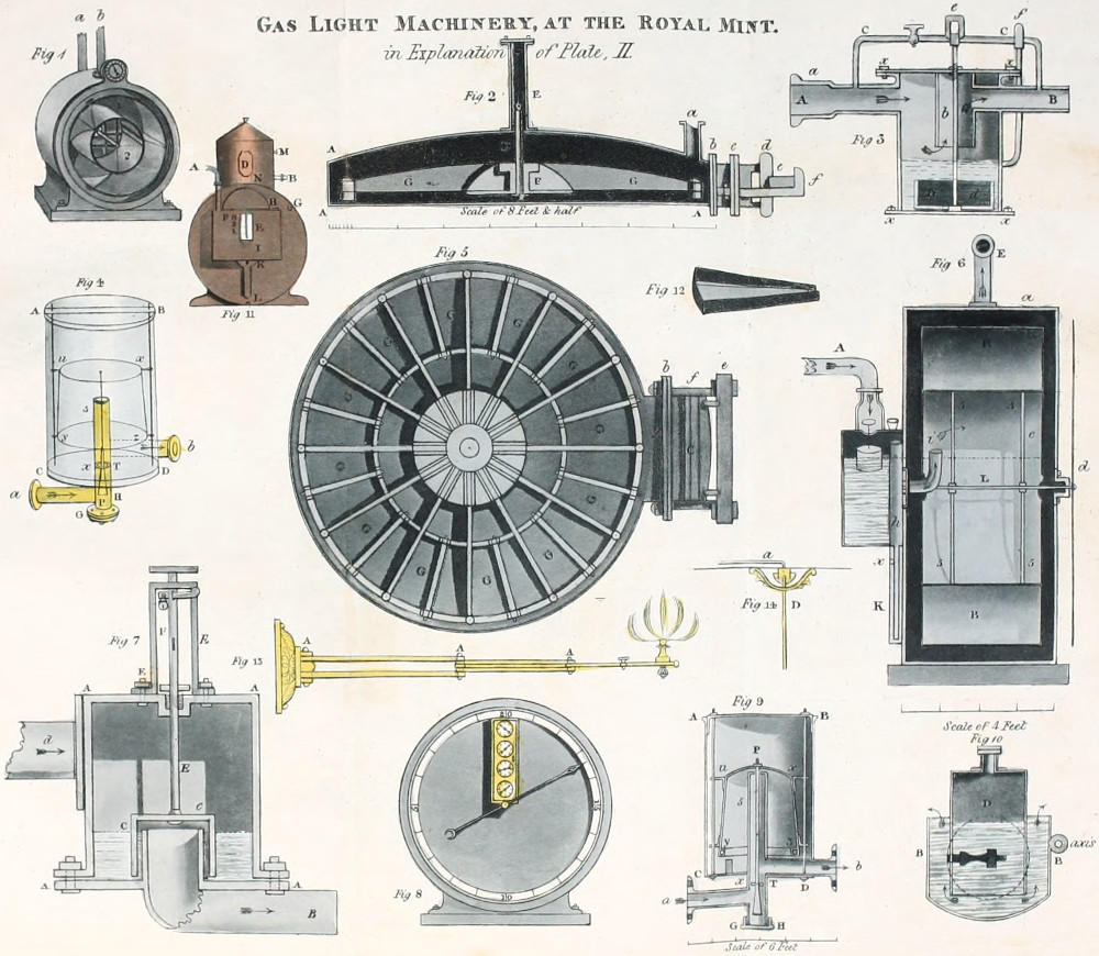
A, B, C, D, fig. 9, pl. III. is a hollow cylindrical
vessel, or the outer case of the machine. It is made
of sheet iron or copper, japanned within and without,
closed at the top and bottom. It is placed
between the gas holder and the mains, into which
the gas is to be conveyed. a, x, is a pipe which
proceeds from the outer vessel and branches upwards
in the centre of the base of the outer vessel
A, B, C, D. It brings the purified gas into the
governor. b, T, is the outlet pipe which conveys the
gas from the governor into the mains. It is placed
above the inlet pipe and communicates with the
interior vessel. G, H, a short projecting hollow
cylinder, which proceeds downwards from the
centre of the base of the outer case of the
machine A, B, C, D. u, x, y, z, is the regulator,
properly so called; it consists of a small conical
vessel, also made of sheet iron or copper, closed
at the top and open at bottom, japanned within
and without. This vessel rises and falls vertically
in the outer cylindrical case. A, B, C, D,
of the machine, when the latter is filled with water.
It is kept steady in its motion by two slender guide
rods, as shewn in the sketch.
Between the inlet pipe which conveys the
gas into the governor, and the outlet pipe which
conveys the gas into the mains, is fixed horizontally
a partition plate, having a circular aperture
in the centre. This plate is seen between the
letters x, T.
Through this orifice passes a perpendicular axis
P, which is fixed at the top in the centre of the
regulator or interior floating vessel u, x, y, z.
The interior extremity of the axis P, is furnished
with a cone, having its base downwards, and projecting
beyond the pipe a, x, into the short
cylinder G, H. The base of this cone slightly
exceeds the diameter of the orifice x, T, so as to
close up entirely, when the regulator is raised to
its greatest height in the outer vessel A, B, C, D.
But when the floating vessel u, x, y, z, descends in
the outer vessel A, B, C, the vertex of the adjusting
cone P, is just entering the aperture.
The regulator is conical, and its form is in exact
proportion to the loss of the weight of water which
it displaces; so that the gas conveyed into it always
retains an invariable density at whatever height the
regulator may be immersed in the water in the
outer vessel. If the outer vessel be filled with water
up to the top of the central branch pipe, the interior
vessel will float, and the water will stand in the
outer vessel at the same height as in the inside of
the regulator; hence the density of the gas within
will be the same as the outer air. But the density
of the gas in the regulator may be increased at
pleasure by applying a weight to the top of the
regulator, the water will then stand higher on the
outside of the regulator than within, and this
adjustment will remain uniform, because the quantity
of matter of the regulator is in the ratio of its
specific gravity or loss of weight as it becomes
immersed in the water.
Let us suppose that the pipe above the partition
plate be connected with a main, and that
the outlet pipe below the partition plate be connected
with a gas holder supplying gas into the
machine; it will be evident that if the density of the
gas in the inlet pipe becomes by any means increased,
a greater quantity of gas must pass betwixt the
sides of the adjusting cone and the aperture in the
partition plate, the consequence of which will be
that the floating regulator will rise, and therefore
contract the area of the partition plate. And if,
on the contrary, the gas in the inlet pipe decreases
in density the regulator will descend, so that whatever
density the gas may at any time assume in
the gas holders or mains, its density in the floating
vessel u, x, y, z, will remain uniform, and consequently
the velocity of the gas passing into the
mains will be regular.
For when the aperture of the partition plate
would admit more gas than what is necessary
for the density of the gas in the mains, the floating
regulator rises, and by that means raises the
adjusting cone to diminish the aperture in the
partition plate, and when, on the contrary, the
aperture does not allow a sufficient quantity of gas
to come from the gas holders, the gas passes out of
the regulator into the mains, and in so doing the
regulator descends, and consequently the adjusting
cone increases the opening to admit the requisite
gas into the mains.
The further application of this machine, for
regulating the height of the gas flames issuing
from burners or lamps of different kinds will be
shewn hereafter.
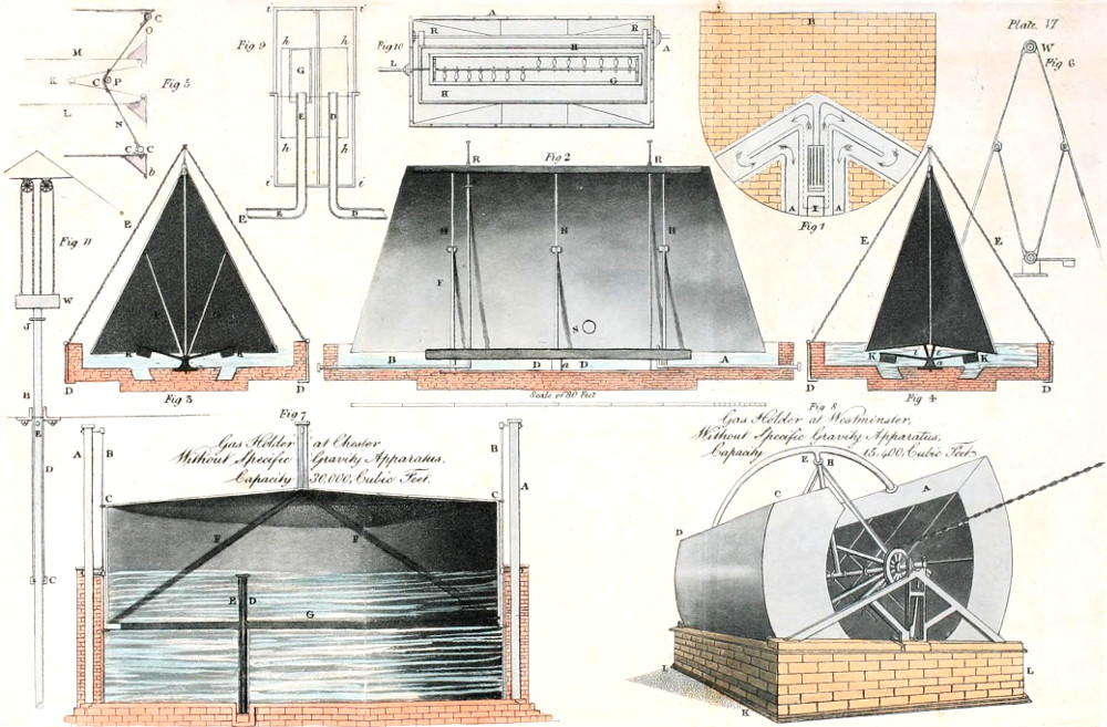
Fig. 7, plate VI., exhibits a perpendicular section
of the gas holder at Chester. A, A, are wooden
beams or pillars fixed into sockets or shafts constructed
on the outside of the brick-work, and
descending as seen in the design to the depth of
the tank. There are four of these pillars, three
only are seen in the section. B, B, are round iron
guide rods rendered steady by stays at the upper
extremity of the rods.
To the upper and lower edges of the gas holder
are fastened eye bolts, C, C, through which the
guide rods, B, B, are inserted, so that the gas
holder must move steadily and firmly. D, E, are
the inlet and outlet pipes which convey the gas
into and out of the gas holder.
F, F, are diagonal stays for supporting the roof
of the gas holder, which has a slope of ten feet from
the centre to the circumference. G, is the wooden
curb at the lower margin of the machine.
This gas holder is circular. It measures forty-eight
feet in diameter, and thirteen feet in height;
its weight is eight tons.
The regulator adapted to this gas holder, measures
three feet across its base, and its height is
three feet three inches. The base of the regulating
cone is four inches, and its length two feet. The
machine is made of sheet iron japanned within and
without.
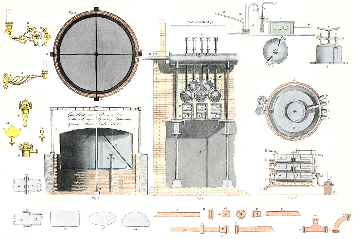
The construction of this gas holder, as exhibited
plate V., fig. 2, shows a perpendicular section, and
fig. 3, a plan of the machine; a, a, a, a, fig. 3,
are upright pillars, two of which B, B, are seen in
the section, fig. 2.
In the centre of the gas holder is fixed a pipe,
which allows the gas holder to slide on the central
guide rod G, made fast at the bottom of the cistern,
and at the top of the cross framing. C, C, are diagonal
stays; D, the inlet pipe which conveys the
gas into the gas holder E; the outlet pipe F, the
wooden curb.
The capacity of this gas holder is 30,000 cubic
feet; its regulator is precisely similar to that before
described. The weight of the gas holder, exclusive
of the wooden curbs at top and bottom, is between
eight and nine tons.[39]
The gas holder thus disencumbered of its specific
gravity apparatus, requires no building to enclose
it, it may be erected in the open air, for the machine
cannot suffer from the rain or snow falling upon it,
nor can the action of the wind render the lights
unsteady.
The saving which has been effected by these improvements
is very great. A gas holder without
balance weight and specific gravity apparatus, with
its governor, may be erected complete for action,
for little more than half the cost that would be required
for the erection of an apparatus of the same
capacity constructed on the old plan.
The cheapest house constructed of sheet iron to
surround a circular gas holder of 15,000 cubic feet
capacity, supposing the surface of its cistern or
tank to be level with the ground, costs no less
than £. 320. The balance weights and chains
£. 60, and the cast-iron framing for supporting the
specific gravity machinery £. 150.
The cost of a gas holder of the before-mentioned
capacity, will be £. 300, and a cast-iron tank
for it, £. 800.—If the tank be constructed of
brick-work, it will cost about £. 500, and if of wood
(an iron-bound vat,) it will cost £. 600.
A governor or regulating guage adapted to a gas
holder of from 10,000 to 40,000 cubic feet capacity,
costs £. 50. In the construction of the gas holders,
as hitherto described, it is always advisable when
the situation will admit it, that the diameter to the
height of the machine should be in the proportion
as three to two. If these dimensions be observed,
and the gas holder is not burdened by iron stays,
it will not displace a column of water more than
one inch and a half in height. And by adapting
to the machine, a governor or regulating guage,
a considerable saving will be effected. The gas
holder may then be constructed as shown fig. 7,
plate VI., or fig. 2, plate V. A circular gas holder
of 30,000 cubic feet capacity, if properly constructed,
weighs no more than eight or nine tons,
including its wooden curb at its lowest extremity,
and its diagonal stays.[40]
The roof of the machine ought to be constructed
of thicker sheet iron than those forming its sides.
The only object of the balance weight, is to counterpoise
the weight of the chain of the gas holder of
the old construction, so that when the gas holder
is wholly immersed in the cistern, the chain and
balance weight are in equilibrium, deducting the
required pressure with which the gas holder is
intended to act. And this ought never to exceed
from half an inch to an inch perpendicular head
of water.
The sheet iron best adapted for constructing gas
holders, is that known in commerce as No. 16,
wire guage.[42] Gas holders made of plates of iron of
this kind, have now been in use for upwards of nine
years, and are not in the least injured or decayed.
Self-interested views may sometimes lead unprincipled
workmen to make use of sheet iron plates
of a much greater thickness, but experience has
sufficiently shown that any greater thickness than
what has been specified is wholly unnecessary, and
only serves as a drawback to the facility of the
general operation.
The revolving gas holder is an ingenious contrivance
invented by Mr. Clegg, for storing large
quantities of gas. A gas holder of this construction
may be erected with advantage in situations
where the nature of the ground will not
admit of a deep cistern either above or below the
ground being constructed, without an enormous
expence.
The base which it occupies is no larger than
what would be required for a gas holder of equal
capacity, built on the plan of the gas holders of
which descriptions have been just given.
It regulates its own specific gravity. And though
more expensive in the construction, yet as it does
not require a deep cistern, like the machines already
described, it can be erected at the same cost. The
revolving gas holder is exhibited, fig. 8, plate VI.
Its capacity is 15,000 cubic feet; it weighs 12 tons.
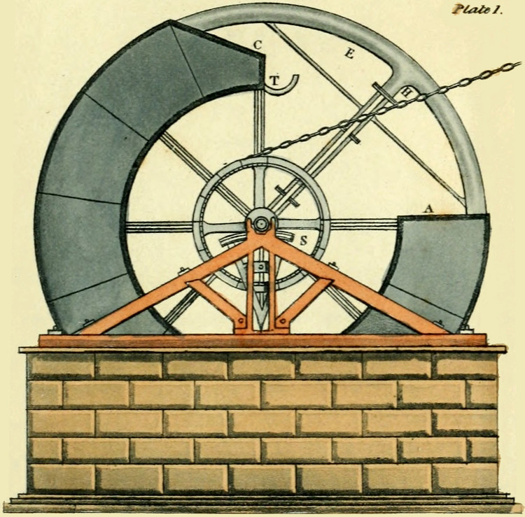
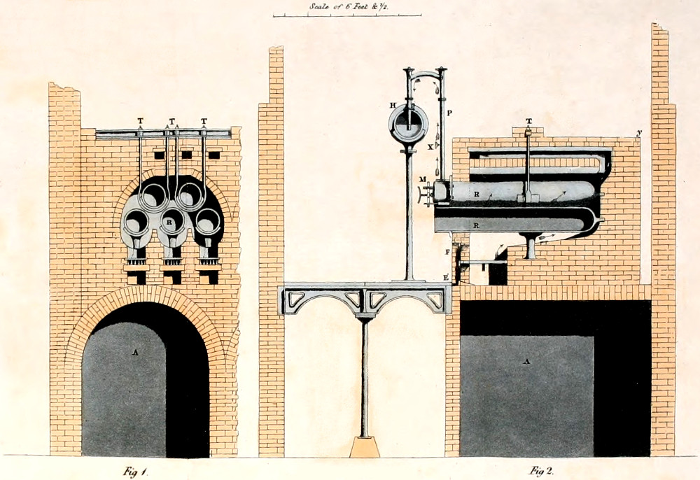
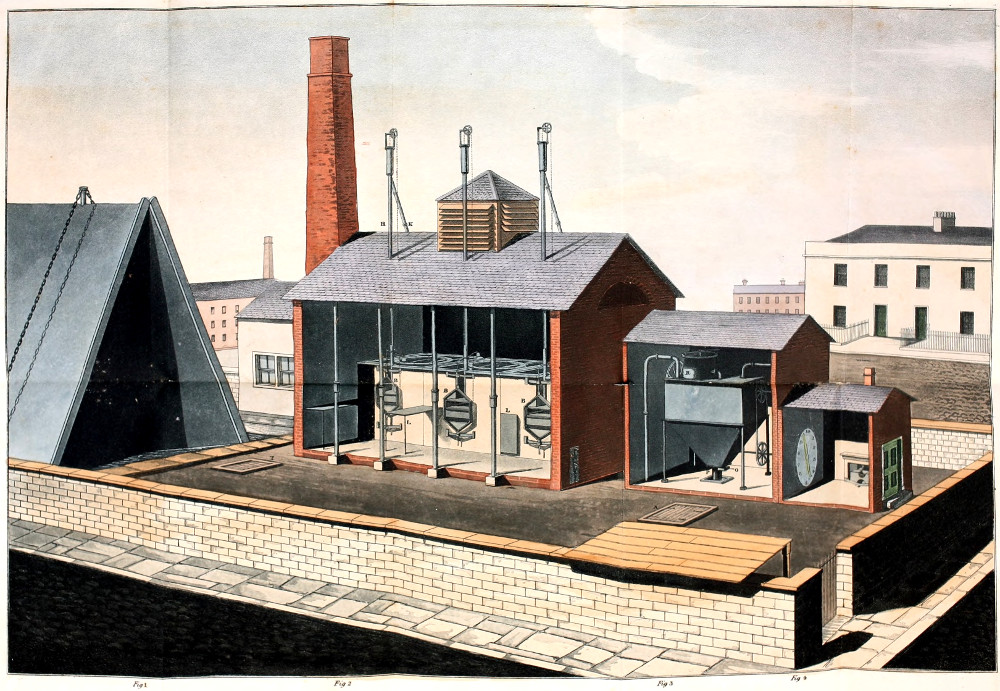
Plate I., (on the title page,) exhibits a perpendicular
section of the gas holder.
On inspecting fig. 8, plate VI., it will be seen
that this machine is the segment of a hollow
cylinder, or broad wheel, formed by two concentric
cylindric surfaces of 250° each, revolving upon an
horizontal axis, and supported upon a wooden
frame or truss, in a brick cistern, I, K, L.
The extremity C, D, fig. 8, plate VI., or C,
plate I., of the segment of the cylinder, is open,
and the other extremity A, is closed. E, is a
balance pipe, which connects the closed with the
open extremity of the machine.
This pipe is made of such a weight as to counterpoise
the interval between the open and closed end
of the gas holder, so that the machine may move in
a segment of a circle equally, in whatever position
it may happen to be placed, and hence the gas will
be discharged from the gas holder with an uniform
velocity.
The balance pipe E, is closed at the part where
the letter E is placed; H, is a straight pipe, which
forms the communication between the balance
pipe E, and the horizontal axis upon which the
machine moves. This axis is hollow: it is supported
by stays and braces, as shown in the design
on the title page. The cistern in which the gas
holder moves is 71⁄2 feet deep. It must be evident
that the gas being conveyed into the open end of
the hollow axis, it will pass through the pipe H,
into the balance pipe E, and this being stopped up
near E, the gas will proceed into the closed end
of the gas holder. The operation will therefore
be as follows:
Let us suppose the closed extremity of the
machine to be at the surface of the water in the
cistern, and the gas flowing through the axis as
described, the extremity of the machine will begin
to fill, and consequently to ascend; the gas holder
will therefore continue to move upon its axis until
the open end C, D, fig. 8, plate VI., or C, plate I.,
comes nearly to the surface of the water, and when
the gas is required to be discharged, it will return
through the same channel by which it entered. A
sufficient pressure is given to this gas holder for discharging
the gas at the velocity required, by means
of a weight suspended to one extremity of a chain,
passing over a pulley, whilst the other end is
fastened into the groove of a small circle attached to
the stays of the machine, as shown in the designs.
The circle is graduated to express the capacity of
the machine. Thus any degree of pressure may be
given to the gas, and the gas holder will retrograde
in an arc describing 270° of a circle, as the gas
becomes discharged, until the end A, again arrives
at the surface of the water.
The small curved pipe T, plate I., serves to let
the common air escape out of the angular extremity
of the machine, whilst filling with gas, when the
margin of this part of the machine becomes immersed
in the water, and to let the common air
enter again, when the gas holder is discharging
its contents.
S, plate I., is a friction sector, upon which the
axis of the machine revolves. The advantage of
this contrivance is, that the friction is very much
diminished. The length of the friction sector is
eight feet, the diameter of the gudgeon or axis four
inches; therefore the space described by its outer
circumference and its centre is in the proportion
of 96 to 4.
To find the capacity of a revolving gas holder,
of given dimensions, take the area of the whole
diameter, then the area of the inner cylinder, multiply
the difference by the length, and from this
deduct one-fourth.
The collapsing gas holder is a still farther improvement
by Mr. Clegg, on this part of the gas
light apparatus, and certainly of all the contrivances
which have been invented for collecting and storing
up large quantities of gas, this machine must be
pronounced to be by far the most simple, economical,
and efficient. The striking advantage of the revolving
gas holder which we have just been describing
is, that it enables the dimensions of the tank to
be very much diminished, where the nature of the
ground will not admit of a cistern of great depth
being sunk, except at an extraordinary expence;
but the still superior feature of the collapsing gas
holder which we now come to describe, is, that it
may be constructed of any required capacity, and
adapted to a tank or cistern of such diminished
depth, as scarcely to deserve that name. It requires
a sheet of water no more than 18 inches in height,
so that it may be constructed in or upon ground of
all descriptions, not only with every possible facility,
but at an immense saving of expence.
Fig. 1, plate VII., exhibits a perspective view of
this gas holder. It is composed of[43] two quadrangular
side plates joined to two end plates, meeting
together at top in a ridge, like the roof of a house.
The side and end plates are united together by
air tight hinges, and the joints are covered with
leather, to allow the side plates to fold together
and to open in the manner of a portfolio. The
bottom edges of the gas holder are immersed in a
shallow cistern of water, to confine the gas. By the
opening out or closing up of the sides and ends of
the gas holder, its internal capacity is enlarged or
diminished, and this variation of capacity is effected
without a deep tank of water to immerse the whole
gas holder in, as required in the ordinary construction
of rising and falling gas holders. The collapsing
gas holder requires therefore only a very
shallow trough of water to immerse the bottom
edges of the gas holder to prevent the escape of the
gas introduced into it. The lower edges of the gas
holder which dip in water are made to move in an
horizontal plane or nearly so, when they are opened,
so that they dip very little deeper in the water when
shut or folded together, than when opened out.
For this purpose the top or ridge joints which
unite the two sides of the gas holder, are slightly
raised up when the sides close or approach together,
or slightly depressed when the sides open out or
recede from each other. To guide the whole gas
holder in this movement, two perpendicular rods
rise from the bottom of the shallow tank which pass
through sockets in the ridge joints at the upper part
of the gas holder. These sockets are secured by collars
of leather round the shafts or rods, to prevent
the escape of the gas, and they are braced by chains
proceeding from their upper extremities and fastened
at the ground on each side of the tank.
The weight of the gas holder is balanced by levers
bent in the form of the letter L, and placed inside
of the gas holder. These levers move on centre pins
fixed at the bottom of the shallow trough, which
pass through the angles of the L levers. The perpendicular
arms of the levers are jointed at their
upper extremities to the sides of the gas holder,
nearly in the middle. At the ends of the horizontal
arms of the L levers, are weights to counterbalance
the weights of the gas holder, and both sides of the
gasholder are provided with these kind of levers,
which at the same time that they balance its weight
cause the ridge joint of the machine to rise and fall,
as before described, so that the under edges of the
gasholder, which are immersed in the water to
confine the gas, must move in an horizontal plane
instead of describing an arc of a circle as they would
do if the ridge joint was a fixed centre of motion.
When the gas holder is closed the perpendicular
arms of the levers stand nearly in a perpendicular
position, but when the gas holder is opened out the
levers become inclined. And as they move upon a
fixed fulcrum at their lower extremities, and are
jointed to the sides of the gas holder at their upper
extremities, they allow the whole of the gas holder
to descend gradually upon the guide rods, nearly in
the same degree as the lower edges would rise up
if the ridge joint was stable, and if the sides described
an arc of a circle.
It is obvious, however, that the latter movement is
not very essential, but it is convenient and necessary
to make a very inconsiderable depth of water in the
trough or tank serve the purpose it is intended. It
may be also observed that the sides of the collapsing
gas holder may be made to unfold or open on a
fixed ridge point as a centre of motion, but it will
then require a considerable depth of water in the
tank to keep the lower edges of the sides and ends
of the machine always beneath the surface of the
water, because the sides of the gas holder then describe
an arc of a circle when they are open. Fig.
1, plate VII., is a perspective view of the apparatus,
as it appears when partly filled with gas. Fig.
2, plate VI., exhibits a perpendicular longitudinal
section made through the middle of the gas
holder and tank; fig. 3, plate VI., represents a
transverse section; fig. 4, plate VI., is an end view
of the machine, and fig. 5, exhibits an horizontal
plan or section of part of the gas holder, or one
of its ends, to show how the end plates are jointed
together, and the leather applied to prevent the
escape of the gas.
A, fig. 2, is the inlet pipe which conveys the
gas into the machine, it rises up perpendicularly
through the water in the tank, high enough to
prevent the water entering it. B, is the exit
pipe for discharging the gas into the mains
from the gas holder. It rises up nearly to the top
of the machine. C, C, are the guide rods, they are
firmly fixed at their lower extremities into a cast-iron
framing D, D, beneath the bottom of the
tank. The upper ends of these rods are kept
steady by chains E, E, fig. 3, and fig. 4, descending
on each side of the gas holder, and fastened
at bottom to D, D, part of the same iron framing.
F, G, K, K, are the balance (or L) levers
which suspend or bear up the gas holders; they
move on fixed centre pins supported in pieces
a, a, fig. 2, and 3, of the framing D. The upper
end of the perpendicular arms are jointed to the
iron bars H, H, H, see fig. 2, which are riveted
to the side plates of the gas holder; they are
united by knuckle joints W, fig. 6, which allow
the sides of the machine to approach each other
till they come together. The arms i, i, of the
bent levers F, G, K, K, fig. 4, are placed nearly at
right angles to the other arms F, G, fig. 3, and the
extremities of the arms i, i, are loaded with counterpoise
weights K, K, which always tend to
bring the arms F, G, into a vertical position, and
consequently to close up the sides of the gas
holder, in order to expel the gas through the exit
pipe B, fig. 2.
Three pairs of the above mentioned L levers are
represented in fig. 2, in the length of the gas holder
to support it in different parts and to prevent it
altering its figure. The weight that must be
used is according to the magnitude of the machine.
The pairs of levers F, G, K, K, fig. 3, are
placed side by side on the same centre pins,
and cross each other. K, K, are counterpoises at
the ends of the arms i, i, they are long pieces of
iron extending from one lever K, to the next
lever. The tank is furnished at the bottom
with a recess, as seen in fig. 3, and 4, to allow the
arms i, i, and counterpoises K, K, to descend
beneath the edges of the gas holder. In the
course of the movement of the machine, the sides
of the gas holder are shorter at the top or ridge
joints than at the bottom edges, as seen in fig. 2,
in order that the under edges of the folding
ends can move in an horizontal plane. Each of
the folding ends is made of two triangular plates,
connected together by an air tight joint, and each
plate is again jointed to its respective side plate,
and they are made tight by introducing a piece of
leather or oil-cloth, or any other flexible substance
impervious to air in the angle at the joint.
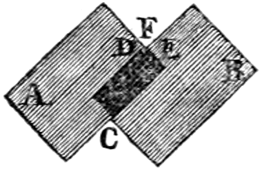
Fig. 5, represents the end plates of the gas
holder when nearly extended, but when it is closed
up, the two parts N, O, of the end assume the
position as shewn by dotted lines. L, M, fig. 5,
shews how the ends of the two side plates are
turned outwards at b, to render them stiff and
firm. As all the flexible joints are made strong
by metallic joints or hinges, the leather has no
stress to bear but only to prevent the escape of the
gas; R, R, fig. 2, are the collars of leather to prevent
the escape of the gas at the openings in the
top or ridge joint where the guide rods c, c, pass
through.
The tank must be filled with water to such a
level that the under edges of the sides and ends
of the gas holder will be a few inches immersed
in the water. The counterpoises K, K, fig. 3,
tend to close the sides of the machine together,
and expel the gas from the gas holder through
the pipe B, fig. 2. The counterpoises are so adjusted
in weight as to force out the gas with the
requisite pressure.
If more gas be introduced by the pipe A, it distends
the sides of the machine and moves them
outwards upon the ridge joint. A man hole, as
seen at S, fig. 2, is made in each side of the gas
holder, to give entrance when any repairs are
necessary, or to oil or examine the joining leathers.
It is scarcely necessary to add that the form and
dimensions of this gas holder, and the materials
of which it can be made may be varied without any
deviation from its essential properties as they have
been now described. For instance, the ends of
the gas holder may be formed of more than two
folding plates, united together, if it is judged
necessary, and the levers F, G, may be varied in
number, form, or proportion, provided they balance
the weight of the sides and cause the lower edges
of the gas holder to move nearly in an horizontal
plane. Or the balance levers may be laid aside entirely,
and the gas holder may be suspended from
the upper part of the guide rods C, C, without
moving up and down thereon. But in this case it
will require more water in the tank to keep the
open end of the gas holder always immersed in the
water; the weight of the sides of the gas holder
will then tend more to bring them together and to
expel the gas.
In proportion as the quantity of water sufficient
for the tank of the collapsing gas holder is less than
that required for the tanks of other gas holders, it is
attended with this further advantage, that the water
can be let off or removed without any expence when
repairs are necessary. If the repairs indeed are
trivial, they can be made without letting off the
water at all, the depth being no more than one
foot. In the case, on the contrary, of the gas
holder, with or without specific gravity apparatus,
the quantity of water is so considerable, that the
means provided for carrying it off must always be
attended with great difficulty and expence; and
yet it is a provision which is in all cases indispensable,
no matter however difficult or expensive,
for no material repair to the interior of the apparatus
can be otherwise effected.
With regard to the best size of a gas holder
adapted to a certain number of retorts, it may be
stated, that this machine should be of a sufficient
capacity to hold the whole quantity of gas that is
required for the supply of the lights during one
night, exclusive of what may be furnished by the
retorts during that time.
The bulk of gas which a collapsing gas holder
of given dimensions will contain, may be found,
by multiplying the area of the triangle contained
between the side plates when at their greatest extent,
and the surface of the water, by the mean
length of the side plate. For example, suppose
the base of the triangular end plate be 30 feet long,
and 30 feet high, and that the length of the side
plate at the top be 40 feet, and at the bottom 60 feet,
30 × 15 = 450 area of end plate,
450 × 50 = mean length of end plate,
= 22,000 cubic feet capacity.[44]
It must be sufficiently obvious that when the
gas holder is full, and the distillation of the gas
continues going on, that unless a provision is made
for conveying away the surplus gas, it must escape
by bubbling up from underneath the gas holder.
And should the gas holder happen to be enclosed
within walls, the gas may by chance accumulate,
so as to give rise to serious accidents.
As a remedy for this evil the manufacturers of
coal gas have until very lately contented themselves
with what is called a safety tube, adapted to the
gas holder, by which, all the superfluous gas was
carried away into the open air; or by leaving large
apertures in the roof or upper part of the building,
for the ready escape of the gas. By either of these
devices the danger from the accumulation of waste
gas, was in part only avoided, and instances might
be named where dangerous consequences ensued
from an accumulation of gas, in a confined atmosphere,
in the vicinity of the upper part of the
gas holder.
In some instances, indeed, recourse was had to the
establishment of a communication between all
the reservoirs and an auxiliary gas holder or gas
holders, by means of a pipe furnished with an
hydraulic valve; but this was an expensive arrangement
which required personal superintendance, and
depended, of course, for its efficiency on the integrity
and good conduct of the servant employed.
Mr. Clegg has now, however, invented what has
been termed the Reciprocating Safety Valve, which
has a self-acting operation, and by which an exit
for the surplus gas of any number of gas holders
that may be in action is provided to an unlimited
extent. A communication is established between
all the gas holders and a waste pipe, which communication
opens or closes by the action of the gas,
as occasion requires, and which may be extended
to any number of gas holders at a trifling cost.
The apparatus has now been adopted at the
greater number of gas light establishments, and
has been uniformly found most efficient in its operation.
Fig. 9, plate VI., presents a perpendicular
section of the apparatus; h, h, h, h, is a small
vessel made of sheet iron, about eighteen inches in
diameter, and twenty inches deep, closed at top
and open at bottom. It is inverted into an outer
air tight vessel, i, i, i, i, of double the height and
rather greater diameter, which is filled with water
to a certain height; D, is a pipe communicating
with the gas holders that are in action; this pipe
branches upwards through the bottom of the outer
vessel, i, i, i, i, and reaches a little above the surface
of the water in the outer vessel. E, is a small
pipe, the upper extremity of which is sealed by
means of an inverted sheet iron cup G, the edge of
which is submersed under the surface of the water
in the outer vessel, i, i, i, i. This pipe conveys
the waste gas into the upper part of any chimney.
For let us suppose that the gas holders become
overcharged; the gas must then acquire an increased
density before the wooden curb of the gas holder
G, fig. 7, plate VI.,[45] at the lower extremity of
the overcharged gas holder can begin to rise out of
the water. But when the elasticity of the gas is
thus far increasing, and before the curb can wholly
emerge out of the water, the small vessel h, h, h, h,
of the reciprocating safety valve, ascends, and consequently
establishes a communication between the
overcharged gas holder and the pipe D, of the
reciprocating safety valve. The surplus gas thus
passes into the waste pipe E, E, which had been
before sealed by the inverted cup G, and is hence
conveyed into the upper part of the chimney
where it terminates, so that no accumulation of gas
can ever take place above, or in the vicinity of any
gas holder.
It must be obvious on the other hand, that when
the gas in any of the gas holders has recovered its
original density, the reciprocating safety valve will
again be closed by the descending of the cup G.