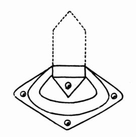
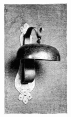
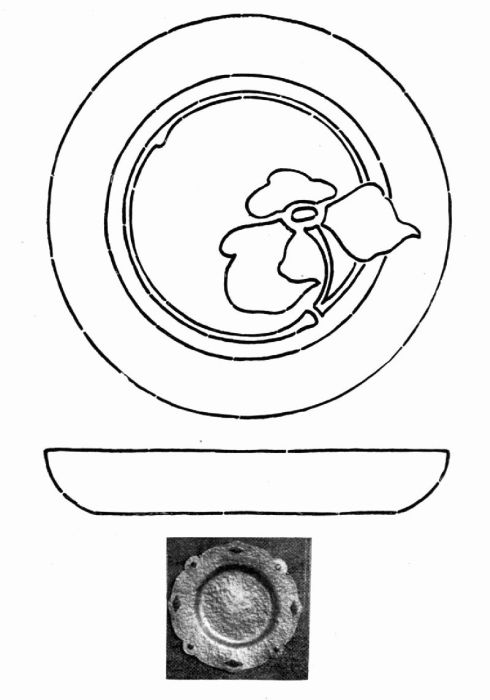
The pattern for this sconce as shown at Plate 29A is
transferred to the metal which is then cut out. The part
which serves as a reflector is raised by placing the metal face
down on a sand bag, or on pitch and with the pein end of a
chaser's hammer or with a pointed horn hammer, driving the
center down to the required depth. If the face is somewhat
irregular, it can be trued up by placing it on a block of
wood and going over it with a rawhide hammer.
The shelf on which the candle socket rests is formed
by bending the lower part of the sconce at right angles as
shown by the dotted line. The projections at 2, 3, 4, Plate 29 A,
when bent into shape as shown on Plate 29 form the
supports for the candle socket. The projection at 5 Plate 29 A when bent into shape serves as a bracket to support the
shelf. The candle socket is made from a strip of metal bent
into cylindrical shape with the ends riveted together. When
the socket has been riveted and holes drilled as indicated, the
sconce is finished according to taste and mounted on a back
of wood stained to harmonize with the color of the metal.
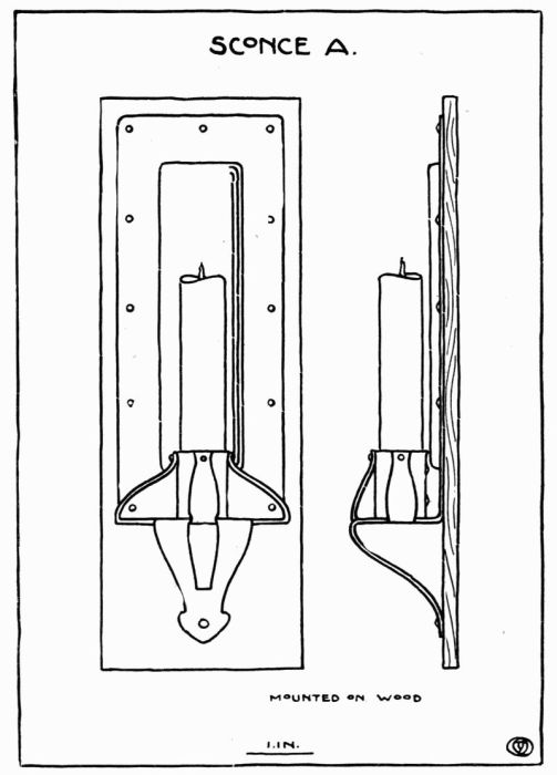 Plate 29.
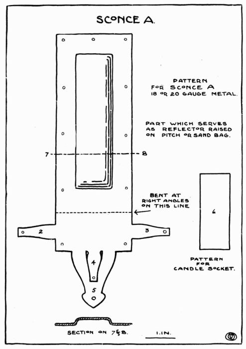 Plate 29 A.
 Plate 30.
A rectangular piece of metal is cut out about 1/2 inch
larger on all sides than the design calls for and given a
hammered surface with the pein end of a large hammer.
After the design has been transferred to the back of the
metal, it is then placed on pitch face down, and with a
suitable tool the lines are sunk at A and B, Plate 31, about
1/16", as shown in the section at C. It is then removed
from the pitch and, after cleaning, is put over a sand bag
face up, and with a rawhide hammer, the part that is to
serve as a reflector is concaved a little.
The candle socket is made like the pattern as shown at
D. It is bent cylindrical in shape and the ends are riveted
together, then the laps on either side are bent nearly at right
angles and serve to hold the socket in place. The cup is
made from a circular piece of metal hammered into a slightly
conical shape, E. A rod the length required is bent at right
angles with a shoulder left at each end. The bracket is
made next like the pattern F and bent into shape as at G.
When all the parts are finished, they are put together.
Place the rod in a vise with the short end up. The cup is
put over the pin at H, and also the socket, so that the pin
passes through the holes in both laps. The pin is then
headed up, holding all securely in place. The bracket is
next riveted to the back at K, through which the rod is put,
the pin passing through the back is headed up at L. After
finishing, the sconce may be mounted on a wood back.
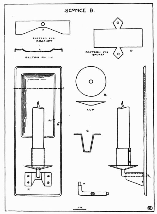 Plate 31.
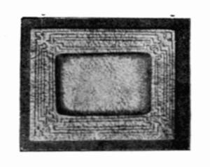
This object is made as follows: Take a piece of metal
quite a little larger than the outline of the frame that is
to be made. Draw on this piece of metal the outline of the
frame and also the extensions which are folded back to give
the thickness necessary for the reception of the picture,
glass, and back, as shown at B. Have the side opposite to
that on which the drawing is done free from scratches as it is
to serve later as the front. Any decoration that is used
must be of the simplest sort. This decoration may be pierced
or in repousse. The frame here illustrated and the plate of
designs were intended for repousse as more satisfactory
results have been obtained by this process. After the
design for the decoration of the front of the frame has been
transferred to the same side of the metal as the outline,
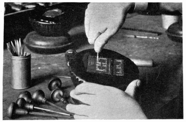
it must be prepared for the repousse process. This is done
by placing it on a pitch pot. The pitch is softened enough
so that the metal will stick to it. After placing the metal on
the pitch, work a little of the pitch over the edges as this
will hold it more securely. It is then allowed to cool or
harden before working. With a suitable tool and hammer,
after the pitch is hard, follow the lines which make up the
design or decorative part of the frame. The lines should be
gone over lightly, slowly, and carefully at first until the
design is fairly well started; then they may be gone over
again, sinking them a little deeper each time until they
have been carried deep enough to give the design the required
relief on the face of the frame. For this part of the
work the tool should not be used as a punch, driving the
metal down in one place and then moving it to another and
so on, but it should be kept moving all the time and should
at the same time receive a repeated number of light blows
from the hammer. By so doing the face of the work will
be smooth, otherwise each blow from the hammer will show.
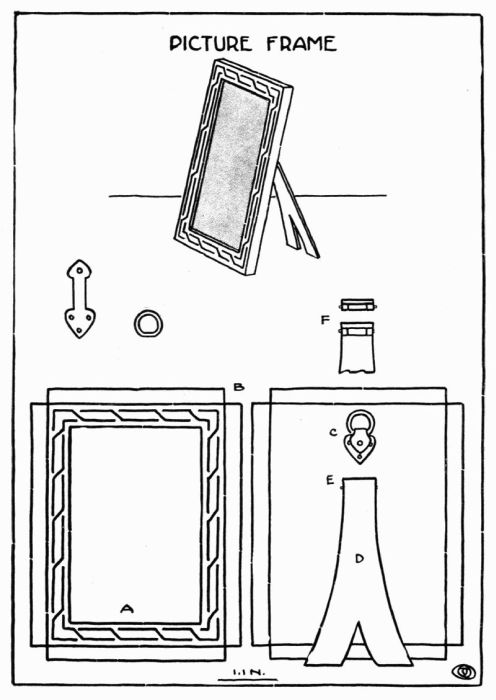 Plate 32.
If there is doubt as to the depth to which the lines should
be carried, the work may be taken off the pitch occasionally,
so that the face may be seen. It is not an easy thing to
reduce relief in this work, therefore it is better to go carefully
working it up slowly. After the repousse part of the frame
is done, clean it with kerosene and pickle.
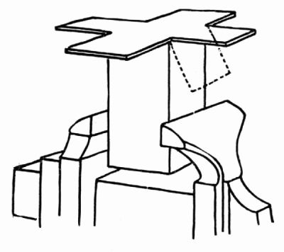
The corners may then be cut out as at B, filed up
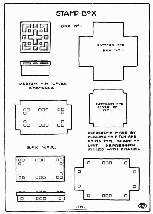
square, and beveled as in the box. The sides are then
bent back over a block of wood or metal, bringing the
corners well together. They are then soldered. A metal
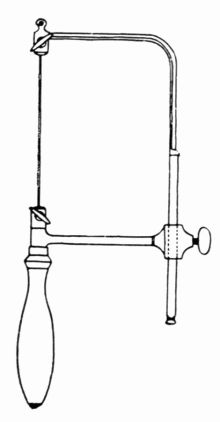
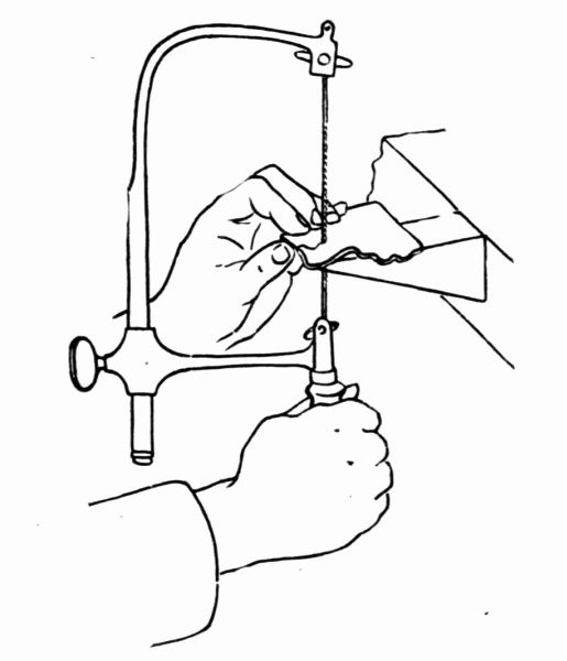
saw is used to make the opening, A, the edges of which
are then filed up square.
The back for this frame is made in the same way as
the front except that it is left perfectly plain. This should
be made to fit inside of the frame tight enough so that no
fastening will be needed to hold it in place.
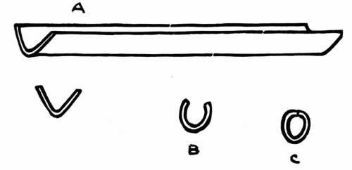
A frame of this size and kind may be made to hang or
to stand. If it is to hang, a small ring may be made and
fastened to the back as shown at C. If it is to stand, a
support of some kind such as is shown at D is needed. This
is made of the same thickness metal as the frame and may
be made in many outlines. This support may be made stationary
by riveting it to the back, or hinged, which is much
better, as is shown at E and F. The hinge is made by
taking a piece of about 1/8" tubing and cutting three pieces,
making one of the pieces equal in width to the other two and
having the three equal in width to the top of the support.
The two short pieces are soldered to the back and the long
piece to the support. A piece of wire equal in diameter to
the hole in the tube is then cut and put in place which
hinges the back and support together.
The method of making the tubing used for the above
is described on page 110.
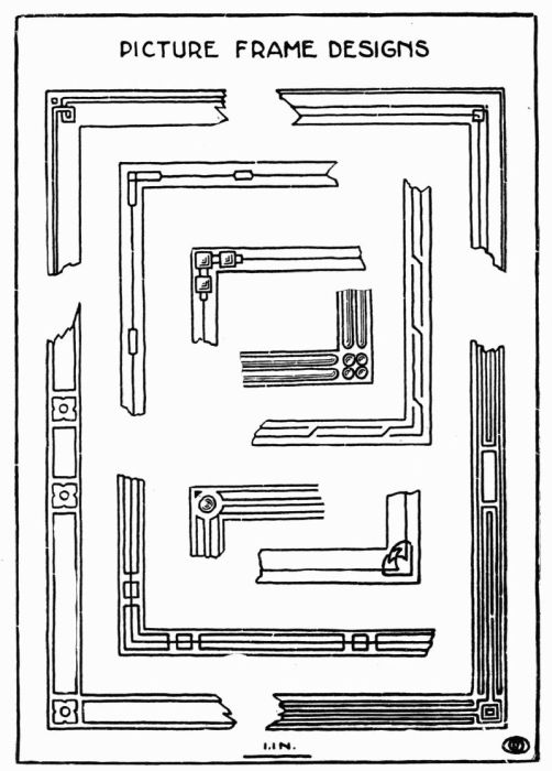 Plate 33.
A piece of silver solder, a slate slab such as is ordinarily
used for grinding ink, powdered or lump borax, and a soft
hair brush of some sort are all that is necessary for the
process of soldering in addition to what we already have.
The pieces of metal that are to be soldered must be
absolutely free from all foreign matter. To insure this the
joint is scraped bright with some sharpe-edged tool. Care
must be taken to keep the fingers away from the joint as
any moisture or greasy substance will prevent the solder
from running. The best results are obtained only by being
extremely careful as to cleanliness throughout the process.
Being sure that the slab is perfectly clean, a little water is
put in it and the lump of borax is ground around until the
water becomes like thin cream. If powdered borax is
used a block of wood will answer as a pestle to grind the
borax to the right consistency.
The solder may be obtained any gauge, but about 20
answers for most purposes. After cutting the solder into
pieces about 1/16 of an inch long and about the same width,
drop them into the borax that has been ground to give them
a coating of borax and to remove any grease that may have
adhered to them. Coat the surfaces that are to be soldered
with the borax being careful to get no more borax about
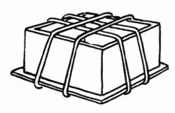
than is necessary. Put the parts together and bind them
with No. 24 iron wire, not too tightly. The pieces of solder
are then lifted with the brush used for the borax or with a
pair of tweezers and placed next to the edge that is to be
soldered, about one inch apart. The object is then placed
on the annealing tray, which answers for soldering as well,
and with the blow-pipe it is heated, very slowly at first until
the water has evaporated and the borax crystallized and
dissolved, the flame may then be applied more directly and
the object brought to a soldering heat. If the heat is applied
too quickly, it will throw off the solder; and if heated
hotter than necessary it is liable to melt or burn the parts
being soldered, so the process demands the closest attention
from the start.
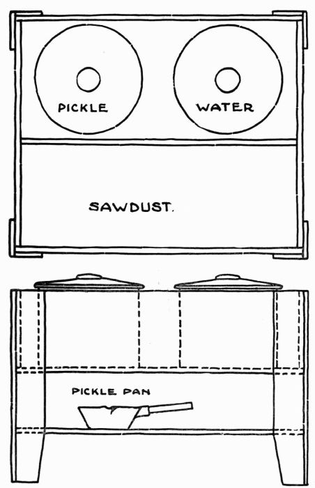
The object is then pickled, washed in clear water and
dried in the sawdust.
If the above directions are carefully followed good
results may be expected.
Repousse or embossing involves practically the same
principle as modeling in clay or wax, the only difference
being that metal is used as the material and that different
tools are employed. In this, as in clay or wax work, it is
desirable to bring certain parts of a design into relief; to do
this with metal the work must be placed on a substance
which will give some resistance and yet allow each blow
of the hammer or tool to make an impression. The substance
commonly used for this purpose has the following
composition, in the proportions given:
Black pitch 1 lb.
Tallow 3 teaspoonfuls.
Plaster of Paris 1/2 cup.
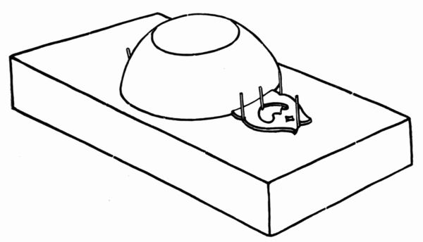
The pitch is put in some kind of dish (agate is good),
placed over a gas plate, and melted. The tallow is then
added and the plaster sprinkled and stirred in, the whole
being well mixed. It is then poured into the pitch pot, or
whatever it is to be used in. When used in hot weather
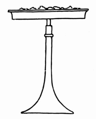
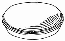
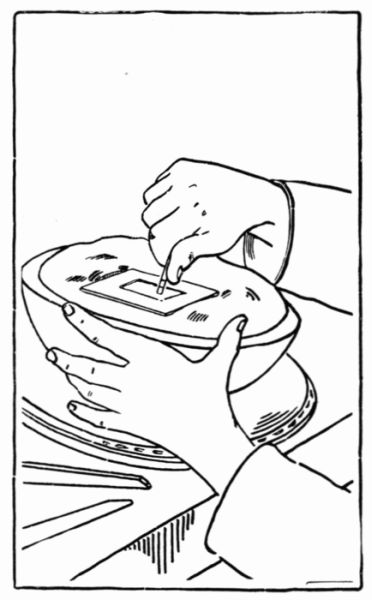
more plaster must be used. A pot, hemispherical in shape,
Figure 21, made of cast iron about ½ inch thick is generally
used. This, when placed on a chaser's pad or ring, Figure 21,
may be turned at any angle, and is found to be a great
convenience. An ordinary 7" × 12" baking pan of iron
serves the purpose, or a box may be made of wood, but
of course this is not so durable.
After allowing the composition to cool partly, yet
while soft enough to stick, the piece of work that is to be
embossed is placed on it, the right side next to the pitch.
It is then allowed to cool still more; when quite hard or
when it is difficult to make an impression on it with the
thumb nail, it is ready to work on. The design is next
drawn or transferred to the metal by the use of carbon paper
and then scratched on with a scratch awl to make the
drawing more permanent, as in going over the piece of
work the pencil or carbon lines are easily erased.
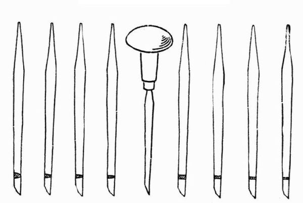
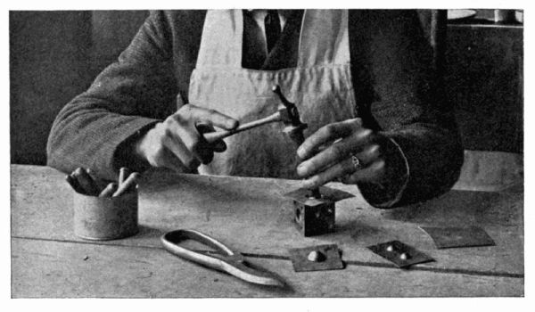
The tools necessary for this work may be made as
needed according to each individual design. There are a
few general ones that are always found useful, such as
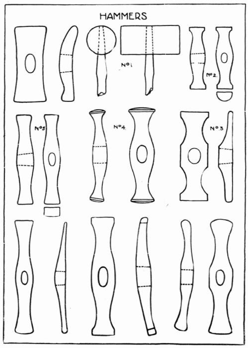
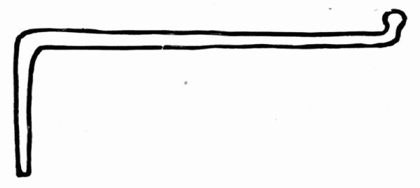
those shown at Figure 5. Figure 22 shows a hammer
generally used for this work.
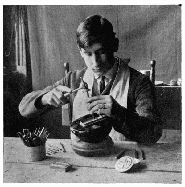 Figure 21.
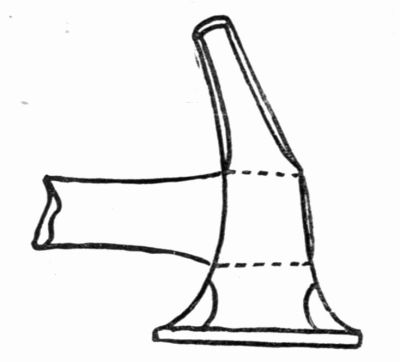 Figure 22.
 CHAFING DISH.