TO ALL WHOM IT MAY CONCERN:
Be it known that I, FRIEDRICH BANGERTER, of the City of New York
(Borough of Richmond), County of Richmond and State of New York, have
invented certain new and useful improvements in
APPARATUS FOR THE EDUCTION, STORAGE
AND APPLICATION OF ENERGY FROM
EXPANSIBLE MATERIALS,
of which the following is a full, clear and exact specification, such as
will enable others skilled in the art to which it appertains to make and
use the same.
This invention relates to apparatus whereby energy may be educed from
expansible materials, due to the expansion and contraction thereof on
changes of temperature, and the said energy either applied direct or
stored and applied for the purpose of operating machines and devices of
various kinds.
I show and describe herein two forms of apparatus for obtaining such
expansion and contraction and the required energy therefrom, and I also
show two forms in which the energy so obtained is accumulated and
stored. In connection therewith, I show the application of my invention
to the running of clocks, but it will be understood that the invention
is not limited in its application to that particular class of machine,
and that it may be applied to any use of which it is susceptible.
It is well known that all metals are capable of some degree of expansion
and contraction, and some metals have this property in greater degree
than others. The amount of expansion for each degree rise in temperature
is quite regular, and is called the co-efficient of expansion. It is
also well known that zinc has this property in greater degree than any
other of the solid metals, its co-efficient of linear expansion being
appreciably higher. For this reason, as well as because of its
relatively low cost, I preferably make use of zinc in the construction
of the expansible parts of my apparatus.
One of the objects of my invention, therefore, is to provide an
expansion device of novel construction and arrangement, which will
generate energy and maintain motion during changes in temperature, to
such an appreciable and useful amount, as to constitute it in fact a
temperature motor.
A further object of my invention is to provide means for accumulating or
storing the energy thus generated.
A further object is to provide means for applying the energy thus
generated and stored.
Other objects, such as compactness, durability and comparatively low
cost of the apparatus, will appear in the following description, in
which reference is had to the accompanying drawings.
In the drawings:—
Fig. 1 is a front elevation, showing the application of my invention to
a clock provided, in this case, with a mainspring as usual;
Fig. 2 is a rear elevation of the same with a part removed;
Fig. 3 is an enlarged perspective detail showing how the strips forming
part of the expansion member or coil are connected up;
Fig. 4 is a sectional view, on lines 5—5 of Fig. 1;
Fig. 5 is an enlarged detail elevation, with parts removed;
Fig. 6 is an enlarged detail cross section of the central portion of the
apparatus, with part broken away;
Fig. 7 is a rear elevation of the same with parts broken away;
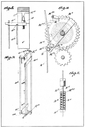
Fig. 8 is an enlarged detail of the upper portion of the apparatus shown
in Fig. 4, with parts removed;
Fig. 9 is a perspective detail, partly broken away;
Fig. 10 is an enlarged detail of a portion of the ratchet mechanism
shown in the lower portion of Figs. 6 and 7;
Fig. 11 is an enlarged section of a flexible coupling shown in Fig. 7;
Fig. 12 is an elevation of a modification of the expansion coil;
Fig. 12ª is a perspective view showing how two of such modified
expansion coils may be connected;
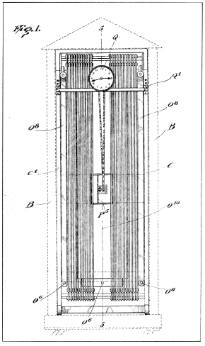 Fig. 1.
BANGERTER’S PERPETUAL TIME CLOCK
Fig. 13 is a front elevation showing my invention applied to another
form of force storage mechanism;
Fig. 14 is a plan view of same, on lines 14—14 of Fig. 13;
Fig. 15 is a rear elevation on lines 15—15 of Fig. 14;
Fig. 16 is a vertical section on lines 16—16 of Fig. 14;
Fig. 17 is an enlarged detail of part of the apparatus shown in the
upper portion of Fig. 16;
Fig. 18 is an enlarged detail of the ball-discharging means shown in the
lower portion of Fig. 16;
Fig. 19 is an enlarged detail of the loading device shown in the
opposite part of the lower portion of Fig. 16; and
Fig. 20 is a plan view on lines 20—20 of Fig. 13.
Referring to the construction illustrated in Fig. 1 to 11, inclusive, B
represents the outer frame of the apparatus.
Mounted within the outer frame B is an inner frame comprising the
uprights C, C¹, which are rigidly secured by cross-bars D¹, D².
The outer frame B, as well as the inner frame uprights C, C¹ are
preferably formed of wood or other material capable of a low degree of
expansion.
Within the upper and lower ends of the inner frame are anti-friction
knife-bars E, E¹, the upper one of which, E, has each end within a
vertically disposed slot E² in the uprights C, C¹, within which said
knife-bar may be moved vertically, as hereinafter described.
Each end of the lower knife-bar E¹ lies immovable within a recess in a
plate E³ mounted on each of the uprights C, C¹.
These knife-bars, which are preferably formed of hardened steel, have
oppositely disposed relatively sharp edges E5, which act as bearings
for a series of horizontally disposed anti-friction levers, F, F¹, which
I will term balance-levers, since they are intended to balance evenly
and freely on the thin edges of the knife-bars with little friction
somewhat in the nature of a scale-balance. These levers are pivotally
connected to a series of metallic expansion strips G, G¹, G², G³, etc.,
the construction and arrangement and manner of connecting up the same
being more clearly shown in Fig. 3.
It will be observed that the arrangement of the levers F and expansion
strips G, G¹, etc., is such as to form, in effect, a spiral, the short
strip G being connected to one end of one of the balance-levers F, and
the strip G being connected at its lower end to the opposite end of said
lever, the upper end of said strip G¹ being connected to one end of the
first one of the levers F¹. To the opposite end of said lever F¹ the
upper end of strip G² is connected, the lower end of said strip being
connected to the left-hand end of the second one of the levers F, and so
on to the final short strip Gx. The levers F, F¹ must be formed of a
metal capable of withstanding great strain without bending, and for this
purpose I prefer to use the metal known as macadamite.
For convenience of designation, I will refer to each of these groups of
balance-levers F, F¹, and expansion strips G, G¹, etc., as expansion
coils, and while I have herein shown but two sets of such expansion
coils, it is to be understood that there may be any number of such sets
desired, and any desired number of strips and levers composing such
coils, depending upon the character of the work to be performed.
Furthermore, I desire it to be understood that when I use the terms
“strips"—as characterizing the members connecting the
balance-levers—either in the specification or claims, I do not limit
myself to the form of connecting member or “strips” shown, but mean to
include in the use of the term “strips” any other form such as wires,
rods or bars of either square, round, hexagonal or other cross sectional
shape.
The ends of the short strips G, Gx are connected by wires H, H¹ with
the opposite ends of what I will term a coil lever I, which, as more
clearly shown in Fig. 5, is keyed to a shaft J, which latter has its end
journaled upon the cross-bars J¹, J² secured to the uprights C, C¹ of
the inner frame of the apparatus, and this shaft I will name a coil
shaft.
Keyed to the coil shaft J is a lever K, which it may be proper to
designate as a stress lever, since from it is suspended a weight K¹, the
function of which is to place a certain amount of stress upon the series
of expansion strips and balance-levers composing the expansion coil,
keeping the metal of the strips slightly stretched and preventing any
loss of motion at the different points of connection, and thereby
furthering a very important object, which is to make of each series of
expansion strips
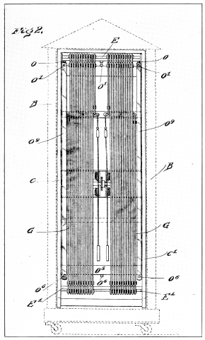 Fig. 2.
BANGERTER’S PERPETUAL TIME CLOCK
and balance-levers a single spiral unit, throughout which the expansion
and contraction of the strips are transmitted.
Also keyed to the shaft J is a power transmisson lever L, and any rotary
motion imparted to said shaft is necessarily imparted to the lever L in
the form of reciprocating motion.
Referring now to the power storage device, one or a number of which may
be used in connection with my expansion coils.
Disposed approximately midway of the uprights C, C¹ and within casing M,
secured at its ends to said uprights, is rotatably mounted a power
transmission shaft M¹, keyed to which is a spur wheel M². Also mounted
on the shaft M¹ is a spur wheel M³, meshing with which at its upper and
lower sides are two spur wheels M4, M5, loosely mounted upon short
supporting shafts M6, M7, journaled in uprights M8, M8
secured to the casing M. To each of the spur wheels M4, M5 is
secured the outer end of a coil spring M9, M10, respectively, the
inner ends of said springs being secured to the respective shafts M6,
M7, the arrangement being such that when the springs are placed under
tension by the rotation of the shafts M6, M7, the force of the
springs rotates the spur wheels M4, M5, thereby rotating the spur
wheel M³, shaft M¹ and the spur wheel M².
Also mounted upon each of the respective short shafts M6, M7, and
keyed thereto, is a ratchet wheel M11, M12, and adjacent thereto
and loosely mounted upon each of said shafts M6, M7 is a pawl
carrier plate M13, M14, each carrying a pawl indicated at M15,
M16, which is adapted to engage the teeth of the ratchet wheels
M11, M12, being held in engagement therewith by springs, one of
which is shown at M17, secured to said pawl carrier M13. Suitably
mounted upon the casing M, and adapted to engage the teeth of the
ratchet wheels M11, M12, is a detent M19, to prevent reverse
movement of said ratchet wheels.
The pawl carrier plate M13 is provided with a pin M21, and secured
thereby loosely to said carrier is one end of a connecting rod M21ª,
the other end of said connecting rod being connected to one end of a
longitudinally flexible coupling M22, the other end of said coupling
being secured by means of the connecting rod M23 to the power
transmission lever L. The function of the flexible coupling M22 will
be hereinafter referred to.
The pawl carrier M13 also carries, at its lower end, a pin N, and
loosely mounted thereon is one end of a connecting rod N¹, the other end
of said rod being connected to a pin N² secured to the pawl carrier
M14, whereby, when motion is imparted to pawl carrier M13 and,
through the pawl M15 to the ratchet wheel M11, motion is imparted
to the pawl carrier M14, and through its pawl M16 to the ratchet
wheel M12. From the pin N² is suspended a weight N³ to return the
pawl carriers to their lowermost positions when they complete their
upward travel.
The flexible coupling M22 comprises a tubular casing N4, which is
provided at one end with an opening N5, through which projects a rod
N6 having a head N7, which is adapted to bear against a spiral
spring N8 mounted within said casing, the other end of said rod N6
being connected to the rod M23.
The operation of the apparatus, as thus far described, will be more
readily apparent from an inspection of Fig. 5.
Assuming that the expansion coil there shown has been subject to a
normal temperature of say 75 degrees Fahrenheit, and at that temperature
the lever L is in the position shown in full lines on a decrease in
temperature of say 10 degrees, the contraction of the coil, which will
operate upon its entire length, will exert a pressure at the ends
thereof in the direction of the arrows, the result of which will be to
rotate the shaft J and raise the lever L against the force of the
weighted lever K (carrying the latter therewith) to the position shown
in dotted lines, thereby actuating the ratchet wheels M11, M12,
and winding up the springs M9, M10, of the power-storage device,
the force there stored being afterwards taken off, as required, through
the medium of the power transmission shaft M¹ and spur wheel M² and any
suitable gearing or power transmission means.
The function of the flexible coupling indicated at M22 will now be
quite clear. It will be seen that the coil spring N8 will be
sufficiently strong not to give under the pull of the lever L except
when the springs M9, M10 are wound full. When that condition
exists, the coil spring N8 will give, under the force of the lever L,
and
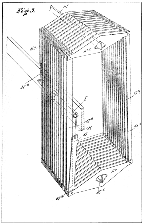 Fig. 3.
BANGERTER’S PERPETUAL TIME CLOCK
no further power will be applied to the springs M9, M10. When,
however, those springs have become unwound to a sufficient extent the
spring N8 of the coupling M22 will be stronger than the springs of
the power-storage device and will transmit, from the expansion coil, the
force necessary to wind said springs as often as they become unwound; in
other cases the force will be expended in simply compressing the coil
spring N8 without effect upon the springs of the power-storage
device.
Referring now to what I will term the force-increasing devices, which
are more clearly shown in Figs.
1,
2,
4,
8 and
9.
Near each end of the upper knife-bar E, and contacting therewith at its
under surface, is a support O, in the form of a flat-headed bolt (Fig.
8), the shank of said bolt passing through one end of lever O¹, which is
fulcrumed at O² upon the upper surface of a cross-bar O³ securely
fastened to the rear portion of the uprights C, C¹. To the front of said
uprights is rigidly secured a second cross-bar O4, and at the lower
portion of said uprights and rigidly secured thereto is a third
cross-bar O5, against the under surface of which rests a lever O6
(Fig. 9) having its fulcrum point at O7.
As shown in Fig. 2, there are three sets of the levers O¹, at the upper
end of the expansion coils at the rear side thereof below the knife-bars
E, one lever at each end of said bar and one in the middle thereof. As
these levers act directly upon the under surface of the knife-bars E to
raise the same I will call them knife-bar lifting-levers. There are also
the same number of levers O6 at the lower end of the expansion coils
below the cross-bar O5 projecting through to the forward side of the
apparatus, as shown in Fig. 1.
Rigidly secured to the cross-bar O4 is one end of a relatively heavy
metallic expansion strip O8,—preferably formed of zinc—the lower
end being secured to one end of the lever O6; to the opposite end of
the lever O6 is secured the lower end of a similar but longer zinc
strip O9, the upper end of the strip O9 being secured to the rear
end of the lever O¹. As shown in Figs. 1 and 2, there are two of these
strips O8 at the front and two of the strips O9 at the rear of the
apparatus.
In addition to the heavy strips O8, O9, there is provided at the
front of the apparatus a heavy wide expansion sheet or strip O10,
which, at its upper end, is rigidly secured to the cross-bar O4, and
at its lower end to the front end of the middle one of the levers O6.
A similar heavy wide expansion sheet or strip O11 is secured, at its
lower end, to the rear end of the middle lever O6, and, at its upper
end, to the middle one of the levers O¹.
These heavy strips O8, O9 and sheets O10, O11 are preferably
formed of zinc, and are not only capable of great expansion and
contraction, but will be capable by their contraction of lifting the
entire weight of the knife-bars E, with the carried balance-levers and
expansion strips of expansion coils, the operation thereof being as
follows:
The front strips O8 and rear strips O9 and the front sheets O10
and the rear sheets O11 are connected to the levers O6, so as to
form, in effect, single expansion strips and sheets of relatively great
length. They are fastened, however, at their front upper ends to the
cross-bars O4, so that the expansion cannot extend beyond that point
and takes place in a direction towards the opposite end, and, of course,
the contraction takes place in the opposite direction. Assuming now that
at a temperature of say 75 degrees Fahr. these heavy strips and sheets
lie in the position shown in Figs. 4 and 9 (the heavy strips O8,
O9 being shown in Fig. 9, and the heavy wide sheets O10, O11 in
Fig. 4), on a decrease in temperature of say five degrees Fahr., the
heavy strips O8, O9 and sheets O11, O12 will contract in the
direction of the arrows, depressing the rear ends of the levers O¹,
O6, and thereby through the levers O¹ lifting the knife-bars E, and
the balance-levers suspended thereon, with the result that the force
normally exerted at the ends of each expansion coil is increased to the
extent of the lifting power of the contraction of the metal strips and
sheets.
I have found by experiment as well as observation that the average daily
change of temperature in residence and office buildings is about five
degrees. Sometimes the changes will be much greater, and sometimes less.
On even a low average of temperature change, my apparatus will be able
to generate force in larger amounts than required, and the surplus will
be stored in a power-storage device such as above described, or by means
hereinafter referred to, which surplus will
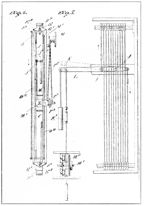 Fig. 4.
Fig. 5.
BANGERTER’S PERPETUAL TIME CLOCK
be drawn upon when it should happen that the average temperature is
approximately uniform.
For clearness of illustration, I have shown, as above stated, but two
sets of expansion coils, but there is no limit to the number that may be
used. Assuming that we have an apparatus with four expansion coils, each
knife-bar holding 50 balance levers, giving a total of 200 levers, with
expansion strips of the same number, in 5-foot lengths, we would have a
total of 1,000 linear feet of zinc strips, which entire length of strips
will, on the slightest change of temperature, get longer or shorter. The
expansion and contracting of this 1,000 feet of zinc strips for every
temperature change of 5 degrees Fahr. will be 1 inch. Now, assuming that
the knife-bars are pulled upward by heavy strips O8, O9, and
sheets O10, O11 of five feet length (making ten feet for the front
and rear strips and sheets), on a decrease in temperature of 5 degrees
Fahr. the upward movement of those bars will be 10-1000 of one inch;
this contraction (10-1000) will now be multiplied as many times as there
are levers and strips in the expansion coils, viz., 200 times, which
would be 2 inches, and this, together with 1 inch from the contraction
of the expansion coils alone, will give a total movement of 3 inches. If
the strips are of a capacity to pull or lift 100 pounds, we obtain a
lift of 100 pounds 3 inches. As thirty-three per cent approximately must
be deducted for loss by stress (it being necessary to place the coils
under strain, as shown in the drawings and described above), the final
result will be a power to lift 100 pounds 2 inches, or 10 pounds 20
inches, and this force will be sufficient to run a large sized time
clock with powerful striking force.
As illustrated in Figs. 4,
5,
6 and
7, the power applied by the springs
M9, M10 to the power transmission shaft M¹ is taken, through the
spur wheel M² by means of any suitable gearing, to run a clock or any
other machine adapted to the purpose. As there illustrated, I show the
spur wheel M² meshing with a pinion P, through which is driven the spur
wheel P¹, which latter meshes with a pinion P², through which is driven
a sprocket wheel P³ carried by the bracket P4, which latter, as well
as the shafts carrying said spur wheels and pinions, are supported by an
upright P5 mounted upon the casing M. The sprocket wheel P³ carries a
sprocket chain P6, which, through any suitable gearing, is adapted
to wind the main spring of a clock indicated at Q, carried by suitable
supports on the cross-bar Q¹ secured to the uprights C, C¹. As this
clock may be of any well known form, it will not be necessary to
describe the same in detail, except to state that as soon as the main
spring of the clock becomes weaker than the springs of the power-storage
device illustrated in Fig. 7, the latter will wind the clock main
spring, and as in this manner it is wound frequently, it is always kept
at a uniform high tension, which is desirable and results in good
time-keeping.
In Fig. 12 I show a modification of my invention, wherein, instead of
having the balance-levers F, F¹ arranged side by side, they are
superposed one above the other, in this case a plurality of knife-bars
E, E¹ also being superposed one above the other, the expansion strips G,
G¹, etc. (in this case shown as formed of wires or rods), and
balance-levers being arranged in the same plane, somewhat in the nature
of a coiled spring, the coil shaft being indicated at J and the coil
lever at I, to which are connected the end expansion strips G, Gx,
and the weight K¹ for placing the coil under tension. By this
arrangement of balance-levers and expansion strips, in the same plane,
much economy of space is effected, and when desired, a great number of
such coils may be suspended upon the series of knife-bars.
In Fig. 12ª I show two such coils connected in series, the terminal
expansion strip Gx of the front coil being connected to one end of
the lever I, and the opposite terminal G of that coil being connected to
the shortest one of the rear set of levers F1ª, the terminal Gy of
the rear set being connected to the other end of the lever I. Thus two
or more such coils may be connected, and the force of expansion and
contraction of the combined coils transmitted to the lever I. When a
number of such combined coils are suspended from the knife-bars E, E¹,
the levers connecting their respective terminals may be themselves
connected by a system of compound levers such, for example, as shown in
Fig. 13, to be hereinafter referred to.
Referring now to Figs. 13 to 20 inclusive. These figures illustrate
another form of the invention whereby not only the power-storage device
of the preceding
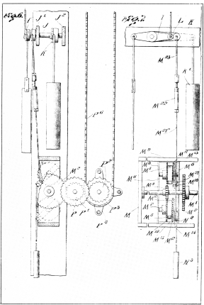 Fig. 6.
Fig. 7.
BANGERTER’S PERPETUAL TIME CLOCK
figures may be dispensed with, but also the main spring of the clock
there shown, both of these elements being supplanted by apparatus
effecting the raising and lowering of weights (in this instance shown in
the form of balls), the force of expansion and contraction of the coils
being utilized to operate a rotary member which elevates a series of
weights and discharges the same into a storage receiver, the clock (or
other machine) being operated through the energy so stored and given up
by the falling of said weights.
As illustrated in said figures, this feature of the invention consists
of a frame, indicated in whole at 10, located about midway the length of
the expansion coils shown in Fig. 1, and it may be supported by securing
it to the uprights C, C¹, or in any other suitable manner.
Said frame comprises two horizontally disposed longitudinal framing
members, 10ª, 10b, which are connected at each end by cross-bars (not
shown).
Mounted on the supports 10ª, 10b, are four uprights, 12ª, 12b,
13ª, 13b. The uprights 12ª 12b are connected at their upper ends
by a longitudinal framing member 14ª, and the uprights 13ª 13b are
connected by longitudinal framing member 14b, said framing members
14ª 14b being also in turn connected at their ends by transverse bars
(not shown), said members constituting an open frame for the working
parts of the apparatus.
Mounted respectively upon the longitudinal framing members 10ª 10b,
approximately midway thereof, are two standards, 16ª 16b, which are
rigidly secured together by a cross-bar 17, said standards and cross-bar
constituting a rigid support for the gearing now to be described.
Rotatably mounted upon the standards 16ª, 16b is a driving shaft 18,
one end of which is journaled in the standard 16ª, and the other end in
a bearing-bolt 19 passing through the standard 16b, which, being
threaded, is capable of fine adjustment.
Mounted upon and keyed to the shaft 18 is a wheel 19, the spokes 20 of
which support a rim 21, within which are set a series of pockets 22, the
inner surfaces of which are so shaped as to permit their receiving
successively, at the bottom of the wheel, a series of balls 23 and
holding the same during a travel of 180 degrees, or one-half revolution
of the wheel, when they are discharged as hereinafter described. This
wheel I will term an energy-storing wheel, since it acts through the
force taken from the expansion coils to raise the balls, the lowering of
which is to drive the wheel now to be described.
Loosely mounted on the shaft 18 is a wheel 24, smaller in diameter than
the wheel 19, the spokes 25 of which, secured to the hub 26, support a
rim 27, within which are set a series of pockets 28, which are adapted
to receive successively, at the top of the wheel, the balls 23, and
discharge the same when they have been lowered through 180 degrees or,
in other words, at the bottom of the wheel. The inner wall of the
pockets 28 is formed, for the most part, with a pronounced rounded
groove (indicated at 28ª), as shown above the ball in Fig. 18, which
groove lies under the ball when the pocket is in its uppermost position,
as shown in Fig. 17, said groove becoming less pronounced at one edge
towards the opposite portion of the pocket, at which point it has an
approximately level surface at one side, as shown in Fig. 18, and
indicated at 28b; the subject of this arrangement being that the ball
may be readily discharged in this position, and securely held within the
pocket when the ball and pocket are in other positions. The wheel
24—which I will designate as the power-transmission wheel—is supported
upon ball bearings indicated at 28c, 28d, which are held in
position by collars 28e, 28f, both keyed to shaft 18.
Mounted upon a collar 29, which is keyed to the driving shaft 18, is a
ratchet wheel 30, engaging the teeth of which are two pawls 31, 32,
secured to one arm of a double-arm pawl-carrier 33, the other arm of
which is connected by a rod 34 to a lever 35, one end of which lever is
pivotally connected to a standard 36, secured to the frame, and the
other end of which is provided with a weight 36ª.
Near the inner end of the lever 35 connection is made by means of the
connecting rods 37 and 38, link 39 and rods 40, 41, with two levers
indicated at L, L, which are adapted to take power from the expansion
coils heretofore described, through the coil shafts J, J, to which
shafts are also connected the coil levers I, I, the ends of the latter
being connected to the strips G, Gx of the expansion coil by the
wires H, H¹, as already set forth and clearly illustrated in Figs. 2, 3,
5, 6 and 7.
As illustrated in Fig. 13, upon contraction of the
| Fig. 8. | Fig. 10. |
| Fig. 9. | Fig. 11. |
BANGERTER’S PERPETUAL TIME CLOCK
expansion coils, the wires H, H¹ will be pulled in the direction
indicated by the arrows, the ends of the long arms of the levers L,
L—through the movement of the shafts J, J—will rise, thereby, through
the rods 40, 41, link 39 and rods 38, 37, raising the lever 35, and
through the rod 34 actuating the pawl carrier 33, and through the pawls
31, 32, imparting rotary motion to the ratchet wheel 30, and, through
it, to the shaft 18 and the power-storing wheel 19, said pawl carrier
being returned to its normal position by the weight 36ª. Motion of said
wheel and shaft in the reverse direction is prevented by means of a
ratchet wheel 42, keyed to the collar 29, engaging the teeth of which
wheel is a detent 43, carried by a plate 44, secured to the supports 45,
affixed to the standard 16ª.
The hub member 26 of the power transmission wheel 24 is provided with a
sprocket wheel 46, which is adapted to engage and drive a sprocket chain
47, and thereby drive the great wheel of a clock mechanism or gearing of
any other machine adapted to the purpose.
Having shown the mechanism for driving the energy-storing wheel 19,
which, as already stated, is keyed to the shaft 18, I will now describe
the mechanism for driving the power transmission wheel 24, which runs
loose on the shaft 18.
It will be seen from an inspection of Fig. 16 that the wheel 19 is of
greater diameter than the wheel 24.
Suitably mounted between said wheels, on cross-bars 48, 49, I provide a
series of ball-storage runways designated in whole at 50 (see Fig. 14),
and, as shown in Fig. 16, these runways are laterally inclined
downwardly from the wheel 19 to the wheel 24.
Similar ball runways designated in whole at 51 are provided at the lower
portion of said wheels and between the same (Fig. 20), being mounted
upon cross-bars 52, 53, but the last named runways are laterally
inclined in the reverse direction to that of the runways 50.
The ball-storage runways 50 comprise inclined floor members 54, 54ª,
54b, each having longitudinally a slight downward inclination in the
direction of the arrows. These runways also comprise longitudinally
extending walls 55, 56, 57, 58, one end of the wall 55 being curved to
meet one end of the wall 57, leaving a passageway 59 between it and one
end of the wall 56. One end of the wall 58 is similarly curved to meet
one end of the wall 56, leaving a passageway 60 between it and one end
of the wall 57. Thus are provided parallel runways 61, 62 and 63, with
passageways from one to the other, whereby a ball deposited in runway 61
will move continuously from that end of the series of runways to the
other end. The runway 61 is provided with an end wall 61ª, and adjacent
thereto the longitudinal wall 55 is provided with an opening 61b to
permit the passage therethrough successively of balls from the
energy-storing wheel 19 to the runway 61.
Projecting through the standard 16b is a threaded bolt 63ª, the end
of the shank of which is beveled, as clearly shown in Figs. 14 and 16,
the function of which is to eject from the uppermost pocket 22 of the
wheel 19, as the same revolves, the balls 23, and thrust them
successively into the runway 61.
At the lower end of the runway 63 is provided a laterally movable
receptacle 64, which has a receiving capacity of one ball only. Said
receptacle comprises a base 65 and perpendicular stop 66. The base 65 is
connected to the floor member 54b of the runway 63 by a horizontally
disposed hinge 67, and to it is also affixed a plate 68, carrying a
downwardly extending lever arm 69, which is formed at its lower
extremity with an outwardly curving portion 70, which is adapted to
engage with the spokes 25 of the wheel 24 and be thereby pressed
inwardly, the result of which is to depress the outer end of the base 65
of the ball receptacle 64, inclining the same in such position that the
ball therein will fall into the adjacent pocket of the wheel 24, the
ball being prevented from falling therefrom on the opposite side by the
stop 71 secured to the standard 16ª. The center of gravity of the lever
arm 69 is such that when the curved lower portion is in its normal
forwardly extended position the rear side of the base 65 of the
receptacle 64 will be depressed and the forward side elevated, so that
the forward side will normally project above the floor level of the
runway 63 and serve as a stop to prevent more than one ball occupying
any of the space within said receptacle at one time.
The ball-storage runways 51 comprise inclined floor members 72, 72ª,
72b, each having a slight downward inclination longitudinally in the
direction of the arrows. They also comprise longitudinally extending
walls 73,
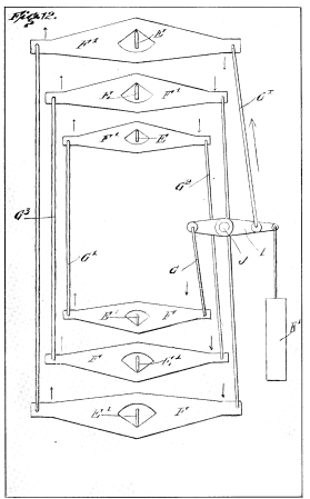 Fig. 12.
BANGERTER’S PERPETUAL TIME CLOCK
74, 75 and 76, one end of the wall 73 being curved to meet one end of
the wall 75, leaving a passageway 77 between it and one end of the wall
74. One end of the wall 76 is similarly curved to meet one end of the
wall 74, leaving a passageway 78 between it and the other end of the
wall 75. There are thus formed parallel runways 79, 80 and 81, with
passageways from one to the other, whereby a ball deposited at the other
end of the runway 79 will move continuously from that end of the series
of runways to the other end. The runway 79 is provided with an end wall
82, and adjacent thereto the longitudinal wall 76 is provided with an
opening 76ª to permit the passage therethrough, at intervals, of balls
from the power-transmission wheel 24 to the runway 79. Adjacent the wall
82 is perpendicularly disposed pin 82ª whereby the balls, as they pass
through the opening in the wall 76 are deflected to pass through the
runway 79 in the direction of the arrow.
At the lower end of the runway 81 is provided a laterally movable
receptacle 83, which has a receiving capacity for one ball only. Said
receptacle comprises a base 84 and end stop 85. Said receptacle is
horizontally hinged at 86 to the floor member 72 of the runway 81, and
is provided with an outward extension 87, which is adapted to be engaged
by a shoulder 88 on the ball pockets 22, and thereby depress the outer
edge of the base of the receptacle in such a way as to eject the ball
therefrom, and place the same in the pocket of the wheel 19.
It will be seen that the hinge 86 (Fig. 19) is off center and when the
base 84 of the receptacle 83 is depressed at the rear the upper end of a
pin 89, projecting upwardly from the base 84 contacts with the upper
portion of the wall 74, thereby preventing the rear portion of the base
being depressed too low. When a ball is in said receptacle, the forward
end will be elevated so that a portion of the side edge of the base will
be projected above the floor member of the runway 81, serving as a stop
to prevent more than one ball occupying any of the space within said
receptacle. When one ball moves into a pocket 22, another ball quickly
moves into the receptacle, taking its position at the rear thereof. This
operation takes place when the base 84 is level with the floor member of
the runway 81, the outer end of the base rising as soon as the pocket
and its ball have passed by the projection 87.
It will be seen that the energy-storing wheel 19, which takes its motive
power through the shaft 18 from the expansion coils, acts to raise the
balls or weights from the lower ball runways 51 to the ball storage
runways 50. The wheel 19 may act at more or less irregular intervals,
while the power transmission wheel 24 acts—and must act—continuously
and regularly. This wheel takes and transmits power from the lowering of
the balls, which are delivered to it when the pockets are in the
position of the one shown uppermost in Fig. 15, and are discharged from
the pockets when in the position of the one shown lowermost in said
figure, in which position of the wheel the approximately flat surface of
the pocket (Fig. 18) is lowermost, or under the ball, permitting ready
discharge of same. From the delivery side of the power transmission
wheel 24 the balls are discharged into the runway 79, being deflected
into proper direction by the pin 83ª, thence passing through the
passageway 78 through the runway 80 in the direction of the arrow,
thence through the opening 77 into the runway 81, thence into receptacle
83, and when the shoulder 88 of the energy-storing wheel 19 reaches a
point opposite said receptacle the base of the latter is depressed,
which results in passing a ball into the wheel pocket; as the wheel
turns and the next pocket arrives in position another ball is taken on,
and so on, as long as there are any balls in the lower runway. When a
ball on the wheel 19 reaches the uppermost position, as shown in Fig.
16, it contacts with the ejector 63ª and is thereby passed into the
runway 61 and thence to the lower end of that series of runways, and in
the same way the balls following will take position in the upper series
of runways.
It will be understood that when my invention is applied to the operation
of a clock the power taken from the power transmission wheel 24 will be
given up gradually, being controlled by the pendulum or balance wheel
governed escapement in the usual way.
In the application of my invention as last above described the apparatus
will be designed and built to furnish energy sufficient not only to run
the clock, but provide a surplus for storage. On some days the variation
in temperature may be but two or three degrees, and on
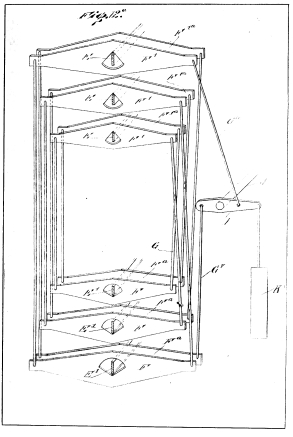 Fig. 12ª.
BANGERTER’S PERPETUAL TIME CLOCK
other days it may be as high as twenty degrees. If the clock requires
for its operation the lowering of three balls each day the apparatus
will be so arranged that with an average daily temperature variation of,
say, six degrees, four balls will be raised, of which three will operate
the power transmission wheel and one will be held in storage. With a
variation of twelve degrees, eight balls will be raised, of which five
balls will be left in storage. If the ball storage runways each have a
holding capacity for one hundred balls, and the variation in temperature
is greater than required, the balls will soon be lifted from the lower
to the upper runways. Assuming that on certain days there will be no
variation in temperature, and as a result the energy-storing wheel
should not revolve, the running of the clock will not be interrupted,
for the power transmission wheel will continue revolving, taking its
power from the balls in storage.
I wish it understood that I do not confine myself to the precise details
of construction and arrangement of parts as herein set forth and
described or to the materials specified, as modification and variation
may be made without departing from the spirit of the invention as
defined by the appended claims.
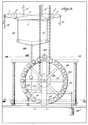 Fig. 13.
BANGERTER’S PERPETUAL TIME CLOCK
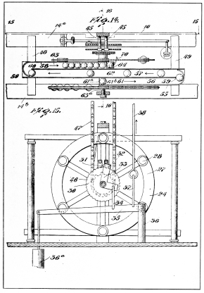 Fig. 14.
Fig. 15.
BANGERTER’S PERPETUAL TIME CLOCK
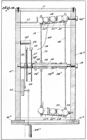 Fig. 16.
BANGERTER’S PERPETUAL TIME CLOCK
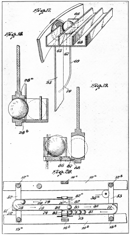 Fig. 17.
Fig. 18.
Fig. 19.
Fig. 20.
BANGERTER’S PERPETUAL TIME CLOCK
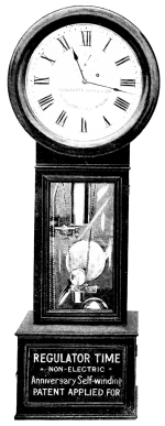 BANGERTER’S NON-ELECTRIC REGULATOR TIME
CLOCK—ANNIVERSARY SELF-WINDING.
Patent Applied for, 1911.