By J. S. ZERBE, M.E.
Price, per volume, 60 cents, Net. Postage extra.
AUTOMOBILES
This is a subject in which every boy is interested. While few
mechanics have the opportunity to actually build an automobile,
it is the knowledge, which he must acquire about every particular
device used, that enables him to repair and put such machines in
order. The aim of this book is to make the boy acquainted with
each element, so that he may understand why it is made in that
special way, and what the advantages and disadvantages are of
the different types. To that end each structure is shown in
detail as much as possible, and the parts separated so as to
give a clear insight of the different functions, all of which are
explained by original drawings specially prepared to aid the reader.
MOTORS
To the boy who wants to know the theory and the practical
working of the different kinds of motors, told in language which
he can understand, and illustrated with clear and explicit drawings,
this volume will be appreciated. It sets forth the groundwork
on which power is based, and includes steam generators, and
engines, as well as wind and water motors, and thoroughly describes
the Internal Combustion Engine. It has special chapters
on Carbureters, Ignition, and Electrical systems used, and particularly
points out the parts and fittings required with all devices
needed in enginry. It explains the value of compounding,
condensing, pre-heating and expansion, together with the methods
used to calculate and transmit power. Numerous original illustrations.
AEROPLANES
This work is not intended to set forth the exploits of aviators
nor to give a history of the Art. It is a book of instructions intended
to point out the theories of flying, as given by the pioneers,
the practical application of power to the various flying structures;
how they are built; the different methods of controlling them;
the advantages and disadvantages of the types now in use; and
suggestions as to the directions in which improvements are required.
It distinctly points out wherein mechanical flight differs
from bird flight, and what are the relations of shape, form, size
and weight. It treats of kites, gliders and model aeroplanes,
and has an interesting chapter on the aeroplane and its uses in
the great war. All the illustrations have been specially prepared
for the work.
Development of the Industry. The First Patent.
Newton’s car. Watt’s Invention. Traction. Push
legs. Power. Springs. Water Tube Boiler. The
First Differential. The First Gas Motor Car. Gasoline
Car. Flash Boiler System. The Carbureter. Improved
Structures. The Order of Development. Speed
vs. Power. Lighter Vehicles.
The Frame. Channel-bar Frames. How the Frame
is suspended. Fore and aft Motion. Lateral Motion.
Cantilever Spring. Shock Absorbers. The Axle. Live
Axles. Dead Axles. Semi-Floating Axle. Full Floating
Axle. Wheels. Flexibility. Large vs. Small
Wheels. Minimizing Shocks. Resiliency.
Tires. Solid Tires. Cushion Tires. Pneumatic
Tires. Single Tubes. Double Tubes. The Outer Tube.
The Inner Tube. Advantage of Double Tube. Putting
on and Taking off Double Tubes. Damage to Tires.
Repair to Tires. Vulcanizing. Oil as an enemy of
Tires. Non-skidding Tires. Tires for City Use. Side
slipping. Faulty Alinement. Broken Fabric. Bruises.
Under Inflation. Stretched Tires. Blistered Tires.
Rim Cutting. Inflation Pressures. Expansion of
Heated Air.
The Steering Column. Motor Control. Throttle
Movement. Steering Wheel Type. Steering Gear.
Front Axle. Running Brake. Double-acting Contracting
Brake. Contracting Brake. Equalizers. The
Emergency Brake. Combined Service and Emergency
Brake.
Power Transmitted to Wheels through Springs. Illustrating
power transmission. Torsion Rod. The
Torque Tube. Radius Rod. Chain Drive. Jack Shaft.
Objections to Chains. Shaft Drive. Train of Shafting.
Clutch Requirements, Frictional Contact. Cone
Clutch. Compression Spring in Clutches. The Multiple
Disk Clutch. Its Construction. Disadvantages
of Multiple-Disk Clutches. Care of Multiple Disk
Clutch.
Transmission Leverage. Economy of Transmission
Gearing. Types of Transmission. The Progressive.
Low Gear. Intermediate Gear. High Gear. Reverse.
Selective Type. Low Gear. Intermediate Gear. High
Gear. Reverse Gear. Control Lever for Progressive
Transmission. Operation of the Selective Gear. Selector
Bars. Shifting Lever. Speed Selectors. 3-speed
Selectors. 4-Speed Selectors. An approved Type of
Selector. Controlling the Selector. Using the Clutch
and Selector. Planetary Transmission. Frictional
Transmission.
Value of Fuel Utilized. The Waste. Water Absorption.
Engine Types. The Four-Cycle Engine.
The Two-Cycle. Compression. Economy of Four-Cycle
Engine. Valve Movements. The Ignition point in the
Cycle. The Fly-wheel. Impulses in Four-Cycle Engine.
The Cylinder Case, and Connections. Piston
and Crank Construction. Calculating the Efficiency.
Pressures in Explosions. Expansion Line. Mean Effective
Pressure. The Two-cycle Engine. Foot Pounds.
Work or Energy. Cycle of Operation. The Crank
Shaft. Special Metal. Engine Troubles. Difficulties
pointed out. Starting the Engine. Carbureter. Low
Compression. Mixtures. Spark Plugs. The Weather.
Drainage.
Air Cooling. Air-Cooling Devices. Water Cooling.
Gravity System. Locating the Reservoir. Force System
of Cooling. The Radiator Connections. Radiators.
Construction of Radiator. Operation of Radiator.
The Pump. Pump Construction. Action of
Pump.
Carbureted Air. Composition of Gasoline. Gasoline
Expansion. Requirements of a Carbureter. Evaporation.
Air Saturation. Air Contact with Gasoline.
Instantaneous Combustion. Compression. Compression
as a Mixing Means. Carbureter Types. The
Spraying Carbureter. Dissecting the Carbureter.
The Mixing Chamber. The Float Chamber. The
Venturi Tube. The Inlet Valve. The Throttle Valve.
The Secondary Air Supply. Automatic Admission of
Secondary Air. Carbureter Adjustments. Special
Points Concerning Carbureters. Thin Mixtures.
Speeds and Mixtures. Surface Carbureter. The Float.
The Oil Inlet. Securing Surface for air Contact.
Seeing the Effect of Electricity. Action of a current.
Amperes and Volts. Conductivity. Resistance. Generating
Electricity. Magnetic Field. Armature. Batteries.
Metallic Couples. What Determines Voltage.
Controlling Amperage. Dry Batteries. Cell Construction.
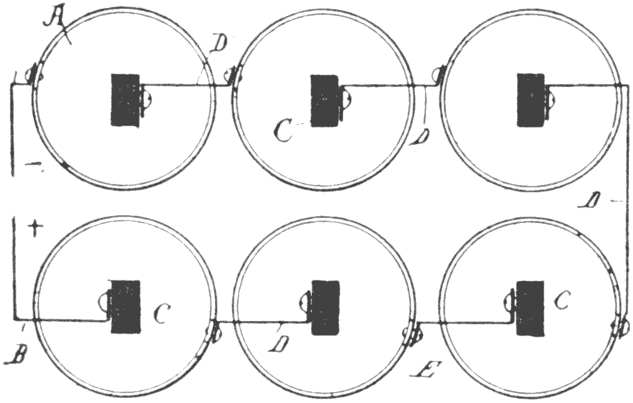
Connecting up Cells. The Series Connection.
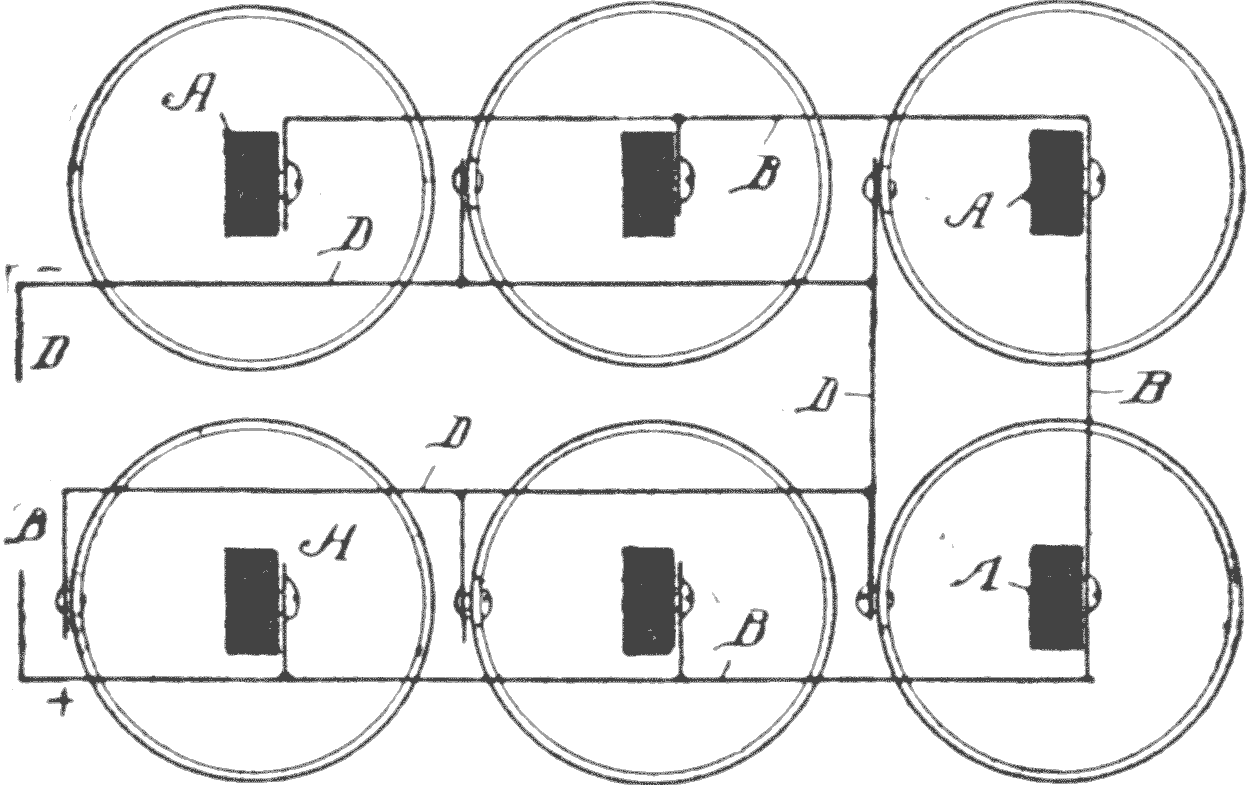
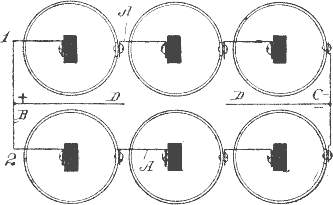
The Parallel Connection. Series-Multiple Connection.
Storage Batteries. The Sparking Methods. Air Resistance.
Make and Break Spark. The High Tension
System. The Spark Plug. How Produced. The Magneto.
Difference Between Dynamo and Magneto. Advantages
of Magneto. Different Kinds of Magnetos.
Primary and Secondary. Igniters. High Tension Coils,
Inductance. Constructing a coil. A Simple High
Tension Sparking System. Condenser. Interrupter.
Arrangement of a high Tension System. The High Tension
Connections. The Secondary Coil. Operation of
System. The Spark Gap. Function of the Interrupter.
Vibratory Coils. Operation of Vibratory Coil. Surging
Movement of Current. Timing Device. Contact
Makers. The Contact Breaker. Sparking Plugs.
Testing Plugs. Short Circuiting Faults. Short Circuiting
of Secondary Wires.
Self Starting. Simple Type of Starter. The Distributer.
Lighting. Car Signals. Speed Signals.
Mufflers. Exhaust. Construction of Muffler. Ball and
Roller Bearing. Race ways. The Three-point Contact.
Wrong Constructions. Roller Bearings. Form of
Roller Bearings.
Running Close to the Curb. The Middle of the
Road. Community Regulations. Approaching Car
Track. Coasting. Signs of the Road. Operating the
Control. The Crucial Point. Clutch Pedal and Spark
control. Neutral Position of Transmission Lever.
Throwing in Gear. In Reversing. Quick Stops. Ease
in Manipulating Progressive System. Wiring for
Lighting System. Wiring up for Ignition.
An Experiment with Gasoline. Air Necessary for
Explosion. Making an Explosive Mixture. Gunpowder.
Filled Tank not Explosive. Why Gasoline
will not Burn Within a closed Tank. Filling Tanks
having Dried out Gasoline. To Extinguish Gasoline
Fires. Ammonia as an Extinguisher. Leaks. Lubricants.
Viscosity. Carbonization. Acid in Lubricants.
Composition of Lubricants. Grease. Graphite. The
Test for Cylinder Lubricants. Fire Test. Lubricating
Systems. Pressure Method. The Precision
System. Combined Force, Feed, and Splash System.
Regular Inspection a good Habit. The Brake Shoe.
Familiarity with Working Parts. The Engine. Connecting
Rods. Valves. Cam Shaft. The Clearance.
Clutches. The Clutch Leather. Rivets in the Leather.
Transmission System. The Differential. Universal
Joints. Steering Gear. Worm and Worm Wheel.
Batteries. The Vibrator. The Electrolyte. Contact
Points. The Magneto. Magneto Impulses. Timing
the Magneto. The Carbureter. Wrong Adjustment.
Weather.
Requirements. Gasoline-electric Trucks. The Current
Used. Mechanically-produced Electricity. Current
from Batteries. Primary Battery. Secondary
or Storage Battery. Reversal of Current. Charging.
Time required, and Current. Troubles in Use. Overcharging.
The Circuiting. Economy in Use of Current.
Series and Parallel. The Connections. The
Controller. The General Equipment. Accessories.
Seating Arrangement. The Transmission. Brakes.
The building and development of auto vehicles
form one of the most remarkable pages in the
history of manufactures. The subject nearest the
boy is the motorcycle, which is a direct development
of the bicycle. From this to the larger
power vehicles is but another step, so that in
setting forth the structures involved the aim
should be to show how one form of device grew
out of the preceding one, and how each structure
following in the train, became desirable and necessary.
It would be impossible in a limited work of this
kind to show the various modifications of all the
elements which make up a complete structure.
When these vehicles were first brought out, the
mechanism was exceedingly simple, being, in
reality, nothing more than the hitching up of some
form of motive power with running gears.
But now all that is changed. The old type
steering mechanism was imperfect; the attachment
of the wheels to the axles had to be modified;
the wheels themselves entirely revolutionized;
speed changing and reversing especially adapted
for quick and positive work; and even the easy
starting of the motor had to be provided for.
The entire equipment required a multiplicity
of new devices, such as signaling apparatus,
lighting systems, safety appliances, means to prevent
skidding, wind shields, a reorganization of
body and seating arrangement, and a reconstruction
of the springs and their attachment to the
chassis.
The electrical part has made as rapid strides,
and in the development the sparking mechanism
has approached perfection, and brought into existence
a wonderful variety of systems, so that
each cycle of improvements has made them more
efficient, but simpler to construct, understand and
use.
It is a rare thing to-day to see any of the power
machines dragged home by horse power. Not
many years ago this was a common sight. The
size, shape, and materials used, have been understood
by scientific analysis and study, so that
breakage, under ordinary uses, is not at all a
common thing.
It is the aim of this book to show in as simple
a manner as possible how this wonderful transformation
has been brought about, and to furnish
one or more types of each element, properly constructed
and arranged, so that the boy may understand
how each part is built, and the particular
reasons for the structures.
In no branch of manufactures can be found
such a variety of technical designations as have
grown out of this industry. By virtue of necessity,
many of these names have been coined to
suit the conditions. This knowledge is imparted
in these pages, which contains a complete glossary
of every term used in the art.
The Author.
CHAPTER I AUTOMOBILE HISTORY AND DEVELOPMENT
AUTOMOBILES
It is generally believed that automobiles originated
within the present century, this idea having
gained currency because, until within the past
twenty years, no practical machines were put
on the market.
Development of the Industry.—The development
of the industry has been a peculiar one, in
some respects. As early as the year 1275, Roger
Bacon speculated on the possibilities of using
steam, or some other form of motive power on
wagons, for propelling them.
This is remarkable, when it is understood that
the steam engine, as constructed by Watt, was not
invented until about 1780. Prior to Watt, steam
engines were in operation, the valves of which
were manually operated. Watt’s energies were
directed to making the valves work automatically,
and in economizing the use of steam.
The First Patent.—In 1619, two Englishmen,
Ramsey and Wildgoose, secured a patent for
“drawing carts without horses,” and even before
that time inventors in Germany had made vehicles
which were propelled by powerful springs. In
the Netherlands devices were constructed to move
wagons by means of the wind.
Newton’s Car.—In 1700 Sir Isaac Newton invented
a steam car, in which he used Hero’s steam
engine, and N. J. Cuguet, a Frenchman, invented
a steam car which had some remarkable properties.
Watt’s Invention.—Later Watt invented, and
was granted a patent, in 1784, for a steam vehicle,
and twelve years thereafter, the first American
patent was issued to W. Read, of Massachusetts,
for a steam-driven automobile.
These were followed by Symington, about the
same time, together with Trevithick, in 1802,
Evans in 1805, and Griffith in 1821. While numerous
others contributed to the art, the foregoing
were the pioneers.
Evans has the distinction of being the first to
build a combined boat and wagon; and Griffith
was the originator of the body type which had
cabins or apartments for the use of travelers.
Traction.—Steam engines were in a fairly
perfected condition two hundred years ago, and
it has been considered remarkable that for over
one hundred and fifty years no practical road
device was brought out.
The reason for this was not due to engine faults,
but attributable to other things which were not
understood at the time. One of these was the
question of traction.
Push Legs.—It was believed in the early history
of the art, that some other means should be
adopted for applying the power, rather than to
exert it on the wheels; but as late as 1824 Gordon
secured a patent for an improved form of “push
legs,” which stepped along and thus propelled
the vehicle. This form of propulsion has been
revived, in a measure, by the so-called “caterpillar
tractors,” in which the wheels are provided with
feet, which step along, and are thus specially
adapted for heavy trucks on soft roads or on cross
country travel.
Power.—One other difficulty was in the construction
of the boiler. What is now understood
as the water tube boiler was then unknown, hence
they were made in such a manner that a large body
of water had to be carried in the boiler, and this
meant great weight to be transported.
Springs.—Prior to the attempted introduction
of steam, vehicles had springs, and the great problem
then appeared to find a type of vehicle which
would permit the transfer of the power from the
engine to the wheels, since the springs change the
relative positions of the engine and axle.
Water Tube Boiler.—From 1820 to 1840 was
the great period of boiler development. The
water tube type provided a means whereby considerably
less than one-half of the water was required
in the boiler itself; and in 1832 a motor drawn vehicle,
having springs arranged for carrying the
entire load, was devised by Dr. Church, of Birmingham,
England.
The First Differential.—Hills, in 1840, made
the first differential. Before that time the power
was applied to a single wheel, but in that year
Dietz invented a form of rubber tire. This, and
the differential, made wheels the tractors for all
time.
But now a new era was ushered in. It was not
a period of active work in the development of motor-driven
wagons, but the possibilities of using
other than steam-driven vehicles was felt.
The First Gas Motor Car.—In France, Lenoir
was the first to devise a gas motor car. Compressed
gas was used; and Ravel, in 1870, also
produced a gas-driven machine. As early as
1862 Gardner used a gas motor fed with carbureted
air instead of gas, but the weight of the engine
was against all attempts in that direction.
Gasoline Car.—Markus, of Vienna, built a gasoline
car in 1877, and this was followed by Levassor,
the engineer of Panhard and Levassor, in
France, who used Daimler’s invention in the development
of their car. Gottlieb Daimler, the
father of the automobile industry, produced the
first practical gasoline motor, his invention being
based on the four-cycle type of engine.
The invention of the gasoline, or the Internal
Combustion Engine as it is called, was the first
great advance. The weight of the fuel was so
small, compared with the power produced, that it
revolutionized the art.
And now began that series of developments
which embraced every part of the vehicle from the
wheels to the top. At first the improvements were
slowly effected, and many of them were most unsatisfactory.
Flash Boiler System.—The flash system of
using water in boilers, invented by Serpollet in
France, for a long time kept even pace with gasoline
cars, in economy, and in ease of management;
but now that system has been entirely driven out,
and gasoline taken its place. This, in time, must
make way for a still cheaper fuel, and one more
easily handled, either through the crude oil itself,
or from some cheap derivative of it; or, possibly,
a spirit distillation, in the form of alcohol, which
will take the place of the high-priced article now
so universally used.
The natural consequence of improvements has
been to bring forth a multiplicity of devices, particularly
in the direction of more readily assimulating
and using the hydro-carbon fuels. The efforts
of inventors will now be in the direction of
eliminating many of them.
The Carbureter.—Heretofore the carbureter
has been regarded as an essential element in every
system. What a world, or, rather, worlds of
troubles, hung about the carbureter. It was, and
is, delicate, susceptible of the most minute adjustment,
and in times past, before it had reached the
present perfected form, was the bane of every
motorist.
A fuel, ignitable at a very low temperature, or
capable of ready volatilization, has been considered
absolutely necessary to successful operation.
Such is not the case now.
Improved Structure.—The delicate parts of the
operative mechanism are being replaced by strong,
non-breakable forms, all of which tend to make a
more perfect machine, and this, in turn, insures a
greater demand for vehicles.
The Order of Development.—In undertaking
any work requiring mechanical skill, and in which
the action of coöperative elements is necessary,
the uses must be considered. In a vehicle, the first
element is the weight to be carried; then the
strength of the frame and wheels necessary to
maintain the load.
Next should follow, in order, the power needed,
and this entails a consideration of the speed element.
These features are comparatively simple
with a motorcycle; but they are more complex
with the automobile type, particularly as to the
structure of the frame and the gearing and wheels
which are to be operated by the motor.
Speed vs. Power.—Thus, a motor exerting
twenty horse power may run the vehicle at a maximum
of twenty miles an hour, and carry a load of
fifteen hundred pounds; or it may have a maximum
speed of eight miles an hour, and carry
three thousand pounds with equal safety. It will
thus be seen that speed is just as important as
power, in considering utility.
Lighter Vehicles.—The tendency of the day is
toward lighter vehicles, brought about, in a large
measure, by improved materials in every direction.
It is no longer urged that heavy, ponderous
machines are required to furnish stable and durable
vehicles.
Nothing can stop or retard this great industry.
It is attractive to men and fascinating to boys.
To acquire a knowledge of its “mysteries,” should
be a part of the education of every young man.
CHAPTER II THE FRAME, AND ITS ACCESSORIES
Under this title should be included the frame,
axles, springs, wheels, steering gear and brakes.
From the beginning it was recognized that the
different strains and stresses set up by the passing
of the wheels over uneven ground and by the
motor and driving mechanism, must be taken care
of before reaching the body of the automobile,
which otherwise would soon go to pieces.
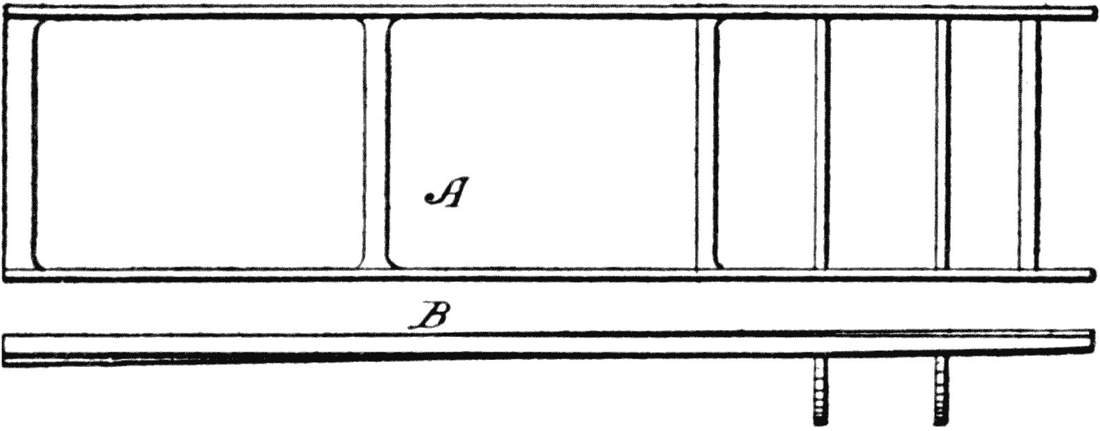
Fig. 1. Views of Plain Frame.
The Frame.—Therefore, not only springs had
to be interposed between the body and the wheel
axles, but also a substructure for the body, called
the frame, which must be rigid enough to prevent
any destructive strains from reaching the body.
In Fig. 1, A shows a top view of a frame made
up of channel bars and B shows a side view to
illustrate how the torsion or twist takes place. It
will be understood that the frame thus made is not
designed to lend itself to the entire inequalities of
the road, as the springs are interposed for that
purpose.
Experience in the construction and use of tubular
frames, as first employed in bicycles, proved
too expensive for assembling, when used in automobiles.
The tubular form of construction was
very soon displaced by frames consisting of metal
parts bolted or riveted together. The main or
side members are now usually made of channel
steel which gives great rigidity and strength, compared
with its weight.
Fig. 2. Quarter Elliptic.
How the Frame is Suspended.—The important
feature is to mount this frame on the axle. The
frame, carrying a body and all the load of the
vehicle, has to permit three distinct movements.
First. That due to the inequalities of the road,
which produces a torsional twist.
Second. A lateral swing, caused by traveling
alongside a hill, or due to centrifugal force when
making a turn rapidly.
Third. A fore and aft movement, as when traveling
over undulating surfaces, or in suddenly
stopping and starting.
Fig. 2a. Half Elliptic.
For these reasons springs must be made to compensate
for such motions, and to absorb the jar
as much as possible.
Fig. 3. Three-quarter Elliptic.
The Springs.—Many forms of spring mountings
have been devised, but the following illustrations
show the types which set forth the principles
involved. Outside of coiled springs which are
used in some forms of delivery cars, the standard
springs are leaf springs, built up from a number
of steel leaves.
There are four distinct forms of springs used,
as follows:
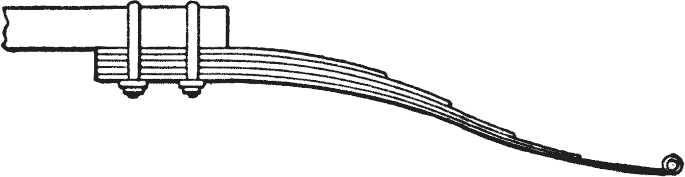
1. The quarter elliptic, used on Ford, and similar
cars, as illustrated in Fig. 2.
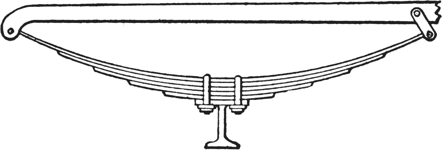
2. The half elliptic, Fig. 2a, which is the most
widely-used form. These springs are usually attached
with their front end directly to the frame,
and with the rear end by means of a shackle; the
center is fastened by spring clips to the axle.
Fig. 4. Full Elliptic.
Where a distance rod is used, as on the rear
axle, both ends are attached by shackles.
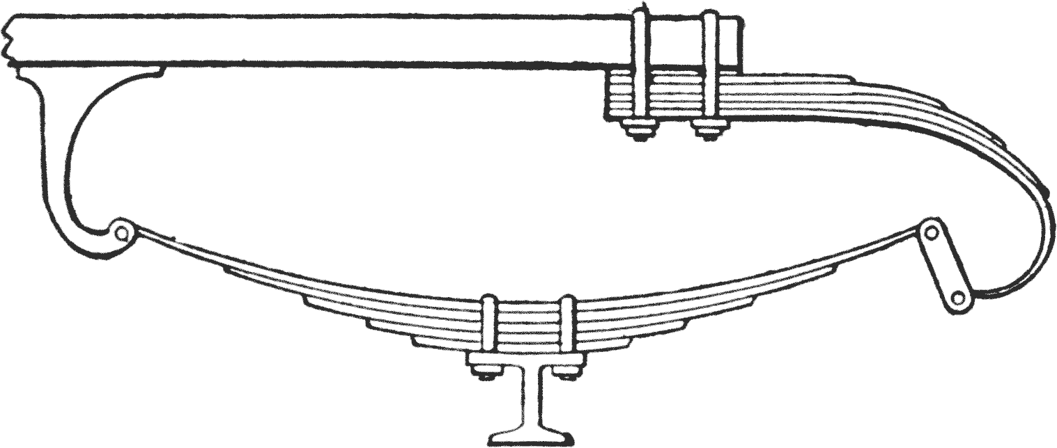
3. The three quarter elliptic, Fig. 3, always
used as a suspension for the rear axle. This
form gives more flexibility than a half elliptic,
and is still stiffer so far as side motion is concerned,
than the following type.
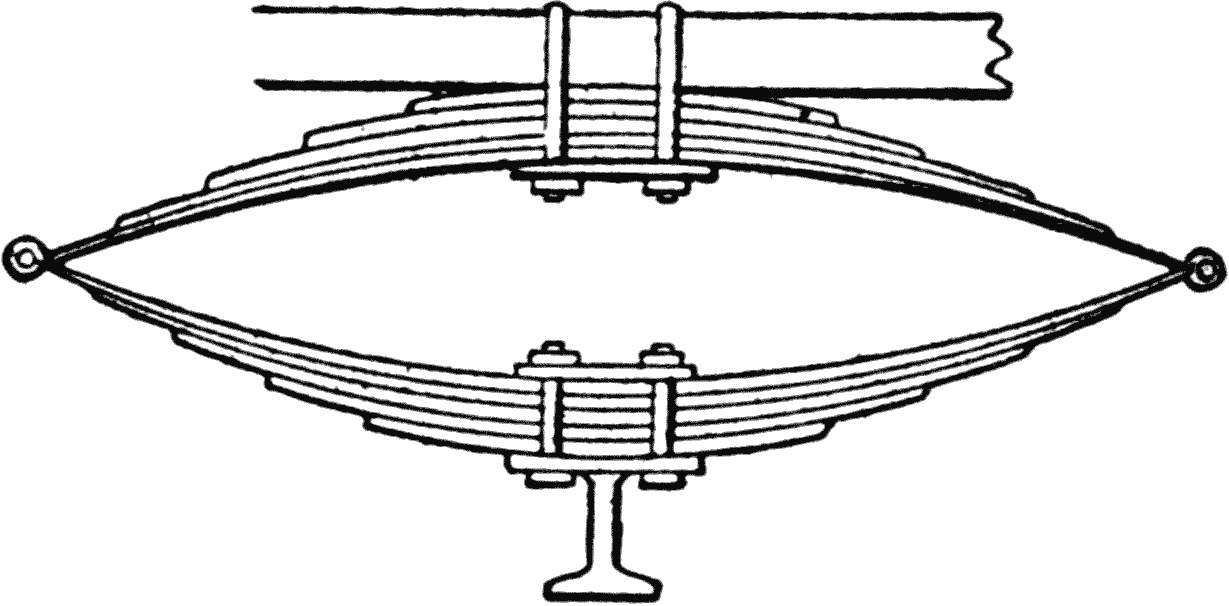
4. The full elliptic, Fig. 4, was formerly used
much more than at the present time.
There are also in use springs comprising a combination
of half elliptic, or three quarter elliptic,
on each axle, in which the front end is shackled to
the frame, and the rear ends connected by shackles
to another half elliptic spring, the center of which
is fastened to the frame.
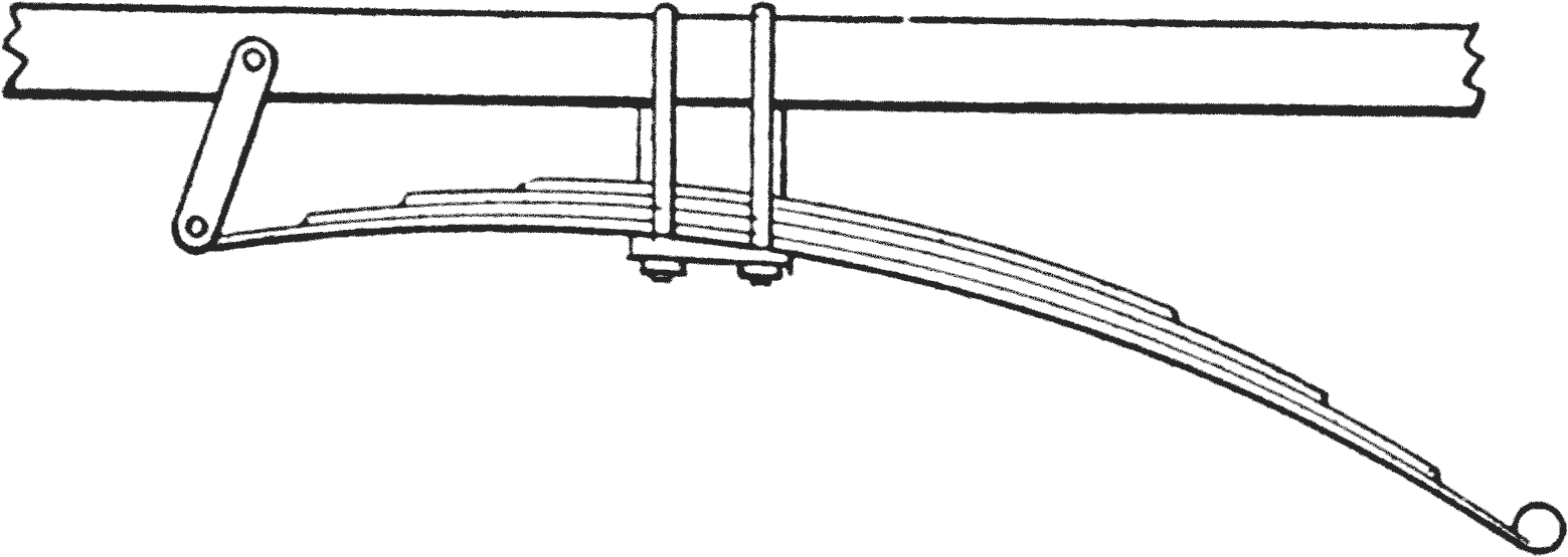
Fig. 4a. Cantilever Spring.
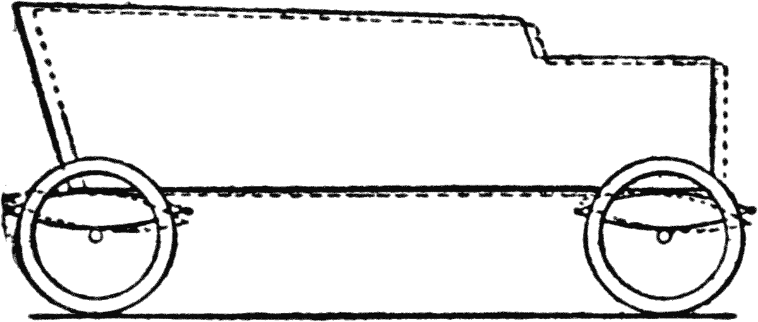
Fore and Aft Motion. Provision must be
made, in all cases, for the fore and aft movement
of the car body which takes place in stopping
or starting, and, particularly when the wheels
strike an obstruction.
Fig. 5. Fore and Aft Motion.
Flues. Fig. 5 shows a side view of a car, in
which the dotted lines indicate the position of the
body, relative to the normal, when the wheels
strike an obstacle.
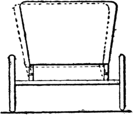
Lateral Motion. In like manner when the car
swings around a corner, or is traveling along a
hill-side, the springs must hold the body from
swinging too far. Fig. 6 illustrates, by means
of the dotted lines, the side movement. It is obvious,
therefore, that the springs have a duty to
perform in addition to that of merely giving flexibility
to the body.
Fig. 6. Lateral Motion.
Cantilever Spring.—A special form of half
elliptic springs, lately developed, and of increasing
use, is the cantilever spring, where the axle is
attached to one end, the center of the spring being
pivoted to the frame, and the other end shackled
to or sliding in the frame.
Shock Absorbers.—Shock absorbers are mechanical
means placed between the frame and the
axles for the purpose of dampening the sudden
recoil of the springs after being compressed, when
meeting a road obstacle. In the absence of such
a device the recoil is likely to suddenly throw up
the frame, body and passengers, or produce an unpleasant
shock.
Originally, simple leather straps were used,
reaching from the body to the axle, which only
limited, but did not dampen or gradually absorb
the shock. Now different forms of frictional resisting
toggle-levers are used, which not only absorb
the shocks, but also prevent the bumping of
the axle against the frame, and eliminate breaking
of springs.
The Axle.—Axles are of two kinds, generally
designated as “live,” when they turn the wheels;
and “dead” when they do not turn the wheels, but
simply support the weight of the frame and of the
body.
Dead axles are used with double chain drive,
as, in that case, the sprocket wheels are attached
directly to the sides of the wheels and the wheels
turn on the studs, or ends of the dead axle.
Live Axles.—1. Plain live axles originally consisted
of a shaft without differential gearing, having
one wheel fast on it, the other turning. Modern
construction shows two axle shafts in a housing,
the weight of the car, and the tooth pressure
of the differential being carried by the axle shafts.
2. Semi-floating axles have the weight of the
car carried by the axle shafts, whereas the tooth
pressure of the differential is supported by the
housing, and only the turning effect or torsion is
transmitted by the axle shafts.
Fig. 7. Floating Axle.Fig. 8. Semi-floating Axle.
3. Full floating axles carry the full weight of
the car, and the differential bevel gear teeth pressure
with the housing, so that the axle shafts carry
no load but only the torsional stress.
Both full and semi-floating constructions are applied
to rear axles only. The front wheels are now
universally applied to knuckles, which swing on
vertical pivot pins at the ends of the dead axles.
Wheels.—Wheels are now in a transition state.
The ultimate wheel has not yet appeared; but
whatever its form or construction, certain things
are essential.
Flexibility.—In the ordinary wagon or carriage
wheel, there is but little, if any, flexibility;
but in automobiles, where speed is a consideration,
elasticity, either in the rim, or in some other part
of the wheel, is necessary.
One of the reasons for this is, that on account
of tire expense, motor wheels are smaller than
carriage wheels. Making them smaller, however,
produces certain disadvantages. One is that in
going over the inequalities of the road, the axle on
the small wheel has a greater vertical movement
than on a large wheel, and the jar on striking an
obstruction is more pronounced, also. These disadvantages,
however, are more than counterbalanced
by the elasticity of the invention.
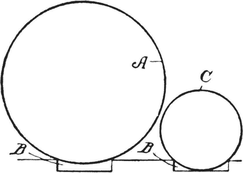
Large vs. Small Wheels.—Fig. 9 shows a large
wheel A, passing over a depression B. The large
arc of the wheel does not permit the rim to go to
the bottom. On the other hand, the small wheel C
goes to the bottom of the depression, and the vertical
distance which the axle of this wheel must
travel, is three times as far as in the case of the
wheel A.
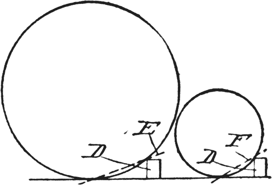
In Fig. 10, where the large wheel strikes an obstruction
D, the angle of its upward movement, as
designated by the line E, is much less than the impact
force of the small wheel, as shown by the
greater slope or incline of the line F.
Minimizing Shocks.—It is obvious, therefore,
that if part of this shock can be taken up by the
tire, the difference due to the smaller diameter of
the wheel, will not be so apparent.
The thickness, or widths of the tires also minimizes
the impact and distribute the jars while
running, so that with these advantages a small
wheel has been found to be more practical than a
large one.
Resiliency.—Most wheels are now made with
wooden spokes, secured by means of a pair of
metal-flanged hub plates, bolted together so as to
clamp the radiating spokes, but wire wheels are
now coming more into favor, whereas cast or
pressed solid steel wheels are used on some heavy
trucks.
CHAPTER III TIRES, TUBES, AND RIMS
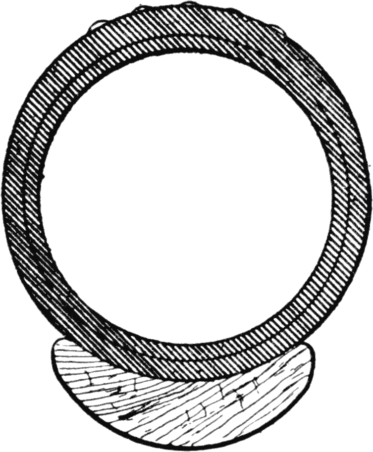
Tires.—Three kinds of tires are now used,
namely: Solid, cushion, and pneumatic. These
forms all use rubber, or some compound with the
qualities and characteristics of rubber, so as to afford
a good tractive surface, as well as resiliency.
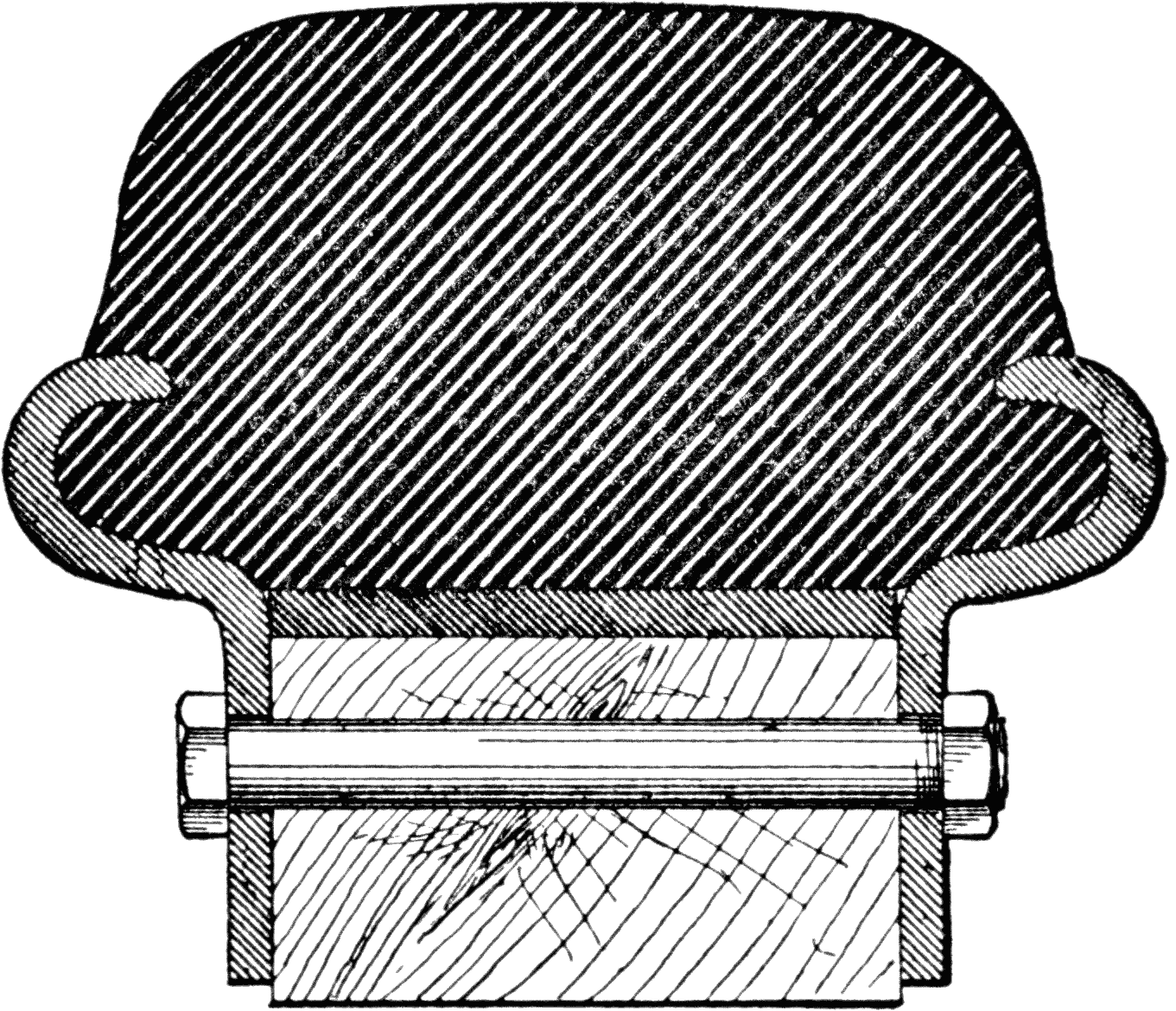
Fig. 11. Solid Tire.
The solid tires are used on heavy trucks,
where weight and not speed must be provided for.
Cushion tires are sometimes employed on cars
and trucks of medium weight.
Pneumatic tires, in which air is used, are universally
used in automobiles for all other purposes.
Fig. 12. Single Tube.
The air is confined in two ways:
First, by what is known as the “single tube.”
(Fig. 12.)
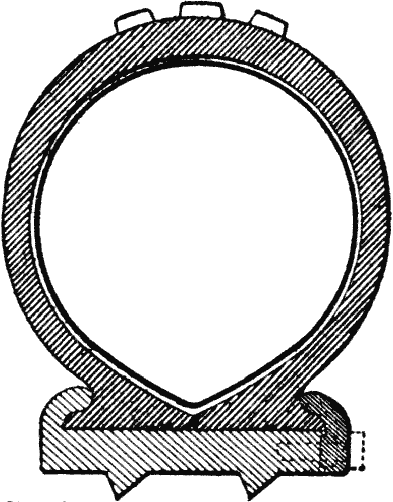
Second, by the “double,” or inner tube system.
(Fig. 13.)
The single tube is well adapted for light vehicles,
or where great speed or weight are not considered,
and this type is now confined to bicycles.
But it has certain disadvantages, namely: That
of creeping, due to the impossibility of properly
securing it to the rim of the wheel. Sand and grit
are also liable to creep in between the tire and
rim, and wear the material, thereby ruining it.
The outer casing, or shoe, is split on its inner
side, and usually provided with an annular flange
on each side of the split, which rests against the
rim of the wheel, and is adapted to receive a rim
which securely fastens the annular flange of the
shoe, to the rim of the wheel.
Fig. 13. Double Tube.
Various ways are provided for holding the shoe
to the rim of the wheel; but in the different types
shown by the illustrations, Figs. 13 and 14, the
shoe has a flange which is held within channels on
the rim, or by some form of fastening device.
The inner tube is usually of thin elastic rubber,
so made that when properly inflated it will
fit the outer tube or casing. The outer part, which
can be made of a different rubber compound, and
is better adapted to stand wear, whereas, the inner
tube, which is made of the best, and more
costly material is protected.
Advantage of Double Tube.—The great advantage
of the double tube is due to the positive
means of fastening it to the rim of the wheel, so
as to prevent creeping.
In the single tire construction the latter is liable
to roll out of its bed where quick turns are made,
but with the double tube this is not possible.
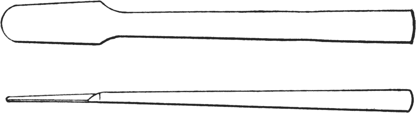
Fig. 14. Illustrating Tire-removing Tool.
Putting On and Taking Off Double Tubes.—To
do this properly with clincher tires is quite an
art. A pair of blunt, round-ended levers is best
for the purpose.
The practice is to use cold chisels, screw drivers
and like sharp or pointed tools. This is bad practice.
A pair of levers, as shown in Fig. 14, can be
made by any one, and you may be sure that their
use will not be liable to jag a hole in the inner
tube during the removal process.
When the inner tube is put into the outer casing,
or tire, as it is called, powdered talcum should be
liberally applied, to the tube and also placed within
the casing. The tube is then put in and carefully
distributed and straightened out before the clinchers
are put on.
A little air blown into the tube will prevent it
from being pinched under the flanges of the casing.
The spare tubes should be inclosed in a receptacle
of some kind which will exclude light, and
protect them from heat. With the advent of the
quick detachable rims of different forms these
troubles have happily disappeared in the modern
automobile.
Damages to Tires.—Many things must be provided
for in the matter of tire keep. The thing
most necessary to guard against is punctures,
caused either by sharp stones, or nails. When a
casing has a heavy protective tread the inner tube
may not be effected, but it frequently happens that
the outer casing is slitted for some distance, and
the great pressure forces the thin wall of the inner
tube into the slitted opening, and it is thus ruptured,
not on account of its being punctured, but
because the outer tire did not afford protection
against the pressure.
Repairs to Tires.—It is not a difficult job to repair
tires, and the apparatus for doing it is very
simple. Rubber, in its natural state, is a white,
thick, milky juice, which after several heating and
refining processes becomes dark and sticky.
Vulcanizing.—When in this condition and
properly mixed with sulphur, it may be vulcanized,
which destroys the stickiness, and makes it
firm and elastic. Vulcanizing is a kind of baking
process, the maximum heat being about 275 degrees,
but generally less. The time required is
from 12 to 15 minutes, dependent on the thickness
of the mass to be vulcanized.
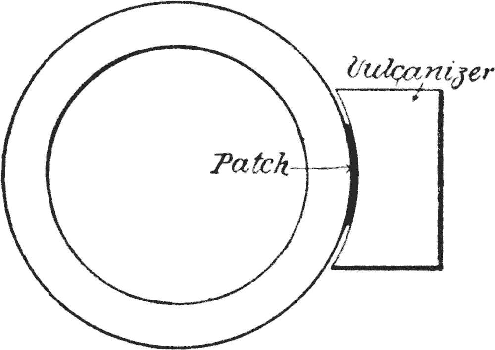
Fig. 15. Vulcanizer.
When the torn or cut portion of the tube or tire
is carefully cleaned, it is filled with the plastic
rubber, and the heater is applied. The heater,
one form of which is shown in Fig. 15, is merely a
shell with a heater connection, and this being
partly filled with water, generates steam, the
temperature of the shell being, of course, dependent
on the pressure of the steam developed.
To repair the inner tube, it should be first
rubbed with sand paper, and liquid rubber cement
applied. When this becomes tacky apply the
patch and dry. It is then ready to be vulcanized.
Oil as an Enemy of Tires.—All literature on
the subject of tires give warnings as to the insidious
character of oil, which deteriorates the
rubber. Most manufacturers now make an oil
proof quality, but the cheaper grades are not to
be depended on.
The action of oil shows itself in several ways,
but principally because it dissolves the rubber.
Non-Skidding Tires.—Various means are provided
in the shape of tire treads to prevent skidding,
the most important being vacuum cups, the
herring-bone formation, and various ribbed or
ridged surfaces. Nevertheless, for smooth asphalt
pavements, chains or similar substitutes are
found most satisfactory.
Sudden application of the brakes, or the sliding
of wheels on hillsides or the skidding of the
car in making short turns at too great speeds, are
the most destructive things for tires, however good
they may be.
Tires For City Use.—A tire which may be of
good service for country roads, might not be available
for city work. The tendency of many drivers
is to hug the curb too closely, and the result is a
wear on the side, which is its weakest point. It
is like the side of a shoe, the upper of which can
be readily worn through, whereas the sole will
stand hard usage.
In country use the great danger is in the winter
months, where the wheels must pass over or along
frozen ruts. There the same difficulties of side
wear are liable to destroy the best material.
Side Slipping.—The same remarks apply to the
weakness of tires due to side slipping. The fibers
of the fabric are ruptured at the weak point and
the least external abrasion assists in destroying
it.
Fig. 16. Turning Action on Front Wheel.
Faulty Alinement.—Another cause of ruptured
tires is attributable to improper alinement
of wheels, due to the wheel being not exactly true,
through a bent axle, or improper adjustment.
This is more frequently the case with front than
with rear wheels.
It will be readily understood that while the rear
wheels have the traction applied to them, the front
wheels, fixed as they are, to the short turning
knuckles, are affected by a movement diagonally
across the tire, at every turn which is made.
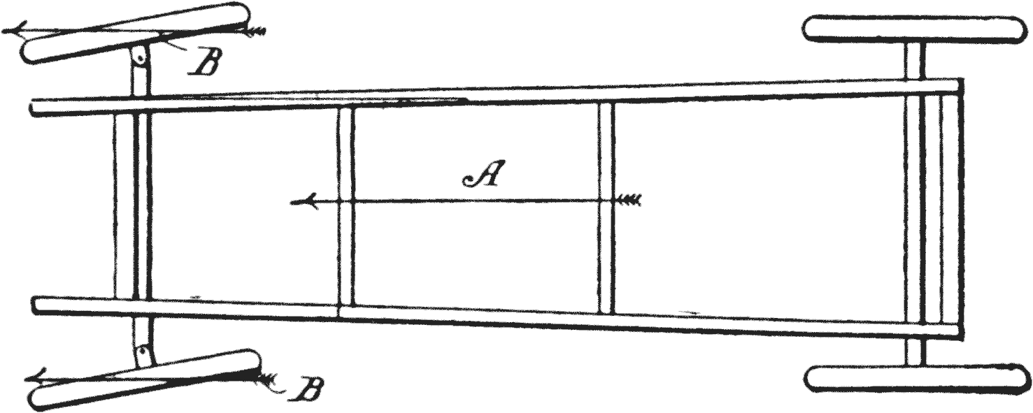
This is shown by reference to Fig. 16. The
movement of the car is in the direction of the arrow
A, consequently, when the wheels are turned,
the momentum of its forward end is in the direction
of the arrows B B.
When the turn is to the right, the strain is on
the inside of one tire and on the outside of the
other, and when the movement is to the left the
conditions are reversed in the stress, and this explains
why the tires of front wheels are so liable
to yield, in all cases where turns are made at
high speeds.
Broken Fabric.—The fabric of a tire may be
ruptured without giving any indications on its
outer side. When there is a strong impact force,
like a transverse ridge, which will force in the
tire, several things occur. First, the body of the
tire is flattened out so that it has a bulging cheek
on each side; and, second, a strain is produced on
the longitudinal fibers.
Bruises.—The result of such a severe bruise is
to cause a break, not transversely, or longitudinally,
but usually, obliquely, for the following
reason. The fabric has one set of its threads running
across the tire, and the other set around the
perimeter. This arrangement of the fabric usually
prevents a straight break in either direction,
and the weakest part of the fabric is across the
diagonal direction.
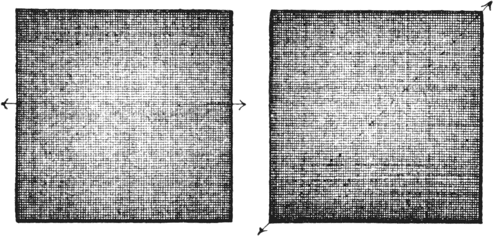
Fig. 17. Illustrating the Strain on Fabric. Fig. 18.
Try the experiment with a handkerchief, as
shown in Fig. 17 by stretching it in the direction
of the threads; and then look at Fig. 18, in which
case the tension is diagonally, or across the corners.
This will be sufficient, probably, to suggest
to your mind the reason for the break on diagonal
lines.
The rubber material is not sufficient to prevent
the stretch which the fabric permits, hence the
break follows.
Under Inflation.—To permit a wheel to run
flat causes a tire to stretch more on the tread than
along the clinch line.
Stretched Tires.—A good illustration of this is
shown in Fig. 19, where the tread is a succession
of irregular wavy surfaces, whereas the sides remain
round and full.
Many attribute this to poor or defective tires.
The best tire in the market will show symptoms
of this kind, if allowed to run when deflated. In
such cases the flatness produces a continual pouching
out of the sides, which follow the wheel around,
and tend to produce a creeping of the fabric.
Fig. 19. Effect of Flat-Tire.
In time the rubber works away, or along on the
fabric, until it becomes stretched at the tread, and
all the pressure in the tire will not again restore
it to the proper condition.
Blistered Tires.—A blister is a plain case of
the rubber being separated from the fabric. At
first the injury may be a small cut down to the
fabric, which, after being neglected for a time,
permits sand to enter, and a grinding takes place,
each movement of the parts causing a further
separation, and pressure expands the rubber, until,
finally, it bulges out and gives an unsightly appearance,
as well as starts the tire on its road to
destruction.
Such defects can be cured, if taken in time, as
many compounds are on the market for this purpose.
Rim Cutting.—This is caused by sand or sharp
particles being forced in between the tire and
edges of the rim, which causes a wearing out at
the contact points. Insufficient air is another
cause. The tires flatten and are then cut by the
metal.
Frequently the tire is too small for the rim, and
this is always bad for it. Heavy loads will cause
cutting, because the tire will be flattened out, although
inflated to the proper tension.
It is good practice to turn a tire, when one side
wears more than the other. This wearing on one
edge excessively, shows some defect in the wheel
alinement, which needs correcting. Possibly the
wheels may not be parallel. This is a frequent
trouble with front wheels, on account of the bending
of the arm which runs from the knuckle.
Inflation Pressures.—Manufacturers of tires
furnish data with respect to the proper pressures
for their products, and these vary somewhat, and
it is wise to observe the pressures which they indicate
for the different sizes.
Expansion of Heated Air.—There is another
cause of tire expansion, not generally considered,
which is due to the expansion of heated air. It is
not infrequently the case that a tire will, in running,
heat up fifty or sixty degrees, which means
an expansion of one-eighth the volume of air
within the tube. If, therefore, there is any weakness
in the walls of the tire, a blowout follows.
As this heating is liable to take place to a
greater extent in the summer than in winter, it is
obvious that it is better to under inflate during
that period, than to have an over pressure, particularly
with old, or considerably worn, or injured
tires.
CHAPTER IV THE STEERING GEAR AND BRAKES
The Steering Column.—This is a very important
mechanical element of the car. Its direct
useful functions are to carry or hold the mechanism
for steering the machine, and for the motor
control, controlling the air supply for the fuel, as
well as for regulating the sparking mechanism.
Motor Control.—Some machines are provided
with a foot lever mechanism (accelerator) as well
as the throttle lever on the steering wheel. This
is advantageous, because in moving through
crowded streets, where frequent and quick
changes are necessary, the foot is the most convenient
for controlling purposes.
Throttle Movement.—A downward pressure of
the foot opens the throttle, and a spring returns it
to its normal position. The foot throttle is also
convenient when shifting the transmission gear, as
both hands are otherwise engaged, one to operate
the gear-shifting levers, and the other for steering.
The hand throttle on the steering wheel, however,
is most convenient for long runs, when little
change is required, and it can then be set so as to
avoid the use of the foot lever.
The levers are so arranged that they do not entirely
close the throttle, but, when fully thrown to
a closed position, will still provide a sufficient
opening to keep the engine running light.
Fig. 20. Steering Wheel.
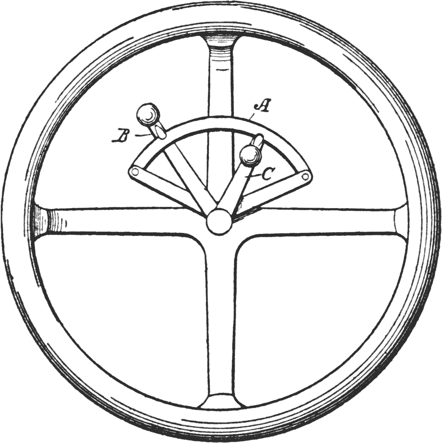
Steering Wheel Type.—The drawing, Fig. 20,
shows a type of steering wheel, which has a segment
A. The long lever B is for throttling purposes,
as above described, and the short lever C
for operating the sparking device.
These levers are differently disposed and arranged
on the wheel, or on the column supporting
the wheel shaft, but the illustration is sufficient to
show the principle of construction, and we are interested
only in the types and not in the modifications
which are available, and are constantly being
made to meet certain conditions.
Fig. 21. Steering Gear.
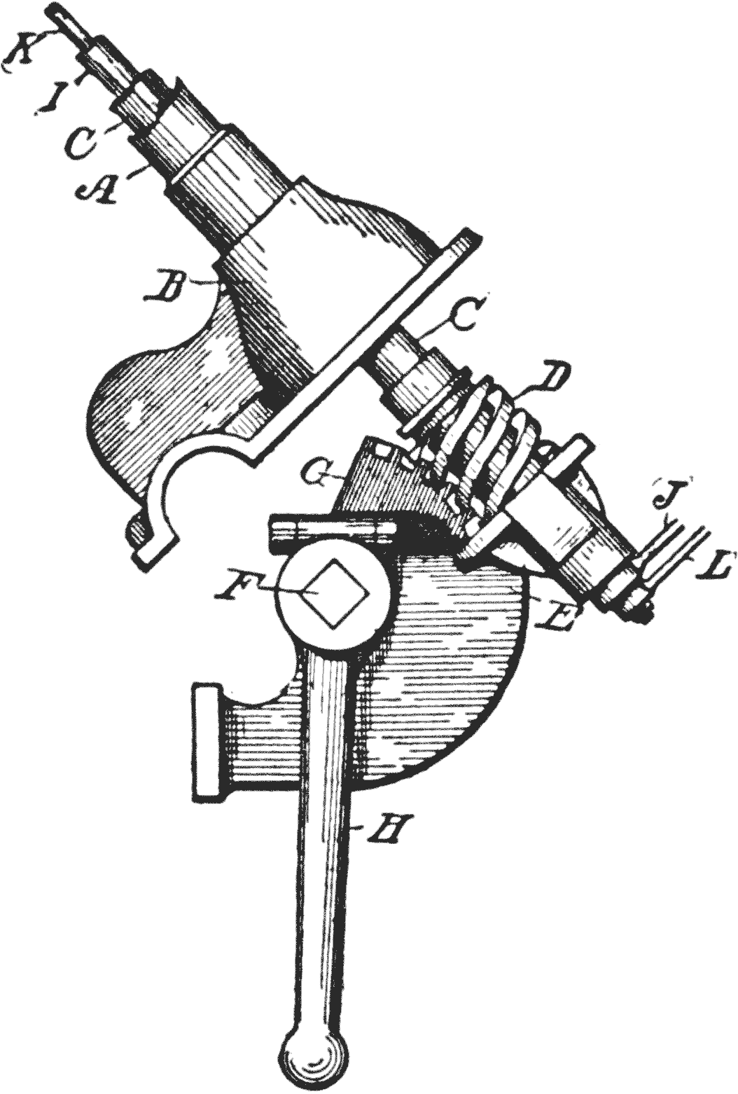
Steering Gear.—Fig. 21 shows an approved
form of construction for the gear, which converts
the rotating motion to a direct line movement. In
this the hollow supporting column A, is firmly
fixed to a base B.
The shaft C which passes through the column,
has a worm D at its lower end, and is journaled in
a base E, which carries a cross shaft F, in which
is mounted the worm wheel G. One end of the
shaft F has an arm H for moving the arms of the
wheel knuckles.
Within the tubular shaft C, is a tubular shaft I,
for the throttle lever to operate, the lower end of
which has an arm J, and within the shaft I, is a
shaft K for the sparking lever, the lower end having
an arm L.
In the best cars all these parts are made adjustable,
so as to provide for wear. In examining or
selecting a car, this is one of the points to note.
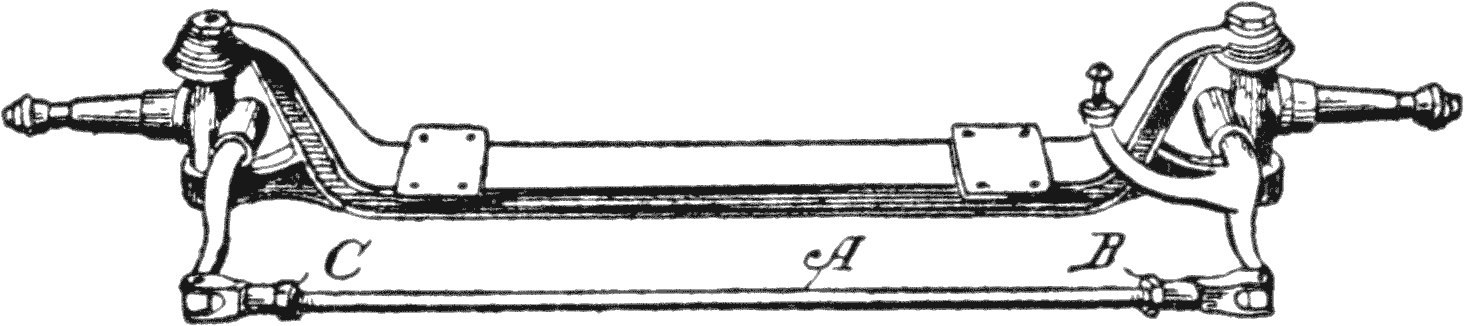
Fig. 22. Type of Front Axle.
Front Axle.—Fig. 22 shows a common form of
front axle, with knuckles and cross connecting rod
A, the latter providing means, by the nuts B C, for
alineing the wheels.
The Brakes.—These are made in two types, one
which is usually in the form of a contracting band,
and the other which expands.
All cars are now equipped with two braking systems,
one being the service, or running brake, and
the other the emergency brake. These brakes are
all of the drum type, and are either expanding, or
contracting bands tightening against the drums.
Running Brake.—The running brake is operated
by the foot pedal, whereas the emergency brake
is generally connected up with the lever at the side
of the seat.
The foot pedal is on some cars connected with
the clutch in such a way that when pedal is pressed
to set the brake, the clutch is released. This prevents
an inexperienced or confused driver from
applying the brake when he forgets to release the
clutch.
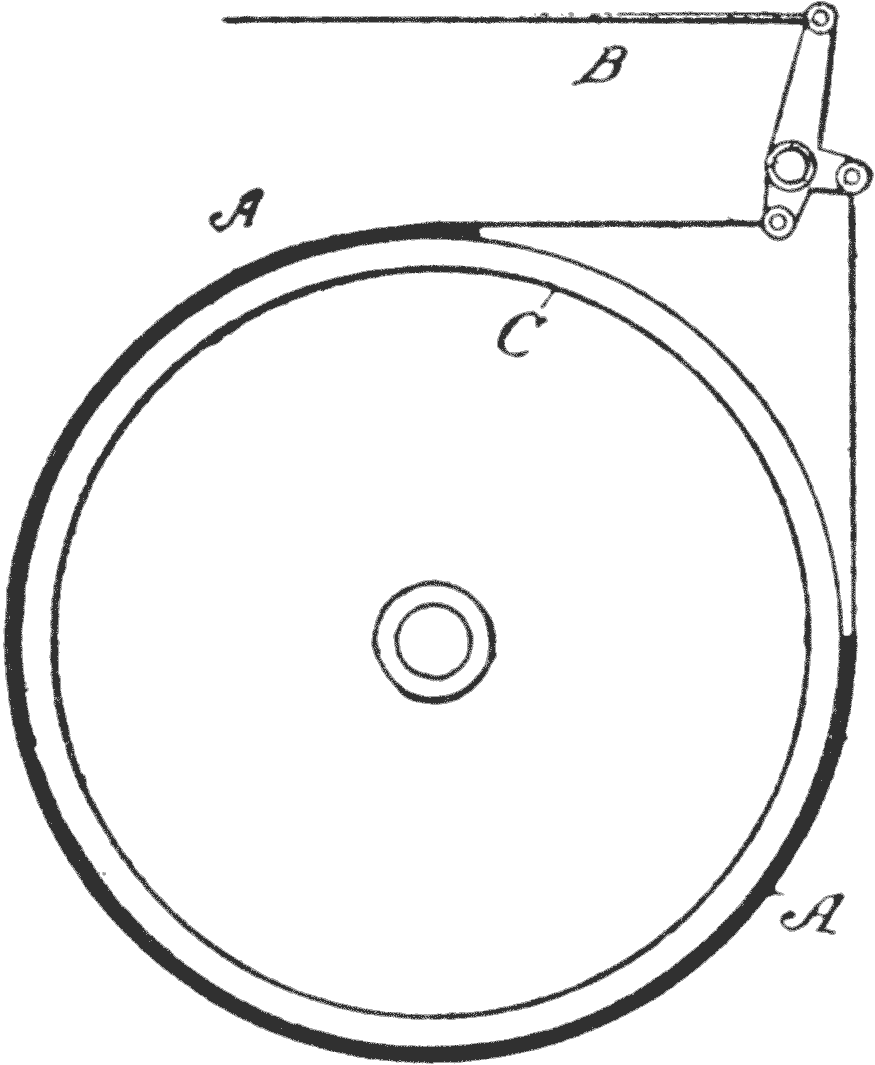
Double-Acting Contracting Brake.—Fig. 23
shows the manner in which a double-acting contracting
brake operates. As the band A, has a
tension on each end, when the rod B, is drawn forwardly,
it is immaterial which way the brake drum
C travels.
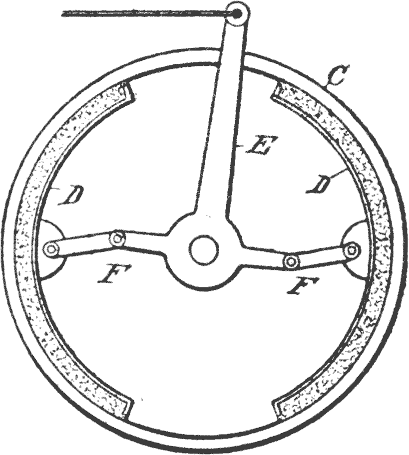
In Fig. 24 the drum C has a pair of oppositely-disposed
shoes D, which are held in such a position
that they are not revoluble, and may be moved
outwardly by the lever E and links F.
These figures, of course, show merely the simple
forms of the two types, and do not go into the refinements
of construction which make them so effective
in service.
It is obvious, however, that the power exerted
through either type of brake, depends on the leverage
afforded by the relative lengths of the limbs
of the bell-crank lever E, to each other.
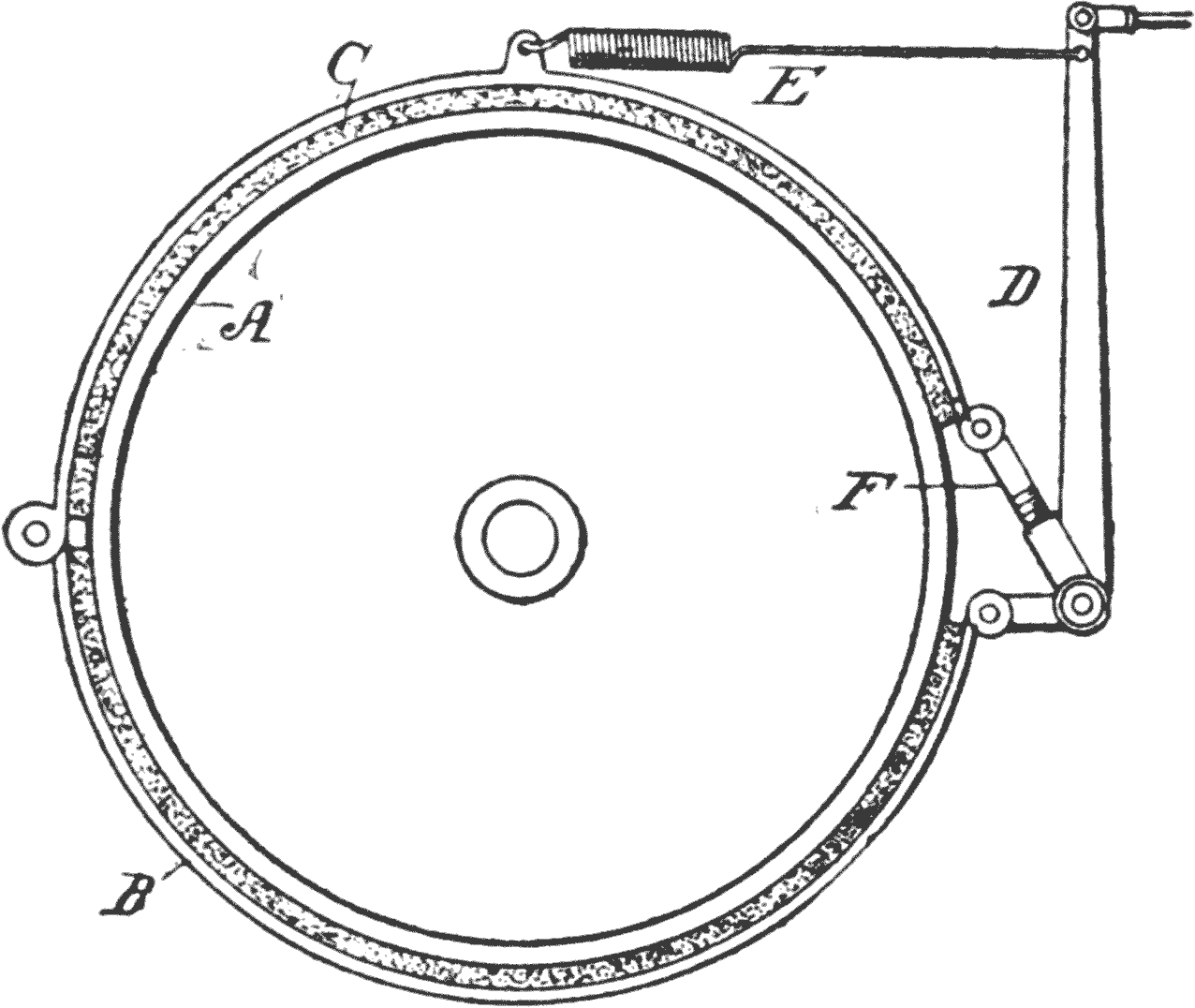
Contracting Brake.—Fig. 25 shows a well-known
type of contraction brake, in which the
cylinder A, has thereon two brake bands B C,
hinged together at their rear ends. At their front
ends they are connected with a bell-crank lever
D, the forward movement of the upper end of the
lever being such as to cause the bands to pinch the
drum A.
A contractile spring E draws back the lever
when the foot releases the pedal, and the link F,
between the bell-crank lever and the upper band
C, has a turnbuckle arrangement to provide for
taking up in case of wear.
The brake bands have means for automatically
holding them clear of the wheels when not in use.
Fig. 25. Contract Mechanism.
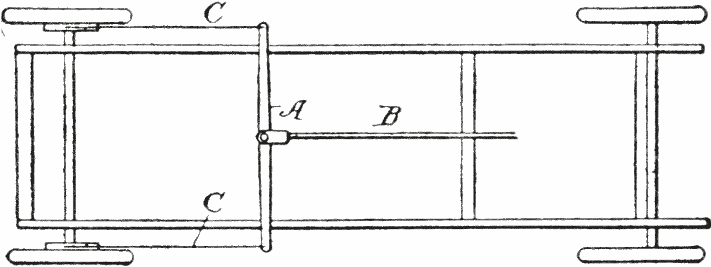
Equalizers.—Sometimes the brake is placed on
the propeller shaft; but when one of the brakes
is placed on each wheel, an equalizing bar, or other
means, must be used. One form of this is shown
in Fig. 26, in which A is the bar, B the rod which
goes to the brake lever, and C C, the rods that run
back to the brakes on the wheels.
Naturally, the equalizer will not act with the
same effect on both wheels, unless they are in the
same condition. Frequently one of the brake
cylinders will be dry and the other coated with
grease, or accumulate moisture from some source.
It is, therefore, a necessary part of inspection and
care to keep them in serviceable condition.
Fig. 26. Equalizer Bar.
The Emergency Brake.—The emergency brake
has a pawl which acts in the teeth of a segment
alongside of the lever, so it may be held in any
position to which the lever may be thrown. This
lever has no provision whereby the clutch is disengaged
when the brake is applied, for the reason
that should it become necessary to stop a car going
up hill, and when the emergency brake is required,
the brakes would have to be released before
the clutch could be thrown in, so that the car
would be likely to start down hill before this
could be done. On this account the emergency
brake has no connection with the clutch.
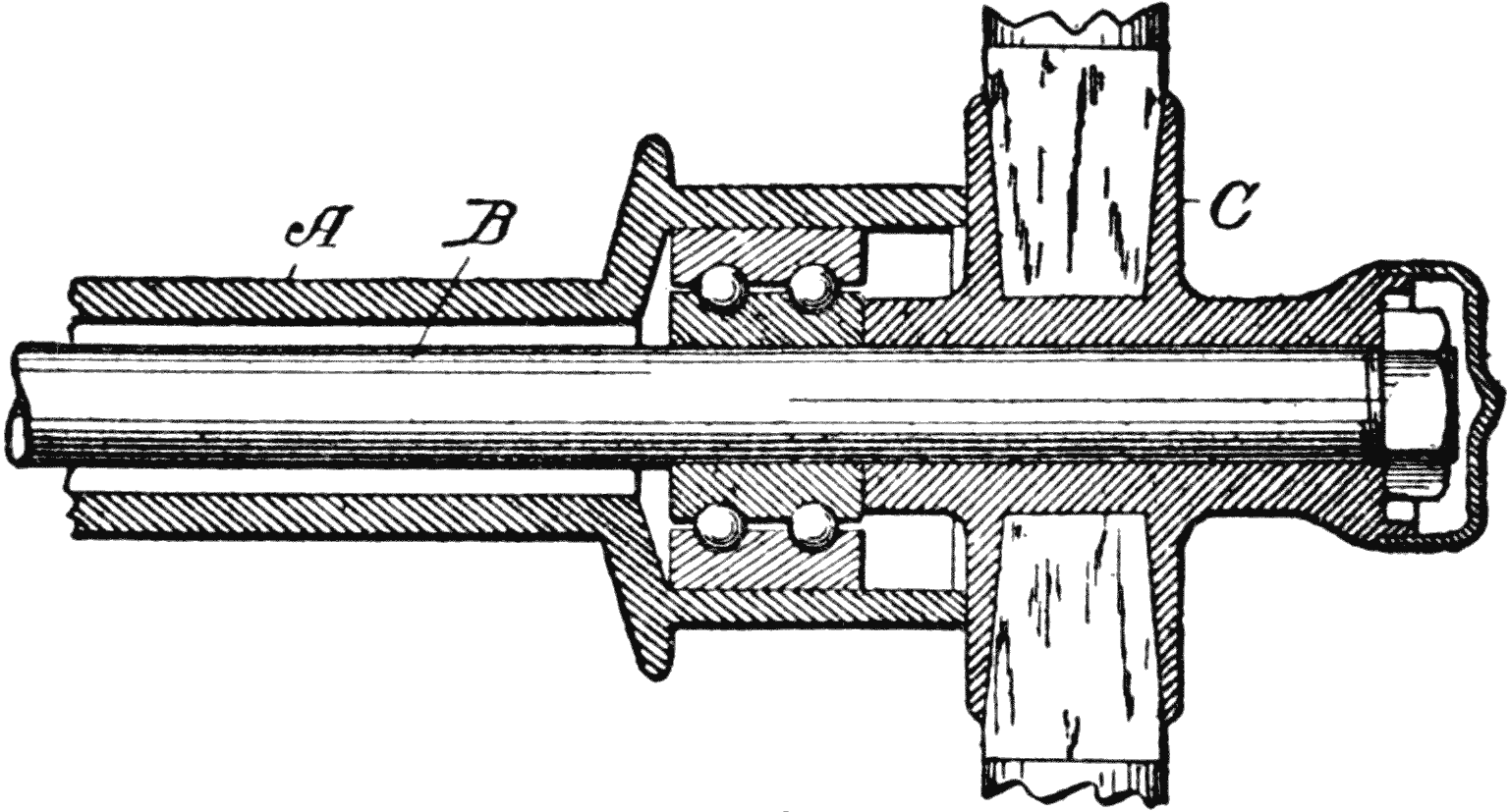
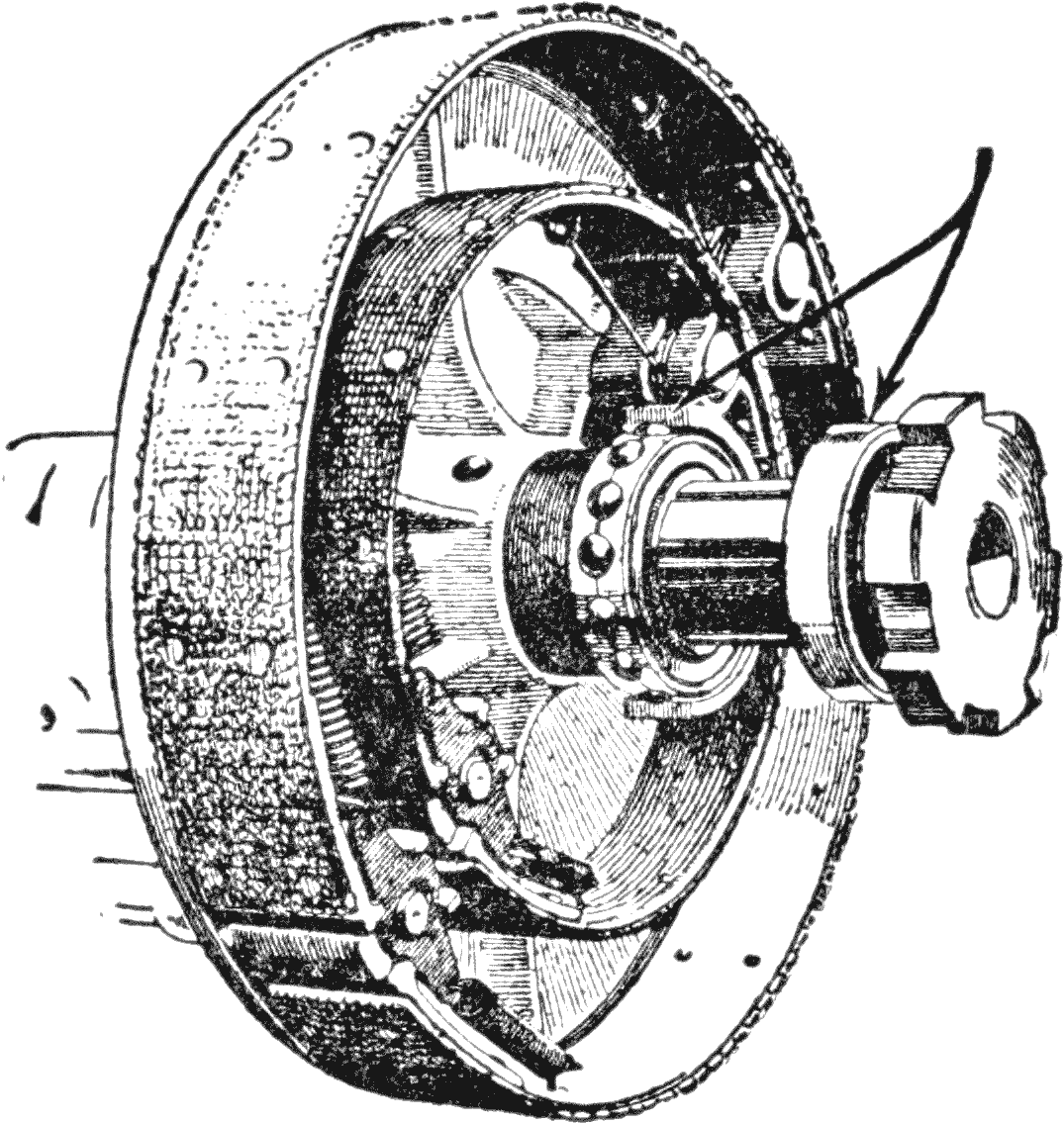
Fig. 27. Rear axle. Service and Emergency Brake.
Combined Service and Emergency Brake.—Fig. 27
represents a standard type of service and
emergency brake, each of the internal expanding
type. As both are inclosed in a drum they
are absolutely free from dirt and dust, and the
construction shown eliminates rattling of the
parts.
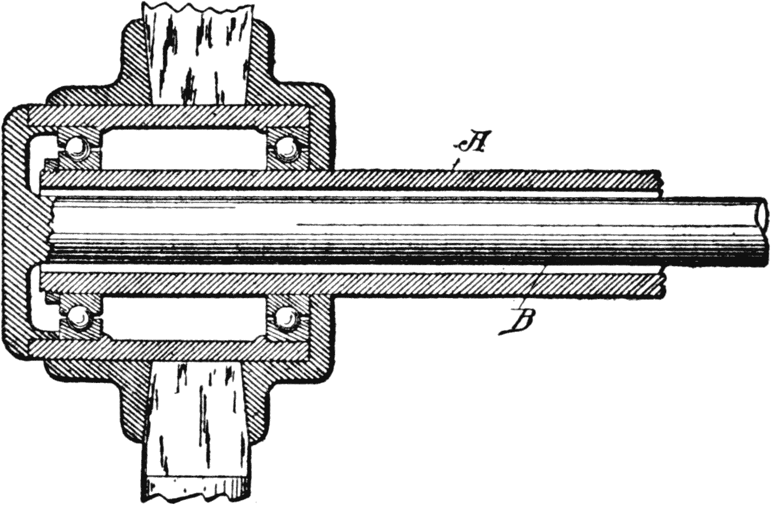
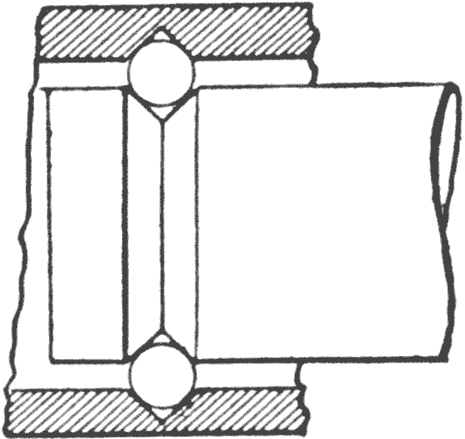
The wheel bearing is also represented by the
annular ball-bearing type of construction, in
which the balls are unusually large, and therefore,
capable of taking great weight and high speed
without undue wear.
CHAPTER V THE DIFFERENTIAL
The Meaning of Differential.—This is a term
used to designate the difference in the turning
movement of two wheels on opposite ends of an
axle. For various reasons they do not turn at
the same rate of speed, particularly in turning
corners, where the outer wheel must travel a
greater distance than the inner wheel.
If both wheels are fixed to the shaft the latter
would be submitted to a torque, or one of the
wheels would slip, and thus be destructive of
tires.
On the other hand, if one wheel should be loose,
then, as power is applied to the shaft, the tractive
action would be on one wheel only, and this would
be bad practice, and frequently cause the wheel
to slip, and thus unduly increase the wear of the
tire.
The differential is made up of a system of gears,
which are so arranged that one wheel may turn
independently of the other, and at the same time
the effective driving power is utilized by each.
Various forms of this mechanism have been developed.
While the differential is an exceedingly
simple piece of mechanism, it is not such an easy
matter to describe its operation, so that the principle
will be explained by a series of illustrations.
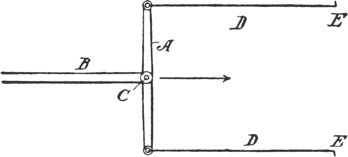
Equalizer Bar.—Examine Fig. 28. Let A be
an equalizer bar, mounted on the end of a thrust
bar B, by a pivot C, so the ends will swing back
and forth freely. A horizontal bar D is hinged at
each end of the equalizer, which bars project forwardly
parallel with each other and these are provided
with right-angled bends E E, simply for
convenience in describing the operation.
Fig. 28. Equalizing Mechanism.Fig. 29. Resistance in Equalization.
While differential gears are very simple structurally,
it is not an easy matter to explain the
principle on which a faster motion is transmitted
to one wheel than another, and under conditions
where the speed is constantly changing.
Fig. 30. Equalizer and Differential Movements.
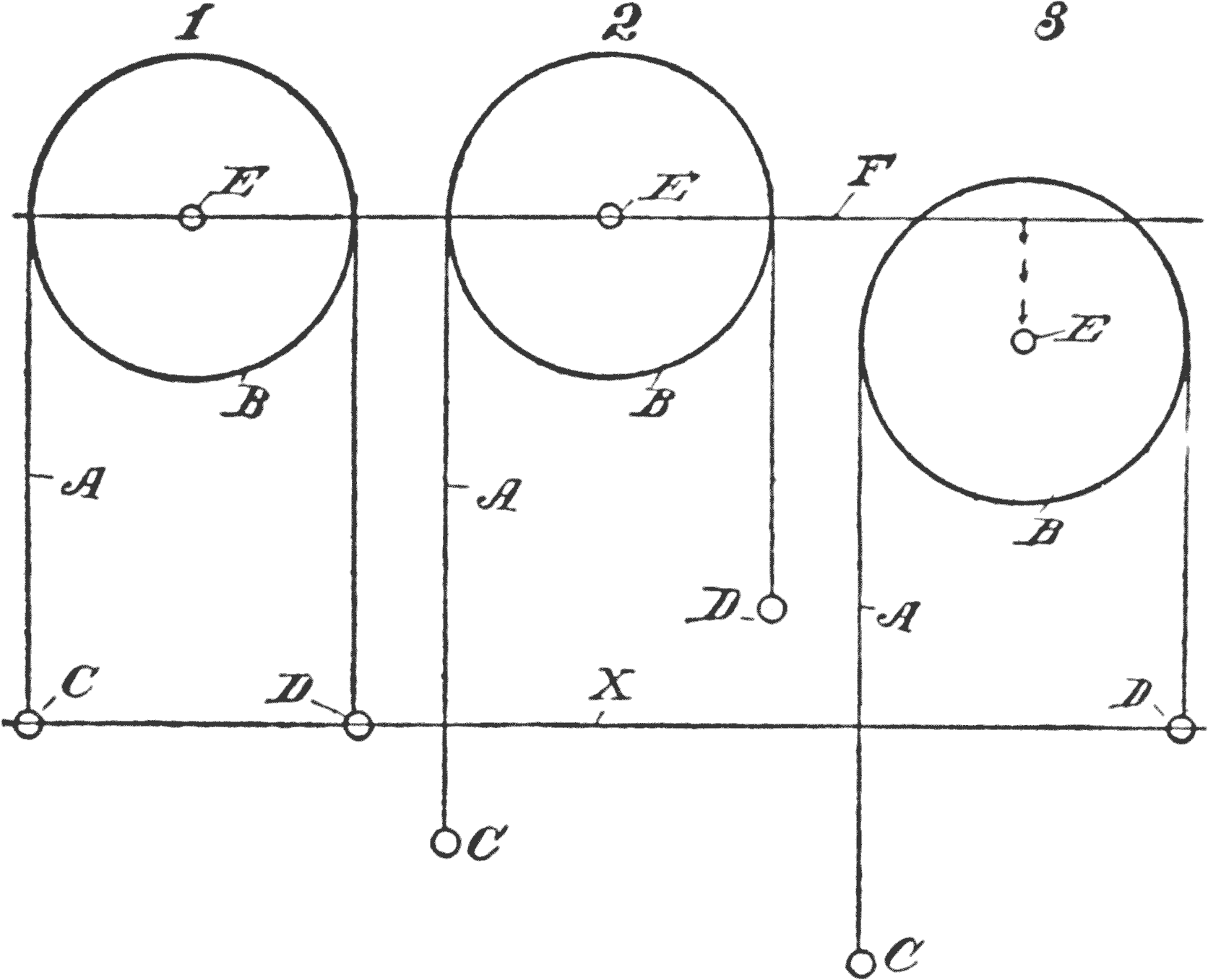
For instance, in Fig. 30, a cord A, over a pulley
B, has weights C, D, at its ends. If the pivot
or fulcrum E, of the wheel, is stationary, as in
sketch 1, and the wheel is turned, say a quarter
of the way around, one weight will move down
below the line X the same distance that the other
weight moves above it, as shown in 2.
Thus far we have an equalizer, pure and simple.
But a differential requires something more. It
is necessary, under certain conditions, for the
weight D to move a greater distance in the same
time than C, or the reverse. Or, as sometimes
happens, one of the weights, as for instance, in
3, remains fixed while the other moves.
In this case, with the pivot pin E fixed, such
a thing would be impossible, hence, in order to
make such a relative movement between the two
weights, the pin must move, and this motion is
shown in 3, where it moves down from the line F.
That movement, or change of position of the pivot
E, is what takes place in the small intermediate
gears in a train of differential gearing.
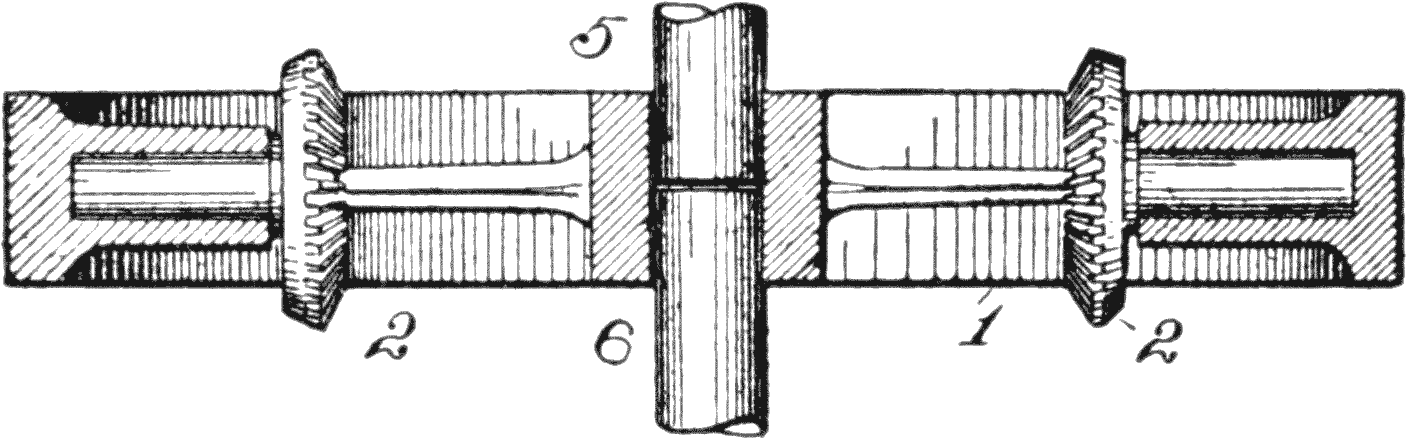
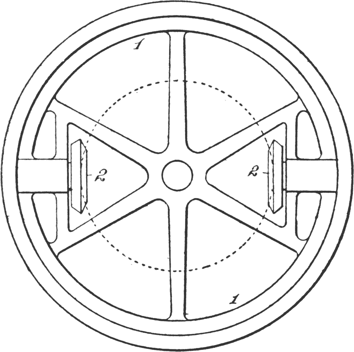
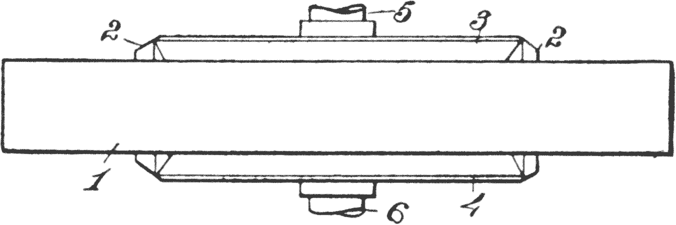
Transmission Wheel.—In Fig. 32 is shown a
section of the differential housing, 1, in which,
for convenience, all refinements of construction
are eliminated. This shows the divided axle
shafts 5, 6. In Fig. 33 is shown a side view of the
same housing. This may be connected with the
motor shaft by means of bevel gears, or driven by
a sprocket chain. In either case the housing 1 is
the substitute for the thrust bar B, in Fig. 28, and
the bevel pinions 2, which are mounted within the
wheel 1, represent the equalizer bar of that figure.
Fig. 31. Differential in Housing.
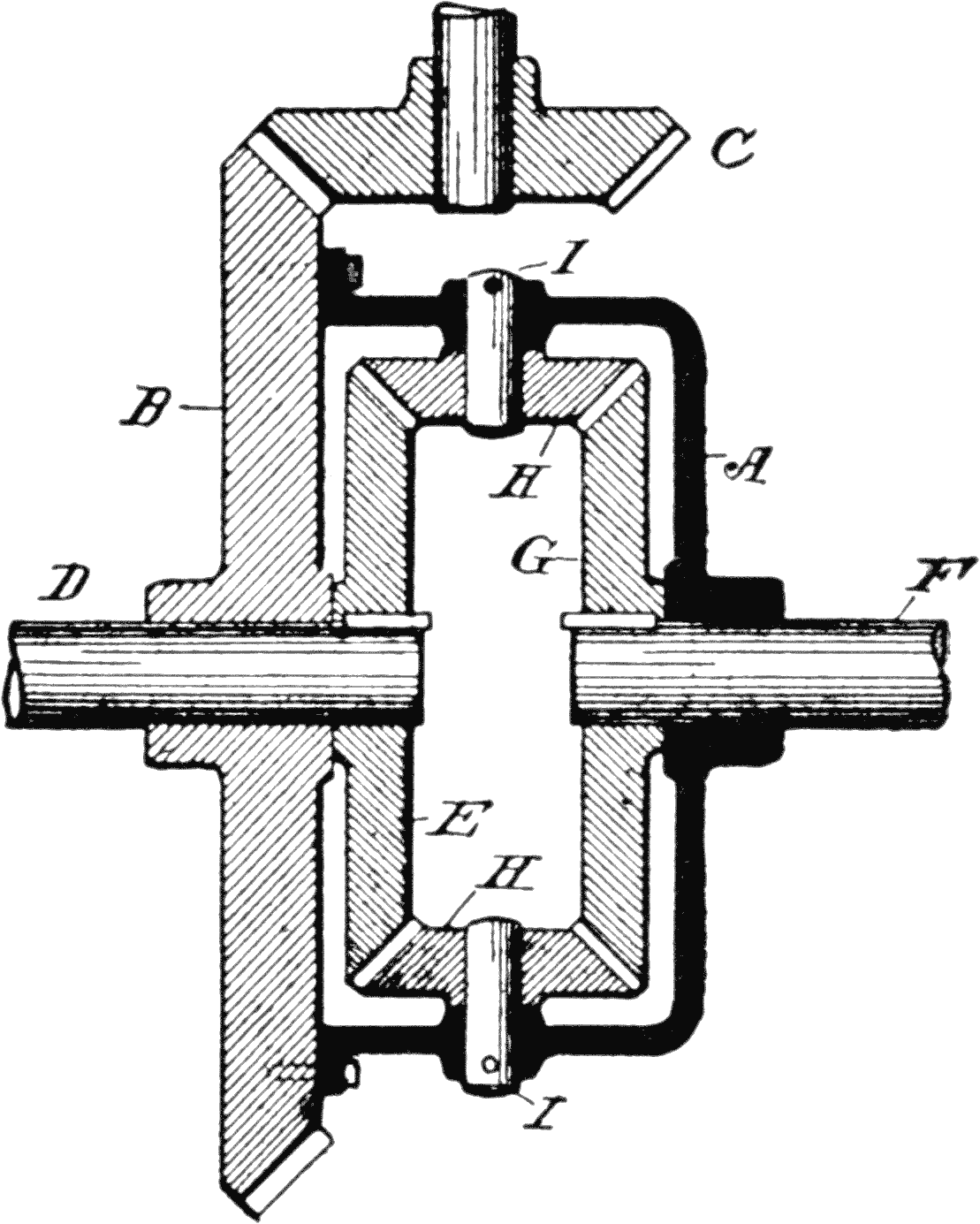
The gears which make up the train are usually
put into a suitable casing, as illustrated in Fig.
31, which gives a good example of the construction.
The housing A is fixed to the side of a
large bevel gear B, this gear being designed to
receive power from the motor through a bevel
pinion C. One part of the axle D passes through
the gear B, and is fixed to a bevel gear E within
the housing, and the other part of the axle F
passes through the housing and is fixed to a bevel
gear G, the same size as gear E.
Intermediate the two gears is a pair of bevel
pinions H, H, and these latter are mounted on
pivots I, I, projecting inwardly from the housing.
The fact that the pinions are attached to housing
has the effect of complicating the matter, so
that it may be well to show the relative arrangement
of the gears without the housing.
Fig. 32. Section of Differential.Fig. 33. Side View of Differential Wheel.
In Fig. 34 we have added to Fig. 33, two bevel
gears 3, 4, which are mounted on the axles 5, 6,
these representing the rear drive axles of the
car.
Action of Transmission Gearing.—From the
foregoing it will be seen that the axles abut each
other, within the hub of the large gear 1, within
which they are journaled. We might, therefore,
call these pinions the counterparts of the bars E E.
Fig. 34. Top View of Differential Wheel.
As long as the resistance to the turning movements
of the pinions 3, 4 is the same, the housing
through pinions 2, 2, will simply carry the bevel
gears 3, 4 around with it, without turning them,
just the same as the equalizer bar B was moved
forward without either end swinging back or
forth; but the moment the wheel of the shaft 5,
for instance, is compelled to travel at a higher
rate of speed, or the wheel on shaft 6 meets with a
greater resistance, the small equalizing gears 2
will turn, and the revoluble motion of the housing
1, while transmitting the power, and also carrying
the gears, will act, in effect, the same as the push
bar shown in the previous illustration.
Like the equalizing bar, the effect is to turn one
wheel, say 3, with less, and the other wheel 4 with
more than the normal power or speed.
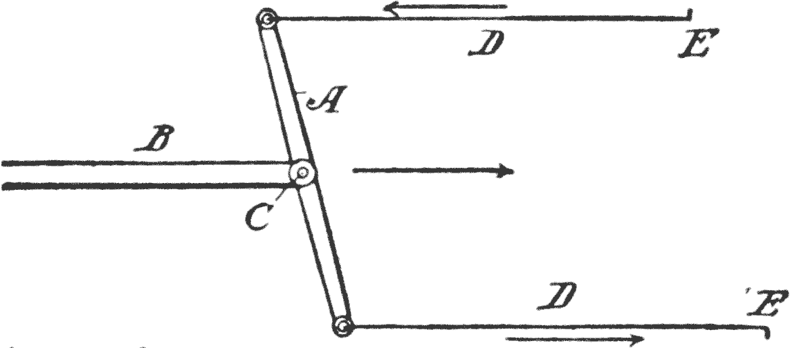
Fig. 28 shows the principle on which all differential
automobile gearing is based, that is, that
both wheels receive half of the driving power even
if one wheel should turn faster, as shown at Fig.
29, which is the case when turning a corner.
This is what causes the power to drive both wheels
at all times, whether going straight or on a turn.
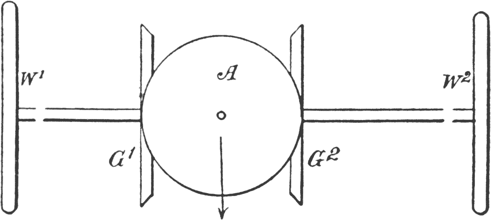
Fig. 34a. Differential Gears.
If, however, one wheel gets on slippery ground,
then A, Fig. 29, will move forward, without pulling
on the lower end. As the lever A has the
same action as the pinion in a differential, shown
in Fig. 34a, it will be seen that if the pinion center
is moved in the direction of the arrow, and if the
wheel W1 slips, the pinion will simply roll on the
bevel gear G2 without driving it on the wheel W2.
This is the disagreeable characteristic of a differential,
that makes one wheel spin when it
touches a slippery spot on the road, and stalls the
car, because the other wheels cannot get any driving
power.
CHAPTER VI THE DRIVE
The term used to designate the transmission
of power from the engine to the wheels, is called
the drive.
In nearly all cars the engine shaft runs fore and
aft, and consequently is at right angles to the
axles. This, of course, necessitates some sort of
gearing between the engine shaft and axle. This
change is made in the bevel gear drive hereafter
explained.
As the engine is mounted on the frame of the
car, which rests on springs, and the axle is below
the springs, it is obvious that the drive must be
transmitted between two parts which have a relative
up and down movement.
This necessitates several things, structurally,
which should be considered.
First. A flexible joint must be interposed in
the system, where a shaft is used to transmit the
power.
Second. Torsion rods are necessary to prevent
the housing or casing of the rear axle from
turning, due to reaction of the driving bevel gear.
Third. A rod, or rods, are required to prevent
a fore and aft movement of the rear axle. The
rods run from the ends of the rear axle housing to
some convenient point on the frame.
Illustrating Power Transmission.—For convenience,
these mechanical elements are illustrated
on a frame.
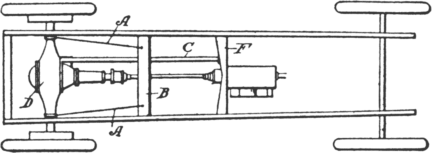
Fig. 35. Radius Rods.
Fig. 35 shows a frame which has its rear axle
provided with a pair of radius rods A A. These
have their rear ends attached, in any suitable
manner, to the axle housing, near the springs and
the forward ends are brought forward and pivoted
to the cross beam B.
Torsion Rod.—These rods thus take care of any
undue strain which takes place by the wheel striking
obstructions.
C represents the torsion rod which has its rear
end firmly secured to the housing D, and its forward
end to the cross piece E. This prevents the
housing from turning, and also serves to provide
against any undue thrust of the driving bevel.
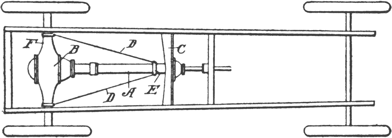
Some cars dispense with the torsion rod, by incasing
the shaft in a torsion tube. Such a form of
construction is shown in Fig. 36.
The torque tube A, as it is called, is rigidly secured
to the housing B, of the rear axle, the forward
end being pivoted to a cross piece C of the
frame.
Fig. 36. Torque Tube.
The radius rods D D, have their forward ends
attached to a sleeve E, located near the forward
end of the torque tube A, and the rear ends are secured
to the axle housing F at the spring seats.
Some manufacturers avoid the use of these
radius rods by such a construction in the springs
as will prevent any forward and rearward movement
of the axle.
Chain Drive.—The chain drive machines require
the radius rods, or some other means to
counteract the movement of the axle when it meets
an obstruction, particularly where the chain
transmits the power to the differential on the
wheel shaft.
Jackshaft.—With the double chain drive no
differential is used on the axle, but, instead
thereof, it is placed on the jackshaft which carries
the small driving sprocket wheels. The chain
transmits the power direct to each wheel, and a
radius rod is necessary to hold the shaft of the
drive sprocket wheel the proper distance from the
rear axle.
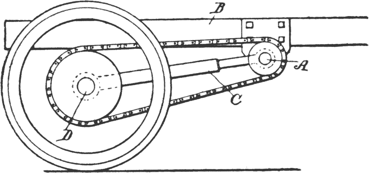
Fig. 37. Chain Drive.
Such an arrangement is shown in Fig. 37, in
which the drive, or jackshaft A is mounted transversely
across the vertically-movable frame B,
and the torque bar C, therefore, serves as the
means for keeping the jackshaft and the axle
D the proper distance apart, and it is also arranged
to serve as a radius rod to prevent any
undue tension on the chain when a wheel strikes
an obstruction.
The wheels of such a truck turn freely on the
axle stubs of a dead axle.
Objections to Chains.—Few pleasure cars are
now equipped in this manner, as the shaft drive
is more desirable for several reasons: The use
of chains is always objectionable, as the efficiency
decreases with wear quicker than the shaft drive,
and requires the jackshaft, sprocket chains and
sprocket wheels, besides the noise and excessive
wear, by stretching of chains, which are always inherent
in the use of chains.
It is impossible to prevent dirt, sand and grit
from adhering to the chains, unless they are inclosed,
a thing which is difficult and expensive.
If they are not so protected the lubricant only
serves to catch the grit and retain it, so that when
it is carried around by the chain, the wheel and
chain are both worn out.
Another difficulty in the use of chains is due to
the inability to keep them at a proper tension at
all times. All chains will stretch in use, consequently
the tension will change, and when wear
takes place, the distance of the centers of driving
and driven sprockets has to be adjusted, calling
again for another mechanical complication.
Shaft Drive.—The shaft of the engine, being
on the frame, has a vertical movement, and the
axle, to which power is to be transmitted, is below.
The engine must be mounted so the shaft
inclines, or, be placed low enough, so that it will be
on a direct line with the rear shaft.
In either case some flexible means must be provided
between the engine shaft and axle on account
of the relative vertical motion between engine
and rear axle. The straight line drive is
most desirable, in every way, as the full power of
the engine is available, and this is usually arranged
for by lowering the engine bed sufficiently
so that the shaft will point straight to the axle
when the car is loaded.
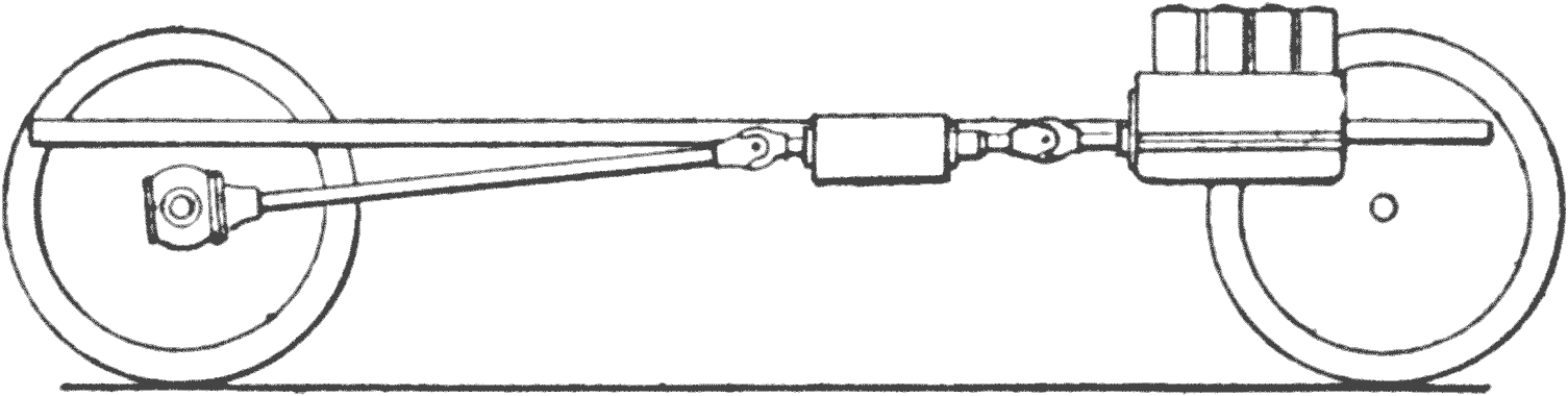
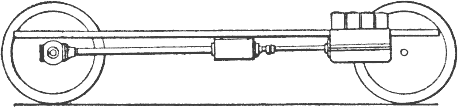
Fig. 38. Shaft Drive.Fig. 39. Straight Line Drive.
Train of Shafting.—Several lengths of shafting
are often interposed between the engine shaft
and axle, and some cars have two universal joints
in the shaft line, one mounted forward of the
transmission case and the other to the rear of it.
Or, more frequently, one in the rear of the transmission
and one in front of the rear axle.
It seems, however, to be the most general practice
to have a single universal joint directly behind
the gear case, and the shaft forward of the
case only slightly inclined.
Figs. 38 and 39, show the two types, the former
being the straight line drive, and the latter a form
of construction where the two universal joints
make the drive through a line which minimizes the
angles as much as possible between the shafts.
Figs. 38 and 39 are not intended to show all the
elements in the train of shafting, such as joints
and connections, but is merely designed to illustrate
the disposition of the drive shafting relative
to the engine and rear axle.
CHAPTER VII CLUTCHES
Clutches are essential in all gasoline cars, for
the reason that the driving power of the motor
must be frequently disconnected from the running
gear.
These devices are designed to transmit motion
from the engine to the transmission shaft, so that
when the clutch is engaged the transmission shaft
will turn with the engine shaft.
Clutch Requirements.—The first requisite of
a clutch is its ability to firmly hold the two shafts
together; the second is, that it may be engaged
gradually, and not suddenly; third, that it must
disconnect instantaneously; and, fourth, that the
force required to hold the two parts of the clutch
together must not produce an end thrust on either
shaft.
These requirements must be met by a condition
that the act of engaging the clutch will not necessitate
a long movement of the foot pedal which sets
the clutch. Other considerations must be taken
into account, also, and that is facility for examining
and repairing, easy removal of worn or broken
parts, and capability of adjustment as the contact
surfaces wear.
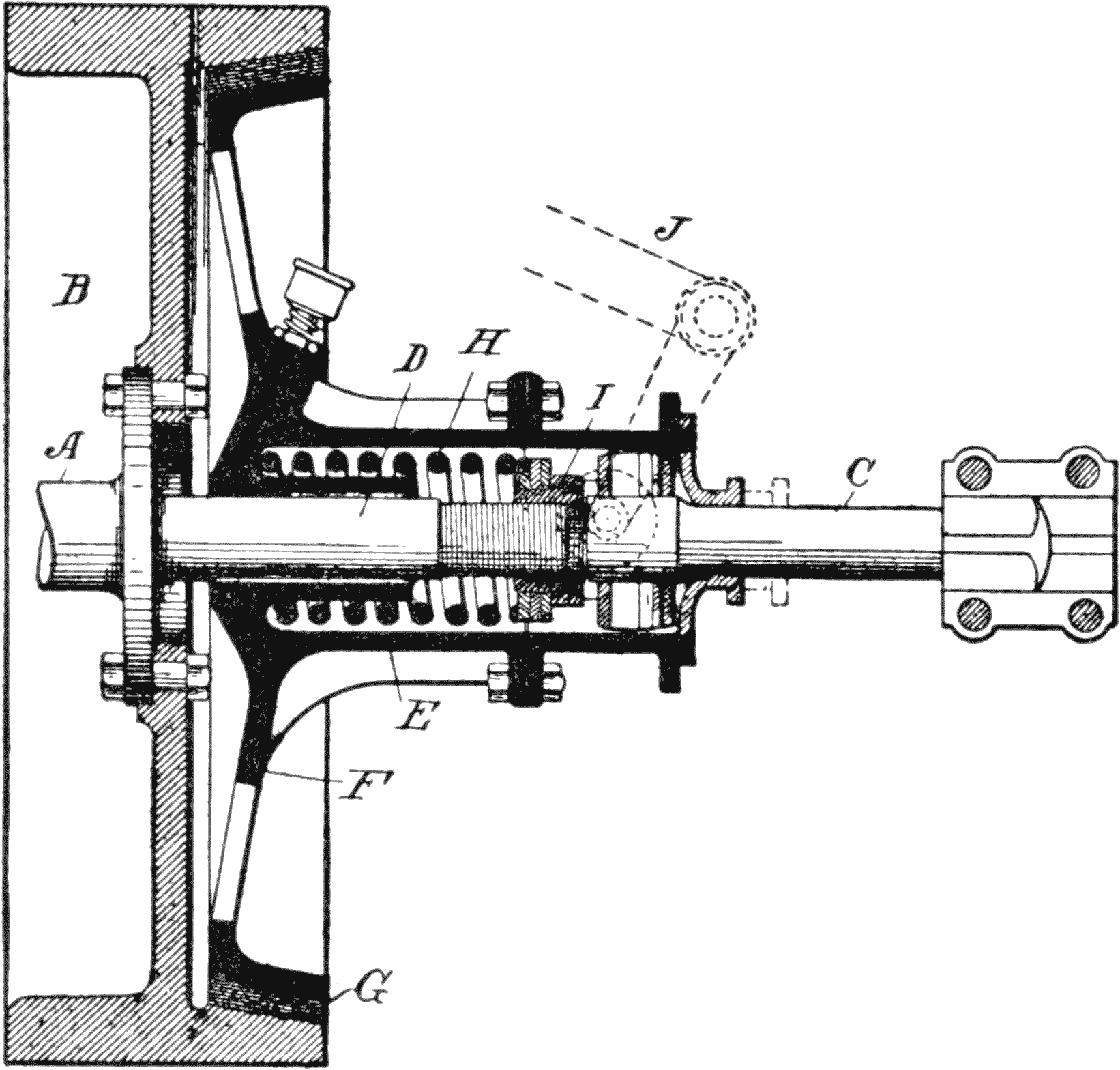
Fig. 40. Cone Clutch.
It will be seen, therefore, that there are many
elements necessary to provide a satisfactory
clutch, well adapted for all purposes, and all these
factors must be considered and understood by the
boy who would be well informed.
Frictional Contact.—In any form of automobile
clutches, there must be a frictional contact,
which means wear, whatever may be the character
of the material employed for the surfaces which
are in engagement. As a result, clutches are now
made which will permit the use of oil. Others dispense
with it entirely.
Each type has its advantages. The cone
clutches usually do not use a lubricant. This is
described in the diagram, Fig. 40.
Cone Clutch.—In the drawing A represents
the engine shaft, which has a fly wheel B, and C
is the transmission shaft. The engine shaft has a
short projecting stem D, which abuts the end of
the transmission shaft C.
A hollow hub E is loosely journaled on the
stem D, and is of sufficient length to extend
over and have a bearing on the transmission shaft
C, this latter being squared so it will turn with
the hub, or it may be provided with a feather to
work in a suitable groove in the hub, so that both
will turn together, while permitting the hub to
move longitudinally.
The inner end of the hub E has a web F, with a
conical bearing surface G, which engages with an
internal cone on the fly wheel.
Compression Spring in Clutches.—Within the
hollow hub E is a compression spring H, one end
of which rests against the inner end of the hub,
and the outer end contacts against a collar I,
which collar is screwed on the threaded end of the
stem D, and by means of which the pressure of
the spring may be regulated from time to time.
The normal action of the spring is to throw the
cone surface G, into engagement, as shown in the
diagram, and when the foot presses down the pedal
J, the hub is moved back against the tension of
the spring, and the clutch released.
It is obvious that if oil should find its way between
the cone surfaces the grip would be materially
lessened, and depending upon the kind of
materials used.
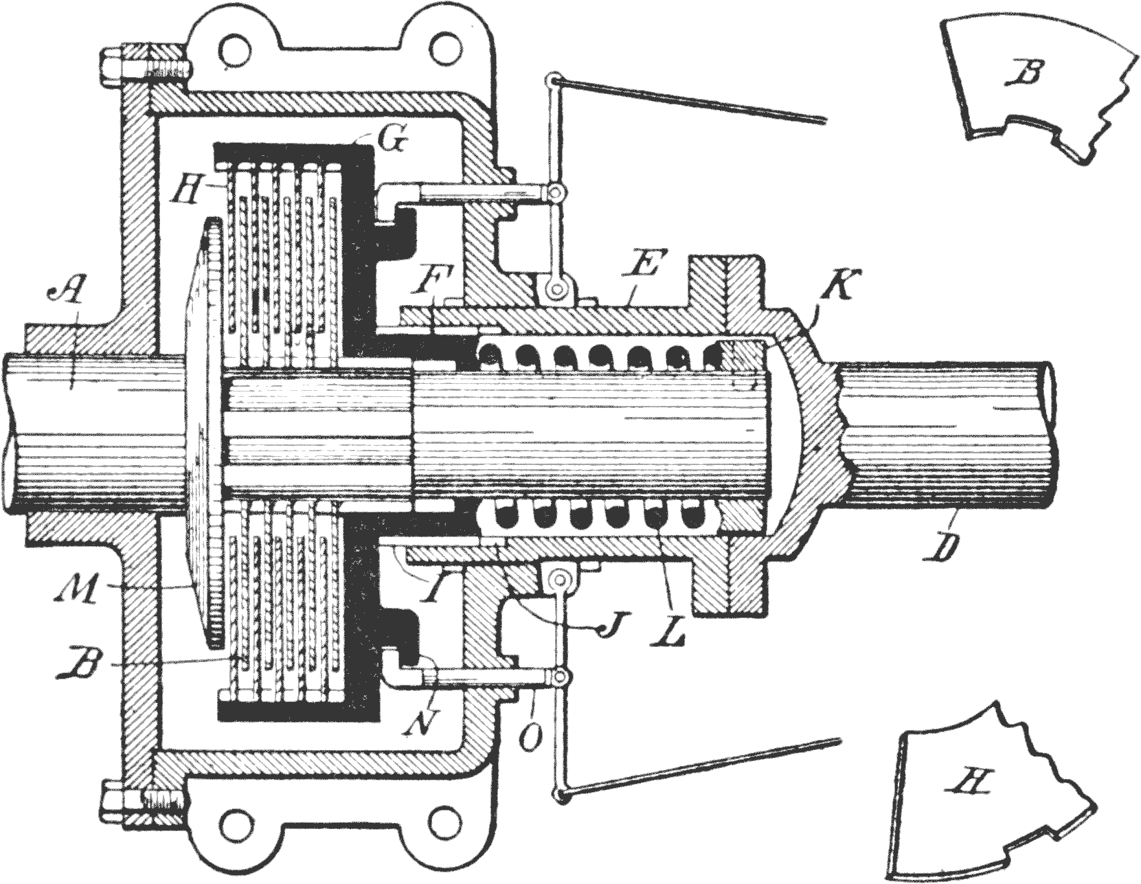
Fig. 41. Multiple Disk Clutch.
The Multiple Disk Clutch.—A type of clutch
which uses oil is shown in Fig. 41. The prominent
feature of the multiple disk is the large area
of contact surfaces available, and this, together
with the comparative freedom from wear, owing
to the lubricating material, makes it a favorite
structure, especially on account of its gradual engagement
which is not easily obtainable with a
cone clutch.
In the drawing, the transmission shaft A has
its ends reduced to receive thereon a set of disks
B. The shaft is ribbed along the surface where
the disks are located, and the disks B have cut-out
portions C, for the ribs, so that, while the
disks must turn with the shaft, they are free to
move longitudinally.
The end of the engine shaft D, has a tubular
housing E, to receive the end of the transmission
shaft A. The inner end of this housing embraces
the flange F, of a cylindrical shell G, this shell
having within a series of disks H, secured to the
shell so they will slide longitudinally, but turn
therewith, and these disks alternate with the disks
on the transmission shaft.
It will be observed that the flange F, of the
shell G, has a tongue I, which slides within a
groove J in the housing, so that the shell G, while
turning with the shaft D, may be moved longitudinally
on the shaft A, a limited distance.
The end of the shaft A, has a collar K, and
between this collar and the end of the flange F,
is an expansion spring L, so that the normal action
of the spring is to push the web of the shell
G, toward the disk head M, and thus force all the
disks together and produce the friction of a very
large surface.
In order to release the clutch, it is necessary to
draw back the shell G. The mechanical action is
merely shown, not the exact structural arrangement.
An annular flange N is formed on the
head of the shell, and a pair of hook-shaped bars
O, pass through the wall of the case, their outer
ends being actuated by the foot pedal, in any convenient
manner.
Disadvantages of Multiple-Disk Clutches.—These
clutches have also their weaknesses. Sometimes
they will grip too quickly, if the lubricating
oil is too thin, or if there is not enough of it; or,
if it becomes very thick and gummy, the disks
will not free themselves quickly, and the clutch
will drag.
Care of Multiple-Disks.—When such is the
case, it is better to take out all the lubricant, and
thoroughly clean off the disks, and put in a fresh
supply. If the case is kept properly closed, so
that the oils will not be wasted, and no dust can
enter, a light, thin oil, will last for a long time.
When the clutch slips, it is due to wear, or to
insufficient spring pressure, and a new adjustment
is necessary; and it is frequently the case that the
rod between the clutch and pedal must be taken
up, this being the case, usually, where there is any
wear in the clutch itself.
The disks are, usually, wholly of metal.
Among other materials, cork is used to face friction
surfaces of different clutch designs, and a
variety of materials are constantly added to the
list, which have good wearing qualities.
CHAPTER VIII TRANSMISSION, OR CHANGE SPEED GEARS
Owing to the peculiar character of Internal
Combustion Engines, there is always a certain
speed at which it will work more satisfactorily,
and with greater economy.
In this respect it is unlike the steam engine,
which has a much wider range of effectiveness.
Since all cars now use internal combustion motors,
and throttling is unsatisfactory, as a means of
controlling the engine, or changing the speed and
power, so as to use it economically, a mechanical
speed change system is essential.
This contains certain gears, which are designed
to change the speed of the transmission shaft relative
to the engine shaft.
Transmission Leverage.—It is simply using
leverage in order to produce a more effective
pull, or to attain greater speed, from a shaft
which runs at a certain number of revolutions.
If we have a motor with a shaft speed of, say,
800 revolutions per minute, and an axle with a
speed of 400 revolutions, the ratio would be 2 to 1.
Now, to speed up the machine, so that the axle will
turn 800 revolutions, would require an engine
speed of 1600, which might be impossible.
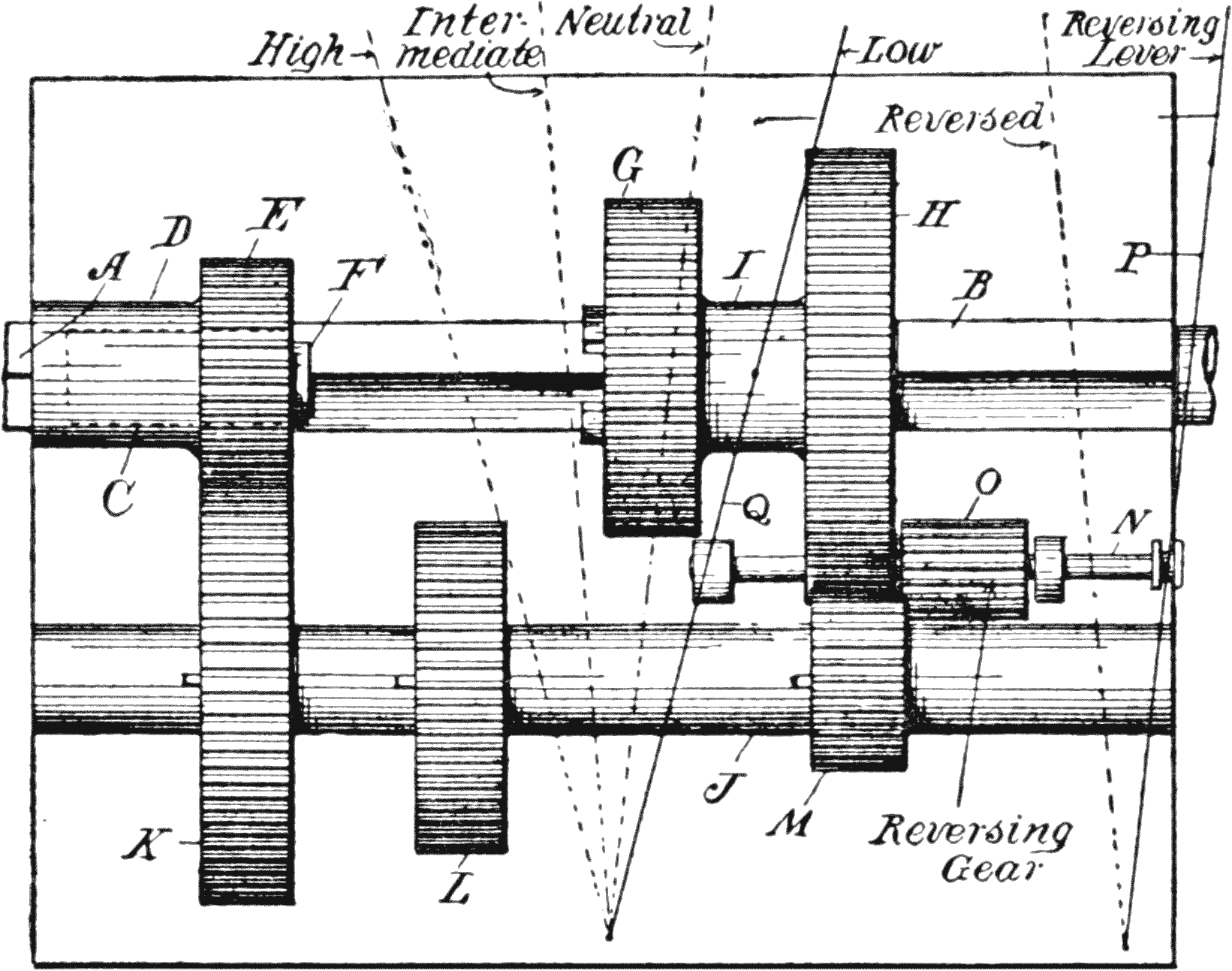
Fig. 42. Progressive Transmission. Low.
Economy of Transmission Gearing.—From an
economical standpoint, also, it would be undesirable,
even though the engine should be able to make
the speed.
Owing to the explosion impulses of the gasoline
motor, a heavy fly wheel is necessary on the engine
shaft, in order to store up power by momentum,
and also to give a uniform speed.
In hill climbing, or in carrying heavy loads,
the transmission shaft must have its speed cut
down, while permitting the engine to run at full or
normal speed.
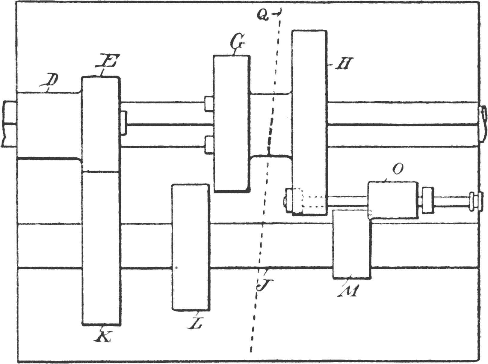
Fig. 43. Neutral Position.
The transmission gearing is, therefore, the most
satisfactory solution of the problem, because
changing the engine speed destroys its effectiveness,
and we shall, therefore, consider some of the
types for that purpose.
There are two distinct systems of transmission,
namely: The Positive, and the Frictional. Of
the positive system we have the planetary and the
sliding gear types. The sliding gear type has two
methods of control, one known as the progressive,
and the other the selective.
Characteristics of Transmission.—The progressive,
selective and planetary types, are entirely
different from the frictional system, for the reason
that they effect the changes by step movements,
the speeds being produced at certain
ratios, whereas the frictional method has indefinite
and infinite ratios.
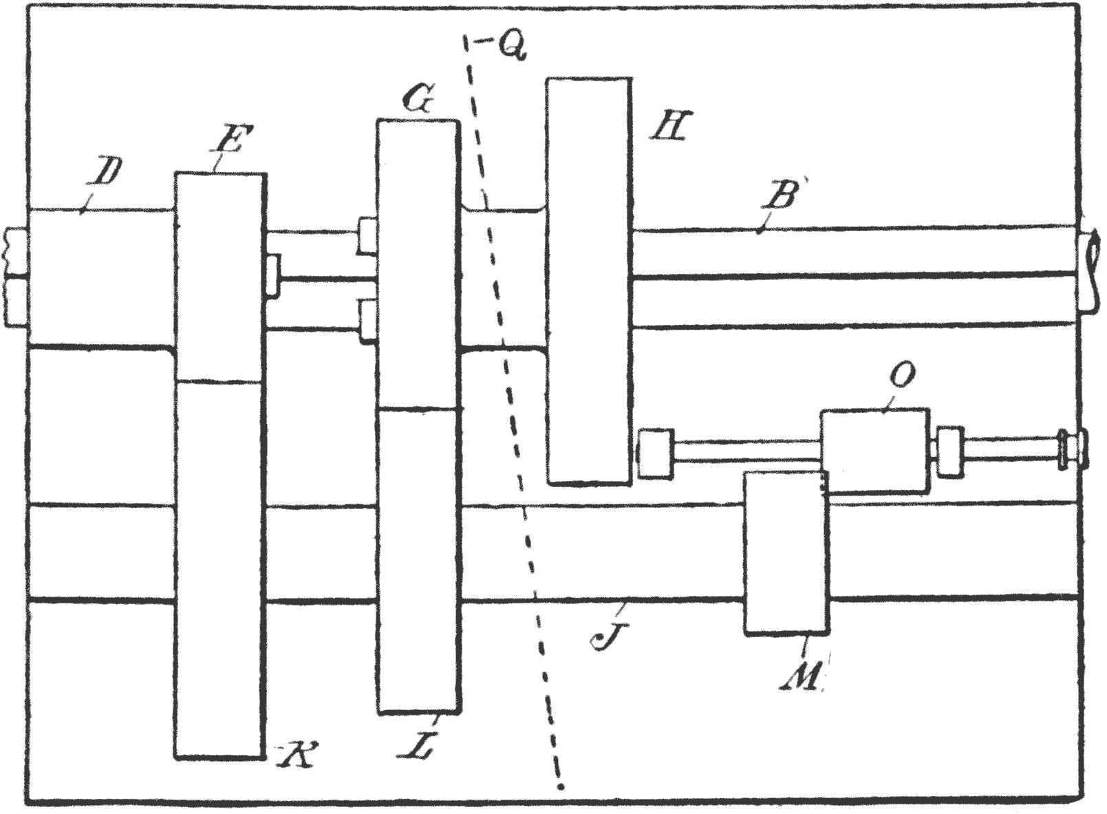
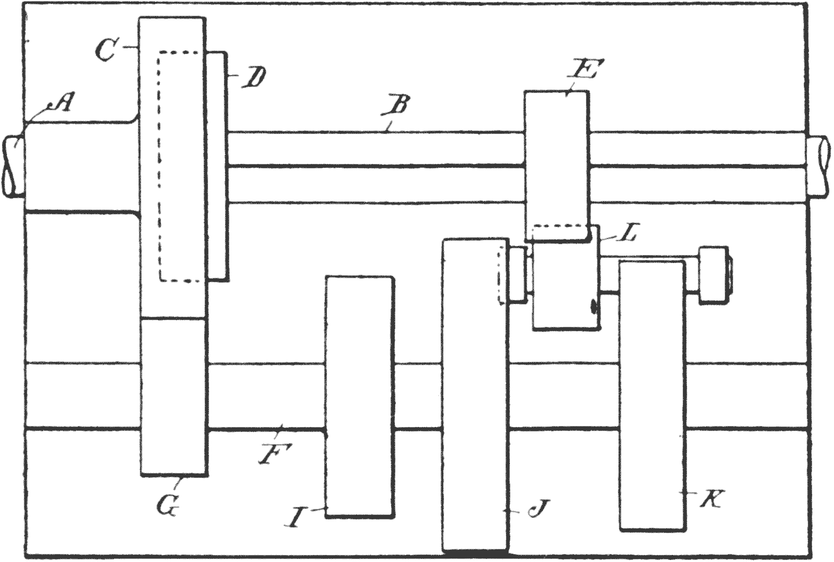
Fig. 44. Intermediate.
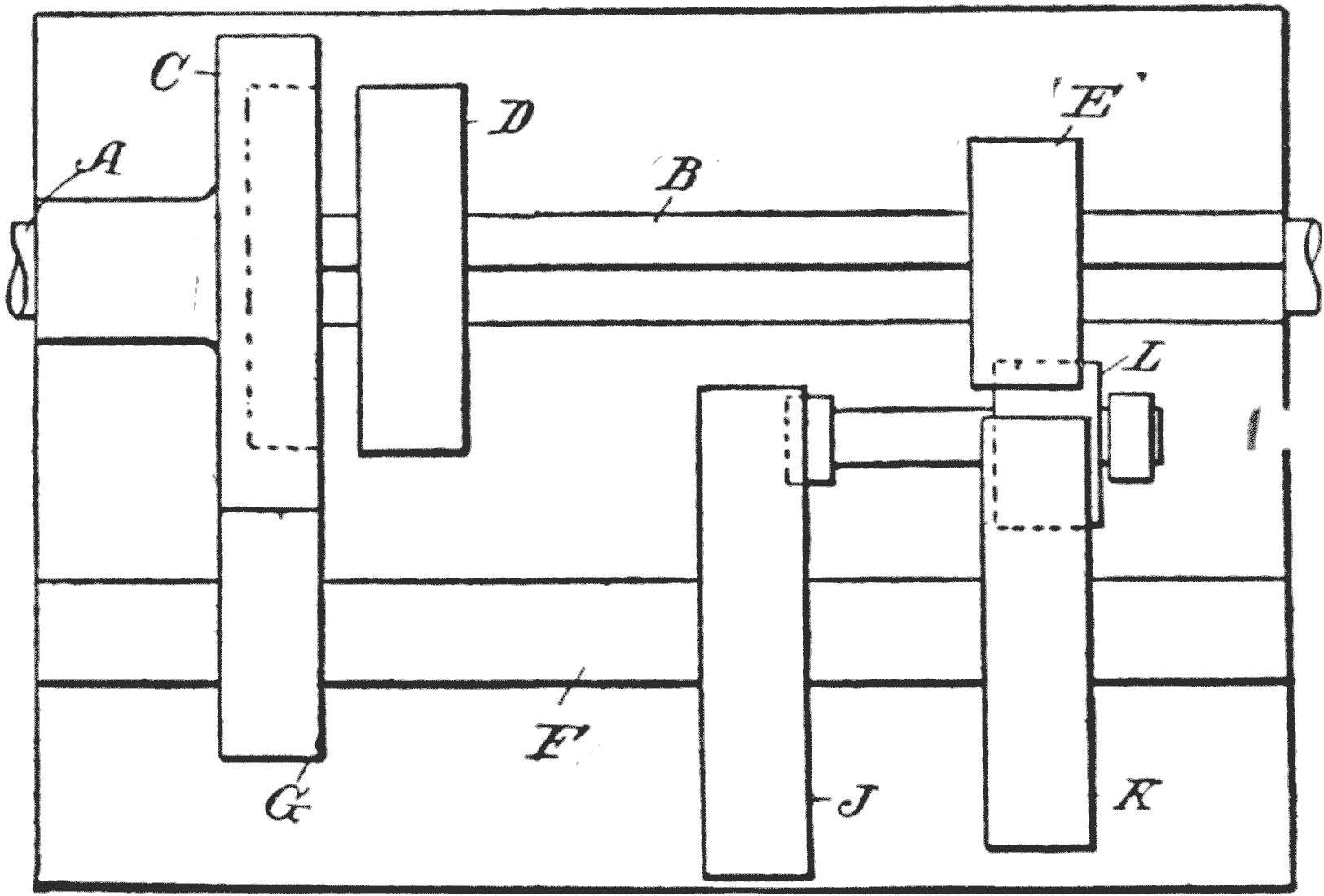
The following diagrams will clearly bring out
the distinctive features of each. Fig. 42 shows
a shaft A, which derives power from the engine,
having in line with it a shaft B, which connects
with the driven shaft. The shaft B is squared,
but it has a round end C, which is socketed axially
within the head of the shaft A.
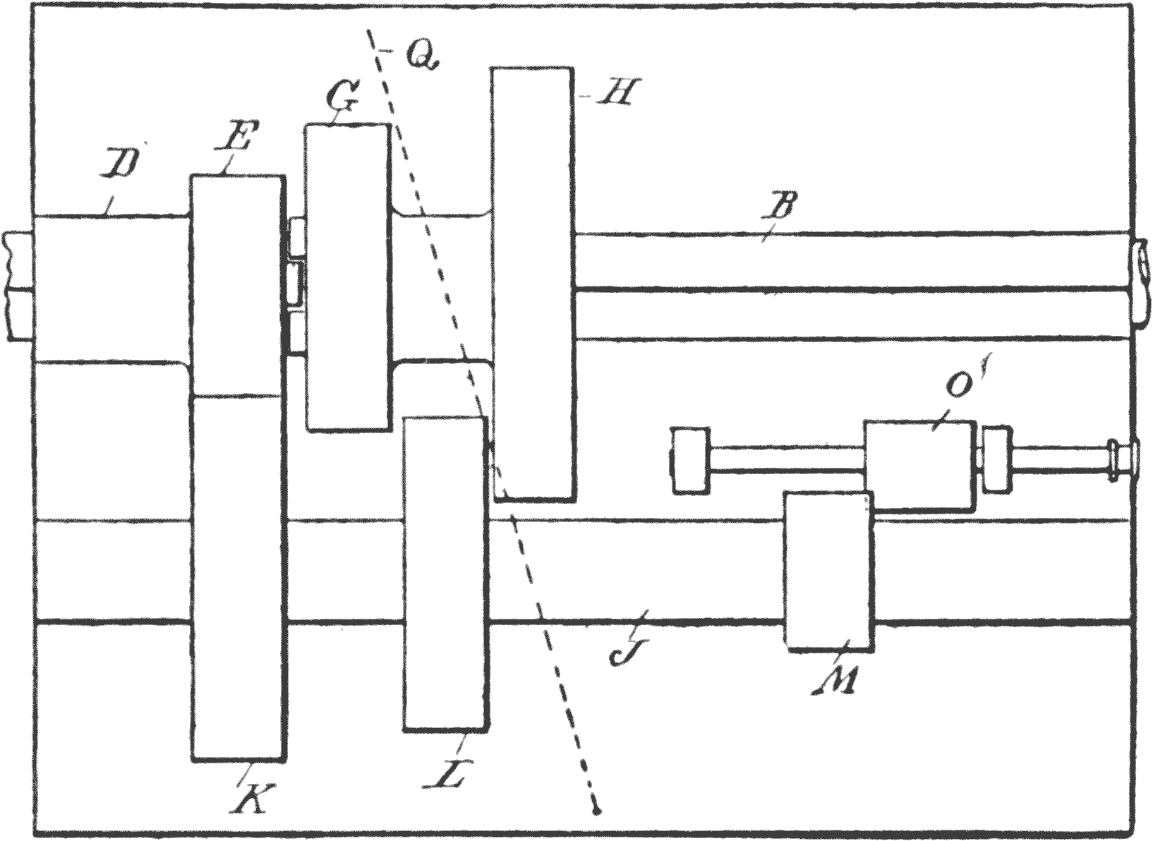
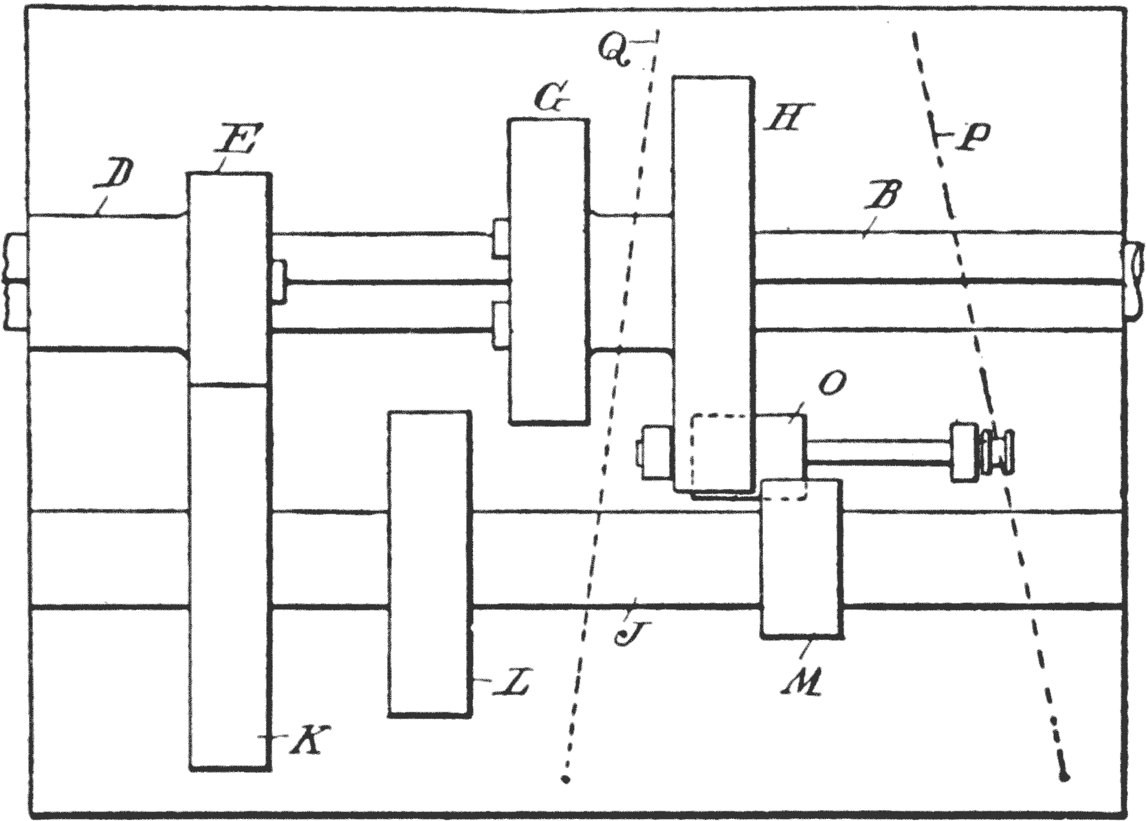
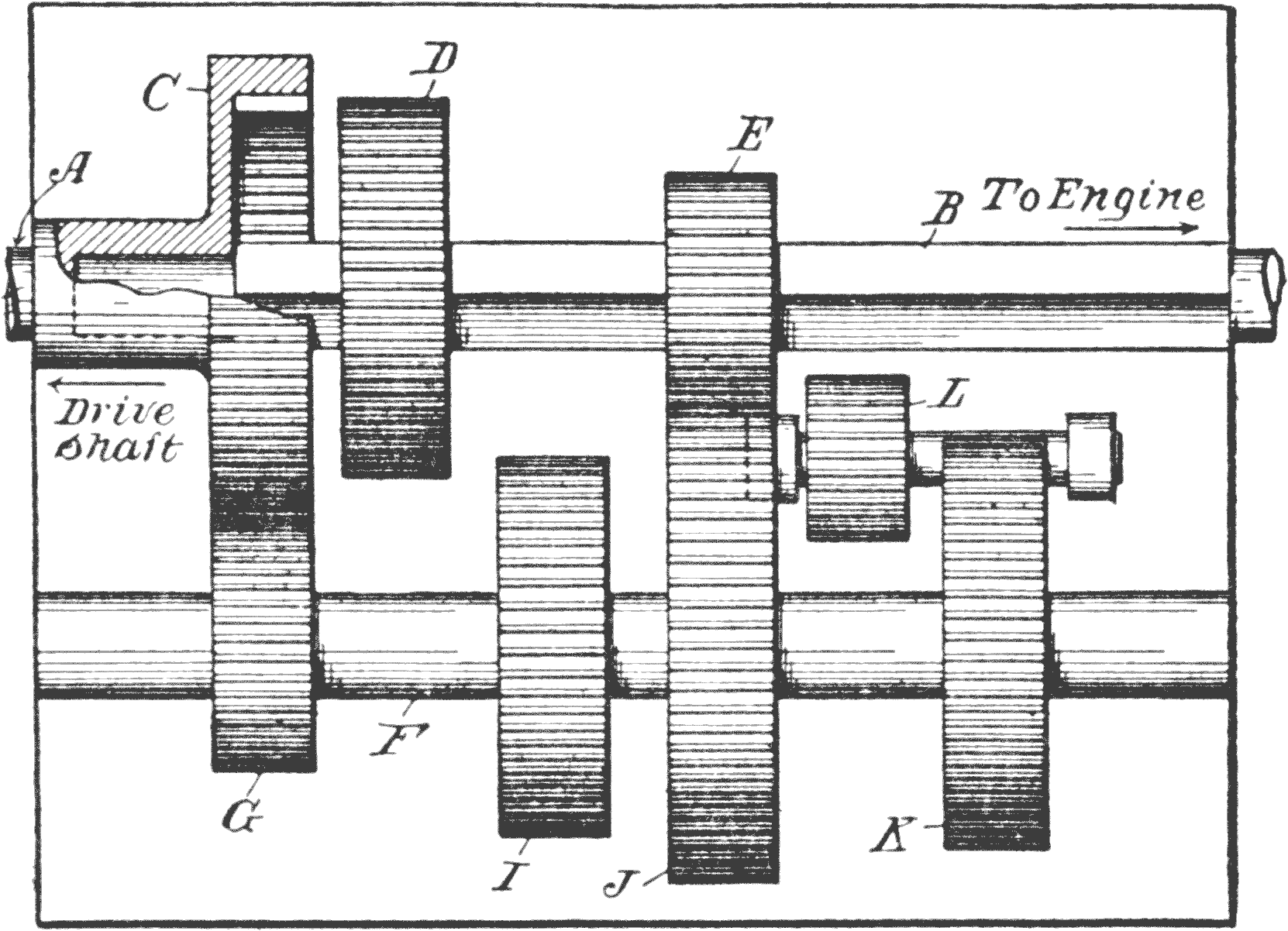
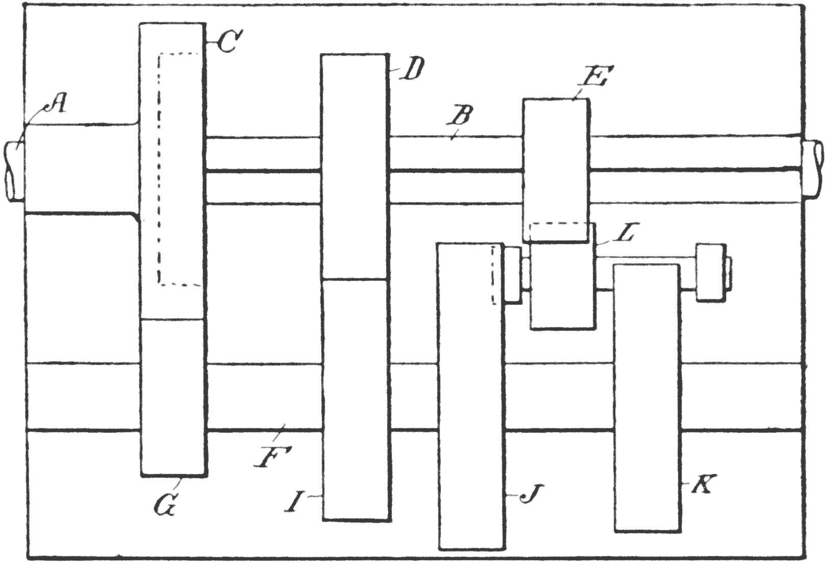
The Progressive.—The head D has a small
pinion E, and on its side is provided with projecting
teeth F. The loosely-revolving squared shaft
B has thereon a pair of spur gear G H, separated
from each other a trifle more than the width of
each gear, and they are united by an intermediate
hub so they turn in unison.
Fig. 45. High.
Below the shaft B, and parallel therewith, is a
shaft J, which carries a spur gear K, that is constantly
in mesh with the pinion E. To the right is
a smaller gear L, which is the same diameter as
the gear G, with which it is adapted to mesh; and
a small gear M, about one-third the diameter of
the gear H, is also mounted on the right-hand end
of the shaft, which meshes with the gear H, when
the latter is moved to the right on its shaft B.
Behind the two gears H, M, is a shaft N,
parallel with shaft J, which is so mounted that
it has a longitudinal movement, and this carries a
broad-faced pinion O, so that it is wide enough
to engage with both of the gears H, M, when they
are not in line, or in engagement with each other,
as shown in Fig. 44.
This latter shaft N, is moved longitudinally by
means of the reversing lever P. This lever, together
with the gear-shifting lever, hereafter explained,
are merely indicated in their present manner,
in order to show, diagrammatically, how the
gears are shifted.
Low Gear.—The gear-shifting lever Q, in Fig.
42, in this instance, shows the large gear H, moved
into mesh with the gear M, so that power is transmitted
from the engine shaft A, through gears E,
K, shaft J, and gears M, H, to the driven shaft
B.
In examining Fig. 43, it will be seen that the
shifting lever I, has moved the gears G, H, so
they are intermediate to the gears L, M. The
mechanism is now at what is called the neutral
position, which means that the engine drives only
the shaft A, and the shaft J, through the gears
E, K.
Intermediate Gear.—Now, when the lever is
moved over another step, as in Fig. 44, the gears
G L mesh together, and motion is transmitted
from the gear E, to gear K, through shaft J, and
gears L G, to the shaft B.
Fig. 46. Reverse.
This is called the intermediate, which in this
size gears, drives the shaft at half the engine
speed, or half of the speed of shaft A, for the
reason that gears G L, are of the same diameter,
and gears E and K are in the ratio of 1 to 2.
High Gear.—When the lever is shifted another
notch, as shown in Fig. 45, the crown teeth F G,
of the respective gears E G, engage, and the two
shafts A B, are locked together, thus turning the
two shafts in unison. This is called direct drive,
in which case the shaft B, turns with the engine.
Reversing.—When the car is not running the
gears G H are always in a neutral position, as
shown in Fig. 41, and in order to reverse shaft
B, the lever P, is drawn back, as shown in Fig. 44,
so that the small gear O, will engage with the
large and the small gears H M, respectively.
The result is, gear H, is reversed, and this reversal
can take place only when the two gears G
H are in a neutral position.
The term progressive takes its name from the
motion of the control lever involved in changing
the gears. It proceeds regularly from the lowest
to the highest.
Selective Type.—The second method, the selective,
enables the operator to select any speed at
will, and in doing so, it is not necessary to go
through the other speeds to reach the high or the
low, as is the case with the progressive.
Where there are only three speeds forward, and
one in reversing, this is not so material, but as
the better class cars have four speeds forward,
it means that in order to reach high the gear in
a progressive system must go through two intermediate
speeds.
The shaft B, Fig. 47, which connects with the
engine through a clutch, has its end journaled in
a driven shaft A, and a gear C is fixed to the shaft
B, and provided with a recessed side. This has
internal teeth to receive the teeth of a sliding
gear D. Another, smaller, sliding gear E is also
on the shaft.
Fig. 47. Selective Transmission. Low Gear.
Below the shafts A B is a shaft F, which carries
a gear G, about half the diameter of the gear C,
with which it is constantly in engagement. This
shaft, further, has a gear I, the same diameter as
the gear D, with which it meshes, and the shaft
also carries a gear K, smaller than gear J.
Behind the gear K is an idler pinion L, in such
position that it may be slid into contact with K,
and the gear E, on shaft B, is also adapted to be
meshed with the pinion L by sliding contact.
All the gears G I J K are keyed to the shaft F,
and only the gears D E and L are capable of being
shifted.
Low Gear.—Fig. 47 shows the gears E J in
engagement, and the motion is, therefore, transmitted
from the shaft B, through gears E J and
gear G to C, thereby giving a slow speed to the
driven shaft A. This is called low gear.
Fig. 48. Intermediate.
Intermediate Gear.—To change into the intermediate,
the gear D, engages with I, Fig. 48, so
that both shafts B F run at the same speed, but
in opposite directions, since these two gears are
of the same diameter. The selective mechanism,
as hereinafter explained, shows how this may be
done so that the gear E, will also be thrown out
of engagement with J at the same time.
It will, of course, be understood that while the
gears E J turn the shaft F in a direction opposite
the shaft B, the shaft A is again reversed by the
gears G C, so that both shafts A B, turn in the
same direction, but the shaft A, now turns at just
half the speed of shaft B, because the gear G is
only half the diameter of C.
Fig. 49. High.
High Gear.—The direct drive, Fig. 49, is arranged
by connecting the two shafts A B together,
and this is done by means of the teeth of the wheel
D, engaging with the internal teeth of the gear C,
so that shaft A turns with the engine.
Reverse Gear.—The reversing engagement is
brought about by putting the gears K L E into
mesh with each other, as in Fig. 50, thus making
the transmission from shaft B, through gears
E L and K, shaft F, and back to A, through gears
G C.
Fig. 50. Reverse.
A four-speed selection transmission uses four,
instead of three, gears on the driving shaft, without
in any way changing the principles above outlined.
Control Lever for Progressive Transmission.—A
careful study of the following mechanism,
taken in connection with the accompanying sketch
of the change speed gear, and the relations of the
several elements, will explain the method now
generally employed in the use of the progressive
type.
The diagram, Fig. 51, shows the engine 1, with
its shaft 2, connected directly with the shaft A of
the transmission gearing. Intermediate the gear
box and the engine 1, is a clutch 4, with which
the foot pedal 5 is connected.
Fig. 51. Progressive Control Mechanism.
The gear box has thereon a fore and aft sliding
bar 6, the forward end of which projects through
the case and is pivotally connected with the change
speed lever 7. The lever has a quadrant 8, alongside,
with four notches therein, for the low, intermediate,
and high and also for the neutral positions
of the lever.
The sliding bar 6, has an arm, the fork of
which spans the hub I of the gears G H, so they
may be carried in either direction when the speed
lever swings to and fro.
The reversing lever 10 may be connected up
with a bar, similar to 6, but for convenience herein,
we employ a vertical lever R, pivoted to a cross
rock-shaft S. The lower end of this lever has a
fork T to engage the collar of the shaft N of the
idler pinion. The upper end of the lever is connected
with the reversing lever 10 by a link U.
The quadrant, alongside the reversing lever,
has two notches, as shown, one being designed to
hold the lever in a cut-out position, whereas the
other notch is to hold the lever 10 when the running
gear is in action.
Operation of the Progressive Gear.—The relative
arrangement of the parts gives a comprehensive
idea of the mechanical ideas involved, and by
referring to the description and illustrations of
the gears, it will be seen how the change lever 7,
in moving back one notch, from its neutral position,
will throw the gear G into mesh with L, and
another movement of the lever to the next notch,
will cause the crown teeth on G, to engage with the
teeth on gear E, and thus effect a high gear connection.
The Selector Mechanism.—This is more or
less confusing to the novice, and the accompanying
illustration, Fig. 52, shows a perspective view, in
which some of the parts are drawn out of proportion,
merely for the sake of clearness. The aim
is to show principles and not details of exact mechanical
construction.
Fig. 52. Selective Control Mechanism.
Selector Bars.—The two selector bars A B,
are mounted in guide ways so they move longitudinally
alongside each other a limited distance.
Each bar has an arm, as at C D, the end of each
having a curved finger E to engage the annular
grooves on the hubs of the shifting gears.
Above these bars, and at right angles
thereto, is a rock-shaft F, mounted in bearings G
G, so that it is longitudinally-movable a limited
distance, to shift the selector lever H from one bar
A to the other bar B.
Shifting Lever.—The selector I has two fore
and aft slots J K, these slots being of such width
that the gear shifting lever L can travel therein
back and forth. Midway between the ends of the
bar the intermediate wall of the selector plate has
a cut-out portion as at M, so the lever may pass
through.
This opening, or gate-way, is in such a position,
relative to the cross lots N O, of the bars A B,
that when the lever is in line with the gate-way,
the slots N O are also in line, and in a neutral
position, so that when a lateral motion is imparted
to the lever L, and the rock-shaft F is moved longitudinally,
the selector lever H will then engage
with the other bar.
Speed Selectors.—The selector I, in Fig. 52,
while made substantially the same in all cars, has
a different order of lever movement. Each manufacturer
has his own preferential type. In some
cases the lever must be thrown forward in order
to reverse, and in others it is drawn back.
In certain cars the lever is moved forwardly to
throw the gears into first, or low, while a number
of makers insist that the first movement should be
to the rear.
This is, really, an immaterial matter, so long
as there is no standard, and each claims some distinctive
feature of value for his particular choice.
3-Speed Selectors.—Figs. 53, 54 and 55 show
the 3-speed selectors, in each of which the reverse
is brought about by moving the lever to the forward
end of the selector. In Figs. 53 and 54 the
lever slot, for reversing, is in the inside, whereas
in 55 it is in the outside slot. The form 53 also
has, in certain makes, the reverse at the rear end
of the selector.
4-Speed Selectors.—The greatest variety is
found in the 4-speed types, represented by Figs.
56, 57, 58 and 59, the almost universal plan being
to place the reverse in the single side slot, as
shown in Fig. 56.
Fig. 60. Control-Lever Bracket.
One of the most practicable and easily operated
selectors is shown in Fig. 60, which is used on the
Jeffery car.
Controlling the Selector.—It will be seen, on
examination of the selector, that if, in starting,
the lever is at its neutral position, as it should be,
and it is moved inwardly the distance of about an
inch, it will be in position where it can be moved
forward to the first speed position.
The clutch of the car may then be disengaged
gently, by pressing the foot down slowly, and at
the same time pressing the accelerator with the
right foot, so as to increase the speed of the motor
sufficiently to take care of the load.
After the clutch engages and the car has
traveled about ten feet, pressure on the accelerator
is released, and the clutch pedal pulled down
quickly, and the lever is then pulled straight back
to the second speed.
Using the Clutch and Selector.—For the third
and fourth speeds the same course is followed. If,
in hill climbing, or in going through a heavy
stretch of mud or sand, lower speed is required,
the clutch is thrown out, and, if traveling on fourth
speed, the control lever is quickly pulled to the
rear end of the slot, and then the clutch thrown in.
If it is on third speed, the clutch is disengaged,
the control lever pushed forward, at the same time
pressing it inwardly so it will pass through the
gate, and then pulling it back to the second speed.
Fig. 61. Planetary Transmission.
Planetary Transmission.—Fig. 61 shows the
general arrangement of the planetary transmission.
The disk A, carries four small planet gears
B, B, B, B, the hub C´ of which is attached to the
transmission shaft. These four planet wheels
mesh with and travel around a central gear C, of
the same diameter this gear being attached to the
engine shaft D.
E is a loosely-revolving drum, with internal
teeth, to mesh with the planet wheels B. The
drum E, and the disk or planet wheel carrier A,
are provided with braking mechanism so that
either may be slowed down or entirely stopped.
For slow speed E is stationary; for high speed
A and E revolve with the gear C; and for reversing
A is locked by means of the brake.
Fig. 62. Frictional Transmission.
Frictional Transmission.—A single illustration
will suffice to show the principle involved in Frictional
transmission. Fig. 62 represents a driven
shaft A, which receives its power from the engine,
and on which is mounted a friction wheel B, that
is adapted to travel along on the shaft in front of
a friction disk C, secured to the transmission shaft
D.
The shaft A has a spline E, and means are provided
at the end of the wheel B to draw it back and
forth on the shaft, the slightest movement toward
the center of the friction disk C serving to increase
the speed of the driven shaft D.
CHAPTER IX THE MOTOR
This is a subject so vast and comprehensive,
that it will require most careful thought and attention
in order to get a working idea of the principle.
The greatest refinements are resorted to
in the building and handling of engines, and more
attention is bestowed on this part of the automobile
than on any other feature for the following
reason:
Value of Fuel Utilized.—Not more than eighteen
per cent. of the value of the fuel is actually
utilized. The rest is waste. A gasoline engine is
a heat motor,—that is, it derives its power from
the expansion of the fuel, and this expansion is
produced by the heat.
Now the loss referred to comes about in this
way: About 52 per cent. of the loss is taken up
by the water which surrounds the engine cylinders;
from sixteen to seventeen per cent. escapes at the
exhaust; and fifteen per cent. loss is due to conduction
and radiation.
The Waste.—The great waste, therefore, lies
in the cooling means, which must be employed.
The temperature of the ignited gases reaches fully
2200 degrees, which is over ten times the temperature
required to convert water into steam.
Water absorbs more heat than any other substance,
so that this quality is utilized; but the
water, if not kept in motion, when applied to such
a highly-heated surface as an engine cylinder,
would be converted into superheated steam, and
would then be of no further value.
Water Absorption.—This necessitates a constant
and intermitting motion, so that the more
rapidly the water moves, the less it will become
heated. At the same time, means must be provided
to cool the water in its circuit back to the
engine, and the most efficient means to accomplish
this is to provide a radiator at the forward end
of the machine.
The circulating system, together with the radiator,
will be described under their proper headings.
Engine Types.—There are two distinct types of
engine, one called the two-cycle, and the other the
four-cycle.Cycle has reference to a period or turn,
in which certain mechanical operations are completed
in regular order so to form a succession
of events.
The Four-Cycle Engine.—These events in a
four-cycle engine require the crank to make two
complete turns, the order being as follows: Starting
with the explosion of the charge, the first element
in the cycle, is the downward movement of
the piston (expansion); second, the return of the
piston to the upper end of the cylinder (exhaust);
third, the downward movement of the piston, on
its second revolution, and the drawing in of a
fresh charge of fuel (suction); and fourth, the
return stroke which compresses the fuel for driving
the piston down the next stroke (compression).
The Two-Cycle.—The two-cycle engine, at the
explosion, sends the piston downwardly, and as
the crank case and cylinder are connected up together
so as to form an air tight receptacle, within
which the crank and shaft turn, the downward
movement of the piston compresses all the gas
which has been previously drawn into the crank
case.
When the piston reaches the extreme limit of
its downward movement, it uncovers a port in the
side wall of the cylinder, so as to afford an outlet
for the gases of combustion, and immediately
thereafter the piston also uncovers a duct that
leads from the crank case, so that the previously
compressed gases, as stated, rush in, and this inward
movement of the fresh gas, also facilitates
the movement of the burnt gases at the opposite
side.
Compression.—When the piston starts on its
return stroke, or upward movement, it compresses
the charge thus received, and when the piston
nears the upper end of its stroke the sparking
mechanism again explodes it, so that the cycle is
formed by the two operations, performed by a
single turn of the crank shaft.
This latter type of engine is not used to a great
extent. It has the advantage that no valves are
used, except the one at the inlet of the gas to the
crank case, and no stems, push rods, cam shafts,
or springs are required to control the movements
of the fresh and burnt gases. Aside from that
such engines weigh considerably less than the four
cycle type.
Economy of Four-Cycle Engine.—On the other
hand, the four cycle is more economical, because
there is more time for the admission of the fuel,
and for exhausting the gases. Furthermore, it is
obvious that in a two cycle engine more or less of
the fresh fuel gas is mixed with and is discharged
from the cylinder with the burnt gases.
As the discharge of the burnt gases and the admission
of a fresh charge, is practically simultaneous,
the opening of the discharge is placed in the
cylinder at such a point that the pressure of the
gases cannot be utilized for the full downward
stroke, as is the case with the four cycle type.
THE FOUR-CYCLE ENGINEFig. 63. Firing Position.Fig. 64. Return First Cycle.
Valve Movements.—Before proceeding to explain
the engine in detail, the different valve movements
of a four cycle cylinder are shown, and this
will be of service in explaining the different parts
as they are referred to.
In the construction of engines, as will be more
particularly pointed out hereinafter, the inlet and
exhaust valves are usually operated by mechanical
means, but certain engines are so constructed that
the inlet valve is automatic in its operation, and
the exhaust valve only is actuated mechanically.
In the drawings, Figs. 63 to 66, inclusive, both
valves are operated from cams on a secondary
shaft, and in the first of these four figures the
crank has just turned the point where the piston
is at its highest limit, and is about to descend.
Both valves A B are closed, and the spark fires the
charge, driving down the piston to its lowest limit.
In Fig. 64 the crank is shown about to move the
piston upwardly, and just as it turns the dead
center the cam C, on the secondary shaft, unseats
the valve B, through the stem D. As the piston
moves upwardly, the burnt gases are forced out
past the valve B.
When the piston reaches the highest point in its
first revolution, as shown in Fig. 65, the stem D
drops off the cam C, thus closing the discharge,
and immediately the valve A is opened by the
cam E moving the valve stem F upwardly, and as
the piston now descends, fuel is now drawn in until
the piston reaches its lowest point.
In Fig. 66 the crank is turning the dead center,
and is about to move upwardly, and the cams G E
are now both in such position that the valves A B
are closed, and when the piston moves up again,
to complete the second revolution, the fuel gas
within the cylinder is compressed, and ready to
be fired the moment the crank reaches the position,
shown in Fig. 63.
Fig. 65. Drawing in Charge.Fig. 66. Compression.
The Ignition Point in the Cycle.—In practice,
the firing takes place before the crank has
made the turn past the dead center, and this is
called pre-ignition, when the spark is advanced
too far to the left. The ignition should take place
slightly before the crank turns, because it takes
a small interval of time for the charge to burn the
gases, and during this time the crank will have
passed the dead center, and started on its way
downwardly.
From the diagrams it will be observed that two
of the strokes, namely the first and the third, are
downward, and the second and fourth are upward,
and that the downward strokes take place during
the admission and impulse, and the compression
and exhaust while the piston moves upwardly.
The Fly-Wheel.—As the impulse in this type
can take place only at each second revolution, it
is obvious that some means must be provided to
keep the shaft moving during the two turns, and
for this purpose the fly-wheel is utilized.
Practice has found the multi-cylinder type the
most valuable, in connection with the fly-wheel, as
in employing two or more cylinders in line, a
smaller fly wheel will be sufficient.
Impulses in 4-Cylinder Engine.—In such a
case the four cylinders are arranged so the impulse
will be at four different points of the shaft,
and we may assume that the four cylinders in
Figs. 63, 64, 65 and 66, show the relative positions
of the four pistons in a four cylinder engine.
The Cylinder Case, and Connections.—A cross
section of a case and the relative positions of the
various parts, is shown in Fig. 67. The cylinder
A is provided with a water jacket B, so as to form
a space C around the cylinder which has an inlet
pipe D at the bottom, and an outlet pipe E at the
upper end.
Fig. 67. Automatic Inlet Valve.
The inlet valve F is in the head of the cylinder,
and it is held against its seat by a tension spring
G. The exhaust valve H is placed in a lateral extension
of the cylinder, in such a position that it
is directly above the secondary shaft I running
through the crank case. The stem J of the valve,
is actuated by a cam K on the secondary shaft, and
it is, preferably, made in two parts, the upper being
so arranged that it has a limited longitudinal
movement independently of the lower part, and a
spring is arranged so as to provide for longitudinal
thrust in either direction.
The crank shaft M has alongside the crank, a
gear wheel N, which meshes with a gear O on the
secondary shaft I, this latter gear being twice the
diameter of the gear N.
Piston and Crank Construction.—The piston
is hollow, and the crank is located as close to the
head as possible. This has two or more circumferential
grooves, to receive packing rings. The
rings are made of very hard steel, and are turned
up slightly larger than the diameter of the cylinder,
and then cut across diagonally, so they may
be sprung into place, and when in position they
will bear against the inside of the cylinder, and
thus serve to prevent the passage of the gases.
Calculating the Efficiency.—The great problem
with every beginner is to know something of
the power of the engine, and how it is determined.
Considering that the boy knows nothing of the
terms used to designate the step we shall try to
make the following description as free from technicalities
as possible.
In Fig. 68 a cylinder is represented, containing
a piston A. B C indicate the limits of the stroke,
and for convenience this space is provided with
eleven marks to represent the pressure of the ignited
gases at various portions of the travel of the
piston.
Pressure in Explosion.—When the explosion
takes place, at B, the pressure will be, approximately,
230 pounds per square inch of the piston.
When it moves to the next mark the pressure has
decreased to 220 pounds, at the next mark it is
200, and so on, until, at the end of the stroke, opposite
C, the pressure is only 40 pounds.
Fig. 68. Calculating Efficiency.
Expansion Line.—These figures represent the
expansion line. It is now necessary to get the
mean effective pressure, which means that we must
know what the average pressure of the gas is in
each square inch from B to C.
Mean Effective Pressure.—This is obtained by
adding together the figures given in the sketch,
and the result is, 1530. As eleven pressures were
required to produce this sum, it should be divided
by that number, making the result 148, avoiding
fractions, as we shall do in all the calculations.
The figures represent that the mean effective
pressure of the gases on the piston is 148 pounds.
If this is multiplied by the area of the piston, and
this result by the stroke in feet and the number of
power strokes per minute, we get what is called
foot pounds.
Foot Pounds.—Assuming that the diameter of
the piston is 5 inches, which, figure, if multiplied
by 3.1416, will give its area as a little over 15-1/2
square inches. Let us assume the crank is 4
inches. This will give a power stroke of 8 inches.
To find out how many power strokes there are
in a minute, we must know the revolutions, and
this being taken at 800, and a power stroke at only
every other revolution, would mean that we have
400 impulses, and each impulse traveled 8 inches,
= 3200.
This represents inches, which must be converted
into feet, so that we have 266 feet of power strokes
per minute.
First multiply the mean effective pressure on
the cylinder, that is 148 × 15-1/2, which equals 2294.
Then, 2294 × 266, equals 610,204. This product
represents foot pounds.
Work or Energy.—A foot pound is the amount
of work or energy expended in raising a weight
of one pound, through a distance of one foot. If
550 pounds should be raised one foot in one second
of time it would represent one horse power of work
accomplished. If 550 pounds should be raised one
foot in one minute of time it would be equal to
550 × 60 = 33,000 foot pounds, and this would
mean one horse power, or the work done in one
minute of time.
Fig. 69. Two-cycle Expansion Position.
In our above calculation we have determined
how many foot pounds we had in a minute of time,
so that if we divide the foot pounds 610,204, by
33,000, we shall get as a result, a little over 18-1/2
horse power.
The Two-Cycle Engine.—The longitudinal
shell A, Fig. 69, is separate from the crank case B,
the latter being secured to the former by flanges
and bolts, as at C. The piston D is of such length
that when it reaches the limit of its compression
stroke, as shown in this figure, it covers both the
supply port E and the discharge port F.
In its outward stroke the upper end clears both
of these ports as in Fig. 71, the discharge port F
being the first to open, as shown in Fig. 70.
Fig. 70. Exhausting.Fig. 71. Compression.
Cycle of Operations.—The cycle of operation
is as follows: The inward stroke, which is in the
direction of the head of the cylinder, draws in the
gaseous fuel through the valve G, and at its outward
stroke the gas in the crank case B is compressed,
and the moment the end of the piston
passes the inlet port E, the gas passes through
the duct H into the cylinder above the piston.
The burnt gases within the cylinder pass out the
discharge port F, facilitated, in a measure, by the
compressed inflowing gas. When the piston again
returns, and passes the discharge port, the gas is
trapped, and is compressed during the inward
stroke of the piston.
The Crank Shaft.—The most important element
in the engine is the crank shaft. It is usually
made of a single steel forging, and out of this
are turned up the crank wrists, the crank arms,
and the bearings which are placed intermediate
the different cranks. It is made extremely large
to provide for any strain due to the fuel explosions,
and it is the most difficult part of the engine
to turn out.
Fig. 72. Crank Shaft.
Special Metals.—Special metals are used by
various manufacturers, and the sizes and structural
shapes are now so well understood that few
of them break, although in the early history of the
engine this was the weak and troublesome part of
the car.
Improper alining, in the case, and poor or faulty
bearings, were responsible for many accidents,
and now means have been found to overcome most
of these objections.
Engine Troubles.—When we come to consider
the engine troubles, so-called, we shall find there
are legions of them. In these days many of the
troubles are easy to remedy, but to remedy them
means that the causes of troubles should be understood.
A physician cannot prescribe for a disease
until he has made a diagnosis.
Sometimes the difficulty will be recognized by
the symptoms, and is easily adjusted. But suppose
the firing is all right, and the engine fails
to pick up, and seems to be dying out, it may be
attributable to several causes, either one of which
would account for it.
Difficulties Pointed Out.—If the engine seems
to run down, and fails to pick up quickly, it may be
due to water in the carbureter, or to a weak battery,
or to leaks in the water jacket that will admit
water into the compression chamber, or the
trouble may be faulty compression.
Other things should be looked up: The pump
may be out of order, the connections loose, and
thus permit waste through the leaks, or there may
be a stoppage somewhere in the water circulation,
or the water may be exhausted, or the gasoline too
low or too poor for the kind of carbureter which
you have.
If anything is due to the engine itself, in the vast
majority of cases, it is due to poor compression.
The engine is too often blamed for faults which
belong elsewhere. Nevertheless, it is well carefully
to examine the bearings, to look over the
clutch, and the bearings in the line leading to the
drive shaft.
Starting the Engine.—In starting, some engines
give a great deal of trouble, usually due to
wrong adjustment of the sparking device. This
should not be advanced too much. If the trouble
is not at that point, it may arise from too weak a
suction, or an obstruction in the carbureter itself.
Carbureter.—At slow turning speed of the engine,
the carbureter is very sluggish, because it
must be started up from a condition of repose, and
unless there is the best of compression, the suction
will not be sufficient to dislodge or move the slightest
impediment which may be in the way.
Low Compression.—Low compression arises
from numerous causes. A carelessly screwed
sparking plug; defective or partly blown out
gasket in the cylinder head; loose, or partly open
compression cock; a sticking valve; a rusted, or
defective inlet valve; leak in the combustion chamber;
or a worn or scratched cylinder.
Whenever it is possible, the engine should be examined
to observe the condition of the piston
rings. Sometimes the rings will break into small
pieces, and these parts will wear the most perceptible
creases in the cylinder walls. When such is
the case they will have to be taken out and lapped.
Mixtures.—Too rich a mixture has the effect, in
many cases, of causing a deposit of carbon which
is bad for the engine. It coats the walls of the
cylinders, and is hard to remove. The application
of petroleum and alcohol, if allowed to remain
in the cylinder for some hours, will aid in taking
it out, but removing the cylinder and scraping is
the only safe method.
The usual way to test the cylinders to see
whether either misses fire, is to cut out all of the
spark plugs except one, and then test that, and so
with all the others in succession, and in this way
the location of the trouble will be discovered.
Spark Plugs.—It is also the case that carbon
deposits on the plug points will become heated up
to such a point that pre-ignition will take place.
Over-heated cylinders may cause this, and in certain
cases, where the rotor arm wears, at the contact
point, it leaves a trail of metallic particles
over which the current will travel.
The Weather.—Cold weather is often a serious
check to the starting of an engine, the water
jacket, or some of the piping may be frozen, or the
lubricating oil may become too thick to render
proper service.
Drainage.—A careful operator will see to it that
when the car is left all the water will be drained
from the pipes and the water jacket and pump,
and the parts can be dried out by running the engine
for a minute or so, during the time of draining,
so as to heat up the parts.
CHAPTER X COOLING SYSTEMS
Proper cooling is a necessary feature of all
gasoline motors, otherwise the intense heat of the
burning fuel would expand the pistons to such an
extent as to prevent their free motion in the cylinders,
as well as destroy the spark plugs, injure the
springs, and make lubrication a difficult matter,
if not impossible, by burning up the oil.
Air Cooling.—Cooling was originally obtained
by using air, which was blown against the cylinders;
but this was not generally developed to a
satisfactory degree except for small motors.
Air does not take up heat readily, whereas water
is the greatest absorbent known, and in the primary
stages of the art water was objected to on
account of its weight, and for the further reason
that the jacketing of the engine was considered a
needless expense.
One of the best known devices to increase the
cooling capacity with air cooling, and now largely
used in motorcycles, is to provide the cylinders
with a plurality of thin broad ribs, annularly-disposed,
as shown in Fig. 72a.
Fig. 72a. Increasing Cooling Area.
Air-Cooling Devices.—A highly-heated metallic
surface actually repels such a subtile fluid as air,
hence it is necessary to supply the cylinders with
a blast of air, and also provide a greater cooling
area, so that if the ribs themselves can be cooled,
the temperature will be decreased in proportion
to the enlarged surface thus provided.
In using water this artifice is not necessary, because
it will absorb heat instantly along the surface
in contact with the metal, and quickly change
the heated particles in favor of the cooler portions.
Water Cooling.—While heat will cause a circulation
of water in a definite direction, for the foregoing
reason, it has been found that, in practice,
it is more practical to keep up the movement by
mechanical means.
This is done by a pump placed in the line of the
circulating pipe, and usually so arranged that the
cold, or coldest, water is forced into the circulating
area around the cylinders.
Fig. 73. Movement of Heated Water.
Gravity System.—The natural circulation is
founded on the principle of the well known law,
that heated water will flow upwardly, hence, if a
cylinder, such as A, Fig. 73, which has a water
jacket around it, has its lower end connected by
a pipe B, from the bottom of a water reservoir C,
and the upper end of the jacket is provided with a
pipe connection D, with the upper part of the
reservoir, the water will flow from the bottom of
the reservoir to the jacket, and from the top of the
jacket to the reservoir, in the direction of the arrows.
Locating the Reservoir.—This flow would be
materially increased if the reservoir should be located
a considerable distance above the jacket.
But in an automobile it would be difficult to use an
elevated reservoir, and, furthermore, as means
must be provided to cool the water, such disposition
of the reservoir would be still more impracticable.
Fig. 74. Cooling System.
The area forward of the engine is the most
available space for placing the water tank, and,
especially for the reasons that the radiator itself
may be utilized for inclosing the engine hood,
and because the air, which is only partially heated
in passing through the radiator, serves to keep
the space within the hood reasonably cool.
Force System of Cooling.—Under the circumstances
the water should be caused to circulate
by mechanical means, which, while it adds another
operative element to the machinery, is nevertheless
so much more effective that it is worth the care,
attention and expense which are involved.
The Radiator Connection.—In Fig. 74 a radiator,
engine and circulating system are connected
together to show the relative arrangement of the
various elements, in which the pump A is placed in
the pipe line B running from the lower end of the
radiator C to the manifold D at the lower end of
the water jacket of the engine.
The upper end of the radiator is connected by a
pipe E with the top of the jacket, and the pipes are
thus so disposed as to be free of the other mechanism,
and are all contained within the hood of the
engine.
A fan F, suitably geared to the crane shaft of
the engine, provides a means for inducing an air
current through the radiator whenever the engine
is running.
Radiators.—Much time and money has been
spent in developing a simple and efficient type of
radiator. As, of necessity, it must be made up of
a multiplicity of parts, leakage is apt to occur, and
while in the past most of the constructions depended
on soldering together the various portions,
it will be seen how insecure such a system of construction
must be necessarily.
Construction of Radiator.—In Fig. 75, is shown
a front and a sectional view of portion of a simple
type, which is made up of square tubes A, their
ends being fitted into square holes formed through
front and rear plates B C, and the tubes are so arranged
that there are small spaces D between the
tubes.
Fig. 75. Radiator Type.
When water enters through the inlet tube E, it
fills the spaces, and being cooled moves downwardly,
while the air rushing through the open-ended
tubes, cools down the water over the large
area thus afforded.
All radiators employ substantially the same construction,
the illustration given being merely to
show the principle of the device.
A drain cock G, Fig. 74 should be placed in the
system below the radiator, in the pipe line B, so
that water can be drained off from all the pipes, to
prevent liability of freezing. The diagram shows
the fan shaft connected and run by a belt H.
This is not the best construction, as it is not a
positive drive. Most cars are provided with gearing
for this purpose.
Operation of Radiator.—The water is thus carried
from the bottom of the radiator to the water
jacket space, and from the upper end of the jacketed
area to the top of the radiator, and used over
again.
More or less of the water is lost by evaporation,
so more must be added from time to time, and the
radiator should be kept as full as possible to get
the best results. If the water level falls too far
below the return pipe at the top of the radiator,
the area of the heating surface and the decreased
quantity of water exposed to the cooling surface,
are likely to cause undue heating, or vaporization.
The Pump.—A variety of pumps are used, but
they are generally based on the principle of the
turbine impelling system, or on centrifugal action.
A type which utilizes both these principles is
shown in Figs. 76 and 77, in which the former is a
cross vertical section of 77 along line 1, and the
latter is a central vertical section on line 2 of Fig.
76.
The device comprises a cylindrical shell A, with
an inlet B, at one edge near the front wall, and an
outlet C at the upper edge near the rear wall.
Pump Construction.—Within is a revoluble
tubular hub D, with one end E projecting, to which
power is applied. A disk partition G is secured
to this hub, midway between its ends, and on each
side of the partition is a pair of oppositely-projecting
convolute blades, those on the inlet side, indicated
by H, and the ones in the discharge side by
I.
Fig. 76. Side View of Pump.Fig. 77. Section.
It will be noticed that the blades H on the intake
side are so disposed that their concave surfaces
are on the advance sides while those in the discharge
end of the shell have their convex faces in
the retreating side.
Action of Pump.—The hub has inlet ports J below
each blade, and discharge ports K between
each of the blades I. When rotating the points
of the blades H catch the water at the inlet and
drive it inwardly through the ports J, from which
it passes through the hub to the ports K, and is
then violently thrown by centrifugal motion, and
by the action of the blades I to the discharge opening
C.
Should the pump cease working there is always
a free passage way for the natural circulation of
water through the pump.
CHAPTER XI CARBURETERS
In considering carbureters it would be well to
have an understanding of what is meant by this
term. It is the practice to call the vaporized fuel
from the carbureter, a gas; but this is a misnomer.
It is not a gas, but a vapor, being merely
air which is charged with small particles of gasoline.
Carbureted Air.—It has been frequently termed
also a carbureted fuel. This is a wrong term.
What is meant is carbureted air, because the air
carries the fuel with it, and is impregnated with a
carbon charge.
Composition of Gasoline.—Gasoline contains,
approximately, 82 per cent. carbon, and 15 per
cent. of hydrogen. This mixture of the two fuel
elements requires about two parts of oxygen to
one part of the gasoline, but as common air is only
one-fifth oxygen and four-fifths nitrogen, which
does not aid in combustion, it is necessary to supply
five times the amount of air, which would mean
at least fifteen parts of air to one of the gasoline.
In speaking of parts it must not be understood,
that reference is made to parts in a liquid form,
but it is necessary for the gasoline to be put into
the form of a gas, and this gas becomes the measure
from which we determine the parts.
Gasoline Expansion.—If a cubic inch of gasoline
is converted into a gas, it will occupy a space
equal to about one cubic foot, which means that it
now has a volume, or bulk of 1728 cubic inches.
Now, for every 1728 inches, there must be about
30,000 cubic inches of air, in order to make a combustible
fuel out of the mixture.
Requirements of a Carbureter.—A carbureter
is designed to do several well-defined things:
First; it must be able to comminute, or break up
the liquid fuel into infinitesimally small particles.
Second; it must be able to properly mingle the
vapor thus produced.
Third; it should be so constructed that it will
automatically check the inflow of gasoline, and
prevent flooding, or waste of the fuel.
Evaporation.—All liquids have the property
known as vaporization, and will change their form
into a gaseous state at ordinary temperatures.
All solids will vaporize, if sufficient heat is applied.
But at the ordinary temperature, with
which we have to deal, in considering the use of
carbureters, air is the factor which facilitates the
process.
Air Saturation.—Gasoline, confined in a vessel,
will vaporize up to a point where it completely
saturates the air contained therein, and then
ceases. If allowed to stand in the open air, it will,
in time, entirely evaporate. This is true of water,
also.
It is well, in this connection, to observe another
thing. If the same quantity of liquid is placed in
two separate vessels, one very tall, with a small
surface of air in contact with the two surfaces, and
the other vessel very shallow, so it has a large surface
in contact with air, the latter will produce the
most speedy evaporation. This shows that contact
with air is the factor of the greatest importance
in making a vapor.
Air Contact With Gasoline.—The office of a
carbureter is to provide the proper amount of air
to the liquid fuel,—that is, up to that point where
it can be utilized as a fuel to the best advantage.
If a drop of gasoline, in one case is broken up into
five hundred tiny particles, and in the other case
into one thousand, it is obvious that in the latter
case the air comes into contact with double the
surface of the liquid than in the former case,
hence will be so much more efficient, for the following
reason:
Perfect combustion is the desired object in the
engine cylinder. The more nearly the vapor approaches
an impalpable gas the quicker will it ignite.
Furthermore, the more intimate the air and
the vapor are mixed the better will be the explosion
or combustion.
Compression.—The compression of the carbureted
air in the engine cylinder performs certain
very important things: When any gas is compressed
the temperature is increased, the theory
being that at each compression to one-half its
volume, the temperature is increased double its
former heat.
If, therefore, compression in a cylinder reaches,
say, 90 pounds, the heat set up is sufficient to instantaneously
break up the small globules of gasoline,
and at the same time produce a more intimate
unity, which tends to make a more efficient mixture
than would be possible without the compression.
Compression as a Mixing Means.—It will also
be understood, that compression permits the
bringing together of a much larger amount of fuel
at each charge than would be possible without it,
so that the two factors, namely, the volatilizing
action of the air, the mixing of the air and vapor,
and the compression, all serve to mix together the
elements which will produce an explosion when
the proper heat is finally applied.
Carbureter Types.—There are two distinct
types of carbureters, one in which the gasoline is
forced out through a very fine nozzle, and at the
ejecting point is mixed with a current of air which
passes to the engine cylinders, and this is designated
as the spraying device.
The other form of construction depends for carbureting
the air on exposing a large body of the
gasoline to a passing blast of air, and is called the
surface type.
The Spraying Carbureter.—As most cars now
use the spraying system, that type will be considered
first. There is no special form of nozzle
required to eject the fuel, and the distinctive features
of the various designs has been to produce
positive and regular feed and to assure the proper
mixture at all times during the operation of the
engine.
Dissecting the Carbureter.—For the purpose
of making each particular part of a carbureter
clear and distinct, let us build up one, so that
special attention may be directed to the various
operative elements.
A cored cylindrical casting A, Fig. 78, is provided,
which has a large opening in its lower end
that is closed by a plug B. This plug has an upwardly-extending
tubular projection B´. The upper
end of the cylinder has a cap C, open centrally,
and having an opening formed by a downwardly-projecting
tube D, and this has a contracted throat
as at E.
The Mixing Chamber.—The exterior of the
downwardly-projecting cap tube, is turned up
true, and fits into the tubular extension B´. The
particular feature of this sketch is to show the adjustment
of the needle valve which admits the
gasoline, and the relative position of the float.
Fig. 78. Carbureter Float and Needle.
The Float Chamber.—The circularly-formed
chamber G, within which the float operates, contains
the liquid fuel. The inner end of the plug
B has a cross duct I, and centrally is an upwardly-projecting
tubular extension J, the bore being flaring,
as shown, and in this the needle valve K rests
and is made adjustable at its upper threaded end.
When the needle valve is raised, gasoline flows
through the duct I upwardly past the flaring orifice,
in J, and air is permitted to flow in through
the openings I around the central tube J, so that
the air and gasoline meet above the upper end of
the tube.
The Venturi Tube.—The inwardly-projecting
part E constitutes what is called a venturi tube,
the upwardly-rushing air between the contracted
opening formed around the tube at this point being
such that when the two fluids meet and spread out
in the enlarged opening above, the particles of
gasoline are not only broken up minutely, but are
intimately mixed with the air.
Fig. 79. Carbureter Inlet Valve.
The Inlet Valve.—Now if this chamber G has
at one side an extension, like L, Fig. 79, means
may be provided for adding a valve to be controlled
by the float. Within the extension is an
upwardly-moving needle valve M, which is designed
to close the duct which leads from the gasoline
supply.
Between the valve and the float is the fulcrum O,
of a lever N, the short end of which engages with
the upper end of the valve and the long end rests
on the float H, as shown. The movement of the
float above the predetermined point has the effect
of seating the needle valve M, thus cutting off the
inflow of gasoline until that in the chamber G
is drawn out so that the float descends and again
admits a fresh supply.
Fig. 80. Carbureter Discharge Port.
Thus far we have the fuel oil control, together
with the manner in which the primary air supply
is introduced. We shall now go a step further,
and illustrate the mixing chamber, discharge and
throttle.
The Throttle Valve.—Referring to Fig. 80 it
will be seen that directly above the venturi tube
described, is a space O. This is the mixing chamber,
which has an outlet P to the left, which connects
with the engine cylinders.
Within this tube is a throttle valve Q, operated
by the throttle lever on the steering wheel of the
car. It is simply a disk which fits into the interior
of the conduit and is adapted to be turned
by a stem R, on which it is mounted.
While the lower inlets K are designed to supply
the primary air for carburetion, it is found necessary
to admit a secondary supply, and this should
be taken into the mixing chamber directly instead
of passing the tube which conveys the oil.
The Secondary Air Supply.—The particular
reasons for thus admitting the air may be explained
as follows: When the engine draws in a
supply of carbureted air, more or less of a vacuum
is brought about in the mixing chamber O. The
faster the engine runs the richer will the mixture
become, because the additional suction draws in an
increasing quantity of gasoline, but the throat of
the tube does not change, and the requisite, proportionate
quantity of air does not follow, so that
the mixture has too much fuel for the air.
Automatic Admission of Secondary Air.—If
the engine should be speeded up so twice the
amount of oil is drawn into the mixing chamber,
the additional suction will not, at the same time,
draw in twice the amount of air.
This necessitates a provision whereby the secondary
air shall be admitted automatically only at
times when the suction exceeds the normal requirement,
or to prevent too rich a mixture, which
is explained by reference to Fig. 80.
Fig. 81. Carbureter Secondary Air Inlet.
The extension S, on the right side of the shell,
has an opening T, with a seat to receive a weighted
valve, like a ball U, preferably reinforced by a
spring V, which is capable of having its pressure
on the seat regulated by an adjusting screw W.
It will be obvious, therefore, that during the
normal action of the engine suction, no air will
enter the duct T; but when an undue vacuum exists
in the chamber O, the ball valve U is raised,
and additional air is supplied to the carbureted
air within the chamber.
Fig. 82. Complete Carbureter.
Carbureter Adjustment.—Each of these four
elements has some particular method of adjustment,
as will be more particularly noticed in the
completely assembled carbureter, made up of the
foregoing illustrations, in which the details are refined
and shown as actually made in one of the
well known types of carbureters.
Fig. 82 shows the different parts arranged in a
practical manner, in which the regulating arm for
controlling the throttle, as well as the secondary
air supply and the gasoline inlets are capable of
being adjusted by special means.
Special Points Concerning Carbureters.—A
rich mixture is undesirable, except in the case of
heavy loads and at slow speed, for various reasons.
It does not burn quickly, or explode as
readily as a lean one, and owing to the slow combustion
the temperature in the engine cylinder remains
high to the end of the stroke.
Thin Mixtures.—On the other hand, a thin mixture
will compress better and burn with greater
facility, and at the same time heat the cylinder
less than the rich mixture, to say nothing of the
saving in fuel. It has long been recognized that a
carbureter will not act uniformly with all engines.
Some have better compression than others, and
some have more efficient sparking means. This
has a bearing on the character of the fuel delivered
to the cylinders.
Speeds and Mixtures.—There is also a wide difference
in the performances of engines at high and
at low speeds, as to the quality of the mixtures required,
so it will be seen that a carbureter which
is capable of being controlled for all emergencies,
is the one to select.
Above all, the structure should be such that the
valves can be easily taken out for inspection and
repairs. It is impossible to prevent grit from
finding its way into the gasoline, and it is astonishing
how the smallest piece of fiber, finding a lodgment
in a valve, will disarrange the entire power
system.
Surface Carbureter.—These devices depend
on presenting as large an area of gasoline as possible,
and then conducting the air flow over the
surface so as to take up the volatile hydro-carbon.
The Float.—Such devices also require a float
to regulate the inflow of fuel, and the distinctive
feature of construction depends on increasing or
decreasing the area so exposed to the moving air
column.
Fig. 83 shows a well-known type of this character
which is a combination spray and surface
carbureter. A U-shaped tube A, with the air inlet
at B, and discharge at C, has a butterfly valve
D in its latter end. Below the U-shaped bend, is a
reservoir E to contain a float F, vertically-movable
around a central stem G which is part of and
projects down from the U-shaped tube.
Fig. 83. Surface Carbureter.
Through this stem G is a duct H, the lower end
of which communicates with the gasoline reservoir,
or float chamber, and the upper end has a
small orifice leading to the U-shaped tube. A
valve stem I is adapted to regulate the inflow of
gasoline through the duct.
The Gasoline Inlet.—At one side of the reservoir
is an extension J, within which is a vertically
disposed needle valve K, seated in the duct
I, by way of which gasoline is admitted. A lever
M, pivoted at N, has one end attached to the float
F, and the other end is in engagement with the
needle valve K.
The float is so arranged as to permit the gasoline
to flow up into the U-shaped tube A, and form
a small pool of the fuel before it closes the needle
valve K.
Securing Surface for Air Contact.—Directly
above the oil inlet duct H, the U-shaped tube is
contracted by a downwardly-projecting wall P, the
object being to compel all the passing air to intimately
come into contact with the gasoline pool,
and thus take up as much vapor as possible.
In this arrangement the suction of the engine
does not draw up the gasoline from the reservoir,
but all the energy is expended in moving air
through the tube, and past the contracted throat.
In starting the engine the float is momentarily
depressed by the pin Q, and a drain duct R is provided
to prevent flooding of the tube A.
CHAPTER XII IGNITION SYSTEMS
The universal use of electricity as a means of
igniting the fuel in gasoline motors, makes it
necessary that the novice should know something
of the fundamentals of the science.
Seeing the Effect of Electricity.—While it is
impossible to see a current, there are certain mechanical
devices which enables it to be seen by
the effects produced on them. One of these devices
is the armature which, if placed across the
poles of a horseshoe magnet, will adhere to the
magnet, by means of its magnetic pull.
Another exhibition is the spark caused by separating
the contact point of a conductor through
which a current is flowing, causing a spark.
Action of a Current.—The current flowing
over a wire acts substantially the same as water
flowing through a pipe, that is, the quantity is dependent
on the size of the wire, just as in water
where the diameter of the pipe determines the
flow.
Amperes and Volts.—Water may flow sluggishly
through a pipe, or be forced through with
great violence. So with an electric current.
Pressure, therefore, expresses the second similarity
in the two mediums.
The quantity of flow in an electric current is
called amperes and the pressure is designated as
volts.
Conductivity.—All metals conduct a current
with greater or less facility. Silver is the best
conductor, followed by copper. German silver offers
a great resistance, and many alloys offer
greater or less opposition to the flow.
Resistance.—The length of a wire also serves to
check the flow, and this may be overcome by enlarging
the size of the wire, or by increasing the
pressure, or voltage.
Generating Electricity.—A current may be
generated by a dynamo, or by means of cells.
The dynamo derives its motion from an engine,
which turns, what is called, the armature past a
number of magnets, called the field. The armature
contains a series of wire wrappings, extending
around from end to end, and the field is
composed of metallic heads, each carrying a
coil.
Magnetic Field.—When these coils have a current
flowing through them the heads become magnetized,
and have what is called a magnetic field
surrounding them and extending out some distance,
and the armature coils pass through these
magnetic fields.
As these wires cut the lines of force in the magnetic
fields, a current is set up in the armature,
and as the armature windings are connected up
with the lead and the return wires which transmit
the current, it will be seen that the strength, or
pressure of the current depends on the speed of
the armature movement.
Batteries.—The other method of generating a
current is to use a jar of electrolyte, a liquid which
may be either an acid or a salt solution. If certain
metals which are opposite to each other, are
placed in this solution, a chemical action takes
place, which results in producing current, and this
may be shown by connecting together the two
metals by a wire outside of the jar.
Metallic Couples.—Within the jar the solution
serves as the conductor between the two metals.
Copper and zinc are two good metal couples, in
which zinc is the positive, and copper the negative.
As zinc is readily eaten away by the action of the
electrolyte, carbon is used instead.
What Determines Voltage.—Each cell with
the two metals, will furnish approximately two
volts. It is immaterial whether the cell contains
a pint or a gallon of liquid, or what the size of the
plates may be. In any event the pressure will not
be greater than two volts.
Controlling Amperage.—But the metal plates
may be made very large, or have a great surface
in each cell. The greater the surface the greater
the amperage, so that while each cell has only two
volts, it may have a very small amperage, or it
may have two, five, ten, or even more amperes
flowing therefrom.
Dry Batteries.—Instead of using cells with
liquid in them, as the electrolyte, a dry cell is
made which acts efficiently. This is usually made
in the form of a zinc cup, within which is centrally
held a carbon rod, and the space around the rod
is filled with ground carbon and dioxide of manganese,
and moistened with sal ammoniac.
Cell Construction.—The zinc cell and the
carbon have upwardly-projecting posts to which
the wires are attached, and when thus made the
top of the cup is closed with pitch, or some suitable
preparation to prevent evaporation and to
retain the substances within, and the whole is then
inclosed in a jacket, usually of pasteboard.
Usually these cells give one and a half volts,
and are very durable. This is, of course, a very
low voltage, and it is necessary, for this reason,
to use at least a half dozen, to operate the coil
used in an ignition system.
Connecting Up Cells.—If we have a number of
cells they can be connected with each other so as
to get an additional voltage as well as greater amperage.
This statement must be understood in a
definite way. Supposing we have six cells, each
with an output of 1-1/2 volts, and an ampere flow of
25 in each. Multiplying 25 by 9 makes 225 watts.
Fig. 84. Series Wiring.
We may connect up the six cells in such a way
that we can get
First: 9 volts, and 25 amperes, equal to 225
watts, or,
Second: 1-1/2 volts and 150 amperes, equal to
225 watts, or,
Third: 4-1/2 volts and 50 amperes, also equal to
225 watts.
In either case, you will see we have 225 watts.
These three windings are designated as series,
parallel, and series multiple.
The Series Connection.—The illustration, Fig.
84, shows the series winding. Here the positive
wire B is connected with the carbon pole C, and
the wire D, wired up with the zinc pole, E, the connections
being made directly through each cell,
to the outlet wire F. Now, as we have six cells,
the combined voltage is 1-1/2 × 6 = 9 volts.
As, however, all the cells now act as one cell, the
amperage is just the same as of one cell, namely,
25.
Fig. 85. Parallel Wiring.
The Parallel Connection.—Fig. 85 shows the
parallel connection. Here all the carbon terminals
A are connected together in series by a wire
B, and all the zinc terminals C by a wire D. In
this method the voltage of the battery is the same
as that of a single cell, but the amperage is the
same as that of a single cell multiplied by the
number of cells, namely, 25 amperes × 6.
Series Multiple Connection.—The series
multiple, Fig. 86, is so arranged as to form two
distinct batteries, 1 and 2. Each battery is connected
up in series, by means of the wires A, which
join the carbon and zinc. In this way we have
at one end a pair of carbon terminals which are
joined by a wire B, and at the other end a pair
of zinc terminals, joined by a wire C.
Fig. 86. Multiple Wiring.
If, now, these two wires B C are put into circuit
with each other, as illustrated by the wires D, we
shall have a form of battery which will have the
voltage equal to the voltage of one cell multiplied
by the cells in either battery 1 or 2. This is 1-1/2
volts × 3, equal to 4-1/2. The amperage, on the
other hand, is found by that of one cell multiplied
by the number of batteries. This is 25 amperes
× 2, equal to 50.
This, if well understood, will enable the user,
for instance, to strengthen a battery, where it is
weak, by connecting it up in series multiple, instead
of in parallel.
Naturally, the cells in the series should be of
equal strength and should be frequently tested, to
find where the weakness is. If the combined amperage
is below the minimum, considering the
time it has been in use, it is possible the cause is
due to a weak cell, which takes from others, instead
of giving. This should be replaced.
Storage Batteries.—The matter pertaining to
these batteries is fully set forth in connection with
Electric vehicles, in a subsequent chapter.
Primary as well as storage batteries may be used
for ignition purposes, the object being to obtain a
form of battery which shall have a constant and
reliable output, and give a reasonable service in
point of time.
The Sparking Methods.—Automobiles are
equipped with either the low or the high tension
system. Any circuit having a small voltage is
termed low tension, to distinguish it from a high
tension, or high voltage.
When a current passes along a conductor, no
visible effect is produced, unless the voltage should
be too great for the carrying wire. In that case
it will heat the conductor to redness and thus enable
the eye to see it. The heat is thus caused
by resistance.
Air Resistance.—Air has resistance, the same
as all other substances. It is, in fact an absolute
non-conductor, so that with an ordinary current,
such as is used for electric lighting, the separated
ends of a conductor may be placed very close together
and the current would not leap across.
Make and Break Spark.—On the other hand,
even with the weakest current, if the two ends are
brought into contact, and then separated, a spark
will follow, due to the flow of the current which is
interrupted at the breaking of the contact, and the
effort of the current to keep on flowing through
the wire.
This is called the low tension system, or the
make and break method of ignition, where the act
of breaking the circuit produces the spark and ignites
the charge.
The high tension system, on the other hand, depends
on producing a current of sufficient pressure
to be able to make the current leap across the small
gap which is formed between the ends of the conductor.
The Spark Plug.—The mechanical device with
the separated conductor ends, where the spark is
produced, is called the spark plug, and must be located
within the cylinder of the engine. The gap
is between the separated ends of the conductor
within the plug, is usually about one thirty-second
of an inch.
How Produced.—The low tension may be produced
either by a primary or a storage battery, or
by a magneto designed for the purpose. This
requires some consideration of the meaning and
construction of a magneto.
Fig. 87. Dynamo Connection.Fig. 88. Magneto.
The Magneto.—This device is simply a dynamo,
structurally, but it differs in this respect: What
is called the field, or the cores around which the
wires of the field are wound, are made of permanent
magnets. The ordinary dynamo has merely
soft iron, which is demagnetized as soon as the
current ceases to flow in the field windings.
The permanent magnet cores are made of hardened
steel, the same as is done with horse shoe
magnets, and others of that class, whereby they
are enabled to retain the magnetic charge. A
dynamo must have its fields energized.
Difference Between Dynamo and Magneto.—Fig.
87 will give an idea of the difference between
the two. In the dynamo the pole pieces A of the
field have the ends of their windings B connected
to the brushes C, and the circuit wires D for the
electric lights are connected with the brushes.
On the other hand, the magneto with its field 1
of a permanent magnet, the armature 2 is in a
permanent magnetic field, so that the current can
be taken directly from the brushes 3 by the wires
4, as in Fig. 88.
Advantages of Magneto.—Owing to the permanent
magnetized character of the field, it operates
more satisfactory for ignition purposes on an
automobile than a regular type of dynamo. The
dynamo should be driven at a regular speed,
whereas the magneto can be driven at any speed,
as it is not self regulating, like the magneto.
However, dynamos are used for the purpose, but
in that case they are provided with mechanical
means for giving them a regular motion.
Different Kinds of Magnetos.—There are two
general types of magnetos; first those which have
rotating armature; and second, those with stationary
armatures and revolving inductors. The
high tension type is provided with a self-contained
coil, or it may have a high tension coil separate
from the magneto.
The low tension magneto has an armature of
fairly thick wire, one end of the wire being
grounded to the armature core and the other connected
with a terminal which is insulated from the
magneto. From these two points the current is
distributed.
In the high tension magneto two coils are necessary,
one called the primary, and the other the
secondary. The primary generates a low pressure
current, and the secondary a high tension,
and the spark is produced by the latter.
Igniters.—In the low tension system an igniter
must be placed in the head of the engine cylinder
which will mechanically make and break the circuit;
but in the high tension device a spark plug
is available, the points of which are stationary and
in close contact with each other.
For the foregoing reasons, therefore, while the
low tension is very simple so far as the wiring is
concerned, the mechanical devices necessary to
make and break, are somewhat difficult and complicated.
The high tension wiring is much more
complex, but it has the advantage that no mechanism
is necessary in the engine except the spark
plug.
High Tension Coils.—Before proceeding to an
explanation of the systems referred to, we shall
explain the action and operation of the high tension
coils. These coils depend for their action on
what is called inductance. Suppose two wires lie
side by side, but not touching each other, and a
current of electricity is sent through one of these
wires, which we will call the primary, the other,
called the secondary, will take a current from the
primary. If the wires are the same size, and of
the same material, the current in the two wires
will be of substantially the same potentiality.
By this is meant that they will have the same
amperage and voltage.
Inductance.—But assuming that the primary
wire is larger than the secondary, then the current
carried by inductance across the space between
the two wires will be changed in the secondary
so that it has a larger voltage, but a correspondingly
lower amperage. This is what high tension
means.
The convenient way to arrange these wires
parallel with each other, is to wind the two different
size wires on the same core, in which the
coarse wire, which forms the primary, is first
wound around the core, and on this is wound the
fine wire.
Constructing a Coil.—Such a coil is shown in
section in Fig. 89, in which the core A is a hard
rubber or fiber tube, with disk ends B of the same
material. The primary wire C is large in cross
section, and carefully insulated. The opposite
ends are brought out through the disk heads, and
run to the generator, that is, the battery or
dynamo. The fine wire D, which constitutes the
secondary winding, is also of insulated wire,
wrapped over the primary, and its ends are connected
up with the sparking mechanism, as will
be more fully explained hereinafter.
Fig. 89. Induction Coil.
A Simple High Tension Sparking System.—With
such a coil, of proper size, and adapted to
receive the required current, several things are
necessary in order to produce a sparking effect.
Condenser.—One of these is a condenser, which,
while a spark can be produced without it, is nevertheless
an important element. The office of a condenser
is to absorb a certain amount of current.
It will be remembered that the drawing apart of
the points in a conductor, produced a spark.
Now in the secondary current, of the high tension
system, is an interrupter, a mechanism that
makes and breaks the circuit continuously.
Interrupter.—Whenever the interrupter opens
the circuit, the condenser absorbs the surging current
produced by the break, so that it acts like
a storage battery in the system.
Fig. 90. High Tension Circuit.
The interrupter may be made something like
the mechanism of an electric bell, in which the
current is interrupted as the clapper moves back
and forth.
By referring to Fig. 90 a comprehensive idea
may be obtained of a high tension system for
igniting the compressed fuel in a gasoline engine.
Arrangement of a High Tension System.—The
dynamo A, or the battery, as the case may be,
is connected up with the primary coil B, by means
of the circuit wires C. The secondary coil D,
which is, of course, wound around the primary B,
in practice, has one of its terminals E extending
to what we shall call the spark plug F.
The other terminal G, of the secondary coil, also
extends to the spark plug F, there being, of course,
a gap between the two ends of these wires in the
spark plug.
Now, close up to the secondary, D, is a condenser
H, the terminals of which are connected up with
the two wires E G, and between the condenser and
the spark plug F, is the interrupter I.
The High Tension Connections.—With this
understanding of the action of the magneto, the
accompanying sketch of a high tension system will
be understood.
The magneto A, Fig. 91, has on its armature
shaft B, two distributer rings C D, which form the
terminals for the two wires E F, which run out
from the armature winding. C is connected by
metallic contact with this shaft, and D insulated
therefrom. Also, alongside of the ring D, is the
interrupter wheel G which engages the finger H,
and thus interrupts the circuit.
Above the armature shaft, and parallel therewith,
is a shaft I, turned at half the armature
shaft by means of the two gear wheels J K. On
the end of this shaft is a finger J, revoluble therewith,
and this engages successively with four contact
plates K, each plate being connected with a
spark plug in the engine, assuming, of course,
that there are four cylinders in the engine.
Fig. 91. High Tension Connections.
The ring C has its contact finger connected by a
wire L with one end of a primary coil M, while the
other terminal has a wire N which goes to one
terminal of the interrupter G. The other outlet
of the interrupter is connected up with the contact
finger of the other collector ring D. This
contact finger also has a wire connection P with
one terminal of a condenser Q, the other end of
the condenser being connected with the wire N,
running from the primary coil M.
The Secondary Coil.—The secondary, or high
tension coil R, has one end grounded, which means
that it is connected up with the metal of the
engine, and the other terminal is connected by a
wire T, with the finger J on the distributer disk.
In operation, we will assume that the current
leaves the armature over the wire E; it has two
paths, one through ring D, wire O, and interrupter
G, back to the other wire F of the armature; or,
after passing the ring D it may pass over O, to
the interrupter, then through wire N, primary
coil M, and wire L, back to the armature.
Operation of System.—The revoluble disk of
the interrupter G is so arranged that when the
armature has the greatest current intensity it is
opened by its turning movement, so that the current
is compelled to take the last named course
through the primary coil M, and at the same time
a certain portion of the current is absorbed by the
condenser Q.
This intense charge of the current in the primary
induces a high tension current in the secondary
coil R, and the result is that the current
from the secondary goes through the wire T
to the finger J, and from the finger J to the contact
plate K, and to the particular spark plug
which happens to be connected up by one of the
wires U with that plate.
The Spark Gap.—The current in leaping over
the gap made by the spark plug, goes through the
engine metal to the other end of the secondary
coil R, at the place indicated by S.
It should be understood that the coils M R are
in a separate box, and usually placed in a convenient
position in the machine.
The diagram illustrating the foregoing, is designed
merely to show in a simple manner, how the
different mechanical and electrical parts are connected
up together.
Function of the Interrupter.—The interrupter
G, while placed in the primary circuit,
necessarily controls not only the primary, but
also the secondary circuit. It should not be confounded
with the distributer to which the wire T
runs from the secondary coil.
The office of the interrupter is to break the
primary circuit of the magneto at a time when a
spark is required, and the duty of the distributer
is to have its finger J in such a position at that
particular time as to make the connection in the
secondary circuit with the particular spark plug
which requires a spark.
Vibratory Coils.—The secondary coil may be
so constructed that it will give only a single spark
at each impulse, or a plurality of them, and many
argue that the latter is more efficient for that reason.
Fig. 92. Vibratory Coil.
The diagram, Fig. 92 will show how this type of
secondary is made and operated. The induction
coil has a core A of soft iron, and at one end is an
armature B, mounted on the end of a spring finger
C, this finger being attached to a binding post D.
The spring C holds the armature B normally
out of contact with the end of the core A, and in
contact with the end of an adjusting screw E which
screws through a post F. The primary coil has
one of its ends connected up with the binding post
D, by a wire G; and the other terminal of the
primary, has a wire H which goes to the battery
I, and from the battery to the post F, through
wire J.
A condenser K is placed intermediate the two
wires G J, by the connections L M. The wire H
has a switch N in its line, as shown, and the secondary
coil O is wound around the primary in the
usual manner.
Operation of Vibratory Coil.—The operation
is as follows: When the switch N is closed the
current from the battery goes through the primary
coil, wire G, spring finger C, and wire J
back to the battery which originated the energy.
The result of this current is to magnetize the core
A, and thus draw the armature B away from the
adjusting screw E, thereby breaking the primary
circuit, which demagnetizes the core, and the
spring finger returns and again establishes a circuit.
This action of the vibrating armature is exactly
similar to the electric bell, but there is one important
addition, and that is the condenser K
which is added to the familiar mechanism, and the
uses of which should be explained in connection
with this apparatus.
Surging Movement of Current.—Whenever
a primary current is broken, a surging effect takes
place. When the break occurs the strength of the
field or force in the armature winding rapidly
decreases, and when the connection is again made
this force rapidly increases. This objection of
the current to constantly change its current
strength, produces what is called self inductance.
Timing Device.—The current in the secondary,
which makes the spark, at the time the break
occurs, depends for its strength on the rapidity
with which the strength of the primary goes down,
so that a timing device is used on a plain or
ordinary coil to effect this.
Fig. 93. Contact Maker.
In the vibratory coil, however, the object is to
make the break with exceeding rapidity so there
will be a series of sparks, instead of only a single
one at each break.
Contact Makers.—This device is designed to
afford a means whereby a circuit is closed, and
broken only at the time a spark is made. A type
of this device is shown in Fig. 93.
It is simply a case A, usually attached to the
gear box of an engine, which serves as the journal
bearing for a shaft B, which enters at one side,
and drives a cam C. Within the case is a spring
finger D, attached to a binding post E, and the
free end of the spring has an A-shaped contact
point F which is designed to enter the V-shaped
notch of the cam, as the latter turns.
To prevent the A-shaped projection from coming
into contact with the cam when the V-shaped
portion is opposite, an adjustable screw G is provided,
which screws through a bushing of insulating
material secured to the case.
Fig. 94. Contact Breaker.
The current is through the adjusting screw,
spring finger D, and binding post E. By this
construction the circuit is broken during the entire
revolution of the cam, except when the notch
in the cam appears at the A-shaped contact point.
The Contact Breaker.—Compare this with the
contact breaker shown in Fig. 94. The case is
also provided to receive the end of a journal A,
which rotates a cam. In this case the cam B has
an A-shaped projection C. This projection comes
into contact only momentarily with the anti-friction
wheel D on one end of a lever E, which is
pivoted midway between its ends to the case.
The free end of the lever is normally held out
of contact with a terminal F, by means of a spring
G. The terminal is insulated from the case. By
this arrangement the circuit is closed at all times
except during that short period when the point C
is in contact with the wheel D.
Sparking Plugs.—Much of the difficulty of satisfactory
running is due to the sparking plug
which contains the small points, on which everything
in the power system depends. The intense
heat generated at that point by the secondary coil
tends to destroy them, so that the points should be
larger when used with a magneto, and they should
be closer together than if used wholly with a
battery.
Testing Plugs.—This is a simple matter, and in
so-called engine troubles, this is generally the first
thing considered. It should be unscrewed and
laid on the cylinder so it is in metallic contact.
The character of the spark exhibited, when the
engine is cranked, will show whether or not the
fault is due to the plug or to the electrical source.
If no spark is obtained then the electrical system
must be examined. Commence at the battery.
When the engine is on the sparking point and the
primary switch closed, the terminals of the suspected
wires may be touched by a test wire and
if a current then flows it will indicate a break at
that point.
Short Circuiting Faults.—A short circuit is
one where the path of the current is from the
lead to the return wire at some point between the
battery, or source of electrical energy, and the
coil or other mechanism which is to be operated
by the electricity.
When this occurs the first thing is to examine
the conductors and ascertain whether the insulation
is intact. Sometimes the insulation becomes
worn or frayed, and it is not infrequent for the
ends of the wire, where attached to the binding
post to spread out, where the conductor is made
up of a lot of small wires, and some of them touch
the metal alongside of the binding post.
Short Circuiting of Secondary Wires.—The
secondary wires often cause short circuiting by
lying too close to the metal of the engine or case.
Great care should be observed to use the best
insulated wire, and to see that they are free from
dangerous contact.
Stranded cables are better for all wiring purposes,
as vibration will not affect the screws which
hold them at the contacts. A solid wire will cause
a constant jar, and affect all connections.
CHAPTER XIII AUTOMOBILE ACCESSORIES
Self-starting devices are the latest permanent
addition to a perfect car equipment. Two
general types are being made, one purely mechanical
in its character, and the other operated
by the engine itself.
The mechanical devices usually have some connection
with the forwardly-projecting end of the
crank shaft, where the present cranking shaft is
located, and some of the inventions in this respect
have an arrangement whereby the driver is able
manually to operate the starter from his seat.
The actual work of turning the shaft is now performed
by compressed air which actuates mechanism
that gives from one to two turns to the shaft,
sufficient to ignite the fuel in several of the cylinders.
Simple Type of Starter.—The simplest type of
starter is that which utilizes the cylinders themselves
to give the initial turns. To illustrate the
matter we have given some sketches of the engine
cycle, in Fig. 95. The four positions of the piston
in a four-cylinder engine are so placed that the
spark cannot ignite the charge in either cylinder.
Cylinders 1 and 2 are descending, and 3 and 4
are ascending. The charge in 4 is partially compressed,
but it must reach the position indicated
by the dotted lines A before it can be ignited.
Fig. 95. Starting Mechanism.
The sparking mechanism was cut off before the
cylinder 1 reached its highest point, at the previous
stopping of the car, so that it still has an unexploded
charge; and piston 3 is now discharging
the gas from that cylinder.
As the engine is now at rest, the problem is to
supply a charge to cylinder 1, or a pressure of
sufficient strength to turn the engine shaft so
that the piston in 1 will be brought up to the explosion
line A. It is accomplished in the following
manner:
One or more of the engine cylinders is connected
up by a small pipe with a storage tank,
located at any convenient point, so that at each
explosion a portion of the charge in the cylinders
goes into the tank, where it is held by a check
valve.
The Distributer.—This tank is connected with
a distributer, which controls the pressure flow to
the different cylinders. In Fig. 91 the distributer
would send this pressure to cylinder No.
1. The opening of a valve readily accomplishes
this, and if the charge in No. 4 should not explode,
the next in order to get the compressed
gas from the tank, would be cylinder 4, which
would bring cylinder 3 into position for firing.
As soon as ignition takes place, the driver
merely shuts off the valve, and no further attention
is required to operate it.
Lighting.—Most cars depend for illumination
on the use of compressed gas usually, some form
of acetylene, which makes a brilliant light, and is
not expensive.
The best cars, however, are also equipped with
electricity, some depending on storage batteries,
and others on current generated on the car itself.
There is nothing in either system that requires
any special explanation, nor are they difficult to
care for and operate.
Signaling.—It has been the custom for drivers,
in approaching corners, or street intersections,
to hold out the right hand as a sign that a turn is
to be made to the right, or the left hand for a turn
in the other direction.
Car Signals.—Numerous devices are now on
the market designed to be located both in front
and in rear of the vehicle, which are intended to
indicate direction, as well as to impart other information.
These signals are under control of the driver,
and have signs on them which indicate “stop,”
“right,” “left,” or other words which conspicuously
display the intention of the driver.
All machines have signaling horns of some
character, operated, usually, by some mechanical
arrangement connected with the gearing or by
compressed air, and others are connected up with
the engine exhaust. Chime whistles are so operated.
Speed Signals.—Other inventions are designed
to indicate, by automatic mechanism, the speed of
the car, in which color displays the relative speed.
Thus, a car going at the normal speed, say 10
miles per hour, would show a white light; from
10 to 15 miles, blue; from 15 to 20 miles, green;
and above that speed, red.
The foregoing colors and speeds are arbitrarily
selected, merely to show the ideas involved. The
device in question has nothing whatever to do
with the regular speed registering mechanism of
the car, but is designed to show pedestrians and
police officials the actual running speed at a
glance.
Mufflers.—There is really no excuse for noisy
automobiles. Mufflers are now made which absolutely
eliminate all noise from the exhaust.
The great difficulty in the past has been to make
them sufficiently large for the engine. If too
small they do not take care of the exhaust properly,
and they also serve to check the flow of the
exhaust gases from the engine, and thus greatly
decrease the power of the engine.
Exhaust.—All racing engines are made without
exhausts, so there will be nothing to retard
the flow of the exhaust.
The function of the muffler is to receive the
exhaust gas and permit it to expand as nearly
as possible down to atmospheric pressure before
delivering it to the air. Fig. 96 shows the
simplest form in which it can be made.
Construction of Muffler.—The inner pipe
A, from the engine exhaust, passes axially through
a cylinder B, the pipe, however, being closed at
its inner end where it is attached to the head C.
Numerous small holes D are formed through this
pipe for the escape of the burnt gases.
Within the cylinder B is a smaller cylinder E,
surrounding the inner tube. This has one end
attached to the head C, and its other end is open
so as to provide a passage way F from the interior
of the cylinder. The discharge ports are
at G, through the head C.
Fig. 96. Muffler.
Almost any design of muffler is serviceable, if
it has sufficient area. However large it may be it
is always advisable to have a valve in the pipe A
from the engine manifold, so the muffler can be
cut out going up steep hills.
Ball and Roller Bearings.—All running gears
are provided with either ball, or roller bearings.
For heavy vehicles roller bearings are
most serviceable, but for light vehicles and for
speed most manufacturers prefer ball-bearings.
Race Ways.—The object in the use of balls, is
to provide two, three, or four points of contact,
which should be so arranged as to have the paths
of the bearings of equal lengths, as nearly as
possible, and thus prevent the balls from wearing
by creeping along the contact walls, and also
thereby wearing the paths on which they travel.
Fig. 97. 3-Point Roller Bearing.
The Three-Point Contact.—To understand the
full importance of this, examine Fig. 97, in which
A is the roller, or shaft, and B the hub having
the raceway C designed to hold the balls D, and
gives two points of contact, the third point being
the shaft A.
Fig. 98. Wrong Bearing.
Compare the foregoing figure with the illustration
given in Fig. 98, where the contact points
A, B, C, represent the three bearing circles,
which differ in their circumference, and it is obvious
that a ball in traveling around must slip somewhere
on one or more of the paths A, B, C.
Fig. 99. Improper Alinement.
Wrong Construction.—Another sample of
wrong construction is shown in Fig. 99. In this
diagram the three bearing points A, B, C, also
represent circles of different diameters, which are
sure to wear grooves in the three paths made by
the balls.
Fig. 100. Correct Raceways.
The most ideal form of bearing is shown in Fig.
100, which represents the four-point contact, and
this also provides against longitudinal thrust of
the shaft or axle.
Roller Bearings.—This type of bearing is ideal
because of the large surface which is available.
The difficulty is to keep the rollers parallel, with
the shaft. Furthermore, they should not roll in
contact with each other. To obviate this the
rollers are put into a cage.
Fig. 101. Cage for Roller Bearing.
Form of Roller Bearing.—Fig. 101 shows a
side and a cross section of a set of rollers held
within a cage formed of two end rings A A, each
roller B having at its end a reduced bearing C,
and intermediate the rollers are tie rods D, which
keep the rings in proper relation to each other,
and also prevent them from alining themselves
diagonally along the shaft, or against the bearing
within the boxing.
To provide means for utilizing roller bearings
so they will take up end thrust, taper rollers are
employed, as shown in Fig. 102.
Fig. 102. Roller Bearing.
The shaft, or axle, A, has two runways, B, C,
which are conically-formed, and inclined toward
each other. The rollers D are tapering, and have
their small ends pointed towards each other so
that the outer ends of the bearing surfaces E of
the hub are at a considerable angle to the axis of
the shaft.
These rollers are also mounted in cages which
turn around the shaft. This structure, in a modified
form, is largely used in automobile construction.
CHAPTER XIV RUNNING AN AUTOMOBILE
Don’t look to de right, don’t look to de left;
But keep in de middle ob de road.
This couplet formed part of an old song long
before the automobile was known. It serves as a
text for some advice in running a machine. When
a novice takes out a car for the first time he feels
pretty safe in the block intermediate the crossings,
and it is only when he comes to the intersecting
streets that he begins to feel that something
must be done with the signal or the levers,
or both.
Running Close to the Curb.—If he runs
near the curb he will find it necessary to go very
close up to the corner before he is able to
notice an approach of a vehicle from the right.
If he nears the corner running near the middle of
the road, it will not be necessary for him to keep
such a sharp watch for the sudden appearance of
a vehicle, which gives the novice such a fright.
The Middle of the Road.—For this reason,
therefore, the homely advice above, is very appropriate.
When in the middle of the road, the looking
to the right, or to the left is a matter which
is unnecessary.
In every community certain local regulations
are established, which should be learned, but there
are well known rules, which have grown into well
recognized laws everywhere, and if they are once
understood, will apply wherever you happen to
be.
Community Regulations.—The first of these is
to keep to the right in passing a vehicle which is
approaching you.
The second is, to pass to the left of a vehicle
which is going in the same direction.
Third, in making a turn at the intersection of
streets make a loop which will carry you beyond
the farther side of the street, and do not try to
turn within the limits of the crossing, or the
corners of the street curbs.
Fourth, between street intersections, do not try
to make a turn until you have examined the street
behind you, and never attempt to make a long
diagonal cut when the turn is being made.
Approaching Car Tracks.—In approaching car
tracks do so on the principle that a train is coming,
and act accordingly. Don’t take anything
for granted. This applies when there are any
obstructions either way along the track for several
hundred feet from the roadway on which you are
traveling.
Coasting.—It is a mistake to coast down hill
with the brakes set for controlling the car. Instead,
cut out the ignition, select a gear best suited
for the grade of the hill, and run the machine
down under compression; that is to say, against
the engine. If the grade is very steep select low
gear, and in that way you have a very strong
leverage.
Fig. 103. Caution Signs.
This saves an immense amount of wear on the
brakes, and if the grade is extraordinarily steep
the brakes may be used to reënforce the compression.
Signs of the Road.—The American Motor
League has adopted a series of caution signs
shown in Fig. 103, which are explained as follows:
1. Approach to a steep descent. 2. Approaching
railroad crossing. 3. Branch road to the
right. 4. Branch road to the left. 5. Cross
roads. 6. Ditch or abrupt depression in the road.
7. Approach to a hummock. 8. City, village, or
collection of inhabited dwellings.
These signs are placed from 100 to 300 yards
from the points to which they refer.
Operating the Control.—All cars have practically
the same arrangement of pedals for controlling
the car with the feet. This refers, of
course, to the clutch, brake, and throttle pedals.
In cities, running through crowded streets, the
foot throttle should be used, so as to keep both
hands free; but in the open country, where change
is not required so frequently, this control is
usually by hand.
The Crucial Point.—The crucial point of
every learner, is starting the machine. The first
duty is to note that the transmission lever is at
the neutral point, and that the emergency brake
is set. The spark control lever is then set at the
proper point, and the engine cranked, if it has
no self starting mechanism.
Clutch Pedal and Spark Control.—Now, before
touching the clutch pedal, adjust the spark
control lever until the engine has picked up its
speed properly. Then depress the clutch pedal
so as to disengage the clutch, and release the
emergency brake. Leaving the clutch still disengaged
move the transmission lever to low gear,
and, with the right foot, press down the throttle
pedal, if there is any slacking in the speed of the
engine.
The clutch pedal may now be slowly allowed to
raise by the foot until it gradually takes hold.
It is at this point where the beginner must take
the utmost care. Invariably, he will do this too
quickly. After several trials he will learn to do
it deliberately, so as to avoid the jerk caused by a
sudden grip.
Neutral Position of Transmission Lever.—The
moment the car stops, reach for the transmission
lever, and put it into its neutral position.
This should never be neglected.
After the car starts, and it is apparent that the
engine is running strong, depress the clutch pedal
with the left foot, and quickly change the transmission
lever to the next speed, and the clutch
is then again deliberately thrown in.
Throwing in Gears.—There is an art in throwing
in the gears which experience will enable a
driver to do without grinding. To change from
intermediate to high, observe the same order,—that
is, release the clutch, then change the transmission
lever, and again slowly bring the clutch
into operation.
In Reversing.—For reversing, wait until the
car stops. Then cut out, or release the clutch.
The brakes must be released, the transmission
lever moved to a reverse position, and the clutch
then thrown in gradually.
Quick Stops.—Quick stops are sometimes
necessary. This is done by pressing down the
clutch and brake pedals, with the feet, and setting
the emergency brake at the same time. For ordinary
stops, close the throttle, so as to allow the
engine to reduce the speed on its compression,
then throw out the clutch with the left foot, and
follow this up by pressing the brake pedal with
the right foot, so as to gradually bring the car to a
stop.
Then put the transmission lever to its neutral
position.
Ease in Manipulating Progressive System.—Of
the two types, the progressive system of
transmission is the easiest to master, as the novice
frequently finds it difficult to quickly grasp the
position and movement of the lever. He has so
many things to learn about at the start. The
progressive type is easy to master as it needs to
be moved in one direction only.
Fig. 104. Wiring for Lighting Circuit.
In either case, however, the aim should be to
make the two gears engage each other at as nearly
the same speed as possible. If the learner will
remember that the object of temporarily throwing
out the clutch, is to allow the clutch shaft to slow
down, and then move the transmission lever afterwards,
he will be able, after several trials, to
catch them at a point where they will easily engage
each other without any noise.
This applies to the selection type, also.
It has been stated that a locomotive engineer
becomes so used to the feel of his engine that he
can sense a wrong action of any part of the immense
mechanism under his control. There is a
vibratory instinct, if we may so term it, that
affects the driver, which does not extend to the
person seated at his side.
It is so particularly in the case of an automobile
driver. The steering wheel is a sort of
antennæ, which imparts a vibratory intelligence
to him, that cannot be grasped or understood by
others in the car.
At first the matter of driving is a feeling of intensity
in doing certain things, and in trying to
anticipate the conditions. This state of mind continues
until driving becomes a reflex action. The
throttle, or the pedals are instinctively moved;
the throwing in of a gear is proceeded with in an
easy, natural fashion, and the starting movement
is brought about without a perceptible jerk.
Fig. 105. Ignition Wiring.
Wiring for Lighting.—For the purpose of giving
a comprehensive idea of the method used in
wiring up the lighting apparatus of a car, a full
page diagram is given, Fig. 104, which is regarded
as the most approved form. This shows two main
head lamps, a rear lamp, two side lamps, and a
dash lamp.
The system is equally well adapted for battery
or dynamo generation, and by the aid of the sketch
all the circuits can be readily traced out on a
machine, or an initial installation put in.
Wiring up for Ignition.—As an important part
in the care of a car depends on knowing the correct
leads of all wires in the ignition system, a
plain diagram is presented, Fig. 105, which, if
carefully studied, will serve as a guide for this
type of ignition.
The engine shows two independent batteries as
the source of electrical power for starting, and
a motor-generator for running service. The
motor generator transforms the direct current
of the batteries into the alternating current necessary
for ignition, which latter is raised to a high
tension in the ordinary way, as heretofore explained.
The sizes of the two sets of wires are also indicated,
and the switch shows how connection is
made when the starter switch is thrown in.
CHAPTER XV FUEL AND LUBRICANTS
There is greater misconception and real ignorance
about gasoline than concerning any other
subject or material connected with automobiles.
The explosive nature of gasoline seems to act the
same as gunpowder, whereas, in fact, it is entirely
different.
Knowledge on this important subject is lacking,
because not enough care and study has been
bestowed on it to bring out the proper information.
Most people know that in order to explode
gasoline in an engine, air is required; but few of
them stop to consider that air is also the important
thing necessary to burn gasoline in the open
air.
An Experiment With Gasoline.—Experiments
have been made with gasoline which show better
than anything else where the danger lies, and
what should be avoided. A can, partly filled with
gasoline, was permitted to stand for a few minutes,
until some of the gasoline was allowed to
evaporate. The escaping vapor of course readily
ignited and burned, but no explosion followed.
It burned, but the blaze was at the top only. The
gasoline in the can did not burn; only the vapor
which was collecting and escaping at the top.
Gasoline was next put into a half pint cream
bottle, so that it was half full. The opening of
such a bottle is nearly as large diametrically as
the bottle itself. After allowed to stand so as to
permit evaporation to take place, a lighted match
was thrust down into the gasoline. While the
vapor at the top burned, the gasoline extinguished
the match, the reason being that there was not
enough oxygen within the bottle at the region of
the surface of the gasoline to make an explosive
mixture, and there was not an explosive mixture
formed until the vapor had issued from the mouth
of the bottle, and came into contact with the surrounding
atmosphere.
Air Necessary for Explosion.—The fact is, the
hydro-carbon in the gasoline needs air to support
combustion, and it must have at least three
parts of oxygen (which means fifteen parts of
air), to one part of carbon, before it can be ignited.
Air, for this purpose, cannot by any possibility,
find its way down into the bottle, hence it
will be seen that no danger need be anticipated
from this source.
The inexperienced, however, will tell you, that
he knows it will explode, because he has had some
experience of that kind. Let us explain what
happened in these explosions, and then the difference
in the conditions will be understood.
Making an Explosive Mixture.—The same
bottle used with the previous experiment was
then taken, and the same amount of gasoline put
into it. Air was then fanned into it, and a match
applied. An explosion followed, because enough
air has been admitted to make an inflammable gas.
If the mouth of the bottle is large enough to permit
the products of combustion to pass out, no
harm results; but if the opening of the bottle is
too small, then the expanding gases will shatter
the bottle.
Gunpowder.—Gunpowder acts differently, for
the following reasons: Enough oxygen is compounded
with the gunpowder to support combustion,
and when a sufficient heat is applied it requires
no outside air to cause combustion. The
principal constituent of gunpowder is a fuel; so
with gasoline. Every fuel requires oxygen before
it will burn.
Filled Tank not Explosive.—If a tank is entirely
filled with gasoline, it cannot explode. It
may leak, and the escaping gasoline is thus
brought into contact with sufficient air to aërate
it. When this burns it develops a heat; this in
turn increases the temperature of the gasoline
and increases the rate of evaporation, so that it
now begins to issue forth in greater volume, thus
adding to the intensity of the flame; and as the
evaporation increases, it reaches a point where the
tank openings are not large enough to permit it
to escape fast enough, and an explosion follows.
Why Gasoline will not Burn Within a Closed
Tank.—Now this explosion is attributed to the
burning of the gasoline within the tank. Such is
not the case, for the reasons stated. It will be
found that the difficulty lies in allowing the tank to
become filled with an explosive gas, and it is
brought about in this way:
If all the gasoline is drawn from a tank, the
sides of the tank will retain enough gasoline to
form a heavy vapor of hydro-carbon gases. This
gas is heavier than air, and, like water, will remain
in the bottom. Sooner or later some of the
gas will pass out, particularly the lighter portions,
and air will intermingle with the gas, and it is
then in a ripe condition for an explosion.
It is obvious, therefore, that the first duty is to
see that there are no leaks, and when discovered,
to repair immediately.
Filling Tanks Having Dried Out Gasoline.—The
second, and more important care, is, to be
sure and not attempt to fill a tank which has been
allowed to run dry, without first blowing out the
vapor, if there is any danger from lights. If
there is still oil in the tank when you refill, there
is no danger from explosions, because the vapor
within is too heavy, and requires too much air to
explode.
To Extinguish Gasoline Fires.—When a fire
actually takes place in a gasoline tank, do not use
water in trying to extinguish it. Dry sand, or a
woolen blanket will be far more serviceable. The
latter should not be applied haphazard, as so many
do in the excitement of the moment. Try and remember
what it is that the blanket is used for.
The object is to try and prevent air from reaching
the flame, hence the effort should be to so arrange
the blanket that air cannot reach the burning
part.
Ammonia as an Extinguisher.—It is better,
therefore, to place the blanket around the lower
part of the tank, or below the flame itself, so as to
prevent air from rushing up into the burning
zone. The air coming in from above will soon be
inadequate to aërate the flame, and it will be
smothered.
A bottle of ammonia, and one should always be
kept handy, is the best, in the absence of regular
extinguishers, to kill the flame.
The lesson learned from the experiments show,
that a large amount of air is necessary to make an
explosive compound.
Leaks.—Leaks in tanks can be repaired temporarily,
with tire cement, and patches, but as
gasoline affects the rubber it should be properly
soldered up at the first opportunity.
Water in gasoline is the most serious trouble.
All fuel of this kind should be strained through
chamois leather. This will effectually prevent
water from getting in.
Lubricants.—A necessary element in gasoline
engines, is a lubricant. This is as essential as the
fuel itself. The object is to remove friction between
the moving parts. Cylinders of engines are
heated to high temperatures, and this makes wear
between the parts not lubricated a most serious
one.
While ordinary gasoline would be a good lubricant
for some uses, it would be of no avail in the
cylinders of an explosion engine, for two reasons:
First, it has but little viscosity,—that is, it has no
body which holds together so as to produce a film
on the surface of the contacting metals.
Viscosity.—The film produced by gasoline, for
instance, is very thin, but that of castor oil is
very thick. The latter, therefore, has greater
viscosity. Then again, gasoline, is readily
affected by temperature. If it ignites readily, and
thus loses its character as a lubricant, it can be
of no service.
It is necessary, therefore, that the lubricant
should not be affected or changed in its character
at a low heat.
Carbonization.—Some oils when subjected to
heat, or when exposed to air, will become sticky
or gummy. This is one of the most serious things
possible in a gas engine cylinder, because a
deposit is formed which causes carbonization
through the continued application of heat, resulting
in the scratching of the cylinder by breaking
the packing rings.
Acid in Lubricants.—In the early production
of lubricants, acid was one of the elements in oils
not carefully guarded against; and even now,
with all the skill of the manufacturer, a small percentage
will be found in most products. The presence
of this produces corrosion, or pitting of the
working parts. This, and the presence of foreign
matter, will condemn any oil for cylinder purposes.
Composition of Lubricants.—Lubricants are
composed of either animal, vegetable, or mineral
matter, and they may be liquids or solids, or a
combination of both.
Of the latter, graphite is the best and most
widely known. It is one form of carbon, and is
used in a finely-divided state, either dry, or mixed
with a good lubricating oil.
Soapstone is also frequently employed and generally
with a liquid lubricant.
Grease.—Grease, usually of animal origin,
used in connection with graphite, makes by far the
best lubricant for bearings, and for similar purposes,
as it can be readily retained in the bearings.
Graphite.—On the other hand, graphite, if introduced
in a cylinder with a good liquid lubricant,
will, in time, fill up the pores of the metal,
and thus produce a good surface, and it also protects
the cylinders from carbonizing, and prevents
the pistons from “Freezing” as it is called when
it is caused to stick together by the heat.
The Test of Cylinder Lubricants.—For cylinders
the lubricant should have a flash point of at
least 375, and a fire test of 430 degrees, Fahrenheit.
Flashpoint has reference to the temperature
at which it will give off inflammable vapor. Fire
test has reference to the temperature at which the
oil will actually ignite and burn.
Any oil, in burning, will deposit more or less
carbon, because being a fuel, it must have carbon.
As mineral oils will stand higher temperatures
before igniting, than animal or vegetable oils they
are best suited for cylinders.
Lubricating Systems.—Various systems are
employed in automobiles. The splash system has
the advantage of simplicity since the cylinders, as
well as the bearings, are provided with a modicum
of oil at every revolution of the crank, the latter,
or the connecting rods, being adapted to strike the
pool of oil in the bottom of the chamber.
The cylinder walls do not get the greatest benefit
from this method of distributing the lubricant,
as the splash is at the point when the piston
reaches the lowest turn, so the lubrication on the
cylinder is effectual only so far as the piston is
able to draw it up or entrain it in its upward movement.
Pressure Method.—Supplementing the splash,
and frequently used as the sole mean is the plan
adopted by many, and known as the pressure system,
which not only lubricates the bearings and
cylinders, but also the other mechanism in the
car, is the use of pressure, which may be exerted
by gravity, or by the use of hand pumps.
Some employ the exhaust of the engine to draw
up the oil. This requires ducts leading to all the
parts which are adapted to take a liquid lubricant.
The Precision System.—The most positive
method is that which has a pump connected with
the engine, which forces the oil to all the bearings
at each turn of the engine, and for that reason is
called the precision system. It has the advantage
that every bearing must get a certain portion of
the lubricant, and as arrangement is made to
catch and return the unused oil, it is also economical
in use, although more expensive to apply.
Fig. 106. Lubricating System.
Combined Force Feed and Splash System.—In
Fig. 106 is illustrated one of the latest improved
systems, in which there is utilized an internal
force feed and a constant level splash system.
In this equipment a reservoir under the
crank case contains the supply of oil.
From the reservoir the lubricant is pumped
through a tube extending the entire length of the
crank case, with lateral connections leading directly
to each main bearing and to each cam shaft
bearing. Any surplus to the bearings drips into
small pans directly under the connecting rods.
An open end tube projects from the connecting
rod, and leads to the connecting rod bearing. At
each revolution of the crank shaft this tube dips
into the pan and forces sufficient oil directly to
the connecting rod bearing for lubrication.
There is a constant circulation of oil directly
to and through every bearing in the motor, by
means of a pump driven from the cam shaft. The
oil pressure gauge on the dash, and the gauge on
the crank case, will instantly tell what is going
on. This is a very economical system.
CHAPTER XVI CARE OF THE CAR
Many people have an impression that as long
as a car runs all right no care should be given to
it. It is for this very reason we urge that a careful
inspection should be made at regular intervals.
The matter of going over the various parts, and
examining the operative elements, should be
made a habit. Become thoroughly acquainted
with the mechanism.
Regular Inspection a Good Habit.—This is as
much a duty, as to keep the parts well oiled, or to
supply it with water at proper intervals. In the
present high state of the art pertaining to the
manufacture of automobiles, the different parts
are so made as to stand a great deal of wear and
hard usage, so that before they show any signs
of giving away, they will be worn down to the
danger point.
The Brake Shoe.—As an illustration, take the
brake shoe. This may work satisfactorily and
efficiently for a long time, and you flatter yourself
that you have a perfect car in this respect.
The next day it gives out, and it is sure to be at
the most critical moment. This is the history of
all breakdowns.
If an examination had been made a day or a
week before, it would have shown the worn condition,
and permitted repair at that time when there
was ample opportunity.
Familiarity with Working Parts.—So with
every other part of the car. The fact that it is
working well should encourage you to examine the
different parts to find the loose or worn elements.
It will teach you the weak spots. Familiarity
with a car is an important element, and is the
most efficient training practice, especially for one
who wishes to acquire information and practical
knowledge on this subject.
The Engine.—There is nothing so vital as the
engine. Several hours given each month, or even
an hour or two a week to overhauling it, will amply
repay you. The proper way is to do this inspection
and overhauling in a systematic way. One
day one part can be examined, and the next day
another part made the subject of investigation.
Connecting Rods.—A loose bolt in one of the
connecting rods, while it may run along for a week
or two, and cause no damage, is sure to cause
trouble unless arrested. The moment the connection
of a wire begins to loosen, it will never
stop until it has severed the connection entirely.
In taking apart an engine every part should be
cleaned as it is removed, taking the utmost care of
each pin, bolt, or nut. The walls of the cylinders
should be examined, the piston rings tested and
note whether they are worn.
Valves.—Then the valves need testing separately,
and reground if there is the least indication
of undue wear on one side more than on the other,
or if there is the least carbon coating apparent.
The best preparation for grinding them is a
very fine emery, mixed with a heavy lubricant, to
which should be added a small amount of kerosene.
Cam-shaft.—When the cam-shaft is removed,
note the marks, to see where they register with
the marks on the cam shaft gears. Familiarize
yourself with these details.
The Clearance.—Particularly examine the
clearance between the valve stem and plunger rod.
If the clearance is too great, the exhaust valve
will open too late. A small clearance is necessary
to allow for the expansion of the valve stem.
Clutches.—Some clutches are so arranged that
they may be removed as a whole; in others the
separate parts may be taken out. If the latter
appears worn, replace it at once. Do not wait until
necessity compels you. Leather for this purpose
should always be kept on hand, and the old
leathers used as patterns for cutting the new.
The Clutch Leather.—When the leather wears
down so the rivet heads are in contact with the
metal surface, they should be taken out, and the
leather countersunk, so that the new rivets will be
deep enough to clear contact. This is something
which, at the time you are examining the car, has
not yet given any trouble, but the next day, if
not attended to, the clutch may refuse to release
itself quickly, and you are apt to wonder what the
trouble may be.
Rivets in the Leather.—Keep the rivet heads
free of metallic contact. This, and care in putting
on the leather evenly will make a clutch that is sure
to give you efficient service. If it does not grip
quickly after the foot releases it, the spring is not
at proper tension. On the other hand, the spring
should not be too strong, and to push back the foot
with too great force, because this will set the
clutch, and give the car an unpleasant jerk.
Transmission System.—The transmission system
should be examined at frequent intervals.
The main thing is to note the ball bearings, and to
remove old grease which has accumulated there.
All ball bearings, however made, and applied, have
more or less of a grinding effect. As a result,
small particles of iron are cut off from the contact
surfaces, which is indicated by the fact that
the grease is discolored, or blackened.
The grease which is allowed to remain in the
case for a long time has these small particles in
contact with the balls and runways, and is sure
to wear more than new grease. Plumbago in the
grease will be of great service in aiding to coat
the balls with a good surface.
These remarks as to the removal of old grease
is desirable wherever ball bearings are employed.
The gears in the case should also be examined
to ascertain whether the edges are chipped, or
what the wearing action is.
The Differential.—This also requires care,
but carelessness in lubrication is the only feature
lacking in so many cars, and it is the most frequent
shortcoming with the novice. The differential
seems to be the one part of a car which, in
his estimation, requires no attention.
If there is any play between the pinions and the
studs, it should be promptly taken up. This can
be done, usually, by inserting washers of proper
thickness behind the gears, in cases where no provision
has been made for adjustment.
Universal Joints.—The wearing points of the
universal are in the pins. These are susceptible
of a great deal of wearing down before the facts
will make themselves known in the operation of
the machine, hence the necessity of examining this
part when you are on an inspecting tour.
Steering Gear.—The steering gear should be
taken apart, and every working portion cleaned.
The ball-bearings may be worn, or the joint out of
adjustment, to which the stiffness of the turning
movement is likely due.
Worm and Worm Wheel.—When wear begins
between the worm and worm wheel, there is a
looseness apparent, so that the steering wheel
must, sometimes make a considerable part of a
turn before the effect will be apparent on the
wheels. This should be taken up so the wheels
will be in full mesh.
The rod from the sector lever to the pedal
should be taken off and examined, to see whether
or not it is bent, and properly adjusted as to
length.
Batteries.—These need inspection and attention
more frequently than any other part of the
mechanism. It is often the case that a battery,
particularly storage batteries, will show strong
amperage, and suddenly give out entirely.
The Vibrator.—When such is the case it may be
attributable to the contact point of the vibrator
having too heavy an adjustment, and as a result,
it will be less responsive, or be slow in its action.
This causes corrosion of the contact points. In
action the vibrator should give a high-pitched
buzzing sound, which produces a hotter spark,
and also preserves the life of the battery.
The Electrolyte.—The electrolyte in the storage
battery may need refilling. The old liquid
should be removed, the case thoroughly washed
out with distilled water, and refilled, using about
three quarters of the old liquid, and the residue
soft fresh water.
Replace buckled or injured grids with new ones.
If a plate has a considerable portion of the minim,
or lead, broken or removed, it is always well to
take it out and put in a new one as the grid in
such a case has a reduced surface.
Contact Points.—Examine all contact points,
and clear the air vents and terminals, and particularly
note how the wires are arranged within
the case, so they will not be subjected to vibration
and thus affect the terminals.
The utmost care should be exercised to line up
the valves so they act at the proper time in the
revolution of the crank shaft. Usually the inlet
valve plunger has a lock-nut adjustment, so that
it may be set at the proper point.
The points are indicated on the fly wheel and
engine base, and when they coincide with, say
cylinder No. 1, which is usually taken as the guide,
the contact must be made between the valve-stem
and plunger. If you find that the contact takes
place before the two points are opposite each
other, the valves open too early.
The Magneto.—The only difference between the
magneto and the battery system, as applied on
cars, is in the method of obtaining the primary
current. The magneto dispenses with the battery
cells, the coil, the commutator, or contact breaker,
which must be used with the battery, and the
switching plug.
Instead of the foregoing elements however, the
magneto requires a contact breaker, and a condenser.
It is, therefore, much more simple to examine
and keep in order, than a battery outfit.
The magneto, owing to the fact that it always has
within itself the means to generate a current, and
does not deplete itself, is far preferable to a battery.
Owing to the high tension character of most
magnetos, the spark is also much hotter, and for
that reason the ignition is more positive.
Magneto Impulses.—As the magneto gives out
impulses of certain intensity at each revolution,
which impulses are designed to actuate the sparking
mechanism at certain definite periods, it is
obvious that the contact breaker must be properly
set.
Timing the Magneto.—This is what is called
timing the magneto, and it is one of the things
necessary to observe, and to be able to adjust, if it
is found that, for any reason, the disk, or the
wheel of the contact breaker has turned on the
shaft, as will sometimes be the case.
All mechanism of this kind should be “spotted,”
that is, have punch marks on the disk and shaft
so that it can always be put back to the proper
operative position, or nearly so, and thus save the
time and labor required for retiming.
In general, however, it may be said that the
magneto is one of the mechanical elements, which
needs less care and attention than any other part
of the car, and it is safe to examine and go through
every other part of the machinery before attempting
to tamper with the magneto.
The Carbureter.—In the past carbureters have
had a bad reputation, probably, deservedly so.
The great difficulty with most of them has been in
the floats, and the float connections with the inlets.
This, and the fact that small particles, which
somehow get into the oil, and block the flow at the
needle point, and the presence of water, are the
serious troubles.
One can be remedied only by a thorough overhauling,
and the other by using special care in
filling the tank with fuel. The float chamber
should be kept clean, as well as the ducts and
valve controlling the flow.
Sometimes a small fiber will be lodged somewhere
in the pipes, and this will catch small
particles, and temporarily arrest them. The accumulated
mass when dislodged blocks the valve,
and the mystery seems inexplainable.
Wrong adjustment in a carbureter manifests itself
in three ways: If the smoke is black, and the
flame is red, the mixture is too rich; a yellow flame
indicates a lean mixture; and a blue flame and
clear exhaust shows that it is properly set.
If an explosion takes place in the muffler, it is
an indication that gasoline, or the vapor, has been
carried over; and white smoke discharging from
it shows that there is too much lubricating material
going into the cylinders.
Weather will affect mixtures, and more air is
generally required on a hot day than during damp
weather. This explains why a machine will run
without trouble with a certain adjustment one day,
and be very unsatisfactory the next. These things
should be observed and mentally noted.
CHAPTER XVII ELECTRIC VEHICLES
The construction of electrically-equipped cars
is one which requires pages of explanations and
illustrations to do it justice. The scope of the
present work was originally intended to cover
only gasoline-driven cars, so that this chapter,
which in a measure only sets forth the manner in
which such automobiles are built, will more particularly
point out the mechanism which pertains
to the operation, and the care needed to maintain
them.
It is a long and difficult study to understand
the electrical details necessary to build, repair,
or maintain electric cars, but it is part of the general
mechanic’s duty to understand where the
troubles lie, when the mechanism fails to respond,
and most of the electrical devices are now so made
that the ordinary mechanic is able to make repairs,
even though he may not have a technical
knowledge of electricity.
Within the past five years this type of automobile
has been improved to such an extent that
it is steadily gaining ground, and their use growing
to such a degree that it may soon become a
great rival of the gasoline car, especially for
pleasure purposes.
There never has been any question as to the
value of electric motors for traction service.
Wherever a current of electricity can be distributed
and transmitted to a motor, it is the
most satisfactory method of moving vehicles, as
has been shown in street railways.
Requirements.—But on individual cars, incapable
of getting current from a system of wiring,
the matter presents an entirely different aspect,
and brings forth new problems, hence storage
batteries must be resorted to, and this involves
the consideration of many elements that may be
ignored with the usual traction system.
Inventors have vied with each other to produce
a type of battery that would possess at least three
particular features of excellence, which may be
stated as follows:
First. Exceeding lightness, proportioned to
the energy exerted, and compactness of structure.
Second. A form of grid which will hold the
matter, or active material, within it, and prevent
it from disintegrating or falling out of the recesses
into which it is pressed.
Third. To add to the life of the battery, or
to the individual grids, or plates, which means the
discovery of new material, available to receive and
accumulate the electric charge.
Gasoline-electric Trucks.—Of late some progress
has been made in constructing a type of
electrics in which a gasoline engine is used, that
is connected up with an electric generator. The
latter is used to charge a storage battery also
mounted on the truck, and the storage battery
supplies the motor.
The gasoline engine being connected with the
electric generator is constantly in condition to
charge the storage battery and may be set in motion,
whenever the charge in the storage battery
falls below a certain electro motive force. At
other times the motor is at rest.
In this type the electric motor is connected with
the axle of the vehicle, so that it is always ready
for service whether the gasoline motor is running
or not.
In the ordinary gasoline automobile it is essential
that the motor must be maintained in service
at all times, so that any derangement in that part
of the system, which includes the mechanism intermediate
the motor and axle, or the electrical
devices, or the carbureter, means a dead car.
It is urged that by combining the two systems
a much wider range of usefulness will be obtained,
and practice shows such to be the case. It has,
however, some defects, one of which is the great
weight necessary to maintain the entire train of
mechanism thus described.
The other disadvantage is the great first cost,
although it is maintained that the decreased cost
of maintaining the cars, while in use, is sufficient
to warrant an increased cost in the selling price
of the machines.
It is undeniably true that such mechanism
means additional care, and is liable to add to the
complications necessary to operate the system,
and it is obvious that these considerations will
prevent the use of this type in all small vehicles,
whereas it may be most serviceable and available
in heavy trucks for transporting merchandise.
The Current Used.—Storage batteries are
charged with and use a direct current. The
difference between a direct and an alternating
current is, that in the first the current flows continuously
over a wire in one direction, whereas in
the latter it changes its direction, going, for an
instant, from the north pole to the south pole, and
the next instant from the south pole to the north
pole, and for this reason it is said to alternate.
Mechanically-produced electricity.—The alternating
method is the natural form of flow in
a current derived from mechanism, as, for instance,
by means of a rotating armature.
The electricity, in this case, is produced by a
metallic body moving through a magnetic field,
and as it passes through it takes up a certain
electric impulse in one direction when the body
approaches the field, and instantly reverses and
flows in the opposite direction as the body recedes
from the magnet, or field.
To convert this alternating phase into what is
called a direct current, certain dynamos are provided
with a commutator, and the function of this
commutator, which has two oppositely-disposed
fingers contacting therewith, is to so divert the
alternating impulses that they will go over the
wire in one direction only.
Current from Batteries.—Currents derived
from batteries do not have the alternating flow.
Instead, the movement is in one direction only,
and it is in connection with this method of producing
electricity that the terms positive and
negative are found convenient in describing the
current, and the action of the mechanism operated
by it.
Primary Battery.—The primary battery is one
which generates an electric current. It comprises
one or more pairs of plates, of which zinc and
copper are examples, although other couples are
found to be equally serviceable.
Two metals, or materials, such as carbon and
zinc, are selected, which are termed electrical opposites,
or which are positive-negative to each
other, and when such couples are immersed in an
electrolyte a current will be set up between the
two plates, if a wire is attached to each plate,
and the outer ends of these wires brought together,
a continuous current will flow through the
wire.
The electrolyte is a solution of water, with a
small amount of sulphuric acid. Numerous acid
solutions are made, and salt, or saline solutions
are also frequently employed.
Secondary, or Storage Batteries.—These are
also called Accumulators, because they are so constructed
that they will accumulate a certain
charge. The term Secondary is used to indicate
the idea that they receive their charge from an
outside source, in distinction from a Primary,
which generates its own current.
After the secondary is once charged it then begins
to work on its own account, the same as a
primary battery.
Reversal of Currents.—When a storage battery
is being charged from an outside source of
electricity, the current flows within the battery in
one direction; but the moment the outside source is
discontinued, and the battery itself is connected up
with mechanism, it becomes a source of energy, but
the current output is in the opposite direction.
The foregoing suggestions and features of explanation
are thought to be desirable, in view of
the following statements which pertain to the
operation of machines of this type.
Charging.—One of the most important things
in the care and handling of machines of this character,
is the charging of the batteries. The utmost
caution must be exercised to prevent derangement
of the batteries.
Thus, to connect the positive pole of the charging
generator with the negative pole of the
storage battery would reverse the current and
quickly destroy the plates.
Time Required, and Current.—It requires time
to charge a battery, usually from twenty to thirty
hours. The usual charging rate is about fifty
amperes for a cell with a capacity of forty ampere
hours, and the voltage should be somewhat
higher than the normal voltage output designed
for the battery when it is in action.
Troubles in Use.—The most frequent trouble
in the use of batteries comes from short circuiting.
This arises from two causes. The grids of
the batteries are made of lead, cast in the form
of flat plates, having small interstices, or openings,
which are filled with various preparations,
principally peroxide of lead.
Other types use iron and nickel, and many are
composed of lead and zinc, but in any case the
object of the grid is to receive and hold the active
material, and present as large a surface of the
minum as possible to the action of the electrolyte.
When in use the lead particles begin to disintegrate,
more or less, and fall out of the cavities
of the grid, dropping to the bottom of the
cell. In time the material thus deposited will
form a path between the two adjoining plates,
producing what is called a short-circuit, and if the
accumulation is not removed, the plates will be
seriously injured.
Overcharging.—Sometimes the plates are overcharged,
and the result is they will buckle, so that
they touch each other, and a short circuit results.
These hints are usually sufficient to indicate where
the trouble will be found if the current measuring
instruments indicate an excessive flow of current.
In such cases the first direction to which the examiner
turns is the battery.
The Circuiting.—It has been found necessary,
in providing for the operations of an electric
vehicle, that the motor should have a means
whereby the speed and power of its output can
be regulated.
This may seem a very simple matter, at first
glance, because, without stopping to examine the
problem, and all the elements involved, it would
be easy to settle it by simply giving the motor
more or less current. To do so would turn the
motor faster or slower.
In the gasoline car provision is made whereby,
through the change speed gears, the engine gets
the benefit of the leverage, by reducing the speed
of the axle, relative to the engine shaft, at first
speed, and this enables the motor to pull the car
up steep grades, or over difficult roads, which it
would not be able to do if the relative rotations
were the same as at high speed.
Economy in Use of Current.—The same thing
is necessary in the operation of the electric motor.
The current must be so arranged that at certain
periods it will be more effective than at others,
and this effectiveness is generally wanted at times
when the axles turn very slow, just the same as
with the gasoline car.
This economizes, and prevents the waste of current.
It is accomplished by connecting up the
cells in such a manner that they may give a large
voltage and small amperage, or a low voltage and
great amperage, and in doing so will not detract
from the efficiency of the battery.
Series and Parallel.—The device resorted to,
whereby this may be accomplished, is in the manner
that the cells are connected up with each other.
In a general way, it may be said that the voltage
has reference to the force, or pressure of the current,
whereas amperage is the quantity which
flows over the wire.
Each cell has a voltage of, approximately, one
and a half volts, and it matters not how large the
cell may be, the voltage is no more. The amperage,
however, depends on the surface area of the
plates comprising the active agents in the cell,
so that each cell has, say one and a half volts, and
ten, or twenty, or more amperes.
If a number of such cells are connected up in
one way the output may be represented in high
amperage, or in high voltage. If we have a certain
number of cells, which, when combined, give
ten volts and hundred amperes, the result would
be 10 × 100, equal to 1000 Watts.
But they may also be so connected together
that they will have an output of 100 amperes and
10 volts, the total of which is also 1000 Watts.
Such a current would be put through the motor
under ordinary running conditions, as a high driving
power is not necessary.
But suppose it is desired to have a high or
strong driving power; then the force of all the
volts is required, so that one hundred volts are
used, and only ten amperes.
The Connections.—This is brought about by
connecting up the cells in series, or, in multiple
or in parallel. The series connection is where
the cells are placed in a row, for instance, and
are connected together so that the carbon plate
of one cell is joined by a wire with the zinc plate
of the other cell; or the positive plate of one is
connected with the negative plate of the other,
and so on.
In that case all the current generated in all the
cells join and flow along in one stream, from one
end of the battery to the other. But now, all
the positive plates may be connected together
with one wire, and all the negative plates may be
connected together with another wire, so that
these two wires will thus be parallel with each
other, and the lead wires which go to the motor
are attached to these two parallel wires, and would
represent the parallel type of connection.
But it is the most common practice to divide
the cell into two sets, each of which is called a
unit. Each unit, having a certain number of
cells, can also have them connected up in series,
or in parallel, and the different parallel units may
be connected up together, so as to form a connection
which is in multiple or in series multiple.
Suppose there are eight units, each of ten volts,
the motor would receive eighty volts. But now,
if the cells are in parallel, or in multiple, as the
case may be, then the pressure at the motor is
equal to that of a single unit, but the current flow
is eight times that of the foregoing example.
The object, therefore, is to change the battery
pressure on the one hand, and to produce the
most effective action on the other hand, at the
motor, and to do so make both battery and motor
more efficient.
The Controller.—The device which performs
this operation, at the will of the operator, is called
the Controller, which changes the wiring connection
from series to multiple, or the reverse.
The Controller is, in all probability, the most
complicated piece of mechanism in the entire
electric car. It must make an entire series of
changes for each of the different speeds, of which
there are frequently six.
The fields of the motor are also connected in
series, or both series and multiple, so as to give
a still greater efficiency. By this means the terminal
points of the Controller may be turned,
(1), so they will connect the batteries in multiple
and the field windings in series; or, (2), the batteries
in multiple and the fields in series multiple;
or, (3), the batteries in series and the fields in
series; or, (4), the batteries in series and the fields
in multiple.
The figures in parentheses indicate the first,
second, third and fourth speeds, respectively, and
in such an arrangement two battery units are
used, and also two motors.
The same rule as to efficiency applies with one
motor, and two or more battery units. The battery
unit may be of any desired number of cells,
as stated.
The General Equipment.—Cars for pleasure
purposes are of different types, such as runabouts,
roadsters, victorias, coupés, broughams,
and the like, provided with batteries which will
permit runs of at least 100 miles on each charge.
Speeds.—The Controller will permit of speeds
ranging from five to thirty miles an hour. The
number of cells vary with different makes, from
twenty to forty, and the number of plates in each
cell average about fifteen.
It will thus be seen that the operating limit
is wide enough to permit considerable latitude;
but recharging stations are now found everywhere,
particularly in the cities, and in the large
towns.
Accessories.—A fully-equipped electric, designed
for the greatest luxury and comfort, has
two head lamps, two side, and a tail lamp, and
one in the interior, a lighting switch to control
all the lights, a ventilator, voltammeter, shaft odometer,
for showing speed and distance traveled,
complete outfit of tools, novelty toilet set and
case, cut glass flower vase, eight day clock and
mirrors suitably arranged within the body.
Seating Arrangement.—The broughams and
coupés are especially arranged for comfortably
seating the occupants.
In some the drive is at the rear seats, and the
steering mechanism may be by means of a wheel,
as in gasoline cars, or through a lever.
Most Bodies are now made with aluminum
panels, and sashless quarter windows, with drop
doors, front and rear windows, and rain vision
front windows.
The Transmission.—This varies in the different
types, and in the makes. Chains, bevel, or
worms gears, are employed, and in some cars two
of these types are used, some of these devices being
the products of the highest engineering skill.
The rear axles of the smaller vehicles are generally
of the semi-floating type, usually made of
vanadium steel, while the housing is drawn from
sheet steel.
For heavier vehicles of the brougham style, the
rear axles are full-floating and furnished with
extra large annular ball-bearings in the hubs.
GLOSSARY OF WORDS USED IN TEXT OF THIS VOLUME — THE MOTOR BOYS SERIES — Baseball Joe Series — The Racer Boys Series — The Dorothy Dale Series — The Motor Girls Series — Ruth Fielding Series — The Dave Dashaway Series — The Speedwell Boys Series — Transcriber’s Notes
Abrasive.
A material which wears away another material.
Absorbent.
A material which will take up a liquid.
Accumulate.
To bring together; to amass; to collect.
Accentuate.
To bring out clearly; to lay great stress upon.
Accelerator.
Mechanism for adding to the speed or power.
Accessories.
The adjuncts to a car, not essential to its running but contributing to its make up.
Acetylene.
A hydro-carbon gas, generated from a carbide by the application of water.
Alinement.
Being in line; arranging in proper place.
Ampere.
The unit of current; the term in which strength of the current is measured. An ampere is an electromotive force of one volt through a resistance of one ohm.
Annular.
Pertaining to or formed like a ring.
Annularly-disposed.
Running around; circularly-formed on the outside.
Anticipate.
Thinking or acting ahead.
Antennae.
A forwardly-projecting feeler, or hair-like appendage. Applies to the wires of a wireless telegraphy outfit, which are elevated, and receive the high tension impulses.
Anti-friction.
A device or means to prevent the action of rubbing or wearing.
Armature.
A body of iron or other suitable metal, which is in the magnetic field of a magnet.
Arbitrary.
Stubborn determination. Doing a thing without regard to consequences.
Asphaltum.
A combustible mixture of hydrocarbons; mineral pitch; also found in certain crude oil.
Atmosphere.
The mass or body of gases surrounding the earth.
Attributable.
To ascribe something to a state or condition.
Automatic.
So made that it will operate without any external aid or mechanism.
Available.
That which can be made use of.
Auxiliary.
An aid; added to; giving or furnishing aid.
Battery.
A combination of two or more cells.
Bearing.
A term applied to a metal housing in which a journal or shaft turns.
Bell-crank.
A lever, which is bent at right angles, and is pivoted to swing at the point near the right angled bend.
Binding post.
A stud or projection, usually provided with a hole to receive a screw, and adapted to hold a wire.
Buckled.
Specifically bent or distorted out of shape, but particularly applied to storage battery plates which are bent.
Carbureter.
A mechanical device which is so arranged that it will receive and discharge a certain proportion of air, and mix therewith a quantity of hydro-carbon vapor.
Carbureted air.
Air which is charged with a vapor of hydro-carbon gas, like gasoline.
Carbon.
A material like coke, ground or crushed, and formed into sticks or plates by molding or compression. It requires a high heat to melt or burn, and is used as electrodes for arc lamps and for battery elements.
Carbonization.
Coated with carbon. Turned into the form of carbon.
Cell.
A vessel containing an electrolyte and two elements.
Centrifugal.
The outwardly-moving force from a rotating body.
Change-speed gears.
The part of an automobile which is in the line of the driving shafts, and designed to change the speed of the axle relative to the speed of the engine shaft.
Channel bars.
A bar made U-shaped in cross section.
Chemical action.
A term to describe the change brought about by uniting chemicals of different kinds.
Circuiting.
The manner of wiring up an electric device so the current will perform its work.
Circumferential.
Around the outside,
Clearance.
That space in the head of an engine cylinder, above the piston, in which the gas is compressed previous to igniting it.
Clutch.
A mechanism which is placed on the abutting ends of a pair of shafts, and designed to couple or uncouple the two shafts together.
Cooperation.
Acting in unison. In harmony.
Combustion chamber.
That part of a cylinder in which the gases are ignited and expanded.
Comminuted.
Finely divided. A powder.
Commutator.
A cylinder on the end of the armature of a dynamo or motor, and provided with a pair of contact plates for each particular coil in the armature, in order to change the direction of the current.
Compression.
A term used to designate the forcing together of the carbureted air drawn into the chamber of an internal combustion engine.
Compensate.
Paying for a thing; to give ample in return.
Compounded.
The uniting of elements, in such manner that they are changed. Water is a compound. The atmosphere is merely a mixture.
Comprehension.
Understanding. A full knowledge.
Complex.
Difficult to understand. Involved.
Condenser.
A term applied to the changing of gas to a liquid state. Used in electrical devices to collect a current in high tension apparatus.
Conduit.
A channel, or an avenue through which liquids may be transported.
Conically-formed.
Made in the shape of a cone.
Conductivity.
Pertaining to the quality of a material to transmit an electrical wave or impulse.
Contracted.
Drawn in; made smaller.
Control.
Within power to handle.
Control Lever.
A bar by the side of the driver’s seat, which enables him to check the speed of the car.
Contact Maker.
A device which is designed to keep the circuit broken during the revolution of the shaft, and to throw it in only momentarily at each revolution.
Contact Breaker.
A device which is designed to keep the current established except during a small portion of each revolution.
Contact Plates.
A series of plates arranged in an electric circuit which are to be successively thrown into the circuit.
Constituent.
An element; one part of a combination of elementary substances.
Conspicuously.
Prominent. In the foreground.
Constituting.
That which comprises the elements in a material. That of which it is made.
Convolute.
A spiral form of winding, like a watch spring.
Corrosion.
To disintegrate. To be eaten away by acid, or the action of any material, or by the weather.
Counterpart.
The same as; something like another; similar to.
Counteract.
To act in a contrary direction; adversely to.
Crucial.
The testing point; a difficult or trying position.
Cylindrical.
Having the form of a cylinder. A barrel-like shape or form.
Cycle.
A period; a time during which certain elements operate or act.
Cycle (Two).
An internal combustion engine, in which the gas is drawn in and exploded at each revolution of the crank shaft.
Cycle (Four).
An internal combustion engine, in which the gas is drawn in and exploded at every other revolution of the crank shaft.
Dead Center.
A term to designate the inoperative point of the crank.
Deflected.
Driven away; thrown off.
Depression.
A recess; a sunken part.
Designated.
Named; set forth; pointed out.
Deteriorate.
Depleted; grown worse.
Deviation.
Changed from a certain course.
Diameter.
The direction across a body.
Diagonally.
Any direction which is not across a body at right angles, nor longitudinal.
Diagrammatically.
A drawing which shows the relation and operation of parts, without showing them in the correct mechanical structural forms.
Diagram.
A drawing or sketch which shows the characteristics of a structure in simple lines.
Diagnosis.
An examination which takes into consideration all the elements which make up the condition.
Differential.
Any mechanism which seeks to take care of and utilize the difference of speed or power in the various elements in a machine.
Dioxide of Manganese.
The native state of manganese.
Disengaged.
Separated from; not attached.
Distillation.
The act of abstracting a substance by vaporization, and afterwards returning the vapor to a liquid form by means of a cool temperature. The act of separating the more volatile from the less volatile parts of a substance.
Dissecting.
Taking apart; viewing the separated or different elements.
Distribution.
Spread about; in electricity, the method of directing the current to various parts of the system.
Distilled.
A liquid which has been vaporized and condensed back into a liquid.
Dynamo.
An apparatus, consisting of field and core magnets, which, when the core is turned, will develop a current of electricity.
Effective.
Producing the best results.
Electrolyte.
Any material which is capable of being decomposed by an electric current.
Eliminate.
To take away from; to remove; to take out.
Elliptical.
A form which is in the shape of an ellipse.
Emergency.
At the last or critical moment.
Equipped.
Built with; arranged with all the elements.
Excessive.
Too much; more than normal.
Exhaust.
The discharge of the burnt gas from an internal combustion engine.
Expansion.
The term applied to the increases in volume by heat of a gas, or other substance.
Expansion line.
The line formed by the different pressures at various parts of the piston during the active stroke.
Explosion.
The burning and expansive force of a fuel.
Equalizer.
A mechanical element which is interposed between a moving and two or more moved parts to even up the force upon the moved parts.
Facility.
Ease; easiness in performing.
Fascination.
Attraction; an irresistible or powerful influence.
Field.
A term used to designate the magnetic influence of pole pieces which surround an armature in a dynamo or motor.
Fire test.
The determination of the point at which any substance will actually burst into flame.
Flash system.
A method of igniting substances. A leaping spark.
Flash point.
The temperature at which a fuel will flash but not burn.
Flexible.
Yielding; capable of being distorted.
Floating.
A condition in which a substance will not sink in a liquid.
Foot pounds.
A unit, usually determined by the number of pounds raised one foot in one second of time. 550 pounds raised one foot in one second of time, means 550 foot pounds.
Formation.
The act, or process of making, by the combination of materials.
Frictional.
The rubbing together of parts.
Fulcrum.
The point round which a lever turns.
Function.
Any specific power of acting or operating that belongs to an agent.
Fundamental.
The first. The primitive order of anything, or of any act.
Gasket.
A small interposing substance, usually softer than the united particles, for the purpose of effecting a tight joint.
Gear Box.
A case or shell designed to hold the transmission, or other wheels, in a piece of mechanism.
Gear-Shifting.
The mechanism for changing the speed gears in an automobile.
Globules.
Small particles of liquid.
Gravity.
The attraction of mass for mass; weight; the accelerating tendency of material to move toward the earth.
Graphite.
A form of carbon. A natural product especially used as a dry lubricant.
Ground carbon.
Usually gas coke.
High tension.
An electric current which has an exceedingly high voltage.
Herring bone.
A term applied to various mechanical structures. It is primarily made up of a rib from which a number of small spines branch out in opposite directions.
Hood.
The covering or enclosure at the forward part of an automobile, within which the engine is placed.
Housing.
Any enclosure, or covering.
Hummock.
A rising, more or less pronounced, in the roadway.
Hydro-carbon.
Usually applied to a gas evolved from gasoline. This substance has from 80 to 83 per cent. of carbon, and from 12 to 15 per cent. of hydrogen.
Hydrogen.
One of the lightest elementary substances. Two-thirds of water is hydrogen.
Idler pinion.
A small gear, usually placed so it may be moved to be in contact with one or more gears, but is not directly connected up in the line of the gearing.
Ignitable.
The term applied to substances which can be brought to the point of burning or exploding.
Immaterial.
Not important.
Imparted.
Given to something else; transferred over.
Impregnated.
To infuse or saturate with another substance.
Impalpable.
Exceedingly fine.
Impulses.
An action which is irregular or at certain periods.
Impediment.
Something which is in the way.
Impact.
A striking against; a force which contacts with another.
Incline.
A declivity; a slope.
Induction coil.
A core with two windings thereon, one of coarse and one of fine wire, so as to change a current from a low voltage to a high voltage, and from a high amperage to a correspondingly low amperage.
Ingredient.
The element in a compound.
Inductor.
Any part of an electrical apparatus which acts on another by induction.
Inflation.
The stimulation or the arousing to unnatural action. The enlarging of a substance.
Inflammable.
Any substance which will burn is called inflammable.
Intervening.
Between; intermediate certain things, or parts.
Integral.
A part of; different parts of a machine which are of the same substance.
Intersection.
To divide at a certain point. The crossing point of one line over another.
Interrupter.
A piece of mechanism which cuts out an electric current at regular intervals.
Interposed.
Placed before; coming between.
Intimate.
Very close. Nearly related.
Insidious.
An influence, not of the best.
Internal, expanding.
Referring to the condition of a gas within an internal combustion engine.
Internal cone.
A clutch which has a cone within the wheel, to receive a part which contacts with it.
Intermeshing.
The meeting of the teeth of gears.
Intermittent.
Having periods of intermission.
Intermingle.
Mixing. Closely united.
Internal combustion.
A burning within a cylinder or chamber.
Insulated.
A conductor, or other material so coated as to prevent a current of electricity from passing, to or from the same through the substance so placed on it.
Invariably.
Constant; a uniform condition.
Journaled.
Held within a bearing so it may revolve.
Jump spark.
A system of igniting the carbureted air in an explosion engine, which consists in having a small separation between the points in a conductor, and in using a current with a sufficiently high voltage to jump across the gap thus made.
Lapped.
A term used to designate the smoothing out of engine cylinders or of any metal too hard to be handled by the lathe.
Lateral.
Across; longitudinal, means lengthwise, and lateral is the term to express the direction at right angles to the longitudinal line.
Lock nut.
Any device which will prevent the nut from turning loose after being tightened.
Longitudinal.
The long way across an article.
Low tension.
A current which has a low voltage.
Lubricant.
Any substance which, when applied to moving parts, will decrease friction.
Lubrication.
The act of applying a lubricant.
Magnet.
A metallic substance which has power to attract iron or steel.
Magneto.
A permanent magnet and a revolving armature for generating a current.
Magnetic pull.
The action exercised by a magnet of attracting or repelling.
Magnetic field.
The space or region near a magnet or charged wire.
Make and break.
In igniting systems a piece of mechanism which makes and breaks a circuit, so as to produce a spark each time when the wires are separated.
Manifold.
A series of piping on the engine, so as to bring all the inlet or exhaust pipes together.
Manually.
Operating by hand.
Maximum.
The utmost; the greatest amount or sum.
Mesh.
Fitting together, like the teeth of gear wheels.
Mean Effective Pressure.
That pressure in the movement of a cylinder which represents the average, as the piston moves from end to end of its stroke.
Metallic couples.
Usually two metals of different structure, and of different polarities.
Minimize.
To belittle; the smallest amount.
Misconception.
A wrong idea; a mistaken view.
Misnomer.
A false name; a wrong appellation.
Minutely.
Very accurate; correct to the smallest feature.
Momentarily.
For an instant only.
Momentum.
That quality of matter which is the combined energy of mass and speed. Inertia.
Multi-cylinder.
More than one; several put together.
Multiple.
Containing or consisting of more than one.
Multiple disk.
A form of clutch where there are a number of disks which contact with one another.
Muffler.
A device for silencing the noise of the explosion of the engine.
Neutral.
Neither.
Normal.
The usual form, manner, or condition.
Obliquely.
Branching off from a straight line, at an angle.
Obstruction.
Something in the way.
Operation.
A process; an act, or a manner of doing a thing.
Oxygen.
The life giving element in the atmosphere. One-third of water is oxygen; one-fifth of the atmosphere is oxygen.
Parallel.
The same distance apart all along.
Pedestrian.
A footman; a walker.
Perceptible.
That which can be observed with our senses.
Perimeter.
The outer margin of a wheel; the bounding line of any figure of two dimensions.
Pedal.
A foot operated lever.
Permanent magnet.
A bar of steel, charged with magnetism which it retains indefinitely.
Perspective.
A view of an object which shows all three dimensions from one side.
Pinion.
A small toothed wheel.
Planetary.
A system of gears where two or more mesh with and revolve around a central gear.
Plurality.
Numerous; more than one.
Plumbago.
Graphite; a form of carbon; a lubricant.
Potentiality.
The term applied to the volts and amperes in an electric current.
Positive.
One which deflects a needle to the left.
Pre-ignition.
Where the spark ignites the charge before the piston begins to descend, or ahead of its proper time.
Precision.
A system of oiling the machinery which depends on a pump that sends in a definite amount of lubricant at each turn of the engine.
Predeterminate.
Arranging beforehand.
Preferential.
A more satisfactory manner, or time; estimating one thing above another.
Primary.
The first. As applied to electrical devices it has reference to a battery which generates a current in contradistinction to the secondary or storage battery.
Proportionate.
The ratio to something else. This compared with that.
Properties.
The attributes of matter.
Protective.
That which shields; a covering, or an enclosure.
Progressive.
Proceeding in a direct line.
Propelling.
Moving; drawing; giving motive power.
Pneumatic.
Pertaining to air.
Push leg.
An old system of propelling mechanism for vehicles. Not used in that manner now. The pawl engaging a lever, is the only form in which the push leg is now employed.
Puncture.
A rupture; a hole; a tear.
Quadrant.
One-fourth of a circle.
Radiating.
Moving out in all directions from a common center.
Radiation.
Applied to the movement of heat from a body.
Radiator.
A device which cools water, by the application of air.
Raceway.
A track for the movement and guidance of anti-friction balls.
Radius.
That line from a center to the circumferential or outer line or point.
Rectilinear.
Right; straight.
Recessed.
A depression; a cavity.
Reinforce.
The term applied to any means which may be employed to strengthen any part.
Requisite.
Necessary.
Registering.
To indicate; also applied to mechanism where one part exactly coincides with another part.
Resorted.
Where one device is utilized instead of another.
Refinement.
Made better; a more satisfactory form.
Retreating.
Falling back; one part to the rear of another.
Reversed.
Turned about; in the opposite direction. Inversed means; upside down.
Resiliency.
That property of matter which will yield, or change its form and return to its original form.
Resistance.
That property of all matter to object to a change of form; the force which opposes the movement of a current through a conductor.
Ribbed.
Having raised surfaces, of greater or less length.
Rock shaft.
A shaft which turns back and forth; oscillating.
Rotatable.
Turning, as a wheel on its axle; often confounded with the word revoluble, which describes the movement of a body through an orbit. The earth rotates on its axis once every twenty-four hours; it revolves through space around the sun once every year.
Rotor arm.
An arm adapted to swing through an arc.
Saturate.
To absorb a liquid or gas to full capacity.
Secondary.
The second place; applied to a battery, it is one which receives and holds a charge.
Sectional.
A part; a view across the parts.
Selector.
A plate with notches in it for a lever, which is moved through the openings at the will of the operator.
Selector plate.
The notched, or slotted plate, in which the transmission lever travels.
Series.
One following directly after the other; in electrical connections, the wires attached in line from positive to negative, through the different cells.
Series multiple.
A wiring system wherein the cells are placed in two or more groups, and the groups connected up in series.
Segment.
A portion of a disk cut off by a straight line. Distinguished from a sector which is made by two radial lines running from the center to the circumference.
Self starting.
A mechanism on automobiles for starting the engine without muscular effort.
Self-inductance.
In electricity, the property of one metal to receive an electrical charge without being in contact with the charged wire.
Selective.
The term applied to a system of transmission, whereby the driver is able to select any speed without going through any intermediate speed.
Service brake.
The brake ordinarily used in running a car.
Semi-floating.
An axle in which the wheels are secured directly to the axle shafts, but where the reaction of the differential and bevel gear drive is supported by the axle housing.
Shackle.
A device for restraining or holding.
Simultaneous.
At the same time; occurring at the same moment.
Solution.
To solve a question. To dissolve solid matter in a liquid.
Soapstone.
A rock which has a structure similar to that of soap.
Speculate.
To consider a subject from the standpoint of probabilities.
Sprocket.
A wheel with teeth in it adapted to engage with a chain, for driving purposes.
Spur gear.
A gear with teeth which are at right angles with the body of the gear.
Spline.
A rib usually along the side of a shaft, to engage in a groove in the hub or wheel.
Sparking.
The jumping of a spark from one conductor to another due to the high heat developed when the current leaps the gap.
Spark plug.
A plug which has in it two conductors which lead to its inner end, and have their ends in close proximity, across which the current leaps.
Structurally.
The manner in which a device is made of its various parts.
Straight line drive.
The system of transmitting power in an automobile, which consists in employing a train of shafting in a direct line from the engine shaft to the differential.
Stranded (cable).
A conductor, or wire rope, made up of a number of small wire strands.
Storage battery.
A container, or accumulator, of electricity, which is designed to receive a charge of electricity, and to give it forth as required.
Susceptible.
A condition in which the truth is considered probable from a knowledge of all the surroundings.
Superheated.
A substance, such as steam, heated above the normal temperature which is given to it when it is generated.
Surging.
The term applied to a high tension current, which, during the impulses, appears to move back and forth, as though it possessed elasticity.
Symptoms.
Appearances; the outward manifestations of a condition.
Systematic.
Done in regular order.
Technicalities.
The scientific and orderly terms and requirements.
Tension.
Voltage. The force of the current. Also the power applied on a spring, or the amount of force it will exert.
Terminal.
The end, or the starting point, as well as the last or final end of a wire or connection.
Threaded.
The spirally-formed ribs on a bolt or in a nut.
Throttle.
The device on an automobile which opens or closes the discharge port of a carbureter.
Timing.
A device which times the sparking mechanism.
Timing device.
The entire mechanism which provides for sparking at certain periods.
Torque.
A twist.
Torsional.
A movement around a shaft.
Transmission.
The mechanism which sends the power from the engine to the axles.
Tubular housing.
A covering, or shield for a shaft such as a tube, within which the shaft is mounted.
Turnbuckle.
A device which provides for tightening a rod, wire, or strut.
Undulating.
Wave-like; a regular motion of a sinuous character.
Unison.
Together; acting as one.
Universal.
Pertaining to all things.
Universal joint.
A joint connecting two shafts so arranged that the shafts may be placed at an angle with each other.
Utilized.
To take advantage of. To use.
Vacuum.
A space from which the air has been exhausted.
Vaporize.
Changing from a solid or liquid into a gas.
Venturi.
A form of tube which is contracted between the ends.
Vertical.
A direction at right angles to the surface of water.
Vibratory coil.
A coil in a high tension circuit that has a spring finger which, in vibrating to and fro, cuts the current in and out.
Viscosity.
A glutinous, sticky body; slowly flowing; opposed to mobility; usually applied to thick oils. The degree of cohesion of a liquid, usually in connection with oils.
Volatile.
That which is easily changed into a gas at ordinary temperatures.
Volts.
The measure of the tension of a current.
Vulcanizing.
The process of treating raw rubber with sulphur in the presence of heat.
(Trade Mark, Reg. U. S. Pat. Of.) By CLARENCE YOUNG 12mo. Illustrated. Price per volume, 60 cents, postpaid.
The Motor Boys
or Chums Through Thick and Thin
The Motor Boys Overland
or A Lone Trip for Fun and Fortune
The Motor Boys in Mexico.
or The Secret of The Buried City
The Motor Boys Across the Plains
or The Hermit of Lost Lake
The Motor Boys Afloat
or The Stirring Cruise of the Dartaway
The Motor Boys on the Atlantic
or The Mystery of the Lighthouse
The Motor Boys in Strange Waters
or Lost in a Floating Forest
The Motor Boys on the Pacific
or The Young Derelict Hunters
The Motor Boys in the Clouds
or A Trip for Fame and Fortune
The Motor Boys Over the Rockies
or A Mystery of the Air
The Motor Boys Over the Ocean
or A Marvellous Rescue in Mid-Air
The Motor Boys on the Wing
or Seeking the Airship Treasure
The Motor Boys After a Fortune
or The Hut on Snake Island
The Motor Boys on the Border
or Sixty Nuggets of Gold
The Motor Boys Under the Sea
or From Airship to Submarine
The Motor Boys on Road and River(new)
or Racing to Save a Life
CUPPLES & LEON CO., Publishers, NEW YORK
Up-to-date Baseball Stories
By LESTER CHADWICK
Author of “The College Sports Series” 12mo. Illustrated. Price per volume, 60 cents, postpaid.
Ever since the success of Mr. Chadwick’s
“College Sports Series” we have been urged
to get him to write a series dealing exclusively
with baseball, a subject in which he is
unexcelled by any living American author
or coach.
Baseball Joe of the Silver Stars or The Rivals of Riverside
In this volume, the first of the series, Joe
is introduced as an everyday country boy
who loves to play baseball and is particularly
anxious to make his mark as a pitcher. He finds it almost
impossible to get on the local nine, but, after a struggle, he
succeeds. A splendid picture of the great national game in
the smaller towns of our country.
Baseball Joe on the School Nine or Pitching for the Blue Banner
Joe’s great ambition was to go to boarding school and play
on the school team. He got to boarding school but found it
harder making the team there than it was getting on the nine
at home. He fought his way along, and at last saw his chance
and took it, and made good.
Baseball Joe at Yale or Pitching for the College Championship
From a preparatory school Baseball Joe goes to Yale University.
He makes the freshman nine and in his second year
becomes a varsity pitcher and pitches in several big games.
Baseball Joe in the Central League or Making Good as a Professional Pitcher
In this volume the scene of action is shifted from Yale College
to a baseball league of our central states. Baseball Joe’s
work in the box for Old Eli had been noted by one of the
managers and Joe gets an offer he cannot resist. Joe accepts
the offer and makes good.
Baseball Joe in the Big League or A Young Pitcher’s Hardest Struggle
From the Central League Joe is drafted into the St. Louis
Nationals. At first he has little to do in the pitcher’s box, but
gradually he wins favor. A corking baseball story that fans,
both young and old, will enjoy.
CUPPLES & LEON CO., Publishers, NEW YORK
by CLARENCE YOUNG
Author of “The Motor Boys Series”, “Jack Ranger Series”, etc. etc. Fine cloth binding. Illustrated. Price per volume, 60c postpaid.
The announcement of a new series of stories by
Mr. Clarence Young is always hailed with delight
by boys and girls throughout the country, and we
predict an even greater success for these new books,
than that now enjoyed by the “Motor Boys Series.”
The Racer Boys or The Mystery of the Wreck
This, the first volume of the series, tells who
the Racer Boys were and how they chanced to be
out on the ocean in a great storm. Adventures
follow in rapid succession in a manner that only Mr. Young can describe.
The Racer Boys At Boarding School or Striving for the Championship
When the Racer Boys arrived at the school everything was at a standstill,
and the students lacked ambition and leadership. The Racers
took hold with a will, got their father to aid the head of the school
financially, and then reorganized the football team.
The Racer Boys To The Rescue or Stirring Days in a Winter Camp
Here is a story filled with the spirit of good times in winter—skating,
ice-boating and hunting.
The Racer Boys on The Prairies or The Treasure of Golden Peak
From their boarding school the Racer Boys accept an invitation to
visit a ranch in the West.
The Racer Boys on Guard or The Rebellion of Riverview Hall
Once more the boys are back at boarding school, where they have
many frolics, and enter more than one athletic contest.
The Racer Boys Forging Ahead or The Rivals of the School League
Once more the Racer Boys go back to Riverview Hall, to meet their
many chums as well as several enemies. Athletics play an important
part in this volume, and the rivalry is keen from start to finish. The
Racer Boys show what they can do under the most trying circumstances.
CUPPLES & LEON CO., Publishers, NEW YORK
By MARGARET PENROSE
Author of “The Motor Girls Series” 12mo. Illustrated. Price per volume, 60 cents, postpaid.
Dorothy Dale: A Girl of To-Day
Dorothy is the daughter of an old Civil
War veteran who is running a weekly newspaper
in a small Eastern town. When her
father falls sick, the girl shows what she
can do to support the family.
Dorothy Dale at Glenwood School
More prosperous times have come to the
Dale family, and Major Dale resolves to send
Dorothy to a boarding school.
Dorothy Dale’s Great Secret
A splendid story of one girl’s devotion to another. How
Dorothy kept the secret makes an absorbing story.
Dorothy Dale and Her Chums
A story of school life, and of strange adventures among the
gypsies.
Dorothy Dale’s Queer Holidays
Relates the details of a mystery that surrounded Tanglewood
Park.
Dorothy Dale’s Camping Days
Many things happen, from the time Dorothy and her chums
are met coming down the hillside on a treacherous load of hay.
Dorothy Dale’s School Rivals
Dorothy and her chum, Tavia, return to Glenwood School.
A new student becomes Dorothy’s rival and troubles at home
add to her difficulties.
Dorothy Dale in the City
Dorothy is invited to New York City by her aunt. This
tale presents a clever picture of life in New York as it appears
to one who has never before visited the Metropolis.
Dorothy Dale’s Promise
Strange indeed was the promise and given under strange
circumstances. Only a girl as strong of purpose as was Dorothy
Dale would have undertaken the task she set for herself.
Dorothy Dale in the West
Dorothy’s father and her aunt inherited a valuable tract
of land in the West. The aunt, Dorothy and Tavia, made a
long journey to visit the place, where they had many adventures.
CUPPLES & LEON CO., Publishers, NEW YORK
By MARGARET PENROSE
Author of the highly successful “Dorothy Dale Series” 12mo. Illustrated. Price per volume, 60 cents, postpaid.
The Motor Girls or A Mystery of the Road
When Cora Kimball got her touring car she
did not imagine so many adventures were in
store for her. A tale all wide awake girls
will appreciate.
The Motor Girls on a Tour or Keeping a Strange Promise
A great many things happen in this volume.
A precious heirloom is missing, and how it was traced
up is told with absorbing interest.
The Motor Girls at Lookout Beach or In Quest of the Runaways
There was a great excitement when the Motor Girls decided
to go to Lookout Beach for the summer.
The Motor Girls Through New England or Held by the Gypsies
A strong story and one which will make this series more
popular than ever. The girls go on a motoring trip through
New England.
The Motor Girls on Cedar Lake or The Hermit of Fern Island
How Cora and her chums went camping on the lake shore
and how they took trips in their motor boat, are told in a way
all girls will enjoy.
The Motor Girls on the Coast or The Waif from the Sea
The scene is shifted to the sea coast where the girls pay
a visit. They have their motor boat with them and go out
for many good times.
The Motor Girls on Crystal Bay or The Secret of the Red Oar
More jolly times, on the water and at a cute little bungalow
on the shore of the bay. A tale that will interest all girls.
The Motor Girls on Waters Blue or The Strange Cruise of the Tartar
Before the girls started on a long cruise down to the
West Indies, they fell in with a foreign girl and she informed
them that her father was being held a political prisoner on
one of the islands. A story that is full of fun as well as mystery.
CUPPLES & LEON CO., Publishers, NEW YORK
By ALICE B. EMERSON
12mo. Illustrated. Price per volume, 40 cents, postpaid.
Ruth Fielding of The Red Mill or Jaspar Parloe’s Secret
Telling how Ruth, an orphan girl, came
to live with her miserly uncle, and how
the girl’s sunny disposition melted the old
miller’s heart.
Ruth Fielding at Briarwood Hall or Solving the Campus Mystery
Ruth was sent by her uncle to boarding
school. She made many friends, also one
enemy, who made much trouble for her.
Ruth Fielding at Snow Camp or Lost in the Backwoods
A thrilling tale of adventures in the backwoods in winter,
is told in a manner to interest every girl.
Ruth Fielding at Lighthouse Point or Nita, the Girl Castaway
From boarding school the scene is shifted to the Atlantic
Coast, where Ruth goes for a summer vacation with some chums.
Ruth Fielding at Silver Ranch or Schoolgirls Among the Cowboys
A story with a western flavor. How the girls came to the
rescue of Bashful Ike, the cowboy, is told in a way that is most
absorbing.
Ruth Fielding on Cliff Island or The Old Hunter’s Treasure Box
Ruth and her friends go to Cliff Island, and there have
many good times during the winter season.
Ruth Fielding at Sunrise Farm or What Became of the Raby Orphans
Jolly good times at a farmhouse in the country, where Ruth
rescues two orphan children who ran away.
Ruth Fielding and the Gypsies or The Missing Pearl Necklace
This volume tells of stirring adventures at a Gypsy encampment,
of a missing heirloom, and how Ruth has it restored to
its owner.
CUPPLES & LEON CO., Publishers, NEW YORK
By ROY ROCKWOOD
Author of the “Speedwell Boys Series” and the “Great Marvel Series.” 12mo. Illustrated. Price per volume, 40 cents, postpaid.
Never was there a more clever young aviator than Dave
Dashaway. All up-to-date lads will surely wish to read
about him.
Dave Dashaway the Young Aviator or In the Clouds for Fame and Fortune
This initial volume tells how the hero ran
away from his miserly guardian, fell in with
a successful airman, and became a young
aviator of note.
Dave Dashaway and His Hydroplane or Daring Adventures Over the Great Lakes
Showing how Dave continued his career as a birdman and
had many adventures over the Great Lakes, and how he
foiled the plans of some Canadian smugglers.
Dave Dashaway and His Giant Airship or A Marvellous Trip Across the Atlantic
How the giant airship was constructed and how the daring
young aviator and his friends made the hazardous journey
through the clouds from the new world to the old, is told in a
way to hold the reader spellbound.
Dave Dashaway Around the World or A Young Yankee Aviator Among Many Nations
An absorbing tale of a great air flight around the world,
of adventures in Alaska, Siberia and elsewhere. A true to
life picture of what may be accomplished in the near future.
Dave Dashaway: Air Champion or Wizard Work in the Clouds
Dave makes several daring trips, and then enters a contest
for a big prize. An aviation tale thrilling in the extreme.
CUPPLES & LEON CO., Publishers, NEW YORK
By ROY ROCKWOOD
Author of “The Dave Dashaway Series,” “Great Marvel Series,” etc. 12mo. Illustrated. Price per volume, 40 cents, postpaid.
All boys who love to be on the go will welcome the Speedwell
boys. They are clean cut and loyal lads.
The Speedwell Boys on Motor Cycles or The Mystery of a Great Conflagration
The lads were poor, but they did a rich
man a great service and he presented them
with their motor cycles. What a great fire
led to is exceedingly well told.
The Speedwell Boys and Their Racing Auto or A Run for the Golden Cup
A tale of automobiling and of intense rivalry on the road.
There was an endurance run and the boys entered the contest.
On the run they rounded up some men who were wanted by
the law.
The Speedwell Boys and Their Power Launch or To the Rescue of the Castaways
Here is an unusual story. There was a wreck, and the lads,
in their power launch, set out to the rescue. A vivid picture
of a great storm adds to the interest of the tale.
The Speedwell Boys in a Submarine or The Lost Treasure of Rocky Cove
An old sailor knows of a treasure lost under water because
of a cliff falling into the sea. The boys get a chance to go
out in a submarine and they make a hunt for the treasure.
The Speedwell Boys and Their Ice Racer or The Perils of a Great Blizzard
The boys had an idea for a new sort of iceboat, to be run
by combined wind and motor power. How they built the craft,
and what fine times they had on board of it, is well related.
CUPPLES & LEON CO., Publishers, NEW YORK
Italicized text is surrounded by underscores: _italics_.
Bold text is surrounded by asterisks: *bold*.
Small capitals are changed to all capitals.
Illustrations have been moved so they do not break up the paragraphs.
Obvious typographical errors and punctuation errors have been corrected
after careful comparison with other occurrences within the text and
consultation of external sources. Punctuation and capitalisation for figures and glossary has been made consistent silently.
Otherwise, except for those changes noted below,
all misspellings in the text, and inconsistent or archaic usage, have
been retained.
The following corrections have been applied to the text (before/after):