18. Tools and Appliances.—The different operations
of mining are carried on by the use of picks,
shovels, bars, saws, axes, hammers (large and small),
chisels, wheel and hand barrows, windlasses, ropes,
wooden or leather buckets, gauge-sticks, mason’s levels
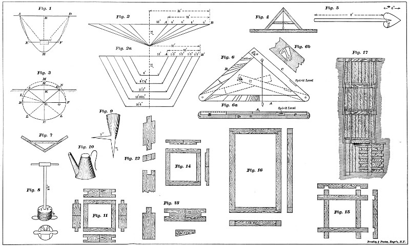
(Pl. XI, Fig. 4), plumb-lines, candles, closed lanterns,
tin pipes, rubber and canvas hose, canvas, nails, etc., etc.,
of the kinds in common use; and the following special
tools and appliances, viz.:
The Miner’s Pick. Smaller and lighter than the common
pick. Neither its head nor its handle exceeds 2
feet in length.
The Miner’s Shovel. Similar in shape to a common
shovel, but not exceeding 2 feet in length.
The Push Pick (Pl. XI, Fig 5), which has a lance-shaped
blade about 3½ in. wide and 6 in. long attached
to a handle about 2 feet long.
The Field Level (Pl. XI, Fig 6), which consists of
three strips of wood about 2" × ½", arranged as shown.
The strip A is 4' between centres of pins; B and C are
2', 915/16"; the angle at a = 90°. A spirit-level is inserted
in piece C, and a plumb-line attached as shown. The
markings on A are used for gentle slopes, those on B
for steep ones.
The other sides of B and C are divided into degrees
of arc, the centre being at the middle point of the outside
edge of A.
The Slope Block, which is a wooden cube used in connection
with a mason’s level for fixing slopes.
Angle Templets (Pl. XI, Fig. 7), making a definite
angle, used in laying out galleries.
The Miner’s Truck or Car. A small, four-wheeled
wagon with fixed axles and very short wheel-base; exterior
dimensions about 20" wide, 18" to 20" high, and
30" long. Used for carrying earth through galleries,
and usually hoisted up the shaft and dumped outside,
replacing the buckets used in sinking the shaft.
The Miner’s Bellows (Pl. XI, Fig. 8). A leather bag
with wooden top and bottom, provided with inlet and
outlet valves, from the latter of which the air is led off
in pipes or hose. In using the bellows the miner stands
upon the lower handles and works the bellows with his
hands by the upper ones.
This is frequently replaced by a common blacksmith’s
bellows or the rotary blower from a portable forge; and
sometimes by an improvised air-pump, consisting of a
large open cask filled with water and another smaller one,
with one head removed and the other provided with
outlet and inlet valves and an air-tube, inverted over
the large cask, supported by a spring-pole and worked
up and down by hand in the water of the lower cask.
The Miner’s Candlestick (Pl. XI, Fig. 9), which holds a
candle, and may be driven into the side or bottom of a
gallery.
Miner’s Lamps (Pl. XI, Fig. 10), can be used only
when the ventilation is good, as they give off more
smoke than candles.
When an electric-light plant is available, incandescent
lamps will be used for mining.
Earth Augers, similar to those used for boring
post-holes, but of different diameters, are sometimes
used for placing camouflets. Their shanks are made
in short lengths, which can be joined together to allow
of boring a deep hole from a narrow shaft or gallery.
19. The Dimensions of Galleries and Shafts are
determined by the use to be made of them, the necessity
of ventilation, and the minimum space in which a
man can work.
They are usually about as follows, viz.:
|
Height,
feet. |
Width,
feet. |
| 1. Great or grand galleries |
6 |
7 |
| 2. Common galleries |
6 |
3½ |
| 3. Half galleries |
4½ |
3 |
| 4. Branches |
3½ |
2½ |
| 5. Small branches (rameaux de combat). |
2½ |
2 |
Shafts vary in size—from the smallest in which a
man can work (about 2' × 4'), to any size that may be
required, seldom exceeding 10' × 10'.
Great galleries are used for descent into a ditch, and
when it is wished to pass cannon through them.13
Common galleries are used for descent into a ditch,
and for communications. Troops can pass through
them “by twos.”
Half galleries answer for general purposes of attack.
They allow the miner to work freely in different positions
without being cramped, but are small enough to
admit of rapid driving. Branches and small branches
are driven out from the galleries to the mine-chambers,
etc. They can be driven rapidly for short distances
(10 to 20 feet); but when of greater length the earth is
removed from them with difficulty, they are not easily
ventilated, and are too small for use as communications.
20. Shaft and Gallery Linings.—In very firm soil
it is sometimes practicable to drive small shafts and
galleries short distances without lining them; but if
these are to stand for any length of time, there is always
danger of their falling in, particularly if shaken
by the explosion of mines in their vicinity. When it
is considered safe to use them, however, the shafts
should be elliptical in plan, and the roofs of the galleries
should be pointed arches. As a rule, however, both
shafts and galleries should be lined. Those which are
permanent in their character—as the main galleries of
the countermines of a permanent work—are lined with
masonry. Masonry linings may be of brick, stone, or
concrete walls and arches. The smaller galleries constructed
during a siege, and all the shafts and galleries
of the attack, are lined with wood. Wooden linings are
of two general types, known as cases, and frames and
sheeting.
21. Cases (Pl. XI, Figs. 11 and 12) are made of plank,
from 6" to 12" wide, each case consisting of a cap-sill, a
ground-sill, and two stanchions. The cap and ground-sills
are cut to a length equal to the clear width of the
shaft or gallery plus twice the thickness of the stanchions;
a rectangular notch is cut in each end to receive
a corresponding tenon cut on the stanchion.
The length of the stanchions between shoulders is
equal to the clear length of the shaft or height of the
gallery. The length of the tenons is generally equal
to the thickness of the cap and ground sill (usually 2´´),
and their width about three inches. Notches are cut
in the sides of all the pieces of the case, as shown in
the figure, for convenience in handling them.
In grand galleries the tenons at the top of the stanchions
are usually shorter than the thickness of the cap-sill,
and those at the bottom, as well as the mortises in
the ground-sill, are omitted. The stanchions are kept
from collapsing by blocks nailed to the ground-sills.
These blocks are 2" thick, and wide enough (about 9´´)
to so guide the wheels of a gun-carriage as to prevent
the axle striking the stanchions.
In cases for smaller galleries also the tenons are
sometimes omitted at the bottom of the stanchions,
the mortises in the ground-sills cut an inch or two
deeper, and the stanchions kept from collapsing by
keys driven in the mortises (Pl. XI, Fig. 13).
22. Shaft and Gallery Frames (Pl. XI, Figs. 14,
15, and 16) are made of scantlings, halved together at
the ends, as shown in the figures. Sheeting is made of
boards or planks of the necessary thickness, sawn to
proper lengths, and bevelled at the ends. When
sawn lumber is not available, the frames may be made
of saplings, and in some cases poles may be used for
sheeting.
The middle of each cap and ground sill, both in
frames and cases, is distinctly marked by a shallow saw
cut or otherwise.
23. The following table gives the dimensions, in
inches, usually adopted for the pieces of cases, frames,
and sheeting, for galleries of different sizes, viz.:
|
Cases. |
Frames and Sheeting. |
|
Ground-sill. |
Stanchions. |
Cap-sill. |
Ground-sill. |
Stanchions. |
Cap-sill. |
Sheeting. |
|
In. |
In. |
In. |
In. |
In. |
In. |
In. |
| Great galleries |
3 |
4 |
5 |
6 × 4 |
6 × 6 |
6 × 9 |
2 |
| Common galleries |
2 |
2 |
2 |
6 × 3 |
6 × 6 |
6 × 8 |
1½ |
| Half galleries |
2 |
2 |
2 |
5 × 3 |
5 × 5 |
5 × 7 |
1½ |
| Branches |
1½ or 2 |
1½ or 2 |
1½ or 2 |
4 × 3 |
4 × 4 |
4 × 5 |
1 or 1½ |
| Small branches |
1 to 2 |
1 to 2 |
1 to 2 |
3 × 3 |
3 × 3 |
3 × 4 |
1 |
The cases of branches and small branches are sometimes
made very strong, with a view to resist rupture
by the explosion of neighboring mines. For this purpose
cases made of oak plank 4" thick are used, and the
branch near its end is packed full of scantlings provided
with rope-handles at their ends for withdrawing
them after the mine is fired. This packing is, however,
of doubtful utility, since a compression of the case sufficient
to call the resistance of the packing into play is
very apt to produce a permanent deformation of the
cases, which will jam the scantlings and prevent their
removal. For convenience in use the pieces of cases
should be of uniform width.
24. Relative Advantages of Cases, and Frames
and Sheeting.—In favorable soil, cases, when they can
be obtained, allow of more rapid progress and give a
lining with a smooth interior. In very bad soil they
cannot be used for the larger galleries.
Frames and sheeting can be used in all soils which
admit of mining operations, and can usually be improvised
from materials found in the vicinity.
25. Sinking a Shaft by Frames and Sheeting.—The
size and position of a shaft are usually determined
by the character and direction of the gallery which is
to start out from it. It is evident (Pl. XI, Fig. 17) that
the clear width of the shaft must be enough greater
than the outside width of the gallery to allow the side
sheeting of the gallery to be freely inserted outside the
frames of the gallery and inside those of the shaft; also,
that the shaft frames must be so spaced as to leave a
clear space at the bottom for the gallery. This space
must be equal to the clear height of the gallery, increased
by the thickness of the cap-sill, the sheeting,
and one or two inches for easy working. This and the
thickness of one frame being deducted from the depth
of the shaft, the remainder may be divided up into a
number of equal or unequal parts called shaft intervals.
In order that the sheeting may not yield under the pressure
of the earth, these intervals seldom exceed 4 feet.
The length of the shaft must be great enough to allow
the miners to work freely, and to insert the sheeting
for the first gallery interval.
The sheeting for both shafts and galleries is cut in
lengths about 1 foot greater than the interval between
frame centres.
26. The size and position of the shaft having been
fixed, the top frame (Pl. XI, Fig. 15) is placed in position
and secured by pegs, and the direction of its axis is accurately
fixed by the score marks at the middle of the
end pieces. The side and end pieces of this frame are
respectively about 3 feet longer than those of the other
frames, and are so halved together as to make of their
ends four projecting horns, 1½' long, which keep the
frame in place during the excavation of the first interval.
This frame is usually placed with its top flush with
the surface of the ground. The miner proceeds to excavate
the shaft with pick and shovel, making it large
enough in plan to admit the sheeting outside the frame.
Usually the first interval can be excavated without supporting
the earth at the sides, which are vertical or
slightly undercut, so that at the bottom of the interval
the shaft will be large enough to admit the second
frame, the sheeting of the first interval, and a system
of wedges which hold this sheeting out from the second
frame a distance somewhat greater than the thickness
of the sheeting of the second interval. The verticality
of the sides is determined by the plumb-line, and the
size of the shaft by two gauge-sticks cut respectively
to the outside length and width of the excavation, and
distinctly marked at their centres.
To avoid the inconvenience of working under the top
frame, the first interval is frequently marked out and
excavated before the frame is fixed in its position.
When the shaft is deep enough the second frame is
put in place and nailed together; the notches in the
ends of the side pieces turned upward and those of the
end pieces downward. The top and second frame are
connected by nailing to them four battens of proper
length (two on each side), which suspend the second
frame from the top frame at the established interval.
The second frame is placed vertically below the top
frame by using the plumb-line and the scores in the
frames.
The sheeting is inserted outside the top frame, bevelled
end first, bevel outside, and pushed down until its top
is flush with the top frame. The lower end of the
sheeting is held out from the lower frame by suitable
wedges, and the excavation of the second interval is
commenced.
In ordinary soil the sides of the shaft will now require
support. Sheeting is therefore introduced and pushed
down as the excavation proceeds, and the wedges previously
placed are removed to make room for the sheeting.
27. If the pressure of the earth becomes great enough
to spring the sheeting-planks inward, an auxiliary frame
is introduced. This is a frame similar to the shaft
frames, but from 4 to 6 inches larger in outside dimensions.
The sheeting rests directly against the outside of this
frame, and is thus held out far enough to allow the third
frame to be placed and the wedges to be inserted as before.
The auxiliary frame is then removed and used in the
next interval.
28. Successive frames are placed in the same manner
until the one directly over the gallery is reached.
Great care is taken to place this frame at exactly the
right height, and the shaft is then continued to the required
depth. A frame is placed at the bottom with
its top at the level of the floor of the gallery, and the
sheeting is allowed to rest directly against the outside
of this frame. When the soil will allow it, the sheeting
is omitted wholly or in part over the portion of the
shaft which is to form the gallery entrance.
29. Precautions.—In sinking shafts especial care
must be taken to make the excavation no larger than
is required for placing the lining, since if a vacant
space is left outside the lining the sides of the shaft
may give way through its entire height, and fall against
the lining with a blow which will crush it in.
This is often the cause of fatal accidents both in shafts
and galleries.
30. Partly-lined Shafts, i.e., those in which the
sheeting-planks are separated from each other by
greater or less intervals, should only be used for small
depths and when they are expected to stand for a very
short time.
They are a constant menace to the miners, owing to
the danger of their caving in, and in a much greater
degree to the probability of stones, etc., falling from
the unprotected parts and seriously injuring or killing
the men at the bottom.
31. Driving a Gallery with Frames and Sheeting.—The
direction of the gallery has already been marked
by the scores on the shaft frames; but it must be verified
by plumb-lines, and two small pickets be driven on
the line of its axis, which is located exactly by small
nails, one driven in the head of each picket.
Two gauge-rods are prepared, giving the extreme
height and breadth of the excavation, i.e., the height
of the frame plus two thicknesses of top sheeting, and
the breadth of the frame plus four thicknesses of side
sheeting. The middle of each gauge-rod is also plainly
marked.
A gallery frame is set up against the side of the shaft
(Pl. XI, Fig. 17), its ground-sill flush with the bottom
frame of the shaft; or its stanchions may rest upon
the shaft frame as a ground-sill.
The gallery frame is carefully located and fastened in
position with battens and braces. The shaft sheeting
is then forced down two or three inches with a bar, and
the top sheeting of the gallery inserted and driven in
until its end is supported by the earth. It is given the
proper upward pitch by a scantling laid across it and
secured to the shaft frames. The shaft sheeting is
forced further down, the earth at the top excavated,
and the top gallery sheeting advanced. As this work
proceeds the side sheeting-planks are successively inserted
and driven forward.
In this way the gallery is advanced one gallery interval,
usually about 4 feet, when a second frame is
placed. Its position is verified by the score marks;
for direction, by a line; for grade, by a spirit, mason’s,
or field level; and for verticality, by a plumb-line. It is
then secured in place by nailing battens to it and the
preceding frame. Wedges are inserted between the
frame and the sheeting, and the gallery is continued by
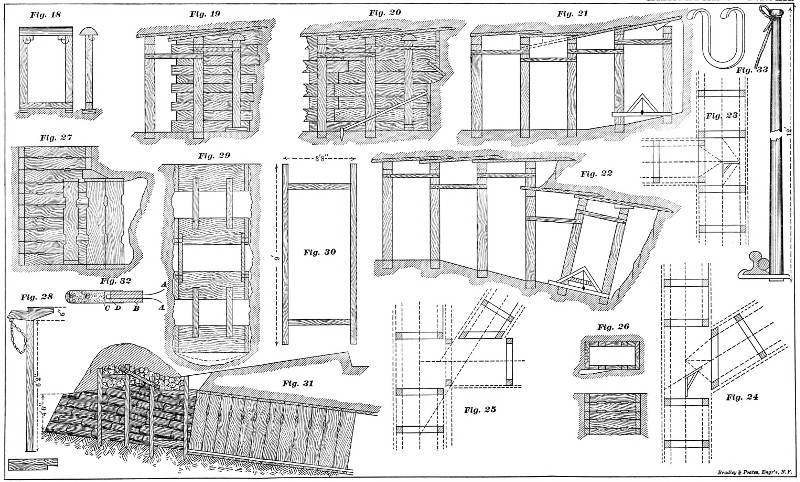
the same methods (Pl. XII, Fig. 19). When the sheeting
is advanced only by hard driving the frames are
slightly inclined to the rear at first, and are afterwards
driven forward until vertical.
32. If, while advancing the sheeting, the pressure
upon it becomes so great as to spring it, a false frame (Pl.
XII, Fig. 18) must be used. This consists of a cap-sill,
ground-sill, and two stanchions, connected by mortises
and tenons. The stanchions have tenons and the sills
mortises at each end. The cap-sill is usually rounded
on top and, for facility in setting up and removing, its
mortises are longer than the width of the tenons.
The latter are held in place by wedges when the frame
is in position. The false frame is usually made of the
same height as the common frames and, when side
sheeting is used, wider by twice the thickness of this
sheeting. When side sheeting is not used, its outside
width may be equal to the clear width of the gallery.
In using the frame (Pl. XII, Fig. 19) the ground-sill is
first placed accurately in position at a half interval in advance,
the stanchions are set up, and the cap-sill placed
upon them and wedged. The whole frame is then
raised about 2 inches by folding wedges placed under
each end of the ground-sill, and is secured by battens.
The sheeting will now rest directly upon the cap-sill
and stanchions, and have the proper inclination to clear
the next frame by its own thickness, as is required.
The next frame is then set up, the wedges driven
under the sheeting, and the false frame removed; which
is easily done, owing to its construction.
33. When the soil is very bad a shield (Pl. XII, Fig. 20)
is used to prevent the earth in front and above from
caving into the gallery. In starting out from the shaft
the following method is adopted: As soon as the top
sheeting is sufficiently advanced and the shaft sheeting
is forced down about 1 foot, the top plank of the side
sheeting is inserted and driven forward about 2 feet, and
the earth at the top of the gallery is excavated for from
6 inches to 1 foot in advance. A piece of plank a foot
wide and in length equal to the width of the gallery is
then placed directly under the top sheeting and against
the face of the excavation, and is held in place by braces
at its ends secured to the shaft lining. The shaft sheeting
is then lowered another foot, the next plank of the
side sheeting inserted, the earth excavated, and a
second plank of the shield placed in the same way as
before. This is continued until the entire face is covered.
The top and side sheeting are then driven forward,
and the top plank of the shield is removed and replaced
in advance; after which each plank is removed
and replaced in succession, as above described.
34. Inclined Galleries.—Method of fixing the slope.—If
the gallery instead of being horizontal is ascending
(Pl. XII, Fig. 21) or descending (Fig. 22), the proper slope
is obtained by using a slope-block whose edge is equal to
the rise or fall of the gallery in one interval. This is
placed upon the lower of two consecutive ground-sills,
and the proper height of the other is determined by a
mason’s or spirit level (Fig. 21). If a field-level or
a mason’s level properly marked for the slope is used,
the slope-block may be dispensed with (Fig. 22).
35. Position of Frames.—In driving descending galleries
better progress will be made and less material used
if the frames are set at right angles to the axis of the gallery
(Pl. XII, Fig. 22); and this is the usual custom. In
driving ascending galleries this is impracticable, and the
frames are set vertically (Fig. 21). In all other respects
inclined galleries are driven in the same manner as
horizontal ones.
36. Partly-lined Galleries.—In very firm soil side
sheeting may be omitted entirely, and in that less firm
the side planks need not be in contact. When the side
sheeting is omitted the width of excavation may be reduced
to the clear width of the gallery, and the stanchions
be let into the side wall flush with its surface.
In this case the ground-sills are frequently omitted, the
stanchions resting upon wooden blocks, stones,or directly
upon the earth.
To save material, the planks of the top sheeting are
sometimes more or less separated also. This can only
be recommended when rapid and temporary work is
required with limited materials; and in these cases the
earth between the planks should be supported by a
packing of sticks, brush, etc., etc.
37. Change of Direction in Galleries.—In changing
the direction of a gallery, the new direction is laid off
by using a carefully made angle-templet (Pl. XI, Fig. 7)
or slope-block, field-level, etc., and it is prolonged in
the new direction by the methods already described.
When the soil is firm enough to stand safely while excavating
and lining one gallery interval, even if somewhat
short, no difficulty exists in changing the direction of a
gallery in either a vertical or horizontal plane, since the
excavation in the new direction may be made so large
that the miner working in it can place the new frames
and introduce the sheeting and wedges. The gallery
can then be carried on without diminution in size.
When the soil is bad, however, special arrangements
must be made for introducing the sheeting.
38. Change of Slope.—To pass from a horizontal to
an ascending gallery (Pl. XII, Fig. 21) it is only necessary
to give the top sheeting the proper angle by holding
down its back end with a piece of scantling placed
across the gallery for that purpose; and, to give the side
sheeting the proper inclination, cutting trenches in the
bottom of the gallery for the lower pieces, if necessary.
In passing from a horizontal to a descending gallery
(Pl. XII, Fig. 22) the roof may be carried forward horizontally,
and the floor given the desired pitch by increasing
the height of the consecutive frames, until
enough head-room is obtained to allow the top sheeting
for the descending gallery to be inserted at the proper
height and angle. The frame at this point is made with
a cap-sill (upon which the sheeting rests directly), and
a second cross-piece below it, serving as a cap-sill for
the descending gallery. From this point forward the
frames may be set perpendicular to the axis of the gallery,
as previously stated.
If the descending gallery is very steep and the horizontal
pressure of the soil great, it may be necessary to
strengthen the stanchions of the last two or three vertical
frames by cross-pieces near their upper ends.
39. Change of Direction Horizontally.—Slight changes
of direction of narrow galleries, either to right or
left, may be made in a manner entirely similar to that
above described for descending galleries, by widening
the frames until the side sheeting can be inserted at the
required angle, and strengthening the cap-sills, when necessary,
with additional stanchions.
When the gallery is wide or the changes of direction
abrupt, however, it is customary to drive the gallery
entirely beyond the turning-point, and then break out
a gallery in the new direction from the side of the original
gallery.
40. Returns.—A gallery starting out from the side
of another is called a return, and is rectangular or oblique
according to the angle made by its axis with that of the
original gallery, which is called the gallery of departure.
That the return may be broken out, the interval between
the frames of the gallery of departure at this
point must be such as to admit between the stanchions
a frame and the side sheeting of the return (Pl. XII,
Fig. 23). This part of the gallery of departure is called
a landing, and its floor is made horizontal.
If the return is oblique (Fig. 24), its width measured
along the gallery of departure will be determined by
an oblique section, and may be so great that the strength
of the lining of the gallery of departure will not allow
the necessary length of landing. In this case a short
rectangular return is first broken out from the side of
the gallery of departure, and the new gallery is broken
out from the side of this return (Fig. 25). The latter
method diminishes the length of the landing when the
change of direction is less than 45°.
41. The floor of a return is started at the level of the
floor of its landing. In firm soils which will stand for a
short time without support the first frame may be set
up entirely outside the gallery of departure (Pl. XII,
Figs. 24 and 25) and may be of the same height in clear
as this gallery. When the soil is bad, however, and side
sheeting is required in the gallery of departure, the first
frame of the return must be set up against this sheeting
in the interval between the stanchions of the landing
(Fig. 23). This makes the clear height of the return at
this frame less than that of the gallery of departure by
a little more than the thickness of the sheeting.
The first frame of an oblique return should be so
made that the sides of the stanchions will be parallel to
the side walls of the return, thus giving a good bearing
to the side sheeting.
In very bad soil, the first few frames of a return must
be firmly braced to resist the backward thrust of the
earth, by battens connecting them together and by
struts across the gallery of departure. The latter are
removed when the return is sufficiently advanced.
42. A Complete Map must be made of every system
of mines, showing the centres of shafts, and the
axes and slopes of all galleries; giving also the references
and lengths of all landings, and the locations,
references, and dimensions of all mine chambers.
43. Working Drawings must also be made from
which sheeting can be cut to proper lengths and angle-templets,
etc., cut and framed.
These can be easily and accurately drawn by remembering
that, to allow the miners to insert the sheeting,
every return must have such dimensions outside its
sheeting that, if it were free to move, its lining could
be slid back across its landing as a drawer slides in
a table. The size of the landings and dimensions of
frames having thus been determined, the parts of the
galleries between them may be divided into intervals,
which, for convenience, should be equal, since this will
allow the sheeting to be cut to a uniform length.
44. Sinking a Shaft with Cases.—(Pl. XII, Figs.
26 and 27.)—A case of the required size is put together
and accurately placed upon the site of the shaft, whose
dimensions are marked upon the ground outside it.
The case is then removed and the earth excavated to
the depth of the case, which is placed in the excavation
with its top flush with the surface of the ground. Its
position is carefully verified, and it is secured in position
by packing earth around it. The excavation is
then continued for the depth of another case, which is
put in place as follows, viz.:
One end piece is placed in position, the tenons of the
two side pieces are inserted in the mortises at its ends,
and the side pieces are pushed back into position; a
pocket-shaped excavation is made with a push-pick
beyond the end of one of the side pieces and running
back three or four inches into the side wall; the remaining
end piece is inserted in this far enough to allow the
mortise at its other end to slip over its corresponding
tenon; it is then drawn back, and the tenons at
both ends fitted into their mortises. The notches cut
in the sides of the pieces allow them to be easily
handled.
The next case is placed in the same way, care being
taken not to excavate two consecutive pockets at the
same angle.
When practicable, it is well to fill up these pockets
by stuffing in sods from below before placing the next
case.
Some miners prefer to place one tenoned piece first,
then the two mortised pieces, leaving a wedge-shaped
opening behind one of them, and insert the other
tenoned piece last, drawing the mortised piece forward
upon its tenon.
When the sides of the cases are tenoned at one end
only and secured by wedges at the other, they are easily
placed in position without cutting out behind them.
45. Upon reaching the level of the top of the gallery,
the pieces on the gallery side of the shaft are omitted
if the ground is firm, but if it needs support these
pieces are put in place and secured by cleats or braces,
but the tenons are not inserted in the mortises.
46. Driving a Gallery with Cases (Pl. XII, Fig.
27).—This is practicable only when the soil is somewhat
firm. In breaking out from the side of the shaft,
a frame is first placed inside the shaft to support the
ends of the shaft cases resting against the pieces which
are to be removed. The latter pieces are then taken
out and grooves are cut in the earth for the ground-sill,
stanchions, and cap-sill of the gallery, and these are
put in place in a manner entirely analogous to that described
for sinking a shaft. This case is set flush with
the inside of the shaft and supports the side pieces,
whose tenons rest upon its stanchions. The projecting
earth is then cut away and grooves are cut for the next
case, which is placed in position and the excavation
continued as before.
47. When the earth shows a tendency to cave, which
it frequently will in great galleries, the cap-sill must
be put in position and supported while the miner excavates
the grooves for the ground-sill and stanchions.
To support the cap-sill, two crutches are used. A
crutch (Pl. XII, Fig. 28) consists of an upright piece of
timber carrying a cross-piece whose length is equal to the
width of two cases. The upright piece rests upon the
ground-sill of the case already placed, and is raised to
the proper height by wedges. The part of the cross-piece
which projects in advance is made 2 inches higher
than the rear part, to support the cap-sill somewhat
above its final level, so as to allow the tenons of the
stanchions to be easily inserted. The rear part of the
cross-piece is attached to the upright by an iron rod or
short chain.
So soon as the case is set and adjusted to position
the crutches are taken down by removing the wedges,
and are replaced under the next cap-sill.
48. In very firm soil shafts and galleries are frequently
driven with cases not in juxtaposition, but separated
by greater or less intervals. Pieces of planks
(which may be parts of cases) placed vertically and
resting against the sides and ends of the cases in
shafts, or horizontally and resting upon the cap-sills in
galleries, and somewhat separated from each other, are
used to support the earth between the cases.
The same remarks apply to this construction as to
the similar one sometimes used when mining with
frames and sheeting.
49. Change of Direction in Galleries Lined with
Cases.—Slight changes in direction in a horizontal
plane can be easily and gradually made by setting
each case a little obliquely to the one preceding it,
and separating the stanchions on one side while they
touch on the other, supporting the roof in the wedge-shaped
openings, if necessary, with pieces of wood, etc.
For an abrupt change, it is better to break out a rectangular
return from the side of the gallery and pass
from this into the required direction by gradual
change.
If the return is to be of the same height as the gallery
of departure, the cap-sills of the latter, for a distance
equal to the width of the return, are lifted off the
tenons of the stanchions by struts and wedges, and the
first case of the return is set as in breaking out from
a shaft; the ground-sill is, however, narrowed by the
thickness of the stanchions of the gallery of departure
so that the face of the case of the return is flush with
the inside of the gallery of departure, and the ends of
the cap-sills of the latter rest upon the cap-sill of the
first case of the return.
50. Change of Slope.—In passing from a horizontal
to a descending gallery the change may be made gradually,
in a manner similar to that described for a change
in horizontal direction, and the cases remain normal to
the axis of the gallery. (Pl. XII, Fig. 31.)
To pass to an ascending gallery by the method above
described would require the earth at the face of the
gallery to be undercut in order to introduce the case,
and this undercutting would be continued so long as
the cases were normal to the axis of the gallery. This
construction is, as a rule, impracticable. In ascending
galleries, therefore, the cases are set with their stanchions
vertical, while their cap and ground sills lie in
the slope of the roof and floor of the gallery.
51. To conform with this requirement, and for convenience
in setting up, the ends of the stanchions
receive the proper bevel, while the sides of the tenons
and mortises are made parallel to the sides of the
stanchions. (Pl. XII, Fig. 12.)
52. Shafts à la Boule.—In order to place a charge
of explosive directly under the ground occupied, or for
other reasons, it is frequently necessary to sink a small
shaft in the least possible time. For this purpose a
modified form of cases is sometimes used, in which the
ends are halved together instead of being tenoned
and mortised. (Pl. XII, Fig. 29.) They are spaced at
greater or less distances apart, according to the nature
of the ground, and are connected together by battens.
Stones, pieces of wood, etc., etc., are driven between
them and the sides of the shaft to support the latter.
This construction is called a shaft à la Boule. It is
expected to stand for a few days at most. Many other
extemporized linings may be used for similar purposes.
53. Blinded Galleries.—Galleries cannot be successfully
driven with less than 3 to 3½ feet of undisturbed
earth over their sheeting. In making a descent into a
ditch, or in pushing forward an approach in siege
operations, it is often impracticable to lower the bottom
of the trench of departure sufficiently to give the
requisite cover for starting a gallery at once. In these
cases blinded descents or galleries may be used, the tops
and sides of which are supported by blindage-frames,
or blinds, each of which consists of two side parts of
4" × 6" scantling 9' long, united by two cross-pieces of
the same section 3' 8" long, which are mortised or
halved into them, leaving horns at each end 1' long.
(Pl. XII, Fig. 30.)
54. The galleries are constructed as follows (Pl. XII,
Fig. 31): A double sap with a width of 8' is broken out
from the side of the trench in the direction required and
is driven forward in the usual manner, but with a continual
increase in depth, at a slope not exceeding ¼.
The side slopes are as steep as the earth will allow.
Two blindage-frames are set up vertically on the sides
of the sap, 7' apart in clear, with their tops at the level
of the tops of the trench gabions, their bottom horns
resting in holes dug for them. These frames are prevented
from falling inward by another frame placed
crosswise upon them, with its horns resting on their
cross-pieces. The side of this top frame toward the
front may be held up by a stake or crutch, and the
second pair of frames be placed at such an interval that
their horns will interlock with those of the top frame.
Successive frames may be placed in the same manner.
The covering or “roof” is formed by three or four
layers of fascines placed across the trench on top of
the frames, and covered with earth thrown back upon
them as the work proceeds. The sides of the gallery
are held up by fascines, etc., laid along outside the
frames.
As soon as the bottom of the blinded gallery has
reached the proper depth a mine-gallery may be started
and carried forward.
55. The blindage-frames described above give to
the gallery a clear width and height of 7'. For smaller
galleries the blinds may all be made shorter and of
lighter scantling; or, if desired, those for the sides may
be of a different length from those for the top.
56. Rate of Advance of Galleries.—The following
table gives an estimate of the men and tools required
for shafts and galleries, with the probable rate of advance
in good soil:
| KEY: |
| NC O |
= N. C. Officer. |
| M |
= Miners. |
| P |
= Picks. |
| MP |
= Miners' Picks. |
| P-p |
= Push-picks. |
| Sh |
= Shovels. |
| MS |
= Miners' Shovels. |
| MT |
= Miner’s Truck. |
| F-l |
= Field-levels. |
| M-r |
= Measuring-rod 6´. |
| T-l |
= Tracing-line. |
| M S |
= Mauls or Sledges. |
| CB |
= Canvas Buckets. |
| R-l |
= Rope-ladder. |
| W-b |
= Wheel-barrows. |
| MB |
= Miners' Bellows. |
| Pr. |
= Progress, ins. per. hour. |
| Kind of Gallery, etc. |
Men. |
Tools. |
| NC O |
M |
P |
MP |
P-p |
Sh |
MS |
MT |
F-l |
M-r |
T-l |
M S |
CB |
R-l |
W-b |
MB |
Pt. |
Great gallery or }
Blinded gallery} |
1 |
1214 |
4 |
2 |
2 |
8 |
|
|
1 |
1 |
1 |
1 |
|
|
4 |
|
12 |
| Common gallery |
1 |
4 |
|
1 |
1 |
2 |
1 |
1 |
1 |
1 |
1 |
1 |
|
|
|
1 |
12 |
| Half gallery |
1 |
415 |
|
1 |
1 |
2 |
1 |
1 |
1 |
1 |
1 |
1 |
|
|
|
1 |
16 |
| Branch gallery |
1 |
415 |
|
1 |
1 |
2 |
1 |
1 |
1 |
1 |
1 |
1 |
|
|
|
1 |
24 |
| Small branch |
1 |
3 |
|
1 |
1 |
|
2 |
116 |
17 |
1 |
|
1 |
1 |
|
|
1 |
{ 30
{ to
{ 36 |
| Shaft |
1 |
418 |
|
1 |
1 |
2 |
1 |
|
1 |
1 |
1 |
1 |
1 |
1 |
|
|
{ 18
{ 24 |
57. The gases resulting from firing mines and from
the lamps, bodies, and candles of the miners so vitiate
the air in galleries that, unless means for ventilating
them are adopted, the miners must eventually abandon
them or become asphyxiated.
In ordinary circumstances, when no powder gases
are present, a gallery cannot be driven safely more
than 60 feet without ventilation.
The measures adopted for ventilating galleries consist,
1st, in forcing in fresh air; 2d, in drawing out foul
air; and, 3d, in assisting the natural diffusion and circulation
of the air through them.
58. The first is accomplished by forcing air through
pipes, which may be of tin, wood, or common hose,
leading to the point where ventilation is required.
The air is forced in by the use of the miner’s bellows
or other apparatus already described. This method is
simple in its application and places the fresh air where
it is needed, but drives the foul air back into the galleries
occupied by other miners. It is the only practicable
method of ventilating single, long, narrow galleries
and branches.
59. The second method may be applied to a system
consisting of a number of galleries connected by transversals,
by so placing an exhausting fan as to draw the
air out through one gallery, while by light wooden or
canvas doors and screens the other galleries are so
arranged that the fresh air, entering from the exterior,
sweeps through the galleries occupied by the miners,
and escapes through the unoccupied gallery leading to
the fan, carrying the gases with it.
In this method a single large gallery may be ventilated
by using a canvas partition placed near the top or
on one side, so that the fresh air will go in on one side
around the end of the partition and back by the other
side to the fan.
This method has the advantage of carrying the gases
away from the galleries occupied by the men, and supplying
fresh air throughout those which are occupied.
The exhaust may be produced by a fire constantly
burning at the foot of a shaft instead of by a fan.
The method is, however, complicated in its application,
and can seldom be used for military mines.
60. The third method, or assisting natural ventilation,
is carried out by cutting numerous cross-galleries
connecting those which are near each other, by making
air-shafts and bore-holes connecting the galleries with
the surface of the ground, and, when practicable, by
placing the openings of the shafts and galleries at different
levels. This method will serve for a few men
working leisurely in preparing countermines before an
attack, but is entirely inadequate during active mining
operations.
61. By the use of masks covering the face, and supplied
with fresh air either through hose or from a reservoir
of compressed air carried with him, a miner may
work in galleries in which the air is irrespirable. The
advantages which may frequently result from the time
thus saved justify providing apparatus of this kind for
use in mining operations.
62. Mine-chambers to contain the charge of explosive
are preferably nearly cubical in form, and if not
charged at once, or if of large size, must have sufficient
lining to support the roof and sides.
When they are above the level of the gallery they
are arranged to drain into it. They are made large
enough to contain the receptacle for the charge and to
allow the charge to be placed in it. They are, as a rule,
placed in short returns at one side of the branch or gallery,
but may be at its end, above or below it. The mine-chamber
frequently consists of so much of the end of
the gallery as is necessary to contain the charge.
63. Preparing the Charge.—The weight of the
charge necessary to produce the desired effect is determined
by the rules previously given. Its volume, if of
powder or compressed gun-cotton, may be found by
allowing 30 cubic inches to the pound; and if of dynamite,
about 20 cubic inches.
If the mine-chamber is perfectly dry, and the mine
is to be fired at once, a layer of straw may be placed
upon the floor of the chamber and the charge contained
in canvas bags laid upon it. When the ground is more
or less wet, or when the mine is not to be fired immediately,
the charge should have a water-proof covering,
which may be a thoroughly calked and pitched box, an
ale-barrel or beer-keg, the metal barrels in which powder
is shipped, or India-rubber or pitched-canvas bags,—depending
upon the amount of moisture present and
the time that the charge is to remain in place. Many
of the high explosives are not affected by dampness,
and but little if any by water; but to secure the fuse
and its connections from injury, and to remove all danger
of misfires, the explosive should in all cases be
protected from water if practicable.
64. Distribution of Fuses in the Charges.—Gunpowder
will explode with full effect if ignited, but to
prevent the explosion of the central part of a large
charge scattering the exterior portion before it is ignited
a number of fuzes should be used. They may
convey fire only, but must all be ignited by the firing
apparatus, and simultaneously. One fuze to each 100
lbs. of powder is not too great an allowance; but when
lack of time or appliances does not admit of placing a
number of fuzes, the desired effect may be obtained by
increasing the charge of powder and using one fuze.
(See Abbot, Prof. Papers Corps of Engineers, No. 23,
1881, p. 62, for number of fuzes needed; and pp. 244-51
for simultaneous ignitions.)
The high explosives detonate with full force only
when exploded with a detonating fuze. Under favorable
conditions one fuze will detonate a very large charge,
but cases arise in which a portion of the charge explodes
and the remainder does not. To insure the best results,
therefore, it is desirable to distribute fuzes throughout
a large charge, at the rate of perhaps one fuze to each
50 lbs. These fuzes should contain from 20 to 30 grains
of fulminate of mercury, which is itself very sensitive
to shock, and has in a high degree the power of detonating
the other explosives. One fuze only (or, for
safety against defects, two or three) need be connected
with the firing apparatus, the others serving to reinforce
and carry on the wave of explosion after it is started—differing
in this respect from their use with charges of
gunpowder.19
65. Character and Construction of Fuzes.—Formerly,
for firing mines, trains of powders put up in linen
tubes, quick-match, and other similar devices were
used. Electric-blasting apparatus is now in such common
use that it will always be available for any extended
mining operations. For single mines with small charges
it may, however, be necessary sometimes to resort to
the older method of firing, the apparatus for which can
be readily improvised. But even in these cases “Bickford”
or “Safety” fuze will usually be available, and
may be used alone for firing gunpowder, or with a common
fulminate-of-mercury “blasting-cap” for high explosives.
It burns at the rate of about 4 feet per minute.
Very quick-burning fuzes are also made which
may be used at times (e. g., Bickford Instantaneous,
which burns at the rate of 120 feet a second; Gomez
Lightning, which burns so rapidly that it may almost be
said to detonate; etc.) Great care must be taken not
to mistake them for the common Bickford.
66. Electric Fuzes are made of three general classes:
First, those which are fired by a spark from a high-tension
machine; second, those which are ignited by a current
from a battery or “dynamo;” third, those which
can be fired by either. (Abels, etc.)
67. Those of the second class are manufactured in
large quantities, and, in connection with a portable dynamo
or “blasting-battery,” are almost universally used
for blasting operations throughout the United States.
These fuzes (Pl. XII, Fig. 32) are made up of two
insulated copper wires, A, A, passing through a small
cylindrical block of insulating material, B, and terminating
about 1/16 inch above its end. A very fine platinum
wire, C, about 1/1000 inch in diameter and 1/8 inch long,
connects the ends of the insulated wires. Surrounding
the platinum wire is a small quantity of gun-cotton,
mealed powder, or fulminate of mercury, D. A copper
capsule containing 15 to 30 grains of fulminate of mercury,
E, is pressed down over the cylindrical block far
enough to bring the fulminate in contact with the
material surrounding the platinum wire, and the whole
fuze is then coated with a water-proof composition. The
insulated copper wires are cut to various lengths for
convenience in connecting with the conductors or lead
wires from the battery.
68. Fuzes of the first and third classes are now but
little used. Many of them are unsatisfactory and dangerous.
They differ in construction from those of the
second class principally in that the platinum-wire bridge
is omitted, and the exploding spark or current passes
from one insulated copper wire to the other through a
material which is ignited by it.
69. Placing the Fuses in the Charges.—A certain
number of cartridges or packages should be selected,
each fuse inserted and well packed in the explosive,
and the wires or free end of the safety fuse brought
out through the opening, which should be made water-proof,
if necessary, by securely closing and thoroughly
pitching it. The wires or exterior part of the fuse
should then be securely fastened to the outside of the
cartridge, so that an accidental strain upon them will
not break the waterproofing or move the fuse from its
place. They are then coiled up and remain so until the
cartridge is placed in the general charge of the mine.
70. Several of the high explosives congeal at a temperature
above the freezing-point of water, and in this
state are less sensitive to shock, and explode with difficulty
if closely packed in cartridges as usually delivered
from the factories. They explode more readily when
in the form of a powder. When using them in cold
weather, therefore, each fuse should be put in a cartridge
loosely filled with the powdered explosive, or with
some high explosive not affected by cold. Others need
special primers to cause detonation. The fuses should,
of course, be placed in these primers.
71. Placing the Charges.—The charge is placed
in the mine-chambers, either in the dark, by light reflected
through the galleries, by closed lanterns carefully
placed and guarded, or, when practicable, by incandescent
electric lights. It is carried through low
and narrow galleries on men’s backs or in miner’s cars,
and should for this reason be put up in packages not
exceeding 50 lbs. in weight.
It is packed in the chamber with great care, and
under the immediate supervision of the responsible
officer. The packages containing the fuses are distributed
uniformly throughout the mass, and the wires
uncoiled and led back into the gallery, the free ends of
the two wires of each fuse having been previously
twisted together for safety against electric currents and
for identification.
These wires, which must be long enough to reach
through the tamping, are all collected together and led
back through it in a wooden or other conduit, which protects
them from injury while tamping the mine.
When electric lights are used, great care must be
taken to remove the light and all its conducting wires
before the wires of the fuses are uncoiled and laid
along the gallery.
72. Tamping.—Mines are tamped with sods and
earth, wood and earth, sand-bags, etc., etc.
When sods are used the branch is filled for about 3
feet with sods carefully laid and packed with the joints
filled with earth. About 3 feet of earth is solidly
packed against this, then alternate layers of sods and
earth until the desired length of tamping is obtained.
To tamp with wood and earth or sand-bags, a wooden
shield is first placed across the branch and firmly
braced; behind this, earth is solidly packed or sand-bags
carefully laid until the required length of tamping
is obtained. Sometimes a second shield is put up behind
the earth tamping, and firmly braced in position.
The strength of the tamping is also increased by pieces
of timber crossing each other diagonally, with their
ends resting against the sides of the branch. Sand-bags
make the best tamping, as they offer high resistance
and are easily placed and removed.
The tamping should have a length equal to at least
1½ times the line of least resistance of a common mine
corresponding to the charge, and if not of the best
quality, to twice this line.
73. Firing Mines.—If electric fuses are used the
main conductors or lead wires coiled upon a reel are
taken in and the ends properly joined to the fuse wires;
they are then led through the galleries, attached to
the battery, and fired at the designated instant. Under
no circumstances should the main lead wires be
connected to the battery or dynamo until everything is
ready for firing.
If a Bickford fuse is used its length is regulated to the
desired time of firing from its known rate of burning.
The miner lights the end and retires; the explosion
takes place approximately at the calculated time.
With the “Lightning Gomez” or similar fuses a length
reaching to the firing-point may be used. It is lighted
at the desired time, and burns with such rapidity that
for lengths not exceeding 300 or 400 feet the time of
burning is inappreciable.
Instead of using great lengths of these fuses, they
may be cut shorter and their ends be brought together
and inserted in a little mealed powder which is fired
by a piece of safety-fuse, slow match or port-fire, etc.,
long enough to give the miner time to retire to a safe
distance after igniting it.
Bickford fuse is best ignited by a piece of cotton
wicking soaked in oil and loosely tied around it. This,
when lighted, will burn through the covering and set
fire to the composition. By this device many fuses
may be ignited in a short time. A slow match or
“touch-paper” for igniting quick-burning fuses or powder-trains
may be made by soaking common paper in a
strong solution of nitre and drying it.
74. In favorable soil a camouflet or small mine may
sometimes be placed and fired very quickly by the following
process:
A hole 2" to 3" in diameter and of the desired depth
is bored in the proper direction with an auger or boring-bar.
A cartridge containing from ½ lb. to 2 lbs. of
dynamite is pushed down to the bottom and fired. The
explosion increases the diameter of the hole somewhat
throughout, and obstructs it more or less with loose
earth. At the same time it enlarges the part near the
seat of the charge into a bottle-shaped cavity, whose
size varies with the charge used and the nature of the
soil. The hole is rapidly cleared out with a long-handled
scoop, the cavity filled with powder, primed,
and fired.
The enlargement made by the charges of dynamite
above given may contain from 50 to 100 lbs. of gunpowder
under favorable circumstances.
75. In stony soil this method becomes very difficult
if not impracticable; and when it can be used the preliminary
explosion of dynamite vitiates to a greater or
less degree the air of the shaft or gallery from which
the boring is made, and also informs the enemy of the
progress and intention of the miner.
To remove the latter objections, the English authorities
recommend the use of holes 6" or 8" in diameter,
bored with earth-augers, charged to a length of 2 or
3 calibres, and well tamped. When applicable, this
method is manifestly a great improvement upon the
other; but the auger is so liable to be stopped by
stones which a boring-bar might break or push to one
side, that it can only be applied in very favorable soil.