By Herbert M. Wilson, M. Am. Soc. C. E.
Introduction.
The mine disaster, which occurred at Cherry, Ill., on November 13th,
1909, when 527 men were in the mine, resulting in the entombment of 330
men, of whom 310 were killed, has again focused public attention on the
frequent recurrence of such disasters and their appalling consequences.
Interest in the possible prevention of such disasters, and the possible
means of combating subsequent mine fires and rescuing the imprisoned
miners, has been heightened as it was not even by the series of three
equally extensive disasters which occurred in 1907, for the reason that,
after the Cherry disaster, 20 men were rescued alive after an entombment
of one week, when practically all hope of rescuing any of the miners had
been abandoned.
This accident, occurring, as it does, a little more than 1½ years after
the enactment of legislation by Congress instructing the Director of the
United States Geological Survey to investigate the causes and possible
means of preventing the loss of life in coal-mining
operations, makes this an opportune time to review what has been done by
the Geological Survey during this time, toward carrying out the intent
of this Act.
It may be stated with confidence, that had such a disaster occurred a
year or more ago, all the entombed men must have perished, as it would
have been impossible to enter the mine without the protection afforded
by artificial respiratory apparatus. Moreover, but for the presence of
the skilled corps of Government engineers, experienced by more than a
year’s training in similar operations in more than twenty disasters, the
mine would have been sealed until the fire had burned out, and neither
the dead, nor those who were found alive, would have been recovered for
many weeks. In the interval great suffering and loss would have been
inflicted on the miners, because of enforced idleness, and on the mine
owners because of continued inability to re-open and resume
operations.
Character of the Work.—The United States Geological Survey
has been engaged continuously since 1904 in conducting investigations
relating to structural materials, such as stone, clay, cement, etc., and
in making tests and analyses of the coals, lignites, and other mineral
fuel substances, belonging to, and for the use of, the Government.
Incidentally, the Survey has been considering means to increase
efficiency in the use of these resources as fuels and structural
materials, in the hope that the investigations will lead to their best
utilization.
These inquiries attracted attention to the waste of human life incident
to the mining of fuel and its preparation for the market, with the
result that, in May, 1908, provision was made by Congress for
investigations into the causes of mine explosions with a view to their
prevention.
Statistics collected by the Geological Survey show that the average
death rate in the coal mines of the United States from accidents of all
kinds, including gas and dust explosions, falls of roof, powder
explosions, etc., is three times that of France, Belgium, or Germany. On
the other hand, in no country in the world are natural conditions so
favorable for the safe extraction of coal as in the United States. In
Belgium, foremost in the study of mining conditions, a constant
reduction in the death rate has been secured, and from a rate once
nearly as great as that of the United States, namely, 3.28 per thousand,
in the period 1851-60, it had been reduced to about 2 per thousand in
the period 1881-90; and in the last decade this has been further reduced
to nearly 1 per thousand. It seems certain, from the investigations
already made by the Geological Survey, that better means of safeguarding
the lives of miners will be found, and that the death rate from mine
accidents will soon show a marked reduction.
Other statistics collected by the Geological Survey show that, to the
close of 1907, nearly 7,000,000,000 tons of coal had been mined in the
United States, and it is estimated that for every ton mined nearly a ton
has been wasted, 3,500,000,000 tons being left in the ground or thrown
on the dump as of a grade too low for commercial use. To the close of
1907 the production represents an exhaustion of somewhat more than
10,000,000,000 tons of coal. It has been estimated that if the
production continues to increase, from the present annual output of
approximately 415,000,000 tons, at the rate which has prevailed during
the last fifty years, the greater part of the more accessible coal
supply will be exhausted before the middle of the next century.
The Forest Service estimates that, at the present rate of consumption,
renewals of growth not being taken into account, the timber supply will
be exhausted within the next quarter of a century. It is desirable,
therefore, that all information possible be gained regarding the most
suitable substitutes for wood for building and engineering construction,
such as iron, stone, clay products, concrete, etc., and that the minimum
proportion in which these materials should be used for a given purpose,
be ascertained. Exhaustion, by use in engineering and building
construction, applies not only to the iron ore, clay, and cement-making
materials, but, in larger ratio, to the fuel essential to rendering
these substances available for materials of construction. Incidentally,
investigations into the waste of structural materials have developed the
fact that the destructive losses, due to fires in combustible buildings,
amount to more than $200,000,000 per annum. A sum even greater than this
is annually expended on fire protection. Inquiries looking to the
reduction of fire losses are being conducted in order to ascertain the
most suitable fire-resisting materials for building construction.
Early in 1904, during the Louisiana Purchase Exposition, Congress made
provision for tests, demonstrations, and investigations concerning the
fuels and structural materials of the United States. These
investigations were organized subsequently as the Technologic Branch
of the United States Geological Survey, under Mr. Joseph A. Holmes,
Expert in Charge, and the President of the United States invited a group
of civilian engineers and Chiefs of Engineering Bureaus of the
Government to act as a National Advisory Board concerning the method of
conducting this work, with a view to making it of more immediate benefit
to the Government and to the people of the United States. This Society
is formally represented on this Board by C. C. Schneider,
Past-President, Am. Soc. C. E., and George S. Webster, M. Am. Soc.
C. E. Among representatives of other engineering societies, or of
Government Bureaus, the membership of the National Advisory Board
includes other members of this Society, as follows: General William
Crozier, Frank T. Chambers, Professor W. K. Hatt, Richard L.
Humphrey, Robert W. Hunt, H. G. Kelley, Robert W. Lesley, John B.
Lober, Hunter McDonald, and Frederick H. Newell.
In view, therefore, of the important part taken both officially and
unofficially by members of this Society in the planning and organization
of this work, it seems proper to present a statement of the scope,
methods, and progress of these investigations. Whereas the Act governing
this work limits the testing and investigation of fuels and of
structural materials to those belonging to the United States, the
activities of the Federal Government in the use of these materials so
far exceeds that of any other single concern in the United States, that
the results cannot but be of great value to all engineers and to all
those engaged in engineering works.
Mine Accidents Investigations.
Organization, and Character of the Work.—The mine rescue
investigations, carried on at the Federal testing station, at Pittsburg,
Pa., include five lines of attack:
1.—Investigations in the mines to determine the conditions leading
up to mine disasters, the presence and the relative explosibility of
mine gas and coal dust, and mine fires and means of preventing and
combating them.
2.—Tests to determine the relative safety, or otherwise, of the
various explosives used in coal mining, when ignited in the presence of
explosible mixtures of natural gas and air, or coal dust, or of
both.
3.—Tests to determine the conditions under which electric
equipment is safe in coal-mining operations.
4.—Tests to determine the safety of various types of mine lights
in the presence of inflammable gas, and their accuracy in detecting
small percentages of mine gas.
5.—Tests of the various artificial breathing apparatus, and the
training of miners and of skilled mining engineers in rescue
methods.
The first four of these lines of investigation have to do with
preventive measures, and are those on which ultimately the greatest
dependence must be placed. The fifth is one in which the result seems at
first to be the most apparent. It has to do, not with prevention, but
with the cure of conditions which should not arise, or, at least, should
be greatly ameliorated.
During the last 19 years, 28,514 men have been killed in the coal-mining
industries.2 In 1907
alone, 3,125 men lost their lives in coal mines, and, in addition,
nearly 800 were killed in the metal mines and quarries of the country.
Including the injured, 8,441 men suffered casualties in the mines in
that year. In every mining camp containing 1,000 men, 4.86 were taken by
violent death in that year. In the mining of coal in Great Britain, 1.31
men were killed in every 1,000 employed in the same year; in France,
1.1; in Belgium, 0.94, or less than 1 man in every 1,000 employed. It is
thus seen that from three to four times as many men are being killed in
the United States as in any European coal-producing country. This safer
condition in Europe has resulted from the use of safer explosives, or
the better use of the explosives available; from the reduction in the
use of open lights; from the establishment of mine rescue stations and
the training with artificial breathing apparatus; and from the adoption
of regulations for safeguarding the lives of the workmen.
The mining engineering field force of the Geological Survey, at the head
of which is Mr. George S. Rice, an experienced mining and consulting
engineer, has already made great progress in the study of underground
mining conditions and methods. Nearly all the more dangerous coal mines
in the United States have been examined; samples of gas, coal, and dust
have been taken and analyzed at the chemical laboratories at Pittsburg;
extended tests have been made as to the explosibility of various
mixtures of gas and air; as to the explosibility of dust from various
typical coals; as to the chemical composition and
physical characteristics of this dust; the degree of fineness necessary
to the most explosive conditions; and the methods of dampening the dust
by water, by humidifying, by steam, or of deadening its explosibility by
the addition of calcium chloride, stone dust, etc. A bulletin outlining
the results thus far obtained in the study of the coal-dust problem is
now in course of publication.3
After reviewing the history of observations and experiments with coal
dust carried on in Europe, and later, the experiments at the French,
German, Belgian, and English explosives-testing stations, this bulletin
takes up the coal-dust question in the United States. Further chapters
concern the tests as to the explosibility of coal dust, made by the
Geological Survey, at Pittsburg; investigations, both at the Pittsburg
laboratory and in mines, as to the humidity of mine air. There is also a
chapter on the chemical investigations into the ignition of coal dust by
Dr. J. C. W. Frazer, of the Geological Survey. The application
of some of these data to actual mine conditions in Europe, in the last
year, is treated by Mr. Axel Larsen; the use of exhaust steam in a mine
of the Consolidation Coal Company, in West Virginia, is discussed by Mr.
Frank Haas, Consulting Engineer; and the use of sprays in Oklahoma coal
mines is the subject of a chapter by Mr. Carl Scholz, Vice-President of
the Rock Island Coal Mining Company.
An earlier bulletin setting forth the literature and certain mine
investigations of explosive gases and dust,4 has already been issued. After treating of
methods of collecting and analyzing the gases found in mines, of
investigations as to the rate of liberation of gas from coal, and of
studies on coal dust, this bulletin discusses such factors as the
restraining influence of shale dust and dampness on coal-dust
explosions. It then takes up practical considerations as to the danger
of explosions, including the relative inflammability of old and fresh
coal dust. The problems involved are undergoing further investigation
and elaboration, in the light of information already gathered.
Permissible Explosives.—The most important progress in
these tests and investigations has been made in those relating to the
various explosives used in getting coal from mines. Immediately upon the
enactment of the first legislation, in the spring of 1908, arrangements
were perfected whereby the lower portion of the old Arsenal grounds
belonging to the War Department and adjacent to the Pennsylvania
Railroad, on the Alleghany River, at 40th and Butler Streets, Pittsburg,
Pa., were transferred to the Interior Department for use in these
investigations. Meantime, in anticipation of the appropriation, Mr.
Clarence Hall, an engineer experienced in the manufacture and use of
explosives, was sent to Europe to study the methods of testing
explosives practiced at the Government stations in Great Britain,
Germany, Belgium, and France. Mr. Joseph A. Holmes also visited Europe
for the purpose of studying methods of ameliorating conditions in the
mines. Three foreign mining experts, the chiefs of investigating bureaus
in Belgium, Germany, and England, spent three months studying conditions
in the United States at the invitation of the Secretary of the Interior,
to whom they submitted a valuable report.5
Under the supervision of the writer, Chief Engineer of these
investigations, detailed plans and specifications had been prepared in
advance for the necessary apparatus and the transformation of the
buildings at Pittsburg to the purposes of this work. It was possible,
therefore, to undertake immediately the changes in existing buildings,
the erection of new buildings, the installation of railway tracks,
laboratories, and the plumbing, heating, and lighting plant, etc. This
work was carried on with unusual expedition, under the direction of the
Assistant Chief Engineer, Mr. James C. Roberts, and was completed within
a few months, by which time most of the apparatus was delivered and
installed.
One building (No. 17) is devoted to the smaller physical tests of
explosives. It was rendered fire resistant by heavily covering the
floors, ceiling, and walls with cement on metal lath, and otherwise
protecting the openings. In it are installed apparatus for determining
calorific value of explosives, pressure produced on ignition,
susceptibility to ignition when dropped, rate of detonation, length and
duration of flame, and kindred factors. Elsewhere on the grounds is a
gallery of boiler-steel plate, 100 ft. long and more than 6 ft. in
diameter, solidly attached to a mass of concrete at one end, in which is
embedded a cannon from which to discharge the explosive under test, and
open at the other end, and otherwise so constructed as to
simulate a small section of a mine gallery (Fig. 2, Plate VI). The heavy mortar pendulum, for the
pendulum test for determining the force produced by an explosive, is
near by, as is also an armored pit in which large quantities of
explosive may be detonated, with a view to studying the effects of
magazine explosions, and for testing as to the rate at which ignition of
an explosive travels from one end to the other of a cartridge, and the
sensitiveness of one cartridge to explosion by discharge of another
near by.
In another building (No. 21), is a well-equipped chemical laboratory for
chemical analyses and investigations of explosives, structural
materials, and fuels.
Several months were required to calibrate the various apparatus, and to
make analyses of the available natural gas to determine the correct
method of proportioning it with air, so as to produce exact mixtures of
2, 4, 6, or 8% of methane with air. Tests of existing explosives were
made in air and in inflammable mixtures of air and gas, with a view to
fixing on some standard explosive as a basis of comparison. Ultimately,
40% nitro-glycerine dynamite was adopted as the standard. Investigative
tests having been made, and the various factors concerning all the
explosives on the market having been determined, a circular was sent to
all manufacturers of explosives in the United States, on January 9th,
1909, and was also published in the various technical journals, through
the associated press, and otherwise.
On May 15th, 1909, all the explosives which had been offered for test,
as permissible, having been tested, the first list of permissible
explosives was issued, as given in the following circular:
“EXPLOSIVES CIRCULAR NO. 1.
“DEPARTMENT OF THE INTERIOR.
“United States Geological Survey.
“May 15, 1909.
“LIST OF PERMISSIBLE EXPLOSIVES.
“Tested prior to May 15, 1909.
“As a part of the investigation of mine explosions authorized by
Congress in May, 1908, it was decided by the Secretary of the Interior
that a careful examination should be made of the various explosives used
in mining operations, with a view to determining the extent to
which the use of such explosives might be responsible for the occurrence
of these disasters.
“The preliminary investigation showed the necessity of subjecting to
rigid tests all explosives intended for use in mines where either gas or
dry inflammable dust is present in quantity or under conditions which
are indicative of danger.
“With this in view, a letter was sent by the Director of the United
States Geological Survey on January 9, 1909, to the manufacturers of
explosives in the United States, setting forth the conditions under
which these explosives would be examined and the nature of the tests to
which they would be subjected.
“Inasmuch as the conditions and tests described in this letter were
subsequently followed in testing the explosives given in the list below,
they are here reproduced, as follows:
“(1) The manufacturer is to furnish 100 pounds of each explosive which
he desires to have tested; he is to be responsible for the care,
handling, and delivery of this material at the testing station on the
United States arsenal grounds, Fortieth and Butler streets, Pittsburg,
Pa., at the time the explosive is to be tested; and he is to have a
representative present during the tests, who will be responsible for the
handling of the packages containing the explosives until they are opened
for testing.
“(2) No one is to be present at or to participate in these tests except
the necessary government officers at the testing station, their
assistants, and the representative of the manufacturer of the explosives
to be tested.
“(3) The tests will be made in the order of the receipt of the
applications for them, provided the necessary quantity of the explosive
is delivered at the plant by the time assigned, of which due notice will
be given by the Geological Survey.
“(4) Preference will be given to the testing of explosives that are now
being manufactured and that are in that sense already on the market. No
test will be made of any new explosive which is not now being
manufactured and marketed, until all explosives now on the market that
may be offered for testing have been tested.
“(5) A list of the explosives which pass certain requirements
satisfactorily will be furnished to the state mine inspectors, and will
be made public in such further manner as may be considered
desirable.
“TEST REQUIREMENTS FOR EXPLOSIVES.
“The tests will be made by the engineers of the United States Explosives
Testing Station at Pittsburg, Pa., in gas and dust gallery No. 1. The
charge of explosive to be fired in tests 1, 2, and 3 shall be equal in
disruptive power to one-half pound (227 grams) of 40 per cent.
nitroglycerin dynamite in its original wrapper, of the following
formula:
| Nitroglycerin |
40 |
| Nitrate of sodium |
44 |
| Wood pulp |
15 |
| Calcium carbonate |
1 |
| 100 |
“Each charge shall be fired with an electric fuse of sufficient power to
completely detonate or explode the charge, as recommended by the
manufacturer. The explosive must be in such condition that the chemical
and physical tests do not show any unfavorable results. The explosives
in which the charge used is less than 100 grams (0.22 pound) will be
weighed in tinfoil without the original wrapper.
“The dust used in tests 2, 3, and 4 will be of the same degree of
fineness and taken from one mine.6
“Test 1.—Ten shots with the
charge as described above, in its original wrapper, shall be fired, each
with 1 pound of clay tamping, at a gallery temperature of 77° F., into a
mixture of gas and air containing 8 per cent. of methane and ethane. An
explosive will pass this test if all ten shots fail to ignite the
mixture.
“Test 2.—Ten shots with charge as
previously noted, in its original wrapper, shall be fired, each with 1
pound of clay tamping at a gallery temperature of 77° F., into a mixture
of gas and air containing 4 per cent. of methane and ethane and 20
pounds of bituminous coal dust, 18 pounds of which is to be placed on
shelves laterally arranged along the first 20 feet of the gallery, and 2
pounds to be placed near the inlet of the mixing system in such a manner
that all or part of it will be suspended in the first division of the
gallery. An explosive will pass this test if all ten shots fail to
ignite the mixture.
“Test 3.—Ten shots with charge as
previously noted, in its original wrapper, shall be fired, each with 1
pound of clay tamping at a gallery temperature of 77° F., into 40 pounds
of bituminous coal dust, 20 pounds of which is to be distributed
uniformly on a horse placed in front of the cannon and 20 pounds placed
on side shelves in sections 4, 5, and 6. An explosive will pass this
test if all ten shots fail to ignite the mixture.
“Test 4.—A limit charge will be
determined within 25 grams by firing charges in their original wrappers,
untamped, at a gallery temperature of 77° F., into a mixture of gas and
air containing 4 per cent. of methane and ethane and 20 pounds of
bituminous coal dust, to be arranged in the same manner as in test 2.
This limit charge is to be repeated five times under the same conditions
before being established.
“Note.—At least 2 pounds of clay
tamping will be used with slow-burning explosives.
“Washington, D. C., January 9,
1909.
“In response to the above communication applications were received from
12 manufacturers for the testing of 29 explosives. Of these explosives,
the 17 given in the following list have passed all the test requirements
set forth, and will be termed permissible explosives.
“Permissible explosives tested prior to May 15, 1909.
| Brand. |
Manufacturer. |
| Ætna coal powder A |
Ætna Powder Co., Chicago, Ill. |
| Ætna coal powder B |
Do. |
| Carbonite No. 1 |
E. I. Dupont de Nemours Powder Co., Wilmington, Del. |
|
Carbonite No. 2 |
E. I. Du Pont de Nemours Powder Co., Wilmington, Del. |
| Carbonite No. 3 |
Do. |
| Carbonite No. 1 L. F. |
Do. |
| Carbonite No. 2 L. F. |
Do. |
| Coal special No. 1 |
Keystone Powder Co., Emporium, Pa. |
| Coal special No. 2 |
Do. |
| Coalite No. 1 |
Potts Powder Co., New York City. |
| Coalite No. 2 D |
Do. |
| Collier dynamite No. 2 |
Sinnamahoning Powder Co., Emporium, Pa. |
| Collier dynamite No. 4 |
Do. |
| Collier dynamite No. 5 |
Do. |
| Masurite M. L. F. |
Masurite Explosive Co., Sharon, Pa. |
| Meteor dynamite |
E. I. Du Pont de Nemours Powder Co., Wilmington, Del. |
| Monobel |
Do. |
“Subject to the conditions named below, a permissible explosive is
defined as an explosive which has passed gas and dust gallery tests Nos.
1, 2, and 3 as described above, and of which in test No. 4 1½ pounds
(680 grams) of the explosive has been fired into the mixture there
described without causing an ignition.
“Provided:
“1. That the explosive is in all respects similar to the sample
submitted by the manufacturer for test.
“2. That double-strength detonators are used of not less strength than 1
gram charge consisting by weight of 90 parts of mercury fulminate and 10
parts of potassium chlorate (or its equivalent), except for the
explosive ‘Masurite M. L. F.’ for which the detonator shall be
of not less strength than 1½ grams charge.
“3. That the explosive, if in a frozen condition, shall be thoroughly
thawed in a safe and suitable manner before use.
“4. That the amount used in practice does not exceed 1½ pounds (680
grams) properly tamped.
“The above partial list includes the permissible explosives that have
passed these tests prior to May 15, 1909. The announcement of the
passing of like tests by other explosives will be made public
immediately after the completion of the tests for such explosives.
“A description of the method followed in making these and the many
additional tests to which each explosive is subjected, together with the
full data obtained in each case, will be published by the Survey at an
early date.
“NOTES AND SUGGESTIONS.
“It may be wise to point out in this connection certain differences
between the permissible explosives as a class and the black powders now
so generally used in coal mining, as follows:
“(a) With equal quantities of each, the flame of the black powder
is more than three times as long and has a duration three thousand to
more than four thousand times that of one of the permissible explosives,
also the rate of explosion is slower.
“(b) The permissible explosives are one and one-fourth to one and
three-fourths times as strong and are said, if properly used, to do
twice the work of black powder in bringing down coal; hence only half
the quantity need be used.
“(c) With 1 pound of a permissible explosive or 2 pounds of black
powder, the quantity of noxious gases given off from a shot averages
approximately the same, the quantity from the black powder being less
than from some of the permissible explosives and slightly greater than
from others. The time elapsing after firing before the miner returns to
the working face or fires another shot should not be less for
permissible explosives than for black powder.
“The use of permissible explosives should be considered as supplemental
to and not as a substitute for other safety precautions in mines where
gas or inflammable coal dust is present under conditions indicative of
danger. As stated above, they should be used with strong detonators; and
the charge used in practice should not exceed 1½ pounds, and in many
cases need not exceed 1 pound.
“Inasmuch as no explosive manufactured for use in mining is flameless,
and as no such explosive is entirely safe under all the variable mining
conditions, the use of the terms ‘flameless’ and ‘safety’ as applied to
explosives is likely to be misunderstood, may endanger human life, and
should be discouraged.
“Joseph A. Holmes,
“Expert in Charge Technologic Branch.
“Approved, May 18, 1909:
“Geo. Otis Smith,
“Director.”
In the meantime, many of the explosives submitted, which heretofore had
been on the market as safety explosives, were found to be unsafe for use
in gaseous or dusty mines, and the manufacturers were permitted to
withdraw them. Their weaknesses being known, as a result of these tests,
the manufacturers were enabled to produce similar, but safer,
explosives. Consequently, applications for further tests continued to
pour in, as they still do, and on October 1st, 1909, a second list of
permissible explosives was issued, as follows:
“EXPLOSIVES CIRCULAR NO. 2.
“DEPARTMENT OF THE INTERIOR.
“United States Geological Survey.
October 1, 1909.
“LIST OF PERMISSIBLE EXPLOSIVES.
“Tested prior to October 1, 1909.
“The following list of permissible explosives tested by the United
States Geological Survey at Pittsburg, Pa., is hereby published for the
benefit of operators, mine owners, mine inspectors, miners, and others
interested.
“The conditions and test requirements described in Explosives Circular
No. 1, issued under date of May 15, 1909, have been followed in all
subsequent tests.
“Subject to the provisions named below, a permissible explosive is
defined as an explosive which is in such condition that the chemical and
physical tests do not show any unfavorable results; which has passed gas
and dust gallery tests Nos. 1 and 3, as described in circular No. 1; and
of which, in test No. 4, 1½ pounds (680 grams) has been fired into the
mixture there described without causing ignition.
“Permissible explosives tested prior to October 1, 1909.
“[Those reported in Explosives Circular No. 1 are marked *.]
| Brand. |
Manufacturer. |
| * Ætna coal powder A |
Ætna Powder Co., Chicago, Ill. |
| Ætna coal powder AA |
Do. |
| * Ætna coal powder B |
Do. |
| Ætna coal powder C |
Do. |
| Bituminite No. 1 |
Jefferson Powder Co., Birmingham, Ala. |
| Black Diamond No. 3 |
Illinois Powder Manufacturing Co., St. Louis, Mo. |
| Black Diamond No. 4 |
Do. |
| * Carbonite No. 1 |
E. I. Du Pont de Nemours Powder Co., Wilmington, Del. |
| * Carbonite No. 2 |
Do. |
| * Carbonite No. 3 |
Do. |
| * Carbonite No. 1-L. F. |
Do. |
| * Carbonite No. 2-L. F. |
Do. |
| * Coalite No. 1 |
Potts Powder Co., New York City. |
| * Coalite No. 2-D. |
Do. |
| * Coal special No. 1 |
Keystone Powder Co., Emporium, Pa. |
| * Coal special No. 2 |
Do. |
|
* Collier dynamite No. 2. |
Sinnamahoning Powder Manufacturing Co., Emporium, Pa. |
| * Collier dynamite No. 4. |
Do. |
| * Collier dynamite No. 5. |
Do. |
| Giant A low-flame dynamite. |
Giant Powder Co. (Con.), Giant, Cal. |
| Giant B low-flame dynamite. |
Do. |
| Giant C low-flame dynamite. |
Do. |
| * Masurite M. L. F. |
Masurite Explosives Co., Sharon, Pa. |
| * Meteor dynamite. |
E. I. Du Pont de Nemours Powder Co., Wilmington, Del. |
| Mine-ite A. |
Burton Powder Co., Pittsburg, Pa. |
| Mine-ite B. |
Do. |
| * Monobel. |
E. I. Du Pont de Nemours Powder Co., Wilmington, Del. |
| Tunnelite No. 5. |
G. R. McAbee Powder and Oil Co., Pittsburg, Pa. |
| Tunnelite No. 6. |
Do. |
| Tunnelite No. 7. |
Do. |
| Tunnelite No. 8. |
Do. |
“Provided:
“1. That the explosive is in all respects similar to sample submitted by
the manufacturer for test.
“2. That No. 6 detonators, preferably No. 6 electric detonators (double
strength), are used of not less strength than 1 gram charge, consisting
by weight of 90 parts of mercury fulminate and 10 parts of potassium
chlorate (or its equivalent), except for the explosive ‘Masurite
M. L. F.,’ for which the detonator shall be of not less strength
than 1½ grams charge.
“3. That the explosive, if frozen, shall be thoroughly thawed in a safe
and suitable manner before use.
“4. That the amount used in practice does not exceed 1½ pounds (680
grams), properly tamped.
“The above partial list includes all the permissible explosives that
have passed these tests prior to October 1, 1909. The announcement of
the passing of like tests by other explosives will be made public
immediately after the completion of the tests.
“With a view to the wise use of these explosives it may be well in this
connection to point out again certain differences between the
permissible explosives as a class and the black powders now so generally
used in coal mining, as follows:
“(a) With equal quantities of each, the flame of the black powder
is more than three times as long and has a duration three thousand to
more than four thousand times that of one of the permissible explosives;
the rate of explosion also is slower.
“(b) The permissible explosives are one and one-fourth to one and
three-fourths times as strong and are said, if properly used, to do
twice the work of black powder in bringing down coal; hence only half
the quantity need be used.
“(c) With 1 pound of a permissible explosive or 2 pounds of black
powder, the quantity of noxious gases given off from a shot averages
approximately the same, the quantity from the black powder being less
than from some of the permissible explosives and slightly greater than
from others. The time elapsing after firing before the miner returns to
the working face or fires another shot should not be less for
permissible explosives than for black powder.
“The use of permissible explosives should be considered as supplemental
to and not as a substitute for other safety precautions in mines where
gas or inflammable coal dust is present under conditions indicating
danger. As stated above, they should be used with strong detonators, and
the charge used in practice should not exceed 1½ pounds and in many
cases need not exceed 1 pound.
“Joseph A. Holmes,
“Expert in Charge Technologic Branch.
“Approved, October 11, 1909.
“H. C. Rizer,
“Acting Director.”
The second list contains 31 explosives which the Government is prepared
to brand as permissible, and therefore comparatively safe, for use in
gaseous and dusty mines. An equally large number of so-called safety
powders failed to pass these tests. Immediately on the passing of the
tests, as to the permissibility of any explosive, the facts are reported
to the manufacturer and to the various State mine inspectors. When
published, the permissible lists were issued to all explosives
manufacturers, all mine operators in the United States, and State
inspectors. The effect has been the enactment, by three of the largest
coal-producing States, of legislation or regulations prohibiting the use
of any but permissible explosives in gaseous or dusty mines, and other
States must soon follow. To prevent fraud, endeavor is being made to
restrict the use of the brand “Permissible Explosive, U. S. Testing
Station, Pittsburg, Pa.,” to only such boxes or packages as contain
listed permissible explosives.
As these tests clearly demonstrate, both in the records thereof and
visually to such as follow them, that certain explosives, especially
those which are slow-burning like black powder, or produce high
temperature in connection with comparative slow burning, will ignite
mixtures of gas and air, or mixtures of coal dust and air, and cause
explosions. The results point out clearly to all concerned, the danger
of using such explosives. The remedy is also made available by the
announcement of the names of a large number of explosives now on the
market at reasonable cost, which will not cause explosions under these
conditions. It is believed that when permissible explosives are
generally adopted in coal mines, this source of danger will have been
greatly minimized.
Explosives Investigations.—Questions have arisen on the
part of miners or of mine operators as to the greater cost in using
permissible explosives due to their expense, which is slightly in excess
of that of other explosives; as to their greater shattering effect in
breaking down the coal, and in giving a smaller percentage of lump and a
larger percentage of slack; and as to the possible danger of breathing
the gases produced.
Observations made in mines by Mr. J. J. Rutledge, an experienced
coal miner and careful mining engineer connected with the Geological
Survey, as to the amount of coal obtained by the use of permissible and
other explosives, tend to indicate that the permissible explosives are
not more, but perhaps less expensive than others, in view of the fact
that, because of their greater relative power, a smaller quantity is
required to do the work than is the case, say, with black powder. On the
other hand, for safety and for certainty of detonation, stronger
detonators are recommended for use with permissible explosives,
preferably electric detonators. These may cost a few cents more per
blast than the squib or fuse, but there is no danger that they will
ignite the gas, and the difference in cost is, in some measure, offset
by the greater certainty of action and the fact that they produce a much
more powerful explosion, thus again permitting the use of still smaller
quantities of the explosive and, consequently, reducing the cost. These
investigations are still in progress.
Concerning the shattering of the coal: This is being remedied in some of
the permissible explosives by the introduction of dopes, moisture, or
other means of slowing down the disruptive effect, so as to produce the
heaving and breaking effect obtained with the slower-burning powders
instead of the shattering effect produced by
dynamite. There is every reason to believe that as the permissible
explosives are perfected, and as experience develops the proper methods
of using them, this difficulty will be overcome in large measure. This
matter is also being investigated by the Survey mining engineers and
others, by the actual use of such explosives in coal-mining
operations.
Of the gases given off by explosives, those resulting from black powder
are accompanied by considerable odor and smoke, and, consequently, the
miners go back more slowly after the shots, allowing time for the gases
to be dissipated by the ventilation. With the permissible explosive, the
miner, seeing no smoke and observing little odor, is apt to be
incautious, and to think that he may run back immediately. As more is
learned of the use of these explosives, this source of danger, which is,
however, inconsiderable, will be diminished. Table 1 gives the
percentages of the gaseous products of combustions from equal weights of
black powder and two of the permissible explosives. Of the latter, one
represents the maximum amount of injurious gases, and the other the
minimum amount, between which limits the permissible explosives
approximately vary.
Such noxious gases as may be produced by the discharge of the explosive
are diluted by a much larger volume of air, and are practically
harmless, as proven by actual analysis of samples taken at the face
immediately after a discharge.
TABLE 1.
|
Black
powder. |
Permissible Explosives. |
| Maximum. |
Minimum. |
| CO2 |
22.8 |
14.50 |
21.4 |
| CO |
10.3 |
27.74 |
1.3 |
| N |
10.3 |
45.09 |
74.4 |
In addition to investigations as to explosives for use in coal mining,
the Explosives Section of the Geological Survey analyzes and tests all
such materials, fuses, caps, etc., purchased by the Isthmian Canal
Commission, as well as many other kinds used by the Government. It is
thus acquiring a large fund of useful information, which will be
published from time to time, relative to the kinds of explosives
and the manner of using them best suited to any blasting operations,
either above or under water, in hard rock, earth, or coal. There has
been issued from the press, recently, a primer of explosives,7 by Mr. Clarence Hall, the
engineer in charge of these tests, and Professor C. E. Munroe,
Consulting Explosives Chemist, which contains a large amount of valuable
fundamental information, so simply expressed as to be easily
understandable by coal miners, and yet sufficiently detailed to be a
valuable guide to all persons who have to handle or use explosives.
In the first chapters are described the various combustible substances,
and the chemical reactions leading to their explosibility. The low and
high explosives are differentiated, and the sensitiveness of fulminate
of mercury and other detonators is clearly pointed out. The various
explosives, such as gunpowder, black blasting powder, potassium chlorate
powders, nitro-glycerine powders, etc., are described, and their
peculiarities and suitability for different purposes are set forth. The
character and method of using the different explosives, both in opening
up work and in enclosed work in coal mines, follow, with information as
to the proper method of handling, transporting, storing, and thawing the
same. Then follow chapters on squibs, fuses, and detonators; on methods
of shooting coal off the solid; location of bore-holes; undercutting;
and the relative advantages of small and large charges, with
descriptions of proper methods of loading and firing the same. The
subjects of explosives for blasting in rock, firing machines, blasting
machines, and tests thereof, conclude the report.
The work of the chemical laboratory in which explosives are analyzed,
and in which mine gases and the gases produced by combustion of
explosives and explosions of coal-gas or coal dust are studied, has been
of the most fundamental and important character. The Government is
procuring a confidential record of the chemical composition and mode of
manufacture of all explosives, fuses, etc., which are on the market.
This information cannot but add greatly to the knowledge as to the
chemistry of explosives for use in mines, and will furnish the basis on
which remedial measures may be devised.
A bulletin (shortly to go to press) which gives the details of the
physical tests of the permissible explosives thus far tested, will set
forth elaborately the character of the testing apparatus, and the method
of use and of computing results.8
This bulletin contains a chapter, by Mr. Rutledge, setting forth in
detail the results of his observations as to the best methods of using
permissible explosives in getting coal from various mines in which they
are used. This information will be most valuable in guiding mining
engineers who desire to adopt the use of permissible explosives, as to
the best methods of handling them.
Electricity in Mines.—In connection with the use of
electricity in mines, an informal series of tests has been made on all
enclosed electric fuses, as to whether or not they will ignite an
explosive mixture of air and gas when blown out. The results of this
work, which is under the direction of Mr. H. H. Clark, Electrical
Engineer for Mines, have been furnished the manufacturers for their
guidance in perfecting safer fuses, a series of tests of which has been
announced. A series of tests as to the ability of the insulation of
electric wiring to withstand the attacks of acid mine waters is in
progress, which will lead, it is hoped, to the development of more
permanent and cheaper insulation for use in mine wiring. A series of
competitive tests of enclosed motors for use in mines has been
announced, and is in progress, the object being to determine whether or
not sparking from such motors will cause an explosion in the presence of
inflammable gas.
In the grounds outside of Building No. 10 is a large steel gallery, much
shorter than Gallery No. 1, in fact, but 30 ft. in length, and much
greater in diameter, namely, 10 ft. (Fig. 3, Plate X), in which electric motors, electric cutting
machines, and similar apparatus, are being tested in the presence of
explosive mixtures of gas and dust and with large amperage and high
voltage, such as may be used in the largest electrical equipment in
mines.
The investigation as to the ability of insulation to withstand the
effects of acid mine waters has been very difficult and complicated. At
first it was believed possible that mine waters from nearby Pennsylvania
mines and of known percentages of acidity could be procured and kept in
an immersion tank at approximately any given percentage of strength.
This was found to be impracticable, as these waters seem to undergo
rapid change the moment they are exposed to the air or are transported,
in addition to the changes wrought by evaporation
in the tank. It has been necessary, therefore, to analyze and study
carefully these waters with a view to reproducing them artificially for
the purpose of these tests. Concerning the insulation, delicate
questions have arisen as to a standard of durability which shall be
commensurate with reasonable cost. These preliminary points are being
solved in conference with the manufacturers, and it is expected that the
results will soon permit of starting the actual tests.
Safety-Lamp Investigations.—Many so-called safety lamps are
on the market, and preliminary tests of them have been made in the lamp
gallery, in Building No. 17 (Fig. 2, Plate X). After nearly a year of endeavor to
calibrate this gallery, and to co-ordinate its results with those
produced in similar galleries in Europe, this preliminary inquiry has
been completed, and the manufacturers and agents of all safety lamps
have been invited to be present at tests of their products at the
Pittsburg laboratory.
A circular dated November 19th, 1909, contains an outline of these
tests, which are to be conducted under the direction of Mr. J. W.
Paul, an experienced coal-mining engineer and ex-Chief of the Department
of State Mine Inspection of West Virginia. The lamps will be subjected
to the following tests:
(a).—Each lamp will be placed in a mixture of air and
explosive natural gas containing 6, 8, and 10% of gas, moving at a
velocity of from 200 to 2,500 ft. per min., to determine the velocity of
the air current which will ignite the mixture surrounding the lamp. The
current will be made to move against the lamp in a horizontal, vertical
ascending, and vertical descending direction, and at an angle of 45°,
ascending and descending.
(b).—After completing the tests herein described, the lamps
will be subjected to the tests described under (a), with the air
and gas mixture under pressure up to 6 in. of water column.
(c).—Under the conditions outlined in (a), coal dust
will be introduced into the current of air and gas to determine its
effect, if any, in inducing the ignition of the gas mixture.
(d).—Each lamp will be placed in a mixture of air and
varying percentages of explosive natural gas to determine the action of
the gas on the flame of the lamp.
(e).—Each lamp will be placed in a mixture of air and
varying percentages of carbonic acid gas to determine the action of the
gas on the flame.
(f).—Lamps equipped with internal igniters will be placed
in explosive mixtures of air and gas in a quiet state and in a moving
current, and the effect of the igniter on the surrounding mixture will
be observed.
(g).—The oils (illuminants) used in the lamps will be
tested as to viscosity, gravity, flashing point, congealing point, and
composition.
(h).—Safety-lamp globes will be tested by placing each
globe in position in the lamp and allowing the flame to impinge against
the globe for 3 min. after the lamp has been burning with a full flame
for 10 min., to determine whether the globe will break.
(i).—Each safety-lamp globe will be mounted in a lighted
lamp with up-feed, and placed for 5 min. in an explosive mixture of air
and gas moving at the rate of 1,000 ft. per min., to determine whether
the heat will break the glass and, if it is broken, to note the
character of the fracture.
(j).—Safety-lamp globes will be broken by impact, by
allowing each globe to fall and strike, horizontally, on a block of
seasoned white oak, the distance of fall being recorded.
(k).—Each safety lamp globe will be mounted in a safety
lamp and, when the lamp is in a horizontal position, a steel pick
weighing 100 grammes will be permitted to fall a sufficient distance to
break the globe by striking its center, the distance of the fall to be
recorded.
(l).—To determine the candle power of safety lamps, a
photometer equipped with a standardized lamp will be used. The
candle-power will be determined along a line at right angles to the axis
of the flame; also along lines at angles to the axis of the flame both
above and below the horizontal. The candle-power will be read after the
lamp has been burning 20 min.
(m).—The time a safety lamp will continue to burn with a
full charge of illuminant will be determined.
(n).—Wicks in lamps must be of sufficient length to be at
all times in contact with the bottom of the vessel in which the
illuminant is contained, and, before it is used, the wick shall be dried
to remove moisture.
Mine-Rescue Methods.—Mr. Paul, who has had perhaps as wide
an experience as any mining man in the investigation of and in rescue
work at mine disasters, is also in charge of the mine-rescue
apparatus and training for the Geological Survey. These operations
consist chiefly of a thorough test of the various artificial breathing
apparatus, or so-called oxygen helmets. Most of these are of European
make and find favor in Great Britain, Belgium, France, or Germany,
largely according as they are of domestic design and manufacture. As yet
nothing has been produced in the United States which fulfills all the
requirements of a thoroughly efficient and safe breathing apparatus for
use in mine disasters.
At the Pittsburg testing station there are a number of all kinds of
apparatus. The tests of these are to determine ease of use, of repair,
durability, safety under all conditions, period during which the supply
of artificial air or oxygen can be relied on, and other essential
data.
In addition to the central testing station, sub-stations for training
miners, and as headquarters for field investigation as to the causes of
mine disasters and for rescue work in the more dangerous coal fields,
have been established; at Urbana, Ill., in charge of Mr. R. Y.
Williams, Mining Engineer; at Knoxville, Tenn., in charge of Mr.
J. J. Rutledge, Mining Engineer; at McAlester, Okla., in charge of
Mr. L. M. Jones, Assistant Mining Engineer; and at Seattle, Wash.,
in charge of Mr. Hugh Wolflin, Assistant Mining Engineer. Others may
soon be established in Colorado and elsewhere, in charge of skilled
mining engineers who have been trained in this work at Pittsburg, and
who will be assisted by trained miners. It is not to be expected that
under any but extraordinary circumstances, such as those which occurred
at Cherry, Ill., the few Government engineers, located at widely
scattered points throughout the United States, can hope to save the
lives of miners after a disaster occurs. As a rule, all who are alive in
the mine on such an occasion, are killed within a few hours. This is
almost invariably the case after a dust explosion, and is likely to be
true after a gas explosion, although a fire such as that at Cherry,
Ill., offers the greatest opportunity for subsequent successful rescue
operations. The most to be hoped for from the Government engineers is
that they shall train miners and be available to assist and advise State
inspectors and mine owners, should their services be
called for.
It should be borne in mind that the Federal Government has no
police duties in the States, and that, therefore, its employees may not
direct operations or have other responsible charge in the enforcement of
State laws. There is little reason to doubt that these Federal mining
engineers, both because of their preliminary education as mining
engineers and their subsequent training in charge of mine operations,
and more recently in mine-accidents investigations and rescue work, are
eminently fitted to furnish advice and assistance on such occasions. The
mere fact that, within a year, some of these men have been present at,
and assisted in, rescue work or in opening up after disasters at nearly
twenty of such catastrophes, whereas the average mining engineer or
superintendent may be connected with but one in a lifetime, should make
their advice and assistance of supreme value on such occasions. They
cannot be held in any way responsible for tardiness, however, nor be
unduly credited with effective measures taken after a mine disaster,
because of their lack of responsible authority or charge, except in
occasional instances where such may be given them by the mine owners or
the State officials, from a reliance on their superior equipment for
such work.
Successful rescue operations may only be looked for when the time, now
believed to be not far distant, has been reached when the mine operators
throughout the various fields will have their own rescue stations, as is
the practice in Europe, and have available, at certain strategic mines,
the necessary artificial breathing apparatus, and have in their employ
skilled miners who have been trained in rescue work at the Government
stations. Then, on the occurrence of a disaster, the engineer in charge
of the Government station may advise by wire all those who have proper
equipment or training to assemble, and it may be possible to gather,
within an hour or two of a disaster, a sufficiently large corps of
helmet-men to enable them to recover such persons as have not been
killed before the fire—which usually is started by the
explosion—has gained sufficient headway to prevent entrance into
the mine. Without such apparatus, it is essential that the fans be
started, and the mine cleared of gas. The usual effect of this is to
give life to any incipient fire. With the apparatus, the more dense the
gas, the safer the helmet-men are from a secondary explosion or from the
rapid ignition of a fire, because of the absence of the oxygen necessary
to combustion.
The miners who were saved at Cherry, Ill., on November 20th,
1909, owe their lives primarily to the work of the Government engineers.
The sub-station of the Survey at Urbana, Ill., was promptly notified of
the disaster on the afternoon of November 13th. Arrangements were
immediately made, whereby Mr. R. Y. Williams, Mining Engineer in
Charge, and his Assistant, Mr. J. M. Webb, with their apparatus,
were rushed by special train to the scene, arriving early the following
day (Sunday).
Chief Mining Engineer, George S. Rice, Chief of Rescue Division,
J. W. Paul, and Assistant Engineer, F. F. Morris, learned of
the disaster through the daily press, at their homes in Pittsburg, on
Sunday. They left immediately with four sets of rescue apparatus,
reaching Cherry on Monday morning. Meantime, Messrs. Williams and Webb,
equipped with oxygen helmets, had made two trips into the shaft, but
were driven out by the heat. Both shafts were shortly resealed with a
view to combating the fire, which had now made considerable headway.
The direction of the operations at Cherry, was, by right of
jurisdiction, in charge of the State Mine Inspectors of Illinois, at
whose solicitation the Government engineers were brought into conference
as to the proper means to follow in an effort to get into the mine. The
disaster was not due to an explosion of coal or gas, but was the result
of a fire ignited in hay, in the stable within the mine. The flame had
come through the top of the air-shaft, and had disabled the ventilating
fans. A rescue corps of twelve men, unprotected by artificial breathing
apparatus, had entered the mine, and all had been killed. When the
shafts were resealed on Monday evening, the 15th, a small hole was left
for the insertion of a water-pipe or hose. During the afternoon and
evening, a sprinkler was rigged up, and, by Tuesday morning, was in
successful operation, the temperature in the shaft at that time being
109° Fahr. After the temperature had been reduced to about 100°, the
Federal engineers volunteered to descend into the shaft and make an
exploration. The rescue party, consisting of Messrs. Rice, Paul, and
Williams, equipped with artificial breathing apparatus, made an
exploration near the bottom of the air-shaft and located the first body.
After they had returned to the surface, three of the Illinois State
Inspectors, who had previously received training by the Government
engineers in the use of the rescue apparatus, including Inspectors Moses
and Taylor, descended, made
tests of the air, and found that with the fan running slowly, it was
possible to work in the shaft. The rescue corps then took hose down the
main shaft, having first attached it to a fire engine belonging to the
Chicago Fire Department. Water was directed on the fire at the bottom of
the shaft, greatly diminishing its force, and it was soon subdued
sufficiently to permit the firemen to enter the mine without the
protection of breathing apparatus.
Unfortunately, these operations could be pursued only under the most
disadvantageous circumstances and surrounded by the greatest possible
precautions, due to the frequent heavy falls of roof—a result of
the heating by the mine fire—and the presence of large quantities
of black-damp. All movements of unprotected rescuers had to be preceded
by exploration by the trained rescue corps, who analyzed the gases, as
the fire still continued to burn, and watched closely for falls,
possible explosions, or a revival of the fire. While the heavy work of
shoring up, and removing bodies, was being carried on by the unprotected
rescue force, the helmet-men explored the more distant parts of the
mine, and on Saturday afternoon, November 20th, one week after the
disaster, a room was discovered in which a number of miners, with great
presence of mind, had walled themselves in in order to keep out the
smoke and heat. From this room 20 living men were taken, of whom 12 were
recovered in a helpless condition, by the helmet-men.
This is not the first time this Government mining corps has performed
valiant services. Directly and indirectly the members have saved from
fifteen to twenty lives in the short time they have been organized. At
the Marianna, Pa., disaster, the corps found one man still alive among
150 bodies, and he was brought to the surface. He recovered entirely
after a month in the hospital.
At the Leiter mine, at Zeigler, Ill., two employees, who had been
trained in the use of the oxygen helmets by members of the Government’s
corps, went down into the mine, following an explosion, and brought one
man to the surface, where they resuscitated him.
Equally good service, either in actual rescue operations, or in
explorations after mine disasters, or in fire-fighting, has been
rendered by this force at the Darr, Star Junction, Hazel, Clarinda,
Sewickley, Berwind-White No. 37, and Wehrum, Pa., mine disasters; at
Monongah and Lick Branch, W. Va.; at Deering, Sunnyside, and Shelburn,
Ind., Jobs, Ohio, and at Roslyn, Wash.
Explosives Laboratory.—The rooms grouped at the south end
of Building No. 21, at Pittsburg, are occupied as a laboratory for the
chemical examination and analysis of explosives, and are in charge of
Mr. W. O. Snelling.
Samples of all explosives used in the testing gallery, ballistic
pendulum, pressure gauge, and other testing apparatus, are here
subjected to chemical analysis in order to determine the component
materials and their exact percentages. Tests are also made to determine
the stability of the explosive, or its liability to decompose at various
temperatures, and other properties which are of importance in showing
the factors which will control the safety of the explosive during
transportation and storage.
In the investigation of all explosives, the first procedure is a
qualitative examination to determine what constituents are present.
Owing to the large number of organic and inorganic compounds which enter
into the composition of explosive mixtures, this examination must be
thorough. Several hundred chemical bodies have been used in explosives
at different times, and some of these materials can be separated from
others with which they are mixed only by the most careful and exact
methods of chemical analysis.
Following the qualitative examination, a method is selected for the
separation and weighing of each of the constituents previously found to
be present. These methods, of course, vary widely, according to the
particular materials to be separated, it being usually necessary to
devise a special method of analysis for each explosive, unless it is
found, by the qualitative analysis, to be similar to some ordinary
explosive, in which case the ordinary method of analysis of that
explosive can be carried out. Most safety powders require special
treatment, while most grades of dynamite and all ordinary forms of black
blasting powder are readily analyzed by the usual methods.
The examination of black blasting powder has been greatly facilitated
and, at the same time, made considerably more accurate, by means of a
densimeter devised at this laboratory. In this apparatus a Torricellian
vacuum is used as a means of displacing the air surrounding the grains
of powder, and through very simple manipulation the true density of
black powder is determined with a high degree of accuracy. In Building
No. 17 there is an apparatus for separating or grading the sizes of
black powder (Fig. 1, Plate X).
By means of two factors, the moisture coefficient and the hygroscopic
coefficient, which have been worked out at this laboratory, a number of
important observations can be made on black powder, in determining the
relative efficiency of the graphite coating to resist moisture, and also
as a means of judging the thoroughness with which the components of the
powder are mixed. The moisture coefficient relates to the amount of
moisture which is taken up by the grains of the powder in a definite
time under standard conditions of saturation; and the hygroscopic
coefficient relates to the affinity of the constituents of the powder
for moisture under the same standard conditions.
Besides the examination of explosives used at the testing station, those
for the Reclamation Service, the Isthmian Canal Commission, and other
divisions of the Government, are also inspected and analyzed at the
explosives laboratory. At the present time, the Isthmian Canal
Commission is probably the largest user of explosives in the world, and
samples used in its work are inspected, tested, and analyzed at this
laboratory, and at the branch laboratories at Gibbstown and Pompton
Lakes, N. J., and at Xenia, Ohio.
Aside from the usual analysis of explosives for the Isthmian Canal
Commission, special tests are made to determine the liability of the
explosive to exude nitro-glycerine, and to deteriorate in unfavorable
weather conditions. These tests are necessary, because of the warm and
moist climate of the Isthmus of Panama.
Gas and Dust Gallery No. 1.—Gallery No. 1 is cylindrical in
form, 100 ft. long, and has a minimum internal diameter of 6⅓ ft. It
consists of fifteen similar sections, each 6⅔ ft. long and built up in
in-and-out courses. The first three sections, those nearest the concrete
head, are of ½-in. boiler-plate steel, the remaining twelve sections are
of ⅜-in. boiler-plate steel, and have a tensile strength of, at least,
55,000 lb. per sq. in. Each section has one release pressure door,
centrally placed on top, equipped with a rubber bumper to prevent its
destruction when opened quickly. In use, this door may be either closed
and unfastened, closed and fastened by stud-bolts, or left open. Each
section is also equipped with one ¾-in. plate-glass window, 6 by 6 in.,
centrally placed in the side of the gallery (Fig. 1, and Figs. 1 and 2, Plate VI). The sections are held together by a
lap-joint. At each lap-joint there is, on the interior of the gallery, a
2½-in. circular, angle iron, on the face of which a paper diaphragm may
be placed and held in
position by semicircular washers, studs, and wedges. These paper
diaphragms are used to assist in confining a gas-and-air mixture.
Fig. 1.
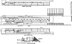
EXPLOSIVES TESTING GALLERY No. 1
Natural gas from the mains of the City of Pittsburg is used to represent
that found in the mines by actual analysis. A typical analysis of this
gas is as follows:
Volumetric Analysis of Typical Natural Gas.
| Hydrogen gases |
0 |
| Carbon dioxide |
0.1 |
| Oxygen |
0 |
| Heavy hydrocarbons |
0 |
| Carbon monoxide |
0 |
| Methane |
81.8 |
| Ethane |
16.8 |
| Nitrogen |
1.3 |
The volume of gas used is measured by an accurate test meter reading to
one-twentieth of a cubic foot. The required amount is admitted near the
bottom, to one or more of the 20-ft. divisions of the gallery, from a
2-in. pipe, 14 ft. long. The pipe has perforations arranged so that an
equal flow of gas is maintained from each unit length.
Each 20-ft. division of the gallery is further equipped with an exterior
circulating system, as shown by Fig. 1, thus
providing an efficient method of mixing the gas with the air. For the
first division this circulating system is stationary, a portion of the
piping being equipped with heating coils for maintaining a constant
temperature.
The other divisions have a common circulating system mounted on a truck
which may be used on any of these divisions. Valves are provided for
isolating the fan so that a possible explosion will not
injure it.
In the center section of each division is an indicator cock which is
used to provide means of recording pressures above and below
atmospheric, or of sampling the air-and-gas mixture. The first division
of the gallery is equipped with shelves laterally placed, for the
support of coal dust.
The cannon in which the explosive is fired is placed in the concrete
head, the axial line of the bore-hole being coincident with that of the
gallery. This cannon (Fig. 2) is similar to
that used in the ballistic pendulum. The charge is fired electrically
from the observation room. To minimize the risk of loading the cannon,
the charger carries in his
pocket the plug of a stage switch (the only plug of its kind on the
ground), so that it is impossible to complete the circuit until the
charger has left the gallery. That portion of the first division of the
gallery which is not embedded in concrete, has a 3-in. covering made up
of blocks of magnesia, asbestos fiber, asbestos, cement, a thin layer of
8-oz. duck, and strips of water-proof roofing paper, the whole being
covered with a thick coat of graphite paint. The object of this covering
is to assist in maintaining a constant temperature.
Fig. 2.
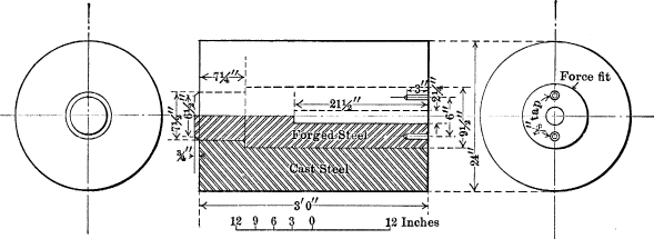
The entire gallery rests on a concrete foundation 10 ft. wide, which has
a maximum height of 4½ ft. and a minimum height of 2 ft.
The concrete head in which the cannon is placed completely closes that
end of the gallery. A narrow drain extends under the entire length of
the gallery, and a tapped hole at the bottom of each section provides an
efficient means of drainage.
The buildings near the gallery are protected by two barricades near the
open end, each 10 ft. high and 30 ft. long. A back-stop, consisting of a
swinging steel plate, 6 ft. high and 9 ft. long, 50 ft. from the end of
the gallery, prevents any of the stemming from doing damage.
Tests are witnessed from an observation room, a protected position about
60 ft. from the gallery. The walls of the room are 18 in. thick, and the
line of vision passes through a ½-in. plate glass, 6 in. wide and 37 ft.
long, and is further confined by two external guards, each 37 ft. long
and 3 ft. wide.
In this gallery a series of experiments has been undertaken to determine
the amount of moisture necessary with different coal dusts, in order to
reduce the likelihood of a coal-dust explosion from a blown-out shot of
one of the dangerous types of explosives.
Coal dust taken from the roads of one of the coal mines in the Pittsburg
district required at least 12% of water to prevent an ignition. It has
also been proven that the finer the dust the more water is required, and
when it was 100-mesh fine, 30% of water was required to prevent its
ignition by the flame of a blown-out shot in direct contact. The methods
now used in sprinkling have been proven entirely insufficient for
thoroughly moistening the dust, and hence are unreliable in preventing a
general dust explosion.
At this station successful experiments have been carried out by using
humidifiers to moisten the atmosphere after the temperature of the air
outside the gallery has been raised to mine temperature and drawn
through the humidifiers. It has been found that if a relative humidity
of 90%, at a temperature of 60° Fahr., is maintained for 48 hours,
simulating summer conditions in a mine, the absorption of moisture by
the dust and the blanketing effect of the humid air prevent the general
ignition of the dust.
These humidity tests have been run in Gas and Dust Gallery No. 1 with
special equipment consisting of a Koerting exhauster having a capacity
of 240,000 cu. ft. per hour, which draws the air out of the gallery
through the first doorway, or that next the concrete head in which the
cannon is embedded.
The other end of the gallery is closed by means of brattice cloth and
paper diaphragms, the entire gallery being made practically air-tight.
The air enters the fifteenth doorway through a box, passing over steam
radiators to increase its temperature, and then through the humidifier
heads.
Explosives Testing Apparatus.
There is no exposed woodwork in Building No. 17, which is 40 by 60 ft.,
two stories high, and substantially constructed of heavy stone masonry,
with a slate roof. The structure within is entirely fire-proof. Iron
columns and girders, and wooden girders heavily encased in cement,
support the floors which are either of cement slab construction or of
wooden flooring protected by expanded metal and cement mortar, both
above and beneath. At one end, on the ground floor, is the exposing and
recording apparatus for flame tests of explosives, also pressure gauges,
and a calorimeter, and, at the other end, is a gallery for testing
safety lamps.
The larger portion of the second floor is occupied by a gas-tight
training room for rescue work, and an audience chamber, from which
persons interested in such work may observe the methods of procedure. A
storage room for rescue apparatus and different models of safety lamps
is also on this floor.
The disruptive force of explosives is determined in three ways, namely,
by the ballistic pendulum, by the Bichel pressure gauge, and by Trauzl
lead blocks.
Ballistic Pendulum.—The disruptive force of explosives, as
tested by the ballistic pendulum, is measured by the amount of
oscillation. The standard unit of comparison is a charge of ½ lb. of 40%
nitro-glycerine dynamite. The apparatus consists essentially of a 12-in.
mortar (Fig. 3, Plate VI), weighing
31,600 lb., and suspended as a pendulum from a beam having knife-edges.
A steel cannon is mounted on a truck set on a track laid in line with
the direction of the swing of the mortar. At the time of firing the
cannon may be placed 1/16-in. from the muzzle of the mortar. The beam,
from which the mortar is suspended, rests on concrete walls, 51 by 120
in. at the base and 139 in. high. On top of each wall is a 1-in.
base-plate, 7 by 48 in., anchored to the wall by ⅝-in. bolts, 28 in.
long. The knife-edges rest on bearing-plates placed on these
base-plates. The bearing-plates are provided with small grooves for the
purpose of keeping the knife-edges in oil and protected from the
weather. The knife-edges are each 6 in. long, 2 11/16 in. deep from
point to back, 2 in. wide at the back, and taper 50° with the
horizontal, starting on a line 1½ in. from the back. The point is
rounded to conform to a radius of ¼ in. The back of each is 2 in. longer
than the edge, making a total length of 10 in., and is 1 in. deep and 12
in. wide. This shoulder gives bolting surface to the beam from which the
mortar is hung. The beam is of solid steel, has a 4 by 8-in. section,
and is 87 in. long. Heavy steel castings are bolted to it to take the
threads of the machine-steel rods which form the saddles on which the
mortar is suspended. The radius of the swing, measured from the point of
the knife-edges to the center of the trunnions, is 89¾ in.
Plate VI.
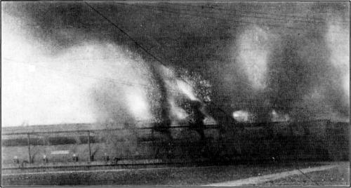
Fig. 1.—Explosion from Coal Dust in Gas
and Dust Gallery No. 1.
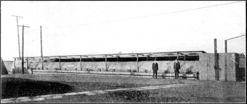
Fig. 2.—Mine Gallery No. 1.
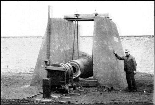
Fig. 3.—Ballistic Pendulum.
The cannon consists of two parts, a jacket and a liner. The jacket is 36
in. long, has an external diameter of 24 in., and internal diameters of
9½ and 7½ in. It is made of the best cast steel or of forged steel.
The liner is 36½ in. long, with a 1-in. shoulder, 7¾ in. from the
back, changing the diameter from 9½ to 7½ in. The bore is smooth, being
2¼ in. in diameter and 21½ in. long. The cannon rests on a 4-wheel
truck, to which it is well braced by straps and rods. A track of 30-in.
gauge extends about 9 ft. from the muzzle of the mortar to the bumper
for the cannon.
The shot is fired by an electric firing battery, from the first floor of
Building No. 17, about 10 yd. away. To insure the safety of the operator
and the charger, the man who loads the cannon carries a safety plug
without which the charge cannot be exploded. The wires for connecting to
the fuse after charging are placed conveniently, and the safety plug is
then inserted in a box at the end of the west wall. The completion of
the firing battery by the switch at the firing place is indicated by the
flashing of a red light, after which all that is necessary to set off
the charge is to press a button on the battery. An automatic recording
device at the back of the mortar records the length of swing which, by a
vernier, may be read to 1/200 in.
Bichel Pressure Gauges.—Pressure gauges are constructed for
the purpose of determining the unit disruptive force of explosives
detonating at different rates of velocity, by measuring pressures
developed in an enclosed space from which the generated gases cannot
escape. The apparatus consists of a stout steel cylinder, which may be
made absolutely air-tight; an air-pump and proper connections for
exhausting the air in the cylinder to a pressure equivalent to 10 mm. of
mercury; an insulated plug for providing the means of igniting the
charge; a valve by which the gaseous products of combustion may be
removed for subsequent analysis; and an indicator drum (Fig. 1,
Plate VII) with proper connections for
driving it at a determinable speed.
Plate
VII.
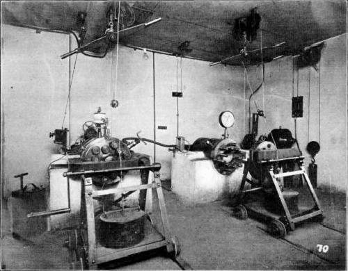
Fig. 1.—Bichel Pressure
Gauges.
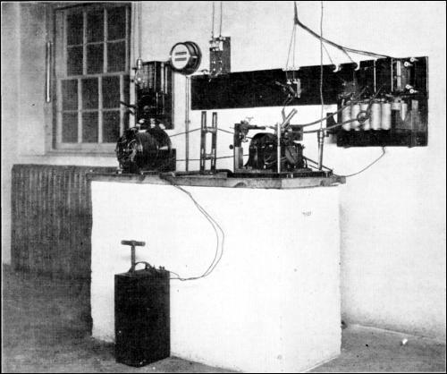
Fig. 2.—Rate of Detonation
Recorder.
This apparatus is in the southeast corner of Building No. 17. The
cylinder is 31½ in. long, 19¾ in. in diameter, and is anchored to a
solid concrete footing at a convenient height for handling. The
explosion chamber is 19 in. long and 7⅞ in. in diameter, with a capacity
of exactly 15 liters. The cover of the cylinder is a heavy piece of
steel held in place by stout screw-bolts and a heavy steel clamp.
The charge is placed on a small wire tripod, and connections are made
with a fuse to an electric firing battery for igniting the charges. The
cover is drawn tight, with the twelve heavy bolts against lead washers.
The air in the cylinder is exhausted to 10 mm., mercury column, in order
to approach more closely the conditions of a stemmed
charge exploding in a bore-hole inaccessible to air; the indicator drum
is placed in position and set in motion; and, finally, the shot is
fired. The record shown on the indicator card is a rapidly ascending
curve for quick explosives and a shallower, slowly rising curve for
explosives of slow detonation. When the gases cool, the curve merges
into a straight line, which indicates the pressures of the cooled gases
on the sides of the chamber.
Since the ratio of the volume of the cylinder to the volume of the
charge may be computed, the pressure of the confined charge may also be
found, and this pressure often exceeds 100,000 lb. per sq. in. The
cooling effect of the inner surface on the gaseous products of
combustion, a vital point in computations of the disruptive force of
explosives by this method, is determined by comparing the pressures
obtained in the original cylinder with those in a second cylinder of
larger capacity, into which has been inserted one or more steel
cylinders to increase the superficial area while keeping the volume
equal to that of the first cylinders. By comparing results, a curve may
be plotted, which will determine the actual pressures developed, with
the surface-cooling effect eliminated.
Trauzl Lead Blocks.—The lead-block test is the method
adopted by the Fifth International Congress of Applied Chemistry as the
standard for measuring the disruptive force of explosives. The unit by
this test is defined to be the force required to enlarge the bore-hole
in the block to an amount equivalent to that produced by 10 grammes of
standard 40% nitro-glycerine dynamite stemmed with 50 grammes of dry
sand under standard conditions as produced with the tamping device. The
results of this test, when compared with those of the Bichel gauge,
indicate that, for explosives of high detonation, the lead block is
quite accurate, but for slow explosives, such as gunpowder, the
expansion of the gases is not fast enough to make comparative results of
value. The reason for this is that the gases escape through the bore of
the block rather than take effect in expanding the bore-hole.
The lead blocks are cylindrical, 200 mm. in diameter, and 200 mm. high.
Each has a central cavity, 25 mm. in diameter and 125 mm. deep
(Fig. 1, Plate IX), in which the
charge is placed. The blocks are made of desilverized lead of the best
quality, and, as nearly as possible, under identical conditions. The
charge is placed in the cavity and prepared for detonation with an
electrical exploder and
stemming. After the explosion the bore-hole is pear-shaped, the size of
the cavity depending, not only on the disruptive power of the explosive,
but also on its rate of detonation, as already indicated. The size of
the bore-hole is measured by filling the cavity with water from a
burette. The difference in the capacity of the cavity before and after
detonation indicates the enlarging power of the explosive.
Calorimeter.—The explosion calorimeter is designed to
measure the amount of heat given off by the detonation of explosive
charges of 100 grammes. The apparatus consists of the calorimeter bomb
(Fig. 1, Plate VIII), the inner
receiver or immersion vessel, a wooden tub, a registering thermometer,
and a rocking frame. This piece of apparatus stands on the east side of
Building No. 17.
The bottle-shaped bomb is made of ½-in. wrought steel, and has a
capacity of 30 liters. On opposite sides near the top are bored
apertures, one for the exhaust valve for obtaining a partial vacuum
(about 20 mm., mercury column) after the bomb has been charged, the
other for inserting the plug through which passes the fuse wire for
igniting the charge. The bomb is closed with a cap, by which the chamber
may be made absolutely air-tight. It is 30 in. high with the cap on,
weighs 158 lb., and is handled to and from the immersion vessel by a
small crane.
The inner receiver is made of 1/16-in. sheet copper, 30⅞ in. deep, and
with an inner diameter of 17⅞ in. It is nickel-plated, and strengthened
on the outside with bands of copper wire, and its capacity is about 70
liters. The outer tub is made of 1-in. lumber strengthened with four
brass hoops on the outside. It is 33 in. deep, and its inner diameter is
21 in.
The stirring device, operated vertically by an electric motor, consists
of a small wooden beam connected to a system of three rings having a
horizontal bearing surface. When the apparatus is put together, the
inner receiver rests on a small standard on top of the base of the outer
tank, and the rings of the stirring device are run between the bomb and
the inner receiver. The bomb itself rests on a small standard placed on
the bottom of the inner receiver. The apparatus is provided with a
snugly fitting board cover. The bomb is charged from the top, the
explosive being suspended in its center. The air is exhausted to the
desired degree of rarification. The caps are then screwed on, and the
apparatus is set together as described.
The apparatus is assembled on scales and weighed before the water is
poured in and after the receiver is filled. From the weight of the water
thus obtained and the rise of temperature, the calorific value may be
computed. The charge is exploded by electricity, while the water is
being stirred. The rise in the temperature of the water is read by a
magnifying glass, from a thermometer which measures temperature
differences of 0.01 degree. From the readings obtained, the maximum
temperature of explosion may be determined, according to certain
formulas for calorimetric experiments. Proper corrections are made for
the effects, on the temperature readings, of the formation of the
products of combustion, and for the heat-absorbing power of the
apparatus.
Impact Machine.—In Building No. 17, at the south side, is
an impact machine designed to gauge the sensitiveness of explosives to
shock. For this purpose, a drop-hammer, constructed to meet the
following requirements, is used: A substantial, unyielding foundation;
minimum friction in the guide-grooves; and no escape or scattering of
the explosive when struck by the falling weight. This machine is modeled
after one used in Germany, but is much improved in details of
construction.
The apparatus, Fig. 1, Plate XI,
consists essentially of the following parts: An endless chain working in
a vertical path and provided with lugs; a steel anvil on which the charge
of explosive is held by a steel stamp; a demagnetizing collar moving
freely in vertical guides and provided with jaws placed so that the lugs
of the chain may engage them; a steel weight sliding loosely in vertical
guides and drawn by the demagnetizing collar to determinable heights
when the machine is in operation; a second demagnetizing collar, which
may be set at known heights, and provided with a release for the jaws of
the first collar; and a recording device geared to a vertically-driven
threaded rod which raises or lowers, sets the second demagnetizing
collar, and thus determines the height of fall of the weight. By this
apparatus the weight may be lifted to different known heights, and
dropped on the steel stamp which transmits the shock to the explosive.
The fall necessary to explode the sample is thus determined.
The hammers are of varying weight, the one generally used weighing 2,000
grammes. As the sensitiveness of an explosive is influenced by
temperature changes, water at 25° cent. is allowed to flow through the
anvil in order to keep its temperature uniform.
Flame Test.—An apparatus, Fig. 2, Plate VIII, designed to measure the length and
duration of flames given off by explosives, is placed at the northeast
corner of Building No. 17. It consists essentially of a cannon, a
photographing device, and a drum geared for high speed, to which a
sensitized film may be attached.
Plate
VIII.
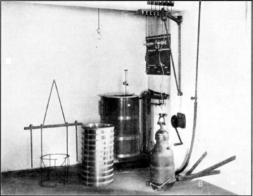
Fig. 1.—Explosives
Calorimeter.
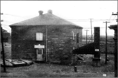
Fig. 2.—Building No. 17, and Flame-Test
Apparatus.

Fig. 3.—Small Lead Block
Test.
About 13 ft. outside the wall of Building No. 17, set in a concrete
footing, is a cannon pointing vertically into an encasing cylinder or
stack, 20 ft. high and 43 in. in diameter. This cannon is a duplicate of
the one used for the ballistic pendulum, details of which have already
been given. The stack or cylinder is of ¼-in. boiler plate, in
twenty-four sections, and is absolutely tight against light at the base
and on the sides. It is connected with a dark room in Building No. 17 by
a light-tight conduit of rectangular section, 12 in. wide, horizontal on
the bottom, and sloping on the top from a height of 8¼ ft. at the stack
to 21 in. at the inside of the wall of the building.
The conduit is carefully insulated from the light at all joints, and is
riveted to the stack. A vertical slit, 2 in. wide and 8 ft. long,
coincident with the center line of the conduit, is cut in the stack. A
vertical plane drawn through the center line of the bore-hole of the
cannon and that of the slit, if produced, intersects the center line of
a quartz lens, and coincides with the center of a stenopaic slit and the
axis of the revolving drum carrying the film. The photographing
apparatus consists of a shutter, a quartz lens, and a stenopaic slit, 76
by 1.7 mm., between the lens and the sensitized film on the rotary drum.
The quartz lens is used because it will focus the ultra-violet rays,
which are those attending extreme heat.
The drum is 50 cm. in circumference and 10 cm. deep. It is driven by a
220-volt motor connected to a tachometer which reads both meters per
second and revolutions per minute. A maximum peripheral speed of 20 m.
per sec. may be obtained.
When the cannon is charged, the operator retires to the dark room in
which the recording apparatus is located, starts the drum, obtains the
desired speed, and fires the shot by means of a battery. When developed,
the film shows a blur of certain dimensions, produced by the flame from
the charge. From the two dimensions—height and lateral
displacement—the length and duration of the flame of the explosive
are determined.
The results of flame tests of a permissible explosive and a test of
black blasting powder, all shot without stemming, are shown on
Fig. 2, Plate IX. In this test, the
speed of the drum carrying the black powder negative was reduced to one
sixty-fourth of that for the permissible explosives, in order that the
photograph might come within the limits of the negative. In other words,
the duration of the black powder flame, as shown, should be multiplied
by 64 for comparison with that of the permissible explosive, which is
from 3,500 to 4,000 times quicker.
Plate IX.
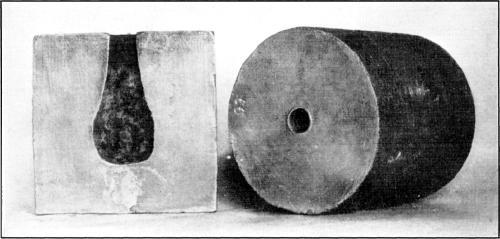
Fig. 1.—Trauzl Lead Blocks.
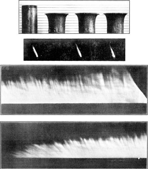
Fig. 2.—Powder Flames.
Apparatus for Measuring Rate of Detonation.—The rate at
which detonation travels through a given length of an explosive can be
measured by an apparatus installed in and near Building No. 17. Its most
essential feature is a recording device, with an electrical connection,
by which very small time intervals can be measured with great
exactness.
The explosive is placed in a sheet-iron tube about 1½ in. in diameter
and 4 ft. long, and suspended by cords in a pit, 11 ft. deep and 16 ft.
in diameter. This pit was once used as the well of a gas tank, Fig. 2,
Plate VIII. In adapting the pit to its
new use, the tank was cut in two; the top half, inverted, was placed in
the pit on a bed of saw-dust, and the space between the tank and the
masonry walls of the pit was filled with saw-dust. The cover of the pit
consists of heavy timbers framed together and overlaid by a 12-in. layer
of concrete reinforced by six I-beams. Four
straps extend over the top and down to eight “deadmen” planted about 8
ft. below the surface of the ground.
The recording device, known as the Mettegang recorder, Fig. 2,
Plate VII, comprises two sparking induction coils
and a rapidly revolving metallic drum driven by a small motor, the
periphery of the drum having a thin coating of lampblack. A vibration
tachometer which will indicate any speed between 50 and 150 rev. per
sec., is directly connected to the drum, so that any chance of error by
slipping is eliminated. The wires leading to the primary coils of the
sparking coils pass through the explosive a meter or more apart. Wires
lead from the secondary coils to two platinum points placed a fraction
of a millimeter from the periphery of the drum. A separate circuit is
provided for the firing lines.
In making a test, the separate cartridges, with the paper trimmed from
the ends, are placed, end to end, in the sheet-iron tube; the drum is
given the desired peripheral speed, and the charge is exploded. The
usual length between the points in the tube is 1 m., and the time
required for the detonation of a charge of that length is shown by the
distance between the beginning of two rows of dots on the drum made by
the sparks from the secondary coil circuits, the dots starting the
instant the primary circuits are broken by the detonation. At one end of
the drum are gear teeth, 1 mm. apart on centers, which can be made to
engage a worm revolving a pointer in front of a dial graduated to
hundredths; by means of this and a filar eyepiece, the distance between
the start of the two rows of spark dots on the drum can be measured
accurately to 0.01 mm. As the drum is 500 mm. in circumference, and its
normal speed is 86 rev. per sec., it is theoretically possible to
measure time to one four-millionth of a second, though with a cartridge
1 m. long, such refinement has not been found necessary.
The use of small lead blocks affords another means of determining the
rate of detonation or quickness of an explosive. Each block (a cylinder,
2½ in. long and 1½ in. in diameter) is enclosed in a piece of paper so
that a shell is formed above the block, in which to place the charge. A
small steel disk of the same diameter as the block is first placed in
the shell on top of the block, then the charge with a detonator is
inserted. The charge is customarily 100 grammes. On detonation of the
charge, a deformation of the lead takes place, the amount of which is
due to the quickness of the explosive used (Fig. 3, Plate VIII).
Sample Record of Tests.
The procedure followed in the examination of an explosive is shown by
the following outline:
1.—Physical Examination.
(a).—Record of appearance and marks on original
package.
(b).—Dimensions of cartridge.
(c).—Weight of cartridge, color and specific gravity of
powder.
2.—Chemical Analysis.
(a).—Record of moisture, nitro-glycerine, sodium or
potassium nitrate, and other chemical constituents, as set forth by the
analysis; percentage of ash, hygroscopic coefficient—the amount of
water taken up in 24 hours in a saturated atmosphere, at 15° cent., by 5
grammes, as compared with the weight of the explosive.
(b).—Analysis of products of combustion from 100 grammes,
including gaseous products, solids, and water.
(c).—Composition of gaseous products of combustion,
including carbon monoxide and carbon dioxide, hydrogen, nitrogen,
etc.
(d).—Composition of solid products of combustion,
subdivided into soluble and insoluble.
3.—A Typical Analysis of Natural Gas.
Used in tests, as follows:
| Carbon dioxide |
0.0 |
per cent. |
| Heavy hydrocarbons |
0.2 |
” ” |
| Oxygen |
0.1 |
” ” |
| Carbon monoxide |
0.0 |
” ” |
| Methane |
82.4 |
” ” |
| Ethane |
15.3 |
” ” |
| Nitrogen |
2.0 |
” ” |
| 100.00 |
per cent. |
4.—Typical Analysis of Bituminous Coal Dust, 100-Mesh Fine,
Used in Tests.
| Moisture |
1.90 |
| Volatile matter |
35.05 |
| Fixed carbon |
58.92 |
| Ash |
4.13 |
|
100.00 |
| Sulphur |
1.04 |
5.—An Average Analysis of Detonators.
Used on Trauzl lead blocks, pressure gauge, calorimeter, and small lead
blocks:
| M - l |
l |
. Triple-strength exploder. |
| m |
| Charge |
1.5729 grammes. |
| |
| |
Mercury
fulminate. |
Chlorate
of potash. |
| Specification |
89.73 |
10.27 |
Used on all other tests:
| M - 260 |
l |
. Double-strength exploder. |
| m |
| Charge |
0.9805 grammes. |
| |
| |
Mercury
fulminate. |
Chlorate
of potash. |
| Specification |
91.31 |
8.69 |
6.—Ballistic-Pendulum Tests.
This record includes powder used, weight of charge, swing of mortar, and
unit disruptive charge, the latter being the charge required to produce
a swing of the mortar equal to that produced by ½ lb. (227 grammes) of
40% dynamite, or 3.01 in.
7.—Record of Tests.
Tests Nos. 1 to 5 in Gallery No. 1, as set forth in preceding
circular.
8.—Trauzl Lead-Block Test.
Powder and test numbers, expansion of bore-hole in cubic centimeters,
and average expansion compared with that produced by a like quantity (10
grammes) of 40% dynamite, the latter giving an average expansion of 294
cu. cm.
9.—Pressure Gauge.
Powder and test number, weight of charge, charging density, height of
curve, pressure developed, and pressure developed after cooling,
compared with pressure developed after elimination of surface influences
by a like quantity (100 grammes) of 40% dynamite, the average being
8,439 kg. per sq. cm.
10.—Rate of Detonation.
Powder and test number, size of cartridge, and rate of detonation in
meters per second, for comparison with rate of detonation of 40%
dynamite, which, under the same conditions, averages 4,690 m.
per sec.
11.—Impact Machine.
Explosive and test numbers, distance of fall (2,000-gramme weight)
necessary to cause explosion, for comparison with length of fall, 11
cm., necessary to cause explosion of 40% dynamite.
12.—Distance of Explosive Wave Transmitted by 1.25 by 8-in.
Cartridge.
Explosive and test numbers, weight of cartridge, distance separating
cartridges in tests, resulting explosion or non-explosion, for
comparison with two cartridges of 40% dynamite, hung, under identical
conditions, 13 in. apart, end to end, in which case detonation of the
first cartridge will explode the second.
13.—Flame Test.
Explosive and test numbers, charge 100 grammes with 1 lb. of clay
stemming, average length of flame and average duration of flame, for
comparison with photographs produced by 40% dynamite under like
conditions.
14.—Small Lead Blocks.
Powder and test numbers, weight of charge, and compression produced in
blocks.
15.—Calories Developed.
Number of large calories developed per kilogramme of explosive, for
comparison with 1,000 grammes of 40% dynamite, which develop, on an
average, 1,229 large calories.
Blasting Powder Separator.
The grains of black blasting powder are graded by a separator, similar
to those used in powder mills, but of reduced size. It consists of an
inclined wooden box, with slots on the sides to carry a series of
screens, and a vertical conduit at the end for carrying off the grains
as they are screened into separate small bins (Fig. 1, Plate X). At the upper end of the screens is a small
12 by 16-in. hopper, with a sliding brass apron to regulate the feed.
The screens are shaken laterally by an eccentric rod operated by hand.
The top of the hopper is about 6½ ft. above the floor. The box is 6 ft.
10 in. long, from tip to tip, and inclines at an angle of 9 degrees.
Plate X.
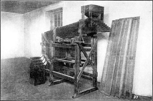
Fig. 1.—Separator for Grading Black
Powder.
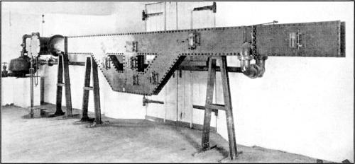
Fig. 2.—Safety Lamp Testing
Gallery.
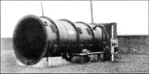
Fig. 3.—Mine Gallery No. 2.
After separation the grains fall through a vertical conduit, and thence
to the bins through zinc chutes, 1 by 2 in. in section. Care is taken to
have no steel or iron exposed to the powder.
The screens are held by light wooden frames which slip into the inclined
box from the upper end. In this way, any or all of the screens may be
used at once, thus separating all grades, or making only such
separations as are desired. The screens with the largest meshes are
diagonally-perforated zinc plates. Table 2 gives the number of holes per
square foot in zinc plates perforated with circular holes of the
diameters stated.
TABLE 2.—Number of Holes per Square Foot
in Zinc Plates with Circular Perforations.
Diameter,
in inches |
Number
of holes. |
| 1/2 |
353 |
| 4/10 |
518 |
| 1/3 |
782 |
| 1/4 |
1,392 |
| 1/6 |
1,680 |
| 1/8 |
3,456 |
| 1/10 |
6,636 |
| 1/16 |
12,800 |
The finer meshes are obtained by using linen screens with holes of two
sizes, namely, 1/20 in. square and 1/28 in. square.
Until a few years ago, black blasting powder was manufactured in the
sizes given in Table 3.
TABLE 3.—Gradation of Black Blasting
Powder.
| Grade. |
Mesh. |
| CC |
2-2½ |
| C |
2½-3 |
| F |
3-5 |
| FF |
5-8 |
| FFF |
8-16 |
| FFFF |
16-28 |
In late years there has been considerable demand for special sizes and
mixed grains for individual mines, especially in Illinois. As no
material change has been made in the brands, the letters now used are
not indicative of the size of the grains, which they are supposed to
represent. Of 29 samples of black blasting powder recently received from
the Illinois Powder Commission, only 10 were found to contain 95% of the
size of grains they were supposed to represent; 4 contained 90%; 7
varied from 80 to 90%; several others were mixtures of small and large
grains, and were branded FF black blasting powder; and one sample
contained only 8.5% of the size of grains it was supposed to represent.
The remaining samples showed many variations, even when sold under the
same name. The practice of thus mixing grades is exceedingly dangerous,
because a miner, after becoming accustomed to one brand of FF powder of
uniform separation, may receive another make of similar brand but of
mixed grains, and, consequently, he cannot gauge the quantity of powder
to be used. The result is often an over-load or a blown-out shot. The
smaller grains will burn first, and the larger ones may be thrown out
before combustion is complete, and thus ignite any fire-damp
present.
Plate XI.
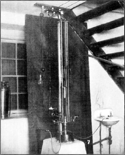
Fig. 1.—Impact Machine.
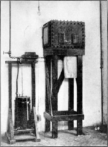
Fig. 2.—Lamp Testing Box.
Lamp Testing Gallery.
At the Pittsburg testing station, there is a gallery for testing safety
lamps in the presence of various percentages of inflammable gas. In this
gallery the safety of the lamps in these gaseous mixtures may be tested,
and it is also possible for mine inspectors and fire bosses to bring
their safety lamps to this station, and test their measurements of
percentage of gas, by noting the length and the appearance of the flame
in the presence of mixtures containing known percentages of methane
and air.
The gas-tight gallery used for testing the lamps, consists of a
rectangular conduit (Fig. 2, Plate X),
having sheet-steel sides, 6 mm. thick and 433 mm. wide, the top and
bottom being of channel iron. The gallery rests on two steel trestles,
and to one end is attached a No. 5 Koerting exhauster, capable of
aspirating 50 cu. m. per min., under a pressure of 500 mm. of water,
with the necessary valve, steam separator, etc. The mouth of the
exhauster passes through the wall of the building and discharges into
the open air.
Besides the main horizontal conduit, there are two secondary conduits
connected by a short horizontal length, and the whole is put together so
that the safety lamp under test may be placed in a current of air, or of
air and gas, which strikes it horizontally, vertically upward or
downward, or at an angle of 45° (Fig. 3).
The path of the current is determined by detachable sheet-steel
doors.
Fig. 3.
![SAFTY [sic] LAMP TESTING GALLERY](https://openoldbooks.sgp1.digitaloceanspaces.com/books/asce-paper-1171/images/fig3.png "SAFTY [sic] LAMP TESTING GALLERY")
There are five double observing windows of plate glass, which open on
hinges. The size of each window is 7½ by 3 in.; the inner glass is ¼ in.
thick and the outer one, ½ in. thick. These glasses are separated by a
space of ¼ in. The upper conduit has four safety doors along the top,
each of the inclined conduits has one safety door, and the walls and
windows are provided with rubber gaskets or asbestos packing, to make
them gas-tight. The cross-sectional area of the conduit is 434
sq. cm.
The air inlet consists of 36 perforations, 22 mm. in diameter, in a
bronze plate or diaphragm. The object of this diaphragm is to produce
pressure in the conduit before the mixing boxes, and permit the
measuring of the velocity of the current. The air-current, after
passing through the holes, enters the mixer, a cast-steel box traversed
by 36 copper tubes, each perforated by 12 openings, 3 mm. in diameter,
arranged in a spiral along its length and equally spaced. The total
cross-sectional area of the tubes is 137 sq. cm.
The explosive gas enters the interior of the box around the tubes
through large pipes, each 90 mm. in diameter, passes thence through the
432 openings in the copper tubes, and mixes thoroughly with the air
flowing through these tubes. The current through the apparatus is
induced by the exhauster, and its course is determined by the position
of the doors.
The gallery can be controlled so as to provide rapidly and easily a
current of known velocity and known percentage of methane. In the
explosive current of gas and air, safety lamps of any size or design can
be tested under conditions simulating those found occasionally in mines,
air-currents containing methane in dangerous proportions striking the
lamps at different angles, and the relative safety of the various types
of lamps under such conditions can be determined. In this gallery it is
also possible to test lighting devices either in a quiet atmosphere or
in a moving current, and, by subjecting the lamps to air containing
known percentages of methane, it is possible to acquaint the user with
the appearance of the flame caps.
Breathing Apparatus.
With this apparatus, the wearer may explore a gaseous mine, approach
fires for the purpose of fighting them, or make investigations after an
explosion. Its object is to provide air or oxygen to be breathed by the
wearer in coal mines, when the mine air is so full of poisonous gases as
to render life in its presence impossible.
A variety of forms of rescue helmets and apparatus are on the market,
almost all of European manufacture, which are being subjected to
comparative trials as to their durability and safety, the ease or
inconvenience involved in their use, etc. All consist essentially of
helmets which fit air-tight about the head, or of air-tight nose clamps
and mouthpieces (Fig. 1, Plate XII).
These several forms of breathing apparatus are of three types:
1.—The liquid-air type, in which air, in a liquid state,
evaporates and provides a constant supply of fresh air.
2.—The chemical oxygen-producing type, which artificially makes or
supplies oxygen for breathing at about the rate required; and,
3.—The compressed-oxygen type.
Apparatus of the first type, weighing 20 lb., supplies enough air to
last about 3 hours, and the products of breathing pass through a
check-valve directly into space. Apparatus of the second type supplies
oxygen obtained from oxygen-producing chemicals, and also provides means
of absorbing the carbonic acid gas produced in respiration. They contain
also the requisite tubes, valves, connections, etc., for the
transmission of the fresh air and the respired air so as to produce
sufficient oxygen while in use; to absorb and purify the products of
expiration; and to convey the fresh air to the mouth without
contamination by the atmosphere in which the apparatus is used. Three
oxygen-generating cartridges are provided, each supplying oxygen enough
for 1 hour, making the total capacity 3 hours. Changes of cylinders can
be made in a few seconds while breathing is suspended. This apparatus
weighs from 20 to 25 lb., according to the number of oxygen generators
carried. The cartridges for generating oxygen, provided with this
apparatus, are of no value after having been used for about an hour.
The third type of apparatus is equipped with strong cylinders charged
with oxygen under high pressure; two potash regenerative cans for
absorbing the carbon dioxide gas exhaled; a facial helmet; the necessary
valves, tubes, etc., for the control of the oxygen; and a finimeter
which registers the contents of the cylinders in atmospheres and minutes
of duration. The two cartridges used for absorbing the carbonic acid gas
are of no value after having been in use for two hours.
If inhalation is through the mouth alone, a mouthpiece is attached to
the end of the breathing tube by which the air or oxygen is supplied,
the nose is closed by a clip, and the eyes are protected by goggles. To
inhale through both nose and mouth, the miner wears a helmet or headgear
which can be made to fit tightly around the face. The helmet has two
tubes attached, one for inspiration and the other for expiration. In the
oxygen-cylinder apparatus these tubes lead to and from rubber sacks used
for pure-air and bad-air reserves.
Mine-Rescue Training.
It has been found in actual service that when a miner, equipped with
breathing apparatus for the first time, enters a mine in which an
explosion has occurred, he is soon overcome by excitement or
nervousness induced by the artificial conditions of breathing imposed by
the apparatus, the darkness and heat, and the consciousness that he is
surrounded with poisonous gases. It has also been found that a brief
period of training in the use of such apparatus, under conditions
simulating those encountered in a mine after a disaster, gives the miner
confidence and enables him to use the apparatus successfully under the
strain of the vigorous exertion incident to rescue work.
The rescue corps consists of five or six miners under the direction of a
mining engineer who is experienced in rescue operations and familiar with the
conditions existing after mine disasters. The miners work in pairs, so
that one may assist the other in case of accident, or of injury to the
breathing apparatus, and so that each may watch the condition of the
oxygen supply, as shown by the gauges in the other’s outfit.
The training is given in the gas-tight room of Building No. 17, or in
similar rooms at sub-stations (Fig. 2, Plate XII). This room is made absolutely dark, and
is filled with formaldehyde gas, SO2, CO2, or CO,
produced by burning sulphur or charcoal on braziers. At each period of
training, the miners enter and walk a distance of about 1 mile, the
average distance usually traveled from the mine mouth to the working
face or point of explosion. They then remove a number of timbers; lift a
quantity of brick or hard lump-coal into wheel-barrows; climb through
artificial tunnels, up and down inclines, and over surfaces strewn with
coal or stone; operate a machine with a device attached to it, which
automatically records the foot-pounds of work done; and perform other
vigorous exercise, during a period of 2 hours. This routine is repeated
daily during 1 week, after which the rescue corps is considered
sufficiently trained for active service.
Plate
XII.
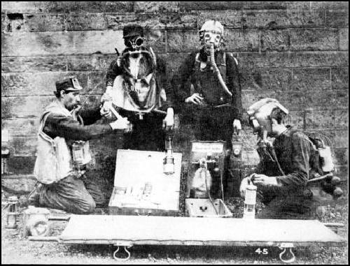
Fig. 1.—Breathing and Rescue
Apparatus.
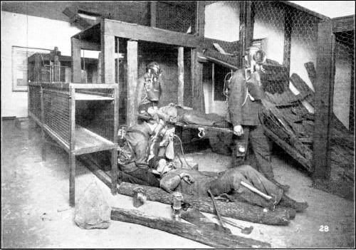
Fig. 2.—Rescue Training Room.
The apparatus used for recording the foot-pounds of work done by the
person operating the work machine within the gas-tight rescue room,
comprises a small dial with electrical connections, which records the
number of strokes made by the machine, and a pencil point which rests on
a paper diaphragm, fastened to a horizontal brass disk. This disk is
driven by clockwork, and makes one complete revolution per hour. When
the machine is in operation, the pencil point works back and forth,
making a broad line on the paper; when the operator of the machine
rests, the pencil point traces a single line. The
apparatus thus records the number of strokes given by the operator
during a given time. From the weight lifted, the height of lift, and the
number of strokes in the given time, the foot-pounds of work are readily
calculated.
Electric Testing Apparatus.
On the ground floor of Building No. 10, two rooms are occupied as
laboratories for investigating the electrical equipment used in mining
operations. The purpose of these investigations is to ascertain the
conditions under which electricity of various voltages may be used with
safety—in mine haulage, hoisting, pumping, or lighting—in
the presence of dangerous mixtures of explosive gases or of dust. It is
also proposed to test various kinds of insulation and insulators in this
laboratory, and to determine the durability of such insulation in the
presence of such corrosive gases and water as are found in mines.
A water-proof wooden tank, measuring 15 by 5 by 5 ft., is installed, in
which insulation and insulating materials are tested under either pure
or polluted water. Various electric lighting devices and equipment can
be connected from a switch-board in Building No. 17 with Gas-and-Dust
Gallery No. 2, for testing the effect of such lighting apparatus in the
presence of explosive mixtures of gas and dust, as set forth on page 220.
In the electrical laboratory, Building No. 10, is a booster set
developing 60 kw., and an appropriate switch-board for taking direct
current at 220 volts from the turbo-generator and converting it into
current varying from 0 to 750 volts. There are also transformers for
developing 60-cycle, alternating current at voltages of from 110 to
2,200. The switch-board is designed to handle these various voltages and
to communicate them to the apparatus under test in Building No. 10,
Gallery No. 2, or elsewhere.
Tests are in progress of insulating materials for use in mines, and of
electric fuses, lights, etc., in Gallery No. 2 (Fig. 3, Plate X), and in the lamp-testing box (Fig. 2, Plate XI). It is proposed, at the earliest
possible date, to make comparative tests of the safety of various mine
locomotives and mine-hoisting equipment through the medium of this
laboratory, and it is believed that the results will furnish valuable
information as a guide to the safety, reliability, and durability of
these appliances when electrically operated.
Electric Lamp and Fuse Testing Box.—An apparatus for
testing safety lamps and electric lights and fuses, consists of ¼-in.
iron plates, bolted together with 1½ in. angle-irons to form a box with
inside dimensions of 18 by 18 by 24 in. The box is placed on a stand at
such a height that the observation windows are on a level with the
observer’s eye (Fig. 2, Plate XI), and it
is connected, by a gas-pipe, with a supply of natural gas which can be
measured by a gas-holder or meter alongside the box.
By the use of this apparatus the effect of explosive gas on flames, of
electric sparks on explosive mixtures of gas and air, and of breaking
electric lamps in an explosive mixture of gas and air, may be studied.
The safety lamps are introduced into the box from beneath, through a
hole 6 in. square, covered with a hinged iron lid, admission to which is
had through a flexible rubber sleeve, 20 in. long.
The behavior of the standard safety lamp and of the safety lamps
undergoing test may be compared in this box as to height of flame for
different percentages of methane in the air, the effect of such flames
in igniting gas, etc.
In each end of the box is an opening 1 ft. square, over which may be
placed a paper diaphragm held by skeleton doors, the purpose of which is
to confine the gas in such a manner that, should an explosion occur, no
damage would be done. In the front of the box are two plate-glass
observing windows, 2⅝ by 5½ in. In the side of the box, between the two
windows, is a ⅜-in. hole, which can be closed by a tap-screw, through
which samples for chemical analysis are drawn.
The gasometer consists of two iron cans, the lower one being open at the
top and filled with water and the upper one open at the bottom and
suspended by a counterweight. The latter has attached to its upper
surface a scale which moves with it, thereby measuring the amount of gas
in the holder. A two-way cock permits the admission of gas into the
gasometer and thence into the testing box.
Gas-and-Dust Gallery No. 2.—This gallery is constructed of
sheet steel and is similar to Gallery No. 1, the length, however, being
only 30 ft. and the diameter 10 ft. It rests on a concrete foundation
(Fig. 3, Plate X). Diaphragms can be
placed across either extremity, or at various sections, to confine the
mixtures of gas and air in which the tests are made. The admission of
gas is controlled by pipes and valves, and the gas and air can be
stirred or mixed by a fan, as described for Gallery No. 1, and as shown
by Fig. 1.
Gallery No. 2 is used for investigating the effect of flames of various
lamps, of electric currents, motors, and coal-cutting machines, in the
presence of known mixtures of explosive gas and air. It is also used for
testing the length of flame of safety lamps in still air carrying
various proportions of methane, and, for this purpose, is more
convenient than the lamp gallery. In tests with explosive mixtures,
after the device to be tested has been introduced and preparations are
completed, operations are controlled from a safe distance by a
switch-board in a building near-by.
Among other investigations conducted in this gallery are those of the
effect of sparks on known gas mixtures. These sparks are such as those
struck from a pick on flint, but in this case they are produced by
rubbing a rapidly revolving emery wheel against a steel file. The effect
of a spark produced by a short circuit of known voltage, the flame from
an arc lamp, etc., may also be studied in this gallery.
Structural Materials Investigations.
The structural materials investigations are being conducted for the
purpose of determining the nature and extent of the materials available
for use in the building and construction work of the Government, and how
these materials may be used most efficiently.
These investigations include:
(1).—Inquiries into the distribution and local availability, near
each of the building centers in the United States, of such materials as
are needed by the Government.
(2).—How these materials may be used most efficiently.
(3).—Their fire-resisting qualities and strength at different
temperatures.
(4).—The best and most economic methods of protecting steel by
fire-resistant covering.
(5).—The most efficient methods of proportioning and mixing the
aggregate, locally available, for different purposes.
(6).—The character and value of protective coatings, or of various
mixes, to prevent deterioration by sea water, alkali, and other
destructive agencies.
(7).—The kinds and forms of reinforcement for concrete necessary
to secure the greatest strength in beams, columns, floor slabs, etc.
(8).—Investigation of the clays and of the products of clays
needed in Government works, as to their strength, durability,
suitability as
fire-resisting materials, and the methods of analyzing and testing clay
products.
(9).—Tests of building stones, and investigations as to their
availability near the various building centers throughout the United
States.
The operations of the Structural Materials Division include
investigations into cement-making materials, constituent materials of
concrete, building stones, clays, clay products, iron, steel, and
miscellaneous materials of construction, for the use of the Government.
The organization comprises a number of sections, including those for the
chemical and physical examination of Departmental purchases; field
sampling and laboratory examination of constituent materials of concrete
collected by skilled field inspectors in the neighborhood of the larger
commercial and building centers; similar field sampling of building
stones and of clays and clay products, offered for use in Government
buildings or engineering construction; and the forwarding of such
samples to the testing laboratories at St. Louis or Pittsburg for
investigation and test. The investigative tests include experiments
regarding destructive agencies, such as electrolysis, alkaline earths
and waters, salt water, fire, and weathering; also experiments with
protective and water-proofing agencies, including the various washes or
patented mixtures on the market, and the methods of washing, and mixing
mortars and concrete, which are likely to result in rendering such
materials less pervious to water.
Investigations are also being conducted to determine the nature and
extent of materials available for use in the building-construction work
of the Government, and how these materials may be used most efficiently
and safely. While the act authorizing this work does not permit
investigations or tests for private parties, it is believed that these
tests for the Government cannot fail to be of great general value. The
aggregate expenditure by the Federal Government in building and
engineering construction is about $40,000,000 annually. This work is
being executed under so many different conditions, at points so widely
separated geographically, and requires so great a variety of materials,
that the problems to be solved for the Government can hardly fail to
cover a large share of the needs of the Engineering Profession, State
and municipal governments, and the general public.
Character of the Work.—The tests and analyses, of the
materials of construction purchased by the various bureaus and
departments for the use of the Government, are to determine the
character, quality,
suitability, and availability of the materials submitted, and to
ascertain data leading to more accurate working values as a basis for
better working specifications, so as to enable Government officials to
use such materials with more economy and increased efficiency.
Investigative tests of materials entering into Government construction,
relative to the larger problems involved in the use of materials
purchased by the Government, include exhaustive study of the suitability
for use, in concrete construction on the Isthmian Canal, of the sand and
stone, and of the cementing value of pozzuolanic material, found on the
Isthmus; the strength, elasticity, and chemical properties of structural
steel for canal lock-gates; of wire rope and cables for use in hoisting
and haulage; and the most suitable sand and stone available for concrete
and reinforced concrete for under-water construction, such as the
retaining walls being built by the Quartermaster’s Department of the
Army, in San Francisco Harbor.
These tests also include investigations into the disintegrating effect
of alkaline soil and water on the concrete and reinforced concrete
structures of the Reclamation Service, with a view to preventing such
disintegration; investigations into the proper proportions and
dimensions of concrete and reinforced concrete structural columns,
beams, and piers, and of walls of brick and of building stone, and of
the various types of metal used for reinforcement by the Supervising
Architect in the construction of public buildings; investigations into
the sand, gravel, and broken stone available for local use in concrete
construction, such as columns, piers, arches, floor slabs, etc., as a
guide to the more economical design of public structures, and to
determine the proper method of mixing the materials to render the
concrete most impervious to water and resistant to weather and other
destructive agencies.
Other lines of research may be stated briefly as follows:
The extent to which concrete made from cement and local materials can be
most safely and efficiently used for different purposes under different
conditions;
The best methods for mixing and utilizing the various constituent
materials locally available for use in Government construction;
The materials suitable for the manufacture of cement on the public
lands, or where the Government has planned extensive building or
engineering construction work, where no cement plants now exist;
The kinds and forms of reinforcement for concrete, and the best
methods of applying them in order to secure the greatest strength in
compression, tension, shear, etc., in reinforced concrete beams,
columns, floor slabs, etc.;
The influence of acids, oils, salts, and other foreign materials,
long-continued strain, or electric currents, on the permanence of the
steel in reinforced concrete;
The value of protective coatings as preventives of deterioration of
structural materials by destructive agencies; and
The establishment of working stresses for various structural materials
needed by the Government in its buildings.
Investigations are being made into the effects of fire and the rate of
conductivity of heat on concrete and reinforced concrete, brick, tile,
building stone, etc., as a guide to the use of the most suitable
materials for fire-proof building construction and the proper
dimensioning of fire-resistive coverings.
Investigations and tests are being made, with a view to the preparation
of working specifications for use in Government construction, of bricks,
tile, sand-lime brick, paving brick, sewer pipe, roofing slates,
flooring tiles, cable conduits, electric insulators, architectural terra
cotta, fire-brick, and all shapes of refractories and other clay
products, regarding which no satisfactory data for the preparation of
specifications of working values now exist.
Investigations of the clay deposits throughout the United States are in
progress, to determine proper methods of converting them into building
brick, tile, etc., at the most reasonable cost, and the suitability of
the resulting material for erection in structural forms and to meet
building requirements.
Investigations are being made in the field, of building stones locally
available, and physical and chemical tests of these building stones to
determine their bearing or crushing strength; the most suitable mortars
for use with them; their resistance to weathering; their fire-resistive
and fire-proof qualities, etc., regarding which practically no adequate
information is available as a guide to Government engineering and
building design.
Results Accomplished.—During one period of six months
alone, more than 2,500 samples, taken from Government purchases of
structural materials, were examined, of which more than 300 failed to
meet the specified requirements, representing many thousands of dollars
worth of inferior material rejected, which otherwise would have been
paid for by the Government. These tests were the means of detecting the
inferior quality of large quantities of materials delivered on
contracts, and the moral effect on bidders has proven as important a
factor in the maintenance of a high quality of purchases, as in the
saving of money.
The examination of sands, gravels, and crushed stones, as constituent
materials for concrete and reinforced concrete construction, has
developed data showing that certain materials, locally available near
large building centers and previously regarded as inferior in quality,
were, in fact, superior to other and more expensive materials which it
had been proposed to use.
These investigations have represented an actual saving in the cost of
construction on the work of the Isthmian Canal Commission, of the
Supervising Architect, and of certain States and cities which have
benefited by the information disseminated regarding these constituent
materials.
Investigations of clay products, only recently inaugurated, have already
resulted in the ascertainment of important facts relative to the colloid
matter of clay and its measurement, and the bearing thereof on the
plasticity and working values of various clays. The study of the
preliminary treatment of clays difficult to handle dry, has furnished
useful information regarding the drying of such clays, and concerning
the fire resistance of bricks made of soft, stiff, or dried clay of
various densities.
The field collection and investigation of building-stone samples have
developed some important facts which had not been considered previously,
relative to the effect of quarrying, in relation to the strike and dip
of the bedding planes of building stone, and the strength and durability
of the same material when erected in building construction. These
investigations have also developed certain fundamental facts relative to
the effects of blasting (as compared with channeling or cutting) on the
strength and durability of quarried building stone.
Mineral Chemistry Laboratories.—Investigations and analyses
of the materials of engineering and building construction are carried on
at Pittsburg in four of the larger rooms of Building No. 21. In this
laboratory, are conducted research investigations into the effect of
alkaline waters and soils on the constituent materials of concrete
available in arid regions, as related to the life and permanency of the
concrete and reinforced concrete construction of the Reclamation
Service.
These investigations include a study of individual salts found in
particular alkalis, and a study of the results of allowing solutions of
various alkalis to percolate through cylinders of cement mortar and
concrete. Other research analyses have to do with the investigation of
destructive and preservative agencies for concrete, reinforced concrete,
and similar materials, and with the chemistry of the effects of salt
water on concrete, etc. The routine chemical analyses of the constituent
materials of concrete and cement-making materials, are made in this
laboratory, as are also a large number of miscellaneous chemical
analyses and investigations of reinforcement metal, the composition of
building stones, and allied work.
A heat laboratory, in charge of Dr. J. K. Clement, occupies three
rooms on the ground floor of Building No. 21, and is concerned chiefly
with the measurement of temperatures in gas producers, in the furnaces
of steam boilers, kilns, etc. The work includes determinations of the
thermal conductivity of fire clays, concrete, and other building
materials, and of their fire-resisting properties; measurements of the
thermal expansion and specific heats of fire-bricks, porcelain, and
glazes; and investigations of the effect of temperature variations on
the various chemical processes which take place in the fuel bed of the
gas producer, boiler furnace, etc.
The heat laboratory is equipped for the calibration of the thermometers
and pyrometers, and electrical and other physical apparatus used by the
various sections of the Technologic Branch.
For convenience in analyzing materials received from the various
purchasing officers attached to the Government bureaus, this work is
housed in a laboratory on the fourth floor of the Geological Survey
Building in Washington.
Large quantities and many varieties of building materials for use in
public buildings under contract with the Supervising Architect’s office,
are submitted to the laboratory by contractors to determine whether or
not they meet the specified requirements. Further examinations are made
of samples submitted by superintendents of construction, representing
material actually furnished by contractors. It is frequently found that
the sample of material submitted by the contractor is of far better
quality than that sent by the superintendent to represent deliveries.
The needed constant check on deliveries is thus provided.
In addition to this work for the office of the Supervising Architect,
similar work on purchases and supplies is carried on for the Isthmian
Canal Commission, the Quartermaster-General’s Department of the Army,
the Life Saving Service, the Reclamation Service, and other branches of
the Government. About 300 samples are examined each month, requiring an
average of 12 determinations per sample, or about 3,600 determinations
per month.
The chemical laboratory for testing Government purchases of structural
materials is equipped with the necessary apparatus for making the
requisite physical and chemical tests. For the physical tests of cement,
there are a tensile test machine, briquette moulds, a pat tank for
boiling tests to determine soundness, water tanks for the storage of
briquettes, a moist oven, apparatus to determine specific gravity,
fineness of grinding, etc.
The chemical laboratory at Washington is equipped with the necessary
analytical balances, steam ovens, baths, blast lamps, stills, etc.,
required in the routine chemical analysis of cement, plaster, clay,
bricks and terra cotta, mineral paints and pigments, roofing material,
tern plate and asphaltic compounds, water-proofing materials, iron and
steel alloys, etc.
At present, materials which require investigative tests as a basis for
the preparation of suitable specifications, tests not connected with the
immediate determination as to whether or not the purchases are in
accordance with the specifications, are referred to the chemical
laboratories attached to the Structural Materials Division, at
Pittsburg.
The inspection and tests of cement purchased in large quantities, such
as the larger purchases on behalf of public-building construction under
the Supervising Architect, or the great 4,500,000-bbl. contract of the
Isthmian Canal Commission, are made in the cement-testing laboratory of
the Survey, in the Lehigh Portland cement district, at
Northampton, Pa.
Testing Machines.—The various structural forms into which
concrete and reinforced concrete may be assembled for use in
public-building construction, are undergoing investigative tests as to
their compressive and tensile strength, resistance to shearing, modulus
of elasticity, coefficient of expansion, fire-resistive qualities, etc.
Similar tests are being conducted on building stone, clay products, and
the structural forms in which steel and iron are used for building
construction.
The compressive, tensile, and other large testing machines, for all
kinds of structural materials reaching the testing stations, are under
the general supervision of Richard L. Humphrey, M. Am. Soc. C. E.
The immediate direction of the physical tests on the larger testing
machines is in charge of Mr. H. H. Kaplan.
Most of this testing apparatus, prior to 1909, was housed in buildings
loaned by the City of St. Louis, in Forest Park, St. Louis, Mo., and the
arrangement of these buildings, details of equipment, organization, and
methods of conducting the tests, are fully set forth in Bulletin No. 329
of the U. S. Geological Survey. In brief, this equipment included
motor-driven, universal, four-screw testing machines, as follows: One
600,000-lb., vertical automatic, four-screw machine; one 200,000-lb.,
automatic, four-screw machine; and one 200,000-lb. and one 100,000-lb.
machine of the same type, but with three screws. There are a number of
smaller machines of 50,000, 40,000, 10,000, and 2,000 lb.,
respectively.
These machines are equipped so that all are available for making tensile
and compressive tests (Fig. 1, Plate XIII). The 600,000-lb. machine is capable
of testing columns up to 30-ft. lengths, and of making transverse tests
of beams up to 25-ft. span, and tension tests for specimens up to 24 ft.
in length. The smaller machines are capable of making tension and
compressive tests up to 4 ft. in length and transverse beam tests up to
12 ft. span. In addition, there are ample subsidiary apparatus,
including concrete mixers with capacities of ½ and 1 cu. yd., five
hollow concrete block machines, automatic sifting machines, briquette
moulds, storage tanks, etc.
Plate
XIII.
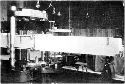
Fig. 1.—Testing Beam in 200,000-Lb.
Machine.
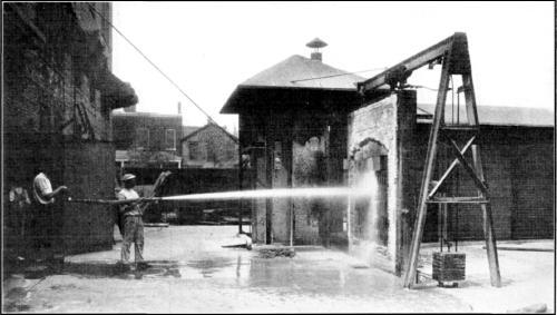
Fig. 2.—Fire Test of Panel.
At the Atlantic City sub-station, there is also a 200,000-lb.,
universal, four-screw testing machine, with miscellaneous equipment for
testing cement and moulding concrete, etc.; and at the Northampton
sub-station, there is a complete equipment of apparatus for cement
testing, capable of handling 10,000 bbl. per day.
At the Pittsburg testing station, a 10,000,000-lb., vertical,
compression testing machine (Plate XIV),
made by Tinius Olsen and Company, is being erected for making a complete
series of comparative tests of various building stones of 2, 4, and
12-in. cube, of stone prisms, 12 in. base and 24 in. high, of concrete
and reinforced concrete columns up to 65 ft. in height, and of brick
piers and structural-steel columns up to the the limits of the capacity
and height of the machine.
Plate
XIV.
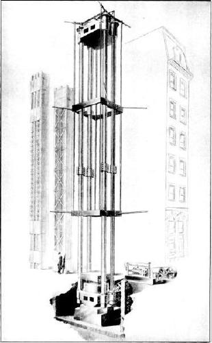
10,000,000-Lb. Testing Machine.
This machine is a large hydraulic press, with an adjustable head, and a
weighing system for recording the loading developed by a triple-plunger
pump. It has a maximum clearance of 65 ft. between heads; the clearance
in the machine is a trifle more than 6 ft. between screws, and the heads
are 6 ft. square.
The machine consists of a base containing the main cylinder, with a
sectional area of 2,000 sq. in., upon which rests the lower platform or
head, which is provided with a ball-and-socket bearing. The upper head
is adjustable over four vertical screws, 13½ in. in diameter and 72 ft.
2 in. long, by a system of gearing operating four nuts with
ball-bearings upon which the head rests. The shafting operating this
mechanism is connected with a variable-speed motor which actuates the
triple-plunger pump supplying the pressure to the main cylinder (Fig. 4).
Fig. 4.
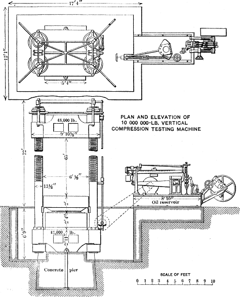
The weighing device consists of a set of standard Olsen levers for
weighing one-eightieth of the total load on the main cylinder. This
reduction is effected through the medium of a piston and a diaphragm.
The main cylinder has a diameter of 50 in., and the smaller one, a
diameter of 5 9/16 in. The weighing beam is balanced by an
automatically-operated poise weight, and is provided with a device for
applying successive counterweights of 1,000,000 lb. each. Each division
on the dial is equivalent to a 100-lb. load, and smaller subdivisions
are made possible by an additional needle-beam.
The power is applied by a 15-h.p., 220-volt, variable-speed motor
operating a triple-plunger pump, the gearing operating the upper head
being driven by the same motor. The extreme length of the main screws
necessitates splicing, which is accomplished as follows:
In the center of the screws, at the splice, is a 3-in. threaded pin for
centering the upper and lower screws; this splice is strengthened by
sleeve nuts, split to facilitate their removal whenever it is necessary
to lower the upper head; after the head has passed the splice, the
sleeve nuts are replaced.
In order to maintain a constant load, a needle-valve has been provided,
which, when the pump is operated at its lowest speed, will allow a
sufficient quantity of oil to flow into the main cylinder to equalize
whatever leakage there may be. The main cylinder has a vertical movement
of 24 in. The speed of the machine, for the purpose of adjustment, using
the gearing attached to the upper head, is 10 in. per
min. The speed for applying loads, controlled by the variable-speed
motor driving the pump, varies from a minimum of at least 1/60 in. per
min. to a maximum of at least ½ in. per min. The machine has a
guaranteed accuracy of at least one-third of 1%, for any load of more
than 100,000 lb., up to its capacity.
The castings for the base and the top head weigh approximately 48,000
lb. each. Each main screw weighs more than 40,000 lb., the lower
platform weighing about 25,000 lb., and the main cylinder, 16,000 lb.
The top of the machine will be about 70 ft. above the top
of the floor, and the concrete foundation, upon which it rests, is about
8 ft. below the floor line.
Concrete and Cement Investigations.—The investigations
relating to concrete include the examination of the deposits of sand,
gravel, stone, etc., in the field, the collection of representative
samples, and the shipment of these samples to the laboratory for
analysis and test. These tests are conducted in connection with the
investigation of cement mortars, made from a typical Portland cement
prepared by thoroughly mixing a number of brands, each of which must
meet the following requirements:
Specific gravity, not less than 3.10;
Fineness, residue not to exceed 8% on No. 100, nor 25% on No. 200
sieve;
Time of setting: Initial set, not less than 30 min.; hard set, not less
than 1 hour, nor more than 10 hours.
Tensile strength: Requirements applying to neat cement and to 1 part
cement with 3 parts standard sand:
| Time specification. |
Neat cement.
Pounds. |
1:3 Mix.
Pounds. |
| 24 hours in moist air |
175 |
... |
| 7 days (1 day in moist air, 6 days in water) |
500 |
175 |
| 28 days (1 day in moist air, 27 days in water) |
600 |
250 |
Constancy of volume: Pats of neat cement, 3 in. in diameter, ½ in. thick
at center, tapering to a thin edge, shall be kept in moist air for a
period of 24 hours. A pat is kept in air at normal temperature and
observed at intervals for at least 28 days. Another pat is kept in water
maintained as near 70° Fahr. as practicable, and is observed at
intervals for at least 28 days. A third pat is exposed in an atmosphere
of steam above boiling water, in a loosely-closed vessel, for 5 hours.
These pats must remain firm and hard and show no signs of distortion,
checking, cracking, or disfiguration.
The cement shall not contain more than 1.75% of anhydrous sulphuric
acid, nor more than 4% of magnesium oxide.
A test of the neat cement must be made with each mortar series for
comparison of the quality of the typical Portland cement.
The constituent materials are subjected to the following examination and
determinations, and, in addition, are analyzed to determine the
composition and character of the stone, sand, etc.:
1.—Mineralogical examination,
2.—Specific gravity,
3.—Weight, per cubic foot,
4.—Sifting (granulometric composition),
5.—Percentage of silt and character of same,
6.—Percentage of voids,
7.—Character of stone as to percentage of absorption, porosity,
permeability, compressive strength, and behavior under treatment.
Physical tests are made to determine the tensile, compressive, and
transverse strengths of the cement and mortar test pieces, with various
preparations of cement and various percentages of material. Tests are
also made to determine porosity, permeability, volumetric changes in
setting, absorption, coefficient of expansion, effect of oil, etc.
Investigation of concretes made from mixtures of typical Portland
cement, sand, stone, and gravel, includes tests on cylinders, prisms,
cubes, and other standard test pieces, with various proportions of
materials and at ages ranging from 30 to 360 days. Full-sized plain
concrete beams, moulded building blocks, reinforced concrete beams,
columns, floor slabs, arches, etc., are tested to determine the effect,
character, and amount of reinforcement, the effect of changes in volume,
size, and composition, and the effect of different methods of loading
and of supporting these pieces, etc.
These investigations include detailed inquiry in the field and research
in the chemical and physical laboratories regarding the effects of
alkaline soils and waters on structures of concrete being built by the
Reclamation Service in the arid regions. It has been noted that on
certain of the Reclamation projects, notably on the Sun River Project,
near Great Falls, Mont., the Shoshone Project, near Cody, Wyo., and the
Carlsbad and Hondo Projects in the Pecos Valley, N. Mex., structures of
concrete, reinforced concrete, building stones, brick, and tile, show
evidence of disintegration. This is attributed to the effects of
alkaline waters or soils coming into contact with the structures, or to
the constituent materials used. In co-operation with the Reclamation
Service, samples of the waters, soils, and constituent materials, are
collected in the field, and are subjected to careful chemical
examination in the mineral laboratories at Pittsburg.
Plate XV.
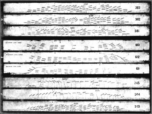
Fig. 1.—Characteristic Failures of
Reinforced Concrete Beams.
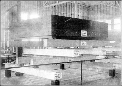
Fig. 2.—Arrangement of Static Load Test
for Reinforced Concrete Beams.
The cylinders used in the percolation tests are composed of typical
Portland cement mixed with sand, gravel, and broken stone of known
composition and behavior, and of cement mixed with sand, gravel, and
broken stone collected in the neighborhood of the Reclamation projects
under investigation.
Fig. 5.
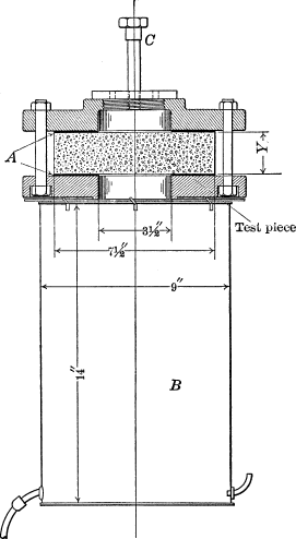
It is also proposed to subject these test pieces, some made with
water of known purity, and others with alkaline water, to contact with
alkaline soils near the projects, and with soil of known composition
near the testing laboratories at Pittsburg. As these tests progress and
other lines of investigation are developed, the programme will be
extended, in the hope that the inquiry may develop methods of preparing
and mixing concrete and reinforced concrete which can be used in
alkaline soils without danger of disintegration.
Investigations into the effect of salt water on cement mortars and
concretes, and the effect of electrolysis, are being conducted at
Atlantic City, N. J., where the test pieces may be immersed in deep
sea water for longer or shorter periods of time.
At the Pittsburg laboratory a great amount of investigative work is done
for the purpose of determining the suitability and availability of
various structural materials submitted for use by the Government. While
primarily valuable only to the Government, the results of these tests
are of indirect value to all who are interested in the use of similar
materials. Among such investigations have been those relating to the
strength, elasticity, and chemical properties of wire rope for use in
the Canal Zone; investigations of the suitability and cementing value of
concrete,
sand, stone, and pozzuolanic material found on the Isthmus;
investigations as to the relative resistance to corrosion of various
types of wire screens for use in the Canal Zone; into the suitability
for use, in concrete sea-wall construction, of sand and stone from the
vicinity of San Francisco; into the properties of reinforced concrete
floor slabs; routine tests of reinforcing metal, and of reinforced
concrete beams and columns, for the Supervising Architect of the
Treasury Department, etc. The results have been set forth in three
bulletins9 which
describe the methods of conducting these tests and also tests on
constituent materials of concrete and plain concrete beams. In addition,
there are in process of publication a number of bulletins giving the
results of tests on reinforced concrete beams, columns, and floor slabs,
concrete building blocks, etc.
The Northampton laboratory was established because it is in the center
of the Lehigh cement district, and therefore available for the mill
sampling and testing of purchases of cement made by the Isthmian Canal
Commission; it is also available for tests of cement purchased in the
Lehigh district by the Supervising Architect and others. It is in a
building, the outer walls of which are of cement plaster applied over
metal lath nailed to studding. The partitions are of the same
construction, and the floors and roof are of concrete throughout.
The inspection at the factories and the sampling of the cement are under
the immediate direction of the Commission; the testing is under the
direction of the U. S. Geological Survey. A large force of
employees is required, in view of the magnitude of the work, which
includes the daily testing of consignments ranging from 5,000 to 10,000
bbl., sampled in lots of 100 bbl., which is equivalent to from 50 to 100
samples tested per day.
The cement to be sampled is taken from the storage bins and kept under
seal by the chief inspector pending the results of the test. The
quantity of cement sampled is sufficient for the tests required under
the specifications of the Isthmian Canal Commission, as well as for
preliminary tests made by the cement company, and check tests made at
the Geological Survey laboratory, at Pittsburg.
The tests specified by the Commission include determination of
specific gravity, fineness of grinding, time of setting, soundness,
tensile strength (with three parts of standard quartz sand for 7 and 28
days, respectively), and determination of sulphur anhydride
(SO3), and magnesia (MgO).
The briquette-making and testing room is fitted with a mixing table,
moist closet, briquette-storage tanks, and testing machines. The mixing
table has a concrete top, in which is set plate glass, 18 in. square and
1 in. thick. Underneath the table are shelves for moulds, glass plates,
etc.
The moist closet, 5 ft. high, 3 ft. 10 in. wide, and 1 ft. 8 in. deep,
is divided into two compartments by a vertical partition, and each
compartment is fitted with cleats for supporting thirteen tiers of glass
plates. On each pair of cleats, in each compartment, can be placed four
glass plates, each plate containing a 4-gang mould, making storage for
416 briquettes. With the exception of the doors, which are of wood lined
with copper, the closet is of 1:1 cement mortar, poured monolithic, even
to the cleats for supporting the glass plates.
The immersion tanks, of the same mortar, are in tiers of three,
supported by a steel structure. They are 6¼ ft. long, 2¼ ft. wide, and 6
in. deep, and 2,000 briquettes can be stored in each tank. The overflow
from the top tank wastes into the second, which, in turn, wastes into
the third. Water is kept running constantly.
The briquette-testing machine is a Fairbanks shot machine with a
capacity of 2,000 lb., and is regulated to apply the load at the rate of
600 lb. per min. Twenty-four 4-gang moulds, of the type recommended by
the Special Committee on Uniform Tests of Cement, of the American
Society of Civil Engineers, are used.
The room for noting time of set and soundness is fitted with a mixing
table similar to that in the briquette-making room. The Vicat apparatus
is used for determining the normal consistency, and the Gilmore
apparatus for the time of setting. While setting, the soundness pats are
stored in galvanized-iron pans having about 1 in. of water in the
bottom, and covered with dampened felt or burlap. The pats rest on a
rack slightly above the water and well below the felt.
For specific gravity tests, the Le Chatelier bottles are used. A pan, in
which five bottles can be immersed at one time, is used for maintaining
the benzine at a constant temperature. The samples are weighed on a pair
of Troemner’s No. 7 scales.
The fineness room is fitted with tables, two sets of standard No. 100
and No. 200 sieves, and two Troemner’s No. 7 scales similar to those
used for the specific gravity tests.
The storage room is fitted with shelves for the storage of samples being
held for 28-day tests.
The mould-cleaning room contains tables for cleaning moulds, and racks
for air pats.
An effort is made to keep all the rooms at a temperature of 70° Fahr.,
and, with this in view, a Bristol recording thermometer is placed in the
briquette-room. Two wet-and-dry bulb hygrometers are used to determine
the moisture in the air.
Samples are taken from the conveyor which carries the cement to the
storage bins, at the approximate rate of one sample for each 100 bbl.
After each 4,000-bbl. bin has been filled, it is sealed until all tests
have been made, when, if these have been satisfactory, it is released
for shipment.
The samples are taken in cans, 9 in. high and 7½ in. in diameter. These
cans are delivered in the preparation room where the contents are mixed
and passed through a No. 20 sieve. Separate samples are then weighed out
for mortar briquettes, for soundness pats, and for the specific-gravity
and fineness tests. These are placed in smaller cans and a quantity
sufficient for a re-test is held in the storage room awaiting the
results of all the tests.
The sample for briquettes is mixed with three parts standard crushed
quartz, and then taken to the briquette-making room, where eight
briquettes are made, four for 7-day and four for 28-day tests. These are
placed in the moist closet in damp air for 24 hours, then removed from
the moulds, and placed in water for the remainder of the test period. At
the proper time they are taken from the immersion tank and broken.
From the sample for soundness, four pats are made. The time of setting
is determined on one of these pats. They are placed in the pan
previously described, for 24 hours, then one is placed in running water
and one in air for 28 days. The others are treated in the boiler, one in
boiling water for 3 hours and one in steam at atmospheric pressure for 5
hours.
The sample taken for specific gravity and fineness is dried in the oven
at 100° cent. in order to drive off moisture. Two samples are then
carefully weighed out, 50 grammes for fineness and 64 grammes
for specific gravity, and the determinations are made. As soon as
anything unsatisfactory develops, a re-test is made. If, however, the
cement satisfies all requirements, a report sheet containing all the
data for a bin, is made out, and the cement is ready for shipment. From
every fifth bin, special neat and mortar briquettes are made, which are
intended for tests at ages up to ten years.
Salt-Water Laboratory.—The laboratory at Atlantic City, for
conducting investigations into the effects of salt water on concrete and
reinforced concrete, is situated so that water more than 25 ft. deep is
available for immersion tests of the setting and deterioration of such
materials.
Through the courtesy of the municipality of Atlantic City, Young’s
cottage, on old Young’s Pier, has been turned over, at a nominal rental,
to the Geological Survey for the conduct of these tests. The laboratory
building is about 700 ft. from the boardwalk, and occupies a space about
100 by 45 ft. It is one story high, of frame-cottage construction, and
stands on wooden piles at one side of the pier proper and about 20 ft.
above the water, which is about 19 ft. deep at this point. Fresh running
water, gas, electric light, and electric power are supplied to the
building (Fig. 6).
Fig. 6.
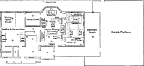
PLAN OF LABORATORY FOR SALT-WATER TESTS AT ATLANTIC CITY, N.
J.
In this laboratory investigations will be made of the cause of the
failure and disintegration of cement and concrete subjected to the
action of sea water. Tests are conducted so as to approach, as nearly as
possible, the actual conditions found in concrete construction along the
sea coast. All sea-water tests are made in the ocean, some will probably
be paralleled by ocean-water laboratory tests and all by fresh-water
comparative tests.
Cements, in the form of pats, briquettes, cubes, cylinders, and in a
loose ground state, and also mortars and concretes in cube, cylinder,
and slab form, are subjected to sea water.
The general plan for the investigations is as follows:
1.—Determination of the failing elements and the nature of the
failure;
2.—Determination of the value of the theories advanced at the
present time; and,
3.—Determination of a method of eliminating or chemically
recombining the injurious elements.
Preliminary tests are in progress, including a study of the effect of
salt water on mortars and concretes of various mixtures and ages.
The proportions of these mixtures and the methods of mixing will be
varied from time to time, as suggested by the progress of the tests.
Fire-Proofing Tests.—Tests of the fire-proofing and
fire-resistive properties of various structural materials are carried on
in the laboratories in Building No. 10, at Pittsburg, and in
co-operation with the Board or Fire Underwriters at its Chicago
laboratory (Fig. 2, Plate XIII). These
tests include three essential classes of material: (a), clay
products, protective coverings representative of numerous varieties of
brick and fire-proofing tiles, including those on the market and those
especially manufactured for these tests in the laboratory at Pittsburg;
(b), characteristic granites of New England, with subsequent
tests of the various building stones found throughout the United States;
and (c), cement and concrete covering material, building blocks,
and concrete reinforced by steel bars embedded at different depths for
the purpose of studying the effect of expansion on the protective
covering.
In co-operation with the physical laboratory, these tests include a
study of the relative rates of conductivity of cement mortars and
concretes. By embedding thermo-couples in cylinders composed of the
materials under test, obtaining a given temperature by an electric coil,
and noting the time required to raise the temperature at the various
embedded couples to a given degree, the rate of conductivity may be
determined. Other tests include those in muffles to determine the rate
of expansion and the effect of heat and compressive stresses combined on
the compressive strength of the various structural materials. The
methods of making the panel tests, and the equipment used, are described
and illustrated in Bulletin No. 329, and the results of the tests have
been published in detail.10
Building Stones Investigations.—The field investigations of
building stones are conducted by Mr. E. F. Burchard, and include
the examination of the various deposits found throughout the United
States. A study of the granites of New England has been commenced, which
includes the collection of type specimens of fine, medium, and
coarse-grained granites, and of dark, medium, and light-gray or white
granites. A comparative series of these granites, consisting of prisms
and cubes of 4 and 2 in., respectively, has been prepared.
The standard adopted for compressive test pieces in the 10,000,000-lb.
machine is a prism, having a base of 12 in. and being 24 in. high. The
tests include not only those for compression or crushing strength, but
also those for resistance to compressive strains of the prisms and
cubes, when raised to high temperatures in muffles or kilns; resistance
to weathering, freezing, and thawing; porosity; fire-resisting
qualities, etc.
In collecting field samples, special attention is paid to the occurrence
of the stone, extent of the deposit, strike, dip, etc., and specimens
are procured having their faces cut with reference to the bedding
planes, in order that compressive and weathering tests may be made, not
only in relation to these planes but at those angles thereto in which
the material is most frequently used commercially. Attention is also
paid to the results of blasting, in its relation to compressive strains,
as blasting is believed to have a material effect on stones, especially
on those which may occur in the foundations of great masonry dams, and
type specimens of stone quarried by channeling, as well as by blasting,
are collected and tested.
Clay and Clay Products Investigations.—These investigations
are in charge of Mr. A. V. Bleininger, and include the study of the
occurrence of clay beds in various parts of the United States, and the
adaptability of each clay to the manufacture of the various clay
products.
Experiments on grinding, drying, and burning the materials are conducted
at the Pittsburg testing station, to ascertain the most favorable
conditions for preparing and burning each clay, and to determine the
most suitable economic use to which it may be put, such as the
manufacture of building or paving bricks, architectural tiles, sewer
tiles, etc.
The laboratory is equipped with various grinding and drying devices,
muffles, kilns, and apparatus for chemical investigations, physical
tests, and the manufacture and subsequent investigative tests of clay
products.
This section occupies the east end of Building No. 10, and rooms on the
first and second floors have been allotted for this work. In addition, a
brick structure, 46 by 30 ft., provided with a 60-ft. iron stack, has
been erected for housing the necessary kilns and furnaces.
On the ground floor of Building No. 10, adjoining the cement and
concrete section, is a storage room for raw materials and product under
investigation. Adjoining this room, and connecting with it by wide
doors, is the grinding room, containing a 5-ft. wet pan, with 2,000-lb.
rollers, to be used for both dry and wet grinding. Later, a heavy dry
pan is to be installed. With these machines, even the hardest material
can be easily disintegrated and prepared. In this room there is also a
jaw crusher for reducing smaller quantities of very hard material, as
well as a 30 by 16-in. iron ball mill, for fine grinding. These machines
are belted to a line shaft along the wall across the building. Ample
sink drainage is provided for flushing and cleaning the wet pan, when
changing from one clay to another.
A large room adjoining is for the operation of all moulding and shaping
machines, representing the usual commercial processes. At present these
include an auger machine, with a rotary universal brick and tile cutter,
Fig. 1, Plate XVI, and a set of brick
and special dies, a hand repress for paving brick, and a hand screw
press for dry pressing. The brick machine is operated from the main
shaft which crosses the building in this room and is driven from a
50-h.p. motor. It is possible thus to study the power consumption under
different loads and with different clays, as well as with varying
degrees of water content in the clay. As the needs of the work demand
it, other types of machines are to be installed. For special tests in
which pressure is an important factor it is intended to fit up one of
the compression testing machines of the cement section with the
necessary dies, thus enabling the pressing to be carried on under known
pressures. Crushing, transverse, and other tests of clay products are
made on the testing machines of the cement and concrete
laboratories.
Plate
XVI.
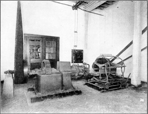
Fig. 1.—Brick Machine and Universal
Cutter.
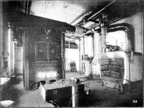
Fig. 2.—House-Heating Boilers, Building
No. 21.
Outside of the building, in a lean-to, there is a double-chamber rattler
for the testing of paving brick according to the specifications of the
National Brick Manufacturers’ Association.
In the smaller room adjoining the machine laboratory there are two small
wet-grinding ball mills, of two and four jars, respectively, and also a
9-leaf laboratory filter press.
Fig. 7.
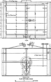
CLAY-DRYING OVEN
The remaining room on the first floor is devoted to the drying of clays
and clay wares. The equipment consists of a large sheet-iron drying oven
of special construction, which permits of close regulation of the
temperature (Fig. 7). It is heated by gas
burners, and is used for the preliminary heat treatment of raw clays, in
connection with
the study of the drying problems of certain raw materials. It is
intended to work with temperatures as high as 250° cent.
Another drying closet, heated by steam coils (Fig. 8), intended for drying various clay products,
has been designed with special reference to the exact regulation of the
temperature, humidity, and velocity of the air flowing through it. Both
dryers connect by flues with an iron stack outside the building. This
stack is provided with a suction fan, driven by a belt from an electric
motor.
On the second floor are the chemical, physical, and research
laboratories, dealing with the precise manipulations of the tests and
investigations.
Fig. 8.
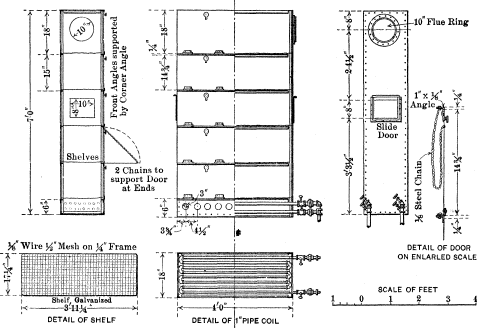
DRYING CLOSETS FOR CERAMICS
The chemical laboratory is fully equipped with the necessary apparatus
for carrying on special chemical research in silicate chemistry,
including electrical resistance furnaces, shaking devices, etc. It is
not the intention to do routine work in this laboratory. The office
adjoins this laboratory, and near it is the physical laboratory, devoted
to the study of the structure of raw materials. The latter contains
Nobel and Schoene elutriators, together with viscosimeters of the flow
and the Coulomb and Clark electrical types, sieves, voluminometers,
colorimeters, vernier shrinkage gauges, micrometers, microscopes, and
the necessary balances.
The room across the hall is devoted to the study of the specific
gravity, absorption, porosity, permeability, hardness, translucency,
etc., of burnt-clay products, all the necessary apparatus being
provided. In the two remaining rooms, intended for research work,
special apparatus adapted to the particular investigation may be set up.
All the rooms are piped for water, gas, compressed air, steam, and
drainage, and wired for light and power.
In the kiln house there is a test kiln adapted for solid fuel and gas.
It is of the down-draft type, with an available burning space of about 8
cu. ft. (Fig. 9). For heavier ware and the
study of the fire behavior of clay products under conditions approaching
those of practice, a round down-draft kiln, with an inside diameter of 6
ft., is installed. About 13 ft. above the floor level, and supported by
iron beams, there is a flue parallel to the long side of the structure.
This flue conducts the gases of the kilns to the stack, which is
symmetrically located with reference to the kiln house. Natural gas is
the principal fuel. In addition to these kilns, a small muffle furnace,
fired with
petroleum, is provided for the determination of melting points, and an
electric carbon resistance furnace, with an aluminum muffle for
high-temperature work. For crucible-fusion work, a gas-fired pot furnace
is installed.
Fig. 9.
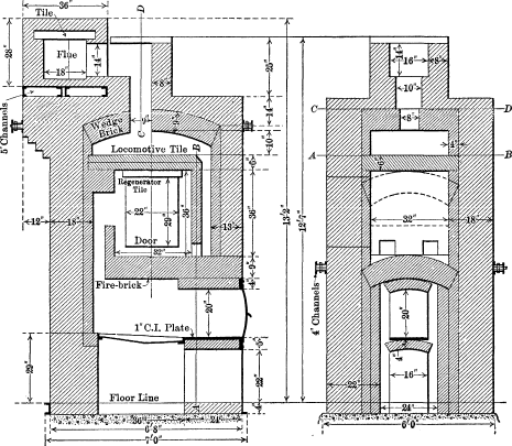
DOWN-DRAFT KILN
Along the north wall, bins are provided for the storage of fuel, clay,
sand, and other kiln supplies. There are two floor drainage sinks, and
electric current, steam, water, and compressed air, are provided.
Results of the Work.—More than 39,300 separate test pieces
have been made at the structural-materials testing laboratory. In
connection with the study of these, 86,000 tests and nearly 14,000
chemical analyses have been made. Of these tests more than 13,600 have
been of the constituent materials of concrete, including tensile tests
of cement briquettes, compression tests of cylinders and cubes, and
transverse tests of various specimens.
Nearly 1,200 beams of concrete or reinforced concrete, each 13 ft. long
and 8 by 11 in. in cross-section, have been made, and, in connection
with the investigation of the behavior of these beams, nearly 3,000
tests have been made. Nearly 900 of these beams, probably more than
double the entire number made in other laboratories in
the United States, during a period of more than 15 years, have been
tested.
In the section of building blocks, 2,200 blocks have been tested,
including, with auxiliary pieces, more than 4,500 tests; also, more than
900 pieces of concrete have been tested for permeability and shear. The
physical tests have numbered 14,000; tests of steel for reinforcement,
3,800; and 550 tests to determine fire-resistive qualities of various
building materials, have been made on 30 special panels, and on
miscellaneous pieces.
The tests of the permeability of cement mortars and concretes, and of
water-proofing and damp-proofing materials, have numbered 3,470.
The results of the work of the Structural Materials Division have
already appeared in preliminary bulletins, as follows: No. 324, “San
Francisco Earthquake and Fire of April 18, 1906, and Their Effects on
Structures and Structural Materials”; No. 329, “Organization, Equipment,
and Operation of the Structural-Materials Testing Laboratories
at St. Louis, Mo.”; No. 331, “Portland Cement Mortars and Their
Constituent Materials” (based on nearly 25,000 tests); No. 344,
“Strength of Concrete Beams” (based on tests of 108 beams); No. 370,
“Fire-Resistive Properties of Various Building Materials”; No. 387, “The
Colloid Matter of Clay and its Measurements.” A bulletin on the results
of tests of reinforced concrete beams, one on the manufacture and
chemistry of lime, and one on drying tests of brick, are in course of
publication.
Fuel Investigations.
The scope of the fuel investigations has been planned to conform to the
provisions of the Act of Congress which provides for analyzing and
testing coals, lignites, and other mineral fuel substances belonging to
the United States, or for the use of the United States Government, and
examinations for the purpose of increasing the general efficiency or
available supply of the fuel resources in the United States.
In conformity with this plan, the investigations inaugurated at St.
Louis had for their initial object the analyzing and testing of the
coals of the United States, using in this work samples of from 1 to 3
carloads, collected with great care from typical localities in the more
important coal fields of the country, with a view to determining the
relative values of those different fuels. In the work at Norfolk, during
1907, this purpose was modified to the extent of keeping in view
relative fuel efficiencies for naval purposes. The tests at Denver have
been on coal from Government land or from land contiguous thereto, and
are conducted solely with a view to perfecting methods of coking this
coal by prior washing and by manipulation in the process of coking.
Three general lines of inquiry are embodied in the plan of investigation
undertaken and contemplated by the Technologic Branch, after conference
and with the advice and approval of the Advisory Board: 1. The
ascertainment of the best mode of utilizing any fuel deposit owned or to
be used by the Government, or the fuel of any extensive deposit as a
whole, by conducting a more thorough investigation into its combustion
under steam boilers, conversion into producer gas, or into coke,
briquettes, etc. 2. The prevention of waste, through the study of the
possibility of improvement in the methods of mining, shipping,
utilizing, etc. 3. The inspection and analysis of coal and
lignite purchased under specification for the use of the Government, to
ascertain its heating value, ash, contained moisture, etc.
The first general line of work concerns the investigation and testing of
the fuel resources of the United States, and especially those belonging
to the Federal Government, to determine a more efficient and more
economical method of utilizing the same. This work has developed along
the following lines:
The collection of representative samples for chemical analysis, and
calorimeter tests by a corps of skilled mine samplers, from the mines
selected as typical of extensive deposits of coal in a given field or
from a given bed of coal; and the collection from the same mines of
larger samples of from 1 to 3 carloads, shipped to the testing station
for tests in boiler furnaces, gas producers, etc., as a check on the
analysis and calorimeter tests;
The testing of each coal received to determine the most efficient and
least wasteful method of use in different furnaces suitable for public
buildings or power plants or ships of the Government;
The testing of other portions of the same shipment of coal in the gas
producer, for continuous runs during periods of a few days up to several
weeks, in order to determine the availability of this fuel for use in
such producers, and the best method of handling it, to determine the
conditions requisite to produce the largest amount of high-grade gas
available for power purposes;
The testing of another portion of the same coal in a briquette machine
at different pressures and with different percentages and kinds of
binder, in order to determine the feasibility of briquetting the slack
or fine coal. Combustion tests are then made of these briquettes, to
determine the conditions under which they may be burned
advantageously;
Demonstrations, on a commercial scale, of the possibility of producing
briquettes from American lignites, and the relative value of these for
purposes of combustion as compared with the run-of-mine coal from which
the briquettes are made;
The finding of cheaper binders for use in briquetting friable coals not
suited for coking purposes;
Investigations into the distribution, chemical composition, and
calorific value of the peat deposits available in those portions of the
United States where coal is not found, and the preparation of such
peat for combustion, by drying or briquetting, to render it useful as a
local substitute for coal;
Investigations into the character of the various petroleums found
throughout the United States, with a view to determining their calorific
value, chemical composition, and the various methods whereby they may be
made most economically available for more efficient use as power
producers, through the various methods of combustion;
Investigations and tests into the relative efficiency, as power
producers in internal-combustion engines, of the heavier distillates of
petroleum, as well as of kerosene and gasoline, in order to ascertain
the commercial value and relative efficiency of each product in the
various types of engines;
Investigations into the most efficient methods of utilizing the various
coals available throughout the United States for heating small public
buildings, army posts, etc., in order that these coals may be used more
economically than at present;
Investigative studies into the processes of combustion within boiler
furnaces and gas producers to ascertain the temperatures at which the
most complete combustion of the gases takes place, and the means whereby
such temperatures may be produced and maintained, thus diminishing the
loss of values up the smokestack and the amount of smoke produced;
Investigations and tests into the possibilities of coking coals which
have hitherto been classed as non-coking, and the making of comparative
tests of all coals found in the United States, especially those from the
public lands of the West;
Investigations, by means of washing in suitable machines, to determine
the possibility of improving the quality of American coals for various
methods of combustion, and with a view to making them more available for
the production of coke of high-grade metallurgical value, as free as
possible from sulphur and other injurious substances.
At each stage of the process of testing, samples of the coal have been
forwarded to the chemical laboratory for analyses; combustion
temperatures have been measured; and samples of gas collected from
various parts of the combustion chambers of the gas producers and boiler
furnaces have been analyzed, in order that a study of these data may
throw such light on the processes of combustion and indicate such
necessary changes in the apparatus, as might result in larger economies
in the use of coal.
The second line of investigation concerns the methods of mining and
preparing coal for the market, and the collection of mine samples of
coal, oil, etc., for analysis and testing. It is well known that, under
present methods of mining, from 10 to 75% of any given deposit of coal
is left underground as props and supports, or as low-grade material, or
in overlying beds broken up through mining the lower bed first. An
average of 50% of the coal is thus wasted or rendered valueless, as it
cannot be removed subsequently because of the caving or falling in of
the roofs of abandoned galleries and the breaking up of the adjoining
overlying beds, including coal, floor, and roof.
The investigations into waste in mining and the testing of the waste,
bone, and slack coal in gas producers, as briquettes, etc., have, for
their purpose, the prevention of this form of waste by demonstrating
that these materials, now wasted, may be used profitably, by means of
gas producers and engines, for power purposes.
The third general line of investigation concerns the inspection and
sampling of fuel delivered to the Government under purchase contracts,
and the analyzing and testing of the samples collected, to determine
their heating value and the extent to which they may or may not comply
with the specifications under which they are purchased. The coal
delivered at the public buildings in the District of Columbia is sampled
by special representatives of the Technologic Branch of the Survey. The
taking of similar samples at public buildings and posts throughout the
United States, and the shipment of the samples in hermetically sealed
cans or jars to the chemical laboratory at Washington, is for the most
part looked after by special officers or employees at each place. These
purchases are made, to an increasing extent, under specifications which
provide premiums for coal delivered in excess of standards, and
penalties for deliveries below standards fixed in the specifications.
The standard for bituminous coals is based mainly on the heat units,
ash, and sulphur, while that for anthracite coal is based mainly on the
percentage of ash and the heat units.
In connection with all these lines of fuel testing, certain research
work, both chemical and physical, is carried on to determine the true
composition and properties of the different varieties of coal, the
changes in the transformation from peat to lignite, from lignite to
bituminous coal, and from bituminous to anthracite coal, and the
chemical and physical processes in combustion. Experiments are conducted
concerning the destructive distillation of fuels; the by-products of
coking
processes; the spontaneous combustion of coal; the storage of coal, and
the loss in value in various methods of storing; and kindred questions,
such as the weathering of coal. These experiments may yield valuable
results through careful chemical research work supplemented by equally
careful observations in the field.
Inspection and Mine Sampling.—In the Geological Survey
Building, at Washington, coal purchased for Government use on a
guaranteed-analysis or heat-value basis, is inspected and sampled.
Some of the employees on this work are constantly at the mines taking
samples, or at public works inspecting coal for Government use, while
others are stationed at Washington to look after the deliveries of coal
to the many public buildings, and to collect and prepare samples taken
from these deliveries for analysis, as well as to prepare samples
received from public works and buildings in other parts of the
country.
The preparation of these samples is carried on in a room in the basement
of the building, where special machinery has been installed for this
work. Fig. 10 shows a plan of this room and
the arrangement of the sampling and crushing machinery.
Fig. 10.
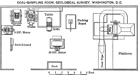
The crushing of the coal produces great quantities of objectionable
dust, and to prevent this dust from giving trouble outside the sampling
room, the wooden partitions on three sides of the room (the fourth side
being a masonry wall) are completely covered on the outside with
galvanized sheet iron. The only openings to the room are two doors,
which are likewise covered with sheet iron, and provided with broad
flanges of the same material, in order to seal effectually the openings
when the doors are shut. Fresh air is drawn into the room by a fan,
through a pipe leading to the outer air. A dust-collecting system which
carries the coal dust and spent air from the room, consists of an
arrangement of 8-in. and 12-in. pipes leading from hoods, placed over
the crushing machines, to the main furnace stack of the building. The
draft in this stack draws all the dust from the crushers directly
through the hoods to the main pipe, where most of it is deposited.
The equipment of the sampling room consists of one motor-driven, baby
hammer crusher, which has a capacity of about 1 ton per hour and crushes
to a fineness of ¼-in. mesh; one adjustable chipmunk jaw crusher, for 5-
and 10-lb. samples; one set of 4½ by 7½-in. rolls, crushing to 60 mesh,
for small samples; one large bucking board, and several different sizes
of riffle samplers for reducing samples to small quantities. The small
crushers are belted to a shaft driven by a separate motor from that
driving the baby crusher.
In conducting the inspection of departmental purchases of coal in
Washington, the office is notified whenever a delivery of coal is to be
made at one of the buildings, and an inspector is sent, who remains
during the unloading of the coal. He is provided with galvanized-iron
buckets having lids and locks; each bucket holds about 60 lb. of coal.
In these buckets he puts small quantities of the coal taken from every
portion of the delivery, and when the delivery has been completed, he
locks the buckets and notifies the office to send a wagon for them. The
buckets are numbered consecutively, and the inspector makes a record of
these numbers, the date, point of delivery, quality of coal delivered,
etc. The buckets are also tagged to prevent error. He then reports to
the office in person, or by telephone, for assignment to another point
in the city. All the samples are delivered to the crushing room in the
basement of the Survey Building, to be prepared for analysis.11
Samples taken from coal delivered to points outside of Washington are
taken by representatives of the department for which the coal is being
purchased, according to instructions furnished them, and, from time to
time, the regular inspectors are sent to see that these instructions are
being complied with. These samples are crushed by hand, reduced to about
2 lb. at the point where they are taken, and sent
to Washington, in proper air-tight containers, by mail or express,
accompanied by appropriate descriptions.
Each sample is entered in the sample record book when received, and is
given a serial number. For each contract a card is provided giving
information relative to the contract. On this card is also entered the
serial number of each sample of coal delivered under that contract.
After the samples are recorded, they are sent to the crushing room,
where they are reduced to the proper bulk and fineness for analysis.
They are then sent, in rubber-stoppered bottles, accompanied by blank
analysis report cards and card receipts, one for each sample, showing
the serial numbers, to the fuel laboratory for analysis. The receipt
card for each sample is signed and returned to the inspection office,
and when the analysis has been made, the analysis report card showing
the result is returned. This result is entered at once on the contract
card, and when all analyses have been received, covering the entire
delivery of coal, the average quality is calculated, and the results are
reported to the proper department.
The matter of supplying the Pittsburg plant with fuel for test purposes
is also carried on from the Washington office. Preliminary to a series
of investigations, the kinds and amounts of coal required are decided
on, and the localities from which these coals are to be obtained are
determined. Negotiations are then opened with the mine owners, who, in
most cases, generously donate the coal. When the preliminaries have been
arranged, an inspector is sent to the mine to supervise the loading and
shipment of the coal. This inspector enters the mine and takes, for
chemical analysis, small mine samples which are sent to the laboratory
at Pittsburg in metal cans by mail, accompanied by proper identification
cards. The results of the analysis are furnished to the experts in
charge at the testing plant, for their information and guidance in the
investigations for which the coal was shipped.
All samples for testing purposes are designated consecutively in the
order of shipment, “Pittsburg No. 1,” “Pittsburg No. 2,” etc. A complete
record of all shipments is kept on card forms at the Pittsburg plant,
and a duplicate set of these is on file in the inspection office at
Washington.
Analysis of Fuels.—The routine analyses of fuel used in the
combustion tests at Pittsburg, and of the gases resulting from
combustion
or from explosions in the testing galleries, or sampled in the mines,
are made in Building No. 21.12 A small laboratory is also maintained on the second
floor of the south end of Building No. 13, for analyses of gases
resulting from combustion in the producer-gas plant, and from explosions
in Galleries Nos. 1 and 2, etc. From four to six chemists are
continually employed in this laboratory (in 8-hour shifts), during
prolonged gas-producer tests, and three chemists are also employed in
analyzing gases relating to mine explosions.
In addition to these gas analyses, there are also made in the main
laboratory, analyses and calorific tests of all coal samples collected
by the Geological Survey in connection with its land-classification work
on the coal lands of the Western States. Routine analyses of mine, car,
and furnace samples of fuels for testing, before and after washing and
briquetting, before coking and the resultant coke, and extraction
analyses of binders for briquettes, etc., are also made in this
laboratory.
The fuel-testing laboratory at Washington is equipped with three Mahler
bomb calorimeters and the necessary balances and chemical equipment
required in the proximate analysis of coal. More than 650 deliveries of
coal are sampled each month for tests, representing 50,000 tons
purchased per month, besides daily deliveries, on ship-board, of 550,000
tons of coal for the Panama Railroad. The data obtained by these tests
furnish the basis for payment. The tests cover deliveries of coal to the
forty odd bureaus, and to the District Municipal buildings in
Washington; to the arsenals at Watertown, Mass., Frankford, Pa., and
Rock Island, Ill.; and to a number of navy yards, through the Bureau of
Yards and Docks; to military posts in various parts of the country; for
the Quartermaster-General’s Department; to the Reclamation Service; to
Indian Agencies and Soldiers’ Homes; to several lighthouse districts;
and to the superintendents of the various public buildings throughout
the United States, through the Treasury Department; etc. During 1909,
the average rate of reporting fuel samples was 540 per month, requiring,
on an average, six determinations per sample, or about 3,240
determinations per month.
Fig. 11.
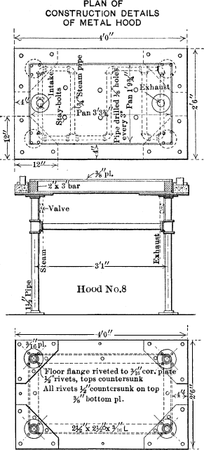
Fuel-Research Laboratories.—Smaller laboratories,
occupying, on the average, three rooms each, are located in Building No.
21. One is used for chemical investigations and calorific tests of
petroleum collected from the various oil fields of the United States;
another is used
for investigations relative to the extraction of coal and the rapidity
of oxidization of coals by standard solutions of oxidizing agents; and
another is occupied with investigations into the destructive
distillation of coal. The researches under way show the wide variation
in chemical composition and calorific value of the various crude oils,
indicate the possibility of the extraction of coal constituents by
solvents, and point to important results relative to the equilibrium of
gases at high temperatures in furnaces and gas producers. The
investigations also bear directly on the coking processes, especially
the by-product process, as showing the varying proportion of each of the
volatile products derivable from types of coals occurring in the various
coal fields of the United States, the time and temperature at which
these distillates are given off, the variation in quality and quantity
of the products, according to the conditions of temperature, and, in
addition, explain the deterioration of coals in storage, etc.
At the Washington office, microscopic investigations into the life
history of coal, lignite, and peat are being conducted. These
investigations have already progressed far enough to admit of the
identification of some of the botanical constituents of the older peats
and the younger lignites, and it is believed that the origin of the
older lignites, and even of some of the more recent bituminous coals,
may be developed through this examination.
In the chemical laboratories, in Building No. 21, the hoods (Figs. 11 and 12) are of
iron, with a brick pan underneath. They are supported on iron pipes, as
are most of the other fixtures in the laboratories
in this building. The hood proper is of japanned, pressed-iron plate,
No. 22 gauge, the same material being used for the boxes, slides, and
bottom surrounding the hood. The sash is hung on red copper pulleys, and
the corners of the hood are reinforced with pressed, japanned, riveted
plate to which the ventilating pipe is riveted.
Fig. 12.
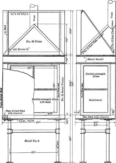
ELEVATION OF CONSTRUCTION DETAILS OF METAL HOOD
There is some variety in the cupboards and tables provided in the
various laboratories, but, in general, they follow the design shown in
Fig. 13. The table tops, 12 ft. long, are
of clear maple in full-length pieces, ⅞ in. thick and 2⅝ in. wide, laid
on edge and drilled at 18-in. intervals for bolts. These pieces are
glued and drawn together by the bolts, the heads of which are
countersunk. The tops, planed off, sanded, and rounded, are supported on
pipe legs and frames of 1¼ by 1½-in. galvanized-iron pipe with screw
flanges fitting to the floor and top. Under the tops are drawers and
above them re-agent shelves. Halfway between the table top and the floor
is a wire shelf of a frame-work of No. 2 wire interlaced with No. 12
weave of ⅝-in. square mesh.
Fig. 13.
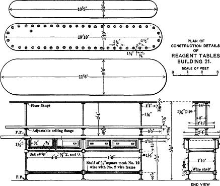
Certain of the tables used in the laboratory are fitted with cupboards
beneath and with drawers, and, in place of re-agent stands,
porcelain-lined sinks are sunk into them. These tables follow, in
general style and construction, the re-agent tables. The tables used in
connection with calorimeter determinations are illustrated in Fig. 14. The sinks provided throughout these
laboratories are of standard porcelain enamel, rolled rim, 18 by 13 in.,
with enameled back, over a sink and drain board, 24 in. long on the left
side, though there are variations from this type in some instances.
Fig. 14.
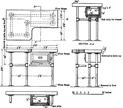
CONSTRUCTION DETAILS OF CALORIMETER TABLES
The plumbing includes separate lines of pipe to each hood and table; one
each for cold water, steam at from 5 to 10 lb. pressure, compressed air,
natural gas, and, in some cases, live steam at a pressure of
60 lb.
On each table is an exposed drainage system of 2½-in. galvanized-iron
pipe, in the upper surface of which holes have been bored, through which
the various apparatus drain by means of flexible connections of glass or
rubber. These pipes and the sinks, etc., discharge into main drains,
hung to the ceiling of the floor beneath. These drains are of wood,
asphaltum coated, with an inside diameter ranging from 3 to 6 in., and
at the proper grades to secure free discharge. These wooden drain-pipes
are made in short lengths, strengthened by a spiral wrapping of metal
bands, and are tested to a pressure of 40 lb. per sq. in. Angles are
turned and branches connected in 4- and 6-in. square headers.
The entire building is ventilated by a force or blower fan in the
basement, and by an exhaust fan in the attic with sufficient capacity to
insure complete renewal of air in each laboratory once in
20 min.
The blower fan is placed in the center of the building, on the ground
floor, and is 100 in. in diameter. Its capacity is about 30,000 cu. ft.
of air per min., and it forces the air, through a series of pipes, into
registers placed in each of the laboratories.
The exhaust fan, in the center of the attic, is run at 550 rev. per
min., and has a capacity of 22,600 cu. ft. of air per min. It draws the
air from each of the rooms below, as well as from the hoods, through a
main pipe, 48 in. in diameter.
Steaming and Combustion Tests.—The investigations included
under the term, fuel efficiency, relate to the utilization of the
various types of fuels found in the coal and oil fields, and deal
primarily with the combustion of such fuels in gas producers, in the
furnaces of steam boilers, in locomotives, etc., and with the efficiency
and utilization of petroleum, kerosene, gasoline, etc., in
internal-combustion engines. This work is under the general direction of
Mr. R. L. Fernald, and is conducted principally in Buildings Nos.
13 (Plate XVII) and 21.
Plate
XVII.
PLAN OF BUILDING 13,
TESTING STATION AT PITTSBURG, PA.
For tests of combustion of fuels purchased by the Government, the
equipment consists of two Heine, water-tube boilers, each of 210 h.p.,
set in Building No. 13. One of these boilers is equipped with a Jones
underfeed stoker, and is baffled in the regular way. At four points in
the setting, large pipes have been built into the brick wall, to permit
making observations on the temperature of the gas, and to take samples
of the gas for chemical analysis.
The other boiler is set with a plain hand-fired grate. It is baffled to
give an extra passage for the gases (Fig. 15). Through the side of this boiler, at the
rear end, the gases from the long combustion chamber (Plate XVIII) enter and take the same course as
those from the hand-fired grate. Both the hand-fired grate and the long
combustion chamber may be operated at the same time, but it is expected
that usually only one will be in operation. A forced-draft fan has been
installed at one side of the hand-fired boiler, to provide air pressure
when coal is being burned at high capacity. This fan is also connected
in such a way as to furnish air for the long combustion chamber when
desired. A more complete description of the boilers may be found in
Professional Paper No. 48, and Bulletin No. 325 of
the U. S. Geological Survey, in which the water-measuring apparatus
is also described.13
Fig. 15.
On account of the distance from Building No. 21 to the main group of
buildings, it was considered inadvisable to attempt to furnish steam
from Building No. 13 to Building No. 21, either for heating or power
purposes. In view, moreover, of the necessity of installing various
types and sizes of house-heating boilers, on account of tests to be made
thereon in connection with these investigations, it was decided to
install these boilers in the lower floor of Building No. 21, where they
could be utilized, not only in making the necessary tests, but in
furnishing heat and steam for the building and the chemical laboratories
therein.
In addition to the physical laboratory on the lower floor of Building
No. 21, and the house-heating boiler plant with the necessary coal
storage, there are rooms devoted to the storage of heavy supplies,
samples of fuels and oils, and miscellaneous commercial apparatus. One
room is occupied by the ventilating fan and one is used for the
necessary crushers, rolls, sizing screens, etc., required in connection
with the sampling of coal prior to analysis.
The Quartermaster’s Department having expressed a wish that tests be
made of the heating value and efficiency of the various fuels offered
that Department, in connection with the heating of military posts
throughout the country, three house-heating boilers were procured which
represent, in a general way, the types and sizes used in a medium-sized
hospital or other similar building, and in smaller residences (Fig. 2,
Plate XVI). The larger apparatus is a
horizontal return-tubular boiler, 60 in. in diameter, 16 ft. long, and
having fifty-four 4-in. tubes.14
In order to determine whether such a boiler may be operated under
heating conditions without making smoke, when burning various kinds of
coal, it has been installed in accordance with accepted ideas regarding
the prevention of smoke. A fire-brick arch extends over the entire grate
surface and past the bridge wall. A baffle wall has been built in the
combustion chamber, which compels the gases to pass downward and to
divide through two openings before they reach the boiler shell.
Provision has been made for the admission of air at the front of the
furnace, underneath the arch, and at the rear end of the bridge wall,
thus furnishing air both above and below the fire. It is not expected
that all coals can be burned without smoke in this furnace, but it is
desirable to determine under what conditions some kinds of coals may be
burned without objectionable smoke.15
For sampling the gases in the smokebox of the horizontal return-tubular
boiler, a special flue-gas sampler was designed, in order to obtain a
composite sample of the gases escaping from the boiler.
The other heaters are two cast-iron house-heating boilers. One can
supply 400 sq. ft. of radiation and the other about 4,000 sq. ft. They
were installed primarily for the purpose of testing coals to determine
their relative value when burned for heating purposes. They are piped to
a specially designed separator, and from this to a pressure-reducing
valve. Beyond this valve an orifice allows the steam to escape into the
regular heating mains. This arrangement makes it possible to maintain a
practically constant load on the boilers.
There is a fourth boiler, designed and built for testing purposes by the
Quartermaster’s Department. This is a tubular boiler designed on the
lines of a house-heating boiler, but for use as a calorimeter to
determine the relative heat value of different fuels reduced to the
basis of a standard cord of oak wood.
A series of research tests on the processes of combustion is being
conducted in Building No. 13, by Mr. Henry Kreisinger. These tests are
being made chiefly in a long combustion chamber (Figs. 16 and 17, and Figs. 1 and 2,
Plate XVIII), which is fed with coal
from a Murphy mechanical stoker, and discharges the hot gases at the
rear end of the combustion chamber, into the hand-fired Heine boiler.
The walls and roof of this chamber are double; the inner wall is 9 in.
thick, of fire-brick; the outer one is 8 in. thick, and is faced with
red pressed brick. Between the walls of the sides there is a 2-in. air
space, and between them on the roof a 1-in. layer of asbestos paste is
placed. The inner walls and roof have three special slip-joints, to
allow for expansion. The floor is of concrete, protected by a 1½-in.
layer of asbestos board, which in turn is covered by a 3-in. layer of
earth; on top of this earth there is a 4-in. layer of fire-brick (not
shown in the drawings).
Fig. 16.
CROSS-SECTIONS OF CHAMBER AND OF FURNACE, LONG COMBUSTION
CHAMBER
Inasmuch as one of the first problems to be attacked will be the
determination of the length of travel and the time required to complete
combustion in a flame in which the lines of stream flow are nearly
parallel, great care was taken to make the inner surfaces of the
tunnel smooth, and all corners and hollows are rounded out in the
direction of travel of the gases.
Provision is made, by large peep-holes in the sides, and by smaller
sampling holes in the top, for observing the fuel bed at several points
and also the flame at 5-ft. intervals along the tunnel. Temperatures and
gas samples are taken simultaneously at a number of points through these
holes, so as to determine, if possible, the progress of combustion (Fig.
1, Plate
XVIII).
About twenty thermo-couples are embedded in the walls, roof, and floor,
some within 1 in. of the inside edge of the tunnel walls, and some in
the red pressed brick near the outer surface, the object of which is to
procure data on heat conduction through well-built brick walls16 (Fig. 2, Plate XVIII).
Plate
XVIII.
Fig. 1.—Long Combustion
Chamber.
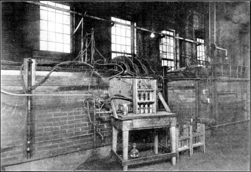
Fig. 2.—Gas Sampling Apparatus, Long
Combustion Chamber.
In order to minimize the leakage of air through the brickwork, the
furnace and tunnel are kept as nearly as possible at atmospheric
pressure by the combined use of pressure and exhausting fans.
Nevertheless, the leakage is determined periodically as accurately as
possible.
At first a number of tests were run to calibrate the apparatus as a
whole, all these preliminary tests being made on cheap, carefully
inspected, uniform screenings from the same seam of the same mine near
Pittsburg. Later tests will be run with other coals of various volatile
contents and various distillation properties.
It is anticipated that the progress of the tests may suggest changes in
the construction or operation of this chamber. It is especially
contemplated that the section of the chamber may be narrowed down by
laying sand in the bottom and fire-brick thereon; also that baffle walls
may be built into various portions of it, and that cooling surfaces with
baffling may be introduced. In addition to variations in the tests, due
to changes in construction in the combustion chamber, there will be
variations in the fuels tested. Especial effort will be made to procure
fuels ranging in volatile content from 15 to 27 and to 40%, and those
high in tar and heavy hydro-carbons. It is also proposed to vary the
conditions of testing by burning at high rates, such as at 15, 20, and
30 lb. per ft. of grate surface, and even higher. Records will be kept
of the weight of coal fired and of each firing, of
the weight of ash, etc.; samples of coal and of ash will be taken for
chemical and physical analysis, as well as samples of the gas, and other
essential data. These records will be studied in detail.
Fig. 17.
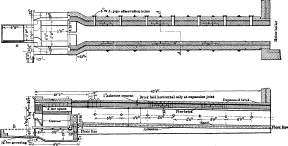
LONGITUDINAL SECTIONS OF LONG COMBUSTION CHAMBER
A series of heat-transmission tests undertaken two years ago, is being
continued on the ground floor of Building No. 21, on modified apparatus
reconstructed in the light of the earlier experiments by Mr. W. T.
Ray. The purpose of the tests on this apparatus has been to determine
some of the laws controlling the rate of transmission of heat from a hot
gas to a liquid and vice versa, the two being on the opposite
sides of a metal tube.
It appears that four factors determine the rate of heat impartation from
the gas to any small area of the metal17:
(1).—The temperature difference between the body of the gas and
the metal;
(2).—The weight of the gas per cubic foot, which is proportional
to the number of molecules in any unit of volume;
(3).—The bodily velocity of the motion of the gas parallel to any
small area under consideration; and (probably),
(4).—The specific heat of the gas at constant pressure.
The apparatus consists of an electric resistance furnace containing
coils of nickel wire, a small (interchangeable) multi-tubular boiler,
and a steam-jet apparatus for reducing the air pressure at the exit end,
so as to cause a flow of air through the boiler. A surface condenser was
attached to the boiler’s steam outlet, the condensed steam being weighed
as a check on the feed-water measurements. A number of thermometers and
thermo-couples were used to obtain atmospheric-air temperature,
temperatures of the air entering and leaving the boilers, and feed-water
temperature.
The apparatus is now being reconstructed with appliances for measuring
the quantity of air entering the furnace, and an automatic
electric-furnace temperature regulator.
Three sizes of boiler have been tested thus far, the dimensions being as
given in Table 4.
Each of the three boilers was tested at several temperatures of entering
air, up to 1,500° Fahr., about ten tests being made at each temperature.
It is also the intention to run, on these three boilers,
about eight tests at temperatures of 1,800°, 2,100° and 2,400° Fahr.,
respectively. A bulletin on the work already done, together with much
incidental matter, is in course of preparation.18
TABLE 4.—Dimensions of Boilers Nos. 1, 2,
and 3.
| Items. |
Boiler
No. 1. |
Boiler
No. 2. |
Boiler
No. 3. |
Distance, outside to outside of boiler heads, in inches |
8.28 |
8.28 |
16.125 |
Actual outside diameter of flues, in inches |
0.252 |
0.313 |
0.252 |
Actual inside diameter of flues, in inches |
0.175 |
0.230 |
0.175 |
Number of flues (tubes) |
10 |
10 |
10 |
The work on the first three boilers is only a beginning; preparations
are being made to test eight more multi-tubular boilers of various
lengths and tube diameters, under similar conditions. Because of the
experience already obtained, it will be necessary to make only eight
tests at each initial air temperature.
When the work on multi-tubular boilers is completed, water-tube boilers
will be taken up, for which a fairly complete outline has been prepared.
This second or water-tube portion of the investigation is really of the
greater scientific and commercial interest, but the multi-tubular
boilers were investigated first because the mathematical treatment is
much simpler.
Producer-Gas Tests.—The producer-gas plant at the Pittsburg
testing station is in charge of Mr. Carl D. Smith, and has been
installed for the purpose of testing low-grade fuel, bone coal, roof
coal, mine refuse, and such material as is usually considered of little
value, or even worthless for power purposes. The gas engine, gas
producer, economizer, wet scrubber (Fig. 1, Plate XIX), and accessories, are in Building No.
13, and the dry scrubber, gas-holder, and water-cooling apparatus are
immediately outside that building (Fig. 2, Plate XIX).
Plate
XIX.
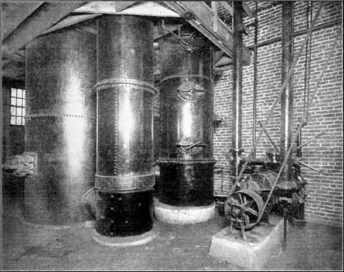
Fig. 1.—Gas Producer, Economizer, and
Wet Scrubber.
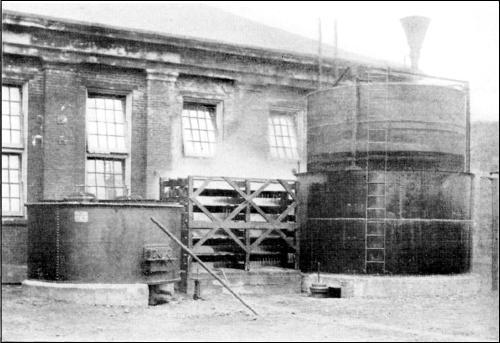
Fig. 2.—Producer Gas: Dry Scrubber and
Gas Holder.
At present immense quantities of fuel are left at the mines, in the form
of culm and slack, which, in quality, are much below the average output.
Such fuel is considered of little or no value, chiefly because there is
no apparatus in general use which can burn it to good advantage. The
heat value of this fuel is often from 50 to 75% of that of the fuel
marketed, and if not utilized, represents an
immense waste of natural resources. Large quantities of low-grade fuel
are also left in the mines, simply because present conditions do not
warrant its extraction, and it is left in such a way that it will be
very difficult, if not practically impossible, for future generations to
take out such fuel when it will be at a premium. Again, there are large
deposits of low-grade coal in regions far remote from the sources of the
present fuel supply, but where its successful and economic utilization
would be a boon to the community and a material advantage to the country
at large. The great importance of the successful utilization of
low-grade fuel is obvious. Until within very recent years little had
been accomplished along these lines, and there was little hope of ever
being able to use these fuels successfully.
The development of the gas producer for the utilization of ordinary
fuels,19 however,
indicates that the successful utilization of practically all low-grade
fuel is well within the range of possibility. It is notable that,
although all producer-gas tests at the Government testing stations, at
St. Louis and Norfolk, were made in a type of producer20 designed primarily for a good
grade of anthracite coal, the fuels tested included a wide range of
bituminous coals and lignites, and even peat and bone coal, and that, in
nearly every test, little serious difficulty was encountered in
maintaining satisfactory operating conditions.21 It is interesting to note that in one
test, a bone coal containing more than 45% of ash was easily handled in
the producer, and that practically full load was maintained for the
regulation test period of 50 hours.22
It is not expected that all the fuels tested will prove to be of
immediate commercial value, but it is hoped that much light will be
thrown on this important problem.
The equipment for this work consists of a single gas generator, rated at
150 h.p., and a three-cylinder, vertical gas engine of the same
capacity. The producer is a Loomis-Pettibone, down-draft, made by the
Power and Mining Machinery Company, of Cudahy, Wis., and is known as its
“Type C” plant. The gas generator consists of a
cylindrical shell, 6 ft. in diameter, carefully lined with fire-brick,
and having an internal diameter of approximately 4 ft. Near the bottom
of the generator there is a fire-brick grate, on which the fuel bed
rests. The fuel is charged at the top of the producer through a door
(Fig. 1, Plate XX), which may be left
open a considerable time without affecting the operation of the
producer, thus enabling the operator to watch and control the fuel bed
with little inconvenience. As the gas is generated, it passes downward
through the hot fuel bed and through the fire-brick grate. This
down-draft feature “fixes,” or makes into permanent gases, the tarry
vapors which are distilled from bituminous coal when it is first charged
into the producer. A motor-driven exhauster with a capacity of 375 cu.
ft. per min., draws the hot gas from the base of the producer through an
economizer, where the sensible heat of the gas is used to pre-heat the
air and to form the water vapor necessary for the operation of the
producer. The pre-heated air and vapor leave the economizer and enter
the producer through a passageway near the top and above the fuel bed.
From the economizer the gas is drawn through a wet scrubber where it
undergoes a further cooling and is cleansed of dirt and dust. After
passing the wet scrubber, the gas, under a light pressure, is forced, by
the exhauster, through a dry scrubber to a gas-holder with a capacity of
about 1,000 cu. ft.
All the fuel used is carefully weighed on scales which are checked from
time to time by standard weights; and, as the fuel is charged into the
producer, a sample is taken for chemical analysis and for the
determination of its calorific power. The water required for the
generation of the vapor is supplied from a small tank carefully
graduated to pounds; this observation is made and recorded every hour.
All the water used in the wet scrubber is measured by passing it through
a piston-type water meter, which is calibrated from time to time to
insure a fair degree of accuracy in the measurement. Provision is made
for observing the pressure and temperature of the gas at various points;
these are observed and recorded every hour.
From the holder the gas passes through a large meter to the vertical
three-cylinder Westinghouse engine, which is connected by a belt to a
175-kw., direct-current generator. The load on the generator is measured
by carefully calibrated switch-board instruments, and is regulated by a
specially constructed water rheostat which stands in front of the
building.
Careful notes are kept of the engine operation; the gas consumption and
the load on the engine are observed and recorded every 20 min.; the
quantity of jacket water used on the gas engine, and also its
temperature entering and leaving the engine jackets, are recorded every
hour. Indicator cards are taken every 2 hours. The work is continuous,
and each day is divided into three shifts of 8 hours each; the length of
a test, however, is determined very largely by the character and
behavior of the fuel used.
A preliminary study of the relative efficiency of the coals found in
different portions of the United States, as producers of illuminating
gas, has been nearly completed under the direction of Mr. Alfred H.
White, and a bulletin setting forth the results is in press.23
Tests of Liquid Fuels.—Tests of liquid fuels in
internal-combustion engines, in charge of Mr. R. M. Strong, are
conducted in the engine-room of Building No. 13.
The various liquid hydro-carbon fuels used in internal-combustion
engines for producing power, range from the light refined oils, such as
naphtha, to the crude petroleums, and have a correspondingly wide
variation of physical and chemical properties.
The most satisfactory of the liquid fuels for use in internal-combustion
engines, are alcohol and the light refined hydro-carbon oils, such as
gasoline. These fuels, however, are the most expensive in commercial
use, even when consumed with the highest practical efficiency, which, it
is thought, has already been attained, as far as present types of
engines are concerned.
At present little is known as to how far many of the very cheap
distillates and crude petroleums can be used as fuel for
internal-combustion engines. It is difficult to use them at all,
regardless of efficiency.
Gasoline is comparatively constant in quality, and can be used with
equal efficiency in any gasoline engine of the better grade. There are
many makes of high-grade gasoline engines, tests on any of which may be
taken as representative of the performance and action of gasoline in an
internal-combustion engine, if the conditions under which the tests were
made are clearly stated and are similar.
Kerosene varies widely in quality, and requires special devices for its
use, but is a little cheaper than gasoline. It is possible that the
kerosene engine may be developed so as to permit it to take the place of
the smaller stationary and marine gasoline engines. This would mean
considerable saving in fuel cost to the small power user, who now finds
the liquid-fuel internal-combustion engine of commercial advantage. A
number of engines at present on the market use kerosene; some use only
the lighter grades and are at best comparatively less efficient than
gasoline engines. All these engines have to be adjusted to the grade of
oil to be used in order to get the best results.
Kerosene engines are of two general types: the external-vaporizer type,
in which the fuel is vaporized and mixed with air before or as it is
taken into the cylinder; and the internal-vaporizer type, in which the
liquid fuel is forced into the cylinder and vaporized by contact with
the hot gases or heated walls of a combustion chamber at the head of the
cylinder. A number of special devices for vaporizing kerosene and the
lighter distillates have been tried and used with some success. Heat is
necessary to vaporize the kerosene as quickly as it is required, and the
degree of heat must be held between the temperature of vaporization and
that at which the oil will be carbonized. The vapor must also be
thoroughly and uniformly mixed with air in order to obtain complete
combustion. As yet, no reliable data on these limiting temperatures for
kerosene and similar oils have been obtained. No investigation has ever
been made of possible methods for preventing the oils from carbonizing
at the higher temperatures, and the properties of explosive mixtures of
oil vapors and air have not been studied. This field of engineering
laboratory research is of vital importance to the solution of the
kerosene-engine problem.
Distillates or fuel oils and the crude oils are much the cheapest of the
liquid fuels, and if used efficiently in internal-combustion engines
would be by far the cheapest fuels available in many large
districts.
Several engine builders are developing kerosene vaporizers, which are
built as a part of the engine, or are adapted to each different engine,
as required to obtain the best results. Most of these vaporizers use the
heat and the exhaust gases to vaporize the fuel, but they differ greatly
in construction; some are of the retort type, and others are of the
float-feed carburetter type. To what extent the lower-grade fuel oils
can be used with these vaporizers is yet to be determined.
There are only a few successful oil engines on the American market. The
most prominent of these represent specific applications of the principal
methods of internal vaporization, and all except one are of the hot-bulb
ignition type. It will probably be found that no one of the 4-stroke
cycle, or 2-stroke cycle, engines is best for all grades of oil, but
rather that each is best for some one grade. The Diesel engine is in a
class by itself, its cycle and method of control being somewhat
different from the others.
An investigation of the comparative adaptability of gasoline and alcohol
to use in internal-combustion engines, consisting of more than 2,000
tests, was made at the temporary fuel-testing plant of the Geological
Survey, at Norfolk, Va., in 1907. A detailed report of these tests is in
preparation.24 A
similar investigation of the comparative adaptability of kerosenes has
been commenced, with a view to obtaining data on their economical use,
leading up to the investigation of the comparative fuel values of the
cheaper distillates and crude petroleum, as before discussed.
Washing and Coking Tests.—The investigations relating to
the preparation of low-grade coals, such as those high in ash or
sulphur, by processes that will give them a higher market value or
increase their efficiency in use, are in charge of Mr. A. W.
Belden. They include the washing and coking tests of coals, and the
briquetting of slack and low-grade coal and culm-bank refuse so as to
adapt these fuels for combustion in furnaces, etc.
This work has been conducted in the washery and coking plant temporarily
located at Denver, Colo., and in Building No. 32 at the Pittsburg
testing station, where briquetting is in progress. The details of these
tests are set forth in the various bulletins issued by the Geological
Survey.25
The washing tests are carried out in the following manner: As the raw
coal is received at the plant, it is shoveled from the railroad cars to
the hopper scale, and weighed. It then passes through the tooth-roll
crusher, where the lumps are broken down to a maximum size of 2½ in. An
apron conveyor delivers the coal to an elevator
which raises it to one of the storage bins. As the coal is being
elevated, an average sample representing the whole shipment is taken. An
analysis is made of this sample of raw coal and float-and-sink tests are
run to determine the size to which it is necessary to crush before
washing, and the percentage of refuse with the best separation. From the
data thus obtained, the washing machines are adjusted so that the
washing test is made with full knowledge of the separations possible
under varying percentages of refuse. The raw coal is drawn from the bin
and delivered to a corrugated-roll disintegrator, where it is crushed to
the size found most suitable, and is then delivered by the raw-coal
elevator to another storage bin. The arrangement of the plant is such
that the coal may be first washed on a Stewart jig, and the refuse then
delivered to and re-washed on a special jig, or the refuse may be
re-crushed and then re-washed.
When the coal is to be washed, it drops to the sluice box, where it is
mixed with the water and sluiced to the jigs. In drawing off the washed
coal, or when the uncrushed raw coal is to be drawn from a bin and
crushed for the washing tests, however, a gate just below the coal-flow
regulating gate is thrown in, and the coal falls into a central hopper
instead of into the sluice box. Ordinarily, this gate forms one side of
the vertical chute. The coal in this central hopper is carried by a
chute to the apron conveyor, and thence to the roll disintegrator, or,
in case it is washed coal, to a swing-hammer crusher. It will be noted
that coal, in this manner, can be drawn from a bin at the same time that
coal is being taken from another bin, and sluiced to the jigs for
washing, the two operations not interfering in the least.
The washed coal, after being crushed and elevated to the top of the
building, is conveyed by a chute to the coke-oven larry, and is weighed
on the track scale, after which it is charged to the oven. The refuse is
sampled and weighed as it is wheeled to the dump pile, and from this
sample the analysis is made and a float-and-sink test run to determine
the “loss of good coal” in the refuse and to show the efficiency of the
washing test.
The coking tests have been conducted in a battery of two beehive ovens,
one 7 ft. high and 12 ft. in diameter, the other, 6¼ ft. high and 12 ft.
in diameter. A standard larry with a capacity of 8 tons, and the
necessary scales for weighing accurately the coal charged and
coke produced, complete the equipment. The coal is usually run through a
roll crusher which breaks it to about ½-in. size, or through a
Pennsylvania hammer crusher. The fineness of the coals put through the
hammer crusher varies somewhat, but the average, taken from a large
number of samples, is as follows: Through ⅛-in. mesh, 100%; over
10-mesh, 31.43%; over 20-mesh, 24.29%; over 40-mesh, 22.86%; over
60-mesh, 10 per cent. The results of the coking tests are set forth in
detail in the various publications issued on this subject.26
Tests of coke produced in the illuminating-gas investigations before
referred to, and a study of commercial coking and by-product plants, are
included in these investigations.
Briquetting Investigations.—These investigations are in
charge of Mr. C. L. Wright, and are conducted in Building No. 32,
which is of fire-proof construction, having a steel-skeleton frame work,
reinforced-concrete floors, and 2-in. cement curtain walls, plastered on
expanded-metal laths. In this building two briquetting machines are
installed, one an English machine of the Johnson type, and the other a
German lignite machine of very powerful construction.
The investigations include the possibility of making satisfactory
commercial fuels from lignite or low-grade coals which do not stand
shipment well, the benefiting of culm or slack coals which are wasted or
sold at unremunerative prices, and the possibility of improving the
efficiency of good coals. Some of the various forms of commercial
briquettes, American and foreign, are shown in Fig. 2, Plate XX. After undergoing chemical analysis, the
coal is elevated and fed to a storage bin, whence it is drawn through a
chute to a hopper on the weighing scales. There it is mixed with varying
percentages of different kinds of binding material, and the tests are
conducted so as to ascertain the most suitable binder for each kind of
fuel, which will produce the most durable and weather-proof briquette at
least cost, and the minimum quantity necessary to produce a good, firm
briquette. After weighing, the materials to be tested are run through
the necessary grinding and pulverizing machines and are fed into the
briquetting machines, whence the manufactured briquettes are delivered
for loading or storage. The materials to be used in the German machine
are also dried and cooled again.
Plate XX.
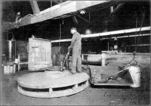
Fig. 1.—Charging Floor of Gas
Producer.
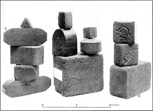
Fig. 2.—European and American
Briquettes.
The briquettes made at this plant are then subjected to physical tests
in order to determine their weathering qualities and their resistance to
abrasion; extraction tests and chemical analyses are also made.
Meanwhile other briquettes from the same lots are subjected to
combustion tests for comparison with the same coal not briquetted. These
tests are made in stationary boilers, in house-heating boilers, on
locomotives, naval vessels, etc., and the results, both of the processes
of manufacture, and of the tests, are published in various bulletins
issued by the Geological Survey.27
The equipment includes storage bins for the raw coal, scales for
weighing, machines for crushing or cracking the pitch, grinders,
crushers, and disintegrators for reducing the coal to the desired
fineness, heating and mixing apparatus, presses and moulds for forming
the briquettes, a Schulz drier, and a cooling apparatus.
There is a small experimental hand-briquetting press (Fig. 1, Plate XXI) for making preliminary tests of the
briquetting qualities of the various coals and lignites. With this it is
easily possible to vary the pressure, heat, percentage and kind of
binder, so as to determine the best briquetting conditions for each fuel
before subjecting it to large-scale commercial tests in the big
briquetting machines.
This hand press will exert pressures up to 50 tons or 100,000 lb. per
sq. in., on a plunger 3 in. in diameter. This plunger enters a mould,
which can be heated by a steam jacket supplied with ordinary saturated
steam at a pressure of 125 lb., and compresses the fuel into a
briquette, 8 in. long, under the conditions of temperature and pressure
desired.
The Johnson briquetting machine, which requires 25 h.p. for its
operation, exerts a pressure of about 2,500 lb. per sq. in., and makes
briquettes of rectangular form, 6¾ by 4¼ by 2½ in., and having an
average weight of about 3¾ lb. The capacity of the machine (Fig. 2, Plate XXI) is about 3.8 tons of briquettes
per 8-hour day.
Plate
XXI.
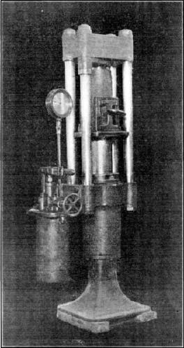
Fig. 1.—Hand Briquetting
Press.
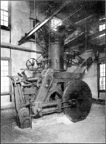
Fig. 2.—Coal Briquetting
Machine.
Under the hopper on the scales for the raw material is a square wooden
reciprocal plunger which pushes the fuel into a hole in the floor at a
uniform rate. The pitch is added as uniformly as possible by hand, as
the coal passes this hole. Under this hole a horizontal screw conveyor
carries the fuel and pitch to the disintegrator, in front
of which, in the feeding chute, there is a powerful magnet for picking
out any pieces of iron which might enter the machine and cause
trouble.
The ground mixture is elevated from the disintegrator to a point above
the top of the upper mixer of the machine. At the base of this cylinder,
steam can be admitted by several openings to heat the material to any
desired temperature, usually from 180° to 205° Fahr. There, a plunger,
making 17 strokes per min., compresses two briquettes at each
stroke.
The German lignite-briquetting machine (Figs. 18
and 19) was made by the Maschinenfabrik
Buckau Actien-Gesellschaft, Magdeburg, Germany. Lignite from the storage
room on the third floor of the building is fed into one end of a Schulz
tubular drier (Fig. 1, Plate XXII),
which is similar to a multi-tubular boiler set at a slight angle from
the horizontal, and slowly revolved by worm and wheel gearing, the
lignite passing through the tubes and the steam being within the boiler.
From this drier the lignite passes through a sorting sieve and crushing
rolls to a cooling apparatus, which consists of four horizontal circular
plates, about 13 ft. in diameter, over which the dried material is moved
by rakes. After cooling, the material is carried by a long, worm
conveyor to a large hopper over the briquette press, and by a feeding
box to the press (Fig. 2, Plate XXII).
Plate
XXII.
Fig. 1.—Dryer for Lignite Briquetting
Press.
Fig. 2.—Lignite Briquetting
Machine.
The press, which is of the open-mould type, consists of a ram and die
plates, the latter being set so as to make a tube which gradually tapers
toward the delivery end of the machine. The briquettes have a
cross-section similar to an ellipse with the ends slightly cut off; they
are about 1¼ in. thick and average about 1 lb. in weight (Fig. 2, Plate XX). The press is operated by a direct
connection with a steam engine of 150 h.p., the base of which is
continuous with that of the press. The exhaust steam from the engine is
used to heat the driver.
The plunger makes from 80 to 100 strokes per min., the pressure exerted
ranging from 14,000 to 28,000 lb. per sq. in., the capacity of the
machine being 1 briquette per stroke, or from 2½ to 3 tons of completed
briquettes per hour. It is expected that no binder will be needed for
practically all the brown lignite briquetted by this machine, thus
reducing the cost as compared with the briquetting of coals, which
require from 5 to 7% of water-gas, pitch binder costing more than 50
cents per ton of manufactured briquettes.
Fig. 18.
Fig. 19.
Peat Investigations.—Investigations into the distribution,
production, origin, nature, and uses of peat are being conducted by Mr.
C. A. Davis, and include co-operative arrangements with State
Geological Surveys and the Geologic Branch of the U. S. Geological
Survey. These organizations conduct surveys which include the mapping of
the peat deposits in the field, the determination of their extent and
limitations, the sampling of peat from various depths, and the
transmittal of samples to the Pittsburg laboratories for analysis and
test.28
This work is co-ordinated in such a manner as to result in uniform
methods of procedure in studying the peat deposits of the United States.
The samples of peat are subjected to microscopic examination, in order
to determine their origin and age, and to chemical and physical tests at
the laboratories in Pittsburg, so as to ascertain the chemical
composition and calorific value, the resistance to compressive strains,
the ash and moisture content, drying properties, resistance to abrasion,
etc. Occasionally, large quantities of peat are disintegrated and
machined, and portions, after drying for different periods, are
subjected to combustion tests in steam boilers and to tests in the gas
producer, to ascertain their efficiency as power producers.
Results.—The full value of such investigations as have been
described in the preceding pages cannot be realized for many years; but,
even within the four years during which this work has been under way,
certain investigations have led to important results, some of which may
be briefly mentioned:
The chemical and calorific determinations of coals purchased for the use
of the Government have resulted in the delivery of a better grade of
fuel without corresponding increase in cost, and, consequently, in
saving to the Government. Under this system, of purchasing its coal
under specifications and testing, the Government is getting more nearly
what it pays for and is paying for what it gets. These investigations,
by suggesting changes in equipment and methods, are also indicating the
practicability of the purchase of cheaper fuels, such as bituminous coal
and the smaller sizes of pea, buckwheat, etc., instead of the more
expensive sizes of anthracite, with a corresponding saving in cost. The
Government’s fuel bill now aggregates about $10,000,000 yearly.
The making and assembling of chemical analyses and calorific
determinations (checked by other tests) of carefully selected samples of
coals from nearly 1,000 different localities, in the different coal
fields of the United States, with the additions, from time to time, of
samples representing parts of coal fields or newly opened beds of coal
in the same field, furnish invaluable sources of accurate information,
not only for use of the Government, but also for the general public. Of
the above-mentioned localities, 501 were in the public-land States and
427 in the Central, Eastern, and Southern States.
The chemical analyses
of the coals found throughout the United
States have been made with such uniformity of method, both as to
collection of samples and analytical procedure, as to yield results
strictly comparable for coals from all parts of the country, and furnish
complete information, as a basis for future purchases and use by the
Government and by the general public, of all types of American
coals.
Other researches have resulted in the acquirement of valuable
information regarding the distribution of temperature in the fuel bed of
gas producers and furnaces, showing a range of from 400° to 1,300°
cent., and have thus furnished data indicating specific difficulties to
be overcome in gas-producer improvements for greater fuel
efficiency.
The recent studies of the volatile matter in coal, and its relation to
the operation of coke ovens and other forms of combustion, have
demonstrated that as much as one-third of this matter is inert and
non-combustible, a fact which may have a direct bearing on smoke
prevention by explaining its cause and indicating means for its
abatement.
Experiments in the storage of coal have proven that oxygen is absorbed
during exposure to air, thereby causing, in some cases, a deterioration
in heating value, and indicating that, for certain coals, in case they
are to be stored a long time for naval and other purposes, storage under
water is advisable.
The tests of different coals under steam boilers have shown the
possibility of increasing the general efficiency of hand-fired steam
boilers from 10 to 15% over ordinary results. If this saving could be
made in the great number of hand-fired boilers now being operated in all
parts of the United States, it would result in large saving in the fuel
bill of the country. Experiments which have been made with
residence-heating boilers justify the belief that it will be possible
to perfect such types of boilers as may economically give a smokeless
operation. The tests under steam boilers furnish specific information as
to the most efficient method of utilizing each of a number of different
types of coal in Government buildings and power plants in different
parts of the country.
The tests in the gas producer have shown that many fuels of such low
grade as to be practically valueless for steam-furnace purposes,
including slack coal, bone coal, and lignite, may be economically
converted into producer gas, and may thus generate sufficient power to
render them of high commercial value.
Practically every shipment out of several hundred tested in the gas
producers, including coals as high in ash content as 45%, and lignites
and peats high in moisture, has been successfully converted into
producer gas which has been used in operating gas engines. It has been
estimated that on an average there was developed from each coal tested
in the gas-producer plant two and one-half times the power developed
when used in the ordinary steam-boiler plant, and that such relative
efficiencies will probably hold good for the average plant of moderate
power capacity, though this ratio may be greatly reduced in large steam
plants of the most modern type. It was found that the low-grade lignites
of North Dakota developed as much power, when converted into producer
gas, as did the best West Virginia bituminous coals when utilized under
the steam boiler; and, in this way, lignite beds underlying from
20,000,000 to 30,000,000 acres of public lands, supposed to have little
or no commercial value, are shown to have a large value for power
development.
The tests made with reference to the manufacture and combustion of
briquetted coal have demonstrated conclusively that by this means many
low-grade bituminous coals and lignites may have their commercial value
increased to an extent which more than covers the increased cost of
making; and these tests have also shown that bituminous coals of the
higher grades may be burned in locomotives with greatly increased
efficiency and capacity and with less smoke than the same coal not
briquetted. These tests have shown that, with the same fuel consumption
of briquettes as of raw coal, the same locomotive can very materially
increase its hauling capacity and thus reduce the cost of
transportation.
The investigations into smoke abatement have indicated clearly
that each type of coal may be burned practically without smoke in some
type of furnace or with some arrangement of mechanical stoker, draft,
etc. The elimination of smoke means more complete combustion of the
fuel, and consequently less waste and higher efficiency.
The investigations into the waste of coal in mining have shown the
enormous extent of this waste, aggregating probably from 300,000,000 to
400,000,000 tons yearly, of which at least one-half might be saved. It
is being demonstrated that the low-grade coals, high in sulphur and ash,
now left underground, can be used economically in the gas producer for
power and light, and, therefore, should be mined at the same time that
the high-grade coal is being removed. Moreover, attention is now being
called to the practicability of a further large reduction of waste
through more efficient mining methods.
The washing tests have demonstrated the fact that many coals, too high
in ash and sulphur for economic use under the steam boiler or for
coking, may be rendered of commercial value by proper treatment in the
washery. The coking tests have also demonstrated that, by proper methods
of preparation for and manipulation in the beehive oven, many coals
which were not supposed to be of economic value for coking purposes, may
be rendered so by prior washing and proper treatment. Of more than 100
coals tested during 1906 from the Mississippi Valley and the Eastern
States, most of which coals were regarded as non-coking, all except 6
were found, by careful manipulation, to make fairly good coke for
foundry and other metallurgical purposes. Of 52 coals from the Rocky
Mountain region, all but 3 produced good coke under proper treatment,
though a number of these had been considered non-coking coals.
Investigations into the relative efficiency of gasoline and denatured
alcohol as power producers, undertaken in connection with work for the
Navy Department, have demonstrated that with proper manipulation of the
carburetters, igniters, degree of compression, etc., denatured alcohol
has the same power-producing value, gallon for gallon, as gasoline. This
is a most interesting development, in view of the fact that the heat
value of a gallon of alcohol is only a little more than 0.6 that of a
gallon of gasoline. To secure these results, compressions of from 150 to
180 lb. per sq. in. were used, these pressures involving an increase in
weight of engine. Although the engine especially
designed for alcohol will be heavier than a gasoline engine of the same
size, it will have a sufficiently greater power capacity so that the
weight per horse-power need not be greater.
Several hundred tons of peat have been tested to determine methods of
drying, compressing into briquettes, and utilization for power
production in the gas producer. In connection with these peat
investigations, a reconnoissance survey has been made of the peat
deposits of the Atlantic Coast. Samples have been obtained by boring to
different depths in many widely distributed peat-bogs, and these samples
have been analyzed and tested in order to determine their origin,
nature, and fuel value.
The extent and number of tests from which these results have been
derived will be appreciated from the fact that, in three years, nearly
15,000 tests were made, in each of which large quantities of fuel were
consumed. These tests involved nearly 1,250,000 physical observations
and 67,080 chemical determinations, made with a view to analyze the
results of the tests and to indicate any necessary changes in the
methods as they progressed. For coking, cupola, and washing, 596 tests,
of which nearly 300 involved the use of nearly 1,000 tons of coal, have
been made at Denver. For briquetting, 312 tests have been made.
Briquettes have been used in combustion tests in which 250 tons of
briquetted coal were consumed in battleship tests, 210 tons in
torpedo-boat tests, 320 tons in locomotive tests on three railway
systems, and 70 tons were consumed under stationary steam boilers. Of
producer gas tests, 175 have been made, of which 7 were long-time runs
of a week or more in duration, consuming in all 105 tons of coal. There
have been 300 house-heating boiler tests and 575 steam-boiler tests;
also, 83 railway-locomotive and 23 naval-vessel tests have been made on
run-of-mine coal in comparison with briquetted coal; also, 125 tests
have been made in connection with heat-transmission experiments, and
2,254 gasoline- and alcohol-engine tests. Nearly 10,000 samples of coal
were taken for analysis, of which 3,000 were from public-land States.
Nearly 5,000 inspection samples, of coal purchased by the Government for
its use, have been taken and tested.
The results of the tests made in the course of these investigations, as
summarized, have been published in twelve separate Bulletins, three of
which, Nos. 261, 290, and 332, set forth in detail the operations of the
fuel-testing plant for 1904, 1905, and 1906. Professional
Paper No. 48, in three volumes, describes in greater detail each stage
of the operations for 1904 and 1905.
Separate Bulletins, descriptive of the methods and results of the work
in detail, have been published, as follows: No. 323, Experimental work
conducted in the chemical laboratory; No. 325, A study of four hundred
steaming tests; No. 334, Burning of coal without smoke in boiler plants;
No. 336, Washing and coking tests of coal, and cupola tests of coke; No.
339, Purchase of coal under specifications on basis of heating value;
No. 343, Binders for coal briquettes; No. 362, Mine sampling and
chemical analyses of coals in 1907; No. 363, Comparative tests of
run-of-mine and briquetted coal on locomotives, including torpedo-boat
tests, and some foreign specifications for briquetted fuel; No. 366,
Tests of coal and briquettes as fuel for house-heating boilers; No. 367,
Significance of drafts in steam-boiler practice; No. 368, Coking and
washing tests of coal at Denver; No. 373, Smokeless combustion of coal
in boiler plants, with a chapter on central heating plants; No. 378,
Results of purchasing coal under Government specifications; No. 382, The
effect of oxygen in coal; and, No. 385, Briquetting tests at
Norfolk, Va.
Mr.
Allen.
Kenneth Allen, M. Am. Soc. C.
E.—The speaker would like to know whether anything has been
done in the United States toward utilizing marsh mud for fuel.
In an address by Mr. Edward Atkinson, before the New England Water Works
Association, in 1904, on the subject of “Bog Fuel,” he referred to its
extensive use in Sweden and elsewhere, and intimated that there was a
wide field for its use in America.
The percentage of combustible material in the mud of ordinary marsh
lands is very considerable, and there are enormous deposits readily
available; but it is hardly probable that its calorific value is
sufficiently high to render its general use at this time profitable.
As an example of the amount of organic matter which may remain stored in
these muds for many years, the speaker would mention a sample taken from
the bottom of a trench, which he had analyzed a few years ago. Although
taken from a depth of about 15 ft., much of the vegetable fiber remained
intact. The material proved to be 70¾% volatile.
Possibly before the existing available coal deposits are exhausted, the
exploitation of meadow muds for fuel may become profitable.
Mr.
Kreisinger.
Henry Kreisinger, Esq.29 (by letter).—Mr. Wilson
gives a brief description of a long furnace and an outline of the
research work which is being done in it. It may be well to discuss
somewhat more fully the proposed investigations and point out the
practical value of the findings to which they may lead.
In general, the object is to study the process of combustion of coal.
When soft coal is burned in any furnace, part of the combustible is
driven off shortly after charging, and has to be burned in the space
between the fuel bed and the exit of the gases, which is called the
combustion space. There is enough evidence to show that, with a constant
air supply, the completeness of the combustion of the volatile
combustible depends on the length of time the latter stays within the
combustion space; but, with a constant rate of charging the coal, this
length of time depends directly on the extent of the combustion space.
Thus, if the volume of the volatile combustible evolved per second and
the admixed air is 40 cu. ft., and the extent of the combustion space is
80 cu. ft., the average time the gas will stay within the latter is 2
sec.; if the combustion space is 20 cu. ft., the average time the
mixture can stay in this space is only ½ sec., and its combustion will
be less complete than in the first case. Thus it is seen that the extent
of the combustion space of a furnace is an important factor in the
economic combustion of volatile coals. The specific object of the
investigations, thus far planned, is to determine the extent of the
combustion space required to attain practically complete combustion when
a given quantity of a given coal is burned under definite conditions.
With this object in view, the furnace has been provided with a
combustion space large enough for the highest volatile coals and for the
highest customary rate of combustion. To illustrate the application of
the data which will be obtained by these experiments, the following
queries are given:
Suppose it is required to design a furnace which will burn coal from a
certain Illinois mine at the rate of 1,000 lb. per hour, with a
resulting temperature of not less than 2,800° Fahr. How large a
combustion space is required to burn, with practical completeness, the
volatile combustible? What completeness of combustion can be attained,
if the combustion space is only three-fourths of the required extent? In
the present state of the knowledge of the process of combustion of coal,
these queries cannot be answered definitely. In the literature on
combustion one may find statements that the gases must be completely
burned before leaving the furnace or before they strike the cooling
surfaces of the boiler; but there is no definite information available
as to how long the gases must be kept in the furnace or how large the
combustion space must be in order to obtain practically complete
combustion. It is strange that so little is known of such an old art as
the combustion of coal.
The research work under consideration is fundamentally a problem in
physical chemistry, and, for that reason, has been assigned to a
committee consisting of the writer as Engineer, Dr. J. C. W.
Frazer, Chemist, and Dr. J. K. Clement, Physicist. The outcome of
the investigation may prove of extreme interest to mechanical and fuel
engineers, and to all who have anything to do with the burning of coal
or the construction of furnaces. In the experiments thus far planned the
following factors will be considered:
Effect of the Nature of Coal on the Extent of Combustion Space
Required.—The steaming coals mined in different localities
evolve different volumes of volatile combustible, even when burned at
the same rate. The coal which analyzes 45% of volatile matter evolves a
much greater volume of gases and tar vapors than that analyzing only 15
per cent. These evolved gases and tar vapors must be burned in the
space. Consequently, a furnace burning high volatile coal must have a
much larger combustion space than that burning coal low in volatile
combustible.
There is enough evidence to show that the extent of combustion space
required to burn the volatile combustible depends, not only on the
volume of the combustible mixture, but also on the chemical composition
of the volatile combustible. Thus the volatile combustible of
low volatile coal, when mixed with an equal volume of air, may require 1
sec. in the combustion space to burn practically to completeness, while
it may require 2 sec. to burn the same volume of the volatile
combustible of high volatile coal with the same completeness; so that
the extent of the combustion space required to burn various kinds of
coal may not be directly proportional to the volatile matter of the
coal.
Effect of the Rate of Combustion on the Extent of Combustion Space
Required.—With the same coal, the volume of the volatile
combustible distilled from the fuel bed per unit of time varies as the
rate of combustion. Thus, when this rate is double that of the standard,
the volume of gases and tar vapors driven from the fuel is about
doubled. To this increased volume of volatile combustible, about double
the volume of air must be added, and, if the mixture is to be kept the
same length of time within the combustion space, the latter should be
about twice as large as for the standard rate of combustion. Thus the
combustion space required for complete combustion varies, not only with
the nature of the coal, but also with the rate of firing the fuel,
which, of course, is self-evident.
Effect of Air Supply on the Extent of Combustion Space
Required.—Another factor which influences the extent of the
combustion space is the quantity of air mixed with the volatile
combustible. Perhaps, within certain limits, the combustion space may be
decreased when the supply of air is increased. However, any statement at
present is only speculation; the facts must be determined
experimentally. One fact is known, namely, that, in order to obtain
higher temperatures of the products of combustion, the air supply must
be decreased.
Effect of Rate of Heating of Coal on the Extent of Combustion Space
Required.—There is still another factor, a very important one,
which, with a given coal and any given air supply, will influence the
extent of the combustion space. This factor is the rate of heating of
the coal when feeding it into the furnace. The so-called “proximate”
analysis of coal is indeed only very approximate. When the analysis
shows, say, 40% of volatile matter and 45% of fixed carbon, it does not
mean that the coal is actually composed of so much volatile matter and
so much fixed carbon; it simply means that, under a certain rate of
heating attained by certain standard laboratory conditions, 40% of the
coal has been driven off as “volatile matter.” If the rate or method of
heating were different, the amount of volatile matter driven off would
also be different. Chemists state that it is difficult to obtain
accurate checks on “proximate” analysis. To illustrate this factor,
further reference may be made to the operation of the up-draft
bituminous gas producers. In the generator of such producers the tar
vapors leave the freshly fired fuel, pass through the wet scrubber, and
are finally separated by the tar extractor as a black, pasty substance
in a semi-liquid state. If this tar is subjected to the standard
proximate
analysis, it will be shown that from 40 to 50% of it is fixed carbon,
although it left the gas generator as volatile matter. It is desired to
emphasize the fact that different rates of heating of high volatile
coals will not only drive off different percentages of volatile matter,
but that the latter itself varies greatly in chemical composition and
physical properties as regards inflammability and rapidity of
combustion. Thus it may be said that the extent of the combustion space
required for the complete oxidation of the volatile combustible depends
on the method of charging the fuel, that is, on how rapidly the fresh
fuel is heated. If this factor is given proper consideration, it may be
possible to reduce very materially the necessary space required for
complete combustion.
The Effect of the Rate of Mixing the Volatile Combustible and Air on
the Extent of the Combustion Space.—When studying the effects
discussed in the preceding paragraphs, the rate of mixing the volatile
combustible with the supply of air must be as constant as practicable.
At first, tests will be made with no special mixing devices, the mixing
will be accomplished entirely by the streams of air entering the furnace
at the stoker, and by natural diffusion. Although there appears to be
violent stirring of the gases above the fuel bed, the mixture of the
gases does not become homogeneous until they are about 10 or 15 ft. from
the stoker. The mixing caused by the air currents forced into the
furnace at the stoker is very distinct, and can be readily observed
through the peep-hole in the side wall of the Heine boiler, opposite the
long combustion chamber. This mixing is shown in Fig. 20. A is a current of air forced from the
ash-pit directly upward through the fuel bed; B and B are
streams of air forced above the fuel bed through numerous small openings
at the furnace side of each hopper. Those currents cause the gases to
flow out of the furnace in two spirals, as shown in Fig. 20. The velocity of rotation on the outside of
the two spirals appears to be about 10 ft. per sec., when the rate of
combustion is about 750 lb. of coal per hour. It is reasonable to expect
that when the rate of mixing is increased by building piers and other
mixing structures immediately back of the grate, the completeness of the
combustion will be effected in less time, and a smaller combustion space
will be required. Thus, the mixing structures may be an important factor
in the extent of the required combustion space.
Fig. 20.
SECTION THROUGH STOKER
SHOWING MIXING OF GASES
CAUSED BY CURRENTS OF AIR
To sum up, it can be said that the extent of the space required to
obtain a combustion which can be considered complete for all practical
purposes, depends on the following factors:
(a).—Nature of coal,
(b).—Rate of combustion,
(c).—Supply of air,
(d).—Rate of heating fuel,
(e).—Rate of mixing volatile combustible and air.
Just how much the extent of the combustion space required will be
influenced by these factors is the object of the experiments under
discussion.
The Scope of the Experiments.—With this object in view, as
explained in the preceding paragraphs, the following series of
experiments are planned:
Six or eight typical coals are to be selected, each representing a
certain group of nearly the same chemical composition. Each series will
consist of several sets of tests, each set being run with all the
conditions constant except the one, the effect of which on the size of
the combustion space is to be investigated. Thus a set of four or five
tests will be made, varying in rate of combustion from 20 to 80 lb. of
coal per square foot of grate per hour, keeping the supply of air per
pound of combustible and the rate of heating constant. This set will
show the effect of the rate of combustion of the coal on the extent of
space required to obtain combustion which is practically complete. Other
variables, such as composition of coal, supply of air, and rate of
heating, remain constant.
Another set of four or five tests will be made with the same coal and at
the same rate of combustion, but the air supply will be different for
each test. This set of tests will be repeated for two or three different
rates of combustion. Thus each of these sets will give the effect of the
air supply on the extent of combustion space when the coal and rate of
combustion remain constant.
Still another set of tests should be made in which the time of heating
the coal when feeding it into the furnace will vary from 3 to 30 min. In
each of the tests of this set, the rate of combustion and the air supply
will be kept constant, and the set will be repeated for two or three
rates of combustion and two or three supplies of air. Each of these sets
of tests will give the effect of the rate of heating of fresh fuel on
the extent of combustion space required to burn the distilled volatile
combustible. These sets of experiments will require a modification in
the stoker mechanism, and, on that account, may be put off until all the
other tests on the other selected typical coals are completed. As the
investigation proceeds, enough may be learned so that the number of
tests in each series may be gradually reduced. After all the desirable
tests are made with the furnace as it stands, several kinds of mixing
structures will be built successively back of the stoker and tried, one
kind at a time, with a set of representative tests. Thus the
effectiveness of such mixing structures will be determined.
Determining the Completeness of Combustion.—The
completeness of combustion in the successive cross-sections of the
stream of gases is determined mainly by the chemical analysis of samples
of gases collected through the openings at these respective
cross-sections. The first of these cross-sections at which gas samples
are collected, passes through the middle of the bridge wall; the others
are placed at intervals of 5 ft. through the entire length of the
furnace. Measurements of the temperature of the gases, and direct
observations of the length and color of the flames and of any visible
smoke will be also made through the side peep-holes. These direct
observations, together with the gas analysis, will furnish enough data
to determine the length of travel of the combustible mixture to reach
practically complete combustion.
In other words, these observations will determine the extent of the
combustion space for various kinds of coal when burned under certain
given conditions. Direct observations and the analysis of gases at
sections nearer the stoker than that at which the combustion is
practically complete, will show how the process of combustion approaches
its completion. This information will be of extreme value in determining
the effect of shortening the combustion space on the loss of heat due to
incomplete combustion.
Method of Collecting Gas Samples.—The collection of gas
samples is a difficult problem in itself, when one considers that the
temperature
of the gases, as they are in the furnace, ranges from 2,400° to 3,200°
Fahr.; consequently, the samples must be collected with water-cooled
tubes. Thus far, about 25 preliminary tests have been made. These tests
show that the composition of the gases at the cross-sections near the
stoker is not uniform, and that more than one sample must be taken from
each cross-section. It was decided to take 9 samples from the
cross-section immediately back of the stoker, and reduce the number in
the sections following, according to the uniformity of the gas
composition. Thus, about 35 simultaneous gas samples must be taken for
each test. The samples will be subjected, not only to the usual
determination of CO2, O2 and CO, but to a complete
analysis. It is also realized that some of the carbon-hydrogen compounds
which, at the furnace temperature, exist as heavy gases, are condensed
to liquids and solids when cooled in the sampling tubes, where they
settle and tend to clog it. To neglect the presence of this form of the
combustible would introduce considerable error in the determination of
the completeness of combustion at any of the cross-sections. Therefore,
special water-cooled sampling tubes are constructed and equipped with
filters which separate the liquid and solid combustible from the gases.
The contents of these filters are then also subjected to complete
analysis. To obtain quantitative data, a measured quantity of gases must
be drawn through these filtering sampling tubes.
The Measuring of Temperatures.—At present the only possible
known method of measuring the temperature of the furnace gases is by
optical and radiation pyrometers. Platinum thermo-couples are soon
destroyed by the corrosive action of the hot gases. The pyrometers used
at present are the Wanner optical pyrometer and the Fery radiation
pyrometer.
The Flow of Heat Through Furnace Walls.—An interesting side
investigation has developed, in the study of the loss of heat through
the furnace walls. In the description of this experimental furnace it
has been said that the side walls contained a 2-in. air space, which, in
the roof, was replaced with a 1-in. layer of asbestos. To determine the
relative resistance to heat flow of the air space and the asbestos
layer, 20 thermo-couples were embedded, in groups of four, to different
depths at three places in the side wall and at two places in the roof.
In the side wall, one of the thermo-couples of each group was placed in
the inner wall near the furnace surface; the second thermo-couple was
placed in the same wall, but near the surface facing the air space; the
third thermo-couple was placed in the outer wall near the inner surface;
and the fourth was placed near the outer surface in the outer wall. In
the roof the second and third thermo-couples were placed in the brick
near the surface on each side of the asbestos layer. These
thermo-couples have shown that the temperature drop across the 2-in. air
space was much less than that across the 1-in. layer of asbestos;
in fact, that it was considerably less than the temperature drop through
the same thickness of the brick wall.
The results obtained prove that, as far as heat insulation is concerned,
air spaces in furnace walls are undesirable. The heat is not conducted
through the air, but leaps across the space by radiation. In furnace
construction a solid wall is a better heat insulator than one of the
same total thickness containing an air space. If it is necessary to
build a furnace wall in two parts on account of unequal expansion, the
space between the two walls should be filled with some solid, cheap,
non-conducting materials, such as ash, sand, or crushed brick. A more
detailed account of these experiments may be found in a Bulletin of the
U. S. Geological Survey entitled “The Flow of Heat Through Furnace
Walls.”
Mr.
Snelling.
Walter O. Snelling, Esq.30 (by letter).—The work
of the United States Testing Station at Pittsburg has been set forth so
fully by Mr. Wilson that a further statement as to the results achieved
may seem like repetition. It would be most unlikely, however, that
studies of such variety should possess no other value than along the
direct lines being investigated. In the case of the Mine Accidents
Division, at least, it is certain that the indirect benefits of some of
the studies have been far-reaching, and are now proving of value in
lines far removed from those which were the primary object of the
investigation. They are developing facts which will be of great value to
all engineers or contractors engaged in tunneling or quarrying. As the
writer’s experience has been solely in connection with the chemical
examination of explosives, he will confine his discussion to this
phase.
In studying the properties of various explosives, and in testing work to
separate those in which the danger of igniting explosive mixtures of
coal dust and air, or of fire-damp and air, is greatest, from those in
which this danger is least, much information has been collected. Mr.
Wilson has described many of the tests, and it can be readily seen that
in carrying out these and other tests on each of the explosives
submitted, a great many facts relating to the properties of explosive
compounds have been obtained, which were soon found to be of decided
value in directions other than the simple differentiation of explosives
which are safe from those which are unsafe in the presence of explosive
mixtures of fire-damp or coal dust.
The factors which determine the suitability of an explosive for work in
material of any particular physical characteristics depend on the
relationship of such properties as percussive force (or the initial blow
produced by the products of the decomposition of the explosive at the
moment of explosion), and the heaving force (or the continued pressure
produced by the products of the decomposition, after the
initial blow at the instant of detonation). Where an explosive has been
used in coal or rock of a certain degree of brittleness, and where the
work of the explosive with that particular coal is not thoroughly
satisfactory, it becomes evident that through the systematic use of the
information available at the Testing Station (and now in course of
publication in the form of bulletins), in regard to the relationship
between percussive and heaving forces in different explosives, as shown
by the tests with small lead blocks, the Trauzl test, and the ballistic
pendulum, that explosives can be selected which, possessing in modified
form the properties of the explosive not entirely satisfactory in that
type of coal or rock, would combine all the favorable properties of the
first explosive, together with such additional advantages as would come
from its added adaptation to the material in which it is to be used.
For example, if the explosive in use were found to have too great a
shattering effect on the coal, an examination of the small lead-block
test of this explosive, and a comparison of this with lead-block tests
of other explosives having practically the same strength, as shown by
the ballistic pendulum, will enable the mine manager to select from
those already on the Permissible List (and therefore vouched for in
regard to safety in the presence of gas and coal dust, when used in a
proper way), some explosive which will have the same strength, and yet
which, because of lessened percussive force or shattering effect, will
produce coal in the manner desired. If one takes the other extreme, and
considers a mine in which the product is used exclusively for the
preparation of coke (and therefore where shattering of the coal is in no
way a disadvantage), the mine superintendent’s interest will be
primarily to select an explosive which, as indicated by suitable
lead-block, Trauzl, and ballistic pendulum tests, will produce the
greatest amount of coal at the least cost.
As the cost of the explosive does not form any part of the tables
prepared by the Testing Station, the relative cost must be computed from
the manufacturer’s prices, but the results tabulated by the Station will
contain all the other data necessary to give the mine superintendent
(who cares to take the small amount of trouble necessary to familiarize
himself with the tables) all the information which is required to
compare the action of one explosive with that of any other explosive
tested.
In this way it is seen that, aside from the primary consideration of
safety in the presence of explosive mixtures of fire-damp and coal dust
(a condition alike fulfilled by all explosives admitted to the
Permissible List), the data prepared by the Testing Station also give
the information necessary to enable the discriminating mine manager to
select an explosive adapted to the particular physical qualities of the
coal at his mine, or to decide intelligently between two explosives of
the same cost on the basis of their actual energy content
in the particular form of the heaving or percussive force required in
his work.
Up to the present time the investigations have been confined to
explosives used in coal mining, because the Act of Congress establishing
the Testing Station has thus limited its work. Accordingly, it is not
possible to compare, on the systematic basis just mentioned, the
explosives generally used in rock work. It is probable that, if the Bill
now before Congress in regard to the establishment of a Bureau of Mines
is passed, work of this character will be undertaken, and the tables of
explosives now prepared will be extended to cover all those intended for
general mining and quarrying use. Data of such character are
unobtainable to-day, and, as a result, a considerable percentage of
explosives now used in all mining operations is wasted, because of their
lack of adaptation to the materials being blasted. It is well known, for
example, that when an explosive of high percussive force is used in
excavating in a soft or easily compressed medium, a considerable
percentage of its force is wasted as heat energy, performing no other
function than the distortion and compression of the material in which it
is fired, without exerting either an appreciable cracking or fissuring
effect, or a heaving or throwing of the material.
Owing to lack of information in regard to the exact relationship between
the percussive and the heaving force in particular explosives, this
waste, as compared with the quantity required for the work with a
properly balanced material, will continue; but it is to be hoped that it
will soon be possible to give the mining and quarrying industries
suitable information in regard to the properties of the various
explosives, so that the railroad contractor and the metal miner may have
the same simple and exact means of discrimination between suitable and
unsuitable explosives that is now being provided for the benefit of the
coal miner.
Another of the important but indirect benefits of this work has been the
production of uniformity of strength and composition in explosives. An
example of this helpful influence is the standardization of detonating
caps and electric detonators. In the early days of the explosive
industry, it was apparently advantageous for each manufacturer to have a
separate system of trade nomenclature by which to designate the
strengths of the different detonators manufactured by him. The necessity
and even the advantage of such methods have long been outgrown, and yet,
until the past year, the explosive industry has had to labor under
conditions which made it almost impossible for the user of explosives to
compare, in cost or strength, detonators of different manufacturers; or
to select intelligently the detonator best suited to the explosive to be
used. After conference with the manufacturers of detonating caps and
electric detonators, a standard system of naming the strengths of these
products has been selected by the
Testing Station, and has met with a most hearty response. It is
encouraging to note that, in recent trade catalogues, detonators are
named in such a way as to enable the user to determine directly the
strength of the contained charge, which is a decided advantage to every
user of explosives and also to manufacturers.
The uniformity of composition of explosives (and many difficulties in
mining work and many accidents have been rightly or wrongly attributed
to lack of uniformity) may be considered as settled in regard to all
those on the Permissible List. One of the conditions required of every
explosive on that list is that its composition must continue
substantially the same as the samples submitted originally for official
test. Up to the present, all explosives admitted to the Permissible List
have maintained their original composition, as determined by subsequent
analyses of samples selected from mines in which the explosive was in
use, and comparison with the original samples.
The data assembled by the Testing Station in regard to particular
explosives have also been of great benefit to the manufacturers. When
the explosives tests were commenced, comparatively few explosives were
being made in the United States for which it was even claimed by the
manufacturers that they were at all safe in the presence of explosive
mixtures of gas or coal dust. It was evident that, without systematic
tests, very little knowledge of the safety or lack of safety of any
particular explosive could ever be gained, and, consequently, the user
of explosives was apt to regard with incredulity any claim by the
manufacturer in regard to the qualities of safety. Owing to lack of
proof, this was most natural; and it was also evident that the very slow
process of testing, which was offered by a study of mine explosions
during past years, was sufficient only to prove the danger of black
powder, and not in any way to indicate the safety of any of the brands
of mining powder for which this property was claimed. Indeed, one of the
few explosives to which the name, “safety,” was attached, at the time
the Government experiments were first undertaken, was found to be
anything but safe when tested in the gallery, although there is no
reason to believe that the makers of this and other explosives claiming
“safety” for their product, did not have the fullest confidence in their
safety.
The Testing Station offered the first opportunity in the United States
to obtain facts in regard to the danger of any particular explosive in
the presence of explosive mixtures of gas or coal dust. With most
commendable energy, the manufacturers of explosives, noting the early
failures of their powders in the testing gallery, began at once to
modify them in such ways as suggested by the behavior of the explosives
when under test, and, in a short time, returned to the Testing Station
with improved products, able to stand the severe
tests required. In this way the Testing Station has been a most active
agent in increasing the general safety of explosives, and the
manufacturers have shown clearly that it never was their desire to offer
inferior explosives to the public, but that their failures in the past
were due solely to lack of information in regard to the action of
explosives under the conditions which exist before a mine disaster. The
chance being offered to duplicate, at the Testing Station, the
conditions represented in a mine in the presence of gas, they showed an
eagerness to modify and improve their explosives so as to enable them to
answer severe mining conditions, which is most commendable to American
industry.
In regard to the unfavorable conditions existing in mines in the past,
the same arguments may be used. In spite of the frequency of mine
accidents in the United States, and in spite of the high death rate in
coal mining as compared with that in other countries, it must be said in
fairness that this has been the result of ignorance of the actual
conditions which produce mine explosions, rather than any willful
disregard of the known laws of safety by mine owners. Conditions in
American mines are far different from those obtaining in mines abroad,
and, as a result, the rules which years of experience had taught to
foreign colliery managers were not quickly applied to conditions
existing in American mines; but, as soon as the work at the Pittsburg
Station had demonstrated the explosibility of the coal dust from
adjoining mines, and had shown the very great safety of some explosives
as compared with others, there was at once a readiness on the part of
mine owners throughout the country to improve conditions in their mines,
and to take advantage of all the studies made by the Government, thus
showing clearly that the disasters of the past had been due to lack of
sufficient information rather that to any willful disregard of the value
of human lives.
Another of the indirect benefits of the work of the Station has resulted
from its examination of explosives for the Panama Canal. For several
years the Isthmian Canal Commission has been one of the largest users of
explosives in the world, and, in the purchase of the enormous quantities
required, it was found necessary to establish a system of careful
examination and inspection. This was done in order to insure the safety
of the explosives delivered on the Isthmus, and also to make certain
that the standards named in the contract were being maintained at all
times. With its established corps of chemists and engineers, it was
natural that this important work should be taken up by the Technologic
Branch of the United States Geological Survey, and, during the past
three years, many millions of pounds of dynamite have been inspected and
samples analyzed by the chemists connected with the Pittsburg Testing
Station, thus insuring the high standard of these materials.
One of the many ways in which this work for the Canal Commission has
proved of advantage is shown by the fact that, as a result of studies at
the Testing Station, electric detonators are being made to-day which, in
water-proof qualities, are greatly superior to any similar product. As
the improvements of these detonators were made by a member of the
testing staff, all the pecuniary advantages arising from them have gone
directly to the Government, which to-day is obtaining superior electric
detonators, and at a cost of about one-third of the price of the former
materials.
All the work of the Technologic Branch is being carried out along
eminently practical lines, and is far removed from such work as can be
taken up advantageously by private or by State agencies. The work of the
Mine Accidents Division was taken up primarily to reduce the number of
mine accidents, and to increase the general conditions of safety in
mining. As the work of this Division has progressed, it has been found
to be of great advantage to the miner and the mine owner, while the
ultimate results of the studies will be of still greater value to every
consumer of coal, as they will insure a continued supply of this
valuable product, and at a lower cost than if the present methods,
wasteful alike in lives and in coal, had been allowed to continue for
another decade.
Mr.
Bartoccini.
A. Bartoccini, Assoc. M. Am. Soc.
C. E. (by letter).—The writer made a personal
investigation of the mine disaster of Cherry, Ill. He interviewed the
men who escaped on the day of the accident, and also several of those
who were rescued one week later. He also interrogated the superintendent
and the engineer of the mine, and obtained all the information asked for
and also the plans of the mine showing the progress of the work.
After a careful investigation the writer found that the following
conditions existed at the mine at the time of the disaster:
First.—There were no means for extinguishing fires in the
mine.
Second.—There were no signal systems of any kind. Had the
mine been provided with electric signals and telephones, like some of
the most modern mines in the United States, the majority of the men
could have been saved, by getting into communication with the outside
and working in conjunction with the rescuers.
Third.—The miners had never received instructions of how to
behave in case of fire.
Fourth.—The main entries and stables were lighted with open
torches.
Fifth.—The organization of the mine was defective in some
way, for at the time of the disaster orders came from every
direction.
Sixth.—The air shaft was used also as a hoisting shaft.
Seventh.—The main shaft practically reached only to the
second vein; its extension to the third and deepest vein was not
used.
Eighth.—Plans of the workings of the second and third veins
were not up to date. The last survey recorded on them was that of June,
1909. This would have made rescue work almost impossible to men not
familiar with the mine.
Ninth.—The inside survey of the mine was not connected with
the outside survey.
Would it not be possible for the United States Geological Survey to
enforce rules which would prevent the existence of conditions such as
those mentioned? The Survey is doing wonderful work, as shown by the
rescue of twenty miners at Cherry one week after the conflagration; but
there is no doubt that perhaps all the men could have been saved if
telephone communications with the outside had been established.
Telephone lines to resist any kind of a fire, can easily be installed,
and the expense is small, almost negligible when one considers the
enormous losses suffered by the mine owners and by the families of the
victims.
Mr.
Stott.
H. G. Stott, M. Am. Soc. C.
E.—The curves shown by Mr. Wilson give a clear general idea
of the relative efficiencies of steam and gas engines when treated from
a purely theoretical thermodynamic point of view. This point of view,
however, is only justified when small units having a maximum brake
horse-power not exceeding 1,000 are considered.
The steam engine or turbine operating under a gauge pressure of 200 lb.
per sq. in., and with 150° superheat, has a maximum temperature of 538°
Fahr. in its cylinder, while that of the gas engine varies between
2,000° and 3,000° Fahr.
The lubrication of a surface continually subjected to the latter
temperature would be impossible, so that water jackets on the cylinders
and, in the larger units, in the pistons become absolutely necessary. As
the cylinders increase in diameter, it is necessary, of course, to
increase their strength in proportion to their area, which, in turn, is
proportional to the square of the diameter. The cooling surface,
however, is only proportional to the circumference, or a single function
of the diameter. Increasing the strength in proportion to the square of
the diameter soon leads to difficulties, because of the fact that the
flow of heat through a metal is a comparatively slow process; the thick
walls of the cylinders on large engines cannot conduct the heat away
fast enough, and all sorts of strains are set up in the metal, due to
the enormous difference in temperature between the inside and the jacket
lining of the cylinder.
These conditions produce cut and cracked cylinders, with a natural
resultant of high maintenance and depreciation costs. These costs, in
some cases, have been so great, not only in the United States, but in
Europe and Africa, as to cause the complete abandonment of large gas
engine plants after a few years of attempted operation.
The first consideration in any power plant is that it shall be
thoroughly reliable in operation, and the second is that it shall be
economical, not only in operation, but in maintenance and depreciation.
Therefore, in using the comparative efficiency curves shown in Mr.
Wilson’s paper it should be kept in mind that the cost of power is not
only the fuel cost, but the fuel plus the maintenance and depreciation
charges, and that the latter items should not be taken from the first
year’s account, but as an average of at least five years.
The small gas engine is a very satisfactory apparatus when supplied with
good, clean gas, and when given proper attention, but great caution
should be used before investing in large units, until further
developments in the art take place, as conservation of capital is just
as important as conservation of coal.
Mr.
Dunn.
B. W. Dunn, Esq.31 (by letter.)—The growing
importance of investigations of explosives, with a view to increasing
the consumer’s knowledge of proper methods for handling and using them,
is evident when it is noted that the total production of explosives in
the United States has grown from less than 9,000,000 lb. in 1840 to
about 215,000,000 lb. in 1905. Table 5 has been compiled by the Bureau
of Explosives of the American Railway Association.
TABLE 5.—Manufacture of Explosives in the
United States, 1909.
| Kind of explosives. |
Number of
factories. |
Maximum Capacity, in
Pounds. |
| Daily. |
Annual. |
| Black powder |
49 |
1,220,150 |
366,135,000 |
| High explosives |
37 |
1,203,935 |
361,180,500 |
| Smokeless powders |
5 |
75,686 |
22,705,800 |
The first problem presented by this phenomenal increase relates to the
safe transportation of this material from the factories to points of
consumption. A package of explosives may make many journeys through
densely populated centers, and rest temporarily in many widely separated
storehouses before it reaches its final destination. A comprehensive
view of the entire railway mileage of the United States would show at
any instant about 5,000 cars partially or completely loaded with
explosives. More than 1,200 storage magazines are listed by the Bureau
of Explosives as sources of shipments of explosives by rail.
The increase in the demand for explosives has not been due entirely to
the increase in mining operations. The civil engineer has been expanding
his use of them until now carloads of dynamite, used on the Isthmus of
Panama in a single blast, bring to the steam shovels as much as 75,000
cu. yd. of material, the dislodgment of which by manual labor would have
required days of time and hundreds of men. Without the assistance of
explosives, the construction of subways and the driving of tunnels would
be impracticable. Even the farmer has awakened to the value of this
concentrated source of power, and he uses it for the cheap and effective
uprooting of large stumps over extended areas in Oregon, while an entire
acre of subsoil in South Carolina, too refractory for the plow, is
broken up and made available for successful cultivation by one explosion
of a series of well-placed charges of dynamite. It has also been found
by experience that a few cents’ worth of explosive will be as effective
as a dollar’s worth of manual labor in preparing holes for transplanting
trees.
The use of explosives in war and in preparation for war is now almost a
negligible quantity when compared with the general demand from peaceful
industries. With the completion of the Panama Canal, it is estimated
that the Government will have used in that work alone more explosives
than have been expended in all the battles of history.
Until a few years ago little interest was manifested by the public in
safeguarding the manufacture, transportation, storage, and use of
explosives. Anyone possessing the necessary degree of ignorance, or
rashness, was free to engage in their manufacture with incomplete
equipment; they were transported by many railroads without any special
precautions; the location of magazines in the immediate vicinity of
dwellings, railways, and public highways, was criticized only after some
disastrous explosion; and the often inexperienced consumer was without
access to a competent and disinterested source of information such as he
now has in the testing plant at Pittsburg so well described by Mr.
Wilson.
The first general move to improve these conditions is believed to have
been made by the American Railway Association in April, 1905. It
resulted in the organization of a Bureau of Explosives which, through
its inspectors, now exercises supervision over the transportation of all
kinds of dangerous articles on 223,630 of the 245,000 miles of railways
in the United States and Canada. A general idea of the kind and volume
of inspection work is shown by the following extracts from the Annual
Report of the Chief Inspector, dated February, 1910:
|
1909. |
1908. |
“Total number of railway lines members of Bureau December 31st
|
172 |
158 |
Total mileage of Bureau lines December 31st
|
209,984 |
202,186 |
Total number of inspections of stations for explosives
|
6,953 |
5,603 |
Number of stations receiving two or more inspections for explosives
|
1,839 |
1,309 |
Total number of inspections of stations for inflammables
|
6,950 |
1,098 |
Number of stations receiving two or more inspections for inflammables
|
1,886 |
.... |
Total number of inspections of factories
|
278 |
270 |
Number of factories receiving two or more inspections
|
75 |
69 |
Total number of inspections of magazines
|
1,293 |
1,540 |
Number of magazines receiving two or more inspections
|
349 |
361 |
Total number of boxes of high explosives condemned as unsafe for
transportation
|
10,029 |
4,852 |
Total number of kegs of black powder condemned as unsafe for
transportation
|
1,468 |
531 |
Total number of cars in transit containing explosives inspected
|
475 |
448 |
Total number of cars in transit showing serious violations of the
regulations
|
168 |
197 |
Total number of inspections of steamship companies’ piers (inflammable,
75; explosive, 63)
|
138 |
.... |
Total number of inspections made by Bureau
|
16,087 |
8,959 |
Total number of lectures to railway officials and employes and meetings
addressed on the subject of safe transportation of explosives and other
dangerous articles
|
215 |
171 |
|
1909. |
1908. |
1907. |
“Total number of accidents resulting in explosions or fires in
transportation of explosives by rail
|
12 |
22 |
79 |
Total known property loss account explosions or accidents in
transporting explosives by rail
|
$2,673 |
$114,629 |
$496,820 |
Total number of persons injured by explosions in transit
|
7 |
53 |
80 |
Total number of persons killed by explosions in transit
|
6 |
26 |
52 |
“During the same period reports have been rendered to the Chief
Inspector by the Chemical Laboratory of the Bureau on 734 samples, as
follows:
| Explosives |
211 |
| Fireworks |
186 |
| Inflammables |
304 |
| Paper for lining high explosive boxes |
31 |
| Ammunition |
2 |
| Total |
734 |
“As a means of ensuring the uniform enforcement of the regulations, by a
well grounded appreciation of their significance and application, the
lectures delivered by representatives of the Bureau have
proved most successful. The promulgation of the regulations is not of
itself sufficient to ensure uniformity or efficiency in their
observance, and so these lectures form a valuable supplement to the
inspection service. They have been successfully continued throughout the
year, and the requests for the delivery of them by the managements of so
many of the membership lines, is a convincing testimonial of the high
esteem in which they are held.
“While the lectures are primarily intended for the instruction and
information of the officials and employes of the railway companies, and
especially of those whose duties bring them into immediate contact with
the dangerous articles handled in transportation, the manufacturers and
shippers are invited, and they have attended them in considerable
numbers. Many of this class have voluntarily expressed their
commendation of the lectures as a medium of education, and signified
their approval of them in flattering terms.
“The scope of these lectures embraces elementary instruction in the
characteristics of explosives and inflammables and the hazards
encountered in their transportation and in what respects the regulations
afford protection against them. The requirements of the law, and the
attendant penalties for violation, are fully described. Methods of
preparation, packing, marking, receiving, handling and delivering, are
explained by stereopticon lantern slides. These are interesting of
themselves, and are the best means of stamping the impression they are
intended to convey upon the minds of the audiences, and are always an
acceptable feature of the lectures. The reception generally given to the
lectures by those who have attended them, often at the voluntary
surrender of time intended for rest while off duty, may be stated as an
indication that the subject matter is one in which they are
interested.
“The facilities of the Young Men’s Christian Association, in halls,
lanterns and skilled lantern operators, have been generously accorded
and made use of to great advantage, in connection with the lectures at
many places. The co-operation of this Association affords a convenient
and economical method of securing the above facilities, and the
Association has expressed its satisfaction with the arrangement as in
line with the educational features which they provide for their
members.
“During the year 1909, 215 lectures were delivered at various points
throughout the United States.”
The Bureau of Explosives, of the American Railway Association, and the
Bureau of Mines, of the United States Geological Survey, were
independent products of a general agitation due to the appreciation by a
limited number of public-spirited citizens of the gravity of the
“explosive” problem. It is the plain duty of the average citizen to
become familiar with work of this kind prosecuted in his behalf. He may
be able to help the work by assisting to overcome misguided opposition
to it. Evidences of this opposition may be noted in the efforts of some
shippers to avoid the expense of providing suitable shipping containers
for explosives and inflammable articles, and in the threats of miners’
labor unions to strike rather than use permissible explosives instead of
black powder in mining coal in gaseous or dusty mines.
Too much credit cannot be given Messrs. Holmes and Wilson, and
other officials of the Technologic Branch of the United States
Geological Survey, for the investigations described in this paper. They
are establishing reasonable standards for many structural materials;
they are teaching the manufacturer what he can and should produce, and
the consumer what he has a right to demand; with scientific accuracy
they are pointing the way to a conservation of our natural resources and
to a saving of life which will repay the nation many times for the cost
of their work.
When these facts become thoroughly appreciated and digested by the
average citizen, these gentlemen and their able assistants will have no
further cause to fear the withdrawal of financial or moral support for
their work.
Mr.
Wilson.
Herbert M. Wilson, M. Am. Soc. C. E.
(by letter).—The Fuel Division of the United States Geological
Survey has given considerable attention to the use of peat as a fuel for
combustion under boiler furnaces, in gas producers, and for other
purposes. It is doubtless to this material that Mr. Allen refers in
speaking of utilizing “marsh mud for fuel,” since he refers to an
address by Mr. Edward Atkinson on the subject of “Bog Fuel” in which he
characterized peat by the more popular term “marsh mud.”
In Europe, where fuel is expensive, 10,000,000 tons of peat are used
annually for fuel purposes. A preliminary and incomplete examination,
made by Mr. C. A. Davis, of the Fuel Division of the Geological
Survey, indicates that the peat beds of the United States extend
throughout an area of more than 11,000 sq. miles. The larger part of
this is in New England, New York, Minnesota, Wisconsin, New Jersey,
Virginia, and other Coastal States which contain little or no coal. It
has been estimated that this area will produce 13,000,000,000 tons of
air-dried peat.
At present peat production is in its infancy in the United States,
though there are in operation several commercial plants which find a
ready market for their product and are being operated at a profit. A
test was made at the Pittsburg plant on North Carolina peat operated in
a gas producer—the resulting producer gas being used to run a gas
engine of 150 h.p.—the load on which was measured on a
switch-board. Peat containing nearly 30% of ash and 15% of water gave 1
commercial horse-power-hour for each 4 lb. of peat fired in the
producer. Had the peat cost $2 per ton to dig and prepare for the
producer, each horse-power-hour developed would have cost 0.4 of a cent.
The fuel cost of running an electric plant properly equipped for using
peat fuel, of even this low grade, in the gas producer would be about $4
per 100 h.p. developed per 10-hour day.
Equally good results were procured in tests of Florida and Michigan peat
operated in the gas producer. The investigations of peat under Mr. Davis
include studies of simple commercial methods of drying, the chemical and
fuel value, analyses of the peat, studies of the
mechanical methods of digging and disintegrating the peat, and physical
tests to determine the strength of air-dried peat to support a load.
The calorific value of peat, as shown by numerous analyses made by the
United States Geological Survey, runs from about 7,500 to nearly 11,000
B.t.u., moisture free, including the ash, which varies from less than 2%
to 20%, the latter being considered in Europe the limit of commercial
use for fuel. Analyses of 25 samples of peat from Florida, within these
limits as to ash, show a range of from 8,269 to 10,865 B.t.u., only four
of the series being below 9,000 B.t.u., and four exceeding 10,500
B.t.u., moisture free. Such fuel in Florida is likely to be utilized
soon, since it only needs to be dug and dried in order to render it fit
for the furnace or gas producer. Many bituminous coals now used
commercially have fuel value as low as 11,000 B.t.u., moisture free, and
with maximum ash content of 20%; buckwheat anthracite averages near the
same figures, often running as high as 24% ash.
One bulletin concerning the peats of Maine has been published, and
another, concerning the peat industries of the United States, is in
course of publication.
Mr. Bartoccini asks whether it would not be possible for the United
States Geological Survey to enforce rules which would prevent the
existence of conditions such as occurred at the mine disaster of
Cherry, Ill.
The United States Government has no police power within the States, and
it is not within its province to enact or enforce rules or laws, or even
to make police inspection regarding the methods of operating mining
properties. The province of the mine accidents investigations and that
of its successor, the Bureau of Mines, is, within the States, like that
of other and similar Government bureaus in the Interior Department, the
Department of Agriculture, and other Federal departments, merely to
investigate and disseminate information. It remains for the States to
enact laws and rules applying the remedies which may be indicated as a
result of Federal investigation.
Investigations are now in progress and tests are being conducted with a
view to issuing circulars concerning the methods of fighting mine fires,
the installation of telephones and other means of signaling, and other
subjects of the kind to which Mr. Bartoccini refers.
Much as the writer appreciates the kindly and sympathetic spirit of the
discussion of Messrs. Allen and Bartoccini, he appreciates even more
that of Colonel Dunn and Mr. Stott, who are recognized authorities
regarding the subjects they discuss, and of Messrs. Kreisinger and
Snelling, who have added materially to the details presented in the
paper relative to the particular investigations of which they have
charge in Pittsburg.
Mr. Snelling’s reference to the use of explosives in blasting operations
should be of interest to all civil engineers, as well as to mining
engineers, as should Colonel Dunn’s discussion concerning the means
adopted to safeguard the transportation of explosives.
Since the presentation of the paper, Congress has enacted a law
establishing, in the Department of the Interior, a United States Bureau
of Mines. To this Bureau have been transferred from the Geological
Survey the fuel-testing and the mine accidents investigations described
in this paper. To the writer it seems a matter for deep regret that the
investigations of the structural materials belonging to and for the use
of the United States, were not also transferred to the same Bureau. On
the last day of the session of Congress, a conference report transferred
these from the Geological Survey to the Bureau of Standards. It is
doubtful whether the continuation of these investigations in that
Bureau, presided over as it is by physicists and chemists of high
scientific attainments, will be of as immediate value to engineers and
to those engaged in building and engineering construction as they would
in the Bureau of Mines, charged as it is with the investigations
pertinent to the mining and quarrying industries, and having in its
employ mining, mechanical, and civil engineers.
Ellipses (...) represent omitted text at beginning or end of a
paragraph. For consistency, common fractions such as ½ have also been
expanded.
Gas and Dust Gallery No. 1.—Gallery No. 1 is cylindrical
in form, 100 ft. long, and has a minimum internal diameter of 6 1/3
ft. It consists of fifteen similar sections, each 6 2/3 ft. long
and built up in in-and-out courses. The first three sections, those
nearest the concrete head, are of 1/2-in. boiler-plate steel, the
remaining twelve sections are of 3/8-in. boiler-plate steel, and have a
tensile strength of, at least, 55,000 lb. per sq. in....
...The beam, from which the mortar is suspended, rests on concrete
walls, 51 by 120 in. at the base and 139 in. high. On top of each wall
is a 1-in. base-plate, 7 by 48 in., anchored to the wall by 5/8-in.
bolts, 28 in. long....
This apparatus is in the southeast corner of Building No. 17. The
cylinder is 31 1/2 in. long, 19 1/4 in. in diameter, and is
anchored to a solid concrete footing at a convenient height for
handling. The explosion chamber is 19 in. long and 7 7/8 in. in
diameter, with a capacity of exactly 15 liters....
The inner receiver is made of 1/16-in. sheet copper, 30 7/8 in.
deep, and with an inner diameter of 17 7/8 in. It is nickel-plated,
and strengthened on the outside with bands of copper wire, and its
capacity is about 70 liters....
...In the front of the box are two plate-glass observing windows,
2 5/8 by 5 1/2 in. In the side of the box, between the two
windows, is a 3/8-in. hole, which can be closed by a tap-screw, through
which samples for chemical analysis are drawn.
There is some variety in the cupboards and tables provided in the
various laboratories, but, in general, they follow the design shown in
Fig. 13. The table tops, 12 ft. long, are
of clear maple in full-length pieces, 7/8 in. thick and 2 5/8 in.
wide, laid on edge and drilled at 18-in. intervals for bolts. These
pieces are glued and drawn together by the bolts, the heads of which are
countersunk. The tops, planed off, sanded, and rounded, are supported on
pipe legs and frames of 1 1/4 by 1 1/2-in. galvanized-iron
pipe with screw flanges fitting to the floor and top. Under the tops are
drawers and above them re-agent shelves. Halfway between the table top
and the floor is a wire shelf of a frame-work of No. 2 wire interlaced
with No. 12 weave of 5/8-in. square mesh.
...The fineness of the coals put through the hammer crusher varies
somewhat, but the average, taken from a large number of samples, is as
follows: Through 1/8-in. mesh, 100%; over 10-mesh, 31.43%; over 20-mesh,
24.29%; over 40-mesh, 22.86%; over 60-mesh, 10 per cent....


