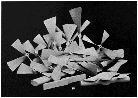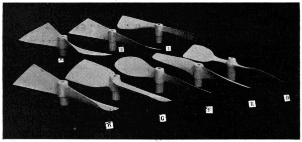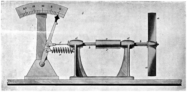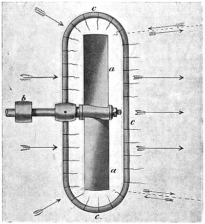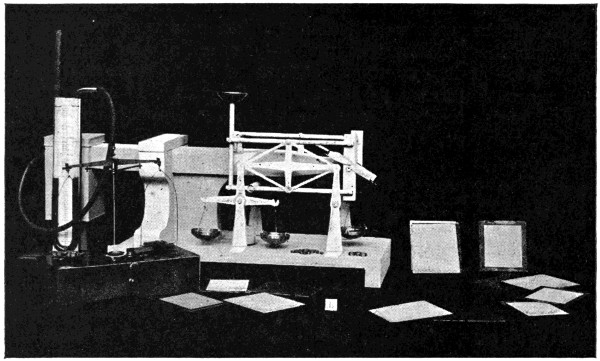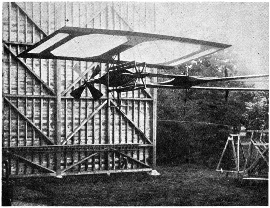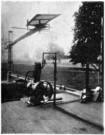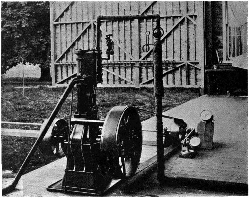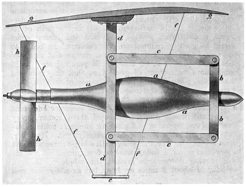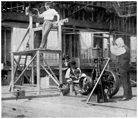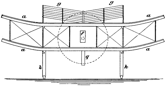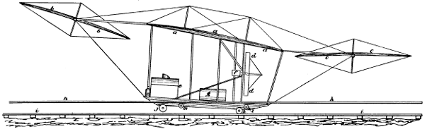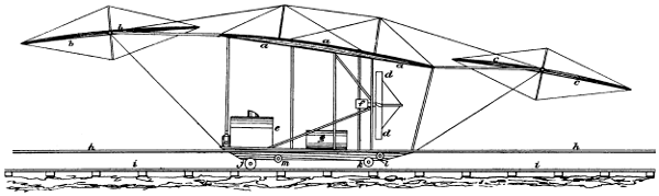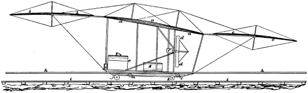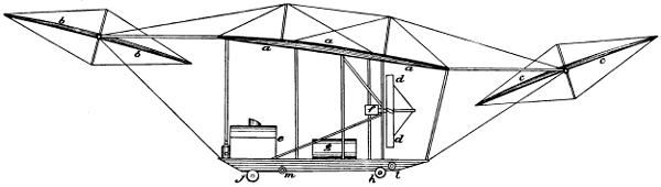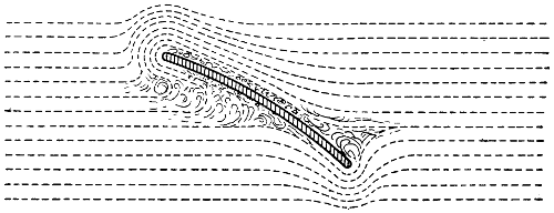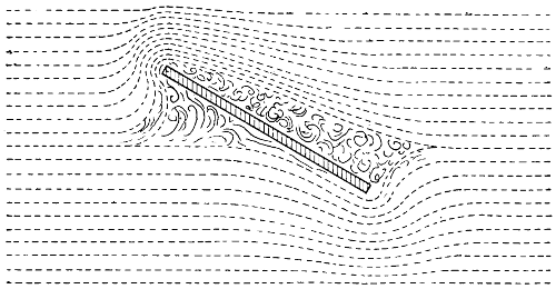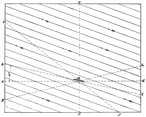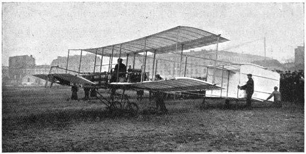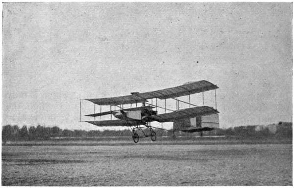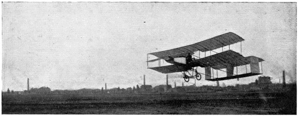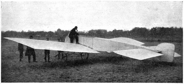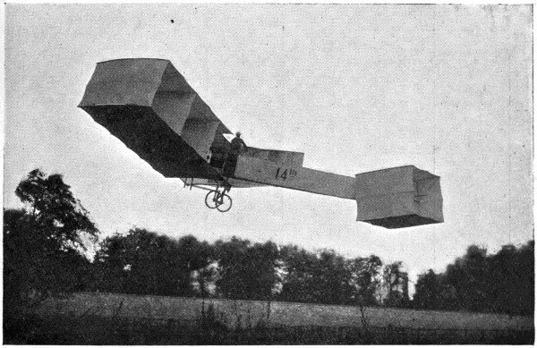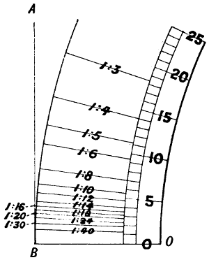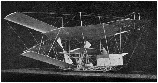
Fig. 74.—Photograph of a model of my machine, showing the fore and
aft horizontal rudders and the superposed aeroplanes.
In my early “whirling table”[5] experiments, the
aeroplanes used were from 6 inches to 4 feet in width.
They were for the most part made of thin pine, being
slightly concave on the underneath side and convex on
the top, both the fore and aft edges being very sharp.
I generally mounted them at an angle of 1 in 14[6]—that
is, in such a position that in advancing 14 feet they
pressed the air down 1 foot. With this arrangement,
I found that with a screw thrust of 5 lbs. the aeroplane
would lift 5 × 14, or 70 lbs., while if the same plane
was mounted at an angle of 1 in 10, the lifting effect
was almost 50 lbs. (5 × 10). This demonstrated that
the skin friction on these very sharp, smooth and well-made
aeroplanes was so small a factor as not to be
considered. When, however, there was the least irregularity
in the shape of the aeroplane, the lifting effect,
when considered in terms of screw thrust, was greatly
diminished. With a well-made wooden plane placed at
an angle of 1 in 14, I was able to carry as much as
113 lbs. to the H.P., whereas with an aeroplane consisting
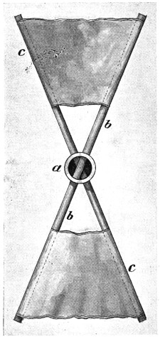
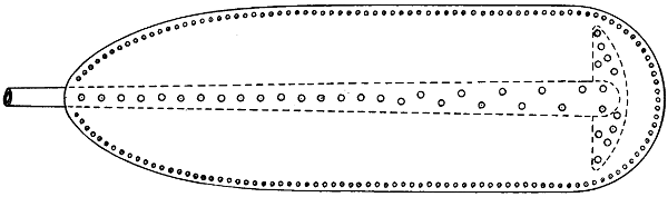
of a wooden frame covered with a cotton fabric (Fig. 75),
I was only able to carry 40 lbs. to the H.P.[7]

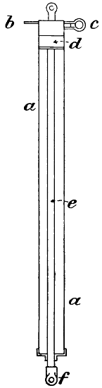
Fig. 75.—The fabric-covered aeroplane experimented with. The
efficiency of this aeroplane was only 40 per cent. of that of a well-made
wooden aeroplane.
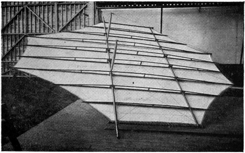
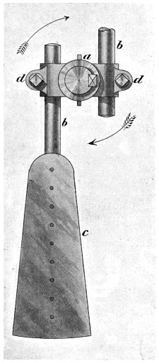
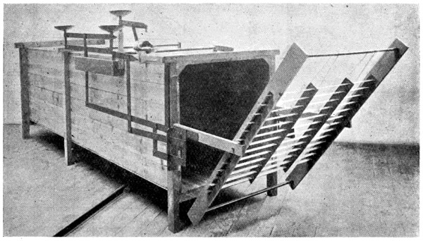
Fig. 76.—The forward rudder of my large machine, showing the fabric
attached to the lower side. The top was also covered with fabric.
This rudder considered as an aeroplane had a very high efficiency
and worked very well indeed.
These facts taken into consideration with my other
experiments with large aeroplanes, demonstrated to my
mind that it would not be a very easy matter to make a
large and efficient aeroplane. If I obtained the necessary
rigidity by making it of boards, it would be vastly too
heavy for the purpose, while if I obtained the necessary
lightness by making the framework of steel and covering
it with a silk or cotton fabric in the usual way, the
distortion would be so great that it would require
altogether too much power to propel it through the
air. I therefore decided on making a completely new
form of aeroplane. I constructed a large steel framework
arranged in such a manner that the fore and aft edges
consisted of tightly drawn steel wires. This framework
was provided with a number of light wooden longitudinal
trusses, similar to those shown in Fig. 76. The bottom
side was then covered with balloon fabric secured at the
edges, and also by two longitudinal lines of lacing
through the centre. It was stretched very tightly and
slightly varnished, but not sufficiently to make it absolutely
air-tight. The top of this framework was covered with
the same kind of material, but varnished so as to make
it absolutely airtight. The top and bottom were then
laced together forming very sharp fore and aft edges,
and the top side was firmly secured to the light wooden
trusses before referred to. Upon running this aeroplane,
I found that a certain quantity of air passed through
the lower side and set up a pressure between the upper
and lower coverings. The imprisoned air pressed the
top covering upward, forming longitudinal corrugations
which did not offer any perceptible resistance to the air,
whereas the bottom fabric, having practically the same
pressure on both sides, was not distorted in the least.
This aeroplane was found to be nearly as efficient as it
would have been had it been carved out of a solid piece
of wood. It will be seen by the illustration that this
large or main aeroplane is practically octagonal in shape,
its greatest width being 50 feet, and the total area
1,500 square feet.
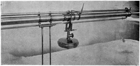
Upon running my large machine over the track (Fig. 77)
with only the main aeroplane in position, I found that
a lifting effect of 3,000 to 4,000 lbs. could be obtained with
a speed of 37 to 42 miles an hour. It was not always
an easy matter to ascertain exactly what the lifting effect
was at a given speed on account of the wind that was
generally blowing. Early in my experiments, I found
if I ran my machine fast enough to produce a lifting effect
within 1,000 lbs. of the total weight of the machine, that it
was almost sure to leave the rails if the least wind was
blowing. It was, therefore, necessary for me to devise some
means of keeping the machine on the track. The first plan
tried was to attach some very heavy cast-iron wheels
weighing with their axle-trees and connections about
11⁄2 tons. These were constructed in such a manner that
the light flanged wheels supporting the machine on the
steel rails could be lifted 6 inches above the track, leaving
the heavy wheels still on the rails for guiding the machine.
This arrangement was tried on several occasions, the
machine being run fast enough to lift the forward end
off the track. However, I found considerable difficulty in
starting and stopping quickly on account of the great
weight, and the amount of energy necessary to set such
heavy wheels spinning at a high velocity. The last experiment
with these wheels was made when a head wind was
blowing at the rate of about 10 miles an hour. It was
rather unsteady, and when the machine was running at its
greatest velocity, a sudden gust lifted not only the front
end, but also the heavy front wheels completely off the
track, and the machine falling on soft ground was soon
blown over by the wind.
I then provided a safety track of 3 × 9 Georgia pine
placed about 2 feet above the steel rails, the wooden track
being 30 feet gauge and the steel rails 9 feet gauge (Fig. 77).
The machine was next furnished with four extra wheels
placed on strong outriggers and adjusted in such a manner
that when it had been lifted 1 inch clear of the steel rails,
these extra wheels would engage the upper wooden track.[8]
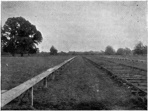
Fig. 77.—View of the track used in my experiments. The machine was
run along the steel railway which was 9 feet gauge, and was prevented
from rising by the wooden track which was 35 feet gauge.
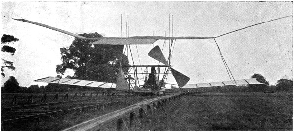
Fig. 78.—The machine on the track tied up to the dynamometer.
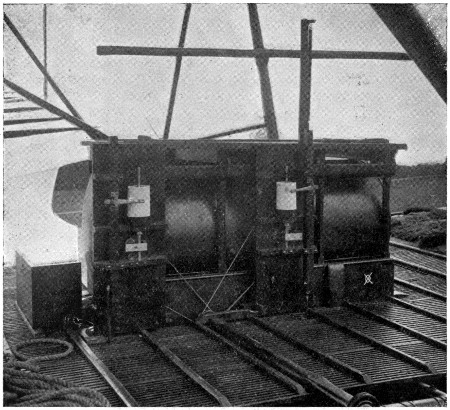
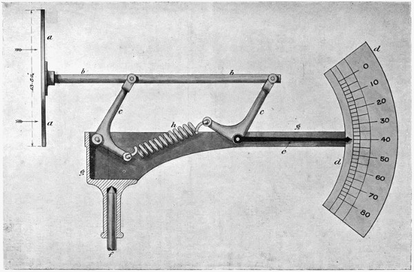
Fig. 79.—Two dynagraphs, one for making a diagram of the lifting effect
off the main axle-tree, and the other for making a diagram of the lift
off the front axle-tree. By this arrangement, I was able to ascertain
the exact lifting effect at all speeds, and to arrange my aeroplanes in
such a manner that the center of lifting effect was directly over the
center of gravity. The paper-covered cylinders made one rotation in
2,000 feet.
When fully equipped, my large machine had five long
and narrow aeroplanes projecting from each side. Those
that are attached to the sides of the main aeroplanes are
27 feet long, thus bringing the total width of the machine
up to 104 feet. The machine is also provided with a fore
and an aft rudder made on the same general plan as
the main aeroplane. When all the aeroplanes are in
position, the total lifting surface is brought up to about
6,000 square feet. I have, however, never run the machine
with all the planes in position. My late experiments were
conducted with the main aeroplane, the fore and aft
rudders, and the top and bottom side planes in position,
the total area then being 4,000 square feet. With the
machine thus equipped, with 600 lbs. of water in the tank
and boiler and with the naphtha and three men on board,
the total weight was a little less than 8,000 lbs. The first
run under these conditions was made with a steam pressure
of 150 lbs. to the square inch, in a dead calm, and all four
of the lower wheels remained constantly on the rails, none
of the wheels on the outriggers touching the upper track.
The second run was made with 240 lbs. steam pressure
to the square inch. On this occasion, the machine seemed
to vibrate between the upper and lower tracks. About
three of the top wheels were engaged at the same time, the
weight on the lower steel rails being practically nil. Preparations
were then made for a third run with nearly the
full power of the engines. The machine was tied up to a
dynamometer (Fig. 78), and the engines were started with a
pressure of about 200 lbs. to the square inch. The gas
supply was then gradually turned on with the throttle
valves wide open; the pressure soon increased, and when
310 lbs. was reached, the dynamometer showed a screw
thrust of 2,100 lbs.,[9] but to this must be added the incline
of the track which amounts to about 64 lbs. The actual
thrust was therefore 2,164 lbs. In order to keep the thrust
of the screws as nearly constant as possible, I had placed a
small safety valve—3⁄4-inch—in the steam pipe leading to
one of the engines. This valve was adjusted in such a
manner that it gave a slight puff of steam at each stroke of
the engine with a pressure of 310 lbs. to the square inch,
and a steady blast at 320 lbs. to the square inch. As the
valves and steam passages of these engines were made very
large, and as the piston speed was not excessive, I believed
if the steam pressure was kept constant that the screw
thrust would also remain nearly constant, because as the
machine advances and the screws commence to run slightly
faster, an additional quantity of steam will be called for and
this could be supplied by turning on more gas. When
everything was ready, with careful observers stationed on
each side of the track, the order was given to let go. The
enormous screw thrust started the machine so quickly that
it nearly threw the engineers off their feet, and the machine
bounded over the track at a great rate. Upon noticing
a slight diminution in the steam pressure, I turned on
more gas, when almost instantly the steam commenced
to blow a steady blast from the small safety valve, showing
that the pressure was at least 320 lbs. in the pipes supplying
the engines with steam. Before starting on this run, the
wheels that were to engage the upper track were painted,
and it was the duty of one of my assistants to observe
these wheels during the run, while another assistant
watched the pressure gauges and dynagraphs (Fig. 79).
The first part of the track was up a slight incline, but the
machine was lifted clear of the lower rails and all of the
top wheels were fully engaged on the upper track when
about 600 feet had been covered. The speed rapidly
increased, and when 900 feet had been covered, one of the
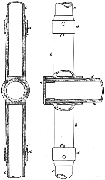
rear axle-trees, which were of 2-inch steel tubing, doubled
up (Fig. 80), and set the rear end of the machine completely
free. The pencils ran completely across the cylinders
of the dynagraphs and caught on the underneath end.
The rear end of the machine being set free, raised considerably
above the track and swayed. At about 1,000
feet, the left forward wheel also got clear of the upper track
and shortly afterwards, the right forward wheel tore up
about 100 feet of the upper track. Steam was at once
shut off and the machine sank directly to the earth
imbedding the wheels in the soft turf (Figs. 81 and 82)
without leaving any other marks, showing most conclusively
that the machine was completely suspended in
the air before it settled to the earth. In this accident,
one of the pine timbers forming the upper track went
completely through the lower framework of the machine
and broke a number of the tubes, but no damage was done
to the machinery except a slight injury to one of the
screws (Fig. 83).
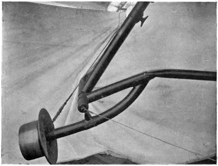
Fig. 80.—The outrigger wheel that gave out and caused an accident
with the machine.
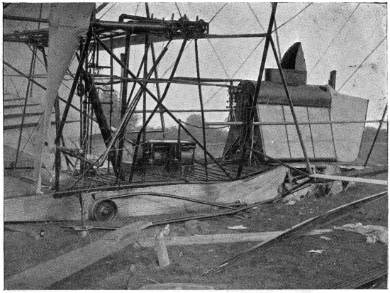
Fig. 81.—Shows the broken planks and the wreck that they caused. It
will be observed that the wheels sank directly into the ground
without leaving any track.
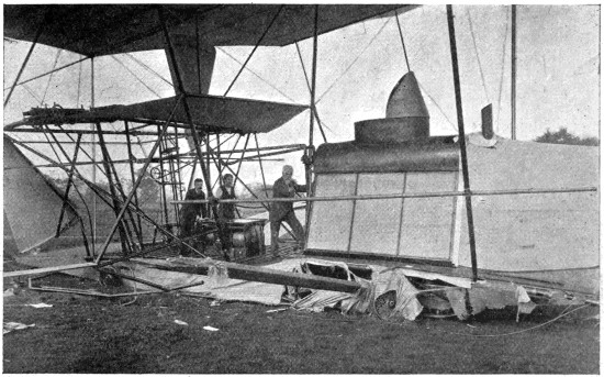
Fig. 82.—The condition of the machine after the accident. One of the
broken planks that formed the upper track is shown. It will be
observed that the wheels have sunk directly into the ground without
leaving any tracks, showing that the machine did not run along the
ground, but came directly down when it stopped.
In my experiments with the small apparatus for ascertaining
the power required to perform artificial flight,
I found that the most advantageous angle for my aeroplane
was 1 in 14, but when I came to make my large machine,
I placed my aeroplanes at an angle of 1 in 8 so as to
be able to get a great lifting effect at a moderate speed with
a short run. In the experiments which led to the accident
above referred to, the total lifting effect upon the machine
must have been at least 10,000 lbs. All the wheels which
had been previously painted and which engaged the upper
track were completely cleaned of their paint and had made
an impression on the wood, which clearly indicated that the
load which they had been lifting was considerable.[10]
Moreover, the strain necessary to double up the axle-trees
was fully 1,000 lbs. each, without considering the lift on
the forward axle-trees which did not give way but broke
the upper track.
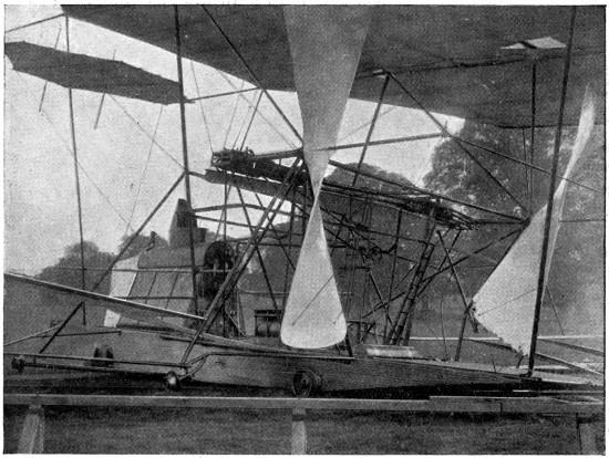
Fig. 83.—This shows the screw damaged by the broken planks; also a
hole in the main aeroplane caused by the flying splinters.
The advantages arising from driving the aeroplanes on
to new air, the inertia of which has not been disturbed, are
clearly shown in these experiments. The lifting effect of
the planes was 2·5 lbs. per square foot. A plane loaded at
this rate will fall through the air with a velocity of
22·36 miles per hour, according to the formula √200 × P = V.
But as the planes were set at an angle of 1 in 8, and as
the machine travelled at the rate of 40 miles an hour, the
planes only pressed the air downwards 5 miles an hour
(40 ÷ 8 = 5). A fall of 5 miles an hour without advancing
would only exert a pressure of ·125 lb. per square foot,
according to the formula (V² × ·005 = P).[11]
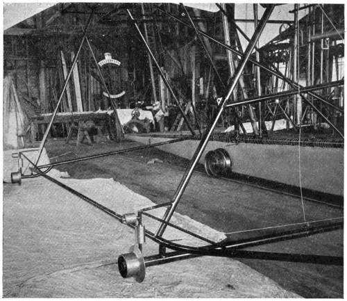
Fig. 84.—This shows a form of outrigger wheels which were
ultimately used.
Engineers and mathematicians who have written to
prove that flying machines were impossible have generally
computed the efficiency of aeroplanes moving through the
air, on the basis that the lifting effect would be equal to a
wind blowing against the plane at the rate at which the
air was pressed down by the plane while being driven
through the air. According to this system of reasoning,
my 4,000 square feet of aeroplanes would have lifted only
·125 lb. per square foot, and in order to have lifted
10,000 lbs. they would have to have had an area twenty
times as great. This corresponds exactly with the discrepancy
which Professor Langley has found in the formula
of Newton.
With aeroplanes of one-half the width of those I
employed, and with a velocity twice as great, the angle
could be much less, and the advantages of continually
running on to fresh air would be still more manifest. With
a screw thrust of 2,000 lbs., the air pressure on each square
foot of the projected area of the screw blades is 21·3 lbs.,
while the pressure on the entire discs of the screws is 4 lbs.
per square foot, which would seem to show with screws of
this size, that four blades would be more efficient than two.
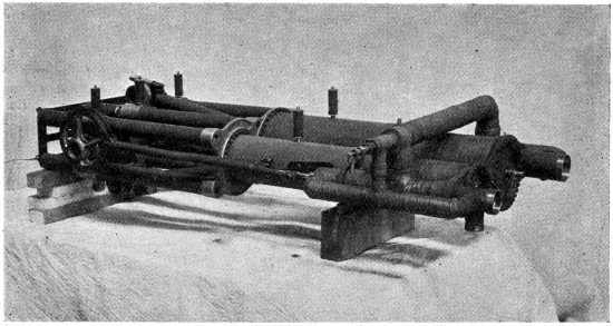
Fig. 85.—One pair of my compound engines. This engine weighed 310 lbs.
and developed 180 H.P., with 320 lbs. of steam per square inch.
The engines, as before stated, are compound (Fig. 85).
The area of the high-pressure piston is 20 square inches, and
that of the low-pressure piston is 50·26 square inches. Both
have a stroke of 12 inches. With a boiler pressure of 320 lbs.,
the pressure on the low-pressure piston is 125 lbs. to the
square inch. This abnormally high pressure in the low-pressure
cylinder is due to the fact that there is a very large
amount of clearance in the high-pressure cylinder to prevent
shock in case water should go over when the machine
pitches; moreover, the steam in the high-pressure cylinder
is cut off at three-quarters stroke, while the steam in the
low-pressure cylinder is cut off at five-eighths stroke. If
we should compute the power of these engines with the
steam entering at full stroke, without any friction, and with
no back pressure on the low-pressure cylinder, the total
horse-power would foot up to 461·36 horse-power at the
speed at which the engines were run—namely, 375 turns
per minute. If we compute the actual power consumed by
the screws, by multiplying their thrust, which is probably
2,000 lbs. while they are travelling, by their pitch, 16 feet,
and this by the number of turns which they make in a
minute, and then divide the product by 33,000,
2,000 × 16 × 37533,000
= 363·63,
we find that we have 363·63 horse-power in actual effect
delivered on the screws of the machine, which shows that
there is rather less than 22 per cent. loss in the engines, due
to cutting off before the end of the stroke, to back pressure,
and to friction. The actual power applied to the machine
being 363·63 horse-power, it is interesting to know what
becomes of it. When the machine has advanced 40 miles
(which it would do in an hour), the screws have travelled
68·1 miles (375 × 16 × 605,280) = 68·1; therefore, 150 horse-power
is wasted in slip, and 213·63 horse-power consumed
in driving the machine through the air. Now, as the planes
are set at an angle of 1 in 8, the power actually used in
lifting the machine is 133·33, and the loss in driving the
body of the machine, its framework and wires through the
air is 90·30 horse-power.
| Power |
lost in |
screw slip, |
150 |
|
H.P. |
| „ |
„ |
driving machinery and framework, |
80 |
·30 |
„ |
| „ |
actually consumed in lifting the machine, |
133 |
·33 |
„ |
| Total power delivered by the engines, |
363 |
·63 |
„ |
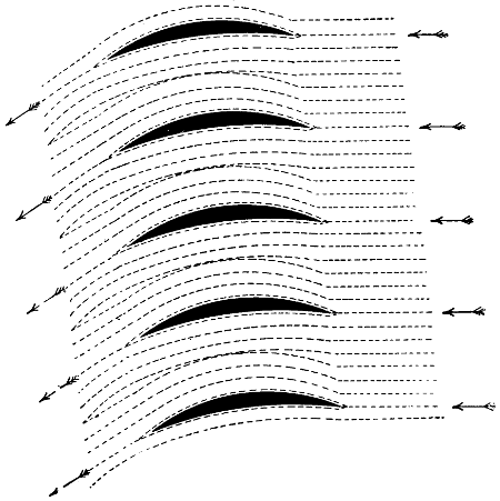
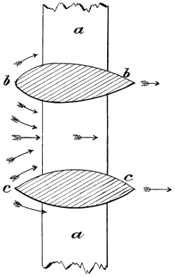
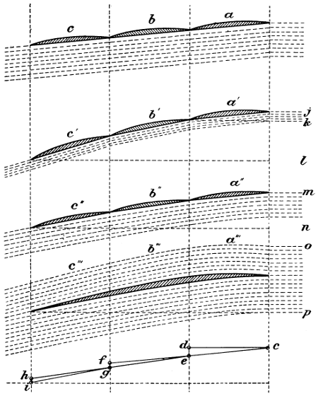
Fig. 86.—The path that the air has to take in passing between superposed
aeroplanes in close proximity to each other. By this arrangement the
drift is considerably increased.
My experiments have demonstrated that relatively narrow
aeroplanes lift more per square foot than very wide ones;
but as an aeroplane, no matter how narrow it may be, must
of necessity have some thickness, it is not advantageous to
place them too near together. Suppose that aeroplanes
should be made 1⁄4-inch thick, and be superposed 3 inches
apart—that is, at a pitch of 3 inches—one-twelfth part of the
whole space through which these planes would have to be
driven would be occupied by the planes themselves, and
eleven-twelfths would be air space (Fig. 86). If a group
of planes thus mounted should be driven through the air
at the rate of 36 miles an hour,[12] the air would have to be
driven forward at the rate of 3 miles an hour, or else it
would have to be compressed, or spun out, and pass between
the spaces at a speed of 39 miles an hour. As a matter of
fact, however, the difference in pressure is so very small
that practically no atmospheric compression takes place.
The air, therefore, is driven forward at the rate of 3 miles
an hour, and this consumes a great deal of power; in fact,
so much that there is a decided disadvantage in using
narrow planes thus arranged.
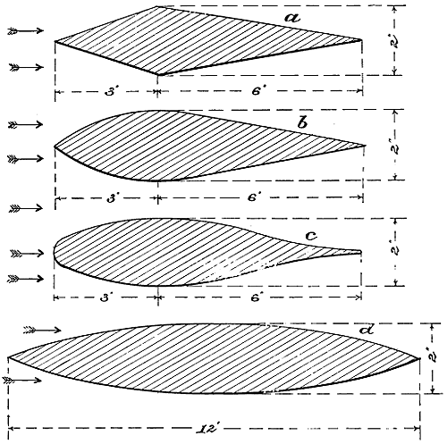
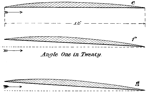
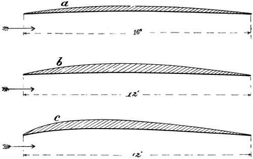
In regard to the curvature of narrow aeroplanes, I have
found that if one only desires to lift a large load in proportion
to the area, the planes may be made very hollow
on the underneath side; but when one considers the lift in
terms of the screw thrust, I find it advisable that the planes
should be as thin as possible, and the underneath side nearly
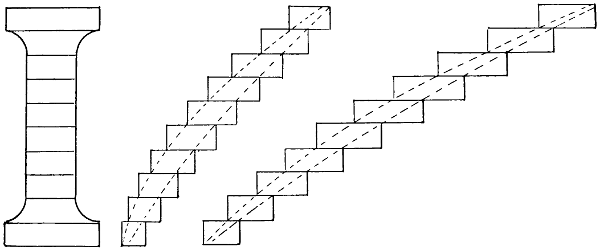
flat. I have also found that it is a great advantage to
arrange the planes after the manner shown in Fig. 87. In
this manner the sum of all the spaces between the planes
is equal to the whole area occupied by the planes; consequently,
the air neither has to be compressed, spun out,
nor driven forward. I am, therefore, able by this arrangement
to produce a large lifting effect per square foot, and, at the
same time, to keep the screw thrust within reasonable limits.
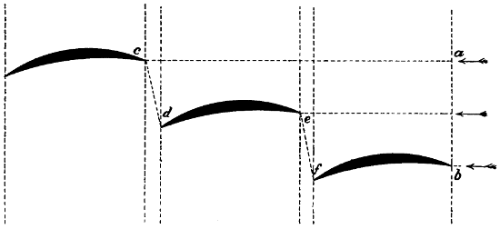
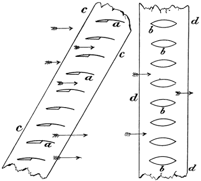
Fig. 87.—The position of narrow aeroplanes arranged in such a manner
that the air has free passage between them, and this arrangement has
been found superior to arranging one above the other after the manner
of a Venetian blind.
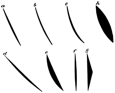
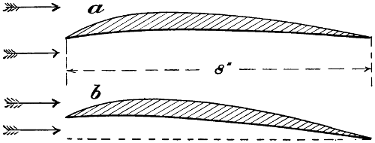
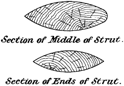
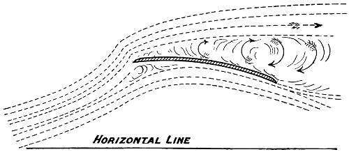
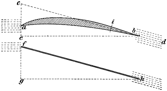
A large number of experiments with very narrow aeroplanes
have been conducted by Mr. Horatio Philipps at
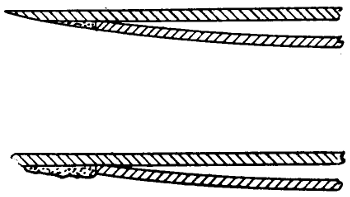
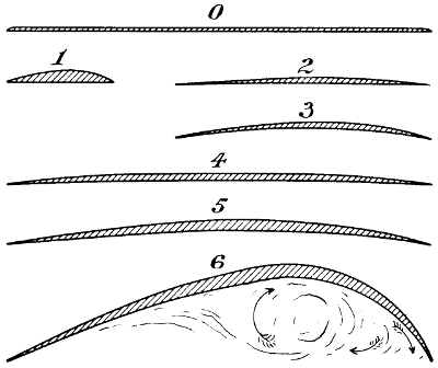
Harrow, in England. Fig. 88 shows a cross-section of one
of Mr. Philipps’ planes. Mr. Philipps is of the opinion that
the air, in striking the top side of the plane, is thrown
upwards in the manner shown, and a partial vacuum is
thereby formed over the central part of the plane, and that
the lifting effect of planes made in this form is therefore
very much greater than with ordinary narrow planes. I
have experimented with these “sustainers” (as Mr. Philipps
calls them) myself, and I find it is quite true that they lift
in some cases as much as 8 lbs. per square foot,[13] but the
lifting effect is not produced in the exact manner that Mr.
Philipps seems to suppose. The air does not glance off in
the manner shown. As the “sustainer” strikes the air two
currents are formed, one following the exact contour of the
top, and the other that of the bottom. These two currents
join and are thrown downwards, as relates to the “sustainer,”
at an angle which is the resultant of the angles at which
the two currents meet. These “sustainers” may be made
to lift when the front edge is lower than the rear edge,
because they encounter still air, and leave it with a downward
motion.
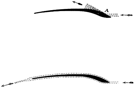
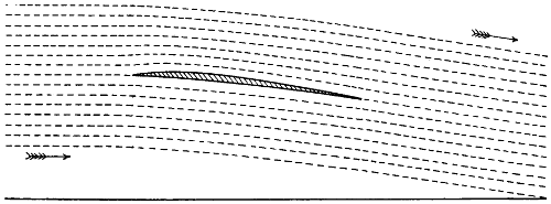
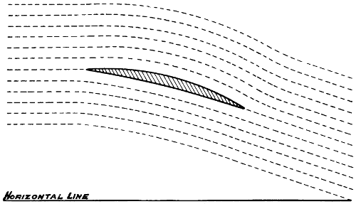
Fig. 88.—The very narrow aeroplanes, or sustainers, employed by Mr.
Philipps. It has been supposed that the air in striking at A was
deflected in the manner shown, but such is not the case. The air in
reality follows the surface, as shown in the dotted line in the second
illustration.
In my experiments with narrow superposed planes, I
have always found that with strips of thin metal made
sharp at both edges and only slightly curved, the lifting
effect, when considered in terms of screw thrust, was always
greater than with any arrangement of the wooden aeroplanes
used in Philipps’ experiments. It would, therefore,
appear that there is no advantage in the peculiar form of
“sustainer” employed by this inventor.
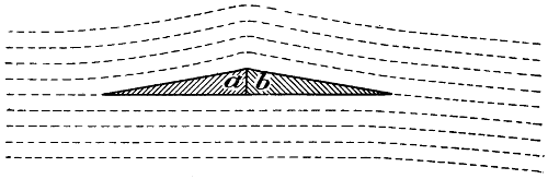
If an aeroplane be made perfectly flat on the bottom side
and convex on the top, and be mounted in the air so that
the bottom side is exactly horizontal, it produces a lifting
effect no matter in which direction it is run, because, as it
advances, it encounters stationary air which is divided into
two streams. The top stream being unable to fly off at a
tangent when turning over the top curve, flows down the
incline and joins the current which is flowing over the lower
horizontal surface. The angle at which the combined
stream of air leaves the plane is the resultant of these two
angles; consequently, as the plane finds the air in a
stationary condition, and leaves it with a downward
motion, the plane itself must be lifted. It is true that small
and narrow aeroplanes may be made to lift considerably
more per square foot of surface than very large ones, but
they do not offer the same safeguard against a rapid descent
to the earth in case of a stoppage or breakdown of the
machinery. With a large aeroplane properly adjusted, a
rapid and destructive fall to the earth is quite impossible.
Before I commenced my experiments at Baldwyn’s Park,
I attempted to obtain some information in regard to the
action of screw propellers working in the air. I went to
Paris and saw the apparatus which the French Government
employed for testing the efficiency of screw propellers, but
the propellers were so very badly made that the experiments
were of no value. Upon consulting an English
experimenter, who had made a “life-long study” of the
question, he assured me that I should find the screw propeller
very inefficient and very wasteful of power, and
that all screw propellers had a powerful fan-blower action,
drawing in air at the centre and discharging it with great
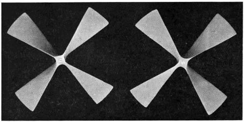
force at the periphery. I found that no two men were
agreed as to the action of screw propellers. All the data or
formulæ available were so confusing and contradictory as to
be of no value whatsoever. Some experimenters were of
the opinion that, in computing the thrust of a screw, we
should only consider the projected area of the blades, and
that the thrust would be equal to a wind blowing against a
normal plane of equal area at a velocity equal to the slip.
Others were of the opinion that the whole screw disc would
have to be considered; that is, that the thrust would be
equal to a wind blowing against a normal plane having an
area equal to the whole disc, and at the velocity of the slip.
The projected area of the two screw blades of my machine
is 94 square feet, and the area of the two screw discs is 500
square feet. According to the first system of reasoning,
therefore, the screw thrust of my large machine, when
running at 40 miles an hour with a slip of 18 miles per hour,
would have been, according to the well-known formula,
V² × ·005 = P
18² × ·005 × 94 = 152·28 lbs.
If, however, we should have considered the whole screw
disc, it would have been 18² × ·005 × 500 = 810 lbs.
However, when the machine was run over the track at this
rate, the thrust was found to be rather more than 2,000 lbs.
When the machine was secured to the track and the screws
revolved until the pitch in feet, multiplied by the turns per
minute, was equal to 68 miles an hour, it was found that
the screw thrust was 2,164 lbs. In this case, it was of course,
all slip, and when the screws had been making a few
turns they had established a well-defined air-current, and
the power exerted by the engine was simply to maintain
this air current. It is interesting to note that, if we
compute the projected area of these blades by the foregoing
formula, the thrust would be—68² × ·005 × 94 = 2,173·28 lbs.,
which is almost exactly the observed screw thrust.
When I first commenced my experiments with a large
machine, I did not know exactly what sort of boiler, gas
generator, or burner I should finally adopt; I did not know
the exact size that it would be necessary to make my
engines; I did not know the size, the pitch, or the diameter
of the screws which would be the most advantageous;
neither did I know the form of aeroplane which I should
finally adopt. It was, therefore, necessary for me to make
the foundation or platform of my machine of such a
character that it would allow me to make the modifications
necessary to arrive at the best results. The platform of the
machine is, therefore, rather larger than is necessary, and I
find if I were to design a completely new machine, that it
would be possible to greatly reduce the weight of the framework,
and, what is still more, to greatly reduce the force
necessary to drive it through the air.
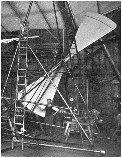
Fig. 89.—One of the large screws being hoisted into position. Its size
may be judged by comparison with the man.
At the present time, the body of my machine is a large
platform, about 8 feet wide and 40 feet long. Each side is
formed of very long trusses of steel tubes, braced in every
direction by strong steel wires. The trusses which give
stiffness are all below the platform. In designing a new
machine, I should make the trusses much deeper and at the
same time very much lighter, and, instead of having them
below the platform on which the boiler is situated, I should
have them constructed in such a manner as to completely
enclose the boiler and the greater part of the machinery.[14]
I should make the cross-section of the framework rectangular
and pointed at each end. I should cover the
outside very carefully with balloon material, giving it a
perfectly smooth and even surface throughout, so that it
might be easily driven through the air.
In regard to the screws, I am at the present time able to
mount screws 17 feet 10 inches in diameter (Fig. 89). I
find, however, that my machine would be much more
efficient if the screws were 24 feet in diameter and I
believe with such very large screws, four blades would be
much more efficient than two.
My machine may be steered to the right or to the left by
running one of the propellers faster than the other. Very
convenient throttle valves have been provided to facilitate
this system of steering. An ordinary vertical rudder placed
just after the screws may, however, prove more convenient
if not more efficient.
The machine is provided with fore and aft horizontal
rudders, both of which are connected with the same
windlass.
In regard to the stability of the machine, the centre
of weight is much below the centre of lifting effect;
moreover, the upper wings are set at such an angle that
whenever the machine tilts to the right or to the left
the lifting effect is increased on the lower side and
diminished on the higher side. This simple arrangement
makes it automatic as far as rolling is concerned. I am
of the opinion that whenever flying machines come into
use, it will be necessary to steer in a vertical direction
by means of an automatic steering gear controlled by
a gyroscope. It will certainly not be more difficult to
manœuvre and steer such machines than it is to control
completely submerged torpedoes.
When the machine is once perfected, it will not require
a railway track to enable it to get the necessary velocity
to rise. A short run over a moderately level field will
suffice. As far as landing is concerned, the aerial
navigator will touch the ground when moving forward,
and the machine will be brought to a state of rest by
sliding on the ground for a short distance. In this
manner very little shock will result, whereas if the
machine is stopped in the air and allowed to fall directly
to the earth without advancing, the shock, although
not strong enough to be dangerous to life or limb, might
be sufficient to disarrange or injure the machinery.
So far I have only discussed the navigation of the
air by the use of propellers driven by a steam engine.
The engines that I employ are what is known as compound
engines—that is, they have a large and a small cylinder.
Steam at a very high pressure enters the high-pressure
cylinder, expands and escapes at a lower pressure into
a larger cylinder where it again expands and does more
work. A compound engine is more economical in steam
than a simple engine, and therefore requires a smaller
boiler to develop the same horse-power, so that when
we consider the weight of water and fuel for a given
time, together with the weight of the boiler and the
engine, the engine motor with a compound engine is
lighter than a simple engine. However, if only the weight
of the engine is to be considered then the simple engine
will develop more power per unit of weight than the
compound engine. For instance, if, instead of allowing
the steam to enter the small cylinder, and the exhaust
from this cylinder to enter the large or low-pressure
cylinder—which necessitates that the high-pressure piston
has to work against a back pressure equal to the full
pressure on the low-pressure cylinder—I should connect
both cylinders direct with the live steam, and allow both
to discharge their exhaust directly into the air, I should
then have a pair of simple engines, and instead of
developing 363 H.P. they would develop fully 500 H.P.,
or nearly 1 H.P. for every pound of their weight. I
mention this fact to show that the engines are exceedingly
light, and that when compared with simple engines their
power should be computed on the same basis. It will,
therefore, be seen that if we do not take into consideration
the steam supply or the amount of fuel and water
necessary, the simple steam engine is an exceedingly
light motor.
But, as before stated, great improvements have recently
been made in oil engines. I have thought much on this
subject, and am of the opinion that if one had an unlimited
supply of money, a series of experiments could be very
profitably conducted with a view of adapting the oil
engine for use on flying machines. If we use a steam
engine, it is necessary to have a boiler, and at best a boiler
is rather a large and heavy object to drive through the
air. If we use an oil engine, no boiler is necessary, and
the amount of heat carried over in the cooling water
will only be one-seventh part of what is carried over
in the exhaust from a steam engine of the same power.
Therefore, the condenser only need be one-seventh part
the size, and consequently should be made lighter with
the tubes placed at a greater distance apart, and thus
reduce the amount of power necessary to drive the machine
through the air. Moreover, the supply of water necessary
will be greatly reduced, and a cheaper and heavier oil
may be employed, which is not so liable to take fire in
case of an accident. It is then only a question as to
whether an oil engine can be made so light as to keep
its weight within that of a steam motor; that is, an
oil engine in order to be available for the purpose must
be as light, including its water supply, as a complete
steam motor, which includes not only the engine, but
also the boiler, the feed pumps, the water supply, the
burner, the gas generator, and six-sevenths of the
condenser. It requires a very perfect steam engine and
boiler, not using a vacuum, to develop a horse-power
with a consumption of 11⁄2 lbs. of petroleum per hour; but
there are many oil engines which develop a horse-power
with rather less than 1 lb. of oil per hour. It will,
therefore, be seen that, as far as fuel is concerned, the
oil engine has a decided advantage over the more complicated
steam motor. Moreover, with an oil engine, the
cooling water is not under pressure, so that the waste of
water would be much less than with a steam engine, where
the pressure is so high as to cause a considerable amount
of waste through joints and numerous stuffing-boxes.
The great advances that have been made of late years
in electrical science and engineering have led many to
believe that almost any knotty scientific question may
be solved by the employment of electrical engineering,
and a great deal has been written and said in regard
to navigating the air by flying machines driven by
electric motors.
Before I commenced my experiments, I made enquiries
of all the prominent electrical engineering establishments
where there was any likelihood of obtaining light and
efficient electric motors, and found that it was impossible
to obtain one that would develop a horse-power for any
considerable time that would weigh less than 150 lbs.
Since that time, notwithstanding that a great deal has
appeared in the public prints about the efficiency and
lightness of electric motors, I am unable to learn of any
concern that is ready to furnish a complete motor, including
a primary battery, which would supply the necessary current
for two hours at a time, at a weight of less than 150 lbs.
per horse-power, and as far as I have been able to ascertain
from what I have myself seen, I cannot learn that there are
any motors in practical use which do not weigh, including
their storage batteries, at least 300 lbs. per horse-power.
The last electric motor which I examined was in a boat; it
was driven by a primary battery which weighed over
1,000 lbs. to the horse-power. From this I am of the
opinion that we cannot at present look to electricity with
any hope of finding a motor which is suitable for the purpose
of aerial navigation.
There is no question but what birds, and for that matter
all animals, when considered as thermo-dynamic machines,
are very perfect motors; they develop the full theoretical
amount of energy of the carbon consumed. This we are
quite unable to do with any artificial machine, but birds,
for the most part, have to content themselves with food
which is not very rich in carbon. It is quite true that
a bird may develop from ten to fifteen times as much power
from the carbon consumed as can be developed by the best
steam engine, but, as an off-set against this, a steam engine
is able to consume petroleum, which has at least twenty
times as many thermal units per pound as the ordinary
food of birds. The movement of a bird’s wings, from long
years of development, has without doubt attained a great
degree of perfection. Birds are able to scull themselves
through the air with very little loss of energy. To imitate
by mechanical means, the exact and delicate motion of their
wings would certainly be a very difficult task, and I do not
believe that we should attempt it in constructing an artificial
flying machine. In Nature it is necessary that an
animal should be made all in one piece. It is, therefore,
quite out of the question that any part or parts should
revolve. For land animals there is no question but what
legs are the most perfect system possible, but in terrestrial
locomotion by machinery, not necessarily in one piece,
wheels are found to be much more effective and efficient.
The swiftest animal can only travel for a minute of time at
half the speed of a locomotive, while the locomotive is able
to maintain its much greater speed for many hours at a
time. The largest land animals only weigh about 5 tons,
while the largest locomotives weigh from 60 to 80 tons. In
the sea, the largest animal weighs about 75 tons, while the
ordinary Atlantic liner weighs from 4,000 to 14,000 tons.
The whale, no doubt, is able to maintain a high speed for
several hours at a time, but the modern steamer is able
to maintain a still higher speed for many consecutive days.
As artificial machines for terrestrial and aquatic locomotion
have been made immensely stronger and larger than
land or water animals, so with flying machines, it will be
necessary to construct them much heavier and stronger
than the largest bird. If one should attempt to propel such
a machine with wings, it would be quite as difficult a
problem to solve as it would be to make a locomotive
that would walk on legs. What is required in a flying
machine is something to which a very large amount of
power can be directly and continuously applied without
any intervening levers or joints, and this we find in the
screw propeller.
..........
When the Brayton gas engine first made its appearance,
I commenced drawings of a flying machine, using a modification
of the Brayton motor which I designed expressly
for the purpose; but even this was found to be too heavy,
and it was not until after I had abandoned the vertical
screw system that it was possible for me to design a machine
which, in theory, ought to fly. The next machine which I
considered was on the kite or aeroplane system. This was
also to be driven by an oil engine. Oil engines at that time
were not so simple as now, and, moreover, the system of
ignition was very heavy, cumbersome, and uncertain. Since
that time, however, gas and oil engines have been very
much improved, and the ignition tube which is almost
universally used has greatly simplified the ignition, so
that at the present time, I am of the opinion that an oil
engine might be designed which would be suitable for the
purpose.
In 1889 I had my attention drawn to some very thin,
strong, and comparatively cheap tubes which were being
made in France, and it was only after I had seen these
tubes that I seriously considered the question of making a
flying machine. I obtained a large quantity of them and
found that they were very light, that they would stand
enormously high pressures, and generate a very large
quantity of steam. Upon going into a mathematical calculation
of the whole subject, I found that it would be possible
to make a machine on the aeroplane system, driven by a
steam engine, which would be sufficiently strong to lift
itself into the air. I first made drawings of a steam engine,
and a pair of these engines was afterwards made. These
engines are constructed, for the most part, of a very high
grade of cast steel, the cylinders being only 3⁄32 of an inch
thick, the crank shafts hollow, and every part as strong and
light as possible. They are compound, each having a
high-pressure piston with an area of 20 square inches,
a low-pressure piston of 50·26 square inches, and a
common stroke of 1 foot. When first finished, they were
found to weigh 300 lbs. each; but after putting on the oil
cups, felting, painting, and making some slight alterations,
the weight was brought up to 320 lbs. each, or a total of
640 lbs. for the two engines, which have since developed
362 horse-power with a steam pressure of 320 lbs. per square
inch. A photograph of one of these engines is shown
in Fig. 85.
..........
When first designing this engine, I did not know how
much power I might require from it. I thought that in
some cases it might be necessary to allow the high-pressure
steam to enter the low-pressure cylinder direct, but as this
would involve a considerable loss, I constructed a species of
an injector. This injector may be so adjusted that when
the steam in the boiler rises above a certain predetermined
point, say 300 lbs. to the square inch, it opens a valve and
escapes past the high-pressure cylinder instead of blowing
off at the safety valve. In escaping through this valve, a
fall of about 200 lbs. pressure per square inch is made to do
work on the surrounding steam and to drive it forward in
the pipe, producing a pressure on the low-pressure piston
considerably higher than the back pressure on the high-pressure
piston. In this way a portion of the work which
would otherwise be lost is utilised, and it is possible, with
an unlimited supply of steam, to cause the engines to
develop an enormous amount of power.
..........
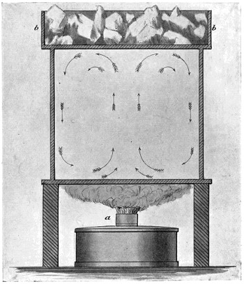
Boiler Experiments.—The first boiler which I made was
constructed something on the Herreshoff principle, but
instead of having one simple pipe in one very long coil, I
used a series of very small and light pipes, connected in such
a manner that there was a rapid circulation through the
whole—the tubes increasing in size and number as the
steam was generated. I intended that there should be a
pressure of about 100 lbs. more on the feed water end of the
series than on the steam end, and I believed that this
difference in pressure would be sufficient to ensure a direct
and positive circulation through every tube in the series.
This first boiler was exceedingly light, but the workmanship,
as far as putting the tubes together was concerned,
was very bad, and it was found impossible to so adjust the
supply of water as to make dry steam without overheating
and destroying the tubes.
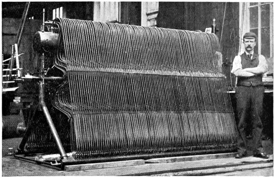
Fig. 90.—Steam boiler employed in my experiments. With this boiler,
I had no trouble in producing all the steam that I could possibly use,
and at any pressure up to 400 lbs. to the square inch.
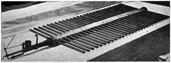
Fig. 91.—The burner employed in my steam experiments. This produced
a dense and uniform blue purple flame 20 inch deep.
Before making another boiler I obtained a quantity of
copper tubes, about 8 feet long, 3⁄8 inch external diameter,
and 1⁄50 of an inch thick. I subjected about 100 of these
tubes to an internal pressure of 1 ton per square inch
of cold kerosine oil, and as none of them leaked I did
not test any more, but commenced my experiments by
placing some of them in a white-hot petroleum fire. I
found that I could evaporate as much as 261⁄2 lbs. of water
per square foot of heating surface per hour, and that with a
forced circulation, although the quantity of water passing was
very small but positive, there was no danger of over-heating.
I conducted many experiments with a pressure of over
400 lbs. per square inch, but none of the tubes failed. I
then mounted a single tube in a white-hot furnace, also
with a water circulation, and found that it only burst
under steam at a pressure of 1,650 lbs. per square inch.
A large boiler, having about 800 square feet of heating
surface including the feed-water heater, was then constructed.
It is shown in Fig. 90. This boiler is about
41⁄2 feet wide at the bottom, 8 feet long and 6 feet high.
It weighs with the casing, the dome, the smoke stack
and connections, a little less than 1,000 lbs. The water
first passes through a system of small tubes—1⁄4 inch in
diameter and 1⁄60 inch thick—which were placed at the
top of the boiler and immediately over the larger tubes—not
shown in the cut. This feed-water heater is found to
be very effective. It utilises the heat of the products of
combustion after they have passed through the boiler
proper and greatly reduces their temperature, while the
feed-water enters the boiler at a temperature of 250° F.
A forced circulation is maintained in the boiler, the
feed-water entering through a spring valve, the spring
valve being adjusted in such a manner that the pressure
on the water is always 30 lbs. per square inch in excess
of the boiler pressure. This fall of 30 lbs. in pressure
acts upon the surrounding hot water which has already
passed through the tubes, and drives it down through a
vertical outside tube, thus ensuring a positive and rapid
circulation through all the tubes. This apparatus is found
to work extremely well. A little glass tube at the top
provided with a moving button, indicates exactly how
many pounds of water per hour are passing into the boiler.
By this means, the engineer is not only enabled to ascertain
at a glance whether or not the pumps are working,
but also to what degree they are working.
Water may be considered as 2,400 times as efficient as
air, volume for volume, in condensing steam. When a
condenser is made for the purpose of using water as a
cooling agent, a large number of small tubes may be
grouped together in a box, and the water may be pumped
in at one end of the box and discharged at the other end
through relatively small openings; but when air is
employed, the tubes or condensing surface must be widely
distributed, so that a very large amount of air is encountered,
and the air which has struck one tube and become
heated must never strike a second tube.
In order to accomplish this, I make my condenser something
in the form of a Venetian blind, the tubes being
made of very thin copper and each tube in the form of
a small aeroplane. These were driven edgewise through
the air, so that the actual volume of air passing between
them is several thousand times greater than the volume of
water passing through a marine condenser. I find that
with such a condenser I can recover the full weight of the
copper tubes in water every five minutes, and if I use
aluminium, in half that time. Moreover, experiments have
shown that a condenser may be made to sustain considerably
more than its own weight and the weight of its
contents in the air, and that all the steam may be condensed
into water sufficiently cool to be pumped with certainty.
I find that the most advantageous position for the
condenser is immediately after the screw propellers. In
this case, if the machine is moving through the air at the
rate of 50 miles an hour, and the slip of the screws is
15 miles an hour, it follows that the air will be passing
through the condenser at the rate of 65 miles an hour. At
this velocity, the lifting effect on the narrow aeroplanes
forming the condenser is very great, and at the same time
the steam is very rapidly condensed. The tubes are
placed at such an angle as to keep them completely drained
and prevent the accumulation of oil, the steam entering
the higher end and the water being discharged at the
lower end.
..........
These experiments demonstrated most conclusively that
as much as 133 lbs. could be sustained and carried by the
expenditure of one horse-power, and that a screw was a
fairly efficient air propeller. They also demonstrated that
a well made aeroplane, placed at an angle of 1 in 14, would
lift practically fourteen times the thrust required to drive
it through the air, and that the skin friction on a smooth
and well finished aeroplane or screw was so small as not
to be considered. A large number of aeroplanes were
experimented with, and it was found that those which
were slightly concave on the underneath side and convex
on the top, both edges being very sharp and the surface
very smooth and regular, were the most efficient; also that
with small screw propellers, two blades having slightly
increasing pitch were the most efficient.
Since writing the foregoing, great progress has been
made with flying machines, and great disasters have
happened to airships or balloons. Count Zeppelin’s
gigantic airship encountered a squall or thunder shower,
and the work of years, which had cost over £100,000,
was reduced to scrap metal in a few minutes. Similar
disasters have happened to other balloons.
The British Dirigible No. 2 has not attempted a long
flight, but the Wright Brothers, Farman, and De la Grange
have all met with a certain degree of success.
A few months ago, the remarkable feats of the Wright
Brothers in the States were discredited in Europe. It was
claimed that “the accounts were not authentic,” “too good
to be true,” etc., but recent events have shown that the
Wright Brothers are able to outdo anything that was
reported in the American Press. On many occasions they
have remained in the air for more than an hour, and have
travelled at the rate of 30 to 40 miles an hour; in fact, the
remarkable success of the Wright Brothers has placed the
true flying machine in a new category.
It can no longer be ranked with the philosopher’s stone
or with perpetual motion. Success is assured, and great
and startling events may take place within the next few
years.
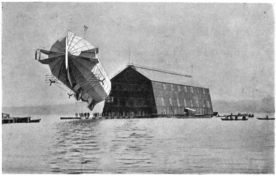
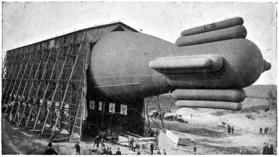
Fig. 92.—Count Zeppelin’s aluminium-covered airship coming out of its
shed on Lake Constance.
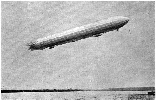
Fig. 93.—Count Zeppelin’s airship in full flight.
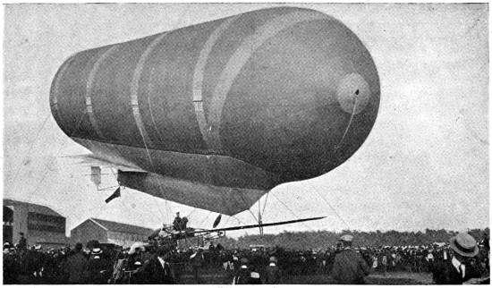
Fig. 94.—The new British war balloon “Dirigible” No 2.
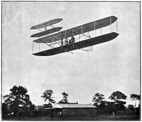
Fig. 95.—The Wright aeroplane in full flight.