INTRODUCTION.
This book is the outcome of a course of six lectures delivered at the
Cooper Union in the city of New York in February and March, 1902,
under the auspices of Columbia University. It seemed desirable by the
President of the University that the subject-matter of the lectures
should be prepared for ultimate publication. The six Parts of the
book, therefore, comprise the substance of the six lectures, suitably
expanded for the purposes of publication.
It may be interesting to state that the half-tone illustrations
have, with scarcely an exception, been prepared from photographs of
the actual subjects illustrated. All such illustrations in Parts V
and VI devoted to the Nicaragua and Panama Canal routes are made
from photographs at the various locations by members of the force of
the Isthmian Canal Commission; they are, therefore, absolutely true
representations of the actual localities to which they apply.
For other illustrations the author wishes to express his indebtedness
to Messrs. G. P. Putnam’s Sons, Messrs. Turneaure and Russell, John
Wiley & Sons, The Morrison-Jewell Filtration Company, Mr. H. M.
Sperry, Signal Engineer, The Engineering News, The Railroad
Gazette, The American Society of Civil Engineers, The Standard
Switch and Signal Company, The Baldwin Locomotive Works, the American
Locomotive Works, Mr. Clemens Herschel, and the International Pump
Company, and to others from whom the author has received courtesies
which he deeply appreciates.
The classification or division of the matter of the text, and
the table of contents, have been made so complete, with a view to
convenience even of the desultory reader in seeking any particular
subject or paragraph, that no index has been prepared, as it is
believed that the table of contents, as arranged, practically supplies
the information ordinarily given by a comprehensive index.
Complete and detailed treatments of the purely technical matters
covered by Part II will be found in the author’s “Elasticity and
Resistance of Materials” and in his “Stresses in Bridge and Roof
Trusses, Arched Ribs and Suspension Bridges.”
W. H. B.
Columbia University,
October 24, 1902.
PART I. ANCIENT CIVIL-ENGINEERING WORKS. — CHAPTER I.
1. Introductory.—It is a common impression even among civil
engineers that their profession is of modern origin, and it is
frequently called the youngest of the professions. That impression is
erroneous from every point of view. Many engineering works of magnitude
and of great importance to the people whom they served were executed
in the very dawn of history, and they have been followed by many other
works of at least equal magnitude and under circumstances scarcely
less noteworthy, of which we have either remains or records. During
the lapse of the arts and of almost every process of civilization
throughout the darkness of the Middle Ages there was little if any
progress made in the art of the engineer, and what little was done
was executed almost entirely under the name of architecture. With the
revival of intellectual activity and with the development of science
the value of its practical application to the growing nations of the
civilized world caused the modern profession of civil-engineering
to take definite shape and to be known by the name which it now
carries, but which was not known to ancient peoples. Unfortunately the
beginnings of engineering cannot be traced; there is no historical
record running back far enough to render account of the earliest
engineering works whose ruins remain as enduring evidence of what was
then accomplished.
It is probably correct to state that the material progress of any
people has always been concurrent with the development of the
art of civil-engineering, and, hence, that the practice of civil
engineering began among the people who made the earliest progress in
civilization, to whom “the art of directing the Great Sources of Power
in Nature for the use and convenience of man” became an early and
imperative necessity. Indeed that conclusion is confirmed by the most
ancient ruins of what may be termed public works that archæological
investigations have revealed to us, among which are those to be found
in the Chaldean region, in India, and in Egypt. Obviously, anything
like a detailed account of the structural and other works of such
ancient character must be lacking, as some of them were built before
even the beginnings of history. Our only data, therefore, are the
remains of such works, and unfortunately they have too frequently been
subject to the destructive operations of both man and nature.
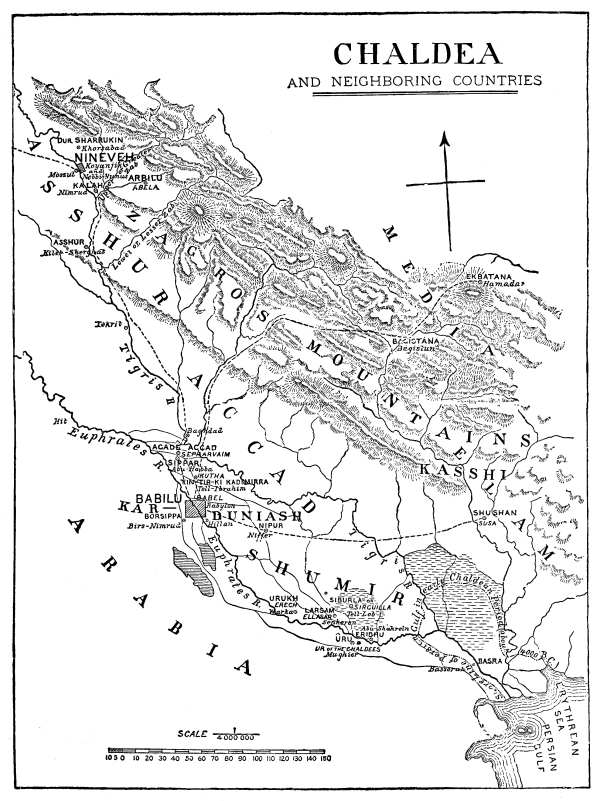
2. Hydraulic Works of Chaldea and Egypt.—It is absolutely
certain that the populous centres of prehistoric times could not
have existed nor have been served with those means of communication
imperatively necessary to their welfare without the practice of the
art of engineering, under whatever name they may have applied to
it. It is known beyond any doubt that the anciently populous and
prosperous country at the head of the Persian Gulf and watered by the
Euphrates and the Tigris was irrigated and served by a most complete
system of canals, and the same observation can be made in reference
to the valley of the Nile. It is not possible at this period of
that country’s history to determine to what extent irrigation was
practised or how extensively the former country was served by water
transportation conducted along artificial channels; but hydraulic
works, including dams and sluices with other regulating appliances
designed to bring waters from the rivers on to the land, were certainly
among the earliest executed for the benefit of the communities
inhabiting those regions. The remains of those works, spread over a
large territory in the vicinity of ancient Babylon, Nippur, and other
centres of population, show beyond the slightest doubt that there
existed a network of water communication throughout what was in those
days a country rich in agricultural products and which supported the
operations of a most prosperous commerce. These canals were of ample
dimensions to float boats of no mean size, although much smaller than
those occupied in our larger systems of canal transportation. They
were many miles in length, frequently interlacing among themselves
and intersecting both the Tigris and the Euphrates. The remains of
these canals, some of them still containing water, show that they must
originally have been filled to depths varying from five or six to
fifteen or twenty feet, and that their widths may have been twenty-five
or thirty feet or more. Another curious feature is their occasional
arrangement in twos and threes alongside of each other with embankments
only between. The entire Euphrates-Tigris valley from the head of the
Persian Gulf at least to modern Baghdad (i.e., Babylonia) and possibly
to ancient Nineveh was served by these artificial waterways. Later,
when Alexander the Great made one of his victorious expeditions through
the Assyrian country, he found in the Tigris obstructions to the
passage of his ships down-stream in the shape of masonry dams. This was
between 356 and 322 B.C. These substantial
dams were built across the river for the purpose of intakes to
irrigating-canals for the benefit of the adjacent country. These
canals, like those of Egypt, were fitted with all the necessary
regulating-devices of sluices or gates, both of a crude character, but
evidently sufficiently effective for their purpose.
It is known that there were in those early days interchanges of large
amounts and varieties of commodities, and it is almost if not quite
certain that the countries tributary to the Persian Gulf not only
produced sufficient grain for their own needs, but also carried on
considerable commerce with the Asiatic coast. We have no means of
ascertaining either the volume or the precise character of the traffic,
but there is little or no doubt of its existence. It is established
also that the waters of the Red Sea and the Nile were connected
by a canal about 1450 B.C. Recent
investigations about Nippur and other sites of ancient cities in that
region confirm other indications that the practice of some branches of
hydraulic engineering had received material development from possibly
two to four thousand years before the Christian era.
3. Structural Works in Chaldea and Egypt.—The ruins of ancient
buildings which have been unearthed by excavations in the same vicinity
show with the same degree of certainty that the art of constructing
buildings of considerable dimensions had also made material progress
at the same time, and in many cases must have involved engineering
considerations of a decided character both as to structural materials
and to foundations. Bricks were manufactured and used. Stones were
quarried and dressed for building purposes and applied so as to
produce structural results of considerable excellence. Even the arch
was probably used to some extent in that locality in those early
days, but stone and timber beams were constantly employed. In the
prehistoric masonry constructions of both the Egyptians and Chaldeans
and probably other prehistoric peoples, lime or cement mortar was not
employed, but came into use at a subsequent period when the properties
of lime and cement as cementing materials began to be recognized. The
first cementing material probably used in Egypt was a sticky clay, or
possibly a calcareous clay or earth. The same material was also used
in the valley of the Euphrates, but in the latter country there are
springs of bitumen, where that material exudes from the earth in large
quantities. The use of this asphaltic cement at times possibly involved
that of sand or gravel in some of the early constructions. Later,
lime mortar and possibly a weak hydraulic cement came to be employed,
although there is little if any evidence of the latter material.
Iron was manufactured and used at least in small quantities, and for
some structural purposes, even though in a crude manner. Bituminous
or other asphaltic material was found as a natural product at various
points, and its value for certain structural purposes was well known;
it was used both for waterproofing and for cement. It is practically
certain that the construction of engineering works whose interesting
ruins still remain involved a considerable number of affiliated
engineering operations of which no evidence has yet been found, and of
the employment of tools and appliances of which we have no record. So
far as these works were of a public character they were constructed
by the aid of a very different labor system from that now existing.
The kings or ruling potentates of those early times were clothed with
the most arbitrary authority, sometimes exercised wisely in the best
interests of their people, but at other times the ruling motive was
selfishness actuated by the most intense egotism and brutal tyranny.
Hence all public works were executed practically as royal enterprises
and chiefly by forced labor, perhaps generally without compensation
except mere sustenance. Under such conditions it was possible
to construct works on a scale out of all proportion to national
usefulness and without structural economy. When it is remembered
that these conditions existed without even the shadow of engineering
science, it is obvious that structural economy or the adaptation of
well-considered means to an end will not be found to characterize
engineering operations of prehistoric times. Nevertheless there are
evidences of good judgment and reasonable engineering design found in
connection with some of these works, particularly with those of an
hydraulic character. Water was lifted or pumped by spiral or screw
machines and by water-wheels, and it is not improbable that other
appliances of power served the purposes of many industrial and crude
manufacturing operations which it is now impossible for us to determine.
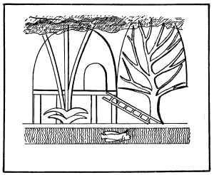
Fig. 1.—Home Built on Piles
in the Land of Punt.
It is an interesting fact that while many ancient works were
exceedingly massive, like the pyramids, the largest of those of which
the ruins have been preserved seldom seem to show little or any
evidence of serious settlement. Whether the ancients had unusually
sound ideas as to the design of foundation works, or whether those only
have come down to us that were founded directly upon rock, we have
scarcely any means of deciding. Nor can we determine at this time what
special recourses were available for foundation work on soft ground.
Probably one of the earliest recognized instances, if not the earliest,
of the building of structures on piles is that given by Sir George
Rawlinson, when he states that a fleet of merchant vessels sent down
the northeast African coast by the Egyptian queen Hatasu, probably 1700
B.C. or 1600 B.C.,
found a people whose huts were supported on piles in order to raise
them above the marshy ground and possibly for additional safety. A
representation (Fig. 1) of one of these native
homes on piles is found among Egyptian hieroglyphics of the period of
Queen Hatasu.
4. Ancient Maritime Commerce.—It is well known that both the
Chaldean region and the Nile valley and delta, at least from Ethiopia
to the Mediterranean Sea, were densely populated during the period
of two to four or five thousand years before the Christian era. By
means of the irrigation works to which reference has already been made
both lands became highly productive, and it is also well known that
those peoples carried on a considerable commerce with other countries,
as did the Phœnicians also, at least between the innumerable wars
which seemed to be the main business of states in those days. These
commercial operations required not only the construction of fleets of
what seem to us small vessels for such purposes, but also harbor-works
at least suitable to the vessels then in use. The marine activity of
the Phœnicians is undoubted, and there is strong reason to believe that
there was also similar activity between Babylonian ports and those east
of them along the shores of the Indian Ocean, perhaps even as far as
ancient Cathay, and possibly also to the eastern coast of Africa.
Investigations in the early history of Egypt have shown that a
Phœnician fleet, constructed at some Egyptian port on the Red Sea,
undoubtedly made the complete circuit of Africa and returned to Egypt
through the Mediterranean Sea the third year after setting out, over
2100 years (about 600 B.C.) before the
historic fleet of the Portuguese explorer Vasco da Gama sailed the same
circuit in the opposite direction. It is therefore probable, in view of
these facts, that at least simple harbor-works of sufficient efficiency
for those early days found place in the public works of the ancient
kingdoms bordering upon the Mediterranean and Red seas and the Persian Gulf.
5. The Change of the Nile Channel at Memphis.—Although such
obscure accounts as can be gathered in connection with the founding of
the city of Memphis are so shadowy as to be largely legendary, it has
been established beyond much if any doubt that prior to its building
the reigning Egyptian monarch determined to change the course of the
Nile so as to make it flow on the easterly side of the valley instead
of the westerly. This was for the purpose of securing ample space for
his city on the west of the river, and, also, that the latter might
furnish a defence towards the east, from which direction invading
enemies usually approached. He accordingly formed an immense dam or
dike across the Nile as it then existed, and compelled it to change its
course near the foot of the Libyan Hills on the west and seek a new
channel nearer the easterly side of the valley. This must have been an
engineering work of almost appalling magnitude in those early times,
yet even with the crude means and limited resources of that early
period, possibly, if not probably, at least 5000 B.C.,
the work was successfully accomplished.
6. The Pyramids.—Among the most prominent ancient structural
works are the pyramids of Egypt, those royal tombs of which so much
has been written. These are found chiefly in the immediate vicinity of
Memphis on the Nile. There are sixty or seventy of them in all, the
first of which was built by the Egyptian king Khufu and is known as
the “Great Pyramid” or the “First Pyramid of Ghizeh.” They have been
called “the most prodigious of all human constructions.” Their ages
are uncertain, but they probably date from about 4000 B.C.
to about 2500 B.C. These are antedated,
however, by two Egyptian pyramidal constructions of still more ancient
character whose ages cannot be determined, one at Meydoum and the other
at Saccarah.
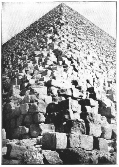
A Corner of the Great Pyramid.
(Copyright by S. S. McClure Co., 1902.
Courtesy of McClure’s Magazine.)
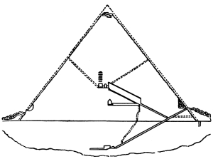
Fig. 2.—Section of the Great Pyramid.
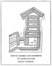
Fig. 3.
The pyramids at Memphis are constructed of limestone and granite, the
latter being the prominent material and used entirely for certain
portions of the pyramids where the stone would be subjected to severe
duty. The great mass of most of the pyramids consists of roughly hewn
or squared blocks with little of any material properly considered
mortar. The interior portions, especially of the later pyramids, were
sometimes partially composed of chips, rough stones, mud bricks, or
even mud, cellular retaining-walls being used in the latter cases for
the main structural features. In all pyramids, however, the outer or
exposed surfaces and the walls and roofs of all interior chambers were
finished with finely jointed large stones, perhaps usually polished.
The Great Pyramid has a square base, which was originally 764 feet on a
side, with a height of apex above the surface of the ground of over 480
feet. This great mass of masonry contains about 3,500,000 cubic yards
and weighs nearly 7,000,000 tons. The area of its base is 13.4 acres.
The Greek historian Herodotus states that its construction required the
labor of 100,000 men for twenty years. An enormous quantity of granite
was required to be transported about 500 miles down the Nile from the
quarries at Syene. Some of the blocks at the base are 30 feet long with
a cross-section of 5 feet by 4 or 5 feet. The bulk of the entire mass
is of comparatively small stones, although so squared and dressed as
to fit closely together. Familiar descriptions of this work have told
us that the small passages leading from the exterior to the sepulchral
chambers are placed nearly in a vertical plane through the apex. The
highest or king’s chamber, as it is called, measures 34 feet by 17
feet and is 19 feet high, and in it is placed the sarcophagus of King
Khufu. It is composed entirely of granite most exactly cut and fitted
and beautifully polished. The construction of the roof is remarkable,
as it is composed of nine great blocks “each nearly 19 feet long and 4
feet wide, which are laid side by side upon the walls so as to form a
complete ceiling.” There is a singular feature of construction of this
ceiling designed to remove all pressure from it and consisting of five
alternate open spaces and blocks of granite placed in vertical series,
the highest open space being roofed over with inclined granite slabs
leaning or strutted against each other like the letter V inverted.
This arrangement relieves the ceiling of the sepulchral chamber from
all pressure; indeed only the inclined highest set of granite blocks
or slabs carry any load besides their own weight. There are two small
ventilating- or air-shafts running in about equally inclined directions
upward from the king’s chamber to the north and south faces of the
pyramid. These air-shafts are square and vary between 6 and 9 inches on
a side. The age of this pyramid is probably not far from 5000 years.
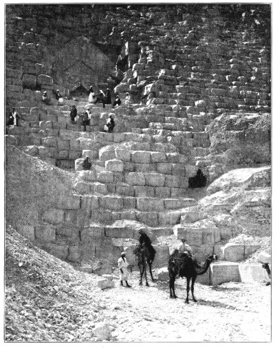
Entrance to the Great Pyramid.
The second pyramid is not much inferior in size to the Great Pyramid,
its base being a square of about 707 feet on a side, and its height
about 454 feet. The remaining pyramids are much inferior in size,
diminishing to comparatively small dimensions, and of materials much
inferior to those used in the earlier and larger pyramids.
7. Obelisks, Labyrinths, and Temples.—Among other constructions
of the Egyptians which may be called engineering in character, as well
as architectural, are the obelisks, the “Labyrinth” so called, on the
shore of Lake Mœris, and the magnificent temples at the ancient capital
Thebes, which are the most remarkable architectural creations probably
that the world has ever known. These latter were not completed by one
king, as was each of the pyramids. They were sometimes despoiled and
largely wrecked by invading hosts from Assyria, and then reconstructed
in following periods by successive Egyptian kings and again added
to by still subsequent monarchs, whose reigns were characterized
by statesmanship, success in war, and prosperity in the country.
Their construction conclusively indicates laborious operations and
transportation of great blocks of stone characteristic of engineering
development of the highest order for the days in which they took place.
The dates of these constructions are by no means well defined, but they
extend over the period running from probably about 2500 B.C.
to about 400 B.C., with the summit of excellence
about midway between.
Another class of ancient structures which can receive but a passing
notice, although it deserves more, is the elaborate rock tombs of some
of the old Egyptian monarchs in the rocks of the Libyan Hills. They
were very extensive constructions and contained numerous successions of
“passages, chambers, corridors, staircases, and pillared halls, each
further removed from the entrance than the last, and all covered
with an infinite number of brilliant paintings.” These tombs really
constituted rock tunnels with complicated ramifications which must have
added much to the difficulty of the work and required the exercise of
engineering skill and resources of a high order.
8. Nile Irrigation.—The value of the waters of the Nile for
irrigation and fertilization were fully appreciated by the ancient
Egyptians. They also apparently realized the national value of some
means of equalizing the overflow, although the annual régimen of
the Nile was unusually uniform. There were, however, periods of
great depression throughout the whole Nile valley consequent upon
the phenomenal failure of overflow to the normal extent. One of the
earliest monarchs who was actuated by a fine public spirit undertook to
solve the problem of providing against such depressions by diverting
a portion of the flood-waters of the Nile into an enormous reservoir,
so that during seasons of insufficient inundation the reservoir-waters
could be drawn upon for the purpose of irrigation. This monarch is
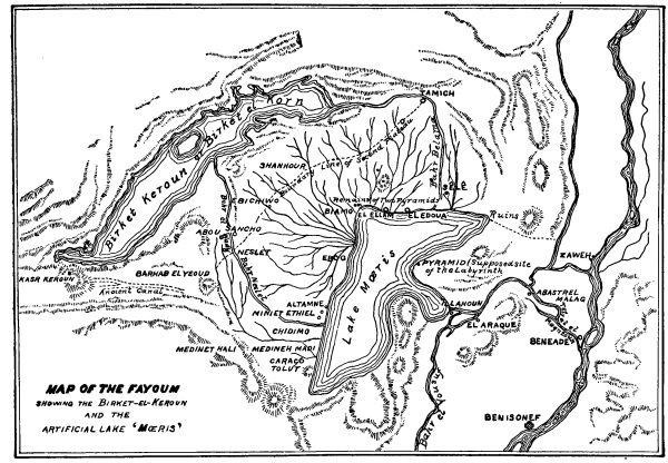
known as the good Amenemhat, although the Greeks call him Mœris. In the
Nile valley, less than a hundred miles above Memphis, on the left side
or to the west of the river, there is a gap in the Libyan Hills leading
to an immense depression, the lower parts of which are much below
the level of the water in the Nile. This topographical depression,
perhaps 50 miles in length by 30 in breadth, with an area between 600
and 700 square miles, now contains two bodies of water or lakes, one
known as the Birket Keroun and the other as Lake Mœris. The vicinity
of this depression is called the Fayoum. A narrow rocky gorge connects
it with the west branch of the Nile, known as Bahr el Yousuf, and it
is probable that during extreme high water in the Nile there was a
natural overflow into the Fayoum. The good Amenemhat, with the judgment
of an engineer, or guided by advisers who possessed that judgment,
appreciated the potential value of this natural depression as a
possible reservoir for the surplus Nile waters and excavated a channel,
possibly a natural channel enlarged, of suitable depth from it to the
Bahr el Yousuf. As a consequence he secured a storage-reservoir of
enormous capacity and which proved of inestimable value to the lowlands
along the Nile in times of shortage in the river-floods.
Investigators have differed much in their conclusions as to the extent
of this reservoir. Some have maintained that only the lower depressions
of the Fayoum were filled for reservoir purposes, while others, like
Mr. Cope Whitehouse, believe that the entire depression of the Fayoum
was utilized with the exception of a few very high points, and that
the depth of water might have been as much as 300 feet in some places.
In the latter case the circuit of the lake would have been from 300 to
500 miles. Whatever may have been the size of the lake, however, its
construction and use with its regulating-works was a piece of hydraulic
engineering of the highest type, and it indicates an extraordinary
development of that class of operations for the period in which it was
executed. The exact date of this construction cannot be determined, but
it may have been as early as 2000 B.C., or perhaps earlier.
9. Prehistoric Bridge-building.—The development of the art
of bridge-building seems to have lagged somewhat in the prehistoric
period. The use of rafts and boats prevented the need of bridges for
crossing streams from being pressing. It is not improbable that some
small and crude pile or other timber structures of short spans were
employed, but no remains of this class of construction have been found.
Large quantities of timber and much of an excellent quality were used
in the construction of buildings. That much is known, but there is
practically no evidence leading to the belief that timber bridges of
any magnitude were used by prehistoric people. It is highly probable
that single-timber-beam crossings of small streams were used, but that
must be considered the limit of ancient bridging until other evidence
than that now available is found.
10. Ancient Brick-making.—It has already been seen that stone
as a building material has been used since the most ancient periods,
and the use of brick goes back almost as far. Fortunately it was
frequently a custom of the ancient brick-makers to stamp proprietary
marks upon their bricks, and we know by these marks that bricks were
made in the Chaldean regions certainly from 3000 to 4000 years before
the Christian era. In Egypt also the manufacture of brick dates back
nearly or quite as far. Some of these Chaldean bricks, as well as
those in other parts of the ancient world, were of poor quality,
readily destroyed by water or even a heavy storm of rain when driving
upon them. Other bricks, however, were manufactured of good quality
of material and by such methods as to produce results which compare
favorably with our modern building-bricks. The ruins of cities, at
least in Assyria and Chaldea, show that enormous buildings, many of
them palaces of kings, were constructed largely of these bricks,
although they were elaborately decorated with other material. The
walls were heavy, indeed so massive that many of the ruin-mounds are
frequently formed almost entirely of the disintegrated brick of poorer
quality. These old builders not only executed their work on a large
scale, but did not hesitate to pile up practically an artificial
mountain of earth, or other suitable material, on which to construct
a palace or temple. The danger of water to these native bricks was so
well known and recognized that elaborate and very excellent systems of
subsurface drains or sewers were frequently constructed to carry off
the storm-water as fast as it fell.
11. Ancient Arches.—In the practice of these building
operations it became necessary to form many openings and to
construct roofs for the sewers or drains, and the arch, both true
and false, came to be used in the Euphrates valley, in that of
the Nile, and in other portions of the ancient world. Pointed
sewer-arches of brick have been found in what is supposed to
be the palace of Nimrod on the Tigris River, possibly of the
date about 1300 B.C. Excavations at Nippur
have revealed a mud-brick pointed arch supposed to date back to
possibly 4000 B.C. Also semicircular
voussoir arches have been discovered at the ruins of Khorsabad near
Nineveh with spans of 12 to 15 feet. These arches are supposed to
belong to the reign of Sargon, an Assyrian king who flourished about
705 to 722 B.C. Again, the ancient
so-called treasury of Atreus at Mycenæ in Greece, although a dome,
exhibits an excellent example of the method of forming the false
arch, the date of the construction being probably about 1000
B.C. The main portion of this structure
consists of a pointed dome, the diameter of the base being 48 feet and
the interior central height 49 feet. A central section shows a beehive
shape, as in Fig. 6.
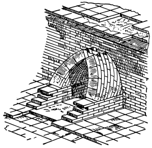
VAULTED DRAIN, KHORSABAD
Fig. 4.
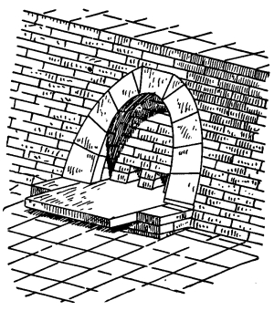
VAULTED DRAINS, KHORSABAD.
Fig. 5.
The exterior approach is between two walls 20 feet apart, the
intermediate entrance to the dome or main chamber being a
passage 9 feet 6 inches wide at the bottom and 7 feet 10 inches
at the top and about 19 feet high. At right angles to the entrance
there is a chamber 27 feet by 20 feet cut into the adjacent rock,
entered through a doorway about 4 feet 6 inches wide and 9 feet 6
inches high. Both the main entrance to the dome and the doorway to the
adjacent chamber are covered or roofed with large flat lintel-stones,
over which are the triangular relieving (false) arches, so common in
ancient construction, by which the lintels are relieved of load, the
triangular openings being closed by single, great upright flat stones.
There are a considerable number of these in Greece. The stone used is
a “hard and beautiful breccia” from the neighboring hills and Mount
Eubora near by. The courses of stone are about two feet thick and
closely fitted without cement.
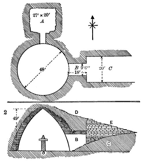
Fig. 6.—Plan and Section of the
Treasury of Atreus at Mycenæ.
1. Plan of the Treasury of Atreus: A,
rock-cut chamber, probably a tomb; B, doorway; C,
approach.
2. Section of the above: B, doorway;
C, approach filled up with earth; D, slope of the ground;
E, wall on north side of approach; F, lintel stone,
weight 133 tons; G, door to rock-cut chamber.
The great majority, or perhaps all, of the Assyrian true arches, so far
discovered, are formed of wedge-shaped bricks, most of them being
semicircular, although some are pointed, the span being not over about
15 feet. The most of the arches found at Nineveh and Babylon belong to
a period reaching possibly from 1300 to 800 B.C.,
but some of the Egyptian arches are still older. Egyptians, Assyrians, Greeks,
and other ancient people used false arches formed by projecting each
horizontal course of stones or bricks over that below it on either side
of an opening. The repetition of this procedure at last brings both
sides of the opening together at the top of the arch, and they are
surmounted at that point with a single flat stone, brick, or tile. It
has been supposed by some that these false arches, whose sides may be
formed either straight or curved, exhibit the oldest form of the arch,
and that the true arch with its ring or rings of wedge-shaped voussoirs
was a subsequent development. It is possible that this is true, but
the complete proof certainly is lacking. In Egypt and Chaldea both
styles of arches were used concurrently, and it is probably impossible
to determine which preceded the other. Again, some engineers have
contended that two flat slabs of stone leaning against each other,
each inclined like the rafters of a roof, was the original form of the
arch, as found in the pyramids of Egypt; but it is probable that the
true arch was used in Chaldea prior to the time of the pyramids. Indeed
crude arches of brick have been found at Thebes in Egypt dating back
possibly to 2500 B.C., or still earlier.
Aside from that, however, such an arrangement of two stones is not
an arch at all, either true or false. The arrangement is simply a
combination of two beams. A condition of stress characteristic of that
in the true arch is lacking.
The ancient character of the engineering works whose ruins are found
in Chaldea and Assyria is shown by the simple facts that Babylon was
destroyed about the year 690 B.C. and Nineveh
about the year 606 B.C.
CHAPTER II.
12. The Beginnings of Engineering Works of Record.—In a
later period of the world’s history we reach a stage in the development of
engineering works of which we have both records and remains in such
well-defined shape that the characteristics of the profession may
be realized in a definite manner. This is particularly true of the
civil-engineering works of the Romans. In their sturdy and unyielding
character, with their limitless energy and resolution, the conditions
requisite for the execution of engineering works of great magnitude are
found. An effeminate or generally æsthetic nation like the Greeks would
furnish but indifferent opportunity for the inception and development
of great engineering works, but the resolute and vigorous Roman nation
offered precisely the conditions needed. They appreciated among other
things the absolute necessity of the freest possible communication
with the countries which they conquered and made part of their own
empire. They recognized water transportation as the most economical
and effective, and used it wherever possible. They also realized the
advantages of roads of the highest degree of solidity and excellence.
No other roads have ever been constructed so direct, so solid, and so
admirably adapted to their purposes as those built by the Romans. They
virtually ignored all obstacles and built their highways in the most
direct line practicable, making deep cuts and fills with apparently
little regard for those features which we consider obstacles of
sufficient magnitude to be avoided. They regarded this system of land
communication so highly that they made it radiate from the Golden
Mile-stone in the Roman Forum. The point from which radiated these
roads was therefore in the very centre of Roman life and authority, and
it fitly indicated the importance which the Roman government gave to
the system of communication that bound together with the strongest
bonds all parts of the republic and of the empire.
The design and construction of these roads must have been a matter to
which their constructors gave the most careful attention and study.
They were works involving principles deduced from the most careful
thought and extended experience. There were incorporated in them
the most effective materials of construction then known, and it was
evidently the purpose of their constructors that they should possess
indefinite endurance. The existence of some of them at the present
time, with no other attention given to them than required for ordinary
maintenance, demonstrates that the confidence of the builders was not misplaced.
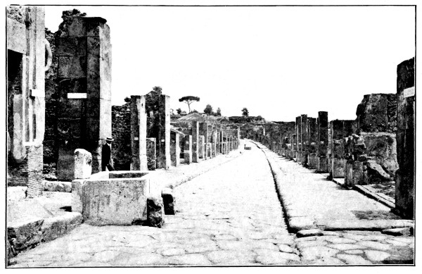
Street Fountain and Watering-trough in Pompeii.
Called the Fountain of Plenty, from the figure
with Horn of Plenty on the perforated upright post.
13. The Appian Way and other Roman Roads.—Probably the
oldest and most celebrated of these old Roman roads is the Appian Way. It
was the most substantially built, and the breadth of roadway varied from
14 to 18 feet exclusive of the footwalks. Statius called it the Queen
of Roads. It was begun by Appius Claudius Cæcus, 312 years before the
Christian era. He carried its construction from the Roman gate called
Porta Capena to Capua, but it was not entirely completed till about
the year 30 B.C. Its total length was three
hundred and fifty miles, and it formed a perfect highway from Rome to
Brundisium, an important port on what may be called the southeastern
point of Italy. It was built in such an enduring manner that it
appears to have been in perfect repair as late as 500 to 565
A.D.
The plan of construction of these roads was so varied as to suit
local conditions, but only as required by sound engineering judgment.
They wisely employed local materials wherever possible, but did not
hesitate to transport proper material from distant points wherever
necessary. This seemed to be one of their fundamental principles of
road construction. In this respect the old Romans exhibited more
engineering and business wisdom than some of the American states in
the beginnings of improved road construction in this country. An
examination of the remains of some Roman roads now existing appears to
indicate that in earth the bottom of the requisite excavation was first
suitably compacted, apparently by ramming, although rollers may have
been used. On this compacted subgrade were laid two or three courses
of flat stones on their beds and generally in mortar. The second layer
placed on the preceding was rubble masonry of small stones or of coarse
concrete. On the latter was placed the third layer of finer concrete.
The fourth or surface course, consisting of close and nicely jointed
polygonal blocks, was then put in place, and formed an excellent
unyielding pavement. This resulted in a most substantial roadway,
sometimes exceeding 3 feet in total thickness. It is difficult to
conceive of a more substantial and enduring type of road construction.
The two lower layers were omitted when the road was constructed in
rock. Obviously the finer concrete constituting the second layer from
the top surface was a binder between the pavement surface and the
foundation of the roadway structure.
The paved part of a great road was usually about 16 feet in width,
and raised stone causeways or walls separated it from an unpaved way
on each side having half the width of the main or paved portion. This
seemed to be the type of the great or main Roman roads. Other highways
of less important character were constructed of inferior materials,
earth or clay sometimes being used instead of mortar; but in such cases
greater crowning was employed, and the road was more elevated, possibly
for better drainage. Then, as now, adequate drainage was considered one
of the first features of good road design. City streets were paved with
the nicely jointed polygonal blocks to which reference has already been
made, while the footways were paved with rectangular slabs much like
our modern sidewalks.
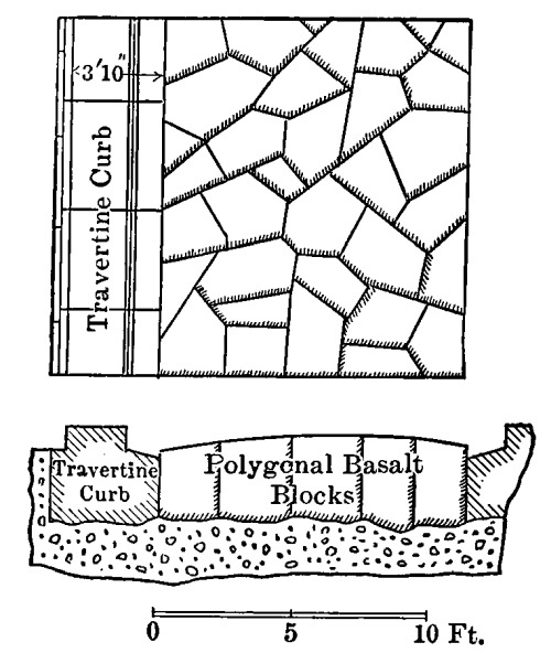
EXAMPLE OF EARLY BASALT ROAD.
BY THE TEMPLE OF SATURN ON
THE CLIVUS CAPITOLINUS.
Fig. 7.
The smooth polygonal pavements of the old Romans put to the keenest
shame the barbarous cobblestone street surfaces with which the people
of American cities have been and are still so tortured.
The beneficial influence of these old Roman highways has extended down
even to the present time in France, where some of them were built.
The unnecessarily elaborate construction has not been followed, but
the recognition of the public benefits of excellent roads has been
maintained. The lower course of the foundation-stones apparently began
to be set on edge toward the latter part of the eighteenth century, the
French engineer Tresaguet having adopted that practice in 1764. At the
same time he reduced the thickness of the upper layers. His methods
were but modifications of the old Roman system, and they prevailed in
France until the influence of the English engineers Macadam and Telford
began to be felt.
14. Natural Advantages of Rome in Structural Stones.—Although
the ancient Romans were born engineers, possessing the mental qualities
and sturdy character requisite for the analytic treatment and execution
of engineering problems, it is doubtful whether they would have
attained to such an advanced position in structural matters had not the
city of Rome been so favorably located.
The geological character of the great Roman plain and the Roman hills
certainly contributed most materially to the early development of
some of the most prominent of the Roman engineering works. The plain
surrounding the city of Rome is composed largely of alluvial and sandy
deposits, or of the emissions of neighboring volcanoes, of which the
Alban Hills form a group. While these and other volcanic hills in the
vicinity are, and have been for a long period, quiescent, they were
formerly in a very active state. The scoriæ, or matter emitted in
volcanic eruptions, is found there in all possible degrees of coherence
or solidity, from pulverulent masses to hard rock. The characteristic
Roman material called tufa is a mixture of volcanic ash and sand, loose
and friable, as dropped from the eruptions in large quantities or again
compressed into masses with all degrees of hardness. The hard varieties
of yellow or brown tufa form building material much used, although a
considerable percentage of it would not be considered fit building
material for structures of even moderate height at the present time.
The most of it weathers easily, but forms a fairly good building-stone
when protected by a coating of plaster or stucco.
Another class of building-stones found at or in the vicinity of Rome
is the so-called “peperino,” consisting chiefly of two varieties of
conglomerate of ash, gravel, broken pieces of lava, and pieces of
limestone, some possessing good weathering qualities, while others
do not. Ancient quarries of these stones exist whence millions of
cubic yards have been removed, and are still being worked. The better
varieties of “peperino” possess good resisting qualities, and were much
used in those portions of masonry construction where high resistance
was needed, as in the ring-stones of arches, heavily loaded points of
foundations, and other similar situations.
Some of the prehistoric masonry remains of the Romans show that their
earliest constructors appreciated intelligently the qualities of this
stone for portions of works where the duty was most severe.
Lava from the extinct volcanoes of the Alban Hills called “silex” was
used for paving roads and for making concrete. It was hard and of gray
color. At times considerable quantities of this stone were employed. A
species of pure limestone called “travertine,” of a creamy white color,
was quarried at Tibur or Tivoli, and began to be used about the second
century B.C. Vitruvius speaks of its having good
weathering qualities, but naturally it is easily calcined. Its structure is
crystalline, and it is strong in consequence of that quality only when
it is laid on its bed.
15. Pozzuolana Hydraulic Cement.—The most valuable of all
building materials of old Rome was the “pozzuolana,” as it furnished
the basis of a strong, enduring, and economic concrete, and permitted
almost an indefinite development of masonry construction. Had there
not been at Rome the materials ready at hand to be manufactured into
an excellent cementing product, it is highly probable that neither the
structural advance nor the commercial supremacy of the Roman people
could have been attained. It is at least certain that the majority
of the great masonry works constructed by the Romans could not have
been built without the hydraulic cementing material produced with so
little difficulty and in such large quantities from the volcanic earth
called pozzuolana. The name is believed to have its origin from the
large masses of this material at Pozzuoli near Naples. Great beds are
also found at and near Rome. The earliest date of its use cannot be
determined, but it has given that strong and durable character to Roman
concrete which has enabled Roman masonry to stand throughout centuries,
to the admiration of engineers.
It is a volcanic ash, generally pulverulent, of a reddish color, but
differs somewhat in appearance and texture according to the locality
from which it is taken. It consists chiefly of silicate of alumina, but
contains a little oxide of iron, alkali, and possibly other components.
The Romans therefore pulverized the pozzuolana and mixed it with lime
to make hydraulic cement. This in turn was mixed with sand and gravel
and broken stone to form mortar and concrete, and that process is
carried on to this day. The concrete was hand-mixed, and treated about
as it is at present. After having been well mixed the Romans frequently
deposited it in layers of 6 to 9 or 10 inches thick, and subjected
it to ramming. In connection with this matter of mortar and concrete
production, Vitruvius observes that pit-sand is preferable to either
sea or river sand.
16. Roman Bricks and Masonry.—The Romans produced bricks
both by sun-baking and by burning, although there are now remaining
apparently no specimens of the former in Rome. Bricks were used very
largely for facing purposes, such as a veneer for concrete work. The
failure to recognize this fact has led some investigators and writers
into error. As matter of fact bricks were used as a covering for
concrete work, the latter performing all the structural functions.
The old Roman aqueducts were frequently lined with concrete, made of a
mixture of pozzuolana, lime, and crushed (pounded) bricks or potsherds.
The same material was also used for floors under the fine mortar in
which the mosaics were imbedded.
Marble came into use in Rome about 100 B.C.,
from Luna, near modern Carrara, Mt. Hymettus, and Mt. Pentelicus, near
Athens and the Isle of Paros, nearly all being for sculpture purposes.
Colored and structural marbles were brought from quarries in various
parts of Italy, Greece, Phrygia, Egypt, near Thebes (oriental alabaster
or “onyx”), Arabia, and near Damascus.
From the latter part of the first century B.C.
the hard building-stones like granites and basalts were brought to Rome in
large quantities. Most of the granites came from Philæ on the Nile.
The basalts came both from Lacedæmonia and Egypt. Both emery (from the
island of Naxos in the Ægean Sea) and diamond-dust drills were used
in quarrying or working these stones. Ships among the largest, if not
the largest, of those days, were built to transport obelisks and other
large monoliths.
The quality of ancient Roman mortar varies considerably as it is now
found. That of the first and second centuries is remarkably hard, and
made with red pozzuolana. In the third century it began to be inferior
in quality, brown pozzuolana sometimes being used. The reason for this
difference in quality cannot be confidently assigned. The deterioration
noted in the third century work may be due to the introduction of bad
materials, or to the wrong manipulation of material intrinsically good,
or it is not unlikely the deterioration is due to a combination of
these two influences. The use of mortar indicates a class of early
construction; it is found in the Servian wall on the Aventine, of date
700 B.C., or possibly earlier.
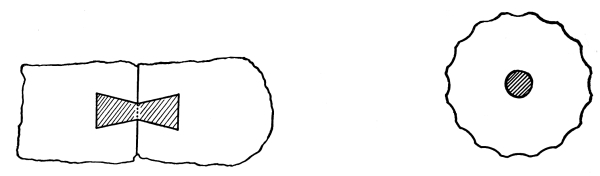
Dovetail Wooden Tenon.Wooden Dowel.
Fig. 8.
Under the empire (27 B.C. to A.D.
475) large blocks of tufa, limestone (travertine), or marble were set with very close
joints, with either no mortar or, if any, as thin as paper; end, top,
and bottom clamps of iron were used to bond such stones together. It
was also customary, in laying such large, nicely finished blocks of
stone without mortar, to use double dovetailed wooden ties, or, as in
the case of columns, a continuous central dowel of wood, as shown in
the figures.
The joints were frequently so close as to give the impression that the
stones might have been fitted by grinding together. In rectangular
dimension stonework (ashlar) great care was taken, as at present, to
secure a good bond by the use of judiciously proportioned headers and
stretchers. Foundation courses were made thicker than the body of
the superincumbent wall, apparently to distribute foundation weights
precisely as done at present. Weaker stone was used in thicker portions
of walls, and strong stone in thinner portions. Also at points of
concentrated loading, piers or columns of strong stone are found built
into the bodies of walls of softer or weaker stone. Quarry chips,
broken lava, broken bricks, or other suitable refuse fragments were
used for concrete in the interest of economy, the broken material
always being so chosen as to possess a sharp surface to which the
cement would attach itself in the strongest possible bond.
At the quarries where the stones were cut the latter were marked
apparently to identify their places in the complete structure, or
for other purposes. The remains of the quarries themselves as seen
at present are remarkable both for their enormous extent and for the
system on which the quarrying was conducted. It appears that the
systems employed were admirably adapted to the character of the stone
worked, and that the quarrying operations were executed as efficiently
and with as sound engineering judgment as those employed in great
modern quarries.
17. Roman Building Laws.—So much depended upon the excellence
of the building in Rome, and upon the materials and methods employed,
that building laws or municipal regulations were enacted in the
ancient city, prescribing kind and quality of material, thickness of
walls, maximum height of buildings, minimum width of streets, and
many other provisions quite similar to those enacted in our modern
cities. The differences appear to arise from the different local
conditions to be dealt with, rather than from any failure on the part
of the old Romans to reach an adequate conception of the general
plans suitable for the masses of buildings in a great city. Prior to
the great fire A.D. 64 in Nero’s reign, an act
prescribing fire-proof exterior coverings of buildings was under consideration,
and subsequently to that conflagration it was enacted into law. Many
of the city roads or streets were paved with closely fitting irregular
polygonal blocks of basalt, laid on concrete foundations, and with
limestone (travertine) curbs and gutters, producing an effect not
unlike our modern streets.
18. Old Roman Walls.—In no class of works did the ancient
Romans show greater engineering skill or development than in the
massive masonry structures that were built not only in and about the
city of Rome, but also in distant provinces under Roman jurisdiction.
Among the home structures various walls, constituting strong defences
against the attacks of enemies, stand in particular prominence. Some of
these great structures had their origin prior even to historic times.
The so-called “Wall of Romulus,” around the famous Roma Quadrata of the
Palentine, is among the latter. It is supposed by many that this wall
formed the primitive circuit of the legendary city of Romulus. That,
however, is an archæological and not an engineering question, and,
whatever its correct answer may be, the wall itself is a great
engineering work; it demonstrates that the early Romans, whatever may
have been their origin, had attained no little skill in quarrying and
in the building of dry masonry, no mortar being used in this ancient
wall. Portions of it 40 feet high and 10 feet thick at bottom, built
against a rocky hill, are still standing. The courses are 22 to 24
inches thick, and they are laid as alternate headers and stretchers;
the lengths of the blocks being 3 to 5 feet, and the width from 19 to
22 inches. The ends of the blocks are carefully worked and true, as are
the vertical joints in much of the wall, although some of the latter,
on the other hand, are left as much as 2 inches open.
Civil engineers, who are familiar with the difficulties frequently
experienced in laying up dry walls of considerable height, as evidenced
by many instances of failure probably within the knowledge of every
experienced engineer, will realize that this great dry masonry
structure must have been put in place by men of no little engineering
capacity. The rock is soft tufa, and marks on the blocks indicate that
chisels from ¼ to ¾ inch in width were used, as well as sharp-pointed
picks. In all cases the faces of the blocks were left undressed, i.e.,
in modern terms they were “quarry-faced.”
19. The Servian Wall.—Later in the history of Rome the great
Servian Wall, built chiefly by Servius Tullius to enclose the seven
hills of Rome, occupies a most prominent position as an engineering
work. Part of the wall, all of which belongs to the regal period (753
to 509 B.C.), is supposed to be earlier than Servius,
and may have been planned and executed by Tarquinius Priscus. A part only
of the stones of this wall were laid in cement mortar, and concrete
was used, to some extent at least, in its foundation and backing. The
presence of cement mortar in this structure differentiates it radically
from the wall of Romulus. Probably the discovery of pozzuolana cement,
and the fabrication of mortar and concrete from it, had been made in
the intervening period between the two constructions. Tufa, usually the
softer varieties but of varying degrees of hardness, was mostly used in
this wall, and the blocks were placed, as in the previous instance, as
alternate headers and stretchers in courses about two feet thick.
Portions of the wall 45 feet high and about 12 feet thick have been
uncovered. At points it was pierced with arched openings of 11 feet 5
inches span, possibly as embrasures for catapults or other engines of
war. The upper parts of these openings are circular arches with the
usual wedge-like ring-stones. The voussoirs were cut from peperino
stone. This wall, like that of Romulus, was constructed as a military
work of defence, and at some points it was built up from the bottom
of a wide foss 30 feet deep. At such places it was counterforted or
buttressed, a portion of wall 11 feet 6 inches long being found between
two counterforts, each of the latter being 9 feet wide and projecting 7
feet 9 inches out from the wall.
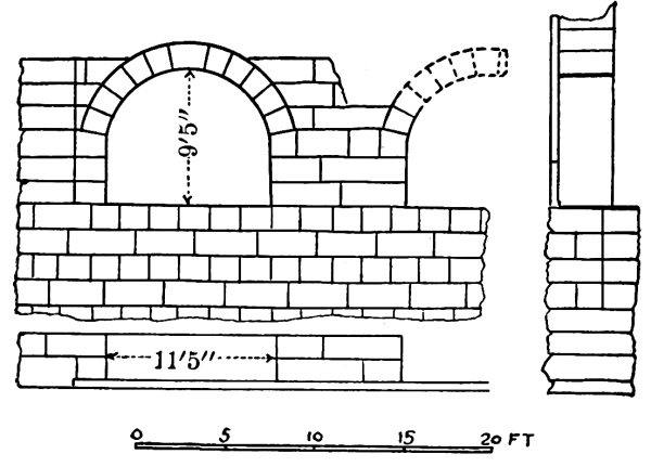
Fig. 9.—Part of Servian Wall on Aventine.
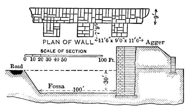
Fig. 10.—Wall and Agger of Servius.
20. Old Roman Sewers.—It is demonstrable by the writings
of Vitruvius and others that the old Romans, or at any rate the better
educated of them, possessed a correct general idea of some portions of
the science of Sanitary Engineering, so far as anything of the nature
of science could then be known. Their sanitary views were certainly
abreast of the scientific knowledge of that early day. The existence
of the “cloacæ,” or great sewers, of the ancient city of Rome showed
that its people, or at least its rulers, not only appreciated the value
of draining and sewering their city, but also that they knew how to
secure the construction of efficient and enduring sewers or drains. It
has been stated, and it is probably true, that this system of cloacæ,
or sewers, was so complete that every street of the ancient city was
drained through its members into the Tiber. They were undoubtedly the
result of a gradual growth in sewer construction and did not spring at
once into existence, but they date back certainly to the beginning of
the period of the kings (753 B.C.). The famous
Cloaca Maxima, as great as any sewer in the system, and certainly the most
noted, is still in use, much of it being in good order. The mouth of the
latter where it discharges into the Tiber is 11 feet wide and 12 feet
high, constituting a large arch opening with three rings of voussoirs
of peperino stone. Many other sewers of this system are also built
with arch tops of the same stone, with neatly cut and closely fitting
voussoirs. We do not find, unfortunately, any detailed accounts of the
procedures involved in the design of these sewers, yet it is altogether
probable that the old Roman civil engineers formed the cross-sections,
grades, and other physical features of their sewer system by rational
processes, although they would doubtless appear crude and elementary at
the present time. It would not be strange if they made many failures in
the course of their structural experiences, but they certainly left in
the old Roman sewers examples of enduring work of its kind.
Some portions of this ancient sewer system are built with tops that are
not true arches, and it is not impossible that they antedate the regal
period. These tops are false arches formed of horizontal courses of
tufa or peperino, each projecting over that below until the two sides
thus formed meet at the top. The outline of the crowns of such sewers
may therefore be triangular, curved, or polygonal; they were usually
triangular. Smaller drains forming feeders to the larger members of
the system were formed with tops composed of two flat stones laid with
equal inclination to a vertical line so as to lean against each other
at their upper edges and over the axis of the sewer. This method of
forming the tops of the drains by two inclined flat stones was a crude
but effective way of accomplishing the desired purpose.
The main members of this great sewer system seem to have followed the
meandering courses of small rivers or streams, constituting the natural
drainage-courses of the site of the city. The Cloaca Maxima has an
exceedingly crooked course and it, along with others, was probably
first formed by walling up the sides of a stream and subsequently
closing in the top. Modern engineers know that such an alignment for
a sewer is viciously bad, and while this complicated system of drains
is admirably constructed in many ways for its date, it cannot be
considered a perfect piece of engineering work in the light of present
engineering knowledge. It is probable that the walling in of the sides
of the original streams began to be done in Rome at least as early as
the advent of the Tarquins, possibly as early as 800 B.C.
or earlier.
We know little about the original outfalls or points of discharge into
the Tiber, except that, as previously stated, these points were made
through the massive quay-walls constructed during the period of the
kings along both shores of the Tiber, probably largely for defence as
originally built. The discharge of the old Roman sewers through the
face of this quay-wall and into the river is precisely the manner in
which the sewers of New York City in many places are discharged into
the North, East, and Harlem rivers.
The Cloaca Maxima is not the only great ancient sewer thus far
discovered. There are at least two others equal to it, and some of the
single stones with which they are built contain as much as 45 cubic
feet each. These cloacæ were not mere sewers; indeed they were more
drains than sewers, for they carried off flood-waters and the natural
drainage as well as the sewerage. They were therefore combined sewers
and drains closely akin to the sewers of our “combined” systems. The
openings into them were made along the streets of Rome and in public
buildings or some other public places. There is no evidence that
they were ventilated except through these openings, and from each
noxious gases were constantly rising to be taken into the lungs of
the passers-by. It is a rather curious as well as important fact that
so far as excavations have been made there is practically no evidence
that a private residence in Rome was connected with the sewers. The
“latrines” were generally located adjacent to the Roman kitchens and
discharged into the cloacæ.
21. Early Roman Bridges.—The early Romans were excellent
bridge-builders as well as constructors in other lines of engineering
work. Although the ancient city was first located on the left bank of
the Tiber, apparently it was but a comparatively short time before
the need of means for readily crossing from bank to bank was felt.
The capacity of the Roman engineers was equal to the demands of the
occasion, and it is now known that seven or eight ancient bridges
connected the two shores of the river Tiber. The oldest bridge is that
known as Pons Sublicius. No iron was used in its construction, as
bronze was the chief metal employed in that early day. The structure
was probably all of timber except possibly the abutments and the piers.
A French engineer, Colonel Emy, has exhibited in his “Traité de l’Art
de la Charpenterie” a plan of this structure restored as an all-timber
bridge with pile foundations. Lanciani, on the other hand, believes
that the abutments and piers must have been of masonry. The masonry
structures, however, known to exist at a later day may have been parts
of the work of rebuilding after the two destructions by floods. The
date of its construction is not known, but tradition places it in
the time of Ancus Marcius. This may or may not be correct. A flood
destroyed the bridge in 23 B.C., and again in
the time of Antoninus Pius, but on both occasions it was rebuilt. The structure
has long since disappeared. The piers only remained for a number of
centuries, and the last traces of them were removed in 1877 in order to
clear the bed of the river.
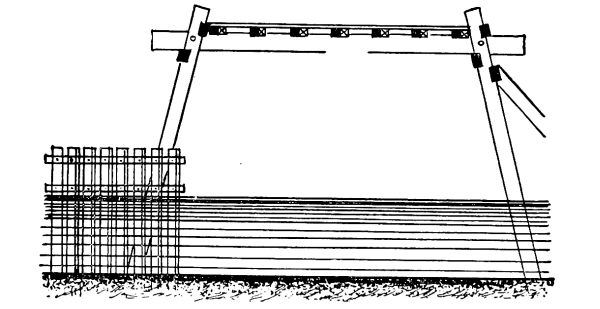
Fig. 11 shows Colonel Emy’s restoration of
the plan for the pile bridge which Julius Cæsar built across the Rhine
in ten days for military purposes. This plan may or may not include
accurate features of the structure, but it is certain that such a
timber bridge was built, and well preserved pieces of the piles have
been taken from under water at the site little the worse for wear after
two thousand years of submersion.
The censor Ælius Scaurus built a masonry arch across the Tiber about a
mile and a half from Rome in the year 100 B.C.
This bridge is now known as the Ponte Molle, and some parts of the
original structure are supposed to be included in it, having been
retained in the repeated alterations. The arches vary in span from 51
to 79 feet, and the width of the structure is a little less than 29 feet.
In or about the year 104 A.D. the emperor
Trajan constructed what is supposed to be a wooden arch bridge with
masonry piers across the Danube just below the rapids of the Iron Gate.
Cross-section at Pier.
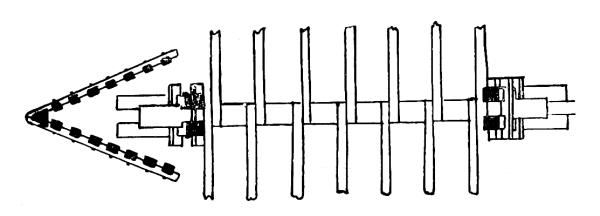
Plan at Pier.
Fig. 11.—Bridge thrown across
the Rhine by Julius Cæsar.
A bas relief on the Trajan Column at Rome exhibits the timber
arches, but fails to give the span lengths, which have been the subject
of much controversy, some supposing them to have been as much as 170 feet.
The ancient Pons Fabricius, now known as Ponte Quattiro Capi, still
exists, and it is the only one which remains intact after an expiration
of nearly two thousand years. It has three arches, the fourth being
concealed by the modern embankment at one end; a small arch pierces the
pier between the other two arches. This structure is divided into two
parts by the island of Æsculapius. It is known that a wooden bridge
must have joined that island with the left bank of the Tiber as early
as 192 B.C., and a similar structure on the other
side of the island is supposed to have completed the structure. While Lucius
Fabricius was Commissioner of Roads in the year 62 B.C.
he reconstructed the first-named portion into a masonry structure of
arches. An engraved inscription below the parapets shows that the work
was duly and satisfactorily completed, and further that it was the
custom to require the constructors or builders of bridges to guarantee
their work for the period of forty years. Possession of the last
deposit, made in advance as a guarantee of the satisfactory fulfilment
of the contract, could not be regained until the forty-first year after
completion.
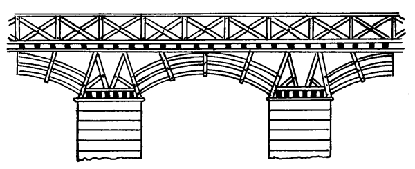
Fig. 12.—Trajan’s Bridge.
The Pons Cestius is a bridge since known as the Pons Gratianus and
Ponte di S. Bartolomeo. Its first construction is supposed to have
been completed in or about 46 B.C.,
and it was rebuilt for the first time in A.D. 365.
A third restoration took place in the eleventh century. The modern
reconstruction in 1886-89 was so complete that only the middle arch
remains as an ancient portion of the structure. The island divides the
bridge into two parts, the Ship of Æsculapius lying between the two,
but it is not known when or by whom the island was turned into that form.
Another old Roman bridge, of which but a small portion is now standing,
is Pons Æmilius, the piers of which were founded in 181 B.C.,
but the arches were added and the bridge completed only in 143
B.C. It was badly placed, so that the current of
the river in times of high water exerted a heavy pressure upon the piers, and
in consequence it was at least four times carried away by floods, the
first time in the year A.D. 280.
The discovery of what appears to be a row of three or four ruins of
piers nearly 340 feet up-stream from the Ponte Sisto seems to indicate
that a bridge was once located at that point, although little or
nothing is known of it as a bridge structure. Some suppose it to be the
bridge of Agrippa.
The most historical of all the old Roman bridges is that which was
called Pons Ælius, now known as Ponte S. Angelo, built by Hadrian
A.D. 136. Before the reconstruction of the
bridge in 1892 six masonry arches were visible, and the discovery
of two more since that date makes a total of eight, of which it is
supposed that only three were needed in a dry season. The pavement
of the approach to this bridge as it existed in 1892 was the ancient
roadway surface. Its condition at that time was an evidence of the
substantial character of the old Roman pavement.
Below the latter bridge remains of another can be seen at low water. It
is supposed that this structure was the work of Nero, although its name
is not known.
The modern Ponte Sisto is a reconstruction of the old Pons
Valentinianus or bridge of Valentinian I. The latter was an old Roman
bridge, and it was regarded as one of the most impressive of all the
structures crossing the river. It was rebuilt in
A.D. 366-67.
The most of these bridges were built of masonry and are of the usual
substantial type characteristic of the early Romans. They were
ornamented by masonry features in the main portions and by ornate
balustrades along either side of the roadway and sidewalks. The roadway
pavements were of the usual irregular polygonal old Roman type, the
sidewalk surfaces being composed of the large slabs or stones commonly
used in the early days of Rome for that purpose.
22. Bridge of Alcantara.—Among the old Roman bridges should
be mentioned that constructed at Alcantara in Spain, supposedly by Trajan,
about A.D. 105. It is 670 feet long and its greatest
height is 210 feet. One of its spans is partially destroyed. The structure
is built of blocks of stone without cementing material. In this case
the number of arches is even, there being six in all, the central two
having larger spans than those which flank them. It is a bridge of no
little impressiveness and beauty and is a most successful design.
23. Military Bridges of the Romans.—In the old Roman military
expeditions the art of constructing temporary timber structures along
lines of communication was well known and practised with a high degree
of ability. Just what system of construction was employed cannot be
determined, but piles were constantly used. At least some of these
timber military bridges, and possibly all, were constructed with
comparatively short spans, the trusses being composed of such braces
and beams as might be put in place between bents of piles. As already
observed, some of the sticks of these bridges have been found in the
beds of German rivers, and at other places, perfectly preserved after
an immersion of about two thousand years. These instances furnish
conclusive evidence of the enduring qualities of timber always
saturated with water.
24. The Roman Arch.—The Romans developed the semicircular
arch to a high degree of excellence, and used it most extensively in many
sewers, roads, and aqueducts. While the aqueduct spans were usually
made with a length of about 18 or 20 feet, they built arches with span
lengths as much as 120 feet or more, comparing favorably with our
modern arch-bridge work. They seldom used any other curve for their
arches than the circular, and when they built bridges an odd number
of spans was usually employed, with the central opening the largest,
possibly in obedience to the well-known esthetic law that an odd
number of openings is more agreeable to the eye than an even number.
Apparently they were apprehensive of the safety of the piers from
which their arches sprang, and it was not an uncommon rule to make
the thickness of the piers one third of the clear span. Nearly one
fourth of the entire length of the structure would thus be occupied
by the pier thicknesses. Although the use of mortar, both lime and
cement, early came into use with the Romans, they usually laid up the
ring-stones of their arches dry, i.e., with out the interposition of
mortar joints.
CHAPTER III.
25. The Roman Water-supply.—There is no stronger evidence
of engineering development in ancient Rome, nor of the advanced state of
civilization which characterized its people, than its famous system of
water-supply, which was remarkable both for the volume of water daily
supplied to the city and for the extensive aqueducts, many of whose
ruins still stand, as impressive monuments of the vast public works
completed by the Romans. These ruins, and those of many other works,
would of themselves assure us of the elaborate system of supply, but
fortunately there has been preserved a most admirable description of
it, the laws regulating consumption, the manner of administering the
water department of the government of the ancient city, and much other
collateral information of a most interesting character. In the work
entitled, in English, “The Two Books on the Water-supply of the City
of Rome,” by (Sextus) Julius Frontinus, an eminent old Roman citizen,
who, besides having filled the office of water commissioner[1]
of the city, was governor of Britain and three times consul, as well as having
enjoyed the dignity of being augur. He may properly be called a Roman
engineer, although he evidently was a man of many public affairs,
and so esteemed by the emperors who ruled during his time that he
accompanied them in various wars as a military man of high rank. He
wrote seven books at least, viz., “A Treatise on Surveying,” “Art of
War,” “Strategematics,” “Essays on Farming,” “Treatise on Boundaries,
Roads, etc.,” “A Work on Roman Colonies,” and his account of the
water-works of Rome, entitled “De Aquis.” It is the latter book in which
engineers are particularly interested. The translation of this book
from the original Latin is made from what is termed the “Montecassino
Manuscript,” an account of which with the translation is given by
Mr. Clemens Herschel in his entertaining work, “Frontinus, and the
Water-supply of the City of Rome.”
As near as can be determined Frontinus lived from about
A.D. 35 to A.D.
103 or 104. Judging from the offices which Frontinus held and the
honors which he enjoyed throughout his life, it would appear that
he was a patrician; he was certainly a man of excellent executive
capacity, of intellectual vigor and refined taste, and a conscientious
public servant. The water-supply of the city was held by the Romans
to be one of the most important of all its public works, and its
administration during the life of Frontinus was entrusted to what
we should call a water commissioner, appointed by the emperor. It
was considered to be an office of dignity and honor, and the proper
discharge of its responsibilities was a public duty which required a
high order of talent, as well as great integrity of character.
26. The Roman Aqueducts.—Frontinus states that from the
foundation of the city of Rome until 313 B.C.,
i.e., for a period of 441 years, the only water-supply was that drawn either
from the river Tiber or from wells or springs. The veneration of the Romans
for springs is a well-known feature of their religious tenets. They
were preserved with the greatest care, and hedged about with careful
safeguards against irreverent treatment or polluting conditions.
Apparently after this date the people of Rome began to feel the need
of a public water-supply adequate to meet the requirements of a great
city. At any rate, in the year 313 B.C.
the first aqueduct, called the Appia, for bringing public water into
the city of Rome was attempted by Censors Appius Claudius, Crassus, and
C. Plautius, the former having constructed the aqueduct, and the latter
having found the springs. Appius must have been an engineer of no mean
capacity, for it was he who constructed the first portion of the Appian
Way. The origin of this water-supply is some springs about 10 miles
from Rome, and they may now be seen at the bottom of stone quarries in
the valley of the Anio River. This aqueduct, Aqua Appia, is mostly
an underground waterway, only about 300 feet of it being carried on
masonry arches. At the point where it enters the city it was over 50
feet below the surface; its clear cross-section is given as 2½ feet
wide by 5 feet high. The elevation of its water surface in Rome was
probably under 60 feet above sea-level.
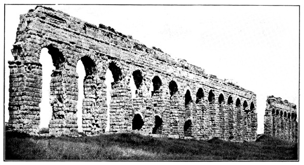
Claudia, of dimension stone, and Anio Novus,
of brick and concrete, on top of it.
27. Anio Vetus.—The next aqueduct built for the water-supply
of Rome was called Anio Vetus. It was built 272-269 B.C.,
and is about 43 miles long; it took its water from the river Anio. About
1100 feet of its length was carried above ground on an artificial
structure. It also was a low-level aqueduct, the elevation at which it
delivered water at Rome being about 150 feet above sea-level. It was
built of heavy blocks of masonry, laid in cement, and the cross-section
of its channel was about 3.7 feet wide by 8 feet high. In the year 144
B.C. the Roman senate made an appropriation
equal to about $400,000 of our money to repair the two aqueducts
already constructed, and to construct a new one called Aqua
Marcia, to deliver water to the city at an elevation of about
195 feet above sea-level. This aqueduct was finished 140 B.C.;
it is nearly 58 miles long, and carried water of most excellent quality
through a channel which, at the head of the aqueduct, was 5⅞ feet wide
by 8³/₁₀ feet high, but farther down the structure was reduced to 3
feet wide by 5⁷/₁₀ feet high. The excellent water of these springs
is used for the present supply of Rome, and is brought in the Aqua
Pia, built in 1869, as a reconstruction of the old Aqua Marcia. This
aqueduct, like its two predecessors, is built of dimension stone,
18 inches by 18 inches by 42 inches, or larger, laid in cement; but
concrete and brick were used in the later aqueducts, with the exception
of Claudia.
28. Tepula.—The aqueduct called Aqua Tepula, about 11 miles
in length, and completed 125 B.C., was constructed
to bring into the city of Rome a slightly warm water from the volcanic springs
situated on the hill called Monte Albani (Alban Hills) southeast of
Rome. The temperature of these springs is about 63° Fahr. In the year
B.C. 33 Agrippa caused the water from some springs
high up the same valley to be brought in over the aqueduct Aqua Julia, 14 miles
long. This latter water was considerably colder than that of the Tepula
Springs. The two waters were united before reaching Rome and allowed to
flow together far enough to be thoroughly mixed. They were then divided
and carried into Rome in two conduits. The volume of water carried
in the Aqua Julia was about three times that taken from the Tepula
Springs, the cross-section of the latter being only 2.7 feet wide by
3.3 feet high, while that of Julia was 2.3 feet by 4.6 feet. The water
from Aqua Julia entered Rome at an elevation of about 212 feet above
sea-level, and that from Aqua Tepula about 11 feet lower.
29. Virgo.—The sixth aqueduct in chronological order was called
Virgo, and it was completed 19 B.C. It takes water
from springs about 8 miles from Rome and only about 80 feet above sea-level,
but the length of the aqueduct is about 13 miles. The delivery of water
in the city by this aqueduct is about 67 feet above that level. The
cross-section of this channel is about 1.6 feet wide and 6.6 feet high.
30. Alsietina.—The preceding aqueducts are all located on
the left or easterly bank of the Tiber, but one early structure was
located on the right bank of the Tiber to supply what was called the
Trans-Tiberine section of the city, and it was known as Aqua Alsietina.
The emperor Augustus had this aqueduct constructed during his reign,
and it was finished in the year A.D. 10. Its source
is a small lake of the same name with itself, about 20 miles from Rome. The
elevation of this lake is about 680 feet above sea-level, while the
water was delivered at an elevation of about 55 feet above the same
level. The water carried by this aqueduct was of such a poor quality
that Frontinus could not “conceive why such a wise prince as Augustus
should have brought to Rome such a discreditable and unwholesome water
as the Alsietina, unless it was for the use of Naumachia.” The latter
was a small artificial lake or pond in which sham naval fights were conducted.
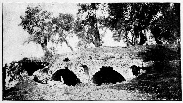
Sand and Pebble Catch-tanks near Tivoli.
Dimension-stone
aqueducts of Marcia at either end
of the tank built of small stone;
opus incretum.
The arches are chambers of the tanks.
31. Claudia.—The eighth aqueduct described by Frontinus
is the Aqua Claudia, built of dimension stone, which he calls a magnificent
work on account of the large volume of water which it supplied, its
good quality, and the impressive character of considerable portions of
the aqueduct itself, between 9 and 10 miles being carried on arches.
It was built in 38-52 A.D. and is forty-three
miles long. The sources of its supply are found in the valley of the Anio,
and consequently it belongs to the system on the left bank of the Tiber.
The cross-section of its channel was about 3.3 feet wide by 6.6
feet high. It was a work greatly admired by the Roman people, as is
evidenced by the praise “given to it by Roman authors who wrote at that
time.” It delivered water at the Palatine 185 feet above sea-level.
According to Pliny, the combined cost of it and the Aqua Anio Novus
was 55,500,000 sestertii, or nearly $3,000,000. This aqueduct probably
belongs to the highest type of Roman hydraulic engineering. It follows
closely the location of the Aqua Marcia, although its alignment now
includes a cut-off tunnel about 3 miles long, the latter having been
constructed about thirty-six years after the aqueduct was opened. Mr.
Clemens Herschel observes that the total sum expended for these two
aqueducts makes a cost of about $6 per lineal foot for the two. The
arches of this aqueduct and those of the Anio Novus have clear spans of
18 to 20 feet, with a thickness at the crown of about 3 feet.
32. Anio Novus.—The ninth aqueduct described by Frontinus is
called Anio Novus. It was also constructed in the years A.D.
38-52. This aqueduct has a length of about 54 miles and takes
its supply from artificial reservoirs constructed by Nero at his
country-seat in the valley of the Anio near modern Subiaco. This
structure is built of brick masonry lined with concrete. That portion
of the Aqua Claudia which is located on the Campagna carries for 7
miles the Anio Novus, and it forms the long line of aqueduct ruins near
Roma Vecchia. The upper surface of the arch-ring at the crown forms the
bottom of the channel of the aqueduct. The cross-section of the channel
of the Anio Novus was 3.3 feet wide by 9 feet high. The elevation of
the water in this, as in the Claudia, when it reached the Palatine was
about 185 feet above sea-level. The Anio Novus in some respects would
seem to be a scarcely less notable work than the Claudia. About 8 miles
of its length is carried on arches, some of them reaching a height of
about 105 feet from the ground.
33. Lengths and Dates of Aqueducts.—These nine aqueducts
constituted all those described by Frontinus, as no others were
completed prior to his time. Five others were, however, subsequently
completed between the years 109 A.D. and
306 A.D., but enough has already been shown
in connection with the older structures to show the character of the
water-supply of ancient Rome.
The following tabular statement is a part of that given by Mr. F. W.
Blackford in “The Journal of the Association of Engineering Societies,”
December, 1896. It shows the dates and lengths of the ancient aqueducts
of Rome between the years 312 B.C. and 226
A.D., with the length of the arch portions.
The list includes those built up to the end of the Empire. It will be
observed that the total length of the aqueducts is 346 miles, and that
of the arch portions 44 miles. The figures vary a little from those
given by Lanciani and others, but they are essentially accurate.
| Name. |
Date.
B.C. |
Total Length
in Miles. |
Length of Arches
in Miles. |
| Appia |
312 |
11 |
Little |
| Vetus |
272-264 |
43 |
” |
| Marcia |
145 |
61 |
12 |
| Tepula |
126 |
13 |
Little |
| Julia |
34 |
15 |
6 |
| Virgo |
21 |
14 |
Little |
| |
|
|
|
| |
A.D. |
|
|
| Alsietina |
10 |
22 |
Little |
| Augusta |
10 |
6 |
” |
| Claudia |
50 |
46 |
10 |
| Anio Novus |
52 |
58 |
9 |
| Triana |
109 |
42 |
Little |
| Alexandrina |
226 |
15 |
7 |
| Totals |
|
346 |
44 |
34. Intakes and Settling-basins.—The preceding brief
descriptions of the old Roman aqueducts give but a superficial idea
of the real features of those great works and of the system of
water-supply of which they were such essential portions. Enough has
been shown, however, to demonstrate conclusively that the engineers and
constructors of old Rome were men who, on the one hand, possessed a
high order of engineering talent and, on the other, ability to put in
place great structures whose proportions and physical characteristics
have commanded the admiration of engineers and others from the time of
their completion to the present day. If a detailed statement were to be
made in regard to the water-supply of ancient Rome, it would
appear that much care was taken to insure wholesome and potable water.
At the intakes of a number of the aqueducts, reservoirs or basins
were constructed in which the waters were first received and which
acted as settling-basins, so that as much sedimentation as possible
might take place. Similar basins (picinæ) were also constructed at
different points along the aqueducts for the same purpose and for
such other purposes as the preservation of the water in a portion
of the aqueduct in case another portion had to be repaired or met
with an accident which for the time being might put it out of use.
These basins were usually constructed of a number of apartments, the
water flowing from one to the other, very much as sewage in some
sewage-disposal works flows at the present time through a series of
settling-basins. The object of these picinæ was the clearing of the
water by sedimentation. Indeed there was in some cases a use of salt in
the water to aid in clarifying it. This is an early type of the modern
process of clarifying water by chemical precipitation, not the best of
potable water practice, but one that is sometimes permissible.
35. Delivery-tanks.—The aqueducts brought the water to
castellæ or delivery-tanks, i.e., small reservoirs, both inside the city and
outside of it, and from these users were obliged by law to take
their supplies; that is, for baths, for fountains, for public uses,
for irrigation, and for private uses. When Frontinus wrote his “De
Aquis” a little less than three tenths of all the water brought to
Rome by the aqueducts was used outside of the city. The remainder was
distributed in the city from 247 delivery-tanks or small reservoirs,
about one sixth of it being consumed by 39 ornamental fountains and 591
water-basins.
36. Leakage and Lining of Aqueducts.—These aqueducts were
by no means water-tight. Indeed they were subject to serious leakage, and
Frontinus shows that forces of laborers were constantly employed in
maintaining and repairing them. As has been stated, the older aqueducts
were built of dimension stones, while the later were constructed of
concrete or bricks and concrete. The channels of these aqueducts, as
well as reservoirs and other similar structures, were made as nearly
water-tight as possible by lining them with a concrete in which
pottery, broken into fine fragments, was mixed with mortar.
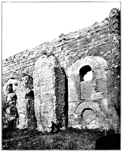
Claudia and Anio Novus near Porta Furba.
Repairs in
brickwork and in a composite
of concrete and brickwork.
37. Grade of Aqueduct Channels.—The fall of the water
surface in these aqueducts cannot be exactly determined. The
levelling-instruments used by the Romans were simple and, as we should
regard them, crude, although they served fairly well the purposes
to which they were applied. They were not sufficiently accurate to
determine closely the slope or grade of the water surface in the
aqueduct channels. The deposition of the lime from the water along the
water surface on the sides of the channels in many cases would enable
that slope to be determined at the present time, but sufficiently
careful examinations have not yet been made for that purpose. Lanciani
states that the slopes in the Aqua Anio Vetus vary from about one
in one thousand to four in one thousand. An examination of the
incrustation on the sides of the Aqua Marcia near its intake makes it
appear that the slope of the surface was about .06 foot per 100 feet,
which would produce a velocity, according to the formula of Darcy, of
about 3.3 feet per second. In some aqueducts built in Roman provinces
it would appear that slopes have been found ranging from one in six
hundred to one in three thousand.
38. Qualities of Roman Waters.—The chief characteristic in most
of the old Roman waters was their extreme hardness. They range from
11° to 48° of hardness, the latter belonging to the water of the Anio,
while the potable waters in this country scarcely reach 5°. The old
Romans recognized these characteristics of their waters and, as has
been intimated, used the best of them for table purposes, while the
less wholesome were employed for fountains, flushing sewers, and other
purposes not affected by undesirable qualities. The water from Claudia,
for instance, was used for the imperial table. The water from the Aqua
Marcia was also of excellent quality, while that brought in by the Aqua
Alsietina was probably not used for potable purposes at all.
39. Combined Aqueducts.—In several cases a number of aqueduct
channels were carried in one aqueduct. A marked instance of this kind
was that of Julia, Tepula, and Marcia, all being carried in vertical
series in one structure. Numerous instances of this sort occurred.
40. Property Rights in Roman Waters.—In reading the two books
of Frontinus one will be impressed by the property values which the old
Romans created in water rights. The laws of Rome were exceedingly
explicit as to the rights of water-users and as to the manner in which
water should be taken from the aqueducts and from the pipes leading
from the reservoirs in and about the city. The proper methods for
taking the water and using it were carefully set forth, and penalties
were prescribed for violations of the laws pertaining to the use of
water. There were many abuses in old Rome in the administration of
the public water-supply, and one of the most troublesome duties which
Frontinus had to perform lay in reforming those abuses and preventing
the stealing of water. The unit of use of water (a “quinaria,” whose
value is not now determinable) was the volume which would flow from
an orifice .907 inch in diameter and having an area of about .63 of
a square inch. Mr. Herschel shows that in consequence of the failure
of the Romans to understand the laws of the discharge of water under
varying heads, the quinaria may have ranged from .0143 cubic foot to
.0044 cubic foot per second or between even wider limits.
41. Ajutages and Unit of Measurement.—Frontinus describes
twenty-five ajutages of different diameter, officially approved in
connection with the Roman system of public water-supply; but only
fifteen of these were actually used in his day. All of these were
circular in form, although two others had been used prior to that time.
They varied in diameter from .907 to 8.964 English inches and were
originally made of lead, but that soft metal lent itself too easily to
the efforts of unscrupulous water-users to enlarge them by thinning the
metal. In his time they were made of bronze, which was a hard metal
and could not be tampered with so as to enlarge its cross-section. The
discharge through the smallest of these ajutages was the quinaria, the
unit in the scale of water rights. The largest of the above ajutages
had a capacity of a little over 97 quinariæ.
This unit (the quinaria) was based wholly on superficial area, and had
no relation whatever to the head over the orifice or to the velocity
corresponding to that head. Although Frontinus refers in several cases
to the fact that the deeper the ajutage is placed below the water
surface the greater will be the discharge through it, also to the fact
that a channel or pipe of a given area of cross-section will pass more
water when the latter flows through it with a high velocity, he and
other Roman engineers seem to have failed completely to connect the
idea of volume of discharge to the product of area of section by
velocity. In the Roman mind of his day, and for perhaps several hundred
years after that, the area of the cross-section of the prism of water
in motion was the only measure of the volume of discharge. This seems
actually preposterous at the present time, and yet, as observed by Mr.
Herschel, possibly a majority of people now living have no clearer idea
of the volume of water flowing in either a closed or open channel.
Existing statutes even respecting water rights bear out this statement,
improbable as it may at first sight appear. This early Roman view of
the discharge is, however, in some respects inexplicable, for Hero of
Alexandria wrote, probably in the period 100-50 B.C.,
that the section of flow only was not sufficient to determine the quantity of
water furnished by a spring. He proceeded to set forth that it was also
necessary to know the velocity of the current, and further explained
that by forming a reservoir into which a stream would discharge for an
hour the flow or discharge of that stream for the same length of time
would be equal to the volume of water received by the reservoir. His
ideas as to the discharge of a stream of water were apparently as clear
as those of a hydraulic engineer of the present time. Indeed the method
which he outlines is one which is now used wherever practicable.
It has been a question with some whether Frontinus and other Roman
engineers were acquainted with the fact that a flaring or outward
ajutage would increase the flow or discharge through the orifice. The
evidence seems insufficient to establish completely that degree of
knowledge on their part. At the same time, in the CXII chapter of
Frontinus’ book on the “Water-supply of the City of Rome,” he states
that in some cases pipes of greater diameter than that of the orifice
were improperly attached to legal ajutages. He then states: “As a
consequence the water, not being held together for the lawful distance,
and being on the contrary forced through the short restricted distance,
easily filled the adjoining larger pipe.” He was convinced that the use
of a pipe with increased diameter under such circumstances would give
the user of the water a larger supply than that to which he was
entitled, and he was certainly right in at least most cases.
The actual unit orifice through which the unit volume of water called
the quinaria was discharged was usually of bronze stamped by a proper
official, thus making its use legal for a given amount of water. The
Roman engineers understood that such an orifice should be inserted
accurately at right angles to the side of the vessel or orifice, and
that was the only legal way to make the insertion. Furthermore, the law
required that there should be no change in the diameter of the pipe
within 50 feet of the orifice. It was well known that a flaring pipe
of increased diameter applied immediately at the orifice would largely
increase the discharge, and unscrupulous people resorted to that means
for increasing the amount of water to be obtained for a given price.
42. The Stealing of Water.—It appears also that Frontinus
experienced much trouble from clandestine abstraction of water
from reservoirs and water-pipes. The administration of the water
commissioner’s office had been exceedingly corrupt prior to his
induction into office, and some of his most troublesome official work
arose from his efforts to detect water-thieves, and to guard the supply
system from being tapped irregularly or illegally. We occasionally
hear of similar instances of water-stealing at the present time, which
shows that human nature has not altogether changed since the time of
Frontinus.
43. Aqueduct Alignment and Design of Siphons.—The alignment
of some of the Roman aqueducts followed closely the contours of the
hills around the heads of valleys, while others took a more direct line
across the valleys on suitable structures, frequently series of arches.
Judging from our own point of view it may not be clear at first sight
why such extensive masonry constructions were used when the aqueduct
could have been kept in excavation by following more closely the
topography of the country. There is little doubt that the Romans knew
perfectly well what they were about. Indeed it is definitely stated in
some of the old Roman writings that the structures were built across
valleys for the specific purpose of saving distance which, in most
instances at least, meant saving in cost.
These masonry structures, it must be remembered, were built of material
immediately at hand. Furthermore, these aqueducts were generally only
made of sufficient width for the purpose of carrying water-channels.
They were not wide structures. In some cases they were not more than
8 feet or 9 feet wide for a height of nearly 100 feet. The cost of
construction was thus largely reduced below that of wide structures.
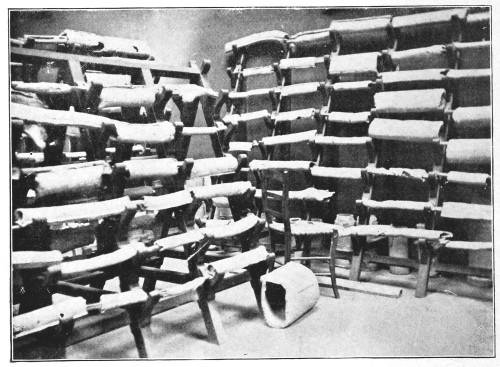
Old Roman Lead and Terra-cotta Pipe.
The Romans were perfectly familiar with the construction of inverted
siphons. As a matter of fact Vitruvius, in Chapter VII of his Eighth
book, describes in detail how they should be designed. His specific
descriptions relate to lead pipes, but it is clear from what he states
at other points that he considered earthenware pipes equally available.
He sets forth how the pipes should be carried down one slope, along the
bottom of the valley, and up the other slope, the lowest portion being
called the “venter.” He realized the necessity of guarding all elbows
in the pipe by using a single piece of stone as a detail for the elbow,
a hole being cut in it in each direction in which the adjoining
sections of pipe should be inserted, the sections of lead pipe being
10 feet long, and even goes so far as to describe the stand-pipes that
should be inserted for the purpose of allowing air to escape. Vitruvius
also advises that the water should not only be admitted to inverted
siphons in a gradual manner, but that ashes should be thrown into the
water when the siphon is first used in order that they may settle into
the joints or open places so as to close any existing leaks. Lead pipe
siphons, 12 to 18 inches in diameter, with 1 inch thickness of metal
under 200 feet head, built in ancient times, have been found at Lyons
in France. Also a drain-pipe siphon with masonry reinforcement was
built at Alatri in Italy 125 B.C. to carry water
under a head of about 340 feet. There are other notable instances of inverted
siphons constructed and used during the ancient Roman period, some of
them being of lead pipe imbedded in concrete.
CHAPTER IV.
44. Antiquity of Masonry Aqueducts.—Masonry aqueducts, either
solid or with open arches, were not first constructed by the city of
Rome; their origin was much farther back in antiquity than that. The
Greeks at least used them before the Roman engineers, and it is not
unlikely that the latter drew their original ideas from the former, if
indeed they were not instructed by them. Nor during the times of the
Romans was the construction of aqueducts confined to Rome. Wherever
Roman colonies were created it would appear that vast sums were
expended in the construction of aqueducts for the purpose of suitably
supplying cities with water. Such constructions are found at many
points in Spain, France, and other countries which were in ancient
times Roman colonies. It is probable that there are not less than one
hundred, and perhaps many more, of such structures in existence at the
present time.
45. Pont du Gard.—Among the more prominent aqueducts
constructed during the old Roman period and outside of Italy were the
Pont du Gard at Nismes in the south of France, and those at Segovia and
Tarragona in Spain. The Pont du Gard has three tiers of arches with a
single channel at the top. The greatest height above the river Gardon
is about 180 feet, and the length of the structure along the second
tier of arches is 885 feet. The arches in the lowest tier are 51 feet,
63 feet, and 80.5 feet in span, while the arches in the highest tier
are uniformly 15 feet 9 inches in span. The thickness of the masonry
at the top of the structure from face to face is 11 feet 9 inches, and
20 feet 9 inches at the lower tier of arches, the thickness at the
intermediate tier being 15 feet.
The largest arch has a depth of keystone of 5 feet 3 inches, while the
other arches of the lower tier have a depth of keystone of 5 feet. The
depth of the ring-stones of the small upper arches is 2 feet 7 inches.
This structure forms a sort of composite construction, the lower arches
constituting four separate arch-rings placed side by side, making a
total thickness of 20 feet 9 inches. The intermediate arches consist
of three similar series of narrow arches placed side by side, but the
masonry of the upper tier is continuous throughout from face to face.
The three and four parallel series of arches of the middle and lowest
tiers are in no way bonded or connected with each other. There is no
cementing material in any of the arch-rings, but cement mortar was used
in rubble masonry or concrete around the channel through which the
water flowed above the upper tier of small arches. This structure is
supposed to have been built between the years 31 B.C.
and 14 A.D.
46. Aqueducts at Segovia, Metz, and Other Places.—The Segovia
aqueduct was built by the emperor Trajan about A.D.
100-115. It is built without mortar, and has 109 arches, but 30 are modern,
being reproductions of the old. It has a length of over 2400 feet, and
in places its height is about 100 feet. The old Tarragona aqueduct is
built with two series of arches, 25 being in the upper series and 11
in the lower. It is 876 feet long and has a maximum height of over 80
feet. At Mayence there are ruins of an aqueduct about 16,000 feet long.
In Dacia, Africa, and Greece there are other similar ruins. Near Metz
are the remains of a large old Roman aqueduct. It consisted of a single
row of arches, and had no features of particular prominence. This
latter observation, however, could not be made of one of the bridges in
the aqueduct at Antioch. Although the masonry and design of this latter
structure were crude, its greatest height is 200 feet, and its length
700 feet. The lower portion of this structure was a solid wall with the
exception of two openings, the arches extending in a single row along
its upper portion. On the island of Mytilene are the ruins of another
old aqueduct about 500 feet long, with a maximum height of about 80 feet.
The building of these remarkable aqueducts was practised at least
down to the later periods of the Roman empire, that of Pyrgos, near
Constantinople,—built not earlier than the tenth century,—being an
excellent example. It consists of two branches at right angles to each
other. The greater branch is 670 feet long, and its greatest height
106 feet. There are three tiers of arches, the two upper being of
semicircular and the lower of Gothic outline. The number in each tier
for a given height is the same, but with an increasing length of span
in rising from the lowest to the highest tier. Thus the highest tier of
piers is the lightest, relieving the top of the structure of weight.
The lowest row of piers is reinforced by counterforts or buttresses.
At the top of the structure the width or thickness is 11 feet, but the
thickness increases uniformly to 21 feet at the bottom. The smaller
branch of the aqueduct is 300 feet long, and was built with twelve
semicircular arches.
47. Tunnels.—The construction of tunnels, especially in
connection with the building of aqueducts, constituting a branch
of engineering procedure, was frequently practised by the ancient
nations. Large tunnel-works were executed many times by the ancient
Greeks and Romans. It would seem that the Greeks were the instructors
of the Romans in this line of engineering operations. As early as
B.C. 625 we are told that the Greek engineer
Eupalinus constructed a tunnel 8 feet broad, 8 feet high, and 4200 feet
long, through which was built a channel for carrying water to the city
of Athens.
Sixty-five years later a similar work was constructed for the same
Grecian city. Indeed it appears that tunnels were constructed in the
time of the earliest history of aqueducts built to supply ancient Greek
and Roman cities with water.
It is certain that at the beginning of the Christian era tunnelling
processes were well known among the Romans. Vitruvius writes, in
speaking of the construction of aqueducts, in Chapter VII of the Eighth
Book: “If hills intervene between the city wall and spring head,
tunnels underground must be made, preserving the fall above assigned;
if the ground cut through be sandstone or stone, the channel may be cut
therein; but if the soil be earth or gravel, side walls must be built,
and an arch turned over, and through this the water may be conducted.
The distance between the shafts over the tunnelled part is to be 120 feet.”
The Romans pierced rock in their tunnel-work, not only by chiselling,
but sometimes by building fire against the rock so as to heat it as
hot as possible. The heated rock was then drenched with cold water, so
that it might be cracked and disintegrated to as great an extent as
practicable. According to Pliny vinegar was used instead of water in
some cases, under the impression that it was more efficacious.
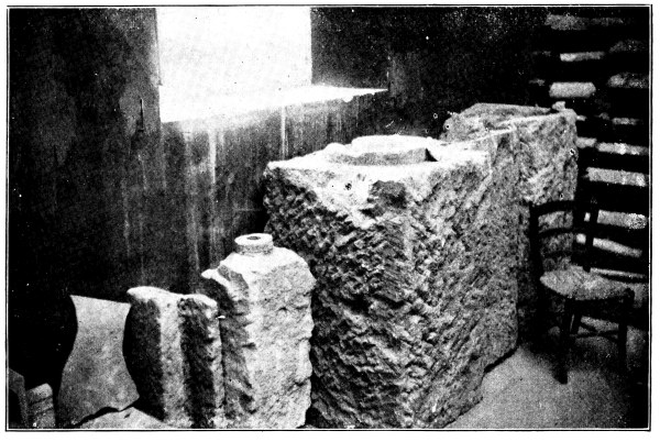
Roman water-pipe made of bored-out blocks of stone.
One of the methods mentioned by Vitruvius is plainly “the cut and
cover” procedure of the present day. In Duruy’s history of Rome a
tunnel over three miles long is mentioned on a line of an aqueduct at
Antibes in France, as well as another constructed to drain Lake Fucinus
in Italy, about A.D. 50. It is there stated that the latter
required eleven years’ labor of 30,000 men to build a rock tunnel with
a section of 86 to 96 square feet 18,000 feet long.
Lanciani, in his “Ancient Rome,” states that about A.D.
152 a Roman engineer (Nonius Datus) began the construction of a tunnel in
Algeria, and after having carefully laid out the axis of the tunnel
across the ridge “by surveying, and taking the levels of the
mountains,” left the progress of the work in the hands of the
contractor and his workmen. After the rather long absence from such
a work of four years he was called back by the Roman governor to
ascertain why the two opposite sections of the tunnel, as constructed,
would not meet, and to take the requisite measures for the completion
of the work through which water was to be conducted to Saldæ in
a suitable channel. He explains that there should have been no
difficulty, and that the failure of the two headings to meet was due to
the negligence of the contractor and his assistant, whom he states “had
committed blunder upon blunder,” although he writes, “As always happens
in these cases, the fault was attributed to the engineer.” He solved
the problem by connecting the two approximately parallel tunnels by a
transverse tunnel, so that water was finally brought to the city of Saldæ.
The art of tunnel construction has been one of the most widely
practised branches of Civil-Engineering from the times of the ancient
Assyrians, Egyptians, Greeks, Romans, and other ancient nations down to
the present.
48. Ostia, the Harbor of Rome.—The capacity of the ancient
Romans to build harbor-works is shown by what they did at Ostia, which
was then at the mouth of the Tiber, but is now not less than four miles
inland from the present shore line. At the Ostia mouth of the river the
present annual average advance seaward is not less than 30 feet, and at
the Fiumicino mouth about one third of that amount.
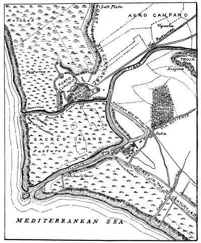
Fig. 13.—Plan of Ostia and Porto.
The ancient port of Ostia is supposed to have been founded during the
reign of the fourth king Ancus Marcius, but it attained its period of
greatest importance during the reign of Claudius and Trajanus. At that
time the fertile portions of the Campania had been so largely taken
up by the country-places of the wealthy Romans that it was no longer
possible for the peasantry to cultivate sufficient ground to yield the
grain required by the home market of the Romans. Large fleets were
consequently engaged in the foreign grain-trade of Rome. The wheat and
other grain required in great quantities was grown mostly in Egypt,
although Carthage and other countries supplied large amounts. The great
fleets occupied in this trade made ancient Ostia their Roman port. At
the present time it has no inhabitants, but is a group of complete
ruins, with its streets of tombs, baths, palaces, and temples, deeply
covered with the accumulations of many centuries. Enough excavations
have been made along the shores of the Tiber at this point to show that
the river was bordered with continuous and substantial masonry quays,
flanked on the land side by successions of great warehouses, obviously
designed to receive grain, wine, oil, and other products of the time.
The entrance to this harbor was difficult, as the mouth of the river
was shallow, with bars apparently obstructing its approach. There
were no jetties, or other seaward works for the protection of vessels
desiring to make the harbor. It is stated that during one storm nearly
or quite two hundred vessels were destroyed while they were actually in
the harbor.
49. Harbors of Claudius and Trajan.—The difficulty
in entering the mouth of the Tiber prompted the emperor Claudius to
construct another harbor to accommodate the vast commerce then centring
at the port of Rome. Instead of increasing the capacity of Ostia and
opening the mouth of the river by deepening it, he constructed a new
harbor on what was then the seashore, a short distance from Ostia, and
connected it with the Tiber by a canal, the extension of which by the
natural forces of the river has become the Fiumicino, the only present
navigable entrance to the river. This harbor was enclosed by two walls
stretching out from the shore, and converging on the sea side to a
suitable opening left for the entrance of ships. The superficial area
of this harbor was about 175 acres, but it became insufficient during
the time of Trajan. He then proceeded to excavate inland a hexagonal
harbor with a superficial area of about 100 acres, which was connected
both with the harbor of Claudius and the canal connecting the latter
with the Tiber. These harbor-works were elaborate in their fittings
for the accommodation of ships, and were built most substantially of
masonry. They showed that at least in some branches of harbor-work the
old Romans were as good engineers as in the construction of aqueducts,
bridges, and other internal public works. The harbors at ancient
Ostia, including those of Claudius and Trajan, were not the only works
of their class constructed by the Romans, but they are sufficient to
show as great advancement in harbor and dock work as in other lines of
engineering.
These harbors were practically defenceless and exposed to the
incursions of pirates, which came to be frequently and successfully
made in the days of the declining power of Rome. It was therefore
rather early in the Christian era that these attacks discouraged, and
ultimately drove away, first, the maritime business of the Romans and,
subsequently, all the inhabitants of these ports, leaving the pillaged
remnants of the vast harbor-works, warehouses, palaces, temples, and
other buildings in the ruined condition in which they are now found.
CHAPTER V.
50. Ancient Engineering Science.—The state of what may be
called the philosophy or science of engineering construction in
ancient Rome is admirably illustrated by the work on Architecture by
Marcus Vitruvius Pollio, who is ordinarily known as Vitruvius, and who
wrote probably a little more than two thousand years ago. He calls
himself an architect, and his work is a classic in that profession
of which he claims to be a member. Although much of his work was
purely architectural, a great portion of it, on the other hand, was
not architecture as we now know it, but civil-engineering in the best
sense of the term. It must be remembered, therefore, that what is here
written applies to that large portion of his work which is purely
civil-engineering.
It will be seen that although he understood really little or nothing
about the science of civil-engineering as we now comprehend it, he
perceived many of the general and fundamental principles of the best
practice of that profession and frequently applied them in a manner
which would do credit to a modern civil engineer. He not only laid
down axioms to govern the design of civil-engineering structures and
machinery for the transmission of power, but he also set forth many
considerations bearing upon public and private health and the practice
of sanitary engineering in a way that was highly creditable to the
state of scientific knowledge in his day. Speaking of the general
qualifications of an architect, remembering that that word as he
understood it includes the civil engineer, he states: “An architect
should be ingenious, and apt in the acquisition of knowledge; ... he
should be a good writer, a skilful draughtsman, versed in geometry and
optics, expert at figures, acquainted with history, informed on the
principles of natural and moral philosophy, somewhat of a musician, not
ignorant of the sciences both of law and physics, nor of the motions,
laws, and relations to each other of the heavenly bodies.” Again he
adds: “Moral philosophy will teach the architect to be above meanness
in his dealings and to avoid arrogance; it will make him just,
compliant, and faithful to his employer; and, what is of the highest
importance, it will prevent avarice gaining an ascendency over him; for
he should not be occupied with the thoughts of filling his coffers, nor
with the desire of grasping everything in the shape of gain, but by
the gravity of his manners and a good character should be careful to
preserve his dignity.”
These quaint statements of the desirable qualities of a professional
man are worthy to be considered rules of good professional living at
this time fully as much as they were in the days of old Rome. His
esteem for his profession was evidently high, but not higher than the
value which every civil engineer should put upon his professional
life. The need of a general education for a civil engineer is greater
now even than in his day, although musical accomplishments need not
be considered as essential in modern engineering practice. That
qualification, it is interesting to observe in passing, was inserted by
Vitruvius in order to illustrate the wide range of engineering practice
in those days when the architect-engineer was called upon, among other
things, to construct catapults and other engines of war, in which
a nice adjustment of gut ropes was determined by the musical tones
emitted under the desired tension.
51. Ancient Views of the Physical Properties of Materials.—When
it is remembered that the chemical constitution of materials used in
engineering was absolutely unknown, that no quantitative determination
of physical qualities had been made, and that the first correct
conception of engineering science had yet to be acquired, it is
a matter of wonder that there had been attained the engineering
development evidenced both by ancient writings like those of Vitruvius
and great engineering works like those of Rome, in the Babylonian Plain
and in Egypt. In discussing the problem of water-supply, he mentions
that certain learned ancients, “physiologists and philosophers,
maintained that there are four elements—air, fire, water, and
earth—and that their mixture, according to the difference of the
species, formed a natural mode of different qualities. We must
recollect that not only from these elements are all things generated,
but that they can neither be nourished nor grow without their
assistance.” This view of the construction of material things was not
conducive to a clear comprehension of those physical laws which lie at
the foundation of engineering science, and it is absolutely essential
that these elementary considerations be kept constantly in view in
considering the engineering attainments of the Romans and other ancient
peoples.
52. Roman Civil Engineers Searching for Water.—In ancient
times, as at present, it was very important in many cases to know
where to look for water, and how to make what might promise to be a
successful search for it. Vitruvius states that the sources of water
for a supply may easily be found “if the springs are open and flowing
above ground.” If the sources are not so evident, but are more obscure,
he recommends that “before sunrise one must lie down prostrate in the
spot where he seeks to find it, and, with his chin placed on the ground
and fixed, look around the place; for, the chin being fixed, the eye
cannot range upwards further than it ought and is confined to the
level of the place. Then where the vapors are seen curling together
and rising into the air, there dig, because those appearances are not
discovered in dry places.” This method of discovering water-supply
would be considered by modern engineers at least somewhat awkward as
well as damp and disagreeable in the early morning hours. It is not
more fantastic, however, or less philosophical than the use of the
divining-rod, which has been practised in modern times as well as
ancient, and is used even in some country districts at the present time.
Vitruvius does not forget that the local features, including both those
of soil and of an artificial character, may affect the quality of the
water and possibly make it dangerous. He, therefore, sets forth general
directions by which good potable water may be found and that of a
dangerous nature avoided. The necessity of distinguishing between good
and bad water was as present to his mind and to the minds of the old
Roman engineers as to civil engineers of the present day, but the means
for making a successful discrimination were crude and obviously faulty,
and very often unsuccessful. He set forth, what is well known, that
rain-water when collected from an uncontaminated atmosphere is most
wholesome, but proceeds to give reasons which would not now be
considered in the highest degree scientific.
In Chapter V of his Eighth Book there are described some “means of
judging water” so quaint and amusing that they may now well be quoted
even though no civil engineer would be bold enough to cite them in
modern hydraulic practice. He says: “If it be of an open and running
stream, before we lay it on, the shape of the limbs of the inhabitants
of the neighborhood should be looked to and considered. If they are
strongly formed, of fresh color, with sound legs and without blear
eyes, the supply is of good quality.” At another point he comes rather
closely to our modern requirements which look to the exclusion of
minute and elementary vegetable growths, when he says: “Moreover, if
the water itself, when in the spring, is limpid and transparent, and
the places over which it runs do not generate moss, nor reeds, nor
other filth be near it, everything about it having a clean appearance,
it will be manifest by these signs that such water is light and
exceedingly wholesome.”
53. Locating and Designing Conduits.—In treating of the
manner of conducting water in pipes or other conduits, he adverts to the
necessity of accurate levelling and the instruments that were used
for that purpose. The three instruments which he mentions as being
used are called the dioptra, the level (libra aquaria), and the
chorobates, the latter consisting of a rod about 20 feet in length,
having two legs at its extremities of equal length and at right angles
to it. Cross-pieces were fastened between the rod and the legs with
vertical lines accurately marked on them. These vertical lines were
placed in a truly vertical position by means of plumb-lines so that the
top of the rod was perfectly level, and the work could thus be made
level in reference to it.
In Rome the water was generally conducted either by means of open
channels, usually built in masonry for the purpose, or in lead pipes,
or in “earthen tubes.” Vitruvius states that the open channels should
be as solid as possible, and have a fall of not less than one half a
foot in 100 feet. The open channels were covered with an arch top, so
that the sun might be kept from striking the water. After bringing the
water to the city it was divided into three parts. One was for the
supply of pools and fountains, another for the supply of baths, and
a third for the supply of private houses. A charge was made for the
use of water for the pools, fountains, and baths, and in this way a
yearly revenue was obtained. A further charge was also made for the
water used in private houses, the revenue from which was applied for
the maintenance of the aqueduct which supplied the water. The treatment
to be given to the different soils, rocks, and other materials through
which the conduit was built which brought the supply to Rome is duly
set forth by Vitruvius, and he describes the conditions under which
tunnels were constructed. He also described the methods of classifying
the lead pipes through which water was conducted from the reservoirs
to the various points in the city after stating that they must be made
in lengths of not less than 10 feet. The sheets of lead employed in
the manufacture of the pipes he describes as ranging in width from 5
inches to 100 inches. The diameter of the pipe would obviously equal
very closely the width of the sheet divided by the ratio between the
circumference and the diameter of the corresponding circle.
54. Siphons.—He speaks of passing valleys in the construction
of the conduits by means of what we now call siphons, and prescribes a
method for relieving it of the accumulated air. In speaking of earthen
tubes or pipes he says that they are to be provided not less than 2
inches thick and “tongued at one end so that they may fit into one
another,” the joints being coated with quicklime and oil. He further
observes that water conducted through earthen pipes is more wholesome
than that through lead, and that water conveyed in lead must be
injurious because from it white lead is obtained, which is said to be
injurious to the human system. Indeed the effects of lead-poisoning
were recognized in those early days, and its avoidance was attempted.
In the digging of wells he wisely states that “the utmost ingenuity
and discrimination” must be used in the examination of the conditions
under which wells were to be dug. He also appreciated the advantage of
sedimentation, for he advises that reservoirs be made in compartments
so that, as the water flows from one to another, sedimentation may take
place and the water be made more wholesome.
55. Healthful Sites for Cities.—In the location of cities,
as well as of private residences, Vitruvius lays down the general
principle that the greatest care should be taken to select sites which
are healthy and subject only to clean and sanitary surroundings. Marshy
places and those subject to fogs, especially those “charged with the
exhalations of the fenny animals,” are to be avoided. Apparently this
reference to “fenny animals” may have beneath it the fundamental idea
of bacteria, but that is not certain. The main point of all these
directions for the securing of sanitary conditions of living is that,
so far as his technical knowledge permitted him to go, he insists on
the same class of wholesome conditions that would be prescribed by a
modern sanitary engineer.
56. Foundations of Structures.—Similarly in Chapter V
of his First Book, on “Foundations of Walls and Towers,” Vitruvius shows a
realization of the principal conditions needful and requisite for
the suitable founding of heavy buildings. After a sanitary site for
a city is determined and one that can be put in communication with
other people “by good roads, and river or sea navigation for the
transportation of merchandise,” he proceeds to state that “foundations
should be carried down to solid bottom, if such can be found, and
that they should be built thereon of such thickness as may be
necessary for the proper support of that part of the wall standing
above the natural level of the ground. They should be of the soundest
workmanship, and materials of greater thickness than the walls above.”
Again, in speaking of the foundations supporting columns, he states:
“The intervals between the foundations brought up under the columns
should be either rammed down hard, or arched, so as to prevent the
foundation-piers from swerving. If solid ground cannot be come to, and
the ground be loose or marshy, the place must be excavated, cleared,
and either alder, olive, or oak piles, previously charred, must be
driven with a machine as close to each other as possible and the
intervals between the piles filled with ashes. The heaviest foundations
may be laid on such a base.” It is thus seen that pile foundations were
used by the Romans, and that the piles were driven with a machine. It
would be difficult to give sounder general rules of practice even after
more than two thousand years’ additional experience.
57. Pozzuolana and Sand.—Of all the materials which were
useful to the Romans in their various classes of construction, including the
foundations of roads, “pozzuolana” must have been the most useful,
and that which contributed more to the development of successful
construction in Rome than any other single agent. Vitruvius speaks
of it frequently and gives rules not only for the use of it in the
production of mortar and concrete, but also lays down at considerable
length the treatment which should be given to lime in order to produce
the best results. It was common, according to his statements, to use
two measures of “pozzuolana” with one of lime in order to obtain
a suitable cementing material. This mixture was used in varying
proportions with sand and gravel or broken stone to produce concrete.
He describes the various grades of sands to be found about Rome and the
manner of using them. The statement is made that sand should be free of
earth and that the best of it was such as to yield a “grating sound”
when “rubbed between the fingers.” This is certainly a good engineering
test of sand. He prefers pit-sand to either river- or sea-sand; indeed
throughout all his directions regarding this particular class of construction
his rules might be used at the present time with perfect propriety.
58. Lime Mortar.—The old Romans had also discovered the
advisability of allowing lime to stand for a considerable period
of time after slaking. This insured the slaking of all those small
portions which were possibly a little hydraulic and therefore slaked
very slowly. He prescribes as a good proportion two parts of sand
to one of lime, and also mentions the proportion of three to one.
He attempts to explain the setting, as we term it, of lime, but his
explanation in obscure terms, involving qualities of the elements of
fire and air, is not very satisfactory.
59. Roman Bricks according to Vitruvius.—As is well known,
the Romans were good brick-makers, and they were well aware that bricks
made from “ductile and cohesive” “red or white chalky” earth were far
preferable to those made of more gravelly or sandy clay. The Roman
bricks were both sun-dried and kiln-burned.
60. Roman Timber.—Timber was a material much used by the
Romans, and the greater part of that which they used probably was
grown in Italy, although considerable quantities were imported from
other localities. Vitruvius writes in considerable detail concerning
the selection of timber while standing, as well as in reference to its
treatment before being used in structures. Like every material used
by the old Romans in construction, the various kinds and qualities of
timber received careful study from them, and they were by no means
novices in the art of producing the best results from those kinds of
timber with which they were familiar.
61. The Rules of Vitruvius for Harbors.—In Chapter XII of
his Fifth Book Vitruvius lays down certain general rules for the selection
and formation of harbors, and it is known that the Romans were familiar
with elaborate and effective harbor construction, as is shown by
that at Ostia. He appreciates that a natural harbor is one which has
“rocks or long promontories jutting out, which from the shape of the
place form curves or angles,” and that in such places “nothing more
is necessary than to construct portices and arsenals around them, or
passages to the markets.” He then proceeds to state that if such a
natural formation is not to be found, and that if “on one side there
is a more proper shore than on the other, by means of building or of
heaps of stones, a projection is run out, and in this the enclosures of
harbors are formed.” He then proceeds to explain how “pozzuolana” and
lime, in the proportion of two of the former to one of the latter, are
used in subaqueous construction. He also prescribed a mode of building
a masonry wall up from the bottom of an excavation made within what we
should call a coffer-dam, formed, among other things, “of oaken piles
tied together with chain pieces.” The Romans knew well how to select
harbors and how to construct in an effective manner the artificial
works connected with them, although it appears that the effects of
tidal and river currents in estuaries were neither well understood in
themselves nor in their transporting power of the solid material which
those currents eroded.
62. The Thrusts of Arches and Earth; Retaining-walls and
Pavements.—Although the Romans possessed little or no knowledge
of analytical mechanics they attained to some good qualitative
mechanical conceptions. Among other things they understood fairly
well the general character of the thrust of an arch and the tendency
of the earth to overthrow a retaining-wall. They knew that a massive
abutment was needed to receive safely the thrust of an arch, and they
counterforted or buttressed retaining-walls in order to hold them
firmly in place. They also realized the danger of wet earth pressing
against a retaining-wall, and even made a series of offsets or teeth
on the inside of the wall on which the earth rested in order to aid in
holding the wall in place. Vitruvius recommends as a safeguard against
the pressure of earth wet by winter rains that “the thickness of the
wall must be proportioned to the weight of earth against it,” and that
counterforts or buttresses be employed “at a distance from each other
equal to the height of the foundations, and of the same width as the
foundations,” the projections at the bottom being equal in thickness to
that of the wall, and diminishing toward the top.
He gives in considerable detail instructions for the forming of
pavements and stucco work, so many examples of which are still existing
in Rome. These rules are in many respects precisely the same as would
govern the construction of similar work at the present time. There are
also described in a general way the methods of producing white and
red lead, as pigments of paints, and a considerable number of other
pigments of different colors.
63. The Professional Spirit of Vitruvius.—It is evident,
from many passages in the writings of this Roman architect-engineer, that
the ways of the professional men in old Rome were not always such as
led to his peace of mind. Vitruvius utters bitter complaints which show
that he did not consider purely professional knowledge and service to
be adequately recognized or appreciated by his countrymen. He writes
that in the city of Ephesus an ancient law provided that if the cost of
a given work completed under the plans and specifications of an
architect did not exceed the estimate, he was commended “with decrees
and honors,” but if the cost exceeded the estimate with 25 per cent
added thereto, he “was required to pay that excess out of his own
pocket.” Then he exclaims, “Would to God that such a law existed among
the Roman people, not only in respect to their public but also to
their private buildings, for then the unskilful could not commit their
depredations with impunity, and those who were the most skilful in the
intricacies of the art would follow the profession!”
64. Mechanical Appliances of the Ancients.—It is well
known that the ancients possessed at least some simple types of machines,
for the reason that they raised many great stones to a considerable
height in completed works after having transported them great distances
from the quarries whence they were taken. Undoubtedly these machines
were of a simple and crude character and were made effective largely
by the power of great numbers of men. We are not acquainted with all
the details of these machines, although the general types are fairly
well known. The elementary machines, including the lever, the inclined
plane, the pulley, and the screw, which is only an application of the
inclined plane, were all used not only by the Romans, but probably by
every civilized ancient nation. Vitruvius describes a considerable
number of these machines, and from his descriptions it is clear that
they had wide application in the structural works of the Romans. The
block and fall, as we term the pulley at the present time, was a common
machine in the plant of a Roman constructor, as were also various
modifications and applications of the lever, the roller, and the
inclined plane.
65. Unlimited Forces and Time.—It is neither surprising
nor very remarkable that with the use of these simple machines, aided by
a practically unlimited number of men, the necessary raising or other
movement of heavy weights was accomplished by the Romans and other
ancient peoples. It is to be borne in mind that the element of time was
of far less consequence in those days than at present, and that the
rate of progress made in the construction of most if not all ancient
engineering works was what we should consider intolerably slow.
PART II. BRIDGES. — CHAPTER VI.
66. Introductory.—Although the bridge structures of
to-day serve the same general purposes as those served by the most ancient
structures, they are very different engineering products. It is not
long, in comparison with the historic and prehistoric periods during
which bridges have been built, since the science of mechanics has been
sufficiently developed to make bridge design a rational procedure; and
it is scarcely more than a century since the principles of mechanics
were first applied to the design of bridge structures in such a way as
to determine even approximately the amount of stress produced in any
member by the imposed load. Naturally the first efforts made toward a
truly rational bridge design were in fact simple and crude and only
loosely approximate in their results. Probably the first analytic
treatment of bridges was given to the design of arches in masonry and
then in cast-iron. As the action of forces in structures became better
known through the development of mechanical science, the applications
of the latter became less crude and approximate and the approach to the
refined accuracy of the present day was begun.
67. First Cast-iron Arch.—These older structures, nearly
all of them arches or more or less related to the arch, first appeared in
cast-iron in the latter part of the eighteenth century, when nothing
like an accurate analysis of forces developed by the application of a
given load was known. The first cast-iron arch was erected over the
Severn in England near Coalbrookdale in the year 1779. This bridge had
a span of 100 feet, and the under surface of the arch or soffit at the
crown was 45 feet above the points at the abutment from which the arch
sprang, or, as civil engineers put it, the arch had a span of 100 feet
and a rise or versine of 45 feet. Other cast-iron arches were built in
England soon after.
68. Early Timber Bridges in America.—Timber bridges have
been built since the earliest historic periods and even earlier, but the
widest and boldest applications of timber to bridge structures have
been made in this country, beginning near the end of the eighteenth
century and running to the middle of the nineteenth century, when
timber began to be displaced by iron. Timber bridges and those of
combined iron and timber are built to some extent even at the present
day, but the most extended work of this class is to be found in the
period just named.
In 1660 what was called the “Great Bridge” was built across the
Charles River near Boston, and was a structure on piles. Other similar
structures followed, but the first long-span timber bridge, where
genuine bridge trussing or framing was used, appears to have been
completed in 1792, when Colonel William P. Riddle constructed the
Amoskeag Bridge across the Merrimac River at Manchester, N. H., in
six spans of a little over 92 feet from centre to centre of piers.
From that time timber bridges, mostly on the combined arch and truss
principle, were built, many of them examples of remarkably excellent
engineering structures for their day. Among these the most prominent
were the Bellows Falls Bridge, in two spans of 184 feet each from
centre to centre of piers, over the Connecticut River, built in 1785-92
by Colonel Enoch Hale; the Essex-Merrimac Bridge over the Merrimac
River, three miles above Newburyport, Mass., built by Timothy Palmer
in 1792, consisting actually of two bridges with Deer Island between
them, the principal feature of each being a kind of arched truss of 160
feet span on one side of the island and 113 feet span on the other;
the Piscataqua Bridge, seven miles above Portsmouth, N. H., in which a
“stupendous arch of 244 feet cord is allowed to be a masterly piece of
architecture, planned and built by the ingenious Timothy Palmer of
Newburyport, Mass.,” in 1794; the so-called “Permanent Bridge” over
the Schuylkill River at Philadelphia, built in 1804-06 in two arches
of 150 feet and one of 195 feet, all in the clear, after the design
of Timothy Palmer; the Waterford Bridge over the Hudson River, built
in 1804 by Theodore Burr, in four combined arch and truss spans, one
of 154 feet, one of 161 feet, one of 176 feet, and the fourth of 180
feet, all in the clear; the Trenton Bridge, built in 1804-06 over
the Delaware River at Trenton, N. J., by Theodore Burr, in five arch
spans of the bowstring type, ranging from 161 feet to 203 feet in the
clear; a remarkable kind of wooden suspension bridge built by Theodore
Burr in 1808 across the Mohawk River at Schenectady, N. Y., in spans
ranging in length from 157 feet to 190 feet; the Susquehanna Bridge at
Harrisburg, Pa., built by Theodore Burr in 1812-16 in twelve spans of
about 210 feet each; the so-called Colossus Bridge, built in 1812 by
Lewis Wernwag over the Schuylkill River at Fairmount, Pa., with a clear
span of 340 feet 3¾ inches; the New Hope Bridge, built in 1814 over the
Delaware River, in six 175 feet combined arch and truss spans, and a
considerable number of others built by the same engineer.
Some of these wooden bridges, like those at Easton, Pa., and at
Waterford, N. Y., remained in use for over ninety years with only
ordinary repairs and with nearly all of the timber in good condition.
In such cases the arches and trusses have been housed and covered
with boards, so as to make what has been commonly called a covered
bridge. The curious timber suspension bridge built by Theodore Burr
at Schenectady was used twenty years as originally built, but its
excessive deflection under loads made it necessary to build up a pier
under the middle of each span so as to support the bridge structure
at those points. These bridges were all constructed to carry highway
traffic, but timber bridges to carry railroad traffic were subsequently
built on similar plans, except that Burr’s plan of wooden suspension
bridge at Schenectady was never repeated.

MOHAWK BRIDGE AT SCHENECTADY N.Y.
Built by Theodore Burr.
Fig. 1.

PATENT BRIDGE “COLOSSUS”
Across the River Schuylkill at Philadelphia.
Built by Lewis Wernwag.
Single Arch 340 feet 3¾ inches.
Fig. 2.
69. Town Lattice Bridge.—A later type of timber bridge
which was most extensively used in this country was invented by Ithiel Town
in January, 1820, which was known as the Town lattice bridge. This
timber bridge was among those used for railroad structures. As shown by
the plan it was composed of a close timber lattice, heavy plank being
used as the lattice members, and they were all joined by wooden pins at
their intersections. This type of timber structure was comparatively
common not longer ago than twenty-five years, and probably some
structures of its kind are still in use. The close latticework with its
many pinned intersections made a very safe and strong frame-work, and
it enjoyed deserved popularity. It was the forerunner in timber of the
modern all-riveted iron and steel lattice truss. It is of sufficient
significance to state, in connection with the Town lattice, that its
inventor claimed that his trusses could be made of wrought or cast-iron
as well as timber. In many cases timber arches were combined with them.
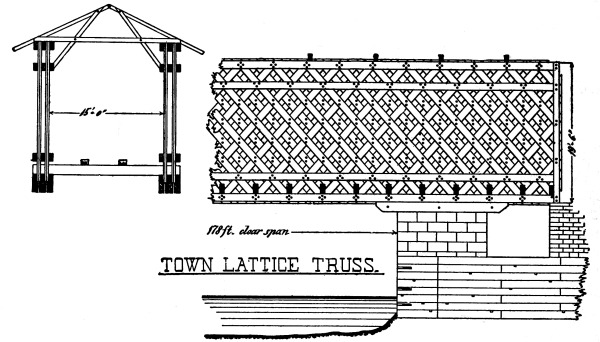
Fig. 3.
70. Howe Truss.—The next distinct advance made in the
development of bridge construction in the United States was made by
brevet Lieutenant-Colonel Long of the Corps of Engineers, U.S.A., in
1830-39, and by William Howe, who patented the bridge known as the
Howe truss, although the structure more lately known under that name
is a modification of Howe’s original truss. Long’s truss was entirely
of timber, including the keys, pins, or treenails required, and it was
frequently built in combination with the wooden arch. The truss was
considerably used, but it was not sufficiently popular to remain in use.
Howe Truss-Bridge.

Fig. 4.
The Howe truss was not an all-wooden bridge. The top and bottom
horizontal members, known as “chords,” the inclined braces between
them and the vertical end braces, all connecting the two chords, were
of timber, and they were bolted at all intersections; but the vertical
braces were of round iron with screw ends. These rods extended through
both chords and received nuts at both ends pressing on cast-iron
washers through which the rods extended. These wrought-iron round rods
were in groups at each panel-point, numbering as many as existing
stresses required. The ends of the timber braces abutted against
cast-iron joint-boxes. The railroad floor was carried on heavy timber
ties running entirely across the bridge and resting upon the lower
chord members. It was a structure simple in character, easily framed,
and of materials readily secured. It was also easily erected and could
quickly be constructed for any reasonable length of span. It possessed
so many merits that it became widely adopted and is used in modified
form at the present day, particularly on lines where the first cost
of construction must be kept as low as possible. The large amount of
timber in it and the simple character of its wrought-iron or steel
members greatly reduces its first cost.
71. Pratt Truss.—In 1844 the two Pratts, Thomas W. and Caleb,
patented the truss, largely of timber, which has since been perpetuated
in form by probably the largest number of iron and steel spans ever
constructed on a single type. The original Pratt trusses had timber
upper and lower chords, but the vertical braces were also made of
timber instead of iron, while the inclined braces were of round
wrought-iron with screw ends, the reverse of the web arrangement in the
Howe type. This truss had the great advantage of making the longest
braces (of iron) resist tension only, while the shorter vertical braces
resist compression. As a partially timber bridge it could not compete
with the Howe truss, because it contained materially more iron and
consequently was more costly. This structure practically closed the
period of development of timber bridges.
72. Squire Whipple’s Work.—What amounted to a new epoch
in the development of bridge construction in this country practically
began in 1840 when Squire Whipple built his first bowstring truss with
wrought-iron tension and cast-iron compression members. While the
Pratts and Howe had begun to employ to some extent the analysis of
stresses in the design of their bridge members, the era of exact bridge
analysis began with Squire Whipple. He subjected his bridge designs to
the exacting requirements of a rational analysis, and to him belongs
the honor of placing the design of bridges upon the firm foundation of
a systematic mathematical analysis.
73. Character of Work of Early Builders.—The names of
Palmer, Burr, and Wernwag were connected with an era of admirable engineering
works, but, with bridge analysis practically unknown, and with the
simplest and crudest materials at their disposal, their resources
were largely constituted of an intuitive engineering judgment of high
quality and remarkable force in the execution of their designs never
excelled in American engineering. They occasionally made failures, it
is true, but it is not recorded that they ever made the same error
twice, and the works which they constructed form a series of precedents
which have made themselves felt in the entire development of American
bridge-building.
CHAPTER VII.
74. Modern Bridge Theory.—The evolution of bridge
design having reached that point where necessity of accurate analysis
began to make itself felt, it is necessary to recognize some of the
fundamental theoretical considerations which lie at the base of modern
bridge theory, and which involve to a considerable extent that branch
of engineering science known as the elasticity or strength of the
materials used in engineering construction.
The entire group of modern bridge structures may be divided into simple
beams or girders, trusses, arches, suspension bridges, and arched ribs,
each class being adapted to carry either highway or railway traffic.
That class of structure known as beams or girders is characterized by
very few features. There are solid beams like those of timber, with
square or rectangular cross-sections, and the so-called flanged girders
which are constituted of two horizontal pieces, one at the top and the
other at the bottom, connected by a vertical plate running the entire
length of the beam. The fundamental theory is identically the same for
both and is known as the “common theory of flexure,” i.e., the theory
of beams carrying loads.
If an ordinary scantling or piece of timber of square or rectangular
cross-section, like a plank or a timber joist, so commonly used for
floors, be supported at each end, it is a matter of common observation
that it will sustain an amount of load depending upon the dimensions
of the stick and length of span. When such a bar or piece is loaded
certain forces or stresses, as they are called, are brought into action
in its interior. The word “stress” is used simply to indicate a force
that exists in the interior of any piece of material. It is a force and
nothing else. It is treated and analyzed in every way precisely as a
force. If the stresses or forces set up by the loading in the interior
of the bar become greater than the material can resist, it begins to
break, and the breaking of that portion of the timber in which the
stresses or forces are greatest constitutes its failure. The load which
produces this failure in a beam is called the breaking load of the
beam. In engineering practice all beams are so designed or proportioned
that the greatest load placed on them shall be only a safe percentage
of the breaking load; the safe load usually being found between ⅓ and ⅙
of the breaking load. In most buildings the safe or working load, as it
is called, is probably about ¼ of the breaking load.
75. The Stresses in Beams.—The proper design of beams or
girders to carry prescribed loads is based upon the stresses which are
developed or brought into action by them. It can easily be observed
that if a beam supported at each end be composed of a number of thin
planks or boards placed one upon the other, it will carry very little
load. Each plank or board acts independently of the others and a
very small load will cause a sag, as shown in Fig. 6.
If there be taken, on the other hand, a beam made of a single stick of
timber of the same width and depth as the number of planks shown in
Fig. 6, so as to secure the solid beam shown
in Fig. 7, it is a further common observation
that this latter beam may carry many times the load which the laminated
beam, shown in Fig. 6, sustains. The thin
planks or boards readily slide over each other, so that the ends
present the serrated form shown in Fig. 6. The
preventing of this sliding is the sole cause of the greatly increased
stiffness of the solid beam shown in Fig. 7,
for there is thus developed along the imaginary horizontal sections
in the solid beam of Fig. 7 what are called
shearing forces or stresses; and since they exist on horizontal
sections or planes running throughout the entire length of the beam,
they are called horizontal shears.
At each end of the beam shown in Fig. 7
there will be an upward or supporting force exerted by the abutments
on which the ends of the beam rest. Those upward or supporting forces
are shown at R and R′ and are called reactions, because
the abutments, so to speak, react against the ends of the beam when the
latter is loaded. These reactions depend for their value on the amount
and the location of the loading which the beam carries. Obviously these
upward forces or reactions tend to cut or shear off the ends of the
beam immediately above them, and if the loads were sufficiently large
and the beam kept from bending, the reactions would actually shear off
those ends, just as punches or shears in a machine-shop actually shear
off the metal when the rivet-hole is punched, or when a plate is cut
by shearing into two parts. The beam, however, bends or sags before
shearing apart actually takes place.
Fig. 8.
Fig. 9.
76. Vertical and Horizontal Shearing Stresses.—If it be
supposed that the length of the beam is divided into a great number of
parts by imaginary vertical lines, like those shown in Fig. 8,
then vertical shearing forces will be developed in those vertical planes and
sometimes, though not often, they are enough to cause failure. It is
not an uncommon thing, on the other hand, in timber to have actual
shearing failure take place along a horizontal plane through the centre
of the beam. Indeed this is recognized frequently as the principal
method of failure in very short spans. When this horizontal shearing
failure takes place, the upper and lower parts of the beam slide over
each other and act precisely like the group of planks shown in Fig. 6.
If, then, the loaded beam be divided by vertical and horizontal
planes into the small rectangular portions shown in Figs. 8
and 9, on each such vertical and horizontal
imaginary plane there will be respectively vertical and horizontal
shearing forces, which are shown by arrows in Fig. 9.
It will be noticed in that figure that in each corner of the rectangle
the two shearing forces act either toward or from each other; in no
case do the two adjacent shearing forces act around the rectangle in
the same direction. This is a condition of shearing stresses peculiar
to the bent beam. It can be demonstrated by theory and is confirmed
by experiment. There is a further peculiarity about these shearing
forces which act in pairs either toward or from the same angle in any
rectangle, and it is that the two stresses adjacent to each other have
precisely the same value per square inch (or any square unit that may
be used) of the surface on which they act. These stresses per square
inch vary, however, either along the length of the beam or as the
centre line of any normal cross-section is departed from. They are
greatest along the centre line or central horizontal plane represented
by AB, and they are zero at the top and bottom surfaces of the beam.
Inasmuch as the horizontal shear along the plane AʹBʹ is less
than that along AB in Fig. 9, a part of the
latter has been taken up by the horizontal fibres of the beam lying between
the two planes. In other words, the horizontal layer of fibres at AʹBʹ
is subjected to a greater stress or force along its length than at
AB. The same general observation can be made in reference to any
horizontal layer of fibres that is farther away from the centre than
another. Hence the farther any fibre is from the centre the greater
will be the stress or force to which it is subjected in the direction
of its length. It results, then, that the horizontal layers of fibres
which are farthest from the centre line of the beam, i.e., those at
the exterior surfaces, will be subjected to the greatest force or
stress, and that is precisely what exists in a loaded beam whatever the
material may be.
77. Law of Variation of Stresses of Tension and
Compression.—Since a horizontal beam supported at each end is
deflected or bent downward when loaded, it will take a curved form like
that shown in either Fig. 7 or Fig. 10;
but this deflection can only take place by the shortening of the top of
the beam and the lengthening of its bottom. This shows that the upper
part of the beam is compressed throughout its entire length, while the
lower part is stretched. In engineering language, it is stated that the
upper part of the beam is thus subjected to compression and the lower
part to tension. The horizontal layers or fibres receive their tension
and compression from the vertical and horizontal shearing forces in the
manner already explained. If the conditions of loading of the bent beam
should be subjected to mathematical analysis, it would be found that
throughout the originally horizontal plane AB, Fig. 7,
passing through the centre of each section there would be no stress of
either tension or compression, although the horizontal shearing stress
there would be a maximum. Further, as this central plane is departed
from the stress of tension or compression per square inch in any
vertical section would be found to increase directly as the distance
from it. This is a very simple law, but one of the greatest importance
in the design of all beams and girders, whatever may be the form or
size of cross-section. It is a law, which applies equally to the solid
timber beam and to the flanged steel girder, whether that girder be
rolled in the mill or built up of plates and angles or other sections
in the shop. It is a fundamental law of what is called the common
theory of flexure, and is the very foundation of all beam and girder
design. The horizontal plane represented by the line AB in Fig. 8,
along which there is neither tension nor compression, is called the
“neutral plane,” and its intersection with any normal cross-section of
the beam is called the “neutral axis” of that section. Mathematical
analysis shows that the neutral plane passes through the centres of
gravity of all the normal sections of the beam and, hence, that the
neutral axis passes through the passes through the centre of gravity of
the section to which it belongs.
78. Fundamental Formulæ of Theory of Beams.—The fundamental
formulæ of the theory of loaded beams may be quite simply written.
Fig. 10 exhibits in a much exaggerated manner
a bent beam supporting any system of loads W₁, W₂,
W₃, etc., while Fig. 11 shows a normal
cross-section of the same beam. In Fig. 10
AB is the neutral line, and in Fig. 11
CD is the neutral axis passing through the centre of gravity,
c.g., of the section.
Fig. 10.
Fig. 11.
If a is the amount of force or stress on a square inch (or
other square unit), i.e., the intensity of stress, at the distance of
unity from the neutral axis CD of the section, then, by the
fundamental law already stated, the amount acting on another square
inch at any other distance z from the neutral axis will be
az. This quantity is called the “intensity of stress” (tension
or compression) at the distance z from the neutral axis.
Evidently it has its greatest values in the extreme fibres of the
section, i.e., ad and ad₁. At the neutral axis az
becomes equal to zero. FG in Fig. 11 represents
the same line as FG in Fig. 10. If the line
FH in Fig. 11 be laid down equal to ad
and at right angles to FG, and if O represent the
centre of gravity, c.g., of the section, then let the straight
line LH be drawn. Any line drawn parallel to FH from
FG to LH will represent the intensity of stress in the
corresponding part of the beam’s cross-section. Obviously, as these
lines are drawn in opposite directions from FG, those above
O will indicate stress of one kind, and those below that point
stress of another kind, i.e., if that above be tension, that below
will be compression. It can be demonstrated by a simple process that
the total tension on one side of the neutral axis is just equal to
the total compression on the other side, and from that condition it
follows that the neutral axis must pass through the centre of gravity
or centroid of the section.
Returning to the left-hand portion of Fig. 11,
let dA represent a very small portion of the cross-section; then
will az. dA be the amount of stress acting on it. The moment of
this stress or force about the neutral axis will be
azdA·z = az²· dA.
If this expression be applied to every small portion of the entire
section, the aggregate or total sum of the small moments so found will
be the moment of all the stresses in the section about the neutral
axis. That moment will have the value
| M = |
∫az²· dA |
= a ∫z²· dA |
= aI.(1) |
In equation (1) the symbol ∫
means that the sum of all the small quantities to the right of it
is taken, and I stands for that sum which, in the science of
mechanics, is called the moment of inertia of the cross-section about
its neutral axis. The value of the quantity I may easily be
computed for all forms of section. Numerical values belonging to all
the usual forms employed in engineering practice are found in extended
tables in the handbooks of the large iron and steel companies of the
country, so that its use ordinarily involves no computations of its value.
Equation (1) may readily be changed into two other forms for convenient
practical use. In Fig. 10 mn is supposed
to be a very short portion of the centre line of the beam represented
by dl. Before the beam is bent the section FG is supposed
to have the position MN parallel to PQ. Also let u
be the small amount of stretching or compression (shortening) of
a unit’s length of fibre at unit’s distance from the centre line
AB of the beam, then will udl and uzdl be the
short lines parallel to GN in the triangle GmN shown
in the figure. The point C is the
centre of curvature of the line mn, and Cn = Cm is the
radius. The two triangles Cnm and mNG are therefore
similar, hence
| udl |
= |
mn |
= |
dl |
; ∴ u = |
I |
(2) |
| I |
ρ |
ρ |
ρ |
If the quantity called the coefficient or modulus
of elasticity be represented by E, then, by the fundamental law
of the theory of elasticity in solid bodies,
a = Eu. (3)
As has already been shown, the greatest stresses (intensities) in the
section are +ad (tension) and -ad₁ (compression). If
K represent that greatest intensity of stress, then
If the value of a from equation (4) be
substituted in equation (1),
79. Practical Applications.—Equation (5)
is a formula constantly used in engineering practice. All quantities in the second
member are known in any given case. K is prescribed in the
specifications, and is known as the “working resistance” in the design
of beams and girders. For rolled steel beams in buildings it is
frequently taken at 16,000 pounds, i.e., 16,000 pounds per square inch,
about one fourth the breaking strength of the steel. In railroad-bridge
work it may be found between 10,000 and 12,000 pounds, or approximately
one fifth of the breaking strength of the steel. The quantities
I and d depend upon the form and dimensions of the
cross-section, and are either known or may be determined. The quotient
I ÷ d is now known as the “section modulus,” and its numerical
values for all forms of rolled beams can be found in published tables.
The use of equation (5) is therefore in the highest
degree convenient and practicable.
80. Deflection.—It is frequently necessary, both in the design
of beams and framed bridges, to ascertain how much the given loading
will cause the beam or truss to sag, or, in engineering language, to
deflect below the position occupied when unloaded. The deflection is
determined by the sagging in the vertical plane of the neutral line
below its position when the structure carries no load. In Fig. 10
the curved line AB is the neutral line of the beam when supporting
loads. If the loads should be removed, the line AB would return
to a horizontal position. The line drawn horizontally through A
and indicated by x is the position of the centre line of the
beam before being bent. The vertical distance w below this
horizontal line shows the amount by which the point at the end of the
line x is dropped in consequence of the flexure of the beam.
The vertical distance w is therefore called the deflection.
Evidently the deflection varies with the amount of loading and with the
distance from the end of the beam. The curved line AB in one
special case only is a circle. The general character of that curve is
determined by the loading and the length of span.
In order that the deflection may be properly considered it is necessary
that the relation between x and w shall be established
for all conditions of loading and length of span. If the value of
u from equation (2) be placed in
equation (3), there will result
If the value of a from equation (6) be substituted in the last
member of equation (1), there will at once result
It is established by a very simple process in differential calculus that
Hence, substituting from equation (8) in
equation (7),
Equation (9) may be used by means of some
very simple operations in integral calculus to determine the value
of w in terms of x and the loads on the beam when the
value of the bending moment M is known, and the procedures for
determining that quantity will presently be given.
Using the processes of the calculus, the two following equations will
immediately be found:
As already explained, numerical values for both E and
I may be taken at once from tables already prepared for
all materials and for all shapes of beams ordinarily employed in
structural work, so that equation (11) enables
the deflection or sag of the bent beam to be computed in any case.
The expression dw/dx is the tangent of the angle made by the
neutral line of a bent beam with a horizontal line at any given point,
and it is a quantity that it is sometimes necessary to determine.
dw and dx are indefinitely short vertical and horizontal
lines respectively, as shown immediately to the left of B in
Fig. 10.
Equation (11) is not used in structural work
nearly as much as equation (5), but both of them
are of practical value and involve only simple operations in their use.
81. Bending Moments and Shears with Single Load.—The second
members of equations (5) and (9)
exhibit values of the moments of the internal forces or stresses in any normal
cross-section of a bent beam about the neutral axis of the section, while the
values of Mmust be expressed in terms of the external forces or loading.
Inasmuch as the latter moment develops just the internal moment, it is obvious
that the two must be equal. In order to write the value of the external
moment in terms of any loading, it is probably the simplest procedure
to consider a beam carrying a single load. In Fig. 12,
AB is such a beam, and W is a load which may be placed
anywhere in the span, whose length is l. The distances of the
load from the abutments are represented by x₁ and x₂.
The reactions or supporting forces exerted under the ends of the beam
at the abutments are shown by R and R′. The reactions,
determined by the simple law of the lever, are
| R |
= W |
x₂ |
and |
Rʹ |
= W |
x₁ |
(12) |
| l |
l |
The greatest bending moment in the beam will occur
at the point of application of the load, and its value will be
| M₁ |
= Rx₁ |
= W |
x₁x₂ |
= - Rʹx₂ |
(13) |
| l |
| M₁ |
= Rx₁ |
= - Rʹx₂ |
= W |
x₁x₂ |
| l |
Fig. 12.
The bending moments at the end of the beam are obviously zero, and
the second and fourth members of equation (13) show that
the moment increases directly as the distance from either end. Hence in the lower
portion of Fig. 12, at D, immediately
under the load W, the line DC is laid off at any
convenient scale to represent the moment M₁. The straight
lines AC and CB are then drawn. Any vertical intercept,
as FH or KL, between AB and either AC
or CB will represent the bending moment at the corresponding
point in the beam. The simple triangular diagram ACB therefore
represents the complete condition of bending of the beam under the
single load W placed at any point in the span.
The beam AB is supposed for the moment to have no weight.
Consequently the only force acting upon the portion of the beam
AO is the reaction R, and, similarly, Rʹ is the
only force acting upon the portion OB. Obviously so far as
the simple action of these two forces or reactions is concerned, the
tendency of each is to cause vertical slices of the beam, so to speak,
to slide over each other. In other words, in engineering language,
the portion AO of the beam is subjected to the shear S =
R, while OB is subjected to the shear Sʹ = -Rʹ. The
cross-sectional area of the beam must be sufficient to resist the shear
S or Sʹ. The upper part of Fig. 13
shaded with broken vertical lines indicates this condition of shear.
It is evident from this simple case that the total vertical shears at
the ends of any beam will be the reactions or supporting forces exerted
at those ends, and that each will remain constant for the adjoining
portion of the beam.
The third member of equation (13) shows that
the greatest bending moment M₁ in the beam varies as the product
x₁x₂ of the segments of the span. That product will have
its greatest value when x₁ = x₂. Hence a simple beam
loaded by a single weight will be subjected to the greatest possible
bending moment when the weight is placed at the middle of the span, at
which point also that moment will be found.
82. Bending Moments and Shears with any System of Loads.—The
general case of a simple beam loaded with any system of weights
whatever may be represented in Fig. 13, in which
the beam of Fig. 12 is supposed to carry three
loads, w₁, w₂, w₃. The spacing of the loads is
as shown. The reactions or supporting forces Rʹ are determined
precisely as in Fig. 12, each reaction in
this case being the resultant of three loads instead of one. Applying
the law of the lever as before, the reaction R will have the value
| R |
= W₃ |
+ |
d |
+ |
W₂ |
d + c |
+ |
W₁ |
d + c + b |
(14) |
| l |
l |
l |
A similar value may be written for Rʹ, but it is probably
simpler, after having found one reaction, to write
R′ = W₁ + W₂ + W₃ - R.(15)
As the beam is supposed to have no weight, no load will act upon the
beam between the given weights. The bending moments at the points of
application of the three weights or loads will be
| M₁ = Ra, |
 |
(16) |
| M₂ = R(a + b) - W₁b, |
| M₃ = R(a + b + c) - W₁(b + c) - W₂c. |
After substituting the value of R from
equation (14) in equations (16)
the values of the latter are at once known.
Fig. 13.
The bending produced by each weight will also be represented precisely
like that in Fig. 12. The triangle ANB represents
the bending produced by W₁; AOB the bending produced by W₂;
and APB the bending produced by W₃. The resultant bending
effect produced by the three loads or weights acting simultaneously
is simply the summation of the three effects each due to a single
load. Hence DC is erected vertically through the point of
application of W₁, so as to equal DN added to the two
vertical intercepts between AB and AP, and AB
and AO. Similarly, HF is equal to HO added to
the intercepts between AB and AP, and AB and
BN. Finally, KL is equal to PL added to the other
two intercepts, one between AB and BN, and the other
between AB and BO. Straight lines then are drawn through
A, C, F, K, and B. Any vertical
intercept between AB and ACFKB will represent the bending
moment in the beam at the corresponding point. Obviously any number of
loads of any magnitude, or a uniform load, may be treated in precisely
the same way.
An important practical rule can readily be deduced from the equations
(16), each one of which may be regarded as a general equation of
moments. If the system of three, or any other number of loads, be moved
a small distance Δx, while they all remain separated by the same
distances as before, the bending moment M will be changed by the
amount shown in equation (16a):
ΔM = RΔx - W₁Δx - W₂Δx - etc.(16a)
If the notation of the differential calculus be used by writing
the letter d instead of Δ, and if both members of equation (16a)
be then divided by dx, equation (16b) will result:
| ΔM |
= |
dM |
= |
R - W₁ - W₂ - etc. = shear. (16b) |
| Δx |
dx |
The second member of this equation shows the sum of all the external
forces acting on one portion of the beam, that portion being limited
by the section about which the moment M acts. That sum of
all the external forces, as given by the second member of equation
(16b), is evidently the total transverse shear at the section
considered. Equation (16b) then shows, in the language of the
differential calculus, that the first derivative of M in respect
to x is equal to the total transverse shear. It is further
established in the differential calculus that whenever a function,
such as M, the bending moment, is a maximum or a minimum, the
first derivative is equal to zero. The application of this principle
to equation (16b) shows that the bending moment in
any beam or truss has its greatest value wherever the shear is zero. Hence, in
order to determine at what section the bending moment has its greatest
value in any loaded beam carrying a given system of loads, it is only
necessary to sum up all the forces or loads, including the reaction
R, on that beam from one end to the point where that sum or
shear is zero; at this latter point the greatest moment sought will be
found. This is a very simple method of determining the section at which
the greatest moment in the beam exists.
The preceding formulæ and diagrams may be extended to include any
number of loads, and they are constantly used in engineering practice,
not only for beams and girders in buildings, but also for bridges
carrying railroad trains. Whatever may be the number of loads,
the expressions for the bending moments at the various points of
application of those loads are to be written precisely as indicated in
equations (16). When the number of loads becomes
great the number of terms in the equations correspondingly increase, but
in reality they are just as simple as those for a smaller number of loads.
The diagram for the vertical shear in this beam is the lower part
of Fig. 13. As in the case of Fig. 12
the shear at A is the reaction R, as it is Rʹ at
the other end of the beam. The shear in the portion AD of the
beam has the value R, but in passing the point D to the
right the weight W₁ represented by OT must be subtracted
from R, so that the shear over the section b of the
span is R - W₁ or QV in the diagram. Similarly,
in passing the point H toward the right, both W₂ and
W₁ must be subtracted from R, giving the negative shear
(the previous shear being taken positive) VW. The negative shear
VW remains constant throughout the distance c, but is
increased by W₃ at the point L, so that throughout the
distance d the shear Sʹ = -Rʹ. These shear values
are all shown in the lower portion of Fig. 13
by the vertical shaded lines. Obviously it is a matter of indifference
whether the shear above the straight line GJ is made positive
or negative; it is only necessary to recognize that the signs are different.
In the case of heavy beams, either built or rolled, as in railroad
structures, it is of the greatest importance to determine both the
bending moments and the shears, as represented in the preceding
equations and diagrams, and to provide sufficient metal to resist them.
The case of Fig. 13 is perfectly general
for moments and shears, and the methods developed are applicable to any
amount or any system of loading whatever.
83. Bending Moments and Shears with Uniform Loads.—Fig. 14
represents what is really a special case of Fig. 13, in which the
loading is uniform for each unit of length of the beam throughout
the whole span l. Inasmuch as the load is uniformly distributed,
it is evident that the reaction at each end of the beam
will be one half the total load, or
Fig. 14.
The general expression for the bending moment at any point G in
the span, and located at the distance x from the end A,
will take the form
| M = Rx - wx |
. |
x |
= |
w |
x(l-x).(18) |
| 2 |
2 |
This equation, giving the value of M, is
the equation of a parabola with the vertex over the middle of the span.
The bending moment at the latter point will be found by placing x =
l/2 in equation (18), which will give
Hence, in Fig. 14, if the vertical line
DC be erected at D, so as to represent the value
of M in equation (19) to a convenient scale, the
parabola ACB may be at once drawn. Any vertical intercept, as GF
between AB and the curve AFCB, will represent by the same
scale the bending moment in the beam at the point indicated by the
intercept. Equation (19), giving the greatest external
bending moment in a simple beam due to a uniform load, is constantly employed in
structural work, and shows that that moment is equal to the total
load multiplied by one eighth of the span.
It has already been shown, in connection with Fig. 12,
that when a single centre weight rests on a beam the centre bending moment is
equal to that weight multiplied by one fourth the span. If the total
uniform load in the one case is equal to the single load in the other,
these equations show that the single centre load will produce just
double the bending moment due to the same load uniformly distributed
over the span. Wherever it is feasible, therefore, the load should be
distributed rather than concentrated at the centre of the span.
That portion of Fig. 14 shaded with
vertical lines shows the shear existing in the beam. Evidently the
shear at each end is equal to the reaction, or one half the total load
on the span. The expression for the shear at any point, as G,
distant x from A will be
| S = R - wx = w |
( |
l |
- x |
) |
(20) |
| 2 |
If x = l/2 in equation (20), S becomes equal
to zero. In other words, there is no shear at the centre of the span of a beam
uniformly loaded. Hence, if at each end of the span a vertical line
AK or BL be laid off downward, and if straight lines
KD and DL be drawn, any vertical intercept, as GH,
between these lines and AB will represent the shear at the
corresponding point. Equation (20) also shows that the
shear S at any point is equal to the load resting on the beam between the
centre D and that point. Although this case of uniform loading
is a special one it finds wide application in practical operations.
84. Greatest Shear for Uniform Moving Load.—The preceding
loads have been treated as if they were occupying fixed positions on
the beams considered. This is not always the case. Many of the most
important problems in connection with the loading of beams and bridges
arise under the supposition that the load is movable, like that of a
passing railroad train. One of the simplest of these problems, although
of much importance, consists in finding the location of a uniform
moving load, like that of a train of cars, which will produce the
greatest shear at a given point of a simple beam, such as that
represented in Fig. 15, in which a moving load
is supposed to pass continuously over the span from the left-hand end
A. It is required to determine what position of this uniform
load will produce the greatest shear at the section C.
Fig. 15.
Let the moving load extend from A to any point D to the
right of C. The two reactions R and Rʹ may be
found by the methods already indicated. Let W represent the
uniform load resting on the portion CD of the span. The shear
S′ existing at C will be
Sʹ = Rʹ - W.(21)
Let R‴ be that part of Rʹ which is due to W, and
Rʺ that part due to the load on AC. Evidently R‴
is less than W; then
Sʹ = Rʺ + R‴ - W.(22)
Since the negative quantity W is greater than the positive
quantity R‴, S′ will have its greatest value when both
W and R‴ are zero. Hence the greatest shear at the point
C will exist when
Sʹ = Rʺ.(23)
Obviously the loading must extend at least from A to C in
order that Rʺ may have its maximum value. Hence the greatest
shear at any section will exist when the uniform load extends from the
end of the span to that section, whatever may be the density of the load.
If the segment of the span covered by the moving load is greater than
one half the span, the maximum shear is called the main shear;
but if that segment is less than one half the span, the maximum shear
is called the counter-shear. The reason for these two names will
be apparent later in the discussion of bridge-trusses.
This rule for determining the maximum shear at any section of a beam is
equally applicable to bridge-trusses under certain conditions, and has
an important bearing upon the determination of the greatest stresses in
some of the members of bridge-frames, although it has less importance
now than it had in the earlier days of bridge-building.
85. Bending Moments and Shears for Cantilever Beams.—The case
of a loaded overhanging beam or cantilever bracket, as shown in Fig. 16,
is sometimes found. In that figure a single weight W is
supposed to be applied at the end, while a uniform load w per
unit of length extends over its length l. The bending moment at
any point C distant x from the end will obviously be
Fig. 16.
The greatest value of the bending moment will be
found by placing x equal to l in equation (24), and it
will have the value
The shear at any point and at the end A
respectively will be
S = W + wx and S₁ = W + wl. (26)
The shear due to W is equal to itself and
is constant throughout the whole length of the beam.
The second term of the second member of equation (24) is the equation
of a parabola with its vertex at B, Fig. 16. Hence
if AF be laid off equal to (wl²) /2, and
if the parabola FHB be drawn, any vertical intercept, as HK,
between that curve and AB will represent the bending moment
at the corresponding point. On the other hand, the first term of the
second member of equation (24) shows that the bending moment due to
W varies directly as the distance from B. Hence if
AG be laid off vertically downward from A equal to
Wl to any convenient scale, then any intercept, as KL,
between AB and BG will represent the bending moment due
to W at the corresponding point of the beam.
86. Greatest Bending Moment with any System of Loading.—One
of the most important positions of loading to be established either for
simple beams or for bridge-trusses is that at which any given system
of loading whatever is to be placed on any span so as to produce the
maximum bending moment at any prescribed point in that span. In order
to make the case perfectly general a system of arbitrary loads, like
that shown in Fig. 17, is assumed and the system
is supposed to be a moving one.
Fig. 17.
The separate loads are placed at fixed distances apart, indicated by
the letters a, b, c, d, etc., W₁
being supposed to be at the head of the train, while W is
the last load having a variable distance x between it and the
end of the span. In Fig. 17 this system of
moving loads or train is supposed to pass over the span l from
right to left. The problem is to determine the position of the loading,
so that the bending moment at the section C of the beam or
truss will be a maximum, the section C being at the distance
lʹ from the left-hand end of the span. The complete analysis of
this problem is comparatively simple and may readily be found, but it
is not necessary for the accomplishment of the present purpose to give
it here. In order to exhibit the formula which expresses the desired
condition, let Wₙʹ be that weight which is really placed at
C, but which is assumed to be an indefinitely short distance to
the left of that point, for a reason which will presently be explained.
The equation of condition or criterion sought will then be the
following:
| lʹ |
= |
W₁ + W₂ + ... + Wₙʹ |
(27) |
| l |
W₁ + W₂ + W₃ + ... + Wₙ |
If the loads are so placed as to fulfil the condition expressed in
equation (27), the bending moment at section C
will be a maximum. If the variation in the train weights is very great, it
is possible that there may be more than one position of the train which
will satisfy that equation. It is necessary, therefore, frequently
to try different positions of the loading by that criterion and then
ascertain which of the resulting maximum moments is the greatest. It
is not usually necessary to make more than one or two such trials. The
application of the equation is therefore simple and involves but little
labor.
It will usually happen that Wₙʹ in equation (27)
is not to be taken as the whole of that weight, but only so much of it as may be
necessary to satisfy the equation. This is simply assuming that any
weight, W, may be considered as made up of two separate weights
placed indefinitely near to each other, which is permissible.
After having found the position of loading which satisfies equation
(27), the resulting maximum bending moment will take the following form:
| M₁ |
= |
lʹ |
[ |
W₁a + (W₁+ W₂)b + ... + (W₁ + W₂ + ... + Wₙ)x |
] |
| l |
| - |
W₁a - (W₁ + W₂)b - ... - (W₁ + W₂ + ... + W₍ₙʹ₋₁₎)(?). |
(28) |
In this equation x corresponds to the position of loading for
maximum bending, while the sign (?) represents the distance between
the concentrations W₍ₙʹ₋₁₎ and Wₙʹ. This equation has
a very formidable appearance, but its composition is simple and it
is constantly used in making computations for the design of railroad
bridges. The loads W₁, W₂, W₃, etc., represent the
actual weights on the driving-axles and other axles of locomotives,
tenders, and cars, and the spacings a, b, c, etc.,
are the actual spacings found between those axles. In other words,
these quantities are the actual weights and dimensions of the different
portions of moving railroad trains.
The computations indicated by equation (28) are not made
anew in every instance. Concentrated weights of typical locomotives, tenders, and
cars are prescribed by different railroad companies for their different
classes of trains, ranging from the heaviest freight traffic to the
lightest passenger train. A tabulation is then made from equation
(28) for each such typical train, and it is used as frequently as is
necessary to design a bridge to carry the prescribed traffic. The
tabulations thus made are never changed for a given or prescribed
loading.
87. Applications to Rolled Beams.—It is to be remembered
that these last observations do not limit the use of equations (27)
and (28) to railroad-bridge trusses only; they are equally applicable to
solid and rolled beams and are frequently used in connection with
their design. Great quantities of these beams and various rolled steel
shapes are used in the construction of large modern city buildings, as
well as in railroad and highway bridge structures. The steel frames
of the great office buildings, so many of which are seen in New
York and Chicago as well as in other cities, which carry the entire
weight of the building, are formed wholly of these steel shapes. The
so-called handbooks published by steel-producing companies exhibit the
various shapes rolled in each mill. These books also give in tabular
statements many numerical values of the moment of inertia, the section
modulus, and other elements of all these sections, so that the formulæ
which have been established in the preceding pages may be applied in
practical work with great convenience and little labor. Tables are
also given showing the sizes of rolled beams required to sustain the
loads named in them. Such tables are formed for practical use, so that,
knowing the distance apart of the beams, their span, and the load per
square foot which they carry, the required size of beam may be selected
without even computation. Such labor-saving tables are quite common
at the present time, and they reduce greatly the labor of numerical
computations.
CHAPTER VIII.
88. The Truss Element or Triangle of Bracing.—A number of the
preceding formulæ find their applications to bridge-trusses, as well
as to beams; hence it is necessary to give attention at least to some
simple forms of those trusses.
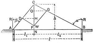
Fig. 18.
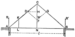
Fig. 18a.
The skeleton of every bridge-truss properly designed to carry its load
is an assemblage of triangles. In other words, the truss element,
i.e., the simplest possible truss, is the triangular frame, such as is
shown in skeleton in Figs. 18 and 18a.
These simple triangular frames are sometimes called the King-post
Truss. The action of such a triangular frame in carrying a vertical
load is extremely simple. In Fig. 18 let the weight
W be suspended from the apex C of the triangle. The line CF
represents that weight, and if the latter be resolved into its two
components parallel to the two upper members of the triangular frame,
the two component forces CG and CD will result. If from
D and G the horizontal lines DH and GO be
drawn, those two lines will represent the horizontal components of the
forces or stresses in the two bars CA and CB. The force
HD will act to the left at the point A, and the force
CG will act to the right at B, and as these two forces
are equal and opposite to each other, equilibrium will result. Either
of the horizontal forces will represent the magnitude of the tension in
AB. Both AC and CB will be in compression, the
former being compressed by the force CD, and the latter by the
force CG. The manner of drawing a parallelogram of forces makes
the triangle COG similar to CNB, and CHD similar
to CNA; hence HW divided by CH will be equal to
AN divided by NB. But HW is the vertical component
of the stress in CB, while CH is the vertical component
of the stress in AC, the latter being represented by the
reaction R and the former by the reaction R′. It is seen,
therefore, that the weight W is carried by the frame to the
two abutment supports A and B, precisely as if it were
a solid beam. In other words, the important principle is established
that when weights rest upon a simple truss supported at each end they
will produce reactions at the ends in accordance with the principle of
the lever, precisely as in the case of a solid beam. In engineering
parlance it is stated that the weight W is divided according
to the principle of the lever, and that each portion travels to its
proper abutment through the members of the triangular frame. If the
two inclined members of the triangular frame are equally inclined to a
vertical, the case of Fig. 18a results,
in which one half of the weight goes to each abutment.
The triangular frame, with equally inclined sides, shown in Fig. 18a,
is evidently the simplest form of roof-truss, constituting
two equally inclined members with a horizontal tie.
89. Simple Trusses.—The simplest forms of trussing used
for bridge purposes are those shown in Figs. 19,
20, and 21. There are
many other forms which are exhibited in complete treatises on bridge
structures, but these three are as simple as any, and they have been
far more used than any other types. The horizontal members af
and AB are called the “chords,” the former being the upper chord
and the latter the lower chord. The vertical and inclined members
connecting the two chords are called the web members or braces. When a
bridge is loaded, either by its own weight only, or by its own weight
added to that of a moving train of cars, the upper chord will evidently
be in compression, while the lower chord is in tension. A portion,
which may be called a half, of the web members will be in tension and
the other portion, or half, will be in compression.
The function of the upper and lower chords is to take up or resist the
horizontal tension and compression which correspond to the direct
stresses of tension and compression existing in the longitudinal
fibres of a loaded solid or flanged beam. The metal designed to take
these so-called direct stresses is concentrated in the chords of
trusses, whereas it is distributed throughout the entire section of a
beam, whether that beam be solid or flanged. The function of the web
members of a truss is to resist the transverse or vertical shear which
is represented by the algebraic sum of the reactions and loads. The
total section of a solid beam resists these vertical shears, while
the web only of a flanged beam is estimated to perform that duty. The
horizontal shears, which have already been recognized as existing along
the horizontal planes in a bent beam, are resisted by the inclined
web members of a truss, the horizontal stress components being the
horizontal shears, whereas the vertical shears are resisted by the
vertical web members of a truss. If the web members are all inclined,
as shown in Fig. 21, each web member resists
both horizontal and vertical shear. It is thus seen that the members of
a truss perform precisely the same duties as the various portions of
either solid or flanged beams. Inasmuch as the chords of bridge-trusses
resist the direct or horizontal stresses of tension and compression
produced by the bending in the truss, it is obvious that the greatest
chord stresses will be found at the centre of the span, and that they
will be the smallest at the ends of the span. In the web members, on
the contrary, since the vertical shear is the greatest at the ends of
the span and equal to the reactions at those points, decreasing towards
the centre precisely as in solid beams, the greatest web stresses
will be found at the ends of the span and the least near the centre.
It is obvious that the areas of cross-sections of either chords or
web members must be proportioned to the stresses which they carry.
Hence the distribution of stresses just described tends to a uniform
distribution of the truss weights over the span.
90. The Pratt Truss Type.—In the discussion of these three
simple types of trusses, the simplest possible loading of a perfectly
uniform train will be assumed. The portions into which the trusses are
divided by the vertical or inclined bracing are called panels. In Fig. 19,
for instance, the points 1, 2, 3, 4, 5, and 6 of the lower chord and
a, b, c, d, e, and f of
the upper chord are called panel-points. The distance between each
consecutive two of these points is called a panel length. The uniform
train-load which is to be assumed will be represented by the weight
W at each panel-point. This is called the “moving load” or “live
load.” The own weight of the structure is called the “dead load” or
the “fixed load.” The dead load per upper-chord panel will be taken
as Wʹ, and W₁ for the lower chord. The loads to be used
will, therefore, be as follows:
| Panel moving load |
= |
W ; |
| Upper-chord panel dead load |
= |
Wʹ; |
| Lower |
” |
” |
” |
” |
= |
W₁. |
There will also be used the length of panel and
depth of truss as follows:
- Panel length = p;
- Depth of truss = d.
In these simple trusses with horizontal upper and lower chords the
stress in any inclined web members is equal to the shear multiplied by
the secant of the inclination of the members to a vertical line. Also,
at each panel-point every inclined web member, in passing from the end
to the centre of the span, adds to either chord stress at that point
an amount represented by the horizontal component of the stress which
it carries; or, what is the same thing, an amount equal to the shear
at the panel in question multiplied by the tangent of its angle of
inclination to a vertical line.
It has already been shown in discussing solid beams that the greatest
shear at any section will be found when the uniform moving load covers
one of the segments of the span. This principle holds equally true for
trusses carrying uniform panel-loads like those under consideration. In
determining the stresses in these trusses, therefore, the inclined web
members will take their greatest stresses when the moving train or load
extends from the farthest end of the span up to the foot of the member
in question. In this connection it is to be observed also that any two
web members meeting in the chord which does not carry the moving load
take their greatest stresses for the same position of the latter. The
so-called “counter web members” take no stresses from the dead load.
Inasmuch as every load placed upon a truss will produce compression in
the upper chord and tension in the lower, the greatest chord stresses
will obviously exist when the moving load covers the entire span,
and that condition of loading is to be used for the stresses in the
following cases.
Bearing these general observations in mind, the ordinary simple method
of truss analysis yields the tabulated statement of stresses given
below for the three types selected for consideration. The first case to
be treated is that of Fig. 19, which represents the Pratt
truss type. The moving load is supposed to pass across the bridge from right to
left. The plus sign indicates tension and the minus sign compression.
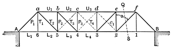
Fig. 19.
| Stress in |
c₁ = |
+ (¹/₇ + ²/₇) W sec a = ³/₇ W
sec a. |
| Stress in |
T₄ = |
+ (¹/₇ + ²/₇ + ³/₇) W sec a = ⁶/₇
W sec a; |
| ” ” |
T₃ = |
+ [(¹/₇ + ²/₇ + ³/₇ + ⁴/₇) W +
Wʹ + W₁] sec a |
| |
= |
(¹⁰/₇ W + Wʹ + W₁) sec a; |
| ” ” |
T₂ = |
+ [(¹/₇ + ²/₇ + ³/₇ + ⁴/₇ + ⁵/₇) W + 2wʹ + 2w₁] sec a |
| |
= |
(¹⁵/₇ W + 2wʹ + 2w₁) sec a; |
| ” ” |
T₁ = |
+ (W + W₁). |
| Stress in |
P₃ = |
- (⁶/₇ W + Wʹ); |
| ” ” |
P₂ = |
- (¹⁰/₇ W + 2Wʹ + W₁); |
| ” ” |
P₁ = |
- 3(W + Wʹ + W₁) sec a. |
| Stress in |
L₁ = |
Stress in L₂ = + 3(W + Wʹ + W₁) tan a; |
| ” ” |
L₃ = |
” ” L₂ + 2(W + Wʹ + W₁)tan a |
| |
= |
+ 5(W + Wʹ + W₁) tan a; |
| ” ” |
L₄ = |
” ” L₃ + (W + Wʹ + W₁) tan a |
| |
= |
+ 6(W + Wʹ + W₁) tan a.
|
| Stress in |
U₁ = |
- Stress in L₃ = - 5(W + Wʹ + W₁) tan α; |
| ” ” |
U₂ = |
- ” ” L₄ = -6(W + Wʹ + W₁) tan α; |
| ” ” |
U₃ |
” ” U₂ = -6(W + Wʹ + W₁) tan α. |
It is easy to check any of the chord stresses by the method of moments.
As an example, let moments first be taken about the panel-point 5 in
the lower chord, and then about the panel-point c in the upper
chord. The following expressions for the chord members U₁
and L₄ will be found, and it will be noticed that they are
identical with the stresses for the same members given in the preceding
tabulation, the counter-members, shown in broken lines, being omitted
from consideration as they are not needed.
| Stress in U₁ |
= |
R . 2p - (W + Wʹ + W₁)p |
| d |
| |
= |
5(W + Wʹ + W₁) |
| |
= |
5(W + Wʹ + W₁) tan α. (29) |
| Stress in L₄ |
= |
R . 3p - 2(W + Wʹ + W₁) . 1½ p |
| d |
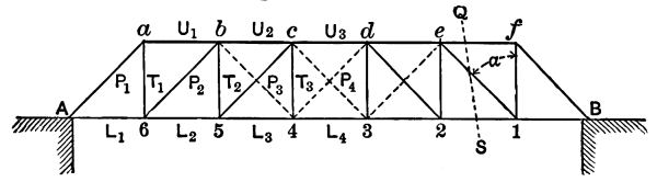
Fig. 20.
91. The Howe Truss Type.—The truss shown in Fig. 20
is the skeleton of the Howe truss, to which reference has already been made.
The inclined web members are all in compression, while the vertical web
members are all in tension. In the Howe truss all compression members
are composed of timber. It has the disadvantage of subjecting the
longest web members to compression. It thus makes the truss, if built
all in iron or steel, heavier and more expensive than the trusses of
the Pratt type. As in the preceding case, the moving train or load is
supposed to pass across the bridge from B to A. Also, as
before, the + sign indicates tension and the - sign compression. The
greatest stresses, given in the tabulated statement below, can be
computed or checked by the method of moments in this case, precisely as
in the preceding.
| Stress in |
c₁ = |
- (¹/₇ + ²/₇) W sec a = - ³/₇ W sec a. |
| Stress in |
P₄ = |
- (¹/₇ + ²/₇ + ³/₇) W sec a = - ⁶/₇ W sec a; |
| ” ” |
P₃ = |
- (¹⁰/₇ W + Wʹ + W₁) sec a; |
| ” ” |
P₂ = |
- (¹⁵/₇ W + 2Wʹ + 2W₁) sec a; |
| ” ” |
P₁ = |
- 3(W + Wʹ + W₁) sec a. |
| Stress in |
T₃ = |
+ (¹⁰/₇ W + W₁) sec a; |
| ” ” |
T₂ = |
+ (¹⁵/₇ W + Wʹ + 2W₁) sec a; |
| ” ” |
T₁ = |
+ (3W + 2Wʹ + 3W₁) sec a. |
| Stress in |
L₁ = |
+ 3(W + Wʹ +W₁) tan a; |
| ” ” |
L₂ = |
+ 3(W + Wʹ + W₁) tan a + 2(W + Wʹ + W₁) tan a |
| |
= |
+ 5(W + Wʹ + W₁) tan a; |
| ” ” |
L₃ |
+ 5(W + Wʹ + W₁) tan a + (W + Wʹ + W₁) tan a |
| |
= |
+ 6(W + Wʹ + W₁) tan a; |
| ” ” |
L₄ = |
Stress in L₃. |
| Stress in |
U₁ = |
- Stress in L₁ |
| ” ” |
U₂ = |
- ” ” L₂; |
| ” ” |
U₃ = |
- ” ” L₃. |
It will be noticed in the cases of Figs. 19
and 20 that upper and lower chord panels in
the same lozenge or oblique panel have identically the same stresses,
but with opposite signs. For instance, in Fig.
20 the stress in U₂ is equal in amount to that in L₂;
and the same observation can be made in reference to the stresses in
U₂ and L₄ of Fig. 19. This
must necessarily always be the case in trusses having vertical web members.
In making computations for these forms of trusses it is very essential
to observe where the first counter-member, as c₁, must be used.
These counter-members may be omitted if the proper main web members
near the centre of the span are designed to take both tension and compression.
92. The Simple Triangular Truss.—The truss shown in Fig. 21,
in which all the web members have equal inclination to a vertical line,
is sometimes called the Warren Truss, although that term has also been
applied specially to this type of truss so proportioned as to make the
depth just equal to the panel length. As before, the moving train is
supposed to pass over the bridge from B toward A, while
the + sign represents tension and the - sign compression. The greatest
stresses are the following.
Fig. 21.
| Stress in |
P₄ = |
- (⁶/₇W + ½Wʹ) sec a, or |
| + (⁶/₇W - ½W′) sec a; |
| ” ” |
P₃ = |
- (¹⁰/₇W + 1½W′ + W₁) sec a, or |
| + (³/₇ W - 1½Wʹ - W₁) sec a; |
| ” ” |
P₂ = |
- (¹⁵/₇ W + 2½Wʹ + 2W₁) sec a; |
| ” ” |
P₁ = |
- (3W + 3½ Wʹ + 3W₁) sec a. |
| Stress in |
T₃ = |
+ (¹⁰/₇W + ½Wʹ + W₁) sec a, or |
| - (³/₇W - ½Wʹ - W₁) sec a; |
| ” ” |
T₂ = |
+ (¹⁵/₇W + 1½W′ + 2W₁) sec a; |
| ” ” |
T₁ = |
+ (3W + 2½Wʹ + 3W₁) sec a. |
| Stress in |
L₁ = |
+ 3(W + Wʹ + W₁) tan a + ½W′ tan a; |
| ” ” |
L₂ = |
Stress in L₁ + (5W + 5Wʹ + 5W₁) tan a |
| |
= |
+ 8(W + Wʹ + W₁) tan a + ½Wʹ tan a; |
| ” ” |
L₃ = |
Stress in L₂ + 3(W + Wʹ + W₁) tan a |
| |
= |
+ 11 (W + Wʹ + W₁) tan a + ½Wʹ tan a; |
| ” ” |
L₄ = |
Stress in L₃ + (W + Wʹ + W₁) tan a. |
| |
= |
+ 12 (W + Wʹ + W₁) tan a + ½Wʹ tan a. |
| Stress in |
U₁ = |
- 6(W + Wʹ + W₁) tan a; |
| ” ” |
U₂ = |
- 6(W + Wʹ + W₁)tan a - 4(W + Wʹ + W₁) tan a |
| |
= |
- 10(W + Wʹ + W₁) tan a; |
| ” ” |
U₃ = |
- 10(W + Wʹ + W₁) tan a - 2(W + Wʹ + W₁) tan a |
| |
= |
- 12(W + Wʹ + W₁) tan a. |
The chord stresses may be checked or found by the method of moments,
precisely as in the case of Fig. 19. If, for instance,
it is desired to determine the stresses in the upper chord member
U₂, moments must be taken about the lower-chord panel-point 5,
and about the upper-chord panel-point d for the lower-chord
stress in L₄. Taking moments about those points, results given
in equations (31) and (32) will at
once follow, which it will be observed are identical with the values
previously found for the same members.
| Stress in U₂ |
= |
(3W + 3½ W′ + 3W₁). 2p - 2W′p - (W + W₁)p |
| d |
| |
= |
-10(W + W′ + W₁) tan a(31) |
| |
| Stress in L₄ |
= |
(3W + 3½ W′ + 3W₁). 3½ p - 3(W + W₁) . 1½p - 3W′. 2p |
| d |
| |
| |
= |
+ 12(W + W₁ + W′) tan a + ½W′ tan a(32) |
93. Through- and Deck-Bridges.—These simple trusses have all
been taken as belonging to the “through” type, i.e., the moving load
passes along their lower chords. It is quite common to have the moving
load pass along the upper chords, in which cases the bridges are
said to be “deck” structures. The general methods of computation are
precisely the same whether the trusses be deck or through. It is only
necessary carefully to observe that the application of the methods of
analysis depends upon the position of each panel-load as it passes
across the structure.
Fig. 22.
94. Multiple Systems of Triangulation.—Figs. 19,
20, and 21 exhibit
what are called single systems of triangulation or single systems of
bracing, but in each of those types the system of web members may be
double or triple; in other words, they may be manifold. There have
been many bridges built in which two or more systems of bracing are
employed. Fig. 22 represents a truss with a double system
of triangulation, known at one time as the Whipple truss. Fig. 23,
again, exhibits a quadruple system of triangulation with all inclined
web members. The method of computation for such manifold systems
is precisely the same as for a single system, each system in the
compound truss being treated as carrying those loads only which
rest at its panel-points. This procedure is not quite accurate. The
complete consideration of an exact method of computation would take
the treatment into a region of rather complicated analysis beyond the
purposes of these lectures, but its outlines will be set forth on a
later page. The exact method of treatment of two or more web systems
involves the elastic properties of the material of which the trusses
are composed. In the best modern bridge practice engineers prefer to
design trusses of all lengths with single web systems, although the
panels are frequently subdivided to avoid stringers and floor-beams of
too great weight.
Fig. 23.
95. Influence of Mill and Shop Capacity on Length of Span.—In
the early years of iron and steel bridge-building the sizes of
individual members were limited by the shop capacity for handling
and manufacturing, and by the relatively small dimensions of bars of
various shapes, and of plates which could be produced by rolling-mills.
As both mill and shop processes have advanced and their capacities
increased, corresponding progress has been made in bridge design. Civil
engineers have availed themselves of those advances, so that at the
present time single system trusses with depths as great as 85 feet or
more and spans of over 550 feet are not considered specially remarkable.
96. Trusses with Broken or Inclined Chords.—As the lengths
of spans have increased certain substantial advantages have been gained in
design by no longer making the upper chords horizontal in the case of
long through-spans, or indeed in the cases of through-spans of moderate
length. The greatest bending moments and the greatest chord stresses
have been shown to exist at the centre of the span, while the greatest
web stresses are found near the ends. Trusses may be lightened in view
of those considerations by making their depths less at the ends than at
the centre. This not only decreases the sectional areas of the heaviest
web members near the ends of the truss, but also shortens them. It
adds somewhat to the sectional area of the end upper-chord members,
but the resultant effect is a decrease in total weight of material and
increased stability against wind pressure by the decreased height and
less exposure near the ends. It has therefore come to be the ruling
practice at the present time to make through-trusses with inclined
upper chords for practically all spans from about 200 feet upward. A
skeleton diagram of such a truss is given in Fig. 24.
Fig. 24.
97. Position of any Moving Load for Greatest Web Stress.—In
the preceding treatment of bridge-trusses with parallel and
horizontal chords a moving or live load has been taken as a series
of uniform weights concentrated at the panel-points. This simple
procedure was formerly generally used, and at the present time it
is occasionally employed, but it is now almost universal practice
to assume for railroad bridges a moving load consisting of a series
of concentrations, which represent both in amount and distribution
the weights on the axles of an actual railroad train. If a bridge is
supposed to be traversed by such a train, it becomes necessary to
determine a method for ascertaining the positions of the train causing
the greatest stresses in the various members of the bridge-truss. The
mathematical demonstration of the formulæ determining those positions of
loading need not be given here, but it can be found in almost any
standard work on bridges.
In order to show concisely the results of such a demonstration let it
be desired to find the position of a moving load which will give the
greatest stress to any web member, as S in Fig. 24.
Let the point of intersection of GK and DC be found in the point
O, then let CK be extended, and on its extension let the
perpendicular h be dropped from O. The distance of the
point O from A, the end of the span, is i, while
m is the distance AD. Using the same notation which has
been employed in the discussion of beams, together with that shown in
Fig. 24, equation (33)
expresses the condition to be fulfilled by the train-loads in order
that S shall have its greatest stress. The first parenthesis
in the second member of that equation represents the load between
the panel p and the left end of the span, while the second
parenthesis represents the load in panel p itself.
| W₁ + W₂ + ... + Wₙ = - |
l |
(W₁ + W₂ + etc.) |
| i |
| |
+ (W₃ + W₄ + etc.) |
l(m + i) |
.(33) |
| pi |
It will be noticed in equation (33) that the quantity m
shows in what panel the inclined web member whose greatest stress is desired
is located, and it is important to observe that panel carefully. If,
for instance, the vertical member KD were in question, the point
O would be located at the intersection of the panel NK
and the lower chord of the bridge. In other words, the point O
must be at the intersection of the two chord members belonging to the
same panel in which the web member is located.
98. Application of Criterions for both Chord and Web
Stresses.—The criterion, equation (33), belongs to web
members only. If it is desired to find the position of moving load which will
give the greatest chord stresses in any panel, equation (27),
already established for beams, is to be used precisely as it stands, the
quantity l′ representing the distance from one end of the span
to the panel-point about which moments are taken.
If the desired positions of the moving load for greatest stresses have
been found by equations (27) and (33),
those stresses themselves are readily found by taking moments about
panel-points for chord members and about the intersection-points
O, Fig. 24, for web members. These
operations are simple in character and are performed with great
facility. Tabulations and diagrams are made for given systems of
loading by which these computations are much shortened and which enable
the numerical work of any special case to be performed quickly and
with little liability to error. These tabulations and diagrams and
other shortening processes may be found set forth in detail in many
publications and works on bridge structures. They constitute a part of
the office outfit of civil engineers engaged in structural work.
The criterion, equation (27), for the greatest bending
moments in a bridge is applicable to any truss whatever, whether the chords are
parallel or inclined, but it is not so with equation (33).
If the chords of the trusses are parallel, the quantity i in equation
(33) becomes infinitely great, and the equation takes the following form:
| W₁ + W₂ + ... + Wₙ = |
l |
(W₃ + W₄ + etc.)(34) |
| p |
Ordinarily the span l divided by the panel length p is
equal to the number of panels in the span. Hence equation (34)
shows, in the case of parallel or horizontal chords, that when the moving load
is placed for the greatest web stress in any panel, the total load on
the bridge is equal to the load in that panel multiplied by the total
number of panels.
99. Influence Lines.—A graphical method, known as that of
“influence lines,” is used for determining the greatest shears and
bending moments caused by a train of concentrated weights passing along
a beam or bridge-truss. Obviously it must express in essence that which
has already been shown by the formulæ which determine positions of
moving loads for the greatest shears and bending moments. In reality it
is the application of graphical methods which have become so popular to
the determination of the greatest stresses in beams and bridges.
100. Influence Lines for Moments both for Beams and Trusses.—It
is convenient to construct these influence lines for an arbitrary load
which may be considered a unit load; the effect of any other load will
then be in proportion to its magnitude. The results determined from
influence lines drawn for a load which may be considered a unit can,
therefore, be made available for other loads by multiplying the former
by the ratio between any desired load and that for which the influence
lines are found.
Fig. 25.—Bending Moment in a Simple Beam.
AB in Fig. 25 represents a beam
simply supported at each end, so that any load g resting upon
it will be divided between the points of support, according to the law
of the lever. Let it be desired to determine the bending moment at the
section X produced by the load g in all of its positions
as it passes across the span from A to B. Two expressions
for the bending moment must be written, one for the load g at
any point in AX, and the other for the load at any point in
BX. The expression for the first bending moment is
and that for the latter
As shown in the figure, z and x, the
latter locating the section at which the bending moments are to be found, are
measured to the right from A. Equation (a) shows that
if the quantity g(l-x) be laid off, by any convenient scale, as BK at
right angles to AB, XC will represent the moment M
by the same scale when x = z or when z has any value
between 0 and x. Similarly will AD be laid off at
right angles to AB by the same scale as before, to represent
gx. Then when x = z the expression for M′ will
have the same value XC as before. Hence if the lines AC
and CB be drawn as parts of AK and DB, any
vertical intercept between AB and ACB will represent
the bending at X produced by the load g when placed at
the point from which the intercept is drawn. The lines AC and
CB are the influence lines for the bending moments produced
by the load g in its passage across the span AB. It is
to be observed that the influence lines are continuous only when the
positions of the moving load are consecutive. In case those positions
are not consecutive the influence lines are polygonal in form.
If there are a number of loads g resting on the span at the same
time, the total bending moments produced at X will be found by
taking the sum of all the vertical intercepts between AB and
ACB, drawn at the various points where those loads rest. The
influence lines drawn for a single load, therefore, may be at once used
for any number of loads.
The load g is considered as a unit load. If the vertical
intercepts representing the bending moments by the scale used are
themselves represented by y, and if W represent any load
whatever, the general expression for the bending moment at X,
produced by any system of loads, will be
If this expression be written as a series, the
general value of the bending moment will be the following:
| M = |
l |
(W₁y₁ + W₂y₂ + W₃y₃ + etc.).
(d) |
| g |
The effect of a moving train upon the bending moment at any given
section is thus easily made apparent by means of influence lines. It is
obvious that there will be as many influence lines to be drawn as there
are sections to be considered. In the case of a truss-bridge there will
be such a section at every panel-point.
A slight modification of the preceding results is to be made
when the loads are applied to the beam or truss at panel-points only.
In Fig. 25 let 1, 2, 3, 4, 5, 6, and 7 be panel-points
at which loads are applied, and let the load g be located at the distance
z′ to the right of panel-point 5, also let the panel length be p.
The reactions at 5 and 6 will then be
| R₅ = g |
p - z′ |
and R₆ = g |
z′ |
. |
| p |
p |
The reactions at A will then be
Hence the moment at any section X in the panel
in question will be
| M = Rx-R₅(z′-(z-x)) = g |
[ |
l-x |
z - (z-z′ + p-x) |
z′ |
] |
.(e) |
| l |
p |
Remembering that z-z′ is a constant quantity, it is at once
clear that the preceding expression is the equation of a straight line,
with M and z or z′ the variables. If z′ =
0, equation (e) becomes identical with
equation (a), while if z′ = p,
it becomes identical with equation (b).
Hence the influence line for the panel in which the load is placed, as
5-6, is the straight line KL. It is manifest that when the load
g is in any other panel than that in which the section X
is located, the effect of the two reactions at the extremities of that
panel will be precisely the same at the section as the weight itself
acting along its own line of action. Hence the two portions AK
and BL of the influence line are to be constructed as if the
load were applied directly to the beam or truss, and in the manner
already shown. The complete influence line will then be AKLB,
and it shows that the existence of the panel slightly reduces the
bending at any section within its limits. The panel 5-6, as treated,
is that of a beam in which the bending moment will, in general, vary
from point to point. If AB were a truss, however, X
would always be taken at a panel-point, and no intercept between
panel-points, as 5 and 6, would be considered.
101. Influence Lines for Shears both for Beams and Trusses.—The
influence lines for shears in a simple beam, supported at each end,
can be drawn in the manner shown in Fig. 25a.
In that figure AB represents a non-continuous beam with span l supported
from A. The reaction at A will be
Fig. 25a.—Shear in a Simple Beam.
Let X be the section at which the shear for various positions of
g is to be found. When g is placed at any point between
A and X the shear S at the latter point will be
but when the load is placed between B
and X the shear becomes
Obviously these two values of the shear are equations of two parallel
straight lines, that represented by equation (f)
passing through A, and that represented by equation (h)
passing through B, the constant vertical distance between them being
g. Hence let BF be laid off negatively downward and
AG positively upward, each being equal to g by any
convenient scale. The ordinates drawn from the various positions 1, 2,
3 ... 6 of g on AB to AD and BC will be
the shears at X produced by the load g at any point of
the span, and determined by equations (f)
and (h). The influence line, therefore, for
the section X will be the broken line ADCB. When g
is at X the sign of the shear changes, since the latter passes
through a zero value.
If a train of weights W₁, W₂, W₃, etc., passes
across the span, the total shear at X will be found by taking
the sum of the vertical intercepts between AB and ADCB,
drawn at the positions occupied by the various single weights of the
train. If those single weights are expressed in terms of the unit load
g, the shear S will have the value
y being the general value of the intercept
between AB and the influence line. The latter shows that the
greatest negative shear at X will exist when the greatest
possible amount of loading is placed on AX only, while the
greatest positive shear at the same section will exist when BX
only is loaded. If BX is the smaller segment of span, the latter
shear is called the “counter-shear,” and the former the “main shear.”
If the loads are applied at panel-points of the span only, the
treatment is the same in general character as that employed for bending
moments. In Fig. 25a let 4 and 5 be
the panel-points between which the load g is found, and let the
panel length be p. Also, let z′ be the distance of the
weight g from panel-point 4. The reactions at A and 4
will then be
| R = |
l - z |
g and R₄ = |
p - z′ |
g. |
| l |
p |
The shear at the section X for any position of the weight
g will then be
| S = R - R₄ = g |
( |
z′ |
- |
z |
) |
.(k) |
| p |
l |
As this is the equation of a straight line, with S and z
or z′ for the coordinates, the influence line for the panel
in which the section X is located will be the straight line
represented by KL in Fig. 25a.
If z′ is placed equal to 0 and p successively, then will
equation (k) become identical with
equations (f) and (h)
in succession. The shears at points 4 and 5 will therefore
take the same values as if the loads were applied directly to the beam.
For the reasons stated in connection with the consideration of bending
moments, loads in other panels than that containing the section for
which the influence line is drawn will have the same effect on that
section as if they were applied directly to the beam or truss. Hence
AKLB is the complete influence line for this case.
It is evident that there must be as many influence lines drawn as
there are sections to be discussed. Also, if g is taken as some
convenient unit, i.e., 1000 or 10,000 pounds, it is clear that the
labors of computation will be much reduced.
102. Application of Influence-line Method to Trusses.—In
considering both the bending moments and shears when the loads are
applied at panel-points, it has been assumed, as would be the case
in an ordinary beam, that the bending moments as well as the shears
may vary in the panel; but this latter condition does not hold in
a bridge-truss. Neither bending moment nor shear varies in any one
panel. Yet the influence lines for moments and shears are to be drawn
precisely as shown in Figs. 25 and 25a.
The section X will always be found at a panel-point, and no intercept drawn within
the limits of the panel adjacent to that section carrying the load
g is to be used. This method will be illustrated by the aid of
Fig. 25b.
The employment of influence lines may be illustrated by determining the
moment and shear in a single section of the truss shown in Fig. 24,
which is reproduced in Fig. 25c, when carrying the moving load
exhibited in Fig. 25b, although its use may be much extended
beyond this simple procedure.
The moving load shown in Fig. 25b
is that of a railroad train consisting of a uniform train-load of
4000 pounds per linear foot drawn by two locomotives with the wheel
concentrations shown; it is a train-load frequently used in the design
of the heaviest class of railroad structures. If the criterion of
equation (27) be applied to this moving load,
passing along the truss shown in Fig.
25c, from left to right, it will be found that the greatest
bending moment is produced at the section Q when the second
driving-axle of the second locomotive is placed at the truss section in
question, as shown in Fig. 25c.
The unit load to be used in connection with the influence lines will be
taken at 10,000 pounds. Remembering that the panel lengths are each 30
feet, it will be seen that the panel-point Q is 150 feet from
A. Hence the product gx will be 1,500,000 foot-pounds.
Similarly the product g(l - x) will be 900,000 foot-pounds.
Laying off the first of these quantities, as AD, at a scale of
1,000,000 foot-pounds per linear inch, and the second quantity, as
BK, by the same scale, the influence line ACB can at once
be completed. Vertical lines are next to be drawn through the positions
of the various weights, including one through the centre of the uniform
train-load 110 feet in length resting on the truss. The vertical line
through the centre of the uniform train-load is shown at O.
By carefully scaling the vertical intercepts between AB and
ACB, and remembering that each of the loads on the truss must be
divided by 10,000, the following tabulated statement will be obtained,
the sum of the intercepts for each set of equal weights being added
into one item, and all the items of intercepts being multiplied by 1,000,000:
| .195 × |
110 × |
.4 |
× |
1,000,000 |
= |
8,580,000 |
foot- |
pounds. |
| 1.78 × |
2.6 |
|
× |
” |
= |
4,628,000 |
” |
” |
| 2.14 × |
4 |
|
× |
” |
= |
8,560,000 |
” |
” |
| .485 × |
2 |
|
× |
” |
= |
970,000 |
” |
” |
| 1.525 × |
2.6 |
|
× |
” |
= |
3,965,000 |
” |
” |
| .9 × |
4 |
|
× |
” |
= |
3,600,000 |
” |
” |
| .12 × |
2 |
|
× |
” |
= |
240,000 |
” |
” |
| |
2⟌30,543,000 |
” |
” |
| Moment for one truss |
= |
15,271,500 |
” |
” |
The lever-arm of ef, i.e., the normal distance from Q to
ef, is 39.7 feet. Hence the stress in ef is
| 15,271,500 |
= |
384,700 pounds. |
| 39.7 |
All the chord stresses can obviously be found
in the same manner.
In order to place the same moving load so as to produce the greatest
shear at the same section Q, the criterion of equation (33)
must be employed. The dimensions of the truss shown in connection with
Fig. 29 give the following data to be used in
that equation: i = 210 feet, m = 60 feet, and p = 30 feet.
| Hence |
l(m + i) |
= |
10²/₇, |
l |
= |
1¹/₇. |
| pi |
i |

Fig. 25b.
Fig. 25c.
Fig. 25d.
Introducing these quantities into equation (33),
and remembering that the train moves on to the bridge
from A, it would be found that the second axle of the first
locomotive must be placed at the section Q, as shown in
Fig. 25d, which exhibits the lower-chord
panel-points numbered from 1 to 7. The conventional unit load g
will be taken in this case at 20,000 pounds. It is represented as
AG and BF (Fig. 25d),
laid off at a scale of 10,000 pounds per inch. K is immediately
under panel-point 5 and L is immediately above panel-point 6,
hence the broken line AKLB is the influence line desired. The
vertical lines are then drawn from each train concentration in its
proper position, all as shown, including the vertical line through the
centre of the 54 feet of uniform train-load on the left. The summation
of all the vertical intercepts between AB and the influence line
AKL, having regard to the scale and to the ratio between the
various loads and the unit load g, will give the following
tabular statement:
| .22 × |
54 × |
.2 |
× |
10,000 |
= |
23,760 |
pounds. |
| 2.2 × |
|
1.3 |
× |
” |
= |
28,600 |
” |
| 3.02 × |
|
2 |
× |
” |
= |
60,400 |
” |
| .9 × |
|
1 |
× |
” |
= |
9,000 |
” |
| 4.06 × |
|
1.3 |
× |
” |
= |
53,780 |
” |
| 4.53 × |
|
2 |
× |
” |
= |
90,060 |
” |
| .5 × |
|
1 |
× |
” |
= |
5,000 |
” |
| |
2⟌ |
270,600 |
” |
| Shear for one truss |
= |
135,300 |
” |
These simple operations illustrate the main principles of the method of
influence lines from which numerous and useful extensions may be made.
CHAPTER IX.
103. Lateral Wind Pressure on Trusses.—The duties of
a bridge structure are not confined entirely to the supporting of vertical
loads. There are some horizontal or lateral loads of considerable
magnitude which must be resisted; these are the wind loads resulting
from wind pressure against both structure and moving train. In order
to determine the magnitudes of these loads it is assumed in the first
place that the direction of the wind is practically or exactly at
right angles to the planes of the trusses and the sides of the cars.
This assumption is essentially correct. There is probably nothing
else so variable as both the direction and pressure of the wind.
These variations are not so apparent in the exposure of our bodies
to the wind, for the reason that we cannot readily appreciate even
considerable changes either in direction or pressure. As a matter of
fact suitable measuring apparatus shows that there is nothing steady
or continued in connection with the wind unless it be its incessant
variability. Its direction may be either horizontal or inclined, or
even vertical, while within a few seconds its pressure may vary between
wide limits. Under such circumstances the wind is as likely to blow
directly against both bridge and train as in any other direction, and
inasmuch as such a condition would subject the structure to its most
severe duty against lateral forces, it is only safe and proper that the
assumption should be made. The open work of bridge-trusses enables the
wind to exert practically its full pressure against both trusses of a
single-track bridge, or against even three trusses if they are used for
a double-track structure. Hence it is customary to take the exposed
surface of bridge-trusses as the total projected area on a plane
throughout the bridge axis of both trusses if there are two, or of three
trusses if there are three. Inasmuch as the floor of a bridge from its
lowest point to the top of the rails or other highest point of the
floor is practically closed against the passage of the wind, all that
surface between the lowest point and the top of the rail or highest
floor-member is considered area on which wind pressure may act.
Many experimental observations show that on large surfaces, greater
perhaps than 400 or 500 square feet in area, the pressure of the wind
seldom exceeds 20 or 25 pounds per square foot, while it may reach 80
or 90 pounds, or possibly more on small surfaces of from 2 to 40 or 50
square feet in area. This distinction between small and large exposed
areas in the treatment of wind pressures is fundamental and should
never be neglected.
This whole subject of wind pressures has not yet been brought into
a completely definite or well-defined condition through lack of
sufficient experimental observations, but in order to be at least
reasonably safe civil engineers frequently, and perhaps usually,
assume a wind pressure acting simultaneously on both bridge and train
at 30 pounds per square foot of exposed surface and 50 pounds per
square foot of the total exposed surface of a bridge structure which
carries no moving load. This distinction arises chiefly from the fact
that a wind pressure of 30 pounds per square foot on the side of many
railroad trains, particularly light ones, will overturn them, and it
would be useless to use a larger pressure for a loaded structure. There
have been wind pressures in this country so great as to blow unloaded
bridges off their piers; indeed in one case a locomotive was overturned
which must have resisted a wind pressure on its exposed surface of not
less than 90 pounds and possibly more than 100 pounds per square foot.
The consideration of wind pressure is of the greatest importance in
connection with the high trusses of long spans, as well as in long
suspension and cantilever bridges, and in the design of high viaducts,
all of which structures receive lateral wind pressures of great magnitude.
Some engineers, instead of deducing the lateral wind loads from the
area of the projected truss surfaces, specify a certain amount for each
linear foot of span, as in ”The General Specifications for Steel
Railroad Bridges and Viaducts” by Mr. Theodore Cooper it is prescribed
that a lateral force of 150 pounds for each foot of span shall be taken
along the upper chords of through-bridges and the lower chords of
deck-bridges for all spans up to 300 feet in length; and that for the
same spans a lateral force of 450 pounds for each foot of span shall
be taken for the lower chords of through-spans and the upper chords of
deck-spans, 300 pounds of this to be treated as a moving load and as
acting on a train of cars at a line 8⁵/₁₀ feet above the base of rail.
When the span exceeds 300 feet in length each of the above amounts
of load per linear foot is to be increased by 10 pounds for each
additional 30 feet of span.
Special wind-loadings and conditions under which they are to be used
are also prescribed for viaducts.
These wind loads are resisted in the bridges on which they act by a
truss formed between each two upper chords for the upper portion of the
bridge, and between each two lower chords for the lower portion of the
structure.
Fig. 26.
104. Upper and Lower Lateral Bracing.—Fig. 26
shows what are called the upper and lower lateral bracing for such trusses as
are shown in the preceding figures. The wind is supposed to act in the
direction shown by the arrow. DERA and KLBC are the
two portals at the ends of the structure, braced so as to resist the
lateral wind pressures. It will be observed that the systems of bracing
between the chords make an ordinary truss, but in a horizontal plane,
except in the case of inclined chords like that of Fig. 24.
In the latter case the lateral trusses are obviously not in horizontal planes,
but they may be considered in computations precisely as if they were.
These lateral trusses are then treated with their horizontal panel wind
loads just as the vertical trusses are treated for their corresponding
vertical loads, and the resulting stresses are employed in designing
web and chord members precisely as in vertical trusses. The wind
stresses in the chords, in some cases, are to be added to those due
to vertical loading, and in some cases subtracted. In other words,
the resultant stresses are recognized and the chord members are so
designed as properly to resist them. At the present time it is the
tendency in the best structural work to make all the web members
of these lateral trusses of such section that they can resist both
tension and compression, as this contributes to the general stiffness
of the structure. On account of the great variability of the wind
pressures and the liability of the blows of greatest intensity to vary
suddenly, some engineers regard all the wind load on structure or train
as a moving load and make their computations accordingly. It is an
excellent practice and is probably at least as close an approximation
to actual wind effects as the assumption of a uniform wind pressure on
a structure.
Both the lateral and transverse wind bracing of railroad bridges have
other essential duties to perform than the resistance of lateral wind
pressures. Rapidly moving railroad trains produce a swaying effect on
a bridge, in consequence of unavoidable unevenness of tracks, lack of
balance of locomotive driving-wheels, and other similar influences.
These must be resisted wholly by the lateral and transverse bracing,
and these results constitute an important part of the duties of that
bracing. These peculiar demands, in connection with the lateral
stability of bridges, make it the more desirable that the lateral and
transverse bracing should be as stiff as practicable.
105. Bridge Plans and Shopwork.—After the computations
for a bridge design are completed in a civil engineer’s office they
are placed in the drawing-room, where the most detailed and exact
plans of every piece which enters the bridge are made. The numerical
computations connected with this part of bridge construction are of a
laborious nature and must be made with absolute accuracy, otherwise it
would be quite impossible to put the bridge together in the field. The
various quantities of bars, plates, angles, and other shapes required
are then ordered from the rolling-mill by means of these plans or
drawings. On receipt of the material at the shop the shopwork of
manufacture is begun, and it involves a great variety of operations.
The bridge-shop is filled with tools and engines of the heaviest
description. Punches, lathes, planers, riveters, forges, boring and
other machines of the largest dimensions are all brought to bear in the
manufacture of the completed bridge.
106. Erection of Bridges.—When the shop operations are
completed the bridge members are shipped to the site where the bridge
is to be erected or put in place for final use. A timber staging,
frequently of the heaviest timbers for large spans, called false works,
is first erected in a temporary but very substantial manner. The top
of this false work, or timber staging, is of such height that it will
receive the steelwork of the bridge at exactly the right elevation. The
bridge members are then brought onto the staging and each put in place
and joined with pins and rivets. If the shopwork has not been done with
mathematical accuracy, the bridge will not go together. On the accuracy
of the shopwork, therefore, depends the possibility of properly fitting
and joining the structure in its final position. The operations of the
shop are so nicely disposed and so accurately performed that it is not
an exaggeration to state that the serious misfit of a bridge member
in American engineering practice at the present time is practically
impossible. This leads to rapid erection so that the steelwork of a
pin-connected railroad bridge 500 feet long can be put in place on the
timber staging, or false works, and made safe in less than four days,
although such a feat would have been considered impossible twenty years ago.
Fig. 27.
107. Statically Determinate Trusses.—The bridge structures
which have been treated require but the simplest analysis, based only
on statical equations of equilibrium of forces acting in one plane,
i.e., the plane of the truss. It is known from the science of mechanics
that the number of those equations is at most but three for any system
of forces or loads, viz., two equations of forces and one of moments.
This may be simply illustrated by the system of forces F₁, F₂, etc.,
in Fig. 27. Let each force be resolved into
its vertical and horizontal components V and H. Also let
l₁, l₂, etc. (not shown in the figure), be the normals
or lever-arms dropped from any point A on the lines of action
of the forces F₁, F₂, etc., so that the moments of the
forces about that point will be F₁l₁, F₂l₂, etc. The
conditions of purely statical equilibrium are expressed by the three
general equations
- H₁ + H₂ + etc. = F₁ cos a₁ + F₂ cos a₂ + etc. = 0; (35)
- V₁ + V₂ + etc. = F₁ sin a₁ + F₂ sin a₂ + etc. = 0; (36)
- Fl = F₁l₁ + F₂l₂ + etc. = 0. (37)
If all the forces except three are known, obviously those three can
be found by the three preceding equations; but if more than three are
unknown, those three equations are not sufficient to find them. Other
equations must be available or the unknown forces cannot be found. In
modern methods of stress determinations those other needed equations
express known elastic relations or values, such as deflections or the
work performed in stressing the different members of structures under
loads. A few fundamental equations of these methods will be given.
In Figs. 19, 20,
and 21 let the truss be cut or divided by the
imaginary sections QS. Each section cuts but three members,
and as the loads and reactions are known, the stresses in the cut
members will yield but three unknown forces, which may be found by the
three equations of equilibrium (35), (36), (37).
If more than three members are cut, however, as in the section
TV of Figs. 22 and 23,
making more than three unknown equations to be found, other equations
than the three of statical equilibrium must be available. Hence
the general principle that if it is possible to cut not more
than three members by a section through the truss, it is statically
determinate, but if it is not possible to cut less than four or
more, the stresses are statically indeterminate.
At each joint in the truss the stresses in the members meeting there
constitute, with the external forces or loads acting at the same point,
a system in equilibrium represented by the two equations (35) and
(36). If there are m such joints in the entire structure, there
will be 2m such equations by which the same number of unknown
quantities may be found. Since equilibrium exists at every joint in the
truss, the entire truss will be in equilibrium, and that is equivalent
to the equilibrium of all the external forces acting on it. This latter
condition is expressed by the three equations (35), (36), and (37),
and they are essentially included in the number 2m. Hence there will
remain but 2m - 3 equations available for the determination of
unknown stresses or external forces.
If, therefore, all the external forces (loads and reactions) are known,
the 2m - 3 equations of static equilibrium can be applied
to the determination of stresses in the bars of the truss or other
structure. It follows, therefore, that the greatest number of bars that
a statically determinate truss can have is
n = 2m - 3. (38)
In Fig. 19 there are twelve joints and
twenty-one members, omitting counter web members and the verticals
ab and fl, which are, statically speaking, either
superfluous or not really bars of the truss. Hence
m = 12 and 2m - 3 = 21. (39)
Again, in Fig. 21 there
are fifteen joints. Hence
m = 15, 2m - 3 = 27,
and there are twenty-seven bars or members of the
truss. The number of joints and bars in actual, statically determinate
trusses, therefore, confirm the results.
108. Continuous Beams and Trusses—Theorem of Three
Moments.—These considerations find direct application to what
are known as ”continuous beams,” i.e., beams (or trusses) which reach
continuously over two or more spans, as shown in Fig. 28.
Fig. 28.
The beam shown is continuous over three spans, but a beam or truss may
be continuous over any number of spans. In general the ends of the beam
or girder may be fixed or held at the ends A and D, so
that bending moments M and M₃ at the same points may have
value. The bending moments at the other points of support are
represented by M₁, M₂, etc. The points of support may
or may not be at the same elevation, but they are usually assumed to
be so in engineering practice. Finally, it is ordinarily assumed that
the continuous structure is straight before being loaded, and that in
that condition it simply touches the points of support. Whether the
preceding assumptions are made or not, a perfectly general equation
can be written expressing the relation between the bending moments
over each set of three consecutive points of support, as M,
M₁, and M₂, or M₁, M₂, and M₃. Such an equation
expresses what is called the ”Theorem of Three Moments.” It is not
necessary to give the most general form of this theorem, as that
which is ordinarily used embodies the simplifying assumptions already
described. This simplified form of the ”Theorem of Three Moments”
applied to the case of Fig. 28 will yield
the following two equations:
| Ml₁ + 2M₁(l₁ + l₂) + M₂l₂ + |
1 |
¹ |
∑ |
W(l₁² - z²)z |
| l₁ |
|
| + |
1 |
¹ |
∑ |
W(l₂² - z²)z = 0. (40) |
| l₂ |
|
| |
| M₁l₂ + 2M₂(l₂ + l₃) + M₃l₃ + |
1 |
² |
∑ |
W(l₂² - z²)z |
| l₂ |
|
| + |
1 |
³ |
∑ |
W(l₃² - z²)z = 0. (41) |
| l₃ |
|
The figure over the sign of summation shows the span to which the
summation belongs. If there is but one weight or load W in each
span, the sign of summation is to be omitted. In an ordinary bridge
structure or beam the ends are simply supported and M = M₃ = 0.
In any case if the number of supports be n, there will be
n - 2 equations like the preceding.
If the end moments M and M₃ are not zero, they will be
determinable by the local conditions in each instance. In any event,
therefore, they will be known, and there will be but n - 2
unknown moments to be found by the same number of equations. When the
moments are known the reactions follow from simple formulæ.
109. Application to Draw- or Swing-bridges.—In general
the reactions or supporting forces of the beams and trusses of
ordinary civil-engineering practice are vertical, and all their
points of application are known. Hence there are but two equations
of equilibrium, equations (36) and (37), for external forces.
These two equations for the external forces and the n - 2 equations
derived from the theorem of three moments are therefore always
sufficient to determine the n reactions. After the reactions
are known all the stresses in the bars or members of the trusses can
at once be found. The preceding equations and methods as described
are constantly employed in the design and construction of swing- or
drawbridges.
110. Special Method for Deflection of Trusses.—The method of
finding the elastic deflections produced by the bending of solid beams
has already been shown, but it is frequently necessary to determine the
elastic deflections of bridge-trusses or other jointed or so-called
articulate frames or structures. It is not practicable to use the
same formulæ for the latter class of structures as for the former.
The elastic deflection of a bridge- or roof-truss depends upon the
stretching or compressions of its various members in consequence of the
tensile or compressive forces to which they are subjected. Any method
by which the deflection is found, therefore, must involve these elastic
changes of length. There are a number of methods which give the desired
expressions, but probably the simplest as well as the most elegant
procedure is that which reaches the desired expression through the
consideration of the work performed in the truss members in producing
their elastic lengthenings and shortenings.
The general features of this method can readily be shown by reference
to Fig. 29. It may be supposed that it is desired to
find the deflection of any point, as J, of the lower chord produced both
by the dead and live load which it carries. It is known from what has
preceded that every member of the upper chord will be shortened and
that every member of the lower chord will be lengthened; and also that
generally the vertical web members will be shortened and the inclined
web members lengthened. If there can be obtained an expression giving
that part of the deflection of J which is due to the change of
length of any one member of the truss independently of the others,
then that expression may be applied to every other member in the
entire truss, and by taking the sum of all those effects the desired
deflection will at once result. While this expression will be found for
some one particular truss member, it will be of such a general form
that it may be used for any truss member whatever; it will be written
for the upper-chord member BC in Fig. 29.
Fig. 29.
The general problem is to determine the deflection of the point
J when the bridge carries both dead and moving load over the
entire span, as shown in Fig. 29. The
general plan of procedure is first to find the stresses due to this
combined load in every member of the truss, so that the corresponding
lengthening or shortening is at once shown. The effect of this
lengthening and shortening for any single member BC in producing
deflection at J is then determined; the sum of all such effects
for every member of the truss is next taken, and that sum is the
deflection sought. In this case the vertical deflection will be found,
because that is the deflection generally desired in connection with
bridge structures, but precisely the same method and essentially the
same formulæ are used to find the deflection in any direction whatever.
The following notation will be employed:
Let w = deflection in inches at any
panel-point or joint of the truss;
” P = any arbitrary load or weight
supposed to be hung at the point where the deflection is desired and
acting as if gradually applied. This may be taken as unity;
” Z = stress produced in any member of
truss by P;
” S = stress produced in any member of
truss by the combined dead and moving loads;
Let l = length in inches of any member of
the truss in which Z or S is found;
” A = area of cross-section of same member
in square inches;
” E = coefficient of elasticity.
S or Z may be either tension or compression, and the
formulæ will be so expressed that tension will be made positive and
compression negative.
The change of length of the chord member BC produced by a stress
gradually increasing from zero to S is
If it be supposed that BC is a spring of such stiffness that it
will be compressed by the gradual application of Z exactly as
much as the shortening of the actual member by the stress S, the
deflection of the point 4 with the weight P hung from it, and
due to that compression alone, will be precisely the same as that due
to the actual shortening of BC by the combined dead and moving loads.
It is known by one of the elementary principles of mechanics that,
since P acts along the direction of the vertical deflection
w, the work performed by the weight P over that
deflection is equal to the work performed by Z over the change
of length l. Hence
| l |
Pw |
= |
l |
Z |
Sl |
, or |
| 2 |
2 |
AE |
The quantity Z÷P is the stress produced in the member by a unit
load applied at the joint or point where the deflection is desired.
Again, S÷A is the stress per unit of area, i.e., intensity of
stress, in the member considered by the actual dead and moving loads.
For brevity let these be written
then
If the influence of every member of the truss is similarly expressed,
the value of the total deflection produced by the dead and moving loads
will be
The sign of summation ∑ indicates that the
summation is to extend over all the web and chord members of the truss.
111. Application of Method for Deflection to Triangular
Frame.—Before applying those equations to the case of Fig. 29
it is best to consider a simpler case, i.e., that of the triangular frame
shown in Fig. 18. The reactions are
| R |
= |
l₂ |
W and Rʹ |
= |
l₁ |
W |
.(45) |
| l |
l |
The stresses in the various members are:
| In CB, S = |
l₁ |
W sec α. |
|
| l |
| In CA, S = |
l₂ |
W sec β. |
|
| l |
| In AB, S = |
l₂ |
W tan β. |
= |
l₁ |
W tan α. |
| l |
l |
- Also: CB = h sec α; area of section = A₁.
- CA = h sec β; ” ” ” = A₂.
- AB = l; ” ” ” = A₃.
In this instance it is simplest to take P = W.
Equation (44) then gives
| w |
= |
( |
l₁² |
|
h sec³ α |
+ |
l₂² |
|
h sec³ β |
+ |
l₂² |
|
l tan² β |
) |
W |
(46) |
| l² |
A₁ |
l² |
A₂ |
l² |
A₃ |
E |
Let it be supposed that
| l |
= |
25 feet = 300 inches; |
| h |
= |
8 feet 4 inches = 100 inches; |
| l₂ |
= |
16 feet 8 inches = 200 inches and l₁ = 100 inches; |
| tan β |
= |
1; sec β = 1.414; |
| sec α |
= |
2.24; |
| W |
= |
10,000 pounds. |
If the bars are all supposed to be of yellow-pine timber, there may be taken
| E |
= |
1,000,000 pounds; |
| A₁ |
= |
10″ × 12″ = 120 square inches; |
| A₂ |
= |
10″ × 10″ = 100 square inches; |
| A₃ |
= |
10″ × 12″ = 120 square inches. |
The insertion of these quantities in equation (46)
gives the deflection
w = .01042 + .01253 + .01111 = 0.034. (47)
Equation (47) is so written as
to show the portion of the deflection due to each member of the frame.
In applying either equation (43) or equation (44)
care must be taken to give each stress and its corresponding strain (lengthening or
shortening) the proper sign. As the formulæ have been written and
used, a tensile stress and its resulting stretch must each be written
positive, while a compressive stress must be written negative. This
holds true for both the stresses Z and S (or z and
s). The magnitude of the assumed load P is a matter of
indifference, since the stress Z will always be proportional to
it and the ratio P ÷ Z will therefore be constant. P is
frequently taken as unity; or, as in the case just given, it may have
any value that the conditions of the problem make most convenient.
112. Application of Method for Deflection to Truss.—In
making application of the deflection formulæ to any steel railroad truss
similar to that shown in Fig. 29, it will first be
necessary to determine the stresses in all its members due to the dead and
moving loads, since the deflection under the moving load is sought. These
loads will be considered uniform, and that is sufficiently accurate for
any railroad bridge. The moving train-load will be taken as covering
the entire span, assumed, for a single-track railroad, 240 feet in
length between centres of end pins. There are eight panels of 30
feet each, and the depth of truss at centre is 40 feet. Other truss
dimensions are as shown in Fig. 29. The dead loads,
or own weight, are taken at 400 pounds per linear foot of span for the rails
and other pieces that constitute the track; at 400 pounds per linear foot for the
steel floor-beams and stringers, and 1600 pounds per linear foot for
the weight of trusses and bracing. The moving train-load will be taken
at 4000 pounds per linear foot. This will make the panel-loads for each
truss as follows:
| Lower-chord dead load, |
30 × 800 = |
24,000 |
pounds |
per |
panel. |
| Lower-chord moving load, |
30 × 2000 = |
60,000 |
” |
” |
” |
| Total load on lower chord |
= |
84,000 |
” |
” |
” |
| Upper-chord dead load, |
30 × 400 = |
12,000 |
” |
” |
” |
The structure is a “through” bridge, hence all moving loads rest on the
lower chord.
Fig. 30.
The stresses in the truss members due to the combined uniform dead and
moving load are best found by the graphical method. One diagram only is
needed to determine all the stresses, and it is shown in Fig. 30.
This diagram is drawn accurately to scale, and the stresses measured from it
are shown in the table on page 136.
The stresses in all the truss members due to the unit load hung at
J are readily found by the single diagram shown in Fig. 31,
also carefully drawn to scale. These stresses measured from the diagram
are given in the table as indicated by the column z; they are
also represented in equation (44) by the letter z. The quantity
s in equation (44) is the intensity of the stress (pounds
per square inch of cross-section of member) produced by the combined dead
and moving loads in each member. As shown, these stresses are least in
the web members near the centre of the span, and greatest in the chord
members. The lengths in inches of the truss members are shown in the
proper column of the table. It will be observed that all counter web
members are omitted, as they are not needed for the uniform load. The
coefficient of elasticity (E) is taken at 28,000,000 pounds.
The quantities represented by the second member of equation (44)
are computed from these data, and they appear in the last column of the
table, the sum of which gives the desired deflection in inches. The
elements of the table show how much of the deflection is due to the
chords and to the web members, and they show that disregarding the
latter would lead to a considerable error.
| |
S |
s |
z |
l |
w |
| L₁ |
+373,300 |
+12,000 |
+.555 |
360 |
+.08563 |
| L₂ |
+373,300 |
+12,000 |
+.555 |
360 |
+.08563 |
| L₃ |
+480,000 |
+12,000 |
+.833 |
360 |
+.1284 |
| L₄ |
+540,000 |
+12,000 |
+1.125 |
360 |
+.1736 |
| P₁ |
-502,300 |
-9,000 |
-.748 |
472 |
+.1132 |
| U₁ |
-501,000 |
-9,500 |
-.870 |
376 |
+.1108 |
| U₂ |
-544,800 |
-10,000 |
-1.135 |
363 |
+.1472 |
| U₃ |
-576,000 |
-10,000 |
-1.50 |
360 |
+.1928 |
| T₁ |
+84,000 |
+9,000 |
0 |
324 |
— |
| T₂ |
+143,500 |
+10,000 |
+.3738 |
472 |
+.0629 |
| P₂ |
-12,000 |
-1,000 |
-.250 |
432 |
+.00386 |
| T₃ |
+93,720 |
+7,400 |
+.456 |
562 |
+.0677 |
| P₃ |
+12,000 |
+1,000 |
-.35 |
480 |
-.0060 |
| T₄ |
+60,000 |
+4,800 |
+.625 |
600 |
+.0643 |
| P₄ |
-12,000 |
-1,000 |
0 |
480 |
— |
| |
| Deflection for ½ truss members = 1.2300 inches. |
| Deflection at J = 2 × 1.2300 = 2.4600 inches. |
Fig. 31.
As the deflection is usually desired in inches, the lengths of members
must be taken in the same unit.
113. Method of Least Work.—The so-called theorem or
principle of “Least Work” is closely related to the subject of elastic
deflections just considered in its availability for furnishing
equations of condition in addition to those of a purely statical
character in cases where indetermination would result without them.
This principle of least work is expressed in the simple statement
that when any structure supports external loading the work performed
in producing elastic deformation of all the members will be the least
possible. Although this principle may not be susceptible of a complete
and general demonstration, it may be shown to hold true in many cases
if not all. The hypothesis is most reasonable and furnishes elegant
solutions in many useful problems.
The application of this principle requires the determination of
expressions for the work performed in the elastic lengthening and
shortening of pieces subjected either to tension or compression, and
for the work performed in the elastic bending of beams carrying loads
at right angles to their axes. Both of these expressions can be very
simply found.
Let it be supposed that a piece of material whose length is L
and the area of whose cross-section is A is either stretched or
compressed by the weight or load S applied so as to increase
gradually from zero to its full value. The elastic change of length
will be SL/AE, E being the coefficient of elasticity. The
average force acting will be ½S, hence the work performed in
producing the strain will be
It will generally be best, although not necessary, to take L in
inches. The expression (48) applies either to tension or compression
precisely as it stands.
To obtain the expression for the work performed by the stresses in a
beam bent by loads acting at right angles to its axis, a differential
length (dL) of the beam is considered at any normal section in
which the bending moment is M, the total length being L.
Let I be the moment of inertia of the normal section, A,
about an axis passing through the centre of gravity of the latter, and
let k be the intensity of stress (usually the stress per square
inch) at any point distant d from the axis about which I
is taken. The elastic change produced in the indefinitely short length
dL when the intensity k exists is (k/E)dL.
If dA is an indefinitely small portion of the normal section,
the average force or stress, either of tension or compression, acting
through the small elastic change of length just given, can be written
by the aid of equation (5) as
| ½k . dA |
= |
Md |
. dA.(49) |
| 2I |
Hence the work performed in any normal section of
the member, for which M remains unchanged, will be, since
∫k. dA. d = M,
| ∫ |
M |
kd . dA . dL |
= |
M² |
. dL.(50) |
| 2IE |
2IE |
The work performed throughout the entire piece
will then be
Each of the expressions (48)
and (51) belongs to a single piece or member of
the structure. The total work performed in all the pieces subjected
either to direct stress or to bending, and which, according to the
principle of least work, must be a minimum, is found by taking the
summation of the two preceding expressions:
| e |
= |
1 |
∑ |
S²L |
+ |
1 |
∑ ∫ |
M² |
dL |
= |
minimum. (52) |
| 2E |
A |
2E |
I |
In making an application of equation (52)
it is to be remembered that S is the direct stress of tension or
compression in any member, and that M is the general value of
the bending moment in any bent member expressed in terms of the length L.
114. Application of Method of Least Work to General
Problem.—The problem which generally presents itself in the use of
equation (52) is the finding of an equation which expresses
the condition that the work expended in producing elastic deformation shall
be a minimum, some particular stress in the structure or some external
load or force being the variable. If t represent that variable,
then the desired equation of condition will be found simply by placing
the first differential coefficient of e in equation (52)
equal to zero:
| de |
= |
1 |
( |
∑ |
S |
|
dS |
dL + |
∑ ∫ |
M |
|
dM |
dL |
) |
= 0.(53) |
| dt |
E |
A |
dt |
I |
dt |
The solution of equation (53) will give a value of t
which will make the work performed as expressed in equation (52)
a minimum. This method is not a difficult one to employ in such cases as those
of drawbridges and stiffened suspension bridges. In the latter case
particularly it is of great practical value.
115. Application of Method of Least Work to Trussed Beam.—The
method of least work may be illustrated by the application of the
preceding equations to the simple truss shown in Fig. 32.
The pieces BC and GD are supposed to be of yellow-pine timber,
the former 10 inches by 14 inches (vertical) in section and the
latter 8 inches by 10 inches, while each of the pieces BD
and DC are two 1⅝-inch round steel bars. The coefficient of
elasticity E will be taken at 1,000,000 pounds for the timber
and 28,000,000 for the steel. The length of BC is 360 inches;
GD 96 inches; BD = 96 × 2.13 = 204.5 inches.
tan α = 1.875 and sec α = 2.13.
The weight W resting at G is 20,000 pounds. A part of
this weight is carried by BC as a simple timber beam, while
the remainder of the load will be carried on the triangular frame
BCD acting as a truss, the elastic deflection of the latter
throwing a part of the load on BC acting as a beam. According to
the principle of least work the division of the load will be such as
to make the work performed in straining the different members of the
system a minimum.
That part of W which rests on BC as a simple beam may
be represented by W₁, while W₂ represents the remaining
portion carried by the triangular frame. As G is at the centre
of the span, the beam reaction at either B or C is
½W₁. Hence the general value of the bending moment in either
half of the beam at any distance x from either B or
C is
M = ½W₁x. Hence M²dL = ¼W₁²x²dx.
As there is but one member acting as a beam, whose moment of inertia
I is constant, the second term of the second member of
equation (52) becomes, by the aid of the preceding equation,
| 1 |
∫ |
M²dL + |
= |
1 |
∫₀ |
½ |
¼W₁²x²dx |
= |
1 |
|
W₁²l³ |
. (54) |
| 2EI |
EI |
EI |
96 |
Fig. 32.
The numerical elements of the expression for the work done in the
members of the triangular frame are:
| Member. |
Stress. |
Length. |
Area of Section. |
| BC |
½W₂ tan α |
360 inches = l |
140 |
square |
inches |
| DC |
½W₂ sec α |
204.5 ” |
4.14 |
” |
” |
| DG |
W₂ |
96 ” |
80 |
” |
” |
| I = |
10 × 14³ |
= |
27440 |
= |
2286.7. |
| 12 |
12 |
The substitution of those quantities in the first term of the second
member of equation (52) will give
| 1 |
∑ |
S²L |
= |
1 |
( |
W₂² tan² α . 360 |
+ |
W₂² . 96 |
) |
| 2E |
A |
2,000,000 |
4 × 140 |
80 |
| + |
2 |
|
W₂² sec² α .204.5 |
= |
.000,003,73 W₂². |
| 56,000,000 |
4 × 4.14 |
The substitution of numerical quantities in equation (54)
gives
| 1 |
|
W₁²l³ |
= |
.000,213W₁². |
| EI |
96 |
Or, since W - W₂ = W₁,
e = .000,003,73W₂² + .000,213(W - W₂)². (55)
Hence
| de |
= |
.000,007,46W₂ - .000,426(W - W₂) = 0. (56) |
| dW₂ |
The solution of this equation gives
W₂ = .893W = 19,660 pounds.
W₁ = 340 ”
It is interesting to observe that the first term of the second
member of equation (56) is the deflection of the
point of application of W₂ as a point in the frame, while the
second term is the deflection of the point of application of W₁
considered as a point of the beam. In other words, the condition
resulting from the application of the principle of least work is
equivalent to making the elastic deflections by W₁ and W₂
equal. Indeed equation (53) expresses the
equivalence of deflections whenever the features of the problem are
such as to involve concurrent deflections of two different parts of the
structure.
116. Removal of Indetermination by Methods of Least Work and
Deflection.—The indetermination existing in connection with the
computations for such trusses as those shown in Fig. 22
and Fig. 23 can be removed by finding equations of condition
by the aid of the method of least work or of deflections. It is evident that the
component systems of bracing of which such trusses are composed must
all deflect equally. Hence expressions may be found for the deflections
of those component trusses, each under its own load. Since these
deflections must be equal, equations of condition at once result. A
sufficient number of such equations, taken with those required by
statical equilibrium, can be found to solve completely the problem.
Such methods, however, are laborious, and the ordinary assumption of
each system carrying wholly the loads resting at its panel-points is
sufficiently near for all ordinary purposes.
The method of least work can be very conveniently used for the solution
of a great number of simple problems, like that which requires the
determination of the four reactions under the four legs of a table,
carrying a single weight or a number of weights, and many others of the
same character.
CHAPTER X.
117. The Arched Rib, of both Steel and Masonry.—During the
past ten or fifteen years the type of bridge structure called the
arched rib has come into much use, and its merits insure for it a wider
application in the future. It partakes somewhat of the nature of both
truss and arch; or it may be considered a curved beam or girder. The
ordinary beam or truss when placed in a horizontal position and loaded
vertically yields only vertical reactions. Under the same conditions,
however, the arched rib will produce both vertical and horizontal
reactions, and the latter must either be resisted by abutments of
sufficient mass, or by a tie-rod, usually horizontal, connecting the
springing points of the rib.
The arched rib may be built solid, as was done in the early days of
bridge-building in this country when engineers like Palmer, Burr, and
Wernwag introduced timber arches in combination with their wooden
trusses, or as a curved plate girder, one of the most prominent
examples of which is the Washington Bridge across the Harlem River
in the city of New York; or, again, as a braced frame or curved
truss, like the 800 feet arched rib carrying the roadway traffic and
trolley cars across the Niagara gorge, or like those used in such
great railroad train-sheds as the Grand Central Station, New York,
the Pennsylvania stations at Jersey City and Philadelphia, and the
Philadelphia and Reading station in Philadelphia. Those are all
admirable examples of steel arched ribs, and they are built to sustain
not only vertical loads but, in the case of station roofs, the normal
or horizontal wind pressures.
Within a few years, less than ten, another type of arched rib has been
brought into use and promises to be one of the most beautiful as well
as the most substantial applications of this type of structure; that
is, the arched rib of combined steel and concrete. Many examples of
this type of structure already exist both in this country and in
Europe, probably the most prominent of which in this country is that at
Topeka, Kansas, across the Kansas River.
Fig. 33.
Fig. 34.
Fig. 35.
The characteristic feature of this type of structure, so far as the
stresses developed in it are concerned, is the thrust throughout its
length, more or less nearly parallel to its axis, which is combined
with the bending moments and shears similar to those found in
ordinary bridge-trusses. This thrust is the arch characteristic and
differentiates it in a measure from the ordinary bridge-truss, while
the bending moments and shears to which it is subjected differentiate
it, on the other hand, from the pure arch type or a series of blocks in
which thrust only exists. The thrust, bending moments, and shears
in arched ribs are all affected by certain principal features of
design. Those features are either fixedness of the ends of the ribs
or the presence of pin-joints at those ends or at the crown. Fig. 33
represents an arched rib with its ends D and F supposed
to be rigidly fixed in masonry or by other effective means.
118. Arched Rib with Ends Fixed.—The railroad steel arched
bridge at St. Louis, built by Captain Eads between 1868 and 1874, is
a structure of this character. The three spans (two each 537 feet 3
inches and one 552 feet 6 inches in length from centre to centre of
piers) consist of ribs the main members of which are composed of chrome
steel. It was a structure of unprecedented span when it was built,
and constituted one of the boldest pieces of engineering in its day.
The chords of the ribs are tubes made of steel staves, and their ends
are rigidly anchored to the masonry piers on which they rest. It is
exceedingly difficult, indeed impossible, to fix rigidly the ends of
such a structure, and observations in this particular instance have
shown that the extremities of the ribs are not truly fixed, for the
piers themselves yield a little, giving elastic motion under some
conditions of loading.
119. Arched Rib with Ends Jointed.—The rib shown in
Fig. 34 is different from the preceding in that pin-joints
are supplied at each end, so that the rib may experience elastic distortion or strain
by small rotations about the pins at A and B. In the
computations for such a design it is assumed that the ends of the
rib may freely change their inclination at those points. As a matter
of fact the friction is so great, even if no corrosion exists, as to
prevent motion, but the presence of the pins makes no bending moment
possible at the end joints, and the failure to move freely probably
produces no serious effect upon the stresses in the ribs. The presence
of these pin-joints simplifies the computations of stresses and renders
them better defined, so that there is less doubt as to the actual
condition of stress under a given load than in the type shown in Fig. 33
with ends fixed more or less stiffly. In Fig. 34, if the horizontal
force H exerted by the ends of the rib against the points of
support is known, the remaining stresses in the structure can readily
be computed; but neither in Fig. 34 nor in
Fig. 33 are statical equations sufficient for
the determination of stresses. Equations of condition, depending upon
the elastic properties of the material, are required before solutions
of the problems arising can be made.
120. Arched Rib with Crown and Ends Jointed.—The rib
shown in Fig. 35 possesses one characteristic radically
different from any found in the ribs of Figs. 33
and 34, in that it is three-jointed,
one pin-joint being at the crown and one at each end. So far as the
conditions of stress are concerned, this is the simplest rib of all.
Since there is a pin-joint at the crown as well as at the ends, the
bending moments must be zero at each of those three points whatever
may be the condition of loading. The point of application of the force
or thrust at the crown, therefore, is always known, as well as the
points of application at the ends of the joints. As will presently be
seen, this condition makes equations of statical equilibrium sufficient
for the determination of all stresses in the rib, and no equations
depending upon the elastic properties of the material are required. The
stresses in this class of ribs, therefore, are more easily determined
than in the other two, and they are better defined. These qualities
have insured for it a somewhat more popular position than either
of the other two classes. The ribs of the great train-sheds of the
Pennsylvania and Reading railroads in Jersey City and in Philadelphia
belong to this class, while those of the Grand Central Station at New
York City belong to the class shown in Fig. 34,
as does the arched rib across the Niagara gorge, to which reference
has already been made.
121. Relative Stiffness of Arch Ribs.—Obviously the
three-hinged ribs are less stiff than the two-hinged ribs or those with
fixed ends. This is a matter of less consequence for station roofs than
for structures carrying railroad loads. The joints of the two-hinged
rib being at the ends of the structure, there is but little difference
in stiffness between that class of ribs and those with ends fixed.
Indeed the difference is so slight, and the uncertainty as to the
degree of fixedness of the fixed ends of the rib is so great, that the
latter type of rib possesses no real advantage over that with hinged ends.
122. General Conditions of Analysis of Arched Ribs.—In
each of the three types of arched ribs shown in Figs. 33,
34, and 35 it is
supposed that all external forces act in the vertical planes which
contain the centre lines of the various members of the rib. There are,
therefore, the three conditions of statical equilibrium expressed by
the three equations (35), (36), and (37). In practically
all cases, except those of arched ribs employed in roof construction, all the
external loads are vertical. In such cases the equations of statical
equilibrium of the entire structure may be reduced to two only, viz.,
equations (36) and (37). These features of the problems
connected with the design of arched ribs will always make necessary, except in
the case of the three-hinged rib (Fig. 35),
equations of condition depending upon the elastic properties of the structure.
The rib represented by Fig. 33 is supposed to have its
ends so fixed that the inclinations of the centre line at F and D
will never change whatever may be the loading or the variation of
temperature. This requires the application at each of those points of
a couple whose moment varies in value, but which is always equal and
opposite to the bending moment at the same point produced by the loads
imposed on the rib. It is also to be observed that the loads resting
upon the rib are not divided between the points of support F
and D in accordance with the law of the lever, since the
conditions of fixedness at the ends are equivalent to continuity. There
are then to be found, as acting external to the rib, the two vertical
reactions and the two moments at F and D, as well as
the horizontal thrust exerted at the ends of the structure, which is
sometimes resisted by the tie-rod, making five unknown quantities.
Inasmuch as all external loading is supposed to be vertical, equations
(36) and (37) are the only statical equations available, and three
others, depending upon the elastic properties of the structure, must be
supplied in order to obtain the total of five equations of condition to
determine the five unknown quantities. Inasmuch as the end inclinations
remain unchanged, the total extension or compression of the material
at any given constant distance from the axis of the rib taken between
the two end sections F and D must be equal to zero.
Similarly, whatever may be the amount or condition of loading, the
vertical and horizontal deflections of either of the ends F
or D in relation to the other must be zero, since no relative
motion between these two points can take place. It is not necessary in
these lectures to give the demonstration of the equations which express
the three preceding elastic conditions, but if M is the general
value of the bending moment for any point of the rib, and if x
and y are the horizontal and vertical coordinates of the centre
line of the rib, taking the central point of the section at either
F or D as an origin, those equations, taken in the order
in which the elastic conditions have been named, will be the following,
in which n represents a short length of rib within which the
bending moment M is supposed to remain unchanged.
| F |
|
F |
|
F |
|
| ∑ |
nM = 0; |
∑ |
nMx = 0; |
∑ |
nMy = 0;(57) |
| D |
|
D |
|
D |
|
The second and third of these equations express the condition that
the vertical and horizontal deflections respectively of the two ends
in reference to each other shall be zero. The conditions expressed by
equation (57) are constantly used in engineering practice
to determine the bending moments and stresses which exist in the arched rib with
fixed ends. The graphical method is ordinarily used for that purpose,
as its employment is a comparatively simple procedure for a rib whose
curvature is any whatever.
If the rib has hinged joints at the ends, as in Fig. 34,
obviously there can be no bending moment at either of those two points, and hence
the two equations of condition which were required in connection with
Fig. 33 to determine them will not be needed. There is,
therefore, no restriction as to the angle of inclination of the centre line of
the rib at those two points. Again, it is obvious that either end A
or B may have vertical movement, i.e., deflection in reference
to the other, without affecting the condition of stress in any member
of the rib; but it is equally obvious that neither A nor
B can be moved horizontally, i.e., deflected in reference to the
other, without producing bending in the rib and developing stresses in
the various members. The unknown quantities in this case are,
therefore, only the horizontal thrust H exerted at the two
springing points A and B, and the two vertical reactions,
making a total of three unknown quantities, equations for two of which
will be given by equations (36) and (37).
The other equation required is the third expression in
equation (57), expressing the condition that the
horizontal deflection of either of the points A or B in
respect to the other is zero, since the span AB is supposed
to remain unchanged. By the application of the graphical method
to this case, as to the preceding, the employment of equations
(36), (37), and (58)
will afford an easy and quick determination of the three unknown
quantities, whatever may be the curvature of the rib.
If the reactions and horizontal thrust H are found, stresses in
every member may readily be computed and the complete design made.
If the arch is three-hinged, as in Fig. 35,
the condition that the bending moment must be zero at the crown
C under all conditions of loading gives a third statical
equation independent of the elastic properties of the structure which,
in connection with equations (36) and (37),
give three equations of condition sufficient to determine the two
vertical reactions and the horizontal thrust H. In this case,
as has already been stated, no elastic equations of condition are required.
The determination of the end reactions, bending moments, and horizontal
thrust H, in these various cases, is all that is necessary in
order to compute with ease and immediately the stresses in every member
of the rib. These computations are obviously the final numerical work
required for the complete design of the structure. These procedures are
always followed, and in precisely the manner indicated, in the design
of arched ribs by civil engineers, whether the rib be articulated,
i.e., with open bracing, or with a solid plate web, like those of the
Washington Bridge across the Harlem River.
CHAPTER XI.
123. Beams of Combined Steel and Concrete.[2]—A
reference has already been made to a class of beams and arches recently
come into use and now quite widely employed, composed of steel and
concrete, the former being completely surrounded by and imbedded in
the latter. These composite beams are very extensively used in the
floors of fire-proof buildings as well as for other purposes. Arches of
combined concrete and steel were probably first built in Germany and
but a comparatively few years ago. During the past ten years they have
been largely introduced into this country, and many such structures
have not only been designed but built. The most prominent design
of arches of combined concrete and steel are those of the proposed
memorial bridge across the Potomac River at Washington, for which a
first prize was awarded as the result of a national competition in the
early part of 1900. So far as the bending or flexure of these composite
beams and arches is concerned, the theory is identically the same
for both, the formulæ for each of which are given below. In order to
express these formulæ the following notation will be needed:
MEMORIAL BRIDGE ACROSS THE POTOMAC
AT WASHINGTON D.C.
PLAN NO. 2.
Wm. H. Burr, Civil Engineer.
E. P. Casey, Associated Architect.
Plan Awarded First Prize in National Competition.
River spans 192 feet clear.
Total length of structure 3615 feet.
PLAN NO. 1.
Wm. H. Burr, Civil Engineer.
E. P. Casey, Associated Architect.
The Towers of this Plan were Recommended by Board of Award
to be
Substituted for Those in Plan No. 2.
River spans 283 feet clear. Total length of structure 3437 feet.
P is the thrust along the arch determined by the methods
explained in the consideration of arched ribs.
l is the distance of the line of the thrust P from the
axis of the arched rib.
E₁ and E₂ are coefficients of elasticity for the two
materials.
A₁ and A₂ are areas of normal section of the two
materials.
I₁ and I₂ are moments of inertia of A₁ and
A₂ about the neutral axes of the composite beam or arch sections.
k₁ and k₂ are intensities of bending stress in the
extreme fibres of the two materials.
h₁ and h₂ are total depths of the two materials.
d₁ and d₂ are distances from the neutral axes to farthest
fibres of the two materials; distances to other extreme fibres would be
(h₁-d₁) and (h₂-d₂).
W₁ and W₂ are loads, either distributed or concentrated,
carried by the two portions.
W = W₁ + W₂ is total load on the beam or arch.
| q₁ |
= |
W₁ |
and |
q₂ |
= |
W₂ |
; ∴ |
q₁ + q₂ |
= 1; |
e |
E₂ |
. |
| W |
W |
E₁ |
The application of the theory of flexure to the case of a beam or arch
of two different materials, steel and concrete in this case, will give
the following results:
M = Pl; hence M₁ = q₁Pl and M₂ = q₂Pl. (59)
| q₁ |
= |
W₁ |
= |
E₁I₁ |
(60) |
| W |
E₁I₁ + E₂I₂ |
| |
| q₂ |
= |
W₂ |
= |
E₂I₂ |
(61) |
| W |
E₁I₁ + E₂I₂ |
| k₁ |
= |
p |
+ |
Md |
(62) |
| A₁ + eA₂ |
I₁ + eI₂ |
| k₂ |
= e |
( |
P |
+ |
Md |
) |
(63) |
| A₁ + eA₂ |
I₁ + eI₂ |
These formulæ exhibit some of the main features of the analysis which
must be used in designing either beams or arches of combined steel and
concrete. In the use of these equations care must be taken to give the
proper sign to the bending moment M. They obviously apply to the
combination of any two materials, although at the present time the only
two used in such composite structures are steel and concrete. If the
subscript 1 belongs to the concrete portion, and the subscript 2 to the
steel portion, there may be taken E₁ = 1,500,000 to 3,000,000
and E₂ = 30,000,000. Hence e = 20 to 10.
The purpose of introducing the steel into the concrete is to make
available in the composite structure the high tensile resistance of that
metal. A very small steel cross-section is sufficient to satisfactorily
accomplish that purpose. The percentage of the total composite section
represented by the steel will vary somewhat with the dimensions of the
structure and the mode of using the material; it will usually range
from 0.75 per cent to 1.5 per cent of the total section. The large mass
of concrete in which the steel should be completely imbedded serves not
only to afford a large portion of the compressive resistance required
in both arches and beams, but also to preserve the steel effectively
from corrosion. Many experiments have shown that it requires but a
small per cent of steel section to give great tensile resistance to the
composite mass.
CHAPTER XII.
124. The Masonry Arch.—The masonry arch is so old that
its origin is lost in antiquity, but its complete theory has been developed
with that of other bridge structures only within the latest period.
It is only possible here to give some of the main features of that
theory and a few of the fundamental ideas on which it is based. It is
customary among engineers to regard the masonry arch as an assemblage
of blocks finely cut to accurate dimensions, so that the assumption
of either a uniform or uniformly varying pressure in the surface of
contact between any two may be at least sufficiently near the truth for
all practical purposes. Although care is taken to make joints between
ring-stones or voussoirs completely cemented or filled with a rich
cement mortar, it is usually the implicit assumption that such joints
do not resist tension. As a matter of fact many arch joints are capable
of resisting considerable tension, but, in consequence of settlement
or shrinkage, cracks in them that may be almost or quite imperceptible
frequently prevent complete continuity. It is, therefore, considered
judicious to determine the stability of the ordinary masonry arch on
the assumption that the joints do not resist tension.
In these observations it is not intended to convey the impression that
no analysts treat the ordinary arch as a continuous elastic masonry
mass, like the composite arches of steel and concrete. Although much
may be said in favor of such treatment for all arches, it is believed
that prolonged experience with arch structures makes it advisable to
neglect any small capacity of resistance to tension which an ordinary
cut-stone masonry joint may possess, in the interests of reasonable
security.
The ring-stones or voussoirs of an arch are usually cut to form
circular or elliptic curves, or to lines which do not differ sensibly
from those curves. The arch-ring may make a complete semicircle, as
in the old Roman arches, or a segment of a semicircle; or the stones
may be arranged to make a pointed arch, like the Gothic; or, again,
a complete semiellipse may be formed, or possibly a segment of that
curve. When a complete semiellipse or complete semicircle is formed,
the arches are said to be full-centred, and in those cases they spring
from a horizontal joint at each end. On the other hand, segmental
arches spring from inclined joints at each end called skew-backs.
125. Old and New Theories of the Arch.—In the older theories of
the arch, considered as a series of blocks simply abutting against each
other, the resultant loading on each block was assumed to be vertical.
In the modern theories, on the other hand, the resultant loading on any
block is taken precisely as it is, either vertical or inclined, as the
case may be. Many arches are loaded with earth over their arch-rings.
This earth loading produces a horizontal pressure against each of the
stones, as well as a vertical loading due to its own weight. In such
cases it is necessary to recognize this horizontal or lateral pressure
of the earth, as it is called, as a part of the arch loading.
It is known from the theory of earth pressure that the amount of that
pressure per square foot or any other square unit may vary between
rather wide limits, the upper of which is called the abutting power
of earth, and the latter the conjugate pressure due to its own weight
only. If w is the weight per cubic unit of earth and x
the depth considered, and if φ be the angle of repose of the earth, the
abutting power per square unit will have the value:
| p |
= |
wx |
1 + sin φ |
.(64) |
| 1 - sin φ |
while the horizontal or conjugate pressure due to
the weight of earth only will be:
| pʹ |
= |
wx |
1 - sin φ |
.(65) |
| 1 + sin φ |
The use of these formulæ will be illustrated by
actual arch computations.
Fig. 36.
Fig. 37.
Fig. 36 is supposed to show a set of ring-stones for
an arch of any curvature whatever. The joints LM and ON represent
the skew-backs or springing joints, while R and R₁ represent
the supporting forces or reactions with centres of action at aʹ
and a₁. The ring is divided into blocks or pieces by the
joints at a, b, c, d, and e, the
resultant loading or force on each block being given by the lines with
arrow-heads and numbered 1, 2, 3, 4, 5, 6, and 7. Fig. 37
represents a force polygon constructed in the ordinary manner by laying off
carefully to scale the two reactions R and R₁, together
with the loads or forces numbered 1 to 7, inclusive. By constructing the
so-called polygonal frame in the ring-stones of Fig. 36 in the
usual manner with its lines or sides parallel to the radiating lines in
Fig. 37, as shown by the broken lines, the points a,
b, c, etc., are found where the resultant forces cut each joint.
The line drawn through those points thus determined is called the
line of resistance of the arch. Obviously, if that line of resistance
be determined, the complete stability or instability of the arch,
as the case may be, will be established. Furthermore, the complete
determination of the force polygon in Fig. 37,
and the corresponding polygonal frame drawn in the arch-ring,
constitute all the computations involved in the design of an arch.
The thrust T₀ at the crown, shown both in Fig. 36
and Fig. 37, is frequently horizontal,
although not necessarily so; its value is shown by Fig. 37.
In the older arch theories a principle was enunciated called the “principle
of least resistance.” The thrust T₀ is a fundamental and
so-called passive force. That is, its magnitude depends not only upon
its position, but also largely upon the magnitude of the active forces
which represent the loading on the arch-ring. Under the principle of
least resistance it was laid down as a fundamental proposition, in
making arch computations, that this passive force T₀ must be the
least possible consistent with the stability of the structure. While
this provisional proposition answered its purpose well enough, there
are other clearer methods of procedure which are thoroughly rational
and involve the employment of no extraneous considerations other than
those attached to the determination of statical equilibrium.
A scrutiny of the conditions existing in Fig. 36
will show that if the external forces or loadings on the individual blocks of
the ring are given, four quantities are to be determined, viz., the two reactions
R and R₁ and their lines of action. Inasmuch as no
elastic features of the structure are to be considered, there are
available for the determination of these four quantities the three
equations of equilibrium, equations (35), (36), and (37),
which are not sufficient for the purpose. If one line of action, such as that of
R, be located by assuming its point of application aʹ,
the three equations just named will be sufficient for the determination
of the remaining three equations; and that is precisely the method
employed. It is tentative, but perfectly practicable. If, instead of
assuming one of the points of application of the reactions, we assume
both of those points and construct a trial polygonal frame, it will
be necessary to use but two of the three equations of statical
equilibrium. For that purpose there are employed equations (35) and
(36), but in a graphical manner, which will presently be illustrated.
126. Stress Conditions in the Arch-ring.—Before proceeding
to the construction of an actual line of resistance, a little
consideration must be given to the stress conditions in the arch-ring.
As the joints are considered capable of resisting no tension, the
dimensions of the arch-ring must be finally so proportioned that
pressure only will exist in each and every joint. If each centre of
pressure, as a, b, etc., in Fig. 36,
is found in the middle third of the joint, it is known from a very
simple demonstration in mechanics that no tension will ever exist
in that joint, although the pressure may be zero at one extremity
and a maximum at the other. This is the condition usually imposed in
designing an arch-ring to carry given dead or live loads. It is usually
specified that “the line of resistance of the ring must lie in the
middle third.” It must be borne in mind, however, that the stability
of the ring is perfectly consistent with the location of the line of
resistance outside of the limits of the middle third, provided it is
not so far outside as to induce crushing of the ring-stones. Whenever
that crushing begins the arch is in serious danger and complete failure
is likely to result.
127. Applications to an Actual Arch.—These principles will be
applied to the arch-ring shown in Fig. 38, in which the
clear span TU is 90 feet. The radius CO of the soffit (as the under
surface of the arch is called) is 50 feet, the ring being circular
and segmental. The uniform thickness of the ring shown at the various
joints is assumed at 4 feet as a trial value. The loading above the
ring to the level of the line EʹO is assumed to be dry earth
weighing, when well rammed in place, 100 pounds per cubic foot. The
depth of this earth filling at the crown n of the arch is taken
at 4 feet. The ring-stones are assumed to be of granite or best quality
of limestone, weighing 160 pounds per cubic foot. The thickness or
width of arch-ring of one foot is assumed, as each foot in width is
like every other foot, and the loads are taken for that width of ring.
The rectangle EJJʹEʹ is supposed to represent a moving load
covering one half of the span and averaging 500 pounds per linear foot;
in other words, averaging 500 pounds per square foot of upper surface
projected in the line EʹO. The total length of the arch-ring,
measured on the soffit, is about 113 feet, and it is divided into ten
equal portions for the purpose of convenient computation. The radial
joints so located are as shown at de, fg, hk. From
the points where these joints cut the extrados (as the upper surface of
the arch-ring is called) vertical broken lines are erected, as shown in
Fig. 38.
Fig. 38.
The horizontal line drawn to the left from f gives the vertical
projection of that part of the extrados between d and f,
and the horizontal earth pressure on df will be precisely the
same in amount as that on the vertical projection of df, as
just found. In the same manner the horizontal earth pressure on that
part of the extrados between any two adjacent joints may be found. The
mid-depths of these vertical projections below the line E′O
are to be carefully measured by scale and then used for the values of
x in equations (64) and (65),
which now become equations (66) and (67),
as the angle of repose φ is taken to correspond to a slope of earth
surface of 1 vertical on 1½ horizontal.
p = 3.51wx. (66)
pʹ = 0.285wx.(67)
The horizontal earth pressures thus found are as follows:
| h₁ = |
101,500 |
pounds; |
|
h₃ = |
30,625 |
pounds; |
| 8,700 |
” |
2,625 |
” |
| h₂ = |
59,500 |
” |
|
h₄ = |
9,800 |
” |
| 5,100 |
” |
840 |
” |
These quantities h₁, etc., are found by multiplying the two
intensities p and p′ by the vertical projections of the
surface on which they act. The larger values are found by equation (66)
and represent the abutting power of the earth, while the smaller values
are found by equation (67), and represent the horizontal or conjugate
pressure of the earth due to its own weight only. The actual horizontal
earth pressure against the arch-ring may lie anywhere between these limits.
The weights of the moving load, earth, and ring-stones between each
pair of vertical lines and radial joints shown in Fig. 38
are next to be determined, and they are as follows:
| W₁ = |
27,300 |
pounds; |
|
W₆ = |
12,300 |
pounds; |
| W₂ = |
27,900 |
” |
W₇ = |
15,550 |
” |
| W₃ = |
24,500 |
” |
W₈ = |
19,500 |
” |
| W₄ = |
21,300 |
” |
W₉ = |
19,400 |
” |
| W₅ = |
18,300 |
” |
W₁₀ = |
24,300 |
” |
The centres of gravity of these various vertical forces are shown in
Fig. 38 at the points W₁, W₂,
etc. The triangles of forces shown in that figure and composed, each
one, of a vertical and horizontal force as described, are laid down
in actual position on the arch-ring, as shown. All data are thus
secured for completing the force polygon and polygonal frame or
line of resistance. It will be assumed that the reactions R
and R′ cut the springing joints at c and a,
respectively, one third of the width of the joint from the soffit, and
it will further be assumed that b, the mid-point of the joint
at the crown, is also in the line of resistance. The assumption of
the location of these three points is made for the reason, as is well
known, that with a given system of forces a polygonal frame may be
found which will pass through any three points in the ring.
Fig. 39.
The force polygon B, 1, 2, 3, ..., 10, A, Fig. 39,
is then drawn with the loadings on each ring segment found as already
explained. The horizontal forces are taken as represented by the
smaller values of h₁, h₂, h₃, h₄. Other
force polygons with larger values of these horizontal forces were tried
and not found satisfactory. Having constructed the force polygon and
assumed the trial pole Pʹ, the radial lines are drawn from it as
shown in Fig. 39. The polygonal frame shown in
broken lines in Fig. 38 results from this trial pole.
The frame practically passes through b and c, but leaves
the ring, passing outside of it, above the joint VU. The point
q in this frame is vertically above a. The “three-point”
method of finding the frame that will pass through a, b,
and c was then employed. The line A6, Fig. 39,
was drawn; then P′D was drawn parallel to qb, Fig. 38 (not shown);
after which PD was drawn parallel to ab, until it intercepted the
horizontal line PQ, the line PʹQ having previously been drawn
parallel to qc (not shown). The final pole P was thus
found. The polygonal frame shown in full lines in the arch-ring was
then drawn with sides parallel to the lines radiating from P,
all in accordance with the usual methods for such graphic analysis.
That polygonal frame lies within the middle third of the arch-ring,
although at three points it touches the limit of the middle third. The
arch, therefore, is stable.
This construction shows that, with the actual loading of the ring, a
line of resistance can be found lying within the middle third; its
stability under the conditions assumed is, therefore, demonstrated.
It does not follow that the line of resistance as determined must
necessarily exist, since there may be others located still more
favorably for stability. This indetermination results from the fact
already observed that the equations of statical equilibrium are not
sufficient in number to determine the four unknown quantities (the
two horizontal and the two vertical reactions); but the process of
demonstrating the stability of the arch-ring is simple and sufficient
for all ordinary purposes. The line of resistance found, if not the
true one, is so near to it that no sensible waste of material is
involved in employing it. This indetermination has prompted some
engineers and other analysts to consider all arch-rings as elastic,
thus obtaining other equations of condition. While such a procedure may
be permissible, it is scarcely necessary, and perhaps not advisable, in
view of the fact that many joints of cut-stone arches become slightly
open by very small cracks, resulting possibly from unequal settlement,
quite harmless in themselves, having practically no effect upon the
stability of the structure.
128. Intensities of Pressure in the Arch-ring.—It still remains
to ascertain whether the actual pressures of masonry in the arch-ring
are too high or not. The greatest single force shown in the force
polygon in Fig. 39 is the reaction R,
having a value by scale of 122,000 pounds, under the left end of the
arch, and it is supposed to act at the limit of the middle third of the
joint. Hence the average pressure on that joint will be
| 122,000 × 2 |
= |
61,000 pounds per square foot. |
| 4 |
This value may be taken as satisfactory for
granite or the best quality of limestone.
Again, it is necessary in bridges, as in some other structures, to
determine whether there is any liability of stones to slip on each
other. In order that motion shall take place the resultant forces acting
on the surface of a stone joint must have an inclination to that
surface less than a value which is not well determined and which
depends upon the condition of the surface of the stone; it certainly
must be less than 70°. The inclination of every resultant force in Fig. 38
to the surface on which it acts is considerably greater than that
value and, hence, the stability of friction is certainly secured.
129. Permissible Working Pressures.—The working values
of pressures permissible on cut-stone and brick or other masonry must
be inferred from the results of the actual tests of such classes of
masonry in connection with the results of experience with structures
in which the actual pressures existing are known. It is safe to state
that with such classes of material as are used in the best grade of
engineering structures these pressures will generally be found not to
exceed the following limits:
Concrete, 20,000 to 40,000 pounds per square foot.
Cement rubble, same values.
Hard-burned brick, cement mortar joints, 30,000 to 50,000 pounds per
square foot.
Limestone ashlar, 40,000 to 60,000 pounds per square foot.
Granite ashlar, 50,000 to 70,000 pounds per square foot.
The masonry arch is at the same time the most graceful and the most
substantial and durable of all bridge structures, and it is deservedly
coming to be more and more used in modern bridge practice. One of the
greatest railroad corporations in the United States has, for a number
of years, been substituting, wherever practicable, masonry arches for
the iron and steel structures replaced. The high degree of excellence
already developed in this country in the manufacture of the best grades
of hydraulic cement at reasonable prices, and the abundance of cut
stone, has brought this type of structure within the limits of a sound
economy where cost but a few years ago would have excluded it. It is
obviously limited in use to spans that are not very great but yet
considerably longer than any hitherto constructed.
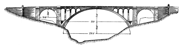
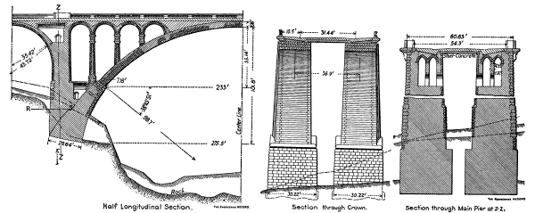
Fig. 40.—Elevation of Luxemburg Bridge
and Sections of Main Span.
130. Largest Arch Spans.—The longest arch span yet built
has been but recently completed in Germany at the city of Luxemburg. This
bridge has a span of 275.5 feet and a rise of 101.8 feet. It is rather
peculiarly built in two parallel parts separated 19.5 feet in the
clear, the space between being spanned by slabs or beams of combined
concrete and steel. The arch-ring is 4.75 feet thick at the crown and
7.18 feet thick at a point 53.14 feet vertically below the crown where
it joins the spandrel masonry. The roadway is about 52.5 feet wide and
144.5 feet above the water in the Petrusse River, which it spans.
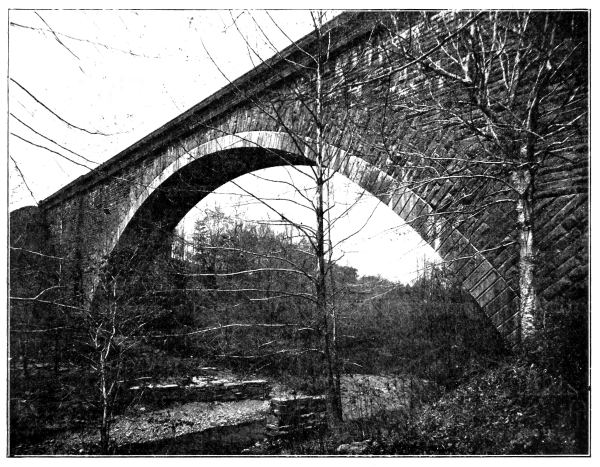
Cabin John Bridge, near Washington, D. C.
The longest arch in this country is known as the Cabin John Bridge of
220 feet span and 57.5 feet rise. It is a segmental arch and is located
a short distance from the city of Washington, carrying the aqueduct for
the water-supply of that city. These lengths of span may be exceeded in
good ordinary masonry construction, but the high degree of strength and
comparative lightness which characterize the combination of steel and
concrete will enable bridges to be built in considerably greater spans
than any yet contemplated in cut-stone masonry.
CHAPTER XIII.
131. Cantilever and Stiffened Suspension Bridges.—There
are two other types of bridges of later development which have, in recent
years, become prominent by remarkable examples of both completed
structure and design; they are known as the cantilever and stiffened
suspension bridges. Both are adapted to long spans, although the latter
may be applied to much longer spans than the former. A cantilever
structure, with a main span of 1800 feet between centres of piers, is
now in process of construction across the St. Lawrence River at Quebec,
while the well-known Forth Bridge across the Firth of Forth in Scotland
has a main span of 1710 feet. The longest stiffened suspension bridge
yet constructed is the New York and Brooklyn Bridge, with a river span
of about 1595.5 feet between centres of towers, but the stiffened
suspension system has been shown by actual design to be applicable to
spans of more than 3200 feet, with material now commercially produced.
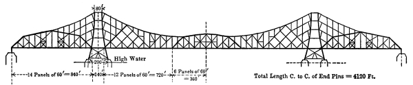
Fig. 41.
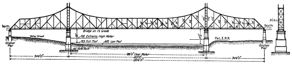
Fig. 42.—Monongahela Bridge—Pittsburgh,
Carnegie & Western Railroad (Wabash), at Pittsburgh.
132. Cantilever Bridges.—Figs. 41
and 42 exhibit in skeleton outline two
prominent cantilever designs for structures in this country. That shown
in Fig. 41 was intended for a bridge across the Hudson
River between Sixtieth and Seventieth streets, New York City. The main central
opening has a span of 1800 feet, and a length of 2000 feet between
centres of towers. Fig. 42 shows the Monongahela River
cantilever bridge,[3]
now being built at Pittsburgh, Penn. Both figures
exhibit the prominent features of the cantilever system. The main parts
are the towers, at each end of the centre span, which are 534.5 feet
high in the North River Bridge and 135 feet high in the Monongahela
River structure, and the central main or river span with its simple
non-continuous truss hung from the ends of the cantilever brackets or
arms which flank it on both sides. These cantilever arms are simply
projecting trusses continuous with the shore- or anchor-arms. They
rest on the piers at either end of the main span, as a lever rests on
its fulcrum. This arrangement requires the shore extremities or the
anchor-arms to be anchored down by a heavy weight formed by the masonry
piers at those points. Recapitulating and starting from the two shore
ends of the structure, there are the anchor-spans, continuous at the
towers, with the cantilever arms projecting outward toward the centre
of the main opening and supporting at their ends the suspended truss,
which is a simple, non-continuous one. It is thus evident that the
cantilever bridge is a structure composed of continuous trusses with
points of contraflexure permanently fixed at the ends of the suspended
span. The greatest bending moments are at the towers, and the great
depth at that point is given for the purpose of affording adequate
resistance to those moments by the members of the structure. The
following statement shows some elements of the more prominent
cantilever bridges of this country and of the Forth Bridge:
| Name. |
Length of Cantilever
Opening,
Centre to Centre
of Towers. |
Total Length. |
| Pittsburgh |
812 |
feet. |
1504 |
feet. |
| Red Rock (Colo.) |
660 |
” |
990 |
” |
| Memphis (Tenn.) |
790.48 |
” |
2378.2 |
” |
| Forth |
1710 |
” |
5330 |
” |
The arrangement of web members of cantilever structures is designed to
be such as will transfer the loads from the points of application to
the points of support in the shortest and most direct paths. Both Figs.
41 and 42 show these general
results accomplished by an advantageous arrangement of web members.
It is interesting to note that the first cantilever bridge designed
and built in this country was constructed in 1871. This structure was
designed and erected by the late C. Shaler Smith, a prominent civil
engineer of his day.
133. Stiffened Suspension Bridges.—The stiffened suspension
bridge is a structure radically different in its main features and its
mode of transferring load to points of support from any heretofore
considered, except arched ribs. When a load is supported by a beam or
truss, the stresses, either in the web members of the truss or in the
solid web of the beams, travel up and down those members in zigzag
directions with a relatively large amount of metal required for that
kind of transference. That metal is represented by the weight of the
web members of the truss and of the solid web of the beam. Again, there
are two sets of truss members—the chords or flanges, one of which
sustains tension and the other an equal amount of compression. The
greater part of this metal must be so placed and used that the working
intensities of stress are comparatively small. This is particularly the
case in compression members of both chords and webs which constitute
the greater portion of the weight of the truss. All compression members
are known as long columns which sustain not only direct compression but
bending, and the amount of stress or load which they carry per square
inch is relatively small, decreasing as the length increases. For
all these reasons the amount of metal required for both beams and
trusses is comparatively large. In suspension bridges, however, the
conditions requiring the employment of a relatively large amount of
metal with relatively small unit stresses are absent. The main members
of a suspension bridge are the cables and the stiffening trusses, the
latter being light in reference to the length of span. The cables are
subjected to tension only, which is the most economical of all methods
of using metal. A member in tension tends to straighten itself, so
that it is never subjected to bending by the load which it carries.
The opposite condition exists with compression members. Again, grades
of steel possessing the highest ultimate resistance may be used in the
manufacture of cables. It is well known that wire is the strongest form
in which either wrought-iron or steel can be manufactured. While the
ultimate tensile resistance of ordinary structural steel will seldom
rise above 70,000 pounds per square inch, steel wire, suitable to be
used in suspension-bridge cables, may be depended upon, at the present
time, to give an ultimate resistance of at least 180,000 pounds per
square inch. The elastic limit of ordinary structural steel is but
little above half its ultimate resistance, while the elastic limit
of the steel used in suspension-bridge cables is probably not less
than three fourths of its ultimate resistance. It is seen, therefore,
that the high resistance of steel wire makes the steel cable of the
suspension bridge a remarkably economical application of metal to
structural purposes.
The latest example of stiffened suspension-bridge is the new East River
Bridge reaching across the East River from Broadway in Brooklyn to
Delancey Street, New York City, now being built, with a main span of
1600 feet between centres of towers. The entire length of the metal
structure is 7200 feet, and the elevation of the centres of cable at
the tops of the towers is 333 feet above mean high water.
Fig. 43 shows a view of this bridge. Its three principal
divisions are the cables, the stiffening trusses, and the towers. The latter afford
suitable points of support for the cables, which not only extend over
the river span, but are carried back to points on the land where they
are securely attached to a heavy mass of anchorage masonry. These
anchorages must be sufficiently heavy to prevent any load which may
come upon the bridge from moving them by the pull of the cables. It is
usual to make these masses so great that they are capable of resisting
from two to two and a half times the pull of the cables.
Fig. 43.—New East River Bridge.
134. The Stiffening Truss.—The function of the stiffening
trusses is peculiar and imperatively essential to the proper action of
the whole system. If they are absent and a weight should be placed upon
the cable at any point, a deep sag at that point would result. If a
moving load should attempt to pass along a roadway supported by a cable
only, the latter would be greatly distorted, and it would be impossible
to use such a structure for ordinary traffic. Some means must then be
employed by which the cable shall maintain essentially the same shape
and position, whatever may be the amount of loading. It can be readily
shown that if any perfectly flexible suspension-bridge cable carries a
load of uniform intensity over the span from one tower to the other,
the curve of the cable will be a parabola, with its vertex at the
lowest point. Furthermore, it can also be shown that if any portion of
the span be subjected to a uniform load, the corresponding portion of
the cable will also assume a parabolic curve. It is assumed in all
ordinary suspension-bridge design that the total weight of the
structure, including the cables and the suspension-rods which connect
the stiffening trusses to the cable, is uniformly distributed over
the span, and that assumption is essentially correct. So far as the
weight of the structure is concerned, therefore, the curve of the cable
will always be parabolic. It only remains, therefore, to devise such
stiffening trusses as will cause any moving load passing on or over
the bridge to be carried uniformly to the cables throughout the entire
span. This condition means that if any moving load whatever covers any
portion of the span, the corresponding pull of the suspension-rods on
the cables must be uniform from one tower to the other, and that result
can be practically accomplished by the proper design of stiffening
trusses; it is the complete function of those trusses to perform just
that duty.
135. Location and Arrangement of Stiffening Trusses.—It
has been, and is at the present time to a considerable extent, an open
question as to the best location and arrangement of the stiffening
trusses. The more common method in structures built is that illustrated
by the New York and Brooklyn and the new East River bridges. Those
stiffening trusses are uniform in depth, extending from one tower to
the other, or into the land spans, and connected with the cables by
suspension-rods running from the latter down to the lower chords of the
trusses. It is obvious that the floor along which the moving load is
carried must have considerable transverse stiffness, and hence it may
appear advisable to place the stiffening trusses so that the floor may
be carried by them. On the other hand, some civil engineers maintain
that it is a better distribution of stiffening metal to place it where
the cables themselves may form members of the stiffening trusses, with
a view to greater economy of material.
Figs. 44, 45, and
46 illustrate some of the principal proposed methods
of constructing stiffening trusses in direct connection with the
cables. The structure shown in Fig. 44 illustrates
the skeleton design of the Point Bridge at Pittsburgh. The curved member is a
parabolic cable composed of eye-bars. This parabolic cable carries the entire
weight of the structure and moving load when uniformly distributed. If
a single weight rests at the centre, the two straight members of the
upper chord may be assumed to carry it. If a single weight rests at any
other point of the span, it will be distributed by the bracing between
the straight and curved members of the stiffening truss. Obviously the
most unbalanced loading will occur when one half of the span is covered
with moving load. In that case the bowstring stiffening truss in
either half of Fig. 44 will make the required distribution
and prevent the parabolic tension member from changing its form.

Fig. 44.

Fig. 45.

Fig. 46.
The type of bracing shown in Fig. 45 possesses some
advantages of a peculiar nature. Each curved lower chord of the stiffening truss
corresponds to the position of the perfectly flexible cable with
the moving load covering that half of the span which belongs to the
greatest sag of the cable. The two parabolic cables thus cross each
other in a symmetrical manner at the centre of the span. If the moving
load covers the entire span, the line of resistance or centre line of
imaginary cable will be the parabola, shown by the broken line midway
along each crescent stiffening truss. The diagonal bracing placed
between the cables is so distributed and applied as to maintain the
positions of cables under all conditions of loading.
The mode of constructing the stiffening truss between two cables, shown
in Fig. 46, is that adopted by Mr. G. Lindenthal in his
design for a proposed stiffened suspension bridge across the Hudson River with a
span of about 3000 feet. The two cables are parabolic in curvature and
may be either concentric or parallel. This system of stiffening bracing
possesses some advantages of uniformity and is well placed to secure
efficient results. The same system has been used in suspension bridges
of short span by Mr. Lindenthal at both St. Louis and Pittsburgh. The
stiffening bracing produces practically a continuous stiffening truss
from one tower to the other, whereas the systems shown in Figs. 44
and 45 involve practically a joint at the centre of the span.
In all these three types of vertical stiffness the floor is designed
to meet only the exigencies of local loading, being connected with the
stiffening truss above by suspension bars or rods, preferably of stiff section.
When stiffening trusses are placed along the line of the floor, as in
the case of the two East River bridges, to which reference has already
been made, those trusses need not necessarily be of uniform depth, and
they may be continuous from tower to tower or jointed at the centre,
like those of the New York and Brooklyn suspension bridge. This centre
joint detracts a little from the stiffness of the structure, but in a
proper design this is not serious.
136. Division of Load between Cables and Stiffening Truss.—In
a case where continuous stiffening trusses are employed it is obvious
that they may carry some portion of the moving load as ordinary
trusses. The portion so carried will be that which is required to make
the deflection of the stiffening truss equal to that of the cable
added to the stretch of the suspension-rods. In the old theory of the
stiffening truss constructed along the floor of the bridge this effect
was ignored, and the computations for the stresses in those trusses
were made by the aid of equations of statical equilibrium only. That
assumption, that the cable carried the entire load, was necessary
to remove the ambiguity which would otherwise exist. In modern
suspension-bridge design those trusses may be assumed continuous from
tower to tower with their ends anchored at the towers, or they may be
designed to be carried continuously through portions of the land spans
and held at their extremities by struts reaching down to anchorages,
so that those ends may never rise nor fall, but move horizontally if
required. If there are no pin-joints in the trusses at the centre
and ends of the main span, equations of statical equilibrium are not
sufficient to enable the reactions under the trusses and the horizontal
component of cable tension to be found.
One of the best methods of procedure for such cases is that of
least work, in which the horizontal component of cable tension is
so found that the total work performed in the elastic deflection of
the stiffening trusses, suspension-rods, cables, and towers is a
minimum. After having found this horizontal component of the cable
tension and the reactions under the stiffening trusses, the stresses
in all the members of the entire structure can be at once determined.
It is obvious that the stiffening truss and the cables must deflect
together. It is equally evident that the deeper the stiffening trusses
are the more load will be required to deflect them to any given
amount, and hence that the deeper they are the more load they will
carry independently of the cable. It is desirable to throw as much of
the duty of carrying loads upon the cables as possible. It therefore
follows that the stiffening trusses should be made as shallow as the
proper discharge of their stiffening duties will permit.
137. Stresses in Cables and Moments and Shears in Trusses.—The
necessary limits of this discussion will not permit even the simplest
analyses to be given. It is evident, however, that the greatest
cable stresses will exist at the tops of the towers, and that if the
horizontal component of cable tension be found by any proper method,
the stress at any other point will be equal to that horizontal
component multiplied by the secant of cable inclination to a horizontal
line, it being supposed that the suspenders are found in a vertical
plane.
If the stiffening trusses are jointed at the centre of the main span,
as well as at the ends, the simple equations of statical equilibrium
are sufficient in number to make all computations, for the reason that
the centre pin-joint gives the additional condition that, whatever may
be the amount or distribution of loading, the centre moment must be
zero. If l is the length of main or centre span and p the
moving load per linear foot of span, and if the stiffening trusses run
from tower to tower, the following equations will give their greatest
moments and shears both by the old and new theory of the stiffening truss.
| |
p = load per lin. ft.,
Old theory. |
l = length of span in ft.,
New theory. |
|
|
| Max. moment |
M = 0.01856pl² |
M = 0.01652pl² |
 |
no centre |
| Max. shear |
S = ⅛pl |
S = ⅛pl |
hinge. |
| With centre hinge |
M = 0.01883pl² and |
S = ⅛pl |
|
The details of the theory of stiffening trusses for suspension
bridges have been well developed during the past few years and are
fully exhibited in modern engineering literature. The long spans
requiring stiffened suspension bridges are usually found over navigable
streams, and hence those bridges must be placed at comparatively
high elevations. This is illustrated by the clear height of 135 feet
required under the East River suspension-bridge structures already
completed and in progress. Furthermore, the heights of towers above
the lowest points of the cables usually run from one eighth to one
twelfth of the span. These features expose the entire structure to
comparatively high wind pressures, which must be carefully provided
against. This is done by the requisite lateral bracing between the
stiffening trusses and by what is called the cradling of the cables.
The latter expression simply means that the cables as they are built
are swung out of a vertical plane and toward the axis of the structure,
being held in that position by suitable details. The cables on opposite
sides of the bridge are thus moved in toward each other so as to
produce increased stability against lateral movement. Occasionally
horizontal cables are stretched between the towers in parabolic curves
in order to resist horizontal pressures, just as the main cables carry
vertical loads. This matter of stability against lateral wind pressures
requires and receives the same degree of careful consideration in
design as that accorded to the effects of vertical loading. The same
general observation applies also to the design of the towers.
138. Thermal Stresses and Moments in Stiffened Suspension
Bridges.—All material used in engineering structures expands and
contracts with rising and falling temperatures to such an extent
that the resulting motions must be provided for in structures of
considerable magnitude. In ordinary truss-bridges one end is supported
upon rollers, so that as the span changes its length the truss ends
move the required amount upon the rollers. In the case of stiffened
suspension bridges, however, the ends of the cables at the anchorages
are rigidly fixed, so that any adjustment required by change of
temperature must be consistent with the change of length of cable
between the anchorages. The backstays, which are those portions of
the cables extending from the anchorages to the tops of the towers,
expand and contract precisely as do the portions of the cable between
the tops of the towers. As the cables lengthen, therefore, the sag or
rise at the centre of the main span will be due to the change in the
entire length of cable from anchorage to anchorage. In order to meet
this condition it is usual to support the cables at the tops of the
towers on seats called saddles which rest upon rollers, so as to afford
any motion that may be required. Designs have been made in which the
cables are fixed to the tops of steel towers. In such cases changes
of temperature would subject the towers to considerable bending which
would be provided for in the design.
The rise and fall at the centres of long spans of stiffened suspension
bridges is considerable; indeed, for a variation of 120° Fahr. the
centre of the New York and Brooklyn Bridge changes its elevation by
4.6 feet if the saddles are free to move, as intended. In the case of
a stiffened suspension bridge designed to cross the North River at New
York City with a main span of 3200 feet a variation of 120° Fahr. in
temperature would produce a change of elevation of the centre of the
span of 6.36 feet. Such thermal motions in the structure obviously will
produce stresses of considerable magnitude in various parts of the
stiffening trusses, all of which are invariably recognized and provided
for in good design.
139. Formation of the Cables.—At the present time
suspension-bridge cables are made by grouping together in one
cylindrical mass a large number of so-called strands or individual
small cables, each composed of a large number of parallel wires about
one sixth of an inch in diameter. The four cables of the New York and
Brooklyn Bridge are each composed of 19 strands, each of the latter
containing 332 parallel wires, making a total of 6308 wires, the cables
themselves being 15½ inches in diameter. The wire is No. 7 gauge,
i.e., 0.18 inch in diameter. In the new East River Bridge each of the
four cables is 18¼ inches in diameter and contains 37 strands, each
strand being composed of 208 wires all laid parallel to each other,
or a total of 7696 wires. The size of the wire is No. 6 (Roebling)
gauge, i.e., 0.192 inch in diameter. These strands are formed by laying
wire by wire, each in its proper place. The strands are then bound
together into a single cable, around which is tightly wound a sheathing
or casing of smaller wire, 0.134 inch in diameter for the New York
and Brooklyn Bridge. The tightness of this binding wire insures the
unity of the whole cable, each wire having been placed in its original
position so as to take a tension equal to that of each of the other
wires. The suspension-rods are usually of wire cables and are attached
by suitable details to the lower chords of the stiffening truss, also
by specially designed clamps to the cable. The stiffening trusses are
usually built with all riveted joints, so as to secure the greatest
possible stiffness from end to end. The stiffened suspension bridge has
been shown by experience, as well as by theory, to be well adapted to
carry railroad traffic over long spans.
140. Economical Limits of Spans.—In the past, suspension
bridges have, in a number of cases, been built for comparatively short
spans, but it is well recognized among engineers that their economical
use must be found for spans of comparatively great length. While
definite lower limits cannot now be assigned to such spans, it is
probable that with present materials of construction and with available
shop and mill capacities the ordinary truss-bridge may be economically
used up to spans approximately 700 to 800 feet, and that above that
limit the cantilever system is economically applicable to lengths of
span not yet determined but probably between 1600 and 2000 feet. The
special field of economical employment of the long-span stiffened
suspension bridge will be found at the upper limit of the cantilever
system. So far as present investigations indicate, the stiffened
suspension type of structure may be employed to advantage from about
1800 feet up to the maximum practicable length of span not yet
assignable, but perhaps in the vicinity of 4000 feet. Obviously such
limits are approximate only and may be pushed upward by further
improvements in the production of material and in the enlargement of
both shop and mill capacity.
PART III. WATER-WORKS FOR CITIES AND TOWNS. — CHAPTER XIV.
141. Introductory.—A preceding lecture in this course has
shown to what an advanced state the public supply of water to large cities
was developed in ancient times. The old Romans, Greeks, Egyptians, and
other ancient peoples evidently possessed an adequate appreciation of
the value of efficient systems of public water-supply. Very curiously
that appreciation diminished so greatly as almost to disappear
during the middle ages. The demoralization of public spirit and the
decrease of national power which followed the fall of Rome induced, in
their turn, among other things, a neglect of the works of the great
water system of Rome, entailing their partial destruction. The same
retrogression in civilization seemed to affect other ancient nations
as well, until probably the lowest state of the use of public waters
and the construction of public water systems was reached somewhere
between A.D. 1000 and A.D.
1300 or 1400. Without reasonable doubt the terrible epidemics or
plagues of the middle ages can be charged to the absence of suitable
water-supplies and affiliated consequences. During that middle period
of the absence of scientific knowledge and any apparent desire to
acquire it, sanitary works and consequently sanitary conditions of
life were absolutely neglected. No progress whatever was made toward
reaching those conditions so imperative in large centres of population
for the well-being of the community. Grossly polluted waters were
constantly used for public and private supplies, and no efforts
whatever were made among the masses toward the suitable disposition
of refuse matters or, in a word, to attain to sanitary conditions of
living.
A few important works were completed, particularly in Spain, but
nothing indicative of general relief from the depths of ignorance and
sanitary demoralization to which the greater portion of the civilized
world had sunk at that time. The city of Paris took all its water from
the Seine, except that which was supplied by a small aqueduct built in
1183. So small was the supply, aside from the water obtained from the
river, that in 1550 it is estimated that the former amounted to about
one quart only per head of population per day. The situation in London
was equally bad, for it was only in the first half of the thirteenth
century that spring-water was brought to the city by means of lead
pipes and masonry conduits. Public water-works began to be constructed
in Germany on a small scale in the early part of the fifteenth century.
Obviously no pumps were available in those early days of water-supply,
so that the small systems which have been mentioned were of the
gravity class; that is, the water flowed naturally in open or closed
channels from its sources to the points of consumption. Pumps of a
simple and crude type first began to be used at a point on the old
London Bridge in 1582, and in Hanover in 1527. Subsequently to those
dates other pumps were set up on London Bridge, and installations
of the same class of machinery were made in Paris in 1608, usually
operated by water-power in some simple manner, as by the force of the
water-currents. In 1624 the Paris supply received a reinforcement of
200,000 gallons per day by the completion of the aqueduct Arcueil. The
New River Company was incorporated in 1619 for the partial supply of
the city of London, and it began to lay its pipes at that time. As its
name indicates, it took its supply from New River, and the inception of
its business is believed to mark the first application of the principle
of supplying each house with water. This company is still in existence
and furnishes a considerable portion of the present London supply.
142. First Steam-pumps.—The application of steam to
the creation or development of power by Watt, near the end of the
eighteenth century, stimulated greatly the construction of water-works,
as it offered a very convenient and economical system of pumping. It
seems probable that the first steam-pumps were used in London in 1761.
Twenty years later a steam-pump was erected in Paris, while another
was installed in 1783. The second steam-pump in London was probably
constructed in 1787. In all these earlier instances of the use of
steam-pumps river supplies were naturally used.
143. Water-supply of Paris and London.—After the early
employment of steam pumping-machinery demonstrated its great efficiency
for public water-supplies, the extension of the latter became more
rapid, and since 1800 the supplies of the two great cities of London
and Paris have been greatly increased. As late as 1890 the Paris
supply amounted to about 65 gallons per head of population, one fourth
of which was used as potable, being drawn from springs, while three
fourths, drawn from rivers, was used for street-cleaning or other
public purposes. This supply, however, was found inadequate and was
re-enforced in 1892 by an addition of 30,000,000 gallons per day of
potable water brought to the city by an aqueduct 63 miles long. Another
addition of about 15,000,000 gallons has been provided more recently.
Rather curiously the water-supply of London is afforded by eight
private companies, one of which is the old New River Company already
mentioned. These companies, with one exception, draw their supply
mainly from the rivers Thames and Lea, all such water being filtered.
The remaining company draws its water from deep wells driven into the
chalk. The total population supplied amounts to about 5,500,000, the
rate of supply being thus less than 45 gallons per head per day.
144. Early Water-pipes.—Inasmuch as the use of cast-iron
for pipes was only begun about the year 1800, other materials were
used prior to that date. As is well known, the pipes used in ancient
water-works were either of lead or earthenware. In the eighteenth
century wooden pipes made of logs with their centres bored out were
used, sometimes 6 or 7 inches in diameter. As many lines of these log
pipes were used as needed to conduct a single line of supply. In the
earlier portion of the nineteenth century such log pipes, usually of
pine or spruce, were used by the old Manhattan Company for the supply
of New York City. A section of such a wooden pipe, with a bore of
about 2½ inches is preserved in the museum of the Department of
Civil-Engineering of Columbia University. Large quantities of such
pipes were formerly used.
145. Earliest Water-supplies in the United States.—The
earliest system of public water-supply in this country was completed for the
city of Boston in 1652. This was a gravity system. It is believed
that the first pumping-machinery for such a supply was set up for the
town of Bethlehem, Pa., and put in operation in 1754. Subsequently
water-supplies were completed for Providence, R. I., 1772, and for
Morristown, N. J., in 1791; the latter has maintained a continuous
existence since that date. The first use of steam pumping-machinery in
this country was in Philadelphia in 1800. This machinery, curiously
enough, was largely of wood, including some portions of the boiler; it
was necessarily very crude and would perform with 100 pounds of coal
only about one twenty-fifth or one thirtieth of what may be expected
from first-class pumping-machinery at the present time. Other cities
and towns soon began to follow the lead of these earlier municipalities
in the construction of public water-supplies, but the principal
development in this class of public works has taken place since about 1850.
It is estimated that the total population supplied in 1880 was about
12,000,000, which rose to about 23,000,000 in 1890, and it is probably
not less than 50,000,000 at the present time.
146. Quality and Uses of Public Water-supply.—Advances
in the public supplies in this country have been made rather in the line of
quantity than quality. Insufficient attention has been given both
to the quality of the original supply and to the character of the
reservoirs in which it is gathered until within possibly the past
decade. A few cities like Boston have scrutinized with care both the
quality of the water and the character of the bottom and banks of
reservoirs, and have spared neither means nor expense to acquire a high
degree of excellence in their potable water. The same observations
can be applied to a few other large cities, but to a few only. The
realization of the dependence of public health upon the character
of water-supply, however, has been rapidly extending, and it will
doubtless be but a short time before the care exercised in collecting
and preparing water for public use will be as great in this country
as in Europe, where few large cities omit the filtration of public waters.
The distribution of water supplied for public use is not limited to
domestic purposes, although that class of consumption controls public
health so far as it is affected by the consumption of water. The
applications of water to such public purposes as street-cleaning and
the extinguishing of fires are of the greatest importance and must
receive most careful consideration. Again, the so-called system of
water-carriage in the disposal of domestic and manufacturing wastes,
constituting the field of sewage-disposal, depends wholly upon the
efficiency of the water-supply.
147. Amount of Public Water-supply.—The first question
confronting an engineer in the design of public water-supply is the
amount which should be provided, usually stated on the basis of an
estimated quantity per head of population. This is not in all cases
completely rational, but it is by far the best basis available. If the
water-supply is designed for a small city or town previously supplied
by wells or other individual sources, the first year’s consumption
will be low per head of population for the reason that many people
will retain their own sources instead of taking a share of the public
supply. As time elapses that portion of population decreases quite
rapidly in numbers, and in a comparatively few years practically the
whole population will use the public supply. In communities, therefore,
where public systems have long existed and it is desired either to
add to the old supply or to install new ones, the only safe basis of
estimate is the entire population.
148. Increase of Daily Consumption and the Division of
that Consumption.—The amount of water required per head of population
might naturally be assumed identical with the past consumption, but
that would frequently be incorrect. It is one of the most prominent
features of the history of public water-supplies in this country
that the consumption per head of population has increased with great
rapidity from the early years of the installation of the different
systems, for reasons both legitimate and illegitimate. The daily
average consumption of water from the Cochituate Works of the Boston
supply increased from 42 gallons per head of population in 1850 to
107 gallons in 1893, and in the Mystic Works of the same supply the
increase was from 27 gallons in 1865 to 89 gallons in 1894. Again, the
daily average consumption in Chicago rose from 43 gallons per head per
day in 1860 to 147 gallons in 1893, while in Philadelphia during the
same period the increase was from 36 gallons per head per day to 150
gallons. In Cambridge, Mass., the increase in daily average consumption
per head of population was from 44 gallons in 1870 to 70 gallons in
1894. These instances are sufficient to show that, under existing
conditions, the daily consumption was increased at a rapid rate in the
cities named, and they have been selected as fairly representative
of the whole field. Civil engineers have made extended studies in
connection with this question in a great number of cities, for it bears
upon one of the most important lines of public works. It is absolutely
essential to the health and business prosperity of every city that the
water-supply should be abundant, safe, and adapted to the industrial
and commercial pursuits of its population. It is imperative, therefore,
that the division of the daily supply should be carefully analyzed.
For this purpose the water-supply of a city may be, and frequently is,
divided into four parts:
- (1) That used for domestic purposes;
- (2) That used for commercial and industrial purposes;
- (3) That used for public purposes;
- (4) That part of the supply which is wasted.
1. That portion of the supply consumed for domestic purposes includes
not only the water used in private residences, but in those branches
of consumption which may be considered of a household character found
in hotels, clubs, stores, markets, laundries, and stables, or for
any other residential service. As might be expected, this branch of
consumption varies largely from one city to another. The results of one
of the most interesting and suggestive studies ever made in connection
with this subject are given by Mr. Dexter Brackett, M. Am. Soc. C. E.,
in the Transactions of the American Society of Civil Engineers for
1895. In Boston the purely domestic consumption varied in different
houses and apartments from 59 gallons per head per day in costly
apartments down to 16.6 gallons per head per day in the poorest class
of apartment. In Brookline, one of the finest suburbs of Boston,
the quantity was 44.3 gallons per day. In some other cities of
Massachusetts, as Newton, Fall River, and Worcester, this class of
consumption varied from 6.6 gallons to 26.5 gallons per day, the latter
quantity being found at Newton in some of the best residences, and the
former at houses also in Newton having but one faucet each. In Yonkers,
N. Y., where the system was metered, the amount was 21.4 gallons per
head of population per day, while in portions of London, England, it
varied from 18.6 to 25.5 gallons per head per day. The average of these
figures gives a result of 18.2 gallons per head per day, which, in
round numbers, may be put at 20 gallons.
2. It is obvious that the rate of consumption for commercial and
industrial purposes in any city must vary far more than that for
domestic purposes, for the reason that some cities may be essentially
residential in character while others may be essentially manufacturing.
At the same time, it is to be remembered that many manufacturing
establishments may have their own water-supply. The city of Fall River,
Mass., is eminently a manufacturing city, yet Mr. Brackett found that
the manufacturing demand on the public water-supply amounted to 2
gallons only per inhabitant per day, as the manufacturers draw the
most of their supply from the river, but that where the manufacturers
depend upon the public supply for all their water the amount rises to a
value between 20 and 30 gallons per inhabitant. In Boston in 1892 the
water consumed for all manufacturing and industrial purposes, including
railroads, gas-works, elevators, breweries, etc., amounted to 9.24
gallons per head of population per day, while in Yonkers in 1897 the
total consumption for commercial purposes was 27.4 gallons per head
per day. In the city of New York, as nearly as can be estimated, the
consumption for commercial purposes is probably not far from 25 gallons
per inhabitant per day. Reviewing all these results, it may be stated
that the water consumption for commercial and industrial purposes will
generally range from 10 to 30 gallons per inhabitant per day.
3. The consumption of water for public purposes is a smaller amount
than either of the two preceding. It covers such uses as public
buildings, schools, street-sprinkling, sewer-flushing, fountains,
fires, and other miscellaneous objects, more or less similar to those
just named. The total use of this character was 3.75 gallons per
inhabitant per day for Boston in 1892, and 5.57 gallons per inhabitant
per day for Fall River in 1899. A few other cities give the following
results: Minneapolis in 1897, 5 gallons; Indianapolis, 3 gallons;
Rochester, N. Y., 3 gallons; Newton, Mass., 4 gallons; Madison, Wis.,
10 gallons. In Paris it is estimated that not far from 2.5 gallons per
head of population per day are used. It is probable, therefore, that an
amount of 5 gallons per day per inhabitant will cover this particular
line of consumption.
4. A substantial portion of the water-supply of every city fails to
serve any useful purpose, for the reason that it runs to waste either
by intention or by neglect. The sources of this waste are defective
plumbing, including leaky faucets and cocks; deliberate omission to
close faucets and cocks, constituting wilful waste; defective or broken
mains, including leaky joints; and waste to prevent freezing.
149. Waste of Public Water.—All these wastes except
the last are inexcusable. There is no difficulty in detecting defective
plumbing, and its existence is generally known to the householder;
but if the wasted water is not measured and paid for, it is far too
frequently considered more economical to continue the waste than to pay
for the plumber’s services. In a multitude of cases cocks are left open
indefinitely for all sorts of insignificant reasons; in closets, under
the erroneous impression that the continuous running of the stream will
materially aid in a more effective cleansing of soil- and sewer-pipes,
failing completely to appreciate that a far more powerful stream is
required for that purpose; sometimes in sinks, for refrigerating
purposes, and in many other inexcusably wrong ways. These sources
of wilful waste lead to large losses and constitute one of the most
unsatisfactory phases of administration of a public water system.
Such losses result in a vicious waste of public money. The amount of
water flowing from leaky joints and from leaks in pipes and mains is
necessarily indeterminate because it escapes without evidence at the
surface except in rare cases. In every instance where examinations have
been made and a careful record kept of the amount of water supplied
to a city, it has been found that the aggregate of the measured
amounts consumed fail nearly to equal the total supply. There are
probable errors both in the measurement of the quantities supplied
and in the quantities consumed, but the large discrepancy cannot be
accounted for in this manner. In many cases consumed water has even
been carefully measured by meters, as at Yonkers, New York, Newton,
Milton, and Fall River, Mass., Madison, Wis., and at other places,
but yet the discrepancy appears to be nearly as wide as ever. Again,
in 1893 observations were carefully made on the consumption of the
water received by the Mystic supply of the Boston system at all
hours of the twenty-four. Obviously between 1 and 4 A.M.
the useful consumption should be nearly nothing, but, on the contrary, it
was found to be nearly 60 per cent of the average hourly consumption
for the entire twenty-four hours. The waste at Buffalo, N. Y., in 1894
was estimated at 70 per cent of the total supply. Similar observations
in other places have given practically the same results. It has also
been found that, in a number of instances, where old watercourses have
been completely obliterated by considerable depths of filling required
by the adopted grades of city streets and lots, and excavations for
buildings have subsequently been opened practically the full volume of
the former streams are flowing along the original but filled channel.
This result has been observed under a practically impervious paved
city surface. It is difficult to imagine the source of such a supply
except from defective pipe systems or sewers. A flow of a least 100,000
gallons per day from a broken pipe which found its way into a sewer has
also been discovered without surface evidence. These and many other
results of experience conclusively demonstrate that much water flows to
waste unobserved from leaky joints and defective or broken pipes.
Inasmuch as cast-iron water-pipes are produced in lengths which net
12 feet as laid, there will be at least 440 joints per mile. Furthermore,
as leaky joints and broken pipes are as likely to occur at one place
as another, it seems reasonable to estimate leakage through them as
proportionate to the length of the pipe-line in a system; and that
conventional law is frequently assumed. New pipe-lines have sometimes
shown a leakage of 500 to 1200 gallons per mile of line per day. Civil
engineers have sometimes specified the maximum permissible leakage of
a new pipe-line at 60 to 80 gallons per mile of line per day for each
inch in diameter of pipe, thus permitting 600 to 800 gallons to escape
from a 10-inch pipe. In 1888 the late Mr. Chas. B. Brush reported a
leakage of about 6400 gallons per mile per day from a practically new
24-inch cast-iron main, 11 miles long, of the Hackensack Water Company,
the pressure being 110 pounds per square inch. Tests of water-pipes in
German and Dutch cities have been reported as showing less waste than
300 gallons per mile per day, but such low results, unless for very low
pressures and short lines, may reasonably be doubted. Obviously losses
of this character will probably increase with the age of the pipe. By
a very ingenious procedure based upon his own experience, Mr. Emil
Kuichling of Rochester, N. Y., reaches the conclusion that a reasonable
allowance for the waste from leaky joints and defective pipes is 2500
to 3000 gallons per mile of cast-iron pipe-line per day. If, as is
frequently the case, the population per mile of pipe ranges from 300 to
1000, the preceding allowance amounts to 3 to 10 gallons per head of
population per day. The loss or waste due to running cocks or faucets
to prevent freezing cannot be estimated with sufficient accuracy to
receive a definite valuation, but it must be considered an element of
the total item of waste.
150. Analysis of Reasonable Daily Supply per Head of
Population.—It has repeatedly been found that the losses or wastes
set forth in the preceding statements amount apparently to quantities
varying from 30 to 50 per cent of the total supply; or, to put it a
little differently, the water unaccounted for in even the best systems
now constructed apparently may reach one third to one half of the total
supply. This is an exceedingly wasteful and unbusinesslike showing.
It is probable that the statement is, to some extent at least, an
exaggeration. It is practically certain that either the amount supplied
or the amounts consumed, or both, are never measured with the greatest
accuracy, and that the errors are such as generally swell the apparent
quantity wasted. After making judicious use of the data thus afforded
by experience, it is probable that the following tabular statement
given by Messrs. Turneaure and Russell represents limits within which
should be found the daily average supply of water in a well-constructed
and well-administered system.
| Use. |
Gallons per Head per Day. |
| Minimum. |
Average. |
Maximum. |
| Domestic |
15 |
25 |
40 |
| Industrial and commercial |
5 |
20 |
35 |
| Public |
3 |
5 |
10 |
| Waste |
15 |
25 |
30 |
| Total |
38 |
75 |
115 |
The values given in the preceding table are reasonable and sufficient
to supply the legitimate needs of any community, but, as will be shown
in the succeeding table, there are cities in this country whose average
consumption is more than twice the maximum rate given above.
151. Actual Daily Consumption in Cities of the United
States.—The following table exhibits the average daily consumption
of water throughout the entire year for the cities given, as determined
for the years indicated in the table.
The city of Buffalo shows a daily consumption of 271 gallons per
inhabitant, and Allegheny, Pa., 247 gallons per inhabitant. There are a
considerable number showing an average daily consumption per inhabitant
of 160 gallons or more. All such high averages exhibit extravagant use
of water, or otherwise inefficient administration of the water-supply.
The reduction of such high rates of consumption is one of the most
difficult problems confronting the administration of public works. The
use of the meter has proved most efficient in preventing wastes or
other extravagant consumption, as in that case every consumer pays a
prescribed rate for the amount which he takes.
TABLE I.
- LEGEND:
- (A) = Population per Tap.
- (B) = Per Cent of Taps Metered
- (C) = Consumption per Inhabitant Daily, Gallons.
| |
Population. |
(A) |
(B) |
(C) |
(B) |
(C) |
(C) |
| |
1890. |
1890. |
1890. |
1890. |
1895. |
1895. |
1900. |
| New York |
1,515,301 |
13.9 |
20.2 |
79 |
27.0 |
100 |
115 |
| Chicago |
1,099,850 |
7.1 |
2.5 |
140 |
2.8 |
139 |
190 |
| Philadelphia |
1,046,964 |
6.1 |
0.3 |
132 |
0.74 |
162 |
229 |
| Brooklyn |
838,547 |
8.7 |
2.5 |
72 |
1.9 |
89 |
. . . |
| St. Louis |
451,770 |
11.8 |
8.2 |
72 |
7.4 |
98 |
11 |
| Boston |
448,477 |
6.6 |
5.0 |
80 |
5.2 |
100 |
143 |
| Cincinnati |
305,891 |
8.5 |
4.1 |
112 |
6.5 |
35 |
121 |
| San Francisco |
298,997 |
9.9 |
41.4 |
61 |
28.0 |
63 |
73 |
| Cleveland |
270,055 |
8.7 |
5.8 |
103 |
4.5 |
142 |
175 |
| Buffalo |
255,664 |
6.3 |
0.2 |
186 |
0.85 |
271 |
262 |
| New Orleans |
242,039 |
54.0 |
0.4 |
37 |
. . . |
35 |
48 |
| Washington |
230,392 |
6.5 |
0.3 |
158 |
1.5 |
200 |
174 |
| Montreal |
216,000 |
5.3 |
17 |
67 |
1.6 |
83 |
. . . |
| Detroit |
205,876 |
5.1 |
2.1 |
161 |
8.2 |
152 |
156 |
| Milwaukee |
204,468 |
11.1 |
31.9 |
110 |
51.0 |
101 |
84 |
| Toronto |
181,000 |
4.0 |
4.1 |
100 |
3.7 |
100 |
. . . |
| Minneapolis |
164,738 |
16.5 |
6.3 |
75 |
16.0 |
88 |
93 |
| Louisville |
161,129 |
11.9 |
5.9 |
74 |
6.6 |
97 |
. . . |
| Rochester |
133,896 |
5.4 |
11.4 |
66 |
18.0 |
71 |
83 |
| St. Paul |
133,156 |
12.7 |
4.2 |
60 |
1.7 |
60 |
51 |
| Providence |
132,146 |
9.4 |
62.4 |
48 |
74.0 |
57 |
54 |
| Indianapolis |
105,436 |
35.6 |
7.6 |
71 |
7.1 |
74 |
79 |
| Allegheny |
105,287 |
7.0 |
0 |
238 |
7.1 |
247 |
. . . |
| Columbus |
88,150 |
11.5 |
6.4 |
78 |
9.3 |
127 |
183 |
| Worcester |
84,655 |
8.9 |
89.4 |
59 |
90.0 |
66 |
67 |
| Toledo |
81,434 |
18.6 |
9.4 |
72 |
35.0 |
70 |
59 |
| Lowell |
77,696 |
9.2 |
22.9 |
66 |
33.0 |
82 |
83 |
| Nashville |
76,168 |
14.9 |
0.8 |
146 |
24.0 |
139 |
140 |
| Fall River |
74,398 |
14.9 |
74.6 |
29 |
82.0 |
35 |
35 |
| Atlanta |
65,533 |
20.0 |
89.6 |
36 |
99.0 |
42 |
61 |
| Memphis |
64,495 |
11.9 |
3.7 |
124 |
4.6 |
100 |
98 |
| Quebec |
63,000 |
10.4 |
0 |
160 |
0 |
170 |
. . . |
| Dayton, O. |
61,220 |
20.0 |
3.8 |
47 |
24.0 |
50 |
62 |
| Camden, N. J. |
58,313 |
. . . |
. . . |
131 |
0 |
200 |
185 |
| Des Moines, Ia. |
50,093 |
20.0 |
60.0 |
55 |
42.6 |
43 |
48 |
| Ottawa, Ont. |
44,000 |
4.2 |
0 |
130 |
0 |
0 |
. . . |
| Yonkers, N. Y. |
32,033 |
12.0 |
82.4 |
68 |
99.8 |
100 |
76 |
| Newton, Mass. |
24,379 |
5.5 |
67.4 |
40 |
77.3 |
65 |
62 |
| Madison, Wis. |
13,426 |
11.0 |
31.0 |
40 |
61.0 |
52 |
44 |
| Albany, N. Y. |
98,000 |
. . . |
0.4 |
162 |
12.3 |
. . . |
192 |
| New Bedford, Mass. |
55,000 |
. . . |
. . . |
99 |
15.4 |
. . . |
101 |
| Springfield, Mass. |
49,299 |
. . . |
. . . |
87 |
31.9 |
. . . |
88 |
| Holyoke, Mass. |
40,000 |
. . . |
. . . |
77 |
5.82 |
. . . |
[4]103 |
152. Actual Daily Consumption in Foreign Cities.—It has
been for a long time a well recognized fact that the daily use of water in
American municipalities is far greater per inhabitant than in European
cities. It is difficult to explain the marked difference, but it is
probably due in large part to the more extravagant general habits of
the American people. Examinations in a number of cases have shown that
the actual domestic use of water, at least in some of the American
cities, is not very different from that found in corresponding foreign
cities. Table II exhibits the consumption of water in European cities,
as compiled from various sources and given by Turneaure and Russell.
TABLE II.
| City. |
Estimated
Population. |
Consumption
per Capita
Daily,
Gallons. |
| England, 1896-97:[5] |
|
|
| London |
5,700,000 |
42 |
| Manchester |
849,093 |
40 |
| Liverpool |
790,000 |
34 |
| Birmingham |
680,140 |
28 |
| Bradford |
436,260 |
31 |
| Leeds |
420,000 |
43 |
| Sheffield |
415,000 |
21 |
| Nottingham |
272,781 |
24 |
| Brighton |
165,000 |
43 |
| Plymouth |
98,575 |
59 |
| Germany, 1890 (Lueger): |
|
|
| Berlin |
1,427,200 |
18 |
| Breslau |
330,000 |
20 |
| Cologne |
281,700 |
34 |
| Dresden |
276,500 |
21 |
| Düsseldorf |
144,600 |
25 |
| Stuttgart |
139,800 |
26 |
| Dortmund |
89,700 |
78 |
| Wiesbaden |
62,000 |
20 |
| France, 1892 (Bechmann): |
|
|
| Paris |
2,500,000 |
53 |
| Marseilles |
406,919 |
202 |
| Lyons |
401,930 |
31 |
| Bordeaux |
252,654 |
58 |
| Toulouse |
148,220 |
26 |
| Nantes |
125,000 |
13 |
| Rouen |
107,000 |
32 |
| Brest |
70,778 |
3 |
| Grenoble |
60,855 |
264 |
| Other countries, 1892-96 (Bechmann): |
|
|
| Naples |
481,500 |
53 |
| Rome |
437,419 |
264 |
| Florence |
192,000 |
21 |
| Venice |
130,000 |
11 |
| Zurich |
80,000 |
60 |
| Geneva |
70,000 |
61 |
| Amsterdam |
515,000 |
20 |
| Rotterdam |
240,000 |
53 |
| Brussels |
489,500 |
20 |
| Vienna |
1,365,000 |
20 |
| St. Petersburg |
960,000 |
40 |
| Bombay |
810,000 |
61 |
| Sidney |
423,600 |
38 |
| Buenos Ayres |
680,000 |
34 |
These foreign averages, with three exceptions, represent reasonable
quantities of water used, and they have been confirmed as reasonable by
many special investigations made in this country.
153. Variations in Rate of Daily Consumption.—The preceding
observations are all based upon an average total consumption found by
dividing the total annual consumption by the number of days in the
year. This is obviously sufficient in a determination of the total
supply needed, but it is not sufficient in those matters which involve
a rate of supply during the different hours of the day, or the amount
of the supply for the summer months as compared with those of the
winter. As a general rule the greatest supply will be required during
the hot summer months when lawn- and street-sprinkling is most active.
It appears from observations made in a considerable number of the
large cities of the United States that the maximum monthly average
consumption may run from about 110 to nearly 140 per cent of the
monthly average throughout the year. As an approximate value only, it
may be assumed for ordinary purposes that the maximum monthly demand
will be 125 per cent of the average.
The daily rate taken throughout the year is considerably more variable
than the monthly. There are days in some portions of the year when
consumption by hotels and industrial activities is at a minimum. On the
other hand, there are other days when those activities are at a maximum
and the total draft will be correspondingly high. Experience has
shown that the maximum total draft may vary from about 115 to nearly
200 per cent of the average. It is permissible, therefore, to take
approximately for general purposes the maximum total daily consumption
as 150 per cent of the average. Manifestly any total consumption will
have an hourly rate which may vary greatly from the early morning
hours, when the draft should be almost nothing, to the forenoon hours
on certain days of the week, when the draft is a maximum. These
variations have frequently been investigated, and it has been shown
that the maximum rate per hour of a maximum day may sometimes rise
higher than 300 per cent of the average hourly rate for the year. These
considerations obviously attain their greatest importance in connection
with the capacity of the plant, either power or gravity, from which the
city directly draws its supply. The hourly capacity of the pumps or
steam-plant furnishing the supply need not necessarily be equal to the
maximum, since storage-reservoirs may be and usually are used; but the
capacity of the pipe system leading from such storage-reservoirs must
be equal to the maximum hourly rate required.
154. Supply of Fire-streams.—The draft on a water-supply
for fire-extinguishing purposes may have an important influence upon
the hourly rate of consumption. These observations are particularly
pertinent in connection with the water-supply of small cities where the
draft of fire-engines may be considered a large percentage of the total
hourly consumption. It is obviously impossible to assign precisely the
number of fire-streams which may be required simultaneously in a city
having a given population, but experiences of a considerable number of
civil engineers furnish reasonable bases on which such estimates may be
made. Table III exhibits such estimates as made by the civil engineers
indicated. It is given by Mr. Emil Kuichling in the Transactions of the
American Society of Civil Engineers for December, 1897. Probably no
more reasonable estimate can be now presented.
TABLE III.
TABLE EXHIBITING ESTIMATED NUMBER OF
FIRE-STREAMS REQUIRED
SIMULTANEOUSLY
IN AMERICAN CITIES OF VARIOUS
MAGNITUDES.
Population of
Community. |
Number of Fire-streams Required Simultaneously. |
1
Freeman. |
2
Shedd. |
3
Fanning. |
4
Kuichling. |
| 1,000 |
2 to 3 |
— |
— |
3 |
| 4,000 |
— |
— |
7 |
6 |
| 5,000 |
4 to 8 |
5 |
— |
6 |
| 10,000 |
6 to 12 |
7 |
10 |
9 |
| 20,000 |
8 to 15 |
10 |
— |
12 |
| 40,000 |
12 to 18 |
14 |
— |
18 |
| 50,000 |
— |
— |
14 |
20 |
| 60,000 |
15 to 22 |
17 |
— |
22 |
| 100,000 |
20 to 30 |
22 |
18 |
23 |
| 150,000 |
— |
— |
25 |
34 |
| 180,000 |
— |
30 |
— |
38 |
| 200,000 |
30 to 50 |
— |
— |
40 |
| 250,000 |
— |
— |
— |
44 |
| 300,000 |
— |
— |
— |
48 |
The discharge of each fire-stream will of course vary with its diameter
and the pressure at the fire-engine, but as an average it is reasonable
to assume that each stream will discharge 250 gallons per minute. The
quantity of water required, therefore, to supply the estimated number
of streams given in Table III is found by simply multiplying the number
of those streams by 250, to ascertain the total number of gallons
consumed per minute. If x is the number of thousand inhabitants
in any city, and if y represents the required number of streams,
then Mr. Kuichling deduces the following formulæ for y by the
use of the preceding tables, i.e., these formulæ express the results
given in the preceding table as nearly as simple forms of formulæ permit.
| For Freeman’s data: |
 |
y min. |
= |
1.7√x + 0.033x, |
 |
(1) |
| y max. |
= |
x |
+ 10. |
|
| 5 |
| For Shedd’s data: |
|
y |
= |
√5x |
= 2.24 √x. |
|
(2) |
| For Fanning’s data: |
|
y |
= |
x |
+ 9 |
|
(3) |
| 10 |
| For the author’s data: |
|
y |
= |
2.8 √x. |
|
(4) |
While for the average ordinary consumption of
water, expressed in gallons per head and day, q, Mr. Coffin’s
formula, as given in his paper previously cited, may be taken
q = 40x⁰˙¹⁴.(5)
By combining equation (5) with equation (4),
remembering that the maximum rate of consumption is usually about 1.5 times the average, the
total draft in gallons per minute upon the discharging system at the
time of a conflagration will become as follows:
| Q = 250 (2.8 √x) + |
3 |
|
40 × 1000 |
x¹˙¹⁴ |
| 2 |
1440 |
| = 250 |
( |
2.8√x + |
x¹˙¹⁴ |
) |
(6) |
| 6 |
This maximum rate of consumption during a
conflagration does not affect the total supply of a large city like
New York, Boston, or Chicago, but it may become of relatively great
importance in a small city or town. In a large city this draft may and
frequently does tax the capacity of a small district of the discharging
system. In designing such systems, therefore, even for large cities, it
is necessary to insure all districts against a small local supply when
a large one may pressingly be needed.
CHAPTER XV.
155. Waste of Water, Particularly in the City of New York.—The
quantity of water involved in designing a water-supply for cities and
towns is much larger than that which is actually needed. The experience
of civil engineers in many cities, both in this country and in Europe,
shows conclusively that the portion of water actually wasted or running
away without serving any purpose will usually run from 30 to 50 per
cent of the total amount brought to the distributing system. In the
city of New York there is strong reason to believe that the wastage
is not less than two thirds of the total quantity supplied. It is
frequently assumed that both the quantities supplied and the quantities
uselessly wasted in New York are larger than in other places. As a
matter of fact those quantities are actually smaller than in some other
large cities. While the supply per inhabitant in New York City is much
larger than should be required, the use of water by its citizens is not
extravagant when gauged by the criterion of use in other large cities.
This question was most carefully and exhaustively investigated in 1899
and the early part of 1900 by Mr. John R. Freeman of Boston, acting for
the comptroller of the city of New York.
The usual wastes of a water-supply system may be distributed under six
principal heads. First, leaky house-plumbing; second, and “possibly
first in order of magnitude,” leaky service-pipes connecting the
house pipe system with street-mains; third, leaving water-cocks open
unnecessarily; fourth, leaky joints in street-mains or pipes; fifth,
possibly pervious beds and banks of distributing-reservoirs; sixth,
stealing or “unlawful diversion” of water through surreptitious connections.
The sixth item is probably an extremely small one in New York, although
instances of that kind of waste have been found. It is an old wastage
known as far back in time as the ancient Roman water-supply. The second
and third items probably constitute the bulk of the wastage in this city.
156. Division of Daily Consumption in the City of New York.—In
the course of his search for the various sources of consumption, Mr.
Freeman concluded from his examinations and from the use of the various
means placed at his command for measuring the daily consumption between
December 2nd and December 5th, 1899, and December 8th and December 15th,
1899, that the average daily consumption could be divided as follows:
| |
Gallons per
Inhabitant
per Day. |
|
| Probable average amount really used |
40 |
|
| Assumed incurable waste |
10 |
75 |
| Curable waste, probably |
65 |
| Daily uniform rate of delivery by Croton Aqueduct |
115 |
|
In his investigations Mr. Freeman had the elevation of water in the
Central Park reservoir carefully observed every six minutes throughout
the twenty-four hours. At the same time the uniform flow through the
new Croton Aqueduct was known as accurately as the flow through such
a conduit can be gauged at the present time. Knowing, therefore, the
concurrent variation of volume in the Central Park reservoir supplied
by the new Croton Aqueduct and the rate of flow in that aqueduct, the
consumption of water per twenty-four hours would be known with the same
degree of accuracy with which the flow in the aqueduct is measured. It
was found by these means that the actual consumption between the hours
of 2 and 4 A.M. was at the rate of 94 gallons
per inhabitant per day, although the actual use at that time was as
near zero as it is possible to approach during the whole twenty-four
hours. Nearly all of that rate of consumption represents waste.
Summing up the whole matter in the light of his investigations, Mr.
Freeman made the following as his nearest estimate to the actual
consumption of the daily supply of water of New York City:
| |
Gallons per
Inhabitant
per Day. |
| Actual Use: |
|
| Domestic (average) |
12 - 20 |
| Manufacturing and commercial |
20 - 30 |
| City buildings, etc. |
2 - 4 |
| Fires, street flushing and sprinkling |
0.4 - 0.7 |
| Total |
34 - 55 |
| Incurable Waste (probabilities): |
|
| Leaks in mains |
1 - 2 |
| Leaks in old and abandoned service-pipes |
1 - 2 |
| Poor plumbing, all taps metered and closely inspected |
2 - 3 |
| Careless and wilful wastes |
1 - 2 |
| Under-registry of meters |
1 - 1 |
| Total incurable waste and under-registry |
6 - 10 |
| Minimum use and waste |
40 -65 |
| Needless Waste: |
|
| Leaks in street-mains (a guess) |
15 - 10 |
| Leaks in service-pipes between houses and street-mains (a guess) |
15 - 10 |
| Defective plumbing (a guess) |
25 - 15 |
| Careless and wilful opening of cocks (a guess) |
17 - 14 |
| To prevent freezing in winter and for cooling in summer |
3 - 1 |
| Total needless waste |
75 - 50 |
| Total consumption |
115 - 115 |
157. Daily Domestic Consumption.—The quantity assigned in
the preceding statement to domestic use is confirmed by the abundant
experience in other cities where services are carefully metered, as in
Fall River, Lawrence, and Worcester, Mass., and in Woonsocket, R. I.,
where measurements by meters show that the domestic consumption has
varied from 11.2 to 16.3 gallons per inhabitant per day. Furthermore,
annual reports of the former Department of Public Works and the
present Department of Water-supply for the City of New York show that
during the years 1890 to 1898 such meters as have been used in the
territory supplied by the Croton and the Bronx aqueducts indicate a
daily consumption varying from 13.8 to 24.2 gallons per inhabitant
per day. The same character of confirmatory evidence can be applied
to the quantities assigned to manufacturing and commercial uses, city
buildings and fires, street flushing and sprinkling.
158. Incurable and Curable Wastes.—The items composing
incurable waste, unfortunately, cannot be so definitely treated. It
is perfectly well known, however, among civil engineers, that a large
amount of leakage takes place from corporation cocks, which are those
inserted in the street-mains to form the connection between the latter
and the house service-pipes. Again, many of these service-pipes are
abandoned and insufficiently closed, or not closed at all, leaving
constantly running streams whose continuous subsurface discharges
escape detection and frequently find their way into sewers. Water-pipes
which have been laid many years frequently become so deeply corroded
as to afford many leaks and sometimes cracks. Doubtless there are many
portions of a great distributing system, like that in New York City,
which need replacing and afford many large leaks, but undiscoverable
from the surface. Many lead joints of street-mains also become leaky
with age, while others are leaky when first laid in spite of inspection
during construction. Just how much these items of waste would aggregate
it is impossible accurately to state, but from careful observations
made in other places 5 to 10 gallons per day per head of population
seems reasonable. A three-year-old cast-iron fire-protection pipe
5.57 miles long and mainly 16 inches in diameter, under an average
pressure of 114 pounds per square inch, was tested in Providence in
1900 and showed a leakage at lead joints only of 446 gallons per mile
per twenty-four hours, which was equivalent to .22 gallon per foot
of lead joint per twenty-four hours. Further tests in 1900 of seven
lines of new pipe laid by the Metropolitan Board of Boston, and tested
under pressures varying from 50 to 150 pounds per square inch by Mr.
F. P. Stearns, chief engineer, and Mr. Dexter Brackett, engineer of
Distribution Department, and having an aggregate length of 51.4 miles
with diameters ranging from 16 to 48 inches, gave an average leakage
per lineal foot of pipe in gallons per twenty-four hours ranging from
.6 to 3.7 gallons (average 2.47 gallons), equivalent to an average
leakage of 3 gallons per twenty-four hours per lineal foot of lead
joint. The possible rates of leakage from street-mains are to be
applied to a total length of pipe-lines of 833 miles for the boroughs
of Manhattan and the Bronx. The borough of Brooklyn has somewhat over
600 miles of street-mains, but they are not to be considered in
connection with the Croton and Bronx water-supply.
All these considerations either confirm or make reasonable the
estimates of the various items of actual use and waste set forth by
Mr. Freeman.
159. Needless and Incurable Waste in City of New
York.—Concisely summing up his conclusions, it may be stated that
in the year 1899 the average consumption per inhabitant of the boroughs
of Manhattan and the Bronx was 115 gallons; of these 115 gallons the
needless average waste may be 65 gallons, while the incurable or
necessary waste may probably be taken at 10 gallons per inhabitant
per day. It is further probable that the total underground leakage in
New York City is to be placed somewhere between 20 to 35 gallons per
inhabitant per day.
160. Increase in Population.—The total volume of daily
supply to any community is determined by the population; but the population
is as a whole constantly increasing. It becomes necessary, therefore, to
estimate the capacity of a water-supply system in view of the future
population of the city to be supplied. No definite rule can be set
as to the future period for which the capacity of any desired system
is to be estimated. It may be stated that no shorter period of time
than probably ten years should be considered, indeed it is frequently
prudent to provide for a period of not less than twenty years, and it
may sometimes be necessary or advisable to consider a possible source
of supply for even fifty years. Provision must be made not only for the
present population, but for the increase during those periods of time,
or at least for the possible development that may be needed.
The increase in population of cities will obviously vary for different
locations with the character of the occupations followed and with
the development of such important factors of industrial life as
railroad connections, facilities for marine commerce, the capacity for
development of the surrounding country, and other influences which aid
in the increase of commerce and industrial activity and the growth
of population. It has been observed, as a matter of experience, that
large cities generally reach a point where their subsequent increase
of population is represented by a practically constant percentage, the
value of that percentage depending upon local considerations. In 1893,
when it was desired to estimate the future population of London for as
much as forty years, it was found that the increase for the ten years
from 1881 to 1891 was 18.2 per cent, with an average of about 20 per
cent for several previous decades. It could, therefore, be reasonably
estimated for the city of London that its population at the end of any
ten-year period would be 18.2 per cent greater than its population
at the beginning of that period. In Appendix 1 of the report of the
Massachusetts State Board of Health upon the Metropolitan water-supply
for the city of Boston made in 1895, the increases for the two ten-year
periods 1870-1880 and 1880-1890 were 6 per cent and 9.6 per cent
respectively for the city proper, but for the population within a
ten-mile radius from the centre of the city they were 28.7 per cent
and 33.7 per cent respectively. The corresponding percentages for the
cities of New York, Philadelphia, and Chicago for the same periods are
as shown in the following tabular statement:
| |
Population. |
Percentages of Increase. |
| 1870. |
1880. |
1890. |
1870-80. |
1880-90. |
| New York |
1,626,119 |
2,131,051 |
2,821,802 |
31 |
32 |
| Philadelphia |
726,247 |
921,458 |
1,162,577 |
27 |
26 |
| Chicago |
310,996 |
550,618 |
1,075,158 |
77 |
95[6] |
Obviously every estimate of this kind must be made upon the merits
of the case under consideration. The probable increase of population
for any particular city is sometimes estimated by considering the
circumstances of growth of some other city of practically the
same size, and if possible with the same commercial industries or
residential environment, or making suitable allowances for variations
in these respects. Since it is imperative to secure as accurate
estimates as practicable, both methods or other suitable methods should
be employed, in order that the results may be confirmed or modified by
comparison. In every case the supply system should be designed to meet
reasonable estimated requirements for the longest practicable future
period, preferably not less than twenty years.
161. Sources of Public Water-supplies.—One of the most
important features of a proposed water-supply is its source, since not
only the potable qualities are largely affected by it, but frequently
the amount also. The two general classes into which potable waters
are divided in respect to their sources are surface-waters and
ground-waters. Surface-waters include rain-water collected as it falls,
water from rivers or smaller streams, and water from natural lakes;
they are collected in reservoirs and lakes or impounding reservoirs.
Ground-waters are those collected from springs, from ordinary or
shallow wells, from deep or artesian wells, and from horizontal
galleries, like those sometimes constructed near and parallel to
subsurface streams or in subsurface bodies of water, affording
opportunity for filtration from the latter through sand or other open
materials to them.
The quality of water will obviously be affected by the kind of material
through which it percolates or flows. Surface-waters, flowing over
the surface of the ground or percolating but a short distance below
the surface, naturally have contact with vegetable matter, unless
they are collected in a country where the soil is sandy and where the
vegetation is scarce. If such waters flow through swamps or over beds
of peat or other similar vegetable mould or soil, they may become so
impregnated with organic matter or so deeply colored by it that they
are not available for potable purposes. Ground-waters, on the other
hand, possess the advantage of having flowed through comparatively
great depths of sand or other earthy material essentially free of
organic matter. They may, however, in some locations, carry prejudicial
amounts of objectionable salts in solution, rendering them unfit for
use. As a rule, ground-waters are apt to be of better quality than
surface-waters, but they do not generally stand storage in reservoirs
as well as surface potable waters. It is advisable to store them in
covered reservoirs from which the light is excluded, rather than in
open reservoirs. They are sometimes impregnated with salts of iron to
such an extent as to make it necessary to resort to suitable processes
for their removal, and they are also occasionally found so hard as to
require the employment of methods of softening them.
Both sources of supply are much used in the United States. Table IV
shows the percentages of the various classes of supplies as found in
this country during the year 1897; the total number of supplies having
been at that time nearly 4000.
TABLE IV.
WATER-SUPPLIES OF THE UNITED STATES.
| |
Source. |
Per Cent of
Total. |
| Surface-waters: |
Rivers |
25 |
|
| Lakes |
7 |
|
| Impounding reservoirs |
6 |
|
| Combinations |
.5 |
|
| |
|
38.5 |
| Ground-waters: |
Shallow wells |
26 |
|
| Artesian wells |
10 |
|
| Spring |
15 |
|
| Galleries and tunnels |
1 |
|
| Combinations |
2 |
|
| |
|
54 |
Surface- and
ground-waters: |
Rivers and ground-waters |
6 |
|
| Lakes and ground-waters |
1 |
|
| Impounding reservoirs and ground-waters |
.5 |
|
| |
|
7.5 |
| |
Total |
|
100.0 |
It will be observed that a little more than one half of the supplies
are from ground-waters. The practice in connection with European public
water-supplies is different in that a considerably larger percentage of
the total is taken from ground-waters.
The original source of essentially all the water available for public
water-supplies is the rainfall. It becomes of the greatest necessity,
therefore, to secure all possible information regarding rainfall
wherever it may be necessary to construct a public water-supply. Civil
engineers and other observers have for many years maintained continuous
records of rainfall observations at various points throughout the
country, but it is within only a comparatively short time that the
number of those points has been large. Through the extension of the
work of the Weather Bureau, points of rainfall observation are now
scattered quite generally throughout all States of the Union. The
oldest observations are naturally found in connection with stations
located in the Eastern States, where the rainfall is more uniformly
distributed than in many other portions of the country. Obviously
rainfall records become of the greatest importance in those localities
like the semiarid regions of the far West where long periods of no rain
occur.
162. Rain-gauges and their Records.—The instrument used
for the collection of rain in order to determine the amount falling in a given
time is the rain-gauge, which may be fitted with such appliances as to
give a continuous record of the rate of rainfall. It has been found
that the location of the rain-gauge has a very important influence
upon the amount of rain which it collects. It should be placed where
wind currents around high structures in its vicinity cannot affect its
record. The top of a large flat-roofed building is a good location in
a city, although the elevation above the surface of the ground, as is
well known, affects the quantity of water collected by the gauge. The
collection will be greater at a low elevation than at a high one, in
consequence of the greater wind currents at the higher point, it being
well known that less rain will be collected where there is the most
wind, other things being equal.
Ordinary Rain-gauge.
163. Elements of Annual and Monthly Rainfall.—In consequence
of the great variations in the rate of rainfall, not only for different
portions of the country, but at different times during the same storm,
it becomes necessary to determine various quantities such as the
maximum, minimum, and mean annual rainfall, the actual monthly rainfall
for different months of the year, and the maximum and minimum monthly
rainfall for as long a period as possible. The minimum monthly rainfall
and the minimum annual rainfall are of special importance in connection
with public water-supply and water-power questions, since those minima
will, in connection with the area of a given watershed, determine
the greatest amount of water which can be made available for use. In
entering upon the consideration of such questions, therefore, civil
engineers must inform themselves with the greatest detail as to the
characteristics of the monthly and the annual rainfall of the locality
in which their works are to be located.
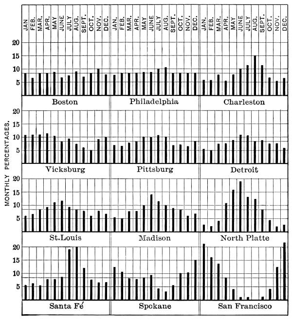
MONTHLY VARIATIONS IN RAINFALL.
Fig. 1.
TABLE V.
GENERAL RAINFALL STATISTICS
FOR THE UNITED STATES.
- LEGEND:
- (A) = Mean Yearly Rainfall.
- (B) = Per Cent of Summer and Autumn Rain to Mean Yearly.
- (C) = Per Cent Driest Year to Mean Year.
- (D) = Per Cent Two Driest Years.
- (E) = Per Cent Three Driest Years.
- (F) = Number of Years’ Record.
| Station. |
(A) |
(B) |
(C) |
(D) |
(E) |
(F) |
| North Atlantic: |
|
|
|
|
|
|
| Boston |
45.4 |
50 |
60 |
70 |
80 |
79 |
| New York |
44.7 |
52 |
62 |
77 |
80 |
61 |
| Philadelphia |
42.3 |
52 |
70 |
75 |
80 |
72 |
| Washington |
42.9 |
51 |
69 |
71 |
74 |
45 |
| South Atlantic: |
|
|
|
|
|
|
| Wilmington |
53.7 |
61 |
75 |
80 |
81 |
26 |
| Charleston |
49.1 |
61 |
48 |
55 |
62 |
89 |
| Augusta |
48.0 |
50 |
81 |
88 |
87 |
27 |
| Jacksonville |
54.1 |
65 |
74 |
77 |
83 |
27 |
| Key West |
38.2 |
70 |
54 |
61 |
73 |
49 |
| Gulf and Lower Mississippi: |
|
|
|
|
|
|
| Montgomery |
52.5 |
42 |
76 |
80 |
83 |
24 |
| Mobile |
62.6 |
51 |
68 |
75 |
78 |
26 |
| New Orleans |
60.3 |
52 |
64 |
75 |
77 |
26 |
| Galveston |
47.7 |
58 |
50 |
65 |
72 |
26 |
| Nashville |
50.2 |
46 |
67 |
73 |
83 |
32 |
| Ohio Valley: |
|
|
|
|
|
|
| Pittsburg |
36.6 |
53 |
70 |
78 |
85 |
54 |
| Cincinnati |
42.1 |
50 |
60 |
72 |
71 |
62 |
| Indianapolis |
42.2 |
51 |
59 |
76 |
82 |
27 |
| Cairo |
42.6 |
47 |
62 |
75 |
81 |
25 |
| Louisville |
47.2 |
48 |
74 |
81 |
85 |
25 |
| Lake Region: |
|
|
|
|
|
|
| Detroit |
32.5 |
56 |
65 |
72 |
79 |
46 |
| Cleveland |
36.6 |
54 |
71 |
74 |
81 |
41 |
| Duluth |
30.7 |
63 |
65 |
81 |
88 |
26 |
| Upper Mississippi Valley: |
|
|
|
|
|
|
| St. Louis |
40.8 |
52 |
55 |
65 |
75 |
60 |
| Chicago |
34.0 |
54 |
66 |
80 |
86 |
30 |
| Milwaukee |
31.0 |
55 |
66 |
74 |
73 |
53 |
| Madison |
33.2 |
58 |
39 |
58 |
68 |
28 |
| The Plains: |
|
|
|
|
|
|
| Omaha |
31.4 |
63 |
57 |
63 |
70 |
27 |
| North Platte |
18.1 |
61 |
56 |
67 |
72 |
22 |
| Denver |
14.3 |
48 |
59 |
71 |
77 |
27 |
| Cheyenne |
12.7 |
55 |
39 |
62 |
75 |
27 |
| The Plateau: |
|
|
|
|
|
|
| Tucson |
11.7 |
65 |
44 |
79 |
80 |
19 |
| Santa Fé |
14.6 |
69 |
53 |
63 |
66 |
37 |
| Salt Lake City |
18.8 |
39 |
55 |
64 |
74 |
29 |
| Walla Walla |
15.4 |
38 |
46 |
81 |
86 |
27 |
| Pacific Coast: |
|
|
|
|
|
|
| Astoria |
77.0 |
33 |
64 |
68 |
77 |
34 |
| Portland |
46.2 |
31 |
67 |
76 |
79 |
27 |
| Sacramento |
19.9 |
16 |
42 |
67 |
84 |
47 |
| San Francisco |
23.4 |
17 |
51 |
73 |
78 |
47 |
| Los Angeles |
17.2 |
15 |
33 |
48 |
59 |
24 |
| San Diego |
9.7 |
18 |
30 |
54 |
61 |
47 |
The diagram Fig. 1 and Table V
are constructed from data given in the bulletins of the Weather Bureau
and exhibit some of the general features of the rainfall for different
points throughout this country. The heavy lines of the diagram show
the average monthly precipitation at the points indicated, for periods
of a considerable number of years, as shown in the table. It will
be observed that the rainfall is comparatively uniform in the North
Atlantic States but quite variable on the Pacific coast, as well as in
the Mississippi and Missouri valleys and west of those valleys.
164. Hourly or Less Rates of Rainfall.—Although not
often of great importance in connection with public water-supply systems,
it is sometimes necessary to possess data regarding maximum hourly (or
less) rates of precipitation in connection with sewer or drainage
work. The earlier records give exaggerated reports of maximum rates of
rainfall, although that rate varies rapidly with the time. Throughout
a rain-storm the rate of precipitation is constantly varying and
the maximum rate seldom if ever extends over a period equal to a
half-hour; usually it lasts but a few minutes only. In this country
an average rate of 1 inch per hour, extending throughout one hour,
is phenomenal, although that rare amount is sometimes exceeded. A
maximum rate of about 4 inches per hour, lasting 15 to 30 minutes, is,
roughly speaking, about as high as any precipitation of which we have
reliable records. The waste ways or other provisions for the discharge
of surplus or flood-waters of the Metropolitan Water-supply of Boston
are designed to afford relief for a total precipitation of 6 inches
in twenty-four hours. It is safe to state that an excess of that
accommodation will probably never be required.
165. Extent of Heavy Rain-storms.—In all engineering
questions necessitating the consideration of these great rain-storms it
is necessary to remember that their extent is frequently much greater
than the areas of watersheds usually contemplated in connection with
water-supply work. The late Mr. James B. Francis found in the great
storm of October, 1869, which had its maximum intensity in Connecticut,
that the area over which 6 inches or more of rain fell exceeded 24,000
square miles, and that the area over which a depth of 10 inches or more
fell was 519 miles. Again, in the New England storm of February, 1886, 6
inches or more of rain fell over an area of at least 3000 square miles.
Storm records show that as much as 8 or 10 inches in depth have fallen
over areas ranging from 1800 to 500 square miles, respectively, in a
single storm.
166. Provision for Low Rainfall Years.—The capacity of any
public water-supply must evidently be sufficient to meet not only
the general exigencies of the year of lowest rainfall, but also the
conditions resulting from the driest periods of that year. It is
customary among civil engineers to consider months as the smaller units
of a dry year. It is necessary, therefore, to examine not only the
annual rainfalls but the monthly rates of precipitation during critical
years, i.e., usually during dry years.
It is impossible to determine absolutely the year of least rainfall
which may be expected, but evidently the longer the period over which
observations have extended the nearer that end will be attained. It is
sometimes assumed that the lowest annual rainfall likely to be expected
in a long period of years is 80 per cent of the average annual rainfall
for the same period. Or, it is sometimes assumed that the average
rainfall for the lowest two or three consecutive years will be 80
per cent of the average for the entire period, and that the year of
minimum rainfall may be expected to yield two thirds of the annual
average precipitation. Such features will necessarily vary with the
location of the district considered. Conclusions which may be true for
the New England or northern Atlantic States probably will not hold for
the south Atlantic and Gulf States. Data for such conclusions must
be obtained from the rainfall of the locality considered. Table VI
exhibits the comparative monthly rainfall which J. T. Fanning suggests
may be used approximately for the average Atlantic coast districts.
TABLE VI.
| |
Mean
Monthly
Rainfall,
Inches. |
Respective
Ratios. |
Probable
Depth in
Inches of
Actual
Rainfall. |
| January |
4 |
× 1.65 |
= 6.6 |
| February |
4 |
× 1.50 |
= 6.0 |
| March |
4 |
× 1.65 |
= 6.6 |
| April |
4 |
× 1.45 |
= 5.8 |
| May |
4 |
× .85 |
= 3.4 |
| June |
4 |
× .75 |
= 3.0 |
| July |
4 |
× .35 |
= 1.4 |
| August |
4 |
× .25 |
= 1.0 |
| September |
4 |
× .30 |
= 1.2 |
| October |
4 |
× .45 |
= 1.8 |
| November |
4 |
× 1.20 |
= 4.8 |
| December |
4 |
× 1.60 |
= 6.4 |
If the average monthly rainfall throughout the year were one inch, the
values of the ratios would show the actual monthly precipitation. In
general the table would be used by dividing the total yearly rainfall
by 12, and then multiplying that monthly average by the proper ratio
taken from the table opposite the month required. Such tables should
only be used for approximate purposes and when actual rainfall records
are not available for the district considered.
167. Available Portion of Rainfall or Run-off of Watersheds.—If
the public water-supply is to be drawn from a stream where the desired
rainfall records exist, it is necessary to know what portion of the
rainfall, either in the driest or in other years, may be available.
This is one of the departments of the hydraulics of streams for which
much data yet remain to be secured. The watersheds or areas drained
by some streams, like the Sudbury River of the Boston, and the Croton
of the New York water-supply, have, however, been studied with
sufficient care to give reliable data. The amount of water flowing in
a stream from any watershed for a given period, as a year, is called
the annual “run-off” of the watershed, and it is usually expressed
as a certain percentage of the total rainfall on the area drained.
For certain purposes it is sometimes more convenient to express the
run-off from the watershed as the number of cubic feet of water per
second per square mile of area. Table VII, taken from Turneaure and
Russell, exhibits run-off data for a considerable number of streams in
connection with both average and minimum rainfalls.
TABLE VII.
STATISTICS OF THE FLOW OF STREAMS.
| Stream. |
Area Drained,
Square Miles. |
Years. |
Average Yearly. |
Year of Minimum Flow. |
Rain,
Inches. |
Flow,
Inches. |
Per
Cent. |
Rain,
Inches. |
Flow,
Inches. |
Per
Cent. |
| Sudbury |
75.2 |
1875-97 |
45.77 |
22.22 |
48.6 |
32.78 |
11.19 |
34.1 |
| Cochituate |
18.87 |
1863-96 |
47.08 |
20.33 |
43.2 |
31.20 |
9.76 |
31.3 |
| Mystic |
26.9 |
1878-96 |
43.79 |
19.96 |
45.6 |
31.22 |
9.32 |
29.8 |
| Connecticut |
10,234 |
1871-85 |
44.69 |
25.25 |
56.5 |
40.02 |
18.25 |
45.6 |
| Croton |
338 |
1870-94 |
48.38 |
24.57 |
50.8 |
38.52 |
14.54 |
37.8 |
| Upper Hudson |
4,500 |
1888-96 |
39.70 |
23.36 |
59.0 |
33.49 |
17.46 |
52.2 |
| Genesee |
1,060 |
1894-96 |
39.82 |
12.95 |
32.5 |
31.00 |
6.67 |
21.5 |
| Passaic |
822 |
1877-93 |
47.08 |
25.44 |
54.0 |
35.64 |
15.23 |
42.7 |
| Upper Mississippi |
3,265 |
1885-99 |
26.57 |
4.90 |
18.4 |
22.86 |
1.62 |
7.1 |
| Stream. |
Area Drained,
Square Miles. |
Years. |
Average for
December to May. |
Average for
June to November. |
Rain,
Inches. |
Flow,
Inches. |
Per
Cent. |
Rain,
Inches. |
Flow,
Inches. |
Per
Cent. |
| Sudbury |
75.2 |
1875-97 |
22.98 |
17.52| |
76.0 |
22.61 |
4.70 |
20.8 |
| Cochituate |
18.87 |
1863-96 |
22.97 |
14.87 |
64.7 |
24.10 |
5.46 |
22.7 |
| Mystic |
26.9 |
1878-96 |
22.11 |
15.12 |
68.4 |
21.66 |
4.84 |
22.4 |
| Connecticut |
10,234 |
1871-85 |
20.13 |
17.95 |
89.1 |
24.56 |
7.30 |
29.7 |
| Croton |
338 |
1870-94 |
23.39 |
17.81 |
76.1 |
24.99 |
6.76 |
27.0 |
| Upper Hudson |
4,500 |
1888-96 |
18.20 |
16.23 |
89.0 |
21.50 |
7.13 |
33.0 |
| Genesee |
1,060 |
1894-96 |
19.58 |
10.20 |
52.2 |
20.24 |
2.75 |
13.6 |
| Passaic |
822 |
1877-93 |
22.47 |
18.22 |
81.1 |
24.39 |
7.19 |
29.5 |
The information to be drawn from this table is sufficient to give clear
and general relations between the recorded precipitation and run-off.
The percentage of run-off is seen to vary quite widely, but as a rule
it is materially less for the year of minimum flow than for the average
year. That feature of the table is an expression of the general law,
other things being equal, that the smaller the precipitation the less
will be the percentage of run-off. A number of influences act to
produce that result. During a year of great precipitation the earth is
more nearly saturated the greater part of the time, and hence when rain
falls less of it will percolate into the ground and more of it will run
off. Again, if the ground is absolutely dry, a certain amount of rain
would have to fall before any run-off would take place. The area and
shape of a watershed will also affect to some extent the flow of the
stream which drains it. A larger run-off would reasonably be expected
from a long narrow watershed than from one more nearly circular in
outline. The greater the massing of the watershed, so to speak, the
more opportunity there is for the water to be held by the ground and
the less would be the run-off.
TABLE VIII.
AVERAGE YIELD OF SUDBURY WATERSHED,
1875-1899, INCLUSIVE,
VARIOUSLY EXPRESSED.
(Area of watershed, 75.2 square miles.)
| Month. |
Per Square Mile. |
Rainfall. |
Cubic Feet
per Second. |
Million
Gallons
per Day. |
Collected,
Inches. |
Per Cent
Collected. |
Total,
Inches. |
| January |
1.937 |
1.252 |
2.233 |
51.6 |
4.33 |
| February |
2.904 |
1.877 |
3.050 |
71.7 |
4.26 |
| March |
4.489 |
2.901 |
5.175 |
117.4 |
4.41 |
| April |
3.124 |
2.019 |
3.485 |
107.5 |
3.24 |
| May |
1.680 |
1.086 |
1.936 |
58.1 |
3.33 |
| June |
.735 |
.475 |
.821 |
28.0 |
2.93 |
| July |
.305 |
.197 |
.352 |
9.3 |
3.77 |
| August |
.478 |
.309 |
.551 |
13.3 |
4.16 |
| September |
.376 |
.243 |
.419 |
13.0 |
3.23 |
| October |
.829 |
.536 |
.956 |
21.9 |
4.37 |
| November |
1.474 |
.953 |
1.645 |
39.0 |
4.22 |
| December |
1.612 |
1.042 |
1.859 |
51.9 |
3.58 |
| Year |
1.655 |
1.070 |
22.482 |
49.1 |
45.8 |
168. Run-off of Sudbury Watershed.—Table VIII
has been given by Mr. Charles W. Sherman, as representing the average yield of the
Sudbury watershed for the period 1875 to 1899, inclusive, expressed in
several different ways. The average rainfall was 45.83 inches, and the
percentage which represents the run-off is 49.1 per cent of the total.
The average monthly run-off varies from .305 cubic foot (for July) to
4.489 cubic feet (for March) per second per square mile. As a general
rule it may be stated that the average run-off from the drainage areas
of New England streams amounts very closely to 1,000,000 gallons per
square mile per day. The area of the Sudbury watershed is 75.2 square
miles, with 6.5 per cent of that total area occupied by the surface of
lakes or reservoirs. As will presently be seen, the amount of exposed
water surface in any watershed has an appreciable influence upon its
run-off.
169. Run-off of Croton Watershed.—The total area of
the Croton watershed, from which New York City draws its supply, i.e., the
area up-stream from the new Croton Dam, is 360.4 square miles, of which 16.1
square miles, or 4.47 per cent, of its total area is water surface. Mr.
John R. Freeman found in the investigations covered by his report to
the comptroller of the city of New York in 1900 that the average annual
rainfall on that area for the thirty-two years beginning 1868 and
ending 1899 was 48.07 inches, and that the average run-off for the same
period was 47.7 per cent of the total average rainfall, equivalent to a
depth of 22.93 inches.
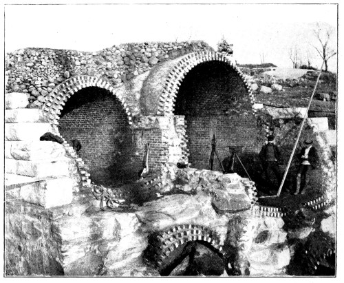
Aqueducts near Jerome Park Reservoir,
New York City.
Table IX gives the main elements of the
rainfall and run-off for the Croton watershed during the thirty-two
year period, for the averages just given.
TABLE IX.
RAINFALL ON CROTON WATERSHED
IN TOTAL INCHES—1868-1898.
NATURAL FLOW OF CROTON RIVER
AT OLD CROTON DAM,
IN EQUIVALENT INCHES.
PERCENTAGE OF RUN-OFF TO RAINFALL
FOR EACH YEAR.
| Year. |
Total
Rainfall. |
Total
Run-off. |
Per Cent. |
| 1868 |
50.33 |
33.33 |
66.22 |
| 1869 |
48.36 |
23.61 |
48.82 |
| 1870 |
44.63 |
19.20 |
43.02 |
| 1871 |
48.94 |
19.46 |
39.76 |
| 1872 |
40.74 |
16.92 |
41.53 |
| 1873 |
43.87 |
25.02 |
57.03 |
| 1874 |
42.37 |
25.10 |
59.24 |
| 1875 |
43.66 |
24.77 |
56.73 |
| 1876 |
40.68 |
21.09 |
51.84 |
| 1877 |
48.23 |
20.22 |
41.92 |
| 1878 |
55.70 |
27.17 |
48.78 |
| 1879 |
47.04 |
19.65 |
41.77 |
| 1880 |
36.92 |
12.63 |
34.21 |
| 1881 |
46.69 |
19.25 |
41.23 |
| 1882 |
52.35 |
24.28 |
46.38 |
| 1883 |
42.70 |
13.33 |
31.22 |
| 1884 |
51.28 |
24.08 |
46.96 |
| 1885 |
43.67 |
17.71 |
40.55 |
| 1886 |
47.74 |
20.10 |
42.10 |
| 1887 |
57.29 |
26.61 |
46.45 |
| 1888 |
60.69 |
35.27 |
58.12 |
| 1889 |
55.70 |
31.39 |
56.36 |
| 1890 |
54.05 |
25.95 |
48.01 |
| 1891 |
47.20 |
23.48 |
49.75 |
| 1892 |
44.28 |
17.68 |
39.93 |
| 1893 |
54.87 |
29.05 |
52.94 |
| 1894 |
47.33 |
20.56 |
43.44 |
| 1895 |
40.58 |
15.95 |
39.31 |
| 1896 |
45.85 |
23.26 |
50.73 |
| 1897 |
53.12 |
25.59 |
48.17 |
| 1898 |
57.40 |
29.72 |
51.77 |
| 1899 |
44.67 |
22.28 |
49.88 |
| Average for |
48.07 |
22.93 |
47.70 |
| 32 years. |
The table shows that the least annual rainfall was 36.92 inches for
1880, and that the run-off represented a depth of 12.63 inches only, or
34.21 per cent of the total annual precipitation. As a rule the same
feature of a low percentage of run-off will be found belonging to the
years of low rainfall, although there are many irregularities in the
results. On the other hand, the high percentages of run-off are for the
years 1868, 1888, and 1889, and they will generally be found belonging
to years of relatively great precipitation. A low percentage of run-off
will also be lower if the year to which it belongs follows a dry year
or a dry cycle of two or three years. Similarly the high percentages
of run-off will, as a rule, be higher if they follow years of high
precipitation; that is, if they belong to a cycle of relatively great
rainfall.
170. Evaporation from Reservoirs.—If it is contemplated
to build reservoirs on a watershed the capacity of which is being
estimated on the basis of either the driest year or the driest
two- or three year cycle, it is necessary to make a deduction from the
rainfall for the evaporation which will take place from the surface of
the proposed reservoir. In order that that deduction may be made as
a proper allowance for added water surface in a drainage area, it is
necessary that the amount of evaporation be determined for the district
considered. The rate of evaporation is dependent upon the area of water
surface, upon the wind, and upon the temperature both of the water and
air above it. Numerous evaporation observations have been made both in
this and other countries, and extensive evaporation tables have been
prepared by the Weather Bureau, from which a reasonable estimate of the
monthly evaporation for all months in the year may be made for almost
any point in the United States. Particularly available observations
have been made by Mr. Desmond Fitzgerald of Boston on the Chestnut
Hill reservoirs of the Boston Water-supply, and by Mr. Emil Kuichling,
engineer of the Rochester Water-works, on the Mount Hope reservoir of
the Rochester supply. Table X exhibits the results of the observations
of both these civil engineers.
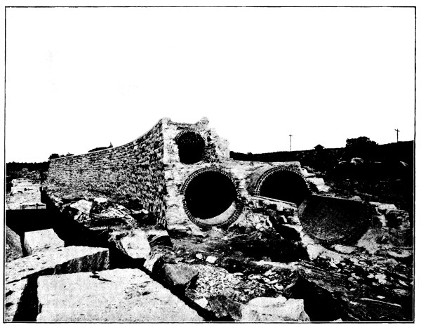
Aqueduct Division Wall of Jerome Park Reservoir
New York City.
As would be anticipated, the period from May to September, both
inclusive, shows by far the greatest evaporation of the whole year,
while December, January, and February are the months of least
evaporation. The total annual evaporation at Boston was 39.2 inches and
34.54 inches at Rochester.
TABLE X.
MEAN MONTHLY EVAPORATIONS.
| Month. |
Chestnut Hill Reservoir,
Boston, Mass. |
Mount Hope Reservoir,
Rochester, N. Y. |
Evaporation,
Inches. |
Per Cent of
Yearly
Evaporation. |
Evaporation,
Inches. |
Per Cent of
Yearly
Evaporation. |
| January |
0.96 |
2.4 |
0.52 |
1.5 |
| February |
1.05 |
2.7 |
0.54 |
1.6 |
| March |
1.70 |
4.3 |
1.33 |
3.9 |
| April |
2.97 |
7.6 |
2.62 |
7.6 |
| May |
4.46 |
11.4 |
3.93 |
11.4 |
| June |
5.54 |
14.2 |
4.94 |
14.3 |
| July |
5.98 |
15.2 |
5.47 |
15.8 |
| August |
5.50 |
14.0 |
5.30 |
15.4 |
| September |
4.12 |
10.4 |
4.15 |
12.0 |
| October |
3.16 |
8.1 |
3.16 |
9.1 |
| November |
2.25 |
5.7 |
1.45 |
4.2 |
| December |
1.51 |
3.9 |
1.13 |
3.2 |
| Total for year |
39.20 |
|
34.54 |
|
| Mean temperature |
48°.6 |
47°.8 |
A reference to data of the Weather Bureau will show that annual
evaporation as high as 100 inches, or even more, may be expected on
the plateaux of Arizona and New Mexico. Other portions of the arid
country in the western part of the United States will indicate annual
evaporations running anywhere from 50 to 90 inches per year, while on
the north Pacific coast it will fall as low as 18 to 40 inches.
171. Evaporation from the Earth’s Surface.—Data are lacking
for anything like a reasonably accurate estimate of evaporation from
the earth’s surface. It is well known that the loss of water from that
source is considerable in soils like those of swamps, particularly
when exposed to the warm sun, but no reliable estimate can be obtained
for the exact amount. Nor is this necessary for the usual water-supply
problems, since it is included in the difference between the total
rainfall of any district and the observed run-off in the streams.
Indeed evaporation from reservoirs is similarly included for reservoirs
existing when the run-off observations are made.
CHAPTER XVI.
172. Application of Fitzgerald’s Results to the Croton
Watershed.—The evaporation data determined by Messrs. Fitzgerald
and Kuichling are sufficient for all ordinary purposes in the North
Atlantic States. In the discussion of the capacity of the Croton
watershed Mr. Fitzgerald’s results will be taken, as the conditions
of the Croton watershed in respect to temperature and atmosphere are
affected by the proximity to the ocean, and other features of the case
make it more nearly like the Metropolitan drainage area near Boston
than the more elevated inland district near Rochester.
If the monthly amounts of evaporation be taken from the preceding
table, and if it further be observed that a volume of water 1
square mile in area and 1 inch thick contains 17,377,536 gallons,
the following table (Table XI) of amounts of evaporation from the
reservoirs in the Croton watershed, including the new Croton Lake, will
result, since the total area of water surface of all these reservoirs
is 16.1 square miles.
TABLE XI.
| Jan. |
0.96 × |
16.1 |
× |
17,377,536 |
= |
268,600,000 |
gallons. |
| Feb. |
1.05 × |
” |
× |
” |
= |
293,800,000 |
” |
| Mar. |
1.70 × |
” |
× |
” |
= |
475,700,000 |
” |
| April |
2.97 × |
” |
× |
” |
= |
831,000,000 |
” |
| May |
4.46 × |
” |
× |
” |
= |
1,247,900,000 |
” |
| June |
5.54 × |
” |
× |
” |
= |
1,550,100,000 |
” |
| July |
5.98 × |
” |
× |
” |
= |
1,673,200,000 |
” |
| Aug. |
5.50 × |
” |
× |
” |
= |
1,538,900,000 |
” |
| Sept. |
4.12 × |
” |
× |
” |
= |
1,152,800,000 |
” |
| Oct. |
3.16 × |
” |
× |
” |
= |
884,200,000 |
” |
| Nov. |
2.25 × |
” |
× |
” |
= |
629,600,000 |
” |
| Dec. |
1.51 × |
” |
× |
” |
= |
422,500,000 |
” |
| |
39.20 |
Total |
= |
10,968,300,000 |
” |
It will be seen from this table that the total annual evaporation from
all the reservoir surfaces of the Croton watershed, as it will exist
when the new Croton Lake is completed, will be nearly 11,000,000,000
gallons, enough to supply the boroughs of Bronx and Manhattan at the
present rate of consumption for about forty days.
173. The Capacity of the Croton Watershed.—The use of
the preceding figures and numbers can be well illustrated by considering
the capacity of the Croton watershed in its relations to the present
water needs of the boroughs of Bronx and Manhattan which that watershed
is designed to supply. The total area of the Croton watershed is 360.4
square miles, of which 16.1 square miles, as has already been observed,
is water surface. As a matter of fact the run-off observations from
that watershed have been maintained or computed for the thirty-two-year
period from 1868 to 1899, inclusive, covering the evaporation from the
reservoirs and lake surfaces as they have existed during that period.
The later observations, therefore, include the effects of evaporation
from the more lately constructed reservoirs, but none of these data
cover evaporation from the entire surface of the new Croton Lake, whose
excess over that of the old reservoir is nearly one third of the total
water surface of the entire shed. As a margin of safety and for the
purpose of simplification, separate allowance will be made for the
evaporation from all the reservoir and lake surfaces of the entire
watershed as it will exist on the completion of the new Croton Lake, as
a deduction from the run-off. The preceding table (Table XI) exhibits
those deductions for evaporation as they will be made in the next table.
In Table IX the year 1880 yields the lowest run-off of the entire
thirty-two-year period. The total precipitation was 36.92 inches, and
only 34.21 per cent of it was available as run-off. The first column in
Table XII gives the amount of monthly rainfall for the entire year, the
sum of which aggregates 36.92 inches. Each of these monthly quantities
multiplied by .3421 will give the amount of rainfall available for
run-off, and the latter quantity multiplied by the number of square
miles in the watershed (360.4) will show the total depth of available
water concentrated upon a single square mile. If the latter quantity be
multiplied by 17,378,000, the total number of gallons available for the
entire month will result, from which must be subtracted the evaporation
for the same month. Carrying out these operations for each month in the
year, the monthly available quantities for water-supply will be found,
as shown in the last column.
TABLE XII.
| (Jan. |
3.43 × |
.3421 |
= |
1.173) × |
360.4 |
× |
17,378,000 |
- |
268,600,000 = |
7,077,700,000 |
| (Feb. |
3.40 × |
” |
= |
1.163) × |
” |
× |
” |
- |
293,800,000 = |
6,989,900,000 |
| (Mar. |
3.90 × |
” |
= |
1.334) × |
” |
× |
” |
- |
475,700,000 = |
7,879,000,000 |
| (April |
3.57 × |
” |
= |
1.221) × |
” |
× |
” |
- |
831,000,000 = |
6,816,000,000 |
| (May |
1.04 × |
” |
= |
.356) × |
” |
× |
” |
- |
1,247,900,000 = |
982,000,000 |
| (June |
1.40 × |
” |
= |
.479) × |
” |
× |
” |
- |
1,550,100,000 = |
1,449,800,000 |
| (July |
5.86 × |
” |
= |
2.005) × |
” |
× |
” |
- |
1,673,200,000 = |
10,890,000,000 |
| (Aug. |
4.16 × |
” |
= |
1.423) × |
” |
× |
” |
- |
1,538,900,000 = |
7,373,100,000 |
| (Sept. |
2.42 × |
” |
= |
.828) × |
” |
× |
” |
- |
1,152,800,000 = |
4,032,900,000 |
| (Oct. |
2.83 × |
” |
= |
.968) × |
” |
× |
” |
- |
884,200,000 = |
5,178,500,000 |
| (Nov. |
2.32 × |
” |
= |
.794) × |
” |
× |
” |
- |
629,600,000 = |
4,343,100,000 |
| (Dec. |
2.59 × |
” |
= |
.886) × |
” |
× |
” |
- |
422,500,000 = |
5,126,300,000 |
| |
36.92 |
|
The sum of the twelve monthly available quantities will give the total
number of gallons per year applicable to meeting the water demands of
the boroughs of Bronx and Manhattan.
174. Necessary Storage for New York Supply to Compensate
for Deficiency.—At the present time the average daily consumption
per inhabitant of those two boroughs is 115 gallons, and if the total
population be taken at 2,200,000, the total daily consumption will
be 2,200,000 × 115 = 253,000,000 gallons. If the latter quantity be
multiplied by 30.5, the latter being taken as the average number of
days in the month throughout the year, the average monthly draft of
water for the two boroughs in question will be 7,716,500,000 gallons.
The subtraction of the latter quantity from the monthly results in the
preceding table will exhibit a deficiency which must be met by storage
or a surplus available for storage. Table XIII exhibits the twelve
monthly differences of that character.
TABLE XIII.
| 7,077,700,000 |
- |
7,716,500,000 |
= |
- |
638,800,000 |
|
| 6,989,900,000 |
- |
” |
= |
- |
726,600,000 |
|
| 7,879,000,000 |
- |
” |
= |
- |
|
+ 162,500,000 |
| 6,816,000,000 |
- |
” |
= |
- |
900,500,000 |
|
| 982,000,000 |
- |
” |
= |
- |
6,734,500,000 |
|
| 1,449,800,000 |
- |
” |
= |
- |
6,266,700,000 |
|
| 10,890,000,000 |
- |
” |
= |
- |
|
+ 3,173,500,000 |
| 7,373,100,000 |
- |
” |
= |
- |
343,400,000 |
|
| 4,032,900,000 |
- |
” |
= |
- |
3,683,600,000 |
|
| 5,178,500,000 |
- |
” |
= |
- |
2,538,000,000 |
|
| 4,343,100,000 |
- |
” |
= |
- |
3,373,400,000 |
|
| 5,126,300,000 |
- |
” |
= |
- |
2,590,200,000 |
|
| |
- |
27,795,700,000 |
+3,336,000,000 |
| |
+ |
3,336,000,000 |
|
| |
- |
24,459,700,000 |
|
It is seen from this table that the total monthly deficiencies
aggregate 27,795,700,000 gallons and that there are only two months in
which the run-off exceeds the consumption, the surplus for those two
months being only 3,336,000,000 gallons. The total deficiency for the
year is therefore 24,459,700,000 gallons. Dividing the latter quantity
by the average daily draft of 253,000,000 gallons, there will result
a period of 97 days, or more than one quarter of a year, during which
the minimum annual rainfall would fail to supply any water to the city
at all. These results show that in case of a low rainfall year, like
that of 1880, the precipitation upon the Croton watershed would supply
sufficient water for the boroughs of Bronx and Manhattan at the present
rate of consumption for three fourths of the year only. A distressingly
serious water famine would result unless the year were begun by
sufficient available storage in the reservoirs of the basin at least
equal to 24,459,700,000 gallons. Should such a low rainfall year or
one nearly approaching it be one of a two- or three-year low rainfall
cycle, such a reserve storage would be impossible and the resulting
conditions would be most serious for the city. If an average year, for
which the total rainfall would be about 48 inches preceded such a year
of low rainfall, the conditions would be less serious. The figures
would stand as follows:
| Total run-off = |
|
| 17,377,536 × 360.4 × 22.93 - 17,377,536 × 16.1 × 39.2 |
| |
= |
132,640,000,000 |
gallons. |
| Total annual consumption |
= |
92,345,000,000 |
” |
| Available for storage |
= |
40,295,000,000 |
” |
| Deficiency |
= |
24,459,700,000 |
” |
| Surplus |
= |
15,835,300,000 |
” |
The average year would, therefore, yield enough run-off water if stored
to more than make up the deficiency of the least rainfall year by
nearly 16,000,000,000 gallons. In order to secure the desired volume it
would therefore be necessary to have storage capacity at least equal
to 24,459,700,000 gallons; indeed, in order to meet all the exigencies
of a public water-supply it would be necessary to have far more than
that amount. As a matter of fact there are in the Croton watershed
seven artificial reservoirs with a total storage capacity of nearly
41,000,000,000 gallons, besides a number of small ponds in addition
to the new Croton Lake which with water surface at the masonry crest
of the dam has a total additional storage capacity of 23,700,000,000
gallons. The storage capacity of the new Croton Lake may be increased
by the use of flash-boards 4 feet high placed along its crest, so
that with its water surface at grade 200 its total capacity will be
increased to 26,500,000,000 gallons. After the new Croton reservoir is
in use the total storage capacity of all the reservoirs and ponds in
the Croton watershed will be raised to 70,245,000,000 gallons, which
can be further augmented by the Jerome Park reservoir when completed by
an amount equal to 1,900,000,000 gallons. This is equivalent, at the
present rate of consumption, to a storage supply for 285 days for the
boroughs of Manhattan and the Bronx.
175. No Exact Rule for Storage Capacity.—This question
of the amount of storage capacity to be provided in connection with
public water-supplies is one which cannot be reduced to an exact
rule. Obviously if the continuous flow afforded from any source is
always greater per day than any draft that can ever be made upon it,
no storage-reservoirs at all would be needed, although they might be
necessary for the purpose of sedimentation. On the other hand, as in
the case of New York City, if the demand upon the supply has reached
its capacity or exceeded it for low rainfall years, it may be necessary
to provide storage capacity sufficient to collect all the run-off of
the watershed. The civil engineer must from his experience and from the
data before him determine what capacity between those limits is to be
secured. When the question of volume or capacity of storage is settled
the mode of distribution of that volume or capacity in reservoirs is to
be determined, and that affects to some extent the potability of the
water. If there is a large area of shallow storage, the vegetable
matter of the soil may affect the water in a number of ways. Again, it
is advisable in this connection to consider certain reservoir effects
as to color and contained organic matter in general.
176. The Color of Water.—The potability[7]
of water collected from any watershed is materially affected by its
color. Although iron may produce a brownish tinge, by far the greater
amount of color is produced by dissolved vegetable matter. Repeated
examinations of colored water have shown that discoloration is in many
cases at least a measure of the vegetable matter contained in it.
While this may not indicate that the water is materially unwholesome,
it shows conclusively the existence of conditions which are usually
productive of minute lower forms of vegetation from which both bad
taste and odors are likely to arise.
There are two periods in the year of maximum intensity of color, one
occurring in June and the other in November. The former is due to the
abundant drainage of peaty or other excessively vegetable soils from
the spring rains. After June the sun bleaches the water to a material
extent until the autumn, when the dying vegetation imparts more or less
coloring to the water falling upon it. This last agency produces its
maximum effect in the month of November.
There are various arbitrary scales employed by which colors may be
measured and discolored waters compared. Among others, dilute solutions
of platinum and cobalt are used, in which the relative proportions of
those substances are varied so as to resemble closely the colors of the
water. The amount of platinum used is a measure of the color, one unit
of which corresponds to one part of the metal in 10,000 parts of water.
Again, the depth at which a platinum wire 1 mm. (.039 inch) in diameter
and 1 inch long can be seen in the water is also taken as a measure
of the color, the amount of the latter being inversely as the depth.
This method has found extended and satisfactory use in connection with
the Metropolitan Water-supply of Boston, the Cochituate water having a
degree of color represented by .25 to .30, while the Sudbury water has
somewhat more than twice as much. The Cochituate water is practically
colorless.
The origin of the color of water is chiefly the swamps which drain into
the water-supply, or the vegetation remaining upon a new reservoir site
when the surface soil has not been removed before the filling of the
reservoir. The drainage of swamps should not, as a rule, be permitted
to flow into a public water-supply, as it is naturally heavily charged
with vegetable matter and is correspondingly discolored. This matter,
like many others connected with the sanitation of potable public
waters, has been most carefully investigated by the State Board of
Health of Massachusetts in connection with the Boston water-supply.
Its work has shown the strong advisability of diverting the drainage
of large swamps from a public supply as carrying too much vegetable
matter even when highly diluted by clear water conforming to desirable
sanitary standards.
177. Stripping Reservoir Sites.—The question of stripping
or cleaning reservoir sites of soil is also one which has been carefully
studied by the Massachusetts State Board of Health. As a consequence
large amounts of money have been expended by the city of Boston in
stripping the soil from reservoir sites to the average depth in some
cases of 9 inches for wooded land and 12½ inches for meadow land. This
was done in the case of the Nashua River reservoir having a superficial
area of 6.56 square miles at a cost of nearly $2,910,000, or about
$700 per acre. It has been found that the beneficial effect of this
stripping is fully secured if the black loam in which vegetation
flourishes is removed.
Wachusetts Reservoir, showing Stripping of Soil.
This stripping of soil is indicative of the great care taken to secure
a high quality of water for the city of Boston, but it is not done in
the Croton watershed of the New York supply. It cannot be doubted that
the quality of the Croton supply would have been sensibly enhanced by
a similar treatment of its reservoir sites. Mr. F. B. Stearns, chief
engineer of the Metropolitan Water-supply of Boston, states that in
some cases the effects of filling reservoirs without removing the soil
and vegetable matter have “continued for twenty years or more without
apparent diminution.” On the other hand, water discolored by vegetable
matter becomes bleached to some extent at least by standing in
reservoirs whose sites have been stripped of soil.
178. Average Depth of Reservoirs should be as Great as Practicable.—In
the selection of reservoir locations those are preferable where the
average depths will be greatest and where shallow margins are reduced
to a minimum. It may sometimes be necessary to excavate marginal
portions which would otherwise be shallow with a full reservoir.
There should be as little water as possible of a less low-water
depth than 10 or 12 feet, otherwise there may be a tendency to
aquatic vegetable growth. The following table exhibits the areas,
average depths, capacity, and other features of a number of prominent
storage-reservoirs.
COMPARATIVE TABLE OF AREAS, DEPTHS, AND CAPACITIES OF STORAGE
RESERVOIRS WITH HEIGHTS AND LENGTHS OF DAMS.
- LEGEND:
- (A) = Area Square Miles.
- (B) = Average Depth, Feet.
- (C) = Length of Dam, Feet.
- (D) = Capacity, Million Gallons.
Name and Location
of Reservoir. |
(A) |
(B) |
Maximum Height of Dam. |
(C) |
(D) |
Above
Ground. |
Above
Rock. |
| Swift River, Mass |
36.96 |
53 |
144 |
... |
2,470 |
406,000 |
| Nashua River, Mass |
6.56 |
46 |
129 |
158 |
1,250 |
63,068 |
| Nira, near Poona, India |
7.25 |
27 |
100 |
... |
3,000 |
41,143 |
| Tansa, Bombay, India |
5.50 |
33 |
127 |
131 |
8,770 |
37,500 |
| Khadakvasla, Poona, India |
5.50 |
32 |
100 |
107 |
5,080 |
36,737 |
| New Croton, N. Y. |
.... |
.. |
157 |
225 |
1,270 |
32,000 |
| Elan and Claerwen, Birmingham, |
2.34 |
43 |
98-128 |
... |
4,460 |
20,838 |
| Eng., water-works |
| (total for six reservoirs) |
| All Boston water-works |
5.82 |
14 |
14-65 |
... |
..... |
15,867 |
| reservoirs combined |
| Vyrnwy, Liverpool, Eng. |
1.75 |
.. |
84 |
129 |
1,350 |
14,560 |
| Ware River, Mass. |
1.62 |
33 |
71 |
... |
785 |
11,190 |
| Sodom, N. Y. |
.... |
.. |
72 |
89 |
500 |
9,500 |
| Reservoir No. 5, |
1.91 |
19 |
65 |
70 |
1,865 |
7,438 |
| Boston water-works |
| Titicus, N. Y. |
.... |
.. |
105 |
115 |
..... |
7,000 |
| Hobbs Brook, |
1.00 |
12 |
23 |
... |
..... |
2,500 |
| Cambridge water-works |
| Cochituate, Boston water-works |
1.35 |
8 |
.. |
... |
..... |
2,160 |
| Reservoir No. 6, |
0.29 |
25 |
52 |
... |
1,500 |
1,500 |
| Boston water-works |
179. Overturn of Contents of Reservoirs Due to Seasonal Changes
of Temperature.—It will be noticed that the average depth is less
than about 20 feet in few cases only. If the water is deep, its mean
temperature throughout the year will be lower than if shallow. During
the warmer portion of the year the upper layers of the water are
obviously of a higher temperature than the lower portions, since the
latter receive much less immediate effect from the sun’s rays. As the
upper portions of the water are of higher temperature, they are also
lighter and hence remain at or near the top. For the same reason the
water at the bottom of the reservoir remains there throughout the warm
season and until the cool weather of the autumn begins. The top layers
of water then continue to fall in temperature until it is lower than
that of the water at the bottom, when the surface-water becomes the
heaviest and sinks. It displaces subsurface water lighter than itself,
the latter coming to the surface to be cooled in turn.
This operation produces a complete overturning of the entire reservoir
volume as the late autumn or early winter approaches. It thus brings to
the surface-water which has been lying at the bottom of the reservoir
all summer in contact with what vegetable matter may have been there.
The depleted oxygen of the bottom water is thus replenished with a
corresponding betterment of condition. It is the great sanitary effort
of nature to improve the quality of stored water entrusted to its care,
and it continues until the surface is cooled to a temperature perhaps
lower than that of the greatest density of water.
Another great turn-over in the water of a lake or reservoir covered
with ice during the winter occurs in the spring. When the ice melts,
the resulting water rises a little in temperature until it reaches
possibly its greatest density at 39°.2 Fahr., and then sinks,
displacing subsurface water. This goes on until all the ice is melted
and until all water cooled by it, near the surface, below 39°.2 Fahr.
has been raised to that temperature. The period of summer stagnation
then follows.
180. The Construction of Reservoirs.—The natural topography
and sometimes the geology of the locality determines the location of
the reservoir. The first requirement obviously is tightness. If for
any reason whatever, such as leaky banks or bottom, porous subsurface
material, or for any other defect, the water cannot be retained in the
reservoir, it is useless. Some very perplexing questions in this
connection have arisen. Indeed reservoirs have been completed only
to be found incapable of holding their contents. Such results are
evidently not creditable to the engineers who are responsible for them,
and they should be avoided.
YARROW RESERVOIR, LIVERPOOL WATER-SUPPLY
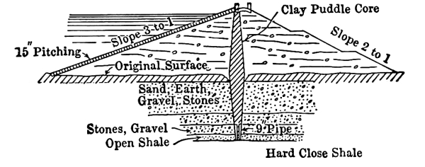
SAN LEANDRO DAM, SAN FRANCISCO WATER-WORKS
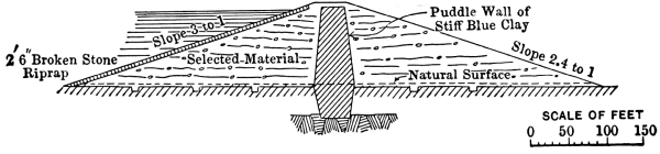
TITICUS DAM, NEW YORK WATER-SUPPLY

In order that the bottom of the reservoir may be water-tight it must
be so well supported by firm underlying material that it will not be
injured by the weight of water above it, which in artificial reservoirs
may reach 30 to 100 feet or more in depth. The subsurface material at
the site of any proposed structure of this character must, therefore,
be carefully examined so as to avoid all porous material, crevasses in
rocks, or other open places where water might escape. Objectionable
material may frequently be removed and replaced with that which is
more suitable, and rock crevices and other open places may sometimes
be filled with concrete and made satisfactory. Whatever may be the
conditions existing, the finished bottom of the reservoir should be
placed only on well-compacted, firm, unyielding material.
The character of the reservoir bottom will depend somewhat upon the
cost of suitable material of which to construct it. If a bottom of
natural earth cannot be used, a pavement of stone, brick, or concrete
may be employed from 8 inches to a foot or a foot and a half in
thickness. The reservoir banks must be placed upon carefully prepared
foundations, sometimes with masonry core-walls. They are frequently
composed of clayey and gravelly material mixed in proper proportions
and called puddle, although that term is more generally applied to a
mixture of clay and gravel designed to form a truly impervious wall
in the centre of the reservoir embankment. Some engineers require the
core-wall, as it is called, to be constructed of masonry, with the
earth or gravelly material carried up each side of this wall in layers
6 to 9 inches thick, well moistened and each layer thoroughly rolled
with a grooved roller, or treated in some equivalent manner in order
that the whole mass may not be in strata but essentially continuous
and as nearly impervious as possible. The masonry core-wall should be
founded on bed-rock or its equivalent. Its thickness will depend upon
the height of the embankment. If the latter is not more than 20 or 25
feet high, the core-wall need not be more than 4 to 6 feet thick, but
if the embankment reaches a height of 75 feet or even 100 feet, it must
be made 15 to 20 feet thick, or possibly more, at the base. Its top
should be not less than 4 or 6 feet thick, imbedded in the earth and
carried well above the highest surface of water in the reservoir.
The thickness of the clay puddle-wall employed as the central core
of the reservoir embankment is usually made much thicker than that
of masonry. As a rough rule it may be made twice as thick as the
masonry core at the deepest point and not less than about 6 feet at
the top. The thickness of the puddle core is sometimes varied to meet
the requirements of the natural material in which it is embedded at
different depths.
Frequently, when embankments are under about 20 feet high, the
core-walls may be omitted, excavation having been made at the base of
the embankment down to rock or other impervious material, and if the
entire bank is carried up with well-selected and puddled material.
The interior slopes of reservoir embankments are usually covered with
roughly dressed stone pavement 12 to 18 inches thick, laid upon a
broken stone foundation 8 to 12 inches thick, for a protection against
the wash of waves, the pavement in any case being placed upon the bank
slope after having been thoroughly and firmly compacted. The sloping
and bottom pavements, of whatever material they may be composed, should
be made continuous with each other so as to offer no escape for the
water. In some cases where it has been found difficult to make the
interior surfaces of reservoirs water-tight, asphalt or other similar
water-tight layers have been used with excellent results.
The care necessary to be exercised in the construction of storage or
other reservoirs when earth dams or embankments are used can better be
appreciated when it is realized that almost all such banks, even when
properly provided with masonry or clay-puddle core-walls, are saturated
with water, even on the down-stream side, at least throughout their
lower portions. A board of engineers appointed by the commissioners
of the Croton Aqueduct in the summer of 1901 made a large number
of examinations in the earth embankments in the Croton watershed,
and found that with scarcely an exception those embankments were
saturated throughout the lower portions of their masses, although in
every case a masonry core-wall had been built. The results of those
investigations showed that the water had percolated through the earth
portion of the embankments and even through the core-walls, which had
been carried down to bed-rock. This induced saturation, more or less,
of the material on the down-stream slopes of the embankments. When
material is thus filled with water, unless it is suitably selected, it
is apt to become soft and unstable, so that any superincumbent weight
resting upon it might produce failure. The fact that such embankments
may become saturated with water fixes limits to their heights, since
the surface of saturation in the interior of the bank has generally
a flatter slope than that of the exterior surface. The height of the
embankment therefore should be such that the exterior slope cannot cut
into the saturated material at its foot, at least to any great extent.
From what precedes it is evident that the height of an earth embankment
will depend largely upon the slope of the exterior surface. This slope
is made 1 vertical to 2, 2½, or 3 horizontal. The more gradual slope is
sometimes preferable. It is advisable also to introduce terraces and to
encourage the growth of sod so as to protect the surface from wash. The
inner paved slope may be as steep as 1 vertical to 1½ or 2 horizontal.
BOG BROOK DAM NO. 1.—RESERVOIR 1.
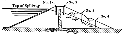
TITICUS DAM.—RESERVOIR M.
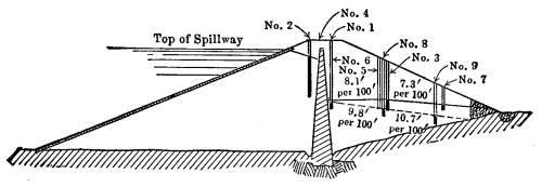
AMAWALK DAM.—RESERVOIR A.

Earth Dams in Croton Watershed,
showing Slopes of Saturation.
181. Gate-houses, and Pipe-lines in Embankments.—It
is necessary to construct the requisite pipe-lines and conduits leading
from the storage-reservoirs to the points of consumption, and sometimes
such lines bring the water to the reservoir. Wherever such pipes-line
or conduits either enter or leave a reservoir gates and valves must
be provided so as properly to control the admission and outflow
of the water. These gate-houses, as they are called, because they
contain the gates or valves and such other appurtenances or details
as are requisite for operation and maintenance, are usually built of
substantial masonry. They are the special outward features of every
reservoir construction, and their architecture should be characteristic
and suitable to the functions which they perform. Where the pipes are
carried through embankments it is necessary to use special precautions
to prevent the water from flowing along their exterior surfaces.
Many reservoirs have been constructed under defective design in this
respect, and their embankments have failed. Frequently small masonry
walls are built around the pipes and imbedded in the bank, so as to
form stops for any initial streams of water that might find their way
along the pipe. In short, every care and resource known to the civil
engineer must be employed in reservoir construction to make its bottom
and its banks proof against leakage and to secure permanence and
stability in every feature.
182. High Masonry Dams.—The greatest depths of water
impounded in reservoirs are found usually where it is necessary to
construct a high dam across the course of a river, as at the new Croton
dam. In such cases it is not uncommon to require a dam over 75 to
100 feet high above the original bed of the river, which is usually
constructed of masonry with foundations carried down to bed-rock in
order to secure suitable stability and prevent flow or leakage beneath
the structure. It is necessary to secure that result not only along the
foundation-bed of the dam, but around its ends, and special care is
taken in those portions of the work.
The new Croton dam is the highest masonry structure of its class yet
built. The crest of its masonry overflow-weir is 149 feet above the
original river-bed, with the extreme top of the masonry work of the
remaining portion of the dam carried 14 feet higher. A depth of earth
and rock excavation of 131 feet below the river-bed was necessary
in order to secure a suitable foundation on bed-rock. The total
maximum height, therefore, of the new Croton dam, from the lowest
foundation-point to the extreme top, is 294 feet, and the depth of
water at the up-stream face of the dam will be 136 feet when the
overflow is just beginning, or 140 feet if 4 feet additional head be
secured by the use of flash-boards. In the prosecution of this class
of work it is necessary not only to reach bed-rock, but to remove all
soft portions of it down to sound hard material, to clean out all
crevices and fissures of sensible size, refilling them with hydraulic
cement mortar or concrete, and to shape the exposed rock surfaces so
as to make them at least approximately normal to the resultant loads
upon them, to secure a complete and as nearly as possible water-tight
bond with the superimposed masonry. If any streams or other small
watercourses should be encountered, they must either be stopped or
led off where they will not affect the work, or, as is sometimes
done, the water issuing from them may be carried safely through the
masonry mass in small pipes. The object is to keep as much water out
of the foundation-bed as possible, so as to eliminate upward pressure
underneath the dam caused by the head of water in the subsequently full
reservoir. It is a question how much dependence can be placed upon the
exclusion of water from the foundation-bed. In the best class of work
undoubtedly the bond can be good enough to exclude more or less water,
but it is probably only safe and prudent so to design the dam as to be
stable even though water be not fully excluded.
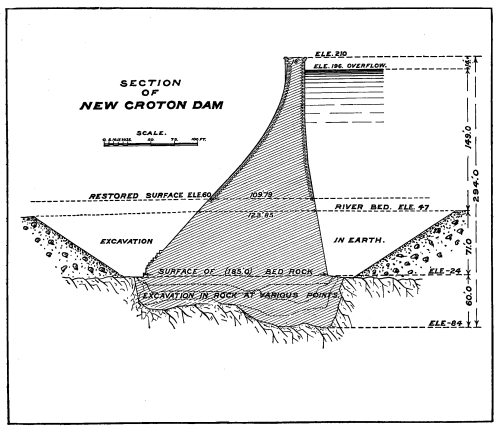
Cross-section of New Croton Dam.
The stability of the masonry dam must be secured both for the reservoir
full and empty. With a full reservoir the horizontal pressure of water
on the up-stream face tends to overturn the dam down-stream. When the
water is entirely withdrawn the pressure under the up-stream edge of
the foundation becomes much greater, so that safety and stability
under both extreme conditions must be assured. There are a number of
systems of computation to which engineers resort in order to secure a
design which shall certainly be stable under all conditions. That which
is commonly employed in this country is based upon two fundamental
propositions, under one of which the pressure at any point in the
entire masonry mass must not exceed a certain safe amount per square
foot, while the other is of a more technical character, requiring that
the centre of pressure shall, in every horizontal plane of the dam,
approach nowhere nearer than one third the horizontal thickness of
the masonry to one edge of it. A further condition is also prescribed
which prevents any portion of the dam from slipping or sliding over
that below it. As a matter of fact when the first two conditions are
assured the third is usually fulfilled concurrently. Obviously there
will be great advantage accruing to a dam if the entire mass of masonry
is essentially monolithic. In order that that may be the case either
concrete or rubble is usually employed for the great mass of the
masonry structure, the exterior surfaces frequently being composed of a
shell of cut-stone, so as to provide a neat and tasteful finish. This
exterior skin or layer of cut masonry need not average more than 1½ to
2½ feet thick.
The pressures prescribed for safety in the construction of masonry dams
vary from about 16,000 to 28,000 or 30,000 pounds per square foot.
Sometimes, as in the masonry dams found in the Croton watershed, limits
of 16,000 to 20,000 pounds per square foot are prescribed for the upper
portions of the dams and a gradually increasing pressure up to 30,000
pounds per square foot in passing downward to the foundation-bed. There
are reasons of a purely technical character why the prescribed safe
working pressure must be taken less on the down-stream or front side of
the dam than on the up-stream or rear face.
The section of a masonry dam designed under the conditions outlined
will secure stability through the weight of the structure alone, hence
it is called a gravity section. In some cases the rock bed and sides of
a ravine in which the stream must be dammed will permit a curved
structure to be built, the curvature being so placed as to be convex
up-stream or against the water pressure. In such a case the dam really
becomes a horizontal arch and, if the curvature is sufficiently sharp,
it may be designed as an arch horizontally pressed. The cross-section
then has much less thickness (and hence less area) than if designed
on a straight line so as to produce a gravity section. A number of
such dams have been built, and one very remarkable example of its kind
is the Bear Valley dam in California; it was built as a part of the
irrigation system.
Foundation Masonry of New Croton Dam.
CHAPTER XVII.
183. Gravity Supplies.—When investigation has shown
that a sufficient quantity of water may be obtained for a required public
supply from any of the sources to which reference has been made,
and that a sufficient storage capacity may be provided to meet the
exigencies of low rainfall years, it will be evident if the water
can be delivered to the points of consumption by gravity, or whether
pumping must be employed, or recourse be made to both agencies.
If the elevation of the source of supply is sufficiently great to
permit the water to flow by gravity either to storage-reservoirs or to
service-reservoirs and thence to the points of consumption, a proper
pipe-line or conduit must be designed to afford a suitable channel. If
the topography permits, a conduit may be laid which does not run full,
but which has sufficient grade or slope to induce the water to flow in
it as if it were an open channel. This is the character of such great
closed masonry channels as the new and old Croton aqueducts of the
New York water-supply and the Sudbury and Wachusetts aqueducts of the
Boston supply. These conduits are of brick masonry backed with concrete
carried sometimes on embankments and sometimes through rock tunnels.
When they act like open channels a very small slope is employed, 0.7 of
a foot per mile being a ruling gradient for the new Croton aqueduct,
and 1 foot per mile for the Sudbury. Where these conduits cross
depressions and follow approximately the surface, or where they pass
under rivers, their construction must be changed so that they will not
only run full, but under greater or less pressure, as the case may be.
184. Masonry Conduits.—In general the conduits employed
to bring water from the watersheds to reservoirs at or near places of
consumption may be divided into two classes, masonry and metal,
although timber-stave pipes of large diameter are much used in the
western portion of the country. The masonry conduits obviously cannot
be permitted to run full, meaning under pressure, for the reason that
masonry is not adapted to resist the tension which would be created
under the head or pressure of water induced in the full pipe. They
must rather be so employed as to permit the water to flow with its
upper surface exposed to the atmosphere, although masonry conduits are
always closed at the top. In other words, they must be permitted to
run partially full, the natural grade or slope of the water surface
in them inducing the necessary velocity of flow or current. Evidently
the velocity in such masonry conduits is comparatively small, seldom
exceeding about 3 feet per second. The new and old Croton aqueducts,
the Sudbury and Wachusetts aqueducts of the Metropolitan Water-supply
of Boston, are excellent types of such conveyors of water. They are
sometimes of circular shape, but more frequently of the horseshoe
outline for the sides and top, with an inverted arch at the bottom for
the purpose of some concentration of flow when a small amount of water
is being discharged and for structural reasons.
The interiors of these conduits are either constructed of brick or
they may be of concrete or other masonry affording smooth surfaces.
In the latest construction Portland-cement concrete or that concrete
reinforced with light rods of iron or steel is much used. Bricks, if
employed, should be of good quality and laid accurately to the outline
desired with about ¼-inch joints, so as to offer as smooth a surface as
possible for the water to flow over. In special cases the interiors of
these conduits may be finished with a smooth coating of Portland-cement
mortar. If conduits are supported on embankments, great care must be
exercised in constructing their foundation supports, since any sensible
settlement would be likely to form cracks through which much water
might easily escape. When carried through tunnels they are frequently
made circular in outline. They must occasionally be cleaned, especially
in view of the fact that low orders of vegetable growths appear on
their sides and so obstruct the free flow of water.
185. Metal Conduits.—Metal conduits have been much used
within the past fifteen or twenty years. Among the most prominent of these
are the Hemlock Lake aqueduct of the Rochester Water-works, and that
of the East Jersey Water Company through which the water-supply of the
city of Newark, N. J., flows. When these metal conduits or pipes equal
24 to 30 or more inches in diameter they are usually made of steel
plates, the latter being of such thickness as is required to resist
the pressure acting within them. The riveted sections of these pipes
may be of cylindrical shape, each alternate section being sufficiently
small in diameter just to enter the other alternate sections of little
larger diameter, the interior diameter of the larger sections obviously
being equal to the interior diameter of the smaller sections plus twice
the thickness of the plate. Each section may also be slightly conical
in shape, the larger ends having a diameter just large enough to pass
sufficiently over the smaller end of the next section to form a joint.
Large cast-iron pipes are also sometimes used to form these metal
conduits up to an interior diameter of 48 inches. The selection of the
type of conduit within the limits of diameter adapted to both metals is
usually made a matter of economy. The interior of the cast-iron pipe is
smoother than that of the riveted steel, although this is not a serious
matter in deciding upon the type of pipe to be used.
Steel-plate conduits have been manufactured and used up to a diameter
of 9 feet. In this case the pipe was used in connection with
water-power purposes and with a length of 153 feet only, the plates
being ½ inch thick. The steel-plate conduits of the East Jersey Water
Company’s pipes are as follows:
| Diameter. |
Thickness. |
Length. |
| 48 |
inches |
¼ |
inch |
|
21 |
miles. |
| 48 |
” |
⁵/₁₆ |
” |
| 48 |
” |
⅜ |
” |
| 36 |
” |
¼ |
” |
|
5 |
” |
The diameters and lengths of the metal pipes or conduits of the Hemlock
Lake conduit of the Rochester Water-works are as follows:
| 36- |
inch |
wrought-iron |
pipe |
9.60 |
miles. |
| 24 |
” |
” |
” |
2.96 |
” |
| 24 |
” |
cast-iron pipe |
15.82 |
” |
| |
|
Total |
28.39 |
” |
All metal conduits or pipes are carefully coated with a suitable
asphalt or tar preparation or varnish applied hot and sometimes baked
before being put in place. This is for the purpose of protecting the
metal against corrosion. Cast-iron pipes have been used longer and
much more extensively than wrought-iron or steel, but an experience
extending over thirty to forty years has shown that the latter class of
pipes possesses satisfactory durability and may be used to advantage
whenever economical considerations may be served.
186. General Formula for Discharge of Conduits—Chezy’s
Formula.—It is imperative in designing aqueducts of either masonry
or metal to determine their discharging capacity, which in general
will depend largely upon the slope of channel or head of water and
the resistance offered by the bed or interior of the pipe to the flow
of water. The resistance of liquid friction is so much more than all
others in this class of water-conveyors that it is usually the only one
considered. There is a certain formula much used by civil engineers
for this purpose; it is known as Chezy’s formula, for the reason that
it was first established by the French engineer Antoine Chezy about
the year 1775, although it is an open question whether the beginnings
of the formula were not made twenty or more years prior to that date.
Its demonstration involves the general consideration of the resistance
which a liquid meets in flowing over any surface, such as that of the
interior of a pipe or conduit, or the bed and banks of a stream.
The force of liquid friction is found to be proportional to the
heaviness of the liquid (i.e., to the weight of a cubic unit, such as a
cubic foot), to the area of wetted surface over which the liquid flows,
and nearly to the square of the velocity with which the liquid moves.
Hence if lʹ is the length of channel, p the wetted
portion of the perimeter of the cross-section, w the weight of
a cubic unit of the liquid, and v the velocity, the total force
of liquid friction for the length l′ of channel will be F
= ζwpl′v², ζ being the coefficient of liquid friction. The path
of the force F for a unit of time is v, and the work
W which it performs in that unit of time is equal to the weight
wal′ falling through the height h′, a being the
area of the cross-section of the stream.
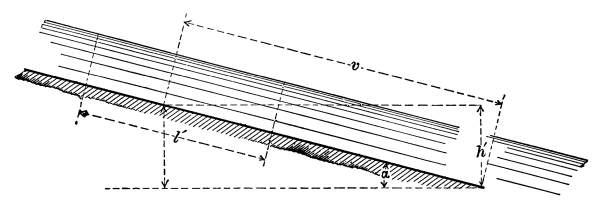
Fig. 2.
Hence W = ζwplʹv².v = wal′h′.(7)
| ζv²v = |
a |
, |
v = √(1/ζ) (a/p) (h′/v)
= c√rs. (8) |
| p |
In this equation
| c = √1/ζ; r = |
a |
= hydraulic mean radius; |
| p |
| s = |
hʹ |
= sine of inclination of stream’s bed. |
| v |
As the motion of the water is assumed to be uniform, the head lost by
friction for the total length of channel l is the total fall
h, and by equation (8), since
If, as in the case of the ordinary cast-iron water-pipes of a public
supply system, the cross-section a is circular,
and
| h = |
4.2g |
|
l |
|
v² |
= |
f |
l |
|
v² |
,(10) |
| c² |
d |
2g |
d |
2g |
in which f = 8g ÷ c².
The quantity f is sometimes called the “friction factor.” For
smooth, new pipes from 4 feet down to 3 inches in diameter its value
may be taken from .015 to .03. An approximate mean value may be taken
at .02.
The last member of equation (8) is Chezy’s
formula, and it is one of the most used expressions in hydraulic
engineering. Some values for the coefficient c will presently
be given. The quantity r found by dividing the area of the
cross-section of the stream by the wetted portion of its perimeter is
called the “hydraulic mean radius,” or simply the “mean radius.” The
other quantity, s, appearing in the formula is, as shown by the
figure, the sine of the inclination of the bed of the stream.
In order to determine the discharge of any pipe, conduit, or open
channel carrying a known depth of water, it is only necessary to
compute r and s from known data and select such a
value of the coefficient c as may best fit the circumstances
of the particular case in question. The substitution of those
quantities in Chezy’s formula, i.e., equation (8),
will give the mean velocity v of the water which, when
multiplied by the area of cross-section of the stream, will give the
discharge of the latter per second of time. It is customary to compute
r in feet. The coefficient c is always determined so as
to give velocity in feet per second of time. Hence if the area of the
cross-section of the stream, a, is taken in square feet, as is
ordinarily the case, the discharge av will be in cubic feet per second.
Progress View of Construction of New Croton Dam.
187. Kutter’s Formula.—The coefficient c in Chezy’s
formula is not a constant quantity, but it varies with the mean radius
r, with the sine of inclination s, and with the character
of the bottom and sides of the open channel, i.e., with the roughness
of the interior surface of the closed pipe. Many efforts have been
made and much labor expended in order to find an expression for this
coefficient which may accurately fit various streams and pipes. These
efforts have met with only a moderate degree of success. The form of
expression for c which is used most among engineers is that
known as Kutter’s formula, as it was established by the Swiss engineer
W. R. Kutter. This formula is as follows:
c = |
√r |
 |
1.811 |
+ 41.65 + |
.00281 |
 |
. |
| n |
s |
| ——————————— |
| n |
√r |
+ 41.65 + |
.00281 |
| n |
s |
The quantity n in this formula is called
the “coefficient of roughness,” since its value depends upon the
character of the surface over which the water flows. It has the following set of
values for the surfaces indicated:
- n = 0.009 for well-planed timber;
- n = 0.010 for neat cement;
- n = 0.011 for cement with one third sand;
- n = 0.012 for unplaned timber;
- n = 0.013 for ashlar and brickwork;
- n = 0.015 for unclean surfaces in sewers and conduits;
- n = 0.017 for rubble masonry;
- n = 0.020 for canals in very firm gravel;
- n = 0.025 for canals and rivers free from stones and weeds;
- n = 0.030 for canals and rivers with some stones and weeds;
- n = 0.035 for canals and rivers in bad order.
188. Hydraulic Gradient.—Before illustrating the use of
Chezy’s formula in connection with masonry and metal conduits, of which mention
has already been made, it is best to define another quantity constantly
used in connection with closed iron or steel pipes. This quantity is
called the “hydraulic gradient.” If a closed iron or steel pipe is
running full of water and under pressure and if small vertical tubes
be inserted in the top of the pipe with their lower ends bent so as
to be at right angles to its axis, the water will rise to heights in
the tubes depending upon the pressures of water in the pipe or conduit
at the points of insertion. Such tubes with the water columns in them
are called piezometers. They are constantly used in connection with
water-pipes in order to show the pressures at the points where they are
inserted. A number of such pipes being inserted along an iron pipe or
conduit, a line may be imagined to be drawn through the upper surfaces
of the columns of water, and that line is called the “hydraulic
gradient.” It represents the upper surface of water in an open channel
discharging with the same velocity existing in the closed pipe.
In case Chezy’s formula is used to determine the velocity of discharge
in a closed pipe running under pressure, the sine of inclination
s must be that of the hydraulic gradient and not the sine of
inclination of the axis of the closed pipe. In the determination of
this quantity s by the use of piezometer tubes, if a straight
pipe remains of constant section between any two points, it is
only necessary to insert the tubes at those points and observe the
difference in levels of the water columns in them. That difference of
levels or elevations will represent the height which is to be divided
by the length of pipe or conduit between the same two points in order
to determine the sine s.
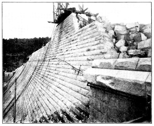
Progress View of Construction of New Croton Dam.
The hydraulic gradient plays a very important part in the construction
of a long pipe-line or conduit. If any part of the pipe should rise
above the hydraulic gradient, the discharge would no longer be full
below that point. It is necessary, therefore, always to lay the pipe or
the closed conduit so that all parts of it shall be below the hydraulic
gradient. Caution is obviously necessary to lay a pipe carrying water
deep enough below the surface of the ground in cold climates to protect
the water against freezing. At the same time if the pipe-line is a long
one it must follow the surface of the ground approximately in order to
save expensive cutting. There will, therefore, generally be summits
in pipe-lines, and inasmuch as all potable water carries some air
dissolved in it, that air is liable to accumulate at the high points or
summits. If that accumulation goes on long enough, it will seriously
trench upon the carrying capacity of the pipe and decrease its flow. It
is therefore necessary to provide at summits what are called blow-off
cocks to let the air escape. At the low points of the pipe-line, on the
contrary, the solid matter, such as sand and dirt, carried by the water
is liable to accumulate, and it is customary to arrange blow-offs also
at such points, so as to enable some of the water to escape and carry
with it the sand and dirt.
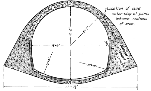
IN LOOSE EARTH.
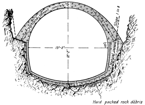
IN ROCK.
Weston Aqueduct. Sections of Aqueduct and Embankment.
SECTION OF EMBANKMENT.
ON EMBANKMENT.
Weston Aqueduct. Sections of Aqueduct and Embankment.
Gradient, 1 in 5000.
189. Flow of Water in Large Masonry Conduits.—In order to apply
Chezy’s formula first to the flow of the masonry aqueducts of the New
York and Boston water-supplies, it is necessary to have the outlines of
those conduits so that the wetted perimeter and hence the mean radius
may be determined for any depth of water in them.
OUTLINES OF AQUADUCTS.
Fig. 3.
The figure shows the desired cross-sections drawn carefully to
scale. Table XIV has been computed and
arranged from data taken from various official sources so as to show
the depth, mean velocity, discharge per second and per twenty-four
hours, and the coefficient used in Chezy’s formula, together with the
coefficient of roughness n in Kutter’s formula for the conduits
shown in the figure.
This table exhibits in a concise and clear manner the use of Chezy’s
formula in this class of hydraulic work.
TABLE XIV.
- LEGEND:
- (A) = Depth, in Feet.
- (B) = Hydraulic Radius r, Feet.
- (C) = Coefficient c.
- (D) = Mean Velocity, Feet.
- (E) = Cubic Feet per Second.
- (F) = Gallons per 24 Hours.
| Aqueducts. |
(A) |
(B) |
Grade
s. |
(C) |
(D) |
Discharge. |
n in
Kutter’s
Formula. |
| (E) |
(F) |
| † New Croton (1899) |
8.42 |
3.974 |
.0001326 |
153.3 |
3.52 |
371.6 |
240,200,000 |
|
| † ”” (after two years’ use) |
.. |
2.338 |
” |
131.3 |
2.312 |
.. |
.. |
.0133 |
| ‡ ”” |
.. |
1 |
” |
119.3 |
1.374 |
|
|
|
| ‡ ”” |
.. |
1.5 |
” |
126.3 |
1.781 |
|
|
|
| ‡ ”” |
.. |
2 |
” |
129.8 |
2.114 |
|
|
|
| ‡ ”” |
.. |
2.5 |
” |
132 |
2.404 |
|
|
|
| ‡ ”” |
.. |
3 |
” |
133.4 |
2.661 |
|
|
|
| ‡ ”” |
.. |
3.5 |
” |
134 |
2.887 |
|
|
|
| ‡ ”” |
.. |
4 |
” |
134.4 |
3.095 |
|
|
|
| Old Croton (1899) clean |
6 |
2.338 |
.. |
133.4 |
2.958 |
122.8 |
79,400,000 |
.0133 |
| ”” ordinary condition; |
6 |
2.338 |
.. |
123.2 |
.. |
.. |
73,300,000 |
|
| not clean |
| ”” not clean |
7.33 |
2.368 |
.. |
118.2 |
.. |
.. |
85,600,000 |
|
| Dorchester Bay tunnel |
.. |
1.875 |
.. |
119 |
|
|
|
|
| ”” |
.. |
2.338 |
.. |
125.0 |
.. |
.. |
.. |
.014 |
| Wachusetts, new; probably |
.. |
.. |
.. |
144.9 |
|
|
|
|
| clean (approx.) |
| Sudbury, clean |
.. |
.5 |
.000189 |
116.9 |
1.14 |
|
|
|
| ”” |
.. |
1.0 |
” |
127.0 |
1.74 |
|
|
|
| ”” |
.. |
1.5 |
” |
133.3 |
2.24 |
|
|
|
| ”” |
.. |
2.0 |
” |
137.8 |
2.68 |
|
|
|
| ”” |
.. |
2.5 |
” |
140.4 |
3.04 |
|
|
|
| † From report by J. R. Freeman to B. S. Coler, 1899. |
| ‡ From report of New York Aqueduct Commission. |
190. Flow of Water through Large Closed Pipes.—The
masonry conduits to which consideration has been given in the preceding
paragraphs carry water precisely as in an open canal, but the closed
conduits or pipes of steel plates and cast-iron, like the Hemlock
Lake conduit at Rochester and the East Jersey conduit of the Newark
Water-works, are of an entirely different type, as they carry water
under pressure. Hence the slope or sine of inclination s belongs
to the hydraulic gradient rather than to the grade of the pipe itself.
Where the pipe-line is a long one its average grade frequently does not
differ much from the hydraulic gradient, but the latter quantity must
always be used. As in the case of the masonry conduits, the coefficient
c in Chezy’s formula will vary considerably with the degree of
roughness of the interior surface of the pipe, with the slope s,
and with the mean radius r. An important distinction must be
made between riveted steel pipes and those of cast-iron, for the reason
that the rivet-heads on the inside of the former exert an appreciable
influence upon the coefficient c. The rivet-heads add to the
roughness or unevenness of the interior of the pipe. Table XV gives the
elements of the flow or discharge in the two pipe-lines which have been
taken as types, as determined by actual measurements; it also exhibits
similar elements for timber-stave pipes, to which reference will be
made later.
CROTON AQUEDUCT
IN EARTH.
As would be expected, the velocity of flow in these pipes may be and
generally is considerably higher than the velocity of movement in
masonry channels. Both Tables XV and XVI
give considerable range of coefficients computed and arranged from
authoritative sources, and the coefficients c for Chezy’s
formula represent the best hydraulic practice in connection with such
works at the present time. In using the formula for any special case,
great care must be taken to select a value for c which has been
established for conditions as closely as possible to those in question.
This is essential in order that the results of estimated discharges may
not be disappointing, as they sometimes have been where that condition
so necessary to accuracy has not been fulfilled.
TABLE XV.
VALUES OF COEFFICIENT c.
- LEGEND:
- (A) = Hydraulic Radius r.
- (B) = Hydraulic Gradient.
- (C) = Mean Velocity.
| Pipe-line. |
Diameter. |
(A) |
(B) |
(C) |
| Hemlock Lake |
36″ |
wrought-iron |
9″ |
.000411 |
1.532 |
| ”” |
24″ |
wr’t and cast |
6″ |
.00239 |
3.448 |
| Rush Lake to Mt. Hope |
24″ |
cast-iron |
6″ |
.00255 |
3.448 |
| Sudbury aqueduct |
48″ |
” ” |
12″ |
|
3.738 |
| ”” |
48″ |
” ” |
12″ |
|
4.965 |
| ”” |
48″ |
” ” |
12″ |
|
6.195 |
| ”” |
48″ |
” ” |
12″ |
|
3.738 |
| ”” |
48″ |
” ” |
12″ |
|
4.965 |
| ”” |
48″ |
” ” |
12″ |
|
6.195 |
| East Jersey Water Co. |
48″ |
steel riveted pipe |
12″ |
.002 |
4.62 |
| Timber-stave pipe, Ogden, Utah |
72″.5 |
|
|
|
.5 |
| ””
”” |
72″.5 |
|
12″ |
|
1.0 |
| ””
”” |
72″.5 |
|
12″ |
|
1.5 |
| ””
”” |
72″.5 |
|
12″ |
|
2.0 |
| ””
”” |
72″.5 |
|
12″ |
|
2.5 |
| ””
”” |
72″.5 |
|
12″ |
|
3.0 |
| ””
”” |
72″.5 |
|
12″ |
|
3.5 |
| ””
”” |
72″.5 |
|
12″ |
|
4.0 |
- LEGEND:
- (A) = Coefficient c.
- (B) = Cubic Feet per Second.
- (C) = Gallons per 24 Hours.
| Pipe-line. |
(A) |
Discharge. |
Remarks. |
| (B) |
(C) |
| Hemlock Lake |
87.3 |
10.83124> |
7,000,000 |
|
| ”” |
99.7 |
10.83124 |
7,000,000 |
1892. |
| Rush Lake to Mt. Hope |
96.5 |
10.83124 |
7,000,000 |
|
| Sudbury aqueduct |
140.14 |
|
|
Pipe |
| ”” |
142.11 |
|
|
new |
| ”” |
144.09 |
|
|
1880. |
| ”” |
139.94† |
|
|
After cleaning, 1894-95.
Before cleaning,
c = 108 |
| ”” |
141.74† |
|
|
| ”” |
143.16† |
|
|
| East Jersey Water Co. |
103.3 |
58.02 |
7,500,00 |
1891. |
| Timber-stave pipe, Ogden, Utah |
72 |
|
|
1897. |
| ””
”” |
96 |
|
| ””
”” |
109 |
| ””
”” |
115 |
| ””
”” |
119 |
| ””
”” |
122 |
| ””
”” |
124 |
| ””
”” |
126 |
| † These values correspond to the formula c = 131.88v⁰˙⁰⁴⁵. |
TABLE XVI.
VALUES OF c IN v = c√rs.
| |
No. |
1 |
2 |
3 |
4 |
5 |
6 |
| |
Age. |
New |
4 Years |
New |
New |
New |
New |
Velocity
Feet/sec. |
Diam.
Inches. |
36 |
36 |
38 |
38 |
42 |
42 |
| 0.5 |
c in
v =
c√rs. |
|
|
|
|
|
|
| 1 |
86 |
|
|
|
|
96 |
| 1.48 |
|
|
|
|
|
|
| 1.5 |
90.6 |
|
|
|
|
103 |
| 2.0 |
95.2 |
|
|
|
|
107.9 |
| 2.44 |
|
|
|
|
115.9 |
|
| 2.5 |
99.4 |
|
|
|
|
111 |
| 3 |
103.3 |
|
|
|
|
112.6 |
| 3.23 |
|
|
114 |
|
|
|
| 3.27 |
|
|
116.6 |
|
|
|
| 3.32 |
|
|
|
|
|
|
| 3.5 |
107 |
|
|
|
|
113 |
| 3.52 |
|
|
|
|
|
|
| 3.9 |
|
|
|
109.2 |
|
|
| 3.96 |
|
|
|
|
|
|
| 4 |
110.6 |
|
|
|
|
112.8 |
| 4.5 |
114 |
|
|
|
|
111.8 |
| 4.93 |
|
106.3 |
|
|
|
|
| 5 |
117.2 |
|
|
|
|
110.8 |
| 5.5 |
120.4 |
|
|
|
|
110.2 |
| 6 |
123.6 |
|
|
|
|
110 |
| 12.6 |
|
|
|
|
|
|
Kutter’s n =
coefficient
of roughness |
|
.014 |
.013 |
.013 |
.013 |
.013 |
.013 |
| |
No. |
7 |
8 |
9 |
10 |
11 |
12 |
13 |
| |
Age. |
New |
New |
4 Years |
4 Years |
New |
New |
5 Years |
Velocity
Feet/sec. |
Diam.
Inches. |
42 |
48 |
48 |
48 |
48 |
72 |
103 |
| 0.5 |
c in
v =
c√rs. |
|
|
|
|
|
110 |
126.5 |
| 1 |
101 |
101.2 |
78 |
97.2 |
97.1 |
110 |
116.6 |
| 1.48 |
|
|
|
|
|
|
|
| 1.5 |
102.8 |
105.4 |
84.6 |
100.8 |
98.7 |
111 |
112.7 |
| 2.0 |
104.3 |
108.8 |
89.6 |
103.3 |
100.3 |
110 |
110.3 |
| 2.44 |
|
|
|
|
|
|
|
| 2.5 |
105.5 |
111.2 |
92.4 |
104.9 |
101.6 |
108 |
108.8 |
| 3 |
106.4 |
111.8 |
93 |
105.3 |
102.2 |
108 |
107.7 |
| 3.23 |
|
|
|
|
|
|
|
| 3.27 |
|
|
|
|
|
|
|
| 3.32 |
|
|
|
|
|
|
|
| 3.5 |
107.2 |
113.4 |
93.2 |
104.8 |
103.6 |
110 |
106.9 |
| 3.52 |
|
|
|
|
|
|
|
| 3.9 |
|
|
|
|
|
|
|
| 3.96 |
|
|
|
|
|
|
|
| 4 |
107.8 |
113.2 |
94 |
104 |
104.2 |
111 |
106.2 |
| 4.5 |
108.2 |
112.4 |
94.2 |
103.7 |
104.7 |
|
105.6 |
| 4.93 |
|
|
|
|
|
|
|
| 5 |
108.4 |
112 |
94.4 |
103.7 |
105.1 |
|
|
| 5.5 |
108.5 |
11.7 |
94.7 |
103.7 |
105.2 |
|
|
| 6 |
108.5 |
111.6 |
94.9 |
103.7 |
105.2 |
|
|
| 12.6 |
|
|
|
|
|
|
|
Kutter’s n =
coefficient
of roughness |
|
.013 |
.013 |
.016 |
.014 |
.014 |
.014 |
|
| Exp. |
Nos. 1-2. |
Clemens Herschel, 1802. |
East Jersey Conduit, |
cylindrical joints. |
| Nos. 3-4. |
E. Kuichling, 1895. |
New Rochester conduit, |
cylindrical joints. |
| No. 5. |
I. W. Smith, 1896. |
Portland, Oregon, |
water-works. |
| Nos. 6-7. |
Clemens Herschel, 1896. |
East Jersey conduit, |
taper joints. |
| No. 8. |
Clemens Herschel, 1892. |
East Jersey conduit, |
cylindrical joints. |
| Nos. 9-10. |
Clemens Herschel, 1896. |
East Jersey conduit, |
cylindrical joints. |
| No. 11. |
Clemens Herschel, 1896. |
East Jersey conduit, |
taper joints. |
| No. 12. |
Marx, Wing, Hoskins, 1897. |
Pioneer El. Power Co., |
Ogden, Utah. |
| No. 13. |
Clemens Herschel, 1887. |
Holyoke, Mass., |
testing flume. |
CROTON AQUEDUCT
IN ROCK.
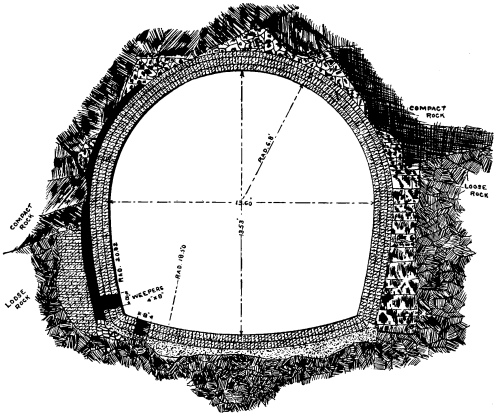
191. Change of Hydraulic Gradient by Changing Diameter
of Pipe.—It has already been seen, in the case of closed pipes or
conduits, that the hydraulic gradient with slope s governs the
velocity of flow, and also that all parts of the pipe-line must be
kept below that gradient. It is sometimes desirable, in order to meet
conditions either of topography or of flow, to raise or lower the
hydraulic gradient over the whole or some portion of the pipe-line.
This can easily be done to any needed extent by varying the diameter of
the pipe. An increase in diameter will in general decrease the velocity
of the water and increase its pressure, thus increasing correspondingly
the height of the columns of water in the piezometer tubes. As the
top surface of the latter determines the hydraulic gradient, it is
seen that increasing the diameter of a portion of the pipe-line will
correspondingly raise the gradient over the same portion. Thus by a
proper relative variation of diameters the hydraulic gradient of a
given pipe-line may readily be controlled within sufficient limits to
meet any ordinary requirements of this character.
192. Control of Flow by Gates at Upper End of
Pipe-line.—Obviously, if the pressure in the pipe-line is
diminished, less thickness of metal will be required to resist it, and
a corresponding degree of economy may be reached by a decrease in the
quantity of metal. In the 21 miles of 48-inch steel-plate pipe of the
East Jersey Water Company there is a fall of 340 feet; if, therefore,
the flow through that pipe were regulated by a gate or gates at its
lower end, the lower portion of the line would be subjected to great
intensity of pressure. If, however, the flow through the pipe is
controlled by a gate or gates at its upper end, enough water only may
be admitted to enable it to flow full with the velocity due to the
hydraulic gradient. By such a procedure the pressure upon the pipe over
and above that which is necessary to produce the gradient is avoided.
This condition is not only judicious in the reduction of the amount of
metal required, but also in reducing both the leakage and the tendency
to further leakage, which is largely increased by high pressures. This
feature of control of pressure in a long pipe-line with considerable
fall is always worthy of most careful consideration.
193. Flow in Old and New Cast-iron Pipes—Tubercles.—The
velocity of flow through cast-iron mains or conduits or through the
cast-iron pipes of a distribution system of public water-supply
depends largely upon the condition of the interior surface of the
pipes as affected by age. All cast-iron pipes before being shipped
from the foundry where they are manufactured are immersed in a hot
bath of suitable coal-tar pitch composition in order to protect them
from corrosion. After having been in use a few years this coating
on the interior of the pipes is worn off in spots and corrosion at
once begins. The iron oxide produced under these circumstances forms
projections, or tubercles as they are called, of greatly exaggerated
volume and out of all proportion to the actual weight of oxide of iron.
When the pipes are emptied these tubercles are readily removed by
scraping, but before their removal they greatly obstruct the flow of
water through the pipes. Indeed this obstruction is so great that the
discharging capacity of cast-iron mains must be treated in view of its
depreciation from this source.
Table XVII exhibits the value of the
coefficient c to be used in Chezy’s formula for all cast-iron
pipes having been in use for the periods shown.
TABLE XVII.
TABLE OF VALUES OF f AND c.
- LEGEND:
- (A) = Diameter, Inches.
- (B) = Hydraulic Radius r, Inches.
- (C) = Velocity, Feet per Second.
- (D) = Coefficient c.
- (E) = Coefficient f.
| Authority. |
Pipe-line |
(A) |
(B) |
(C) |
(D) |
(E) |
| Darcy |
New Pipe |
3.22 |
.8 |
0.29 |
78.5 |
.0418 |
| 10.71 |
100.0 |
.0257 |
| Darcy |
Old cast-iron pipe |
9.63 |
2.41 |
1.00 |
72.5 |
.0489 |
| lined with deposit |
12.42 |
74.0 |
.0468 |
| Darcy |
Pipe above cleaned |
9.63 |
2.41 |
0.91 |
90.0 |
.0316 |
| 14.75 |
98.0 |
.0269 |
| Brush |
Cast-iron pipe tar-coated |
20 |
5 |
2.00 |
114.0 |
.0197 |
| and in service 5 years. |
3.00 |
110.0 |
.0214 |
| Darrach |
Cast-iron pipe in service |
20 |
5 |
2.71 |
67.5 |
.0568 |
| 11 years |
5.11 |
83.0 |
.0376 |
| Darrach |
Cast-iron pipe in service |
36 |
9 |
1.58 |
60.0 |
.0716 |
| 7 years |
2.37 |
66.0 |
.0586 |
Obviously it is not possible to clean the smaller pipes of a
distribution system, but large cast-iron conduits may be emptied at
suitable periods and have their interior surfaces cleaned of tubercles
or other accumulations. At the same time, if necessary, a new coal-tar
coating can be applied.
Table XVIII exhibits the values of
the coefficient c to be used in Chezy’s formula for new and
clean coated cast-iron pipes. It represents the results of actual
hydraulic experience and is taken from Hamilton Smith’s “Hydraulics.”
A comparison between this table and that which precedes will show how
serious the effect of tubercles may be on the discharging capacity of a
cast-iron pipe.
In using Chezy’s formula, v = c√rs,
in connection with either Table XVII or XVIII,
the slope or sine of inclination s of the hydraulic gradient may
be readily computed by equation (10), which
gives the head lost by friction in a closed circular pipe as
It is only necessary in a straight pipe or one
nearly straight to compute the quantity
TABLE XVIII.
VALUES OF c IN FORMULA: v = c√rs.
Velocity v,
Feet per
Second. |
Diameters in Feet (d = 4r). |
| .05 |
.1 |
1 |
1.5 |
2 |
2.5 |
3 |
| 1 |
|
80.0 |
96.1 |
102.8 |
108.8 |
112.7 |
116.7 |
| 2 |
77.8 |
88.9 |
104.0 |
110.9 |
116.2 |
120.3 |
123.8 |
| 3 |
82.4 |
93.7 |
108.7 |
115.6 |
120.8 |
124.8 |
128.3 |
| 4 |
85.6 |
97.0 |
112.0 |
118.9 |
124.0 |
128.1 |
131.5 |
| 5 |
87.6 |
99.3 |
114.4 |
121.3 |
126.5 |
130.6 |
134.1 |
| 6 |
89.1 |
101.0 |
116.3 |
123.2 |
128.6 |
132.6 |
136.3 |
| 7 |
90.0 |
102.4 |
118.0 |
125.0 |
130.4 |
134.6 |
138.2 |
| 8 |
90.0 |
103.3 |
119.3 |
126.4 |
132.0 |
136.3 |
140.0 |
| 9 |
90.7 |
104.0 |
120.4 |
127.7 |
133.3 |
137.7 |
141.6 |
| 10 |
90.8 |
104.5 |
121.4 |
128.8 |
134.5 |
139.0 |
142.9 |
| 11 |
90.9 |
104.7 |
122.0 |
129.7 |
135.6 |
140.2 |
144.2 |
| 12 |
91.0 |
104.8 |
122.5 |
130.4 |
136.4 |
141.1 |
145.2 |
| 13 |
91.0 |
105.0 |
122.9 |
131.0 |
137.1 |
141.9 |
146.1 |
| 14 |
91.0 |
105.0 |
123.2 |
131.5 |
137.6 |
142.5 |
146.7 |
| 15 |
91.0 |
105.0 |
123.6 |
131.8 |
138.0 |
142.9 |
147.2 |
| 20(?) |
|
|
123.9 |
132.9 |
|
|
|
Velocity v,
Feet per
Second. |
Diameters in Feet (d = 4r). |
| 3.5 |
4 |
5 |
6 |
7 |
8 |
| 1 |
120.2 |
123.0 |
127.8 |
131.8 |
134.8 |
137.5 |
| 2 |
127.0 |
129.9 |
134.3 |
138.0 |
141.0 |
143.3 |
| 3 |
131.4 |
134.2 |
138.6 |
142.3 |
145.4 |
147.6 |
| 4 |
134.6 |
137.4 |
141.9 |
145.5 |
148.6 |
151.0 |
| 5 |
137.1 |
140.0 |
144.7 |
148.1 |
151.2 |
153.6 |
| 6 |
139.4 |
142.3 |
146.9 |
150.5 |
153.5 |
|
| 7 |
141.5 |
144.5 |
149.0 |
152.7 |
|
| 8 |
143.3 |
146.3 |
151.0 |
154.9 |
| 9 |
145.0 |
148.1 |
152.8 |
156.7 |
| 10 |
146.4 |
149.7 |
154.6 |
|
| 11 |
147.7 |
151.0 |
|
| 12 |
148.8 |
152.3 |
| 13 |
149.8 |
153.2 |
| 14 |
150.5 |
154.0 |
| 15 |
151.1 |
154.6 |
| 20(?) |
|
|
194. Timber-stave Pipes.—In the western part of the country
long conduits or pipe-lines are frequently constructed of timber called
redwood. Staves of suitable thickness, sometimes 1¾ inches, are
accurately shaped and finished with smooth surfaces so as to form large
pipes of any desired diameter. These staves are held rigidly in place
with steel bands drawn tight with nuts on screw ends, so as to close
tightly the joints between them. Such wooden conduits are rapidly and
cheaply built and are very durable. They have the further advantage
of requiring no interior coating, as the timber surface remains
indefinitely unaffected by the water flowing over it. The latter part
of Table XV shows coefficients for Chezy’s formula which may be used
for such a class of timber conduits. As the interior surfaces of such
closed conduits are always very smooth, the coefficients are seen to
be relatively large, and such pipes are, therefore, well adapted to
maintain unimpaired discharging capacity for great lengths of time.
CHAPTER XVIII.
195. Pumping and Pumps.—When it is impossible to secure
water at sufficient elevation to be delivered to the points of consumption
by gravity, it is necessary to resort to pumping in order to raise it
to the desired level. Indeed it is sometimes necessary to resort to
pumping in connection with a gravity supply in order to deliver water
to the higher parts of the distribution system, the lower points being
supplied by gravity. This combination of gravity supply with pumping
is not unusual. That part of New York north of Thirty-fourth Street
between Lexington and Fifth avenues, north of Thirty-fifth Street
between Fifth and Sixth avenues, north of Fifty-first Street between
Sixth and Ninth avenues, north of Fifty-fifth Street between Ninth and
Tenth avenues, north of Fifty-eighth Street between Tenth and Eleventh
avenues, and north of Seventy-second Street between Eleventh Avenue
and the North River, with elevation of 60 feet or more above mean high
tide-water, is supplied from the high-service reservoir near High
Bridge, the water being elevated to it from the Croton supply by the
pumping-station at the westerly end of the bridge. The elevation of the
water surface in the High Bridge reservoir is 208 feet, and that of the
large reservoir in Central Park 115 feet, above mean high tide-water.
Some specially high points on the northern part of Manhattan Island are
supplied from the High Bridge tower, whose water surface is 316 feet
above mean high tide.
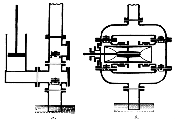
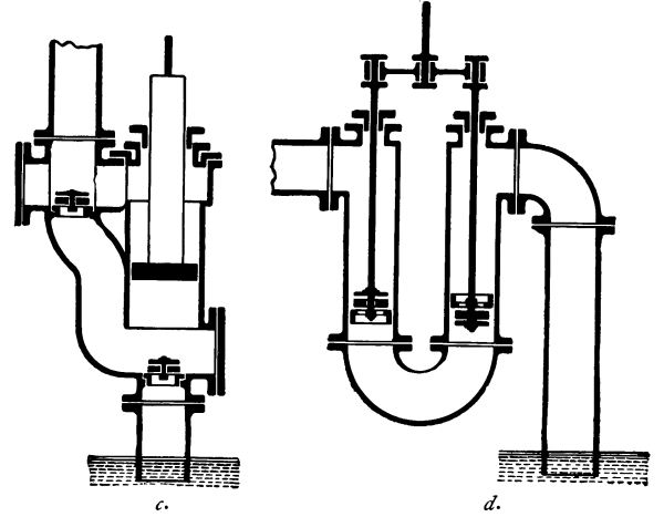
Skeleton Pumps.
The pumps employed for the purpose of elevating water to
distributing-reservoirs are among the finest pieces of machinery built
by engineers at the present time. They are usually actuated by steam
as a motive power, the steam being supplied from suitable boilers or
batteries of boilers in which coal is generally used as fuel. The
modern pumping-engine is in reality a combination of three classes of
machinery, the boilers, the steam-engines, and the pumps. There are
various types of boilers as well as of engines and pumps, all, when
judiciously designed and arranged, well adapted to the pumping-engine
process. The pumps are generally what are called displacement
pumps; that is, the water in the pump-cylinder is displaced by the
reciprocating motion of a piston or plunger. These pumps may be either
double-acting or single-acting; in the former case, as the piston or
plunger moves in one direction it forces the water ahead of it into the
main or pipe leading up to the reservoir into which the water is to
be delivered, while the water rising from the pump-well follows back
of the piston or plunger to the end of its stroke. When the motion
is reversed the latter water is forced on its way upward through the
main, while the water rises from the pump-well into the other end of
the water-cylinder. In the case of single-acting pumps water is drawn
up into the water-cylinder from the pump-well during one stroke and
forced up through the main during the next stroke, one operation only
being performed at one time. The pump-well is a well or tank, usually
of masonry, into which the water runs by gravity and from which the
pump raises it to the reservoir. For the purposes of accessibility and
convenience in repairing, the pump is always placed at an elevation
above the water in the pump-well, the pressure of the atmosphere on the
water in the well forcing the latter up into the pump-cylinder as the
piston recedes in its stroke. The height of a column of water 1 square
inch in section representing the pressure of the atmosphere per square
inch is about 34 feet, but a pump-cylinder should not be placed more
than about 18 feet above the surface of the water in the pump-well in
order that the water may rise readily as it follows the stroke of the
plunger.
In the operation of the ordinary pump the direction of the water as it
flows into and out of the pump-cylinder must necessarily be reversed,
and this is true also with the type of pump called the differential
plunger-pump, which is really a single-acting pump designed so as to
act in driving the water into the main like a double-acting pump,
i.e., both motions of the plunger force water through the main, but
only one draws water from the pump-well into the pump-cylinder. Valves
may be so arranged in the pump-piston as to make the progress of the
water through the pump continuous in one direction and so avoid the
irregularities and shocks which necessarily arise to some extent from a
reversal of the motion of the water.
The steam is used in the steam-cylinders of a pumping-engine precisely
as in every other type of steam-engine. At the present time compound
or triple-expansion engines are generally used, among the well-known
types being the Worthington duplex direct-acting pump without crank or
fly-wheel, the Gaskill crank and fly-wheel pumping-engine, the Allis
and the Leavitt pumping-engines, both of the latter employing the crank
and fly-wheel and both may be used as single- or double-acting pumps,
usually as the latter. The characteristic feature of the well-known
Worthington pumping-engine is the movement of the valves of each of the
two engines by the other for the purpose of securing a quiet seating of
the valves and smooth working.
One of the most important details of the pumping-engine is the
system of valves in the water-cylinder, and much ingenuity has been
successfully expended in the design of proper valve systems. These
pump-valves must, among other things, meet the following requirements
as efficiently as possible: they must close promptly and tightly, so
that no water may pass through them to create slip or leakage; they
should have a small lift, so as to allow prompt closing, and large
waterways, to permit a free flow through them with little resistance;
they must also be easily operated, so as to require little power,
and, like all details of machinery, they should be simple and easily
accessible for repairing when necessary.
As steam is always used expansively, its force impelling the plunger
will have a constant value during the early portion of the stroke
only, and a much less value, due to the expansion of the steam, at
and near the end of the stroke, while the head of water against which
the pump operates is practically constant. There is, therefore, an
excess of effort during the first part of the stroke and a deficiency
during the latter part. Unless there should be some means of taking
up or cushioning this difference, the operation of the pump would be
irregular during the stroke and productive of water-hammer or blows to
the engine. Two means are employed to remove this undesirable effect,
i.e., the fly-wheel and the air-chamber, or both. In the one case the
excess of work performed by the steam in the early part of the stroke
is stored up as energy in the accelerated motion of the fly-wheel and
given out by the latter near the end of the stroke, thus producing the
desired equalization. The air-chamber is a large reservoir containing
air, attached to and freely communicating with the force-main or pipe
near its connection with the pumps. In this case the excess of work
performed at the beginning of the stroke is used in compressing the
air in the air-chamber, sufficient water entering to accomplish that
purpose. This compressed air acts as a cushion, expanding again at the
end of the stroke and reinforcing the decreasing effort of the steam.
196. Resistances of Pumps and Main—Dynamic Head.—Obviously
the water flowing through the pipes, pump-cylinders, and pump-valves
will experience some resistance, and it is one purpose in good
pumping-engine design to make the progress of the water through the
pump so direct and free as to reduce these losses to a minimum.
Similarly the large pipe or main, called the force-main, leading
from the pump up to the reservoir into which the water is delivered,
sometimes several thousand feet long, will afford a resistance of
friction to the water flowing through it. The head which measures
this frictional loss is given by equation (10) on page 239.
All these resistances will increase rapidly with the velocity with which the
water flows through the pipes and other passages, as do all hydraulic
losses. It is obviously advisable, therefore, to make this velocity
as low as practicable without unduly increasing the diameter of the
force-main. This velocity seldom exceeds about 3 feet per second.
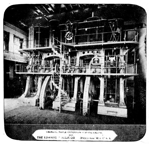
Allis Pump.
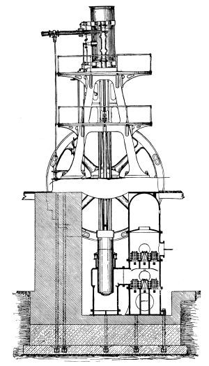
Section of Allis Pumping-Engine.
The static head against which the pumping-engine operates
is the vertical height or elevation between the water surfaces
in the pump-well and the reservoir. The head which represents
the resistances of the passages through the pump and force-main,
when added to the sum of the static head and the head due to
the velocity in the force-main, gives what is called the dynamic
head; it represents the total head against which the pump acts.
If h represents the static head, hʹ the head due to
all the resistances, and h″ the head due to the velocity in the
force-main, then the dynamic head will be
| H = h + hʹ + h″ |
= |
h |
+ |
f |
l |
|
v² |
+ n |
v² |
+ |
v² |
, |
| d |
2g |
2g |
2g |
in which f has a value of about .015 and
n is a coefficient which when multiplied by the velocity head
will represent the loss of head incurred by the water in passing
through the pump-cylinder and valves. The latter quantity is variable
in value; but it is seldom more than a few feet.
197. Duty of Pumping-engines.—It is thus seen that
the collective machines and force-main forming the pumping system
afford opportunity for a number of serious losses of energy found
chiefly in the boiler, the engine, and the pump. The excellence of
a pumping-plant, including the boilers, may obviously be measured
by the amount of useful work performed by a standard quantity, as
100 pounds of coal. Sixty or more years ago, in the days of the old
Cornish pumping-engine, the standard of excellence or “duty” was the
number of foot-pounds of work, i.e., the number of pounds lifted
one foot high, performed by one bushel of coal. As early as 1843
the Cornish pumping-engine reached a duty, per bushel of coal, of
107,500,000 foot-pounds. These pumping-engines were single-acting, the
steam raising a weight the descent of which forced the water up the
delivery-pipe.
At a later date and until about ten years ago the usual standard or
criterion applied to pumping-engines for city water-works was the
amount of work performed in lifting water for each 100 pounds of
coal consumed; this result was also called the “duty” of the engine.
In order to determine the duty of a pumping-engine it was thus only
necessary to observe carefully for a given period of time, i.e.,
twenty-four hours or some other arbitrary period, the amount of coal
consumed, the condition of the furnace-fires at the beginning and end
of the test being as nearly the same as possible, and measure at the
same time the total amount of water discharged into the reservoir.
The total weight of water raised multiplied by the total number of
feet of elevation from the water surface in the pump-well to that in
the reservoir would give the total number of foot-pounds of useful
work performed. This quantity divided by the number of hundred pounds
of coal consumed would then give what is called the “duty” of the
pumping-engine.
198. Data to be Observed in Pumping-engine Tests.—Obviously
it is necessary to observe a considerable number of data with care.
No pump works with absolute perfection. A little water will run back
through the valves before they are seated, and there will be a little
leakage either through the valves or through the packing around the
piston or plunger, or both sources of leakage may exist. That leakage
and back-flow represent the amount of slip or water which escapes
to the back of the plunger after having been in front of it. In
well-constructed machinery this slip or leakage is now very small and
may be but a small fraction of one per cent. Inasmuch as the amount
of work performed by the steam will be the same whether this slip
or leakage exists or not, the latter is now frequently ignored in
estimating the duty of pumping-engines, the displacement of the piston
or plunger itself being taken as the volume of water pumped at each
stroke.
Again, in discussing the efficiency of the steam portion of the
machinery the amount of partial vacuum maintained in the vacuum-pump,
which is used to move the water of the condensed steam, is affected
by atmospheric pressure, as is the work which is performed. Hence
in complete engine tests it is necessary to observe the height of
the barometer during the test. It is also necessary to observe the
temperature of feed-water supplied to the boiler, and to use accurate
appliances for ascertaining with the greatest exactness practicable
the weight of dry steam used in the steam-cylinders and the amount of
water which it carries. It is not necessary for the present purpose
to discuss with minuteness these details, but it is evident from the
preceding observations that the complete test of a pumping-engine
involves the accurate observation of many data and their careful use in
computations. The determination of the duty alone is but a simple part
of those computations, and the duty is all that is now in question.
199. Basis of Computations for Duty.—It was formerly
necessary in giving the duty of a pumping-engine to state whether
the 100 pounds of coal was actually coal as shovelled into the
furnace, or whether it was that coal less the weight of ash remaining
after combustion. It was also necessary to specify the quality
of coal used, because the heating capacity of different coals may
vary materially. For these different reasons the statement of
the duty of a pumping-engine in terms of a given weight of coal
consumed involved considerable uncertainty, hence in 1891 a
committee of the American Society of Mechanical Engineers,
appointed for the purpose, took into consideration the best
method of determining and stating the duty of a pumping-engine.
The report of that committee may be found in vol. XII
of the Transactions of that Society. The committee recommended
that in a duty test 1,000,000 heat-units (called British
Thermal Units or, as abbreviated, frequently B.T.U.) should be
substituted for 100 pounds of coal. In other words, that the
following should be the expression for the duty:
| Duty = |
foot-pounds of work done |
× 1,000,000. |
| total number of heat-units consumed |
For some grades of coal in which 1,000,000 heat-units would be
available for every 100 pounds the numerical value of the duty
expressed in the new terms would be unchanged, but for other grades of
coal the new expression of the duty might be considerably different.
200. Heat-units and Ash in 100 Pounds of Coal, and Amount of
Work Equivalent to a Heat-unit.—The following table exhibits
results determined by Mr. George H. Barrus (Trans. A. S. M. E., vol.
XIV. page 816), giving an approximate idea of the total number
of heat-units which are made available by the combustion of 100 pounds
of coal of the kinds indicated:
| Semibitumintous: |
| George’s Creek Cumberland, |
Percentage of Ash. |
| 1,287,400 to 1,421,700 |
6.1 to 8.6 |
| Pocahontas, |
| 1,360,800 to 1,460,300 |
3.2 to 6.2 |
| New River, |
| 1,385,800 to 1,392,200 |
3.5 to 5.7 |
Bituminous: |
| Youghiogheny, Pa., lump, |
| 1,294,100 |
5.9 |
| Youghiogheny, Pa., slack, |
| 1,166,400 |
10.2 |
| Frontenac, Kan., |
| 1,050,600 |
17.7 |
| Cape Breton Caledonia, |
| 1,242,000 |
8.7 |
Anthracite: |
| 1,152,100 to 1,318,900 |
9.1 to 10.5 |
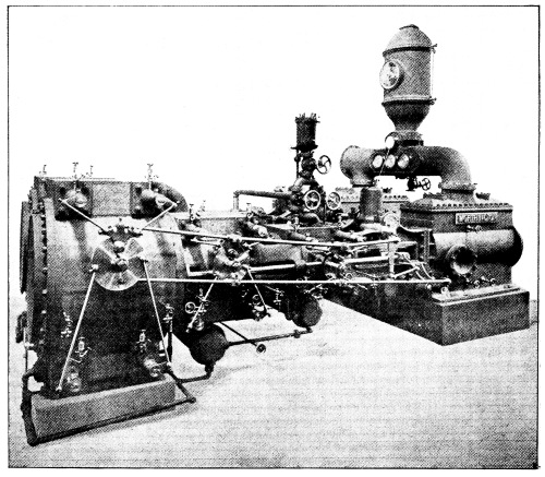
Worthington Pump.
Each unit or B.T.U. represents the amount of heat required to raise
one pound of water at 32° Fahr. 1° Fahr., and it is equal to 778
foot-pounds of work. In other words, 778 foot-pounds of work is said
to be the mechanical equivalent of one heat-unit. The amount of work,
therefore, which one pound of dry steam is capable of performing at
any given pressure and at the corresponding temperature may readily
be found by multiplying the number of available heat-units which it
contains, and which may be readily computed if not already known, by
778, or as in a pumping-engine duty trial, knowing by observation the
number of pounds of steam at a given pressure and temperature supplied
through the steam-cylinders, the number of heat-units supplied in
that steam is at once known or may easily be computed. Then observing
or computing the total weight of water raised by the pumping-engine,
as well as the total head (the dynamic head) against which the
pumping-engine has worked, the total number of foot-pounds of work
performed can be at once deduced. This latter quantity divided by the
number of million heat-units will give the desired duty.
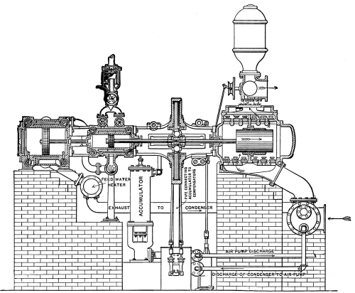
Section of Worthington Pump.
201. Three Methods of Estimating Duty.—At the present time
it is frequently, and perhaps usually, customary to give the duty in
terms of 100 pounds of coal consumed, as well as in terms of 1,000,000
heat-units. Frequently, also, the duty is expressed in terms of 1000
pounds of dry steam containing about 1,000,000 heat-units. As has
sometimes been written, the duty unit is 100 for coal, 1000 for steam,
and 1,000,000 for heat-units.
202. Trial Test and Duty of Allis Pumping-engine.—The
following data are taken from a duty test of an Allis pumping-engine
at Hackensack, N. J., in 1899 by Prof. James E. Denton. This
pumping-engine was built to give a duty not less than 145,000,000
foot-pounds for each “1000 pounds of dry steam consumed by the engine,
assuming the weight of water delivered to be that of the number of
cubic feet displaced by the plungers on their inward stroke, i.e., to
be 145,000,000 foot-pounds at a steam pressure of 175 pounds gauge.”
The capacity of the engine was to be 12,000,000 gallons per twenty-four
hours at a piston speed not exceeding 217 feet per minute. The engine
was of the vertical triple-expansion type with cylinders 25.5 inches,
47 inches, and 73 inches in diameter with a stroke of 42¹/₁₆ inches,
the single-acting plunger being 25.524 inches in diameter. The
following data and figures illustrate the manner of computing the duty:
DUTY PER 1000 POUNDS OF DRY STEAM
BY PLUNGER DISPLACEMENT.
| 1. |
Circumference of plungers, Cl |
80.1875 ins. |
| 2. |
Length of stroke, 7 |
42.0625 ins. |
| 3. |
Number of plungers (single-acting) |
3 |
| 4. |
Aggregate displacement of plunger per revolution = |
|
| |
3C²l |
= d |
64,4557.1 cu. ins. |
| |
4π |
| 5. |
Revolutions during 24 hours, N |
43,337 |
| 6. |
Weight of one cubic foot of water, w |
62.42 lbs. |
| 7. |
Total head pumped against, H |
266.61 ft. |
| 8. |
Total feed-water per 24 hours, W |
160,354 lbs. |
| 9. |
Duty per 1000 lbs. of feed-water = |
|
| d × w |
× |
H × N × 1000 |
| 1728 |
W |
| = 2,331,976 × |
266.61 × 43,337 × 1000 |
= |
168,027,200 ft.-lbs. |
| 160,354 |
| 10. |
Percentage of moisture in steam at engine-throttle valve |
0.3 per cent. |
| 11. |
Duty per 1000 lbs. of dry steam, |
168,027,200 |
= 168,532,800 ft.-lbs. |
| 0.997 |
DUTY PER MILLION HEAT-UNITS.
| 12. |
Average steam pressure at throttle above atmosphere. |
173 lbs. |
| 13. |
Average feed-water temperature. |
78°.5 Fahr. |
| 14. |
Total heat in one pound of steam containing |
1,194.2 B. T. U. |
| |
0.3 per cent. of moisture above 32° Fahr. |
| 15. |
Heat per lb. of feed-water above 32° Fahr. |
46.5 ” |
| 16. |
Heat supplied per lb. of feed-water |
1,147.7 ” |
| |
above 32° Fahr. |
|
| 17. |
Duty per lb. of feed-water. |
168,027.2 ft.-lbs. |
| 18. |
Duty per million B. T. U. |
146,403,614 ” |
203. Conditions Affecting Duty of Pumping-engines.—Manifestly
the duty of a pumping-engine by whatever standard it may be measured
will vary with the conditions under which it is made. A new engine
running under the favoring circumstances of a short-time test may be
expected to give a higher duty than when running under the ordinary
conditions of usage one month after another. Hence it can scarcely
be expected that the monthly performance, and much less the yearly
performance, of an engine will show as high results as when tested for
a day or two or for less time.
204. Speeds and Duties of Modern Pumping-engines.—The
following table gives the piston or plunger speeds of a number of the best
modern pumping-engines, and the corresponding duties, with the standards by
which those duties are measured.
- LEGEND:
- (A) = Piston Speed in Feet per Minute.
- (B) = Piston Speed in Feet per Minute.
| Engine. |
Piston Speed
in Feet
per Minute. |
Duty in
Foot-pounds. |
Expressed in |
| Ridgewood Station, Brooklyn, |
164.0 |
137,953,585 |
1000 lbs. of dry steam |
| Worthington engine |
| 14th St. pumping-station, Chicago; |
210.54 |
133,445,000 |
Million |
B.T.U. |
| built by Lake Erie Engine Works |
| Allis engine at Hackensack, N. J. |
210.65 |
146,403,416 |
” |
” |
| Snow pump at Indianapolis |
214.6 |
150,100,000 |
” |
” |
| Leavitt pump at Chestnut Hill |
|
144,499,032 |
” |
” |
| Nordberg at Wildwood |
256.0 |
162,132,517 |
” |
” |
| Allis at Chestnut Hill, |
192.5 |
157,002,500 |
Million |
B.T.U. |
| tested May 1, 1900 |
| Allis at St. Louis, |
197.16 |
158,077,324 |
” |
” |
| tested February 26, 1900 |
| Barr at Waltham, Mass. |
194.28 |
128,865,000 |
1000 lbs. of dry steam |
| Allis at St. Paul, Minn. |
189.0 |
144,463,000 |
””” |
| Lake Erie Engine Works at Buffalo |
207.7 |
135,403,745 |
Million |
B.T.U. |
These results show that material advances have been made in
pumping-engine designs within a comparatively few years.
CHAPTER XIX.
205. Distributing-reservoirs and their Capacities.—The
water of a public supply seldom runs from the storage-reservoir directly
into the distributing system or is pumped directly into it, although such
practices may in some cases be permissible for small towns or cities.
Generally distributing-reservoirs are provided either in or immediately
adjacent to the distributing system of pipes, meaning the water-pipes
large and small which are laid through the streets of a city or town,
and the service-pipes leading from the latter directly to the consumers.
The capacity ordinarily given to these distributing-reservoirs is not
controlled by any rigid rule, but depends upon the local circumstances
of each case. If they are of masonry and covered with masonry arches,
as required for the reception of some filtered waters, they are made as
small as practicable on account of their costs. If, on the contrary,
they are open and formed of suitably constructed embankments, like the
distributing-reservoirs of New York City in Central Park and at High
Bridge, they are and should be of much greater capacity. The storage
volume of the High Bridge reservoir amounts to 11,000,000 gallons,
while that of the Central Park reservoir is 1,000,000,000 gallons.
Again, the capacity of the old receiving-basin in Central Park is
200,000,000 gallons. These reservoirs act also as equalizers against
the varying draft on the system during the different portions of the
day and furnish all desired storage for the demands of fire-streams,
which, while it lasts, may be a demand at a high rate. It may be
approximately stated under ordinary circumstances that the capacity of
distributing-reservoirs for a given system should equal from two or
three to eight or ten days supply. It is advantageous to approach the
upper of those limits when practicable. The volume of water retained in
these reservoirs acts in some cases as a needed storage, while repairs
of pumping-machinery or other exigencies may temporarily stop the flow
into them. The larger their capacity the more effectively will such
exigencies be met.
206. System of Distributing Mains and Pipes.—Gate-houses
must be placed at the distributing-reservoirs within which are found
and operated the requisite gates controlling the supply into the
reservoir and the outflow from it into the distributing system. The
latter begins at the distributing-reservoir where there may be one or
two or more large mains, usually of cast-iron. These mains conduct
the water into the branching system of pipes which forms a network
over the entire city or town. A few lines of large pipes are laid so
as to divide the total area to be supplied into convenient portions
served by pipes of smaller diameter leading from the larger, so that
practically every street shall carry its line or lines of piping from
which every resident or user may draw the desired supply. Obviously,
as a rule, the further the beginning of the distributing system is
departed from in following out the ramifications of the various lines
the smaller will the diameter of pipe become. The smallest cast-iron
pipe of a distributing system is seldom less than 3 inches, and
sometimes not less than 4 or 6 inches. There should be no dead ends
in any distributing system. By a dead end is meant the end of a line
of pipes, which is closed so that no water circulates through it.
Whenever a branch pipe ceases it should be extended so as to connect
with some other pipe in the system in order to induce circulation. The
entire distributing system should therefore, in its extreme as well
as central portions, constitute an interlaced system and not a series
of closed ends. This is essential for the purity and potability of
the water-supply. A circulation in all parts of the entire system is
essential and it should be everywhere secured.
The diagram shows a portion of the distributing system of the city
of New York. It will be noticed that there is a complete connection of
the outlying portions, so as to make the interlacing and corresponding
circulation as complete and active as possible.
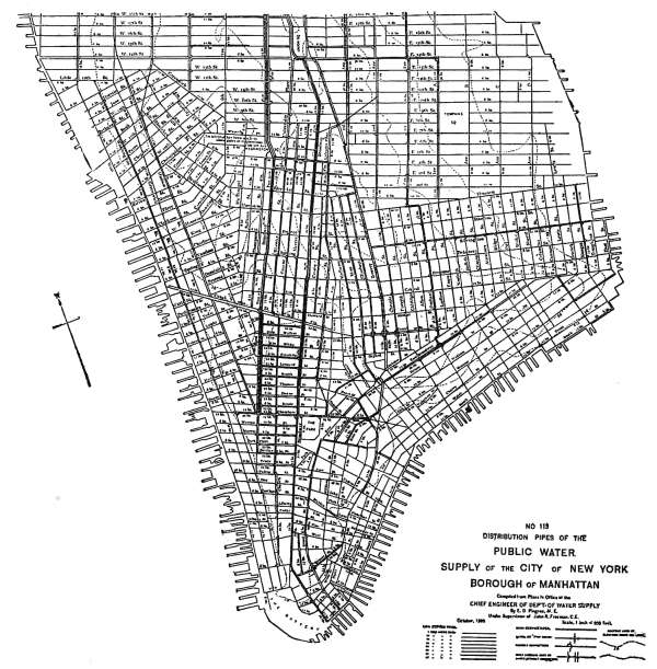
Fig. 4.—New York City
Distributing System.
207. Diameters of and Velocities in Distributing Mains and
Pipes.—In laying out a distributing system it will not be possible
to base the diameters at different points on close computations for
velocity or discharges based upon considerations of friction or other
resistances, as the conditions under which the pipes are found are
too complicated to make such a method workable. Approximate estimates
may be made as to the number of consumers to be supplied at a given
section of a main pipe, and consequently what the diameter should be
to pass the required daily supply so that the velocity may not exceed
certain maximum limits known to be advisable. Such estimates may be
made at a considerable number of what may be termed critical points of
the system, and the diameters may be ascertained in that manner with
sufficient accuracy. In this field of hydraulics a sound engineering
judgment, based upon experience, is a very important element, as it is
in a great many other engineering operations.
It will follow from these considerations that as a rule the larger
diameters of pipe in a given distributing system will belong to the
greater lengths, and it will be found that the velocities of water in
the various parts of a system will seldom exceed the following limits,
which, although stated with some precision, are to be regarded only as
approximate:
| For |
4 |
-inch |
pipe |
23 |
feet |
per |
second. |
| ” |
6 |
” |
” |
23 |
” |
” |
” |
| ” |
8 |
” |
” |
17 |
” |
” |
” |
| ” |
11 |
” |
” |
12 |
” |
” |
” |
| ” |
12 |
” |
” |
12 |
” |
” |
” |
| ” |
16 |
” |
” |
9 |
” |
” |
” |
| ” |
20 |
” |
” |
8 |
” |
” |
” |
| ” |
24 |
” |
” |
7 |
” |
” |
” |
| ” |
30 |
” |
” |
7 |
” |
” |
” |
| ” |
36 |
” |
” |
7 |
” |
” |
” |
| ” |
48 |
” |
” |
7 |
” |
” |
” |
| ” |
60 |
” |
” |
7 |
” |
” |
” |
208. Required Pressures in Mains and Pipes.—In designing
distributing systems it is very essential so to apportion the pipes
as to secure the requisite pressure at the various street services.
Like many other features of a water-supply system no exact rules can
be given, but it may be stated that at the street-level a pressure of
at least 20 to 30 pounds should be found in resident districts, and
from 30 to 35 or 40 pounds in business districts. The character and
height of buildings affect these pressures to a large extent. Old pipe
systems usually have many weak points, and while pressures requisite
to carry water to the top of three- or four-story buildings are
needed, any great excess above that would be apt to cause breaks and
result in serious leakages. If the distributing system is one in which
the pressure for fire-streams is to be found at the hydrants, then
greater pressures than those named must be provided. In such cases the
pressures in pipes at the hydrants should range from 60 to 100 pounds.
209. Fire-hydrants.—Fire-hydrants must be placed usually at
street corners, if the blocks are not too long, and so distributed as
to control with facility the entire district in which they are found.
Unless fire-engines are used to create their own pressure, the lower
the pressure at the hydrant the nearer together the hydrants must be
placed. It is obvious, however, that when the pressure of the system
is depended upon for fire-streams it is desirable to have the pressure
comparatively high, so far as the hydrants are concerned, as under
those conditions they may be placed farther apart and a less number
will be required.
210. Elements of Distributing Systems.—The following
table gives a number of statistics, exhibiting the elements of the
distributing system of a considerable number of cities, including some
pumping and meter data pertinent to the costs of pumping on the one
hand and the extension of the use of meters on the other.
It contains information of no little practical value in connection with
the administration of the distributing systems and the consumption
of water in it. This table has been compiled by Mr. Chas. W. Sherman
of the New England Water-works Association, and was published in the
proceedings of that association for September, 1901. The service-pipes,
varying from ½ to 10 inches in diameter, are of cast-iron,
wrought-iron, lead, galvanized iron, tin-lined, rubber-lined,
cement-lined, enamelled and tarred, the practice varying widely not
only from one city to another, but in the same city.
TABLE XIX
- LEGEND:
- (A) = Kind of Pipe.
- (B) = Size of Pipe. Ins
- (C) = Total Length in Use, Miles.
- (D) = Cost of Repairs per Mile.
- (E) = Total Number of Hydrants in Use.
| Name of City or Town. |
(A) |
(B) |
(C) |
(D) |
(E) |
| Albany, N. Y. |
|
|
129.7 |
|
808 |
| Atlantic City, N. J. |
C.I. |
4-20 |
47.6 |
|
519 |
| Boston, Mass. |
C.I. |
2-48 |
713.4 |
27.09 |
7606 |
| Burilngton, Vt. |
C.I. |
4-30 |
38.0 |
4.61 |
213 |
| C.I. |
| W.I. |
| Cambridge, Mass. |
|
|
|
|
968 |
| Chelsea, Mass. |
C.I. |
6-16 |
37.8 |
|
253 |
| Concord, N. H. |
C.I. |
4-30 |
60.2 |
|
267 |
| C.I. |
| Fall River, Mass. |
C.I. |
6-24 |
87.3 |
|
954 |
| Fitchburg, Mass. |
C.I. |
2-20 |
66.6 |
|
499 |
| Holyoke, Mass. |
C.I. |
½-30 |
81.6 |
5.14 |
860 |
| W.I. |
| Lowell, Mass. |
|
|
127.8 |
|
1098 |
| Lynn, Mass. |
W.I. |
2-20 |
|
129.4 |
952 |
| C.I. |
| C.I. |
| Madison, Wis. |
C.I. |
4-16 |
34.3 |
|
169 |
| Manchester, N. H. |
C.I. |
4-20 |
96.9 |
|
743 |
| C.I. |
Metropolitan
Water-works |
Owned by |
C.I. |
6-60 |
69.8 |
|
|
| C.I. |
| Tot. Sup. by |
C.I. |
4-60 |
1360.3 |
|
11913 |
| C.I. |
| Kal. |
| Minneapolis, Minn. |
C.I. |
1¼-50 |
269.2 |
|
3172 |
| Steel. |
| New Bedford, Mass. |
C.I. |
4-36 |
92.7 |
24.00 |
738 |
| New London, Conn. |
W.I. |
4-24 |
50.5 |
18.71 |
258 |
| C.I. |
| C.I. |
| Newton, Mass. |
C.I. |
4-20 |
136.6 |
6.43 |
935 |
| Providence, R. I. |
C.I. |
6-36 |
324.6 |
0.56 |
1886 |
| ” |
H.P. Fire System |
C.I. |
12-24 |
5.6 |
|
92 |
| Quincy, Mass. |
W.I. |
1-36 |
144.7 |
5.50 |
955 † |
| C.I. |
| C.I. |
| Springfield, Mass. |
C.I. |
2-20 |
84.1 |
|
539 |
| Kal. |
| Woonsocket, R. I. |
C.I. |
4-20 |
45.8 |
3.57 |
548 |
| Yonkers, N. Y. |
|
|
74.1 |
|
771 |
| Worcester, Mass. |
|
2-40 |
173.5 |
|
1763 |
† Public hydrants only.
TABLE XIX. (continued)
- LEGEND:
- (F) = Total Number of Gates in Use.
- (G) = Range of Pressure on Mains at Centre, Pounds.
- (H) = Size of Service-pipe in Inches.
- (I) = Total Number of Service-taps in Use.
- (J) = Total Number of Meters in Use.
- (K) = Total Pumpage for the Year in Gallons.
- (L) = Average Static Head against which Pumps Work, Feet.
| Name of City or Town. |
(F) |
(G) |
(H) |
(I) |
(J) |
(K) |
(L) |
| Albany, N. Y. |
803 |
|
|
|
2030 |
|
|
| Atlantic City, N. J. |
|
|
½-4 |
4,249 |
3298 |
955,726,046 |
81.7 |
| 148,662,947 |
119.5 |
| Boston, Mass. |
8910 |
40-90 |
½-8 |
87,525 |
4516 |
|
|
| Burlington, Vt. |
618 |
70-85 |
½-6 |
3,350 |
2311 |
312,896,525 |
289 |
| Cambridge, Mass. |
399 |
48-50 |
⅝-2 |
14,207 |
860 |
2,651,277,240 |
|
| 6,146 |
104 |
| Chelsea, Mass. |
757 |
|
|
3,340 |
1010 |
142,772,165 |
|
| Concord, N. H. |
940 |
80 |
½-2 |
6,943 |
6,544 |
1,388,776,336 |
186.2 |
| Fall River, Mass. |
554 |
75 L.S |
¾-8 |
4,432 |
2,427 |
|
|
| 155 H.S. |
| Fitchburg, Mass. |
734 |
80-100 |
⅝-4 |
3,610 |
210 |
|
|
| Holyoke, Mass. |
1188 |
|
|
10,634 |
5,586 |
2,042,066,140 |
156.1 |
| Lowell, Mass. |
966 |
45-60 |
¾-4 |
13,504 |
2,571 |
378,782,675 |
|
| 1,330,784,875 |
| Lynn, Mass. |
234 |
|
|
2,758 |
2,586 |
306,637,454 |
223.8 |
| Madison, Wis. |
910 |
|
½-6 |
5,513 |
3,667 |
|
|
| Manchester, N. H. |
|
|
|
|
|
|
|
Metropolitan
Water-works |
268 |
|
|
134,496 |
10,385 |
15,027,410,000(a) |
|
| 9,431,140,000(b) |
| 2,015,130,000(c) |
| Minneapolis, Minn. |
2195 |
|
⅝-1 |
20,064 |
5,030 |
6,863,135,200 |
|
| New Bedford, Mass. |
1065 |
28-64 |
½-10 |
9,280 |
1,429 |
2,307,429,372 |
167.2 |
| New London, Conn. |
318 |
40-48 |
½-4 |
3,088 |
229 |
|
|
| Newton, Mass. |
801 |
84 |
½-6 |
7,087 |
6,001 |
762,876,073 |
234 |
| Providence, R. I. |
3399 |
64-73 |
½-10 |
21,566 |
17,813 |
3,833,243,445 |
171.6 |
| 34,401,038 |
172.4 |
| ” H.P. Fire System |
31 |
114 |
|
|
|
578,940,480 |
111.2 |
| Quincy, Mass. |
1889 |
30-35 H.S |
1-6 |
9,764 |
3,122 |
|
|
| 100-120 L.S.† |
| Springfield, Mass. |
1001 |
78-85 |
⅝-3 |
4,330 |
122 |
|
|
| Woonsocket, R. I. |
456 |
50-120 |
⅝-6 |
2,193 |
1,889 |
340,849,628 |
237.6 |
| Yonkers, N. Y. |
498 |
|
¼-8 |
4,968 |
4,852 |
1,323,696,099 |
|
| Worcester, Mass. |
2432 |
70 L.S. |
|
13,292 |
12,529 |
|
|
| 150 H.S.† |
† Public hydrants only.
- C.L. = cement-lined.
- (a) = Chestnut Hill high service.
- (b) = Chestnut Hill low service.
- (c) = Spot Pond Pumping-station.
TABLE XIX. (continued)
- LEGEND:
- (M) = Average Dynamic Head against which Pumps Work, Feet.
- (N) = Duty in Foot-pounds per 100 Pounds of Coal. No Deductions.
| Name of City or Town. |
Kind of
Pipe. |
Size of
Pipe. |
(M) |
(N) |
| Albany, N. Y. |
.. |
.. |
.. |
.. |
| Atlantic City, N. J. |
C.I. |
4-20 |
123.3 |
36,501,217 |
| 119.5 |
15,518,455 |
| Boston, Mass. |
C.I. |
2-48 |
.. |
.. |
| Burlington, Vt. |
C.I. |
4-30 |
316 |
.. |
| C.I. |
| W.I. |
| Cambridge, Mass. |
.. |
.. |
.. |
.. |
| Chelsea, Mass. |
C.I. |
6-16 |
.. |
.. |
| Concord, N. H. |
C.I. |
4-30 |
.. |
.. |
| C.I. |
| Fall River, Mass. |
C.I. |
6-24 |
.. |
.. |
| Fitchburg, Mass. |
C.I. |
2-20 |
.. |
.. |
| Holyoke, Mass. |
C.I. |
½-30 |
.. |
.. |
| W.I. |
| Lowell, Mass. |
.. |
.. |
163.9 |
93,489,048 |
| Lynn, Mass. |
W.I. |
2-20 |
167
167 |
88,780,036
87,265,319 |
| C.I. |
| C.I. |
| Madison, Wis. |
C.I. |
4-16 |
242.4 |
47,530,839 |
| Manchester, N. H. |
C.I. |
4-20 |
.. |
.. |
| C.I. |
| Metropolitan |
Owned by |
C.I. |
6-60 |
96.5 |
121,800,000 |
| C.I. |
| Water-works |
Tot. Sup. by |
C.I. |
4-60 |
51.8
125.6 |
109,380,000
80,400,000 |
| C.I. |
| Kal. |
| Minneapolis, Minn. |
C.I. |
½-50 |
.. |
68,016,609 |
| Steel. |
| New Bedford, Mass. |
C.I. |
4-36 |
192 |
130,336,508 |
| New London, Conn. |
W.I. |
4-24 |
.. |
.. |
| C.I. |
| C.I. |
| Newton, Mass. |
C.I. |
4-20 |
254 |
72,500,000 |
| Providence, R. I. |
C.I. |
6-36 |
176.9 |
101,301,600 |
| 177.7 |
60,329,100 |
| 124.7 |
68,533,300 |
| ” |
H.P. Fire System |
C.I. |
12-24 |
.. |
.. |
| Quincy, Mass. |
C.I. |
2-20 |
.. |
.. |
| Kal. |
| Springfield, Mass. |
W.I. |
1-36 |
.. |
.. |
| C.I. |
| C.I. |
| Woonsocket, R. I. |
C.I. |
4-20 |
239.5 |
51,024,641 |
| Yonkers, N. Y. |
.. |
.. |
.. |
.. |
| Worcester, Mass. |
.. |
2-40 |
.. |
.. |
TABLE XIX. (continued)
- LEGEND:
- (O) = Cost per Million Gallons raised 1 Foot High.
- Pumping-station Expenses.
- (P) = Cost per Million Gallons raised 1 Foot High.
- Figured on Total Maintenance.
- (R) = Rate of Interest Per Cent.
| Name of City or Town. |
(O) |
(P) |
Net Cost
of Works
to Date. |
Bonded
Debt
at Date. |
Value of
Sinking Fund
at Date. |
(R) |
| Albany, N. Y. |
.. |
$0.264 |
$916,723.59 |
$892,000 |
$100,407.01 |
4½-5 |
| Atlantic City, N. J. |
.. |
.. |
23,054,387.81 |
11,960,272 |
10,144,647.08 |
3½-6 |
| Boston, Mass. |
0.08 |
0.366 |
468,039.73 |
248,000 |
64,076.40 |
3½-4 |
| Burlington, Vt. |
.. |
.. |
5,670,229.52 |
3,302,100 |
604,326.58 |
|
| Cambridge, Mass. |
.. |
.. |
483,335.52 |
300,000 |
50,921 |
|
| Chelsea, Mass. |
.. |
.. |
857,440.98 |
650,000 |
|
|
| Concord, N. H. |
.. |
.. |
1,937,862.93 |
1,920,000 |
581,647.78 |
5.1 |
| Fall River, Mass. |
.. |
.. |
452,091.09 |
648,000 |
195,908.91 |
|
| Fitchburg, Mass. |
.. |
.. |
1,244,742.23 |
300,000 |
37,403.46 |
4 |
| Holyoke, Mass. |
0.0399 |
.. |
.. |
1,274,700 |
287,226.20 |
|
| Lowell, Mass. |
0.042 |
0.51 |
2,472,821.85 |
1,800,300 |
524,027.50 |
3½-5 |
| Lynn, Mass. |
0.159 |
.. |
37,630.13 |
|
|
|
| Madison, Wis. |
.. |
.. |
1,513.012.79 |
900,000 |
159,466.83 |
4-6 |
Metropolitan
Water-works |
Owned by |
0.0314 |
|
|
|
|
|
| Tot. Sup. by |
0.032 |
|
|
|
|
|
| Minneapolis, Minn. |
0.043 |
|
|
|
|
|
| New Bedford, Mass. |
0.033 |
|
|
|
|
|
| New London, Conn. |
0.0259 |
0.2867 |
1,820,107.73 |
558,000 |
148,793.77 |
av. 4.44 |
| Newton, Mass. |
.. |
.. |
706,978.44 |
410,000 |
.. |
3.5-4 |
| Providence, R. I. |
0.05 |
0.59 |
2,034,808.07 |
2,075,000 |
849,115.40 |
av. 4.7 |
| ” |
H.P. Fire-system |
.. |
L.S. = 0.0259 |
6,470,093.35 |
5,920,000 |
713,431.62 |
av. 3.7 |
| Quincy, Mass. |
.. |
H.S. = 0.1134 |
|
|
|
|
| Springfield, Mass. |
.. |
.. |
.. |
720,500 |
.. |
4 |
| Woonsocket, R. I. |
.. |
.. |
2,128,559.56 |
1,500,000 |
461,861.90 |
av. 5.9 |
| Yonkers, N. Y. |
0.061 |
0.37 |
390,841.78 |
|
|
|
| Worcester, Mass. |
.. |
.. |
1,577,105.15 |
1,475,000 |
310,700 |
3.5-7 |
CHAPTER XX.
211. Sanitary Improvement of Public Water-supplies.—In
the preceding consideration of a public water-supply it has been virtually
assumed that the water will reach consumers in the proper sanitary
condition; but this is not always the case. With great increase of
population and corresponding increase of manufacturing and other
industries there arise many sources of contamination, so that pure
spring- or river-water for public supplies becomes less available and
at the present time in this country it is rarely to be had.
The legal responsibility of parties who allow sewage, manufacturing
wastes, or other contaminating matter to flow into streams is already
clearly recognized, and many cities and towns are required to dispose
of their sewage and other wastes in such manner as to avoid polluting
streams of water flowing past sewer outfalls or manufacturing
establishments; but even these restraints are not sufficient. If a
stream has once been polluted it can scarcely be considered safe as
a supply for potable water for public or private purposes. There are
certain diseases whose bacilli are water-borne and which are conveyed
by drinking-water containing them; prominent among such diseases are
typhoid fever and cholera. Experience has many times shown that these
bacilli or disease germs may find their way from isolated country
houses as well as from the sewage of cities into water that would
otherwise be potable. Besides such considerations as these it is
equally well known from engineering experience that many waters of
otherwise fair quality carry the remains of organic matter in one shape
or another which operate prejudicially to the physical condition of
those who drink such water. It is therefore becoming more and more
the conviction of civil engineers and sanitarians that there are few
sources of potable water so free from some degree of pollution that
the supplies drawn from them do not require treatment in order to put
them into good condition for drinking. It is not intended in this
observation to state that there are no streams or springs from which
natural waters may not be immediately used for domestic purposes
without improving them by artificial means, but it may be stated even
at the present time that no water of a public water-supply should
be used without treatment, unless the most thorough bacteriological
examinations show that its sanitary condition is eminently satisfactory.
It is the common experience of many public water-supplies in this
country that during certain seasons of the year, extending through the
summer and autumn months, certain low forms of vegetation flourish,
causing sometimes discoloration and always offensive tastes and odors.
While such waters are usually not dangerous, they certainly are not
desirable and may cause the human system to become receptive in respect
to pathogenic bacilli. The tendency at the present time, therefore,
is to consider the improvement of any water-supply that may be
contemplated for any city or town.
212. Improvement by Sedimentation.—The two broad methods
of improving the water of a public supply at the present time are
sedimentation and filtration, the latter generally through clean sand,
although sometimes other fine granular material or porous mass is used.
The operation of sedimentation is carried on when water is allowed to
stand absolutely at rest or to move through a series of basins with
such small velocity that the greater portion of the solid material
held in suspension is given an opportunity to settle to the bottom.
All water which is taken from natural sources, whether surface or
underground, carries some solid matter. Some waters, like spring-water
or from an underground supply, are so clear as to be very nearly free
from solid matter in suspension, but, on the other hand, there are
waters, like those from silt-bearing rivers, which carry large amounts.
Observations upon the Mississippi River at St. Louis have shown that
the suspended matter may reach as much as 1000 parts in one million,
although the quantity held in suspension is usually much less than
that. Similar observations have been made upon other silt-bearing
streams. Such large proportions of suspended solid matter are not
usually found in streams used for potable purposes, but there are
few surface sources of water-supply the water from which will not be
sensibly improved by sedimentation in settling-basins or reservoirs.
The process of sedimentation is usually preliminary to that of
filtration. If raw water, i.e., as it comes from its natural source,
is conducted directly to filtration-beds, the amount of solid matter
is frequently so great that the surface of the filter would be too
quickly clogged; hence it is advisable in almost every case to subject
to sedimentation any water which is designed to be treated subsequently
by filtration.
The degree of turbidity is usually measured by means similar to those
employed in gauging discoloration from vegetable matter. One method
devised by Mr. Allen Hazen, to which allusion will again be made, is
that in which the depth in inches is observed at which a platinum wire
1 mm. in diameter and 1 inch long can be seen. The degree of turbidity
is then represented by the reciprocal of that distance. The permissible
turbidity estimated in this manner is taken by different authorities
at different values running from .025 to .2. Water of this degree of
turbidity appears, when seen through a glass, to be practically clear.
The rapidity with which sedimentation can be performed depends greatly
upon the character and degree of comminution of the solid material.
If it is coarse, comparatively speaking, it will quickly fall to the
bottom; if the solid matter is clay of fine texture, it is dissipated
through the water in an excessively high degree of diffusion and
will remain obstinately suspended. This has been found to be the
case at some points with the Ohio River water. Ordinarily sufficient
sedimentation can be accomplished where the water remains at rest
from twenty-four to forty-eight hours; in general, observations as
to this matter, however, must be applied very cautiously. Water of
the Mississippi River at St. Louis has been found to deposit nearly
all of its sediment within twenty-four hours. At Cincinnati, on the
other hand, the Ohio River water carries so fine a sediment that on an
average not more than 75 per cent of it will be deposited in three days
by unaided subsidence. Again, at Omaha the water of the Missouri
River has been found to be turbid at the end of seventy-two hours.
In some cases, as with the waters of the Delaware and Schuylkill at
Philadelphia, a greater amount of subsidence has been found to exist at
times at the end of twenty-four hours than after forty-eight hours. It
is obvious that some special conditions must have produced such results
that would not ordinarily occur in connection with the operation of
sedimentation.
213. Sedimentation Aided by Chemicals.—In cases where
simple unaided subsidence proceeds too slowly it can be accelerated by the
introduction of suitable chemicals. At Cincinnati, for instance, it
was found advantageous to introduce into the water before flowing into
the settling-basins a small amount of alum or sulphate of alumina,
depending upon the degree of turbidity, the average being about 1.6
grains per gallon, rising to perhaps 4 grains in floods. By these
means a few hours of aided sedimentation would produce more subsidence
than could be obtained in several days without the chemicals. A
similar recommendation has been made for the purpose of improving the
water-supply for the city of Washington, D. C., from the Potomac River.
In other cases between 5 and 6 grains of lime per gallon have produced
effective results.
214. Amount of Solid Matter Removed by Sedimentation.—Under
adverse conditions, or with sediment which remains obstinately
suspended, not more than 25 to 50 per cent of the solid material
will be removed by sedimentation, but when the process is working
satisfactorily, sometimes by the aid of chemicals acting as coagulants,
90 to 99 per cent even of the solid material may be removed. The
operation of sedimentation has another beneficial effect in that the
solid matter when being deposited carries down with it large numbers of
bacteria, which, in some cases, have been observed to be 80 or 90 per
cent of the total contents of the water. In other words, the subsidence
of the solid matter clears the water of a large portion of the bacteria.
215. Two Methods of Operating
Sedimentation-basins.—Sedimentation is carried on in two ways, one
being the “fill-and-draw” method and the other the “continuous” method.
In the former method a basin or reservoir is first filled with water and
then allowed to stand while the subsidence goes on for perhaps
twenty-four hours. The clear water is then drawn off, after which the
reservoir is again filled. In the continuous method, on the other
hand, water is allowed to flow into a single reservoir or series of
reservoirs through which it passes at an extremely low velocity, so
that its contents will not entirely change within perhaps twenty-four
hours or more. In this method the clear water is continuously
discharging at a comparatively low rate, the velocity in the reservoir
being so small that the solid matter may be deposited as in the
fill-and-draw method. Both of these methods are used, and both are
effective. The choice will be dependent upon local conditions. In
the continuous method the solid matter is largely deposited nearer
the point of entrance into the reservoir, but more generally over
the bottom in the fill-and-draw method. The velocity of flow in the
reservoirs of the continuous method generally ranges between 0.5 inch
and 2.5 inches per minute. Occasionally the velocity may be slightly
less than the least of these values, and sometimes one or two inches
more than the maximum value.
216. Sizes and Construction of Settling-basins.—The sizes
of the settling-basins will obviously depend to a considerable extent
upon the daily consumption of water. There is no general rule to be
followed, but the capacity of storage volume of those actually in use
run from less than 1 to possibly 14 or 15 days’ supply. Under ordinary
circumstances their volumes may usually be taken from 5 to 6 or 8 days’
supply. Their shape should be such as to allow the greatest economy
in the construction of embankments and bottoms. They may generally be
made rectangular. Their depths is also a matter, to some extent, of
constructive economy. The depth of water will usually be found between
about 10 and 16 feet, it being supposed that possibly 2 or 3 feet of
depth will be required for the collection of sediment. These basins
must be water-tight. The bottom surfaces may be covered with concrete 6
to 9 inches thick, with water-tight firm puddle 12 to 18 inches thick
underneath, resting on firm compacted earth. The inner embankment
surfaces or slopes may be paved with 10- or 12-inch riprap resting on
about 18 inches of broken stone over a layer of puddle of equal
thickness with the bottom and continuous with it. Occasionally the
bottom and sides may be simply puddled with clay and lined with brick
or riprap pavement, laid on gravel, or broken stone. It is only
necessary that the sides and bottoms shall be tight and of such degree
of hardness and continuity as to admit of thorough cleaning.
The bottoms of sedimentation-basins may advantageously not be made
level. In order to facilitate cleaning away the solid matter settling
on them, a valley or depression may be formed along the centre line to
which the two portions of the bottom slope. A grade in this channel or
central valley of 1 in 500 with slopes on either side of 1 in 200 or 1
in 300 will be effective in the disposition of the solid matter. At the
lowest end of the central valley there should be suitable gates through
which the accumulated sediment can be moved out of the basin. This
sedimentary matter will in many cases be soft mud, but its movement
will always be facilitated by the use of suitable streams of water. The
frequency of cleaning will depend upon the amount of sediment carried
by the water and upon its accumulation in the basin. Whenever its depth
ranges from 1 to 2 or 3 feet it is removed.
Complete control of the entrance of the water to and its exit from
the basin must evidently be secured by suitable gates or valves and
other appliances required for the satisfactory operation of the basin.
In some cases the cost of sedimentation-reservoirs with concrete
bottoms and sides has risen as high as $9000 per million gallons of
capacity; but where the cheaper lining has been used, as in the case
of reservoirs at Philadelphia, the range has been from about $3300 to
about $4300.
217. Two Methods of Filtration.—After the process of
sedimentation is completed there will necessarily always be found the
remains of organic matter and certain other polluting material which
should be removed before the water is allowed to enter the distributing
system. This removal is accomplished usually by filtration through
clean sand, but occasionally through porous material, such as concrete
slabs, porcelain, or other similar material. The latter processes are not
much used at the present time, and they will not be further considered.
The filtration of water through sand is carried on by two distinct
methods, one called slow sand filtration and the other rapid sand
filtration. In the first method the water is simply allowed to filter
slowly through beds of sand from 2 to 3 or 5 feet thick and suitably
arranged for the purpose. In the second method special appliances and
conditions are employed in such manner as to cause the water to flow
through the sand at a much more rapid rate. The method of slow sand
filtration will first receive attention.
218. Conditions Necessary for Reduction of Organic Matter.—The
most objectionable class of polluting materials includes organic matter
which from one source or another finds its way into natural waters.
Such material has originally constituted or formed a part of living
organisms and chemically consists of varying proportions of carbon,
oxygen, hydrogen, and nitrogen. As found in public water-supplies it
is usually in some stage of decomposition. The chemical operations
taking place in these decompositions are more or less complicated, but
in a general way it may be said that the first step is the oxidizing
of the carbon which may produce either carbon monoxide or carbon
dioxide and a combination of nitrogen with hydrogen as ammonia. When
the conditions are favorable, i.e., when free oxygen is present, the
ammonia may be oxidized by it, thus producing nitric acid and water.
If, as is generally the case, suitable other substances, as alkalis,
are present, the nitric acid combines with them, forming nitrates more
or less soluble and essentially innocuous. It is therefore seen that
the complete result is a chemical change from the original organic
matter, offensive and possibly dangerously polluting, to gaseous and
solid matter, the former escaping from the water and the latter either
passing off unobjectionably in a soluble state or precipitating to
the bottom as inert mineral matter. In order that these processes may
be completely effective, two or three conditions are necessary, i.e.,
sunlight, free oxygen, and certain species of that minute and low class
of organisms known as bacteria, the nature and conditions of existence
of which have been scientifically known and studied within a period
extending scarcely farther back than ten or fifteen years. The precise
nature of their operations and their relations to the presence of the
necessary oxygen, or just the parts which they play in the process of
decomposition, are not completely known, although much progress has
been made in their determination. It is positively known that their
presence and that of uncombined oxygen are essential. Certain species
of these bacteria will live and work only in the presence of sunlight
and oxygen; these are known as aerobic bacteria. Other species,
forming a class known as anaerobic bacteria, live and effect their
operations in the absence of sunlight and oxygen in that offensive
mode of decomposition which takes place in cesspools and other closed
receptacles for sewage and waste matter. They play an essential part in
what promises to be one of the most valuable methods of sewage-disposal
in which the septic tank is a main feature.
219. Slow Filtration through Sand—Intermittent Filtration.—In
the slow sand filtration method of purifying the water of a
water-supply the aerobic bacteria only act. In order that their
operations may be completed, free oxygen and sunlight are essential
requisites, and the first of these is found in every natural water
which can be considered potable. Any water which does not contain
sufficient free oxygen for this purpose is to be regarded with
suspicion, and generally cannot be considered suitable for domestic
purposes. The amount of uncombined oxygen contained in any potable
natural water is greatly variable and changes much with the period of
exposure in a quiet state, as well as with pressure and temperature.
In the river Seine it has averaged nearly 11 parts in a million
throughout the year, being lowest in July and August and highest in
December and January. It has been found in the experimental work of
the Massachusetts State Board of Health that free or dissolved oxygen
in potable water may vary from 8.1 parts at 80° Fahr. to 14.7 parts by
weight at 32° Fahr. in 1,000,000 at atmospheric pressure.
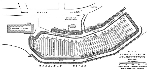
Fig. 4.

No. 1. CROSS-SECTION AT NORTH END OF BED.

No. 2. CROSS-SECTION AT BEGINNING OF PIPE UNDERDRAIN.

No. 3. CROSS-SECTION AT SOUTH END OF BED.
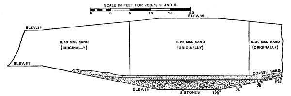
No. 4. CROSS-SECTION AT END OF LOWEST GRAVEL UNDERDRAIN.
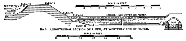
No. 5. LONGITUDINAL SECTION OF A BED, AT WESTERLY END OF FILTER.
TYPICAL SECTIONS OF UNIT BEDS IN LAWRENCE CITY FILTER.
APRIL, 1901.
COPIED FROM PLAN FURNISHED BY A.D. MARBLE, CITY ENGINEER.
In some cases where liability to dangerous contamination exists it may
be advisable to increase the available supply of oxygen in the water by
using a slow sand filter intermittently, as has been done at Lawrence,
Mass. Instead of permitting a continuous flow of water through the
sand, that flow is allowed for a period of 6 to 12 hours only, after
which the filter rests and is drained for perhaps an equal period.
During this intermission another filter-bed is brought into use in the
same manner. Alternating thus between two or more filters, the flow in
any one is intermittent. In this manner the oxygen of the air finds its
way into the sand voids of each drained filter in turn and thus becomes
available in the presence of suitable species of bacteria for reducing
the organic matter in the water next passing through the filter.
Intermittent filters operated in this manner are not much used, but the
most prominent instance is that at Lawrence, Mass. At that place the
water after being filtered is pumped to a higher elevation for use in
the distribution system. The pumps have been run nineteen hours out of
the twenty-four, and the water is shut off from the filters five hours
before the pumps stop. The gate admitting water to the filter is open
one hour before they start. Nine hours of each day the filter does not
receive water, and rests absolutely about four hours.
220. Removal of Bacteria in the Filter.—The grains of
the sand at and near the surface of a slow sand filter, within a short time
after its operation is begun, acquire a gelatinous coating, densest at
the surface and decreasing rapidly as the mass of sand is entered. This
gelatinous coating of the grains is organic in character and probably
largely made up of numerous colonies of bacteria whose presence is
necessary for the reduction of the organic matter. It is necessary
to distinguish between these species of bacteria and those which are
pathogenic and characteristic of such diseases as typhoid fever,
cholera, and others that are water-borne. Every potable surface-water
and possibly all rain-water carry bacteria which are not pathogenic and
which apparently accumulate in dense masses at and near the surface of
the slow sand filter. As the water finds its way through the sand it
loses its organic matter and its bacteria, both those of a pathogenic
and non-pathogenic character. Potable water, therefore, is purified and
rendered innocuous by the removal in the filter of all its bacteria,
including both the harmless and dangerous.
221. Preliminary Treatment—Sizes of Sand Grains.—In
designing filtration-works consideration must be given to the character
of water involved. There are waters which when standing in open reservoirs
exposed to the sunlight will develop disagreeable tastes and odors, and
it may be necessary to give them preliminary treatment especially for
the removal of such objectionable constituents.
The character and coarseness of the sand employed are both elements
affecting its efficiency as a filtering material. It should not be
calcareous, for then masses of it may be cemented together and injure
or partially destroy the working capacity. Again, if it is too coarse
and approaches the size of gravel, water may run freely through it
without experiencing any purification. Much labor has been expended,
especially by the State Board of Health of Massachusetts, in
investigating the characteristics of sand and the sizes of grains
best adapted to filter purposes. In that work it has become necessary
to classify sands according to degrees of fineness or coarseness.
The diameter of a grain of sand in the system of classification
employed means the cube root of the product of the greatest and least
diameters of a grain multiplied by a third diameter at right angles
to the greatest and least. The “effective” size of any given mass of
sand means the greatest diameter of the finest 10 per cent of the
total mass. There is also a term called the “uniformity coefficient.”
The uniformity coefficient is the quotient arising from dividing
the greatest diameter of the finest 60 per cent of the mass by the
greatest diameter of the finest 10 per cent of the same mass. These are
arbitrary terms which have been reached by experience as convenient for
use in classifying sands. Evidently absolute uniformity in size will be
indicated by a uniformity coefficient of 1, and the greater the variety
in size the greater will be the uniformity coefficient. Sands taken
from different vicinities and sometimes even from the same bed will
exhibit a great range in size of grain.
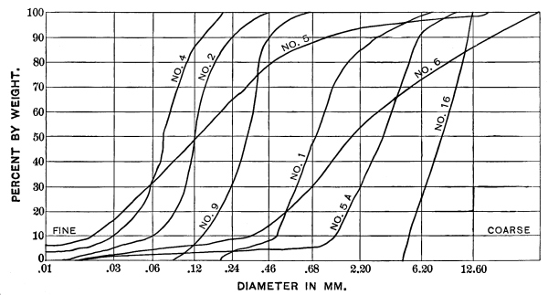
Fig. 5.—Sizes of Grain or Fineness of Sand.
Fig. 5 represents the actual variety of size of grain
as found in eight lots of sand among others examined in the laboratory of the
Massachusetts State Board of Health. The vertical scale shows the per
cent by weight of portions having the maximum grains less in diameter
than shown on the horizontal line. The more slope, like No. 5 or 6,
the greater is the variety in size of grain. Those lines more nearly
vertical belong to sands more nearly uniform in size of grain.
222. Most Effective Sizes of Sand Grains.—Investigations
by the Massachusetts State Board of Health indicate that a sand whose
effective diameter of grain is .2 mm. (.008 inch) is perhaps the most
efficient in removing organic matter and bacteria from natural potable
waters. At the same time wide experience with the operation of actual
filters seems to indicate that no particular advantage attaches to
any special size of grain, so long as it is not too fine to permit
the desired rate of filtration or so coarse as to allow the water to
flow through it too freely. Experiments have shown that effective
sizes of sand from .14 to .38 mm. in diameter possess practically
the same efficiency in a slow sand filter. The action of the filter
is apparently a partial straining out of both organic material and
bacteria, but chiefly the reduction of organic matter in the manner
already described and probably the destruction to a large extent of
the bacteria, especially those of a pathogenic nature, although at the
present time it is impossible to state the precise extent of either
mode of action.
223. Air and Water Capacities.—Another important physical
feature of filter-sands, especially in connection with intermittent
filtration, is the amount of voids between the grains. When the
intermittent filter is allowed to drain, so that the only water
remaining in it is that held between the grains by capillary
attraction, generally at the bottom of the filter unless the sand is
very fine, the volume of the water which remains in the voids is called
the water capacity of the sand. The remaining volume between the grains
is called the air capacity of the same sand. It is evident that the air
capacity added to the water capacity will make the total voids between
the sand grains.
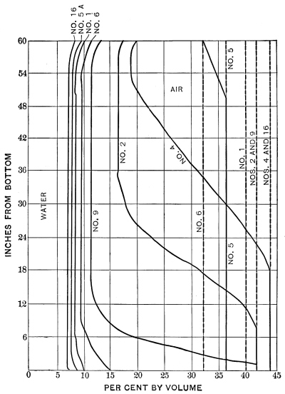
Fig. 6.
Fig. 6 shows the amount of air and water capacities
of the same sands whose sizes of grains are exhibited in Fig. 5.
The depth of the sand is supposed to be 60 inches, as shown on the
vertical line at the left of the diagram, while the percentages of
the total volume representing the amounts of voids is shown on the
horizontal line at the bottom of the diagram. Both air and water
capacities for each sand are shown by the various numbered lines
partially vertical and partially inclined. It will be observed that
the fine sands No. 2 and No. 4 have large water capacities, the water
capacity being shown by that part of the diagram lying below and to
the left of each line. It will be noticed that No. 5 sand is made up
of approximately equal portions of fine and coarse grains, the former
largely filling the voids between the latter. This mixture, as shown by
the No. 5 line, gives a very high water capacity and a correspondingly
low air capacity. Obviously a sand with a high water capacity has a
correspondingly low air capacity, and in general would not be a very
good sand for an intermittent filter, since it is
the purpose of the latter to secure in the voids between the sand
grains as much oxygen as practicable whenever the filter may be at rest.
224. Bacterial Efficiency and Purification—Hygienic
Efficiency.—As the function of a filter is to remove as far as
possible the organic matter and bacteria of the applied water, there
must be some criterion by which its efficiency in the performance
of those functions can be expressed. The bacterial efficiency is
represented by the ratio found by dividing the number of bacteria after
filtration in a prescribed cubic unit, as a cubic centimeter, by the
number which the same volume of raw water held before being applied
to the filter. This is a rather misleading ratio, for the reason that
the effluent water may contain bacteria of certain species which grow
in the lower portions of a filter or in the drains which conduct the
effluent from it. It is possible, therefore, that bacteria may be found
in a filter effluent when all of the bacteria originally held in the
water have been removed. Hence the ratio expressing what is called the
bacterial purification arises from dividing the number of bacteria
actually removed from a cubic centimeter of water by the filter by the
number originally held by a cubic centimeter of raw water. The smaller
the first of these ratios the higher the degree of efficiency. Extended
experience, both in the filters of such laboratories as that of the
Massachusetts State Board of Health and with actual filters of public
water-supplies, show that under attainable conditions of operation 98
to 100 per cent of all the bacteria originally found in the water may
be removed.
There is also used the term hygienic efficiency which is used in
connection with slow sand filters. This means simply the per cent of
pathogenic bacteria removed by the filter, and there is good reason to
believe that it is at least as high as the bacterial purification.
225. Bacterial Activity near Top of Filter.—The work
of removal of bacteria and organic matter has been found by extended
investigations to be performed almost entirely within 6 or 8 inches
of the top surface of the sand; indeed the most active part of that
operation is probably concentrated within less than 3 inches of the
surface. At any rate the retained bacteria and nitrogenous matter are
found to decrease very rapidly within a foot from the upper surface,
below which stratum the quantity is relatively very small and its
rate of decrease necessarily slow. A little of this nitrogenous or
gelatinous matter is found to surround to a slight extent the sand
grains found at the bottom of the filter. Some authorities have
considered that the more steady uniform efficiency of the deeper
filters is due to this effect.
226. Rate of Filtration.—The rate at which water can
be made to flow through a slow sand filter is of economical importance, for
the reason that the higher the rate the less will be the area required
to purify a given quantity per day. Foreign engineers and other
sanitary authorities advocate generally slower rates of filtration
than American engineers are inclined to favor. The usual rate in
Europe is not far from 1.6 to 2.5 million gallons per acre per day.
There is also considerable range in this country, and the rate may
reach 3 million gallons per acre per day. Indeed a considerable number
of tests have shown that for short periods of time, at least, some
waters may be efficiently filtered at rates as high as 7 to 8 million
gallons per acre per day, but probably no American engineer is ready
to introduce such high rates as yet. As a matter of fact the rate will
depend considerably upon the character of water used. Clear water from
mountain lakes and streams uncontaminated and carrying little solid
material may be filtered safely and properly at much higher rates of
filtration than river or other waters carrying more sediment and more
organic matter. This principle is recognized both in Europe and in this
country. It would appear from experience that slow sand filters at
the present time with rates of 2.5 to 3 million gallons per acre per
day may be employed for practically any water that may be considered
suitable for a public supply, and that with these rates high degrees of
both bacterial purification and hygienic efficiency may be reached.
227. Effective Head on Filter.—Inasmuch as the depth of
sand ranges from perhaps 3 to 5 feet the water will experience considerable
resistance in flowing through it. The distance in elevation between the
water surface over the filter and that of the water as it leaves the
filter measures the loss of head experienced in passing through the
sand and the drainage-passages under it. It has been maintained by some
foreign authorities that this loss of head should be not more
than 24 to 30 inches; that a greater head would force the water
through the sand at such a rate as to render desired purification
impossible. Experience both in the laboratory and with public filters
in this country does not appear to sustain that view of the matter;
considerably greater heads than 30 inches have been used with entirely
satisfactory results both as to the removal of organic matter and
bacteria. It appears to be best so to arrange the flow of water through
the sand and the underdrains as to avoid in either a pressure below
the atmosphere, as in that case some of the dissolved air in the water
escapes and produces undesirable disturbances in the sand, resulting
in reduced efficiency. No precise rule can be given in respect to this
feature of filtration, but it seems probable that satisfactory results
may be obtained under proper working of filters with a loss of head
not greater than the depth of water on the filter added to the depth
of sand in it, although that maximum limit would ordinarily not be
reached. The depth of water on the filter may be taken from 3 to 5
feet. In this country it is seldom less than the least of these limits,
and perhaps not often equal to the greater limit.
228. Constant Rate of Filtration Necessary.—Care should
be taken in the operation of filters to avoid any sudden change in the
texture or degree of compactness of the sand. At the times when workmen
must necessarily walk over the surface they should be provided with
special broad-based footwear, so as to produce as little effect of
this kind as possible where they step. Sudden changes in the degree
of compactness cause correspondingly sudden changes in the rate of
filtration, and such changes produce a deterioration of efficiency.
This may be due to two or three reasons. Possibly such changes may open
small channels through which water finds its way too freely; or the
breaking of the gelatinous bond between the grains of sand may operate
prejudicially. At any rate it is essential to avoid such sudden changes
and maintain as nearly uniform a rate of filtration over the entire
filter as possible. Again, the age of a filter affects to some extent
its efficiency. A month or two of time is required, when a new filter
is started, to attain what may be called its normal efficiency. Even
after that length of time the filter gains in its power to retain and
destroy bacteria. This action is particularly characteristic of filters
formed of comparatively coarse sand.
229. Scraping of Filters.—More or less solid inert as
well as organic matter accumulates on the surfaces of the slow sand filters,
so that at the end of proper periods of time, depending upon the character
of the water filtered, this surface accumulation must be scraped off
and removed together with the sand into which it has penetrated. In
scraping the filter it is impossible to remove less than .25 or .5
inch of sand, and at least .5 to .75 inch is removed whenever a filter
is scraped. Sometimes 1 or 2 inches may be removed. This sand may be
washed and again placed upon the filter for use. The operation of
scraping exhibits a fresh sand surface to the applied water. It has
been held, particularly by foreign authorities, that this operation of
scraping militates against the efficiency of the filter for the time
being. The investigations of the Massachusetts State Board of Health
and other experiences in this country do not confirm that view which
is based on the assumption that the top nitrogenous film is essential
to efficiency. These investigations have shown that this film is not
necessary in intermittent filters; that in many instances no diminution
of efficiency has resulted from a removal of the film to a depth of
.3 inch; that even the presence of that film has not given efficiency
to coarse sand when the coating was thick enough to completely clog
the filter; and, further, that the material of this nitrogenous
film is found at a depth of several inches below the surface. It is
practically certain that the scraping to depths not exceeding 1 inch
have no sensible effect upon the efficiency under proper management and
operation of the filters. This is particularly true if the thickness of
sand is from 3 to 5 feet. It is undoubtedly true that with very shallow
sand filters from 1 to 2 feet in depth the scraping of the surface may
have some effect upon bacterial efficiency.
It has been the custom in connection with some European filters to
waste the water which first passes through after cleaning, but the
usual practice in this country is to fill slowly the filter with
filtered water from below and, after the sand is submerged, to permit
it to stand a little while before use. Care taken in this manner will
insure an efficiency to a freshly scraped filter sufficient to avoid
any wastage.
230. Introduction of Water to Intermittent Filters.—Where
intermittent filters are used it is of the greatest importance to
conduct the water to them so as not to disturb the sand on their
surfaces. This can readily be done in a number of ways. If the shape
of the filter is not oblong, it will be advisable to form a number of
main drains or passages in the sand from which smaller depressions or
passages near together may lead the water to all parts of the surface.
The flowing of the first water through these depressions will permit
the entire surface to be covered so gradually as not to disturb the
sand grains, and it is essential that such means or their equivalent
be employed. If the filter is long and narrow in shape, the main
ditch along one of the longer sides, with depressions at right angles
to it or across the filter and near together, will be sufficient
to accomplish the desired purpose. Obviously when filters are not
intermittently used such precautions are not needed.
231. Effect of Low Temperature.—In the early days of the
use of sand filters in this country it was frequently supposed that the low
temperature of the winter caused decreased bacterial purification and a
decrease in power to reduce organic material. It now appears that such
is not the case. The effects of low temperature, such as is experienced
in winters of this climate, may be overcome by temporarily covering the
filters so that heavy ice cannot form and produce disturbances in one
way or another prejudicial to efficiency of operation. The agencies
which operate to reduce efficiency in cold weather are no longer
believed to be those due to low temperature. They are rather indirect
and mechanical, and may be readily overcome by the prevention of the
formation of ice.
232. Choice of Intermittent or Continuous Filtration.—The
process of slow sand filtration when continuous has been shown by
experience to be entirely effective for ordinary potable waters, but in
those cases where the amount of dissolved oxygen may be low and where
the amount of organic matter is relatively high it may be advisable
to resort to intermittent filtration. Neither method, however, can be
depended upon to render potable a water which has been robbed of its
free oxygen by an excessive amount of contaminated organic matter. Nor
can these processes be expected to remove coloring matter produced by
peaty soils or other conditions in which large amounts of vegetable
matter have been absorbed by the water. The methods, therefore, have
their limitations, although their field of application is sufficiently
wide to cover nearly all classes of potable water.
233. Size and Arrangement of Slow Sand Filters.—Among
the first questions to arise in the design of slow sand filters are their
size and arrangement. The total area will be determined by the total daily
draft and the rate of filtration. Rates of filtration running from
2.5 to 3 million gallons per acre per day, or even more, have been
found satisfactory and are customary in this country. Having given,
therefore, the total daily quantity required, it is only necessary to
divide that by the rate of filtration per acre and the result will be
the number of acres required for the total filter-bed surface. This net
area, however, is not sufficient. Unless there is requisite storage of
filtered water to meet the variation in the hourly draft for the day,
the capacity of the filters must be sufficient to meet the greatest
hourly rate, which must be taken at least 1½ times the average hourly
demand during the day; indeed this is only prudent in any case.
Again, it is necessary to divide the total filter surface into small
portions called beds, so that one or more of them may be withdrawn from
use for cleaning or repairs, while a sufficient filter-area remains in
operation to supply the greatest hourly draft. This surplus area will
usually run from 5 to 20 per cent of the total area of the filter-beds,
although for small towns and cities it may be much more. The sizes of
the filter-beds will depend upon the local circumstances of each case.
It is evident that as each single bed must have its individual set of
appliances and its separating walls, the purpose of economy will be
best served by making the beds as large as practicable. At the same
time they must not be made too large, for in that case the portion
out of use might form so large a percentage of the total area as to
increase unduly the cost of the entire plant. A size of bed varying
between .5 and 1.5 acres is frequently and perhaps generally found in
foreign filtering-plants. If filter-beds range in area from .5 acre
to 2 acres, the latter for large plants, the purposes of economy
and convenience in administration will probably be well served. The
grouping of the beds is an important consideration and will depend
somewhat, at least, upon the shape of the plot of ground taken for the
filters. It is advisable that the inlets to the different beds should,
as far as possible, discharge from a single inlet-pipe or main. This
will generally be most conveniently accomplished by making the beds
rectangular in shape, grouped on each side of the supply-main, with
their longest dimensions at right angles to it. This arrangement is
illustrated by the grouping of the filter-beds in the Albany plant,
shown in Fig. 7. In the case of a
single oblong bed, like that at Lawrence, Mass., shown in
Fig. 4, page 284, its relatively great length and
small width makes it possible to run the main supply along one side,
from which branch depressions with concrete bottoms enable the water
to be distributed uniformly over its surface in the manner shown in
the figure. It is further necessary to group the filter-beds, pumps,
sand-cleaning appliances, and other portions of the plant, so that
the ends of economy and efficient administration may be served in the
highest degree. It is always necessary that these features of the whole
filtration system should be carefully kept in view in laying out the
entire plant.
234. Design of Filter-beds.—The preparation of the site
for a group of filtration-beds also involves the consideration of a number
of principal questions. In the first place, the depth required for
the sand and underdrains will not be far from 5 feet, and there must
be a suitable bottom prepared below the collecting-drains. Again, the
depth of water above the sand may vary from 3 to 5 feet, making the
total depth, including the bottom, of the filter proper about 10 or 11
feet, and this may represent the depth of excavation to be made. If the
material on which the filter to be built is soft, it may be necessary
to drive piles to support the superincumbent weight. The bottom must be
made water-tight. This can be done either by the use of a layer of well
rammed or packed clay, 1 to 2 feet in thickness, carrying 6 or 8 inches
of concrete, or by a surface of paved brick or stone. If the sides of
the filter-beds are of embankments with surface slopes, the latter may
be protected in the same manner. If the sides are of walls of masonry,
concrete is an excellent material to be used for the purpose.
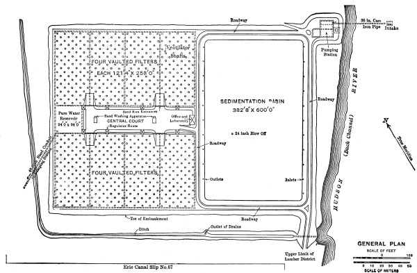
Fig. 7.—Sedimentation-basin and
Filter-beds at Albany, N. Y.
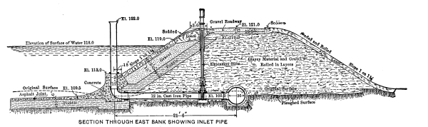
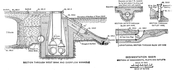
Filtration-plant at Albany, N. Y.
In designing the sides of filters or of the piers projecting up
through the sand for the support of the roof, in case there is one, it
is imperative that care be taken to prevent water from flowing down
through the joints between the sand and the sides of piers or the
masonry sides of the filter-beds. There should be no vertical joint of
that character, but the faces of masonry in contact with the sand
should both slope and be made in steps, so that any settlement of the
sand will tend to close the joint, while the steps will prevent flow.
Nor should there be angles in which sand is to be packed; filleted
corners are far preferable and should be used.
235. Covered Filters.—It has become the custom where
the best results are expected in cold climates, if not in all cases, to cover
filters with masonry roofs of domes and cylindrical or groined arches
supported on masonry columns. Such roofs are usually covered with earth
to a depth of 1 to 2 or 3 feet. They prevent any injurious action on
the sides of the filters produced by thick ice or the effects of such
ice upon the upper portions of the sand. In summer they also protect
against the baking and cracking of the upper surface of the sand when
exposed to the sun and prevent, to a considerable extent, the growth
of algæ in different portions of the beds. They are expensive, filters
with masonry covers costing once and a half to twice as much as open
filters, but they enhance the sanitary value of the water. The height
of the masonry roof must be about 2 to 3 feet above the upper surface
of the water and high enough to offer convenient access to the sand
when it is to be cleaned and renewed. The length of span for the arches
or domes is seldom more than 12 or 15 feet.
236. Clear-water Drain-pipes of Filters.—After the water
has passed through the sand it must be withdrawn from the bottom of the
filter with as little resistance as practicable. This necessitates,
in the first place, the bottom of the filter to be so shaped as to
induce the flow of the filtered water toward the lines of drain-pipes
which are laid to receive it. These pipes consist of the main members
and the branches, the main members being laid along the centres of the
beds and the branches running from them. The bottoms of the filters,
therefore, should be formed with depressions in which the main pipes
are laid, and with such grades as to expedite the movement of the water
flowing through the branches. If the bottoms are of concrete, they can
advantageously be made of inverted arches or domes, the drain-pipes
being laid along the lines of greatest depression. In such cases the
loads produced by the weight of the roof are more nearly uniformly
distributed over the bottom. The sizes of the drains will be dependent
upon the areas from which they withdraw water. It is advisable to make
them rather large, in order that the water may flow through them more
freely. They seldom need exceed 6 or 8 inches. They are preferably made
of salt-glazed vitrified pipes laid with open joints, around and in the
vicinity of which are placed gravel or broken stone, the largest pieces
with a maximum diameter of 1 to 2 inches. The largest broken stone or
coarsest gravel is near the pipe and should decrease in size as the
drain-pipe is receded from, so that the final portions of the gravel
farthest removed from the drains will not permit the filter-sand to
pass into it. When properly designed and arranged, the loss of head in
passing from the farthest points of a filter-bed to the point of exit
from the filter will not exceed about .01 to .02 of a foot.
Interior of Covered Filter at Ashland, Wis.
237. Arrangement of the Sand at Lawrence and Albany.—Above
this gravel is placed the filtering-sand, about 4 feet thick in the Albany
filter and 3 to 4 feet thick in the filter at Lawrence, Mass. The sand
in the Albany filter was specified to have not “more than 10 per cent
less than .27 mm.” in diameter and “at least 10 per cent by weight
shall be less than .36 mm.” in diameter. Over the entire floor was
spread not more than 12 inches of gravel or broken stone, the lower
7 inches consisting of broken stone or gravel with greatest diameter
varying from 1 inch to 2 inches; the remaining 5 inches of the lower
1 foot was composed of broken stone or gravel decreasing from 1 inch
in greatest diameter to a grain a little coarser than that of the
sand above it. In all cases, sand for the filter-bed should be free
from everything that can be classed as dirt, including clay, loam,
and vegetable matter. Furthermore, it should be free from any mineral
matter which might change the character of the water and render it less
fit for use.
Partially Filled Covered Sand Filter showing Drain-pipe.
This filtering-sand is usually placed in position with a horizontal
surface. At Lawrence, however, it was placed with a wavy surface, the
horizontal distance between the crests of two consecutive waves being
30 feet, the concrete gutter for admitting the water being half-way
between, all as shown in the illustrations. The sand of this filter was
of two grades, the coarser sand having an effective size of 0.3 mm.
(.118 inch) and the finer an effective size of 0.25 mm. (.098 inch).
The two different sizes of sand are seen not to be arranged in
horizontal layers, but so that the finer is over the drains and the
coarser between. The No. 70 sand is capable of passing 70 million
gallons per acre per day with a head on it equal to the depth of sand,
while the No. 50 sand can pass 50 million gallons per acre per day
with a head on it equal to its depth. There appears to be no special
advantage in placing the sand in filters other than in horizontal
layers with an effective size practically uniform.
238. Velocity of Flow through Sand.—The velocity with
which water will flow through a given depth of sand with a known depth or
head above the surface of the latter has been carefully investigated by
the Massachusetts State Board of Health with the following results:
v = the velocity at which a solid column
of water, whose section equals in area that of the bed of sand, moves
downward through the sand in meters per day; this is practically the
number of million gallons passing through the sand per acre per day.
c = a constant, having the value of 1000
for clean sand, and 800 for filter-sand after having been some time in
use.
d = the effective size of the sand-grain
in millimeters.
h = the head lost by the water in passing
through the sand at the rate v; this is the effective head of water
producing motion through the sand.
l = the thickness of the sand bed.
t = the temperature of the water in
degrees Fahr.
The velocity v, as determined by experiment, takes the following form:
| v = cd² |
h |
( |
t + 10 |
) |
. |
| l |
60 |
This formula cannot be used for the flow of water through all sands of
all thicknesses and under all circumstances. It is limited to effective
diameters of sand between .1 and 3 mm., having a uniformity coefficient
not greater than 5. h and l may be taken in any unit as
long as both are expressed in the same unit, since the ratio of the two
quantities will then not be affected. If the effective head of water
on the filter or the head lost is equal to the thickness of the bed
of sand, the ratio of h divided by l will be 1. In case
the formula is used to express the quantity of water flowing through
the sand per acre per day, it must be remembered that v will be
the number of million gallons and not the total number of gallons. The
formula can only be used when the sand is well compacted and where the
voids of the sand are entirely filled with water.
239. Frequency of Scraping and Amount Filtered between
Scrapings.—The frequency of the scraping of filters will depend
upon the amount of organic matter in the water and upon the rate
of filtration. Between the years 1893 and 1900 the periods between
scrapings of the Lawrence filter ranged generally from 20 to 32 days,
although periods as small as 13 or 19 are found in the records. The
quantity of water passed between scrapings varies generally from
67 million to 90 million gallons, although it fell as low as 49
millions and rose as high as 109 millions. In the case of the Albany
filter-plant, up to the end of the year 1900 the shortest period
between scrapings was about 15 days and the longest about 42 days,
the smallest quantity of water passing through any filter between
scrapings being 26,735,000 gallons and the largest 76,982,000 gallons.
The operation of the Albany filters for the year 1901 shows that the
average run of a bed was 26 days between scrapings, with a total of
70,000,000 gallons per acre for that period. These figures represent
about the usual workings of slow sand filters at the present time, the
period between scrapings running usually between 15 and 30 days, and the
quantity from 30 million gallons per acre to 100 million gallons per acre.
Filters for City of Albany, N. Y.
240. Cleaning the Clogged Sand.—The clogged sand scraped
from the top of the filters at the periods of cleaning is removed to
a convenient point where appliances and machinery are available for
washing it. This is an item of some importance in the administration of
filters, as the sand which is removed and washed is at a later period
replaced upon the filter-bed. Various methods have been tried for the
purpose of cleaning sand efficiently and economically. The continuous
ejector sand-washer, one set of which is used at Albany, is probably as
efficient as any machine yet devised. It is shown in Fig. 8.
It will be observed that the dirty sand is fed to the machine at one end into
a hopper-shaped receptacle. In the bottom of this hopper is a nozzle
through which water is discharged from a pipe running along the entire
bottom of the machine. This jet of water forces the sand upward through
a suitable pipe into a reservoir which discharges the sand and water
into another hopper, and so on through the series of five. Evidently
there may be any number of hoppers in the series, a jet of water being
provided at the bottom of each. In this manner the sand and water are
thoroughly mixed together and compelled to flow upward from each hopper
to the next, the dirty water overflowing also from each hopper into a
tank underneath, whence it runs to waste. The clean sand and water flow
out of the machine at the end opposite to that at which they entered.
After the washed sand is dried it is ready to be replaced in the filter.
241. Controlling or Regulating Apparatus.—It is essential
to the proper working of a slow sand filter that the amount of water
admitted to and passing through it shall be as nearly uniform as
practicable. This necessitates controlling or regulating apparatus, of
which there are two general classes, the one automatic and the other
worked by hand. There are a considerable number of appliances of both
classes. The filtered water flows from the end of the drains to one or
two small tanks formed by suitable masonry walls immediately outside
of the filter-beds and rises to a level determined by the loss of head
in passing through the filter. The difference in elevation between
the water surface over the sand and that in the filtered water-tanks
shows the effective head which causes the water to flow through the
sand. The object of the controlling or regulating appliances is to keep
that head as nearly constant as possible. Both the hand and automatic
appliances preserve the value of that head by maintaining constant
discharges through either vertical or horizontal orifices, the orifices
themselves being movable. They may be rectangular or other orifices
with horizontal lips or crests. If the control is automatic it is
accomplished usually by a float which raises and lowers the orifice in
such a way as to maintain a constant difference of level between the
filtered and the unfiltered water. The figures illustrate both types of
regulating appliances, the actions of which will be readily understood.
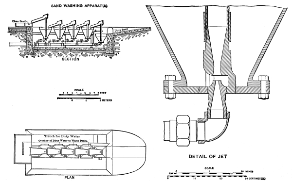
Fig. 8.—Ejector Sand-washer.
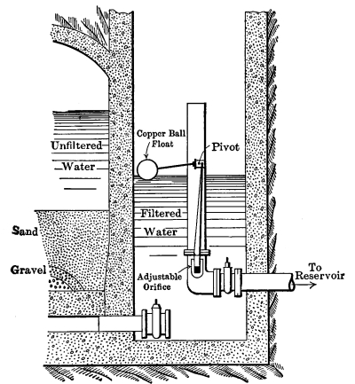
Fig. 9.—Ball-float Regulator of
Rate of Filtration.
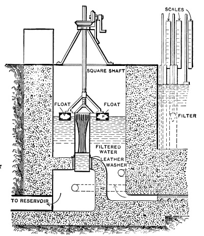
Fig. 10.—Regulator in Use in Zurich,
Switzerland.
M. Peter, Engineer.
242. Cost of Slow Sand Filters.—The cost of both the open
and covered slow sand filters will obviously vary according to the cost of
labor and materials at their sites. The original cost of the Lawrence
filter, about 2.44 acres in total area, was nearly $25,000 per acre.
The cost of covered filters, so far as constructed in this country,
varies from about $44,000 to nearly $51,000 per acre excluding the
pipe, pumping plants, and sedimentation-basins. The Albany covered
filters cost about $38,000 per acre including filtering materials, but
excluding excavation, pumps, buildings, sedimentation-basins, piping,
and sand-washing machinery, or nearly $46,000 per acre including those
items except pumps and sedimentation-basins. The roof, included in
the preceding estimate, cost about $14,000 per acre. The smaller the
filters the greater the cost per acre, as a rule, as would be expected.
A single open filter at Poughkeepsie and three open filter-beds at
Berwyn, Pa., cost respectively $42,000 and $36,000 per acre, the former
being little less than .7 acre in area and the latter having an
aggregate area of a little more than one half acre. A covered filter at
Ashland, Wis., consisting of three beds of one sixth acre each, cost at
the rate of about $70,000 per acre.
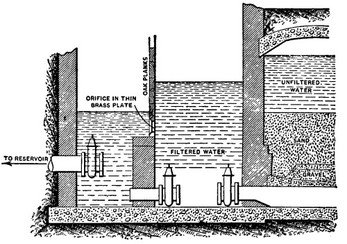
Fig. 11.—Regulating Apparatus Designed by
Allen Hazen for the Albany Filters.
Fig. 12.—Regulator of Rate of Filtration.
243. Cost of Operation of Albany Filter.—The cost of
operating the Albany filter, including only the costs of scraping, removing
sand, refilling, incidentals, lost time, and washing the sand during
seventeen months ending December 29, 1900, was $1.66 per million
gallons filtered. The cost of removing the sand (excluding scraping),
washing, and refilling was $1.21 per cubic yard. The total cost of
operating the entire filter-plant, including all items, for the year
1900 was $4.52 per million gallons filtered. This covers all expenses,
including pumping, superintendence, and laboratory, which can be
charged to the operation of the filter-plant. The average removal of
albuminoid ammonia at Albany for the year 1900 was 49 per cent and
of the free ammonia 78 per cent of that in the raw water, while the
average bacterial removal was over 99 per cent, running from 98.3 per
cent to 99.6 per cent. The volume of water used in washing the sand was
about twelve and a half times the volume of the sand. Each cubic yard
of sand washed, therefore, required twelve and a half cubic yards of water.
Fig. 13.—Regulator Designed
by W. H. Lindley
for the Filters at Warsaw, Poland.
244. Operation and Cost of Operation of Lawrence Filter.—It
was originally intended that the Lawrence filter should be worked
intermittently. The Merrimac River water, which is used by the city of
Lawrence, was known to carry at certain periods of the year sufficient
typhoid germs received from the city of Lowell to produce at least
mild epidemics. The intermittent operation was considered necessary to
furnish the filter with the requisite oxygen to destroy beyond a doubt
all pathogenic bacteria. The increasing demands of water consumption
during the years that have elapsed since filtration began in 1894 have
seriously modified these conditions, so that the intermittent feature
of operation of the filter is no longer very prominent. During 1898,
for instance, the filter was drained only four to thirteen times per
month, with an average of eight monthly drainings. In 1899 the
drainings were more frequent, varying from five to fourteen per month
and averaging eleven times. Finally, in 1900, the monthly drainings
ranged from three to thirteen, with an average of eight. It may be
considered, therefore, that the Lawrence filter occupies a kind of
intermediate position between intermittent and continuous operation.
The total cost of operating the filter at Lawrence, including scraping
and washing of sand, refilling, removal of snow and ice, and general
items in the period from 1895 to 1900, both inclusive, varied from a
minimum of $7.70 per million gallons to $9.00 per million gallons. If
the removal of snow and ice be omitted, these amounts will be reduced
to $5.10 and $6.90 respectively. The cost of washing the sand only in
the Lawrence filter during the same period varied from 45 to 67 cents
per cubic yard. The volume of water required for that washing varied
from ten to fourteen times the volume of sand.
245. Sanitary Results of Operation of Lawrence and Albany
Filters.—The average number of bacteria in the Merrimac River
water applied to the filter during the period 1894 to 1899, both
inclusive, varied from about 1900 per cubic centimeter to 34,900, and
the percentage of reduction attained by passing the water through the
filter varied in the same period generally from 97 to 99.8 per cent,
with an average of about 99.1 per cent.
In the city of Lawrence the average number of cases of typhoid
fever per 10,000 of population has been about one third, since the
introduction of filtered water, of the number of cases which existed
prior to the installation of the filters, and less than one fourth as
many deaths. A large number of the cases of typhoid occurring after the
installation of the filter have been traced to the use of unfiltered
water, and it is probable that all or nearly all could be similarly
accounted for.
In the city of Albany the experience had been quite similar. The
average number of deaths per year from typhoid fever for ten years
before the introduction of filtered water was 84, while in 1900, with
the filter in operation, the total number of deaths was 39. These
figures are sufficient to show the marked beneficial effect of filtered
water on the public health.
Jewell Filter.
246. Rapid Filtration with Coagulants.—It has been
seen that the rate of filtration through open sand filters does not usually
exceed 2 to 4 million gallons per acre per day under ordinary
circumstances. Much greater rates would clog the sand and produce less
efficient results. Experience has also shown that such methods cannot
be depended upon to remove from water coloring matter of a vegetable
origin or very finely divided sediment. In order to accomplish these
ends it is necessary to employ suitable chemicals which, acting as
coagulants, may accomplish results impracticable in the open filter.
Resort has therefore been made first to the adoption of suitable
coagulants and then to such increased heads or pressures as to force
the water through the sand at rates from 25 to 30 or even 50 times as
great as practicable in slow sand filtration. These rapid sand filters
are called mechanical filters. If the water is forced through them under
pressure, they consist of closed tanks in which sand is placed so as to
leave sufficient volume above it for the influent water and, supported
upon a platform carrying perforated pipes, strainers, or equivalent
details through which the filtered water may flow into a suitable
system of effluent pipes in the lower part of the filter. If water is
forced through the sand by the required head, the upper part of the
filter may be open, but of sufficient height to accommodate it. The
same filtering material, clean sand, is used as in the slow filters;
the only differences, aside from the higher rate of filtration, are
the greater head and the introduction of a coagulant to the water.
The depth of sand used may vary from 2 to 4 feet. The thickness of a
relatively fine sand may be less than that of a coarser sand.
247. Operation of Coagulants.—The coagulant which
has been found to give the best results is ordinary alum or sulphate of
aluminum. If sulphate of aluminum is dissolved in water containing
a little lime or magnesia, aluminum hydrate and sulphuric acid are
formed. The aluminum hydrate is a sticky gelatinous substance which
gathers together in a flocculent mass the particles of suspended
matter in the water, and it also adheres to the grains of sand when
those masses have settled to the bottom. This flocculent, gelatinous
mass covers the sand and passes into its voids. As the water is
forced through it the bacteria and suspended matter are held, leaving
a clear effluent to pass through. Other coagulants are used, such
as the hydrate of iron, but it costs more than alum and is not so
effective in removing color, although it is an excellent coagulant
for removing turbidity. Physicians have made objection to the use
of alum for this purpose, on the ground that any excess might pass
into distribution-pipes and so be consumed by the water-users to the
detriment of health. While it is possible that further experience
may show that there is material ground for this objection, it has
thus far not been found to be so. It is, however, essential that
only the necessary amount of alum should be used and that there may
be a sufficient amount of alkali to combine with the sulphuric acid.
Otherwise the acidulated water may attack the iron and lead pipes and
so injure the water and produce serious trouble. It can only be stated
that the method and operation of these mechanical filters have thus far
been sufficiently successful to avoid any of these difficulties.
The Jewell Filter-plant at Norristown, Penn.
248. Principal Parts of Mechanical Filter-plant—Coagulation
and Subsidence.—The principal parts of a complete mechanical
filter-plant in the order of their succession are a solution-tank,
a measuring-tank, a sedimentation-basin, and a filter. In case of
great turbidity the sedimentation may be completed in two stages, the
first in a settling-basin prior to receiving the coagulant, and the
second in another basin subsequent to the coagulation. The tanks are
usually of wood, although they may be of steel. The solution-tank is a
comparatively small vessel in which the alum is dissolved. The solution
is then run into the measuring-tank, from which it flows into the water
at a constant rate maintained by suitable regulating apparatus. It is
imperative for the successful working of the mechanical filter-plant
that the coagulant be introduced to the water at a uniform rate. This
rate will obviously depend upon the character of the water. The
coagulating solution runs from the measuring-tank into the pipe through
which the water to be filtered flows and in which it first receives
the alum. The water and the coagulating solution are thus thoroughly
mixed and flow into the sedimentation-basin. The subsidence which is
provided for in this basin may be omitted in very clear waters which
carry little solid matter, but the operation of the filter itself will
be more satisfactorily accomplished if as much work as feasible is done
before reaching it. The mixture must remain in this basin a sufficient
length of time to allow such subsidence as can reasonably be attained.
It appears from experience in this part of the work that it is not well
to introduce the coagulant too long before the water enters the filter,
especially if the water be fairly clear. In the case of the presence
of finely divided solid matter, however, sufficient time must be
permitted for the necessary settlement. A period ranging in length from
½ hour to 6 or 8 hours may be advantageously assigned to this part of
the operation, the shorter period for clear waters and the longer for
very turbid waters. It has been suggested that two applications of the
coagulant might be beneficial, the principal portion being given to the
water before entering the sedimentation-basin and the other just before
the waters enters the filter. The work of the filter, especially with
turbid waters, may be much reduced by simple subsidence for a period
of perhaps 24 hours before receiving the coagulant, the secondary
subsidence taking place in the settling-basin in the manner already
described. Duplicate solution- and measuring-tanks will be required in
order that the process may be continuous while one set is out of use.
In this process it is absolutely essential also that the coagulant
should be of the best quality, inferior grades having been found to be
unsatisfactory in their operation.
249. Amount of Coagulant—Advantageous Effect of Alum on
Organic Matter.—The amount of sulphate of alumina will vary largely
with the quality of water. In the investigation made by Mr. Fuller in
connection with the Ohio River supply for the city of Cincinnati, he
found that with very slight turbidity only ¾ grain was required per
gallon of water, but that a high degree of turbidity required as much
as 4.4 grains per gallon, with intermediate amounts for intermediate
degrees of turbidity. It was estimated that these quantities would
correspond to an average annual amount of about 1.6 grains per
gallon. In case there should be a period of three days of subsidence
preliminary to filtration, he estimated that for the greater part of
the time the amount of alum would vary from 1 to 3 grains per gallon.
Occasionally more and sometimes less would be required.
Alum has some specially valuable qualities in connection with this
class of purification work. It combines with coloring matter,
particularly that which has been acquired from contact of the water
with vegetation, and precipitates it. It seems to combine also, to some
extent, with the organic matter carried by the water and thus enhances
the efficiency of filtration.
250. High Heads and Rates for Rapid Filtration.—The
principal work of investigation of filtration in mechanical or pressure
filters has been made for the cities of Pittsburg, Cincinnati, Louisville,
and Providence, R. I. In the experimental work of those investigations
rates of filtration ranging from 46 million to 170 million gallons per
acre per day have been employed with essentially the same efficiency.
This is a practical result of great importance, particularly if in
the continued use of these filters on a large scale a satisfactorily
high efficiency can be reached and maintained. It was observed that
the number of bacteria in the effluent varied with that in the raw
water. It was also noticed that similarly to the operation of slow sand
filters the rate of filtration should not be changed suddenly, as that
is likely to cause breaks in the sand and militate against continued
efficiency.
In his experimental work at Cincinnati Mr. Fuller found that with
fine sand an available head on the filter of 12 feet gave economical
results. He also states that “high rates are more economical than low
ones, and that the full head which can be economically used should be
provided. Just where the economical limit of the rate of filtration is
can only be determined from practical experience with a wider range of
conditions than exist here, but there seem to be no indications that
the capacity of a plant originally constructed on a medium rate basis
(100 million to 125 million gallons per acre daily) could not readily
and economically be increased, as the consumption demanded, to rates at
least as high as the highest tried here (170 million gallons per acre
daily), provided the full economical increase in loss of head could be
obtained.”
251. Types and General Arrangement of Mechanical Filters.—These
mechanical or pressure (by gravity) filters have until lately been
constructed by companies owning patents either on the process or on
the different parts of the filters. The fundamental patent, however,
protecting rapid sand filters with the continuous application of
a coagulant has expired and the city of Louisville, Ky., is now
constructing rapid sand filters different in design from those
heretofore used. The types that have been most common heretofore are
the Jewell subsidence gravity filter, the Continental gravity filter,
the New York sectional-wash gravity filter, and others. They all
possess the main feature of accelerating the rate of filtration by
pressure, either in a closed tank (rarely) with comparatively small
water volume above the sand or by an open filter with sufficient head
of water above the sand to accomplish the high rate desired. This
latter method is that now generally used, as by it the requisite
steadiness of head or pressure can be secured. The closed type is
subject to objectionable sudden changes of pressure which prevent
or break uniform rates of filtration. The sand is supported upon a
platform with a suitable system of pipes fitted with valves or gates
for the withdrawal of the filtered water, the space below the platform
forming a small sedimentation-chamber. They are usually constructed in
comparatively small circular units, so that one or more of a group may
be withdrawn from operation for the purposes of cleaning or repairs
without interfering with the operation of the others. This system of
small units, gives some marked practical advantages, as housing is
readily accomplished, and if necessary the plant may be easily removed
from one point to another.
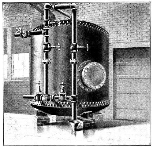
Continental Filter.
It is obvious that with the large amount of water forced through
a given area of filter-bed the sand will become clogged within a
comparatively short time, requiring washing and replacing. Mr. Fuller
found at Cincinnati that the periods between washings when fine sand
was used in the filters ranged from 8 to 24 hours, with an average of
15, but with coarse sand the average became 20, with a range of from
6 to 36 hours. The time required for washing the sand at Cincinnati
was 20 minutes for coarse or 30 minutes for fine. At Providence Mr.
Weston found that the average time of washing was about 11 minutes.
The cleaning is accomplished partially by stirring the sand with
revolving arms, as shown in the accompanying figures, but generally
by forcing the water in a reverse direction through the sand and
allowing the wash-water either to run to waste or to be again purified.
The filters are designed for the purpose of cleaning by the reversal
of the direction of the flow of water. Latterly the sand has been
cleaned by forcing compressed air at a low pressure through it and the
superimposed water. The passage of the air or water upward through the
sand produces such a commotion among the grains that they rub against
each other and clean themselves of the adhering material, allowing it
to be carried off by the water above the sand. Both methods are much
used and are satisfactorily effective for the purpose.
It was found at Cincinnati that 4 to 9 per cent, with an average of 5
per cent, of filtered water was required for washing the fine sand, and
only 2 to 6 per cent, with an average of 3 per cent, for the coarse
sand of the mechanical filters used in Mr. Fuller’s experiments. Mr.
Weston has found about the same figures in his experimental work at
Providence. The wash-water need not be wasted at all if it is pumped
back into the subsidence-tanks.
It has been found in some cases that the efficiency of the filters
after washing is not quite normal, and that possibly 2 or 3 per cent
of the water must be wasted unless it is allowed to run back into
the subsidence-tanks and again pass through the filter. Under such
circumstances it has required 20 to 30 minutes of operation of the
filter after washing to regain its normal efficiency.
252. Cost of Mechanical Filters.—The cost of these
mechanical filters has been found to range as high as a rate of
$500,000 per acre, which is probably about ten times as much as
the rate of cost for the slow sand filters. On the other hand, the
efficiency of the mechanical filters may be as high as the other class,
with a rate of filtration from thirty to fifty times as great, and with
a cost of operation less than that of the slow sand filters. The cost
of the filters per million gallons of filtered water may, therefore, be
reduced to perhaps one fourth of that of the slow sand type.
253. Relative Features of Slow and Rapid Filtration.—It
is premature, even unnecessary, to make a comparison between the slow and
rapid sand filters. The former are well adapted to a large class of
potable waters in which there is not too much or too finely divided
solid matter and in which the coloring from organic origin is not
serious. They have the advantage of requiring no chemicals and are
capable of attaining a high degree of efficiency. The average rate
of filtration may be taken about 3,000,000 gallons per acre per day.
The rapid sand filter, on the contrary, requires the application of
a coagulant, but has thirty to fifty times the capacity of the other
class. It is better adapted to the removal of turbidity and color,
and when properly operated it gives a high efficiency. A sufficiently
extended experience has not yet, however, been attained to enable a
complete statement to be made as to the entire field to which they
may be adapted. They have certainly been shown to possess valuable
qualities in a number of respects, and they are undoubtedly destined to
play an important part in the purification of waters.
CHAPTER XXI.
254. Introductory.—The first step toward the construction
of a railroad is the location of the line, which requires as an initiative
a careful ocular examination of the general vicinity of the proposed
road, supplemented by simple and approximate instrumental work rapidly
performed. Following this reconnaissance, as it is called, more
complete surveys and examinations are made both in the field and on the
maps plotted from the data of the field-work. The prosecution of this
series of operations produces the final location, together with the
accumulation of such maps, profiles, and other data as may be required
in the construction of the road-bed, bridges, and other structures
constituting the complete railroad line with its ballast and track in
place ready for traffic.
The ultimate purpose of any railroad line is the transportation of
passengers and freight under conditions, including those of a physical
nature connected with the road as well as the rates received, leading
to profitable returns. Competition or other circumstances attending the
traffic of a given road will fix the maximum rates to be charged for
transportation. It is the business, first, of the civil engineer so to
locate and design the road and, second, of the manager so to conduct
the transportation as to make the margin of profits the greatest
possible. It will be the purpose of this lecture to consider in a
general way only some of the features of a railroad and its operation
which are related directly to civil-engineering.
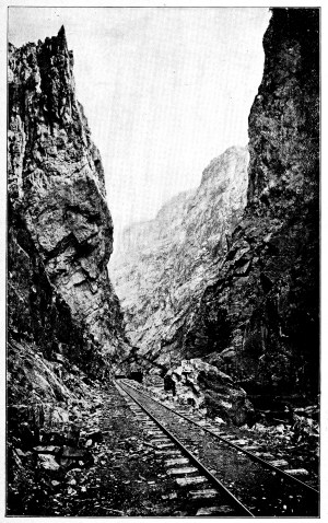
The Royal Gorge.
255. Train Resistances.—It is a fact confirmed by constant
daily experience that, however nicely the machine impelling the
railroad train or the tracks supporting the cars may be built,
considerable frictional and other resistance is offered to the movement
of the train when the latter passes over a perfectly level and straight
track.
A considerable portion of the cost of transportation is expended in
overcoming this resistance. When the line fails to be either level
or straight other resistances of magnitude are developed; they are
called the resistances of grades and curves: and it is the business of
the civil engineer so to design the railroad as to reduce these two
classes of resistance to an absolute minimum, in view of certain other
conditions which must be concurrently maintained.
256. Grades.—The grade of a railroad is expressed usually
in this country by the number of feet through which 100 feet of length
of line rises or falls, or by some expression equivalent to that. If,
for instance, the line rises 1.5 or 2 feet in 100, it is said to have
an ascending grade of 1.5 or 2 per cent. Or if the line falls the same
amount in the same length, it is said to have a descending grade of
1.5 or 2 per cent. It is evident that a grade which descends in one
direction would be an ascending grade for trains moving in the opposite
direction, so that grades favoring traffic in one direction oppose it
in the other. Hence, other things being equal, that road is the most
advantageous for the movement of trains which has the least grade. The
grades of railroads seldom exceed 2 or 2.5 per cent, although, as will
presently be shown, there are some striking exceptions to that general
observation. The actual angles of inclination of railroad tracks
from a horizontal line are therefore as angles very small, but their
disadvantages for traffic increase rapidly.
A simple principle in mechanics shows that if the railroad train with
a weight W moves up a 2 per cent grade, one component of the train
weight acts directly against the tractive force of the locomotive or
other motive power. If a is the angle of inclination of the
track to a horizontal line, this opposing component will have the
value W sin a. When angles are small their sines are
essentially equal to their tangents. Hence, in this case, sin a
would have the value .02 or ¹/₅₀ of the train weight. If the weight of
the train were 500 tons, which is a rather light train for the present
time, this opposing force would be 10 tons, or 20,000 pounds, which,
as we shall see later on, is more than one half of the total tractive
force of any but the heaviest locomotives built at the present day.
This simple instance shows the advantage of keeping railroad grades
down to the lowest practicable values.
One of the most economical freight-carrying roads in the United States
is the Lake Shore and Michigan Southern of the New York Central system,
running from Buffalo to Chicago. Its maximum grade is 0.4 of 1 per
cent. The maximum grade of the N. Y. C. & H. R. R. R. is 0.75 of 1 per
cent between New York City and Albany and between Albany and Buffalo,
1.74 per cent at Albany, 1.12 per cent at Schenectady, and 1 per cent
at Batavia. Pushers or assistant locomotives are used for heavy trains
at the three latter points. The maximum grade of the Pennsylvania R. R.
on the famous Horseshoe Curve between Altoona and Cresson is 1.8 per
cent. It is advantageous, whereever practicable, to concentrate heavy
grades within a short distance, as in the case of the New York Central
at Albany, and use auxiliary engines, called pushers or assistants.
Some of the heaviest grades used in this country are found on the
trans-continental lines where they pass the summits of the Rocky
Mountains or the Sierras. In one portion of its line over a stretch of
25.4 miles the Southern Pacific R. R. rises 2674 feet with a maximum
grade of 2.2 per cent; also approaching the Tehacipi Pass in California
the maximum grade is about 2.4 per cent. At the Marshall Pass on the
Denver & Rio Grande R. R. there is a rise of 3675 feet in 25 miles with
a maximum grade of 4 per cent. The Central Pacific R. R. (now a part of
the Southern Pacific system) rises 992 feet in 13 miles with a maximum
grade of 2 per cent. The Northern Pacific R. R. rises at one place 1668
feet in an air-line distance of 13 miles with a maximum grade of 2.2
per cent. Probably the heaviest grade in the world on an ordinary steam
railroad is that of the Calumet Mine branch of the Denver & Rio Grande
R. R., which makes an elevation of 2700 feet in 7 miles on an 8 per
cent grade and with 25° curves as maximum curvature. These instances
are sufficient to illustrate maximum railroad grades found in the
United States.
257. Curves.—Civil engineers in different parts of the
world have rather peculiar classifications of curves. In this country the
railroad curve is indicated by the number of degrees in it which
subtend a chord 100 feet in length. Evidently the smaller the radius
or the sharper the curvature the greater will be the number of degrees
between the radii drawn from the centre of a circle to the extremities
of a 100-feet chord. American civil engineers use this system for the
reason that the usual tape or chain used in railroad surveying is 100
feet long. A very simple and elementary trigonometric analysis shows
that under this system the radius of any curve will be equal to 50
divided by the sine of one half of the angle between the two radii
drawn to the extremities of the 100-feet chord. In other words, it is
equal to 50 divided by the sine of one half the degree of curvature.
The application of this simple formula will give the following tabular
values of the radii for the curves indicated:
| Curve. |
Radius in Feet. |
| 1° |
5729.65 |
| 2° |
2864.93 |
| 3° |
1910.08 |
| 4° |
1432.69 |
| 5° |
1146.28 |
| 6° |
955.36 |
| 7° |
819.02 |
| 8° |
716.78 |
| 9° |
637.27 |
| 10° |
573.69 |
| 12° |
478.74 |
| 15° |
383.06 |
| 20° |
287.91 |
258. Resistance of Curves and Compensation in Grades.—Inasmuch
as the resistance offered to hauling the train around a curve increases
quite rapidly as the radius of curvature decreases, it is obvious
that in constructing a railroad the degree of each curve should be
kept as low as practicable, and that there should be no more curves
than necessary. While no definite rule can be given as to such
matters, curves as sharp as 10° (573.69 feet radius) should be avoided
wherever practicable. It is not advisable to run trains at the highest
attainable speeds around such curves, nor is it done. Inasmuch as curve
resistance has considerable magnitude, as well as the resistance of
grades, it is natural that wherever curves occur grades should be less
than would be permissible on straight lines or, as they are called,
tangents. If a maximum gradient is prescribed in the construction of
a railroad, that gradient will determine the maximum weight of train
which can be hauled on the straight portions or tangents of the road.
If one of these grades should occur on a curve, a less weight of
train could be handled by the same engine than on a tangent. Hence it
is customary to reduce grades by a small amount for each degree of
curvature of a curve. This operation of modifying the grades on curves
so as to enable a locomotive to haul the same train around them as up
the maximum grade on a tangent is called compensating the curves for
grade. There is no regular rule prescribed for this purpose, because
the combination may necessarily vary between rather wide limits in
view of speed, condition of track, and other influencing elements.
The compensation, however, has perhaps frequently been taken as lying
between .03 and .05 per cent of grade for each degree of curvature. In
other words, for a 5° curve the grade would be .15 to .25 per cent less
than on a tangent. This compensation for grades is carefully considered
in each case by civil engineers in view of experience and such data as special
investigations and general railroad operation have shown to be expedient.
Fig. 1.
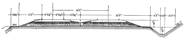
GRAVEL BALLAST

STONE BALLAST
NEW YORK CENTRAL & HUDSON RIVER RY.
Fig. 2.
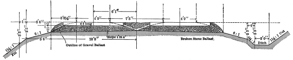
Fig. 3. PENNSYLVANIA RY.
259. Transition Curves.—High speeds for which modern railroads
are constructed have made it necessary not only to protect road-beds,
but also to make the passage from tangents to curves as easy and smooth
as possible. This is accomplished by introducing between the curve and
the tangent at each end what is called a “transition” curve. This is a
compound curve, i.e., a curve with varying radius. At the point where
the tangent or straight line ceases the radius of the transition curve
is infinitely great, and it is gradually reduced to the radius of the
actual curve at the point where it meets the latter. By means of such
gradual change of curvature the trucks of a rapidly moving train do
not suddenly pass from the tangent to the curve proper, but they pass
gradually from motion in a straight line to the sharpest curvature over
the transition curve. The rate of transition is fixed by the character
of the curves, which have been subjected to careful analysis by civil
engineers, and they can be found fully discussed in standard works on
railroad location.
Fig. 4.—Baltimore Belt-line
Tunnel, B. & O. Ry.
260. Road-bed, including Ties.—Not only the high rates of
speed of modern railroad trains but the great weights of locomotives and cars
have demanded a remarkable degree of perfection in the construction of
the road-bed and in the manufacture of rails. The favorite ballast at
the present time for the best types of road-beds is generally broken
stone, although gravel is used. The first requisites are a solid
foundation and perfect drainage whether in cuts or fills. Figs. 1,
2, 3, and 4
show two or three types of road-bed used by the New York
Central and Hudson River R. R., the Pennsylvania R. R., and a special
type adopted by the B. & O. for the belt-line tunnel at Baltimore.
These sections show all main dimensions and the provision made for
drainage. The general depth of ballast is about 18 inches, including
the drainage layer at the bottom. The total width of road-bed for a
double-track line varies frequently between 24 and 25 feet, while the
width of a single-track line may be found between 13 and 14 feet. In
the cross-sections shown the requirements for drainage are found to be
admirably met. Timber ties are almost invariably used at the present
time in this country, although some experimental steel ties have been
laid at various points. Fig. 5 shows the steel tie adopted
for experiment on the N. Y. C. & H. R. R. R. within the city limits of
New York. The time will undoubtedly come when some substitute for timber
must be found, but the additional cost of steel ties at the present
time does not indicate their early adoption.
Fig. 5.
Fig. 6.
Cañon of the Rio Las Animas, near Rockwood.
261. Mountain Locations of Railroad Lines.—The skill of
the civil engineer is sometimes severely taxed in making mountain locations
of railroads. Probably no more skilful engineering work of this kind
has ever been done than in the crossings of the Rocky Mountains and the
Sierras in this country by trans-continental railroad lines, although
more striking examples of railroad location for short distances may
perhaps be found in Europe or other countries. The main problem in such
cases is the making of distance in order to attain a desired elevation
without exceeding maximum grades, such as those which have already
been given. Most interesting engineering expedients must sometimes
be resorted to. One of the oldest of these is the switchback plan
shown in Fig. 6. This is probably the simplest procedure
in order to make distance in attaining elevation. The line is run up the side of
a mountain at its maximum grade as far in one direction as it may be
desirable to go. It then runs back on itself a short distance before
being diverted so as to pass up another grade in the reverse direction.
This zigzagging of alignment may obviously be made to attain any
desired elevation and so overcome the summit of a mountain range. The
old switchback coal road near Mauch Chunk, Pa., is one of the oldest
and more famous instances of the method, which has many times been
employed in other locations.
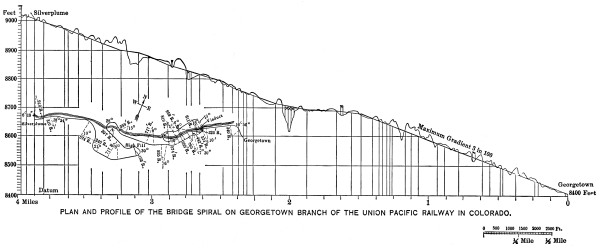
Fig. 7.
A more striking method, perhaps, is that of loops by which the
direction of a line or motion of a train on it is continuous. Distance
is made by a judicious use of the topography of the locality so as to
run the line as far up the side of the valley as practicable and then
turn as much as a semicircle or more, sometimes over a bridge structure
and sometimes in tunnel, so as to give further elevation by running
either on the opposite side of the valley or on the same. A succession
of loops or other curves suitably located will give the distance
desired in order to reach the summit.
262. The Georgetown Loop.—Fig. 7
shows one of these spiral or loop locations on the Georgetown branch
of the Union Pacific Railroad in Colorado. It is a well-known and
prominent instance of railroad location of this kind. On the higher
portion of this loop system included in the figure
there is a viaduct on a curve which crosses the line 75 feet above the
rail below it and 90 feet above the water. This location is a specimen
of excellent railroad engineering. The length of line shown in the
figure, including the spiral, is 8½ miles, and it cost $265,000 per
mile exclusive of the bridges.
263. Tunnel-loop Location, Rhætian Railways, Switzerland.—In
Figs. 8 and 9 are shown
two portions of the Albula branch of the Rhætian Railways, Canton
Graubünden, southeastern Switzerland. The line connects the valleys
of the Albula and the Inn, the former being one of the branches of
the Rhine and the latter of the Danube; it therefore cuts the divide
between the watersheds of those two rivers. It is a 3.28-feet gauge
single-track road, and is built largely for tourist traffic, as the
scenic properties of the line are remarkable.
The maximum grade on this line is 3.5 per cent. Over one portion of the
line 7.8 miles long one third of that distance is in tunnel and 15 per
cent of it on viaducts. The radii of the centre lines of the tunnels
are 460 and 394 feet, while the lengths of the tunnels range from 1591
to 2250 feet, with a maximum grade in them of 3 per cent. The weight of
rails used is 50 pounds per yard on grades of 2.5 per cent or less, but
for heavier grades 55-pound rails are employed. The cross-ties are of
mild steel and weigh 80 pounds each except in the long Albula tunnel,
where treated oak ties are used as being better adapted to the special
conditions existing there. It will be observed that in each case the
line rises from the left-hand portion of the figure toward the right.
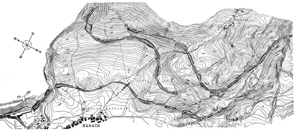
Fig. 8.
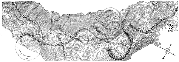
Fig. 9.
The tunnels are represented by broken lines, and they are in every
instance on circular curves. Fig. 9 represents the line
running from a point on the east side of the Albula River through a heavy cut
and then across the valley of the Albula into a tunnel 2250 feet long.
The line then runs chiefly in cuts to a point where there are two
tunnels, one over the other; indeed the line over-laps itself in loops
and tunnels a number of times in that vicinity. That portion of the
road shown in Fig. 8 is less remarkable than the other,
although it exhibits extraordinary alignment. This example of railroad location
is one of the most striking among those yet completed. It would
appear to indicate that no topographical difficulties are too great
to be overcome by the civil engineer in railroad location in a most
rugged and precipitous country. Obviously such a line could not be
economically operated for heavy freight traffic.
Railroad lines frequently lead through mountainous regions affording
some of the grandest scenery in the world accessible to the travelling
public. In this country the Canadian Pacific, the Northern Pacific, the
Great Northern, and the Rio Grande Western probably exhibit the most
remarkable instances of this kind.
CHAPTER XXII.
264. Railroad Signalling.—The birth of the art of railroad
signalling was probably coexistent with that of the railroad. At the
very outset of the movement of railroad trains it became imperative to
insure to a given train the sole use of the single track at schedule
periods. Both head-to-head and rear-end collisions were liable to occur
on main tracks, as well as false meetings at branches and cross-overs.
265. The Pilot Guard.—One of the earliest if not the
earliest of systematic procedures in England to accomplish the safe use of
a railroad track involved the employment of the “pilot guard” on
single-track roads. The pilot was an employé whose duty it was to
accompany every train over a stated section of the line. The authority
to start trains was lodged in him. When it became necessary to start
two or three trains from the same point and in the same direction, it
was also his duty to issue to each train conductor what was called a
pilot ticket, equivalent to a modern train order to run the train over
the section under his control. In that case he was obliged to accompany
the last train to the other end of his section, and no more trains
could move over that section in the same direction until his return
to his first station. As no train could pass over the section without
either him or his pilot ticket, it is clear that the system could
prevent head-to-head collisions, but in itself it is not sufficient to
eliminate rear-end collisions. This system is still employed in Great
Britain on some short branch lines.
266. The Train-Staff.—Another method nearly as old as
the preceding is that of the train-staff, used in an improved form at the
present time on some single-track roads. No train under this system can
pass over any given section of the line unless it carries the staff
belonging to that section, the staff being a piece of wood or metal 1 to
1¼ inches in diameter and 18 to 20 inches long. In order to cover the
case of two or more trains starting in the same direction at one end
of a section before running a train in the opposite direction, tickets
were issued, the staff being taken by the last train. The proper
operation of this method, like that of the preceding, would prevent
head-to-head collisions, but is not sufficient in itself to prevent one
train running into the rear of another while both are proceeding in the
same direction in the same section.
267. First Basis of Railroad Signalling.—These and other
similar systems answered fairly well the more simple requirements of
early railroad operation. Strictly speaking they are not methods of
signalling, although it may be said that each train is a signal in
itself. With the development of railroad business it was found that
other methods better adapted to a more efficient and rapid movement
of trains were imperative. It was in response to the advancing
requirements of the railroad business that the first approach to
what is now so well known as the block system of signalling was made
in 1842. An English engineer, subsequently, Sir W. F. Cooke, stated
the following sound principles as to the basis of efficient railroad
signalling:
“Every point of a line is a dangerous point which ought to be covered
by signals. The whole distance ought to be divided into sections, and
at the end as well as at the beginning of them there ought to be a
signal, by means of which the entrance to the section is open to each
train when we are sure that it is free. As these sections are too long
to be worked by a traction rod, they ought to be worked by electricity.”
The main features of railroad signalling, as thus set forth, have
continued to characterize the development of the block system from
that early day to the present. The electrical application to which
reference is made in the preceding quotation was that of the needle,
which by its varying position could indicate either “line clear” or
“line blocked.” In 1851 electric bells were used in railroad signalling
on the Southeastern Railway of England. Various other developments were
completed from time to time in Great Britain until the Sykes system of
block signalling was patented in 1875. One of the main features of the
system, and perhaps the most prominent, was the control of the track
signals at the entrance end of the block by the signalman at the
advance end. He exerted this control by electrically operated locks.
About 1876 the Pennsylvania Railroad introduced the block system into
the United States, which has since been greatly developed in a number
of different forms, and its use has been widely extended over many if
not most of the great railroad systems of the country. It is not only
used for the movement of trains, but also for the protection of such
special danger-points as switches, cross-overs, junctions, drawbridges,
heavy descending grades, sharp curves, and other points needing the
protection which a well-designed block system affords.
268. Code of American Railway Association.—The code of the
American Railway Association gives the following definitions among
others pertaining to the block system:
Block.—A length of track of defined limits, the use of which by
trains is controlled by block signals.
Block Station.—The office from which block signals are operated.
Block Signal.—A fixed signal controlling the use of a block.
Home Block Signal.—A fixed signal at the entrance of a block to
control trains in entering and using said block.
Distant Block Signal.—A fixed signal of distinctive character
used in connection with a home block signal to regulate the approach
thereto.
Advance Block Signal.—A fixed signal placed in advance of a
home block signal to provide a supplementary block between the home
block signal and the advance block signal.
Block System.—A series of consecutive blocks controlled by
block signals.
Telegraph Block System.—One in which the signals are operated
manually upon telegraphic information.
Controlled-Manual Block System.—One in which the signals are
operated manually, and by its construction requires the co-operation
of a signalman at both ends of the block to display a clear signal.
Automatic Block System.—One in which the signals are operated
by electric, pneumatic, or other agency, actuated by a train or by
certain conditions affecting the use of a block.
268a. The Block.—It is seen by these definitions that
what may be called the unit in railroad signalling is the “block”; it may
be of almost any length from a few hundred feet to 6 or 8 miles, or even
more. On a single-track railroad it may evidently extend from one side
track or passing-place to another. Over portions of lines carrying
heavy traffic it may be a half-mile or less. The length of block will
depend, then, upon the intensity and kind of traffic, the physical
features of the line, such as curvature, grade, sidings, cross-overs,
and other similar features, the location, whether in cities, towns, or
open country, as well as upon other elements affecting conditions of
operation which it is desirable to attain.
269. Three Classes of Railroad Signals—The Disc.—The
signals used in railroad operation may mainly be divided into three
classes: semaphores, banners, and discs. In general they may convey
information by form, position, and color. The disc is used by causing
it to appear and disappear before an aperture, usually a little larger
than itself, in a case standing perhaps 10 or 12 feet high alongside
the track, and is admirably typified in the Hall electric signal.
On account of its shape, the case in which the disc is operated is
frequently called the banjo, as it is quite similar in shape to that
musical instrument placed in a vertical position, the key end resting
on the ground.
270. The Banner Signal.—The banner signal is usually
operated by rotation about a vertical axis, frequently in connection with
switches. Its full face painted red, exposed with its plane at right
angles to the track, indicates “danger” or “stop.” With its face turned
parallel to the track, showing only its edge to approaching trains, a
“clear” line or “safety” is indicated.
In the present development of railroad signalling the banner and disc
patterns have a comparatively limited application, although, on the
whole, they are largely used. The banner signal is mostly employed in
the manual operation of switches, turn-outs, and cross-overs, and for
other local purposes, particularly on lines of light traffic.
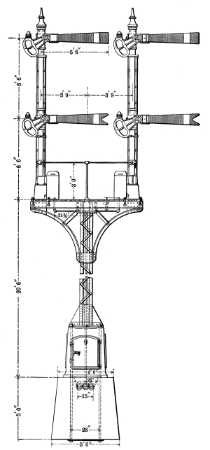
Fig. 10.—Semaphore Signals.
271. The Semaphore.—The semaphore is now mainly used in
connection with block signalling. Like many other appliances in
railroad signalling it was first used in England, by Mr. C. H. Gregory,
about 1841. Its name is derived from the combination of two Greek words
signifying a sign-bearer. It consists of a post varying in height
from about 3 to 35 or 40 feet, carrying an arm at its top from 3 to
5 feet long, pivoted within a foot or 18 inches of one end, the long
end suitably shaped and painted and the other arranged with a lens so
that when operated at night in connection with a lamp it may exhibit a
properly colored light. The post of the semaphore is placed alongside
the track so as to be on the right-hand side of an approaching train,
the long arm rising and falling as a signal away from the track and in
a plane at right angles to it. The other arm of the semaphore signal
may be connected by wires or rods and light chains running over pulleys
with suitable levers and weights operated either in a near-by signal
cabin or by a signalman stationed near the semaphore itself; or it may
be operated by electric or pneumatic power, as in many of the later
installations. The semaphore may, therefore, be operated at the post or
by suitable appliances at a distance.
Semaphore on Pennsylvania Railroad.
272. Colors for Signalling.—The colors used either for
painted signals for daylight exposure or for coloring lenses for night
signalling are red, white, and green, as ordinarily employed in this
country; red signifying “danger” or “stop,” white signifying “safety” or
“clear track,” and green signifying “caution” or “proceed with train
under control,” indicating that a train may go forward cautiously,
expecting to find an obstruction or occupied track. In England green is
largely employed to indicate “safety” or “clear track,” on the ground
that a white light is so similar to any other in its vicinity that the
latter may too easily be mistaken for a signal. While there is some
diversity of views in this country on that point, the consensus of
engineering opinion seems to favor the retention of the white for the
track safety signal.
273. Indications of the Semaphore.—It is evident
that a semaphore affords facilities of form, position, and color in its
use for the purpose of signalling. The horizontal position is the most
striking for the semaphore arm, as it then extends at right angles
to the post and to the right or away from the track; this position
is, therefore, taken to indicate “danger” or “stop.” No train may,
therefore, proceed against a horizontal semaphore arm.
It might at first sight appear that the vertical position of the
semaphore arm close against the post could be taken to indicate
“safety” or “clear track” or “proceed,” but experience has shown that
such a position may be injudicious, except under special conditions
where it has lately been employed to make that indication. If the
semaphore arm should be knocked or blown from the ordinary post,
the engineman of an approaching train probably would not be able to
detect the actual condition of things and might accept the appearance
of the semaphore as indicating a clear line, thus justifying himself
in proceeding at full speed, while the signalman in his cabin might
have placed the signal at “danger.” A position of the semaphore arm,
therefore, at an angle of 65° or 70° below the horizontal is usually
taken as a safety signal. This position is in marked contrast to the
horizontal arm and at the same time makes the absence of the semaphore
arm impossible without immediate detection from an approaching
locomotive. After dark the semaphore in a position of danger exhibits
a red light through the lens in its short arm when the long arm is at
the “danger” position or horizontal. Similarly, when the long arm is in
the safety position a white light is exhibited through the lens in the
shorter arm, so that the respective conditions of clear or obstructed
track are made evident to the engineman as well by night as by day on
his approach to the semaphore.
In some of the latest signal work three positions of the semaphore
arm on one post, known as three-position block signalling, have been
employed. In this system a special post, frequently on a signal bridge
over the track, permits the vertical position of the semaphore arm
to indicate “clear track,” while the diagonal or inclined position
below the horizontal indicates “caution.” In the Mozier three-position
signal a diagonal or inclined position above the horizontal indicates
“caution” an addition to the two usual positions of “stop” and “clear.”
These are the elements, so to speak, of railroad signalling at the
present day. They are combined with various appliances and in various
sequences, so as to express all the varied conditions of the track
structure which affect the operation of the road or the movement of
trains upon it. These combinations and the appliances employed in them
are more or less involved in their principal features and complicated
in their details, although the main principles and salient points are
simple and may easily be exhibited as to their mode of operation and
general results. In this treatment of the subject it will only be
possible to accomplish these general purposes without attempting to set
forth the mechanical details by which the main purposes of railroad
signalling are accomplished.
274. General Character of Block System.—It is evident
from what has already been stated that the block system of signalling
involves the use of fixed signals located so as to convey promptly to
approaching trains certain information as to the condition of points
of danger approached. Furthermore, this system of signals is designed
and operated on the assumption that every point is to be considered as
a danger-point until information is given that a condition of safety
exists. The usual position of signals, or what may be called the normal
position, is that of “danger,” and no position of “safety” is to be
given to any signal except to permit a train to pass into a block whose
condition of safety or clear track is absolutely assured. These are the
ground principles on which the signal systems to be considered are
designed and operated, although there are some conditions under which
the normal signal position may be that of safety.
275. Block Systems in Use.—The block systems now in
general use are:
The Manual, in which the signals at each end of each block are wholly
controlled and operated by the signalman at each signal point.
The Controlled-Manual, in which the signals at the entrance to each
block are controlled either electrically or in some other manner by
the signalman at the other extremity of that block, but are operated
subject to that control by the signalman at the entrance of the block.
The Auto-Manual, in which the signals are generally operated and
controlled as in the Manual or Controlled-Manual, except that they are
automatically returned to the danger position as the rear car of a
moving train passes them.
The Automatic, in which the operation of the signals is wholly
automatic and generally by electricity, or by a combination of electric
and pneumatic mechanism. In this system no signalmen are required.
The Machine, which is a controlled block system for single-track
operation and in which machines operated electrically with detachable
parts, as staffs, are employed in connection with other fixed signals
alongside the track.
The main features of these various systems of blocking are, in
respect to their signalling, the same, but the means for actuating or
manipulating the signals and the conditions under which moving trains
receive the necessary instructions are different. They all have the
same main objects in view of improving railroad operation by enhancing
both safety and facility of train movement.
“Absolute” blocking is that system of block signalling which absolutely
prevents one train passing into a block until the preceding train is
entirely out of it, or, in other words, until the block is absolutely clear.
“Permissive” blocking is, strictly speaking, the violation of the true
block system of signalling, since under it a train may under certain
precautionary conditions enter a block before the preceding train has
passed out of it.
276. Locations of Signals.—In proceeding to locate
signals along a railroad line it is imperative to recognize the preceding
purposes as controlling motives. Signals must be seen readily and
clearly in order to be of the greatest service to the enginemen of
approaching trains, and their positions must be selected with that
end in view. Locations of switches, cross-overs, junctions, and other
similar track features will control the locations of the signals which
are to protect them. The main or home signal in these special cases may
usually be placed from 50 to 200 feet from the point which is to be
governed, the so-called “distant” signal being placed about 2000 feet
for level track back of the main or home signal.
277. Home, Distant, and Advance Signals.—A complete
system of signals employed in blocking includes first of all the so-called
“home” signal at each extremity of a block, then at a distance of 2000
to 2500 feet back from the home signal is placed the “distant” signal.
The latter is thus approached and passed before reaching the home
signal. On the other side of the “home” signal at least a maximum train
length into a block about to be entered by a moving train is placed
the “advance” signal. The distance of the advance signal from the home
signal may be 1500 to 2500 feet. As a moving train approaches the end
of a block it first meets the distant signal, the purpose of which is
to indicate what the engineman may expect to find at the home signal.
If the distant signal is in the danger position, he will pass it with
caution and place his train under control so as to be able to stop at
the home signal. If he finds the distant signal in a safety position,
indicating the same position of the home signal, he may approach the
latter without reducing speed, confident that the next section is clear
and ready for him. The advance signal forms a kind of secondary or
supplementary block into which the train, under certain conditions,
may enter when the block in which it is found is obstructed, but no
train may pass the advance signal unless the entire block is clear
except when, under permissive working, the train proceeds with caution,
expecting to find the track either obstructed or occupied. This group of
three signals—the distant, the home, and the advance—taken in
the order in which the moving train finds them, is located at each
extremity of the block. Although the home signal is said to control the
movement of trains in a block at the entrance to which it is found, as
a matter of fact it appears that the advance signal in the final event
holds that control.
278. Typical Working of Auto-Controlled Manual System.—The
mode of employing these signals can be illustrated in a typical way
by the diagrams, Figs, 11, 12,
and 13, which exhibit in a skeleton
manner Pattenall’s improved Sykes system which belongs to the
Auto-Controlled Manual class. In these figures the end of block 1,
the whole of blocks 2 and 3, and the beginning of block 4 are shown.
Stations A, B, and C indicate the extremities of
blocks. The signals S, Sʹ, and S″ are the home
signals, while D, Dʹ, and D″ indicate distant
signals, and A, Aʹ, and A″ advance signals. As
the diagrams indicate, the stretch of double-track road is represented
with east- and west-bound tracks. In order to simplify the diagrams,
signals and stations are shown for one track only; they would simply
be duplicated for the other track. The signal cabin is supposed to be
located at each station, and at that cabin are found the levers and
other appliances for working the signals operated there, the signals
themselves being exposed alongside the track. In each signal cabin
there is an indicator, as shown at I, Iʹ, and I″.
On the face of each indicator there are two slots, shown opposite the
lines E and F. In the upper of these slots appears either
the word “Clear” or “Blocked.” In the lower slot appears either the
word “Passed” or “On.” The significance of these words will appear
presently. On this indicator face at P, Pʹ, and P″
are located electric push-buttons called plungers. The operation of
the levers indicated at L, the counterweights d, and the
locking detail l are evident from an inspection of the figure,
and need no special explanation. It is only necessary to state that the
locking-device l holds the bar bc until it is released at
the proper time, and that the counterweight may then return the lever
from its extreme leftward position to that at the extreme right, at the
same time placing the semaphore arm S in the position of danger.
It is particularly important to bear in mind this last observation.
The counterweight is the feature of the system which always holds
the semaphore arm in the position of danger, making that its normal
position, except when it is put to safety for the passing of a train.
Fig. 11.


Fig. 12.
Fig. 13.
If a westward train is represented in Fig. 11 at
T as approaching station A to enter the block 2, both the
distant signal D and the home signal S being at danger, the
system is so arranged that the signalman at station A cannot
change those signals, i.e., to a position of safety, until the
signalman at station B permits him to do so. If the signalman
at station A desires to open block 2 for the entrance of the
train T, he asks the signalman at station B by wire
to release the lock l to enable him to do so. If there is no
train in block 2, the signalman at station B pushes the button
P′ or “plunges” it. This raises the lock l at station
A and the signalman immediately pulls the lever L to
its extreme leftward position, throwing both the signals S and
D to the position of safety or clear, indicated by the dotted
lines at S². At the same time the indicator E at station
A shows the words “Clear to B,” while the slot Fʹ
at B shows the words “On from A.” The signals at stations
B and C are supposed to be in their normal position of
danger, and the indicator E′ at station B shows the words
“Blocked to C.” The home and distant signals Sʹ and
Dʹ are now at danger, but the train T may enter block
2 and proceeds to do so, it being remembered that the signalman at
station A cannot move the lever L, as it has passed out
of his control; not even the signalman at station B can give him
power to do so. The train T now passes station A into
block 2. As the last car passes over the point G its wheels
strike what is called a track-treadle, an appliance having electrical
connection with the lock l. The effect of the wheels of the last
car of the train passing over the treadle at G is to release
lock l, enabling the signalman at station A immediately
to raise the arms S and D to the position of danger.
It is to be observed that he cannot do this until the entire train
has passed into block 2; nor, since his plunger is locked by the same
treadle at G, can he signal “Safety” or “Clear” to the entrance
of block 1. Hence no train can enter block 1 to collide with the rear
end of the train just entering block 2. When the signalman at station
A has raised his signal S to danger, it again passes
out of his control, indeed out of both his control and that of the
signalman at B, until the last car of the train passes over the
treadle Gʹ at the entrance of block 3.
The train has now passed into block 2 and is approaching station
B. The signalman at B asks C by wire to release
the lever Lʹ, and if block 3 is clear, C plunges at P″.
C then throws his lever Lʹ so as to place the home and
distant signals Sʹ and Dʹ at safety. The condition of
things will then be shown by Fig. 12. As soon
as the last car of the train has passed over the treadle at Gʹ
his lever Lʹ will be released and he can then throw the lever to
the danger position, raising the home and distant signals Sʹ and
Dʹ to the horizontal. After the danger position is assumed by
the home signal Sʹ, as well as the distant signal Dʹ, he
has no power over them until the signalman at station C confers
it on him by plunging the button P″.
While the train has been in block 2, the indicator Iʹ has shown
“Blocked to C” and “Train on from A,” but as the train
passes B the indicator reads “Blocked to C” and “Train
passed from A,” while the indicator I″ at C reads
“Blocked to D” and “Train on from B.” This condition of
the signals and trains is shown by Fig. 13.
Also, when the last car passes over the treadle Gʹ, but not till
then, B may permit A to admit a train to enter block 2
should A so desire. Finally, when the train approaches C,
the signalman at that point asks D to enable him to permit the
train to enter block 4, and C confers the power by plunging if
that block is clear. Fig. 13 exhibits the
corresponding signals at C.
This sequence of operations is typical of what takes place in this
particular block signal system at the limits of every successive block,
and differs only in details characteristic of this system from those
which are performed in any other block signal system.
279. General Results.—It is seen first that no signalman
can operate a signal until the condition in the block ahead of him is such
as to make it proper for him to do so, and then he can only indicate
what is necessary for the safe entrance of the train into that block.
Furthermore, immediately on the passage of the train past his home
signal he must put the latter to danger or the counterweight may do it
for him, the train itself when in a safe position having conferred the
requisite power upon him. The signalman at the advance end of the block
always knows when the train is about to enter it, for he is obliged to
give his permission for that entrance. His indicator shows this result,
and will continue to show it until the train passes out of the block.
It is to be observed that the upper openings marked E on the
indicator give information of the condition of the block in advance,
while the lower openings give information of the block in the rear.
It is particularly important to notice that after the signalman at the
advance end of a block has “plunged” his plunger remains locked and it
cannot be released until the train admitted to the block covered by
the plunger has completely passed out of that block, permitting the
track-treadle at the entrance to the next block to unlock the plunger.
This feature makes it impossible for one train to enter a block until
the preceding train has passed out of it.
If the permissive system of using a block be employed, in which the
train is permitted to enter that block before a preceding train leaves
it, the treadle gives no protection against a rear-end collision with
the first train. In such an exigency other devices must be used or the
following train must proceed cautiously, expecting to find the track occupied.
280. Distant Signals.—Thus far the distant signals have
been treated incidentally only. They may be operated concurrently with
or independently of the home signal in such a way that if danger is
indicated, the distant signal gives its indication prior to that of the
home signal. In this manner protection is given to the rear of a train
approaching a block against the home signal set at “danger.” After the
obstruction is removed and the block cleared, the home signal is set at
“safety” before the distant signal is cleared.
281. Function of Advance Signals.—The advance signals are
used when for any purpose it is desired to form a short block in a regular
block. If, for instance, block 3 in Fig. 11 were obstructed
by a train stopped by some failure of a locomotive detail, a train approaching
station B in section 2 against the home signal Sʹ set at
“danger” would be obliged to stop before entering block 3. It might
then be permitted to enter the latter block, to be stopped by the
advance signal Aʹ set at “danger” or under instructions to pass
it cautiously, expecting to find the track obstructed. It is thus seen
that the advance signal creates what may be called an emergency block,
and in reality finally controls the movement of trains in the block in
which it is located. It would never be cleared unless the home signal
were first cleared, nor would it be set at “danger” unless the home
signal gave the same indication.
The preceding operation of the block system of signalling controls the
movement of trains along a double-track line.
Fig. 14.
282. Signalling at a Single-track Crossing.—A somewhat
similar sequence of signal operations controls train movements at a crossing,
whether single- or double-track. Fig. 14 illustrates
the use of signals required for the safe movement of trains at a single-track
railroad crossing, which is supposed to be that of a north-and-south
line crossing obliquely an east-and-west line. Precisely the same
arrangement of signals operated in the same manner would be required
if the crossing were at the angle of 90°. The signal cabin is placed,
as shown, as near as practicable to the actual intersection of tracks.
Trains may pass in either direction on either track, but in every
case they would be governed by the signals at the right-hand side of
the track as seen by the engineman. There will therefore be a set of
signals on both sides of each track, each set governing the movement of
trains in its own direction. Each home signal may be placed about 350
feet from the actual intersection, and each distant signal 1200 to
1500 feet from the home signal, or 1550 feet to 1800 feet from the
intersection. Each advance signal must be at least as far in advance
of the home signal as the maximum length of train, since it may be
used to stop a train, the rear car of which should completely pass the
home signal. In their normal positions every home signal should be set
at “danger,” carrying with them the distant signals giving the same
indication. The advance signals must also indicate “danger” with the
home signal. No train can then pass the crossing until the home and
distant signals indicate a clear line for it, the other signals at the
crossing, except possibly the advance signal, being set at “danger.”
If for any reason it is desired to hold the train after it is entirely
free of the crossing, the advance signal would also indicate “danger.”
It is thus seen that if the signals are properly set and obeyed, it is
impossible for two trains to attempt a crossing at the same time. It is
not an uncommon occurrence, however, for an engineman to run his train
against the danger signal, and in order to make it impossible for the
train to reach the crossing even under these circumstances a derailing
device is used. This derailing arrangement is shown in Fig. 14,
about 300 feet from the crossing, although it may be placed from 300 to 500
feet from that point. Its purpose is to derail any train attempting
to make the crossing against the danger signal. The operation of the
derail is evident from the skeleton lines of the figure. When the home
signal is at danger the movable part of the derailing device is at this
point turned so as to catch the flanges of the wheels as they attempt
to pass it. The train is thus thrown upon the cross-ties at such a
distance from the crossing as will produce a stop before reaching it.
When the home signal is at safety the derail operated with the signal
is closed and the line is continuous. This combination of signals and
derail coacting serves efficiently to prevent collisions at crossings,
although trains may be occasionally derailed in accomplishing that end.
The preceding explanations of the use of signals and derail apply to
a train that may approach the crossing in either direction on either
track, as is obvious from an inspection of the diagram itself.
283. Signalling at a Double-track Crossing.—In the
case of a double-track crossing, the arrangement of signals and derails
is precisely the same as for a single-track crossing, each set of signals
shown in Fig. 15 covering one track. In other
words, the line of single track is to take the place of each rail with
its set of signals in that figure. There will be but four derails, one
for each track only on the approach to the crossing. The working of
the signals with the derails is precisely the same as has already been
explained for the single-track crossing.
Fig. 15.
Fig. 16.
284. Signalling for Double-track Junction and Cross-over.—Fig. 16
represents a skeleton diagram of signals required for a junction of
two double-track roads and a cross-over. This arrangement covers the
use of switches. The location of signals and signal cabin as shown is
self-explanatory, after what has already been stated in connection with
single- and double-track crossings. It will be observed that the home
signals for both the west-bound main and branch tracks are identical in
location, and are shown by the solid double flag, the distant signal
being shown by its notched end at a considerable distance back of the
double home signal. It will, furthermore, be observed that at each home
signal there is a derailing-switch interlocked, in the lock-and-block
system presently to be explained, with the home signals operated
simultaneously with them. If, therefore, an engineman attempts to
run his train past a home signal set at danger, the result will be
the derailment of his train, thus brought to rest before it can make
any collision with another. It is obvious in this case that if the
switches from the main to the branch tracks or at the extremities of
the cross-over are worked independently, they must be operated directly
in connection with the signals. For complete protection they should be
interlocked with the signals so that it would be impossible to clear
any signal without simultaneously setting the switches consistently
with those signals. The diagram exhibits clearly the indications which
must be made in order to effect any desired train movement at such a
junction of tracks.
285. General Observations.—Similar arrangements of
signals, derails, or switches must be made wherever switches, cross-overs,
and junctions are found, the detailed variations of those signals
and switches being made to meet the individual requirements of each
local case. The combinations of switches and switch-signals frequently
become very complicated in yards where the tracks are numerous and
the combinations exceedingly varied, in order to meet the conditions
created by the movement of trains into and out of the yard.
The preceding explanations are intended only to give a clear idea
of the main features of signalling, in order to secure the highest
degree of safety and facility in the movement of trains over a modern
railroad. While they exhibit the external or apparent combinations of
signals for that purpose, they do not touch in detail and scarcely
in general upon the mechanical appliances found in the signal cabin
and along the tracks required to accomplish the necessary signal
movements. The considerations in detail of those appliances would cover
extended examinations of purely mechanical, electrical, pneumatic, and
electro-pneumatic combinations too involved to be set forth in any but
the most extended and careful study. They have at the present time been
brought to a wonderful degree of mechanical perfection and afford a
field of most interesting and profitable study, into which, however, it
is not possible in these general statements of the subject to enter.
Fig. 17.
286. Interlocking-machines.—The earliest machine
perfected for use in this department of railroad signalling was the
Saxby and Farmer interlocking-machine, first brought out in England and
subsequently introduced in this country between 1874 and 1876. This
machine has been much improved since and has been widely used. Other
interlocking-machines have also been devised and used in this country
in connection with the most improved systems of signalling, until
at the present time a high degree of mechanical excellence has been
reached.
The interlocking-machine in what is called the lock-and-block system
of signalling is designed to operate signals, or signals in connection
with switches, derailing-points, or other dangerous track features, so
as to make it impossible for a signalman to make a wrong combination,
that is, a combination in which the signals will induce the engineman
to run his train into danger. The signals and switches or other track
details are so connected and interlocked with each other as to form
certain desired combinations by the movement of designated levers in
the signal cabin or tower. These combinations are predetermined in
the design and connections of the appliances used, and they cannot
be changed when once made except by design or by breakage of the
parts; they cannot be deranged by any action of the signalman. He
may delay trains by awkward or even wrong movement of levers, but he
cannot actually clear his signals for the movement of a train without
simultaneously giving that train a clear and safe track. As has been
stated, he cannot organize an accident. Figs. 17
and 18 show banks or series of levers
belonging to interlocking-machines. As is evident from these figures,
the levers are numerous if the machine operates the switches and
signals of a large yard, for the simple reason that a great many
combinations must be made in order to meet the requirements of train
movements in such a yard. The signalman, however, makes himself
acquainted with the various combinations requisite for outgoing and
incoming trains and the possible movements required for the shifting
or hauling out of empty trains. He has before him diagrams showing in
full the lever movements which must be made for the accomplishment of
any or of all these movements, and he simply follows the directions of
the diagrams and his instructions in the performance of his duty. He
cannot derange the combinations, although he may be slow in reaching
them. The locking-frame which compels him to make a clear track
whenever his signals give a clear indication to the engineman lies
below the lower end of the levers seen in the figures. The short arms
of the levers carry tappets with notches in their edges into which fit
pointed pieces of metal or dogs; the arrangement of these notches and
dogs is such as to make the desired combinations and no others. It will
be observed that a spring-latch handle projects from a point near the
upper end of each lever where the latter is grasped in operating the
machine. This spring-latch handle must be pressed close to the lever
before the latter can be moved. The pressing of the spring-latch handle
against the lever effects a suitable train of unlocking before which
the lever cannot be moved and after which it is thrown over to the
full limit and locked there. The desired combination for the movement
of the train through any number of switches may require a similar
movement of a number of levers, but the entire movement of that set, as
required, must be completely effected before the signals are cleared,
and when they are so cleared the right combination forming a clear
track for the train, and that one only, is secured. These meagre and
superficial statements indicate in a general way, however imperfectly,
the ends attained in a modern interlocking-machine. They secure for
railroad traffic as nearly as possible an absolutely safe track. They
eliminate, as far as it is possible to do so, the inefficiency of
human nature, the erratic, indifferent, or wilfully negligent features
of human agency, and substitute therefor the certainty of efficient
mechanical appliances. In some and perhaps many States grade crossings
are required by statute to adopt measures that are equivalent to the
most advanced lock-and-block system of signalling. So vast has become
railroad traffic upon the great trunk lines of the country that it
would be impossible to operate them at all without the perfected modern
systems of railroad signalling. They constitute the means by which all
train movements are controlled, and without such systems great modern
railroads could not be operated.
Fig. 18.
The swiftly moving “limited” express passenger trains, equipped with
practically every luxury of modern life, speed their way so swiftly
and smoothly over many hundreds of miles without the incident of an
interruption, and in such a regular and matter-of-fact way, that the
suggestion of an intricate system of signalling governing its movements
is never thought of. Yet such a train moves not a yard over its track
without the saving authority of its block signals. If the engineman
were to neglect even for a mile the indication of the semaphore, he would
place in fatal peril the safety of his train and of every life in it.
287. Methods of Applying Power in Systems of Signalling.—The
mechanical appliances used in accomplishing these ends are among the
most efficient in character and delicate yet certain in motive power
which engineering science has yet produced. The electric circuit formed
by the rails of the track plays a most important part, particularly in
securing the safety of the rear of the train in making it absolutely
certain whether even rear cars that may have broken away have either
passed out of the block or are still in it. The electric circuit in one
application or another was among the earliest means used in railroad
signalling. Electric power is also used in connection with compressed
air for the working of signals. Among the latest and perhaps the most
advanced types of lock-and-block signalling is that which is actuated
by low-pressure compressed air, the maximum pressure being 15 pounds
only per square inch. The compressed air is supplied by a simple
compressor, and it is communicated from the signal cabin to the most
remote signal or switch by pipes and suitable cylinders fitted with
pistons controlled by valves, thus effecting the final signal or switch
movements. It has been successfully applied at the yard of the Grand
Central Station in New York City and at many other similar points. In
this connection it is interesting to observe that while the original
Saxby and Farmer interlocking-machine was installed from England in
this country, as has already been observed, about 1875, American
engineers have within a year reciprocated the favor by furnishing and
putting in place most successfully in one of the great railroad yards
of London the first low-pressure pneumatic lock-and-block system[8]
found in Great Britain.
288. Train-staff Signalling.—The lock-and-block system
gives the highest degree of security attainable at the present time for
double-track railroad traffic, but the simpler character of the
single-track railroad business can be advantageously controlled by a
somewhat simpler and less expensive system, which is a modification
of the old train-staff method. It is one of the “machine” methods of
signalling. The type which has been used widely in England, Australia
and India, and to some extent in this country is called the Webb and
Thompson train-staff machine, shown in Fig. 19.
It will be observed that the machine contains ten staffs (18 to 20
inches long and 1 to 1¼ inches in diameter), but as many as fifteen
are sometimes used. These staffs can be removed from the machine at
one end of a section of the road at which a train is to enter, only by
permission from the operator at the farther end of the section. If the
station at the entrance to that section is called A, and the
station at the farther end X, the following description of the
operation of the instrument is given by Mr. Charles Hansel in a very
concise and excellent manner:
Fig. 19.—Webb and Thompson
Train-staff Machine.
“When a train is ready to move from A to X the operator
at A presses down the lever which is seen at the bottom of the
right-hand dial, sounding one bell at X, which is for the
purpose of calling the attention of the operator at X to the
fact that A desires to send a train forward. The operator at
X acknowledges the call by pressing the lever on his instrument,
sounding a bell in the tower at A. The operator at A
then asks permission from X to withdraw staff by pressing down
the lever before mentioned three times, giving three rings on the
bell at X, and immediately turns his right-hand pointer to the
left, leaving it in the horizontal position pointing to the words ‘For
staff,’ indicating that he desires operator at X to release
his instrument so that he can take a staff or train order from it.
If there is no train or any portion of a train between A and
X, the holding down of the lever at X closes the circuit
in the lock magnets at A, which enables the operator at A
to withdraw a staff. As soon as this staff is removed from A,
A turns the left-hand pointer to the words ‘Staff out,’ and
in removing this staff from the instrument A the galvanometer
needle which is seen in the centre of the instrument between the two
dials vibrates, indicating to the operator at X that A
has withdrawn his staff. X then releases the lever which he
has held down in order that A might withdraw a staff and turns
his left-hand indicator to ‘Staff out,’ and with this position of the
instrument a staff cannot be withdrawn from either one.
“The first method of delivering this staff to the engineer as a train
order was to place it in a staff-crane, which crane was located on the
platform outside of the block station. With the staff in this position
it has been found in actual practice that the engineman can pick it up
while his train is running at a speed of 30 miles per hour. A second
staff cannot be removed from A nor a staff removed from X
until this staff which was taken by the engineman in going from
A to X is placed in the staff instrument at X;
consequently the delivering of a staff from A to the engineman
gives him absolute control of the section between A and X.
“This train order staff also controls all switches leading from
the main line between A and X, for with the style of
switch-stand which we have designed for the purpose the trainman cannot
open the switch until he has secured the staff from the engineman
and inserted it in the switch-stand, and as soon as he throws the
switch-lever and opens the switch he fastens the train-staff in the
switch-stand, and it cannot be removed until the switchman has closed
and locked the switch for the main line. When this is done he may
remove the train-staff and return it to the engineman. It will thus
be seen that this train order, in the shape of a staff, gives the
engineman absolute control over the section, and also insures that all
switches from the main line are set properly before he can deliver the
train-staff to the instrument at X.
“In order that the operator at X may be assured that the entire
train has passed his station, we may divide the staff in two and
deliver one half to the engineman and the other half to the trainman on
the caboose or rear end of the train, and it will be necessary for the
operator at X to have the two halves so that he may complete the
staff in order to insert it into the staff instrument at X, as
it is impossible to insert a portion of the staff; it must be entirely
complete before it can be returned to the staff instrument.”
Instead of using the entire staff as a whole or in two parts, Mr.
Hansel suggests that one or more rings on the body of the staff be
removed from the latter and given to the engineman or other trainman to
be placed upon a corresponding staff at the extreme end of the section.
This would answer the purpose, for no staff can be inserted in a
machine unless all the rings are in their proper positions. These rings
can be taken up by a train moving at any speed from a suitable crane at
any point alongside the track.
For a rapid movement of trains on a single-track railroad under this
staff system an engineman must know before he approaches the end of the
section whether the staff is ready for delivery to him. In order to
accomplish that purpose the usual distant and home signals may readily
be employed. The distant signal would show him what to expect, so that
he would approach the entrance to the section either at full speed or
with his train under control according to the indication. Similarly,
electric circuits may be employed in connection with the staff or rings
in the control of signals which it may be desired to employ.
The electric train-staff may also be used in a permissive block system,
the section of the track between stations A and X
constituting the block. In Fig. 19, showing the machine,
a horizontal arm is seen to extend across its face and to the right. This is the
permissive attachment which must be operated by the special staff shown
on the left half of the machine about midway of its height. If it is
desired to run two or three trains or two or three sections of the
same train from A before admitting a train at X in the
opposite direction, the operator at A so advises the operator at
X. The latter then permits A to remove the special staff
with which the extreme right-hand end of the permissive attachment is
unlocked and a tablet taken out. This tablet is equivalent to a train
order and is given to the train immediately starting from A. A
second tablet is given in a similar manner to the second section or
train, and a third to the third section. The last section of train or
train itself starting from A takes all the remaining tablets and
the special staff for insertion in the machine at X. In this
manner head-to-head collisions are prevented when a number of trains
are passing through the block in the same direction before the entrance
of a train in the opposite direction. This system has been found to
work satisfactorily where it has been used in this country, although
its use has been quite limited. Evidently, in itself, it is not
sufficient to prevent rear-end collisions in a block between trains
moving in the same direction. In order to avoid such collisions where a
train falls behind its schedule time or for any reason is stopped in a
block, prompt use must be made of rear flagmen or other means to stop
or to control the movement of the first following train.
Fig. 20.
The most improved form of high-speed train-staff machine is shown in
Fig. 20, as made and installed by the Union
Switch and Signal Company and used by a number of the largest railroad
systems of the United States. In these machines the staffs are but a
few ounces in weight.
CHAPTER XXIII.
289. Evolution of the Locomotive.—The evolution of
the steam locomotive may be called the most spectacular portion of the
development of railroad engineering. The enormous engines used at
the present time for hauling both heavy freight and fast passenger
trains possess little in common, in respect of their principal
features, with the crude machines, awkward in appearance and of little
hauling capacity, which were used in the early part of the nineteenth
century in the beginning of railroad operation. The primitive and
ill-proportioned machine, ungainly in the highest degree, designed and
built by Trevithick as far back as 1803, was a true progenitor of the
modern locomotive, although the family resemblance is not at first very
evident. Several such locomotive machines were designed and operated
between 1800 and 1829 when Stevenson’s Rocket was brought out. The
water was carried in a boiler on a wagon immediately behind the engine,
and the steam-cylinder in those early machines was placed almost
anywhere but where it now seems to belong. The Rocket has some general
features of resemblance to the machines built seventy years later, but
when placed side by side it might easily be supposed that seven hundred
years rather than seventy had elapsed between the two productions of
the shop.
After the famous locomotive trial in which Robert Stevenson distanced
his competitors, the design of the locomotive advanced rapidly, and
it was but a few years later when the modern locomotive began to be
accurately foreshadowed in the machines then constructed. This was true
both in England and the United States.
The first steam locomotive in this country is believed to be the
machine built by John Stevens at Hoboken, N. J., in 1825 and operated
in 1825-27. This locomotive has practically the arrangement of boiler
and cylinder which is found upon the modern contractors’ engines used
for pile-driving, hoisting, and similar operations. It would certainly
be difficult to imagine that it had any relation to the great express
and freight locomotives of the present day. The rectilinear motions
of the piston were transformed into the rotary motion of the wheels
by means of gearing consisting of a simple arrangement of cog-wheels.
About the same time a model of an English locomotive called the
Stockton and Darlington No. 1 was brought to the United States by Mr.
William Strickland of Philadelphia. The next important step in American
locomotive development was the construction of the locomotive “John
Bull” for the Camden and Amboy Railroad Company in the English shops
of Stevenson & Company in the years 1830-31. This machine has the
general features, although not the large dimensions, of many modern
locomotives. The cow-catcher is a little more elaborate in design and
far-reaching in its proportions than the similar appendage of the
present day, but the general arrangement of the fire-box and boiler,
the steam-cylinders, the driving-wheels and smoke-stack is quite
similar to a modern American locomotive. This machine, “John Bull,” and
train made the trip from New York City to Chicago and return under its
own steam in 1893. It was one of the prominent features of the World’s
Columbian Exposition. It rests in the National Museum at Washington,
where it is one of the most interesting early remains of mechanical
engineering in this country. One of the cars used in this train was
the original used on the Camden and Amboy Road about 1836. Its body
was used as a chicken-coop at South Amboy, N. J., for many years, and
was rescued from this condition of degradation for the purpose of the
Exposition trip in 1893. The original driving-wheels had locust spokes
and felloes, the hubs and tires being of iron.
The locomotive “George Washington” was built, as a considerable
number have been since, with one driving-axle, and was designed to
be used on heavy grades. This machine was built by William Norris &
Sons of Philadelphia, who were the progenitors of the present great
establishment of the Baldwin Locomotive Works. While the development of
the locomotive was subjected to many vicissitudes in principles,
general arrangement, and size in order to meet the varying requirements
of different roads as well as the fancies or more rational ideas of the
designers, its advance was rapid. As early as 1846 we find practically
the modern consolidation type, followed in 1851 by the ordinary
eight-wheel engine of which thousands have been constructed within
the past fifty years. The first Mogul built by the Baldwin Locomotive
Works was almost if not quite as early in the field. Both these types
of machines carry the principal portion of their weight upon the
driving-wheels and were calculated to yield a high tractive capacity,
especially as the weights of the engines increased. The weight of the
little “John Bull” was but 22,425 pounds, while that of the great
modern machine may be as much as 267,800 pounds, with 53,500 pounds on
a single driving-axle.
290. Increase of Locomotive Weight and Rate of Combustion
of Fuel.—The development of railroad business in the United States
has been so rapid as to create rigorous exactions of every feature of a
locomotive calculated to increase its tractive force. Any enhancement
of train-load without increasing the costs of the train force or other
cost of movement will obviously lead to economy in transportation.
In order that the locomotive may yield the correspondingly augmented
tractive force the weight resting upon the drivers must be increased,
which means a greater machine and at the same time higher working
pressures of steam. This demands greater boiler capacity and strength
and a proportionately increased rate of combustion, so as to move the
locomotive and train by the stored-up energy of the fuel transformed in
the engine through steam pressure. The higher that pressure the greater
the amount of energy stored up in a unit of weight of the steam and the
greater will be the capacity of a given amount of water to perform the
work of hauling a train. The greater the weight of train moved and the
greater its speed the more energy must be supplied by the steam, and,
again, that can only be done with a correspondingly greater consumption
of fuel. In the early days of the small and crude machines to which
allusion has already been made the simplest fuel was sufficiently
effective. As the duties performed by the locomotive became more
intense a higher grade of fuel, i.e., one in which a greater amount of
heat energy is stored per unit of weight, was required. Both anthracite
and bituminous coal have admirably filled these requirements. The
movement of a great modern locomotive and its train at an average
rate of 30 to 60 miles per hour requires the combustion of fuel at a
high rate and the rapid evaporation of steam at pressures of 180 to
225 or more pounds per square inch. The consumption of coal by such a
locomotive may reach 100 pounds per minute, and two barrels of water
may be evaporated in the same time. This latter rate would require over
a gallon of water per second to be ejected through the stack as exhaust
steam. Some of the most marked improvements in locomotive practice have
been made practically within the past six or seven years in order to
meet these exacting requirements.
While the operations of locomotives will obviously depend largely upon
quality of fuel, speed, and other conditions, the investigations of
Prof. W. F. M. Goss and others appear to indicate that 12 to 14 pounds
of water per hour may be evaporated by a good locomotive boiler per
square foot of heating surface, and that 25 to 30 pounds of steam will
be required per indicated horse-power per hour.
291. Principal Parts of a Modern Locomotive.—The
principal features of a modern locomotive are the boiler with the smoke-stack
placed on the front end and the fire-box or furnace at the rear,
the tubes, about 2 inches in diameter, through which the hot
gases of combustion pass from the furnace to the smoke-stack, the
steam-cylinders with their fittings of valves and valve movements, and
the driving-wheels. These features must all be designed more or less
in reference to each other, and whatever improvements have been made
are indicated almost entirely by the relative or absolute dimensions
of those main features. The boiler must be of sufficient size so that
the water contained in it may afford a free steam production, requiring
in turn a corresponding furnace capacity with the resulting heating
surface. The latter is that aggregate surface of the interior chambers
of the boiler through which the heat produced by combustion finds its
way to the water evaporated in steam; it is composed almost entirely of
the surfaces of the steel plates of the fire-box and of the numerous
tubes running through the boiler and parallel to its centre, exposed
to the hot gases of combustion and in contact with the water on the
opposite sides of those plates. Evidently an increase in size of the
fire-box with the correspondingly increased combustion will furnish a
proportionally larger amount of steam at the desired high pressure,
but an increase in the size of the fire-box is limited both in length
and in width. It is found that it is essentially impracticable for a
fireman to serve a fire-box more than about 10 feet in length. The
maximum width of the locomotive limits the width of the fire-box.
Fig. 21.
292. The Wootten Fire-box and Boiler.—As the demand
arose for an enlarged furnace the width of the latter was restricted by
the width between the driving-wheel tires, less than 4 feet 6 inches. That
difficulty was overcome by what is known as the Wootten fire-box, which
was brought out by John E. Wootten of the Philadelphia and Reading
Railroad about 1877, and has since been developed and greatly improved
by others. The Wootten boiler with its sloping top and great width
extending out over the rear driving-wheels presented a rather curious
appearance and was a distinct departure in locomotive boiler design.
Fig. 21 shows an elevation
and two sections of the original Wootten type
of boiler. It will be noticed that in front of the fire-box there is a
combustion-chamber of considerable length, 2½ to 3 feet long. This
boiler was first designed to burn the poorer grades of fuel, such as
coal-slack, in which the combustion-chamber to complete the combustion
of the fuel was thought essential. By Wootten’s device, i.e., extending
the boiler out over the driving-wheels, a much greater width of
fire-box was secured, but the height of the locomotive was considerably
increased. It cannot be definitely stated just how high the centre of
the locomotive boiler may be placed above the track without prejudice
to safety in running at high speeds, but it has not generally been
thought best to lift that centre more than about 9½ feet above the
tops of rails, and this matter has been held clearly in view in the
development of the wide fire-box type of locomotive boilers.
Like every other new form of machine, the Wootten boiler developed some
weak features, although there was no disappointment in its steaming
capacity. It will be noticed in the figure
that the plates forming that part of the boiler over the fire-box show
abrupt changes in curvature which induced ruptures of the stay-bolts
and resulted in other weaknesses. This boiler passed through various
stages of development, till at the present time Figs. 22
and 23 show its most advanced form, which
is satisfactory in almost or quite every detail. The sudden changes
in direction of the plates in the first Wootten example have been
displaced by more gradual and easy shapes. Indeed there are few
features other than those which characterize simple and easy boiler
construction. The enormous grate area is evident from the horizontal
dimensions of the fire-box, which are about 120 inches in length by
about 106 inches in breadth. The boiler has over 4000 square feet of
heating surface and carries about 200 pounds per square inch pressure
of steam. The combustion-chamber in front of the fire-box has been
reduced to a length of about 6 inches, just enough for the protection
of the expanded ends of the tubes. The barrel of the boiler in front of
the fire-box has a diameter of 80 inches and a length of about 15 feet.
The grate area is not far from 100 square feet. The improvements which
have culminated in the production of this boiler are due largely to Mr.
Samuel Higgins of the Lehigh Valley Road.
Fig. 22.
Fig. 23.
293. Locomotives with Wootten Boilers.—Fig. 24
exhibits a consolidation freight locomotive of the Lehigh Valley Railroad,
having the boiler shown in Figs. 22 and 23.
This machine is one of the most efficient and powerful locomotives
produced at the present time. The locomotive shown in Fig. 25
has a record. It is one used on the fast Reading express service between
Philadelphia and Atlantic City during the season of the latter resort.
It has run one of the fastest schedule trains in the world and has
attracted attention in this country and abroad. Its type is called the
Atlantic and, as the view shows, it is fitted with the Wootten improved
type of boiler. It will be noticed that the wide fire-box does not
reach out over the rear drivers, but over the small trailing-wheels
immediately behind them. This is a feature of wide locomotive fire-box
practice at the present time to which recourse is frequently had.
There is no special significance attached to the presence of the
small trailing-wheels except as a support for the rear end of the
boiler, their diameters being small enough to allow the extension of
the fire-box over them without unduly elevating the centre of the
boiler.
Fig. 24.
The cylinders of these and many other locomotives are known as the
Vauclain compound. In other words, it is a compound locomotive, there
being two cylinders, one immediately over the other, on each side. The
diameter of the upper cylinder is much less than that of the lower. The
steam is first admitted into the small upper cylinder and after doing
its work there passes into the lower or larger cylinder, where it
does its work a second time with greater expansion. By means of this
compound or double-cylinder use of the steam a higher rate of expansion
is secured and a more uniform pull is exerted upon the train, the first
generally contributing to a more economical employment of the steam,
which in turn means a less amount of fuel burned for a given amount of
tractive work performed.
Fig. 25.
In the early part of November, 1901, an engine of this type hauling a
train composed of five cars and weighing 235 tons made a run of 55.5
miles between Philadelphia and Atlantic City at the rate of 71.6 miles
per hour, the fastest single mile being made at a rate of a little less
than 86 miles per hour.
The power being developed by these engines runs as high as 1400 H.P. at
high speeds and 2000 H.P. at the lower speeds of freight trains.
The chief economic advantage of these wide fire-box machines lies in
the fact that very indifferent grades of fuel may be consumed. Indeed
there are cases where fuel so poor as to be unmarketable has been used
most satisfactorily. With a narrow and small fire-box a desired high
rate of combustion sometimes demands a draft strong enough to raise
the fuel over the grate-bars. This difficulty is avoided in the large
fire-box, where sufficient combustion for rapid steaming is produced
with less intensity of blast.
294. Recent Improvements in Locomotive Design.—Concurrently
with the development of the Wootten type of boiler, other wide fire-box
types have been brought to a high state of excellence. In reality
general locomotive progress within the past few years has been summed
up by Mr. F. J. Cole as follows:
(a) The general introduction of the wide fire-box for burning
bituminous coal.
(b) The use of flues of largely increased length.
(c) The improvements in the design of piston-valves and their
introduction into general use.
(d) The recent progress made in the use of tandem compound
cylinders.
Fig. 26.
The piston-valve, to which reference is made, is a valve in the shape
of two pistons connected by an enlarged stem or pipe the entire length
of the double piston, the arrangement depending upon the length of
steam-cylinder or stroke; it may be 31 or 32 inches. This piston-valve
is placed between the steam-cylinder and the boiler, and is so moved
by eccentrics attached to the driving-wheel axles through the medium
of rocking levers and valve-stems as to admit steam to the cylinder at
the beginning of the stroke and allow it to escape after the stroke is
completed. Fig. 26 shows a section through the centre
of one of these piston-valves. It will be noticed that the live steam is admitted
around a central portion of the valve, and that the steam escapes through the
exhaust-passages at each end of the piston-valve. This type of valve is
advantageous with high steam pressures for the reason that its “blast,”
i.e., the steam pressure, does not press it against its bearings as
is the case with the old type of slide-valve, the wear of which with
modern high steam pressures would be excessive, although under more
recent slide-valve design this objection does not hold.
Fig. 27.
295. Compound Locomotives with Tandem Cylinders.—The
tandem compound locomotive, as recently built, is a locomotive in which
the high-pressure cylinder is placed immediately in front of the
low-pressure cylinder and in line with it. In the Vauclain type it
is necessary to have a piston-rod for each of the two cylinders, one
above the other, each taking hold of the same cross-head. In the tandem
arrangement with the two cylinders each in line, but one piston-rod is
required. An example of a locomotive with this tandem arrangement of
compound cylinders will be shown farther on.
Fig. 28.
Figs. 27 and 28 show
two sections, one transverse and one longitudinal, of a type of large
fire-box boiler built by the American Locomotive Works at Schenectady.
The diameter of the barrel of the boiler in front of the fire-box is
about 5 feet 8 inches, while the clear greatest width of the fire-box
is 5 feet 4½ inches. The length of the latter is 8 feet 7 inches,
making a total grate area in this particular instance of over 45 square
feet. There are 338 2-inch tubes, each 16 feet in length. The total
length over all of the boiler is 31 feet ½ inch. The result of such a
design is an arrangement by which a large grate area is secured and
a corresponding high rate of combustion without a too violent draft.
In designing locomotive boilers for bituminous coal one square foot
of grate area is sometimes provided for each 60 to 70 square feet of
heating surface in the tubes.
Fig. 29.
296. Evaporative Efficiency of Different Rates of
Combustion.—In the development of this particular class of
locomotive boilers it is to be remembered that as a rule the highest
rates of combustion frequently mean a decreased evaporation of water at
boiler pressure per pound of fuel. Modern locomotives may burn over 200
pounds of coal per square foot of grate area per hour, and in doing so
the evaporation may be less than 5 pounds of water per pound of fuel.
On the other hand, when the coal burned does not exceed 50 pounds per
square foot of grate area per hour, as much as 8 pounds of water may be
evaporated for each pound of coal. It is judicious, therefore, to have
large grate area, other things being equal, in order that the highest
attainable efficiency in evaporation may be reached.
296a. Tractive Force of a Locomotive.—The tractive force
of a locomotive arises from the fact that one solid body cannot be moved
over another, however smooth the surface of contact may be, without
developing the force called resistance of friction. This resistance is
measured by what is called the coefficient of friction, determined only
by experiment. The resistance of friction and this coefficient will
depend both upon the degree of smoothness of the surface of contact
and on its character. If surfaces are lubricated, as in the moving
parts of machinery, the force of friction is very much decreased, but
in the absence of that lubricant it will have a much higher value.
The coefficient of friction is a ratio which denotes the part of the
weight of the body moved which must be applied as a force to that body
in order to put it in motion against the resistance of friction. In
the case of lubricated surfaces this ratio may be as small as a few
hundredths. In the case of locomotive driving-wheels and the track on
which they rest this value is usually taken at .2 to .25.
There are times when it is desirable to increase the resistance of
friction between locomotive drivers and the rails. For this purpose a
simple device, called the sand-box, is frequently placed on the top of
a locomotive boiler with pipes running down from it so as to discharge
the sand on the rails immediately in front of the drivers. The sand is
crushed under the wheels and offers an increased resistance to their
slipping.
The tractive force of a locomotive may also be computed from the
pressure of steam against the pistons in the steam-cylinders. If the
indicated horse-power in the cylinder be represented by H.P., and
if all frictional or other resistance between the cylinder and the
draw-bar be neglected, the following equality will hold:
| Draw-bar pull × |
speed of train in miles |
= H.P. × 33,000 × 60. |
| per hour × |
5280 |
If S = speed in miles per hour, and if T = draw-bar pull,
then the preceding equality gives
This value of the “pull” must be diminished by
the friction of the locomotive as a machine, by the rolling resistance
of the trucks and tender, and by the atmospheric resistance of the
locomotive as the head of the train. Prof. Goss proposes the following
approximate values for these resistances in a paper read before the New
England Railroad Club in December, 1901.
A number of tests have shown that a steam pressure of 3.8 pounds per
square inch on the piston is required to overcome the machine friction
of the locomotive. Hence if d is the diameter of the piston in
inches, L the piston-stroke in feet, and D the diameter
of driver in feet, while f is that part of the draw-bar pull
required to overcome machine friction, the following equation will hold:
| f.πD = 3.8 |
πd² |
× 2L × 2. |
| 4 |
Again, if W be the rolling load in tons on tender and trucks
(excluding that on drivers), and if r be that part of the
draw-bar pull required to overcome the rolling resistance due to
W, then experience indicates that approximately, in pounds,
As before, S is the speed in miles per hour.
Finally, if h be that part of the draw-bar pull in pounds
required to overcome the head resistance (atmospheric) of the
locomotive, there may be written approximately
h = .11S².
The actual draw-bar pull in pounds available for
moving the train will then be
| t = T - f - r - h = |
375 H.P. |
- 3.8 |
d²L |
- W |
( |
2 + |
S |
) |
- .11S². |
| S |
D |
6 |
The maximum value of t should be taken as
one fourth the greatest weight on drivers.
If H is the total heating surface in square feet, and if 12
pounds of water be evaporated per square foot per hour, while 28 pounds
of steam are required per horse-power per hour, then
| H.P. = |
12H |
and |
375 H.P. |
= |
161H |
. |
| 28 |
S |
S |
Hence
| t = |
161H |
- 3.8 |
d²L |
- W |
( |
2 + |
S |
) |
- .11S². |
| S |
D |
6 |
The actual draw-bar pull in pounds may then be
computed by this formula.
Some recent tests of actual trains (both heavy and light) on the N.
Y. C. & H. R. R. R. between Mott Haven Junction and the Grand Central
Station, New York City, a distance of 5.3 miles, by M. Bion J. Arnold,
by means of a dynamometer-car, gave the actual average draw-bar pull
per ton of 2000 pounds as ranging from 12 to 25 pounds going in one
direction and 12.1 to 24 pounds in the opposite direction. There were
eight tests in each direction, and the greatest speed did not exceed 30
miles per hour.
As the diameter of the driver appears in the preceding formulæ, it may
be well to state that an approximate rule for that diameter is to make
it as many inches as the desired maximum speed in miles per hour, i.e.,
70 inches for 70 miles, or 80 inches for 80 miles, per hour.
297. Central Atlantic Type of Locomotive.—Fig. 29
represents what is termed the Central Atlantic type (single cylinder)
of engine, which is used for hauling most of the fast passenger trains
on the New York Central and Hudson River Railroad. The characteristics
of boiler and fire-box are such as are shown in Figs. 27
and 28.
The cylinders are 21 inches internal diameter, and the stroke is 26
inches. The total grate area is 50 square feet, and the total heating
surface 3500 square feet. The total weight of the locomotive is 176,000
pounds, with 95,000 on the drivers. It will be observed that the total
weight of locomotive per square foot of heating surface is scarcely
more than 650 pounds, which is a low value. The boiler pressure carried
may be 200 pounds per square inch or more. The tractive force of this
locomotive may be taken at 24,700 pounds. There is supplied to these
engines, among others, what is called a traction-increasing device.
This traction-increaser is nothing more nor less than a compressed-air
cylinder secured to the boiler, so that as its piston is pressed
outward, i.e., downward, it carries with it a lever, the fulcrum of
which is on the equalizing-lever of the locomotive frame, the other
or short end of the lever being attached to the main bar of the frame
itself. This operation redistributes the boiler-load on the frame,
so as to increase that portion which is carried by the drivers. This
has been found to be a convenient device in starting trains and on up
grades. In the present instance the traction-increaser may be operated
so as to increase the load on the drivers by about 12,000 pounds. It
is not supposed to be used except when needed under the circumstances
indicated.
Fig. 30.
A number of indicator-cards taken from the steam-cylinders of these
engines hauling the Empire State Express and other fast passenger
trains on the Hudson River Division of the N. Y. C. & H. R. R. R.,
show that with a train weighing about 208 tons while running at a
speed of 75 miles per hour 1323 H.P. was developed. Fig. 30
shows these indicator diagrams. With a train weighing 685 tons 1452 H.P. was
indicated at a speed of 63 miles per hour.
298. Consolidation Engine, N. Y. C. & H. R. R. R.—One
of the heaviest wide fire-box compound consolidation engines recently built
for the New York Central freight service is shown in Fig. 31.
It will be noticed that there is but one cylinder on each side of the
locomotive, and that they are of different diameters. One of these
cylinders, 23 inches inside diameter, is a high-pressure cylinder,
and the other, 35 inches inside diameter, is a low-pressure cylinder,
the stroke in each case being 34 inches. The total grate area is 50.3
square feet, the fire-box being 8 feet long by 6 feet 3 inches wide.
The total heating surface is 3480 square feet. The diameter of the
barrel of the boiler at the front end is 72 inches, and the diameter
of the drivers 63 inches. The pressure of steam in the boiler is 210
pounds per square inch. The total weight of the locomotive is 194,000
pounds, of which 167,000 rests upon the drivers. These engines afford
a maximum tractive force of 37,900 pounds. This engine is typical of
those used for the New York Central freight service. They have hauled
trains weighing nearly 2200 tons over the New York Central road.
Fig. 31.
299. P., B. & L. E. Consolidation.—The consolidation
locomotive shown in Fig. 32 is a remarkable one in that it
was for a time the heaviest constructed, but its weight has since been exceeded by at
least two of the Decapod type built for the Sante Fé company. It was
built at the Pittsburg works of the American Locomotive Company for
the Pittsburg, Bessemer and Lake Erie Railroad to haul heavy trains of
iron ore. The total weight is 250,300 pounds, of which the remarkable
proportion of 225,200 is carried by the drivers. The tender carries
7500 gallons of water, and the weight of it when loaded is 141,100
pounds, so that the total weight of engine and tender is 391,400
pounds. The average weight of engine and tender therefore approaches
7000 pounds per lineal foot. This is not a compound locomotive, but
each cylinder has 24 inches inside diameter and 32 inches stroke, the
diameter of the driving-wheels being 54 inches. The boiler carries a
pressure of 220 pounds, and the tractive force of the locomotive is
63,000 pounds.
Fig. 32.
A noticeable feature of this design, and one which does not agree with
modern views prompting the design of wide fire-boxes, is its great
length of 11 feet and its small width of 3 feet 4¼ inches. There are
in the boiler 406 2¼-inch tubes, each 15 feet long, the total heating
surface being 3805 square feet.
300. L. S. & M. S. Fast Passenger Engine.—The
locomotive shown in Fig. 33 is also a remarkable one
in some of its features, chief among which is the 19 feet length of tubes. It
was built at the Brooks works of the American Locomotive Company for the
Lake Shore and Michigan Southern Railroad. The total weight of engine
is 174,500 pounds, of which 130,000 pounds rests upon the drivers. The
rear truck carries 23,000 pounds and the front truck 21,500 pounds.
This is not a compound engine. The cylinders have each an inside
diameter of 20½ inches, and 28 inches stroke. As this locomotive is
for fast passenger traffic, the driving-wheels are each 80 inches in
diameter, and the driving-wheel base is 14 feet. The fire-box is 85 ×
84 inches, giving a grate area of 48½ square feet and a total heating
surface of 3343 square feet. There are 285 2¼-inch flues, each 19 feet
long. The tender carries 6000 gallons of water. Cast and compressed
steel were used in this design to the greatest possible extent, and
the result is shown in that the weight divided by the square feet of
heating surface is 52.18 pounds.
Fig. 33.
301. Northern Pacific Tandem Compound Locomotive.—The
diagram shown in Fig. 34 exhibits the outlines
and main features of a tandem compound locomotive to which allusion has
already been made. It was built at Schenectady, New York, in 1900, for
the Northern Pacific Railroad, and was intended for heavy service on
the mining portions of that line.
The diameters of the high- and low-pressure cylinders are respectively
each 15 and 28 inches, with a stroke of 34 inches, while the boiler
pressure is 225 pounds per square inch. The total weight of the machine
is 195,000 pounds and the weight on the drivers 170,000 pounds, the
diameter of the drivers being 55 inches. As the figure
shows, it belongs to the consolidation type. The fire-box is 10 feet long by
3.5 feet wide, giving a grate area of 35 square feet, with which is found
a total heating surface of 3080 square feet. There are 388 2-inch
tubes, each 14 feet 2 inches long. These engines are among the earliest
compound-tandem type and have been very successful. Other locomotives
of practically the same general type have been fitted with a wide
fire-box, 8 feet 4 inches long by 6 feet 3 inches wide, with the grate
area thus increased to 52.3 square feet.
Fig. 34.
302. Union Pacific Vauclain Compound Locomotive.—The next
example of modern locomotive is the Vauclain compound type used on the
Union Pacific Railroad. It is a ten-wheel passenger engine and one of
a large number in use. The weight on the drivers is 142,000 pounds,
and the total weight of the locomotive is about 185,000 pounds. The
high-pressure cylinder has an inside diameter of 15½ inches, while the
low-pressure cylinder has a diameter of 26 inches. The stroke is 28
inches and the diameter of the driving-wheels 79 inches. On the Union
Pacific Railroad the diameter of the driving-wheel varies somewhat with
the grades of the divisions on which the engines run.
Fig. 35.
In some portions of the country, as in Southern California, oil has
come into quite extended use for locomotive fuel.
303. Southern Pacific Mogul with Vanderbilt Boiler.—The
locomotive shown in Fig. 36 belongs to the Mogul type,
having three pairs of driving-wheels and one pair of pilots. It is fitted with the
Vanderbilt boiler adapted to the use of oil fuel. The locomotives of
which this is an example were built for the Southern Pacific Company,
and they have performed their work in a highly satisfactory manner.
They are not particularly large locomotives as those matters go at the
present day, as they carry about 135,000 pounds on the drivers and
22,000 pounds on the truck, giving a total weight of 157,000 pounds.
The characteristic feature of the machine is its adaptation to the
burning of oil, which requires practically no labor in firing, although
the services of a fireman must still be retained.
Fig. 36.
304. The “Soo” Decapod Locomotive.—It has been seen that
the results of Trevethick’s early efforts was a crude and simple machine,
with what might be termed, in courtesy to that early attempt, a single
pair of drivers. Subsequently, as locomotive evolution took place,
two pairs of drivers coupled with the horizontal connecting-rod were
employed. Then the Mogul with the three pairs of coupled drivers was
used, and at or about the same time the consolidation type with four
pairs of coupled drivers was found adapted in a high degree to the
hauling of great freight trains. The last evolution in driving-wheel
arrangement is exhibited in Fig. 37. It
belongs to what is called the Decapod type. As a matter of fact, five
pairs of coupled driving-wheels have been occasionally used for a
considerable number of years, but this engine is the Decapod brought
up to the highest point of modern excellence. As shown, it uses steam
by the Vauclain compound system, the small or high-pressure cylinder
being underneath the low-pressure cylinder. They have been built by the
Baldwin Locomotive Works for the Minneapolis, St. Paul and Sault Ste.
Marie Railroad Company, on what is called the “Soo Line.” It has given
so much satisfaction that more of this type but of greater weight are
being built for the same company. This engine was limited to a total
weight of 215,000 pounds, with 190,000 pounds on the drivers.
Fig. 37.
Fig. 38.
Fig. 39.
Fig. 40.
305. The A., T. & S. F. Decapod, the Heaviest Locomotive
yet Built.—The heaviest locomotive yet constructed, consequently
occupying the primacy in weight, is that shown in Fig. 38.
It is a Decapod operated with others of its type by the A., T. & S. F. Company
near Bakersfield, California. It is a tandem compound coal-burner, as
shown by the illustration, the high-pressure cylinder being in front of
the low-pressure. The dimensions of cylinders are 19 and 32 × 32 inches
stroke, and the driving-wheels are 57 inches in diameter. The total
height from the top of stack down to the rail is 15 feet 6 inches,
while the height of the centre of the boiler above the rails is 9 feet
10 inches. Figs. 39 and 40
show some of the main boiler and fire-box dimensions. There are 463
2¼-inch tubes, each 19 feet long. The total heating surface is 5390
square feet, about one eighth of an acre, the length of the fire-box
being 108 inches and the width 78 inches. The heating surface in the
tubes is 5156 square feet, and in the fire-box 210.3 square feet;
the grate surface having an area of 58.5 square feet. The boiler is
designed to carry a working pressure of 225 pounds per square inch, the
boiler-plates being ¹⁵/₁₆ inch, ⁹/₁₆ inch, and ⅞ inch thick, according
to location. As shown by the illustrations, the boiler is what is
termed an extended wagon-top with wide fire-box. The total weight
of the locomotive itself is 267,800 pounds, while the weight on the
driving-wheels is 237,800 pounds, making 47,560 pounds on each axle.
The tractive force of this locomotive is estimated to be over 62,000
pounds.
306. Comparison of Some of the Heaviest Locomotives in Use.—The
following table gives a comparison of the heaviest locomotives thus far
built, as taken from the Railroad Gazette for January 31, 1902,
revised to September 1, 1902.
COMPARISON OF HEAVIEST LOCOMOTIVES.
| |
Atchison,
Topeka
& Santa Fé. |
Pittsburg,
Bessemer &
Lake Erie. |
Union
Railroad. |
| Name of builder |
Baldwin |
Pittsburg |
Pittsburg |
| Size of cylinders |
19 & 32 × 32 in. |
24 × 32 in. |
23 × 32 in. |
| Total weight |
267,800 lbs. |
250,300 lbs. |
230,000 lbs. |
| Weight on drivers |
237,800 lbs. |
225,200 lbs. |
208,000 lbs. |
| Driving-wheels, diam. |
57 in. |
54 in. |
54 in. |
| Heating surface |
5,390 sq. ft. |
3,805 sq. ft. |
3,322 sq. ft. |
| Grate area |
58.5 sq. ft. |
36.8 sq. ft. |
33.5 sq. ft. |
| |
Illinois
Central. |
Lehigh
Valley. |
|
| Name of builder |
Brooks |
Baldwin |
|
| Size of cylinders |
23 × 30 in. |
18 & 30 × 30 in. |
| Total weight |
232,200 lbs. |
225,082 lbs. |
| Weight on drivers |
193,200 lbs. |
202,232 lbs. |
| Driving-wheels, diam. |
57 in. |
55 in. |
| Heating surface |
3,500 sq. ft. |
4,104 sq. ft. |
| Grate area |
37.5 sq. ft. |
90 sq. ft. |
These instances of modern locomotive construction are impressive,
especially when considered in contrast with the type of engine in use
not more than fifty years ago. They indicate an almost incredible
advance in railroad transportation, and they account for the fact that
a bushel of wheat can be brought overland at the present time from
Chicago to New York City, a distance of 900 miles, for about one third
of the lowest charge for delivering a valise from the Grand Central
Station in the city of New York to a residence within a mile of it.
PART V. THE NICARAGUA ROUTE FOR A SHIP-CANAL.
307. Feasibility of Nicaragua Route.—The feasibility
of a ship-canal between the two oceans across Nicaragua has been recognized
almost since the discovery of Lake Nicaragua in 1522 by Gil Gonzales
de Avila, who was sent out from Spain to succeed Balboa, after the
execution of the latter by Pedro Arias de Avila at Acla on the Isthmus
of Panama.
308. Discovery of Lake Nicaragua.—Gil Gonzales set sail
from the Bay of Panama in January of that year northward along the Pacific
coast as far as the Gulf of Fonseca. He landed there and proceeded to
explore the country with one hundred men, and found what he considered
a great inland sea, as we now know, about 14 miles from the Pacific
Ocean at the place of least separation. The country was inhabited,
and he found a native chief called Nicarao, who was settled with his
people at or near the site of the present city of Rivas. As he found
it a goodly country, fertile and abounding in precious metals, he
immediately proceeded to take possession of it for his sovereign, but
the Spanish explorer was sufficiently gracious to the friendly chief
to name Lake Nicaragua after him. From that time the part of Nicaragua
in the vicinity of the lake received much attention, and the Spaniards
made conquest of it without delay. Among those who were the earliest
visitors was a Captain Diego Machuca, who, with two hundred men under
his command, explored Lake Nicaragua in 1529 and constructed boats on
it, a brigantine among them. He seems to have been the first one who
entered and sailed down the Desaguadero River, now called the San Juan,
and one of the rapids in the upper portion of the river now bears his
name. He pursued his course into the Caribbean Sea and sailed eastward
to the Isthmus of Panama.
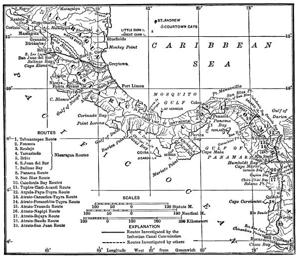
Map of American Isthmus,
showing Proposed Canal Routes.
309. Early Maritime Commerce with Lake Nicaragua.—Subsequently
sea-going vessels passed through the San Juan River in both directions
and maintained a maritime trade of some magnitude between the shores
of Lake Nicaragua and Spain. Obviously these vessels must have been
rather small for ocean-going craft, unless there was more water in the
San Juan River in those early days than at present. There are some
obscure traditions of earthquakes having disturbed the bed of the river
and made its passage more difficult by reducing the depth of water in
some of the rapids; but these reports are little more than traditionary
and lack authoritative confirmation. It is certain, however, that the
marine traffic, to which reference has been made, was maintained for a
long period of years, its greatest activity existing at about the
beginning of the seventeenth century. It was in connection with this
traffic probably that the city of Granada at the northwestern extremity
of the lake was established, perhaps before 1530.
310. Early Examination of Nicaragua Route.—Although
the apparently easy connection between the Caribbean Sea and Lake
Nicaragua, together with the proximity of the latter to the
Pacific coast, at once indicated the possibility of a feasible
water communication between the two oceans, probably no systematic
investigation to determine a definite canal line was made until that
undertaken by Manuel Galisteo in 1779 under the instruction of Charles
III., who was then on the throne of Spain. Galisteo made a report in
1781 that Lake Nicaragua was 134 feet higher than the Pacific Ocean,
and that high mountains intervened between the lake and the ocean,
making it impracticable to establish a water communication between
the two. In spite of the discouragement of this report a company was
subsequently formed under the patronage of the crown to construct a
canal from Lake Nicaragua along the Sanoa River to the Gulf of Nicoya,
but nothing ever came of the project.
311. English Invasion of Nicaragua.—The country was
invaded in 1780 by an English expedition sent out from Jamaica under Captain
Horatio Nelson, who subsequently became the great admiral. He proceeded
up the San Juan River, and after some fighting captured by assault Fort
San Juan at Castillo Viejo. Nelson and his force, however, were ill
qualified to take care of themselves in that tropical country where
drenching rains were constantly falling, and he was therefore obliged
to abandon his plan of taking possession of Lake Nicaragua and returned
instead to Jamaica. The tropical fevers induced by exposure reduced
the crew of his own ship, two hundred in number, to only ten after his
return to Jamaica, and he himself nearly lost his life by sickness.
312. Atlantic and Pacific Ship-canal Company.—Subsequently
to this period the Nicaragua route attracted more or less attention until
Mr. E. G. Squier, the first consul for the United States in Nicaragua,
negotiated a treaty between the two countries for facilitating the
traffic from the Atlantic to the Pacific Ocean by means of a ship-canal
or railroad in the interest of the Atlantic and Pacific Ship-canal
Company, composed of Cornelius Vanderbilt, Joseph L. White, Nathaniel
Wolfe, and others. It was at this time that the Nicaragua route became
prominent as a line of travel between New York and San Francisco.
Ships carried passengers and freight from New York to Greytown, then
trans-shipped them to river steamboats running up the San Juan River
and across the southerly end of the lake to a small town called La
Virgin, whence a good road for 14 miles overland led to the Pacific
port of San Juan del Sur. Pacific coast steamships completed the trip
between the latter port and San Francisco.
313. Survey and Project of Col. O. W. Childs.—This
traffic stimulated the old idea of a ship-canal across the Central American
isthmus on the Nicaragua route to such an extent that Col. O. W.
Childs, an eminent civil engineer, was instructed by the American
Atlantic and Pacific Ship-canal Company to make surveys and
examinations for the project of a ship-canal on that route. The results
of his surveys, made in 1850-52, have become classic in interoceanic
canal literature. He concluded that the most feasible route lay up the
San Juan River from Greytown to Lake Nicaragua, across that lake, and
down the general course of the Rio Grande on the west side of Nicaragua
to Brito on the Pacific coast. This is practically identical with
the route adopted by the Isthmian Canal Commission now (1902) being
discussed in Congress.
314. The Project of the Maritime Canal Company.—The
project planned by Col. Childs, like those which preceded it, had no
substantial issue, but the general subject of an isthmian canal across
Nicaragua was, from that time, under almost constant agitation and
consideration more or less active until the Maritime Canal Company of
Nicaragua was organized in February, 1889, under concessions secured
from the governments of Nicaragua and Costa Rica by Mr. A. G. Menocal.
This company made a careful examination of all preceding proposed
routes, and finally settled upon a plan radically different in some
respects from any before considered. The Caribbean end of the canal
was located on the Greytown Lagoon west of Greytown. From that point
the line followed up the valley of the Deseado River
and cut across the hills into the valley of the San Juan above its
junction with the San Carlos. A dam was to be constructed across the
San Juan River at Ochoa, below the mouth of the San Carlos, so as
to bring the surface of Lake Nicaragua down to that point. From its
junction with the San Juan River the canal line followed that river
to the lake, across the latter to Las Lajas, and thence down the Rio
Grande to the Pacific coast at Brito. It was contemplated under this
plan to carry the lake level to a point called La Flor, 13.5 miles
west of the lake, and drop down to the Pacific from that point by
locks suitably located. After partially excavating the canal prism for
about three quarters of a mile from the Greytown Lagoon, constructing
a line of railroad up the Deseado valley, as well as a telegraph
line, and doing certain other work preparatory to the actual work of
construction, the Maritime Canal Company became involved in financial
difficulties and suspended operations without again resuming them.
Breakwater of the Maritime Canal Company.
The closed former entrance to Greytown harbor is shown on the left.
315. The Work of the Ludlow and Nicaragua Canal Commissions.—In
1895 and again in 1897 two commissions were appointed by the President
of the United States to consider the plans and estimates of the
Maritime Canal Company in the one case, and the problem of a ship-canal
on the Nicaragua route in the latter. Neither of these commissions,
however, had the funds at its disposal requisite for a full and
complete consideration of the problem. In 1899, therefore, the Isthmian
Canal Commission was created by Act of Congress, and appointed by
the President of the United States, to determine the most feasible
and practical route across the Central American isthmus for a canal,
together with the cost of constructing it and placing it under
the control, management, and ownership of the United States. This
commission consisted of nine members, and included civil and military
engineers, an officer of the navy, an ex-senator of the United States,
and a statistician. It was the province and duty of this commission to
make examinations of the entire isthmus from the Atrato River in the
northwestern corner of South America to the western limits of Nicaragua
for the purpose of determining the most feasible and practical route
for a ship-canal between those territorial limits. This brings the
general consideration of the isthmian canal question to the Nicaragua
route in particular, to which alone attention will be directed in this part.
316. The Route of the Isthmian Canal Commission.—The
Isthmian Canal Commission adopted a route practically following the San Juan
River from near Greytown to the lake, across the latter to Las Lajas on
its westerly shore, and thence up the course of the Las Lajas River,
across the continental divide into the Rio Grande valley, and down the
latter to Brito at the mouth of the Rio Grande on the Pacific coast.
As has already been stated, this is practically the line adopted by
Col. Childs almost exactly fifty years ago. It is also essentially the
route adopted by the Nicaragua Canal Commission appointed in 1897,
and which completed its operations immediately prior to the creation
of the Isthmian Canal Commission. The amount of work performed in the
field under the direction of the commission can be realized from the
statement that twenty working parties were organized in Nicaragua with
one hundred and fifty-nine civil engineers and other assistants, and
four hundred and fifty-five laborers.
317. Standard Dimensions of Canal Prism.—By the Act of
Congress creating it, the latter commission was instructed to consider plans
and estimates for a canal of sufficient capacity to accommodate the
largest ships afloat. In order to meet the requirements of those
statutory instructions the commission decided to adopt 35 feet as the
minimum depth of water in the canal throughout its entire length from
the deep water of one ocean to that of the other, wherever the most
feasible and practical route might be located, the investigations of
the commission having shown that the final location to be selected must
narrow down to a choice between the Panama and the Nicaragua routes.
It was further decided by the commission that the standard width of
excavation at the bottom of the canal should be 150 feet, with 500 feet
for the ocean entrances to harbors, and 800 feet in those harbors.
Greater widths than that of the bottom of standard excavations were
also adopted for river and lake portions. The slopes of the sides of
the excavation were determined to be 1 vertical on 1½ horizontal for
firm earth, but as flat as 1 vertical on 3 or even 6 horizontal for
soft mud or silt in marshy locations. In rock cutting below water the
sides of the excavation would be vertical, but as steep as 4 vertical
on 1 horizontal above water.
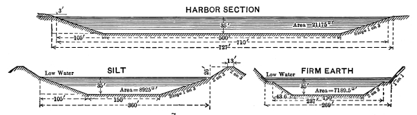
Standard Sections adopted by the Isthmian Canal Commission.
The longest ship afloat at the present time (1902) is the Oceanic of
the White Star Line, and its length is about 704 feet. The widest
ships, i.e., the ships having the greatest beam, are naval vessels,
and at the present time none has a greater beam than about 77 feet. In
order to afford accommodation for further development in both length
and beam of ships without leading to extravagant dimensions, the
commission decided to provide locks having a usable length of 740 feet
with a clear width of 84 feet. These general dimensions
meet fully the requirements of the law, and were adopted for plans and
estimates on both the Panama and Nicaragua routes.
318. The San Juan Delta.—The entire Central American
isthmus is volcanic in character, and this is particularly true of the
country along the Nicaragua route with the exception of the lowlands
immediately back of the ocean shore line in the vicinity of Greytown.
From the latter point to Fort San Carlos, where the San Juan River
leaves the lake, is approximately 100 miles. With the exception of
the 15 miles nearest to the seacoast the San Juan River runs mostly
through a rugged country with high hills densely wooded on either
side. The soil is mostly heavy clay, although the bottom of the valley
immediately adjacent to the river is largely of sandy silt with some
mixture of clay. Between the hills back of Greytown and the seacoast
the country is almost a continuous morass covered with coarse grasses
and other dense tropical vegetation, but with a number of small
isolated hills projecting up like islands in the surrounding marsh,
and interspersed with numerous lagoons. All this flat country has the
appearance of forming a delta through which a number of mouths of the
San Juan River find their way. One of these, called the Lower San Juan,
empties into the Greytown Lagoon, but the main mouth of the San Juan,
called the Colorado, branches from the main river at the point where
the Lower San Juan begins, about 13 or 14 miles from the ocean. The
Colorado itself is composed of two branches, and at the place where it
empties into the sea there are a number of long narrow lagoons parallel
to the seashore, appearing to indicate comparatively recent shore
formation. Again, a small river called the Rio San Juanillo leaves the
main river 3 or 4 miles above the junction of the lower San Juan and
the Colorado, and pursues a meandering course through the low marshy
grounds back of Greytown, and finally again joins the Lower San Juan
near the town. This marshy lowland is underlaid by and formed largely
of dark-colored sand brought down mostly from the volcanic mountains of
Costa Rica by two rivers, the San Carlos and the Serapiqui, the former
joining the San Juan about 44 miles and the latter about 23 miles from
the sea.
Greytown Lagoon (formerly Greytown Harbor),
showing Greytown in the Distance.
319. The San Carlos and Serapiqui Rivers.—Both those
Costa Rican rivers are subject to sudden and violent floods, and they bring
down large quantities of this volcanic sand, the specific gravity of
which is rather low. The San Carlos bears the greater burden of this
kind. In fact its bed, even when not in a state of flood, is at many
points at least composed of moving sands. Both rivers are clear-water
streams except in high water stages. Below the junction of the San
Carlos the San Juan is necessarily in times of floods a large bearer of
silt and sand, but above that point it carries little or no sediment.
There are no streams of magnitude which join the San Juan between the
lake and the San Carlos.
320. The Rapids and Castillo Viejo.—About 54 miles
from the ocean are the Machuca Rapids, and from that point to a distance
of about 75 miles from the ocean other rapids are found, the principal of
which are the Castillo and the Toro. The Castillo Rapids are at the
point called Castillo Viejo, where there is located an old Spanish
fort on the top of the high hill around the base of which the river
flows. The town of Castillo Viejo has a small population of perhaps 500
to 600 people. It is a place with historical associations, to which
reference has already been made. It was here that Captain (afterwards
Admiral) Nelson captured the Spanish fort in 1780. It is a place of
some importance in connection with the river traffic in consequence of
necessary transhipment of freight and passengers to overcome the rapids.
321. The Upper San Juan.—The upper reaches of the San
Juan within about 20 miles of the lake are bordered with considerable marshy
ground. In the vicinity of its exit from the lake there is a wide strip
of soft marshy country around the entire southeastern shore.
322. The Rainfall from Greytown to the Lake.—The entire
country between Greytown and the lake is intensely tropical, and the vegetation
is characteristically dense. It is particularly so at Greytown, where
the total annual rainfall sometimes reaches as much as 300 inches.
It rains many times in a day, and nearly every day in the year. The
strong easterly and northeasterly trade winds, heavy-laden with the
evaporation from the tropical sea, meet the high ground in the vicinity
of Greytown and precipitate their watery contents in frequent and heavy
showers. The general course of the San Juan valley is a little north
of west or south of east, and the trade winds appear to follow the
course of the valley to the lake. The rainfall steadily decreases as
the seashore is left behind, so that at Fort San Carlos, the point of
exit of the river from the lake, the annual precipitation may vary from
75 to 100 inches. There is no so-called dry season between the lake and
the Caribbean Sea, although at Fort San Carlos the rainfall is so small
between the middle of December and the middle of May that that period
may perhaps be considered, relatively speaking, a dry season. It is
evident, therefore, that all the conditions are favorable to luxuriant
tropical growths over this entire eastern portion of the canal route,
and the coarse grasses, palms, and other tropical vegetation found in
it are indescribably dense. The same general observation is applicable
to the forest and undergrowth throughout the entire course of the river
from Greytown to Fort San Carlos. All of the high ground is heavily
timbered, with undergrowth so dense that no survey line can be run
until it is first completely cut out. That observation holds with added
force throughout the swampy country adjacent to the seashore. All the
heavy forest growth carries dense vines and innumerable orchids, which
so cover the trunks and branches of trees as in many places completely
to obscure them.
The Maritime Canal Company’s Canal Cut leading
out of Greytown Lagoon.
323. Lake-surface Elevation and Slope of the River.—The
lake surface has an area of about 3000 square miles and varies in elevation
with the amount of rainfall in its basin from about 97 or 98 to perhaps
110 feet above the ocean. The average elevation can probably be taken
at about 104 feet above the sea. The length of the lake is about 103
miles, with a greatest width of 45 miles. The area of its watershed is
about 12,000 square miles. Inasmuch as the length of the San Juan River
from the ocean to the lake is but a little more than 100 miles, its
average fall is seen to be about 1 foot per mile. The greatest slope of
the river surface is at Castillo Rapids, where it falls about 6 feet
in ⅜ of a mile. At the Machuca Rapids it falls about 4 feet in 1
mile. From the foot of Machuca Rapids to the mouth of the San Carlos,
a distance of a little over 15 miles, the surface of the river falls
about 1 foot only. This pool, with practically no sensible current,
is called Agua Muerte, or Dead Water. The relatively great depth of
this pool shows conclusively that the upper San Juan, i.e., above the
mouth of the San Carlos, carries no silt, otherwise the pool would
be filled; in other words, that part of the San Juan River is not a
sediment-bearer. The slope of the river surface in the Toro Rapids,
about 27 miles from the lake, gives a fall of 7³/₁₀ feet in 1⁷/₁₀ miles.
324. Discharges of the San Juan, San Carlos, and Serapiqui.—In
times of heavy floods the San Carlos River may discharge as much as
100,000 cubic feet per second into the San Juan, but such floods have
a duration of a comparatively few hours only. Its low water-discharge
may fall below 3000 cubic feet per second. The maximum outflow of the
lake during a rainy season or a season of heavy rainfall probably never
exceeds about 70,000 cubic feet per second, but that rate of discharge
may continue for a number of weeks. The low water-discharge of the San
Juan above the mouth of the San Carlos may fall below 10,000 feet per
second, or 13,000 feet per second below the mouth of the San Carlos but
above that of the Serapiqui.
325. Navigation on the San Juan.—From what has been
said of the San Juan River it is evident that in times of low water no boats
drawing more than about 5 or 6 feet can navigate it, and most of the
river boats draw less than that amount. In times of low water no boat
can navigate the Lower San Juan drawing more than about 2½ to 3 feet
of water. Nor, again, can the ordinary river boats pass up the rapids
at Castillo except at high water. It is necessary, therefore, that
the larger boats used on the river confine their trips on the one
hand between the mouth of the Colorado and Castillo, and on the other
between Castillo above the rapids to Fort San Carlos. It is the custom,
therefore, to transfer passengers and freight from boats below the
rapids at Castillo by a short tramway to other boats in waiting above
the rapids at that point. Boats pass up Machuca and Toro rapids at
practically all seasons, but sometimes with difficulty.
In order to meet the exigencies of low water in the Lower San Juan
a railroad called the Silico Lake Railroad, with 3 feet
gauge, has been constructed from a point opposite the mouth of the Colorado,
called Boca Colorado, to Lake Silico in the marshes back of Greytown,
a distance of about 6 miles. Light-draft boats connect Lake Silico
with Greytown for the transfer of passengers and freight. The type of
light-draft steamboat used on the San Juan River is the stern-wheel
pattern, so much used on the western rivers of this country, the
lower deck carrying the engines and boilers as well as freight, while
the upper deck, fitted with crude staterooms, furnishes a kind of
accommodation for passengers.
326. The Canal Line through the Lake and Across the
West Side.—The little town of Fort San Carlos on a point raised
somewhat above the lake where the San Juan River leaves the latter is
the second place on the entire river from Greytown where any population
may said to be found, and probably not more than 400 or 500 people even
there. Its position is on the north side of the river, at the extreme
southeastern end of the lake, commanding a fine view of the water and
the country bordering it in that vicinity. To the westward lie the
Solentiname Islands, a group a short distance to the north of which
the sailing line for the canal in the lake is located. After passing
this group of islands that line deflects a little toward the south, so
that its course westward is but a little north of west, straight to
a point near to and opposite Las Lajas on the westerly shore of the
lake, southwest from the large island on which Ometepe and Madeira are
located; indeed those two volcanic cones, the former still active,
constitute the entire island. The point called Las Lajas is at the
mouth of a small river of that name which discharges any sensible
amount of water only during the wet season; it is located not more
than 10 miles from Ometepe, and affords a most impressive view of that
perfect volcanic cone rising almost an exact mile above the water. The
general direction of the canal route is a little west of south from Las
Lajas on the lake to Brito on the ocean shore. The line follows the
Las Lajas about a mile and a half only of the 5 miles from the lake in
a southwesterly direction to the point where the continental divide
is crossed. The elevation of the divide at this place is about 145
feet only above sea-level. The line then descends immediately into the
valley of the Rio Grande and follows that stream to its mouth at Brito.
The Maritime Canal Company’s Railroad near Greytown.
327. Character of the Country West of the Lake.—The country
on the west side of the lake exhibits a character radically different from
that on the easterly side, i.e., between the lake and the Caribbean. It
is a country in which much more population is found. While there are
no towns along the 17 miles of the route from Las Lajas to Brito, the
old city Rivas, containing perhaps 12,000 to 15,000 people, is about 6
miles from Las Lajas, and the small towns of San Jorge, Buenos Ayres,
Potosi, as well as others, are in the same general vicinity.
Plantations of cacao and various tropical fruits abound, and there
is a large amount of land under cultivation. It is largely a cleared
country, so that far less dense forest areas are found.
There are two distinct seasons in the year, the wet and the dry, the
latter extending from about the middle of December to the middle of
May. The annual rainfall is extremely variable, but in the vicinity
of Rivas it may run from 30 or 40 to nearly 100 inches. The country
is of great natural beauty, and one which, under well-administered
governmental control, would afford many places of delightful
residence. The trade winds blow across the lake from east to west with
considerable intensity and great regularity. They produce a beneficial
effect upon the climate and render atmospheric conditions far more
agreeable than in that part of Nicaragua in the vicinity of Greytown.
It will be remembered that Rivas is the city where the American
filibuster Walker was taken prisoner by the Costa Ricans and
Nicaraguans and shot in 1857.
328. Granada to Managua, thence to Corinto.—At the
northwestern end of the lake is located the attractive city Granada, sometimes
called the “Boston of Nicaragua.” A reference to a map of Nicaragua
will show that a short distance north of Granada is the river Tipitapa,
which connects Lake Nicaragua with Lake Managua, the latter lying 18
miles to the northwest of the former. A railroad connects Granada
with the city of Managua, which is the capital of Nicaragua, running
on its way through the city of Masaya, chiefly noted for the volcano
of the same name located near by, and which has been subjected to a
most destructive eruption. The old lava-flow still shows its path of
destruction by a broad black mark extending many miles across the
country. A railroad connects Lake Managua at Momotombo with the Pacific
port of Corinto.
329. General Features of the Route.—It is thus seen
that the proposed route of the Nicaragua Canal lies first along the valley
of the San Juan River, then across the lake, cutting the
continental divide west of the latter at the low elevation of 145 feet above the
sea, thence following the valley of the Rio Grande to the Pacific Ocean
at Brito. From Greytown to Castillo the San Juan River is the boundary
between Nicaragua and Costa Rica, and concessions from both governments
would be necessary for that part of its construction. From Castillo
to the Pacific Ocean the route lies entirely in Nicaraguan territory,
and the only concession necessary for that portion of the line
would be from the government of Nicaragua. From Castillo to and around
the southern end of the lake the boundary-line is located 3 miles
easterly from the river, following its turns, and the same distance
from the lake shore, all by an agreement recently reached between
the two governments. The summit level of the canal would therefore
be the surface of the water in Lake Nicaragua, which is carried down
to Conchuda, 52 miles from the lake on the San Juan River toward the
east, by a great dam located there, and to a lock between 4 and 5 miles
from the lake toward the west. Hence the summit level would stretch
throughout a distance of about 126 miles, leaving a little more than 46
miles on the Caribbean end and about 12 miles on the Pacific end of the
regular canal section. The 50-mile stretch from the lake to the point
where the canal cuts the San Juan River near Conchuda is a canalized
portion of the San Juan River, as a large amount of excavation must be
done there in order to give the minimum required depth of 35 feet. The
points of river bends or curves are in some cases cut off by excavated
canal section in order to shorten the line and reduce the curvature.
Considerable portions of the line in the lake, particularly near
Fort San Carlos, would be excavated. For several miles in the latter
vicinity large quantities of silt and mud must be removed, as the lake
is shallow and the bottom is very soft. The entrance into the western
portion of the canal at Las Lajas requires a large amount of rock excavation,
as the shore and bed of the lake there are almost entirely of rock.
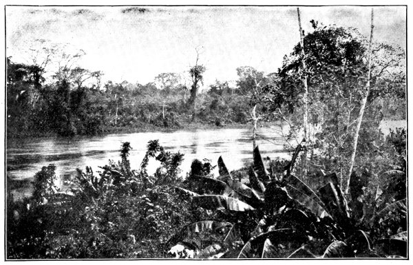
Scene on the San Juan River.
330. Artificial Harbor at Greytown.—The preceding
observations are mostly of a general character, and give but little
consideration to the engineering features of the canal construction. In
considering the canal as a carrier of ocean traffic probably the first
inquiry will be that relating to harbors. In reality there is no natural
harbor at either end of the Nicaragua route. Fifty years ago there
was an excellent harbor at Greytown into which ships drawing as much
as 30 feet found ready entrance, and within which was afforded a
well-protected anchorage. As early as that date, however, a point of
land or sand-pit was already pushing its way northward in consequence
of the movement of the sand along the beach in that direction, and
in 1865 it had nearly closed the entrance to the harbor. For many
years that entrance has been entirely closed, and now what was
once the protected harbor of Greytown is a shallow body of water,
completely closed, and known as the Greytown Lagoon.
There is a narrow, circuitous, and shallow channel leading from it out to
an opening in the sand-bar, which may be navigated by boats drawing not more
than 2 or 3 feet, and by means of which freight and passengers are taken from
steamers, which are obliged to anchor in the offing. Occasionally heavy
storms break through this strip of sand between Greytown Lagoon and
the ocean, and for a short time form a shallow entrance to the former.
The sand movement in that vicinity northward or westward is so active
that it is but a short time before such openings are again closed. The
deepest water in the lagoon probably does not exceed 8 or 10 feet at
the present time, and the most of it is much shallower. The tidal
action at Greytown is almost nothing, as the range of tide between high
and low is less than 1 foot. The mean level of the Caribbean Sea is the
same as that of the Pacific Ocean.
Under these circumstances it is necessary to create what is practically
a new harbor at Greytown, and that work is contemplated in the plans
of the Isthmian Canal Commission. The canal line is found entering the
lagoon about 1 mile northwest of Greytown, where a harbor is planned
having a length of 2500 feet and a width of 500 feet, increased at
the inner end to 800 feet to provide a turning-basin. The entrance to
this harbor from the ocean will be dredged to a width of 500 feet at
the bottom, and it will be protected outside of the beach-line by two
jetties, the easterly about 3000 feet long, and the westerly somewhat
shorter. These jetties would “be built of loose stone of irregular
shape and size, resting on a suitable foundation,” the largest,
constituting the covering, weighing not less than 10 to 15 tons each.
These jetties would be carried 6 feet above high water and have a top
width of 20 feet. The trade winds, which blow from the easterly and
northeasterly, would have a direction approximately at right angles to
that of the easterly jetty, and ships making the entrance of the canal
would consequently be protected against them while between the jetties.
The easterly of these jetties would act as an obstruction against the
westerly movement of the sand, but it is practically certain that a
considerable amount of the latter would be swept into the channel,
and possibly to some extent into the harbor, necessitating dredging
a considerable portion of the time. The commission estimates that
the maintenance of the entrance and harbor would require an annual
expenditure of $100,000.
331. Artificial Harbor at Brito.—The harbor at Brito
presents a problem of a different kind. There is absolutely no semblance of
a harbor there at the present time (1902); it is simply a location on the
sandy beach of the ocean protected against swells from the west by a
projecting rocky point called Brito Head, the Rio Grande River emptying
into the ocean just at the foot of Brito Head, between it and the canal
terminus. The entire harbor and its entrance would be excavated in the
low ground of that vicinity, composed mostly of sand and silt, although
there would be a little rock excavation. The entrance to the harbor
would be dredged 500 feet wide at the bottom, and be protected by a
single jetty on the southeasterly side. The harbor itself would be
excavated back of the present beach; it would have a length of 2200
feet and a width of 800 feet. As the depth of water increases rather
rapidly off shore, the 10-fathom curve is found at about 2200 feet from
low-water mark, hence the jetty would not need to be more than probably
1800 to 2000 feet long. In this vicinity the water is usually smooth;
indeed but few storms annually visit this part of the coast. The
conditions are quite similar to those found on the coast of Southern
California. There is little sand movement in this vicinity, and the
annual expenditures for maintenance of the harbor and entrance would be
relatively small; the commission has estimated them at $50,000.
332. From Greytown Harbor to Lock No. 2.—The canal
line, on leaving the harbor at Greytown, is found in low marshy ground
for a distance of about 7 miles, the excavation being mainly through
the sand, silt, mud, and vegetable matter characteristic of that
location. Throughout almost this entire distance the natural surface
is but little above sea-level. The first ground elevated much above
this marshy country is known as the Misterioso Hills, in which Lock
No. 1 is founded, having a lift of 36½ feet and raising the water
surface in the canal by that amount above sea-level. Another stretch
of marshy country, but not quite so wet as the preceding, follows for
a distance of about 11 miles, when the Rio Negro Hills rise abruptly
to an elevation of a little over 150 feet above sea-level. At this
point is located Lock No. 2, with a lift of 18½ feet. This lock is
about 21 miles from the 6-fathom line off Greytown. The canal line here
practically reaches the San Juan River, the latter lying a considerable
distance easterly of the canal, between this point and the ocean.
Between Greytown and Lock No. 2 embankments, never reaching a greater
height than 10 to 15 feet, are required to keep the water in the canal
at various locations along the low ground. These embankments do not
necessarily follow parallel to the centre line of the canal route, but
are planned to connect hills, or rather high ground, so as to reduce
their length and give them a more stable character than if they were
located close to the canal excavation. While some embankments will
still be found above Lock No. 2, they are few, and even lower than
those already noticed. From Lock No. 2 to Lake Nicaragua the route
of the canal lies practically along the San Juan River, the chief
exception to that statement being the cut-off in the vicinity of the
Conchuda dam.
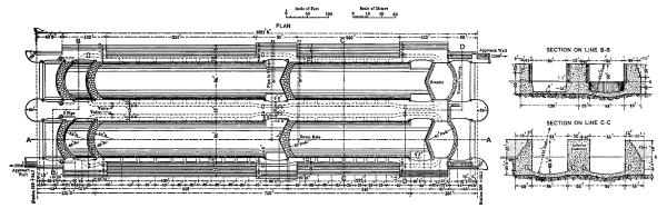

Lock No. 1, Nicaragua Route,
about Seven Miles from Greytown.
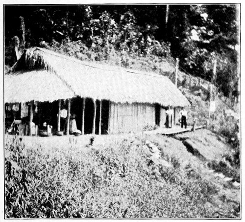
Telegraph Office at Ochoa on the San Juan River.
333. From Lock No. 2 to the Lake.—Inasmuch as both
the Serapiqui and San Carlos rivers flow from Costa Rican territory into
the San Juan, that is, from its right bank, the canal line necessarily
is located along the northerly or left bank of that river. At a
distance of 23 miles from the ocean the canal line cuts through what
are called the Serapiqui Hills opposite the mouth of the river of that
name, and at a distance of a little over 26 miles from the ocean it
pierces the Tamborcito Ridge, where is found the deepest cutting on the
entire route. The total length of cut through this ridge is about 3000
feet, but its greatest depth is 297 feet, and it consists largely of
hard, basaltic rock. The next lock, or Lock No. 3, is found about 17
miles from Lock No. 2, or 38 miles from the sea, and it has, like
Lock No. 2, a lift of 18½ feet, raising the surface of the water in
the canal to an elevation of 73½ feet above the sea. Continuous heavy
cutting through what are called the Machado Hills brings the line to
Lock No. 4, at a distance of a little less than 41 miles from the
ocean. This lock has a lift varying from 30.5 to 36.5 feet, inasmuch
as it raises the surface of the water in the canal to the summit level
in the lake. The maximum lift of 36.5 feet would be required when the
lake level stands at an elevation of 110 feet above the sea, and 30.5
feet when the same surface stands at an elevation of 104 feet above the
sea. Although the water surface in the canal level above this lock is
identical with the summit level in the lake, the canal line again runs
through continuous heavy cutting for a distance of 5 miles before it
reaches the canalized San Juan. This portion of the line between Lock
No. 4 and the San Juan River is called the Conchuda cut-off, for the
reason that the point called Conchuda, where the great dam is located,
is but 3 miles down the river from the point where the canal enters it.
From Conchuda to the lake, as has already been stated, the canal line
follows the course of the San Juan River, which must be canalized by
considerable excavation of earth and rock, both along the bed and in
cut-offs. The greater part of this cutting must obviously be on that
portion of the river toward the lake, as that is the highest part of
the river-bed in its natural condition.
334. Fort San Carlos to Brito.—The distance from the
point of entrance of the canal into the San Juan River near Conchuda to
Fort San Carlos on the shore of Lake Nicaragua is about 50 miles, while
the distance across the lake on the canal line is 70.5 miles, which brings
the line to Las Lajas on the southwesterly shore of the lake.
There is considerable heavy cutting through the continental divide
between the lake and the first lock westerly of it, i.e., Lock No. 5.
The maximum cutting is but 76 feet in depth, and the average is but
little less than that for nearly 3 miles. This lock is located a little
less than 10 miles from the lake and nearly 176 miles from the 6-fathom
line off Greytown. The place at which this lock is located is known as
Buen Retiro. The lift of Lock No. 5 varies from 28½ feet as a maximum
to the minimum of 22½ feet, bringing the water surface in the canal
down to 81½ feet above mean ocean level. Lock No. 6 is located but
about 2 miles west of Lock No. 5, and also has a lift of 28½ feet. The
line now runs along the course of the Rio Grande to the ocean, Lock No.
7 being also 2 miles west of Lock No. 6, again with a lift of 28½ feet.
The last lock on the line, or Lock No. 8, but a mile from the Pacific
Ocean, and about 182 miles from the Caribbean Sea, has a maximum lift
of 28½ feet, and a minimum lift of 20½ feet, the range of tide in the
Pacific Ocean being but 8 feet at Brito. There are thus four locks
between the lake and the Pacific Ocean, each having a possible lift of
28½ feet.
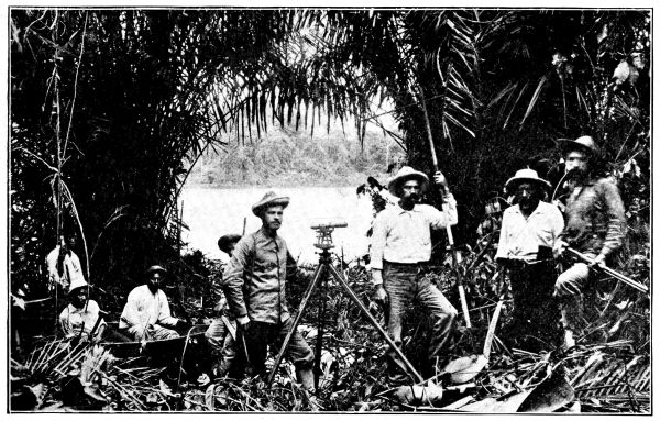
Surveying Party of the Isthmian Canal Commission
on the San Juan River.
The entire distance between the 6-fathom lines in the two oceans is
183.66 miles.
335. Examinations by Borings.—Obviously it is of the
greatest importance that such structures as the locks and dams required in
connection with this canal route should be founded on bed-rock. In
order to determine not only such questions, but the character of all
materials to be excavated from one end of the route to the other, a
great number of borings were made along the canal line, not only by the
water-jet process, but also with the diamond drill. By means of the
latter, whenever it was so desired, cores or circular pieces could be
taken out of the bed-rock so as to show precisely its character at all
depths. These borings, both through earthy material by the jet and into
bed-rock by the diamond drill, were made at suitable distances apart
along the centre line of the canal, and in considerable numbers, closer
together at proposed lock and dam sites. By these means every lock on
the line has certainly been located on bed-rock, as well as the great
dam at Conchuda. In addition to this the commission has been able to
classify the material to be excavated, so that if the canal should be
built every contractor would know precisely the character and quantity
of the various materials which he would have to deal with.
336. Classification and Estimate of Quantities.—The following
table is arranged to exhibit a few only of the principal items of
excavation, so as to give an approximate idea at least of the magnitude
of the work to be done:
| Dredging |
130,920,905 |
cu. yds. |
| Dry earth |
47,440,316 |
” |
| Soft rock |
14,029,170 |
” |
| Hard rock |
24,151,214 |
” |
| Rock under water |
2,780,040 |
” |
| Embankment and back-filling |
8,389,960 |
” |
| Clearing |
6,831 |
acres. |
| Stone-pitching |
250,089 |
sq. yds. |
| Concrete, excluding retaining-walls |
3,400,840 |
cu. yds. |
| Concrete in retaining-walls |
424,321 |
” |
| Cut-stone |
22,272 |
” |
| Steel and iron, |
|
|
| excluding cast-iron culvert lining |
61,735,230 |
lbs. |
| Cast-iron culvert lining |
19,286,000 |
” |
| Brick culvert lining |
34,542 |
cu. yds. |
| Cost of lock machinery |
$1,600,000 |
|
| Excavation in coffer-dam |
9,907 |
cu. yds. |
| Pneumatic work |
145,557 |
” |
| Piling |
415,600 |
lin. ft. |
| Rock fill in jetties |
451,500 |
cu. yds. |
| Clay puddle, bottom and side |
936,800 |
” |
337. Classification and Unit Prices.—The classification of the
material to be excavated, both on the Nicaragua and Panama routes, was
one to which the commission gave very thoughtful study no less than to
the prices to be used in making the estimates. The following table,
taken from pages 67 and 68 of the commission’s report, exhibits the
classification and the prices adopted by the commission for purposes of
its estimates:
| Removal of hard rock, per cu. yd. |
$1.15 |
| Removal of soft rock, per cu. yd |
.80 |
| Removal of earth, not handled by dredge, per cu. yd. |
.45 |
| Removal of dredgable material, per cu. yd. |
.20 |
| Removal of rock, under water, per cu. yd. |
4.75 |
| Embankments and back-filling, per cu. yd. |
.60 |
| Rock in jetty construction, per cu. yd. |
2.50 |
| Stone-pitching, including necessary backing, per sq. yd. |
2.00 |
| Clearing and grubbing in swamp sections of Nicaragua, per acre |
200.00 |
| Other clearing and grubbing on both routes, per acre |
100.00 |
| Concrete, in place, per cu. yd. |
8.00 |
| Finished granite, per cu. yd. |
60.00 |
| Brick in culvert lining, per cu. yd. |
15.00 |
| All metal in locks, exclusive of machinery and culvert linings, per lb. |
.075 |
| All metal in sluices, per lb. |
.075 |
| Cast-iron in culvert lining, per lb. |
.04 |
| Allowance for each lock-chamber for operating machinery |
50,000.00 |
| Additional allowance for each group of locks for power-plant |
100,000.00 |
| Price of timber in locks, per M B. M |
100.00 |
| Sheet-piling in spillways, per M B. M |
75.00 |
| Bearing piles in spillways, per lin. ft. |
.50 |
| Average price of pneumatic work for the Bohio dam, |
|
| below elevation—30, per cu. yd. |
29.50 |
| Caisson work for the Conchuda dam, in place, per cu. yd. |
20.00 |
| Single-track railroad complete with switches, |
|
| stations, and rolling stock, per mile of main line |
75,000.00 |
There are evidently other more or less uncertain expenditures,
depending upon all possible conditions affecting the cost of such work,
including those of climate, police, and sanitation. In order to cover
such expenditure the commission determined to add 20 per cent to all
its estimates of cost on both routes, and that percentage was so added
in all cases.
338. Curvature of the Route.—Among the engineering features
of a ship-canal line it is evident that curvature is one of great
importance. Small steam-vessels may easily navigate almost any tortuous
channel, but it is not so with great ocean steamships. On the other
hand, it may require very deep and expensive cutting to reduce the
curvature of the route, as curves are usually introduced to carry the
line around some high ground. It is necessary, therefore, to make a
careful and judicious balance between these opposing considerations.
The commission wisely decided to incur even heavy cutting at some
points for the purpose of avoiding troublesome curvature on the
Nicaragua route. The table on page 415, taken
from page 135 of the commission’s report, gives all the elements of
curvature for the entire line.
Boring Party of the Isthmian Canal Commission
on a Raft in the San Juan River.
From the description of the line as given, it is evident that much
curvature must be found in spite of the most judicious efforts to avoid
it, and the table indicates that condition. Yet the amount of curvature
may be considered moderate for a location through such a country as
Nicaragua. The smallest radius is seen to be a little over 4000 feet.
The result may be considered satisfactory for such a difficult canal
country, although the total amount of curvature is rather formidable.
Number of
Curves. |
Radius. |
Length. |
Total Degrees of Curve. |
| |
Feet. |
Miles. |
° |
′ |
″ |
| 2 |
17,189 |
1.53 |
26 |
51 |
10 |
| 8 |
11,459 |
6.80 |
179 |
31 |
50 |
| 4 |
8,594 |
4.31 |
151 |
40 |
50 |
| 1 |
8,385 |
1.43 |
51 |
44 |
30 |
| 2 |
7,814 |
1.90 |
73 |
28 |
30 |
| 1 |
7,759 |
1.73 |
67 |
16 |
50 |
| 5 |
6,876 |
4.64 |
204 |
34 |
40 |
| 2 |
5,927 |
2.40 |
122 |
41 |
20 |
| 16 |
5,730 |
11.08 |
584 |
47 |
40 |
| 2 |
5,289 |
2.27 |
129 |
45 |
50 |
| 1 |
5,209 |
1.15 |
66 |
38 |
30 |
| 2 |
5,056 |
1.22 |
73 |
17 |
40 |
| 1 |
4,982 |
.82 |
49 |
49 |
00 |
| 3 |
4,911 |
2.75 |
169 |
36 |
00 |
| 1 |
4,297 |
.63 |
44 |
19 |
50 |
| 1 |
4,175 |
.81 |
58 |
20 |
40 |
| 4 |
4,045 |
3.82 |
285 |
25 |
40 |
| 56 |
|
49.29 |
2,339 |
50 |
30 |
339. The Conchuda Dam and Wasteway.—The most important
single engineering feature of the whole plan is the dam at Conchuda.
The ordinary low-water elevation in the river at the dam site may be taken
at about 55 feet above the sea. Inasmuch as the greatest elevation of
the water in the lake is supposed to be about 110 feet, it will be
seen that its surface will be but 55 feet above the present elevation,
making its maximum depth at that point about 105 feet if there should
be no fill on the up-stream side of the dam, inasmuch as the present
depth of water in the river at the stage assumed is about 50 feet.
This dam would be a structure of concrete masonry with cut-stone facing
only at a few points where it would be advisable to use that material.
A large part of the flood discharge, or the discharge of other surplus
water, would be made over a properly designed crest of the dam; hence
its outline would be that shown in the accompanying figure, shaped
so as to prevent the overflowing sheet of water from damaging the
structure. This dam will be founded upon pneumatic caissons, and the
borings made by the commission show that the deepest of them would
reach satisfactory bed-rock at no greater depth than 25 feet below
sea-level, or about 80 feet below the ordinary stage of water in the
river. The construction of this dam therefore would involve no unusual
operations, but it would all be performed within the more usual and
easy limits of the pneumatic process of constructing foundations. The
masonry crest of this dam would be finished at the elevation of 97
feet above sea-level, or about 13 feet below the highest elevation of
water in the lake. The length of that part of this masonry dam, located
on pneumatic caissons, would be 731 feet, but the total length of the
entire masonry structure would be 1310 feet. The total length of crest,
including the masonry piers on it, over which the surplus waters would
flow, would be 810 feet, but there are twenty piers 9 feet thick, so
that the net length of crest available for overflow of waste-waters
would be about 630 feet. The piers to which reference is made are those
required for the support of the movable gates of the Stoney type which
would be employed to regulate the discharge over the dam. The maximum
elevation of the tops of these piers required for the support and
operation of the Stoney gates is 132 feet above sea-level. The masonry
dam thus furnished with movable gates can be used in times of flood
to prevent the water of the lake rising above about 110 feet above
sea-level. In times of low rainfall or during the dry season the gates
would prevent the escape of water needed for storage.
Castillo Viejo, on the San Juan River,
about thirty-seven miles from the lake
and at the Castillo Rapids. The old fort is
shown on the right at the summit of the hill.
The total available length of crest on this masonry dam is not
sufficient to exercise all the control that is needed to keep the lake
within desired limits, and the commission was obliged to avail itself
of a low depression or saddle between the hills less than a half-mile
easterly of the dam site. The depression affords an additional total
length of crest of 1239 feet, or, taking out thirty-one piers, each 9
feet wide, a net available length of 960 feet, making in combination
with the crest of the main dam a total net available length of 1590
feet. The total wastage over these two structures, i.e., the main dam
at Conchuda and the Conchuda wasteway on the Costa Rican side of the
river, may be at the rate of 100,000 cubic feet per second, with a
maximum depth over the crest of 7 feet, which is sufficient to meet the
demands of the heaviest rainfall in the lake basin.
The plans and elevations on pages 421,
423, and 424 show all the main
features of both the Conchuda dam and wasteway as designed by the commission.
340. Regulation of the Lake Level.—One of the most important
engineering questions connected with the consideration of the Nicaragua
route is that of the regulation or control of the surface of the water
in Lake Nicaragua constituting the summit level of the canal.
As has already been stated, the drainage-basin of the lake, about
12,000 square miles in area, is subjected to an annual wet season
extending from about the middle of May to the middle of December,
the dry season extending over the remaining portion of the year. The
average annual rainfall over the entire lake basin is not accurately
known, although the Isthmian Canal Commission maintained rainfall
records at several points on the lake shore and at other points in the
basin during periods of 1½ to 2 years, and records running back over
periods of perhaps 12 to 15 years are available from Rivas, Granada,
and Masaya. Fortunately, also, both the Nicaragua and the Isthmian
Canal Commissions maintained gauging-stations at various points on the
San Juan throughout the periods of service of these commissions, so
that the discharges of the river could be known from accurate measures
at various seasons for at least two or three years. These observations,
although not as extended as could be desired, yield sufficient data for
a comparatively thorough treatment of the subject of lake-surface control.
Obviously throughout the rainy season of the year, except during years
of low rainfall, some water would necessarily be wasted from the lake
because its retention would raise the surface of the lake too high,
causing damage, floods, or injurious overflows at various places around
the lake shore. On the other hand, unless some water were stored from
the rainy periods or wet seasons there would not be sufficient in
the lake to supply during the dry period of the year, or during low
rainfall years, the requisite quantity for the wastage of evaporation
from its surface and for the operation of the canal, and at the same
time maintain the minimum depth of water of 35 feet required in the
canal. It was necessary, therefore, to design at least the general
features of such regulating-works as would prevent the lake from rising
too high in wet periods, and from falling too low in dry periods or low
rainfall years.
Village of Fort San Carlos at Entrance to the San Juan River.
Lake Nicaragua is on the right and San Juan River
in the middle ground.
341. Evaporation and Lockage.—The observations of
both commissions show conclusively that the average evaporation from the
surface of Lake Nicaragua is about 60 inches or 5 feet per year,
varying from perhaps a maximum of 6 inches per month to a minimum of
possibly about 4 inches per month. Furthermore, careful estimates of
the quantity of water required for the purposes of the canal, on the
supposition that about 10,000,000 tons of traffic would pass through
it annually, including lockage, leakage through the gates of the
locks, evaporation, power purposes, and other incidentals, show that
about 1000 cubic feet of water per second must be provided. Whatever
may be the character of the season, therefore, there must be at
least sufficient water stored in the lake to provide for the wastage
of evaporation from the lake and canal surfaces and for the proper
operation of all the locks throughout the length of the canal. The
superficial area of Lake Nicaragua is but little less than 3000 square
miles. The quantity of water required for the operation of the canal,
amounting to 1000 cubic feet per second, would, for the entire year,
make a layer of water over the lake surface of less than 5 inches in
thickness. In other words, the operation of the canal, for a traffic of
about 10,000,000 tons annually, requires an amount of water less than
one twelfth of that which would be evaporated from the lake surface
during the same period.
342. The Required Slope of the Canalized River Surface.—The
dam located at Conchuda and fitted with suitable movable gates
affords means of accomplishing the entire lake-surface control. That dam is
located, however, nearly 53 miles from the lake, and in order that the
requisite discharge may take place over it during the rainy season
there must be considerable slope of the water surface in the canalized
river from the lake down to the dam. It was necessary, therefore, to
compute that slope, from data secured by the commission, with the
lake surface at various elevations between the minimum and maximum
permitted. These slopes were found to be such that the difference in
elevations of the surface of the water at the dam and in the lake might
vary from about 6 to 9 feet, those figures representing the total fall
for the distance of 53 miles.
343. All Surplus Water to be Discharged over the Conchuda
Dam.—The Nicaragua Commission contemplated the construction of
dams not only on the San Juan River at Boca San Carlos, about 6 miles
below Conchuda, but also another a few miles west of the lake at La
Flor, so as to discharge the surplus waters at both points, but by far
the largest part over the dam at Boca San Carlos. The Isthmian Canal
Commission, however, decided to build no dam on the west side of the
lake, but to discharge all the surplus waters over the dam at Conchuda.
The Active Volcano Ometepe in Lake Nicaragua,
showing Clouds on Leeward Side of the Summit.
The crater is nearly eleven miles from the canal line.
344. Control of the Surface Elevation of the Lake.—The
rainfall records in the lake basin have shown that a dry season beginning
as early as November may be followed by an extremely low rainfall
period, which in turn would be followed by a dry season in natural
sequence, lasting as late as June. It may happen, therefore, that
from November until a year from the succeeding June, constituting a
period of nineteen months, there will be a very meagre rainfall in the
lake basin, during which the precipitation of the seven low rainfall
wet months may not be sufficient even to make good the depletion of
evaporation alone during the same period. It would be necessary, then,
at the end of any wet season whatever, i.e., during the first half of
any December, or in November, to make sure of sufficient storage in the
lake to meet the requirements of the driest nineteen months that can
be anticipated. That condition was assumed by the commission, and the
elements of control of the lake surface, in its plans, are such as to
afford resources to meet precisely those low-water conditions.
Plan of Conchuda Dam Site,
showing Location of Boring.
The commission’s study of these features of the Nicaragua Canal problem
resulted in plans of works to prevent the surface of the lake ever
falling below 104 feet above sea-level, or rarely if ever rising higher
than the elevation of 110 feet above the same level, thus making the
possible range of the lake surface about 6 feet between its lowest and
its highest position.
Obviously at the end of a dry season the gates at the dam will always
be found closed, and there will be no water escaping from the lake
except by evaporation and to supply the needs of canal operation. It
is equally evident that the gates will also remain closed so as to
permit no wastage during the early part of the wet season. As the wet
season proceeds the surface of the lake will rise toward, and generally
quite to its maximum elevation; the operation of wasting over the
weirs will then commence. The time of beginning of this wastage will
depend upon the amount and distribution of the rainfall during the
wet period. Indeed no wastage whatever would be permitted during such
a low-water wet season as that shown by the records of 1890, which
was almost phenomenal in its low precipitation. The rainfall for the
entire drainage-basin would be impounded in the lake in that case, and
it would then fall short of restoring the depletion resulting from
evaporation and requirements of the canal. On the other hand, during
such a wet season as that of 1897 wastage would begin at an early date.
In general it may be said that neither the rate nor the law of the rise
of water surface in the lake can be predicted. There will be years when
no wastage will be permitted, but generally considerable wastage will
be necessary in order to prevent the lake rising above the permissible
highest stage.
Profile of Site of Conchuda Dam showing Borings.
Detailed computations based upon the statistics of actual rainfall
records in the basin of Lake Nicaragua may be found by referring to
pages 147 to 152 of the Report of the Isthmian Canal Commission, and
they need not be repeated here. Those computations show among other
things that October is often a month of excessive rainfall, and that
the greatest elevation of the lake surface is likely to follow the
precipitation of that month. Hence the greatest discharge of surplus
waters over the Conchuda dam may be expected in consequence of the
resulting run-off or inflow into the lake. Those computations also
show that at long intervals of time the lake surface might reach an
elevation of nearly 112 feet above sea-level for short periods, causing
the discharge in the canalized river or over the Conchuda dam to reach
possibly 76,000 cubic feet per second, the elevation of the water at
the dam being 104 feet above sea-level. Furthermore, the Sabalos River
and one or two other small streams, emptying into the San Juan above
the dam, might concurrently be in flood for at least a few hours and
augment the discharge over the dam to 100,000 cubic feet per second.
The regulating-works at the dam, consisting of the movable (Stoney)
gates, were devised by the commission to afford that rate of discharge,
an aggregate net or available length of overflow crest at the dam and
wasteway of 1590 feet being necessary for that purpose with a depth of
water on the crest not exceeding 7 feet.
CONCHUDA DAM.
SECTION SHOWING CAISSONS
CONCHUDA DAM.
DIAGRAM SHOWING ARRANGEMENT
OF SLUICE GATE
The commission states on page 156 of its report:
“While, therefore, no detailed instructions can be set forth
regarding the condition of the sluices at the wasteway on specified
dates, the general lines of their operation should be stated below,
viz.:
“1. A full lake with surface probably a little
above 110 feet on December 1.
“2. Wasteway sluices closed at least from about
December 1 to some date in the early portion of the succeeding rainy
season, or throughout that season if it be one of unusually low
precipitation.
“3. A variable opening of wasteway sluices, if
necessary, during the intermediate portion of the rainy season, so as
to maintain the lake surface elevation but little, if any, below 110 at
the beginning of October.
“4. The operation of wasteway sluices during
October and November so as to reach the 1st of December with a full
lake, or lake elevation probably a little above 110 feet.”
It is thus seen that while the measures for control and regulation are
entirely feasible, they are not sharply defined, nor so simple that
some experience in their operation might not be needful for the most
satisfactory results.
345. Greatest Velocities in Canalized River.—It is necessary
to ascertain whether the velocities induced in the canalized portions
of the San Juan River would not be too high for the convenience of
traffic during the highest rainfall season. The following table and the
succeeding paragraph, taken from the commission’s report, show that no
sensible difficulty of this kind would exist.
Elevation of
Lake. |
Elevation of Water at Dam. |
| 103 Feet. |
104 Feet. |
| Feet. |
Feet per
Second. |
Miles per
Hour. |
Feet per
Second. |
Miles per
Hour. |
| 110 |
4.16 |
2.8 |
3.9 |
2.7 |
| 111 |
4.51 |
3.1 |
4.2 |
2.9 |
| 112 |
4.85 |
3.3 |
4.5 |
3.1 |
“The discharge of the river corresponding to the velocity of 2.7 miles
per hour is 63,200 cubic feet per second; while that corresponding to
3.3 miles per hour is 77,000 cubic feet per second. These estimated
high velocities will occur but rarely, and they will not sensibly
inconvenience navigation. In reality they are too high, for the reason
that while the overflow at the minimum river section materially increases
the areas of those sections, it has been neglected in this discussion.”
Brito, at the Pacific Terminus of the Nicaragua Route,
showing the mouth of the Rio Grande on the left and
the easterly side of Brito Head.
346. Wasteways or Overflows.—At a number of places on the route
there are some small streams which must be taken into the canal, and
which when in flood require that certain wasteways or overflows from
the canal prism should be provided at or near where such streams are
received. These wasteways are simply overfall-weirs with the crests
at the elevation of the lowest water surface in the canal prism. The
principal works of this kind are on the east side of the lake and
involve a total drainage area or area of watershed of about 107 square
miles. Ample provision has been made by the commission for all such
structural features.
347. Temporary Harbors and Service Railroad.—Before
actual work could be begun at either end of the Nicaragua route temporary
harbors would have to be constructed both at Greytown and at Brito
to enable contractors to land plant and supplies or other material.
These temporary harbors would probably require no greater depth of
water than 18 feet, but they would be works of considerable magnitude,
and provision was made for them in the commission’s estimate of cost.
Again, a service railroad of substantial character would have to be
built from Greytown up to Sabalos, approximately half-way between the
Conchuda dam and Fort San Carlos, as well as from the west shore of the
lake to Brito, making a total line of about 100 miles. The commission
estimated the cost of this railroad and its rolling stock at $75,000
per mile.
348. Itemized Statement of Length and Cost.—The following
table gives the lengths of the various portions of the canal and the
principal items of its cost, so arranged as to show the classification
of the various items of the total sum to be expended for all purposes
during the construction of the entire work.
The commission estimated the total time required in preparing for and
performing the actual construction of the work at eight years, but the
writer believes that at least two years more should be allowed for the work.
| |
Miles. |
Cost. |
| Greytown harbor and entrance |
2.15 |
$2,198,860 |
| Section from Greytown harbor to lock No. 1, |
|
|
| including approach-wall to lock |
7.44 |
4,899,887 |
| Diversion of Lower San Juan |
|
40,100 |
| Diversion of San Juanillo |
|
116,760 |
| Lock No. 1, including excavation |
.20 |
5,719,689 |
| Section from lock No. 1 to lock No. 2, including |
|
|
| approach-walls, embankments, and wasteway |
10.96 |
6,296,632 |
| Lock No. 2, including excavation |
.20 |
4,050,270 |
| Section from lock No. 2 to lock No. 3, including |
|
|
| approach-walls, embankments, and wasteway |
16.75 |
19,330,654 |
| Lock No. 3, including excavation |
.20 |
3,832,745 |
| Section from lock No. 3 to lock No. 4, including |
|
|
| approach-walls, embankments, and wasteway |
2.77 |
4,310,580 |
| Lock No. 4, including excavation |
.20 |
5,655,871 |
| Section from lock No. 4 to San Juan River, |
|
|
| including approach-wall and embankments |
5.30 |
8,579,431 |
| Conchuda dam, including sluices and machinery |
|
4,017,650 |
| Auxiliary wasteway, including sluices, |
|
|
| machinery, and approach-channels |
|
2,045,322 |
| San Juan River section |
49.64 |
23,155,670 |
| Lake Nicaragua section |
70.51 |
7,877,611 |
| Lake Nicaragua to lock No. 5, including approach-wall |
|
|
| to lock and receiving-basins for the Rio Grande |
|
|
| and Chocolata |
9.09 |
19,566,575 |
| Diversion of the Las Lajas |
|
199,382 |
| Lock No. 5, including excavation |
.20 |
4,913,512 |
| Dam near Buen Retiro |
|
125,591 |
| Section from lock No. 5 to lock No. 6, including |
|
|
| approach-walls and wasteway |
2.04 |
3,259,283 |
| Lock No. 6, including excavation |
.20 |
4,368,667 |
| Section from lock No. 6 to lock No. 7, including |
|
|
| approach-walls, embankments, and wasteway |
1.83 |
2,309,710 |
| Diversion of Rio Grande |
|
176,180 |
| Lock No. 7, including excavation |
.20 |
4,709,502 |
| Section from lock No. 7 to lock No. 8, including |
|
|
| approach-walls, embankments, and wasteway |
2.43 |
1,787,496 |
| Diversion of Rio Grande |
|
117,580 |
| Lock No. 8, including excavation |
.20 |
4,920,899 |
| Section from lock No. 8 to Brito harbor, |
|
|
| including approach-wall |
.23 |
553,476 |
| Brito harbor and entrance, including jetty |
.92 |
1,509,470 |
| Railroad, including branch line to Conchud dam site, |
|
|
| at $75,000 per mile |
|
7,575,000 |
| Engineering, police, sanitation, and general |
|
|
| contingencies, 20 per cent. |
|
1,644,010 |
| Aggregate |
183.66 |
$189,864,062 |
PART VI. THE PANAMA ROUTE FOR A SHIP-CANAL.
349. The First Panama Transit Line.—The Panama route
as a line of transit across the isthmus was established, as near as can be
determined, between 1517 and 1520. The first settlement, at the site
of the town of old Panama, 6 or 7 miles easterly of the present city
of that name, was begun in August, 1517. This was the Pacific end of
the line. The Atlantic end was finally established in 1519 at Nombre
de Dios, the more easterly port of Acla, where Balboa was tried and
executed, having first been selected but subsequently rejected.
The old town of Panama was made a city by royal decree from the throne
of Spain in September, 1521. At the same time it was given a coat of
arms and special privileges were conferred upon it. The course of
travel then established ran by a road well known at the present time
through a small place called Cruces on the river Chagres, about 17
miles distant from Panama. It must have been an excellent road for
those days. Bridges were even laid across streams and the surface was
paved, although probably rather crudely. According to some accounts it
was only wide enough for use by beasts of burden, but some have stated
that it was wide enough to enable two carts to pass each other.
350. Harbor of Porto Bello Established in 1597.—The
harbor of the Atlantic terminus at Nombre de Dios did not prove entirely
satisfactory, and Porto Bello, westerly of the former point, was made
the Atlantic port in 1597 for this isthmian line of transit. The harbor
of Porto Bello is excellent, and the location was more healthful,
although Porto Bello itself was subsequently abandoned, largely on
account of its unhealthfulness.
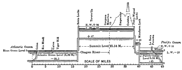
PROFILE OF PANAMA ROUTE
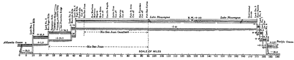
PROFILE OF NICARAGUA ROUTE
Profiles of the two Canal Routes. The horizontal scales
are different, but the vertical scales are the same.
351. First Traffic along the Chagres River, and the Importance
of the Isthmian Commerce.—As early as 1534, or soon after that date,
boats began to pass up and down the Chagres River between Cruces and
its mouth on the Caribbean shore, and thence along the coast to Nombre
de Dios and subsequently to Porto Bello. The importance of the commerce
which sprang up across the isthmus and in connection with this isthmian
route is well set forth in the last paragraph on page 28 of the report
of the Isthmian Canal Commission:
“The commerce of the isthmus increased during the century and Panama
became a place of great mercantile importance, with a profitable trade
extending to the Spice Islands and the Asiatic coast. It was at the
height of its prosperity in 1585, and was called with good reason
the toll-gate between western Europe and eastern Asia. Meanwhile the
commerce whose tolls only brought such benefits to Panama enriched
Spain, and her people were generously rewarded for the aid given by
Ferdinand and Isabella in the effort to open a direct route westward to
Cathay, notwithstanding the disadvantages of the isthmian transit.”
352. First Survey for Isthmian Canal Ordered in 1520.—This
commercial prosperity suggested to those interested in it, and soon
after its beginning, the possibility of a ship-canal to connect the
waters of the two oceans. It is stated even that Charles V. directed
that a survey should be made for the purpose of determining the
feasibility of such a work as early as 1520. “The governor, Pascual
Andagoya, reported that such a work was impracticable and that no
king, however powerful he might be, was capable of forming a junction
of the two seas or of furnishing the means of carrying out such an
undertaking.”
353. Old Panama Sacked by Morgan and the Present City
Founded.—From that time on the city of Panama increased in wealth
and population in consequence of its commercial importance. Trade was
established with the west coast of South America and with the ports on
the Pacific coast of Central America. In spite of the fact that it was
made by the Spaniards a fortress second in strength in America only to
old Cartagena, it was sacked and burned by Morgan’s buccaneers in
February, 1671. The new city, that is the present city, was founded in
1673, it not being considered advisable to rebuild on the old site.
View of the Harbor of Colon.
354. The Beginnings of the French Enterprise.—The project
of a canal on this route was kept alive for more than three centuries
by agitation sometimes active and sometimes apparently dying out for
long periods, until there was organized in Paris, in 1876, a company
entitled “Société Civile Internationale du Canal Interocéanique,” with
Gen. Etienne Türr as president, for the purpose of making surveys and
explorations for a ship-canal between the two oceans on this route.
355. The Wyse Concession and International Congress of
1879.—The work on the isthmus for this company was prosecuted
under the direction of Lieut. L. N. B. Wyse, a French naval officer,
and he obtained for his company in 1878 a concession from the Colombian
Government, conferring the requisite rights and privileges for the
construction of a ship-canal on the Panama route and the authority to
do such other things as might be necessary or advisable in connection
with that project. This concession is ordinarily known as the Wyse
concession.
A general plan for this transisthmian canal was the subject of
consideration at an international scientific congress convened in Paris
in May, 1879, and composed of 135 delegates from France, Germany, Great
Britain, the United States, and other countries, but the majority of
whom were French. This congress was convened under the auspices of
Ferdinand de Lesseps, and after remaining in session for two weeks a
decision, not unanimous, was reached that an international canal ought
to be located on the Panama route, and that it should be a sea-level
canal without locks. The fact was apparently overlooked that the range
between high and low tides in the Bay of Panama, about 20 feet, was so
great as to require a tidal lock at that terminus.
356. The Plan without Locks of the Old Panama Canal Company.—A
company entitled “Compagnie Universelle du Canal Interocéanique”
was organized, with Ferdinand de Lesseps as president, immediately
after the adjournment of the international congress. The purpose of
this company was the construction and operation of the canal, and it
purchased the Wyse concession from the original company for the sum
of 10,000,000 francs. An immediate but unsuccessful attempt was made
to finance the company in August, 1879. This necessitated a second
attempt, which was made in December, 1880, with success, as the entire
issue of 600,000 shares of 500 francs each was sold. Two years were
then devoted to examinations and surveys and preliminary work upon the
canal, but it was 1883 before operations upon a large scale were begun.
The plan adopted and followed by this company was that of a sea-level
canal, affording a depth of 29.5 feet and a bottom width of 72 feet. It
was estimated that the necessary excavation would amount to 157,000,000
cubic yards.
The Atlantic terminus of this canal route was located at Colon, and
at Panama on the Pacific side. The line passed through the low grounds
just north of Monkey Hill to Gatun, 6 miles from the Atlantic terminus,
and where it first met the Chagres River. For a distance of 21 miles
it followed the general course of the Chagres to Obispo, but left it
at the latter point and passing up the valley of a small tributary
cut through the continental divide at Culebra, and descended thence
by the valley of the Rio Grande to the mouth of that river where it
enters Panama Bay. The total length of this line from 30 feet depth
in the Atlantic to the same depth in the Pacific was about 47 miles.
The maximum height of the continental divide on the centre line of the
canal in the Culebra cut was about 333 feet above the sea, which is a
little higher than the lowest point of the divide in that vicinity.
Important considerations in connection with the adjacent alignment made
it advisable to cut the divide at a point not its lowest.
Old Dredges near Colon.
357. The Control of the Floods in the Chagres.—Various
schemes were proposed for the purpose of controlling the floods of the Chagres
River, the suddenness and magnitude of which were at once recognized as
among the greatest difficulties to be encountered in the construction
of the work. Although it was seriously proposed at one time to control
this difficulty by building a dam across the Chagres at Gamboa, that
plan was never adopted, and the problem of control of the Chagres
floods remained unsolved for a long period.
358. Estimate of Time and Cost—Appointment of Liquidators.—It
was estimated by de Lesseps in 1880 that eight years would be
required for the completion of the canal, and that its cost would be
$127,600,000. The company prosecuted its work with activity until the
latter part of 1887, when it became evident that the sea-level plan of
canal was not feasible with the resources at its command. Changes were
soon made in the plans, and it was concluded to expedite the completion
of the canal by the introduction of locks, deferring the change to a
sea-level canal until some period when conditions would be sufficiently
favorable to enable the company to attain that end. Work was prosecuted
under this modified plan until 1889, when the company became bankrupt
and was dissolved by judgment of the French court called the Tribunal
Civil de la Seine, on February 4, 1889. An officer, called the
liquidator, corresponding quite closely to a receiver in this country,
was appointed by the court to take charge of the company’s affairs.
At no time was the project of completing the canal abandoned, but the
liquidator gradually curtailed operations and finally suspended the
work on May 15, 1889.
359. The “Commission d’Etude.”—He determined to take
into careful consideration the feasibility of the project, and to that
end appointed a “commission d’études,” composed of eleven French and
foreign engineers, headed by Inspector-General Guillemain, director
of the Ecole Nationale des Ponts et Chaussées. This commission
visited the isthmus and made a careful study of the entire enterprise,
and subsequently submitted a plan for the canal involving locks. The
cost of completing the entire work was estimated to be $112,500,000,
but the sum of $62,100,000 more was added to cover administration and
financing, making a total of $174,600,000. This commission also gave
an approximate estimate of the value of the work done and of the plant
at $87,300,000, to which some have attached much more importance than
did the commission itself. The latter appears simply to have made the
“estimate” one half of the total cost of completing the work added to
that of financing and administration, as a loose approximation, calling
it an “intuitive estimate”; in other words, it was simply a guess based
upon such information as had been gained in connection with the work
done on the isthmus.
The Partially Completed Panama Canal,
about eight miles from Colon.
360. Extensions of Time for Completion.—By this time the
period specified for completion under the original Wyse concession had nearly
expired. The liquidator then sought from the Colombian Government an
extension of ten years, which was granted under the Colombian law dated
December 26, 1890. This extension was based upon the provision that a
new company should be formed and work on the canal resumed not later
than February 28, 1893. The latter condition was not fulfilled, and a
second extension was obtained on April 4, 1893, which provided that the
ten-year extension of time granted in 1890 might begin to run at any
time prior to October 31, 1894, but not later than that date. When it
became apparent that the provisions of this last extension would not
be carried out an agreement between the Colombian Government and the
new Panama Company was entered into on April 26, 1900, which extended
the time of completion to October 31, 1910. The validity of this last
extension of time has been questioned.
361. Organization of the New Panama Canal Company, 1894.—A
new company, commonly known as the new Panama Canal Company, was organized
on the 20th of October, 1894, with a capital stock of 650,000 shares
of 100 francs each. Under the provisions of the agreement of December
26, 1890, authorizing an extension of time for the construction of
the canal, 50,000 shares passed as full-paid stock to the Colombian
Government, leaving the actual working capital of the new Panama
Company at 60,000,000 francs, that amount having been subscribed in
cash. The most of this capital stock was subscribed for by certain
loan associations, administrator, contractors, and others against whom
suits had been brought in consequence of the financial difficulties
of the old company, it having been charged in the scandals attending
bankruptcy proceedings that they had profited illegally. Those suits
were discontinued under agreements to subscribe by the parties
interested to the capital stock of the new company. The sums thus
obtained constituted more than two thirds of the 60,000,000 francs
remaining of the share capital of the new company after the Colombian
Government received its 50,000 shares. The old company had raised by
the sale of stock and bond not far from $246,000,000, and the number
of persons holding the securities thus sold has been estimated at over
200,000.
362. Priority of the Panama Railroad Concession.—The
Panama Railroad Company holds a concession from the Colombian Government
giving it rights prior to those of the Wyse concession, so that the
latter could not become effective without the concurrence of the Panama
Railroad Company. This is shown by the language of Article III of the
Wyse concession, which reads as follows:
“If the line of the canal to be constructed from sea to sea should pass
to the west and to the north of the imaginary straight line which joins
Cape Tiburon with Garachine Point, the grantees must enter into some
amicable arrangement with the Panama Railroad Company or pay an
indemnity, which shall be established in accordance with the provisions
of Law 46 of August 16, 1867, ‘approving the contract celebration on
July 5, 1867, reformatory of the contract of April 15, 1850, for the
construction of an iron railroad from one ocean to the other through
the Isthmus of Panama.’” It became necessary, therefore, in order to
control this feature of the situation, for the old Panama Company
to secure at least a majority of the stock of the Panama Railroad
Company. As a matter of fact the old Panama Canal Company purchased
nearly 69,000 out of the 70,000 shares of the Panama Railroad
Company, each such share having a par value of $100. These shares of
Panama railroad stock are now held in trust for the benefit of the new
Panama Canal Company. A part of the expenditures of the old company
therefore covered the cost of the Panama Railroad Company’s shares, now
held in trust for the benefit of the new company.
363. Resumption of Work by the New Company—The Engineering
Commission and the Comité Technique.—Immediately after its
organization the new Panama Canal Company resumed the work of
excavation in the Emperador and Culebra cuts with a force of men
which has been reported as varying between 1900 and 3600. It also
gave thorough consideration to the subject of the best plan for the
completion of the canal. The company’s charter provided for the
appointment of a special engineering commission of five members by
the company and the liquidator to report upon the work done and the
conclusions to be drawn from its study. This report was to be rendered
when the amount expended by the new company should reach about one half
of its capital. At the same time the company also appointed a “Comité
Technique,” constituted of fourteen eminent European and American
engineers, to make a study of the entire project, which was to avail
itself of existing data and the results of such other additional
surveys and examinations as it might consider necessary. The report
rendered by this committee was elaborate, and it was made November 16,
1898. It was referred to the statutory commission of five to which
reference has already been made, which commission reported in 1899 that
the canal could be constructed within the limits of time and money
estimated. On December 30, 1899, a special meeting of the stockholders
of the new company was called, but the liquidator, who was one of the
largest stockholders, declined to take part in it, and the report
consequently has not received the required statutory consideration.
The Excavation at the Bohio Lock Site.
364. Plan of the New Company.—The plan adopted by the
company placed the minimum elevation of the summit level of the canal at 97½
feet above the sea, and a maximum at 102½ feet above the same datum.
It provided for a depth of 29½ feet of water and a bottom width of
canal prism of about 98 feet, except at special places where this width
was increased. A dam was to be built near Bohio, which would thus form
an artificial lake with its surface varying from 52.5 to 65.6 feet
above the sea. Under this plan there would be a flight of two locks at
Bohio, about 16 miles from the Atlantic end of the canal, and another
flight of two locks at Obispo about 14 miles from Bohio, thus reaching
the summit level, a single lock at Paraiso, between 6 and 7 miles from
Obispo, a flight of two locks at Pedro Miguel about 1.25 miles from
Paraiso, and finally a single lock at Miraflores, a mile and a quarter
from Pedro Miguel, bringing the canal down to the ocean elevation.
The location of this line was practically the same as that of the
old company. The available length of each lock-chamber was 738 feet,
while the available width was 82 feet, the depth in the clear being
32 feet 10 inches. The lifts were to vary from 26 to 33 feet. It was
estimated that the cost of finishing the canal on this plan would be
$101,850,000, exclusive of administration and financing.
In order to control the floods of the Chagres River, and to furnish a
supply of water for the summit level of the canal, a dam was planned to
be built at a point called Alhajuela, about 12 miles from Obispo, from
which a feeder about 10 miles long, partly an open canal and partly in
tunnels or pipe, would conduct the water from the reservoir thus formed
to the summit level.
365. Alternative Plan of the New Panama Canal Company.—Although
the plan as described was adopted, the “Comité Technique” apparently
favored a modification by which a much deeper excavation through
Culebra Hill would be made, thus omitting the locks at both Obispo and
Paraiso, and making the level of the artificial Lake Bohio the summit
level of the canal. In this modified plan the bottom of the summit
level would be about 32 feet above the sea, and the minimum elevation
of the summit level 61.5 feet above the sea. This modification of plan
had the material advantage of eliminating both the Obispo and Paraiso
locks. The total estimated cost of completing the canal under this plan
was about $105,500,000. Although the Alhajuela feeder would be omitted,
the Alhajuela reservoir would be retained as an agent for controlling
the Chagres floods and to form a reserve water-supply. The difference
in cost of these two plans was comparatively small, but the additional
time required to complete that with the lower summit level was probably
one of the main considerations in its rejection by the committee having
it under consideration.
366. The Isthmian Canal Commission and its Work.—This
brings the project up to the time when the Isthmian Canal Commission was
created in 1899 and when the forces of the new Panama Canal Company
were employed either in taking care of the enormous amount of plant
bequeathed to it by the old company or in the great excavation at
Emperador and Culebra. The total excavation of all classes, made up to
the time when that commission rendered its report, amounted to about
77,000,000 cubic yards.
The work of the commission consisted of a comprehensive and detailed
examination of the entire project and all its accessories, as
contemplated by the new Panama Canal Company, and any modifications of
its plans, either as to alignment, elevations, or subsidiary works,
which it might determine advisable to recommend. In the execution of
this work it was necessary, among other things, to send engineering
parties on the line of the Panama route for the purpose of making
surveys and examinations necessary to confirm estimates of the new
Panama Canal Company as to quantities, elevations, or other physical
features of the line selected, or required in modifications of
alignment or plans. In order to accomplish this portion of its work the
commission placed five working parties on the Panama route with twenty
engineers and other assistants and forty-one laborers.
The French Location for the Bohio Dam.
367. The Route of the Isthmian Canal Commission that of
the New Panama Canal Company.—The commission adopted for the purposes
of its plans and estimates the route selected by the new Panama Canal
Company, which is essentially that of the old company. Starting from
the 6-fathom contour in the harbor of Colon, the line follows the low
marshy ground adjoining the Bay of Limon to its intersection with the
Mindi River; thence through the low ground continuing to Gatun, about
6 miles from Colon, where it first meets the Chagres River. From this
point to Obispo the canal line follows practically the general course
of the Chagres River, although at one point in the marshes below Bohio
it is nearly 2 miles from the farthest bend in the river, at a small
place called Ahorca Lagarto. Bohio is about 17 miles from the Atlantic
terminus, and Obispo about 30 miles. At the latter point the course of
the Chagres River, passing up-stream, lies to the northeast, while the
general direction of the canal line is southeast toward Panama, the
latter leaving the former at this location. The canal route follows up
the general course of a small stream called the Camacho for a distance
of nearly 5 miles where the continental divide is found, and in which
the great Culebra cut is located, about 36 miles from Colon and 13
miles from the Panama terminus. After passing through the Culebra cut
the canal route follows the course of the Rio Grande River to its mouth
at Panama Bay. The mouth of the Rio Grande, where the canal line is
located, is about a mile and a half westerly of the city of Panama. The
Rio Grande is a small, sluggish stream throughout the last 6 miles of
its course, and for that distance the canal excavation would be made
mostly in soft silt or mud.
Although the line selected by the French company is that adopted by
the Isthmian Canal Company for its purposes, a number of most important
features of the general plan have been materially modified by the
commission, as will be easily understood from what has already been
stated in connection with the French plans.
368. Plan for a Sea-level Canal.—The feasibility of
a sea-level canal, but with a tidal lock at the Panama end, was carefully
considered by the commission, and an approximate estimate of the
cost of completing the work on that plan was made. In round numbers
this estimated cost was about $250,000,000, and the time required to
complete the work would probably be nearly or quite twice that needed
for the construction of a canal with locks. The commission therefore
adopted a project for the canal with locks. Both plans and estimates
were carefully developed in accordance therewith.
369. Colon Harbor and Canal Entrance.—The harbor
of Colon has been fairly satisfactory for the commerce of that port, but
it is open to the north, and there are probably two or three days in
every year during which northers blow into the harbor with such
intensity that ships anchored there must put to sea in order to escape
damage. The western limit of this harbor is an artificial point of
land formed by material deposited by the old Panama Canal Company;
it is called Christoph Colon, and near its extreme end are two large
frame residences built for de Lesseps. The entrance to the canal is
immediately south of this artificial point. The commission projected a
canal entrance from the 6-fathom contour in the Bay of Limon, in which
the harbor of Colon is found, swinging on a gentle curve, 6560 feet
radius, to the left around behind the artificial point just mentioned
and then across the shore line to the right into the lowland southerly
of Colon. This channel has a width of 500 feet at the bottom, with side
slopes of 1 on 3, except on the second curve, which is somewhat sharper
than the first, where the bottom width is made 800 feet for a length
of 800 feet for the purpose of a turning-basin. This brings the line
into the canal proper, forming a well-protected harbor for nearly a
mile inside of the shore line. The distance from the 6-fathom line to
this interior harbor is about 2 miles. The total cost of constructing
the channel into the harbor and the harbor itself is $8,057,707, and
the annual cost of maintenance is placed at $30,000. The harbor would
be perfectly protected from the northers which occasionally blow with
such intensity in the Bay of Limon, and it could readily be made in all
weathers by vessels seeking it.
370. Panama Harbor and Entrance to Canal.—The harbor
at the Pacific end of the channel where it joins Panama Bay is of an entirely
different character in some respects. The Bay of Panama is a place
of light winds. Indeed it has been asserted that the difficulties
sometimes experienced by sailing-vessels in finding wind enough to
take them out of Panama Bay are so serious as to constitute a material
objection to the location for a ship-canal on the Panama route. This
difficulty undoubtedly exists at times, but the simple fact is to be
remembered that Panama was a port for sailing-ships for more than two
hundred years before a steamship was known. The harbor of Panama, as
it now exists, is a large area of water at the extreme northern limit
of the bay, immediately adjacent to the city of Panama, protected from
the south by the three islands of Perico, Naos, and Culebra. It has
been called a roadstead. There is good anchorage for heavy-draft ships,
but for the most part the water is shallow. With the commission’s
requirement of a minimum depth of water of 35 feet, a channel about 4
miles long from the mouth of the Rio Grande to the 6-fathom line in
Panama Bay must be excavated. This channel would have a bottom width
of 200 feet with side slopes of 1 on 3 where the material is soft.
Considerable rock would have to be excavated in this channel. At 4.41
miles from the 6-fathom line is located a wharf at the point called La
Boca. A branch of the Panama Railroad Company runs to this wharf, and
at the present time deep-draft ships lie up alongside of it to take on
and discharge cargo. The wharf is a steel frame structure, founded upon
steel cylinders, carried down to bed-rock by the pneumatic process. Its
cost was about $1,284,000. The total cost of the excavated channel
leading from Panama harbor to the pier at La Boca is estimated by the
commission at $1,464,513. As the harbor at Panama is considered an open
roadstead, it requires no estimate for annual cost of maintenance.
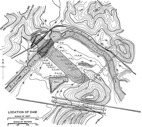
The Bohio Dam Site.
371. The Route from Colon to Bohio.—Starting from the
harbor of Colon, the prism of the canal is excavated through the low and for
the most part marshy ground to the little village called Bohio. The prism
would cut the Chagres River at a number of points, and would require a
diversion-channel for that river for a distance of about 5 miles on the
westerly side of the canal. Levees, or protective embankments, would
also be required on the same side of the canal between Bohio and Gatun,
the Chagres River leaving the canal line at the latter point on its way
to the sea.
372. The Bohio Dam.—The principal engineering feature
of the entire route is found at Bohio; it is the great dam across
the Chagres River at that point, forming Lake Bohio, the summit level of
the canal. The new Panama Canal Company located this dam at a point
about 17 miles from Colon, and designed to make it an earth structure
suitably paved on its faces, but without any other masonry feature.
Some borings had been made along the site, and test-pits were also dug
by the French engineers. It was the conviction of the Isthmian Canal
Commission, however, that the character of the proposed dam might be
affected by a further examination of the subsurface material at the
site. Consequently the boring parties of the Commission sunk a large
number of bore-holes at six different sections or possible sites
along the river in the vicinity of the French location. These borings
revealed great irregularity in the character and disposition of the
material below the bed and banks of the river. In some places the
upper stratum of material was almost clear clay, and in other places
clear sand, while all degrees of admixture of clay and sand were also
found. At the French site the bed-rock at the deepest point
is 143 feet below sea-level, with large masses of pervious and semi-pervious sand,
gravel, and mixtures of those materials with clay. Apparently there is
a geological valley in the rock along the general course of the Chagres
River in this vicinity filled with sand, gravel, and clay, irregularly
distributed and with all degrees of admixture, large masses in all
cases being of open texture and pervious to water. The site adopted by
the commission for the purposes of its plans and estimates is located
nearly half a mile down the course of the river from that selected by
the new Panama Canal Company. The geological valley is nearly 2000 feet
wide at this location, but the deepest rock disclosed by the borings
of the commission is but 128 feet below sea-level. The actual channel
of the river is not more than 150 feet wide and lies on the extreme
easterly side of the valley. The easterly or right bank of the river at
this place is clean rock and rises abruptly to an elevation of about 40
feet above the river surface at ordinary stages. The left or westerly
bank of the river is compacted clay and sand, and rises equally as
abruptly as the rocky bank of the other side, and to about the same
elevation. From the top of the abrupt sandy clay bank a plateau of
rather remarkable uniformity of elevation extends for about 1200 feet
in a southwesterly direction to the rocky hill in which the Bohio
locks would be located. The rock slope on the easterly or northerly
bank of the river runs down under the sandy river-bed, but at such an
inclination that within the limits of the channel the deepest rock is
less than 100 feet below sea-level.
After the completion of all its examinations and after a careful study
of the data disclosed by them, the commission deemed it advisable to
plan such a dam as would cut off absolutely all possible subsurface
flow or seepage through the sand and gravel below the river surface.
It is to be observed that such a subsurface flow might either disturb
the stability of an earth dam or endanger the water-supply of the
summit level of the canal or both. The plan of dam finally adopted
by the commission for the purposes of its estimates is shown by the
accompanying plans and sections. A heavy core-wall of concrete masonry
extends from bed-rock across the entire geological valley to the top
of the structure, or to an elevation of 100 feet above sea-level, thus
absolutely closing the entire valley against any possible flow. The
thickness of this wall at the bottom is 30 feet, but at an elevation
of 30 feet below sea-level its sides begin to batter at such a rate as
to make the thickness of the wall 8 feet at its top. On either side of
this wall are heavy masses of earth embankment of selected material
properly deposited in layers with surface slopes of 1 on 3. As shown
by the plans, the lower portions of the core-wall of this dam would
be sunk to bed-rock by the pneumatic process, the joints between the
caissons being closed and sealed by cylinders sunk in recesses or
wells, also as shown by the plans.
373. Variation in Surface Elevation of Lake.—The profile
of this route shows that the summit level would have an ordinary elevation
of 85 feet above the sea, but it may be drawn down for uses of the
canal to a minimum elevation of 82 feet above the same datum. On the
other hand, under circumstances to be discussed later, it may rise
during the floods of the Chagres to an elevation of 90 or possibly 91
or 92 feet above the level of the sea. The top of the dam therefore
would be from 8 to 10 feet above the highest possible water surface
in the lake, which is sufficient to guard against wash or overtopping
of the dam by waves. The total width of the dam at its top would be
20 feet, and the entire inner slope would be paved with heavy riprap
suitably placed and bedded.
374. Extent of Lake Bohio and the Canal Line in It.—This
dam would create an artificial lake having a superficial area during high
water of about 40 square miles. The water would be backed up to a point
called Alhajuela, about 25 miles up the river from Bohio.
For a distance of nearly 14 miles, i.e., from Bohio to Obispo, the route of
the canal would lie in this lake. Although the water would be from 80
to 90 feet deep at the dam for several miles below Obispo, it would
be necessary to make some excavation along the general course of
the Chagres in order to secure the minimum depth of 35 feet for the
navigable channel.
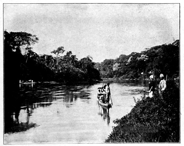
Location of the Proposed Alhajuela Dam on the Upper Chagres.
375. The Floods of the Chagres.—The feature of Lake
Bohio of the greatest importance to the safe and convenient operation of
the canal is that by which the floods of the river Chagres are controlled
or regulated. That river is but little less than 150 miles long, and
its drainage area as nearly as can be estimated, contains about 875
square miles. Above Bohio its current moves some sand and a little silt
in times of flood, but usually it is a clear-water stream. In low water
its discharge may fall to 350 cubic feet per second.
As is well known, the floods of the Chagres have at times been regarded
as almost if not quite insurmountable obstacles to the construction
of a canal on this line. The greatest flood of which there is any
semblance of a reliable record is one which occurred in 1879. No direct
measurements were made, but it is stated with apparent authority that
the flood elevation at Bohio was 39.3 feet above low water. If the
total channel through which the flood flowed at that time had been as
large as at present, actual gaugings or measurements of subsequent
floods show that the maximum discharge in 1879 might have been at the
rate of 136,000 cubic feet per second. As a matter of fact the total
channel section in that year was less than it is at the present time.
Hence if it be assumed that a flood of 140,000 cubic feet per second
must be controlled, an error on the safe side will be committed.
Other great floods of which there are reliable records are as follows:
| 1885 |
Height |
at |
Bohio |
33.8 |
feet |
above |
low |
water. |
| 1888: |
” |
” |
” |
34.7 |
” |
” |
” |
” |
| 1890: |
” |
” |
” |
32.1 |
” |
” |
” |
” |
| 1893: |
” |
” |
” |
28.5 |
” |
” |
” |
” |
The maximum measured rate of the 1890 flood was 74,998 cubic feet per
second, and that of 1893, 48,975 cubic feet per second. It is clear,
therefore, that a flood-flow of 75,000 cubic feet per second is very
rare, and that a flood of 140,000 cubic feet per second exceeds that of
which we have any record for practically forty years.
376. The Gigante Spillway or Waste-weir.—It is obvious
that the dam, as designed by the commission, is of such character that no
water must be permitted to flow over its crest, or even in immediate
proximity to the down-stream embankment. Indeed it is not intended by
the commission that there shall be any wasteway or discharge anywhere
near the dam. At a point about 3 miles southwest of the site of
the dam at Bohio is a low saddle or notch in the hills near the head-waters of
a small stream called the Gigante River. The elevation of this saddle
or notch is such that a solid masonry weir with a crest 2000 feet long
may readily be constructed with its foundations on bed-rock without
deep excavation. This structure is called the Gigante spillway, and
all surplus flood-waters from the Chagres would flow over it. The
waters discharged would flow down to and through some large marshes,
one called Peña Blanca and another Agua Clara, before rejoining the
Chagres. Inasmuch as the canal line runs just easterly of those
marshes, it would be necessary to protect it with the levees or
embankments to which allusion has already been made. These embankments
are neither much extended nor very costly for such a project. The
protection of the canal would be further aided by a short artificial
channel between the two marshes, Peña Blanca and Agua Clara, for which
provision is made in the estimates of the commission. After the surplus
waters from the Gigante spillway pass these marshes they again enter
the Chagres River or flow over the low, half-submerged country along
its borders, and thence through its mouth to the sea near the town of
Chagres, about 6 miles northwest of Gatun.
377. Storage in Lake Bohio for Driest Dry Season.—The
masonry crest of the Gigante spillway would be placed at an elevation of
85 feet above the sea, identically the same as that which may be called
the normal summit level of the canal. It is estimated that the total
uses of water in the canal added to the loss by evaporation, taken
at six inches in depth per month, from the surface of the lake will
amount to about 1070 cubic feet per second if the traffic through the
canal should amount to 10,000,000 tons per annum in ships of ordinary
size. This draft per second is the sum of 406 cubic feet per second
for lockage, 207 for evaporation, 250 for leakage at lock-gates, and
200 for power and other purposes, making a total of 1063, which has
been taken as 1070 cubic feet per second. The amount of storage in Lake
Bohio between the elevations of 85 and 82 feet above sea-level, as
designed, is sufficient to supply the needs of that traffic in excess
of the smallest recorded low-water flow of the Chagres River during the
dry season of a low rainfall year. The lowest monthly average flow of
the Chagres on record at Bohio is 600 cubic feet per second for March,
1891, and for the purposes of this computation that minimum flow has
been supposed to continue for three months. This includes a sensible
margin of safety. In not even the driest year, therefore, can it be
reasonably expected that the summit level of the canal would fall below
the elevation of 82 feet until the total traffic of the canal carried
in ships of the present ordinary size shall exceed 10,000,000 tons.
If the average size of ships continues to increase, as will probably
be the case, less water in proportion to tonnage will be required for
the purposes of lockage. This follows from the fact that with a given
tonnage the greater the capacity of the ships the less the number
required, and consequently the less will be the number of lockages made.
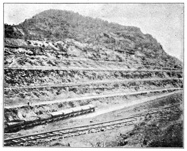
The Eastern Face of the Culebra Cut.
378. Lake Bohio as a Flood controller.—On the other
hand it can be shown that with a depth of 5 feet of water on the crest of
the Gigante spillway the discharge of that weir 2000 feet long will be at
the rate of 78,260 cubic feet per second. If the flood-waters of the
Chagres should flow into Lake Bohio until the head of water on the
crest of the Gigante weir rises to 7½ feet, the rate of discharge over
that weir would be 140,000 cubic feet per second, which, as already
shown, exceeds at least by a little the highest flood-rate on record.
The operation of Lake Bohio as a flood controller or regulator is
therefore exceedingly simple. The flood-waters of the Chagres would
pour into the lake and immediately begin to flow over the Gigante weir,
and continue to do so at an increasing rate as the flood continues.
The discharge of the weir is augmented by the increasing flood, and
decreases only after the passage of the crest of the flood-wave. No
flood even as great as the greatest supposable flood on record can
increase the elevation of the lake more than 92 to 92½ feet above
sea-level, and it will only be at long intervals of time when floods
will raise that elevation more than about 90 feet above sea-level. The
control is automatic and unfailingly certain. It prevents absolutely
any damage from the highest supposable floods of the Chagres, and
reserves in Lake Bohio all that is required for the purposes of the
canal and for wastage by evaporation through the lowest rainfall
season. The floods of the Chagres, therefore, instead of constituting
the obstacle to construction and convenient maintenance of the canal
heretofore supposed, are deprived of all their prejudicial effects and
transformed into beneficial agents for the operation of the waterway.
379. Effect of Highest Floods on Current in Channel in
Lake Bohio.—The highest floods are of short duration, and it can
be stated as a general law that the higher the flood the shorter
its duration. The great floods which it is necessary to consider in
connection with the maintenance and operation of this canal would last
but a comparatively few hours only. The great flood-flow of 140,000
cubic feet per second would increase the current in the narrowest part
of the canal below Obispo to possibly 5 feet per second for a few
hours only, but that is the only inconvenience which would result from
such a flood discharge. That velocity could be reduced by additional
excavation.
380. Alhajuela Reservoir not Needed at Opening of
Canal.—Inasmuch as this system of control, devised and adopted by
the Isthmian Canal Commission, is completely effective in regulating
the Chagres floods; the reservoir proposed to be constructed by the new
Panama Canal Company at Alhajuela on the Chagres about 11 miles above
Obispo is not required, and the cost of its construction would be
avoided. It could, however, as a project be held in reserve. If the
traffic of the canal should increase to such an extent that more water
would be needed for feeding the summit level, the dam could be built at
Alhajuela so as to impound enough additional water to accommodate, with
that stored in Lake Bohio, at least five times the 10,000,000 annual
traffic already considered. Its existence would at the same time act
with substantial effect in controlling the Chagres floods and relieve
the Gigante spillway of a corresponding amount of duty.
381. Locks on Panama Route.—The locks on the Panama
route are designed to have the same dimensions as those in Nicaragua, as
was stated in the lecture on that route. The usable length is 740 feet
and the clear width 84 feet. They would be built chiefly of concrete
masonry, while the gates would be of steel and of the mitre type.
382. The Bohio Locks.—The great dam at Bohio raises
the water surface in the canal from sea-level in the Atlantic maritime
section to an ordinary maximum of 90 feet above sea-level; in other words,
the maximum ordinary total lift would be 90 feet. This total lift is
divided into two parts of 45 feet each. There is therefore a flight
of two locks at Bohio; indeed there are two flights side by side, as
the twin arrangement is designed to be used at all lock sites on both
routes. The typical dimensions and arrangements of these locks, with
the requisite culverts and other features, are shown in the plans and
sections between pages 396 and 397, Part V. They
are not essentially different from other great modern ship-canal locks.
The excavation for the Bohio locks is made in a rocky hill against
which the southwesterly end of the proposed Bohio dam rests, and they
are less than 1000 feet from it.
383. The Pedro Miguel and Miraflores Locks.—After
leaving Bohio Lake at Obispo a flight of two locks is found at Pedro Miguel,
about 7.9 miles from the former or 21½ miles from Bohio. These locks have a
total ordinary maximum lift of 60 feet, divided into two lifts of 30
feet each. The fifth and last lock on the route is at Miraflores. The
average elevation of water between Pedro Miguel and Miraflores is 30
feet above mean sea-level. Inasmuch as the range of tide between high
and low in Panama Bay is about 20 feet, the maximum lift at Miraflores
is 40 feet and the minimum about 20. The twin locks at Miraflores bring
the canal surface down to the Pacific Ocean level, the distance from
those locks to the 6-fathom curve in Panama Bay being 8.54 miles. There
are therefore five locks on the Panama route, all arranged on the twin
plan, and, as on the Nicaragua route, all are founded on rock.
384. Guard-gates near Obispo.—Near Obispo a pair of
guard-gates are arranged “so that if it should become necessary to draw
off the water from the summit cut the level of Lake Bohio would not be
affected.”
385. Character and Stability of the Culebra Cut.—An
unprecedented concentration of heavy cutting is found between
Obispo and Pedro Miguel. This is practically one cut, although the
northwesterly end toward Obispo is called the Emperador, while the
deepest part at the other end, about 3 miles from Pedro Miguel, is the
great Culebra cut with a maximum depth on the centre line
of the canal of 286 ft. On page 93 of the Isthmian Canal Commission’s report is the
following reference to the material in this cut: “There is a little
very hard rock at the eastern end of this section, and
the western 2 miles are in ordinary materials. The remainder consists of a hard
indurated clay, with some softer material at the top and some strata
and dikes of hard rock. In fixing the price it has been rated as soft
rock, but it must be given slopes equivalent to those in earth. This
cut has been estimated on the basis of a bottom width of 150 feet,
with side slopes of 1 on 1.” When the old Panama Canal Company began
its excavation in this cut considerable difficulty was experienced by
the slipping of the material outside of the limits of the cut into the
excavation, and the marks of that action can be seen plainly at the
present time. This experience has given an impression that much of the
material in this cut is unstable, but that impression is erroneous. The
clay which slipped in the early days of the work was not drained, and
like wet clay in numerous places in this country it slipped down into
the excavation. This material is now drained and is perfectly stable.
There is no reason to anticipate any future difficulty if reasonable
conditions of drainage are maintained. The high faces of the cut will
probably weather to some extent, although experience with such clay
faces on the isthmus indicates that the amount of such action will be
small. As a matter of fact the material in which the Culebra cut is
made is stable and will give no sensible difficulty in maintenance.
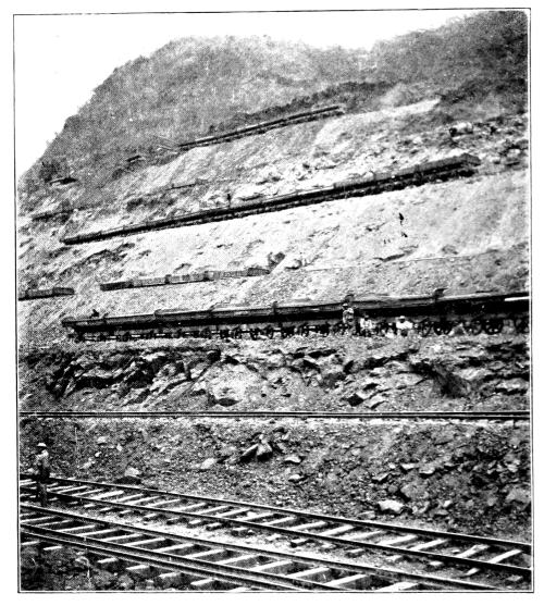
The Culebra Cut.
386. Small Diversion-channels.—Throughout the most of
the distance between Colon and Bohio on the easterly side of the canal the
French plan contemplated an excavated channel to receive a portion of
the waters of the Chagres as well as the flow of two smaller rivers,
the Gatuncillo and the Mindi, so as to conduct them into the Bay
of Manzanillo, immediately to the east of Colon. That so-called
diversion-channel was nearly completed. Under the plan of the
commission it would receive none of the Chagres flow, but it would be
available for intercepting the drainage of the high ground easterly
of the canal line and the flow of the two small rivers named, so that
these waters would not find their way into the canal. There are a few
other small works of similar character in different portions of the
line, all of which were recognized and provided for by the commission.
387. Length and Curvature.—The total length of the Panama
route from the 6-fathom curve at Colon to the same curve in Panama Bay is
49.09 miles. The general direction of the route in passing from Colon
to Panama is from northwest to southeast, the latter point being about
22 miles east of the Atlantic terminus. The depression through which
the line is laid is one of easy topography except at the continental
divide in the Culebra cut. As a consequence there is little heavy
work of excavation, as such matters go except in that cut. A further
consequence of such topography is a comparatively easy alignment, that
is, one in which the amount of curvature is not high. The smallest
radius of curvature is 3281 feet at the entrance to the inner harbor at
the Colon end of the route, and where the width is 800 feet. The radii
of the remaining curves range from 6234 feet to 19,629 feet.
The following table gives all the elements of curvature on the route
and indicates that it is not excessive:
Number of
Curves. |
Length. |
Radius. |
Total Curvature. |
| |
Miles. |
Feet. |
° |
′ |
| 1 |
0.88 |
19,629 |
14 |
17 |
| 1 |
.48 |
13,123 |
11 |
04 |
| 4 |
4.22 |
11,483 |
111 |
32 |
| 15 |
11.61 |
9,842 |
355 |
50 |
| 4 |
2.44 |
8,202 |
90 |
20 |
| 2 |
1.67 |
6,562 |
77 |
00 |
| 1 |
.73 |
6,234 |
35 |
45 |
| 1 |
.82 |
3,281 |
75 |
51 |
| |
22.85 |
|
771 |
39 |
388. Principal Items of Work to be Performed.—The principal
items of the total amount of work to be performed in completing the
Panama Canal, under the plan of the commission, can be classified as
shown in the following table:
| Dredging |
27,659,540 |
cu. yds. |
| Dry earth |
14,386,954 |
” |
| Soft rock |
39,893,235 |
” |
| Hard rock |
8,806,340 |
” |
| Rock under water |
4,891,667 |
” |
| Embankment and back-filling |
1,802,753 |
” |
| Total |
97,440,489 |
” |
| |
| Concrete |
3,762,175 |
cu. yds. |
| Granite |
13,820 |
” |
| Iron and steel |
65,248,900 |
lbs. |
| Excavation in coffer-dam |
7,260 |
cu. yds. |
| Pneumatic work |
108,410 |
” |
389. Lengths of Sections and Elements of Total Cost.—The
lengths of the various sections of this route and the costs of
completing the work upon them are fully set forth in the following
table, taken from the commission’s report, as were the two preceding:
TOTAL ESTIMATED COST.
| |
Miles. |
Cost. |
| Colon entrance and harbor |
2.39 |
$ 8,057,707 |
| Harbor to Bohio locks, including levees |
14.42 |
11,099,839 |
|
|
|
| Bohio locks, including excavation |
.35 |
11,567,275 |
| Lake Bohio |
13.61 |
2,952,154 |
| Obispo gates |
|
295,434 |
| Culebra section |
7.91 |
44,414,460 |
| Pedro Miguel locks, including excavation and dam |
.35 |
9,081,321 |
| Pedro Miguel level |
1.33 |
1,192,286 |
| Miraflores locks, including excavation and spillway |
.20 |
5,781,401 |
| Pacific level |
8.53 |
12,427,971 |
| Bohio dam |
|
6,369,640 |
| Gigante spillway |
|
1,209,419 |
| Peña Blanca outlet |
|
2,448,076 |
| Chagres diversion |
|
1,929,982 |
| Gatun diversion |
|
100,000 |
| Panama Railroad diversion |
|
1,267,500 |
| Total |
49.09 |
120,194,465 |
| Engineering, police, sanitation, and general |
|
|
| contingencies, 20 per cent. |
|
24,038,893 |
| Aggregate |
|
$144,233,358 |
The item in this table called Panama Railroad diversion affords
provision for the reconstruction of the railroad necessitated by the
formation of Lake Bohio. That lake would submerge the present location
of the railroad for 14 or 15 miles.
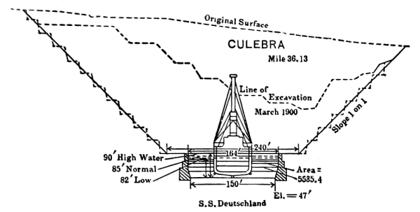
The Culebra Cut with Steamer Deutschland in it.
390. The Twenty Per Cent Allowances for Exigencies.—It
will be observed that in the estimates of cost of the canal on both
the Nicaragua and the Panama routes, 20 per cent is allowed for
“engineering, police, sanitation, and general contingencies.” For the
purposes of comparison the same percentage to cover these items was
used on both routes. As a matter of fact the large amount of work
which has already been performed on the Panama route removes many
uncertainties as to the character of material and other features of
difficulty which would be disclosed only after the beginning of the
work in Nicaragua. It has therefore been contended with considerable
basis of reason that a less percentage to cover these uncertainties
should be employed in connection with the Panama estimates than in
connection with those for the Nicaragua route. Indeed it might be
maintained that the exigencies which increase cost should be made
proportional to the length of route and the untried features. On the
other hand, both Panama and Colon are comparatively large centres
of population, and, furthermore, there is a considerable population
stretched along the line of the Panama Railroad between those points.
The climate and the unsanitary condition of practically every centre
of population in Central America and on the isthmus contribute to the
continual presence of tropical fevers, and other diseases contingent
upon the existing conditions of life. It is probable, among other
things, that yellow fever is always present on the isthmus. Inasmuch as
the Nicaragua route is practically without population, the amount of
disease existing along it is exceedingly small, there being
practically no people to be sick. The initial expenditure for the
sanitation of the cities at the extremities of the Panama route, as
well as for the country between, would be far greater for that route
than on the Nicaragua. This fact compensates, to a substantial extent
at least, for the physical uncertainties on the Nicaragua line. Indeed
a careful examination of all the conditions existing on both routes
indicates the reasonableness of applying the same 20 per cent to both
total estimates of cost.
391. Value of Plant, Property, and Rights on the Isthmus.—The
preceding estimated cost of $144,233,358 for completing the Panama
Canal must be increased by the amount necessary to be paid for all the
property and rights of the new Panama Canal Company on the isthmus. A
large amount of excavation has been performed, amounting to 77,000,000
cubic yards of all classes of materials, and nearly all the right of
way has been purchased. The new Panama Canal Company furnished the
commission with a detailed inventory of its entire properties, which
the latter classified as follows:
- 1. Lands not built on.
- 2. Buildings, 2431 in number, divided among 47 subclassifications.
- 3. Furniture and stable outfit, with 17 subclassifications.
- 4. Floating plant and spare parts, with 24 subclassifications.
- 5. Rolling plant and spare parts, with 17 subclassifications.
- 6. Plant, stationary and semi-stationary, and spare parts,
- with 25 subclassifications.
- 7. Small material and spare parts, with 4 subclassifications.
- 8. Surgical and medical outfit.
- 9. Medical stores.
- 10. Office supplies, stationery.
- 11. Miscellaneous supplies, with 740 subclassifications.
The commission did not estimate any value for the vast amount of plant
along the line of the canal, as its condition in relation to actual use
is uncertain, and the most of it would not be available for efficient
and economical execution of the work by modern American methods. Again,
a considerable amount of excavated material along some portions of the
line has been deposited in spoil-banks immediately adjacent to the
excavation from which it was taken, and would have to be rehandled in
forming the increased size of prism contemplated in the commission’s plan.
In view of all the conditions affecting it, the commission made the
following estimate of the value of the property of the new Panama Canal
Company, as it is now found on the Panama route:
| Canal excavation |
$21,020,386 |
| Chagres diversion |
178,186 |
| Gatun diversion |
1,396,456 |
| Railroad diversion (4 miles) |
300,000 |
| |
22,895,028 |
| Contingencies, 20 per cent |
4,579,005 |
| Aggregate |
27,474,033 |
| Panama Railroad stock at par |
6,850,000 |
| Maps, drawings, and records |
2,000,000 |
| |
$36,324,033 |
The commission added 10 per cent to this total “to cover omissions,
making the total valuation of the” property and rights as now existing,
$40,000,000.
In computing the value of the channel excavation in the above
tabulation it was estimated that “the total quantity of excavation
which will be of value in the new plan is 39,586,332 cubic yards.”
392. Offer of New Panama Canal Company to Sell for
$40,000,000.—In January, 1902, the new Panama Canal Company
offered to sell and transfer to the United States Government all
its property and rights on the isthmus of every description for the
estimate of the commission, viz., $40,000,000. In order to make a
proper comparison between the total costs of constructing the canal on
the two routes it is necessary to add this $40,000,000 to the preceding
aggregate of $144,233,358, making the total cost of the Panama Canal
$184,233,358. It will be remembered that the corresponding total cost
of the Nicaragua Canal would be $189,864,062.
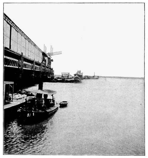
The Railroad Pier at La Boca,
the Panama
end of the Canal.
393. Annual Costs of Operation and Maintenance.—It
is obvious that the cost of operating and maintaining a ship-canal across
the American isthmus would be an annual charge of large amount. A large
organized force would be requisite, and no small amount of material and
work of various kinds and grades would be needed to maintain the works
in suitable condition. The commission made very careful and thorough
studies to ascertain as nearly as practicable what these comparative
costs would be. In doing this it gave careful consideration to the
annual expenditures made in maintaining the various ship-canals of the
world, including the Suez, Manchester, Kiel, and St. Mary’s Falls
canals. The conclusion reached was that the estimated annual costs of
maintenance and operation could reasonably be taken as follows:
| For the Nicaragua Canal |
$3,300,000 |
| For the Panama Canal |
2,000,000 |
| Difference in favor of Panama |
$1,300,000 |
394. Volcanoes and Earthquakes.—Much has been written
regarding the comparative liability to damage of canal works along these
two routes by volcanic or seismic agencies. As is well known, the entire
Central American isthmus is a volcanic region, and in
the past a considerable number of destructive volcanic eruptions have taken
place at a number of points. There is a line of live volcanoes extending
southeasterly through Nicaragua and Costa Rica. Many earthquake
shocks have occurred throughout Nicaragua, Costa Rica, and the State
of Panama, some of which have done more or less damage in large
portions of those districts. At the same time many buildings which
have been injured have not been substantially built. In fact that
has generally been the case. Both routes lie in districts that are
doubtless subject to earthquake shocks, but there is little probability
that the substantial structures of a canal along either line would be
essentially injured by them. The conclusions of the commission as to
this feature of the matter are concisely stated in three paragraphs at
the top of page 170 of its report:
“It is possible and even probable that the more accurately fitting
portions of the canal, such as the lock-gates, may at times be
distorted by earthquakes, and some inconvenience may result therefrom.
That contingency may be classed with the accidental collision of ships with
the gates, and is to be provided for in the same way, by duplicate gates.
“It is possible also that a fissure might open which would drain the
canal, and, if it remained open, might destroy it. This possibility
should not be erected by the fancy into a threatening danger. If
a timorous imagination is to be the guide, no great work can be
undertaken anywhere. This risk may be classed with that of a great
conflagration in a city like that of Chicago in 1871, or Boston in 1872.
“It is the opinion of the commission that such danger as exists from
earthquakes is essentially the same for both the Nicaragua and Panama
routes, and that in neither case is it sufficient to prevent the
construction of the canal.”
The Nicaragua route crosses the line of live volcanoes running from
northwest to southeast through Central America, and the crater of
Ometepe in Lake Nicaragua is about 11 miles only from the line. The
eruptions of Pelée and Soufriere show that such proximity of possible
volcanic action may be a source of great danger, although even the
destruction by them does not certainly indicate damage either to
navigation or to canal structures at the distance of 11 miles. Whatever
volcanic danger may exist lies on the Nicaragua route, for there is no
volcano nearer than 175 miles to the Panama route.
395. Hygienic Conditions on the Two Routes.—The relative
healthfulness of the two routes has already been touched upon. There
is undoubtedly at the present time a vast amount of unhealthfulness
on the Panama route, and practically none on the Nicaragua route, but
this is accounted for when it is remembered, as has also been stated,
that there is practically no population on the Nicaragua route and
a comparatively large population along the Panama line. There is a
wide-spread, popular impression that the Central American countries
are necessarily intensely unhealthful. This is an error, in spite of
the facts that the construction of the Panama Railroad was attended
with an appalling amount of sickness and loss of life, and that records
of many epidemics at other times and in other places exist in nearly
all of these countries. There are the best of good reasons to believe
that with the enforcement of sanitary regulations, which are now well
understood and completely available, the Central American countries
would be as healthful as our Southern States. A proper recognition of
hygienic conditions of life suitable to a tropical climate would work
wonders in Central America in reducing the death-rate. At the present
time the domestic administration of most of the cities and towns of
Nicaragua and Panama, as well as the generality of Central American
cities, is characterized by the absence of practically everything which
makes for public health, and by the presence of nearly every agency
working for the diseases which flourish in tropical climates. When
the United States Government reaches the point of actual construction
of an isthmian canal the sanitary features of that work should be
administered and enforced in every detail with the rigor of the
most exacting military discipline. Under such conditions, epidemics
could either be avoided or reduced to manageable dimensions, but
not otherwise. The commission concluded that “Existing conditions
indicate hygienic advantages for the Nicaragua route, although it is
probable that no less effective sanitary measures must be taken during
construction in the one case than in the other.”
396. Time of Passage through the Canal.—The time required
for passing through a transisthmian canal is affected by the length, by
the number of locks, by the number of curves, and by the sharpness
of curvature. The speed of a ship, and consequently the time of
passage, is also affected by the depth of water under its keel. It
is well known that the same power applied to a ship in deep water
of unlimited width will produce a much higher rate of movement than
the same power applied to the same ship in a restricted waterway,
especially when the draft of the ship is but little less than the
depth of water. These considerations have important bearings both upon
the dimensions of a ship-canal and upon the time required to pass
through it. They were most carefully considered by the commission, as
were also such other matters as the delay incurred in passing through
the locks on each line, the latter including the delay of slowing or
approaching the lock and of increasing speed after passing it, the
time of opening and closing the gates, and the time of emptying and
filling the locks. It is also evident that ships of various sizes will
require different times for their passage. After giving due weight
to all these considerations it was found that what may be called an
average ship would require twelve hours for passing through the Panama
Canal and thirty-three hours for passing through the Nicaragua Canal.
Approximately speaking, therefore, it may be stated that an average
passage through the former waterway will require but one third the time
needed for the latter.
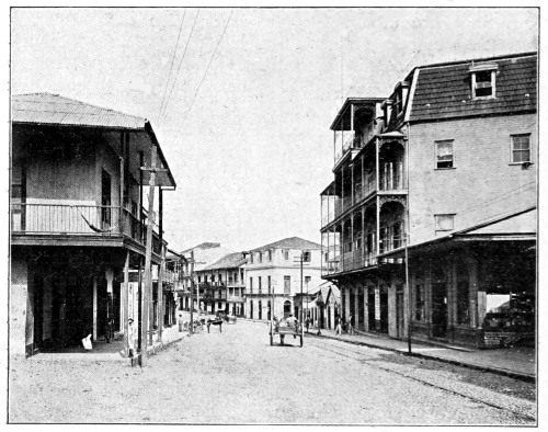
A Street in Panama.
397. Time for Completion on the Two Routes.—The time in
which an isthmian canal may be completed and ready for traffic is an element
of the problem of much importance. There are two features of the work
to be done at Panama, each of which is of sufficient magnitude to
affect to a controlling extent the time required for the construction
of the canal, viz., the Bohio dam and the Culebra cut. Both of these
portions of the work may, however, be prosecuted concurrently and with
entire independence of each other. There are no such features on the
Nicaragua route, although the cut through the divide west of the lake
is probably the largest single work on that route. In considering this
feature of the matter it is well to observe that the total amount of
excavation and embankment of all grades on the Nicaragua route is
practically 228,000,000 cubic yards, while that remaining to be done on
the Panama route is but little more than 97,000,000 cubic yards, or 43
per cent of the former. The accompanying figures show the relative
quantities of total excavation, concrete, iron, and steel required in
construction along the two routes, as well also as the total amounts
and radii of curvature.
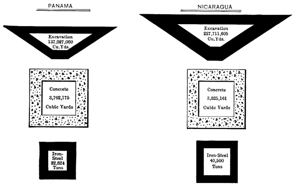
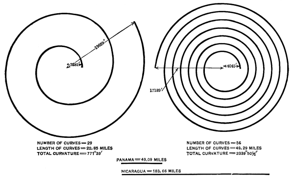
Diagrams comparing some of the main Elements
of the two Routes.
The commission has estimated ten years for the completion of the canal
on the Panama route and eight years for the Nicaragua route, including
in both cases the time required for preparation and that consumed by
unforeseen delays. The writer believes that the actual circumstances
attending work on the two routes would justify an exchange of
these time relations. There is great concentration of work in the
Culebra-Emperador cut on the Panama route, covering about 45 per cent
of the total excavation of all grades (43,000,000 cubic yards), which
is distributed over a distance of about 7 miles, with the location of
greatest intensity at Culebra. This demands efficient organization
and special plant so administered as to reduce the working force to
an absolute minimum by the employment of machinery to the greatest
possible extent. A judicious, effective organization and plant
would transform the execution of this work into what may be called
a manufactory of excavation with all the intensity of direction
and efficiency of well designed and administered machinery which
characterizes the concentration of labor and mechanical appliances in
great manufacturing establishments. Such a successful installation
would involve scarcely more advance in contract operations than was
exhibited, in its day, in the execution of the work on the Chicago
Drainage-canal. By such means only can the peculiar difficulties
attendant upon the execution of great works in the tropics be reduced
to controllable dimensions. The same general observations may be
applied to the construction of the Bohio dam, even should a no more
favorable site be found.
The greatest concentration of excavation on the Nicaragua route is
between the lake and the Pacific, but it constitutes only 10 per cent
of the total excavation of all grades, and it can be completed in far
less time than the great cut on the Panama route. If this were the
only great feature of work besides the dam, the time for completion
of work on this route would be materially less than that required for
the Panama crossing. As a matter of fact, there are a succession of
features of equivalent magnitude, or very nearly so, from Greytown
nearly to Brito, extending over a distance of at least 175 miles,
requiring the construction of a substantial service railroad over a
considerable portion of the distance prior to the beginning of work.
This attenuation of work requires the larger features to be executed in
succession to a considerable extent, or much duplication of plant and
the employment of a great force of laborers, practically all of whom
must be foreigners, housed, organized, and maintained in a practically
uninhabited tropical country where many serious difficulties reach a
maximum. It is not within the experience of civil engineers to execute
by any practicable means that kind of a programme on schedule time.
The weight of this observation is much increased when it is remembered
that the total volume of work may be taken nearly twice as great in
Nicaragua as at Panama, and that large portions between Lake Nicaragua
and the Caribbean Sea must be executed in a region of continual and
enormous rainfall. It would seem more reasonable to the writer to
estimate eight years for the completion of the Panama Canal and ten
years for the completion of the Nicaragua Canal.
398. Industrial and Commercial Value of the Canal.—The
prospective industrial and commercial value of the canal also occupied
the attention of the commission in a broad and careful study of the
elements which enter that part of the problem. It is difficult if not
impossible to predict just what the effect of a transisthmian canal
would be either upon the ocean commerce of the United States or of
other parts of the world, but it seems reasonable to suppose from the
result of the commission’s examinations that had the canal been in
existence in 1899 at least 5,000,000 tons of the actual traffic of
that year would have been accommodated by it. The opening of such a
waterway, like the opening of all other traffic routes, induces the
creation of new traffic to an extent that cannot be estimated, but it
would appear to be reasonable to suppose that within ten years from the
date of its opening the vessel tonnage using it would not be less than
10,000,000 tons.
View of Panama.
The Nicaragua route would favor in distance the traffic between our
Atlantic (including Gulf) and Pacific ports. The distances between
our Atlantic ports and San Francisco would be about 378 nautical
miles less than by Panama. Between New Orleans and San Francisco
this difference in favor of the route by Greytown and Brito would be
580 nautical miles. It must be remembered, however, that the greater
time by at least twenty-four hours required for passage through the
Nicaragua Canal practically obliterates this advantage, and in some
cases would throw the advantage in favor of the Panama waterway. This
last observation would hold with particular force if for any reason
a vessel should not continue her passage, or should continue it at a
reduced speed during hours of darkness, which could not be escaped on
the Nicaragua Canal, but might be avoided at Panama. For all traffic
between the Atlantic (including Gulf) ports and the west coast of
South America the Panama crossing would be the most advantageous. As a
matter of fact, while there may be some small advantage in miles by one
route or the other for the traffic between some particular points, on
the whole neither route would have any very great advantage over the
other in point of distance or time; either would serve efficiently the
purposes of all ocean traffic in which the ports of the United States
are directly interested.
The effect of this ship waterway upon the well-being of the United
States is not altogether of a commercial character. As indicated by
the commission, this additional bond between the two portions of the
country will have a beneficial effect upon the unity of the political
interests as well as upon the commercial welfare of the country. Indeed
it is the judgment of many well-informed people that the commercial
advantages resulting from a closer touch between the Atlantic and
Pacific coasts of the country are of less consequence than the unifying
of political interests.
In a final comparison between the two routes it is to be remembered
that the concession under which the new Panama Company has been and
is now prosecuting its work is practically valueless for the purposes
of this country. It will therefore be necessary to secure from the
republic of Colombia, for the Panama route, as well as from the
republics of Nicaragua and Costa Rica, for the Nicaragua route, such
new concessions as may be adequate for all the purposes of the United
States in the construction of this transisthmian canal. The cost of
those concessions in either case must be added to the estimated total
cost of the work, as set forth, in order to reach the total cost of the
canal along either route.
399. Comparison of Routes.—Concisely
stating the situation, its main features may be expressed somewhat as follows:
Both routes are entirely “practicable and feasible.”
Neither route has any material commercial advantage over the other as
to time, although the distance between our Atlantic (including Gulf)
and Pacific ports is less by the Nicaragua route.
The Panama route has about one fourth the length of that in Nicaragua;
it has less locks, less elevation of summit level, and far less
curvature, all contributing to correspondingly decreased risks peculiar
to the passage through a canal. The estimated annual cost of operation
and maintenance of the Panama route is but six tenths that for the
Nicaragua route.
The harbor features may be made adequate for all the needs of a canal
by either route, with such little preponderance of advantage as may
exist in favor of the Panama crossing.
The commission estimated ten years for the completion of the Panama
Canal and eight years for the Nicaragua waterway, but the writer
believes that these relations should be exchanged, or at least that the
time of completion for the Panama route should not be estimated greater
than for the Nicaragua.
The water-supply is practically unlimited on both routes, but the
controlling or regulating works, being automatic, are much simpler and
more easily operated and maintained on the Panama route.
The Nicaragua route is practically uninhabited, and consequently
practically no sickness exists there. On the Panama route, on the
contrary, there is a considerable population extending along the entire
line, among which yellow fever and other tropical diseases are probably
always found. Initial sanitary works of much larger magnitude would be
required on the Panama route than on the Nicaragua, although probably
as rigorous sanitary measures would be required during the construction
of the canal on one route as on the other.
The railroad on the Panama route and other facilities offered by a
considerable existing population render the beginning of work and the
housing and organization of the requisite labor force less difficult
and more prompt than on the Nicaragua route.
The greater amount of work on the Nicaragua route, and its distribution
over a far greater length of line, involve the employment of a
correspondingly greater force of laborers, with greater attendant
difficulties, for an equally prompt completion of the work.
The relative seismic conditions of the two routes cannot be
quantitatively stated with accuracy, but in neither case are they of
sufficient gravity to cause anxiety as to the effects upon completed
canal structures.
Concessions and treaties require to be secured and negotiated for the
construction of the canal on either route, and under the conditions
created by the $40,000,000 offer of the new Panama Canal Company
this feature of both routes appears to possess about the same
characteristics, although the Nicaragua route is, perhaps, freer
from the complicating shadows of prior rights and concessions.