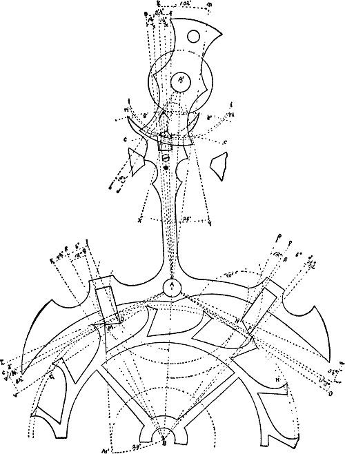
The pallets are to be
equidistant; the wheel teeth of the “club” form; there are to be two
rollers; wheel, pallet, and balance centers are to be in straight line.
The lock is to be 1½°, the run ¼°, making a total lock of 1¾°; the
movement of pallets from drop to drop is to be 10°, while the fork is to
move through 10¼° from bank to bank; the lift on the wheel teeth is to
be 3°, while the remainder is to be the lift on the pallets as follows:
10¼ − (1¾ + 3) = 5½° for lift of pallets.
The wheel is to have 15 teeth, with pallets spanning 3 teeth or 2½
spaces, making the angle from lock to lock = 360 ÷ 15 × 2½ = 60°, the
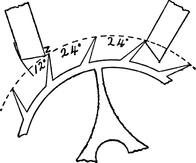
interval from tooth to tooth is 360 ÷ 15 = 24°; divided by 2
pallets = 24 ÷ 2 = 12° for width of tooth, pallet and drop; drop is to
be 1½°, the tooth is to be ¾ the width of the pallet, making a tooth of
a width of 4½° and a pallet of 6°.
The draw is to be 12° on each pallet, while the locking faces of the
teeth are to incline 24°. The acting length of fork is to be equal to
the distance of centers of scape wheel and pallets; the impulse angle is
to be 28°; freedom from dart and safety, roller is to be 1¼°, and for
dart and corner of crescent 5°; freedom for ruby pin and acting edge of
fork is to be 1¼°; width of slot is to be ½ the total motion, or
10¼ ÷ 2 = 5⅛°; shake of ruby pin in slot = ¼°, leaving 5⅛ − ¼ = 4⅞° for
width of ruby pin.
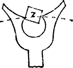
Radius of safety roller to be 4⁄7 of the theoretical impulse radius. The
length of horn is to be such that the end would point at least to the
center of the ruby pin when the edge of the crescent passes the dart;
space between the end of horn and ruby pin is to be 1½°.
It is well to know that the angles for width of teeth, pallets and drop
are measured from the wheel center, while the lifting and locking angles
are struck from the pallet center, the draw from the locking corners of
the pallets, and the inclination of the teeth from the locking edge.
In the fork and roller action, the angle of motion, the width of slot,
the ruby pin and its shake, the freedom between dart and roller, of ruby
pin with acting edge of fork and end of horn are all measured from the
pallet center, while the impulse angle and the crescent are measured
from the balance center. A sensible drawing board measures 17 × 24
inches, we also require a set of good drawing instruments, the finer the
instruments the better; pay special attention to the compasses, pens and
protractor; add to this a straight ruler and set square.
The best all-round drawing paper, both for India ink and colored work
has a rough surface; it must be fastened firmly and evenly to the board
by means of thumb tacks; the lines must be light and made with a hard
pencil. Use Higgins’ India ink, which dries rapidly.
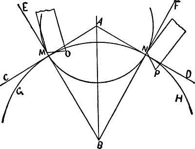
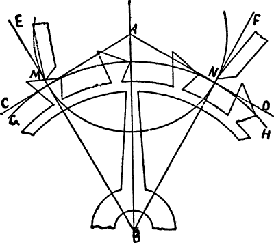
We will begin by drawing the center line A′ A B; use the point B for the
escape center; place the compass on it and strike G H, the primitive or
geometrical circle of the escape wheel; set the center of the protractor
at B and mark off an angle of 30° on each side of the line of centers;
this will give us the angles A B E and A B F together, forming the angle
F B E of 60°, which represents from lock to lock of the pallets. Since
the chord of the angle of 60° is equal to the radius of the circle, this
gives us an easy means of verifying this angle by placing the compass at
the points of intersection of F B and E B with the primitive circle G H;
this distance must be equal to the radius of the circle. At these points
we will construct right angles to E B and F B, thus forming the tangents
C A and D A to the primitive circle G H. These tangents meet on the line
of centers at A, which will be the pallet center. Place the compass at A
and draw the locking circle M N at the points of intersection of E B and
F B with the primitive circle G H. The locking edges of the pallets will
always
stand on this circle no matter in what relation the pallets
stand to the wheel. Place the center of the protractor at B and draw the
angle of width of pallets of 6°; I B E being for the engaging and J B F
for the disengaging pallet. In the equidistant pallet I B is drawn on
the side towards the center, while J B is drawn further from the center.
If we were drawing a circular pallet, one-half the width of pallets
would be placed on each side of E B and F B. At the points of
intersection of I B and J B with the primitive circle G H we draw the
path O for the discharging edge of the engaging and P for that of the
disengaging pallet. The total lock being 1¾°, we construct V′ A at this
angle from C A; the point of intersection of V′ A with the locking
circle M N, is the position of the locking corner of the engaging
pallet. The pallet having 12° draw when locked we place the center of
the protractor on this corner and draw the angle Q M E. Q M will be the
locking face of the engaging pallet. If the face of the pallet were on
the line E B there would be no draw, and if placed to the opposite side
of E B the tooth would repel the pallet, forming what is known as the
repellant escapement.
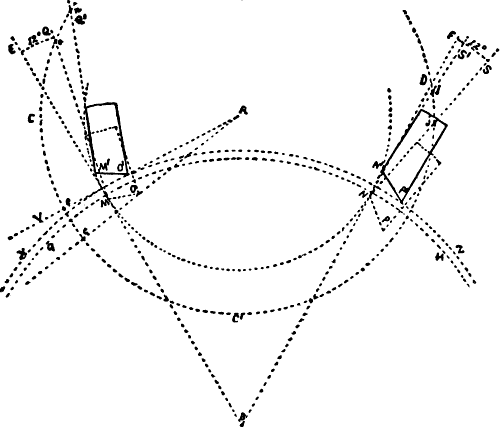
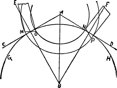
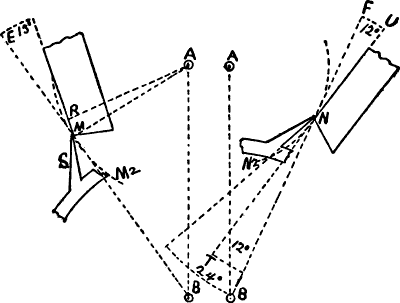
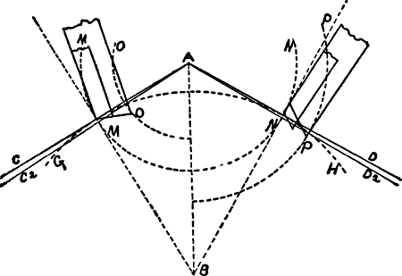
Fig. 28.
Having shown how to delineate the locking face of the engaging pallet
when locked, we will now consider how to draft both it and the
disengaging pallet in correct positions when unlocked; to do so we
direct our attention until further notice to Fig. 28. The locking faces
Q M of the engaging and S N of the disengaging pallets are shown in
dotted lines when locked. We must now consider the relation which the
locking faces will bear to E B in the engaging, and to F B in the
disengaging pallets when unlocked. This is a question of some
importance; it is easy enough to represent the 12° from the 30° angles
when locked; we must be certain that they would occupy exactly that
position and yet show them unlocked; we shall take pains to do so. In
due time we shall show that there is no appreciable loss of lift on the
engaging pallet in the escapement illustrated; the angle T A V
therefore shows the total lift; we have not shown the corresponding
angles on the disengaging side because the angles are somewhat
different, but the total lift is still the same. G H represents the
primitive circle of the escape wheel, and X Z that of the real, while
M N represents the circular course which the locking corners of the
pallets take in an equidistant escapement. At a convenient position we
will construct the circle C C′ D from the pallet center A. Notice the
points e and c, where V A and T A intersect this circle; the space
between e and c represents the extent of the motion of the pallets
at this particular distance from the center A; this being so, then let
us apply it to the engaging pallet. At the point of intersection o of
the dotted line Q M (which is an extended line on which the face of the
pallet lies when locked), with the circle C C′ D, we will plant our
dividers and transfer e c to o n. By setting our dividers on o M
and transferring to n M′, we will obtain the location of Q′ M′, the
locking face when unlocked. Let us now turn our attention to the
disengaging pallet. The dotted line S N represents the location of the
locking face of the disengaging pallet when locked at an angle of 12°
from F B. At the intersection of S N with the circle C C′ D we obtain
the point j. The motion of the two pallets being equal, we transfer
the distance e c with the dividers from j and obtain the point l.
By setting the dividers on j N and transferring to l N′ we draw the
line S′ N′ on which the locking face of the disengaging pallet will be
located when unlocked. It will be perfectly clear to anyone that through
these means we can correctly represent the pallets in any desired
position.
We will notice that the face Q′ M′ of the engaging pallet when unlocked
stands at a greater angle to E B than it did when locked, while the
opposite is the case on the disengaging pallet, in which the angle
S′ N′ F is much less than S N F. This shows that the deeper the
engaging pallet locks, the lighter will the draw be, while the opposite
holds good with the disengaging pallet; also, that the draw increases
during the unlocking of the engaging, and decreases during the unlocking
of the disengaging pallet. These points show that the draw should be
measured with the fork standing against the bank; not when the locking
corner of the pallet stands on the primitive circle, as is so often
done. The recoil of the wheel (which determines the draw), is
illustrated by the difference between the locking circle M N and the
face Q M for the engaging, and S N for the disengaging pallet, and along
the acting surface it is alike on each pallet, showing that the draft
angle should be the same on each pallet.
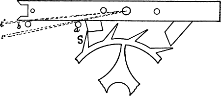
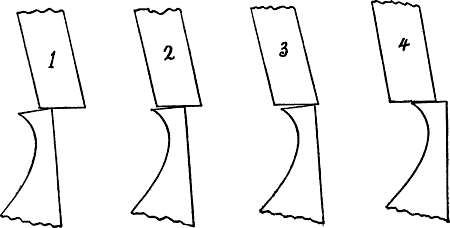
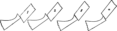
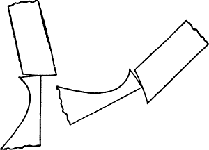
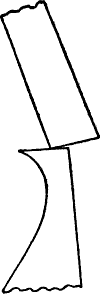
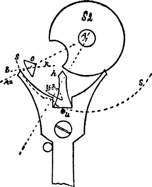
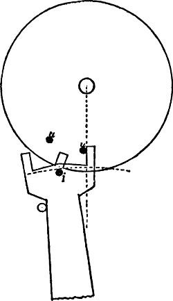
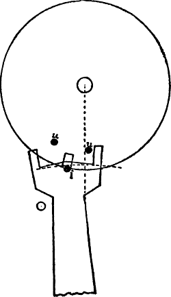
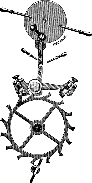
A number of years ago we constructed the escapement model which we
herewith illustrate. All the parts are adjustable; the pallets can be
moved in any direction, the draft angles can be changed at will. Through
this model we can practically demonstrate the points of which we have
spoken. Such a model can be made by workmen after studying these
papers.
In both the equidistant and circular pallets the locking face S N of the
disengaging pallet deviates more from the locking circle M N than does
the locking face Q M of the engaging pallet, as will be seen in the
diagram. This is because the draft angle is struck from E B which
deviates from the locking circle in such a manner, that if the face of a
pallet were planted on it and locked deep enough to show it, the
wheel would actually repel the pallet, whereas with the disengaging
pallet if it were planted on F B, it would actually produce draw if
locked very deep; this is on account of the natural deviation of the 30°
lines from the locking circle. This difference is more pronounced in the
circular than in the equidistant pallet, because in the former we have
two locking circles, the larger one being for the engaging pallet, and
as an arc of a large circle does not deviate as much from a straight
line as does that of a smaller circle, it will be easily understood that
the natural difference before spoken of is only enhanced thereby. For
this reason in order to produce an actual draw of 12°, the engaging
pallet may be set at a slightly greater angle from E B in the circular
escapement; the amount depends upon the width of the pallets; the
requirements are that the recoil of the wheel will be the same on each
pallet. We must, however, repeat that one of the most important points
is to measure the draw when the fork stands against the bank, thereby
increasing the draw on the engaging and decreasing that of the
disengaging pallet during the unlocking action, thus naturally
balancing one fault with another.
We will again proceed with the delineation of the escapement here
illustrated. After having drawn the locking face Q M, we draw the angle
of width of teeth of 4½°, by planting the protractor on the escape
center B. We measure the angle E B K, from the locking face of the
pallet; the line E B does not touch the locking face of the pallet at
the present time of contact with the tooth, therefore a line must be
drawn from the point of contact to the center B. We did so in our
drawing but do not illustrate it, as in a reduced engraving of this kind
it would be too close to E B and would only cause confusion. We will now
draw in the lifting angle of 3° for the tooth. From the tangent C A we
draw T A at the required angle; at the point of intersection of T A with
the 30° line E B we have the real circumference of the escape wheel. It
will only be necessary to connect the locking edge of the tooth with the
line K B, where the real or outer circle intersects it. It must be drawn
in the same manner in the circular escapement; if the tooth were drawn
up to the intersection of K B with T A, the lift would be too great, as
that point is further from the center A than the points of contact are.
If the real or outer circle of the wheel intersects both the locking
circle M N and the path O of the discharging edge at the points where
T A intersects them, then there will be no loss of lift on the
engaging pallet. This is precisely how it is in the diagram; but if
there is any deviation, then the angle of loss must be measured on the
real diameter of the wheel and not on the primitive, as is usually
done, as the real diameter of the wheel, or in other words the heel of
the tooth, forms the last point of contact. With a wider tooth and a
greater lifting angle there will even be a gain of lift on the
engaging pallet; the pallet in such a case would actually require a
smaller lifting angle, according to the amount of gain. We gave full
directions for measuring the loss when describing its effects in Fig. 8.
Whatever the loss amounts to, it is added to the lifting plane of the
pallet. In the diagram under discussion there is no loss, consequently
the lifting angle on the pallet is to be 5½°. From V′ A we draw V A at
the required angle; the point of intersection of V A with the path O
will be the discharging edge O. It will now only be necessary to connect
the locking corner M with it, and we have the lifting plane of the
pallet; the discharging side of the pallet is then drawn parallel to the
locking face and made a suitable length. We will now draw the locking
edges of the tooth by placing the center of the protractor on the
locking edge M and construct the angle B M M′ of 24° and draw a circle
from the scape center B, to which the line M M′ will be a tangent. We
will utilize this circle in drawing in the faces of the other teeth
after having spaced them off 24° apart, by simply putting a ruler on
the locking edges and on the periphery of the circle.
We now construct W′ A as a tangent to the outer circle of the wheel,
thus forming the lifting angle D A W′ of 3° for the teeth; this
corresponds to the angle T A C on the engaging side. W′ A touches the
outer circle of the wheel at the intersection of F B with it. We will
notice that there is considerable deviation of W′ A from the circle at
the intersection of J B with it. At the intersecting of this point we
draw U A; the angle U A W′ is the loss of lift. This angle must be added
to the lifting angle of the pallets; we see that in this action there is
no loss on the engaging pallet, but on the disengaging the loss amounts
to approximately ⅞° in the action illustrated. As we have allowed ¼° of
run for the pallets, the discharging edge P is removed at this angle
from U A; we do not illustrate it, as the lines would cause confusion
being so close together. The lifting angle on the pallet is measured
from the point P and amounts to 5½° + the angle of the loss; the angle
W A U embraces the above angles besides ¼° for run. If the locks are
equal on each pallet, it proves that the lifts are also equal. This
gives us a practical method of proving the correctness of the drawing;
to do so, place the dividers on the locking circle M N at the
intersection of T A and V A with it, as this is the extent of motion;
transfer this measurement to N, if the actual lift is the same on each
pallet, the dividers will locate the point which the locking corner N
will occupy when locked; this, in the present case, will be at an
angle of 1¾° below the tangent D A. By this simple method, the
correctness of our proposition that the loss of lift should be measured
from the outside circle of the wheel, can be proven. We often see the
loss measured for the engaging pallet on the primitive circumference
G H, and on the real circumference for the disengaging; if one is right
then the other must be wrong, as there is a noticeable deviation of the
tangent C A from the primitive circle G H at the intersection of the
locking circle M N; had we added this amount to the lifting angle V′ A V
of the engaging pallet, the result would have been that the discharging
edge O would be over 1° below its present location, thus showing that by
the time the lift on the engaging pallet had been completed, the locking
corner N of the disengaging pallet would be locked at an angle of 2¾°
instead of only 1¾°. Many watches contain precisely this fault. If we
wish to make a draft showing the pallets at any desired position, at the
center of motion for instance, with the fork standing on the line of
centers, we would proceed in the following manner: 10¼° being the total
motion, one-half would equal 5⅛°; as the total lock equals 1¾°, we
deduct this amount from it which leaves 5⅛ − 1¾ = 3⅜°, which is the
angle at which the locking corner M should be shown above the tangent
C A. Now let us see where the locking corner N should stand; M having
moved up 5⅛°, therefore N moved down by that amount, the lift on the
pallet being 5½° and on the tooth 3° (which is added to the tangent
D A), it follows that N should stand 5½ + 3 − 5⅛ = 3⅜° above D A. We can
prove it by the lock, namely: 3⅜° + 1¾ = 5⅛°, half the remaining motion.
This shows how simple it is to draft pallets in various positions,
remembering always to use the tangents to the primitive circle as
measuring points. We have fully explained how to draw in the draft angle
on the pallets when unlocked, and do not require to repeat it, except to
say, that most authorities draw a tangent R N to the locking circle M N,
forming in other words, the right angle R N A, then construct an angle
of 12° from R N. We have drawn ours in by our own method, which is the
correct one. While we here illustrate S N R at an angle of 12° it is in
reality less than that amount; had we constructed S N at an angle of
12° from R N, then the draw would be 12° from F B, when the primitive
circumference of the wheel is reached, but more than 12° when the
fork is against the bank.
The space between the discharging edge P and the heel of the tooth forms
the angle of drop J B I of 1½°; the definition for drop is that it is
the freedom for wheel and pallet. This is not, strictly speaking,
perfectly correct, as, during the unlocking action there will be a
recoil of the wheel to the extent of the draft angle; the heel of the
tooth will therefore approach the edge P, and the discharging side of
the pallet approaches the tooth, as only the discharging edge moves on
the path P.
A good length for the teeth is 1⁄10 the diameter of the wheel, measured
from the primitive diameter and from the locking edge of the tooth.
The backs of the teeth are hollowed out so as not to interfere with the
pallets, and are given a nice form; likewise the rim and arms are drawn
in as light and as neat as possible, consistent with strength.
Having explained the delineation of the wheel and pallet action we will
now turn our attention to that of the fork and roller. We tried to
explain these actions in such a manner that by the time we came to
delineate them no difficulty would be found, as in our analysis we
discussed the subject sufficiently to enable any one of ordinary
intelligence to obtain a correct knowledge of them. The fork and roller
action in straight line, right, or any other angle is delineated after
the methods we are about to give.
We specified that the acting length of fork was to be equal to the
center distance of wheel and pallets; this gives a fork of a fair
length.
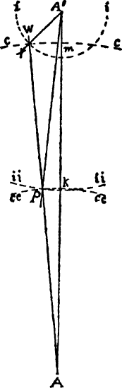
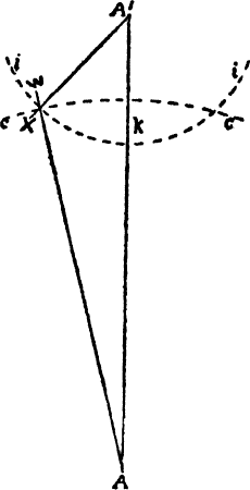
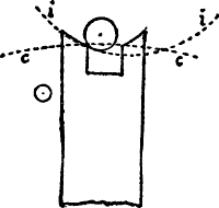
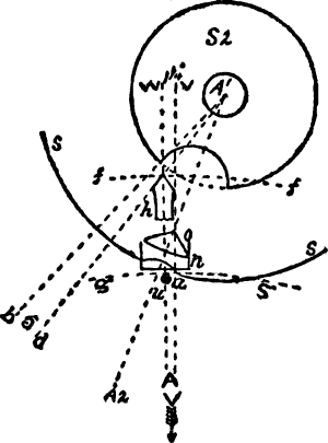
Having drawn the line of centers A′ A we will construct an angle equal
to half the angular motion of the pallets; the latter in the case under
consideration being 10¼°, therefore 5⅛° is spaced off on each side of
the line of centers, forming the angles m A k of 10¼°. Placing our
dividers on A B the center distance of ’scape wheel and pallets, we
plant them on A and construct c c; thus we will have the acting length
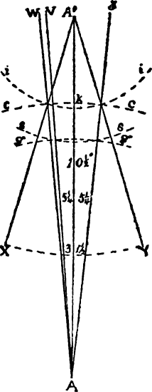
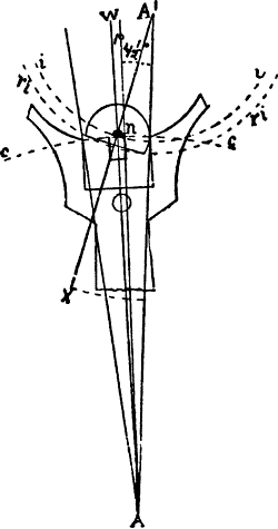
of fork and its path. We saw in our analysis that the impulse angle
should be as small as possible. We will use one of 28° in our draft of
the double roller; we might however remark that this angle should vary
with the construction of the escapements in different watches; if too
small, the balance may be stopped when the escapement is locked, while
if too great it can be stopped during the lift; both these defects are
to be avoided. The angles being respectively 10¼° and 28° it follows
they are of the following proportions: 28° ÷ 10.25 = 2.7316. The impulse
radius therefore bears this relation (but in the inverse ratio to the
angles), to the acting length of fork.
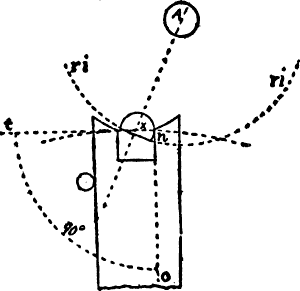
We will put it in the following proportion; let Ac equal acting length
of fork, and x the unknown quantity; 28∶10.25 ∷ Ac∶x; the answer
will be the theoretical impulse radius. Having found the required radius
we plant one jaw of our measuring instrument on the point of
intersection of c c with k A or m A and locate the other jaw on
the line of centers; we thus obtain A′ the balance center. Through the
points of intersection before designated we will draft X A′ and Y A′
forming the impulse angle X A′ Y of 28°. At the intersection of this
angle with the fork angle k A′ m, we draw i i from the center A;
this gives us the theoretical impulse circle. The total lock being 1¾°
it follows that the angle described by the balance in unlocking
= 1¾ × 2.7316 = 4.788°. According to the specifications the width of
slot is to be 5⅛°; placing the center of the protractor on A we
construct half of this angle on each side of k A, which passes through
the center of the fork when it rests against the bank; this gives us the
angle s A n of 5⅛°. If the disengaging pallet were shown locked then
m A would represent the center of the fork. The slot is to be made of
sufficient depth so there will be no possibility of the ruby pin
touching the bottom of it. The ruby pin is to have 1¼° freedom in
passing the acting edge of the fork; from the center A we construct the
angle t A n of 1¼°; at the point of intersection of t A with c c
the acting radius of the fork, we locate the real impulse radius and
draw the arc ri ri which describes the path made by the face of the
ruby pin. The ruby pin is to have ¼° of shake in the slot; it will
therefore have a width of 4⅞°; this width is drawn in with the ruby pin
imagined as standing over the line of centers and is then transferred to
the position which the ruby pin is to occupy in the drawing.
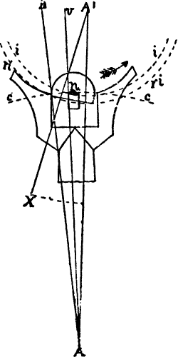
The radius of the safety roller was given as 4⁄7 of the theoretical
impulse radius. They may be made of various proportions; thus ⅔ is often
used. Remember that the smaller we make it, the less the friction during
accidental contact with the guard pin, the greater must the passing
hollow be and the horn of fork and guard point must be longer, which
increases the weight of the fork.
Having drawn in the safety roller, and having specified that the freedom
between the dart and safety roller was to be 1¼°, the dart being in the
center of the fork, consequently k A is the center of it; therefore we
construct the angle k A X of 1¼°. At the point of intersection of X A
with the safety roller we draw the arc g g; this locates the point of
the dart which we will now draw in. We will next draw d A′ from the
balance center and touching the point of the dart; we now construct
b A′ at an angle of 5° to it. This is to allow the necessary freedom
for the dart when entering the crescent; from A′ we draw a line through
the center of the ruby pin. We do not show it in the drawing, as it
would be indiscernible, coming very close to A′ X. This line will also
pass through the center of the crescent. At the point of intersection of
A′ b with the safety roller we have one of the edges of the crescent. By
placing our compass at the center of the crescent on the periphery of
the roller and on the edge which we have just found, it follows that our
compass will span the radius of the crescent. We now sweep the arc for
the latter, thus also drawing in the remaining half of the crescent on
the other side of A′ X and bringing the crescent of sufficient depth
that no possibility exists of the dart touching in or on the edges of
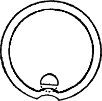
it. We will now draw in the impulse roller and make it as light as
possible consistent with strength. A hole is shown through the impulse
roller to counterbalance the reduced weight at the crescent. When
describing Fig. 24, we gave instructions for finding the dimensions of
crescent and position of guard pin for the single roller. We will find
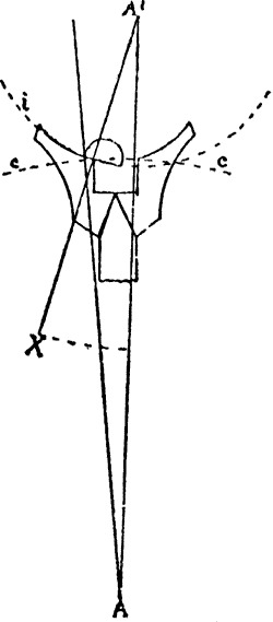
the length of horn; to do so we must closely follow directions given for
Fig. 25. In locating the end of the horn, we must find the location of
the center of the crescent and ruby pin after the edge of the crescent
has passed the dart. From the point of intersection of A′ b with the
safety roller we transfer the radius of the crescent on the periphery of
the safety roller towards the side against the bank, then draw a line
from A′ through the point so found. At point of intersection of this
line with the real impulse circle r i r i we draw an arc radiating
from the pallet center; the end of the horn will be located on this arc.
In our drawing the arc spoken of coincides with the dart radius g g.
As before pointed out, we gave particulars when treating on Fig. 25,
therefore considered it unnecessary to further complicate the draft by
the addition of all the constructional lines. We specified that the
freedom between ruby pin and end of horn was to be 1½°; these lines
(which we do not show) are drawn from the pallet center. Having
located the end of the horn on the side standing against the bank, we
place the dividers on it and on the point of intersection of k A with
g g—which in this case is on the point of the dart,—and transfer
this measurement along g g which will locate the end of the horn on
the opposite side.
We have the acting edges of the fork on cc and have also found the
position of the ends of the horns; their curvature is drawn in the
following manner: We place our compasses on A and r i, spanning
therefore the real impulse radius; the compass is now set on the acting
edge of the fork and an arc swept with it which is then to be
intersected by another arc swept from the end of the horn, on the same
side of the fork. At the point of intersection of the arcs the compass
is planted and the curvature of the horn drawn in, the same operation is
to be repeated with the other horn. We will now draw in the sides of the
horn of such a form that should the watch rebank, the side of the ruby
pin will squarely strike the fork. If the back of the ruby pin strikes
the fork there will be a greater tendency of breaking it and injuring
the pivots on account of acting like a wedge. The fork and pallets are
now drawn in as lightly as possible and of such form as to admit of
their being readily poised. The banks are to be drawn at equal distances
from the line of centers. In delineating the fork and roller action in
any desired position, it must be remembered that the points of location
of the real impulse radius, the end of horn, the dart or guard pin and
crescent, must all be obtained when standing against the bank, and
the arcs drawn which they describe; the parts are then located according
to the angle at which they are removed from the banks.
We think the instructions given are ample to enable any one to master
the subject. We may add that when one becomes well acquainted with the
escapement, many of the angles radiating from a common center, may be
drawn in at once. We had intended describing the mechanical construction
of the escapement, which does unmistakably present some difficulties on
account of the small dimensions of the parts, but nevertheless it can be
mechanically executed true to the principles enumerated. We have evolved
a method of so producing them that young men in a comparatively short
period have made them from their drafts (without automatic machinery)
that their watches start off when run down the moment the crown is
touched. Perhaps later on we will write up the subject. It is our
intention of doing so, as we make use of such explanations in our
regular work.