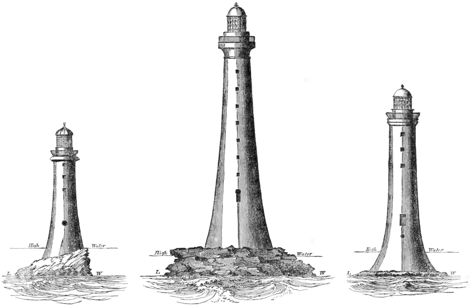
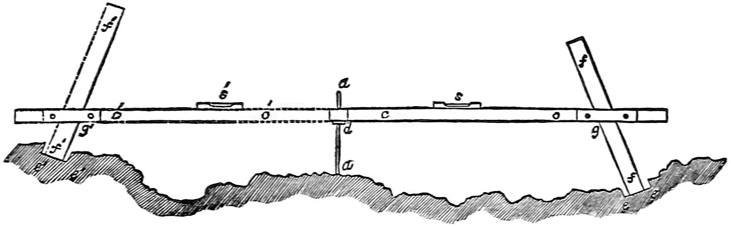
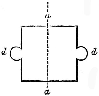
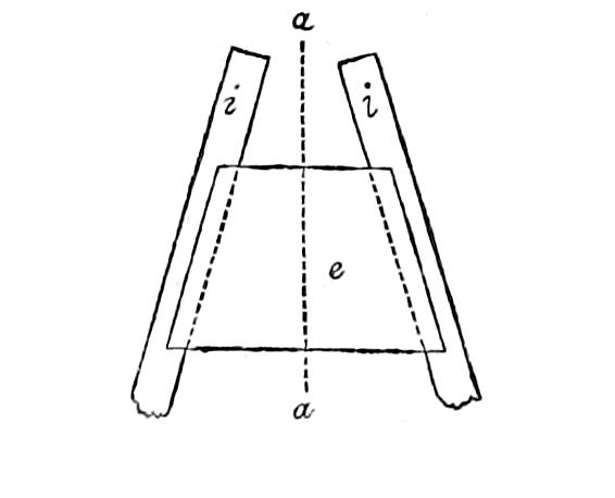
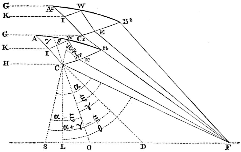
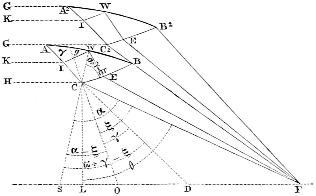
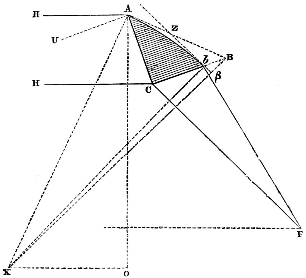
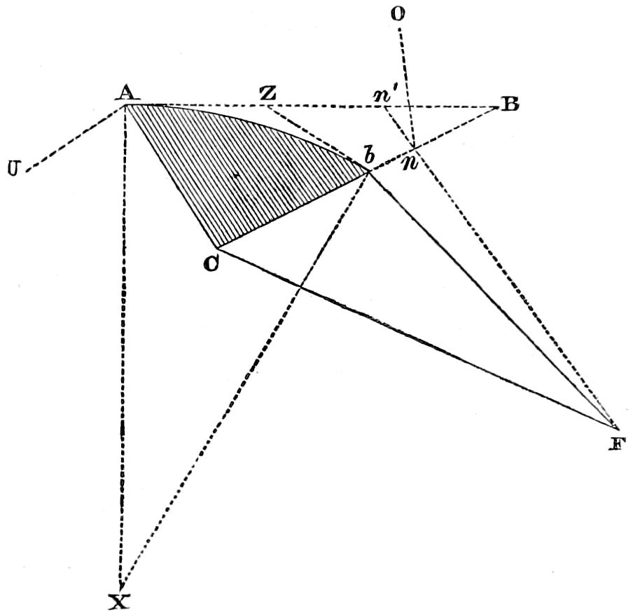
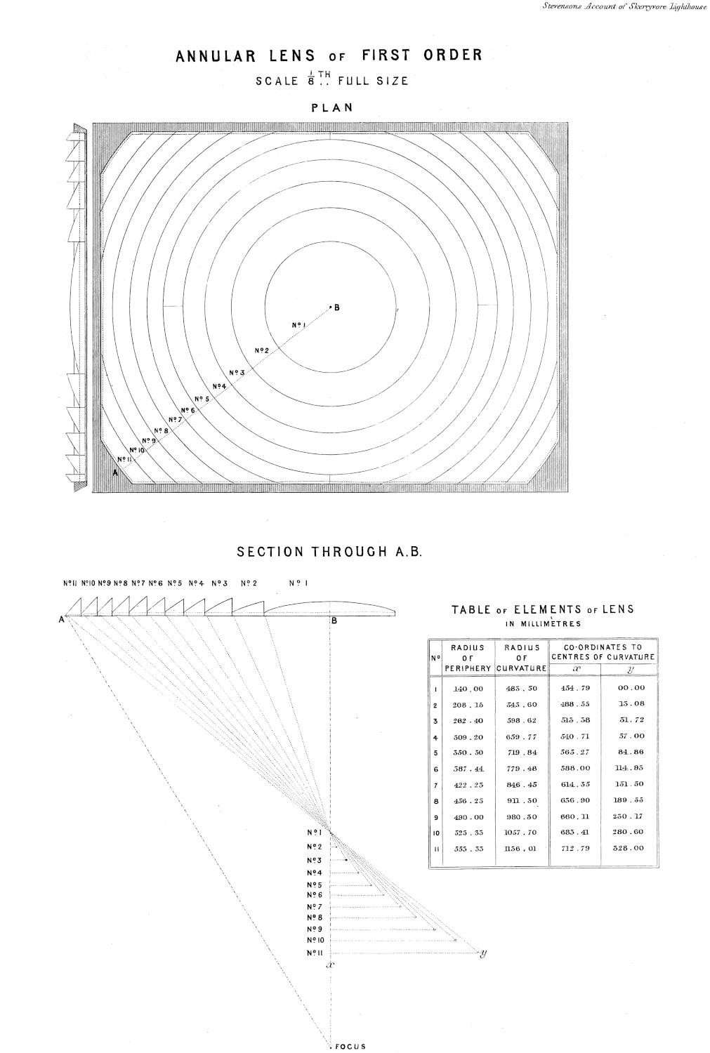
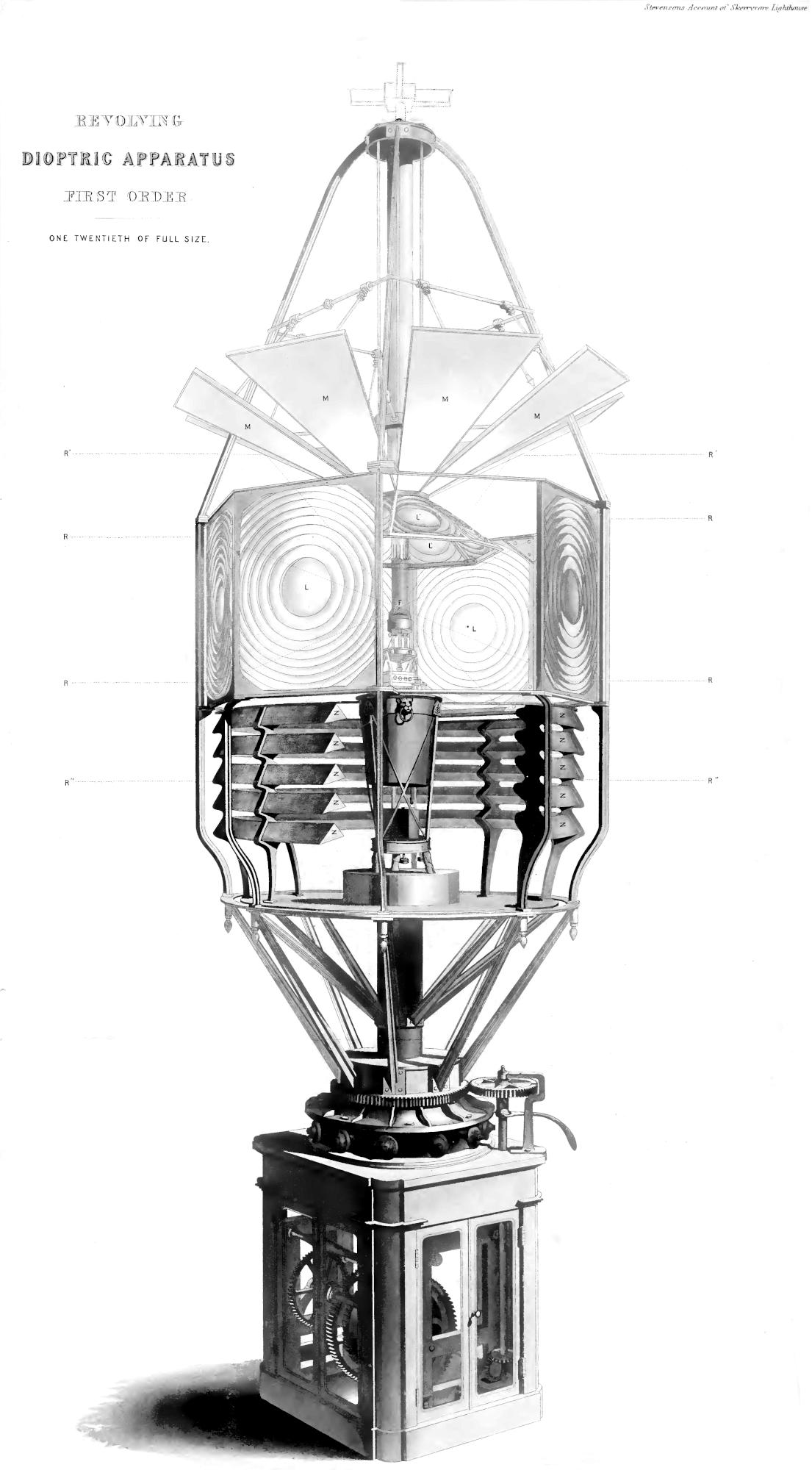
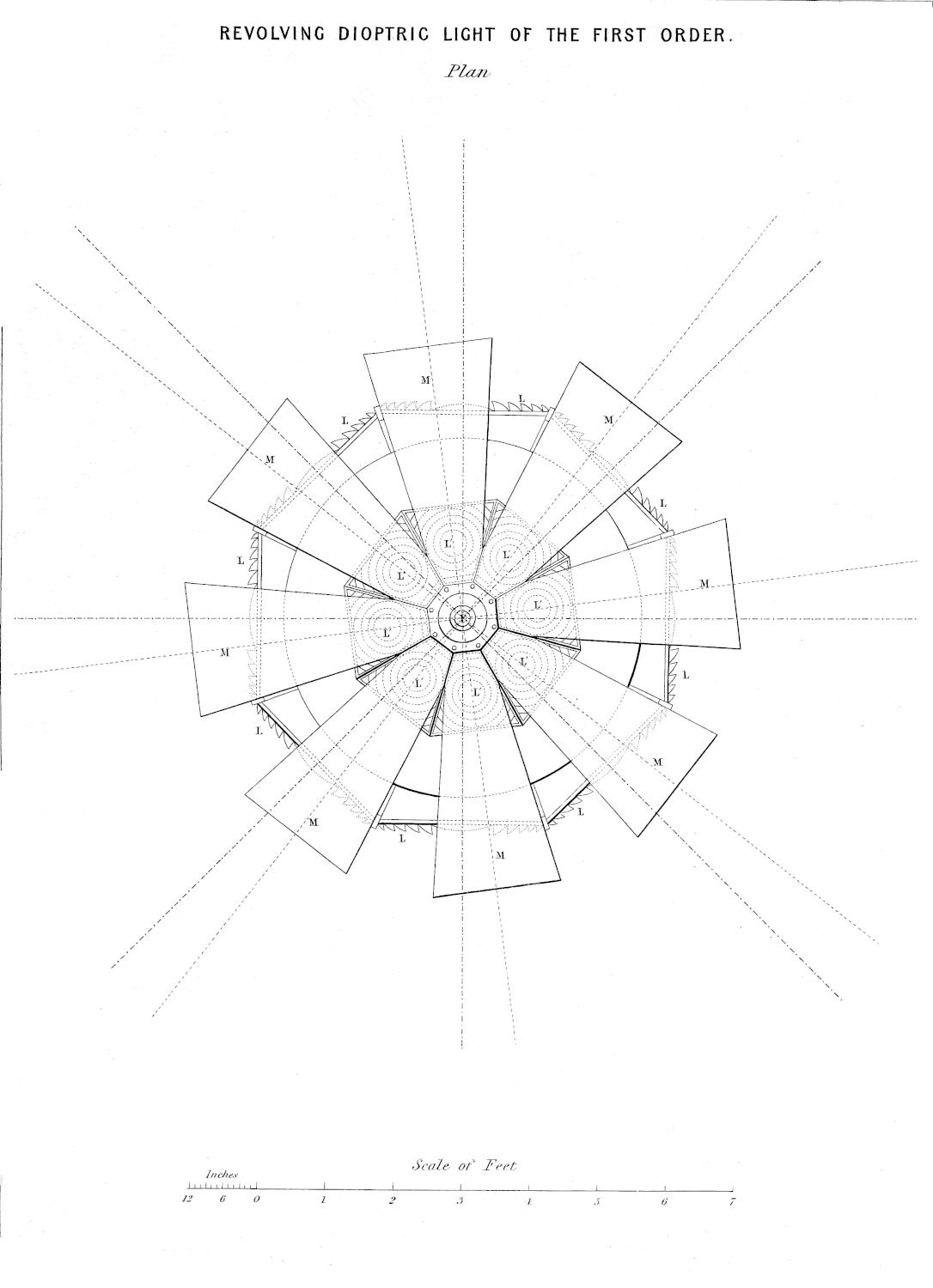
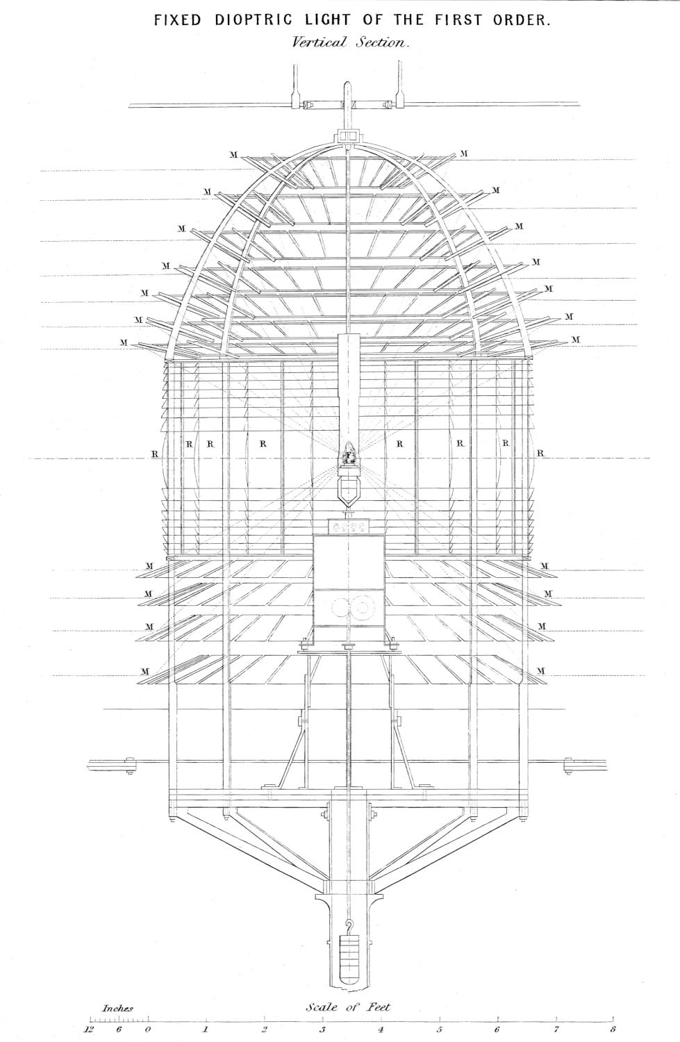
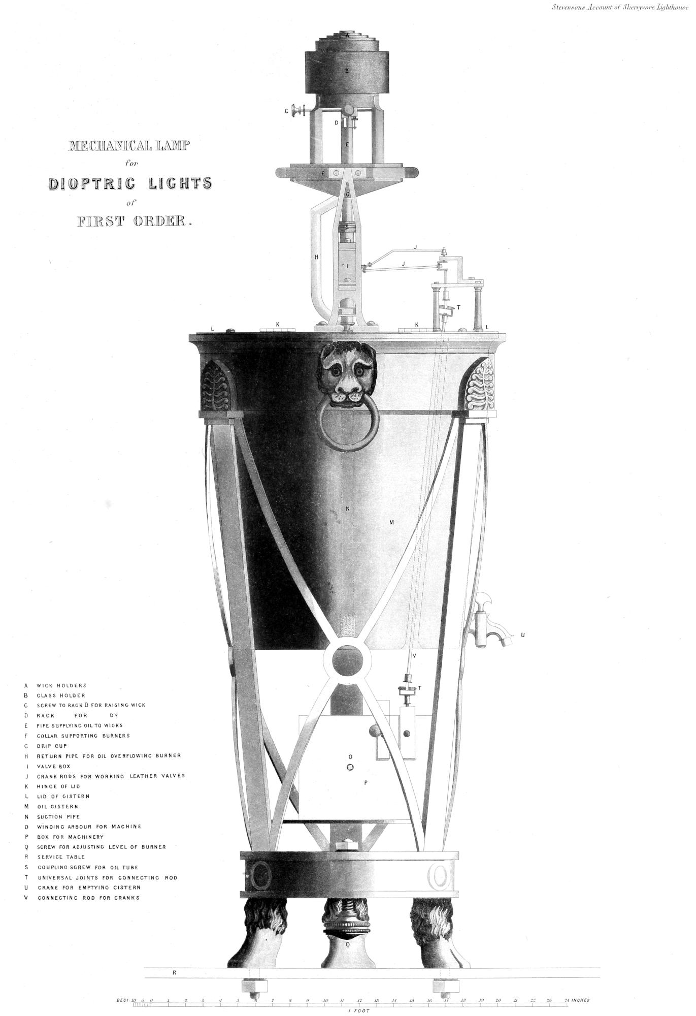
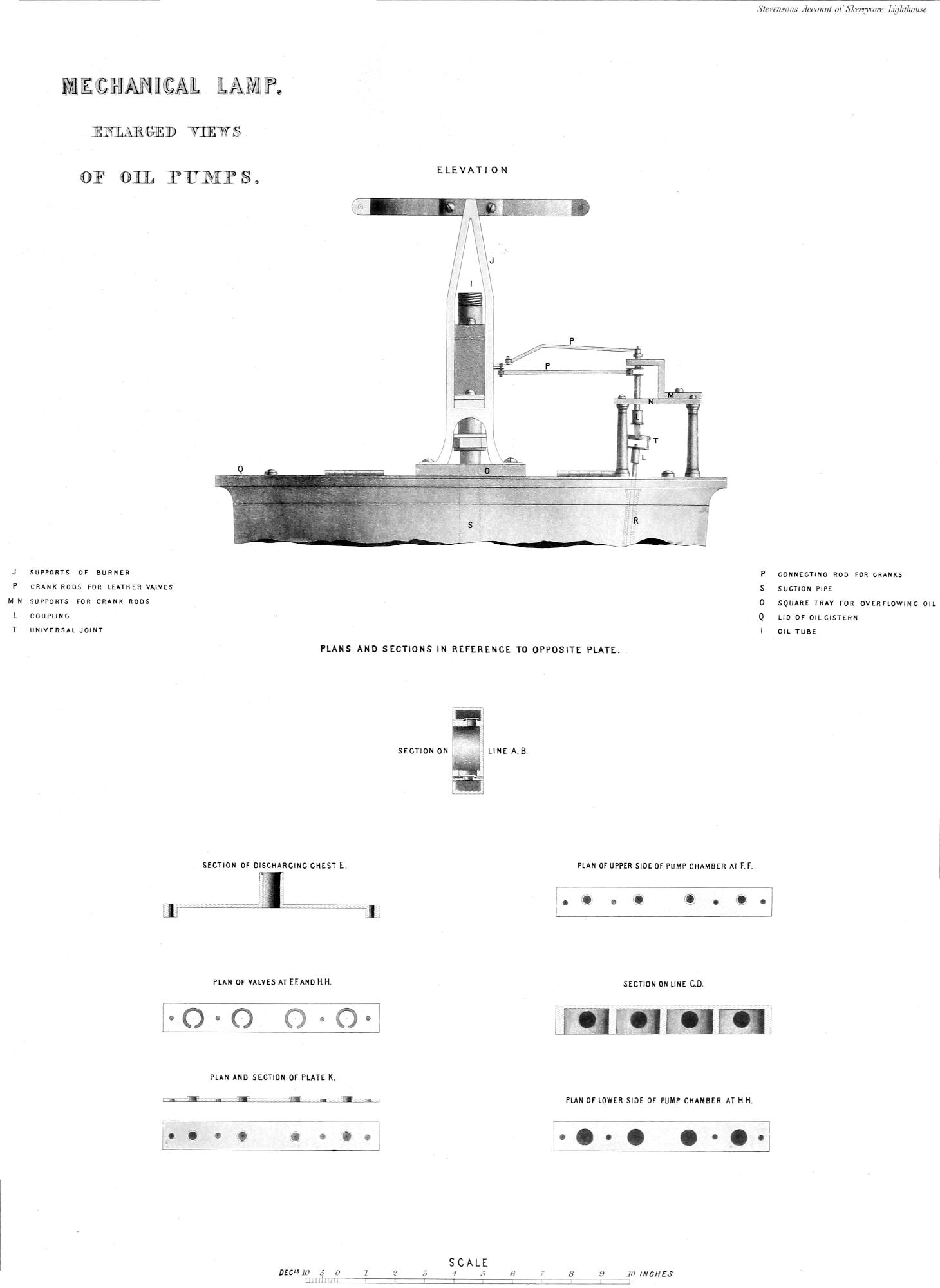
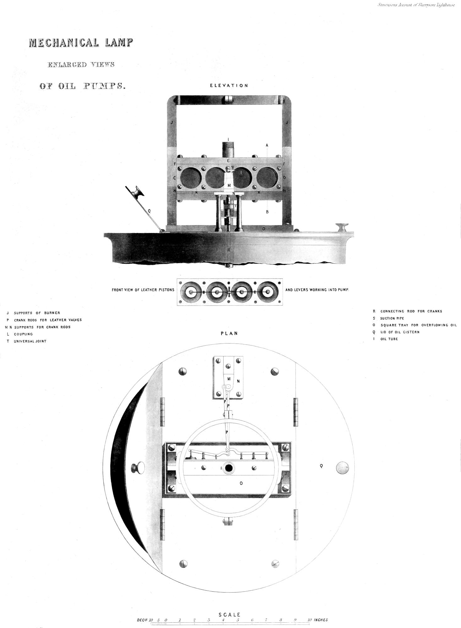
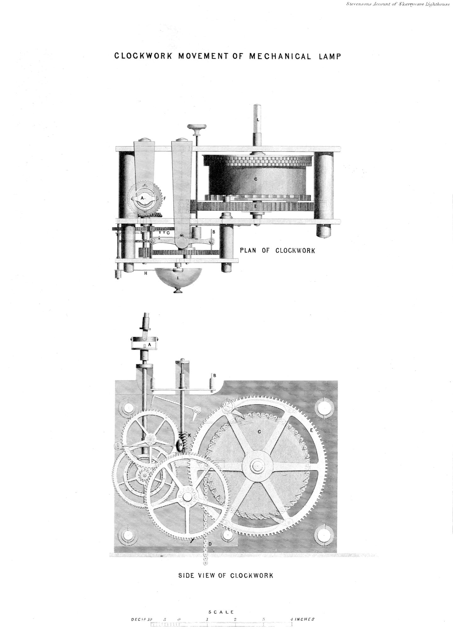
Larger versions of illustrations and plates are available by opening them in a new tab or window.
New original cover art included with this eBook is granted to the public domain.
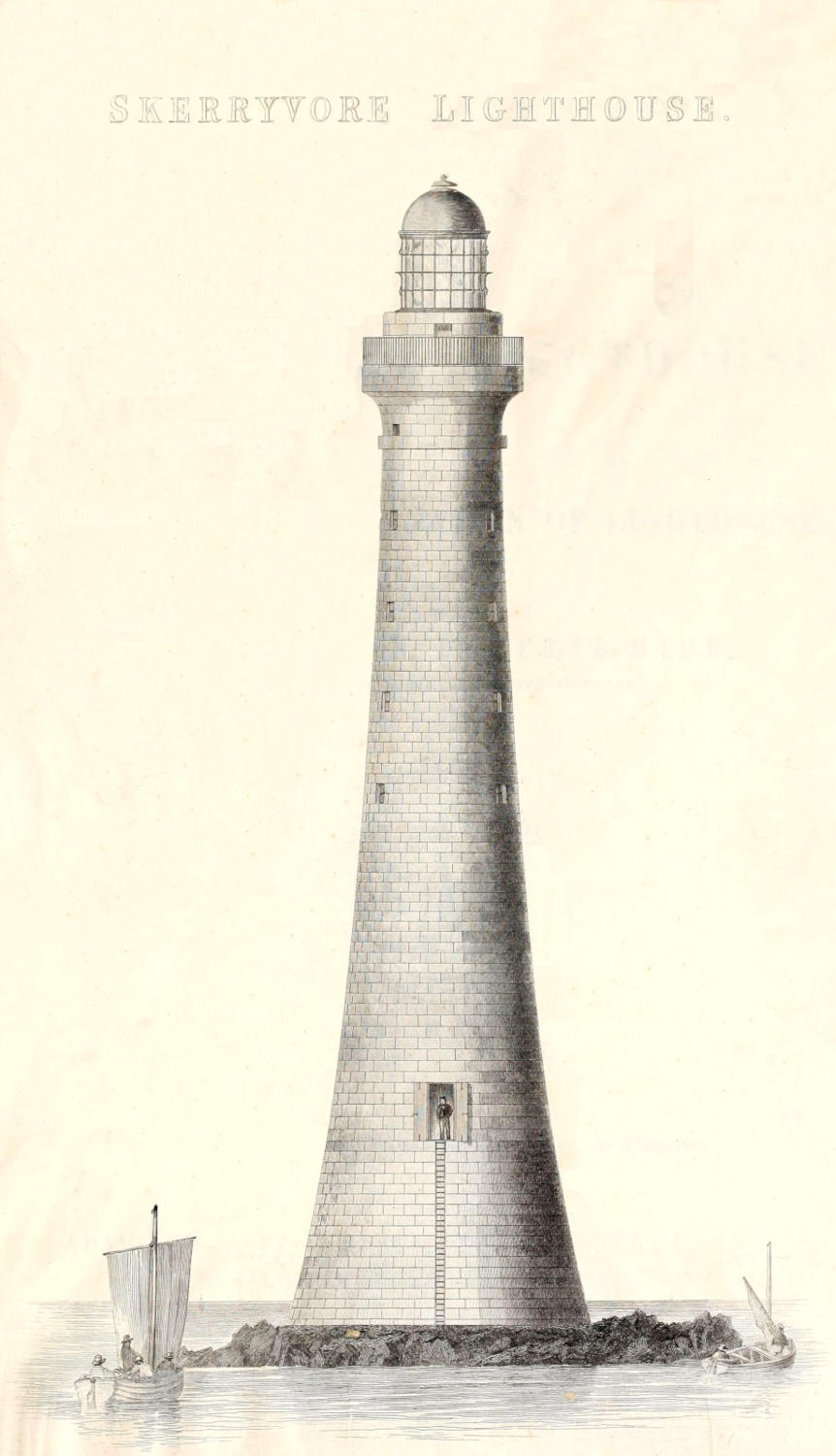
SKERRYVORE LIGHTHOUSE.
BY ALAN STEVENSON, LL.B., F.R.S.E., M.I.C.E., ENGINEER TO THE NORTHERN LIGHTHOUSE BOARD.
“ΥΠΕΡ · ΤΩΝ · ΠΛΩΙΖΟΜΕΝΩΝ” Inscription on the Ancient Pharos of Alexandria.
BY ORDER OF THE COMMISSIONERS OF NORTHERN LIGHTHOUSES.
ADAM AND CHARLES BLACK, NORTH BRIDGE, EDINBURGH.
LONGMAN AND CO., LONDON.
MDCCCXLVIII.
PRINTED BY NEILL AND COMPANY, EDINBURGH.
PREFACE.
I am unwilling to dismiss the following pages from my hands
without saying a few words in extenuation of the defects which
they contain. My chief plea in defence is, that the preparation of
this Account of the Skerryvore Lighthouse, and the Notes on the
Illumination of Lighthouses which follow it, was not chosen or
assumed by me, but was a task imposed by the express desire of
the Lighthouse Board, to whose enlightened and liberal views the
Mariner owes the erection of the Lighthouse itself. My labours
were also continually interrupted by the urgent calls of my official
duties; and, on several occasions, I was forced to dismiss unfinished
chapters from my mind for a period of several months—circumstances
which, I hope, will in some measure account for the
desultory character of the performance, the disproportion of some
of its parts, and more especially for repetitions and perhaps omissions
which would otherwise have been quite unpardonable.
Having said thus much by way of apology for this Volume,
I must acknowledge my many and great obligations to my Father
who preceded me as Engineer to the Board of Northern Lighthouses,
and of whose experience, as the Architect of no fewer than
twenty-five Lighthouses, including that of the Bell Rock, I had
the full benefit during the erection of the Skerryvore Lighthouse.
To the generosity of my esteemed friend, M. Leonor Fresnel, I
owe all that I know of the Dioptric System of Illumination, invented
by his late illustrious Brother; but this general acknowledgment
will not supersede the necessity of frequent repetitions
of my obligations to him, as occasion offers, in the course of these
pages. I have also derived much assistance, as a careful reader
will easily trace, from the valuable little work of M. Peclet, entitled
Traité de l’Eclairage. There are, besides, many other obligations,
which I cannot attempt to acknowledge individually, but
which those, who kindly conferred them, well know how much I
value.
In the Account of the Skerryvore Lighthouse, which forms the
first part of this Volume, there is an important omission; and, in this
short prefatory notice, I gladly embrace the only opportunity, which
now remains, of supplying the defect. Although, in the course of
the Narrative, I have occasionally noticed some special deliverances
from danger, I have altogether neglected to record the remarkable
fact, that, amidst our almost daily perils, during six seasons
on the Skerryvore Rock, there was no loss of either life or
limb amongst us. Those who best know the nature of the service
in which we were engaged,—the daily jeopardy connected with
landing weighty materials in a heavy surf and transporting the
workmen in boats through a boisterous sea, the risks to so many
men, involved in mining the foundations of the Tower in a space
so limited, and above all, the destruction, in a single night by
the violence of the waves, of our temporary barrack on the Rock,
which had cost the toils of a whole season, will not wonder that
I am anxious to express, what I know to have been a general
feeling amongst those engaged in the work—that of heartfelt thankfulness
to Almighty God for merciful preservation in danger, and
for the final success which terminated our arduous and protracted
labours.
Edinburgh, March 25, 1848.
CONTENTS.
PART I.
ACCOUNT OF SKERRYVORE LIGHTHOUSE.
Page
Introduction — Constitution of the Lighthouse Board — Lights established since 1821 — Improvements in the mode of illumination — Dioptric
Lights — Beacons and Buoys,
Preliminary arrangements and works, including survey of the rocks, and opening of quarries from 1834 to 1837 — Survey of the Skerryvore
rocks — Disadvantages of Tyree — Pier and workyard at Hynish, Tyree — Quarries at Hynish — Skerryvore Committee appointed,
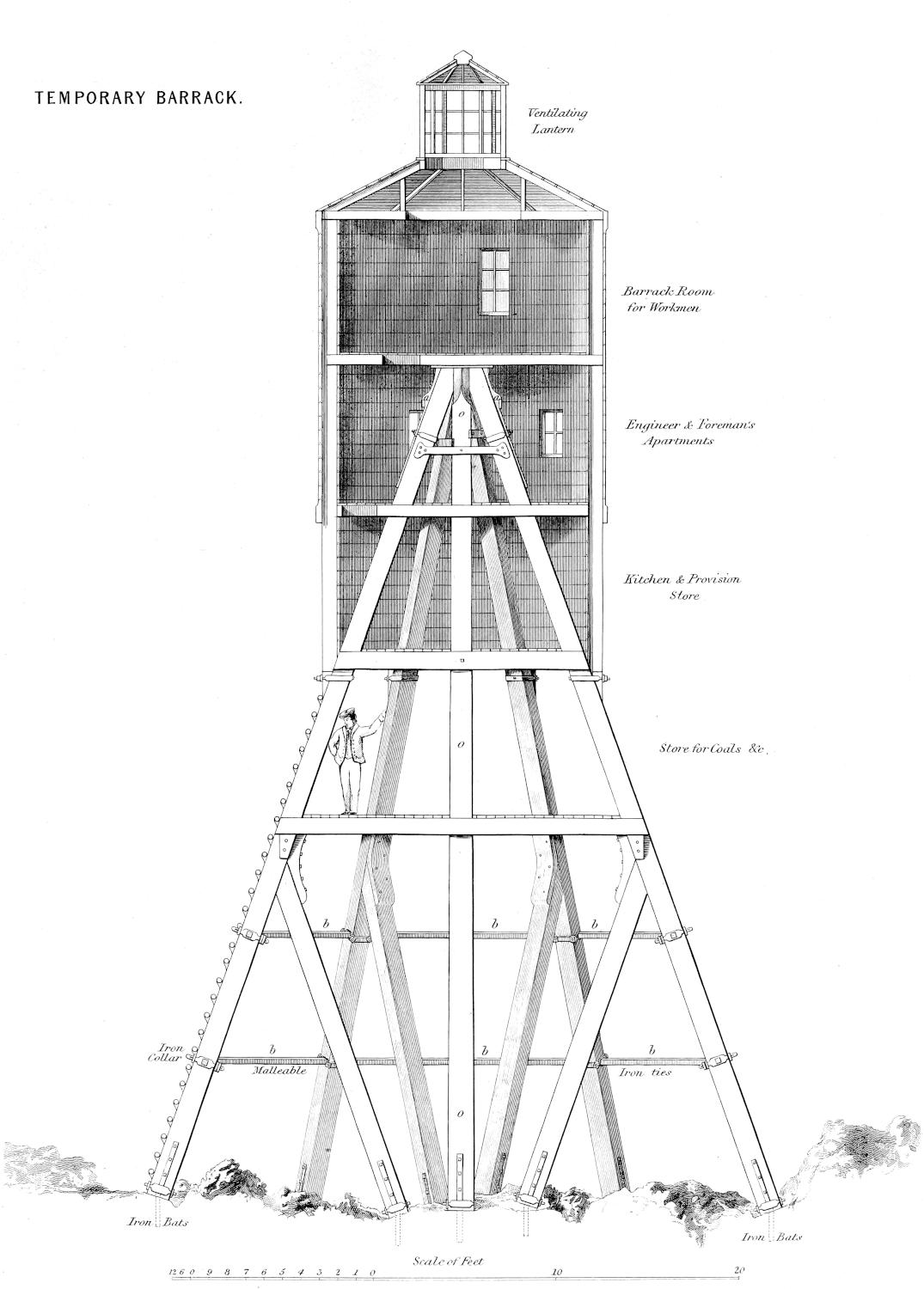
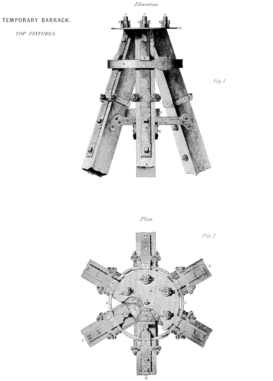
Temporary Barrack on Rock — Tools and machinery — Steam Tender for the works —
Employment and wages of workmen — Progress of the outfit for the
season’s operations — Embark for Skerryvore — Lay down moorings, and try to land on the Rock —
Driven to Mull — First day’s work on the Rock — Shipment of materials
at Glasgow and Greenock — Reach Tyree — Driven to Mull — Return to Tyree — First good day’s work
on the Rock — Sudden gale and great peril to the vessels — Reach Hynish
in safety — Detained by bad weather four days at Hynish — Return to the Rock and have six days of
good weather — Erection of the pyramid of the wooden barrack — Mode
of determining the length of the beams, and the sites for their fixtures — Pyramid completed — Mode
of living while erecting the barrack — Shoals of Medusæ
seen — Driven by a gale to Mull — Return to Hynish and are driven to Coll — Return to the Rock —
Driven to Tyree — Return to the Rock — Horizontal braces fixed — Driven
to Mull — Heavy gale — Timber cast on Tyree —
Return to Rock and further progress of barrack — Last day’s work on
Rock this season — Precaution for the benefit of shipwrecked seamen — View from top of pyramid —
Destruction of the barrack during a gale — Letter from Mr
Hogben — Proceed to Skerryvore — State in which the Rock was found — Cause of the destruction of
the barrack — Preparations for a new barrack — Works at Hynish — Hynish
quarries,
Shipping station and pier at Hynish — Granite quarries in Mull — Observations on the quarrying of granite — Dressing of the Lighthouse
blocks — Excavation of foundation for the Lighthouse Tower on the Skerryvore Rock — Fitting up of the second barrack on the Rock — Sudden death of George
Middlemiss — Wharf and landing-place on the Rock — Ring-bolts, water-tanks, and
railways — Incidents of the season — Effects of a gale from the south-west — Mutiny of
the crew — Near approach of the vessels to the Rock, and other circumstances shewing the importance of a Light on the Skerryvore,
CHAPTER IX. CONCLUDING OPERATIONS AND EXHIBITION OF THE LIGHT.
Harbour works — Bo Pheg beacon — Light-keepers’ and seamen’s houses — Concluding works on the Rock, such as pointing, &c. — Interior
fittings of the Tower — Light-room apparatus, and first exhibition of the Light — Removal of the barrack from the Rock — Expense,
NOTES ON THE ILLUMINATION OF LIGHTHOUSES, WITH SHORT NOTICES OF THEIR HISTORY, 181.
Early history, 181 — Colossus of Rhodes, 182 — Pharos of Alexandria,
183 — Coruna Tower, 187 — Lighthouse at the mouth of the Quadalquivir, 188 — Ancient
Phari in Britain, 188 — Tour de Corduan, 189 — Eddystone, 189 — Bell Rock,
192 — Carlingford, 194 — Iron lighthouses, 194 — Early modes of illumination,
195 — Flame, 196 — Drummond and Voltaic Lights, 199 — Mr Gurney’s Lamp,
200 — Argand Burners, 200.
Application of Paraboloidal Mirrors, 205 — Reflection, 207 — Paraboloidal Mirrors,
209 — Divergence of Paraboloidal Mirrors, 212 — Effect of Paraboloidal Mirrors, 217 — Power of
ditto, 218 — Manufacture of reflectors, 218 — Testing of mirrors, 219 — Argand Lamps used in
reflectors, 220 — Arrangements for raising or lowering the Argand wick, 222 — Flowing of the lamp,
223 — Placing the lamp in the focus, 226 — Distinctions of Catoptric Lights, 227 — Colour
as a distinction for lights, 229 — Arrangement of reflectors on the frame, 230 — Bordier Marcet’s reflectors,
232 — Fanal sidéral, 232 — Fanal à double effet, 234 — Fanal à double face,
236 — Mr Barlow’s spherical mirrors, 237 — Captain Smith’s mirrors in the form of a parabolic spindle,
238.
Early history of Lighthouse lenses, Condorcet, Buffon, Brewster, Fresnel, 239 — Refraction,
242 — Lenses, 245 — Spherical aberration, 248 — Fresnel’s formulæ for annular lenses,
249 — Testing lenses, 255 — Divergence of lenses, 256 — Illuminating power of lenses,
257 — Arrangement of lenses in a Lighthouse, 258 — Pyramidal lenses and mirrors, 259 — Curved
mirrors, 260 — Cylindric refractors of fixed Lights, 263 — Application of crossed prisms to cause flashes,
264 — True cylindric form given to refractors, and other improvements in their construction, 264 — Catadioptric
zones, the mode of computing their elements, &c., 267 — Testing of zones, 282 — Framing of zones,
286 — Mechanical lamp, 286 — Height of flame of mechanical lamp, 289 — Position of flame
in reference to focus, 290 — Working of the pumps, 291 — Choice of focal point for various parts of apparatus,
292 — Choice of a focal point for zones, 292 — Application of spherical mirrors to fixed Dioptric Lights,
293 — Arrangement of Dioptric apparatus, 293 — Arrangement of Dioptric apparatus in Lightroom,
294 — Power of Dioptric instruments, 298 — Orders of French Lights, 298 — Distinctions of
Dioptric Lights, 299 — Comparison of Dioptric and Catoptric apparatus for revolving lights, 301 — Comparison for
fixed lights, 303 — Summary of views as to two systems for revolving lights,
306 — Summary of views as to two systems for fixed lights, 306 — Advantages and disadvantages of both systems under
certain circumstances, 308 — Distinctions of the Dioptric Lights and the application of coloured media, 311 — Captain
Basil Hall’s proposal for fixed lights, 313 — Effects of rapid motion on the power of lights, 315 — Connection of
experiments with irradiation, 320.
VARIOUS GENERAL CONSIDERATIONS CONNECTED WITH LIGHTHOUSES, 320.
Masking Lights, 320 — Double Lights, 322 — Leading Lights,
323 — Distribution of Lights on a coast, 325 — Height of Lighthouse Tower, and its relation to range of light,
328 — Diagonal Lantern, 330 — Glazing of Lantern, 331 — Ventilation of Lanterns,
331 — Arrangements and Management of a Lighthouse, 334 — Cleansing of apparatus, 335 — Mode
of measuring relative power of lights, 336 — More accurate comparison of intensity of lights, 338 — Floating Lights,
346 — Beacons and Buoys, 347.
PART FIRST. ACCOUNT OF THE SKERRYVORE LIGHTHOUSE. — INTRODUCTION.
In the course of preparing the account of the building of the
Skerryvore Lighthouse, it occurred to me, that a short Introduction
should be prefixed, embracing a concise view of the constitution
and acts of the Board of Commissioners of Northern Lights,
more especially from 1824, when my Father’s work on the Bell
Rock Lighthouse was published, up to the present time. This
object will be best accomplished, by presenting to the reader, in
the first place, an account of the constitution and powers of the
Lighthouse Board, chiefly drawn from the “Introduction to the
Bye-Laws, Rules, and Regulations of the Commissioners of Northern
Lighthouses,” prepared by a Committee of their number; and
by afterwards briefly noticing the principal works of the Board
since 1824, and stating generally the nature of the changes
and improvements made within that period on the mode of illumination,
of which I propose, in a subsequent part of this volume, to
give a somewhat detailed account.
The trade of Scotland had begun to increase very soon after
the settlement of the civil war in 1745; but it was not till the year
Constitution of
the Lighthouse
Board.
1784 that the general establishment of Sea Lights upon the Coast
appears to have been brought under the notice of the Legislature.
In that year, the subject was first mentioned at a meeting of the
Convention of the Royal Burghs of Scotland, by Mr Dempster of
Dunichen, M.P., the Provost of the burgh of Forfar; and, in the
year 1786, that gentleman brought a bill into Parliament, and an
Act was obtained establishing the present Board of Northern
Lights.
This Act sets forth, that “it would conduce greatly to the
security of navigation and the fisheries, if four Lighthouses were
erected in the Northern parts of Great Britain, one on Kinnaird’s
Head, Aberdeenshire, one in the North Isles of Orkney, one
on the point of Scalpa, in the Island of Harris, and a fourth on
the Mull of Kintyre, Argyllshire;” and it accordingly authorises
the erection of those four Lighthouses. The Commissioners appointed
for carrying this Act into execution were, the Lord Advocate
and Solicitor-General of Scotland, the Lord Provost and first
Bailie of Edinburgh, the Lord Provost and first Bailie of Glasgow,
the Provosts of Aberdeen, Inverness, and Campbeltown, the Sheriffs
of the counties of Edinburgh, Lanark, Renfrew, Bute, Argyll,
Inverness, Ross, Orkney and Zetland, Caithness, and Aberdeen.
An Act was subsequently passed, which authorised the Commissioners,
when any new Lighthouse was established on any part of
the coast of Scotland, to add to their number the Provost or Chief
Magistrate of the nearest Royal Burgh, and also the Sheriff-Depute
of the nearest county; and, by the exercise of this power of assumption,
the board now includes the Sheriffs of the counties of
Ayr, Fife, Forfar, Wigtown, Sutherland, Kincardine, and Kirkcudbright.
To enable the Board to carry on the intended works
and to provide the means of maintaining the Lights, those Acts gave
power to the Commissioners to levy a duty of 1d. per ton on British
vessels, and 2d. per ton on foreign vessels; and liability to pay
this duty was incurred by all vessels passing any of the Lighthouses
in the course of a voyage; but this single payment freed them from
any farther exaction, although they should pass more than one
Lighthouse in the course of the voyage. The Board held its first
meeting at Edinburgh on 1st August 1786. A Secretary and
Engineer were appointed, and a resolution was adopted to borrow
L.1200. For this sum the Magistrates of the five Royal Burghs
named in the Act interposed their security; and, at the same time,
assigned, in farther security, the duties under the Act of Parliament.
After appointing a Committee to prepare matters for a general
meeting, they adjourned till the 23d of January 1787. Some inconvenience
having been felt in conducting the business of the
Board, particularly in the holding of stock and other property, by
reason of its not being an incorporated body, an Act was obtained
for erecting the Commissioners into a body politic, by the name of
the “Commissioners of the Northern Lighthouses.” Several Acts
have been subsequently passed, in order to facilitate the erection
of particular Lighthouses, and for the purpose of granting duties
for their support. All those duties, however, are now abolished,
and others have been substituted, the collection of which is regulated
by an Act, 6th and 7th William IV., cap. 79, intituled, “An
Act for vesting Lighthouses, Lights, and Sea-marks on the Coasts
of England, in the Corporation of Trinity-House of Deptford
Strond, and for making provision respecting Lighthouses, Lights,
Buoys, Beacons, and Sea-marks, and the Tolls and Duties payable
in respect thereof.” This Act declares, “That from the first day
of January one thousand eight hundred and thirty-seven, the tolls
now payable by or in respect of vessels for or towards the maintenance
of the several lighthouses at present under the management
of the Commissioners of Northern Lighthouses shall cease to
be payable, and that, in lieu thereof, there shall thenceforth for
ever be paid to the said Commissioners of the Northern Lighthouses,
for every vessel belonging to the United Kingdom of Great
Britain and Ireland (the same not belonging to his Majesty, his
heirs or successors, or being navigated wholly in ballast), and for
every foreign vessel which, by any Act of Parliament, order in
Council, convention, or treaty, shall be privileged to enter the
ports of the said United Kingdom, upon paying the same duties of
tonnage as are paid by British vessels (the same not being vessels
navigated wholly in ballast), which shall pass any of the said
lighthouses, or derive benefit thereby, the toll of one halfpenny
per ton of the burden of every such vessel for each time of passing
every such lighthouse, or deriving benefit thereby, and of one
penny per ton for each time of passing the Bell Rock Lighthouse,
and double the said tolls for every foreign vessel not so privileged.”
And with regard to any new Lighthouses to be hereafter erected,
it is provided, that there “shall be paid to the Commissioners by
the owner, or other person having the command of any vessel not
belonging to His Majesty, which shall pass such lighthouse, or
derive benefit thereby, such reasonable toll as shall have been first
approved in that behalf by His Majesty in Council.” Before the
passing of this Act, the Commissioners had been uncontrolled in
the selection of stations for Lighthouses, or in choosing the characteristic
appearance for the Lights; but it being considered desirable
to have a systematic arrangement in the three kingdoms,
the Irish Lighthouse Board, as well as the Commissioners, are
now required to give notice to the Corporation of the Trinity-House
of Deptford Strond, before altering the character of any
Light, or erecting any new Lighthouse; and that Corporation
must, within the period of six months after receiving such notice,
signify their opinion as to the propriety of the change, or
the utility of any new Lighthouses submitted for their consideration.
The Act, however, provides, that, if the Commissioners are
dissatisfied with the opinion of the Trinity-House, they may appeal
to the Privy Council, whose determination is final. By this
Act, also, an important power is given to the Commissioners to
control the exhibition of all harbour and local Lights, or other
sea-marks, and to prevent the exhibition of any Lights or fires on
the sea-coast, which might be mistaken for the regular Lights exhibited
by the Board. In the Appendix I have given a copy of the
Annual Statement of the Income and Expenditure of the Board
for the year 1846, prepared by Mr Alexander Cuningham, the
Secretary to the Commissioners.
Since the Sumburghhead Lighthouse in Zetland was lighted
in the year Lights established
since 1821.
1821, with a notice of which the account of the Bell
Rock Lighthouse concludes, the Commissioners have been engaged
in the establishment of seventeen new Lighthouses, and the remodelling
of several old ones; and they have, more particularly,
effected important changes in the mode of illumination, and have
begun to place Beacons and Buoys on the coast. They have, besides,
executed several considerable improvements, for the purpose
of facilitating the communication with the Lighthouses at Kintyre
in Argyllshire, Cape Wrath in Sutherlandshire, and Dunnethead
in the county of Caithness, by the establishment of landing-piers
and the formation of roads, varying in length from three to ten
miles, in connection with those Stations. Of those works, many
interesting details might be given, were it not desirable that the
introduction to an account of a single Lighthouse should be restricted
within a very moderate compass; and I have, therefore,
thought it sufficient to lay before the reader the most important
circumstances of each Lighthouse Station belonging to the Board
in a tabular form in the Appendix.
I shall not, in this place, enter on any exposition of the general
principles which regulate the illumination of Lighthouses, and still
less will it be proper to discuss the advantages of the different methods
of illumination by Reflection and Refraction, as I shall, in
the sequel, find a more convenient opportunity for speaking somewhat
in detail on those subjects. It will be enough to present a
very brief notice of the Improvements in
the mode of illumination.improvements in the mode of illuminating
Lighthouses, which the Northern Lights Board have introduced
since 1824, up to which time, as already mentioned, a sketch of
their works is already before the public. One of the most important
changes in Lighthouse apparatus was, unquestionably, the introduction
of Revolving Lights at the Tour de Corduan about the
year 1780, by which the means of distinguishing one light from
another were greatly extended, and a marked difference in the appearance
of contiguous lights was at once simply obtained. The
mere variation of the velocity of the revolution is so simple as to
afford an obvious source of distinction among lights; and yet it is
remarkable, that it was only lately that one of its principal advantages
was perceived by my Father, who first applied it in the year
1827 as a means of distinction for the Light of Buchanness. This
distinction consists in giving the frame a greater number of sides or
faces, and a more rapid revolution, so as to cause a flash in every
five seconds of time, which produces an effect so marked and characteristic
as to afford by far the most effective distinction which
has been exhibited since the introduction of Revolving Lights.
Under the auspices of the Board, this distinction has been since
applied at the Rhinns of Islay Lighthouse, and has given much
satisfaction wherever it has been tried. The late King of the
Netherlands, a great patron of the useful arts, was so much pleased
with this device that he presented the author of it with a splendid
gold medal, in token of his approbation. The only other improvement
on the Reflecting Lights, which I shall notice in this
place, is that called the intermittent light, which is due to the
same officer, and was by him introduced at the stations of Mull of
Galloway, Tarbetness, and Barrahead. It consists of the apparatus
of a fixed Light, in front of which two cylindric shades are
alternately shut and opened by a vertical movement, so as to produce
a sudden extinction and exhibition of the light, in a manner
very difference from the gradual decline and growth of the flash,
which is produced in revolving Lights by the attenuating effects
of divergence on the penumbral portions of the light reflected from
the mirror.
Dioptric Lights.
The introduction of lenticular apparatus into Lighthouses has
been the last great improvement effected in their illumination.
So far back as the year 1823, the attention of the Commissioners was
first called by their Engineer to the invention of the late Augustin
Fresnel, who had succeeded in building polyzonal lenses of large
dimensions, and in adapting to them a lamp of great power, having
four concentric wicks supplied with oil by a clock-work movement
like that of the Carcel lamp. A committee was appointed to consider
this subject; and under its direction a long train of experiments
was made with those instruments and with the paraboloidal
mirrors which are generally used in British Lighthouses. The
results of the experiments led the Board, in the summer of 1834,
to send me on a mission to France, with instructions to report
my opinion as to the comparative merits of the dioptric and catoptric
apparatus for the illumination of Lighthouses. Through the
kindness of my friend M. Leonor Fresnel, Secretary of the
Commission des Phares, who in the most liberal manner put me in
possession of all the information which I required, and afforded me
an opportunity of visiting the most important Lighthouses on the
French coast, I was enabled on my return to report very fully my
views on the various topics whose investigation had been committed
to me by the Lighthouse Board.
The characteristics of the two systems of illumination by Reflection
and Refraction may be briefly described as follows: In the
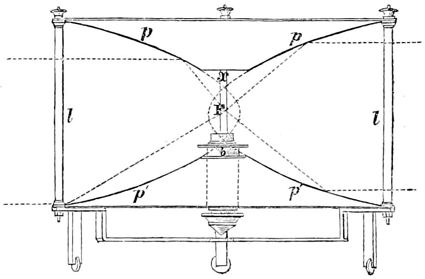
reflecting apparatus, the lamp is placed in front of the mirror,
whose surface is so formed that the rays which fall upon it, and
are reflected from it, must afterwards move in lines parallel to the
axis of the mirror; while in using Refracting instruments, the
flame is placed behind the lens, whose action is simply to bend the
rays in their passage through it, in such a manner that they come
out from its face parallel to a line drawn from the focus to the centre
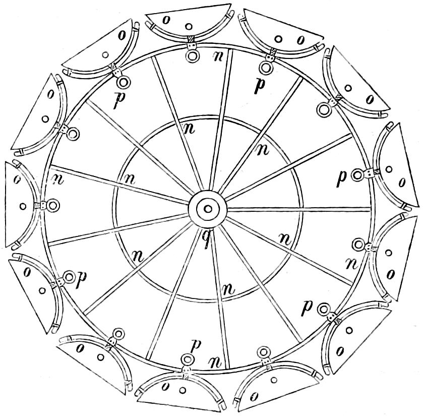
of the lens. In Revolving Lights, on the reflecting principle, the
mirrors containing the lamps are placed on a frame which revolves
on its centre, and carries them round in succession to the different
points of the horizon, so that each mirror produces a bright flash
when it crosses the line drawn from an observer’s eye to the centre
of the Lighthouse; but in Refracting Lights, a single lamp of great
power is fixed in the centre of the lightroom, while the lenses,
placed on a revolving frame, intercept and modify the rays which
fall upon them from the Lamp, as they pass in front of it, and thus
produce successive flashes whenever the centre of the lens crosses
the imaginary line already noticed, as joining the observer’s eye
and the lightroom.
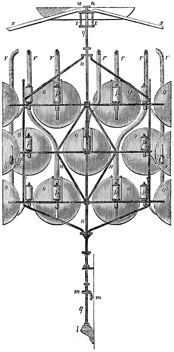
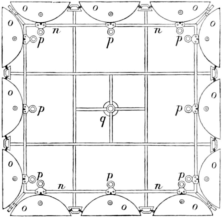
In Fixed Lights, on the Reflecting plan, the mirrors are ranged
around a fixed chandelier in tiers, one above another, their centres
being placed in spiral lines, so that each shall subtend an equal arc
of the horizon, and thus distribute the light with as little inequality
as is consistent with the application of such an instrument as the
paraboloidal mirror to this purpose. This object of distributing
the light equally over the horizon, which, next to intensity, is the
main object of a fixed light, and ought, indeed, to be strictly co-ordinate
with it, is much better effected by using dioptric instruments.
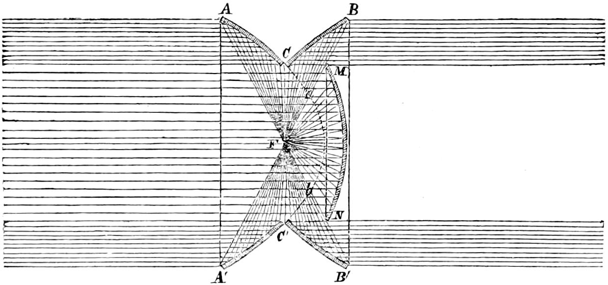
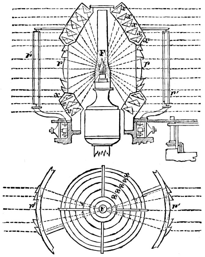
That apparatus consists of successive rings or bent prisms
arranged in the form of a hoop or belt, which may be described as
a cylinder, generated by the revolution of the central section of a
polyzonal lens about its focus as a vertical axis, and which consequently
acts only in a vertical direction, leaving the natural horizontal
divergence of the light unchanged, and thus distributing
it with perfect equality in every direction.
Those two systems of illumination possess advantages and defects
peculiar to each. The lenticular instruments insure greater
intensity when applied to revolving lights; but this advantage is
in part counterbalanced by the greater duration of the flash caused
by the reflectors, whose divergence is greater; while in fixed lights,
the refracting instruments not only produce at least an equal intensity
of light, but, what is of the greatest importance, afford the
same quantity of light in all directions, a property which fixed
Lights on the reflecting principle employed in Britain cannot
possess.
On my return from France I made a Report, which was printed
by order of the Commissioners; and the views which I gave of
the superiority of the refracting apparatus, led the Board to adopt
the resolution of at once converting the revolving light of Inchkeith
from the catoptric to the dioptric system, as its nearness to
Edinburgh offered good opportunity of observation as to the effect
of the change. In October 1835, the new light was exhibited to
the public, and I was forthwith instructed to make a similar change
on the fixed light of the Isle of May; but in carrying this into
effect, I introduced an important modification of the form of the
refracting part of the apparatus, with the view of obtaining a still
nearer approach to the equal distribution of the light. The only
other considerable change in the lightroom apparatus which has
since been effected, is the substitution of catadioptric zones in room
of the mirrors hitherto used in the subsidiary parts of the larger
French lights, which, as will appear in the sequel, was suggested
by me in 1841, and finally carried into effect in 1843, agreeably
to the computations of M. Leonor Fresnel. A Table of the
Elements of those zones computed by myself, and closely verifying
M. Fresnel’s results, will be found in the Appendix. The
lenticular apparatus has been applied at the new Lighthouse stations
of the Little Ross and the Skerryvore, and, still more recently,
at Covesea Skerries, Cromarty Point, Chanonry Point,
Loch Ryan, and Girdleness.
The establishment of a system of Beacons and
Buoys.
Beacons and Buoys on the
coast of Scotland for the purpose of affording additional facilities
to navigation, had long been looked upon as a desirable extension
of the operations of the Northern Lights Board; and the increase
of the trade and shipping of the kingdom having, some years ago,
directed particular attention to the subject, a committee was
named, on the 12th January 1839, to take special superintendence
of that department. In 1840, the Engineer reported to the committee
upwards of fifty stations for Beacons, and nearly a hundred
for Buoys, as auxiliaries to the navigation in situations where the
establishment of a Lighthouse was either too expensive or not
warranted by the wants of the district; and means were immediately
taken for erecting three Beacons in the Frith of Forth, two
in the Clyde, one in Loch Ryan, and two in Cambeltown Loch.
Beacons were also erected on the Iron Rock or Skervuile in the
Sound of Jura, and on the Covesea Skerries in Morayshire, in connection
with the Lighthouse of that name. Those works, notwithstanding
many obstacles arising from doubts as to the powers of
the Board, have been carried on with great vigour. In the Appendix,
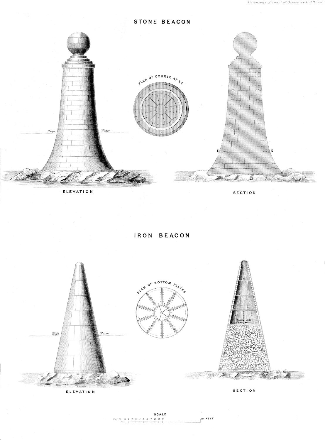
I have given drawings of three of those Beacons, one being
of masonry, and the other two of iron; and also Tables which
shew the positions of the various Beacons and Buoys at present
belonging to the Board.
CHAPTER I. TOPOGRAPHIC NOTICE OF THE SKERRYVORE ROCK.
From the great difficulty of access to the inhospitable rock of
Skerryvore, which is exposed to the full fury of the Atlantic, and
is surrounded by an almost perpetual surf, the erection of a Light
Tower on its small and rugged surface has always been regarded
as an undertaking of the most formidable kind. So discouraging
was the consideration of expense, and the uncertainty of the final
success of such a work, that the Commissioners of the Northern
Lighthouses, after successfully completing the arduous and somewhat
similar work on the Bell Rock, were induced to proceed with
other operations of less magnitude, but probably, in some respects,
of no less utility; and to delay the construction of the Skerryvore
Lighthouse till the present time, although the Act of Parliament
authorising its erection was obtained so long ago as 1814.
The cluster of Rocks, of which that called the Skerryvore is
the largest, has ever been a just cause of terror to the mariner. Its
dangers have long been known, and the means of removing these
dangers, by converting its dark horrors into a cheering guide for
the benighted mariner, have often occupied the attention of the
Lighthouse Board, and especially of my predecessor in the office
of their Engineer, with whom it was a constant subject of interest,
from its similarity to his own work on the Bell Rock.
The first landing that my Father, in the course of his annual
voyages round the coast, as Engineer of the Northern Lighthouse
Board, effected on Skerryvore, was in the year 1804. In 1814,
he visited it a second time, while accompanying a committee of
the Commissioners on a tour of inspection to the Lighthouses
all round the coast, from the Frith of Forth to the Clyde. On
that occasion, Sir Walter Scott was of the party, and we find in
his diary the following record of his impressions at the time,
expressed in the terse and humorous language by which this
interesting relic of the poet is characterised; and as the hasty
observations of that great man seem worthy of a place in a work
descriptive of the means which have been taken to obviate the
dangers to which he refers, no apology seems necessary for introducing
it in this place.
“Having crept upon deck about four in the morning,” says Sir
Walter, “I find we are beating to windward off the Isle of Tyree,
with the determination, on the part of Mr Stevenson, that his constituents
should visit a reef of rocks called Skerry Vhor, where he
thought it would be essential to have a Lighthouse. Loud remonstrances,
on the part of the Commissioners, who, one and all,
declare they will subscribe to his opinion, whatever it may be,
rather than continue the infernal buffeting. Quiet perseverance
on the part of Mr S., and great kicking, bouncing, and squabbling,
upon that of the yacht, who seems to like the idea of Skerryvore
as little as the Commissioners. At length, by dint of exertion,
come in sight of this long ridge of rocks (chiefly under water) on
which the tide breaks in a most tremendous style. There appear
a few low broad rocks at one end of the reef, which is about a
mile in length. These are never entirely under water, though the
surf dashes over them. To go through all the forms, Hamilton,
Duff,[1] and I, resolve to land upon these bare rocks, in company with
Mr Stevenson. Pull through a very heavy swell with great difficulty,
and approach a tremendous surf dashing over black pointed
rocks. Our rowers, however, get the boat into a quiet creek
between two rocks, where we contrive to land well wetted. I
saw nothing remarkable in my way excepting several seals, which
we might have shot, but, in the doubtful circumstances of the
landing, we did not care to bring guns. We took possession of the
rock in name of the Commissioners, and generously bestowed our
own great names on its crags and creeks. The rock was carefully
measured by Mr S. It will be a most desolate position for a
Lighthouse—the Bell Rock and Eddystone a joke to it, for the
nearest land is the wild island of Tyree, at fourteen miles distance.
So much for the Skerry Vhor.”
Notwithstanding those occasional visits, however, it was not
till the year 1834, that the Commissioners directed their Engineer
to make a survey of the whole of this extensive reef, preparatory
to taking measures for the erection of a Lighthouse on that part of
it which might be found, after careful inspection, to afford the
most suitable site; and, at the same time, the shores of part of the
Island of Tyree were surveyed, with the view of establishing a
Signal Tower for communicating with the Lighthouse, and of
forming a small harbour, of shelter for the vessels to be employed
in attending it. From these surveys the general view of the Reef
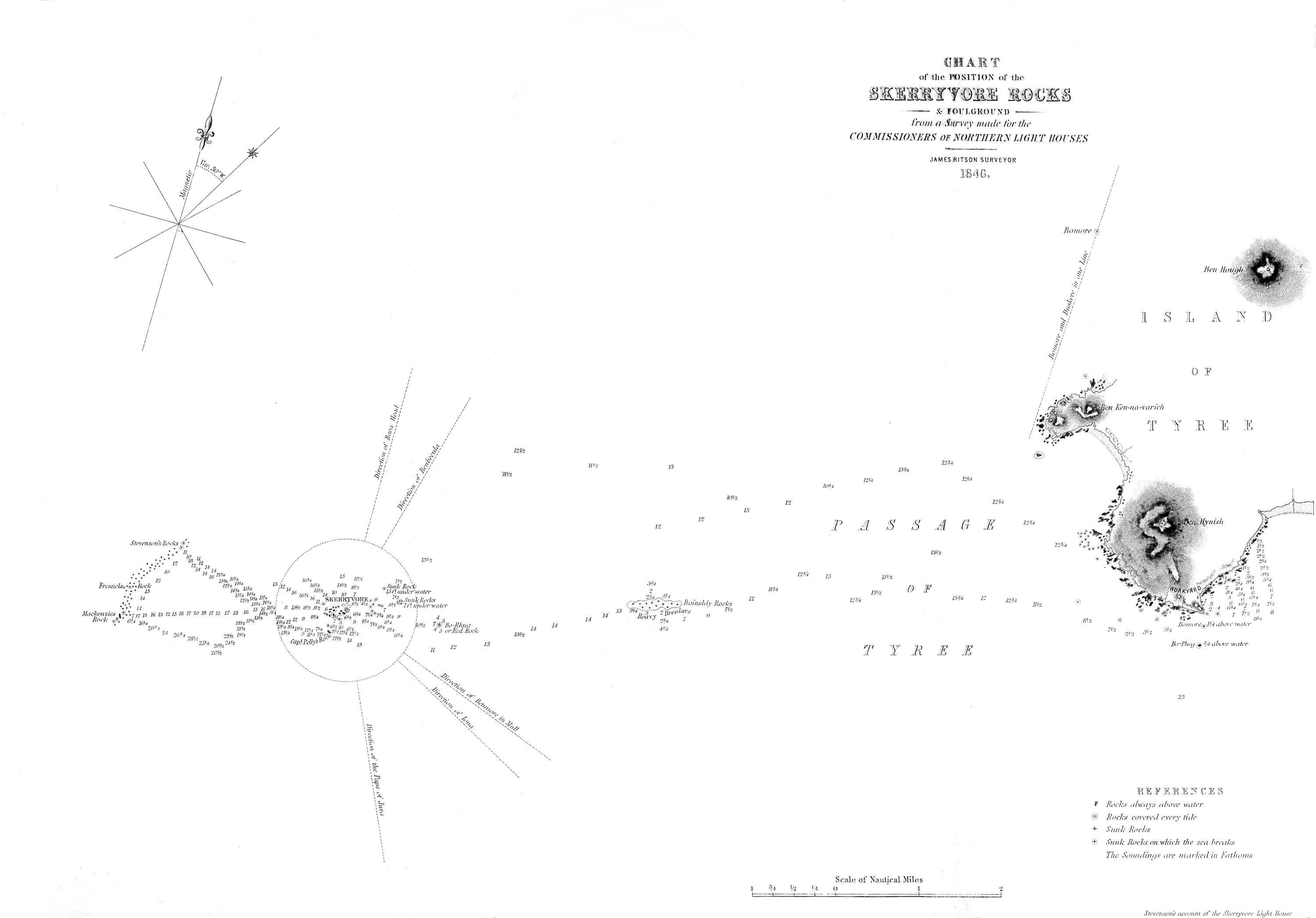
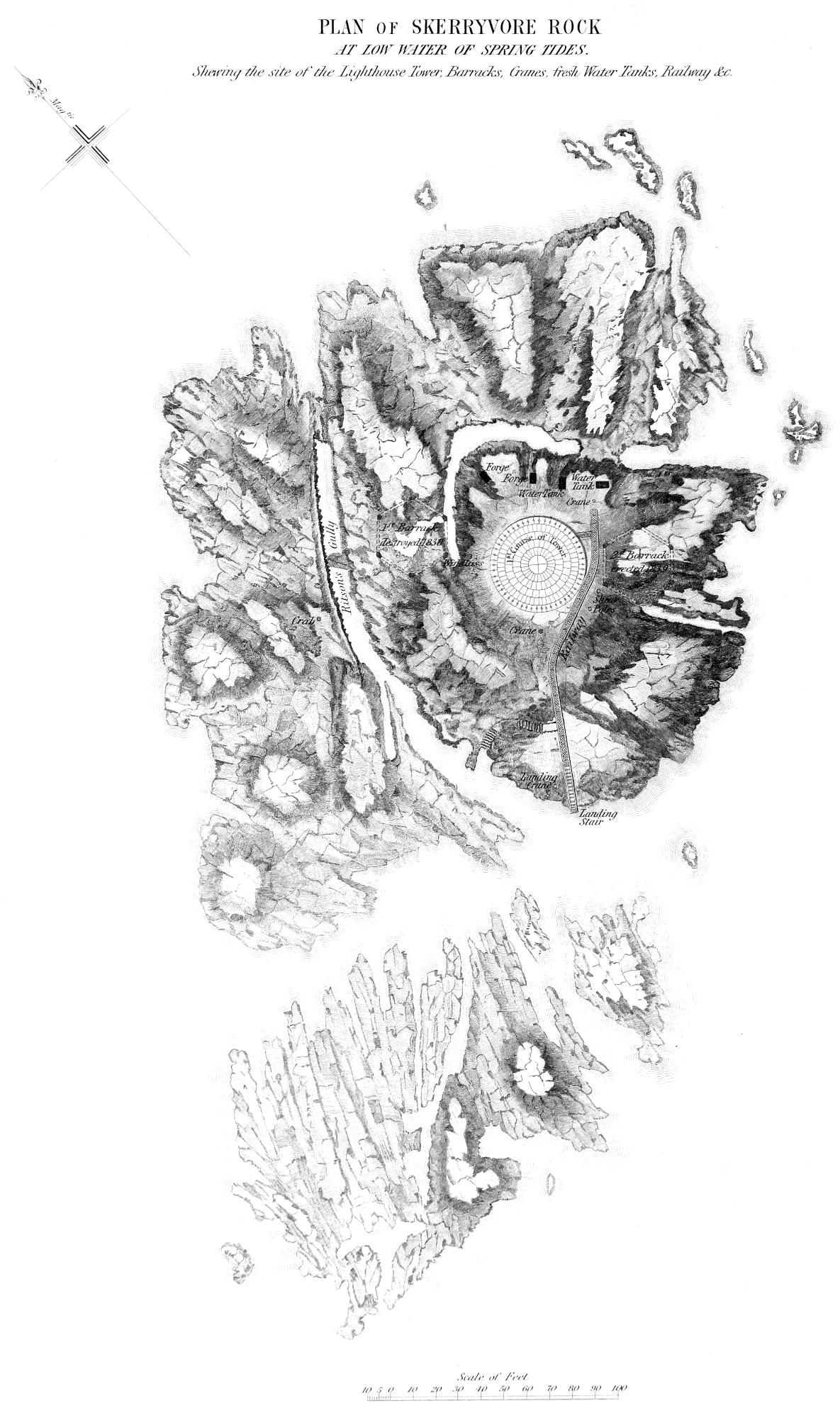
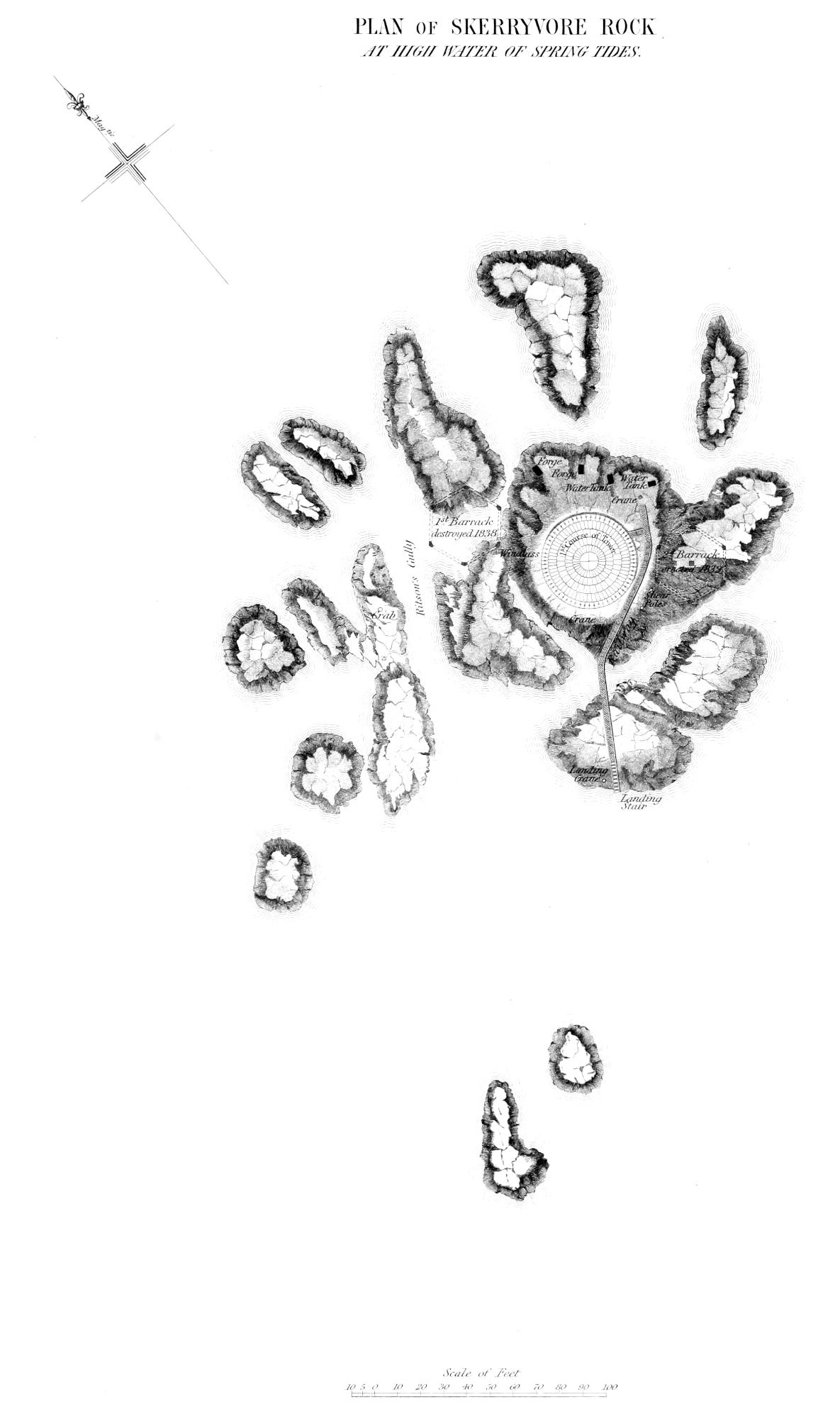
which is given in Plate II., and the enlarged plan shewn in Plate
III. of the Skerryvore or principal Rock, on which the Lighthouse
has been built, were constructed.
The Skerryvore or principal Rock of this remarkable group,
is situated in North Lat. 56° 19′ 22″, and West Long. 7° 6′ 32″.[2]
It is about 11 Nautic miles W.S.W ¹⁄₄ W. of the island of Tyree,
which is the nearest land, 20 miles W.N.W ³⁄₄ N. of the island of
Iona, 33 miles S. ¹⁄₄ E. of the Lighthouse of Barrahead, the most
southern of the Hebrides, and 53¹⁄₂ miles N.E. by N. of Mallinhead,
in the county of Donegal in Ireland. It may also be added, that
the principal rock is about 50 miles from the nearest point of
the main land of Scotland. The extent of the Reef, and its
situation in reference to the general position of the coast, will be
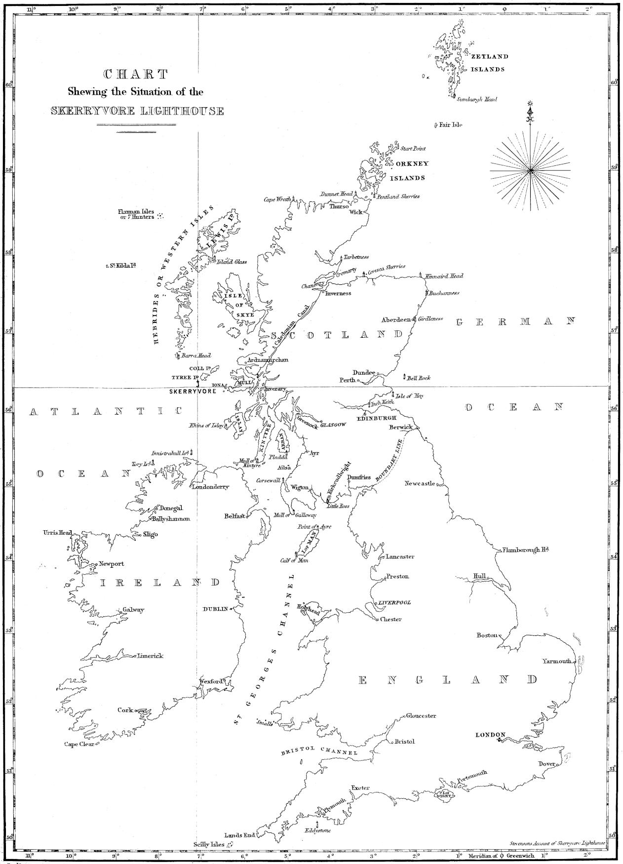
best understood by referring to Plate I., which is a small Map
of the British Isles. From this it will be seen that it lies in an
irregular semicircular sea, inclosed by the southern extremity of the
Hebrides, the rugged shores of Argyllshire, and the northern coast
of Ireland on the one side, but open on the other to the Atlantic.
[2] According to information for which I am indebted to Captain Yolland, R.E., of the
Ordnance Survey.
The importance of the Skerryvore as a station for a Lighthouse
is so evident as to require but little comment. Although the
smaller class of coasting vessels almost invariably sail through the
sheltered Sounds of Mull, Loing, and Islay, to avoid the difficulties
and dangers (Skerryvore among the number) of the rough navigation
of the outward passage, yet these rocks lie much in the track
of the larger vessels bound over seas round the North of Ireland
from the Clyde and the Mersey. Government Cruisers and Ships
of War are also necessarily often within a short distance of its
dangers. But for homeward-bound vessels sailing for the Clyde, or
for any of the Ports in the Irish sea, and directing their course for
the North Irish Channel, the establishment of a light at this place is
of the last importance. When such vessels happened to encounter
bad weather before making land, and so had difficulty in ascertaining
their true position in relation to the coast, they often, in the
event of being driven so far north from their course, as to miss
the lights of Ireland or that of Barrahead, continued their progress
onwards in the direction of the Skerryvore Rocks; and
thus, while running in apparent safety, and probably, from the state
of the weather, not within sight of Tyree, which it is often difficult
to see, they were very liable to encounter some of the many
detached rocks and shoals which form this broken reef of nearly
seven miles in extent.
In estimating the risks to which vessels were exposed from
this cause, the peculiarly insidious nature of the danger must be
kept in view. A headland, or line of coast, which rises to some
height above the surface of the sea can be seen in most states of
the weather, at a sufficient distance, even during the night, to enable
the seaman to avoid danger; but, in approaching a sunken reef
or a low rock, in the dark, there is no object to warn the crew of
their position, until their vessel gets unexpectedly among breakers,
after which it is generally too late to bring her round again. And
even the very knowledge of the existence of a reef, such as this,
often causes the seaman, in ignorance of its exact position, to give
it too wide a berth; in which case his ship is liable to be carried
away by the force of tides or winds, perhaps on a lee shore, where,
although the crew may be saved, the vessel generally goes to
pieces.
The exhibition of a Light, however, altogether changes the
case. Instead of shunning as a danger those dreaded rocks, vessels
will steer boldly on their course, until checked by the Light,
availing themselves of which they will be enabled to lie off-and-on
during the night, and so wait the return of daylight, in perfect
confidence as to their position, and without the necessity of endeavouring
to avoid hidden dangers. Thus, that which was formerly
an obstruction and a danger, is rendered an aid and a safety,
to the navigation of the western coasts of our country.
That this source of danger to shipping was by no means imaginary,
and the consequent terror of mariners far from being ill
founded, there is a too melancholy proof in the following list of
disasters caused by the Skerryvore Rock, and the neighbouring
dangers off the coast of Tyree:—
In
1790.
The Ship Rebecca of 700 tons lost; crew saved.
1804.
Ship Brigand of Nova Scotia, Wright, master, of 600 tons, lost off Hough, in Tyree; crew saved.
1804.
A Brig, M‘Iver, master, lost off Hough; crew saved.
1806.
Ellen of Bath, Paterson, master, of 90 tons, lost off Balaphuil, in Tyree; one man drowned.
1809.
Brig Mary, Sanders, master, lost off Balaphuil; crew saved.
1813.
Sloop, Penelope of Wick, 60 tons, lost at Gott Bay, Tyree; crew saved.
1810.
A Brig from New York, Greenlees, master, lost off Hynish Point, Tyree; crew all drowned.
1813.
A Sloop, Eugene M‘Intyre, master, lost off Balaphuil; one man drowned.
1814.
Brig, Betsey of Leith, Ross, master, lost off Hough; crew saved.
1817.
A Brig, of 400 tons, foundered off Kennavarah, Tyree; crew all drowned. Numerous casks of butter came ashore.
1818.
Sloop, Benlomond of Greenock, M‘Lauchlan, master, lost off Balaphuil; crew all drowned.
1819.
Sloop, Bee, Coice, master, of 60 tons, lost off Hough; crew saved.
1820.
A Sloop, M‘Donald, master, of 50 tons, lost in Reef Bay, Tyree; crew saved.
1820.
Ship, Masters, of Port-Glasgow, Martin, master, of 700 tons, foundered off Skerryvore Rocks, and came ashore at Clate
Hynish, in Tyree; crew saved.
1821.
Sloop, Catharine, M‘Rae, master lost; crew saved.
1821.
A Sloop, of 60 tons, lost off Hough; master and three men drowned.
1825.
Sloop, Dan of Campbelltown, M‘Innes, master, of 50 tons, lost; crew saved.
1828.
Sloop, Delight, of 70 tons, Stevenson, Master, lost.
1828.
An Irish Schooner of 100 tons, Montgomery, master, lost off Hough; crew saved.
1828.
Jane of Sligo, Collins, master, lost off Balaphuil.
1829.
Van Scapan of Stockholm, Fisherton, master, of 700 tons, lost off Hough; fourteen people
drowned.
1834.
Confidence of Dundee, Wesley, master, lost off Hough; crew saved.
1834.
A Schooner of 70 tons, lost; three men drowned.
1835.
Peggy, Bitters, master, of 500 tons, lost off Beist, Tyree; crew saved.
1841.
April 2. Majestic of North Shields, Tait, master, of 400 tons, foundered by a sea off Boinshly Rock, and came
ashore at Gott Bay; captain and four men washed overboard and drowned, and the mate and one seaman had their legs broken when the vessel
was struck by the sea.
1842.
Fleurs of Liverpool, Thomson, master, of 300 tons, lost off Kennavarah; crew saved.
1842.
March 14. Two deck beams, a knee, and some pieces of deck-plank of a North American built vessel, came ashore at Clate Hynish.
1842.
A Barra Boat wrecked, and four corpses washed ashore; two men, a woman and a child.
1842.
Pieces of wreck were seen in the Sound of Coll, and at the same time the shores of Tyree were strewed with candles, mostly of wax,
supposed to be altar candles for the West Indies.
1843.
September 2. The Prussian Barque Formosa, of 326 tons, P. R. Reick, master, lost off Hough; two seamen drowned.
1844.
December 1. The Hull of a Sloop of about 70 tons, was washed ashore off Clate Hynish. The Hull was very much broken up by
being in contact with the rocks; and one of the planks, apparently off the taffrail, had the words “Port of Dundee” lettered upon it; the crew
supposed to be all drowned.
This list is made up chiefly from data kindly furnished to me
by the Rev. Neil Maclean, the Minister of Tyree and Coll, whose
long residence on the former island has afforded him ample opportunity
for making observations on the subject. It is not to be
imagined, however, that Mr Maclean’s list, which is made up from
recollection, contains a full catalogue of the disasters caused by the
Skerryvore, within the dates which it cites. Very many vessels were
wrecked on this dangerous reef whose names could never be learned,
and of which nothing but portions of the drift wood or cargo came
ashore; and there have, no doubt, been many shipwrecks of which
not a single trace has been left. Nothing, indeed, is more probable
than that many of the foreign vessels whose course lay through the
North Irish Channel, and whose fate has been briefly and vaguely
described, as “foundered at sea,” have met their fate on the infames
scopuli of the Skerryvore. It is also well known that the Tyree
Fishermen were in the constant practice of visiting the Skerryvore,
after gales, in quest of wrecks and their produce, in finding which
they were but too often successful.
The natives of Tyree have many traditions of vessels having
struck on the Skerryvore and gone to pieces; but, as might have
been anticipated, few traces of this were to be found on the Rocks
themselves, the breach of sea which sweeps over them during
storms being sufficient to remove any heavy bodies which might be
left there after a shipwreck. Some relics, however, were found
during the progress of the works, and among the rest an anchor
which was fished up close to the Rock, and which appeared to have
belonged to a vessel of about 150 tons burden. It had been wasted
to a perfect shadow by the action of the sea, and was covered with
a thick coating of seaweed and barnacles. Although, however,
the Rocks themselves do not retain the proofs of the disasters of
which they have been the cause, the shores of the neighbouring
Islands, during the progress of the works, were frequently strewed
with drift wreck in such a manner as clearly to indicate what had
taken place on the shoals round the Skerryvore.
On examining Plate II., it will be seen that what I have
hitherto denominated the Skerryvore Reef, is a tract of foul ground,
consisting of various small rocks, some always above the level of
the sea, others covered at high water, and exposed only at low
water, and others, again, constantly under the surface, but on which
the sea is often seen to break after heavy gales from the westward.
This cluster of rocks extends from Tyree in a south-westerly direction,
leaving, however, between that island and the rock called
Boinshly, the first of the great Skerryvore cluster, a passage of
about five miles in breadth, and having a depth of thirteen fathoms
at low water of spring tides, but not without hidden dangers, which
line the rugged shores of Tyree from Kennavarah to Ben Hynish,
and some of which lie farther off than might be expected. This
passage is called the passage of Tyree; but it is by no means safe
during strong and long continued gales, as the sea which rises between
Tyree and Skerryvore, is such that no vessel can live in
it. I have myself often seen it one field of white broken water,
the whole way from Tyree to the Rock; and we know that the
wreck of the Majestic, which occurred in 1841, during the progress
of the works, was entirely caused by the heavy seas which she
encountered off Boinshly.
The principal rocks of the group, are called Boinshly, Bo-rhua,
and Skerryvore, while those lying to the westward, which have
been more recently laid down, have received the names of Mackenzie,
Fresnel, and Stevenson.
The rock called Boinshly lies about 3³⁄₄ miles from Skerryvore,
and is of considerable extent. The origin of the names of the different
rocks in the vicinity of Tyree is by no means clear, and very
little assistance or information is to be obtained in this matter from
the natives. The name of Boinshly is probably derived from the
Gaelic words boun, signifying bottom, and slighe, deceitful, as indicative
of the dangers of the place; but other interpretations have
been put on it, and that which has been now given is by no means
certain. In the course of the survey, several soundings were
at considerable risk obtained, both upon this Rock itself, and in its
immediate vicinity. The sea in that exposed situation is seldom
so tranquil as to warrant an attempt to approach very near this
Rock. The swell, which, in a greater or less degree, almost
constantly prevails, is apt to impel, or seemingly draw the boat
as by a kind of suction, upon the rock; and sometimes such accidents
cannot be prevented, even although the greatest caution
is used. Sudden lifts of the sea, during an apparent calm, are
common in all the more exposed parts of the coast, more especially
in the Orkney and Zetland Isles, and on the shores of the
most western of the Hebrides; and any one much accustomed to
the use of boats on these shores, must have experienced the hazard
of encountering such unexpected risings of the sea, more especially
near shelving rocks, or in rapid tide-ways. In some places the
boatmen apply the name of lumps to these sudden waves. This
effect is not felt to the same extent in attempting to reach a
rock which is partially uncovered at low water, as a landing
can, in such a case, often be effected on one side, at a time when
the same rock on the opposite side, or a sunk rock just topping
with the water, would, on every side, be quite unapproachable.
From the soundings marked on the plan, it will be seen that
shoal water extends all round Boinshly to distances varying
from a quarter to half a mile. The sea breaks on the rock with
great violence, and its position can easily be discovered from the
island of Tyree by the white foam with which it is almost constantly
surrounded, and which, in the heavy swells which sometimes
accompany a dead calm, before or after a heavy gale of
wind, rises to a prodigious height in a column or jet, resembling,
at a distance, the play of a gigantic fountain. So high, indeed,
does the sea rise on this shoal after heavy gales, that it often quite
obscures the larger and more distant object of the Rock and
Tower of the Skerryvore, even when viewed from the top of Ben
Hynish in Tyree. The wooden barrack erected on the Skerryvore
for the use of the workmen during the progress of the operations,
although about sixty feet in height, was often lost sight of at
Tyree by the uprising of the sea on Boinshly, and could be seen
only during the calm that intervenes between returning waves.
The next Rock that occurs is Bo-rhua, a name derived from
the Celtic, and signifying, according to the natives, Red Rock. It
lies about 2³⁄₄ miles from Boinshly, and about one mile from the
Skerryvore. The passage between it and Boinshly is clear, and
has a depth of about fourteen fathoms; but it is too narrow to be
safely navigated except by daylight, even under the most favourable
circumstances, and then no mariner would run the risk of taking
such a passage, but would prefer, even at some sacrifice of time, the
fairway of the passage of Tyree. Bo-rhua is completely covered at
high, but is dry at low water. The extent of rock uncovered is
about forty feet by twenty feet, and the highest point of it is about
six feet above low water level of spring tides. A small outlying
pinnacle, about ten feet square, is also uncovered at low water. The
depth immediately round Bo-rhua is considerable, from three to
seven fathoms being found within fifty feet of it; and in this respect
it differs from Boinshly, which, as already mentioned, is
surrounded by shoal water for some distance. Between Bo-rhua
and Skerryvore, however, which is a distance of about a mile,
there cannot properly be said to be any clear navigable channel, as
will be distinctly seen by referring to the plan. The whole of this
tract may, in fact, be termed foul ground.
The Skerryvore or chief rock, and the detached rocks immediately
surrounding it, were surveyed with greater minuteness than
the others, as it was at once apparent, that on this part of the reef
alone could a suitable site for a lighthouse be found. The name is
derived from the Gaelic, and signifies the Great Rock. It is very
much wasted and cut up; the number of detached rocks, sunk and
exposed, in its immediate neighbourhood, whose positions were determined
during the survey, amounting to no fewer than 130. The
depth of water between those different detached fragments, which
extend over a surface of about a mile in length, by half a mile in
breadth, is considerable, varying from 2¹⁄₂ to 8¹⁄₂ fathoms at low
water of spring tides.
The surface of the main or principal rock, on which the Lighthouse
has been placed, measures, at the lowest tides, about 280 feet
square. It is extremely irregular, and is intersected by many gullies
or fissures, of considerable breadth, and of unlooked for depth,
and which leave it solid only to the extent of 160 feet by 70 feet.
The extremity of one of these gullies, at the south-east corner of
the rock, forms the landing-creek, which is a narrow track of 30
feet wide, having deep water; and, with the help of some artificial
clearing and dressing, which was executed with much difficulty, by
blasting under water, while the other works were in progress, its
sides and bottom are now comparatively smooth. At this place a
landing can often be effected when the rock is unapproachable from
any other quarter, although great inconvenience is felt from the
surge, which finds its way from the opposite side of the rock,
through the westward opening of the gulley in which the landing-place
is situated.
Another of the gullies, immediately to the south-east of the
Lighthouse, was found, on examination, to undermine the rock to
the extent of eight or ten feet, and to terminate in a hollow submarine
chamber, which threw up a spout or jet of water about
twenty feet high, resembling in appearance the Geyser of Iceland,
and accompanied by a loud sound like the snorting of some sea
monster. The effect of this marine jet d’eau was at times extremely
beautiful, the water being so much broken as to form a
snow-white and opaque pillar, surrounded by a fine vapour, in
which, during sunshine, beautiful rainbows were observed. But
its beauties by no means reconciled us to the inconvenience and
discomfort it occasioned, by drenching us whenever our work carried
us near it. One calm day I contrived, at a very low tide,
by means of ropes and a ladder, to explore the interior of the
cavern, from which this fountain rose, and found it to terminate
in a polished spherical chamber, about seven feet in diameter, its
floor filled with boulders, whose incessant play had hollowed it
out of the veined rock, and rendered its interior beautifully
smooth and glassy. As I considered that this curious cavern
penetrated too far, and came too close to what I had selected as the
best foundation, I changed the site of the tower, so as to avoid any
chance of its being undermined. I also deemed it prudent to fill
up the cavity, to prevent its further extension, and at the same
time to rid ourselves of the discomfort of being drenched by
the column of water which spouted up from it, even during fine
weather, when the sea was apparently calm. This gulley affords a
good example of the power of pebbles kept constantly in play by
the waves to wear down the hardest rock, and shews what extensive
effects so insignificant an agent may effect in the course of
time.
Before the excavation for the foundation of the tower was made,
a single conical loaf of rock, about five feet in diameter, rose to the
height of eighteen feet above the level of high water, the greater
part of the rest of its surface being about six feet above the tide
mark.
In addition to its shattered and disjointed appearance, the
Skerryvore Rock presents, in another respect, a striking example
of the action of the sea, which no one, on first landing on the rock,
can fail to perceive. I allude to the glassy smoothness of its surface,
a feature that existed to so remarkable an extent as to have
proved throughout the whole duration of the work, but more especially
at its commencement, a serious obstacle and hindrance to the
operations. It may, at first sight, appear strange that this grievance
should have been so much felt; but, when I mention that the landings
were often made in very bad weather, it will be obvious that
there was considerable danger in springing ashore from a boat in
a heavy surf upon an irregular mass of rock as smooth and slippery
as ice. The workmen were, in that respect, often sorely tried, and
many inconvenient accidents occurred from falls. It was after one
of these trials of patience, that the foreman of the masons was
heard very graphically to describe a landing on the rock as “like
climbing up the side of a bottle.” Instead of a weather-beaten
rock, whitened by the dung of sea-fowls, and with marine crustacea
adhering to it, the surface of the Skerryvore is smoothly polished
by the action of the waves, every projecting angle or point is
worn down, and the whole presents more the appearance of a mass
of dark-coloured glass than a reef of gneiss-rock. Excepting in
some of the more sheltered crevices, no marine crustacea find shelter;
but different kinds of sea-plants grow upon it, in great abundance,
at and below the low water mark. These plants are, doubtless,
enabled to resist the action of the waves in the same way as
the sapling, yielding to the blast, is preserved during the storm that
uproots the aged and more stubborn oak.
The rocks of Skerryvore have the same characteristics as those
of the neighbourhood of Tyree, being what we may, perhaps, call
a syenitic gneiss, as it consists of quartz, felspar, hornblende, and
also mica. It will be seen, from the narrative of the progress of
the works, that this rock was, from its hardness, exceedingly difficult
and tedious to excavate. The only variation in the geology of
the Skerryvore, is the presence of a trap rock, in the form of a
dyke of basalt, which intersects the strata, and exhibits a fine specimen
of the intrusion of igneous rocks. It is shewn in Plate,
No. III., by a thick black line.
Connected with this general view of the appearance and geology
of the rock, it may be interesting also to notice, that a considerable
mass of foreign matter, somewhat resembling, in its
structure, a deposit of lime, was found in different places resting in
horizontal layers of various thickness and size. This substance
was found in pools or sheltered parts of the rock, about the level
of high water mark, and, in some cases, even a little below it. It
was so hard as to admit of a pretty high degree of polish; and
emitted an offensive odour on being burned in the fire, or rubbed
on a stone with water. It gave other clear indications of containing
animal matter, and in other respects resembled the bergmeal
and guano. To account for its presence in such a situation, seems
rather a difficult problem. On sending a specimen of this material
to my friend the Rev. Dr Fleming, Professor of Natural Philosophy
in King’s College, Aberdeen, I received from him an analysis
of the substance, and a concurrence in the opinion I had
formed as to its containing animal matter; and Dr Fleming, indeed,
expressed his belief that the matter in question is the indurated
soil of birds, and had been deposited when the reef was more
extensive, and the resort, and probably the breeding-place of sea-fowls.[3]
How this singular formation should be found on the verge
of the ocean, and even within the high water mark, in spite of
winds and waves, or how it should have assumed the stratified
structure which seems to indicate the depositation of successive
layers in still water, are matters very difficult to be explained, without
coming to the conclusion, that the uncovered surface of Skerryvore
Rock must at some distant period have been much more extensive
than at present, so as to permit the deposit to go on in an interior
basin or lagoon, sheltered from the waves, and somewhat similar
to those which Dr Darwin has described as characteristic of the
Coral Isles of the Pacific. This supposition seems not at all improbable,
as it does not require a great stretch of fancy to conceive, that
at some period, the whole of the rocks in the immediate vicinity
of Skerryvore, and extending perhaps even so far as Bo-rhua, may
have been connected by a matrix of softer materials, which have
gradually yielded to the action of the sea, leaving the harder portions
to be smoothed and polished by the waves, and to assume the
characteristic features of permanent rocks and sunk reefs which
they now possess. There is also some countenance to such a view
to be derived from the features of the neighbouring Island of Tyree,
which contains numerous small lagoons, in which such deposits
might be formed by the flocks of sea fowl which frequent them.
Some of these pools are so near the shore, as to make it no difficult
matter to conceive that their walls might be broken by the sea,
and that they might eventually become part of it, and thus exhibit
the phenomenon of deposits apparently lacustrine within the verge
of the ocean.
[3] Dr Fleming has since obtained from Ichaboe indurated bird-soil or guano, closely resembling
that from the Skerryvore.
Another remarkable feature which I observed in the Skerryvore
Rock, was a deposit of gravel in the narrow crevices of the
rock, which run nearly from north-east to south-west, dipping at an
angle of 80° to the westward. In almost all of the fissures we found
great quantities of small water worn boulders, less in size than a horsebean,
and generally of the same materials as the rock itself. The
boulders bore the appearance of having been forced into the fissures
of the rock by some very powerful pressure, and were wedged hard
into the crevices. In some cases a considerable quantity of softer
matter containing iron was found, and in it the pebbles were imbedded.
In the upper parts of the rock the crevices swarmed
with centipedes of a reddish-brown colour. The rock was covered
with sea fowl when first visited, and during heavy gales seals resorted
to it.
About three miles to the westward of Skerryvore lie Mackenzie’s
Rock, Fresnel’s Rock, and Stevenson’s Rock, which, as will be
seen from Plate II., are connected by a tract of foul ground of
about a mile and a quarter in length. Those rocks are the western
limit of what we have already denominated the Skerryvore Reef.
The passage between them and the Skerryvore or main rock is clear,
and has a depth of water varying from eleven to twenty-eight
fathoms.
Mackenzie’s Rock, which derives its name from the celebrated
Marine Surveyor, is uncovered, at low water, to the extent of about
forty yards, and consists of scattered patches of rock, one of which,
at its highest part, rises about ten feet above high water mark of
spring-tides. Fresnel’s and Stevenson’s Rocks are always under
water; but the sea is often seen to break violently over them, as
well as over the whole stretch of the sunken reefs which extend
between them. The first of those rocks is indebted for its name
to the great optical philosopher, who so greatly improved lighthouses;
and the second bears the name of the surveyor who first
laid down the rock,—the late Engineer of the Northern Lights
Board.
During the progress of the survey, a register of the rise and fall
of the tides was regularly kept at Hynish on the neighbouring
Island of Tyree; and from those observations it was determined,
that the rise at that place is between twelve and thirteen feet at
high spring tides, and three feet at dead low neap tides; and observations
subsequently made while the works were in progress,
gave the same results at the Rock of Skerryvore. It is high
water at the Rock at full and change of the moon, at five hours
and twenty-five minutes. The tides round the Skerryvore are not
remarkable for their rapidity. In spring-tides the velocity is between
four and five miles, and in neap-tides between two and
three miles an hour. The flood sets to the N.N.E., and the ebb to
the S.S.W.
CHAPTER II. PRELIMINARY ARRANGEMENTS AND WORKS, INCLUDING SURVEY OF THE ROCKS, AND OPENING OF QUARRIES, FROM 1834 to 1837.
In this chapter I shall very briefly notice those preliminary arrangements
which may be said to have been in a great measure preparatory
to the commencement of the work itself. It has been already
stated, that the erection of the Lighthouse was provided for
in the Act of 1814; but so formidable did this work appear,
that although it was repeatedly under consideration, it was not
until the General Meeting of the Board, on the 8th July 1834,
that any measures were taken to carry into effect the provisions
of the Act. On that occasion it was moved by the late Mr
Maconochie, Sheriff of Orkney and Zetland, that the Engineer
should be instructed to make the Survey of the
Skerryvore
Rocks.
necessary survey, and to report
as to the expense of erecting the Lighthouse. In terms of
this remit, the survey of the Rocks was commenced in the autumn
of 1834; but from the broken state of the weather, little was
effected at that time beyond making the triangulation; and it was
not until the summer of 1835 that the survey was completed from
which the Chart, Plate No. II. was constructed. This survey was
attended with much more labour than its extent would lead one
to suppose, in consequence of its embracing the entire range of
operations required in a more extensive nautical survey, and combining
with the ordinary details required for a Chart, the minute
accuracy in regard to surface and levels, which are always necessary
for the purposes of the Engineer.
The first step was the measurement of a base line in the low
lands of the adjoining Island of Tyree, which, owing to the distance
and disadvantageous position of that island, could not be
satisfactorily extended to the Rock without fixing stations in some
of the more distant islands; and in the course of the work not fewer
than twenty land triangles were measured. The calculations of the
distances founded on this triangulation agreed with those afterwards
obtained from the data of the Trigonometrical Survey, which were
kindly furnished to me by Captain Yolland of the Royal Engineers,
in 1843. For the purpose of making the soundings and laying
down the sunken rocks, an entirely separate triangulation, based
upon and connected with that which has already been noticed, became
necessary, as the land objects were too distant, and their relative
positions were such as to render it difficult by observations from
them alone to determine any stations on the sea. Buoys were therefore
moored at convenient points, and their positions determined
by a subsidiary triangulation, so as to form a net-work of triangles
between the shore and the Skerryvore Rock. The distances between
these buoys were afterwards used as the bases of imaginary
triangles, having points of sounding or shoals in their apex;
and the angles subtended by those distances being measured by
the sextant, the positions of the shoals or soundings were thence
easily deduced and protracted on the Chart.[4] In connection also
with the soundings whose positions were determined in the way
above described, a complete set of tide observations was made,
extending over a period of about six weeks. Those tide observations
were connected in point of time, with the soundings, and
were employed as the means of correcting the observed depths
taken with the sounding-line, so as to give the true depth in reference
to the high or low water of a given tide. Accurate measurements,
and minute sections, were also made of the rocks in reference
to the tide-level, and more especially of the main rock, on which
alone it was obvious, from the first inspection, that the Lighthouse
Tower could be erected. In the course of this survey, the positions
of upwards of 140 rocks were determined, and laid down on the
Chart, and 500 soundings were taken, and their positions protracted.
An interesting fact was also noticed regarding the mean level of all
the tides which had been watched during the period of about six
weeks, as above noticed, viz., that the point half way between the
high and low water of every tide is on one and the same level. This
fact regarding the tides was, it is believed, first detected by my
Father, in the course of some tidal observations which he made in
the Dornoch Frith in 1830, and has since been observed in the
Frith of Forth in 1833, and again on the shores of the Isle of Man,
and at Liverpool. The agreement of so many observations by various
persons at places on the opposite shores of the Kingdom, seems to
imply the universality of this phenomenon in the British Seas; and
the position of Skerryvore would lead to the belief, that it is
not confined to narrow seas, but that it exists in the ocean. I
cannot dismiss the subject of the survey, without mentioning the
late Mr James Ritson, who acted as principal assistant surveyor,
and to whose zeal and intelligence so much of its accuracy is
to be attributed. The deep gulley which intersects the main
Rock from N.E. to S.W., and across which he one day sprang while
it was filled with a breaking wave, bears his name, as a memorial
of his activity and perseverance. At the close of the survey in
1835, the station-pole was left wedged and batted into one of the
fissures or crevices of the Rock, and a cask of water was firmly
lashed to ring-bolts in a cleft of the highest part of the Rock, in
the hope that it might possibly prove useful to some shipwrecked
seamen.
[4]Vide Stevenson’s Marine Surveying and Hydrometry. Edinburgh, 1842, p. 144.
For the purposes of navigation generally, a survey merely
indicating the position and extent of the foul ground would have
been sufficient. But in connection with the work which was about
to be commenced, it was particularly desirable to have exact details
of the depths, rocks, and shallows of the surrounding sea, with the
nature of the bottom, accurately laid down; and our experience
during the course of the work, more than once shewed how essential
was the possession of minute topographic information to
the safety of the shipping attending the works; more especially as
some of the vessels lay very near the rocks, and were frequently
driven, by a sudden change of wind, to seek shelter, during the
darkest nights, among the neighbouring islands.
Until this time the greatest ignorance prevailed amongst seamen
as to the extent of the Reef, which had never before been minutely
surveyed. Of this some proofs occurred even during the
progress of the survey; for several vessels came so near the Rocks
as to cause, in the minds of the surveyors, who witnessed their
temerity, serious fears for their safety. On one occasion, in particular,
a large vessel belonging to Yarmouth, with a cargo of timber,
was actually boarded between Mackenzie’s Rock and the main Rock
of Skerryvore by the surveyors, who warned the master of his
danger in having so nearly approached these rocks, of the existence
of which his chart gave no indication. On another occasion,
a vessel belonging to Newcastle was boarded while passing between
Bo-Rhua and the main Rock; and so little, indeed, had the master
(whose chart terminated with the main Rock, and shewed nothing of
Bo-Rhua) been dreaming of danger, or fancying that he was within
a cable’s length of the reef, that he was found lying at ease on the
companion, enjoying his pipe, with his wife sitting beside him knitting
stockings.
Much preliminary investigation was necessarily occasioned by
the difficulties and disadvantages arising from the remote situation
of the island in which a great part of the works was to be carried
on. Not only is the Rock itself often inaccessible and dangerous,
being surrounded by numerous shoals, and visited by the heaviest
seas of the Atlantic; but what gave rise to no small part of the
difficulties which attended this work, was the nature of the neighbouring
Island of Tyree. Disadvantages of
Tyree.
This island is unhappily destitute of any
shelter for shipping, a fact which was noticed as a hinderance to its
improvement, upwards of 140 years ago, by Martin, in his well-known
description of the Western Islands.[5] Nor is its interior
more attractive; for although some parts of the soil when cultivated
are excellent, the greater part of its surface is composed of
sand. It was therefore obvious, at a glance, that Tyree was one
of those places to which every thing must be brought; and this is
not much to be wondered at, as the population, who, on a surface
not exceeding 27 square miles, amounted in 1841 to 4687 souls,
labour under all the disadvantages of remoteness from markets,
inaccessible shores and stormy seas, and the oft-recurring toil of
seeking fuel (of which Tyree itself is destitute) from the Island
of Mull, nearly 30 miles distant, through a stormy sea. It is
said that this total absence of fuel in Tyree is the result of the
reckless manner in which it was wasted, in former days, in the preparation
of whisky; but, however this may be, certain it is that
the want of fuel greatly depresses the condition of the people. For
our works, therefore, craftsmen of every sort were to be transported,
houses were to be built for their reception, provisions and
fuel were to be imported, and tools and implements of every kind
were to be made.
[5] A Description of the Western Islands of Scotland, &c., by M. Martin, Gent. London,
1703. Vide 2d Edition of 1716, p. 267.
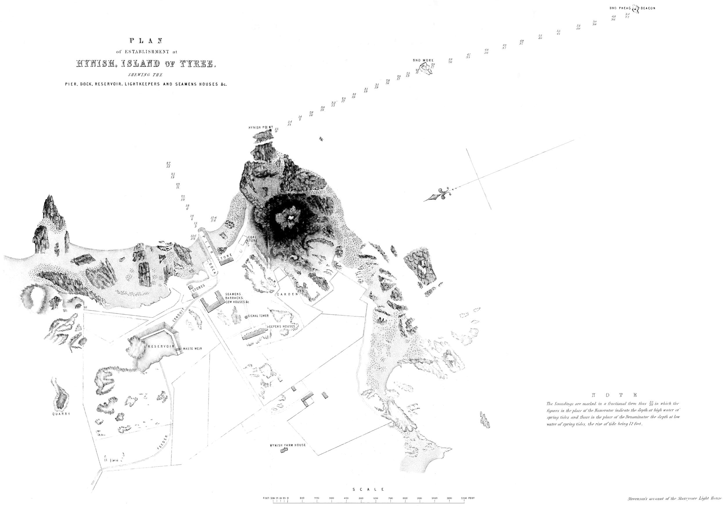
In the course of the survey, much attention had been bestowed
upon the selection of a convenient place for a workyard in Tyree
for the preparation of materials, and in examining its rugged
shores in quest of the best site for a Harbour, for the shipment
of the building materials for the Rock, and for the all-important
purpose of enabling the future attending vessel to lie in safety
within sight of signals from the Rock, when the Light should
come to be exhibited to the public. The point chosen for this
establishment was Pier and workyard
at Hynish
Tyree.
Hynish, which, though twelve miles distant, is,
nevertheless, the nearest creek to the Skerryvore Rock, and which,
however exposed it may be, if compared with creeks elsewhere
dignified with the name of Harbour, certainly affords as good prospect
of shelter as any other part of the Island of Tyree, and is, in this
respect, greatly to be preferred to any other place within sight of
the Rock. A deputation of the Commissioners visited the Skerryvore
in the month of July 1836, and concurred with the Engineer
in regard to his choice of Hynish as a site for the Harbour and
establishment.
Another most important point of inquiry was regarding the
materials for building the Lighthouse; and on this subject the suggestions
in a Report by the Engineer, of the 31st December 1835, were
followed, which proposed the opening of quarries among the gneiss
rocks around Quarries at
Hynish.
Hynish. Much facility was afforded by the liberality
of the late Duke of Argyll, the proprietor of Tyree, who granted
to the Commissioners free permission “to quarry materials for
the purpose of the Lighthouse, on any part of the Argyll estates.”
This freedom was generously continued by the present Duke, who
has all along taken a lively interest in the success of the works.
In terms, therefore, of the Engineer’s recommendations contained
in the above noticed Report, Mr James Scott and fourteen
quarriers were employed, during the summers of 1836 and 1837,
in opening quarries, with very promising appearances of final success,
among the gneiss rocks near Hynish Point. In the summer
of 1837, Mr Scott and his party turned out about 3800 cubic
feet of rock, capable of being applied to the purposes of squared
masonry, and a very large quantity of stones fit for rubble work.
This produce, although small, if contrasted with that of established
quarries, is by no means despicable, when the force employed
and all the disadvantages of the situation are considered; and if
the nature of the material, which is full of rents and fissures (technically
called dries and cutters), the frequent deceptions attending
the opening of new quarries, the excessive hardness and unworkable
nature of the rock, the quality and size of the blocks required
to entitle them to claim a place in a marine tower, and the great
loss of time, caused by the badness of the weather, be considered,
it will not appear that Mr Scott and his party had been eating the
bread of idleness.
In the mean time, measures had been taken for obtaining from
his Grace the Duke of Argyll a feu of fifteen acres of ground at
Hynish, for carrying on the works, with a view to its being finally
occupied as an establishment for the crew of the vessel which was
to attend the Lighthouse, and the families of the four lightkeepers,
as well as for the site of the harbour. To this was added a lease
of thirty acres, for the various purposes connected with a workyard,
and such an establishment as seemed necessary for carrying
on the work. A subject of anxious deliberation with the Board,
was the construction of the harbour at Hynish for the vessels
engaged in the service of the work; and the Commissioners, on
the 24th May 1837, authorized the Engineer to make arrangements
for commencing the formation of the Pier. The work
was, accordingly, undertaken, in terms of his Reports of the 31st
December 1835, and 27th February 1836; and the summer of
1837 was chiefly occupied in preparing a wharf, mostly composed
of pierres-perdues,[6] and in the opening of the quarry already
noticed. Such may serve as a brief and somewhat desultory
notice of the work during the seasons of 1836 and 1837, after
which it appeared to the Board that the operations must soon
assume such an aspect as to require the superintendence of a committee
of their number, as well as that of an Engineer specially
entrusted with the management of the work.
[6] Blocks rough from the quarry, which are dropt or thrown promiscuously into the sea.
At the meeting of the Board, on the 8th December 1837, a
Committee of their number was accordingly named, to superintend
the erection of the Lighthouse. Skerryvore Committee
appointed.
This Committee consisted of—Robert
Bruce, Esq., Sheriff of Argyllshire; Andrew Murray,
Esq., Sheriff of Aberdeenshire; Robert Thomson, Esq., Sheriff of
Caithness; and the late James Maconochie, Esq., Sheriff of
Orkney and Zetland; and, shortly after its appointment, the Committee,
on the motion of Mr Bruce, the Chairman, appointed me
Engineer for the work.
Among the first matters which engaged the attention of this
Committee, was a Report from the Engineer, dated the 30th
January 1838, in which the necessity of erecting a wooden
barrack, as a place of shelter for the workmen on the Rock,
was pointed out; the general arrangements for carrying on the
operations were described; and the building of a steam-tender,
to act as a towing vessel for the stone lighters between the
workyard in Tyree and the Rock, was also recommended.
The Report was accompanied by a detailed requisition or estimate
for the operations of the ensuing season, amounting to
L.15,000 : 3 : 3; of which sum it was proposed to expend about
one-third in building a steam-tender, and the rest in erecting the
wooden barrack on the Rock, and in providing tools and materials
for the work, as well as in the wages of men to be employed in
preparing the foundation of the Lighthouse Tower, and in building
the Pier, and dressing stones at Hynish.
The Committee, after considerable deliberation, sanctioned the
various items of the estimate, but hesitated to embark in the expense
of building a steamer, until a fruitless correspondence with
various ports of the kingdom, with the view of purchasing an
old vessel, satisfied them of the necessity of building a tender
expressly for the purpose.
Offers were immediately received from various parties at
Greenock for the preparation of the wooden barrack, which was
soon afterwards commenced by the late Mr John Fleming, house-carpenter,
who was the successful competitor.
CHAPTER III. ON THE CONSTRUCTION OF LIGHTHOUSE TOWERS.
In this chapter I purpose, in the first place, to make a few observations
regarding the construction of Lighthouse Towers in
situations which are exposed to the assault of the waves, and
afterwards to give a short notice of the design which I adopted
for the Tower on the Skerryvore Rock. In making a design
for a Lighthouse Tower in an exposed situation, numerous considerations
at once present themselves to the Engineer; and it
is difficult to assign to any one of them a priority in the train
of thought which eventually conducts him to the formation of
his plan. These considerations, however, may be conveniently
divided into two classes:—1st, Those which refer to elements
common to Lighthouses in all situations, and differ only in
amount, such as the height of the Tower necessary for commanding
a given visible horizon, and the accommodation required
for the Lightkeepers and the Stores; and, 2d, Those which are
peculiar to Towers in exposed situations, and which refer solely
to their fitness to resist the force of the waves which tend to
destroy them. The first class of considerations is so extremely
simple, as to require few remarks in this place. The distance at
which it is desirable that a light should be visible being ascertained,
with reference to the nature of the surrounding seas and
the extent to which any dangerous or foul ground lies seaward of
the proposed Lighthouse, the height of the Tower is at once determined
by means of the known relations which subsist between
the spheroidicity of the earth, the effects of atmospheric refraction,
and the height required for an object which is to be seen from a
given distance. The question regarding the space to be provided
in the interior of the Tower, can only be properly answered
by a person who has a minute practical acquaintance with the
peculiar wants and the internal economy of Lighthouses. The
accommodation required for Lighthouses in exposed situations
must, in a considerable degree, depend upon the greater or less
facility of access to them, and the opportunities for replenishing
the stores of all kinds which are in daily consumption. In such
places, also, the risk of accidents naturally leads to the precaution
of retaining additional Lightkeepers, and of having duplicates
or even triplets of those parts of the apparatus that are
liable to be injured. Of such circumstances, corresponding extension
of the space devoted to the reception of Stores and the
accommodation of the Lightkeepers, is the necessary consequence.
In the long nights of a Scotch winter, when the lamps are kept
burning for about seventeen hours, during which time they are
never left for a moment without the superintendence of at least
one Keeper, the care of the light, even in the most favourable
situations, necessarily occupies at least two persons; but in places
like the Eddystone, the Bell Rock, and the Skerryvore, where it
sometimes happens that six or eight weeks elapse without its being
possible to effect a landing, it has been thought necessary that
there should never be fewer than three Keepers on duty. This
addition to the ordinary establishment of a Lighthouse calls for
a greater number of sleeping-cabins, and, at the same time, involves
a corresponding increase in the supply of water, fuel and
other provisions, requiring much additional stowage. So far, therefore,
a Light Tower in an exposed situation, differs from one on
shore only in the extent of its internal accommodation.
The second class of considerations, which must guide the Engineer
in framing a design for a Light Tower which is exposed
to the force of the waves, refers solely to the stability of the
building.
The first observation which must occur to any one who considers
the subject is, that we know little of the nature, amount and
modifications of the forces, on the proper investigation of which the
application of the principle which regulates the construction must
be based. When it is recollected, that, so far from possessing any
accurate information regarding the momentum of the waves, we
have little more than conjecture to guide us, it will be obvious,
that we are not in a situation to estimate the power or intensity
of those shocks to which Sea Towers are subject; and much less
can we pretend to deal with the variations of these forces which
shoals and obstructing rocks produce, or to determine the power
of the waves as destructive agents. No systematic or intelligible
attempt has been made practically to measure the force of the
waves, so as to furnish the Engineer with a constant to guide him
in his attempts to oppose the inroads of the ocean. The only
experiments, indeed, on the subject, with which I am acquainted,
are those of Mr Thomas Stevenson, Civil-Engineer, who had long
entertained the idea of registering the force of the impulse of the
waves, and lately contrived an instrument for the purpose, which
he has applied at various parts of the coast. I therefore gladly
avail myself of the present opportunity, to give a brief statement
of the results indicated by it, as contained in a paper by the inventor,
which appeared in the Transactions of the Royal Society
of Edinburgh of 20th January 1845, and of which a digest will
be found in the Appendix, as any attempt to throw light upon
this most obscure, but highly important subject, cannot fail to be
interesting, not merely to the philosopher, but to the Marine
Architect. It would naturally be expected, that the force of the
waves should vary according to the season of the year, and the
nature of the exposure, and this expectation is fully justified by
the indications of the Marine Dynamometer. Thus it appears,
that during five summer months of 1843 and 1844, the average
indications registered at different places near Tyree and
Skerryvore, gave 611 lb. of pressure per square foot of surface
exposed to the waves; while the average for the winter months
for the same places during those two years, gave 2086 lb.
per square foot, or upwards of three times that of the summer
months. It also appears, that the greatest result as yet obtained
at Skerryvore Rock was 4335 lb. per square foot; while that observed
on the Bell Rock was 3013 lb., or one-fourth part less than
that of Skerryvore. But these experiments have not been continued
long enough as yet to render them available for the Engineer.
In the present state of our information, therefore, we
cannot be said to possess the elements of exact investigation, and
must consequently be guided chiefly by the results of those numerous
cases which observation collects, and which reason arranges,
in the form which constitutes what is called professional
experience. This kind of experience can only be acquired by
long habit in carefully observing the appearance and effects of
waves in different situations, and under various circumstances. We
must attend to their magnitude and velocity, their level in regard
to the rocks on which they break, the height of the spray caused by
their collision against the shore, the masses of rock which they
have been able to move, and those which have successfully resisted
their assault; as also, where such exist, the slopes of the shores
produced by the waves, viewed in connection with the nature of the
materials composing the beach, with many other transient features
which an experienced eye seizes and fixes in the mind as elements
of primary importance in determining the power of the sea to produce
certain effects. Such phenomena, with all their features and circumstances,
we may carry in our recollection; and by comparing them
with what has been observed at places where we know that artificial
works have resisted the shocks of the waves, we may in some
cases successfully arrive at a conclusion as to what works will, at all
events, be within the bounds of safety. We must not, however,
in any case, venture to approach too near the limit of stability, so
long as we continue to labour under our present disadvantages of
defective information on some of the most important elements
in the inquiry. If it be asked, therefore, how the size and form
of buildings exposed to the shock of the waves are to be determined,
the answer must be, that, in any given case, the problem is
to be solved chiefly by the union of an extensive knowledge of
what the sea has done against man, and how, and to what extent,
man has succeeded in controlling the sea; together with a cautious
comparison of the circumstances which modify and affect any given
case which has not been the object of direct experience; nor does
it seem possible as yet to found the art of Engineering, in so far
as it refers to this class of works, upon any more exact basis.
The uncertainty which must ever attend such reasoning can only,
it is obvious, be dispelled by actual experience of the result; and
time only can test the success of our schemes in cases of difficulty.
A primary inquiry, in regard to Towers in an exposed situation,
is the question, whether their stability should depend upon their
strength or their weight; or, in other words, on their cohesion, or
their inertia? In preferring weight to strength, we more closely
follow the course pointed out by the analogy of nature; and
this must not be regarded as a mere notional advantage, for the
more close the analogy between nature and our works, the less
difficulty we shall experience in passing from nature to art, and
the more directly will our observations on natural phenomena bear
upon the artificial project. If, for example, we make a series of
observations on the force of the sea, as exerted on masses of rock,
and endeavour to draw from these observations some conclusions
as to the amount and direction of that force, as exhibited by the
masses of rock which resist it successfully and the forms which
these masses assume, we shall pass naturally to the determination
of the mass and form of a building which may be capable of opposing
similar forces, as we conclude, with some reason, that the mass and
form of the natural rock are exponents of the amount and direction
of the forces they have so long continued to resist. It will readily
be perceived, that we are in a very different and less advantageous
position when we attempt, from such observations of natural phenomena,
in which weight is solely concerned, to deduce the strength of
an artificial fabric capable of resisting the same forces; for we must
at once pass from one category to another, and endeavour to determine
the strength of a comparatively light object which shall be
able to sustain the same shock, which we know, by direct experience,
may be resisted by a given weight. Another very obvious
reason why we should prefer mass and weight to strength, as a source
of stability, is, that the effect of mere inertia is constant and unchangeable
in its nature; while the strength which results, even
from the most judiciously disposed and well executed fixtures of a
comparatively light fabric, is constantly subject to be impaired by
the loosening of such fixtures, occasioned by the almost incessant
tremor to which structures of this kind must be subject, from the
beating of the waves.[7] Mass, therefore, seems to be a source of
stability, the effect of which is at once apprehended by the mind, as
more in harmony with the conservative principles of nature, and
unquestionably less liable to be deteriorated than the strength,
which depends upon the careful proportion and adjustment of
parts.
[7] It was chiefly on these grounds that the Commissioners of Northern Lights, after consulting
a Committee of the Royal Society of Edinburgh, and Messrs Cubitt and Rennie, Civil
Engineers, rejected the design of Captain Sir Samuel Brown, R. N., who volunteered a proposal
to build an Iron Pillar at the time that the erection of the Skerryvore Lighthouse was
determined on in 1835.
Having satisfied himself that weight is the most eligible source
of stability, the next step of the Engineer is to inquire what
quantity of matter is necessary to produce stability, and what is
the most advantageous form for its arrangement in a tower. The
first question, which respects the mass to be employed, is, as already
stated, one of the utmost difficulty, and can be solved by experience
alone, directed by that natural sagacity which Smeaton, in
his account of his own thoughts on the subject, with much naïveté,
terms ‘feelings,’ in contradistinction to that more accurate process
of deduction which he calls ‘calculation.’ It is very difficult, for
example, to conceive that the waves could displace a cylindric
block of granite, 25 feet in diameter and 10 feet high, which would
contain about 380 tons, and we almost feel that they could not do
so. If, in order to test the soundness of this expectation, we appeal
to such experience as we possess, and apply to the largest vertical
section of such a solid, the greatest force yet indicated by my
brother’s Marine Dynamometer, which, as already stated, is 4335
lb. per square foot, we shall obtain a pressure of 484 tons, which,
being reduced by one-half[8] for the loss of force occasioned by the
convexity of the opposing cylindric surface, gives 242 tons, as
the greatest force of the waves tending to displace the cylinder.
But in the extreme case we have now supposed the solid will
be entirely immersed in the water, and its efficient weight will thus
be reduced by 140 tons, or the weight of an equal bulk of sea-water;
and the remaining weight of 240 tons, by which it will resist
the force of the waves, will be almost exactly equal to the pressure
which they exert. This imaginary cylinder may, however,
be regarded as still within the limits of safety, because the waves
could not overturn it, unless their pressure exceeded the weight of
the block in a ratio greater than that of its diameter to its height,
which in this case is that of 25 to 10, or 2¹⁄₂ times. In order, therefore,
to endanger the stability of the solid by overturning it, the pressure,
instead of being 240 tons, must be 600 tons.[9] We have thus
seen, that the cylinder is secure from the chance of being overturned;
but we have yet to consider how far it is exempt from the risk of being
displaced by the pressure of the waves, causing it to slide along
the surface of the Rock, owing to deficiency of friction between
the two surfaces in contact. The block, for our present purposes,
may be regarded as monolithic, either being really so or as a mass
composed of parts so united by joggles, treenails and mortar, as to
be free from any tendency to disintegration by the force of the
waves; and in this case the stability of the cylinder will depend
upon the amount of friction opposing the pressure of the waves
which tends to produce a sliding movement. It appears, by some
experiments of M. Rondelet,[10] that the friction of a block of stone
sliding on a chiselled floor of rock is equal to ⁷⁄₁₀ths of its own weight;
and we should thus obtain in the present instance 168 tons, as the
amount of friction tending to resist the pressure of the waves, which
would therefore exert a power superior to that resistance by 74
tons.[11] But this excess of force would be easily neutralized by the
adhesion of the mortar and the abutment of the block against the
sides of the foundation pit into which Lighthouse Towers in such
exposed places are generally sunk in the solid rock. When, in
addition to these considerations, we learn that the solid frustum,
or lower part of the Eddystone Tower, which has weathered so
many storms for the last ninety years, does not greatly exceed in
mass the imaginary cylindric block which I have spoken of, our
confidence in the stability of the cylinder is greatly increased.
Our belief receives a still farther confirmation from the fact,
that the strongest instance recorded of the power of the waves,
falls considerably short of the case which we have just imagined.
The instance alluded to is given in Mr Lyell’s Geology, on the
authority of the Reverend George Low, of Fetlar, in Zetland,
who mentions, that a block, whose dimensions seem to give
us reason to estimate its weight at nearly 300 tons (or about
one-fifth less than that of the cylinder), was moved over a point,
and thrown into the sea; and it must be remembered, that the
form of this block, which was only 5 feet thick and about 40 feet
long, rendered it very susceptible of a sliding motion, and must
have greatly aided its transport. We may therefore not unreasonably
conclude, that, in designing such a tower, it is safe to assume
a mass which our own judgment and recorded facts seem to concur
in pronouncing beyond the power of the greatest waves, as
fixing the lowest limit to which the contents of the proposed edifice
may be reduced.
[8] This reduction seems to be warranted by the results of some experiments of Bossut.
[9] This is the product of 240 tons, by the ratio of 2·5.
[11] The number 168 is ⁷⁄₁₀ths of 240, which is the weight of the cylinder, reduced by the
weight of an equal bulk of salt water; and 74 is the excess of 242 tons, the pressure of the
waves, above 168, the amount of friction.
There are several circumstances, however, which tend to increase
or diminish the stability of the same mass exposed to the
same forces. Of these a very prominent one is the form of the
mass, which may be so modified as to offer more or less resistance
to the forces which assault the building. Thus a parallelopiped
would be a much less suitable form for a sea tower than
a cylinder, and so proportionally of all the polygonal prisms
which may occur between these two extremes. I remember having
heard it proposed, in the course of conversation, by a non-professional
friend, that Lighthouse Towers might be formed in
such a manner, that each horizontal section should be a wedge
with its narrow end directed to the greatest assaulting force.
This notion is in itself not destitute of ingenuity; for, if the circumstances
to which it is to be adapted were constant, we should
thereby present the form of least resistance, and, at the same time,
the greatest depth and strength of the building to the line of
greatest impulse. But the notion is wholly impracticable, because
the direction of the winds and waves is so variable, as
to render it almost certain that a Tower so constructed would,
on some occasion, be assaulted in the line of its thinnest section;
and thus, what might in one case be an advantage, would, in
the event of such a change in the point of attack, become a
great source of weakness, as the flat side of the wedge would
then be opposed to the force, thereby presenting to the direct
assault of the waves the largest surface, with, at the same time, the
most disadvantageous disposition of the resisting matter. There
seems little reason, therefore, for any doubt as to the circular section
being practically the most suitable for a Tower exposed in
every direction to the force of the waves.
Next to this, and hardly to be separated from it, inasmuch as it
involves the question regarding the form of the Tower, is the
position of the centre of gravity. The stability of any solid will,
in general, greatly depend upon its centre of gravity being placed
as low as possible; and the general sectional form which this
notion of stability indicates is that of a triangle. This figure revolving
on its vertical axis, must, of course, generate a cone as the
solid, which has its centre of gravity most advantageously placed,
while its rounded contour would oppose the least resistance which
is attainable in every direction. Whether, therefore, we make
strength or weight the source of stability, the conic frustum seems,
abstractly speaking, the most advantageous form for a high
Tower. But there are various considerations which concur to
modify this general conclusion, and, in practice, to render the conical
form less eligible than might at first be imagined. Of these considerations,
the most prominent theoretically, although, I must
confess, not the most influential in guiding our practice, is, that
the base of the cone must in many cases meet the foundation on
which the Tower is to stand, in such a manner, as to form an
angular space in which the waves may break with violence. The
second objection is more considerable in practice, and is founded
on the disadvantageous arrangement of the materials, which would
take place in a conic frustum carried to the great height which
Lighthouse Towers must generally attain, in order to render them
useful as sea-marks. Towards its top, the Tower cannot be assaulted
with so great a force as at the base, or, rather, its top
is entirely above the shock of heavy waves; and, as the conoidal
solid should be prolate in proportion to the intensity of the shock
which it must resist, it follows that, if the base be constructed
as a frustum of a given cone, the top part ought to be formed
of successive frusta of other cones, gradually less prolate than
that of the base. But it is obvious, that the union of frusta of
different cones, independently of the objection which might be
urged against the sudden change of direction at their junction,
as affording the waves a point for advantageous assault, would form
a figure of inharmonious and unpleasing contour, circumstances
which necessarily lead to the adoption of a curve osculating the outline
of the successive frusta composing the Tower; and hence, we
can hardly doubt, has really arisen in the mind of Smeaton the beautiful
form which his genius invented for the Lighthouse Tower of
the Eddystone, and which subsequent Engineers have contented
themselves to copy, as the general outline which meets all the conditions
of the problem which they have to solve. And here I
cannot help observing, as an interesting, and by no means unusual,
psychological fact, that men sometimes appear to be conducted to
a right conclusion by an erroneous train of reasoning; and such,
from his “Narrative,” we are led to believe, must have been the
case with Smeaton in his own conception of the form most suitable
for his great work. In that “Narrative” (§ 81), he seems
to imply, that the trunk of an oak was the counterpart or antitype
of that form which his (§ 246) “feelings, rather than calculations,”
led him to prefer. Now, there is no analogy between
the case of the tree and that of the Lighthouse, the tree being
assaulted at the top, and the Lighthouse at the base; and although
Smeaton goes on, in the course of the paragraph above
alluded to, to suppose the branches to be cut off, and water to
wash round the base of the oak, it is to be feared the analogy
is not thereby strengthened; as the materials composing the tree
and the tower are so different, that it is impossible to imagine
that the same opposing forces can be resisted by similar properties
in both. It is obvious, indeed, that Smeaton has unconsciously
contrived to obscure his own clear conceptions in his attempt
to connect them with a fancied natural analogy between a
tree which is shaken by the wind acting on its bushy top, and which
resists its enemy by the strength of its fibrous texture and wide-spreading
ligamentous roots, and a tower of masonry, whose
weight and friction alone enable it to meet the assault of the waves
which wash round its base; and it is very singular, that, throughout
his reasonings on this subject, he does not appear to have regarded
those properties of the tree which he has most fitly characterized
as “its elasticity,” and the “coherence of its parts.” One
is tempted to conclude that Smeaton had, in the first place, reasoned
quite soundly, and arrived by a perfectly legitimate process
at his true conclusion; and that it was only in the vain attempt
to justify these conclusions to others, and convey to them conceptions
which a large class of minds can never receive, that he has
misrepresented his own mode of reasoning. In the paragraph preceding
that which refers to the tree (§ 80), he has, in point of fact,
clearly developed the true views of the subject; and, with the
single exception of the allusion to the oak, he has discussed the question
throughout in a masterly style.
In a word, then, the sum of our knowledge appears to be contained
in this proposition—That, as the stability of a sea-tower
depends, cæteris paribus, on the lowness of its centre of gravity, the
general notion of its form is that of a cone; but that, as the forces to
which its several horizontal sections are opposed decrease towards its
top in a rapid ratio, the solid should be generated by the revolution
of some curve line convex to the axis of the tower, and gradually approaching
to parallelism with it. And this is, in fact, a general description
of the Eddystone Tower devised by Smeaton.
No. 1.
It is deserving of notice, as one of the many proofs which the
records of antiquity afford of the similarity of the results of human
thought in all ages, and of the truth of the Wise Man’s saying, that
“there is nothing new under the sun,” that the ancient Egyptians
appear to have had the same conceptions of the solid of stability
that were present to the mind of the modern Engineer of the Eddystone
Lighthouse. In the admirable work recently published by
Sir J. Gardner Wilkinson on the Manners and Customs of the
Ancient Egyptians, he gives, in the first volume of his
second series, at page 253, a wood-cut, shewing the figure
of the deity Pthah, under the symbol of stability, according
to Egyptian conceptions. This symbol so closely and
strikingly resembles the general appearance of the Eddystone,
that I willingly give it a place in the text, (No. 1)
denuded, however, of the arms and head-dress of the deity whom
it shrouds.
In applying these general notions to the design of a Tower for
the Skerryvore Rock, I was, of course, guided by numerous circumstances,
which modified my views and produced the individual form
of Tower which I have adopted. Since the days of Smeaton, when
his magnificent Tower was lighted by common candles, the application
of optical apparatus to Lighthouses has greatly altered the state
of the case; and the improvement of the system in modern times
has, in most instances, rendered a greater altitude of Tower desirable,
in order to extend, as much as possible, the benefit of a system
capable of illuminating the visible horizon of any Tower which
human art can reasonably hope to construct. In the particular
case of the Skerryvore, also, the great distance of the outlying rocks
(some of which, as will be seen from the chart, are 3 miles right
seaward of the Lighthouse) concurs with the improvement of the
Lights, in making it desirable that the Tower should be of considerable
height, and that the light should command an extensive range.
It was, therefore, from the first consideration of the subject, determined
that the Light should be elevated about 150 feet above high
water of spring tides, so as to illuminate a visible horizon of not
less than 18 miles of radius; and, after much deliberation, and a full
consideration of the infrequency of communication with the proposed
Lighthouse from the great difficulty of landing on the Rock,
and the consequent uncertainty of keeping up the supplies, I found
that, for the convenient accommodation of the Lightkeepers and
the suitable stowage of the stores, a void space of about 13,000
cubic feet would be required. These elements being fixed, the
general proportions of the Tower came next to be considered.
In the Eddystone the radius of the base, at the level of high water
of spring tides, is somewhat less than one-fifth of the height of the
Tower above that level; while in the Bell Rock, at the same level,
it is little more than one-seventh of the height. If, again, we suppose
the curve of the Eddystone to be continued downwards to
the level of low water, the radius (in so far as we may judge from
sketching the continuation of a curve undefined by any geometrical
property) would be rather more than one-fourth of the whole
height above that level; while in the Bell Rock the proportion, in
reference to the same level, is a little more than one-fifth. Viewing
the whole height of the Skerryvore Tower above high water of
spring tides as equal to 142 feet, and finding that, in the cases
of the Eddystone and the Bell Rock, the radius of the horizontal
section at that level is respectively one-fifth and one-seventh
of the whole height; and again, viewing the extreme height of
the Skerryvore Tower above low water of spring tides as equal
to about 155 feet, and considering the proportionate radii of the
Bell Rock and Eddystone (in so far as the latter is ascertainable)
as respectively one-fifth and one-fourth of the heights of the top of
the masonry above the level of low water, I finally decided upon
giving the Tower at the Skerryvore such dimensions as would
not be widely discordant with these general proportions. In
this view, I determined that the radius of the base should not
exceed 22 feet, on the level of about 4 feet above the high water
mark, where I expected to obtain a solid foundation—a base
which bears to the whole height of the Tower a proportion
somewhat less than that of the Bell Rock, which is one-fifth.
It so happens, that the diameter adopted is nearly the greatest
which the Rock affords; for, although a glance at the accompanying
plan of the Rock at high water (Plate, No. III.) would lead
one to suppose that a more extended base might have been obtained,
I found, after many careful examinations of the gullies and
fissures which intersect it, that some of the concealed fissures run
much farther into the Rock than might at first be imagined. The
adoption of a much larger base, even had it been otherwise advisable,
would therefore have involved some risk of the external ring of stones
of the lowest course giving way by the yielding of an unsound part
of the outer portion of the Rock to the pressure of the superincumbent
mass, and might eventually have led to the destruction of the
Tower.
No. 2.
The height of the Pillar having been finally fixed at 138·5 feet,
and the radius of the base, at the level of about 4 feet above high
water, at 21 feet, I next proceeded to consider the details of its
proportions. Of the whole height of 138·5 feet, 18 were to be
absorbed in a suitable capital for the Pillar, consisting of a parapet
for the Lantern, an abacus, a cavetto, and a belt separating these
from the shaft. The internal void I determined should be 12
feet in diameter, as the size most suitable for the reception of
the lantern and apparatus; and this, combined with the choice
of about 13,000 cubic feet of void already mentioned, fixed the
height of the solid frustum at the base of the Tower at about
26 feet above the foundation. Having farther decided that the
thinnest part of the walls, immediately under the belt-course
which separates the capital from the shaft, should not be less than
2 feet thick, as necessary to give due solidity and strength to the
walls, and prevent, by the breadth of the joints, the percolation
through the walls of the water which might be furiously dashed
against them in storms, I had nothing farther to do but to determine
the nature of the line which should connect the extremities
of the top and bottom radii of the Pillar. As I had already concluded
that this line must, as in the Eddystone and Bell Rock, be
a curve line, concave to the sea, I next proceeded to try the effects
of various curves traced between these points, in giving a convenient
and advantageous disposition of the materials, with regard to both
the thickness of the walls and the mass of the solid frustum at the
base of the Tower. These two points, as will be better
understood by means of the accompanying diagram
(No. 2), are separated from each other vertically 120·25
feet, and are horizontally distant from each other 13
feet, which is the excess of the bottom radius over that
of the top of the shaft, or the consequent amount of
what may be called the aggregate slope of the wall.
The solid generated by the revolution of some curve
line about the vertical axis of the building then becomes
the shaft of the pillar. For this purpose I tried four different
curves, the Parabola, Logarithmic, Hyperbola, and Conchoid, figures
of which, upon the same scale, will be found in Plate, No. IV.,
with the position of the centre of gravity, which was carefully
calculated, marked on each. The logarithmic curve I at once rejected,
from its too near approach to a conic frustum, and the excessive
thickness of the walls which such a figure would produce,
where the hollow cylindric space for the internal accommodation
commences at the level of 26 feet above the base. The parabolic
form displeased my eye by the too rapid change of its slope near
the base; and I had some difficulty in reconciling myself to the condition
of the exterior ring of stones at the base, too much of the
outer portion of each stone being left without the advantage of direct
pressure from the superincumbent mass of the wall above. The
two remaining pillars, derived from the hyperbolic and
conchoidal[12]
frusta, are nearly identical in form; and of these two curves I preferred
the former, which gives the most advantageous arrangement
of materials, in regard to stability, of all the four forms. This
quality of advantageous proportion exists in these forms, in the
ratio of the numbers in the last column of the following table:[13]
which shews a slight superiority of the Hyperbolic over any of
the other forms.
Hypothetical Towers.
Height of the Tower in feet. (H.)
Diameter
Volume of solid Tower in cubic feet. M.
Distance of centre of Gravity from Base. G.
HG
Economic Advantage. G.M.G′·M′.
at Base in feet.
at Top in feet.
Hyperbolic,
120
42
16
62,915
41·227
2·911
1·00000
Conchoidal,
120
42
16
62,984
41·336
2·903
0·99627
Parabolic,
120
42
16
63,605
43·400
2·765
0·93963
Logarithmic,
120
42
16
74,742
42·460
2·826
0·81608
Conical,
120
42
16
84,737
43·280
2·773
0·70725
[12] The solid, in this case, would have been formed by the revolution of the interior conchoid
of Nicomedes about its directrix; and its co-ordinates were kindly calculated for me by my
late revered preceptor, Dr Wallace, Professor of Mathematics in the University of Edinburgh,
who employed so many hours of his latter years in labours of kindness among his friends.
This act of the Professor was the result of a conversation I had with him on the subject.
Before I received his friendly communication, however, I had resolved to adopt the rectangular
hyperbola, whose co-ordinates I had myself determined with this view some time before;
and when I found that the conchoid and the hyperbola, traced between the two fixed points
by means of the calculated co-ordinates, were so nearly coincident, that it was difficult to
prevent their running into each other, even when drawn out on a large scale, I determined
to adhere to my original purpose of adopting the latter curve as my guide.
[13] The last column of this table is derived as follows:—Assuming that the economic advantage
of any proposed tower of given height and diameter at base and top, is inversely as the mass
and the height of the centre of gravity above the base, and denoting these quantities by M and G
respectively, the fraction 1G·M
may be taken as an indication of the economic advantage of
the proposed tower. Let 1G′·M′
express the economic advantage of another tower; then the
advantage of the second tower, compared to that of the first, taken as unity, will be
G·MG′·M′, by
which expression, the last column in the table was calculated.
The shaft of the Skerryvore Pillar, accordingly, is a solid, generated
by the revolution of a rectangular hyperbola about its asymptote
as a vertical axis. Its exact height is 120·25 feet, and
its diameter at the base 42 feet, and at the top 16 feet. The ordinates
of the curve, at every foot of the height of the column,
were carefully determined in feet to three places of decimals; and
the Appendix contains a tabular view of the co-ordinates from
which the working drawings were made at full size. The first 26
feet of height is a solid frustum, containing about 27,110 cubic feet,
and weighing about 1990 tons.[14] Immediately above this level the
walls are 9·58 feet thick, whence they gradually decrease throughout
the whole height of the shaft, until at the belt they are reduced
to 2 feet in thickness. Above the shaft rests a cylindric belt 18
inches deep; and this is surmounted by a cavetto 6 feet high, and
having 3 feet of projection. The contour of this cavetto is that
resulting from a quadrant of an ellipse revolving about the centre
of the tower, with a radius of 8 feet on the level of its transverse
axis; and the moulds for this curve were drawn at full size from
co-ordinates calculated for the purpose. The cavetto supports an
abacus 3 feet deep, the upper surface of which forms the balcony
of the tower, and above it rest the parapet-wall and lantern.
[14] At the rate of 13·62 cubic feet of granite to a ton.
It may, perhaps, be not uninteresting to the reader to examine
the woodcuts (No. 3), which shew, on one scale, the elevations of
the Lighthouses of the Eddystone, the Bell Rock, and the Skerryvore,
and exhibit the level of their foundations in relation to high
water. They will also serve to give some idea of the proportionate
masses of the three buildings. The position of the centre of gravity,
as calculated from measurements of the solids, is also marked by a
round black dot on each tower; and in the table following, I have
given the cubic contents of each of these towers, the height of the
centre of gravity above the base and the ratio of that quantity
to the height of the tower.
No. 3.
EDDYSTONE.
SKERRYVORE.
BELL ROCK.
Lighthouse.
Height of Tower above first entire course. (H)
Contents of Tower.
Diameter
Distance of centre of gravity in feet from Base. (G)
HG
at Base.
at Top.
Eddystone,
68
13,343
26
15
15·92
4·27
Bell Rock,
100
28,530
42
15
23·59
4·24
Skerryvore,
138·5
58,580
42
16
34·95
3·96
I come now to notice the few subordinate points in which the
design of the Skerryvore Tower may be regarded as differing from
those of the Eddystone and the Bell Rock. In glancing at the
contrasted figures of the three buildings, it will be at once observed
that the outline of the Skerryvore approaches more nearly
to that of a conic frustum than the other two. To the adoption
of this form, various considerations induced me; and these I shall
very briefly detail. In the first place, it seemed to me that, in
both the Bell Rock and the Eddystone, the thickness of the walls
had been reduced to the lowest limits of safety towards the top;
and the effects of the sea and wind acting upon a heavy cornice,
cause a degree of tremor which I felt satisfied would not occur
in a building with thicker walls. The effect of thickening the
walls at the top, is, of course, cæteris paribus, to diminish the
projection of the base, and thus to produce less concavity of
figure, and consequently a nearer approximation to the contour of
a conic frustum. I have already stated, that this excess of the
bottom radius over that of the top, is in the Skerryvore Tower
13 feet, and that the height of the shaft is 120·25 feet. The
quotient resulting from the division of the height by the excess of
bottom radius over that at the top is 9·27; and, if the figure had been
conical, this number would have given a measure of the slope of the
walls throughout. There can be little doubt that the more nearly
we approach to the perpendicular, the more fully do the stones at
the base receive the effect of the pressure of the superincumbent
mass as a means of retaining them in their places, and the more perfectly
does this pressure act as a bond of union among the parts of
the Tower. This consideration materially weighed with me in
making a more near approach to the conic frustum, which, next to
the perpendicular wall, must, other circumstances being equal, possess
the property of pressing the mass below with a greater weight,
and in a more advantageous manner, than a curved outline in
which the stones at the base are necessarily farther removed from
the line of the vertical pressure of the mass at the top.[15]
This vertical
pressure operates in preventing any stone being withdrawn
from the wall in a manner which, to my mind, is much more satisfactory
than an excessive refinement in dovetailing and joggling,
which I consider as chiefly useful in the early stages of the progress
of a work, when it is exposed to storms, and before the superstructure
is raised to such a height as to prevent seas from
breaking right over it.
[15] It is most satisfactory to find that the views expressed above, regarding the eligibility
of the conical form, seem to have the sanction of the late Dr Thomas Young, who appears to
have connected his preference of this form with its greater efficiency as a source of friction
among the parts of a building. In his syllabus of Lectures, under the section “Architecture,”
he thus speaks: “For a Lighthouse where a great force of wind and water was to be resisted,
Mr Smeaton chose a curve convex to the axis. In such a case, the strength depends more
on weight than on cohesion, and also in a considerable degree on the friction which is the effect
of that weight. Perhaps a cone would be an eligible form.”
If these views be substantially correct, it may not, perhaps, be
altogether inadmissible (without, however, venturing to enunciate
any general law) to conclude, that, in the three Lighthouses of the
Eddystone, the Bell Rock, and the Skerryvore, this source of union
among the outer stones of the lower courses must bear some proportion
to the numbers 753, 659, and 927, which are the quotients of
the height of the column, divided by the difference of the top and
bottom radii of the shaft in each case respectively. This consideration
seems too important to be entirely overlooked; and I conceive
that, by following out this view, I have been enabled to depart with
perfect safety from the intricate and elaborate work required for the
connection of the materials by means of dovetailing and joggling,
which the adoption of a more concave outline (in which the vertical
pressure could not have been so advantageously transmitted
to the outer stones of the base), would perhaps have rendered advisable.
In the case of the Bell Rock, however, whose construction,
in regard to this property, is the least advantageous
of the three buildings, it must be borne in mind that the Tower
is covered to the depth of 15 feet at spring tides, and that this
principle of vertical pressure could not have been safely appealed
to during the whole time which intervened between the commencement
of the building and the attainment of a height sufficient
to render it available, which, in a Tower having so great
a part submerged, was of necessity much prolonged. The stones
were thus exposed to the full effect of heavy seas, at all levels,
during two entire winters, and could not therefore have been safely
left, without being kept together by numerous ties and dovetails.
It also seemed important, in designing that Tower, with reference
to the rise of tide, to give its lower part a sloping form, as the least
likely to obstruct the free passage of the waves. The outer stones
of the lower courses were also selected of unusual length inwards, so
as to bring them more under the influence of the vertical pressure
of the upper wall.
Before leaving this subject, I may remark, that it is quite possible
to construct a Tower of a curved form, in such a manner,
that the pressure of the upper part of the pillar shall be distributed
to the greatest advantage on every stone, by building the outer
walls as inverted arches, so that the section of each stone shall
be that of a voussoir, with joints perpendicular to the successive
tangents of the curve. This arrangement of the stones is,
in fact, practised in sea walls of various kinds, and has even
been recommended for circular Towers in an ingenious paper
in the Transactions of the Royal Scottish Society of Arts. But
in many situations, and at Skerryvore in particular, this mode
of transmitting the pressure, so as to throw it perpendicular
to the beds of the stones, is inadmissible, as conducing to or involving
a greater evil. The evil has already been noticed, and
consists in the thrust of the lowest stone (which is of course inclined
to the horizon) having a tendency to push out the sides
of the Rock on which the Tower is built. This fear, where the
Towers are to be placed on small steep rocks or pinnacles, and more
especially when these Rocks are traversed by veins nearly vertical,
is by no means visionary; and there is good reason to apprehend,
that the pressure thus resulting in a line considerably inclined to
the plane of cleavage, might throw outwards a thin portion of
rock, which, under the more conservative influence of a vertical
pressure, might continue to retain its connection with the rest of
the Rock unimpaired for ages.
Another method of, in some degree, increasing the resistance of
a Sea Tower to a horizontal thrust, if such aid be required, is to
give the line of courses a continuous spiral form, instead of building
them in successive horizontal layers. Were there reason to fear
that the entire dislocation of the building might take place in a plane
nearly horizontal, this method seems more calculated to counteract
the danger than the use of dowels or joggles passing from
the course below to the course above; but, as this is one of the
accidents least to be apprehended, there does not seem any good
ground for resorting to a mode of structure which would lead
to considerable intricacy of workmanship, and would, in practice,
be attended with difficulty in obtaining a proper vertical bond
or union among the several stones.
The only remaining point, in which the example furnished by
the Eddystone and Bell Rock Lighthouses has been at all materially
departed from, is (as has already been hinted at by an unavoidable
anticipation) the mode of uniting the different parts of the masonry
together. In both these Towers the stones were dovetailed
throughout the buildings, chiefly (at least in the case of the Bell
Rock where the foundation was so much below the tide) with
the view of preventing the sea from washing away the courses
which might be left exposed to the winter storms before the weight
of the superstructure had been brought to bear upon them. In the
upper part of the Bell Rock my father also introduced a kind of
band joggle, which consists of a flat ribband of stone raised upon
the upper bed of one course, and fitting into a corresponding
groove cut in the under bed of the course above; and this system
of tying the adjoining courses together also forms a chief feature
in his design for a Lighthouse on the Wolf Rock.[16]
When the
great pressure of the superstructure of these Towers, however, and
the effect of the mortar are considered, there seems little probability
of one course being dislocated, in defiance of the friction resulting
from the weight of the column. An impulse sufficient to
produce such an effect would tend to overset the whole superstructure
from mere deficiency in weight, and in this case the
joggle would have little effect. But if joggles be thought necessary
for this purpose, the ribband form certainly produces a better
arrangement than that of the cubic joggles employed by Smeaton
for connecting the adjoining courses of his building together, as the
sectional strength of these scattered square joggles is very small
compared to the effect of a shock which could be supposed capable
of moving the whole mass of a Tower. In the lower parts of the
Skerryvore Tower, I entirely dispensed with dovetailing and
joggles between the courses, and thus avoided much expensive dressing
of materials. The stones were retained in their places during
the early progress of the work, chiefly by common diamond joggles,
and the courses were temporarily united to each other by wooden
treenails, like those used in the Eddystone and Bell Rock. These
treenails had split ends, with small wedges of hardwood loosely inserted,
which being forced against the bottom of the holes in the
course below, into which the treenails were driven, expanded their
lower ends until they pressed against the sides of the holes; while
their tops were made tight by similar wedges driven into them with
a mallet. I have, however, adopted the ribband-joggle in the higher
part of the Tower, where the walls begin to get thin in the very
same manner as at the Bell Rock, where it was used, partly that it
might counteract any tendency to a spreading outwards of the stones,
and partly that it might operate as a kind of false joint to exclude
the water which, when pressed with great violence against
the Tower, is apt to be forced through a straight or plain joint.
The stones in the higher courses throughout each ring are also
connected at the ends by double dovetailed joggles, which unite
the two adjoining stones; and the walls are, besides, tied together
at various points by means of the floor stones, which are all
connected by dovetails let into large circular stones which form
the centres of the floors. I also ventured to leave out the metallic
ties at the cornice, which consisted, at the Eddystone, of chains,
and, at the Bell Rock, of copper rings. The reasons which induced
me to adopt this change I need not here enlarge upon.
It is sufficient to state, that I believe I have nearly balanced the
forces which would have tended to throw the cornice outwards,
had a greater disproportion existed in the weight of the outer and
inner parts of the cavetto, and to point out (Plate VII.) that the
Lightroom or highest floor occurs, at such a level, as of itself to
answer all the ends which metallic ties could have served.
[16] Account of the Bell Rock Lighthouse, Plate XXI.
CHAPTER IV. OPERATIONS OF 1838.
The hazardous nature of the anchorage, and the consequent
difficulty of mooring a vessel in the neighbourhood of the Skerryvore
Rock, induced me, from the first, to consider it as a matter of great
importance, even at a large expenditure of time and money, to
erect Temporary Barrack
on Rock.
some temporary dwelling on the Rock for the accommodation
of the people engaged in the work, with the view of rendering
the operations less dependent on the state of the sea, which
varied with every wind. So important, indeed, did this object appear
to me, that I was at times apt to look upon it as an indispensable
step towards ultimate success. That opinion was amply
confirmed during our first season’s operations, by the experience of
the oft-recurring difficulty of returning to the moorings when driven
away by stress of weather, together with the daily risk and loss of
time in landing the workmen in small boats, even in weather when
they could be profitably occupied if once placed on this small terra
firma. With this view, I naturally turned to the same plan which
had been adopted at the Bell Rock, where the temporary barrack
stood the test of five winters. That structure, which is represented
in Plate No. V., and is particularly described in the Appendix
to my father’s Account of the Bell Rock Lighthouse, consisted
of an open framework of six logs, about 47 feet long and 13 inches
square, assembled in such a manner as to form by their union a
hexagonal pyramid, on the top of which rested a wooden turret;
the whole erection rising to the height of about 60 feet above the
rock. This pyramidal framework was strongly trussed and tied;
and, being open at the lower part, offered little resistance to the
waves. The upper part contained a gallery for keeping various
stores and such materials as could not be safely left on the Rock,
even in the finest weather; but it was framed of lighter materials,
so as to admit of its yielding easily to any extraordinary waves,
without involving injury to the principal part of the structure,
by offering great resistance to the sea. The turret on the top was
in the form of a twelve-sided prism, 12 feet in diameter, and 30
feet high, and was securely attached, by means of the ties and
braces shewn in the drawing, to the apex of the pyramid, which
entered into the lower part of it. The small space which the turret
afforded was, with the utmost economy of room, divided into three
storeys, of which the lower was entirely taken up by the kitchen
and the bread-store, a great deal of room being occupied by the
main beams of the pyramid which passed through its centre. The
next storey was subdivided into two chambers, of which one was
appropriated to the foreman of the works and the landing-master,
while the other was set apart for myself; and the top storey, which
was surmounted by a small lantern and ventilator, formed a barrack
room, capable of containing 30 people. Of the comforts and discomforts
of this habitation I shall at some future time have occasion
to speak. I merely draw attention to its erection at present,
as an operation, which it was most desirable should precede every
other work on the Rock. One of the first proceedings, therefore,
was to obtain estimates for the preparation of this log-house, which,
in order to avoid loss of time in making adjustments on the Rock,
was to be carefully fitted up in the workyard of the contractor
before being shipped. Drawings and a specification were accordingly
prepared, and submitted to several carpenters in Greenock,
who gave in offers for the work; and it was finally commenced in
the month of March, by the late Mr John Fleming, who was the
successful offerer.
Tools and Machinery.
It was also necessary to provide a large assortment of quarriers’
and masons’ tools of every kind; and many cranes, crabs,
anchors, mooring buoys and other implements were ordered, according
to detailed specifications and drawings. These preparations
necessarily occupied the early part of the year 1838.
From the extent of the foul ground round the Skerryvore, and
the absence of good harbours in the neighbourhood, it was foreseen
at the outset that the operation of landing about 6000 tons of
materials on the Rock could not be accomplished by means of sailing
vessels with that degree of certainty or regularity which was
desirable, in order to obtain the full benefit of the short working
season which the climate of the Western Hebrides affords; and
the necessity for providing a Steam Tender for
the Works.
steam tender was, therefore, generally
admitted. It has already been stated, that, in order to avoid the
expense attending the building of a vessel for this purpose, application
was made at the principal ports of the kingdom, with the
view of purchasing a suitable vessel; but, although twenty-four
vessels of nearly the required dimensions were offered for sale, not
one of them was considered fit for such a service, the great majority
being light craft, such as are generally used in river and port navigation.
It was therefore found necessary to build a steamer; for
which purpose, specifications and drawings were prepared, and after
receiving various tenders from respectable parties, a contract was
entered into with Messrs Menzies and Sons, shipbuilders, and
Messrs J. B. Maxton and Co., engineers, both of Leith, for building
a steamer of 150 tons, with two engines of 30 horse power
each.
The use of a steamer, at the very outset of the works, would
doubtless have proved of the greatest service in the erection of the
barrack on the Rock, and would have materially lightened our
cares and toils; but I am not sure that I should have acquired so
thorough an acquaintance with the difficulties and dangers of the
Skerryvore, or that I should have been so well prepared for all the
obstacles that presented themselves in the after parts of the work,
had the first season’s operations been conducted under those advantages
which are always derived from the use of steam-power.
As it was, we had much to bear from the smallness of the Lighthouse
Tender, named the Pharos, a vessel of 36 tons, new register,
which was all the regular shipping attendance we possessed during
this first season; and the inconvenience arising from her heavy
pitching, was, to landsmen, by no means the least evil to be endured.
But the frequent loss of opportunities, of which we might
easily have availed ourselves, if we had possessed the command of
steam-power, and the danger and difficulty of managing a sailing
vessel in the foul ground near the Rock, and between it and Tyree,
were, perhaps, even more felt by the seamen than by the landsmen;
and if the experience of a single year’s work can form any
ground for an estimate of the length of time required for building
the Skerryvore Lighthouse, with a sailing vessel, I should say,
we must still (even in 1845) have been engaged in the masonry
part of the work, which was finished on the 25th July 1842.
About the middle of April, arrangements were made with Mr
Charles Neilson, a builder in Aberdeen, to select granite masons
for the works at the Skerryvore, as it was expected that the operation
of dressing stones for the Tower would be begun in the ensuing
summer; and it was also obvious, that their services would be
required in excavating seats for the supports of the Barrack-house
on the Rock. Employment and
Wages of Workmen.
Masons were accordingly selected, and engaged on
the terms stated in the following letter to Mr James Scott, the
Foreman, who was sent to Aberdeen to assist in choosing the
men:—“Although it is difficult to fix the precise number of men
who may be required, during the progress of the works, as this
must, in some measure, depend upon the produce of the quarries at
Hynish, and of those to be opened in Mull, you may, in the mean
time, engage thirty masons or stone-cutters, twelve quarriers, and
three or four smiths, for two years of certain employment. With
regard to the rate of wages to be paid to the men, this will, in
some measure, depend upon the demand for the season at Aberdeen;
it is, at all events, expected, that they will on no account
exceed the rate of 3s. 10d. per day for masons, and 2s. 6d. per
day for quarriers, as paid last season during the long day, or from
the 1st of February till 31st of October; and for the short day
during the remaining three months, 3s. for the masons, and 2s. for
the quarriers, from 1st November till 31st January.
“It is intended that subsistence money shall be paid to such of
the families or relatives of the workmen as may require it; and
that their wages shall be fully settled monthly, deducting the subsistence
money advanced to their relatives. A Store will be kept
at the works by the Lighthouse Board, from which provisions will
be served out at stated periods, to be fixed by the storekeeper; and
these provisions shall be sold to the workmen at the cost prices at
which such stores are laid in. Barrack accommodation or lodgings,
with cooking, will also, as formerly, be allowed to the men free
of expense.”
Progress of the
outfit for the season’s
operations.
Early in the month of May the preparation of the wooden barrack
for the Rock had been completed, and the whole had been set
up in the workyard at Greenock; and when I visited it for the
last time about the 5th of that month, I found it all ready for shipment,
excepting some additional iron ties, which I ordered for
securing the turret to the top of the pyramid, which were to be
applied at the level of the floor of the upper or barrack-room
storey. I also found that the moorings, including the mushroom
anchors and chains, and the workyard materials, consisting of
several cranes, trucks, a janker for the transport of timber, and a
Woolwich sling-cart for carrying stones to the various sheds, were
in the course of preparation. A large assortment of masons’ and
quarriers’ tools was at the same time ready for shipment at Aberdeen.
Early in June, a vessel called the Duke of Montrose was
chartered to carry coals to Tyree, both for household purposes and
for the work; and two small portable smiths’ forges were prepared
for use on the Rock.
In providing the means of efficiently carrying on so many complicated
operations in a situation so difficult and remote, it is impossible,
even with the greatest foresight, to avoid omissions;
while delay of a most injurious kind may result from very trivial
wants. Even the omission of a handful of sand, or a piece of clay,
might effectually stop for a season the progress of plans, in the
maturing of which hundreds of pounds had been expended. Accordingly,
although I had bestowed all the forethought which I
could give to the various details of the preparation for the season (of
which I found it absolutely indispensable to be personally aware,
even to the extent of the cooking dishes), new wants were continually
springing up, and new delays occasioned, so that it was not until
the evening of the 23d of June that I could Embark for
Skerryvore.
embark at Tobermory
in the Pharos Lighthouse Tender, commanded by Mr Thomas
Macurich, with all the requisites on board for commencing the season’s
operations. Next morning we moored off Hynish Point about
three o’clock, and, from the roughness of the passage, were not unwilling
to land at that early hour. Here I found that Mr Scott,
the foreman of the workyard, had, notwithstanding the unworkable
nature of the Rock, more particularly afterwards noticed, procured
about sixty fine blocks of gneiss, as the produce of the Tyree
quarries, which had been wrought for upwards of 15 months; and
had at the same time completed the masonry of a range of buildings
for stores and barracks, capable of containing upwards of 100
men, and had built about 100 feet in length of a landing-pier,
reaching nearly to low-water mark. A magazine for gunpowder,
of which a considerable stock was required for quarrying purposes,
had also been built; and a piece of garden ground had been inclosed
and stocked for the use of the people to be employed at the
works. Measures had also been taken for inclosing the ground,
which had been feued by the Board from the Duke of Argyll. This
day being Sunday, nothing was done at Hynish, and we waited
until next morning before sailing for the Rock.
25th June.—Sailed in the Pharos from Hynish Bay this morning
about six, with Mr Scott, the foreman of the workyard, and
one or two masons on board; but, having a foul wind during the
early part of the day, and the weather falling afterwards calm, it
was not until three in the morning of the 26th that we reached the
Rock.
26th June.—Our first step was to Lay down Moorings,
and try to
land on the Rock.lay down moorings for the
tender as near the Rock as seemed to be consistent with safety. The
position chosen by Mr Macurich, who commanded the vessel, was
to the S.S.E. of the Rock, about a quarter of a mile off, and in
13 fathoms water, on an irregular rocky bottom. About half-past
five I attempted a landing on the Rock, but there was a great deal
too much sea. The vessel was pitching the bowsprit under at her
moorings, and the surf broke into the creek where landings are
generally made, in such a manner as to render it quite impossible
to get near the Rock. After hanging on our oars in the boat for
nearly an hour, in the hope of a smooth lull between the heavy
seas, we returned to the vessel, and, as the wind still freshened
from the S.E., we reefed the mainsail and set the first jib, and
steered for the Mull shores, where, about ten at night, we came to
an anchor in Loch Loich, not far from the Island of Iona.
27th June.—Next day also being unsuitable for attempting to
reach the Skerryvore, the vessel lay in North Bay, and the early part
of the day was spent in a careful examination of the granite Rocks
of the district called Driven to Mull.Ross of Mull, with the view of establishing quarries
there; as our experience of the unsatisfactoriness of working
the Tyree quarries during fifteen months had frequently led me
to anticipate the necessity of soon seeking a supply of materials in
some other quarter. In this district an almost inexhaustible supply
of flesh-coloured granite was found, not certainly of the hardest
description, but singularly equal and homogeneous in its texture.
I therefore made a general survey of the neighbouring localities,
with a view to select the best position for opening quarries and
establishing a landing place or wharf for shipping the materials, as
well as for erecting barracks for the workmen. In the afternoon,
I embarked at the call of Mr Macurich, to attempt another landing
on the Skerryvore; but as the wind soon fell calm, we did very
little good until evening, when some progress was made in stretching
across towards the Rock.
28th June.—At nine this morning, we reached our moorings at
the Rock, but there was still so much surf that a landing could not
be attempted till mid-day, when I went with Mr Macurich in the
boat, and with some difficulty contrived to spring on the Rock,
after which the boat returned to the vessel for the rest of the
party. While left alone on this sea-beaten Rock, on which I had
landed with so much difficulty, and as I watched the waves, of
which every succeeding one seemed to rise higher than the last,
the idea was for a few minutes forcibly impressed on my mind,
that it might, probably, be found impracticable to remove me
from the Rock, and I could not avoid indulging in those unaccountable
fancies which lead men to speculate with something like
pleasure upon the horrors of their seemingly impending fate. These
reflections were rendered more impressive by the thought that many
human beings must have perished amongst those rocks. A consideration,
however, of the rarity of an opportunity of landing on
the Rock, and the necessary shortness of our stay, soon recalled
me to my duty, and before the boat returned with a few of the
workmen, I had projected some arrangements as to the first step
to be taken in erecting the framework of the barrack-house. The
second landing was more easily effected, as the tide had fallen, and
the landing-place was more sheltered, First day’s work
on the Rock.
so that we were the more
emboldened to make a fair commencement of operations. It was a
day of great bustle and interest, the work consisting in chalking out
and marking on the Rock with paint, the sites of the Lighthouse-Tower,
and the wooden barrack, and the positions for cranes, crabs,
and ring-bolts for guys and other tackling, as well as ascertaining
such dimensions as would enable me at once to proceed to fit up
the log-house, or barrack, at our next landing. In that way, we
spent four hours on the Rock, much to the annoyance of the
seals and the innumerable sea-fowl, which we drove from their
favourite haunts. During the whole day, the sun had great power;
and the smell from the cast-away feathers and the soil of the sea-fowl
was extremely disagreeable. I was amazed to find that those
animals should select, as their place of repose, a rock in the
Atlantic, intersected by deep gullies which are never dry, with only
one pinnacle, about 5 feet in diameter, raised about 16 feet above
the sea. while the greater part is only 5 feet above high water.
Yet, in a crevice of this Rock, I found an egg resting on a few
downy feathers, which the first wave must have infallibly washed
away! After the day’s work on the Rock, we sailed for Tyree,
but did not reach the workyard till next morning at nine; and
a long day of bustle and hurry was spent there in preparing provisions,
timber, ring-bolts, chains and all sorts of tackling for the
operations connected with the erection of the barrack on the Rock.
On the evening of the 30th June, I sailed for Greenock, whence I
trusted soon to return to the Skerryvore with the whole of the
materials, to commence operations.
It seldom happens that human expectations are fully realised,
especially in matters which excite a strong interest in the mind,
and thus lead one to desire a more rapid progress than usual.
But this is peculiarly true in all arrangements which depend on
the co-operation of many persons; and so I experienced on my visit
to Greenock and Glasgow, where I had given orders for Shipment of all
the materials at
Glasgow and
Greenock.
shipping all
the machinery and apparatus required for carrying on the works,
such as cranes, trucks, boats, blocks and tackle, anchors, coals,
grindstones, stucco, pavement, mats and fascines for blasting, clay
for puddling, shear-poles, and innumerable small utensils, some of
no great value, but all necessary to the success of the work. The
great bulk of those materials were despatched by a vessel called the
New Leven, and part by the Mary Clark, on the 24th July; but it
was not until the 30th that the Pharos Lighthouse tender was
fully loaded, on the morning of which day I again embarked at
Greenock for the Skerryvore Rock. The weather proving somewhat
unfavourable, we were forced (being very heavily laden) to
pass through the Crinan Canal, instead of going round the Mull of
Kintyre, so that it was not till the morning of the 4th August that
we landed at Reach Tyree.
Hynish, in Tyree. Here I found some farther progress
had been made in building the barracks for the men, some of
the houses being already roofed and slated. The quarries, too, had
turned out stones sufficient for about four of the lowest courses of
the Tower, a quantity which might be estimated at about 7920
cubic feet. Next day (August 5th), the wind blowing strong from
the S.S.W., we were forced to leave Hynish Bay, Driven to Mull.
and retreat before
a very heavy sea to Tobermory. We immediately sailed again,
and made for Loch Erin, a small creek in the Island of Coll, as
being nearer to Hynish and better adapted for enabling us to take
advantage of any sudden improvement in the weather. On our arrival
at this singular natural haven, at nine in the evening, I was
glad to find the New Leven, before mentioned as having loaded
materials at Greenock lying already there, waiting a favourable
change of wind. Next morning we weighed anchor, Return to Tyree.
and sailed
along with that vessel for Hynish, where she was immediately discharged
of her cargo, which was chiefly intended for the workyard
there, and took in materials for the erection of the barrack on the
Skerryvore Rock.
7th August.—We this morning took on board various tools
and implements for the Rock, together with workmen to the number
of four carpenters, sixteen masons and quarriers, and a smith,
along with Mr George Middlemiss, as foreman. Having sailed with
a northerly wind, we made a landing about noon, First good day’s
work on the Rock.
and had what
may be called our first entire day of work on the Rock. Our
work was by no means easy, as we had to erect shear-poles and
fix crabs for landing the materials, and to lash every article that
was landed, with great care down to ring-bolts on the Rock, which
a few of the masons were fixing, while the rest of the people were
discharging the vessel. All this was attended with a good deal of
trouble, and it required my constant attention to keep everything
going on in a fair train, so as to prevent one party of workmen
requiring to wait for another; but, after eight hours of very hard
work, I had the satisfaction of seeing all the materials which had
been landed left in a secure state. The extreme smoothness of
the surface of the Rock greatly impeded the landing of materials;
for as yet we had no tramways on which wheeled trucks
could be moved, and the transport by hand of heavy materials
over so irregular and slippery a surface was attended with considerable
danger. A short trial was this day made of boring one
of the holes for the stancheons or bats, by which the timbers of the
Barrack were to be secured to the Rock; and I found, that with a
jumper of 3¹⁄₂ inches diameter, a depth of about 3 inches was bored
in one hour. The commencement of the operations involved much
labour and considerable discomfort; but it invariably happened
throughout the work, that in spite of all the fatigue and privation
attending a day’s work on this unsheltered Rock, the landsmen were
for the most part sorry to exchange it for the ship, which rolled
so heavily as to leave few free from sea-sickness, and to deprive
most of the workmen of sleep at night, even after their unusually
great exertions during the day.
On leaving the Rock at night we had the greatest difficulty in
boarding the Pharos with two boats containing upwards of thirty-two
persons, as the vessel rolled so heavily, that there was great
danger of the boats being thrown right upon her deck. Next
morning (8th August) we landed, with some sea running, about
nine o’clock, before which hour it was impracticable, owing to the
surf in the landing creek. Our first work was to prepare the
tackling for landing the heavy materials from the New Leven,
which came up about eleven o’clock, and was made fast by a warp
to the Pharos. We next took means for fixing the smith’s forge
on the Rock and preparing the fixtures for the crab, which stood
on the point of rock to the westward (see Plate III.), and served
chiefly for raising the beams of the log-house into their places.
The greater part of the day, till half-past eight in the evening
(when it became dark), was spent in lining off with accuracy the
site of the supports of the wooden barrack, and in landing and
fixing by strong lashings to the Rock, all the principal timbers and
iron fixtures. The spot in which the framework of the first
barrack was placed, will be seen by reference to Plate III. The
Rock was at this place a good deal lower than the site afterwards
adopted for the barrack. The high water of spring-tides rose 2¹⁄₂
feet upon the legs or main beams; but this site had many advantages,
as it left more room for operations at or near the Tower
itself than could have been obtained in any other position.
We also made some progress in erecting a wooden shed round
the smith’s forge, to protect him and his fire from the wind and
the spray of the sea. As we left the Rock in the boats, speculating
on the prospect of getting the whole of the materials discharged in
the course of next day, it was remarked that the northern sky
was very clear, and that the wind had entirely fallen. The great
and sudden stillness of the air, which permitted every ripple on the
ocean to be heard, was regarded by Mr Macurich and the seamen
generally, as the forerunner of a change; and the moon, which rose
red and fiery, confirmed their fears of a gale. Nor were they
wrong in their forebodings. Sudden gale, and
great peril to the
vessels.About midnight there was a stiff
breeze from the S.E., which induced the master of the New
Leven to hoist sail, cast loose from us, and run; and had not the
seaman on watch on the deck of the Pharos fallen asleep in consequence
of excessive fatigue, there can be little doubt we should
have been at once called to follow her example, if, indeed, we
had not led the way. No sooner, however, did Mr Macurich
become aware of the state of the wind, which was blowing very
strong at S.S.E. right into the landing place, than he roused
me about two o’clock. At this time there was a very heavy sea;
the little vessel was pitching her forecastle under, and we had
to contend with a strong tide combined with the wind against
us in working clear of the Rock, from which our moorings were
not more than a quarter of a mile to windward; while from the
place where we lay, half of the horizon was foul ground, all lying
to our leeward. We soon set sail, but in vain tried to weather
the sunk rock Bo-Rhua, whose large black mass (after having
imagined ourselves past it) we discovered encircled by a wreath of
white foam within less than a cable’s length of us. The heavy seas
we encountered had greatly deceived us as to our progress, and thick
blinding showers of rain made it difficult to see far beyond the
vessel’s head. Such was the precarious and dangerous position of
the vessel, that had an attempt been made to tack her amidst the
surf which came rolling off the Rock, she would most probably have
missed stays, the consequence of which would have been the inevitable
loss of the vessel and of every soul on board. In this dilemma
we were obliged to resort to a less dangerous expedient, by wearing
the ship and running her through the narrow passage between Bo-Rhua
and the sunk rocks, about 300 yards to the W.N.W. of it,
although this was a most hazardous attempt, as we had then little
or no knowledge of that dangerous and intricate passage. A more
anxious night I never spent; there being upwards of thirty people
on board, with the prospect, during several hours, of the vessel
striking every minute. And here I must award due praise to Mr
Macurich for the coolness and intrepidity which he on this occasion
displayed, and the calmness with which he gave his orders
to the crew; and as I stood in the companion, telling him the
time at intervals of five minutes, so as to enable him the better
to judge of the vessel’s way through the water, I could not but
remark the necessity for silence on the part of the master of a
vessel in cases of difficulty. The workmen were told to be getting
ready for landing, but we did not make them aware of the full extent
of the danger; and to avoid confusion, they were not permitted
to come on deck. We had no sooner cleared the sunk
rocks already alluded to, than we were in fear of the great reef of
Boinshly, and the heavy seas which were breaking over the foul
ground all round it. In this way we spent a night of almost
uninterrupted anxiety until daylight, and at eight in the morning
Reach Hynish in
safety.
we came to the moorings in Hynish Bay, after a hard struggle
against wind and tide and a very heavy sea, which made us hang
dead a long time off Hynish Point. At one time I feared we
should have been forced, as I had been, when returning from my
first unsuccessful and discouraging attempt to land on the Skerryvore
in 1836, to go round the west side of Tyree and Coll, which
is a very foul coast; and when we did round Hynish Point, it was
almost at the expense of our boat, which the heavy sea had nearly
swept away from us. After all this anxiety about our safety and
discomfort from rain, wind, and spray, during five or six hours, we
were not sorry to set foot even on the wild shores of Tyree; and I
trust there were none who did not gratefully acknowledge the protecting
care of Almighty God, in preserving us through such peril.
Detained by bad
weather four days
at Hynish.
It was not until Monday the 13th that a landing was again
effected on the rock, as the wind continued to blow strongly from
the south; and the intervening four days were spent in Hynish
Bay, landing in the morning, and again returning to the vessel in
the evening. During this time I was engaged in making drawings
of some of the lower courses of the Lighthouse Tower, with a
view to fix finally upon dimensions, from which working drawings
and wooden moulds for cutting the stones could be made. The
only alleviation of my impatience at being detained at Hynish was
the satisfaction of seeing some 20 feet of the pier founded at low
water. Late in the evening of the 13th August we again landed on
the Rock, when we found time, before dark, to complete the fixture
of the smith’s forge, which I had been forced to leave unfinished.
Even the short period of work this evening was curtailed by a
very heavy shower, which drenched us to the skin—a great evil,
where there are many people to be accommodated in a small vessel,
without room for much spare clothing, or the means of getting any
thing quickly dried. Return to the
Rock, and have
six days of good
weather.
After this we had an uninterrupted tract of
good weather for six days; and as we landed every morning at
four o’clock, and remained on the Rock until eight, taking only
half an hour for breakfast, and the same time for dinner, we had
thus the work of twenty-eight persons for about ninety hours.
Erection of the
Pyramid of the
wooden Barrack.
After carefully setting out the radial directions in which the
six legs, or main beams were to stand, our next step was to lay
off their approximate distances from the centre of the Barrack, and
to clear a space in the solid Rock of sufficient extent to admit of
adjusting the exact positions of the bats before boring the holes.
This operation involved the necessity of blasting parts of the Rock
by very small shots, the bores being about 1¹⁄₂ inch diameter, and 15
inches in depth, and so directed as to have the effect of throwing
off a thin superficial crust without shaking the solid part below.
The materials thus quarried in forming the seats for each post were
thrown, by means of tackle, into the deepest pools, to prevent their
being driven by the sea against the timbers of the barrack, and so
injuring them.
No. 4.
No. 5.
Mode of determining
the
length of the
Beams, and the
sites for their
fixtures.
For ascertaining the exact length of each of the six beams,
which formed by their union a pyramid of about 21° 30′ of inclination,
and, at the same time, for determining its exact place,
in reference to the centre of the hexagon, both of which elements
necessarily varied with the level of the irregular surface of the
Rock, I used the following simple arrangement:—Each beam
being of the greatest length that could be required, the level and
distance from the centre were ascertained for the longest beam,
which, of course, had the lowest seat or rest, by means of a
wooden frame, shewn in the diagram (No. 4), in which a a is
a vertical rod of iron firmly batted into the rock, so as to coincide
with the centre of the pyramid to be formed by the main
beams, and of sufficient length to exceed the greatest variation of
level between the different points where the beams are likely to
stand; c c is a horizontal board which can be freely turned about
a a horizontally, and resting upon a small shoulder d, and which
is equal in length to the radius of the hexagon, on the horizontal
plane at the level of the lowest beam. On this board is a spirit-level
s, which regulates its horizontality; e e is the approximate
position of the lower end of the beam; f f is a pitched board,
representing the section of the permanent beam, on a vertical
plane passing through the axis of the pyramid, and also shewing
its inclination towards the centre of the pyramid. As this pitched
board is capable of being moved up or down by sliding through a
groove at g, it may be successively applied to the rough surface at
e e in the course of cutting it down, and thus be made truly to represent
the position of the beam, and, at the same time, give the
inclination of the surface e e, which must be at right angles to the
axis of the beam f f. In this way, by repeated trials, the surface
was truly dressed to its proper inclination, and the length ascertained
which required to be cut from the beam, so as to make
it rest on that surface when in its true position. Hence, also,
in the case of all the other beams, the length which the pitch-board
f f was moved upwards through the groove g, beyond the
level c c, indicated the quantity to be cut from the end of any
given beam.[17] The surface of the Rock, dressed for the seat of the
beam, being thus brought to its proper inclination, the sliding-board
correctly set and the centre line a a of the beam carefully
marked on the Rock, a square board (see fig. No. 5) representing
the cross section of one of the beams, was then put
down at the proper distance, so as to cover the
space indicated by the pitch-board as the site of
the beam, and with its centre coinciding with the
radius already traced on the dressed seat or bed.
When so placed, the small round knobs, or ears,
dd (No. 5) on this board, shewed the position of the holes to be
bored for the bats or side fixtures, which, as afterwards shewn in
figure (No. 8, p. 88), spread outwards from the axis of the beam,
and thus formed a kind of dovetail. In order to make the holes
capable of receiving the bats and, at the same time, embracing the
timbers of the barrack, a quoin of wood (Nos. 6 and 7) e, was
put down, with bevelled faces or grooves g, cut in it for directing
the motion of the jumper or boring iron i, thus:—
No. 6.
No. 7.
These holes were bored with jumpers, 3¹⁄₂ inches in diameter, and
were sunk 2 feet deep in the rock. The boring of each hole took
upwards of eight hours, in consequence of the hardness of the material,
which is gneiss, a stone considerably more difficult to bore
than even the granite of Aberdeenshire. The bats or stancheons,
although very accurately forged, were occasionally found not to
fit truly, owing to unavoidable twists in the holes, which arose
from dries or veins in the Rock crossing the line of the hole,
and thus disturbing the motion of the jumper. This gave us
much trouble, and shewed that, had we determined, as I at
first contemplated, to cut a lewis-hole, swelling towards the base,
the work would have been almost impracticable. The mode which
I had proposed for executing this operation was to bore a number
of very small holes, inclined at the proper angle, all round the outside
of this lewis chamber, and then to cut out between them; but
this, as our after experience in cutting the foundation of the Tower
proved, would have occupied an extent of time which we should
have been very unwilling to bestow upon a merely temporary erection
like the wooden barrack. Even as it was, and with all the
retrenchments that could be safely adopted, the preparation of the
seats for the six outer or main beams, and those for the six inner
braces, employed twelve men for four days.
[17] The accented letters e′, c′, f′, g′, o′, s′,
in the figure (No. 4), page 85, denote the various
parts of the gauging-rule, when applied to the beam, opposite that to which the letters
e, c, f, g, o, s, in the text, refer.
No. 8.
After the seats for the timbers had been dressed in this manner,
the carpenters were employed cutting the beams to their respective
lengths, the piece to be cut off being measured, as already stated,
by the length through which the sliding-board f f (No. 4, p. 85) had
been raised above its position on the level platform on which the
pyramid had been erected in the workyard at Greenock. At the
same time, the stancheons (k k) in the figure (No. 8, p. 88), and the
glands or collars ee (in figure No. 8), were let into grooves in the
beam, and the holes admitting the screwed bolts aa, to pass through
the two stancheons and the beam between them, were bored with
an auger, and widened with a red hot iron. The tops of the beams
bb (see fig. No. 9), having been already fitted in the workyard at
Greenock, so as to meet a hexagonal quoin of hardwood e, round
which they were assembled as shewn in the figure (No. 9), straps of
iron d d, were made to pass over the top of the whole, and were
secured to the beams with bolts, and a spike at a was driven into
the centre to wedge the timbers tightly up, so as to fill a ring which
embraced the exterior of the whole. It was obvious, that if the
sliding-board (described on p. 85) had indicated the true inclination
of the seat on the Rock for the end of the beam to rest on,
as well as its radial distance from the centre of the pyramid and
the corresponding length of the beams, the top of each beam must
necessarily meet in its exact place around the central hexagonal
quoin. The operation of determining the positions and lengths of
such beams on a rugged rock, and placing them with the accuracy
requisite, to insure their mitering truly at the top, was attended
with a good deal of trouble; and I have judged it advisable to give
these details, as they may prove useful to others who may have a
similar work in hand.
No. 9.
After a good deal of trouble, owing to the lowness of the Rock
and the smallness of its surface, the six main beams, each nearly 50
feet long, were raised on end by means of shear-poles, and the iron
straps which passed over the top of them, and the ring which
embraced the whole so as to secure them at the top, were fixed
with much care. The temporary guys were removed on the afternoon
of the 18th August. A plummet suspended from the centre
of the quoin, after all the six beams were in their places and the
stancheons had been run up with lead, came within half-an-inch of
the centre bar, which was about 40 feet below the point of suspension,
thus indicating an angular deviation of less than 4′. This is a
very good approximation, under all the circumstances with which
we had to contend; and it is chiefly to be imputed to the very
accurate measures pursued in the workyard of the contractor at
Greenock, by Mr George Middlemiss, foreman of the carpenters
(who then acted as superintendent of the contract works), and
whose intelligence and zeal made him, at all times, able and ready
to do full justice to all my suggestions for incurring as little loss
of time on the Rock as possible. The operation of fixing these
six beams, which formed, by their union, a hexagonal pyramid of
about 44 feet high, and about 34 feet in diameter at the base,
occupied only six days, including the cutting of the seats and the
boring of the holes in the Rock. Much labour and time were
consumed in the mere moving of beams, each weighing about 13
cwt., over the rugged surface of the Rock, for which purpose we
could only use a small set of shear-poles, with crabs and blocks,
and tackle purchase; and it sometimes happened, that merely for
the purpose of moving a beam, it was necessary to place a special
ring-bolt for holding a snatch-block for a few minutes, in spite of
all the care and forethought which had been bestowed, in selecting
the most advantageous positions for placing them, before the work
of raising the beam was begun. Nor was the necessity for securing
every loose material by means of lashings to the Rock, before
leaving for the night, an insignificant source of delay; for we
were sometimes forced by the waves or the darkness, which drove
us from our work, to lower a beam which was just ready for being
fixed and to replace it in a safe situation.
Pyramid completed.
On Saturday the 18th August, the pyramid having been successfully
erected, the men were busied for two hours, before embarking
for the vessel, in collecting and lashing all the loose materials
to the Rock, for the sky gave some indications of a change.
As we took to the boats, I looked at the result of our labours with
some satisfaction, not unmingled with gratitude.
During the week, while we had been engaged in fitting up the
main timbers of the barrack, the weather had been very fine; and
except the long hours of toil and the sea-sickness on board the
vessel, there was nothing to complain of; Mode of living
while erecting
the Barrack.
but the economy of
our life while moored for days off the Rock, was somewhat singular.
We landed at four o’clock every morning to commence
work, and generally breakfasted on the Rock at eight, at which
time the boat arrived with large pitchers of tea, bags of biscuit,
and canteens of beef. Breakfast was despatched in half an hour
and work again resumed, till about two o’clock, which hour
brought the dinner, differing in its materials from breakfast only
in the addition of a thick pottage of vegetables, and the substitution
of beer for tea. Dinner occupied no longer time than breakfast,
and like it, was succeeded by another season of toil, which
lasted until eight and sometimes till nine o’clock, when it was so
dark that we could scarcely scramble to the boats, and were often
glad to avail ourselves of all the assistance we could obtain from an
occasional flash of a lantern and from following the voices. Once
on the deck of the little tender and the boats hoisted in, the materials
of breakfast were again produced under the name of supper;
but the heaving of the vessel damped the animation which attended
the meals on the Rock, and destroyed the appetite of the
men, who, with few exceptions, were so little sea-worthy as to
prefer messing on the Rock even during rain, to facing the closeness
of the forecastle. As I generally retired to the cabin to write
up my notes, when that was practicable, and to wait the arrival
of my own refection, I was sometimes considerably amused by
the regularity with which the men chose their mess-masters,
and the desire which some displayed for the important duties of
carving and distributing the rations. Even the short time that
could be snatched from the half-hour’s interval at dinner, was
generally devoted to a nap; and the amount of hard labour and
long exposure to the sun, which could hardly be reckoned at less
than 16 hours a-day, prevented much conversation over supper:
yet, in many, the love of controversy is so deeply rooted, that I
have often, from my small cabin, overheard the political topics of
the day, with regard to Church and State, very gravely discussed
on deck, over a pipe of tobacco. Perhaps the great heat below,
where upwards of twenty people were confined, might in some
measure account for this wakefulness on board the Tender.
One beautiful morning, during our stay of six days at the
Rock, we had a visit from Shoals of Medusæ
seen.
a shoal of small fish, whose novel appearance
made me take them for a fleet of some species of Nautilus.
Those animals came in such numbers, that the pale blue silky
membranes or sails, which wafted them before a gentle breeze
over the glassy surface of the ocean, literally covered the water as
far as we could see. One of those animals I sent in a small phial
to my friend, Professor Fleming, then of King’s College, Aberdeen,
who assigns to it the Linnean name of Medusa velilla, and says it
is noticed by Dr Walker and Mr Pennant, as a native of Scotland.
The threatening of the previous night was fully verified by the
succeeding Sunday morning, as a strong southerly wind with heavy
showers, forced us to part from our moorings at the Rock at break
of day, and make sail for Hynish Bay, where we anchored at seven.
On Monday I landed at Hynish; but as the wind, which had increased
to a strong gale, was still rising and inclining more to E., Mr
Macurich summoned me to the boat, when, with much difficulty, and
at the expense of shipping several seas, we reached the vessel which
was pitching the bowsprit under. Driven by a gale
to Mull.
This soon forced us to run for the
Sound of Mull, where we were detained until Saturday the 25th,
on the morning of which day we again made Hynish Bay; but the
wind, which had been less violent when we started from Tobermory
the night before, again commencing to blow strong from the
same unpropitious quarter, Return to Hynish,
and are driven to
Coll.
we had only time to land at Hynish,
and take on board a salted sheep (which proved a rather unpalatable
addition to our provisions), when we were forced to seek
shelter in our old quarters at Loch Erin in Coll. As we entered
Loch Erin, we saw the Regent (the General Lighthouse Tender)
leave the Sound of Mull, and again put back to Tobermory. Next
day (the 26th August) we left Loch Erin, and boarded the Regent;
but the weather proving boisterous, we were again forced into our
old anchorage, while the Regent proceeded with the Engineer, who
was then on his annual voyage, to Barrahead Lighthouse, without
attempting to go near the Skerryvore. From this date the weather
did not prove favourable for a landing until the 30th, when the
wind being N.W., we sailed from Loch Erin at daybreak, Return to the
Rock.
and
reached the Skerryvore at ten. We now discharged all the remaining
materials which had been shipped for the Rock with a
view to complete the pyramid of the barrack, which it was intended
should stand the test of a winter, deferring the fixing of the habitable
part till next spring.
31st August.—The last day of August was one of considerable
discomfort. Our landing at four in the morning was attended with
great difficulty and some danger; and throughout the day we were
a good deal incommoded by a thick drizzling rain, which continued
without intermission. About mid-day the sea rose so much as to
render it no longer prudent to delay leaving the Rock, and we
therefore embarked. After lying at our moorings until half-past
two, in what, to landsmen, was a most distressing sea, Driven to Tyree.
we slipped
and ran for Hynish Bay, which we reached at 5¹⁄₂ P.M. The weather
continued boisterous until next evening (1st September), when
the wind went round to the north, and at eight all the men were
summoned on board; but although we sailed at daybreak, we could
not reach the moorings with daylight; Return to the
Rock.
and it was not till the
morning of the 4th September, about four o’clock, that we could
again land on the Rock. We succeeded, in spite of a very unfavourable
day, in remaining till three o’clock, Horizontal braces
fixed.
during which time
we fixed the whole of the horizontal braces, and got everything
which we had not been able to secure in its place firmly lashed
to the ring-bolts on the Rock, after which Driven to Mull.
we were forced to leave
it for Mull. Heavy gale.
The gale continued to blow very hard, without any
intermission, for some days; and on the 6th, Timber cast on
Tyree.
some wreck-timber,
covered with goose-barnacles, came ashore among the surf at the
beach at Hynish, but no trace of its history was ever found, nor
did any rumour reach us of a shipwreck having occurred on this
coast. It was not till the 8th that we could again attempt to
reach the Skerryvore; when, sailing from Mull with a fair wind,
and taking on board at Hynish nine masons, and Mr C. Barclay,
foreman of the quarriers, we again landed on it at 2¹⁄₂ P.M.Return to Rock,
and farther progress
of barrack. We
succeeded in getting up the mortar gallery (see Plate V.), and in
fixing some of the diagonal braces, and left the Rock about eight.
A marrot perched on the vessel’s side this afternoon, much fatigued
and evidently desirous to get on board; but the sailors, from some
superstitious dread, would not admit the poor bird.
10th September.—We landed at four o’clock, and had a long
and good day’s work until daylight left us. We were now within
twenty-four hours at most of completing all that could be expected
to be done this season; and it was with no small anxiety that I observed
a change of wind from N.E. to S.S.W., accompanied by a
fall of the sympiesometer; as in the event of a change of weather
at that season, it seemed very uncertain when we might again land,
and still more uncertain whether our work, in its incomplete
state, could resist the winter’s seas.
11th September.—Last day’s work
on Rock this
season.
This was our last day’s work on the Rock
this season. We landed at four o’clock with very great difficulty,
and some danger of having our boats swamped; and we were
forced, owing to the heavy sea which broke upon it, to leave the
Rock at high water; but, about one o’clock, we were enabled to
return, as the sea fell a little. By dint of great exertions, we got
the last of the diagonal braces fixed, and the bats run up with lead
and painted, for their protection against corrosion. We also contrived
to remove the greater part of the tools from the Rock, but
some we were forced to leave to their fate. To the upper part of
the pyramid we lashed a water-tight chest, containing biscuits and
a cask of water, Precaution for
the benefit of
shipwrecked
seamen.to serve as a means of support to any shipwrecked
mariners who might chance to reach the Rock. I also caused some
spars to be lashed at various levels, by way of testing the effects of
the sea; but to how little purpose, the sequel will shew. Before leaving
the Rock, I climbed to the top of the pyramid, View from top of
pyramid.
from which I
now, for the first time, got a bird’s eye view of the various shoals
which the stormy state of the sea so well disclosed; and my elevation
above the Rock itself decreased the apparent elevation of the
rugged ledge so much, that it seemed to me as if each successive
wave must sweep right over its surface, and carry us all before it
into the wide Atlantic. So loud was the roaring of the wind among
the timbers of the barrack, and so hoarse the clamour of the waves,
that I could not hear the voices of the men below; and I, with
difficulty, occasionally caught the sharp tinkle of the hammers on
the Rock. When I looked back upon the works of the season,
upon our difficulties, and, I must add, dangers, and the small result
of our exertions—for we had only been 165 hours at work on the
Rock between the 7th August and the 11th September—I could
see that, in good truth, there were many difficulties before us; but
there was also much cause for thankfulness, in the many escapes
we had made.
After a somewhat precarious embarkation in the boats, and
shipping several seas in our way, we reached the vessel, and immediately
set sail with three cheers, rejoicing to have thus concluded
our season’s work.
After spending a few days at Hynish in making various arrangements
for the operations of the next season, which were to
embrace the extension of the pier, the completion of the barracks
and the erection of sheds and workshops for carrying on the dressing
of the materials for the Lighthouse Tower, I left Tyree with
the pleasing belief that the successful termination of our first season’s
labours might be taken as an omen of future success. But
how uncertain are even the most rational sources of satisfaction
which Time can furnish! On the 12th November, I received from
Mr Hogben, the clerk and store-keeper at Tyree, the unwelcome
intelligence Destruction of
the barrack
during a gale.
that the Barrack-house had been destroyed, as was supposed,
by the heavy sea of the 3d November; and as his letters contain
all the facts of the case in so far as they could be collected at
the time, I cannot do better than quote them at full length:—Letter from
Mr Hogben.
“Skerryvore
Lighthouse Works, Tyree, 5th November 1838.—Dear Sir,—I
am extremely sorry to inform you, that the barrack erected on
Skerryvore Rock has totally disappeared. It was seen on the 31st
of October, when I observed no change in its appearance. On the
two following days the weather was showery, with haze, so that the
Rock was not seen; and on the 3d it rained almost all day, with
strong breezes. In the evening the wind increased to a gale, with
a great swell, and an extraordinary high tide. Yesterday (Sunday
the 4th) the weather was moderate, but the swell prevented the
Rock being seen from the low ground. Mr Scott and Charles Barclay,
however, having gone to the top of Ben Hynish, got a momentary
glimpse of the Rock through the spray, and both were of
opinion that the barrack was gone. This was not credited by the
workmen who had been employed at it, but this morning we found
it to be the case; the Rock was pretty clearly seen, but no trace of
the barrack. From the circumstance of the yard of a large vessel,
and also a piece of a boom, having come ashore in the direction of
the Rock, we think it is not improbable that some wreck has happened,
and that some part of it has been thrown upon the barrack
by the force of the sea. Should any opportunity occur for going
out to the Rock, we shall take advantage of it, in order to give
you farther information on the subject. I remain, &c. (Signed)
Wm. S. Hogben.” A subsequent letter from Mr Hogben is of the
following tenor:—“Skerryvore Lighthouse Works, Tyree, 10th
November 1838.—Dear Sir,—This morning, Charles Barclay, with
a boat and four men, went out to the Rock to view the site of the
barrack; and, the weather being moderate, he got a good landing.
The following is the state in which he found everything:—The
whole barrack timbers had been carried away, excepting the long
beam next the place where the crab stood which drew up the
beams, and about seven feet of the long beam opposite the place
where the other crab stood. The former of these beams had fallen
in the direction of the highest part of the Rock, and had drawn
one of the iron stancheons 16 inches. The latter was all in
splinters, with one of the iron stancheons broken, and the other
bent. The rest of the stancheons were broken at the point between
the round and the flat, and some of them were drawn about
9 inches. The iron hoop which bound the top of the beams was
lying at the distance of about the length of the beams to the
eastward of the centre of the barrack, having one of its screws
broken. Five large wooden knees were remaining, a ladder partly
broken, some moulds for taking the angle of the beams, and most
of the quarry and masons’ tools. The grindstone was thrown from
the top of the Rock into a deep hole on the side next Tyree, a distance
of about 12 yards, apparently whole. The smith’s forge had
disappeared, and the anvil had been thrown about 8 yards to the
N.E. of the place, where it was left; it was brought ashore, along
with the hoop which encircled the top of the barrack. The iron
posts which supported the bellows were standing. The crab on the
S.W. side was thrown from its place to the east side of the site of
the barrack, a distance of about 15 or 20 yards, and was dashed to
pieces, excepting the axle, handles, pinion, and the trunk of the
barrel. The other crab was thrown from its place to the N.E.,
over a part of the rock 5 or 6 feet high, to a distance of about 6
yards, and was found in a similar state to the former. A stone
measuring three-fourths of a ton was found near the seat of one of
the beams; it had been thrown up from the hole where it had been
deposited while cutting the seats for the barrack timbers. One of
the ring-bolts near the top of the Rock to which the chain binding
the wood had been made fast, was broken close by the surface of
the Rock, and the wood was all gone. The mooring buoy has
also disappeared. The barrack was seen from the top of Ben Keen-na-vara,
by some men on Saturday, 3d November, so that the
succeeding night, which was truly awful, must have done the
damage. I may mention, that many of the islanders say that they
have not seen such a swell as on that evening for about sixteen
years. I am happy to say that no damage has been done to the
works on shore here, as on that evening the wind was about S.W.,
and we are pretty much sheltered from the wind in that direction.
The shore on the S.W. side of the island is strewed with sea-weed,
which has been carried up far beyond the usual reach of the tide.
Hoping that the above information will suffice, I remain, &c.
(Signed) “Wm. S. Hogben.”
On the day on which I received this discouraging intelligence,
I requested a special meeting of the Committee, for the purpose of
deliberating as to the best course to be pursued, when I received
instructions to proceed to the Rock, and for that purpose to hire a
steamer at Glasgow. Proceed to
Skerryvore.
I accordingly started that very evening for
Skerryvore, with the intention at the same time of removing such
of the men from Tyree as were not to be employed during the
winter. I left Greenock in the steamer Tobermory, accompanied
by Mr Macurich of the Lighthouse tender, at midnight of the
14th November, after some delay in repairing a leak in the boiler,
which was discovered in time before starting, and reached Hynish
at 11 on the forenoon of the 16th, having got a good passage
round the Mull of Kintyre. The weather was, however, in every
other respect most unfavourable for the purpose; and having
merely touched, in passing Tyree, at the workyard at Hynish, to
inquire whether any thing farther had transpired, and to take
on board Mr Charles Barclay, who had visited the Rock after
the loss of the barrack, we at once proceeded and reached Skerryvore
about 4 o’clock in the afternoon. The sea ran very high,
and there was not the most remote chance of landing, but, having
got into the boat, I approached near enough to the Rock
to enable me to survey State in which
the Rock was
found.
the melancholy remains of our labours,
which seemed to be in the same state in which they were described
by Mr Hogben. The beam which lay back on the inclined
ledge still kept its place, having been firmly lashed by Mr
Charles Barclay to a ring which was near it when he landed on
the 10th November; and I could see the remains of some of the
stancheons and of the crabs which the sea had left. After waiting,
in the hope of a change in the state of the sea, until it was nearly
dark, we again turned towards Tyree, in all the gloom of a stormy
night, and depressed by mingled disappointment and sad forebodings,
occasioned by the fate of our intended asylum from the waves.
Owing to the heavy sea, and a strong gale against us, we hung for
a long time off Hynish Point, and did not reach the Bay till midnight.
Next morning about 7, we came off Hynish, in order to
take in the men who were to go home for the winter. The ground
was deeply covered with snow, which made the embarkation of
so many persons and so much baggage a tedious and uncomfortable
operation; and when we sailed, we experienced all the inconveniences
of a strong gale and a heavy sea, with the concomitant of a
deck covered with passengers, all very sick and much dispirited.
Many of the men, indeed, seemed to be as deeply concerned for the
loss we had sustained as I myself was. To add to our difficulties,
the vessel, under the care of a native pilot, had touched slightly on
a rock off Hynish Point, and gave some indications of leaking.
We, however, reached Oban in safety.
No. 10.
Various conjectures were made as to the cause of the destruction
of the barrack. Those who saw it erected were so confident
of its stability, that they could not avoid connecting its failure with
some injury received from the wreck-timber, which had come ashore
on the island of Tyree, two days after the supposed date of the accident.
In this opinion they were strengthened by the total destruction
of the cranes and other objects on the rock, forgetting that the
timber of the barrack itself, when once let loose, must of necessity
have proved even a more powerful agent of destruction than the
driftwood of the wreck. But whatever doubt may exist as to the
Cause of the
destruction of
the barrack.
first cause of the injury, there seems good reason to suppose that
the dismemberment of the parts of the structure had commenced
with the removal of the horizontal braces, and that the beams,
having thus more liberty for play and tremor, had gradually shaken
loose the fixtures at the top, which consisted of straps cc, passing
right over the tops aa, of the beams and b b, the hexagonal
quoin of hardwood already noticed at p. 88, which were secured
by means of a central bolt d, and finally girt outside by a ring,
ee, as shewn in the annexed woodcut (No. 10.) The moment
this dismemberment occurred, the
beams would be free to work their
own destruction; and the enormous
leverage which they exerted,
when dashed to and fro by the
breakers, would soon snap the iron
stancheons at the base, and throw
all loose to the waves. The only
remaining beam was that which
was supported against a ledge of
rock, and which had received the
sea from the opposite direction
to that in which it was found lying. That beam, however, although
firmly lashed to the rock by the men who first visited it
after the accident, along with Mr Charles Barclay, also disappeared
in the course of the winter. As a proof how severely these beams
had been dashed by the waves, I may state, that the only remaining
part of a beam which I saw attached to the iron stancheons, when
I landed in the following spring, was so thoroughly riven and
shaken as to be quite like a bundle of lathwood.
No. 11.
These circumstances by no means shook my belief in the suitableness
of the plan adopted for obtaining a temporary dwelling
on the rock; but they induced me, as soon as I received authority
from the Commissioners, whose confident expectation of final success
was not damped by the unhappy issue of our season’s labours,
to examine very carefully the whole details of the ties and fastenings.Preparations for
a new barrack.
In preparing a similar structure for next season, I resolved
to strengthen the ties at the top, where I imagined the former
failure to have occurred, by adding six strong stancheons a, a
(Plate V.), one to each beam, with heads passing through a centre-plate
(H), which united them in one as a cap and to which they
were secured by strong screws and keys. The nature of those
fixtures will be more easily understood by a reference to the figures
(1) and (2) in Plate VI., which shew an elevation and plan of the
upper part of the beams. In the elevation only the beams A, B, C,
are shewn; but in the plan, all the six beams appear mitering at
their heads n, n, to the central beam or tie o, o (see also Plate V.),
which was introduced to counteract the tendency of the heavy seas
that might burst inside the pyramid, and by exerting a powerful
force in the vertical direction, might separate the beams at the top.
In the Plate (VI.), a, a, are strong stancheons of iron attached to
the outside of the beams by bolts, and also by collars r, r, attached
to ears g, g. These stancheons being bent into the vertical direction
and rounded at the top, passed through the malleable iron plate H,
which was held down, and, as already stated, bound the beams
together by nuts c, c, and wedges b, b. Through a hole in the centre
of this plate, a large spike p was driven, which produced an expansion
of the central beam, and thus wedged up or tightened all the
joints formed by the mitering of the seven timbers. On each of those
stancheons, snugs were formed at e, capable of receiving and retaining
in its place against any tendency to move upwards, a strong
metallic ring g, which was tightly keyed by wedges at k. Additional
ties of iron D, E, F, were also provided, which connected
the six beams together in pairs. Each end of those ties was attached
to the timbers by three spikes; one tie, D, is shewn a little
fore-shortened; another, E, is seen only on the end; while the third
F, is shewn as cut off at the middle. Lastly, an important change
was made, by the substitution of malleable iron for wooden braces
(see Plate V.) b, b, b, b, in the horizontal direction. Fixtures of this
kind held the whole more firmly together; and their construction was
such that they might firmly embrace each beam, without requiring
any means of attachment beyond wedging tightly up; and thus the
entire strength of the timbers was unimpaired by the driving of
spikes or bolts. Those braces (No. 11), a, a, had, at each end, double
knobs, and were pushed up along the beams, until they squeezed the
timbers x, x, x between them; plates p, p (having holes in them
through which the double knobs of the braces were made to pass),
were then put on and keyed and screwed, as shewn in the figure, so
that each beam was quite enclosed by fixtures, which were thus independent
of spikes or bolts. Thin hardwood wedges were afterwards
driven in, wherever they could be inserted between the iron
and the timber; and those wedges were “stitched” to the beams
with common nails, merely to prevent their dropping downward,
after any temporary contraction of the timber from the state of the
atmosphere. In all this, I have anticipated what more properly
belongs to the works of the season 1839; but I consider it best,
for the sake of clearness, to connect this account of the new with
the destruction of the old Barrack.
While the operations already described were in progress at the
Rock, Works at Hynish.
various works were going forward at the workyard in Tyree.
About 16 masons, 12 quarriers, and 4 carpenters, were employed
in building the barracks for the workmen and in erecting smiths’
and carpenters’ shops. A large room, paved with a stone floor,
for drawing out at full size the courses of the Tower and making
the moulds for dressing the stones, was also provided; and a platform
of squared masonry was set in the workyard, on which the
courses were to be laid, before being shipped for the Rock. During
the season, the pier had also been carried out 256 feet, to a point
15 feet within the low-water mark. It was also necessary to
provide depositories for the security of tools and other implements,
as well as a large coal-shed for the supply of the Steamer which was
then in the course of being built. It had, as already noticed, been
determined that the stores were to be served out at the cost prices
of the Greenock market, to be paid for once a month, at the same
time that the wages of the men were paid. That arrangement had
been carried into effect on a small scale, from the very beginning
of the works; but this season it became necessary, owing to the
increased number of men, to conduct it on a more extended and
systematic plan; and, for that purpose, a person was required to act
as storekeeper and clerk. In order also to preserve the provisions
from injury by damp and to secure them from the inroads of
the needy Celts and from innumerable rats which overrun that
part of Tyree, it was found necessary to set apart, as a storehouse,
a large room on the second storey of one of the workshops.
The chief articles served out in the store were meal, molasses,
sugar, coffee, tea, tobacco and butter. The establishment of the
store entailed a great deal of trouble, and led to some expense
for carriage and packages, as well as to occasional trifling losses
in serving out the allowances or from injury sustained in the
transport of the goods; but the inhospitable nature of the country,
and the remoteness of Tyree from the ordinary steam-boat traffic,
made the adoption of some such plan unavoidable. Amongst other
inconveniences which attended the store, not the least may be
reckoned the frequent importunities, on the part of the native labourers
whom we employed, to be permitted to purchase provisions
at the workyard; but that was never acceded to, except
in cases where dearths (which are of frequent occurrence in the
island) rendered the call irresistible. Had their entreaties easily
prevailed, we should soon have had the whole population of Tyree
as our regular customers at the Store.
Hynish Quarries.
The quarries at Hynish, as already stated, were by no means
productive. The great proportion of the materials which had been
quarried, was found to be applicable only to the building of the
pier and the inclosing walls, and to the various erections in the
workyard; and not more than one-tenth of the whole could be
dressed as blocks for the Tower.
During the numerous occasions on which I had been driven by
stress of weather to the neighbouring coasts, I had visited the
quarries around Oban and in various parts of Morven and Mull.
When so forced to leave what I might more especially call my post,
I had an opportunity of seeing the quarries at Ardentallen near
Oban, which contain the old red sandstone strongly impregnated
with clay. That stone is by no means suitable for the
face-work of a marine building, in such a situation as the
Skerryvore; while the comparatively small quantity of hearting
which could be admitted into such a work, made it inexpedient
to seek such materials at so great a distance. In this way, the
Ardentallen quarry seemed completely excluded from the field.
At another time, in passing through Inverary, I devoted a day to
the examination of the quarries which had lately been opened at
that place and in which a beautiful porphyry is wrought; but I
saw no appearance of very large blocks, or, at all events, nothing
that could favour the expectation of a considerable supply. But
after carefully weighing the matter, the great masses of granite at
the Ross of Mull finally determined my choice in favour of that
locality; and the Duke of Argyll having, with the greatest liberality,
ratified his predecessor’s grant of liberty to the Lighthouse
Board to quarry stones from any part of the Argyll estates, it was
resolved to take measures early in the spring of 1839 for opening
quarries at North Bay, in Mull, where an excellent station for
shipping had been discovered, close to the place where we saw the
most promising appearance of rock. This measure seemed the
more indispensable, as the last part of the quarry terred[18] or laid
bare at Hynish, had greatly disappointed our expectations. The
unworkable nature of gneiss rock also and its extreme uncertainty
with regard to quality, farther concurred to make a change
most desirable. Granite, indeed, is a material in many respects
superior to sandstone, gneiss, or porphyry. The first it greatly
excels in durability and weight; and, as a stone for the workyard,
it is superior to the other two, from its property of being fissile,
or easily split in any direction. In this respect it resembles certain
parts of some sandstone strata which are commonly called liver
rock, of which Craigleith quarry, near Edinburgh, furnishes an excellent
example. Porphyry, and, I think, all other igneous rocks
(excepting granite), gneiss also, and most of the other primary
rocks, have not this property, being fissile only in one plane, so that
quarries of those rocks generally turn out very uncouth or irregular
stones, which, though they may in some favourable cases possess
good natural beds, will always be found to have ragged and irregular
joints, which, for the most part, are incapable of being properly
dressed.
[18] This term in Scotland denotes the removal of the soil and unsolid material, in order to
lay bare the rock previous to working the quarry, and seems obviously to be derived from the
Latin “terra,” perhaps through the medium of some old charter. The quantity of terring
very much affects the profitable working of a quarry.
CHAPTER V. OPERATIONS OF 1839.
During the winter months which intervened between November
1838 and March 1839, a small detachment of men, consisting of
three masons, nine quarriers, and one smith, were left at Hynish
under the superintendence of Mr Charles Barclay, to clear the
landing-place of several patches of rock which encumbered the
entrance. Shipping Station
and Pier at
Hynish.
They were also to build some walls of inclosure, and
to quarry and dress stones for the pier and other buildings at Hynish.
The provision of accommodation for shipping at that place
was now naturally regarded as of more urgent necessity than formerly,
because the importation of stones from Mull, which the
failure of the Tyree stone had rendered unavoidable, led to the
necessity of a reshipment of all the materials at Hynish, where
they were dressed before being sent to the Rock. It may, perhaps,
be naturally enough imagined, that instead of importing the materials
to be dressed at Tyree and there reshipped in order to be
carried to the Rock, they might have been prepared in Mull, and
sent directly to the Skerryvore; but many things concurred to
render this inexpedient, if not altogether impracticable. The advantage
of being able, by means of a good telescope, in some measure
to ascertain the state of the sea at the Rock, the comparative
shortness of the passage, which gave the prospect of several cargoes
being landed on it in one day during fine weather, and the convenience
of communicating with the Rock by signal, were circumstances
in themselves quite sufficient to determine my choice in
favour of Hynish, as the place from which the materials must be
shipped for the Rock, even if there had been no other considerations
leading to the same conclusion. But in addition to all
this, I could not fail to perceive that Hynish was the only place
for the permanent station of the vessel attending on the future
Lighthouse; and that on that account alone the construction of a
Harbour there was unavoidable. That the arrangement, by which
the future station for the Tender was used as the workyard for
the operations, was the most judicious that could have been
adopted, was fully proved by my subsequent experience of the
advantage of assembling all our materials and all our force at a
point as near to the Rock as possible, so that we might be at all
times ready to supply defects or omissions, and take advantage of
every favourable change of the sea or sky.
In the middle of March the Regent conveyed from Aberdeen
a detachment of twenty-nine masons and quarriers and five smiths,
and the foreman of the workyard, who, together with the men
already at Hynish and the native labourers, were to be employed
during the season of 1839, in the various departments of the work.
On their arrival the men were separated into two small bands, of
which the one, consisting of six masons, twelve quarriers, one
smith and a foreman, was stationed at North Bay in Mull, where
the new quarries were to be opened; while the other had its head
quarters at Hynish, and, when not engaged in the work on the
Rock itself, was subdivided into smaller parties, varying in number
with the nature of the particular operations in which the men
were occupied.
On the afternoon of the 19th April I sailed from Greenock in
the Regent, for North Bay in Mull, Granite quarries
in Mull.
where the quarries were to be
opened. We had on board the whole materials of the new Barrack,
which was to supply the place of that which had been destroyed
in the preceding month of November; and we had also a
party of carpenters who came to fit up the Barrack in a temporary
manner at North Bay, as a residence for the masons who were to
be engaged in preparing more permanent dwellings for the quarriers
and in forming a landing-wharf for the shipment of the stones
for Tyree. It was not till the 25th, after a tedious passage of six
days, that we anchored at North Bay; and next morning we had
the satisfaction of seeing the steamer, the Skerryvore (by which
name she was specially set apart for the service of the works), arrive
in the Bay with a party of masons and quarriers, who had
been appointed to meet us in order to begin the work.
The necessary arrangements with the Duke of Argyll’s tenants
at the Ross of Mull (in which district North Bay is situated) having
been already made, no time was lost in erecting the wooden Barrack;
and, in seven days after our arrival, the masons and quarriers
entered their new habitation under the charge of Mr Charles
Stewart, whom I left as foreman of the North Bay works. Mr
Stewart and his party, following the example of diligence thus set
to them, were not less expeditious in proceeding with the work
which had been assigned to them; and by the beginning of August
a range of barracks, capable of accommodating forty persons, had
been erected, a landing wharf had been built, and various storehouses
had been provided, although the quarry had to be opened,
and the blocks of stone required for those various works were still
in situ at the time of our landing at North Bay three months before.
The landing wharf is placed on a small projecting face of
rock in a depth of 12 feet at high water of ordinary spring tides.
It presents a face of 40 feet in length, and was provided with
wooden fenders for the protection of the vessels loading stones.
Landward of it a considerable space was levelled, by cutting and
filling, to serve as a yard for storing the quarried materials, so as
to be ready for shipment. The quarry itself was opened in the
face of a hill, so steep as almost to deserve the name of a cliff; but
advantage was taken of a deep gully which intersected it and in
it an inclined plane was formed communicating directly with the
landing-place. This gully was partly cleared by excavation of the
rock and partly, where necessary, its inequalities were smoothed
down by filling it with stone shivers; and along its bed thus prepared,
longitudinal sleepers of timber were laid, to which edge-rails
were attached.
At the top of the incline two iron drums or barrels were set,
and round them were wound, in opposite directions, the chains by
which the trucks or wagons, loaded with stones from the quarry,
were lowered to the wharf below. A powerful break apparatus
was attached to those barrels, to check the velocity of the descending
wagons, which was also in part counteracted, by making
their gravity act as a power to raise the empty wagons in the same
manner as is usually practised in coal-mines.
The quarry itself, as already stated, was opened in the face of
the cliff, at a point where the successive beds of solid rock seemed
to promise the fairest prospect of success. The preliminary operation
was to remove a very thin alluvial cover which scarcely
concealed from view a large mass of most beautiful granite, whose
reddish colour is said to have given the name of Ross[19] to that part
of Mull, the shores of which everywhere exhibit massive slopes of
that fine rock. The granite is separated very abruptly from the
basalts of the surrounding district, so as to leave the Ross purely
granitic; but in no part of the whole coast, which abounds with
creeks and bays, does the rock appear to be of equal quality, or so
conveniently situated for shipping, and so easily accessible to quarriers,
as at the spot we had chosen. I know of no instance of a
quarry so fully answering the most sanguine expectations as that
of the Ross of Mull; and I have never seen a granite quarry of
equally great resources, as regards both the quantity and the quality
of the material produced. The rock in general yielded easily
before well-directed shots, and was separated into large masses,
capable of being advantageously cut, with little loss of material, into
shapely blocks, by means of wedges, which work remarkably
well in that rock. A few weeks after the quarrying operations
had been commenced, a single shot detached 150 tons of excellent
stone, in the cutting of which into blocks for the Lighthouse Tower
little loss of material occurred; and in the course of the season of
1839, although the summer was chiefly spent in the preliminary
works above noticed, the Mull quarries produced nearly as much
workable material for the Lighthouse Tower as the Hynish quarries
had done in three years. In the course of the future working
of the quarry, when it came to be more fully opened, its resources
were so great, that on one occasion a single shot shook about 570
tons, while another shot detached a mass of 460 tons. In that
way, between April 1839 and June 1840, material had been quarried
in that single spot, sufficient to supply 4300 selected blocks,
varying in weight from ³⁄₄ ton to 2¹⁄₂ tons each. The average
monthly produce of the quarries was about 400 tons, and there
were generally employed in them 26 quarriers, 3 labourers, and
2 smiths. The quantity of gunpowder consumed in the quarry
was small, as it was almost exclusively employed in great bores
about 11 feet deep, for the purpose of detaching large masses
which had no open side and could not be removed by means of
the pinch or crow-bar. When a mass of rock had been thus removed,
it was cut up into various portions by means of wedges,
and finally subdivided into blocks, hammer (or as it is called
quarry) dressed, according to rough moulds, whose dimensions
exceeded those of the stones of the various courses of the building
by a quantity which was considered sufficient to cover any
casualty in the final dressing of the block by the masons at Hynish,
and which allowance was generally equal to a film of rock
about 1¹⁄₂ inch in depth. The blocks thus roughly formed were
shipped for Hynish, distant about 26 miles, through a tempestuous
sea, open to the full reach of the Atlantic towards the south-west,
sometimes in a small vessel called the “Queen,” belonging to the
Commissioners, and sometimes in undecked boats of 16 tons, belonging
to the adventurous men of Tyree. The freight usually
paid was 5s. a ton, and yet the whole of the blocks for the Lighthouse
Tower, and many of those used in the pier at Hynish, were
laid down to the number of about 5000, at the rate of 2s. 1¹⁄₂d. per
cubic foot, including all the expense of building barracks, opening
quarries, freight of stones, and the expense of building and maintaining
the small vessel called the “Queen,” above noticed. The
stone of the Mull quarries is a reddish or flesh-coloured granite, in
which felspar predominates. About 13·66 cubic feet weigh a ton,
and it is not quite so hard as the granite of Aberdeen.
[19] Whether from any inflection
of the Celtic Rhua, or Roy, or directly from the Italian
Rosso, it would, perhaps, be impossible to determine.
As I am not aware that any professional work contains a detailed
description of the quarrying of granite, some observations
on that subject may not be unacceptable in this place; Observations on
the quarrying
of granite.
and I therefore
propose, at the risk of appearing somewhat prolix, to give a
pretty minute account of the mode of opening and working a granite
quarry, more especially as practised by us at North Bay.
Having laid bare the rock of earth, gravel, or other loose matter
(which operation, as I have elsewhere mentioned, is in Scotland
technically called terring), and having swept or washed clean
the surface of the rock so as to have a good view of the natural
seams or joints which traverse it, the next step is to fix the best
place for putting in a bore or mine.
In selecting the position of the bore, the direction of the seams
and veins of the rock must be duly considered, with a view to
employ the force of the explosion to the greatest advantage in
separating the natural joints or beds of the rock, instead of shattering
the solid masses or posts (as they are called in the language
of the quarry) into shivers or fragments.
One thing to be strictly borne in mind is, that the bore should
never be in the centre of a fine or large block, but should be placed
within a few inches of its back so as not to break the finer rock
into small and useless fragments; and care must, at the same time,
be taken to keep the bore clear of cracked or unsound rock, as the
jumper, in passing through such material, is liable to be jammed
by the cracks and fissures before it can be driven to the proposed
depth. It is not possible to lay down precise rules for guiding the
quarrier in choosing the place of the bore, as his plan must be regulated
chiefly by the circumstances of each case; but it may be
observed, that having first determined the depth of the hole, it will
seldom be found advantageous to keep the bore farther back from
the face of the rock than about four-fifths of that depth. The
depth itself, also, to which the mine should be carried, is a point
for deliberation with the skilful and experienced quarrier, who
will take great care not to go so deep as to pass through the solid
rock in which he is boring and thus to touch a bed, unless indeed
he shall think it advisable to attempt to raise more than one post of
rock by a single mine, in which case he will carry the bore through
the first post into the second or third as the case may be. But in
all cases the boring must be stopt at two inches before coming to
the bed or seam of the post in which the mine is to terminate, lest
the exploding powder should escape by the bottom of the bore, and
thus leave the top of the rock altogether undisturbed. In endeavouring
to procure large materials, the bores should in general be
as deep as possible. It is only experience, however, which teaches
the quarrier to form a sound prognosis as to the direction and
level of the beds of the rock at any particular spot, and enables
him to choose the most advantageous position and depth for the
mines.
In the blasting of granite there are a few general rules which
(although it may not be necessary to follow them in every case)
may be considered as constituting the best practice. If the bore
be a vertical one of the depth of 6 feet, 2¹⁄₂ inches diameter at the
top, diminishing to 2 inches at the bottom, may be considered a proportionate
caliber. If the bore be a deep one (perhaps of 14 feet),
its diameter will require to be 3¹⁄₂ inches at the top, and should diminish
to 2³⁄₄ inches at the bottom; and the quantity of powder
required for the charge will in most cases be about as much as is
required to fill ²⁄₅ths of the hole.[20]
[20] Miners and quarriers, who always work by empirical rules, disregard entirely the line
of least resistance as a measure for the charge, and invariably refer to the depth of the bore.
The patent fusee having been inserted among the powder, with
its end about the centre of the charge, and the upper part of the
bore having been filled up with dried clay, well forced down with a
wooden rammer faced with copper, a length of 3 or 4 inches of the
fusee should be left outside the bore, to which the match is to be
attached. Having cleared away every thing near the blast which
can receive any injury and covered up the machinery of the cranes
with strong planks, the mine may be said to be ready for being
fired; and, on a signal given, by blowing a horn, all hands retreat
to a safe distance, with the exception of the fireman, who then lights
the match, and follows the others as fast as possible.
If, as already stated, the object in quarrying be to obtain large
materials, the bores should, if possible, be deep; and, in that case,
the rock will seldom be thrown down in fragments by the blast,
but will merely be cracked, and intersected by rents about one
inch in width. Recourse must therefore be had to what, in quarry
language, is called a Bull, which consists in running a quantity of
loose powder into the crack which has been made by the blast, at
that part where its explosion seems most likely to throw out the
cracked or broken mass in various fragments and disengage them
from their place in the rock. In bulling, perhaps twice as much
powder as was used in the bore is loosely poured into the crack,
care being at the same time taken to get as much of it to go under
the bottom of the rock as possible. After enough of powder has
been poured into the crack, a quantity of dried smithy ashes, or
dry sand, is run in over the powder, so as completely to cover
it, except so much as is required to fire it by; and that coating,
which is merely superficial, is employed partly to keep down
the powder, and partly for security against its being accidentally
fired before all things are ready. The fireman having seen every
thing cleared away, gives notice to sound the alarm, when all hands
escape to a distance in the direction which is supposed to be the
safest. The match is then applied, and the fireman retires, as fast
and as far as he can, yet so as if possible to keep in view, during
his retreat, the progress of the match. The operation of bulling is
far more dangerous than the firing of a bore, as the charge is much
greater, and not so well confined, so that many splinters are thrown
off, and the direction in which they fly varies continually with the
direction of the cracks which the original bore may have produced.
As might be expected, by far the greater part of the accidents which
occur to firemen in granite quarries, arise from that practice.
No. 12
Should it happen, as it sometimes does, that after having gone
through those operations, the quarrier fails in getting the cracked
mass thrown down to the bottom of the quarry, he varies his mode
of attack, and proceeds to bore a row of plug-holes on the face of
the rock in such a line as to cut off a part from one end of the
shaken mass; and for that purpose he is often obliged to hang a
scaffold over the face of the rock on which to stand while boring
the holes. Those plug-holes should be slightly inclined, so that,
when the wedges, called plugs[21] and feathers, are driven into them,
they may rend the rock in such a direction that
the piece intended to be cut off may be a little
narrower on the inner than the outer face, so
that, thus resting on an incline it may be more
easily taken out. The plug-holes should be cut
at one foot asunder, and bored with a jumper 1¹⁄₂
inch diameter to the depth of 9 inches; and if the
plug-holes be deep, and some difficulty in driving
be expected, the plugs should be carefully
greased or oiled previously to being driven. Having cut off a
block as above described, an attempt may be made, if the mass
be great, to throw it down by means of bulling; but if it be of
lesser dimensions, and there be reason to expect that it may be
removed in the ordinary way, the power of the crane may be
applied to draw it down. For that purpose, the quarrier employs
an instrument called a Dog, which is a strong short hook,
armed like a pick on the point with steel, and having a ring in
the end of it for the hook of the crane-chain to pass through. Having
cut a small hole with a pick, on the upper part of the block which
is meant to be removed, the steeled point of the dog is inserted
into it, in such a manner that the weight of the crane-chain may retain
it steadily in its place. Five or six men then heave on the crane a
strain just as much as they suppose it may bear, without danger of
carrying away any of its fixtures; and as many men as can find
room are, at the same time, employed at the top of the rock, working
with crow-bars behind the block, so as to shake it and loosen
its hold. The two parties continue their work reciprocally, leading
and following,—the men at the crane, still keeping up the strain,
and taking care not to heave so much as to break any of the chains,
while those on the top continue to shake the block by means of the
crow-bars, or throw in stones into the opening, which is always
getting wider between the block and the cliff, so as to prevent the
loosened mass from falling back into its old place. When the block
has been drawn as far forward as to appear just ready to fall over the
cliff, one of the most expert men at the crane stands carefully watching
the movement of the block; and whenever the stone begins to
fall, he instantly throws the crane out of the gear, so as to prevent
the wheelwork being pulled to pieces by the tumbling mass getting
entangled in the chains, on which it frequently falls and breaks
them to pieces. The operation of taking down large blocks from a
great height is very tedious, and is often attended with much danger,
as the stone, when it falls on the bottom of the quarries, makes the
shivers among which it alights fly in all directions with a force
which nothing can withstand.
[21] The plug (fig. 12,
cc′), and feathers (fig. 12, dd′), are flat pieces of malleable iron,
slightly tapered, and forming together a kind of compound wedge, the two feathers being
first inserted into the hole, and the plug being driven between them by a series of gentle
blows, from malls of the weight of from 30 lb. to 35 lb.
An opening being made in the manner above described, by
getting one piece brought down, the same process is continued by
cutting off and taking down pieces of eight or ten tons weight, until
there be as many blocks in the floor of the quarry as can be easily
managed at one time. Those masses are then arranged by means
of the crane in convenient positions for being cut up into blocks of
the requisite sizes; and as all of them are within range of the crane,
they can with its assistance be easily turned over or set in any position.
While some of the men are employed in cutting up those
blocks, others are clearing away the rubbish, and others are boring
holes or making ready for a fresh blast.
No. 13.
If those blocks, which we have supposed to be brought down
to the quarry floor and to be ready for cutting, exceed seven feet
in depth of cut, their farther subdivision will require the use of the
plugs and feathers already described; but if their depth or thickness
fall short of that, the ordinary iron wedges will answer. If
the cut be of the depth of about 6 feet, the wedges must be placed
about 3 inches apart from side to side; but if the depth of cut be
less, they may be set 4 or 5 inches asunder. The method of setting
in those wedges is as follows:—The person who cuts the wedge-holes
generally works in a sitting posture, and if the block will
admit of it, he prefers to bestride it, with a stone, as a stool, under
each foot. He works with a pick of 16 lb. weight, having a handle
only 16 inches long, with which he cuts the first hole generally
about 3 inches from the end of the block. The holes are for the
most part about 2¹⁄₂ inches deep, and 3¹⁄₂ inches long, and must be well
cleared out at the bottom with a sharp pick; and the wedges must
be set in a line as fair and straight as possible. Cutting wedges of
that kind are of iron, from 7 to 9 inches long, and 2¹⁄₂ inches broad,
and weigh about 7 lb. weight each. When in good order they must
not be sharp in the mouth, but about ³⁄₈ of an inch thick, to prevent
their grounding in the bottom of the hole; for if they but touch
the bottom of the hole, they fly out at the first touch of the mall.
When the wedges have been all properly arranged for a cut, the
workman proceeds to give each of them in succession a gentle tap,
so as to make them all fast; and for that purpose he uses a mall
about 30 lb. weight (fig. No. 13), and having a handle 2 feet 9 inches
long. He then goes over all the wedges, giving each
of them a smart blow in regular, yet not too rapid
succession, but allowing a little time for the parts of
the stone to separate gradually. If the wedges be
forced too quickly, there is great danger of the cut
being spoiled by its flying out obliquely at one side,
and thus not reaching throughout the whole depth
of the block. The blocks, when thus subdivided
by means of the wedges, are generally nearly of the
size required by the rough moulds sent from the
workyard, and are fit to be carried to the stone-cutter’s
shed.
Fig. 14.
As a conclusion to the above account of quarrying,
it may perhaps be thought desirable to
give some notion of the probable time required to
perform certain parts of that sort of work. In boring holes of
1 inch to 1¹⁄₄ inch in diameter, it may be observed that they
are generally done with the hand mall (fig. No. 14), one and
the same person striking with the mall with one hand, and
turning the boring tool for himself with the other; and in
most cases a man will bore 9 or 10 inches an hour in granite
rock. If the bore be 1¹⁄₂ inch diameter, as for plugs, three
men will generally bore two plug holes in one hour, each hole
being about 9 inches deep. If the bore be for blasting and
of 2 or 2¹⁄₂ inches diameter, three men will bore, at the rate of one foot
per hour, to the depth of 6 or 7 feet; but if the bore be for a large
blast of 13 or 14 feet deep, the hole must be 3¹⁄₂ inches in diameter at
the top (diminishing to 2³⁄₄ inches at bottom), and will employ three
men working hard between two and three days. Bores of that sort,
indeed, cannot be made (at least by hand) to a greater depth than
14 or 15 feet, as the weight of a rod of iron, 17 feet in length, and
2 inches in diameter, makes it quite unmanageable for one man either
to turn or to lift; while, from its great mass, the strokes of the mall
produce little effect on it. The malls used in boring holes, which
require three men, are 7 or 8 lb. weight, having handles
3 feet long (fig. No. 15), and are swung over the shoulder,
while striking for down bores, in the same manner as a
smith’s forehammer is used. An expert cutter with the
wedges will make good wages by cutting holes at the rate
of 2¹⁄₂d. for a dozen of holes, taking light and heavy cuts
as they come to hand.
No. 15.
What has been said above of boring and blasting
refers only to downright or vertical bores; but, in the
lower parts of a quarry, it is often necessary to have recourse
to what are called breast-bores, from their running
in a nearly horizontal direction and piercing the front
or breast of the rock. Those bores are not so easily
made as the downright bores and, in general, are only used where
the rock is low, or in taking up bottom rock. They can seldom be
carried to a greater depth than about 9 or 10 feet, owing to the
difficulty of turning the jumper, and can never be bored quite horizontally,
but require as much dip as will retain a little water in the
hole to keep the jumper moving. Instead of throwing the mass
outward, as is done by down-bores, those breast-bores generally only
cut or break the stone in the direction or line of the bore, so that
the block always requires to be afterwards removed by bulling, in
the manner already described.
Dressing of the
Lighthouse blocks.
The dressing of the blocks for the Lighthouse Tower, as already
mentioned, was one of the most important operations in the
workyard at Hynish; and as no writer with whom I am acquainted
has given any account of the mode now practised of dressing
granite, I hope I shall be excused for attempting, in this place, to
give some idea of the method employed by the masons of Aberdeenshire,
whose skill in that department of workmanship is well
known both in our own and in other countries. As the whole
of the materials for the Tower were to be dressed in such a
manner as to avoid the necessity of any fitting on the Rock, by
the introduction of what are technically called closers, the greatest
accuracy in the formation of the moulds from which the stones
were to be shaped became necessary. With that view, I had a
trainer or radius made with a moveable vernier, capable of sliding
along it, so as to give the differences between the readings of
the feet, as far as to the thirtieth part of an inch; and I was thus
enabled to lay off the batter or slope on each course (according to
the quantities in the Table of Co-ordinates in the Appendix) with
great nicety, and so to trace very distinctly the contour of the
intended column.[22] On the stone floor of an apartment in one of
the workshops, the quadrant of each course of the building was
carefully drawn out, at full size, and divided into the sectors which
were required for preserving a due bond among the joints of the
adjoining courses. The form of each stone in the tower having
been thus determined by those full-sized draughts, moulds, representing
the beds and sides of each stone, were prepared according to
them, of seasoned timber, well shielded at the angles with sheet-iron,
to prevent their being injured. Those moulds having been
marked with reference to the number of the course, and the position
of the stones in the wall, were given to the foreman of the workyard,
who regulated the work of each of the stone-cutters, often to
the number of 70 men. A proper block having been selected for
each stone, leaving about 1¹⁄₂ inch all round the extremity of the
moulds when applied to its several faces, it was conveyed, by means
of the sling-cart, to the shed where it was to be dressed. The
shed for dressing granite stones differs in no respect from an ordinary
mason’s shed, except in its greater height; but, as the stone
cutter, in order to wield his tools to advantage, must, at certain
parts of the work, stand on the top of the block, it has been found,
that a height of about 15 feet is required for the back-wall of a
granite mason’s shed. Each man also requires, for large blocks, a
space of about 10 feet (measured along the front of the shed), as
his peculiar territory.
[22] Such nicety, I would observe, was by no means superfluous, because the arrangements of
the Tower precluded the possibility of using a trainer in building; and as the whole was done
by means of plumb-templets, the greatest accuracy in tracing the curve of the Tower became
necessary, as the only true basis of good workmanship on the Rock.
When a block has been brought to the shed, the first thing to
be done, if it is a large stone of 1¹⁄₂ or 2 tons weight, is to lay it
nearly level on the ground, with the side which is to be first dressed
uppermost. The form or plan is then sketched upon it according
to the mould, and the stone is blocked out with a large hammer
weighing 30 or 35 lb. (fig. No. 16), which is the most
suitable weight for ordinary men, although a stout
man will manage one of 40 lb. well enough, if the
block be lying in an advantageous position. When
the stone has been thus rudely blocked out, it is set
upon its edge with a gentle inclination to one side,
so that the mason, who mounts on the top of it, may
conveniently use a pick of 18 lb. weight, having a
handle three feet long, to dress off very roughly the
most prominent parts of its irregular surface. In
doing that he makes a great many deep ruts in a
downward direction, at the same time taking care
that none of them shall be so deep as to fall below
the general surface of the stone when finished.
When he has in that style dressed as far down the surface of the
stone as he can conveniently reach, (and that is generally about
half way,) the stone is then thrown over and set up on the opposite
edge, when he again mounts upon it, and goes over the rest of the
surface in the same manner, until the whole shall be reduced to one
rough plane, so that in spite of numerous partial inequalities, the
general face may be straight, or what is technically termed out of
winding. A stone in that state is also said to be well opened.
No. 16.
No. 17.
No. 18.
The next step is to raise the stone so that it may incline at
about 30° or 40° with the horizon; after which the mason, standing
at the higher side, commences to put on the draughts or
guide-lines all round the edge of the face which he has just
opened. For that purpose he first employs a pick of about 12 lb.
weight, having a handle about 2 feet in length
(fig. No. 17), with which he dresses a band of
about 3 inches broad, taking care that this band
or draught be straight and out of winding. He
then, with the pick, goes over the whole face between
the draughts, dressing off all the ridges
which still remain between the ruts which he had
made while the stone was standing on edge, as
before noticed, so that the whole surface will present
the appearance of a pretty regularly dabbed
face. Having arrived at that stage, he next proceeds
to put on the true draughts (as round the
edges of the stone, as in the case of the guide-lines),
with the cast-steel chisel or punch (a, a′, fig. No. 18), and a
small iron-mall of 3¹⁄₂ lb. weight; and afterwards with the axe, he
carefully axes a band about 2¹⁄₂ inches broad, so as to be
quite out of winding, and as straight as possible all round.
The dressing is then completed between those bands. If the
block be a broad one, the mason will probably be able to
take in only one half of the face at a time; and, in that case,
the stone must be let down at the high side, and the other
one raised as high as may be necessary to enable him to
work to advantage. If the surface thus dressed, which is in this
case supposed to be the largest side, be intended for the bed of a
stone, the knobs or high points between the pick-dabs are merely
roughly dressed down with a blunt axe, so as to be all as low as
the axed lines or draughts round the extremities, and thus to present
no convexity on which the stone, when laid, could rock; but if
the surface should be meant for a fine face, the dressing must be
commenced with a bluntish axe, taking care that all the axe marks
be made quite across the stone, at right angles to the side where the
workman stands. The whole face having been once gone over in
that manner with a blunt axe, a sharper and well ground axe is
next used for crossing the first axing in such a manner that all the
second axe-marks may be inclined at an angle of 45°, or thereby,
with the first. The whole face having been thus brought to a
smoother and more uniform surface, the third and last axing follows;
and then the mason uses his shortest and lightest axe, which
must, for that work, be well ground and sharp. That
axing must be done right across the block, or in the
same direction as the first axing had been done, and in
that state the surface of the stone may be supposed to be
fine enough for most kinds of work used in housebuilding
or in public works; but for very fine work, such
as some sepulchral monuments, or for surfaces which
are afterwards to be polished, it is not unusual to axe
four or even five times, care being always taken that how
often soever that operation may be performed, the axing
should never be made twice consecutively in the same
direction, for by that precaution alone can a true and even
surface be obtained. (The form of the axe is shewn in fig. No. 19.)
No. 19.
No. 20.
The dressing of the first face being finished in the manner described,
the block is laid flat on the ground, and the plan or form
of the stone is then accurately drawn on it, according to the
mould, with some substance that makes a bright or good mark,
such as a piece of tile ground sharp, or a thin splinter of logwood.
If there be much waste to be taken off beyond the lines so drawn,
a hammer, whose weight must be in proportion to the piece to
be struck off, is applied; but care must be taken not to come too
near the lines with the hammer, and it is generally safe
to leave at least an inch outside of them. The piece
which is left gives a good hold for the chipper or pincher
(fig. No. 20), which is next carefully applied along the
line, being steadily held within one hand, and with the
other sharply struck with a small iron mall of 3¹⁄₂ lb.
weight, having a short handle about 8 inches in length. While
the chipper receives sharp strokes in succession with the mall,
it must be slowly moved several times along the line from one
end of the stone to the other, till the piece projecting beyond the
line, or a part of it, breaks off. Such is the power of this small instrument,
that it not infrequently cuts down to a depth of 9 or even
12 inches, thereby doing more execution and to greater purpose, than
a heavy hammer can generally accomplish, even in the hands of a
skilful workman. The chipper is a tool lately introduced; but has
now become a most important article in every hewer’s kit. It makes
a regular and clean cut, and leaves little to be done by the punches
and chisels (fig. No. 18, in p. 122), in preparing the arris of the next
face of the stone. The block is now raised a little from the ground,
and the workman standing at its higher side, the axing of which he
has just finished, puts on with the punches and chisel a fine band or
draught along the side next to that just dressed. He then applies to
the finished face the square or bevel, according to the inclination of
the faces, and dresses a band across the stone at each end of the block;
and, finally, joins those two cross bands by means of another band
along the back. In that way the external draughts on the second side
are completed. He then with the pick and axe dresses away the material
between those draughts until the second face is finished; and
the same process is repeated for each side of the block which requires
to be dressed. If the block be a large one, and it require to
be dressed on all its sides, it will, lastly, be cut to the proper thickness
or height, which is regulated by means of a gauge,
known, in the technical language of the shed, as “a
grippers” (fig. No. 21),[23] from its embracing the stone
on three sides. It is simply a three-sided iron templet,
having one long and one short tail (at right angles
to the connecting piece), the space between the two
tails shewing the thickness of the stone.
[23] The figure shews “a grippers” for a stone 14 inches thick.
No. 21.
The practical reader will readily see, that what has been said
above about the hewing of granite, is chiefly applicable to the dressing
of the large stones used in public works, such as docks, bridges, or
marine towers; and it may be proper to add, that such heavy materials
are always dressed on the ground, and that a piece of wood is
placed under each end of the stone as a necessary precaution to prevent
its being split by the blows of the mall. In dressing the lighter
materials for house building, where a good deal of fine work is generally
required, the stones are laid on what is called a banker, similar
to that which is used in hewing freestone. The banker is a bench
of stone 2¹⁄₂ or 3 feet long, and 2 feet broad, and is raised about
2 feet above the ground, so as to suit the workman’s convenience.
In dressing one of the outside stones of the first or lowest
courses of the Skerryvore Tower, a mason was occupied eighty-five
hours (see Plans of courses, Plate VIII.); and in dressing one of
the largest of the hearting or inner stones of the same courses, fifty-five
hours. But as the work proceeded, owing to the greater readiness
which the men had acquired in the application of the moulds,
gauges and bevels, the time occupied, gradually decreased to the
extent of about ten hours for each stone, until the work had been
carried on as far as to the thirteenth course, where the number of
outside stones was reduced to twenty-four, at which stage of the
work, the time required for dressing increased to about one hundred
and twenty hours for each outside stone. From that point upwards,
the time again gradually decreased till we reached the sixty-fourth
course, where it may be stated, that, on an average, a man was employed
sixty-three hours in dressing each stone; but the time gained
in the last instance seemed to depend less on the readier application
of the implements, than on the gradual diminution in the size of
the stones, which, from that level upwards, decreased along with the
thickness of the wall. But above the sixty-fourth course, a very
marked increase in the time of dressing took place, owing to the
introduction of the ribband or ring joggles (shewn in the Plans of
the 84th and 94th courses, Plate VIII.); and to the substitution of
the dovetailed joggles in the place of the square or diamond joggles,
which were used in the lower parts of the building. The time
required for dressing a stone of the sixty-fifth course was ninety-three
hours of one man, a circumstance which strikingly shews,
that a small, and, apparently, trifling alteration in the style of
workmanship may sometimes increase to a considerable extent,
the expense of a great work. Each radiating stone of the eighty-fourth
course, which forms the floor that goes quite through the
wall, required one hundred and sixty-one hours for its completion;
and the other radiating floor-stones, which did not pass quite
through the wall to the outside, occupied one man about one hundred
and twenty hours. Each centre stone of the floors into which
the others were dovetailed, required about three hundred and twenty
hours of one man’s time. The time of a labourer occupied in cutting
a hole for the dovetailed Lewis bats, by which the stones were
raised, was about three hours.
The tools necessary fully to equip a granite mason are as follows:—One
dressing hammer about 16 or 18 lb. weight; 6 dressing
picks, from 12 to 20 lb. weight; one small hand-mall, or
mash-hammer, about 4 lb. weight; 3 stone axes about 7 lb.; 16
or 18 cast-steel punches and chisels, with one or two chippers or
pinchers of 2¹⁄₂ lb. weight. One large blocking-hammer of 30 or
32 lb., may very well serve for eight men. The value of a granite
mason’s kit may be estimated, when in good working order, at
about L.7. A very great revolution has taken place during a
few years in the method of working granite. The most important
change is the substitution of the hand-mall and chisel in the operation
of putting the drafts or bands on the stones, in place of arris-picks,
which made the workmanship clumsy, tedious and imperfect,
by slowly grinding down the stone at a great expense of labour
to the hewer, who was forced to remain bent forward in an irksome
posture, without the relief which is obtained by occasionally shifting
his position, a change, which, every one who has been long employed
in any laborious occupation, knows well how to value. The
introduction of the chipper may also be regarded as one of the most
important modern improvements in the art of working granite; and
had it not been for those changes, the actual expense of dressing the
blocks for the Skerryvore Tower, as ascertained from the journals
of the works, would have been exceeded by a sum of between
L.4000 and L.5000; and it may even be questioned whether it
would have been at all practicable with such tools to cut the dovetailed
spaces of the floors out of the solid stone.
Excavation of
Foundation for the
Lighthouse Tower
on the Skerryvore
Rock.
The excavation of the foundation of the Lighthouse Tower was
the first operation which engaged my attention at Skerryvore Rock,
at the beginning of the season of 1839. It was commenced on the
6th of May, and was continued up to the last hour of our remaining
on the Rock, on the 3d of September. A more unpromising prospect
of success in any work than that which presented itself at the
commencement of our labours, I can scarcely conceive. The great
irregularity of the surface, and the extraordinary hardness and unworkable
nature of the material, together with the want of room on
the Rock, greatly added to the other difficulties and delays, which
could not fail, even under the most favourable circumstances, to
attend the excavation of a foundation-pit on a rock at the distance
of 12 miles from the land. The Rock, as already noticed, is a hard
and tough gneiss, and required the expenditure of about four times
as much labour and steel for boring as are generally consumed in
boring the Aberdeenshire granite.
After a careful survey of the Rock, and having fully weighed all
the risks of injuring the foundation, I determined at once to enter
upon a horizontal cut, so as to lay bare a level floor of extent sufficient
to contain the foundation pit for the Tower. The very rugged
and uneven form of the Rock made this an almost necessary precaution,
in order to prevent any misconception as to its real state,
for it was traversed by numerous veins and bands inclined at various
angles, on the position and extent of which the stability of
the foundation in no small degree depended. That operation occupied
30 men for 102 days, and required the firing of no fewer than
246 shots, chiefly horizontal, while the quantity of material removed
did not greatly exceed 2000 tons. It was a work of some
hazard; for the small surface of the Rock confined us within 30, and
sometimes within a dozen yards of the mines, while its form afforded
us no cover from the flying splinters. The only precautions we
could adopt were to cover the mines with mats and with coarse nets,
which I had caused to be made during the previous winter, of the
old ropes of one of the Lighthouse Tenders, and in each blast to
apportion very carefully the charge of powder to the work that was
to be done. That was managed with great skill by Charles Barclay,
the foreman of the quarriers, who charged all the bores, and,
along with myself, fired all the shots. So completely did the simple
expedient of covering the bores with nets and mats check the flight
of the stones, that, except on one or two occasions, none of the splinters
reached us, and all the damage done was a slight injury to one
of the cranes. Perhaps, also, our safety may, in some measure, be
attributed to a change which I introduced into the mode of charging
the horizontal shots, by which all the risk of pushing home the
powder in the ordinary mode with the tamping rod is avoided.
That change consisted in using a kind of shovel, formed of a rod,
armed with a hollow half-cylinder of sheet copper, which contained
the powder, and being inverted by giving the rod half a turn round
its axis, made the powder drop out when the cylinder reached the
bottom of the bore. It was, in all respects, excepting size, the same
as the charging-rod used for great guns. The amount of materials
removed by blasting, as nearly as I could ascertain, was only about
1000 cubic yards; and, taking all the circumstances into account,
it may be doubted whether there be any instance in modern engineering
of an operation of so small an extent occupying so much time,
and involving so great risk. The blasting of the Rock, however,
was not the only difficulty with which we had to contend, for it
also became necessary to remove the quarried materials, amounting
to about 2000 tons, into the deep water round us, to prevent
their being thrown by the waves upon the Rock, and so endangering
the future temporary Barrack. That was rather a laborious
work, and occupied two cranes, with temporary runs and trucks,
during the greater part of the time we spent on the Rock. I am
well aware that the quantity of materials which I have just mentioned,
will be apt to produce a smile from those who have been
chiefly conversant with the gigantic but simple operations which
generally characterize the great railways of this country; but if it
be remembered that we were at the mercy of the winds and waves
of the wide Atlantic, and were every day in the expectation of a
sudden call to leave the Rock, and betake ourselves to the vessel,
and on several occasions had our cranes and other tools swept into
the sea, the slowness of our progress will excite less surprise; and
still less will those who duly weigh the dangers of our daily life,
both in our little vessel and on the Rock, and who, at the same
time, reflect on the many striking proofs which we almost every
hour experienced of the care of an Almighty hand, be disposed to
withhold their sympathy from the heartfelt expressions of gratitude
which often went round our little circle in the boats, as we rowed
in the twilight from the Rock to the ship. Isolation from the
world, in a situation of common danger, produces amongst most
men a freer interchange of the feelings of dependence on the Almighty,
than is common in the more chilly intercourse of ordinary
life.
With a view to lessen the dangers of blasting in such a situation,
I had provided a galvanic battery on the plan proposed by Mr
Martyn Roberts, but I used it less frequently than I intended. The
attachments of the wires were very liable to be broken from various
causes, where there were many men congregated in a small space;
and as we could not venture to leave the apparatus on the Rock,
the frequent re-shipment of it in a heavy sea was another cause of
the derangement of its parts. I soon, therefore, laid it aside, and
only had recourse to it when any work was to be done under
water, or in cases where the simultaneous firing of several mines
(for which it is admirably adapted) was of importance in effecting
any special purpose.
When the floor had been roughly levelled I again carefully surveyed
the Rock, with the view of fixing precisely the site of the
foundation-pit, and of taking advantage of its form and structure
to adopt the largest diameter for the Tower of which the Rock
would admit. In some places I found that parts of the Rock, apparently
solid, had been undermined by the constant action of the
waves, to the distance of 13 feet inward from its face; but none
of those cavernous excavations reached the main nucleus, so that,
after much deliberation and repeated examinations of all the veins
and fissures, I was enabled to mark out a foundation-pit 42 feet in
diameter, on one level throughout. That was a point of no small
importance; and although it had cost great labour at the very outset,
much time was saved by it in the subsequent stages of the work.
Not only was the labour thereby avoided of cutting the rock into separate
terraces, and fitting the blocks to each successive step, as was
done by Smeaton at the Eddystone; but the certainty that we had
a level foundation to start from, enabled us at once to commence the
dressing of stones without regard to any irregularities in the surface
of the Rock; and the building operations, when once commenced,
continued unimpeded by the necessity for accommodating the
courses to their places in the foundation-pit, so that the Tower soon
rose above the level, at which there was the greatest risk of the
stones being removed by the waves before the pressure of the superincumbent
building had become great enough to retain them in
their places.
The outline of the circular foundation pit, 42 feet in diameter,
having been traced with a trainer on the rock, numerous jumper-holes
were bored in various places, having their bottoms all terminating
in one level plane, so as to serve as guides for the depth to
which the basin was to be excavated. The depth did not exceed 15
inches below the average level, already laid bare by the cutting of
the rough horizontal floor which has just been described; and before
the close of the season of 1839, about one-third of the area of
the circle had been cleared, and was ready for the final pick-dressing
which prepared it for the reception of the first course. The
excavation of this circular basin was conducted with the greatest
caution, and few shots were permitted to be fired lest the foundation
should in any place be shaken by the action of the gunpowder
on any of the natural fissures of the Rock. The work was chiefly
done by means of what are called plugs and feathers, the form
of which has already been shewn in the woodcuts (No. 12, p. 115).
In that part of the work the bores were nearly horizontal, and the
action of the plug and feathers was to throw up a thin superficial
shelf or paring of rock of from 6 to 12 inches in depth, and not
more than 2 feet square. By that painful process an area of about
1400 superficial feet was cleared. The chief trouble connected
with that operation was cutting, by means of the pick, a vertical
face for the entrance of the horizontal jumpers or boring rods;
and wherever advantage could be taken of natural fissures it was
gladly done. Another considerable source of labour was the dressing
of the vertical edges of the basin, as that implied cutting a
square check, 15 inches deep and about 130 feet long, in the
hardest gneiss rock; and the labour attending which, can only be
fully estimated by a practical stone-cutter who has wrought in
such a material. The plan employed was to bore all around the
periphery of the circle, 1⁵⁄₈ inch vertical jumper-holes, 6 inches apart,
to the required depth, and to cut out the stone between them. The
surface thus left was afterwards carefully dressed, so as to admit
vertical and horizontal moulds, representing truly the form of the
masonry which the check was intended to receive. The experience
of the labour attending that operation gave me great reason
for congratulation on having adopted a foundation on one level
throughout, instead of cutting the rock into several terraces, at each
of which the same labour of cutting angular checks must necessarily
have been encountered. The cutting of the foundation occupied
20 men for 217 days in all, whereof 168 days were in the season of
1839, and the rest in the summer of 1840.
The minute details given in my account of the destruction
of the first Barrack, have entirely superseded the need for any
particular description of the fitting up of the second Barrack on the
Rock; and I shall therefore confine myself to a brief notice of the
work in the chronological order in which it occurred. Fitting up of the
Second Barrack
on the Rock.
On the 1st
of July, after the level floor for the foundation of the Tower had
been roughly cleared, and all risk of injury from the firing of mines
was past, the boring of holes for the fixtures of the second Barrack
was begun; and so great were our exertions, that in the short
period of fourteen days, the pyramidal frame-work on which the
Barrack-house was to stand (see Plate V.), consisting of 13 beams,
of about 50 feet in length, with all their braces, ties and stancheons,
and the malleable iron cap which secured their union at the top,
was firmly fixed on the Rock. After the pyramid was completed,
the Barrack-house (which had previously been removed from
North Bay, where, as already noticed, it had served as a temporary
abode for the men who opened the quarries there), was
transported, piece-meal, from Hynish to the Rock as required; for
it was not considered prudent, after the experience of last year,
to trust, even in the finest part of the season, a great quantity of
timber to lashings on the Rock. The fitting-up of the Barrack-house
was completed on the 3d September and occupied only
eleven days; so that the whole work extended to only twenty-five
days, a remarkably short time for such a work, in such a situation.
That despatch, indeed, was only obtained by working (as
we did both during the excavation of the foundation and the erection
of the Barrack), at all times when the weather would permit,
from four o’clock in the morning till eight, and even nine in the
evening, with an interval of only half-an-hour for breakfast and
the same for dinner. The erection of the Barrack was a work of
great difficulty and anxiety; for, as every thing depended on the
exact union of all its parts, the slightest error in any dimension
would have stopped the work until it could be remedied, a delay
which, in such a situation, would, at certain stages of its progress,
have proved fatal to the whole structure. Sudden death of
George Middlemiss.
I cannot, therefore, omit
this opportunity of paying a tribute, in passing, to the memory of
the late Mr George Middlemiss, the foreman of the carpenters who
fitted up the Barrack, whose zeal for the completion of the work
was very conspicuous. Poor Middlemiss died very suddenly at
Hynish, about a fortnight after the completion of his labours on
the Rock. He had received some instructions from me, so late as
11 o’clock, on the night of the 20th September; and when one of
the men went to call him next morning at 6 o’clock, he was found
dead, and in such a state as led Mr Moxey, the surgeon attached
to the works, after a careful examination, to conclude, that he had
died of paralysis of the heart, about three hours before he was
found, or not more than four hours after I had seen him, to all
appearance, in perfect health!
Wharf and Landing-place
on the
Rock.
No inconsiderable part of the labour of this season was devoted
to the clearing of the landing-place, which was formed in
a natural creek (see Plate III.) and in excavating the rocks in
front of the line of wharf, so as to admit the vessels carrying
the building materials to come alongside of it. That work
could only be done at certain times of tide and during very
fine weather, and was, therefore, tedious as well as hazardous.
After two entire days spent in cutting with a sickle, mounted
on a long pole, the thick cover of gigantic sea-weed, which hid
the true form of the Rock from view, we were able to mark
out the line of the wharf; and after all the mines were bored
and charged and the tide had risen, and every one had retired
from the spot, the whole were fired at the same instant, by
means of the galvanic battery, to the great amazement and
even terror of some of the native boatmen, who were obviously
much puzzled to trace the mysterious links which connected the
drawing of a string at the distance of about 100 yards, with a low
murmur, like distant thunder, and a sudden commotion of the
waters in the landing-place, which boiled up, and then belched
forth a dense cloud of smoke; nor was their surprise lessened,
when they saw that it had been followed by a large rent in the
rock; for so effectually had the simultaneous firing of the mines
done its work, that a flat face for a quay had been cleared in a
moment, and little remained to be done, to give the appearance of
a regular wharf and to fit it for the approach of a stone lighter,
except attaching wooden fenders and a trap ladder.
Ring-bolts, Water-Tanks,
and Railways.
A good deal of time was also spent in fixing a great many ring-bolts
on various parts of the Rock and its outlyers, for the use of the
shipping, which we expected to carry stones to the Rock the next
season and in clearing a line for a permanent iron railway, about
50 yards long, from the landing wharf to the Tower, the position
of which is shewn in Plate III. The railway was used for the
conveyance of materials from the stone-lighters to the building, and
is now the highway for all the stores which pass from the wharf to
the Tower. Means were also taken for laying down two cast-iron
water-tanks on the Rock in tolerably sheltered positions, as
shewn in Plate III. One of those tanks was completed and filled
with water, but the sole-plate only of the other was fixed, as unfortunately
one of the plates dropped from the vessel’s side into
the water, while the seamen were lowering it into one of the boats,
a loss which prevented the second tank from being finished till the
next year. Those tanks, together, held about 900 gallons, and
contained our chief supply of water during the whole subsequent
progress of the works, when there were often about fifty men on
the Rock.
Incidents of the
Season.
I shall conclude this Chapter, by noticing a few incidents which
occurred during the season of 1839, serving, in some degree to
throw light upon the peculiar difficulties we had to encounter, or
tending to shew the importance of the work in which the Commissioners
had engaged.
Effects of a gale
from the S.W.
On the 9th of August a strong gale suddenly sprang up from
the S.W., which, while it lasted, caused us much alarm and anxiety
at Hynish, whither we had been driven from our station at the
Rock to seek shelter at the commencement of the storm. Several
small pieces of timber, which we had left on the Rock when we
were forced to leave it, came ashore in Balaphuil Bay; and it was
generally reported in the Island that the Barrack had, for the
second time, been destroyed. That report I did not credit, as I
had great confidence in the fixtures which attached it to the Rock;
but my anxiety to ascertain the true state of the case, led me to
examine the south-eastern shore of Tyree, when all that could be
discovered was a few pieces of loose timber, and one of the smith’s
cooling tubs, which had been washed from the Rock. Next day,
however, the smith’s bellows came ashore in the same Bay, and
so little injured, that we had them repaired and put in use again
on the Rock. On the 12th of August, when the weather permitted
us to return to our station at the Skerryvore, we found all the
timbers which had been lashed down with chains to the Rock
scattered in every direction around the beams of the Barrack,
the smith’s forge overturned, the bellows of course gone; one of
the cranes also which had been used for the removal of the excavated
materials had been swept away, and not a vestige of it
left, except a small piece of one of the wooden stays, which the
force of the waves had broken. But that which most of all
surprised us, and gave us the greatest concern, as an alarming
proof of the force of the sea and a source of great inconvenience
and hazard during the rest of the season, was the disappearance
of our moorings, which had been lost by the foundering of the
cask buoy in the heavy surf which the gale had raised. During all
the rest of our stay at the Rock that season, we were forced to
ride at anchor in foul rocky ground of the worst and most irregular
description, over which the vessel frequently drifted to a considerable
distance, occasioning us no small fear for our safety.
That was the second set of moorings which had disappeared at
Skerryvore; and a stronger proof of the very great power of the
western swell can hardly be imagined, as nothing of the kind had
happened during the whole time the Bell Rock works were in progress.
That circumstance also convinced us of the necessity of
adopting vessels of small burden for landing the materials. So
great, indeed, was the difficulty of hanging even the boats at the
Rock, that on two occasions (on the nights of the 4th May and 12th
July) we had both the boats half filled by the sea, and nine or ten
men thrown out on the Rock by the kanting of one of the boats
at the recoil of the wave. The landing department was indeed,
throughout the whole season, attended with great difficulty, and
was to me a source of constant anxiety; for, in the daily transport
to and from the vessel and the Rock of 30 men, unaccustomed to
boating, during a period of four months, it was more than could
have been expected that we should have been preserved from the
loss of either life or limb. On the night of the 3d September,
when we left our anchorage at the Skerryvore for the season, every
heart was full of rejoicing, and many cordial expressions of gratitude
to our Almighty Protector were uttered in deep whispers by
the more seriously disposed men, whose number bore a goodly
proportion to our whole band. I cannot omit saying, in this place,
that both Mr Macurich, who acted as landing-master on the Rock,
and the late Mr Heddle, the master of the steam-tender, conducted
the boating department in a most masterly style.
As an aggravation of our difficulties, we were occasionally
much annoyed by the unprincipled and cowardly conduct of a few
of the seamen, who, despite the contempt of their comrades, fearing
or pretending to fear the risk of lying all night so near the face of
the Rock, spared no pains to spread alarm, and made several
attempts, Mutiny of the
Crew.
by threatening desertion, to extort a rise of wages.
They even spoke of leaving the vessel at the Rock, which they
could easily have done by some of the native boats which called
in passing to see the progress of the works; and Mr Heddle, the
master of the steamer, was forced to dismiss the mutineers on the
first occasion when the vessel was driven for shelter to the land,
and to rely during the rest of the season on the native boatmen
to supply their place. That firm conduct had, for some time afterwards,
the desired effect on those who remained; but the spirit of
disaffection having spread pretty widely, we had subsequently
several other instances of sudden desertion from the service.
In the course of my residence for four months on board the
tender moored off the Rock, I had opportunities of witnessing
many proofs of the great necessity which existed for a Light on
the Skerryvore; and if I had ever entertained any doubt as to
the beneficial effects of such an establishment, the experience of the
season of 1839 must have entirely removed it. Near approach of
Vessels to the
Rock, and other
circumstances
shewing the importance
of a Light
on the Skerryvore.
It often happened
that for several days successively, not fewer than five or six vessels
of large size, both outward and homeward bound, were visible at
distances varying from 3 to 6 miles from the Rock; and much
anxiety was often felt by us for the safety of those vessels, several
of which approached so near the outlying rocks as to keep us for
some time in the most painful suspense. On two occasions, more
especially, I was about to direct the steam to be raised, in order that
the Skerryvore tender might be sent to warn the masters of vessels
of their danger, or if too late for that, to afford them assistance in
case of accident. On the 29th of May a large schooner, and on the
13th of June a large brig ran right down upon the western outlyers,
called Fresnel’s Rocks (which were covered at the time), and just
put about in time to avoid striking; and on the 12th June, a fine
foreign barque (apparently a Prussian) passed so close to Bo-Rhua
as to leave us for a short time in doubt whether or not she had
struck on it. On the 21st of June, also, a large brig came very
near the rocks which lie off Tyree, at the base of Ben-Hynish, in
trying to avoid Boinshley Rock, which lies about 5 miles to the
N.W. of the Skerryvore. Those circumstances, together with the
list of shipwrecks already given at page 23, afford strong proofs
that the Skerryvore Rock occupies a most fatal position in a great
fairway much frequented by large vessels bound to or from ports
in the Irish Sea and in the Clyde.
There cannot be a doubt that many vessels have been wrecked
on the Skerryvore and its numerous outlyers, being borne down
upon the reef by the strong tide which runs at the rate of between
four and five miles an hour at the height of spring tides; and the
natives of Tyree have many stories about chains and anchors and
hidden treasures, with which their fancy has filled every nook of
the Rocks. To what extent those stories, which are often most
circumstantially told, may be true, it is not easy to determine;
but in the end of July 1839, we succeeded, under the guidance of
a native boatman, in raising from a creek in one of the detached
shelves to the south-west of the main Rock, an anchor worn by the
action of the sea to a mere skeleton, a circumstance which so far
corroborates the truth of their traditions.
CHAPTER VI. OPERATIONS OF 1840.
In describing the progress of the works during the season of
1840, I shall speak of the various departments separately, as in the
last chapter, beginning with the workyard at Hynish.
Hynish Workyard.
During the preceding winter months, the establishment at Hynish
was reduced to about fifty persons, of whom twenty-seven were
masons employed chiefly in dressing blocks for the Lighthouse, in
laying the stone platform in the workyard (on which each course was
adjusted previously to its being shipped for the Rock, to prevent the
occurrence of mistakes which might not be easily remedied there),
and in building some additional barracks, masons’ sheds and a limekiln
for the summer of 1840. The quarriers and labourers formed
a party of about eighteen, and were engaged in cutting blocks in the
Tyree quarries, which, although unfit for the Lighthouse Tower,
were very suitable for the completion of the Pier at Hynish; while
nine carpenters had full occupation in making moulds for dressing
the Lighthouse blocks, preparing oaken treenails to be used in the
lower courses of the Lighthouse Tower, and in dressing handles
for the masons’ and quarriers’ tools. In the month of April, a reinforcement
of thirty-seven masons from Aberdeen arrived at
Hynish; and the greater number of them were at once employed
in the dressing of stones for the Tower; while a few assisted in
building the dressed materials in a temporary manner on the stone
platform in the workyard already mentioned. The number of
masons in the workyard, during the summer months, varied considerably,
according to the state of the works on the Rock, where
seldom fewer than thirty men were stationed throughout the whole
working season. But the dressing of the stones for the Tower
proceeded with considerable vigour; and notwithstanding the inroads
necessarily made upon the men’s time, by their being frequently
required to assist in the landing of materials from Mull, a
work for which few of the Tyree men were fit, from their awkwardness
in the management of cranes and all kinds of machinery
or tackling, and also by the constant detachment of a considerable
number both of men and of tools for the laborious work of dressing
the foundation-pit at the Rock, upwards of 20,000 cubic feet of
granite had been dressed and fitted on the platform, when I left
Hynish in the end of October 1840.
Hynish Pier.
During the whole of the summer, the traffic at the pier at
Hynish was so great in landing materials from the Mull quarries,
and in shipping stones for the Rock, that much inconvenience was
felt from want of room. Nearly 4000 tons were shipped and discharged
at the quay, independently altogether of the ballasting of
each vessel which discharged at the pier, and the receiving, storing,
and finally supplying coals to the steamer, which formed no
inconsiderable item of the labour. Every exertion was made to
extend the pier, so soon as the works at the Rock were closed for
the season and the stone trade with Mull had ceased; and by
great perseverance on the part of Mr James Scott, the foreman of
the workyard, whom I always found ready, night and day, to
second and even to anticipate my wishes in regard to the progress
of the works, an additional length of 36 feet was added to the
berthage of the quay before the winter had set in.
The Rock.
The first landing on the Rock, for the purpose of resuming the
work in 1840, was on the 30th April, when all things connected
with the Barrack were found in nearly the same state in which we
had left them seven months before. The red paint with which
we had coated it had become nearly white, partly by a covering
of sea-salt, and by blanching of the paint itself, but chiefly towards
the top by the soil of the numerous sea-fowl which had perched on
the roof. The timbers, also, bore the signs of being wave-washed,
and in the more sheltered parts were tufted with the finer kinds
of seaweed; the iron-work was much rusted and entirely divested
of paint. The door had been firmly secured with lashings and
bolts, and some difficulty was experienced in forcing an entrance
into the interior, about the state of which, as our future abode,
much curiosity was naturally felt by the men, who were desirous
to know how it had weathered a seven months’ exposure to the
waves of the Atlantic. It was with no small pleasure, therefore,
that, when the door was opened and the windows unbarred and
the sunshine admitted to dispel its gloom and chilly damp, we
found, that although the water had forced its way through some
of the imperfect seams in the window-frames, the interior shewed
evident signs of the stability of the fabric, and was in some places
so dry, that the greater part of the biscuits which we had left the
year before, as a store for shipwrecked seamen who might find
their way to the Rock, although some of them were wet and pulpy
on the side nearest the outer walls, admitted of being dried, and
when a little toasted at the fire, were palatable enough to hungry
men, so that, in fact, we consumed the greater part of that stock
before we entered on our new supply.
The most important change which had occurred during the
winter, was the removal of a mass of rock in the neighbourhood of
the foundation-pit, which had been shaken by the effects of the
blasting operations of the previous year. That mass, the moving of
which shewed that a great weight of water had passed over the
Rock, weighed about five tons, and had been detached from its bed
during a heavy gale from the N.W., in the month of March, and
carried right across the foundation-pit to the Barrack, against one
of the beams of which it had rested, and had partially injured
the iron collars or glands by which the beam was secured. The
stone was broken into small fragments by a party of men, who
had been appointed to visit the Rock after heavy gales, and had
landed on the 27th of March, to see the state of the Barrack. The
men, in their anxiety to break down the block, which they
feared might injure the Barrack, if thrown against it by the waves,
and allured by the smoothness of the sea, most imprudently remained
all night, mooring their boat in the landing creek, and
trusting to the scanty stock of provisions which they had brought
out, with the intention of at once returning to Hynish. The risk
involved in such a proceeding, we afterwards had many opportunities
of knowing during our stay on the Rock, as we were often
forced to make fast all our materials, to prevent their being washed
away by the sudden rising of the waves, especially about the time
of high-water in spring-tides. The discomforts, however, experienced
by the men on that occasion while in the Barrack, without
fire, light or bedding, in a cold dark night of spring were such,
that several of them did not afterwards much affect the Rock as a
residence even in summer.
Owing to the great difficulty of landing on the Rock in the
early part of May, few opportunities occurred of preparing the
Barrack as a habitation; Life in the
Barrack.
and it was not until the 14th of that
month that we were enabled to take up our quarters in it; and
even then we were most uncomfortably lodged, as many of the
smaller fittings which are essential to a wind-and-water-tight habitation
had not been completed. During the first month we suffered
much from the flooding of our apartments with water, at
times when heavy sprays lashed the walls of the Barrack with
great violence and also during rainy weather; and in northerly
gales we had much difficulty in keeping ourselves warm. On one
occasion, also, we were fourteen days without communication with
the shore or the steamer; and during the greater part of that time
we saw nothing but white fields of foam as far as the eye could
reach, and heard nothing but the whistling of the wind and the
thunder of the waves, which were at times so loud as to make
it almost impossible to hear any one speak. For several days,
the seas rose so high as to prevent our attempting to go down to
the Rock; and the cold and comfortless nature of our abode reduced
all hands to the necessity of seeking warmth in bed, where
(rising only to our meals) we generally spent the greater part of the
day listening to the howling of the winds and the beating of the
waves, which occasionally made the house tremble in a startling
manner. Such a scene, with the ruins of the former barrack not
20 yards from us, was calculated only to inspire the most desponding
anticipations; and I well remember the undefined sense of
dread that flashed across my mind, on being awakened one night by
a heavy sea which struck the Barrack, and made my cot or hammock
swing inwards from the wall, and was immediately followed
by a cry of terror from the men in the apartment above me, most
of whom, startled by the sound and tremour, immediately sprang
from their berths to the floor, impressed with the idea that the
whole fabric had been washed into the sea. The alarm, however,
was very short and the solemn pause, which succeeded the cry, was
soon followed by words of reassurance and congratulation. Towards
the end of the fourteen days I began to grow very uneasy,
as our provisions were drawing to a close; and when we were at
length justified, by the state of the sea on the rock, in making the
signal to those on shore (at the hour fixed for pointing the telescope
at Hynish on the Barrack), that a landing could be effected,
we had not more than twenty-four hours’ provision on the Rock,
so that when the steamer came in sight she was hailed by all hands
with the greatest joy!
The construction of the Barrack has already been very fully
described, and a glance at Plate V. will be sufficient to give a
pretty correct idea of the nature of our singular dwelling. Immediately
under the wooden tower was an open gallery, the floor of
which was removed at the end of each season, so as to allow free
space for the passage of the sea during the storms of winter, but on
which, during the summer, we kept the stock of coals, the tool-chests,
the beef and beer casks, and other smaller materials which
we could not, even at that season, safely leave on the Rock itself.
Next came the kitchen and provision store, a six-sided apartment
about 12 feet in diameter and somewhat more than 7 feet high, in
which small space, curtailed as it was by the seven beams which
passed through it, stood a caboose, capable of cooking for forty
men, and various cupboards and lockers, lined with tin, for holding
the biscuits, meal, flour, barley and other things needful for the
sustenance of the human frame. That apartment, for protection
against fire, was coated, partly with tin and partly with sheet-lead,
which latter, although not in all respects the most desirable material
to come in contact with that element, was found to be the only one
which we could in some parts conveniently apply. The next storey
was divided into two apartments, whereof one was shared by Mr
Thomas Macurich, who superintended the landing of all the materials
and Mr Charles Stewart, the foreman of the builders, and the
other was allotted to myself. The apartments thus occupied consisted
of a twelve-sided narrow space twisted around a centre
pyramid, whose bevelled faces formed, as will in part be seen by
inspecting Plate V., their sloping walls on one side. The half of
that space constituted my apartment, which, I think, would be generally
pronounced not over commodious; and when it is added that
it contained my bed, desk, chair and table, and a stock of groceries,
it will readily be imagined I had little room to spare for myself.
So much attention was paid to economy of space, that the recesses of
the pyramid formed by the meeting of the beams were boarded over
and made into cupboards; while my cot, or framed hammock (which,
during the night, rested upon brackets which could be folded close
to the wall when not required), was, during the day, hoisted by
pullies to the roof of the apartment, so as to leave me as much
space to move about in as a prisoner could expect. The cornice of
the apartment consisted of a narrow shelf adorned with books,
which I found very needful helps to solitary life. The highest
apartment was also twelve-sided, surmounted by a pyramidal roof
and a small six-sided lantern or ventilator, and was lined round
the sides with four tiers of berths, capable of accommodating thirty
people. The closeness of that room was most intolerable, especially
during the heat of fine weather in summer, at which time several of
the men preferred taking a nap on the rock, with the clear blue sky
for a canopy. The economy of our life on the Rock was strange
enough. At half-past three in the morning we were called, and at
four the work commenced, continuing till eight, when half-an-hour
was given for breakfast: after which it was carried on till two, when
another half-hour was given for dinner; and the work was again
resumed and continued till seven, eight, and even nine o’clock,
when anything urgent was in hand. Supper was then produced
and eaten with more leisure and comfort in the cool of the evening.
Such protracted exertion produced a continual drowsiness,
and almost every one who sat down fell fast asleep. I have myself
repeatedly fallen asleep in the middle of breakfast or dinner;
and have not unfrequently awakened, pen in hand, with a half-written
word on the paper! Yet life on the Skerryvore Rock
was by no means destitute of its peculiar pleasures. The grandeur
of the ocean’s rage, the deep murmur of the waves, the hoarse
cry of the sea-birds, which wheeled continually over us, especially
at our meals, the low moaning of the wind, or the gorgeous brightness
of a glassy sea and a cloudless sky, and the solemn stillness of
a deep blue vault, studded with stars, or cheered by the splendours
of the full moon, were the phases of external things that often arrested
our thoughts in a situation where, with all the bustle that
sometimes prevailed, there was necessarily so much time for reflection.
Those changes, together with the continual succession of
hopes and fears connected with the important work in which we
were engaged, and the oft-recurring calls for advice or direction,
as well as occasional hours devoted to reading and correspondence,
and the pleasures of news from home, were more than sufficient to
reconcile me to, nay, to make me really enjoy, an uninterrupted residence,
on one occasion, of not less than five weeks on that desert
Rock.
During the first half of the season 30 men were engaged 14 hours
a day in the preparation of Foundation-pit.
the foundation-pit, which, as already
said, was a work of the greatest labour. The Rock, indeed, was
in many places so hard as often to make it seem hopeless that tools
could make any impression on it. The time employed in the excavation
and the number of tools expended on it, were very great, as
a pick seldom stood more than three strokes in the harder quartzose
veins; but our perseverance was at length amply rewarded by
obtaining a foundation so level and so fairly wrought throughout
the whole area of a circle 42 feet in diameter, as to present to the
view the appearance of a gigantic basin of variegated marble; and
so much pleased were the workmen themselves with the result of
their protracted toil, that many of them expressed serious regret
that the foundation must soon be covered up so, as (we trusted),
never to be seen again. In the dressing of the Rock much inconvenience
arose from the small splinters which flew out before
the tools, sometimes rising to the height of 40 feet, and coming
in at the windows of the Barrack; and after several injuries had
been sustained, I at length found it necessary to send to Glasgow
for fencing masks to protect the men’s faces. In all our work, nothing
was more grudged than the occasional loss of half a day in
baling out the water from the foundation-pit after it had been filled
by a heavy sea.
Landing of materials
on the Rock.
Before we had made an actual trial of landing stones on a
Rock at the distance of 12 miles from the nearest shore, exposed
to the incessant beating of Atlantic waves, there was much room
for doubt as to the measure of success to be expected; and, as
the time approached, I naturally looked to the attempt with increasing
anxiety, as to an experiment in a great measure decisive
of the future complexion of our operations. Four small vessels,
carrying from 16 to 19 tons, had been built at Leith and Dumbarton,
for the purpose of carrying the stones on their decks, so as
to admit of their being easily lifted by the crane, and so to avoid
the risk which would have been incurred by any attempt to raise
stones by a crane from the hold of a vessel moored to a rock
in the open sea and moving about with every wave. Had that
been attempted, the crane would, on many occasions, have been
pulled down before the stone could be cleared from the hold. The
vessels were very similar to those which were used for the same
purpose at the Bell Rock; and I therefore beg leave to refer the
reader to page 509, and to Plate XI. of my Father’s account of
that work, for a description of them. Being decked all over, to
give room for cargo (for they carried nothing in the hold but
empty casks for the purpose of floating them in the event of their
sustaining any injury), they were towed between Hynish and the
Rock by the steamer, and being cast off as near the landing-place
as possible, were taken by the boats to the creek, and moored with
warps to the fenders at the quay.
The first trial of the lighters in landing stones on the Rock
was made on the 20th of June, on which occasion both the steamer
and the stone craft were decorated with flags; and due honour
was done to the occasion of landing the first stone, by firing a
salvo shot and drinking success to the works. The landing service
throughout the whole progress of the works was one of much difficulty
and anxiety and many narrow escapes were made; but it
was managed with great prudence, and at the same time with unremitting
energy, by Messrs Macurich and Heddle, in their several
departments, both ashore and afloat. On many occasions the men
who steered the lighters ran great risks; and it was often found
necessary to lash them to the rails, to prevent their being thrown
overboard by the sudden bounds of the vessels, or being carried
away by the weight of water which swept their decks as they were
towed through a heavy sea. Sometimes, also, we were forced,
owing to the rush of the sea into the creek, which threatened
to lift the vessels on the top of the Rock, to draw out the loaded
lighters from the wharf without landing a single stone, after they
had been towed through a stormy passage of 13 miles; and one day,
during the very best part of the season, so sudden was the bounding
of the vessel before the sea, that eight large warps were snapped
like threads as the lighter was carried violently before a crested
wave which rolled unexpectedly into the creek, while those who
stood on her deck were thrown flat on their faces and imagined
that the vessel had been laid high and dry on the top of the Rock.
During the whole season, however, in the course of landing 800
tons of masonry on the Rock, too often in that dangerous manner,
none of the dressed stones received any great damage, nor was any
other injury of importance sustained.
The building of the Tower was commenced on the 4th July;
Building the
first stone.
but it was not till the 7th that the ceremony of laying the foundation-stone
was performed by His Grace the Duke of Argyll, who,
as proprietor of the adjacent Island of Tyree, took a great interest
in the success of the works, and on that day visited the Skerryvore
with the Duchess of Argyll, the Marquis of Lorne, Lady
Emma Campbell, and a party of friends, in the Toward Castle
steamer. On that occasion His Grace expressed himself much
pleased with the works and kindly left with me a donation of L.10
for the workmen.
The building operations in 1840 were entirely carried on by
means of two cranes with moveable jibs, of which one was fixed
just beyond the foundation, at the place shewn in Plate III., between
the landing quay and the Tower, and was chiefly used in
bringing forward the materials; and the other, placed in the centre
of the Tower, served for laying the stones, and was raised along
with the rise of the building. So perfectly had the stones been
dressed in the workyard at Tyree, that no alteration or paring of
the beds or joints was required; and such was the facility afforded
by the building apparatus, that by working 14 hours, we occasionally
set, through the activity of Mr Charles Stewart, the foreman
builder, so many as 85 blocks in a day. The first course of
masonry was laid by means of a wooden trainer; but the place
of all the subsequent stones was, as already noticed, regulated by
the use of plumb-templets, whose inner faces were arcs of the generating
hyperbola. By those means we succeeded in setting, in a
most perfect manner, six courses, which carried the building to the
height of 8 feet 2 inches, and contained a mass equal to 10,780 cubic
feet. That quantity is not greatly less than the whole materials
of the Eddystone Lighthouse Tower, which, according to my computations
from the drawings of Smeaton, do not exceed 13,300
cubic feet, and is somewhat more than one-third of the contents of
the Bell Rock Tower, which are about 28,500 cubic feet. That
frustum was also nearly equal to one-fifth part of the whole mass
of the proposed building, which is about 56,000 cubic feet. Of the
six courses, the first three are of Hynish gneiss, and the rest are of
granite from the Ross of Mull. The comparative merits of those
two materials may be stated as follows:—The Hynish stone is
harder, and susceptible of finer workmanship, and perhaps its most
perfect blocks are more durable; but it requires much more labour
in dressing than the Mull granite, which is more homogeneous
in its structure and is not intersected by hard veins, like those
which occur in the gneiss of Tyree. There is good reason also
for concluding that the Mull stone is sufficiently durable, because
it contains but a small proportion of micaceous matter, and in its
texture closely resembles some of the blocks of St Oran’s chapel
in the neighbouring Island of Iona, which have resisted the action
of the weather, it is believed, for more than 600 years and still retain
the marks left by the tools of the workmen. I had also carefully
compared the density of the Hynish and Mull stones, by
weighing blocks of known dimensions, and found that it requires
13·16 cubic feet of the former, and 13·66 cubic feet of the latter
to weigh one ton, a difference much less than the appearance of
the stone would lead one to expect. A Tower of the dimensions
of that at Skerryvore, built entirely of Hynish stone, would have
weighed about 4308 tons, while the same mass of Mull stone would
weigh 4252 tons, leaving a difference of not more than 156 tons in
favour of the Hynish stone.
The mortar employed in the building was composed of equal
parts of Aberdda lime and Pozzolano earth, and was therefore
identical, in its composition, with that used by Smeaton at the
Eddystone. Not having been able, after searching the neighbouring
islands, to obtain good sand, I found it inexpedient to adopt the
proportion of equal parts of lime, sand, and Pozzolano, which were
so successfully used at the Bell Rock; but so perfect was the adhesion
of the mortar used at the Skerryvore, that in that mass
of 800 tons only two small leaks were discernible, which being
ripped or opened with an iron, and allowed to run dry, were afterwards
carefully repointed, and have never since shewn the slightest
symptoms of leaking.
CHAPTER VII. OPERATIONS OF 1841.
Hynish workyard.
The workyard at Hynish presented a very busy scene during the
summer and winter of 1840; and the desolation and misery of the
surrounding hamlets of Tyree seemed to enhance the satisfaction
of looking on our small colony, where about 150 souls were collected
in a neat quadrangle of cleanly houses, conspicuous by their
chimnies and windows amongst the hovels of the poor Hebrideans,
who generally make no outlet for the smoke in their gloomy
dwellings, but permit it to escape by the doors. The regular
meals and comfortable lodgings and the cleanly and energetic
habits of the Lowland workmen, whose days were spent in toil and
their evenings, most generally, in the sober recreations of reading
and singing, formed a cheering contrast to the listless, dispirited,
and squalid look of the poor Celts, who have none of the comforts
of civilized life and are equally ignorant of the value of time and
the pleasures of activity.
The number of masons employed in 1841, varied from 60 to
84 and they were chiefly engaged in dressing blocks for the Lighthouse-Tower,
in discharging the cargoes of vessels loaded with
stone from Mull and also in shipping stones for the Rock, in which
operation, their acquaintance with the handling of dressed materials
and their readiness in working the cranes, made them very
useful in directing and also in working along with the native labourers,
who, partly from incapacity and partly from excessive indolence,
could not be trusted for a moment to themselves. During
that year, upwards of 38,000 cubic feet of granite were dressed
into blocks with straight beds and joints, and with faces of double
curvature, so as to suit the contour of the Tower, when arranged
in the wall. The blocks were also fitted with stone joggles, for
retaining them in their places, and with lewis-holes for raising
them in the manner usually practised in building materials of that
description. Of those materials upwards of 70 blocks were floor-stones
(see Plans of 84th and 85th courses, Plate VIII.), dovetailed
on the heads, checked on the joints and having a plain surface on
the upper and a concave one on the under bed. The necessity of
preserving throughout their entire joints a perfect uniformity of
bearing, made the dressing of those materials a work of great
nicety; and each stone, as before noticed, being cut according to
moulds, was fitted temporarily in its place on the platform at
Hynish, previously to its being laid aside as ready for transport to
the Rock. Those various operations were conducted with great
care; and the stones, which were regularly arranged and numbered
according to a schedule, formed, at the time I left the workyard
in the end of October, a considerable pile, bearing ample testimony
to the diligence and zeal of Mr James Scott, the foreman of
the workyard and leader of the party ashore.
Owing to the uncertain and stormy weather in spring, it was
not till the 13th of May, that the first landing was effected on the
Rock. The Rock.
The result of our visit, however, was most satisfactory.
We found the Barrack quite as we had last seen it six months before;
and not one joint of the pile of masonry, which we had left
exposed to the waves, had been shaken or started. The Railway
and Landing Wharf, although much exposed to the breach of the
sea, had survived the winter’s storms with no greater damage than
the loss of one of the sleepers or beams, on which the rails rested,
which had been torn by the waves from its fixtures to the rock.
It was not till a week after our first landing that we were enabled
again to take up our quarters on the Rock; for we had few landings
in the mean time, and some of them, owing to the heavy surf
which played round the Rock, were of no very satisfactory kind.
Our first experience of this season was indeed far from inviting. So
difficult was the first landing, that we were forced to direct all our
endeavours to laying in a small stock of provisions in the Barrack,
before being left on the Rock; and, considering the scanty nature
of the supplies which the weather permitted us to secure, it was
thought prudent to restrict the number of men to eight masons and
myself, with as many tools as we could land, to enable them to
make the necessary repairs and arrangements before fairly commencing
for the season the works of a more strictly progressive
character. The vessel then returned to Tyree with the rest of the
men and all the heavy apparatus which we could not land; and,
to add to the unpleasantness of being left in such a position, with
the improbability of a visit from the vessel for several days, one of
the masons took alarmingly ill soon after the steamer was too far
off for a signal, and suffered so acutely during the whole night,
that his piercing cries in the spasms which accompanied his disorder,
combined with the howling of a strong north-wester and the
incessant lash of the waves, deprived the whole party of sleep
during the first night. In this uncomfortable predicament, until
the steamer returned on the 22d, we spent two days exposed to
winds piercingly cold and in apartments soaked with spray, which
found its way through inlets which had been made by the winter’s
storms. We were not sorry, at the same time, to have an opportunity
of removing the poor man to the care of Dr Campbell,
the surgeon who was attached to the workyard at Hynish and of
reinforcing our stock of provisions and the detachment of men.
We also succeeded in landing the cranes and other building apparatus,
which, owing to the heavy surf on the 20th, we had not
been able to accomplish.
The few first days after getting fairly established in our habitation
for the season, were occupied in extending the railway to a
point on the northern part of the Rock, somewhat sheltered during
certain seas (see Plate III.), where a crane for stowing the materials
previously to building them had been erected; and thus it was
not till the 25th of May that the first cargo of stones was landed.
Next day a crane (then thirty-four years old), which had been
used in the building of the Bell Rock Lighthouse, was placed on
the top of the masonry, and the more cheering operations of mixing
the mortar and of setting stones were begun.
In spite of the unfavourable state of the weather and the continual
distraction of our exertions, occasioned by storms and the
landing of materials, we continued our operations with such vigour
as to complete the solid part of the masonry of the Tower on the
8th July. Until the building had reached to the level of 15 feet,
the work was carried on by the use of two jib-cranes, one on the
Rock and the other on the Tower, by means of which latter the
stones were set, after being brought to hand by the first. But above
that level, shear-legs similar to those used at the Eddystone, were
employed. Those shear-legs were about 50 feet high, and were
erected in the situation, at the side of the Tower, shewn in Plate
III. They consisted of two spars attached at the base to jointed
sockets batted into the Rock, and connected at the top by means of
a crosshead of timber. The jointed sockets permitted the shears
to hang forward at any angle suited to the level and distance of
the part of the Tower to be reached; and chain guys both in front
and behind, secured them from falling either backwards or forwards.
At the crosshead hung an iron sheave with a chain, one
end of which was provided with a hook for raising stones, while
the other was wound around the barrel of a crab machine well
batted down to the rock, by working which the blocks were raised
to such a level as to be within reach of the building crane on the
top of the masonry. The shear-poles were used, until the building
of the Tower was completed, to raise the stones the first lift of
forty feet above the Rock. In the later stages of the work, the
stones, instead of being taken by the building cranes directly from
the shear-poles, were raised from storey to storey by means of crabs
placed inside the Tower, which worked chains, reeved through
sheaves hanging from the end of beams projecting from the windows.
Such beams are called needles, and are described at page
504, and shewn in Plate IX., fig. 3, of my Father’s Account of
the Bell Rock Lighthouse, where they were used for the same
purpose.
During the early part of the season the weather was intensely
cold, with showers of sleet and heavier showers of spray, which
dashed round us in all directions, to the great discomfort of the
poor masons, whose apartments did not admit of a large wardrobe,
while they had not the benefit of much room for drying their
clothes at the small coboose or cooking-stove in the Barrack. For
days together, also, the men were left without building materials,
owing to the impossibility of landing them, or, what was worse,
without the power of building what we had on hand in consequence
of the violence of the winds. During such times we often felt much
anxiety about the safety of the stones which we had piled on the
rock ready for being built; and it took no small trouble, by the occasional
application of the crane, to save them from being swept into
the sea by the surf. The Waves.
Nothing struck me more than the illusive
effect produced on the mind by the great waves which rolled past
the rock. The rapidity of their movements, and the noise which
accompanied their passage through the gullies and rents of the
rugged reef, seemed to give them the appearance of being much
larger than they really were; and, even when viewed from the
Tower, after it had risen to the height of 30 feet, they seemed, on
approaching the rock, to be on the eve of washing right over the top
of the building and sweeping all before them into the sea. It was
a long time before, by continually watching the waves and comparing
their apparent height with the results of their impact on
the rock, we were enabled to correct our notions of their magnitude,
so as to mark the approach of their crested curling heads
with composure; and some of the party never became sufficiently
familiarized with those visitors, to avoid suddenly looking round
when the rush of a breaker was heard behind them, or recoiling a
few paces when they saw its towering crest apparently about to
burst in a torrent over their heads. It was only after a long residence
on the rock and continual experimental observation, that I
acquired confidence to approach within a few feet of the point
which I expected the breakers to reach. I occasionally suffered for
my temerity, by being thoroughly drenched with spray; but by
long perseverance, I attained considerable skill in predicting the
limits of their influence, though ever and anon an extraordinary
wave overthrew all our confidence, by bursting far above the
boundaries which we had assigned in our minds. That, however,
did not generally occur in calm weather, but after strong gales from
the N.W., when the waves had assumed the larger and more flattened
form known by the name of the ground-swell. To gauge
the height of those waves by means of a vertical rod, graduated
with large divisions, so as to be read at a little distance, as the
waves washed it in passing, was an object I had long in view; but
I found it utterly impossible to apply any fixture in the deep water,
in a situation fitted for the purpose. By making numerous comparisons,
however, of the waves, with various known points of
rock near the main Rock, and by availing myself of the observations
of some of the more intelligent of the masons, I was led to
conclude, that the greatest elevation of an unbroken wave, measuring
from the hollow to the crest, does not, in the sea around the
Skerryvore, exceed 15 feet; but the sailors, perhaps from their
being less accustomed to accurate measurement, generally estimated
it at 30 or even 40 feet. Colours of breaking
Waves.
I was often much interested,
while I sat watching the waves that boiled round us on every side,
to observe the peculiar tints which they assumed at the moment
of breaking, passing as they did from the bluish-green colour of
solid water by very rapid changes, to a delicate and very evanescent
blush of rose colour, which invariably accompanied their greatest
state of comminution or disintegration. Those appearances I have
often observed in other places, and I supposed them to be produced
by reflection from the thin plates of water; and took them for indications
of the perfect homogeneousness of the sea-water, in regard
to density, and also of the similarity of its condition at the moment
of breaking.
The Seals.
Amongst the many wonders of the “great deep,” which we
witnessed at the Skerryvore, not the least is the agility and power
displayed by the unshapely seal. I have often seen half a dozen
of those animals round the Rock, playing on the surface or riding
on the crests of curling waves, come so close as to permit us to see
their eyes and head, and lead us to expect that they would be
thrown high and dry at the foot of the Tower; when suddenly they
performed a somersault within a few feet of the Rock, and diving
into the flaky and wreathing foam, disappeared and as suddenly
reappeared a hundred yards off, uttering a strange low cry, as we
supposed, of satisfaction at having caught a fish. At such times
the surf often drove among the crevices of the Rock a bleeding
cod, from whose back a seal had taken a single moderate bite,
leaving the rest to some less fastidious fisher.
The latter part of the season, although not so stormy as the
first, was far from being favourable for the building operations
which, on one occasion, even during the month of July, were suspended
for five days by a violent gale, which made it unsafe to attempt
standing on the Tower. Happily the wind was from the
N.E., a quarter from which it has comparatively little power in
raising heavy seas, otherwise we should infallibly have lost a large
part of the dressed materials which lay piled on the Rock, and, in
all probability, should have had our work thus prematurely cut
short in the middle of summer.
After building a few courses above the level of the solid part
of the Tower, the jib-crane could no longer be conveniently used,
and recourse was had to a balance-crane, which, during the previous
winter, I had caused to be constructed at Edinburgh, in the
workshop of Mr James Dove. That apparatus, which, except as
to its greater size and strength, in order to suit the greater dimensions
of the Tower, was almost identical with that which was
used at the Bell Rock, is shewn in Plate IX.; and it is only
necessary, in this place, to notice its general construction and
mode of working, which is also shewn in Plate XVII. of my
Father’s Account of the Bell Rock Lighthouse. In the hollow
of the Tower, a cast-iron pipe or pillar was erected, susceptible
of being lengthened as the Tower rose, by means of additional
pieces of pillar let in by spigot and faucet joints; and on the
pillar a frame of iron was placed capable of revolving freely
round it, and carrying two trussed arms and a double train of barrels
and gearing. On the one arm hung a cylindric weight of
cast-iron, which could be moved along it by means of the gearing,
so as to increase or diminish by leverage its effect as a counterpoise;
and on the other was a roller. The roller was so connected
with the weight on the opposite arm, as to move along with it, receding
from, or approaching to, the centre pillar of iron in the same
manner as the weight did. From the roller hung a sheave, over
which a chain moved, with a hook at the end for raising the stones.
When a stone was to be raised, the weight and the sheave were
drawn out to the end of the arms of the crane, which projected
over the outside of the walls of the Tower, and they were held in
their places by simply locking the gearing which moved them.
The second train of gearing was then brought into play to work
the chain which hung over the sheave, and so to raise the stone to
a height sufficient to clear the top of the wall. When in that position,
the first train of gearing was slowly unlocked and the slight
declivity inwards from the end of the arms formed an inclined
plane, along which the roller carrying the sheave was allowed
slowly to move (one man using a break on the gearing to prevent
a rapid run), while the first train of gearing was slowly wound by
the others, so as to take up the chain which passed over the sheave,
and thus to keep the stone from descending too low in proportion
as it approached the centre of the Tower. When the stone so
raised had reached such a position as to hang right over the wall,
the crane was made to turn round the centre column in any direction
that was necessary, in order to bring it exactly above the place
where it was to be set; and by working either train of gearing, it
could be moved horizontally or vertically in any way that was
required. The men who wrought the crane, stood on two small
stages of planks attached to either side of the framework, and
moving round the shaft along with it.
The balance-crane was safely landed on the Rock on the 20th
July and on the 25th it was erected in working order on the top
of the masonry. On the afternoon of that day, I had the satisfaction
of seeing it put to a severe trial in raising a stone of nearly
two tons weight and drawing it from the shear-poles already noticed
to the top of the building. As that trial was made at an earlier
stage of the works than was originally intended, the Tower was
of larger diameter than was quite suited to the arrangements of
the crane, which was consequently subjected to the weight of the
stone at the very point of the jib. I felt no small anxiety as to
the result, and had taken the precaution to relieve the centre pillar
or shaft, on which the crane swung, from part of its burden, by
means of a guy attached to a lewis-bat on the top of the building;
yet even with that aid, the point of the jib was depressed 6 or 8
inches on a length of 14 feet. That test, however, having been
successfully passed and not the slightest trace of any injury having
been discoverable in any part of the crane, we continued to work
it with perfect confidence and in the most satisfactory manner
throughout the whole season until the close of the Rock operations
for the year on the 17th of August.
The mass of masonry built during the season was 30,300 cubic
feet, a quantity considerably more than double that contained in
the Eddystone and somewhat more than the mass of the Bell Rock.
The whole was very carefully set and when gauged at the upper
bed of each course was found to preserve the diameter due to the
height, according to the calculated dimensions, within a fraction
rarely exceeding ¹⁄₁₆th of an inch. The height of the mass also,
when measured, exceeded the specified height only by half an inch.
The mortar employed was composed of equal parts of lime from
the Halkin Mountain in North Wales and Pozzolano; and I consider
it if possible superior to that produced from the lime of
Aberdda. When we left the Rock this season, two apartments
were covered in and the third was nearly completed, as will appear
from the section (Plate III.) (on which the progress of the
several seasons is marked), and only about one-third of the whole
Tower remained to be built.
Our last work on the Rock before leaving it for the season on
the 17th August, was to cover the balance-crane with a strong
tarpaulin in order to protect it as much as possible from the weather
and also to make a temporary lightning-conductor from the top of
the building to the sea.
The extent of work done during the season of 1841 at the Rock,
must in a great measure be attributed to the advantage of steam
attendance, without which numerous favourable opportunities of
landing materials must necessarily have been lost, from the uncertainty
which pervades all the movements of sailing craft. The
number of lighters towed out and discharged at the Rock was 120;
and it is remarkable that no accident of importance occurred, although
many risks were run, from the breaking of warps while the
craft lay moored to the landing quay during heavy seas. I cannot
omit in this place to record my sense of the services rendered
to the works by the late Mr James Heddle, who commanded the
steamer and who died from some consumptive disease soon after
the close of the season’s operations. Mr Heddle’s health had been
somewhat enfeebled towards the latter part of the autumn; and
his excessive exertions and continued exposure during his arduous
service, in some measure, I fear, hastened the crisis of his disease,
which at length terminated suddenly by the rupture of an abscess
in the lungs. Of his anxiety to forward the work, and his unwearied
exertion in the discharge of his harassing duty at Skerryvore,
which frequently allowed him less than twenty hours sleep
in a week, I cannot speak too highly, as I consider his intrepidity
and zeal to have been one of the most efficient causes of our success
ever since the commencement of the works on the Rock in
1839. Mr Heddle possessed attainments superior to those generally
found among persons in his walk of life and was in every respect
a most estimable man.
CHAPTER VIII. OPERATIONS OF 1842.
On the 17th of April 1842, I made my first landing on the Skerryvore,
for the season, State of the
Rock in Spring
of 1842.
and found traces of very heavy seas having
passed over the Rock during the preceding winter. Its surface was
washed quite clean from all the scattered materials which were
left lying on it at the end of the last season; and the building, to
the height of 6 or 8 feet from the foundation, was covered with a
thick coating of green sea-weed. The railway had suffered considerably
from large stones having been thrown upon it; and several
blocks of about half a ton in weight were found wedged into
the deep fissures of the Rock, and lying among the main timbers
of the Barrack. Heavy sprays had been playing over the Tower,
in the upper uncovered apartment of which a great number of
water-worn pebbles or boulders were found. Those stones had
been raised by the heavy surf and deposited on the floor of the
apartment and on the top of the wall at a height of no less than
60 feet above high watermark; but the balance-crane, which had
stood all winter on the top of the Tower, had sustained no damage,
although the canvass cover was torn to shreds by the action of the
weather. In the Barrack every thing was in good order except
the smoke-funnel, which, from the effects of the sea-water, was
riddled full of holes and required to be completely renewed.
As I had resolved to keep, during the summer of 1842, a complement
of about eighteen or twenty seamen on the Rock, in addition
to the usual detachment of masons, in order to work the crabs
for raising the materials to the top of the Tower by successive
stages; Commencement
of Rock operations.
my first step was to set about preparing additional accommodation
in the Barrack, by converting the open gallery
(called store for coals, &c., in Plate V.), immediately below the
cook-house, into a covered apartment for lodgings for the additional
hands. I accordingly landed on the 20th of April, with
a stock of provisions, water and fuel and a party of joiners and
a smith, to prepare that apartment by simply flooring over the
joists of the gallery and closing the triangular, or rather trapezoïdal,
spaces between the uprights of the Barrack, with double
planking, protected on the seams with painted canvass, so as to
render them impervious to the heavy sprays which, even in summer,
dashed forcibly on the lower parts of the Barrack. Windows
were formed on the sides least exposed to the intrusion
of the sea; but, with all our precautions, we could not succeed in
keeping dry even the cots or hammocks, which were suspended
there; and it must be admitted that the addition to the Barrack
proved, in bad weather, but a comfortless retreat, the inconveniences
of which few but seamen would have patiently endured.
Those discomforts, however, were to a certain extent, counterbalanced
by some advantages which that singular abode possessed
in hot weather; for, at such times, its inhabitants enjoyed more
room, freer air, and more tolerable temperature, than any of their
neighbours in the highest storey could obtain, owing to the greater
number of persons in that part of the Barrack and its exposure to
the heat of the cook’s stove.
During the remainder of the month of April and the commencement
of May we had frequent stiff gales; and it often happened
that the men could not venture out of the Barrack, owing
to the heavy sea which swept over the Rock. The crane, too,
which had been erected at the wharf for unloading the stones, although
its top stood about 8 feet above the Rock, was often buried
in the breakers and seemed in hourly danger of being carried away,
an event which we were the more ready to fear from our experience
in a former season, when the crane disappeared during a heavy
westerly gale. The sea on those occasions also broke so heavily
on the Barrack, that the windows of my apartment, which were
about 55 feet above the sea, were often darkened by the sheet of
water which flowed over them after the house had been struck by
a wave. From those causes it was not till the 18th May that we
were enabled to occupy the Rock in full force; and on the day following
we commenced building the 38th course on the top of the
last year’s work.
After that period we had a long continuance of north-easterly
winds, which always brought both smooth water for landing materials
and dry weather for building; so that by the 23d of May
our work had made such progress and the Tower had risen so
high, that the chain of the balance-crane, which had been raised
along with the building, by sliding it upwards on the cast-iron
pillar or shaft placed in the centre of the Tower, could not reach
the top of the shear-poles, by which the stones were raised to the
level of about 40 feet above the Rock; and it was found necessary
to rig from the lowest window a beam or needle (in the manner
described at page 155, and as also shewn in Plate IX. of my
Father’s Account of the Bell-Rock Lighthouse), as an intermediate
stage between the top of the Tower and the shear-poles on the
Rock. The needle, as already noticed, projected horizontally from
the window and the stones were raised by a chain which passed
over the sheave at its outer end and was wrought by means of a
crab placed in the interior of the Tower. In that manner we continued
for about six weeks, with little interruption from the weather,
to raise the blocks of stone to the top of the Tower by successive
needles from storey to storey; while the mortar, lewis-bats
and other lighter materials were raised at once by means of a line
wrought by a windlass placed on the Rock.
On the night of Saturday the 9th of July, however, a heavy
sea, caused by a combination of high tides and strong gales, threw
down some of the stones of the belt course which lay piled up
round the base of the Tower ready to be raised for building; and
they were with great difficulty, but most happily, saved from the
insatiable deep. The loss of any of the stones of that course would
have been a serious obstacle to the progress of the works and
might have prevented our completing the erection of the lantern
until next year; and indeed, as that course formed a prominent feature
of the Tower, any slight injury even to the arris or corners of
the outer face would have been much to be regretted. It was with
great satisfaction, therefore, that it was found on examination
next morning that none of the stones had sustained the slightest
damage.
Last Stone.
On the 21st July the last stones of the Tower were safely landed
on the Rock, under a salute from the steamer, as an expression, no
doubt, of the satisfaction which the commander Mr Kerr and his
crew naturally felt at having successfully brought out not fewer
than 75 lighter loads, or about 1500 tons, of stone during the season,
as well as in some measure of their joy at the prospect of a
speedy and happy termination of our arduous labours. The process
of landing, indeed, owing to the fine weather that prevailed
throughout the season, was very easy, compared with that of former
years; in proof of which, I may state, that in 1841, there were
often as many as five warps broken at a single landing, while in
1842, not a single rope was broken in the discharging of the stones.
On the 25th July the last stone of the parapet or top-course was
built; and immediately thereafter we proceeded to remove from the
Tower, the balance-crane and the cast-iron pillar on which it was
swung, and to make way for the erection of the Lantern.
In looking back upon the works we found great cause for
thankfulness for the successful conclusion of the building operations,
without loss of life, or even the occurrence of any serious
accident, excepting the destruction of the first Barrack in November
1839. It also gave me great satisfaction to reflect that, however
difficult a rigid adherence to scrupulous accuracy of workmanship
may be in such a situation as the Skerryvore, it had nevertheless,
from the exactness with which the stones were dressed,
on no occasion been necessary, throughout the execution of the
whole work, to deviate from the rule which I had laid down of
carefully gauging the diameter of each course and of admitting no
variation from the true form materially exceeding ¹⁄₈ inch. Every
part of the stone work, indeed, was fitted in an accurate manner
and the floor stones, in particular, which serve as ties across the
building, were finely dressed and carefully set. All opportunities
were also embraced, whenever it was practicable, to grout each
course over night that the recent masonry might be in a state fit
for building upon in the morning; and by those precautions and
the peculiar properties of the mortar used, any disadvantages from
very rapid building were entirely avoided. Even the elliptic
cavetto which forms the cornice and which projects no less than
three feet from the face of the wall, although bearing a very heavy
entablature or plinth, never gave any signs of settling outwards; and
when I examined it from a stage hung from the end of the balance-crane
just before it was removed, there was no appearance of any
change in the thickness of the joints, although the outer heads of
the stones had been purposely kept a little high to allow for any
tendency to settlement. The effect of the cornice is very bold
and striking and is quite in accordance with the simple and almost
severe style of the pillar itself. The masonry of the Tower is 137
feet 11 inches in height and it contains 58,580 cubic feet or about
4308 tons.
The day after landing the last stone of the parapet, the steamer
started from Tyree for Greenock, with two lighters in tow, for
the transport of The Lantern.
the Lantern; and by the 10th of August the whole
was landed on the Rock. No time was lost in preparing the beds
for the sole-plates of the Lantern, and that operation had been
nearly completed when my Father, in the course of his annual
tour of inspection, as Engineer for the Northern Lights, visited the
Rock, two days after the iron work had been landed. By the
16th the whole of the sashes and the frame of the roof were to
their places; and on the same day the fixtures of the lightning-conductor
were completed. On the 18th of August Mr Bruce, the
Sheriff of Argyll, and some gentlemen who accompanied him and
had spent the preceding night at Hynish, visited the Rock; and,
after breakfasting at the base of the Tower, ascended to the top
and minutely inspected every part of the work. They afterwards
returned to Hynish, whither I accompanied them and had an opportunity
of pointing out to Mr Bruce the various works in progress
there. The party sailed for Oban in the afternoon of the
same day.
From want of room on the Rock it was found necessary to
build the roof of the Lantern in separate pieces instead of rivetting
together the sheets of which it was composed on the ground, and
raising the whole to the top in one mass, as is usually done; but, in
spite of that disadvantage, the work was brought to a close for the
season on the 14th September, on which day the glazing of the
Lantern was completed and the glass was covered with a framework
of timber to protect it from the sea-fowls which frequent in
myriads the Rock and the Tower. The workmen were, on the
same day, removed from the Rock, although with much difficulty,
owing to the heavy surf which broke over the landing-place and
rendered the embarkation more perilous than almost any I had
before experienced at the Skerryvore.
CHAPTER IX. CONCLUDING OPERATIONS AND EXHIBITION OF THE LIGHT.
The shores of Tyree, as already often noticed in these pages,
and as deplored by Martin 140 years ago, in his Account of the
Hebrides, afford few places of safety fit even for boats. It had
therefore been determined, by the Commissioners, that any attempt
at Harbour Works.
the construction of a harbour should be strictly confined
to the provision of a place of shelter for the vessel which was to
attend the Lighthouse. Much attention had been bestowed on
the subject, not merely by myself during my five years’ acquaintance
with Tyree, but also by Mr Thomas Stevenson, who succeeded
me in the charge of the works at Hynish, at the time
when I was appointed Engineer to the Lighthouse Board in January
1843, after the completion of the masonry of the Tower. A
small sandy beach at Hynish, which lies embayed between rugged
rocks, had been selected as the fittest place for the pier; and all
the materials had been landed and shipped there, so that we naturally
looked to it as the site for the projected harbour, not
only as presenting works already finished, which might be made
available as part of a more extended plan, but as a place which,
during an experience of some years, had justified our anticipations
as to its being less frequently disturbed during stormy weather
than most of the neighbouring creeks. All that was contemplated
in the proposed plan, was to form a small basin in which the vessel
could lie sheltered in all states of the weather, and from which
she could find an easy departure in any condition of the sea which
would permit a landing to be made on the Rock. The Skerryvore
Steamer having been sold and a small vessel of 35 tons, named the
“Francis,” having been purchased at Deal, the dock accommodation
at Hynish was, for the sake of economy, laid out with reference
to the shelter of that vessel. It was calculated that a basin
100 feet in length and 50 feet wide, would afford sufficient room
for such a vessel; and as her draught of water is between 7 and 8
feet, it was thought sufficient to provide for a depth of about 12
feet at high water of spring-tides, which, it was expected, would
render the dock accessible during good springs at about three
quarters flood.
The exposure of the shore at Hynish, to the effects of heavy
westerly swells, made it desirable to avoid carrying the entrance of
the basin so far seaward, as, under more favourable circumstances,
would undoubtedly have been done; and it was accordingly determined
that the landing pier should be extended to about 40 feet
seaward of low-water mark, and terminated in a round head, as
shewn in Plate X., having a talus wall on its seaward face, composed
of rough blocks, arranged in courses regularly receding, so
as to form a slope of 45° of inclination, as shewn in Plate XI.
The inner face of that pier, being nearly vertical and guarded by
fenders of timber, had served as the quay for landing and shipping
stones and other stores and it now forms one side of the basin or
dock. The other side consists of a shorter talus wall, built about
60 feet to the westward of the first, and, together with the crossheads
projecting from each wall and containing the gateway,
completes the inclosure of the basin. In the gateway, booms
are employed, as the shifting nature of the sand and the heavy
seas render gates inadmissible. The space contained between
those walls was left completely dry at low water of spring-tides,
and was chiefly composed of rock, covered with a thin layer of
shifting sand, which varied in depth with the state of the wind
and sea. The rocky matter, consisting of decomposed gneiss,
was excavated to the extent of about 5000 tons, in three separate
compartments, protected by successive dams of rubble masonry,
built with Pozzolano mortar, and presenting an aggregate
area of 7339 square feet. Those dams, two feet thick, proved
so water-tight, that by the aid of a small hand-pump, the excavation
and the building of the entrance heads of the booms went regularly
forward without any delay, although the men worked in the
bottom of the pit, surrounded on all sides by the sea, which, at
high water of spring-tides, rose 17 feet above them. The dams
were sheltered from the action of the swell by a temporary breakwater
of heavy blocks, which formed a convenient roadway for the
transport of the materials during the progress of the works, and
which were removed at the close of the operations.
The talus wall for protecting the seaward side of the harbour,
has about 60 feet of its foundation laid in a depth of water
varying at low spring-tides from 18 inches to 3¹⁄₂ feet. The mode
of its construction, as already stated, is shewn in Plate XI. It is
surmounted by a strong parapet of rustic masonry of Mull granite,
and is altogether a most substantial piece of work.
The idea of a tide-basin with boom-gates facing the breach of
Atlantic waves is somewhat novel and was not very hastily entertained
by me at first; but the most complete success has attended
the plan. During my occasional visits to the works in the
course of the summer 1843, our attention had been often occupied
with considering the probability of the sand shutting up the basin;
and as a single tide during heavy winds from the N.W., made
great changes on the appearance of the beach, we feared that the
vessel might often be imprisoned within the boomgates by a bank
of sand heaped against them by the sea. To such an extent did
the accumulation go before the harbour was fully opened, that on
many occasions there was not water for a rowboat to pass between
the boom-heads even at the highest spring-tides. The only
remedy for such an evil, was obviously to attempt some mode of
artificial scouring; and for that purpose, it was proposed to divert
several small streams which run from Ben Hynish and the neighbouring
hills through the grounds at Hynish, into one feeder, and
pen them up in a pond, so as to afford the means of scouring the entrance
to the basin from the incumbrance of the loose sand which
might choke it. Those streams were repeatedly gauged during the
summer and were found to deliver from 13 to 50 cubic feet of water
per minute, according to the state of the weather,—a supply which
seemed ample for the purpose in view. The sand at Hynish is
of a light nature and is easily acted on by currents of very feeble
power. It consists of comminuted shells and requires about 25¹⁄₂
cubic feet to make a ton, instead of 24 feet, which is the common
allowance for silicious sand. The leave of the Duke of Argyll and
also of the Farmer at Hynish, having been obtained, various cuts
were made and the stream was diverted into a pond capable of
containing about 175,000 cubic feet and provided with a waste-weir
and with sluices for opening the communication between the
pond and the scouring tunnel, from which the water flows in a
stream of about 9 square feet of area, at the rate of about 260 feet
per minute for a period of 1¹⁄₄ hour. The operation of scouring is
performed at low water and is generally found quite sufficient for
the purpose of clearing a passage down to the bare rock in a single
tide. Nothing can be more satisfactory than to witness the effect
of that process in opening the entrance to a basin apparently inaccessible;
and but for such an arrangement, the dock must have
remained permanently choked with sand and sea-weed. The position
of the various works is marked in Plate X., which shews the
ground at Hynish.
On the side of the dock stands a crane, which is used for various
purposes connected with the shipment and discharging of
materials. It also serves for raising the booms, by means of a
double hook, which can be attached to the chain and which embraces
the pegs in the centre of each boom, shewn in Plate XI.
The two tiers of booms are firmly lashed down by means of chains
passing through ring-bolts in the manner shewn in the section
(Plate XI.), so as to prevent their rising with the tide.
The necessity of providing somewhere in the neighbouring
island of Tyree for the proper accommodation of the vessel which
was to wait upon the Lighthouse (if it could ever have been a matter
of doubt), was abundantly demonstrated by the experience of
1843, and more especially by that of the months of November and
December. Owing to the shortness of the day and the distance
of any place of shelter from the Skerryvore, together with the difficulty
of landing on the Rock and the extreme variableness and
uncertainty of the climate, the Regent Tender, although constantly
waiting on the coast and making trials on every occasion that
seemed to offer any prospect of success, could not effect any communication
with the people who had been left on the Rock, during
a period of no less than seven long weeks. The poor seamen
who were living in the Barrack passed that time most drearily, for
not only had their clothes been literally worn to rags, but they
suffered the want of many things dearer to them than clothes, and
amongst others of tobacco, the failure of the supply of which they
had despondingly recorded in chalk on the walls of their prison-house,
with the date of the occurrence! Unless, therefore, the
vessel had been stationed near the rock, the few casual and uncertain
opportunities which occur at intervals, during the short days
of winter, would often have been lost, and the future maintenance
of the Light rendered excessively precarious. The experience of
subsequent years, during which the relief of the Light-keepers has
been kept up with considerable regularity, shews that the small
Harbour at Hynish forms a most important integral part of the
Establishment of Skerryvore, than which I believe no Lighthouse
on the coast is more comfortable as a residence.
In connection with the Harbour at Hynish, I naturally notice
the erection of a Bo Pheg Beacon.
Beacon on a rock called Bo Pheg, which
is dry only at low water of spring tides. It lies about one mile
NE. from Hynish Point, (See Plates II. and X.) right in
the track of the Tender in its passage to and from the Lighthouse.
From the great difficulty of landing on that small rock,
over which the sea almost continually breaks, even in very
fine weather, the shortness of the time during which the men
could remain at work, and the want of room on its irregular surface
of about 16 yards square, the erection of a beacon proved to
be a work of great difficulty. The Beacon consisted of an open
frame-work of iron, (somewhat on the same plan as that which
is described in the Appendix) and calculated to offer little
opposition to the free passage of the waves; but before all
the fixtures could be completed, the heavy storms of the winter of
1844, acting on its unfinished base (the bats of which were only
partially secured), destroyed it piecemeal, at a season when no
landing could be effected, nor any effort made to save almost any
part of it from the sea. In the ensuing summer, a second Beacon,
consisting of a hollow cone, composed of iron plates, united together
by strong flanges and attached to the rock by webbed flanges
round its base with strong bats passing through them, was fixed
down to the rock; and in order to increase its weight, the interior
was filled with concrete gravel. That structure also has since
yielded to the force of the waves, after giving slight indications of
movement, an effect which I attribute chiefly to the smallness of
the base, which the narrow limits of the rock unhappily prescribe.
Another necessary part of the Establishment at Hynish, was
the provision of Lightkeepers’ and
Seamen’s House.
dwelling-houses for the families of the Lightkeepers
and Seamen and of Storehouses of various kinds. Those
were partly built on purpose and partly consisted of altered forms
of the buildings which had been found necessary as barracks for
workmen and stores for materials, during the progress of the works.
On landing on the Rock, on the 29th of March 1843, the
Resident Engineer had the satisfaction of finding the whole building
perfectly water-tight and saw not the slightest trace of a defective
joint. Concluding works
on the Rock, such
as pointing, &c.
The outside joints of the building were therefore
carefully “ripped,” and repointed with mortar, composed of
equal parts of Halkin lime and Pozzolano. That operation, from
the difficulty of employing many men, where suspended scaffolds
were necessary and from the care with which it requires to be
executed, occupied a great deal of time.
Another tedious operation was the Interior fittings of
the Tower.
fitting up of the interior of
the Tower with wainscot lining and forming the various stories
into apartments separate from the staircase. Much work was also
expended in providing the fire-places with proper flues, in fitting
up water tanks, coal stores, and oil tanks, and also in conveying
the air-tubes between the Lightroom and the several apartments
by which the signal bells are rung for summoning the keepers to
mount guard. The keeper on duty is, by the rules of the Service,
forbidden, under penalty of instant dismissal, to leave the Light-room,
on any pretext, until relieved by the next who mounts
guard, and who is summoned by means of a bell placed inside his
cot or sleeping berth, which is rung by means of a small piston,
propelled by simply blowing into a mouth-piece in the Light-room.
The keeper in bed answers this signal by a “counter-blast,” which
rings another bell in the Light-room, and informs the keeper there
that his signal has been heard and will be obeyed.
Arrangement of
the several apartments.
The general arrangement of the Tower, may be seen in the
Section Plate VIII.; and the details of its subdivision are very
similar to those shewn in Plate XVI. of my Father’s Account of
the Bell Rock Lighthouse. The ascent to the outside door is by
a ladder or trap of gun metal, 26 feet high. The first apartment
on the level of the entrance door, is chiefly appropriated to
the reception of iron water-tanks, capable of holding a supply of
1251 gallons. The next story is set aside for coals, which are
stowed in large iron boxes. The third apartment is a workshop;
the fourth is the provision store; and the fifth is the kitchen.
Above are two stories, each divided into two sleeping apartments,
for the four Light-keepers. Over them is the room for
the Visiting Officers; then follows the oil store, and lastly comes the
Lightroom, making in all twelve apartments. The nearness of the
oil store to the Lightroom is a great convenience to the Keepers,
who are thus saved the trouble of carrying the daily supply of oil
to the Lightroom, up a long flight of steps. The passage from
story to story is by oaken trap ladders, passing through hatches
in each floor and partitioned off from each apartment in order to
prevent accidents and to check cold draughts.
Lightroom Apparatus,
and first exhibition
of the
Light.
The light of Skerryvore was exhibited to the mariner on the
night of the 1st February 1844, in terms of the Statutory Notice,
which will be found in the Appendix. The light is revolving,
appearing in its brightest state once in every minute of time. It
is elevated 150 feet above the sea, and is well seen as far as the
curvature of the earth permits; it is also frequently seen as a
brilliant light from the high land of Barra, a distance of 38 miles.
The apparatus consists of eight annular lenses (of the first order, in
the system of Augustin Fresnel), of 36·22 inches focal distance,
revolving round a lamp with four concentric wicks, and producing
a bright blaze when each lens passes between the lamp and the
eye of a distant observer. Above those lenses are placed eight
pyramidal lenses of 19·68 inches focal distance, inclined at 50°
with the horizon and combined with eight plane mirrors, inclined
in the opposite direction at 50° with the horizon. By this arrangement,
that part of the light from the lamp which would
otherwise escape uselessly beyond the great lenses, upwards into
the sky, being parallelized in its passage through the smaller
lenses and falling on the mirrors, is finally projected forwards
in horizontal beams, so as to aid the effect of the light. Those
lenses and mirrors, however, instead of having their axes in the
same vertical plane with the axes of the principal lenses, are inclined
about 7° horizontally to the right hand, and by that deviation
produce small premonitory blazes, which, blending with the
beams of the larger lenses, tend in some measure to lengthen the
duration of the impression on the eye. So far the apparatus of the
Skerryvore Lighthouse is identical in its general arrangements
with that of the Tour de Corduan, and differs only in the superior
workmanship of the lenses and the machinery, which the experience
of more than twenty years has brought about, since Fresnel
designed that light in 1822. Instead, however, of employing
curved mirrors, as has been done at Corduan, to collect the
light which would otherwise escape below the lenses and, at the
same time, to send it to the horizon, I determined to put in
practice a plan which I had long contemplated, of placing totally
reflecting zones below the lenses, similar in construction
to the zones of the small Harbour Light Apparatus of the fourth
order, which was also invented by Fresnel. This was finally
carried into effect, agreeably to the design of M. Leonor Fresnel,
his brother, with whom I had corresponded on the subject. In the
subsequent pages of this volume, I intend to make some observations
explanatory of the principles and arrangement of the various optical
instruments employed in Lighthouses; and as that will afford
me a more convenient opportunity of describing the nature and properties
of the totally reflecting zones, I shall forbear in this place to
enter into further details as to the construction or action of the
apparatus at the Skerryvore. It is right, however, that I should
mention here that the lenses, mirrors and zones are from the works
of M. François of Paris, whose name I shall afterwards have
occasion to notice; and that the machinery was constructed to my
entire satisfaction, and in a manner worthy of his reputation as a
mechanician, by Mr John Milne of Edinburgh.
In such a situation as the Skerryvore, new wants were discovered
every day; and each summer brought its round of smaller
works, which the experience of the preceding winter had suggested.
The Barrack was found very useful as a place of residence
for the workmen, who were engaged in such needful works;
and it was not until the summer of 1846, Removal of the
Barrack from the
Rock.
that it was taken to
pieces and removed from the Rock, after having kept its place for
six years. Its removal, however, was then thought advisable, as
some of its fixtures, by the continual action of the weather, had
become very loose and precarious; and, although a very small outlay
would have made it almost as stable as at first, it was considered
inexpedient to attempt to perpetuate a structure confessedly
temporary in its nature, and the sudden destruction of which
by the waves, seemed to involve some risk of injury to the Tower
itself.
Expense.
The expense of erecting the Skerryvore Lighthouse, including
the opening of quarries and forming wharfs at the quarries in Mull
and also the Harbour in Tyree, was, as appears from the Account
in the Appendix, L.86,977 : 17 : 7.
In the course of the Summer of 1844, a marble tablet, bearing an
inscription in letters of gold, was, by order of the Commissioners,
placed over one of the windows in the Visiting Officers’ Room.
With a representation of the Tablet and the Inscription, which,
after acknowledging the hand of Almighty God in the success
which attended the work, briefly sets forth the beneficent purposes
for which the Lighthouse was erected and records the laying
of the foundation-stone by his Grace the Duke of Argyll, I willingly
close this most defective narrative of the work.
Engraved by W. & A.K. Johnston
IN SALUTEM OMNIUM
NORTHERN LIGHTHOUSES
A. D. O. M.
AUCTORITATE . ET . CONCILIIS
PHARORUM . SCOTIAE . COLLEGII
HAEC . STRUCTA . FUIT . PHAROS
CUJUS . DIRECTI . FLAMMA
NAUTAE
INFAMIBUS . HIS . SCOPULIS . ADHUC . MERITO . DETERRITI
OPTATUM . PORTUM . RECTIUS . ADVENIRENT.
JOANNES . DUX . DE . ARGYLL
INSULARUM . ADJACENTIUM . DOMINUS
LAPIDEM . AUSPICALEM . RITE . STATUIT
DIE . IV . MENSIS . JULII . ANNO . IV . VICT. REG.
M . D . C . C . C . X . L .
OPERUM . MAGISTRO . ALANO . STEVENSON . L.L.B.
PART SECOND. NOTES ON THE ILLUMINATION OF LIGHTHOUSES.
PART SECOND. NOTES ON THE ILLUMINATION OF LIGHTHOUSES, WITH SHORT NOTICES OF THEIR EARLY HISTORY.
Early History.
The early history of Lighthouses is very uncertain; and some
ingenious antiquaries, finding the want of authentic records, have
been anxious to supply the deficiency by conjectures based upon
casual and obscure allusions in ancient writers, and by vague hypotheses
drawn from the heathen mythology. Some writers have gone
so far as to imagine, that the Cyclopes were the keepers of lighthouses;
whilst others have actually maintained that Cyclops was intended,
by a bold prosopopœia, to represent a lighthouse itself.[24]
A notion so fanciful deserves little consideration; and accords very
ill with that mythology of which it is intended to be an exposition,
as seems sufficiently plain from a passage in the ninth Odyssey,
where Homer (who flourished about 907 B. C.), after describing
the darkness of the night, informs us that the fleet of Ulysses actually
struck the shore of the Cyclopean island, before it could be seen.[25]
[24] This spirit of etymological
conjecture has converted Cyclops, Proteus, Cneph, Phanes,
Canobus, Chiron, Tithonus, Thetis, Amphitrite, Minotaurus, Chronus, Phrontis, and other
demigods, into celebrated lighthouses, or, at all events, has imagined that those mythological
personages were worshipped under the emblem of fire or light in buildings, which, at
the same time, served as guides to the benighted mariner. On the faith, also, of similar
obscure and finely drawn etymologies, various places, such as Calpe and Abyla, the opposite
points of Africa and Europe, at the Straits of the Mediterranean, have been unhesitatingly
recognized as the sites of celebrated light-towers; and the Latin words turris and
columna have been supposed primarily to signify a lighthouse, the first being written Tor-is,
the Tower of fire, and the Col-on, the Pillar of the Sun.
Nor does there appear any better reason for supposing, that
under the history of Tithonus, Chiron, or any other personage of
antiquity, the idea of a lighthouse was conveyed; for such suppositions,
however reconcileable they may appear with some parts
of mythology, involve obvious inconsistencies with others. It
seems, indeed, most improbable, that, in those early times, when
navigation was so little practised, the advantages of beacon lights
were so generally known and acknowledged as to render them the
objects of mythological allegory.
It must not, however, be imagined, that ancient writings are
entirely destitute of allusions to the subject of Beacon Lights for
the guidance of the Mariner. The venerable poet, already noticed,
in speaking of the shield of Achilles, has beautifully described the
flash of a beacon-light in some solitary place, as seen by seamen
leaving their friends, in those lines, which contain ample proof of
the existence of such a provision for the safety of the mariner in
Homer’s time:—
Ὣς δ’ ὅταν ἐκ πόντοιο σέλας ναύτῃσι φανείη
Καιομένοιο πυρὸς, τὸ δὲ καίεται ὑψόθ’ ὄρεσφι,
Σταθμῷ ἐν οἰοπόλῳ· τοὺς δ’ οὐκ ἐθέλοντας ἄελλαι
Πόντον ἐπ’ ἰχθυόεντα φίλων ἀπάνευθε φέρουσιν.
Il., xix., 375.
In the Holy Scriptures the word Beacon occurs but once, and
that in Prophecies of Isaiah (xxx. 17.), who lived above 200
years later than Homer; but it is obvious that the original term,
which the Septuagint translate by the word ἱστος, merely imports
a flagstaff or perch and does not at all imply the knowledge
of beacon-lights among the Hebrews, who were not a maritime
people.
Colossus of
Rhodes.
About 300 years before the Christian era, Chares, the disciple
of Lysippus, constructed the celebrated brazen statue, called
the Colossus of Rhodes. It was of such dimensions as to allow
vessels to sail into the harbour between its legs, which spanned
the entrance. There is considerable probability in the idea that
this figure served the purposes of a lighthouse; but there is no
passage in any ancient writer, where this use of the Colossus is
expressly mentioned. Many inconsistencies occur in the account
of this fabric by early writers, who, in describing the distant objects
which could be seen from it, appear to have forgotten the
height which they assign to the figure. It was partly demolished
by an earthquake, about eighty years after its completion; and so
late as the year 672 of our era, the brass of which it was composed
was sold by the Saracens to a Jewish merchant of Edessa, for a
sum, it is said, equal to L.36,000.
Pharos of Alexandria.
Little is known with certainty regarding the Pharos of Alexandria,
which was regarded by the ancients as one of the seven
wonders of the world. It was built in the reign of Ptolemy Philadelphus,
about 300 years before the Christian era; and Strabo
relates that Sostratus, a friend of the royal family, was the architect.
He describes it as built in a wonderful manner in many stories
of white stone, on a rock forming the promontory of the island
Pharos (whence the Tower derived its name), and says that
the building bore the inscription—“Sostratus of Cnidos, the son of
Dexiphanes, to the Gods, the Saviours, for the benefit of seamen.”
He concludes his brief notice of it by describing the neighbouring
shores as low and encumbered with shoals and snares, and as calling
for the establishment of a lofty and bright beacon, a sign to
guide sailors arriving from the ocean into the entrance to the
haven.[26]
[26] The passage from which the above description is drawn will be found in the Oxford
edition of Strabo, 1807, page 1123. It is as follows: Ἔστι δε και ἀυτο τὸ τῆς νησίδος ἄχρον
πετρα πολυκλύστος, ἔχουσα πῦργον θαυμαστῶς κατεσκευασμένον λευκου λιθου, πολυοροφον, ὁμωνυμον τῇ
νὴσῳ· τουτον δε ἄνέθηκε Σωστρατος Κνὶδιος φιλος τῶν βασιλεων, της των πλωϊζομενων σωτηριας χαριν, ὥς
φησιν ἥ ἐπιγραφη Επιγραμμα, ΣΩΣΤΡΑΤΟΣ ΚΝΙΔΙΟΣ ΔΕΧΙΦΑΝΟΥΣ, ΘΕΟΙΣ ΣΩΤΗΡΣΙΝ
ΥΠΕΡ ΤΩΝ ΠΑΩΙΖΟΜΕΝΩΝ. Ἀλιμένου γαρ ὄυσης και ταπεινῆς της ἕκατέρωθεν παραλίας, ἐχουσης
δε και χοιράδας και βράχη τινὰ, ἔδει σημεὶου τινος ὑψηλου και λαμπρου, τοις ἀπὸ του πελάγους προσπλέουσιν,
ὥστ’ ἐυστοχειν της ἐισβολης του λιμενος. Strabo’s account of the position of the island of
Pharos at once leads to the conclusion of its having formed part of the harbour of Alexandria
(as is abundantly testified by Josephus, Pliny, and other writers), and cannot be easily
reconciled with that of Homer (fourth Odyssey, l. 354), who describes the island as a day’s
sail with a fair wind from the mainland. His words are as follows:—
Νῆσος ἔπειτά τις ἐστὶ πολυκλύστῳ ἐνὶ πόντῳ
Αἰγύπτου προπάροιθε (Φάρον δέ ἑ κικλήσkουσι)
Τοσσον δ’ ἂνευθ’ ὄσσον τεπανημέριη γλαφυρὴ νηῦς
Ἤνυσεν, ᾗ λιγὺς οὖρος ἐπιπνέιῃσιν ὂπισθεν.
Odyssey, iv., l. 354.
Pliny, however, does not scruple to identify the Pharos of Homer’s time with that of his
own day. “Pharos,” says he, “quondam diei navigatione distans ab Ægypto, nunc è turri
nocturnis ignibus cursum navium regens.” Hist. Nat., v. 31; see also Hist. Nat., ii. 87,
and xiii. 21.
The accounts which have come down to us of the dimensions
of this remarkable edifice are exceedingly various; and the statements
of the distance at which it could be seen are clearly fabulous.
That of Josephus (who likens it to the second of Herod’s
three Towers at Jerusalem, called Phasael, in honour of his brother)
is the least removed from probability; yet even he informs us, that
the fire which burnt on the top to enable seamen to anchor in sight
of it, before coming near the shore, and so to avoid the difficulty of
the navigation by night, was visible at a distance equal to about
thirty-four English miles. Such a range for a lighthouse on the low
shores of Egypt, would require a tower about 550 feet in height![27]
Ammianus Marcellinus[28] and Pliny[29]
are both very circumstantial
in their notices of the Pharos as a beacon-light to guide seamen in
approaching the coast of Egypt and port of Alexandria. The latter
adds the interesting fact, that the cost of the Tower was
reckoned at a sum equal to about L.390,000 of our money;[30] and
both of them agree in stating that a light was shewn from it at night.
Ammianus Marcellinus differs from all the other writers, in attributing
the erection of the Tower to Queen Cleopatra. Pliny mentions
in passing, that there were also lighthouses at Ostia and Ravenna.
[27] Bell. Judaic. iv., cap. 10, sec. 5. (Havercamp’s Josephus, tom. ii., p. 309. Amsterdam,
1726.) ἐν δεξιᾳ δε ἡ προσαγορευομενη Φαρος νησις προκειται, πῦργον ανἐχουσα μεγιστον,
εκπυρσευοντα τοις καταπλὲουσιν, ἐπι τριακοσιους σταδιους, ὤς ἐν νυκτὶ πὂρρωθεν ὁρμιζοιντο προς την δυσχέρειαν
του καταπλοῦ. And again, in the sixth Book of the same History (v. 4, sec. 3, tom. ii.,
p. 330), he says, και τὸ μεν σχημα παρεῴκει τῳ κατα τὴν Φαρον ἐκπυρσεὐοντι τοις επ’ Αλεξανδρείας
πλέουσι. The height of the Tower in the text proceeds on the idea of the observer’s eye
being ten feet above the sea.
[28] Ammianus Marcellinus, l. xxii., c. 16. (Leipsic 1807, tom. i., p. 306.) Hoc littus
cum fallacibus et insidiosis accessibus affligeret antehac navigantes discriminibus plurimis,
excogitavit in portu Cleopatra turrim excelsam, quae Pharos a loco ipso cognominatur,
praelucendi navibus nocturna suggerens ministeria; cum, quondam ex Parthenio
pelago venientes aut Libyco, per pandas oras et patulas, montium nullas speculas vel
collium signa cernentes, harenarum inlisae glutinosae mollitiae frangerentur.
[29] Plinii Hist. Nat., xxxvi. 18. (Paris, 1723, p. 739.) Magnificatur et alia turris
a rege facta in insula Pharo portum obtinente Alexandriae, quam constitisse octingentis
talentis tradunt; magno animo (nequid omittamus) Ptolemai regis, quod in ea permiserit
Sostrati Guidii Architecti structuræ ipsius nomen inscribi. Usus ejus, nocturno navium
cursu ignes ostendere ad praenuncianda vada portûsque introïtum: quales, jam compluribus
locis flagrant, ut Ostiae ac Ravennae. Periculum in continuatione ignium, ne sidus
existimetur, quoniam è longinquo similis flammarum aspectus est.
[30] Supposing, as is most probable, that Pliny means the Egyptian talent; the Attic
talent was about one-half the value of the other.
If the reports of some writers are to be believed, this Tower
must have far exceeded in size the great Pyramid itself; but the
fact that a building of comparatively so late a date should have so
completely disappeared, whilst the Pyramid remains almost unchanged,
is a sufficient reason for rejecting, as erroneous, the dimensions
which have been assigned by most writers to the Pharos
of Alexandria. Some have pretended that large mirrors were employed
to direct the rays of the beacon-light on its top, in the
most advantageous direction; but, in so far as I know, there is no
definite evidence in favour of this supposition. Others, with
greater probability, have imagined that this celebrated beacon was
known to mariners, simply by the uncertain and rude light afforded
by a common fire. In speaking of the Pharos, the poet Lucian, on
most occasions sufficiently fond of the marvellous, takes no notice
of the gigantic mirrors which it is said to have contained. He thus
speaks of this celebrated lighthouse as having indicated to Julius
Cæsar his approach to the Pharos of Egypt on the seventh night
after he sailed from Troy:
Septima nox, Zephyro nunquam laxante rudentes,
Ostendit Phariis Ægyptia littora flammis.
Sed prius orta dies nocturna lampada texit,
Quam tutas intraret aquas.
Pharsal., ix., 1004.
It is true that, by using the word “lampada,” which can only
with propriety be applied to a more perfect mode of illumination
than an open fire, he appears to indicate that the “flammis” of
which he speaks, were not so produced. The word lampada may
however, be used metaphorically; and flammis would, in this case,
not improperly describe the irregular appearance of a common fire.
Perhaps, also, the opinion that some kind of lamp was used in
the Pharos, may seem to receive countenance from the remarkable
words of Pliny, in the passage above cited—“Periculum in continuatione
ignium, ne sidus existimetur, quoniam è longinquo similis
flammarum aspectus est.” The fear he expresses lest the light
viewed from a distance should be mistaken for a star, could hardly
be applicable to the diffuse, oscillating, lambent light derived from
an open fire, and certainly gives some reason for imagining that,
even at that remote time, the art of illuminating lighthouses was
better understood than in the early part of the present century.
Before leaving the subject of the Pharos of Alexandria, I wish
to vindicate the memory of its architect Sostratus from the calumny
of Lucian, who, in his Treatise on the art of writing history, with
his usual acrimony, accuses the builder of the Pharos of a fraud, in
cutting his own name on the solid walls of the Tower, and covering
the inscription with plaster, on which he carved the name of
his royal master Ptolemy.[31] Against this assertion I would oppose
the testimony of Strabo, who calls Sostratus the “friend of the
Kings” (see the quotation at the foot of page 183), and the direct
evidence of Pliny, who, in the passage above cited, expressly states,
as a proof of Ptolemy’s magnanimity, his giving the architect liberty
to inscribe his own name on the Tower. The only other notices
of the Pharos which I have been able to find in ancient writers
are from Cæsar’s Commentaries, Valerius Flaccus, and Pomponius
Mela.[32] At Alexandria, there is a modern lighthouse called the
Pharos, which is maintained by the Pacha of Egypt.
[31] Lucian, in his Treatise (Amsterdam, 1743, vol. ii., p. 68.) Πως δει ἱστοριαν συγγραφειν, thus
details the merit and fraud of Sostratus. Ορᾷς τον Κνίδιον ἐκεῖνον ἀρχιτεκτονα, οἶον ἐποίησεν;
οἰκοδομὴσας γαρ τον ἐπὶ τῇ Φαρῳ πῦργον, μεγιστον και καλλιστον ἔργων ἀπαντων, ὡς πυρσεύοιτο ἀπ’ αὐτου
τοις ναυτιλλομενοις, ἐπὶ πολὺ της θαλασσης, και μὴ καταφέροιντο εἰς την Παραιτονίαν, παγχάλεπον, ὣς
φασιν, οὖσαν και ἄφυκτον, εἴ τις ἐμπεσοι εἴς τα, ἕρματα. Οἰκοδομήσας οὐν το ἔργον, ἔνδοθεν μεν, κατα
των λιθων, το αὐτου ὄνομα ἐπέγραψεν. Ἐπιχρίσας δὲ τιτάνῳ και ἐπικαλύψας, ἐπέγραψε το ὀνομα του
τότε βασιλέυοντος, εἰδὼς, ὃσπερ και ἐγενετο, πάνυ ὀλιγου χρονου, συνεκπεσουμενα μεν τῳ χρισματι τα γραμματα,
εκφανησόμενον δε ΣΩΣΤΡΑΤΟΣ ΔΕΧΙΦΑΝΟΥΣ Κνιδιος. θεοις σωτηρσιν ὑπερ των πλωΐζομεων, κ.τ.λ.
[32] Cæsar de Bell. Civil., iii. 98 (Lond. 1712, p. 355). Pharus est in insula turris,
magna altitudine, mirificis operibus extructa, quae nomen ab insula accepit.
Valerius Flaccus very distinctly sets forth the great advantage of lighthouses to the
seaman, and especially speaks of those at Alexandria and Ostia in these lines—
Non ita Tyrrhenus stupet Ioniusve magister,
Qui portus, Tyberine, tuos, claramque serenâ
Arce Pharon præceps subiit:
Argonaut, vii., v. 84.
Pompon. Mela, ii. cap. 7.
Coruña Tower
Mr Moore, in his History of Ireland, vol. i., p. 16, speaks of
the Tower of Coruña, which he says is mentioned in the traditionary
history of that country, as a lighthouse erected for the use of
the Irish in their frequent early intercourse with Spain. In confirmation
of this opinion, he cites a somewhat obscure passage from
Æthicus, the cosmographer. This in all probability is the tower
which Humboldt mentions in his Narrative under the name of the
Iron Tower, which was built as a lighthouse by Caius Saevius Lupus,
an architect of the city of Aqua Flavia, the modern Chaves.[33]
A Lighthouse has lately been established on this headland, for
which Dioptric apparatus was supplied from the workshop of M.
Letourneau of Paris.
[33] “The traditionary history,” says Mr Moore, “of the latter country (Ireland) gives
an account of an ancient Pharos or lighthouse erected in the neighbourhood of the port now
called Coruña, for the use of navigators on their passage between that coast and Ireland.
There is a remarkable coincidence between this tradition and an account given by Æthicus,
the cosmographer, of a lofty Pharos or lighthouse standing formerly on the sea-coast of
Gallicia, and serving as a beacon in the direction of Britain. Secundus Angulus intendit
ubi Brigantia civitas sita est Galliciae, et altissimum Pharum et inter pauca memorandi
operis ad speculum Britanniae. Whether the translation I have given of the last three
words of this passage convey their real meaning, I know not; but they have been hitherto
pronounced unintelligible. The passage is thus noticed by Casaubon, in a note on Strabo,
lib. iii. ‘Æthicus in Hispaniae descriptione altissimi cujusdam Fari meminit.’” The passage
in Strabo above referred to is on page 179 of the first volume of the Oxford folio edition
of 1807, where the geographer speaks of Cape Νεριον, which Casaubon distinctly identifies
with the Cabo de Finisterra of modern seamen.
There is also a record in Strabo of a magnificent lighthouse of
stone at Lighthouse at the
mouth of the Guadalquivir.
Capio, or Apio, near the Harbour of Menestheus (the modern
Mesa Asta, or Puerto de Sta. Maria), which he describes as
built on a rock nearly surrounded by the sea, as a guide for the
shallows at the mouth of the Guadalquivir, in terms almost identical
with those used by him in speaking of the Pharos of Alexandria.
I am not aware of any other notice of this great work, for
such it seems to have been, to have deserved the praises of Strabo.[34]
[34] The words of Strabo are (Oxon. 1807, p. 184), Και ὁ του Καπὶωνος (vel Ἀπιωνος)
πὺργος ἵδρυται ἐπι πέτρας ἀμφκλυστου, θαυμασιως κατεσκευασμένος, ὥσπερ ό Φαρος τῆς των πλωϊζομενων
σωτηριας χαριν, ῃ τε γαρ ἐκβαλλομενη χους ὕπο του ποταμου βραχεα ποιει και χοιραδωδης ἐστὶν
ὁ πρὸ ἀυτου τοπος ὥστε δει σημειου τινος ἐπιφανοῦς.
Ancient Phari in
Britain.
In Camden’s Britannia, a passing notice is taken of the ruins
called Cæsar’s Altar, at Dover, and of the Tour d’Ordre, at Boulogne,
on the opposite coast; both of which are conjectured to
have been ancient lighthouses. Pennant describes the remains of
a Roman Pharos near Holywell, but cites no authorities for his
opinion as to its use. There were likewise remains of a similar
structure at Flamborough-head. A very meagre and unintelligible
account is also given of a lighthouse at St Edmund’s Chapel, on
the coast of Norfolk, in Gough’s additions to Camden, by which it
might seem that the lighthouse was erected in 1272.[35]
[35] Gough’s Camden’s Britannia, vol. i., 318, and vol. ii., p. 198; Batcheller, in his
Dover Guide (1845, p. 111), says, that the Dover Pharos was built “during the lieutenancy
of Aulus Plautius and Ostorius Scapula, the latter of whom left Britain, A. D. 53.”—Pennant’s
History of Whiteford and Holywell, p. 112.
Such seems to be the sum of our knowledge of the ancient history
of lighthouses, which, it must be admitted, is neither accurate
nor extensive. Our information regarding modern lighthouses is
of course more minute in its details and more worthy of credit.
The greater part of it is drawn from authentic sources; and much
of what is afterwards stated is the result of my own observation,
during my visits to the most important lighthouses of Europe.
The first lighthouse of modern days that merits attention, is
the Tour de Corduan.Tour de Corduan, which, in point of architectural grandeur, is
unquestionably the noblest edifice of the kind in the world. It is
situated on an extensive reef at the mouth of the river Garonne,
and serves as a guide to the shipping of Bordeaux and the Languedoc
Canal, and indeed of all that part of the Bay of Biscay. It
was founded in the year 1584, but was not completed till 1610,
under Henri IV. It is minutely described in Belidor’s Architecture
Hydraulique. The building is 197 feet in height, and consists
of a pile of masonry, forming successive galleries, enriched with
pilasters and friezes, and rising above each other with gradually
diminished diameters. Those galleries are surmounted by a conical
tower, which terminates in the lantern. Round the base is a
wall of circumvallation, 134 feet in diameter, in which the light-keepers’
apartments are formed, somewhat in the style of casemates.
This wall is an outwork of defence, and receives the chief
shock of the waves. The tower itself contains a chapel, and various
apartments; and the ascent is by a spacious staircase. The
first light exhibited in the Tour de Corduan was obtained by burning
billets of oak-wood, in a chauffer at the top of the tower; and
the use of coal instead of wood, was the first improvement which
the light received. A rude reflector, in the form of an inverted cone,
was afterwards added, to prevent the loss of light which escaped
upwards. About the year 1780, M. Lenoir was employed to substitute
paraboloïdal reflectors and lamps; and in 1822, the light
received its last improvement, by the introduction of the dioptric
instruments of Augustin Fresnel, the celebrated French Academician.
Eddystone.
The history of the famous Lighthouse on the Eddystone Rocks
is well known to the general reader, from the narrative of
Smeaton the Engineer. Those Rocks are 9¹⁄₂ miles from the Ram-Head,
on the coast of Cornwall; and from the small extent of the
surface of the chief Rock and its exposed situation, the construction
of the Lighthouse was a work of very great difficulty. The
first erection was of timber, designed by Mr Winstanley; and was
commenced in 1696. The light was exhibited in November 1698.
It was soon found, however, that the sea rose upon that tower to
a much greater height than had been anticipated; so much so, it is
said, as to “bury under the water” the lantern, which was sixty
feet above the Rock; and the Engineer was therefore afterwards
under the necessity of enlarging the Tower, and carrying it to the
height of 120 feet. In November 1703, some considerable repairs
were required, and Mr Winstanley, accompanied by his workmen,
went to the Lighthouse to attend to their execution; but the
storm of the 26th of that month, carried away the whole erection,
when the Engineer and all his assistants unhappily perished!
The want of a light on the Eddystone, soon led to a fatal accident;
for not long after the destruction of Mr Winstanley’s lighthouse,
the Winchilsea man-of-war was wrecked on the Eddystone
Rocks, and most of her crew were lost. Three years, however,
elapsed, after this melancholy proof of the necessity for a light, before
the Trinity-House of London could obtain a new Act of Parliament,
to extend their powers; and it was not till the month of
July 1706, that the construction of a new lighthouse was begun
under the direction of Mr John Rudyerd of London. On the 28th
of July 1708, the new light was first shewn, and it continued to be
regularly exhibited till the year 1755, when the whole fabric was
destroyed by accidental fire, after it had stood forty-seven years.
But for this circumstance, it is impossible to tell how long the
lighthouse might, with occasional repair, have lasted, as Mr
Rudyerd seems to have executed his task with much judgment,
carefully rejecting all architectural decoration, as unsuitable for
such a situation, and directing his attention to the formation of a
tower which should offer the least resistance to the waves. The
height of the tower, which was of a conical form and constructed
of timber, was 92 feet, including the lantern; and the diameter at
the base, which was a little above the level of high water, was 23
feet.
The advantages of a light on the Eddystone having been so
long known and acknowledged by seamen, no time was permitted
to elapse before active measures were taken for its restoration;
and Smeaton, to whom application was made for advice on the
subject, recommended the exclusive use of stone as the material,
which, both from its weight and other qualities, he considered
most suitable for the situation. On the 5th of April 1756,
Smeaton first landed on the Rock and made arrangements for
erecting a Lighthouse of stone and preparing the foundations, by
cutting the surface of the rock into regular horizontal benches,
into which the stones were carefully dovetailed or notched. The
first stone was laid on 12th June 1757 and the last on the 24th of
August 1759. The Tower measures 68 feet in height and 26 feet
in diameter at the level of the first entire course; and the diameter
under the cornice is 15 feet. The first 12 feet of the Tower
form a solid mass of masonry; and the stones of which it is composed
are united by means of stone joggles, dovetailed joints, and
oaken treenails. It is remarkable that Smeaton should have
adopted an arched form for the floors of his building, instead of employing
the floors as tie-walls formed of dovetailed stones. To
counteract the injurious tendency of the outward thrust of those
arched floors, he had recourse to the ingenious expedient of laying,
in circular trenches or grooves cut in the stones which
form the outside casing, tie-belts of chain, which were heated before
being set in the grooves by means of an application of hot lead
and became tight in cooling, after they were fixed in the wall.
The light was exhibited on the 16th October 1759; but such was
the state of lighthouse apparatus in Britain at that period, that
a feeble light from tallow candles was all that decorated this noble
structure. In 1807, when the property of this lighthouse again
came into the hands of the Trinity-House, at the expiry of a long
lease, Argand burners, and paraboloïdal reflectors of silvered copper,
were substituted for the chandelier of candles.
Bell Rock.
The dangerous reef called the Inch Cape, or Bell Rock, so long
a terror to mariners, was well known to the earliest navigators of
Scotland. Its dangers were so generally acknowledged, that the
Abbots of Aberbrothwick, from which the Rock is distant about
twelve miles, caused a float to be fixed upon the Rock with a bell
attached to it, which being swung by the motion of the waves,
served by its tolling to warn the mariner of his approach to the
reef. From this circumstance, which formed the groundwork of
Southey’s striking ballad of Sir Ralph the Rover, the Rock
is said to have derived its name. Amongst the many losses which
occurred on the Bell Rock in modern times, one of the most remarkable
is that of the York, seventy-four, with all her crew,
part of the wreck having been afterwards found on the Rock and
part having come ashore on the neighbouring coast. During the
survey of the Rock also, several instances were discovered of the
extent of loss which this reef had occasioned; and many articles
of ships’ furnishings were picked up on it, as well as various
coins, a bayonet, a silver shoe-buckle, and many other small objects.
Impressed with the great importance of some guide for
the Bell Rock, Captain Brodie, R.N., set a small subscription
on foot and erected a beacon of spars on the Rock, which, however,
was soon destroyed by the sea. He afterwards constructed
a second beacon, which soon shared the same fate. It was not,
therefore, until 1802, when the Commissioners of Northern Lights
brought a bill into Parliament for power to erect a lighthouse on
it, that any efficient measures were contemplated for the protection
of seamen from this Rock, which, being covered at every spring-tide
to the depth of from twelve to sixteen feet, and lying right in the
fairway to the Friths of Forth and Tay, had been the occasion of
much loss both of property and life. In 1806, the bill passed into
a law; and various ingenious plans were suggested for overcoming
the difficulties which were apprehended, in erecting a lighthouse
on a rock twelve miles from land, and covered to the depth of
twelve feet by the tide. But the suggestion of Mr Robert Stevenson,
the Engineer to the Lighthouse Board, after being submitted
to the late Mr Rennie, was at length adopted; and it was determined
to construct a tower of masonry, on the principle of the
Eddystone. On the 17th of August 1807, Mr Stevenson accordingly
landed with his workmen and commenced the work
by preparing the Rock to receive the supports of a temporary
pyramid of timber, on which a barrack-house for the reception of
the workmen (similar to that which has already been described
in a preceding part of this volume) was to be placed; and
during this operation, much hazard was often incurred in transporting
the men from the Rock, which was only dry for a few
hours at spring-tides, to the vessel which lay moored off it. The
lowest floor of this temporary erection, in which the mortar for the
building was prepared, was often broken up and removed by the
force of the sea. The foundation for the tower having been excavated,
the first stone was laid on the 10th July 1808, at the depth
of sixteen feet below the high water of spring-tides; and at the
end of the second season, the building was five feet six inches
above the lowest part of the foundation. The third season’s
operations terminated by finishing the solid part of the structure,
which is thirty feet in height; and the whole of the masonry was
completed in October 1810. The light was first exhibited to the
public on the night of the 1st of February 1811. The difficulties
and hazards of this work were chiefly caused by the short time
during which the Rock was accessible between the ebbing and
flowing tides; and amongst the many eventful incidents which
render the history of this work interesting, was the narrow escape
which the Engineer and thirty-one persons made from being
drowned, by the rising of the tide upon the Rock, before a boat
came to their assistance, at a time when the attending vessel had
broken adrift. This circumstance occurred before the Barrack-house
was erected, and is narrated by Mr Stevenson, in his Account
of the work, published at the expense of the Lighthouse
Board in 1824, to which I would refer for more minute information
on the subject of this work and the other lighthouses on the coast of
Scotland.
The Bell Rock Tower is 100 feet in height, 42 feet in diameter
at the base, and 15 at the top. The door is 30 feet from
the base and the ascent is by a massive copper ladder. The apartments,
including the light-room, are six in number. The light is a
revolving red and white light; and is produced by the revolution
of a frame containing sixteen Argand lamps, placed in the foci of
paraboloïdal mirrors, arranged on a quadrangular frame, whose alternate
faces have shades of red glass placed before the reflectors, so
that a red and white light is shewn successively. The machinery,
which causes the revolution of the frame containing the lamps, is
also applied to tolling two large bells, to give warning to the
mariner of his approach to the Rock in foggy weather. The
erection of the Bell Rock Lighthouse cost L.61,331 : 9 : 2.
Carlingford.
The most remarkable Lighthouse on the coast of Ireland is that
of Carlingford, near Cranfield Point, at the entrance of Carlingford
Lough. It was built according to the design of Mr George Halpin,
the Inspector of the Irish Lights; and was a work of an arduous
nature, being founded 12 feet below the level of high-water, on the
Hawlbowling Rock, which lies about two miles off Cranfield Point.
The figure of the Tower is that of a frustum of a cone, 111 feet in
height, and 48 in diameter at the base. The light, which is fixed, is
from oil burned in Argand lamps, placed in the foci of paraboloïdal
mirrors. It was first exhibited on the night of December 20, 1830.
There are various other Lighthouses, which, in themselves, are
sufficiently deserving of a separate notice, were it not that they
have more or less something in common with those already described,
which are unquestionably the most remarkable edifices of
the kind. The first design for an Iron Lighthouses.
Iron Lighthouse, is that by my
Father for the Bell Rock, in the year 1800. The invention of
Mr Mitchell of Belfast, for applying the principle of the screw
to the erection of Lighthouses on soft foundations, deserves a
longer notice than is consistent with the nature of these notes.
It must therefore be sufficient to say, that the principal Lighthouses
on this plan (those of the Maplin, Fleetwood, and Belfast
Lough) consist of piles or of hollow pillars of cast-iron, grouped together
in the form of a truncated pyramid, and closely resembling,
in the general arrangement of their parts, the Beacon shewn in Plate
XXX., and that erected on the Carr Rock in 1821. The lower
end of each pillar is furnished with a flat screw or worm and a
sharp point, which is screwed into the sand, clay, or gravel, or
other soft subsoil. Mr Alexander Gordon of London also fitted
up a Lighthouse, composed of cast-iron plates, which was erected
at Morant, in the West Indies, a style of building in itself by
no means eligible, and which seems suitable only where stone
cannot be easily obtained, or conveniently applied. Both those
plans (except in so far as the screw is concerned, which is indeed
the distinguishing feature of Mr Mitchell’s ingenious plan) are
to be found in one of my Father’s designs for the Bell Rock Lighthouse
(see his Account, at Plate VII., figs. 2, 3, 4, and 5, and
pp. 499, 500). Dr Potts has also invented a method of driving
piles by means of atmospheric pressure, which has been used at the
South Galliper Beacon, on the Goodwin Sands.
Having thus hastily described the most interesting and celebrated
Lighthouses, I proceed to the proper object of these Notes,
which are chiefly intended to make known the various methods
now in use for the illumination of Lighthouses. There can be
little doubt, that down to a very late period, Early modes of
Illumination.
the only mode of
illumination adopted in the Lighthouses, even of the most civilized
nations of Europe, was the combustion of wood or coal in chauffers,
on the tops of high towers or hills. It consists with the personal
knowledge of many persons now living, that the Isle of May Light,
in the Frith of Forth, previous to its being assumed by the Commissioners
of the Northern Lights in 1786, was of that kind; and,
even in England, the art of illumination had made so little progress,
that the magnificent Tower of the Eddystone, for about forty
years after it came from the hands of Smeaton, could boast of no
better Light than that derived from a few miserable tallow candles.
Such methods were most imperfect, not only in point of efficiency
and power, but also as respects the distinction of one light from another,
an object which, on a difficult and rugged coast, may be considered
as of almost equal importance with the distance at which
the Light can be seen.
Solid substances which remain so throughout their combustion,
are only luminous at their own surface, and exhibit phenomena,
such as the dull red heat of iron, or of most kinds of pit-coal, and
are therefore more suited for the purpose of producing heat than
light. But by using substances which are formed into inflammable
vapours, at a temperature below that which is required for the
ignition of the substances themselves, gas is obtained and Flame.flame is
produced. Much light is thus evolved at a comparatively low
temperature. The gas necessarily rises above the combustible substance
from which it is evolved, owing to its being formed at a
temperature considerably higher than that of the surrounding air,
than which it is necessarily rarer. Of this description are the flames
obtained by the burning of the various oils, which are generally
employed in the illumination of lighthouses. In the combustion
of oil, wicks of some fibrous substance, such as cotton, are used,
into which the oil ascends by capillary action, and being supplied
in very thin films, is easily volatilized into vapour or gas
by the heat of the burning wick. The gas of pit-coal has been
occasionally used in lighthouses; it is conveyed in tubes to the
burners, in the same manner as when employed for domestic
purposes. There are certain advantages, more especially in dioptric
lights, where there is only one large central flame, which
would render the use of gas desirable. The form of the flame,
which is an object of considerable importance, would thus be rendered
less variable, and could be more easily regulated, and the inconvenience
of the clock-work of the lamp would be wholly avoided.
But it is obvious, that gas is by no means suitable for the majority
of lighthouses, their distant situation and generally difficult access
rendering the transport of large quantities of coal expensive and
uncertain; whilst in many of them there is no means of erecting
the apparatus necessary for manufacturing gas. There are other
considerations which must induce us to pause before adopting gas as
the fuel of lighthouses; for, however much the risk of accident may
be diminished in the present day, it still forms a question, which
ought not to be hastily decided, how far we should be justified in
running even the most remote risk of explosion in establishments
such as lighthouses, whose sudden failure might involve consequences
of the most fatal description, and whose situation is often
such, that their re-establishment must be a work of great expense
and time. Gas is, besides, far from being suitable in catoptric lights,
to which, in many cases (especially when the frame is moveable,
as in revolving lights), it could not be easily applied. The oil most
generally employed in the Lighthouses of England is the sperm oil
of commerce, which is obtained from the South Sea whale (Physeter
macrocephalus). In France, the colza oil, which is expressed from
the seed of a species of wild cabbage (Brassica oleracea colza), and
the olive oil are chiefly used; and a species of the former has lately
been successfully introduced into the Lighthouses of Great Britain.
Of all these oils, the purified sperm oil has hitherto been generally
considered the most advantageous for lighthouse purposes; but there
is every reason for anticipating that the late adoption of the colza
oil in many of the British Lights, on the suggestion of Mr Joseph
Hume, M.P., while chairman of a select committee of the House of
Commons on Lighthouses, will lead to an important saving, as its
combustion produces an equal quantity of light at somewhat more
than one-half of the expense for spermaceti oil. Careful trials have
been made of this oil; and on the 10th of March 1847, I was enabled
to report the results to the Commissioners of Northern Lighthouses
in the following terms:
“1. The colza oil possesses the advantage of remaining fluid at
temperatures which thicken the spermaceti oil so that it requires
the application of the frost lamp.
“2. It appears, from pretty careful photometrical measurements
of various kinds, that the light derived from the colza oil is, in
point of intensity, a little superior to that derived from the spermaceti
oil, being in the ratio of 1·056 to 1.
“3. The colza oil burns both in the Fresnel lamp and the single
Argand burner with a thick wick during seventeen hours without
requiring any coaling of the wick or any adjustment of the damper;
and the flame seems to be more steady and free from flickering
than that from spermaceti oil.
“4. There seems (most probably owing to the greater steadiness
of the flame) to be less breakage of glass chimneys with the
colza than with the spermaceti oil.
“5. The consumption of oil, in so far as that can be ascertained
during so short a period of trial, seems in the Fresnel lamp to be
121 for colza, and 114 for spermaceti; while in the common Argand,
the consumption appears to be 910 for colza, and 902 for
spermaceti.
“6. If we assume the means of these numbers, 515 for colza,
and 508 for spermaceti, as representing the relative expenditure of
these oils, and if the price of colza be 3s. 9d., while that of spermaceti
is 6s. 9d. per imperial gallon, we shall have a saving in the
ratio of 1 to 1·755, which, at the present rate of supply for the
Northern Lights, would give a saving of about L.3266 per annum.
“Of these conclusions, the three last may be considered as
more or less conjectural, being founded on data derived from too
short a trial; but the striking agreement of the results obtained at
the six lights in which the experiments were made, tends in some
measure to supply the place of a longer period of trial; and I have
no hesitation, therefore, in recommending the Board at once to introduce
the use of the colza oil into all the dioptric lights, except
that of Skerryvore, where some special reasons induce me to defer
the change for another season. In the catoptric lights, the only
reason for not making an equally extensive trial is the necessity
for renewing all the burners, which require to be so constructed as
to receive thick wicks of brown cotton; and it may perhaps be
considered prudent to proceed with some caution in changing the
apparatus, so as to suit it for burning a patent oil, the circumstances
attending the regular and extensive supply of which are
not yet fully known. I may remark, that I have burnt the colza
oil in the solar lamp alluded to in my last report; but I disapprove
of it as tending to elongate the flame vertically, and thus to decrease
its horizontal volume. The elongated form of flame increases
the divergence vertically where the light is lost, and so far
circumscribes its horizontal range where it is most required. I
have therefore substituted the thick wick burner for the solar lamp,
whereby an equally complete combustion is obtained, and the
proper form of the flame is at the same time preserved.”[36]
[36] Since the above report was written, the price of colza oil has risen; and other circumstances
have occurred to justify the caution as to the universal adoption of that oil.
Drummond and
Voltaic Lights.
The application of the Drummond and Voltaic lights[37] to lighthouse
purposes is, owing to their prodigious intensity, a very desirable
consummation; but it is surrounded by so many practical
difficulties that, in the present state of our knowledge, it may safely
be pronounced unattainable. The uncertainty which attends
the exhibition of both these lights, is of itself a sufficient reason
for coming to this conclusion. But other reasons unhappily are
not wanting. The smallness of the flame renders them wholly
inapplicable to dioptric instruments, which require a great body
of flame in order to produce a degree of divergence sufficient to
render the duration of the flash in revolving lights long enough to
answer the purpose of the mariner. M. Fresnel made some experiments
on the application of the Drummond light to dioptric
instruments, which completely demonstrate their unfitness for
this combination. He found that the light obtained by placing it
in the focus of a great annular lens was much more intense than
that produced by the great lamp and lens; but the divergence
did not exceed 30′; so that, in a revolution like that of the Corduan
Light, the flashes would last only 1¹⁄₃ second, and would not,
therefore, be seen in such a manner as to suit the practical purposes
of a revolving light. The great cylindric refractor used in
fixed lights of the first order, was also tried with the Drummond
light in its focus; but it gave coloured spectra at the top and bottom,
and only a small bar of white light was transmitted from the centre
of the instrument. The same deficiency of divergence completely
unfits the combination of the Drummond light with the reflector
for the purposes of a fixed light, and even if this cause did not
operate against its application in revolving lights on the catoptric
plan, the supply of the gases, which is attended with almost insurmountable
difficulties, would, in any case, render the maintenance
of the light precarious and uncertain in the last degree.
[37] The Drummond light is produced by the ignition or combustion of a ball of lime
(³⁄₈ inch diameter) in the united flames of hydrogen and oxygen gases, and is equal to about
264 flames of an ordinary Argand Lamp with the best Spermaceti oil. It derives its name
from the late Lieut. Drummond, R. E., who first applied it in the focus of a paraboloïd
for geodetical purposes, and afterwards proposed it for Lighthouses. (See his Account of
the Light in the Phil. Trans. for 1826, p. 324, and for 1830, p. 383.) The Voltaic light
is obtained by passing a stream of Voltaic electricity from a powerful battery between two
charcoal points, the distance between which requires great nicety of adjustment, and is the
chief circumstance which influences the stability and the permanency of the light. The
Voltaic light greatly exceeds the Drummond light in intensity, as ascertained by actual
comparison of their effects; but the ratio of their power has not been accurately determined.
It was first exhibited in the focus of a reflector by Mr James Gardner, formerly engaged
in the Ordnance Survey of Great Britain.
Mr Gurney’s
Lamp.
In 1835, Mr Gurney proposed the combination of a current of
oxygen with the flame of oil, in order to obtain a powerful light
of sufficient size to produce the divergence required for the illumination
of lighthouses. The Trinity-House of London entertained
the proposal, and made some experiments on this important subject;
but the plan was finally rejected as disadvantageous in practice.
Argand Burners.
Until the invention by Argand (about the year 1784), of the
lamp with a double current of air, the art of illumination seems to
have received no improvement, and to have occupied very little
attention from the time of Cardan, or at all events of
Dr Hook,
who, about the year 1677, in a monograph entitled “Lampas,”
made some important observations on the constitution of flame, so
as to make one wonder that he should have stopped short of the
discoveries of later inventors. Before Argand’s time, every wick
consisted of a solid cord, whose flame was fed only by the current
of air on its outside; and the consequence of this arrangement is,
that the stream of vapour or smoke, especially from the centre
of thick wicks, escapes unburnt, because, before it reaches the
height at which the combustion of the central stream can take
place, its temperature has become too low to admit of its
ignition.[38]
The chief improvements which had been made, consisted in
varying the level of the oil in the cistern, or in attempts to
render that level constant, by mechanical means, and in lessening
the thickness of the wick, by spreading its substance into a flat
form, thus reducing the stream of gas which escapes from the
centre of a thick cylindric wick without being burnt, and thereby
causing a more complete combustion, and producing less smoke
and a whiter flame. To Argand belongs the great merit of having
first formed the wick into a hollow cylinder, thus supplying the
flame with two currents of air, one of which, as in the case of the
solid wick, envelopes the flame, and the other, passing through
the centre of the wick, is enveloped by the flame itself. He also
added a chimney, which served to defend the flame from irregular
draughts of air, and to regulate the proportion between the velocities
of the currents of air and the stream of gas. This was indeed
a most important step in the art of illumination, and causes the
great difference between the incomplete combustion, which, owing
chiefly, as we have seen, to a defect in the supply of air, always
takes place with a solid wick (from which much unburnt gas
escapes in the form of smoke), and that more perfect combustion
in which passage is given for a free current of air through the centre
of the wick. The invention of Argand came nearly perfect from
his hands; and but a few slight modifications of his original arrangement
have been introduced. The Argand burner consists
of two concentric tubes or cylinders, separated by a small annular
space, which is shut at the bottom, and communicates by a pipe
with the oil fountain, whose level ought to be a little below the
level of the upper edge of the cylinders. In this annular space,
partly filled with oil from the fountain, stands a cylindric wick of
cotton, loosely wove, into which the oil rises freely by capillary action.
The wick has its lower edge fixed to a metallic ferule or
ring, called a wickholder, which (by means of a peculiar arrangement,
to be afterwards described) gives the power of raising or depressing
the wick to any convenient level with regard to the burner.
A cylinder of glass, of greater diameter than the burner, rests on a
gallery or ring which hangs from the burner and surrounds it. This
glass cylinder, or chimney as it is generally called, should stand
vertically with its axis coincident with that of the burner itself.
The effect of this arrangement is obvious, and has already in part
been indicated. The flame is thus necessarily bounded on all sides
by two conical concentric surfaces, one external and concave, and
the other internal and convex, both of which receive a free current
of air. The flame is therefore very thin in every direction;
and, as a consequence of the mutual radiation of its different parts
on each other, it is throughout its entire surface of more equal temperature
than can ever be attained in the thick solid wick or the narrow
flat one. The glass cylinder also increases the force of the two
currents which pass outside and inside of the flame; and the union
of so many favourable circumstances produces a greater amount of
pure light than has yet been obtained by any other method. The
contraction of the glass chimney (known by the technical name
of the shoulder) at a point a little above the level of the wick,
tends to direct the current of air inwards on the flame, thereby
causing a more perfect combustion and the evolution of more light.
[38] That the form of a flame is necessarily conoidal, and that its height is determined by
the relation subsisting between its diameter and the continually varying velocities of the
currents of gas and air, may be easily shewn; and the combustion of each annular film of the
stream of gas from the wick can take place only at a level determined by, and continually
varying with, the ratio of the velocities of the streams of gas and air. I am unwilling to
offer this explanation in my own words, when those of M. Peclet, in his excellent work,
Traité de l’Eclairage, are at hand,—“Let us conceive,” says he, “a very thin film or layer
of inflammable gas placed horizontally, and which rises into the air parallel to itself, with
a uniform motion. We shall suppose that it cannot be burnt, except at its circumference,
and that the top and bottom of the film are, by some means, preserved from combustion
(they are so preserved in ordinary flames, by the films which precede and follow them). If
the circumference is at a high enough temperature it will burn; at each instant the
film or layer of air, which has assisted the combustion and also the products of
that combustion, being very hot, will rise very rapidly, and will make room for other
layers or films of air, which will rise in their turn; and as the diameter of the film
of gas is continually diminishing, it is obvious that its combustion will offer the appearance
of a series of circles continually growing smaller, and terminating at length in
a point. If we trace in thought the series of circles which the combustion has successively
developed, we shall form a cone whose length will depend on the ratio of the velocities
of the films of gas and of air which escape after combustion. If, for example, the
velocity of the current of air were very great, compared to the velocity of the cylinder of
gas, the entire combustion would take place, while the film of gas passes over a very small
space; and the cone formed by the succession of luminous circles would, consequently, be
very short. If, on the contrary, there were but a very small difference between these velocities,
the luminous circles would only appear at considerable intervals from each other;
for the air which had served for combustion, being unable to feed it longer, the surface of the
cylinder could not become luminous until the difference of velocity had freed it from the
air which had served for the preceding combustion. If, then, we imagine a set of similar
films succeeding each other, each of them would give rise to the same series of coloured
rings; and as there would be a film in each section of the cone in a state of combustion
at the same instant of time, the cone would, of course, appear luminous throughout its
height.”—Peclet, Traité de l’Eclairage, p. 51.
Great as the improvement of Argand undoubtedly was, the
value of the lamp alone as a means for the illumination of lighthouses
must be regarded as comparatively small. The primary
object of a lighthouse is to give early notice to the mariner of
his approach to the coast, and it is therefore necessary that the
light be of such a kind that it may be seen at a great distance.
Every one is practically acquainted with the fact that the rays
proceed in all directions from a luminous body in straight lines;
and if we could obtain a ball equally luminous in every part of its
surface, it would give an equal share of light to every part of
the inner surface of a hollow sphere, whose centre coincided
with the centre of the ball. Again, if an opaque body were
placed between the luminous ball and the hollow sphere, the part
opposite that body would be deprived of the light by the interception
of the rays, and no light would emerge from a hole bored in
that part of the surface of the hollow sphere. The bearing of
these facts is obvious; and no one can fail to perceive that in the
case of a lighthouse illuminated by a single unassisted burner, a
seaman could only receive the benefit of that small portion of light
which emerges from the lamp in a line joining his eye and the
centre of the flame. The other rays would be occupied partly
in making the light visible in other parts of the horizon, and
but a very small portion of them would be usefully employed
for that purpose, while all the rest would be lost by escaping upwards
into the sky, or downwards below the plane in which seamen
can see a lighthouse. This state of matters would be little
improved by increasing the number of burners, as the effective part
of the light would only be augmented by the addition of an equally
trifling portion of light from each burner. The small pencils of rays
thus meeting at the eye of a distant observer, would form a very
minute fraction of the whole quantity of light uselessly escaping
above and below the horizon, and also at the back of each flame;
and the wasteful expenditure of light would be enormous. By
such a method no practically efficient sea-light could ever be obtained.
CATOPTRIC [39] SYSTEM OF LIGHTS.
[39] From the Greek κατοπτρον, a mirror; a compound of κατα, opposite to, and ὂπτομαι,
I see.
For those defects a simple remedy is found in the well known
power possessed by most bodies, of reflecting or throwing back
from them the light which falls upon them. This property is not
possessed by all reflecting bodies in an equal degree, some absorbing
more and some less of the incident light. Perhaps the earliest
attempts to apply this property as a corrective for the direction of
the rays from a Lighthouse, would be confined to placing plane
mirrors behind each lamp; yet this would prove but a partial remedy,
as it would still leave the greater part of the light to stray above and
below the proper direction. Hollow mirrors of a spherical form
might next be tried; and if properly placed with reference to the
flame, would constitute a very great improvement in lighthouse illumination.
But those steps in the march of improvement are more
imaginary than real; and I am not aware of any well authenticated
records of such gradual attempts having preceded the adoption of
the right mode of applying reflection as a means of rectifying the
direction of the rays emerging from a lighthouse. There is, on the
contrary, distinct evidence that the impulse given by Argand’s
invention, led to an immediate adoption of the most perfect form
of reflecting instruments.
Application of
Paraboloïdal Mirrors
into Lighthouses.
The name of the inventor of paraboloïdal mirrors and the date
of their first application to Lighthouses, have not been accurately
ascertained. The earliest notice which I have been able to find, is
that by Mr William Hutchinson, the pious and intelligent author
of a quarto volume on “Practical Seamanship” (published at Liverpool
in 1791), who notices (at p. 93) the erection of the four lights at
Bidstone and Hoylake, in the year 1763, and describes large parabolic
moulds, fashioned of wood and lined with mirror-glass, and
smaller ones of polished tin-plate, as in use in those Lighthouses.
Mr Hutchinson seems to have understood the nature, properties,
and defects of the instruments which he describes, and has shewn
a good acquaintance with many of the most important circumstances
to be attended to in the illumination of Lighthouses. Many claims
to inventions rest on more slender grounds than might be found
in Mr Hutchinson’s book for concluding him to have first invented
the paraboloïdal mirror and applied it to use in a Lighthouse;[40]
but, in the absence of any statement as to the date when
the mirrors were really adopted, the merit of the improvement
must, in justice, be awarded to others.
[40] Mr Hutchinson
seems also (“Practical Seamanship,” p. 198) to have tried speculum
metal as a material for Lighthouse reflectors.
M. Teulere, a member of the Royal Corps of Engineers of
Bridges and Roads in France, is, by some, considered the first who
hinted at the advantages of paraboloïdal reflectors; and he is said, in
a memoir dated the 26th June 1783, to have proposed their combination
with Argand lamps, ranged on a revolving frame, for the
Corduan Lighthouse. Whatever foundation there may be for the
claim of M. Teulere, certain it is that this plan was actually carried
into effect at Corduan, under the directions of the Chevalier
Borda; and to him is generally awarded the merit of having conceived
the idea of applying paraboloïdal mirrors to lighthouses.
These were most important steps in the improvement of lighthouses,
as not only the power of the lights was thus greatly increased, but
the introduction of a revolving frame proved a valuable source of
differences in the appearance of lights, and, in this way, has since
been the means of greatly extending their utility. The exact date
of the change on the light of the Corduan is not known; but as it
was made by Lenoir, the same young artist to whom Borda, about
the year 1780, entrusted the construction of his reflecting circle, it
has been conjectured by some that the improvement of the light
was made about the same time. The reflectors were formed of
sheet-copper, plated with silver, and had a double ordinate of 31
French inches. It was not long before these improvements were
adopted in England, by the Trinity-House of London, who sent
a deputation to France to inquire into their nature. In Scotland,
one of the first acts of the Northern Lights Board in
1786, was to substitute reflectors in the room of the coal-light
then in use at the Isle of May in the Frith of Forth, which, along
with the light on the Cumbrae Isle in the Frith of Clyde, had,
till that period, been the only beacons on the Scotch coast. The
first reflectors employed in Scotland were formed of facets of mirror
glass, placed in hollow paraboloïdal moulds of plaster, according to
the designs of the late Mr Thomas Smith, the Engineer of the Board,
who (as appears from the article Reflector, in the Supplement to the
third edition of the Encyclopædia Britannica) was not aware of
what had been done in France, and had himself conceived the
idea of this combination. The same system was also adopted in
Ireland; and in time, variously modified, it became general wherever
lighthouses are known.
To enable us to enter on the subject of the proper forms of reflectors,
we must glance very briefly at the Reflection.laws of reflection. Those
laws are two in number. 1st, The ray which falls on a reflecting
surface, called the incident ray, and the ray which leaves the
reflector, called the reflected ray, are always in one plane, which
plane is perpendicular to the reflecting surface. 2d, The angle
which the reflected ray makes with the reflector is always equal
to the angle which the incident ray makes with it, or, in other words,
the angle of incidence is equal to the angle of reflection.[41]
[41] This will be more readily
understood by referring to the accompanying figure (No. 22),
in which CDEF is the reflecting surface; GHOKI the plane of reflection perpendicular
to that surface; BO a line perpendicular or normal to the surface CDEF; and AO the
incident ray. Then if in the plane GHOKI,
the angle BOI be made equal to AOB, OA′
is the reflected ray; BOG is then the angle of
incidence; and BOI the angle of reflection.
GOH and IOK, which are the complements
of those angles, are, indeed, more strictly
speaking, the angles of incidence and reflection;
but in cases where the reflecting surface
is curved, it is more convenient to refer
the angles to the normal BO.
Fig. 22.
It would lead to prolixity altogether superfluous in this place,
to explain, in a rigorous manner, the effects produced by various
reflecting surfaces on the direction of the rays incident on them;
as any one who comprehends the laws of reflection just enumerated,
may easily satisfy himself of the following truths: 1st, That
a plane mirror makes no change on the divergence of the rays, but
merely causes them to emerge from its surface in the same direction
as if they had come from a point as much behind the mirror
as the luminous body lies in front of it. 2d, A convex reflecting
surface increases divergence, and disperses the rays in the same
manner as if they had come directly from a point behind it, whose
distance from the mirror increases with the distance of the luminous
body from its surface, and diminishes with the degree of convexity
of the mirror. 3d, A concave surface diminishes the divergence
of the rays incident upon it from a point between the surface
and its centre of curvature; the distance of the point in which the
reflected rays converge diminishing as the distance of the radiant
point or the concavity of the mirror is increased. It is obvious,
therefore, that concave mirrors are those which are required to produce
a correction of the path of the rays, so as to apply them to
most advantage in a lighthouse, the object to be attained being that
of throwing the greatest amount of light towards given points in
the horizon, and collecting the divergent rays, which, as we have
already seen, are scattered above and below it.
To simplify our view of this matter, I shall, in the first place,
suppose that the object to be attained is to throw the whole rays
of a single lamp, with an infinitely small flame, to a given mathematical
point at a moderate distance; and, as this is a case which
can hardly occur in the practice of Lighthouse illumination, I content
myself with observing that this object may be attained approximately
by placing the lamp in front of a spherical mirror at
any distance greater than half the radius of the curve surface, or accurately
by placing it in one focus of an elliptical mirror; in all
those cases the rays would meet in the opposite, or, as they are
termed, conjugate foci. Let us next suppose that our object is to
illuminate, by means of a mathematical point of light, a small circular
space on the horizon equal in diameter to the mirror employed;
this object will be rigorously attained only by placing the
light in the focus of a paraboloïdal reflector. The same object
may be approximately attained by placing the light in a spherical
mirror, at a point half-way between the centre of curvature and
the surface of the mirror, provided the surface of the mirror shall
subtend only a small angle at the centre of curvature. The paraboloïdal
mirror, on the contrary, has the property of converging to
the focus parallel rays falling upon every point of its surface, however
extended it may be.
Paraboloïdal
Mirrors.
Any one practically acquainted with this subject, must at once
perceive that the paraboloïdal mirror completely fulfils one great
object required in a lighthouse; and to render this more obvious
to the general reader, I shall, for the present, confine my remarks
to the case of those lighthouses which exhibit to the mariner in
every part of the horizon, pencils of light at certain intervals of
time, separated by periods of darkness, reserving the consideration
of Lights which are continually in sight all round the horizon or
over a given portion of it, for a subsequent part of these Notes. In
doing this, I am aware that I may appear to be departing from the
strict order of investigation, by suddenly introducing the idea of motion;
but a little consideration will, I think, satisfy the reader that
this is, in reality, the more convenient mode of treating the subject.
Let us suppose, then, that our object is to give occasional flashes of
light, separated by intervals of darkness, to seamen in various azimuths
and at various distances from a lighthouse. It is obvious that
this may be most efficiently done by causing concave mirrors, which
collect the rays from lamps placed in them and thereby increase the
light in front of the mirror, to revolve round a vertical axis with a
velocity suited to produce the required number of flashes in a given
time. The paraboloïdal mirror is best adapted for producing this
effect, for the following reasons: 1st, Because it alone produces a
rigorous parallelism of all rays proceeding from its focus, and falling
upon any point of its surface, however distant the point of reflection
from that focus, or however far in front of it. 2d, Because it therefore
embraces in its action the greatest number of the whole rays
coming from the focus, and, cæteris paribus, will produce the strongest
light. 3d, Because the theoretical object to be attained is to make
those flashes equally powerful at any distance, an effect which would
be rigorously fulfilled by placing an infinitely small flame in a perfect
paraboloïdal mirror. And, 4th, Because, although absolute
equality of luminousness at any distance is not attainable, and, in
practice, is inconsistent with other conditions required in a useful
light, we still, by using the parabolic mirror, make the nearest
approach to parallelism of the reflected rays, and consequently obtain
the strongest light which is consistent with a due regard to a
certain duration of the flash on the eye of a distant observer, which
is measured by the angle of the luminous cone projected to the
horizon.
Having thus so far anticipated what some might think would
more naturally have occurred in a subsequent part of these Notes,
I return to a more detailed consideration of the parabola itself, and
its product, the paraboloïdal mirror. I content myself, however,
with describing the parabola, by that property which peculiarly
adapts it to the purposes of a lighthouse. The parabola, then, is
a curve of the second order, obtained by cutting a cone in a plane
parallel to one side, which possesses this remarkable property, that
a line drawn from the focus to any point in the curve, makes, with a
tangent at that point, an angle equal to that which a line parallel to
the axis of the curve makes with that tangent.[42]
[42] See third corollary to Proposition III. of Wallace’s Conic Sections, which shews
that a tangent to the parabola makes equal angles with the diameter which passes through
the point of contact and a straight line drawn from that point to the focus. The curve
may be traced in two different ways, both dependent on the property, that the distance of
any point in the parabola from the focus is equal to its distance from the directrix.
To draw the curve mechanically (fig. 23), let F be the focus, MF the focal distance
(chosen at pleasure according to rules which I shall afterwards notice), KMX is the axis,
and AB the directrix (the dotted line f F e, bounded by the curve at either end, would then
be the parameter or latus rectum). Place the edge of the straight ruler AKHB along the
directrix; and let LHB be a square ruler
which may slide along the fixed ruler AKHB,
so that the edge HL may be constantly perpendicular
to AB, or parallel to MX, the
axis; let LDF be a string equal in length
to HL, and having one end fixed in F, and
the other at L, a point in the sliding square.
Then if the string be stretched by a pencil D,
so as to keep the part DL close to the edge
of the square, and if at the same time the
square be gently pushed along the line AB,
the point D will be forced to move along the
edge LH of the square, and will trace out a curve which will be the required parabola.
This is obvious from the consideration, that the string LDF being equal in length to LH,
and LD being common to both, the remainder DF must be equal to the remainder DH, so
that the point which traces the curve being equidistant from the directrix and the focus
must, in terms of the above definition, describe a parabola.
Fig. 23.
In the second place, the same property, as already stated, furnishes us with the means
of tracing the curve by finding successive points
therein. Draw a line a b perpendicular to the axis
OX, and the position in this line, of a point p
through which the curve passes, is easily found thus:
Describe from F the focus as a centre with a radius
equal to the perpendicular distance O d of the line
a b from the directrix AB, a circle cutting the line
a b in two points p and p′; then both these points
are in the curve. By repeating the same process,
any number of points in the curve may be obtained.
Fig. 24.
Lastly, from the equation to the curve, the length y of any ordinate may be computed,
in terms of m its principal focal distance, and x its abscissa, by the simple expression,—
y = √4 m x.
It is easy to see, that if this curve revolve about its axis, it will
generate a parabolic conoid, which we may conceive to be concave
or convex, as we please. If the surface be concave, we obtain the
mirror of which we are in search; for every principal section, or
that passing through the axis of such a mirror, will necessarily
possess the same properties as that of the plane curve, and will
each have a focus meeting in one and the same point; the union of
all these sections will therefore form a mirror capable of reflecting,
in a direction parallel to the axis and to each other, all the rays of
light which fall on its surface.
We have already seen that a perfect paraboloïdal mirror, with
a point of light infinitely small placed in the focus, would project
a beam equally intense at any distance, every transverse section
of which would be of the same superficial extent. Divergence of
Paraboloïdal
Mirrors.
In practice,
these conditions can never be rigorously fulfilled. No perfect instrument
can come from the hands of man, and every mirror must
of necessity possess many defects. To obtain a true mathematical
point of light is also impossible; and for the purposes of a lighthouse,
it would be completely useless, as will appear from the following
simple considerations. Let us suppose that a true paraboloïdal
mirror, having a double ordinate or space of two feet, and
illuminated by a point of light, projects a truly cylindric beam of
light to the horizon, and that it revolves horizontally round a vertical
axis, with such a velocity as to cause the beam to pass over
the eye of an observer stationed at the distance of 100 feet in one
second of time, and we shall find that another observer, at a distance
of 15 miles from the mirror, would not see the light at all,
although of equal size, because its velocity at that distance would
be so great as only to be present to his eye for ¹⁄₇₉₂d of a second,
a space of time far too short to make a perceptible impression
on the eye of a distant observer. This is no mere hypothesis
unsupported by facts; for I shall have occasion, in another part of
these Notes, to describe certain experiments, by which it was ascertained
that a beam of light emerging from a lens, and passing over
the eye of an observer at 14 miles distance, in a space of time equal
to ¹⁄₁₆₆th of a second, became altogether invisible at that distance.
For this evil, happily a very simple and efficient remedy may
be found in what may be said to constitute a theoretical defect in
the combination of the Argand burner with the reflector. The
burner, instead of being a mathematical point, has generally a diameter
of about one inch, and a ray proceeding from the edge of
the flame to any point on the surface of the mirror, makes with the
line joining that point and the principal focus an angle which,
being repeated by reflection, gives the effective divergence of each
side of the mirror at that point.[43]
[43] This is easily understood by
reference to the accompanying figure (No. 25.), in which
AOB is a central section of a paraboloïdal mirror.
Fig. 25.
PF = distance from the focus F to a point in the
curve P, and PG a tangent drawn from P to the surface
of the flame at G;
FG = radius of the wick or flame;
and GPF = G′PF′ = divergence of one side of mirror,
and consequently 2 GPF = the whole effective divergence
of the mirror at that cross section.
Now sin GPF = GFPF
or the sine of the divergence from each point
= Radius of flame.Distance
from focus to point of reflection.
Fig. 26.
It is obvious that this quantity which varies inversely
with the distance of the reflecting surface from
the focus, is greatest at the vertex of the curve, and
least at the sides or edges of the paraboloïd. The
most useful part of the light, or that which conduces to the strongest part of the flash in a
revolving light, is that which is derived from the cone of rays which is bounded by the limits
of this minimum divergence; for the faint light which first reaches the eye of a distant
observer, in the revolution of a reflector, is not that which is reflected by the sides or edges,
as might at first be supposed, but proceeds from the centre. The light, in fact, gradually
increases in power in proportion as additional rays of reflected light are brought to bear
on the observer’s eye, until, last of all, the extreme edge of the mirror adds its effect. The
light continues in its best state until the opposite limit of minimum divergence has been
reached, when it begins gradually to decline, receding from the margin of the mirror towards
the centre, and, having at length reached the limit of its maximum divergence, it finally
disappears at the centre. The increase and decline of the power of a mirror in the course
of its movement round the circle of the lantern, as seen by a distant observer, will, therefore,
in all its different states, be measured by the areas of a series of circles described from
its focus, with radii equal to the distance of the focus from the point of the mirror which
reflects to the observer’s eye the extreme ray which can reach him in any given position of the
mirror. This will be more easily understood by referring to the accompanying diagram, Fig. 26,
in which e a e′ is the principal section of a paraboloïdal mirror, F its focus, αFA its axis, and
FK the radius of the flame. If the reflector revolve round a vertical axis at O, an observer
placed in front of it (at a distance so great that the subtense of the mirror’s width would be
small enough to allow us safely to
consider the lines drawn from e and
e′ to his eye as parallel), would receive
the first ray of light in the direction
a D, as reflected at a, from a
single point on the edge of the flame
(where a tangent to the flame would
pass through a); and conversely he
would lose the last ray at D′, as reflected
at a, from a single point on
the opposite margin of the flame;
and hence, as above, the greatest divergence
is measured by the angle
which the flame subtends at the
vertex a of the mirror, being the sum
of the angles α and α′. We shall
next suppose the mirror to move a
little, so that the observer may receive
at G a ray of light from some
other point in the flame which is reflected
at b; while another ray from
an opposite point reflected at b′ would be seen in the parallel direction b′ G′, thus indicating
the boundary of a circular portion of the mirror b a b′, the whole of which would reflect
light to the distant observer’s eye. Again, let us suppose a ray to come from another
part of the flame, and be reflected at the mirror’s edge e into the direction e H, and another
from the opposite side of the flame to be reflected at its opposite edge e′, into the direction
e′ G″, and we obtain the full effect of the whole reflecting surface, which will continue unabated
until the mirror in the course of its revolution shall reflect at e′ to the observer’s eye, a
ray from a point in the margin of the flame (through which a tangent drawn from e′ to
the flame would pass) in such a direction, that the angle which it makes with the axis of
the mirror is equal to that subtended by the radius of the flame at the distance F e or F e′.
After this the light would recede from the edges of the mirror in the same gradual manner,
until it should vanish in the direction a D′, which is the opposite limit of the extreme divergence
of the instrument. In the above explanation, I have confined myself simply to the
effects of the outer ring of the flame, which is the source of divergence; but I need not remind
the reader that every portion of the flame radiates light, which, being reflected, conduces
to the effect. Some rays also are passing from the opposite sides of the flame through the
true focus, so as to be normally reflected in lines parallel to its axis. The solid lines in
the diagram shew the theoretical reflection of rays proceeding from F to b, b′, e, e′, where
they are diverted into the directions b B, b′ B′, e E, and e′ E′; and by contrast with the
dotted lines, serve to render more perceptible the path of the divergent rays which come
from the edge of the flame. The Greek letters indicate the angles of divergence, and point
out their relations to each other on either side of the mirror. The arcs of greatest and
least divergence are marked in the diagram. This subject will be found treated less directly,
but, certainly, more concisely and neatly, by Mr W. H. Barlow, in a paper on the Illumination
of Lighthouses in the London Transactions for 1837, p. 218.
It is still more obvious that a perfect paraboloïdal figure, and
a luminous point mathematically true, would render the illumination
of the whole horizon by means of a fixed light impossible; and
it is only from the divergence caused by the size of the flame which
is substituted for the point, that we are enabled to render even
revolving lights practically useful. But for this aberration, the
slowest revolution in a revolving light would be inconsistent with
a continued observable series, such as the practical seamen could follow,
and would, as we have seen, render the flashes of a revolving
light too transient for any useful purpose; whilst fixed lights, being
visible in the azimuths only in which the mirrors are placed, would,
over the greater part of the distant horizon, be altogether invisible.
The size of the flame, therefore, which is placed in the focus of a
paraboloïdal mirror, when taken in connexion with the form of the
mirror itself, leads to those important modifications in the paths of
the rays and the form of the resultant beam of light, which have
rendered the catoptric system of lights so great a benefit to the benighted
seamen.
In order to obtain a mirror capable of producing a given divergence
of the reflected beam, therefore, we must proportion its focal
distance to the diameter of the flame in such a manner, that the
sine of one-half of the whole effective divergence of the mirror, may
be equal to the quotient of the radius of the flame, divided by the distance
of a given point on the surface of the mirror from the focus.
The best proportions for paraboloïdal mirrors depend on the objects
which they are meant to attain. Those which are intended
to give great divergence to the resultant beams, as in fixed lights,
capable of illuminating the whole horizon at one time, should
have a short focal distance; while those mirrors which are designed
to produce a nearer approach to parallelism (as in the case
of revolving lights which illuminate but a few degrees of the horizon
at any one instant of time), will have the opposite form.
Those two objects may, no doubt, be attained with the same mirror,
by increasing or diminishing the size of the burner; but that is
by no means desirable, as any change on the size of a burner, which
is found to be the best in other respects, must be considered as to
some extent disadvantageous.
What I have stated above as to the use of mirrors with a short
focal distance for lights of great divergence, proceeds on the assumption,
that the penumbral portion of the light on each side of the
strongest beam (which is confined within the limits of the least divergence,
due to that portion of the mirror where the focal distance
is the greatest) is to be pressed into service in the illumination of
the horizon; and it is the chief inconvenience which attends the
application of paraboloïdal mirrors to fixed lights, that because it is
impracticable to apply a number of mirrors sufficient to light the
whole horizon with an equally strong light, spaces occur on either
side of each reflector in which the mariner has a light sensibly
inferior to that which illuminates the sector near the axis of each
mirror. This will be best explained by stating the numerical results
of the computations of the divergence of the mirrors used in the
Northern Lights for this purpose, both at the vertex and the sides.
In a mirror whose focal distance is 4 inches, and its greatest double
ordinate 21 inches, illuminated by a flame 1 inch in diameter,
we find by computation, that the greatest divergence is 14° 22′,
and that the strongest arc of light is only 5° 16′; a difference so
great, that while the one may admit of the horizon being imperfectly
illuminated by means of 26 reflectors, the superior light
which would result from confining the duty of each instrument
within the range of its best effect, could only be obtained by the
use of 68 reflectors, and the expenditure of a proportionately great
quantity of oil, not to speak of the great practical difficulty which
would attend the arrangement of so many lamps in a lantern of
moderate size. In revolving lights, the mirrors are not, as in fixed
lights, inconveniently taxed for horizontal divergence, because each
portion of the divergent beam visits successively each point of
the horizon. In this view of the merits of fixed and revolving
lights, I should be disposed to recommend, in any new organisation
of lights with parabolic reflectors, the adoption, in fixed lights, of
reflectors with a short focal distance and small span, so as to admit
of many being ranged around the frame; while in revolving
lights, it would be my aim to approach the largest size of reflector
that could be made, so as if possible to illuminate each face of the
revolving frame by means of a large lamp in a single mirror, with
a great focal distance, thereby diminishing the difference between
the divergence of the powerful cone of rays reflected from the more
distant parts of the mirror and that of the feebler and more diffuse
light from its apex.
Effect of Paraboloïdal
mirrors.
The maximum luminous effect of the reflectors ordinarily employed
in fixed lights, as determined by observation, is generally
equal to about 350 times the effect of the unassisted flame which
is placed in the focus; while for those employed in revolving lights,
which are of larger size, it is valued at 450. This estimate, however,
is strictly applicable only at the distances at which the observations
have been made, as the proportional value of the reflected beam
must necessarily vary with the distance of the observer, agreeably
to some law dependent upon the unequal distribution of the
light in the illuminous cone which proceeds from it. The effect
also varies very much in particular instruments. The ordinary
burners used in lighthouses are one inch in diameter, and the focal
distance generally adopted is 4 inches, so that the extreme divergence
of the mirror in the horizontal plane may be estimated at about
14° 22′; while the divergence of the most luminous cone is 5° 16′
for the small reflectors, and 4° 25′ for the larger size. In arranging
reflectors on the frame of a fixed light, however, it is advisable
to calculate upon a less amount of effective divergence, for beyond
11° the light is very feeble; but the difficulty of placing
many mirrors on one frame, and the great expense of oil required
for so many lamps, have generally led to the adoption of the first
valuation of the effective divergence.
Power of Paraboloïdal
Mirrors.
The measure of the illuminating power of a paraboloïdal mirror
may be estimated as the quotient of theSURFACEof the circle which
cuts it in the plane of its greatest double ordinate, divided by the surface
of the largest vertical section of the flame, and diminished by the
loss of light in the process of reflection. This estimate will be found
near enough for all practical purposes; but it is obviously inaccurate,
inasmuch as it overlooks the circumstance of the focal distance
of each portion of the mirror being different, and the consequent
increase in the length of the various trajectories at each point of
the surface as you recede from the axis; and the only correct rule,
therefore, is, to find an imaginary focal distance which must be the
radius of a spherical segment which shall answer the double condition
of having its surface equal to that of the greatest cross section
of the mirror, and of including, at the same time, a number of
degrees equal to those which are brought under the influence of the
reflecting action of the paraboloïd. This subject, however, as I
have already hinted, is not of great practical importance; and I
shall not therefore dilate on it farther, but content myself with saying,
that such a line will be found to be a mean proportional between
the greatest and least focal distances of the mirror.[44] The large
mirrors used in the Northern Lights have about ¹²⁄₁₇ths of the whole
light of the lamp incident on their surface; the rest escapes in the
comparatively useless state of naturally radiating light.
[44] This subject is treated in
detail in M. Barlow’s Paper already noticed. (London
Transactions for 1837, p. 212.)
Manufacture of
Reflectors.
The reflectors used in the best lighthouses, are made of sheet-copper
plated in the proportion of six ounces of silver to sixteen
ounces of copper. They are moulded to the paraboloïdal form, by
a delicate and laborious process of beating with mallets and hammers
of various forms and materials, and are frequently tested during
the operation by the application of a mould carefully formed.
After being brought to the curve, they are stiffened round the
edge by means of a strong bizzle, and a strap of brass which is
attached to it for the purpose of preventing any accidental alteration
of the figure of the reflector. Polishing powders are then applied,
and the instrument receives its last finish. The details of
this manufacture are given in the Appendix.
Testing of
Mirrors.
Two gauges of brass are employed to test the form of the reflector.
One is for the back, and is used by the workmen during the
process of hammering, and the other is applied to the concave face
as a test, while the mirror is receiving its final polish. It is then
tested, by trying a burner in the focus, and measuring the intensity
of the light at various points of the reflected conical beam.
Another test may also be applied successively to various points in
the surface, by masking the rest of the mirror; but as it proceeds
upon the assumption that the surface of the reflector is perfect,
and that we can measure accurately the distance from a radiant coincident
with the focus to the point of the mirror to be tried, it is
in practice almost useless. For such a trial we must place a screen
in the line of the axis of the mirror at some given distance from
it, and ascertain whether the image of a very small object placed
in the conjugate focus, which is due to the distance of the screen
in front of the focus, be reflected to any point considerably distant
from the centre of the screen through which the prolongation of
the axis of the mirror should pass. We thus obtain a measure of
the error of the instrument. For this purpose, we must find
the position of the conjugate focus, which corresponds to the
distance of the screen. If b be the distance to which the object
should be removed outwards from the principal focus of the mirror,
d the distance from the focus to the screen, and r the distance
from the focus to that point of the mirror which is to be tested,
we shall have b = r²d
as the distance to which the object must be
removed outwards from the true focus on the line of the axis.[45]
[45] The truth of this equation may
be easily ascertained as follows (See fig. 27):—Let
AP be the mirror, F its principal
focus, and PH the line of reflection of the
ray FP; then an object at I will be reflected
at P to the conjugate focus O,
where the screen is supposed to be placed.
But by construction, FPI = HPO = POF,
and the angle at F being common, the
triangle FPI is similar to FPO, and hence
FO ∶ PF ∷ PF ∶ FI, and FI = PF²FO; and
substituting the letters in the text, we get
d ∶ r ∷ r ∶ b, and b =
r²d.
Fig. 27.
Fig. 28.
Fig. 29.
Fig. 30.
Fig. 31.
Argand Lamps
used in Reflectors.
The flame generally used in reflectors, is from an Argand fountain-lamp,
whose wick is an inch in diameter. Much care is bestowed
upon the manufacture of the lamps for the Northern Lighthouses,
which sometimes have their burners tipped with silver to
prevent wasting by the great heat which is evolved. The burners
are also fitted with a sliding apparatus, accurately formed, by
which they may be removed from the interior of the mirror at the
time of cleaning them, and returned exactly to the same place, and
locked by means of a key. This arrangement, which is shewn in
figs. 28, 29, and 30, is very important, as it insures the burner always
being in the focus, and does not require that the reflector be lifted
out of its place every time it is cleaned; so that, when once
carefully set and screwed down to the frame, it is never altered.
In these figs. a a a represents one of the reflectors, b is the burner,
and c a cylindric fountain, which contains 24 ounces of oil. The
oil-pipe, the fountain c for supplying oil, and the burner b, are
connected with the rectangular frame d, which is moveable in a
vertical direction upon the guide-rods e and f, by which it can be
let down, so that the burner may be lowered out of the reflector, by
simply turning the handle g (as will be more fully understood by
examining figs. 28 and 29), which has the effect of forcing a thread
(like that of a screw) on the outside of the guide into a groove in
the frame, or withdrawing it, and thus allows it to slide down or
locks it at pleasure. An aperture of an elliptical form, measuring
about two inches by three, is cut in the upper and lower part of
the reflector, the lower serving for the free egress and ingress of
the burner, and the upper, to which the copper tube h is attached,
serving for ventilation; i shews a cross section and a back view of
the main bar of the chandelier or frame on which the reflectors are
ranged, each being made to rest on knobs of brass, one of which, as
seen at k k, is soldered to the brass band l, that clasps the exterior
of the reflector. Fig. 28 is a section of the reflector a a, shewing
the position of the burner b, with the glass chimney b′, and oil-cup l,
which receives any oil that may drop from the lamp. Fig. 30 shews
the apparatus for moving the lamp up and down, so as to remove it
from the reflector at the time of cleaning it. In the diagram (fig. 30)
the fountain c is moved partly down; d d shews the rectangular
frame on which the burner is mounted, e e the elongated socket-guides
through which the guide-rods slide, and f the guide-rod, connected
with the perforated sockets on which the checking-handle g
slides. The oil-cup l (covered with a lid and wick-holder, as shewn
in fig. 31) also serves as a frost-lamp during the long
nights of winter, when the oil is apt to turn thick. It is
attached to the lower part of the oil-tube by the arm h;
and is lighted about an hour before sunset, so as to prepare
the reflector lamp for lighting at the proper time.
The communication between the burner and the fountain is easily
opened or shut in the burners used in the Scotch Lighthouses,
by simply giving the fountain a turn of one quadrant of the horizon
round its own vertical axis by means of the round knob at its top,
and thereby moving a simple slide-valve, which shuts off the communication
between the fountain-tube and lamp-tube. By this
mode, the oil is cut off about fifteen minutes before extinguishing
the lights, so that when that is done, the burner is quite free of oil.
Fig. 32.
It would needlessly occupy much time and space to describe the
various means (many of them sufficiently clumsy) which have been
employed, and in many places are still in use, for raising and depressing
the wick; it will be enough to say, that they all involve
some application of the rack and pinion. Arrangements for
Raising or lowering
the Argand
Wick.
I shall, therefore, only describe
the method (invented, it is believed, by M. Verzy) which is
adopted in all the Lighthouses in the district of the Commissioners
of Northern Lights. The arrangement is as follows (see figs. 32,
33, 34, 35, 36):—The inner tube t of the burner is enclosed by a
strong tube s, which fits to it tightly, so as not to be easily moved.
This strong tube has a spiral groove cut on its outer or convex surface.
The wick-holder has two small pegs projecting from it, the
one on the inside (not seen), and the other on the outside at a
(fig. 33). That on the inside works in the spiral groove of the
tube S (figs. 32 and 33), already described as embracing the inner
tube t; and all that is required for raising the wick is to make the
wick-holder turn round on its vertical axis. This is effected by
means of the small external peg a of the wick-holder (fig. 33), which
moves in a vertical slit a (figs. 32 and 34),
cut in a tube standing
in the burner, and concentric with it, and which also moves freely
round its axis. Small knobs nn (figs. 32, 34, and 36), at the top
of this tube, fit into a notch in the upper ring of the gallery, which
supports the glass chimney. By turning this gallery g (see figs. 33
and 36), therefore, motion is given to the tube, with its knobs nn,
whose vertical slit a (while it holds the external peg of the wick-holder,
and also turns it round along with it) permits that peg a to
slide upwards or downwards, and thus the wick-holder rises or falls,
according as its own internal peg moves up or down the spiral groove
in the tube S. In fig. 32, C shews the glass chimney resting on
the gallery g g.
Fig. 33.
Fig. 34.
Fig. 35.
Fig. 36.
An important point in the economy of the Argand lamp, is the
level at which the outlet for the oil, in its passage from the fountain to
the burner, should be cut. The cutting of this hole (generally called
the flow-hole) in the pipe is termed the Flowing of the
Lamp.flowing of the lamp, and is
commonly done by successive trials, until the oil stands at the proper
level of the burner, before the wick is put in. A more ready
and accurate method of accomplishing this object and at once determining
the level at which the flow-hole should be cut, was introduced
by Mr James Murdoch, the Foreman of Lightroom Repairs to the
Scotch Board, and is generally employed in the Northern Lighthouses.
Its nature will be readily understood by a reference to the
accompanying diagram, No. 37:
Fig. 37.
The hatched surface represents
a metallic ruler, with a spirit-level
at L; C is the cup in which the bottom
of the fountain f (shewn in
dotted lines) rests. When the
fountain is removed, and the ruler
rests on the edge of the cup C, the
screw at A is used to adjust the
level at L; and a gauge GG is allowed
to fall until a notch in it at
x′ rests on the outer tube of the
burner F; the pinching-screw B
retains this ruler in its place, and
the point x′ indicates the level at
which the oil should stand in the
burner. The level line x′ x indicates
the level on which the top
of the flow-hole H should be cut
in the fountain-tube, which is shewn in dotted lines within the
outer tube, or body of the lamp. In other words, y′ x′ measures
the level at which the oil should stand in the burner below the
lower edge of the metallic ruler, while the corresponding line y x,
at the opposite end, shews the level of the top of the flow-hole H,
below the edge of the cup C. The gauge GG applied to that point
of the fountain which coincides with the edge of the cup (so that y′
coincides with y) measures the length yx = y′ x′; and a set-square
applied at x gives the position of H on the fountain-tube. The
round dot at a shews the position of the air-hole in the body of the
lamp, which establishes a connection between the external air and
the surface of the oil. The rods SS′ shew the sliding gear (described
as d and f, page 221), and are only introduced to identify
this diagram with those of the fountain and burner which have
preceded it.
The most advantageous level of the flow-hole depends on many
circumstances too obscure and complicated to admit of any systematic
elucidation; and it is enough for all practical purposes, to
know that the capillary powers of the wick, and the greater or less
viscidity of the oil, are the chief circumstances which determine
that level. Actual experience is the only sure guide to the best
practice in this respect; and I therefore content myself with stating,
that it is generally found that the sperm oil should stand in
the empty burner at about ³⁄₈ inch below its top. For colza oil ²⁄₈
inch is sufficient. In summer, owing to the oil being more fluid,
there is sometimes a tendency to overflow the burner; but any
inconvenience arising from it is avoided by the plan adopted in the
Northern Lights, of shutting off the oil (by means of the apparatus
already alluded to on p. 222) about fifteen minutes before
extinguishing the lights in the morning.
Fig. 38.
The arrangement for cutting off the oil is very simple,
as will be seen from the annexed diagram (fig. 38),
in which F is the fountain, T the oil-tube leading to
the burner, and V the flow-hole, with its sliding valve.
By turning the handle H one quadrant of the circle,
the whole fountain F and tube T turn round their vertical
axis, while the valve V, which rests in a notch
in the cup of the lamp, remains still, and sliding over
T, opens the flow-hole. S is the screw-plug which retains
the oil in the fountain, and which is unscrewed
and removed when the fountain is to be filled.
Fig. 39.
Fig. 40.
Placing the Lamp
in the Focus.
In the reflecting apparatus of the Northern Lighthouses, the focal
position of
the lamp is not,
as we have already
seen, liable
to derangement,
by the removal
of the
burner for the
purpose of cleaning,
as the sliding
gear described
at p. 221 insures
the return
of the lamp to its
true place. The burner is originally set by means of a gauge, which
touches four points of the mirror’s surface (one of them being its vertex,
and the other three in the
vertical plane of its greatest
double ordinate). This gauge
being provided with a short
tube or collar properly placed
for the purpose of receiving
the burner, at once verifies its
true position, both vertical and
horizontal. The diagrams 39
and 40 shew the nature of the
apparatus for adjusting the
burners, the one being a plan
and the other a section. The
four points which touch the
curve are one g at the vertex,
two in the same horizontal
plane with the focus, and near the edge of the mirror at PP, and
the fourth, also near the edge, and in the same vertical plane with
the focus. F is the focus. The horizontal arms are graduated, and
fitted with sliding pieces and clamping screws at R, so as to admit
of being varied with the width of the mirror; but each gauge applies
only to curves of the same focal distance; the distance F g being
fixed. The gauge, when applied to the mirror, is properly secured
by the screws at R, R, and R′; and the burner which is attached
to the oil-tube in a temporary manner at A, is raised into the interior
of the mirror. If the tube of the burner ascends into the circular
tube at F until (when fixed by the checking handle already
noticed at p. 221) its upper edge just touches a narrow projection
inside the tube F (so placed that the rim of the burner should just
touch it when it is on the level required for putting the brightest
part of the flame in the focus), then the burner is in the proper position;
but if, on the one hand, the axis of the burner stands beyond
F, at some point between it and N (which lies in the plane of the
mirror’s edge), the bent tube O from the fountain must be shortened
at A; and if it rise too high, that tube must be bent down (and vice
versa), until, by successive trials, it shall exactly fit into the tube F,
and stand at the proper level. A skilful workman soon comes to
guess those quantities very accurately; and, almost at the first trial,
curtails the tube to the proper length, and bends it to the suitable
level. All that is needful is to proceed cautiously, so as not to cut
the tube too short, for this leads to some trouble.
The great advantage derived by seamen from the establishment
of lights on a coast, soon makes the calls for additional lights
so frequent, that their very number itself produces a new evil, in
the difficulty of distinguishing the lights from each other. As the
object of a light is to make known to the benighted mariner the
land he has made, with as much certainty as the sight of a hill or
tower would shew him his position during the day, it becomes an
object of the first importance to Distinctions of
Catoptric Lights.
impress upon each light a distinctive
character, which shall effectually prevent the possibility of its
being mistaken for any other.
Catoptric lights are susceptible of nine separate distinctions,
which are called fixed, revolving white, revolving red and white, revolving
red with two whites, revolving white with two reds, flashing,
intermittent, double fixed lights, and double revolving white lights.
The first exhibits a steady and uniform appearance, which is not
subject to any change; and the reflectors used for it (as already
noticed) are of smaller dimensions than those employed in revolving
lights. This is necessary, in order to permit them to be ranged
round the circular frame, with their axes inclined at such an angle,
as shall enable them to illuminate every point of the horizon. The
revolving light is produced by the revolution of a frame with three
or four sides, having reflectors of a larger size grouped on each side,
with their axes parallel; and as the revolution exhibits once in
two minutes, or once in a minute, as may be required, a light gradually
increasing to full strength, and in the same gradual manner
decreasing to total darkness, its appearance is extremely well
marked. The succession of red and white lights is caused by the
revolution of a frame whose different sides present red and white
lights; and these, as already mentioned, afford three separate distinctions,
namely, alternate red and white; the succession of two
white lights after one red, and the succession of two red lights
after one white light. The flashing light is produced in the same
manner as the revolving light; but owing to a different construction
of the frame, the reflectors on each of eight sides are arranged
with their rims or faces in one vertical plane, and their axes in
a line inclined to the perpendicular, a disposition of the mirrors
which, together with the greater quickness of the revolution, which
shews a flash once in five seconds of time, produces a very striking
effect, totally different from that of a revolving light, and presenting
the appearance of the flash alternately rising and sinking.
The brightest and darkest periods being but momentary, this light
is farther characterised by a rapid succession of bright flashes,
from which it gets its name. The intermittent light is distinguished
by bursting suddenly into view and continuing steady
for a short time, after which it is suddenly eclipsed for half a
minute. Its striking appearance is produced by the perpendicular
motion of circular shades in front of the reflectors, by which
the light is alternately hid and displayed. This distinction, as
well as that called the flashing light, is peculiar to the Scotch
coast, having been first introduced by the late Engineer of the
Northern Lights Board. The double lights (which are seldom
used except where there is a necessity for a leading line, as a guide
for taking some channel or avoiding some danger) are generally
exhibited from two Towers, one of which is higher than the other.
At the Calf of Man, a striking variety has been introduced into the
character of leading lights, by substituting, for two fixed lights,
two lights which revolve in the same periods, and exhibit their
flashes at the same instant; and these lights are, of course, susceptible
of the other variety enumerated above, that of two revolving
red and white lights, or flashing lights, coming into view at equal
intervals of time. The utility of all these distinctions is to be
valued with reference to their property of at once striking the eye
of an observer and being instantaneously obvious to strangers.
The introduction of colour, as a source of distinction, is necessary,
in order to obtain a sufficient number of distinctions; but it
is in itself an evil of no small magnitude; as the effect is produced
by interposing coloured media between the burner and the observer’s
eye, and much light is thus lost by the absorption of those rays,
which are held back in order to cause the appearance which is desired.
Trial has been made of various colours; but red, blue, and
green alone have been found useful, and the two latter only at
distances so short as to render them altogether unfit for sea-lights.
Owing to the depth of tint which is required to produce a marked
effect, the red shades generally used absorb from ⁴⁄₇ths to ⁵⁄₆ths of
the whole light, an enormous loss, and sufficient to discourage the
adoption of that mode of distinction in every situation where it
can possibly be avoided. The red glass used in France absorbs
only ⁴⁄₇ths of the light; but its colour produces, as might be expected,
a much less marked distinction to the seaman’s eye. In the
Lighthouses of Scotland, a simple and convenient arrangement
exists for colouring the lights, which consists in using chimneys of
red glass, instead of placing large discs in front of the reflectors.
Fig. 41.
After what has been already said on the subject of divergence,
it will at once be seen, that in revolving lights the reflectors
are placed with their axes parallel to each other, so as to concentrate
their power in one direction; whilst in fixed lights it is
necessary, in order to approach as near as possible to an equal distribution
of the light over the horizon, Arrangement of
Reflectors on the
Frame.
to place the reflectors, with
their axes inclined to each other, at an angle somewhat less than
that of the divergence of the reflected cone. For this purpose, a
brass gauge (see fig. 41), composed of two long arms, AM, AM,
somewhat in the form of a pair of common dividers, connected
by a means of a graduated limb A, is employed. The arms
having been first placed at the angle, which is supplemental to
that of the inclination of the axes of the two adjacent mirrors at
O, are made to span the faces of the reflectors, one of which is
moved about till its edges are in close contact with the flat surface
of one of the arms of the gauge.
Fig. 42.
Fig. 43.
Figs. 42 and 43 shew an elevation and plan of a revolving
apparatus on the catoptric principle. In these figures, n n shews
the reflector frame or chandelier; o o, the reflectors with their oil-fountains
pp. The whole is attached to the revolving axis or shaft
q. The copper tubes rr convey the smoke from the lamps; ss are
cross bars which support the shaft at t t; u u is a copper pan for
receiving any moisture which may accidentally enter at the central
ventilator in the roof of the light-room; l is a cast-iron bracket,
supporting the cup in which the pivot of the shaft turns; mm
are bevelled wheels, which convey motion from the machine to the
shaft. The machinery does not require any particular notice, being
that of common clock-work, moved by the descent of a weight.
Fig. 44.
Fig. 44 shews a plan of one tier of reflectors arranged in the
manner employed in a fixed catoptric light; nn shews the chandelier,
q the fixed shaft in the
centre, which supports the whole,
oo the reflectors, and pp the fountains
of their lamps. In this
figure (in order to prevent confusion)
only one tier of reflectors
is shewn; the other tiers are so
arranged, that their axes divide
into equal angles the arcs intercepted
between the axes of the
adjoining reflectors on the first tier,
thereby producing the nearest approach
to an equal distribution of the light, which is attainable by
this arrangement.
In lighthouses of moderate height, the proper position for the reflector
itself is perfect horizontality of its axis, which may be ascertained
with sufficient accuracy, by trying with a plummet, whether
the lips of the instrument, which we may conclude to be at right
angles to the plane of its axis, be truly vertical. In lightrooms very
much elevated above the sea, however, the dip of the horizon becomes
notable; and a slight inclination forwards should be given to
the face of the reflectors, so that their axes produced may be tangents
to the earth at the visible horizon of the light-room. This, however,
must not be permitted to interfere with the perfect horizontality of
the top of the burner, which is indispensable to its proper burning.
Bordier Marcet’s
Reflectors.
Various forms of the parabolic mirror were invented by M.
Bordier Marcet, the pupil and successor of Argand, who has
laboured with much enthusiasm in perfecting catoptric instruments,
more especially with a view to their application in the illumination
of lighthouses and the streets of towns. Amongst many other
ingenious combinations, he has invented and constructed an apparatus
which is much used in harbour-lights on the French coast,
where it is known by the fanciful name of Fanal Sidéral.Fanal[46] sidéral.
The object is to fulfil, as economically as possible, the conditions
required in a fixed light, by illuminating, with perfect equality,
every part of the horizon, by means of a single burner; and M.
Bordier Marcet has in his work-shop an instrument of this kind,
eight feet in diameter, which he constructed on speculation. The
apparatus used in harbour-lights, on the French coast, is of much
smaller dimensions, and does not exceed fifteen inches in diameter.
A perfect idea of the construction and effect of this instrument
may be formed, by conceiving a parabola to revolve about
its parameter as a vertical axis, so that its upper and lower limbs
would become the generating lines of two surfaces possessing the
property of reflecting, in lines parallel to the axis of the parabola,
all the rays incident upon them, from a light placed in the point
where the parameter and axis of the generating parabola intersect
each other. This point being the focus of each parabolic section
of this apparatus, light is equally dispersed in every point of the
horizon, when the axis of the parabolic section is in a plane perpendicular
to a vertical line. But however perfectly this apparatus may
attain its important object, it necessarily produces a feeble effect;
because as its action is entirely confined to the vertical direction,
the light distributed by it decreases directly as the distance of the
observer. This beautiful little instrument is shewn at fig. 45, in
which b shews the burner, p p the
upper reflecting surface, and p′ p′ the
lower reflecting surface, both generated
in the manner above described
by the revolution of a parabola about
its parameter x b; F is the focus of
the generating parabola; and ll are
small pillars, which connect the two
reflecting plates, and give strength to the apparatus.
M. Bordier Marcet has also prepared an ingenious modification
of the paraboloïdal mirror, which he has described under the
name of Fanal à double
effet.fanal à double effet; and the object of which is to obtain a
convenient degree of divergence from parabolic mirrors, by the
use of two flames and two reflecting surfaces, each of which is
acted upon by its own flame, and also by that of the other.
This modification consists in the union of two portions of hollow
paraboloïdal mirrors, generated by the revolution of two parabolas
about a common horizontal axis, and illuminated by two
lamps placed in the focus of each. The first surface is generated
by the revolution on its axis of a segment of a paraboloid intercepted
between the parameter and some double ordinate greater
than it, and may, from its form, be called the ribbon-shaped mirror.
The second surface is that of a parabolic conoid, which is cut off by
a vertical plane passing through a double ordinate, which is equal to
the parameter of the parabolic ribbon, which is placed in front of
it. The elements of the curve which forms the conoïdal mirror,
must be so chosen as to have its focus at a convenient distance in
front of that of the ribbon-shaped mirror, so as to admit of placing
the two lamps separate from each other, as well as to produce the
necessary degree of divergence, which is to be obtained by the action
of these mirrors respectively on the flame placed in the focus of
the other. These two mirrors are joined together in the line of the
parametric section of the ribbon, which coincides with the lips of the
conoid at some double ordinate behind its parameter. Each mirror
produces, by means of the lamp placed in its focus, an approach
to parallelism of the reflected rays, which M. Bordier Marcet
has not inaptly termed the principal effect; whilst the action of
each surface on the lamp which is placed in the focus of the other,
causes what the inventor calls the secondary or lateral effect.
Their secondary action may be described thus: The lamp, which
is in the focus of the ribbon, is much nearer the vertex of the
conoid than its own focus; so that its rays making, with normals
to the surface of the conoid, angles greater than those which are
formed by the rays proceeding from its focus, are of necessity reflected
in lines diverging from the axis of the mirror. Those, on
the contrary, which proceed from the focus of the conoid, meet the
ribbon-shaped surface, so as to make angles with its normals more
acute than those which the rays from its own focus could do, and
which are, therefore, reflected in lines converging to the axis of
the mirror. Those reflected rays must therefore cut the axis, and
diverge from it on the other side. This apparatus has been used
at La Hève and some other lights on the French coast; but it is
impossible not to perceive the great loss of light which results
from the use of two flames in one mirror; and it must not be forgotten,
that the divergence which is obtained by means of it is
not confined to the horizontal direction in which only it is wanted;
but that the light is at the same time scattered in every
direction round the edge of the mirror.
Arrangements of a similar kind were proposed and executed for
the same purpose of uniting greater divergence with considerable
power in the central parts of the resultant beam, by Argand himself,
in 1806, and also in 1808, by M. Haudry, Ingénieur des Ponts
et Chaussées. Argand proposed the union of a paraboloid, and an
ellipsoid having their foci coincident in one point, which being the
posterior focus of the latter curve, was illuminated by the rays reflected
to it by means of the ellipsoïdal surface from the lamp placed
in the anterior focus. From the optical focus thus obtained, some
rays would fall on the paraboloïdal surface and produce, by reflection,
a cylinder of parallel rays, while the rest would diverge from
the axis, and form a zone of spreading rays. M. Haudry’s plan
consisted of a combination of a conical with a paraboloïdal mirror,
so placed, that the rays from the front part of the hollow cone
might be nearly parallel to those sent out by the paraboloid; while
the rays from its base diverging from the axis might produce a ring
of divergent rays, similar to that obtained from the ellipsoid of Argand’s
apparatus.
It would occupy much time to exhibit all the disadvantages of
the arrangements in the fanal à double effet of M. Bordier Marcet,
and also in those of Argand and Haudry; and I shall therefore dismiss
the subject by observing, that the loss of light due to the position
of the flame in the apparatus of Argand, is so great as to induce
one to wonder that such combinations should ever have been
attempted. There can be no doubt, that the most efficient mode
of obtaining due divergence from mirrors, is to adopt the paraboloid,
with a short focal distance, which has the double advantage of
increasing the divergence which is due inversely to the focal distance,
and, at the same time, subjecting to the action of the mirror
a larger portion of the luminous sphere proceeding from the flame.
Fig. 46.
Fanal à double
face.
Lastly, I shall notice M. Bordier Marcet’sfanal à double face,
which consists of two paraboloïdal mirrors, truncated in the vertical
plane of the parameter, and united together back to back, so as to be
illuminated by the same lamp placed in their common focus. To
save the light which would otherwise escape the catoptric action, he
adds a parabolic conoid of greater focal distance, and so placed, that
while its focus may coincide with the common focus of the other
mirrors, its size may be so restricted, that it shall not interfere
with the effect of the truncated mirror opposite which it is placed.
The obvious consequence of such an arrangement is, that the rays
(see fig. 46) produced from a lamp in the common focus of the
three mirrors, will produce in opposite directions a luminous ring
from each of the truncated mirrors AC, BC, and A′C′, B′C′, while
the central or conoïdal mirror MN will fill the interior of one of those
luminous rings with a cone of rays, whose intensity will be in the inverse
ratio of MN² to ab² (or FM² to F a²), which latter surface represents
the whole amount of naturally divergent rays, which strike
on ab, and which are spread over MN. Two sets of reflectors of
this form facing in opposite directions (each set arranged in one
plane, and fixed on a frame which could be made to revolve round
a vertical axis), would thus present their brightest effect after considerable
intervals of darkness; but, by arranging them with their
axes slightly inclined, they were made to prolong the light periods
and curtail the dark ones. M. Bordier Marcet speaks of this apparatus
with all the satisfaction generally felt by inventors; but it
is no difficult matter to identify its effect with that of the common
paraboloïdal mirrors. It is obvious, that all the rays which fall
from a true focal point on the three reflectors AC, BC, A′C′, B′C′,
and MN, are merely those which would fall on a single reflector,
whose double ordinate and the portion of the abscissa between that
ordinate and the focus, are equal to those of the first reflector of
the compound system, so that the quantity of light reflected by
the three reflectors is neither more nor less than that which would
be projected by one. All the difference that can exist is, that in the
case of a flame which has a notable size, the surface MN being
farther distant than ab, would produce less aberration and, consequently,
a very slight increase of intensity in the small portion of the
reflected beam of parallel rays due to that part of the compound
mirror. We cannot, therefore, sensibly err in rejecting any advantage
to be derived from this arrangement as insignificant.[47]
[47] See Peclet′s Traité de l′Eclairage, p. 302, from which fig. 46 is copied.
Spherical mirrors have been employed in Lighthouses chiefly
when they can be introduced to aid the effect of refracting apparatus:
and it will not be necessary to say much of them in this
place. I must, however, notice an ingenious proposal of Mr Barlow′s
Spherical Mirrors.
Mr W. H.
Barlow,[48] who suggests placing in front of the flame a small spherical
reflector, whose centre is coincident with the focus of a paraboloïd,
and whose subtense is the parameter of the generating curve. The
small mirror, being somewhat less than a hemisphere, would cause
the light falling upon it to be returned through the focus so as to
reach the paraboloïdal surface and to be finally reflected from that
portion of it which is embraced between the limits of its extreme
divergence. If there were no loss of light at the surface of the
small mirror, its effect would be to increase the power of the beam
of parallel rays by an amount equal to the sum of the rays incident
on the spherical surface, but at the same time to diminish it
by intercepting a portion of the light reflected from the paraboloïd.
I am not aware that such a combination has been tried, as it applies
most advantageously to reflectors whose span does not exceed the
parameter of the generating curve, a form rarely adopted in lighthouses;
but it might also be adapted to reflectors which intercept
a larger portion of light, by making the spherical reflector some
segment less than the hemisphere.
[48] In an excellent paper above noticed, on the Illumination of Lighthouses, in the London
Transactions, for 1837.
Captain Smith’s
Mirrors in the form
of a parabolic
spindle.Captain Smith of the Madras Engineers, has described in the
“Professional papers of the ‘Corps of Royal Engineers,’[49] a new
system of fixed lights,” which consists in placing a flat wick in the
focus of one-half of a hollow parabolic spindle generated by the rotation
of a parabola about its parameter as a vertical axis. The action
of the instrument is obvious, for each vertical section being parabolic,
effects a change only in the vertical divergence of the rays incident
on it from the focus, and suffers their horizontal direction to remain
unaltered; thus each vertical plate of reflected rays passes through
the parameter of the curve and illuminates the opposite point of
the horizon by means of a narrow strip or line of light. Two
hollow spindles of that form, each lighting 180° and facing opposite
azimuths, would, therefore, be sufficient to illuminate the
whole horizon. The author of the paper, however, appears to contemplate
the employment of a series of those mirrors ranged one
above another and breaking joint vertically, somewhat in the manner
already described in speaking of the arrangement of the paraboloïdal
mirrors used in fixed lights. The advantages of this mode
of illumination are much overrated by Captain Smith, who seems
to magnify beyond its real importance the risk attending the
use, in the dioptric apparatus, of a single lamp, whose sudden extinction
would deprive at once the whole horizon of the benefit of
the light; while, on the contrary, he reckons the security obtained
by his arrangement as an advantage of the highest value. In certain
situations, where no regular establishment of trained light-keepers
is maintained, that security may be an object of more importance
and may warrant a greater sacrifice, than is necessary in
Great Britain; but I have no hesitation in saying, that I know of
no situation in which the plan proposed by Captain Smith could
bear comparison with the mode of illumination for fixed lights by
means of the catadioptric instruments of Fresnel.
[50] Most probably directly derived from the Greek διόπτρον, an optical instrument with holes
for looking through, whose name is a compound of διὰ, through, and ὄπτομαι, I see.
One of the earliest notices of the application of lenses to lighthouses
is that recorded by Smeaton in his Narrative of the Eddystone
Lighthouse, where he mentions a London optician, who, in
1759, proposed grinding the glass of the lantern to a radius of seven
feet six inches; but the description is too vague to admit of even a
conjecture regarding the proposed arrangement of the apparatus.
About the middle of the last century, however, lenses were actually
tried in several lighthouses in the south of England, and in particular
at the South Foreland in the year 1752; but their imperfect
figure and the quantity of light absorbed by the glass, which was of
impure quality and of considerable thickness, rendered their effect
so much inferior to that of the parabolic reflectors then in use, that
after trying some strange combinations of lenses and reflectors, the
former were finally abandoned. Lenses were also tried at the lights
of Portland, Hill of Howth, and Waterford, by Mr Thomas Rogers,
a glass manufacturer in London; who possessed, it is said, the art of
blowing mirrors of glass, “and by a new method silvered over the
convex side without quicksilver.”[51]
[51] Hutchinson’s Practical
Seamanship, p. 200. See also the notice of the spherical mirrors
made by Messrs François and Letourneau of Paris in a subsequent part of this volume.
The object to be attained by the use of lenses in a Lighthouse
is, of course, identical with that which is answered by employing
reflectors; and both instruments effect the same end by different
means, collecting the rays which diverge from a point called the
focus, and projecting them forward in a beam, whose axis coincides
with the produced axis of the instrument. We have already seen
that, in the case of reflection, this result is produced by the light
being thrown back from a surface so formed as to make all the rays
to proceed in one and the same required direction. In the case
of refraction, on the other hand, the rays pass through the refracting
medium, and are bent or refracted from their natural course
into that which is desired.
The celebrated Buffon, to prevent the great absorption of light
by the thickness of the material, which would necessarily result
from giving to a lens of great dimensions a figure continuously
spherical, proposed to grind out of a solid piece of glass, a lens in
steps or concentric zones. This suggestion of Buffon regarding the
construction of large burning glasses, was first executed, with tolerable
success, about the year 1780, by the Abbé Rochon; but such
are the difficulties attending the process of working a solid piece of
glass into the necessary form, that it is believed the only other instrument
ever constructed in this manner, is that which was made
by Messrs Cookson of Newcastle-upon-Tyne, for the Commissioners
of Northern Lighthouses.
The merit of having first suggested the building of lenses in separate
pieces, seems to be due to Condorcet, who, in his Eloge de
Buffon, published so far back as 1773, enumerates the advantages
to be derived from this method. Sir David Brewster also described
this mode of building lenses in 1811, in the Edinburgh
Encyclopædia; and in 1822, the late eminent Fresnel, unacquainted
with the suggestions of Condorcet or the description by
Sir David Brewster, explained, with many ingenious and interesting
details, the same mode of constructing those instruments.
To Fresnel belongs the additional merit of having first followed
up his invention, by the construction of a lens and, in conjunction
with MM. Arago and Mathieu, of placing a powerful lamp in its
focus, and indeed of finally applying it to the practical purposes of
a Lighthouse.
The great advantages which attend the mode of construction
proposed by Condorcet are,—the ease of execution, by which a
more perfect figure may be given to each zone and spherical aberration
in a great measure corrected, and the power of forming a lens
of larger dimensions than could easily be made from a solid piece.
Both Buffon and Condorcet, however, chiefly speak of reducing
the thickness of the material, and do not seem to have thought of determining
the radius and centre of the curvature of the generating
arcs of each zone, having contented themselves with simply depressing
the spherical surface in separate portions. Fresnel, on the
other hand, determined those centres, which constantly recede from
the vertex of the lens in proportion as the zones to which they refer
are removed from its centre; and the surfaces of the zones of the
annular lens, consequently, are not parts of concentric spheres, as in
Buffon’s lens. It deserves notice, that the first lenses constructed
for Fresnel by M. Soleil had their zones polygonal, so that the
surfaces were not annular, a form which Fresnel considered less
accommodated to the ordinary resources of the optician. He also,
with his habitual penetration, preferred the plano-convex to the
double-convex form, as more easily executed.[52] After mature consideration,
he finally adopted crown glass, which, notwithstanding its
greenish colour, he preferred to flint glass, as being more free from
striæ. All his calculations were made in reference to an index of
refraction of 1·51, which he had verified by repeated experiments,
conducted with that patience and accuracy for which, amidst his
higher qualities, he was so remarkably distinguished.[53] The instruments
have received the name of annular lenses, from the figure
of the surface of the zones.
[52] The plano-convex lens, with its curved side towards the parallel rays, is also a form
producing small spherical aberration, a circumstance which may also have influenced his
choice.
[53] My friend, Mr
William Swan, carefully examined, by his new and ingenious method,
described in the Edinburgh New Philosophical Journal, January 1844, several specimens of
the St Gobain glass (which is now used in the manufacture of the lenses), and found its
refractive index to be 1·51793, the difference between the greatest and least values being
only 0·00109.
A ray of light, in passing obliquely from one transparent body
into another of different density, experiences at the point of the intersection
of the common surface of the two planes, a sudden change
of direction, to which the name of Refraction.refraction has naturally been
given, in connection with the most familiar instance of the phenomenon,
which is exhibited by a straight ruler with one half plunged
into a basin of water while the other remains in the air. The ruler
no longer appears straight, but seems to be bent or broken at the point
where it enters the water. It may not be out of place to call attention
to the laws which regulate the change of direction in the incident
light, which are three in number.
1. Incidence and refraction, in uncrystallized media of homogeneous
structure such as glass, always occur in a plane perpendicular
to that of the refracting surface.
2. In the same substances, the angle formed with the perpendicular
by the ray at its entering the surface of the second medium,
has to the angle which it makes with the normal after it
has entered the surface, such a relation, that their sines have a fixed
ratio, which is called the refractive index. When a ray falls normally
on the surface of any substance, it suffers no refraction.
3. The effect of passing from a rare to a dense medium, as from
air into water or glass, is to make the angle of refraction less than
the angle of incidence; and those angles are measured with reference
to a normal to the plane which separates the media at the
point of incidence. The converse phenomenon, of course, takes
place in the passage from a dense to a rare medium, in which case
the angle of incidence is less than the angle of refraction. To this
rule there are a few exceptions; for there are certain combustible
bodies, such as diamond, whose refractive powers are much greater
than other substances of equal density.
Fig. 47.
The diagram (fig. 47) will serve to render those laws more intelligible.
Let a ray of light a O meet a
surface of water n m at O, it will be immediately
bent into the direction O a′; and if,
from the centre O, we describe any circle,
and draw a line b O b′, perpendicular to
nm; then ab and a′ b′, perpendiculars drawn
to the normal bb′, from the points a and
a′ where the circle cuts the incident and
refracted rays, will be the sines of the angle
of incidence b O a, and of the angle of refraction b′ O a′, and the
ratio of those sines to each other, or
b ab′ a′ will be the relative index of
refraction for the two media.
4. It may perhaps be added, for convenience, as a fourth law,
deducible from the others, that since rays passing from a dense
into a rare medium, have their angle of refraction greater than the
angle of incidence, there must be some angle of incidence whose
corresponding angle of refraction is a right angle; beyond which
no refraction can take place, because there is no angle whose sine
can be greater than the radius. In such circumstances, total reflection
ensues. For common glass, whose index of refraction is 1·5, we have
(in the case of emergent rays) sine of incidence =
sine of refraction1·5;
but, as no sine can exceed radius or unity, the angle of incidence
must be limited to 41° 49′; beyond which total reflection will take
place, and the light will return inwards into the glass, being reflected
at its surface.
Thus, if a ray proceed from a point O (fig. 48), within a piece
of glass, to a point C, at its surface
A B; and if O C b, its incidence, be
less than 41° 49′, it will be refracted
in some direction C f; but if
this angle be greater than 41° 49′,
as O C′ b′, the ray will be reflected
back into the glass in the direction
C′ O′.
Fig. 48.
The material hitherto employed in the construction of lighthouse
apparatus is crown glass, which, although it possesses a lower refractive
power than flint glass and has, besides, a slightly greenish tinge,
offers the great practical advantages of being more easily obtained of
homogeneous quality; and, being less subject to deterioration from
atmospheric influences, it is peculiarly suitable for use in the exposed
situations generally occupied by Lighthouses. The refractive
index of crown glass, as already noticed, is about 1·5.
Any one may easily satisfy himself by a careful protraction of
the angles of incidence and refraction, in the manner above described,
as to the truth of the following general propositions resulting
from those laws:—
1. A ray of light passing through a plate of some diaphanous
substance such as glass, with parallel surfaces, suffers no change of
direction, but emerges in a line parallel to its original path, merely
suffering a displacement, depending on the obliquity of the incident
ray, and the refractive power and thickness
of the plate. The effect of this displacement
is merely to give the ray an apparent
point of origin different from the true one.
This will be easily understood by the diagram
(fig. 49), in which a b is a normal to the
plate, whose surfaces x x and x′ x′ are parallel,
r r r r shews the path of the ray, r r the displacement,
and r′ the apparent point of origin
resulting from its altered direction.
Fig. 49.
2. When a ray passes through a triangular prism a b c, the inclination
of the faces a c and c b causes
the emergent ray r′ to be bent towards
a b, the base of the prism, in a measure
depending on the inclination of the
sides of the prism and the obliquity
of the incident ray to the first surface.
Fig. 50.
3. When parallel rays fall on a concave lens, they will, at their
emergence, be divergent. The section
of the diaphanous body a b c d
may be regarded as composed of innumerable
frusta of prisms, having
their apices directed towards the
centre line x r; and the rays which
pass through the centre, being normal
to the surface, will be unchanged
in their direction, while all the others will (as shewn in
the figure) suffer a change of direction, increasing with their distance
from the centre, owing to the increasing inclination of the surfaces
of the lens as they recede from its axis.
Fig. 51.
4. Lastly, when divergent rays fall on a convex lens a b, from
a point f, called the principal
focus, they are made parallel
at their emergence; while,
conversely, parallel rays
which fall on the lens are
united in that point.[54] This
effect, which is the opposite
of that caused by the concave
lens, may be explained in a similar manner, by conceiving the section
a b of the convex lens to be composed of innumerable frusta of
prisms, arranged with their bases towards the centre of the lens.
[54] It is, of course, to be understood that only rays incident near the axis of the lens
are refracted accurately to a focus.
Fig. 52.
Now, it is obvious, that we can derive no assistance, in economising
the rays of a lamp for Lighthouse purposes, from concave
lenses, whose property is to increase the dispersion of the rays incident
on them. With concave lenses, therefore, we have no concern;
and we shall confine ourselves to the consideration of the
convex or converging lenses.
The lens always used in Lighthouses is (for reasons already
noticed) plano-convex, and differs from the last only by having a
plane and a curve surface, instead of two curve surfaces, whose
radii are on opposite sides of the lens. The plano-convex is generally
regarded, by writers on optics, as a case of the double convex
having one side of an infinite radius. Both forms cause parallel
rays to converge to a focus.
We commence with a general view of the relations which exist
between the position of the radiant and the focus.
Fig. 53.
Let Q q be a section of a lens, and f A r its optical axis, or the
line in which a ray of light passes unchanged in its direction through
the lens, from its being normal to both surfaces, whether the lens
be double-convex as above, or
plano-convex (see fig. 53), then
the principal focus f is that point
where the rays from r r r, which
fall parallel to the optic axis on the
outer face of the lens, meet after
refraction at the two faces,—or,
to speak more in the language of
the art which is under consideration, the principal focus f is the
point whence the rays of light, proceeding in their naturally divergent
course, fall on the inner surface Q A q of the lens, and are so
changed by refraction there and at the outer face, that they finally
emerge parallel to the optic axis in the directions Q r, q r. The position
of this point depends partly on the refractive power of the
substance of which the lens is composed and partly on the curvature
of the surface or surfaces which bound it.
It would be quite beyond the scope of these Notes to attempt to
present the subject of refraction at spherical surfaces before the
reader’s view in a rigorous or systematic manner, and thus to advance,
step by step, to the practical application of refracting instruments,
as a means of directing and economising the light in a Pharos.
This would involve the repetition, in a less elegant form, of what is
to be found in all the works on optics; and instead of this, I am content
to refer, where needful, to those works, and shall confine myself
simply to what concerns Lighthouse lenses and their use. It
would also be superfluous to determine the position of the principal
focus of a plano-convex lens, in terms of the refractive index
and radius of curvature,[55] as it can be very accurately found in
practice by exposing the instrument to the sun, in such a manner
that his rays may fall upon it in a direction parallel to its axis.
The point of union between the converging and diverging cones of
rays (where the spectrum is smallest and brightest), which is the
principal focus, is easily found by moving a screen behind the lens,
farther from or nearer to it as may be required. The path of the
Lighthouse optician, moreover, generally lies in the opposite direction;
and his duty is not so much to find the focal distance of a
ready-made lens, as to find the best form of a lens for the various
circumstances of a particular Pharos, whose diameter, in some
measure, determines the focal distance of the instruments to be
employed. All, however, that I shall really have to do is to give
an account of what has been done by the late illustrious Fresnel,
who seems to have devoted such minute attention to every detail
of the Dioptric apparatus, that he has foreseen and provided for
every case that occurs in the practice of Lighthouse illumination.
His brother, Mons. Leonor Fresnel, who succeeded him in the
charge of the Lighthouses of France, has, with the greatest liberality,
put me in possession of the various formulæ used by his lamented
predecessor, in determining the elements of those instruments which
have so greatly improved the lighthouses of modern days.
[55] F =
rm - 1
in which r is the radius of curvature, and m is the refractive index.—Coddington’s
Optics, Chap. VIII. If the radiant be brought near the lens, so as to cast
divergent rays on its surface, then the conjugate focus will recede behind the principal focus;
and when the luminous body reaches the principal focus in front of the lens, the rays will
emerge from its posterior surface in a direction parallel to its axis. If it be brought still
nearer the lens, the rays would emerge as a divergent cone. Hence converging lenses can
only collect rays into a focus, when they proceed from some point more distant than the
principal focus.
Spherical lenses, like spherical mirrors, collect truly into the focus
those rays only which are incident near the axis; and it is, therefore,
of the greatest importance to employ only a small segment of
any sphere as a lens. The experience of this fact, among other considerations,
led Condorcet, as already noticed, to suggest the building
of lenses in separate pieces. Fresnel, however, was the first
who actually constructed a lens on that principle; and he has subdivided,
with such judgment, the surface of the lens into a centre
lens and concentric annular bands and has so carefully determined
the elements of curvature for each, that no farther improvement is
likely to be made in their construction. For the drawings of the
great lens, I have to refer to Plate XII., which also contains a tabular
view of the elements of its various parts. The central disc of the
lens, which is employed in lights of the first order, and whose focal
distance is 920 millimètres, or 36·22 inches, is about 11 inches in
diameter; and the annular rings which surround it vary slightly in
breadth from 2³⁄₄ to 1¹⁄₄ inches. The breadth of any zone or ring is,
within certain limits, a matter of choice, it being desirable, however,
that no part of the lens should be much thicker than the rest, as well
for the purpose of avoiding inconvenient projections on its surface,
as to permit the rays to pass through the whole of the lens with
nearly equal loss by absorption. The objects to be attained in the
polyzonal or compound lens, are chiefly, as above noticed, to correct
the excessive aberration produced by refraction through a
hemisphere or great segment, whose edge would make the parallel
rays falling on its curve surface converge to a point much nearer
the lens than the principal focus, as determined for rays near the
optical axis, and to avoid the increase of material, which would not
only add to the weight of the instrument and the expense of its
construction, but would greatly diminish by absorption the amount
of transmitted light. Various modes of removing similar inconveniences
in telescopic lenses have been devised; and the suggestions
of Descartes, as to combinations of hyperbolic and elliptic
surfaces with plane and spherical ones, more especially fulfil the
whole conditions of the case; but the excessive difficulty which
must attend grinding and polishing those surfaces, has hitherto deprived
us of the advantages which would result from the use of
telescopic lenses entirely free from spherical aberration. In Lighthouse
lenses, where so near an approach to accurate convergence
to a single focus is unnecessary, every purpose is answered by the
partial correction of aberration which may be obtained, by determining
an average radius of curvature for the central disc, and
for each successive belt or ring, as you recede from the vertex of
the lens. In the lenses originally constructed for Fresnel by
Soleil, the zones were united by means of small dowels or joggles
of copper, passing from the one zone into the other; but the greater
exactness of the workmanship now attained, has rendered it safe to
dispense with those fixtures; and the compound lens is now held
together solely by a metallic frame and the close union between the
concentric faces of the rings, which, however, are in contact with
each other at surfaces of only ¹⁄₄ inch in depth, as shewn in Plate
XII. It is remarkable, that an instrument, having about 1300
square inches of surface, and weighing 109 lb., and which is composed
of so many parts, should be held together by so slender a
bond as two narrow strips of polished glass, united by a thin film
of cement.
I now proceed to the formulæ employed by Fresnel, to determine
the elements of the compound lens,[56] in the calculation of
which two cases occur, viz., the central disc and a concentric ring.
The focal distance of the lens and the refractive index of the glass
are the principal data from which we start.
[56] It may be proper to mention that, while the formulæ given in the text are those of
M. Fresnel, I am responsible for the investigations in the Notes; I have, at the same
time, much pleasure in acknowledging my obligations, at various times (about ten years
ago), to Mr Edward Sang, and (more recently) to Mr William Swan, for their kind advice
on this part of the subject.
Fig. 54.
I begin with the case of the central disc or lens round which
the annular rings are arranged. Its principal section is a mixtilinear
figure (fig. 54) composed of a segment
bac, resting on a parallelogram bcde, whose
depth bd or ce is determined by the strength
which is required for the joints which unite
the various portions of the lens. Those particulars
have, as I already stated, been determined with so much
judgment by Fresnel and the dimensions of the lenses so varied
to suit the case of various lights, that nothing in this respect remains
to be done by others.
Fig. 55.
Referring to fig. 55, we have, for obtaining the radius of the
central disc, the following formulæ, in which
r = AB, half the aperture of the lens
r′ = AB′
φ = AF, the focal distance
t′ = A a, the thickness of the lens at the
vertex
t″ = B b, the thickness of the joint
μ = the index of refraction
ρ = the radius of curvature.
Then for the radius of curvature
near the axis we have:
ρ′ = (μ - 1)(φ +
t′μ)
and for that near the margin we
have:
tan i′ = rφ
sin e = sin i′μ r′ = r - t″ . tan e
tan i = r′φ
sin ε = sin iμ
[57] The following steps lead to the formulæ
given in the text. Let APQB (fig. 56) represent
a section of the central lens by a plane
passing through its axis AF; F the focus for
incident rays; and FQPH the path of a ray
refracted finally in the direction PH, parallel
to the axis. Let C be the centre of curvature,
then PC is a normal to the curve at P;
and, producing PQ to meet the axis in G, we have G the focus of the rays, after refraction
at the surface BQ.
Fig. 56.
Then μ = sin PCGsin GPC
= PGCG; and also μ =
sin QFGsin QGF =
QGQF
Now, as P approaches A, we have ultimately PG = AG, QG = BG, and QF = BF;
Therefore, putting AG = θ and AC = ρ′
μ = AGCG =
θθ - ρ′; μ =
BGBF =
θ - t′φ,
from which μ θ - μ ρ′ = θ; and μ φ = θ - t′ and eliminating θ, we have μ² φ + μ ρ′ =
μ φ + t′, whence, as above, ρ′ = (μ - 1)(φ +
t′μ.)
But as this value of the radius of curvature, as already stated, is calculated for rays
near the axis, it would produce a notable aberration for rays incident on the margin of
the lens. In order, therefore, to avoid the effects of aberration as much as possible, a
second radius of curvature must be calculated, so that rays incident on the margin of the
lens may be refracted in a direction parallel to the axis. This second value of the radius
is called ρ″ in the text, and is found as follows (referring to fig. 57):
Let FB′ bx be the course of a ray refracted in the direction bx parallel to the axis A x′.
This ray meets the surface AB in the point B′, whose position may be found approximately
by tracing the path of the ray FB, on the supposition that the surface of the refracting medium
is produced in the directions AB, a′b′.
and because (cos² ε + sin² ε) = 1 we have, by dividing,
sin² α =sin² ε{1 -
2 cos εμ +
1μ²}= μ² sin² εμ² - 2 μ cos ε + 1
and sin α =
μ sin ε√1 - 2 μ cos ε + μ²
Next, since b C = a′bsin AC b
= rsin α,
putting C b = ρ″, and substituting
we have ρ″ = rμ sin ε
√μ² - 2 μ cos ε + 1
and, taking for the radius of curvature, the mean of ρ′ and ρ″ the values calculated for the
central and marginal rays, we have finally ρ = ρ′ + ρ″2
Fig. 58.
I come next to the second case, which concerns the calculation
of the elements of a concentric ring. The section abcde
(fig. 58) of one of those rings includes a mixtilinear
triangle abe, and a rectangle bced, the
thickness bc being the same as that of the edge
of the central disc; and the elements to be determined
are the radius of the curve surface, and
the position of the centre of curvature, with reference
to the vertex of the lens.
Fig. 59.
The radius of curvature of the zone may be calculated by
the following formulæ, in which
(see fig. 59)
r₁ = AB the distance of the outer margin
of the zone from the axis of the lens
r₂ = AE the distance of the inner margin
from the axis
l = BE the breadth of the zone = r₁ - r₂
ρ = the radius of curvature = b C = m C
φ = focal distance AF
t = thickness of the joint B b
t″ = B b
μ = refractive index of the glass
i₁ = BFA
i₂ = EFA
Then tan i′₁ = r₁φ;
tan i′₂ = r₂φ
sin e₁ = sin i′₁μ;
sin e₂ = sin i′₂μ
r′₁ = r₁ - t″ sin e₁; r′₂ = r₂ - t″ sin e₂
tan i₁ = r′₁φ;
tan i₂ = r′₂φ
sin ε = sin i₁μ;
sin ε′ = sin i₂μ
sin α = μ sin ε√μ² - 2 μ cos ε + 1;
sin α′ = μ sin ε′√μ² - 2 μ cos ε′ + 1; η = α′ - ε′
and lastly ρ = 2 cos ε′2 cos {η + ¹⁄₂(α - α′)} sin ¹⁄₂ (α - α′)
which is Fresnel’s value of the radius of
curvature.[58]
[58] The following steps will conduct us to this expression:
Fig. 60.
Let B bf E (fig. 60) represent the section of a zone by a plane passing through the
axis of the lens AF, C the centre of curvature, F the radiant point, and FB′ bx, FE′mx′
the course of the extreme rays which are transmitted through the zone (and the latter of
which passes from E′ to e through a portion of the zone or lens in contact with that under
consideration). Then putting
AB = r₁; AB′ = r′₁; C b = ρ
AE = r₂; AE′ = r′₂; B b = t″; BE = r₁ - r₂ = l
ε = the first angle of refraction b B′ k
η = the second angle of refraction B′ b C
ε′ = the first angle of refraction e E k′
η′ = the second angle of refraction em C
α = the angle of emergence b C q
α′ = the angle of emergence m C q
i′₁ = BFA; i′₂ = EFA; i₁ = B′FA; i₂ = E′FA
e₁ = B b B′; e₂ = E e E′.
Proceeding exactly as in the case of the central
lens we shall have
tan i′₁ = BAAF =
r₁φ;
tan i′₂ = EAAF =
r₂φ
sin e₁ = sin i′₁μ;
sin e₂ = sin i′₂μ
r′₁ = r₁ - t″ sin e₁; r′₂ = r₂ - t″ sin e₂
tan i₁ = r′₁φ;
tan i₂ = r′₂φ
sin ε = sin i₁μ;
sin ε′ = sin i′₂μ
sin α = μ sin ε√μ² - 2 μ cos ε - 1;
and sin α′ = μ sin ε′√μ² - 2 μ cos ε′ + 1
Now, the angle b C m = α - α′ from which (since the triangle bm C is
isosceles) bm C = 90° - ¹⁄₂ (α - α′); also, in the triangle bme, the angle
bme = bm C - em C = 90° - ¹⁄₂ (α - α′) - η
and bem = k′e E′ = 90° - ε′
We have therefore in the triangle bme
bm = be sin bemsin bme =
l cos ε′cos {η + ¹⁄₂ (α - α′)}
and in bm C
b C
=
bm sin bm Csin b C m =
l cos ε′ cos ¹⁄₂ (α - α′)(cos (η + ¹⁄₂ (α - α′)) sin (α - α′)
= l cos ε′ cos ¹⁄₂ (α - α′)cos {η + ¹⁄₂ (α - α′)} 2 sin ¹⁄₂ (α - α′) cos ¹⁄₂ (α - α′)
from which, putting b C = ρ
ρ = l cos ε′2 cos {η + ¹⁄₂ (α - α′)} sin ¹⁄₂ (α - α′)
Lastly, the position of C the centre of curvature for a ring is easily
determined by two co-ordinates in reference to their origin, A,
which is the vertex of the lens (see fig. 60 below), by the equations:
CG
=
ρ . sin α - ab
=
ρ . sin α - r₁
CQ
=
ρ . cos α - q Q
=
ρ . cos α - t″
The elements of each successive zone are determined in the same
manner. The annular lens of the first order of lights in Fresnel’s
system consists, as already stated, of a central disc 11 inches in diameter,
and 10 concentric rings, all of which have a common principal
focus, where the rays of the sun meet after passing through the
lens. With such accuracy are those rings and the disc ground and
placed relatively to each other, that the position of the actual conjugate
focus of the entire surface of the compound lens, differs in
a very small degree from that obtained by calculation in the manner
described below.[59]
Testing Lenses.
The tests generally applied for examining the lenses used in Lighthouses, is to find the
position of the conjugate focus behind the lens, due to a given position of a lamp in front
of it. This test depends on the following considerations:—Draw a line from an object
O in front of a lens, to any point Q
in the lens; and from A, the centre of
the lens, draw AR parallel to OQ, and
cutting a line RF r which passes through
the principal focus F, at right angles to
the axis of the lens; then join the points
Q and R, and produce the line joining them: I, the image of O must be in that line. In
the same way, draw a line from O to q, another point in the lens on the other side of its
axis, and parallel to it draw A r from the centre of the lens, cutting the plane of the principal
focus in r. Join qr, in which line the image will lie; and hence the intersection of
OR and qr, in I, will be the point in which the image of O is formed, or will be the conjugate
focus of the lens due to the distance OA. This mode will serve to give the distance
of the conjugate focus of a lens (neglecting its thickness) for rays falling on its surface at
any angle.
Fig. 61.
We shall suppose QA (fig. 61) to represent the half of a lens, and remembering the
conditions described in reference to the last figure, we shall at once perceive the truth of the
following analogy (fig. 62):—
Fig. 62.
OA ∶ AF ∷ AQ ∶ FR ∷ AI ∶ FI,
and putting OA = δ, AI = φ′, and
AF = φ, we have δ ∶ φ ∷ φ′ ∶ φ′ - φ,
and, consequently, δ φ′ - δ φ = φ φ′;
and hence the following equations, which express the relations subsisting between the
principal focus of the lens and the distance of any object and its corresponding image:
1st, To find the principal focal distance of a lens from the measured position of its object
and its image refracted through it, we have, φ = δ φ′δ + φ′.
2d, For the distance of the object, when that of the image is known, we have, δ =
φ φ′φ′ - φ.
3d, For the position of the image, when that of the object is known, we have, φ′ =
δ φδ - φ.
Fig. 63.
In testing lenses, of course, it is this last equation which we use, because the value of φ or
the principal focus is always known, and is that whose accuracy we wish to try, while δ may
be chosen within certain limits at will. I have found that the best mode of proceeding is the
following:—In front of the lens Q q (see fig. 63) firmly fixed on a frame, place a lamp at O
at the distance of about 50 yards.
Calculate the value of φ′ due to
50 yards, which in this case is
equal to AF′, OA being equal
to δ; and move a screen of white
paper backwards and forwards
until you receive on it the smallest
image that can be formed, which is at the point where the cones of converging and
diverging rays meet. The image will always increase in size whether you approach nearer
to the lens or recede farther from it, according as you pass from the converging into the
diverging cone of rays, or vice versa; and hence the intermediate point is easily found by a
very little practice. The distance from the centre of the lens to the face of the screen, which
must be adjusted so as to be at right angles to a line joining the centre of the lens and the
lamp, is then measured; and its agreement with the calculated length of φ′, is an indication
of the accuracy of the workmanship of the lens. When the measured distance is greater
than the calculated φ′, we know that the lens is too flat; and it is on this side the error
generally falls. On the other hand, when φ′ is greater than the measured distance, we
know that the lens has too great convexity. I have only to add, that an error of ¹⁄₆₀ on
the value of φ′ may be safely admitted in Lighthouse lenses; but I have had many instruments
made by M. François Soleil, whose error fell below ¹⁄₈₀ of φ′. Owing probably
to the mode of grinding, the surfaces of all the lenses I have yet examined are somewhat
too flat.
In the combination of lenses with the flame of a lamp, similar
considerations must influence us in making the necessary arrangements,
as in the case of reflectors. We have already seen that the
size of the flame and its distance from the surface of reflecting instruments
have an important practical bearing on the utility of
the instrument, Divergence of Annular
Lenses.
and that the divergence of the resultant beam materially
affects its fitness for the purpose of a Lighthouse. So also,
in the case of the lens, unless the diameter of the flame of the lamp
has to the focal distance of the instrument a relation such as may
cause an appreciable divergence of the rays refracted through it, it
could not be usefully applied to a Lighthouse; for, without this, the
light would be in sight during so short a time, that the seaman
would have much difficulty in observing it. To determine the
amount of this divergence of the refracted beam, therefore, is a
matter of great practical importance, and I shall briefly point out
the conditions which regulate its amount, as they are nearly identical
with those which determine the divergence of a paraboloïdal
mirror illuminated by a lamp in its focus. The divergence, in the
case of lenses, may be described as the angle which the flame subtends
at the principal focus of the lens, the maximum of which, produced
at the vertex of Fresnel’s great lens by the lamp of four
concentric wicks, is about 5° 9′.[60]
[60] This will be easily seen by examining the annexed
figure (64), in which Q q represents
the lens. A its centre, F the principal focus, b F and b′ F the radius of the flame; then is the
angle b A b′ equal to the maximum divergence of the lens. Sin b AF =
b FAF = sin b′ AF =
Rad. of flameFocal distance;
and twice b AF = the whole divergence at A. Then for the divergence at
the margin of the lens, or at any other point, we have, FQ = √AQ² + AF² and Q x
= √QF² + F x²; and for any angle at Q, we have sin FQ x =
F xFQ.
Fig. 64.
Illuminating
Power of Lenses.
On the subject of the illuminating power of the lenses, it seems
enough to say, that the same general principle regulates the estimate
as in reflectors. Owing to the square form of the lens, however,
there is a greater difficulty in finding a mean focal distance whereby
to correct our estimate of the angle subtended by the light, so as
to equate the varying distance of the several parts of the surface;
but, practically, we shall not greatly err if we consider the quotient
of the surface of the lens divided by the surface of the flame as the
increased power of illumination by the use of the lens. The illuminating
effect of the great lens, as measured at moderate distances,
has generally been taken at 3000 Argand flames, the value of the
great flame in its focus being about 16, thus giving its increasing
power as nearly equal to 180. The more perfect lenses have produced
a considerably greater effect.
The application of lenses to Lighthouses is so obvious as
scarcely to admit of farther explanation than simply to state, Arrangement of
the Lenses
in a Lighthouse. that
those instruments are arranged round a lamp placed in their centre,
and on the level of the focal plane in the manner shewn in Plates
XIII. and XIV.,[61]
so as to form by their union a right octagonal
hollow prism, circulating round the flame which is fixed in the
centre, and shewing to a distant observer successive flashes or
blazes of light, whenever they cross a line joining his eye and the
lamp, in a manner similar to that already noticed in describing the
action of the mirrors. The chief difference in the effect consists in
the greater intensity and shorter duration of the blaze produced
by the lens; which latter quantity is, of course, proportional to the
divergence of the resultant beam. Each lens subtends a central
horizontal pyramid of light of about 46° of inclination, beyond
which limits the lenticular action could not be advantageously
pushed, owing to the extreme obliquity of the incidence of light;
but Fresnel at once conceived the idea of pressing into the service
of the mariner, by means of two very simple expedients, the
light which would otherwise have uselessly escaped above and below
the lenses.
[61] The Plates shew the nature of the mechanical power which gives movement to the
lenses. It consists of a clockwork movement driven by a weight which sets in motion a
plate bearing brackets that carry the lenses. All this, however, can be seen from the
Plates; and I am unwilling to expend time in a detailed explanation of what is obvious by
inspection.
For intercepting the upper portion of the light, Fresnel employed
eight smaller lenses of 500 mm. focal distance (19·68 inches)
inclined inwards towards the lamp, which is also their common
focus and thus forming, by their union, Pyramidal Lenses
and Mirrors.
a frustum of a hollow
octagonal pyramid of 50° of inclination. The light falling on those
lenses is formed into eight beams parallel to the axis of the smaller
lenses, and rising upwards at an angle of 50° inclination. Above
them are ranged eight plane mirrors, so inclined (see Plates XIII.
and XIV.) as to project the beams transmitted by the small lenses
in the horizontal direction, so as finally to increase the effect of the
light. In placing those upper lenses, it is generally thought advisable
to give their axis an horizontal deviation of 7° or 8° from
that of the great lenses and in the direction contrary to that of the
revolution of the frame which carries the lenticular apparatus. By
this arrangement, the flashes of the smaller lenses precede that of
the large ones, and thus tend to correct the chief practical defect
of revolving lenticular lights by prolonging the bright periods.
The elements of the subsidiary lenses depend upon the very same
principles, and are calculated by the same formulæ as those given
for the great lenses. In fixing the focal distance and inclination
of those subsidiary lenses, Fresnel was guided by a consideration
of the necessity for keeping them sufficiently high to prevent interference
with the free access to the lamp. He also restricted their
dimensions within very moderate limits, so as to avoid too great
weight. The focal distance is the same as that for lenses of the
third order of lights.
Fig. 65.
Owing to the necessary arrangements of a lantern, only a
very small portion of those rays, which escape from below the
lenses, can be rendered available for the purposes of a Lighthouse;
and any attempt to subject it to lenticular action, so as
to add it to the periodic flashes, would have led to a most inconvenient
complication of the apparatus. Fresnel adopted the more
natural and simple course of transmitting it to the horizon in the
form of flat rings of light, or rather of divergent pencils, directed
to various points of the horizon. Curved Mirrors.
This he effected by means of
small curved mirrors, disposed in tiers, one above another, like the
leaves of a Venetian blind—an arrangement which he also adopted
(shewn in Plates XV. and XVI.) for intercepting the light which
escapes above as well as below the dioptric
belt in fixed lights. Those curved
mirrors are, strictly speaking, generated
(see fig. 65) by portions, such as a b, of
parabolas, having their foci coincident
with F, the common flame of the system.
In practice, however, they are formed as
portions of a curved surface, ground by
the radius of the circle, which osculates
the given parabolic segment.[62] The
mirrors are plates of glass, silvered on the back and set in flat
cases of sheet-brass. They are suspended on a circular frame by
screws, which are attached to the backs of the brass cases, and
which afford the means of adjusting them to their true inclination,
so that they may reflect objects on the horizon of the Lighthouse
to an observer’s eye, placed in the common focus of the
system.[63]
[62] To find the radius and centre of a circle, which shall osculate a given parabola, whose
focus is in F, draw the normals to the curve from p and P, meeting in O, and draw N e
parallel to a tangent of the curve, or to p P, then P O
or p O is the radius required. Now, we have similar triangles
P pd and N en, and P H and ph are (proximate)
ordinates; hence we have the following analogies:—
P d ∶ P p ∷ PH ∶ PN
N e ∶ N n ∷ PH ∶ PN
Fig. 66.
Hence compounding those
ratios (in which P d = N n
nearly)
N e ∶ P p
∷
PH² ∶ PN²
also N e ∶ P p
∷
NO ∶ PO,
(for O P p and N oe are similar
triangles)
PH² ∶ PN² ∷ NO ∶ OP,
then PN²- PH² = HN²
and PO - NO = NP,
therefore
HN² ∶ PN² ∷ NP ∶ PO,
and finally, PO = PN³HN².
Then put FP = HC = FN = ρ; HN
=
ρ - z; then as FP² - FH² = PH² = ρ² - z²
PN² = PH² + HN²
=
(ρ² - z²) + (ρ² - 2 ρ z + z²)
=
2ρ² - 2 ρ z
PN
=
√2 ρ (ρ - z)
Therefore PO
=
√{2 ρ (ρ - z)}³(ρ - z)²
=
√{2 ρ (ρ - z)}³(ρ - z)⁴
and finally, PO
=
2√2√ρ³ρ - z
Fig. 67.
To find the versed sine of the curvature (which may be useful
in the examination of the mirrors by a mould) we may proceed
(see fig. 67) to
put AG = f; BE = C; AC = R
then BG² = AG . GD
4 BG² = BE² = 4 AG . GD
C² = 4 f . (2 R - f)
C² = 8 f R - 4 f²
From which equation,
2 f - 2 R = ± √4 R² - C² = -2 R +
C²4 R -
C⁴64 R³ &c.
2 f = C²4 R -
C⁴64 R³ f = C²8 R -
C⁴128 R³.
Fig. 68.
In order to test the accuracy of the workmanship of the mirrors, recourse must again
be had, as in the case of the lenses and parabolic mirrors, to the formula of conjugate foci, in
which we shall call R = the radius of curvature of the mirror M m (fig. 68); a = the distance
of a light, f, which is arbitrarily placed in front of the mirror; and b = the distance of a moveable
screen S, on which the rays reflected from the mirror may converge in a focus. We must find
the distance b, at which, with any given distance a, such convergence should take place.
f M′ = a
SM′ = b
OM′ = R
Then (because f MS is bisected by
OM, and for points near the vertex
of the mirror at M′)
SM′ ∶ f M′ ∷ SO ∶ O f
or
b ∶ a ∷ R - b ∶ a - R
ab - R a = R b - ab.
From which b = R a2 a - R, the distance required, in which an error of ¹⁄₃₀ (of its whole
length) may be safely admitted.
[63] At such times when the horizon cannot be
seen, the mirror may be placed, by means of a
clinometer, with a spirit-level, set to the proper
angle, which may be easily mechanically determined
as follows: Draw a line from the focus F
through the point O, where the centre of the mirror
is to be, producing it beyond that point to a convenient
distance at I; through O draw HOH, parallel
to the horizon FH; bisect IOH by MOM,
which coincides with a tangent to the mirror at
its centre O; and MOH is the angle required to
be laid off, or its complement.
Fig. 69.
Cylindric Refractors
for Fixed
Lights.
Having once contemplated the possibility of illuminating Lighthouses
by dioptric means, Fresnel quickly perceived the advantage
of employing for fixed lights a lamp placed in the centre of a
polygonal hoop, consisting of a series of refractors, infinitely small
in their length and having their axes in planes parallel to the
horizon. Such a continuation of vertical sections, by refracting
the rays proceeding from the focus, only in the vertical direction,
must distribute a zone of light equally brilliant in every point of
the horizon. This effect will be easily understood, by considering
the middle vertical section of one of the great annular lenses,
already described, abstractly from its relation to the rest of the
instrument. It will readily be perceived that this section possesses
the property of simply refracting the rays in one plane coincident
with the line of the section and in a direction parallel to
the horizon, and cannot collect the rays from either side of the
vertical line; and if this section, by its revolution about a vertical
axis, becomes the generating line of the enveloping hoop, above
noticed, such a hoop will of course possess the property of refracting
an equally diffused zone of light round the horizon. The difficulty,
however, of forming this apparatus appeared so great, that
Fresnel determined to substitute for it a vertical polygon, composed
of what have been improperly called cylindric lenses, but
which in reality are mixtilinear and horizontal prisms, distributing
the light which they receive from the focus nearly equally over the
horizontal sector which they subtend. This polygon has a sufficient
number of sides to enable it to give, at the angle formed by
the junction of two of them, a light not very much inferior to
what is produced by one of the sides; and the upper and lower
courses of curved mirrors are always so placed as partly to make
up for the deficiency of the light at the angles. The effect sought
for in a fixed light is thus obtained in a much more perfect manner,
than by any combination of the parabolic mirrors used in the
British Lighthouses.
Application of
crossed prisms to
cause occasional
flashes.An ingenious modification of the fixed apparatus is also due to
the inventive mind of Fresnel, who conceived the idea of placing
one apparatus of this kind in front of another, with the axis of the
cylindric pieces crossing each other at right angles. As those cylindric
pieces have the property of refracting all the rays which they
receive from the focus, in a direction perpendicular to the mixtilinear
section which generates them, it is obvious that if two refracting
media of this sort be arranged as above described, their
joint action will unite the rays which come from their common
focus into a beam, whose sectional area is equal to the overlapped
surface of the two instruments, and that they will thus produce,
although in a disadvantageous manner, the effect of an annular lens.
It was by availing himself of this property of crossed prisms, that
Fresnel invented the distinction for lights, which he calls a fixed
light varied by flashes; in which the flashes are caused by the revolution
of cylindric refractors with vertical axes, ranged round the
outside of the fixed light apparatus already described.
Having been directed by the Commissioners of the Northern
Lighthouses to convert the fixed catoptric light of the Isle of May,
into a dioptric light of the first order, I proposed, that an attempt
should be made True Cylindric
form given to the
Refractors and
other improvements
in their
Construction.
to form a true cylindric, instead of a polygonal belt
for the refracting part of the apparatus; and this task was successfully
completed by Messrs Cookson of Newcastle in the year 1836.
The disadvantage of the polygon lies in the excess of the radius of
the circumscribing circle over that of the inscribed circle, which
occasions an unequal distribution of light between its angles and the
centre of each of its sides; and this fault can only be fully remedied
by constructing a cylindric belt, whose generating line is the middle
mixtilinear section of an annular lens, revolving about a vertical
axis passing through its principal focus. This is, in fact, the only
form which can possibly produce an equal diffusion of the incident
light over every part of the horizon.
I at first imagined that the whole hoop of refractors might be built
between two metallic rings, connecting them to each other solely by
the means employed in cementing the pieces of the annular lenses;
but a little consideration convinced me that this construction would
make it necessary to build the zone at the lighthouse itself, and
would thus greatly increase the risk of fracture. I was therefore
reluctantly induced to divide the whole cylinder into ten arcs,
each of which being set in a metallic frame, might be capable of
being moved separately. The chance of any error in the figure
of the instrument has thus a probability of being confined within
narrower limits; whilst the rectification of any defective part becomes
at the same time more easy. One other variation from the
mode of construction at first contemplated for the Isle of May refractors,
was forced upon me by the repeated failures which occurred
in attempting to form the middle zone in one piece; and it
was at length found necessary to divide this belt by a line passing
through the horizontal plane of the focus. Such a division of the
central zone, however, was not attended with any appreciable loss
of light, as the entire coincidence of the junction of the two pieces
with the horizontal plane of the focus, confines the interception of
the light to the fine joint at which they are cemented. With the
exception of those trifling changes, the idea at first entertained of
the construction of the instrument was fully realised at the manufactory
of Messrs Cookson. I also, at a subsequent period, greatly
improved the arrangement of this apparatus, by giving to the metallic
frames which contain the prisms, a rhomboidal,[64] instead of a
rectangular form. The junction of the frames being thus inclined
from the perpendicular, do not in any azimuth intercept the light
throughout the whole height of the refracting belt, but the interception
is confined to a small rhomboidal space, whose area is inversely
proportional to the sine of the angle of inclination; and if
the helical joints be formed between the opposite angles of the old
rectangular frames, the amount of intercepted light becomes absolutely
equal in every azimuth.[65]
[64] The form would not
be exactly rhomboidal, but would be a portion of a flat helix intercepted
between two planes, cutting the enveloped cylinder at right angles to its axis.
[65] See my Report on the Refractors of the Isle of May Light, 8th October 1836.
Fig. 70.
Such an apparatus is shewn in Plate XVII.; and the accompanying
diagram (fig. 70) shews an elevation ABCD, a section
BD, and a plan ABD, of a single pannel of this improved compound
belt. AC and BD are the diagonal joints above described.
Time and perseverance, and the patience and skill of Monsieur
François Soleil, whom I urged to undertake the task, were at
length crowned with success; and I had the satisfaction at last of
seeing a fixed light apparatus, having its form truly cylindric, and
its central belt in one piece, while the joints were inclined to the
horizon at such an angle as to render the light perfectly equal in
every azimuth.
The loss of light by reflection at the surface of the most perfect
mirrors, and the perishable nature of the material composing their
polish, induced me, so far back as 1835, in a Report on the Light
of Inchkeith, which had just been altered to the dioptric system,
to propose the substitution of totally reflecting prisms, even in lights
of the first order or largest dimensions. In this attempt I was
much encouraged by the singular liberality of Mr Leonor Fresnel,
to whose friendship (as I have often, with much pleasure, acknowledged)
I owe all that I know of dioptric Lighthouses. He
not only freely communicated to me the method pursued by his
distinguished brother Augustin Fresnel, in determining the
forms of the zones of the small apparatus, introduced by him into
the Harbour Lights of France, and his own mode of rigorously
solving some of the preliminary questions involved in the computations;
but put me in possession of various important suggestions,
which substantially embrace the whole subject. Another
friend also helped me, by pointing out certain less direct methods
of determining some of the elements, which greatly abridged the
labours of computation. Mr Fresnel agreed with me in anticipating
a considerable increase of the light derived from the accessory
part of the apparatus; but he expressed his opinion, that in
order to prevent great absorption, the rings should not greatly
exceed those of the small apparatus in their sectional area. This
would have required about forty rings to intercept the same quantity
of light acted upon by the curved mirrors; and, although the
difficulties of grinding were somewhat similar to those which had
already been encountered in forming the cylindric belt for the Isle
of May apparatus, there were also some special difficulties attending
the formation of the Catadioptric
Zones.
catadioptric zones, which appeared so
formidable as to deter me by the expense of grinding so many
zones, and led me to think of adopting flint glass. Considerable
masses, of a very pure and homogeneous appearance, had been
shewn to me by the late Dr Ritchie of the London University,
who calculated upon the uniform and permanent success of his
process; but, whatever foundation there might have been for this
hope, it was removed by his death, which occurred soon afterwards,
and I was forced to return to the idea of using crown glass. In order,
therefore, to enable me to estimate more correctly the advantage
of the zones, I procured from Messrs Cookson of Newcastle, an
average specimen of crown glass, of the thickness of 40 mm. (about
1¹⁄₂ inch), which is the distance traversed by the ray between its immergence
into and its emergence out of the zones of the small apparatus;
and having had it carefully polished, with both faces parallel,
I found, as the result of numerous trials, conducted with
every precaution I could think of, that the loss of light due to the
transmission through it, was somewhat less than ²⁄₇ths of the incident
light. According to the experiments of Bougeur, the loss
by the two refractions may be assumed at ¹⁄₂₀th; so that we could not
sensibly err in concluding that the whole loss due to the transmission
of the light through the zones would not much exceed ²⁄₇ths of
the incident light. In the lights of the first order, the loss by reflection
from the surface of the mirrors, and by the escape of light
through the interstices which separate them, is not less than ²⁄₃ds of
the light incident on that part of the apparatus. On the most
moderate expectation, therefore, which this proportion seemed
to warrant, it appeared that, without any allowance for imperfections
in the figure of the zones, at least twice as much light
would be transmitted through the zones as can be reflected by
the mirrors. The prospect even of a part of this increase being
obtained without the expenditure of more oil, seemed too important
to be readily renounced, more especially when it was
considered that the fixed lights, to which it chiefly applies, are
necessarily much feebler than the revolving lights, as well as more
numerous and more expensive. So many motives pressed me to
the work, that I commenced my labours (during my leisure hours
while engaged at the Skerryvore), and computed Tables of the
Elements of 45 zones, whose lesser sides were 40 millimètres in
length, which were printed in 1840. In 1841, in consequence of
having seen at Paris specimens of purer crown glass, I printed other
Tables from computations of larger zones, which I had made in
1838, but had discarded as unsuited to the inferior quality of English
glass, whose absorption rendered the use of smaller dimensions of the
zone imperative. In the first Table, I had adopted the form of isosceles
triangles, to avoid the difficulty of grinding annular surfaces
with radii of great length (which I found required to be nearly 30
feet), but in the second Table, I adopted a suggestion, conveyed to
me in a letter from M. Leonor Fresnel, by giving each zone the form
of an oblique triangle whose base is the chord of the circle which
osculates the surface of the reflecting side of the zone. Some attempts
were made by Messrs Cookson at Newcastle to execute the
largest of the zones; but the forms differed so widely from the
dimensions assigned in the Table, that I had begun to despair of
success. About this time, I received a communication from M.
Fresnel, pointing out several inaccuracies in my Tables, and more
especially directing my attention to the disadvantage of choosing,
for the focus of the upper series of zones, a high part of the flame,
as I had done with the view of throwing all the light below the horizon,
so that none might be lost. He, at the same time, informed
me of the success of M. François Soleil, in executing zones for
the smaller apparatus, known by the name of the Third Order;
and put me in possession of the results of his computations of large
zones of the First Order, suited to the greatly improved quality of
the crown glass of St Gobain, with an invitation, before I should
adopt his dimensions, to verify his calculations. This I willingly
undertook, and computed the elements of the zones in M. Fresnel’s
Table afresh, with results differing from his only in one or
two instances, to an amount whose angular value does not exceed
more than 2″. The Table in the Appendix contains the result of
my calculations, which are verifications of those of M. Fresnel.
The subject of the zones has thus been very fully weighed; and
it is most satisfactory to think that complete success has attended
the perseverance and ardour of M. François Soleil, who at once
boldly undertook to furnish for the Skerryvore Lighthouse the first
catadioptric apparatus ever constructed on so magnificent a scale.
On the 23d December 1843, M. Fresnel announced, in a letter to
me, the complete success which had attended a trial of the apparatus
at the Royal Observatory at Paris, whereby it appeared that
the illuminating effect of the cupola of zones, was to that of the
seven upper tiers of mirrors of the first order, as 140 to 87. Nothing
can be more beautiful than an entire apparatus for a fixed light of
the first order, such as that shewn in Plates XVII. and XVIII.
It consists of a central belt of refractors, forming a hollow cylinder
6 feet in diameter, and 30 inches high; below it are six triangular
rings of glass, ranged in a cylindrical form, and above a crown
of thirteen rings of glass, forming by their union a hollow cage,
composed of polished glass, 10 feet high and 6 feet in diameter!
I know no work of art more beautiful or creditable to the boldness,
ardour, intelligence, and zeal of the artist.
I must now endeavour to trace the various steps by which the
elements of the zones given in the appended Table have been determined;
and this, I fear, I cannot do without considerable prolixity
of detail. Referring to Plates XV.,
XVI., XVII., and XVIII.,
in which F shews the flame, RR, the refractors, and MRM and
MRM, the spaces through which the light would escape uselessly
above and below the lens, but for the corrective action of the mirrors
MM, which project the rays falling on them to the horizon, I
have to observe that a similar effect is obtained, but in a more perfect
manner, by means of the zones ABC and A₂B₂C₂ (fig. 71, on page
271), whose action on the divergent rays of the lamp causes the
rays FC, FB and FC₂, FB₂ to emerge horizontally, by refracting
them at the inner surfaces BC, B₂C₂, reflecting them at AB, A₂B₂,
and a second time refracting them at AC, A₂C₂.
Fig. 71.
The problem proposed is, therefore, the determination of the
elements and position of a triangle ABC, which, by its revolution
about a vertical axis, passing through the focus of a system of annular
lenses or refractors in F, would generate a ring or zone capable
of transmitting in an horizontal direction by means of total reflection,
the light incident upon its inner side BC from a lamp placed in
the point F. The conditions of the question are based upon the
well-known laws of total reflection, and require that all the rays
coming from the focus F shall be so refracted at entering the surface
BC, as to meet the side BA at such an angle, that instead of passing
out they shall be totally reflected from it, and passing onwards to
the side CA shall, after a second refraction at that surface, finally
emerge from the zone in an horizontal direction. For the solution
of this problem, we have given the positions of F the focus, of the
apex C of the generating triangle of the zone, the length of the side
BC or CA, and the refractive index of the glass. The form of the
zone must then be such as to fulfil the following conditions:—
1. The extreme ray FB must suffer refraction and reflection at
B, and pass to C, where being a second time refracted, it must follow
the horizontal direction CH.
2. The other extreme ray FC must be refracted in C and passing
to A, must at the point be reflected, and a second time reflected, so
as to follow the horizontal course AG (see fig. 72, on opposite page).
These two propositions involve other two in the form of corollaries.
1. That every intermediate ray proceeding from F, and falling
upon BC in any point E, between B and C, must, after refraction
at the surface BC in E into the direction EW, be so reflected at W
from AB into the direction WI, that being parallel to BC, it shall,
after a second refraction in I, at the surface AC, emerge horizontally
in the line IK.
And, 2. That the paths of the two extreme rays must therefore
trace the position of the generating triangle of the zone.
To these considerations it may be added, that as the angles
BCH and FCA are each of them solely due to the refraction at C,
as their common cause, they must be equal to each other, and BCA
being common to both, the remaining angle ACH = the remaining
angle BCF.
We naturally begin by the consideration of the lowest ray FC,
whose path being traced gives the direction of the two refracting
sides BC and AC, leaving only the direction of the reflecting side
BA to be determined. I shall not now explain the reason for neglecting
entirely the consideration of the reflecting side at present,
as I could not do so without anticipating what must be more fully
discussed in the sequel; but I may content myself with stating,
that as the positions of BC and AC depend upon the direction of the
incident ray FC, and on the refractive index of the glass, this part
of the investigation may be carried on apart from any interference
with the reflecting side.
As we know the relation existing between the angles of incidence
and refraction, we might determine the relative positions of
the sides AC and BC, by means of successive corrections obtained
by protraction, tracing the paths of the rays from the horizontal
directions backwards through the zones to the focus. This method,
however, depends entirely upon accurate protraction, and is therefore
unsatisfactory as a final determination, or if employed for any
other purpose than that of affording a rough approximation to the
value of the angle, a knowledge of which may occasionally save
trouble in the employment of more exact means of determination.
I have not, however, on any occasion employed this process, as I
found that a little practice enabled me to make my first estimation
very near the truth. I shall therefore at once proceed to give a
view of the reasoning employed in the investigation.
Fig. 72.
Referring to fig. 72, which shews the first and second zone of
the upper series, we have
Tan LCF = FLCL;
and if we make
the known angle,
SCF = α
OCF = ξ = the complement of BCF = the angle of incidence for FC.
DCΟ = γ = angle of refraction.
LCF = θ = (HCF - 90°) = (2 α - 90°)
SCD = (α + γ - ξ)
And
m = the index of refraction for crown glass,
we obtain the means of determining the angles γ and ξ in two equations,
which are based upon the relation between the angles of incidence
and refraction, and on the interdependence of the various
angles about C. These primary equations are:
sin ξ = m . sin γ and [66]γ = 2 ξ - θ (making 2 α - 90° = θ)
[66] The truth of the first
of these equations (sin ξ = m . sin γ) which merely expresses the
ratio of the sines of the angles of incidence and refraction is obvious; but owing to the great
number of small angles about C, a little consideration may be required to enable one to perceive
the truth of the second. I therefore subjoin the steps by which I reached it. It is obvious
(see fig. 72), that as ACH and BCF are equal, the line SC bisecting HCF must bisect
ACB. But the production of AC clearly gives SCD opposite and equal to ACW and SCD is
by construction = (α - ξ + γ) = (α + γ - ξ), and, therefore, ACB, which is twice ACW or
SCD = (2 α + 2 γ - 2 ξ). Now, by construction OC is a normal to the refracting surface CB
and its production C g gives AC g = γ. But γ =
ACB - g CB = (2 α + 2 γ - 2 ξ) - g CB
= (2 α + 2 γ - 2 ξ) - 90°, hence
γ
=
{2 α + 2 γ - 2 ξ} - 90°,
and γ - 2 γ
=
-γ = -2 ξ + (2 α - 90°) by transposition, and finally changing signs, we have as above:
γ
=
2 ξ - (2 α - 90°)
=
2 ξ - θ.
Eliminating γ between these two equations we obtain:
sin ξ = m . sin (2 ξ - θ)
an expression, which, after various transformations of circular
functions, assumes the form
sin⁴ ξ - 1m sin θ .
sin³ ξ + (14 m² - 1) .
sin² ξ + 12 m
sin θ . sin ξ + ¹⁄₄ sin² θ = 0[67]
[67] This expression is equivalent to that of M. Fresnel, but owing to a simplification in the
fractional coefficients, it is not literally the same. I was led to it by the following steps,
starting from the original equation sin ξ = m sin (2 ξ - θ)
sin ξ
=
m sin (2 ξ - θ)
=
m{sin 2 ξ . cos θ - cos 2 ξ sin θ}
=
m cos θ . sin 2 ξ - m sin θ . cos 2 ξ
=
m cos θ . 2 sin ξ . cos ξ - m sin θ . {1 - 2 sin² ξ}
=
2 m cos θ . sin ξ . cos ξ -
m sin θ + 2 m sin θ . sin² ξ.
Therefore, m sin θ + sin ξ - 2 m sin θ sin² ξ =
2 m cos θ . sin ξ . cos ξ.
Then:
m² sin² θ + 2 m sin θ . sin ξ - 4 m² sin² θ sin² ξ
+ sin² ξ - 4 m sin θ . sin³ ξ + 4 m² sin² θ . sin⁴ ξ
= 4 m² cos² θ sin² ξ (1 - sin² ξ) = 4 m² . cos² θ . sin² ξ -
4 m² cos² θ sin⁴ ξ.
Hence we have:
m² sin² θ + 2 m sin θ . sin ξ +
(1 - 4 m²) . sin² ξ - 4 m sin θ .
sin³ ξ + 4 m² sin⁴ ξ = 0
Then dividing by 4 m² and arranging according to powers of ξ, we have as above:
sin⁴ ξ - 1m sin θ . sin³ ξ +
(14 m² - 1) .
sin² ξ + 12 m .
sin θ . sin ξ + ¹⁄₄ sin² θ = 0
The solution of this equation, which is of the fourth degree, is
somewhat tedious; but as the root, which will satisfy the optical
conditions of the question, must be the sine of an angle, and necessarily
lies between zero and unity; and as the protraction, if conducted
with due care in the manner already described, affords the
means of at once assuming a probable value of ξ not very distant
from the truth, the labour of the calculation, in this particular
case, is not quite so great as might be expected. But notwithstanding
all the abridgments of which the particular case admits, a
considerable amount of labour is required, and a corresponding risk
of error incurred, in merely introducing the numerical values into
the equation preparatory to its solution; and any other method
requiring less arithmetical operation, is, of course, greatly to be
preferred. I therefore willingly adopted the suggestion of a friend,
the benefit of whose advice I have on many occasions experienced,
and made use of the following ordinary method of approximating
to the root of the equation.
If the equation sin ξ - m sin (2 - θ) = 0
(see page 274) be regarded
as an expression for the error, when the true value of ξ which
would satisfy the equation has been introduced into its first member,
we may consider any error in the value of ξ as expressed by
the equation:
sin ξ - m . sin (2 ξ - θ) = ε
and differentiating this expression we have:
d ε
=
cos ξ . d ξ - 2 m cos (2 ξ - θ) . d ξ
=
{cos ξ - 2 m cos (2 ξ - θ)} . d ξ
Then dividing by the differential coefficient we obtain
d ξ = d εcos ξ - 2 m cos (2 ξ - θ)
But when ξ becomes ξ + d ξ, ε will also become ε + d ε; but
ε + d ε = 0
therefore d ε = -ε
hence by substitution we have
d ξ = -εcos ξ - 2 m cos (2 ξ - θ)
d ξ = -{sin ξ - m sin (2 ξ - θ)}cos ξ - 2 m cos (2 ξ - θ)
d ξ = -sin ξ + m sin (2 ξ - θ)cos ξ - 2 m cos (2ξ - θ)
By substituting, therefore, in this last equation the known values
of m and θ, and the assumed value of ξ, a correction is obtained,
which being applied to ξ and the same process repeated, new corrections
may be found until the value of d ξ falls within the limits
of error, which may be considered safe in the particular case. I
need hardly say, that where so great a body of flame is employed
as in the lights of the first order, these limits are soon passed, more
especially as one soon acquires by a little experience the means
of guessing a value of ξ not very far from the truth. It is this
method I have employed in calculating the appended tables of the
zones, in which I have on all occasions, though, perhaps, with
needless exactness, pushed my angular determinations to seconds.
Having in this manner determined the angles of BCF, the obtuse
angle BCA of the generating triangle of the zone is easily and
directly deduced by the following expression, which results from
the obvious relations existing among the known angles about C;
and we have (see fig. 73),
BCA = 90° + γ = 90° + 2 ξ - θ.
We next proceed to consider the form of BA, the reflecting side
of the zone, which is a point of the greatest consequence, as an
error in the inclination of any part of its surface is doubled in the
resulting direction of the reflected rays. The conditions of the
question require, that every ray EW, after reflection at the surface
AB, shall, like WI, be parallel to the first ray, which is reflected
in the direction BC, and after a second refraction at C, emerges
horizontally in CH. But, let us trace backwards the rays as they
emerge in their horizontal directions IK, and it is obvious that if
BA be made a straight line, then will every ray EW meet the first
refracting side BC at the same angle, and there suffering the same
refraction, they will go on parallel to each other, and never meet
in the focus F. This convergence to F, which is a necessary condition
of the problem, may, however, be produced by a curvature
of AB, such that all the rays shall have a degree of convergence before
falling on BC, sufficient to cause them to be finally refracted,
so as to meet in F. On this account, they will occupy less space
in passing through BC, than they did in passing through AC; and
thus BC will be shorter than AC by some quantity which shall give
to that part of AB which is at B the amount of downward inclination
required for causing the ray BF finally to converge to F; and
the line joining B and A must be a curve, every point of which has
its tangent inclined so as to serve the same purpose.
Fig. 73.
To trace tangents to this curve, is therefore the next step in the
process. The direction of the
first tangent AZ depends upon
very simple considerations;
and all that is necessary to be
done is to draw a line AU (fig.
73), parallel to BC (which is
the parallel to the direction of
the reflected rays), and forming
an angle CAU, which is,
of course, equal to the inclination
of the extreme rays refracted
by CB at C, with rays
reflected from the arc which we have yet to trace. The line AX
bisecting this angle, must therefore be a normal to the reflecting
surface at A, and AB drawn perpendicular to AX, is consequently
a tangent to the reflecting arc.
We must next find the direction of the second tangent Z b,
which must be so inclined that the ray F b will, after refraction
at b, be reflected into the direction, b C; but as the rigorous determination
of this is difficult, I shall describe two approximations suggested
to me by M. Leonor Fresnel. The first method is based
upon assuming the inclination of the ray refracted at b to the ray
refracted at C as equal to:
b FCm
(in which expression, m is the refractive index of the glass); a supposition
which obviously differs very little from the truth, as small
arcs may be assumed as nearly equal to their sines. Now, it will
be recollected, that the rays refracted at C and b, must be reflected
at A and b, in a direction parallel to C b, and therefore the inclination
of the reflecting surfaces, or that which should be formed by
the tangents ZA and Z b, being half that of the incident rays, is,
according to the assumption, equal to
b FC2 m, which may be expressed
by ¹⁄₃ b FC, m being equal to 1·51. But as the inclination of the
two radii AX and BX is equal to the inclination of the tangents of
the reflecting surfaces to which they are normals, we obtain for
the excess B β of the secant of the reflecting arc over its radius the
following expression:
The value of B b gives, of course, the direction of the second
tangent Z b (which must be equal in length to AZ), whence we
easily deduce the chord of the reflecting side A b.
[68] The following steps will shew the mode of
obtaining this expression: Suppose (fig. 74,
on opposite page) F n to be a ray incident on the surface BC very near b or B (which, although
exaggerated in the figure for more easy reference, are close together), and let this ray F n be refracted
in the direction n O, and draw nn′ parallel to CA, the ray which is refracted at C, then
will n′n O = m . b FC = ²⁄₃ b FC.
But the tangent AZ should make with the tangent b Z an angle
equal ¹⁄₃ b FC, or one-half the inclination of the rays refracted at b and C, which are afterwards
by the agency of those tangents, to be reflected in the directions parallel to b C and to
each other. Hence we have AX b (which is the inclination of the normals to those tangents),
or AX b = BZ b = b FC2 m = b FC3 nearly.
Fig. 74.
But putting AXB (fig. 73, p. 277) for AX b, and BFC for b FC, a supposition which may
be safely made when the differences are so small, and founding upon the analogy
AX ∶ AB ∷ R ∶ tan AXB, we have BA = AX . tan AXB = AX . tan ¹⁄₃ BFC. Then
AB²
=
B β (B β + 2 AX)
=
B β² + 2 B β . AX
and neglecting B β², which is very small, we
have:
BA² = B β . 2 AX nearly,
hence B β = BA²2 AX
But as above AX = BAtan ¹⁄₃ BFC
and substituting this value of AX we obtain:
B β =BA²2 BAtan ¹⁄₃ BFC
hence we have, as in the text,
B β = ¹⁄₂ BA . tan ¹⁄₃ BFC
The second mode proposed by M. Fresnel, and that which I
found most convenient in practice, consists in forming successive
hypotheses as to the length of the side BC, and tracing the path
of the incident ray FB, which being refracted at B, so as to make
with the normal BK an angle = BKY = y′, and finally reflected in
the direction BC, must make the angle YBZ = MBC. I shall describe
it as follows: In the annexed
figure (fig. 75) MBZ is
a tangent to the reflecting surface
at B, and KBF is the
angle of incidence of the ray
BF before its refraction at B.
If KBF = x´, and the angle of
incidence of FC = ECF = x, we
have BFC (which is the inclination
of those rays to each
other, and must be equal to
the difference of their angles of
incidence to the same surface) = x - x´, whence knowing x, we
easily find a value of x´ corresponding to the length of BC. Then
for finding the angle of refraction KBY = y´ we have:
sin y´ = sin x´m
Fig. 75.
Now, if FB be refracted, so as to make with the reflecting side an
angle equal to ZBY, it must (if the position of B be rightly chosen),
be reflected so as to follow BC, thus making MBC = YBZ, and
calling each of these angles = μ, we have the right angle NBZ made
up of μ + y´ + NBK. But NBK clearly equals μ, because it is the inclination
of the normals to BC and BZ, and hence y´ + 2 μ = 90°.
This, therefore, forms a crucial test for the length of BC. I may
only remark, that we already know the numerical value of y; and
that of μ is easily found, for μ = CBA + ABM = CBA + BAM = CBA +
(MAC - BAC) = CBA + ¹⁄₂ (180° - υ) - BAC. Thus knowing μ and y´,
we have only to see whether
(y´ - 2 μ) - 90° = 0
We have now only to find the length of the radius AX or b X
(see fig. 73, p. 277), which will describe the reflecting surface or
arc AZ b, and to determine the position of its centre X. We
already know the values of y′ and y, the angles of refraction of C
and b, and their difference y - y′ gives us the inclination of the
rays which are to be reflected (into directions parallel to C b) at b
and at A. This quantity is, of course, double the inclination of
tangents to the reflecting surface AZ and b Z, and of their normals
AX and b X. Again, we have the chord line
A b = AC . sin AC bsin (b CA);
and, as above,
AX b = ¹⁄₂ y - y′ = φ
And AX = b X = ρ = A b . sin ¹⁄₂ (180° - φ)sin φ = ¹⁄₂ A b . cosec ¹⁄₂ φ.
And, lastly, for the co-ordinates to X, the centre of curvature
for the reflecting arc, we have
[69] The angle OAX is easily found,
as will be seen by referring to fig. 73, p. 277;
for, AH being horizontal by construction and AO vertical, HAO = 90°; and HAC and
CAU being both known, we have
OAX = 90° - (HAU + UAX) = 90° - (HAU + ¹⁄₂ CAU).
Fig. 76.
The positions of the apices A and B of the angles of the zones
are also easily found in reference to the focus, and are given in the
Table in the Appendix. In fig. 76 we may, in reference to the
known position of C, find that of A
or B, by simply adding the quantities
AH, HC, and BK, to C y or C x,
and by deducting CK from C y; while
it is obvious that those quantities
are respectively proportional to the
length of the known sides AC and
BC, modified by the inclination of
those sides with the horizon. Hence
we have AH = AC . sin ACH; HC =
AC . cos ACH; BK = BC . sin BCK;
and CK = BC . cos BCK.
In the process of grinding the zones, it is found convenient for
the workman to give a curved form to the refracting sides BC and
AC, the one being made convex and the other concave, so that both
being ground to the same radius, the convergence of the rays produced
by the first shall be neutralized by the divergence caused by
the second. By this arrangement we have three points given in space
from which, with given radii, to describe a curvilinear triangle whose
revolution round the vertical axis of the system generates the zone
required. Co-ordinates to those two centres of curvature for the
surfaces AC and BC were determined in reference to arris A of
each zone, and will be found in the Appendix. The mode of finding
those co-ordinates is, of course, similar to that already given;
and, the radii being assumed at 4000 millimètres, the co-ordinates
are respectively proportional to the sine and cosine of the inclination
of the radius at A to the vertical line, which inclination depends
upon the relations of known angles around A and C.
The section ABC (fig. 71, p. 271) of the first zone being thus
determined, we proceed by fixing the point C₂ of the second zone,
which is at the intersection of the horizon GAG₂ with the ray
FBC₂ passing through B. This arrangement prevents any loss of
light between the adjacent zones. The calculation of the elements
of the second and of every following zone, is precisely similar to
that of the first.
The mode of grinding the zones I shall not notice here; but
shall refer the more curious reader to the Appendix, in which I
have given the details of the process followed by M. Theodore
Letourneau, who now manufactures the apparatus for the Northern
Lights Board, in the room of M. François Soleil, who is engaged
at St Petersburg in the same work. I accordingly proceed
to consider what mode should be followed in Testing of Zones.
testing the accuracy
of the zones. For this purpose, various expedients suggested themselves,
such as the application of gauges in the form of a radius,
having at one end a plate with a triangular space cut through it,
equal and similar to the cross section of the zone. The horizontal
motion of this arm would, of course, detect the inaccuracies of the
successive sections of the inclosed zone. The application of such a
gauge, however, seemed difficult, and in order to test the form of the
zones, I satisfied myself with using callipers (similar to the sliding
rules used by shoemakers) for measuring the length of the sides of the
zone, and a goniometer for the angles, which is represented in the
figure (fig. 77), in which ABC represents
the prism, with one angle
inclosed between the arms AC and
AB, moveable round a centre O,
and RR the graduated limb. This
instrument is inconvenient and defective,
as the convexity of the sides
AB and BC of the zone requires
some skill in getting the arms to
be tangents to them.
Fig. 77.
Fig. 78.
A practical test, however, yet remained to be made of the
zones when fixed in the brass frames (shewn at Plate XVIII.),
and assembled around the common focus of the system, by measuring
the final inaccuracy in the path of the rays emergent from
them. I have successfully used the following mode. Having
mounted the frames containing the zones on a carriage revolving
round a small flame placed truly in the common focus, I carefully
marked with a piece of soap the centre of the emergent surface of
each zone; and having attached to a vertical rod of metal a telescope,
provided with a spirit-level and cross-hairs (for cutting the
centre of the image of the flame reflected through the zone) in such
a manner as to be capable of sliding on the rod, I observed the cutting
of the centre of the flame by the cross-hairs. In the case of
any aberration from a normal emergence of the central ray, I had
thus the means of at once determining its amount and direction.
The telescope was moved up or down, and its vertical inclination
was varied until the axis of the instrument coincided with the direction
of the ray emergent from the centre of each zone, which was
made to circulate round the flame, the observer noting any change
in the position of the reflected image of the flame, and causing an
attendant to mark the zones in which the change occurred, that
they might again be subjected to separate examination of the same
kind, by adjusting the telescope to the error of each. The vertical
inclination of the telescope and the consequent aberration of
the ray, was then measured by a graduated arc, with an adjusting
spirit-level, moved by a rack and pinion. The accompanying figure
(fig. 78) shews the arrangement just described. E is the small
flame in the focus; ABC is the zone; TT is the telescope; and R
a graduated limb, on which is read the angular deviation θ of the
axis of the telescope from the horizon. In the figure, the ray
emergent from the centre of AC is shewn dipping below the true
level, to which the line TC is supposed to be parallel. I have succeeded
by this method in detecting the inaccurate position of some
of the zones in the frame; and the error has been reduced by carefully
resetting them, so as to diminish considerably the error of a
great proportion of the emergent rays. Another mode, and that
which, owing to its convenience, was chiefly employed in preference
to that just described, was to measure the vertical inclination
(given in the Table in the Appendix), of each surface of the zone,
and more especially the reflecting surface, by means of the instrument,
shewn in figures 79 and
80, after the zones were fixed
in their place. The figure (No.
79) shews the mode of gauging
the reflecting side AB of a zone
of the upper series; and the second
(No. 80) shews the position
of the instrument in gauging the
reflecting side AB of a zone of
the under series. In those
figures, L is a spirit-level; R, a
graduated limb for reading the
angular deviation from the true
inclination of the tangents to
each surface; and SS are studs
which rest on the convex surfaces
AB and BC of the zones, so as to make the ruler parallel to the
tangents of those sides. I have only to add, that I have restricted
the error, in the position of the reflecting side of the zones, to 50′
as an extreme limit; and I have invariably endeavoured, in altering
the position of the zone in the frame, to throw any error on the
side of safety, by causing the rays to dip below the horizon, rather
than to rise above it.[70]
Fig. 79.
Fig. 80.
[70] In connection with the use of the clinometer,
I determined the inclinations of the tangents
or chords of the three curve surfaces AB, BC,
and AC of each zone with NP, the axis of the
system, by means of the obvious relations of the
known angles about C, A, and B. Those inclinations
(fig. 81) are shewn by the angles BNO,
BON, and CPF; and are given in the Table of
the Zones in the Appendix.
Fig. 81.
Framing of
Zones.
The mode of framing the greater zones is shewn in Plate XVIII.
and is nearly the same as that used for the Small Harbour Light
apparatus of the fourth order (Plate XIX.). The chief difference
consists in the diagonal framing, which I adopted for supporting
the cupola of 13 zones, which, from its great weight, could not
be safely made to rest on the dioptric belt below. That frame is
seen in Plates XVII. and XVIII. and is in accordance with the
mode of jointing the refractors already described. This system
has now been rendered still more complete by the adoption of
lanterns composed of diagonal framework, afterwards described
and shewn at Plate XXVI.
Mechanical Lamp.
We have next to consider the great Lamp, to the proper distribution
of whose light, the whole of the apparatus, above described,
is applied. Fresnel immediately perceived the necessity of combining
with the dioptric instruments which he had invented, a burner
capable of producing a large volume of flame; and the rapidity
with which he matured his notions on this subject and at once
produced an instrument admirably adapted for the end he had in
view, affords one of the many proofs of that happy union of practical
with theoretical talent, for which he was so distinguished.
Fresnel himself has modestly attributed much of the merit of the
invention of this Lamp to M. Arago; but that gentleman, with
great candour, gives the whole credit to his deceased friend, in a
notice regarding lighthouses, which appeared in the Annuaire du
Bureau des Longitudes of 1831. The lamp has four concentric
burners, which are defended from the action of the excessive heat,
produced by their united flames, by means of a superabundant supply
of oil, which is thrown up from a cistern below by a clockwork
movement and constantly overflows the wicks, as in the
mechanical lamp of Carcel. A very tall chimney is found to be
necessary, in order to supply fresh currents of air to each wick
with sufficient rapidity to support the combustion. The carbonisation
of the wicks, however, is by no means so rapid as might
be expected, and it is even found that after they have suffered a
good deal, the flame is not sensibly diminished, as the great heat
evolved from the mass of flame, promotes the rising of the oil in
the cotton. I have seen the large lamp at the Tour de Corduan
burn for seven hours without being snuffed or even having the
wicks raised; and, in the Scotch Lighthouses, it has often, with
Colza oil, maintained, untouched, a full flame for no less a period
than seventeen hours.
Fig. 82.
Fig. 83.
Fig. 84.
The annexed diagrams will give a perfect idea of the nature of
the concentric burner. The first (fig. 82) shews a plan of a burner
of four concentric wicks. The intervals which separate the wicks
from each other and allow the currents of air to pass, diminish a
little in width as they recede from the centre. The next (fig. 83)
shews a section of this burner. C, C′, C″, C‴ are the
rack-handles for raising or depressing each wick; AB
is the horizontal duct which leads the oil to the four
wicks; L, L, L, are small plates of tin by which the
burners are soldered to each other, and which are so
placed as not to hinder the free passage of the air; P is
a clamping screw, which keeps at its proper level the
gallery R, R, which carries the chimney. The last
figure (No. 84) shews the burner with its glass chimney
and damper. E is the glass chimney; F is a sheet-iron
cylinder, which serves to give it a greater length,
and has a small damper D, capable of being turned by
a handle, for regulating the currents of air; and B
is the pipe which supplies the oil to the wicks. The only risk in
using this lamp arises from the liability to occasional derangement
of its leathern valves that force the oil by means of clockwork;
and several of the lights on the French coast, and more especially
the Corduan, have been extinguished by the failure of the lamp for a
few minutes, an accident which has never happened, and scarcely
can occur with the fountain lamps which illuminate the reflectors.
To prevent the occurrence of such accidents, and to render their
consequences less serious, various precautions have been resorted
to. Amongst others, an alarum is attached to the lamp, consisting
of a small cup pierced in the bottom, which receives part of the
overflowing oil from the wicks, and is capable, when full, of balancing
a weight placed at the opposite end of a lever. The moment
the machinery stops, the cup ceases to receive the supply of
oil, and, the remainder running out at the bottom, the equilibrium
of the lever is destroyed, so that it falls and disengages a spring
which rings a bell sufficiently loud to waken the keeper should he
chance to be asleep. It may justly be questioned whether this
alarum would not prove a temptation to the keepers to relax in
their watchfulness and fall asleep; and I have, in all the lamps of
the dioptric lights on the Scotch coast, adopted the converse mode
of causing the bell to cease when the clockwork stops. There is
another precaution of more importance, which consists of having
always at hand in the light-room a spare lamp, trimmed and adjusted
to the height for the focus, which may be substituted for
the other in case of accident. It ought to be noticed, however,
that it takes about twenty minutes from the time of applying the
light to the wicks to bring the flame to its full strength, which, in
order to produce its best effect, should stand at the height of nearly
four inches (10cm.). The inconveniences attending this lamp have led
to several attempts to improve it; and, amongst others, M. Delaveleye
has proposed to substitute a pump having a metallic piston,
in place of the leathern valves, which require constant care, and
must be frequently renewed. A lamp was constructed in this
manner by M. Lepaute, and tried at Corduan; but was afterwards
discontinued until some further improvements could be made upon
it. It has lately been much improved by M. Wagner, an ingenious
artist whom M. Fresnel employed to carry some of his improvements
into effect. In the dioptric lights on the Scotch
coast, a common lamp, with a large wick, is kept constantly ready
for lighting; and, in the event of the sudden extinction of the
mechanical lamp by the failure of the valves, it is only necessary
to unscrew and remove its burner, and put the reserve-lamp in its
place. The height of this lamp is so arranged, that its flame is
in the focus of the lenses, when the lamp is placed on the ring
which supports the burner of the mechanical lamp; and as its
flame, though not very brilliant, has a considerable volume, it
will answer the purpose of maintaining the light in a tolerably
efficient state for a short time, until the light-keepers have time to
repair the valves of the mechanical lamp. Only three occasions
for the use of this reserve-lamp have yet occurred.
Height of the
flame of the Mechanical
Lamp.The most advantageous heights for the flames in dioptric lights
are as follows:—
Inches.
1st Order,
10 to 11
centimètres
=
3·94 to 4·33
2d Order,
8 to 9
......
=
3·15 to 3·54
3d Order,
7 to 8
......
=
2·76 to 3·15
Those heights of flame can be obtained only by a careful adjustment
of the heights of the wicks and the relative levels of the
shoulder of the glass-chimney and the burner, together with a due
proportion for the area of the opening of the iron-damper which
surmounts it. The wicks must be gradually raised during the first
hours of burning to the level of 7 millimètres (0·27 inch) above
the burner, a height which they may only very rarely and but
slightly exceed. By raising the shoulder of the glass-chimney the
volume of the flame is increased; but, after a certain height is
exceeded, the flame, on the other hand, becomes reddish, and its
brilliancy is diminished. The height of the flame is decreased, and it
becomes whiter by lowering the chimney. The chimney is lowered
or raised by simply turning to the right or to the left the cylindric
glass-holder in which it rests (see Plate XXV.). In regulating the
flame, however, recourse is most frequently had to the use of the
damper, by enlarging the opening of which the flame falls and becomes
whiter and purer; while by diminishing its aperture, the contrary
effect is produced. The area of the opening depends on the
inclination of a circular disc capable of turning, vertically through a
quadrant, on a slender axle of wire, which is commanded by the
light-keeper by means of a fine cord which hangs from it to the
table below. When the disc (see fig. 84, p. 287) is in a horizontal
plane the chimney is shut, when in a vertical plane it is open;
and each intermediate inclination increases or decreases the aperture.
I need scarcely add, that in order to produce the proper effect
of a system of lenses or refractors, the vertical axis of the flame
should Position of flame
in reference to
focus of apparatus.
coincide with their common axis; and it is further necessary,
in order to bring the best portion of the flame into a suitable
position with reference to the apparatus, that the top of the burner
should be quite level, and should stand below the plane of the focus
in the following proportions, viz.:—
For
1st order,
28
millimètres
=
1·10
inches.
...
2d order,
26
...
=
1·02
...
...
3d order,
24
...
=
0·95
...
Fig. 85.
For the purpose of placing the lamp in the centre of the apparatus,
a plumbet with a sharp point suspended in the axis of the
apparatus, is used to indicate, by its apex, the place for the centre
of the burner. The lamp is then raised or lowered as required by
means of four adjusting screws Q at the bottom of its pedestal
(Plate XX.); and the top of the burner is made horizontal by a
spirit-level, the most convenient form of which is that of the spherical
segment, which acts in every azimuth. Its application to
this purpose is due, I believe, to M. Letourneau, the successor
of M. François in the construction of dioptric apparatus at Paris.
This level is shewn in the annexed figure (fig. 85), in which ab is
the brass frame containing the level, and O the air-bubble;
and e shews circles of equal altitudes engraved
on the glass. After the first application of
this level, the adjustment of the burner as to its
central position is carefully repeated by means of
a centre gauge (shewn at fig. 90, p. 295), with reference
to the vertex of each lens, or to many points on the internal
surface of the refractors; and being found correct, the level is
again applied to the top of the burner, to detect any deviation
from horizontality that may have occurred during the process of
adjusting it to the axis.
The lamp is subject to derangement, chiefly from the stiffness of
the clack-valves for want of regular cleaning, bursting of the
leathern valves of the oil-box, stiffness of the regulator, and the
wearing of the bevelled gearing which gives motion to the connecting-rod
that works the valves of the oil-pumps.
Working of the
Pumps of the
Lamp.
The pumps of the lamp should raise, in a given time, four times
the quantity of oil actually consumed by burning during that time.
Their hourly produce should be,
lb. avoirdupois.
For the lamp with
four wicks,
6·615
......
three wicks,
4·410
......
two wicks,
1·675
This surplus of three times what is burned is necessary to prevent
the wick from being carbonised too quickly; and it has been
found quite sufficient for that purpose. The discharge from the
pumps is, of course, regulated by changes in the angle of the fans
of the regulator, or in the amount of the moving weight.
Care must be taken, in preparing the leathern valves of the
pump-box or chamber, shewn in Plate XXII., that they be neither
too flaccid from largeness nor too tense from smallness; and also
that, after being fitted, they draw no air. To remove the old valves
and replace them by fresh ones, is a very simple process, more especially
when a proper die or mould is used, which at once cuts the
kid-leather, of which the valves are formed, to the required size and
squeezes them into the proper shape. In Plates XX., XXI., XXII.,
XXIII., XXIV., and XXV., the most minute details are given
as to the clockwork, pumps, burners, and flame of the great lamp.[71]
[71] See also M.
Leonor Fresnel’sInstructions sur l’organisation et la surveillance du
service des Phares et Fanaux de France. Paris, 1842, pp. 12, 13, 14, and 15.
The focal point for the lenses and refractors is in the centre of the
flame and on the level of its brightest film, as shewn in Plate XXV.Choice of Focal
Point for various
parts of the apparatus.
The choice of a focus for the zones naturally formed a most important
practical consideration in their arrangement; and the judicious
remarks of M. Leonor Fresnel on that subject, already noticed,
would alone have induced me to discard my former calculations in
favour of his. For the upper zones, M. Fresnel had adopted a
point in the centre of the flame 10 millimètres above the focus of
the lenses, so that all the light below
that point necessarily falls between
the horizon and the Lighthouse;
but for the lower zones, it
was necessary, owing to their arrangement
for convenience in a
cylindric form, to adopt a separate
focus for each zone in the direction
of the centre of gravity of that
part of the flame which would light
each zone. In this manner (fig. 86)
the foci of the zones recede upwards
from a to f in proportion
to the depression of the zones
a, b, c, d, e, f, so that the line joining each zone and its focus, must
revolve as a radius vector round some point O between them. The
details of this arrangement are shewn in Plate XVIII.; and are
also given in the Table of the Catadioptric Zones in the Appendix.
Fig. 86.
Fig. 87.
In the arc next the land, in fixed lights, a great loss of light
ensues from the escape of the rays uselessly in that direction. So
far back as 1834, I suggested the Application of
Spherical Mirrors
to fixed Dioptric
Lights.
placing a segment of a spherical
mirror, with its centre of curvature coincident with F the focus of
the system, so that the luminous pyramid MFM, of which the mirror
MM forms the base,
might be thrown back
through the focal
point and finally refracted
into such a
direction as to contribute
to the effect of
the lens QAq in seaward
and opposite arc. In the diagram (fig. 87), rr indicate rays
proceeding directly from F; r′r′ rays reflected from MM through
F, and finally refracted at QA q; and r″r″ is the beam compounded
of both. In the best glass-silvered mirrors, this accession of light
would amount to nearly half of the light incident on them. In
such an arrangement, a considerable radius is desirable to decrease
the amount of aberration produced by a large flame. In the case
of revolving lights of the first order, the radius would, of course,
be limited to somewhat less than three feet, which is the focal distance
of the lenses, between which and the focus, the reflecting segment
must be placed; but in fixed lights, the lantern is the limit of
radius, so that a focal length of five feet ten inches may be obtained.
M. François ground some beautiful mirrors of three feet radius,
which were afterwards tinned by his successor, M. Letourneau,
by a new process discovered by himself;[72] and that gentleman is at
present engaged in the construction of reflecting spherical segments
1200mm. square (about 16 superficial feet), to a radius of 1770mm.
(5 feet 10 inches), which subtend a vertical arc of about 40°.
[72] See notice of a similar process practised
about the year 1750 by Mr Rogers of London,
ante, p. 240.
Arrangement of
Dioptric Apparatus.
The arrangements of the dioptric apparatus in the lightroom
will be more fully understood by referring to the Plates.
Plate XIII. shews an elevation of a revolving dioptric apparatus
of the first order; F is the focal point, in which the flame is placed;
L, L great annular lenses, forming by their union an octagonal
prism, with the lamp in its axis, and projecting, in horizontal beams,
the light which they receive from the focus; L′L′, the upper lenses,
forming by their union a frustum of an octagonal pyramid of 50° of
inclination, and having their foci coinciding in the point F. They
parallelise the rays of light which pass over the lenses. M, M are
plane mirrors, placed above the pyramidal lenses L′L′, and so inclined
as to project the beams reflected from them in planes parallel
to the horizon; Z, Z are the lower zones, first used at Skerryvore,
in the room of the curved mirrors which were used at Corduan. The
lower part of Plate XIII. shews the moveable framework which
carries the lenses and mirrors, and the rollers on which it circulates,
with the clockwork which gives motion to the whole. Plate
XIV. is the plan of the apparatus shewn in Plate XIII.
Plate XV. shews a section of a fixed dioptric light of the first
order. F is the focal point in which the flame is placed; R, R
cylindric refractors, forming by their union a prism of thirty-two
sides, or a true cylinder, with the lamp in its axis, and producing
a zone of light of equal intensity in every point of the horizon;
M, M, curved mirrors, ranged in tiers above and below the cylindric
refractors, and having their foci coinciding in the point F; the
effect of the mirrors increases the power of the light, by collecting
and transmitting the rays which would otherwise pass above and
below them, without increasing the effect of the light. Plate XVI.
gives the elements of the curved mirrors MM of Plate XV.
After the details given of the nature of the catadioptric zones,
all that is needful is briefly to refer to Plate XVII., in which ABC
and A′B′C′ shew the upper and lower zones which supply the
place of the mirrors shewn at M, M, in Plate XV.; while DEF
shews the cylindric belt as lately improved, with the diagonal
joints M, N, C; and X, X, represent the diagonal supports for the
cupola ABC. This plate, in connection with the enlarged view
of the same apparatus at Plate XVIII., affords a complete explanation
of the arrangement of all the parts.
Arrangement of
the Dioptric Apparatus
in the Lightroom.
For the purpose of arranging the various parts of the dioptric
apparatus in their proper positions, three gauges are employed.
The first (fig. 88) is for ascertaining that the lenses l, l, meet at the
proper horizontal angle,
so that their axes shall
meet with the proper inclination
in F the focus.
This is done by means of
two arms, whose projecting
points r, r, r, r touch
the backs of the lenses,
while the graduated arc
c indicates the inclination
of l, l, to l, l, or the complement
of that inclination
at F.
Fig. 88.
Fig. 89.
Again, for ascertaining the verticality
of the main lenses, or for setting
the subsidiary lenses or mirrors shewn
in Plates XIII. and XIV., at the required
angle of inclination, recourse
is had to a clinometer (fig. 89) touching
the back of the lens LL by means
of studs at A, A, while the spirit-level
S indicates, on the graduated limb, the amount of deviation
from the vertical position of the instrument, whether accidental or
intentional.
Fig. 90.
Lastly, to test the true
position of the lamp itself,
with reference to the
lenses thus properly arranged,
we apply a radius
or trainer (fig. 90) which
fits into the centre burner
at F, while its point A
touches the centre of the
lens l, l; at B is a graduated slide, which admits of the trainer being
lengthened or shortened to suit various focal distances; and
the spirit-level at c at once corrects any error in the length of the
trainer arising from depression or elevation, and also serves to indicate
the proper level for the burner which is noticed at page 290,
in speaking of the lamp. The dotted line F c′ B′A′ shews the
position of the trainer in reference to an adjacent lens.
The elegant apparatus invented by Augustin Fresnel for Harbour
Lights, on the same principle as that just described for Sea
Lights, is shewn beneath (fig. 91). It consists of thirteen rings of
glass of various diameters arranged one above another, in an oval
form. The five middle rings have an interior diameter of 11·81
inches (30cm.), and like those of the larger apparatus, refract equally
over the horizontal plane of the focus the light which they receive
from it. The other rings or prisms, five of which are upper and
three lower, are ground and set in such a manner, that they project
all the light derived from the focus in a direction parallel to
the other rays by total reflection.
Fig. 91.
The arrangements of this apparatus, which is distinguished by
the addition of external refractors arranged vertically, will be more
fully understood by a reference to fig. 91, which shews its section
and plan. F is the focal point in
which the flame is placed; r, r cylindric
refractors, forming by their union a cylinder
with a lamp in its axis, and producing
a zone of light of equal intensity
all round the horizon; x, x are catadioptric
prismatic rings acting by total reflection,
and giving out zones of light of
equal intensity at every point of the horizon.
The dotted lines shew the course
traversed by the rays of light which proceed
from the lamp, and are acted upon
by the rings of glass. The letters r′r′ shew the external prisms,
having their axes at right angles to those of the principal bent prisms,
composing the refractors at r, r, and revolving around them. This
ingenious application of the property of crossed prism is already described
at page 264.
When this apparatus is employed to light only a part of the
horizon, the rings are discontinued on the side next the land, and
room is thus obtained for using a common fountain lamp; but when
the whole horizon is illuminated, the apparatus must inclose the
flame on every side; and it has in that case been found most convenient
to employ the hydrostatic lamp of Thilorier, which has
a balance of sulphate of zinc in solution.
An instrument differing from this small apparatus only in size,
has lately been introduced into the Lighthouses in France, and has
also been adopted in Scotland for lights in narrow seas. It has
the same number of rings of glass as the small apparatus, and of
the same proportional dimensions. Its internal diameter, however,
is 500 millimètres (about 19¹⁄₂ inches). Drawings of the smaller
apparatus are given at Plate XIX., which also contains the radii
and the centre of curvature for the rings of the central dioptric
belt; while the following Table gives the elements of the eight
prismatic zones (above and below the belt), with the co-ordinates
to their centres of curvature, measured from the arris A of the
outer or emergent surfaces, in whatever position the zone may lie
on the lathe. The dimensions are in millimètres; but may be
easily converted into imperial inches, in the manner described in
the Table of the Great Zones, which will be found in the Appendix:—
Number of Zone.
Radii of curvature.
Horizontal distance from the axis of the system.
Vertical distance from the outer arris.
Number of Zone.
Radii of curvature.
Horizontal distance from the axis of the system.
Vertical distance from the outer arris.
Reflecting Surfaces (Convex).
I.
1094·5
723·5
833·78
V.
1222·9
523·6
1169·1
II.
1045·7
652·8
891·01
VI.
1249·4
544·0
1192·1
III.
1044·5
598·4
933·67
VII.
1150·4
593·5
1062·9
IV.
1087·3
551·9
1010·20
VIII.
1113·6
650·5
985·9
Outer Refracting Surfaces (Concave).
I.
1250·0
1290·7
303·19
V.
1250·00
1100·22
829·52
II.
1250·0
1274·2
445·89
VI.
1250·00
1112·74
821·16
III.
1250·0
1234·0
587·05
VII.
1250·00
1190·50
698·00
IV.
1250·0
1173·0
717·71
VIII.
1250·00
1251·90
557·22
Inner Refracting Surfaces (Convex).
I.
1250·0
150·67
1211·90
V.
1250·00
452·23
1184·20
II.
1250·0
228·19
1208·80
VI.
1250·00
453·07
1185·20
III.
1250·0
305·10
1203·35
VII.
1250·00
374·60
1196·00
IV.
1250·0
381·00
1195·30
VIII.
1250·00
294·35
1203·80
Power of Dioptric
Instruments.
The effect of an annular lens, in combination with the great
lamp, may be estimated at moderate distances to be nearly equal
to that of 3000 Argand flames of about an inch diameter; that of a
cylindric refractor at about 250; and that of a curved mirror may
perhaps on an average be assumed at about 10 Argand flames.
Orders of the
French Lights.
The dioptric lights used in France are divided into four orders,
in relation to their power and range; but in regard to their characteristic
appearances, this division does not apply, as, in each of
the orders, lights of identically the same character may be found,
differing only in the distance at which they can be seen, and in the
expense of their maintenance. The four orders may be briefly described
as follows:—
1st, Lights of the first order having an interior radius or focal
distance of 36·22 inches (92cm.), and lighted by a lamp of four concentric
wicks, consuming 570 gallons of oil per annum.
2d, Lights of the second order having an interior radius of
27·55 inches (70cm.), lighted by a lamp of three concentric wicks,
consuming 384 gallons of oil per annum.
3d, Lights of the third order, lighted by a lamp of two concentric
wicks, consuming 183 gallons of oil per annum. The instruments
used in those lights are of two kinds, one having a focal
distance of 19·68 inches (50cm.), and the other of 9·84 inches
(25cm.).
4th, Lights of the fourth order, or harbour-lights, having an
internal radius of 5·9 inches (15cm.), and lighted by a lamp of one
wick, or Argand burner, consuming 48 gallons of oil per annum.
This apparatus is, as already noticed, now more generally used of a
larger scale, having a focal distance of 9·84 inches (25cm.), and a
lamp of two concentric wicks, consuming about 130 gallons of oil
per annum.[73]
[73] An apparatus of
0m.·185cm. was recently added to the list of French lights under
the name of the Fifth order; while that of 25cm. radius has been called the Fourth, and
that of 15cm. radius is styled the Sixth order. Those minute subdivisions I consider to be
unnecessary.
Distinctions of the
Dioptric Lights.
Those four orders are not intended as distinctions; but are
characteristic of the power and range of lights, which render them
suitable for different localities on the coast, according to the distance
at which they can be seen. This division, therefore, is analogous
to that which separates our lights into sea-lights, secondary
lights, and harbour-lights, terms which are used to designate the
power and position, and not the appearance of the lights to which
they are applied.
Each of the above orders is susceptible of certain combinations,
which produce various appearances, and constitute the distinctions
used for dioptric lights; but the following are those which have
been actually employed as the most useful in practice:—
The first order contains, 1st, Lights producing, once in every
minute, a great flash, preceded by a smaller one, by the revolution
of eight great lenses and eight smaller ones combined with eight
mirrors; 2d, Lights flashing once in every half minute, and composed
of sixteen half lenses. Those lights may have the subsidiary
parts simply catoptric, or diacatoptric; and, 3d, Fixed lights, composed
of a combination of cylindric pieces, with curved mirrors or
catadioptric zones ranged in tiers above and below them.
The second order comprises revolving lights with sixteen or
twelve lenses, which make flashes every half minute; and fixed
lights varied by flashes once in every four minutes, an effect which,
as already noticed, is produced by the revolution of exterior cylindrical
pieces.
The third order (larger diameter) contains common fixed lights,
and fixed lights varied by flashes once in every four minutes.
The third order (smaller diameter) contains fixed lights, varied
by flashes once in three minutes.
The fourth order has fixed lights varied by flashes once in
every three minutes, and fixed lights of the common kind. It has
been thought necessary to change the term “fixed lights varied by
flashes,” for “fixed light with short eclipses,” because it has been
found that, at certain distances, a momentary eclipse precedes the
flash.
These distinctions depend upon the periods of revolution, rather
than upon the characteristic appearance of the light; and therefore
seems less calculated to strike the eye of a seaman, than those employed
on the coasts of Great Britain and Ireland. In conformity
with this system, and in consideration of the great loss of light
which results from the application of coloured media, all distinctions
based upon colour have been discarded in the French lights.
The distinctions are, in fact, only four in number, viz.: Fixed;
Fixed, varied by flashes;[74] Revolving, with flashes once a minute;
and Revolving, with flashes every half minute. To those might
be added, Revolving, with bright periods once in two minutes, and
perhaps Flashing once in five seconds (as introduced by me at the
Little Ross, but I cannot say with such complete success as would
induce me to recommend its general adoption). My own experience
would also lead me to reject the distinction called “Fixed,
varied by flashes,” which I do not consider as possessing a marked
or efficient character.
[74] The “Feu fixe, varié par des éclats,” or “Feu fixe, à courtes éclipses,” of Fresnel.
Comparison of
Dioptric and Catoptric
Apparatus
for Revolving
Lights.
Having thus fully described the nature of the catoptric and
dioptric modes of illuminating lighthouses, I shall next compare
the merits of both systems, with a view to determine their eligibility
in revolving or in fixed lights.
Repeated experiments were made at Gullan-hill, which is distant
from Edinburgh about fifteen miles, during the winters of 1832
and 1833, under the inspection of the Commissioners of Northern
Lights, the result of which was, that the light of one of the great
annular lenses used in the revolving lights of the first order, was
equal to the united effect of about eight of the large reflectors employed
in the revolving lights on the Scotch coast. It may be
said, however, that the dia-catoptric[75] combination of pyramidal
lenses and plane mirrors of Corduan, adds the power of more than
two reflectors to the effect of the great lens; but it ought to be remembered
that in the French lights, this additional power is used
only to compensate for one of the defects of the system by lengthening
the duration of the flash, and therefore contributes, if at all,
only in a very indirect manner, to render the light visible to the
mariner at a greater distance. M. Fresnel found, from the smaller
divergence of the lens, that the eclipses were too long and the bright
periods of the revolution too short; and he therefore determined to
adopt the horizontal deviation of 7° for the upper lenses, with a
view to remedy this defect. Assuming, therefore, that it were required
to increase the number of reflectors in a revolving light of
three sides, so as to render it equal in power to a dioptric revolving
light of the first order, it would be necessary to place eight reflectors
on each face, so that the greatest number of reflectors required
for this purpose may be taken at twenty-four. M. Fresnel has
stated the expenditure of oil in the lamp of four concentric wicks
at 750 grammes of colza oil per hour; and it is found by experience
at the Isle of May and Inchkeith, that the quantity of spermaceti
oil consumed by the great lamp, is equal to that burned by
from fourteen to sixteen of the Argand lamps used in the Scotch
lights. It therefore follows that, by dioptric means, the consumption
of oil necessary for between fourteen and sixteen reflectors,
will produce a light as powerful as that which would require the
oil of twenty-four reflectors in the catoptric system of Scotland;
and, consequently, that there is an excess of oil equal to that consumed
by ten reflectors, or 400 gallons in the year, against the
Scotch system. But in order fully to compare the economy of producing
two revolving lights of equal power by those two methods,
it will be necessary to take into the calculation the interest of the
first outlay in establishing them.
[75] I use this word to designate the arrangement of pyramidal lenses and plane mirrors,
by which the light is first refracted, and then reflected.
The expense of fitting up a revolving light with twenty-four
reflectors, ranged on three faces, may be estimated at L.1298, and
the annual maintenance, including the interest of the first cost of
the apparatus, may be calculated at L.418, 8s. 4d. The fitting up a
revolving light with eight lenses and the dia-catoptric accessory apparatus,
may be estimated at L.1459, and the annual maintenance
at L.354, 10s. 4d. It therefore follows, that to establish and afterwards
maintain a catoptric light of the kind called revolving white,
with a frame of three faces, each equal in power to a face of the
dioptric light of Corduan, an annual outlay of L.63, 18s. more
would be required for the reflecting light than for the lens light;
while for a light of the kind called revolving red and white, whose
frame has four faces, at least thirty-six reflectors would be required
in order to make the light even approach an equality to that of
Corduan; and the catoptric light would in that case cost L.225
more than the dioptric light.
The effect produced by burning an equal quantity of oil, in revolving
lights on either system, may be estimated as follows:—In
a revolving light, like that of Skerryvore, having eight sides, each
lighting with its greatest power a horizontal sector of 4°, we have
32° (or units) of the horizon illuminated with the full power of 3200
Argand flames, and consequently an aggregate effect of 102,400
flames, produced by burning the oil required for sixteen reflectors;
while in a catoptric apparatus, like that of the old light at Inchkeith,
having seven sides of one reflector, each lighting with its
greatest power a sector of 4°·25′, we have nearly 31° (or units) of
the horizon illuminated with the full power of 400 Argand flames,
and consequently an aggregate effect of 12,400 flames as the result
of burning the oil required for seven reflectors. Hence, the effect
of burning the same quantity of oil in revolving lights on either
system, will be represented respectively by 167 12,400 = 28,343 for
the catoptric, contrasted with 102,400 for the dioptric light; or, in
other words, revolving lights on the dioptric principle use the oil
more economically than those on the catoptric plan, nearly in the
ratio of 3·6 to 1.
Comparison of
Catoptric and Dioptric
Apparatus
for Fixed Lights.
I shall now speak of fixed lights, to which the dioptric method
is peculiarly well adapted. The effect produced by the consumption
of a gallon of oil in a fixed light, with twenty-six reflectors,
which is the smallest number that can be properly employed, may
be estimated as follows:—The mean effect of the light spread
over the horizontal sector, subtended by one reflector, as deduced
from measurements made at each horizontal degree, by the method
of shadows, is equal to 174 unassisted Argand burners. If, then,
this quantity be multiplied by 360 degrees, we shall obtain an aggregate
effect of 62,640, which, divided by 1040 (the number of
gallons burned during a year in twenty-six reflectors), would give
60 Argand flames for the effect of the light maintained throughout
the year by the combustion of a gallon of oil. On the other hand,
the power of a catadioptric light of the first order, like that lately
established at Girdleness, may be estimated thus:—The mean effect
of the light produced by the joint effect of both the dioptric and
catadioptric parts of a fixed light apparatus, may be valued at 450
Argand flames, which, multiplied by 360 degrees, gives an aggregate
of 162,000; and if this quantity be divided by 570 (the number
of gallons burned by the great lamp in a year), we shall have about
284 Argand flames for the effect of the light produced by the combustion
of a gallon of oil. It would thus appear that in fixed lights,
the French apparatus, as lately improved, produces, as the average
effect of the combustion of the same quantity of oil over the whole
horizon, upwards of four times the amount of light that is obtained
by the catoptric mode; although, in certain directions, opposite the
axis of each reflector, the catoptric light be fully 50 per centum
more powerful than the dioptric light.
But the great superiority of the dioptric method chiefly rests
upon its perfect fulfilment of an important condition required in a
fixed light, by distributing the rays equally in every point of the
horizon. In the event of the whole horizon not requiring to be
illuminated, the dioptric light would lose a part of its superiority
in economy, and when half the horizon only is lighted, it would
be more expensive than the reflected light; but the greater power
and more equal distribution of the light, may be considered of so
great importance, as far to outweigh the difference of expense. In
the latter case, too, an additional power (as noticed p. 293) can be
given to the dioptric light, by placing at the landward side of the
lightroom, spherical mirrors with their centres in the focus of the
refracting apparatus.[76]
The luminous cones, or pyramids of which
such reflectors would form the bases, instead of passing off uselessly
to the land, would thus be thrown back through the focal point,
and finally refracted, so as to increase the effect of the light seaward,
by nearly one-third of the light which would otherwise be
lost.
[76] A similar arrangement can also be made in revolving lights by making the radius
of the mirrors somewhat less than that of the inscribed circle of the octagon bounded by the
lenses, so that they may circulate freely round the backs of the mirrors. The shortness of
the radius of the reflecting surface would, of course, increase the divergence of the beam of
light refracted through the lenses, as the flame would, in this case, subtend a greater angle
at the face of the mirrors.
The expense of establishing a fixed light composed of twenty-six
reflectors, may be estimated at L.950, and its annual maintenance,
including interest on the first cost of the apparatus, may be
reckoned at L.425, 10s.: and the expense of fitting up a fixed light
on the dioptric principle with catadioptric zones is L.1511, while
its annual maintenance may be taken at L.285, 6s. 4d. It thus
appears that the annual expenditure of the dioptric fixed light is
L.140, 3s. 8d. less than that of a fixed light composed of twenty-six
reflectors; while the average effect, equally diffused over the horizon,
is four times greater.
The comparative views already given of the catoptric and dioptric
modes of illuminating lighthouses, demonstrate that the latter
produces more powerful lights by the combustion of the same
quantity of oil; while it is obvious that the catoptric system insures
a more certain exhibition of the light, from the fountain-lamps
being less liable to derangement than the mechanical lamps used
in dioptric lights. The balance, therefore, of real advantages or
disadvantages, and, consequently, the propriety of adopting the one
or the other system, involves a mixed question, not susceptible of
a very precise solution, and leaving room for different decisions,
according to the value which may be set upon obtaining a cheaper
and better light, on the one hand, as contrasted, on the other, with
less certainty in its exhibition.
Summary of considerations
as to
the fitness of the
two systems for
Revolving Lights.
A few general considerations, serving briefly to recapitulate the
arguments for and against the two systems, may not be out of
place. And, first, regarding the fitness of dioptric instruments for
revolving lights, it appears from the details above given,—
1st, That by placing eight reflectors on each face of a revolving
frame, a light may be obtained as brilliant as that derived from the
great annular lens; and that, in the case of a frame of three sides,
the excess of expense by the reflecting mode, would be L.63, 18s.;
and in the case of a frame of four sides, the excess would amount
to L.225.
2d, That for burning oil economically in revolving lighthouses,
which illuminate every point of the horizon successively, the lens
is more advantageous than the reflector in the ratio of 3·6 to 1.
3d, That the divergence of the rays from the lens being less than
from the reflector, it becomes difficult to produce, by lenses, the
appearance which characterises the catoptric revolving lights, already
so well known to British mariners; and any change of existing
lights which would, of course, affect their appearance, must,
therefore, involve many grave practical objections which would
not at all apply to the case of new lights.
4th, That the uncertainty in the management of the lamp renders
it more difficult to maintain the revolving dioptric lights without
risk of extinction, an accident which has several times occurred
at Corduan and other lighthouses both in France and elsewhere.
5th, That the extinction of one lamp in a revolving catoptric light
is not only less probable, but leads to much less serious consequences
than the extinction of the single lamp in a dioptric light; because,
in the first case, the evil is limited to diminishing the power of one
face by an eighth part; whilst, in the second, the whole horizon is totally
deprived of light. The extinction of a lamp, therefore, in a
dioptric light, leads to evils which may be considered infinitely
great in comparison with the consequences which attend the same
accident in a catoptric light.
Summary of considerations
as to
the fitness of the
two systems for
Fixed Lights.
In comparing the fixed dioptric, and the fixed catoptric apparatus,
the results may be summed up under the following heads:—
1st, It is impossible, by means of any practicable combination of
paraboloïdal reflectors, to distribute round the horizon a zone of
light of exactly equal intensity; while this may be easily effected, by
dioptric means, in the manner already described. In other words,
the qualities required in fixed lights cannot be so fully obtained by
reflectors as by refractors.
2d, The average light produced in every azimuth by burning
one gallon of oil in Argand lamps, with reflectors, is only about
one-fourth of that produced by burning the same quantity in the
dioptric apparatus; and the annual expenditure is L.140, 3s. 8d.
less for the entire dioptric light than for the catoptric light.
3d, The characteristic appearance of the fixed reflecting light
in any one azimuth would not be changed by the adoption of the
dioptric method, although its increased mean power would render
it visible at a greater distance in almost every direction; the only
exception being in the azimuths opposite the axis of each reflector,
where the catoptric light has an excess of power equal to about
50 per centum.
4th, From the equal distribution of the rays, the dioptric light
would be observed at equal distances in every point of the horizon;
an effect which cannot be fully attained by any practicable combination
of paraboloïdal reflectors.
5th, The inconveniences arising from the uncertainty which attends
the use of the mechanical lamp, are not perhaps so much
felt in a fixed as in a revolving light, because the greater simplicity
of the apparatus admits of easier access to it, in case of accident.
6th, But the extinction of a lamp in a catoptric light, leaves
only one twenty-sixth part of the horizon without the benefit of
the light, and the chance of accident arising to vessels from it, may,
therefore, be considered as incalculably less than the danger resulting
from the extinction of the single lamp of the dioptric light,
which deprives the whole horizon of light.
7th, There may also, in certain situations, be some risk arising
from irregularity in the distances at which the same fixed catoptric
light can be seen in the different azimuths. This defect, of course,
does not exist in the dioptric light.
Advantages and
disadvantages of
both systems under
certain circumstances.
There can be little doubt, that the more fully the system of
Fresnel is understood, the more certainly will it be preferred to
the catoptric system of illuminating lighthouses, at least in those
countries where this important branch of administration is conducted
with the care and solicitude which it deserves. It must not,
however, be imagined, that there are no circumstances in which the
catoptric system is not absolutely preferable to illumination by
means of lenses. We have hitherto attended only to horizontal
divergence and its effects, and this is unquestionably the more important
view; but the consideration of vertical divergence must
not be altogether overlooked. Now, while it is obvious that vertical
divergence, at least above the horizon, involves a total loss of
the light which escapes uselessly upwards into space, it is no
less true, that if the sheet of light which reaches the most distant
horizon of the lighthouse, however brilliant, were as thin as the
absence of all vertical divergence would imply, it would be practically
useless; and some measure of dispersion in the arc below
the horizon is therefore absolutely indispensable to constitute a
really useful light. In the reflector, the greatest vertical divergence
below the horizontal plane of the focus is 16° 8′, and that of the lens
is about 4° 30′.
Let us consider for a moment the bearing of those facts upon
the application of the two modes of illumination to special circumstances.
The powerful beam of light transmitted by the lens, peculiarly
fits that instrument for the great sea-lights which are intended
to warn the mariner of his approach to a distant coast which he first
makes on an over-sea voyage; and the deficiency of its divergence,
whether horizontal or vertical, is not practically felt as an inconvenience
in lights of that character, which seldom require to serve
the double purpose of being visible at a great distance, and at the
same time of acting as guides for dangers near the shore. For
such purposes, the lens applies the light much more economically
than the reflector, because, while the duration of its least divergent
beam is nearly equal to that of the reflector, it is eight times
more powerful. A revolving system of eight lenses illuminates
an horizontal arc of 32° with this bright beam. The reflector,
on the other hand, spreads the light over a larger arc of the horizon;
and, while its least divergent beam is much less powerful
than that of the lens, the light which is shed over its extreme
arc is so feeble as to be practically of little use in lights of extensive
range, even during clear weather. When a lighthouse is placed
on a very high headland, however, the deficiency of divergence in
the vertical direction is often found to be productive of some practical
inconvenience; but this defect may be partially remedied by giving
to the lenses a slight inclination outwards from the vertical
plane of the focus, so as to cause the most brilliant portion of the
emergent beam to reach the visible horizon which is due to the
height of the lantern. It may be observed, also, that a lantern at
the height of 150 feet, which, taking into account the common
height of the observer’s eye at sea, commands a range of upwards
of 20 English miles, is sufficient for all the ordinary purposes of
the navigator, and that the intermediate space is practically easily
illuminated, even to within a mile of the lighthouse, by means
of a slight inclination of the subsidiary mirrors, even where the
light from the principal part of the apparatus passes over the seaman’s
head. For the purpose of leading lights, in narrow channels,
on the other hand, and for the illumination of certain narrow
seas, there can be no doubt that reflectors are much more suitable
and convenient. In such cases, the amount of vertical divergence
below the horizon, forms an important element in the question,
because it is absolutely necessary that the mariner should
keep sight of the lights even when he is very near them; while
there is not the same call for a very powerful beam which exists
in the case of sea-lights. Yet even in narrow seas, where low
towers, corresponding to the extent of the range of the light, are
used, but where it is, at the same time, needful to illuminate the
whole or the greater part of the horizon, the use of dioptric instruments
will be found almost unavoidable, especially in fixed lights,
as well from their equalizing the distribution of the light in every
azimuth, as from their much greater economy in situations where a
large annual expenditure would often be disproportionate to the revenue
at disposal. In such places, where certain peculiarities of the
situation require the combination of a light equally diffused over the
greater portion of the horizon, along with a greater vertical divergence
in certain azimuths, than dioptric instruments afford, I have
found it convenient and economical to add to the fixed refracting
apparatus a single paraboloïdal reflector, in order to produce the
desired effect, instead of adapting the whole light to the more expensive
plan for the sake of meeting the wants of a single narrow
sector of its range. In other cases, where the whole horizon is to
be illuminated, and great vertical divergence is at the same time
desirable, a slight elevation of the burner, at the expense, no doubt,
of a small loss of light, is sometimes resorted to, and is found to
produce, with good effect, the requisite depression of the emergent
rays.
In certain situations, where a great range and, consequently,
a powerful light must be combined with tolerably powerful illumination
in the immediate vicinity of the lighthouse, we might,
perhaps, advantageously adopt a variation of the form and dimensions
of the mirrors employed, so as to resemble those formerly
employed at the Tour de Corduan, which were of considerably
larger surface and longer focal distance than those which are used
in Britain. If such a form were adopted, the power of the light for
the purpose of the distant range would be increased; and I would
propose to compensate for the deficiency of divergence consequent
on a long focal distance, by placing a second burner in some position
between the parameter and the vertex, and slightly elevated
above the axis of the instrument, so as to throw the greater portion
of the beam resulting from this second burner below the horizontal
plane of the focus. Such an expedient is no doubt somewhat
clumsy and would at the same time involve the consumption
of twice the quantity of oil used in an ordinary catoptric light;
but I can still conceive it to be preferable, in certain situations, to
the use of lenses alone.
Thus it appears that we must not too absolutely conclude
against one, or in favour of the other mode of illumination for lighthouses;
but, as in every other department of the arts, we shall find
the necessity of patiently weighing all the circumstances of each
particular case that comes before us, before selecting that instrument,
or combination of instruments, which appears most suitable.
Distinctions of the
Dioptric Lights,
and the application
of coloured
media.
The mode of distinguishing lights in the system of Fresnel,
depends more upon their magnitude and the measured interval of the
time of their revolution, than upon their appearance; and no other
very marked distinctions, except Fixed and Revolving, have been
successfully attempted in France. As above stated, I consider the
distinction of the fixed light varied by flashes, to possess an appearance
too slightly differing from that of a revolving light, to admit
of its being safely adopted in situations where revolving lights are
near. The trial which I made at the Little Ross, in the Solway
Frith, of producing, by means of lenses, a light flashing once in five
seconds of time, although successful so far as mere distinction is concerned,
has several practical defects, arising from the shortness of
the duration of the flashes, compared with the powerful effect of the
fixed part of the apparatus, which I consider sufficient to prevent its
adoption in future, especially considering that a much more marked
appearance can be produced, by means of reflectors, as has been
done at the Buchanness in Aberdeenshire, and the Rhinns of Islay
in Argyllshire. Coloured media have never, so far as I know,
been applied to Dioptric apparatus, except in the case of the Maplin
Light at the mouth of the Thames, and Cromarty Point Light
at the entrance to the Cromarty Frith, and in both instances successfully.
The enormous loss of light, however, amounting to no
less than 0·80 of the whole incident rays, forms a great bar to the
adoption of colour as a distinction; and any means which could
tend to lessen that absorption, and at the same time produce the
characteristic appearance, would be most valuable. I have tried
some glasses of a pink tinge, prepared by M. Letourneau of Paris,
whose absorption does not exceed 0·57 of the incident rays; but the
appearance of the light, at a distance, is much less marked than that
produced by the glasses used in Britain.[77] Such deficiency of characteristic
colour might lead to serious consequences, as the transmission
of white rays, through a hazy atmosphere, too often produces,
by absorption, a reddish tinge of the light, for which the less
marked appearance given by the paler media might be easily mistaken.
This colouring power of absorption is so well known, that
red lights are seldom used except in direct contrast with white
ones; but, on a coast so thickly studded with Lighthouses as that
of Britain, the number of distinctions is insufficient to supply all our
wants, so that we are sometimes reluctantly compelled to adopt a
single red light in some situation of lesser importance, or which, from
some local circumstances and the appearance of the lights which
must be seen by the mariner before passing it, is not likely to be
mistaken. The great loss of light by coloured media causes the red
beam, in a revolving light, to be seen at a shorter distance than the
white; and it is conceivable that, in certain circumstances, this
might lead the mariner to mistake a red and white light for a white
light revolving at half the velocity. Such a mistake might perhaps
prove dangerous; but the lights are generally so situated that
there is ample time for the mariner, after first discovering the red
light, and thus correcting any mistake, to shape his course accordingly.
All other coloured media except red have been found useless
as distinctions for any lights of extensive range, and fail to be
efficient, owing to the necessity of absorbing almost all the light
before a marked appearance can be obtained. In a few pier or
ferry lights, green and blue media have been tried, and found available
at the distance of a few cables’ lengths.
It seems to be a natural consequence of the physical distribution
of light, that fixed lights, which illuminate the whole horizon,
should be less powerful than revolving lights which have their effect
concentrated within narrow sectors of the horizon. Any attempt
to increase the power of fixed lights is, therefore, worthy of
attention; Captain Basil
Hall’s proposal
for producing the
appearance of
Fixed Lights by
rapid movement.
and when the late Captain Basil Hall proposed a plan
for effecting this object, it received, as it deserved, the full consideration
of the Lighthouse Board, who authorised me to repeat
Captain Hall’s experiments, and verify his results by observations
made at a considerable distance. As some interesting phenomena
of irradiation were evolved in the course of those trials, I think it
right to give some account of the results which were obtained,
as they bear upon various questions connected with the practical
arrangements of Lighthouses, under certain circumstances.
In revolving lights on the dioptric principle, the annular lens
of Fresnel, as formerly stated, is employed. This instrument, as
the reader already knows, possesses the property of projecting to
the horizon, in the form of one pencil or beam, all the light which
falls on its inner surface from a lamp placed in its principal focus.
The consequence of this action is, that when several lenses are so
arranged as to form a right prism which circulates round a lamp
placed in the common focus, a distant observer receives from each
lens, as its axis crosses his line of vision, a bright flash, which is
succeeded by total darkness, when one of the dark spaces intermediate
between the lenses passes over his eye; and this succession
of bright flashes alternating with dark intervals, produces the characteristic
appearance of a revolving light.
The fixed light, on the other hand, presents to the eye a steady
and unchanging appearance; and the chief object to be obtained
in its construction, is to unite the greatest brilliancy with an equal
distribution of the light in every direction. The condition of perfect
distribution, as already said, is most rigorously fulfilled by the
use of refracting zones or belts, which form, by their union, a
cylinder enveloping the flame placed in its centre, and possess the
property of refracting the light in the vertical direction only, without
affecting its natural divergence horizontally. The light from
the focus which is incident on the inner surface of the belt is
therefore projected forwards in the shape of a flat ring of equal
brilliancy all round the horizon.
This repetition may seem needless, but it is hoped it will be
found useful in rendering intelligible the following outline of the
plan proposed by Captain Hall for the improvement of fixed lights,
and the account of the trials that were made with that object in
view.
The familiar experiment of whirling a burning stick quickly
round the head, so as to produce a ribbon of light, proves the possibility
of causing a continuous impression on the retina by intermittent
images succeeding each other with a certain rapidity.
From the moderate velocity at which this continuity of impression
is obtained, we should be warranted in concluding, a priori, that
the time required to make an impression on the retina is considerably
less than the duration of the impression itself; for the continuity
of effect must, of course, be caused by fresh impulses succeeding
each other before the preceding ones have entirely faded.
If it were otherwise, and the time required to make the impression
were equal to the duration of the sensation, it would obviously
be impossible to obtain a series of impulses so close or continuous
in their effects as to run into and overlap each other, and thus throw
out the intervals of darkness; because the same velocity which
would tend to shorten the dark intervals, would also curtail the
bright flashes, and thus prevent their acting on the eye long enough
to cause an impression. Accordingly, we find that the duration of
an impression is in reality much greater than the time required for
producing the effect on the retina. It is stated by Professor
Wheatstone, in the London Transactions for 1834, that only
about one millionth part of a second is required for making a distinct
impression on the eye; and it appears, from a statement made by
Lamé, at p. 425 of his Cours de Physique, that M. Plateau found
that an impression on the retina preserved its intensity unabated
during one hundredth of a second, so that, however small those
times may be in themselves, the one is yet 10,000 greater than the
other.
It has been ascertained by direct experiment,[78] that the eye can
receive a fresh impression before the preceding one has faded; and,
indeed, if this were impossible, absolute continuity of impression
from any succession of impulses, however rapid, would seem to be
unattainable; and the approach to perfect continuity would be inversely
as the time required to make an impression.
[78] Lamé, Cours de Physique, p. 424. “L’impression peut subsister encore lorsque la
suivante a lieu.”
Effects of rapid
motion on the
power of Lights.
From this property which bright bodies passing rapidly before
the eye possess of communicating a continuous impression to the
sense of sight, Captain Hall conceived the idea, not merely of obtaining
all the effects of a fixed light, by causing a system of lenses
to revolve with such a velocity as to produce a continuous impression,
but, at the same time, of obtaining a much more brilliant appearance,
by the compensating influence of the bright flashes, which
he expected would produce impulses sufficiently powerful and
durable to make the deficiency of light in the dark spaces almost
imperceptible. The mean effect of the whole series of changes
would, he imagined, be thus greatly superior to that which can be
obtained from the same quantity of light equally distributed, as in
fixed lights, over the whole horizon. Now this expectation, if it
be considered solely in reference to the physical distribution of the
light, involves various difficulties. The quantity of light subjected
to instrumental action is the same whether we employ the refracting
zones at present used in fixed dioptric lights, or attempt to obtain
continuity of effect by the rapid revolution of lenses; and the
only difference in the action of those two arrangements is this, that
while the zones distribute the light equally over the whole horizon,
or rather do not interfere with its natural horizontal distribution,
the effect of the proposed method is to collect the light into pencils,
which are made to revolve with such rapidity, that the impression
from each pencil succeeds the preceding one in time to prevent a
sensible occurrence of darkness. To expect that the mean effect of
the light, so applied, should be greater than when it is left to its
natural horizontal divergence, certainly appears at first to involve
something approaching to a contradiction of physical laws. In both
cases, the same quantity of light is acted upon by the instrument;
and in either case, any one observer will receive an impression similar
and equal to that received by any other stationed at a different
part of the horizon; so that, unless we imagine that there is
some loss of light peculiar to one of the methods, we are, in the
physical view of the question, shut up to the conclusion, that the
impressions received by each class of observers must be of equal
intensity. In other words, the same quantity of light is by both
methods employed to convey a continuous impression to the senses
of spectators in every direction, and in both methods equality of
distribution is effected, since it does not at all consist with our hypothesis,
that any one observer in the same class should receive
more or less than his equal share of the light. Then, as to the
probability of the loss of light, it seems natural to expect that this
should occur in connection with the revolving system, because the
velocity is an extraneous circumstance, by no means necessary to
an equal distribution of the light, which can, as we already know,
be more naturally and at the same time perfectly, attained by the
use of the zones.
On the other hand, it must not be forgotten, that although the
effect of both methods is to give each part of the horizon an equal
share of light, there is yet this difference between them, that while
the light from the zones is equally intense at every instant of time,
that evolved by the rapidly circulating lenses is constantly passing
through every phase between total darkness and the brightest flash
of the lens; and this difference, taken in connection with some curious
physiological observations regarding the sensibility of the retina,
gives considerable countenance to the expectation on which
Captain Hall’s ingenious expedient is based. The fact which has
already been noticed, and which the beautiful experiments of M.
Plateau and Professor Wheatstone have of late rendered more
precise, that the duration of an impression on the retina is not only
appreciable, but is much greater than the time required to cause it,
seems to encourage us in expecting, that while the velocity required
to produce continuity of effect would not be found so great as to
interfere with the formation of a full impression, the duration of
the impulse from each flash would remain unaltered, and the dark
intervals which do not excite the retina would, at the same time,
be shortened, and that, therefore, we might in this manner obtain
an effect on the senses exceeding the brilliancy of a steady light
distributed equally in every direction by the ordinary method.
Some persons, indeed, who have speculated on this subject, seem
even to be of opinion, that, so far from the whole effect of the series
of continuous impressions being weakened by a blending of
the dark with the bright intervals, the eye would in reality be stimulated
by the contrast of light and darkness, so as thereby to receive
a more complete and durable impulse from the light. It is
obvious, however, that this question regarding the probable effect
to be anticipated from a revolution so rapid as to cause a continuous
impression, could only have been satisfactorily answered by an appeal
to experiment.
In experimenting on this subject, I used the apparatus formerly
employed by Captain Hall. It consisted of an octagonal frame,
which carried eight of the discs that compose the central part of
Fresnel’s compound lens, and was susceptible of being revolved
slowly or quickly at pleasure, by means of a crank-handle and
some intermediate gearing. The experiments were nearly identical
with those made by Captain Hall, who contrasted the effect of
a single lens at rest, or moving very slowly, with that produced by
the eight lenses, revolving with such velocity as to cause an apparently
continuous impression on the eye. To this experiment I
added that of comparing the beam thrown out by the central portion
of a cylindric refractor, such as is used at the fixed light of
the Isle of May, with the continuous impression obtained by the
rapid revolution of the lenses. Captain Hall made all his comparisons
at the short distance of 100 yards; and in order to obtain
some measure of the intensity, he viewed the lights through plates
of coloured glass until the luminous discs became invisible to the
eye. I repeated those experiments at Gullan, under similar circumstances,
but with very different results. I shall not, however,
enter upon the discussion of those differences here, although
they are susceptible of explanation, and are corroborative of the
conclusions at which I arrived, by comparing the lights from a distance
of 14 miles; but shall briefly notice the more important results
which were obtained by the distant view. They are as follows:—
1. The flash of the lens revolving slowly was very much larger
than that of the rapidly revolving series; and this decrease of size
in the luminous object presented to the eye, became more marked
as the rate of revolution was accelerated, so that, at the velocity of
eight or ten flashes in a second, the naked eye could hardly detect
it, and only a few of the observers saw it; while the steady light
from the fixed refractor was distinctly visible.
2. There was also a marked falling off in the brilliancy of the
rapid flashes as compared with that of the slow ones; but this effect
was by no means so striking as the decrease of volume.
3. Continuity of impression was not attained at the rate of five
flashes in a second, but each flash appeared to be distinctly separated
by an interval of darkness; and even when the nearest approach
to continuity was made, by the recurrence of eight or ten
flashes in a second, the light still presented a twinkling appearance,
which was well contrasted with the steady and unchanging effect
of the cylindric refractor.
4. The light of the cylindric refractor was, as already stated,
steady and unchanging, and of much larger volume than the rapidly
revolving flashes. It did not, however, appear so brilliant as the
flashes of the quickly revolving lenses, more especially at the lower
rate of five flashes in a second.
5. When viewed through a telescope, the difference of volume
between the light of the cylindric refractor and that produced by
the lenses at their greatest velocity was very striking. The former
presented a large diffuse object of inferior brilliancy, while the
latter exhibited a sharp pin-point of brilliant light.
Upon a careful consideration of these facts it appears warrantable
to draw the following general conclusions:—
1. That our expectations as to the effects of light, when distributed
according to the law of its natural horizontal divergence, are
supported by observed facts as to the visibility of such lights, contrasted
with those whose continuity of effect is produced by collecting
the whole light into bright pencils, and causing them to revolve
with great velocity.
2. It appears that this deficiency of visibility seems to be chiefly
due to a want of volume in the luminous object, and also, although
in a less degree, to a loss of intensity, both of which defects appear
to increase in proportion as the motion of the luminous object is
accelerated.
3. That this deficiency of volume is the most remarkable optical
phenomenon connected with the rapid motion of luminous bodies,
and that it appears to be directly proportional to the velocity of
their passage over the eye.
4. That there is reason to suspect that the visibility of distant
lights depends on the volume of the impression in a greater degree
than has perhaps been generally imagined.
5. That, as the size and intensity of the radiants causing these
various impressions to a distant observer were the same, the volume
of the light and, consequently, cæteris paribus, its visibility,
are, within certain limits, proportionate to the time during which
the object is present to the eye.
Such appear to be the general conclusions which those experiments
warrant us in drawing; and the practical result, in so far as
lighthouses are concerned, is sufficient to discourage us from attempting
to improve the visibility of fixed lights in the manner
proposed by Captain Hall, even supposing the practical difficulties
connected with the great centrifugal force generated by the rapid
revolution of the lenses to be less than they really are.
Connection of the
experiments with
Irradiation.
This decrease in the volume of the luminous object caused by
the rapid motion of the lights is interesting, from its apparent
connection with the curious phenomenon of irradiation. When
luminous bodies, such as the lights of distant lamps, are seen
by night, they appear much larger than they would do by day;
and this effect is said to be produced by irradiation. M. Plateau,
in his elaborate essay on this subject, after a careful examination
of all the theories of irradiation, states it to be his opinion,
that the most probable mode of accounting for the various observed
phenomena of irradiation is to suppose, that, in the case of
a night-view, the excitement caused by light is propagated over
the retina beyond the limits of the day-image of the object, owing
to the increased stimulus produced by the contrast of light and
darkness; and he also lays it down as a law confirmed by numerous
experiments, that irradiation increases with the duration of the
observation. It appears, therefore, not unreasonable to conjecture,
that the deficiency of volume observed during the rapid revolution
of the lenses may have been caused by the light being present to
the eye so short a time, that the retina was not stimulated in a degree
sufficient to produce the amount of irradiation required for
causing a large visual object. When, indeed, the statement of
M. Plateau, that irradiation is proportional to the duration of the
observation, is taken in connection with the observed fact, that the
volume of the light decreased as the motion of the lenses was accelerated,
it seems almost impossible to avoid connecting together
the two phenomena as cause and effect.
VARIOUS GENERAL CONSIDERATIONS CONNECTED WITH LIGHTHOUSES.
In the course of supplying the numerous wants of navigation, it
will often be found necessary to cut off, on a given bearing, the beam
proceeding from a Lighthouse, as a guide to the seaman to avoid
some shoal, or as a hint to put about and seek the opposite side of
a channel. This is attended with some little practical difficulty,
especially in lights from reflectors arranged externally on a circle,
because a certain portion of light, chiefly due to the divergence
caused by the size of the flames, and partly from the effects of the
diffraction or inflexion of the light, spreads faintly over a narrow
sector between the light arc and the dark one. Masking Lights.
It becomes necessary,
of course, to make allowance for this penumbral arc by increasing
the masked portion of the lantern; and, where a very
sharp line of demarcation is required, a board is sometimes placed
on the outside of the Lightroom, in such a position, and of such
length, that while it does not enter the boundaries of the luminous
sector, it prevents the more powerful part of the penumbral beam
from reaching the observer’s eye. This effect is, of course, more
conveniently produced, where the circumstances admit of its adoption,
by distributing the reflectors round the concave side of the
lantern, towards the land; but such an arrangement is inapplicable
when the illuminated sector exceeds the dark one. I have found,
by observation, that the sector intercepted between the azimuth
on which the lantern is masked and that on which total darkness
is produced to an observer, at moderate distances, may be estimated
at not less than 3° for dioptric, and 7° for catoptric lights of the
highest class.[79]
[79] The method which I adopted for determining those quantities, was to mask a certain
portion of the lantern of a lighthouse subtending an horizontal sector of about 30° or 40°,
and at night to fix, by actual observation, at the distance of 5 or 6 miles, two points on
the coast between which the light so masked was obscured. The angle included between
the lines joining those points and the centre of the lantern was then determined by triangulation
next day, and half the difference between the observed angle (which is always the
lesser of the two) and the computed subtense of the masked sector of the lantern, is, in
each case, the amount of the allowance stated in the text.
Those quantities may therefore serve to guide the Lighthouse
engineer to approximate more rapidly to his object, as he will generally
be safe in increasing the dark sector, by one or other of the
above constants, according to the kind of apparatus employed. I
need not add, that in a matter of this kind, a final appeal to actual
observation is, in all cases, indispensable.
A few words on the subject of double lights, naturally spring out
of what has been said about the masking of lights. Double Lights.
The term double
lights is properly and distinctly confined to lights on different levels,
but not necessarily (as leading-lights are) in separate towers. The
sole object of using double lights is for distinction from neighbouring
lights; and they are unquestionably most effective in this respect,
when they are placed in the same tower. In this point of view, therefore,
I shall speak of them; and it is obvious that all that peculiarly
belongs to them is, that the difference of level between them shall
be sufficiently great to present the lights as separate objects to the
eye of the seaman, when placed at the greatest distance at which
it may be desirable that he should be able to recognise their characteristic
appearance. In many cases it is not necessary (but it is
certainly always desirable) that the lights should, from the first moment
of their being seen, be known as double lights; but in others,
it may well consist with safety, that two lights, which appear as a
single light when first seen at the distance of 20 miles, shall at 15
or 10 miles distance be discovered to be double. Now we should
at first be apt hastily to imagine, that all that is required to produce
that effect, is to raise the one light above the other to such an extent,
that the distance between them shall be somewhat more than
a minimum visibile at the most distant point of observation, or, in
other words, that the difference of the height of the lights should be
such as to subtend to the eye at the point of observation, an angle
greater than 13″·02, which is the subtense of a minimum visibile
during the day.[80] But the effect of irradiation, to which I have already
alluded, tends to blend together the images of the lights long
before their distance apart has become so low a fraction of the observer’s
distance from the Lighthouse, as to subtend so small an
angle; and I have accordingly found by experiments, conducted
under various circumstances, and at various distances, that repeated
observations gave me 3′ 18″ as the mean of the subtenses calculated
in reference to the distances at which the lights began to be blended
into one.
[80] This quantity is deduced
from observations made by my friend Mr James Gardner,
while engaged on the Ordnance Survey, and may be regarded as the extreme limit of visibility,
under the most favourable circumstances as to the state of the atmosphere and also the
contrast of colours. The observed object, also, was a pole, not a round disc; and it is familiar
to every one accustomed to view distant objects, that vertical length is an important
constituent in their visibility.
Adopting this as the smallest angle which the two lights should
subtend at the observer’s eye, we may find the least vertical distance
between them which will cause them to appear as separate
objects by the following formula:
H = 2 Δ . tan θ
in which Δ is the observer’s distance in feet; θ, half the subtense,
= 1′ 39″; and H the required height of the tower between
the two lights in feet. The following Table gives the height in
feet corresponding to the distance in nautic miles, from 1 to 20
inclusive: the heights, which are the bases of similar isosceles triangles,
increase, of course, in an arithmetical series:
Distance of the observer in Nautic Miles.
Vertical distance in feet between the Lights.
Distance of the observer in Nautic Miles.
Vertical distance in feet between the Lights.
1
6·02
11
66·22
2
12·04
12
72·24
3
18·06
13
78·26
4
24·08
14
84·28
5
30·10
15
90·30
6
36·12
16
96·32
7
42·14
17
102·34
8
48·16
18
108·36
9
54·18
19
114·38
10
60·20
20
120·40
Akin to the subject of Double Lights, is that of Leading Lights.Leading Lights,
the object of which is to indicate to the mariner a given line of
direction by their being seen in one line. In most instances, this
line of direction is used to point out the central part of a narrow
channel; and the alternate opening of the lights, on either side of
their conjunction, serves to indicate to the mariner (who ought to
conjoin with his watching of the lights the observation of the
elapsed time and also frequent soundings) the proper moment for
changing his tack. In some places, the line of conjunction of the
lights is placed nearer to one side of a channel than the other, according
as the set of the tides, or the position of shoals, may seem
to require. In other situations, this line only serves as a cross-bearing
to shew the mariner his approach to some danger, or to indicate
his having passed it, and thus to assure him of his entry on
wider sea-room. Similar considerations to those which determine
the difference of elevation for double lights regulate the choice of
the distance between two leading lights; but the question is less
narrow, and may be generally solved graphically by simply drawing
the lines on an accurate chart of the locality. In some few
situations, the configuration of the coast does not admit of a separation
between the lights, sufficient to cause what is called a sharp
intersection; but, in most cases, there is room enough to place
them so far apart, that but a few yards of deviation in the vessel’s
course, from the exact line of the conjunction of the lights in one,
produces a distinct opening between them on the opposite side of
that line. In order to insure the requisite sharpness of intersection,
the distance between the lights, wherever attainable, should
be not less than one-sixth of the distance between the more seaward
of the two Towers and that point at which the seaman begins
to use the line of conjunction as his guide. I have only
to add, that in situations where the land prevents a considerable
separation between leading lights, they should be placed as nearly
on one level as is consistent with their being seen as vertically separated,
so as in some measure to compensate for their horizontal
nearness, by rendering their intersection more sharp and striking
than it can be where the observer must draw from the upper light
an imaginary perpendicular in his mind, and then estimate the separation
of the lights by the sine of an angle, which decreases as
the difference of their apparent elevations increases.
Distribution of
Lights on a Coast.
The considerations which enter into the choice of the position
and character of the Lights on a line of coast, are either, on the
one hand, so simple and self-evident as scarcely to admit of being
stated in a general form, without becoming mere truisms; or are,
on the other hand, so very numerous and often so complicated as
scarcely to be susceptible of compression into any general laws.
I shall not, therefore, do more than very briefly allude to a few of
the chief considerations which should guide us in the selection of
the sites and characteristic appearance of the Lighthouses to be
placed on a line of coast. Perhaps those views may be most conveniently
stated in the form of distinct propositions:—
1. The most prominent points of a line of coast, or those first
made on over-sea voyages, should be first lighted; and the most
powerful lights should be adapted to them, so that they may be discovered
by the mariner as long as possible before his reaching land.
2. So far as is consistent with a due attention to distinction,
revolving lights of some description, which are necessarily more
powerful than fixed lights, should be employed at the outposts on
a line of coast.
3. Lights of precisely identical character and appearance should
not, if possible, occur within a less distance than 100 miles of each
other on the same line of coast, which is made by over-sea vessels.
4. In all cases, the distinction of colour should never be adopted
except from absolute necessity.
5. Fixed lights and others of less power, may be more readily
adopted in narrow seas, because the range of the lights in such
situations is generally less than that of open sea-lights.
6. In narrow seas also, the distance between lights of the same
appearance may often be safely reduced within much lower limits
than is desirable for the greater sea-lights; and there are many instances
in which the distance separating lights of the same character
need not exceed 50 miles, and there are peculiar cases in which
even a much less separation between similar lights may be sufficient.
7. Lights intended to guard vessels from reefs, shoals, or other
dangers, should in every case be placed, where practicable, to the
seaward of the danger itself, as it is desirable that seamen be
enabled to make the lights with confidence.
8. Views of economy in the first cost of a Lighthouse should
never be permitted to interfere with placing it in the best possible
position; and, when funds are deficient, it will generally be found
that the wisest course is to delay the work until a sum shall have
been obtained sufficient for the erection of the lighthouse on the
best site.
9. The elevation of the lantern above the sea should not, if possible,
for sea-lights, exceed 200 feet; and about 150 feet is sufficient,
under almost any circumstances, to give the range which is
required. Lights placed on high headlands are subject to be frequently
wrapped in fog, and are often thereby rendered useless, at
times when lights on a lower level might be perfectly efficient.
But this rule must not, and indeed cannot, be strictly followed,
especially on the British coast, where there are so many projecting
cliffs, which, while they subject the lights placed on them to
occasional obscuration by fog, would also entirely and permanently
hide from view lights placed on the lower land adjoining
them. In such cases, all that can be done is carefully to weigh
all the circumstances of the locality, and choose that site for the
lighthouse which seems to afford the greatest balance of advantage
to navigation. As might be expected, in questions of this kind,
the opinions of the most experienced persons are often very conflicting,
according to the value which is set on the various elements
which enter into the inquiry.
10. The best position for a sea-light ought rarely to be neglected
for the sake of some neighbouring port, however important
or influential; and the interests of navigation, as well as the true
welfare of the port itself, will generally be much better served by
placing the sea-light where it ought to be, and adding, on a smaller
scale, such subsidiary lights as the channel leading to the entrance
of the port may require.
11. It may be held as a general maxim, that the fewer lights
that can be employed in the illumination of a coast the better, not
only on the score of economy, but also of real efficiency. Every
light needlessly erected may, in certain circumstances, become a
source of confusion to the mariner, and, in the event of another
light being required in the neighbourhood, it becomes a deduction
from the means of distinguishing it from the lights which existed
previous to its establishment. By the needless erection of a new
Lighthouse, therefore, we not only expend public treasure, but
waste the means of distinction among the neighbouring lights.
12. Distinctions of lights, founded upon the minute estimation
of intervals of time between flashes, and especially on the measurement
of the duration of light and dark periods, are less satisfactory
to the great majority of coasting seamen, and are more liable to
derangement by atmospheric changes, than those distinctions which
are founded on what may more properly be called the characteristic
appearance of the lights, in which the times for the recurrence of
certain appearances differ so widely from each other as not to require
for their detection any very minute observation in a stormy
night. Thus, for example, flashing lights of five seconds interval,
and revolving lights of half a minute, one minute, and two minutes,
are much more characteristic than those which are distinguished
from each other by intervals varying according to a slower series
of 5″, 10″, 20″, 40″, &c.
13. Harbour and local lights, which have a circumscribed
range, should generally be fixed instead of revolving; and may
often, for the same reason, be safely distinguished by coloured
media. In many cases also, where the purpose of guiding into a
narrow channel is to be gained, the leading lights which are used,
should, at the same time, be so arranged as to serve for a distinction
from any neighbouring lights.
14. Floating lights, which are very expensive and more or less
uncertain from their liability to drift from their moorings, as well
as defective in power, should never be employed to indicate a
turning point in a navigation in any situation where the conjunction
of lights on the shore can be applied at any reasonable expense.
Height of Lighthouse
Tower,
and its relation to
range of Light.
The spheroïdal form of the Earth requires that the height of a
Lighthouse Tower should increase proportionally to the difference
between the Earth’s radius and the secant of the angle intercepted
between the normal to the spheroïd at the Lighthouse and the
normal at the point of the light’s occultation from the view of a
distant observer. The effect of atmospheric refraction, however,
is too considerable to be neglected in estimating the range of a
light, or in computing the height of a Tower which is required to
give to any light a given range; and we must, therefore, in accordance
with the influence of this element, on the one hand increase the
range due to any given height, and
vice versa reduce the height required
for any given range, which a simple
consideration of the form of the globe
would assign. In considering this
height, we may proceed as follows:—
Fig. 92.
Referring to the accompanying
figure (No. 92), in which S′ d L′ is a
segment of the ocean’s surface, O the
centre of the earth, L′L a Lighthouse,
and S the position of the mariner’s
eye, we obtain the value of LL′ = H′,
the height of the tower in feet by the formula,
H′ = 2 l²3(1.)
in which l = the distance in English miles L′d at which the light
would strike the ocean’s surface. We then reduce this value of H′
by the correction for mean refraction, which permits the light to be
seen at a greater distance, and which =
2 l²21,
(2.)
So as to get, H = 2 l²3 -
2 l²21 =
4 l²7(3.)
an expression which at once gives the height of the tower required,
if the eye of the mariner were just on the surface of the water at
d, where the tangent between his eye at S and the light at L
would touch the sea. We must, therefore, in the first instance,
find the distance d S = l′, which is the radius of the visible horizon
due to the height SS′ = h of his eye above the water, and is, of
course, at once obtained conversely by the expression:—
l′ = √7 h2(4.)
Deducting this distance from SL, the whole effective range of the
light, we have L d = l, and operating with this value in the former
equation,
H = 4 l²7
we find the height of the tower which answers the conditions of
the case.[81] From the above data the following Table has been
computed.
[81] In the above expressions l and l′ are given in English miles, which in Scotland may be
considered as bearing to nautical miles the ratio of 5280 to 6088. In order to convert a
distance given in nautical miles to English miles, all that is needful is to add the log of the
number of nautical miles to log 5280, and subtract log 6088.
H
λ
λ′
H
λ
λ′
H
λ
λ′
Heights in Feet.
Lengths in English Miles.
Lengths in Nautical Miles.
Heights in Feet.
Lengths in English Miles.
Lengths in Nautical Miles.
Heights in Feet.
Lengths in English Miles.
Lengths in Nautical Miles.
5
2·958
2·565
70
11·067
9·598
250
20·916
18·14
10
4·184
3·628
75
11·456
9·935
300
22·912
19·87
15
5·123
4·443
80
11·832
10·26
350
24·748
21·46
20
5·916
5·130
85
12·196
10·57
400
26·457
22·94
25
6·614
5·736
90
12·549
10·88
450
28·062
24·33
30
7·245
6·283
95
12·893
11·18
500
29·580
25·65
35
7·826
6·787
100
13·228
11·47
550
31·024
26·90
40
8·366
7·255
110
13·874
12·03
600
32·403
28·10
45
8·874
7·696
120
14·490
12·56
650
33·726
29·25
50
9·354
8·112
130
15·083
13·08
700
35·000
30·28
55
9·811
8·509
140
15·652
13·57
800
37·416
32·45
60
10·246
8·886
150
17·201
14·91
900
39·836
34·54
65
10·665
9·249
200
18·708
16·22
1000
41·833
36·28
If the distance at which a light of given height can be seen by
a person on a given level be required, it is only needful to add together
the two numbers in the column of lengths λ or λ′ (according
as Nautical or English miles may be sought) corresponding to those
in the column of heights H, which represent respectively the height
of the observer’s eye and the height of the lantern above the sea.
When the height required to render a light visible at a given distance
is required, we must seek first for the number in λ or λ′ corresponding
to the height of the observer’s eye, and deduct this
from the whole proposed range of the light, and opposite the remainder
in λ or λ′ seek for the corresponding number in H.
A considerable practical defect in all the lighthouse lanterns
which I have ever seen, with the exception of those recently constructed
for the Scotch Lighthouses, consists in the vertical direction
of the astragals, which, of course, tend to intercept the whole
or a great part of the light in the azimuth which they subtend.[82]
The consideration of the improvement which I had effected in
giving a Diagonal Lantern.
diagonal direction to the joints of the fixed refractors, first
led me (as stated at p. 266, ante), to adopt a diagonal arrangement
of the framework which carries the cupola of zones and afterwards
for the astragals of the lantern. Not only is this direction of the
astragals more advantageous for equalising the effect of the light;
but the greater stiffness and strength which this arrangement gives
to the frame-work of the lantern make it safe to use more slender
bars and thus also absolutely less light is intercepted. The panes
of glass at the same time become triangular, and are necessarily
stronger than rectangular panes of equal surface. This form of
lantern is extremely light and elegant, and is shewn, with detailed
drawings of some of its principal parts, in Plate XXVI. To
avoid the necessity of painting, which, in situations so exposed
as those which lighthouses generally occupy, is attended with many
inconveniences and no small risk, the framework of the lantern is
now formed of gun-metal and the dome is of copper; so that a first
order lantern of 12 feet diameter and 10 feet height of glass costs,
when glazed, about L.1260. In order to give the lightkeepers
free access to cleanse and wash the upper panes of the lantern (an
operation which in snowy weather must sometimes be frequently
repeated during the night), a narrow gangway, on which they may
safely stand, is placed on the level of the top of the lower panes,
and at the top of the second panes, rings are provided of which the
lightkeepers may lay hold for security in stormy weather. A light
trap-ladder is also attached to the outside of the lantern by means
of which there is an easy access to the ventilator on the dome.
[82] I must also except the small pier light at Kirkcaldy, erected (I believe in 1836)
by my friend Mr Edward Sang.
Glazing of the
Lantern.
Great care is bestowed on the glazing of the lantern, in order
that it may be quite impervious to water, even during the heaviest
gales. When iron is used for the frames, they are carefully and
frequently painted; but gun-metal, as just noticed, is now generally
used in the Scotch Lighthouses. There is great risk of the
glass plates being broken by the shaking of the lantern during high
winds; and as much as possible to prevent this, various precautions
are adopted. The arris of each plate is always carefully rounded
by grinding; and grooves about ¹⁄₂ inch wide, capable of holding a
good thickness of putty, are provided in the astragals for receiving
the glass, which is ¹⁄₄ inch thick. Small pieces of lead or wood are
inserted between the frames and the plates of glass against which
they may press, and by which they are completely separated from
the more unyielding material of which the lantern-frames are composed.
Panes glazed in frames padded with cushions, and capable
of being temporarily fixed in a few minutes, in the room of a
broken plate, are kept ready for use in the Store-room. Those
framed plates are called storm-panes, and have been found very useful
on several occasions, when the glass has been shattered by large
sea-birds coming against it in a stormy night, or by small stones
violently driven against the lantern by the force of the wind.
Ventilation of the
Lanterns.
The ventilation of the lanterns forms a most important element
in the preservation of a good and efficient light. An ill-ventilated
lantern has its sides continually covered with the water of condensation,
which is produced by the contact of the ascending current
of heated air; and the glass thus obscured obstructs the passage of
the rays, and diminishes the power of the light. In the Northern
Lighthouses, ventilators, capable of being opened and shut at pleasure,
so as to admit from without a supply of air when required, are
provided in the parapet-wall on which the lantern stands; the lantern
roof also is surmounted by a cover which, while it closes the
top of an open cylindric tube against the entrance of rain, and descends
over it only so far as is needful for that purpose, still leaves
an open air-space between it and the dome. This arrangement permits
the current of heated air, which is continually flowing from the
lantern through the cylindric tube, to pass between it and the outer
cover, from which it finally escapes to the open air through the space
between the cover and the dome. The door which communicates
from the lightroom through the parapet to the balcony outside,
is also made the means of ventilating the lightroom; and, for that
purpose, it is provided with a sliding bolt at the bottom, which,
being dropped into one or other of the holes cut in the balcony for
its reception, serves to keep the door open at any angle that may
be found necessary. A useful precaution was introduced by my
predecessor, as Engineer to the Northern Lights Board, in order
to prevent the too rapid condensation of heated air on the large internal
surface of the lantern roof, which consists in having two
domes with an air-space between them, as shewn in the enlarged
diagrams in Plate XXVI.
An important improvement in the ventilation of Lighthouses
was some years ago introduced by Dr Faraday into several of the
Lighthouses belonging to the Trinity House, and has since been
adopted in all the dioptric lights belonging to the Commissioners
of Northern Lighthouses. After mentioning several proofs of extremely
bad ventilation in Lighthouses, Dr Faraday thus describes
his apparatus:[83]
[83] Minutes of Institution of Civil Engineers, vol. i., p. 207.
“The ventilating pipe or chimney is a copper tube, 4 inches
in diameter, not, however, in one length, but divided into three or
four pieces; the lower end of each of these pieces for about 1¹⁄₂ inch
is opened out into a conical form, about 5¹⁄₂ inches in diameter at
the lowest part. When the chimney is put together, the upper
end of the bottom piece is inserted about ¹⁄₂ inch into the cone of
the next piece above, and fixed there by three ties or pins, so that
the two pieces are firmly held together; but there is still plenty
of air-way or entrance into the chimney between them. The same
arrangement holds good with each succeeding piece. When the
ventilating chimney is fixed in its place, it is adjusted so that the
lamp-chimney enters about ¹⁄₂ inch into the lower cone, and the top
of the ventilating chimney enters into the cowl or head of the
lantern.
“With this arrangement, it is found that the action of the ventilating
flue is to carry up every portion of the products of combustion
into the cowl; none passes by the cone apertures out of
the flue into the air of the lantern, but a portion of the air passes
from the lantern by these apertures into the flue, and so the lantern
itself is in some degree ventilated.
“The important use of these cone apertures is that when a
sudden gust or eddy of wind strikes into the cowl of the lantern,
it should not have any effect in disturbing or altering the flame.
It is found that the wind may blow suddenly in at the cowl, and
the effect never reaches the lamp. The upper, or the second, or
the third, or even the fourth portion of the ventilating flue might
be entirely closed, yet without altering the flame. The cone junctions
in no way interfere with the tube in carrying up all the products
of combustion; but if any downward current occurs, they
dispose of the whole of it into the room without ever affecting the
lamp. The ventilating flue is in fact a tube, which, as regards the
lamp, can carry everything up but conveys nothing down.”
The advantages of this arrangement, as applied to the Northern
Lighthouses, were much less palpable than those which are described
in the beginning of Dr Faraday’s paper, because their
ventilation was very good before its introduction; and the flame
in particular was perfectly steady, being by no means subject to
derangement from sudden gusts of wind from the roof in the manner
noticed above.
Arrangements and
internal management
of a Lighthouse.
All the Lighthouses in the district of the Commissioners are
under the charge of at least two Lightkeepers, whose duties are to
cleanse and prepare the apparatus for the night illumination, to
mount guard singly after the light is exhibited, and to relieve each
other at stated hours, fixed by the printed regulations and instructions,
under which they act. The rule is, that no keeper on watch
shall, under any circumstances, leave the Lightroom until relieved
by his comrade; and, for the purpose of cutting off all pretext for the
neglect of this universal law, the dwelling-houses are built close to
the Light Tower, and means are provided for making signals directly
from the Lightroom to the sleeping apartments below. These
signals are communicated by air-tubes, through which, by means
of a small piston, or a puff of wind from the mouth, calls can be
exchanged between the keepers, enabling the man on guard in the
Lightroom, at the end of the watch, or on any sudden emergence,
to summon his comrade from below, who, on being thus called, answers
by a counter-blast, to shew that the summons has been heard
and will be obeyed. For the purpose of greater security, in such
situations as the Bell Rock and the Skerryvore, four keepers are
provided for one lightroom; one being always ashore on leave with
his family, and the other three being at the Lighthouse, so that, in
case of the illness of one lightkeeper, an efficient establishment of
two keepers for watching the light may remain. At all the land-lighthouses
also, an agreement is made with some steady person
residing in the neighbourhood, who is instructed in the management
of the light and cleansing of the apparatus, and comes under
an obligation to be ready to do duty in the light-room when called
upon, in the event of the sickness or absence of one of the lightkeepers.
This person is called the occasional keeper, and receives
pay only while actually employed at the Lighthouse; but in order
to keep him in the practice of the duty, he is required to serve in
the lightroom for a fortnight annually in the month of January.
The details of the lightkeeper’s duty may be seen by referring to
the instructions already alluded to, which will be found in the Appendix.
Each of the two lightkeepers has a house for himself and family,
both being under a common roof, but entering by separate doors,
as shewn in Plates XXVII. and XXVIII., which exhibit the buildings
for the new Lighthouse at Ardnamurchan Point, on the coast
of Argyllshire. The principal keeper’s house consists of six rooms,
two of which are at the disposal of the visiting officers of the Board,
whose duty in inspecting the Lighthouse, or superintending repairs,
may call them to the station; and the assistant has four rooms, one
of which is used as a barrack-room for the workmen, who, under
the direction of the Foreman of the lightroom works, execute the
annual repairs of the apparatus.
The early Lighthouses contained accommodation for the lightkeepers
in the Tower itself; but the dust caused by the cleaning
of those rooms in the Tower was found to be very injurious to the
delicate apparatus and machinery in the lightroom. Unless, therefore,
in situations such as Skerryvore, where it is unavoidable, the
dwellings of the lightkeepers ought not to be placed in the Light
Tower, but in an adjoining building.
Great care should be bestowed to produce the utmost cleanliness
in everything connected with a Lighthouse, the optical apparatus
of which is of such a nature as to suffer materially from the effect
of dust in injuring its polish. For this purpose covered ash-pits are
provided at all the dwelling-houses, in order that the dust of the
fire-places may not be carried by the wind to the lightroom; and
for similar reasons, iron floors are used for the lightrooms instead
of stone, which is often liable to abrasion, and all the stonework
near the lantern is regularly painted in oil.
If, in all that belongs to a lighthouse, the greatest cleanliness
be desirable, it is in a still higher degree necessary in every part of
the lightroom apparatus, without which the optical instruments and
the machinery will neither last long nor work well. Cleansing of Apparatus.
Every part
of the apparatus, whether lenses or reflectors, should be carefully
freed from dust before being either washed or burnished; and without
such a precaution, the cleansing process would only serve
to scratch them. For burnishing the reflectors, prepared rouge
(tritoxide of iron) of the finest description, which should be in the
state of an impalpable powder of a deep orange-red colour, is applied,
by means of soft chamois skins, as occasion may require;
but the great art of keeping reflectors clean consists in the daily,
patient, and skilful application of manual labour in rubbing the
surface of the instrument with a perfectly dry, soft, and clean skin,
without rouge. The form of the hollow paraboloid is such, that
some practice is necessary in order to acquire a free movement of
the hand in rubbing reflectors; and its attainment forms one of the
principal lessons in the course of the preliminary instruction, to
which candidates for the situation of a light-keeper are subjected
at the Bell Rock Lighthouse. For cleansing the lenses and glass
mirrors, spirit of wine is used. Having washed the surface of the
instrument with a linen cloth steeped in spirit of wine, it is carefully
dried with a soft and dry linen rubber, and finally rubbed with
a fine chamois skin, free from any dust which would injure the
polish of the glass, as well as from grease. It is sometimes necessary
to use a little fine rouge with a chamois skin, for restoring
any deficiency of polish which may occur from time to time; but
in a well-managed lighthouse this application will seldom, if ever,
be required.
The machinery of all kinds, whether that of the mechanical
lamp or the revolving apparatus, should also be kept scrupulously
clean, and all the journals should be carefully oiled.
Mode of measuring
the relative
intensity and
power of Lights.
As I have had frequent occasion to speak of the comparative
power of lights, it will not be out of place to present the reader
with a few practical observations, chiefly drawn from the excellent
work of M. Peclet to which I have so often referred, on the measurement
of the intensity of lights by the method of shadows.
Fig. 93.
The intensity of light decreases as the observer recedes from
the luminous body, in proportion to the square of his distance.
Suppose a beam of light to proceed from a
radiant at F, and we shall have the rays
which, of course, move in straight lines,
gradually receding from each other, as
b, b′, b″, b‴, and c, c′, c″, c‴, so that the section
of the beam will increase with the
distances F b, and F c; and the same number
of rays, being thus spread over spaces continually increasing,
will illuminate the surfaces with a less intensity. This decrease of
intensity will, therefore, be in the inverse ratio of the extent of
the transverse parallel sections of the luminous cones at b and c,
which, we know, increase as the square of their distances from the
apex of the cone at F. Hence we conclude, that the intensity of
any section of a divergent beam of light decreases as the square of its
distance from the radiant. This law furnishes us with a simple
measure of the comparative intensity of lights. If we suppose two
lights so placed that they may separately illuminate adjacent portions
of a vertical screen of paper, we may, by repeatedly comparing
the luminousness of those surfaces, and moving one of the
lights farther from, or nearer to the screen, at length cause the separate
portions of the paper to become equally luminous. This arrangement,
however, has many practical difficulties, which I shall
not wait to specify; but shall at once indicate a more simple and
equally correct mode of obtaining the same result, by means of the
shadows cast by the lights from an opaque rod, in a vertical position
at O (fig. 94), placed between them, and a screen covered with
white paper on which the shadows fall. It is obvious that the light
at F would cause the object O to cast a shadow
at SS, while the light at F′ would cast a
shadow at S′S′. But while the shadow at S
would still receive light from F′, S′ would
receive light from F, so that those two
shadows are, in fact, the only portions of
the screen which are each illuminated only
by one of the lights, while every other portion
of its surface receives light from both the radiants at F and
F′. If we suppose F to be the weaker light, we can bring it
nearer the screen, until the shadow S′S′, shall become similar in
appearance to the shadow SS; and we shall have the ratio of the
intensity of the light at F to that of the light at F′, as (FS′)² is
to (F′S)², which distances must be measured with the greatest
exactness. Such is the mode commonly used in estimating the
comparative intensities of two lights; but there are various precautions
which are needful in order to prevent errors in comparing
the deepness of the shadows, and to insure the greatest attainable
accuracy in the estimate of the power of the lights, which I shall
endeavour briefly to describe.
Fig. 94.
More accurate comparison
of the intensity
of Lights.
The difficulties of estimating the deepness or sharpness of the
shadow is very great, and many persons seem quite incapable of
arriving at any right judgment in this matter. The same person
also will discover such unaccountable variations in his decision after
observations made at short intervals of time, as, one would think,
can only arise from a sudden change of the intensity of one or
both lights. M. Peclet, in his Traité de l’éclairage, gives, as the
result of his experience (and I can fully confirm his result by my
own), that those differences depend less frequently on any real
difficulty of estimating the deepness of the shadows, than on variations
in the position of the observer, or rather in the angle at which
he views the shadows, and that, consequently, in proportion to the
distance between the two shadows, this source of error is increased.
Any thing like a glossy texture of the surface of the
screen, which then, of course, becomes a reflector, also tends to
aggravate this evil. Thus, if the two lights which are to be compared
be placed on a table, in such situations as to spread pretty
far apart on the screen the shadows of a vertical rod placed between
them; and if the shadow nearer to the observer seem to be
a little deeper or sharper than the other, let the observer look at
them from the other side of the table, and their difference will be
reversed, and that which seemed the paler, will become the deeper.
Again, if the difference between the two shadows be very great
when seen from the right side of the screen, it may happen that,
on viewing them from the left hand, the difference may still be in
favour of the same shadow, but in a much less degree.
“When I observed this effect,” says M. Peclet,[84] “I tried to
view the shadows through a transparent screen, but I remarked
the same variations. They were indeed even more sensible; for a
variation in the distance of the eye of a few centimètres, made a
prodigious change in the deepness of the shadows. I observed also
that the shadow was much deeper when seen in the line of the light,
and that in every other direction, it became paler in proportion as
the eye receded from that direction.
“In all the cases which I have just described, the differences
of the tints when the position is changed, increase in proportion as
the shadows are farther separate; and they grow very minute
when the shadows are almost touching each other.
Fig. 95.
“Let AB (fig. 95) be a white opaque surface, a, a luminous
body, and m, a black opaque body, then the
shadow b′ cast on AB, will appear deeper
when observed from P, than as seen from
Q. This is a fact which may be easily verified,
and the cause of which is easily conceived.
In fact, the surface AB, although
it disperses the light, must still reflect more
of it, in the directions in which the regular reflection takes place;
and hence the rays which are reflected round about the shadow,
must have a greater intensity in the direction of P than in that
of Q, and, consequently, the shadow b′ must appear deeper from the
point P than from Q.
Fig. 96.
“If we now place (fig. 96) two lights
in front of the screen AB, at such distances
that the two shadows a′ and b′ should have
equal intensities, it is evident that if the
eye be placed at P, the shadow b′ must appear
more intense than the shadow a′, and that the reverse will
take place if the eye be at Q. But the difference which is then observed,
arises not only from the difference in the brightness of the
parts surrounding the shadows, but also from a difference in the
intensity of the shadows themselves; for the shadow b′ is illuminated
by b, and radiates much more towards Q than towards P;
and, on the contrary, the shadow a′, which is illuminated by a,
radiates much more towards P than towards Q. We perceive also
why the differences of the tints increase with the separation of the
two shadows, and why they become very small when the shadows
touch each other; it is because, in proportion as the shadows are
farther apart, each of them is illuminated more obliquely, and a
greater quantity of light is radiated (by reflection) in the regular
direction. When they touch each other, on the contrary, they
are illuminated almost perpendicularly, and consequently the shadows
radiate light almost equally on either side.
“Those anomalies of a like kind which are observed when the
shadows are viewed through a translucent body, such as paper
or linen, may be referred to a similar cause. We know, in fact,
that, in looking through a translucent medium, we always, more
or less, distinctly perceive the luminous body behind it, and, also,
that there is a very large proportion of the rays which traverse the
body, which stray but a little from the direction which they would
follow if the substance were absolutely transparent. Consequently,
the space which surrounds the shadow is more luminous in proportion
as we come nearer to the direction of the shadow; and as
the absolute intensity of the shadows diminishes as we come nearer
to the direction of the rays which light them, those two effects
concur to increase the intensity of that shadow to which the eye
is nearer.
“As the dispersion by reflection is much more complete than
by refraction, the variations of which we have just spoken are much
greater with a transparent screen, through which the shadows
are viewed, than with an opaque screen (from which they are
reflected).
“This, then, is the mode of observing which has appeared to
me the best, and by means of which we may obtain very great
precision in measuring the intensity of two lights. I view, first,
the two shadows in such a manner that both of them may be seen
in succession from either side of the body which produces them,
and at equal distances. For this purpose I use a good opera-glass.
I alter the distance of the flames until in those two positions I perceive
the differences (of the intensity in the shadows) to be in opposite
directions. The distances of the lamps may then be considered
as very nearly in the proper proportion for producing equal
shadows, and to make them exactly so, the differences, which are
observed on either side (of the centre line between them), should
be equal; and, of course, the two shadows themselves, seen at
one moment from either side of the opaque body, should be perfectly
equal also.[85] These three observations, which mutually serve
to verify or correct each other, will lead, with a little practice,
to very great precision in the result. We may, also, by using a
narrow screen, bring the shadows sufficiently near to touch each
other; the variations of the tints then become very small by any
change of our position, and we may, in this case, rest content
with observing them from one point. To get rid of large penumbrae
which are always an obstacle in forming a right estimate of
the tints of the shadows, I place the opaque body very near the
screen.
[85] I prefer to view the exterior portions of both shadows from the central line itself,
in which case the opaque rod stands between them, because, in this manner, I obtain a more
correct comparison by the direct contrast of the surfaces than by successive views of them,
however quickly taken.
Fig. 97.
“When we wish to make a great many observations, it is very
convenient to mark divisions on the table (which carries the
lights), in order to read off, by means of them, the distance of the
lamps from the shadows which they illuminate. By this means,
each observation need not occupy more than two minutes. I
generally use a table CC DD (fig. 97), about two mètres long
(6 feet 6 inches), by 80 centimètres wide (2 feet 8 inches). At one
end I place the screen AB, covered with white paper, dull (or not
glazed), and kept in a vertical plane by two small pieces P and Q.
Through the point M, the centre of the opaque body, I draw two
lines Mf and Mg, equally inclined to the central line xy, whose
extremities b′, a′ are the axes of the two shadows. These lines must
be inclined in such a manner that the distance of the shadows may
be a little less than the diameter of the opaque body, or so that
they may actually touch each other, according to the mode of observing
which you wish to follow. These lines M f, M g I divide
into decimètres and centimètres, starting from the points a′, b′ and
over these lines I place the centres of the flames; the distance between
the shadows remains always the same, whatever may be the
distance of the lamps: to determine the distance of each lamp from
the shadow which it illuminates, we ought, strictly speaking, to
take the distance of the centre of the flame b from the point a′;
but as the distance from the point b to the point a′ differs little
from the distance between the points b and b′, we assume the latter
for the former, without causing any sensible error. That distance
may be obtained very conveniently by taking the half of the
sum of the distances of the two extremities z and z′ of the diameter
of the pedestal of the lamp. When the burner is not placed over
the centre of the pedestal, we may suspend from it a small plummet,
whose point will touch some division and indicate the distance
between the centre of the burner and the shadow.
“When the lights are coloured, the shadows are coloured also,
and it is then far more difficult to judge accurately of their intensity.
They may in that case be much better seen from the
point x, as the black opaque body which is interposed between them
renders the difference of colour less sensible to the eye.
“The opaque body M is a cylindric rod of iron, whose upper
part is blackened in the flame of a lamp, in order to prevent the
reflection which might interfere with the sharpness (netteté) of the
shadows, and to make them more distinct when they are viewed
from the point x.”[86]
[86] Those who feel a curiosity to look farther into this subject may consult Count Rumford’s
elaborate paper in the Phil. Trans. for 1794, p. 67.
I shall make a few trifling additions to M. Peclet’s clear
description of his excellent mode of measuring the intensity of
lights. It is, of course, presumed throughout, that the centres of
the flames should be on one level; and I have found it most convenient
to place the lamps on small carriages with rollers, which
are guided by means of fine strips of wood nailed along the table
in the directions gM and fM, and carrying the divided scales of
centimètres. This affords the means of making any slight change
in the position of the lamps so easily, as entirely to avoid the disturbance
of the flame which ensues from lifting the lamp and readjusting
it in another position; and will, in practice, be found
very convenient when many observations are to be made. I have
already said that my own experience has satisfied me that, with
the aid of a good opera-glass, the central observation of the two
shadows, with the opaque rod between them, is by far the best, and
conducts, at once, to a result which is confirmed by the observations
of two assistants who watch the shadows at the same time
on opposite sides of the table, and at equal distances from them. I
have found it convenient in comparing lights, to cover the table
with dull black linen cloth, and to surround it with curtains of the
same material, hung from slender brackets, in such a manner
as to leave space for the observer to move freely round the table
within them. The curtains prevent reflection from the walls of
the chamber in which the experiments may be conducted, and
also lessen the disturbing effects of currents of air. When a comparison
of the intensity, and not of the aggregate power of two
flames, is to be made, it is necessary to adopt the precaution of inclosing
the lights in opaque boxes, with slits of equal area in each,
placed on the same level, and so arranged, in reference to the flames,
as to be directly opposite the brightest portion of each. After
what has been said, it will be almost needless to add that the quotient
of the square of the greater observed distance divided by the
lesser, is the ratio of the illuminating power of the two flames. The
most convenient mode of registering observations, and that which
is generally practised, is in the form of a Table like the following:—
Trials.
Distance.
Squares of Distances.
Illuminating Power, or Quotient of Squares.
Lamp A.
Lamp B.
Lamp A.
Lamp B.
Lamp A.
Lamp B.
1
143
140
20,449
19,700
1·00
0·958
2
117
114
13,689
12,996
1·00
0·949
As a standard lamp by which to test others, I believe few will
be found superior to the best Carcel lamp, which has a clockwork
movement, and whose flame continues to increase in power for
about four hours after it is lighted; after which it maintains its
state permanently, until the supply of oil fails. This fact was verified
by M. Peclet with the greatest care. “I took,” says he,
“two similar lamps. They were lighted at the same time, and
their relative intensities were measured. One was then extinguished,
without touching the wick, and its clockwork movement
was stopped. One hour afterwards, I set the clockwork in motion
and relighted the lamp, but without touching the wick. It
was found in the same state as at the first comparison, and I measured
its intensity in reference to the first. Those experiments
I repeated every hour, and these are the results which I obtained.
The lamp which I call No. 1, is that which remained continually
burning; No. 2, is that which was only lighted during the continuance
of the (successive) observations.”
Times of Observation.
Intensities.
Lamp, No. 1.
Lamp, No. 2.
H.
M.
5
30
100
100
6
30
103
100
7
30
106
100
8
30
110
100
9
30
117
100
10
30
117
100
11
30
117
100
12
30
117
100
This curious scale of increase in power, seems to be solely due
to a peculiarity of the manner in which the lamp, that derives its
supply of oil by clockwork, becomes heated; and the effect may be
described as follows: The heating of the wicks, the chimney, and
the oil in this burner, as in that of all other lamps, tends to increase
the light; but, in an ordinary lamp, acting by a constant pressure,
this maximum of heat is soon attained; whereas in the clockwork-lamp,
into the burner of which the oil is thrown up by a pump,
the whole of the oil in the cistern must reach its maximum temperature
before the best effect of that lamp is produced. After this
state has been reached, there is no disturbing influence at work,
and the lamp burns steadily as long as the oil lasts.
I have myself tried what may naturally appear to be the most
simple mode of obtaining an unvarying standard-light, by employing
a gas-burner, supplied from a gasometer under a constant pressure;
but I found it very difficult to obtain satisfactory proof of the
constancy of the pressure; and in a large town, where there are
many burners around one, their lighting or extinction is found to
exercise a material influence in changing the condition of the flame.
I must confess that I have always been disappointed in attempting
to use a gas-flame as a standard of comparison.
There are various dangers on the shores of Britain, more especially
at the entrance of the great estuaries of England and also in
Ireland, whose position is such as to put them beyond the reach of
regular lighthouses. Sand-banks which are too soft to sustain a
solid structure, and have too deep water on them to admit of the
erection of screw-pile lighthouses, are often the sites for Floating Lights.
mooring
light-vessels, to guide the mariner into the entrance of some estuary,
or enable him to thread his way through the mazes of gats and
channels, which, even during the daytime, baffle the mariner, who
sees no natural object on the low sandy shores of the neighbouring
coast to help him to guess at his true position. The first Light-vessel
moored on the coast of Great Britain, was that at the Nore
in 1734. There are now no fewer than 26 floating lights on the
coast of England.
By the kindness of the Elder Brethren of the Corporation of
Trinity House of Deptford Strond, I am enabled to give the following
brief sketch of the nature and peculiarities of Floating
Lights which was communicated to me by Mr Herbert, the secretary
of the Corporation:—
“The annual expense of maintaining a Floating Light, including
the wages and victualling of the crew, who are eleven in number,
is, on an average, L.1000; and the first cost of such a vessel,
fitted complete with lantern and lighting apparatus, anchors, cables,
&c., is nearly L.5000. The lanterns are octagonal in form, 5 feet
6 inches in diameter; and, where fixed lights are exhibited, they
are fitted with eight Argand lamps, each in the focus of a parabolic
reflector of twelve inches diameter; but, in the revolving
lights, four lamps and reflectors only are fitted. The greatest depth
of water in which any light-vessel belonging to the Corporation of
Trinity House of Deptford Strond at present rides, is about 40
fathoms (which is at the station of the Seven Stones between the
Scilly Islands and the coast of Cornwall).
“The Corporation’s light-vessels are moored with chain-cables
of 1¹⁄₂ inch diameter, and a single mushroom anchor of
32 cwt., in which cases the chain-cables are 200 fathoms in length;
some of the said vessels are moored to span-ground moorings, consisting
of 100 fathoms of chain to each arm, and a mushroom anchor
of similar weight at the end of each; a riding cable of 150
fathoms being in such cases attached to the centre ring of the
ground chain. The tonnage and general dimensions of the light-vessel
are given on the drawing of the lines.” (See Plate XXIX.)
Still lower in the scale of “signs and marks of the sea,” are
Beacons and
Buoys.
Beacons and Buoys, which are used to point out those dangers
which, either owing to the difficulty and expense that would attend
the placing of more efficient marks to serve by night as well
as by day, are necessarily left without lights, or which, from the
peculiarity of their position, in passages too intricate for navigation
by night, are, in practice, considered to be sufficiently indicated by
day-marks alone. Beacons, as being more permanent, are preferred
to Buoys; but they are generally placed only on rocks or banks
which are dry at some period of the tide. On rocks, in exposed
situations, the kind of Beacon used is generally that of squared
masonry, secured by numerous joggles (as shewn at Plate XXXII.);
and in situations difficult of access, and in which works of uncompleted
masonry could not be safely left during the winter season,
an open framework of cast-iron pipes, firmly trussed and braced,
and secured to the rock with strong louis-bats, is preferred. The
details of this framework are shewn at Plates XXX. and XXXI.
A stone Beacon of the form and dimensions shewn in Plate XXXII.,
may be erected for about L.700, and the iron Beacon shewn at
Plate XXX., for about L.640. In less exposed places, where
the bottom is gravel or hard sand, a conical form of Beacon, composed
of cast-iron plates, united with flanges and screws, with rust-joints
between them, is sometimes used. A Beacon of this kind is
shewn at Plate XXXII., which can be erected for about L.400.
Lastly, Buoys, which may be regarded as the least efficient
kind of mark, and as bearing the same relation to a Beacon that a
Floating-light does to a Lighthouse, are used to mark by day dangers
which are always covered even at low water, and also to line out
the fair-ways of channels. They are, for the most part, of one of
the three forms shewn in Plate XXXIII., viz., the Nun-buoy, in
the form of a parabolic spindle, generally truncated at one end, so
as to carry a mast or frame of cage-work, and loaded at the other
end, so as to float in a vertical position; the Can-buoy, which is a
conoid floating on its side; and, lastly, the Cask-buoy, which is a
short frustum of a spindle truncated at both ends, but almost exclusively
used for carrying the warps of vessels riding at moorings.
Those buoys are of various sizes and differ in cost. Mast-buoys,
from 10 to 15 feet in length, cost from L.23, 15s. to L.48; and
those of the Ribble and the Tay, which are 21 and 24 feet long, cost
respectively L.105 and L.79; the Can-buoys are from 5 to 8 feet
long, and cost from L.13, 13s. to L.20, 5s. Large buoys are often
built on kneed frames resembling the timbers of vessels. The Cask-buoy
is generally 6 feet long, and costs L.22, 15s. All these buoys
are formed of strong oaken barrel-staves, well hooped with iron
rings, and shielded with soft timber; and the nozzle-pieces at the
small end of the Nun and Can buoys are generally solid quoins
of oak, formed with a raglet or groove to receive the ends of the
staves. Much skill, on the part of the cooper, is required in heating
and moulding the staves to the required form; and great care
must be taken that they be of well-seasoned timber. Buoys are
not caulked with oakum, but with dry flags closely compressed
between the edges of the staves, which swell on being wet; and
they are carefully proved by steaming them like barrels, to see if
they be quite tight. Buoys are also formed of sheet-iron, in which
case they are sometimes protected with fenders of timber; but they
have been found more troublesome for transport, and, for most
situations, are considered less convenient than those of timber.
In the beginning of 1845, I suggested the idea of rendering
Beacons and Buoys useful during night, by coating them with some
phosphorescent substance, or surmounting them with a globe of
strong glass filled with such a preparation, whose combustion is
very slow, and emits a dull whitish light and little heat. Some
experiments were accordingly made by my suggestion; but I cannot
add that any practically useful result has been obtained.
In laying down Beacons or Buoys, their position is fixed, as
may be seen in the Table in the Appendix, either by the intersection
of two lines drawn through two leading objects on the shore
(the magnetic bearings of which are given for the sake of easy reference
on the spot, in finding out the marks), or by means of the
angles contained between lines drawn to various objects on the
shore, which meet at the Beacon or Buoy from which they are
measured by means of a sextant. In the latter case, the angles are
always measured around the whole horizon, thus affording a check
by the difference of their sum from 360°. The magnetic bearing
of one of those lines is afterwards carefully ascertained, by means
of the prismatic compass (if possible from one of the objects on
shore, and if not, conversely from the Beacon or Buoy), so as to
afford the means of translating the whole into magnetic bearings
for the use of seamen. The buoys are moored, as shewn in Plate
XXXIII., by means of chains and iron sinkers, with a sufficient
allowance in the length of the chain to permit them to ride easily.
APPENDIX .
APPENDIX, No. I. TABLE OF CO-ORDINATES OF AN HYPERBOLIC COLUMN WHOSE DIAMETER AT THE TOP = 16 FEET, AT THE BASE = 42 FEET, AND HEIGHT = 120·25 FEET.
The column is generated by the revolution of a rectangular hyperbola about
one of its asymptotes. In the annexed figure (No. 98), af is the height of the column,
ac and fh the radii of its base and top; and we have to determine the particular
hyperbola which will pass through the points c, h.
Putting be = x; eg = y, the equation to the curve, referred to its asymptotes, is
xy = a²2,
in which the value of the constant a²2 is to be found. For this purpose we have the
conditions ac = 21; fh = 8; and af = 120·25. Let the co-ordinates
of the point c be x′, y′, and of h, x″, y″, then
y′ = 21; y″ = 8; x″ = x′ + 120·25.
Fig. 98.
And since
x′y′ =
a²2 = x″y″
we have
21 x′ = 8 (x′ + 120·25)
from which
x′ = 74
and
a²2
= x′y′ = 74 × 21 = 1554.
Therefore
xy = 1554.
Transferring the origin to a, x becomes x - x′ = x - 74,
and y (x - 74) = 1554, and the required equation by which
the following Table was computed is, y = 1554x - 74.
Tableof the Radii of the Hyperbolic Column at each foot of its
Height.
Height.
Radius.
Height.
Radius.
Height.
Radius.
Height.
Radius.
0
21·000
31
14·800
62
11·426
93
9·305
1
20·720
32
14·660
63
11·343
94
9·250
2
20·447
33
14·523
64
11·261
95
9·195
3
20·182
34
14·389
65
11·180
96
9·141
4
19·923
35
14·257
66
11·100
97
9·088
5
19·671
36
14·127
67
11·021
98
9·035
6
19·425
37
14·000
68
10·944
99
8·983
7
19·185
38
13·875
69
10·867
100
8·931
8
18·951
39
13·752
70
10·792
101
8·880
9
18·723
40
13·632
71
10·717
102
8·830
10
18·500
41
13·513
72
10·644
103
8·780
11
18·282
42
13·397
73
10·571
104
8·730
12
18·070
43
13·282
74
10·500
105
8·681
13
17·862
44
13·170
75
10·430
106
8·633
14
17·659
45
13·059
76
10·360
107
8·586
15
17·461
46
12·950
77
10·291
108
8·539
16
17·267
47
12·843
78
10·224
109
8·492
17
17·077
48
12·738
79
10·157
110
8·446
18
16·891
49
12·634
80
10·091
111
8·400
19
16·710
50
12·532
81
10·026
112
8·355
20
16·532
51
12·432
82
9·962
113
8·310
21
16·358
52
12·333
83
9·898
114
8·266
22
16·188
53
12·236
84
9·835
115
8·222
23
16·021
54
12·141
85
9·774
116
8·179
24
15·857
55
12·046
86
9·712
117
8·136
25
15·697
56
11·954
87
9·652
118
8·094
26
15·540
57
11·862
88
9·593
119
8·052
27
15·386
58
11·773
89
9·534
120
8·010
28
15·235
59
11·684
90
9·476
120·25
8·000
29
15·087
60
11·597
91
9·418
...
...
30
14·942
61
11·511
92
9·361
...
...
APPENDIX, No. II. NOTES ON THE MANUFACTURE OF PARABOLOÏDAL REFLECTORS, from Information furnished by Mr James Murdoch, of the Northern Lights Service .
Fig. 99.
The reflector-plate consists of virgin-silver and the purest copper (from
the ingot), in the proportion of 6 oz. of silver to 16 oz. of copper. The two
metals are in pieces, forming a flat parallelopepid of about nine inches of
surface. Being first thoroughly scraped and cleared from rust with a file,
they are tied together with wire and placed in the furnace, where they are
united by means of a flux composed of burnt borax and nitre, mixed to the
consistence of cream. Their thickness is sufficient to admit of their being
repeatedly passed through the rolling-mill, so as at last to come out a plate
twenty-eight inches square. Every time it is passed through the rollers,
the plate is annealed in the furnace before being again pressed. It is then
cut into a circular disc ready for working; and great care should be taken
to keep the metal perfectly clean during the whole of the hammering and
polishing processes. The first step towards forming the plate to the curve,
is to raise the back or copper side to a slight convexity by beating, with the
boxwood mallet (fig. 99), rounded at each end, c and d, its inner or silver
side upon a large block of beechwood, of a form slightly concave. This
beating is begun at the edge of the plate, and gradually reaches the centre.
After the disc has been raised to the proper height on the wooden block,
the next step is to take it to the horse (fig. 103, opposite page), where it is
beaten with the wooden mallet (fig. 100), its concave face being in contact
with the bright steel-head a (fig. 103), until it has nearly reached the proper
height for the reflector, for which the workman has a gauge or mould to guide
him; in this course of raising, as it is called, the peened face
bab (fig. 100) is
first used, and then recourse is had to the opposite or flat face for smoothing
it after being raised. In this last course of raising, as well as in the process
of smoothing the reflector all over, the workman bestrides the horse.
Fig. 100.
Fig. 101.
During the process of raising with the peened side of the mallet, an external
mould FGHF (fig. 101), with a needle-point P, at its vertex, is applied,
to indicate its proper position with reference to the mould; and allowance
is made on the height and diameter of the reflector to meet the expansion
of the metal during the hard-hammering which is to follow. After
each course of the raising with the wooden mallets, the reflector must be
annealed in the following manner:—The reflector is first damped with
clean water, and its surface dusted over with a powder, composed of one
pint of powdered charcoal to one ounce of saltpetre, which is applied by
means of a thin flannel bag. The reflector is then put on a clear charcoal
fire, where it is turned round as the powder flies off, which is an indication
that the metal is duly heated. Over-heating is very injurious. When removed
from the fire, the reflector is plunged into a large tub, containing
what is called the pickle, which is a solution of one quart of vitriol in five
or six gallons of water. After this it is washed with clean water, and
scoured with Calais sand.
The next step is to put the reflector, thus raised nearly to its true form,
into an iron stool, where a small hole being drilled in its vertex, a circle
is described from this point with a beam-compass, so as to cut the paraboloïd
to the proposed size.
Fig. 102.
Fig. 103.
Fig. 104.
Fig. 105.
The reflector is next hard-hammered all over (or planished, as it is technically
termed) on the bright steel-head a (fig. 103), with the planishing
hammer (fig. 102); and to facilitate working, the reflector is slung in a
flexible frame SS, and counterbalanced by a weight w, hanging by a cord
over the pulleys pp. When the reflector is all planished over, the next
process is the smoothing, which is done on the steel-head a, with a lighter
hammer (fig. 104 ), muffled with fine parchment at each end. After it is
smoothed comes the finishing, or what is called the filling up to the mould.
This is a tedious process, and the workman requires continually to have recourse
to the marble table at M, on which he lays the reflector, as shewn
in fig. 105, and applies to successive portions of its surface the mould gn,
which has a needle-point centred at n,
in the small hole drilled in the vertex.
During this examination, he marks
with a fine slate-pencil those portions
of the reflector which do not meet the
mould gn. The parts, so marked, are
gently gone over with the muffled
hammer, until every point touches the
mould. This last process requires
great caution; for, if any part of the
surface be raised above the gauge, it
is hardly possible to remedy it. Such
a mistake, indeed, can only be corrected by annealing the reflector afresh,
and bringing it back to the true form with the mallet; but reflectors so
cobbled are never good. The table M (fig. 105) rests on a square box C,
in which the tools and moulds are kept.
Fig. 106.
When thus finished from the hammer, the reflector is put into the apparatus
shewn in fig. 106, which is placed at the end of a long dark corridor.
RR is a wooden frame fixed to the wall with projecting brackets at
K, which carry the reflector, fixed at E, E, by means of screws, so as always
to have a definite position with reference to the bracket B, which
carries the lamp and its fountain f, so arranged that its flame may admit
of perfect adjustment to the point which ought to be the focus of the reflector.
For the purpose of this
adjustment, S shews screws for
raising and depressing the level
of the burner; and the lines
or marks M, M′ shewn at the
sockets J being brought into
line, regulate the position of
the burner in the plane of the
focus, after it has been raised
to the level of that plane by
means of the screws at S. The
lamp being lighted and thus
properly placed, its effect on the
reflector’s surface is observed by
some one stationed at a convenient distance; and if the whole surface appear
luminous, the instrument is considered fit for polishing; but if any
dark spaces be found in it, the whole reflector must be again carefully tested
by means of the mould, and the defective parts remedied in the manner
above described.
The next step is to turn over the edge of the reflector, so as to stiffen it.
For this purpose it is placed in the matrix P′P′ (fig. 107), and the needle-point
at V is adjusted by the screw at D, so as just to enter the small hole
formerly drilled in the vertex of the reflector. The die-plate PP (which is
worked by means of the arms AA, which turn the screw S) then descends
and presses the edge over, which is finished with a finely polished tool C,
revolving round the axis of the instrument, which coincides with the centre
of the matrix and die. In order to ensure a steady vertical movement of
the die-plate PP, cross-arms FF, which are provided with sockets HH,
which slide over the rods GG, GG, are added to prevent any lateral shake
or derangement. The whole frame is stiffened by the cross-head in which
the screw S works.
Fig. 107.
Fig. 108.
Fig. 109.
The reflector is then placed on the circular cast-iron table (figs. 108,
109), to which it is attached by the clamp-screws S, S. In this position,
the bizzle W (fig. 108) and back-belt NAN (fig. 109), are soldered on. After
this the reflector is ready for being finally polished; for which purpose,
it is placed in a chaise percée, padded round the edges, and is first scoured
all over with a piece of pure charcoal of hard wood, and next with a mixture
of Florence oil and finely washed rottenstone, applied by means of a
large ball of superfine cloth. It is then carefully cleansed with a piece of
fine flannel dipped in Florence oil, and afterwards dusted over with the
powder of well washed whiting, and wiped out with a soft cotton cloth.
Lastly, it is carefully rubbed by the naked hand, with finely washed
rouge and clean water, and wiped with a smooth chamois skin. In all the
polishing and cleansing processes, some skill in manipulation is required,
as the hand is generally moved in such a manner as to describe successive
circles with their planes parallel to the lips of the reflector, and their
centres in the axis of the generating curve.
The prices paid to the workmen for the various departments of the reflector-making
are generally as follows:—
Raising the plate to the curve, with the wooden mallet,
L.0
10
0
Hammering and smoothing to the mould,
1
5
0
Finishing in the die, and putting on bizzle and back-belt,
0
6
0
Polishing,
0
12
0
L.2
13
0
The prices paid to the manufacturer were for the large reflectors of 24
inches aperture, L.43; for the small ones of 21 inches, L.31, 12s. The lamp
with the sliding-carriage, required for each, costs L.6.
APPENDIX, No. III. NOTES ON THE GRINDING OF THE VARIOUS PIECES COMPOSING THE INSTRUMENTS USED IN DIOPTRIC LIGHTHOUSES, CHIEFLY FROM NOTES FURNISHED BY M. THEODORE LETOURNEAU OF PARIS. — Dressing off the rough part of the Ring. — The Emery Grinding. — The Polish. — Adjustment of the Prisms. — Composition of the Cement for fixing the glass on the lathe. — Composition of cement used for the adjustment of the pieces of glass which touch each other. — Cement for filling up voids, and fixing the rings in the frames. — Prices of the various parts of the Dioptric Apparatus.
The glass used in all the parts of the optical apparatus of the dioptric
Lighthouses is that of St Gobain, whose index of refraction is 1·51.
As well on account of the difficulty experienced in producing at all
times regular castings of glass from the moulds, as in order to compensate
for the frequent accidents, which occur in the first application of the rubbers
to the inequalities of the surface of the glass, the castings, whether for
rings of lenses or prisms, are made from moulds, exceeding the intended size
of the finished pieces by one-eighth part.
We shall take as an example, which is well calculated to illustrate the
difficulties of the grinding process, one of the prismatic rings of a Catadioptric
Light of the first order. The first operation will be to take off the rough
arris at the angles of the pieces as they come from the moulds, and to reduce
to equality the length of each of the four quadrantal prisms or segments by
removing from each the quantity that may be necessary to make those
four pieces, when placed on a circle, exactly equal to that of the finished
zones. Each of them must have an excess of material at the various surfaces
just sufficient to insure
the rubber having scope
enough to remove all the
flaws or defects of the two
surfaces to be first ground,
which are the (concave and
convex) refracting faces of
the zone (the sides AC and
BC in the Table in the Appendix,
No. IV.)
Fig. 110.
The pieces must be
placed end to end on the
horizontal plane or table of
the lathe at AA (fig. 110),
and must rest on the exterior arris A of the reflecting side, on which arris
there is ground a narrow plane whose width is proportionate to the projection
of the outer edge beyond the inner edge of the zone, foreshortened by the
bevel or inclination of the reflecting side, when resting (as in fig. 110) on
the circular iron belt, which is screwed to the table of the lathe provided for
its reception. This narrow plane at the arris A should be sufficient to give
the prism a solid and regular bearing on the circular iron belt. In this figure
(fig. 110) ab is the vertical axis of the lathe, n the point from which the co-ordinates
for O, the grinding centre for the exterior concave refracting surface
AC, are measured, and e AC the arc swept by the grinding surface. Conversely,
n′ is the origin of the co-ordinates for the grinding centre O of the
interior convex refracting surface BC, and e CB the arc swept by its grinding
surface. Some skill is required in fixing the prism on the belt, for, on the
one hand, there is an obstacle to correct workmanship from the dragging motion
of the platform, and, on the other, by the unequal subdivision of the
weight of the glass, which should be nearly balanced. This narrow plane
being perfectly adjusted for all the segments so as to bed them quite level,
the circular iron belt on which the ring should be ground, is placed on its
platform, in the manner represented in the figure. It should be as truly
levelled as possible, otherwise all the subsequent operations will be deranged
by it. This iron belt is heated by means of heating pans; and the
degree of heat may be practically judged of by the ebullition of drops of
water let fall on it. The segments of glass are also at the same time placed
in a stove heated with steam, and are generally raised to about 120° centigrade.
The difference between the time required for the two operations of
heating the iron belt and the glass segments is employed in laying or bedding
a quantity of cement on the reflecting side of the segment, so as to fill up the
angular space between the glass and the iron belt, and also to serve as a seat
for the segment in the manner shewn in fig. 110. This operation is performed
on a plane surface, in order that the lower part of the mastic may be precisely
on a level with the narrow plane already ground on the outer arris of
the reflecting side. After being sure that the heat is equally spread over
every part of the circular iron belt, the segment is arranged on it; and the
workman must, at this juncture, exert all his skill in placing the parts of
the segment in a position nearly concentric with the belt, or in a truly circular
form, making due allowance, however, for the inequalities existing at
various parts of the rough material, and at the same time taking care that
there should be an interval of at least two millimètres (or about ¹⁄₁₂th inch)
between the ends of each of the two adjacent segments. Without this interval
the heat evolved during the polishing would either dilate the glass so
much as to cause the ends of the segments to fly into splinters, or make it
needful to remove the zone before this should take place, the inevitable consequence
of which would be the fracture of the pieces. Those intervals between
the segments are filled with statuary’s plaster, which must be carefully
washed and brushed at each change of the emery employed in grinding.
The exterior diameter of the circular iron belt must be precisely equal
to that of the ring, because, if larger, the free movement of the rubbers to
and fro on the concave refracting surface AC (fig. 110) could not take place.
By what is already said, it will be obvious that the grinding process is
begun at the refracting sides AC and BC, and a few words will shew that this
could hardly be otherwise. If a commencement be made on the reflecting
side, which appears at first sight more natural, the consequence is obvious.
Having provided for an excess of material in every direction, the segment must
consequently be larger than it will be when finished; and the surfaces therefore
cannot be true and perfect, except they be ground throughout their entire
segmental section, from their centres of curvature, in reference to some given
apex of the generating triangle. Now, if the reflecting side were finished
first, it might continue to possess this excess of size after being finished, and
would, therefore, afford no accurate starting point for the grinding of the
other surfaces; it would also present no surface or narrow plane for resting
firmly on the iron belt, but would then depend merely on its own finished
plane, which, being curved and considerably
inclined, would not give a solid
bearing for the glass. The other mode
of commencing with the two refracting
sides, on the contrary, gives a solid
bearing on the narrow plane already
ground on the reflecting side at A; and
after these surfaces have been ground,
and the segments inverted (as shewn
in fig. 111), the outer edge of this narrow
plane at the arris A, which has
been fully defined by the intersection
of the finished surface AC just ground,
and also the apex at C, which has
been determined by the intersection of
AC and BC, combine to fix an accurate starting point for the rubber, in
grinding the reflecting surface AB.
Fig. 111.
The ring is generally reduced from the rough state by means of fixed rubbers,
the adjustment of which is more easily regulated than that of the moveable
beam or radius of the arc, which is used to give the exact curvature of
the surface. Those fixed rubbers are 150 millimètres (nearly 6 inches) wide,
by 200 millimètres (nearly 8 inches) long, and are of cast-iron. Three such
rubbers are placed at equidistant points of the circle. Two cutters of sheet-iron
attached to arms placed vertically (as are also those which carry the
rubbers), and moving in grooves radiating towards the centre of the lathe,
so as to admit of adjustment to suit the varying radii of the zones, serve
gradually to abrade the outer and inner arrises of the segments, so as to prevent
the splintering to which, from becoming too sharp, those arrises, without
this precaution, would be liable. Those rubbers are, besides, fixed by stems
to frames, in the form of quadrants of the circle, which allow of a change
in the direction of the planes, as occasion may require.
Instead of the siliceous sand formerly used, the powder of pounded freestone
is employed, as it is found to wear the tools less, and to form a better
preparation for the subsequent grinding operations. It is easy to conceive
that the action of the fixed rubbers necessarily produces ruts or inequalities
in the circular direction. The operation of rough dressing, therefore, is
not finished until, when those first rubbers are removed, the surfaces of the
segments have been subject, for the required time, to the action of moveable
rubbers, attached to arms working as radii of curvature, in a plane at right
angles to the horizontal movement of the lathe, which carries the zones.
The form of the segment should be nearly perfect, after the rough grinding
is finished. The lathe and the zone are then subjected to an extremely
careful washing. Every place where the stone-powder might adhere is
dusted. The radius of curvature is verified afresh, agreeably to the co-ordinates
(Appendix, No. IV.); and emery is used instead of powdered stone;
beginning with that called No. 1, which is drawn after suspension in water
for one minute. Brushes are used for spreading the emery on the surface
of the glass. The quantity ought always to be sufficient to prevent the direct
contact of the cast-iron rubber with the glass. Splintering or scratching,
which cannot be easily effaced, may result from the neglect of this precaution.
Practice alone, and an eye duly trained by continual experience, can determine
the point of time at which each kind of emery must be discontinued.
The celerity of the work depends on circumstances very difficult to appreciate,
such as the amount of the pressure of the rubbers, or the degree of
accuracy with which the radius of curvature has been adjusted, during the
rough grinding. Each kind of emery in succession thus corrects the form
of the zone and refines the grain of the surface of the glass; and each change
to a fresh material requires the same attention to cleanliness, so as to remove
every trace of the substance last used in grinding, and thus to give each
successive process its full and legitimate effect. The douci is the fifth and
last kind of emery which precedes the polish. It is drawn off after ten
minutes’ suspension in water, and is extremely fine. Before applying it, the
greatest care is necessary to insure cleanliness, as a single grain of any of
the preceding kinds of emery might cause scratches, which the polish cannot
remove.
The same considerations which induce the workman most carefully to
cleanse the lathe and everything connected with it, before employing the last
emery called the douci, are still more urgent in the case of the final polish.
The only change which is made at this last stage of the work is to replace
the first rubber by a new one, both longer and wider by about 50 millimètres
(nearly 2 inches). On its lower face is attached with cement a piece of
soft carpet, whose edges are fixed to the rubber by means of flat bands of iron,
attached with screws. This security, added to that given by the cement, is
necessary to fit it to resist the great pressure it must sustain. A practical
question, which experience alone can resolve, occurs at this stage, as the
operation of polishing may, in the hands of unskilful persons, be so inopportunely
commenced, as to make that work almost endless. Thus, the mere
circumstance of spreading at the beginning too thick layers of rouge, or
using unsuitable kinds of carpet, would cut scratches in the glass, and thus
perhaps make it necessary to return to the use of the emery called douci.
Sometimes, also, if the carpets be not washed at the very time of using them,
scratches are formed by the dust which they may contain. This shews, that
the use of rouge should be rather sparing than otherwise, at the commencement
of the polish; and that the carpet-cloths should be brushed and washed
twice rather than once. In all cases, the quality of the carpet forms an important
element in the success of the working.
When the polish is finished, the ring is detached from the circular belt,
simply by the tap of a hammer, on the inner edge of the circle. The division
of the zones (which are quarters of the circle) into eighths, is done by means
of a sawing machine consisting of a flat copper-wheel, one-half millimètre
(¹⁄₅₀th inch) in thickness, attached to an arm with a counterpoise. This
wheel descends and cuts the zone by means of emery, which is continually
applied to it; the direction of the cut is radial. The two halves of the zone
are detached from each other, as soon as their weight exceeds the resistance
of the part which remains to be sawn.
The adjustment of the prisms in the frames, involves an operation which
is not without risk. Much care is required in handling the sharp arrises
of the glass, which are very acute and delicate and at the same time lie in
a curved direction, which makes them liable to be splintered in the hands
of unskilful persons.
With the exception of the plane vertical surfaces of the annular lenses,
and the central band and rings of the dioptric belts of fixed lights, which are
ground by means of vertical rubbers with a reciprocating movement, every
other plane surface is executed by hand on a flat table.
8
parts Swedish pitch.
1
do. of wood ashes.
The whole is heated in an iron pot until fully liquified and thoroughly
mixed. This cement is used almost in a state of ebullition, so that it
cannot be handled without the precaution of continually dipping the hands
in cold water.
12
parts
white lead.
1
do.
minium or red lead.
5
do.
boiled lintseed oil.
The whole is pounded on an iron table by means of a
flat mullet, like that used by painters (fig. 112), whose
grinding surface is ab, and c the knob for the hand. This
cement is applied liquid so as to offer no resistance to
the close union of the pieces, which it is intended to unite.
Fig. 112.
12
parts
white lead.
3
do.
whiting.
1
do.
minium.
4
do.
boiled lintseed oil.
This last composition differs from the former only in the introduction of
whiting, which, while like minium it has a desiccative property, gives more
body to the cement and prevents
the formation of cracks.
The oil is also decreased in
quantity, as the cement must
be used in a more compact
state. The trituration of this
cement is performed by means
of a cylindric iron roller ab, with a centre-spoke cd for the hand (fig. 113).
Fig. 113.
It is essential for the production of good cement, that the mixture of
the ingredients be complete.
The expense of the various parts of the Dioptric apparatus is as follows:
Great lens of first order, L.58 (8 of which are required); pyramidal
lens and mirror, L.14, 12s. (8 of which are required); catadioptric cupola,
L.480; catadioptric rings below lenses, L.360; pannel of dioptric belt for
fixed light of first order, L.56 (of which 8 are required for the whole circle);
apparatus of fourth order, for a fixed light, for whole horizon, L.128; apparatus
of sixth order, for whole horizon, L.44. The expense of the mechanical
lamp of the first order with four wicks, as made for the Scotch
Lighthouses by Mr John Milne of Edinburgh, is L.30.
Diagrams illustrative of the Table , Appendix, No. IV. — APPENDIX, No. IV. TABLE OF THE ELEMENTS OF CATADIOPTRIC ZONES SUITED FOR LIGHTS OF THE FIRST ORDER IN THE SYSTEM OF AUGUSTIN FRESNEL.
Fig. 114.
Fig. 115.
Fig. 116.
Fig. 117.
Note.—The
Six co-ordinates of the Generating Triangle of each Zone in these Tables have the Focus of the Principal Lenses of the System
for their origin; it being considered more convenient, in executing the necessary protractions, preparatory to the
construction of the grinding apparatus, at once to refer the whole of the grinding machinery to the axis of the
apparatus. To prevent the appearance of any inconsistency, however, it is proper to mention, that the radiant points
of the series of Zones, do not exactly coincide with the Focus of the Lenses nor with each other; and that to avoid
the parallax which the distance of the radiant points from the origin of the co-ordinates would occasion, it is necessary to
make some corrections upon the linear dimensions, so as to find the line corresponding to the angles θ, ξ, and the
distance Δ. In the Hyperpyral series, which stands above
the flame, the Zones have the radiant point 10 millimetres above the Focus of the Lenses, and each y of this
series, therefore, requires a reduction of that quantity; while the x
remains unchanged. In the Hypopyral series, which stands below
the flame, the Focus or radiant points of each Zone, varies its place in the flame, moving upwards as the Zone is
lower, so that the line joining the Zones and the Foci, revolves as a radius vector round a point between them. In
this way, the x’s remain unaltered; but the y’s will be lengthened successively
by the addition of 10, 14, 19, 25, 32, and 40 millimetres. As these Tables contain the dimensions of Zones which
are intended as an addition to the apparatus of Fresnel,
I have adopted the metric scale, so as to render them at once applicable to the existing protractions of that system.
It is only necessary to add, that the conversion of millimetres
into imperial inches, is easily effected by adding the log. millimetres to the log. ̅2·59516, the sum being the log. of
the equivalent of the first term in imperial inches.
θ
ξ
BCA,
ABC,
BAC,
BA,
BC,
AC,
Co-ordinates of the Apices of the Generating Triangle, in Millimetres,
having the Axis of the System cut by the horizontal plane of the focus of the Annular Lenses, for its origin. (Fig. 116.)
Inclination of the Sides of the Generating Triangle to the Vertical
Axis of the System. (Fig. 117.)
APPENDIX, No. V. NOTICE TO MARINERS.—SKERRYVORE LIGHTHOUSE.
The Commissioners of the Northern Lighthouses hereby give notice,
that a Lighthouse has been erected upon the Skerryvore Rock, which lies
off the Island of Tyree, in the county of Argyll, the Light of which will be
exhibited on the Night of the 1st February 1844, and every Night thereafter,
from sunset to sunrise.
A specification of the bearings of the Lighthouse and character of the
Light will be found on the next page.
And the Commissioners hereby further give notice, that by virtue of a
Warrant from the Queen in Council, of date the 13th December 1843,
the following Tolls will be levied for voyages in respect of which benefit
will be derived from this Light, viz., from every British Vessel (the same
not belonging to Her Majesty, or being navigated wholly in ballast), and
for every Foreign Vessel which, by any Act of Parliament, Order in Council,
Convention, or Treaty, shall be privileged to enter the Ports of the
United Kingdom of Great Britain and Ireland, upon paying the same
duties of tonnage as are paid by British Vessels (the same not being navigated
wholly in ballast), the Toll of One Penny per Ton of the Burden of
every such Vessel; and for every Foreign Vessel not so privileged, the
Toll of Two Pence per Ton.
By Order of the Commissioners,
(Signed)C. Cuningham, (Signed)Alex. Cuningham,
}Joint Secs.
Edinburgh, 23d December 1843.
The following is a Specification of the Position of the Lighthouse, and
the Appearance of the Light, by Mr Alan Stevenson, Engineer to
the Commissioners.
The Skerryvore Rock lies off the Island of Tyree, in Lat. 56° 19′ 22″
N.; Long. 7° 6′ 32″ W.
By Compass, the Lighthouse bears from Barrahead Lighthouse S. ¹⁄₄ E.,
distant 33 nautic miles; from Hynish Point, in Tyree, WSW. ¹⁄₂ W.,
distant 10¹⁄₃ miles; from Iona Island, WNW. ³⁄₄ N., distant 20 miles;
from Rhinns of Islay Lighthouse, N. ¹⁄₄ E., distant 44 miles; and from
Innistrahull Lighthouse in Ireland, NE. by N., distant 53¹⁄₂ miles.
Owing to the distance to which the foul ground extends on every side
of the rock on which the Lighthouse is placed, and the weight of sea which
breaks on the shallow ground all round it, it is necessary to give the Light
a wide berth. The better to enable seamen to judge of this, their attention
is called to the prefixed Chart,[87]
which exhibits the relative position
of the Skerryvore Rock, and the various dangers around it. In particular,
it is necessary to notice the position of those rocks which lie seaward of
the Lighthouse, viz. Mackenzie’s Rock, about 3 miles W. by S. ¹⁄₄ S. from
the Lighthouse; Stevenson’s, 2¹⁄₄ miles W. ¹⁄₂ N.; and Fresnel’s, which lies
between these two Rocks. To the left of the prefixed Chart is a small
diagram, which exhibits the position of the Skerryvore Rock in reference
to the principal landmarks above noticed.
[87] A copy of the Chart referred to will
be found at Plate II. at the end of this volume.
The Skerryvore Light will be known to mariners as a Revolving Light,
producing a Bright Flash once every minute. The Lantern, which is open
all round, is elevated 150 feet above the level of the sea. In clear weather
the flashes of the Light will be seen at the distance of six leagues, and at
lesser distances according to the state of the atmosphere; and to a near observer,
in favourable circumstances, the Light will not wholly disappear
between the flashes.
APPENDIX, No. VI. ACCOUNT OF THE EXPENSE OF ERECTING THE SKERRYVORE LIGHTHOUSE AND OF THE SUBSIDIARY WORKS.
Establishment at Hynish.
Wages of the different workmen quarrying and dressing the stones, and building the dwelling-houses,
barracks, storehouses, inclosure and subdivision dykes, draining and trenching the ground, &c., at Hynish, and the wages of joiners
preparing and fitting up the joiner work,
£2996
7
7
Timber, pavement, bricks, ironmongery, glass, &c., &c., used in the erections,
1376
16
9
¹⁄₂
Slater, plaster, and plumber work of the houses,
436
1
0
Paid the tenant of Hynish for a barn which was used as a barrack to accommodate the workmen when
they first landed at Tyree,
13
0
0
£4822
5
4
¹⁄₂
Note.—Although these buildings had been erected for the purposes of the
works, yet the greater part of them were designed to serve as part of the permanent accommodation required at Tyree in connection
with the Lighthouse Establishment, and have accordingly been so applied.
Rock Barrack, No. 1.
Cost of the barrack on the Rock, which was destroyed, including the contractor’s account for extra
work, &c.,
£742
17
7
Lead for running up the bats and for other purposes about the barrack,
14
11
6
¹⁄₂
A smith’s forge, bellows, anvil, and smith’s tools used at Rock in erecting the barrack,
32
19
1
¹⁄₄
790
8
2
³⁄₄
Rock Barrack, No. 2.
Cost of the carpenter and joiner work on the second barrack, the expense of fitting and erecting it
at Greenock, the wages of four joiners and a smith, furnished by the contractor to assist in its erection at Skerryvore, including
sundry other minor charges,
£911
14
4
Cost of the iron-work of the barrack,
369
11
8
Lead for running up the bats and protecting the timber of cooking apartment, &c.,
29
11
10
Cooking apparatus for the cook-room of barrack, sheet-iron smoke tube, cooking utensils, &c.,
54
16
6
Bedding for beds of barrack,
90
9
1
Expense of upholding and making sundry small repairs on the barrack since its erection,
22
18
6
¹⁄₂
1479
1
11
¹⁄₂
Cost of the furniture, bedding, and other utensils required for the dwelling-houses, barracks, &c.,
connected with the different establishments of the works,
830
19
2
Establishment at North Bay.
Wages of the quarriers, masons, joiners, &c., quarrying stones, building the barracks, storehouses,
&c., &c., and fitting up the joiner work,
£378
11
9
Timber and other furnishings for the erections, the expense of making the doors and
windows, including furnishings required for erecting the habitable part of Skerryvore
Barrack at North Bay as a temporary accommodation for the workmen, and sundry other charges,
361
4
7
Sundry furnishings—such as utensils for provision store, smithy, &c.,
13
2
5
752
18
9
Quarries at North Bay.
Cost of rails and timber for railway and timber, &c., for shipping-pier at North Bay,
£131
5
1
Wages of workmen who were employed at quarries in North Bay, quarrying the lighthouse blocks,
constructing the pier, railway, &c.,
1752
5
3
1883
10
4
Temporary Wharf and Railway at the Skerryvore Rock.
Cost of timber used in the wharf and railway at the Skerryvore Rock,
£103
18
6
Iron bats, bolts, &c., for fastening the timber, rails for railway, and sundry furnishings connected
with an apparatus for blasting under water,
119
7
6
Wages of the workmen constructing the railway, fastening the timber of wharf, &c.,
34
10
5
257
16
5
Excavation at Rock and Platform, &c.
Wages of the workmen excavating the foundation for the Lighthouse Tower, on the Skerryvore Rock,
£609
2
3
¹⁄₂
A portable forge, and other smith’s tools, used at the rock for this work,
21
15
10
Wages of the workmen excavating the site of a platform
at the workyard in Hynish, and quarrying and dressing stones for sill of platform,
£107
16
5
Cost of freestone from Garscube Quarry, Glasgow, for part of the sill of platform,
24
14
0
763
8
6
¹⁄₂
Dressing Lighthouse Blocks.
Wages of masons, including the assistance of labourers, carters, &c., in dressing the blocks
for the Lighthouse Tower at Hynish,
£8589
8
7
¹⁄₂
Timber for moulds of the various blocks, and the joiners’ wages making the moulds,
384
18
10
Timber, &c., and wages of joiners in erecting sheds for the masons,
955
4
5
9929
11
10
¹⁄₂
Expense of victualling the workmen and others who were employed at the rock during the operation of the whole works,
1503
18
6
Implements and Tools for Masons, Smiths, &c.
Amount paid to sundry persons for the implements and tools used by the workmen in all the departments of the works,
£1176
9
6
¹⁄₂
Wages of the smiths and their hammermen keeping these tools in repair and making others,
908
16
5
2085
5
11
¹⁄₂
Machinery for the Works at the Rock, Hynish, and North Bay.
Cost of cranes, crabs, winches, trucks, iron blocks, chains, rope-guys, &c., with sundry other
furnishings connected with these articles,
£1516
9
5
1 Woolwich or sling-cart, a janker for wood, and four jack-screws,
89
6
4
Large balance crane used in building the Lighthouse Tower,
533
10
0
¹⁄₂
Hoisting beams or needles, and a pair of strong sheer-poles, used in building the Lighthouse Tower,
42
11
2
2181
16
11
¹⁄₂
Cartage Account.
Cost of 3 large draught horses and a pony, for the use of the works,
£127
9
10
¹⁄₂
Carts and stable utensils,
65
14
2
¹⁄₂
Harness and other furniture, and keeping them in repair,
52
2
3
¹⁄₂
Provender for the horses for seven years,
858
14
8
1104
1
0
¹⁄₂
Mortar Account.
Cost of the lime which was used for all the departments of the works,
£331
9
8
Pozzolano which was used for the building of the Lighthouse Tower, excepting a small portion for
the works of the harbour or dock,
376
16
4
Mastic, cements, and stucco,
39
6
10
Wages of labourers grinding and sifting Pozzolano at Hynish, and burning and sifting a portion of the lime,
121
18
8
Packages to contain Pozzolano, to prevent its admixture with other cargo when on board ship,
20
0
1
889
11
7
Signal Tower at Hynish.
Expense of quarrying, dressing, and building the stones, and executing the joiner work of the
Signal Tower at Hynish,
£370
13
2
Pavement and bricks for the interior,
32
13
1
Cast-iron floor, with lintels and sole plates for windows, and cast-iron supports for do.,
110
13
4
Timber for joisting of floors, lining of walls and
windows, including the glazing of them, a wooden trap, flag-pole, and other furnishings for interior,
284
9
0
Plumber work of roof,
35
9
6
A 5 feet achromatic telescope, with stand, &c., for Signal Tower,
35
10
0
Cost of a code of signals, flags, return books, and other furnishings,
11
10
6
880
18
7
Lights Account.
Expense of the apparatus required for the lights at the Pier and Signal Tower at Hynish,
including fitting up, &c.,
£66
7
0
Cost of oil and other requisites for upholding these lights,
136
5
8
Salary of the Lightkeepers, &c.,
131
11
7
334
4
3
“Skerryvore” Steamer.
First cost and complete outfit of the steamer Skerryvore,
£5930
0
11
Alteration on the engines, by raising the shafts, &c.,
423
5
0
Repairs on the hull and engines, on various occasions, during the progress of the works,
1057
4
2
Sailing expenses (exclusive of the cost of coals supplied when the steamer was at Hynish),
and sundry other minor charges,
5538
10
11
¹⁄₄
12,949
1
0
¹⁄₄
“Queen” Tender.
First cost and complete outfit of the “Queen” Tender,
£935
13
3
Sailing expenses and other charges,
1010
7
9
Repairs on the hull, rigging, sails, &c.,
77
12
8
¹⁄₄
2023
13
8
¹⁄₄
Stone
Lighters.
First cost and outfit of four lighters for transporting the Lighthouse blocks, &c.,
from Hynish to the Skerryvore Rock,
£1666
15
6
¹⁄₂
Hawsers for towing, mooring-ropes, heaving-lines, &c., used in the course of transporting
the stones to the Rock,
249
1
6
Upholding the lighters in repair, and sundry other charges,
178
9
9
¹⁄₂
Expense transporting the lighters on various occasions to different places,
58
15
10
Expense shifting and attending upon the lighters when lying at Leith, and advertising them for sale,
19
9
10
¹⁄₂
2172
12
6
¹⁄₂
Moorings.
Cost of the buoys for mooring the vessels belonging to the works in Hynish Bay, and at the
Rock, when lying there,
£240
1
3
Cast-iron mushroom anchors for mooring the buoys,
118
7
4
Wrought-iron common anchors, grapnels, &c., for mooring the vessels, warping, kedging, &c.,
48
16
1
Chains and shackles for do., &c.,
354
2
7
Upholding and keeping in repair the buoys,
4
17
1
766
4
4
Boats and Attendance.
Cost of 8 boats, with oars, sails, tackling, &c.,
£207
19
11
¹⁄₂
Upholding these boats in repair,
28
13
9
Amount paid for the use of boats and their crews assisting to discharge cargoes from vessels
previous to the pier being built,
119
6
0
355
19
8
¹⁄₂
Amount paid the owners of hired vessels, as freights of the Lighthouse blocks from the quarries
at North Bay, in Mull, to the workyard at Hynish,
1300
14
8
¹⁄₂
Freight and
Sailing Expenses.
Freights and other charges paid the owners of hired vessels, vessels, for the materials
which were imported for the use of various departments of the works, exclusive of the Lighthouse blocks from North Bay,
4045
9
7
¹⁄₂
Wages of labourers, &c., discharging the cargoes from the vessels at the Pier at Hynish,
and the wages of workmen quarrying stones for ballast, and putting it on board the vessels,
933
12
10
Amount paid for travelling expenses, and other charges connected with the transport of the
workmen, including the expenses of the Officers, &c., travelling on the business of the works,
1711
11
2
Cost of the coals supplied to the steamer “Skerryvore,” when plying between the Skerryvore Rock,
Hynish, &c., for the household purposes of the different departments of the works, and also for the smith’s forge,
1463
0
7
¹⁄₂
Cost of the blasting powder used for the purpose of quarrying stones, excavating rocks, &c.
375
14
2
¹⁄₂
Lighthouse Tower.
Wages of the workmen who were engaged at Skerryvore Rock in building the Tower, and shipping
the materials at Hynish for Rock, including the wages of masons, &c., assisting the other tradesmen in the respective
departments of their work, after the completion of the building operations,
£2381
11
7
Cost of the wainscot and other articles for the joinery of the interior of the Lighthouse; the
wages of the joiners preparing the wood at Hynish, and fitting it up at the Tower,
1415
5
1
Green heart and oak for treenails, for securing the lower courses of Lighthouse Tower,
40
10
4
Plate-glass for windows and borrowed lights in
partitions of Tower,
84
7
4
Lewis bats, hinges, &c., for entrance-door and shutters of Tower, and the locks and other
mounting for the interior,
218
15
2
14 Copper oil-cisterns, a copper-pump, gauging-rods for do.,
276
10
7
Cast-iron water-tanks and coal-boxes, for interior of Tower,
160
13
9
A large cooking apparatus for kitchen of Tower, a stove to heat the lower apartments, and cast-iron
smoke-tubes for both fire-places,
117
17
7
A bell-metal railing for balcony,
341
13
1
A bell-metal ladder from rock to entrance-door of Tower,
194
13
4
A cast-iron pillar to support floor of light-room,
17
8
7
A bell-metal lightning-conductor for Tower, and fixtures,
65
13
0
Cast-iron permanent railway on the Skerryvore Rock, from the landing creek to the Tower; a cast-iron
platform near the Tower, and stairs at landing creek,
493
11
8
A crane erected at the landing creek, for landing materials on the rock,
98
13
2
A copper flagstaff and ball for the top of the Lighthouse Tower, with bell-metal base, fixtures,
pulleys, &c.,
66
10
8
A brass force-pump, for pumping water up from tanks to kitchen of Lighthouse,
31
17
5
Premiums paid the seamen who were employed in the shipping department, in lieu of extra time,
454
2
6
Premiums paid 17 seamen who were employed in the
building works at the Rock during the season of 1842, in lieu of extra time,
121
11
0
Premiums of the landing master at Rock, foreman of masons, &c.,
96
12
0
Cost of the furniture, bedding, utensils, books, &c., for the Lighthouse Tower,
304
6
10
Sundry furnishings connected with the building of the Lighthouse Tower,—the wages of workmen quarrying
stones at Hynish for Lighthouse Tower, previous to opening quarries at North Bay, and the wages of workmen, and furnishings for the
general purposes of the works,
1386
18
5
¹⁄₂
Cost of three models, in stucco, of different forms of the Lighthouse,
22
4
6
Cast-iron water-tanks, which were built and secured into recesses of the rock, for the supplying
of the rock works,—new water-casks, and their repairs, for taking off water,
17
5
11
Feu-duty, rent of ground, assessed taxes, &c., for the establishment at Hynish,
143
6
4
8551
19
10
¹⁄₂
Cost of the iron and steel which were used for all the departments of the works,
1299
3
5
¹⁄₄
Lightroom and Apparatus.
Cost of the lantern of cast-iron, with facings of bell-metal, including the cleaning and trimming
paths, and bell-metal ladder outside of lantern, and the wages of the contractor’s workmen fitting them up at Skerryvore,
£863
13
6
Plate-glass for the lantern,
268
4
6
Copper dome of lantern, including the internal frame of do., drip-pan, copper steps,
handles, air-tubes, rain-water pipes, a platform outside of dome for cleaning
the vents, with the wages of the contractor’s workmen fitting them up at Skerryvore,
348
16
9
Machinery of the revolving apparatus, and brass case for do. complete; three machines for pumping
the oil for supplying the burner; the expense of the lamps, fountains, &c.; and bell-metal frames for annular lenses, zones,
pyramidal lenses, &c., with the wages of the contractor’s workmen fitting up the above apparatus at Skerryvore,
1244
10
6
¹⁄₂
The charge of Mr François of Paris furnishing eight annular lenses, and two spare do., with eight catadioptric
frames of the first order for lower part, and eight pyramidal lenses, with mirrors, for upper part,
£762
0
0
Expense of transporting the whole apparatus to Leith,
79
7
10
841
7
10
Cost of two bells, and one spare do., used during foggy weather,
£107
6
3
Shafting for do.; bevel wheels, levers, hammers, &c., connecting with the machinery of apparatus,
63
14
11
¹⁄₂
171
1
2
¹⁄₂
Eighteen screens for lantern, cased with iron, and brass mounted, with rollers, &c., and the
time of workmen fitting them up at Skerryvore,
48
7
6
Air watch-bells from lightroom to bedrooms and kitchen, time of workmen fitting them up at Skerryvore,
and furnishings for the complete working of do.,
34
13
0
Brass medallion heads and copper tubes for
ventilation of lightroom,
8
9
6
Wood and workmanship making models of the catadioptric zones to a full size, and a brass model
of frame for zones to a small scale,
22
1
2
3851
5
6
Salaries, Agencies, and Office Expenses.
Salaries of the Engineer, Surveyor, Clerk, and Store-keeper, including expenses of the survey
of the rocks and adjoining Islands,
£3262
10
5
Agency of the Agent at Aberdeen, who made the monthly payments to the workmen’s relatives, and
for some time superintending the making of tools; and the agency of the Lighthouse Agent at Greenock transacting business for the works,
294
13
11
Iron safe, &c., books, and other stationery for the various departments of the works,
99
10
10
3656
15
2
Petty disbursements and miscellaneous expenses, made on account of the general purposes of the works,
308
7
9
Lightkeepers’ Houses.
Wages of workmen, quarrying, dressing, and building the stones of houses at Hynish for light-keepers,
building the brick partitions and lining of walls, and the wages of joiners executing the joiner-work,
£1893
6
2
Timber and other articles used in the joinery of the houses,
462
19
9
Plumber-work of roof, including the expense of bringing the water into the houses, &c.,
963
18
6
Bricks for partitions, lining of external walls, &c.,
73
10
0
Pavement for floors, water-cisterns, &c.,
51
16
0
Workmanship, executing the plaster-work (the lime being charged in a special account for this article),
38
12
11
Glass for glazing the windows and fan-lights,
20
12
3
Locks, hinges, and other mounting for the doors and windows,
101
11
11
Cans for the chimney heads,
9
16
6
Furniture, bedding, utensils, &c., supplied for these houses,
299
0
4
3915
4
4
Pier at Hynish.
Wages of masons, quarriers, carters, labourers, &c., quarrying, dressing, and building the stones
of a pier at Hynish for the landing and shipping of materials,
£2300
17
1
¹⁄₂
Iron rails for the works of building the pier,
53
10
1
Timbers for fenders of pier, and other purposes connected with the building of it,
130
19
4
Cost of a pont for building the pier,
106
8
11
2591
15
5
¹⁄₂
Dock or Harbour for Tender.
Wages of workmen, quarrying, dressing, and building stones to form a talus wall and parapet
along the south side and round the point of the pier at Hynish; raising the pier one course; excavating rock in the interior
of the harbour or dock and along the point of pier; quarrying, dressing, and building the stones of boom-heads and walls of
dock; excavating reservoir and forming embankment of do, for scouring sand, &c., from the dock; forming the feeders to
reservoir, and the tail-race from reservoir to dock, refreshments to workmen during night and tide works, &c.,
£6676
10
6
Timber for double set of boom-gates of dock, copper for sheathing their ends, and mounting for booms,
101
2
6
Timber used in constructing coffer-dams, and for the general purposes of the harbour works,
135
18
0
Cost of two sluices, and of the machinery, &c., complete for working them,
81
14
0
Two cast-iron ladders for sides of pier and dock,
13
1
9
Cost of sea-boots, &c., and keeping them in repair, which were used by the workmen at tide works,
26
12
0
Cost of silt-pumps, and furnishings of leather, &c.,
for making others, and keeping them in repair,
9
10
0
Compensation paid the tenant of the farm of Hynish, for liberty to cut drains for a supply of water
for a reservoir,
5
0
0
Two signal lamps, two torches, turpentine, &c., for signalizing when the tender enters the dock at night,
5
14
8
7055
3
5
Total,
£89,817
6
11
Deductions—
Price of steamer “Skerryvore,” sold,
£1616
0
6
Do. of sloop “Queen,” sold,
200
0
0
Do. of 4 Stone Lighters, sold,
225
0
0
Do. of Horses and Carts, sold,
60
0
0
Implements sold or afterwards used at other works of the Board,
738
8
10
2839
9
4
£86,977
17
7
APPENDIX, No. VII. EXCERPTS FROM AN ACCOUNT OF EXPERIMENTS UPON THE FORCE OF THE WAVES OF THE ATLANTIC AND GERMAN OCEANS. By Thomas Stevenson, F.R.S.E., Civil-Engineer, Edinburgh. (From the Transactions of the Royal Society of Edinburgh, Vol. XVI.)
The letters (see Plate IV.) D E F D represent a cast-iron cylinder, which
is firmly bolted at the projecting flanges G to the rock where the experiments
are wanted. This cylinder has a flange at D D. L L is a door,
which is opened when the observation is to be read off. A A is of iron, and
forms a circular plate or disc, on which the sea impinges. Fastened to the
disc are four guide-rods B B B B. These rods pass through a circular plate
C C (which is screwed down to the flange D D), and also through holes in the
bottom E F. Within the cylinder there is attached to the plate C C a
powerful steel spring, to the other or free end of which is fastened the small
circular plate K K, which again is secured to the guide-rods B B B B. There
are also rings of leather T T, that slide on the guide-rods, and serve as
indices for registering how far the rods are pushed through the holes in the
bottom; or, in other words, how much the spring has been drawn out or
lengthened by the force of the sea acting upon the plate or disc A A. The
object of having four leathern rings, where one might have answered the
purpose, was merely that they might serve as a check upon each other;
and so perfectly did they answer the purpose intended, that in every instance
they were found equidistant from the bottom of the cylinder; proving
thereby, that after the recoil of the spring, they had all kept their places.
The guide-rods are graduated, so as to enable the observer to note exactly
the quantity that the spring has yielded.
This instrument, which may, perhaps, be not improperly termed a
Marine Dynamometer, is, therefore, a self-registering apparatus which indicates
the maximum force of the waves. In the graduation of the instrument,
the power of the spring is ascertained by carefully loading the disc
with weights, so that when the quantity that the spring has yielded by the
action of the sea is known, the pressure due to the area of the disc exposed
is known also. The discs employed were from 3 to 9 inches diameter, but
generally 6 inches, and the powers of the springs varied from 10 lb. to about
50 lb. for every ¹⁄₈ inch of elongation. Their respective effects were afterwards
reduced to a value per square foot. The instrument was generally
placed so as to be immersed at about three-fourths tide, and in such situations
as would afford a considerable depth of water. It is not desirable to
have the instrument placed at a much lower level, as it has not unfrequently
happened during a gale, that for days together no one could approach it to
read off the result and readjust the indices to zero. It must, however, at
the same time be remarked, that it is in most situations almost impossible
to receive the force unimpaired, as the waves are more or less broken by
hidden rocks or shoal ground before they reach the instrument.
In connection with the apparatus above described, a graduated pole was
erected on an outlying sunken rock, for the purpose of ascertaining the
height of the waves; but the observations were not of so satisfactory a
nature as could have been desired, and the poles soon worked loose from
their attachments, and disappeared.
With the instrument which has been explained, I entered upon the following
train of observations:—
In 1842 several observations were made on the waves of the Irish Sea
at the island of Little Ross, lying off the Bay of Kirkcudbright. Since
April 1843 till now, continued observations have been made on the Atlantic
at the Skerryvore and neighbouring rocks lying off the island of Tyree,
Argyllshire; and in 1844 a series of observations was begun on the German
Ocean at the Bell Rock. It will be seen, that in selecting these localities
a varied exposure has been embraced, comprising the comparatively sheltered
Irish Sea, the more exposed eastern shore of Scotland, and the wild
Rocks of Skerryvore, which are open to the full fury of the Atlantic, the far
distant shores of North America being the nearest land on the west.
Referring for more full information to the tables of experiments which
are given at the end of this paper, it will be sufficient in this place to state
generally the following as the results obtained.
In the Atlantic Ocean, according to the observations made at the Skerryvore
rocks, the average of results for five of the summer months during the
years 1843 and 1844, is 611 lb. per square foot. The average results for six
of the winter months (1843 and 1844), is 2086 lb. per square foot, or thrice
as great as in the summer months.
The greatest result yet obtained at Skerryvore was during the heavy
westerly gale of 29th March 1845, when a pressure of 6083 lb. per square
foot was registered. The next highest is 5323 lb.
In the German Ocean, according to the observations made at the Bell
Rock, the greatest result yet obtained is 3013 lb. per square foot.
It thus appears, that the greatest effect of the sea, which has been observed,
is that of the Atlantic at Skerryvore, which is nearly equal to three
tons per square foot.
These experiments, amounting to 267 in number, and on the Atlantic
alone, extending over 23 months continuously, are not intended to prove anything
farther than the simple fact, that the sea has been known to exert a
force equivalent to a pressure of three tons per square foot, however much
more.
It is proper, however, to observe, that there may be some objection to
referring the action of the sea to a statical value. Although the instrument
might perhaps be made capable of giving a dynamical result, it was considered
unnecessary, in these preliminary experiments, to do anything more
than represent the maximum pressure registered by the spring, because the
effects of the waves may, from supposing them to have continuity of action,
be perhaps regarded as similar to a statical pressure, rather than to the impact
of a hard body. The near coincidence, or indeed almost perfect agreement
of the results of the experiments made with different instruments, goes
far to shew that the waves act in very much the same manner as a pressure,
although both pressure and impact must obviously enter into their effect.
In the experiments, begun February 1844, and given at the end of the
paper, the three instruments had not only different areas of discs, but very
different powers of springs, and yet the results were almost identical. Now,
the same force, supposing the waves to act like the impact of a hard body,
would, in the Marine Dynamometer, have assumed very different statical
values, according to the spaces in which that force was expended or developed;
so that with the same force of impact, the indication of a weak
spring would be less than that of a stronger.
In future experiments it may be interesting, however, to test the springs
dynamically, by means of the impact of a heavy body dropped from a given
height upon the plate or disc of the instrument. In some experiments lately
made in this way, by dropping a cannon-ball upon the disc, it appeared,
that, within the limits of the experiments, there was for each individual
spring a ratio between the value registered by the leathern index and
the calculated momentum of the impinging body. These ratios were, of
course, found to vary in springs of different power, and to be constant only
for springs of the same power. Did the waves, therefore, act by a sudden
finite impact, like the cannon-ball employed in this instance, we could
scarcely have found such harmony between the results of instruments with
different springs, as the experiments alluded to afford. At the same time,
the result cannot, perhaps, be in strictness considered correct; but, from the
elongation of the spring being very small, the results may be regarded as
practically correct,—the more so when we find so remarkable a coincidence
of results as that alluded to.
Experiments.—With reference to the following experiments I have only
to observe, that those which were made at Little Ross, upon the Irish Sea, cannot,
from the unusual fineness of the weather at the time, be regarded as affording
a true value of the effects of a hard gale in these seas. Of the others it is
to be noticed, that where two or three instruments were for some time employed as
a check upon each other, and only one or two readings are given, the want has
occurred either from the instruments being under repair, or being difficult of access
in stormy weather, or during neap tides. It often happened also, in consequence
of the springs proving too weak, when new ones had to be made, or the area of
the disc reduced. Registers of the state of the weather, apparent height of
spray, &c., were generally kept; but it was not considered necessary to complicate
the Tables by inserting these, excepting in one or two instances.
Dates.
lbs. to a Square Foot.
Observations at Little Ross.
1842.
April
25
15
28
51
June
1
36
4
81·5
20
86·5
24
840·0
25
458·0
July
25
380·0
Aug.
2
570·0
5
665·0
6
380·0
9
380·0
The Observations at the Skerryvore Rock, and the neighbouring Island of Tyree,
distant 13 miles from the Skerryvore, are as follows:—
1843.
April
24
455
25
707
May
7
243
11
182
12
243
16
364
20
-
495
476
June
3
182
4
519
7
428
8
855
9
173
July
2
476
3
-
723
866
30
433
Aug.
9
346
22
723
30
389
Sept.
5
866
21
952
Oct.
5
1535
6
1606
Nov.
18
1711
19
1497
27
1497
29
2353
Dec.
5
2674
8
-
3421
At least
14
2460
26
1947
In January, two instruments were placed beside each other, but not set parallel.
These instruments had springs of different power, the one being about double that of the other, and one had a disc
of 3 inches diameter, the other 6 inches.
1844.
Jan.
6
962
928
7
2353
357
9
1925
1000
10
826
1000
Both instruments set parallel.
16
424
427
Another instrument was placed beside them, but the two marked thus* were found to
be too weak, as the leathers were found flattened, and one of the instruments was broken, and was not repaired till the 15th February.
[88] On this occasion, 14 stones were slightly moved, and
14 scattered, all of which had been built into the round-head or end
of Hynish Pier, which was still in an unfinished state, and a Dynamometer which was attached to the Pier, registered on this
occasion 2557 lb. These stones weighed from 1 to 1¹⁄₂ tons, and exposed, when built into the wall, about two square feet
of surface. The stone to which the instrument was fixed was turned upside down, although it weighed about 1¹⁄₄ ton =
2800 lb.
A more exposed point of the Skerryvore Rock was at this time chosen
for experiment; and with the view of ascertaining the effect of the waves
at different heights upon the rock, two instruments were fixed, the one
(No. I.) several feet lower, and about 40 feet seaward of the other (No. II.).
It was observed, that about half-flood the force of the waves was a good
deal expended before they reached the place where No. I. was placed, from
there being so little water on the rocks outside; whereas when the tide
was higher, the waves were, from the greater depth of water, not so much
broken when they reached No. II. The results of the Marine Dynamometer
shew generally about twice the force at No. II. as at No. I.; a result
which shews how important it would be to ascertain the relative forces of
the waves at different levels upon our breakwaters and other seaworks.
Date.
Remarks.
No. of Instru- ment.
Pressure in lbs. per Square Foot.
1845.
Jan.
7
Heavy sea.
I.
1714
...
II.
4182
12
Very heavy swell.
I.
2856
...
II.
5032
16
Heavy ground swell.
I.
2856
...
II.
4752
22
A good deal of sea.
I.
2856
...
II.
5323
28
Heavy ground swell.
I.
2627
...
II.
4562
Feb.
5
Fresh gales.
I.
856
...
II.
3042
21
...
I.
1827
...
II.
3422
24
Fresh breezes.
I.
1256
...
II.
3802
March
9
Ground swell.
I.
1256
Waves supposed about 10 feet high.
II.
3041
11
Short sea.
I.
1028
24
Heavy sea.
I.
2281
Waves supposed about 20 feet high.
II.
4562
26
Swell.
I.
1256
Waves about 6 feet high.
II.
3041
29
Strong gale, with heavy sea, the highest waves supposed 20 feet high, and the spray rose about 70 feet.
I.
2856
...
II.
6083
Register of Observations on the force of the Sea, made at the Bell Rock, German
Ocean.
Dates.
lbs. to a Square Foot.
1844.
Sept.
15
853
20
2260
Oct.
9
3013
...
2562
26
1142
27
958
Nov.
12
1680
13
1920
Dec.
13
1560
26
1439
1845.
Jan.
7
1559
10
1439
11
1439
15
1559
25
959
26
719
27
1199
30
2879
31
1559
Feb.
6
2999
24
1199
25
959
27
839
28
1319
March
4
959
7
1079
11
1919
20
2519
21
2759
24
1319
25
959
28
599
30
1079
APPENDIX, No. VIII. LIST OF NORTHERN LIGHTHOUSES, BEACONS AND BUOYS. FOR 1848.
Name of Light.
Situation of Light.
Number of Lights.
Appearance of Light.
Distance visible in Nautic Miles.
Points of Compass within which Light is Visible.
Height of Lantern in feet above High-water Spring Tides.
North Latitude.
West Longitude.
Date of first Exhibition.
INCHKEITH
Highest Land on the Island of Inchkeith, in Fifeshire
One
Revolving, and appearing in its brightest state once every minute
18
All round the Compass
220
56°
2′
3°
8′
1804
ISLE OF MAY
Highest Land on Isle of May, in Fifeshire
One
Fixed
21
All round the Compass
240
56°
11′
2°
33′
1816
DO. LEADING LIGHT
Placed about 130 feet below the High Light, and to the NE. by N. of it
One
Fixed
15
When seen inONEline with the High Light, these two Lights bear NE.
by N. ¹⁄₄ N., and SW. by S. ¹⁄₄ S., and in this line lead about half a mile to the Eastward of the North Carr Rock. The Lights
must on no account be opened to the Westward
110
1844
BELL ROCK
Bell Rock, a sunk reef, 11³⁄₄ miles S. by E. ¹⁄₃ E. off Arbroath, in Forfarshire
One
Revolving, and shewing alternately a red and white light every 2 minutes
14
All round the Compass
90
56°
26′
2°
23′
1811
GIRDLENESS
Girdleness, Kincardineshire
Two
Fixed Lights, one above the other
19 & 16
From NNE. to WSW. ¹⁄₂ W. Easterly and Southerly
185 & 115
57°
8′
2°
3′
1833
BUCHANNESS
Buchanness, Aberdeenshire
One
Flashing once every 5 seconds
16
From N. by E. to SW. by W. Easterly
130
57°
28′
1°
46′
1827
KINNAIRDHEAD
Kinnairdhead, Aberdeenshire
One
Fixed
15
From WNW. to SE. Northerly
120
57°
42′
2°
0′
1787
COVESEA SKERRIES
Craighead, Morayshire
One
Revolving, and appearing in its brightest state once every minute. From W. by N. ¹⁄₄ N. to SE. by E. ¹⁄₄ E. the light
is of the natural appearance; but from SE. by E. ¹⁄₄ E. to SE. ¹⁄₄ S. it is coloured RED
18
From W. by N. ¹⁄₄ N. to SE. ¹⁄₄ S. Northerly
160
57°
43′
3°
20′
1846
CHANONRY POINT
Chanonry Point, Ross-shire
One
Fixed
11
From W. ¹⁄₂ N. to N. by E. Southerly
40
57°
35′
4°
5′
1846
CROMARTY POINT
Cromartyshire
One
Fixed and red
9
From WNW. to SE. by E. ¹⁄₄ S. Northerly
50
57°
41′
4°
2′
1846
TARBETNESS
Tarbetness, Cromartyshire
One
Intermittent, suddenly bursting into view, and continuing in sight 2¹⁄₂ min., then suddenly eclipsed for half a
minute. But within the Moray Frith, in Southerly and South-westerly directions from Tarbetness, the light does not intermit,
but is permanently visible
18
From SW. ¹⁄₂ W. to W. ¹⁄₂ N. Easterly
175
57°
51′
8°
48′
1830
NOSSHEAD
Nosshead, Caithness-shire (building)
DUNNETHEAD
Dunnethead, most northern point of the Mainland of Scotland, Caithness-shire
One
Fixed
23
From SE. ¹⁄₂ E. to W. Northerly
346
58°
40′
3°
21′
1831
PENTLAND SKERRIES
Pentland Skerries Island, Orkney
Two
Fixed, and 100 feet apart
16 & 18
All round the Compass
140 & 170
58°
41′
2°
55′
1794
START POINT
Start Point, Sanday Island, the most eastern point of Orkney
One
Revolving, and appearing in its brightest state once every minute
15
All round the Compass
100
59°
17′
2°
23′
1806
SUMBURGH-HEAD
The most southern Headland of Zetland
One
Fixed
22
From NE. by E. ¹⁄₄ E. to NW. by N. ¹⁄₄ N. Southerly
300
59°
51′
1°
16′
1821
CAPE WRATH
Cape Wrath, north-western Headland of Sutherlandshire
One
Revolving, and shewing alternately a red and white light every 2 minutes
25
From SE. ¹⁄₂ E. to SW. by W. Northerly
400
58°
37′
5°
0′
1828
ISLAND GLASS
Island Glass, one of the Harris Isles, Inverness-shire
One
Fixed
16
From W. by S. to ENE. ¹⁄₂ E. Southerly
130
57°
52′
6°
33′
1789
BARRAHEAD
Highest land on Bernera Island, Inverness-shire
One
Intermittent, suddenly bursting into view, and continuing in sight 2¹⁄₂ min., then suddenly eclipsed for half a minute
Skerryvore Reef, 12 miles WSW. ¹⁄₂ W. from Tyree Island, with foul ground all round it
One
Revolving, and appearing at its brightest once every minute
18
All round the Compass
150
56°
19′
7°
7′
1844
RHINS OF ISLAY
Oversay, small Island off Islay, Argyleshire
One
Flashing once every 5 seconds
17
From NNE. to SE. Southerly
150
55°
41′
6°
29′
1825
MULL OF KINTYRE
South-western Headland of Argyleshire
One
Fixed
22
From NNE. ¹⁄₂ E. to S. by W. ¹⁄₄ W. Southerly
297
55°
1′
5°
49′
1787
PLADDA
Pladda Isle, off south-east point of Arran, county of Bute
Two
Fixed, the one above the other
13 & 16
From NW. by W. to NE. by E. Southerly
77 & 130
55°
26′
5°
7′
1790
CORSEWALL
Western side of entrance to Loch Ryan, in Wigtonshire
One
Revolving, and shewing alternately a red and white light every 2 minutes
15
From NE. by E. to SW. Northerly
112
55°
1′
5°
9′
1817
LOCH RYAN
Cairn Ryan Point, within Loch Ryan, Wigtonshire
One
Fixed
10
From S. by W. ¹⁄₈ W. to N. ⁷⁄₈ E. Westerly
30
54°
58′
5°
2′
1847
MULL OF GALLOWAY
Southern extremity of the Mainland of Scotland, Wigtonshire
One
Intermittent, suddenly bursting into view, and continuing in sight 2¹⁄₂ min., then suddenly eclipsed for half a minute
23
From NE. to NW. ¹⁄₂ W. Southerly
325
54°
38′
4°
51′
1830
LITTLE ROSS
Little Ross Island, Kirkcudbrightshire
One
Flashing once every 5 seconds
18
From N. by E. to NW. by W. Southerly
175
54°
46′
4°
5′
1843
POINT OF AYRE
Northern extremity of Isle of Man
One
Revolving, and shewing alternately a red and white light every 2 minutes
15
From S. by W. to W. by N. Northerly
106
54°
25′
4°
22′
1818
CALF OF MAN
West side Calf Island, at the southern extremity of Isle of Man
Two
Revolving, and shewing white lights every 2 minutes
22 & 24
From NE. ¹⁄₃ to SW. W. Southerly
275 & 368
54°
3′
4°
49′
1818
[89] At Hynish Point in Tyree Island, two fixed Lights are shewn
from the Pier, but ONLY
when the Vessel which attends the Lighthouse is
expected to enter the Dock at Hynish. In the Trinity House Chart, Skerryvore Light is erroneously described as “Intermittent.”
BEACONS AND BUOYS.
FRITH OF FORTH DISTRICT.
Name of Station.
Description of Mark.
Depth at Low Water of Spring Tides.
Bearings of Marks and of Lines of Intersection Meeting at the Station.
MIDDLE BANK, WEST END, BUOY.
6 Feet Buoy, Red.
3¹⁄₂ Feet.
Alloa Tower in line with the Centre of Clackmannan Pier—Bearing
N. by E.
Clackmannan Church Spire in line with High Chimney-Stack
of Park-Farm House—Bearing NE. ¹⁄₂ E.
Middle Bank Buoy, East End—Bearing SE. by S.
MIDDLE BANK, EAST END, BUOY.
6 Feet Buoy, Red.
4 Feet.
Tullyallan House in line with Tullyallan Old Church Spire,
in ruins—Bearing ESE. ¹⁄₂ S.
Remarkable Clump of Trees on distant high land in line
with Airth Church Spire—Bearing W. by N. ¹⁄₂ N.
Buoy off Inch Brake Rock—Bearing S. by E.
INCH BRAKE BUOY.
6 Feet Buoy, Black.
5 Feet.
Flagstaff on the Ferry Pier, Kincardine, clear outside of
Kincardine Stone Pier—Bearing N. by E.
Alloa Church Spire in line with South Corner of Kennet Pans
Distillery Garden Wall—Bearing N. by W.
Long Annat Buoy—Bearing SSE. ¹⁄₂ E.
LONG ANNAT
6 Feet Buoy,
9 Feet.
Sands House, West Wing, in line with West Face of
Annat Quarry—Bearing NNE. ¹⁄₂ E.
Binns Monument in line with the Middle of Bo’ness Pier—Bearing SE. by S.
Hen and Chicken’s Buoy—Bearing SE. by E. ¹⁄₄ S.
HEN AND CHICKEN’S BUOY.
6 Feet Buoy, Black.
12 Feet.
The East Wing of Culross Abbey in line with Eastmost House in Culross
Village—Bearing NNE. ¹⁄₂ E.
Airth Castle, in line with High-Water Mark on
Long Annat Point—Bearing NW. ¹⁄₄ W.
Buoy on East End of Dods’ Bank—Bearing SSE. ¹⁄₂ E.
DODS’ BANK BUOY.
7 Feet Buoy, Red.
15 Feet.
Berry-Law Trees in line with the Chimney-Stack of
Bunyan’s Farm—Bearing E. by N.
Chimney Stack of the Snub Coal Pit (the first Stack West of
Kinneil New Iron Works), in line with the West Pier Wall of Bo’ness—Bearing WSW. ³⁄₄ W.
Comary House, East Wing, in line with the West Wing of the Factor’s
House—Bearing N. by E. ³⁄₄ E.
Valleyfield House, a little East of the Eastern House on Preston
Island, about half-way between the house and where the Island dries at half-tide—Bearing N. by E. ¹⁄₄ E.
The Buoy of Hen and Chicken’s Rock—Bearing NNW. ¹⁄₂ W.
BEAMER BEACON.
Painted Black, with Spherical Ball at top.
Rock Dry at Low Water.
Bo’ness Pier—Bearing NW. by W.
Charleston Pier, Outer End—Bearing NW. by N.
South-West Extremity of the Point at North Queensferry—Bearing ESE. ¹⁄₄ E.
The Halls, or principal South Queensferry Pier—Bearing SSE. ¹⁄₄ E.
DRUM SAND EAST BUOY.
7 Feet Buoy, Red.
12 Feet.
Newbigging House in line with East Edge of Carcraig Rock—Bearing
NE. ¹⁄₂ E.
Oxscare Beacon—Bearing E. ³⁄₄ N.
Inchkeith Lighthouse—Bearing ESE. ¹⁄₂ E.
Highest Point of Arthur’s Seat in line with Nelson’s Monument—Bearing
S. by E. ³⁄₄ E.
DRUM SAND WEST BUOY.
8 Feet Buoy, Red, with Fenders.
3¹⁄₄ Fathoms.
South Point of Inchkeith in line with Centre
of Opening of Mickery Stone—Bearing ESE. ¹⁄₄ E.
Inchkeith Lighthouse—Bearing ESE. ¹⁄₂ E.
Fordel House in line with Centre of Donibristle
House—Bearing N. ¹⁄₄ E.
Chimney-Stack of Castle Landhill Farm-House in line with
End of Lazarett Pier—Bearing NW. ³⁄₈ N.
OXSCARE BEACON.
Painted Red, with Flat Cone at top.
Rock Dry at Low Water.
South Point of Carlin’s Nose—Bearing W. ³⁄₄ N.
Burntisland Pier—Bearing ENE.
Extremity of Kinghornness—Bearing E. ¹⁄₂ N.
Inchkeith Lighthouse—Bearing ESE. ¹⁄₄ E.
Martello Tower—Bearing SSE. ³⁄₄ E.
Granton Pier—Bearing S. by E. ¹⁄₄ E.
WEST GUNNET BUOY.
8 Feet Buoy, White.
3³⁄₄ Fathoms.
Nelson’s Monument just clear East of North Leith Church Spire—Bearing SSW.
North Berwick Law in line with North End of Long Craig—Bearing ESE. ¹⁄₄ E.
Clump of Trees East of Grange House
in line with Burntisland Church Spire—Bearing N. ¹⁄₂ W.
Inchkeith Lighthouse—Bearing E. ¹⁄₂ S.
EAST GUNNET BUOY.
8 Feet Buoy, White.
3¹⁄₂ Fathoms.
Notch at the foot of East Brow of the Pentland Hills in
line with North Leith Church Spire—Bearing SSW. ³⁄₄ W.
Carlin’s Nose clear of the North Side of Mickery Stone—Bearing WNW. ³⁄₄ W.
Kinghorn New Free Church in line with Kinghornness—Bearing NE. by N.
Inchkeith Lighthouse—Bearing E.
PALLAS BUOY.
7 Feet Buoy, Striped White and Black horizontally.
3¹⁄₂ Fathoms.
Kinghorn Free Church in line with Swan’s Factory—Bearing
N. by E. ³⁄₄ E.
North Brow of Inchkeith in line with the Centre of Silly
Carr Rock—Bearing ENE. ¹⁄₄ N.
Assembly Hall Spire, Edinburgh, in line with Martello
Tower—Bearing SW. ³⁄₄ S.
Inchkeith Lighthouse—Bearing ENE. ³⁄₄ E.
HERWIT BUOY.
8 Feet Buoy, Black.
4³⁄₄ Fathoms.
East Brow of Pentland Hills, touching West Brow of Arthur’s
Seat (half way up)—Bearing SW. ¹⁄₂ W.
East Stables (Red-tiled House) of Pettycur in line with East Brow of
Inchkeith—Bearing N. by W.
Inchkeith Lighthouse—Bearing N. by W. ¹⁄₂ W.
CRAIG WAUGH
8 Feet Buoy,
4 Fathoms.
Pettycur Pier in line with Eastern Brow of Inchkeith—Bearing N. by W. ¹⁄₂ W.
Assembly Hall Spire just clear, West of Nelson’s Monument—Bearing W. ³⁄₄ S.
Inchkeith Lighthouse—Bearing N. by W. ³⁄₄ W.
NORTH CRAIG MAST BUOY.
12 Feet Mast Buoy, Chequered Red and White.
3¹⁄₄ Fathoms.
Nelson’s Monument in line with West Wing of Leith Baths—Bearing WSW. ¹⁄₄ W.
Summit of East Lomond Hill in line with Big House Trees—Bearing N. ¹⁄₂ E.
Carlin’s Nose in line with Centre of Mickery Stone—Bearing WNW.
WEST ROCK-HEAD, OFF DYSART, BUOY.
6 Feet Buoy, Red.
3¹⁄₄ Fathoms.
Dysart Coal-Pit Chimney-Stack in line with Middle of
Gable of Pan Hall House—Bearing N. ¹⁄₄ E.
North End of Portbrae Church, Kirkcaldy, just clear of the
End of Kirkcaldy Pier—Bearing WNW. ³⁄₄ W.
Inchkeith Lighthouse—Bearing SW. by S.
N.B.—The highest part of the Rock bearing N. ¹⁄₄ E. distant about one-half cable’s length from Buoy.
EAST ROCK-HEAD, OFF DYSART, BUOY.
6 Feet Buoy, Black.
3¹⁄₂ Fathoms.
Wemyss Old Castle in line with Southern Houses of East
Wemyss—Bearing NE. by E. ¹⁄₄ E.
East Wing of Dysart Church in line with Town-House
Steeple—Bearing NNW. ³⁄₄ W.
Buoy on West Rock-Head—Bearing W. by N. ¹⁄₄ N.
Inchkeith Lighthouse—Bearing SW. ¹⁄₂ S.
N.B.—The highest part of Rock, bearing NW. ¹⁄₄ W., distant about two cables’ lengths.
EAST VOWS ROCK, BEACON, OFF ELIE.
Pyramid of Iron Pillars, with open Cylindric Cage on top, painted Red.
Rock Dry at Low Water.
Ruins on Chapelness—Bearing N. ³⁄₄ E.
North End of Elie Pier—Bearing E. ³⁄₄ N.
Extremity of Elieness—Bearing E. by S. ¹⁄₂ S.
Isle of May Lighthouse—Bearing ESE. ¹⁄₄ S.
West Vows Rock—Bearing WNW. ¹⁄₂ N. distant ¹⁄₂ mile.
Buoy on Thill Rock—Bearing ESE. ¹⁄₈ S. distant two cables’ lengths.
THILL ROCK BUOY.
7 Feet Buoy, Black.
3³⁄₄ Fathoms.
West End of Millhouse Cottage in line with North
End of Elie Pier—Bearing NE.
Pettie Law in line with West Chimney-Stack of David
Ovenstone’s House—Bearing N. ³⁄₈ W.
Ruin on Chapelness—Bearing NNW. ¹⁄₂ W.
Beacon on East Vows Rock—Bearing WNW. ¹⁄₈ N.
N.B.—The Buoy lies about 35 fathoms to the SSE. of the highest part of the Rock.
SOUTH CARR BEACON.
Painted Red, with Cross at top.
Rock Dry at Low Water.
Cairn on Bass Rock—Bearing N. by E.
Isle of May Lighthouse—Bearing NE.
Dunbar Church Tower—Bearing SSE. ¹⁄₄ S.
Oldham Farm-House Chimney-Stack—Bearing W. ¹⁄₄ N.
NORTH CARR BEACON.
Beacon of Stone, with Iron Frame and Ball.
Rock Dry at Low Water.
1¹⁄₄ Mile from Fifeness—Bearing from Isle of May
Light NNE. distant 6 Nautic Miles.
BEACONS AND BUOYS.
DISTRICT OF FRITHS OF MORAY, CROMARTY, INVERNESS,
AND DORNOCH.
Name of Station.
Description of Mark.
Depth at Low Water of Spring Tides.
Magnetic Bearings of Marks and of Lines of Intersection Meeting at the Station.
COVESEA SKERRIES BEACON.
Pyramid of Iron Pillars, with open cylindric Cage, and a Cross, rising to the height of about 50 feet above High water.
Rock dry at Low water.
Covesea Skerries Lighthouse on the neighbouring land of Craighead—Bears
WSW. ¹⁄₄ W. distant one mile.
LONGMAN POINT BEACON.
Cone of Iron Plates painted Black.
Beach Dry at Low water of Spring Tides.
End of Kessock South Pier—Bearing W. by N. ¹⁄₄ N.
Craigtown Point—Bearing NW. ¹⁄₂ W.
Meiklemee, East End Buoy—Bearing E. ¹⁄₂ N.
Bogbain House in line with Rigmore House—Bearing S. ³⁄₄ E.
End of Longman Point—Bearing N. ¹⁄₄ W. distant 40 Fathoms.
MEIKLEMEE BANK BUOY. East End.
6 Feet Buoy. Black.
12 Feet.
Park’s Farm-House in line with Rigmore House—Bearing SSW.
Middle of space between the Houses of Scorguoy Farm-Yard in line with Black
Mill Chimney—Bearing W. ¹⁄₄ S.
Chanonry Point Lighthouse—Bearing ENE. ¹⁄₄ E.
MIDDLE BANK BUOY. East End.
6 Feet Buoy. Black.
12 Feet.
Scorguoy Farm-Yard (South End), in line with Black Mill Chimney—Bearing
W. ¹⁄₂ S.
Round Clump of Trees, North of Ley’s House,
in line with Rigmore House—Bearing SW. ³⁄₄ S.
Chanonry Point Lighthouse—Bearing ENE.
Meiklemee Bank Buoy—Bearing W. ⁵⁄₈ S.
PETTY BANK BUOY. North or Outer Edge.
6 Feet Buoy. Chequered Black and White.
12 Feet.
Dalcross Castle in line with Fishtown Farm-House—Bearing SE. ³⁄₄ S.
Extremity of East Suter in line with Store-house,
Chanonry Point—Bearing ENE. ³⁄₄ N.
Munlochy Buoy—Bearing N.
MUNLOCHY BUOY.
6 Feet Buoy. Black.
12 Feet.
West Wing of Avoch House, now in ruins, in line with the most
Western slated House or Cottage in Avoch—Bearing N. ¹⁄₄ W.
North End of Fort-George in line with Chanonry
Point—Bearing ENE. ¹⁄₄ E.
SKATE BANK BUOY. East End.
6 Feet Buoy. Black.
12¹⁄₂ Feet.
The East Wing of Kincurdie House in line with Spire
of Rosemarkie Kirk—Bearing NNE. ¹⁄₂ E.
Flagstaff of Fort-George in line with the Outer End
of Chanonry Pier—Bearing ENE. ¹⁄₄ E.
Dalcross Castle in line with Cottage on Sea-cliff—Bearing
S. ³⁄₄ E.
Munlochy Buoy—Bearing WSW. ¹⁄₈ W.
CRAIGMEE OR FORT-GEORGE BANK BUOY.
6 Feet Buoy. Chequered Black and White.
2¹⁄₄ Fathoms.
High Part, or West Brow of Altarlie Point, in
line with Chanonry Point Lighthouse—Bearing SW. ³⁄₄ W.
Patch of Trees at West End of Broomhill Wood,
called Broomhill Bush, in line with Platcock House—Bearing WNW. ¹⁄₄ W.
RIFF BANK BUOY. West End.
6 Feet Buoy. Black.
3²⁄₃ Fathoms.
Craighead Farm-House in line with the most Western of the Three
Burns—Bearing N. by E. ¹⁄₄ E.
Broomhill Bush (East End) in line with the Manse of
Rosemarkie—Bearing W. ¹⁄₂ N.
Chanonry Point Lighthouse—Bearing WSW. ³⁄₄ S.
RIFF BANK BUOY. Middle or North Angle.
6 Feet Buoy. Black.
3¹⁄₂ Fathoms.
Three remarkable Trees at North End of
Craigie Wood, in line with Rosemarkie Manse—Bearing W. ¹⁄₂ S.
Gamekeeper’s House at End of Wood in line with Cave
on Sea-shore, a little East of the Three Burns—Bearing NW. ¹⁄₂ W.
Chanonry Point Lighthouse—Bearing WSW. ¹⁄₂ S.
RIFF BANK BUOY. East End.
12 Feet Mast-Buoy. Black.
4¹⁄₂ Fathoms.
Castle Craig Rock in line with Stack Rock at foot of
West Suter—Bearing N. by E. ¹⁄₄ E.
Store-House on Chanonry Point, shut in by the North
corner of Fort-George, and in line with Lower part of South Brow
of Ord Hill—Bearing W. ³⁄₄ S.
Towrie Lumb Wood in line with Craigie Wood (South End)—Bearing W.
WHITENNESS BEACON. (In preparation.)
—
—
—
NAVITY BANK BUOY. South Edge.
6 Feet Buoy. Chequered Black and White.
2¹⁄₂ Fathoms.
Trees at end of Navity Farm-House in line with East
Bank or Cliff of Craighouse Burn—Bearing N. ³⁄₄ E.
Extremity of Wood on Brow of East
Suter in line with Lower part of Brow of West Suter—Bearing NE. by E.
Chanonry Point Lighthouse—Bearing SW. by W.
Riff Bank Mast Buoy—Bearing SE. ⁵⁄₈ E.
NIGG SANDS BUOY. East End.
6 Feet Buoy. Black.
2 Fathoms.
Cromarty Gaelic Kirk Steeple in line with East Wing of
Hotel—Bearing S. ³⁄₄ E.
Face of East Suter apparently on a line halfway between
Ferryhouse and Stable—Bearing SE. by E.
NIGG SANDS BUOY. West End.
6 Feet Buoy. Black.
1²⁄₃ Fathoms.
Farm-House of Dalney in line with the Pigeon-house
East of Ballintrade—Bearing NNE. ¹⁄₈ E.
Extremity of West Suter in line with Cromarty
Lighthouse—Bearing SE. ⁵⁄₈ E.
NEWHALL BANK BUOY. East End.
6 Feet Buoy. Chequered Black and White.
2¹⁄₂ Fathoms.
Priesthill Farm-House in line with Easternmost House in
Ballintrade—Bearing NNE. ³⁄₄ E.
East Brow of West Suter in line with Cromarty Gaelic
Kirk—Bearing ESE. ¹⁄₈ S.
Nigg Sands West Buoy—Bearing ENE. ³⁄₈ N.
THREE KINGS ROCKS BUOY.
8 Feet Buoy. Red.
7¹⁄₂ Fathoms.
Eastern Trees upon Top of the High Land, being the most projecting and
highest part of Sea Cliff, West of Gilliam Burn, in line with the
Highest Eastern part of Three Kings Rock—Bearing WNW. ¹⁄₄ N.
Duke of Sutherland’s Monument in line with West
End of Long Storehouse in Shandwick—Bearing N. by E. ³⁄₈ E.
CULLODEN ROCK BUOY.
8 Feet Buoy. Black.
8³⁄₄ Fathoms.
Brucefield Farm-House in line with Tarbetness Lighthouse Flag-Staff—Bearing
WSW. ³⁄₄ W.
Duke of Sutherland’s Monument in line with Lower Corner of
Wood farthest West from Dunrobin Castle—Bearing NNW.
FAIRWAY BUOY OFF TAIN BAR.
12 Feet Mast Buoy. Red.
5 Fathoms.
West End of Bentavie Hill in line with Trentham
Farm-House—Bearing NNW. ⁷⁄₈ W.
West Brow of East Suter in line with Meiklerennie
Farm-House—Bearing SW. ³⁄₈ W.
Tarbetness Lighthouse—Bearing SE. ³⁄₄ E.
TAIN BAR INNER BUOY. North Side.
6 Feet Buoy. Black.
2¹⁄₂ Fathoms.
Remarkable Hollow or Notch in High Land East
of East Suter, in line with Lochslain Castle—Bearing SSW. ¹⁄₄ W.
Lower West Brow of Cambusmore Hill in line with East
End of West Embo Wood—Bearing N. by W. ³⁄₄ W.
Tarbetness Lighthouse—Bearing ESE. ¹⁄₂ S.
Fairway Buoy off Tain Bar—Bearing E. ³⁄₄ S.
TAIN BAR INNER BUOY. South Side.
6 Feet Buoy. Chequered Black and White.
4²⁄₃ Fathoms.
Remarkable Hollow or Notch in High LandEast of East Suter in line with Meiklerennie
Farmhouse—Bearing SSW. ³⁄₈ W.
West End of East Embo Wood in line with Embo
Farmhouse—Bearing N. ¹⁄₂ W.
Fairway Buoy off Tain Bar—Bearing E. ¹⁄₄ N.
Tain Bar Inner Buoy (North Side)—Bearing ENE. ³⁄₈ N.
Dornoch Spire—Bearing NNW. ³⁄₄ W.
BEACONS AND BUOYS.
FRITH OF CLYDE DISTRICT.
Name of Station.
Description of Mark.
Depth at Low Water of Spring Tides.
Bearings of Marks and of Lines of Intersection Meeting at the Station.
FULLARTON ROCK BUOY.
7 Feet Buoy. Red.
3¹⁄₂ Fathoms.
Clump of Trees at East side of Clachlan
Farm, just opening from the West Brow of Holy Island—Bearing N. by E.
Standing Stone upon Kinross Point—Bearing W.
Buoy moored upon ESE. Tail of Rock. The shallowest part of Rock has 8 Feet at Low water of Spring Tides.
ARRANMAN’S BARRELS ROCKS BUOY.
8 Feet Buoy. Red.
8¹⁄₂ Fathoms.
West End of Arranman’s Barrels Shoal—Bearing W. by N.
North-East Extremity of Shoal—Bearing N. ¹⁄₂ E.
Ballyshare House in line with the Lower East End of Dunacreein
Rock—Bearing NW. ¹⁄₂ W.
The Buoy is moored abreast of the middle of the Shoal, and is distant from the Low water Rocks about half a cable’s
length.
OTTERARD ROCK BUOY.
8 Feet Buoy. Black.
3³⁄₄ Fathoms.
Clump of Trees at Ballaminich
Farm-House in line with the lower part of the South-eastern Brow of Island Davaar—Bearing SW. ¹⁄₄ W.
The remarkable Notch in distant Hill called Balavilan, in line with North End of Green
Patch on the rising ground in Field south of Long Dyke near Smerby Farm-House—Bearing WNW. ³⁄₄ N.
Macrinnan’s Point—Bearing WSW. ¹⁄₂ W.
The Buoy is moored upon ESE. Tail of Rock. The shallowest part of Rock at Low water of Springs has 12 Feet.
MILLBEG BANK BUOY.
6 Feet Buoy. Black.
2 Fathoms.
Campbelton Town-House Spire in line with House in ruins on Trench
Point—Bearing WNW.
Crossbeg Farm-House in line with Lower part or Mouth of Porter’s
Glen—Bearing N. ¹⁄₄ W.
CAMPBELTON HARBOUR OUTER BUOY.
6 Feet Buoy. Red.
2¹⁄₄ Fathoms.
West Corner of Gaelic Church in line with Trench Point—Bearing
W. by N. ¹⁄₄ N.
West End of Baraskie Farm-House (dwelling-house) in line with Angle of Plantation,
and also with the Corner of the Second Field to the South of the House—Bearing N. ³⁄₈ E.
CAMPBELTON HARBOUR INNER BUOY.
6 Feet Buoy. Black.
1¹⁄₄ Fathoms.
Castle Hill Church in line with high water-mark on Trench
Point—Bearing WNW. ¹⁄₄ W.
North End of Higher Glenremisdil Farm-House in line with Cottage at East End of
Hetly House—Bearing SW. ³⁄₄ S.
MILLMORE BEACON.
Pyramid of Iron Spars with Wire Ball on top.
Beach dry at Low water.
Campbelton North Pier-head—Bearing NW. by W.
Macrinnan’s Point—Bearing ENE. ¹⁄₄ N.
TRENCH POINT BEACON.
Pyramid of Iron Spars with Wire Ball on top.
Beach dry at Low water.
Campbelton North Pier-head—Bearing NW. by W.
Outer or Red Buoy (above described)—Bearing ESE. ¹⁄₄ E.
LAPPOCK BEACON.
Tower with Stone Ball on top, painted Red.
Rock dry at Low water.
Troon Harbour Light—Bearing S. by W. ¹⁄₄ W.
Beacon on Lady Isle—Bearing SW. ¹⁄₂ W.
Extremity of Ardrossan Pier—Bearing NNW. ¹⁄₄ W.
BREAST ROCK BEACON.
Pyramid of Iron Pillars, with cylindric open Cage, painted Red.
Rock dry at Low water.
Turnberry Point—Bearing NE. by N. ¹⁄₈ E.
Pladda Lighthouse—Bearing NNW.
Ailsa Craig (Highest Point)—Bearing W.
LOCH RYAN INNER BUOY.
7 Feet Buoy. Red.
3¹⁄₂ Fathoms.
Mr Moore’s Pigeon-House in line with Angle of Plantation lying to the North of
Corsewall House—Bearing N. by W. ³⁄₈ W.
East End of Cairn Ryan Hill Quarry, and East End of Plantation, at the foot of
the same hill, in line with North Chimney of Mrs Begg’s Inn, Cairn Ryan
Village—Bearing NE. ³⁄₄ N.
North End of Stranraer Pier—Bearing SSW. ¹⁄₄ W.
BEACON ON THE SPIT OF SCAR POINT, OFF KIRKCOLM POINT, IN LOCH RYAN.
Cone of Iron Plates, painted Red.
Dry at Low water.
Loch Ryan Lighthouse—Bearing NNE. ¹⁄₄ E.
Lochnoll Houses—Bearing SE. by E.
Stranraer Pier End—Bearing SSW. ¹⁄₂ W.
Waukmill Houses—Bearing SW. by W.
Corsewall House in line with The Scar off Kirkcolm Point—Bearing
NNW. ¹⁄₄ N.
LOCH RYAN OUTER BUOY.
7 Feet Buoy, Black.
3¹⁄₂ Fathoms.
Portincally Farm-House in line with the Brow of Clachan Head—Bearing
NNW. ¹⁄₄ W.
Mr Charles M‘Donald’s House in line with the South End of General
Wallace’s Porter’s Lodge—Bearing SE.
LAGGAN, OR EBBSTONE ROCK BEACON.
Pyramid of Iron Pillars, with cylindric Open Cage on top, painted Red.
Rock dry at Low water.
Corsewall Lighthouse—Bearing NE. by E.
Ailsa Craig (Highest Point)—Bearing NE. ³⁄₄ N.
Laggan Point—Bearing SSE. ¹⁄₂ E.
BEACONS AND BUOYS.
LOCH FYNE DISTRICT.
Name of Station.
Description of Mark.
Depth at Low Water of Spring Tides.
Magnetic Bearings of Marks and of Lines of Intersection Meeting at the Station.
OFF ARDLAMONT POINT OR BRADEICH ROCKS, ARGYLESHIRE, BUOY.
8 Feet Buoy. Red.
2³⁄₄ Fathoms.
South-West Extremity of West and Eastern
Hills upon Ardlamont Point in line with Extremity of
Point—Bearing NW. ³⁄₄ W.
Highest Part of Bradeich Rocks—Bearing NNW. ¹⁄₂ W.
South End of Inchmarnock Island—Bearing S. ¹⁄₂ W.
Extremity of Land South of Ardlamont
Point—Bearing N. by W.
The Buoy lies about 115 fathoms distant from High water-mark upon the Point, and about 45 fathoms from the
highest part of Bradeich Rocks.
N.B.—There is a small Rock which dries at Low Spring Tides, about 10 or 12 fathoms outside of the highest main Rock.
SKERNA SCALLAIG ROCK, OFF ENTRANCE TO CRINAN CANAL, ARGYLESHIRE, BUOY.
7 Feet Buoy. Red.
2¹⁄₂ Fathoms.
South Wing of Sir John Ord’s Stables in line with
North Extremity of Dunchoan Island—Bearing NE. by E.
Silver Craig’s Point, Island More—Bearing SE. by S. ¹⁄₂ E.
West Wing of Ardrishaig Hotel in line with
Lighthouse upon End of Ardrishaig Pier—Bearing N. ¹⁄₂ E.
N.B.—The Buoy lies upon the South-West tail of the Shoal or Rock.
OTTER BANK BEACON, OFF ENTRANCE TO LOCH FYNE,
ARGYLLSHIRE. (Building.)
Conical Iron Beacon. To be painted Black.
Gravel Beach. Dry at Low water.
Auchabolonabaith House (East Wing) in line with Centre
of Cottage—Bearing N. by W. ¹⁄₄ W.
Strathlachlan Hill in line with Schoolhouse Point—Bearing ENE.
End of Liath Island—Bearing W. ¹⁄₄ S.
WEST OTTER BEACON, OFF CASTLE LACHLAN, LOCH FYNE, ARGYLESHIRE. (Building.)
Conical Iron Beacon. To be painted Black.
Gravel Beach. Dry at Low water.
End of Minard Point—Bearing SW. by W. ¹⁄₄ W.
End of Chapel Island—Bearing ENE. ³⁄₄ E.
Barneycarry Farmhouse in line with North-East End
of Hugh Island—Bearing SE. ¹⁄₄ E.
BEACONS AND BUOYS.
OBAN BAY, ARGYLESHIRE.
Name of Station.
Description of Mark.
Depth at Low Water of Spring Tides.
Magnetic Bearings of Marks and of Lines of Intersection Meeting at the Station.
SKERRAT ROCK. S. W. End.
10 Feet Buoy, with Fenders. Red.
Dry at Low-water of Spring Tides.
Centre of Oban Free Church Window in line with
North-Eastern Chimney of Freemason’s Hall—Bearing SE. by E.
Centre of Skerry Dhu or Black Rock (apparently in middle of Sound
of Kerrera) in line with Ardincaple Point—Bearing WSW.
Buoy on North-Eastern End of Skerrat Shoal—Bearing
NE. ¹⁄₂ E. distant 105 fathoms.
SKERRAT SHOAL, N. E. End.
6 Feet Buoy. Chequered Black and White.
12 Feet at Low water of Spring Tides.
Oban Free Church Steeple in line with South Chimney Top of
Spring Well Cottage—Bearing SE.
Ardincaple Point, a little West of the Western End of Skerry Dhu or
Black Rock—Bearing WSW.
Buoy on Skerrat Rock—Bearing SW. ¹⁄₂ W. distant 105 fathoms.
N.B.—No Vessel should attempt to pass between those Buoys.
BEACONS AND BUOYS.
LINNHE LOCH DISTRICT, ARGYLESHIRE.
Name of Station.
Description of Mark.
Depth at Low Water of Spring Tides.
Magnetic Bearings of Marks and of Lines of Intersection Meeting at the Station.
CULCHENNA SPIT BUOY.
10 Feet Mast Buoy, with Red Ball.
4 Fathoms.
West End of Ardgour House in line with East
End of Hugh Boyd’s Cottage—Bearing N. ⁷⁄₈ E.
John Cameron’s Cottage in line with End of Culchenna
Point—Bearing NE. ³⁄₄ E.
Sallachan Point—Bearing NNW. ¹⁄₄ W.
Chlavoulin Spit Buoy—Bearing N. ³⁄₄ E.
CHLAVOULIN SPIT BUOY.
7 Feet Buoy. Black.
2 Fathoms.
Centre of Ardgour House in line with Centre
of Hugh Boyd’s Cottage—Bearing N. by E.
East End of Second Wood from Corran Point in
line with Barn at East End of Hugh Campbell’s Cottage (Eastern
House in Village of Chlavoulin)—Bearing NE. ³⁄₄ E.
Corran Flat Buoy—Bearing ENE. ³⁄₄ E.
End of Sallachan Point—Bearing W.
CORRAN FLAT BUOY.
6 Feet Buoy. Black.
3³⁄₄ Fathoms.
West End of Brow of Sallachan Hill covered with
Wood in line with Donald M‘Lean’s House—Bearing NW. by W. ¹⁄₄ W.
West Chimney-Stack of South Corran Ferry House in line with
White Part of Rock near High Water Mark at the
End of a Dyke—Bearing E. ³⁄₄ N.
South Brow of Stroncrigan Hill in line with End
of Corran Cliff—Bearing NE. by E. ¹⁄₈ E.
CORRAN BANK, NORTH-WEST END, BUOY.
6 Feet Buoy. Chequered Black and White.
2³⁄₄ Fathoms.
Bunrie Point in line with High Water Mark on Corran
Point—Bearing S. by W. ¹⁄₂ W.
Belfry of Corran Church—Bearing W. by N.
CORRAN BANK, SOUTH-EAST END, BUOY.
6 Feet Buoy. Black.
3¹⁄₂ Fathoms.
Culchenna Point and Kintallon Point, in line with
End of Cliff of Corran Point—Bearing SW. by S. ¹⁄₈ W.
Belfry of Corran Church—Bearing NW. by W. ⁵⁄₈ W.
South Keil Farmhouse, in line with Arch of Bridge on Road—Bearing NNW.
Corran Bank North Buoy—Bearing NNW.
LOCHYFLAT EAST BUOY.
6 Feet Buoy. Red.
2³⁄₄ Fathoms.
South End of Wood at Stroncrigan Point,
just clear of Cambusnagaul Point—Bearing SW. by W. ³⁄₄ W.
East End of Donald Cameron’s House in Corpach,
in line with North End of Old Engine House—Bearing N. by W. ¹⁄₄ W.
South End of Free Church in line with North
End of Greyhouse, or Old Corpach House—Bearing N. ⁷⁄₈ E.
Entrance of Caledonian Canal—Bearing N. by W. ¹⁄₂ W.
LOCHYFLAT MIDDLE BUOY.
6 Feet Buoy. Red.
3¹⁄₂ Fathoms.
East End of Henderson’s House or Croft
in line with East End of Schoolhouse near Cambusnagaul
Point—Bearing W. ¹⁄₂ S.
Fish-house in line with End of Dearg
Point—Bearing N. by W. ³⁄₄ W.
Entrance of Caledonian Canal—Bearing N.
North End of Wood at Banavie at
South Side of Canal in line with Clump of
Trees at East End of John Cameron’s Cottage in
Kilcorpach—Bearing NE. by E. ¹⁄₄ E.
Buoy on East End of Lochyflat—Bearing NE. ³⁄₄ N.
M‘Lean’s Rock Buoy—Bearing NW. by N.
LOCHYFLAT WEST BUOY.
6 Feet Buoy. Red.
3 Fathoms.
Cameron’s Monument in line with End of Dearg
Point—Bearing N. ¹⁄₄ E.
North or Steep Face of Donnay Hill in
line with South Wing of Old Castle of Inverlochy—Bearing E. ³⁄₈ S.
Lochyflat Middle Buoy—Bearing NE.
M‘Lean’s Rock Buoy—Bearing N. by E. ¹⁄₄ E.
Fort-William Pier—Bearing SSW. ¹⁄₈ W.
MACLEAN’S ROCK, LOCHEILHEAD, BUOY.
6 Feet Buoy. Black.
3³⁄₄ Fathoms.
Old Engine-House in line with High Water Mark on South
End of Island Creiah—Bearing N. by E. ¹⁄₈ E.
North Brow of Donnay Hill in line with Alan Kennedy’s
Barn, Southmost House in Kilcorpach—Bearing E. ³⁄₄ S.
Lochyflat West Buoy—Bearing S. by W. ¹⁄₄ W.
Fort-William Pier—Bearing S. by W. ³⁄₄ W.
NEW ROCK, LOCHEILHEAD, BUOY.
6 Feet Buoy. Chequered Black and White.
3 Fathoms.
Cameron’s Monument in line with End of Dearg
Point—Bearing N. ¹⁄₄ E.
North End of Free Church in line with High Water
Mark on East End of Island Creiah—Bearing NE. ³⁄₄ N.
Centre of Donnay Hill in line with Alan Kennedy’s
Barn—Bearing E. ⁷⁄₈ S.
N.B.—Depth at Low Water of Spring Tides on Rock is 8 feet. The Buoy, moored in 3 fathoms, swings clear of the Rock
on west side of it.
By order of the Board,
ALAN STEVENSON, Engineer.
Edinburgh, 1st January 1848.
NOTICE TO MARINERS.
The Commissioners of Northern Lighthouseshave resolved to publish, on 1st
January annually, for the use of Mariners, a Descriptive List of all the Lighthouses, Beacons,
and Buoys under their charge, giving the characteristic appearance and correct bearings of each.
Marinersare particularly requested to notice, that they shouldNEVER PURCHASEany ListEXCEPT THAT FOR THE YEAR CURRENTat the time of purchase. As changes may have taken
place, no reliance can be placed on any List which has been published for a preceding year.
Publishersare particularly cautioned not to sell any List which has been published on
a preceding year. Arrangements have been made with the Publishers of the Board, that
all copies remaining on hand with any Publisher, at the close of any year, will be exchanged
for the New Issue; and all Publishers areMOST PARTICULARLY REQUESTEDnot to retain
on hand any copies of a past issue.
By Order of the Board,
ALEX. CUNINGHAM, Secretary.
Northern Lights Office, Edinburgh, 1st January 1848.
}
APPENDIX, No. IX. REPORT TO THE COMMISSIONERS OF NORTHERN LIGHTHOUSES, FOR THE YEAR 1846; WITH APPENDICES. By Alexander Cuningham, W.S., Secretary to the Board.
The gross amount of Duties received from Shipping in the year to
31st December 1846, as per detailed State appended hereto (No. I., p. 429),
is £46,001 : 11 : 2⁶⁄₈.
The Commission paid to Collectors in the same period is £2401 : 7 : 3⁴⁄₈,
and Repayments of Duties erroneously charged, &c., £218 : 16 : 10²⁄₈, making
the nett amount of Duties for the year £43,381 : 7 : 1, as also appears
from State, No. I., p. 429.
The nett amount of Duties in the year 1845 was
£52,391
8
4
While that received in 1846 is
43,381
7
1
Making a Deficiency in the year of
£9,010
1
3
Whereof—
Half-year to 30th June,
£2350
9
1
Ditto to 31st December,
6659
12
2
£9,010
1
3
It is to be observed, however, that during the currency of this year, two
reductions in the amount of Light-duties, resolved upon by the Board, have
come into operation.
1. The first of these reductions was one halfpenny per ton (or one-half
of the amount leviable by Statute) for the Bell Rock Light; one farthing
per ton (or one-half of the amount leviable) for each of the Lights of
Corsewell and Mull of Galloway; and one-eighth of a penny per ton (or
one-fourth of the amount leviable) for Pladda Light. These reductions
were in operation during the first half of the year 1846. They were estimated
to produce a deficiency in the annual Revenue of £5160, which, for
the half-year, gives £2580. The actual deficiency in the amount levied for
the first half of 1846, over that levied in the corresponding period of the
preceding year, was £2350 : 9 : 1, being still £230 under the estimated
amount.
2. The Board came to the resolution of making such a further reduction
as should, including the previous one, give an aggregate abatement to
the Coasting Trade, for each of the Lighthouses, of 50 per cent., that is,
the amount leviable for each of the Lights being, previous to the first reduction,
one halfpenny per ton, was reduced for the Coasting Trade to one
farthing per ton; the amount for the Bell Rock and Skerryvore Lights,
being one penny, was reduced to one halfpenny per ton. This reduction
commenced on the 1st day of July 1846, and has consequently been in operation
during the last half of that year. It was estimated to produce a deficiency
in the annual revenue of the Board of £14,394 : 14 : 5, which, for
the half-year, gives £7197 : 9 : 2. The actual deficiency in the amount levied
for the last half of 1846, over that levied in the corresponding period
of the preceding year, was £6659 : 12 : 2, being £540 under the estimated
amount.
It is also proper to observe, that while there is the above deficiency in Receipts of the year 1846, as
contrasted with 1845, of
£9010
1
3
There was a surplus Receipt of the year 1845, as contrasted with 1844, amounting to
6612
17
8
Making the Deficiency in 1846, as contrasted with the
Receipts of 1844, upon which the calculations of the Board were founded, only
£2397
3
7
On the other hand, the greater reduction having been in operation only
during half the year, a greater deficiency in the Revenue must be looked
for in future years.
The Light-Duties in 1845 were contributed by 163,174 vessels in the
Coasting Trade, giving an aggregate tonnage of 15,566,461, and by 45,612
vessels in Oversea Trade, giving an aggregate tonnage of 9,300,983.
The Light-Duties in 1846 have been contributed by 163,166 vessels in
the Coasting Trade, giving an aggregate tonnage of 15,926,634, and by
50,324 vessels in the Oversea Trade, giving an aggregate tonnage of
9,577,478.
A contrast of these statements shews an increase in the Coasting Trade
of 1846 in tonnage of 360,173, with eight fewer vessels; and in the Oversea
Trade an increase of 4712 vessels, with a tonnage of 276,495.
These results (somewhat singular in their relative amounts) establish the
important fact, that, though there is a deficiency in the revenue of the
Board, it truly arises from the reductions in the Duties, and not from any
reduction in the Shipping.
For the information of the Board, there will be found appended (p. 433)
a statement shewing the progressive increase of tonnage during the last four
years.
The amount of Duties received in the year 1846, as above, is
£46,001
11
2
⁶⁄₈
While the Ordinary Expenditure of the Board has been
32,063
6
3
Giving a Surplus Receipt for the year to meet Extraordinary Expenditure of (see
State, No. II., p. 432)
£13,938
4
11
⁶⁄₈
But the total Expenditure of the Board in the Year has been
£60,374
15
9
²⁄₈
From which if there be deducted the Gross Receipts, per page 425,
47,895
8
8
⁶⁄₈
It gives a Balance superexpended beyond the surplus of the year of
£12,479
7
0
⁴⁄₈
The Balance on hand at 31st March 1846 was
£42,069
6
10
While that on hand at 31st March 1847 is
29,589
19
9
⁴⁄₈
Difference equal to superexpenditure,
£12,479
7
0
⁴⁄₈
There has been expended on the various Works in progress, prior to the
year 1846 and in that year, as follows:—
Prior to 1846.
In 1846.
Total.
Skerryvore Lighthouse Works
£93,576
10
0
£227
8
2
£93,803
18
2
Add Bo-Pheg Beacon
416
10
7
25
10
1
442
0
8
£93,993
0
7
£252
18
3
£94,245
18
10
Covesea Lighthouse Works
9,523
17
6
1,109
5
4
10,633
2
10
Cromarty Ditto
2,895
18
8
342
9
3
3,238
7
11
Chanonry Ditto
2,832
16
1
405
7
8
3,238
3
9
Ardnamurchan Ditto
296
2
2
2,343
17
6
2,639
19
8
Laggan Spur Beacon
...
...
748
10
6
748
10
6
Island Glass New Buildings and Inclosures
3,064
15
3
1,797
3
5
¹⁄₂
4,861
18
8
¹⁄₂
Nosshead Lighthouse Works
...
...
1,467
6
1
1,467
6
1
Loch Ryan Ditto
...
...
829
12
9
¹⁄₂
829
12
9
¹⁄₂
Pentland Skerries New Works
...
...
3,135
17
5
¹⁄₂
3,135
17
5
¹⁄₂
Ditto Dioptric Light
...
...
2,037
11
4
2,037
11
4
Renewal of Fixed Lights
...
...
3,035
14
4
3,035
14
4
Buoys, &c.
...
...
1,549
14
11
¹⁄₂
1,549
14
11
¹⁄₂
Campbeltown Beacons
...
...
17
4
10
17
4
10
Lappock Beacon
...
...
8
12
5
8
12
5
Startpoint New Works
...
...
5
19
4
5
19
4
Elie or Vows Beacon
...
...
205
5
8
205
5
8
Whiteness Beacon
...
...
152
5
8
152
5
8
Longman’s Point Ditto
...
...
164
15
6
164
15
6
Loch Ryan Ditto
...
...
152
5
9
152
5
9
Brist Beacon
734
2
9
8
12
5
742
15
2
Mull of Kintyre Dykes and Road
586
14
4
647
17
9
1,234
12
1
There has been expended on the new Steamer “Pharos,” £18,977 : 6 : 7.
The Commissioners have purchased a House at Crail for £105 : 19 : 4
for the use of the Boatmen attending at the Isle of May.
The attention of the Commissioners is called to the circumstance that
a complete change has been made this year in the mode of stating the Accounts.
The Accounts are now, for the first time, concentrated in the Secretary’s
department, and for every item entered in the subjoined abstract,
reference is now, and will hereafter, be made to a page of the Ledger containing
a detailed account vouching the charge. Following out this arrangement,
the account has been branched into three heads or divisions.
The first head comprises the ordinary expenses of the Lighthouses. In
this branch it has been thought right to state separately, under the head of
the Isle of May, the interest on the debt to Government, being the balance
of the price of the Island. The second head comprises the ordinary expenses
of the Board, not in the first instance chargeable against any particular
Lighthouse, but falling to be afterwards allocated in the final view of
the Receipt and Expenditure of each Lighthouse. This branch is again
subdivided so as to shew—
1.
The Expense of Collection.
2.
Repayments, &c. of Light-Duties overcharged.
3.
The Expense of the Establishment, including Salaries, Stationery, &c.
4.
The Shipping Establishment.
5.
Beacons and Buoys—ordinary maintenance.
6.
The Storehouse, Leith.
7.
Charities and Superannuations.
8.
Miscellaneous Payments.
The last division of the abstract comprises what is termed the extraordinary
expenditure, that is, the expense of New Works and others not falling
to be allocated upon the Lighthouses.
In effecting this change, various payments which appeared in the former
abstracts will not now be found in the present, such as Rents and Feu-duties,
which are now charged to the respective Lighthouses for which they are
paid; the Storekeeper’s Salary, which is stated in the Storehouse Account;
the Office-Keeper’s, in the Office Account, &c., and the Salaries of the Officers
of the Board will be found under the head of Edinburgh Establishment.
ABSTRACT of theReceiptsandPaymentson Account of theDutieslevied for theNorthern Lighthousesfor the year 1846.
Which has been received in the following proportions for each Lighthouse,
as appears from State, No. II., pp. 430-3,
viz.:—
1.
Inchkeith,
£2524
9
2
²⁄₈
2.
Isle of May,
3825
8
5
⁴⁄₈
3.
Bell Rock,
5342
15
5
⁴⁄₈
4.
Girdleness,
2458
4
5
⁴⁄₈
5.
Buchanness,
1880
1
3
⁴⁄₈
6.
Kinnairdshead,
1744
11
3
⁴⁄₈
7.
Tarbetness,
329
17
4
⁶⁄₈
8.
Sumburghhead,
286
18
2
⁶⁄₈
9.
Startpoint,
1154
5
4
²⁄₈
10.
Pentland Skerries,
1370
10
5
⁶⁄₈
11.
Dunnethead,
1311
1
10
²⁄₈
12.
Capewrath,
1278
9
9
13.
Island Glass,
679
1
10
⁶⁄₈
14.
Barrahead,
1063
3
2
⁶⁄₈
15.
Skerryvore,
2090
11
3
⁴⁄₈
16.
Lismore,
239
11
4
17.
Rhinns of Islay,
1414
5
8
⁶⁄₈
18.
Mull of Kintyre,
1549
0
1
19.
Pladda,
2762
14
3
⁷⁄₈
20.
Corsewall,
2811
5
3
⁶⁄₈
21.
Mull of Galloway,
2823
19
8
⁶⁄₈
22.
Little Ross,
1187
7
9
⁴⁄₈
23.
Point of Ayre,
1755
17
5
⁴⁄₈
24.
Calf of Man (two Lights),
3839
2
11
²⁄₈
25.
Covesea Skerries,
193
7
0
26.
Cromarty,
27
14
11
27.
Chanonry,
57
15
1
£46,001
11
3
⁷⁄₈
Deduct fractions short credited by Bankers,
0
0
1
¹⁄₈
As above,
£46,001
11
2
⁶⁄₈
II.
Miscellaneous Receipts—
Folio in Ledger.
32 & 73
Rent of Stable behind the Office,
£18
0
0
73
Do. of Small Houses at Arbroath,
5
5
0
33
Proceeds sale of Regent Tender,
485
14
3
32
Composition of 1s. 6d. per pound from the Trustee on Andrew Greig’s Bankrupt
Estate, on a claim of £340, 11s. 8d. and Expenses arising from an evasion of Light-dues,
27
0
9
30
Price of Lighter sold to Kirkcaldy Harbour Commissioners,
60
0
0
74
Do. do. to Leith Shipping Company,
45
0
0
40
Do. of Horse sold at Barrahead,
10
0
0
...
Do. of an Ass sold at Inchkeith,
0
9
6
149
Do. of Articles sold at Skerryvore,
126
5
10
73,75, & 315
Fines imposed on Light-keepers, received,
13
1
8
74
Sum received from the General Post-Office, for the maintenance of the Harbour
Light at Portpatrick for the year 1845,
136
10
9
40 & 75
Interest received from the Royal Bank on money deposited,
BranchIII.—Ordinary Expenses, being the
Maintenance of Lights, &c. p. 420,
£16,103
0
2
³⁄₄
BranchIII.—Ordinary
Expenses, falling to be allocated upon each Lighthouse, p. 424,
15,960
6
0
¹⁄₄
BranchIII.—Extraordinary Expenses not
allocated to each Lighthouse, as above,
28,311
9
6
¹⁄₄
60,374
15
9
²⁄₈
Balance superexpended in 1846,
£12,479
7
0
⁴⁄₈
Balance on hand at 31st March 1846,
42,069
6
10
Balance on hand at 31st March 1847,
£29,589
19
9
¹⁄₂
Whereof—
In the Royal Bank,
£28,944
16
8
In Secretary’s Account,
40
16
11
£28,985
13
7
89
Balance due by Peter Grant, Superintendent, Nosshead,
203
10
2
157
Balance due by Master of Prince of Wales Tender,
35
3
4
161
Balance due by Steward of Pharos Steamer,
30
19
2
164
Balance due by Master of Francis, Skerryvore Tender,
2
12
5
166
Balance due by Superintendent of Light-keepers,
11
11
2
168
Balance due by Foreman of Light-room Repairs,
5
3
5
172
Balance due by Buoymaster,
5
1
6
176
Balance due by Store-keeper,
7
17
0
180
Balance due by Thomas Hope, Superintendent, Island Glass,
87
17
7
¹⁄₂
307
Balance due by Master of Pharos,
5
10
8
318
Balance due by James Scott, Superintendent, Pentland Skerries,
188
12
3
Folio in Small Ledger.
6
Sum due by Robert Selkirk’s Representatives, to be paid when Insurance money is received,
10
0
0
8
Balance due by Richard Cumming, Light-keeper,
2
13
0
9
Balance due by James Laughton, do.,
3
0
0
10
Balance due by William Kirk, do.,
4
14
6
Equal to Balance,
29,589
19
9
¹⁄₂
Edinburgh,
5th May 1847.—Prepared and Reported by
(Signed) ALEX. CUNINGHAM, Secretary.
84 George Street, Edinburgh, 25th May 1847.
In obedience to the Remit by the Honourable Board of Commissioners of Northern
Lighthouses, I have carefully audited the Accounts of the Board for the year ending
31st March 1847; and I have to report, that the Accounts are clearly and accurately
stated—that they are fully vouched—and that, in my humble opinion, the Report of the
Secretary contains a very distinct statement of the Intromissions of the Board during the
above period.
(Signed) KENNETH MACKENZIE, Accountant.
STATEMENTS ANNEXED TO THE SECRETARY’S REPORT FOR 1846.
No. I.—Account of Northern Light-Duties received in the Year 1846.
Gross Receipts.
Commission to Collectors.
Repayments, &c.
Nett Duties Received.
1.
Aberdeen,
£2243
3
9
⁴⁄₈
£121
11
8
⁴⁄₈
£5
14
5
£2115
17
8
2.
Alloa,
402
6
1
⁴⁄₈
23
6
8
6
17
9
372
1
8
⁴⁄₈
3.
Arbroath,
254
2
11
⁶⁄₈
12
17
2
⁶⁄₈
3
17
7
²⁄₈
237
8
1
⁶⁄₈
4.
Ayr,
158
12
11
8
1
10
1
15
10
148
15
3
5.
Aberystwith,
6
17
6
⁴⁄₈
0
6
9
⁴⁄₈
0
1
0
6
9
9
6.
Arundel,
...
...
...
...
7.
Banff,
467
7
5
28
17
6
2
19
3
435
10
8
8.
Borrowstounness,
675
6
1
⁴⁄₈
48
11
9
⁴⁄₈
9
4
1
617
10
3
9.
Barnstaple,
1
7
2
⁴⁄₈
0
1
4
⁴⁄₈
...
1
5
10
10.
Beaumaris,
123
17
1
⁴⁄₈
6
12
7
⁴⁄₈
0
15
1
116
9
5
11.
Berwick,
121
0
8
⁴⁄₈
6
11
9
⁴⁄₈
0
1
8
114
7
3
12.
Bideford,
8
14
11
0
8
9
...
8
6
2
13.
Boston,
9
15
0
⁴⁄₈
0
10
7
⁴⁄₈
0
5
6
8
18
11
14.
Bridgewater,
12
0
7
⁷⁄₈
0
11
11
⁷⁄₈
0
2
10
11
5
10
15.
Bridlington,
26
1
3
⁴⁄₈
1
6
1
...
24
15
2
⁴⁄₈
16.
Bridport,
2
18
0
⁴⁄₈
0
2
10
⁴⁄₈
...
2
15
2
17.
Bristol,
124
12
7
²⁄₈
6
4
6
⁶⁄₈
0
14
0
117
14
0
⁴⁄₈
18.
Baltimore,
...
...
...
...
19.
Belfast,
2446
1
4
²⁄₈
125
6
4
²⁄₈
56
12
10
2264
2
2
20.
Campbeltown,
82
14
9
⁴⁄₈
5
2
1
⁴⁄₈
1
12
8
76
0
0
21.
Caernarvon,
25
13
10
1
7
7
0
8
0
23
18
3
22.
Cardiff,
110
19
7
5
11
0
...
105
8
7
23.
Cardigan,
1
7
11
⁴⁄₈
0
1
7
⁴⁄₈
...
1
6
4
24.
Carlisle,
84
0
3
²⁄₈
4
7
9
²⁄₈
0
10
5
79
2
1
25.
Chepstow,
0
14
11
0
0
9
...
0
14
2
26.
Chester,
158
4
5
¹⁄₈
8
1
5
³⁄₈
1
0
0
149
2
11
⁶⁄₈
27.
Chichester,
2
15
6
²⁄₈
0
3
9
²⁄₈
...
2
11
9
28.
Clay,
1
2
6
0
1
8
⁴⁄₈
...
1
0
9
⁴⁄₈
29.
Colchester,
...
...
...
...
30.
Cowes,
...
...
...
...
31.
Coleraine,
101
5
8
⁴⁄₈
5
1
7
...
96
4
1
⁴⁄₈
32.
Cork,
70
13
1
3
10
6
2
0
9
65
1
10
33.
Dunbar,
115
11
11
7
1
2
0
11
4
107
19
5
34.
Dundee,
2062
9
10
105
7
2
7
15
10
1949
6
10
35.
Dumfries,
351
10
6
⁴⁄₈
24
13
0
⁴⁄₈
2
10
8
324
6
10
36.
Dartmouth,
...
...
...
...
37.
Deal,
...
...
...
...
38.
Dover,
0
8
0
⁴⁄₈
0
0
5
...
0
7
7
⁴⁄₈
39.
Dublin,
2256
17
10
114
0
9
9
16
9
2133
0
4
40.
Drogheda,
149
8
2
⁴⁄₈
7
9
5
...
141
18
9
⁴⁄₈
41.
Dundalk,
120
6
6
⁴⁄₈
6
0
3
⁴⁄₈
0
6
8
113
19
7
42.
Exeter,
2
17
5
⁴⁄₈
0
3
0
⁴⁄₈
...
2
14
5
43.
Fisherrow,
219
0
8
⁶⁄₈
13
12
4
⁴⁄₈
0
15
3
204
13
1
²⁄₈
44.
Falmouth,
...
...
...
...
45.
Faversham,
...
...
...
...
46.
Fowey,
2
4
11
0
3
0
⁴⁄₈
...
2
1
10
⁴⁄₈
47.
Glasgow,
3599
16
10
182
14
4
⁴⁄₈
11
15
11
⁴⁄₈
3405
6
6
48.
Greenock,
2671
0
9
137
13
8
7
10
6
2525
16
7
49.
Grangemouth,
1251
12
5
62
11
6
2
16
10
1186
4
1
50.
Gainsborough,
5
19
8
0
6
9
...
5
12
11
51.
Gloucester,
61
12
11
²⁄₈
3
1
8
²⁄₈
0
2
0
58
9
3
52.
Goole,
31
2
4
1
12
2
...
29
10
2
53.
Grimsby,
64
11
3
⁴⁄₈
3
4
7
...
61
6
8
⁴⁄₈
54.
Gweek,
...
...
...
...
55.
Galway,
38
6
0
1
18
3
⁴⁄₈
0
6
0
36
1
8
⁴⁄₈
56.
Hartlepool,
153
4
0
7
13
2
...
145
10
10
57.
Harwich,
...
...
...
...
58.
Hull,
1532
8
2
⁴⁄₈
76
12
5
⁴⁄₈
0
10
0
1455
5
9
59.
Inverness,
920
17
1
²⁄₈
56
12
11
⁴⁄₈
7
1
11
857
2
2
⁶⁄₈
60.
Irvine,
915
10
10
63
8
11
3
8
8
848
13
3
61.
Ipswich,
17
5
0
0
17
3
0
2
0
16
5
9
62.
Isle of Man,
373
18
9
¹⁄₈
22
15
5
⁶⁄₈
1
13
9
349
9
6
³⁄₄
63.
Kirkcaldy,
745
5
5
42
16
2
1
16
2
700
13
1
64.
Kirkwall,
131
15
6
⁴⁄₈
7
9
0
⁴⁄₈
0
9
9
123
16
9
65.
Leith,
3224
7
3
161
4
4
17
14
2
3045
8
9
66.
Lerwick,
173
1
1
8
13
0
0
11
1
163
17
0
67.
Lancaster,
107
0
5
¹⁄₈
6
3
6
⁵⁄₈
0
18
8
99
18
2
⁴⁄₈
68.
Leigh,
...
...
...
...
69.
Liverpool,
6780
19
5
342
8
9
9
13
11
6428
16
9
70.
Llanelly,
8
12
3
0
11
9
...
8
0
6
71.
London,
1943
8
9
⁶⁄₈
97
3
4
⁶⁄₈
...
1846
5
5
72.
Lyme,
...
...
...
...
73.
Lynn,
79
7
7
4
15
2
⁴⁄₈
0
7
2
74
5
2
⁴⁄₈
74.
Limerick,
160
2
4
⁴⁄₈
8
3
2
⁴⁄₈
0
5
0
151
14
2
75.
Londonderry,
1058
2
4
53
6
6
...
1004
15
10
76.
Montrose,
357
13
2
²⁄₈
18
6
0
²⁄₈
0
10
3
338
16
11
77.
Maldon,
...
...
...
...
78.
Milford,
14
4
6
⁴⁄₈
0
19
7
...
13
4
11
⁴⁄₈
79.
Maryport,
87
17
1
⁴⁄₈
4
5
7
2
6
11
⁴⁄₈
81
4
7
80.
Newcastle-on-Tyne,
2118
16
8
⁴⁄₈
75
2
9
0
14
8
2042
19
3
⁴⁄₈
81.
Newhaven,
1
14
10
0
1
9
...
1
13
1
82.
Newport,
41
2
8
2
1
1
⁴⁄₈
...
39
1
6
⁴⁄₈
83.
Newry,
230
16
2
13
3
9
14
6
11
203
5
6
84.
Perth,
275
14
3
14
13
6
⁴⁄₈
0
19
10
260
0
10
⁴⁄₈
85.
Port-Glasgow,
496
8
6
24
16
3
0
15
7
470
16
8
86.
Padstow,
2
15
1
³⁄₈
0
2
8
³⁄₈
0
5
0
2
7
5
87.
Penzance,
1
6
10
0
1
4
...
1
5
6
88.
Plymouth,
25
4
9
1
6
2
0
1
0
23
17
7
89.
Poole,
0
11
6
0
0
7
...
0
10
11
90.
Portsmouth,
10
12
4
⁴⁄₈
0
10
6
⁴⁄₈
0
4
9
9
17
1
91.
Preston,
562
1
11
41
14
10
...
520
7
1
92.
Ramsgate,
...
...
...
...
93.
Rochester,
1
15
1
0
1
10
...
1
13
3
94.
Rye,
0
18
3
⁴⁄₈
0
0
10
⁴⁄₈
...
0
17
5
95.
Ross,
12
17
10
0
12
11
0
4
7
12
0
4
96.
Stranraer,
90
17
9
4
16
6
1
9
3
84
12
0
97.
Stornoway,
56
6
11
⁴⁄₈
2
16
2
⁴⁄₈
0
3
6
53
7
3
98.
Scarborough,
8
14
10
⁴⁄₈
0
8
8
⁴⁄₈
...
8
6
2
99.
Seilly,
...
...
...
...
100.
Shoreham,
0
19
6
⁷⁄₈
0
0
11
⁷⁄₈
...
0
18
7
101.
Southampton,
30
0
9
1
10
1
...
28
10
8
102.
St Ives,
3
9
9
¹⁄₈
0
5
2
¹⁄₈
0
0
1
3
4
6
103.
Stockton,
226
19
2
12
0
2
⁴⁄₈
5
11
0
209
7
11
⁴⁄₈
104.
Sunderland,
908
14
9
⁶⁄₈
47
1
4
⁶⁄₈
0
14
9
860
18
8
105.
Swansea,
28
4
9
⁶⁄₈
1
12
3
...
26
12
6
106.
Sligo,
355
0
4
19
15
10
⁶⁄₈
0
10
4
334
14
1
⁶⁄₈
107.
Truro,
0
11
0
0
0
9
...
0
10
3
108.
Tralee,
9
7
10
⁴⁄₈
0
9
4
²⁄₈
0
2
8
8
15
10
²⁄₈
109.
Wick,
356
17
9
⁴⁄₈
20
10
2
⁴⁄₈
4
9
1
331
18
6
110.
Wigton,
83
9
5
5
5
5
1
12
11
76
11
1
111.
Weymouth,
0
15
10
²⁄₈
0
0
9
²⁄₈
...
0
15
1
112.
Whitby,
31
5
10
1
11
4
...
29
14
6
113.
Whitehaven,
328
1
9
18
5
5
...
309
16
4
114.
Woodbridge,
3
18
9
0
3
11
...
3
14
10
115.
Waterford,
57
14
3
⁴⁄₈
2
17
10
⁴⁄₈
...
54
16
5
116.
Westport,
41
0
6
⁴⁄₈
2
1
0
...
38
19
6
⁴⁄₈
117.
Wexford,
32
19
2
1
12
11
⁶⁄₈
...
31
6
2
²⁄₈
118.
Yarmouth,
49
5
6
2
9
5
...
46
16
1
£46,001
11
3
⁷⁄₈
£2401
7
3
⁴⁄₈
£218
16
10
²⁄₈
£43,381
7
2
¹⁄₈
Deduct—Amount of fractions short credited by Bank,
0
0
1
¹⁄₈
...
...
0
0
1
¹⁄₈
£46,001
11
2
⁶⁄₈
£2401
7
3
⁴⁄₈
£218
16
10
²⁄₈
£43,381
7
1
Gross Receipts,
£46,001
11
2
⁶⁄₈
Deduct—Commission,
£2401
7
3
⁴⁄₈
Deduct—Repayments, &c.,
218
16
10
²⁄₈
2620
4
1
⁶⁄₈
Nett Duties received in year to 31st December 1846,
43,381
7
1
No. II.—State shewing the Gross Receipts on
account of each of the Northern Lighthouses, the Number of Vessels,
and amount of Tonnage passing them;—the Particular Expenses of the Lighthouses, and their Proportions of
the General Expenses, embracing Commissions to, and Repayments by, the Collectors; Expenses of the Shipping
Establishment, Salaries to Officers, Experiments, and other General Expenses; also the Ordinary Expenses of
Beacons and Buoys, for the Year 1846.
Note.—Covesea Skerries, Cromarty, and
Chanonry, were not lighted till the 15th May, to which is owing the small amount of their Revenue; and
Loch Ryan was not lighted till the 3d of March subsequent to the period embraced in this
State.
Note.—The General Expenses in the above State
are allocated to each Lighthouse in the same proportions as the Particular
Expenses. The expense of Beacons and Buoys is equally divided by the number of Lighthouses, and the same amount allocated
to each Lighthouse.
No. III.—Statement shewing the Increase in Tonnage during the Years 1843-44-45-46, over 1842.
Coasting.
Oversea.
Total.
The amount of the Tonnage in 1842 was
11,620,172
6,738,433
18,358,605
The amount of the Tonnage in 1843 was
12,190,745
7,194,932
19,385,677
Increase in 1843 over 1842
570,573
456,499
1,027,072
Coasting.
Oversea.
Total.
The amount of Tonnage in 1843 was
12,190,745
7,194,932
19,385,677
The amount of Tonnage in 1844 was
13,425,614
7,737,617
21,163,231
Increase in 1844 over 1843
1,234,869
542,685
1,777,554
Increase in 1844 over 1842
1,805,442
999,184
2,804,626
Coasting.
Oversea.
Total.
The amount of Tonnage in 1844 was
13,425,614
7,737,617
21,163,231
The amount of Tonnage in 1845 was
15,566,461
9,300,983
24,867,444
Increase in 1845 over 1844
2,140,847
1,563,366
3,704,213
Increase in 1845 over 1842
3,946,289
2,562,550
6,508,839
Coasting.
Oversea.
Total.
The amount of Tonnage in 1845 was
15,566,461
9,300,983
24,867,444
The amount of Tonnage in 1846 was
15,926,634
9,577,478
25,504,112
Increase in 1846 over 1845
360,173
276,495
636,668
Increase in 1846 over 1842
4,306,462
2,839,045
7,145,507
APPENDIX, No. X. INSTRUCTIONS TO THE LIGHT-KEEPERS IN THE SERVICE OF THE COMMISSIONERS OF NORTHERN LIGHTHOUSES.
1. The Lamps shall be kept burning bright and clear every night from
sunset to sunrise; and in order that the greatest degree of light may be
maintained throughout the night, the Wicks must be trimmed every four
hours, or oftener if necessary; and the Keeper who has the first watch shall
take care to turn the oil-valves so as to let the oil flow into the Burner a
sufficient time before lighting.
2. The Light-keepers shall keep a regular and constant Watch in the
Light-room throughout the night. The First Watch shall begin at sunset.
The Light-keepers are to take the watches alternately, in such manner
that he who has the first watch one night, shall have the second watch next
night. The length or duration of the watch shall not, in ordinary cases,
exceed four hours; but during the period between the months of October
and March, both inclusive, the first watch shall change at eight o’clock.
The watches shall at all times be so arranged as to have a shift at midnight.
3. At stations where there is only one Light-room, the daily duty shall
be laid out in two departments, and the Light-keepers shall change from
one department to the other every Saturday night.
4. First Department.—The Light-keeper who has this department,
shall immediately after the morning Watch, polish or otherwise cleanse the
Reflectors or Refractors till they are brought into a proper state of brilliancy;
he shall also thoroughly cleanse the lamps, and carefully dust the
Chandelier. He shall supply the Burners with cotton, the Lamps with oil,
and shall have every thing connected with the Apparatus in a state of
readiness for lighting in the evening.
5. Second Department.—The Light-keeper who has this department
shall cleanse the glass of the Lantern, lamp-glasses, copper and brass work
and utensils, the walls, floors, and balcony of the Light-room, and the apparatus
and machinery therewith connected; together with the Tower stair,
passage, doors, and windows, from the Light-room to the Oil cellar.
6. For the more effectual cleansing of the glass of the Lantern, and
management of the Lamps at the time of lighting, both Light-keepers shall
be upon watch throughout the first hour of the first watch every night, during
the winter period, between the first day of October and last day of
March, when they shall jointly do the duty of the Light-room during that
hour. These changes to and from the double watch shall be intimated by
the Keepers in the Monthly Returns for October and April.
7. At those stations where there are two Light-rooms, each Light-keeper
shall perform the entire duty of both departments in that Light-room to
which he may be especially appointed. But after the first hour of the first
Watch, the Light-keeper who has charge of this watch shall perform the
whole duty of trimming and attending the Lights of both Light-rooms till
the expiry of his watch; and in like manner, his successor on the watch
shall perform the whole duty of both Light-rooms during his watch.
8. The Light-keeper on duty shall on no pretence whatever, during his
watch, leave the Light-room and balcony, or the passage leading from one
Light-room to another, at stations where there are two Lights. Bells are
provided at each Light-room to enable the Light-keeper on duty to summon
the absent Light-keeper; and if at any time the Light-keeper on duty shall
think the presence or assistance of the Light-keeper not on duty is necessary,
he shall call him by ringing his bell, which should be immediately
answered by the return signal, and the Keeper so called, should repair to
the Light-room without delay. In like manner, when the watches come
to be changed, the bell shall be rung to call the Light-keeper next in turn.
After which the Light-keeper on duty shall, at his peril, remain on guard
till he is relieved by the Light-keeper in person who has the next watch.
9. Should the bell of the Light-keeper whose turn it is to mount guard,
happen to be in an unserviceable state, the other house-bell shall be used,
and some of the inmates of that house shall call the Light-keeper not on
duty, so as by all means to avoid leaving the Light-room without a constant
watch during the night.
10. The Principal Light-keeper is held responsible for the safety and
good order of the Stores, Utensils, and apparatus of what kind soever, and
for every thing being put to its proper use, and kept in its proper place.
He shall take care that none of the stores or materials are wasted, and shall
observe the strictest economy, and the most careful management, yet so as
to maintain in every respect the best possible light.
11. The Principal Light-keeper shall daily serve out the allowance of
Oil and other Stores for the use of the Light-room. The oil is to be measured
by the Assistant, at the sight of the Principal Light-keeper.
12. The Light-keepers shall keep a daily Journal of the quantity of Oil
expended, the routine of their duty, and the state of the Weather, embodying
any other remarks that may occur. These shall be written in the
Journal-Books to be kept at each station for the purpose, at the periods of
the day when they occur, as they must on no account be trusted to memory.
On the first day of each month they shall make up and transmit to the
Engineer a return, which shall be an accurate copy of the Journal for the
preceding month.
13. The Light-keepers are also required to take notice of any Shipwreck
which shall happen within the district of the Lighthouse, and to enter an
account thereof, according to the prescribed form, in a Book furnished to
each Station for this purpose; and in such account he shall state whether
the Light was seen by any one on board the shipwrecked Vessel and recognised
by them, and how long it was seen before the vessel struck. A copy
of this entry shall form the Shipwreck Return, to be forthwith forwarded to
the Engineer.
14. A book containing a Note of the Vessels passing each Lighthouse
daily shall be kept; and an annual Schedule, shewing the number of vessels
in each month, shall be sent to the Engineer in the month of January.
15. The Monthly and Shipwreck Returns are to be written by the
Assistant, and the accompanying letters by the Principal Light-keeper.
The whole shall be carefully compared and signed by both Light-keepers,
as directed by the printed form, and despatched by post to the Engineer as
soon as possible.
16. For the purpose of keeping up the practical knowledge of the
“Occasional Keeper,” he shall be annually called in by the Principal
Light-keeper to do duty for a fortnight in the month of January; and the
same shall be stated in the Monthly Letter.
17. The Principal Light-keeper is held responsible for the regularity of
the Watches throughout the night, for the cleanliness and good order of the
Reflecting or Refracting Apparatus, Machinery, and Utensils, and for the
due performance of the whole duty of the Light-room or Light-rooms, as the
case may be, whether performed by him personally, or by the Assistant.
18. The Principal Light-keeper is also held responsible for the good
order and condition of the Household Furniture belonging to the Lighthouse
Board, as well in his own as in the Assistant’s house. This duty extends
also to the cleanliness of the several apartments, passages, stairs,
roofs, water-cisterns, store-rooms, work-shops, privies, ash-pits of the dwelling-houses,
offices, court, and immediate access to the Lighthouse.
19. The Light-keepers shall endeavour to keep in good order and repair
the Dykes enclosing the Lighthouse grounds, the Landing-places, and
Roads leading from thence to the Lighthouse and the Drains therewith
connected, together with all other things placed under their charge.
20. When stores of any kind are to be landed for the use of the Lighthouse,
the Light-keepers shall attend and give their assistance. The Principal
Light-keeper must, upon these occasions, satisfy himself, as far as
possible, of the quantity and condition of the stores received, which must be
duly entered in the Store-book and Monthly Return-book.
21. The Light-keepers are to make a Report of the quality of the
Stores, in the Monthly Return for March annually, or earlier should circumstances
render this necessary; and this Report must proceed upon
special trial of the several Cisterns of Oil and of the other Stores in detail,
both at the time of receiving them and after the experience of the winter
months.
22. At all stations where Peat Fuel is in use, there must be such a
quantity of Peats provided, that the Stock of the former year shall be a
sufficient supply to the end of the current year.
23. Should the supply of any of the Lighthouse Stores at any time appear
to the Principal Light-keeper to be getting short, so as thereby to endanger
the regular appearance of the Light, he shall immediately intimate
the same to the Engineer, and he must be guided by prudence in reducing
the stated number of Burners until a supply be received.
24. The Light-keepers are prohibited from carrying on any trade or
business whatever. They are also prohibited from having any boarders or
lodgers in their dwelling-houses, and from keeping dogs at the Lighthouse
establishments.
25. The Light-keepers are also directed to take care that no smuggled
goods are harboured or concealed in any way in or about the Lighthouse
premises or grounds.
26. The Light-keepers have permission to go from home to draw their
salaries, and also to attend church. The Assistant Light-keeper, on all occasions
of leave of absence, must consult the Principal Light-keeper as to
the proper time for such leave, and obtain his consent; in like manner, the
Principal Light-keeper shall duly intimate his intention of going from home
to the Assistant Light-keeper;—it being expressly ordered that only one
Light-keeper shall be absent from the Lighthouse at one and the same
time.
27. While the Principal Light-keeper is absent, or is incapacitated for
duty by sickness, the full charge of the Light-room duty and of the premises
shall devolve upon the Assistant, who shall in that case have access to
the keys of the Light-room stores, and be held responsible in all respects
as the Principal Light-keeper; and in the case of the incapacity of either
Light-keeper, the assistance of the Occasional Light-keeper shall be immediately
called in, and notice of the same given to the Engineer. Notice of
any such occurrences to be taken in the Monthly Return, or by special letter
to the Engineer, should circumstances render this necessary.
28. The Light-keepers are required to be sober and industrious, cleanly
in their persons and linens, and orderly in their families. They must conduct
themselves with civility to strangers, by shewing the premises, at such
hours as do not interfere with the proper duties of their office; it being expressly
understood, that strangers shall not be admitted into the Light-room
after sunset. But no money or other gratuity shall be taken from
strangers on any pretence whatever.
29. The Light-keepers are to appear in their Uniform-dress when any
of the Commissioners or Principal Officers visit a station, and also on Sunday;—on
which day, at noon, the weather permitting, the Lighthouse flag
shall be hoisted by the Assistant Light-keeper, or in his absence by the
Principal Light-keeper, when it shall remain displayed until sunset.
30. These Instructions are to be read in the Light-room by the Principal
Light-keeper, in the hearing of his Assistant, on the term days, before
drawing his salary; and notice thereof taken in the Monthly Returns.
31. In the event of any neglect occurring in the performance of any
part of the duties required from a Light-keeper, the offending party shall,
jointly with the other Light-keeper or Light-keepers at the station, send
immediate notice of the circumstance to the Engineer; and in the event of
one party refusing or neglecting to concur in giving this intimation, the
others (whether Principals or Assistants) shall proceed to give the notice in
their own names.
32. The breach of any of the foregoing Rules and Instructions shall subject
the Light-keepers to dismissal, or to such other punishment as the
nature of the offence may require.
33. It is recommended that the Principal Light-keeper, or other Principal
Officer at the respective Lighthouses for the time being, shall, every Sunday,
perform the service pointed out for the inmates, by reading a portion
of the Scriptures, and any other religious book furnished by the Board, and
the Prayer composed for their use by the Rev. Dr Brunton, one of the
Ministers of Edinburgh, or other Prayers in any work furnished by the
Board. For this purpose, the Principal Light-keeper shall invite the
families to assemble at noon in the Visiting Officer’s room.
34. The Light-keepers are to observe that the above general Regulations
are without prejudice to any more special Instructions which may be
made applicable to any particular Lighthouse, or to such orders as may
from time to time be issued by the Engineer.
Alan Stevenson, Engineer
for Northern Lighthouses.
Northern Lights Office, Edinburgh, 16th June 1847.
Edinburgh, 16th June 1847.
The Commissioners having considered the preceding Rules and
Instructions, approve of the same, direct them to be substituted for those
now in use, appoint them to be signed by the Engineer, and copies of them
and of this Minute to be issued to the present Light-keepers; direct a copy
to be delivered in future to each Light-keeper at the time of his appointment,
that they may understand that they are placed under the department
and superintendence of the Engineer, who is held responsible for the strict
observance of the Rules and Instructions, and for their general good conduct;
that the Engineer has power, in case of neglect or disobedience, instantly
to suspend and remove any of the Light-keepers, and to report the
case to the Commissioners, by whom it will be considered, and the offending
party subjected to dismissal, or such other punishment as the offence
may merit. In case of a punishment less than dismissal, that circumstance,
as well as the general conduct of the Light-keeper, will always be taken into
consideration when any application may be made for superannuated allowance.
Extracted from the Minutes by Alex. Cuningham, Sec.
Transcriber’s Notes
EDINBURGH:
PRINTED BY NEILL AND COMPANY, OLD FISHMARKET.
PLATE I
Engd. by W. & A. K. Johnston Edinr.
CHART
Shewing the Situation of the
SKERRYVORE LIGHTHOUSE
Stevensons Account of Skerryvore Lighthouse
PLATE II.
Engraved by W. & A. K. Johnston Edinburgh.
CHART
of the POSITION of the
SKERRYVORE ROCKS
& FOULGROUND
from a Survey made for the
COMMISSIONERS OF NORTHERN LIGHT HOUSES
JAMES RITSON SURVEYOR
1846.
Stevenson’s Account of the Skerryvore Lighthouse.
PLATE
Stevenson’s Account of Skerryvore Lighthouse.
James Andrews, Delt.William Miller, Sculpt.
PLAN of SKERRYVORE ROCK
AT LOW WATER OF SPRING TIDES.
Shewing the site of the Lighthouse Tower, Barracks, Cranes, fresh Water Tanks, Railway &c.
No. III.
Stevenson’s Account of Skerryvore Lighthouse.
James Andrews, Delt.William Miller, Sculpt.
PLAN of SKERRYVORE ROCK
AT HIGH WATER OF SPRING TIDES.
PLATE IV.
Stevenson’s Account of Skerryvore Lighthouse.
James Andrews, Delt.G. Aikman Sc
CURVES FOR LIGHTHOUSE TOWERS
PARABOLA CONCHOID LOGARITHMIC HYPERBOLA
W. & A. K. Johnston Sculpt.
MARINE DYNAMOMETER, SMALL SIZE, LENGTH 18 INCHES.
PLATE V.
Stevenson’s Account of Skerryvore Lighthouse.
Walter Ferrier Delt.G. Aikman Sculpt.
TEMPORARY BARRACK.
Barrack Room for Workmen
Engineer & Foreman’s Apartments
Kitchen & Provision Store
Store for Coals &c.
PLATE VI.
Stevenson’s Account of Skerryvore Lighthouse.
Walter Ferrier Delt.G. Aikman Scuplt.
Elevation
Fig. 1
TEMPORARY BARRACK.
TOP FIXTURES.
Plan
Fig. 2
PLATE VII.
Stevenson’s Account of Skerryvore Lighthouse.
James Andrews, Delt.William Miller, Sculpt.
ELEVATION.
PLATE VIII.
Stevenson’s Account of Skerryvore Lighthouse.
James Andrews, Delt.William Miller, Sculpt.
SECTION.
84th. Course
94th. Course
32d. Course
28th. Course
1st. Course
19th. Course
PLATE IX.
Stevenson’s Account of Skerryvore Lighthouse.
G. H. Slight Delt.W. H. Lizars Sculpt.
BALANCE CRANE USED AT SKERRYVORE.
Elevation
Plan
Section shewing Rollers
Plan of Rollers
Plan of Pedestal & Frame Circle
End view of Crane
PLATE X.
Engraved by W. & A. K. Johnston, Edinburgh.
PLAN
of ESTABLISHMENT at
HYNISH, ISLAND OF TYREE.
SHEWING THE
PIER, DOCK, RESERVOIR, LIGHTKEEPERS AND SEAMENS HOUSES &c.
NOTE
The Soundings are marked in a fractional form thus ³²⁄₂₀ in which the
figures in the place of the Numerator indicate the depth at high water of
spring tides and those in the place of the Denominator the depth at low
water of spring tides, the rise of tide being 12 feet.
Stevensons account of the Skerryvore Light House
PLATE XI.
Stevenson’s Account of Skerryvore Lighthouse.
Walter Ferrier, Delt.William Miller, Sculpt.
HYNISH DOCK.
Elevation.
Section across Gates.
SINGLE BOOM
PLATE XII
J. L. Kerr, delt.Engd. by W. & A. K. Johnston Edinr.
Stevenson’s Account of Skerryvore Lighthouse.
ANNULAR LENS OF FIRST ORDER
SCALE 1¹⁄₈th.. FULL SIZE
PLAN
SECTION THROUGH A.B.
TABLE OF ELEMENTS OF LENS
IN MILLIMÈTRES
No
RADIUS OF PERIPHERY
RADIUS OF CURVATURE
CO-ORDINATES TO CENTRES OF CURVATURE
x
y
1
140.00
483.50
454.79
00.00
2
208.15
543.60
488.55
13.08
3
262.40
598.62
513.38
31.72
4
309.20
659.77
540.71
57.00
5
350.50
719.84
565.27
84.86
6
387.44
779.48
588.00
114.93
7
422.23
846.45
614.35
151.50
8
456.23
911.30
636.90
189.55
9
490.00
980.30
660.11
250.17
10
523.33
1057.70
683.41
280.60
11
553.33
1136.01
712.79
328.00
PLATE XIII
G. H. Slight Delt.Engd. by W. & A. K. Johnston Edinr.
Stevenson’s Account of Skerryvore Lighthouse.
REVOLVING
DIOPTRIC APPARATUS
FIRST ORDER.
ONE TWENTIETH OF FULL SIZE.
PLATE XIV.
Stevenson’s Account of Skerryvore Lighthouse.
G. Aikman, Sculpt.
REVOLVING DIOPTRIC LIGHT OF THE FIRST ORDER.
Plan
PLATE XV.
Stevenson’s Account of Skerryvore Lighthouse.
G. Aikman, Sculpt.
FIXED DIOPTRIC LIGHT OF THE FIRST ORDER.
Vertical Section.
PLATE. XVI.
Stevenson’s Account of Skerryvore Lighthouse.
J. Andrews Delt.W. H. Lizars Sculpt.
1st.
ORDER of LIGHTS.
CONCAVE MIRRORS.
Stevenson’s Account of Skerryvore Lighthouse.
FIXED
CATADIOPTRIC LIGHT
OF 1st. ORDER
ONE NINETEENTH OF FULL SIZE
PLATE XVII.
REFERENCES.
A B C. CATADIOPTRIC ZONES.
D E F. COMPOUND DIOPTRIC BELT WITH
DIAGONAL JOINTS C N M.
A′ B′ C′. LOWER CATADIOPTRIC ZONES ONE
DIVISION BEING LEFT OUT FOR
FREE ACCESS TO THE LAMP.
F. FOCUS WITH FLAME OF LAMP.
REFERENCES.
X X X. DIAGONAL SUPPORTS FOR THE
UPPER CATADIOPTRIC ZONES.
H H. SERVICE TABLE ON WHICH THE
LAMP RESTS & WHERE THE KEEPER
STANDS TO TRIM THE BURNER.
R R. DIAGONAL FRAME FOR CARRYING
THE APPARATUS.
James Andrews, Delt.William Miller, Sc.
PLATE XVIII.
Stevenson’s Account of Skerryvore Lighthouse.
G. H. Slight Delt.W. H. Lizars Sculpt.
1st.
ORDER of LIGHTS.
FIXED
CATADIOPTRIC
APPARATUS.
PLATE XIX.
Engd. by W. & A. K. Johnston Edinr.
Stevenson’s Account of Skerryvore Lighthouse.
CATADIOPTRIC APPARATUS.
FOURTH ORDER
PLATE XX
Walter H. Ferrier, delt.Engraved by W. & A. K. Johnston Edinr.
Stevenson’s Account of Skerryvore Lighthouse.
MECHANICAL LAMP
for
DIOPTRIC LIGHTS
of
FIRST ORDER.
A WICK HOLDERS
B GLASS HOLDER
C SCREW TO RACK D FOR RAISING WICK
D RACK FOR Do.
E PIPE SUPPLYING OIL TO WICKS
F COLLAR SUPPORTING BURNERS
G DRIP CUP
H RETURN PIPE FOR OIL OVERFLOWING BURNER
I VALVE BOX
J CRANK RODS FOR WORKING LEATHER VALVES
K HINGE OF LID
L LID OF CISTERN
M OIL CISTERN
N SUCTION PIPE
O WINDING ARBOUR FOR MACHINE
P BOX FOR MACHINERY
Q SCREW FOR ADJUSTING LEVEL OF BURNER
R SERVICE TABLE
S COUPLING SCREW FOR OIL TUBE
T UNIVERSAL JOINTS FOR CONNECTING ROD
U CRANE FOR EMPTYING CISTERN
V CONNECTING ROD FOR CRANKS
PLATE XXI
Walter H. Ferrier, delt.Engraved by W. & A. K. Johnston Edinr.
Stevenson’s Account of Skerryvore Lighthouse.
MECHANICAL LAMP.
ENLARGED VIEWS
OF OIL PUMPS.
ELEVATION
J SUPPORTS OF BURNER
P CRANK RODS FOR LEATHER VALVES
M N SUPPORTS FOR CRANK RODS
L COUPLING
T UNIVERSAL JOINT
P CONNECTING ROD FOR CRANKS
S SUCTION PIPE
O SQUARE TRAY FOR OVERFLOWING OIL
Q LID OF OIL CISTERN
I OIL TUBE
PLANS AND SECTIONS IN REFERENCE TO OPPOSITE PLATE.
SECTION ON LINE A. B.
SECTION OF DISCHARGING CHEST E.
PLAN OF VALVES AT F. F. AND H. H.
PLAN AND SECTION OF PLATE K.
PLAN OF UPPER SIDE OF PUMP CHAMBER AT F. F.
SECTION ON LINE C. D.
PLAN OF LOWER SIDE OF PUMP CHAMBER AT H. H.
PLATE XXII
Walter H. Ferrier, delt.Engraved by W. & A. K. Johnston, Edinr.
Stevenson’s Account of Skerryvore Lighthouse.
MECHANICAL LAMP
ENLARGED VIEWS
OF OIL PUMPS.
ELEVATION
FRONT VIEW OF LEATHER PISTONS AND LEVERS WORKING INTO PUMP
J SUPPORTS OF BURNER
P CRANK RODS FOR LEATHER VALVES
M N SUPPORTS FOR CRANK RODS
L COUPLING
T UNIVERSAL JOINT
R CONNECTING ROD FOR CRANKS
S SUCTION PIPE
O SQUARE TRAY FOR OVERFLOWING OIL
Q LID OF OIL CISTERN
I OIL TUBE
PLAN
PLATE XXIII
Walter H. Ferrier Delt.Engd. by W. & A. K. Johnston Edinr.
Stevenson’s Account of Skerryvore Lighthouse.
CLOCKWORK MOVEMENT OF MECHANICAL LAMP
PLAN OF CLOCKWORK
SIDE VIEW OF CLOCKWORK
PLATE XXIV
James Andrews, delt.Engd. by W. & A. K. Johnston Edinr.
Stevenson’s Account of Skerryvore Lighthouse.
CLOCKWORK MOVEMENT AND BURNER OF MECHANICAL LAMP
SECTION OF BURNERS
ELEVATION OF WICKHOLDER
ELEVATION OF INNER TUBE OF GLASS GALLERY
PLAN OF BURNERS
PLAN OF THE LOWER SIDE OF BURNERS
SHEWING THE HANDLES OF THE RACKS FOR ELEVATING THE WICKS
A. UNIVERSAL JOINT OF PUMP ROD
B. REGULATOR
C. CHAIN BARREL
D. CHAIN
E. DRIVING WHEEL
F. BEVEL WHEELS FOR HORIZONTAL MOTION
G. WHEEL WITH COGS FOR LIFTING BELL-HAMMER
H. HAMMER FOR STRIKING ALARUM BELL
I. ALARUM BELL WHICH REPEATS WHILE THE PUMP IS WORKING
K. ENDLESS SCREW ON AXIS OF REGULATOR
L. WINDING ARBOUR
END VIEW OF CLOCKWORK
PLATE XXV.
Stevenson’s Account of Skerryvore Lighthouse.
G. Aikman, Sculpt.
FLAME
FOR 1st. ORDER OF
DIOPTRIC LIGHTS
at full size.
GLASS CHIMNEY
PLANE OF FOCUS
GLASS HOLDER
PLATE XXVI
James Andrews Delt.Engd. by W. & A. K. Johnston Edinr.
Stevenson’s Account of Skerryvore Lighthouse.
LANTERN
1ST. ORDER OF LIGHTS.
PARAPET WALL
ENLARGED SECTION OF CORNICE
ELEVATION & SIDE VIEW OF UPPER PARTS OF
ASTRAGALS
ELEVATION & PLAN OF HORIZONTAL
PARTS OF ASTRAGALS
ELEVATION & SIDE VIEW OF LOWER
PARTS OF ASTRAGALS
ENLARGED SECTIONS OF ASTRAGALS
ENLARGED SECTION OF
SOLE PLATE & ASTRAGAL
PLATE XXVII.
Stevenson’s Account of Skerryvore Lighthouse.
James Andrews, Delt.William Miller, Sculpt.
ARDNAMURCHAN LIGHTHOUSE.
PLATE XXVIII.
Stevenson’s Account of Skerryvore Lighthouse.
H. G. Slight delt.G. Aikman Sculpt.
ARDNAMURCHAN LIGHTHOUSE.
PLAN
PLATE XXIX
James Andrews Delt.Engd. by W. & A. K. Johnston Edinr.
Stevenson’s Account of Skerryvore Lighthouse.
DIMENSIONS
Ft.In.
Length between the perpendiculars
80·0
Breadth moulded
20·6
Do. extreme
21·0
Depth in hold
10·8
Burthen in Tons 158⁹⁄₉₄
FLOATING LIGHT VESSEL
Reduced from Drawings in possession
of Honble. Corporation of Trinity House
Deptford Strond.
MIDSHIP SECTION
PLATE XXX
G. H. Slight Delt.Engraved by W. & A. K. Johnston Edinr.
G. H. Slight. Delt.Engraved by W. & A. K. Johnston Edinr.
COVESEA SKERRIES BEACON
Plan on c d
Plan on a b
Section
showing
connection of
cage with
main Pillars
Plan on e f
Section
showing
connection
of Pillars
Section showing
attachment of Pillars
to the Sole plates
and its connection
with Rocks
by Bats
Connecting Plate
Plan on g h
Stevenson’s Account of Skerryvore Lighthouse.
PLATE XXXII
James Andrews Delt.Engd. by W. & A. K. Johnston Edinr.
Stevenson’s Account of Skerryvore Lighthouse
STONE BEACON
ELEVATION
PLAN OF COURSE AT E E
SECTION
IRON BEACON
ELEVATION
PLAN OF BOTTOM PLATES
SECTION
PLATE XXXIII
James Andrews Delt.Engd. by W. & A. K. Johnston Edinr.
Stevenson’s Account of Skerryvore Lighthouse.
BUOYS
MAST BUOY
CAN BUOY
NUN BUOY
FOR WRECKS
CASK BUOY
SPHERICAL BUOY
NELSON BUOY
RIVER RIBBLE
FAIRWAY BUOY
RIVER TAY
Inconsistent, archaic spelling, hyphenation, typography etc. have been retained, also in proper and geographic
names and in numbering of illustrations and plates, except as listed under Changes below. Depending on the hard- and
software used and their settings not all elements may display as intended, and zooming and horizontal and/or
vertical scrolling may be necessary to view the larger elements.
The book regularly refers to a book published by the author’s father: An Account of the Bell Rock Light-House by Robert Stevenson,
which is available at Project Gutenberg: https://www.gutenberg.org/ebooks/48414.
Text in a dashed box underneath an illustration is text that does not
occur as such in the source document, but that has been transcribed from inside the illustration for the sake of clarity.
Page xi: the errata have already been corrected in the text; see also under Changes made below.
Page 149, ... the same mass of Mull stone would weigh 4252 tons ...: possibly an error for 4152 tons (which would make the calculation correct).
Page 174: ... somewhat on the same plan as that which is described in the Appendix ...: it is not clear to which Appendix this refers;
possibly the reference is to Plate XXXI.
Page 252 ff.: Figures 59 and 60 are identical.
Page 271 ff.: Figures 71 and 72 are identical.
Page 276, See fig. 73 and the following paragraph: the description appears to refer to Fig. 71/72 rather than to fig. 73.
Page 362, Conversely, n′ is the origin of the co-ordinates for the grinding centre O of the interior convex refracting
surface BC, ...: in the illustration (Fig. 110) this appears to be a lower case o.
Page 389, entries for May 14 and 15, 1844: the order as given here is the one printed in the source document; the
reason for the inverse order is not clear.
Page 422, item Charities &c, number 2: Since last Act: there appears to be a discrepancy between the individual amounts
paid out and the sub-total given.
Changes made:
Footnotes, illustrations and tables have been moved outside text paragraphs; marginalia have been moved to where they appeared to
fit best in the paragraph concerned.
In certain tables, Do. or do. have been replaced with the dittoed text.
Some obvious minor typographical and punctuation errors have been corrected silently. Some minor oddities in text lay-out have been
changed silently for easier readability.
Repeated table and column headers, carry/brought forward, subtotals etc. on page transitions in lists and tables have been removed,
except partly on the transition from page 423 to 424.
Suter and Souter have been standardised to Suter.
Page xi: the errata listed have already been corrected in the text. The amount L.93,306 : 8 : 10 does
not occur on line 6 of page 178; the amount L.90,268, 12 : 1 that does occur on line 7 of that page has been replaced
by L.86,977 : 17 : 7 as given in the Appendix (page 384).
Page 61, Footnote The last column of this table ...: ... will be
G·MG·M′, by which expression ...
changed to ... will be G·MG′·M′, by which
expression ....
Page 231: In these figures, n n shews the reflector flame ... changed to In these figures, n n shews
the reflector frame ....
Page 267: François Soliel, whom I urged ... changed to François Soleil, whom I urged ...; ... the light derived from the
accessary part ... changed to ... the light derived from the accessory part ....
Page 281: OA = ρ . cos . OAX. changed to OA = ρ . cos OAX.
Page 284: F is the small flame in the focus ... changed to E is the small flame in the focus ....
Page 413, entry The Commission paid to Collectors ...: £2401 : 7 : 0⁴⁄₈ changed to £2401 : 7 : 3⁴⁄₈ cf. page 429.