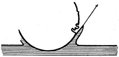
There will be but few of my readers who have
not, in some heavy shower of rain, beguiled
the tedium of enforced waiting by watching, perhaps
half-unconsciously, the thousand little crystal fountains
that start up from the surface of pool or river; noting
now and then a surrounding coronet of lesser jets, or
here and there a bubble that floats for a moment and
then vanishes.
It is to this apparently insignificant transaction,
which always has been and always will be so familiar,
and to others of a like nature, that I desire to call the
attention of those who are interested in natural phenomena;
hoping to share with them some of the
delight that I have myself felt, in contemplating the
exquisite forms that the camera has revealed, and in
watching the progress of a multitude of events, compressed
indeed within the limits of a few hundredths
of a second, but none the less orderly and inevitable,
and of which the sequence is in part easy to anticipate
and understand, while in part it taxes the highest
mathematical powers to elucidate.
In these modern days of kinematographs and snapshot
cameras it might seem an easy matter to follow,
by the aid of photography, even a splashing drop.
But in reality the task is not so simple, for the changes
of form that take place in a splash are far too rapid to
come within reach of any ordinary kinematograph,
and even the quickest photographic shutter is also
much too slow, so that it is necessary to have recourse
to the far shorter exposure of a suitable electric spark.
The originals of the photographs which illustrate this
book were taken by means of a spark, whose duration
was certainly less than three-millionths of a second,
an interval of time which bears to a whole second
about the same proportion as a day to a thousand
years.
In order to obtain the photographs, advantage was
taken of the fact that whatever be the sequence
of events in any particular splash, this sequence will
be exactly repeated every time that a falling drop
strikes the surface under exactly the same conditions,
and the problem to be solved was, therefore, as
follows:—To cause a drop of definite size to fall
from a definite height in absolute darkness so as
to strike the surface of the liquid into which it falls
at a spot towards which is directed a photographic
camera with uncovered lens, and armed with an
exceptionally sensitive plate, and to illuminate the
drop at the instant that it just touches the surface
by a flash of such excessively short duration that no
appreciable change of form can take place while the
drop is illuminated.
This gives us a photograph of the earliest stage.
The plate must then be removed and a fresh one
substituted; a second drop, of exactly the same size,
must be let fall from exactly the same place, and
photographed in just the same way, but the flash must
now be so timed as to take place at a slightly later
stage of the splash, say, one-thousandth of a second
later. The photographic plate must be then again
removed and a third substituted, on which a still later
stage is to be depicted, and in this way the phenomenon
can be followed step by step.
By adopting this process, and not attempting to
follow the same individual splash throughout, we avoid
two great difficulties: (1) the necessity of shifting our
photographic plate or film through a distance equal to
the breadth of the whole picture every five hundredth
or thousandth of a second (if we wish to obtain
pictures of stages so near together as this); and (2)
the difficulty of obtaining brilliant flashes of light of
sufficiently short duration at these very short intervals.
For these we substitute two other difficulties: (1)
that of delivering the drops exactly as required; and
(2) that of timing the flash on each occasion within
one or two thousandths of a second, so as to pick out
the exact stage we wish to photograph.
I will now describe how these two problems have
been solved.
It is easy enough to arrange for the production of
small drops of almost exactly equal size. They may
be allowed to fall one by one at a steady rate from the
end of a fine glass tube connected to a vessel in which
the liquid is maintained at a constant level, as in
Fig. 1, or they may be squeezed out slowly as required
by means of a syringe held in a clip as in Fig. 2.
Any required number of these small drops can be
caught, and allowed to run together if a larger drop is
to be experimented with.
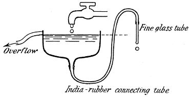
Fig. 1
|
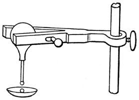
Fig. 2
|
If the liquid used is mercury, the drops may be
caught in any little glass cup such as a deeply concave
watch-glass; but other liquids, such as water or milk,
would wet the glass and stick to it.
If, however, the inside surface of the watch-glass be
first carefully smoked in the flame of a candle, then
even water or milk will roll over it without sticking,
and the drop thus made up will retain a spheroidal
form, and can be conveyed to the place of observation
in the dark room, where it is transferred to the
"dropping cup."
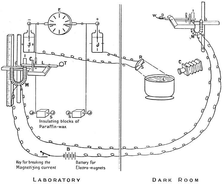
This consists of a similar, deep, smoked watch-glass
(W)—see Plate I—supported on the end of
a small horizontal lever, a light cylindrical rod of
about the dimensions of an ordinary uncut lead
pencil, pivoted about a horizontal axle near the end
to which the watch-glass is attached. The other end
is armed with a small light piece of iron (I) and is
held in position by means of an electro-magnet (M),
against the action of a spring. On cutting off the
current from the electro-magnet the spring, acting as a
catapult, tosses up the longer arm of the lever and thus
removes the watch-glass from below the drop (D),
which is left unsupported in mid-air, so that it falls
from a definite fixed distance into a bowl of water
placed below it, towards the surface of which the
camera (C) is directed. This solves problem number
one. Of course, if we wish to observe the splash of
a solid sphere, there is no need to smoke the surface
of the watch-glass. Indeed, the sphere may be more
conveniently supported on a small ring.
Now for the production and timing of the flash. Two
large Leyden jars (JJ) are provided, and charged by
an electrical machine on their inner coats, one positively
and one negatively. Stout wires lead from the outer
coats to the dark room, and terminate in a spark-gap
(S) between magnesium terminals close over the surface
of the water in the bowl just mentioned. If the
inner coats are now connected together, the positive
and negative charges unite with a dazzling flash and a
simultaneous discharge and flash takes place between
the two outer coats across the spark-gap in the dark
room.
This latter is the illuminating spark; we have now
to time it correctly.
For this purpose it is arranged that the discharge
shall be effected by means of a falling metal sphere (T)
which I shall call the timing sphere, which passes between
two terminals S and S connected one to the inside
of one jar and one to the inside of the other. These
terminals are just too far apart for a spark to leap
across, till the timing sphere passes between them and
thus shortens the gap; then the discharge takes place,
with its accompanying flash in the dark room.
The release of the timing sphere is effected by an
arrangement of lever and spring controlled by an
electro-magnet exactly similar to that which releases
the drop in the dark room, and the two electro-magnets
are on the same electric circuit, so that the drop and
timing sphere are released simultaneously. But while
the drop always falls the same distance, the height
through which the timing sphere has to fall before
producing discharge can be adjusted at will, and to
great nicety, by moving its releasing-lever up or down
a vertical support with a scale attached.
If, for example, a particular stage of the splash is
photographed when the timing sphere falls just four
feet to the gap, then by raising its releasing-lever about
two-fifths of an inch, the laws of falling bodies tell us
that we shall postpone the flash by just one-thousandth
of a second, and the next photograph will accordingly
reveal a stage just so much later.
|
PLATE I
Arrangement of apparatus for photographing splashes.
|
E is the electrical machine.
J J are the Leyden jars whose inner
coats are connected to the sparking knobs S S.
L is the lever for releasing the timing sphere T.
C is the catapult.
I is the light strip of iron held down by the electro-magnet M.
|
D is the drop resting on the smoked watch-glass W.
M is the electro-magnet holding down the lever against the action of the
catapult, by means of the thin strip of iron I.
C is the camera directed towards the
liquid L into which the drop will fall.
S is the spark-gap between magnesium
terminals connected to the outer coats of the Leyden jars.
R is the concave mirror.
|
It ought still to be mentioned that to make the
utmost use of the illuminating power of the spark, it
is necessary to place close behind it a little concave
mirror (R), by means of which a compact beam of rays,
which would otherwise have been wasted, is directed
to the required spot. By this addition we imitate, in
miniature, the search-light of a man-of-war.
As with all experimental devices, the precision
attainable with this arrangement is limited by several
circumstances. In the first place, the demagnetization
of the iron cores of the electro-magnets, when the
current is cut off, is not truly instantaneous, and the
time required depends on the strength of the magnetizing
current and on the temperature of the iron, which
in turn will depend on the length of time for which
the current has been running. This variation would
be of no importance if the two magnets were exactly
alike and the springs of exactly equal strength, conditions
which can be nearly but not perfectly fulfilled.
|
PLATE II
Photographs taken to test the accuracy of the "timing."
|
|
A more important source of uncertainty arises from
the fact that the time at which the spark takes place
depends partly on the magnitude of the + and -
charges which have been allowed to accumulate on the
discharging knobs connected to the two Leyden jars,
for when these charges are larger, then the spark will
be longer and will take place earlier and before the
timing sphere has reached the mid-position. The
charging has therefore to be carefully watched by
means of the indications of a suitable electrometer,
and the timing sphere must on each occasion be
released when the charges have just reached the right
value. But even this does not entirely suffice, for the
passage of the spark depends also partly on the state
of the surface of the knobs, which cannot be kept at
any high degree of polish.
Still, when care is taken to keep the conditions as
nearly as possible constant, neither of these sources of
error is serious, and the reader can judge for himself
of the accuracy of the timing from the photographs
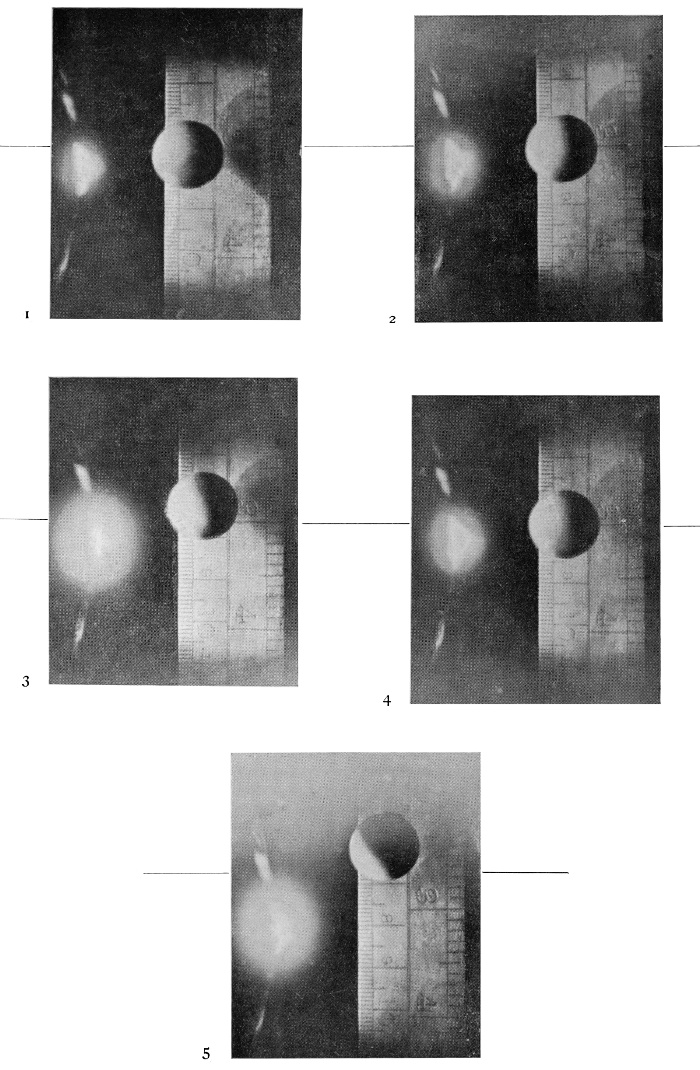
given on Plate II, in which a solid sphere was let fall
in the dark room past a metre scale. The timing sphere
was arranged, in the first four photographs, to illuminate
it at the same stage in its fall, after a descent
of thirty centimetres; if the timing had been perfect
the sphere would appear on each occasion at the same
mark on the scale.
It will be observed that in the first, second, and
fourth photographs the falling sphere is almost
accurately bisected by the long line of the three-inch
mark on the right-hand edge of the scale. The
greatest difference of position being just about one
millimetre (as read off the left-hand scale), which
would correspond to an error of about 1/2700 of a
second. But the third photograph is earlier, showing
the sphere 4·5 millimetres higher up, a distance which
implies an error of just 1/600 of a second.
A fifth photograph was then taken, with the timing
arranged so as to illuminate the sphere one centimetre
higher up, and it will be seen that if we compare this
with No. 3, the error is again only one millimetre.
Thus Nos. 3 and 5 agree very closely, but disagree
with Nos. 1, 2, and 4 by about 1/600 of a second.
The photographs themselves supply the reason.
For there happens to be visible on each an (out-of-focus)
image of the spark, and this image is very much
the same in 1, 2 and 4, but much larger and brighter
in 3 and 5, showing that the knobs were then more
highly charged, which would account for the spark
occurring a little too early.
But when we are watching the splash made by the
fall of a liquid drop, instead of a solid sphere, there is
a new and more serious source of difficulty. For the
drop as it lies on the smoked glass cup is not perfectly
spherical, but is flattened by its own weight, as shown
in Fig. 3, and on the sudden removal of the supporting
cup it oscillates between an oval form,
elongated vertically, and a flattened form (see
Fig. 4). These oscillations are unavoidable, and
their extent will depend partly on the amount of
adhesion between the smoked surface and the drop,
and as this adhesion is never entirely absent and is
variable, depending partly on the length of time that
the drop has been lying in the cup, it follows that the
drop will always receive a slight tug downwards at
starting, which will be greater on some occasions than
on others. On this account not only will the time
taken to reach the water vary slightly, but the drop
will strike it sometimes when elongated and sometimes
when flattened, and the resulting splash will be
affected by this circumstance.
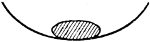
Fig. 3
|
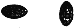
Fig. 4
|
The four photographs on the next page were taken
in succession in order to afford the reader an
opportunity
of judging for himself the sort of accuracy
attainable when a liquid drop was concerned.
The fall was 30 centim., and the greatest discrepancy
is 4·8 millimetres, corresponding to 1/560 of a
second. Thus even here the error does not amount
to two-thousandths of a second.
Photographs taken to test the timing of a falling drop.
With higher falls the timing sphere is moving
more quickly past the discharging knobs, and the
error due to a longer or shorter spark is correspondingly
less, so that it appears safe to say that the
accuracy of the timing was such that, when all precautions
were taken, any desired stage could be picked
out within two-thousandths of a second.
It is not however pretended that the precautions
necessary for the most accurate timing were always
taken, especially in the earlier Series of Photographs,
for the main object of the experiments was to find out
what happened, and only incidentally to ascertain
exactly how long it took to happen, and there is no
doubt that on some occasions, through the smoke-film
being allowed to wear away, adhesions to the dropping
cup occurred, with a corresponding disturbance of the
timing, before the defect was noticed and remedied.
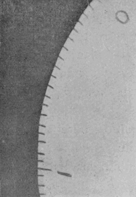
Fig. 5
Photograph of the edge of a rapidly whirling disc.
It remains to mention, for the sake of those interested in photography,
that notwithstanding the sensitiveness of the plates and the brilliance
of the illuminating spark, its duration was so short that the negatives
were always "under-exposed."
[C] I have
mentioned that the effective duration of the spark was less than
three-millionths of a second. The evidence for this is the accompanying
photograph (Fig. 5), taken of a cardboard disc when rotating at a rate
of fifty-three turns per second; the disc was 22
cm. in diameter, and had been roughly graduated
round the edge with pen and ink. The photograph
of the part that was in focus shows no perceptible
blurring of the edge of the marks, and with a lens, a
blurring of one-tenth of a millimetre would be easily
detectable. Since the edge was moving at a rate of
36·5 metres per second (about 78 miles per hour), the
time taken to traverse one-tenth of a millimetre would
be rather less than three-millionths of a second. Hence
we may conclude that the illumination did not last so
long as this.
The weakness of the negatives was met by a
prolonged development of about forty minutes in a
saturated solution of eikonogen. This forbade the
use of any artificial light, and all the photographic
processes had to be conducted in absolute darkness.
To avoid the tedium of long waiting in the dark
room, a light-tight tray was constructed, in which
several developing dishes could be placed, and the
whole brought out into the daylight and suitably
rocked. In this way ten or twelve photographs could
be developed simultaneously.
It may be worth while to mention here that the
bright spark given by breaking the primary circuit of
an induction coil at the surface of mercury was found
to be of much too long duration to be useful for the
purposes of splash-photography.
CHAPTER II — THE SPLASH OF A DROP—LOW FALL
We will now turn to the photographic record
itself. The first series shows the splash of a
drop of water weighing ·2 of a gram, and therefore 7·36
millimetres (or rather less than one-third of an inch) in
diameter, falling 40 cm. (about 16 inches) into milk
mixed with water. The object of adding milk to the
water was to make it more visible. The addition of
milk makes, as we shall see, a little but not much
difference in the general character of the splash.
The scale of the figures is three-quarters of the
actual size.
The number written against any figure gives, on
the assumption that no unobserved error has crept in,
the time in decimal parts of a second that has elapsed
since the stage marked "T = 0," which is nearest to
the first instant of contact. The reader will understand
from what has been said that the error in any
of these times may be as much as two-thousandths of
a second, but is not likely to be more than that, when
all precautions were taken.
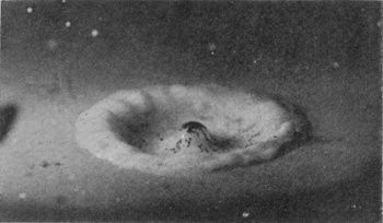
It will be observed that as the drop descends into
the liquid the upper portion is at first not appreciably
distorted, but that a little cup or crater of liquid is
thrown up round it. As the drop descends further,
this crater grows wider and higher and thicker in the
wall, and jets are shot out from its edge or rim. These
jets are visible even in the second figure. The black
marks on the inside wall of the crater are due to the
lamp-black carried down with the drop from the
smoked surface of the supporting cup: though in
one sense a disfigurement, they serve to show by their
presence that the interior of the crater is lined by the
original liquid which formed the drop, and thus afford
useful information as to the nature of the flow.
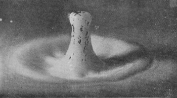
The crater rises with great rapidity up to Fig. 4.
In Fig. 5 the walls are beginning to grow thicker,
while the next three figures show the crater subsiding
and widening, till in Fig. 9 it lies as a mere ring of
lobes on the surface, surrounding a central hollow.
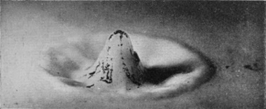
Fig. 10 shows the beginning of the rebound, in the
rising of a central column. It will be seen that the
lamp-black is now all swept to the middle, indicating
that the liquid of the original drop emerges at the head
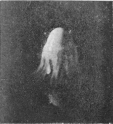
of the central column. Full confirmation of this is
obtained from Fig. 12, which represents the emergent
column obtained when the circumstances are all the
same, except that we have a drop of milk falling into
water instead of water falling into milk. It will
be observed that the upper part only of the column
is visible, precisely because it contains nearly all the
milk of the drop, while the lower part, consisting
chiefly of transparent water, remains invisible.
SERIES I—(continued)
10
0·064 sec. |
|
11
0·073 sec. |
| 12 |
|
13
0·093 sec. |
|
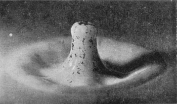
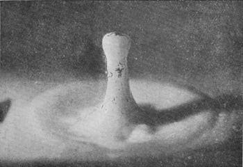
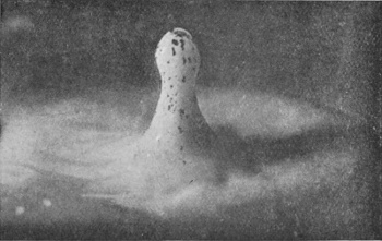
No. 15 shows the column at its greatest height, and
it should be noticed that Figs. 16 and 17 show a
tendency on the part of the head of this column to
split off as a separate drop.
SERIES I—(continued)
14
0·103 sec. |
|
15
0·116 sec. |
|
16
0·129 sec. |
|
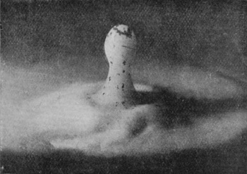
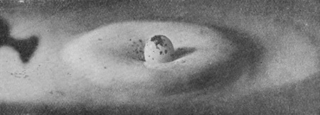
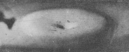
The column in subsiding forms a "cake" of liquid
round the base. The edge of this circular cake (see
Figs. 17, 18, and 19) is the first well-marked ripple
spreading outwards in an ever-widening circle.
SERIES I—(continued)
17
0·153 sec. |
|
18
0·197 sec. |
|
19
0·217 sec. |
|
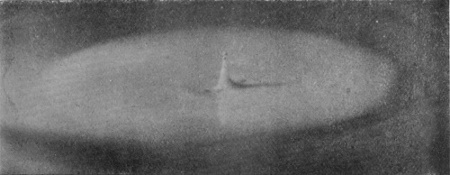
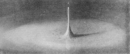
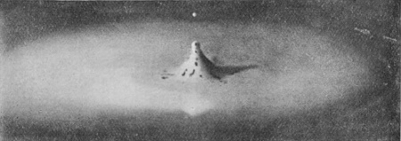
If Fig. 19 is reached without the top of the
column having separated, then the splash follows the
course shown in Figs. 20a to 23a, in which it will be
observed that the disappearance of the first column
is very quickly followed by the rise of a secondary
column very different in shape, which itself subsides
again, but has not yet (in 23a) formed, as it ultimately
will, a second "cake" on the top of the first. Thus
the second ripple follows late after the first.
SERIES I—(continued)
Alternative (a).
20a
0·240 sec. |
|
21a
0·242 sec. |

|
22a
0·248 sec. |
|
23a
0·253 sec. |
|
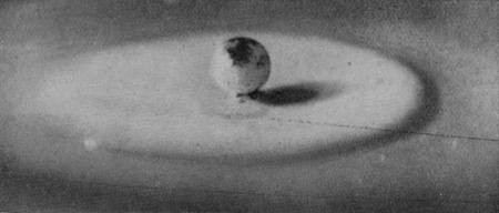
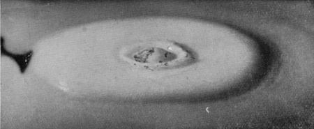
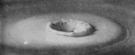
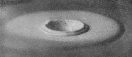
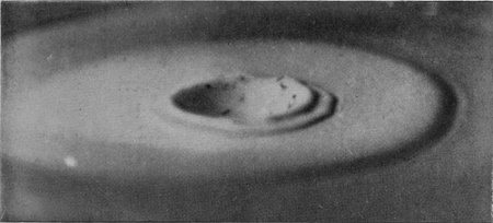
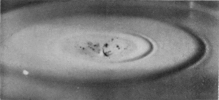
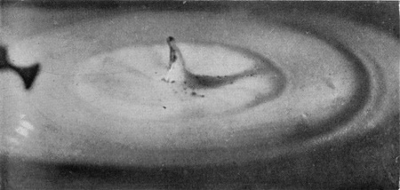
If, however, the summit of the primary column
succeeds in breaking off (as in Fig. 18b), or even in
very nearly breaking off, then the impact of this
newly-formed drop forms a second slight crater on
the top of the first cake, and we have the series
(18b to 24b), in which it will be observed that the
rim of the secondary crater spreads rapidly outwards,
so that a second well-marked circular ripple
in this case quickly follows the first. The secondary
column that is thrown up in Fig. 23b is very like that
which emerged at a much earlier stage in the (a)
series.
The photographs of this (b) series show very
beautifully the manner in which the advancing edge
of the ripple degenerates into smaller ripples travelling
with greater speed.
SERIES I—(continued)
Alternative (b).
18b
0·214 sec. |
|
19b
0·237 sec. |
|
20b
0·242 sec. |
|
21b
0·244 sec. |
|
SERIES I—(continued)
Alternative (b).
22b
0·261 sec. |
|
23b
0·257 sec. |
|
24b
0·311 sec. |
|
It will be readily understood that if the splitting off
of the head of the primary column happens to take
place a little earlier, or on the other hand is nearly,
but not quite, complete when it descends below the
surface, then subsequent configurations will differ
somewhat from either of the sub-series here shown.
Since any figure photographed might belong to
either sequence, the disentanglement of the two series
required careful consideration and long experimenting.
The reappearance of the original drop at the head
of the rebounding column, of which the explanation
has been given in this chapter, is easily verified by
naked-eye observation.
Let the reader when he next receives a cup of tea
or coffee to which no milk has yet been added, make
the simple experiment of dropping into it from a spoon,
at the height of fifteen or sixteen inches above the
surface, a single drop of milk. He will have no
difficulty in recognizing that the column which
emerges carries the white milk-drop at the top only
slightly stained by the liquid into which it has
fallen.
In the same way naked-eye observation reveals the
crater thrown up by the entry of a big rain-drop into
a pool of water. In either case what we are able
to glimpse is a "stationary" stage. The rebounding
column reaches a maximum height, remains poised
for an instant, and then descends. The same is true
of the crater. It is the relatively long duration of the
moment of poise that produces on the eye a clear
impression where all else is blurred by rapid change.
But there is frequently a curious illusion. We often
seem to see the crater with the column standing erect
in the middle of it. We know now that in reality the
crater has vanished before the column appears. But
the image of the crater has not time to fade before
that of the column is superposed on it.
Those who are accustomed "to believe nothing
that they hear and only half of what they see" may
be glad to find at least the latter part of their maxim
so completely justified.
CHAPTER III — PRINCIPLES INVOLVED — FOOTNOTES:
The reader's attention has now been directed to
various features which, with certain modifications,
will be found in many of the splashes that we shall
examine; but so far the language used has been simply
descriptive and in no way explanatory. Instead of
going on to describe other splashes in the same way,
and thus to accumulate a great mass of uncoördinated
descriptive detail, it will be better to pause for a
moment in order to become acquainted with certain
principles connected with the behaviour of liquids, the
application of which will go a long way towards explaining
what we see going on in any splash.
The first principle to be understood is that the
surface layers of any liquid behave like a uniformly
stretched skin or membrane, which is always endeavouring
to contract and to diminish its area. If
the surface is flat, like the surface of still liquid in a
bowl, this surface-tension has only the effect of exerting
a small inward pull on the walls of the bowl. But
if the surface is curved, with a convexity outwards,
then the surface layers, on account of their tension,
press the interior liquid back, and thus tend to check
the growth of any protuberance; while, on the other
hand, if the surface is concave outwards, then the
surface-tension tends to pull the interior liquid forward,
and so to diminish the concavity.
Direct evidence of this surface-tension is easy to
cite. We have it in any pendent drop, such as any
of those shown in the accompanying figures.
WATER.
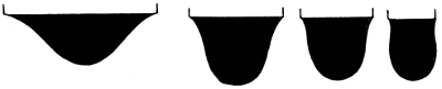
TURPENTINE.

Pendent drops (magnified 2-1/4 times).
If we ask ourselves how it is that the liquid
in the interior of one of these drops does not flow out,
pressed as it is by the liquid above it, the answer is
that everywhere the stretched skin presses it back.
A soap-bubble too presses on the air in its interior,
both the outside layers and the inside layers of the thin
film being curved over the interior space. This is the
reason that a soap-bubble blown on the bowl of a pipe
will slowly collapse again if we remove the stem
of the pipe from our mouth. The bubble drives the
interior air back through the pipe. And it is easy to
show that if two soap-bubbles be blown on the ends
of two tubes which can be connected together by
opening a tap between them, then the smaller will
collapse and blow out the larger. The reason of this
is that in the bubble of smaller radius the surface
layers are more sharply curved, and therefore exert
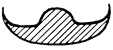
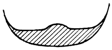
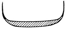
a greater pressure on the air within. Thus if a strap
be pulled at each end with a total tension T and bent
over a solid cylinder of small radius, as in Fig. 6, it is
easy to see that the pressure on the surface of the part
of the cylinder touched by the strap is less than if the
strap be bent over an equal area on a cylinder of larger
radius (Fig. 7). The tension of the surface layers
of a liquid causes them to act on the liquid within,
exactly as does the stretched strap on the solid in
these figures. If at any place the liquid presents, as
it generally does, not a cylindrical surface, but one
with curvature in two directions, then the pressure
corresponds to what would be produced by two straps
crossing at right angles, laid one over the other, each
with the curvature of the surface in its direction
(Fig. 8).
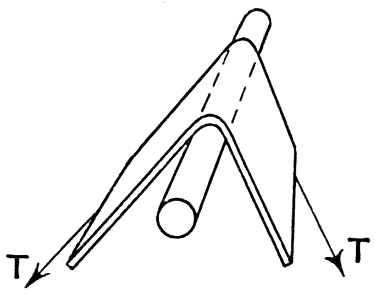
Fig. 6
|
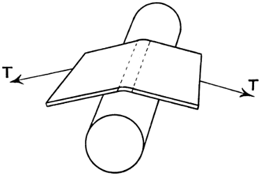
Fig. 7
|
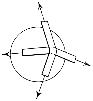
Fig. 8
|
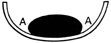
Fig. 9
|
We can now understand why the drop that has been
lying on the watch-glass should oscillate in its descent.
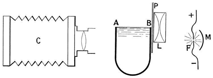
The sharp curvature of the edge AA of the drop (see
Fig. 9) tells us that the liquid there is pushed back by
the pressure of the stretched surface layers, and when
the supporting glass is removed the sides of the drop
move inwards, driving the liquid into the lower part,
the tendency being to make the drop spherical, and so
to equalize the pressure of the surface at all points.
But in the process the liquid overshoots the mark,
and the drop becomes elongated vertically and flattened
at the sides. This causes the curvature at
top and bottom to be sharper than at the sides, and
on this account the back-pressure of the ends soon
checks the elongation and finally reverses the flow
of liquid, and the drop flattens again. As an example
of the way in which a concavity of the surface
is pulled out by the surface-tension may be cited
the dimples made by the weight of an aquatic insect,
where its feet rest on the surface without penetrating
it.
This same surface-tension checks the rise of the
crater, and would cause it to subside again even without
the action of gravity. Thus the pressures of the
sharply curved crater-edge on the liquid between the
crater walls are indicated by the dotted arrows in
Fig. 10, and arise from the surface-tension indicated
by the full arrows. During the
early part of the splash the surface-tension
is more important than
gravity in checking the rise of the
walls. For, as the numbers show,
the crater of Series I is already at about its maximum
height in No. 4, i.e. about seven-thousandths
of a second after first contact. In this time the
fall due to gravity would be only about 1/100 of an
inch. Thus if gravity had not acted the crater
would only have risen about 1/100 of an inch higher.
The same reasoning applies to the rise of the central
column, but here the curvature at the summit
is much less sharp. The numbers show that the
column reaches its maximum height in about 5/100
of a second after its start in No. 10, and in this
time the fall due to gravity is about half an inch,
so that gravity has reduced the height by this
amount.
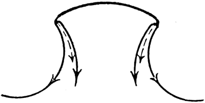
Fig. 10
The second principle which I will now mention
enables us to explain the occurrence of the jets and
rays at the edge of the crater and their splitting into
drops.
It was shown in 1873 by the blind Belgian
philosopher, Plateau,[D] that a cylinder of liquid is not
a figure of stable equilibrium if its length exceeds
about 3-1/7 times its diameter. Thus a long cylindrical
rod of liquid, such as Fig. 11, if it could be obtained
and left for a moment to itself, would at once topple
into a row of sensibly equal, equidistant drops, the
number of which is expressed by a very simple law,
viz. that for every 3-1/7 times the diameter there is a
drop, or that the distance between the centres of the
drops is equal to the circumference of the cylinder.

Fig. 11
The cause of this instability is the action of the
same skin-tension that we have already spoken of.
Calculation shows, and Plateau was able to confirm
the calculation by experiment, that if through chance
agitations lobes are formed at a nearer distance apart
than 3-1/7 times the radius, with hollows between as in
the accompanying Fig. 12, then the curvatures will be
such as to make the skin-tension push the protuberances
back and pull the hollows out. But if the protuberances
occur at any greater distances apart than
the length of the perimeter, then the sharper curvature
of the narrower parts will drive the liquid there
into the parts already wider, thus any such an initial
accidental inequality of diameter will go on increasing,
or the whole will topple into drops.

Fig. 12
At the last moment the drops are joined by narrow
necks of liquid (Fig. 13), which themselves split up
into secondary droplets (Fig. 14).

Fig. 13
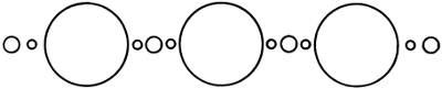
Fig. 14
What we have said of a straight liquid cylinder
applies also to an annulus of liquid made by bending
such a cylinder into a ring. This also will spontaneously
segment or topple into drops according to
the same law.[E] Now the edge of the crater is practically
such a ring, and it topples into a more or less
regular set of protuberances, the liquid being driven
from the parts between into the protuberances.
Now while the crater is rising the liquid is flowing
up from below towards the rim, and the spontaneous
segmentation of the rim means that channels of easier
flow are created, whereby the liquid is driven into the
protuberances, which thus become a series of jets.
These are the jets or arms which we see at the edge
of the crater. Examination with a lens of some of
the craters will show that the lines of easier flow
leading to a jet are often marked by streaks of
lamp-black
in Series I, or by streaks of milk in Series II.
This explanation of the formation of the jets applies also
to a similar phenomenon on a much larger scale, with
which the reader will be already familiar. If he has
ever watched on a still day, on a straight, slightly
shelving sandy shore, the waves that have just impetus
enough to curl over and break, he will have noticed
that up to a certain moment the wave presents a long,
smooth, horizontal cylindrical edge (see Fig. 15a) from
which, at a given instant, are shot out an immense
array of little jets which speedily break into foam,
and at the same moment the back of the wave,
hitherto smooth, is seen to be furrowed or combed
(see Fig. 15b). The jets are due to the segmentation of
the cylindrical rim according to Plateau's law, and the
ridges between the furrows mark the lines of easier
flow determined by the position of the jets.
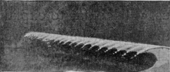
Fig. 15b
|
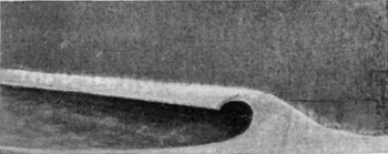
Fig. 15a
|
|
Diagrams of a breaking wave.
|
The tendency of the central column of Series I to
separate into two parts is only another illustration of
the same instability of a liquid cylinder. The column,
however, is much thicker than the jets, and its surface
is therefore less sharply curved, and consequently the
inward pressure of the stretched curved surface is
relatively slight and the segmentation proceeds only
slowly. Since this segmentation must originate in
some accidental tremor, we see how it is that the
summit of the column may succeed in separating off
on some occasions and not on others. As a matter of
fact, the height of fall for this particular splash was
purposely selected, so that the column thrown up
should just not succeed in dividing in order that the
formation of the subsequent ripples might not be disturbed
by the falling in of the drops split off. But, as
the reader will have perceived, the margin allowed
was not quite sufficient.
The two principles that I have now explained, viz.
the principle of the skin-tension, and the principle of
the instability and spontaneous segmentation of a
liquid cylinder, jet, or annulus, will go far to explain
much that we shall see in any splash, but it is well
that the reader should realize how much has been left
unexplained. Why, for example, should the crater
rise so suddenly and vertically immediately round the
drop as it enters? Why should the drop spread itself
out as a lining over the inside of the crater, turning
itself inside out, as it were, and making an inverted
umbrella of itself? Why when the crater subsides
should it flow inwards rather than outwards, so as to
throw up such a remarkable central column?
These questions, which demand that we should
trace the motion of every particle of the water back
to the original impulse given by the impact of the
drop, are much more difficult to answer, and can only
be satisfactorily dealt with by a complicated mathematical
analysis. Something, however, in the way of
a general explanation will be given in a later chapter.