Note. The objects with Numbers after them are those contained in the present PART: and the
Numbers shew the Pages where they stand.
| A |
| 1 |
Adding Machine; or Machine to cast up correctly large columns of figures. |
| 2 |
Air Pump; essay towards completing the vacuum. |
| B |
| 3 |
Barrel Spring, to lengthen the going of Clocks and other spring-driven Machines. 26 |
| 4 |
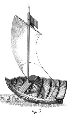
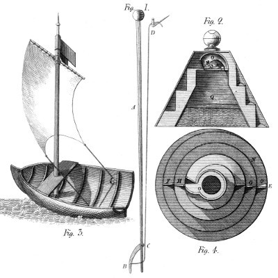
Boats (serpentine) for lessening the expence of traction. |
| 5 |
Bobbin or Lace (Machine for making) and for covering Whips, &c. with great rapidity. |
| 6 |
Bowking Machine for Calico Printers. |
| 7 |
Bucket Wheels (a combination of) to raise water. |
| C |
| 8 |
Canals (open) as Hydraulic Machines of great force. |
| 9 |
Canter, or inclined Plane for Draymen. 72 |
| 10 |
Chain to act equably on my wheels. |
| 11 |
Chocolate Mill (rotatory.) |
| 12 |
Cocks (equilibrium) to avoid leakage. |
| 13 |
Colour Mill for Calico Printers. |
| 14 |
Compasses (bisecting.) |
| 15 |
Cotton (Machine for batting.) |
| 16 |
Crane, combining variable powers with speed and safety. (rewarded by the Society of Arts.) 57 |
| 17 |
Crank (epicycloidal) or parallel motion. Rewarded by Bonaparte. 30 |
| D |
| 18 |
Dash Wheel for Calico Printers, acting with greater rapidity than usual. |
| 19 |
Differential Wheels for gaining immense power. 54 |
| 20 |
Doffing Machine, of great force for taking Cylinders from their Mandrills. |
| 21 |
Draw-bench for my twisted pinions. |
| 22 |
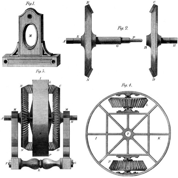
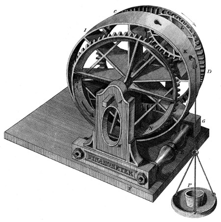
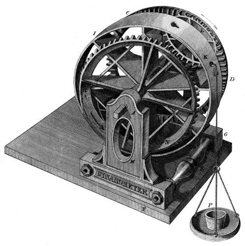
Dynamometer, for measuring powers and resistances in motion. 15 |
| 23 |
Dynamometer, second kind. |
| E |
| 24 |
Engine for cutting my Patent Wheels in small and middling dimensions. |
| 25 |
Engine for cutting my large bevil Wheels and wooden Models, either on my System, or the usual one. |
| |
N. B. These objects will occupy considerable space in the work. |
| 26 |
Engraving Machine for Calico Printers, being an important application of my Cog or toothed Wheels. |
| 27 |
Engraving Machine for large patterns. |
| 28 |
Essay to derive power from expanding Solids. |
| 29 |
Evaporation (Machine to promote.) 78 |
| 30 |
Eyes (Machine for making rapidly.) |
| F |
| 31 |
Fire escape (on a retarding principle.) |
| 32 |
—— (by breaking the fall.) |
| 33 |
Fires (Portable Engine to extinguish.) |
| 34 |
Fires (Watch Engine always ready for.) |
| 35 |
Flax (Machine for breaking) with rapidity. |
| 36 |
Forging Bar iron and steel (Machine for.) |
| 37 |
Friction (to prevent.) |
| 38 |
Friction (to prevent) Thoughts on. |
| G |
| 39 |
Geering and ungeering (Machine for). |
| 40 |
Do. Do. for swift motions. |
| 41 |
Grating or cutting green Roots, Tobacco, &c. (Machine for.) 79 |
| H |
| 42 |
Helico-Centrifugal Machine, for raising water in large quantities. |
| 43 |
Horse Wheel for saving room and gaining speed. 53 |
| 44 |
Horse Wheel (reciprocating) for Mangles, &c. |
| 45 |
Horse Wheel, with means for turning the Horse when he acts in two directions. |
| 46 |
Horizontal Pump of large produce, driven by wind. |
| 47 |
Hot Air as power, while heating liquids, rooms, &c. |
| L |
| 48 |
Lamp for the Table; suspending the oil by it’s weight. |
| 49 |
Lithographic, or Copper-plate Press, with several curious and useful properties. |
| M |
| 50 |
Machine for clearing turbid liquors. |
| 51 |
Machine for driving Boats on Canals, under Tunnels, &c. without disturbing the Water. |
| 52 |
Machine to assist in taking Medicine, Pills, &c. (Humani nihil alienum.) |
| 53 |
Mangle (perpetual or rotatory). |
| 54 |
Marine-Level (two essays on a.) |
| 55 |
Micrometer for measuring very minute spaces. 83 |
| 56 |
Mirrors to collect Solar Heat, (method of forming.) |
| 57 |
Mover, by dropping weights. 76 |
| N |
| 58 |
Nails (Machine for moulding.) |
| 59 |
Nails (Machine for forging.) |
| P |
| 60 |
Pencyclograph, or Instrument for describing portions of Circles, and finding their centres by inspection. 51 |
| 61 |
Peristaltic Machine, for raising much water, to small heights. 69 |
| 62 |
Persian Wheel modified, for raising water. |
| 63 |
Pitch-fork, for musicians, with variable tones. |
| 64 |
Power-wheel by heated Air. 43 |
| 65 |
Press, direct and differential. 66 |
| 66 |
Press (eccentric Bar.) |
| 67 |
Printing Machine (two coloured.) |
| 68 |
Protracting Motion (Machine for.) 49 |
| 69 |
Pullies (my Patent much improved.) 33 |
| 70 |
Pump (my equable.) 45 |
| 71 |
Pump, triple, in one column. |
| 72 |
Pump (portable) worked by pedals. |
| 73 |
Punch Machine for Engravers. |
| 74 |
Punch Machine on another principle. |
| 75 |
Do. rotatory, for my Engraving Machine. |
| R |
| 76 |
Reciprocating Motion, (long) for Mangles, &c. |
| 77 |
Reflector parabolico conical, or plano parabolical for light houses, &c. |
| 78 |
Regulator: (not centrifugal) for Wind or Water Mills, Steam Engines, &c. |
| 79 |
Retrographic Machine (Machine for Writing backwards) for Engravers. |
| 80 |
Rotato-gyratory Churn. |
| S |
| 81 |
Screw, with greatly diminished friction. 81 |
| 82 |
Screws, (Machine for forging) &c. |
| 83 |
Spinning Machines, (my Patent), Eagles, &c. |
| 84 |
Spinning Machinery: another system, adapted chiefly to wool. |
| 85 |
Spring, to keep a door strongly closed, yet open easily. |
| 86 |
Steel Yard, differential: for weighing vast weights with short levers. |
| 87 |
Syphon, (mechanical) to expel part of the water at the highest point. |
| T |
| 88 |
Tallow (Machine for cutting and trying.) |
| 89 |
Tea-table (commodious help for the.) |
| V |
| 90 |
Ventilator, rotatory, yet by pressure. |
| 91 |
Vessel (expanding) for Pumps, Steam Engines, &c. |
| W |
| 92 |
Washing Apparatus: for Hospitals, &c. confining the offensive matter until cleansed away: thus promoting salubrity. |
| 93 |
Water-wheel, (horizontal) probably the best of the impulsive kind. |
| 94 |
The same, for high falls. |
| 95 |
Water-wheel, (inclined) employing the weight of the fluid. |
| 96 |
Water, (Machine for raising large quantities.) |
| 97 |
Weaving by Power: manner of driving the Shuttle, (executed A. D. 1780.) |
| 98 |
Wedge Machine (perpetual.) |
| 99 |
Wheels (my System of cog or toothed.) |
| 100 |
Windmill of great power. |
| Page |
16, |
line |
17, |
for fig. read plate. |
| „ |
22, |
„ |
4, |
for posistion, read position. |
| „ |
22, |
„ |
7, |
for 17, read 15. |
| „ |
22, |
„ |
9, |
for fig. read plate. |
| „ |
22, |
„ |
23, |
for fig. read plate. |
| „ |
24, |
„ |
16, |
for clylinder at P, read cylinder at K. |
| „ |
24, |
„ |
22, |
for fig. read plate. |
| „ |
26, |
„ |
16, |
for E, read C. |
| „ |
28, |
„ |
5, |
for diamenter, read diameters. |
| „ |
35, |
„ |
10, |
for inconvencies, read inconveniences. |
| „ |
36, |
„ |
8, |
for of pulley, read of the pulley. |
| „ |
40, |
„ |
25, |
for as, read of. |
| „ |
41, |
„ |
4, |
for loose 1; read loose — |
| „ |
41, |
„ |
5, |
for pulleys, read pulley. |
| „ |
43, |
„ |
18, |
for furnish surplus, read furnish a surplus. |
| „ |
43, |
„ |
22, |
for occpied, read occupied. |
| „ |
46, |
„ |
17, |
for power, read motion. |
| „ |
49, |
„ |
22, |
for diffential, read differential. |
| „ |
55, |
„ |
21, |
|
- |
for 20,200, read 20200. |
| „ |
55, |
„ |
24, |
| „ |
55, |
„ |
26, |
| „ |
55, |
„ |
28, |
for 99,990, read ,99990. |
| „ |
58, |
„ |
23, |
for figures, read figure. |
| „ |
62, |
„ |
2, |
end the quotation marks at “lifting.” |
| „ |
62, |
„ |
8, |
for gasping, read anxious. |
| „ |
63, |
„ |
7, |
for wishd, read wished. |
| „ |
64, |
„ |
2, |
for ladders, read ladder. |
| „ |
66, |
„ |
11, |
for occasionaly, read occasionally. |
| „ |
67, |
„ |
7, |
for G N, read L N. |
| „ |
68, |
„ |
2, |
for two hundred, read three hundred. |
| „ |
75, |
„ |
4, |
for 300℔s. read 100℔s. |
| „ |
82, |
„ |
16, |
for fig. 9, read fig. 10. |
| „ |
83, |
„ |
11, |
for an of inch, read of an inch. |
PART SECOND. — INTRODUCTION. — MEMOIR ON A NEW SYSTEM OF COG OR TOOTHED WHEELS, — OF THE CUTTING ENGINE, To form Spur-wheels, on my late Patent principle . — OF A DOOR-SPRING, To keep a Door strongly closed, yet suffer it to be opened easily . — OF A DRAW-BENCH, For making my twisted Pinions . — OF A GEERING CHAIN, Formed to work in the Patent Wheels . — OF A SERPENTINE BOAT OR VESSEL, To lessen the Expence of Traction, &c. — OF A MACHINE For destroying, or lessening Friction . — OF A SECOND MACHINE, To avoid or diminish Friction . — OF AN EQUILIBRIUM COCK, To prevent abrasion and leakage . — OF A MACHINE To communicate and suspend Motion . — OF A MACHINE To set on, and suspend, rapid Motions . — OF A MACHINE For forging Screws, Beads, &c. — OF A DIFFERENTIAL STEEL-YARD, To weigh vast Weights with short Levers . — OF A RETROGRAPH, Or a Machine to write backwards, for Engravers . — OF AN EYE MACHINE, Or Machine for making the Eyes of Hooks and Eyes . — OF A VENTILATOR, Rotatory yet by pressure . — OF A COMBINATION OF WHEELS To raise Water . — OF AN ECCENTRIC BAR PRESS, For clearing wetted goods of Water . — OF A COLOUR MILL, For Calico Printers . — OF A DYNAMOMETER, Or a second Machine to measure power & resistance in motion .
A NEW CENTURY OF
Inventions.
In the progress of a work like the present, no competent
reason could have been assigned for omitting to bring forward
my System of Toothed Wheels, the Patent for which has lately
expired:—a System which a few years ago, excited in this
town, so much interest, aroused so much animosity, and was
treated with so much illiberality:—But which, also, was fostered
with so much public spirit, tried with so much candour,
and adopted with so much confidence. It was I say, incumbent
on me to bring the merits of this System into public view,
had it only been to justify myself for proposing, and my friends
for adopting it. But stronger reasons point now to the same
measure. From the intimate connection the System holds with
the subjects of this essay, it must be often adverted to; and
I have been already obliged to speak of it in terms which can
hardly have been understood by those readers who had not
previously considered the general Subject. I should therefore
be still in danger of filling these Pages with unintelligible assertions,
did I not begin by marking out the foundations on
which my statements are built; or by explaining to a certain
degree, the Principles of the new System. Without then
abandoning the tacit engagement I have taken with my unlearned
readers—not to entangle them in too much theory,
I think it indispensable to quote the Memoir I read before
the Literary and Philosophical Society of Manchester, in
December, 1815; which small work will form the basis of
the practical remarks I shall have to make on the subject, as
this work proceeds. The Memoir is thus introduced in the
transactions of that learned body:
By Mr. James White, Engineer.[1]
COMMUNICATED BY T. JARROLD, M. D.
(Read December 29th, 1815.)
“The subject of this paper, though merely of a mechanical
nature, cannot fail to interest the Philosophical Society of a
town like Manchester, so eminently distinguished for the practice
of mechanical science; unless as I fear may be the case,
my want of sufficient theoretic knowledge or of perspicuity in
the explication, should render my communication not completely
intelligible. To be convinced of the importance of the
subject, we need only reflect on the vast number of toothed
wheels that are daily revolving in this active and populous
district, and on the share which they take in the quantity
and value of its productions; and it is obvious that any invention
tending to divest these instruments of their imperfections,
whether it be by lessening their expence, prolonging their duration,
or diminishing their friction, must have a beneficial
influence on the general prosperity. Now I apprehend that all
these ends will be obtained in a greater or less degree, by
having wheels formed upon the new system.
I shall not content myself by proving the above theoretically,
but shall present the society with wheels, the nature of which
is to turn each other in perfect silence, while the friction and
wear of their teeth, if any exist, are so small as to elude computation,
and which communicate the greatest known velocity
without shaking, and by a steady and uniform pressure.
Before I proceed to the particular description of my own
wheels, I shall point out one striking defect of the system now
in use, without reverting to the period when mechanical tools
and operations were greatly inferior to those of modern times.
Practical mechanics of late, especially in Britain, have accidentally
hit upon better forms and proportions for wheels than
were formerly used; whilst the theoretic mechanic, from the
time of De la Hire, (about a century ago) has uniformly
taught that the true form of the teeth of wheels depends upon
the curve called an epicycloid, and that of teeth destined to
work in a straight rack depends upon the simple cycloid. The
cycloid is a curve which may be formed by the trace of a nail
in the circumference of a cart wheel, during the period of one
revolution of the wheel, or from the nail’s leaving the ground
to its return; and the epicycloid is a curve that may be formed
by the trace of a nail, in the circumference of a wheel, which
wheel rolls (without sliding) along the circumference of another
wheel.
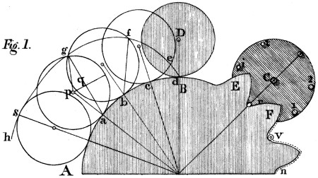
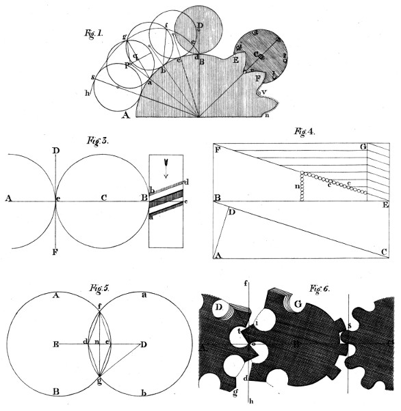
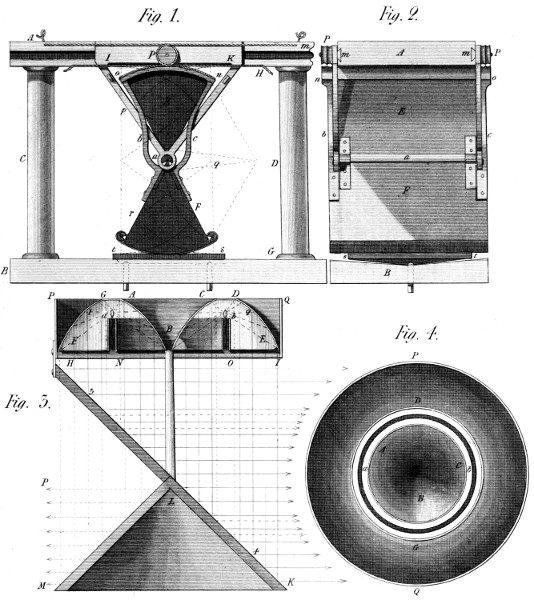
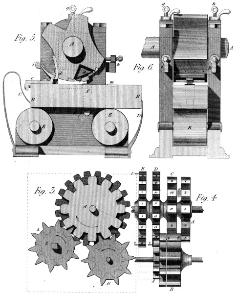
Let A B (Plate 13, fig. 1.) be part of the circumference of
a wheel A B F to which it is designed to adapt teeth, so formed
as to produce equable motion in the wheel C, when that of the
wheel A B F is also equable. Also, let the teeth so formed,
act upon the indefinitely small pins r, i, t, let into the plane of
the wheel C, near its circumference. To give the teeth of the
wheel A B F a proper form, (according to the present prevailing
system) a style or pencil may be fixed in the circumference
of a circle D equal to the wheel C, and a paper may be
placed behind both circles, on which by the rolling of the circle
D on A B, will be traced the epicycloid d, e, f, g, s, h, of
which the circle A B F is called the base, and D the generating
circle. Thus then the wheel to which the teeth are to
belong is the base of the curve, and the wheel to be acted upon
is the generating circle; but it must be understood that those
wheels are not estimated in this description at their extreme
diameters, but at a distance from their circumferences sufficient
to admit of the necessary penetration of the teeth; or, as
M. Camus terms it, where the primitive circles of the wheels
touch each other, which is in what is called in this country
the pitch line.
Now it has been long demonstrated by mathematicians, that
teeth constructed as above would impart equable motion to
wheels, supposing the pins, r, i, t, &c. indefinitely small.
This point therefore need not be farther insisted upon.
So far the theoretic view is clear; but when we come to practice,
the pins r, i, t, previously conceived to be indefinitely small,
must have strength, and consequently a considerable diameter,
as represented at 1, 2; hence we must take away from the area
of the curve a breadth as at v and n = to the semidiameter
of the pins, and then equable motion will continue to be produced
as before. But it is known to mathematicians that the
curve so modified will no longer be strictly an epicycloid; and it
was on this account that I was careful above, to say that the
teeth of wheels producing equable motion, depended upon that
curve; for if the curve of the teeth be a true epicycloid in the
case of thick pins, the motion of the wheels will not be equable.
I purposely omit other interesting circumstances in the application
of this beautiful curve to rotatory motion; a curve by
which I acknowledge that equable motions can be produced,
when the teeth of the ordinary geering are made in this manner.
But here is the misfortune:—besides the difficulty of executing
teeth in the true theoretical form, (which indeed is
seldom attempted), this form cannot continue to exist; and hence
it is that the best, the most silent geering becomes at last
imperfect, noisy and destructive of the machinery, and especially
injurious to its more delicate operations.
The cause of this progressive deterioration may be thus explained:
Referring again to fig. 1, we there see the base of the
curve A B divided into the equal parts a b, b c, and c d; and
observing the passage of the generating circle D, from the
origin of the curve at d, to the first division c on the base, we
shall find no more than the small portion d e, of the curve
developed, whereas a second equal step of the generating circle
c b, will extend the curve forward from e to f, a greater distance
than the former; while a third equal step a b, will extend
the curve from f to g, a distance greater than the last; and
the successive increments of the curve will be still greater, as
it approaches its summit; yet all these parts correspond to
equal advances of the wheel, namely, to the equal parts a b,
b c and c d of the base, and to equal ones of rotation of the
generating circle. Surely then the parts s g, g f, of the epicycloidal
tooth will be worn out sooner than those f e, e d,
which are rubbed with so much less velocity than the other,
even though the pressure were the same. But the pressure
is not the same. For, the line a g is the direction in which the
pressure of the curve acts at the point g, and the line p q, is
the length of the lever-arm on which that pressure acts, to turn
the generating circle on its axis (now supposed to be fixt;)
but, as the turning force or rotatory effort of the wheels,
is by hypothesis uniform, the pressure at g must be inversely
as p q; that is, inversely as the cosine of half the
angle of rotation of the generating circle; hence it would be
infinite at s, the summit of the curve, when this circle has made
a semi-revolution.
Thus it appears that independently of the effects of percussion,
the end of an epicycloidal tooth must wear out sooner than
any part nearer its base, (and if so, much more it may be supposed
of a tooth of another form;) and that when its form is
thus changed, the advantage it gave must cease, since nothing
in the working of the wheel can afterwards restore the form,
or remedy the growing evil.
Having now shewn one great defect in the common system
of wheels, I shall proceed to develope the principles of the new
system, which may be understood through the medium of the
three following propositions.
1. The action of a wheel of the new kind on another with
which it works or geers is the same at every moment of its
revolution, so that the least possible motion of the circumference
of one, generates an exactly equal and similar motion
in that of the other.
2. There are but two points, one in each wheel, that necessarily
touch each other at the same time, and their contact
will always take place indefinitely near the plane that passes
through the two axes of the wheels, if the diameters of the
latter, at the useful or pressing points are in the exact ratio of
their number of teeth respectively; in which case there will be
no sensible friction between the points in contact.
3. In consequence of the properties above-mentioned, the
epicycloidal or any other form of the teeth, is no longer indispensable;
but many different forms may be used, without disturbing
the principle of equable motion.
With regard to the demonstration of the first proposition, I
must premise an observation of M. Camus on this subject, in
his Mechanics, 3d. part, page 306, viz. “if all wheels could
have teeth infinitely fine, their geering, which might then
be considered as a simple contact, would have the property
required, [that of acting uniformly] since we have seen that a
wheel and a pinion have the same tangential force, when the
motion of one is communicated to the other, by an infinitely
small penetration of the particles of their respective circumferences.”
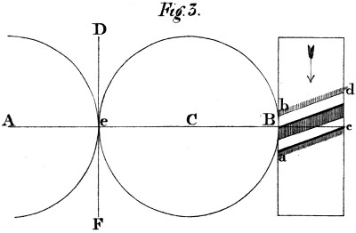
Now suppose that on the cylindrical surface of a spur-wheel B
c, (fig. 3) we cut oblique or rather screw-formed teeth, of which
two are shewn at a c, b d, so inclined to the plane of the wheel,
as that the end c of the tooth a c may not pass the plane of the
axes A B c, until the end b of the other tooth b d has arrived
at it, this wheel will virtually be divided into an infinite number
of teeth, or at least into a number greater than that of the
particles of matter, contained in a circular line of the wheel’s
circumference. For suppose the surface of a similar, but longer
cylinder, stripped from it and stretched on the plane A B C E
(fig. 4) where the former oblique line will become the hypothenuse
B C, of the right angled triangle C A B, and will
represent all the teeth of the given wheel, according to the
sketch E G at the bottom of the diagram. Here the lines A
B and C E, are equal to the circumference of the base of the
cylinder, and A C and B E to its length; and if between A
and B, there exist a number, m, of particles of matter, and
between A and C a number, n, the whole surfaced A B C E will
contain m n particles, or the product of m and n; and the line B
C, will contain a number = √m² + n², from a well known theorem;
whence it appears that the line B C is necessarily longer
than A B, and hence contains more particles of matter.[2]
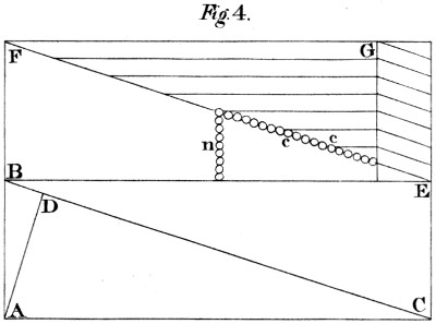
It is besides evident, that the difference between the lines
B C and A B, depends on the angle A C B; in the choice of
which, there is a considerable latitude. For general use however,
I have chosen an angle of obliquity of 15°, which I shall
now assume as the basis of the following calculations. The tangent
of 15°, per tables, is in round numbers 268 to radius 1000;
and the object now is to find the number of particles in the
oblique line B C, when the line A B, contains any other
number, t.
By geometry, B C(x) = √r² + t² = √1000² + 268² = 1035 nearly;
and this last number is to 268, as the number of particles in
the oblique line B C is to the number contained in the circumference
A B, of the base of the cylinder. Hence it appears,
that a wheel cut into teeth of this form, contains (virtually) about
four times as many teeth, as a wheel of the same diameter, but
indefinitely thin, would contain. And the disproportion might
be increased, by adopting a smaller angle.
Thus I apprehend it is proved, that the action of a wheel of
this kind, on another with which it geers, is perfectly uniform
in respect of swiftness; and hence the proof that it is likewise
so, as to the force communicated.
Before I proceed to the second proposition, I ought perhaps
to anticipate some objections that have been made to this system
of geering, and which may have already occurred to some
gentlemen present. For example, it has been supposed that the
friction of these teeth, is augmented by their inclination to the
plane of the wheel; but I dare presume to have already proved,
that it is this very obliquity, joined to the total absence of motion
in direction of the axes, that destroys the friction, instead of
creating it. I acknowledge however, that the pressure on the
points of contact, is greater than it would be on teeth, parallel
to the axes of the wheels, and I farther concede that this pressure
tends to displace the wheels in the direction of the axes,
(unless this tendency is destroyed by a tooth, with two opposite
inclinations.) But supposing this counteraction neglected, let
us ascertain the importance of these objections. First, with
regard to the increase of pressure on the point D of the line
B C, (representing the oblique tooth in question,) relative to
that which would be on the line B E, (which represents a tooth
of common geering:) let A D be drawn perpendicular to B
C. If the point D can slide freely on the line B C, (and this
is the most favourable supposition for the objection,) its pressure
will be exerted perpendicularly to this line; and if the
point A, moves from A to B, the point D, leaving at the
same moment the point A, and moving in direction A D,
will only arrive at D in the same time, its motion having been
slower than that of A, in the proportion of A B to A D;
whence by the principle of virtual velocities, its pressure on
B C is to that on A C, as the said lines A B to D A.
To convert these pressures into numbers, according to the
above data; we have A C = 1000, A B = 268, B C = 1035;
then from the similar triangles B A C, B D A, it will be B
C : A C ∷ A B : A D = 268000⁄1035 = 259 nearly. Therefore the
pressure on B C, is to that on A C, as 268 to 259, or as
1035 : 1000.
To find what part of the force tends to drive the point B, in
the direction B E, (for this is what impels the wheels, in the
direction of their axes,) we may consider the triangle B A C as
an inclined plane, of which B C is the length, and A B the
height; and the total pressure on C B, which may be represented
by C B, (1035) may be resolved into two others, namely,
A B and A C, which will represent the pressures on those
lines respectively, (268 and 1000.) Hence the pressure on B
C, is augmented only in the ratio of 1035 to 1000, or about
1⁄29 part by the obliquity; and the tendency of the wheels to
move in the direction of their axes, (when this angle is used,)
is the 268⁄1000 of the original stress, that is, rather more than one
quarter. But since the longitudinal motion of an axis can be
prevented by a point almost invisible applied to its centre, it
follows that the effect of this tendency can be annulled, without
any sensible loss of the active power. It may be added, that
in vertical axes, those circumstances lose all their importance,
since whatever force tends to depress the one and increase
its friction, tends equally to elevate the other, and relieve its
step of its load; a case that would be made eminently useful,
by throwing a larger portion of pressure on the slow-moving
axes, and taking it off from the more rapid ones.
We now proceed to the second proposition. The truth of
the assertions, contained in this proposition, must, I should
suppose, be evident, from the consideration of two circles
touching each other, and at the point of contact, coinciding
with their common tangent at that point. Let A and B be two
circles, tangent to each other, (fig. 3) in e. A C is the line
joining the centres, and D F the common tangent of the circles
at e; which is at right angles with A C; and so are the circumferences
of the two circles at the point e. For the circles and
tangent coincide for the moment. Hence then I conclude,
1st that a motion (evanescently small) of the point common to
the three lines, can take place without quitting the tangent D
F: and 2d. that if there is an infinite number of teeth in these
circles, those which are found in the line of the centres, will
geer together in preference to those which are out of it, since
the latter have the common tangent, and an interval of space
between them.
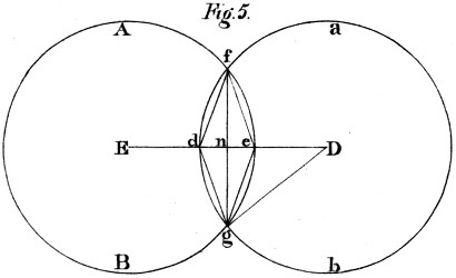
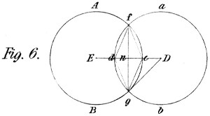
The truth of this proposition (or an indefinite approximation
to truth,) may be deduced from the supposition that the two
circles do actually penetrate each other. To this end let A B
a b, in fig. 5, be two equal circles, placed parallel to each
other in two contiguous planes, so as for one to hide the
other, in the indefinitely small curvilinear space d f e g. I
say that if the arc d g is indefinitely small, the rotation of the
two circles will occasion no more friction between the touching
surfaces, g e f and f d g, than there would be between the two
circles placed in the same plane, and touching at the point n
the same common tangent.
For draw the lines D E, f d, d g, g f, g e and g D; and
adverting to the known equation of the circle, let d n = x, g n
= y and D g = a, the absciss, ordinate and radius of the circle;
we have 2 a x - x² = y². From this equation we obtain
a = (y² + x²)/2x, the denominator of this fraction (2x) being the width,
d e, of the touching surfaces f d g, and f e g of the two circles.
But the numerator (y² + x²) is equal to the square of the chord
g d of the angle E D g, which chord I shall call z; then we
have a = x²/2x from which equation we derive this proportion,
a : z ∷ z : 2x = z²/a. But in very small angles, the sines are
taken for the arcs without sensible error; and with greater
reason may the chords; if then we suppose the arc d g, or the
chord z, indefinitely small, we shall find the line d e = 2x =
z²/a, indefinitely smaller; that is, of an order of infinitessimals
one degree lower; for it is well known that the square of evanescent
quantities are indefinitely smaller than the quantities themselves.
And to apply this, if the chord z represent the circular distance
of two particles of matter found in the screw-formed tooth
a c, of the wheel B c, fig. 3, (referred to the circle a b, fig. 5),
that distance z will be a mean proportional between the radius
D g of such wheel, and the double versed sine of this inconceivably
small angle.[3]
I am aware that some mathematicians maintain, that the
smallest portion of a curve cannot strictly coincide with a right
line; a doctrine which I am not going to impugn. But however
this may be, it appears certain that there is no such mathematical
curve exhibited in the material world; but only polygons
of a greater or less number of sides, according to the
density of the various substances, that fall under our observation.
I shall therefore proceed to apply the foregoing theory,
not indeed to the ultimate particles of matter, (because I do
not know their dimensions,) but to those real particles which
have been actually measured. Thus, experimental philosophy
shews, that a cube of gold of 1⁄2 inch side, may be drawn upon
silver to a length of 1442623 feet, and afterwards flattened to a
breadth of 1⁄100 of an inch, the two sides of which form a breadth
of 1⁄50 of an inch: so that if we divide the above length by 25,
we shall have the length of a similar ribbon of metal of 1⁄2 an
inch in breadth, namely, 57704 feet; which cut into lengths of
1⁄2 an inch, (or multiplied by 24, the half inches in a foot) give
1384896 such squares, which must constitute the number of
laminæ of a half inch cube of gold, or 2769792 for an inch thickness.
Let us suppose then a wheel of gold, of two feet in diameter,
the friction of whose teeth it is proposed to determine.
We must first seek what number of particles are contained in
that part of the tooth or teeth, that are found in one inch of
the wheel’s circumference; this we have just seen to be 2769792
thicknesses of the leaves, or diameters of the particles, such as
we are now contemplating.
We shall now have this proportion, (see fig. 4) 268 (A B) :
1035 (B C) ∷ 2769792 (no. of particles in one inch of circumference
of base) : x = 10696771 particles in that part of the line
B C, which corresponds with that inch of the circumference.
Thus each of the latter particles measured in the direction A
B, is equal to the fraction 1⁄10696771ths of an inch. And if that
fraction be taken for the arc g d, (fig. 5) then to find the length
of the line d e, (on which the friction of this and all other
geering depends) we must use this analogy; 12 inch (rad. of
wheel) : 1⁄10696771 of an inch (chord g d) ∷ 1⁄10696771 of an inch (g d) :
d e, the line required = 1⁄1273050917917292 of an inch. This result
is still beyond the truth, as we do not know how much smaller
the ultimate molecules of gold are.
To advert now to some of the practical effects of this system,
I would beg leave to present a form of the teeth, the sole working
of which would be a sufficient demonstration of the truth
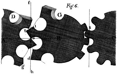
of the foregoing theory. A, B, (fig. 6) are two wheels of
which the primitive circles or pitch-lines touch each other at o.
As all the homologous points of any screw-formed tooth, are at
the same distance from the centres of their wheels, I am at
liberty to give the teeth a rhomboidal form, o t i; and if the
angle o exists all round both wheels, (of which I have attempted
graphically to give an idea at D G,) in this case,
those particles only which exist in the plane of the tangents
f h, &c. and infinitely near that plane passing at right angles
to it through the centres A and B, will touch each other;
and there, as we have already proved, no sensible motion of
the kind producing friction, exists between the points in actual
contact. I might add, as the figure evidently indicates, that if
any such motion did exist, the angles o would quit each other,
and the figure of such teeth become absurd in practice; but on
the other hand, if such teeth can exist and work usefully
(which I assert they can, nay that all teeth have in this system
a tendency to assume that form at the working points;) this
circumstance is of itself a practical evidence of the truth of the
foregoing theory, and of what I have said concerning it.
It must have been perceived that I have in some degree anticipated
the demonstration of my third proposition, namely,
that the epicycloidal or any other given form of the teeth, is
not essential to this geering. It appears that teeth formed as
epicycloids, will become more convex by working; since the
base of the curve is the only point where they suffer no diminution
by friction; whilst those of every other form, that likewise
penetrate beyond the primitive circles of the wheels, will
also assume a figure of the same nature, by the rounding off of
their points, and the hollowing of the corresponding parts of
the teeth they impel; and that operation will continue till an
angle similar to that at o, but generally more obtuse, prevails
around both wheels; when all sensible change of figure or loss
of matter will cease, as the wheels now before you will evince.
On the right of the drawing, (fig. 6) the teeth of the wheel
B are angular, (suppose square) and those of the wheel C
rounded off by any curve s, within an epicycloid. All that is
necessary to remark in this case is, that the teeth of the wheel
B must not extend beyond its primitive circle, whilst the round
parts of those of the wheel C, do more or less extend beyond
its primitive circle; whence it becomes evident, that the contact
of such teeth, (if infinite in number) can only take place
in the plane of the common tangent at right angles to A B;
also that if these teeth are sufficiently hard to withstand ordinary
pressure, without indentation in these circumstances, there
is no perceptible reason for a sensible change of form; since
this contact only takes place where the two motions are alike,
both in swiftness and direction. A fact I am going to mention
may outweigh this reasoning in the minds of some, but cannot
invalidate it. I caused two of these wheels made of brass, to
be turned with rapidity under a considerable resistance for several
weeks together, keeping them always anointed with oil
and emery, one of the most destructive mixtures known for
rubbing metals; but after this severe trial, the teeth of the
wheels, at their primitive circles were found as entire as before
the experiment. And why? Certainly for no other reason
than that they worked without sensible friction.
Hitherto nothing has been said of wheels in the conical form,
usually denominated mitre and bevel geer. But my models will
prove, that they are both comprehended in the system. The
only condition of this unity of principle is, that the axes of two
wheels, instead of being parallel to each other, be always
found in the same plane. With this condition, every property
above-mentioned, extends to this class of wheels, which my
methods of executing also include, as indeed they do every
possible case of geering.
Being afraid of trespassing on the time of the society, I have
suppressed a part of this paper, perhaps already too long; but
I hope I may be indulged with a few remarks on the application
of those wheels to practical purposes. And first, as to
what I have myself seen; these wheels have been used in several
important machines to which they have given much swiftness,
softness or precision of motion as the case required. They
have done more; they have given birth to machines of no small
importance, that could not have existed without them. In
rapid motions they do all that band or cord can perform, with the
addition of mathematical exactness, and an important saving of
power. In spinning factories these properties must be peculiarly
interesting; and in calico-printing, where the various delicate
operations require great precision of motion. In clock-making
also, this property is of great importance in regulating the action
of the weight, and thus giving full scope to the equalizing principle
whatever it be. I may add, it almost annuls the cause of
anomaly in these machines, since a given clock will go with less
than 1⁄4 of the weight usually employed to move it. Another
useful application may be mentioned; in flatting mills, where
one roller is driven by a pinion from the other, there is a constant
combat between the effort of the plate to pass equally
through the rollers, and the action of the common geering,
which is more or less convulsive. Whence the plate is puckered,
and the resistance much increased, both which circumstances
these wheels completely obviate; and many similar
cases might be adduced.
I shall only add, that my ambition will be highly gratified if,
through the approbation of this learned society, I may hope to
contribute to the improvement and perfection of the manufactures
of this county; and if the invention be found of general
utility to my much loved country.”
Subsequently to the reading of the above paper, I had occasion
to execute many wheels on this principle; and their appearance,
and use, excited on the one hand much interest, and on the other
much opposition. I had even to complain of real injury in that
contest: against which I defended myself with a warmth that I
thought proportionate to the attack.—But all this was local and
temporary: and writing now for a more enlarged sphere, and perhaps
for a more extended period, I feel inclined to lay aside every
consideration, but those immediately connected with the influence
of this work on the public prosperity. I shall therefore
avoid all reference to the names either of my friends or my opponents.
My friends will live in a grateful heart, as long as memory
itself shall last; my enemies, if I have any, will be forgiven—or,
at worst, forgotten; and my System is henceforward
left to wind its way into public notice and usefulness,
by its own intrinsic merits.
Certain Observations which I was induced to make on occasion
of a re-print of the above Memoir, may assist in introducing
what remains to be said on the subject. They commence
thus:
The foregoing little work, which first brought this subject
into public notice in this town, was not the only method employed
to develope its principles, and urge its adoption. A
second paper was read, at the next meeting of the society, and
some time after, a third, at the Exchange Dining Room; on
both which occasions new modes of reasoning were pursued,
and new kinds of proof adduced. On the first, a model was
exhibited of two screw-formed teeth (connected with proper
centres) exactly like those represented in fig. 6; by the action
of which on each other, it became manifest that teeth of this
angular shape do work together without inconvenience, and
therefore, that all sensible friction is, in this case, done
away.
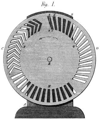
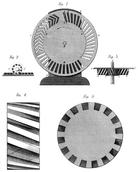
On the latter occasion (the lecture at the Exchange) two
other methods were brought forward, to corroborate the principles
before stated: (see Plate 14, fig. 1.) The first was a
kind of transparency, in which a line of light represented the
place of contact of two wheels working together; by the partial
and variable obscuration of which, the successive action of
every portion of the teeth was clearly shewn. The second
method consisted of two pair of wheels, made from loaf sugar,
the teeth of which were cut one pair in the usual form, and
the other on the new principle. Here, the difference in the
effects of the two methods was so great, that the common teeth
were almost immediately worn or broken down, by the very
same kind of impulse that the new wheels sustained without
injury: and with a loss of matter almost imperceptible, since
many thousand revolutions of the wheels took place without
detaching so many grains of sugar!
These Observations include likewise the following remarks:
In adverting to a few of the difficulties we have encountered,
it will appear curious that one of them should spring from a
most useful property of the system: but the paradox is thus
explained. As there is no method more effectual for giving the
teeth a perfect form, than working the wheels together, (covering
them with an abrasive substance) we have most frequently
chosen to depend on that important property; and
have therefore set the wheels at work as they came from the
foundry, instead of chipping the teeth, as is usual when common
wheels are expected to act well in the first instance. But
our wheels being then full of asperities, their action would be
of course imperfect and noisy, till time had smoothed and equalized
the touching surfaces: a state of things that might well
stagger the opinion of a candid observer unacquainted with the
system. Happily however we can now appeal to the fact of
many wheels having become silent, that were once referred to
with triumph, as proofs of a radical defect in the principle. It
may not be improper to add here, that if highly finished wheels
were particularly desired, we would engage to cut them in
metal on this principle, with all the perfection of surface given
to common wheels by the first masters.
In the use of bevel wheels of this description (with singly inclined
teeth) there is doubtless a tendency to approach toward
or recede from each other; the extent of which (for cylindrical
wheels) has been already determined. This tendency goes, so
far, to give a bend to the shaft; and, if this be very weak, to
create a degree of friction on the teeth as the wheels revolve.
It is therefore desirable that the shafts should be rather too
strong than too weak; since the principle can only exist entire,
when the wheels in working, are kept in the same planes which
they occupy when at rest. This is too evident to be further
insisted on.
But a greater, or at least a more frequent cause of friction
in the wheels is the motion, endwise, of the shafts, arising
from a want of solidity in the bearers, and especially of connection
between them; for whenever these are strongly connected,
and the shafts well fitted to their steps, all circular
commotion is ipso facto destroyed; while the longitudinal tendency
produced by the teeth on the shafts is certainly an advantage:
because it prevents the shaking that often arises from
their vibration, endwise, when lying on unsteady bearers,
or on bearers between which they have too much liberty.
A few words will make known the process of reasoning by
which I arrived at the idea that forms the basis of this invention.
I had been conferring with a well-known mechanical
character, (to whom the art is greatly indebted)—and hearing
his observations on the advantage derived from having two
equal cog wheels connected together, with the teeth of the one
placed opposite the spaces of the other; so as to reduce the pitch
one half, and the friction still more; (since the latter follows
the ratio of the double versed sines of the half-angles between the
teeth respectively:)—and no sooner had I left that gentleman,
than my imagination thus whispered—“What that gentleman
says is both true and important.” “But if two wheels thus
placed, produce so good an effect, three wheels (dividing
the original pitch into three), would produce a better: and
four, a better still: And five a better than that. And for
the same reason, an indefinite number of such wheels would
be indefinitely better! We must then cut off the corners of
all those teeth, and we shall have one screw-formed line, that
will represent an indefinite number of teeth, and approach indefinitely
near to absolute perfection!” Thus did this Invention
originate: and it soon appeared to me, to be the nearest approach
of material exactitude to mathematical precision, that is to be
found in the whole circle of practical mechanics. For not only
is the relative motion of the touching points of two wheels (that
is their friction), less than the distance between two of the
nearest particles of matter, but it is as many times less than
that distance, as that distance is less than the half diameter of
any wheel whose teeth are thus formed.
I assert therefore that these teeth, placed in proper circumstances,
do work without sensible friction at their pitch
lines: as although by means of mathematical abstraction, it
may be possible to assign a degree of friction between them,
that degree cannot be realized on a material surface: and I
fear not the friction on mathematical surfaces, if my material
surfaces do not suffer from it. I take leave then to repeat, that
no friction can justly be said to arise from a motion, too short
to carry a rubbing particle from one particle of a rubbed surface
to the next! and this is precisely the case in the present
instance.
Continuing to reflect on this important subject, I soon perceived
that the screw-formed line would give the teeth a tendency to slide
out of each other; and to drive the shafts of the wheels endwise
in opposite directions; but even that evil is not great:
for, confining the obliquity within 15 degrees, that tendency is
only about one quarter of the useful effort; and a stop acting on
the central points of the axes, will annul this tendency without
any sensible loss of power. We need not even have recourse to
this expedient when any good reason opposes it: for this
tendency can be destroyed altogether by using two opposite
inclinations: giving the teeth the form of a V on the surface of
the wheels—a method which I actually followed on the very
first pair I ever executed, which I believe are now in the
Conservatory of Arts at Paris.
A circumstance somewhat remarkable deserves to be here
noticed. In the specification of a Patent which I have seen in
a periodical work since my return from Paris, for things respecting
steam engines, and dated, if I recollect right, in 1804
or 5, this V formed tooth is introduced—as an article of the specification,
yet having no connection whatever with its other subjects;
nor being attended with the most distant allusion to the
principle of this geering. The fact is that I had these V wheels
in my Portique, in 1801, when that exhibition took place in
which my Parallel motion appeared and was rewarded by a
Medal from Bonaparte: so that two of my countrymen at least,
engineers like myself, appear to have taken occasion from that
exhibition, to draw my inventions from France to England—a
thing by no means wrong in itself nor displeasing to me: who
was then totally precluded from holding any communication of
that kind with my native country.
It would be repeating the statements contained in the foregoing
memoir, to say more on the general principles of this
System. I request therefore, my readers to give that paper an
attentive perusal; and to accept the following recapitulation of
its contents:
1. To cut teeth of this form in any wheel is, virtually, to
divide it into a number of teeth as near to infinite, as the smallness
of a material point is to that of a mathematical one.
2. By the use of these teeth, and the multitude of contacts succeeding
each other thence arising, all perceptible noise or
commotion is prevented. (This of course supposes good execution,
or long-continued previous working.)
3. For the same reasons, all sensible abrasion is avoided:
for we have proved that the passage of any point of one wheel,
over the corresponding point of another, is indefinitely less than
the distance between the nearest particles of matter. (This
supposes the action confined to the pitch line of the wheel; and
this it will be in all common cases—since the teeth wear each
other in preference, within and without that line; which therefore
must remain prominent.)
4. From the foregoing it appears that the teeth of two wheels
working together tend constantly to assume a form more and
more perfect: as they abrade each other while imperfect, and
cannot wear themselves beyond perfection.
5. For a similar reason the division of the teeth cannot remain
unequal: for those that are too far distant from a given
tooth will be attacked behind, and those that are too near
before; so that the division also will finally become perfect.
But it must be remembered that these recoveries of form are
in their nature very slow; since the nearer the teeth come to
perfection the slower is their approach to it: so that in thus
dwelling on these properties, we do not advise the making of
bad wheels that they may become good; but only wish to
destroy an honest prejudice that has already much impeded the
progress of the System; namely, that it requires great nicety to
adjust them so as to work together at all: which is—(to say
the least) a very great error.
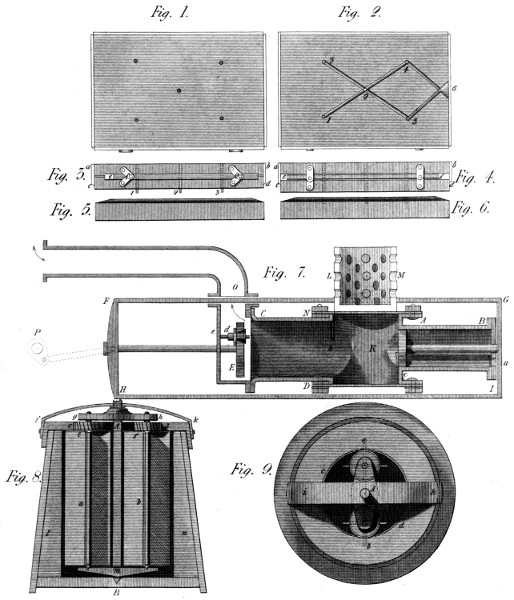
In Plate 14, fig. 1, I have shewn the apparatus presented at
the Exchange, as mentioned in page 110 preceding. A B is
the stand; C D is a disk turning on the centre E; b a is the
transparent line cut through the stand, and representing the
place of contact of two wheels geering together. It is there
seen, (supposing the disk to turn in the direction of the arrow)
that the action of the teeth, is always progressive along
the transparent line a b; whether the single or double obliquity
G or F be used. In reality, the lower end of any tooth c, does
not uncover the line a b, till the upper point of the succeeding
tooth d has begun to cover it; whereas, observing a few of the
common teeth represented at H, as directed to the centre of
the disk, they would be seen to pass the line a b all at once;
and thus to represent, with a certain exaggeration, the transient
manner of acting of the common geering.
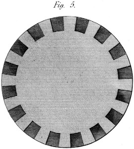
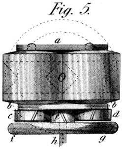
Some knowledge of the nature of this geering may be gathered
from its very appearance: see fig. 5 Plate 14. To represent
these teeth properly, no light must appear between
them. The tops of the teeth offer a continued circular line,
similar to what it would be if there were no teeth at all: and
the latter are distinguished only by a different shading of their
front and lateral surfaces. The reason (as has been already
observed) is, that they are necessarily so placed, as that
the last end of any tooth shall not quit the plane of the centres,
until the first end of the succeeding tooth arrives at it; which
principle precludes the possibility of any space remaining between
the teeth, that an eye directed parallelly to the axes
could penetrate. Such a space indeed would introduce a portion
of the properties of the old geering, which it is the object of
this System to avoid. As this wheel then appears in fig. 5, so
it acts: that is equally and perpetually.
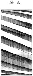
It were well also to observe the appearance of these wheels
on their edges; or in the planes which, as wheels they occupy.
The 4th. figure of this Plate is outlined with some care, in
order to shew the varying, and seemingly anomalous form
which the teeth assume as they approach the boundaries of the
figure. Although cut as obliquely to the axis there, as any
where else, the receding cylindrical surface, thus seen, appears
to take this obliquity away; and the very outward teeth seem
nearly parallel to the axis of the wheel. But this is only appearance:
and we give here one example of it, that we may
not be obliged to lose much time hereafter, in drawing correctly,
wheels on this principle—a process indeed which in
many cases, would be found very difficult, if not impossible.
We have already adverted to the oblique tendencies of these
wheels, when used with a single inclination of the teeth; from
which, among other things, it follows that, in the act of urging
the shafts endwise, they tend also to bend these shafts:
for which reason the shafts require to be stronger than those of
common wheels—that is, when the effort bears any proportion
to their stiffness—a circumstance which, in light rapid movements,
is of small moment. And in heavier works, when it is
desirable to get rid of these tendencies altogether, we have peremptory
means of avoiding the very appearance of this evil.
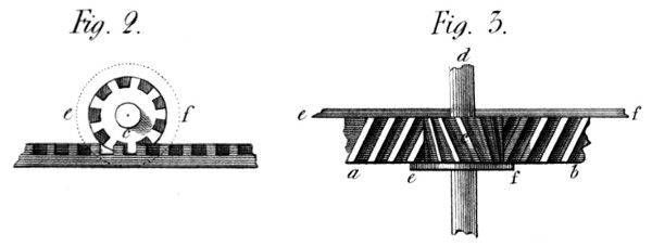
Suppose then (fig. 2 and 3, plate 14) a b to be a straight
rack on this principle; driven by the wheel or pinion c. The
motion, backward, of the pinion, tends, clearly, to urge the
pinion endwise towards d, and the rack sideways towards a b.
But either of these motions is prevented by fixing to the pinion,
or the rack, a cheek e f, to support them against this lateral
pressure. But then, exclaims a doubting friend, you introduce
friction: and it is true: there is now a real rubbing of
the ends of the teeth against this cheek; but the pressure
there being only one quarter of what it would be on the front
of straight teeth, we avoid (on a rough estimate) three quarters
of the friction; while preserving all the constancy and
smoothness of motion which the system gives; and which after
all, is the most important part of the business.
This idea then applies among other things to the racks of
slide-lathes; giving a regular motion to the rest and cutting
tool, thereby adding to the perfection of the turning process:
and many other cases might be adduced.
But instead of using a rack and pinion, as thus described,
two wheels, of any desired proportions might have been thus
treated, and the result would have been the same. They would
have worked with perfect smoothness, under about one quarter
of the friction attendant upon common wheels in similar circumstances.
There are cases therefore, in which it would be
expedient thus to employ the System. I cannot but observe
likewise, that this method of using cheeks to prevent any side
motion in spur wheels, might also be applied to bevel-wheels, to
prevent the angular tendency which the obliquity of their teeth
gives them: and that I prefer such a method of obviating this
evil (where it is one) to any attempt at using teeth in the V
form, on bevel wheels. Still however, as before observed, this
counteraction of the oblique tendencies is not always necessary.
It may be dispensed with in all light and rapid movements;
especially in the use of perpendicular shafts; and where the
driven wheels are small and distributed round a central wheel
in positions nearly opposite each other: of all which cases we
shall see examples in the spinning machinery to be described
hereafter.
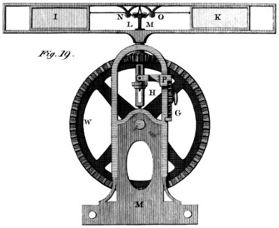
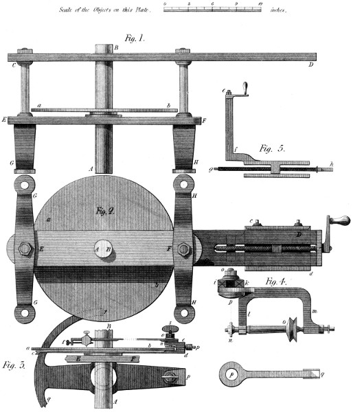
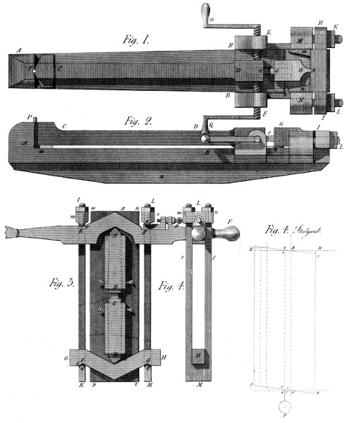
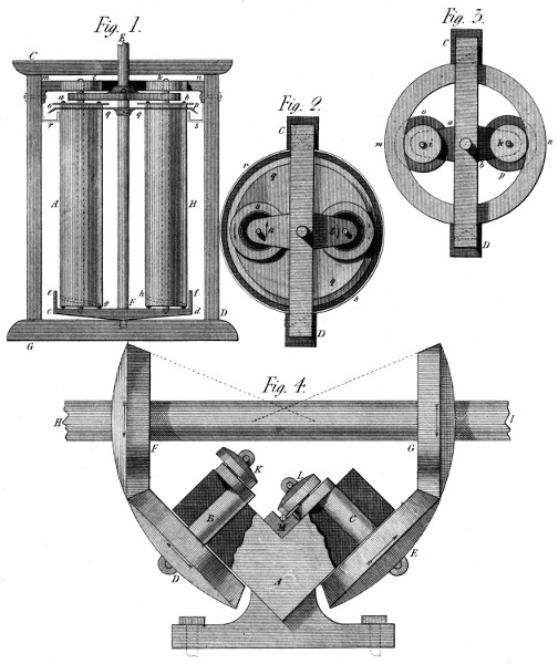
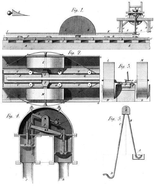
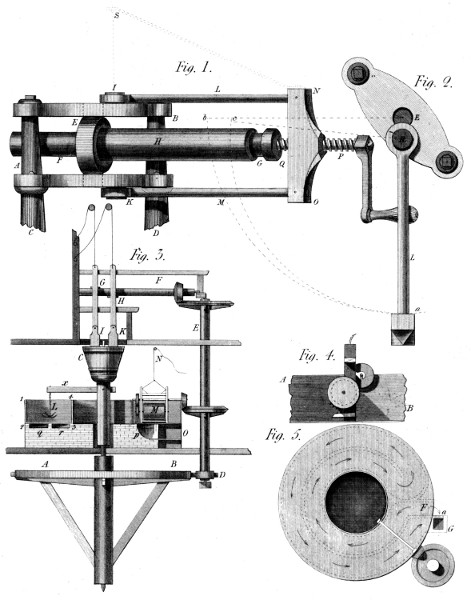
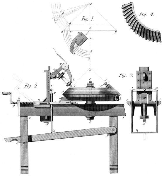
The figures of this Engine (see Plates 15 and 16,) are drawn
to a scale, from the Machine itself, now before me. The scale
of the objects on Plate 15, is one inch and three quarters to
the foot; and that of the objects on Plate 16, one inch and one
third. These were convenient proportions for introducing this
object into the present work; but the size itself of the Machine
is arbitrary. I did not make it according to my ideas of the best
dimensions: but bought it as a common cutting Engine, and
gave it those other properties that my System required.
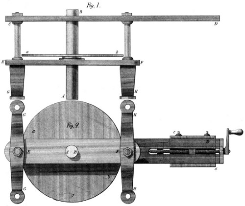
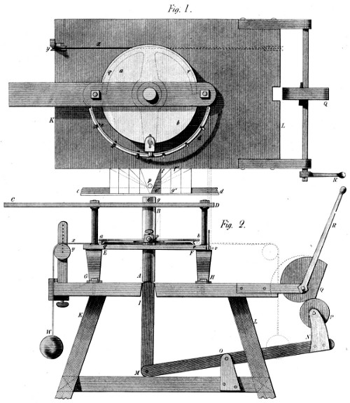
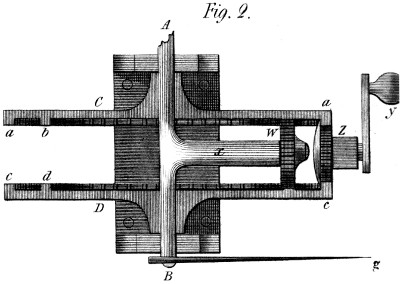
The first remarkable deviation from the usual form is in the
shaft or axis of the dividing plate. See fig. 1 and 2 of the
Plates 15 and 16. The dividing plate a b, is concentric with,
and fixed to an axis A B made as perfectly cylindrical as possible,
so as both to slide and turn in the bars C D, and E F
composing the frame. These bars are bushed, to fit the axis
A B, either with a contracting ring of brass, as usual in some
mathematical instruments; or with type metal, cast around
the axis into rough holes in those bars:—which metal, closing
upon the axis makes a good centre; and will last a long time.
My Engine is made in this manner; and has been renewed in
this part only twice in several years. This frame C D E F of
the Engine, is strongly connected with the feet G G H H, by
means of the nuts E F in the plan: and by these feet it is
fixed to its bench or table, as will be seen in Plate 16.
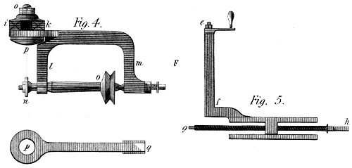
Figure 2 of the present Plate, represents the plan of the Machine,
but turned upside down; so that the feet G H screwed
under the lower plate E F, are wholly visible. In this figure,
also, is shewn at c d, the edges (without the bottom) of the
horizontal slide which carries the stand for the cutter frame
represented in fig. 4. This stand is indicated by the dotted
lines of this figure 2, as situated under the arm D of the bar C
D; but it is better shewn in fig. 5, where e f marks the slide
in which the cutter frame (fig. 4) moves up and down, by means
of the screw and handle e f. In general I avoid dwelling much
on these smaller parts, because they exist, probably in a more
perfect state, in most other machines. In this fig. 5, g h
shews the screw that moves this stand nearer to, or further
from the axis A B of the Engine, according to the diameter of
the wheels: which is also a common process in Machines of
this kind, on which therefore much need not be said. But a
somewhat greater importance attaches to the cutter frame represented
in the 4th. figure: which is a kind of small lathe
whose spindle n o, carries the cutter n, outside the frame, for
the purpose of changing the former without displacing the
latter. The cutter (of any proper section) is placed in or near
that line which is a continuation of the centre of the fixing
screw o p. It is in that line for wheels whose teeth can be
finished with once cutting: but near it for those whose teeth
must be cut at twice. In this same figure, i k represent the
ends of the standards that form the vertical slide e f of fig. 5;
and the separate figure p q, shews the back of the cutter frame
l m, the flat part of which, p, presses correctly on these uprights
i k, and thus fixes this instrument at any desired height,
and to any given angle with the perpendicular: the use of which
arrangement we shall soon have occasion to exemplify.
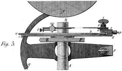
Turning now to fig. 3 of this Plate, we there see the main
shaft A B, broken off at B: and the letters a b again shew the
dividing plate of figs. 1 and 2: under this Plate is seen an alidade
or moveable index, shewn by section only at c, and in
elevation at d e; where it clips the plate as far as n and carries
a boss between n and e, on which the dividing index e f, turns;
and to which it is strongly fixed by a nut o, when the proper number
to be cut is determined. Moreover, this boss forms, itself, the
nut of a thumb-screw s, which, carrying a circular plate at its
lower end, clothed with leather or any soft substance, connects
strongly, without injuring the plate, the moveable index
with any point of it, as determined by the dividing index e f.
This brings us into the midst of things, as it respects the use of
this Engine; for the former index c d, is furnished with a small
roller, p, the motion of which all the foregoing objects must
obey, when they have been fastened together by the thumb-screw
s. We turn then to the figures 1 and 2 of Plate 16, in
order to shew those parts in action: after remarking only that
the form p q r of this fig. 3, is that of the moveable index
shewn before at c d; requiring only, to become complete,
that the part q should be sufficiently lengthened to make the
arc r q a complete semi-circle—for purposes that will shortly
be explained.
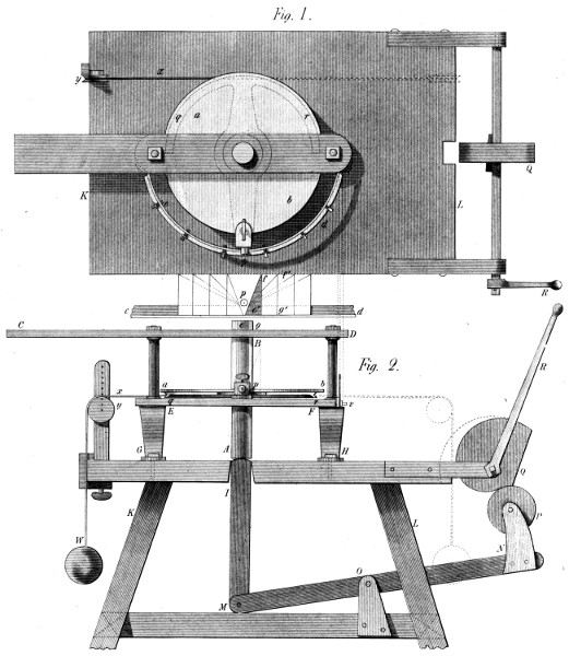
In the two figures of Plate 16, the Machine is shewn as
placed on its bench or table, accompanied by the parts which
give it a distinctive character, and in fact embody the System.
In addition to the parts already described, we first remark the
circular rim c d, fixed to the ends of the bar E F; and made
perfectly concentric with the main shaft A B, and the dividing
plate a b. This rim is shewn in section only, at v fig. 2.
Its section resembles an L, and thus forms a basis for certain
plates that will soon appear; and receives the screws by which
these plates are fastened to it. This being sufficiently clear,
we now proceed to describe the table and the connection of its
mechanism with the foregoing.
In Plate 16, K L is the table: to which the Engine is
screwed through its feet G H. I, is a square bar of wood,
sliding in a mortice through the top of the table; and connected
by a joint with the lever M N—itself moving round a pin at O,
and carrying a friction roller, P, which pressed by the spiral
Q, as turned by the handle R, raises the bar I, and with it
the main axis A B of the plate, and of course the wheel to be
cut, centered as usual on this axis above B. Finally, p q r, in
both figures, is the moveable index first shewn in fig. 3 of Plate
15; prepared to be drawn round by a weight W, hanging to
the cord x, passing over the pulley y, and tied to the right end
of the arc q r, when this is to move to the left; or to its left
end, when the motion is to be toward the right:—these motions
depending on the right or left-handed direction of the
teeth which it might be wished to cut on the Machine.
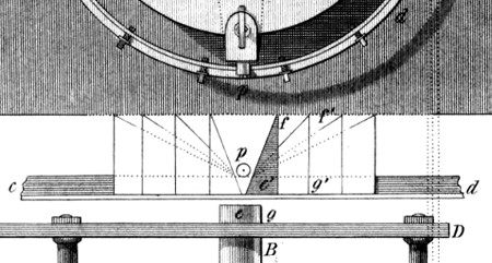
Between the two figures 1 and 2 of this Plate, there appears
a diagram, the base of which is nothing more than a part of the
rim c d supposed straightened, and placed there that its use may
be the easier understood. On the rim is seen a right angled
triangle e g f, against which the roller p will lean by the
action of the weight W on the cord x, and the arc q r of the
moving index p q r. So THAT when, by the handle R, the spiral
Q depresses the lever M N, by means of its roller P, then
the bar I raises the axis A B of the Engine, and the weight W
turns it at the same time, as much as the small roller p permits
by rolling up the side e f of the plate e g f. And thus may a
screw-formed tooth be cut in any wheel centered above B in
the usual manner.
Thus then, in describing this Machine, the manner of using
it has been also shewn: for the cutter, in this Machine, (to
cut spur wheels) is always fixed; and all the motion is composed
of the rotatory and longitudinal movements of the principal
axis, which carries the wheel along with it. The cutter I say
is fixed, at a proper height just above the wheel, and at an angle
to the perpendicular, equal to that it is wished the teeth should
form at it’s pitch line. This inclination as before observed is 15
degrees; and the tangent of 15° is in round numbers 268, when
the radius is 1000. That is, in our present figure, the basis e g
of the plate e g f, occupies 268 divisions of a scale, of which
the height g f contains 1000. It appears then, that to cut a
tooth with 15 degrees inclination, by this Plate, the wheel receiving
that tooth, must be just as large as the rim itself; for
the surface of the wheel would turn more, with a given elevation,
if it were larger than the rim; and would turn less, by
the same elevation, if it were smaller. In a word the whole
theory of this operation, is now clearly seen. The smaller the
wheel to be cut, the longer, horizontally, must be the Plate;
or in other words, as the diameter of the wheel is to that of the
rim, (c d) so is the length e g of the Plate to the length required.
Now this height f g, is always the same; all change therefore,
in the plates, takes place on the horizontal length: and this
length is most easily found by the foregoing RULE OF THREE.
If then, instead of the triangle e f g, I had used the triangle
e′ f′ g′ it would have followed at once, that to produce an inclination
of 15 degrees, I must have taken a wheel of just half
the diameter of the rim; for the plate e′ f′ g′ is just twice as long
as that e f g. To prove this, let us suppose the diameter of a
wheel wanted, to equal one half that of the rim c d: then the
rule will stand thus:
1 is to 2, as 268 is to ...536, the length of the plate according
to the theory; which is precisely the length it is drawn to
compared with that e f g, namely twice as long. Thus the
four triangles, drawn to the right and left in this diagram,
represent the plates for the wheels of the following diameters
respectively:
| No. |
1 |
, a wheel |
equal |
to |
the |
plate rim c d; |
| |
2 |
do. |
do. |
to |
1⁄2 |
do. |
| |
3 |
do. |
do. |
to |
1⁄3 |
do. |
| |
4 |
do. |
do. |
to |
1⁄4 |
do. |
A small anomaly, of form, may be mentioned here to prevent
mistakes. The shaded triangle e f g in the Plate, looks
higher than the rest: but if higher, it is also longer in the
same proportion; and the roller p never reaches the bottom:
so that the effect of this Plate is the same as though it resembled
the others in every respect. In general the effect of
the Plates depends on their length compared with their height:
and indeed they must be made higher than the thickness of the
wheel to be cut, that the latter may disengage itself from the
(fixed) cutter both above and below.
It is proper to observe, that for every pair of wheels there must
be a pair of plates; one leaning to the right and the other to
the left, (see the diagram) but, as before said, the degree of
obliquity must be different in each pair, except in the case
of equal wheels, when the same plate serves for both; only
turning it to the right for one wheel, and to the left for
the other. Nor does this offer any difficulty, as the plates
are made of common tin plate: which is easily brought
to fit the rim, whichever way it is applied. I shall now add
another example of the process for finding the length of the
plates: and to that end repeat that the plate rim c d, is 22
inches in diameter, or 11 inches radius. Supposing then that
we wished to cut a pair of wheels, one of them being 1 inch
in diameter and the other 12 inches; both to have teeth inclined
15 degrees to the axes; (as without that they could not
work together) to do this we must effect these two proportions:
- (1) 1⁄2 inch (radius of small wheel) is to 11 inches, (radius of
plate rim) as 268 parts (of which the height of the
plate is 1000) to another number, which is the length
of the plate sought: measured on a scale of parts of
the same magnitude.
- (2) 6 inches, radius of the large wheel; is to 11 inches radius
of plate rim; as 268 parts (as before) is to another
number, which is the length sought for this second
plate.
| Both proportions being effected, the first plate is |
5896 |
parts. |
| And the second |
491.33 |
do. |
The one of course, to be directed toward the right hand,
and the other toward the left, on the plate rim; where note,
that if the height (1000 parts) is found so numerous as to
create confusion, let 100 parts be assumed; when the length
of the plate will become 26.8 or 26 and 8⁄10 instead of 268, and
the operation will be so much the more simple.
It should be added that this process admits of being further
simplified: since the product of 11 inches, radius of the plate
rim, multiplied by 268 (tangent of 15 degrees, or length
of the plate for a wheel equal in diameter to the plate rim)
since this product, I say, is a constant number, namely: 2948—which,
divided by the half diameter of any wheel, gives, at
once the length of the plate adapted to that operation, in
parts of which the height contains 1000; or supposing the
height to be 100 only, this constant number becomes (nearly
enough for practice) 295. In a word, on a height of plate of
100 parts, when wishing to cut a wheel of 4 inches in diameter,
I merely divide 295 by 2, and get for the length of my
plate 147.5 parts of which the aforesaid height is 100.
It may possibly be suggested that this method of using
plates to determine the obliquity of the teeth is a homely
method, giving some trouble in the execution, and leaving a
certain degree of roughness in that execution. The fact is
allowed; but this method has the advantage of a very general
application, which many a better looking apparatus would not
present.
Besides, for most uses, these teeth require chiefly that the
obliquity should be correct, and not that the surface should be
licked like those of a gewgaw. In fine, the principle of this
Machine once known, its best form will occur to the reflecting
mechanician according to the quality of the work he has in
view: And in fact, in the hands of a well known artist, this
form has been already varied so as to produce effects much
higher wrought than could be drawn from the Machine above
described: which latter however in point of generality, still
preserves the advantage.
That “necessity is the mother of invention,” is a remark
none the less true, for having become a trite proverb; I could
mention the time, place, and circumstance which gave birth to
this little Invention: but such detail would be superfluous. A
certain door was, and is still, most inconvenient, from the
stiffness of the spring, and the noise it occasions in a place
where silence ought to prevail: which state of things suggested
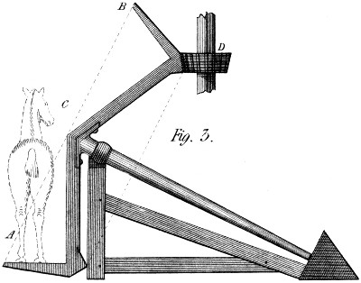
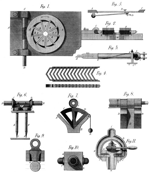
to my mind the Machine represented in fig. 5, of plate 17.
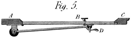
A B C in that Plate, is a horizontal section of the door,
door jambs, &c. The door spring now in use, is a barrel-spring,
with an arm carrying a small roller which presses in a
gutter-formed plate, screwed to the door. My door spring is
on a different principle. The roller is fastened in and by a
small frame to the door, and the arm is fixed to the axis of the
spring, which passes up through the top of the barrel. This
spring is much weaker than the former, insomuch as only just
to close the door by its elasticity; but when the door is shut,
there is a sharp bend in the arm that wedges itself against the
roller, and decuples at least the force of the spring, as tending
to keep the door closed. When therefore it is desired to open
the door, by pressing the door itself, a good push is necessary,
but only for an instant: for as soon as the bent part of the arm
is forced off the roller, there remains only the small resistance
of the spring to be overcome; which latter, when suffered to
act in shutting the door, will not shut it with that noise a
stronger spring would occasion; and yet, when arrived at its first
position, it will keep the door as strongly closed as ever. And
should it be wished to avoid the necessity of pushing hard
against the door, even at first, there is a sliding button and
stem B put through it, which, if pressed from the other side,
with the force only of the spring, will raise the latter beyond
the roller, and thus open the door with perfect facility: and
this same process will take place in pulling the door open by
the hook D from the inside: yet still the door when closed will
be as firmly so as before; the spring-bar acting in the latter
position, as much like an invincible stay as the workman shall
have desired—this property depending clearly on the nearness
of the bend to a right angle.
This device may appear to some an object too inconsiderable
to be justly dignified with the name of an invention. But if I
should sometimes fall into such an error as this, I intend to
compensate for any thing too trivial by giving in other cases,
Inventions of ample size and number. I might even mention
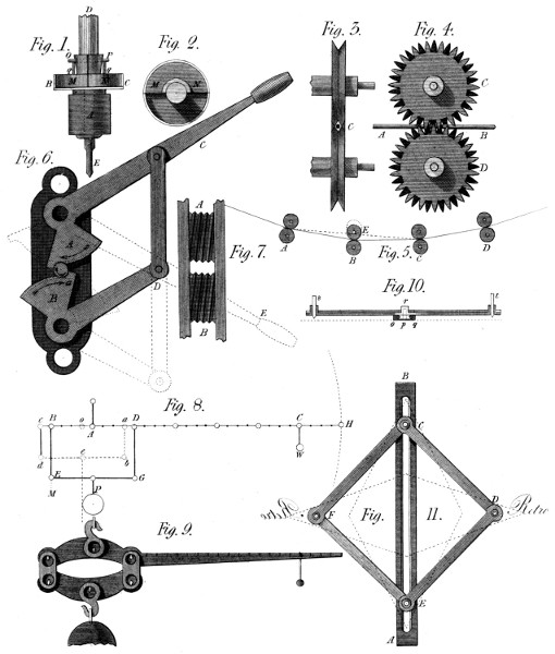
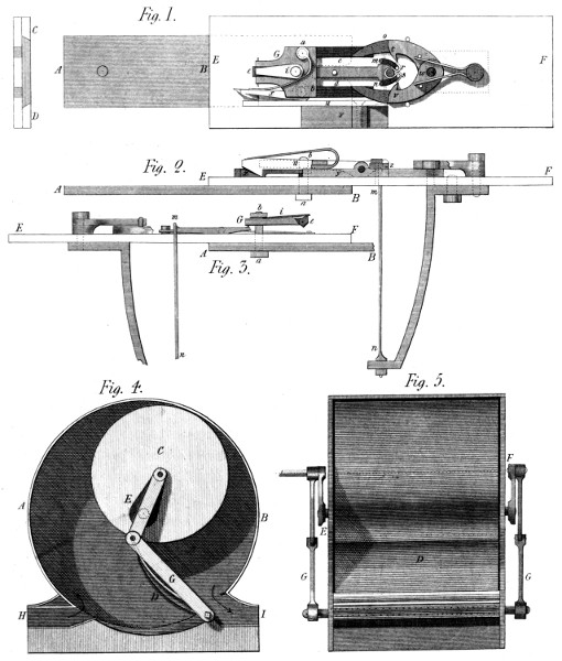
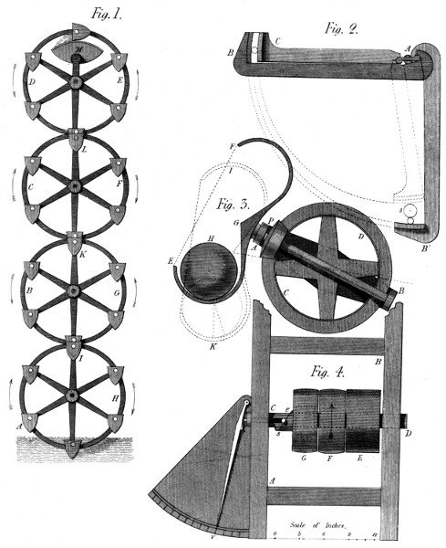
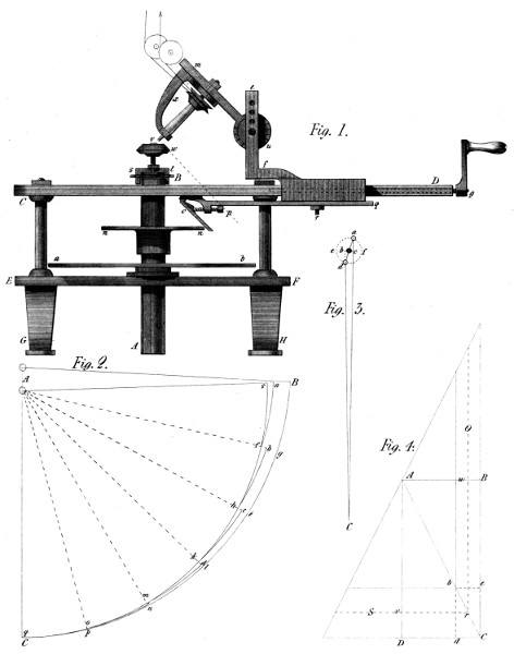
the Cutting Engine given in this part, where several Inventions
are compressed into one, or rather presented as one, of which
several examples will occur.
The pinion wire of clock and watch makers is well known.
I am not wholly acquainted with the manner in which it is
drawn: but I have made my pinion wire, of brass, in lengths of
about a foot, by the Machine described below.
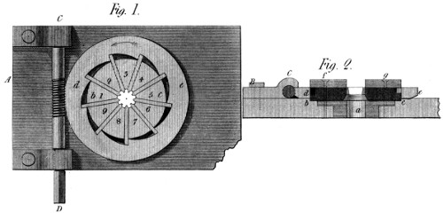
A common Draw-bench (not here represented) is worked in
the usual manner: but the instrument which forms the pinion
(see Plate 17, fig. 1) is of a peculiar construction. It consists of a
plate A B, containing—1st. a guide tube a, (fig. 2) to centre
and conduct the blank wire;—2d. a ring b c, with nine grooves
cut on one of its surfaces, directed to the centre, and in which
are well fitted the cutters 1 2 3 4 5 6 7 8 9; and 3d. a ring d e,
formed into nine spirals exactly like each other, answering to the
cutters, and destined to urge them equally toward the common
centre whenever this circle d e, is turned by the endless screw
C D, in the direction of the arrow. In fig. 2, f g is merely a top
piece to cover at the same time the cutters and the ring d e;
which latter is thus duly centered. The points of the cutters
1, 2, 3, &c. are formed like the spaces of pinion teeth; and in
the other direction, are sloped 15 degrees to the common axis,
as taken at their pitch line.
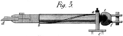
The third figure represents the drawing clams, or pinchers,
with a piece of blank wire d in them, tapered off to give easy
entrance to the cutters. These clams have a cylindrical part
of about a foot long, in which is cut a winding groove a b,
whose use is to turn the wire in the act of drawing; for which
purpose also the swivel e f is provided. The method I employ to
trace this groove to the obliquity required, is to measure the circumference
of the cylinder, and call that 268; and then, to make its
length, in the cylindrical part, equal to 1000 of the same divisions.
But this is right, only when the pinion to be drawn is of equal
diameter with the clam-cylinder a b: so that if it is wished to
draw pinions of a smaller diameter, I further say: diameter of
clam-cylinder is to diameter of pinion, at the pitch line; As
1000 (present length of clam-cylinder) is to required length of
ditto. Thus, for example, if the diameter of the pinion were
only 1⁄4 that of the clam-cylinder, the length of the latter would
be only 250 of the 1000 divisions, before found: and so in proportion
for smaller diameters.
The figure shews this groove receiving a guide screw or stud
a, which, placed in the fixed headstock a c, turns the clams d,
with the wire, just enough to give the teeth an inclination of 15
degrees, thus adapting them to the wheels of which the proportions
have been already given; where note, that the real
dimensions of this pinion Machine are twice as large as those
of the figures 1 and 2: but the size of every thing is of course
variable, according to the pinions required to be produced.
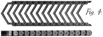
This Chain is shewn in fig. 4 of Plate 17. The links are formed
to an angle, in the middle, similar to that of the wheels at their
pitch line; of which the obliquity, for the V wheels, is greater
than 15 degrees; since the thickness of the wheel, is necessarily
divided between the right and left handed slope. Be this
slope what it may, the chain and wheels must of course be alike,
measured at the pitch line of the wheels; and then, as the
chain geers with a straight line of pinions, they work together
without sensible friction on the teeth, and with nearly the same
steadiness of motions as wheels would work together. Moreover,
if the drum be of a pretty large diameter, its action will
likewise be nearly equable. The degree of precision depends,
however, on the fineness of the pitch, and the largeness of
diameter in the drum; since every chain bending round a cylinder
must form a polygon of a greater or less number of sides,
dependent on these circumstances. I repeat then, that while
the chain works on the pinions in a tangent to them all, there
is no necessary friction between them; nor yet on the pins of
the chain, but only at the drums which actuate and return the
latter:—I shall dismiss the subject, by observing, that I have
used the term drum, because of the similarity of this chain-motion
to that produced by bands, where drums are generally
the movers. But here, this supposed drum is a wheel of proper
diameter, cut into teeth similar to those of the pinions; and
placed at the same height on its spindle. I have reason to
think that this chain, carefully made, would be an useful addition
to the bobbin and fly frame, applied both to the bobbins and spindles,
instead of the bands now in use; which, though a convenient
resource, give a result equally uncertain and imperfect.
The present description of this Machine, will consist, chiefly,
of a translation from my own specification, given at Paris
with the application for a Brevet, or Patent, obtained in the
year 1795, and which is thus introduced.
“It is a well-known fact, that the longer any Boat or Vessel
is, in proportion to its width, the less power it requires to
convey a given load, from one place to another. But these
lengths cannot be extreme, without introducing a degree of
weakness, that would offer great danger in the use of such
vessels. If then a Boat of a given volume, be divided into
several long and narrow ones, the head of each adapted with a
certain exactness to the stern of its forerunner, they will (with
the trifling difference arising from the asperities of their surfaces)
all move through the water with the same ease as any
single one; and carry, unitedly, the same weight as did the
large Boat before it was divided. This idea constitutes the
principle of my Serpentine Vessel.”
“This Invention is not to be considered as an imitation of the
well-known manœuvre of towing one vessel in the wake of
another: for the resistance of the vessels thus towed, remains
nearly, though not quite the same as if drawn along separately.
But here, by the adaptation of the prow of one Boat to the poop
of another, the first alone suffers resistance from the water—which,
although it enters between the joints, strikes only the
first—and from this it follows, that the resistance of these vessels,
in passing from one place to another, bears no necessary
proportion to the weight they carry.”
“Thus then, I obviate the necessity of having broad vessels
to carry the heaviest burdens; for I disseminate the load over
an indefinite length: by which method also, my vessel rides in
shallower water, and depends less for its passage, on the state
of the rivers or the seasons. Besides, they require a much less
number of horses, or exertion of power, to transport a given
quantity of goods; admitting at the same time, a greater
swiftness of motion. And finally, if these vessels travel through
different towns on the same voyage, the goods of each town
may be lodged in the same part, and merely detached in passing,
so as to lose no time in unloading them.”
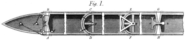
“Fig. 1 of Plate 18, shews the plan of several forms which
I give to the articulations or separate parts of these vessels: so
as to connect them strongly, yet leave them, as a whole, in
some degree flexible. The form A B, is, for the first boat, a
straight line across to form the stern, and for the second an
obtuse angle terminated by a semi-sphere or vertical semi-cylinder,
which enters a hollow and similar figure in the first
Boat—which latter, in this case, forms the Head of the whole
Serpentine Vessel.”
“These two parts or joints, of which we have been speaking,
are held together by a rope c d e f, which, fastened to the
second part at c, passes over two pulleys e d, in the head, to
the small capstan f, by which, both parts are bound together
as tightly as may be judged proper. If it were thought necessary,
the spaces A B might be underlined with a piece of
leather or metal, not to prevent the water from entering between
the Boats, but to prevent its striking those which follow
the others through the water—a precaution less urgent in the
other kind of joint we are about to describe.”
“C D, in this same figure, presents another form of the
head and stern of two contiguous Boats or parts; (which, to
save room, are both supposed to be broken off at some point
between their ends:) where as in the former case, the Boats
are connected so as to remain horizontally flexible. These
forms are semi-cylindrical, the stern concave, and the head
convex, to the same radius; and the motion takes place around
a bolt and pulley p, reeved with a rope coming from one side of
the first Boat near C and led again to a small windlass or capstan
placed on the other side near D. E F, is another modification
of the same kind of joint: the centre of which is a bolt
or stud q, (better seen at q in the 2d. figure) over which a triangular
frame falls from the preceding Boat, and thus connects
them instantaneously; leaving a certain flexibility in the horizontal
direction.”

“Finally, G H shews a simple mean of connecting these Boats,
on the supposition that both ends of each are formed alike to
an obtuse angle in the middle of their breadth. It is a kind of
hook r s, mounted in a frame turning on centres in the preceding
Boat, and reaching over into the succeeding one; where
it finds a hollow step of metal which receives and fits it, so as
to hold these neighbouring Boats with sufficient tightness, but
still with a certain degree of flexibility. Many other methods
might be suggested, by which to form these joints; and almost
any might be made to answer the purpose. I shall therefore
leave this branch of the subject, observing only, that the second
figure of Plate 18, is an elevation of the same things:
which, generally, are marked with the same letters as far as
they are visible.”

“The third figure presents the same objects in perspective;
to which are now added two masts I K, placed obliquely on
that Boat which forms the Head of the whole vessel. This
obliquity is useful when the boat is drawn from one side only;
but is injurious where the traction takes place indifferently
on both sides: so that I should not, now, advise the use
of this method—which indeed, I have avoided in fig. 4 of this
Plate.”
“In every case, each of the masts carries a pulley near I
K, over which passes a rope, the ends of which are fastened
to the masts by proper brackets, near the deck: and to the
middle of this rope is fastened the track rope L, by which the
horses draw the Boat along. By these means the vessel is
steered either to or from the land: for if the knot of the track
rope is brought near the mast I, the Boat (which as before
observed is the head of the whole vessel) veers towards the
horses; and the contrary when the knot is drawn towards the
mast K: both which effects are rendered the more prompt
and decisive, by the use of the lee boards K M, the nature and
use of which are already fully known.”
“But there are cases in which, from its great length, this
Serpentine Boat would require a particular direction, for some
intermediate point between its extremities; as although, in
theory, every separate part ought to pass through the same
water, yet in canals or rivers much bent, this may not invariably
take place; and then a rudder would be useful, even in
the middle of the vessel. I have therefore placed a pair at P
R, fig. 3. Their motion is a vertical revolution, round a horizontal
centre; and as they are formed obliquely to the sides of the
Boat, when one of them is plunged into the water, it tends to
drive the Boat in a sidewise direction: and if at any time it
should be desired to stop the whole vessel, both rudders would
be plunged at once into the water, when they would greatly
contribute to that effect.”

“The fourth figure in this Plate 18, presents a general view
of the vessel, comprising five articulations, (or Boats) besides
the head and stern—which latter would fit each other without
any intermediate parts, and form a Boat alone. Nor do these
five parts by any means limit the useful number: but the Plate
would not have contained more, unless on a scale too small to
be distinctly understood.”
“Returning now to fig. 1, we observe the ropes A D F H
and B C E G, which are supposed fixed to the stern Boat,
and carried to the capstans represented in the Head. These
ropes consolidate the whole fabric, and act, occasionally, as a
kind of muscle, to govern the larger evolutions. These ropes
pass in the brackets placed near the joints A B and C D,
&c. being under the gang ways, of which a portion appears
at S fig. 3, hung upon hinges, that they may be turned up
when the Boat is used in narrow water.”
To the above specification were added the following remarks,
which still apply to this kind of vessel, navigating on
canals and inland rivers: “this vessel admits of the use of every
kind of mover; such as men, horses, wind, or the steam engine;
the latter of which I propose to apply to it in a manner
equally simple and effectual; especially so as not to injure
the banks of any canal, &c. by acting against and disturbing
the water.”
I need not repeat that this Invention dates as high as 1795:
as the Brevet was issued in that year. It may be added that
four parts of such a Boat were executed about the same time;
namely, the head, the stern, and two intermediate pieces: making
together a length of 100 feet; and these, loaded to a certain depth
with stones, were drawn up the river Seine by a single horse
on a trot—which would likewise have taken place had the
Boat been ten times as long; since, as before mentioned, the
resistance of this kind of vessel bears no given proportion to the
Load it carries.
I think it may be assumed that friction is fully expressed by
the word rubbing: and that where rubbing cannot be found,
friction does not exist; especially that kind of friction which
opposes the motion of machinery—in which respect, the
subject is chiefly thought interesting to mechanicians. It would
be abandoning my intended plan in this work, to treat largely
of friction, or any other accident in practical mechanics; but
having already declared myself “no believer in several sorts of
friction,” I am in a measure bound to introduce my description
of the two following articles, by a short reference to the general
subject. I offer then the following remarks, more as hints
for the consideration of learned experimenters, than as conclusions
sufficiently proved to become rules in practice. What I
cannot help urging strongly is, that rolling is not rubbing. If
it were, I would ask in what direction it takes place? Is it in
that of the plane rolled over? or in that of the radii of the
rolling body? If in the former, it would indeed glide over that
plane, and occasion or suffer real friction; but this, I think,
is not pretended. If this motion is in the latter direction,
(that of the radii of the rolling body) it is indefinitely short,
compared with the progressive motion of the rolling body, so
that the power of the latter, to overcome any resistance in that
direction, is infinite. Whenever therefore, in experiments of
this kind, a finite resistance is perceived, it must, I should
think, be ascribed to other causes, and not to friction. In my
wheels for example, (see a former article) where there is a real
and deep penetration of the surfaces, I have proved that the
friction between the teeth is less than the distance between
two of the last particles of matter: and surely, when penetratration
is purposely made as small as possible (by the use of
smooth rollers) the friction thence arising must be still more
imperceptible. But I hear it answered, that this friction is both
known and measured! and certain celebrated experiments are
adduced to prove it. But what I most wonder at is, that a
person so truly learned as the author of those experiments,
should have adopted so remarkable a misnomer; in which to all
appearance, indentation has usurped the name of friction. Nor
let this surprise, surprise any body: nor especially, offend this
learned author himself; for I am persuaded that the sole act of
placing these wooden rollers, on these surfaces of wood, must
indent them both sufficiently to account for all the facts observed;
and still more so when loaded with weights of 100,
500, or 1000lbs. No friction, therefore, is requisite in accounting
for the resistance of these rollers to horizontal motion.
Nay, I submit, whether a resistance, arising from indentation
alone, would not prove to be “directly as the pressures and inversely
as the diameters of the rollers?” To me the subject
presents itself under three aspects: either the whole indentation
takes place on the rollers, when they are very soft and the
rulers very hard; or the latter, when they are very soft and
the rollers very hard: or, which is most likely, this indentation
takes place on both bodies at once; so as to produce a
surface of contact, intermediate between the straight surface of
the rulers, and the cylindrical surface of the rollers. But in
either case, the place of resistance to horizontal motion, must
be out of the line of direction of the roller’s centre of gravity:
and thus would the roller present more or less resistance, independently
of every thing that can be called friction: and
which degree of resistance will continue to exist as long as the
place of contact is made to change on the rulers—for thus to
change this place of contact is to renew this indentation; which
process will elicit a resistance equal to what would be observed
were the roller (without indentation) forced up a plane, inclined
to the horizon in the same angle as a line, drawn from
the centre of the roller to the extreme edge of the surface of
contact, makes with the perpendicular.
I cannot possibly enter at length into this subject, as it makes
no part of my engagement to the public: but I would observe
that this resistance is, a fortiori, something besides friction,
since greasing the surfaces “did not cause any sensible diminution
of it;” whereas it made a difference of one
half! in some others of the experiments alluded to.[4] Were I
asked the reason, I should answer, because friction had little or nothing
to do with it; and I would say further, that greasing or
oiling these surfaces would most likely increase, instead of diminishing,
their resistance to horizontal motion: namely by
softening them, and making them more susceptible of change
of figure: which opinion gathers strength from another fact
adduced, viz: that “rollers of elm produced a friction (or resistance)
of about 2⁄5 greater than those of lignum vitæ:” but
why? because elm is relatively soft and lignum vitæ hard—the only
cause that appears sufficient to account for the facts observed.
I must now leave these remarks to persons having more means
and leisure than myself, to pursue the subject; wishing only,
that useful truth may result from them: and that this unbelief
of mine “in several special kinds of friction,” may at least be
found to have some reasonable ground to rest upon.
But I may be opposed in some of my statements by the fact,
that friction rollers, with centres, have been used with little
advantage; and often laid aside. This I acknowledge; and
go a step further. Friction is by no means of so much consequence
as it was once thought to be: and is not the source of
the greatest defalcations that occur in the use of power. Yet,
to get rid of it, in some cases, would be of considerable importance;
and the subject deserves at least the attention of
every intelligent mechanician.
Those who have used friction rollers, know that it is a thing
of great difficulty, to place their axes exactly parallel to that
which they are intended to support: and even, if rightly placed
at first, that a small degree of abrasion, greater on one pivot
than another, will soon destroy that parallelism; and thus introduce
a growing friction, capable, at length, of rendering
the whole completely useless: for although the original friction
is lessened by being transferred to a slower-moving axis, yet
the latter still resists in some degree, say 1⁄4 of the whole; (its
pivots being 1⁄4 of its whole diameter) so that the cohesion, or
something else, between the main shaft and the friction roller,
(thus resisted) must be sufficient to drag round the latter,
against about 1⁄4 of the original friction; which in a word it
cannot do without some relative motion between those surfaces,
the friction roller lagging behind the main shaft, until its own
friction is overcome by another. And thus it is, that a friction
roller of this kind, does not make so many revolutions on its
pivots, as its diameter compared with that of the main shaft,
would imply; for example, if the shaft were 4 inches in diameter
and the friction roller 8 inches, the latter would not
complete one revolution against two of the former. There
would thus remain a difference spent in real friction, in addition
to that on the axis of the friction roller. Besides this,
we have the want of parallelism above mentioned; which occasions
a rubbing, in the direction of the shafts, small indeed in
quantity, but for that reason very powerful in bringing on a
change of form, and thereby hastening the common destruction.
Both these accidents, therefore, make friction rollers,
in general, an unsatisfactory and perishable expedient: and it
is to make them less so, if not entirely to cure these evils, that
the two following articles are designed.
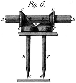
In fig. 6 of Plate 17, A B is an axis which it is desirable to
divest of its friction. To do this, as nearly as may be, I connect
with it two rings of hard metal C D, formed as truncated
cones; and under the shaft, in the same vertical plane, I place
two smaller shafts E F, carrying on their tops, other two
cones, similar to the former. The summits of each pair of
cones meet of course in the points a b of the main shaft; and, on
the principle of bevel geer, every contiguous part of the touching
cones moves with the same velocity: so that there is no sensible
rubbing between them—for, 1st. the pivots c d, are hard and
pointed, and run on the hardest steps that can be obtained;
and, 2ndly. the tendency of the cones u toward each other, is
repelled without friction by the cylinders e f, attached to them,
and which lean right and left against each other, turning with
the same velocity, without causing any friction, or any creeping,
between the two pairs of cones e C, and f D. All the
weight therefore, of the shaft A B, (which of course is kept
in place in the other direction by proper side cheeks, &c.) rests
on the points of the vertical shafts E F, accompanied by no sensible
tendency of these points to quit the places assigned to
them.
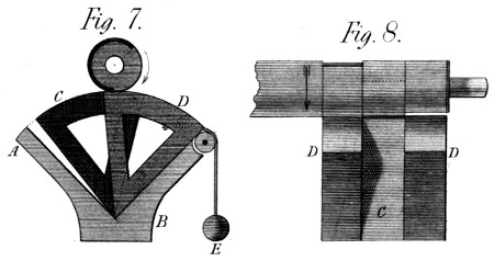
In Plate 17, figs. 7 and 8, offer a mechanism different from
the preceding, though intended to produce a similar effect.
Referring to that cause of friction which consists in the want
of parallelism between a principal shaft and its friction rollers,
I here introduce a form for the latter, which admits of this
consideration being in a measure neglected. These friction
rollers are only portions of cylinders; and they have no shafts.
They turn simply on a sharp edge, placed in a prismatic box
A B, in a well formed angle of which, they move to and fro,
without rubbing. When at rest, these axes D C D, (fig. 7
and 8) are drawn against the right hand side of the box, by
small weights E; and the shaft is carried by one or the other
of them, according as they are, or are not, within reach of its
radius. Thus, in the present position of the shaft, (see fig. 7)
the second arc C supports it, the third having fallen behind the
first, so as not to be seen: and the first arc D being on the
point of taking up the load. In short there are six spaces,
either left or cut on the shaft, opposite the three arcs D C D.
1st. one space, of 1⁄3 of the circumference, left concentric with
the real centre of the shaft, opposite the first arc D, followed
by 2⁄3 of a circumference cut an eighth of an inch lower. 2ndly.
another third of a circumference opposite the second arc C, beginning
where the first ends, and followed by 2⁄3 of a circumference
cut an eighth of an inch lower: and 3rdly, another space of
1⁄3 in circumference, opposite the arc D, followed by a similar
space of 2⁄3 cut an eighth of an inch lower. By these means the
shaft is never without a concentric bearing: and the better to
secure this property these arcs left, may be each of them more
than one third of a circumference in length, so as to avoid the
least drop at each change of roller; and even to give the shaft
a support from two rollers at once, during a good part of its
revolution.
In using this mechanism, the vessel A B, would be filled,
to a certain level, with oil or water, to prevent any blow from
the returning arcs—which latter might be made to fall on a
lining of leather, to avoid still further all commotion: and thus,
even were these rollers not placed quite parallel to the shaft,
this imperfection would be corrected by the frequent renewal of
these movements, and the consequent absence of lateral friction
between the arcs and the shaft. It may be observed that
either of the above methods of destroying friction is not confined
to the vertical direction: but may be so used as to receive
the pressure caused, in any direction, by the action of a wheel
or other agent. And with respect to the best use of each
method respectively, I would propose the former for light and
swift motions, and the latter for slow-going shafts, heavily
laden: it being well understood that the shafts must be kept
in their places, in the less essential directions, by proper steps,
at the discretion of the person who employs these Machines.
Finally, I consider it as a matter of course, that all the
surfaces coming into contact in these operations, should be
as hard and impenetrable as possible. For if, by neglecting
this precaution, any change of form occurred, what is said
above could not be practically true: But these properties can be
realized, with only those degrees of hardness that are often
employed in the mechanical world. Thus a die of hardened steel,
bears almost unimpaired, the strokes and pressure it suffers in
the coining-press. A chisel, stands thousands of blows and
cuts hard metal, without sensibly giving way. The knife-edges
which carry a heavy pendulum, suffer it to vibrate many
years without wearing out; and the fulcrums of scale-beams,
bear enormous weights, for almost an indefinite period, without
any injurious effect. I request therefore, that these facts,
may be put into the scale, when my foregoing statements are
tried: whether as applied to these anti-attrition machines, or
to my late patent wheel work, or both combined: for I foresee the
use of these friction rollers, cut into teeth on that principle, to
insure the proportionality of their respective motions.
In the common form of this useful instrument, no method
seems to have been devised for preventing the plug from being
pressed aside, by the weight of the liquid: which provision
nevertheless would have diminished the wear and tear of the
touching surfaces, and secured much longer the perfection of
the instrument. This property would be particularly desirable
in cocks which convey a fluid from a great height; and still
more so in those used for containing steam or any other fluid
under a high pressure. I can hardly persuade myself that I
have stood so long alone in my ideas upon this subject; but not
having seen any thing published on the subject, under a name
implying the above mentioned property, I venture to give this
as my invention—which indeed it is, even should other persons
have pursued and embodied the same idea.
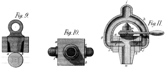
Fig. 9, 10 and 11 of Plate 17, represents one of the forms of
this equilibrium Cock. It consists of a square plug case or
chamber a b, with a hole c d bored transversely through it, exactly
across its centre: and to this chamber is fixed by the
flanches e f, the bifurcated water-passage g h, forming one
body at i. The plug of this instrument admits of various forms and
proportions; of which I have shewn two in the figures 9 and 11.
The first m n, receives the fluid through the two openings c d,
which correspond, in one position of the plug, with the double
water-passage before mentioned. And further, the plug itself
is bored lengthwise in its under end n, so as to form the spout of
the cock: or otherwise (see fig. 9) this spout is taken in a
double form from the outer surface of the plug at b a, so as to
present two streams, thus producing, I think, an instrument
of somewhat greater solidity. All that seems important is, that
whatever be the pressure of the fluid from without, it be made
equal on both sides of the plug, so as to occasion no friction between
it and the chamber. The principle is indeed so effectual,
that one might distribute steam pressure of the greatest strength
or even gunpowder pressure, without much resistance to the
operator, and without injuring the mechanism by oft repeated
action.
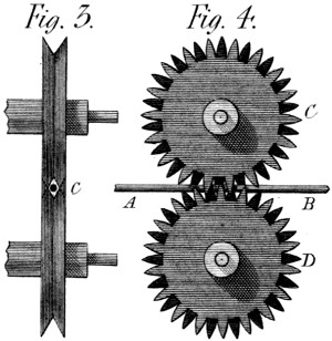
In Plate 19, figs. 3 and 4, shew this mechanism in two
directions. It is composed of two wheels C D, cut (or cast)
into teeth of a peculiar kind, that both geer with one another,
and at the same time, include the chord or round strap A B,
by which they are driven. These teeth can be better represented
by a figure than in words; and will I suppose be
understood from figures 3 and 4: They are divided, on the rim
of each wheel by a space too small to admit a tooth of the other
wheel: but then, every-other tooth is cut away in a sloping
direction on each side of the wheel, from the bottom of the
tooth to its top on the opposite side: so that while these teeth
are working in each other they offer two grooves, in the form
of a V, which coming together surround the chord and press it
in four points, either to drive the wheels by the cord, or to
pull the chord by the wheels, according to the use it may
be wished to make of this mechanism. In fig. 4 the cord is
seen at A B, passing among the teeth of the wheels; and in
fig. 3 it is shewn at C, as a mere circle, in the centre of a
lozenge formed by the teeth whose points now geer together.
Fig. 5 is a sketch belonging to this subject, which shews something
of the manner of using this round strap as a mover: for
by carrying it (either in a horizontal or vertical plane) by a line
slightly curved, from one machine to another, it will drive
them all and give the means of stopping any one at pleasure.
Suppose then, A B C D fig. 5, to be four machines placed
as above mentioned. If I wish to stop the machine B, I
merely draw back the pressure wheel E, and the cord ceases
to lay hold on the machine as shewn by the dotted line: but
when I want to set it on again, I do it by bringing back the
wheel E to its present position. And thus at a small expence,
I could geer a considerable factory, in a way which I think as
durable as it appears economical. The principal objection,
perhaps, is that this cord is liable to wear out soon, by such
incessant action; but then the pressure on it needs not be
great; and of friction properly speaking there is very little:
Besides which, the cords would be made of a peculiar texture,
perhaps of leather, sewed edge to edge and covered like a
whip, by one of the machines I shall bring forward hereafter.

It so happens that many of my Inventions are of a generic
nature, and thus apply to cases which, appearing different,
have nevertheless some common properties. The rule of contraries
especially applies to many of them,—of which this is an
example. It offers a good method of driving a boat through a tunnel,
or other confined space, either by the force of steam or
any convenient power. To this end a rope laid along the side
of such canal, and fixed at each end, or at several intermediate
points, might be led between a pair of wheels like
those above described; which duly turned, would drive the
boat the distance required with the least possible expence of
power, and without the defect of agitating the water.—But
I must not anticipate too much on my intended subjects.
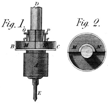
This Invention is under the protection of a Patent. It is
applied to the spindles of my spinning machinery called Eagles,
from their analogy to the machines named Throstles. It is in
my opinion an excellent machine; as it secures a mathematical
equality of twist to any number of spindles from permitting the
use of geering to turn them, which could not have been done without
some means of stopping a single spindle. This mechanism
(see Plate 19 fig. 1 and 2) consists of a toothed pinion A soldered
to the box B C, (partly cut down in the figure to shew its
contents) and with it running loose on the lower part of the spindle
E D. In this box are placed two weights M N, like that M
fig. 2, which both together, fill the box loosely, and, rising
above it, are pinned at O P through the spindle. They are
moreover kept from quitting the latter by the ring shewn in
section at q q, which holds them loosely, yet prevents their
flying away or hurting any one. When now the spindle E D,
turns swiftly, the centrifugal force of the two weights M N,
projects them from the centre as far as possible; and they lay
hold, by friction, of the cylindrical surface of the box B C, and
thus keep the revolutions of the spindle to the same number
of turns per minute, as the pinion A receives from the driving
wheel. But when the spindle is stopped and held by the
fly as usual, then the centrifugal force ceases to act, and the
box B C does not wear out much, by its further revolutions.
And when as before, the spindle is again let loose, that friction
which takes place on the bottom of the box sets the
spindle running again, when the centrifugal force comes to
its aid, so as to unite again the box and the spindle, thus renewing
that valuable property of all spinning machinery, the
mathematical correctness of its movements.
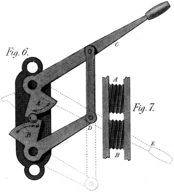
The effect which this Machine is intended to produce, is
analogous to several culinary or officinal processes that might be
named. It is called rolling: but not in the same sense in
which that word is used in manufactories, where rollers form
or modify the body acted on. Here this body itself rolls between
two surfaces moving different ways and receives from
them the desired impressions, and this idea I have extended to
screws; proposing to finish them on some metals and in some
dimensions; and to rough them out in others. The Machine
is represented in figs. 6 and 7 of Plate 19, where fig. 7 shews
the faces of the arcs A B of fig. 6. By the form and connection
of the arms A C and B D, these arcs move opposite
ways: and since they are grooved obliquely as shewn in fig. 7,
if a prepared cylinder of soft metal a, be put between them,
and the handle C be sharply pressed into the position A E,
the cylinder a will be made to roll, and the grooves of fig. 7 be
impressed on it so as to meet and form the screw in question.
The only conditions are, that the arc B A be at least equal in
length to the circumference of the screw, when finished; and
that the grooves (fig. 7) be rightly sloped, and have the form
intended to be given to the threads of that screw. It will occur
of course, that the opening between the arcs at the point where
the blank cylinder is introduced, must be larger than the distance
between the arcs by the whole depth of the threads to be
impressed: which therefore will begin to be formed at two opposite
points the moment the screw a begins to roll. This
however, might and would be otherwise, if it were thought
best to form the arcs A B spirally; and let the deepening process
be gradual: in which latter case another consideration
would occur, namely; that the grooves themselves (see fig. 7)
must diverge a little instead of being parallel, so as to permit
the screw to lengthen as the pressure should displace a part of the
metal. In all cases the upper surface of the grooves should be
milled so as to lay hold of the soft metal, and insure the rolling
motion: and should this material be hot-iron, the stroke
should be taken in an instant, and the machine be kept cool
by every proper method, in the intervals of working.
I need not add that this rolling process would be still easier
performed, if the impressions to be made were circular and not
oblique: such as beads, balls, &c. but these considerations I
leave to my readers.
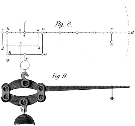
Plate 19, figs. 8 and 9, offers two representations of this
Machine—one intended to shew its manner of acting, and the
other one of its practical forms. By means of the first, (fig. 8)
we may compare it with the common steel-yard; and even
shew the latter as a part of the former. If a weight, or load
to be weighed M, were suspended to the arm A B, and the
counter-weight W, placed at the point C, of the arm A C, we
should have a common steel-yard whose power would be as 5
to 1: for the arm A B is just 1⁄5 of the arm A C, and this is
the principle on which steel-yards are commonly made. But instead
of this, my steel-yard G E B D C H fig. 8, is now infinitely
powerful: so much so indeed, as to be infinitely useless.
If millions of pounds were now to be suspended at P, they would
not raise the weight W one tittle, for they hang entirely on the
point of suspension A. But although the Machine is now useless,
it can be altered in a moment and made both useful and commodious;
only I thought its principle would be the better understood
from being thus shewn in excess. To make it a useful
and powerful Instrument, I only move the hanging bar D G,
to a b; and the bar E B to c d, the lever b d being similar to
that E G. In this state of things, the whole load P is found
at the point o of the lever B H, (for the lever-arms c o and d
e, and those e b, and a o are equal) and the power of this
steel-yard is as the line A C to the line A o; that is as 20 to 1,
instead of being as 5 to 1 which it before was. But this is not
yet a powerful Machine; being chiefly intended to shew the
principle on which it acts—and to prove that however small
the distance A o, that distance, dividing the arm A C, gives
the real power of the steel-yard. And supposing now the arm
A C to be four feet in length, and the distance a D, B c, and
A o, to be 1⁄10 of an inch, then the power of the weight w to
raise (or weigh) the load P is as 48 inches to 1⁄10 of an inch, or
as 480 to 1: so that if the weight w were 10lbs. this steel-yard
would weigh 4800lbs. or upwards of two tons; and it is easy
to see that this power can be almost indefinitely extended.
Fig. 9 of this Plate shews a real steel-yard made on this
principle; the power of which, under its present length, is as
40 to 1. In this Machine all the centres are fixed: and the
load is suspended on knife-edges, the distances of which from
each other and from the common centres are invariable—as
they must be in all instruments of this nature.
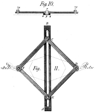
This Machine is exhibited in the two figures 10 and 11 of
Plate 19. It is composed of a straight ruler A B, having an
exactly dove-tailed mortice made along it, to receive the rollers,
(or slides) by means of which the parallelogram C D E
F slides up and down in this mortice. This parallelogram is
composed of four rulers C D, D E, E F, and F C, connected
by cannons or tubes fixed to every-other arm: and on which
the contiguous rulers turn very correctly. Through which
moreover, in two cases, F D the drawing pencils are introduced,
and under which in other two cases, C and E, the guide
rollers already mentioned are nicely fixed by the screws on
which they turn. This is seen by an elevation in fig. 10,
where p marks one of these rollers, and o q the end of the ruler
supposed fixed to the paper by proper blunt points, &c. At r is
seen one of the tubes which form the joints C and E: and r t,
are, one the writing pen, and one the retrographic style or
pencil. Fig. 11 is a plan of the whole Machine: where if the
hand guiding the pen D goes upward, the tracer F rises too.
But if the pen or hand D moves to the right, the tracer moves
to the left at the same moment. In a word this is to write
backward in the sense of engravers, who thus write that their
letters may proceed forward after one impression.
If it were desirable to give the engraver the same facility he
has in the use of a pen, the tracer t, fig. 10, would be terminated
above as a hollow conical cup, into which he would introduce
a pointed style held as a pen. In this case the tracer
t, would be made as short or low as possible, to bring the style
so much the nearer to the paper; and thus to prevent all anomalous
movements.
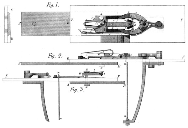
If it were enquired why this Machine is offered to the public
without the Hook Machine; the answer would be, this only
is finished: and it is wished to present nothing here that admits
even a doubt of its utility. The drawings given in Plate 20, figs.
1, 2 and 3, are more intended to be useful in the construction
of this Machine than complete in appearance: so that nothing
has been done by way of shading, but what it was thought
would the better distinguish the parts from each other, and facilitate
their assemblage in one effective Machine. The Machine
consists first of a slide A B, (worked by a lever-handle, a
crank, or any proper first motion.) It glides between two
cheeks C D, (see the end view in fig. 1) connected with the
several parts about to be mentioned. This slide is marked A B
in all the three figures. It carries (by means of the screws a b,
coming through the slits c d, in the main Plate E F) a plate g,
the chief use of which is to support a tumbler e, whose use is
to throw the eye, when made, from the machinery: which
tumbler is kept to its work by the spring i, as will be further explained
presently. This slide itself has a peculiar form at the end
B, (fig. 2) which is shewn by dotted lines at c d in fig. 1. It
is a slit, with the corners rounded off for the purpose of working
the springs now to be described. These springs m n, (see fig.
2) are fixed to a cock, itself screwed behind the main plate:
and they come through the latter to the left-hand-ends of the
small curved mortices seen (with the springs) at m n fig. 1.
The slide A B then, with its forked end shewn by the dotted
lines at c d, is destined to take the springs m n and carry them
to r s, where they are now seen surrounded by the eye almost
formed: for in this motion these springs take the wire (shewn
by the lines dotted across the Machine and previously cut by the
sheers u) and meeting with the obstacles t v, being the thicker
parts of the clams t v w, they bend it into the form r s—when
the screws a b lay hold of the sloping ends of the clams c t w
v d, and squeeze them together; by which operation the hooks
t v finish the eye, by rolling its two ends round the springs m n
now in the position r s. Where note, that the slit c d of the
slide A B is so formed as, when it has carried these springs m n
to r s, to slide forward without doing any thing more to them,
while closing the clams. It performs, however, some other
less important operations, to which it is now necessary to
allude: among other things this slide works the sheers u that
cut the wire, and that, by means of the doubly wedged hook
x, which goes back with the plate G, doing nothing: but
which by the action of its springs fixed at a, falls under the
sloping end of the sheers u; and, when the slide, by the screw
b, carries it to the right hand, raises the end x of the sheers u,
and cuts the wire near v, to prepare it for the operations
already described. The part y in the two figs. 1 and 2, is the
other cheek of the sheers fixed by screws to the main plate,
and covered by a small plate z, in which a nick is cut to form
a passage for the wire, and present it to the sheers, that they
may cut it to the proper length, after having directed it right
across the springs r s, then placed by their elasticity at
m n. It hardly need be added that a stop is placed at o,
to determine the length of the wire so as to form the eye
complete, and not to admit more wire than is sufficient; all
which is regulated between the sheers and the stop, by proper
adjusting screws, which it is very easy to suppose or supply.
Fig. 3 is intended chiefly to shew the mechanism by which
the eye, when finished, is thrown off the pin round which it is
bent by the springs m n. It consists of a tumbler e, placed in
a mortice in the end of the plate g, and kept to a given position
by the pressure of the spring i. When the slide A B is carried
forward, toward E, to perform the operations already noticed,
this tumbler e, gives way to the angle G of the doffing lever m G,
(this lever being shewn also between c m & d n in fig. 1) and rides
towards m without producing any effect either on the plate G
or the lever m G: but when it has once passed the said angle
G, it cannot go again toward F without depressing smartly
the end G of that lever, and thereby raising the end m, thus
starting the eye from the stud m, round which it had been bent
by the processes above described.
At the right of fig. 1 near F, is an object, the use of which
is too evident to need description. It is a double spring for the
purpose of keeping the hooks c t w v d pressed against the pins,
near t v, which determine the position of the said hooks; and the
degree of bend first given to the wire by passing the points t v.
There are some less important parts and operations left undrawn,
in order to prevent confusion in the figures: but they
are such as would strike any person having the above under
his eye. In a word I have done what I thought best to aid the
construction of this Instrument:—which is represented at two
thirds of its natural size—but whose dimensions, of course,
would vary with that of the objects to be produced by it.
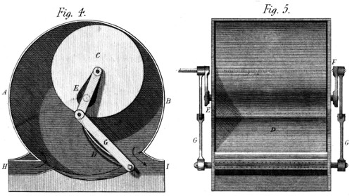
By this title I wish to distinguish this Ventilator from all such
as act by the mere centrifugal force of the air: and to make this
distinction the more palpable, I would add that this Machine
acts like a pump, that is by means of a space alternately contracted
and expanded, into which the air enters, and from which
it is expelled by force as water is from a pump. The means are
the following: A B (fig. 4 of Plate 20) is a hollow cylinder,
of a diameter proportioned to the effect wanted to be produced.
C is a cylinder closed at both ends, which fills that just
mentioned as far as the length goes, excepting a play of
about 1⁄8 of an inch. This interior cylinder revolves in the
former; but not on its own centre. It revolves on an axis E eccentric
to itself, but exactly concentric with the outer cylinder
A B. The centre therefore, of the inner cylinder C, describes
a circle within the outer one, which is always parallel to its
circumference. On the axis of motion of this cylinder C, and
outside of that A B, are fixed two cranks E F fig. 5, which
exactly reach from its centre of motion to its centre of figure:
so that whatever circle the latter describes in the large cylinder,
the former describe the same line without it. And hence
any slide or valve D, driven by these cranks, will always touch,
or be equally near, the circumference of that interior cylinder
C. The valve D then, worked by the bars G from without,
forms a constant separation between the right and left hand
parts of the lunular space left between the fixed and moveable
cylinders; and if the latter turns from C by B to D, the right
hand space C B G is the plenum, and the left hand space C
A D is the vacuum of this Instrument; or in other words the air
will flow in, through the passage H, and flow out through the
passage I: and by a contrary motion of C, it would do the
contrary—but I prefer the first process because any pressure
within the valve D is not liable, then, to press the valve upon
the drum C, and produce contact and friction; which in the
second case it might do. Suffice it to add, that the quantity of
air displaced at each revolution of C round its centre of motion,
is the difference between the area of the drum C and that of the
cylinder A B: and that its quantity at each part of the revolution
is proportionate to the curvilinear triangle G B, multiplied
by the length of either cylinder.
In the prospectus, this Machine was said to be good as “a gas
meter,” which I still think it is. For such a purpose however,
friction and eccentricity of weight should be obviated, by placing
the axis E, in a perpendicular position: when I doubt not
it would measure flowing gas better than many of the machines
that have been proposed for that purpose.
This mode of raising water in its simplicity, is I think called
the Persian wheel. The buckets hang upon centres, dip in the
under water, fill themselves there, and by meeting an obstacle
above which turns the buckets aside, they empty themselves into
the upper back, from which the water is conveyed to the
general reservoir prepared for it. This present Machine is
such an extension of the above principle as to make it applicable
to considerable degrees of elevation, and to many situations
where a single wheel would be of no service. Having
observed that in every train of wheels, the circumferences of
any two wheels, have motions towards each other, as well as
from each other; I perceived that, in a vertical train, this
circumstance might be laid hold of to compose a machine for
raising water. Be therefore, (Plate 21, fig. 1) A B C D four of
a set of wheels thus intended: on the left of the lowest wheel the
buckets move upward, as indicated by the arrow; while those
at B move downward, coming thus to meet the former. The
buckets A are full, and those B are empty; and as the latter,
by the motions of the equal toothed wheels on which they are
hung will infallibly meet the former, and even plunge into them
at I K and L, it is only to put a clack of leather or a valve, in
the bottom of all the buckets, and we have a machine that will
raise water to the top-most wheel, be it ever so high, and there
the water will be poured out into the vessel M, as in the common
Persian wheel above alluded to. On this principle the first
change of buckets will take place at I; where the lower bucket
belonging to the wheel B G will take the water from the upper
bucket of the wheel A H; when the bucket I will go down,
nearly empty, by H and fill itself again in the under water;
But the bucket of the wheel B G having now got the water,
will rise by G to K, where another bucket belonging to the
wheel C F will come empty, and plunging itself into that, take
its water and go upward by way of C to L, where a similar
change will take place and the water from L will rise by E to
M, into which vessel it will be poured by the canting of the
bucket as seen in the figure. Thus it appears that any number
of toothed wheels geering together, surrounded with buckets
valved at bottom, and receiving power from any one of their
number, will raise simply and effectually a quantity of water
not small in proportion to the power employed, and by means
that promise great durability to the Machine.
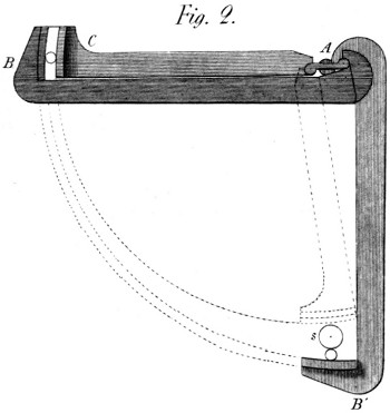
This press (see Plate 21, fig. 2) is indefinitely powerful. It
was invented for the use of my late beloved brother, then contractor
with government for cleansing the sea bedding. It is
composed of a centre piece A, strongly fixed to a post in the
ground, the bars A B A C being suspended above it, so as to
remain horizontally moveable, while describing 1⁄4 of a revolution
round the general centre A. The blankets (or other goods)
are put into the space s, (on a net nailed under the bars)
while in the position A B; and the whole is then thrown with
force towards B C; the length A C being so calculated as to
cease pressing at the desired moment: for such is the power of
this Machine, even without this projectile force, that were the
stress not moderated, nothing could remain whole under its operation.
It is clear however, that, when this operation begins
at s, the relative motion of the jaws s and B is assignable, and
even visible, as shewn by the dotted circles; but as the whole
approaches toward B C that relative motion becomes insensible,
the circles parallel, and consequently the power infinite:
which is all I shall say on the theory of this Machine.
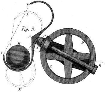
This Machine is delineated in fig. 3 of Plate 21. It has
several properties which I think important in the process of
grinding colours, either in a wet state or a dry. It consists of
a frame A B, which has a hollow centre, through which the
axis of the bevel wheel C D is brought in such manner as
to geer with the bevel pinion P, in whatever position the
frame A B may be placed. The axis of the pinion P carries a
vessel of which E F G is a section, and in which rolls a well
turned and heavy ball H, upon the colour to be ground: which
it crushes in the line of direction of its centre, and to a greater
or lesser width according to the diameter of the ball, as compared
with the section of the groove E G, in which it rolls.
Now as the motion of the vessel E G F, is oblique to the perpendicular,
the contact between it and the ball does not take
place in any great circle of the latter: but is constantly varying
by a twist in its motion dependent upon the angle of the vessel’s
inclination to the horizon. From hence arises the impossibility
of any colour remaining on the ball unground: and in order
likewise, that none may remain uncrushed in any part of
the vessel E F G, the frame A B gives it constantly new
positions, one of which is represented by the dotted lines I K:
where it is seen that the ball bears on a different line of the vessel’s
bottom than it did before. This also adds still greater change
of action to the ball itself, and occasions (taking both these
properties together) an unbounded variety of effect, which necessarily
brings every particle of colour under the ball by the mere
continuance of motion: and thus grinds it all without any care
on the part of the attendants. It may be added, that this vibrating
motion of the frame A B, is easily made to result from
an eccentric stud and proper connecting rods behind the frame;
all which is too easy to require further description.
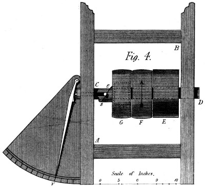
In Plate 21 fig. 4, there is a representation of this Instrument.
It is composed of a frame A B, containing a strong shaft C D,
on which are placed the three following objects. First, a fixed
pulley E, working by a strap, the Machine whose resistance is
to be measured. 2ndly, a loose pulley F, receiving the power
from the mover whatever it be. And 3rdly, a barrel G, which
is the acting pulley, when the strap is put on it from F in the
common method. But this barrel G acts by means of a barrel-spring
within it, which is hooked by one end to the boss of the
shaft, and the other to the rim of the barrel, as is usual for
barrel-springs in general. Now the power produces the desired
motion by coiling this spring to the necessary degree: and to
make that degree visible, there is fixed to this barrel G a spiral
s, which as the spring bends, drives outward the stud t, and
with it the finger v, which, pointing to the graduated scale,
shews at once the number of pounds with which the spring acts
on the shaft C D to turn it. By these means the stress on the
straps and on the Machine turned is known; of which also the
velocity is easily determined by counting the number of revolutions
performed by either of the pulleys E F G, which
are alike in diameter.
In ending the first part of this work, I gave my readers room
to expect this part “within three months,” and am happy now
to fulfil that engagement. Although these pages contain fewer
errors than the former—an apology is due for those that have
crept in: to which I add the promise that every thing shall be
done to lessen them further in the future parts, and wholly to
correct them before the work closes.
| Page |
100, |
line |
2, |
for |
“:”, |
read ∷; |
| „ |
126, |
„ |
4, |
„ |
“on its surface” |
read at its pitch line. |
| „ |
126, |
„ |
17, |
„ |
“its height f g,” |
read the length required. |
| „ |
129, |
„ |
16, |
„ |
“2,” |
read 4, |
| „ |
„ |
„ |
20, |
„ |
“imperfect,” |
read homely. |
| „ |
144, |
„ |
7, |
take away “alone.” |
| „ |
„ |
„ |
8, |
for |
“usually” |
read chiefly. |
| „ |
146, |
„ |
23, |
for |
“the friction,” |
read it. |
| „ |
147, |
„ |
1, |
for |
“nothing,” |
read little or nothing. |
| In fig. 7 of Plate 19, slope the groove of both faces the same way. |
A few words seem wanting to complete the description of
the Cutting Engine above given. They relate principally to
the cutter-frame and cutters. Although, with a view to
celerity, I have shewn the cutter out of the frame (fig. 4) yet
a common frame, carrying the arbor on points, may be used
with propriety; and would often be an eligible substitute for
the frame above described. In cutting bevel wheels however,
either on this Machine or that to be described, there is a form
of the cutter frame which leaves less freedom of choice, as the
cutter itself must have a peculiar form and position. To return
to the cutter for spur wheels, their form (or section) depends
on the degree of finish which the wheels require. For rough
work they may be cylindrical on the face, the sides being under
cut, so as to leave them thickest at the circumference—whence
a certain coarseness of cut ensues, but without any
injury to the spiral form. But, generally speaking, the cutters
are best, when made a little tapering towards the edge,
and toothed on both sides as well as on the circumference.
The teeth should be tolerably fine, but not very so, unless
great smoothness of surface were required: and we have seen
above that, in this System, great smoothness is very seldom
necessary, provided the obliquities be correct. I may add, that
those cutters used on common engines, whose great rapidity
compensates for the small number of their teeth, would not
answer here, on account of the twisting motion in the wheel.
But nothing prevents using cutters, so formed on the sides, as
to round off the teeth in the act of cutting—only the cutter must
be so thin as that its thickness, added to the aforesaid twist,
may not make the spaces too wide. A little observation will
render these things familiar to an attentive observer: nor shall
this work conclude before all that I have gathered from long
observation on this subject, be fully known to my readers.
J. W.
5, Bedford-street, Chorlton Row,
20th. November, 1822.
PART THIRD. — OF A PUNCH MACHINE, For Engravers to Calico Printers . — OF A DIFFERENTIAL PUNCH MACHINE For Engravers . — OF A MACHINE For Moulding Nails. — OF A FIRE ENGINE Giving Power , while heating Rooms, Liquids, &c. — OF A ROTATO-GYRATORY CHURN. — OF A HELICO-CENTRIFUGAL MACHINE, For raising Water in great quantities . — OF A FORGING MACHINE, For Bar Iron, Steel, &c. square or figured . — OF A RECIPROCATING HORSE WHEEL, For Mines, Mangles, &c. — OF AN EXPANDING VESSEL, For Steam Engines, Pumps, Blowing Machines, &c. — OF A GOVERNOR, OR REGULATOR, For Wind-Mills, Water Mills, Steam Engines, &c. — OF A MACHINE For Forging Nails . — OF A MECHANICAL ASSISTANT For the Tea Table . — OF A COPPER-PLATE PRESS, With curious and useful Properties . — OF A REFLECTOR For Lighthouses, &c. — OF A LONG PARALLEL MOTION, For Mangles, and other Reciprocating Machines . — OF A MECHANICAL SYPHON: Which expels Part of it’s Water at the upper Level . — OF A FORCING MACHINE, For taking on and off the Cylinders of Calico Printers . — OF A SYSTEM OF MACHINERY, For cutting and trying Tallow by Power . — OF A WASHING MACHINE, FOR HOSPITALS, Which confines the offensive Matter till cleansed away . — OF A MACHINE, For propelling Boats, on narrow Canals, without disturbing the Water . — OF A MACHINE, For working, swiftly, the Slide-valves of Steam-engines .
A NEW CENTURY OF
Inventions.
It has been observed and regretted by a well-known writer, that
“a periodical work resembles a public carriage—which must depart
at the usual hour, whether full or empty;”—and having
undertaken to deliver this work at stated periods, I have found
myself in a situation not unsimilar: the consequence of which
has been a too cursory view of some of the subjects. I feel
however, that this is not a sufficient apology for any essential
defect: nor would it be more so to say that, although verging
to old age, I am still a young author. Yet I may claim the
privilege of supplying, in the latter parts of the work, what
is most deficient in the former; and thus of proving that I do
not intentionally neglect any thing that might make it practically
useful.
With these views I commence this third part: intending first to
continue the description of the Cutting Engine given at page
121, and here applied to Bevil Wheels; and then to re-consider,
shortly, one or two other objects, that were too rapidly
passed over in their proper places.
Plate 22, repeats at fig. 1, the first figure of Plate 15; by
way of shewing the additions required to extend this method
of cutting teeth, to Bevil Wheels. These additions are first,
a disk n n, concentrically fixed to the main axis A B of the
engine. And, second, an inclined plane o, of variable obliquity,
connected by a joint with the forked sliding bar p q, by
which the plane o is put in contact with the disk, at whatever
distance the cutter-stand e f may be from the common centre,
which distance depends, of course, on the diameter of the
wheel to be cut; and to secure which is the office of the fixing
screw r, in the figure.
It is now evident that for the disk n n, and the shaft A B to
rise, the slide p q and the cutter-stand e f must recede: and
this more or less according to the degree of obliquity of the inclined
plane o, that is according to the slope of the bottom of
the teeth in the wheel w: see the dotted line w p.
A circumstance presents itself, that should be here explained:
when the bevil of the wheel w, or the cone of which the wheel
is a part, is very obtuse, the cutter-stand e f, can not be
driven back by the action of the disk n n on the plane o, without
too great a stress being applied from below, to the axis
A B. (See the apparatus I M O N, Plate 16, fig. 2.) In
this case therefore, the handle R is not used: but a weight is
suspended to the end N of the lever M N, sufficient to give
the whole System A B, a tendency to rise; and the operator
now acts on the screw g, so as to draw back the plane o;
by which motion the disk m n with it’s axis A B is suffered to
move upward, and the wheel is cut, as desired. But on the
other hand when the wheels are portions of acute cones,
they are cut by means of the aforesaid handle; by which the
plane o and the cutter-stand are forced backward as before
intimated.
We proceed now to describe the perpendicular part of the
cutter stand e f; which is made double, as shewn at i k in fig. 4 of
Plate 15; and is also perforated at various heights to receive the
bolt which forms the centre of motion of the arm m u, the latter
having a cylindrical boss u, fitted into the fork of the stand
e f, and so graduated as to determine the angle of it’s obliquity
to the horizon, or it’s parallelism to the dotted line w p, which
indicates the slope of the bottom of the teeth on the wheel.
Finally, the cutter-frame x is fastened to this arm at right
angles to it, and thus forms a right angle (or nearly so) with
the surface of the wheel: and is, moreover, directed to the
centre, produced, of the shaft A B. This latter fact is strictly
true, only when the teeth required are of so common a kind as
not to require greater exactness: for in theory the sides of the
cutter (supposed cylindrical) must alternately direct to that
centre—namely, that side which is actually cutting: so that
a provision must be made to shift the cutter spindle sideways,
a distance equal to it’s diameter; this being no more than
what is necessary in every system of wheel cutting.
We may also consider here, the form of the cutter itself,
v, fig. 1. It is slightly conical, (more or less so according to
it’s use) and of no greater diameter than the smallest width of
the spaces between the teeth of the wheel. A common disk-like
cutter would not produce perfect, nor even tolerable teeth
on a bevil wheel. The reason of this will appear by considering
that a spiral line, either on a cone or it’s base, turns more
the further it is from the centre, and less the nearer it comes
to it. So that a flat cutter placed at any angle, is parallel to
the curve at one place only; whence the propriety of using a
cutter of the kind represented in this figure. It is however
true, that the first opening of the spaces may be made with
a common cutter; but it should be very thin comparatively
with the spaces required: and it’s cut would serve only as a
sketch of such space, serving principally to permit the metal to
escape while finishing the teeth with the cutter just described.
I proceed now to the examination of the plates, and the
manner of adapting their length to the process of cutting spiral
teeth on bevil wheels. But before entering on this subject, I
would explain a kind of inadvertency into which I fell at the
close of my former description of this Engine (see page 129).
In my zeal to be candid in stating the properties of my Machines,
I have suffered it to appear that I thought this an “imperfect”
one:—an expression which, although modified among
the errata, may still cause it to be looked upon as radically defective;
than which nothing could be further from the idea I
wished to convey. I intended merely to express the want of
absolute connection between the two movements of the shaft—the
rotatory and longitudinal motions. I meant that the process
by this Machine was not theoretically certain, because dependent
on the action of a weight (Plate 16, fig. 1 and 2) and an
unforced obedience to the direction of the plates. But this small
remove from rigourous principle is in my opinion much overballanced
by the facility of cutting good wheels of all diameters,
by the sole change of a morsel of tin, which leaves untouched
every other part of the Engine.
Entering then on this branch of the subject, I first observe
that if we chuse for the teeth an inclination of 15 degrees (in
imitation of the cylindrical wheels) it can only be for one point
of such wheels—as observed above. This point therefore I
have placed at r in the middle of the face. And supposing now
that at this point the wheel O were 4 inches in diameter and
the wheel S two inches, these plates would be found as before
by these analogies:
(1) wr, or 2 inches : 11 inches (rad. of plate rim) ∷ 26.8 :
294.8⁄2 = 147.4 plate required.
(2) vr, or 1 inch : 11 inches (rad. of plate rim) ∷ 26.8 :
294.8⁄1 = 294.8 2d. plate required.
But it is plain that the conical face, b C, (common to both
wheels) is broader than the supposed cylindrical ones b e and
b d: and therefore that the above plates must be made longer
(to furnish the said obliquity) in the following proportions,
namely: for the wheel O in the ratio of b e to b C; and for the
wheel s in that of b d to b C: that is, these plates should be
lengthened as the tabular cosines of the angles B A C and
D A C to radius (for b e : b C ∷ A B : A C; and b d : b C ∷
A D : A C.) Thus then,
(1) Cos. 63°27′ : radius ∷ 147.4 (present plate) : required
plate x, = 147.4 r⁄Cos. 63°27′; and
(2) Cos. 26°33′ : radius ∷ 294.8 (present plate) : required
plate y, = 294.8 r⁄Cos. 26°33′.
Now, by the tables, cosine 26°33′ = 894, and cosine 63°27′
(it’s complement) = 447, when radius is 1000: whence dividing
the two equations by r, and substituting these values of
cosines 63°27′ and 26°33′ we shall find the two quantities x
and y, equal. Whence it appears that for every pair of bevil
wheels, whose shafts lie at right angles, the same plate serves
for both wheels: only turning it once to the right, and once
to the left hand on the plate rim.
And if now we measure on a scale of equal parts, the line
A r and call it 100, we shall find the line w r (near enough
for practice) to be 90, and the line v r to be 45, and these
numbers respectively, put for rad. for cos. 26°33′, and for cos.
63°27′, will make the first equation x = 147.4 × 100⁄45 and y = 294.8 × 100⁄90
or x = 327.55 and y = 327.55, &c. confirming the above deduction
that the same plate serves for both wheels; and giving,
withal, the length of the plate required.
In performing this operation by actual measurement of the
lines, I have had in view to trace a path for those of my readers
who may not have the tables, or may be unaccustomed to
use them. The process, generally, is to take the diameter of any
bevil wheel O fig. 4, in the middle of it’s face; and supposing it
a spur wheel, to find it’s plate by the method above given: and
then to multiply the length of that plate by the line A r and divide
the product by the line A w, both measured on the same
scale of equal parts.
It may be well to observe, likewise, that the same method
of finding the plates, applies to bevil wheels of every description
or angle: but that it does not give equal plates for every
pair, except in the above case of wheels placed at right angles
to each other.
I would just remark that by the figure near B, is shewn a
section of the Machine on which I centre the wheels to be cut
on this Engine. It is an inverted cup s t, into which the arbor
is screwed in a true position; and this cup is fixed on the top
of the shaft A B, by the three pressure screws near s t, which
enter a triangular neck made round the shaft, against the
upper slope of which, the screws press so as to draw the cup
downward in the act of centering it. This I say is my present
method; but it is in a measure accidental, the shaft not having
been perforated to receive arbors of the usual kind. Mine,
however, have their utility in the ease with which they are
varied in size, and changed on the Machine: but on their
comparative usefulness I give no opinion. The other is the
most solid method.
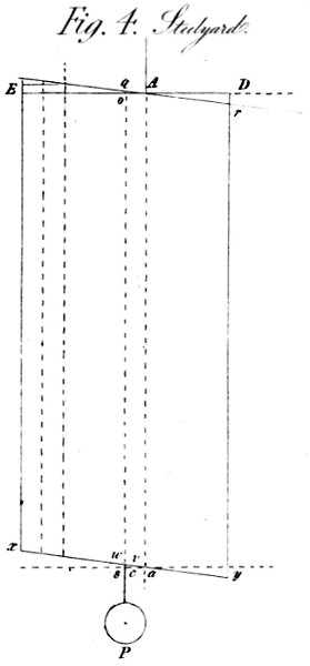
In the description of my differential Steel-yard, (see page 163)
I stated that the load P was wholly collected in the point o;
and that dividing the line A C by the line A o, the power of
the Machine was known. But I should have shewn that this
line (A o) is equal to one half the difference between the arms
A D and A E. To do this, here, (see Plate 23, fig. 4) I
take the Machine in the state of infinite power, before mentioned;
and observe, that in moving the point of suspension
from o towards A, I at once lengthen the arm A E, and
shorten the arm A D: by which process, (supposing each arm
to have been called a) that which I lengthen by any quantity
d becomes a + d, and that which I shorten by the same
quantity becomes a - d, and the difference of these quantities,
is 2d: so that the line A o is in reality one half the difference
between the two arms A D and A E as was required to be
shewn.
But we may go a step further: The two arms of the equibrachial
lever x y may likewise be made unequal: and the line s a
be subdivided in any ratio: which division will augment still
more the power of this Machine. If for example, we hang the
load on the point v, halfway between a and s, that power will
be doubled; for the line c v (representing the space moved
through by the load in this case) is only one half of that w s, or
o q, and might be still less at pleasure. Thus the whole power
of the Machine is now found by dividing the length of the long
arm, beyond D, by the line a v, instead of the former line
A o, or dividing the motion of it’s extremity upward, by the
line c v, the motion downward, of the load P.
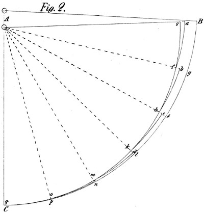
It has been further suggested, that the description of my
excentric Bar Press was not sufficiently explicit. I have therefore
added the figure 2 of Plate 22, to assist in elucidating that
description. I had, perhaps made an undue use of the principle of
virtual velocities by saying, too concisely, (page 174) that “as the
whole approaches toward B C, the relative motion (of the
cheeks s and B) becomes insensible, the circles parallel, and
consequently, the power infinite.” It is however vulgarly
said that power cannot be gained without losing time—which
implies that if time is lost, power will be gained: and the principle
of virtual velocities says the same thing, though in more
appropriate terms—that if a small movement be given to a
system of bodies actually counterpoising each other, the quantity
of motion with which one body ascends, and the other descends
perpendicularly, will be equal: so that, as remarked in
page 50, by “whatever means a slow motion is obtained, dependent
on that of a moving force, the power is great in the
same proportion.” Now, in the eccentric Bar Press, (see
fig. 2) this is so in an eminent degree: for when the bars
are in the position A B, the distance of the cheeks is equal to
B s; and they must move, circularly, as far as A f, to bring
them closer to each other by the quantity s a: dividing therefore,
the distance B g by the line s a, we find (near enough
for practice) the power of the Machine within the limits A g B.
It is nearly as 10 to 1. In like manner this power at A e g, is
equal to the arc e g divided by the line f b; and at A l n to the
arc l n divided by the line d k, namely by the difference of the
lines k l and m n. From the above it appears that the nearing
motion of the cheeks of the press, becomes slower and slower
as the bars A and C come nearer to the point C: insomuch
that the difference between the lines m n and o p is nearly imperceptible,
and that between the lines o p and C q entirely so.
But according to the above process, the distance p C should be
divided by this imperceptible line, to find the power of the press
at the point C; which therefore is immense. Another proof
of this may be drawn from the supposition (see fig. 3) that
the small lever a d is turned round the centre o by a bar o
C fixed to it, and of equal length with the line A C fig. 2. Fig.
3 shews that the lines or bars C d, and a C are moved endwise
by the circular action of the points a and d; and therefore (by
statics) their motion is the same as though caused by the perpendiculars
b o and o c let down from the centre o, on each of
them. Hence the power of this Machine is found by dividing
the distance o C by the sum of the lines b o and o c; which sum
(when these lines vanish by the union of the bars over the centre)
becomes infinitely small: the quotient of which division
therefore is infinitely great—as was to be shewn.

The usual method of making Punches for engraving Copper
Cylinders, (otherwise than by the milling system) is to cut
the desired pattern on a die, and then to transfer that pattern
by blows or pressure to the punch, from which it is again
transferred to the cylinder. My Machine in this operation,
unites motion to the needful pressure; and thus renders the
result more easy and complete. This effect I could the better
ensure, because the surfaces of my punches are essentially convex,
or rather cylindrical; as will appear when my engraving
Machine comes to be described. Their convexity however,
can be diminished at pleasure—whence this Machine is capable
of offering useful assistance to a maker of flat punches.
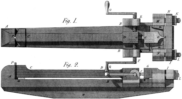
In Plate 23, A B fig. 1 and 2, is the body of the Machine,
with the vibrating bar C D laid upon it; reposing especially
on the correct and level parts of the body at a b; this bar contains
the die c, with which it vibrates between the cheeks
B R, as impelled by the screws E F, it’s centre of motion
being the pin P, duly supported by the strong shoulder A. In
a line with the bar C D, is placed a second vibrator G, containing
the steel d, that is to become a punch, already rounded
into the cylindrical shape it must have when finished. This
vibrator has it’s centre of motion at e fig. 1, and it need not be
added that the curvature of the punch depends on it’s distance
e d from that centre: for the centre of the long bar C D is so
distant as to have little influence on it’s formation. Further,
the cap or bridge H I, which furnishes a centre for the smaller
vibrator G, can be brought forward to any useful position by
the nuts K L: that cap sliding horizontally between the
cheeks M N as directed by the small arms m n. This motion,
then, taken from the nuts K L, serves to impress the work of
the die on the steel prepared for the punch; and this being done
to a first degree, both the handles O Q, are laid hold of: and
by turning the screws the same way one of them goes forward
and the other recedes, until the punch and die have been in
contact over half their surface. At this moment both screws
are turned backward, and the motions of the two vibrators
reversed: by the repetition of which alternate motions accompanied
by the needful pressure, the whole pattern is transferred
from the die to the punch—when the latter is taken out
of the Machine, and filed up in the usual method.
It should be observed, that the smaller vibrator G can be
displaced with ease when the nuts K L are withdrawn: and
this should be frequently done to examine the progress of the
impression. Nor is there any difficulty in re-entering the figures.
In a word, the perfection of this process depends more on
much motion than on violent pressure: whence this facility
of re-entering is a desirable property. This Machine is usually
laid on a bench or tressel, with a long mortice in it,
into which the feather x of this Machine enters so as to be
firmly fixed.
I was the rather induced to attend a second time to the
differential Steel-yard, because I had it in contemplation to
apply that principle to the present purpose; since, to make flat
punches, is to some engravers a more desirable thing than to
make cylindrical ones. I am not fully persuaded that it is even
possible to transfer a large pattern, from a flat die to a flat punch,
by any pressure acting simultaneously on the whole surface.
In those cases, if there is much work, the whole surface goes
down; and the parts that form the pattern do not rise. But,
all that can be done in this case, is, I believe, feasible by the
Machine now to be described.
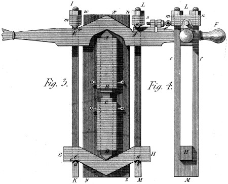
Plate 23, gives in fig. 3 and 4, a representation of this Machine;
A B and C D, are two slides, having wedge-formed
ends above A and below D, well made, well steeled, and well
tempered. One of these slides contains the die and the
other the steel prepared for the punch (see B C). These
wedge-ended slides are embraced by two levers E F, G
H, which are themselves connected by two stirrups I K and
L M, better shewn at fig. 3. These latter are supposed in fig.
4 to be broken at L M, to leave the levers E F and G H more
visible. They are formed, at the turning below, into wedge-like
edges a b; well hardened, that clip the nicks c d of the
lower lever: and at the top of the Machine their arms e f, pass
through the caps m n, above which they are nutted like a
common bolt, and made to press strongly on the main lever
E F. The stirrup placed to the right hand, presses in particular,
by it’s cap n, on the moveable step o, exactly in the
notch q: this step having a backward and forward motion
communicated by the regulating screw p. Before beginning to
use this Machine, I make all it’s arms A E, A g, D e, D d,
equal, when it’s power (see page 162) is infinite; and to put it
in a working state, I turn the screw p backward, say one half
round: which motion (if the screw has 20 threads to the inch)
makes a difference in the two arms A r and A q of 1⁄40 of an inch,
and the virtual centre of the Machine is therefore 1⁄80 of an inch
from the former point A, that is from the edge of the slide
A in this fig. 3. Supposing now, the whole working lever
E F to be 3 feet, and the workman’s force to be 100lbs. in
each arm, then by displacing the lever to any proper distance
from F towards f, he will produce a pressure between
the die and the punch of 200lbs. multiplied by 1440, the
number of times that 1⁄80 of an inch is contained in 18 inches.—That
is, a pressure of two hundred and eighty-eight thousand
pounds!
I have been seduced, by the anticipated brilliancy of this
result, from the regular course of description,—and the plate
w x, y z, which forms the base or frame of this whole Machine has
not yet been spoken of. But that plate is supposed screwed down
to a horizontal bench, at or near the height of a man’s breast;
the slides or cases are fastened to it, and the man is supposed
to work the Machine nearly as he would a die-stock in tapping
a screw. This however is not indispensable; the Machine
might be placed vertically, and these motions given by any
proper mover; or a weight may be suspended to the arm F,
so as to add continuity to pressure. It is however important,
that the position should comport with the frequent extraction of
the punch in order to examine the progress of the work, or
cut away any redundant metal. I have before given it as my
opinion that much could not be expected from mere pressure:
but this is a pressure of a peculiar kind, consisting of immense
powers with very short motions. In this respect it is just what
was wanted, as it can be renewed and repeated frequently,
without loss of time. And the more to facilitate this delicate
operation, the hollow slides or cases B C, are made slightly
pyramidical, to be furnished with set-screws on the four
sides, by which to change the place of bearing; and thus to
meet the case of a flat punch with the advantage of impressing
it by portions, so as to have only to finish it by
brute pressure.
The foregoing application of the principle of the differential
Steel-yard, is, I think, important, and founded on unobjectionable
principles; for although by changing alone the place
of the step o, we disturb a little the parallelism of the stirrups
I K, and L M; we do it not enough to produce, any material
change in the theoretical result. With respect then to the lesser
properties of this Machine, I leave them with confidence in
the hands of those whom they most concern—who doubtless,
will treat them with greater practical utility than I could
myself hope to do.
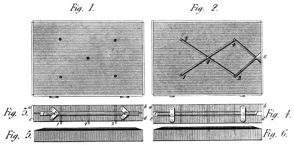
This Machine offers, I think, a valuable application of a well
known Instrument: or rather of the principle on which it is
founded. I allude to that parallel ruler which, by means of
an additional joint, keeps it’s members not only parallel,
but directly opposite each other. In my Machine for moulding
Nails, I wanted to give motions to the two plates different,
yet dependent on each other. Supposing then, (Plate
24 fig. 1, 2, 3, 4,) the upper plate a b, to be moved up and
down by a lever, a screw-press, or any other first mover, I
connect the under plate c d, with it by two (or four) strong
parallel rulers e f, in such a manner, that when the plate a b is
drawn upward it shall extend the arms of the ruler almost to
a straight line, as represented in fig. 4; and then carry the
under plate with it: and when it comes down again (see fig. 3)
it shall not carry down the said under plate, until the same
arms are bent into the position f g; that is, till the two plates
touch each other: the use of which arrangement I will now
explain.
The under side of the upper plate a b, is ground perfectly
flat, and bored at proper distances with holes to receive and
hold the punches which represent the shanks of the nails
that are to be moulded. The lower plate c d is ground true both
on it’s upper and under surfaces; the first to fit the under
surface of the upper plate, and the under surface to impress
a perfect plane on the sand below it. This under surface,
shewn in an inverted position at fig. 2, is moreover
covered with proper prints 1, 2, 3, &c. to form the heads of
the nails in question, and with proper gets (jets?) 3, 5, 6,
&c. for conducting the metal to every part of the surface.
I mean models in relief of those gets; and the under plate is
further pierced with holes, placed exactly like those in the
upper plate, bored indeed from that (and through the aforesaid
prints of the nail-heads) after the parallel joints e f have been
affixed. Now on another level plate with proper ledges,
the sand boxes or flasks, fig. 5 and 6, have been prepared;
and have received an obtuse pyramidical form at one stroke
from a competent press, the construction of which is easily
conceived: or this might be done by hand, if preferred. These
boxes, in-fine, are successively brought under the before described
mechanism while in the state represented in fig. 3, in
which all the nail models are protruded through the under plate
as at 1, 2, 3. The moulder now gives a stroke under the
following circumstances:—Both the plates drop together and
the nail models pierce the sand while the under plate makes
it’s surface perfectly level: but when that motion is reversed,
it is not the under plate which first rises, but the upper—by
which the nail models are drawn out of their holes without disturbing
the sand, for this is kept to it’s place by the under
plate: and when, by the continued motion upward of the
upper plate, the parallel joints are duly extended, and the
nail models quite extracted; then, and not till then, the under
plate leaves the compressed sand, in which are moulded as
many scores of nails as the mould has been made for—and that,
in a space of time almost imperceptible.
I shall conclude the subject by observing, that the counter
flask or box for closing this mould is made in the same way, by
a smooth plate prepared in the same manner; and which must
fit the former, because they are both perfectly level surfaces.
This Machine, though conceived many years ago, can
hardly yet be called an invention—if material existence is
necessary to justify that appellation: for I have never seen
it in action. It may possibly be one of those fascinating conceptions
of which my noble friend the late Earl Stanhope used to
say—“’tis a beautiful invention—but ’twill not do;” yet I give
it with some confidence, because of the great utility it would
present, if it’s chief properties should fulfil my expectations.
The principal idea on which it is founded, is this: to use, as
power, the expansion of that air which feeds the fire; and
again to employ it’s heat heating liquids or rooms, or any
similar purpose. The form I have given to the Machine is by
no means the only one it admits; nor perhaps the best: but it
was indispensable to give the idea (which I hope is not an
“airy nothing”) “a local habitation and a name.”
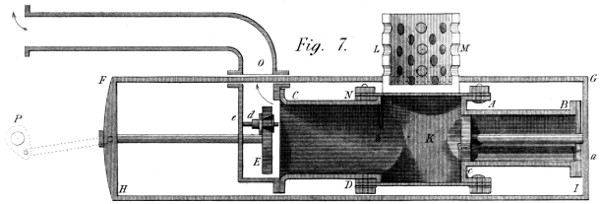
It consists, then, of two cylinders, lying horizontally, of
nearly equal length, but of unequal capacity:—one of which
A B, (Plate 24, fig. 7) is an air pump with a valve in it’s
end a, and another in it’s piston, both opening to the left.
The second cylinder C D, is the working cylinder, as much
larger than the former, as may belong to the principle of
motion already announced. This cylinder receives the piston
E, which fits it nicely, but is not stuffed in the present case.
(It may perhaps be made tight by some of the methods, used to
close metallic pistons.) At all events, this piston is connected
with that c, by a frame F G H I, which embraces the
whole Machine, in a horizontal position, though here shewn in
a vertical. These two cylinders are cast in one piece, together
with an upright cylinder, not bored K; the use of which is to
receive the earthen chafing dish L M, with it’s fire, made
(according to my present views) with coak or charcoal, and lighted
before it is introduced. It is needless to say, that this vessel is
let down into the cylinder K, by a kind of bucket handle
entering any pair of holes in the dish. The top of this latter
cylinder is ground to fit the flanch A N: It swings open on
one of the bolts and falls to again in a moment, to prevent loss
of time in firing. The means of doing this I do not much insist
on, from their extreme facility. Nor do I make it a condition to
use this method at all. The coak, (or perhaps the coal, or the
wood) might be introduced through an upright tube furnished
with two slides, one placed close above the top A N, and the
other at a proper distance above; so as for one to be always
shut. This is nothing more than the System used for feeding
high pressure Steam Engines—only this application is to dry
substances, which forms no insuperable obstacle.
When now the Machine is fired, the pistons E, and c, are
pushed towards b and B respectively; the valve d having been
previously opened, and the valve c opening by this very motion—which
thus clears the large cylinder of it’s included air, while the
air in the pump A B, is brought into contact with the
fire; whence a considerable expansion ensues, and a pressure is
created tending at the same time to drive the piston c to the
right hand, and that E to the left: but acting in the latter
case on a larger area, the whole system moves that way, and
all the air in the pump A B is driven through the fire: where,
being much heated, it acquires great elasticity and developes
considerable power—which, by any of the known methods, may
be applied to any of the known purposes.
I hope my readers will conclude here, that I allow for the disappearance
of the oxigen in this conflagration: but I expect the
expansion of the residue (together with what new vapour may
be developed) will more than compensate for that loss of volume.
By this motion then, the pump A B is again filled with cold
air through the valve a; and the piston E flying out of the cylinder
C D, the hot air it contained rushes into the pipe o, and
thence goes to perform any heating operation that may be desired.
But further, this same recession of the piston E strikes
the stem of the valve d against the cover e, and opens that valve;
by which means the large piston is at liberty to reach again it’s
inner position b: where the bar b closes it’s valve d and prepares
the Machine for a new stroke. For, as before, the pump
or cylinder A B, is full of cold air, and by the backward
motion of it’s piston exposes that air to the fire in K: whence
arises the renewal of all the former phenomena.
Many ideas, and doubtless some objections, will present themselves
to the readers of these pages; of which I shall probably
anticipate some, by noticing a few less important particulars.
And first, is it not to be feared that the vertical cylinder K,
and the whole system K C D E will become too hot—nay
acquire a red heat, and thus introduce danger? The answer,
I think, is that the fire must be lessened, or the Machine enlarged,
until this danger disappears: for by heating air to any
thing like a red heat (without attaining it) the expansion will
be immense: and probably beyond our wants or wishes. The
chaffing dish then (if that is used) must be lessened, that the
air from A B may partly circulate round it, instead of going
wholly through the fire: thus cooling the vertical cylinder K,
and diminishing the intensity of the heat in the working cylinder.
Further, the two cylinders C D and K, might be
inserted in the bottom of a boiler, and surrounded with water;
through which also, may be conducted the pipe O, so as to
concur in the same effect of heating that water, while the
steam thus accruing from the double use of this heat, may be
made to drive an engine, heat a room, or fulfil any common
purpose.
In a word, all our difficulties on this branch of the subject,
seem to lie in excess of action: and we need only mitigate the
general effect, to render this Machine useful, safe, and commodious.
There is another objection that must be met, on pain of
direct censure, which is this: what will become of the ashes?
(for smoke is as yet out of the question) my answer is—a recess,
or several, must be found for them beyond o; to do which will
not be more difficult than to lodge any other residue. But if this
Machine fulfils my views in respect of power, this residue will
be no burden. For example, if ever a farmer should hereafter
drive his plough by such an engine as this, he will manure his
land furrow by furrow with the ashes—an idea which I must
not yet indulge, lest I should be thought fanciful beyond the due
proportion.
But my mechanical impetus is not to be thus instantly
checked. If what I hope, can be realized, there are properties
in this invention, for locomotive engines, superior to any the
steam engine itself can boast. A light Machine: a light combustible:
no water to carry; no steam to condense, &c. &c.
As however I have never tried this felicitous creation, I
assert nothing.
But again, this seems to be a really good method of distributing
heat in any useful direction: for there is an impulsive
force which not only requires no draught to make the
fire burn, but will drive heat to any distance through pipes
of any form, and placed in any position. There is therefore,
a certain utility attached to this Machine, whatever may be it’s
merits as a power engine. Our present methods—of destroying
coals—are excellent! but our methods of making them useful are
defective in the extreme. If you have no draught in your
chimneys you are stifled with smoke. If you have much
draught, you have little heat—for the chimney swallows it, and
half your room is in Norway. Use then an impulsive system, (of
some kind) and you may send your caloric down into the cellar
to be drawn from thence as wanted, for the upper apartments.
But my subject pullulates as I proceed. This idea is by
no means exhausted. It is not an indispensable feature of it,
to heat rooms with the same air that fed the fire. For instance,
if a fire were made under the vertical cylinder K, and led into
and through it by a proper pipe, almost filling it—then the
cold air of the pump A B would pass round that pipe to the
working cylinder C D, and there impel it’s piston E as before.
Not perhaps so strongly; but with an air uncontaminated by burning,
or by ashes—and therefore more congenial with some uses of
the Machine. In fact, air thus introduced might be perfectly
fit for breathing, and still get elasticity enough from this passage,
to force heat to the bottom of any room we wished to
have warmed; whereas, by using only the levity of heated air
to give it motion, we scorch the tops of rooms and factories,
and unmercifully freeze the bottoms. I must beg leave to be a
little severe on this point:—since for a thinking people, as strangers
call us, we have been extremely thoughtless in this respect:
so that as much seems now to do by way of introducing
comfort into our saloons, as was done about the year 1200, when
those chimneys were introduced that are now become a kind of
nuisance. In a word, and I am serious when I say it, the present
arrangement of our chimneys, is in my humble opinion, essentially
unphilosophical; and as such ought to be speedily
discontinued or greatly modified.
In the above pages I have laid myself open to much animadversion,
by a kind of cast for much honest fame. I have
let the public into my secret—I have thought aloud: And if
the greater part of these cogitations should prove to be imaginary,
I shall only plead, that they are drawn from the same
source as the many useful Machines I am known to have devoted
to public utility.
This title I confess, seems very ambitious, as applied to an
utensil for the dairy: but I had to express the combination of it’s own axis,
and those of the leaves or wings about their respective axes,
while gyrating round the common centre.
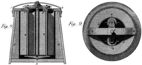
The principal shaft A B, fig. 8 and 9 of Plate 24, is the
general centre of rotation; and a b are two lighter shafts
carried round that centre, and turning at the same time on
their own centres by means of the wheels e f geering in the
fixed wheel c d, (of which one half only is drawn) and
which forms part of the top of the churn. Each of the
shafts a b, carries four leaves or wings (better seen in fig.
9) reaching from the top, nearly to the bottom of the vessel;
and they run in proper steps in the cross piece m,
and also in proper collars in the upper cross piece g h. In fine
their wheels e f, and the fixed wheel c d, which turns them, are
furnished with teeth on my patent principle; and therefore
work without noise or commotion. Now, the principal shaft
A B, rests on the step B at the bottom of the vessel; and
runs, at top, in a collar formed in the metallic bridge i k, which,
fixed to the outside rim of the cover, passes directly over the
centre of the Machine. When therefore, the cream is put
into the churn, (to do which the above mechanism is taken out)
the mechanism is re-placed as now represented; and the main
shaft set in motion by any convenient power: when the side
shafts a b, turned by the fixed wheel c d, give a backward
motion to the wings a b, and create a great agitation of the
cream—for, it should be remarked, that this is not a circular
motion: but each fly produces a kind of vortex round it’s own
centre, while progressing round the common centre. The
consequence of which, as above intimated, is, an unceasing
agitation of the liquid, and, I believe, the best of churning.
This however, I state as a mechanician, not having been initiated
into the secrets of the dairy properly so called.
It may finally be observed, that the leaves or partitions l n,
fixed to the sides of the churn, (beyond the reach of the moveable
wings a b) are destined to prevent still further any general
motion of the butyraceous matter; and thus to accelerate the
churning process: and further these leaves, both fixed and
moveable may be pierced with holes, like the analogous parts
of other utensils of this nature.
The screw of Archimedes, is well known. When used to
raise water it is placed obliquely, in such a position as that it’s
hollow threads become more oblique to the horizon than the axis
of the screw itself: observing which practice, some have said of
this Machine, that it raises water by letting it run down: But this
cannot be true. The threads of the screw merely wedge themselves
under the water, and make it rise in a direction parallel
to the axis of the screw; at the highest end of which it falls
into the upper reservoir.
I once placed a screw of this kind upright, and said (in
thought) is it then impossible to raise water by means of this
screw thus placed? The answer in a few minutes was—“not
at all; there is a force would make it easy: namely, the centrifugal
force:” and this mental soliloquy was the origin of this
Invention, which, some thirty years ago, I shewed to a public
man, whom the lovers of the mechanical arts will long remember.
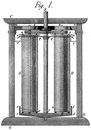
In Plate 25 fig. 1, A B are two screws, perfectly like those
used in exhausting watery foundations; and named of Archimedes.
They are placed perpendicularly in the frame C D,
so as to turn in the cross bars a b, c d, fixed horizontally on the
main shaft E F of the Machine. At the bottom of this shaft,
E F, (which turns in a step on the sill G D) is a low cylindrical
vessel, shewn by a section only at e f, which dips into
the under water nearly to the brim. It is used to carry, in
proper steps, the centres of the screws A B, and, being pierced
with many holes, to feed them amply, without exposing their
motion to any resistance from the stagnant water. These
cylinders A B are merely indicated as screws by the threads,
dotted between h and d and e and g, and their upper mouths
are seen near a b, just under the cross piece marked with
these letters. These screws then, are turned by the wheels
i k, as actuated by the fixed wheel m n, in the same manner
as those of the churn before described; which in fact, is a corollary
from this Machine, but of much later date. To return
to the Helico-centrifugal Machine—the screws A B are
terminated above by circular plates o p (marked with the same
letters in fig. 2 and 3) intended to receive the water from the
mouths of the screw-threads a b, and carry it on to the plate
q q, which insures it’s further progress into the ring canal r s,
also shewn by a section only, to prevent confusion in the figure.
Now what raises the water in these upright screws, is, it’s own
centrifugal force, combined with the revolution of the screws:
for while this central force is urging the water outward, the
screws are bringing their sloping threads like wedges, against
that tendency; and the consequence is, that the water actually
rises perpendicularly till it flows over the ledges or rings
o p, on the plate q q, and thence into the ring canal r s, from
which it is conveyed to any place desired.
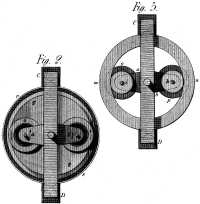
If this Machine is well made and proportioned, I think it is
one of the best that can be used, to do much work by a given
power: It gives no shock to the water; which, when once in
motion, continues to rise, and escapes when arrived at it’s
proper height: and, being spread over a large surface, no
part of it is raised higher than enough. The perfection of the
Machine depends on a due relation between the centrifugal force,
and the sine of the angle, which the threads of the screw make
with the horizon; and this may be modified by the diameter of
the wheels i k, as compared with that of the screws A B.
The figures 2 and 3, are two views of the upper part of the
Machine. They shew, and mark with the same letters, the
cross bar a b, the inside of the screws, and the circular plates o
p, together with the circular conducting plate of which q q, fig.
1, is the section. Fig. 3 shews the fixed wheel m n, the two screw-wheels
i k, the cross piece a b, and under them the plates o p
of the 1st. and 2d. figure.
One other object claims our attention: The threads of the
screws (whether more or less numerous) should each be furnished
with a valve at bottom: that the water may not run out when
the Machine ceases working.
This Machine acts by pressure instead of percussion. But
this pressure is so instantaneous as to resemble a blow, and
so often repeated as to produce a considerable effect in a short
time. The means are represented in fig. 4 of Plate 25.
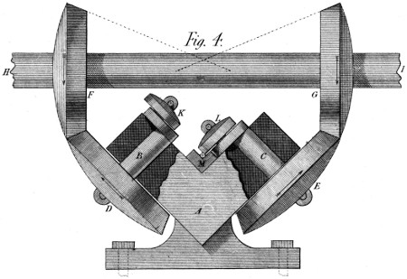
There, A is a mass of metal answering the purpose of an
anvil, but having two surfaces, situated at or nearly at right
angles to each other, on which the metal is alternately struck
or compressed. The two sides of this mass A, are perforated
by two holes, properly bushed, in which turn the crank shafts
B, C: the latter furnished with the bevil wheels D, E, which
geer into and receive motion from two equal bevil wheels F, G,
fixed on the main shaft H I, and to which the power is applied.
It is thus evident that the two crank shafts B, C, will
make the same number of revolutions; and that if one of the
rollers K, L, is placed on the excentric arm of one shaft, and
the other roller on the other (their position being as in the
figure) that then the rollers K L will impinge alternately
on any bar, held in the angle M, and forge or extend it, and
finally leave it reduced to the same dimensions, in it’s whole
length, if, by hand or proper machinery, the bar has been
drawn or pushed along the angle M, in a manner analogous
to this motion at the tilt hammer. It is also clear, that the
size of the bar will be determined on a given Machine, by the
diameters of the rollers K L, compared with the distance of
the shafts from the angle M of the anvil.
It may be of use to observe, that the effect of this Machine
is not confined to square bars: since with unequal rollers K
L, it will produce flat bars; and with rollers properly grooved,
(the piece M being formed accordingly) it will produce round
iron or steel of better texture (I presume) than when taken
from the slitting-mill, and merely passed through grooved rollers.
I expect, at all events, a rapid effect, from four or five
hundred turns of the cranks per minute.
It will occur to every mechanical reader, that the mass M,
which is tempered and adjusted to the principal anvil A, may
be still more varied in form, so as to give other results besides
those above anticipated. Nor need it be said, that the shafts B
C might run in steps capable of being screwed up to their
work, even during the process, should any such motion be expedient.
These are details I do not wish to dwell on in these
descriptions—where I endeavour to make known general and
essential properties, leaving particular views and cases to my
reflecting readers.
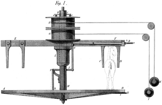
I believe there is no better floor for a working horse to
tread on, than a plane of wood—on condition, of the horse
being rough shod: I speak however, on recollection of many
years’ standing. I then felt persuaded that a horse wastes less
effort by travelling on this floor than on any other; which is one
of my reasons for the adoption of the present Machine. It consists
(Plate 26, fig. 1,) of a wheel A B, on which the horse
walks, as indicated by the sketch of him given in the
figure. Besides this, he is placed between two shafts C D,
affixed to the lever E F, the latter carrying round with it, at
intervals, the drum G, whose office it is to raise the weight I,
whatever kind of resistance that weight represents. This lever
runs by means of it’s cannon L, on a round part of the shaft
common to it and to the drum G. Moreover, there is a second
drum H, destined to raise the weight K, whatever kind of resistance
that represents. Both the drums, G and H, turn on
round parts of the main shaft M, but are alternately connected
with it—first, the drum G, by the rising of the bolt a
into it; and secondly, the drum H, by the falling of the cross
piece b c, between the studs e d affixed to it. Now, this cross
piece b c, is part of a T-formed bar, that penetrates the centre
of the shaft as low as f, where it rests on a transverse lever
f g, connected to the right with the bolt a above mentioned,
and forming a branch of the bent lever f g h, which
works the bolt h i under the wheel. In the present state
of things, if the horse steps forward, he draws the shafts
C D, round the common centre; for the wheel is immoveable
by means of the bolt i, which takes against some fixed
object at k: and thus will the weight I be raised. And
when this motion is achieved, the handle o is raised a few
inches, which brings it into contact with the obstacle p, and puts
a stop to that motion of the lever E F. At the same time the
bolt a, is drawn out of the drum G, and the cross piece b c is
let down between the studs of the drum H, while, by the bent
lever f g h, the bolt h i, which held the wheel, is drawn back,
and then the horse, instead of progressing round the centre of
the wheel, is himself brought locally, to a stand; and without
even knowing it, (for he is blinded) he now treads round the
wheel in a backward direction, and raises the weight K, while
the drum G permits the weight I to descend by the uncoiling
of the rope, till this operation has likewise produced the desired
effect—when things are again placed in the state first observed.
One thing remains to be noticed: It is, that both these motions
might have been produced by acting from a fixed point on the
central bar b c f, through the upper gudgeon of the shaft,
instead of using the handle o, as before directed. It is even easy
to conceive how the Machine may itself be made to perform
these changes, and thus to produce the whole effect without
any personal care or attendance.
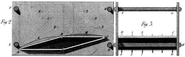
It is one of the simplest and most perfect operations of the mechanic
art, to form a flat surface: witness the process of grinding
looking glasses, and forming one plane from another. Nor is it,
necessarily, more difficult to place two surfaces parallel to each
other, by means of three or more pillars with proper shoulders,
or counternuts against which to screw the plates from behind.
It is therefore easy to compose an expanding and contracting
vessel, that shall become a mover by the force of any fluid,
elastic or not, or shall act as a water or air pump, when driven
by a convenient power; or both together, when this combination
may be desirable. Thus, in Plate 26, fig. 2 and 3, A B C D
is a box with four sides and four jointed angles—which, if one
of it’s sides, D A, be fixed to a given position in the cage or
frame E F G H, will expand or contract according as the
sides A B and D C shall rise toward the perpendicular, or
fall toward the horizontal position. The dotted lines A 2, A
4, A 6, &c. shew that the successive capacities included in
the vessel, are respectively as the sines of the angles which
those sides A B and D C make with the horizon; so that,
although this device furnishes an unequable power, yet it is
equable enough for many purposes in the first few divisions
D 3, D 5, &c. and might be altogether equalized in it’s
effect if necessary. Let us suppose then, that the aperture 8,
brings steam into this vessel: The lid B C will rise to 6, 7,
when, if the pipe 9, communicating with a condenser, be
opened, the steam in the vessel will rush thither and be
destroyed: when the atmosphere will press on the lid B C,
and cause the vessel to collapse with a power proportionate to
that area; for the sloping and parallel sides A B and C D
counterpoise each other; where note, on occasion of the
pressure which I am now speaking of, that the ribs or bars L
M, are used to strengthen the sides of the vessel, and thus
prevent it’s fracture under this pressure.
From this manner of making these expanding vessels, it
follows among other things, that if the frame E F G H were
surrounded with wood or any non-conducting substance, and
made to communicate with a warm close room, the atmosphere
thus acting on the vessel would not cool it, and that therefore,
an atmospheric engine, would, in this respect, be as good as a
steam-acting one. But steam might be introduced into this
outer case, and act as a spring to reciprocate the internal effect
of the same agent.
The third figure of Plate 26, offers an end view of this cage
or frame, shewing the expanding vessel at B C A D, where
the strengthening ribs of fig. 2 are seen endwise at 1, 3, 5, 7,
&c. and moreover, F G and H are the pillars or cross bars
by which the parallelism of the two end plates is effected and
secured.
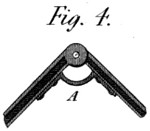
There remains an important subject to be considered: How
to make the corner joints D C, and the end joints steam or water-tight
as required. The small figure 4 answers the question as
far as water is concerned. A is a strip of leather screwed
more or less near to the edges of two contiguous sides of the vessel,
so as to cover the joint or hinge, and make it water
tight whether the pressure come from within or without. This
figure also shews the grooves which receive the stuffing to close
the ends of the vessel, by sliding against the plates or cheeks
E F, &c. fig. 2. The several members of the corner joints
themselves should be well fitted into each other: so indeed as
almost to close the vessel without any stuffing. Nor need we
in all cases be anxious about this stuffing; for I think it very
possible to make this joint close enough for pumping or blowing
without any such provision. I observe, however, that the leather
A, fig. 4, might give place to a strip of thin metal, bent into
the same form, (or nearly so) the elasticity of which would
leave play enough for the joints, on the supposition of working
only with a moderate degree of motion in the said joints.
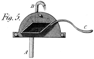
I should not have given this idea so much attention, had I
merely wished to use it where the cylinder-motion now applies:
But my present views go further. I foresee the use of this
Machine for very low pressures—and in very large dimensions;
and I can conceive a proportion between it’s length and height,
that shall as it were annul the effects of friction and leakage,
compared with those of the cylinder-formed piston. But I do
not undertake, or hardly wish now, to exhaust this subject:
being more anxious to deliver the idea to my readers, than to
announce all I intend to undertake by it’s means. I shall,
therefore, merely finish the description of the other figures 5
and 6 of this Plate. The first, is a small hand pump on this
principle, having a suction pipe A, and a rising pipe B, both
having proper valves and opening into the expanding vessel, as
worked by the handle C, much in the manner of a common
pump. It will therefore act by it’s expansive and contractile
properties; and have one good quality we should seek in vain
elsewhere—It will begin the motion of the water with a softness
unknown in the use of pumps in general.
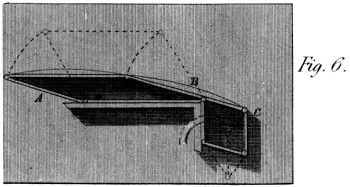
In fine, the sixth figure shews a System of this kind applied
to the two objects, of giving power, and using it. The vessel
A B, receives the power from steam or any other agent; and
the vessel C blows a fire, raises water, or does any analogous
work, without requiring any other parts than those here
displayed.
This Instrument was first intended to regulate the grinding
of a wind-mill; and was used for that purpose in Kent, some
time before my departure for France, in 1792. It is founded
on the doctrine of opposite qualities—and is a practical combat
between equal and unequal motions. In wind-mills, the
mechanism is exposed to all the variations of a capricious element:
and the common way of preventing these convulsive motions
from injuring the flour, was for a man to attend a lever
connected with the bridge tree, (which carries the upper
stone) and by it to bring the stones nearer together when the
wind was strong—and nearer still, when it was violent: and,
contrariwise, to lift again the upper stone when the wind
assumed a milder movement. A process this, which nearly
equalizes the degree of grinding, but not so nearly the quality
of the meal—for this is found to be more heated by great,
than by moderate velocities. At all events I thought a Machine
like the present, would regulate this process, as well as
a man; and it was found to do so—except, perhaps, in very
extreme cases.
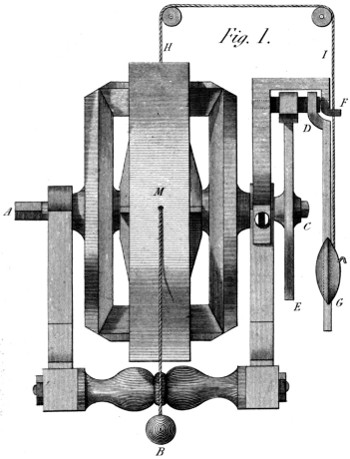
This Governor, is represented in fig. 1 of Plate 27—the
ground work of which is the same as that of the third figure in
Plate 3: for in reality the present Machine claims the precedence
of the Dynamometer; and may therefore, well borrow
a figure from it’s description. A is the power-axis, receiving
motion from any proper shaft of the mill. It is turned backward
by that shaft, and therefore tends to raise the ball B—an
operation equivalent to bringing the mill-stones nearer together.
At the same time, the axis of resistance C, carries
round a pallet-wheel D E, and by the pallet D, sets the pendulum
F G a vibrating, which therefore, by every stroke, lets
down the ball B, and thus raises the upper mill-stone. A proper
position of the latter depends on the similarity of the motion of the
power-axis A, which winds up the ball B, and that of the
axis C, which lets it down. While these are equal, the weight
B remains stationary, and the work goes on well. But if a
gust of wind increases the speed of the mover A, (the pendulum
F G confining the axis C to it’s usual speed) the ball B
is immediately raised and the stones brought closer—which is
what the grinding process requires: And should that gust
increase in violence and become a hurricane, the intermediate
cylinder M, while producing that effect, carries also with it
the cord H I, and thereby raises the bob G of the pendulum,
and thus fits this movement to the increased speed of the
mill: raising, sometimes, the bob to the very centre F of it’s
vibration, where it’s oscillations become rapid enough to unwind
all the excess of motion which the hurricane had occasioned;
until, the wind subsiding, the pendulum acquires a
medium length, and things go on moderately as before.
It may be observed, that the present form of this Machine is
not quite so simple as it might have been made; nor is it so
simple as it first was. The required motions being much
shorter than those of a Dynamometer, the cylinder M, among
other things, might be dispensed with; and one of the intermediate
wheels be likewise suppressed. And if we advert to the
retarding principle which resides in the pendulum, the well
known conical pendulum might be substituted for the present
one; since from it would arise a regular or equable resistance,
opposed to an equable effort. Some however, might then consider
the conical pendulum as an ordinary centrifugal governor;
and, as a mere retarding principle, it may be thought too
complex for the occasion: but I think on the contrary, that it’s
use in this connection, would make this Machine one of the best
of regulators, as well for steam engines as for water and wind-mills
of every description: especially if fitted up with my
Patent Geering.
There is a strong analogy between this Instrument for forging
Nails, and the Machine heretofore given for forging Bar
Iron, Steel, &c. The process of kneading the softened metal,
by means of a pair of alternating cranks, is the very same:
but the acting bars or stampers A, B, are an addition to the
former method. Plate 27, at figs. 2 and 3, gives a representation
of the present Machine; which forms the nail almost
instantaneously, by many contacts of the stampers a b, (fig. 3)
on one of which the figure of the nail is engraven—or rather
filed across that stamper, for no hollow figure is required by
this System.
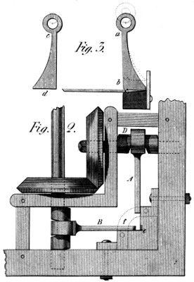
The second stamper c d fig. 3, whose place is at A fig. 2, is
quite plain on it’s face; being destined merely to keep the
metal to it’s thickness—as the particular nail here intended, is
a floor nail, requiring a head on two sides only. As to the
figured stamper b a, fig. 3, it meets a similar form in the anvil,
as at e: and it is by the pressure of these half matrices, that the
head is formed and the bar separated from the nail. It may be
noticed that the stampers a b, c d, are shewn in the figures,
as perfectly straight on the face: but the kind of motion resulting
from that of the cranks, would require a gentle curve
here, which a first experiment will sufficiently indicate.
Some skill would doubtless be necessary in presenting the
nail bar to this Machine; but to make this operation the easier,
there should be a guage, moving toward the working point e,
by a given quantity for each nail: say that this guage comes
forward at each time a distance equal to half the length of a
nail; and that the thickness of the nail bar is so proportioned as
to contain in that length, enough of metal for the nail when
finished.
It remains to be observed, that the stampers or bars A, B,
fig. 2, are contained, in the direction of their width; by two
plates like f, connected with the anvil e, and leaving near e,
an opening large enough for the nail-bar to pass easily.
I shall, perhaps, be laughed at by some unfeeling censor,
for including the tea table in the field of my mechanical speculations.
But, in so doing, I seriously mean to be not only
attentive, but useful to the ladies—who, I am old enough to
believe, deserve this service at my hands. My object is to obviate
for them the necessity of tediously wielding a ponderous
tea-pot, until real and painful fatigue ensues: thus emphatically
making a toil of that pleasure they had hoped for in
administering comfort to others.
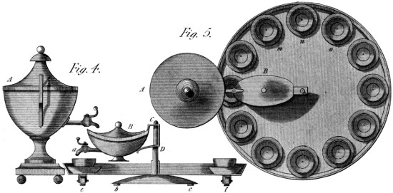
This new method of tea-making admits the use of the common
tea urn—which is placed on the table near the left hand
of the fair distributor. This arrangement is given at figs. 4 and
5 of Plate 27. There, A is the Urn; and B any common tea-pot,
for whose spout, the cock a, has been substituted; and
the handle of which has been slightly modified, so as to make it
a proper centre of rotation. This tea-pot is, of course, opened
before it is brought into the position shewn in the figures. At
C b c, is placed, first of all, on the table, a stand of metal,
terminated upward by the stem C D which forms a vertical
centre to the whole apparatus: and which is sufficiently fixed
to the table by standing on three feet, b c, &c.; under which
are stretched small pieces of Caoutchouc (or India rubber),
which, by their adherence to the table, make the whole steady.
By these means, the tea-pot can be turned round, by a gentle
effort, till it comes under the cock of the urn, from which it
receives the boiling water. And, finally, the tea-board, which
is itself circular, revolves on the same axle C D, supported by
the casters or rollers e f, and bringing successively all the tea-cups
m, n, o, &c., to the spout of the tea-pot, where they are
filled without the smallest difficulty, as will appear by a further
inspection of the figures, and especially by an appeal to
experience.
The above, I should presume, is all that need be said upon
the subject. It remains for some rationally zealous friend of
this social repast, to put these (or other analogous) ideas in
practice: in which enterprize, should he succeed in pleasing
the ladies, he may depend on the approbation of every lord who
deserves the name.
This Machine, as intimated in the Synopsis, was invented
expressly for the use of the lithographic art, as an improvement
on the roller press used in Paris when that process was first
introduced there. I have, however, seen in England the description
of a Machine which takes the desired impression
without any rolling motion. This Machine, in that description,
carries a kind of scraper, or, as the calico printers would say, a
Doctor, which, pressing on a line only (while drawn over the
paper, or the paper under it), acts successively on every part
of the sheet, and, no doubt, gives a good impression. Of the
relative perfection of these methods, I do not presume to judge,
as it is a technical question; and both Systems are, or have
been, used. But, when intense pressure, joined to much precision,
and great economy of power, are desirable, this Invention
appears to me superior to any thing I have seen used for these
purposes.
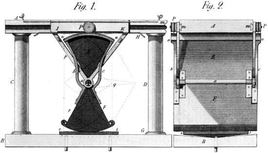
In fig. 1 and 2, (see Plate 28), A B are two horizontal planes
of hard wood or metal, connected, at a proper distance, by the
pillars C D, shewn in fig. 1 only. E F are two Sectors of a
large cylinder, united at the point a, either by a good hinge or
by a joint composed of a hollow prism fixed to the upper sector
E, and of a solid one, more acute, fixed to the lower
sector F; so that, in the latter case, this joint works with an
insensible degree of friction, and thus occasions a great saving
of power.
In the working of this Press, the joint just mentioned, however
made, describes a straight line, parallel both to the floor
B G and the ceiling H A, which have been already shewn to
be parallel to each other: and thus are the joint a and the
sectors E F suspended to the cap or ceiling A H by a pair of
triangular braces I a K, which slide smoothly in two dove-tailed
grooves A m. Moreover, to the lower sector F are fixed
two working arcs b c, one on each side of the Press, and whose
radii are exactly equal to that of the upper sector E (whose
circumference, therefore, is invisible in fig. 1.) Further, just
above these arcs, and in the middle of the slide I K, are placed,
on proper centres, a pair of grooved pulleys P, destined to
work the under sector, without disturbing the motion of the
upper one, which latter is a rolling motion under the aforesaid
ceiling A H. For the said purpose, a metallic cord or chain
is fixed at m (fig. 1), which, passing round one of the pulleys
P, is led to the end n of the arc b c, n o; and near A is fixed a
similar cord, which, carried round the other pulley at P, is led
to the angle o of the same arc b c, n o. By these means, the
sector F is fixed both in place and position, as long as the slide
I K retains it’s present position and state. But, again, a system
of similar cords, placed under the ceiling A H, near the edges
of the upper sector E, determines the place of that sector, in
every case, except a change of position; for a rolling motion
can still have place, without occasioning any other change.
When, therefore, a pulling bar, a crank and fly, or any
other prime mover, applied at the joint a, carries that joint
(say) toward the pillar D, that motion takes place without any
rubbing of surface either above or below; for, when the upper
section has rolled under the ceiling A H, into the position
n p q, the lower section has rolled upon the plate s t, into the
position q r s: in such sort that the analogous angles o t, p r
of both sectors are always found in the same perpendicular
line—or plane—o t, p r; the cause of which I shall now
endeavour to unfold.
When a wheel, in general, rolls on or against any fixed plane
(and the cords m P, A P, now act the part of a fixed plane),
the point of it’s circumference the most distant from that plane,
moves, in a direction parallel to it, just twice as fast as the
centre of such wheel, because it is twice as far from that plane,
the virtual centre of its motion: (an example of which is
found in the wheel of a carriage, whose top moves forward just
twice as fast as it’s axle-tree.) Supposing, then, in the present
case, the frame I a K, with the pulleys P to glide toward the
right hand, the cord A o fixed near A, will turn the arc b c to
the right, twice as fast as the centre of the pulley P moves in that
direction: and if this impulse had acted on the joint a, while
fixed in position, the arc b c would have turned too much by
half. But it so happens (if this expression may be used), that
the joint a itself moves in that direction once as fast as the
pulley-pin; so, that the motion remaining to the sector F is a
single motion, merely sufficient to keep the two sectors E and
F directly under each other, or within the same perpendicular
lines p r, n q s, &c.
Thus, it appears, that the turning motion of the two sectors
is the same; and that a given point of the lower one will always
visit the same point of the corresponding plane s t, independently
of contact with any substance lying on it; and that,
therefore, the pressure, though successive, is perpendicular,
having no tendency to displace or pucker the paper laid on it;
besides which, it may be observed, that the power of this Press
is immense, from the length of the radii of the sectors E F,
and the absence of any rubbing motion.
I observe, further, that racks, made with teeth on my principle,
either singly inclined with cheeks, as in Plate 14, or with
teeth in the V form, will produce a more certain effect than the
cords and pulleys above described, provided the arcs b c, and
the upper sector E, be prepared and toothed accordingly.
The object of this Invention is to join economy of light with
splendour of effect. The means are the following:—
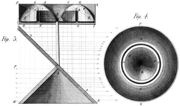
From the nature of reflecting curves, it follows that the
smaller a luminous point is, the more perfectly will its emanations
be reflected; for a focus is a point of the smallest magnitude,
if, indeed, it has any dimensions. My idea, then, is to
make a focus of a line of light very minute in it’s section, but
as large, in it’s contents, as may be desired: thus securing a
considerable fasces of luminous particles while using them in an
economical manner. To this end (see Plate 28, figs. 3 and 4),
I form my reflecting surface of two distinct parts, having a
section common to both, viz.—1st. a concave-parabolic-spindle,
represented at A B C, as cut by a vertical plane passing through
it’s centre; and 2ndly, a parabolical bason E D F G (represented
in the same manner) surrounding the former, and so
placed as that these surfaces have a common focus—namely,
the circular line of which a b is the section; the line itself being
shewn by an elevation passing behind the aforesaid spindle
A B C. This linear focus, therefore, may be two or three
feet in diameter; thus imitating the tenuity of a punctual
focus, while emitting a large quantity of rays.
This Lamp, then, consists of an oil vessel, which is formed
by the outside of the parabolical bowl before-mentioned, surrounded,
in it’s turn, by the cylindrical surface P H, I Q,
this vessel communicating with the wick-ring a N, b O, by
a passage, H I, made as thin as possible, in order to leave
the light at greater liberty to pass downward after reflection.
(Where it is proper to add that the wick-ring is drawn too thick
in the figure.) Now, it is well known that all rays of light issuing
from a point, and falling on the concave surface of paraboloid
belonging to that point as a focus, are reflected from it in lines
parallel to each other; and, therefore, a great part of the
particles emanating from the linear (or circular) focus a b,
and impinging on the surfaces F G A B, and B C D E, will
be reflected perpendicularly downward, as at a, 1 3; b, 2 4,
&c. and this being the case all round the common centre B,
there will be formed a cylinder of light of the diameter H
I, diminished only by the shadows of the wick-ring, the passage
H N O I, and the pillar B L, when that is used, which
is not indispensable.
If this cylinder of light strikes on the plane mirror K H,
placed at an angle of 45° from their direction, these rays will
be reflected horizontally, and, preserving their cylindrical form,
may serve as a powerful beacon to the benighted mariner; the
more useful, because susceptible of those temporary variations
of direction and aspect, long since employed to distinguish one
station from another.
But, if it were desired to illuminate a large space at sea, or
elsewhere, the aforesaid cylinder of rays would be received on
a conical surface K L M, which would give it the form of an
immense sheet of light, of a thickness (allowing for aberration)
equal to the height of P L M, of the same conical surface.
I shall add only one idea—namely, that to light any round
space, building, theatre, &c., this system might be made
very efficient by throwing the sheet of light M P higher
or lower on the walls, &c.; or (altering the angle of the cone
K L M) by bringing it down to any position in or below the
horizon, as circumstances may direct.
It would be superfluous to say that this Lamp might be furnished
with all the advantages of the argand principle; or, the
whole wick-apparatus might be superseded by a circle of minute,
and very numerous gas lights, forming, sensibly, the same
linear focus; or a thin circular slit might produce a real ring
of light, strengthened by all the resources of this new and
splendid discovery.
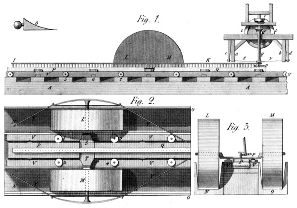
In the year 1793 or 4, I received a written problem, desiring
me to give a plan of a long Reciprocating Motion, that should
be driven by the pit-wheel of a common water-wheel, of given
dimensions, and placed in a given position. In a few days, I
produced the drawing now represented in Plate 29. Its object,
as required, was to move the cylinders L M, figs. 1, 2, 3,
backwards and forwards, in the long grooves or gutters N O, for
the purpose of crushing or bruising their contents: but what
those contents were I never knew. I, however, produced this
Machine, considering it as a general thing, and of a nature to
perform most operations of a similar kind. The Machine
consists—first, of a long rack I K, much like a narrow ladder
placed on it’s edge, and in the teeth of which work those of a
pinion p, whose axis q is connected with the wheel r, which
receives it’s motion from the vertical wheel s t, which is the
pit-wheel in question. This communication takes place by
means of an universal joint x, being a mean of permitting the
pinion p to vibrate from side to side of the rack I K, when
arrived at either end of it. For example, the pinion p now
turns from left to right, and, being on the other side of the
rack, and held by the chain v, it drives the slide P Q in the
same right-handed direction, and, with the slide, the two heavy
cylinders L M before-mentioned;—for, the said slide P Q
carries across it’s middle the axle-tree S T, which is the centre
of both these cylinders, and connects their motion with that of
the slide now in question. Further, there are rollers placed
between the cheeks V V, on which the slide moves horizontally,
as guided by other rollers, placed at the points 1, 2, 3, 4, &c.
Again, the ends of the axle-tree S T are furnished with two
bow-like bridles, which, connected with the pulling bars Y, are
again fastened to the slide P Q, at the two ends of the present
figure.
When, now, the pinion p turns (see fig. 1 and 3), the rack,
slide, and cylinders roll in the grooves, till the end of the rack
comes to that pinion; which, finding no more teeth, swings
round the last, and taking a new position, reverts the motion,
till the other end of the rack comes to it, and occasions
another return: ad inf. This will be better seen at the third
figure, which is an end elevation of a part of the Machine.—There,
P shews the slide and one of the teeth of the rack (which
teeth are longer than the rest, as seen near L M, in fig. 1.)
In this figure, we see at A, a mass of brick-work, covered by
the sleepers 5, 6, 7, &c., on which the long cheeks V V
repose. There, also, the chains v z are seen, connected with
ring-bolts, which go through the bars a b, and are nutted on
the other side of the spring-beams c d, in order to avoid the
commotion which would otherwise attend every change of
motion in the slide and cylinders. For this purpose, also, and
especially to prevent any waste of power at these moments,
there are mixti-linear wedges laid in the gutters, such as are
shewn at 6, which are formed so as to absorb the momentum
of the cylinders, in exact conformity to the time employed by
the pinion p, in swinging round the end tooth of the rack; and
thus to save all the power and time possible.
An ordinary Syphon acts by the pressure of the air on the
upper water, which drives it into the ascending pipe, because
there is a (partial) vacuum made there by the weight of
the falling water in the descending pipe; this being always
longer than the first. Thus, in Plate 29, fig. 5, A B shews
the rising pipe of a Syphon, and C D the falling pipe, which is
longer, and sinks to a lower level D, than that A of the water,
which feeds the machine. E, in this figure, represents the
vessel containing the mechanism on which the new effect
depends: and which I shall now describe.
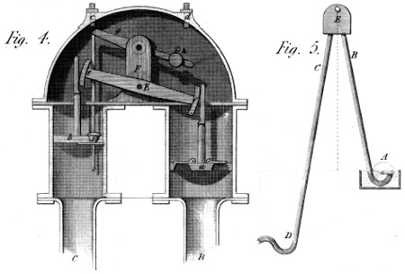
B and C, fig. 4, are, one the ascending pipe A B of fig. 5, and
the other the descending pipe C D. They are surmounted by
two cylinders, of unequal capacities—this inequality bearing
a given proportion to the difference in the heights of the rising
and falling branches of the Syphon. In each of the cylinders
works a piston a, b, which, I think, need not be stuffed,
but well fitted. The large piston has proper valves in it, to
let the water pass upwards, at all times; and the small piston
has a valve i, opening upwards, by means of the mechanism
we are now describing; and closing itself merely by the
arrival of the piston into it’s present position; for the screw c
prevents the valve from rising higher: e, f, are two arcs
belonging to the lever E, and being circles round it’s centre of
motion. They are cut into teeth, on my Patent principle, and
work in the racks similarly toothed, which give motion to the
pistons a b, or receive it from them. Further, behind the
stand F, common to both levers, vibrates, on a pin, another
lever g h, the use of which is to work the aforesaid valve i in
the small piston; and this it does, by means of the weight h, in
the following manner:—The machine being supposed in the
present state, the Syphon will act, as usual, through the valves
of the large piston; and the water pressing on the small one,
with a power proportionate to the excess of it’s column over
that of the other piston (a), will raise the latter as fast as
the piston b descends; but the area of the piston a being
larger than that of the piston b, there will be a pressure within
the vessel b c d a, that must expel (through any prepared
aperture at the top) a quantity of water equal to the difference
of area between the two pistons, multiplied by the stroke of
both: the real quantity of which will ultimately depend on the
difference of level between the higher and lower water; or
between the lengths of the rising and falling branches of the
Syphon, B and C. When, therefore, this stroke is made, the
end h of the lever g h, which carries the ball, will touch the
screw d, and stop the descent of the valve i, which will thus
be opened; when the water will have free egress through the
descending pipe C, and the piston b will then rise through that
water by the weight of the piston a, the valve i being kept open
by the action of the weight h, until the piston b has risen to
it’s present position, when a new stroke is prepared, for the
same reason as before: and thus may water be carried over a
hill of (about) 30 feet above the level of any stream or pond,
and dropped into a lower canal on the other side, with the
condition of leaving a part of that water upon the hill, proportionate
to the difference between the level from which the water
is brought, and that to which it is carried.
The two figures, 1 and 2, of Plate 30, are intended to make
this Machine known, assisted by the following description:—The
first is a front view of it, and the other a partial view from
above. In the former, A B is the frame formed of, and firmly
connected with the two columns C D, which are fixed strongly
to the ground, at such a distance below the ends C D, as to
place the aforesaid frame at the height of about two feet, or
higher, if convenient.
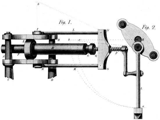
In the two cheeks of the frame A B, are cast or bored two
round holes for receiving the gudgeons of the swivel E, one of
which gudgeons is also seen at E, in fig. 2. This swivel turns
in these holes; and it is itself perforated with a round hole just
large enough to receive freely the body of the mandrel F G.
This mandrel has now on it the cylinder, which is to be taken
off. I K are, moreover, two ears or studs cast or welded on to
the top and bottom of the said frame A B, and at exactly the
same distance from the centres of the swivel E before-mentioned.
These ears receive the ring-formed ends of the bars
L M; see also the bar L, in fig. 2. To these bars is firmly
fixed the cross-bar N O, which forms the nut of the screw P,
by means of which the operation of the machine is duly prepared;
for, now the cup Q (in the centre of which the screw P
revolves against a proper shoulder) receives the end G of the
mandrel, which it presses forcibly, while the whole is in the
position E L, of fig. 2; that is, when the two centres E and
R form one right line with the bar L, figs. 1 and 2. To complete,
then, the process of driving out the mandrel, the bars,
mandrel and cylinder are, at once, strongly made to describe
the arcs a M b, a c; the mandrel revolving round the centre E,
which is that of the swivel and the bars round the stud R.
But, in thus revolving, a given point of the mandrel describes
the quadrant a M B, and a contiguous point of the bars L M
describes the quadrant a c; insomuch, that the mandrel must
have been forced out of the cylinder in direction G F by the
distance c b; where we observe that, at the beginning of this
motion, the two curves a b and a c coincide in their movements,
and only begin greatly to diverge from each other in the latter
parts of these motions (see M b c.) The power, then, of this
machine, when the cylinder sticks fastest to the mandrel, is
infinite: and this power becomes weaker, and the velocity
greater toward the end of the operation; that is, when the
cylinder has slackened on the mandrel, and no longer requires to
be driven with the same force as at the beginning. It may
finally be observed, that the bars L M are suspended by an
oblique bar or chain S N to the ceiling of the room just over
the stud R or I, which is their real centre of motion, in the
above-described process.
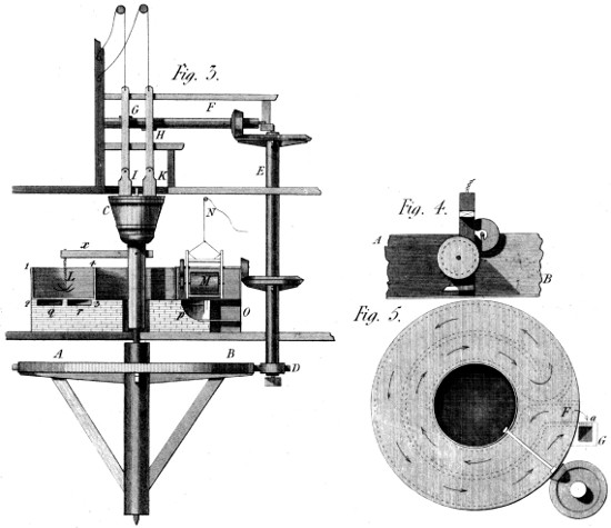
The wheel A B, Plate 30, fig. 3, was a horse-wheel, but
may be a first motion of any given kind. It is placed on the
ground-floor; and over it’s centre is another shaft, having on
it’s upper end a chopping block C, which revolves with the
wheel A B, as turned from below. In this wheel, A B
geers a pinion D, driving the lateral shaft D E, which has
two functions: the first to work the lying shaft F, and by
means of the cams G H, to lift the contiguous stampers;
and, by means of the knives I K, to cut the tallow on the
revolving block before-mentioned. Over this block is fixed
an oblique scraper, which takes the tallow as soon as it is cut,
and pushes it down an inclined channel, placed at C x, into the
boiler. The second use of the shaft E is to turn the mill M,
(better shewn at fig. 4), which is let down into the boiler, in one
stage of the process, and drawn out by the tackle N, when not
wanted. The use of this mill is to tear the fleshy parts of the
substance, while in the act of boiling, and thus to disengage
the tallow with so much the less heat, in order that it may be
so much the less coloured. Besides this machine, there is a
grapple L to be first used, which stirs the tallow in the boiler
by the rotatory motion of the arm x. This position of the
grapple would alone indicate what I have yet to observe—namely,
that the boiler is a kind of ring, the section of which
is the line 1, 2, 3, 4, and it’s depth 1, 2, or 3, 4. To prevent,
still further, the fat from being burnt or coloured, the flue for
the fire is conducted solely under the bottom of the boiler, as
shewn by the dotted lines in fig. 5: the smoke or heated air
being forced to make two revolutions under it, as indicated by
the arrows in this figure, where we see more particularly
the fire-place F in close connection with the rising shaft of the
chimney at G; and this is so, because, with so great a length
of horizontal flue, the fire would not enter the chimney till it
had been heated to a first degree. There is, therefore, an
opening into the chimney at a, and the fire, in lighting, is
suffered to escape directly from the fire-place into the chimney;
by which means, continued a few minutes, there is draught
enough created to make the fire take its useful course through
the flue afore-mentioned. I may just observe, reverting to fig. 3,
that O shews the fire-place in elevation, and p the entrance
into the flue, which last is double under the boiler, as shewn in fig.
5. Finally, the 4th fig. shews an end view of the tearing-mill,
before-mentioned; but here on a larger scale, A B being a
part of the side of the boiler.
Doubtless, the salubrity of every place, where many
people are collected, would be much increased, if all impure
exhalations were expelled as soon as formed; and this is
especially true of those awful but sublime receptacles, provided
by Philanthropy, for the sick, the wounded, and the dying!
To assist in the work of purifying the atmosphere of these doleful
abodes, was the object (30 years ago) of the Ventilator,
presented in page 170 of this work. But, I conceive, that a
share of evil, quite as great, resides in the putrescent qualities
contained in or connected with the clothes, the bed-linen, the
dressings, &c., of the inmates of an hospital; to whose sacred
claims on the efforts of every good citizen, the present article
is devoted.
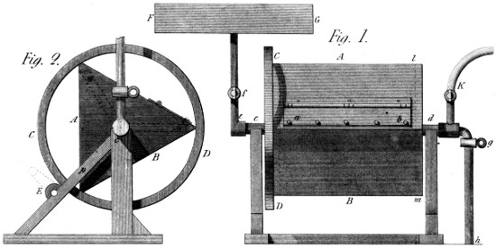
This Washing Machine (see Plate 31, figs. 1 and 2) is a
triangular (or square) box A B, furnished with a lid a b, so
fitted, as, when screwed down, to be hermetically closed.—And,
N. B., to facilitate this operation, I use in it a particular
kind of screw (invented for the hose of fire-engines), which I
shall now describe. I take a common screw, with it’s nut, and
cut away the threads of both, at two opposite quarters of their
respective circumferences, so that the screw can enter the nut
to the bottom without turning; and the stuffing between the
shoulders is so well fitted, in thickness, as to secure the penetration
of the threads of the nut and screw the moment the
latter begins to turn. There is thus a full quarter of a turn,
in which the nut and screw will press as strongly as though the
threads had not been cut away; and thus are nine tenths of the
time required to use a common screw saved by this simple
process: and thus, then, I close the lid afore-mentioned.
This Machine is further composed of a wheel C D, and a
pinion E, to turn it with, either by hand, or by any proper
application of power. The wheel turns the box A B, and
thus agitates the contents in a way not dissimilar to the
operation of the dash-wheels of calico printers. But, again,
this wheel and vessel turn upon two hollow gudgeons c d; one
of which is destined to convey cold water into the wheel from
the reservoir F G, to regulate which is the use of the cock f:
the stuffing box e being made as good as possible, in order to
prevent all leakage, either of air or water. The second hollow
axis d serves two purposes: it gives a passage to the fetid
matter of which the expulsion is desired, and conveys it through
the cock g to the sink or sough below h, without any communication
with the surrounding atmosphere.
But we said this hollow gudgeon had a second use: it is to
bring steam into the revolving vessel A B, from any proper
boiler beyond K, when that part of the process requires it.—There
are, moreover, two partitions C D, l m, made near the
ends of the vessel, and pierced with many holes, in order to
suffer the cold water to flow in, and the dirty water to escape,
without choking up the respective passages: and, finally, at
the eduction end of the Machine (see n, o, p, fig. 2), there are
placed three pipes, reaching from the angles of the box to the
hollow centre, and furnished, at those angles, with valves,
opening outwards; which thus form a kind of hydraulic
machine to raise this matter from those places to the hollow
centre, and thus, after a certain number of revolutions, to
expel it entirely.
The process, then, for cleansing the objects contained in the
vessel A B (including the condition of cutting off all communication
with the ambient space,) is as follows:—
1st.—These objects are dropped into the vessel as soon as
produced, and the vessel is filled, one half or more, with cold
water from the reservoir F G. The things are then left to
steep in this bath for a day or two, or what space of time the
periodical mutations of the house permit. By which operation
alone, the miasmata are already much confined by the water,
even though the lid of the vessel should be but partially shut:
after which, this steeping operation may be continued, with
the accompaniment of a few turns of the handle (E) to fully
saturate every part of the mass. In the second place, a small
stream of water is let through the cock f, and the wheel C D
is kept turning for a few hours, to discharge the cold water
and the most offensive matter, through the cock g, into the
sink: and, thirdly, the steam-cock K is opened (that g being
shut), by which means steam is brought into the vessel A B,
and the whole soon raised to the boiling temperature. This
state of things is continued, as long as it is found necessary; the
motion, of course, being also continued, and even accelerated,
that the mass of objects may fall from angle to angle, and be
thus well washed—that is, well finished, if plain things; and
fully prepared for finishing, by hand, if of a nature to require
close attention. And, finally, in many cases, the warm process
may now be abandoned, and a new stream of cold water
be injected, accompanied by a due motion in the vessel, so as
to rince the contents; and thus leave nothing to do for the
laundresses, but to dry and mangle, or iron them; where, it
is plain, that no inconvenience can have arisen from this process,
either to these persons, or to the other inmates of the house.—Hence,
then, this Machine has the properties announced—of
confining the offensive matter until cleansed away.
The application of steam-power, to the motion of boats on
narrow canals, is, I believe, much impeded by the consideration
that the agitation of the water injures their banks, and would
finally destroy them. On the other hand, it is known, that to
drive a vessel, by acting on a fleeting medium, such as water,
we must, at once, submit to lose about one half of the whole
power employed—that is, the power, armed with energy enough
to produce the required velocity, must go through twice the
space that constitutes the way or progress of the vessel. This
depends, however, on the size of the floats or paddles employed,
compared with the section of the boat, as modified by the form
of the prow; but it is difficult to employ a paddle so large as to
suffer more resistance from the water than the boat itself; and,
if they are found just equal, the loss of power is exactly one
half of the whole. These, then, are the two difficulties which
I hoped to avoid, by the method now to be exhibited.
The idea is this—To have a large and heavy wheel A connected
with a long shaft B, reaching from the boat to the
shore, and, turning that wheel in the boat, to propel the latter,
by means of it’s rolling motion, on the bank or track-way;
or, in some cases, on a proper rack, placed there for that
purpose.
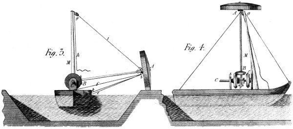
The Machine itself is represented in figs. 3 and 4, of Plate
31; fig. 3 being a stern-view, and fig. 4 a side-view, both of
the machine and the vessel. C is an axis, placed along the
vessel, and turned by any convenient power—as a horse, a
steam-engine, &c. On this axis, considered as the first
motion, are fixed the two bevil wheels b c, from which the long
shaft B A of the rolling wheel takes it’s motion. The use of
the two wheels b c, is to drive the boat in the same direction
on whichever side of the boat the wheel A may be placed; for
this, of course, must follow the track-way, which is sometimes
to the right and sometimes to the left of the vessel.—Between
the two wheels c b, is a sliding block (or catch-box) d,
in which the shaft A B of the large wheel has it’s lower pivot,
and by which it’s wheel B is almost instantaneously shifted
from one to the other of the vertical wheels b c: the catch-box
d being itself worked by a lever, of which the end only is seen
at e, fig. 4. In fig. 3, there is further shewn a rope or stay f,
which, fastened to the socket s, of the rolling wheel A, and
fixed in the middle of the boat, at the greatest possible distance
from it, serves to keep that shaft at or near an angle of 90
degrees with the boat’s side: so that (the vessel being long) it
becomes easy by means of the rudder, assisted, perhaps, by
lee-boards to keep the way of the boat in a line parallel to the
shore, notwithstanding the tendency to veer outward, given by
the wheel A, while acting on a point so far from the body of
the vessel.
I further observe, that, in order to shift the apparatus, with
a certain facility, from one side of the boat to the other, there
is a mast M placed ahead of the mechanism just described,
which rises as high as the length of the main-shaft (but can be
lowered to pass a bridge, &c.), and to the top of which is fixed
the block g, through which a rope passes from the foot of the
mast to the above-mentioned socket of the wheel A. By this
rope the wheel is hauled up till nearly ready to fall over the
centre; when a push from below will complete that passage;
and the wheel A, being afterwards lowered by the rope h i, will
soon find it’s proper position on the other side of the boat, as
before anticipated. Where, it should also be remembered, that
this shaft must have a joint and socket, to permit it’s being bent,
to pass a bridge, &c.
Hitherto we have supposed this rolling wheel to act on the
bank or track-way solely by it’s weight; but this is not our
only resource; for this wheel might be made of a moderate
weight, and be pressed down by a brace reaching along the
boat, toward the head and stern (see k l, fig. 3.), and hauled
taught through an eye of the socket s; by which manœuvre (the
points k l being lower than the centre A of the wheel) the
latter will be pressed forcibly downward, and cause that cohesion
there, from which the boat is ultimately to take her motion.
And, as to the wheel A itself, I have not represented it in
the very form I should wish it to have, because it can be
sufficiently described in words. I should cast this wheel (if made
at all in metal) as a shell, the outside of which would be what is
really seen in the figure (at A), and the rim would have in it
mortices, like those which are made for iron wheels destined to
receive wooden cogs, and geer with cogs of iron. In fact, this
would become a wooden-toothed-wheel, with its teeth roughly
formed and placed, so as to occasion a small expence, and
to be easily changed, when worn away by the friction on the
track-way. Thus would, I am persuaded, a very moderate weight
in the wheel, and as moderate a pressure from the braces k l,
connect the wheel with the road enough to produce the desired
effect, with a trifling loss of the power employed. And thus
might we navigate a narrow canal, with a great saving of
expence; not to mention that other advantage of avoiding
entirely that injury to the banks, which must attend every
system of propelling the boats, founded on the agitation of it’s
waters.
The Slide-valve is an excellent substitute for the hand-geering
of steam-engines, from the simplicity of form which it
introduces, and the certainty of it’s recurring effects. But it
is, I believe deservedly, reproached with being too sluggish in
it’s operation, at the very moment when activity would be
most desirable—namely, at the beginning of the strokes; insomuch,
say some, that the power of the engine is materially
lessened by it. The fact is, that the excentric (usually placed
on the crank-shaft) is almost always moving, and with it the
slide-valves also; which thus open by slow degrees, when they
should open by rapid ones.
Without discussing the question further, I cannot refrain
from introducing this application of the principle of my
Parallel Motion, given in page 237; which appears to me
greatly calculated to obviate these difficulties; and thus to
leave the slide-valve in possession of all it’s own advantages,
with the addition of those which have hitherto belonged
exclusively to the Hand-geering System.
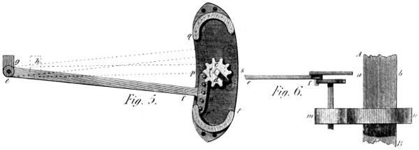
I have represented this Mechanism in figs. 5 and 6, Plate 31:
where A B shew the crank-shaft of a steam-engine, working
by means of slide-valves, the place of the excentric being at a b,
in a line with the pulling-bar e f. Instead, then, of the usual
connecting frame between the excentric at a b, and the valve-lever
at g, I use for the above purpose, a lever e f terminated
by an arc o, furnished (in the present instance) with five teeth,
and connected by the joint e with the valve-lever g, in the
usual manner. In the arc, which terminates this lever to the
right, are the five teeth above-mentioned; and, they geer in
the ten teeth of the wheel c d, which will be seen (in fig. 6) to
be on the same shaft with the spur-wheel m, itself driven by
the spur-wheel n, of twice the diameter. This wheel c d,
therefore, makes two revolutions for one of the crank-shaft:
and, supposing it to turn in the direction of the arrow, it will
first of all draw upward the arc o, producing no effect
on the valve-lever at g; but, when the tooth r is arrived at p
(the tooth p being then arrived at the entrance of the curve q),
the wheel c d will begin to draw the arc o along with it, round
it’s own centre; and, the teeth of the arc being kept in it’s
teeth by the similar curve q, the valve-bar will be drawn from
g to h, in the course of one quarter of a revolution of the
crank-shaft A B. But, now, the tooth r of the arc o will be
found at s: and, therefore, the further revolution of the wheel
c d will carry the arc o downward toward t, until the tooth r
has reached the point t; that is, until the wheel c d has made
another half-revolution, and the shaft A B another quarter;
when, as before, the arc o, conducted by the curve t r, will
again drive back the lever e f, till it comes into it’s present
position: after which, their motions will be regularly continued.
It is, then, evident, that the slide-valves are thus opened and
shut, each during one quarter of a turn of the crank-shaft
A B; and thus they remain stationary during another quarter,
and that, in two positions of said shaft diametrically opposite to
each other. And thus have we a simple mean, adaptable to every
engine, of giving it much of the advantage of the hand-geering
system, while preserving all that of the slide-valve principle.
And, were it desired to lengthen the interregnum of the opening
motion, it would be done by making the wheel c d smaller, and
the ratio of n to m (see fig. 6) larger in the same proportion.
I observe here, however, that care should be taken not to
make the valve motions too rapid, nor the intervals between
them too long; for, I consider one of the best properties of this
motion to be, that it acts like an excentric; that is, slowly at
first, most rapidly afterwards, and finishes as slowly as it began;
which is a precious quality in all reciprocating machines.
Finally, I would remark, that the two last rounds in the rack
of the arc o might be rather larger than the intermediate ones,
and turn, moreover, on pins, so as to suffer less friction when
rolling on the conducting curves q and t. There might also be
a plate or cap rivetted or screwed over all the teeth, so as to
strengthen each one, by the force of the whole, as is shewn in
fig. 1, Plate 29; from which, as before observed, this Mechanism
is deduced.
The foregoing completes the Third Section of my work:
and gives an article beyond the twenty, first intended:—which
I thought important enough to claim this distinction. I now
beg leave to add a remark or two on the text and plates of this,
and the Second Part, by way of clearing up some obscurities,
that might otherwise embarrass my readers.
And, first, in fig. 1, of Plate 21, the receiving vessel M,
erroneously appears to form part of the wheel D E; but
is, in reality, placed before it, as in all similar cases.—And,
further, a small deviation of the circular lines, in Plate
22, has set the plate and it’s description, in page 192, at
variance; the difference between the lines o p and C q being
not “imperceptible,” as there stated. I wish, then, that the
dotted radius A o p, in the said fig. 2, may be carried (or
supposed) halfway between p and C. Finally, in page 200,
line 8, the 24th Plate is incorrectly called the 25th.
I shall conclude this Part, by an observation or two on
the reception my System of Toothed Wheels, as described in
this work, has met with—not intending to speak of the local
difficulties I experienced at a former period. But, here, the
interests of truth force me to break silence. The necessity I
stood under of bringing out this work in Parts, has, at least,
had one advantage: it has given me an opportunity of watching
the workings of prejudice—not to say of envy,—and thus of
neutralizing, in some degree, the effects of either: from
which, however, I claim nothing but the right of making
my labours the more extensively useful, by making them better
known. I have, then, to say that, among a few other objections
to the System, this error has come from so respectable a quarter,
that it would be unjust to Science, and injurious to truth, to
let it pass unrefuted. It has been said, that “my wheels are
a Chinese Invention;” and this proof has been adduced of it—namely,
a sugar-mill, from China, having it’s cylinders fluted
in a spiral direction. Now, the fact is, it would have been
difficult to give a better proof that the wheels are NOT
a “Chinese Invention;” for two inventions are then only alike
when they produce the same effect, by similar means. But
here the effects intended are totally different. A sugar-mill
acts in or near the plane of the centres; and one of it’s
cylinders is not intended to drive the other independently
of pressure between them. This is so true, that the rollers of
many sugar-mills are not fluted at all. Besides this, my wheels
exert no pressure in that direction; and if they did, they would
not be cog-wheels. In a word, their action is at right angles
to the former, and has an object of quite a distinct nature.
These, then, are by no means the same machine; and, therefore,
mine is not a “Chinese Invention.”
Here, however, I beg not to be misunderstood! I should
feel no regret at appearing on the mechanical stage, a few
hundred years after so ancient and astonishing a nation as
the Chinese! But, in this case, truth did not permit me to
sanction, by my silence, this flagrant error.
Finally, an opinion exists, somewhere, that these wheels will
never be generally used, from the difficulty of making them;
and this opinion has been expressed, apparently, with no very
amiable feeling. But, amiable or hateful, the opinion is highly
erroneous! It is so far from fact, that, in a competent manufactory,
they can be made more cheaply than others now are;
and many persons are already calling for them from every
quarter; nor is any thing wanted to insure their immediate prevalence
but a common degree of commercial energy.
PART FOURTH. — OF A CUTTING ENGINE, For large Bevil Wheels and Models, on the Patent Principle . — OF A CENTRIFUGAL DASH-WHEEL, For Bleachers, Dyers, &c. — OF AN HYDRAULIC LAMP For the Table . — OF A MECHANICAL ESSAY, To derive Power from expanding Metals . — OF A MACHINE, For Making Laces, Covering Whips, &c. — OF A BATTING MACHINE, For Cotton, or FINE Filaments in general . — OF A HORIZONTAL WIND MACHINE, For raising Water in large quantities . — OF A FLAX-BREAKING MACHINE. — OF A BOWKING MACHINE, To accelerate and equalize that process . — OF A PRINTING MACHINE, For two Colours . — OF A MACHINE For clearing turbid Liquors . — OF OPEN CANALS, As Hydraulic Machines . — OF A PORTABLE ENGINE, For extinguishing Fires . — OF A WIND MILL, With double Power . — OF A WATCH ENGINE, To extinguish incipient Fires . — OF A MACHINE For Engraving the Cylinders of Calico Printers by Power . — OF A HORIZONTAL WATER WHEEL, Probably the best of the impulsive kind . — OF A NEW SPINNING MACHINE, Called, and being the Patent Eagle . — OF A SECOND SPINNING MACHINE, Adapted principally to Wool . — OF MY PARALLEL MOTION, As applied to HEAVY Steam Engines.
A NEW CENTURY OF
Inventions.
One of the most prominent subjects of this essay, if not the
most important, is the System of Toothed Wheels, with which
the second and third Parts were introduced, and which still
claims a share of my readers’ attention. As hinted a few pages
backward, it seems not enough for me to exhibit and describe
the System, but I must defend it against repeated objections,
on pain of seeing it’s utility delayed, and the public deprived of
it’s real and solid advantages. I am far from wishing to impeach
the motives of those who still nourish or express dissent,
when they deign to bring reasons for so doing; but the mere
opinion—“it won’t do”—expressed by a man of reputation,
may impede, for a time, the progress of an useful discovery,
and thus produce a public evil. This, then, is a result I am
anxious to avert; as the present System has many points of
excellence, against which no insuperable objection can be
brought. Had I not declined, already, to name either the
friends or enemies of the System, I might here appeal to persons
who highly approve of it; and, indeed, who use it daily with
manifest advantage. But, I forbear. If, by means of the
Engines already given, and that I am going to offer, it is proved,
that the difficulty of making these wheels is trifling, compared
with their utility, one important point will be gained: I shall
not hear it repeated, “that the System cannot succeed, because
of the difficulties of it’s execution.”
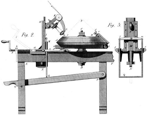
The present Cutting Engine is shewn in figs. 1, 2, 3, of Plate
32. It’s immediate use is to form the teeth of wooden models,
for casting. These are previously built as usual, and lagged
with bay-wood, of sufficient thickness to furnish the teeth, and
leave a small thickness of that wood behind or under them.—A B,
in fig. 2, represents a wheel of this kind, ready for cutting;—mounted
correctly on the centre pin C D, which latter is so
formed as to be fixable in any position on the table or bench
E F. Under the wheel A B, there is a kind of index a b, put
upon the said centre pin C D, which, by means of the clamp and
screw b c d, can be occasionally connected with the wheel A B
so as to turn it, when it is itself turned by the means hereafter
to be mentioned. To proceed with the description: G is a
slide, moving horizontally on the bench E F, as seen at f e
fig. 3; this slide being the basis of the headstock G H, which
contains the perpendicular slide H I, itself the support of the
cutter-frame K L, so constructed as to turn on it’s bolt above
I, and take any proper position over the edge of the wheel or
model A B. This slide, then, with it’s appurtenances H I K
L, moves along the bench E F, as seen in fig. 3 at f e: and
what gives it this motion, is, the screw g, furnished, purposely,
with a left-handed thread, working in the half-nut
contained in the small frame h, which contains also a jointed
cap, that can be lifted off in an instant, and the screw set
at liberty. Moreover, the second use of this screw g, is to be
thus disengaged from it’s nut, and lifted up to about i, where
it serves to push back the slide G towards the wheel, without
that loss of time it would occasion if pushed back by the working
of the screw. The letters M N, shew another important
part of the Machine, applying to the cutting-process. It is an
inclined plane, sloped to the same degree as the bottom of the
teeth of the wheel. (See the line a k.) This inclined plane, then,
is fastened, in any proper place, on the bench E F, by the
wedge N, just like the puppet of a common turning lathe; and
it passes through an opening in the slide G I, or rather suffers
this to pass over it, as better seen at M, fig. 3. Furthermore,
the slide I (fig. 2), after gliding down this inclined plane M G,
will have to be raised between each cutting: and that is the
office of the workman’s hand acting on the lever O P, through
the iron frame Q M, which is shewn at fig. 3, in another
direction; and marked with the letters Q l m. In fine, the
slide G carries on each side of the Machine a pulling
bar n, connected with the said slide, and with a smaller sliding
piece o, the use of which is to hold a pin (seen in the figure,
but leaving no room for a letter of indication), which turns the
wheel A B, by the plate p, as the slide G recedes, and the
cutter-system I K L descends on the inclined plane before-mentioned.
Having thus adverted to all the important parts
of the Machine, we turn to fig. 1, for the purpose of shewing
what the plate (whose edge is seen at o p) means; and the
effect it is intended to produce.
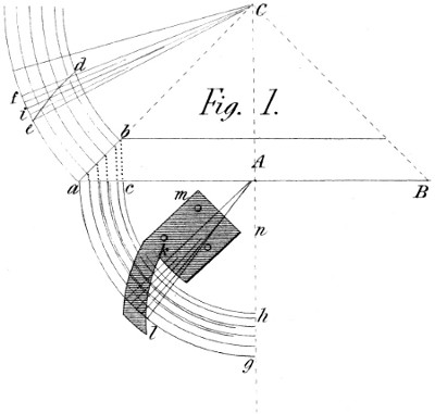
In that figure, let B A c be the section of any wheel it is desired
to cut on this principle. The width of the face of such wheel is
shewn by the line a b; and a c is called the projection of that face,
on the base of the cone of which the wheel A B is a portion;
it’s summit being at C. The line e d, shews one of the spiral
teeth with which the wheel is to be furnished; and I make it
by this uniform process: The pitch of the wheel, whatever it
be, is set off from e to f: and that pitch is divided into eight
parts, (shewn here as four on account of their smallness) while
the width of the face f d, is divided into nine parts, shewn
here (for the same reason) by four and a half divisions. This
latter division is more numerous than the former, that the
principle may be a little overdone; or that the teeth may overlap
each other by 1⁄9 of the pitch: To which purpose, beginning the
spiral line e d at e, I move in the second circular line from e to
the second radial line C i, and draw that diagonal which
forms the first part of the curved line e d. From this
second point, I go to the third circular line, taking also the
third radial line, and drawing the diagonal. This I do until
arrived at the fifth circular line, when I find myself likewise at
the fifth radial line C d f. These four spaces thus gone over,
represent the eight parts into which this part of the face a b
would have been divided, had the figure been larger: and there
remains a small division near d, equal to one half the others,
through which the curve e d is prolonged by a similar process;
and this latter portion is what the successive teeth overlap each
other, as before stated.
Now, it will be seen below, that the needful circular motion
is given to this wheel, by a movement that takes place in a
direction parallel to the base a c B of this figure. The curve
e d, must, therefore, be transferred from the surface of the
cone, to this base a c B. To do this, I place a point of the
compasses at A, and trace, with the openings A a, A c, &c.,
the six quadrants included in the space a c g h, which are now
the projections, on the base, of the circular lines a b f d on the
surface of the said cone. Here, a slight difficulty should be
obviated: strictly speaking, this projection would be horizontal,
and, of course, invisible in this position of the wheel.
But I have supposed the figure a c g h, turned ninety degrees
downward, round the horizontal line a B, so as to make one
representation suffice; and also to shew the connection
of the lines a b g h, with those f d a b. The curve k l, is thus
a copy of that e d, only shortened in the proportion of a b to
a c—that is, of the side of the cone a C, to the half-base
a A.
To secure, then, the coincidence of the pitch, as set off on
the circumferences a f and a g, we must divide a similar
portion of both into an equal number of parts, e f; and treat
them, on the lines a c g h, as we did on those a b d f; by which
means we shall get the curve k l, the projection of that e d. And
this curve k l, must be made part of a plate k l m n (about
1⁄10 of an inch in thickness), the use of which is as follows:
This Plate k l m n, is no other than that marked o p in fig.
2; and it is there fixed to the index a b, directed to the central
pin C D, as it is in fig. 1 to the centre A—insomuch, that the
pin shewn in fig. 2 near o, acting on the sloping curve k l, will
turn that index (and with it the wheel) by the very motion
which draws back the slide G (fig. 2), and lets down the slide
I on it’s inclined plane G M.
We may remark, lastly, that as the present Machine is
adapted to large models, it is not, now, provided with a
dividing-plate, although the means of so doing are self-evident.
On the contrary, the division dots are seen on the edge of the
wheel A B, as is likewise one dot, near b, on the clamp b c,
from which a given distance is set off to each of the dots on the
wheel, so as to give the pitch required. By these means, then,
the wheel is divided and cut, in good, if not in exquisite divisions;
and all the teeth take their shape from the Plate o p
(or k l m n of fig. 1), and are thus good, in that respect also.
To recapitulate the steps of this process—The workman stands
behind the Machine, near E; and, working the screw with
his right hand, draws back the slide G, (the power then
turning the cutter r very swiftly) by which means, the slide
I glides down the inclined plane M, and the cutter, impinging
on the sloping face of the wheel, cuts it to the depth
r a; the shape of the tooth (by the turning of the wheel) being
the spiral form e d of fig. 1. It may be added, that the lifting
lever O permits this descent of the bar Q M, because it is
suffered to fall lower than now represented. Thus, when the
slide G is arrived near h, the tooth is finished; and the cutter
leaves the wheel at a: after which, the cutter-frame and slide
I K L are raised by means of the lever O—the screw g taken
out of it’s steps, and the slide G pushed back by it, until the
vertical slide I rests again on the inclined plane M, as it at
first did. Nothing, now, remains to prepare for cutting a new
tooth, but to change the division-dot, by the application of the
gauge or compasses, from b to the next point on the wheel; to
do which, of course, the clamp b c must be loosened and refastened
by the thumb-screw d. I would just notice the 4th
figure—to say, it is a sketch of one quarter of a bevil wheel;
intended merely to shew the form and position of these teeth,
and the general appearance of the System.
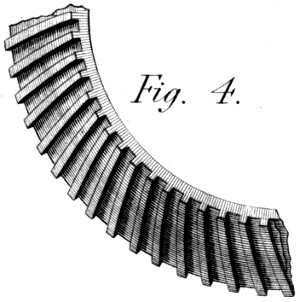
Finally, my readers will please to advert to what has been
already said on the forms of these teeth, and their uses: and
recollect especially what was observed on the epicycloid, as
applied to them. It will easily be perceived, that to put
that form on one of these teeth would be an almost hopeless
attempt!—and, happily, it is not necessary. We can,
however, by using the cutter r with various slopes, and going
several times through each space, cut facets on the teeth,
quite near enough to the theoretical form to make them work
well together; and, as before observed, nothing is wanting to
make the teeth perfect, but to run them together with the
wheels placed in due position.
To form a true estimate of the value of any new machine, it
is necessary to examine the nature and operation of those that
have been used before for similar purposes. And this is the
more needful here, because the present Dash-wheel is essentially
good, both in it’s properties and effects. The only room
left for improvement, seemed to respect the quantity of work
done by it: and this is, the chief point of comparison we
shall establish in what follows:—
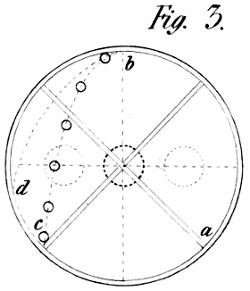
The third figure, in Plate 33, is a sketch of the common
Wash or Dash-wheel. The pieces of calico (or other goods)
are put into it through the round holes, dotted in the figure;
and, by the revolution of the wheel from right to left, are
carried up from a to b, or nearly so; from whence they drop
by their weight to about the point c, where they meet the angle
formed by the circumference of the wheel and one of the four
arms or partitions, by which it is divided. If the wheel go too
fast, the line of falling becomes more like the curve b d, and
the goods strike the circumference too high, and in an oblique
direction;—whence the blow is reduced, and the washing
becomes imperfect. If, on the other hand, the wheel move
too slowly, the pieces slide down the ascending partition (a)
before it comes to the vertex, and thus only fall from the axis
to the lowest point of the wheel;—whence, also, an inefficient
stroke. Thus, do these wheels require a moderate velocity:
and they are reckoned to do their work best when making from
22 to 24 turns, and giving, of course, four times that number
of strokes per minute.
The produce of these wheels is thus circumscribed by a
natural cause that cannot be altered—namely, by the law of
falling bodies; and my Invention has in view to elude the
shackles which confine this process, and to produce a much
greater effect in the same space,—the same time,—and with
the same expence of workmanship.
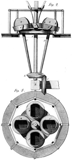
To this end (see figs. 2 and 4, of the same Plate) I place two,
four, or more boxes a, b, c, d, on as many wheels e f, toothed
on my Patent principle; the latter, in the present case, being
about two feet in diameter, and the boxes, in length, three
quarters of that diameter: and of any convenient width,
according to the size of the pieces. The wheels e f are mounted
on the strong shafts C D, which run, below, in the wheel E;
and by which, also, they are turned round the common centre,
by means of the vertical wheel F. Further, in the centre, and
between the wheels e f, I place the bevil wheel i, of half the diameter,
in which the main shaft runs loosely, and which is itself fixed
to the upper frame work, so as not to turn at all. The three
Patent teeth at e i f shew that these wheels are to geer into
each other on that principle: and it is likewise seen that this
whole mechanism is included in a set of rails, of an octagonal
form, for the purpose of preserving the men from danger, while
in the act of charging and discharging the boxes. And here it
is worthy of some remark, that this process must be easier, and
more quickly performed, with these open boxes, than through
holes made in the vertical side of a Dash-wheel, on the usual
principle.
To account, now, for the sloping position of the shafts C D,
and the consequent slope of the boxes, they are thus placed, in
order that the goods may not drag too much on the bottoms of
the boxes, when passing from one end of them to the other.
Instead of this, they are, in fact, thrown, by the centrifugal
force, from the inner angle h (fig. 2) to some point k up
that side of the box which is then outwards; where they
strike, and then fall into the contiguous angle under k, to be
again projected thence, after one revolution round the common
centre; for, it should here be remembered, that, by the given
proportion of the wheels, the circulating wheels e f turn on
their own axes exactly one half round, for every whole revolution
round the common centre A B.
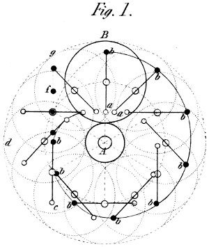
To elucidate this still further, I have outlined, at A fig. 1, the
central wheel i, of fig. 2, together with one of the excentric
wheels B, and the lines a b, a b, &c., representing the boxes,
are supposed to be wires with the balls b b, &c. sliding on
them, as is usual in some experiments on the Whirling Machine—(See
“Ferguson’s Lectures,”) Of these wires, I have
given the true directions in 12 positions of the wheel B: the
epicycloid b b b, &c., shewing the steps by which the ball b is
brought toward the common centre, during three quarters of the
revolution; and also the position of the wire on which it slides:
where it is evident that the ball b has a tendency to preserve
it’s station, at the first end of the wire, until the latter takes
the position b b c, when it forms (or nearly) a tangent to the
curve, and is, at the same time, at right angles to the radius
of motion, A b d. From this moment, then, the ball is free to
leave the centre, and to fly off in a tangent with the velocity
with which the curve itself is generated at that point. We
might, thus, during the rest of it’s flight, seek it somewhere in
the line b f g; but, as the wire continues to change it’s position,
and must turn half round on it’s own axis, by the time it arrives
at B b, or describes a quarter-circle on the common centre, it
will again overtake the ball—and, giving it a curvilinear
direction, will finally carry it to it’s other extremity, at or near
the point B—where it’s motion first began: and thus shall we
give as many strokes to the ball, as half turns to the wheel B;
or, in other words, as many dashes to the cloth, as we give
turns to the boxes, round the common centre.
By this process, then, substituted for that of the common
Dash-wheel, we can increase almost indefinitely, the number of
passages of the cloth from one end of the boxes to the other;
and the force of the dash will be as the squares of those numbers;
since (as Ferguson expresses it) “a double centrifugal
force balances a quadruple power of gravity.” If, then, with
four boxes we turn this machine 60 times in a minute, we shall
have 240 strokes in that time, instead of about 90 given by a
common Dash-wheel; and this difference might be more than
doubled, if so desired: for should, then, the stroke be found
too severe, the boxes might be shortened, so as to lessen it’s
violence, though preserving all it’s frequency.
There are two other objects that present enough analogy to
this Washing process, to be here mentioned. The first is the
operation of Fulling, as applied to woollen cloths in general.
That process, I fear, is not performed at present in the best
manner possible; and I feel persuaded that the centrifugal
motion might be applied to it with advantage—whether as to
quantity of produce, or perfection of effect: and having thus
said, I shall leave the idea to the riper judgment of my
manufacturing readers.
The second object I shall just introduce is, that of Kneading
Dough, for bread, by the same centrifugal agency. It is well
known, that an ingenious baker, of Paris, invented, some time
ago, a method of kneading; which consists in letting the lump
of dough fall successively from the four sides of a square box,
revolving on a horizontal centre. As this idea seems to have
succeeded perfectly, I offer the Centrifugal System, as tending
to quicken, almost indefinitely, such a process; and I particularly
recommend it to the attention of Government, and of
all large establishments as a mean of doing well and rapidly,
by power, what is frequently done slowly and ineffectually,
by the usual methods. Verbum sat.
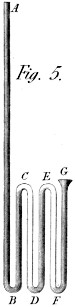
I call this an Hydraulic Lamp, to distinguish it from the
Hydrostatic Lamps, commonly so named: and I think the
distinction proper, because this Machine acts in a different
manner. It’s principle will be seen in a moment, by turning to
the 5th figure, of Plate 33. If, there, we pour oil (or any
liquid) into the bent tube A D G at A, the first effect will be
to raise it to C, in the rising branch B C; and from C it will
trickle down the branch C D, leaving the air, there, to occupy it’s
own place. Continuing to pour, slowly, more oil into A the trickling
oil in C D will ultimately fill the rising tube E D, expelling
the air before it; and, now, the weight to balance the column
in A B will be both the columns B C and E D; whence, of
course, that column will rise as far above C as C is above
B; that is, half-way between C and A. Here, there would be
a small deduction to be made, if the height B C were considerable;
but, as it is only supposed to be about a foot, the compression
of the air in C D, &c., (being about 1⁄3 of a foot or 1⁄90
of an atmosphere) may be neglected. Continuing, then, to
pour oil into A, we shall again fill, not the descending tube
E F, but the rising tube F G; whose column will thus be to
be added to those B C and E D; so that now the column A B
will rise to A, and there abide, as long as the mouth G is kept
full, or nearly so.
The above is the principle of the Lamp announced in the
title; whose effect depends, then, on the number of bends made
in the tube A D G, which number (whatever be the form) it
would be well to make rather greater than smaller, as the
height B C, &c., might be so much the less, compared with the
whole height of the column A B; by which means, also, a
smaller difference in the level of the column below, would return
the oil necessary for the consumption of the wick above.
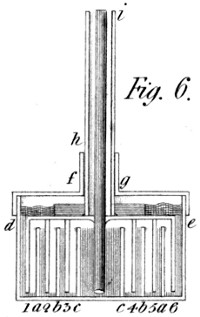
I have given this idea what I think a better form in fig. 6.
Instead of the bent tube A G, of fig. 5, this form supposes a
series of air-tight cups, embracing each other; one half of them
with their mouths opening upwards, and the other half with
theirs opening downwards. They are shewn, by a section only,
in this fig. 6; where a b c, c b a, present the under cups, forming
one piece with the outer surface of the bottom vessel d a c,
c a e: and, while speaking of this part of the Machine, I would
just indicate it’s cover d e f g put on like the lid of a snuff-box,
and carrying a case or tube f g, the use of which will be
mentioned in a moment. To proceed, then, the upper vessel is
shewn by the edges of it’s cups seen immediately over the
figures 1 2 3, 4 5 6, placed between the letters a b c, &c.—These
inverted cups make also one body with the moveable
cover shewn between d and e, and to which is soldered the
tube h i—which, sliding in the case f g, keeps this inverted
vessel steady. Where note: that there is an inner tube soldered
into the tube h i, through which alone the oil rises, and which
can hardly be made too small, since it has only to supply the
consumption of a lamp—namely, a few ounces of oil in a whole
evening. We may, finally, take notice of the weight placed
under f g, upon the said inverted vessel, and which helps to
counterpoise the oil in the rising tube h i; which tube, as before
observed, may be as many times higher than the distance
a d or e a, as there are rising columns between the cups a b c
and those 1 2 3, &c.
I am not wholly prepared to say what portion of the oil it
might be best to re-elevate by the pressure of the aforesaid
weight f g; but, if it were a considerable part of that contained
in the central compartment c c, that column would be shortened
in proportion; and the reservoir at i would, doubtless, feel the
want of it to preserve it’s level. I think, therefore, it might be
well to use, below, a cup or two more than sufficient, so as to
raise the main column higher than actually wanted; and to
coerce this rising tendency, by a small stop-cock in the rising
branch, to be gently opened at the will of the person using the
lamp. I cannot say I have exhausted this subject; either
in these respects, or as to it’s technical capabilities. But I
have fully tried this method of raising oil above it’s level; and
used, for some time, a lamp made on this principle, and which
is still in my possession: and, at some future time, I intend to
bring forward an Hydraulic Machine, founded on the same
principles.
It is not supposed that this Essay can lead, immediately, to
any result of magnitude; but it is thought to be a subject
capable of further extension, and thus, finally, of future
usefulness. Were this process only sufficient to supply a single
house with water, at a small expence, the labour bestowed
on it would not be altogether in vain.
By General Roy’s experiments, cast iron (and steel) expanded
by 180° of heat (or, by passing from the freezing to
the boiling point of Fahrenheit) 0.013 of an inch per foot.
Supposing, then (Plate 34, fig. 1), the tubes A B C to be
20 feet long, their whole expansion will be 0.26 hundredths of
an inch. But, as the tubes are placed in the figure, the half
tubes A D B D act together on the sphere D, and, both
together, drive it in the direction E D, more than as the above
expansion, in the proportion of the line E D to that A D.
Taking, then, one half only of the above expansion = 0.13
hundredths of an inch, that must be augmented in the ratio of
the sine of 60 degrees to radius, or in that of A D to E D. I,
therefore, multiply this decimal 0.13 by the fraction 1000⁄866, which
gives 1300 to be divided by 866, or very nearly 0.15 for the
expansion, in the direction E D, occasioned by the two half
bars A D B D: and the same is true at the other angles F
and G.
Again, to find the expansion (and contraction) of the bars
a b c, we must compute their length as compared with the half
tubes above-mentioned; and that length is to 10 feet (the half
tube A D or B D) as 866 is to 1000 = 11.54 nearly: the expansion
of which is thus found:—if 10 feet expand 0.13, what
will 11.54?—Answer, 0.15. Now, as the machine acts by
the heating of the pipes A B C simultaneously with the cooling
of the bars a b c, we must add the former expansion to this
contraction, which gives us 0.30, or three tenths of an inch for
this combined effect at the three angles of the Machine. And,
supposing, now, any pair of bars to act directly against each
other, as at H I K; and that, further, the bars be stretched
until the angle with the horizon be only 2 degrees, then the
vertical motion at I will be to the horizontal (arising from the
expansion aforesaid) as 1000 to 35, the sine of 2; that will be,
in round numbers, 28 times as great, or 28 times three tenths
of an inch = 8.4 inches, which is the stroke of this Machine in
these dimensions.
In this calculation, I have not forgotten that the vertical and
horizontal motions are nearer alike, when the bars are not
drawn so tight at K H; that is, when the joint I is lowered.
But it is equally true that, when the joint I rises still more, the
difference between these motions is still greater; so that, as a
medium effect, I think we may reckon on an eight-inch stroke
in the present case.
The question now recurs, of what strength are these strokes?
Are they sufficiently powerful to produce a useful effect with
so short a motion? This I cannot say from experience; but,
from the known strength of iron and steel, their power, in these
dimensions, must be very great. A few more observations
may occur in the course of the enlarged description we shall
give of the Machine itself.
A B C are three pipes of cast iron, well turned at the end,
and having conical points of iron, well steeled, let into them,
so as to have no tendency to bend. a b c are three steel bars,
placed in troughs, so as to be heated or cooled by water poured
into the latter. Or, these troughs may be exchanged for tubes,
to admit heated or cooled air, according to the means used to
cause these mutations. In a word, although I have represented
these bars as contained in troughs, I intend to finish my description,
on the supposition that they are tubes, because I
intend to suppose the Machine worked by air instead of water.
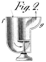
To proceed: at d is an opening under the tube B, into which
air enters, and C is an opening on the top of the tube which
emits the same air, the three pipes being made to communicate
by means of a short junction-pipe at each of the angles D and G.
Here, then, the fire-place f g, fig. 2, must be noticed: the use of
which is both to heat and cool the Machine; and the following
are the means:—This little instrument contains fire in it’s
middle compartment, and that fire draws air into the part f,
and drives it out of the part g. It also turns on a centre-pin,
seen in the figure. This chaffing-dish, then, is placed at i d,
and there serves a double purpose. When it’s pipe g conveys
heated air into the pipes B A C (and out at C), it heats those
pipes and expands them; but, at the same time, the pipe f
of this instrument draws cold air through the three tubes a b c,
in which are the steel bars that require to be contracted: both
which operations conduce alike to the above-described effect.
By these means, the weight w is raised, and (for example)
water sucked into the pump X. But, turning the fire-place
half round, we reverse this effect. The hot air is now drawn,
out of the pipes A B C, and cold air drawn through them, by
which they are cooled; while the hot air, from the fire, is
thrown through the pipe g into the tubes a b c, and passing
through the chimneys k l, there heat the bars and expand them,—both
which operations concur in letting down the weight E,
and thus, in forcing the water of the pump to whatever destination
was previously assigned it.
Many people, in these parts, have seen a certain machine,
said to have been invented by an inmate of that laudable institution
the Liverpool Asylum for Blind People; for the purpose of
making laces, covering whips, &c. I hope the similarity of
name will not induce any reader to suppose that I have had
that machine in view, and am endeavouring to cast it into
the shade, or purposely to supersede it. If any person should
thus think, I have a safe reply at hand. My own invention
(somewhat less perfect than it now is) was made, many years
ago, on purpose to serve an Asylum for the Blind in Paris!—a
reflection with which I shall, at once, close this, perhaps,
unnecessary apology.
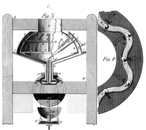
This Machine is represented in Plate 34, at figs. 3 and 4. It
consists of a frame of wood or metal A B, on which are
mounted the following objects:—1st, on the traverse B, a fixed
tube, having for it’s base the horizontal plate a b, and rising
perpendicularly to near c d; where it unites with a conical or
trumpet-like vessel c d, f e; the left side of which is shewn in
perspective, and the right side in a section only. To this
fixture is adjusted the spherical portion g h, h, prepared to
receive several cuts or slits 1 2 3 for the bobbin-slides hereafter-mentioned,
to slide up and down in. This leads us to observe
the upper fixture C, which is a cylinder, terminated downward
by a spherical dome i k, k; also receiving the several cuts
4, 5, 6, into which the aforesaid bobbin-slides pass from the
former slits 1, 2, 3, &c. Now it will be seen that the two
spherical parts thus fixed, are separated from each other by the
circular and horizontal slit l m, whose use is to permit the
pipes shewn in the section at n o, to circulate all round the
machine, while the bobbin-slides and bobbins k p are sometimes
above and sometimes under the said slit l m.
Now, then, it becomes necessary to speak of the cause of
this passage of the bobbin-slides from the under to the upper
parts of the slits 1, 4, 2, 5, and vice versa. That cause is in
the second dome q r, which covers, as far as it rises, the inner
dome f i, k h; and it consists in a serpentine canal, of which a
section is given to the left of q, and at s, in the section of the
principal figure.
But to make this important piece of the Machine better
known, I have drawn it apart, in figure 4, on the supposition—that
it is a portion of a cone instead of a sphere: I say a cone
drawn with the radii t q, t r, according to the dotted line t r.
The surface then of this cone, is supposed straightened in the
lateral figure; and the aforesaid serpentine canal is shewn at a b
c d e, having the rollers of the bobbin-slides placed in that canal,
at the same points a b c, &c. Here also, certain dotted lines
f g, h i, &c. shew the relative positions of the slits 1 4, 2 5,
&c. of the principal figure, and also of the horizontal slit l m:
whence it appears, that the revolution of the bent canal, a b
c, &c. must some times drive the rollers towards g i, &c. and
sometimes towards f h, &c. while the pipes n o pass undisturbedly
round the Machine, in the horizontal slit l m of
both figures.
The question now arises, how is the circular motion given to
the outer dome q r of the principal figure? that dome is
screwed to the cone r v w r, being itself of one piece with the
hollow tube v w, on which the wheel x y is fixed. Now, this
wheel x y, is driven by a vertical wheel z, of twice the diameter,
for a reason we shall soon disclose.
It remains now, principally, to speak of the drawing-system
of this Machine, shewn, in small, at c, and of a natural size in
fig. 5 of this Plate. That Machine has also it’s own tube c x′,
working inside of the fixed tube a b, &c. and terminated, at
bottom, by the wheel x′, which turns it by means of the second
vertical wheel x′ z, fixed on the same axis as the wheel z
before-mentioned, and of half it’s diameter.
Supposing then, for the moment, that the mechanism c
derives from it’s circular motion, the property of drawing
downward the threads from the pipe n o, and the bobbin p;
(being one of the twelve pair distributed round the Machine)
we shall now set the Machine at work, for the purpose of
viewing it’s operation a little more narrowly. Looking at the
two kinds of texture, indicated in the figure below the traverse
B, we see that on the left composed (in weavers’ language) of
a straight warp, crossed by an oblique weft; and this I believe,
is the common texture of round, small ware, as usually woven:
the slope of the weft being less and less as the number of
shuttles diminishes, insomuch that with one shuttle that slope,
might become almost invisible. But in the work made on this
Machine, where, virtually, there are as many shuttles as threads
in the chain, the slope would become very perceptible, too much
so, perhaps, to give a desirable appearance to the work;
although the rapidity of execution, from the multitude of crossings,
would compensate for some imperfection of that kind.
But, in fact, this Machine is intended to make a diagonal or
diamond texture, as in the specimen to the right hand: and
that is the object of the two pair of wheels x y, with z; and
x′ with x′ z before mentioned. Their effect is this: when the
large vertical wheel z, has turned the outer dome and the pins n
o, once round the common centre, the smaller vertical wheel
x′ z, has turned the drawing-system c, just one half as much
round that centre, and thus sloped the threads coming from
the fixed slits in which the bobbins move, as much, in one
direction, as the whole turn given to the pins n o, has sloped
the other half of the threads in the other direction, and the
result has been the aforesaid diagonal texture.
There are a few other things to be observed by way of closing
this article. As the Lace, or Cord is made on the Machine by a
turning motion, it must be received below into a turning vessel,
or it will be twisted, and thus injured. The vessel D, is
provided for that purpose; and is turned by a cord from a
pulley on the axis of the wheel z, coming under two vertical
pullies, and acting on an horizontal pulley F E, connected
with the said vessel; and if preferred, the draught itself might
be placed in, or above, the vessel D, but it would not, I think,
produce so perfect an article.
With respect to the drawing Machinery in the Machine at
c, there is shewn, a flat surface just under that Machinery.
It’s purpose is to serve as a mover for that System: To shew
which, in a clearer manner, is the use of the fifth figure. In this
figure, the drawing rollers turn in a frame a b b, and carry
on one of their shafts a cog-wheel c or d, by which they
receive this motion from the pinion e; this pinion being
connected with the rowel f g, and running with it on a
stud h, more or less removed from the centre, as circumstances
may require. This rowel then, (for it’s edge, formed
as in the figure, is indented with sharp teeth across it’s
face) runs on the flat surface before indicated, at or near e,
(fig. 3) and by the rotatory motion received from the wheel x′,
gives a drawing motion to the rollers, the use of which has
already been explained; namely, to draw down the goods as
they are formed. It need hardly be observed further, that any
kind of filling may be brought down twisted from C, to the entrance
of these rollers at c, and thus be included in the plaited texture;
and in fact, the rollers in fig. 5, are shewn (by the dotted
lines) as formed to receive an object of considerable diameter,
as a whip, &c. that it may be wished to cover. Where I
remark, that this lozenge form of the grooves O, is not given
without a motive: the grooves are thus formed (the cylinders
being supposed capable of opening by a springy movement) in
order that, if desired, they may draw the body downward, so
much the faster, as it’s diameter increases—and thus keep the
covering threads at the same angle in every case. I shall only
add, that these movements can be permanently determined by
wheels, when the rowel f g, acting on the horizontal surface
c, has fixed the real velocities of draught required for a given
purpose.
This Machine then, is capable of excellent results, and of
a speed almost inconceivable: since at every turn, if there
are twelve bobbins p, and twelve pipes n o, it makes twenty-four
passages of the threads among each other, answering, in
some cases, to an inch in length of the fabricated texture; so
that, counting 120 turns per minute, (which is moderate) we
have 2880 passages, and 120 inches of work in a minute;
equal to 200 yards per hour—a quantity which does not yet
limit the produce of this Machine.
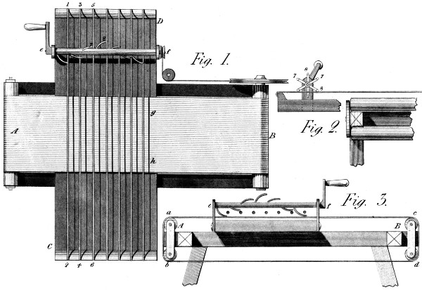
This Machine is represented in figs. 1 2 3 of Plate 35. It
is composed of a frame A B, on which are placed two sets of
rollers a b, c d, round which is stretched an endless feeding
cloth, on the upper surface of which the Cotton is laid by the
attendant. Across this frame A B, is fixed a strong board C
D, having a ledge or bridge at each end, over which are
tightened the cat-gut strings 1 2, 3 4, &c. Moreover, across
this board, is fixed on proper bearings, (placed either straight
or diagonally) the axis e f, furnished with any proper number of
iron fingers 7 8, &c. which spring the cords 1 2, 3 4, &c. every
time they pass by them: where it may be observed, that by the
varied forms of the ends of those fingers, the vibrations are
made to be vertical, horizontal, or oblique, at pleasure. In
fig. 2, these fingers are seen from one end of their axis e f—and
in figs. 1 and 3, they are shewn sideways: and in the
latter figure, the strings are shewn as small circles between e
and f, with the feeding cloth a c, stretched under them.
The following then, describes the effect of this Machine:
The Cotton being laid on this feeding cloth near B, is gently
drawn under the vibrating cords at g h: for while this takes
place by the action of the handle at e, the pulley f by the cord
i, gives a slow motion to the cylinder B, and by it to the feeding
cloth B A g h. The Cotton then passes under the strings
toward B A, and is greatly agitated in the passage; and when
arrived at A, it falls into any proper receptacle—whence it is
taken to undergo the succeeding operations of the factory. I
would just mention, finally, that the axis e f, though here
supposed to be turned by the handle e, would, of course, receive
it’s motion from a proper power; set on, or stopped by
the usual methods.
This Invention has for it’s object, to make a more abundant
use of the wind’s agency, at a given expence, than is usually
done: and the means, generally, are to avoid a part of the
expence lavished on the foundations or fixtures of wind-mills,
and yet to carry more sail than that system admits of. Machines
of this nature, are chiefly used in low marshy countries,
where there is much water to be raised, and little solid ground
to build on. My idea here, is to found the whole on the
water, and to make that element the medium, and as it were
the centre of every motion.
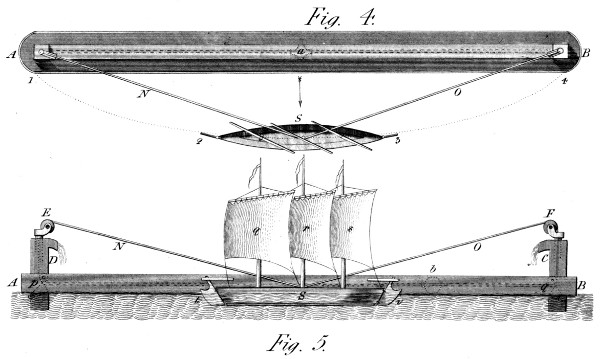
Let us then suppose already constructed, the long and
narrow boat A B, figs. 4 and 5 of Plate 35:—and that there
is contained in the middle of it’s width, a cylindrical pipe of
iron, (or a square wooden box) of equal length, serving as a
pump, by means of a spherical or square piston a or b, drawn
from end to end by the means soon to be described. The cost
of such a pump-barrel would not be great, though it should be
of considerable length—(even 300 feet would not cost so many
pounds). Now, at each end of this vessel A B, there would
be raised a vertical part of equal size C D, surmounted by a
caster, (E F) turning, horizontally, on a hollow centre,
through which a rope would pass from the aforesaid piston,
(a or b) to the boat or ship S, which is the primum mobile of
the System. This boat would further be made to carry as
much sail as possible, and to encounter as little resistance as
possible from the water. It’s properties of carrying sail, might
even be enlarged, by the use of one or more out-riggers, as
is done in various eastern countries.
It would be proper, likewise, to give the vessel a rudder at
each end, and to reverse her motion by changing the sails,
without tacking. This is also represented in the two figures
4 and 5: and, in the present case, the vessel is rigged with
three masts, and three large sails nearly square, yet somewhat
deeper on the lee side than to windward, to make the sails the
more governable, though as large as possible. Supposing now,
all these things arranged, and the rope N O fastened to or near
the middle of the vessel, and to the aforesaid piston over the
pullies of the casters E F; then, if the vessel sails in the long
ellipsis 1, 2, 3, 4, the sum of the two portions of rope N, O,
will be always the same; and, the wind coming from a, in
the direction of the arrow, she will sail advantageously from
1 to 4, or the contrary, carrying the piston from end to end
of the pump; and thus exhausting it at every passage; and
filling it again from the lower water.
To recapitulate—and bring the several parts again to view; S,
in both figures, is the vessel, supposed of the best form for
carrying much sail: E F are two casters with their pullies;
p q are two pullies at the bottom of the vertical barrels C D,
under which the rope passes to the piston at a or b, &c. In
fine, q r s are the three sails, and t v the two rudders, by
which the vessel is steered in either direction, so as to keep
it’s wind without causing too much stress on the rope N O.
This consideration involves another, which must now be cleared
up: namely, how can this mechanism be made to produce the
same effect in every direction of the wind? I answer, the whole
System must be moored at one end A, in the strongest manner;
while the opposite extremity B, shall have liberty to
veer round that point, as a centre, through 90 degrees of
a circle; some one position, between which extremes, will suit
every wind, on this condition, that the vessel by it’s rudders,
keel, &c. be able to keep her ground, although the wind should
come from the convex side of the ellipsis; a thing by no means
impossible, though less desirable than the state first represented.
Thus it appears, that I expect the favourable result of this
System from two sources: the first, (but least) from the length
of this pump, which permits much water to be raised without
much agitation; and second, from the quantity of sail it is possible
to carry by this method, compared with the sails of a wind-mill.
My idea is, indeed, that since the power of the wind is so
boundless, we ought to use it more liberally than we do: and I
am persuaded, that ten times as much work might be done at
a given expense, by such means as these, as can be done by
the usual methods.
Before I quit this subject, I would just observe, that there are
many situations in which this powerful agent might be made
useful, in conjunction with water power, as applied, perhaps, to
encreasing works, and being itself incapable of proportionate
extension. Thus, there are many water mills (used for various
purposes) that are obliged to wait the re-filling of the mill
pond; and which, therefore, lose much time, although the
wheel would be capable of doing even more work than is actually
wanted. In fact, it often happens, that the worse the
supply of water, the better is the wheel: for this has been
sometimes thought a mean of making up the deficiency. In
such a case then, a cheap wind apparatus might double or triple
the effect of the wheel, and the produce of a given establishment.
But it will be objected, that the wind is an uncertain
helper! and thus less fit to be resorted to. This I acknowledge;
but still say, that could it be used when only a breeze or a
zephyr, it’s utility would be much extended; and this is
another consequence of a system founded on the application
of much sail to a given purpose. Still however, as nothing
absolutely conclusive can be said on so variable a subject, I
shall not now lengthen this discussion.
It is important, in most machines, to avoid oscillatory
motions:—which uniformly protract the time of an operation,
or require a greater power to perform it. This consideration
has given rise to the form and properties of the Machine I am
about to describe.
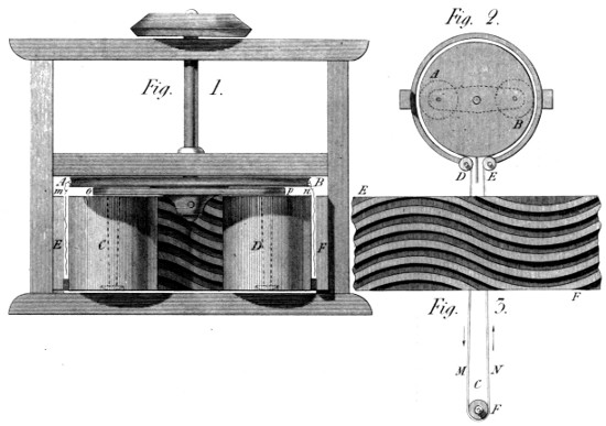
In Plate 36, figs. 1, 2 and 3, represent this production. The
first is an elevation; and the second is a plan, serving to
shew the manner of feeding the Machine. To speak first of
the second figure—A B is a pulley, (shewn at large in fig. 1,
and marked with the same letters;) it’s use is to receive the
endless cord C D E, which is composed of three strands,
like the apparatus of a peruke-maker; these strands being
divided at F, and passing there over three pullies placed at a
proper distance on the same shaft F. These pullies are
gently turned by that shaft, and carry with them the afore-mentioned
triple cord, to which, in the passage toward the
Machine, have been woven small handfuls of flax, by the same
process as the barber uses to fasten the hair of a wig; one
difference however obtains: the flax is knit to the cords at it’s
small end, and within a few inches of it, so that the root-ends
hang pendent, and when that part of the cord enters beyond
the pulley E, those ends hang round the large pulley A B,
against the grooved surface of the outer rim: The method of
grooving this drum is better shewn in fig. 3: and it should be
noted, that the smaller drums C D, are grooved in a similar
form, their diameters being such as to divide exactly, in some
ratio, the outer cylinder E F. In fig. 1, two portions of these
handfulls of flax are represented by the waved lines m
n, drawn between the cylinders C D, and the section E
F of the said outer cylinder; where it is evident, that if
these cylinders had, in that place, teeth like those of fig.
3, these handfulls of flax would appear bent—which is indeed
the process by which the wood is broken, and the filament
divested of it. It appears also by the figure 1, that the cylinders
C D, run on centres, fastened only to the pins of
the cross piece o p, (shewn by dotted lines in fig. 2.) These
cylinders I say, are thus mounted, that there may be no
centres below, to gather up the flax or wood, and thus embarrass
the motion of the Machine.
Adverting then, a second time, to the second figure, the
flax is fastened in small handfulls, to that part of the endless
cord that goes toward the Machine; namely, F E, and
taken off from that part which comes from the Machine behind
the pulley A B: so that the triple cord before mentioned,
there consists of three cords, and passes round the separate
pullies at F. The flax being thus taken off at M, is handed
to the charger at N, and re-fixed to that cord by it’s
other end—so as to be finished by a second passage. It
would be superfluous to add, that the waved form of the grooves
in the cylinders, is intended to break the flax at every point of
it’s passage before those grooves
as conducted by the large pulley A B, (in the centre of
which the main shaft turns without giving it any of it’s own
motion) the said pulley A B, being turned, as before stated,
by the triple cord from the slow motion of the pullies F in the
figure.
Having heard it observed by some Calico Printers, that
there is more or less of inequality in this process as usually
performed; and that some parts of the goods are exposed
to be more acted on than the inner parts, I have thought
the following Machine would be useful, both to equalize and
accelerate that operation.
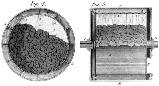
In figs. 4 and 5 of Plate 36, A B is a hollow cylinder, running
on two gudgeons C D, with a very slow motion, and thus,
requiring very little power. One of these gudgeons C, is hollow,
for the purpose of receiving steam from a boiler, like those at
present used. The cylinder A B, is double, both around it’s
circumference, and at it’s ends, (see a b, c d, figs. 4 and 5).
It is also furnished with one or more doors E, through which
to introduce the goods; and which doors are afterwards closed
with screws, like those mentioned in the article “Washing
Machine,” of the third Part. The goods being put in, with
the usual doses of alkaline liquor, &c. the steam is introduced
through the gudgeon into the interstice a b, and thence
through proper openings into the body of the wheel, and
between the cylindrical partitions a b, c d, &c. By the
steam, the water acquires a boiling heat; and by the motion
of the wheel, is carried up in the boxes a b, &c. to the top,
whence it falls through proper holes upon the goods; thus
keeping them wet, and steaming them at the same time. The
figures shew the division of the liquor into several jets 1, 2, 3,
&c. which are constantly falling on the goods, as the process
requires. The 4th. figure shews further, the effect of the
turning motion of the cylinder A B; namely, that of changing
the position of the articles; and offering, successively, every
part thereof to the steam and flowing liquid: and thus, I
presume, must the Bowking process become more rapid and
equal, than that which takes place in a Bowking-keer, unaccompanied
with such a motion.
This Machine occupies a great part of Plate 37. It is represented
in figs. 1 and 2; the first being an inside view
of one of the cheeks; and the second, a view endwise—represented
as broken in the middle, to gain space in the Plate.
As far as possible, both the parts are marked with the same
letters.
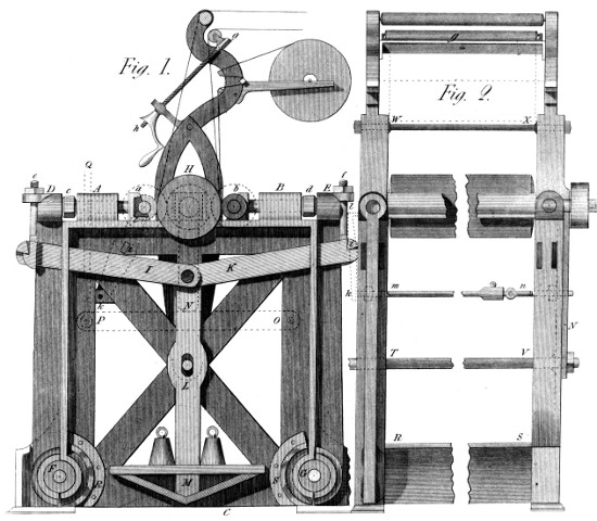
To begin with fig. 1, A B C is the cheek: being a kind of
shallow box with edges to strengthen it and give it thickness
for the steps a b, &c. These steps are strongly fixed to the
screws that slide in the boxes A B, and the nuts of which,
are seen at c d. The screws enter, besides, into the heads of
the perpendicular levers D F, E G, against which these nuts
press to set the cylinders, by their steps a b, against the bowl
H. This pressure of those cylinders a b is a modified
effect: for the levers D F, E G, are drawn inward by the
pulling bars I K; which, meeting in the centre of the Machine,
are pressed downward by the hanging bar L, to which
are suspended the scales and weights M, these being more or
less heavy according to the wish of the Printer. It were well
to mention a circumstance of some importance connected with
this subject:—If the bars I K form together an angle very
obtuse, the power of pressure is immense; and the weights at
M might be the lighter: But, then, the degrees of pressure at
different angles of the bars I K would vary too much, if
any excentricity of the cylinders a b, occasioned any motion. It
is therefore best to use a sensible angle between the bars I K,
together with a weight at M, so much the heavier; by which
means these motions will be the more mild and manageable.
Proceeding with the description: e f are two hooked screws,
by which the pulling bars I K are raised, when necessary, so
as to increase the nip in any corner of the Machine, without
affecting the rest. It should be observed also, that the steps
a b, have dove-tailed slides screwed to them from under the rim,
and in it’s thickness, to make them move more correctly, when
pressed horizontally by the nuts c d. The upper works of this
Printing Machine are not greatly different from those of the
common one. In one respect, however, I think them superior.
The roller, prepared for the returning blanket, is mounted in
a frame g, (fig. 2) which moves on a pin in the centre of the
Machine, insomuch that one screw and nut h, suffices to regulate
this return. This then, is an improvement, as the
printer has but one operation to perform instead of two. The
use of the piece-roller is the same as usual; and the goods are
carried down on stretching bars, &c. exactly in the same manner.
But a more important property of this Machine remains to
be noticed, The two cylinders a b, are made to press diametrically
across the centre of the bowl H; so that it’s shaft suffers
no friction from that pressure. And hence, this two-coloured
Machine requires no more power to work it, than a common
machine for one colour.
A further property of this Machine deserves attention; but
for want of room on the Plate, we are obliged to describe it by
means of dotted lines on the face of the present figure. At a b,
and at H, we have dotted three toothed wheels, of which one
is keyed on each of the mandrels, while the central one
is placed in a frame, forming part of a slide N, (fixed on the
plate N of fig. 2) and by which this wheel is moved up and
down at pleasure. Here it is evident, (see again fig. 1) that
if this central wheel rises, it will turn the mandrel a, backward;
and the mandrel b, forward: and this is a peremptory
method of increasing or lessening the distance between any
two points on the cylinders; or in other words, of fitting the
colours of one cylinder into those of the other—an operation
which is thus performed by a single movement; while in other
machines it is necessary to go on both sides of the machine to
produce the same effect. In a word, this process is completed
in a few moments, by turning backward or forward a nut like
that h, applied to the screw placed against the side of the
Machine, as at P Q.
But we have another important property to speak of. The
colours on the two cylinders must be fitted in, laterally, as well
as longitudinally: and the Machine performs this by an easy
method. At each side of the Machine (see figs. 1 and 2)
is fixed on a centre i, a short lever k l, the bent end of
which (l) rises just to the brass step which carries the mandrel
of the cylinder a, and is formed so as to push that step inward,
when it’s end k is pressed outward; which latter motion is
occasioned by the screw m n, which goes all across the Machine,
and performs the same office on either side as wanted.
This then, is another economy of time and pains; this setting
being usually done by passing round the Machine, from
one side to the other.
Finally, R S shews one of the cross-bars by which the two
cheeks are connected. They are formed as portions of a
hollow cylinder, and screwed to the cheeks through flanches,
the breadth and form of which give considerable strength to
the Machine; which is further strengthened by the bars T V
and W X, in it’s upper parts.
In the above description of this Machine, (in which the parts
common to other machines are omitted) I have endeavoured to
avoid all invidious comparison: and have only said what my
additions appear to warrant, and what, I am persuaded they
will justify, when this Machine shall be compared with others,
placed in the same circumstances for the sake of liberal comparison.
I confess, I again stand on a kind of forbidden ground;
and am uncertain to what degree this Invention will justify it’s
title. Yet I think myself safe in expecting it will produce an
useful effect. But the fact is, I never fully proved it: the
apparatus with which, more than twenty years ago, I was
trying the System, having broken in the experiment—which I
then had no opportunity of resuming.
I had then, as formerly, asked myself a question, viz:
“will not the centrifugal force of a heavier body, suspended
(without chemical action) in a lighter fluid, increase the subsiding
tendency, and quicken the clearing process?”. I then
thought “yes,” and do not yet see why it should not. But not
having any absolute fact to build my conclusions on, I must leave
the whole matter to time and experience; and crave the candour
of my readers in favour of my somewhat bold assumption.
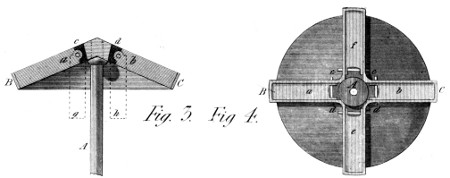
This Machine then, which is to purify muddy liquors by motion,
is thus composed: a perpendicular axis A, (Plate 37, figs. 3 and
4) turns very swiftly, surmounted by a conical cap B C, so
formed, as to receive and lodge in it’s thickness, four or more
vessels a b, f e, which hang on pins c d, near that centre
and have the liberty of leaving it by the centrifugal force, round
the said pins, until lost in the thickness of the cap above mentioned;
where they turn on the common centre, without
suffering any resistance from the surrounding atmosphere.
This conical cap B C, &c. is made as light as possible, by
protuberant ledges, but it’s solid form would be restored by
lighter substances fixed between the arms, so as to add little to
the friction or resistance of the whole mass. Any turbid liquor
then, being introduced into any pair of these vessels while in
the position g h, fig. 3, and put into swift motion, will have
it’s muddy particles thrown from the centre, and (I presume)
soon deposited at the greatest possible distance from that centre:
since, although the centrifugal force will add, in the same
degree, to the tendency outwards of the particles of the liquid,
and make them gravitate more towards the circumference;
that force will not render the liquid less fluid—which, therefore,
will suffer the clearing process to take place sooner with
motion than without it; and this is all I dare advance in the
present state of my knowledge on this subject. Thus have I
again reckoned on the kind forbearance of my readers, and
risqued a little more of “the bubble reputation.”
My readers will supply one remark I had omitted—which is,
that if bodies heavier than the fluid, recede faster from the
centre by this motion, than without it, lighter bodies will
approach toward the centre, and be there collected for the
same reason—another cause for which, will doubtless be the pressure
occasioned by this centrifugal force in the revolving fluid.
I have said, and shall still say, much on the desirableness
of making use of a greater portion of that gigantic agent—Wind,
than has yet been customary. This article is another
attempt to urge it’s propriety. But it will be of no use to those
who cannot extend their views beyond the present state of
things, to that possible state which every successive mechanical
improvement appears to anticipate or promise. These speculations
of mine, suppose extensive means and extensive necessities:
and they promise results still more extensive. In a neighbouring
kingdom, where the country is, as it were, redeemed yearly from
the ocean’s grasp, what would not it’s inhabitants give for a security
against the encroaching tide? or the means of saving
several months to agriculture, by the speedy disembarrassment of
it’s fields from the common destroyer of health and produce? It
is even said, that in the last winter, some dykes in Holland
were broken, and many lives lost by inundation: and in
our own country there is many a submerged spot, over which
there blows wind enough to drink up, or throw out, it’s last
particle. I submit then, the present means, as capable, with
proper modifications, of forwarding every analogous purpose;
and thus as worthy to occupy the attention of every friend to
rational improvement.
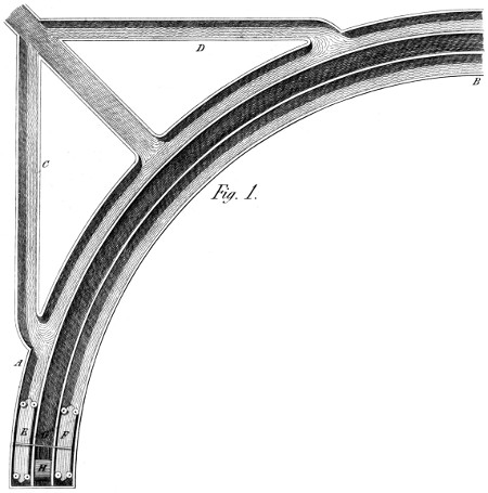
If my 38th. Plate were considered as a corner of any inundated
country, whose boundary were a dyke contiguous to
this chosen spot, I would propose building a long curvilinear
canal A B, of which the middle space should receive and contain
the lower water; and the two outside spaces the upper:
especially the outer circle, which should communicate with a
few branches C D, leading to and through the dyke before
mentioned. In the two outside canals should float a pair of
boats (long and light) E F, joined together by one or more
cross-beams G, which would produce the double effect of connecting
the boats so as to make them bear much sail, without
oversetting; and of carrying along in the middle or lower
canal a kind of water-drag H, that should take with it the
under water, and raise it’s level nearly to that of the upper
canals—into one of which it would enter through it’s lateral
valves, and thence flow into the eduction canals C D as before
stated. My idea will be better understood by referring to the
small figs. 2 and 3, at the bottom of the Plate: for they are,
one, the transverse section of the canals with the boats, and
the other a longitudinal view of one of the vessels in it’s
canal, with the water-drag H in the act of making (what is
technically called) a boar, of the lower water; and raising it
above the level of the valves I K, which open into the
canal.
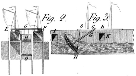
To recapitulate, E F in fig. 2, are the two vessels seen
sternwise, with their sails supposed very large: G the beam
that connects them; H the water-drag; and O one of
several valves which open from the lower water, and close
when the drag is going over them. In fig. 3, H is the
same water-drag, whose distance from the bottom is regulated
by the brace b: it’s beam or shaft, being fixed to the crossbeam
G, of figs. 1, 2, and 3.
Thus then, at one passage of this double vessel along the
curved canal A B, all the water in it’s middle compartment
will be raised into it’s outer one: and be thrown into the sea
through the canals C D, &c. It appears, near E F in this fig.
1, that the vessels E F, have friction pullies or wheels placed
horizontally on their decks, to act against the sides of the
canal and prevent the lee-way: thus converting the whole
effort of the wind to a useful purpose. And here I observe,
that if the wind blows in, or nearly in the direction of the diagonal,
then, the vessel would go almost from one end to
the other of the main canal without tacking, and thus do
an abundance of work at each return: for it is a common
thing for ships to sail nine or ten knots an hour! And here
note, that the present curvilinear form is given to the canal
in order to take all winds, (tacking more or less often) whether
coming from the inside of the curve or from the outside. I
cannot but add that in this Machine—in that I have already
given—or in those I may yet give, there is much to be found
that promises useful application in many an important position.
An example now strikes me. The reservoir at the Manchester
Water Works might furnish room for a floating Machine,
capable, on windy days, to do all the work of the steam
engine, and thus economize a good portion of the fuel it
consumes.
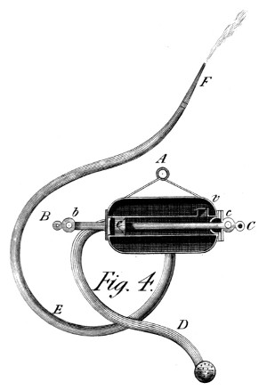
This Machine (see Plate 38, fig. 4) is intended to be carried
or conveyed in a small cart, to the place where an incipient
fire may be preluding to it’s fearful horrors! It is, as to form, a
common lifting pump, inclosed in a vessel of air, whose spring
perpetuates the jet in the usual manner. When used, it is held
on two men’s shoulders, by means of a bar going through the
ring A. Further, a rope is fastened to each of the extreme rings
B C: and a stick put through each of the second rings b c.
Two rows of men are then marshalled along the ropes; one set
to hold-on, and the other to pull in regular time, the piston c
along it’s pump, thereby sucking water through the pipe D,
and forcing it through the valve v into the air vessel: from
which it is forcibly expelled through the directing pipe E F.
Here it is clear, that this small Machine is capable of an effect
almost indefinite: since the rows of men may be very numerous;
there being always people enough at a fire. To
work the Engine by pulling, is nothing more than to repeat
many a nautical manœuvre: and if only one man in the company
should have learn’t to sing the sailors’ song, they would
soon produce—“a long pull, a strong pull, and a pull altogether.”
To be serious, a hundred men may as well work
at this Machine, as ten; and the effect will keep pace with
the cause. In a word, there is scarcely any limit to the
abundance of water, that might be thrown on a fire by such
an Engine as this; of which I shall say nothing more, save that
the bar of the piston rod at c, is intended to be used for
drawing it inward, by the efforts of two men, at each interval
in the effort of the working-men. A mere inspection of fig. 4
will fully shew what here remains unsaid.
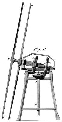
This Mill produces a double power, merely because it uses
two pair of sweeps or sails, both of which (though turning
opposite ways) concur in giving the same motion to the vertical
shaft of the mill. A B fig. 5, (Plate 38) is the shaft in question.
It has on it two bevil wheels or pinions o, b; bearing
the same proportion to their respective wheels: one of which
(o) works in the wheel C, fixed to the outer shaft a c, and
the other (b) in the second wheel D, which takes it’s motion
from the inner shaft E D. This latter, then, is turned
by the front sweeps F G; which revolve, as usual, “against
the sun,” while the other sweeps H I, are braced round the
large shaft a c, and turn with the sun—being sloped and
clothed for that purpose. Now, lest any doubt should arise,
whether these two sets of sails would not injure each other’s
motion—I would remark, that one principal effect of the front
sail on the wind would only be to turn it aside, and thus make it
the more fit to turn the other sails, which require to go the other
way; and which, therefore, will rather be favoured than
otherwise, by the aforesaid effect on the direction of the airy
current. It may be useful to observe, that the two sets of
arms can be put, circularly, into any given position, by means
of the wheels C D, and will retain that position if the proportions
of the wheels to the pinions o b, are the same for each
pair—a result which it is easy to insure.
I shall dwell no longer on this subject, convinced as I am
that nobody will question the propriety of enlarging the scope
of these operations. It is a subject I especially recommend to
our Batavian neighbours—the more, as, without presuming
to dictate on a subject they may think I have not experience
enough to judge of—I have only a hint to give to their
Moolen Maakers, to insure their attention to a subject so intimately
connected with the welfare of their never-forgotten
Vaderland.
It is well known, that many ruinous fires have originated so
slowly, that they might have been put out in a minute, had a
little water been at hand—especially with the power of throwing
it to a short distance. This fact makes it more desirable than it
would at first appear, to have small vessels full of water,
furnished, in themselves, with the power of forming a jet,
without a moment’s delay! and this is the purpose of the
Watch Engine, represented in fig. 6 of Plate 39.
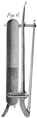
In that figure, A B is a cylindrical vessel, with spherical
ends, made strong enough to bear (without danger) a pressure
of several atmospheres: and into which is introduced, by a
condenser, (which might be the very system C p r) a quantity
of water sufficient to occasion the aforesaid pressure. The
valve C being water-tight, retains entirely this water; and the
Machine is placed on it’s three feet, in a corner of the apartment
it is wished to secure. It is seen in the figure, that the valve-pipe
C p, opens into the ejection pipe p q, while the valve stem p
passes through a collar of leather, and comes in contact with
the lever p R while in it’s present position. If, now, any part
of the house or apartment should be found to be on fire, this
Instrument can be carried there instantaneously, by the pipe
p q, as a handle; and the jet be levelled at the point desired:
when, by taking the lever p R in his hand, with the pipe p q,
the bearer will open the valve C, and thus have an immediate
supply of water, in a state of impulse sufficient to quell a fire
that might else have become so violent as to mock every attempt
to extinguish it! This, then, is the object of the present
simple tribute to public safety.
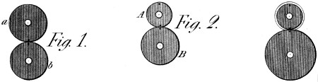
The principle of this Machine is as follows: When two
equal toothed wheels a b (see Plate 39, fig. 1,) geer together, a
given tooth of either wheel visits a given tooth of the other,
once every revolution: and will continue to do so as long as
the wheels continue to revolve. But, when the wheels are unequal,
as A B fig. 2, then different teeth in one wheel, visit the
same tooth in the other, until, after a certain number of turns,
the revolutions of both wheels have a common divisor. My
System of equable Geering (see Part 2d. of this Work,)
justified me in applying this principle to Engraving; and is the
chief foundation of the Machine now to be described: for this
System, as we have seen, communicates the very same kind of
motion that two touching cylindrical surfaces would impart to
each other by mere contact. The punch, therefore, will not
scrape the cylinder, when brought into the desired places of
contact by the aforesaid process. Let us suppose then, (fig. 2)
that the wheels A B, are to each other in diameter and teeth,
as the numbers 2 to 3; and that a given tooth in the wheel A,
(which we have pointed out by a dot) now touches a certain
spot on the wheel B, marked by a dot like the former. When,
now, this spot on the wheel B has made one revolution, the
wheel A will have made 3⁄2, or 11⁄2 revolution: and the tooth
first mentioned, will be found diametrically opposite to the place
where it touched the spot first adverted to. And if, further,
we give the wheel B another turn, the wheel A will again
have made 11⁄2 turn; and the tooth first mentioned will again
visit the spot with which it coincided at the beginning.
| To recapitulate— |
The |
1st. |
turn of B gave |
1.5 |
turns of A, and |
| |
The |
2d. |
turn of B gave |
1.5 |
turns of A: |
| Sum. |
2 |
turns of B & |
3.0 |
turns of A:— |
which numbers are thus in the inverse ratio of the number of
teeth in the wheels respectively.
Referring again to fig. 3, there we see a cylinder to be engraven,
(M) and a porte-outil (or tool-bearer) N, connected by the
wheels A B; whose teeth are singly inclined, like those that
were considered in Part 2d. It can hardly ever occur, that the
circumference of a cylinder can require to be divided into two
parts only: but most often into a greater number, as 9, 11, &c.
and it so happens, (from these initial diameters 2 and 3) that
we must take uneven numbers for our basis, in order to reduce
the System to any thing like regularity. And, this admitted,
the theory of this division will be as follows:
Let the chosen (uneven) number of figures required round
the cylinder be called m: then must the number of teeth in the
small wheel A, be likewise m: when the number in the wheel
B, will come out uniformly m + (m ± 1)/2; in which formula every
case of practice is included. For suppose, any uneven number
to be required, say 11: Then will the cylinder-wheel A, have
11 teeth; and that of the porte-outil (B) 11 + 12⁄2 = 17, or 11
+ 10⁄2 = 16: either of which numbers, working with the 11 teeth
of the cylinder-wheel A, will divide the latter into 11 parts,
as was before stated.
It must, however, be observed, that, as expressing a set of
teeth actually working, these numbers are fictitious; because the
teeth would be too coarse to work well. The numbers thus
found, must, therefore, be multiplied by 2, 3, or more, so as
to bring the teeth to a reasonable size, say 1⁄8 of an inch thick,
according to circumstances.
As another example, take the following: suppose it were required
to engrave a cylinder of 4 inches diameter—or 12.56
in circumference, and to put twenty-five figures round it, giving
very nearly half an inch for each figure. Then the cylinder
wheel (A) must have 25 teeth; and the porte-outil
wheel 25 + 26⁄2 = 38: or, doubling both numbers to give the
teeth a proper strength, the cylinder-wheel would have 50
teeth, and the porte-outil wheel 76.
To proceed now, in stating the principles of this Machine, it is
evident (in this System of geering) that the diameters of the wheels
must be in exact proportion with the number of their teeth, taken
at the pitch lines; and that these pitch lines must be of the
same diameters, respectively, as the cylinder to be engraven,
and the porte-outil taken at the surface of the punch: which
is saying, in other words, that the length of the punch must
be regulated after the diameter of the porte-outil wheel has
been determined from it’s number of teeth, compared with those
of the cylinder-wheel. But we shall return to this topic after
having described more fully the principal parts of the Machine.
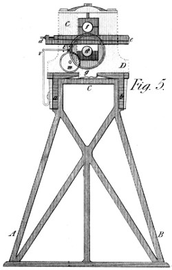
In fig. 5, (which is a kind of transparent view of one end of
the Machine), A B C is one of the stands or legs on which
it rests; a b is a section of the frame or bench, which supports
the headstock C D, one of which is bolted down at each
end of the frame, (see also C D in fig. 3.) This figure shews
the transverse form of the headstock, with the centre (c) of the
porte-outil; and e d are the two wedges that go through the
headstock to support the step of the cylinder, of which the mandrel
appears at f. This mandrel-centre is also covered with a
second step, over f, by which it is kept down by means of
a regulating screw A, (fig. 3) which finally determines the
degree of nearness of the cylinder to the porte-outil, and thus
the depth of the engraving:—that is to say, this regulating
screw influences this depth as far as the wedges (e d) permit:
for by the screw d, these wedges slide on each other so as to
raise or let fall the steps f, by small degrees; the position thus
given being confirmed by the said regulating screw. It is
needless to say that this operation takes place at both ends of
the Machine, (C and D) and thus places the surface of the
cylinder in a line exactly parallel to the slide n q of the porte-outil.
In fig. 3, all the parts thus adverted to, are given in a front
view—where we may observe, that the rope marked by dots at
R, is a loaded friction-drag, used to prevent the porte-outil
from over-running the cylinder, when the punch is just emerging
from between them.
The same figure 3, shews also the position of the frog x,
in the triangular slide of the porte-outil; the latter, as well
as the cylinder, borne by the headstocks C D. Moreover,
the rack w, which gives the end-motion to the punch, is
here shewn, as going through the frog, and connected with it
in one direction by the catch o: and at n, there is a spring,
formed like a horse-shoe, the use of which is to push the frog,
by the catch o, to the right, whenever the rack is suffered to
go that way, by the mechanism hereafter to be described.
The frog, then, (so called because it seems to leap when
the Machine works) must now be adverted to: it consists of
an under mass, formed prismatically to fit exactly the slide n
q, cut out of the porte-outil N. This mass is capped by
a thickness of steel, which completes the passage for the rack
n w, and offers, besides, a compartment for the punch-clams
o, and another (x) for a wooden or steel bridge, being a
portion of a cylinder, so formed, as to support the engraved
cylinder after the stress of the impression is passed, and thus
to equalize the depth of the engraving. The compartment for
the punch-clams at o, is terminated to the right hand by an
obtuse angle near x, which serves as a centre, when, by
proper fixing screws in the rim near o, it is found necessary to
place the punch a little awry. The other properties of this
frog will easily be supposed by my mechanical readers.
We come, then, to it’s motion in the slide. p r shews
a wheel, running loosely on the axis of the porte-outil; and
having fixed to it a concentric rim r, with three or four waves
in it’s circumference. Further, above s, is seen a lever,
turning on a pin in the stud s, and pressing against the right-hand
end of the rack w, when driven to the left by the waves
p r, &c. This rack is cut into ratchet teeth as at w, in
which enters the catch o, as impelled by a proper spring acting
on it, (but not seen in the figure.) As long then, as the
waved wheel p r can turn, with the porte-outil N, this last
described mechanism does nothing: but when p r is stopped, it
begins to work usefully; for the lever s then rides on the waves
p r, and presses the rack w against the spring n, so that the
catch o, takes into some new tooth; by which means, when the
spring n unbends (by the sinking of the lever s into any wave p)
the frog is itself carried toward the right hand—which is the
effect intended. But, in fine, how is this wheel p r stopped
and set agoing a propos? Fig. 5 will shew this, with the aid
of a little imagination—since our fig. 5 is a kind of transparency
rather than a regular view. The wheel m, is a crown
wheel, near which the wheel p r (fig. 3) turns, having a spiral g
on it’s hither surface, which runs between the teeth of the wheel
m and turns it one tooth, in each of it’s own revolutions: But
when, after a given number of these turns, the end of the spiral g
meets with a large tooth on m, it lodges on it, and stops the
motion of the wheel p, and then the aforesaid waves r perform
the task of driving the rack w backward; after which the
spring n changes the place of the frog, so as to make another
line of impressions round the cylinder. It remains then, only
to be explained, how this stoppage is itself stopped; which is
thus: to the porte-outil is fastened, near g, a small arm,
which turns with it, and which in fig. 5 the dot t represents.
This arm, therefore, drives back the beak t, (connected with
the spring v) at every revolution of the porte-outil, thereby
working the small catch that hangs to that beak. This catch,
therefore, slides on the edge of the crown wheel m, but produces
no effect, until it finds there, one small notch, so placed
as to be acted on by the catch when this disengagement is wanted—and,
then, this motion jogs forward the crown wheel m just
enough to take the large tooth out of the way—when the
spiral g begins to move through the common teeth of m, and
thus ceases to act on the rack till the large tooth again comes
to stop the wheel p, and recommence the rack’s motions.
And thus is the place of action of the punch changed after any
number of it’s contacts with the cylinder—that number being
doubled or trebled—or more—when necessary, by increasing
accordingly the number of common teeth in the crown wheel
m, before a large tooth occurs.
A few practical remarks on this mode of engraving may here
be added with advantage. Theoretically speaking, the punch
should form a portion of a cylinder, of equal radius with the
porte-outil wheel, taken at it’s pitch line. But through the
relative weakness of some mandrels, a certain spring takes
place, which requires the punches to be more curved than that
wheel, and even considerably so. This also depends on the
size of the punch, and the fullness of the pattern. In a word,
it depends likewise on the method of employing the Machine—whether
with few passages, and considerable pressure, or with
light pressure, and many swift passages:—The latter System
is in my opinion much the best; since it brings the practice
nearer to the theory of this Machine. If, indeed, the cylinders
and mandrels of Calico Printers, had been originally made
thicker, and thus strong enough to bear the pressure without
sensible deflexion, this would have been, from the first, a
perfect process: and the nearer these objects are brought to
this state of inflexibility, the nearer will it’s effects approach to
perfection; for in all other respects it works with admirable
precision.
I may just add, that the facility with which the revolutions
of this Machine are counted, has induced some persons to dispense
with the rack movement: but for small patterns with
numerous impressions, it is doubtless better to use it—especially
when employing the rapid and light pressures just alluded to;
and these will become additionally interesting when the punches
themselves acquire a more exact form—which is the object of
the third Punch Machine, still remaining to be described.
It is not superfluous to add, that this Engraving Machine
is dangerous to the persons employed—and should therefore
be guarded behind, by a fence-bar, to prevent the hands
or clothes from being drawn in.
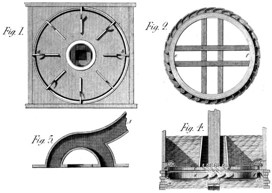
In this title, I have repeated that given in the prospectus:
nor do I think I have assumed too much in so doing. It will
be seen in the course of this description, on what I found my
opinion; which indeed, was substantiated by the fact as soon
as formed: the execution having speedily followed the invention.
The Machine, in it’s different parts, is represented in
figs. 1, 2, 3, and 4 of Plate 40. Fig. 1 is a plan of the floor,
on which the upper water flows, to it’s whole depth, when the
flood gates are opened: this floor being close over the wheel,
as seen in fig. 4, at c d. Further, a b, in both figures, is a
circular slit of the whole diameter, through which the water
rushes at once on all the floats of the wheel; whose axis goes
up into the building through a kind of barrel, that prevents the
water from escaping in any other part than the aforesaid circular
aperture. The wheel itself is represented at e f, fig. 2; and fig. 4
is an elevation of it, with it’s shaft, and a few of the floats, to
shew the manner of their receiving the stroke of the water.
A section of the ring-formed slit is also given at a b, with two
floats receiving the flowing water: and in that elevation is also
shewn two of the swan-necks by which the central part of the
floor is supported on the framing, without stopping the watercourse.
Finally, the slit or aperture a b, figs. 1 and 4, is fitted with
a set of cast iron curves, of which six are shewn in the Plate,
between c and d, and whose use is to turn aside the falling
water to any desired inclination; these instruments being
moved at will by a proper chain of bars, reaching from one to
the other, and connected with eight or more levers at proper
intervals on the floor of the water chamber.
Thus then, it appears that this Machine has two or three very
important properties: 1st. all the water escapes in the same
direction, (relatively to the motion of these wheels) and that
direction concurs with that in which the wheel is made to turn.
2d. Every one of those fluid prisms into which the stream is
divided, is urged with the same velocity, because impelled by
the same head of water. 3d. The velocity of these jets is the
greatest possible, because the water is carried as low as possible
before it is emitted; and falls as little as possible after
it has struck the wheel. 4th. In fine, the inclination of the
floats may be made most perfect; and their form, being that
of a boat slightly curved, is among the best forms possible for
receiving the utmost impulse from flowing water.
Although by these means much is done in favour of the
impulsive system, it is allowed, that, in general, a wheel acting
by impulse, is less effective than a bucket-wheel acting by
the weight of the water. But the higher the fall is made, the
more similar these effects become. Hence, a very high fall
may be made to produce, by impulse, an effect equal to that
of the bucket-wheel. To meet, therefore, such a contingency
as this, I have given, in fig. 3, a cover to the water chamber of
fig. 4, intended to close it upward, and thus adapt it to a fall
of any height; the water entering into this chamber from a
large pipe A, of the required length: and being compressed
accordingly, the result is forcible in proportion.
A few facts on the above subject will not be uninteresting.
When this wheel, fifteen or sixteen years ago, (for I have
forgotten it’s exact date) was about to be put in motion at
La Ferté in France, several knowing ones took upon them to
say “that it would not turn at all.” But who so astonished as
they, when, at twelve feet diameter, and with less than five feet
fall, they saw it make fifty-four turns in the first minute! I acknowledge,
with pleasure, that these men soon expressed their
approbation with unsophisticated candour; for although an
honest prejudice had beset them, it was un-poisoned by that
envy, I have more than once had to deal with in a country we
are accustomed to call better! I therefore take leave, on this
occasion, to say to my beloved countrymen, “Go and do
likewise.”
The Machine commonly used for continued Spinning, in low
numbers, is named a Throstle: and as my Invention acts in
a similar manner, I have presumed to call it an Eagle. My
motive is no mystery. The Machine spins more and better
than a throstle: and reaches, especially, to a fineness unknown
in throstle spinning. It could not, therefore, justly
receive a meaner name, nor even an equal one.
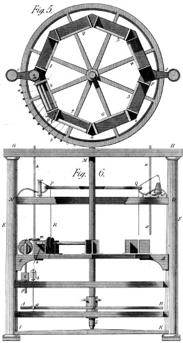
The present Machine then, is a superior kind of throstle,
the construction of which will be understood, by spinners, from
the annexed figures, 5 and 6 of Plate 40. As the principal
difference between the former machines and this, resides in
the toothed wheel by which it’s spindles are turned, we shall
begin this description by adverting to it: A B is that wheel,
cut, at present, into 800 inclined teeth, and working with
pinions of 11 teeth, one of which, with it’s spindle, is shewn
at a b, fig. 6. The revolutions, therefore, of these spindles
to one of the wheel, are 72.7272, &c.; and since the latter,
in spinning, makes from 60 to 70 turns per minute, the spindles
run at the rate of 5000 turns in that time, and might do more
if desired by the spinner. In a word, the useful speed depends
on the size and weight of the spindles, the flyers, &c.
Immediately above and below the wheel A B, are two rings
of cast iron, to which are screwed rims, either of wood or
metal, destined to hold the steps and bolsters of the spindles,
as is usual in a throstle, with the difference of the circular
form, which the wheel of course requires; and the relation of
which, to the rollers, is shewn at a b, fig. 5, being a plan of
this Machine. Returning to fig. 6, the next object upward
is the roller-beam, (cast hollow for lightness) the form of
which is that of an octagon, with two brackets c d, by which
it is fastened to the pillars E F: these, in their turn, being connected
with the top and bottom cross-pieces (G H, I K) so as
to make up the frame, properly so called. All these parts are
placed (in section) similarly to those usually composing the
throstle; and the copping motion is produced by the curve f,
driven by an endless screw on the shaft h f, and acting on the
slide f g, and through it on the ring of which the square i is a
section: and on whose iron plate, in fine, the bobbins drag,
as they do in the throstle. In the Machine before us, the
rollers are driven by two side-shafts h f, which take their
motion either from a train of spur wheels placed above the
traverse G H, or by bevil wheels from two small shafts, coming
under that traverse from the central shaft L M, to those
h f, and acting on the rollers by means of the bevil wheels f
m, seen in the figures. Now, the rollers are contained in
eight heads—1, 2, 3, 4, 5, 6, 7, 8, each of which has it’s
speed wheels in the angles n o, &c. and receive their motion from
six sets of bevil wheels q, &c. which propagate the motion
round each half of the Machine, from the points m and p
respectively.
Above this roller-beam, is the creel-ring N O, which
(either in one or two rows) receives the sixty roving bobbins
that supply the sixty spindles, of which the Machine is composed:
and whose threads pass under the eight sets of rollers—one
thread being suppressed in each of the heads—1, 4, 5, 8,
on account of the columns. (This, at least, is the arrangement
I prefer; but some of the Machines have been made with
eight threads in all the compartments.) Finally, in this frame
G H, I K, is placed a ring P Q, (of glass or bright metal)
over which the rovings are thrown before they are put in the
guides behind the rollers; so that the route of a thread in the
act of being spun, is shewn in fig. 5, by the line P R, S b,
where it meets the bobbin on the spindle a b, before mentioned.
It may be observed here, to prevent ambiguity, that the
guide-boards, with their hooks, are placed below the octagon
roller-beam q n o, &c. as they are in the common
throstle; being, each, 1⁄8 of the whole circumference, and of a
circular form on the outside, reaching, by these hooks, to the
point S, so as to hold the thread just over the centre of the
spindles as at a b, fig. 6. Considering this as a commonplace
subject, I have not attempted to draw these boards,
since their form and position would occur to every constructor:
and this is the reason also, why I have given only the section
of the copping ring i, fig. 6: nor at all shewn the top rollers—nor
the detail of the creel—on all which topics, opinions vary
considerably, while the things themselves are really of minor
importance.
There is, however, in my Patent System, something which
I think important, and which, therefore, I have sketched near
Q, fig. 6. If w x be there considered as the second communication
shaft, a wheel z is put on it, of that kind which is
calculated to work in a certain geering chain, called in French
chaine de Vaucanson, (from the name of it’s inventor); and
further, similar wheels (y) are connected with all the pins on
the creel, round which the chain is carried from the wheel z,
till it comes to it again. The consequence is, that all the
wheels (y) are turned by that chain, so as to untwist the roving
while the spinning rollers draw it off the bobbins: and this
is so, because, in my Patent System, the rovings are over-twisted,
in order to admit their being made very fast, without
the danger of breaking. This then, completes my Patent Eagle,
formed, on the right hand of the figure so as to use over-twisted
roving; and on the left hand, so as to spin common roving
in the usual manner. In both cases, the motion of the spindles
by geering, ensures a mathematical twist, and thus produces
yarn better than common; whence also it’s fineness can be
carried much farther than on a common throstle. It need hardly
be added, that these spindles are stopped and set in motion by
the mechanism described in my second Part, at fig. 1, Plate
19: and there mentioned as “a Machine to set-on and suspend
rapid motions.”
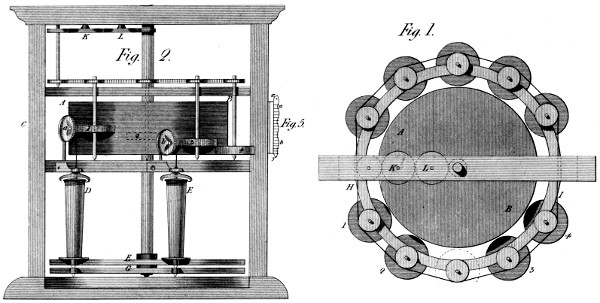
This Machine, represented in Plate 41, figures 1 and 2,
may be called a Spinning-card: whose use, however, I shall
now suppose confined to spinning coarse yarn, or rather rovings,
to be re-spun on the common machines, or on machines similar
to my Eagle just described. It consists, in reality, of an horizontal
card A B, having it’s flyer, &c. adapted
to perform, in a perpendicular position, what those several parts
do, in an horizontal one, on the common carding engine. All
this is so well known, that I have not thought it necessary to
draw it in these figures; but merely to say, that in this Machine,
those operations are performed on the left hand, as at A,
where is introduced a broad flat ribbon of wool, duly made on
a preparing card, and laid on edge in a box at C, from whence
it is drawn by the feeding rollers, &c. so as to cover the whole
of the central card A B. Now, round this central card, are
placed, ten or more small fillet cards, 1, 2, 3, 4, &c. being
at different heights on the central one; by which arrangement,
the whole surface of the latter is stripped by these cards, and
as much filament collected on each, as is sufficient to form a
thread or roving, as before mentioned. But, further, these
small cards have to be stripped in their turn: and that is done
by the circular combs a b, which being placed obliquely to the
cards, receive motion from them, and gather a regular mass
of filament of a size fitted to become the yarn or roving in
question. Nor need this roving be re-drawn, by rollers, before
it is twisted: for it is the property of the bobbins D E, fig. 2,
to draw mathematically: and with any speed that shall have
been determined. If we examine how this is done, we shall
see at bottom, two wheels F G, (toothed on the patent principle)
one of which drives the spindles and flies, and the other
the bobbins D E: the wheel that drives the bobbin having
a few teeth more than that which drives the spindles—whose
pinion is the same in number as that of the bobbin. Thus,
therefore, the bobbin goes as much faster than the spindle as
is necessary to take up all the wool furnished by the comb,
and to the comb by the small card, which receives it from the
central card A B; where note—that the draught, by this
difference of motion is not variable, but determined: since the
heads of the bobbins E D, are a hollow inverted truncated
cone, on which the yarn cannot remain—for in winding, it
drives downward that which is already wound, so as to fill
the whole bobbin from the head—a reason for the conical shape
of the latter object.
It will appear by the upper figure, (which is a plan of the central
card, and the small cards, 1 2, &c.) that the latter receive their
motion from the chain H I, by means of the train of wheels
K L, turning on studs in the upper cross-piece. Suffice it
to add, that the centres of these cards, of the combs, &c.
are fixed to the rings by proper cramps, as will be easily conceived.
I have offered to sight, only the essential parts, to
avoid confusion: and I presume to hope every thing important
will be thus seen without difficulty.
In my present view of this Invention as a preparing Machine,
I would observe, that the central card is only considered as a
distributor, and that I should, now, add to it a System of
machinery to make it a forced distributor. I had, indeed,
prepared this very System to be patentized many years ago:
but the delays that occurred then, followed by the Restoration,
(which gave me an opportunity of coming to England;) made
me suspend this intention—respecting a method, perhaps,
the only thing wanted to make this Machine in all respects
excellent.
In the small figure 5, (Plate 41) x y is supposed to be the
section of a central card, such as A B, fig. 2; and the horizontal
lines between x and y, shew the height of the card teeth.
Of these, I take out a portion in several perpendicular lines
round the card—say, at an inch distance from each other: the
intervals thus stripped, being about 1⁄16 of an inch in width:
and in all these upright slits, I introduce a blade x y, (whose
transverse section is like that of a card wire) and whose edge
is undulated as at a b. Finally, to these blades is given, (by
a proper Machine) a slow up-and-down motion, which makes
them push off the filament from the card wires at the highest
points of the waves, and suffer the wires to retain these filaments
at the lowest points; whence it follows, from the motion
just mentioned, that these points of reception and exclusion
of filament, are constantly changing on the surface of the whole
card, and that, therefore, the card will never be totally clogged
with wool—as it is in the common process. It will be seen
that the use of this System need not interrupt that of the common
flyer, (or stripping card) whose use is to keep the teeth
in working order, and to discharge a part of the obtruding
filament.
In terminating this article, I cannot resist the desire of recommending
this whole subject to any opulent English Manufacturer,
whose zeal and public spirit, are commensurate with
the scope which these hints embrace, and to which they tend,
if duly appreciated.
While this Invention, as described in page 30 of the first
Part, is allowed to possess curious properties, and to be a
pretty thing, opinions do not all concur in declaring it, essentially
and generally, a good thing. Nor could I be unjust
enough to insist that it is so, in every kind and magnitude of
application. I have, however, convinced myself that it is susceptible
of practical excellence, as a first motion to steam engines,
whatever be their dimensions; and have, therefore, presumed to
re-produce it, with those modifications which are required to make
it so. In thus acting, I have again preferred the useful to the
agreeable, and in some measure inverted the order of my subjects.
But I trust this deviation will be excused, in favour of the motive
and the result; on both which I feel a good degree of confidence.
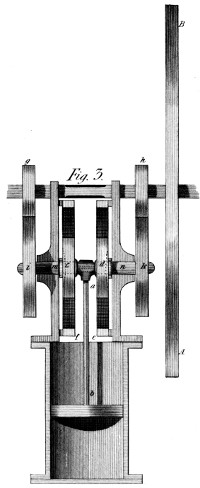
To obviate the point of mechanical weakness in this Parallel
Motion, (see Plate 41, fig. 3,) I have doubled it’s parts; and
brought the piston rod a b, to act, at once, on two of the
circulating wheels c d, placed exactly opposite each other, and
rolling, as before, on the inside of the fixed wheels f e, so as
to produce the rectilinear motion, by the action of the piston
rod on them both. And to make their respective motions
one, (as connected with the fly B A) this latter is fixed to a
shaft common to the two wheels g h, and by which, therefore,
the two other wheels i k, fixed to the crank shafts m n, are
kept in due position. Thus, then, is all winding or twisting
motion done away: and, therefore, can this System be employed
in engines of every required power. Nor need I add,
(what will be generally allowed) that much of the expence,
and of the retardation, which a given engine suffers from the
beam, the connecting rod, &c. will thus be completely obviated.
I must, however, stop every gainsaying mouth, on the circumstance
of using geering between the engine and the fly—a
system which I acknowledge to have been hitherto an evil;
though, perhaps, a necessary evil—as giving (by a simple
method) a double speed to the fly from a single motion of the
piston. At all events, in this shape, I submit only to a very
common difficulty—and might there rest my apology.
But I should have hesitated to go thus far, had I not foreseen that
all the evil arising from this use of wheels, can easily be avoided by
my geering:—by means of which I am bold to say, every vestige of
shake or backlash may be destroyed; and this method of working
a steam engine be made as silent as when a beam is used: in which
case, considerable advantages must accrue from this method.
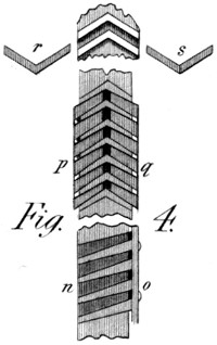
To come to the point:—the small figure 4, in Plate 41, relates
to this subject. My geering is there seen in three forms
or applications—each one intended to bring the above property
into play. The part n o, represents the manner in which two
wheels with singly-inclined teeth, work together when one of
them is furnished with a cheek, as directed in fig. 3 of Plate
14. But here, in addition to that, the teeth of both wheels
are sloped more on one side than on the other, so as to assume
a wedge-like form: insomuch, that in beginning to work, (if not
perfectly formed) the wheels would not occupy the same plane.
For, in fact, the cheek screws press home the cheek o against
a number of thin washers all round the wheel, and thus only
draw the wedge-formed teeth into each other as they become
bedded, and successive washers are taken away. Hence, a
good degree of precision is obtained—accompanied with little
friction, and thus with great durability.
But we stop not here. The part p q of this figure, shews a pair
of wheels doubly inclined—one of them only, being made in two
halves, which are connected together by screws and washers, like
that just described. Here then, another degree of friction is got
rid of—namely, that of the cheek o: but still, a small degree remains,
(dependent on the double versed sine of the angle formed
on the wheel’s circumference, by the thickness of a tooth). This
quantity, is indeed, very minute; and brings, perhaps, the whole
near enough to perfection. To do, however, completely away
with all friction, (see my preceding statement)—as well in the
wheel acting backward, as in that acting forward, we must do
what is shewn in the parts r or s of fig. 4: we must have a pair
of V wheels on the same shaft, with the power of turning one of
them in reference to the other; and then connecting them by
proper screws, &c. to preserve the position thus given: by which
means, in a word, all shake or backlash will be completely annulled.
PART FIFTH. — OF AN ADDING MACHINE, Or Machine to Cast up large Columns of Figures . — OF A ROTATORY PUNCH MACHINE Adapted to my own Engraving Machine . — OF A PORTABLE PUMP, To be worked by the Feet . — OF THE BISECTING COMPASSES. — OF A MUSICIAN’S PITCH-FORK, With variable Tones . — OF AN ESSAY, To obtain a Level at Sea . — OF A SECOND ESSAY, To procure a Marine Level . — OF A FIRE-ESCAPE, On a retarding Principle . — OF A SECOND FIRE-ESCAPE, By breaking the Fall . — OF A ROTATORY CHOCOLATE MILL. — OF A ROTATORY MANGLE. — OF A MACHINE, For driving the Shuttle of Power Looms . — OF AN AIR PUMP, Or Essay towards completing the Vacuum . — OF AN INCLINED WATER WHEEL. — OF A VESSEL, To assist in taking Medicine, &c. — OF AN AERO-HYDRAULIC MACHINE, For raising Water in large quantities . — OF ANOTHER WIND MACHINE, Furnishing immense Powers . — OF A CENTRIFUGAL MIRROR, To collect Solar heat . — OF A SECOND MIRROR, For collecting the Sun’s rays . — OF AN ENGRAVING MACHINE, For large Patterns .
A NEW CENTURY OF
Inventions.
This Machine is not, generally, an arithmetical Machine.
It points lower: and therefore promises more general utility.
Though less comprehensive than machines which perform all the
rules of arithmetic, it is thought capable of taking a prominent
place in the counting-house, and there of effecting two useful
purposes—to secure correctness; and thus, in many cases, to
banish contention. It is represented in figs. 1, 2, 3, and 4
of Plate 42, and in figs. 3 and 4 of Plate 43.
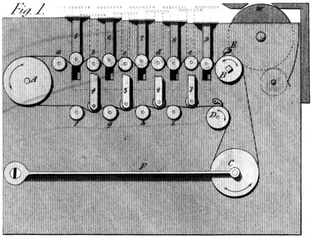
There are two distinct classes of operations which may be
noticed in this Machine: the one that does the addition,
properly speaking; and the other that records it by figures,
in the very terms of common arithmetic. The first operation
is the adding: which is performed by means of an endless geering
chain, stretched round the wheels A B C D, (fig. 1) and
over the two rows of smaller pulleys a b c d e f g h i; where,
observe, that the chain is bent round the pulley A, merely
to shorten the Machine, as otherwise the keys 1 2 3, &c. to 9,
might have been placed in a straight line, and thus the bending
of the chain have been avoided.
The chain, as before observed, geers in the wheels B and
D, which both have ratchets to make them turn one way only.
Now, the keys 1 2, &c. have pulleys at their lower ends,
which press on the aforesaid chain more or less according to
the number it is to produce, and the depth to which it is suffered
to go by the bed on which the keys rest, when pressed
down with the fingers. Thus, if the key 1 be pressed, as low
as it can go, it will bend the chain enough to draw the wheel B
round one tooth—which the catch E will secure, and which the
wheel C will permit it to do by the spring F giving way. But
when the key 1 is suffered to rise again, this spring F will
tighten the chain by drawing it round the pulleys A and D, thus
giving it a circulating motion, more or less rapid, according to
the number of the key pressed. Thus, the key 5 would carry five
teeth of the wheel B to the left; and the catch E would fix the
wheel B in this new position: after which the spring T would
tighten the chain in the same direction and manner as before. It
is thus evident, that which-ever key is pressed down, a given
number of teeth in the wheel B, will be taken and secured
by the catch E; and, afterwards, the chain be again stretched
by the spring F. It may be remarked, that, in the figure, all
the keys are supposed pressed down: so as to turn the wheel B,
a number of teeth equal to the sum of the digits 1, 2, 3—to 9.
But this is merely supposed to shew the increasing deflexion of
the chain, as the digits increase: for the fact can hardly ever
occur. We draw from it, however, one piece of knowledge—which
is, that should the eye, in computing, catch several
numbers at once on the page, the fingers may impress them at
once on the keys and chain; when the result will be the same
as though performed in due succession.
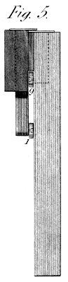
Thus then, the process of adding, is reduced to that of
touching (and pressing as low as possible) a series of keys,
which are marked with the names of the several digits, and
each of which is sure to affect the result according to it’s real
value: And this seems all that need be observed in the
description of this process. It remains, however, to describe
the 5th. figure, which is an elevation of the edge of the keyboard,
intended to shew the manner in which the two rows
of keys are combined and brought to a convenient distance,
for the purpose of being easily fingered.
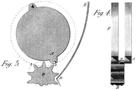
We now come to the other part of the subject—that of recording
the several effects before-mentioned. The principle
feature in this part, is the System of carrying, or transferring
to a new place of figures, the results obtained at any given one.
This operation depends on the effect we can produce by one wheel
on another, placed near it, on the same pin; and on the possibility
of affecting the second, much less than the first is affected: Thus,
in fig. 3 and 4, (Plate 42,) if A be any tooth of one such wheel,
placed out of the plane of the pinion B, it will, in turning, produce
no effect upon that pinion: but if we drive a pin (a) into the tooth
A, that pin will move the pinion B one tooth (and no more) every
time this pin passes from a to b. And if we now place a second
wheel (F) similar to A, at a small distance from it, so as to
geer in all the teeth of the pinion B, this latter wheel will be
turned a space equal to one tooth, every time the pin a passes
the line of the centres of the wheel and pinion A B, (say from
a to b.) It may be added, likewise, that this motion, of one
tooth, is assured by the instrument shewn at E D, which is
called in French a tout ou rien, (signifying all or nothing) and
which, as soon as the given motion is half performed, is sure to
effect the rest: and thus does this part of the process acquire,
likewise, a great degree of certainty—if indeed, certainty
admits of comparison.
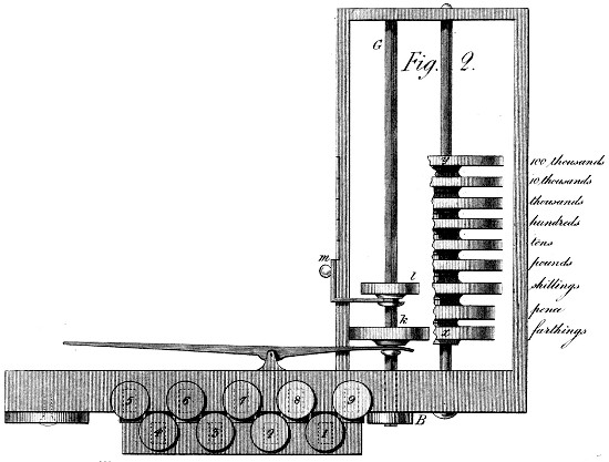
It is then, easy to perceive, how this effect on the different
places of figures is produced: and it is clear, that with the
chain motion just described, it forms the basis of the whole
Machine. There is, however, one other process to be mentioned,
and as the 2d. figure is before us, we shall now advert
to it. In adding up large sums, we have sometimes to work on
the tens, sometimes on the hundreds; which mutations are
thus performed: The wheel B, (fig. 2) is the same as that
B, fig. 1; and it turns the square shaft B G, on which the
wheels k l slide. The wheel l is to our present purpose. It
is now opposite the place of shillings; but by the slide m, it
can be successively placed opposite pounds, tens, hundreds,
&c. at pleasure: on either of which columns, therefore, we
can operate by the chain first described—the wheel B being
the common mover.
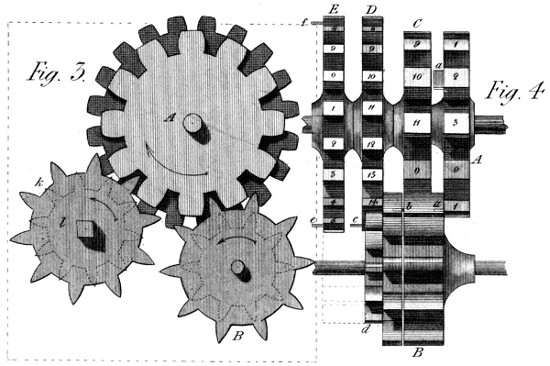
We shall now turn to figs. 3 and 4 of Plate 43, which give
another representation of the carrying-mechanism, adapted
especially to the anomalous carriages of 4, 12, and 20, in
reference to farthings, pence, shillings, and pounds, and then
following the decuple ratio.
In fig. 3, k l represent the two acting wheels of the shaft
B G, fig. 2; the latter dotted, as being placed behind the
former; these wheels, however, are not our present object,
but rather the carrying system before alluded to; and described
separately, in fig. 3 of Plate 42. A, in figures 3 and 4
(of Plate 43) is the first wheel of this series. It has 12 teeth
with three carriage-pins (or plates) a, which jog the carrying-pinion
B, at every passage of 4 teeth; thus shewing every
penny that is accumulated by the farthings. This is so, because
the farthings are marked on the teeth of this first wheel in this
order—1, 2, 3, 0; 1, 2, 3, &c. and it is in passing from 3
to 0, that this wheel, by the carriage-pinion B, jogs forward
the pence wheel C one tooth: But this pence wheel is divided
into 12 numbers, from 0 to 11; and has on it only one carrying-pin
(or plate) b; so that, here, there is no effect produced
on the third wheel D, until 12 pence have been brought to
this second wheel C, by the first, or farthing wheel A. Now,
this third wheel D, is marked, on it’s twenty teeth, with the
figures 0 to 19, and makes, therefore, one revolution, then
only, when there have been twenty shillings impressed upon
it by twenty jogs of the carriage-pin b, in the second wheel C.
But when this wheel D has made one whole revolution, it’s
single carriage-pin c, acting on the small carriage-pinion,
like that c d, (but not shewn) jogs forward, by one tooth, the
wheel E, which expresses pounds; and having two carriage-pins
e f, turns the wheel called tens of pounds, one tooth for
every half turn of this wheel E: and as, on all the succeeding
wheels, to the left from E—(see fig. 2, Plate 42) there are two
sets of digits up to 10, and two carriage-pins; the decuple
ratio now continues without any change: and thus can we
cast up sums consisting of pounds, shillings, pence, and farthings,
expressing the results, in a row of figures, exactly as
they would be written by an accountant. The opening, through
which they would appear, being shewn in fig. 1, at the point
w, corresponding with the line x y of fig. 2 in the same Plate.
I shall only remark, further, that the figures 3 and 4 in Plate
43, are of the natural size, founded, indeed, on the use of
a chain that I think too large; being, in a word, the real
chain de Vaucanson, mentioned in a former article: and that the
figures of Plate 42 are made to half these dimensions, in order
to bring them into a convenient compass on the Plate.
I would just repeat, that I have not attempted here an arithmetical
machine in general; but a Machine fit for the daily
operations of the counting-house; by which to favour the thinking
faculty, by easing it of this ungrateful and uncertain labour.
Had I been thus minded, I could have gone further, in a road
which has been already travelled by my noble friend the late
Earl Stanhope, (then Lord Mahon) but I took a lower aim;
intending in the words of Bacon—“to come home to men’s
business and bosoms.”
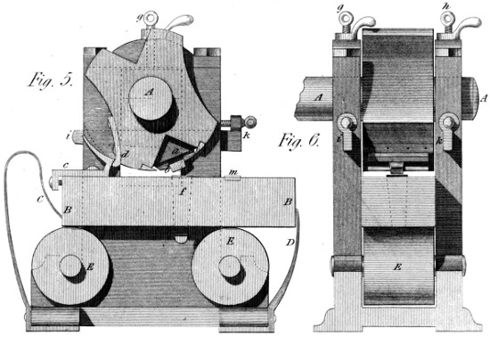
It is highly desirable, (not to say indispensable) in the use of
my engraving Machine, to have punches not only of the true
cylindrical form, but exactly of the proper length. (See the
remarks on this subject, in the description of that Machine).
It is, therefore, a matter of consequence, to be assured that
both these circumstances unite; and to unite them without
depending on personal skill, whenever the work can be accomplished
without such dependence: and this is the object of the
present rotatory Punch Machine. Adverting first to the length
of the punch: that is insured by having a kind of slide on the
Punch Machine, formed like the frog spoken of in the above
article—Engraving Machine. In the 5th. figure of Plate 43,
this slide is shewn at a, and it is at exactly the same distance
from the centre of motion A, as the bottom of the frog-plate
fig. 3 Plate 39 is from it’s centre of motion. Thus,
the bottom of the punch is filed straight, once for all, and
being fixed in proper clams, as in the figures, the shaft A is
set a-turning, by power—from which motion two uses are
derived: first, the cylindrical form is given to the punch by
presenting to it, in it’s revolution, a file duly wedged on the
(now fixed) slide of the Machine B B; against which it is kept
turning, till, by a due depression of the centre A, the radius
is brought to the length required, and the surface perfectly
formed and smoothed. This being achieved, the cams c d, are
fixed to the slide B B, and to the turning body A d, so
that when the die f is moved toward the left hand by the said
cams, the prepared punch gently presses on it, and begins to
receive it’s impressions; which are gradually deepened by the
set screws g h, fig. 6; till, at once, the proper radius is given,
and the engraving sufficiently transferred from the die to the
punch—an operation which this process is calculated to perform,
rather by means of frequent and gentle contacts, than by slow
and heavy pressure. It need not be added, that the motion
of the slide B B is reciprocated by the spring C, against that
D, after each forward motion given to it—as begun by the
cams c d, and continued by the contact of the die and punch, all
which a mere inspection of the figures will sufficiently explain.
It is likewise evident, that the figs. 5 and 6, shew, both, the
same objects, namely:—the regulating wedges i k, the upper
set screws g h, and the rollers E, on which the slide vibrates
during the operation of the Machine.
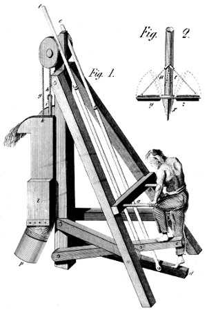
It is not solely because, to work with the feet is a good
method of employing the strength of men, that this device is
presented to the mechanical public; but it is with the view of
so employing the feet and hands, that they may occasion a
constant and equable flow of water. The means, (see Plate 44, fig.
1) are, to provide the man with two supports a b for his hands,
and two pedals c d for his feet, by which the two rods e f
are worked; and by them, through the cords or chains g
h, the piston rods i and k. Of the latter, the one which
answers to the lower pump l, goes through the upper
piston, whose rod is i: and the pistons are both constructed
in the manner shewn in fig. 2; that is to say, the
piston has no body, fitting the pump barrel: but a triangular
bar x, going diagonally across the pump barrel, (which is
square) and carrying two wings or valves y z; which, both
together, fill the barrel when down, and leave it as empty as possible
when up, by which motion the chains a e are slackened.
Further, these pistons, with their rods, are heavy enough to
raise the pedals, the instant the man raises his feet in any
degree: so that, by a proper combination of the motions of his
hands and feet, he can let down a given piston, and begin
again it’s ascending motion before his effort has wholly ceased
on the other pedal. A mean this, of producing a constant and
equable rising motion in the column of water through the pumps
k l; and a mean also, of doing more work with a given fatigue,
than would be possible in a pump whose motions were
merely reciprocal, and the water of which, in rising, would
be subject to any unequable or convulsive motions.
In general, this portable pump was made (many years ago)
with a view to being easily carried to any field or garden,
bordering on a river, and worked on it’s bank; the flexible suction
pipe p being thrown into the river, or a well, as occasion
might require. To this end, the whole frame (as is evident
from the figure) can be folded up into a kind of faggot: and
thus it’s transport from place to place, be made perfectly
commodious.
It often happens, that from a central line, (in drawing for
example) we want to set off, quickly, many equal distances
on each side; or between two given lines we want a central
line; to perform either of which operations, is the use of the
Instrument just mentioned.
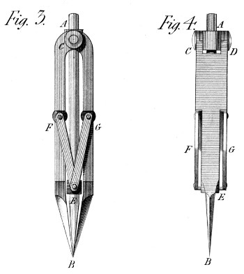
It is represented in Plate 44. figs. 3 and 4, where A B is
the central point, being cylindrical in the greatest part of it’s
length, and conical at E B. It slides correctly in two cannons
or swivels E & A, which also have two short axes or trunnions,
on which first, the double compass joints C D turn; and
second, the two pairs of arms F G. I have called these cannons,
swivels, that I may shew their construction, by referring to figure
1 in Plate 30—which describes the swivel of the forcing Machine;
and which will give a complete idea of what is here
intended. From this construction it will appear evident, that the
point A B, (Plate 44) will be always found in the middle,
between the two points, of the outer legs of the compasses;
and that whether the question is to take two equal distances
from a central point, or to bisect a given line or distance at
one operation. The point or style now slides in the two swivels
A and E; but the Instrument might be so constructed, as for
it to follow the rising motion of the middle joint (E), and thus
to keep the three joints in the same horizontal line: but I think
a small perpendicular motion of the said style, would be always
desirable in the Machine, as a drawing Instrument.
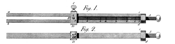
This device is shewn, in two positions, at figs. 1 and 2
of Plate 45. In it’s present application, it is intended to
produce a whole octave on the diatonic scale: and therefore,
the unsupported ends of the fork are just half as long as
they would become if the sliding handle A, were drawn to the
bottom end of the branches c d. For, again, the fixing screw
C, and it’s box D are fastened to this sliding handle by one or
two screws, (s) so as to be always ready to press the branches
against the enclosed slide A B, at whatever place the intended
tone may be found. Now, the branches a c, b d, spring out
of a common trunk c d, which is pierced with a square hole,
exactly fitting this sliding handle A B; and the latter is
marked, at proper distances, with lines across it, each of
which (placed opposite the mark c d) gives such a length to
the remaining branches a b, as to make them sound the note
desired. Thus, the line l, brought to c d, lengthens the
branches a b, to (nearly) 53 parts, from 50 at which they are
now fixed; the whole length a c, being 100. This, and the
following divisions would, of course, follow any desired temperament,
according to the will of the tuner: but I have supposed
them founded on the equi-harmonic scale; and thus will
the successive intervals to be set off on the slide B A, be as follows:
(while the corresponding notes will be those expressed
in the table.)
In the state represented by the figures 1 and 2, the line a B,
is 5000; being one half of the whole length a b, c d.
| To form the |
Sharp |
7th. |
it becomes |
5297 |
the distance |
c d 1, |
being |
297. |
| „ |
greater |
6th. |
„ |
5946 |
„ |
1-2, |
„ |
649. |
| „ |
„ |
5th. |
„ |
6674 |
„ |
2-3, |
„ |
728. |
| „ |
„ |
4th. |
„ |
7491 |
„ |
3-4, |
„ |
817. |
| „ |
„ |
3rd. |
„ |
7937 |
„ |
4-5, |
„ |
446. |
| „ |
„ |
2nd. |
„ |
8909 |
„ |
5-6, |
„ |
972. |
| „ |
fundamental note |
10000 |
„ |
6-7, |
„ |
1091. |
The above lengths 1 2, 2 3, &c. have been measured off on the
slide A B, as nearly as possible, or at least with precision enough
to give the idea: and the rest I must leave the detail of, to
those musical readers who may feel interested in the subject.
I have done right in calling these attempts “essays”: and if
I had said “immature attempts,” they would have been better
designated. Yet, having promised them to my readers, I cannot
now withhold them, although, from want of opportunity of
trial, I can do little more than talk of their supposed properties.
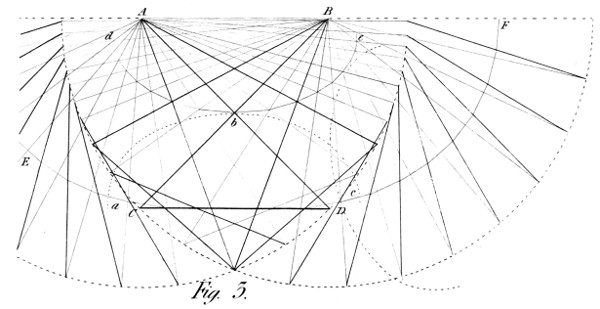
The first essay, as shewn in fig. 3 of Plate 45, is a mental
deduction from a device which I executed in 1801, and
brought before the public at the exhibition then given, by the
French government, of the produce of national industrie. It
was, nothing more than a pendulum, made with a view to
lengthen, considerably, the going of a given clock, without
altering the wheels. To that end, the weight or bob, was
a heavy bar C D, suspended diagonally on two points A B,
placed at a distance from each other, exactly equal to the
length of the said bar: and that by the double cross-bars B C
and A D, of a length sufficient to make the whole assume a form
exactly square: where it may be noted—that were this figure
longer than high, the curve of vibration would have two points
of inflexion, and the bar would not place itself horizontally at
last; and that were it narrower and higher, that curve would
assume a form more like, though still distant from, the arc
of a circle. In the present case, such was the effect of this disposition
of things, that the centre of gravity of the bar described,
in vibrating, a curve E C D F, the lower form of which,
was so near to a horizontal line, that the times of vibration
were immensely prolonged; so much indeed, as to represent a
common pendulum of several thousand feet in height; and
to give a proportionate slowness to any mechanism with which it
should have been connected. In fact, this line is so minutely
different from such horizontal line, that it is wholly included
in the thickness of the drawn-line C D: nor becomes visible but
near it’s two ends C D, when it begins to rise, and then rises
faster than that described by a short common pendulum.
In fine, this curve itself is formed by continually bisecting
the line or bar C D, and drawing lines from it’s centre of
gravity, thus found in one of it’s positions, to the same in
another position, till the curve E C D, &c. arises from this
process.
It follows, then, from the nature of this curve, (or pair of
curves) that the time of vibration of this pendulum is the longer,
the shorter the arcs are, in which it vibrates; and that, when
the vibrations have attained a certain length, compared with
the height to which the centre of gravity rises, the time becomes
considerably shorter. I shall not now pursue this idea,
because it is at once an abstruse question, and at the same time
one of uncertain utility—I mean that it’s use is problematical as
a pendulum: since the time of a vibration depends on it’s length,
which cannot easily be determined by any invariable method.
I shall, however, add two things on this subject, by way of
land mark; the one, that the balance-wheel of a watch has
power enough to drive this pendulum, heavy as it is;—and the
other, that I have seen it make (for many hours together)
vibrations of half a minute’s duration! In a word, this is one
of the subjects, which untoward circumstances have prevented
me from bringing to maturity—but which I owe to
my subscribers, and the public, in any, or every state, to
which I have brought them.
I therefore, say nothing more of this Instrument as a pendulum:
but an inspection of the figure will shew, that it will
not be useless as an Elipsograph—which it clearly is, since the
intersection of the bars A D & B C; describes a true Ellipsis.
It may be further shewn, that the ends of the moveable bar
C D, are the vibrating foci of a second ellipsis, like the
first, which rolls under the other, so that the curve itself
is that which the centre of one ellipsis a b c would describe, by
rolling on the surface of another e b d. But, into these considerations
I cannot now enter, as my “Century of Inventions” is
fast becoming due, and time commands dispatch; I beg leave,
therefore, to pass to the relation this subject seems to bear
to a “Marine Level.”
It must, however, be premised, that I scarcely expect either
of these methods to be correct enough for astronomical observations;
as among other things, they have the nautical top to
contend with: but if I am fortunate enough to have suggested
useful methods of procuring relative stability on board a rolling
ship, so as to suspend the better, a nice instrument of astronomy;
or so to counteract the restless ocean, as to assist
the victims of sea-sickness, I shall not entirely have lost my
labour.
My first idea on this subject, is the following: If we had
on ship-board, a simple pendulum of several thousand feet
high, it appears certain that the oscillations of the ship would
be begun and ended, before any single vibration could
have been given to such a length of pendulum—which
therefore, would scarcely vibrate at all: and if the natural time of
this compound pendulum (for we are not confined to these small
dimensions) were made to be much longer than those of the
ship on it’s meta-centre, this pendulum would scarcely vibrate at
all: because it’s several tendencies to take motion from the
ship, would extinguish each other before they had had time
to produce any common effect.
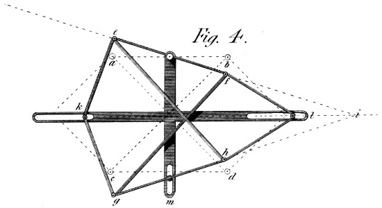
Further, this result would probably be assisted by another
property belonging to this mechanism: see fig. 4. This
diagonal suspension, as repeated at a b c d, fig. 4, is of
such a nature, that when it’s centres a b, are placed in any
oblique position e f, (say by the rolling of a ship) the suspended
bar c d, immediately takes a position of opposite obliquity g h,
pointing upward towards i, just as much as the line e b points
downward; while the middle line k l remains level—whether
caused by the slides k l, or the single slide m.
I dare not assert any thing respecting the form this principle
should assume, in order to produce the most useful effects; but
it appears that the principal weight of the apparatus should be
placed in the centre of gravity of the under bar c d. It would
occur, of course, to every mechanician applying this System
to real use, that in this fig. 4, we have only provided for one
motion of the ship, the rolling motion: and that, in consequence,
this System should be suspended in another similar
one, acting longitudinally, so as to provide for the pitching
motions of the vessel. In a word, I confess, with regret, that
I leave much to do, by way of bringing this idea to maturity—it
being at this late hour, more than doubtful, whether I shall
myself ever be able to resume the subject at sea, where alone
it can be duly tried.
This would seem to be a simpler process than the former:
but how far it may go beyond it in effect, I cannot say—having
never had it in my power to try either of these ideas on
ship-board. I therefore merely present them to my readers, as
themes for future thought and experiment.
Plate 45, fig. 5 represents this System—which is founded
on the idea of deadening oscillatory motions at sea, by connecting
the bodies to be thus guarded, with a stream of flowing
liquid, the horizontal motions of which must be subject to laws
very different from those which rule vibrating bodies merely
suspended.
The fluid used in this Machine (as oil, water, mercury, &c.)
is to be pumped up by appropriate mechanism, from the vessel
into which it flows at x, into a vessel placed a little above z;
and to be let out by the cock y, through a kind of strainer s,
of sufficient collective area to supply, with ease, the descending
column C. The vessel and tube C D are made as thin and
light as possible: and the upper part, which is spherical, is
inclosed in and suspended by the universal joint a b c, like
those used to suspend other bodies, as a compass, &c. Moreover,
the areas, at different heights, of the tube C D, are
made in the inverse ratio of the velocities of the spouting fluid,
at each given depth—so as to leave it but little tendency to press
either outward or inward, while thus obeying the law of gravity.
By these means, then, I think no vibrating motion will be excited
in the falling column: but that the liquid will continue to flow
perpendicularly, so as to preserve (nearly) the quietude of the
vessel C D, and of any mirror or instrument it may be wished
to keep in a given position, by connecting it with the perpendicular
line thus obtained.
I repeat, however, that I know not how far these methods
may go towards obtaining an artificial horizon, for astronomical
uses. Indeed, I fear they will fall short in this respect—but
I think them still worth trying, even for these—but especially
for the purposes to which I have already alluded.
And, if success crowns this publication, to the degree I am
led to anticipate, I will not always leave so rich a question,
in this doubtful predicament.
This is a recollection from the specification of a Patent
which I took out above thirty years ago, and in which I huddled
together as many objects as a child would like to see in a box
of play things. I perhaps acted, then, according to the words of
a French proverb—“abondance de bien ne nuit pas;” but in so
doing, I fell into the charybdis of another French proverb—“qui
trop embrasse, mal étreint,” (a wide embrace cannot be
a strong one) and in so doing, paved the way to much litigation—which
happily did not occur.
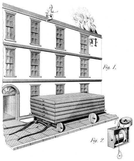
The intention of this Machine, as represented in Plate
46, fig. 2, was to retard the fall of any body, or person, suspended
to it, so as to prevent any concussion on reaching the
ground. The means are brought to view in the perspective
sketch given of the Machine. It is a kind of jack, inclosed in
a case, and supposed to be laid carefully aside in the house
represented in fig. 1 of this Plate. The Machine has a barrel,
much like that of the jacks used for roasting; round which a
rope is coiled, of sufficient length to reach the ground: and
a wheel, connected with this barrel, works in an endless
screw, which turns a shaft also like that of a common jack,
but somewhat stronger; and finally, to this shaft is fixed a small
cross piece, carrying, on pins, two weights y z, inclosed in the
fixed barrel x; by the centrifugal force of which enough friction
is created, to prevent the acceleration of the falling body—whether
a person or weight of any kind.
There is, moreover, a jib a, fig. 1, fixed between some, or all,
the windows of the house whose inhabitants it is wished to
guard from the danger of fire; this jib having the property,
from the form of it’s foot, of taking by the suspension of any
weight to it, a position perpendicular to the wall: Insomuch,
that by the act of suspending the Machine to the jib—engaging
the wrist in the noose n, and perhaps the foot in another loop of
the same cord; a person may safely flee those dangers from
fire, of which so many persons become the unhappy victims.
Since the 46th. Plate was engraved, it has occurred to me,
that a method should have been shewn for raising the cord n,
(fig. 2) after each descent. This operation might be performed
by a handle put on the axis of the Machine, accompanied by
a ratchet on the wheel, just like the similar parts of a jack for
roasting. But, lest the inmates of a house on fire, should not
have presence of mind enough to perform this operation, it
might be better to have a spiral spring in the Machine, to be
wound up by the descending body, and of force sufficient to
raise again the cord after such descent.
This Machine is also shewn in Plate 46, at fig. 1. It consists
of a large truck, A, to be drawn rapidly to any house on
fire, by one or more horses. The carriage or frame part B B,
is an open square frame subtended by a first sheet of sack cloth,
similar to the sacking of a bed: and on this are laid five, or
more, air mattrasses made of sack cloth, and varnished on the
inside so as to be nearly air-tight; I say nearly so, for it is
not intended they should form a spring capable of returning
any object thrown on them. On the contrary, each of the
mattrasses has, at one or both ends, a valve 1, 2, &c. opening
outwards, but kept closed by proper springs, so as to determine
the pressure at which the air shall escape; that pressure being
carefully graduated, so that the upper mattrass shall give way
with ease, the second with greater effort, and the successive
ones with progressive difficulty, until the under one remains
totally closed, and stops the falling body altogether. By these
means, if enough mattrasses are used, and they are duly regulated,
a person may jump from a house of three or four
stories without incurring any danger. As to the length and
breadth of this fire-escape, it should be ample enough to give
the sufferers confidence to take the leap, and as small as an
easy passage in the principal streets would require.
One thing must be described in words—as the mechanism to
which it relates is fixed under the truck; and could not be
seen in this perspective figure. These mattrasses are filled
with air by an horizontal air pump, worked by a crank, which
the axle itself of the hind wheels of the truck forms: whence,
by pinning this axle to either of the hind wheels, the very
motion of the carriage, as drawn by the horses, would distend
the mattrasses—which would thus be ready for use the moment
they arrived on the spot; and moreover, when there, this air
could be replenished, after using, by turning this axle, through
the wheels, by hand cranks slipped on it’s ends at the place
of the linch-pins. Or, in fine, this operation might be performed
by an air pump prepared for it alone, and placed in any
convenient part of the Machine.
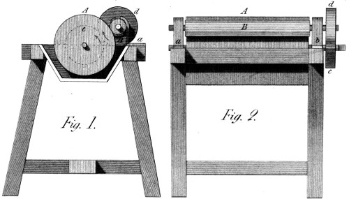
Figures 1 & 2 of Plate 47, exhibit this Machine. It is, merely,
an attempt to effect, by power and a rotatory motion, what
is done by hand and a vibrating one. To understand this latter,
my readers (who have not seen chocolate made) will suppose a
metallic rolling-pin, but cylindrical held in both hands, and
moved parallel to itself, over a slab of marble, to and from the
person employed; who holds the instrument fast when pushing
it from him, and suffers it to turn a little every time he draws
it towards him. He thus presents, sometime or other, every
particle of the chocolate to every part of the slab and the roller:
and this is also done by the Machine shewn in Plate 47.
In figs. 1 and 2, A represents a cylinder of stone or metal,
used instead of the aforesaid slab; and B a cylinder answering to
the roller in question. The latter is placed, by it’s axis, on two
forks a b, so as to lean, by it’s weight, obliquely against the
cylinder A, which it does less or more heavily as the forks, or
stands a b, are placed nearer or farther off from the general
centre. Further, the motions of these two rollers A and B,
are connected by two equal (or nearly equal) wheels c d, by
which, when A is turned, B turns also; but so as to give the
surface of the latter much less velocity than that of A, though
in the same direction. By these means, all the matter adhering
to both cylinders (for chocolate is made in an unctuous state)
is at one time or another, brought into intimate union, and
ground together; and thus is the usual problem resolved, on
rotatory principles: nor need we mention the several scrapers,
&c. that would be applied to gather up the paste to the middle
of the rollers, when spread abroad by the grinding process.
It may not be useless, just to say here, that this is likewise
a good mill for grinding paint or oil colours.
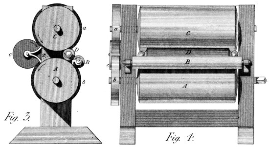
I have insisted, often, on the propriety, mechanically
speaking, of doing every thing by rotatory motion; and thus of
avoiding oscillation wherever it is possible. The present
Mangle is another attempt to employ that principle. In Plate
47, figs. 3 and 4, is an under cylinder, turned as usual by
any convenient power. B is a small cylinder not connected
with it, nor touching it, being intended merely to receive the
weight of the mangle-cylinder D, with the goods rolled on it.
C is an upper cylinder as heavy as necessary, or loaden through
it’s journals or centres, with sufficient weights to make it so.
Again, the motions of the two cylinders A and C, take place
in such a direction, that any round body placed and pressed
between them, would receive from them the same motion; and
thus, a roller of goods, there introduced, will be mangled.
This process is so performed, because the cylinders have
toothed wheels a, b, on their axes, but which do not geer
together: These wheels being connected by an intermediate
wheel c, which makes them concur in producing the rolling effect
above mentioned. But, one thing remains to be observed:
the wheels a b, though drawn apparently equal, are not equal.
The upper one a, has a tooth or two more than the under—so
that the motion to the right hand of the under surface of that
cylinder, is not equal to the opposite motion of the cylinder A.
And hence, the cloth roller D, progresses from D towards x,
between the cylinders A C, and finally falls out at x, after
as many turns of the whole, as the wheels A C have been
calculated to give; and this, is according to the degree of
mangling required.
It is too late to bring this Machine into what might almost be
called an overstocked market of ingenuity—since many power
Looms exist, work, and seem to want nothing to make them
perfect. But an idea of forty years standing, founded on a principle
worthy of attention then, may perhaps not be altogether
vain at present: Besides—I have engaged in my prospectus
to present it to the public. I could, indeed, enter into other
parts of the Power Loom—which I had then begun to execute;
but such is the rapidity with which that Machine is now
striding to perfection, that it would be superfluous. I merely
then, fulfil my promise.
On the afore-mentioned occasion, I thought it of importance,
that the force employed to throw the shuttle, should be
capable of being regulated to any and every degree: and especially
should be fully prepared to act, before it’s action
began: and should, then, act independently of every other
impulse.
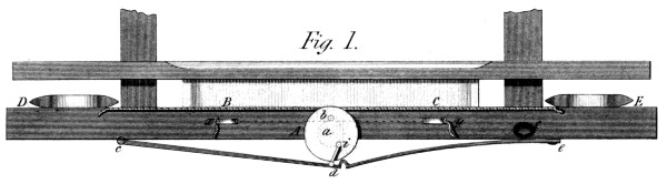
In fig. 1 of Plate 48, A is a wheel or pulley of about six
inches in diameter, from which two cords proceed in opposite
directions (B C) to the pickers, which drive the shuttles D
E in the usual method. This pulley runs on an axis going
through the bottom of the lathe, (or beater) and it might have
a crank, behind, of a radius equal to a b: but to shew the
whole in one figure, I suppose the following mechanism to be
placed in the front of the lathe, and just before the face of this
wheel or pulley A. c d is a bar turning on the centre c, and
receiving at it’s other end the pressure of a spring e d, which
in it’s turn, is susceptible of different degrees of springiness,
as regulated by the screw f. On a stud i in the wheel A, is
put the small bar i d, which forms also a turning joint in the
bar c d: and thus communicates the effort of the spring to the
stud i, and thence to the wheel A. Finally, this wheel has
either under it, on the front side of the lathe, or on it’s axis,
at the back, a pulley, by which it can be turned, by means of
one or other of the cords brought from the breast beam of the
loom, round the pullies x and y, to this wheel a b i, according
to the dotted lines. Supposing then, one of these cords to be
tightened by the backward motion of the lathe, it will draw the
wheel A about half round: when the stud i will rise to the point
b, straining the spring to get over the centre: and as soon as it
is over, the spring will act, and drive the picker and the shuttle
with the desired speed, independently of any other mover. And it
is evident, that now the opposite cord x or y, will be tightened
so that when the lathe shall be again pushed backward to form
the opening for the shuttle the slide will be carried back over
the centre a, and re-produce another impulse in a contrary
direction.
The rapidity with which a vacuum is formed by an Air
Pump, depends on the ratio between the contents of the receiver
and those of the pump barrels. If the latter be just equal to
the contents of the former, (which is a very large proportion)
the exhaustion will follow this series:—there will remain in the
receiver after each stroke, the first contents being 1, 1⁄2, 1⁄4, 1⁄8,
1⁄16, 1⁄32, 1⁄64, 1⁄128, 1⁄256, &c. But if the pump barrel contains
twice the volume of the receiver—then the remaining air, after
the strokes, will be 1⁄3, 1⁄9, 1⁄27, 1⁄81, 1⁄243, 1⁄729, 1⁄2187, 1⁄6561, &c. being
much nearer to a vacuum than on the former supposition.
To meet this case, then, I have thought a water pump might
be used: that is, a barrel or vessel, much larger than the receiver;
and which by the action of a smaller pump, placed on
a lower level, might be alternately filled with water and emptied
so as in a few operations to complete the exhaustion, very nearly.
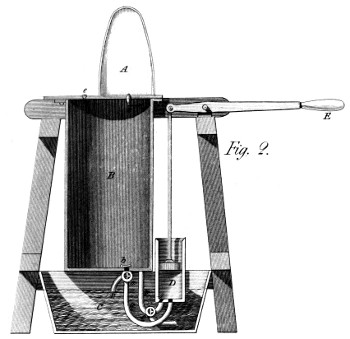
Thus, in fig. 2 of Plate 48, A is a receiver, B is a large
vessel that can be filled with water from the tub C below;
and D is the pump, worked by the handle E. It is a common
water pump, (so much the readier adopted, as requiring little
care in the execution.) The question was to make this pump
alternately fill and empty the vessel B. Adverting first to the
filling, a c are two cocks, having each a side-passage for the
water; and these passages are now so placed, as by working
the pump we suck water out of the tub C, and throw it into
the vessel B, through the valve b;—by which means all its air
is driven out through the lateral valve e. When this is done,
the cocks c d (which are so made as to be worked by the same
mover) are turned into a new position, which opens the pipe p
to the pump D, and that q to the returning spout r; by which
means the water is drawn from the vessel B, and thrown into
the tub C: so that the air is again drawn out of the receiver
A, through the inverted valve s, into the vessel B, and another
degree of exhaustion occasioned. This being done, the
cocks are again put into their present position; the air expelled
by the water through the valve e as before, and a new
stroke prepared. It is scarcely needful to add, that if the vessel
B contained ten times as much volume as the receiver A,
the exhaustion of the latter at each emptying of the vessel B
would follow this ratio—1⁄11, 1⁄121, 1⁄1331, &c. thus approaching
by rapid degrees to a perfect vacuum. The water, or liquid,
used for this purpose would of course be as perfectly purged
of air, as possible.
The principal mechanical merit I conceive this Machine
to possess, lies in the facility it gives of taking a stream of
water as high, and discharging it as low as possible: and both
nearly in the direction in which it naturally flows. Of the advantage
it possesses in keeping the water a long time from falling,
I shall not now speak, as it would require more discussion
than this work comports; and, moreover, the Plate confines us
to a somewhat contracted representation, which I hope my
readers will excuse.
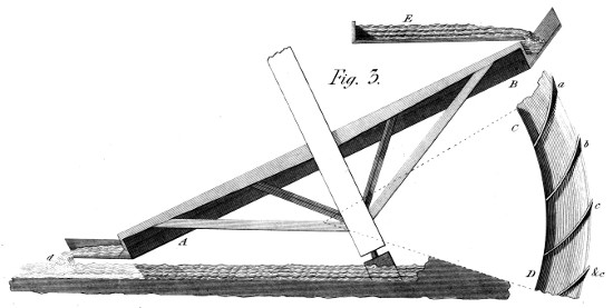
Plate 48 fig. 3, A B is the section of the wheel, and C D
a small portion of it’s circumference—which shews the form
and position of the floats a b c, &c. E is a floor on which the
upper water flows, and from which it falls thinly on to the wheel—whose
motion is purposely made as slow as possible. The
water then, occupies one half of the wheel’s circumference,
falls by a gentle slope and finally leaves the wheel at d,
whether it there touches the lower water, or not. This wheel
is allowed to be incapable of using to advantage a large stream
of water—but is doubtless fit to employ a small stream, in the
best manner.
I have hesitated a moment to describe this method of
helping the weak, in body or mind, to conquer their aversion
to medicine—several persons having threatened me with
a larger dose of ridicule than I am prepared to swallow. But
surely, if we can only conquer a child’s timidity, so as to
induce him to take, speedily, what his health requires, we shall
not do a thing altogether laughable. We shall, perhaps, preserve
a beloved child to the solicitude of a mother! and perhaps—a
citizen to his country! If then, some laugh, more
will approve; and I therefore continue the promised article.
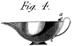
Fig. 4 of Plate 48, shews this cup, composed of an inner
and an outer vessel: the first to hold the medicine, and the
latter a little tea, or other proper liquid to wash it down. The
cups have a spout common to both; but the outer cup retains
it’s contents as long as the small funnel a, is stopped with the
thumb or finger. Thus then, the medicine is first taken, while
the liquid is retained in the outer vessel—but the thumb being
removed, the liquid also flows into the mouth, and in a good
measure removes the taste it was wished to disguise.
The art of constructing Mills, or Machines to be driven by
the wind, is so well known, that the results are considered as
being, very nearly, what a perfect theory would require. It
is, therefore, no part of my purpose to discuss either the
theory or practice of that art. But I think that a still wider
grasp may be taken of this powerful agent, so as to secure a
further degree of utility, even while following less closely the
abstract principles of mechanical philosophy. I enter then,
directly, on the description of another of my wind Machines,
in order to give an idea of the means I contemplate for losing
the importance of those details in the magnitude of the general
effect.
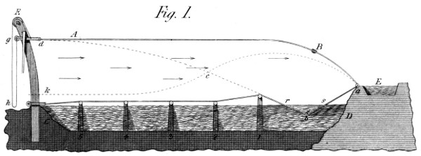
This Machine (see Plate 49, fig. 1,) is capable of great
results merely because it employs, at a small expence, a great
mass of air in motion; whether ill or well, is not the question:
for as this source of power is almost indefinite, methinks we
may draw from it without reserve. The present method of so
doing, consists in using a very large sail, (A B) both to
receive the impulse of the wind, and to raise the water. This
figure is a section of the Machine in it’s length:—and it’s
width (not represented) is as great as the occasion may require.
The sail is here shewn as placed over a lake or other sheet of
water which it might be wished to drain, (or which may serve
as a mill pond to drive any required Machines, by the water
thus raised.) C D is the water in it’s lower bed: and E, is a
canal on a higher level, into which a large quantity is thrown
at each manœuvre of the Machine, a is the bank of the upper
canal, to which is affixed the edge of the canvass, of which
a B A d, is a section; and which might be large to immensity.
At 1 2 3, &c. is a row of stakes as long as the Machine;
and they are capped transversely with round poles, on which
the sail rests when in it’s lowest position. In this state, also,
the part b of the sail, plunges into the water, which rises
above it in the prismatic form, b r s; a row of valves or clacks,
(b) permitting it to rise through them, but preventing it
from again falling that way. Thus, at every change, this
prism of water, is sure to be replenished; and if we suppose the
triangle b r s to have an area of ten square feet, and the prism
to be one hundred feet long, the water there contained will
be a thousand cubic feet—capable, however, of being augmented
or diminished at pleasure, by slackening or tightening
the sail towards A. At d, is the weather-end of this sail,
which is supported when at rest, on the surface of the water,
by the posts and caps before mentioned. This end d, of the
sail is connected with a row of posts C F, placed more or
less closely, as the prevailing strength of the wind and the size
of the sail may require. The sail is held to these posts by
rolling pulley frames, of which one is seen at g, and is drawn
up and down by the rope g h, acting at one end directly on
the rolling pulley-frame g, and the other on the sail d, after
having passed over a pulley (F) in the post itself: where note,
that this effect can be communicated by proper machinery,
from any one of these posts (C F) to all collateral ones; so as
to make the manœuvres general, across the sail, whatever be
it’s magnitude.
The following then, is the operation. The wind blows (by
supposition) in the direction of the arrows in the figure: and
the rolling pulley-frame g is quickly drawn up to g, where the
hook i holds it fast. By a necessary consequence the wind
fills the sail d c r, and stretches it into the figure d A B a:
in doing which it lifts the water r s, and pours it, in all the
width of the sail, into the canal E; thus raising a thousand
cubic feet of water at each stroke. As soon as the water is
turned into the canal E, the hook i is pulled outward, and the
rolling pulley g is forced down, by the wind itself, to the position
k, when the wind blowing over the sail, will give it a bent form,
(k c a) and soon bring the sail into it’s present position on the
posts 1 2, &c.—when water will be again admitted by the
valves at b, and another stroke of the Machine be prepared.
The above contains the basis of this idea. I do not expect
it will obtain at once universal assent: But if I knew the several
grounds of objection, I am persuaded the greatest number
of them could be removed. The first I anticipate, is the
difficulty of turning this Machine to the several winds that
may blow over it. To this objection I would reply, that in
such a case, the canal E, should surround an area made large
enough for the sail, of some polygonal form, say an octagon,
to different sides of which the stretching cords of the sail should
be carried, so as to catch the prevailing winds—but the direction
of which need not be followed to a nicety; since an
obliquity of a few degrees would not prevent the effect.
It might be added, that it is not indispensable that the canal
E should be stationary. Made of wood, or metal, it might
turn round a fixed centre, and be braced into the necessary
positions with ropes—when the posts only (C F) would have
to be removed, or quitted for others duly placed. These ideas
are connected with immense effects; and cannot, therefore,
be lightly disposed of: they both deserve and require serious
attention.
This is the last of those conceptions I shall now bring
forward, for making more than a common use of the WIND as
a first-mover of Machinery. Horizontal windmills are well
known; and this is a horizontal windmill—yet not like those
already in use: for, here, the sails, very large and numerous,
are placed on a boat in the form of a ring, which thus moves
through the water without any other resistance than that
arising from the asperities of it’s surface.
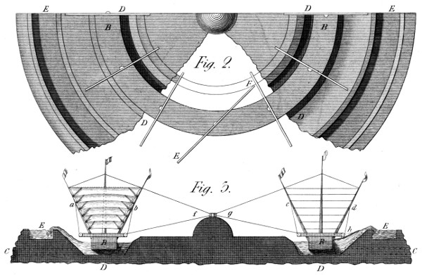
In Plate 49, fig. 3, B B is a section of the Vessel, placed
in a circular canal D, into which the lower water flows through
proper arches (C C) in the banks. The vessel is rigged with
several narrow horizontal sails, stretched on ropes between
the oblique masts a b, c d; and so placed, that the sails (being
a little wider than the interval between the ropes) can open
in one direction, but not in the other; and they are shewn
open at c d, and shut at a b, in the figure. This, therefore,
is a mill, that takes all winds; and although it’s uses might be
various, we shall finish it’s description as adapted to raise
water by the centrifugal force. As before hinted, the canal
D D is circular; and has a bank, sloping outward, with a
canal (E) on it’s top. When, therefore, the wind blows,
the ring boat B (held to the centre by the ropes f g) revolves
around it; and by one or more water drags (h) which it
carries, collects the water on and up the bank, and finally
drives it into the canal E, from which it flows in any destined
direction. If for draining watery lands, it will be done rapidly;
if for irrigating, it will be done abundantly: if, in fine,
for driving any mill with the water thus raised, the machinery
will be very efficient, as working with ten or twenty times as
much sail, as any other windmill can carry. I add, merely
on this occasion, that the sails here mentioned, might be
placed obliquely, instead of straight across the ring vessel;
(see the plan in fig. 2 of this Plate at E F) from which disposition,
nearly all the advantages of the vertical mill might
be transferred to the horizontal; and with this remark I leave
the present interesting subject to the studious and candid
reader.
My fiftieth and last Plate contains this idea: It is not intended
to vie with the usual mirror, in correctness of form, or
intensity of local effect—but to offer, by the largeness of it’s
dimensions, some properties which better mirrors cannot present.
It is intended to pave the way for the use of the Sun’s
rays in Engines of Power. For this purpose, however, it must
probably be transported to some tropical climate, where “a
cloudless sun” diffuses it’s rays more constantly, and less obliquely,
than in our northern climes.
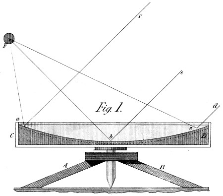
This is the more necessary here, because this Mirror can
only be used in a horizontal position, and is in fact a fluid
Mirror. Fig. 1, shews it mounted on a steady frame A B,
and having a strong axis on which it can be turned, faster or
slower, according to it’s dimensions; and it may or may not
be floated on water, to lessen the stress on the axis. The
Mirror, properly speaking, is composed of mercury—contained
in the revolving vessel C D, whose motion should be given by
proper machinery in the most uniform manner possible. The
mercury, thus turned, acquires a concave surface, a, b, c;
and receiving the parallel rays d c, e b, and, f a, collects them
into the focus F; in, or near which, is placed the vessel where
the effect is to become useful, and which of course is moveable
so as to follow the sun’s motion. Those of my readers who have
seen the machines used for fixing the sun’s image in the solar
microscope, will be at no loss to conceive how our present focal
station must be moved to adapt it to a fixed mirror. I shall only
add further, that it is not necessarily an exact movement that
is here wanted; since the vessel to be heated would have
dimensions somewhat large, and the focus itself be only
brought to a moderate degree of precision. In a word, the
utmost heat wanted would be, what could be usefully employed
in heating water. It remains then to be observed, that the
source of power, in this Machine, is magnitude of parts, more
than precision of form: yet it may be mentioned, that the form
we thus procure in the revolving mercury, is a solid of revolution,
having the logarithmic curve (a, b c) for it’s section—a
curve, which in fact, comes indefinitely near to the parabolic
figure which would be required, if greater precision were attempted.
We finish then, by observing, that the bottom itself
of the revolving vessel might be made concave, (like the
dotted line under that a b c) in order to avoid the necessity of
using a large quantity of mercury, to form the reflecting surface.
This Mirror seems superior to the former, as depending
on fixed materials. It likewise, produces the desired effect,
by offering a very large surface to the sun, and directing the
rays to a focus, nearly enough to give the heat required for
water, as before mentioned.
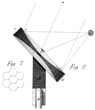
To do this, a frame A (Plate 50, fig. 2) holds the Mirror;
and this frame has a horizontal motion round the post B, something
like a common windmill. In this frame and on two
horizontal trunnions, turns the Mirror C D: and one or both
these trunnions are hollow, to admit of a process we shall
shortly mention. This Mirror itself is composed of an air-tight
ring C D, of a width proportionate to the diameter adopted;
and on which are fixed two heads, much like those of a tambourine,
(or the under head might be made of some metallic
substance). The head a b c, is made of a fine texture, duly
prepared and varnished till it becomes air tight, and then there
are stuck to it, a number of small hexagonal looking-glasses or
mirrors of any kind, (see fig. 7) which thus fill up the whole
space, and prepare the Mirror for the intended change of form.
The method of giving this form, consists in exhausting, more
or less, this tambourine of air, when, by the pressure of the atmosphere,
the heads will take the form a b c, that is a spherically
concave form—fit to reflect the sun’s rays as correctly as
this our object requires; and thus may some thousand small
images of the sun be brought to fall on the same spot, and an
immense heat be occasioned. The accounts we have of the
destruction of the Roman fleet by the united mirrors of Archimedes,
make this process appear the more feasible—as whatever
were the methods of uniting the foci of his mirrors, a
similar effect may be expected from this simple process.
My readers will perceive that this Machine has the advantages
of the universal joint, by which it can be directed to
the sun in every position; and even made to fix his ardours on
any immoveable spot for a good length of time. The persons to
whom I particularly address these ideas, will require no further
details to conceive the less obvious circumstances of this Invention.
In general, we want no effect that requires optical
precision: but if we did, it could be obtained to a good degree,
by methods similar to these.
I shall only add here, that this fig. 2 is given as a section—because
intended to represent a parallelogram, as well as a
solid of revolution: and thus (with proper mirrors) to make
what now appears a spherical focus, a linear one—fit to heat a
cylindrical vessel with it’s contents; and thereby draw power
from the sun’s heat, without running expense. I am serious
when I say, that we can thus, practically, collect the solar
rays which fall on many hundred square feet of surface; and
produce by them, at any desired distance, effects to which
those obtained from modern burning mirrors, are but as sparks
to a blaze.
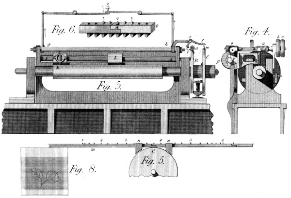
This Machine supposes at once a new kind of engraving, and
admits of patterns of very large dimensions. This kind of engraving
will be best understood by persons acquainted with figure-weaving;
and especially with the manner of mounting the looms
for that purpose. In that System, (see Plate 50, fig. 8) the
patterns are drawn on ruled paper divided into squares; and each
of these squares represents a point in the texture, composed of
one or more threads each way; insomuch that whenever that
square has any desired colour in it on the pattern, it’s threads
are taken by the person who prepares the loom; and they are
missed in every case where nothing appears in that square, or
a colour not then wanted. Now, whatever be the dimensions
of these elementary points on the loom, they may be represented
by squares of any convenient size on the pattern:
only remembering that the smaller they are, in reality, the
better will be the delineation. Thus in carpeting, for example,
an element of this kind may be a square of one tenth of an inch
and more; while one on a ribbon or a piece of silk, is often not
the hundredth part. And therefore, the perfection of this engraving
depends on the fineness of the points of which the figures
are composed. For, in a word, this System proceeds on the
same principle. When any part of a line requires a dot or
mark to be made, the Machine strikes a blow there; and
when no impression is to be made, the Machine (by means
that will be shewn) suffers the cylinder to pass that place without
striking. The means of regulating this is committed to workmen
who merely know how to read off the pattern in it’s length,
as it is now read off in it’s width by the weaver. To describe
the construction of the Machine, (as exhibited in figs. 3 and 4
of Plate 50) A is the cylinder to be engraved; and B is a
worm-wheel fixed to it’s mandril, and destined to turn it.
This it does, slowly, by the endless screw a, as turned by
proper straps on the fast and loose pullies b c, (figs. 3 and 4).
C shews a second wheel, concentric with that B, but running
loose on it’s axis, which is a pin fitted into the end of the mandril.
This wheel, when the threads of the screw a are fine,
requires a motion more rapid than the wheel B—to give which
motion by means of the latter, we use a pair of multiplying
wheels d, which geer, one in the larger bevil wheel cut near
the edge of the wheel B; and the other in a smaller bevil
wheel cut or fixed on the inner face of the wheel C—and
whence this latter wheel receives a velocity of about ten times
the speed of B. The use of this wheel C, is to carry, across
the Machine, certain bars, of wood or metal, shewn in figs.
5 and 6, whose function is to carry short pins or studs 1, 2,
3, 4, &c. for the purpose of determining the places where the
punch is to act, and where it is not. To this end, g h is a
frame, which is raised by a cam or tappet i, fixed in the
endless screw a, once every turn; and that through the medium
of the little tumbler i e f, by which is finally determined
whether the stroke shall take place or not—for m being a
section of the stud bar of figs. 5 and 6, it’s pins, when they
occur, raise the end f of the bent lever f e i; and when
there is no pin or stud in m, this lever is not raised, and
the point i, does not come near enough to the cam to be
laid hold of, in which case no stroke is given. This then, is
so whenever the studs fail in the bar m; and these fail whenever
the pattern-reader has said to the stud-setter, miss: and
they occur whenever he has said take—both which cases
happen more or less often according to the state of the squares
in the pattern.
To be a little more particular: in fig. 5 we see a part of the
wheel C of fig. 3, and also a part of the stud bars m m, which
geer in the wheel C, and which being conducted by the guides
n, follow the motion of that wheel, presenting at f, (fig. 3)
a stud to raise the lever f e, whenever the pattern requires it.
It may be mentioned, that these studs act obliquely on the wing
f of this lever, and thus raise it as they pass under it. And
further, these stud bars are made and fitted to each other in
the manner shewn at fig. 6. There is a geering tooth under
every stud hole, and the last stud hole of a given bar has, fixed
in it, a thin tube a, into which the stud enters the same way as
in any other place: but this tube whether studded or not serves
to lay hold of the succeeding bar b, by it’s first hole—so, in fine,
as to make the bars endless; the attendant having nothing
else to do than to hook them to each other as the wheel C
draws them in.
Thus then, are the strokes of the hammer frame, g h,
conformed to the pattern: for these bars have been studded
before hand by one or more readers and setters; and it is a
merely mechanical process to put them in while the Machine
moves: from which, by the bye, they fall out after the passage
into a proper box, and the studs out of them, to be composed
again from the succeeding figures of the pattern. A
dozen or two of these bars might be prepared at any time and
place, and to any pattern, which they will thus transfer to
a cylinder at any desired moment, without the further preparation
of dies, punches, mills, &c.—as used in other Machines.
N. B. The strength of the blows thus given by the
hammer frame g h, is lessened or augmented by the position of
the point i fixed to the bent lever i e f, and which makes that
lift higher or lower as required—which is a mean of shading
offered by this Machine. But to mention it’s other properties,
the endless screw a, (figs. 3 and 4) carries another endless
screw o, more or less fine, which turns at the same time the
wheel p, and, by that, the long screw s s, whose office it is to
shift, slowly, the punch carriers k l, along the Machine, from
k by l, towards s. And here an observation occurs: this can
only be so, when the pattern permits the action of the punches
k or l, to take place spirally on the cylinder; that is, when
the sketches are distinct enough not to shew the anomaly that
would occur were a straight pattern thus transferred to a set
of spiral lines. But should it be desirable to engrave patterns
so correct as to require an exact parallel motion round
the cylinder, then the motion of this screw must not be continual—but
must intermit and be resumed, at every beginning
of a new line round the cylinder. I hope, I make myself
understood: a pattern drawn on squares, produces lines all
parallel to the first; while the spiral motion of the punch
causes a slight deviation—which, in a word, can either be suffered
or avoided. At all events, this deviation is so much the smaller
as the punch motion is slower in both directions; and, in fine
patterns, must be very small. One remark will close this part
of the subject: although a fine pattern, requires a great number
of blows, and thus a certain expence of time, each blow
can be so much the lighter and more frequent; so as to compensate,
in some degree, for this cause of delay. I add, that
the levers shewn above and around fig. 6, are intended to lift
the hammer frame g h, equally at both ends: while the screw
Z regulates the depth to which it is permitted to fall.
I observe, finally, that, according to the size of the intended
pattern, there are more or fewer of the punch bearers
k l, connected, by their nuts, with the screw s s; each of
which thus engraves it’s sketch, similar to the collateral ones;
and that were it wished to make one pattern of the whole
length and circumference of the cylinder, a single punch
bearer would be required—since nothing else limits the extent
of a pattern engraved by this Machine.
Thus have I gone through my proposed “Century of Inventions,”
for every imperfection in which I beg the indulgence of
my numerous readers. And here I can truly say I have neglected
nothing—although the precarious state of my health may have
sometimes veiled the evidence of my descriptions. On the other
hand, I did not even attempt many of the lesser details of execution;
as I wrote for those to whom they would have been
superfluous: but as to the objects themselves, I believe there
is not one that is without the pale of practical utility. In a
word, many of the subjects have been frequently executed,
and are in daily use: and as to those which remain to be tried,
I engage, if called on, to give them useful existence. And
the better to convince candid minds of the serious attention
I have paid to these subjects, I shall add the scales on which
they have been executed, or to which they are drawn—those
scales expressed by a fraction, shewing what proportion the
figures bear to the reality. Thus the scale of one inch to a
foot will be expressed by the fraction 1⁄12; that of two inches
to a foot, by 1⁄6, &c. that is, the figures, in these cases, will
be (nearly) 1⁄12 or 1⁄6 of the size of the Machines. This premised—and
also that we shall observe the alphabetical order, the following
is the