TOOL PROCESSES IN SPINDLE TURNING
Exercise A-I--1-a. Straight Cuts
1. THE ROUGHING CUT (LARGE GOUGE).
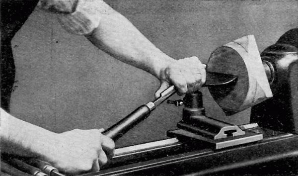
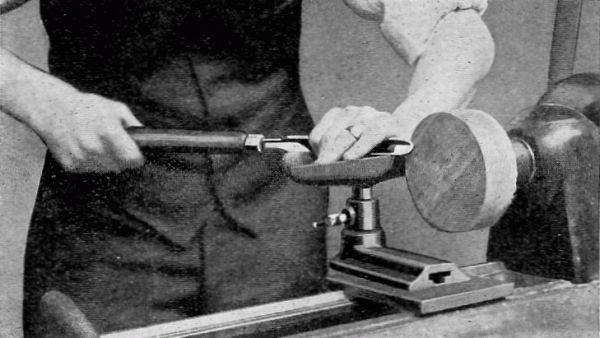
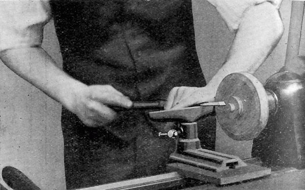
FIG. 4. Place the gouge on the rest so that the level is above the wood
and the cutting edge is tangent to the circle or surface of the
cylinder. The handle should be held well down.
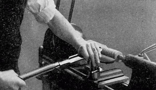
Fig. 4.
Roll the gouge over slightly to the right so that it will make a
shearing cut instead of a scraping cut. This rolling of the tool will
also throw the chips from the operator.
Then lift the handle slowly, forcing the cutting edge deep enough into
the wood to remove all or nearly all of the corners, at the end of the
work which is being turned. This cut is begun about ¾" from the dead
center end. Work back another ¾", moving toward the live center and
make a second cut, and so on until the entire length of the cylinder is
gone over. This method of removing corners should always be followed to
avoid any possibility of breaking a large sliver from the stock, with
consequent danger to the worker.
The tool may then be worked from one end to the other, getting a
fairly-smooth, regular surface, slightly above the diameter required.
However, do not begin on the very edge of the cylinder end. It is better
to begin about 2" from one end and work to the other, and then reverse
and work back.
The tool should also be held at a slight angle to the axis of the
cylinder, with the cutting point always in advance of the handle.
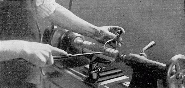
Fig. 5.
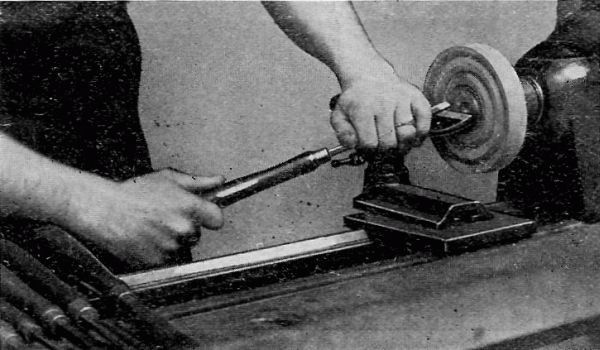
2. THE SIZING CUT (SMALL GOUGE). FIG. 5.
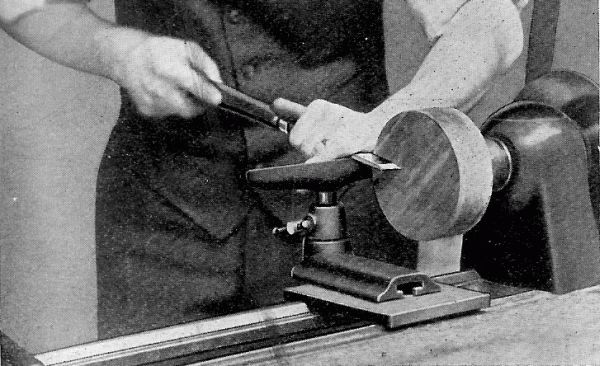
Set the calipers to the required diameter of the cylinder.
With a small gouge held in the right hand scrape grooves about 1" apart,
holding the calipers in the left hand perpendicular to the cylinder and
measuring the cuts as they are made. The scraping should continue until
the calipers will pass easily over the cylinder. It will be well while
scraping to work the handle of the gouge a little from side to side so
that the nose has more clearance. This will prevent the piece which is
being turned from chattering or vibrating.
The calipers will be slightly sprung by coming in contact with the
revolving stock but this error in diameter will be removed by the
finishing cut which removes these marks from the finished cylinder.
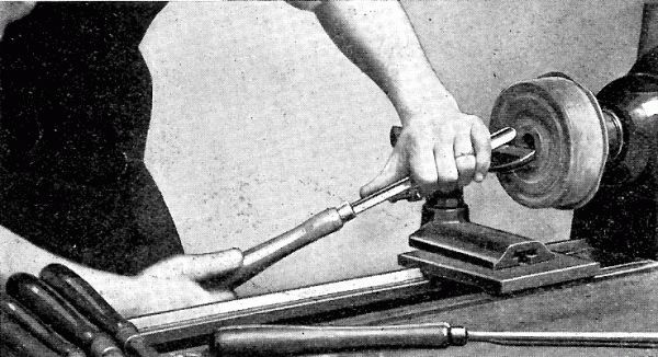
3. THE SMOOTHING CUT (LARGE SKEW).
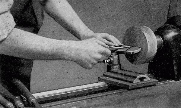
FIG. 6. Lay the skew chisel on the rest with the cutting edge above the
cylinder and at an angle of about 60° to the surface.
Slowly draw the chisel back and at the same time raise the handle until
the chisel begins to cut about ¼" to ⅜" from the heel. The first cut
is begun from 1" to 2" from either end and is pushed toward the near
end. Then begin at the first starting point and cut toward the other
end. One should never start at the end to make a cut as there is danger
that the chisel will catch and cause the wood to split or that the
chisel will be torn from the hands.
The first cut takes off the bumps and rings left by the gouge, and takes
the stock down so one can just see where the scraping to size was done.
Then take the last cut and remove all traces of these, leaving the
cylinder perfectly smooth and of the required diameter at each end. Test
the cylinder for accuracy with a straight edge.
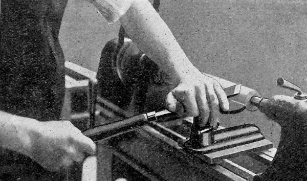
Fig. 6.
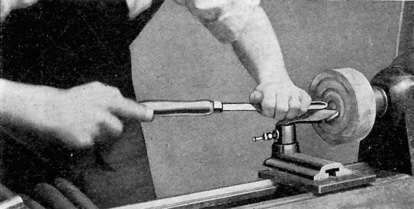
4. TESTING FOR SMOOTHNESS. In testing for smoothness place the palm of
the hand, with the fingers extended straight, lightly on the back of the
cylinder opposite the tool rest. This position will avoid any
possibility of the hand being drawn in between the cylinder and the
rest.
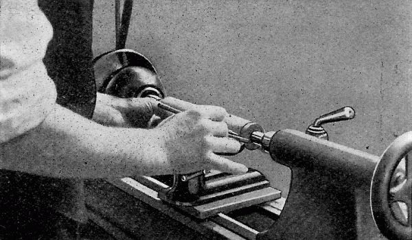
Fig. 7.
5. MEASURING FOR LENGTH (RULE AND PENCIL). FIG. 7. Hold the back edge of
the rule in the left hand and place it on the tool rest so that the
front edge is almost in contact with the revolving cylinder.
With a sharp pencil mark off the required length, starting from the dead
center end. The first mark should be just far enough in on the cylinder
to insure cutting past the point of the dead center. This will leave all
surplus stock at the live center end where it is needed, because, if not
enough stock is left at this end, there is danger of striking the live
center spur with the tool and of injuring the chisel and perhaps the
work.
In case several measurements are to be made, as in some of the following
exercises, the rule should not be moved until all are marked. This will
insure more accurate work than if the rule be changed several times.
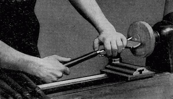
6. SQUARING ENDS (SMALL SKEW AND PARTING TOOL). FIG. 8. This operation
is done with the toe or acute angle of the ½" or ¼" skew chisel.
Place the chisel square on the tool rest. Swing the handle out from the
cylinder so that the grind, which forms the cutting edge, next to the
stock is perpendicular to the axis of the cylinder. The heel of the
chisel is then tipped slightly from the cylinder in order to give
clearness. Raise the handle and push the toe of the chisel into the
stock about ⅛" outside the line indicating the end of the cylinder.
Swing the handle still farther from the cylinder and cut a half V. This
will give clearance for the chisel point and will prevent burning.
Continue this operation on both ends until the cylinder is cut to about
3/16" in diameter.
The remaining ⅛" is then removed by taking very thin cuts (about
1/32") holding the chisel as first stated. After each cut is made the
end should be tested for squareness by holding the edge of the chisel
over the end of the cylinder.
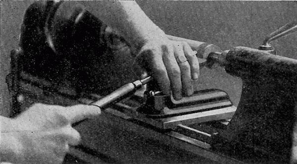
Fig. 8.
This is an easy cut after it is mastered, but is one of the hardest to
learn. Should the operator lose control of the tool and allow any part
other than the point to touch the cylinder, a run or gashing of the
wood will be caused.
In large cylinders where considerable stock has to be cut away in order
to square the ends, time will be saved by sizing the ends down with the
parting tool to within ⅛" of the desired line, leaving enough stock at
the base of the cuts to still hold the cylinder rigid while cutting on
the ends.
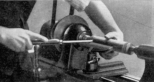
Fig. 9.
For this operation hold the parting tool on the rest with the cutting
edge parallel to the axis of the cylinder and the lower grind tangent to
the cylinder. Lift the handle and force the cutting edge into the wood;
at the same time push the chisel forward to keep it at the proper
tangency.
7. CUTTING OFF (SMALL SKEW). FIG. 9.
After both ends have been squared cut away stock, at both ends, to leave
just enough to hold the cylinder from separating from the waste ends.
With the chisel held in the right hand in the same position as in
squaring the ends, and the fingers of the left hand around the stock to
catch it, slowly force the point of the chisel into the stock at the
live center end, until it is cut free and the cylinder stops in the
operator's hand. Too much pressure should not be used in this operation
or it will cause the cylinder to twist off instead of being cut, and
will leave a ragged hole in the end.
The dead center end, which has been scored heavily before cutting off at
the live center, is then removed by holding the grind of the chisel flat
on the end of the cylinder. The latter is revolved by hand until the
stock is cut away.
Exercise A-I--2-a. Shoulder Cuts
1. Turn a cylinder to the largest diameter required.
2. Lay off measurements with rule and pencil.
3. With the gouge (where space permits) or the parting tool (in narrow
spaces) rough out surplus stock, keeping 1/16" away from the lines
indicating shoulders.
4. Caliper to the diameter of the second step.
5. The shoulders are cut down as described in "Squaring Ends, Step 6,
Straight Cuts."
6. The new diameter or step is then trued up with a skew chisel in the
same manner as a cylinder; except that in nearing the shoulder the
chisel is pushed up on the cylinder until the heel, which is the only
part that can be worked into the corner, becomes the cutting point. Fig.
10. In very narrow steps it will be advisable to use the heel entirely
as a cutting point.
In spaces between shoulders, too narrow to permit the use of the skew
chisel, very effective work can be accomplished by slightly tipping the
parting tool sideways to allow a shearing cut to be taken with the
cutting edge.
7. Where several steps are required on the same cylinder, each
successive one is worked out as above described.
Note:--All preliminary steps in working stock to size, laying of
dimensions, etc., in preparation for the exercise in hand, will be
omitted in the following exercises:
Exercise A-I--3-a. Taper Cuts
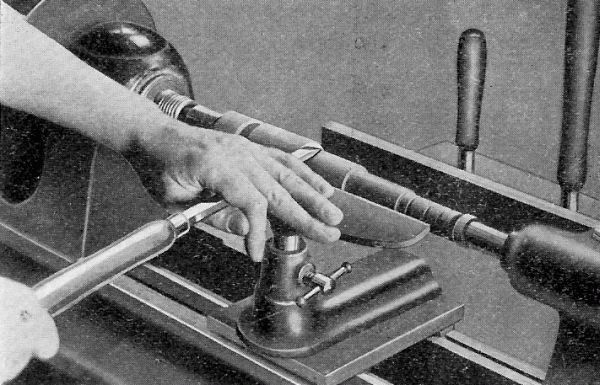
Fig. 10.
Calipering for New Diameters. For all diameters on tapers the calipers
should be set 1/16" larger than the desired measurement in order to
avoid working under size in the finishing cut which removes all caliper
marks.
If the taper runs to the extreme end of the cylinder, as in Plate
A-I--3-a, a parting tool should be used, instead of a gouge, to take off
a very thin shoulder.
If the taper forms an internal angle as in Plate A-I--3-b, a gouge is
used as in Step 2--Sizing Cut--Plate A-I--1-a.
In other cases where tapers connect with straight cylindrical shoulders
it is best to turn the shoulders to size before working the tapers.
In cutting a long straight taper the skew chisel is used, much in the
same manner as in ordinary cylinder work, except that at the start of
each cut the heel must be the cutting point. This will avoid any chance
of the chisel catching and drawing back and thus gouging the wood beyond
the starting point. As soon as the cut is well under way the chisel may
be pushed up on the cylinder so that the cutting point is a little above
the heel. All cuts should be made from the highest point on the cylinder
to the lowest and thus cut across the grain of the wood.
In making the cut, care should be taken to see that the chisel is not
tipped to a greater angle than that of the taper wanted. Should that be
done a hollow, or dished out, taper is sure to be the result instead of
a straight one.
Exercise A-I--4-a. V Cutting
In cutting V's a small skew is almost always used and the cutting is
done with the heel.
Place the chisel square on the tool rest so that the cutting edge is
perpendicular to the axis of the cylinder. Draw the chisel back and
raise the handle so that the heel is driven into the wood, thus scoring
it. This cut should not be too deep or the chisel will burn. This
scoring should be at the exact center of the V cut.
Swing the handle a little to the right and at the same time tip the
chisel so that the grind, which forms the cutting edge, is at an angle
of about 45° with the axis of the cylinder. The handle is then raised at
an angle of 45° bringing the heel down to make a good cut. The chisel is
then swung to the other side and a similar cut is taken. These cuts are
continued, together with the center scoring, until quite close to the
pencil marks. Test the angle before the finishing cut is taken.
It will be found best to have the V slightly greater than 90° at the
base until the final cut is made, at which time it can be trued up.
The V should be tested with the square end of a rule. The cylinder
should not be in motion while testing.
When angles other than 45° are cut, the cutting edge of the chisel
should be tipped so that it is parallel or nearly so to the side of the
cut desired.
A-I--5-a. Concave Cuts
The concave cuts as a rule will give the pupil considerable trouble at
first owing to the fact that the grind, which forms the cutting edge and
which must be held perpendicular to the cylinder at the start, is on the
under side of the tool and cannot be seen. However, as soon as the
correct angle of the tool is located, the cut will be found as easy as
any. Concaves are usually made with a medium sized gouge either the ½"
or ¾".
Place the gouge on the rest with the grind or cutting edge well above
the wood. The tool is then rolled on its side so that the grind at the
cutting point, which is on the lip of the gouge well below the center,
is perpendicular to the axis of the cylinder. Fig. 11.
Slowly raise the handle to force the gouge into the wood. As soon as the
gouge has taken hold, the tool is forced forward and upward by a slight
lowering of the handle, while at the same time it is rolled back toward
its first position. Care should be taken not to roll the chisel too fast
or a perfect arc will not be cut.
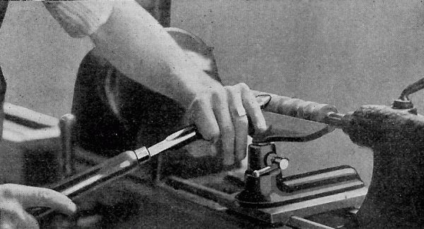
Fig. 11.
By this triple action the grind, which comes in contact with the surface
of the curve, forces the lip sidewise and cuts one quarter of a circle.
Reverse the position of the gouge and cut from the other side in the
same manner to form the other half of the semi-circle. The cutting
should always stop at the base of the cut as there is danger that the
tool will catch when cutting against the grain of the wood on the other
side. Repeat this operation until within about 1/16" of the required
size. At the end of each successive cut the tool should have been forced
far enough forward and upward to bring the grind or nose of the chisel
well out on top of the cut. Fig. 12.
The exact depth of the concave is then calipered in the usual manner as
described before. A finishing cut is then taken after the cut has been
tested with a templet.
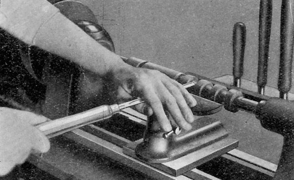
Fig. 12.
A-I--6-a. Convex Cuts
The convex cut, or Bead as it is usually called, is generally considered
the hardest cut to make.--The cut is made with the heel of a small skew
chisel, usually the ¼" or ⅛".
After the cylinder has been marked off, rough out all stock between the
beads with a parting tool. The base of the cuts is finished the same as
described in Plate A-I--1-a, for shoulder cutting. With a sharp pencil
mark the center of each bead to be made. This line is the starting point
for all cutting.
Place the chisel on the rest, with the cutting edge above the cylinder
and the lower grind tangent to it. Draw the chisel back and raise the
handle to bring the heel of the chisel in contact with the cylinder at
the line indicating the center of the bead. The chisel is then moved to
the right (if cutting the right side of the bead); at the same time the
chisel is continually tipped to keep the lower grind tangent to the
revolving cylinder and also to the bead at the point of contact. Fig.
13. This cut is continued until the bottom of the bead is reached. It is
well in turning a series of beads to work the same side of all before
reversing to the other side.
Note:--The same principles employed in this exercise are also used in
working out long convex curves such as are found in chisel handles,
mallet handles, etc. The only exception is that in most cases the point
of contact need not be the heel of the chisel but higher up as in
ordinary straight work.
A-I--7-a--Combination Cuts
These exercises are so designed as to include one or more of each of the
foregoing cuts. The student here is given an opportunity of combining
these cuts into one finished product.
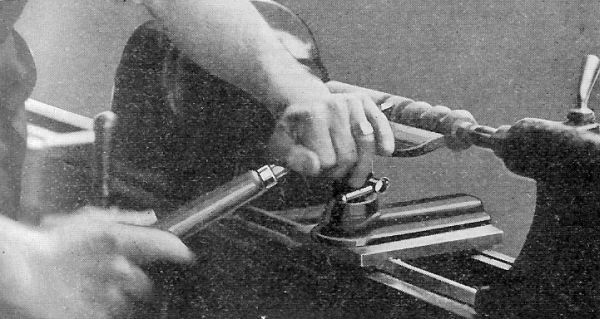
Fig. 13.
An analysis of the exercise chosen should be made to determine which of
the various cuts should be made first, second, etc., in order to produce
the exercise in the shortest time and with the least amount of tool
manipulation.
After the student has mastered these cuts with a certain degree of skill
and accuracy, he is ready to apply them in working out various models in
Section II.
A-II--1-a. Chisel Handles
At this point it is well to state that the small end of all work should
be turned at the dead center. In the case of chisel handles the socket
or ferrule end is at the dead center where the stock can safely be cut
away to permit the fitting of the ferrule or the socket.
After the stock is turned to a cylinder of the largest dimension
desired, the taper, for the socket chisel, should be turned first and
fitted to the chisel in which it is to be used. Then the rest of the
handle is worked out. Ferrules should also be fitted in the same manner.
A drive fit should be used for all ferrules.
A-II--2 and 3. Mallets and Gavels
The biggest source of trouble in these models is getting the handles to
fit true. This is caused by not getting the hole in the head straight.
Turn the head to a cylinder 3/16" larger than the finished dimension.
Then bore the hole perpendicular to the axis as near as possible,
either by leaving it between the lathe centers or by placing it in a
vise. The handle is then fitted into the head. A snug fit is necessary.
If one side "hangs" or is lower than the other the centers are moved
sufficiently to correct it. The head is then turned to exact size and
finished.
A-II--7. Vise Handles.
Turn the spindle with the solid head to dimensions. Bore a hole through
a 1¼" square block and fit the block snugly to the end of the
spindle. Turn this block to the same dimensions as the other head. This
method will save chucking the second head and is much quicker.